VSI Archive Backup System for OpenVMS Guide to Operations
- Software Version:
- ABS/MDMS V4.x
- Operating System and Version:
- VSI OpenVMS Alpha Version 8.4-2L1 or higher
VSI OpenVMS IA-64 Version 8.4-1H1 or higher
VSI OpenVMS x86-64 Version V9.2-3 or higher
Preface
1. About VSI
VMS Software, Inc. (VSI) is an independent software company licensed by Hewlett Packard Enterprise to develop and support the OpenVMS operating system.
2. Intended Audience
This document is intended for storage administrators who are experienced OpenVMS system managers. This document should be used in conjunction with the Introduction to VSI OpenVMS System Manager's Manual.
3. VSI Encourages Your Comments
You may send comments or suggestions regarding this manual or any VSI document by sending electronic mail to the following Internet address: <docinfo@vmssoftware.com>. Users who have VSI OpenVMS support contracts through VSI can contact <support@vmssoftware.com> for help with this product.
4. OpenVMS Documentation
The full VSI OpenVMS documentation set can be found on the VMS Software Documentation webpage at https://docs.vmssoftware.com.
5. Conventions
VMScluster systems are now referred to as OpenVMS Cluster systems. Unless otherwise specified, references to OpenVMS Cluster systems or clusters in this document are synonymous with VMScluster systems.
The contents of the display examples for some utility commands described in this manual may differ slightly from the actual output provided by these commands on your system. However, when the behavior of a command differs significantly between OpenVMS Alpha and Integrity servers, that behavior is described in text and rendered, as appropriate, in separate examples.
In this manual, every use of DECwindows and DECwindows Motif refers to DECwindows Motif for OpenVMS software.
| Convention | Meaning |
|---|---|
|
Ctrl/ x |
A sequence such as Ctrl/ x indicates that you must hold down the key labeled Ctrl while you press another key or a pointing device button. |
|
PF1 x |
A sequence such as PF1 x indicates that you must first press and release the key labeled PF1 and then press and release another key or a pointing device button. |
|
Return |
In examples, a key name enclosed in a box indicates that you press a key on the keyboard. (In text, a key name is not enclosed in a box.) |
|
… |
A horizontal ellipsis in examples indicates one of the
following possibilities:
|
|
. . . |
A vertical ellipsis indicates the omission of items from a code example or command format; the items are omitted because they are not important to the topic being discussed. |
|
( ) |
In command format descriptions, parentheses indicate that you must enclose the options in parentheses if you choose more than one. |
|
[ ] |
In command format descriptions, brackets indicate optional choices. You can choose one or more items or no items. Do not type the brackets on the command line. However, you must include the brackets in the syntax for OpenVMS directory specifications and for a substring specification in an assignment statement. |
|
[ |] |
In command format descriptions, vertical bars separate choices within brackets or braces. Within brackets, the choices are options; within braces, at least one choice is required. Do not type the vertical bars on the command line. |
|
{ } |
In command format descriptions, braces indicate required choices; you must choose at least one of the items listed. Do not type the braces on the command line. |
|
bold text |
This typeface represents the introduction of a new term. It also represents the name of an argument, an attribute, or a reason. |
|
italic text |
Italic text indicates important information, complete titles of manuals, or variables. Variables include information that varies in system output (Internal error number), in command lines (/PRODUCER= name), and in command parameters in text (where dd represents the predefined code for the device type). |
|
UPPERCASE TEXT |
Uppercase text indicates a command, the name of a routine, the name of a file, or the abbreviation for a system privilege. |
|
|
Monospace type indicates code examples and interactive screen displays. In the C programming language, monospace type in text identifies the following elements: keywords, the names of independently compiled external functions and files, syntax summaries, and references to variables or identifiers introduced in an example. |
|
- |
A hyphen at the end of a command format description, command line, or code line indicates that the command or statement continues on the following line. |
|
numbers |
All numbers in text are assumed to be decimal unless otherwise noted. Nondecimal radixes—binary, octal, or hexadecimal—are explicitly indicated. |
Chapter 1. Introduction
Warning
The tape functionality is not supported in ABS/MDMS E4.8. Disregard any mentions of tape throughout this document.
The Archive Backup System for OpenVMS (ABS) is a software product that allows you to save and restore data in a heterogeneous environment. ABS provides you with the ability to perform anything from full system backup operations to user-requested or user-created backup operations. ABS ensures data safety and integrity by providing a secure environment for save and restore operations.
ABS is based on an OpenVMS system environment and all data is saved to (and restored from) archives on OpenVMS systems.
ABS enables you to implement a backup policy that allows you to save the data through automatic or repetitively scheduled save operations. It also enables you to save data randomly using a one-time-only save operation. ABS allows you to use different scheduler interface options to schedule requests. This feature allows you to customize the scheduling of save or restore requests to your system configuration.
Save and restore operations are accomplished using two of the objects recognized by ABS, the save request and the restore request. These objects allow you to save data from online to either a offline volume or to another disk, and if necessary, allows you to restore that data to either its original location or to a different output location.
ABS tracks the location of data when saved as a result of an ABS save request. This information is kept in an ABS catalog. Upon request, ABS accesses the catalog to locate or restore the data. Chapter 2, "Overview" provides an overview of ABS capabilities, and Chapter 3, "Saving and Restoring Data" describes ABS Save and Restore operations, and the associated ABS objects, in more detail.
ABS is integrated with Media, Device and Management Services (MDMS), which performs the following functions on behalf of ABS:
Database Management Services - MDMS maintains the ABS database objects including saves, restores, archives, environments, catalogs, schedules and selections. Database management services are available within a distributed environment using either TCP/IP or DECnet communication protocols. Chapter 3, "Saving and Restoring Data" describes the ABS objects in detail.
Media Management Services - MDMS maintains a set of physical and logical objects for management of backup hardware and media. These objects include domain, locations, nodes, groups, jukeboxes, drives, media types, pools, volumes and magazines. Chapter 4, "Media Management" describes Media Management Services in detail.
Scheduling Services - MDMS provides extensive internal scheduling services for automatically scheduling ABS save and restore requests. Chapter 3, "Saving and Restoring Data" describes Scheduling Services.
Security Services - MDMS provides flexible security options using rights, privileges and object access control for secure use in a distributed environment. Chapter 5, "Security" describes security services.
MDMSview - A graphical user interface that manages all ABS and MDMS objects using a view-based approach for navigation. Views currently supported include Objects, Tasks, Requests, Reports and Domain. Chapter 6, "User Interfaces" describes the Graphical User Interface.
DCL Interface to the Database Objects - A comprehensive set of DCL commands to manage all ABS objects, compatible with the interface for MDMS media management objects. Chapter 6, "User Interfaces" describes DCL operation, with a full reference in the VSI MDMS Reference Guide.
Planning for Disaster Recovery is an important part of any datacenter operation. Chapter 7, "Preparing For Disaster Recovery" offers guidelines on how to plan for disaster recovery with ABS.
Chapter 11, "Architecture" offers an architectural overview of the ABS/MDMS system; you can use this to understand the internal operations of ABS and customize certain operational parameters.
A troubleshooting section has been added in Chapter 12, "Troubleshooting". This chapter describes how to define extended logging options, and offers solutions for some of the more common problems that can occur in an ABS environment.
The appendix offers the following:
Example on configuring MDMS
Procedures for migrating from SLS/MDMS V2.x to ABS/MDMS V4.x environment
Applying Prev3 Support to use SLS as the client after the migration
Upgrading from ABS V2.x/V3.x to V4.x environment
ABS/MDMS support for fibre channel.
Chapter 2. Overview
ABS Operational Environment
ABS Objects
ABS Catalogs
Backup Agent
Media, Device and Management Services (MDMS)
User Interfaces
Scheduler Options
MDMS Objects
Getting Started
This chapter provides an overview on the ABS and MDMS environment. See Chapter 3, "Saving and Restoring Data" for detailed information on how to save and restore data using ABS. See Chapter 4, "Media Management" for information about how to configure and maintain the media management environment.
2.1. ABS Operational Environment
ABS operational environment contains the following components:
ABS objects - ABS objects define physical locations of saved data, the criteria under which save and restore requests are performed, and the save and restore requests themselves. ABS objects are described in Section 2.2, ''ABS Objects''.
ABS catalogs - ABS catalogs are the components of ABS software that contain the history information about ABS save requests. Catalogs contain the records of data saved using ABS. Those records enable you to locate and restore data that was saved using ABS. ABS catalogs are described in Section 2.3, ''ABS Catalogs''.
Backup agent - A backup agent is the utility that performs the actual data movement operation. For OpenVMS systems, the backup agents are the OpenVMS BACKUP Utility and the RMU Backup Utility. Backup agents are described in Section 2.4, ''Backup Agent''.
2.2. ABS Objects
The following sections summarize the objects used by ABS to save and restore data. More detailed information about ABS objects may be found in Chapter 3, "Saving and Restoring Data".
2.2.1. Saves
A save request defines the data to be saved and executes upon immediate invocation or through an automatic, repetitive schedule. You can create save requests using either the MDMSView GUI or the CLI interface.
A save defines the following criteria:
The data to back up - you can specify disks, files or databases to back up
The type of data to back up (VMS files, Oracle Rdb databases or storage areas)
Whether the save is an incremental operation based on a previous save, or otherwise
When to save the data (base date and frequency)
Where to save the data (which archive to use)
The length of time to keep the data (retention period or expiration date)
Who can access a save request (for data safety)
What environment to use to execute the save request
Whether to perform pre- or postprocessing commands
To meet your site’s backup requirements, you will need to create save requests that fulfill those requirements.
2.2.2. Restores
A restore request restores data from an archive back to online storage. You can create restore requests using either the MDMSView GUI or the CLI interface. Restore requests can be executed immediately or at a specified time. You can also schedule restores for repeated operations in the same manner as saves.
A restore defines the following criteria:
The data to restore - you can specify disks, files or databases to restore
The type of data to restore (VMS files, Oracle Rdb databases or storage areas)
Whether the restore is an incremental restore based on a previous restore, or otherwise
Where to restore the data (optional output location other than the original location)
Where the data resides (on which archive)
Who can access a restore request (for data security)
What environment to use to execute the restore request
Whether to perform pre- or postprocessing commands
To meet your storage management requirements, you will need to create restore requests that fulfill those requirements.
Figure 2.1, ''ABS Save or Restore Request'' illustrates the path of a save or restore request.
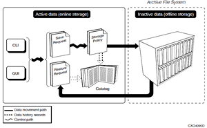
A save or restore request is invoked through the GUI or through the CLI (DCL).
| IF the request is a . . . | THEN the data is . . . |
|---|---|
| Save request | Saved from online storage to the archive. An ABS catalog records the location of the saved data. |
| Restore request | Restored back to online storage. ABS searches the catalog for the location of the data |
2.2.3. Archives
An archive defines the media type and other characteristics where you can safely store data. Each archive has a unique name and contains a set of archive characteristics. You can simply reference an archive name in a save or restore request rather than a complicated set of characteristics. Archives are designed to be shared among many save or restore requests.
Each archive defines the following:
The type of archive to use (TAPE or DISK)
If the archive file system is TAPE, the media type, pool, and location for tape volumes in the archive
How long to keep the data stored in a particular archive (retention period or expiration date). You can specify two archives for save requests that perform both full and incremental operations (at different times) so that the full and incremental saves can have different retention periods and can reside on different volume sets
Who is allowed to access the archive (for data safety)
Who is allowed write data to and read data from the archive (ensures data safety)
Which catalog contains the information about the data stored in the archive
How long to use a volume set
How many save or restore requests can be executed simultaneously
Normally, one archive is associated with both save and restore requests. However, for save requests that perform both full and incremental saves (at different times), you can define two archives: the first for full saves and the second for incremental saves. This allows the full and incremental saves to be performed on different tape volumes with different retention periods.
2.2.4. Environments
An environment object defines the criteria under which save and restore requests are executed.
The criteria defined in an environment include:
Whom to notify when a backup or restore operation has successfully completed (or failed)
The number of drives to use for the save or restore requests
Who is allowed access to the environment (for data security)
Default data safety checks to perform during save or restore operations (such as Full, XOR Redundancy, CRC, or a combination thereof)
Whether to enable log and listing files.
How often to retry the save or restore operation before requiring user intervention
Whether to perform job-wide pre- or post-processing commands
The resulting disposition of the files that are saved
Locking options
2.2.5. Selections
When you specify a set of disk or file specifications for a save or restore request, you are creating (implicitly or explicitly) a selection object. A selection object contains one or more disk or file specifications, together with additional selection criteria and operational attributes including the following:
Options to pass to the Backup Agent (agent qualifiers)
The type of data to be saved (VMS files, Rdb databases and storage areas)
Selection criteria using a combination of before dates and since dates (explicit selection only)
Specific files to exclude that would otherwise be included in the file specification
Who is allowed access to the selection (for data security)
Conflict options (what to do if the file being restored exists)
If you specify a set of disk or file specifications as part of the save or restore request, these files are stored in a default selection for that save or restore. You can use a default selection exclusively in your saves and restores as long as the other selection criteria (including data type) are the same for all files in the request. Alternatively, you can create your own selections explicitly using either the MDMSView GUI or the CLI, and associate them with your save and restore requests. Each save and restore can support multiple selections.
2.2.6. Schedules
You can use a variety of ways of scheduling your save and restore requests, including two methods provided by MDMS, or by the use of a third-party scheduler product (see Section 2.7, ''Scheduler Options''). The schedule object defines on what days and times a save or restore request is run. If you use MDMS scheduling, these schedule objects are executed at the appropriate times and the associated save and restore requests are invoked. If you use a third-party scheduler, the schedule objects are still created, but they do not invoke the associated save or restore requests - that is done by the third-party scheduler. The schedule object is created when you create the associated save or restore request.
For most save and restore requests, you can define a frequency of operation, which together with a base date determine the schedule attributes automatically. However, if you use internal MDMS scheduling, you can specify a custom schedule, and set attributes for scheduling including the following
The days of the week you wish a request to run
The dates of the month you wish a request to run
The months of the year you wish a request to run
The times of the day you wish a request to run - a request can run up to 100 times per day
Specific dates in the next 10 years you wish a request to run, that otherwise would not be run according to the other selection criteria
Specific dates in the next 10 years you wish the request not to run, that otherwise would be run according to the other selection criteria.
Relate one schedule to another, so that its associated save or restore request runs after the related save or restore request.
If you use a third-party scheduler, you can specify non-standard frequencies by using an explicit frequency and interval that is passed to the scheduler, or you can use the scheduler interface directly to manipulate the frequency of the request.
2.3. ABS Catalogs
An ABS catalog consists of a catalog object and the catalog files. The information contained in an ABS catalog object includes:
The type of catalog (FILES, DISKS, VOLUME_SETS)
Whether or not to use an intermediate staging file
Who is allowed to access the catalog (for data safety)
Who is allowed write data to and read data from the catalog (ensures data safety)
The ABS catalog files contain history information about save requests and can be assigned to one or more archives. Each time a save request is initiated through a particular archive, the save request history is recorded in an ABS catalog associated with the archive.
The information contained in an ABS catalog includes:
The name of the data that was saved
The type of data that was saved (OpenVMS Files, Oracle Rdb Database, Oracle Rdb Storage Area, Oracle Database)
The date and time the data was saved
The save set name where the data is located
The location of the save set (disk or tape)
The original location of the data
The owner of the data
Figure 2.2, ''ABS Catalogs'' shows the relationship between an ABS catalog and an ABS archive.
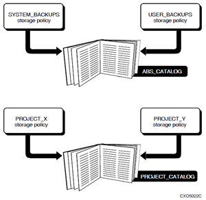
After the installation of ABS is complete, ABS provides a default catalog named ABS_CATALOG. By default, this catalog is associated with all archives unless it is changed by the creator of the archive. All ABS catalogs, both the default catalog and user-created catalogs, support lookup and restore capabilities.
ABS catalogs are node specific but in a VMScluster all nodes could share the same catalog files.
2.4. Backup Agent
ABS uses various backup agents to save and restore data. The backup agent is determined by the type of data, such as VMS files, Oracle Rdb databases, or Oracle Rdb storage areas. The backup agent is responsible for the actual data movement operation, while ABS is responsible for invoking the correct backup agent and recording the information about the save operation.
ABS supports the following backup agents:
OpenVMS BACKUP Utility - For OpenVMS files, ABS uses the OpenVMS BACKUP Utility.
RMU Backup Utility - For Oracle Rdb databases and storage areas, ABS uses the RMU Backup Utility.
2.5. Media, Device and Management Services (MDMS)
Media, Device and Management Services (MDMS), a fully-integrated component of ABS, performs several services for ABS, including:
Database Services - The ABS objects are managed by MDMS databases and are compatible with the MDMS media management databases
Interfaces - Both the MDMSView GUI and the CLI to all objects are managed by MDMS. The old ABS DCL interface is obsolete, but still supported. The old ABS and MDMS GUIs are not supported.
Security Services - MDMS manages access rights and privileges to ABS and MDMS objects, including individual access control on all objects. Security is discussed in Chapter 5, "Security".
Media Management Services - MDMS supports a set of objects for the purpose of media management for ABS. Media management services are described in Chapter 4, "Media Management".
2.6. User Interfaces
The interfaces for ABS are provided by MDMS, which performs all database management on behalf of ABS. MDMS provides the following interfaces.
Warning
In ABS/MDMS E4.8, the Graphical User Interface functionality is still in development and may not function properly.
| Interface | Description |
| MDMSView GUI | MDMS provides a graphical user interface (GUI) called MDMSView that allows manipulation of all ABS and MDMS objects in an integrated GUI. MDMSView provides several “views” of accessing ABS and MDMS information, and is usable on OpenVMS Alpha systems (V7.3-2, V8.2 and V8.3) and OpenVMS IA-64 (V8.2-1 and V8.3). See Chapter 6, "User Interfaces" for a description of MDMSView. |
| MDMS CLI (DCL) | MDMS also provides a Command Line Interface (CLI), which is the Digital Command Line (DCL) interface, for users who prefer this type of interface, or for users whose OpenVMS systems cannot support the MDMSview GUI. See Chapter 6, "User Interfaces" for a brief description of the CLI interface. This interface is also described in its entirety in the VSI MDMS Reference Guide. |
ABS provided its own CLI interface in versions prior to version 4. This interface is now deprecated, but is still provided for backward compatibility. The former ABS GUI, however, is not supported.
2.7. Scheduler Options
MDMS allows the use of different scheduler interfaces. By default MDMS uses an internal interface to the OpenVMS Queue Manager to schedule save and restore requests. MDMS supports the following scheduler interfaces:
INTERNAL (default) - uses an internal interface to OpenVMS Queue Manager
EXTERNAL - uses DCL commands to interface with the OpenVMS Queue Manager by calling a command procedure
SCHEDULER - uses DCL commands to interface with the 3rd party scheduler product by calling a command procedure; the pre-V3.0 ABS scheduler DECscheduler V2.1B may be used with this option if you have a license for that product.
The scheduler interface is invoked when a save or restore request is created, you can either start the request immediately or define a repetitive schedule.
The scheduler interface is used to:
Automate and manage ABS jobs that run repeatedly, such as ABS save and even restore requests.
Capture events through a logging system, so you can generate accounting and historical reports. This may vary depending on the scheduler interface.
Execute all requests remotely as well as locally - transparently to the user.
2.8. MDMS Objects
This section summarizes the MDMS objects for media management. See Chapter 4, "Media Management" for more detailed information on MDMS objects.
2.8.1. Domain
The MDMS domain encompasses all objects that are served by a single MDMS database. These include physical resources such as nodes, jukeboxes, drives and volumes, and logical objects such as media types, pools and magazines. The domain also encompasses all the users that access and manage MDMS resources. A domain may encompass a single site location, or can be geographically distributed, linked via Fibre Channel or a wide area network.
The MDMS domain has a single domain object, which contains:
The default media type, onsite and offsite locations, protections and dates that are assigned to new volumes by default
The default OPCOM classes assigned to new nodes by default
The type of scheduler to be used in the domain
The system users to be notified when volumes are deallocated
The request ID of the next MDMS request
The mapping of low-level rights to high-level rights
The level of access control to be assigned to the domain.
2.8.2. Drives
A drive is a physical resource that can read and write data to tape volumes. Drives may be of one of three types:
Jukebox - The drive is part of a robot-controlled jukebox, and random-access loading and unloading is performed by the robot
Stacker - The drive supports the automatic loading of a succession of volumes in sequential access. Once the volumes are exhausted, operator intervention is needed to load new volumes
Standalone - The drive requires operator intervention for all loads and unloads.
Jukebox drives are associated with a jukebox, and require a drive number identifier if the jukebox is controlled by MRD. Stacker and standalone drives are not associated with a jukebox: this includes drives used in a stacker configuration that are actually in a physical loader.
MDMS supports a drive object for each drive to be managed by MDMS. The drive object includes:
The OpenVMS device name of the drive (this can be the same or different than the drive name).
The media types that the drive supports for both read-write and read-only operations
The nodes and groups with direct access to the drive, including Fibre Channel access
Flags associated with the drive
The state of the drive
Local and/or remote access to the drive
The jukebox associated with the drive
2.8.3. Groups
The MDMS group object is simply a collection of nodes that have some common association. You may define groups to represent OpenVMS clusters, a set of nodes that can access Fiber Channel devices, or for any purpose whatsoever. Groups can typically be used in all commands that support nodes. It is a convenient way to reference a long list of nodes. In commands that support nodes and groups, it is possible to specify both for the command.
The only attribute that a group has is a list of nodes.
2.8.4. Jukeboxes
In MDMS, a jukebox is a generic term applied to any robot-controlled device that supports automatic loading of volumes into drives. MDMS jukeboxes include:
Small, single-drive loaders such as the TZ887 or the TLZ9L
Large, multi-drive libraries with ports, slots and capabilities typically ranging from the tens to the hundreds of volumes, such as the ESL9326
Very large StorageTek (R) silos that may contains literally thousands of volumes and many tens of drives
A jukebox object is associated with each jukebox, and contains the following fields:
Control option - controlled by the SCSI-based MRD subsystem, or DCSC for certain silos
For MRD jukeboxes:
The OpenVMS robot name for the jukebox
The number of slots in the jukebox
The magazine option flag, and optional magazine topology
For DCSC jukeboxes:
The library, ACS and LSM identifiers for the jukebox
The CAP sizes for the jukebox
The location of the jukeboxes
Access options for local and/or remote access to the jukebox
The threshold value for free volumes in the jukebox (before a warning is issued)
The groups and nodes that have direct access to the jukebox, including access via Fibre Channel
The state of the jukebox
2.8.5. Locations
A location describes the physical location of other objects, and is used as a selection criterion for allocating drives and volumes, and for placing tape volumes in a specific place. Locations can exist in a hierarchy, and as such are considered compatible locations for allocation purposes if locations share a common root in the hierarchy.
Locations only have two attributes:
Parent location - The parent location in the hierarchy (a location need not have a parent location)
Spaces - A range of “spaces” to be used for storing volumes, also optional.
2.8.6. Magazines
A magazine is a logical object that contains a set of volumes that are to be moved as a group. Magazines typically relate to a physical magazine that certain jukeboxes require in order to move volumes in and out of a jukebox (for example, a TZ877 or TLZ9L). However, even for jukeboxes requiring physical magazines, it is not a requirement to configure MDMS magazines if you want to treat the movement of the individual volumes independently.
Magazines contain the following attributes:
Slot count
Placement
Jukebox name, start slot or position
Onsite and offsite locations and dates
When a volume is in a magazine, its placement and associated locations are those of the magazine. Magazines can be scheduled to move onsite and offsite. In most cases, this means that all the volumes in the magazine are moved onsite or offsite; the physical magazine itself usually stays with the jukebox with a new set of volumes.
The use of magazines is not required.
2.8.7. Media Types
A media type is a logical object that describes certain attributes of tape volume media. Media types are used as a major selection criterion for drive and volume allocation, and are used to match volumes with compatible drives. Media types contain the following attributes:
Density - A density value or keyword that identifies the density of the media. This value must be one of the keyword values supported by OpenVMS. Density is used in initializing volumes.
Compaction - A flag indicating whether compaction is desired on volumes. Setting compaction usually results in about twice as much data capacity for a tape volume.
Capacity - The size of the media in MB (not used by MDMS).
Length - The length of the media in feet (not used by MDMS).
2.8.8. Nodes
A node is an OpenVMS system in the MDMS domain that is running MDMS. Every node in the domain must have a node definition, which describes the network transports and other information applicable to that system. Node attributes include:
Location of the node
OPCOM classes to be used for OPCOM messages on the node
Supported network transports and transport full names
2.8.9. Pools
A pool is a logical object that contains a set of volumes that can be allocated and used by a set of authorized users. It is one way to separate volumes belonging to different organizations and allowing only users of those organizations to use the volumes. Pool attributes include:
Authorized users - A list of users in node::username format that are authorized to allocate and use volumes in the pool
Default users - A list of users in node::username format that are not only authorized to use volumes, but that use volumes from this pool by default.
Threshold - A minimum value of free volumes in the pool, below which an OPCOM warning message is sent.
A user need only be defined in one of the lists to be able to use volumes in the pool.
The use of pools is not required.
2.8.10. Volumes
A volume is a single piece of tape media that MDMS applications (ABS and HSM) use to store tape-related data. Volumes contains many attributes that are used to describe the type of volume, its placement and location, and dates for scheduling allocation and movement. Volume attributes include:
Media type and pool for the volume
Placement and placement objects such as jukebox, slot, location, magazine
Onsite and offsite locations and scheduled dates
Allocation state, user and scheduled scratch date
Formatting information
Volume protection
Counters
Historical information dates
2.9. Getting Started
This section provides a simple example of how to configure a minimal ABS/MDMS domain and create a save and restore request. Although most configurations are more complex than this, it serves to illustrate how to use the MDMS configuration procedure and the default objects provided by ABS.
Before creating save or restore requests, you should first configure the media management environment. This includes the tape volumes, drives, jukeboxes and other media management objects that you may want to use. The recommended way to do this is to run the MDMS configuration command procedure, which offers an online tutorial and help in defining the configuration. During execution of this procedure, type “?” to get help on any question, and type “??” to get help and (in many cases) a list of existing objects or possible values for answers to questions. To invoke this procedure:
@MDMS$SYSTEM:MDMS$CONFIGURE
A complete example of running this procedure is provided in Appendix A, "Configuration Example".
Having completed the media management configuration, creating a save or restore request in ABS can be very simple if you elect to use the default archives, environments and selection objects. The minimum amount of information you need to specify for a save or restore request is:
The name of the save or restore.
The disks or files to be saved.
The start time of the save.
ABS tries to determine the type of data being saved based on the format of the file specification and assigns by default a relevant archive and environment. So, for example, a save request can be specified and executed in a single DCL command as follows:
$ MDMS CREATE SAVE MY_SAVE/INCLUDE=DISK$USER1:[SMITH...]/STARTThis command creates a save called MY_SAVE, includes the file specification DISK$USER1:[SMITH...] (all files), and starts the save immediately. MDMS determines that this is a save of VMS files based on the file format, and assigns archive SYSTEM_BACKUPS and environment SYSTEM_BACKUPS_ENV, and creates a default selection and schedule. With this save definition, a default frequency of ONE_TIME_ONLY is assigned, and the save is not scheduled for regular execution.
A restore can also be defined. For example, to restore the same files that were saved in MY_SAVE, you can enter the following command:
$ MDMS CREATE RESTORE MY_RESTORE/INCLUDE=DISK$USER1:[SMITH...]/STARTThis command creates a restore called MY_RESTORE, includes the file specification DISK$USER1:[SMITH...] (all files), and starts the restore immediately. MDMS determines that this is a restore of VMS files based on the file format, and assigns archive SYSTEM_BACKUPS and environment SYSTEM_BACKUPS_ENV, and creates a default selection and schedule. With this restore definition, a default frequency of ONE_TIME_ONLY is assigned, and the restore is not scheduled for regular execution.
Note
Define the logical referring to the disk name before executing the restore request. For more information, see the note given in Section 3.5.8, ''Destination (Restore Only)''.
Since these requests were defined with a frequency of ONE_TIME_ONLY, ABS will automatically delete them after a default interval of 3 days after execution.
Of course, creating the backup environment to backup all data in your production environment will involve more complex definitions, including creating your own archives, environments and in some cases selections and schedules. Chapter 3, "Saving and Restoring Data" describes all the ABS objects in detail.
Chapter 3. Saving and Restoring Data
This chapter expands upon the ABS Overview in Chapter 2, "Overview" and describes saving and restoring in detail by discussing the ABS objects, and the meanings, possible values and uses for all attributes. For each object, the attributes are listed in alphabetical order for easy reference, but related attributes are discussed together. The attributes are described without specific syntax or instructions on how to manipulate them, but are named according to the qualifiers in the CLI and attributes on the MDMSView GUI screens. For information on the syntax and semantic rules for each object and attribute, refer to the VSI MDMS Reference Guide.
All objects have an owner, and optional access control which limits access to the object. Since these attributes are common to all objects, they are described in Chapter 5, "Security".
In addition, ABS supports inheriting attributes from one object to another when creating a new object. For example, if you want to create a new save request SAVE2, but use most of the attributes from another save request SAVE1, you can specify SAVE1 as the inherit attribute when you create SAVE2. From there you can modify SAVE2 to define its unique characteristics. This philosophy applies to all ABS and MDMS objects. You can even inherit restore requests from save requests if you want to restore the same files as were previously saved.
Finally, all objects have a description attribute in which you can enter a text string to describe the object. This attribute is not interpreted by either ABS or MDMS, so you can use it for any purpose you see fit. By default, the description is blank.
The following sections discusses all seven ABS objects in detail.
3.1. Archives
Archives define the media type and characteristics about where backup data is stored. Each save and restore uses exactly one archive, except that certain complex save and restores can use two archives (see Section 3.3, ''Cataloging Existing Savesets''). You can use a single archive for many different saves and restores by simply referencing the archive in the save and restore request. ABS defines four archives by default, which you can use in your save and restore requests as needed:
SYSTEM_BACKUPS - For system backups that are normally performed by a system administrator at regularly scheduled times
USER_BACKUPS - For backups performed by a non-privileged user to save or restore his or her own data
DISASTER_RECOVERY - For backups primarily designated for disaster recovery
Although these default archives are provided by ABS, you may modify them as needed to suit your site's operational environment. Alternatively, you can create your own archives and manipulate the attributes as described in the following sections.
3.1.1. Archive Name
This name is used to reference the archive in save and restore requests. There are no required or ad-hoc conventions for archive names, so they can reflect their usage in your environment. However, there are ad-hoc conventions for environment names based on the archive name, so you should restrict the archive name to 60 characters.
3.1.2. Archive Type
ABS supports two types of archive, which are hopefully self-explanatory:
- DISK
The archive data is stored on disk media, which can include optical disk. ABS assumes that all disk media are online and mounted on the OpenVMS system before any save or restore operation is executed. ABS does not perform any load/unload or mount operations on disk archives. When you specify disk archive type, the archive must contain a destination attribute indicating the disk and directory location of the archive data.
- TAPE
The archive data is stored on tape media, and uses MDMS for media management control of the media. When you specify tape archive type, the archive must contain a media type (defined in MDMS) that defines the type of tape media to be used for the archive. Only a single media type is supported. In addition, the archive may optionally contain a pool specification (indicating a set of volumes reserved to users authorized for the pool) and a location specification (used to allocate a drive).
3.1.3. Catalog
A catalog contains information about what data is stored in the archive and where it is stored. Each archive uses exactly one catalog, although catalogs can be shared among different archives. ABS defines a default catalog called ABS_CATALOG, which is assigned to all archives by default if a different catalog is not specified. If you wish to define a different catalog for an archive, then specify a catalog object name (not its location) in the catalog attribute of the archive. For the archive to be useful, the catalog must be defined as a catalog object in MDMS.
An archive with a name of DISASTER_RECOVERY is the only archive allowed to have no catalog associated with it and the save operation is therefore not catalogued (see Chapter 7, "Preparing For Disaster Recovery").
3.1.4. Consolidation
ABS supports the concept of consolidation criteria which determine when a volume set should be retired from use in the archive and a new volume set used. ABS supports three types of consolidation criteria, of which none, one, two or all three can be applicable:
INTERVAL - You can specify an interval as a delta time from the creation of the current volume set to the creation of the next volume set. The current volume set is retired if the consolidation interval is exceeded.
SAVESETS - You can specify the maximum number of savesets that should reside on the volume set. If this number would be exceeded, ABS retires the current volume set and allocates a new volume set for the archive. There is an ANSI-imposed maximum of 10000 savesets in a volume set.
VOLUMES - A volume set can contain one or more physical tape volumes. You can limit the number of volumes by specifying volumes on the consolidation criteria. If this number would be exceeded, ABS retires the volume set and allocates a new volume set. There is an ANSI-imposed maximum limit of 100 volumes in a volume set.
If you specify multiple consolidation criteria, ABS creates a new volume set when the first of any of the defined criteria are exceeded. The default consolidation criteria is an INTERVAL of 7 days. If no consolidation criteria are specified, then ABS creates a new volume set when the ANSI limits apply, or upon the first error writing to the volume set. This is not recommended as you may create excessively large volume sets, and may have to split a volume set between onsite and offsite (vault) locations. Consolidation criteria are only applicable to an archive type of TAPE.
3.1.5. Destination
If you specified an archive type of DISK, you must enter a destination attribute for the archive, or use the default of ABS$ROOT:[000000]. The destination contains the disk and directory location of the data saved in this disk archive. When specifying destination, you should ensure that the specified disk has enough free capacity to handle all data to be saved in this archive. ABS does not monitor the disk for sufficient capacity. ABS clears this attribute if the archive type is TAPE.
Also, if you have specified a logical name as part of the destination name, then ensure that before the restore request is executed, the logical is defined as a concealed logical that is either defined as a system-wide logical name or just has the physical device name before the restore request is executed. If you do not want to use the logical name, then specify the physical device name followed by the directory path as the destination for the restore request.
3.1.6. Drives
ABS allows you to enter a list of drives that can be used by save and restore operations to and from this archive. This should be used only to restrict the drives that would normally be available for these operations for some reason. Normally, you can let ABS select drives for all operations based on media type and location, and so you do not need to specify the drives in the archive. If you do specify drives, be aware that these drives apply to restores as well as saves. Drives are only applicable to an archive type of TAPE.
3.1.6.1. Drive selection
When the drive list is specified in the archive class, the drive is allocated by ABS/MDMS for operation as below:
Volume-set is not present in the archive class
ABS will allocate the first available drive and continues to select a volume matching the selection criteria. If all the drives in drive list are not free then ABS will Indefinitely loop for allocating the drives and wait for drive to be available.
- When the volume set is present in the archive class and the required volume is present in:
Slot - then ABS selects the first available drive from the drive list.
Drive that is part of drive list in the archive class - In this condition the drive where the volume is currently present will be used for save operation.
For example, if drive list consist of 2 drives A and B and if the required volume is present in B, then drive B will be used for the save/restore operation even if drive A comes first in the drive list.
Drive that is not a part of drive list - ABS will unload the volume from the drive and load the volume in first available drive in the drive list.
Note
The above allocation algorithm is applicable only when drive list is specified in the archive class.
3.1.7. Expiration Date and Retention Days
ABS supports two alternative methods of specifying when an archive expires. These are:
Expiration Date - A date given in OpenVMS absolute time that defines a specific future date that the volume data will expire.
Retention Days - The number of days following retirement of the volume set that the data will be retained, after which time it will expire.
Either retention days or expiration date may be given, but not both. By default, ABS defines retention days of 365, meaning that volume data is valid for one year after retirement of the volume set.
For an archive type of TAPE it defines the initial scratch date of the tape volume set. Once a volume has transitioned to FREE state and it has been re-used all catalog entries relating to the past usage of this volume are deleted. You can change the expiration of the archive by setting a new scratch date for the volume. Whenever data is added to the volume set a new scratch date will be set if the expiration date extends beyond the old scratch date.
For an archive type of DISK it defines the time at which the on-disk saveset is deleted. At the same time all catalog entries relating to that saveset are also deleted.
Expiration date and retention days are only applicable to an archive type of TAPE.
ABS supports save requests that sometimes perform full backups and sometimes perform incremental backups. Under these circumstances, it is useful to use different volume sets with different retention days or expiration dates for the fulls and the incrementals. To support this, ABS allows you to specify two archives for save requests: the first applies to the full backups, and the second applies to the incremental backups.
3.1.8. Location
A location is an MDMS object that defines the physical location of volumes, drives or jukeboxes. The location is used as one of the selection criteria (along with media type) for allocating a drive to load a scratch volume to extend the archive. If no location is specified for the archive, ABS uses the default onsite location defined in the MDMS domain. This is the default. Location is only applicable to an archive type of TAPE.
3.1.9. Maximum Saves
ABS supports multiple parallel save operations using a single archive, each operating on a different drive and volume set (archive type TAPE). To enable this feature, specify the maximum number of parallel saves that are desired using the maximum saves attribute. Values can range between 1 and 36, with 1 being the default. This attribute also applies to an archive type of DISK, but without the implications of multiple drives and volume sets being allocated.
3.1.10. Media Type
Media type is an MDMS object that describes the type of tape media to be used in the archive. Specify a media type that is defined within MDMS, or use the default domain media type. The media type is used as a mandatory selection criterion (along with optional pool and location) for volumes to be used in the archive. Media type is only applicable to an archive type of TAPE.
3.1.11. Pool
A pool is a logical MDMS object that relates a collection of volumes to a set of authorized users. In this way, you can allocate a collection of volumes to certain users knowing that other users cannot use volumes from the pool. Similarly, you can assign a pool to an archive, so that all volumes used in the archive must be taken from the volumes that are in the pool. You can specify only one pool per archive. If you do not specify a pool, then only volumes that have no pool defined can be used for the archive (this is also known as the scratch pool).
3.1.12. Volume Sets
The volume sets attribute indicates which volume sets are currently being used by save requests using the archive. There may up to the maximum saves number of volume sets currently being used. These volume sets are those to which the next save operation will be written to the archive. This attribute is normally maintained by ABS and you should not modify it unless there is a pressing need to remove one or more of the volume sets from the list and let ABS allocate new volume sets. Under no circumstances should you add volumes to the volume set list.
3.2. Catalogs
An ABS catalog contains historical information about ABS save operations. This historical information includes the location of data that was saved using ABS. For this purpose, ABS provides a default catalog named ABS_CATALOG.
Some sites can operate efficiently using only ABS_CATALOG provided by ABS. However, using additional catalogs can improve your ABS operations:
Speed of record insertion
Speed of lookup operations
Segregation of saved data
Regular catalog file maintenance
3.2.1. Catalog Name
This name is used to reference the catalog. There are no required or ad-hoc conventions for catalog names, so they can reflect their usage in your environment.
3.2.2. Catalog Node
Catalogs are node specific. You have to specify the MDMS node name where the catalog resides. An empty catalog node name means the local node where the command was issued or where the request executes. In a VMScluster, multiple nodes can share the same catalogs on a common disk as long as they have direct access to the catalog files. During a save operation ABS always accesses the catalog on the local node even though a different node name is specified in the archive. During a restore operation the catalog lookup will be performed for the catalog at the specified node. This allows to restore data that has been saved on another node.
3.2.3. Type
ABS supports four types of catalogs, which are hopefully self-explanatory:
DISKS - This catalog type only stores information about save requests performed. No information about individual filenames are stored in the catalog. The size of a DISKS type catalog is drastically smaller than the FILES catalog type. Save requests using this catalog type must be of type FULL and only specify a disk name. Staging does not apply to these catalogs.
Selective restore can be performed from a DISK type of catalog using ABS.
To view information about saved disks use the /SAVE qualifier with the “SHOW CATALOG” command. The show output lists the data saved, the volume ID and save set name used.
When a save request uses a DISKS type catalog, the following message is displayed in the save request log file:
"Filenames will not be catalogued"
FILES - The FILES type catalog stores all information about save requests performed and all files saved. It allows individual file lookups and restores.
SLS - The SLS type catalog is used only for the lookup of the files backed up by SLS. ABS V4.0x and later versions do not adequately support the use of lookups and restoring of SLS history files. ABS will only be able to restore the latest files that were backed up by SLS.
Note
For ABS to perform a lookup on the SLS History, the following conditions need to be met:
Image SLS$SHR in the SYS$SHARE directory
Logical SLS$HIST_<catalog_name> for performing a lookup on the catalog of SLS Type just as SLS does for the “STOR RESTORE command.
VOLUME_SETS - The VOLUME_SETS type catalog stores all information like the FILES type catalog. However, ABS uses individual files for each volume set. Catalog lookups take slightly longer for VOLUME_SETS type catalogs compared to FILES type catalogs. But VOLUME_SETS type catalogs avoid the constant growth of catalog files because the volume set specific file is deleted once the volume set has been re-used. A VOLUME_SETS type catalog cannot be used for DISK archive types.
Note
In ABS V4.4, the existing lookup on Volume_Set type of catalog is enhanced to use the date qualifiers effectively. This has significantly reduced the lookup time and improved the performance. However, if you still want to use the previous Lookup feature, define the logical ABS_V40_LOOKUP System-wide. By default, this logical is not set.
$
DEFINE/SYSTEM ABS_V40_LOOKUP 1This user defined logical is specific to ABS version 4.4 and will be automatically removed when ABS is uninstalled. In case you want to downgrade ABS, you need to manually deassign this logical to free the space that it has occupied in the System table.
3.2.4. Directory
By default catalog files are created in ABS$CATALOG. Without modification ABS$CATALOG points to ABS$ROOT:[CATALOG]. When creating a new catalog you can create the catalog files in a different location by specifying a device and directory. You have to update the definition of ABS$CATALOG logical in ABS$SYSTARTUP.COM to include the new device and directory solution in form of a search list.
$CREATE/DIRECTORY DKA100:[ABS_CATALOG]$DEFINE/SYSTEM/EXECUTIVE ABS$CATALOG ABS$ROOT:[CATALOG],- DKA100:[ABS_CATALOGS]
This creates a new directory for catalog files and adds it to the ABS$CATALOG search list. The same definition needs to be set in ABS$SYSTARTUP.COM.
If a “SHOW CATALOG/FULL” does not display a directory for a catalog it means the catalog’s location is not included in the ABS$CATALOG search list.
3.2.5. Staging
A catalog that is setup for staging improves the performance of the save operation because the catalog entry for a saved file is first written to a sequential disk file in ABS$CATALOG. Once the backup operation has completed a separate process moves the entries from the staging catalog file to the final catalog which is specified in the archive associated with the save request.
The final catalog does not contain the information about the save operation until the staging process has completed. If you request a backup operation and immediately look in the final catalog, the entries may not be available, yet. The backup operation and the staging process must complete before the currently saved files can be looked up in the catalog.
You can always modify the staging setting for an existing catalog. The use of staging is highly recommended to improve your overall backup times.
The staging catalog file is created in the first location pointed to by logical name ABS$CATALOG.
3.2.6. Catalog Save Entries
Save entries contain information about executing or executed save operations:
Catalog Name - The name of the catalog
Catalog Node - The name of the MDMS node where the catalog resides
Date Archived - The date the save operation was performed
Expiration Date - The original date the entry expires in the catalog (used only for archive type of DISK)
Include - The include file specification used
Object Entries - Number of entries added to the catalog
Archive - The name of the archive or, if the original archive no longer exists the previous archive UID
Environment - The name of the environment or, if the original environment no longer exists the previous environment UID
Save - The name of the save or, if the original save no longer exists the previous environment UID
Save Type - Shows the type of save being performed
all files with recording (R) - All files in a full incremental save with final recording of the backup date
all files (B) - All files in an incremental selective save
all files (S) - All files in a selective save
all files (0) - All files in an incremental save
increment level n - All files modified between incremental save n and n-1
Owner - The owner field of the archive being used
Saveset Format - The format used in the saveset:
RMU_BACKUP - Oracle Rdb/RMU saveset format
VMS_BACKUP - OpenVMS BACKUP saveset format
Archive Type- DISK or TAPE
Saveset Location -
For archive type TAPE the list of volume IDs containing the saveset
For archive type DISK the on-disk location of the saveset
Saveset Name - The filename of the saveset
Saveset Position - The tape mark offset of the beginning of the saveset on tape
Status - The ABS status for the save operation
Severity - The ABS severity level for the save operation
3.2.7. Catalog File Entries
File entries contain information about files which have been saved.
Catalog Name - The name of the catalog
Catalog Node - The name of the MDMS node where the catalog resides
Data Select Type - The format of the entry name
RDB_[Vnm_]_DATABASE - An Oracle Rdb database file
RDB_[Vnm_]_STORAGE_AREA - An Oracle Rdb storage area
VMS_FILES - OpenVMS file specification
VMS_SAVESET - volumeID:saveset specification
Filename - The name of the entry
Source Node - The network nodename where the entry was located
Date Archived - The date the entry was saved
Expiration Date - The original date the entry expires in the catalog (used only for archive type of DISK)
Creation Date - The date the entry was created on the source node
Revision Date - The date the entry was last modified on the source node before being saved
Owner - Owner information of the entry used on the source node
Saveset Name - Copied from related save entry
Saveset Location - Copied from related save entry
Saveset Section -
For archive type of TAPE the index into the list of volume IDs indicating the volume which contains the start of the saved entry
For archive type of DISK it is always 1
Save Type - Copied from related save entry
Status - Copied from related save entry
Severity - Copied from related save entry
3.2.8. Improving Catalog Performance
Catalog files are RMS index-sequential files and as such need regular maintenance to avoid unnecessary file growth and performance penalties. ABS provides a catalog conversion command procedure (“ABS$SYSTEM:ABS$CONVERT_CATALOG.COM”) that improves the target catalog update performance by doing a file-to-file conversion. By converting the target catalogs, you improve catalog update time.
3.2.8.1. Catalog File Sizes
The ABS catalog files will grow as you continue to execute save requests. The sizes depend on the number of files saved and the retention period used. For as long as the retention period has not expired more entries will be added to the catalog. Once the retention period is reached the ABS_CLEAN_CATLG_<node_name> batch job will remove expired entries from the catalog. So, the more the files you save and the longer you want to maintain the archived data, the larger the catalog files size.
Be sure to consider this information when creating catalogs and assigning retention values to your archives. It may be best to create separate catalogs for each archive, if the retention period is different. For example, you may create an archive called MONTHLY_SAVE, with a retention period of one month. Create a catalog called MONTHLY_SAVE to be used by that archive. The catalog size will grow for one month and then maintains its size.
3.2.8.2. Catalog File Maintenance
Run the conversion command procedure for each individual catalog on a regular basis. Catalogs with more frequent delete operations should be converted on a monthly basis. See the logfiles ABS$SYSTEM:ABS$CATALOG_CLEANUP.LOG;* for information on catalog file activities. As a rule of thumb, the catalog must be converted if more than 10% of its records have been deleted.
$ @ABS$SYSTEM:ABS$CONVERT_CATALOG MyCatalogThis example converts all files for catalog “MyCatalog” by creating new copies of the files in the same directory.
For additional improvement you can also move the target catalogs to a different disk by defining a system level search list logical for ABS$CATALOG in ABS$SYSTARTUP.COM. The command procedure also allows you to move the converted files to a different disk or directory.
$ @ABS$SYSTEM:ABS$CONVERT_CATALOG MyCatalog DKA100:[ABS_CATALOGS]This example converts the files for catalog “MyCatalog” and places the new files in location “DKA100:[ABS_CATALOGS”. Once the files have been copied over, you can add the new location to the ABS$CATALOG search list. Rename the old catalog files to *.DAT_OLD and verify that you can lookup information using the new files. Once the new catalog files are used you can delete the old files.
3.2.8.3. Catalog Cleanup
To clean expired entries from the catalog, there is a process that runs in the ABS$node batch queue called ABS_CLEAN_CATLG_node. This process is scheduled to run once a day at 12:30 pm. The scheduled time is set in the ABS$SYSTEM:ABS$START_CATALOG_CLEANUP.COM procedure. You may modify the start time for the job or change the frequency of the job. If you do not have lot of expired entries daily, you may want to run the job less frequently.
The log file generated by this cleanup process is called ABS$LOG:ABS$CATALOG_CLEANUP.LOG. A lot of information about how many records were read from the catalog, how many were deleted, and any errors are kept in this log. Most errors seen should be reported to VSI.
The catalog cleanup process cleans up all the catalogs when executed. We can also nominate the catalogs that need to be cleaned up. Also, we can specify the interval in which this cleanup process needs to run. This would be helpful:
If the cleanup process of all the catalogs takes a long time affecting the other daily jobs.
Cleanup of all the catalogs need not done always.
To nominate catalogs for cleanup:
Stop the catalog cleanup process.
Submit the cleanup COM file with the parameters as mentioned below:
$
@ABS$SYSTEM:ABS$START_CATALOG_CLEANUP catalog_names intervalcatalog_names - Space delimited catalog names. Default: All Catalogs Interval - "+n-"(n denoting the frequency at which the catalogs need to be cleaned). Default: Every Day
Example:
$ @ABS$SYSTEM:ABS$START_CATALOG_CLEANUP "CATLG1 CATLG2 CATLG3" "+2-"This command would nominate CATLG1,CATLG2,CATLG3 catalogs for cleanup and the cleanup runs with the frequency of 2 days. i.e if submitted on 01-Nov-2001, then cleanup runs on 03-Nov-2001 at 12:30, 05-Nov-2001 at 12:30 and so on.
Note
The cleanup of the VAOE file can be performed only after defining the ABS_CATALOG_VAOE_CLEANUP logical System-wide.
$ DEFINE/SYSTEM ABS_CATALOG_VAOE_CLEANUP 13.2.8.4. Staging Catalog
With staging enabled for a catalog ABS writes the catalog entries to a sequential file during a save operation. The save operation at the end creates a command procedure and executes it in a separate process. This unpack process moves all entries from the staging catalog to the final catalog. If all entries have been moved successfully the command procedure is deleted. If the unpack process failed for some reason you can run the command procedure manually. To do this, find the location and name of the command procedure in the logfile of the save request. Then execute the command procedure on the node where the save request was running.
21:21:07   COORD: Staging process PID :  2300143C
21:21:07   COORD: Staging catalog :      ABS$CATALOG:ABS_CATALOG_4.STG;1
21:21:07   COORD: Staging procedure :    ABS$CATALOG:ABS_CATALOG_4_1.COM;1
21:21:07   COORD: Staging logfile :      ABS$LOG:ABS_CATALOG_4.LOG
In this example if the command procedure file “ABS$CATALOG:ABS_CATALOG_4_1.COM” still exists it indicates that the staging unpack process has failed and you can manually execute the command procedure to update the catalog.
Staging files by default are created in the first location pointed to by logcial name MDMS$CATALOG.
3.3. Cataloging Existing Savesets
You may catalog information from existing VMS Backup savesets on tape. This allows you to lookup and restore files from savesets created outside of ABS.
Restrictions:
The saveset must reside on tape
Only VMS Backup savesets may be cataloged
The tape volume must be defined in MDMS and allocated to ABS so that ABS may reference the volume
A separate catalog and archive should be created for the saveset information
To catalog the savesets, create a SAVE request with the name of the tape volume and the saveset name, or wildcard, separated by a colon as the selection (include) and a data_type of VMS_SAVESET:
MDMS CREATE SAVE mysaveset_catalog/INCLUDE=tap001:mysaveset.sav/DATA_TYPE =
VMS_SAVESET/ARCHIVE=my_archive/ENVIRONMENT=my_env/START=01-MAY-2002
or
MDMS CREATE SAVE mysaveset_catalog -
/INCLUDE=tape001:*/DATA_TYPE=VMS_SAVESET/ARCHIVE=my_archive/ENVIRONMENT=
my_env/START=01-MAY-2002
ABS will load the tape listed in the include specification, then do a BACKUP/LIST of the contents, loading the information into the ABS catalog defined in the archive. The original date of the saveset will be preserved in the catalog.
Recommended Implementation:
It is recommended that you create a new catalog to store this data. You should also create a new archive to be used by these cataloging operations. This is mainly if you are cataloging copied tapes, where the dates of the original and the copied savesets will be duplicates.
This will allow you to choose to restore from the original or copies by selecting the appropriate archive for the restore request.
For example:
Several ABS save requests were saved on tape ABS000 using the SYSTEM_BACKUPS archive. Saveset Manager (SSM) was used to copy that tape to another tape, TAP000.
Before cataloging the data, do the following:
Create a new catalog called COPIED_TAPES. Create an archive called COPIED_ARCH, which points to the catalog COPIED_TAPES.
Create a save request specifying TAP000:* for the include specification and give it a data_type of VMS_SAVESET.
ABS will execute the request, cataloging the information into the COPIED_TAPES catalog.
To restore the data which is on ABS000 or TAP000, decide which copy you wish to restore and specify the appropriate archive or catalog on the restore request. For example, to restore from the original tapes, specify the SYSTEM_BACKUPS archive. To restore from the copy, specify the COPIED_ARCH archive. The MDMS SHOW CATALOG/FILES command with the /FULL qualifier will show the volumes used for the data.
Note
If the information about the original and copied savesets is put into the same catalog, they will have exactly the same archived data. This could cause confusion when restoring the data because ABS may not choose the tapes you wish to use for the restore. To make it easier to restore, it is recommended to use a separate catalog (as described above).
3.4. Environments
An environment describes the criteria under which save and restore requests execute, and exactly one environment must be associated with each save and restore request. You can use a single environment for many different saves and restores by simply referencing the environment in the save and restore request. ABS defines five environments by default, which you can use in your save and restore requests as needed:
SYSTEM_BACKUPS_ENV - For system backups that are normally performed by a system administrator at regularly scheduled times
USER_BACKUPS_ENV - For backups performed by a non-privileged user to save or restore his or her own data
DISASTER_RECOVERY_ENV - For backups primarily designated for disaster recovery
DEFAULT_ENV - Used by default in the event one of the other default environments have been deleted
Although these default environments are provided by ABS, you may modify them as needed to suit your site’s operational needs. Alternatively, you can create your own environments and manipulate the attributes as described in the following sections.
3.4.1. Environment Name
This name is used to reference the environment in save and restore requests. There are no required conventions for environment names, but ABS uses an ad-hoc convention that pairs environments and archives. If you specify an archive of name FOO, then by convention there should be a matching environment named FOO_ENV. You can choose to follow or ignore this convention for your site.
3.4.2. Action
The action attribute specifies one of three possible actions to be performed on files saved using this environment. Specify one of the following three actions:
RECORD_DATE - Modify the BACKUP date to reflect the time that this file was backed up; this is the required option if you intend to do incremental backups of this file, and is the default value - supported for files of type VMS_FILES only.
NO_CHANGE - Do not change the online file at all. If this option is specified, you will not be able to perform incremental saves on this file.
DELETE_FILE - This option is used when the backup is intended to be a long-term archive and you wish the file to be removed from the online system. The file is only deleted on a successful save operation.
Although RECORD_DATE is supported for VMS_FILES only, it remains the default for all data types, and is simply ignored for the other types.
3.4.3. Data Safety
The environment object allows you to specify one or more data safety features to ensure the reliability of the data on your offline tape volumes. You can select one or more of the following options:
CRC - Performs a Cyclic Redundancy check and writes it for each data block on a tape volume. This enables detection of a bad block during a restore operation.
FULL_VERIFY - Rereads all saved data and compares to what is on disk during a save. This option approximately doubles the time for the data copy phase of a save operation.
XOR - If the CRC check detects a bad block during a restore operation, the XOR mechanism allows recovery of the block. This option is applicable only to data type VMS_FILES, for which the backup agent is VMS BACKUP.
By default, all three options are enabled for maximum data safety.
3.4.4. Drive Count
The drive count specifies the number of tape drives to use for each save or restore using this environment. If there are at least as many drives available as the drive count, that number of drives are allocated for each save and restore request. If not, a reduced number of drives are allocated.
The default and highly recommended value is 1. The number of drives may range from 1 to 32.
3.4.5. Prologue and Epilogue
The prologue and epilogue attributes in the environment allow you to invoke a command procedure before and/or after the entire save or restore request. This allows you to perform pre-processing and post-processing operations around the entire request. Compare the order of environment prologue and epilogue procedures operations to the individual save and restore prologue and epilogue procedures, which are executed before and/or after each file or disk specification in the save or restore request. The order of execution is illustrated below:
Environment prologue
Start save or restore request
First disk/file specification prologue
First disk/file specification save or restore operation
First disk/file specification epilogue
Next disk/file specification prologue
Next disk/file specification save or restore operation
Next disk/file specification epilogue
......
End save or restore request
Environment epilogue (only on successful completion)
ABS defines logical names that can be used within the prologue or epilogue command procedure. These are defined in the process job table as follows:
| Logical Name | Meaning |
|---|---|
| ABS_SAVE_REQUEST_NAME | Name of the save request |
| ABS_RESTORE_REQUEST_NAME | Name of the restore request |
| ABS_STORAGE_CLASS | Name of the archive |
| ABS_EXECUTION_ENVIRONMENT | Name of the environment |
| ABS_NODE_NAME | Execution node name |
| ABS_OUTPUT_DEVICE | The name of output device, or devices, used by the save or restore request. |
You should enter an OpenVMS command of up to 80 characters in the prologue and/or epilogue strings. For example:
@ABS$SYSTEM:ABS_ENV_PROLOGUE.COM
By default, there are no prologues or epilogues defined for an environment.
3.4.6. Retry Limit and Interval
The retry limit and retry interval options allows you to specify the number of times and how often ABS should retry a object in a save or restore request before operator intervention is required. Specify the following:
Retry Limit - The number of retries (excluding the first attempt) to attempt before activating the notification options. A value of zero means no retries. You can also specify no limit, which means retries will be performed until the request either succeeds, or is manually stopped.
Interval - The interval between retry attempts, expressed as a delta time. The default retry interval is 15 minutes.
Each time a retry attempt is made, ABS generates a warning message. If you wish to see the warning messages, select the warning option in the when attribute for notification.
3.4.7. Listing Option
The listing option allows you to specify the type of listing generated for save and restore requests using this environment. Specify one of the following options:
NONE - Does not generate a listing file
BRIEF - Generates a brief listing file
FULL - Generates a detailed listing file
If not specified, NONE is the default option.
3.4.8. Lock
ABS allows you to specify what a save request should do when data usage conflicts occur by means of the lock attribute. If you specify lock, ABS saves the data even if other applications have the data locked for write access. If you specify nolock ABS does not save the data if other applications have the data locked for write - this is the safer approach. If you specify lock, it is possible that the data you save is inconsistent, as the other application may be writing to the file during the actual save operation. Use lock with caution. The default is nolock.
3.4.9. Notification
ABS uses the notification attributes in the environment to determine who, how and under what circumstances users are notified of ABS events during save and restore operations. ABS supports notification using mail, OPCOM or both. You can specify up to 32 separate notification options in each environment, using the following attributes:
MAIL - Specifies one or more mail users to be notified on certain types of event; specify one or more OpenVMS mail usernames (including node names as needed).
OPCOM - Specifies one or more OPCOM classes to be notified on certain types of events - specify one or more OpenVMS OPCOM classes (e.g. TAPES) to be notified - notification will be directed to the (execution) node(s) specified in the save or restore request.
TYPE - Indicates the level of information given. Select one of the following:
BRIEF - Contains only basic information (default)
NORMAL - Contains a moderate amount of information
FULL - Contains the maximum amount of information
WHEN - Indicates when the notification should occur. Choose one or more of the following:
START - Sends notification at the start of a save or restore request
COMPLETE - Sends notification at the completion of a save or restore request with any status (success or failure)
WARNING - Sends notification if the request completes with a warning, error or fatal status
ERROR - Sends notification if the request completes with an error or fatal status
FATAL - Sends notification if the request completes with a fatal status
You associate a TYPE and WHEN for each MAIL or OPCOM option provided. If you do not specify a TYPE and/or WHEN, a notification option acquires a TYPE of BRIEF and a WHEN of COMPLETE.
If you specify no notification options, then by default ABS sends a brief OPCOM message to class TAPES on completion of every request executed under the environment.
3.4.10. Profile
ABS allows you to specify the user name, node name, cluster name, rights and privileges under which save or restore requests in the environment will execute. ABS supports three main options for username:
ABS - This option specifies that all save and restore requests execute in the context of the ABS user (and account). You should not change the cluster, nodes, rights or privileges with this option, otherwise the saves and restores may not execute correctly. This is the default option, and is recommended for all system backup operations.
<REQUESTER> - This option (including the angle brackets) instructs ABS to run associated save and restore requests under the user profile of the associated save or restore request. The save and restore user profile (which is not normally displayed and not is changeable) is that of the user who created the save or restore request. This option should be used for user backups. With this option you should not adjust node or cluster, but you can manipulate rights and privileges if the user’s normal rights and privileges are not sufficient to run ABS save and restore requests.
Other user - This option instructs ABS to run associated save and restore requests under the profile of a third user (not the save/restore creator or ABS). With this option, you can manipulate rights and privileges if the user’s normal rights and privileges are not sufficient to run ABS save and restore requests. In addition, you should also define node and/or cluster to uniquely identify the user in the domain. Wildcard node and cluster names are supported.
It is recommended that you only specify a user profile for user backups. All other backups should run under the default ABS user profile.
3.5. Saves and Restores
The purpose of a save request is to backup data from primary online disk storage to either alternative disk or optical storage, or to tape storage. Saves are typically performed on a regular basis to provide protection in the event of a disk hardware failure, data corruption or deletion, or site disaster. Saves can also be used for archiving data that must be kept for a relatively long time for business purposes, but does not need to be online.
The purpose of a restore request is to return data from tape or alternate disk or optical storage back to primary online storage. In most cases, restores are performed after a disk hardware failure or user file corruption or deletion - these are usually one-time events. However, sometimes it is necessary to bring archived data online, and restores (perhaps scheduled restores) can be used for this purpose also.
ABS models save and restore requests in a similar fashion so in most cases the attributes for one are applicable to the other (exceptions are noted). The main difference is the direction of data transfer between disk and tape storage. As such, we shall discuss saves and restores in a single section.
You create each save or restore with a unique name, and associate a single archive and a single environment with it. Under certain circumstances, you can associate two archives with save requests. In addition, you implicitly create a schedule with each save request, and specify disks or files to save in objects called selections. As such each save or restore request is related to other ABS objects as shown below:
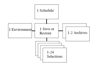
The following sections describes the attributes of save and restore requests.
3.5.1. Save Name or Restore Name
You must assign a unique name to each save and restore request, which is used as the only method of referencing the request. There are no required conventions associated with save and restore names. However, in previous ABS versions, the names could be generated automatically so you might see names that are a combination of the creation date of the request and a generated unique identifier (UID) if you are converting from pre-V4 ABS. For version V4 and later, ABS almost always references saves and restores by name rather than UID, and ABS no longer shows UIDs by default.
3.5.2. Archive
Each save or restore requests is associated with one or two archives, which contain information about where the backed up data is stored. The two archives are for those requests that involve both full and incremental operations: the first archive applies to the full operations and the second applies to the incremental operations. In this way, fulls and incrementals can reside on different volume sets with their own retention days or expiration dates. In other types of request, only one archive is used.
If you do not specify an archive, ABS chooses SYSTEM_BACKUPS.
3.5.3. Base Date, Start Date and Skip Time
The base date is the date and time that you wish the request to first execute on a regular basis. The base date is used for two purposes:
Defining the date and time to be used as a basis for scheduling - all scheduling intervals are based on both the date portion and time portion of the base date, and anniversaries of the base date at intervals defined by the frequency attribute.
Defining the basis for full versus incremental saves for complex frequencies such as dailyfull- weekly, log_2 and log_3. The base date and appropriate anniversaries of the base date define the date of the full saves.
Unless you want to change the scheduling or save type basis for the request, you would not change the base date. As such, the base date will remain a date in the past. Compare this to the start date, which specifies the next start date and time for the request. The start date is updated whenever the request is run to reflect the next time it is scheduled, or NONE if it is not scheduled again.
When a request is first created, and you specify only one of the dates, both dates are set (i.e. the next start date is the base date). By default, neither a base date or start date are supplied so the request is not scheduled for execution.
You can use the start date and skip time to request a one-time special, or non-scheduled, execution of the request. For example, assume that the normal scheduled time for a request is 23:00, as specified in the base date. However, you know that this is a particularly busy night and you want to start this request for tonight only at 21:00 instead. You can do this by setting the start date to 21:00. However, when the request is rescheduled, it will be rescheduled to the next iteration of the base date, or 23:00 the same day. You probably do not want this, so to avoid it you can set the start date together with a skip time to avoid running the request twice. The skip time is an exclusion time (expressed as a delta time) from the specified start date in which the request will not be rescheduled: normally you can set this to one day to avoid running the request twice in the same day. The following table shows some examples of base date, start date and skip time definitions based on a daily frequency:
| Base Date | Start Date | Skip Time | Skip Time |
|---|---|---|---|
| 23-Aug 23:00 | 10-Sep 21:00 | None | 10-Sep 23:00 |
| 23-Aug 23:00 | 10-Sep 21:00 | 1-00:00:00 | 11-Sep 23:00 |
| 23-Aug 23:00 | 10-Sep-23:00 | 2-00:00:00 | 12-Sep 23:00 |
When you specify a skip time, ABS saves it in the database until the request is next rescheduled. When the rescheduling takes place, the skip time is applied to the calculation, then cleared from the database. If you set a skip time and do not see it in the request, then it has already been applied to the next start date.
3.5.4. Before Date, Since Date and Date Archived (Restore Only)
When restoring files, you can choose a specific iteration of the files based on their archive date - that is, the date that they were saved in the archive. If you know the exact date archived, use the data archived attribute. If you know only an approximate date archived, use the before or since attributes to specify a range of dates. So, for example, if you wish to restore a file as it existed in the first week of January, you can specify a before date of the 8th January (at midnight), or a since date of 1st January (at midnight). When determining appropriate before or since dates, you should probably lookup the files in the catalog before requesting a restore, so that you can specify before and since dates that uniquely identify a single iteration of the file to restore.
The before and since dates in the restore apply only to the archive date of the file. They are not related to the before and since dates in the selection object, which refer to files’ online dates that are maintained by OpenVMS.
3.5.5. Catalog (Restore Only)
On a restore, you can specify a catalog name instead of an archive name if you know the name of the catalog from which to locate the restore information, and do not know the name of the archive. Normally, however, you would specify the archive under which the data was saved rather than the catalog.
3.5.6. Include, Exclude, Data Type and Source Node
One of the more obvious attributes of a save or restore request are the file names, disk names path names or database names that you wish to save or restore. There are two options for specifying these names in a save or restore request:
In an INCLUDE specification - You can specify the names directly in the save or restore request in an INCLUDE specification. You can specify multiple disks and/or files in a comma-separated list with the restriction that all disk and file specifications relate to a single data type (for example, VMS files). If you wish to mix file types in a single save or restore request, then you must use the second option.
Note
In case the include specification in the Save request had a directory tree structure, then to maintain the same during the Restore operation, you must specify the wildcard “*” in the include specification of the Restore request.
Example: /Include = TPRD:[TPRD.APPFILES*]*.*;*
If you do not use the wildcard “*” or specify a wildcard other than “*” in the include specification, then all the files are automatically restored to the root directory.
Examples:
/Include = TPRD:[TPRD.APPFILES]*.*;*
/Include = TPRD:[TPRD.APPFILES%]*.*;*
Using SELECTIONS - With this option, you create selection objects directly using the MDMSView GUI or the CLI, specify the appropriate include specifications, then associate the selection object(s) with the save or restore. You can associate multiple selection objects with any save or restore request as long as the total number of disk, file, path or database specifications in all the selection objects does not exceed 24.
When you specify disk, file and database names by including them in the save and restore request, then you are effectively creating a default selection object. This selection object has the same name as the save or restore, with the suffix “_SAVE_SEL_DEL” or “_REST_SEL_DEF” respectively. You can specify the following attributes directly in the save or restore request for inclusion in the default selection:
INCLUDE - A list of disks, files, paths or databases to include in the save or restore.
EXCLUDE - A list of files to exclude from the save or restore that would otherwise have been included according to the include specification. This option applies to data type VMS FILES only
DATA TYPE - The type of data to be saved or restored - select one of the following:
VMS Files - Applicable to VMS files. If only a disk is selected, a FULL backup of the entire disk is performed. If directory and file specifications are specified, then a SELECTIVE backup of files is performed.
Oracle Rdb Database Options - These options (which are version-number specific) specify that you wish to back up an entire Rdb database using the RMU backup utility. In this case, specify the name of the Rdb database files.
Oracle Rdb Storage Area - These options (which are version-number specific) specify that you wish to back up selected storage areas of an Rdb database. In this case specify both the database file name(s) and selected storage areas.
VMS Saveset cataloging - This option applies to cataloging existing VMS Backup saveset from tapes. Enter the tape name followed by a colon (:) and the saveset name (or wildcard). See Section 3.3 for more information on this functionality.
The following table shows examples of the appropriate file, disk, path or database names that are valid for each data type:
| Data Type | Examples | Case Sensitive |
|---|---|---|
| VMS Files |
$1$DUA420: (full disk, physical name)
DISK$USER1: (full disk, logical name)
DISK$USER1:[SMITH...]*.*;* (selective)
DISK$USER1:[SMITH]LOGIN.COM;3 (file)
Note: If the include specifications having “DISK$USER1” are for the restore requests, then the logical “DISK$USER1” referring to the disk name must be defined before executing the restore request. For more information, see the note given in the Section 3.5.8, ''Destination (Restore Only)''. | No |
| Oracle Rdb Databases | DISK2:[USER_RDB]ACCOUNTS.RDB Do not specify a version number. | No |
| Oracle Rdb Storage Areas | DISK2:[RDB]ACCOUNTS.RDB/INCLUDE =BALANCES (save) DISK2:[RDB]ACCOUNTS.RDB /AREA=BALANCES (restore) Do not specify a version number - the include syntax is required, even from the GUI. If entered from the CLI, you must enclose the specification in quotes. | No |
| VMS saveset cataloging | tape_name:saveset_name | No |
If you prefer to use selection objects directly (which enable you to specify additional selection criteria), then create a selection as shown in Section 3.3, ''Cataloging Existing Savesets'', then include the selection in the SELECTIONS attribute in the save or restore request. You can include up to 24 selections in a save or restore request with the caveat that a maximum of 24 disk, file or database file specifications (in total) are supported in a single save or restore request.
3.5.7. Delete Interval and Keep
Some saves and most restores are intended to be run only once, and have a frequency of ONE TIME ONLY. With this in mind, ABS automatically deletes such requests after a defined interval after the request has executed. This interval is the delete interval and can be customized for each save and restore request. If not specified, all ONE TIME ONLY requests are deleted approximately 3 days after execution: the actual delete is performed by a daily scheduled activity which runs at a certain time every day. If the frequency is something other than ONE TIME ONLY, ABS does not automatically delete the request. If the delete interval is set to NONE, then the request is deleted the next time the scheduled activity runs after execution of the request.
If you do not wish to have these requests automatically deleted, then set the keep attribute. This flags the request to be kept indefinitely and clears the delete interval.
3.5.8. Destination (Restore Only)
ABS allows you to restore data to a different disk, directory, file system or pathname from where the data was saved. This is useful if you wish to make additional copies of data from the archive. If you wish to restore to a different location, enter the disk, directory, file system or pathname in the destination attribute of the restore. If not specified, the data is restored to the original source location of the data.
Note
If a logical is used to specify the disk name, which is part of the destination specified for the restore request (the location where the data is restored), then ensure that the logical is defined before executing the restore request.
If the destination is not exclusively provided for the /DESTINATION qualifier, then the restore request considers the include specification path as the default destination.
If the logical is not properly defined, then the restore request fails displaying the “NO_SUCH_DEVICE” error.
3.5.9. Environment
The environment attribute specifies an environment object name for this request. An environment contains attributes relating to how the request is executed. For example, an environment specifies data safety options, notification options and user profile. If not specified, the environment SYSTEM_BACKUPS_ENV is selected if available, otherwise DEFAULT_ENV is selected.
3.5.10. Frequency and Explicit Interval
ABS supports very flexible options for scheduling save and restore requests, both using the internal MDMS scheduling options and using a third part scheduler. The scheduling options can be divided into three main categories:
Standard - ABS provides a list of standard options that you can specify, and the scheduling information is applied to the schedule object automatically. Standard options are supported by both internal MDMS scheduling and an external scheduler product. Standard options are all those that are neither custom or explicit.
Custom - This option allows you to customize the schedule for the request if the standard options are not sufficient. For example, if you want to run the request every second Sunday in January, April, July and October, then the custom option can do this. You specify CUSTOM as the frequency, then modify the schedule object for the request directly. This option is applicable to internal MDMS scheduling only.
Explicit - This option also allows you to customize your schedule, but this time with an external scheduler product. You specify EXPLICIT as a frequency, then enter a string into the EXPLICIT INTERVAL attribute. This attribute is a string that can be understood by the external scheduler product specifying the desired frequency. Alternatively, you can use the user interface of the external scheduler product to specify the frequency of the request. This option is applicable only to external scheduling options.
Select from one of the following frequencies:
ONE TIME ONLY - Executes the save request one time only according to the option specified for Start Date.
After the save request has been executed and the delete interval (default approximately 3 days) have passed, ABS deletes the job from the database (including any external scheduler database). This is the default frequency if none is specified in the request.
ON DEMAND - This option executes the save request according to the option specified for Start Date. The difference between One Time Only and On Demand is that ABS does not delete the request from the database.
DAILY - Executes a save request once per day according to the option specified for Base Date.
WEEKLY FULL, DAILY INCREMENTAL (Saves only) - This option enables you to create a single save request that executes a full backup operation once per week on the day specified in the Base Date, and an incremental backup operation for each subsequent day after the full backup operation is successful. ABS performs the full backup operation on a fixed day of the week during the 7-day cycle.
The Weekly Full/Daily Incremental Process:
For example, if the save request starts the full backup operation on Monday, ABS will always perform the full backup operation on Monday for that particular save request. This happens even if some of the subsequent incremental backup operations fail.
Example A:
Day Type Monday Full Tuesday Level 1 Wednesday Level 2 Thursday Level 3 Friday Level 4 Saturday Level 5 Sunday Level 6 Monday Full If that full backup operation fails, the cycle is repeated until a successful, full backup operation is achieved. ABS considers success and qualified success as a successful completed operation. ABS considers all other status as a failed operation.
Example B:
Day Date and Time Run Type Result Monday 31-MAR-1997 02:00 Full Failure Tuesday 01-APR-1997 02:00 Full Failure Wednesday 02-APR-1997 02:00 Full Success Thursday 03-APR-1997 02:00 Level 3 Success Friday 04-APR-1997 02:00 Level 4 Failure Saturday 05-APR-1997 02:00 Level 5 Success Sunday 06-APR-1997 02:00 Assume skipping this day using a 3rd party scheduler Monday 07-APR-1997 02:00 Full Success If you are manually setting up your schedule to skip special days, ABS skips the next level of an incremental backup operation. In Example B, ABS skips Sunday and does not perform the Level 6 incremental backup operation. ABS resumes the full backup operation again on Monday, and the schedule once again repeats itself.
Notice also in Example B that ABS repeats the full backup operation until a successful full backup operation is achieved on Wednesday. If one of the incremental backup operations fail, ABS skips to the next level of the incremental backup operations. Unlike repeating the full backup operation, ABS does not repeat the same level of incremental backup operations during the 7-day cycle.
In the Example B, the Level 4 incremental backup operation failed on Friday. On Saturday, ABS resumes with a Level 5 incremental backup operation. However, the contents of the incremental backup operations are correct because ABS will back up all new or modified files since the last successful full backup or the last successful lower level incremental backup operation.
The save log file will contain the following backup command issued by ABS for Saturday, 05-APR-1997:
$ BACKUP/.../SINCE=”03-APR-1997 02:00:00.00”
Because the last successful lower level incremental backup operation was performed on 03-APR-1997, all changes to any file since the date and time specified in the BACKUP command are included in the backup operation.
WEEKLY - Executes the save request once per week according to the date and time specified for the start time.
BIWEEKLY - Executes the save request once every two weeks according to the date and time specified for the start time.
MONTHLY - Executes the job the first time on the date and time specified in the start time attribute. Subsequent jobs are scheduled on the first day of each month.
QUARTERLY - Executes the job the first time on the date and time specified in the start time attribute. Subsequent jobs are scheduled to execute on the first day of the quarter (3 month period).
SEMI_ANNUALLY - Executes the job the first time on the date and time specified in the start time attribute. Subsequent jobs are scheduled to execute on the first day of the month every 6 months and 12 months.
ANNUALLY - Executes the job the first time on the date and time specified in the start time attribute. Subsequent jobs are scheduled to execute every 12 months.
LOG-2 (Saves only) - ABS executes a full backup operation on day 1, and an incremental backup operation on day 2. On day 3, ABS executes an extended incremental backup operation. An extended incremental backup operation backs up any file modified since the last full or extended incremental backup operation.
LOG-3 (Saves only) - ABS executes a full backup operation on day 1, and an incremental backup operation on days 2 and 3. On day 4, ABS executes an extended incremental backup operation. An extended incremental backup operation backs up any file modified since the last full or extended incremental backup operation.
Advantages of Log-n backup operations:
Performing Log-n backup operations require less restore operations to fully restore a lost or corrupted disk volume. The higher the number of Log-n, the less restore operations you need to perform. Log-n backup operations are configured on a 32-day schedule, as shown in the examples below:
Figure 3.2. Complex Backup Schedules 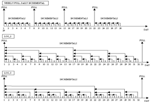
CUSTOM - This option allows you to define a specialized frequency by manipulating the associated schedule object directly. In this way you can define more flexible scheduling frequencies than are offered by the standard options. If you specify CUSTOM but do not modify the schedule object, then the default custom frequency is daily. This option applies only if internal MDMS scheduling is enabled (scheduler options INTERNAL and EXTERNAL).
EXPLICIT - This option enables you to submit the save request using a specific scheduler interval. If you select Explicit, you must enter a scheduler time format valid for the scheduler being used in the EXPLICIT INTERVAL attribute. This option applies only if a thirdparty scheduler is being used (scheduler options SCHEDULER).
NEVER - Never submits the save request and does not call the scheduler to create a job. For example, you may need to create one or more save requests before you determine their schedule. To submit the save request, modify the save request and change the scheduling option.
Depending on the selected scheduling option and the use of a 3rd party scheduler product, the Explicit Interval option allows to specify more flexible intervals. The Explicit Interval is passed as a string to the scheduler in use. Consult your scheduler’s manual for more information.
3.5.11. Incremental
Every save or restore request can be flagged as an incremental operation or a non-incremental operation. An incremental operation saves or restores files based on a previous operation - either a full operation or another incremental operation. For example, you could define a save request that performs a full disk save on Sunday, and an incremental save request that performs incremental saves on Monday through Saturday. The incremental saves will only save files that have been created or modified since the previous save (whether full or incremental). Restores can be performed in a similar fashion.
By default, saves and restores are not flagged as incremental. If you wish to define an incremental save or restore, then set the incremental attribute.
It is important to point out that if you execute an incremental save 127 times in a row without an intervening FULL save, then the 128th “incremental” save will actually be a full save. This rule actually applies to each individual file, disk, path or database specification within the save request, and as such, it is possible for the various files, disks, paths or databases within a single save request to be backed up at different incremental levels, or have a mixture of fulls and incrementals. As such, it is recommended that you intersperse a non-incremental (full) save at least once a week to avoid unexpected full backups on saves/restores marked incremental and to reduce the restore time required with a large number of incrementals. If you are mixing FULL and INCREMENTAL save requests, use the same catalog for both save requests so that the FULL catalog entry will be found and used as a base for the incrementals.
3.5.12. Nodes and Groups
ABS always performs save and restore operations on an OpenVMS execution node, under the control of the ABS coordinator process. Only one execution node actually executes any particular save or restore request at a particular time, but you can specify a list of compatible nodes using either the nodes or groups attributes. At execution time, the node list or group list is scanned in order to determine the execution node, and ABS will attempt to schedule the operation on the first such node. If ABS fails to establish a connection to that node, it will try the next node on the list, and so on until the request is successfully submitted.
For data types VMS files and Oracle databases of all types, the execution node is also the node where the data resides. Therefore, all execution nodes or groups must have access to the data being saved or restored.
If you wish to enter nodes individually, enter a comma-separated list of nodes in the NODES attribute or select a list of nodes from the GUI. Enter the MDMS node object name (which should be the same as the DECnet Phase IV name if DECnet is running) - do not specify the TCP/IP name or DECnet Phase V fullname.
MDMS supports the notion of groups, whereby you can associate a list of nodes which have something in common (for example, nodes in a cluster) into a group, and simply reference the group name. In this case, you can simply enter one or more group names in the GROUPS attribute.
The NODES attribute and GROUPS attribute are mutually exclusive - you have to choose which one to enter.
If you enter neither nodes nor groups, then ABS enters the node from which the save or restore was created in the NODES attribute.
3.5.13. Prologue and Epilogue
The prologue and epilogue attributes in the save or restore request allow you to invoke a command procedure before and/or after each disk, file, path or database specification in the request. This allows you to perform pre-processing and post-processing operations around individual save or restore iterations. Compare the order of save and restore prologue and epilogue procedures operations to the environment prologue and epilogue procedures, which are executed before and/or after the entire save or restore request. The order of execution is illustrated below:
Environment prologue
Start save or restore request
First disk/file specification prologue
First disk/file specification save or restore operation
First disk/file specification epilogue
Next disk/file specification prologue
Next disk/file specification save or restore operation
Next disk/file specification epilogue
......
End save or restore request
Environment epilogue (only on successful completion)
ABS defines logical names that can be used within the prologue or epilogue command procedures. Each name is suffixed by “_n”, where n is the iteration number for each include disk, file, path or database specification. The value for n starts at 1 and goes to 24, the maximum number of include specifications supported by ABS. These logical names are defined in the process job table as follows:
| Logical Name | Meaning |
|---|---|
| ABS_OS_OBJECT_SET_n | The include disk, file, path or database name currently being processed |
| ABS_OS_OBJECT_TYPE_n | The data type for the specification |
| ABS_OS_DMT_n | The type of operation: FULL, INCREMENTAL, SELECTIVE |
| ABS_OS_INCREMENTAL_LEVEL_n | For an INCREMENTAL operation, the incremental level being preformed |
| ABS_OS_VOLUME_SET_n | The volume set being used |
| ABS_OS_START_RVN_n | Starting relative volume number (RVN) of the volume set for the files being processed. The value is zero if the archive type is DISK, |
| ABS_OS_LAST_RVN_n | The last relative volume number in the volume set containing this specification. This value is valid for epilogue procedures only, and equates to “Not yet determined” for prologues. The value is zero if the archive type is DISK. |
| ABS_OS_START_FILE_POSITION_n | The starting file position of the saveset on the tape volume. This indicates how many tape marks from the beginning of the tape need to be skipped to arrive at the file. The value is zero if the archive type is DISK. |
| ABS_OS_SAVESET_NAME_n | The name of the saveset being used. |
| ABS_OS_SAVESET_FORMAT_n | The format of the saveset: either VMS, gtar or RMU. |
| ABS_OS_STATUS_n | The ABS status of the portion of the request for this specification |
3.5.14. Reschedule
The reschedule attribute is used to create a new job with an external scheduler product. Normally, when you create a save or restore request, ABS creates a new scheduler job for the request. If you modify the request, then ABS modifies the existing scheduler job. However, there are circumstances whereby the scheduler job is deleted and needs to be re-created. You can set the reschedule attribute to re-create a new scheduler job for the request. This attribute has no effect when MDMS scheduling is in operation.
3.5.15. Selections
As discussed in section 3.2.3.6, you can specify the files, disks, paths or databases to be included in a save or restore request in one of two ways:
By using the INCLUDE attribute in the save or restore request, and using a default selection
By manually creating SELECTIONS, including the files, disks, paths or databases in the selection objects, then associating the selection objects with the save or restore requests.
The SELECTION attribute is how you associate a selection object with a save or restore request. Simply include the selection names as a comma-separated list in the selections attribute. If you wish to have no selections and use the default selection, specify no selections.
3.5.16. Sequence Option (Saves Only)
A save operation involves a data copy phase and a post-processing phase. For archive type TAPE, the post-processing phase does not require the use of a tape drive, so ABS could start on the next data copy phase using the drive before the post-processing phase of the previous operation is complete. This option speeds up the total save operation - if you want to use this option, specify OVERLAPPED as the sequence option. If, on the other hand, you prefer the data copy and post-processing phases to be performed sequentially, enter SEQUENTIAL for the sequence option.
By default, the sequence option is set to SEQUENTIAL.
3.5.17. Skipping schedule operations on Holidays
This feature allows the system administrator to prevent scheduling of operations on certain dates as operators are not available to service requests.
As stated earlier, the start date specifies the next start date and time for the request. This start date is updated whenever the request is run to reflect the next time it is scheduled, or NONE if it is not scheduled again.
Before a calculated date is assigned to the start date, it is compared against a list of holidays which is loaded into memory from MDMS$DATABASE_LOCATION:HOLIDAYS.DAT at start up.
If the calculated date matches any of the holiday definitions, this date is ignored and we search further for the next valid start date. This process continues until we find a calculated date that does not match any of the holiday definitions and hence can be assigned to the start date.
At start up time, the MDMS server reads all the records in HOLIDAYS.DAT and loads the valid holiday definitions in memory. Definitions that do not confirm to the stated record format are ignored. The valid holiday definitions loaded in memory are displayed in:
$ MDMS SHOW DOMAIN/FULLBy default, there are no holiday definitions. If the system administrator wishes to define a list of holidays, a HOLIDAYS.DAT file has to be created in the database location where the MDMS DATABASE files are present (MDMS$DATABASE_LOCATION:HOLIDAYS.DAT).
Note
Since the MDMS server loads the holiday definitions into memory at start up time, for any changes in HOLIDAYS.DAT to take effect, the MDMS server needs to be restarted.
3.5.17.1. HOLIDAYS.DAT Record Format
The format for each record in HOLIDAYS.DAT file is:
dd-mmm-yyyy,xxxxxxxxxxx
Where:
dd—is the day
mmm—is the first three letters of the month
yyyy—is the year
xxxxxxxx—is the name of the holiday
3.5.17.2. Example: HOLIDAYS.DAT File
The following example shows the contents of a HOLIDAYS.DAT file for the year 2002.
04-JUL-2002,Independence Day
02-SEP-2002,Labor Day
28-NOV-2002,Thanksgiving
25-DEC-2002,Christmas
3.6. Selections
ABS uses selections to hold information about files, disks, paths and databases to be saved or restored. You can elect to specify these names in one of two ways:
By using the INCLUDE attribute in the save or restore request, and using a default selection
By manually creating SELECTIONS, including the files, disks, paths or databases in the selection objects, then associating the selection objects with the save or restore requests.
The first option is discussed in Section 3.5.6, ''Include, Exclude, Data Type and Source Node'' as part of the save and restore option. This section discusses the various attributes in the selection object.
The selection object gives you more flexibility to select files based on dates, agent qualifiers for the backup agent, and specifying conflict options on a restore. You can associate up to 24 selections with a given save and restore request, with the caveat that the total number of disk, file, path or database specifications in all selections does not exceed 24.
There are two steps in using selections:
Creating or modifying a selection object directly by using the MDMSView GUI or the CLI.
Associating the selection to the associated save and restore request by including it in the SELECTIONS attribute of the request.
The following sections describe attributes in the selection object.
3.6.1. Agent Qualifiers
ABS uses a backup agent to perform saves and restores, and the backup agent is dependent on the data type as follows:
VMS Files - The backup agent is the OpenVMS BACKUP utility.
Rdb Databases and Rdb Storage Areas - The backup agent is RMU Backup
Although ABS passes information that you specify in the save, restore and environment to the backup agent, you can pass qualifiers directly to the backup agent using the agent qualifiers attribute. Refer to the appropriate backup agent documentation for information on these qualifiers.
3.6.2. Before Date, Since Date and Date Type (Saves Only)
For save requests, you can select files for saving based on the date files were last modified. You can specify either or both of the following:
Before Date - Any version of the file modified before the specified date
Since Date - Any version of the file modified after the specified date
If you specify both a before and since date, you are providing a range of dates in which to select files. If a file does not have a revision date (modified date), then ABS uses the creation date instead.
ABS does not yet support the date type attribute, which would allow you to select any one of the four online dates maintained by OpenVMS.
3.6.3. Conflict Options (Restore Only)
When restoring files, you may find that there are files of the same name already located in the destination directory or original source location. You can specify what ABS should do if it encounters this situation by specifying one of the following conflict options:
NEW VERSION - Restores the data and header and creates a new version of the file - applicable to VMS files only.
OVERLAY VERSION - Overwrites the online version with the archive version of the data, but keeps the online version of the header.
REPLACE VERSION - Deletes the online version of the file, and restores both the header and data from the archive.
RETAIN VERSION - Keeps the online version of the header and data and does not restore the file from the archive.
If not specified, the default is RETAIN VERSION.
3.6.4. Include, Exclude, Data Type and Source Node
In exactly the same manner as in save and restore requests, you can specify the following attributes in selection objects directly:
INCLUDE - A list of disks, files, paths or databases to include in the save or restore. If you want the file directory structure to be maintained during the restore operation, see the note given in Section 3.5.6, ''Include, Exclude, Data Type and Source Node''.
EXCLUDE - A list of files to exclude from the save or restore that would otherwise have been included according to the include specification. This option applies to data type VMS FILES only
DATA TYPE - The type of data to be saved or restored - select one of the following:
VMS Files - Applicable to VMS files. If only a disk is selected, a FULL backup of the entire disk is performed. If directory and file specifications are specified, then a SELECTIVE backup of files is performed.
Oracle Rdb Database Options - These options (which are version-number specific) specify that you wish to back up an entire Rdb database using the RMU backup utility. In this case, specify the name of the Rdb database files.
Oracle Rdb Storage Area - These options (which are version-number specific) specify that you wish to back up selected storage areas of an Rdb database. In this case specify both the database file name(s) and selected storage areas.
The following table shows examples of the appropriate file, disk, path or database names that are valid for each data type:
| Data Type | Examples | Case Sensitive |
|---|---|---|
| VMS Files |
$1$DUA420: (full disk, physical name) DISK$USER1: (full disk, logical name) DISK$USER1:[SMITH...]*.*;* (selective) DISK$USER1:[SMITH]LOGIN.COM;3 (file) Note: If the include specifications having “DISK$USER1” are for the restore requests, then the logical “DISK$USER1” referring to the disk name must be defined before executing the restore request. For more information, see the note given in the Section 3.5.8, ''Destination (Restore Only)''. | No |
| Oracle Rdb Databases | DISK2:[USER_RDB]ACCOUNTS.RDB Do not specify a version number. | No |
| Oracle Rdb Storage Areas | DISK2:[RDB]ACCOUNTS.RDB/INCLUDE =BALANCES (saves) DISK2:[RDB]ACCOUNTS.RDB /AREA=BALANCES (restores) Do not specify a version number - the include syntax is required, even from the GUI. If entered from the CLI, you must enclose the specification in quotes. | No |
3.7. Schedules
ABS supports very flexible options for scheduling save and restore requests, both using the internal MDMS scheduling options and using a third part scheduler. The scheduling options can be divided into three main categories:
Standard - ABS provides a list of standard options that you can specify, and the scheduling information is applied to the schedule object automatically. Standard options are supported by both internal MDMS scheduling and an external scheduler product. Standard options are all those that are neither custom or explicit.
Custom - This option allows you to customize the schedule for the request if the standard options are not sufficient. For example, if you want to run the request every second Sunday in January, April, July and October, then the custom option can do this. You specify CUSTOM as the frequency, then modify the schedule object for the request directly. This option is applicable to internal MDMS scheduling only.
Explicit - This option also allows you to customize your schedule, but this time with an external scheduler product. You specify EXPLICIT as a frequency, then enter a string into the EXPLICIT INTERVAL attribute. This attribute is a string that can be understood by the external scheduler product specifying the desired frequency. Alternatively, you can use the user interface of the external scheduler product to specify the frequency of the request. This option is applicable only to external scheduling options.
This section discusses the second option, custom schedules, which are only applicable to internal MDMS scheduling. To use a custom schedule, specify CUSTOM as the frequency on the save and restore request, then modify the attributes of the associated schedule object. The schedule object always has the name of the save and restore request, followed by “_SAVE_SCHED” or “REST_SCHED” respectively.
3.7.1. After Schedule
With ABS custom scheduling, you can actually define one schedule to execute after another schedule has completed. For example, if you want SAVE2 to execute immediately after SAVE1 completes, you can modify SAVE2’s schedule object and setting its AFTER SCHEDULE attribute to SAVE1’s schedule object. In this case:
- SAVE2_SAVE_SCHED:
- After Schedule: SAVE1_SAVE_SCHED
If you specify an after schedule and only want the associated request to execute after the after schedule (and not at any other time), then do not specify any other date or time attributes in the schedule. If on the other hand you want the associated request to execute at regular times AND after the specified after schedule, then you can associate date and time attributes to the schedule.
With after schedule, you can also define conditions upon which the schedule will run after the other schedule. The conditions are stored in an attribute called after schedule when. Select from one of the following:
ALL - Always run the schedule after the dependent schedule completion
SUCCESS - Run the schedule if the dependent save or restore completed with a successful status
WARNING - Run the schedule if the dependent save or restore completed with a Warning, Error or Fatal status
ERROR - Run the schedule if the dependent save or restore completed with an Error or Fatal Status
FATAL - Run the schedule if the dependent save or restore completed with a fatal status
NONE - Never run the schedule (can be used as a temporary placeholder)
If an after schedule name is defined, but no conditions are specified, the default condition is ALL. To remove the after schedule dependency, specify no after schedule.
3.7.2. Command
For ABS save and restore commands, the command to run a schedule and execute the associated save and restore request is:
MDMS RUN SCHEDULE schedule_name
You should not modify this command line, unless you know how to activate an ABS request in some other way.
For non-ABS save or restore requests, this command line can be any command that can be submitted to the OpenVMS CLI.
3.7.3. Restriction
There is a restriction with using the /AFTER_SCHEDULE qualifier. Only those schedules (created automatically by MDMS) that have an associated save can be assigned to the /AFTER_SCHEDULE qualifier. Schedules that do NOT have an associated save cannot be assigned to the /AFTER_SCHEDULE qualifier. Hence, any schedule (one with an associated save, or one which executes DCL commands) can have a dependency on a schedule with an associated save, but not on a schedule which executes DCL commands. This is a current MDMS design limitation.
3.7.4. Dates, Days and Months
ABS supplies three attributes in the schedule object by which you can specify on what days you want the schedule to be regularly executed. These are:
Dates - The dates of the month you want the schedule to execute
Days - The days of the week you want the schedule to execute
Months - The months of the year you want the schedule to execute
You can specify the actual dates in the month that you want the schedule to run by number. Here are some examples:
If you do not specify a date attribute, the default is every day of the month.
| Dates | Explanation |
|---|---|
| 1 | First day of month |
| 1-7 | First week of month |
| 1-7, 15-21 | First and third week of month |
| 1-31 | Every day of month (default) |
You can specify the actual day in the week that you want the schedule to run by name. Here are some examples:
| Dates | Explanation |
|---|---|
| SUN | Sunday Only |
| MON-FRI | Monday through Friday Only |
| MON, WED, FRI | Monday, Wednesday and Friday Only |
| FRI-MON, WED | Friday, Saturday, Sunday, Wednesday |
If you do not specify a day attribute, the default is every day of the week.
Finally, you can specify the actual months in the year that you want the schedule to run by name. Here are some examples:
| Dates | Explanation |
|---|---|
| MAR | March Only |
| APR-SEP | April through September Only |
| JAN, APR, JUL, OCT | January, April, July, October Only |
| JAN-DEC | All months |
If you do not specify a month attribute, the default is every month of the year.
The dates, days and months attributes work together so that all must qualify for the schedule to be run. Therefore if you specify days SUN, but months of JAN, JUL only, then the schedule only runs on Sundays in January and July.
The following table shows some examples of how the days, dates and months attributes work together to produce custom schedules.
| Custom Schedule | Dates | Days | Months |
|---|---|---|---|
| First sunday of every month | 1-7 | SUN | JAN-DEC |
| First day of the quarter | 1 | SUN-SAT | JAN, APR, JUL, OCT |
| First and third saturdays of month | 1-7, 15-21 | SAT | JAN-DEC |
| First of month, every four months | 1 | SUN-SAT | FEB, JUN,OCT |
| Weekdays only | 1-31 | MON-FRI | JAN-DEC |
| Summer weekends only | 1-31 | SAT-SUN | JUN-SEP |
If there are schedules that cannot be accommodated by this scheme, then you can use the INCLUDE and EXCLUDE attributes as explained below.
3.7.5. Include and Exclude
Although the days, dates and months attributes can produce a very flexible scheduling scheme, there may be specific days that you want to include or exclude regardless of the regular schedule. You can do this using the following attributes:
INCLUDE - Include specific dates that otherwise may not be included using the days, dates and months attributes
EXCLUDE - Exclude specific dates that otherwise may be included using the days, dates and months attributes
The dates are specified in the standard OpenVMS format DD-MMM-YYYY, and can range from the current date to up to 10 years in the future. Only dates may be specified, not times. Specification of include and exclude dates override the regular schedule as determined by the dates, days and months attributes.
You can also use the include and exclude attributes to augment the days, dates and months in situations that they do not cover what you want. For example, to run on the last day of every month, you can specify DATES 31, DAYS MON-SUN and MONTHS JAN-DEC, then specifically include 28-Feb, 30-Apr, 30-Jun, 30-Sep, 30-Nov.
3.7.6. Times
ABS allows you to specify times that you wish your schedule to run. Normally a schedule runs only once per day, but ABS allows you the flexibility to specify up to 100 times per day for a schedule to run. Simply specify times in the times attribute as a comma-separated list. Be careful to not specify so many times that the schedule executions overlap each other.
Chapter 4. Media Management
This chapter expands on the MDMS object summary given in Chapter 2, "Overview", and describes all the MDMS objects in detail, including the object attributes and operations that can be performed on the objects.
Before going into details on each object, however, the use of the MDMS$CONFIGURE.COM procedure is recommended to configure your MDMS domain and the objects in it. In many cases this should take care of your entire initial configuration.
4.1. MDMS Domain Configuration
If you are configuring your MDMS domain (including all objects in the domain) for the first time, HP recommends that you use the MDMS$CONFIGURE.COM command procedure. This procedure prompts you for most MDMS objects, including domain, drives, jukeboxes, media types, locations and volumes, and establishes relationships between the objects. The goal is to allow complete configuration of simple to moderately complex sites without having to read the manual.
The configuration procedure offers extensive help, and contains much of the information contained in this chapter. Help is offered in a tutorial form if you answer “No” to “Have you used this procedure before”. In addition, for each question asked, you can enter “?” to have help on that question displayed. Furthermore, if you type “??” to a question, not only will the help be displayed, but in most cases a list of possible options is also displayed.
This procedure is also useful when adding additional resources to an existing MDMS configuration. To invoke this procedure, enter:
@MDMS$SYSTEM:MDMS$CONFIGURE.COM
and just follow the questions and help.
A complete example of running the procedure is shown in Appendix A, "Configuration Example".
4.2. Domain
The MDMS domain encompasses all objects that are served by a single MDMS database, and all users that utilize those objects. A domain can range from a single OpenVMS cluster and its backup requirements, to multi-site configurations that may share resources over a wide area network or through Fibre Channel connections. An OpenVMS system running MDMS is considered a node within the MDMS domain, and MDMS server processes within a domain can communicate with one another.
The MDMS domain object is created at initial installation, and cannot be deleted. Its main focus is to maintain domain-wide attributes and defaults, and these attributes are described in the following sections.
4.2.1. ABS Rights
The domain attribute ABS_RIGHTS controls whether a user having certain pre-V4.0 ABS rights can map these to MDMS rights for security purposes (see Chapter 5, "Security" for more information about rights). Setting the attribute allows the mapping, and setting the attribute to false disallows the mapping.
4.2.2. Application Rights
The right MDMS_APPLICATION_RIGHTS is a high-level right that maps to a set of low level rights suitable for MDMS applications (for example, ABS and HSM). Normally these rights should not be changed, or at least not reduced from the default settings otherwise ABS and HSM may not function correctly. You may add rights to application rights if you have your own MDMS applications or command procedures. The ABS and MDMS$SERVER accounts should have MDMS_APPLICATION_RIGHTS granted in the User Authorization File.
4.2.3. Check Access
The check access attribute determines if access controls are checked in the domain. MDMS uses two forms of security: Rights and Access Control. Rights checking is a task-oriented form of security and is always performed. However, access control is an object-oriented form of security and can be optionally enabled or disabled with this attribute. Setting Check Access enables access control checking. Clearing Check Access disables access control checking even if there are objects with access control entries.
4.2.4. Deallocate State
When a volume is deallocated after its data has expired, it may go into one of two states. The transition state is an interim state that the volume goes into after deallocation, but it is not eligible to be used again until a period of time called the transition time expires. This is a safety feature that allows you to examine whether the data has legitimately expired, and if not to retain the volume (put back to the allocated state). If you do not wish this feature, you can disable the transition state and allow volume to return directly to the free state, where it is eligible for immediate allocation and initialization for new data. The domain deallocate state is applied to all volumes that are automatically deallocated by MDMS. When manually deallocating volumes, you can override the domain deallocate state with a state on the deallocate operation itself.
4.2.5. Default Rights
The MDMS default rights attribute maps a set of MDMS low-level rights to all users in the domain. This allows you to give all users a limited set of rights to access MDMS objects and perform operations, without having to expressly modify their accounts. Be aware that default rights are applied to all users on all nodes in the domain, so granting such rights should be carefully reviewed. By default, MDMS maps no rights to the default rights.
4.2.6. Mail Users
When MDMS deallocates volumes based on their scratch date (an operation that is performed once per day), it sends a mail message indicating which volumes were deallocated to the set of users defined in the mail users attributes. You should enter a list of users in the format node::username. Every user in the list will receive the deallocate volume mail messages. This mail address is also used when the ABS catalog unpack process encounters an error.
4.2.7. Maximum Scratch Time
The maximum scratch time is the maximum scratch time that can be applied to any volume when it is allocated. The scratch time is the period of time that you wish the volume to stay allocated because its data is still valid. The maximum scratch time imposes a maximum limit and overrides the volume’s scratch time if it exceeds the maximum. For HSM, the maximum scratch time should be set to zero (unlimited), as HSM volumes’ data remains valid until it is repacked. For ABS uses, this value should be set to the longest period of time you wish to retain any volume.
4.2.8. Media Type
The domain media type attribute is the media type that is applied to new volumes and drives by default when they are created. In a simple configuration, you may only have a single media type, so specifying it in the domain allows you to not have to specify it when creating individual drives and volumes. It may also be applied as a default to ABS archives. You may always override the domain default media type with a specific media type when you create or modify drives and volumes.
4.2.9. Offsite Location
The domain offsite location attribute is applied by default to the offsite location field of new volumes when they are created. The offsite location is an MDMS location that is used for secure storage of the volumes in case of a disaster. You can always override the domain default offsite location when you create or modify volumes.
4.2.10. Onsite Location
The domain onsite location attribute is applied by default to the onsite location field of new volumes when they are created. The onsite location is an MDMS location that is used for storage of the volumes when they are onsite, or quickly accessible to jukeboxes and drives. You can always override the domain default onsite location when you create or modify volumes.
4.2.11. OPCOM Classes
The domain OPCOM classes attribute contains the default OPCOM classes that are applied to new node objects by default when they are created. OPCOM classes are classes of users whose terminals are enabled to receive certain OPCOM classes. You can override the domain default OPCOM classes with specific classes on a per-node basis when you create or modify a node.
4.2.12. Operator Rights
The right MDMS_OPERATOR_RIGHTS is a high-level right that maps to a set of low level rights suitable for operators managing the domain. The default set of operator rights allow for normal operator activities such as loading and unloading volumes into drives, showing any object or operations, and moving volumes offsite and onsite. However, you can add or remove low level rights to/from the operator rights as you wish.
4.2.13. Protection
The domain protection attributes defines the default protection applied to new volumes when they are created. This protection is used by MDMS when it initializes volumes, and writes the protection on the magnetic tape volume itself. You can always override the domain default protection by specifying the protection specifically when creating or modifying a volume.
4.2.14. Relaxed Access
The relaxed access attribute controls the security when a user or application tries to access an object without any access control entries, and access control checking is enabled. If relaxed access is set, such access is granted. If relaxed access is clear, such access is denied. The relaxed access attribute is ignored if the check access attribute is clear.
4.2.15. Request ID
MDMS uses sequentially increasing request identifiers for each request received by the MDMS database server, and this attribute displays the ID of the next request. If this ID is becoming very large, you can reset it to zero or one (or indeed any value) if you wish. The request ID automatically resets to one when it reaches one million.
4.2.16. Scheduler Type
MDMS performs scheduling operations on behalf of itself and ABS. For ABS scheduling, you can choose a scheduler type that best meets your needs, as follows:
Internal - The default internal scheduler type uses MDMS schedule objects and OpenVMS batch queues. This option should be sufficient for most sites as the schedule object supports many custom scheduling options.
External - This option uses MDMS schedule objects and OpenVMS batch queue, but the scheduling is submitted through a command procedure. You can use this option if you have a need to modify the command procedure to perform site-specific operations.
Scheduler - This option uses an external scheduler product via command procedures. ABS supplies a template scheduler command procedure that you can modify to access your own scheduler product. You can also use this option to invoke the pre-V3.0 ABS DECScheduler V2.1B, as long as you have a license for that product.
MDMS-initiated scheduled operations such as MDMS$MOVE_VOLUMES always use the internal MDMS scheduler.
4.2.17. Scratch Time
The domain default scratch time is the default scratch time applied to new volumes when they are created. Scratch time indicates how long a volume is to remain allocated (that is, how long its data is valid and needs to be kept). You can override the domain volume scratch time when you create, modify or allocate individual volumes. For HSM volumes, the scratch time should be set to zero (unlimited), since HSM data remains valid until a volume is repacked.
4.2.18. SYSPRV
MDMS uses user account rights as one mechanism for security within the domain. MDMS allows you to control whether the OpenVMS privilege SYSPRV can map to the ultimate MDMS right MDMS_ALL_RIGHTS. If you set the SYSPRV attribute, users with SYSPRV are assigned MDMS_ALL_RIGHTS, which means they can perform any operation subject to access control checks. Clearing SYSPRV gives users with SYSPRV no special rights.
Note
If you wish to use the SYSPRV attribute from the MDMSView GUI, the user’s authorization file must have SYSPRV defined as a privilege and a default privilege. Having SETPRV is not sufficient as there is no way to set the SYSPRV privilege from the GUI.
4.2.19. Transition Time
The domain default transition time is applied to volumes by default when they are deallocated into the transition state. The transition time determines how long the volumes remain in the transition state before moving to the free state. This attribute is used alongside the deallocation state attribute, which determines the default state that volumes are deallocated into. You can override the domain default transition time when you create, modify, or deallocate a volume.
4.2.20. User Rights
The right MDMS_USER_RIGHTS is a high-level right that maps to a set of low level rights suitable for non-privileged users that perform ABS or HSM operations. The default set of user rights allow for user activities such as creating and manipulating their own volumes and loading and unloading those volumes into drives, showing their volumes. However, you can add or remove low level rights to/from the user rights as you wish.
4.3. Drives
A drive is a physical resource that can read and write data to tape volumes. Drives can be standalone requiring operator intervention for loading and unloading, in a stacker configuration that allows limited automatic sequential loading of volumes, or in a jukebox which provides full random- access automatic loading. Drives are named in MDMS using a unique name across the domain; it may or may not be the same as the OpenVMS device name, as these may not be unique across the domain.
The following sections describe the attributes of a drive.
4.3.1. Access
The access attribute controls whether the drive may be used from local access, remote access or both. Local access includes direct SCSI access, access via a controller such as the HSJ70, access via TMSCP, or access via Fibre Channel, and does not require use of the Remote Device Facility (RDF). Remote access is via a DECnet network requiring RDF. You can set the access to one of the following:
All - Allows both local and remote access (default)
Local - Allows only local access (as defined above)
Remote - Allows only remote access using RDF
4.3.2. Automatic Reply
Automatic reply is the capability of polling hardware to determine if an operator-assist action has completed. For example, if MDMS requests that an operator load a volume into a drive, MDMS can poll the drive to see if the volume was loaded, and if so complete the OPCOM request without an operator reply. Set automatic reply to enable this feature, and clear to require an operator response. Please note that some operations cannot be polled and always require an operator reply. The OPCOM message itself clearly indicates if a reply is needed or automatic replies are enabled.
4.3.3. Device
The device attribute is the OpenVMS device name for the drive. In many cases you can set up the drive name to be the OpenVMS device name, and this is the default when you create a drive. However, the drive name must be unique within the domain, and since the domain can consist of multiple clusters there may be duplicate device names across the domain. In this case you must use different drive names from the OpenVMS device names. Also, you can specify simple or descriptive drive names which are used for most commands, and hide the OpenVMS device in the device name attribute.
4.3.4. Disabled
By default, drives are enabled, meaning that they can be used by MDMS and its applications. However, you may wish to disable a drive from use because it may need repair or be used for some other application. Set the disable flag to disabled the drive, and clear the flag to enable the drive.
4.3.5. Drive Number
If the drive is in a robotically-controlled jukebox, and the jukebox is controlled by MRD, you must set the drive number to the relative drive number in the jukebox used by MRD. Drives in jukeboxes are numbered from 0 to n, according to the SCSI addresses of the drives. Refer to the jukebox documentation on how to specify the relative drive number.
4.3.6. Groups
The groups attribute contains a list of groups containing nodes that have direct access to the drive. Direct access includes direct-SCSI access, access via a controller such as an HSJ70, access via TMSCP, and access via Fibre Channel. You can specify as many groups as you wish, in addition to nodes that may not be in a group.
4.3.7. Jukebox
If the drive is in a jukebox, you must specify which jukebox using the jukebox attribute. Enter a valid jukebox name from an MDMS-defined jukebox. If there is no jukebox, MDMS treats the drive as a standalone drive or as a stacker.
4.3.8. Media Types
A drive must support one or more media types in order for volumes to be used on the drive. In the media type attribute, specify one or more MDMS-defined media types that this drive can both read and write. If you wish, you can restrict the media types to a subset that you wish this drive to handle, and not all the media types it could physically handle. In this way, you can restrict the drive’s usage somewhat.
4.3.9. Nodes
The nodes attribute contains a list of nodes that have direct access to the drive. Direct access includes direct-SCSI access, access via a controller such as an HSJ70, access via TMSCP, and access via Fibre Channel. You can specify as many nodes as you wish, in addition to groups of nodes in the groups attribute.
4.3.10. Read-Only Media Types
In addition to media types that a drive can read and write, a drive may support one or more additional media types that it can only read. In the read-only media type attribute, specify one or more MDMS-defined media types that this drive can only read. This allows this drive to be used when the application operation is read-only (for example, HSM unshelves or ABS restores). Do not duplicate a media type in both the media type list and read-only media type list.
4.3.11. Shared
You can designate whether a drive is to be used by MDMS applications and users only, or by non-MDMS users. If the drive is not shared, the MDMS server process allocates the drive on all clusters to prevent non-MDMS users and applications from allocating it. However, when an MDMS user attempts to allocate the drive, MDMS will deallocate it and allow the allocation. Set the shared attribute if you wish to share the drive with non-MDMS users, and clear if you wish to restrict usage to MDMS users. ABS users who do their own user backups are considered MDMS users, as are all system backups and HSM shelving/unshelving users.
4.3.12. Stacker
Certain types of drive can be configured as a stacker, which allows a limited automatic sequential loading capability of a set of volumes. Such drives may physically reside in a loader or have specialized hardware that allows stacker capabilities. If you wish the drive to support the stacker loading capability, set this attribute and make sure the jukebox attribute does not contain a jukebox name. If you wish the drive to operate as a jukebox or standalone drive, clear this attribute.
4.3.13. State
The drive state field determines the load state of the drive. The drive can be in one of four states:
Empty - There is no volume in the drive
Full - There is a volume in the drive
Loading - A volume is being loaded into the drive
Unloading - A volume is being unloaded from the drive
This is a protected field that is normally handled by MDMS. Only modify this field if you know that there are no outstanding requests and the new state reflects the actual state of the drive.
4.3.14. Allocate Drive (DCL Only)
You allocate a drive so that you can it for reading and writing data to a volume. If you allocate a drive, your process ID and node is stored in the MDMS database, and the drive is allocated in OpenVMS for your process. Because the MDMSView GUI does not operate in a process context, it is not possible to allocate drives from the GUI.
You can either allocate a drive by name, or you can specify selection criteria to be used for MDMS to select an available drive for you and allocate it. The allocation selection criteria include:
Media Type - Select a drive with the specified media type
Location - Used with media type, select a drive in the specified location
Jukebox - Used with media type, select a drive in the specified jukebox
Group - Used with media type, select a drive that is supported by a node in the group
Node - Used with media type, select a drive that is supported by the node
Volume - Select a drive that is compatible with the specified volume (media type and placement)
You can also specify the following options when allocating a drive:
Assist - A flag indicating whether you wish operator assistance if a drive cannot be allocated. Set if you wish assistance, and clear if you wish to use the retry limit and intervals to automatically retry (that is, wait for drives to become available).
Define - Use define to set a logical name for the drive. The logical name evaluates to both the MDMS Drive Name and the OpenVMS device name, and can be used in either MDMS or other DCL commands.
Retry Limit and Interval - If you wish the allocate to retry if there are no available drives, set the retry limit and interval, and specify noassist.
Preferred - If you allocated a drive for a specific volume, you can set preferred to request that the same drive that the volume was last loaded is the preferred drive. If you clear preferred, this forces MDMS to perform a round-robin allocation of the drives.
Reply - You can specify a symbol to receive an operator’s reply message.
Nowrite - You can specify that the drive only has to be compatible for read-only media types, as the desired operation will only read from the drive.
4.3.15. Deallocate Drive (DCL Only)
If you allocated a drive using the DCL “Allocate Drive” command, you should deallocate the drive when you are finished using it, otherwise the drive will remain allocated until your process exits.
Simply issue a deallocate drive and specify the drive name or the logical name obtained from the define option in “Allocate Drive”.
4.3.16. Load Drive
MDMS supports two ways to load volumes into drives:
Load Drive - This loads a scratch volume into a drive via operator intervention or by stacker operation. As such, this option is only for standalone and stacker controlled drives.
Load Volume - This loads a specific volume into a drive, and can apply to all types of drives.
This section discusses the load drive option. The load volume option is discussed under volumes.
The “Load Drive” operation requests either that a scratch volume (in the free state) be loaded into the drive, or the next volume in the stacker is loaded into the drive. In either case, the volume ID of the volume is not known until the load completes, and MDMS reads the magnetic tape label to determine the volume.
The loaded volumes may or may not already be defined in the MDMS database. You can choose to create volume records by setting the “Create” flag, and optionally providing attributes to apply to the volume as follows:
Inherit volume ID - This is the most comprehensive option as it allows the new volume to inherit all non-protected fields from the specified volume.
Media type - Assign this media type to the volume. If you use inherit and media type, the specified media type overrides the inherit media type.
Pool - Assign this volume to the specified pool. If you use inherit and pool, the specified pool overrides the inherit pool.
When issuing the load drive request, you can specify whether the load is for read/write (almost always the case) or read-only, and whether operator assistance is required.
You can also specify an alternative message for the operator. This is included in the OPCOM message instead of the normal MDMS operator message. Use of an alternative message is not recommended.
When initiating a load from the DCL, you can choose a synchronous operation (default) or an asynchronous operation using the /NOWAIT qualifier. From MDMSView, a load is always asynchronous, so that you can continue performing other tasks.
4.3.17. Unload Drive
Unlike the load drive operation, the unload drive can be applied to any type of drive at any time. What it does is simply unload the current volume in the drive, and so you can use this when you don’t know which volume is in the drive. Alternatively, you can use the unload volume operation if you know the volume ID in the drive.
The only option for unload drive is to request operator assistance if needed.
When initiating an unload from the DCL, you can choose a synchronous operation (default) or an asynchronous operation using the /NOWAIT qualifier. From MDMSView, an unload is always asynchronous, so that you can continue performing other tasks.
4.4. Groups
The group object is a logical object that is simply a list of nodes that have something in common. Groups can be used to represent an OpenVMS cluster, a collection of nodes that have access to a device, or for any other purpose. A node may appear in any number of groups. Groups can be specified instead of, or in addition to nodes in drive, jukebox, save and restore objects, and can be used interchangeably with nodes in pool authorization and access control definitions.
Groups contain only one attribute.
4.4.1. Nodes
The list of nodes that comprise the group. Nodes must be OpenVMS nodes that are defined in the MDMS database. You should not use groups for non-OpenVMS nodes.
4.5. Jukeboxes
In MDMS, a jukebox is a generic term applied to any robot-controlled device that supports automatic loading of volumes into drives. Jukeboxes include small, single-drive loaders, large multidrive libraries and very large silos containing thousand of volumes. In general MDMS does not make distinctions among the types of jukeboxes, except for the software subsystem used to control them. MDMS supports both the Media Robot Device (MRD) subsystem for SCSI-controlled robots, and the Digital Cartridge Server Component (DCSC) subsystem for certain silos.
The next sections describe the jukebox attributes.
4.5.1. Access
The access attribute controls whether the jukebox may be used from local access, remote access or both. Local access includes direct SCSI access, access via a controller such as the HSJ70, or access via Fibre Channel, and does not require use of the Remote Device Facility (RDF). Remote access is via a DECnet network requiring RDF. You can set the access to one of the following:
All - Allows both local and remote access (default)
Local - Allows only local access (as defined above)
Remote - Allows only remote access using RDF
4.5.2. ACS ID
For DCSC-controlled jukeboxes, the ACS identifier specifies the Automated Cartridge System Identifier. Each MDMS jukebox maps to one Library Storage Module (LSM), and requires the specification of the Library, ACS and LSM identifiers.
4.5.3. Automatic Reply
Automatic reply is a capability of polling hardware to determine if an operator-assist action has completed. For example, if MDMS requests that an operator move a volume into a port, MDMS can poll the port to see if the volume is there, and if so complete the OPCOM request without an operator reply. Set automatic reply to enable this feature, and clear to require an operator response. Please note that some operations cannot be polled and always require an operator reply. The OPCOM message itself clearly indicates if a reply is needed or automatic replies are enabled.
4.5.4. Cap Size
For DCSC-controlled jukeboxes equipped with Cartridge Access Points (CAPs), this attribute specifies the number of cells for each CAP. The first number is the size for CAP 0, the second for CAP 1, and so on. If a size is not specified, a default value of 40 is used. Specifying a cap size optimizes the movement of volumes to and from the jukebox by filling the CAP to capacity for each move operation.
4.5.5. Control
The control attribute determines the software subsystem that performs robotic actions in the jukebox. The control may be one of the following:
MRD (Media Robot Device) - The default control uses SCSI commands to control the robot in the jukebox. When you specify MRD, you should also specify slot count, robot device name and a flag as to whether the jukebox supports magazines.
DCSC (Digital Cartridge Server Component) - MDMS uses the DCSC subsystem to control the device. When you specify DCSC, you should also specify library ID, ACS ID, LSM ID and CAP sizes. DCSC is used for certain large silo devices only.
4.5.6. Disabled
By default, jukeboxes are enabled, meaning that they can be used by MDMS and its applications. However, you may wish to disable a jukebox from use because it may need repair or be used for some other application. Set the disable flag to disabled the jukebox, and clear the flag to enable the jukebox.
4.5.7. Groups
The groups attribute contains a list of groups containing nodes that have direct access to the jukebox. Direct access includes direct-SCSI access, access via a controller such as an HSJ70, and access via Fibre Channel. TMSCP access is not supported for jukeboxes. You can specify as many groups as you wish, in addition to nodes that may not be in a group.
4.5.8. Library ID
For DCSC-controlled jukeboxes, the Library identifier specifies the library that this jukebox is in. Each MDMS jukebox maps to one Library Storage Module (LSM), and requires the specification of the Library, ACS and LSM identifiers.
4.5.9. Location
The location attribute specifies the physical location of the jukebox. Location can be used as a selection criterion for selecting volumes and drives. Specify an MDMS-defined location for the jukebox. This location may be the same as, or different from, the onsite location that volumes are stored in when not in a jukebox. If different, moves from the jukebox to the onsite location and vice versa will be done in two phases: jukebox to jukebox location, then jukebox location to onsite location, and vice versa.
4.5.10. LSM ID
For DCSC-controlled jukeboxes, the Library Storage Module (LSM) identifier specifies the LSM that comprises this jukebox. Each MDMS jukebox maps to one Library Storage Module (LSM), and requires the specification of the Library, ACS and LSM identifiers.
4.5.11. Nodes
The nodes attribute contains a list of nodes that have direct access to the jukebox. Direct access includes direct-SCSI access, access via a controller such as an HSJ70, and access via Fibre Channel. TMSCP access to jukeboxes is not supported. You can specify as many nodes as you wish, in addition to groups of nodes in the groups attribute.
4.5.12. Robot
For MRD-controlled jukeboxes, the robot name is the OpenVMS device name of the robot device. Robot names normally fall into one of several formats:
GKx0 or GKxn01 for direct-connect SCSI
$n$DUAnnn for access via an HSJ-type controller
$2$GGnx for Fibre Channel access
If the jukebox is controlled by direct connect SCSI (first option), the device must be first loaded on the system with one of the following DCL commands:
Alpha - $ MCR SYSMAN IO CONNECT GKxxx/NOADAPTER/DRIVER=SYS$GKDRIVER.EXE
I64 - $ MCR SYSMAN TO CONNECT GKxxx/NOADAPTER/DRIVER=SYS$GRDDRIVER.EXE
and the device name must begin with GK.
4.5.13. Slot Count
For MRD jukeboxes, the slot count is simply the number of slots (which can contain volumes) in the jukebox. Volumes reside in numbered slots when they are not in a drive. Slots are numbered from 0 to (slot count - 1). Filling in this field is optional: MDMS calculates the slot count by polling the jukebox firmware.
4.5.14. State
The state attribute is a protected field that describes the current state of the jukebox. A jukebox can be in one of three states:
Available - Available for use, and not currently performing an operation
In-Use - Currently performing a robot operation: robot operations occur sequentially; any new operation requested while the robot is in-use is queued
Unavailable - The robot is unavailable for use for some reason
This field is normally maintained by MDMS, so you should not modify it unless a problem has occurred that needs manual cleanup (for example, the robot is stuck in the in-use state when it is clear that it is not in-use).
4.5.15. Threshold
MDMS provides the capability of monitoring the number of free volumes in a jukebox. A free volume is one that is available for allocation and writing new data. Many users would like to maintain a minimum number of free volumes in a jukebox to handle tape writing needs for some period of time. You can specify a threshold value of free volumes, below which an OPCOM message is issued that asks an operator move some more free volumes into the jukebox. In addition, the color status of the jukebox in MDMSView changes to yellow if the number of free volumes falls below the threshold, and to red if there are no free volumes in the jukebox. If you wish to disable threshold OPCOM messages and color status, set the threshold value to 0.
4.5.16. Topology
The topology attribute specifies the physical configuration of a certain type of jukebox when it is being used with magazines. Topology is only useful when all of the following conditions are true:
The jukebox is controlled by MRD
The jukebox is in the TL820 class that allows you to open the jukebox door and insert entire magazines
The jukebox is configured with towers, faces and levels
You specify the topology of the jukebox so that you can move magazines into and out of the jukebox by specifying a position rather than a start slot.
For each tower in the jukebox, you specify the number of faces in the tower, the number of levels in each face, and the number of slots in each level. For TL820-class jukeboxes, the typical values for each tower are 8 faces, 2 or 3 levels per face and 11 slots per level. The associated magazine contains 11 slots and fits into a position specified by tower, face and level. Other jukeboxes may vary.
4.5.17. Usage
The usage attribute determines whether this jukebox is set up to use magazines, and has two values:
Magazine - The jukebox is configured to use magazines
Nomagazine - The jukebox is not configured to use magazines
You should only set usage to magazine if you plan to use MDMS magazine objects and move all the volumes in the magazines together. An alternative is to move individual volumes separately, even if they reside in a physical magazine; in this case set usage to nomagazine.
4.5.18. Inventory Jukebox
MDMS provides the capability to inventory jukeboxes, and “discover” volumes in them and optionally create volumes in the MDMS database to match what was discovered. With this feature, you can simply place new volumes in the jukebox and let MDMS create the associated volume records with attributes that you can specify.
There are two types of inventory:
Inventory using a vision system, which polls the jukebox’s firmware to locate volumes; this option is available for most larger library and silo type jukeboxes, and this operation takes only a few seconds to a few minutes depending on the size of the jukebox.
Physical inventory, which actually loads volumes into drives to read volume labels. This is the only kind of inventory available for small loader-type jukeboxes that lack a vision system. This option is also available for larger jukeboxes, but is not recommended as it takes a considerable amount of time.
You can inventory whole jukeboxes, or specify a volume range or slot range, as follows:
Volume range is supported for DCSC-controlled jukeboxes and MRD-based jukeboxes that have a vision system. Specify a range of volumes such as ABC001-ABC024. Up to 1000 volumes can be specified in a single range. When specifying a volume range, only those volumes are inventoried; other volumes in the jukebox are not.
Slot range is available only for MRD-controlled jukeboxes, and can be applied to either vision or non-vision varieties. With slot range, only the specified slots are inventoried; other slots are not.
While inventorying jukeboxes, MDMS can find volumes that are defined and in the jukebox, that are not defined but are in the jukebox, and that are defined but missing from the jukebox. MDMS provides several options to handle undefined and missing volumes.
If you set the “Create” flag during an inventory, MDMS will create a volume record for each undefined volume it finds in the jukebox. You can specify in advance certain attributes to be applied to this volume record:
Inherit volume ID - This is the most comprehensive option as it allows the new volume to inherit all non-protected fields from the specified volume. You normally use a volume known to be in the jukebox as the inherit volume ID.
Media type - Assign this media type to the volume. If you use inherit and media type, the specified media type overrides the inherit media type
Preinitialized - If you set this flag, the volume will be set to the free state and is immediately available for use. If you clear this flag, the volume will be set to the uninitialized state, and needs to be initialized prior to use. You should set or clear this flag depending on whether the volume is already physically initialized.
If you do not set the “Create” flag, then MDMS will not create new volume records for undefined volumes it finds.
Conversely, you can also define what to do if a volume that should be in the jukebox (according to the database) is found not to be in the jukebox. There are three options that you can apply using the “Missing” attribute:
Delete - Delete the volume from the database; this is not normally what you would want to do because in most cases the volume is simply in another location and you probably want to keep it.
Ignore - Do not change the database; this will probably leave the database in an inconsistent state, but you may prefer to perform the changes manually.
Move - This is the default option, and changes the database to flag that the volume is in the volume’s onsite location.
When initiating an inventory from the DCL, you can choose a synchronous operation (default) or an asynchronous operation using the /NOWAIT qualifier. From MDMSView, an inventory is always asynchronous, so that you can continue performing other tasks.
4.6. Locations
A location is an MDMS object that describes the physical location other objects. Nodes, jukeboxes, magazines, volumes and archives can all have locations associated with them. Locations are used for volume and drive allocation selection criteria, and for placing volumes and magazines in known labelled locations.
Locations can be hierarchical, and locations in hierarchy that have a common source are considered compatible locations. For example, locations SHELF1 and SHELF2 are compatible if they have a common parent location such as ROOM2. Compatible locations are used when allocating drives and volumes using selection criteria, so you should only define hierarchies to the extent that you wish compatible locations. Locations that extend beyond a room or floor are generally not considered compatible, so you should not normally build location hierarchies beyond that level. Locations can also contain “spaces”, that are normally labelled areas in a location that volumes and magazines can be placed in an onsite location. If a volume or magazine contains a space definition, this is output in OPCOM messages so that operator can easily locate a volume or magazine when needed.
Locations contain two attributes, as defined in the following sections.
4.6.1. Parent Location
The parent location is an MDMS location object which is the next level up on the location hierarchy. For example, a location SHELF1 might have a parent location ROOM2, indicating that SHELF1 is in ROOM2. You should define a parent location only if you wish all locations belonging to the parent (including the parent itself) to be compatible when selecting volumes and drives. For example, in a hierarchy of SHELF1 and SHELF2 in ROOM2, volumes in any of the three locations would match a request to allocate a volume from ROOM2. Do not use the location hierarchy for other purposes.
4.6.2. Spaces
Locations can contain spaces, that are used in OPCOM messages when volumes and magazines are being moved from one place to another. Enter a range of spaces in an alphanumeric range separated by a dash. Examples of space ranges are 1-10, A-Z, AAA001-AAA099, 10A-10Z.
4.7. Magazines
A magazine is an MDMS object that contains a set of volumes that are planned to be moved together as a group. It can also relate to physical magazines that some jukeboxes (most notably small loaders) require to move volumes into and out of the jukebox. Magazines can be moved into and out of MRD-controlled jukeboxes with all their volumes at once.
However, just because a jukebox requires a physical magazine does not necessarily mean that you must use MDMS magazines. The physical magazine jukebox can be handled without magazines, and volumes are moved individually as far as MDMS is concerned. The choice should depend on whether you wish the volumes to move independently (don’t use magazines) or as a group together (use magazines).
Magazines are not supported for DCSC-controlled jukeboxes. Magazines have the following attributes.
4.7.1. Jukebox, Start Slot and Position
The jukebox name contains the name of the jukebox if the magazine is in a jukebox. When in a jukebox, a magazine can optionally have a start slot or position, as follows:
In a single-drive loader jukebox, only one magazine can be loaded at a time. In this case, the start slot is always zero, and the number of slots in the jukebox becomes the number of slots in the magazine.
In larger, TL820-type jukeboxes, the magazine can be placed in many different places. If you have associated a topology with the jukebox, you can place the magazine in a “Position”, specified by a tower, face and level specification. This is easier to physically locate in such jukeboxes than the alternative, which is a start slot designation. OPCOM messages for Move Magazine operations will state either position or start slot depending on whether a topology was specified.
All three fields are protected and normally managed by MDMS when a “Move Magazine” operation occurs. Only manipulate these fields if an error occurs and you need to recover the database to a consistent state.
4.7.2. Onsite and Offsite Locations and Dates
When not in a jukebox, a magazine may be either in an onsite or offsite location. An onsite location is one where the magazine can be quickly accessed and moved into a jukebox, which is also onsite. An offsite location is meant to be a secure location in the case of disaster recovery, and generally does not have local access to a jukebox. However, nothing in MDMS precludes the possibility of offsite locations having their own jukeboxes.
Each magazine should have an onsite and offsite location defined, so that operators know where the magazine is physically located. They use these locations, the jukebox name and the placement to determine where a jukebox is at a certain time. Both onsite and offsite locations should be MDMS-defined location objects.
Together with the offsite and onsite locations, you can associate an offsite and onsite date. These dates represent the date the magazine is due to be moved offsite or onsite respectively. Typically, magazines are moved offsite while their volumes’ data is still valid and needs to be protected in a secure location. When the volumes’ data expires, the magazine should be scheduled to be brought onsite, so that the newly-freed volumes can be used for other purposes.
If an offsite and/or onsite date is specified, MDMS initiates the movement of the magazines at some point on the scheduled date automatically. This is performed by the “Move Magazine” scheduled operation, which by default runs at 1:00 am each day. Operators will see OPCOM messages to move the magazines to either the onsite or offsite location.
If you do not wish to have MDMS move magazines automatically, either remove the onsite and offsite dates from the magazine, or disable the scheduled “Move Magazine” activity by assigning a zero time to its schedule object “MDMS$MOVE_MAGAZINES”.
4.7.3. Slot Count
The slot count specifies how many slots are in the magazine. Unlike jukeboxes, this value is required to make magazines work properly.
4.7.4. Spaces
While in an onsite location, the magazine can occupy a space, which is a labelled part of a location that uniquely identifies where the magazine is. A space can be designed to handle a single volume, but since magazines hold multiple volumes, multiple spaces can also be assigned. Enter either a space or a range of spaces for the magazine.
4.7.5. Move Magazine(s)
The supported way to move magazines from one place to another is to use the “Move Magazine” operation. You can move magazines on demand by issuing this operation, or you can let MDMS automatically move magazines according to pre-defined onsite or offsite dates (this is called a “scheduled” move). You can also force an early scheduled move if you want it to occur before the time that MDMS would initiate the move. Moving magazines into jukeboxes must always be performed manually.
When intiating a “Move Magazine”, you can choose a destination for the magazine if the move is not a scheduled move. The destination can be one of three types of places:
Jukebox - You wish to move the magazine and all of its volumes into a jukebox; you would then specify the jukebox name. If the jukebox is a large TL820-type jukebox, you must also specify the “Position”, using tower, face and level, or start slot for the magazine.
Onsite location - You wish to move the magazine to a location that is onsite to the computer hardware that normally uses it. You would then specify the onsite location name, and optionally one or more spaces that the magazine (or volumes from the magazine) will occupy.
Offsite location - You wish to move the magazine to an offsite location for safety in case of a disaster. Specify an offsite location name.
If you want to force a scheduled move, you can select “Scheduled”. In most cases, the destination is predefined, so you don’t need to specify it. However, you can specify an alternative destination for the scheduled move if you wish by specifying a destination as outlined above.
Finally, you can specify if you need operator assistance. This is recommended with “Move Magazine” as magazines cannot be moved without human intervention. Only if you plan to do the physical move yourself or you manually let someone know would you disable operator assistance.
4.8. Media Types
MDMS uses media type objects to hold information about the type of media that volumes and drives can support. MDMS uses media type as a major selection criterion for allocating volumes and drives, and volumes can only be loaded into drives with compatible media types.
Media types contain four attributes, as defined in the following sections.
4.8.1. Capacity
The capacity attribute indicates the capacity of the media in MB. This field is not used by ABS or HSM, but is used by the obsolete product “Sequential Media Filesystem” (SMF).
4.8.2. Compaction
This important field indicates whether you wish the tape to be written with firmware compaction. Enabling compaction usually doubles the capacity of the tape, so this is a desirable option which is set by default. Clear the attribute if you do not wish compaction.
4.8.3. Density
This field indicates the density of the tape that you desire. Many types of tape media (especially DLT tapes) support multiple densities, and certain types of drive can either read and write a certain density, or just read some densities. As such, you can define many media types with different densities that can be assigned to volumes and drives.
MDMS uses the density field when initializing volumes, so the density must be a valid Open- VMS density for the version of the operating system being used. Issue a “HELP INITIALIZE /DENSITY” command to determine the valid densities on the platform.
4.8.4. Length
The length field is used for information purposes only. If your media comes in various lengths, you can differentiate between types by using the length field. Specify an integer value that has meaning to your operators.
4.9. Node
An MDMS node is an OpenVMS system that is running MDMS. All nodes running MDMS must have a node object defined in the database for MDMS to work properly. The node name must be one of the following, in this order: the SCSNODE name, the DECnet Phase IV name, the host name of the IP node, or the DECnet Phase V name. If none of these are defined then MDMS$SERVER should be the node name.
Nodes contain attributes as outlined in the following sections.
4.9.1. Database Server
MDMS operates as a group of co-operating processes running on multiple nodes in multiple clusters in an MDMS domain. One of these MDMS processes is known as the “Database Server”, and it actually controls all MDMS operations in the domain. Although only one node is the database server at any one time, you should enable multiple nodes to be possible database servers in case the actual database server node fails. In this way, failover is supported.
A database server must have direct access to the database files located in MDMS$DATABASE_LOCATION. Direct access, access via MSCP, and access via Fibre Channel are all considered local access. Access via a network protocol or DFS are not considered local access. It is recommended that you enable at least 3 nodes as potential database servers to ensure failover capabilities.
4.9.2. Disabled
Set to disable the node as an MDMS node. Clear to enable the node as an MDMS node.
4.9.3. OPCOM Class
You can specify the OPCOM classes to be used by MDMS for operator messages on this node. By default, the domain default OPCOM classes are used, but you can override this on a node-bynode basis. Specify one or more of the standard OpenVMS OPCOM classes - messages are directed to all login sessions with these OPCOM classes enabled.
4.9.4. Transports and Full Names
You can define which network transports are defined for this node. There are four choices:
DECnet - The DECnet transport is used
TCPIP - The TCP/IP transport is used, and the TCP/IP full name is specified
DECnet, TCPIP - The DECnet and TCP/IP transports can be used, with DECnet preferred
TCPIP, DECnet - The TCP/IP and DECnet transports can be used, with TCP/IP preferred
If you identify TCP/IP as a supported transport, you must define the TCP/IP fullname in the TCP/IP fullname field. These fullnames are normally in the format “node.loc.org.ext”. For example, SLOPER.CXO.CPQCORP.COM
If you identify DECnet as a transport, you need to specify a DECnet full name only if you are using DECnet-Plus (Phase V). In this case, enter the full name, which is normally in a format such as LOCAL:.node. If you are running DECnet Phase IV, do not specify a DECnet full name. The node’s node name is used.
4.10. Pools
A pool is a logical MDMS object that associates a set of volumes with a set of users that are authorized to use those volumes. Every volume can be assigned one pool, for which we say that the volume is in the pool. The pool is then assigned a set of users that are authorized to use the volumes in the pool. If a volume does not have a pool specified, then it is said to belong to the “scratch pool” for which no authorization is required.
Pools have three attributes that are discussed in the following sections.
4.10.1. Authorized Users
You can specify a list of authorized users for the pool, as a comma-separated list of users. Each user should be specified as node::username or group::username, where both the node/group and username portions can contain wildcard characters (*%). To authorize everyone, you can specify *::*. To authorize everyone on a node you can specify nodename::*. Everyone in the authorized user list is allowed to allocate volumes in the pool. Other users require MDMS_ALL_RIGHTS or MDMS_ALLOCATE_ALL rights.
4.10.2. Default Users
Default users are authorized like the authorized users, but in addition are assigned this pool as their default pool. In this case, if they attempt to allocate a volume and don’t specify a pool, they will allocate a volume from this pool. A particular user need only appear in one list: they do not need to be listed in both lists to be an authorized user to their default pool.
4.10.3. Threshold
Pools are useful for dividing volumes between groups or organizations, but they are only useful is there are free volumes in the pool. MDMS provides the capability of monitoring the number of free volumes in a pool. A free volume is one that is available for allocation and writing new data. Many users would like to maintain a minimum number of free volumes in a pool to handle tape writing needs for some period of time. You can specify a threshold value of free volumes, below which an OPCOM message is issued that asks an operator add some more free volumes to the pool. In addition, the color status of the pool in MDMSView changes to yellow if the number of free volumes falls below the threshold, and to red if there are no free volumes in the pool. If you wish to disable threshold OPCOM messages and color status, set the threshold value to 0.
4.11. Volumes
A volume is a physical piece of tape media that contains (or will contain) data written by MDMS applications (ABS or HSM), or user applications. Volumes have many attributes concerning their placement, allocation status, life-cycle dates, protection attributes and many other things.
Volume records can be created manually with a “Create Volume” operation, or automatically be MDMS with “Inventory Jukebox” and “Load Drive” operations. The MDMS$CONFIGURE command procedure can also be used to create volumes.
Once a volume is created it acquires a state. This state determines how the volume may be used at any time, and to an extent where the volume should be placed.
The following figure illustrates the life cycle of volumes, and the following table indicates how a volume transitions from one state to another.
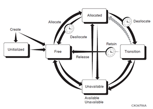
Each row describes an operation with current and new volume states, commands and GUI actions that cause volumes to change states, and if applicable, the volume attributes that MDMS uses to cause volumes to change states. Descriptions following the table explain important aspects of each operation.
| Current State | Transition to New State | New State |
|---|---|---|
| Blank | MDMS CREATE VOLUME Volume Create | UNINTIALIZED |
| Blank | MDMS CREATE VOLUME/PREINIT | FREE |
| UNINITIALIZED | MDMS INITIALIZE VOLUME Volume Initialize | FREE |
| FREE | MDMS INITIALIZE VOLUME Volume Initialize | FREE |
| FREE | MDMS ALLOCATE VOLUME Volume Allocate | ALLOCATED |
| ALLOCATED |
MDMS DEALLOCATE VOLUME Volume Deallocate or automatically on the volume scratch date | TRANSITION |
| ALLOCATED |
MDMS DEALLOCATE VOLUME Volume Deallocate or automatically on the volume scratch date | FREE |
| TRANSITION |
MDMS SET VOLUME /RELEASE Volume Release or automatically on the volume transition time | FREE |
| Any State |
MDMS SET VOLUME /UNAVAILABLE Volume Unavailable | UNAVAILABLE |
| UNAVAILABLE |
MDMS SET VOLUME /AVAILABLE Volume Available | Previous State |
| UNINITIALIZED |
MDMS DELETE VOLUME Volume Delete | BLANK |
| FREE |
MDMS DELETE VOLUME Volume Delete | BLANK |
Note
In the MDMS database, volumes are created with the barcode labels for Vision support. Hence, it is important that the internal label of the volume match with the barcode label.
Example: If a volume’s barcode label is “BDJ541”, then its corresponding entry in the MDMS Volume database will be “BDJ541” only.
When a volume is loaded into a drive, its barcode label is compared with the volume’s internal label. In case of a mismatch, various MDMS operations can wrongly set the placement of such volume(s) to be “ONSITE”.
The following sections describes all the volume attributes in detail, followed by operations that you can perform on volumes.
4.11.1. Allocation Fields - Account, Username, UIC and Job
The account, username and UIC fields are filled in automatically when a volume is allocated, and reflect the calling user or specified user during the allocate. The username is a valid Open- VMS username on the client system performing the allocate, and the account and UIC is from the user’s entry in the system Authorization (UAF) file.
These fields are normally maintained by MDMS and are protected fields. You should not modify these fields unless the volume is deallocated. MDMS maintains the Account, Username and UIC in the volume even after the volume is deallocated, so that you can “retain” the volume back to the allocated state in case of accidental deallocation.
The job name field is not used by ABS, HSM or MDMS.
4.11.2. Allocation and Movement Dates
There are several dates that maintain or control allocation and movement dates for volumes. These are as follows:
Allocation Date - This is the date that the volume was last allocated using the “Allocate Volume” function. This field is protected and maintained by MDMS and should not normally be manually changed.
Scratch date - This is the date the volume is due to be deallocated. MDMS will automatically deallocate the volume on the scratch date, but you can manually deallocate the volume before the scratch date as needed.
Deallocation Date - This is the date the volume is actually deallocated. The volume may go into either the transition state or the free state depending on whether there is a transition time on the volume. This field is protected and maintained by MDMS and should not normally be manually changed.
Onsite Date - This is the date the volume is due to be moved onsite from an offsite location. If this date is specified, MDMS automatically generates a “Move Volume” operation to move the volume onsite. Clear this field if you do not wish MDMS to automatically move the volume onsite.
Offsite Date - This is the date the volume is due to be moved offsite. If this date is specified, MDMS automatically generates a “Move Volume” operation to move the volume offsite. Clear this field if you do not wish MDMS to automatically move the volume offsite.
Transition Time - The transition time indicates that the volume is to enter the transition state when it is deallocated and remain in this state until the transition time has expired. In the transition state, the volume cannot be allocated for use. When the transition time expires, the volume enters the free state and may be re-used.
If an offsite and/or onsite date is specified, MDMS initiates the movement of the volumes at some point on the scheduled date automatically. This is performed by the “Move Volumes” scheduled operation, which by default runs at 1:00 am each day. Operators will see OPCOM messages to move the volumes to either the onsite or offsite location.
If you do not wish to have MDMS move volumes automatically, either remove the onsite and offsite dates from the volume, or disable the scheduled “Move Volumes” activity by assigning a zero time to its schedule object “MDMS$MOVE_VOLUMES”.
4.11.3. History Dates
The history dates are maintained by MDMS, but are for information purposes only. MDMS does not use these dates to perform any operations. The following history dates are maintained:
Creation Date - The date the volume was created in the database. This field is protected and maintained by MDMS and should not normally be manually changed.
Initialize Date - The date the volume was last initialized. This field is protected and maintained by MDMS and should not normally be manually changed.
Freed Date - This is the date the volume was last freed, either directly on deallocation, or upon expiration of the transition time. This field is protected and maintained by MDMS and should not normally be manually changed.
Last Access Date - The date the volume was last loaded (and presumably accessed). This field is protected and maintained by MDMS and should not normally be manually changed.
Cleaned Date - If the volume is a cleaning volume, MDMS updates the cleaned date to reflect the date that the volume was last used for cleaning. Otherwise it is set to the creation date.
Purchase Date - The date the volume was purchased. MDMS makes this the same values as the creation date, but you can adjust this if needed.
4.11.4. State
The state field indicates where in a volume’s life cycle the volume exists. The state field itself is protected, and you should not normally adjust it unless an error occurs. However, you can “Update State” using certain keywords, which checks for validity and results in a consistent database state.
A volume can be in one of the following states, which are shown in normal life-cycle order:
Uninitialized - The default state when a volume is created. This state indicates that the volume needs to be initialized prior to use, and cannot be allocated until then.
Free - When a volume is initialized, and after it has been freed, the volume is in the free state. This means that the volume’s data (if any) is no longer valid and can be used to write new data. This is the only state from which a user can allocate a new volume for use.
Allocated - After a volume is allocated, it enters the allocated state. It remains in this state until the scratch date is reached. MDMS automatically deallocates the volume when the scratch date is reached, and it transitions to either the transition state (if there is a transition time on the volume) or the free state.
Transition - If a volume is deallocated to the transition state, it remains in this state until the transition time expires. At this point, the volume re-enters the free state.
Unavailable - This state is used by MDMS if it detects a problem with the volume. For example, if MDMS cannot read the label on this volume during a load, it puts it in the unavailable state. MDMS remembers the previous state (the “Available State”), so that when it comes out of the unavailable state, it goes back to its previous state.
A picture showing the normal state transitions is provided at the top of the volumes section.
While changing the state directly is not recommended, there are several options for changing state that are supported:
Available - This changes the state from the unavailable state to the volume’s previous state
Unavailable - This changes the current state to unavailable, and remembers the volume’s previous state. The volume cannot be used in this state. You should set this if you believe the volume is corrupted or broken and cannot be used.
Release - If the volume is in the Transition State and you have verified that its data has expired, you can “Release” it to the free state immediately.
Retain - If the volume is in the Transition State and you have verify that its data has NOT expired and is still useful, you can “Retain” the volume back to the allocated state. The existing allocated user, UIC and account are maintained. If the volume was in a volume set, the volume set is re-created.
Preinitialize - If you know that the volume is already initialized, and the volume is in the Uninitialized state, this changes it to the Free state. It does not change the state if the volume is in any other state.
4.11.5. Media Types
A volume’s media types define the type of media for the volume, and what potential compaction or density options the volume can support. As such, before a volume is initialized, it can potentially support many media types. However, once a volume is initialized, MDMS uses the density and compaction attributes from a media type to physically write the tape. As such, a volume should only support one media type at and after the first initialization.
If the volume is in the Uninitialized state, select one or more MDMS-defined media types for the volume. If the volume is in any other state, select a single media type. If no media type is specified, the domain default media type is used.
4.11.6. Pool
A pool contains a collection of volumes that can be used by a set of authorized users. To insert a volume into a pool, simply specify a pool name in the volume’s pool field. If not defined, the volume is placed in the “scratch pool”, and it can be allocated by any user. If the volume is in the free state, the number of free volumes in the pool is incremented.
4.11.7. Previous and Next Volumes
These read-only fields indicate if a volume is in a volume set, and what the previous and next volumes are in the set, relative to this volume. A volume set is created when a tape write operation reaches end-of-tape and a new tape is required to complete the operation. ABS and HSM bind the next volume to the current volume, and create a volume set.
These fields are manipulated by “Bind Volume” and “Unbind Volume” operations, both manually and under control of MDMS applications.
4.11.8. Placement - Jukebox, Magazine, Locations, Drive
The placement fields of a volume indicate where the volume resides, and where it should reside when moved to an onsite or offsite locations. The placement attributes include the following:
Placement - The current placement of the volume - options can be:
Drive - The volume is in a drive, indicated by the drive field
Jukebox - The volume is in a jukebox, indicated by the jukebox field and the slot field
Magazine - The volume is in a magazine, indicated by the magazine field and slot field
Offsite - The volume is in an offsite location, indicated by the offsite location field
Onsite - The volume is in an onsite location, indicated by the onsite location field, with optional space field
Moving - The volume is moving between one place and another
Placement is a protected field managed by MDMS. You should not change placement unless error recovery is needed.
Drive - The name of the drive containing the volume. This field may contain a value even if the volume is not currently in a drive. The drive is a protected field managed by MDMS.
You should not change drive unless error recovery is needed.
Jukebox - The name of the jukebox containing the volume. The jukebox is a protected field managed by MDMS. You should not change jukebox unless error recovery is needed. The slot field indicates the jukebox slot the volume is in, and is filled in even if the volume is actually in a drive.
Magazine - The name of the magazine containing the volume. The magazine is a protected field managed by MDMS. You should not change placement unless error recovery is needed. The slot field indicates the magazine slot the volume is in (this may or may not be the same as the jukebox slot). When the volume is in a magazine, its onsite and offsite location and date fields are invalid, as the magazine’s onsite and offsite location and dates are used instead.
Offsite Location - The designated offsite location for the volume (not valid if the volume is in a magazine)
Onsite Location - The designated onsite location for the volume (not valid if the volume is in a magazine). The Space field indicates which space in the onsite location the volume is in or would be in if the placement is onsite.
4.11.9. Formats - Brand, Format, Block Factor, Record Size
The format fields are not used by ABS, HSM or MDMS, but can be used to document certain characteristics of the volume and its data format. The fields are as follows:
Brand - The manufacturer of the volume - string
Format - The record format used on the tape volume. Options are:
ASCII
BACKUP
EBCDIC
NONE
RMUBACKUP
Record Size - An integer
Block Factor - An integer
4.11.10. Protection
The protection field provides System, Owner, Group and World access protection for the volume. This protection is written to the volume when it is initialized, and provides protection from unauthorized use and re-initialization. The standard protection is:
SYSTEM(R, W) OWNER (R, W) GROUP (R) WORLD (None)
If protection is not set for the volume, the domain default protection is used.
4.11.11. Counters
MDMS provides three counters for volumes, as follows:
Mount Count - This is a count of the number of times the volume is loaded - maintained by MDMS and incremented every time MDMS loads this volume
Error Count - Not maintained by MDMS - set this field any integer you wish
Times Cleaned - If the volume is a cleaning volume, this value is incremented each time the volume is loaded and used for cleaning. Otherwise it is set to 0.
4.11.12. Allocate Volume
You allocate volumes so that you can use them for writing new data. Allocating a volume places it into the Allocated state, and assigns the calling user (or specified user), UIC, and account in the allocation fields. This effectively reserves the volume to the user. The volume remains allocated to the user and unavailable for other use until the scratch date is reached, or unless the volume is manually deallocated.
When allocating a volume, you may specify the user for which you are allocating the volume (for example, ABS). If you do not specify a user, then you as the calling user are placed in the allocation fields.
Also, during allocation, you can change the following fields in the MDMS database to reflect the format to be used on the tape:
Format - The record format used on the tape volume. Options are:
ASCII
BACKUP
EBCDIC
NONE
RMUBACKUP
Record Size - An integer
Block Factor - An integer
Scratch Date - The date when the volume’s data becomes obsolete and the volume should be deallocated - MDMS will automatically deallocate the volume at this time.
Transition Time - When the volume is deallocated, the volume should go into the Transition State and remain in this state until the transition time expires, after which it will go into the Free State. If not specified, the volume goes into the Free State immediately on deallocation.
4.11.13. Allocate Volume(s) by Selection Criteria
Instead of allocating a volume by name, you can specify selection criteria to be used for MDMS to select a free volume for you and allocate it. You can also allocate a volume set by specifying a count of volumes to allocate. The allocation selection criteria include:
Media Type - Select a volume with the specified media type
Location - Used with media type, select a volume in the specified location
Jukebox - Used with media type, select a volume in the specified jukebox
Pool - Select a volume in the specified pool
Like Volume - Select a volume like the specified volume (with the same media type, pool and placement)
Bind Volume - Select a volume like the specified volume (with the same media type, pool and placement) and bind the new volume to the specified volume in a volume set
If you specify a volume count of more than one, then that many volumes will be allocated and placed in a volume set. If you also use the “Bind Volume” selection option, the new volume set is bound to the specified volume set.
You can also specify that you wish to change certain attributes of the volume as follows:
Format - The record format used on the tape volume. Options are:
ASCII
BACKUP
EBCDIC
NONE
RMUBACKUP
Record Size - An integer
Block Factor - An integer
Scratch Date - The date when the volume’s data becomes obsolete and the volume should be deallocated - MDMS will automatically deallocate the volume at this time.
Transition Time - When the volume is deallocated, the volume should go into the Transition
State and remain in this state until the transition time expires, after which it will go into the Free State. If not specified, the volume goes into the Free State immediately on deallocation.
4.11.14. Deallocate Volume
MDMS normally deallocates volumes when their scratch date expires. However, you can deallocate volumes manually in order to free them up earlier than planned. You can deallocate your own volumes, or with the appropriate rights deallocate volumes allocated to other users.
If the volume is in a volume set, the volume is also unbound from the volume set.
The following options are available when you deallocate a volume:
Deallocation State - You can specify if the volume goes into the transition state or the free state on deallocation. The transition state disallows allocation until the transition time expires. You should make sure a transition time is specified, otherwise the domain default transition time is used. If you select the free state, the volume immediately goes into the free state.
Transition Time - If the deallocation state is set to Transition, this is the length of time the volume remains in the transition state. If not specified, the volume’s existing transition time is used, or the domain default transition time is used.
User Name - If the volume is allocated to a user other than yourself, you must specify that user name for the deallocation to occur. You need MDMS_DEALLOCATE_ALL for this option.
Deallocate Volume Set - If the volume is in a volume set, the entire volume set is deallocated by default. You can avoid this by deallocating only the single volume clearing the volume set attribute. Note that the volume set is still unbound at the deallocated volume.
4.11.15. Bind Volume
Binding volumes is the way to create volume sets, by binding one volume (or volume set) to another volume (or volume set). Normally, MDMS applications such as ABS and HSM perform automatic binding when they reach end-of-tape. However, it is sometimes necessary to perform manual binding. For example, if a volume set has been accidentally deallocated but is still needed, you may need to manually bind the set together (although the retain feature does this quite well).
There are only two options when binding a volume set:
Bind Volume ID - The volume or volume set you wish to bind the current volume to. The current volume is always bound to the end of the specified volume set. Note that the allocated user of the volume set must match the allocated user of the current volume for the bind to be successful.
User Name - If this volume is allocated to a different user than yourself, you must specify that user name. This requires the MDMS_BIND_ALL right.
When you bind a new volume to a volume or volume set, the new volume acquires the following attributes of the volume set:
Onsite Date
Offsite Date
Scratch Date
The next and previous volumes are also updated appropriately.
4.11.16. Unbind Volume
Unbinding a volume removes the volume from the volume set without deallocating it. When unbinding a volume you can choose whether to unbind the entire volume set, or break the volume set at the point of the unbind. You can also unbind on behalf of the allocated user.
There are only two options for unbind:
User Name - If this volume is allocated to a different user than yourself, you must specify that user name. This requires the MDMS_UNBIND_ALL right.
Unbind Volume Set - Set this flag if you wish to unbind the entire volume set (that is, none of the volumes will be in a volume set anymore). Clear the flag if you wish to unbind at the point of the current volume (that is, the volumes before and the volumes after will remain in two separate volume sets).
4.11.17. Load Volume
MDMS supports two ways to load volumes into drives:
Load Drive - This loads a scratch volume into a drive via operator intervention or by stacker operation. As such, this option is only for standalone and stacker controlled drives
Load Volume - This loads a specific volume into a drive, and can apply to all types of drive.
This section discusses the load volume option. The load drive option is discussed under drives.
When loading a specific volume, you normally need to specify the drive in which to load the volume, unless a drive has been specifically allocated for a volume (via DCL only). Select a drive with a compatible media type for the volume.
If you are loading a volume into a jukebox drive, and the volume is not in the jukebox, you can specify an automatic “Move Volume” request to move the volume into the jukebox is desired. If you do not specify this option, and the volume is not in the jukebox, the operation will fail.
Another option is to request MDMS to check the volume label. This is normally a good idea as there can be mismatches between the volume’s magnetic label and its bar code label. If the labels do not match, the load fails. If you do not set the label check flag, the load may succeed but the label may be wrong. Use this option with caution.
When issuing the load volume request, you can specify whether the load is for read/write or read-only, and whether operator assistance is required.
You can also specify an alternative message for the operator. This is included in the OPCOM message instead of the normal MDMS operator message. Use of an alternative message is not recommended.
4.11.18. Unload Volume
You can unload a specific volume from a drive by issuing the “Unload Volume” operation. Unlike the “Unload Drive” operation which unloads any volume from the drive, the “Unload Volume” function checks the label on the volume on the drive before unloading it. If the label can be read and does not match the specified volume, the unload fails.
There is only one option for unload volume - operator assistance. This is recommended unless you are personally monitoring the unload operation.
4.11.19. Move Volume(s)
The supported way to move volumes from one place to another is to use the “Move Volume” operation. You can move volumes on demand by issuing this operation, or you can let MDMS automatically move volumes according to pre-defined onsite or offsite dates (this is called a “scheduled” move). You can also force an early scheduled move if you want it to occur before the time that MDMS would initiate the move. Moving volumes into jukeboxes or magazines must always be performed manually.
When intiating a “Move Volume”, you can choose a destination for the volume if the move is not a scheduled move. The destination can be one of four types of places:
Jukebox - You wish to move the volume into a jukebox; you would then specify the jukebox name. You can also specify slot: this is required for small loader jukeboxes unless you perform an inventory afterwards. For vision-equipped jukeboxes, MDMS can determine an appropriate slot for the volume automatically.
Onsite location - You wish to move the volume to a location that is onsite to the computer hardware that normally uses it. You would then specify the onsite location name, and optionally a space that the volume will occupy.
Offsite location - You wish to move the volume to an offsite location for safety in case of a disaster. Specify an offsite location name.
Magazine - You wish to move the volume into a magazine, and specify a magazine slot for the volume.
If you want to force a scheduled move, you can select “Scheduled”. In most cases, the destination is predefined, so you don’t need to specify it. However, you can specify an alternative destination for the scheduled move if you want, by specifying a destination as outlined above.
Also, you can specify whether you need operator assistance to move volume(s) or allow MDMS to move them independently. For example, if you give the MDMS MOVE VOLUME request along with the /PORT qualifer for moving volume(s) to outport(s), MDMS completes the request without operator's assistance based on the availability of free ports.
For every MDMS MOVE VOLUME request, you can view the volume(s) move status. Appropriate OPCOMs are displayed informing the success or failure of a particular MOVE VOLUME request. If operator’s a
4.11.20. Initialize Volume(s)
MDMS supports initialization of volumes to make them available for use. Initializing a volume consists of writing an ANSI label on the volume, and applying compaction and density attributes and the volume protection field in the label. The volume is then free to be written. If the volume was in the Uninitialized state, it will now change to the Free state. All volumes need to be initialized at least once before ABS and HSM can allocate and use them.
Volumes that are already written need to be initialized again if you wish to use the whole volume for writing again. Both ABS and MDMS initialize volumes on every allocation.
When initializing volumes, you can specify four options:
Media Type - If the volume does not have a media type specified, or has more than one media type specified, this is the time to specify a single media type for the volume. This is because the initialize instantiates the density and compaction attributes of the media type when writing to the volume.
Operator Assistance - Recommended if a problem occurs during loading/unloading during the initialization.
Overwrite - If set, this indicates that you wish the volume label to be written regardless of the label currently on the tape. If clear, the initialize will not take place if there is a different label on the tape.
Chapter 5. Security
The security model used by ABS and MDMS is designed to provide flexibility in both the level of security and ease-of-use. ABS uses the MDMS security model, which is based on two main elements:
Rights - The assignment of individual rights to particular users or classes of users that allow them to perform specific operations across the domain. Rights allow users to perform operations on all objects or certain object classes across the domain. This is a task-based form of security.
Access Control - The assignment of access control is on a per-object basis, and allows specific users to perform specific types of operations on the object. This is an object-based form of security.
In addition, you can assign your MDMS domain one of three levels of access-control based security as follows:
No Access Control - As the name implies, MDMS and ABS perform no access control based checking, even if individual objects have access control entries defined. However, rights continue to be checked.
Loose Access Control - This option supports access control checking on objects, but only on those objects that have at least one access control entry. If there is at least one entry, access to the object is restricted to users with access control entries supporting the requested access. With objects with no access control entries, access to the object is implicitly granted.
Tight Access Control - Designed for secure environments, this option supports access control checking on all objects. If there is at least one access control entry on an object, access to the object is restricted to users with access control entries supporting the requested access. With objects with no access control entries, access to the object is implicitly denied.This basically requires that all objects have appropriate access controls to be defined for the object to be used. Certain domain users may access normally inaccessible objects to prevent accidental lock-out due to insufficient access controls.
In general, the security model requires that both rights and access control are applied to users wanting to perform operations. In other words, having the “super” right MDMS_ALL_RIGHTS does not necessarily mean that you can do anything - any access control restrictions must also be satisfied.
This chapter discusses the security model in more detail.
5.1. MDMS Rights
All users - The MDMS Default rights are applied to all users, even though those users may not have any MDMS rights defined in their user authorization file. By default, MDMS does not assign any rights to the default rights, but you can change this.
MDMS Users - The MDMS_USER right contains a set of rights typically granted to nonprivileged MDMS users that require access to tape drives to perform their own backups and restores, or their own file shelving.
MDMS Operators - The MDMS_OPERATOR right contains a set of rights typically needed for operations management of ABS, HSM and MDMS. This option contains more rights than are typically assigned to a non-privileged user, and allows such actions as creating volumes, loading volumes and drives, and inventoring jukeboxes.
MDMS Applications - The MDMS_APPLICATION right contains a set of rights typically needed for MDMS applications - ABS and HSM. You should not modify these rights, as they may cause ABS and HSM to fail.
MDMS Administrators - The MDMS_ALL_RIGHTS low-level right allows a user to perform any operation across the domain.
MDMS assigns defaults to all the high-level rights, you can modify high level rights to contain any list of low-level rights you wish.
To increase flexibility, you can also assign individual users a combination of low-level rights and high-level rights as needed.
The MDMS rights grant permission to perform certain kinds of operations across the domain, rather than restrict access to specific objects. The low-level rights typically are named in the following manner:
MDMS_operation_scope
where “operation” is typically an MDMS DCL command verb such as Allocate or Set. The “scope” may restrict the operation to a certain group of objects. Four common scopes are:
All - Allows the operation on all objects. This is the most powerful scope.
Pool - A volume-specific scope that allows operations on volumes to which you have authorization to the pool to which the volume belongs.
Own - Allows you to perform operations on objects that you own.
Volume - Allows the operation on all volumes.
The following table shows several examples of how the low-level rights work:
| Right | Explanation |
|---|---|
| MDMS_ALLOCATE_ALL | Can allocate any drive or volume |
| MDMS_SET_VOLUME | Can modify any volume’s attributes |
| MDMS_SET_POOL | Can modify a volume’s attributes, if the volume is in a pool for which you have authorization |
| MDMS_DELETE_OWN | Can delete any object that you own |
| MDMS_SHOW_ALL | Can show any object |
| MDMS_SET_ALL | Can modify the attributes of any object |
Refer to the MDMS Reference Guide for a complete list of MDMS low-level rights, and the default mapping of low-level rights to high-level rights.
In previous versions, ABS had a set of rights of its own, and you could map ABS rights to MDMS rights. For backward compatibility purposes, this mapping is still supported as shown in the following table:
| ABS Right | MDMS Rights Granted |
|---|---|
| ABS_BYPASS | MDMS_ALL_RIGHTS |
| ABS_BACKUP_JOB | MDMS_HR_USER |
| ABS_SHOW_ALL | MDMS_SHOW_ALL |
|
ABS_CREATE_EXECUTION_ENV ABS_CREATE_STORAGE_CLASS |
MDMS_CREATE_ALL MDMS_SET_ALL MDMS_SHOW_ALL |
The mapping of ABS to MDMS rights is optional, and is controlled by the “ABS Rights” attribute in the domain. If you enable this attribute, the ABS to MDMS rights mapping is supported.
Finally, you can optionally enable the OpenVMS privilege SYSPRV to map to MDMS_ALL_RIGHTS. This makes it convenient for system managers to gain all needed rights by simply turning on SYSPRV. You can control this option using the “SYSPRV” attribute in the domain. If you enable this attribute, the SYSPRV mapping is supported.
Note
If you wish to use the SYSPRV attribute from the MDMSView GUI, the user’s authorization file must have SYSPRV defined as a privilege and a default privilege. Having SETPRV is not sufficient as there is no way to set the SYSPRV privilege from the GUI.
Having access rights alone does not necessarily mean that you can perform all operations granted by those rights. Access control checks (if any) are applied in addition to rights to determine the final access to an object.
5.2. Access Control
Access control complements the MDMS rights access by granting object-based control over operations. You can assign up to 32 access control entries on any MDMS object, and define the types of access that the user in the entry is granted. There are seven kinds of access that users can be granted as shown in the following table:
| Allowed Access | Explanation |
|---|---|
| CONTROL | The user may modify the object’s access control |
| EXECUTE | The user may perform operations on the object |
| DELETE | The user may delete the object |
| READ | The user may perform restore requests using this object (ABS only) |
| SET | The user may modify the attributes of this object |
| SHOW | The user may show this object |
| WRITE | The user may perform save requests using this object (ABS only) |
You can manipulate access control from MDMSView using the Access tab on an object’s Show screen. From the DCL, you can use the /ACCESS qualifier. In either case, the user name specification should include both node name and user name in the format:
node::username
From either interface, wildcards are supported in both the node and username portions of the specification. For example:
HOUST%::SMITH* allows users whose name begins with SMITH access from HOUST%
JUNGLE::* allows all users access from node JUNGLE
*::SYSTEM allows all users named SYSTEM from all nodes
SYS001::JAMES allows user JAMES from node SYS001 only
If an access control entry matches a requesting user, only the access that is granted in the entry is granted to the user. Allowances that are not specifically listed are not granted.
Access control checks are optionally performed depending on attributes that you can set in the domain. The following table explains the settings:
| Check Access | Relaxed Access | Explanation |
|---|---|---|
| Clear | Clear | No access control checking is done |
| Clear | Set | No access control checking is done |
| Set | Clear |
Access control is checked; if there are no access control entries, access is denied. |
| Set | Set | Access control is checked; if there are no access control entries, access is granted. |
Because of the nature of access control, it is possible to set up access control on an object so that no-one can access the object (even to restore its access control to a usable value). As such, MDMS provides three “escape” mechanisms to allow certain individuals to access the object even if not normally allowed through the access control mechanism:
The owner of an object always has full access to the object. You can disable this feature by clearing the owner field in the object.
Any user that is listed in the access control list of the domain has the same level of access to all objects.
Finally, the user designated by “Last Updated By” in the domain has full access to all objects. This is the user who last modified the domain object, and so is assumed to be a trusted individual with recent access to the object.
To help in determining who the authorized domain users are, the SHOW DOMAIN operation does not use access control checking, so that anyone with MDMS_SHOW_ALL rights can show the domain.
Note
Access control checking is in addition to MDMS rights checking; both must be validated for access to be granted. In addition, if access control checking is disabled in the domain, MDMS rights checking is still performed for all operations.
5.3. Implementing a Security Strategy
Before assigning rights and access control entries to specific users you, as the system administrator, should carefully review your MDMS and ABS domain and determine what kind of access to allow your users.
The MDMS domain is a key determining factor as to what level of security you should implement. The MDMS includes all locations, nodes, jukeboxes, drives, volumes and other MDMS objects that are served by a single MDMS database. Implicit in this statement are that all users, operators and system managers on nodes in the domain are also part of the MDMS domain and need to be granted appropriate access to the domain resources.
Another key issue is what kind of security to the MDMS domain resources, including backup tape volumes, jukeboxes and drives, do you wish to assign to the domain users. Some possible scenarios with suggestions are shown below:
Your domain consists of a single site that is managed by a single organization in a relatively free environment: MDMS high-level rights assigned to specific users are probably all that is necessary here. This is the simplest form of security to maintain.
Your domain consists of a limited number of sites managed by a single organization in a secure environment: Since management of the domain is still under a single organization, a combination of high-level and low-level rights MDMS rights and limited access control checking may be appropriate. Access control entries on volumes and archives might be appropriate to specifically limit who can access data. Loose access control is recommended so objects without access control entries can be accessed. This level of security requires a moderate amount of maintenance.
Your domain needs to be very secure, or your domain is geographically distributed or managed by multiple organizations that do not wish to interfere with each other’s resources. In this case, tight access control with access control entries on every object may be required. This allows each organization to maintain their own resources (volumes, pools, saves, restores and so on), while sharing common resources such as nodes, jukeboxes and drives. An alternative to a distributed domain is to have multiple domains, but resources such as jukeboxes cannot be shared across domains. This level of security requires a substantial amount of maintenance.
VSI recommends that you begin your security setup by assigning MDMS rights to users, and determining the high-level to low-level mappings carefully. Once these are assigned, assign various users high-level rights based on their function. For certain users whose access needs are not cleanly defined as “User” or “Operator”, assign additional needed low-level rights to those users.
VSI also recommends that you disable access control checking in the domain until all of the following are complete:
You have installed the product(s), including any conversions from previous versions or previous products such as SLS.
You have configured your domain.
You have utilized the product(s) successfully in a production environment. You can perform ABS saves and restores, or HSM shelving and unshelving, successfully.
You have analyzed your security requirements and determined that access controls on individual objects are required.
You may be concerned that MDMS enforces both access control and MDMS rights in order to access objects. Why can’t MDMS_ALL_RIGHTS override all access controls? The answer to this is that MDMS_ALL_RIGHTS can be granted to anyone with SYSPRV privilege on any node in the MDMS domain. As the domain is a distributed object, potentially available to multiple organizations, you may not want privileged users in the domain but outside of your organization accessing your resources. As such, even users with MDMS_ALL_RIGHTS should be subject to access control checking.
However, you can enable domain-wide “super users” by defining them with full access control access to the domain. You should limit this access to trusted users across the domain. As these users have the same level of access to all objects as they do the domain, if they are also granted MDMS_ALL_RIGHTS, then they can perform any operation on any object in the domain.
Chapter 6. User Interfaces
ABS and MDMS support two distinct user interfaces, as follows:
A Graphical User Interface that combines both ABS and MDMS functions in a single GUI, and which you can run on OpenVMS systems.
A DCL interface, which now exclusively uses MDMS commands. The old ABS DCL interface is still available for backward compatibility, but will not be enhanced any further.
Both interfaces are designed to be full-function, so the choice of which interface to use is strictly your preference. It is not necessary to switch between interfaces to perform routine management tasks.
6.1. Graphical User Interface
MDMS provides a graphical user interface called MDMSView, which provides several views that you can use to manage your MDMS domain. MDMSView provides support for both media management and (if you have an ABS license) the Archive Backup System. MDMSView is designed to be the preferred interface to ABS and MDMS, with the goal of supporting most, if not all, of the regular management tasks. MDMSView supersedes all previous graphical interfaces for both ABS and MDMS.
MDMSView provides several views into the management of MDMS objects and requests, including ABS objects managed by MDMS. In V4.4, a limited number of views have been implemented, but many more are planned for future releases. MDMSView currently supports the following views:
Domain View - With this view, you can see the relationship between objects. For example, under a specific location, you can see the nodes, (child) locations and jukeboxes in that location. At the next level, you can, for example, see the drives in the jukebox. On selecting a specific object, you can then examine and optionally change its attributes.
Event View - This view allows you to examine the MDMS event and audit logfile, using a variety of selection criteria.
Object View - Similar to the domain view, but the navigation is by object class and is not hierarchical. For example, all 17 objects classes are listed, and all objects in those classes are displayed. You can then select an object to manipulate.
Report View - This view allows you to generate reports on a class of object using selection criteria and attribute display options. Currently, the report view supports only volumes.
Request View - This view allows you to examine current activities in the MDMS database server. A request summary and detailed request information is available, with a single click refresh.
Task View - While both the domain and object view allow manipulation on a single object at a time, the task view allows you to perform operations on multiple objects at once, or use selection criteria to allocate objects. For example, you can create, show, delete and modify multiple objects (of the same type) in one operation.
Event View - This view allows you to look at the MDMS$LOG:MDMS$LOGFILE_<node>.LOG file. It also allows you to reset the log, starting a new file, and set the logfilter (MDMS$LOGFILTER logical).
Each view is provided in a tab from the main screen, and you can be working in several views at the same time, although only one is visible at a time. When switching from one view tab to another, the contents of the tab you are leaving are retained, and you can return to it at any time.
6.1.1. Starting MDMSView
MDMSView is installed at installation time on OpenVMS systems. Please refer to the Installation Guide for instructions on how to install MDMSView and Java on OpenVMS systems.
Once the installation is complete, the following commands are required to activate the GUI:
$ RUN YOUR VERSION SPECIFIC JAVA SETUP.COM FILE
$ SET DISPLAY/CREATE/NODE=nodename/TRANSPORT=TCPIP
$ MDMS/INTERFACE=GUI
where nodename is the TCP/IP node name of the system on which the MDMSView display is to appear. Although the GUI itself must run on an Alpha or an IA-64 system, the MDMSView display can be redirected to any OpenVMS system. The minimum version of Java on an Alpha system is 1.2 and the minimum version of Java on an IA-64 system is 1.4.2.
6.1.2. Look and Feel
Once MDMSView is started, it will come up with the default look and feel for the system. For OpenVMS systems, this is the Java/Metal look and feel. You can adjust the look and feel to your taste by using the View menu as follows:
OpenVMS systems: View>Java Look and Feel or View>Motif Look and Feel
Changing the look and feel requires a new login, so it’s a good idea to change this before logging in. The value is saved in the MDMSView initialization file and is used on all subsequent invocations from this location.
6.1.3. Logging In
Once MDMSView is started and the look and feel is set, you need to log into an OpenVMS system, even if you are running on an OpenVMS system already. You can log into any OpenVMS node in the MDMS domain, as long as it supports TCP/IP communication. Logging in requires three fields, as follows:
Node name: TCP/IP name, address or node name alias indicating the OpenVMS node that you wish to log into. This node must be running MDMS.
User name: A valid OpenVMS user name on the selected node.
Password: The password associated with the user account on the selected node.
If there is a login failure for any reason, the node name and user name are retained for subsequent retries, but the password must always be re-entered.
After a successful login, the login screen disappears and the MDMSView splash screen is displayed.
6.1.4. Selecting A View
The next step is to select a view depending on what you want to do. Here are some tasks that you might wish to perform, and the associated view(s) that support them:
Configure the MDMS domain - Domain view, object view or task view
Create new objects - Domain view, object view or task view
Modify object attributes - Domain view, object view or task view
See relationships between objects - Domain view
Delete objects - Domain view or object view
Observe current MDMS operations - Request view
Look at MDMS audit log entries and events - Event view
Generate volume reports - Report view
Create multiple objects - Task view
Allocate volumes based on selection criteria - Task view
Initialize a set of volumes - Task view
Run and save or restore request - Domain view or object view
View, reset, or add filters to the MDMS logfile.
The domain view and object view produce attribute and operation screens that work on one object at a time. The task view produces screens that can operate on multiple objects, but restrict the display of attributes to those that are common across the objects. The request view is a specialized view that allows you to show current requests (as a whole or in detail), and allows you to delete requests as needed. The report view is a specialized view that generates customized volume reports.
All view displays are divided into two parts:
A left screen containing tree nodes for navigation purposes. The structure of the nodes are view-specific, but the general concept is that there is a level for object classes (for example, Jukebox or Drive), and under the class is a list of relevant objects (for example, JUKE_1, DRIVE_1). You can expand or contract any node (except for leaf nodes) in a manner similar to Windows explorer. If you click on a class name, the associated list of objects are displayed on the right side of the screen. If you click on an object name, the object’s attributes and operations screens are displayed on the right.
A right screen which contains the object attributes, request information or report that you wish to view. When clicking a class name from the left side, the objects in that class are displayed as icons on the right side. You can double-click on any object icon to bring up the object’s attributes and operations screens. In the request view, you can refresh the whole request display or an individual request display by clicking the refresh button.
While resizing the MDMSview screens is not supported, you can choose to view only the left or right screens by using the arrows at the top of the division between the left and right screens. Clicking on the left arrow eliminates the left screen, and clicking on the right arrow eliminates the right screen. To restore the dual screens, click on the opposite arrow.
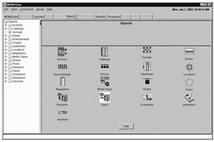
6.1.5. Creating Objects
If you wish to create a new object, you can choose the Domain, Object or Task Views to accomplish this. The Domain and Object Views create objects one at a time, while the Task View can create multiple objects.
To create an object, use one of the following methods:
Click on a class name (e.g. Jukebox) on the left screen, and the class object’s icons are displayed on the right screen. On the right screen press the “Create” button to display a create screen.
From the object view only, click on “Object”, then double-click on one of the class icons that are displayed. On the right screen press the “Create” button to display a create screen.
From the left screen, right-click on a class name, and a popup menu appears. Click on “Create” to display a create screen for that class.
From the task view, expand the Create task and click on one of the class names that appear.
From the task view, right click on the create task, and a popup menu appears. Click on the appropriate class name.
Once a create screen appears, (except for catalogs) you are prompted for two pieces of information:
A name for the new object or objects
An inherit object
The domain and object views allow creation of only one object at a time, whereas the task view allows a comma-separated list of new objects (and also ranges in the case of volumes). Depending on the view, enter the name or names of the new objects you wish to create.
The inherit object allows you to copy most of the attributes from the inherit object to the object being created. If you wish to specify an inherit object, use the combo box to select the existing inherit object. This must be the same type of object, except in the case of restores, in which case you can inherit from either a restore or a save object.
After clicking create, the new object attribute and operations screens appear, which you can then modify to your liking. In the task view, this screen modifies all the newly created objects.
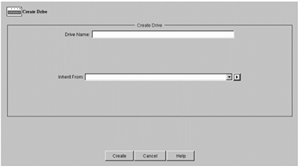
6.1.6. Showing and Modifying Objects
For objects that already exist, you can use the Domain View, Object View or Task View to show and optionally modify objects, or to perform operations on them.
To view an object, use one of the following methods:
From the Domain or Object Views, from the left screen, expand a class name, and click on an object name.
From the Domain or Object View, click on a class name from the left to bring up the class object icons on the right screen, then double click on an object icon.
From the Task View, right click on the Show task, and a popup menu appears, then click on an appropriate class and object.
When an object is selected, its attributes and operations are displayed in a two-dimensional tab screen as follows:
Vertical tabs on the right side of the screen contain the Show and any operations associated with the object. Many objects just have a Show tab, but some (for example, volumes) have a whole list of operational tabs such as load, unload and so on. You can switch between the tabs by simply clicking on them.
For the Show screen, there are also horizontal tabs that display related attributes about the object. Many simple objects have only a General tab that shows all attributes. Other attributes have General and Advanced tabs, if there is not enough room on one tab. Other tabs include:
A Show Access tab, which shows the access controls on the object. This is in a common format for all objects. If your site does not use access controls, you can disable these tabs using the view menu: View>No Access Control Tabs
The Show screen for Jukeboxes and Magazines also has a Contents tab that shows the current contents of the drives and slots in the jukebox, and the slots in a magazine.
Saves and Restores have a selections tab, that shows all selections for the save or restore, and a log tab that displays the latest version of the associated log file.
If you select the Show screen and wish to modify attributes, use the tool tip text for help on any field. Select appropriate values (from all the show tabs as needed), then click on Set. This sends the currently displayed values from all tabs to the MDMS server. If you just wish to view the object’s attributes without modification, click on Cancel after viewing the attributes. This returns you to the object class screen.
MDMSView supports switching from one object to another during displaying of values. For objects that appear in combo boxes or lists, you can view related objects without losing the context of the current object. Each combo box or list attribute supports two methods of viewing, selecting and creating objects:
Click on a small button to the right of the combo box or list to receive a popup menu for the field
Right-click on the combo box or list and receive the same popup menu for the field
From the menu, there are the following options:
Show - To show the selected object
Create - To create a new object
Reset - To go back to the previously selected objects
Clear - To clear the selection
Add and Remove (list only) - To add and remove an object by name
List all (list only), lists all the objects
If you select Show or Create, you will go to an appropriate screen. When you then complete your operation on that object, you will come back to the original object.
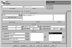
6.1.7. Deleting Objects
You can delete objects from the Domain, Object and Task Views. To delete an object, perform one of the following:
Display the object as discussed in the previous section, then click the Delete button at the bottom of the screen.
Right-click on the object name from the left screen, then select Delete from the pop-up menu.
From the task view, select the Delete task, then select the object class, then select the object names from the list on the delete screen.
A request to delete an object will always bring up a Delete dialog box for confirmation of the delete. You can confirm “OK” or “Cancel” from here.
6.1.8. Viewing Relationships Between Objects
The Domain view provides a way to view the hierarchical structure of the MDMS domain. The left side of the screen provides an object-class-object... hierarchy of objects belonging to other objects, or objects contained in other objects. The left side of the screen displays most of the object classes which contain other objects (the exceptions: selections, schedules and volumes, which have no sub-objects). You can begin the hierarchical navigation at any level, and all sublevels can be displayed.
For example, starting at jukebox, you can view all objects that reside in a jukebox: Drives, Magazines and Volumes. If you then click on Drives, you will see all drives in this jukebox. If you then select a drive and click on it, you can see the volume in the drive.
If your domain is sufficiently complex, you might want to expand the left side of the screen by using the right arrow between the left and right screen. You can then view the entire hierarchy of the domain.
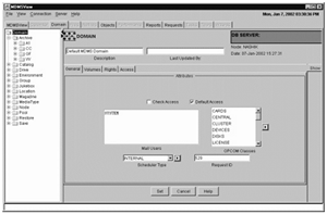
6.1.9. Performing Operations on Objects
If you wish to perform an operation on an object (for example, to load a volume into a drive), you should first display the object’s attributes and operations screens. Then select the desired operation tab, on the right side of the screen. For example, to load a volume, show the volume then click on the Load tab.
The load tab is called an operations tab, and they all follow the same basic concepts. You enter options concerning the operation (for example, operator assistance), then press the appropriate operation button on the bottom left of the screen. This button is always labelled with the appropriate operation (for example, Load).
MDMS has the capability of performing long-running operations synchronously or asynchronously. However, in MDMSView, long-running operations are always submitted asynchronously and control is returned to the user. Asynchronous operations show a dialog box that states that the operation has been queued for processing, but has not yet completed. If you perform an operation that does not result in the dialog box, then you can safely assume it has been completed synchronously.
If you receive a “queued” dialog box, it does not necessarily mean that the operation was fully validated. If you want to check on the status of the operation, use the Request View to monitor the request’s progress.
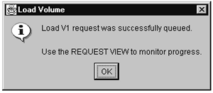
6.1.10. Running Save And Restore Requests
MDMS treats saves and restores in the same manner as other objects that it manages. You can create new saves and restores in the same way that you create other objects, then select a start time for them to run. Clicking Set will schedule the save or restore to run at the requested start date and time.
From MDMSView, however, there is an additional mechanism to run a save or restore. If you wish to run the request immediately, press the “Run” button at the bottom of the Show screen. This initiates an immediate run of the save or restore.
Once you run a save and restore request, you can monitor its progress by pressing the “Log” tab for the save or restore. This tab provides an up-to-date display of the request’s log file.
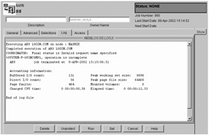
6.1.11. Showing Current Operations
The Request View provides a monitoring capability for all current MDMS operations. You can display all current requests by clicking on Show Requests - this results in a table of requests being displayed. This includes all current requests, and some recently-completed requests.
You can also expand the requests on the left side of the screen and click on a specific request for detailed information about the request. Or you can right-click on the request number on the left screen and select Show.
If you feel that a request is not working correctly, or for any reason you wish to delete the request, you can click on delete from the detailed request screen, or select a request number on the left screen, right-click and select delete from the popup menu.
As with other deletes, a dialog box will appear to confirm the delete of the request.
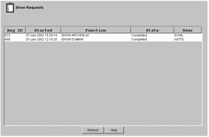
6.1.12. Reporting on Volumes
The Report View provides the capability of generating custom reports on volumes. With this view, you can choose attributes that can be displayed and/or used as selection criteria for volumes.
To select an attribute for display, simply click on the attribute and then press the right arrow button to move it to the display screen. The attributes are displayed in the report in the order selected. If you change your mind or wish to re-order the attributes, select an attribute on the display screen and press the left arrow button to deselect it.
If you wish to use an attribute as a selection criterion, click on the attribute, then click on “Use for Selection”. This will enable a field below (either a text field or combo box) to allow you to enter a selection.
You may display any number of fields and use any number of selection criteria to customize the report. When your selections are ready, you can generate the report by clicking on “Generate”. You can see the resultant report in the “Report Results” tab.
If you wish to save this report, enter a report title in the text field at the bottom of the screen and click on save. The report is saved to the following location on OpenVMS Systems:
sys$common:[mdms.gui.vms]Report_year_month_day_hour_minut_second.txt
An example report file name is: Report_2001_12_17_8_35_17.txt.
Once the results screen is displayed, you can sort the report using any field by clicking on the field’s header. You can reverse-sort the same field by clicking on the field header again.
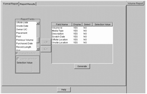
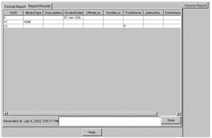
6.1.13. Viewing MDMS Audit and Event Logging
To examine past operations in MDMS, you can use the event view to view the MDMS audit and event logfile. There are five pre-configured options and a fully flexible custom option to allow you to select what you wish to see from the MDMS logfile. The five pre-configured options all apply to the MDMS Database Server logfile and show all operations (auditing and events) for the following amounts of time before the current time:
The last minute
The last 10 minutes
The last hour
The last 24 hours
The last 72 hours
If you wish to see the logfile using other selection criteria, you can use the “Custom” setting. By clicking on “Custom”, a selection screen appears that allows you to select the entries to be displayed as follows:
Node selection: You can choose the default of the DB server (which contains the most complete information), or select a specific client node. Note that request IDs are not supported on client nodes, and nor is selection by low and high request IDs.
Selection Options: You can select a range of entries in the logfile to display by one of:
Elapsed time in minutes (default of 60 minutes) -OR-
Before and/or since dates (specified as an absolute time) -OR-
Low and high request IDs (for DB server only)
Severity Options: For audit completion entries, you can select that only entries of a certain combinations of completion status are displayed. You can select one or more of:
Success (S)
Informational (I)
Warning (W)
Error (E)
Fatal (F)
After entering the selection criteria, you click on the Show button to display. Depending on the size of the log file, this operation may take several seconds to complete. You may want to regularly reset your log files to avoid long response times. The code has been written to scan previous versions of log files if the date and or request selections are not in the latest log file.
The Refresh button at the bottom of the screen refreshes whatever selection is currently on the screen. The Cancel button allows you to enter a new selection.
6.1.14. Errors
MDMSView can report two types of errors:
Those generated by MDMSView itself: these typically appear in a dialog box and in the status bar at the bottom of the screen. These errors normally explain an illegal user operation.
Those generated by the MDMS server on the log-in node. These errors appear in a dialog box with the standard MDMS DCL syntax. These errors are documented in the VSI MDMS Reference Guide.
6.1.15. Help
MDMSView provides three types of help:
Tool-tip Help for every field on every screen. To obtain tool-tip help on a field, simply position the cursor on that field. The help appears near the field within one second and remains on the screen for 4 seconds.
Screen-sensitive Help. For every screen in the Domain, Object or Task Views there is a “Help” button at the bottom right of each screen. If you press this “Help” button, a help screen pops-up with information about the screen you from which you pressed the button. The help information displayed is derived from this manual, the ABS Guide to Operations.
Finally, there is a “Help” pull-down menu from the main screen. This provides the same type of Help as the “Help” button, but starts from the beginning of the manual. You can use the left-screen navigation or a search capability to find what you are interested in.
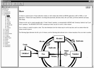
6.2. DCL Interface
MDMS provides a DCL command line interface in addition to MDMSView. Some people prefer a command line interface, and it can also be used for automated command procedures. With this release, the entire command line interface is supported within MDMS, which maintains the database for both media management and ABS objects.
In previous releases, there was an ABS DCL interface that supported the ABS objects. This interface is now deprecated, but still works for backward compatibility. If you have command procedures that use this interface, they will still work. However, this interface will not be enhanced, so a migration to the MDMS DCL verbs is recommended for the long term.
6.2.1. Syntax Overview
The MDMS DCL interface uses a consistent syntax for virtually all commands in the format.
$ MDMS VERB OBJECT_KEYWORD OBJECT_NAME /QUALIFIERS
The verb is a simple action word, and may be one of the following:
ALLOCATE
BIND
CREATE
DEALLOCATE
DELETE
INITIALIZE
INVENTORY
LOAD
SET
SHOW
UNBIND
UNLOAD
The object keyword is the object class name that the verb is to operate on. In MDMS, the object keyword cannot be omitted. MDMS supports the following object keywords:
ARCHIVE
DOMAIN
DRIVE
ENVIRONMENT
GROUP
JUKEBOX
LOCATION
MAGAZINE
MEDIA_TYPE
NODE
POOL
RESTORE
SAVE
SERVER
SCHEDULE
SELECTION
VERSION
VOLUME
Following the object keyword, you should enter an object name. This must be the name of an already-existing object unless the verb is “Create”, in which case the object must not already exist.
The qualifiers for all commands are non-positional and may appear anywhere in the command line.
There are two exceptions to the general command syntax, as follows:
The Move verb takes two arguments. The first is the object name as normal, and the second is a destination object name. The destination object name is not preceded by an object keyword. An example of a Move command is:
MDMS MOVE VOLUME TLZ234 TLZ_JUKE/SLOT=4
The Report verb, which takes a variable number of arguments. This verb uses the syntax of the old SLS Storage Report Volume command. Since the Report verb does not operate on any specific object, the first argument is always the keyword “Volume”, and the other argument is a comma-separated list of display and/or selection attributes. For example:
$ MDMS REPORT VOLUME VOLUME,STATE=ALLOCATED,SCRATCH_DATE,PLACEMENT,PLACNAME
6.2.2. Object Lists
With this release of MDMS, all of the following commands accept a list of objects, so that you can operate on multiple objects in a single command:
CREATE
DELETE
SET
SHOW
If you specify an attribute in a CREATE or SET command and use an object list, then that attribute value is applied to all objects in the list.
6.2.3. Qualifier List
Certain qualifiers accept a list of attributes, and the list can be applied in one of three ways using an appropriate qualifier:
/ADD - The specified value or list is added to any pre-existing list; this is the default option if you do not specify a qualifier
/REMOVE - The specified value or list is removed from any pre-existing list
/REPLACE - The specified value or list replaces any pre-existing list.
Consider the following examples:
MDMS CREATE GROUP COLORADO/NODES=(DENVER, SPRINGS, PUEBLO)
The group Colorado contains nodes Denver, Springs and Pueblo
MDMS SET GROUP COLORADO/NODE=ASPEN
The group Colorado now contains nodes Denver, Springs, Pueblo and Aspen. With no list qualifier specified, /ADD is applied by default.
MDMS SET GROUP COLORADO/NODE=ASPEN/REPLACE
The group Colorado now contains only node Aspen.
6.2.4. Inherit
All MDMS objects now accept the /INHERIT qualifier on Create. This allows you to create new objects and inherit most attributes of an existing object. This provides an easy way to “clone” objects, then apply the any differences in individual commands. It saves the effort of typing in all the attributes once a prototype has been established. In general, only non-protected fields of objects can be inherited.
In addition, the object list capability allows you to clone multiple objects in a single command. For example:
MDMS CREATE DRIVE DRIVE_2, DRIVE_3, DRIVE_4/INHERIT=DRIVE_1
This command creates three drives and applies all non-protected attributes of DRIVE_1 to the three new drives.
6.2.5. Symbols
MDMS now supports symbols on all objects which command procedures can read and process. To use symbols, enter a Show command for a single object. You can define a prefix other than the default one (MDMS_INQ). If prefix is not specified the default prefix is MDMS_INQ. The maximum length of the prefix is 8 characters. This qualifier is supported for wildcard show requests.
The symbols are generally in the format “MDMS_INQ_qualifier”, where “qualifier” is almost always the associated qualifier name for the attribute. The list of symbols for each show command is documented for that command, and is also available in DCL help.
When you issue a Show/Symbols, the show output is not displayed by default. If you wish to see the output as well, use Show/Symbols/Output.
6.2.6. Help and Reference
MDMS supports the normal DCL help mechanisms, as follows:
$ MDMS HELP [VERB] [KEYWORD] [/QUALIFIER]
$ HELP MDMS [VERB] [KEYWORD] [/QUALIFIER]
In addition, you can request help on any error message, for example:
MDMS HELP MESSAGE NOSUCHOBJECT
You can request help on any MDMS logical name, for example:
MDMS HELP LOGICAL MDMS$LOGFILTER
Finally, you can locate the mapping of the old (pre-version 4.0) ABS commands to the MDMS equivalent, for example:
MDMS HELP MAPPING CREATE ARCHIVE
The VSI MDMS Reference Guide fully documents all DCL commands and qualifiers.
6.3. User Interface Restrictions
MDMSView and the MDMS DCL supports operations on Archive Backup System (ABS) objects only if an ABS or SLS license is loaded on the system. The ABS objects are:
Archives
Environments
Restores
Saves
Selections
MDMS supports operations on the other media management objects if the system only has a Hierarchical Storage Management (HSM) license installed, or with an ABS or SLS license.
Chapter 7. Preparing For Disaster Recovery
In case of a disaster you may need to restore all or part of the on-disk data of your computing environment. Basically you need a bootable system disk and a complete ABS/MDMS environment to restore all the rest of your data. This chapter explains the task to get you ABS environment up-and-running from scratch. The procedure differs slightly between OpenVMS and non- OpenVMS systems.
7.1. Disaster Recovery for OpenVMS Systems
To recover from a total loss of your online data you need the following items for recovery:
An image copy of your system disk
A copy of your MDMS$ROOT including the database files
A copy of your ABS$ROOT including all catalog files
A copy of files of any other product required by ABS, such as your 3rd party scheduler product
In all cases you need to keep the information about the saves in a safe place. This information is in the ABS save log and includes:
The volume IDs of the tapes used
The name of the savesets created
The source path of the files being saved
Note
It is important to note the full pathname of the original location of the files.
You can print out this information from the epilog procedure of the environment.
7.1.1. Backup of Your System Disk
The easiest way to save your system disk is by using an ABS SAVE object like this:
Save: SYSTEM_DISK
Description: System Disk Backup for Recovery
Access Control: NONE
Owner: BONFYR::FROEHLIN
Archive: DISASTER_RECOVERY
Base Date: NONE
Delete Interval: NONE
Environment: DISASTER_RECOVERY_ENV
Epilogue:
Execution Nodes: BONFYR
Explicit Interval:
Frequency: DAILY
Groups:
Incremental: NO
Job Number: 0
Prologue:
Schedule: SYSTEM_DISK_SAVE_SCHED
Sequence Option: SEQUENTIAL
Skip Time: NONE
Start Date: NONE
Transaction Status:
Selections: SYSTEM_DISK_SAVE_SEL_DEF
Default Selection -
- Data Select Type: VMS_FILES
- Include: $1$DUA300:
- Exclude:
- Source Node:
This SAVE uses the standard archive of DISASTER_RECOVERY and the standard environment of DISASTER_RECOVERY _ENV which comes with ABS. If these objects do not exist on your system run the ABS database initialization program:
$ RUN SYS$SYSTEM:ABS$DB_INITThis program adds all the missing default ABS objects to the MDMS database.
Saving an OpenVMS system disk online produces many errors for files open for write by the operating system and layered products. Even though, the image backup produced can be used to restore a bootable system disk. The problem comes when executing the site-specific SYSTARTUP_VMS.COM. For example when starting the OpenVMS Queue Manager the command could hang because the Queue Manager files had been saved in an inconsistent state. There are three ways to avoid these kind of problems.
Do a standalone backup of your system disk.
For Alpha systems, refer to the OpenVMS Alpha Upgrade and Installation Manual.
Shutdown components of your system until all critical files are closed before starting the backup of your system disk. To find out which files are open for write use the following method:
$ BACKUP/IMAGE/IGNORE=INTERLOCK SYS$SYSDEVICE: NLA0:DUMMY.SAV/SAVE
Before the backup shutdown all components for which BACKUP reported:
%BACKUP-W-ACCONFLICT, SYS$SYSDEVICE:[SYS0.SYSCOMMON.SYSEXE]QMAN$MASTER.
DAT;1 is open for write by another user
Shutdown of these components can be done in the prolog procedure in environment DISASTER_RECOVER_ENV. The same components can be automatically restarted in the epilog procedure.
Ignore any error messages during the save operation. After restoring your system disk boot into conversational boot and rename your SYSTARTUP_VMS.COM and SYLOGICALS. COM to prevent any startup of extra components or layered products and reboot.
7.1.2. Backup of MDMS$ROOT
Backing up MDMS$ROOT with ABS will always find the MDMS database files open for write. This cannot be avoided. To copy the contents of these files in a consistent way online copies should be made prior to starting the save request. You can use the standard MDMS command procedure to do this:
$ @MDMS$SYSTEM:MDMS$COPY_DB_FILES
This command procedures uses DCL CONVERT/SHARE to create file copies with a file extension of “*.DAT_COPY”. This can be automatically done by executing this command procedure in the prolog of the environment. All files with that extension can then can be automatically deleted in the epilog of the environment.
See ABS$SYSTEM:ABS$DISASTER_RECOVERY.TEMPLATE for an example.
If MDMS$ROOT is not located on your system disk or you want a separate save operation, you can use a separate SAVE object like this:
Save: DISASTER_RECOVERY
Description:
Access Control: BONFYR::ABS (READ, WRITE, EXECUTE, DELETE, SET,
SHOW,
CONTROL)
Owner: BONFYR::ABS
Archive: DISASTER_RECOVERY
Base Date: NONE
Delete Interval: NONE
Environment: DISASTER_RECOVERY_ENV
Epilogue: @ABS$SYSTEM:ABS$DISASTER_RECOVERY.COM EPILOG
Execution Nodes: BONFYR
Explicit Interval:
Frequency: ON_DEMAND
Groups:
Incremental: NO
Job Number: 0
Prologue: @ABS$SYSTEM:ABS$DISASTER_RECOVERY.COM PROLOG
Schedule: DISASTER_RECOVERY_SAVE_SCHED
Sequence Option: SEQUENTIAL
Skip Time: NONE
Start Date: NONE
Transaction Status:
Selections: DISASTER_RECOVERY_SAVE_SEL_DEF
Default Selection -
- Data Select Type: VMS_FILES
- Include: MDMS$ROOT:[000000...]*.*;*
- Exclude: [*...]*.LOG;*,[*...]*_DB.DAT;*
- Source Node:
This save request excludes all the files open for write by MDMS and therefore does not create any error messages in the save log file.
If you want you can combine the save of the MDMS$ROOT and the ABS$ROOT into one save object.
7.1.3. Backup of ABS$ROOT
Backing up ABS$ROOT with ABS will always find the ABS log files open for write because a save request always has a catalog file open for write. Not all catalog files might be accessible through ABS$ROOT. For example if you have created a search list for ABS$CATALOG and extensions to ABS$CATALOG point to other directories and/or disk devices.
If ABS$ROOT is not located on your system disk or you want a separate save operation, you can use a separate SAVE object like this:
Save: DISASTER_RECOVERY
Description:
Access Control: BONFYR::ABS (READ, WRITE, EXECUTE, DELETE, SET,
SHOW,
CONTROL)
Owner: BONFYR::ABS
Archive: DISASTER_RECOVERY
Base Date: NONE
Delete Interval: NONE
Environment: DISASTER_RECOVERY_ENV
Epilogue: @ABS$SYSTEM:ABS$DISASTER_RECOVERY EPILOG
Execution Nodes: BONFYR
Explicit Interval:
Frequency: DAILY
Groups:
Incremental: NO
Job Number: 0
Prologue: @ABS$SYSTEM:ABS$DISASTER_RECOVERY PROLOG
Schedule: DISASTER_RECOVERY_SAVE_SCHED
Sequence Option: SEQUENTIAL
Skip Time: NONE
Start Date: NONE
Transaction Status:
Selections: DISASTER_RECOVERY_SAVE_SEL_DEF
Default Selection -
- Data Select Type: VMS_FILES
- Include: ABSS$ROOT:[000000...]*.*;*,
- Exclude: [*...]COORD_CLEANUP.DAT;*,[*...]*.LOG;
- Source Node:
If this object does not exist on your system run the ABS database initialization program:
$ RUN SYS$SYSTEM:ABS$DB_INIT
This program adds all the missing default ABS objects to the MDMS database.
This save request excludes all the files open for write by ABS like the current logfile and the database file used by the coordinator cleanup process (“ABS$COORD_CLEAN”). There should not be any error message in the save log file.
You have to make sure that you use the DISASTER_RECOVERY archived with an empty catalog name defined. The disaster recovery archive is the only archive which allows no catalog name. Otherwise you get open and verify errors for the catalog being used.
If you have an extended ABS$CATALOG search list, then you have to include the extra entries in the include specification as well. By default the catalog subdirectory is included under ABS$ROOT.
If you want, you can combine the save of the MDMS$ROOT and the ABS$ROOT into one save object.
7.2. Prolog and Epilog Procedure
To use ABS$SYSTEM:ABS$DISASTER_RECOVERY.TEMPLATE, you should rename it to ABS$SYSTEM:ABS$DISASTER_RECOVERY.COM and use it as a prolog and epilogue for the save(s).To automatically prepare the system for a save operation you can use the prolog and epilog feature in the environment object being used. The following example shows you how to use one procedure for both purposes.
$ !
$ !   Abstract:
$ !     This command file is used for saving ABS and MDMS information
$ !     for later disaster recovery. The procedure is used for prolog
$ !     as well as epilog procedures in a SAVE operation.
$ !
$ !
$ !   INPUT:
$ !
$ !     P1 = "" - no operation
$ !     = "PROLOG" - prepares a disaster recovery save operation
$ !     by making online copies of MDMS database files
$ !     = "EPILOG" - does cleanup of save operation by deleting
$ !     copies of files created during prolog
$ !     - lists information about restoring the data
$ !
$ !----------------------------------------------------------------
$ !
$!
$ Start:
$!
$ SET NOON
$ IF P1.EQS."PROLOG" THEN GOTO Prolog
$ IF P1.EQS."EPILOG" THEN GOTO Epilog
$ EXIT
$!
$ Prolog:
$!
$ WRITE SYS$OUTPUT "Disaster Recovery Prolog"
$ WRITE SYS$OUTPUT "."
$ IF F$SEARCH("MDMS$DATABASE_LOCATION:MDMS$DOMAIN_DB.DAT").NES.""
$ THEN
$   WRITE SYS$OUTPUT "Creating online copies of MDMS database
files..."
$   WRITE SYS$OUTPUT "."
$   @MDMS$SYSTEM:MDMS$COPY_DB_FILES
$ ENDIF
$ EXIT
$!
$ Epilog:
$!
$ WRITE SYS$OUTPUT "."
$ IF
F$SEARCH("MDMS$DATABASE_LOCATION:MDMS$DOMAIN_DB.DAT_COPY").NES.""
$ THEN
$   WRITE SYS$OUTPUT "Deleting copies of MDMS database files..."
$   WRITE SYS$OUTPUT "."
$   DELETE/NOLOG MDMS$DATABASE_LOCATION:MDMS$*_DB.DAT_COPY;*
$   ENDIF
$ WRITE SYS$OUTPUT "BACKUP restore commands:
$ WRITE SYS$OUTPUT "."
$ nmax = 'F$TRNLNM("ABS_OS_OBJECT_NUMBER")'
$ n = 1
$!
$ NextObject:
$!
$ VolSetLog = "ABS_OS_VOLUME_SET_''n'"
$ VolRVNLog = "ABS_OS_START_RVN_''n'"
$ ObjectLog = "ABS_OS_OBJECT_SET_''n'"
$ SavsetLog = "ABS_OS_SAVESET_NAME_''n'"
$ CALL GetVolumeList "''F$TRNLNM(VolSetLog)'" 'F$TRNLNM(VolRVNLog)'
VolumeList
$ Destination = "''F$TRNLNM(ObjectLog)'"
$ Destination = F$EXTRACT(0,F$LOCATE(":",Destination),Destination)
$ Destination = "''F$TRNLNM(Destination)'"
$ IF F$LOCATE(".]",Destination).NE.F$LENGTH(Destination)
$ THEN
$   Destination = Destination + "[...]" - "]["
$ ELSE
$   Destination = Destination + "[*...]"
$ ENDIF
$ WRITE SYS$OUTPUT "  $ BACKUP/OVERLAY/EXACT_ORDER/NOASSIST -"
$ WRITE SYS$OUTPUT "  _$ tape:","''F$TRNLNM(Savset-
Log)'/LABEL=(",VolumeList,
$ WRITE SYS$OUTPUT "  _$ ''Destination'"
$ WRITE SYS$OUTPUT "."
$ n = n + 1
$ IF n.LE.nmax THEN GOTO NextObject
$ WRITE SYS$OUTPUT "."
$ WRITE SYS$OUTPUT "After restoring the savesets rename the MDMS
database"
$ WRITE SYS$OUTPUT "files from ""MDMS$*_DB.DAT_COPY"" to
""*.DAT""/NEW_VERSION."
$ WRITE SYS$OUTPUT "."
$ EXIT
$!
$ GetVolumeList: SUBROUTINE
$!
$ VolumeID   = "''P1'"
$ RVN        = 'P2'
$ 'P3'       == ""
$ VolumeRVN  = 1
$!
$ NextVolume:
$!
$ MDMS SHOW VOLUME 'VolumeID'/SYMBOL
$ IF VolumeRVN.GE.RVN
$ THEN
$   IF 'P3'.NES."" THEN 'P3' == 'P3' + ","
$   'P3' == 'P3' + "''MDMS_INQ_VOLUME_ID'"
$ ENDIF
$ IF "''MDMS_INQ_NEXT_VOLUME'".EQS."" THEN GOTO EndVolumeList
$ VolumeID = "''MDMS_INQ_NEXT_VOLUME'"
$ VolumeRVN = VolumeRVN + 1
$ GOTO NextVolume
$!
$ EndVolumeList:
$!
$ EXIT
The example procedure creates copies of the MDMS database files in the prolog phase. This allows to save the files in a consistent state. After a restore from the saveset the files need to be renamed to their original names.
For convenience the procedure prints out the backup commands needed to restore the data using information in logical names defined by ABS during the save operation.
7.2.1. Restoring The System Disk
To restore your system disk you need to use Standalone BACKUP.
For Alpha systems, refer to the OpenVMS Alpha Upgrade and Installation Manual.
Use the information from the ABS save log to specify the parameters for the BACKUP command line:
/LABEL=(volume_1,volume_2,...volume_n) - the volume IDs of the tapes being used
The saveset name
The target disk
/IMAGE/NOASSIST qualifiers
$ BACKUP/IMAGE MKA500:24DEC20012359590./LABEL=(GKF011,GKF022) -
_$DGA100:/NOASSIST
This restores an image of your system disk in saveset “24DEC20012359590.” on tape volumes “GKF011” and “GKF022” to disk device “DGA100”.
After a successful restore, boot from your restored system disk. If your system does not boot all the way through you may have to disable the execution of your “SYSTARTUP_VMS.COM” command procedure by using a conversational boot and renaming the file.
7.2.2. Restoring Remaining Savesets
Once your system is up-and-running you can restore other save sets necessary to complete the disaster recovery: Make sure that all of these components or products are shut down before you restore the individual files. Use the following restore order:
First, any other product required by ABS, such as your 3rd party scheduler data if it has been saved separately. You should startup the component or product just restored.
Restore MDMS$ROOT if it has been saved separately. After the restore rename the “MDMS$*_DB.DAT_COPY” files to “*.DAT”. You can startup MDMS now.
Restore ABS$ROOT if it has been saved separately. Restore any other save used to save the catalog files which are located outside of ABS$ROOT. After the restore you can startup ABS.
Use the information from the ABS save log to specify the parameters for the BACKUP command lines:
/LABEL=(volume_1,volume_2,...volume_n) - the volume IDs of the tapes being used
The saveset name
The target disk
/IMAGE/NOASSIST qualifiers
$ BACKUP/NOASSIST/OVERLAY -
$_MKA500:25DEC20010101010./LABEL=(GKF033,GKF044)-
$_DGA100:[VMS$COMMON.ABS.*...]/LOG
Because ABS has not been started up the ABS$ROOT logical is not available yet. This restores the ABS$ROOT files in saveset “24DEC20012359590.” on tape volumes “GKF033” and “GKF044” to disk location “DGA100:[VMS$COMMON.ABS...]”. This assumes that you ABS$ROOT logical was defined as a concealed device name of “DGA100:[VMS$COMMON.ABS.]”.
Note
It is important to note the full pathname when you save these components or products.
7.3. Non-OpenVMS Systems
Warning
This functionality is not supported in ABS/MDMS E4.8.
ABS cannot restore a bootable system disk of a non-OpenVMS system. Therefore you need to be able to save and restore the system disk locally. Once you have the system disk restored and booted the system you have to install the ABS client software for that platform. Once the ABS client software has been installed you can use ABS on your OpenVMS system to restore data to the client node.
7.4. Thoughts on Save and Restore Procedures
When it comes to setup procedures on how to save and restore files for disaster recovery there is a variety of possibilities depending on your configuration and other system activities.
You do not need to have an up-to-date copy of your system disk to restore your ABS environment. You could start with a fresh installation of OpenVMS. Install ABS and products required to run ABS (e.g. a 3rd party scheduler). While ABS is shutdown restore the MDMS$ROOT and ABS$ROOT and other required components. Startup ABS to restore all the rest of your data.
Or in a VMSCluster with more than one system disk you may be able to restore all your data online using ABS from another node in the cluster.
You can keep a printout of the ABS save log in a safe place. This allows you to restore the data for files on OpenVMS systems using OpenVMS BACKUP. You need to keep the volume IDs, the name of the save sets and the include specifications used in the save operation.
Typically you do not want to keep multiple copies of your disaster recovery saves. You may want to keep 2 copies. So, if you are doing daily disaster recovery saves the archive expiration should be set to 2 days.
You should use non-incremental saves for the disaster recovery. This allows for an easy restore in case of an emergency. You can use incremental saves, but on a restore you have to do all the incremental restores on your own until you have ABS fully up-and-running.
Note
And a final word: Make sure that you have a clear procedure on how to do a disaster recovery. Test your disaster recovery procedure.
Chapter 8. Remote Devices
This chapter explains how to configure and manage remote devices using the Remote Device Facility (RDF). RDF is used for devices remotely connected over a wide-area network, and DECnet is still a requirement for access to these remote devices. RDF is not required for devices connected remotely via Fibre Channel, as these are considered local devices.
8.1. RDF Installation
Warning
RDF is not supported on IA-64 and x86-64 systems.
When you install ABS (non-standard installation) or MDMS, you are asked whether you want to install the RDF software. With the ABS standard installation, the RDF client and server software is installed by default.
During the installation you place the RDF client software on the nodes with disks you want to access for ABS or HSM. You place the RDF server software on the systems to which the tape devices (jukeboxes and drives) are connected. This means that when using RDF, you serve the tape device to the systems with the client disks.
All of the files for RDF are placed in SYS$COMMON:[MDMS.TTI_RDF] for your system.
8.2. Configuring RDF
After installing RDF you should check the TTI_RDEV:CONFIG_nodename.DAT file to make sure it has correct entries.
This file:
is located on the RDF server node with the tape device
is created initially during installation
is a text file
includes the definition of each device accessible by the RDF software. This definition consists of a physical device name and an RDF characteristic name.
Example:
Device $1$MIA0 MIAO
Verify:
Check this file to make sure that all RDF characteristic names are unique to this node.
8.3. Using RDF with MDMS
The following sections describe how to use RDF with MDMS.
8.3.1. Starting Up and Shutting Down RDF Software
Starting up RDF software:
RDF software is automatically started up along with then MDMS software when you enter the following command:
$ @SYS$STARTUP:MDMS$STARTUPShutting down RDF software:
To shut down the RDF software, enter the following command:
$ @SYS$STARTUP:MDMS$SHUTDOWN8.3.2. The RDSHOW Procedure
Required privileges:
The following privileges are required to execute the RDSHOW procedure: NETMBX, TMPMBX.
In addition, the following privileges are required to show information on remote devices allocated by other processes: SYSPRV, WORLD.
8.3.3. Command Overview
You can run the RDSHOW procedure any time after the MDMS software has been started. RDF software is automatically started at this time.
Use the following procedures:
$@TTI_RDEV:RDSHOW CLIENT$@TTI_RDEV:RDSHOW SERVER node_name$@TTI_RDEV:RDSHOW DEVICES
node_name is the node name of any node on which the RDF server software is running.
8.3.4. Showing Your Allocated Remote Devices
To show remote devices that you have allocated, enter the following command from the RDF client node:
$ @TTI_RDEV:RDSHOW CLIENTResult:
RDALLOCATED devices for pid 20200294, user DJ, on node OMAHA::
Local logical    Rmt node    Remote device
TAPE01           MIAMI::     MIAMI$MUC0
DJ is the user name and OMAHA is the current RDF client node.
8.3.5. Showing Available Remote Devices on the Server Node
The RDSHOW SERVER procedure shows the available devices on a specific SERVER node. To execute this procedure, enter the following command from any RDF client or RDF server node:
$ @TTI_RDEV:RDSHOW SERVER MIAMI
MIAMI is the name of the server node whose devices you want shown.
Result:
Available devices on node MIAMI::
Name         Status   Characteristics/Comments
MIAMI$MSA0   in use   msa0
...by pid 20200246, user CATHY (local)
MIAMI$MUA0   in use   mua0
...by pid 202001B6, user CATHY, on node OMAHA::
MIAMI$MUB0   -free-   mub0
MIAMI$MUC0   in use   muc0
...by pid 2020014C, user DJ, on node OMAHA::
This RDSHOW SERVER command shows any available devices on the server node MIAMI, including any device characteristics. In addition, each allocated device shows the process PID, username, and RDF client node name.
The text (local) is shown if the device is locally allocated.
8.3.6. Showing All Remote Devices Allocated on the RDF Client Node
To show all allocated remote devices on an RDF client node, enter the following command from the RDF client node:
$ @TTI_RDEV:RDSHOW DEVICESResult:
Devices RDALLOCATED on node OMAHA::
RDdevice   Rmt node    Remote device   User name   PID
RDEVA0:      MIAMI::    MIAMI$MUC0       DJ          2020014C
RDEVB0:      MIAMI::    MIAMI$MUA0      CATHY        202001B6
This command shows all allocated devices on the RDF client node OMAHA. Use this command to determine which devices are allocated on which nodes.
8.4. Monitoring and Tuning Network Perform
This section describes network issues that are especially important when working with remote devices.
8.4.1. DECnet Phase IV
The Network Control Program (NCP) is used to change various network parameters. RDF (and the rest of your network as a whole) benefits from changing two NCP parameters on all nodes in your network. These parameters are:
PIPELINE QUOTA
LINE RECEIVE BUFFERS
Pipeline quota
The pipeline quota is used to send data packets at an even rate. It can be tuned for specific network configurations. For example, in an Ethernet network, the number of packet buffers represented by the pipeline quota can be calculated as approximately:
buffers = pipeline_quota / 1498
Default:
The default pipeline quota is 10000. At this value, only six packets can be sent before acknowledgment of a packet from the receiving node is required. The sending node stops after the sixth packet is sent if an acknowledgment is not received.
Recommendation:
The PIPELINE QUOTA can be increased to 45,000 allowing 30 packets to be sent before a packet is acknowledged (in an Ethernet network). However, performance improvements have not been verified for values higher than 23,000. It is important to know that increasing the value of PIPELINE QUOTA improves the performance of RDF, but may negatively impact performance of other applications running concurrently with RDF.
Line receive buffers
Similar to the pipeline quota, line receive buffers are used to receive data at a constant rate.
Default:
The default setting for the number of line receive buffers is 6.
Recommendation:
The number of line receive buffers can be increased to 30 allowing 30 packets to be received at a time. However, performance improvements have not been verified for values greater than 15 and as stated above, tuning changes may improve RDF performance while negatively impacting other applications running on the system.
8.4.2. DECnet-Plus (Phase V)
As stated in DECnet-Plus(Phase V), (DECnet/OSI V6.1) Release Notes, a pipeline quota is not used directly. Users may influence packet transmission rates by adjusting the values for the transport’s characteristics MAXIMUM TRANSPORT CONNECTIONS, MAXIMUM RECEIVE BUFFERS, and MAXIMUM WINDOW. The value for the transmit quota is determined by MAXIMUM RECEIVE BUFFERS divided by Actual TRANSPORT CONNECTIONS.
This will be used for the transmit window, unless MAXIMUM WINDOW is less than this quota. In that case, MAXIMUM WINDOW will be used for the transmitter window.
The DECnet-Plus defaults (MAXIMUM TRANSPORT CONNECTIONS = 200 and MAXIMUM RECEIVE BUFFERS = 4000) produce a MAXIMUM WINDOW of 20. Decreasing MAXIMUM TRANSPORT CONNECTIONS with a corresponding increase of MAXIMUM WINDO may improve RDF performance, but also may negatively impact other applications running on the system.
8.4.3. Changing Network Parameters
This section describes how to change the network parameters for DECnet Phase IV and DECnet- PLUS.
8.4.4. Changing Network Parameters for DECnet (Phase IV)
The pipeline quota is an NCP executor parameter. The line receive buffers setting is an NCP line parameter.
The following procedure shows how to display and change these parameters in the permanent DECnet database. These changes should be made on each node of the network.
| Step | Action |
|---|---|
| 1 |
Enter: $ Result: Node Permanent Characteristics as of 24-MAY-1991 10:10:58 Executor node = 20.1 (DENVER) Management version = V4.0.0 . . . Pipeline quota = 10000 |
| 2 |
Enter: NCP> Result: Known line Volatile Summary as of 24-MAY-1991 10:11:13 Line State SVA-0 on |
| 3 |
Enter: NCP>
Result: Line Permanent Characteristics as of 24-MAY-1991 10:11:31 Line = SVA-0 Receive buffers = 6 <-- value to change Controller = normal Protocol = Ethernet Service timer = 4000 Hardware address = 08-00-2B-0D-D0-5F Device buffer size = 1498 |
| 4 |
Enter: NCP> |
Requirement:
For the changed parameters to take effect, the node must be rebooted or DECnet must be shut down.
8.4.5. Changing Network Parameters for DECnet-Plus(Phase V)
The Network Control Language (NCL) is used to change DECnet-Plus network parameters. The transport parameters MAXIMUM RECEIVE BUFFERS, MAXIMUM TRANSPORT CONNECTIONS and MAXIMUM WINDOW can be adjusted by using NCL’s SET OSI TRANSPORT command. For example:
NCL> SET OSI TRANSPORT MAXIMUM RECEIVE BUFFERS = 4000        !default value
NCL> SET OSI TRANSPORT MAXIMUM TRANSPORT CONNECTIONS = 200   !default value
NCL> SET OSI TRANSPORT MAXIMUM WINDOWS = 20                  !default value
To make the parameter change permanent, add the NCL command(s) to the SYS$MANAGER: NET$OSI_TRANSPORT_STARTUP.NCL file. Refer to the DENET-Plus (DECnet/OSI) Network Management manual for detailed information.
8.4.6. Resource Considerations
Changing the default values of line receive buffers and the pipeline quota to the values of 30 and 45000 consumes less than 140 pages of nonpaged dynamic memory.
In addition, you may need to increase the number of large request packets (LRPs) and raise the default value of NETACP BYTLM.
Large request packets
LRPs are used by DECnet to send and receive messages. The number of LRPs is governed by the SYSGEN parameters LRPCOUNT and LRPCOUNTV.
Recommendation:
A minimum of 30 free LRPs is recommended during peak times. Show these parameters and the number of free LRPs by entering the following DCL command:
$ SHOW MEMORY/POOL/FULLResult:
System Memory Resources on 24-JUN-1991 08:13:57.66
Large Packet (LRP) Lookaside   List   Packets   Bytes
Current Total Size                      36       59328
Initial Size (LRPCOUNT)                 25       41200
Maximum Size (LRPCOUNTV)               200       329600
Free Space                              20       32960
In the LRP lookaside list, this system has:
Current Total Size of 36
The SYSGEN parameter LRPCOUNT (LRP Count) has been set to 25. The Current Size is not the same as the Initial Size. This means that OpenVMS software has to allocate more LRPs. This causes system performance degradation while OpenVMS is expanding the LRP lookaside list.
The LRPCOUNT should have been raised to at least 36 so OpenVMS does not have to allocate more LRPs.
Recommendation:
Raise the LRPCOUNT parameter to a minimum of 50. Because the LRPCOUNT parameter is set to only 25, the LRPCOUNT parameter is raised on this system even if the current size was also 25.
Free Space is 20
This is below the recommended free space amount of 30. This also indicates that LRPCOUNT should be raised. Raising LRPCOUNT to 50 (when there are currently 36 LRPs) has the effect of adding 14 LRPs. Fourteen plus the 20 free space equals over 30. This means that the recommended value of 30 free space LRPs is met after LRPCOUNT is set to 50.
The SYSGEN parameter LRPCOUNTV (LRP count virtual) has been set to 200.
The LRPCOUNTV parameter should be at least four times LRPCOUNT. Raising LRPCOUNT may mean that LRPCOUNTV has to be raised. In this case, LRPCOUNTV does not have to be raised because 200 is exactly four times 50 (the new LRPCOUNT value).
Make changes to LRPCOUNT or LRPCOUNTV in both:
SYSGEN (using CURRENT)
SYS$SYSTEM:MODPARAMS.DAT file (for when AUTOGEN is run with REBOOT)
Example: Changing LRPCOUNT to 50 in SYSGEN
Username:   SYSTEM
Password:   (the system password)
$ SET DEFAULT SYS$SYSTEM
$ RUN SYSGEN
SYSGEN>   USE CURRENT
SYSGEN>   SH LRPCOUNT
Parameter Name   Current   Default   Minimum   Maximum
LRPCOUNT              25         4         0      4096
SYSGEN>   SET LRPCOUNT 50
SYSGEN>   WRITE CURRENT
SYSGEN>   SH LRPCOUNT
Parameter Name   Current   Default   Minimum   Maximum
LRPCOUNT              50         4         0      4096
Requirement:
After making changes to SYSGEN, reboot your system so the changes take effect.
Example: Changing the LRPCOUNT for AUTOGEN
Add the following line to MODPARAMS.DAT:
$ MIN_LRPCOUNT = 50 ! ADDED {the date} {your initials}Result:
This ensures that when AUTOGEN runs, LRPCOUNT is not set below 50.
NETACP BYTLM
The default value of NETACP is a BYTLM setting of 65,535. Including overhead, this is enough for only 25 to 30 line receive buffers. This default BYTLM may not be enough.
Recommendation:
Increase the value of NETACP BYTLM to 110,000.
How to increase NETACP BYTLM:
Before starting DECnet, define the logical NETACP$BUFFER_ LIMIT by entering:
$ DEFINE/SYSTEM/NOLOG NETACP$BUFFER_LIMIT 110000
$ @SYS$MANAGER:STARTNET.COM
8.4.7. Controlling RDF’s Effect on the Network
By default, RDF tries to perform I/O requests as fast as possible. In some cases, this can cause the network to slow down. Reducing the network bandwidth used by RDF allows more of the network to become available to other processes.
The RDF logical names that control this are:
RDEV_WRITE_GROUP_SIZE
RDEV_WRITE_GROUP_DELAY
Default:
The default values for these logical names is zero. The following example shows how to define these logical names on the RDF client node:
$ DEFINE/SYSTEM RDEV_WRITE_GROUP_SIZE 30
$ DEFINE/SYSTEM RDEV_WRITE_GROUP_DELAY 1
Further reduction:
To further reduce bandwidth, the RDEV_WRITE_GROUP_DELAY logical can be increased to two (2) or three (3).
Note
Reducing the bandwidth used by RDF causes slower transfers of RDF’s data across the network.
8.4.8. Surviving Network Failures
Remote Device Facility (RDF) can survive network failures of up to 15 minutes long. If the network comes back within the 15 minutes allotted time, the RDCLIENT continues processing WITHOUT ANY INTERRUPTION OR DATA LOSS. When a network link drops while RDF is active, after 10 seconds, RDF creates a new network link, synchronizes I/Os between the RDCLIENT and RDSERVER, and continues processing.
The following example shows how you can test the RDF’s ability to survive a network failure. (This example assumes that you have both the RDSERVER and RDCLIENT processes running.)
$ @tti_rdev:rdallocate tti::mua0:
RDF - Remote Device Facility (Version 4.3I) - RDALLOCATE Procedure
Copyright (c) 1990, 1996 Touch Technologies, Inc.
Device TTI::TTI$MUA0 ALLOCATED, use TAPE01 to reference it
$ backup/rewind/log/ignore=label sys$library:*.* tape01:test
from a second session:
$ run sys$system:NCP
NCP> show known links
Known Link Volatile Summary as of 13-MAR-1996 14:07:38
Link         Node           PID    Process   Remote link   Remote user
24593    20.4 (JR)       2040111C   MARI_11C_5   8244       CTERM
16790    20.3 (FAST)     20400C3A   -rdclient-   16791      tti_rdevSRV
24579    20.6 (CHEERS)   20400113   REMACP       8223       SAMMY
24585    20.6 (CHEERS)   20400113   REMACP       8224       ANDERSON
NCP> disconnect link 16790
.
.
.
Backup pauses momentarily before resuming. Sensing the network disconnect, RDF creates a new -rdclient- link. Verify this by entering the following command:
NCP> show known links
Known Link Volatile Summary as of 13-MAR-1996 16:07:00
Link        Node           PID     Process       Remote link   Remote user
24593   20.4 (JR)       2040111C   MARI_11C_5    8244          CTERM
24579   20.6 (CHEERS)   20400113   REMACP        8223          SAMMY
24585   20.6 (CHEERS)   20400113   REMACP        8224          ANDERSON
24600   20.3 (FAST)     20400C3A   -rdclient-    24601         tti_rdevSRV
NCP> exit
8.5. Controlling Access to RDF Resources
The RDF Security Access feature allows storage administrators to control which remote devices are allowed to be accessed by RDF client nodes.
8.5.1. Allow Specific RDF Clients Access to All Remote Devices
You can allow specific RDF client nodes access to all remote devices.
Example:
For example, if the server node is MIAMI and access to all remote devices is granted only to RDF client nodes OMAHA and DENVER, then do the following:
Edit TTI_RDEV:CONFIG_MIAMI.DAT
Before the first device designation line, insert the /ALLOW qualifier
Edit TTI_RDEV:CONFIG_MIAMI.DAT
CLIENT/ALLOW=(OMAHA,DENVER)
DEVICE $1$MUA0:   MUAO, TK50
DEVICE MSA0:      TU80, 1600bpi
OMAHA and DENVER (the specific RDF CLIENT nodes) are allowed access to all remote devices (MUA0, TU80) on the server node MIAMI.
Requirement:
If there is more than one RDF client node being allowed access, separate the node names by commas.
8.5.2. Allow Specific RDF Clients Access to a Specific Remote Device
You can allow specific RDF client nodes access to a specific remote device.
Example:
If the server node is MIAMI and access to MUA0 is allowed by RDF client nodes OMAHA and DENVER, then do the following:
1. Edit TTI_RDEV:CONFIG_MIAMI.DAT
2. Find the device designation line (for example, DEVICE $1$MUA0:)
3. At the end of the device designation line, add the /ALLOW qualifier:
$ Edit TTI_RDEV:CONFIG_MIAMI.DAT
DEVICE $1$MUA0:   MUA0, TK50/ALLOW=(OMAHA,DENVER)
DEVICE MSA0:      TU80, 1600bpi
OMAHA and DENVER (the specific RDF client nodes ) are allowed access only to device MUA0. In this situation, OMAHA is not allowed to access device TU80.
8.5.3. Deny Specific RDF Clients Access to All Remote Devices
You can deny access from specific RDF client nodes to all remote devices. For example, if the server node is MIAMI and you want to deny access to all remote devices from RDF client nodes OMAHA and DENVER, do the following:
Edit TTI_RDEV:CONFIG_MIAMI.DAT
Before the first device designation line, insert the /DENY qualifier:
$ Edit TTI_RDEV:CONFIG_MIAMI.DAT
CLIENT/DENY=(OMAHA,DENVER)
DEVICE $1$MUA0:   MUA0, TK50
DEVICE MSA0:      TU80, 16700bpi
OMAHA and DENVER are the specific RDF client nodes denied access to all the remote devices (MUA0, TU80) on the server node MIAMI.
8.5.4. Deny Specific RDF Clients Access to a Specific Remote Device
You can deny specific client nodes access to a specific remote device.
Example:
If the server node is MIAMI and you want to deny access to MUA0 from RDF client nodes OMAHA and DENVER, do the following:
Edit TTI_RDEV:CONFIG_MIAMI.DAT
Find the device designation line (for example, DEVICE $1$MUA0:)
At the end of the device designation line, add the /DENY qualifier:
$ Edit TTI_RDEV:CONFIG_MIAMI.DAT
DEVICE $1$MUA0:   MUA0, TK50/DENY=(OMAHA,DENVER)
DEVICE MSA0:      TU80, 16700bpi
OMAHA and DENVER RDF client nodes are denied access to device MUA0 on the server node MIAMI.
8.6. RDserver Inactivity Timer
One of the features of RDF is the RDserver Inactivity Timer. This feature gives system managers more control over rdallocated devices.
The purpose of the RDserver Inactivity Timer is to rddeallocate any rdallocated device if NO I/O activity to the rdallocated device has occurred within a predetermined length of time. When the RDserver Inactivity Timer expires, the server process drops the link to the client node and deallocates the physical device on the server node. On the client side, the client process deallocates the RDEVn0 device.
The default value for the RDserver Inactivity Timer is 3 hours.
The RDserver Inactivity Timer default value can be manually set by defining a system wide logical on the RDserver node prior to rdallocating on the rdclient node. The logical name is RDEV_SERVER_INACTIVITY_TIMEOUT.
To manually set the timeout value:
$ DEFINE/SYSTEM RDEV_SERVER_INACTIVITY_TIMEOUT seconds
For example, to set the RDserver Inactivity Timer to 10 hours, you would execute the following command on the RDserver node:
$ DEFINE/SYSTEM RDEV_SERVER_INACTIVITY_TIMEOUT 36000
8.7. RDF Error Messages
| CLIDENY | Access from this CLIENT to the SERVER is not allowed. Check for "CLIENT/ ALLOW" in the RDserver’s configuration file. |
| CLIENTSBUSY | All 16 pesudo-devices are already in use. |
| DEVDENY | Client is not allowed to the Device or to the Node. This error message is dependent on the "CLIENT/ALLOW", "/ALLOW" or "CLIENT/DENY", "/DENY" qualifiers in the configuration file. Verify that the configuration file qualifier is used appropriately. |
| EMPTYCFG | The RDserver’s configuration file has no valid devices or they are all commented out. |
| EMPTYCFG | The connection to the device was aborted. For some reason the connection was interrupted and the remote device could not be found. Check the configuration file as well as the remote device. |
| NOCLIENT | The RDdriver was not loaded. Most commonly the RDCLIENT_STARTUP.COM file was not executed for this node. |
| NOREMOTE | This is a RDF status message. The remote device could not be found. Verify the configuration file as well as the status of the remote device. |
| SERVERTMO | The RDserver did not respond to the request. Most commonly the RDSERVER_ STARTUP.COM file was not executed on the server node. Or, the server has too many connections already to reply in time to your request. |
Chapter 9. System Backup to Tape for Oracle Databases
This chapter describes the System Backup to Tape (SBT) for Oracle databases feature of Archive Backup System (ABS). You can use this feature of the Archive Backup System and Media, Device and Management Services (MDMS) to back up Oracle8i, Oracle9i and Oracle9i Release 2 (9.2.0.2.0) databases directly to tape using Oracle's Recovery Manager.
We can also use SBT to backup Oracle RDB databases. Oracle RDB Release 7.1.2 has been tested with ABS SBT.
Section 9.12, ''Support for Oracle RDB database'' will deal with SBT support for Oracle RDB database.
As of this writing, the following versions of Oracle databases are supported:
Oracle8i
Oracle9i
In the rest of this section we use Oracle to refer to either Oracle8i or Oracle9i. If there is something that is specific to a release of Oracle, we will specify that release.
This section does not cover all aspects of configuring ABS /MDMS. This section only covers what you need to do to use SBT in the ABS/MDMS domain. Before configuring and using SBT, you must configure the following MDMS objects:
Media
Location
Domain
Node
Jukebox
Tape drives
Pool
Tape volumes
If you have been using ABS/MDMS you will already have your domain configured. If this is your first installation of ABS/MDMS, be sure to configure the above objects before proceeding with this section.
This section is presented in two portions. The first portion of this section reads like a tutorial in configuring and using SBT. You should read through this portion to see what is involved to configure and use SBT with Oracle's Recovery Manager. The second portion describes thing like defaults, logicals, and troubleshooting.
The following topics are covered in this section:
Linking SBT with the Oracle server
Defining the logical MDMS$SBT_TRACE_LEVEL
Configuring ABS
Testing the configuration of SBT
Using SBT with Oracle's Recovery Manager
Using the show catalog command
Using the MDMS scheduler
System Backup to Tape defaults
System Backup to Tape logicals names
System Backup to Tape Restrictions
Troubleshooting tips
9.1. Linking System Backup to Tape with the Oracle Server
Note
This section is not applicable for Oracle9i Release 2 (9.2.0.2). If you are using Oracle9i Release 2 (9.2.0.2), please skip this section (9.1) and refer to section 9.2 for configuring SBT with Oracle9i Release 2 (9.2.0.2).
Before you can use SBT, you must link the SYS$SHARE:MDMS$SBTSHR_MA64.EXE shareable image with the Oracle server. This is a one time procedure. After performing this procedure, you can install a new release of ABS/MDMS and not have to relink the Oracle server to the new release of SBT.
Note
This linking of SBT to the Oracle server is not the same as described in the Oracle installation guide. The procedure in the Oracle installation guide does not use a shareable image and has you shutdown the database and relink with the vendors product with each new release. With the SBT shareable image and this procedure, you only have to shutdown the database and link one time.
This section takes you through the procedure to link the SYS$SHARE:MDMS$SBTSHR_MA64.EXE shareable image with the Oracle server:
Testing Oracle's Recovery Manager
Authorizing privileges and Granting rights to the Oracle server account
Editing Oracle's link option file and command procedures
Shutdown the database
Relinking the ORA_RDBMS: executables
Startup the database
Retesting Oracle's Recovery Manager
9.1.1. Testing Oracle's Recovery Manager before linking System Backup to Tape
Before doing the configuration for SBT, you should make sure that Oracle's Recovery Manager is setup and you are able to access it. If you have been using Oracle's Recovery Manager to write to disk, then you are ready to switch to SBT. If you have not been using Oracle's Recovery Manager, you should try a backup of a tablespace as shown in Example 9.1, ''Oracle's Recovery Manager Backup of System Tablespace to Disk''.
RMAN> run
2> {
3>   allocate channel d1 type disk;
4>   backup tablespace system;
5>   release channel d1;
6> }
Example 9.1, ''Oracle's Recovery Manager Backup of System Tablespace to Disk'' created the file ORA_DB:02D9MBV4_1_1.;1 on my system. Of course your file name will be different. If everything works then you are ready to link Oracle to SBT. If this step did not work, then your Oracle Recovery Manager is not setup correctly. You need to correct this before proceeding.
9.1.2. Authorizing privileges and granting rights to the Oracle server account
Before using SBT, you must authorize the VOLPRO privilege and grant the MDMS_APPLICATION identifier to the Oracle server database administrator account. The VOLPRO privilege allows the Oracle server to mount volumes that belong to ABS. All volumes belong to ABS. The MDMS_APPLICATION allows the Oracle server to use the objects in the MDMS database.
The following example shows the commands that modify the privileges and grant the right to an account called ORACLE9I:
$ MCR AUTHORIZE
UAF> MODIFY ORACLE9I/PRIVILEGES=VOLPRO
UAF> GRANT/ID MDMS_APPLICATION ORACLE9I
UAF> EXIT
$
Note
Be sure to logout and log back in so that the privileges and rights take effect.
9.1.3. Editing Oracle's Link Option File and Command Procedures
In order to link the SBT shareable image, you must change Oracle's link option file and command procedures. This section covers what you need to do for Oracle8i and Oracle9i.
9.1.3.1. Editing Oracle8i Link Option File and Command Procedures
In order to link the SBTshareable image, you must change three of Oracle's files. Before editing these three files, we suggest that you make a copy of the file. In each file, you may need to comment out the line ora_rman_mml_64/lib and/or add the line SYS$SHARE:MDMS$SBTSHR_MA64.EXE/SHARE. The following are the three files and an example of each file with the line to comment out and/or the line to be added commented:
ORA_UTIL:RDBMS_RMAN_NOSHARE.OPT as shown in Example 9.2, ''Edited Oracle8i ORA_UTIL:RDBMS_RMAN_NOSHARE.OPT file''.
ORA_RDBMS:LORACLE_64.COM as shown in Example 9.3, ''Edited Oracle8i ORA_RDBMS:LORACLE_64.COM''.
ORA_UTIL:LOUTL.COM as shown in Example 9.4, ''Edited Oracle8i ORA_UTIL.LOUTL.COM''.
!
!
! rdbms libraries
ora_olb:libvsn8/lib
! ora_rman_mml/lib        COMMENT OUT THIS LINE
ora_olb:libwtc8/lib
ora_olb:libclient8/lib
ora_olb:libcommon8/lib
ora_olb:libgeneric8/lib
ora_olb:libclient8/lib
ora_olb:libcommon8/lib
ora_olb:libgeneric8/lib
ora_olb:libclient8_64/lib/incl=(kgu),-
'rdbmslib$$'-
'plsqllib$$'-
'rdbmslib$$'-
! ora_rman_mml_64/lib,-                   COMMENT OUT THIS LINE
ora_olb:libnro8_64/lib,-
'network$$'-
ora_olb:libtrace8_64/lib,-
'oracore$$'-
'cart64$$'-
ora_olb:libslax8_64/lib,-
'utl$$'-
'oracore$$'-
sys$input/options
sys$share:mdms$sbtshr_ma64.exe/share, -   !!! ADDED THIS LINE
$nonSharedLink:
$ 'loutl_link_cmd$$'/alpha/nouserlibrary'dotrace$$''map$$''mapextra$$''
image$$'=
'filename$$''switch$$''userlink$$'/sysexe -
'p2',-
ora_olb:libclient8/lib,-
ora_olb:libsql8/lib,-
'ocis$$'-
'fastupi$$'-
'network$$'-
'rdbmslib_noshare$$'-
'oracore$$'-
'network$$'-
'rdbmslib_noshare$$'-
'otracelib$$'-
'oracore$$'-
'rdbmslib_noshare$$'-
'oracore$$'-
'useroption$$'-
sys$input/opt
sys$share:mdms$sbtshr_ma64.exe/share, -   !!! ADDED THIS LINE
sys$share:decc$shr/share
! Temporary: fixup readonly attributes between compiler
versions.
psect_attr = $readonly$,pic,shr
9.1.3.2. Editing Oracle9i Link Option file and Command Procedures
In order to link the SBT shareable image, you must change Oracle’s link option file and command procedures. The three files require you to comment out one line and add one line in each file. Before editing these three files, we suggest that you make a copy of the file. In each file, you need to comment out ora_rman_mml_64/lib and add the line SYS$SHARE:MDMS$SBTSHR_MA64.EXE/SHARE. The following are the three files and an example of each file with the line to comment out and the line to add commented:
ORA_RDBMS:RDBMS_RMAN_NOSHARE_64.OPT as shown in Example 9.5, ''Edited ORA_RDBMS:RDBMS_RMAN_NOSHARE_64.OPT file''
ORA_RDBMS:LORACLE_64.COM as shown in Example 9.6, ''Editing ORA_RDBMS:LORACLE_64.COM''
ORA_RDBMS:LSHRCLIENT_64.COM as shown in Example 9.7, ''Editing ORA_RDBMS:LSHRCLIENT_64.COM''
!
!
! rdbms libraries
ora_olb:libvsn9/lib
ora_olb:libobk/lib
! ora_rman_mml_64/lib                      COMMENT OUT THIS LINE
sys$share:mdms$sbtshr_ma64.exe/share   !!! ADDED THIS LINE
ora_olb:libwtc9/lib
ora_olb:libclient9/lib
ora_olb:libcommon9/lib
ora_olb:libgeneric9/lib
ora_olb:libclient9/lib
ora_olb:libcommon9/lib
ora_olb:libgeneric9/lib
ora_olb:libobk_64/lib,-
! ora_rman_mml_64/lib,- COMMENT OUT THIS LINE
ora_olb:libnro9_64/lib,-
'network$$'-
ora_olb:libtrace9_64/lib,-
'oracore$$'-
'cart64$$'-
ora_olb:libslax9_64/lib,-
'utl$$'-
'oracore$$'-
sys$input/options
sys$share:mdms$sbtshr_ma64.exe/share, - !!! ADDED THIS LINE
sys$share:decc$shr/share
o$$:libobk/lib,-
! ora_rman_mml_64/lib,- COMMENT OUT THIS LINE
o$$:libnro9_64/lib,-
'network$$'-
'oracore$$'-
'rdbmslib$$'-
'oracore$$'-
'network$$'-
'rdbmslib$$'-
'otracelib$$'-
'oracore$$'-
'plsql$$'-
'slax$$'-
'utl$$'-
'oracore$$'-
'rdbms2$$'-
o$$:libcore9_objlib_64/lib/include=(sscoreed),-
sys$input/opt
sys$share:mdms$sbtshr_ma64.exe/share, - !!! ADDED THIS LINE
sys$share:decc$shr/share
9.1.4. Shutdown the database
Before relinking the database, you should shutdown the database.
9.1.5. Relinking the ORA_RDBMS: executables
Now that you have prepared the files for relinking, you must relink the ORA_RDBMS: executables. Invoke ORA_ INSTALL:ORACLEINS and select RDBMS for rebuild.
9.1.6. Startup the database
Now that you have relinked the Oracle server, you should startup up the database.
9.1.7. Retesting Oracle's Recovery Manager
Before proceeding, you should retest Oracle's Recovery Manager as you did in Section 9.1.1, ''Testing Oracle's Recovery Manager before linking System Backup to Tape''.
9.2. Configuring Oracle9i Release 2 (9.2.0.2) with SBT
This section describes steps for setting up Oracle9i Release 2 (9.2.0.2) with SBT. Oracle9i Release 2 (9.2.0.2) has support for shared libraries in RMAN. Hence unlike prior versions of Oracle there is no need for linking the SBT shareable image with Oracle server.
ABS kit provides a special SBT shareable (SYS$SHARE:MDMS$SBTSHR_MA64_9I2.EXE) for Oracle9i Release 2 (9.2.0.2). This section takes you through steps to be followed to use MDMS$SBTSHR_MA64_9I2.EXE with Oracle9i Release 2 (9.2.0.2).
9.2.1. Testing Oracle's Recovery Manager before Setting Up System Backup to Tape
Before doing the configuration for SBT, you should make sure that Oracle's Recovery Manager is setup and you are able to access it. If you have been using Oracle's Recovery Manager to write to disk, then you are ready to switch to SBT. If you have not been using Oracle's Recovery Manager, you should try a backup of a tablespace as shown in Example 9.8, ''Oracle's Recovery Manager Backup of System Tablespace to Disk''.
RMAN> run
2> {
3> allocate channel d1 type disk;
4> backup tablespace system;
5> release channel d1;
6> }
System Backup to Tape for Oracle Databases
Example 9.8, ''Oracle's Recovery Manager Backup of System Tablespace to Disk'' created the file ORA_DB:39EGCJVM_1_1.;1 on my system. Of course your file name will be different. If everything works then you are ready to link Oracle to SBT. If this step did not work, then your Oracle Recovery Manager is not setup correctly. You need to correct this before proceeding.
9.2.2. Authorizing Privileges and Granting Rights to the Oracle Server Account
Before using SBT, you must authorize the VOLPRO privilege and grant the MDMS_APPLICATION identifier to the Oracle server database administrator account. The VOLPRO privilege allows the Oracle server to mount volumes that belong to ABS. All volumes belong to ABS. The MDMS_APPLICATION allows the Oracle server to use the objects in the MDMS database.
The following example shows the commands that modify the privileges and grant the right to an account called ORACLE9I:
$ MCR AUTHORIZE
UAF> MODIFY ORACLE9I/PRIVILEGES=VOLPRO
UAF> GRANT/ID MDMS_APPLICATION ORACLE9I
UAF> EXIT
$
Note
Be sure to logout and log back in so that the privileges and rights take effect.
9.2.3. Logical definition for SYS$SHARE:MDMS$SBTSHR_MA64_9I2.EXE
In rdbms_logicals.com add the following line.
$define/sys abs_sbt SYS$SHARE:MDMS$SBTSHR_MA64_9I2.EXE
You can give the logical whatever name you want, I just picked one for the sake of example and I will be making use of the logical in the RMAN script.
This logical will be defined when you execute orauser.com file for setting up the user's default instance.
9.3. Defining the Logical MDMS$SBT_TRACE_LEVEL
The logical MDMS$SBT_TRACE_LEVEL allows you to define how much tracing of SBT you want to appear in your trace file. The logical is defined in SYS$STARTUP:MDMS$SYSTARTUP. COM. However, if you had previous versions of ABS/MDMS on your system, it may not be in SYS$STARTUP:MDMS$SYSTARTUP.COM. You can check using the following command:
$ SEARCH SYS$STARTUP:MDMS$SYSTARTUP.COM MDMS$SBT_TRACE_LEVEL
%SEARCH-I-NOMATCHES, no strings matched
If the search command did not find it, you need to edit SYS$STARTUP:MDMS$SYSTARTUP. TEMPLATE and pull the following code out of it and put the code in SYS$STARTUP: MDMS$SYSTARTUP.COM.
$ !
$ !
$ ! The MDMS$SBT_TRACE_LEVEL log name controls what is written to the
$ ! Oracle trace file for SBT. The trace level can be controlled by
$ ! this logical separately from the trace level in the Oracle parameters.
$ !
$ TR_ERROR = %X00000000 ! Always trace errors, cannot be changed
$ TR_SBTENTRY = %X00000001 ! Entry and exit of oracle called SBT functions
$ TR_SBTPARAM = %X00000002 ! Trace oracle called SBT functions parameters
$ TR_SBTRWENTRY = %X00000004 ! Trace of SBTREAD/SBTWRITE entry
$ TR_SBTRWPARAM = %X00000008 ! Trace of parameters for SBTREAD/SBTWRITE
$ TR_GENINFO = %X00000010 ! Trace general information like backup file
name
$ TR_MEDINFO = %X00000020 ! Trace media movement information
$ TR_TAPSTAT = %X00000040 ! Trace tape/disk transfer stats
$ TR_COMENTRY = %X00000080 ! Entry and exit for common functions
$ TR_COMPARAM = %X00000100 ! Trace parameters for common functions
$ TR_MEDENTRY = %X00000200 ! Entry and exit for media functions
$ TR_MEDPARAM = %X00000400 ! Trace parameters for media functions
$ TR_CATENTRY = %X00000800 ! Entry and exit for catalog functions
$ TR_CATPARAM = %X00001000 ! Trace parameters for catalog functions
$ TR_TAPENTRY = %X00002000 ! Entry and exit for VMSTAPE functions
$ TR_TAPPARAM = %X00004000 ! Trace parameters for VMSTAPE functions
$ TR_VOLENTRY = %X00008000 ! Entry and exit for VOLSET functions
$ TR_VOLPARAM = %x00010000 ! Trace parameters for VOLSET functions
$ tracefilter = TR_GENINFO .OR. TR_MEDINFO
$ DEFINE/SYSTEM/NOLOG MDMS$SBT_TRACE_LEVEL 'tracefilter'
$!
After editing SYS$STARTUP:MDMS$SYSTARTUP.COM, be sure to execute it so the logical is defined. By default the general information and media movement information are traced in the trace file ORA_DUMP:SBTIO.LOG. Refer to Section 9.11.1 for more information about the logical MDMS$SBT_TRACE_LEVEL.
9.4. Configuring System Backup to Tape in the Archive Backup System
Before you can use SBT, you must configure a catalog and an archive in ABS/MDMS. This section describes how to create catalogs and archives. Catalogs store information about what information was backed up. Archives allow you to implement your storage policies.
This section shows you how to create the default catalog (ORACLE_DB) and the default archive (ORACLE_DB_ARCHIVE). By creating these two default objects, you can test SBT easier as described in Section 9.5, ''Testing the Configuration of SBT''.
9.4.1. Creating an ORACLE_DB Catalog
Before you can us the SBT feature, you must create a catalog. The catalog stores the tape volume, saveset name, and piece name. The catalog allows SBT to lookup the tape volume for a restore. You should only create one oracle_db type catalog that is accessible to Oracle’s Recover Manager(s). The catalog is created in ABS$CATALOG:. The catalog must be created in the ABS$CATALOG: directory that is local to all nodes that will access the catalog.
Use the following command to create a catalog named ORACLE_ DB:
$ MDMS CREATE CATALOG ORACLE_DB /TYPE=ORACLE_DB
Note
Do not use the /NODE qualifier when creating the catalog. This version of SBT can only access catalogs that are local to the node.
When doing an Oracle Recovery Manager restore, allocateForMaint, or validate command, you must specify the catalog you want to use. However, the default catalog name for SBT is ORACLE_DB. Therefore, if you do not specify a catalog, it will lookup information in the ORACLE_DB catalog on the local node.
Refer to Section 9.7, ''Using the Show Catalog Command'' for information on how to access the ORACLE_DB catalog.
9.4.2. Creating an Archive
An archive defines the tape volumes and archive attributes where you can safely store data. Each archive has a unique name and contains a set of archive characteristics. You can have as many archives as you want to implement your storage policies. This section describes how to create an archive and what attributes pertain to SBT. You should refer to the command reference guide for information about creating archives and their attributes. You may want to create an archive that keeps tape volumes for a year and another that keeps tape volumes for 35 days.
Note
When using SBT you do not use an environment, save, or restore object.
The following command creates an archive named ORACLE_DB_ ARCHIVE:
$ MDMS CREATE ARCHIVE ORACLE_DB_ARCHIVE - /ARCHIVE_TYPE=TAPE - /CATALOG=(NAME=ORACLE_DB) - /MAXIMUM_SAVES=36 - /MEDIA_TYPE=DLT_III - /POOL=DB_BACKUP_POOL - /RETENTION_DAYS=35 $ MDMS SHOW ARCHIVE ORACLE_DB_ARCHIVE Archive: ORACLE_DB_ARCHIVEDescription: Access Control: NONE Owner: MOE::ORACLE9I Archive Type: TAPE
Catalog - - Name: ORACLE_DB
- Nodes: Consolidation - - Interval: 0007 00:00:00
- Savesets: 0 - Volumes: 0 Destination: Drives:
Expiration Date: NONE Location: CR_2
Maximum Saves: 36
Media Type: DLT_III
Pool: DB_BACKUP_POOL
Retention Days: 35
Volume Sets:
The following describes the different attributes of the archive:
| Archive: ORACLE_DB_ARCHIVE is the name of the archive created. This is the name you must specify in Oracle's Recovery Manager allocate command. See Section 9.6.2, ''Specifying an Archive'' on how to specify the archive name in the allocate command. If you do not specify an archive in Oracle's Recovery Manager commands, ORACLE_DB_ARCHIVE is used as the default. See Section 9.9.1 for more information. |
| Archive Type: this specifies that the backup will be archived to tape. This version does not support archive to disk. |
| Catalog Name: you need to specify which catalog used by this archive. If you create more than one catalog, you must have a different archive for each catalog. However, all archives can use the same catalog. |
| Consolidation Interval: specifies the consolidation interval for the volume sets. The volumes sets are stored in the Volume Sets: attribute. In this example, after 7 days a new volume set is started. The default consolidation interval is 7 days. |
| Drives: specifies the tape drives that you want to use when using this archive. This limits the tape drives that you can use. Unless you need to limit which tape drives to use, I suggest you do not. See Section 9.10.1, ''Doing Parallel Backups'' for restrictions in using this attribute. |
| Location: this location came from the MDMS domain object. SBT uses it in selecting a tape volume and tape drive. Your tape volume, jukebox, and node must also have this location attribute. If you do not need a location to specify the volumes you want to allocate, specify /NOLOCATION. |
| Maximum Saves: this attribute specifies how many backups can use the volume sets in this archive at a time. This works great for ABS saves, however, there is a difference when used with SBT. We suggest that you set it at 36 which is the maximum. You should control the number of backups using Oracle's Recovery Manager and not this attribute. See Section 9.10.1, ''Doing Parallel Backups'' for restrictions in using this attribute. |
| Media Type: this is the media type that SBT uses to allocate tape volumes and tape drives. You must have a media type. |
| Pool: this is the pool that SBT uses to allocate tape volumes along with location and media type. If you do not need a pool to specify the volumes you want to allocate, specify /NOPOOL. |
| Retention Days: this specifies the number of days that the volume will be retained before being scratched. If you want different retention days for different backups, you can use a different archive with a different retention days specified. |
Now that you have created a catalog and archive, you are ready to test that everything is configured correctly. The next section shows how to test the configuration.
9.5. Testing the Configuration of SBT
Now that you have linked SBT with the Oracle server or defined ABS_SBT logical for Oracle 9.2.0.2 and created a catalog and archive, you are ready to test the SBT configuration. Supplied with SBT is a test program, SYS$SYSTEM:MDMS$SBTTEST_MA64.EXE, that allows you to test the SBT interface with ABS/MDMS. This test program is applicable to Oracle 9.2.0.2 also. If you have been using ABS/MDMS you may want to skip this section. It just gives you confidence that ABS/MDMS is setup correctly.
Using sbttest is described in the Oracle documentation. However, their executable will not work with the SYS$SHARE:MDMS$SBTSHR_MA64.EXE. Oracle supplied the sbttest code and I compiled and linked it to work with SYS$SHARE:MDMS$SBTSHR_MA64.EXE and supplied it for your use as SYS$SYSTEM:MDMS$SBTTEST_MA64.EXE.
You must have a catalog and archive defined to use sbttest. In Section 9.4 you created a catalog and archive. You will use these for the test. The following commands show how to use sbttest:
$ SBTTEST :== $SYS$SYSTEM:MDMS$SBTTEST_MA64.EXE
The following describes the commands in the above example:
| Define the sbttest symbol. By default the sbttest command is pointing to Oracle's ORA_RDBMS:SBTTEST.EXE. However, this executable will not work with SBT. |
| Define the MDMS$SBT_ARCHIVE logical. This logical points to the archive that you created in Section 9.4.2, ''Creating an Archive''. In this case, we would not have to define this logical because it is the default. If you did not create an ORACLE_DB_ARCHIVE archive, you would have specified the archive here. |
| Define the MDMS$SBT_CATALOG logical. This logical points to the catalog that you created in Section 9.4.1, ''Creating an ORACLE_DB Catalog''. In this case, we would not have to define this logical because it is the default. If you did not create the default catalog, ORACLE_DB, you would have to specify it here. |
| Run sbttest using the sbttest command. The parameter TESTFILE is a made up name that gets put in the catalog during the backup and then is used for the restore. The data stored and retrieved is 100 blocks of 16384 characters per block. By specifying the -TRACE flag the file SBTTEST.TRC is written (see the following text). |
| Vendor description string shows that you are using the SYS$SHARE:MDMS$SBTSHR_MA64.EXE shareable image. |
The -TRACE flag generates the SBTTEST.TRC trace file. The trace file should look like the following example:
SBT-00001DB2 12/14/01 10:12:30 Using archive ORACLE_DB_ARCHIVE
SBT-00001DB2 12/14/01 10:12:31 Starting backup of testfile for DB: sbtdb
SBT-00001DB2 12/14/01 10:12:31 Using catalog ORACLE_DB
SBT-00001DB2 12/14/01 10:12:31 Attempting to allocate volume set BEB026
SBT-00001DB2 12/14/01 10:12:33 Allocated drive: TLZ88D Device: MOE$MKC200:
SBT-00001DB2 12/14/01 10:12:33 Drive is in jukebox TLZ88J
SBT-00001DB2 12/14/01 10:12:37 Loading/mounting volume BEB026 on drive TLZ88D
SBT-00001DB2 12/14/01 10:12:37 Loading volume BEB026 on drive TLZ88D
SBT-00001DB2 12/14/01 10:12:45 Mounting volume BEB026 on device MOE$MKC200:
SBT-00001DB2 12/14/01 10:12:53 Skipping 9 tapemarks to end of tape
SBT-00001DB2 12/14/01 10:13:02 Ready to write to saveset 2001121410125267.
on volume BEB026
SBT-00001DB2 12/14/01 10:13:07 Using catalog ORACLE_DB
SBT-00001DB2 12/14/01 10:13:07 Finished writing saveset 2001121410125267.
on volume BEB026
SBT-00001DB2 12/14/01 10:13:09 Starting restore of testfile
SBT-00001DB2 12/14/01 10:13:09 Using catalog ORACLE_DB
SBT-00001DB2 12/14/01 10:13:10 Dismounting volume set member: BEB026 RVN 1
SBT-00001DB2 12/14/01 10:13:10 Deallocating drive TLZ88D
SBT-00001DB2 12/14/01 10:13:11 Allocated drive: TLZ88D Device: MOE$MKC200:
SBT-00001DB2 12/14/01 10:13:11 Drive is in jukebox TLZ88J
SBT-00001DB2 12/14/01 10:13:20 Loading/mounting volume BEB026 on drive TLZ88D
SBT-00001DB2 12/14/01 10:13:20 Loading volume BEB026 on drive TLZ88D
SBT-00001DB2 12/14/01 10:13:29 Mounting volume BEB026 on device _RDEVA0:
SBT-00001DB2 12/14/01 10:13:37 Skipping 9 tapemarks to beginning of saveset
SBT-00001DB2 12/14/01 10:13:44 Ready to read from saveset 2001121410125267.
on volume BEB026
SBT-00001DB2 12/14/01 10:13:47 Finished restoring saveset 2001121410125267.
from volume BEB026
SBT-00001DB2 12/14/01 10:13:49 Dismounting volume set member: BEB026 RVN 1
SBT-00001DB2 12/14/01 10:13:49 Deallocating drive TLZ88D
You are now ready to start using Oracle's Recovery Manager to backup your Oracle database to tape. The following section describes what Oracle's Recovery Manager commands allow you to control how you do backups using SBT.
9.6. Using System Backup to Tape with Oracle's Recovery Manager
This section describes how to use SBT to backup your Oracle database. If you have configured SBT correctly using the above steps, you are now ready to use SBT with Oracle's Recovery Manager. How to use Oracle's Recovery Manager is described in Oracle's documentation. This section describes what Oracle Recovery Manager command keywords and parameters affect SBT.
Specify SBT shared library
Specifying an archive
Specifying a catalog
Specifying I/O block size
Specifying archives for duplex backups
9.6.1. Specifying SBT Shared Library
This is applicable only to Oracle9i Release 2 (9.2.0.2). Oracle9i Release 2 (9.2.0.2) has support for shared libraries in RMAN. The SBT shared library must be specified as part of the RMAN script for Oracle to load the sbt shared library.
run
{
allocate channel t1 type 'sbt_tape'
parms="SBT_LIBRARY=abs_sbt,
ENV=(MDMS$SBT_ARCHIVE=REG_RMAN_ARCH,
MDMS$SBT_IO_BLOCK_SIZE=65024)";
backup   filesperset 4
database;
release  channel t1;
}
In the above script SBT_LIBRARY is a keyword which is assigned the logical name abs_sbt. Remember that abs_sbt is a system wide logical pointing to SYS$SHARE:MDMS$SBTSHR_MA64_9I2.EXE. We defined abs_sbt to SYS$SHARE:MDMS$SBTSHR_MA64_9I2.EXE in rdbms_logicals.com.
If you do not specify SBT_LIBRARY params in the script, Oracle will not be able to load the SBT shareable image.
Moreover params should be specified for each and every channel in the script.
9.6.2. Specifying an Archive
In order to have SBT select the archive that you want, you must specify the archive in the Oracle Recovery Manager allocate command. The archive is specified in the parms keyword for the allocate command. Example 9.9, ''Specifying the Archive in the Allocate Command'' shows how to code an Oracle Recovery Manager script for the archive OFFSITE_ARCH. The Oracle server creates the process logical MDMS$SBT_ARCHIVE.
run
{
   allocate channel t1 type 'sbt_tape'
    parms="ENV=(MDMS$SBT_ARCHIVE=OFFSITE_ARCH)”;
   backup tablespace system;
   release channel t1;
}
Note
Everything between the quotes in parms MUST be uppercase characters. The logical abs_sbt alone is an exception. It works for both upper and lower case.
If you are doing a parallel backup, you need to specify an archive for each channel as shown in Example 9.10, ''Specifying the Archive for each Channel''. Also the following example shows how to specify a catalog.
run
{
   allocate channel t1 type 'sbt_tape'
    parms="ENV=(MDMS$SBT_ARCHIVE=ONSITE_ARCH)";
   allocate channel t2 type 'sbt_tape'
    parms="ENV=(MDMS$SBT_ARCHIVE=ONSITE_ARCH)";
   allocate channel t3 type 'sbt_tape'
    parms="ENV=(MDMS$SBT_ARCHIVE=ONSITE_ARCH)";
   backup
     ( tablespace tbs1,tbs2 channel t1 )
     ( tablespace tbs3,tbs4 channel t2 )
     ( tablespace tbs5,tbs6, system channel t3 );
   release channel t1;
   release channel t2;
   release channel t3;
   }
If you have an archive you want to use as a default, you can define MDMS$SBT_ARCHIVE as a system wide logical. Then if you want something different for a particular backup, you can define it in the allocate command. Also, you can specify different archives for each channel you allocate.
9.6.3. Specifying a Catalog
In order to have SBT select the catalog to use, you must specify the catalog in the Oracle Recovery Manager allocate command. The catalog is specified in the parms keyword for the allocate command. Example 9.11, ''Specifying the Catalog in the Allocate Command'' shows how to code an Oracle Recovery Manager script for the catalog OFFSITE_ CAT.
run
{
   allocate channel t1 type 'sbt_tape'
    parms="ENV=(MDMS$SBT_CATALOG=OFFSITE_CAT)";
   restore tablespace tbs6;
   recover tablespace tbs6;
   release channel t1;
}
If you only have one catalog named ORACLE_DB, you never have to specify MDMS$SBT_CATALOG. I only used different catalogs here for examples.
For a Recover Manager backup operation, the catalog in the archive is always used.The MDMS$SBT_CATALOG in the parms keyword of the allocate command is ignored.
For a Recovery Manager restore, crosscheck, or delete expired comand the catalog that SBT uses is determined by the logical MDMS$SBT_CATALOG, the catalog in the archive, or the default catalog. If the logical MDMS$SBT_CATALOG is defined, SBT uses that catalog. If MDMS$SBT_CATALOG is not defined, SBT checks to see if MDMS$SBT_ARCHIVE is defined. If MDMS$SBT_ARCHIVE is defined, SBT uses the catalog in the archive. If MDMS$SBT_ARCHIVE is not defined, the default catalog ORACLE_DB is used.
9.6.4. Specifying an I/O Block Size
To help tune your output to different devices, SBT allows you to specify an I/O block size. In the case of a tape device, the block size is how much data is written to the tape device at one time. The default is the maximum of 65024 bytes. Example 9.12, ''Specifying the I/O Block Size in the Allocate Command'' shows how to code an Oracle Recovery Manager script for the I/O block size of 32768.
run
{
   allocate channel t1 type 'sbt_tape'
    parms="ENV=(MDMS$SBT_ARCHIVE=ONSITE_ARCH,
                MDMS$SBT_IO_BLOCK_SIZE=32768)";
   allocate channel t2 type 'sbt_tape'
    parms="ENV=(MDMS$SBT_ARCHIVE=ONSITE_ARCH,
                MDMS$SBT_IO_BLOCK_SIZE=32768 )";
   allocate channel t3 type 'sbt_tape'
    parms="ENV=(MDMS$SBT_ARCHIVE=ONSITE_ARCH,
                MDMS$SBT_IO_BLOCK_SIZE=32768 )";
   backup filesperset 1
    database;
   backup
    current controlfile;
   release channel t1;
   release channel t2;
   release channel t3;
   }
9.6.5. Specifying Archives for Duplex Backups
SBT allows you specify an archive for each stream of a duplex backup. The duplex mode allows duplicate backups to separate tape volumes. This is accomplished in SBT by having a different archive for each stream. The different archives are passed into SBT using Oracle's Recovery Manager allocate command. The parms keyword uses the keyword of ENV. By using MDMS$SBT_ARCHIVE_1, MDMS$SBT_ ARCHIVE_2, and so forth, you can specify which archive to use for which copy. Example 9.13, ''Duplex Command using two Archives'' shows an example of doing a duplex backup with two archives: OFFSITE_ARCH and ONSITE_ ARCH.
run
{
   set duplex=2;
   allocate channel t1 type 'sbt_tape'
    parms="ENV=(MDMS$SBT_ARCHIVE_1=OFFSITE_ARCH,
                MDMS$SBT_ARCHIVE_2=ONSITE_ARCH)";
   backup tablespace system;
   release channel t1;
}
9.6.6. Using logical MDMS$SBT_RESTORE_SINGLE_CHANNEL
This logical can be optionally used only when performing a restore operation with a single channel .The restore operation will be efficient if this logical is specified. When this logical is specified, SBT will not dismount the tape drive after restoring each backup piece. If the next restore request for a backup piece is in the same tape volume then SBT will position the drive accordingly and restore that piece.
But if the next restore request in that channel is for a backup piece stored in different tape volume then it will dismount the current volume and mount the required volume. When this logical is not specified, SBT will dismount the tape drive after restoring each backup piece. This logical thus avoids unnecessary dismount operations during a restore operation with single channel.
Example 9.14, ''Logical in Oracle's Recovery Manager (RMAN) scripts'' shows how to use this logical in Oracle's Recovery Manager (RMAN) scripts.
run
{
   allocate channel t1 type 'sbt_tape'
    parms="ENV=(MDMS$SBT_CATALOG=REG_ORACLE_DB,
                MDMS$SBT_RESTORE_SINGLE_CHANNEL=TRUE)";
   restore database;
   recover database;
   release channel t1;
   sql 'alter database open ';
}
Note
This logical should be passed only when doing a restore with a single channel. Usage of this logical with multiple channels is not supported as it might lead to a potential deadlock during the restore operation. We also don't recommend you to define this logical system wide and instead we recommend to pass the logical in RMAN scripts.
9.7. Using the Show Catalog Command
Using the show catalog command in MDMS allows you to look up information about a piece name. Because there are different types of catalogs not all of the qualifiers pertain to an ORACLE_DB type of catalog. Also, because the ORACLE_DB catalog type is a variation of another catalog, all of the qualifiers are not what you expect. Example 9.15, ''Simple Show Catalog Example'' shows a simple command to retrieve information about piece name vedbk5ha_1_1.
$ MDMS SHOW CATALOG ORACLE_DB - _$ /SAVE/FULL/PIECE_NAME="vedbk5ha_1_1"
The following describes the command and the different fields in the display that I think might not be obvious to you or I think needs an explanation:
| The MDMS show catalog command-you must use the /SAVE qualifier for an ORACLE_DB catalog type. The /PIECE_NAME lets you look up a particular piece name. The piece name must be in quotes if the piece name is not all uppercase letters. If you do not use the /PIECE_NAME qualifier, you will get every entry in the catalog. You need to use the /FULL qualifier or you will not get much information in the modal default of /BRIEF. |
| Block Size-this is the block size that was sent down from Oracle. When a restore command is issued from the Oracle Recovery Manager, the block size must be the same. |
| Environment and Save-these UID's mean nothing for an ORACLE_DB type catalog. They are here because the ORACLE_DB type catalog is a variation of another ABS catalog. |
| Save Type-this means nothing for an ORACLE_DB type catalog. |
| Saveset Format-this is the format type of the saveset on the I/O device. SBT has its own format and can only be read by SBT. |
| Archive Type-TAPE archive type is the only type supported in this version. |
| Saveset Location-this is the tape volume(s) that the saveset is on. In this example, there are two tape volumes: AIF049 and AIF050. This means that the saveset was started on tape volume AIF049 and finished on tape volume AIF050. If you need to do a restore of this piece name, you need to have both of these volumes onsite. You can use the MDMS show volume command to look up these tape volumes to see if they are onsite or offsite. |
| Saveset Name-this is the name of the file on the tape volume. We are limited to 17 characters so we change piece name into a saveset name on a particular volume. |
| Saveset Position-this is the number of tape marks down from the beginning of the tape where the saveset starts. I doubt if you will ever use this. |
| Status and Severity-these will always be success in the present version. The piece name is only put in the catalog if the backup completed successfully. |
You may want to look up all of the piece names for a particular database. The /INCLUDE qualifier is the one to use. The /INCLUDE qualifier was there before we created the ORACLE_DB type catalog. It accesses the database field of an ORACLE_DB type catalog. Example 9.16, ''Catalog Lookup of All Records for the EMPLOYEE Database'' shows a lookup of all records for the EMPLOYEE database.
Oracle9i> MDMS SHOW CATALOG ORACLE_DB/SAVE/FULL/INCLUDE=EMPLOYEE
Catalog Name: ORACLE_DB
Catalog Node: MOE
Date Archived: 14-DEC-2001 10:04:53
Source Node: MOE
Database: EMPLOYEE
Block Size: 262144
Archive: RMAN_TAPE_TL875_ARCH
Environment: 08E036C7-F07A-11D5-BFEF-5441524E2020
Save: 08E036C8-F07A-11D5-BFED-5441524E2020
Save Type: ()
Owner: ABS
Saveset Format: ORACLE_DB_SBT
Archive Type: TAPE
Saveset Location: DEC031
Saveset Name: 2001121410045349.
Saveset Position: 9
Status: Completed with success
Severity: OP_SUCCESS
Piece Name: 75dbllm4_1_1
Catalog Name: ORACLE_DB
Catalog Node: MOE
Date Archived: 14-DEC-2001 10:00:46
.
.
.
Database: EMPLOYEE
Block Size: 262144
Archive: RMAN_TAPE_TL893_ARCH
Environment: 9868BCE3-E3EA-11D5-8CAB-5441524E2020
Save: 9868BCE2-E3EA-11D5-8CAA-5441524E2020
Save Type: ()
Owner: ABS
Saveset Format: ORACLE_DB_SBT
Archive Type: TAPE
Saveset Location: AFW892
Saveset Name: 2001112810163927.
Saveset Position: 0
Status: Completed with success
Severity: OP_SUCCESS
Piece Name: jpda8rm4_1_1
For more information about the MDMS show catalog command, refer to the reference manual.
9.8. Using the MDMS Scheduler
Because Oracle's Recovery Manager has no way of scheduling scripts to run periodically, you need to use an external scheduler. MDMS provides a scheduling capability. See the command reference guide for creating schedule objects. Example 9.17, ''Creating an MDMS schedule'' shows how to create a schedule to run a command procedure which has Oracle Recovery Manager commands in it.
$ MDMS CREATE SCHEDULE BACKUP_DB_TAPE -
/COMMAND="@DISK$ORACLE5:[ORACLE9I]BACKUP_DB_TAPE.COM" -
/TIMES=21:00
$ MDMS SHOW SCHED BACKUP_DB_TAPE
Schedule: BACKUP_DB_TAPE
Description:
Access Control: NONE
Owner: MOE::ORACLE9I
After Schedule:
After When: NONE
Command: @DISK$ORACLE5:[ORACLE9I]BACKUP_DB_TAPE.COM
Dates: 1-31
Days: MON-SUN
Exclude:
Include:
Months: JAN-DEC
Times: 21:00
Last Start Date: NONE
Next Start Date: 07-DEC-2001 21:00:00
The following example shows my BACKUP_DB_TAPE.COM file:
$ set nover
$ @oracle_home:login
$ set verify
$ rman nocatalog target sys/admin@orcl
run
{
   allocate channel t1 type 'sbt_tape'
    parms="ENV=(MDMS$SBT_ARCHIVE=ONSITE_ARCH)";
   backup
    format 'Empt%t_s%s_p%p'
    database;
   backup
    format 'Empcct%t_s%s_p%p'
    current controlfile;
   release channel t1;
}
exit
$ exit
Note
Since the RMAN script is just a DCL command procedure, the /AFTER_SCHEDULE qualifier cannot be used to link schedules that execute RMAN scripts. That is, schedules that execute RMAN scripts cannot be assigned to the /AFTER_SCHEDULE qualifier on any schedule object. This is a current design limitation.
When specifying a format in the backup command you must put in a % character that creates unique names being sent to SBT.
You can put Oracle's Recovery Manager command line in the scheduler command and execute a stored script through a cmdfile.
9.9. System Backup to Tape Defaults
The SBT feature of ABS/MDMS has defaults. This section describes these defaults.
9.9.1. Archive Name
If you do not pass the parms="ENV=(MDMS$SBT_ ARCHIVE=archive_name)" in an Oracle Recovery Manager allocate command, SBT will use the default ORACLE_DB_ ARCHIVE archive.
9.9.2. Catalog Name
If you do not pass the parms="ENV=(MDMS$SBT_ CATALOG=catalog_name)" in an Oracle Recovery Manager allocate command, SBT will use the default ABS$CATALOG: ORACLE_DB catalog.
9.9.3. I/O Block Size
If you do not pass the parms="ENV=(MDMS$SBT_IO_BLOCK_ SIZE=block_size)" in an Oracle Recovery Manager allocate command, SBT will use a block size of 65024 bytes when writing blocks on the I/O device. This has nothing to do with the block size that Oracle sends down to be written on the I/O device.
9.9.4. MDMS$SBT_RESTORE_SINGLE_CHANNEL=TRUE
If you do not pass params="ENV=(MDMS$SBT_RESTORE_SINGLE_CHANNEL=TRUE)" in an Oracle Recovery manager allocate command, SBT will not treat this restore as a single channel restore and will force a dismount operation after restoring each backup piece.
9.9.5. System Backup to Tape Logicals Names
This section describes the logical names used to control your SBT sessions. These logical names can be a system wide logical (DEFINE/SYSTEM) or be defined in your Oracle Recovery Manager scripts. When using in Oracle's Recovery Manager scripts, the logical is declared when you allocate a channel with the keyword of ENVfor the keyword parms. The following example shows how the MDMS$SBT_ARCHIVE and MDMS$SBT_IO_BLOCK_SIZE logicals are defined as a process logical with Oracle's Recovery Manager allocate command:
run
{
   allocate channel t1 for 'sbt_tape'
    parms="ENV=(MDMS$SBT_ARCHIVE=OFFSITE_ARCHIVE,
                MDMS$SBT_IO_BLOCK_SIZE=32768)";
   ...
}
Note
Everything between the quotes in parms MUST be uppercase characters. The logical abs_sbt alone is an exception. It works for both upper and lower case.
SBT Logical Names
| Logical Name | Description |
|---|---|
| MDMS$SBT_ ARCHIVE | This logical name is the name of the archive used during a backup of the Oracle database. |
| This logical name is the name of the archive used during a backup of the Oracle database. | These logical names are the names of the archives used during a backup of the Oracle database when using the duplex feature of Oracle's Recovery Manager. MDMS$SBT_ARCHIVE_1 is for copy 1, MDMS$SBT_ARCHIVE_2 is for copy 2, and so forth. Example 9.13, ''Duplex Command using two Archives'' is an example of using these logical. |
| MDMS$SBT_IO_ BLOCK_SIZE | This logical name is the size of the block that is written on the tape volume. The default size is 65024 bytes ( 127 * 512 bytes). You cannot specify a value larger than 65024 bytes. |
| MDMS$SBT_ CATALOG |
This logical name is the name of the catalog used for the following Oracle Recovery Manager commands:
|
| MDMS$SBT_TRACE_ LEVEL | This logical allows you to define how much tracing appears in the trace file. The logical is defined in SYS$STARTUP: MDMS$SYSTARTUP.COM. By default the |
9.10. System Backup to Tape Restrictions
This section describes restrictions in the use of this version of SBT.
9.10.1. Doing Parallel Backups
When doing a parallel backup and you do not have all of the SBT resources needed could cause a backup not to complete. When doing a parallel backup, the controlling Oracle server does not let any of the Oracle servers doing the backup end until all servers say they have completed their task. I believe this is to keep the database consistent. However, this can cause the backup to not complete if SBT resources are not available.
Note
This is not really a SBT restriction, but it is placed here to make you aware of the possibility of parallel backups not completing.
The following three scenarios can cause a parallel backup not to complete:
Setting the Drives List in the archive to a number of drives less than the number of parallel streams that Oracle's Recovery Manager starts. If you do not need to restrict the Oracle server backups to certain drives, I suggest you do not put anything in this attribute. If you do use this attribute, be sure you have enough drives for the number of streams in the parallel backup.
Setting the Maximum Saves in the Archive to a number less than the number of parallel streams that Oracle's Recovery Manager starts. I suggest you set it at 36 and control the number of backups from the Oracle Recovery Manager.
Starting more parallel backups than you have tape drives. Do not start two or more parallel backups at the same time unless you have drives available for all streams in the parallel backups.
To illustrate the problems stated above, I will give an example of setting the Maximum Saves in the archive to 2 and then using a Oracle Recovery Manager script that starts 3 parallel streams. Each stream starts the backup, the first two are allowed to get a volume set and start their backup. The third server starts up and finds that there is no volume set available at this time. It keeps trying to get a volume set. In the mean time, the first two servers finish doing the backup. However, the controlling server will not let them end until the third server is finished. Therefore, they hold on to the resources: drive and volume set. The third server can not finish for lack of resources. Any of the above problems stated above can cause this deadlock.
9.10.2. Piece Name Length Greater than 254 Character
A piece name length greater than 254 characters is not supported. This restriction may be lifted in subsequent versions to 511 characters for a piece name length.
9.10.3. Using RDF Drives with SBT
You can NOT use Remote Device Facility (RDF) drives when using Oracle’s tape I/O slaves. RDF drives may be used with SBT if you are not using Oracle’s tape I/O slaves.
9.10.4. Backup with Oracle Dead Connection enabled
During backup, Oracle background server process results in access violation when "Oracle Dead connection" detection is enabled by setting the parameter SQLNET.EXPIRE_TIME with Oracle 9.2.0.4.
To use the sqlnet.expire parameter, the 'backup_tape_io_slaves=TRUE' should be set in the init.ora file specific to the instance and execute the backup.
This is a workaround when using RMAN and ABS SBT with "sqlnet.expire" set to a non-zero value.
9.11. Troubleshooting Tips
This section gives you some tips that may help you troubleshoot SBT if you have problems.
9.11.1. Using the logical MDMS$SBT_TRACE_LEVEL
The logical MDMS$SBT_TRACE_LEVEL allows you define how much tracing appears in the trace file, ORA_DUMP:SBTIO.LOG. By default any error that is detected by SBT, is traced in the trace file. You can define the logical MDMS$SBT_TRACE_LEVEL to display more information. The definition of MDMS$SBT_ TRACE_LEVEL is defined in SYS$STARTUP: MDMS$SYSTARTUP.COM. If the logical is not defined on your system, see Section 9.3 to setup the logical.
There are only three values that you might want to use. The rest of the values are for support use. By default the following values are enabled:
TR_GENINFO - general information about the backup and restore. With this value defined, you will see message about starting the backup or restore.
TR_MEDINFO - information about drives and volumes. With this value define, you will see messages about allocating, loading, mounting, unloading, and deallocating tape volumes and drives.
As a very minimum, we suggest that you enable the above two values so that you can check the progress of backups and restores. If the backup or restore can not get a volume set, it will loop, once a minute, waiting for the volume set to become available. If a tape drive is unavailable,SBT loops waiting for a drive to become available. SBT tries to allocate the tape drive every minute. SBT reports that it can not allocate the tape drive after five minutes and then after 10 minutes and so forth.
Example 9.18, ''ORA_DUMP:SBTIO.LOG with TR_GENINFO and TR_MEDINFO Values Enabled'' shows an example of ORA_DUMP:SBTIO.LOG with TR_GENINFO and TR_MEDINFO values enabled. Note that the SBT-00008140 is the pid, in hexadecimal, of the process doing the backup with SBT- prepended.
EDINFO Values Enabled
SBT-00008140 12/17/01 09:27:11 Using archive RMAN_TAPE_TL875_ARCH
SBT-00008140 12/17/01 09:27:12 Starting backup of r1dbtgjd_1_1 for DB:
EMPLOYEE
SBT-00008140 12/17/01 09:27:12 Using catalog ORACLE_DB
SBT-00008140 12/17/01 09:27:12 Allocated drive: MKC200 Device: MOE$MKC200:
SBT-00008140 12/17/01 09:27:13 Drive is in jukebox TLZ875
SBT-00008140 12/17/01 09:27:13 Allocated volume AIF078
SBT-00008140 12/17/01 09:27:17 Unloading drive MKC200
SBT-00008140 12/17/01 09:27:46 Loading volume AIF078 on drive MKC200
SBT-00008140 12/17/01 09:28:39 Deallocating drive MKC200
SBT-00008140 12/17/01 09:28:39 Initializing volume AIF078
SBT-00008140 12/17/01 09:29:00 Allocated drive: MKC200 Device: MOE$MKC200:
SBT-00008140 12/17/01 09:29:00 Drive is in jukebox TLZ875
SBT-00008140 12/17/01 09:29:00 Loading/mounting volume AIF078 on drive MKC200
SBT-00008140 12/17/01 09:29:00 Loading volume AIF078 on drive MKC200
SBT-00008140 12/17/01 09:29:09 Mounting volume AIF078 on device MOE$MKC200:
SBT-00008140 12/17/01 09:29:18 Ready to write to saveset 2001121709291582.
on volume AIF078
SBT-00008140 12/17/01 09:30:47 Using catalog ORACLE_DB
SBT-00008140 12/17/01 09:30:48 Finished writing saveset 2001121709291582.
on volume AIF078
We hope the only thing that might not be obvious in Example 9.18, ''ORA_DUMP:SBTIO.LOG with TR_GENINFO and TR_MEDINFO Values Enabled'' is the saveset name. We are limited to 17 characters so I change piece name, r1dbtgjd_1_1, into a saveset name, 2001121709291582., on a particular volume.
Another value that you may want to use is TR_TAPSTAT. This gives you statistics about the reading/writing to a tape volume. Example 9.19, ''Trace of Tape Statistics'' shows an example of tape statistics.
SBT-00008140 12/17/01 09:50:49 I/O Statistics: SBT-00008140 12/17/01 09:50:49 DB block size: 262144 bytes

The following describes the entries in Example 9–19:
| DB block size:-this is the size of blocks that Oracle sends to SBT. |
| I/O block size:-this the size of blocks that SBT writes to the I/O device. You can change this with the logical MDMS$SBT_IO_BLOCK_SIZE which can be specified in an Oracle Recovery Manager script or as a system wide logical. |
| Total I/Os:-total I/Os to write the I/O block size blocks to the I/O device. In this example: 620 total I/Os writing 65024 byte blocks to the I/O device. |
| Total I/O wait:-this is the number of milliseconds that SBT waited while the blocks are being written to the I/O device. |
| Maximum I/O wait:-this is the longest wait that SBT made to write a block to the I/O device. |
| Average I/O wait:-this the average wait of the total I/Os for the total I/O wait time. |
| Total Kbytes:-total Kbytes transferred to the I/O device. It is a truncated value. See total bytes below. |
| Total bytes:-total bytes transferred to the I/O device. |
| Total seconds:-this is the number of seconds that SBT waited while the blocks are being written to the I/O device. This does not have the time that Oracle took to provide the information to write to the I/O device. The value is truncated from the total I/O wait in milliseconds. |
| Mbytes/sec:-Mbytes per second transferred based on total Kbytes and total seconds. |
| Bytes/sec:-bytes per second transferred based on total bytes and total seconds. |
Note
These values are the time that SBT waited for the I/O device to give back control. The values have nothing to do with how long it took Oracle to give information to SBT.
9.11.2. Fatal Internal Error
If you should ever get an Internal error, you should report it to the customer support center. Example 9.20, ''Fatal Internal Error Example'' shows an example of a fatal internal error. Anyplace that SBT could have received a value that it did not expect, it is captured and reported as a fatal internal error.
SBT-00001DB2 12/17/01 13:53:45 Internal error
SBT-00001DB2 12/17/01 13:53:45 Extended Status:
The invalid archive type, 23
SBT-00001DB2 12
9.11.3. Check ORA_DUMP:SBTIO.LOG for Errors
Any time you receive an error in Oracle's Recovery Manager that is related to SBT, you should check ORA_DUMP:SBTIO.LOG for errors. We are limited to 250 characters returned to the Oracle Recovery Manager. Therefore, you may not receive all of the information about the error. However, I am not limited to what I put in the ORA_DUMP:SBTIO.LOG file. So be sure to look in ORA_DUMP:SBTIO.LOG when getting an error message that in not all there.
Example 9.21, ''Fatal Error in Oracle's Recovery Manager'' shows an example of a fatal error reported in Oracle's Recovery Manager. Example 9.22, ''Fatal Error in ORA_DUMP:SBTIO.LOG'' shows what is reported in ORA_DUMP:SBTIO.LOG for the same error. The File:, Function: and line are information for me to troubleshoot the problem if it is a software error. In this case, there were no volumes available. Look for it in the ORA_ DUMP:SBTIO.LOG file. In this case, you can look in the archive to see what the media type, pool, and location were.
ORA-27028: skgfqcre: sbtbackup returned error
ORA-19511: Error received from media manager layer, error text:
Fatal media movement error
Failed to allocate tape volume
MDMS object: RMAN_TAPE_TL875_ARCH
System Error: %MDMS-E-NOVOLUMES, no free volumes match selection criteria
%MDMS-E-NOVOLUMES, no free volumes match selection criteria
%MDMS-I-NOVOLSPOOL, no free volumes in the specified pool were found
SBT-0000819F 12/17/01 14:10:20 Fatal media movement error
SBT-0000819F 12/17/01 14:10:20 Extended Status:
Failed to allocate tape volume
MDMS object: RMAN_TAPE_TL875_ARCH
System Error: %MDMS-E-NOVOLUMES, no free volumes match selection criteria
%MDMS-E-NOVOLUMES, no free volumes match selection criteria
%MDMS-I-NOVOLSPOOL, no free volumes in the specified pool were found
File: WRK$ROOT:[SRC]MDMS_SBT_API_MEDIA.C;1, Function:
sbt_media_allocate_volume,
Line 416
Failed to allocate volume with attributes:
Pool:
Media Type: TLZ88M
Location: 110281
9.11.4. Using Tape I/O Slaves
When using tape I/O slaves, you may not receive the error message from SBT in Oracle's Recovery Manager. Example 9.23, ''Volume Offsite Error using Tape I/O Slave'' shows the type of error you may get reported for a tape volume being offsite. Example 9.24, ''Volume Offsite Error Not using Tape I/O Slave'' shows the tape volume offsite error reported when not using tape I/O slaves. So when troubleshooting, also look in the trace log file ORA_ DUMP:SBTIO.LOG. In both cases the error was reported in the trace log file.
RMAN-08031: released channel: t1
RMAN-00571: ===========================================================
RMAN-00569: =============== ERROR MESSAGE STACK FOLLOWS ===============
RMAN-00571: ===========================================================
RMAN-03006: non-retryable error occurred during execution of command: vali
ate
RMAN-07004: unhandled exception during command execution on channel t1
RMAN-10035: exception raised in RPC: ORA-00447: fatal error in background
process
RMAN-10031: ORA-19583 occurred during call to DBMS_BACKUP_RESTORE.RESTORE
ACKUPP
IECE
RMAN>
RMAN-07004: unhandled exception during command execution on channel t1
RMAN-10035: exception raised in RPC: ORA-19507: failed to
retrieve sequential fi LE, handle="6sd8vntq_1_1", parms=""
ORA-27029: skgfrtrv: sbtrestore returned error
ORA-19511: Fatal catalog access error
Piece 6sd8vntq_1_1 cannot be restored because volume AHI164 is offsite
RMAN-10031: ORA-19624 occurred during call to
DBMS_BACKUP_RESTORE.RESTOREBACKUPPIECE
RMAN>
SBT-00000889 11/13/01 16:28:02 Fatal catalog access error
SBT-00000889 11/13/01 16:28:02 Extended Status:
Piece 6sd8vntq_1_1 cannot be restored because volume AHI164 is offsite
9.12. Support for Oracle RDB database
This section describes the System Backup to Tape (SBT) for Oracle RDB databases feature of Archive Backup System (ABS).
ABS V4.3 will support Oracle Rdb RMAN Media Management API V2.0 for Oracle Rdb RMU commands. The System Backup to Tape feature of ABS can be used to backup and restore Oracle RDB Database.
Oracle Media Management V2.0 API for Oracle RDB RMU is an enhancement provided in Oracle RDB RMU Release 7.1.2. The Oracle RDB Release 7.1.2 should be installed for the same. Rdb V7.1 SQL/Services is required to be installed for RMU parallel backup operations.
This section does not cover all aspects of configuring ABS /MDMS. This section only covers what you need to do to use SBT in the ABS/MDMS domain. Before configuring and using SBT, you must configure the following MDMS objects:
Media
Location
Domain
Node
Jukebox
Tape drives
Pool
Tape volumes
If you have been using ABS/MDMS you will already have your domain configured. If this is your first installation of ABS/MDMS, be sure to configure the above objects before proceeding with this section.
For backing up to and restoring data using ABS SBT, RMU commands accept the /LIBRARIAN qualifier. To use the LIBRARIAN qualifier the logical RMU$LIBRARIAN_PATH should be defined. For a parallel RMU backup RMU$LIBRARIAN_PATH should be defined as a system logical so that the multiple processes created by a parallel backup can all translate the logical.
$DEFINE/PROCESS RMU$LIBRARIAN_PATH librarian_shareable_image.exe
$DEFINE/SYSTEM/EXEC RMU$LIBRARIAN_PATH librarian_shareable_image.exe
For configuring SBT, we define the VMS logical RMU$LIBRARIAN_PATH to point to the 32 bit SBT shareable image (MDMS$SBTSHR_NMA32.EXE) which is copied to SYS$COMMON:[ SYSEXE] . MDMS should be restarted for the image to take affect. These logicals need to be defined before the RMU backup or restore command is executed. The image is provided with the ABS kit.
$DEFINE/SYSTEM RMU$LIBRARIAN_PATH
SYS$COMMON:[SYSEXE]MDMS$SBTSHR_NMA32.EXE
Install the file as a shared known image. This associates a known image with the latest version of the image file:
$INSTALL REPLACE /OPEN/HEAD/SHARE
SYS$COMMON:[SYSEXE]MDMS$SBTSHR_NMA32.EXE
The default catalog and archive used by SBT for backup/restore are ORACLE_DB and ORACLE_DB_ARCHIVE. You should create one oracle_db type catalog and an archive.
Use the following command to create a oracle_db type catalog:
$ MDMS CREATE CATALOG ORACLE_DB /TYPE=ORACLE_DB
Use the following command to create the default archive:
$ MDMS CREATE ARCHIVE ORACLE_DB_ARCHIVE -
/ARCHIVE_TYPE=TAPE -
/CATALOG=(NAME=ORACLE_DB) -
/MAXIMUM_SAVES=36 -
/MEDIA_TYPE=DLT_III -
/POOL=DB_BACKUP_POOL -
/RETENTION_DAYS=35
9.12.1. RMU Commands that accept /LIBRARIAN Qualifier
RMU/BACKUP command accepts the /LIBRARIAN qualifier to backup data using ABS SBT.
$RMU/BACKUP/LIBRARIAN=(trace=disk:[directory]tracefile.trace)/LOG DATABASE
FILENAME.RBF
RMU/RESTORE command accept the /LIBRARIAN qualifier for retrieving data using ABS SBT.
$RMU/RESTORE/LIBRARIAN=(trace=disk:[directory]tracefile.trace)/LOG FILENAME.
RBF
FILENAME.RBF is the backup filename. The backup filename excluding the extension must be the same name previously used for an RMU backup using SBT.
The RMU command used with the /LIBRARIAN qualifier cannot specify a list of tape or disk devices. It accepts a backup file ("rbf file") name. Any disk or device specification or file extension specified with the backup file name is ignored for the backup file name specified to the archive. For example, "device:[directory]FILENAME.RBF" is specified as "FILENAME" when the backup file data is stored in or retrieved from the archive. SBT writes trace data to the tracefile, if specified.
The archive application is a "black box" to RMU and the backup file name is the identifier of the stream of data stored in the archive. The MDMS utility used with the ARCHIVE BACKUP SYSTEM is used to associate devices with the stream of data sent to or retrieved from the archive by RMU. Since SBT is a black box to RMU that can store data to tape or disk, device specific qualifiers such as /REWIND, /DENSITY or /LABEL cannot be used with this interface.
$RMU/BACKUP/LIBRARIAN=(WRITER_THREADS=2, trace=disk:[directory]tracefile.
trace)/LOG DATABASE FILENAM.RBF
Each writer thread for a backup operation or reader thread for a restore operation manages its own stream of data. Therefore, each thread uses a unique backup file name generated from the backup file name specified on the command line. A number is incremented and added to the end of each backup file name specified to the archive (except for the first) representing a unique data stream. This number is the equivalent of the volume number associated with non SBT RMU backups and restores.
For the above example, the backup file data stream names FILENAME,
FILENAME02 are specified to the archive to identify the two streams
of data stored in the archive by the two writer threads, which together represent
the stored database. When
$RMU/RESTORE/LIBRARIAN=(READER_THREADS=2, trace=disk:[directory]trace
file.trace)/LOG FILENAM.RBF
is specified to restore the database these same two data stream backup file names, one name specified by each of the two reader threads, will be generated by RMU and sent to the archive application to retrieve all the data associated with the database. If the number of reader threads is less than the number of backup writer threads one or more restore reader threads will restore more than one data stream.
For example, reader threads can be equal to, less than or more than the number of writer threads.
$RMU/RESTORE/LIBRARIAN=(READER_THREADS=1, trace=disk:[directory]tracefile.
trace)/LOG FILENAM.RBF
$RMU/RESTORE/LIBRARIAN=(READER_THREADS=4, trace=disk:[directory]tracefile.
trace)/LOG FILENAM.RBF
The user does not have to specify the same number of reader threads on the restore as writer threads specified on the backup. If a smaller number of reader threads on the restore is specified than the number of writer threads specified in the backup of the database, the data streams to be retrieved will be divided among the specified reader threads using an algorithm which assigns the data streams so that each thread will have an approximately equal amount of work to do. If a larger amount of reader threads is specified on the restore than was specified on the backup, the number of reader threads will be automatically changed to equal the number of writer threads used in the backup. This is done to prevent an error, which would occur if more data streams were requested than were stored using SBT by the backup or if threads were created with no work to do.
$RMU/RESTORE/LIBRARIAN=(READER_THREADS=1, trace=disk:[directory]tracefile.
trace)/LOG/DIRECTORY= disk:[directory1] FILENAM.RBF
During restore, /DIRECTORY qualifier can be used to specifY the destination for the restored database files. The files are restored to the directory specified.
$RMU/RESTORE/ONLY_ROOT/LIBRARIAN=(trace=disk:[directory]tracefile.
trace)/LOG/DIRECTORY= disk:[directory1] FILENAM.RBF
RMU/RESTORE/ONLY_ROOT command rebuilds only the database root file from a backup file, produced earlier by an RMU/BACKUP command, to the condition the database root file was in when the backup was performed.
The /VOLUMES qualifier cannot be used on the RMU/RESTORE command if the /LIBRARIAN qualifier is used. RMU automatically determines the number of data streams stored using SBT based on the backup file name specified for the restore command and sets the volume number to the actual number of stored data streams. This makes sure that all data streams, which represent the database, are retrieved.
The default for both WRITER_THREADS and READER_THREADS is "1". The WRITER_THREADS parameter can only be specified with the /LIBRARIAN qualifier for the RMU/BACKUP database command. The READER_THREADS parameter can only be specified with the /LIBRARIAN qualifier for the RMU/RESTORE database commands.
All other RMU commands that accept the /LIBRARIAN qualifier only use one writer thread or one reader thread representing one archive data stream.
Note
RMU commands only support the retrieval of data using the /LIBRARIAN qualifier that has been stored by other RMU commands using the /LIBRARIAN qualifier.
In addition to the /LIBRARIAN qualifier used with existing RMU commands, there are new commands as follows:
$RMU/LIBRARIAN/LIST=(OUTPUT=disk:[directory]listfile.ext) FILENAME.RBF
RMU/LIBRARIAN/LIST command to list data streams stored using SBT that have been created by RMU from a backup filename.
"/LIST" used alone will display to the default output device. If the "OUTPUT" option is used output will be displayed to the specified file. All data steams existing in the SBT that was generated for the specified backup name will be listed.
$RMU/LIBRARIAN/REMOVE=([NO]CONFIRM) FILENAME.RBF
RMU/LIBRARIAN/REMOVE command to delete data streams stored using SBT that have been created by RMU from a backup filename.
"/REMOVE" deletes all data steams stored using SBT that were generated for the specified backup name.
Warning
This command should be used with caution. The user should be sure that a more recent backup for the database using SBT exists under another name before using this command.
The "CONFIRM" option is the default. It will prompt the user to confirm that he wants to delete the backup from the ABS. The user can then reply "Y(ES)" to do the deletion or "N(O)" to exit the command without doing the deletion if he wants to confirm that a more recent backup for the database exists in the SBT that was generated using a different backup name. The user must specify the “NOCONFIRM" option if he does not want to be prompted. In this case the deletion will be done with no confirmation prompt.
9.12.2. BACKUP/RESTORE Using PLAN Files
The /LIBRARIAN qualifier can be used for parallel backup operations where backup threads can execute in multiple processes. The database backup command can be invoked as a parallel command which uses multiple processes but the other RMU commands which accept the /LIBRARIAN qualifier do not support parallel processes but execute in one process. RDB V7.1 SQL/Services is required to be installed for RMU parallel backup operations.
The following lines in the backup PLAN file used to specify the parameters for parallel backup operations relate directly to ABS SBT.
Backup File = MF_PERSONNEL.RBF
Style = Librarian
Librarian_trace_file = FILE.TRACE
Writer_threads = #
The backup file name must be the same file name specified for the restore and the style must be set to "Librarian" indicating a backup to the LIBRARIAN. "Librarian_trace_file =FILE.TRACE" are optional parameters specified with the /LIBRARIAN qualifier and passed to SBT to be used for diagnostic purposes. If the backup is a parallel operation a PLAN file is created and executed as part of the existing RMU/BACKUP/PARALLEL and RMU/BACKUP/PLAN command syntax. The following is an example of a parallel backup and non parallel restore (the restore is always non parallel and executes in a single process) using the /LIBRARIAN qualifier.
$RMU/BACKUP/PARALLEL=EXECUTOR=2/LIBRARIAN=WRITER_THREADS=1-
/LIST_PLAN=FILENAME.PLAN/NOEXECUTE/LOG DATABASE FILENAM.RBF
$RMU/BACKUP/PLAN FILENAME.PLAN
$RMU/RESTORE/LIBRARIAN=(READER_THREADS=2)/LOG FILENAME
In this example the first backup command creates the PLAN file for a parallel
backup but does not execute it. The second backup command executes the parallel
backup using the PLAN file. Note that 2 worker processes will be used and each
process will use the 1 writer threads specified with the /LIBRARIAN qualifier. Each
writer thread in each process will write one stream of backup data using SBT.
Therefore 2 streams will be written to the LIBRARIAN archive. The streams will be
given the names FILENAME, FILENAME02.
To retrieve the same 2 data streams which represent the backed up Rdb database on the non parallel restore a READER_THREADS=2 parameter can be specified with the /LIBRARIAN qualifier to use 2 threads to execute the restore, or if a READER_THREADS value specified is less than 2 (1 is the default), RMU will determine the number of data streams actually stored by querying the SBT distribute the data streams among the requested reader threads. If a READER_THREADS value is specified that is greater than "2" RMU will set it to "2" so that the restore does not attempt to retrieve data streams which do not exist.
Since all data stream names representing the database are generated based on the backup file name specified for the RMU backup command used with the /LIBRARIAN qualifier, the user must use a different backup file name to store the next backup of the database using SBT.
The user can incorporate the date or some other unique identifier in the backup file name to make it unique if he wants to avoid deleting a previous backup to SBT, which used the same backup file name.
9.12.2.1. PARAMETERS Passed for the PLAN file
WRITER_THREADS=#
Use # writer threads to write # backup data streams using SBT. The database storage areas will be partitioned among the database streams. The streams will be named BACKUP_FILENAME, BACKUP_FILENAME02, BACKUP_FILENAME03, up to BACKUP_FILENAME#. BACKUP_FILENAME is the backup file name specified in the RMU command excluding any specified VMS file extension. This parameter can only be specified for parallel and non parallel database backups. The default is 1 writer thread.
READER_THREADS=#
Use # reader threads to read all the backup data streams from SBT created for the backup filename. The streams will be named BACKUP_FILENAME, BACKUP_FILENAME02, BACKUP_FILENAME03, etc. BACKUP_FILENAME is the backup file name specified in the RMU command excluding any specified VMS file extension. This parameter can only be specified for database restores. The default is 1 reader thread. A reader thread value of 1 is used for all other RMU commands that read data using SBT.
The number of READER_THREADS for a database restore from SBT should be equal to or less than the number of WRITER_THREADS specified for the database backup or the number of reader threads will be set by RMU to be equal to the number of data streams actually stored using SBT. If the READER_THREADS specified for the restore are less than the WRITER_THREADS specified for the backup RMU will partition the data streams among the specified reader threads so that all data streams representing the database are restored. Therefore, each reader thread can read more than one data stream.
TRACE_FILE=file_pecification
The trace data will be written to this file, if specified. The logical MDMS$SBT_TRACE_LEVEL allows you to define how much tracing of SBT you want to appear in your trace file. The logical is defined in SYS$STARTUP:MDMS$SYSTARTUP.COM.
You can check using the following command:
$ SEARCH SYS$STARTUP:MDMS$SYSTARTUP.COM MDMS$SBT_TRACE_LEVEL
%SEARCH-I-NOMATCHES, no strings matched
If the search command did not find it, you need to edit SYS$STARTUP:MDMS$SYSTARTUP. TEMPLATE and pull the following code out of it and put the code in SYS$STARTUP: MDMS$SYSTARTUP.COM.
$ !
$ !
$ ! The MDMS$SBT_TRACE_LEVEL log name controls what is written to the
$ ! Oracle trace file for SBT. The trace level can be controlled by
$ ! this logical separately from the trace level in the Oracle parameters.
$ !
$ TR_ERROR = %X00000000 ! Always trace errors, cannot be changed
$ TR_SBTENTRY = %X00000001 ! Entry and exit of oracle called SBT functions
$ TR_SBTPARAM = %X00000002 ! Trace oracle called SBT functions parameters
$ TR_SBTRWENTRY = %X00000004 ! Trace of SBTREAD/SBTWRITE entry
$ TR_SBTRWPARAM = %X00000008 ! Trace of parameters for SBTREAD/SBTWRITE
$ TR_GENINFO = %X00000010 ! Trace general information like backup file name
$ TR_MEDINFO = %X00000020 ! Trace media movement information
$ TR_TAPSTAT = %X00000040 ! Trace tape/disk transfer stats
$ TR_COMENTRY = %X00000080 ! Entry and exit for common functions
$ TR_COMPARAM = %X00000100 ! Trace parameters for common functions
$ TR_MEDENTRY = %X00000200 ! Entry and exit for media functions
$ TR_MEDPARAM = %X00000400 ! Trace parameters for media functions
$ TR_CATENTRY = %X00000800 ! Entry and exit for catalog functions
$ TR_CATPARAM = %X00001000 ! Trace parameters for catalog functions
$ TR_TAPENTRY = %X00002000 ! Entry and exit for VMSTAPE functions
$ TR_TAPPARAM = %X00004000 ! Trace parameters for VMSTAPE functions
$ TR_VOLENTRY = %X00008000 ! Entry and exit for VOLSET functions
$ TR_VOLPARAM = %x00010000 ! Trace parameters for VOLSET functions
$ tracefilter = TR_GENINFO .OR. TR_MEDINFO
$ DEFINE/SYSTEM/NOLOG MDMS$SBT_TRACE_LEVEL 'tracefilter'
$!
After editing SYS$STARTUP:MDMS$SYSTARTUP.COM, be sure to execute it so the logical is defined.
9.12.3. Logicals to be specified for use with SBT
The two VMS logicals are to be defined for use with SBT. These logicals need to be defined before the RMU backup or restore command is executed and should not be specified with the list of logicals specified with the /LIBRARIAN qualifier.
$DEFINE/PROCESS RMU$LIBRARIAN_PATH librarian_shareable_image.exe
$DEFINE/SYSTEM/EXEC RMU$LIBRARIAN_PATH librarian_shareable_image.exe
This logical must be defined and should point to the SBT shareable image to be loaded and called by RMU backup and restore operations. For a parallel RMU backup RMU$LIBRARIAN_PATH should be defined as a system logical so that the multiple processes created by a parallel backup can all translate the logical.
The default catalog and archive used are ORACLE_DB and ORACLE_DB_ARCHIVE.
The list of process logical names, which SBT may use to specify particular catalogs or archives for storing or retrieving backup files are MDMS$SBT_ARCHIVE, MDMS$SBT_CATALOG.
$DEFINE MDMS$SBT_ARCHIVE REG_RMAN_ARCH
$DEFINE MDMS$SBT_CATALOG REG_ORACLE_DB
9.12.4. SBT Restrctions for Oracle RDB Database
The following scenarios will cause backup not to complete:
Setting the Drives List in the archive to a number of drives less than the number of data streams that RMU starts.
Setting the Maximum Saves in the Archive to a number less than the number of data streams that RMU starts.
Specifying more number of writer threads than you have tape drives.
With OpenVMS Alpha or IA-64 Operating System, V7.3, SBT backup, using user defined catalog (defined using logical MDMS$SBT_CATALOG) fails with "invalid archive type".
Chapter 10. Virtual Library System (VLS)
10.1. Introduction
The HP StorageWorks 6000 Virtual Library System (VLS) is a RAID 5, Serial ATA disk-based SAN backup device that emulates physical tape libraries. This configuration allows disk-to-virtual tape (disk-to-disk) backups to be performed using the existing backup application(s) like ABS/MDMS.
The HP StorageWorks 6000 Virtual Library System accelerates backup performance in complex SAN environments by integrating seamlessly into the existing backup applications and processes. In addition, it also improves the overall reliability. It emulates popular tape libraries and tape drives; it also matches the existing data protection environment. Thus, removing the need to change backup software or monitoring policies. By emulating multiple tape drives simultaneously, more backup jobs are done in parallel resulting in reduced backup times. Additionally, because the data resides on disk, single file restores are exceptionally fast.
The HP 6000 Virtual Library System also provides more virtual devices, reducing the complexity of shared storage while maintaining the manageability of a single system. As your environment changes, the HP 6000 Virtual Library System adapts to it. Also, host masking and mapping ensures that only the appropriate hosts have access to the HP 6000 Virtual Library System.
10.2. Features
Emulates popular tape drives and libraries:
HP VLS integrates seamlessly into existing backup and recovery processes and applications by emulating the following libraries:
– HP StorageWorks ESL E-Series
– HP StorageWorks MSL tape libraries
– HP 1/8 autoloaders
Up to 600 MB/s throughput:
HP VLS provides aggregate performance of over 550MB/s and single stream performance of up to 150MB/s.
Compression:
HP VLS includes user-enabled compression that helps doubling of the effective capacity.
Hot swap array drives:
Hot swap SATA drives allow you to recover from a drive failure without shutting down your system.
Redundant array power supplies and cooling:
Redundant power supplies and cooling fans in the array maintain HP VLS in spite of a component failure.
RAID 5:
RAID 5 provides protection for your data should a drive fail.
Flexibility in configuration:
You can integrate HP VLS into a HP rack with your other storage and server devices.
Simulation capacity:
HP VLS allows simulation of the following six types of drives: DLT7000, DLT8000, SDLT320, LTO1, LTO2, and LTO3.
10.3. Qualification
VLS is qualified to be used with ABS/MDMS V4.3A and later versions.
10.4. Restrictions while using VLS
When using VLS, volumes should be created with volume labels in uppercase only.
Since backup is not taken to a physical tape, volumes cannot be moved to any offsite location.
Chapter 11. Architecture
This chapter describes in more technical details the ABS and MDMS infrastructure and implementation.
11.1. The Server Process
Each OpenVMS node participating in an MDMS Domain runs a generic process called MDMS$SERVER.
Each MDMS server process can implement 3 functions:
Current access to the database, the database server
Forwarding a user request to the current database server
Executing remote requests on behalf of the database server
Domain
All nodes communicating with the same database server belong to the same MDMS Domain. Each MDMS Domain has its own database. Typically you have only one MDMS Domain in your network. But the architecture allows to setup more than one domain. However, one has to make sure that none of the nodes and none of the MDMS objects (i.e jukeboxes) are used in more than one domain.
11.1.1. The Database (DB) Server
11.1.1.1. Database
MDMS keeps all its permanent settings in files in a location defined by logical MDMS$DATABASE. The summary of these files are called the MDMS Database.
Each MDMS server needs access to the MDMS database before it is fully functional. The server translates logical name MDMS$DATABASE_SERVERS which contains a list of potential database server nodes. This logical is defined in MDMS$SYSTARTUP.COM and contains the network names of other servers. Because the server has not yet accessed the database it cannot use an MDMS node name.
While scanning through the database servers list the server tries to contact the remote server using the appropriate network for a given network name:
DECnet, if only alphanumeric characters, e.g. “STAR”
DECnet-Plus, if network name contains “:.”, e.g. “VMS:.STAR”
TCP/IP, if network name contains just dots “.” and a possible colon “:” followed by a number range, e.g. “star.vms.com” or “star.vms.com:2501-2510”
Following are examples of valid TCPIP and DECnet names.
DEC:.CXO.FARMS[::] - Phase V
NABSCO[::] - Phase IV
Note
The DECnet node name is terminated at the "::" if present.
Valid TCP/IP node names:
nabsco-12.cxo.dec.com
nabsco-12[.cxo.dec.com]:
nabsco-12[.cxo.dec.com]:2501
nabsco-12[.cxo.dec.com]:2501-2510
Because the database server list is processed from left to right one can control the order by which server nodes are tried and which network to use. Choosing a network at this point is unrelated to how the node’s transport is defined in the MDMS database.The requesting node and the contacted node must have the network for this server entry enabled otherwise the contact fails and the server continues on with the next entry in the list. The failed attempt is logged in the MDMS server logfile (“MDMS$LOGFILE_LOCATION:MDMS$LOGFILE_<node>.LOG” or “MDMS$LOGFILE_LOCATION:MDMS$LOGFILE_DBSERVER.LOG”).
11.1.1.2. Becoming a DB Server
The MDMS server tries to match an entry in the database server list with one of its own network name definitions. The network name definitions are obtained by retrieving the following values or translating logicals:
SCSNODE sysgen parameter
SYS$NODE for DECnet, stripping off the trailing “::”
SYS$NODE_FULLNAME for DECnet-Plus, stripping off the trailing “::”
{UCX|TCPIP}$INET_HOST and {UCX|TCPIP}$INET_DOMAIN for TCP/IP, concatenating the two strings using a dot “.” in between
MDMS$SERVER, if none of the above are available
If the server finds a match it tries to open the database files. If it successfully opens all the database files it declares itself the database server. Because the files are opened for exclusive write and shared read, no other MDMS server can open the database files after that.
A server remains to be a database server until it exits. At this point the database files are closed and the domain is without a database server until the next server has successfully opened the database files.
If the server finds the files already open it continues on with the search for a DB server.
11.1.1.3. Finding another DB Server
When contacting another server, the server passes all its network names on to the other node. If the other node happens to be a DB server it verifies that the requesting node is defined in the MDMS database. Only when all the node’s network names are defined in the node’s object the DB server grants access to the requesting node. Otherwise the DB server returns a MDMS_NODENOTENA (“node not in database or not fully enabled”).
Once the node is granted access to the DB server the node updates its setting from the database. At this point the TRANSPORT setting of the node is in use. For example it is possible that a server contacted the DB server via DECnet but when it updates its TRANSPORT setting it is only allowed to use TCPIP. So from that point on this server only uses TCPIP to “talk” to the DB server.
Typically all nodes in a domain have the same definition of MDMS$DATABASE_SERVER in their MDMS$SYSTARTUP.COM. But the definitions do not have to match. For example each node could list itself first in the list to give a more round-robin behavior.
11.1.1.4. Failover of the DB Server
Once a MDMS server loses contact to the DB server it starts to search for a new DB server using its own search list in MDMS$DATABASE_SERVER. The server tries the whole search list three times. The search for the DB server finally ends with either:
the node became the DB server itself
the node found another DB server
the request failed with MDMS_NODBACC (“no access to database server”)
Once a new DB server has been established, all nodes start to forward requests to this server.
11.1.1.5. Role of the DB server
The DB server receives all user requests in an MDMS Domain. It coordinates all activities and accesses the MDMS database files. The DB server uses a write through cache to access the database. All database files are RMS index-sequential files and their key layout is defined by “.FDL” (File Definition Language) files in MDMS$SYSTEM.
Most user requests can be executed entirely on the DB server. In some cases the DB server has to send remote requests to other servers in the domain. For example remote load volume requests or remote scheduling requests.
11.1.2. Server Communications
An MDMS server can establish three types of listeners:
The Mailbox Listener
The DECnet Listener
The TCP/IP Listener
The Mailbox Listener is always enabled. The server receives user request through its mailbox described by logical MDMS$MAILBOX. Each user process has its own mailbox to receive the response from the server.
The DECnet Listener is enabled during server startup if DECnet is available on this node indicated by the existence of logical name SYS$NODE or logical SYS$NODE_FULL_NAME. Once the server had access to the database and DECNET is not defined in its TRANSPORT setting the server shuts down the DECnet Listener.
The TCPIP Listener is enabled during server startup if TCP/IP is available on this node indicated by the existence of logical names {UCX|TCPI}$INET_HOST and {UCX|TCPI}$INET_DOMAIN. Once the server had access to the database and TCPIP is not defined in its TRANSPORT setting the server shuts down the TCPIP Listener.
Startup and shutdown of the listeners is logged in the MDMS server logfile. Also the “MDMS SHOW SERVER” display shows the current servers network names at the top and its current TRANSPORT setting which reflects the active network listeners.
Even though a DB server has received a request via DECnet it could use TCPIP to request a remote operation (e.g. load volume) at a third node. It all depends on the TRANSPORT setting of the individual nodes.
11.2. Scheduler Interface
MDMS calls the scheduler interface from the MDMS DB server process.
11.2.1. Option INT_QUEUE_MANAGER
MDMS uses the programming interface to the OpenVMS Queue Manager. A thread in the MDMS DB server submits due requests to the OpenVMS Queue Manager. The request will be submitted to batch queue ABS$<execution_node>. If the batch queue is available on the local node or is within the OpenVMS cluster the MDMS DB server calls the local Queue Manager. For remote nodes the MDMS DB server forwards the request to the remote MDMS serve on the execution node of the request. The remote MDMS server then submits the request to the local batch queue ABS$<execution_node>.
Failures to call the OpenVMS Queue Manager will be logged in the servers’ logfiles.
11.2.2. Option EXT_QUEUE_MANAGER
This option uses the same method as INT_QUEUE_MANAGER to schedule jobs locally or remote. But instead of calling the programming interface of the OpenVMS Queue Manager, a subprocess is created from the MDMS server process to run the command procedure MDMS$SYSTEM:MDMS$EXT_QUEUE_MANAGER.COM. The command procedure issues the DCL commands to create, delete, modify and show batch jobs. Also the command procedure has to return status about the commands and in some cases additional information. See the command procedure template file, MDMS$SYSTEM:ABS$EXT_QUEUE_MANAGER.TEMPLATE for more details.
Failures to execute the command procedure will be logged in the servers’ logfiles. Each activation of the command procedure creates a logfile of MDMS$LOG:MDMS$EXT_QUEUE_MANAGER_<request_name>.LOG. The request name portion of the logfile name maybe truncated to a valid OpenVMS file specification.
11.2.3. Option EXT_SCHEDULER
This option uses the same method as EXT_QUEUE_MANAGER to interface with the scheduler. A subprocess is created to run the command procedure ABS$SYSTEM: ABS$EXT_SCHEDULER.COM. The command procedure issues the DCL commands to create, delete, modify and show jobs for third party scheduler product. Also the command procedure has to return status about the commands and in some cases additional information. See the command procedure template file MDMS$SYSTEM:MDMS$EXT_SCHEDULER.TEMPLATE for more details. In contrast to option EXT_QUEUE_MANAGER, ABS assumes that the third party scheduler product reschedules all requests locally and remote. So MDBS will not call the scheduler if a request is due to run.
Failures to execute the command procedure will be logged in the servers’ logfiles. Each activation of the command procedure creates a logfile of MDBS$LOG:MDMS$EXT_SCHEDULER_<request_name>.LOG. The request name portion of the logfile name maybe truncated to a valid OpenVMS file specification.
11.3. Catalogs
ABS can have multiple catalogs. Each catalog is comprised of three RMS Indexed Sequential Files:
<catalog_name>_%TLE.DAT - Transaction Log Entry
<catalog_name>_%AOE.DAT - Archive Object Entry – not used for FULL_RESTORE catalog type
<catalog_name>_*AOE_INSNC.DAT - Archive Entry Object Instance - not used for FULL_RESTORE catalog type, one file per volume set if VOLUME_SET catalog type
These files must reside in the same directory. Different catalogs can be in different directories or different disk volumes.
The Transaction Log Entry file contains two entries per save request executed. It contains among other data the save set name, the tape’s volume ID and the expiration date of the save set. Depending on record compression the average record size on disk is about 300 bytes. Information in a transaction log entry can be displayed by showing catalog save entries.
The Archive Object Entry file contains one entry for each file backed up. It contains among other data the device and file name. Depending on record compression and depending on actual filename sizes the average record size on disk is about 300 bytes.
The Archive Object Entry Instance file contains an entry for every time a file is backed up. It does not contain the filename but a back pointer to the record in the AOE. Depending on record compression the average record size on disk is about 200 bytes. For a VOLUME_SET catalog type there is one file per volume set in use. The volume set name is part of the instance file name.
Information in the archive object entry and the archive object entry instance can be displayed by showing catalog file entries which contains information from both files.
11.3.1. Catalog Sizes
TLE: This grows to the average size of how many save requests are active.
This file does not have size problems
Low volatility to deletes
300 bytes times number of active save requests times retention period in days + some record overhead.
AOE: This grows to the number of files that are actively being backed up
Medium volatility to deletes
300 bytes times number of active files + some record overhead
AOE_INSNC or AOEI: This can grow very large.
Sized is based on how many files are being backup up and how long the retention time on the file is.
High volatility to deletes.
200 bytes times average number of files backed up per day times the retention period in days.
1 disk volume with 40,000 files
full saves every week (40,000 files)
incrementals 6 times a week (estimate 2,000 files/day)
retention is 30 days for all backups
TLE 300 X 7 X 30 = 63K bytes
AOE: 300 X 40,000 = 12 MB
AOE_INSNC: 200 X 7428 X 30 = 44 MB
1 disk volume, 40,000 files
full saves every night (40,000 files)
retention is 30 days for all backups
TLE: small
AOE: 300 X 40,000 = 12 MB
AOE_INSNC: 200 X 40,000 X 30 = 240 MB
10 disk volumes, total of 400,000 files
full saves every week (400,000 files)
incrementals 6 times a week (20,000 files)
retention is 30 days for all backups
TLE: small
AOE: 300 X 400,000 = 120 MB
AOE_INSNC: 200 X 74285 X 30 = 445 MB
– 10 disk volumes, 400,000 files,
– full saves every night (400,000 files)
– retention is 365 days for all backups
– TLE: small compared to rest
– AOE: 300 X 400,000 = 120 MB
– AOE_INSNC: 200 X 400,000 X 365 = 29 GB
– …and if you had 100 volumes: AOE_INSNC is 292 GB
As you can see from Example 11.4, '''', catalogs can become quite large. Changing the backup schedule so that less files are saved and using shorter retention periods helps to maintain smaller catalogs. If this cannot be achieved extra disk space should be reserved for the ABS catalogs with space for future expansion.
11.4. Coordinator
The coordinator process is created when a SAVE or RESTORE request is scheduled to run. It starts out as a single process in a batch or scheduler job executing ABS$SYSTEM:ABS$COORDINATOR. COM. This process prepares the drive and media for the individual backup agent to move the data. Once the media is ready to be used the coordinator spawns a subprocess using a Pseudo Terminal device to communicate with the subprocess.
The coordinator then “feeds” DCL commands to the subprocess which finally contains the command to execute the backup agent (e.g. OpenVMS BACKUP).
All output by the subprocess is received by the coordinator and checked against entries in the template files in ABS$TEMPLATES. Each backup agent has its own set of template files for the different type of save or restore operations. Even though these files can be changed it is not recommended. The original files have been checksummed for each release and any modification will be noted in the ABS save or restore logfile.
The coordinator starts a separate subprocess for each selection. If the SEQUENCE OPTION of the save or restore is set to SEQUENTIAL the coordinator will not start the next subprocess before the current one has completed. With SEQUENCE _OPTION OVERLAPPED the next subprocess will be started as soon as the backup agent in the current subprocess has reached a point where the archive (i.e. drive) is no longer needed. This is defined internally for each backup agent. For example OpenVMS BACKUP releases the tape drive being used while it executes the recording pass when /RECORD was specified.
11.4.1. Coordinator Cleanup
The coordinator cleanup process (“ABS$COORD_CLEAN”) is responsible to cleanup after a failed save or restore request. It needs to run all the time to perform this task.
Each save or restore request enters a cleanup record into file ABS$SYSTEM: COORD_CLEANUP.DAT. The record contains:
the PID of the process executing the save or restore
the archive being used
The cleanup process reads this file every minute. If it finds an entry for which the PID field refers to a non-existent process it releases the volume set used in the archive so it can be used again.
11.4.2. Volume Sets
To synchronize access to volumes in a volume set ABS keeps pseudo volume records in the volume database. The pseudo volume starts with “&+” and the volume ID of the first volume in the set. To show the pseudo volumes you have to use the /ABS_VOLSET qualifier. The fields in the volume record are used as follows:
Brand: PID of process which has the volume locked or locked the last time. Please, do not change.
Description: A reservation bitmap displayed as a 32 hex-digit value. The low-order bit is the general locking bit which means the volume set is in use while the other bits represent which relative volume in the set is used for a write operation. For troubleshooting purposes this can be set to an all zero value by specifying exactly 32 zeroes.
Length: Currently last volume in set by number. Please, do not change.
Mount Count: Number of savesets on volume set. Please, do not change.
Pool: The EOT tapemark position expressed in number of tapemarks and a version number. Please, do not change.
Chapter 12. Troubleshooting
12.1. Save and Restore Requests
12.1.1. Notification of Save/Restore Completion
The first step to checking the status of save and restore requests is by using the notification options in the environment object. You may set several levels of notification which include start, complete, warning, error and fatal. The notification may be sent by OPCOM or by mail. If you have notification options set, you will receive notification when problems occur with your save and restore requests (or a message about start or completion).
In the MDMS GUI, doing a show of the save or restore request will display the last status of the request. A green (success) or red (error) box will be displayed in the upper right corner of the show output.
12.1.2. Log Files
Each save and restore request creates a log file in the ABS$LOG directory when it is run. The log file is named by the request name. This log contains information about the request, the media management activities, the backup command and any output from the backup process. If errors occur it also contains trace information about the error. The last error message generally contains the actual cause of the error.
12.1.3. Logical Names
There are some logical names which may be defined at a system level which will cause ABS to log more information in the request log files. You should not set these logical names unless advised to by a VSI customer support representative because the log files can grow quite large if you use them.
12.1.4. Alpha Stack Size Logical
If you are running your save/restore request on an OpenVMS Alpha system and you see either ACCVIO or CMA-F-EXCCOP errors in the logs, there is a stack size variable which may eliminate the problem. ABS$COORD_ALPHA_STACKSIZE may be used to increase the stack size beyond the 65536 default. To use the logical, define it at system level to a value which is a multiple of 8192.
$ DEFINE/SYSTEM ABS$COORD_ALPHA_STACKSIZE 8192 * x
12.1.5. Fast Skip Errors
If you receive an ABS_SKIPMARKS_FAILED error there is a logical name which may be defined at system level which turns off the ABS fast skip methods. To disable fast skip do the following command on the affected system:
$ DEFINE/SYSTEM ABS_NO_FAST_SKIP TRUE
12.1.6. Volume Set Locking and Coordinator Cleanup Process
Each volume set used by ABS has a corresponding volume set record. This record is contained in the MDMS volume database and is named “&+XXXXXX” where the x’s represent the volume set name. You may view this record by issuing either of the commands:
$ MDMS SHOW VOLUME “&+XXXXXX”
$ MDMS SHOW VOLUME/ABS_VOLSET xxxxxx
The description field in the record represents the locks on the volume. If it is all zeroes (0), then the record is not locked by a request. If there are one(s) (1) in the field, then the record is locked by one or more requests. The allocation field is used by ABS while setting and clearing the locks. If it is allocated, ABS is in the processing of locking or unlocking the record. If the record is locked a second request attempting the use the volume set will wait for it to be unlocked. In cases where a request fails and the record does not get unlocked, the second request could wait forever.
There is a process called ABS$COORD_CLEAN which must be running at all times. This process keeps track of the requests and which volume sets they are using. If a request fails this process will unlock the volume set record so that it is available to other requests.
The coordinator cleanup process logs its activities by OPCOM messages and in a log file called ABS$LOG:ABS$COORD_CLEANUP.LOG. This log generally does not contain much information. If you are finding that volume set records are not getting unlocked and want to be sure that the coordinator cleanup process is working, you may define a logical name:
$ DEFINE/SYSTEM EPCOT_COORD_CLEANUP_DEBUG TRUE
This will cause more information to be logged to the log file.
To manually unlock the volume set record you may issue the command:
$ MDMS SET VOLUME “&+XXXXXX”/DESCRIPTION=”000000000000000000000000000000”
There are 32 zeroes in the string. You may also set the volume set record to /STATE=FREE. It is not advised to use these commands unless you are sure that the volume set is not in use by another request.
12.2. Media Management
12.2.1. Log Files
The MDMS$SERVER process writes to a log file called MDMS$LOG:MDMS$LOGFILE_<node>_.LOG when it is not an active database server, and a file called MDMS$LOG:MDMS$LOGFILE_DBSERVER.LOG when it is an active database server. These files contains information about MDMS requests which have been executed, other MDMS activities, and errors. The amount of information is controlled by a logical name MDMS$LOGFILTER. This logical is defined in SYS$STARTUP:MDMS$SYSTARTUP.COM. There are bitmask values called LT_xxxx in the command procedure If you wish to turn on more logging you may set the value to these bitmask symbols OR’d together. See the command procedure for more information.
12.2.2. OPCOM
When MDMS requires user intervention, such as making a tape available to a jukebox, an OPCOM message will be generated. The OPCOM messages are sent to the TAPE operator class by default. You may set another operator class in the MDMS domain by using the:
$ MDMS SET DOMAIN/OPCOM_CLASS = opcom_class
A list of supported classes is available in MDMS HELP or in the MDMS Reference Manual.
To enable OPCOM on a terminal so that you may see and reply to the messages, type:
$ SET REPLY/ENABLE=opcom_class
To disable OPCOM, type:
$ REPLY/DISABLE
Operator privilege is required in order to enable OPCOM.
These message are particularly useful when an ABS save or restore request is hung waiting for volume. If MDMS is having difficulty obtaining or loading a volume the OPCOM message may be helpful in determining the problem.
12.2.3. MDMS Requests
Whenever an MDMS request is issued, you may view them using the command
$ MDMS SHOW REQUESTS
Or, you may view the requests by selecting the request tab in MDMSView GUI.
If a request is stalled for some reason you may be able to determine the problem by viewing the request. It is also useful to look in the MDMS$LOGFILE_<node>_.LOG or MDMS$LOGFILE_DBSERVER.LOG files.
The following table provides the various state values under MDMS SHOW REQUEST/FULL.
| Comp DCSC | Completed DCSC request |
| Comp MRD | Completed MRD request |
| Comp Object | Completed lock information request for Object |
| Comp OPCOM | Completed OPCOM request display |
| Comp RDF | Completed RDF operation |
| Comp System | Completed the operation to be performed by system like allocate drive etc. |
| Comp Timer- | Completed the time period of time Particularly for repetion of some requests |
| Completed | Completed the request |
| Starting | Started the processing of the request |
| Wait DCSC | The DCSC is being queried and hence wait on the same |
| Wait Domain | Wait on domain |
| Wait Drive | Wait on drive |
| Wait Group | Wait on group |
| Wait Jukebox | Wait on Juke |
| Wait Location | Wait on Location |
| Wait MRD | Wait on MRD response |
| Wait Magazine | Wait on Magazine |
| Wait Media type | Wait on Media |
| Wait Node | Wait on Node |
| Wait Object | Wait on Object. particularly to find locks |
| Wait OPCOM | Wait on OPCOM display fuction |
| Wait Pool | Wait on Pool |
| Wait RDF | Wait on RDF |
| Wait System | Wait on a system call eg. allocate drive |
| Wait Timer | Wait on the timer specified eg for repetion of some requests |
| Wait Volume | Wait on Volume |
12.2.4. Scheduling Problems
The MDMS database server acts as the scheduler for all ABS and MDMS schedules. The schedules are viewable by using the command:
$ MDMS SHOW SCHEDULES
The MDMS domain contains the type of scheduling that you are using (Internal, External or Scheduler). In the MDMS$LOG:MDMS$LOGFILE_DBSERVER.LOG file, there will be a RUN SCHEDULE command for each schedule executed. If save/restore requests, or MDMS scheduled activities fail to run, there are several ways to track down the problem.
12.2.4.1. Internal Scheduling
If you are using the INTERNAL scheduler type there are log files generated in the MDMS$LOG directory called MDMS$RUN_<#>.LOG. These files contain information about every schedule that is run. You can search these files for the name of the request that you were expecting to be run.
12.2.4.2. External Scheduling
If you are using the EXTERNAL scheduler type, MDMS invokes a command procedure to scheduler the job into a batch queue. This command procedure is called MDMS$SYSTEM: MDMS$EXT_QUEUE_MANAGER.COM. There are log files generated in the MDMS$LOG directory called MDMS$EXQ_<requestname>.LOG which contain the output from a set verify on the command procedure. These logs may give you information about errors generated when the job is being inserted into the batch queue. If you have modified the command procedure they may be especially useful for debugging your procedure.
12.2.4.3. Scheduler Scheduling
If you are using the SCHEDULER scheduler type, MDMS invokes a command procedure to schedule the job in the DECscheduler (or another scheduler product, if you have modified the command procedure).
This command procedure is called MDMS$SYSTEM:MDMS$EXT_SCHEDULER.COM. There are log files generated in the MDMS$LOG directory called MDMS$EXS_<requestname>. LOG. They contain the output from a set verify on the command procedure. These logs may give you information about an error generated when the job is being inserted into the scheduler and may be especially useful if you have modified the command procedure and are debuging.
There are six MDMS scheduled activities scheduled daily.
- MDMS$DEALLOCATE_VOLUMES
- MDMS$DELETE_RESTORES
- MDMS$DELETE_SAVES
- MDMS$MOVE_MAGAZINES
- MDMS$MOVE_VOLUMES
- MDMS$PURGE_LOGS
Each one of these generate a log depending on which scheduler type you are using (see above). If errors occur there may be information in these log files or in the MDMS$LOG:MDMS$LOGFILE_<node>_.LOG file.
12.3. MDMSView GUI
12.3.1. Running MDMSView GUI After ABS/MDMS Installation
After installing ABS/MDMS, you must logout and back in before running the MDMSView GUI on OpenVMS Alpha. Some of the required symbols for Java will be missing if you do not log back in and you may receive errors from the MDMS$SYSTEM:MDMS$START_GUI.COM procedure.
12.3.2. MDMSView Log Screen
If you receive errors while running the GUI, there is a log screen that may be displayed. This window may show more information about the errors. This window comes up with the GUI by default and you can bring it up to the foreground by selecting MDMSView Log Screen from the View pulldown. The information displayed are the actual calls the GUI is sending to the MDMS server.
12.3.3. MDMSView Command Window
The window that initially brings up the GUI has additional information in it. This displays the Java error messages and operations.
12.3.4. MDMS$LOGFILE_*.LOG
The MDMSView GUI is generating requests to the MDMS server, so any problems may be logging errors into the MDMS$LOG:MDMS$LOGFILE_<node>.LOG or MDMS$LOG:MDMS$LOGFILE_DBSERVER.LOG files. If you receive an MDMS error window when executing an action, check these files for errors.
If you receive an error MDMS$ERROR, this means that the MDMS server did not respond correctly to the request. This error may need to be reported to VSI.
12.4. ABS Catalogs
12.4.1. Staging Unpack
If you are using ABS catalogs which are set to use staging, the save/restore request logs will contain information about the staging files, the command procedure used to unpack the file, and the log file generated by the unpack process. The log file is generated in the ABS$LOG directory and contains information about the unpack process. If there were errors during the unpack mail will be sent to the person(s) named as the MAIL recipient(s) in the MDMS domain.
If errors occur, the ABS$CATALOG:*.STG and ABS$CATALOG:*.COM files are not deleted. You may run the *.com file as a batch job with ABS as the user. This allows you to unpack the files once you have determined the reason that they failed. Some reasons may be that the catalog disk is full, the system went down, etc.
If there are errors in the unpack logs which indicate an error with the ABS$CATALOG_UNPACK_STG program, you should report this problem to VSI.
12.4.2. Volume_Set Catalog Cleanup
To perform the cleanup on the VAOE file for the Volume_Set type of catalog, ensure that the logical ABS_CATALOG_VAOE_CLEANUP is defined. Also, the VAOE, VAOEI and the VTLE files corresponding to the catalog must be present in the same location. This is because, before the actual cleanup of the VAOE file, the Cleanup process compares the entries against the VAOEI file to check if the entries are valid. If the entries are found valid, only then the Cleanup process proceeds further.
For example, assuming that the VAOEI files are moved to a directory other than the directory having the VAOE files. In such cases, when the catalog Cleanup process is executed, it deletes all the records in the VAOE file as it does not find the corresponding VAOEI file.
Also, the following must be verified before executing the cleanup process:
Sufficient File Limit (FILLM) Quota and Main Memory is available. The suggested FILLM quota is 500.
- Parallel Save and Restore requests are not executed. If they are executed, then the catalog will have dangling VAOEI entries.
Note
This user defined logical is specific to ABS version 4.4 and will be automatically removed when ABS is uninstalled. In case you want to downgrade ABS, you need to manually deassign this logical to free the space that it has occupied in the System table.
If there is insufficient FILLM quota, ABS displays an OPCOM once, then logs an error in the Cleanup log file and aborts the Cleanup process.
OPCOM message:
The OPCOM message displayed informs you that the FILLM quota is less and also provides the exact number by which the FILLM quota must be incremented:
%%%%%%%%%%% OPCOM 22-APR-2006 21:58:14.26 %%%%%%%%%%%
Message from user SYSTEM on BOLERO
System does not have sufficient FILLM Quota. Catalog cleanup will not be performed.
Please increase the current FILLM quota by 58.
Note
The value displayed by the OPCOM is an approximate value and will vary depending on the number of AOEI files in the customer site.
Error logged in the Cleanup Log file:
ABS-F-ERROR User does not have sufficient open file FILLM quota.
Catalog Cleanup will not be performed. For the user System, please increase
the FILLM quota by 58.
You need to increase the FILLM quota to the suggested value. For that value to take effect, you must log off the terminal and logon again.
12.5. RDF (Remote Device Facility)
When errors occur with RDF (RDEV) devices, you should check your RDF setup and log files in the directories pointed to by the logical names TTI_RDEV and TTI_RDF. There are log files called RDCLIENT_<node>.LOG and RDSERVER_<node>.LOG. Also see the RDF documentation and the chapter about Remote Devices in the ABS Guide to Operations for more information.
12.6. Turning a Qualified Success into a Successful ABS Save
When performing a backup of a disk with open files using the /IGNORE=INTERLOCK qualifier, messages such as %BACKUP-E-VERIFYERR, %BACKUP-E-EOFMISMATCH, and %BACKUP-E-OPENIN are likely to occur. The ABS save request completes with the qualified success status, because these messages are considered possible errors and are recommending a review of the log file to determine if some corrective action needs to be taken.
If you are unconcerned with the occurrence of these error messages, you can instruct
ABS to consider these errors as informational by editing the
ABS$TEMPLATES:VMS_BACKUP-2.PARSE_TEMPLATE template file.
In the file, after the %BACKUP-E-FATALERR{filler}{severity=FATAL_ERROR}
statement, add the following lines:
%BACKUP-E-VERIFYERR{filler}{severity=INFORMATIONAL}
%BACKUP-E-EOFMISMATCH{filler}{severity=INFORMATIONAL}
%BACKUP-E-OPENIN{filler}{severity=INFORMATIONAL}
Note
Every time a new version of ABS is installed, this file is overwritten. It is
necessary to redo the modifications to the
ABS$TEMPLATES:VMS_BACKUP-2_PARSE_TEMPLATE file following every ABS
upgrade.
12.7. Information Required When Reporting Problems
If you report a problem to VSI support, the following information should be included.
If the problem is related to a save request:
MDMS SHOW SAVE/SELECTIONS save
MDMS SHOW ARCHIVE archive
MDMS SHOW ENVIRONMENT environment
MDMS SHOW SCHEDULE schedule
The log file of the save request
If the problem is related to a restore request:
MDMS SHOW RESTORE/SELECTIONS restore
MDMS SHOW ARCHIVE archive
MDMS SHOW ENVIRONMENT environment
MDMS SHOW SCHEDULE schedule
The log file of the restore request
The log file for a corresponding save request which saved the data
MDMS SHOW CATALOG/FILES of the data being requested in the restore request
If the problem is related to MDMS:
MDMS SHOW output of the related volumes, drives, etc
Output from OPCOM messages issued by MDMS
Pertinent information from the MDMS server log
If the problem is related to the MDMSView GUI
GUI version
Steps taken to reproduce the error
Error message(s)
MDMSView Log Screen information
Java version
MDMS Command Window information
Other information may be required, but will be addressed as needed.
Appendix A. Configuration Example
Getting ABS/MDMS up and running is very easy with the MDMS objects configuration command procedure and then create a save.
First you need to setup your MDMS configuration. Using the MDMS$ROOT:[SYSTEM] MDMS$CONFIGURE.COM procedure you can configure your MDMS domain. However, you need the following information to start:
Media type - TLZ06 (a media type you make up)
Onsite location - COMP_ROOM_1 (name you make up)
Offsite location - IRON_MOUNTAIN (name you make up)
IP domain name for node - 78.12.53.81 (if using IP)
Name of your jukebox - TLZ06J (a name you make up)
Robot name - GKB601: (OpenVMS device name controlling the robot)
Drive name - TLZ06D (name you make up)
OpenVMS device name - MOE$MKB600:
Volumes - TLZ000-TLZ012 (made up name or bar code labels)
After configuring MDMS objects, then you can create a save.
The following is a sample run of MDMS$ROOT:[SYSTEM]MDMS$CONFIGURE.COM using the information above.
$ @MDMS$ROOT:[SYSTEM]MDMS$CONFIGURE.COM
MDMS Domain Configuration Procedure
© 2005 Hewlett-Packard Development Company, L.P.
Use this procedure to configure MDMS for the first time or to add objects to the configuration.
Do not use this procedure to convert from MDMS V2.9x - use MDMS$CONVERT_V2_TO_V3.COM instead
Type "?" to any question for help
Type "??" to any question for help and list of values
Type "<return>" to any question for [default] value
Media, Device, and Management Services for ABS and HSM
Command Line Version: V4.4(10)
Shareable Image Version: V4.4(10)
Server Version: V4.4(10)
* Have you used this procedure before [NO]: no
This command procedure prompts you to enter information that is used to configure the media and device management (MDMS) portion of your ABS and HSM environment. If you are running the procedure for the first time you should say "Yes" to "...configure all objects". If you are refining your configuration, you should say "No" to "...configure all objects", and you will be prompted for the types of objects you want to configure.
With the exception of volumes, all object names are strings consisting of the letters A-Z, the numbers 0-9 and the "_" underscore character. White space in object names is not supported. The object names must be unique in the domain and may be from 1 to 31 characters in length. Volume names have a maximum of 6 characters. You can type the answer to any question in upper or lower case and conversions will automatically be performed as needed.
There are a total of 10 types of objects in MDMS, and these are summarized as follows:
Domain – The entire scope of MDMS operations, which can span geographic locations. There is one predefined domain which you can configure using this procedure.
Location – A physical location, configurable as a hierarchy, that may contain volumes, nodes and jukeboxes, and is used as one selection criteria for allocating volumes and drives.
Node – An OpenVMS computer system capable of running MDMS and accessing drives and jukeboxes.
Jukebox – A robotic device capable of automatically loading and unloading volumes into drives. Jukeboxes contains drives and volumes, and optionally slots, ports, CAPS depending on the type of jukebox.
Drive – A tape drive capable of supporting read and/or write operations for ABS and HSM applications.
Pool – A logical object containing a set of volumes that can be allocated by authorized users.
Media Type – A logical object describing a type of media associated with volumes.
Volume – A physical piece of tape media used for storing and retrieving data.
Group – A group of nodes with something in common (e.g. cluster members) that can be specified instead of a list of nodes.
Magazine – A logical set of volumes which are moved as a whole and are contained in a physical magazine cartridge. Magazines are not configured using this procedure. If you want to configure magazines, you should do that manually later.
You will be guided through the following configuration steps during this procedure:
Configure the domain - define default values applicable across the domain
Configure locations - define physical locations that may contain nodes, jukeboxes, magazines and volumes
Configure nodes - define OpenVMS nodes that run MDMS in your domain and optionally assign them to groups
Configure jukeboxes and drives - define jukebox devices in the domain and their associated drives and optionally inventory the jukeboxes
Configure standalone drives and stackers - define drives that are not contained in jukeboxes
Configure volumes - configure tape volumes, together with media types and pools, and optionally inventory jukeboxes and initialize volumes
*You may execute or skip any step. If you say "configure all objects" you will automatically execute all steps. However, you can always exit a step by entering <return> when asked to configure an object.
Type "?" to any question for help
Type "??" to any question for help and a list of values
Type <return> to accept the [default]
* Do you want to configure all objects [YES]: yes
Configuring domain...
* Enter domain default media type: TLZ06
* Apply to default ABS archives? [YES]: YES
* Enter domain default onsite location: COMP_ROOM_1
* Enter domain default offsite location: IRON_MOUNTAIN
* Enter domain default scratch time [365]:
* Enter domain default maximum scratch time [365]:
* Enter domain default transition time [14]:
* Enter domain default deallocation state [TRANSITION]:
* Enter domain default mail notification [SYSTEM]:
* Enter domain default OPCOM classes [TAPES]:
* Enter domain default volume protection [SY:RW, OW:RW, GR:R]:
Configuring locations...
* Enter a location to be configured [NONE]:
Configuring nodes...
* Enter a node to be configured [NONE]: MOE
* Does the node support TCPIP communications [YES]: YES
* Does the node support DECnet communications [YES]: YES
* Enter IP domain name for node []: 78.12.53.81
* Enter DECnet-plus domain name []:
* Enter the location of the node [COMP_ROOM_1]:
* Is this node eligible to be a database server [YES]:
* Enter group names for the node []:
*** Proceed (YES, NO/REENTER, QUIT) [YES]:
* Enter a node to be configured [NONE]:
Configuring jukeboxes...
* Enter a jukebox to be configured [NONE]: TLZ06J
* Enter jukebox control type (MRD or DCSC) [MRD]:
* Enter robot name controlling jukebox: GKB601:
* Enter nodes that directly access jukebox: MOE
* Enter location of jukebox [COMP_ROOM_1]:
*** Proceed (YES, NO/REENTER, QUIT) [YES]:
* Enter media types for jukebox drives [TLZ06]:
* Enter jukebox drive 0 to be configured [NONE]: TLZ06D
* Enter OpenVMS device name of drive [TLZ06D]: MOE$MKB600:
*** Proceed (YES, NO/REENTER, QUIT) [YES]:
* Enter jukebox drive 1 to be configured [NONE]:
* Do you want to perform an inventory of the jukebox [NO]: NO
* Enter a jukebox to be configured [NONE]:
Configuring standalone drives and stackers...
* Enter a drive to be configured [NONE]:
Configuring volumes...
* Enter volume range [NONE]: TLZ000-TLZ012
* Enter media type for volumes [TLZ06]:
* Enter pool for volumes:
* Enter placement (Onsite, Offsite or Jukebox) [ONSITE]:
* Enter the onsite location of volumes [COMP_ROOM_1]:
* Enter the offsite location of volumes [IRON_MOUNTAIN]:
* Are volumes initialized [NO]:
* Do you want to initialize the volumes [NO]: NO
*** Proceed (YES, NO/REENTER, QUIT) [YES]:
MDMS configuration is complete.
The following objects now exist in the database:
Domain definition...
Description: Default MDMS Domain
Access Control: NONE
Last Updated By: MOE::SMITH
Mail: SYSTEM
Offsite Location: IRON_MOUNTAIN
Onsite Location: COMP_ROOM_1
Check Access: NO
Deallocate State: TRANSITION
Default Access: YES
Default Media Type: TLZ06
Opcom Class: TAPES
Request ID: 35
Protection: S:RW,O:RW,G:R,W
DB Server Node: MOE
DB Server Date: 20-DEC-2001 14:17:00
Scheduler Type: INTERNAL
Max Scratch Time: NONE
Scratch Time: 0365 00:00:00
Transition Time: 0014 00:00:00
Locations...
Location Name    In Location
COMP_ROOM_1
IRON_MOUNTAIN
Groups...
%MDMS-E-NOOBJECTS, no such objects currently exist
Nodes...
Node Name     Database    Transports
MOE           YES         TCPIP,DECNET
Drives...
Drive Name    Allocated State    Number Jukebox
TLZ06D        NO        EMPTY          0 TLZ06J
Jukeboxes...
Jukebox Name     State
TLZ06J           AVAILABLE
Media types...
Media Type
TLZ06
Pools...
MDMS-E-NOOBJECTS, no such objects currently exist
Volumes...
Volume ID    State           Scratch Date   Placement
TLZ000       UNINITIALIZED   NONE           ONSITE  COMP_ROOM_1
TLZ001       UNINITIALIZED   NONE           ONSITE  COMP_ROOM_1
TLZ002       UNINITIALIZED   NONE           ONSITE  COMP_ROOM_1
TLZ003       UNINITIALIZED   NONE           ONSITE  COMP_ROOM_1
TLZ004       UNINITIALIZED   NONE           ONSITE  COMP_ROOM_1
TLZ005       UNINITIALIZED   NONE           ONSITE  COMP_ROOM_1
TLZ006       UNINITIALIZED   NONE           ONSITE  COMP_ROOM_1
TLZ007       UNINITIALIZED   NONE           ONSITE  COMP_ROOM_1
TLZ008       UNINITIALIZED   NONE           ONSITE  COMP_ROOM_1
TLZ009       UNINITIALIZED   NONE           ONSITE  COMP_ROOM_1
TLZ010       UNINITIALIZED   NONE           ONSITE  COMP_ROOM_1
TLZ011       UNINITIALIZED   NONE           ONSITE  COMP_ROOM_1
TLZ012       UNINITIALIZED   NONE           ONSITE  COMP_ROOM_1
If you completed the procedure successfully and completely, your system should now be ready for most operations using ABS and/or HSM. If you require further custom configuration, refer to the Guide to Operations.
Now that you have configured MDMS, you need to move the volumes into the jukebox. In this example, the volumes were already in the jukebox. I had to move them into the jukebox in the database. This is why I used /NOASSIST/NOPHYSICAL. The following command moved the volumes into the jukebox in the database. If you have a vision jukebox the volumes will have been configured in the jukebox in the MDMS$CONFIGURE.COM procedure.
$ MDMS MOVE VOL TLZ000-TLZ011 TLZ06J/SLOT=0-11/NOASSIST/NOPHYSICAL
$ MDMS SHOW VOL
Volume ID    State            Scratch Date   Placement
TLZ000       UNINITIALIZED    NONE           JUKEBOX TLZ06J, SLOT 0
TLZ001       UNINITIALIZED    NONE           JUKEBOX TLZ06J, SLOT 1
TLZ002       UNINITIALIZED    NONE           JUKEBOX TLZ06J, SLOT 2
TLZ003       UNINITIALIZED    NONE           JUKEBOX TLZ06J, SLOT 3
TLZ004       UNINITIALIZED    NONE           JUKEBOX TLZ06J, SLOT 4
TLZ005       UNINITIALIZED    NONE           JUKEBOX TLZ06J, SLOT 5
TLZ006       UNINITIALIZED    NONE           JUKEBOX TLZ06J, SLOT 6
TLZ007       UNINITIALIZED    NONE           JUKEBOX TLZ06J, SLOT 7
TLZ008       UNINITIALIZED    NONE           JUKEBOX TLZ06J, SLOT 8
TLZ009       UNINITIALIZED    NONE           JUKEBOX TLZ06J, SLOT 9
TLZ010       UNINITIALIZED    NONE           JUKEBOX TLZ06J, SLOT 10
TLZ011       UNINITIALIZED    NONE           JUKEBOX TLZ06J, SLOT 11
TLZ012       UNINITIALIZED    NONE           ONSITE COMP_ROOM_1
You can show the contents of your jukebox using the following command:
$ MDMS SHOW JUKE TLZ06J/CONTENTS
Jukebox: TLZ06J
Description:
Access Control: NONE
Owner: MOE::SMITH
Nodes: MOE
Groups:
Location: COMP_ROOM_1
Disabled: NO
Auto Reply: YES
Access: ALL
State: AVAILABLE
Control: MRD
Threshold: 0
Free Volumes: 0
Robot: GKB601
Slot Count: 12
Usage: NOMAGAZINE
Jukebox TLZ06J contents:
Number   Drive Name   Allocated   State    Volume
0        TLZ06D       NO          EMPTY
Slot   Volume ID   State           Scratch date   Magazine Slot
   0   TLZ000      UNINITIALIZED   NONE           --- -
   1   TLZ001      UNINITIALIZED   NONE           --- -
   2   TLZ002      UNINITIALIZED   NONE           --- -
   3   TLZ003      UNINITIALIZED   NONE           --- -
   4   TLZ004      UNINITIALIZED   NONE           --- -
   5   TLZ005      UNINITIALIZED   NONE           --- -
   6   TLZ006      UNINITIALIZED   NONE           --- -
   7   TLZ007      UNINITIALIZED   NONE           --- -
   8   TLZ008      UNINITIALIZED   NONE           --- -
   9   TLZ009      UNINITIALIZED   NONE           --- -
  10   TLZ010      UNINITIALIZED   NONE           --- -
  11   TLZ011      UNINITIALIZED   NONE           --- -
Before you can use the volumes, you have to initialize the volumes. If this jukebox would have been a vision jukebox, you could initialize them in the MDMS$CONFIGURE.COM procedure.
$ MDMS INIT VOL TLZ000-TLZ0011/OVER
$ MDMS SHOW VOL

Volume ID    State           Scratch Date   Placement
TLZ000       FREE            NONE           JUKEBOX TLZ06J, SLOT 0
TLZ001       FREE            NONE           JUKEBOX TLZ06J, SLOT 1
TLZ002       FREE            NONE           DRIVE TLZ06D
TLZ003       FREE            NONE           JUKEBOX TLZ06J, SLOT 3
TLZ004       FREE            NONE           JUKEBOX TLZ06J, SLOT 4
TLZ005       FREE            NONE           JUKEBOX TLZ06J, SLOT 5
TLZ006       FREE            NONE           JUKEBOX TLZ06J, SLOT 6
TLZ007       FREE            NONE           JUKEBOX TLZ06J, SLOT 7
TLZ008       FREE            NONE           JUKEBOX TLZ06J, SLOT 8
TLZ009       FREE            NONE           JUKEBOX TLZ06J, SLOT 9
TLZ010       FREE            NONE           JUKEBOX TLZ06J, SLOT 10
TLZ011       FREE            NONE           JUKEBOX TLZ06J, SLOT 11
TLZ012       UNINITIALIZED   NONE           ONSITE COMP_ROOM_1
Check the SYSTEM_BACKUPS_ENV. This environment was created when you installed ABS.
$ MDMS SHOW ENV SYSTEM_BACKUPS_ENV
Environment: SYSTEM_BACKUPS_ENV
Description:
Access Control: MOE::ABS (READ, WRITE, EXECUTE, DELETE, SET,
SHOW,
CONTROL)
Owner: MOE::ABS
Action: RECORD_DATE
Assist: YES
Compression: NONE
Data Safety: CRC,FULL_VERIFY,XOR
Drive Count: 1
Epilogue:
Interval: NONE
Links Only: YES
Listing Option: NONE
Lock: YES
Notification -
- Opcom: TAPES
- Type: BRIEF
- When: FATAL
Notification -
- Mail: <REQUESTER>
- Type: BRIEF
- When: FATAL
Profile -
- Cluster: *
- Node: *
- Privileges:
- Rights:
- User: ABS
Prologue:
Retry Limit: 0
Span Filesystems: YES
Check the SYSTEM_BACKUPS archive. This archive is created when you installed ABS. Make sure that it has the media type of your volumes.
$ MDMS SHOW ARCHIVE SYSTEM_BACKUPS
Archive: SYSTEM_BACKUPS
Description:
Access Control: MOE::ABS (READ, WRITE, EXECUTE, DELETE, SET,
SHOW,
CONTROL)
Owner: MOE::ABS
Archive Type: TAPE
Catalog -
- Name: ABS_CATALOG
- Nodes:
Consolidation -
- Interval: 0007 00:00:00
- Savesets: 0
- Volumes: 0
Destination:
Drives:
Expiration Date: NONE
Location:
Maximum Saves: 1
Media Type: TLZ06
Pool:
Retention Days: 365
Volume Sets:
Now create a save with the following attributes:
Name - SYSTEM_WFD_SR
Frequency - DAILY_FULL_WEEKLY
Include - $1$DKA0:
Environment - system_backups_env
Archive - system_backups
Start = 21:00
$ MDMS CREATE SAVE SYSTEM_WFD_SR -
_$ /FREQUENCY=DAILY_FULL_WEEKLY -
_$ /INCLUDE=$1$DKA0: -
_$ /ENVIRONMENT=system_backups_env
_$ /ARCHIVE=SYSTEM_BACKUPS -
_$ /START=21:00
$ MDMS SHOW SAVE SYSTEM_WFD_SR
Save: SYSTEM_WFD_SR
Description:
Access Control: NONE
Owner: MOE::SMITH
Archive: SYSTEM_BACKUPS
Base Date: 20-DEC-2001 21:00:00
Delete Interval: NONE
Environment: SYSTEM_BACKUPS_ENV
Epilogue:
Execution Nodes: MOE
Explicit Interval:
Frequency: DAILY_FULL_WEEKLY
Groups:
Incremental: NO
Job Number: 0
Prologue:
Schedule: SYSTEM_WFD_SR_SAVE_SCHED
Sequence Option: SEQUENTIAL
Skip Time: NONE
Start Date: 20-DEC-2001 21:00:00
Transaction Status:
Selections: SYSTEM_WFD_SR_SAVE_SEL_DEF
Default Selection -
- Data Select Type: VMS_FILES
- Include: $1$DKA0:
- Exclude:
- Source Node:
All done. You can check the results of the daily backups in ABS$LOG:SYSTEM_WFD_SR.LOG.
Appendix B. Migrating from SLS/MDMS V2.X to ABS/MDMS V4.X
B.1. Introduction
This appendix describes the various conversion activities that are needed when migrating to ABS/MDMS V4.x from SLS/MDMS V2.x. These conversion activities are described in details under separate headings.
For a better understanding of SLS to ABS migration, relevant details on the need for the migration and the tasks to be completed for accomplishing the same are provided. They enable you to decide whether a migration is required and if required, will guide you in planning and executing the same. The details provided include advantages of using ABS, restrictions in the migration, phases involved in the migration, and procedures for executing and completing the migration.
B.2. SLS/MDMS V2.x to ABS/MDMS V4.x Migration
It is important to understand the need for the SLS/MDMS V2.x to ABS/MDMS V4.x migration, as it involves the complete movement of data from SLS environment to ABS environment. Hence, this section is designed to provide the relevant information that encompasses the preconversion details (Need to Know information) and the SLS to ABS conversion procedures.
The SLS to ABS migration involves the following steps:
Converting SLS/MDMS V2.x TAPESTART.COM Symbols and Database files to ABS/MDMS V4.x Database objects.
Applying the Prev3 Support, after the conversion, you can use SLS as the client to view the SLS backed up data.
Converting SLS System Backup files’ (SBK) Symbols to ABS Policy objects.
Following are the points that briefly explain the contents covered:
Need for migration, which includes the advantages of using ABS and some restrictions on the migration procedure. See Section B.2.1, ''Why Convert from SLS/MDMS V2.x to ABS/MDMS V4.x?'' for more information.
Comparison of SLS SBK Symbols and ABS equivalent Backup attributes. This comparison enables you to verify if the SBK Symbols are converted and whether the expected attributes are set in ABS. See Section B.2.2, ''SLS and ABS/MDMS Comparisons'' for more information.
Operational differences between MDMS V2.x and MDMS V3.x. As MDMS V3.x is the base version from which the MDMS V4.x database architecture has evolved, it is important to know the functionality differences between MDMS V2.x and V3.x . See Section B.2.3, ''Operational Differences between MDMS V2 and MDMS V3'' for more information.
Conversion of SLS/MDMS V2.x Symbols and Database objects to ABS/MDMS V4.x Database objects. The Symbols in TAPESTART.COM are converted to the respective MDMS Database objects. See Section B.2.4.1, ''Converting SLS/MDMS V2.x Symbols and Database Files to ABS/MDMS V4.x'' for more information.
Possible conflicts that can occur during the conversion and the methods to resolve the conflicts. See Section B.2.4.1.3, ''Resolving Conflicts during the Conversion'' for more information.
Prev3 Support for using SLS as the client to view the backed up data after the conversion. See Appendix C, “Applying Prev3 Support” for more information.
Conversion of SLS SBK Symbols to ABS Policy objects. SLS SBK Symbols are converted into the following ABS Policy objects: Storage, Environment and Save objects. See Section B.2.4.3, ''Converting SLS SBK Symbols to ABS Policy Objects'' for more information.
Evaluation of the DCL command procedures that are created as part of the SLS SBK Symbols to ABS Policy objects conversion. See Section B.2.4.3.4, ''Evaluating the ABS DCL Command Procedures'' for more information.
Consolidation and implemention of ABS Policy objects for better performance. See Section B.2.4.3.5, ''Consolidating ABS Policy Objects'' and Section B.2.4.3.6, ''Implementing the ABS Policies'' for more information.
Disabling SBK files and monitoring ABS activity after the conversion. See Section B.2.4.3.9, ''Disabling the SLS SBK Files'' and Section B.2.4.3.11, ''Monitoring ABS Activity'' for more information.
In case you want to revert to the SLS/MDMS V2.x environment, you can use the ABS/MDMS V4.x to SLS/MDMS V2.x conversion procedure. (Only the volume database is converted back to the MDMS V2.x environment.) See Section B.2.6, ''Converting MDMS V4.x to a V2.x Volume Database'' for more information.
B.2.1. Why Convert from SLS/MDMS V2.x to ABS/MDMS V4.x?
Storage Library System backup (SLS), a legacy product of HP, has been in existence since the late 1980's and has served the OpenVMS customer base extremely well. With the decision to make ABS/MDMS the default choice as the Backup application on OpenVMS operating system environments, the need has risen to provide guidance to those wanting to migrate from SLS systems to ABS/MDMS systems.
B.2.1.1. Advantages of using ABS
Support on IA-64 for ABS/MDMS
Consolidated Policy Management
More intuitive policy organization, with Shared Policies
Automation of the backup process using MDMS scheduling objects, with minimal user intervention
Better Logging and Diagnostic capabilities
Automatic Full and Incremental operations
More versatile user requested operations
On Disk Backups
A sophisticated and reliable Media Management subsystem
Better user interface using OPCOMs and Mail Notifications
Use of new functionality presented in the ABS/MDMS application that includes Oracle Backups
Stronger scheduling options
Support for new devices introduced by HPE.
Refer to https://www.hpe.com/us/en/storage.html for the list of supported devices.
ABS, an object and policy driven application uses MDMS V4.x for automatically converting the SLS volume, slot and magazine databases, and the TAPESTART.COM command definitions to MDMS database. It enables conversion to ABS in stages on different nodes over time, which is called Rolling Upgrade.
SLS V2.x uses TAPESTART.COM, volume and magazine databases, various data files, and SBK (System Backup) files to do backups. In order to use ABS/MDMS V4.x, you can choose to do one of the following:
Convert SLS media information to MDMS database and SLS SBK files to ABS/MDMS objects. Then, use SLS as a client to restore data that was backed up in SLS environment.
Transfer SLS data completely into ABS/MDMS V4.x environment and use ABS/MDMS to do the backup and restore operations from the beginning. In this case, you will not be migrating from SLS to ABS/MDMS.
Migrate from SLS to ABS/MDMS; use ABS/MDMS to take further backups of the existing SLS data and to take further fresh backups.
The conversion is comprised of the following phases:
SLS to MDMS conversion: This phase involves the conversion of SLS TAPESTART.COM, volume and magazine databases into ABS/MDMS V4.x objects. The command procedure used is MDMS$SYSTEM:MDMS$CONVERT_V2_TO_V4. See Section B.2.4.1, ''Converting SLS/MDMS V2.x Symbols and Database Files to ABS/MDMS V4.x'' for more information.
Prev3 Support: This phase involves applying the Prev3 Support (setting the Prev3 Support logical to “TRUE”) to use SLS as the client for viewing and restoring SLS backed up data. See Appendix C, "Prev3 Support" for more information.
SLS to ABS conversion: This phase involves the conversion of SLS SBK files into ABS V4.x objects. The command procedure used is ABS$SYSTEM:SLS_CONVERT.COM. See Section B.2.4.3, ''Converting SLS SBK Symbols to ABS Policy Objects'' for more information.
B.2.1.2. Restrictions
After migrating from SLS/MDMS to ABS/MDMS environment, MDMS of ABS/MDMS does not use the existing volumes when taking further backups of existing SLS/MDMS data or when taking fresh backups. This is because even after migration SLS/MDMS still owns the volumes. Use fresh volumes to take further backups of existing SLS/MDMS data or to perform fresh backups.
After migrating from SLS/MDMS to ABS/MDMS environment, ABS/MDMS does not allow you to restore SLS/MDMS data automatically from the SLS catalog. You need to set the Prev3 support attribute in ABS/MDMS SYS$MANAGER:MDMS$SYSTARTUP.COM for ABS/MDMS to take over as the server and SLS to become the client. See Appendix C, "Prev3 Support" for more information.
B.2.2. SLS and ABS/MDMS Comparisons
The information provided in the following sections will help you map SLS/MDMS attributes to the equivalent ABS/MDMS attributes. The mapping of attributes will also provide clarity on how the data is populated in ABS/MDMS.
Compared to SLS, ABS/MDMS contains mostly executable code with 60% being DCL command procedures. The result of this difference is that ABS/MDMS cannot be easily customized to your needs. Many of the SLS customizations may already be there in ABS/MDMS. The modifications incorporated in SLS will have to be considered and a strategy to implement this functionality must be taken up in ABS/MDMS. In some cases, a new process might have to be developed on how the backups operations are managed in ABS/MDMS.
B.2.2.1. Comparing SLS SBK Symbols and ABS Equivalent Backup Attributes
Table B.1, ''SBK Symbols in ABS Terminology'' lists the symbols in an SLS SBK file and the equivalent ABS DCL attributes.
| SBK Symbol |
ABS Equivalent DCL Attribute | Meaning |
|---|---|---|
| DAYS_n |
Save Request /SCHEDULE and /EXPLICIT_INTERVAL | Defines how often the backup operations are performed. If INTERVAL= EXPLICIT is used, you must set the EXPLICIT qualifier. |
| TIME_n | Save Request /START_TIME | Defines when the backup operation starts |
| NODE_n | Save Request /SOURCE_NODE |
Defines the node in your network where the data resides. Defaulted to the node where the save request is created. |
| BACKUP_TYPE | Save Request /OBJECT_TYPE | Defines the type of data to be backed up or restored. |
| PRE_PROCESS_FIRST | Environment /PROLOGUE | Defines the command to be executed when the backup job starts |
| PRE_PROCESS_EACH | Save Request /PROLOGUE | Defines the command to be executed prior to every backup operation within a job |
| POST_PROCESS_EACH | Save Request /EPILOGUE | Defines the command to be executed when each operation within a job completes |
| POST_PROCESS_LAST | Environment /EPILOGUE | Defines a command to be executed when the backup job completes |
| NEXT_JOB |
Use dependencies in current scheduler interface option if available. /AFTER_SCHEDULE in the Save’s Schedule object. | Defines the job that must be executed after the current job completes |
| SUMMARY_FILE | ABS REPORT SAVE/FULL or you can search the ABS Catalogs for the job details. | Gives overview information about a save operation in a job. |
| PRIVS | Environment /PROFILE=(PRIVS) | Defines the set of privileges to be used when executing the operation |
| FILES_n | Save request Include Specifi cation |
Defines the set of files or other data objects that need to be backed up or restored. You can create a comma separated list of disk or file names. To add or remove disk or file names on an existing save request (or restore request), use the /ADD or /REMOVE qualifiers. |
|
QUALIFIERS and QUALIFIERS_n
|
In Environment:
In Save:
|
Defines characteristics of the Save operation, such as the type of data being backed up and the options for executing the backup. All other qualifiers can be specified using /QUALIFIERS on the save request. |
| MNTFLAGS | Not supported. ABS controls mounting of tapes. | Defines how the tapes are mounted |
| SAVESET_GEN | Not supported. ABS generates the saveset names. | Defines the name of the saveset stored on the tape |
| PROTECTION | Storage Class /ACCESS | Defines the type of access available to access the backed up data |
| MEDIA_TYPE | Storage Class /TYPE_OF_MEDIA | Defines the MDMS media type that is to be used for the backup operations |
| DENSITY | Density is an attribute of the MDMS media type object. | Defines the tape density to be used for the backup operations |
| REEL_SIZE | Maps to the length attribute of the MDMS media type object. | For 9 track tapes, defines the length of the tape (example 2400 feet) |
| TAPE_POOL | Storage Class (Archive) /TAPE_POOL | Defines the MDMS pool from where the tapes are taken for the backup operations |
| QUICKLOAD | The MDMS drive attribute "AUTO_REPLY" can be specified on a per-drive basis to determine whether a drive is online. | Determines whether MDMS will automatically recognize when a tape drive is online, without operator’s intervention. |
| QUICKLOAD_RETRIES | Not supported | Defines how long a LOAD request must remain outstanding before being canceled. |
| PREALLOC |
ABS allocates and manages volume sets automatically. Storage Class /VOLUME_SET | Determines the number of volumes to be preallocated before a backup begins. You must manually allocate the volume and set the VOLUME_SET to the first volume in the volume set. |
| AUTOSEL | ABS always automatically selects new volumes to append to volume sets (if needed). | Determines whether SLS is allowed to automatically select new volumes from the volume database (if needed) |
| CONTLOADOPT |
Logical Name: ABS$DISABLE_SCRATCH_LOADS set to one. |
Determines whether the operator can substitute a valid tape for the requested tape. By default, ABS requests and accepts scratch tapes. The logical can be defined to force specific tapes to be mounted. |
| UNATTENDED_BACKUPS | ABS always attempts to per form the backup without oper ator intervention. | Determines whether SYSBAK, by default, sends responses to questions rather than requiring operator’s intervention. |
| CONTINUE | ABS Storage Class name. Each Storage Class manages one or more volume sets, and appends data to these volume sets until the Consolidation criteria is exceeded. | Determines how data is consolidated onto the volume sets. |
| HISTORY_SET |
Catalog Name Storage Class /CATALOG | Determines the catalog into which a record on the operations performed and the files backed up is written. |
| SBUPDT_Q | Not supported. If a catalog supports staging, ABS always performs the catalog update in a detached process. | Determines the Batch Queue where the System history set update is performed. |
| SCRATCH_DAYS | Storage Class /RETAIN or /EXPIRATION |
Determines how long data is saved before the tapes are recycled and catalog entries removed. /EXPIRATION and /RETAIN are mutually exclusive. Use one of them depending on whether you want to specify a date (EXPIRATION) or the number of days (RETAIN). |
|
OFFSITE_DATE ONSITE_DATE | MDMS volumes support OFFSITE_DATE and ONSITE_DATE attributes. Also, the MOVE VOLUME commands are automatically generated when they reach the onsite and offsite dates. | Determines when the volume sets are moved offsite or onsite (also called vaulting). |
| TAPE_LABELS | Not supported. | Determines if paper labels are printed for the volumes that are used in the backup. |
| NOTES | Equivalent to the MDMS description field in the Volume object | Stores a free form text note in the volume record for the volumes that are used in the backup. |
| DRIVE_TYPE | Storage Class /DRIVE_LIST |
Determines the list of tape drives to be used. Note: It is recommended that MDMS media types be set up correctly rather than using this field. |
| N_DRIVES |
Environment /DRIVE_COUNT | Determines the number of tape drives to be used during a backup operation. |
| PROGRESS | Not supported | ABS notifies the operator after a certain number of files are backed up. |
| REPLY_MSG | Not supported. MDMS issues all OPCOM messages in a standard format | Determines the notification to be performed when each backup operation is executed and completed. |
| STATUS_MAIL | Environment /NOTIFICATION | Determines the recepient who must be e-mailed when the job completes. |
| LOG_FILE | Not supported. ABS generates a log file in ABS$LOG. To view a save log, you need to type ABS$log followed by the name of the save request. | Determines the name of the log file for the operation. |
| LISTING_GEN | Environment /LISTING_OPTION. ABS generates the listing files, but they are always located in ABS$LISTINGS. They are named the same as the Save request followed by the save operation number. | Determines the name of the backup listing file to be produced from each operation. |
| FULL | Environment /LIST ING_OPTION=FULL | Determines if the listing file provides complete information or only a brief about the backed up files. |
| PRINT_Q | Not supported. | Determines the Print queue where the listing file is printed. |
B.2.3. Operational Differences between MDMS V2 and MDMS V3
This section discusses the main operational differences between MDMS V3 (includes MDMS V3 and later versions) and its previous version MDMS V2 (includes MDMS V2 and lower versions). In some cases, there are conceptual differences in the approach but the output is the same. You are also given an insight into the changes implemented in order to make the upgrade as smooth as possible. Also, the reasons for implementing some changes are explained. It also enables you to use the new features to optimize your configuration and usage of the products.
Any reference to MDMS V2 in this chapter points to MDMS V2 and lower versions
Any reference to MDMS V3 in this chapter points to MDMS V3 and later versions
B.2.3.1. Architecture
The media manager used for previous versions of ABS and HSM was embedded within the SLS product. The MDMS portion of SLS was implemented in the same requester (SLS$TAPMGRRQ), database (SLS$TAPMGRDB) and OPCOM (SLS$OPCOM) processes used for SLS.
The Storage DCL interface contained both SLS and MDMS commands, as did the forms interface and the TAPESTART.COM configuration file. SLS prefix was used for all the Media Management status and error messages. Over all, it was difficult to determine where MDMS stopped and SLS took over. To summarize, it was difficult to differenciate MDMS and SLS functionalities. In addition, SLS contained many restrictions in its design that inhibited optimal use of ABS and HSM in a modern environment.
HP reviewed the SLS/MDMS design and the many requests for enhancements, and decided to completely redesign the Media Manager for ABS and HSM. The result is MDMS V3, which is included as the preferred Media Manager for both ABS and HSM V3.0, and later versions. The following are the main functional differences between MDMS V3 and MDMS V2:
An object oriented design that begins at the user interface and is propagated throughout the product. You will get familiar with the ten classes of objects and use a consistent interface to manipulate them.
A multi-threaded design that allows any number of concurrent operations throughout the MDMS domain.
Completely separated from SLS, MDMS V3 has its own fully functional and distinct user interfaces (DCL and GUI), and error messaging formats. You can select either of the two interfaces and also use them interchangeably to complete tasks. It is no longer necessary to switch interfaces to perform certain functions.
A simplified design that utilizes only one server process on a node. The server process performs all MDMS operations on that node.
Supports modern network protocols that includes TCP/IP and DECnet-Plus with full name support.
New features that enhance ease of use
Manages MDMS jukebox independent of device specifications and supports new devices without code modifications.
Flexible logging and auditing capabilities that enable you to view MDMS task status
While MDMS V3 has been completely re-engineered, a greater effort was taken to ensure compatibility and upgradability with the previous versions. Important attributes and functions that you would be using are retained, though in a slightly different form.
The following sections will guide you through the changes.
B.2.3.2. MDMS Interfaces
MDMS versions prior to MDMS V3 had the following interfaces that were used to configure and execute operations:
TAPESTART.COM was used for configuring drives, jukeboxes, media types and other related parameters. Changes to the configurations required SLS/MDMS to be restarted.
DCL Storage commands were used for day-to-day operations and manipulation of volumes and magazines.
Forms interface was used for complex operations that were not supported by DCL.
Utilities such as SLS$VOLUME was used to repair the volume database after an error occurred
While these interfaces together provided a fully functional product, their inconsistent syntax and coverage made them difficult to be used.
With MDMS V3, a radical new approach was taken. Two interfaces were selected for implementation; both of them are functionally complete. A brief on the two interfaces:
A modern DCL interface –
This interface is designed with a consistent syntax that is easier to remember. It is also functionally complete so that all MDMS operations are initiated without manipulating files or forms. This interface is used by batch jobs and command procedures, as well as by operators.
A modern GUI interface –
Based on Java technology, it is developed for users who prefer graphical interface. Like the DCL interface, it is functionally complete and is used to initiate operations (with necessary exceptions). In addition, it contains many wizards that are used for guidance through complex operations such as configuration and volume rotation. The GUI (Graphical User Interface) is developed for use on OpenVMS Alpha (V7.1-2 and later versions) based systems.
Note
For initiating GUI operations, it is necessary that the TCP/IP be active on the Open- VMS MDMS server node and also on the node where the GUI is active.
There are also limited number of logical names used for tailoring the functionality of the product and initial startup (when the database is not available). The forms interface, TAPESTART.COM and the utilities are eliminated. When you install MDMS V3, you are prompted for converting the TAPESTART.COM and the old databases to the new format. See Section B.2.4.1, ''Converting SLS/MDMS V2.x Symbols and Database Files to ABS/MDMS V4.x'' for more information.
Both the DCL interface and the GUI allow you to create, modify and delete objects even if it results in an inconsistency in the database. Some of the points to remember are:
You can create or modify objects by referencing objects that have not yet been defined. A warning message is displayed if an object contains undefined references to other objects.
You can delete objects that have references to other objects. The GUI Delete Wizard will help you through the procedures to clean up references in an order.
Another global feature has been added to MDMS V3 and is used when creating objects. This is the INHERIT option that allows you to create an object using most of the attributes of an existing object. All fields except the object name and the protected fields can be inherited. See VSI OpenVMS Archive Backup System for OpenVMS MDMS Reference Guide for the fields that cannot be inherited for any particular object.
B.2.3.3. Rights and Privileges
Both the DCL interface and the GUI require privileges to execute commands. These privileges apply to all commands, including defining objects and attributes that used to reside in the TAPESTART. COM.
With MDMS V3, privileges are obtained by defining MDMS rights in the users' UAF definitions. There are three high-level rights, one each for a MDMS user, an Application and an Operator. There are also a large set of low-level rights, several for each command that relate to highlevel rights by a mapping defined in the domain object.
In addition, a Guru right is enabled that allows any command to be executed. The OpenVMS privilege SYSPRV can optionally be used instead of the Guru right. This mechanism replaces the six SLS/MDMS V2 rights defined in the TAPESTART.COM and the OPER privilege.
See VSI OpenVMS ABS/HSM Command Reference Guide for a complete description of the rights.
B.2.3.4. MDMS Domain
There was no real concept of a domain in SLS/MDMS V2. The scope of operations within SLS varied according to what was being considered.
For example, attributes defined in TAPESTART.COM were applicable to all nodes using that version of the file, normally from one node to a cluster. By contrast, volumes, magazines and pools had scope across clusters and were administered by a single database process running elsewhere in the environment.
MDMS V3 formally defines a domain object. The domain object contains default attribute values that can be applied to any object where they are not specifically defined. MDMS V3 formally supports a single domain, which inturn supports a single database. All objects like the jukeboxes, drives, volumes, nodes, magazines are defined within the domain.
This method of defining objects introduces a level of incompatibility with the previous versions, especially with respect to the parameters stored in TAPESTART.COM. Since TAPESTART. COM can potentially be different on every node, default parameters like MAXSCRATCH can have different values on every node. With MDMS V3, the approach is towards defining default attribute values at the domain level, but also allowing you to override some of these at a specific object level (example - OPCOM classes for nodes). In other cases, values such at LOC and VAULT defined in TAPESTART.COM are now separate objects.
After installing MDMS V3, you have to convert each TAPESTART.COM available in your domain. If the TAPESTART.COM files on every node are compatible (not necessarily identical, but not conflicting either), then the SLS/MDMS V2 to ABS/MDMS V3 conversion will be automatic. However, if there are conflicts, then they are flagged in a separate conversion log file, and need to be manually resolved.
Example: Assuming there are two drives named “$1$MUA500” on different nodes, then one or both need to be renamed for use in the new MDMS environment.
It is possible to support multiple domains with MDMS V3, but ensure that objects defined are local to their domain. Each domain has its own database and is independent of other domains and their respective databases.
Example: Your company might have two autonomous groups with their own computer resources, labs and personnel. It is reasonable for each group to operate within the boundaries of their domain and also realize that nodes, jukeboxes, and volumes cannot be shared among the two groups. If there is a need to share certain resources (example - the jukebox), it is possible to utilize a single domain and separate certain resources by specifying unique attributes.
B.2.3.5. Drives
The drive object in MDMS V3 is similar in concept to a drive object in MDMS V2. However, the naming convention for drives in MDMS V3 is different from MDMS V2. In MDMS V2, drives were named after the OpenVMS device name, optionally qualified by a node.
In MDMS V3, drives are named like most other objects; their name must be unique within the domain and can comprise a maximum of 31characters. So, you can specify a drive as DRIVE_1 rather than “$1$MUA510” and specify the OpenVMS device name using the DEVICE_NAME attribute.
It is also equally valid to name the drive after the OpenVMS device name as long as it is unique within the domain. Specify nodes for drives using the NODES or GROUPS attributes. You must specify all nodes or groups that have direct access to the drive.
Note
Do not specify a node or group name in the drive name or the OpenVMS device name.
Consider two drives named “$1$MUA500”, one on cluster “BOSTON” and the other on cluster “HUSTON”, and you want to use a single MDMS domain. You can set up the drives as follows:
$ MDMS CREATE DRIVE BOS_MUA500/DEVICE=$1$MUA500/GROUP=BOSTON
$ MDMS CREATE DRIVE HUS_MUA500/DEVICE=$1$MUA500/GROUP=HUSTON
The new ACCESS attribute can limit use of the drive to be either local or remote access. Local access is defined as access by any of the nodes in the NODES attribute or any of the nodes defined in the group object (in the GROUP attributes). Remote access is defined as access from any other node. By default, both local and remote accesses are allowed.
With MDMS V3, drives can be defined as being jukebox controlled, stacker controlled or standalone.
Jukebox Controlled: A drive is jukebox controlled when it resides in a jukebox, and you want random-access loads/unloads of any volume in the jukebox. Define a jukebox name, control mechanism (MRD or DCSC), and drive number for a MRD jukebox. The drive number is the number MRD uses to refer to the drive and starts from zero.
Stacker Controlled: A drive can be defined as a stacker when it resides in a jukebox and you want sequential loading of volumes, or if the drive supports a stacker loading system. In such cases, do not define a jukebox name but set the “STACKER” attribute.
Stand-alone: If the drive is stand-alone (loadable only by an operator), do not define a jukebox and also clear the “STACKER” attribute.
Set the “AUTOMATIC_REPLY” attribute if you want Opcom requests on the drive to be completed without operator intervention. It enables a polling scheme that automatically cancels the request when the requested condition is satisfied.
B.2.3.6. Jukeboxes
In MDMS V2, jukeboxes were differentiated as libraries, loaders and ACS devices, each with their own commands and functions. With MDMS V3, all automatic loading devices are grouped under the jukebox object.
Jukeboxes can be controlled by one of the following two subsystems. They can also have unique names comprising a maximum of 31 characters:
MRD used for most of the SCSI jukeboxes including some StorageTek silos
DCSC used for most of the existing and older StorageTek silos
The new “ACCESS” attribute can limit use of the jukebox to be either local or remote access. Local access is defined as access by any of the nodes in the “NODES” attribute or any of the nodes defined in the group object (in the GROUP attributes). Remote access is access from any other node. By default, both local and remote accesses are allowed.
For MRD jukeboxes, the robot name is the name of the device that MRD accesses for jukebox control. It is equivalent to the device name that is listed first in the old TAPE_JUKEBOXES definition in the TAPESTART.COM (but without the node name). As with drives, nodes for the jukebox must be specified using the “NODES” or the “GROUPS” attributes.
Jukeboxes now have a “LOCATION” attribute, which is used in Opcom messages related to moving volumes into and out of the jukebox. When moving volumes into a jukebox and if they are not already available in that particular location, you will first be prompted to move them to the jukebox location and then to the actual location. Likewise, when moving volumes out of the jukebox, they will first be moved to the jukebox location and then to the actual location. The reason being that it is more efficient to move all the volumes from their source (wherever they are) to the jukebox location and then move all the volumes to the final destination.
One of the most important aspects of jukeboxes is whether you will be using the jukebox with/without magazines. As described in the Section B.2.3.9, “Magazines”, MDMS V3 treats magazines as a set of volumes within a physical magazine that share a common placement and move schedule. Unlike MDMS V2, it is not necessary to relate volumes to magazines just because they reside in a physical magazine, although you can. It is equally valid for volumes to be moved directly and individually in and out of jukeboxes regardless of whether/not they reside in a magazine within the jukebox. It is the preferred method when it is expected that the volumes will be moved independently in and out of the jukebox.
If you decide to formally use magazines, you should set the jukebox usage to magazine. In addition, if the jukebox can potentially hold multiple magazines at once (example - TL820 style jukebox), you can optionally define a topology field that represents the physical topology of the jukebox (towers, faces, levels and slots). If you define a topology field, Opcom messages relating to magazines movement into and out of the jukebox will contain a magazine position in the jukebox, rather than a start slot for the magazine. Use of topology and position are optional, but they make it easier for operators to identify the appropriate magazine for movement.
Importing and exporting volumes (or magazines) into and out of a jukebox is replaced by a common MOVE command, which specifies a destination parameter. The direction of movement is determined depending on whether the destination is a jukebox, a location or a magazine. Unlike previous versions, you can use a single command to move multiple volumes. The Opcom messages will contain all the volumes to be moved, which have a common source and destination location. If the jukebox supports ports or caps, all available ports and caps will be used. The movement is flexible, in the sense you can place volumes in the ports/caps in any order when importing, and all the ports will be used when exporting volumes. All port/cap oriented jukeboxes support automatic reply on Opcom messages. It means that the messages need not be acknowledged for the move to complete.
B.2.3.7. Locations
The concept of locations have been greatly expanded from SLS/MDMS V2, where a copy of TAPESTART.COM had a single "ONSITE" location defined in the “LOC” symbol and a single "OFFSITE" location defined in the “VAULT” symbol.
With MDMS V3, locations are now separate objects with the object names having a maximum of 31 characters. Locations can be arranged in a hierarchy allowing them to be grouped within other locations. For example, you can define “BOSTON_CAMPUS” as a location with “BUILDING_1” and “BUILDING_2” located in it and “ROOM_100” and “ROOM_200” located in “BUILDING_1”. Locations that have common roots are regarded as compatible locations and are used for allocating drives, and volumes.
Example: When allocating a volume that is available in “ROOM_200” location , if you specify the location as “BUILDING_1”, then the two locations are considered compatible. However, if you had specified the location as “BUILDING_2”, then they would not be considered compatible as “ROOM_200” is located in “BUILDING_1”.
Locations are not officially designated as “ONSITE” or “OFFSITE” as they can be both in some cases. However, each volume and magazine have onsite and offsite location attributes that must be set to valid location objects.
This permits defining any number of onsite or offsite locations across the domain. You can optionally associate spaces with locations. Spaces are subdivisions within a location in which volumes or magazines can be stored. The term "Space" replaces the term "Slot" in SLS/MDMS V2 as that term was considered to be overused. In MDMS V3, a "Slot" is reserved for a numeric slot number in a jukebox or magazine, whereas a “Space” can have a maximum of eight alphanumeric characters.
B.2.3.8. Media Types
In SLS/MDMS V2, media type, density, length and capacity were attributes of drives and volumes. They were defined both in the TAPESTART.COM and volume records. With MDMS V3, media types are defined as objects that contain the density, compaction, length, and capacity attributes. Drives and volumes reference media types only. The other attributes are defined within the media type object.
If you formerly had media types defined in TAPESTART.COM with different attributes, you need to define multiple media types in MDMS V3.
Example: Consider the following TAPESTART.COM definitions:
MTYPE_1 := TK85K
DENS_1 :=
DRIVES_1 := $1$MUA510:, $1$MUA520:
MTYPE_2 := TK85K
DENS_2 := COMP
DRIVES_2 := $1$MUA510:, $1$MUA520:
In the preceding example, two media types are defined with the same name. In MDMS V3, you need to define two distinct media types and allow both drives to support both the media types. The equivalent commands in MDMS V3 are:
$ MDMS CREATE MEDIA_TYPE TK85K_N /NOCOMPACTION
$ MDMS CREATE MEDIA_TYPE TK85K_C /COMPACTION
$ MDMS CREATE DRIVE $1$MUA510:/MEDIA_TYPES=(TK85K_N,TK85K_C)
$ MDMS CREATE DRIVE $1$MUA520:/MEDIA_TYPES=(TK85K_N,TK85K_C)
B.2.3.9. Magazines
As discussed in the jukebox section, the concept of magazine is defined as set of volumes sharing common placement and move schedules, rather than just being volumes loaded in a physical magazine. In MDMS V2, all volumes physically located in magazines had to be bound to the magazine slots for both the DLT-loader jukeboxes and TL820 style bin-packs (if moved as a whole).
When converting from MDMS V2 to MDMS V3, the automatic conversion utility takes the existing magazine definitions and creates magazines for MDMS V3. It is recommended that you continue to use magazines in this manner until you feel comfortable eliminating them. If you do eliminate them, you remove the dependency of moving volumes in the magazine at large.
For TL820 style jukeboxes, volumes will be moved through the ports. For DLT-loader style jukeboxes, OPCOM requests will refer to individual volumes for movement. In this case, the operator must take out the magazine from the jukebox, remove or insert volumes into it and reload the magazine into the jukebox.
If you utilize magazines with the TL820-style jukeboxes, movement of magazines into the jukebox can optionally be performed using jukebox positions. It implies that the magazine must be placed in tower n, face n, level n instead of a start slot. For this placement to be supported, the jukebox must be specified with a topology as explained in the Section B.2.3.6, “Jukeboxes”.
For single-magazine jukeboxes like the TZ887, the magazine can only be placed in one position (start slot 0).
Like individual volumes, magazines can be set up for automatic movement to/from an offsite location by specifying the offsite/onsite location and date for the magazine. All volumes in the magazine will be moved. An automatic procedure is executed daily at a time specified by the logical name MDMS$SCHEDULED_ACTIVITIES_START_HOUR or at 01:00 (default time). However, you can also use the /SCHEDULE qualifier for MDMS V3 to initiate these movements manually as follows:
$ MDMS MOVE MAGAZINE */SCHEDULE=OFFSITE ! Scheduled moves to offsite
$ MDMS MOVE MAGAZINE */SCHEDULE=ONSITE ! Scheduled moves to onsite
$ MDMS MOVE MAGAZINE */SCHEDULE ! All scheduled moves
B.2.3.10. Nodes
A node is an OpenVMS system capable of running MDMS V3. In a domain, a node object must be created for every node running ABS or HSM. If the node runs DECnet, then every node object must have a node name that must be same as the system’s DECnet Phase IV name (SYS$NODE) , or it must be a unique name comprising a maximum of 31 characters.
If you want the node to support either DECnet-Plus (Phase V) or TCP/IP, or both, then define the appropriate fullnames for the node as attributes of the node. The fullnames must not be specified as the node name. For example, the following command specifies a node capable of supporting all three network protocols:
$ MDMS CREATE NODE BOSTON -
$_ /DECNET_FULLNAME=CAP:BOSTON.AYO.CAP.COM -
$_ /TCPIP_FULLNAME=BOSTON.AYO.CAP.COM
A node can be designated as supporting/not supporting a database server. A node supporting a database server must have direct access to the database files in the domain (DFS/NFS access is not recommended). The first node on which you install MDMS V3 must be designated as a database server.
Subsequent nodes might or might not be designated as database servers. Only one node at a time can be the database server but if that node fails or is shut down, another designated database server node will take over as the server.
B.2.3.11. Groups
MDMS V3 introduces the group object as a convenient mechanism for describing a group of nodes that have some common attributes. In a typical environment, you might want to designate a cluster alias as a group with the constituent nodes defined as attributes. However, the group concept can be applied to other groups of nodes rather than just those in a cluster. You can define as many groups as you want and individual nodes can also be defined in any number of groups. However, you might not specify groups within groups, but you might specify nodes within groups.
You can define groups as a set of nodes that have direct access to drives and jukeboxes. Then, relate the group to the drive or jukebox using the “GROUPS” attribute. Other uses for groups can be for the definition of users.
Example: If user “SMITH” is the user for both the “BOSTON” and “HUSTON” clusters, you can define a group containing constituent nodes from both the “BOSTON” and “HUSTON” clusters. You can then utilize this group as part of an authorized user for a volume pool.
B.2.3.12. Pools
Pools retain the same purpose for MDMS V3 as for SLS/MDMS V2. They are used to validate users for allocating free volumes. Pool authorization used to be defined through the old forms interface.
With MDMS V3, pool authorization is defined through the pool object. A pool object must be created for each pool in the domain.
Pool objects have two main attributes: authorized users and default users. Both sets of users must be in the form NODE::USERNAME or GROUP::USERNAME. A pool can support a maximum of 1024 characters of authorized and default users. An authorized user is an account using which the user can allocate free volumes from the pool. A default user is an account using which the user, in addition to allocating free volumes from the pool, can also specify that particular pool to be used when a pool is not specified on allocation. As such, each default user must be specified in only one pool, whereas users can be authorized for any number of pools.
B.2.3.13. Volumes
The volume object is the most critical object for both MDMS V3 and MDMS V2. Nearly all of the attributes from MDMS V2 have been retained, although a few attributes have been renamed. When converting from MDMS V2 to MDMS V3, all volumes in the old volume database are recreated in the new MDMS V3 database. The following table lists attributes that are either not supported or for which the support is changed.
| Old Name | New Name/Support |
|---|---|
| Density | Unsupported, included in media type object |
| Flag | State |
| Length | Unsupported, included in media type object |
| Location | Onsite Location |
| Notes | Description |
| Offsite | Offsite Date |
| Onsite | Onsite Date |
| Other Side | Unsupported, obsolete feature with RV64 only |
| Side | Unsupported, obsolete feature with RV64 only |
| Slot | Space |
| Zero | Unsupported, can set counters individually |
You can create volumes in the MDMS V3 database using one of the following ways:
Using the CREATE VOLUME command (or GUI equivalent), you can explicitly create volumes in the database. This command gives you the maximum flexibility in specifying volume attributes.
Physically inserting volumes into a jukebox and then issuing the INVENTORY JUKEBOX/ CREATE command that references a jukebox/slot range (MRD only), or a volume range (DCSC only). Volume attributes can be set from an inherited volume or a media type can be specified. You can later use the SET VOLUME to customize other attributes.
Using the LOAD DRIVE/CREATE command to perform scratch loads in non-jukebox drives. Volume attributes can be set from an inherited volume or the media type can be specified. You can later use the SET VOLUME command to customize other attributes.
Once a volume is created and initial attributes are set, it is not normally necessary to use the SET VOLUME command to change the attributes. Rather, the attributes are automatically modified when certain commands like the ALLOCATE VOLUME or the LOAD VOLUME commands are issued. However, in some cases, the volume database and physical reality may get out of synchronization. In such cases, you can use the SET VOLUME command to correct the database.
Note that several fields in the volume object are designated as "PROTECTED". MDMS uses these fields to control the volume's operations within its environment. You need special privileges to modify the protected fields; in the GUI you need to select the "Enable Protected" (displayed in the pop up menu when you right-click on the screen) to make these fields writable. When changing a protected field, you must ensure that its new value is consistent with other attributes. For example, if you are manually setting the volume's placement to jukebox, you must first ensure that a jukebox name is defined.
Two key attributes in the volume object are "State” and "Placement". Following are the volume states:
Uninitialized: Default state for a volume that is just then created. A volume cannot be allocated in this state. You must either initialize the volume using the MDMS INITIALIZE command or set the volume to the “Free” state using the MDMS SET VOLUME/PREINITIALIZED command.
Free: Equivalent to the MDMS V2 “Free” state, a volume can be initialized in this state
Allocated: Equivalent to the MDMS V2 “Allocated” state. An Allocated volume cannot be deleted or re-used unless it is released.
Transition: Equivalent to the MDMS V2 “Transition” state that forbids re-allocation for some time called the Transition Time. Deallocating or releasing a volume will either place it in the “Transition” state or the “Free” state, depending on the Transition time.
Unavailable: Equivalent to the MDMS V2 “Down” state that removes a volume from use
The “PLACEMENT” attribute is a new attribute in MDMS V3. It describes a volume's current placement. The volume can be placed in a drive, jukebox, magazine or onsite/offsite location. The placement can also be "MOVING", which means that the volume is changing placements but the change is not yet complete. Volume Load, Unload or Move commands cannot be issued to a volume whose placement is shown as “Moving”. While a volume is moving, it is sometimes necessary for an operator to determine its destination.
Example: When a volume is moved from a jukebox to an onsite location and space, the operator can issue the SHOW VOLUME command for moving volumes to specific locations. The command provides the exact destination/location where the volume is supposed to be moved.
The new MDMS V3 CREATE VOLUME command replaces the previous Storage "ADD VOLUME" command. For maintaining consistency, most attributes are supported for both the CREATE VOLUME and SET VOLUME commands.
Similar to MDMS/SLS V2, volumes in MDMS/ABS V3 can be set up for the following:
Automatic movement to/from an offsite location by specifying an offsite/onsite location and date
Automatic recycling using the scratch date to move from the “ALLOCATED” to “TRANSITION” state
Automatic recycling using the free dates to move from the “TRANSITION” to “FREE” state
An automatic procedure is executed daily at a time specified by the logical name MDMS$SCHEDULED_ACTIVITIES_START_HOUR or at 01:00 (default time). However, MDMS V3 also allows these movements/state changes to be initiated manually using a /SCHEDULE qualifier as follows:
$ MDMS MOVE VOLUME */SCHEDULE=OFFSITE ! Scheduled moves to offsite
$ MDMS MOVE VOLUME */SCHEDULE=ONSITE  ! Scheduled moves to onsite
$ MDMS MOVE VOLUME */SCHEDULE         ! All scheduled moves
$ MDMS DEALLOCATE VOLUME /SCHEDULE    ! All scheduled deallocations
MDMS V3 continues to support the ABS volume set objects (those objects whose volume IDs begins with "&+"). These volume set objects are normally hidden, but they can be displayed in the output for the SHOW VOLUME and REPORT VOLUME commands when the /ABS_VOLSET qualifier is used. In all other aspects, the MDMS V3 volume objects are equivalent to the MDMS V2 volume objects.
B.2.3.14. Remote Devices
In MDMS V3, support for remote devices is handled through the Remote Device Facility (RDF), in the same manner that was supported for SLS/MDMS V2. DECnet support on both the client and target nodes is required when using RDF.
Note
RDF is supported on OpenVMS Alpha V8.3 but not supported on OpenVMS IA-64 V8.2- 1.
B.2.4. Procedures for Converting SLS/MDMS V2.x to ABS/MDMS V4.x
This section provides the following conversion procedures that you must execute in a sequence for migrating from SLS/MDMS V2.x to ABS/MDMS V4.x:
Converting SLS/MDMS V2.x Symbols and Database files to ABS/MDMS V4.x Database objects. See Section B.2.4.1, ''Converting SLS/MDMS V2.x Symbols and Database Files to ABS/MDMS V4.x'' for more information.
Applying Prev3 Support, see Section B.2.4.2, ''Applying Prev3 Support'' for more information.
Converting SLS SBK Symbols to ABS Policy objects. See Section B.2.4.3, ''Converting SLS SBK Symbols to ABS Policy Objects'' for more information.
Each conversion procedure in turn provides the pre-requisites (if any), the steps involved in the conversions and the post-conversion verification details.
B.2.4.1. Converting SLS/MDMS V2.x Symbols and Database Files to ABS/MDMS V4.x
This section describes the procedure to convert TAPESTART.COM symbols and various SLS/MDMS V2.x Database files into the new ABS/MDMS V4.x Database objects. The conversion is automated as much as possible. However after the conversion, you might have to make some corrections or add attributes to objects that were not present in SLS/MDMS V2.X.
Note
Before doing the conversion, to be familiar with the configuration requirements, read the Chapter 4, "Media Management". Also, ensure that ABS/MDMS is installed.
All phases of the conversion process must be executed on the first database node where you installed MDMS V4. During this conversion process, you will get familar with all the phases of the conversion.
B.2.4.1.1. Phases in SLS/MDMS V2.x to ABS/MDMS V4.x Conversion
Converting the symbols in SYS$MANAGER:TAPESTART.COM to MDMS Database objects:
The symbols in SYS$MANAGER:TAPESTART.COM are converted into a node specific command procedure:
MDMS$SYSTEM:MDMS$LOAD_DB_<nodename>.COM
The command procedure contains the MDMS commands to create objects in the ABS/MDMS V4.x database. You can allow the command procedure to be executed as part of the conversion process or you can execute the procedure later.
The conversion process prompts you to restart the MDMS server as the server must be active for the database to be populated with the converted objects. On providing your consent, the conversion process automatically restarts the MDMS server.
The command procedure, when executed, populates the MDMS database. The following MDMS Database objects are created as part of the conversion:
Drive
Juke Box
Domain
Node
Media Type
Location
Magazine
Pool
Volume
Note
The device on which the SLS/MDMS V2.x databases are located must be provided for the conversion to proceed further. In a mixed-architecture OpenVMS Cluster, the SLS/MDMS V2.x TAPEMAST.DAT (volume database file), is typically located on a shared device accessible by all nodes. You need to identify the device where the TAPEMAST.DAT file is located.
During the conversion, any command that caused a conflict or a change in the object when the MDMS$LOAD_DB_<nodename>.COM was executed, is logged into a node specific conflicts file:
Format: MDMS$LOAD_DB_CONFLICTS_<nodename>.COM
To view the conflicts file, you need to give the complete file name:
MDMS$SYSTEM:MDMS$LOAD_DB_CONFLICTS_<nodename>.COM
For information on resolving conflicts, see Section B.2.4.1.3, ''Resolving Conflicts during the Conversion''.
Note
This conversion must be executed on every node that has a different TAPESTART. COM and populates the MDMS database.
Adding the nodes from the Database Access Authorization file (VALIDATE.DAT) to the Node database. This addition/part of the conversion is executed only once on the database server node.
The conversion process prompts you to restart the MDMS server as the server must be active for the database to be populated with the node objects. On providing your consent, the conversion process automatically restarts the MDMS server.
Converting the following SLS/MDMS V2.x database files to ABS/MDMS V4.x database files:
Pool Authorization file (POOLAUTH.DAT)
Slot Definition file (SLOTMAST.DAT)
Volume Database file (TAPEMAST.DAT)
Magazine Database file (SLS$MAGAZINE_MASTER_FILE.DAT)
This conversion is executed only once on the database server node.
MDMS server should not be active during the conversion of the above-mentioned database files. The conversion process informs you that the MDMS server must be shutdown to proceed with the conversion. On providing your consent, the conversion process automatically shuts down the server and complete the conversion.
Note
On any other node that does not use the same TAPESTART.COM as the database node, in addition to converting the SBK (SLS System Backup) files, you also convert the TAPESTART.COM.
B.2.4.1.2. Executing the Conversion Command Procedure
This is an interactive command procedure wherein the conversion process prompts you for particular inputs. Based on the inputs received, it provides you the required information and also the intended outputs.
The whole concept is about converting SLS/MDMS V2.x Symbols and Database objects into ABS/MDMS V4.x Database objects. When the command procedure is executed, a brief on what exactly are converted from SLS/MDMS V2.x and how they are converted is displayed. For more information, see Section B.2.4.1.1, ''Phases in SLS/MDMS V2.x to ABS/MDMS V4.x Conversion''.
Note
SLS/MDMS V2.x DB server must be shut down before executing the conversion command procedure. Use the following command to shut down the SLS/MDMS V2.x DB server: $ @SLS$SYSTEM:SLS$SHUTDOWN
To execute the conversion command procedure, type the following command at the DCL prompt (this command procedure is copied to MDMS$ROOT:[SYSTEM] during the ABS/MDMS installation):
$ @MDMS$SYSTEM:MDMS$CONVERT_V2_TO_V4
The conversion procedure at every stage prompts you on whether you want to proceed with the conversion or cancel it.
The conversion procedure in order to execute or complete certain sections of the conversion has to restart MDMS server. When informed, provide your consent and the conversion process automatically restarts MDMS server to complete the intended task.
The conversion procedure generates a conflicts file to log all the conflicts generated during the conversion.
B.2.4.1.3. Resolving Conflicts during the Conversion
The differences between SLS/MDMS V2.x and ABS/MDMS V4.x result in conflicts during the conversion. Instead of stopping the conversion and prompting you to verify every conflict, the conversion program generates a node-specific conflicts file and logs all the conflicts for every conversion:
$ TYPE MDMS$LOAD_DB_CONFLICTS_<nodename>.COM
In the above-mentioned file name, <nodename> is replaced by the actual node name where the conversion procedure is executed. The conflicts file provides you the commands that were executed and which caused a change in the database. The change is flagged because there already existed an object in the database or that particular command changed an attribute of the existing object.
Note
The conflicts file must not be executed, instead you have to go through each and every conflict logged, and resolve it.
Sample Conflicts File
The following sample conflicts file shows the commands that created the conflict.
Conflicts file name: MDMS$SYSTEM:MDMS$LOAD_DB_CONFLICTS_NODE1.COM
$ MDMS SET DOMAIN/ONSITE_LOCATION=HEADQUARTERS/OFFSITE_LOCATION=ABC
$ MDMS SET DOMAIN /NETWORK_TIMEOUT=0-0:0:0
$ MDMS SET DOMAIN /SCRATCH_TIME=30-0:0:0
$ MDMS SET DOMAIN /TRANSITION_TIME=0-0:0:0
$ MDMS SET DOMAIN /MAXIMUM_SCRATCH_TIME=0-00:00:00
$ MDMS SET DOMAIN /DEALLOCATE_STATE=FREE
$ MDMS SET DOMAIN/MEDIA_TYPE=SLS_MEDIA
$ MDMS SET NODE
Test/DATABASE_SERVER/ENABLE/DECNET_FULLNAME=LOCAL:.Test/LOC=HEADQ
$ MDMS SET MEDIA_TYPE SLS_MEDIA/COMP
$ MDMS SET DRIVE $1$ABC500/ADD/NODES=Test_1
$ MDMS SET DOMAIN/MEDIA_TYPE=SLS_MEDIA is one of the
conflicts logged. It implies that two media types cannot have the same name
in ABS/MDMS V4.x though it is permitted in SLS/MDMS V2.x. One of the media
type name must be changed to resolve this conflict.
Table B.3, ''TAPESTART.COM Symbols and the Corresponding MDMS Objects'' describes the SLS/MDMS V2.x TAPESTART.COM Symbols and their equivalent ABS/MDMS V4.x attributes or objects, and the possible conflict that can result if the TAPESTART.COM Symbol definitions are not accepted in the ABS/MDMS V4.x environment.
| TAPESTART.COM Symbol | MDMS V4 Attribute or Object | Possible Conflict |
|---|---|---|
| ALLOCSCRATCH | If defined, adds the SCRATCH_TIME attribute to the domain object. | If the ALLOCSCRATCH symbol is different in different TAPESTART.com files, the modified ALLOCSCRATCH value resulting in the conflict is added to the conflicts file. |
| DB_NODES | If defined, creates a node object for the nodes in the DB_NODES list. | A conflict can be added if the node exists and an attribute changed in a different TAPESTART.COM file. Every drive and jukebox definition in the TAPESTART. COM can cause a node to be created with a /NODATABASE_SERVER qualifier. A DB node will change the attribute to database server, this can cause a conflict to be added to the conflicts file. |
| DCSC_n_NODES | If defined, creates a node object and adds the “NODE” attribute to the DCSC jukebox. | All addition of nodes to jukeboxes cause a conflict to be added to the conflicts file. |
| DCSC_DRIVES | If defined, creates a drive object for DCSC. | When adding attributes, if an attribute is found to be different, then that attribute is added to the conflicts file. |
| DENS_x | If defined, adds the density or compaction attribute to a media type. If the value is “COMP” or “NOCOMP” then the compaction attribute is defined as “YES” or “NO”. If the density is anything other than “COMP” or “NOCOMP”, then the value is placed in the “Density” attribute. | If the DENS_x is different for the same media type, then that DENS_x value is added to the conflicts file. |
| FRESTA | If defined, adds the deallocate state attribute to the domain object. | If the FRESTA symbol is different in different TAPESTART.COM files, then that Fresta value resulting in the conflict is added to the conflicts file. |
| LOC | Creates a location object and also sets the “ONSITE_LOCATION” attribute in domain object. | If the location object exists or is different than the “ONSITE LOCATION” attribute set in the domain object, then that LOC value resulting in the conflict is added to the conflicts file. This conflict can result if you have different LOC symbols in two TAPESTART.COM files. |
| MAXSCRATCH | If defined, adds the maximum scratch time attribute to the domain object. | If the MAXSCRATCH symbol is different in different TAPESTART.COM files, then that MAXSCRATCH value resulting in the conflict is added to the conflicts file. |
| MTYPE_x | Creates a media type object for each MTYPE_x. | If the media type is duplicated, the duplicate media type name is added to the conflicts file. In SLS/MDMS V2.x, you can have the same media type name with Compaction and Nocompaction attributes set. But, in ABS/MDMS V4.x, you cannot have duplicate media types. You need to change the name of one of the media type and enter it into the database again. You might have to change ABS or HSM and the respective volume, and drive objects to reflect the media type change. |
| NET_REQUEST_TIM EOUT | If defined, adds the “NETWORK_TIMEOUT” attribute to the domain object. | If the NET_REQUEST_TIMEOUT is different in different TAPESTART. COM files, then that TIMEOUT value resulting in the conflict is added to the conflicts file. |
| PROTECTION | Adds the default protection to the domain object. | If the PROTECTION is different in different TAPESTART.COM files, then that “PROTECTION” attribute resulting in the conflict is added to the conflicts file. |
| QUICKLOAD | When drives are created, the “QUICKLOAD” attribute is added as automatic reply. | If the drive’s automatic reply is changed, then the modified attribute resulting in the conflict is added to the conflicts file. |
| TAPE_JUKEBOXES | Creates a jukebox object for each jukebox in the list. | If the jukebox is already defined and any of the attributes change, the changed attribute resulting in the conflict is added to the conflicts file. |
| TAPEPURGE_MAIL | If defined, adds the “MAIL” attribute to the domain object. | If the TAPEPURGE_MAIL is different in different TAPESTART.COM files, then that TAPEPURGE_MAIL value resulting in the conflict is added to the conflicts file. |
| TOPERS | If defined, adds the “OPCOM CLASS” attribute to the domain object. | If the TOPERS symbol is different in different TAPESTART.COM files, then that TOPERS symbol resulting in the conflict is added to the conflicts file. |
| TRANS_AGE | If defined, adds the “TRANSITION TIME” attribute to the domain object. | If the TRANS_AGE symbol is different in different TAPESTART.COM files, then that TRANS_AGE symbol resulting in the conflict is added to the conflicts file. |
| VLT | Creates a location object and also sets the “OFFSITE_LOCATION” attribute in the domain object. | If the object exists or is different than the “OFFSITE_LOCATION” attribute in the domain object, then that VLT value resulting in the conflict is added to the conflicts file. The conflict can result if you have different VLT symbols in two Tapestart. Com files. |
B.2.4.1.4. Verifying Objects and their Attributes after the Conversion
There are possibilities that the object’s attributes are modified after the conversion due to the differences between MDMS V2.x and MDMS V4.x. Ensure that the attributes you want are set for each of the objects.
Table B.4, ''Verifying Objects and their Attributes after the Conversion'' lists the objects, their attributes that must be set and appropriate descriptions for the same.
| Object | Attribute | Description/Verification |
|---|---|---|
| Drive | Drive |
Ensure that all the drives are defined during the conversion. In the MDMS V3 domain, you can have only one drive with a given name. But, in MDMS V2.x, you could have two drives with the same name provided they were in different TAPESTART. COM files. Ensure that all drives in your domain are in the database. Example: You can create two drives named “DRIVE1” and “DRIVE2”.
Every time a node is added to the drive, a conflict is added to the conflict file. This prompts you to verify if the node really belongs to this drive or if you need to create another drive. |
| Description | This attribute is left blank during the conversion. Ensure that you provide the appropriate description after the conversion. | |
| Device | Ensure that only the device name is displayed after the conversion. The node name must not be a part of the device name. | |
| Nodes | Ensure that the list of node(s) displayed are the node(s) that can communicate with the drive. | |
| Disabled | The conversion program enables all the drives. If you want the drive disabled, then set the “DISABLED” attribute to “YES”. | |
| State |
Ensure that the drive is in the appropriate state. If not, set the “STATE” attribute to the appropriate value. You can also verify the state by issuing the following command: $ MDMS SHOW DRIVE <drive_name>/CHECK | |
| Automatic reply | This attribute is set from the QUICKLOAD symbol (SLS/MDMS V2.x). Ensure that it is the intended drive behavior. | |
| RW media types | The conversion program, as and when it finds a media type(s), immediately adds it to the drive. Make sure the one that is added is the correct read-write media type(s) for the drive. | |
| RO Media Types | There is no read-only media type(s) in MDMS V2.x. So, it is not added to the drives during the conversion. If needed, you can add read-only media type(s) to the drive object. | |
| Access | The conversion program is not aware of the access type that must be set. Hence, it sets the access to “ALL”. Ensure that it is the access type that you want to be set for the drive. | |
| Jukebox | Ensure that the jukebox name displayed is the one that the drive belongs to. | |
| Drive Number | Ensure that the drive number displayed is the one that is used for the robot commands on the drive. | |
| Domain | Description | Ensure that the description displayed is appropriate for the domain. The default description is: Default MDMS Domain. |
|
Ensure that the account displayed is the intended recepient for the e-mails sent when a volume reaches its scratch date and MDMS deallocates it. If you do not want any e-mails sent, then leave the “Mail” field blank. The default recepient is “SYSTEM”. | ||
| Offsite location | Ensure that the offsite location displayed is the default location for the objects that you create. This default value is set from the value defined for the VLT symbol in the TAPESTART.COM. It can be different in different TAPESTART.COM files. | |
| Onsite location | Ensure that the onsite location displayed is the default location for the objects that you create. | |
| Default media type | Ensure that the media type displayed is the default media type you want to be assigned to volumes that do not have a media type specified when they are created. | |
| Deallocate state | Ensure that the deallocate state displayed is the default state you want volumes to move to, once they reach their scratch date. The state can be modified every time you convert the TAPESTART. COM on a new node. | |
| Opcom classes | Ensure that the Opcom Classe(s) displayed is the one that should receive all the MDMS Opcom messages. The Opcom Class can be modified every time you convert the TAPESTART. COM on a new node. | |
| Protection | Ensure that the protection displayed is the default protection that is assigned to volumes for which the protection is not specified. | |
| Maximum scratch time | Ensure that the maximum scratch time value displayed is the default value to be assigned for volumes in your domain. The maximum scratch time can be modified every time you convert the TAPESTART.COM on a new node. | |
| Scratch time | Ensure that the scratch time value displayed is the default value to be assigned for volumes in your domain. The scratch time can be modified every time you convert the TAPESTART.COM on a new node. | |
| Transition time | Ensure that the transition time value displayed is the default value assigned to volumes in your domain. The transition time can be modified every time you convert the TAPESTART.COM on a new node. | |
| Network timeout | Ensure that the network timeout value displayed is the default timeout value that you want. The network timeout value can be modified every time you convert the TAPESTART.COM on a new node. | |
| Location | Description | Ensure that you provide the appropriate description for the location after the conversion is completed. By default, the description is not provided during the conversion. |
| Spaces | Ensure that you set the spaces after the conversion is completed. By default, the spaces are not set during the conversion. | |
| In location | If the location is in a higher level location, ensure that you set this attribute as it is not set during the conversion. | |
| Media type | Media type |
Ensure that all the media types that were there before the conversion are available after the conversion also. In MDMS V3, media types with duplicate names are not allowed, in the sense, you can have only one media type with the same name. For example, if you had two media types with the same name in MDMS V2.x, the second media type (duplicate media type) is not created in the MDMS V3 database during the conversion. |
| Description | Ensure that you provide the appropriate description for the media type after the conversion is completed. By default, the description is not provided during the conversion. | |
| Density | The density is only changed when the DENS_x symbol in the TAPESTART.COM is assigned a value other than “COMP” or “NOCOMP”. Ensure that the assigned value is set during the conversion. | |
| Compaction | The compaction is set to “YES” if the DENS_x symbol in the TAPESTART.COM file is set as “COMP”. The compaction attribute is set to “NO” if the DENS_x symbol is set as “NOCOMP”. Ensure that the assigned value is set during the conversion. | |
| Capacity | If the DENS_x value is not defined as “COMP” or “NOCOMP”, then the capacity is set to the DENS_x value specified in the TAPESTART.COM. Ensure that the assigned value is set during the conversion. | |
| Jukebox | Description | Ensure that you provide the appropriate description for the jukebox after the conversion is completed. By default, the description is not provided during the conversion. |
| Nodes | Ensure that the list of node(s) displayed are the node(s) that can communicate with the robot. | |
| Location | Ensure that the location displayed is where the jukebox is residing. | |
| Disabled | The conversion program enables all the jukeboxes. If you want a particular jukebox disabled, set the “DISABLED” attribute to “YES”. | |
| Autoreply | The conversion program sets the “AUTOREPLY” attribute to “YES” which means that the jukebox will automatically reply to all Opcom messages. Ensure that this is the intended behavior of the jukebox. | |
| Access | The conversion program is not aware of the access type that must be set. Hence, it sets the access to “ALL”. Ensure that this is the access type that you want to be set for the jukebox. | |
| Control | If MRD is controlling the robot, then ensure that the control is set to “MRD”. If the robot is controlled by “DCSC”, then ensure that the control is set to “DCSC”. | |
| Robot | Ensure that the robot name displayed is the one that is used by the jukebox. | |
| Slot count | You need to set the slot count manually. The conversion program cannot identify the number of slots and provides the available number directly without verification. | |
| Usage | Ensure that the usage is appropriately set for the type of jukebox that you have as the conversion program cannot identify whether a jukebox does/does not use a magazine. If the jukebox uses magazine, then you have to manually configure the jukebox to include the magazine usage. The default setting is “NOMAGAZINE”. | |
| Magazine | Description | Ensure that you provide the appropriate description for the magazine after the conversion is completed. By default, the description is not provided during the conversion. |
| Offsite location | The old magazine record does not have an offsite location. So, you need to provide the appropriate offsite location. | |
| Offsite date | The old magazine record does not have an offsite date. So, you need to provide the appropriate offsite date. | |
| Onsite location | The old magazine record does not have an onsite location. So, you need to provide the appropriate onsite location. | |
| Offsite date | The old magazine record does not have an offsite date. So you need to provide the appropriate offsite date. | |
| Node | Description | Ensure that you provide the appropriate description for the node(s) after the conversion is completed. By default, the description is not provided during the conversion. |
| DECnet-Plus fullname | The conversion program does not provide the DECnet-Plus fullname as the node’s TAPESTART.COM does not support DECnet-Plus. If the node on which the conversion is completed uses DECnet-Plus, then you need to provide the appropriate DECnet-Plus fullname. | |
| TCP/IP fullname | The conversion program does not provide the TCP/IP fullname as the node’s TAPESTART.COM does not support TCP/IP. If the node on which the conversion is completed uses TCP/IP, then you need to provide the appropriate TCP/IP fullname. | |
| Disabled | The conversion program sets the “DISABLED” attribute to “NO”, inturn enabling access to the node. Ensure that you want the particular node to be enabled. | |
| Database server |
If the “DATABASE SERVER” attribute is set to “YES”, then the node on which the conversion is completed has the potential to become a database server. The logical MDMS$DATABASE_SERVERS must have the particular node name in its definition of nodes, in the domain object. This definition is defined in SYS$STARTUP:MDMS$SYSTARTUP.COM. | |
| Location | Ensure that this is the location that the node belongs to. During the conversion, it might have been changed depending on the TAPESTART.COM or the default location set in the domain object when it was created. | |
| Opcom classes | The Opcom class is defined in the domain object as an Opcom class when the node was created. Ensure that this is the Opcom class for this particular node. | |
| Transports | Ensure that the transport displayed is the one that you want for this particular node. The conversion program cannot identify the transports that you want and hence takes only the defaults. | |
| POOL | Description | Ensure that you provide the appropriate description for the pool(s) after the conversion is completed. By default, the description is not provided during the conversion. |
| Authorized users |
Ensure that the comma separated list contains the names of all the authorized users for the pool. The format for specifying an authorized user must be: NODE::user | |
| Default users |
Ensure that you specify the default users for the pool as the conversion program does not provide the default users list. The format for specifying a default user must be: NODE::user. | |
| VOLUME |
The conversion program provides all the necessary attributes. Type the following command to view the complete volume attributes.: MDMS SHOW VOLUME <Volume_Name>/FULL |
B.2.4.1.5. Upgrading the Domain to MDMS V4.x
Upgrading your SLS/MDMS V2 domain starts with the nodes, which have been defined as database servers in symbol DB_NODES in file TAPESTART.COM. See VSI Archive Backup System for OpenVMS Installation Guide for details on how to execute the following steps:
Shut down all SLS/MDMS database servers in your SLS/MDMS domain.
Install version MDMS V4 on nodes that were acting as database servers previously.
When the new servers are up-and-running, veify and if possible change the configuration and database entries so that they match your previous SLS/MDMS V2 setup.
Edit SYS$MANAGER:MDMS$SYSTARTUP.COM and ensure that:
Logical name MDMS$DATABASE_SERVERS includes the current node’s DECnet (Phase IV) node name.
Logical name MDMS$PREV3_SUPPORT is set to TRUE to enable the SLS/MDMS V2 support function in the new server.
Logical name MDMS$VERSION3 is set to TRUE to direct ABS and/or HSM to use the new MDMS V4 interface.
If you had to change any of the previous logical name settings, you have to restart the server by executing the following command procedure :
$ @SYS$STARTUP:MDMS$STARTUP RESTART
You can type the server's logfile to verify that the DECnet listener for object SLS$DB has been successfully started.
To support load, unload and operator requests from old SLS/MDMS clients, you have to edit SYS$MANAGER:TAPESTART.COM and change the line which defines DB_NODES to the following:
$ DB_NODES = ""
This prevents a SLS/MDMS V2 server from starting the old database server process SLS$TAPMGRDB.
Start ABS or HSM.
B.2.4.2. Applying Prev3 Support
Prev3 Support is provided to enable SLS/MDMS V2.x users to restore and view the SLS backed up data in ABS/MDMS V4.x environment. After the migration, you will be using SLS as the client to restore and view the data as and when needed.
The Prev3 Support is mapped to the logical “MDMS$PREV3_SUPPORT” in SYS$MANAGER: MDMS$SYSTARTUP.COM. This logical is by default set to “FALSE”. In order to enable the Prev3 Support, you need to set the logical to “TRUE”.
$ ed SYS$MANAGER:MDMS$SYSTARTUP.COM
$ DEFINE/SYSTEM/NOLOG MDMS$SUPPORT_PRE_V3 -
"TRUE"
Then, you need to shut down and restart MDMS followed by SLS. See Appendix C, "Prev3 Support" for more information.
Note
In case you want to use SLS along with ABS/MDMS for some time (on the same system), retain the “MDMS$PREV3_SUPPORT” in SYS$MANAGER:MDMS$SYSTARTUP. COM as “FALSE”. This ensures that both ABS and SLS work in the same environment but with no knowledge of each other.
You can consider this logical setting if you want to have a test environment where you will be using SLS and simultaneously working on ABS to understand its functionalities (like the Save and Restore processes executed in ABS/MDMS). By doing this, you will have sufficient time to analyze the differences in the common functionalities executed by two different Backup applications and also gain more clarity on the migration.
In case you want to convert the volume database back to MDMS V2.x, then ensure that the Prev3 Support logical is set to “FALSE” after you complete the volume database conversion. This will enable both SLS and ABS to work in parallel on the same node. For more information, see Appendix C, "Prev3 Support".
B.2.4.3. Converting SLS SBK Symbols to ABS Policy Objects
This section describes the procedure for converting the SLS SBK symbols to ABS Policy objects. The SLS SBK attributes are converted into the following ABS Policy objects:
Storage Class (Archive)
Execution Environment
Save Request(s)
The conversion pre-requisistes are explained in detail. The SBK symbols and the corresponding ABS object attributes are also listed in Table B.1, ''SBK Symbols in ABS Terminology'' for your reference.
B.2.4.3.1. Pre-requsites for the Conversion
The following sub-sections provide pointers to tasks that need to be accomplished before proceeding with the conversion of SLS SBK files to ABS Policy objects. For a smooth conversion, ensure that you are aware of your site requirements and backup management policies.
Converting MDMS V2.x Symbols and Databases to MDMS V4.x Database Objects
The first step in migrating from SLS to ABS environment is to convert the SLS/MDMS V2.x Symbols and Databases into ABS/MDMS V4.x Database objects. For more information, see Section B.2.4.1, ''Converting SLS/MDMS V2.x Symbols and Database Files to ABS/MDMS V4.x''. Note that this version of ABS (T4.4) and all future versions require the accompanying version of MDMS that is included in the installation kit.
Determining Use of SLS
The next step in migrating from SLS to ABS is to identify the need for SLS and to know that ABS is at par with SLS. The following are the three major functionalities in SLS:
Taking System Backups
Taking Standby Archiving
Taking User Backups
ABS provides the same functionality as SLS SBK files and User Backups. However, ABS cannot provide the same function as SLS Standby Archiving.
If you use SLS SBK files (as many sites do), then converting to ABS is relatively simple. If you use SLS User Backups, converting to ABS is slightly more involved, but is still straightforward. If you use SLS Standby Archiving, ABS does not provide the equivalent functionality.
Determining Valid SBK Files
At many sites, only few of the SBK files located in the SLS$SYSBAK are actually used for regular backups. The other SBK files available are a result of experimentation or are outdated.
In order to simplify the conversion of SLS SBK files to ABS Policy objects, you need to identify the SBK files that are active or in use. Some pointers to select valid SBK files:
SBK files that are regularly scheduled for taking data backups by SLS
The DAYS_1 symbol is defined for scheduling automatic backups.
SBK files that are manually executed by yourself or the Operator
If the DAYS_1 symbol is left blank or is commented out, then those SBK files will be manually executed by yourself or the Operator.
It is important to determine whether SBK files that are not scheduled for taking automatic backups are at least manually executed. If not, they are the prime candidates to be considered as outdated or unused.
Once you have identified the obsolete or unused SBK files, you can remove them from SLS$SYSBAK (take backup of these files before removing them in case they are required in thefuture).
Installing SLS SBK Files to ABS Policy Objects Conversion Utility
After you have cleaned the SLS$SYSBAK directory to contain only those SBK files you actually want to convert, install the appropriate conversion utility provided as part of the ABS kit. The following conversion utilities are provided:
Alpha: SLSTOAABS<Version>, example: SLSTOAABSA043
You need to determine the OpenVMS architecture being used on the node where you want to execute the conversion and then install the appropriate utility. The conversion is managed by SLS_CONVERT.COM that is provided when the conversion utility is installed.
It is also an interactive installation procedure and is on similar lines with ABS installation, where you are prompted to provide appropriate details for the installation to complete. The conversion utility is installed into ABS$SYSTEM:SLS_CONVERT.COM. A sub-directory called SLS_CONVERSION is created under ABS$ROOT. In addition, the logical name ABS$SLS_CONVERSION is defined to point to the work directory for the conversion effort.
B.2.4.3.2. Executing SLS SBK Files to ABS Policy Objects Conversion
Once you have installed the conversion utility, issue the following command to convert the selected SBK Symbols to ABS Policy objects:
$ @ABS$SYSTEM:SLS_CONVERT <SBK File_Name> ! Conversion of a single SBK file
$ @ABS$SYSTEM:SLS_CONVERT * ! Conversion of all SBK files
Note
SLS/MDMS V2.x must be restarted before executing the conversion utility. Use the following command to restart SLS/MDMS V2.x: @SYS$STARTUP:SLS$STARTUP
The conversion utility when executed requires a SBK file name or a “*” as the input parameter. The asterisk symbol is used when you want to convert all the SBK files to ABS DCL Command procedures. If you want to convert a single SBK file, you must specify the SBK file name without the “_SBK.COM” or “SLS$SYSBAK” on the command line. See Section B.2.4.3.3, ''Command Syntax'' for more information.
The conversion utility creates a DCL command procedure for every SBK file. Each command procedure will be named the same as the SBK file but substituting “SBK” with “ABS”. For example, if the SBK file “Example1_SBK.COM” is converted, the output command procedure will be “ABS$SLS_CONVERSION:Example1_ABS.COM”.
Each command procedure will have the ABS Policy objects defined from the respective symbols in the SBK file. Modifications are not made to your ABS Policy Configuration directly. This allows you to experiment with the conversion utility safely, without affecting either the execution of your SLS SBK files or starting the ABS Save requests inadvertently.
B.2.4.3.3. Command Syntax
$ @ABS$SYSTEM:SLS_CONVERT <wildcard_SBK_spec> [<match1>] [<match2>…]
<wildcard_SBK_spec>
This parameter identifies the set of SBK files to be converted by this command. The string given must not include SLS$SYSBAK: or the _SBK.COM suffix. For example, if you want to convert the SBK file “SLS$SYSBAK:Example*_SBK.COM”, you must issue the command:
$ @ABS$SYSTEM:SLS_CONVERT Example*
<match1> … <match7>
These optional parameters allow you to search the SBK files defined by the <wildcarded_SBK_spec> and only process those files that contain all the given strings. Since the SLS_CONVERT command procedure uses a /MATCH=AND on the Search command, the strings must all appear on the same line in the SBK file.
Sample Conversion
$ @ABS$SYSTEM:SLS_CONVERT *
Building list of SBK's from SLS$SYSBAK:*_SBK.COM;0
Processing SLS$ROOT:[SYSBAK]SLS_ABS_Example1_SBK.COM;1...
Processing SLS$ROOT:[SYSBAK]SLS_ABS_Example2_SBK.COM;1...
Processing SLS$ROOT:[SYSBAK]SLS_ABS_Example3_SBK.COM;1...
Processing SLS$ROOT:[SYSBAK]SLS_ABS_Example4_SBK.COM;1...
Processing SLS$ROOT:[SYSBAK]SLS_ABS_Example5_SBK.COM;1...
SLS_CONVERT: All specified files have been processed.
SLS_CONVERT: Cleanup being performed...
B.2.4.3.4. Evaluating the ABS DCL Command Procedures
After executing the conversion utility, you can view one ABS DCL command procedure created for each SBK file that was converted, in the ABS$SLS_CONVERSION directory. The output command procedure contains:
A block of comments indicating that the file was produced by the conversion utility and the date, and time of the conversion.
Name of the SBK file represented in the command file.
The list of SBK parameters that are not converted by the conversion utility and the reason for the same.
An ABS CREATE STORAGE command to create a Storage Class (Archive). It corresponds to the MDMS Create Archive command.
An ABS CREATE ENVIRONMENT command to create an Execution Environment.
One or more ABS Save commands and ABS SET SAVE commands to create one or more Save requests.
The creation of a Prologue command file. The Prologue command file must be integrated with any of the site specific prologue command files to complete the functions defined by the SBK.
The creation of an Epilogue command file. The Epilogue command file must be integrated with any of the site specific epilogue command files to complete the functions defined by the SBK.
The conversion utility attempts to duplicate the backup policy reflected in each SBK file. Though the command procedures can be executed immediately, it is highly recommended that you review the individual file’s contents before executing them. It is to ensure that there are no errors and the ABS Policy objects to be created accurately reflect the intended backup policy.
Sample ABS DCL Command Procedure
$ EDIT ABS$ROOT:[SLS_CONVERSION]Example_ABS.COM
$ !--------------------------------------------------------
$ ! SLS SBK files represented here:
$ ! SLS_ABS_Example_SBK
$ !$ ! SBK Symbols not yet converted:
$ ! REPLY_MSG - please add to PROLOG and EPILOG
$ !--------------------------------------------------------
$ ! Unsupported SBK Symbols:
$ ! NEXT_JOB - use POLYCENTER Schedule Dependencies
$ ! SUMMARY_FILE - use the ABS REPORT SAVE/FULL
$ ! MNTFLAGS - ABS controls the way tapes are mounted
$ ! SAVESET_GEN - ABS controls the name of savesets
$ ! DENSITY - This is unsupported in ABS
$ ! REEL_SIZE - This is unsupported in ABS
$ ! QUICKLOAD - Set this parameter in TAPESTART.COM
$ ! PREALLOC - This is unsupported in ABS
$ ! AUTOSEL - ABS always auto-selects new tapes
$ ! CONTLOADOPT - ABS requires all tapes to be labelled
$ ! UNATTENDED_BACKUPS - ABS always executes unattended
$ ! SBUPDT_Q - ABS Catalog updates are done in a detached process
$ ! PROGRESS - This is unsupported in ABS
$ ! LOG_FILE - ABS controls the name of the log file
$ ! LISTING_GEN - ABS controls the name of the listing file
$ ! PRINT_Q - ABS will not print the listing file
$ !--------------------------------------------------------
$ ! All commands and qualifiers have been shortened
$ ! to 4 characters or fewer to avoid DCL Command
$ ! Line length limitations.
$ !--------------------------------------------------------
$ Create the GENERIC catalog
$ MC SYS$SYSTEM:ABS$CATALOG_OBJECT -
CREATE GENERIC -
BRIEF -
ABS -
YES -
ABS$CATALOG
$ Create a new Storage Class
$ ! Comments:
$! Naming Storage Class using SBK CONTINUE symbol
$ ! Create will fail if it already exists
$ ! Assuming Storage Class parameters are consistent
$ ! Using nodename from NODE_1 for Execution Node
$ ! ACL Comments:
$ ! Owner (ABS) will be given full access
$ ! Ignoring Owner and Group access in PROTECTION
$ !
$ ABS Cre Sto 1 -
/OWN=ABS -
/EXEC="UNO" -
/MED="" -
/TYP="SLS_MEDIA" -
/DRI=(UNO$MKA100) -
/CAT="GENERIC" -
/RET=60
$ ABS Set Sto 1 -
/ACC=(USER="SYSTEM",ACC="READ+SHOW+WRITE+SET")
$ ABS Set Sto 1 -
/ACC=(USER="*::*",ACC="READ+SHOW")
$ !--------------------------------------------------------
$ ! Create a new Environment
$ ! Comments:
$ ! REPLY_MSG Not Yet Implemented
$ ABS Cre Env SLS_ABS_Example_ABS_ENV -
/OW=ABS -
/DRI=1 -
/LIS=BR -
/PROF=(USER=ABS,PRIV="BYPASS")
$ !--------------------------------------------------------
$ ! Create new Save Request(s)
$ ! Comments:
$ ! Defining source node as NODE_1 = UNO
$ ABS Save/Name=SLS_ABS_Example_ABS_SEL_1 -
/STO="1" -
/ENV="SLS_ABS_Example_ABS_ENV" -
/SCH=Never -
SYS$SYSDEVICE:[APARNA]*.COM;*/OBJECT="VMS Files" -
/SOURCE_NODE="UNO" -
/AGENT_QUAL="/EXPIRED/BEFORE=TODAY"
$ ! Comments:
$ ! /BEFORE qualifier not implemented - copied as is
$ !--------------------------------------------------------
$ ! The Save Requests were not able to be scheduled automatically because one
or more of the following conditions were true:
$ ! More than one DAYS_n was specified in the SBK
$ ! The DAYS_n specified day names (e.g. MONDAY ) which is not supported by
ABS
$ ! The list below identifies the DAYS_n in the SBK and the equivalent POLYCENTER
Scheduler syntax.
$ ! Original SBK DAYS parameter TUESDAY
$ ! is equivalent to Scheduler qualifiers:
$ ! /START="05:00:00"
$ ! /DAYS=(TUESDAY)
$ ! /INTERVAL="NONE"
$ !--------------------------------------------------------
$ ! Create Prolog Command File
$ ! This command file should be integrated with the Execution Environment's
Prolog Command file. It will be executed prior to the ABS job, and define the
Load Timeout parameters, as well as the SLS symbols which might be used in
the customer's prolog and epilog commands.
$ ! Comments:
$ ! QUICKLOAD_RETRIES converted to ABS$<SC>_LOAD_TIMEOUT
$ ! Used estimate of 20 seconds per retry for conversion
$ !
$ OPEN/WRITE PrologComFile ABS$SLS_CONVERSION:SLS_ABS_Example_ABS_PROLOG.COM
$ WRITE PrologComFile -
"$ DEFINE/JOB ABS$1_LOAD_TIMEOUT 1600"
$ WRITE PrologComFile -
"$ @ABS$SLS_CONVERSION:SLS_SYMBOLS.COM"
$ WRITE PrologComFile "$ EXIT"
$ Close PrologComFile
$ ! End of Prolog Command File Creation
$ !--------------------------------------------------------
$ ! Create the Epilog Command File
$ ! This Epilog Command File should be integrated with the Environment's Epilog
command file. This will be executed after the ABS Save Request completes,
and will issue appropriate STORAGE commands to set such volume
attributes as NOTES, ONSITE_DATE, and OFFSITE date.
$ ! Comments:
$ ! Only TAPE_LABELS = 3 is supported
$ ! Setting TAPE_LABELS to 3 (print labels after job)
$ !
$ OPEN/WRITE EpilogComFile ABS$SLS_CONVERSION:SLS_ABS_Example_ABS_EPILOG.COM
$ WRITE EpilogComFile -
"$ MyVol = F$TRNLNM(""ABS_OS_VOLUME_SET_1"")"
$ WRITE EpilogComFile -
"$ STORAGE LABEL 'MyVol"
$ WRITE EpilogComFile -
"$ STORAGE SET VOLUME 'MyVol /NOTES=""SYSTEM BACKUP"""
$ ! LISTING_GEN is not supported
$ ! ABS Listing Files are named ABS$LISTINGS:<RequestName>_<stream>.LIS
$ ! PRINT_Q is not supported
$ ! Please use your own PRINT command here, if desired
$ WRITE EpilogComFile "$ EXIT"
$ CLOSE EpilogComFile
$ ! End of Epilog command file creation
$ ! End of Command Procedure
$ EXIT
It is recommended that you go through every line in the command procedure and understand the conversion. Some of the important points that you need to verify in the command procedure are:
Naming conventions used in the conversion as it can differ from what is exepected
Errors in converting the SBK policy
Possible ABS Policy consolidation
B.2.4.3.5. Consolidating ABS Policy Objects
Before executing the command procedures to create the ABS Policy objects, you should try to consolidate Storage Classes and Execution Environments. You can also combine the Save requests if warranted by the intended policy. In some cases, breaking a Save request into several sub-requests is better for various reasons like reducing the nightly backup time, simplifying an overall backup policy, or backing up different objects at different intervals.
Attempts are not made to consolidate the Storage Classes and Execution Environments, or to overlay the Save requests for more optimum performance.
Consolidating Storage Classes
Consolidating the Storage Classes is done by comparing the parameters of pairs of Storage Classes. For each pair of Storage Class, you can determine whether they can be combined or left unchanged. Note that in all cases, you can decide that one or the other parameter is correct for both and consolidate based upon that decision. See Table B.5, ''Storage Class (Archive) Parameter'' to view the list of Storage Class parameters and their matching criteria.
| Storage Class Parameter | Matching Criteria |
|---|---|
| Name | Provide a meaningful name Type of |
| Type of Media | Should match |
| Tape Pool | Should match |
| Media Location | Should match |
| Access Control | Alright if not matching, select the best to be used in the intended Archive Class |
| Owner | Both should be ABS |
| Retention | Alright if not matching, select the best to be used in the intended Archive Class |
| Volume Set | Not set, can leave as is |
| Consolidation | Alright if not matching, select the best to be used in the intended Storage Class (Archive) |
| Catalog | Alright if not matching |
| Maximum Saves | Always set to “1” from the conversion utility |
| Drive List | Alright if not matching, select the best to be used in the intended Storage Class (Archive) |
Based on the intended use of the Archive Class, only the Administrator at a site can actually determine if two separate Archive Classes can be consolidated.
Consolidating Execution Environments
Consolidating Execution Environments is done by comparing the parameters of pairs of Environments. For each pair of Environments, you can determine whether they can be combined or left as is. If your decision indicates that the parameters do match and when combined can serve the same purpose, then consolidate them. See Table B.6, ''Execution Environment Parameter'' to view the list of Environment parameters and their matching criteria.
| Environment Parameter | Matching Criteria |
|---|---|
| Name | Provide a meaningful name |
| Data Safety | Alright if not matching, select the best to be used in the intended Environment |
| Listing option | Alright if not matching, HP recommends not producing listings |
| Span FileSystems | Should match |
| Links Option | Should match |
| Action | Should match |
| Profile | Will always be set as ABS from the conversion utility. Select the best PRIVILEGES to be used in the intended Environment. |
| Notification | Alright if not matching, select the best to be used in the intended Environment |
| Lock | Should match |
| Drive count | Alright if not matching, select the best to be used in the intended Environment |
| Retry Limit | Alright if not matching, select the best to be used in the intended Environment |
| Prologue | Should match or can be combined |
| Epilogue | Should match or can be combined |
Based on the intended use of the Environment, only the Administrator at a site can actually determine if two separate Environments can be consolidated.
B.2.4.3.6. Implementing the ABS Policies
The DCL command procedure for every SBK file that is converted contains the ABS DCL Commands to create a Storage Class (Archive), an Execution Environment and a single or multiple Save requests. After you have examined the raw output command files from the conversion utility and completed the consolidations or modifications that seem appropriate, the command files can simply be executed using the “at the rate” sign (@) operator at the DCL prompt.
$ @ABS$ROOT:[SLS_CONVERSION]<DCL Command Procedure file name>
Example:
$ @ABS$ROOT:[SLS_CONVERSION]SLS_ABS_Example_ABS.COM;1
Save Request SLS_ABS_Example_ABS_SEL_1 has been successfully created.
Note
To execute the command procedure, the user account must be granted the ABS_BYPASS privilege. Type the following command at the DCL prompt to grant the privilege: $MC AUTHORIZE GRANT/ID ABS_BYPASS <USER_NAME>.
Each command procedure when executed creates the following:
Creates a Catalog (the catalog created will be the same for all the DCL command procedures. Hence, you need to comment out the catalog creation commands in the subsequent command procedures for the procedures to execute successfully).
Creates a Storage Class
Creates an Execution Environment
Creates one or more Save requests and associated schedules
Can create a Prologue command procedure
Can create an Epilogue command procedure
The Prologue and Epilogue command procedures are created in the ABS$SLS_CONVERSION directory and will have the same name as that of the corresponding save request, and are appended with the “_PROLOG” or “_EPILOG” suffix.
Example: If you convert the Example1_SBK.COM, the following Prologue and Epilogue command files are created:
ABS$SLS_CONVERSION:Example1_ABS_PROLOG.COM
ABS$SLS_CONVERSION:Example1_ABS_EPILOG.COM
B.2.4.3.7. Integrating the Prologue and Epilogue Commands
If you need the features implemented in the Prologue or Epilogue command procedures, you must integrate them into the Prologue and Epilogue command procedures that you have (if any). There are some commands that are not directly supported by ABS; such commands are written into the Prologue and Epilogue command procedures to be implemented later, if required.
Example: ABS does not support the symbols “Offsite Date” or “Onsite Date” given in the SBK file. However, by issuing the appropriate MDMS SET VOLUME command, these symbols can be implemented. The conversion utility writes these commands into the Prologue or Epilogue command files.
Both the Execution Environment and the Save request can have Prologue and Epilogue commands associated with them. They can usually be the execution of a site specific command procedure. If you want the features implemented in the Prologue or the Epilogue command procedures (produced by the conversion utility), you have to execute them from your site specific command procedure.
Naming Conventions Used
STORAGE CLASS (ARCHIVE)
The name of the Storage Class created will be the value of the CONTINUE symbol (if defined in the SBK file) appended by the suffix “_SC”. If the CONTINUE symbol is not defined, the name of the Storage Class will be the same as the SBK file name appended by the “_SC” suffix.
ENVIRONMENT
The name of the Environment created will be the same as the SBK file name followed by the “_ENV” suffix. When a Save request specifies a Storage Class, the default Environment used will be the same name as the Storage Class followed by the “_ENV” suffix. Thus, the Environment that is created should be the default choice.
SAVE
The name of the Save request(s) created will be same as the SBK file, appended by the “_FULL”, “_INC” or “_SEL” suffix. The appended suffix indicates the type of backup that was performed in SLS.
Each SBK file when converted can produce a single or multiple Save requests. This discretion of generating a single or multiple Save requests depends on the following conditions:
QUALIFIERS_n differ in the type of operation
More than 24 include specifications are found in a single SBK file
SBK file name: Example1_SBK.COM
Include Specifications:
Files_1:== Disk$User1:[Example]*.*
Files_2:== Disk$User1:[Example]*.txt
Qualifiers_n:
Qualifiers_1:== /Image ! Full backup
Qualifiers_2:== /Since=Backup ! Incremental backup
In the preceding example, the nature of backup operations performed are different. One type of Save request when executed takes the entire disk backup whereas the other type of Save request when executed takes only differential/incremental backup.
After the DCL command procedure “Example1_ABS.COM” is executed, the following ABS Policy objects are created:
Archive class: Example_ABS_SC
Environment: Example_ABS_ENV
Save:
Example_ABS_FULL_1
Example_ABS_INCR_1
Two Save requests are created from a single DCL command procedure to implement the SavePolicy object. This is because in ABS, a Save request can either perform a Full backup, Incremental backup or a Selective backup and not a combination involving any of them.
If all the QUALIFIERS_n specify the same type of operation and there are fewer than 24 FILES_n specified, then the conversion utility produces a DCL command procedure, which when executed provides a single Save request.
SBK file name: Example2_SBK.COM
Include Specifications:
Files_1:== Disk$User1:[Example]*.*
Files_2:== Disk$User1:[Example]*.Txt
.
.
Files_24:== Disk$User1:[Example]*.Com
.
.
.
Files_27:== Disk$User1:[Example1]*.Dat
More than 27 include specifications are provided.
Qualifiers_n:
Qualifiers_n:== /Image ! Full backup
After the DCL command procedure “Example2_ABS.COM” is executed, the following ABS Policy objects are created:
Archive class: Example2_ABS_SC
Environment: Example2_ABS_ENV
Save:
Example2_ABS_FULL_1
Example2_ABS_FULL_2
Two Save requests are created for a single DCL command procedure to implement the Save Policy object. This is because in ABS, a Save request can have a maximum of 24 include specifications. The remaining include specifications are included in the subsequent Save request that is created. The first Save request “Example2_ABS_FULL_1” executes the backup for all the 24 include specifications. The next Save request “Example2_ABS_FULL_2” executes the backup for the remaining three include specifications.
Note
The conversion utility had a limit of 9 include specification for a single Save request. This limit is removed in ABS/MDMS T4.4 conversion utility to combine the 24 include specifications in a single Save request. Currently ABS/MDMS supports 24 include specifications in a Save request.
B.2.4.3.8. ABS Policy Attributes in SBK Terminology
This section provides information on the ABS Policy objects’ parameters, their corresponding SBK Symbols and the meaning of those parameters. Refer to the following tables for better understanding of how the parameters are mapped to the respective Symbols in the SBK files.
Table B.7, ''ABS Storage Class Parameter and SLS SBK Equivalent'' lists the ABS Storage Class parameters and their equivalent SBK symbols.
Table B.8, ''ABS Execution Environment Parameter and SLS SBK Equivalent'' lists the ABS Execution Environment parameters and their equivalent SBK symbols.
Table B.9, ''ABS Save Request Parameter and SLS SBK Equivalent'' lists ABS Save request parameters and their equivalent SBK symbols.
| Storage Class Parameter | SBK Equivalent | Meaning |
|---|---|---|
| Name | CONTINUE | Common name that can be referenced by multiple Save requests |
| Archive Type | <None> | Determines if the Storage Class is tape based (type is MDMS) or disk based (type is FILES- 11) |
| Owner | <None> | Determines the NODE::USER of the Storage Class owner. The owner will always have the CONTROL access. |
| ACL | PROTECTION | Determines access to the backed up data. ABS provides full ACL based access. SLS only provides OpenVMS-style System, Owner, Group and World access. |
| Tape Pool | TAPE_POOL | MDMS pool from where volumes are allocated for backups |
| Type of Media | MEDIA_TYPE | MDMS media type to be allocated for backups |
| Retain Value | SCRATCH_DAYS | Number of days the backed up data will be saved before the tapes are recycled. Note that a Save request can specify a retention shorter or equal to the value in the Storage Class. |
| Consolidation | CONTINUE | Set of parameters that determine how the backup savesets will be consolidated onto tapes. For example, if the Consolidation Interval is set to seven days, savesets will be appended onto a volume set for seven days before a new volume set is created. |
| Catalog | HISTORY_SET | Name of the catalog that stores data about the |
| Maximum Saves | <None> | Number of simultaneous Save requests that can be written into the Storage Class. Also, determines the number of MDMS volume sets that are simultaneously active in the Storage Class. |
| Media Location | <None> | MDMS onsite location field to match when allocating volumes for backups. |
| Drive List | DRIVE_TYPE | List of specific drives to be used for backup operations in the Storage Class. Normally, it must be managed through the MDMS drive objects. |
| Environment Parameter | SBK Equivalent | Meaning |
|---|---|---|
| Name | <None> | Identifies the Environment to be referenced by the Save requests |
| Owner | <None> | Identifies the owner for the Environment. |
| ACL | <None> | Identifies access to the Environment |
| Data Safety | QUALIFIERS | Bitmask that contains the data safety options to be applied during the backup. Data safety options include CRC checking and full data verification. |
| Listing Option | LISTING_GEN FULL | Determines whether a listing file is produced and if it is a “FULL” or a “BRIEF” listing. |
| Action | QUALIFIERS | Determines the action to be taken on the original data objects (example - on the files backed up). Options include None, Record Backup Date, or Delete. |
| Profile | PRIVS | Determines the username, privileges and access rights used during the backup operation. The special keyword “<REQUESTER>” indicates that the backup operations must be performed with the username, privileges and access rights of the person issuing the ABS SAVE command. |
| Notification | REPLY_MSG STATUS_MAIL | Determines when and how the notification is created, and also the operator who is notified. |
| Locking Option | QUALIFIERS | Determines the extent to which the inter-locking is done between the backup in progress and an active file system. Options include Ignore File Writers and Hot Backup. |
| Drive Count | N_DRIVES | Determines the number of tape drives to be used during the backup operations. |
| Retry Count | <None> | Determines how many times a failed backup must be retried. |
| Interval | <None> | Determines how often a failed backup must be retried. |
| Prologue Command | PRE_PROCESS_FI RST | Command that must be executed when the backup starts, contrast to the Save request Prologue. |
| Epilogue Command | POST_PROCESS_ LAST | Command that must be executed when the backup completes, contrast to the Save request Epilogue. |
| Save Request Parameter | SBK Equivalent | Meaning |
|---|---|---|
| Name | SBK File name | Identifies the group of backup operations to be performed. |
| Type of Save | QUALIFIERS | Determines the type of backup executed; whether it is Full, Incremental or Selective (individual file) backup. |
| Source Node | NODE_n | Identifies the Node where the data resides. |
| Include Spec (Include Specification) | FILES_n | Identifies the data to be backed up. Multiple include specifications can be given on a single Save request, and each can have a different Object Type. |
| Object Type | BACKUP_TYPE | Identifies the type of data to be backed up. ABS supports different data types. Some of them include OpenVMS Files and Oracle RDB Databases. |
| Agent Qual. (Agent Qualifiers) | QUALIFIERS | Allows backup agent specific qualifiers to be added to the command that is used to take data backup. |
| Since Date | QUALIFIERS | Determines if data objects to be backed up must be selected based on creation/modification date. |
| Before Date | QUALIFIERS | Determines if data objects to be backed up must be selected based on creation/modification date. |
| Exclude Specification | QUALIFIERS | Determines selected data objects to be excluded from the backup. |
| Storage Class (Archive) Name | <None> | Provides the Storage Class name into which the data is backed up. |
| Environment | <None> | Provides the name of the Execution Environment that needs to be used for the backup operations. |
| Start Time | TIME_n | Indicates the time at which the Save request must start each time it is scheduled for taking backups. Note that an SBK can provide multiple DAYS_n and TIME_n parameters but an ABS Save request is restricted to a single Start Time and Interval. |
| Scheduling Interval | DAYS_n | Identifies the repeat interval for the Save request. ABS provides a variety of predefined simple inter vals, such as Daily, Weekly, Monthly, as well as several “complex” intervals, such as Weekly Full with Daily Incremental, and log based schedules. See the information on "Log-n Backup Schedules" in ABS for a full description of log based schedules. |
| Explicit Interval | DAYS_n | |
| Prologue Command | PRE_PROCESS_E ACH | Command that must be executed before each backup operation within the Save request starts, contrast to the Environment’s Prologue. |
| Epilogue Command | POST_PROCESS_ EACH | Command that must be executed after each backup operation within the Save request completes, contrast to the Environment’s Epilogue. |
B.2.4.3.9. Disabling the SLS SBK Files
It is very important to note that once you have executed the DCL Command procedures, the ABS Save requests will be executing according to their schedules. It means that you will be performing both SLS and ABS backups if you do not disable the SLS SBK files.
The SLS SBK files can be disabled by leaving their DAYS_n and TIME_n qualifiers blank or by commenting out these qualifiers. This causes SLS to no longer schedule the SBK files for execution.
Since SLS and ABS use different media management subsystems, it is highly recommended that you do not use both products on the same node. If you do, you will find that the SLS and MDMS volume databases can become unsynchronized. There can also be contention and other unexpected troubles with drives and jukeboxes. If you want to stage your SLS to ABS conversion across the network, the following approach is recommended:
Define your database server as your first set of nodes to convert; these nodes will execute the MDMS database server.
Perform the MDMS conversion on these nodes (see Section B.2.4.1, ''Converting SLS/MDMS V2.x Symbols and Database Files to ABS/MDMS V4.x'').
Perform the ABS conversion on these nodes (see Section B.2.4.3, ''Converting SLS SBK Symbols to ABS Policy Objects'').
On other client nodes still running SLS, define the symbol DB_NODES in the TAPESTART. COM to point to nodes in the ABS/MDMS database server.
After the conversion on the server node, MDMS V4.x will start managing the volume, magazine and slot databases but the client systems are still able to use SLS as the backup paradigm. It is recommended that you convert the remainder of your systems to ABS/MDMS V4.x as early as possible, because some of the more unusual features of SLS/MDMS V2.x are not supported by the new ABS/MDMS V4.x database server.
B.2.4.3.10. Converting User Backup policy
The conversion utility does not convert User Backup policy automatically. It is only intended to make converting SBK files easier or automatic.
Note
There is no automatic way to set up archives for the entire user population or for a large set of users. The only way to accomplish the task is by creating a DCL command procedure and issuing the correct ABS DCL commands.
B.2.4.3.11. Monitoring ABS Activity
After implementing your backup policy in ABS, you should carefully monitor the activities of ABS until you are confident that your policy is being executed as intended. There are three ways to monitor ABS activity:
View the schedules (MDMS SHOW SCHEDULE or MDMS SHOW SAVE *).
Set up Notification criteria on the Environments to send you e-mail when ABS operations complete. The e-mail will contain the name of the job and the final status.
Examine the ABS Log files. All ABS Log files are created in the ABS$LOG: directory and are given the same name as the Save request.
For catalog operations, you can do the following:
Monitor the Staging Log files
These are named ABS$LOG:<Catalog_Name>_<Stream>.LOG
Monitor the Catalog cleanup log files
These are named ABS$LOG:ABS$CATALOG_CLEANUP.LOG
B.2.5. Troubleshooting SLS/MDMS V2.x to ABS/MDMS V4.x Errors
Startup Issues
The equivalent for SLS$ROOT:[000000]TAPESTARTnodename.COM is found in MDMS$LOG:MDMS$STARTUP_nodename.LOG. Verify this log file for issues that could have come up when the product was started. Note that as with SLS, turning on the Opcom can reveal problems such as the syntax errors and licensing issues.
Save and Restore Issues
SLS users are used to reading log files for system backups found in the directory SLS$SYSBAK_LOGS. In the same manner ABS/MDMS will put its log files in the directory ABS$LOG. Saves and Restores can be checked for normal completion by scanning their associated log files. The log files by default are named the same as the SAVE policy itself. A helpful trick to monitor these logs is to use the command:
$TYPE/TAIL/CONT
This command takes you to the end of the file as the log buffer is dumped to disk.
History or Catalog Issues
ABS$CATALOG:Catalog_n.LOG
This log tracks the processing of staging files for catalogs. Check this file if data recently backed up is not showing up in the appropriate catalog. The SLS equivalent are the SLS$SBUPDT.LOG files found in SLS$MAINTENANCE_LOGS.
ABS$CATALOG:ABS$CATALOG_CLEANUP.LOG
This log records the information about the daily cleanup of catalogs and removal of obsolete records. Check this file if you suspect that your catalogs are not cleaned as volumes free up. In SLS you will have checked the files, SLS$DATA:SYSCLN.LOG and SLS$DATA:CLEANUP.LOG.
Miscellaneous Logs (no SLS Equivalents)
ABS$CATALOG:ABS$COORD_CLEANUP_nodename.LOG
The ABS coordinator is responsible for a number of different functions. Should there be a suspected problem with the coordinator, this log will be a starting point for troubleshooting.
MDMS$LOG:MDMS$LOGFILE_DBSERVER.LOG
Tracks events that have happened on the system and also the errors due to the MDMS$SERVER process. There are other files in the MDMS$LOGFILE directory, as well as additional settings for more in depth troubleshooting that are useful in particular troubleshooting situations. HP Services will guide you to use these additional settings if the need arises.
Storage Report on Volume Database does not Work after the Conversion
$ STORAGE REPORT VOL VOL,DRIVE,STATUS,MEDIA
%SLS-E-MBXASSIGN, error assigning channel to SLS$MAILBOX mailbox
-SYSTEM-W-NOSUCHDEV, no such device available
%SLS-F-NOMFACES, unable to access master file\
Reason
After the conversion, the volume database that is active is with the MDMS V4.X database.
Suggestion
If you want to view the entire Volume(s) details, type the following command at the DCL prompt:
$ MDMS SHOW VOLUME <VOLUME_NAME>/FULL
For a brief listing, type the following command at the DCL prompt:
$ MDMS SHOW VOLUME <VOLUME_NAME>/BRIEF
Conversion Failing when Multiple Versions of the DAT Files exist in the Primast Directory
Following is a snap shot of the SLS/MDMS V2.x to ABS/MDMS V4.x conversion process
Renaming the following files:
SLS$MASTER:POOLAUTH.DAT;* to SLS$MASTER:POOLAUTH.DAT_OLD;*
SLS$MASTER:SLOTMAST.DAT;* to SLS$MASTER:SLOTMAST.DAT_OLD;*
SLS$MASTER:TAPEMAST.DAT;* to SLS$MASTER:TAPEMAST.DAT_OLD;*
SLS$MASTER:SLS$MAGAZINE_MASTER_FILE.DAT;* to
SLS$MASTER:SLS$MAGAZINE_MASTER_FILE.DAT_OLD;*
Press Enter to continue:
%RENAME-I-RENAMED, $2$DKA0:[SLS$FILES.PRIMAST]POOLAUTH.DAT;1 renamed to
$2$DKA0:[SLS$FILES.PRIMAST]POOLAUTH.DAT_OLD;1
%RENAME-I-RENAMED, $2$DKA0:[SLS$FILES.PRIMAST]SLOTMAST.DAT;2 renamed to
$2$DKA0:[SLS$FILES.PRIMAST]SLOTMAST.DAT_OLD;2
%RENAME-E-OPENOUT, error opening $2$DKA0:[SLS$FILES.PRIMAST]TAPEMAST.
DAT_OLD;2 as output
-RMS-E-ENT, ACP enter function failed
-SYSTEM-W-DUPFILENAME, duplicate file name
%RENAME-E-OPENOUT, error opening $2$DKA0:[SLS$FILES.PRIMAST]TAPEMAST.
DAT_OLD;1 as output
-RMS-E-ENT, ACP enter function failed
-SYSTEM-W-DUPFILENAME, duplicate file name
Reason
The above-mentioned error is seen if multiple versions of the same DAT file are present in the Primast directory.
Solution
Follow these steps:
Rename the existing *.Dat_old files to *.Dat in the SLS$ROOT:[PRIMAST] directory.
Purge the *.Dat files.
Execute the conversion again.
PoolAuth.Dat File Locked During the Conversion
Following is a snap shot of the SLS/MDMS V2.x to ABS/MDMS V4.x conversion process
Renaming the following files:
SLS$MASTER:POOLAUTH.DAT;* to SLS$MASTER:POOLAUTH.DAT_OLD;*
Opening file $2$DKA0:[SLS$FILES.PRIMAST]POOLAUTH.DAT; failed with:
%RMS-E-FLK, file currently locked by another user
Reason
The above-mentioned error is seen if SLS is still active on other Client nodes and the conversion is executed on the Database server node. The Client nodes will still be accessing the DAT files (in the PRIMAST directory) on the Database server node.
Solution
Shutdown SLS on all the other nodes connected to the server and execute the conversion again.
SLS SBK Symbols to ABS Policy Objects Conversion Fails
$ @ABS$SYSTEM:SLS_CONVERT SLS_ABS_SIMPLE
No SBK files match the specification: SLS$SYSBAK:SLS_Example_SBK.COM;0
Enter wildcard SBK specification: :
Reason
The above-mentioned error is seen if you try to convert SLS SBK symbols to ABS Policy objects without starting SLS. The logical SLS$SYSBAK is set only when SLS is started.
Solution
Start SLS and do the conversion again.
B.2.6. Converting MDMS V4.x to a V2.x Volume Database
This section describes how to convert back the ABS/MDMS V4.x volume database to SLS/MDMS V2.x volume database.
For some reason, you need to convert back to SLS/MDMS V2.x, a conversion command procedure is provided to do the conversion. The conversion procedure converts back only the volume database. If you have added new objects after the conversion, you need to add these objects back to TAPESTART.COM manually or to the following SLS/MDMS V2.x database files:
Database authorization file (VALIDATE.DAT)
Pool Authorization file (POOLAUTH.DAT)
Slot Definition file (SLOTMAST.DAT)
Volume Database file (TAPEMAST.DAT)
Magazine Database file (SLS$MAGAZINE_MASTER_FILE.DAT)
To execute the conversion command procedure, type the following command at the DCL prompt (this command procedure is copied to MDMS$ROOT:[SYSTEM] during the ABS/MDMS installation):
$ @MDMS$SYSTEM:MDMS$CONVERT_V4_TO_V2
This is also an interactive command procedure that provides introduction to the conversion and also guides you through the conversion. The conversion procedure prompts you to provide particular inputs based on which you are provided the required information and also the intended output. The intended output here will be the conversion of volume database from MDMS V4 to MDMS V2 environment.
Appendix C. Prev3 Support
Prev3 Support is provided to enable SLS/MDMS V2.x users to restore SLS data that was previously backed up, even after migrating to ABS/MDMS V4.x. While using the Prev3 Support, you will use SLS as the client to restore the necessary data as and when required.
The Prev3 Support is a logical MDMS$PREV3_SUPPORT in the SYS$MANAGER: MDMS$SYSTARTUP.COM. It is by default set to “FALSE”. In order to enable the Prev3 Support, you need to set this logical to “TRUE”.
When the logical is set to “FALSE” (the default value), both SLS/MDMS V2.x and ABS/MDMS V4.x can operate on the same node without interferring with each other’s settings. This is explained in the following “Using SLS/MDMS and ABS/MDMS Simultaneously”:
C.1. Using SLS/MDMS and ABS/MDMS Simultaneo
Both SLS/MDMS and ABS/MDMS can be used on the same system (with no knowledge of each other). Each product will maintain separate volume databases. This is accomplished by defining the logical MDMS$PREV3_SUPPORT to “FALSE”.
In SYS$STARTUP:MDMS$SYSTARTUP.COM, set the logical MDMS$PREV3_SUPPORT to “FALSE”. Setting the logical to “FALSE” ensures that there are no interference between the two applications.
When ABS/MDMS and SLS/MDMS are configured to run without knowledge of each other, caution must be taken when defining jukeboxes and drives to both environments. Database discrepancies can potentially result.
C.1.1. Defining the Prev3 Support Logical
Edit SYS$MANAGER:MDMS$SYSTARTUP.COM and define the logical as:
$ DEFINE/SYSTEM/NOLOG MDMS$SUPPORT_PRE_V3 -
"FALSE"
Shutdown SLS and MDMS
$ @SLS$SYSTEM:SLS$SHUTDOWN
$ @SYS$STARTUP:MDMS$SHUTDOWN
Restart MDMS and then SLS
$ @SYS$STARTUP:MDMS$STARTUP
$ @SYS$STARTUP:SLS$STARTUP
C.1.1.1. Processes Existing on the System after the Logical is Set
SLS/MDMS 2.9* code stream:
SLS$TAPMGRDB Database server
SLS$TAPMGRRQ
SLS$TAPMGRUT Seen at product startup and midnight processing
SLS$OPCOM
ABS/MDMS 3.*,4.* code stream:
MDMS$SERVER Can be database server or client process
ABS$COORD_CLEAN
ABS$POLICY 3.* ABS process
C.1.1.2. Creating Separate Pools for SLS and ABS
Caution
Crossing volumes between the two applications must be achieved carefully when running SLS and ABS/MDMS together on the same node. Be sure that each application knows only of its volumes that it can use.
After identifying the volumes in the jukebox that will be designated for use by SLS and ABS/MDMS applications, do the following:
Create a pool in ABS/MDMS called “SLS” and place all of the volumes to be used by SLS in this pool.
Create a pool in SLS called “ABS” and place all the volumes to be used by ABS in this pool.
The purpose of creating separate pools is to set aside volumes in each application that the other application will use. This prevents the allocation and use of SLS volumes by ABS and vice-a-verse.
Though the jukebox will be loaded with both the volumes, inventory and allocations will overlook those volumes they are not aware off.
C.1.1.3. Examining the RDF Settings
Depending on which product is started last determins whether RDF will be executed from the SLS/MDMS or the ABS/MDMS environment. You can determine what environment is in use by examining the logical TTI_RDEV:
SLS logical definition:
$ SHOW LOG TTI_RDEV
"TTI_RDEV" = "SLS$ROOT:[TTI_RDEV]" (LNM$SYSTEM_TABLE)
ABS/MDMS logical definition:
$ SHOW LOG TTI_RDEV
"TTI_RDEV" = "MDMS$ROOT:[TTI_RDEV.ALPHA]" (LNM$SYSTEM_TABLE)
C.2. Using SLS as the Client for ABS/MDMS
When the Prev3 Support logical is set to “TRUE”, then SLS/MDMS V2.x will start using the ABS/MDMS V4.x volume database; in the sense, SLS/MDMS will be the client that can be used to restore and view SLS backed up data when needed.
SLS/MDMS can be configured to use the ABS/MDMS volume database. This can be accomplished by defining the logical MDMS$PREV3_SUPPORT to “TRUE”. This functionality is provided for encouraging customers to migrate from SLS to MDMS. It helps in ensuring that the database remains intact even after moving ABS/MDMS.
With MDMS$SUPPORT_PRE_V3 set to "TRUE", the SLS$TAPMGRDB process is eliminated and replaced by the MDMS$SERVER process. The SLS RQ process is led to believe that it is communicating to SLS processes, but in fact it is communicating to specific functions in the MDMS$SERVER process. Below is an explanation on how this is achieved.
With the logical defined to “TRUE”, the MDMS$SERVER starts listening on the following two DECnet objects:
SLS$DB - the object the SLS$RQ process connects to for database access
SLS$DBX - the object the SLS$RQ process connects to to find out the SLS$DB process in the cluster (or even a single node)
When a SLS command is issued, it communicates with the SLS$DBX object to find out the database server node. Then, the SLS RQ process connects to the SLS$DB object on that node, which in turn executes another function in the MDMS$SERVER process to get the task done. This internal function aids in mapping the SLS message to the corresponding MDMS message and then provides the output to SLS (in the format that SLS understands).
C.2.1. Defining the Prev3 Support Logical
Edit SYS$MANAGER:MDMS$SYSTARTUP.COM and define the logical as:
$ DEFINE/SYSTEM/NOLOG MDMS$SUPPORT_PRE_V3 -
              "TRUE"
Shutdown SLS and MDMS
$ @SLS$SYSTEM:SLS$SHUTDOWN
$ @SYS$STARTUP:MDMS$SHUTDOWN
Restart MDMS first and then SLS
$ @SYS$STARTUP:MDMS$STARTUP
$ @SYS$STARTUP:SLS$STARTUP
Caution
Make sure ABS/MDMS is started before starting SLS, else SLS will get the lock on the SLS$DB object.
C.2.1.1. Processes Existing on the System after the Logical is Set
- SLS$TAPMGRRQ
- SLS$TAPMGRUT Seen at product startup and midnight processing
- SLS$OPCOM
ABS/MDMS 3.*,4.* code stream:
- MDMS$SERVER Can be database server or client process
- ABS$COORD_CLEAN
- ABS$POLICY 3.* ABS process
C.2.1.2. Examining the RDF Settings
Since SLS has started later TTI_RDEV definition will be as follows:
$ SHOW LOG TTI_RDEV
"TTI_RDEV" = "SLS$ROOT:[TTI_RDEV]" (LNM$SYSTEM_TABLE)
In case you want to use the RDF in ABS/MDMS environment, comment out the following lines in SLS$SYSTEM:LOADER.COM:
$ @SLS$SYSTEM:SLS$START_RDF
$ if (.not. $status)
$ then
$ tapestart_log = "SLS$ROOT:[000000]TAPESTART''F$GETSYI("NODENAME")'.LOG"
$ request "RDF startup failed during SLS startup. See ''tapestart_log'
log
$ endif
Also, comment out the following lines written for RDF shutdown in SLS$SYSTEM:SHUTDOWN. COM:
$SHUT_RDF:
$ CTX = ""
$ I = F$CONTEXT("PROCESS",CTX,"PRCNAM","--RDserver--","EQL")
$ PID = F$PID(CTX)
$ If (PID .nes. "") Then @TTI_RDEV:RDSERVER_SHUTDOWN
$!
$ WAIT 00:00:10
$ CTX = ""
$ I = F$CONTEXT("PROCESS",CTX,"PRCNAM","--RDserver--","EQL")
$ PID = F$PID(CTX)
$ If (PID .eqs. "")
$ then
$ CTX = ""
$ I = F$CONTEXT("PROCESS",CTX,"PRCNAM","--RDclient--","EQL")
$ PID = F$PID(CTX)
$ If (PID .nes. "") Then @TTI_RDEV:RDCLIENT_SHUTDOWN
$ endif
C.2.1.3. Supported STORAGE Commands
Following are the Storage commands that are supported even after the SLS/MDMS V2.x to ABS/MDMS V4.x conversion:
Show Commands (SHOW VOLUME, SHOW MAGAZINE, SHOW JUKE, SHOW VERSION)
BIND/UNBIND commands
ADD (ADD MAGAZINE, ADD VOLUME) commands
SET (SET VOLUME) commands
Appendix D. Upgrading from ABS V2.X/V3.X to V4.x Environment
D.1. Introduction
This appendix describes the various conversion activities that are needed when upgrading to ABS/MDMS V4.x from previous versions of ABS. These upgrades from V2.x or V3.x are described under different headings for your reference.
For upgrading from ABS V2.x/V3.x to the latest version, separate procedures are provided that guide you to through the upgrade process. It also covers converting specific catalog format, RMS and RDB policy databases.
D.2. Upgrading from ABS/MDMS V2.x/V3.x to V4.x
This section on upgrading from ABS/MDMS V2.x/V3.x provides details on the version specific upgrade command procedures that must be executed to upgrade to an ABS/MDMS V4.x version. It also involves converting the catalog formats, RMS and RDB policy databases.
D.2.1. Converting ABS/MDMS V2.x to ABS/MDMS V4.x
ABS V2.x uses TAPESTART.COM, Volume and Magazine databases, and various data files for Media Management. It also uses ABS Policy database for the ABS objects. You might want to convert the media information into the MDMS databases or create new objects. In ABS/MDMS V4.x, the ABS Policy Engine has been moved into the MDMS server. To upgrade to ABS V4.x, the ABS 2.x or 3.x Policy database information must be exported to the MDMS database. You also need to do some catalog modifications.
Note
If you are using an ABS RDB policy database, it must be converted to an RMS database before exporting the data to the V4.x format. The RDB conversion must be done before updating to V4.x. See Section D.2.5, ''Converting ABS V2.x/V3.x RDB Policy Database to ABS V4.x (MDMS Server Database)''.
To convert TAPESTART.COM, Volume and Magazine databases into ABS/MDMS V4.x databases, use the command procedure MDMS$SYSTEM: MDMS$CONVERT_V2_TO_V3. See Section D.2.2, ''Converting ABS V3.0B and MDMS 2.x to ABS/MDMS V4.x'' for more information.
To convert ABS catalogs, use SYS$SYSTEM:ABS$CATALOG_UPGRADE.EXE. See Section D.2.4, ''Converting ABS V2.x Catalogs to V4.x Format'' for more information.
To convert the ABS RDB database to an RMS database, see Section D.2.5, ''Converting ABS V2.x/V3.x RDB Policy Database to ABS V4.x (MDMS Server Database)'' for more information.
To convert the ABS Policy database to V4.x format, use SYS$SYSTEM: ABS$CONVERT_V3_TO_V4.EXE. See Section D.2.6, ''Converting ABS V3.x RMS Policy Database to ABS V4.x (MDMS Server Database)'' for more information.
D.2.2. Converting ABS V3.0B and MDMS 2.x to ABS/MDMS V4.x
MDMS V2.x uses TAPESTART.COM, Volume and Magazine databases. You might want to convert them into the MDMS databases or create new objects. ABS V3.0B uses the ABS policy databases which must be moved to the MDMS database.
To convert TAPESTART.COM, Volume and Magazine databases into MDMS V4.x, use the command procedure MDMS$SYSTEM: MDMS$CONVERT_V2_TO_V4. See Section B.2.4.1, “Converting SLS/MDMS V2.x Symbols and Database Files to ABS/MDMS V4.x” for more information.
To convert the ABS policy database into the V4.x format, use ABS$SYSTEM: ABS$CONVERT_V3_TO_V4.EXE. See Section D.2.6, “Converting ABS V3.x RMS Policy Database to ABS V4.x (MDMS Server Database)” for more information.
D.2.3. Converting ABS/MDMS V3.1x or 3.2x to ABS/MDMS V4.x
MDMS V3.x needs no conversion to work with ABS/MDMS V4.x. ABS V3.1 or V3.2 uses the ABS policy database that must be moved into the MDMS database.
To convert the ABS Policy database to V4.x format, use ABS$SYSTEM: ABS$CONVERT_V3_TO_V4.EXE.
D.2.4. Converting ABS V2.x Catalogs to V4.x Format
If you are upgrading from ABS V2.1, 2.1A or 2.1B, you must convert the catalog format before using them in ABS V4.x. The catalog upgrade utility upgrades catalogs from their previous formats to the new V4.x formats and also deletes expired summary records from those catalogs. The log file ABS_LOG:ABS_CATALOG_V22_UPGRADE.LOG is generated with information about all of the catalog entries that are modified or deleted.
The catalog upgrade has an update parameter called “p1” that requires the name of the catalog you want to upgrade, as the input.
You can use the catalog upgrade to upgrade a single ABS catalog or all the ABS catalogs. To upgrade a single ABS catalog, specify the catalog name as to the input to the “p1” parameter. To upgrade all the catalogs, enter an asterisk “*” as the wildcard character or leave the “p1” parameter blank.
Follow these steps to execute the utility:
Define the following symbol:
$ CATALOG_UPGRADE :== $ABS_SYSTEM:ABS$CATALOG_UPGRADE.EXE
Enter one of the following commands:
$ CATALOG_UPGRADE ! upgrades all ABS catalogs
$ CATALOG_UPGRADE * !equivalent to example above
$ CATALOG_UPGRADE ABS_CATALOG ! Upgrades a catalog named ABS_CATALOG
Note
The ABS cagtalogs must be inactive while the catalog upgrade utility is executed. The catalog that is being upgraded will be locked; no save, restore, or lookup operations are allowed while the upgrade is in progress.
D.2.5. Converting ABS V2.x/V3.x RDB Policy Database to ABS V4.x (MDMS Server Database)
If you are still using an RDB Policy database, the command procedure to convert it to RMS is available in the previous versions of ABS. You need to extract the command procedure from one of the earlier ABS kits or contact HP Customer Support for assistance.
Note
The ABS V2.x/V3.x RDB Policy database conversion must be done prior to updating to V4.x.
Follow these steps to convert ABS V2.x or 3.x RDB Policy database to V4.x.
Before updating to V4.x, convert the RDB Policy database to RMS Policy database using the conversion programs provided with the ABS V3.1A or V3.2 kits.
$ @ ABS$SYSTEM:ABS$CONVERT_TO_RMS
Convert the RMS Policy database to MDMS database as described in Section D.2.6, “Converting ABS V3.x RMS Policy Database to ABS V4.x (MDMS Server Database)” for more information.
D.2.6. Converting ABS V3.x RMS Policy Database to ABS V4.x (MDMS Server Database)
Before upgrading to V4.x, type “ABS SHOW <Object_name>/FULL. This command provides the required objects’ details in an output file, which you can use for reference after the upgrade. Then upgrade to V4.x and execute the following steps to convert the ABS policy database to V4.x:
Pre-requisites
Before executing the conversion, ensure that the following are verified:
The old ABS Policy database files (ABS$DATABASE:EPCOT.DB%) are not being used at present.
ABS V4.x and MDMS V4.x are configured and running on all the Clients and Servers.
Run the SYS$SYSTEM: ABS$CONVERT_V3_TO_V4.EXE utility to convert the ABS 3.x database to MDMS Database. The utility exports only the highest version of the Policy object. Details of new MDMS objects created are logged in ABS$CONVERT_V3_TO_V4.LOG.
Sample Conversion –
$ RUN SYS$SYSTEM:ABS$CONVERT_V3_TO_V4.EXE
Enter the Path of ABS V3.x Policy Database Files [ABS$DATABASE:] :
Converting ARCHIVE Objects...
Converting ENVIRONMENT Objects...
Converting SAVE Objects...
Converting RESTORE Objects...$
Additional Information –
The additional information on backing up of Oracle database, managing history files and running SLS and ABS/MDMS simultaneously help you to manage the backups effectively.
Backing up Oracle Database –
Oracle RDB backups are available in ABS/MDMS as it was in SLS. When a Save request in created, select the appropriate DATA_SELECT_TYPE for the version and the area of RDB that you want to backup. This will automatically create the SELECTION policy. The backup must be scheduled as any other ABS/MDMS backup. Though not required, it would be a good practice to create a CATALOG for only these types of backups.
Note
ABS/MDMS can also backup up Oracle 8i and 9i databases. However, this functionality is not available in SLS. Refer to Chapter 9, "System Backup to Tape for Oracle Databases" on how to set up the Oracle database.
Managing the SLS data in History Files
Currently there is no functionality for reading the SLS history files from ABS/MDMS and initiating a backup. Two scenarios are available for recovering pre ABS/MDMS data from SLS:
Keep an instance of SLS running for history lookups only. The SLS and ABS licenses will support this environment. Once information is located in SLS, initiate a restore manual restore command using the Backup utility.
Capture data from SLS volumes and feed data directly into ABS catalogs. This can prove to be a large task so it is important to consider which backups may need to be restored mostly commonly.
To catalog existing savesets, create a SAVE policy as follows:MDMS CREATE SAVE mysaveset_catalog –
/INCLUDE=yourtape:*-
/DATA_TYPE=VMS_SAVESET-
/ARCHIVE=my_archive-
/ENVIRONMENT=my_environment
/START=your_start_time
The data from the tape will be written to the catalog designated by the ARCHIVE Policy.
Appendix E. ABS/MDMS Support for Fibre Channel
E.1. Introduction
The following section describes the support by the ABS/MDMS for the Fibre Channel (FC) connected devices. It discusses the configurations supported and restrictions if any.
Fibre Channel, a highly-reliable, gigabit interconnect technology allows concurrent, guaranteed delivery communications among workstations, mainframes, servers, data storage systems, and other peripherals using SCSI and IP protocols. FC offers significant speed, distance and cost advantages. Computer and storage systems can be separated and distributed efficiently with FC.
The ability to easily share resources amongst systems is both a major benefit and a possible source of problems.
This section assumes basic level of familiarity with FC protocol and configuration and administration of FC connected device. Refer to the Guidelines for OpenVMS Cluster Configurations for details on
Tape and Medium Changer Device Names
Configuring a Fibre Channel Tape Device
Changing the Name of an Existing Fibre Channel Tape Device
Moving a Physical Tape Device on Fibre Channel
Serving a Fibre Channel Tape Device
Replacing a Fibre Channel Tape Device
Determining the Physical Location of a Fibre Channel Tape Device
E.2. Issues with sharing FC connected devices
Hosts on the fabric can be configured as a single cluster or as multiple clusters and/or non-clustered nodes. Devices connected over the FC can potentially be visible to all the servers on the storage area network. For the purposes of this paper, we will assume that all of the systems are running OpenVMS so that communications between non-clustered systems will be well defined.
This introduces the issue of different servers writing over each other or intertwined writes if the access to the device is not synchronized. Currently, there is no OpenVMS resource lock mechanism that spans the domain of the SAN and all of the possibly heterogeneous systems connected to it.
The OpenVMS operating system neither supports sharing of single devices across different operating systems nor between OpenVMS nodes not within the same VMScluster. The HSG access path setting for each device and/or FC switch zoning can be used to ensure that each HSG storage device is accessible to only one cluster or one non-clustered system.
E.3. FC connected tape devices, medium changers (robots) and SMS Products
The SCSI tapes and libraries are connected to the Fibre Channel by a Fibre-to-SCSI bridge known as the Modular Data Router (MDR). Open VMS currently support MDR connected to a switch and configured in SCSI Command Controller (SCC) mode. Network Storage Router (NSR) M2402 by VSI is a key component in a complete data protection solution.
It allows multiple host servers to communicate with a SCSI tape device over a Fibre Channel link making backup speeds five times faster. HSM has been tested and qualified with Network Storage Router (NSR) M2402.
Tape and medium changer devices are automatically named and configured using the SYSMAN IO FIND and IO AUTOCONFIGURE commands as described in the Guidelines for OpenVMS Cluster Configurations. Fibre Channel tape names are in the form $2$MGAn. The letter for the controller is always A, allocation class is set as 2. The device mnemonic for tapes is MG and GG for medium changers. The device unit n is automatically generated by OpenVMS. Tape and medium changer names are automatically kept consistent within a single OpenVMS Cluster system. Once any node in the cluster names a tape device, all other nodes in the cluster automatically choose the same name for that device. The chosen device name remains the same through all subsequent reboot operations in the cluster.
If multiple non-clustered Alpha systems on a SAN need to access the same tape device on the Fibre Channel, then the application software must provide synchronized device access.
E.3.1. VSI Media Device Management System (MDMS) for OpenVMS
MDMS V3.2 and above supports sharing of tape device and juke box (media changer) across non-clustered nodes as long all the nodes are in a single MDMS domain and use MDMS to allocate the drive. You must specify all the nodes or groups of nodes who can directly access the Drive or Jukebox (through FC). The accessibility attribute is defined by using the /NODE or /GROUP qualifiers in the DCL command set for MDMS or by using the MDMS GUI. MDMS presently supports sharing of a tape device across a maximum of 32 clusters.
Due to the VMS algorithm of discovery and naming the device, it may happen that the same tape, media changer device may be visible as different device name on nodes in different clusters. This would introduce the problem of nodes, that see the device with a different name than that specified in the DEVICE field of MDMS drive database, not able to access the device. One way of configuring such FC served devices is by manually editing the SYS$SYSTEM: SYS$DEVICES.DAT file on the clusters sharing the device so as to make the device name the same. Please refer OpenVMS Cluster Configuration Manual for details.
E.3.2. VSI Archive Backup System (ABS) for OpenVMS
ABS uses MDMS to allocate tape devices, hence ABS supports the entire configuration supported by MDMS. ABS V3.2 and above provides for FC connected tape storage support.
Comment:
Other than the unique naming convention for FC devices, the application (such as listed above) does not see the FC connected storage resource as being any different than a similar direct connected SCSI device. The FC as seen from a high level application is merely a communication channel, whose protocol is provided by the device driver and host bus adapter, or the Modular Data Router.
MDMS V3.2 and above only controls the access to the share tape storage for the ABS,
HSM, and SSM if the operator makes use of MDMS to allocate the tape drive. Further
MDMS must be running on at least one node of each cluster or standalone system that shares the tape library. All this within the same MDMS Domain only.
The tape drives must be set to NOSHARE.
Any system outside of the MDMS Domain that shares the tape device is unprotected, and can cause a conflict.
FC environment doesn't have any universal manager who maintains the information of devices. Since VMS does not manage the allocation of drive across two or more clusters, MDMS polls the nodes listed in the drive object to ensure that none of the nodes listed in the drive list has allocated the device. In case the node listed is unreachable, then MDMS returns a drive check error. MDMS will not allow other nodes to access the drive without knowing the status of drive on one node as it may possibly lead to a dataloss scenario.
A possible workaround is suggested bwlow:
The customer needs to create an MDMS GROUP object. The GROUP object should consist of all the NODEs accessing the DRIVE/JUKEBOX and the DRIVE/JUKEBOX objects should have the GROUP listed in the DRIVE/JUKEBOX objects.
At the time of system bootup the following command needs to be executed.
$ MDMS SET GROUP xyx/NODE=node_name/ADD
At the time of the system shutdown the following needs to be executed.
$ MDMS SET GROUP xyx/NODE=node_name/REMOVE
The above workaround is applicable only when the node is shutting down normally. In case the node is not reachable when there is a network issue due to reasons other than a normal node shutdown (E.g. Due to a node crash or due to a network cable issue) the above workaround will not be applicable.
Another alternative the system administrator can consider is to remove the NODE name from the DRIVE object in case of the customer wants to shutdown one of the nodes in a FC environment.
E.4. Multipathing
Multipathed configurations are possible with FC as well as SCSI storage interconnect.
SMS Products support the multipathed configurations supported by Open VMS. Current version of OpenVMS 7.3 does not support multipathing on tape devices connected to FC using MDR.
Multipathing is transparent to ABS and MDMS.
E.4.1. Configurations Tested
The following configurations have been tested on FC connected devices.
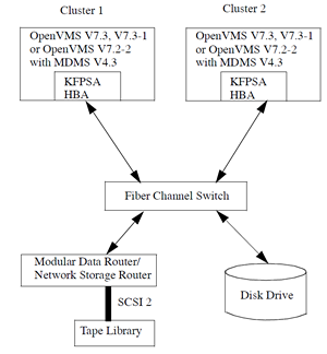
MDMS:
OpenVMS: 7.2-2, 7.3, 7.3-1
MDMS Version: V3.2, V4.0, V4.1
Tape devices and libraries connected on FC through MDR + FC SAN Switch + KGPSA Host Bus Adapter to an Alpha computer.
Clustered and Non-Clustered configuration.
ABS:
OpenVMS: 7.2-2, 7.3, 7.3-1
ABS Version: V3.2, V4.0, V4.1
MDMS Version: V3.2, V4.0, V4.1
Tape devices and libraries connected on FC through MDR + FC SAN Switch + KGPSA Host Bus Adapter to an Alpha computer. Clustered and Non-Clustered configuration.
SMS Products support only the FC connected devices and configuration that are supported by Open VMS V7.2-2 and above. Please refer Open VMS documentation for details on the supported HBAs, firmware version, devices, systems, and software version.