VSI ACMS for OpenVMS Getting Started
- Software Version:
- ACMS for OpenVMS Version 5.3-3
- Operating System and Version:
- VSI OpenVMS Alpha Version 8.4-2L1 or higher
VSI OpenVMS IA-64 Version 8.4-1H1 or higher
Preface
1. About VSI
VMS Software, Inc. (VSI) is an independent software company licensed by Hewlett Packard Enterprise to develop and support the OpenVMS operating system.
2. About this manual
This manual provides introductory information to help you get started with VSI ACMS for OpenVMS (ACMS). The manual includes a step-by-step tutorial for developing a simple ACMS application. It also provides an overview of the AVERTZ car rental sample application that ships with the ACMS software kit.
3. Document Structure
This document contains the following chapters and appendixes:
| Contains an overview of ACMS software and documentation. It contains the following chapters: | |
|
Describes the TP style of computing, its differences from traditional timesharing computing, and the key features of an ACMS TP system. | |
|
Provides an overview of the steps required to build an ACMS application. | |
|
Describes what happens as ACMS executes the series of steps that make up a task. | |
|
Provides an overview of managing the ACMS system and applications, and describes the tools ACMS provides for this work. | |
|
Outlines the ACMS product packages. | |
|
Contains a step-by-step tutorial for developing a simple ACMS application. It contains the following chapters: | |
|
Contains a list of prerequisites for performing the tutorial and an overview of ACMS application development concepts. | |
|
Describes in step-by-step detail how to write the data entry task using ACMS, DECforms, and CDD definitions. | |
| Describes in step-by-step detail how to write the inquiry/update task using ACMS, DECforms, and CDD definitions. | |
| Describes how to combine the data entry task and the inquiry/update task into a task group. It also describes how to write startup and cleanup procedures, how to link the object modules into a server image, and how to test the tasks using the ACMS Task Debugger. | |
| Describes how to write the application definition and then build this definition into an application database that ACMS uses at run time. | |
| Describes how to write the menu definition and then build this definition into a menu database that ACMS uses at run time. | |
|
Chapter 12, "System Management Requirements for Installing the Tutorial Application" | Describes procedures that the system manager follows to prepare for the installation of the tutorial application. |
| Describes how to install and run the tutorial application. | |
| Contains an overview of the AVERTZ car rental sample application that ships with the ACMS software kit. It contains the following chapters: | |
| Describes three perspectives of an ACMS system, the system manager's view, the user's view, and the developer's view. | |
| Helps you build, install, and set up the AVERTZ sample application. | |
| Presents a fictional conversation and transaction between a reservation clerk working for AVERTZ operations in New England and a customer who needs a rental car. | |
| Takes a brief look at some of the work involved in designing and developing an ACMS application. | |
|
Appendixes | |
|
Appendix A, "Utilities for Solving Problems in an ACMS Application" | Describes how ACMS runs a task, and introduces some utilities that are available to help you solve problems in running a new ACMS application. |
| Lists the source files created by the tutorial in Part II,''Tutorial'' and describes how to access the online versions of these files. | |
4. ACMS Help
ACMS and its components provide extensive online help.
DCL level help
Enter
HELP ACMSat the DCL prompt for complete help about theACMScommand and qualifiers, and for other elements of ACMS for which independent help systems do not exist. DCL level help also provides brief help messages for elements of ACMS that contain independent help systems (such as the ACMS utilities) and for related products used by ACMS (such as DECforms or Oracle CDD/Repository).ACMS utilities help
Each of the following ACMS utilities has an online help system:
ACMS Debugger ACMSGEN Utility
ACMS Queue Manager (ACMSQUEMGR)
Application Definition Utility (ADU)
Application Authorization Utility (AAU)
Device Definition Utility (DDU)
User Definition Utility (UDU)
Audit Trail Report Utility (ATR)
Software Event Log Utility Program (SWLUP)
The two ways to get utility-specific help are:
Run the utility and type
HELPat the utility prompt.Use the DCL
HELPcommand. At the "Topic?" prompt, type@followed by the name of the utility. Use the ACMS prefix, even if the utility does not have an ACMS prefix (except for SWLUP). For example:Topic? @ACMSQUEMGR Topic? @ACMSADU
However, do not use the ACMS prefix with SWLUP:
Topic? @SWLUP
Note
Note that if you run the ACMS Debugger Utility and then type
HELP, you must specify a file. If you ask for help from the DCL level with@, you do not need to specify a file.ACMSPARAM.COM and ACMEXCPAR.COM help
Help for the command procedures that set parameters and quotas is a subset of the DCL level help. You have access to this help from the DCL prompt, or from within the command procedures.
LSE help
ACMS provides ACMS-specific help within the LSE templates that assist in the creation of applications, tasks, task groups, and menus. The ACMS- specific LSE help is a subset of the ADU help system. Within the LSE templates, this help is context-sensitive. Type
HELP/IND
                            (PF1-PF2)
at any placeholder for which you want help.Error help
ACMS and each of its utilities provide error message help. Use
HELP ACMS ERRORSfrom the DCL prompt for ACMS error message help. UseHELP ERRORSfrom the individual utility prompts for error message help for that utility.Terminal user help
At each menu within an ACMS application, ACMS provides help about terminal user commands, special key mappings, and general information about menus and how to select tasks from menus.
Forms help
For complete help for DECforms or TDMS, use the help systems for these products.
5. Related Documents
| ACMS Information | Description |
|---|---|
| VSI ACMS Version 5.0 for OpenVMS Installation Guide | Description of installation requirements, the installation procedure, and postinstallation tasks. |
| VSI ACMS for OpenVMS Getting Started | Overview of ACMS software and documentation. Tutorial for developing a simple ACMS application. Description of the AVERTZ sample application. |
| VSI ACMS for OpenVMS Concepts and Design Guidelines | Description of how to design an ACMS application. |
| VSI ACMS for OpenVMS Writing Applications | Description of how to write task, task group, application, and menu definitions using the Application Definition Utility. Description of how to write and migrate ACMS applications on an OpenVMS system. |
| VSI ACMS for OpenVMS Writing Server Procedures | Description of how to write programs to use with tasks and how to debug tasks and programs. |
| VSI ACMS for OpenVMS Systems Interface Programming | Description of using Systems Interface (SI) Services to submit tasks to an ACMS system. |
| VSI ACMS for OpenVMS ADU Reference Manual | Reference information about the ADU commands, phrases, and clauses. |
| VSI ACMS for OpenVMS Quick Reference | List of ACMS syntax with brief descriptions. |
| VSI ACMS for OpenVMS Managing Applications | Description of authorizing, running, and managing ACMS applications, and controlling the ACMS system. |
| VSI ACMS for OpenVMS Remote Systems Management Guide | Description of the features of the Remote Manager for managing ACMS systems, how to use the features, and how to manage the Remote Manager. |
| Online help | Online help about ACMS and its utilities. |
6. OpenVMS Documentation
The full VSI OpenVMS documentation set can be found on the VMS Software Documentation webpage at https://docs.vmssoftware.com.
7. VSI Encourages Your Comments
You may send comments or suggestions regarding this manual or any VSI document by sending electronic mail to the following Internet address: <docinfo@vmssoftware.com>. Users who have VSI OpenVMS support contracts through VSI can contact <support@vmssoftware.com> for help with this product.
8. Conventions
The following conventions are used in this manual:
| Ctrl/x | A sequence such as Ctrl/x indicates that you must press and hold the key labeled Ctrl while you press another key or a pointing device button. |
| PF1 x | A sequence such as PF1 x indicates that you must first press and release the key labeled PF1 and then press and release another key or a pointing device button. |
| Return | In the HTML version of this document, this convention appears as brackets rather than a box. |
| . . . |
A horizontal ellipsis in examples indicates one of the
following possibilities:
|
| ⋮ | A vertical ellipsis indicates the omission of items from a code example or command format; the items are omitted because they are not important to the topic being discussed. |
Monospace text | Monospace type indicates code examples and interactive screen displays. In the C programming language, monospace type in text identifies the following elements: keywords, the names of independently compiled external functions and files, syntax summaries, and references to variables or identifiers introduced in an example. In the HMTL version of this document, this text style may appear as italics. |
| - | A hyphen at the end of a command format description, command line, or code line indicates that the command or statement continues on the following line. |
| numbers | All numbers in text are assumed to be decimal unless otherwise noted. Nondecimal radixes—binary, octal, or hexadecimal—are explicitly indicated. |
| bold text | Bold text represents the introduction of a new term or the name of an argument, an attribute, or a reason. In the HMTL version of this document, this text style may appear as italics. |
| italic text | Italic text indicates important information, complete titles of
manuals, or variables. Variables include information that aries in
system output (Internal error number), in
command lines
(/PRODUCER=name), and in
command parameters in text (where dd represents
the predefined code for the device type). |
| UPPERCASE | Uppercase text indicates the name of a routine, the name of a file, the name of a file protection code, or the abbreviation for a system privilege. In command format descriptions, uppercase text is an optional keyword. |
| UPPERCASE | In command format descriptions, uppercase text that is underlined is required. You must include it in the statement if the clause is used. |
| lowercase | In command format descriptions, a lowercase word indicates a required element. |
| <lowercase> | In command format descriptions, lowercase text in angle brackets indicates a required clause or phrase. |
| ( ) | In command format descriptions, parentheses indicate that you must enclose the options in parentheses if you choose more than one. |
| [ | | ] | In command format descriptions, vertical bars within square brackets indicate that you can choose any combination of the enclosed options, but you can choose each option only once. |
| { | | } | In command format descriptions, vertical bars within braces indicate that you must choose one of the options listed, but you can use each option only once. |
9. References to Oracle Products
VSI ACMS documentation set, to which this document belongs, refers to the following Oracle products by their full and abbreviated names:
| Full product name | Shortened product name |
|---|---|
| Oracle Common Data Dictionary | CDD |
| Oracle Rdb | Rdb |
| Oracle Database/DBMS | DBMS |
| Oracle Trace | Trace |
Part I. Introduction
This part provides an overview of ACMS software and documentation.
Chapter 1. Product Overview
The ACMS transaction processing system is a TP monitor that runs on the OpenVMS operating system. It is intended for businesses that require high performance, security, data integrity, and both centralized and distributed processing. Retail, banking, financial services, telecommunications, health, customer service, manufacturing, and insurance are some of the industries that can make use of the ACMS system.
With ACMS, businesses can shrink development time for their applications, streamline application maintenance, and lower the cost per transaction. Applications can be configured for distribution over many systems, providing a flexible response to changes in business conditions. The open-ended OpenVMS architecture and networking allow for growth without disruption of services.
This chapter describes the TP style of computing, its differences from traditional timesharing computing, and the key features of an ACMS TP system.
1.1. Transaction Processing
Transaction processing allows businesses to maintain timely and accurate data about their operations. Many users access the same database or databases to perform a series of steps related to a business function. Each activity represents a transaction. Transactions can occur between a user and a computer, or just among computers.
The applications written for transaction processing usually involve updating a database and notifying the user that the change has taken place as intended. Maintaining up-to-date, accurate databases is an essential function of transaction processing applications.
Examples of typical TP applications include processing a customer's request for withdrawal or deposit of funds, maintaining a retail store's online inventory, and cross-referencing and updating of patients' medical records.
In these cases, many users from different locations want access to the same database, at the same time, for a specific business activity. As a result, high availability, rapid response time, and data integrity are important criteria for a TP system.
Systems must be capable of growing.
Databases must be available and stay reliable throughout transaction processing.
The TP system must allow for different levels of technical sophistication for its users.
1.2. TP and Timesharing
Before transaction processing systems became a reality, first batch processing and then timesharing were the computing styles that handled the large volume of data transactions necessary for business.
In a timesharing system, each user has a separate process, and computer resources are parceled out according to a schedule that makes it appear that each process has the full attention of the central processing unit (CPU). Some processes can interact with a database; others can run word processing, a spreadsheet, or other interactive software. Figure 1.1, ''Traditional Timesharing Environment'' shows a typical timesharing system, which has many users using display terminal s and interacting with a CPU.
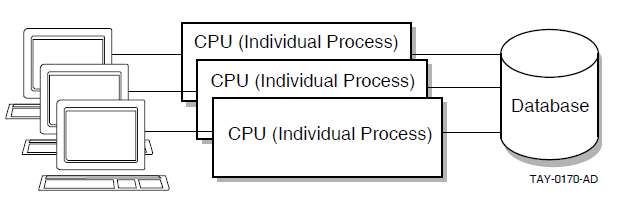
TP applications are typically high-volume, online applications with repetitive operations on data critical to the mission of a business. In a traditional timesharing system, these applications can tax system resources because each user requires a separate process.
Specialized transaction processing systems were developed to make more efficient use of system resources and to provide utilities for managing and controlling these complex applications. Figure 1.2, ''Transaction Processing System Environment'' illustrates a transaction processing system environment.
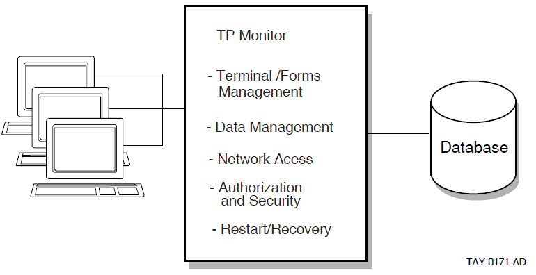
A TP system, like a typical timesharing system, has many users, but they do not each require a separate process. Instead, a TP monitor manages access to the CPU, functioning like a specialized operating system within your operating system.
The TP monitor can include facilities for terminal and forms management, data management, network access, authorization and security, and restart/recovery. These facilities allow you to control what users do, how often they do it, and when they do it.
1.3. ACMS TP Monitor Features
ACMS is a TP monitor that provides a development, run-time, and application management system for TP applications. It is designed for a modular, flexible development style and efficient use of system resources in large on-line applications.
ACMS combines a structured, high-level application definition language and utilities to build, manage, and control complex applications. The modular nature of ACMS applications makes them more efficient to develop and run, and easier to maintain than traditional applications programs. ACMS applications can be modified by changing individual components, rather than rewriting the entire application.
ACMS is also part of an integrated application development environment which includes presentation services, transaction and database management, programming languages, and tools.
1.3.1. Configuration Options
Terminal, menu, and other input/output (I/O) functions are separated in ACMS from database or file processing and computational functions. The terminal and menu functions are handled on the front end of the transaction processing system, while the data processing and computation are performed on the back end of the system.
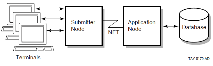
The separation of functions in ACMS makes it possible for you to distribute ACMS applications across a network of computers, installing front-end functions on one or more nodes and back-end functions on another set of nodes in the network. In a distributed transaction processing environment, the front end is also called the submitter node, because it is the node from which tasks are selected and sent to the back-end node. The back end is also called the application node, because it is the node on which the application execution and data processing are performed.
Figure 1.3, ''Distributed ACMS System'' illustrates an ACMS system environment distributed across a network.
1.3.2. Efficient Use of System Resources
Most TP applications put heavy demands on computer processing power and memory resources. An important requirement for TP applications is that they make efficient use of the resources available. With a traditional TP system, structuring applications to minimize the strain on a system can demand additional design and programming time. ACMS is designed to use computer resources, such as memory and CPU, efficiently to help maximize run-time performance.
ACMS uses dedicated OpenVMS processes to manage terminal I/O, execute processing and data manipulation subroutines, and control the application run-time system.
ACMS has a multithreaded internal design. In a system that uses multithreaded processes, a single process can manage more than one user or process at the same time. On the front end of an ACMS system, a single process can display forms and menus for many users rather than have each user need a separate process to do this work. On the back end, a single process can handle the flow control, or the complex coordination of data processing and computations, of each user's work rather than have OpenVMS manage each user's process separately. Also on the back end, rather than each user using a separate process to access the database, a single process can manage paths into the database for many users at one time. To help you manage heavy system use, ACMS allows you to create additional processes on the back end as the need arises.
The separation of functions in ACMS makes it possible to increase the speed and reliability of ACMS transactions by distributing the front-end and back-end functions across a network. You can offload forms processing to a smaller front-end computer and use more powerful computers for back-end data processing. You can configure each node in the distributed system for the processing of specific tasks.
1.3.3. Easy System Expansion
It is easy to expand an ACMS system to meet your growing business needs. Without rewriting your application code, you can distribute existing ACMS applications or add nodes to an existing network of distributed ACMS applications.
To accommodate more users, you can add small clusters of computers as front-end nodes to handle additional terminal and forms processing. To increase application processing capabilities, you can add high-performance computers as back-end nodes.
1.3.4. Availability
By distributing the forms processing functions of an ACMS application, you can make the system more available in the event of system failures. Using the features of DECnet network software, OpenVMS Cluster networks, and volume shadowing, ACMS eliminates single points of system failure and significantly increases the amount of time your applications are available to you.
For more information on configuring your ACMS system for high availability, see VSI ACMS for OpenVMS Managing Applications.
1.3.5. Queued Tasks
Some ACMS applications use data that is collected and processed interactively. The application displays a menu or a form on a video terminal through which users enter data. Then the application processes the data and either displays the results of the processing or requests more data.
Other ACMS applications require that data be collected once and then stored in a temporary storage area, or queue, for the application to process at another time. For these types of applications, data can be collected using a device other than a terminal, such as a card-punch time clock, and sent to a special ACMS queuing facility. The ACMS queuing facility lets you place tasks in a queue and then submit the tasks for processing at another time. Using the queuing facilities provided by ACMS, you can design applications to immediately process in real-time (such as capturing data), and alternatively defer processing of work that does not require real-time processing until later.
Data capture and deferred processing of data
An example of this type of application is one that processes hundreds of time cards in a very short time during a shift change. In this type of application, processing each data item immediately can affect system performance and be costly in the use of system resources. Employees would have to wait in line while each time card was read into the system and then processed. The ACMS queuing facility lets you capture the data quickly and store it for future processing.
High application availability
In a distributed environment, if the back-end node becomes unavailable, the front-end node can continue to submit tasks to queues. When the back-end node becomes available, the ACMS queuing facility automatically submits the tasks for processing.
Data and transaction integrity
If the system becomes unavailable while processing a queued task, the ACMS Queued Task Initiator (QTI) continues trying to submit that task. As with all ACMS queued tasks, the dequeue (removal from the queue) and database updates are all tied together as a single transaction, ensuring that database updates will take place once and only once. The changes that the task was making to the database at the time of failure are not made permanent until the task succeeds. This is one way that ACMS can ensure the integrity of your database.
For more information on ACMS queues, see VSI ACMS for OpenVMS Writing Applications.
1.3.6. Modular Applications
ACMS applications are made up of a set of component definitions that describe and control the work of an application, and a set of subroutines that access databases and files. You use the ACMS Application Definition Utility(ADU) for creating and processing the component definitions of an ACMS application. To write application subroutines, called server procedures, you can use any third-generation language that conforms to the OpenVMS Calling Standard, such as C or COBOL.
ADU includes a high-level, English-like definitional language. You use the statements and clauses of the language to create definitions for each application component of an ACMS application. In addition, you use ADU commands to process the definitions. When you process a definition, you build a binary file from the definition that is interpreted at run time.
ACMS applications are easier to develop and maintain than traditional applications because modular definitions replace system programming calls. Developing sets of component definitions and application subroutines emphasizes the principles of structured programming. As a result, you can divide responsibilities for developing parts of an application among many programmers.
The modularity of ACMS applications also makes maintenance easier. Terminal I/O is separate from data processing, and application logic is separate from system and application management. To change an application, you make changes to a component's definition, rather than rewrite the entire application.
Chapter 2, "Developing ACMS Applications" provides an introduction to developing ACMS applications. For detailed information on developing applications using ADU, see VSI ACMS for OpenVMS ADU Reference Manual and VSI ACMS for OpenVMS Writing Applications.
1.3.7. Data and Transaction Integrity
TP systems must ensure that data remains consistent and work remains intact if the system or database becomes unavailable. Using data management products and the DECdtm Services for OpenVMS (a collection of OpenVMS services that provide for the management of distributed transactions), ACMS provides full data and transaction integrity and consistency.
A resource manager controls shared access to a set of recoverable resources, such as a database. In an application that accesses a single database or set of files, resource managers ensure integrity by providing rollback recovery. Resource managers available to ACMS include RMS, Rdb, and DBMS. When a database transaction updates a database, the resource manager commits the change when the transaction ends. Committing the change makes it permanent. If the system or database becomes unavailable before the database transaction ends, the resource manager rolls back the database, returning it to the state it was in before the transaction started.
For applications that use distributed transactions, that is, a single grouping of operations on more than one recoverable resource or resource manager, the DECdtm services provide rollback recovery following a two-phase commit protocol. Two-phase commit protocol ensures that, when changes are made to data during a distributed transaction, either all resource managers commit the distributed transaction or all work will be rolled back.
Prepare phase, in which each resource manager indicates a willingness to commit
Commit phase, in which each resource manager is instructed by the controlling transaction manager to either commit and roll forward, or abort and roll back
Processes data in more than one database or file on a single node or across a network
If a transaction is prevented from completing anywhere on a network, the entire transaction is rolled back to its starting point, and your work can be recovered.
Queues tasks and their data
DECdtm services guarantee that a queued task is entered on the queue and that the task is not removed from the queue until the data is processed successfully exactly once.
DECdtm components include a transaction manager and resource managers. The transaction manager oversees the phases of a two-phase commit for either a database transaction or an ACMS queuing facility operation. Resource managers (such as Rdb, DBMS, and RMS) manage the access to their recovery data and databases.
Each node in the network has its own DECdtm transaction manager and one or more of the supported resource managers. For each transaction, a DECdtm transaction manager tracks which resource managers are being used to process data. If an event on the system keeps the transaction from completing anywhere on a network, all databases affected by that transaction are rolled back to their original state.
You can also design applications that use the ACMS queuing facility to place tasks in a queue file. The ACMS queuing facility uses DECdtm services to ensure that every task on the queue is processed exactly once. In a distributed system, tasks and their data can be entered on the front-end queue. If the back-end node becomes unavailable, the tasks and their data are held in the queue. When the back-end node becomes available again, the tasks are submitted for processing.
1.3.8. Security
Authorize users to use ACMS
Control terminals connecting to ACMS
Limit the applications a user can run
For example, you can give a personnel employee access to a task that updates a confidential file, but ensure that the employee cannot view sensitive information in the file, make unauthorized changes to the file, or gain access to the file outside the context of the task.
For a more detailed introduction to defining access to ACMS and applications, see Chapter 4, "Managing ACMS Systems and Applications". For details on managing an ACMS system, see VSI ACMS for OpenVMS Managing Applications.
1.3.9. Presentation Services
Users select and run ACMS tasks from menus. Figure 1.5, ''Sample ACMS Menu'' shows a sample ACMS menu.
To create menus, ACMS supports DECforms, a forms product running on the OpenVMS operating system, as its primary presentation service. In addition, ACMS provides support for VSI Terminal Data Management System (TDMS). DECforms is the first commercial implementation of the proposed ANSI/ISO standard Form Interface Management System (FIMS), a system for interaction between applications and display devices. Using DECforms, you can write a forms application program (which describes the function of a display) separately from the user interface of the display (such as a menu or form).
ACMS uses standard menus in both DECforms format and TDMS format. You can easily customize these standard menus. For more information on using DECforms or TDMS, see the appropriate product documentation. For an example of using DECforms to create standard ACMS menus, see Chapter 11, "Defining and Building the Menu".
ACMS provides support for other presentation service products. Using the ACMS Request Interface and the ACMS Systems Interface, you can create applications that use forms management products, such as FMS, or special devices, such as electronic badge readers.
The Request Interface allows you to use presentation services other than DECforms or TDMS for I/O functions limited to one user per process. ACMS provides an easy-to-use programming interface with the Request Interface to forms products such as FMS (Forms Management System), SMG (Screen Management Facility), terminal interface products from other vendors, and menus in an ALL-IN-1 office integration system.
The Systems Interface allows you to use presentation services for single-user or multiple-user I/O functions. The Systems Interface provides a set of software system services that give systems programmers the flexibility to design customized interfaces for complex systems or devices, such as badge or bar code readers.
For more information on using the Request Interface, see VSI ACMS for OpenVMS Writing Applications. For more information on using the Systems Interface, see VSI ACMS for OpenVMS Systems Interface Programming.
1.4. OpenVMS Support
ACMS is part of a family of software products designed to help you manage data in all areas of your organization. Layered on the OpenVMS operating1 system, these products work together with high-level programming languages to provide a total information management system you can tailor to your needs. Depending on your needs, you can choose from a variety of products for front-end I/O functions as well as back-end data management functions.
The following sections introduce some of the products you can use with ACMS to build a transaction processing system.
1.4.1. Data Management Products
Rdb, a relational database management system
Rdb is a full-function relational database management system for general purpose, multiuser, centralized or distributed TP applications. It is relatively easy to use, yet provides high performance and the ability to restructure data relationships.
Use Rdb if the structure of your database is expected to change significantly over time. You can use the SQL data definition and manipulation language with Rdb databases.
DBMS, a CODASYL-compliant network database management system
DBMS is a high-performance database management system for general purpose, multiuser TP applications in which the relationships between different parts of the database are very complex.
Use DBMS for applications that involve complex but relatively stable data relationships and predictable information requests.
RMS, a record management system
RMS is the OpenVMS operating system's default file management system with optional journaling. Journaling is the process of recording information about operations on a file into a recoverable resource. Access to data stored in RMS files can be either sequential or random, with the random access being either by key (for indexed files) or by record number (for relative files).
Other database products or file management systems that support the OpenVMS Calling Standard
1.4.2. CDD Data Dictionary
The CDD data dictionary system provides a central storage location for data descriptions and definitions shared by ACMS, other related products, and programming languages.
Ensures the integrity of shared metadata and the procedures used to analyze, maintain, manage, and design business metadata
Provides a centralized repository for information management shops
Offers a dynamic aid to software application development
1.4.3. Programming Languages and Tools
As a member of a family of layered software products, ACMS makes use of high-level programming languages and tools.
You can write and debug application programs using a variety of high-level programming languages, including COBOL, FORTRAN, and C, and the OpenVMS Debugger. You can use any high-level language that adheres to the OpenVMS Calling Standard.
DEC/Code Management System (CMS)
CMS is a program source file library for software management and version tracking.
DEC/Module Management System (MMS)
MMS is a tool that automates and simplifies the building of software systems.
Language-Sensitive Editor (LSE)
The Language-Sensitive Editor (LSE) is a multilanguage editor that helps you quickly and accurately write application programs. Templates for commands and statements in a variety of languages and layered products, including ACMS, SQL, and DECforms, are provided with LSE.
Source Code Analyzer (SCA)
SCA is a multilanguage, interactive cross-reference and static analysis tool that can help you understand the complexities of a large software project.
Performance and Coverage Analyzer (PCA)
PCA is a tool that analyzes program test coverage and the run-time behavior of your application.
DEC/Test Manager (DTM)
DEC/Test Manager is a tool that organizes and automates the performance and evaluation of software tests.
For more information about programming productivity tools, see A Methodology for Software Development Using OpenVMS Tools, or the documentation for each individual product.
Oracle Trace is a tool that collects data and creates detailed reports on events that occur when an ACMS application runs. The information you collect with Oracle Trace can help you tune your ACMS system and improve performance.
For information on using Trace with ACMS applications, see VSI ACMS for OpenVMS Managing Applications.
1.5. Professional Services and Support
Training for application designers, developers, and system mangers
Training on related OpenVMS layered products
Design and development consulting services
Software support and problem-solving
Software tool kits designed to help in the building of a TP system
For information on available TP system support services, see your VSI representative.
1.6. Overview of the ACMS Application Development Life Cycle
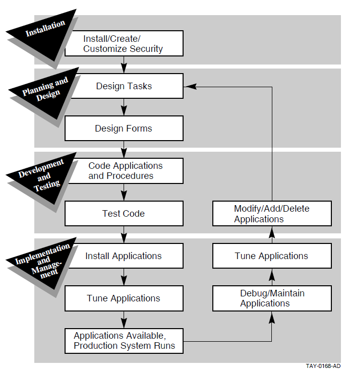
The application development life cycle is an approach and process for developing complex software applications in discrete segments, called phases.
The first phase in the life cycle for ACMS applications is the preparation of the design and development environment. This phase involves the installation of ACMS and other related software tools.
The second phase in the life cycle is the planning and design of the forms, databases, and applications. In building the TP system, system designers determine what business functions the application must address, and map those business functions to software and hardware capabilities.
The third phase in the life cycle is the development and testing of the forms, databases, and applications that were designed during the planning and design phase. In addition to developing forms and databases, application developers also define ACMS application components, generally for several different applications.
The fourth phase in the life cycle is the implementation and management of the TP system. System managers set up hardware for users, and move the TP applications into the user environment. Once the applications are in the users environment, the system manager maintains that environment.
Figure 1.6, ''Interaction of the Phases of the ACMS Application Development Life Cycle'' shows how the phases fit together for a complete transaction processing development system.
The next three chapters describe the development, implementation, and management of ACMS applications.
Chapter 2. Developing ACMS Applications
With the ACMS software you can develop applications to automate business functions. An ACMS application is made up of a set of components and third-generation programming language code.
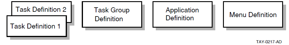
Task definitions to describe units of work
Task group definitions to describe the resources required by a group of tasks
Application definition to describe the environment and control characteristics of tasks and task groups
Menu to display a list from which terminal users can choose an available task
You use the ACMS Application Development Utility (ADU) to develop these components. ADU provides a high-level English-like definitional language that you use to write definitions for each component. After you write the component definitions, you use ADU to create binary versions of the files. These binary files are called database files. Although these binary files are known as database files or databases, they differ from traditional databases in which you can store and access data. For example, after you write a menu definition, you use ADU to build the menu database. At run time, ACMS uses the database files to run and control the application.
Figure 2.1, ''ACMS Application Components'' shows the relationships of the component definitions. One or more tasks make up a task group, and one or more task groups make up an application.
Because ACMS applications are made up of sets of components, they are more efficient to run and easier to maintain than traditional application programs. ACMS task definitions separate forms processing from data processing. At run time, this separation helps ensure an efficient use of system resources. Maintaining the application is also simplified. Because each application component is a separate definition, you can modify applications by changing individual components, rather than rewriting the entire application.
Map business functions to tasks.
Define the tasks.
Define the resources for groups of tasks.
Define the run-time characteristics for an application.
Define the forms and menus.
Debug and test the application.
2.1. Mapping Business Functions to Tasks
Each application is designed to meet a business need and automate a business function. In ACMS, the functions of a business relate to the tasks in an application. By analyzing the business needs, an application designer can make decisions about how best to map the business functions to ACMS tasks. The application design takes into consideration how users will work with the application as well as how the application will use system resources. When the design is complete, the job of defining ACMS application components and writing programming language code begins.
For more information on ACMS application design decisions, see VSI ACMS for OpenVMS Concepts and Design Guidelines.
2.2. Defining Tasks
In ACMS, a set of tasks in an application relates to a set of business functions. Tasks in a retail sales application might be recording a new sale and updating the inventory database. Each task, in turn, is made up of a series of steps that perform the actual work. The user can select one of these tasks from a menu. Figure 2.2, ''Structure of an ACMS Application'' shows the basic structure of an ACMS transaction processing application.
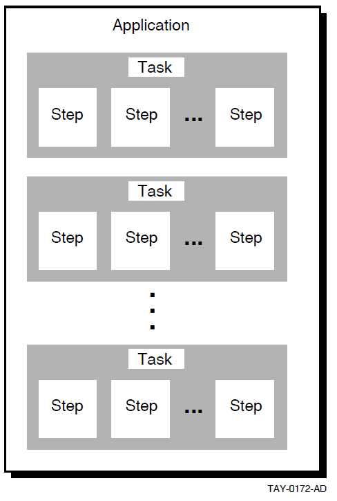
Tasks are the building blocks of an ACMS application. They are the units of work a user selects from an ACMS menu.
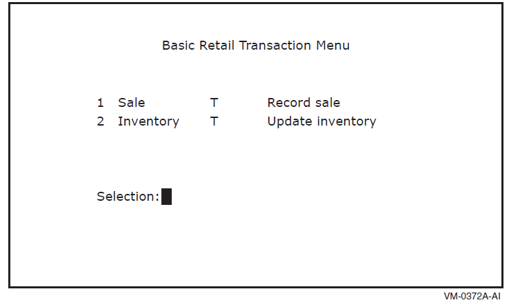
From a user's point of view, a task is a single business transaction performed repeatedly during the course of a day, such as recording a sale or updating an inventory database or file. Figure 2.3, ''Simple ACMS Menu'' shows a simple menu that a sales or inventory clerk using a retail sales application might see. The clerk can choose between tasks for recording a sale or updating inventory records.
Although tasks appear as individual items on the menu, they are typically made up of a series of steps that result in a change to a database or file. To share data among the parts of an application, ACMS provides special buffers called workspaces. Workspaces, for example, pass data between steps in the task and between tasks that work together in an application. The steps involved in updating an inventory database or file, for example, might retrieve the current record of an item, enter the updated information, and receive notification that the change was made correctly. ACMS uses workspaces to pass the updated information and notification.
The following sections provide an introduction to task steps and workspaces.
2.2.1. Defining Task Steps
Exchange steps handle data input/output, interacting with DECforms or TDMS forms, or with other presentation services and devices using the ACMS Request Interface.
Processing steps handle computation or interaction with databases or files. Processing steps can use either a procedure written in a high-level programming language (such as COBOL, FORTRAN, or BASIC), DCL commands, or OpenVMS images.
Block steps collect the task steps (exchange and processing) into functional groups. Grouping task steps makes the structure of the task definition more modular and, therefore, easier to develop and maintain.
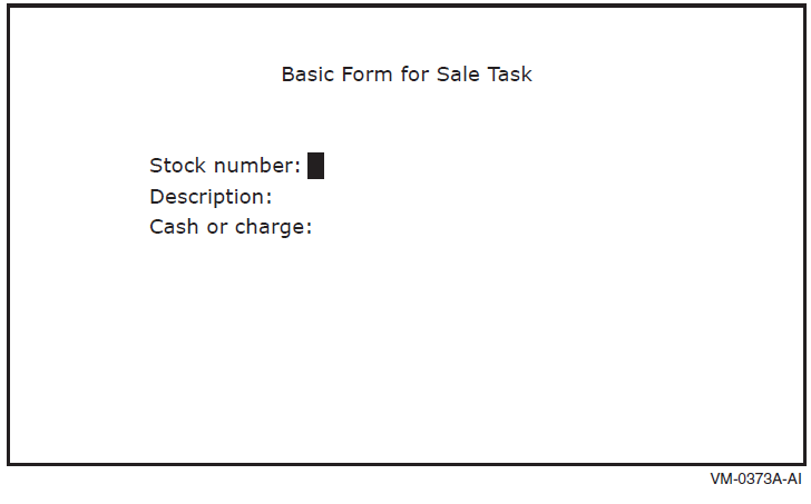
An exchange step to display a form that prompts the user to supply information such as a stock number and a description of an inventory item
A processing step to write the information the user supplies to a database or file
Figure 2.4, ''Simple Form for a Sales Task'' shows a form you might see after selecting the Sale task from the menu in Figure 2.3, ''Simple ACMS Menu''. An exchange step displays the form and prompts the sales clerk to enter a stock number, a description of the item, and whether the sale is cash or charge. A processing step records the sale, subtracts the item from the store's inventory, and prints an invoice for the customer.
An exchange step in which the user supplies information to a form on a terminal, in this case the item whose inventory record is to be updated
A processing step in which a procedure reads the item's inventory record from the database or file
An exchange step in which the inventory record is displayed in a second form on the terminal and the user updates the record
A processing step in which the updated record is written to the database or file
Figure 2.5, ''Task Steps for an Inventory Update Task'' shows the sequence of exchange and processing steps for a simple inventory update task a warehouse clerk might select from the menu in Figure 2.3, ''Simple ACMS Menu''.
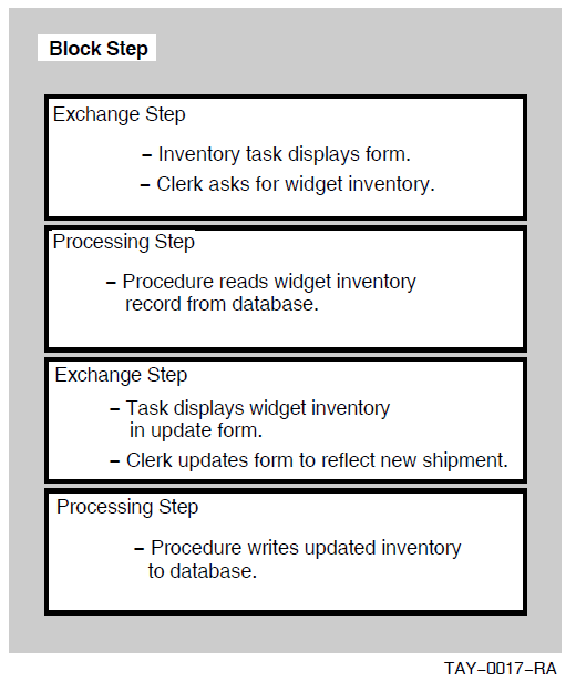
After the warehouse clerk selects the inventory update task, an exchange step displays a query form and prompts the clerk to supply the inventory item to be updated, in this case widgets. A processing step calls a procedure that reads the widget inventory record. A second exchange step displays the inventory, in this case 0 widgets, in an update form, and allows the warehouse clerk to update the record to reflect the arrival of 100 widgets. The final processing step calls a procedure that stores the updated record in the inventory database or file.
2.2.1.1. Writing Server Procedures
Processing steps can run server procedures written in a high-level programming language. ACMS supports all programming languages that conform to the OpenVMS Calling Standard, such as COBOL, FORTRAN, or C. You use OpenVMS utilities to write, debug, and compile server procedures.
When all the procedures you need for a task or group of tasks are ready, you link the procedures to create a single procedure server image. At run time, ACMS creates at least one special process called a procedure server process, and activates and loads the procedure server image. When a user selects a task that uses the procedures, ACMS runs the programs. Figure 2.6, ''Parts of a Procedure Server'' shows the parts of a procedure server.
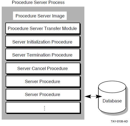
Initialization procedures to open all the files and to ready any databases needed by a group of tasks
Termination procedures to close at one time all the files and any databases used by a group of tasks
Cancel procedures to clean up context held by a task in a server when the task cancels before completing successfully
When you create a procedure server, you include any initialization, termination, and cancel procedures as part of the procedure server image. These special procedures can help conserve system resources because the work they do is done once for the group of tasks that use the procedure server.
For more information on creating procedure servers, see VSI ACMS for OpenVMS Writing Server Procedures.
2.2.1.2. Using DCL Servers
Processing steps can run OpenVMS images, DIGITAL Command Language (DCL) commands, and DCL command procedures. Tasks with these types of processing steps require a DCL server. You define a DCL server in a task group definition.
OpenVMS utilities, such as MAIL
Existing programs you want to run under ACMS without converting immediately into ACMS multiple-step tasks
Third-party software required by some ACMS application users, such as spreadsheets
For more information on defining servers in task groups, see VSI ACMS for OpenVMS Writing Applications.
2.2.2. Defining Workspaces
Steps in tasks
Tasks in a task group
Forms and tasks
Processing steps and databases or files
For example, you use workspaces when you pass data from a form on a terminal to and from a database or file. A workspace can contain data provided by a user at a terminal through an exchange step or a processing step in the same task group. Tasks read information from workspaces and write information to them.
When a user selects a task, ACMS stores any text the user supplied in the ACMS$SELECTION_STRING system workspace.
For example, when a user selects a task from a menu by entering a number and then text, the text is stored in the ACMS$SELECTION_STRING system workspace. The task the user selected can access the string stored in the workspace.
When a task runs, ACMS stores the status of task steps in the ACMS$PROCESSING_STATUS system workspace.
You can use the workspace to check for the status of a task step and take appropriate action.
ACMS stores information about a user and the user's device in the ACMS$TASK_INFORMATION system workspace.
For example, you can define a task that uses information about the user to determine what type of work to perform.
2.3. Defining Resources for Groups of Tasks
Procedures called by the tasks in the group.
DECforms forms used by the tasks in the group.
TDMS request libraries used by the tasks in the group.
Message files used by the tasks in the group.
Procedure servers available to the task group and any special server attributes, including server name and server image file specification, names of all step procedures handled by the server, and optional initialization, termination, or cancellation procedures.
Workspaces available to the task group.
See VSI ACMS for OpenVMS Writing Applications for information on defining task groups.
2.4. Defining Run-Time Characteristics for an Application
The application definition describes the run-time characteristics for an ACMS application, its servers, and its tasks. The run-time characteristics include information about which users can access tasks in the application and whether an audit of the application runs.
Defining the control characteristics of an application separately from its tasks and task groups allows you to use the tasks in different run-time environments.
You create an application definition using ADU. After you create the definition, you use ADU to build the definition into a binary application database file. ADU compiles information from the task group database file and the application definition to provide the ACMS run-time system with control information, pointers to task groups, and information required to run tasks.
You can change many of the characteristics of an application while the application is running. The changes remain in effect until the application is stopped. You make the changes permanent by modifying the application definition.
For more detailed information on defining ACMS applications using ADU, see VSI ACMS for OpenVMS Writing Applications and VSI ACMS for OpenVMS ADU Reference Manual. For information on changing the characteristics of a running application, see VSI ACMS for OpenVMS Managing Applications.
2.5. Defining Menus
Users select and run ACMS tasks from menus similar to those shown in Figure 2.3, ''Simple ACMS Menu''. Menus can include two types of entries: tasks and other menus. Tasks do the work of an application; menus display other tasks and other menus. Because a user can select one menu from another, application programmers can build menu hierarchies or trees. One menu tree can make tasks from many applications available, so users can access many applications from a single menu.
ACMS uses two presentation services, DECforms and TDMS, to display menus. The ACMS software kit includes a DECforms form and a TDMS form for displaying standard menus. You can easily revise the standard format to customize it to your application. You can also use the ACMS Request Interface to include other menu formats in your applications, such as menus in an ALL-IN-1 office integration system.
You create a menu definition for each menu you want to display. The definition describes the characteristics of the menu, including the list of items on the menu and a description of each item.
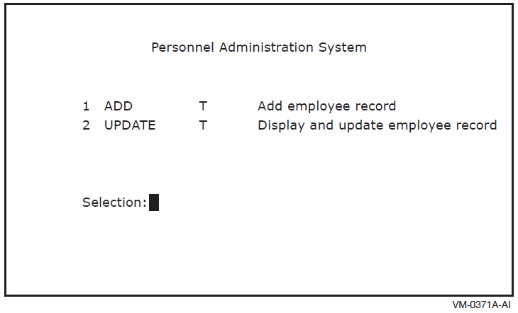
In the standard DECforms and TDMS formats, the only information required in a menu definition is the list of entries that appears on the menu. The menu definition includes an entry name for each entry as it appears on the menu, and an entry type, which tells ACMS whether the entry is a task or another menu. In Figure 2.7, ''Retail Transaction Menu with Task and Menu Entries'', the entry names are Sale, Inventory, Cancel, Return, and Complaint. The entry type is indicated by the letters T, for task, and M, for menu, following the entry name. You can include additional information in a menu, such as a menu title and text describing the entries.
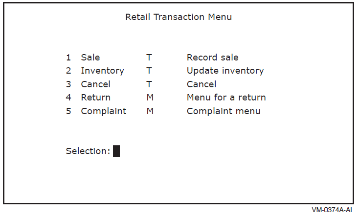
Entry number
Entry name
Depending on the design of your application, you can supply additional information to a selected task following the task name or number in a menu. In Figure 2.7, ''Retail Transaction Menu with Task and Menu Entries'', for example, you can specify the Inventory task followed by an inventory item number at the Selection: prompt.
For more information on ACMS menus, see VSI ACMS for OpenVMS Writing Applications.
2.6. Debugging and Testing
Before you include a task group in your application, use the ACMS and OpenVMS debugging tools to test and debug the task group, its member tasks, and procedures called by the tasks. The ACMS Task Debugger allows you to examine individual tasks and find out how ACMS manages the branching from one task to another. You use the OpenVMS Debugger to check whether or not procedures and forms are correct.
The ACMS Task Debugger is the primary tool for debugging tasks because it lets you control tasks while they are running. For example, you can pause at each step in a task. You can look at the values in the task workspaces, change these values if necessary, and resume task execution where you left off.
Workspace contents at the beginning and end of a step
Actions taken by task and server cancel procedures
Recovery operations performed by ACMS
The ACMS Task Debugger uses the OpenVMS Debugger to debug procedures in processing steps. You use the OpenVMS Debugger to check whether or not procedures execute and variables contain the values you expect. For example, you can pause after a procedure reads a record, check the values in a task workspace, and then resume task execution.
ACMS also provides a way to debug running applications. You can debug servers while they are running and obtain server process dumps for servers that stop unexpectedly.
For information on testing and debugging, see VSI ACMS for OpenVMS Writing Server Procedures. For a step-by-step introduction to developing an ACMS application, see Part II,''Tutorial''.
Chapter 3. ACMS Run-Time System
ACMS applications run under the control of the ACMS run-time system. The run-time system executes tasks according to the control characteristics in the application definition.
This chapter describes what happens as ACMS executes the series of steps that make up a task. Each part of the task is discussed in terms of the OpenVMS and ACMS run-time processes and their functions.
3.1. ACMS Processes
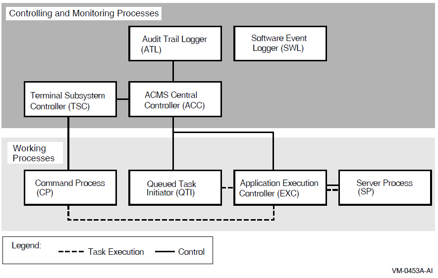
The ACMS run-time system is made up of eight specialized processes. Four processes manage the processing of a transaction; four monitor and control the run-time system. Figure 3.1, ''ACMS Run-Time Processes'' shows the processes that make up the ACMS run-time system. The following sections explain these specialized processes.
3.1.1. Transaction Processing Processes
Command Process (CP)
Queued Task Initiator (QTI)
Application Execution Controller (EXC)
Server process (SP)
A Command Process (CP) manages logins and interaction between terminals and ACMS. CPs display menus, accept and interpret terminal user commands, and communicate with the Application Execution Controller. An ACMS system can include more than one CP.
A CP separates an application's interactions with the terminal from its processing work. This separation makes it possible to distribute the application, off-loading forms and menus to a front-end, or submitter node, and concentrating computations and data processing on one or more back-end, or application nodes.
The ACMS Queued Task Initiator (QTI) dequeues task elements that were placed in a queue by an ACMS programming service, and initiates tasks in an application. For example, you can design a task that places another task in a queue, allowing users and the application to continue working without waiting for the queued task to complete. The QTI later executes the queued task.
The Application Execution Controller(EXC) processes the definitions of the tasks in an application, managing all the tasks in an application simultaneously. The EXC is responsible for task security, allocating workspaces, and scheduling, creating, and communicating with servers. The EXC accepts messages from the CP or QTI (which invoke tasks on behalf of the user), passes forms for exchange steps to the CP, creates server processes that call procedures in processing steps, and creates workspaces for sharing data by tasks.
Each application on an ACMS system has its own execution controller. You can run more than one application on a node and have more than one active EXC at a time.
The server process (SP) carries out the high-level programming language routines or DCL routines that handle a task's processing work and database or file I/O. The SP calls the appropriate subroutine for a task. The EXC uses the results to determine what to do next and passes the final task results to the CP or QTI. Each application can use more than one server process.
The CP uses the menu database to display menus for a user. The EXC uses the task group database to determine flow control for tasks and which server to call for a particular task. The EXC uses the application database to determine such information as the process characteristics for server process and security through an access control list (ACL) for a task. The ACL specifies which users can execute a task.
3.1.2. Monitoring and Controlling Processes
ACMS Central Controller (ACC)
Terminal Subsystem Controller (TSC)
Audit Trail Logger (ATL)
Software Event Logger (SWL)
The ACMS Central Controller (ACC) is the central control point for the ACMS run-time system. It starts and controls the Terminal Subsystem Controller, the QTI, the EXC, and the Audit Trail Logger (ATL).
The Terminal Subsystem Controller (TSC) is responsible for creating and controlling the number of active CPs and for assigning terminals to CPs. The TSC starts and stops CPs as needed within limits that you define. It also controls which terminals can access ACMS.
The Audit Trail Logger (ATL) is responsible for writing information about a running ACMS system to the audit trail log file. The ATL keeps a record of when the ACMS system starts and stops, when users log in, and when applications and tasks start and stop. The ACC always starts the ATL when the ACMS system is started. With the Audit Trail Report Utility (ATR), you can create summary reports based on information recorded by the ATL.
The Software Event Logger (SWL) records all software errors and event messages that occur during the execution of ACMS application programs. The Software Event Log Utility Program (SWLUP) allows you to create reports containing selected information recorded by the SWL.
3.2. Run-Time Processing of Tasks
When users log in to the OpenVMS operating system, OpenVMS starts a process for each of them. However, when users sign in to the ACMS TP monitor, they share a single ACMS Command Process (CP). The CP first confirms that a user is authorized to access ACMS; then it displays the user's menu and accepts task selections.
Determines to which application the task belongs
Locates the EXC for that application
- Passes control to the EXC, which:
Confirms that the user has access to the task
Determines how the task handles terminal input/output
If a user does not have access to the task, the execution controller passes an error message to the CP for display on the user's terminal.
Finds the task definition in the task group database
Allocates and initializes workspaces for the task
Executes the task
The EXC starts and stops SPs as needed within limits set by the application definition. The task definition and the kind of processing the task does determine when and how long an SP is allocated.
VSI ACMS for OpenVMS Writing Applications provides more detailed information on the run-time processing of ACMS tasks.
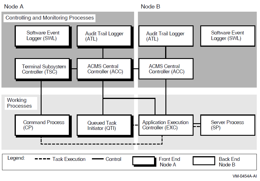
3.3. Run-Time Processing in a Distributed Environment
With ACMS, you can separate terminal and menu functions from the run-time processing of an application. This separation lets you run applications on a single computer, in an OpenVMS Cluster, or across the nodes of a network. In a distributed environment, the presentation service providing the terminal or device interface resides on a front-end processor, while the application managers and databases reside on a back-end processor.
Separating an ACMS application's functions using a front end that manages terminal functions and a back end that manages data processing has many benefits. For example, you can distribute your work among several applications, each running on its own back-end process and each available to users from a single menu. Users can select tasks and access the applications from a single menu on the front end. By distributing the run-time processing of tasks, you can improve system performance and the use of system resources.
Figure 3.2, ''Run-Time Processing with a Separate Front End'' shows the run-time processing of an application with terminal I/O shifted to a separate front-end computer or OpenVMS Cluster.
At run time, ACMS handles user logins and task requests for applications running on a network in much the same way it handles them for a single-node application. When a user enters ACMS, the CP controls the user's terminal, managing logins and the display of menus.
For details on applications with separate front-end processing, see VSI ACMS for OpenVMS Managing Applications, VSI ACMS for OpenVMS Writing Applications, and VSI ACMS for OpenVMS ADU Reference Manual.
Chapter 4. Managing ACMS Systems and Applications
Installing the application database in a protected directory (an operating system structure that catalogs a set of files stored on a disk or tape)
Authorizing users and terminals to access ACMS, the application, and tasks in the application
Starting the ACMS system and application
Monitoring applications
Enabling applications to run with terminal I/O shifted to a front-end computer, an OpenVMS Cluster network, or a set of computers
Tuning the ACMS system by setting quotas, parameters, and privileges so the system runs efficiently
This chapter provides an overview of managing the ACMS system and applications, and describes the tools ACMS provides for this work. For a more detailed explanation of these features, see VSI ACMS for OpenVMS Managing Applications.
4.1. Authorizing Access to ACMS
When many users share one OpenVMS system, it is important to control the facilities each user can access. For example, some users might need access only to ACMS, while others need access to the OpenVMS operating system as well as to ACMS.
The OpenVMS Authorize Utility controls user authorization in general. The Authorize Utility sets up user accounts and assigns OpenVMS privileges and quotas for users. Privileges are characteristics assigned to users or programs that determine which operations they can perform. For example, to use most of the ACMS operator commands requires the OpenVMS OPER privilege.
The ACMS Device Definition Utility (DDU) controls which devices on a OpenVMS system have access to ACMS applications, and determines whether a terminal is controlled by the OpenVMS operating system or by ACMS. Authorized ACMS users at terminals controlled by OpenVMS have access to both the OpenVMS operating system and ACMS, while users at terminals controlled by ACMS have access only to ACMS. System managers can also use DDU to allow users to sign in to ACMS automatically.
The ACMS User Definition Utility (UDU) controls which authorized OpenVMS users can sign in to ACMS and defines characteristics for each user. For example, system managers can use UDU to define ACMS proxies, define which menu a user sees or what a user selects upon entering ACMS.
See VSI ACMS for OpenVMS Managing Applications for information on how to use DDU and UDU. See your OpenVMS system management documentation for more information about the OpenVMS Authorize Utility.
4.2. Authorizing ACMS Applications
After application definitions are created and application databases are produced with the Application Definition Utility (ADU), the system manager installs the application databases in ACMS$DIRECTORY (a privileged directory). The system manager defines the location of this directory.
To ensure that only valid application databases are stored in ACMS$DIRECTORY, the ACMS system manager uses the ACMS Application Authorization Utility (AAU) to create an application authorization. This authorization describes characteristics of an application, such as who can install the application database in ACMS$DIRECTORY and what names are valid for the application.
4.3. Controlling ACMS Applications
The ACMS operator commands let you install, start, stop, or modify applications, as well as control which applications are available to which users. Starting and stopping applications individually helps you control the use of resources and the availability of required files and databases.
When you start an application, ACMS allocates the resources the application needs. The tasks in the application are then ready for users to select. When you stop an application, ACMS releases the resources used by the application, and the tasks in the application are no longer available.
The following sections explain the types of information you can collect about the ACMS system, applications, and users.
4.3.1. Displaying System and Application Information
One or more applications, including such information as a list of active server processes
An active application, specifying the intervals at which you want to collect information about the application
The ACMS system, including a list of active users and applications
One or more active ACMS users, including the users' names, active tasks, and device names
One or more active tasks
One or more active servers
Task queues that are being processed by the Queued Task Initiator (QTI)
4.3.2. Receiving ACMS Operational Messages
ACMS sends status and other operational messages to terminals that are assigned as ACMS operator terminals.
An operator terminal receives messages from ACMS if an application, the Audit Trail Logger (ATL), or the Terminal Subsystem Controller (TSC) stops unexpectedly. The operational messages are also logged in the software event log (SWL) file. An ACMS operator, who is authorized to use ACMS operator commands, can find and correct problems more quickly with an authorized operator terminal than with an error log file only.
4.4. Monitoring ACMS Applications
An important part of managing an ACMS application is keeping track of its activity. For example, you might want to account for the computer resources that an application uses. You might also want to keep track of who uses the applications and what tasks they run. Monitoring an application helps you keep a system running efficiently.
Audit Trail Logger (ATL), which gathers information about an active ACMS system and writes the information to the audit trail log file
Oracle Trace™, a product that collects data about events that occur during application run time and writes the information to a data file
Software Event Logger (SWL), which records all software errors and event messages that occur during the execution of ACMS application programs.
The following sections discuss the ATL, Oracle Trace, and the SWL. For more information about the ATL, Oracle Trace, and the SWL, see VSI ACMS for OpenVMS Managing Applications.
4.4.1. Using the Audit Trail Logger
The audit log includes information about system and application starts and stops, user sign-ins and sign-outs, processing errors, user task selections, and task completions. You can use this information to determine who is using ACMS, what applications and tasks they are running, and what tasks have been completed or canceled.
Type of information in the record
Time the record was created
Description of the recorded event
4.4.2. Using Oracle Trace
Use of resources
You can check such statistics as response time of an application's data processing and computational functions.
Ease of use
For example, you can use Oracle Trace to test the design of forms, steps, and tasks by tracing the time it takes to complete a function.
Users and use of applications
You can collect such information as how many times users complete a form or a task.
Auditing information
With Oracle Trace, you can collect more detailed auditing information than with ACMS auditing tools. For example, ACMS audit reports can indicate only that a task has started or stopped. With Oracle Trace, you can collect details about the parts of a task.
4.4.3. Using the Software Event Logger
The Software Event Logger (SWL), which records all run-time software error and event messages, is another useful tool for tracking errors that occur when an ACMS application is executing.
User information
Process information
System time
Extended error information
The Software Event Log Utility (SWLUP) allows you to create reports using information recorded by the SWL.
4.5. Tuning the ACMS System
Once you set your system parameters and quotas, you may have to tune your system occasionally. ACMS provides two command procedures, ACMSPARAM.COM and ACMEXCPAR.COM, to determine ACMS quotas and parameters after an ACMS installation or upgrade.
Make sure you have adequate hardware resources for your workload
Examine the design of your application in addition to tuning your operating system
VSI ACMS for OpenVMS Concepts and Design Guidelines contains information on how to design your application to avoid performance problems.
See VSI ACMS for OpenVMS Managing Applications for information on fine tuning your applications. Additional information to help you design your ACMS system and applications to run efficiently appears throughout the ACMS documentation set.
Chapter 5. ACMS Product Kits and Documentation
This chapter outlines the ACMS product kits.
5.1. ACMS Product Kits
ACMS Development System
The ACMS development system contains all the components you need to create and control ACMS applications. You can define, build, and debug multiple-step tasks and task groups, as well as menus and applications.
You must have the CDD dictionary installed on your system to run the full development kit.
The development system includes both the run-time option and the remote access option software. This manual concentrates on the features of the development system.
ACMS Run-Time Option
The ACMS run-time option lets you run existing ACMS applications or programs and change application attributes (for example, menu definitions). With the run-time option, you can define menus and applications, as well as tasks and task groups that use DCL servers.
The run-time option includes all the facilities of the development software except the ACMS Task Debugger, and the ability to define multiple-step tasks that use server procedures. To modify definitions, you must have installed CDD, which is optional with the run-time option. The run-time option includes the remote access option software.
ACMS Remote Access Option
The ACMS remote access option allows you to access ACMS applications running on other nodes in a DECnet network from nodes that do not necessarily have any ACMS applications running on them. The remote access option software lets you place users and the terminal input/output associated with their tasks on one system (a front-end, or submitter, node) and the data storage files on another (a back-end, or application, node).
Part II. Tutorial
This part is intended for application programmers who are using ACMS software for the first time. The book contains a step-by-step tutorial for developing a simple ACMS application. This application involves the integration of several products: ACMS, DECforms, RMS, and Oracle CDD/Repository software.
Chapter 6. Introduction
This chapter gives introductory material and lists the prerequisites for performing a step-by-step tutorial for developing a simple ACMS application. This chapter also provides an overview of ACMS application development concepts. The tutorial begins in Chapter 7, "Developing the Data Entry Task".
6.1. Before You Begin
- Make sure that your system is running compatible versions of the following software:
OpenVMS system
ACMS
DECforms
CDD
Become familiar with the OpenVMS operating system and with a text editor such as the Language-Sensitive Editor (LSE). You use a text editor to create and edit the program source elements in this manual.
Acquire a personal OpenVMS account on a system that is running ACMS, DECforms, and CDD software. Check with your system manager to ensure that your account has the necessary privileges to access these products. To run the ACMS Task Debugger as described in Section 9.4, ''Testing a Task in the ACMS Task Debugger'', make sure that your OpenVMS account has a BYTLM quota of 50,000.
All the source code developed in this tutorial is available on line. You can view the source files to compare them with those that you create here, or you can copy the online source files instead of typing them yourself. Appendix B, "Source Files Used in the Tutorial" lists these files and describes how to access them.
The procedures in this tutorial are written in COBOL. You can, however, write procedures in any high-level language that adheres to the OpenVMS Calling Standard. Also, it is not necessary to be familiar with COBOL to perform the tutorial.
This tutorial application uses an RMS master file to store and retrieve records. RMS is a file management system that is supplied with the OpenVMS operating system. If you are already running database software such as Rdb, you may wish to convert this tutorial application at some later time to one that accesses an Rdb database. In this case, refer to the appropriate database documentation for creating the database and for writing the statements that access it.
6.2. Application Development Life Cycle
Several phases make up the life cycle of an application. For an overall perspective of application development, it is helpful to know where the development phase fits into this life cycle and what assumptions this tutorial makes about the other phases.
Figure 1.6, ''Interaction of the Phases of the ACMS Application Development Life Cycle'' identifies the phases of the application development life cycle. Note that you may have to revisit the intermediate phases several times during the course of developing a complex application.
During the orientation and installation phase, you install the product and deliver training in the development of applications.
During the planning and design phase, you perform requirements analysis, functional analysis, and prototyping for an application.
For the purpose of this tutorial application, assume that the planning and design phase has already been completed. The designers have decided on a nondistributed environment and a simple ACMS application that meets the needs of their personnel administration system. In this system, a user adds a new employee record to a master file or updates an existing employee record. The designers have determined which fields of data an employee record should contain, how those fields should appear on the data entry form, what error checking the application should contain, and other relevant design criteria.
During the development and testing phase, you write and test the code that implements the design of the application. This manual steps you through the coding process. For this tutorial application, you write CDD definitions, DECforms IFDL code, ACMS definitions, and COBOL procedures.
The development phase also includes testing the application. This manual steps you through the process of testing your task definitions in the ACMS Task Debugger prior to completing the application. You then have an opportunity to run and test the application more fully at the conclusion of code development.
During the implementation and management phase, you transfer an application from your development system to a production system and fulfill system management requirements for the application. Chapter 12, "System Management Requirements for Installing the Tutorial Application", describes the steps a system manager performs to authorize an ACMS user and an ACMS application on an OpenVMS system. Until your system manager performs these management functions, you cannot install and run this tutorial application.
6.3. ACMS Application Development Concepts
An ACMS application consists of a set of tasks that relate to the functions of a business. A task is the unit of work that a user selects from an ACMS menu. Each task usually comprises a sequence of steps that perform this unit of work. You use the ACMS task definition language to define tasks.
Figure 6.1, ''Execution Flow of an ACMS Task Definition'' illustrates the basic principles of the ACMS task definition language (TDL) used to write a task definition. The task definition specifies an interface to the presentation service (forms management system) for communication with a terminal or other device. The task definition also specifies an interface to a procedure server for executing procedures (user-written subroutines) that handle database I/O and computational work.
The semantics of the ACMS task definition language are based on a call and return model. Task definition steps perform calls to the presentation service in exchange steps, and to the procedure server in processing steps. The presentation service and procedure server perform a function and return control to the task definition. Upon return of control to the task definition, subsequent parts of a step can evaluate the results of the call and, if necessary, handle any error conditions.
In the first exchange step, the task definition calls the presentation service to display a form on the terminal screen (for example, a form to add a new employee record to a database). When the terminal user finishes filling in the form, the user presses a specified key (or keys) that allows the task definition to receive the input data.
In the processing step, the task definition then calls Procedure 1 in the procedure server to write that input data to the database. Procedure 1 then returns its results (either success or failure). If Procedure 1 fails to write to the database, step 2 then passes control to step 3.
Figure 6.1. Execution Flow of an ACMS Task Definition 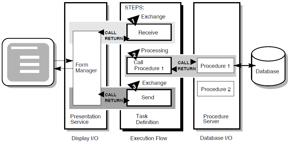
In the second exchange step, the task definition calls the presentation service to send an error message to the terminal screen (for example, that the employee number of the new record duplicates an existing employee number). The presentation service then returns control to step 3.
6.3.1. Writing ACMS Definitions
A task definition describes, in steps, the work to be accomplished in the task. For example, a task can collect information from a user and call a procedure to store the information in a file or database.
A task group definition specifies similar tasks for control purposes and defines resources common to all tasks in the group.
An application definition describes the environment and control characteristics of tasks and task groups.
A menu definition describes how users access one or more applications. Usually this definition allows users to access one or more tasks from an ACMS menu.
You build the task, task group, and application definitions into an application that runs under the control of the ACMS run-time environment. You build a menu definition separately, because it is not necessarily tied to a single application.
The first task asks the user to enter employee data. The user can then save this data in a master file.
The second task displays an employee record from the master file when the user enters an existing employee number. After examining the record, the user can change the information in it and write the changed record back to the file.
Figure 6.2, ''ACMS Application Components'' does not show that there can be more than one task group definition specified for a single application. Also, more than one menu definition can specify tasks that point to the same application. Conversely, a single menu definition can specify tasks in different applications.
Because ACMS applications are modular, you develop each part of an application independently. If you need to change a task definition later, the change does not necessarily affect the task group, application, or menu definitions. Many types of changes do not affect other modules.
6.3.2. Composition of ACMS Definitions
Exchange steps usually interact with the Form Manager to handle forms I/O (that is, the input and output between the task and the user). An exchange step can interact with DECforms or TDMS forms, or interface with other devices using the ACMS Request Interface or the ACMS Systems Interface for communicating with nonstandard devices. Figure 6.1, ''Execution Flow of an ACMS Task Definition'' illustrates an execution flow with two exchange steps.
Processing steps call step procedures (user-written subroutines) to handle computations and interactions with databases or files, typically using procedures written in a high-level programming language (any language adhering to the OpenVMS Calling Standard). ACMS uses two types of servers: procedure servers for executing a procedure, and DCL servers for invoking images or DCL commands. Figure 6.1, ''Execution Flow of an ACMS Task Definition'' illustrates an execution flow with one processing step.
A server process may perform an initialization routine of common work when the server is started, rather than each time a task is selected. ACMS manages pools of servers to save on image activation.
Servers are serially reusable (that is, while attached to a task, a server process is not available to other tasks until the task call has completed). A single server process can be called by many different ACMS tasks in a serial fashion. Once the call is complete, the server is then available to be called by another ACMS task.
When ACMS starts a processing step, it allocates a procedure server process to a task to execute the procedure in that step. This single-threaded process remains allocated to the task for the duration of one or more processing steps.
In ACMS, a workspace is a buffer used to pass data between the task and processing steps, and between the task and exchange steps.
Task group definitions combine similar tasks of an application that need to share common resources such as workspaces, a library of presentation services requests, and procedure servers.
Task groups that belong to an application
Characteristics that control the tasks, such as security restrictions on which users can select a particular task
Servers, such as the number of server processes that can be active at the same time
The application, such as whether application activity is recorded in the audit trail log
Menu definitions list both tasks and additional menus that a user can select from a menu. For example, the tasks on a menu can include adding new employee records, displaying employee information, and entering labor data.
When you write definitions for ACMS tasks, ACMS automatically stores the definitions in a CDD dictionary. At run time, the definitions are represented in binary form in ACMS-defined databases. For example, a task group definition is represented by a task group database that contains a binary representation of the task group definition.
6.4. ACMS Integration with DECforms
Although ACMS supports several presentation services, ACMS supports DECforms as its primary presentation service. DECforms provides such features as FIMS compliance, device-class independence, storage of form context between exchanges, input verification (values, ranges, and types), and escape routines.
6.4.1. DECforms Concepts
DECforms architecture provides a full separation of form from function. This separation allows you to write an application program (the function) without being concerned with the intricacies of the user interface (the form) for that program.
Normally, the term form means a document with blanks for the insertion of information. In DECforms, however, the form is a specification that may govern the complete user interface to an application program. The form specification completely describes all terminal screen interactions, the data that is transferred to and from the screen, and any display processing that takes place.
A panel consists of the information and images that are physically displayed on the user's terminal screen. A panel is composed of such items as fixed background information (literals), fields (blanks for insertion of information), attributes, function key control, and customized help messages.
You can partition the display into rectangular areas called viewports by specifying viewport declarations within the form definition. You can adjust the viewport to any size and locate it anywhere on the display (such that viewports overlap one another). For a panel to be visible, it must be associated with a viewport.
Figure 6.3, ''Panels and Viewports'' illustrates the concept of specifying panel declarations and viewport declarations within the DECforms form definition. You specify a viewport name within each panel declaration. By doing this, you map each panel to a specific viewport. At run time, each panel appears on the terminal screen within its viewport.
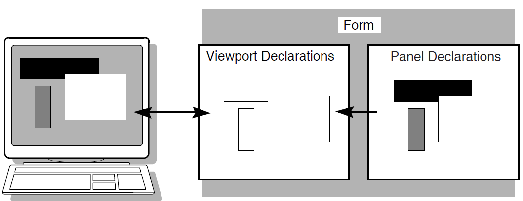
The DECforms Form Manager is the run-time component that provides the interface between the terminal display and an ACMS application. The Form Manager controls panel display, user input, and data transfer between the form and ACMS. A DECforms form is loaded by the Form Manager at execution time under the direction of an ACMS application program.
Note
In normal DECforms programming practice, both panels of this tutorial application are defined in a single form. However, the tutorial application defines a separate form for each panel simply to illustrate how ACMS handles multiple forms. For advanced DECforms design and programming, see VSI DECforms Guide to Commands and Utilities.
6.4.2. ACMS Interaction with DECforms
In DECforms, the form record is a structure that controls data transfer between ACMS and the form. The form record identifies which form data items (variables associated with the form) are to be returned to ACMS.
Figure 6.4, ''DECforms Interaction with ACMS'' shows the interaction between DECforms and ACMS when ACMS requests information from DECforms.
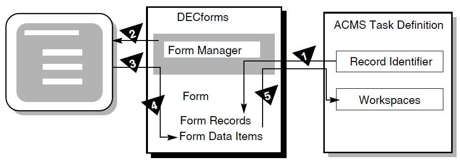
- To request information, ACMS calls the Form Manager with a RECEIVE or TRANSCEIVE call. In that call, ACMS performs the following operations:
Tells the Form Manager the name of the form needed to collect data.
Tells the Form Manager the record identifier being received.
Gives the Form Manager the ACMS workspaces used to transfer data.
The Form Manager displays a panel on the user's terminal screen. The displayed panel is specified in the form that ACMS names in its RECEIVE or TRANSCEIVE call to DECforms.
The Form Manager accepts input from the user's terminal.
The Form Manager uses the form record to store the user's input data in the appropriate form data items.
The Form Manager completes the request by returning data to the ACMS workspaces.
6.5. ACMS Integration with Resource Managers
Resource managers (RMs) are the software products that store and manage the data accessed by ACMS applications. A resource manager controls shared access to a set of recoverable resources, such as a database.
Rdb database management system
DBMS database management system
RMS file management system
ACMS queuing facility
6.5.1. Accessing a Database or a Master File
VSI's resource managers are not an integral part of the TP system, but are instead under the control of the operating system (OS). This OS control of resource managers permits database sharing among TP and non-TP applications, decision support systems, and remote nodes requesting data.
ACMS supports Rdb as its primary database management system. For Rdb conceptual information, refer to the Rdb documentation.
For the sake of simplicity, this tutorial application uses an RMS master file to store and retrieve records. RMS is an OpenVMS-supplied file management system that supports sequential, relative, or indexed files. The initialization procedure in this tutorial creates the RMS file (EMPLOYEE.DAT) when you run the application for the first time.
6.5.2. ACMS Interaction with a Resource Manager
To access a database, ACMS interacts with a procedure server process. The procedure server process, in turn, interacts with the resource manager of the database. As shown in Figure 6.5, ''A Resource Manager Interacting with ACMS'', processing steps call step procedures (user-written subroutines) to handle interactions with the resource managers of databases or files.
ACMS uses a procedure server process for executing a procedure. When starting a processing step, ACMS allocates a procedure server process to execute the procedure in that step. The procedure server process remains allocated to the task for the duration of one or more processing steps in the task.
In an update task, you need at least one exchange step to prompt the user for a key value, and another to display the requested record for modification. You need one processing step to retrieve the record from the database, and another to write the record back to the database with the user's changes. Figure 6.5, ''A Resource Manager Interacting with ACMS'' shows the interactions among ACMS, the procedure server, and the resource manager to execute a simple update task.
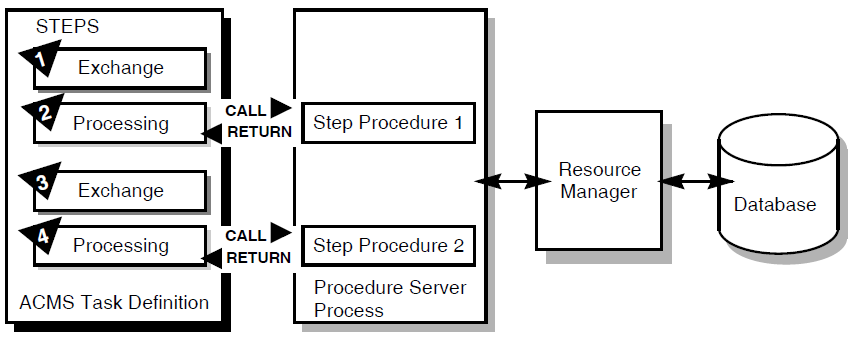
An exchange step calls the Form Manager (not shown) to display a panel on which the user can supply a key value (for example, an employee number).
A processing step calls procedure 1, which in turn retrieves an employee record from the database through its resource manager. The record retrieved matches the employee number that the user entered.
An exchange step calls the Form Manager to display a panel with the information contained in the employee record. The user can modify this information (for example, change the employee's address).
A processing step calls procedure 2, which in turn writes the modified employee record to the database.
For a full picture of the ACMS execution flow that includes the Form Manager's role in exchange steps, refer to Figure 6.1, ''Execution Flow of an ACMS Task Definition''.
6.6. Defining Fields and Records in CDD
The CDD dictionary system provides a central storage repository for shareable data definitions. CDD is an active dictionary system that provides the user interface known as CDO (Common Dictionary Operator).
The dictionary contains metadata (descriptions of data) in the form of dictionary definitions. The most commonly used dictionary definitions are fields, records, and databases.
A field definition describes the data that can be stored in a specific field in your application. Field definitions typically include information such as data type and size. The tutorial application defines the following fields: employee number, name, street address, city, state, and zip code.
A record definition typically consists of a grouping of field definitions. The tutorial application defines a record named EMPLOYEE_INFO_RECORD, which contains a group of field definitions corresponding to the preceding fields.
This tutorial application creates your personal CDD dictionary. It also sets up your default CDD directory so that all your definitions are located there automatically. By setting a default CDD directory, the tutorial application can identify EMPLOYEE_INFO_RECORD by its name alone (without having to use its full path name).
Chapter 7. Developing the Data Entry Task
This chapter describes in step-by-step detail how to write the Data Entry Task using ACMS, DECforms, and CDD definitions. Before you begin, check the prerequisites for this tutorial listed in Section 6.1, ''Before You Begin''.
7.1. Defining a CDD Environment
This tutorial application requires you to create a personal CDD directory. You then need to define this directory to be your default CDD directory, so that all your definitions are located there automatically.
Create your personal subdirectory under CDD$COMPATIBILITY (a system logical that on most systems points to the system dictionary directory SYS$COMMON:[CDDPLUS]).
Or, define a directory in your own account to be your dictionary (for example, USER$1:[JONES.CDD]).
The directory used as your CDD dictionary in this tutorial is represented by the placeholder disk:[cdd_directory]. When this specification appears on subsequent pages, you are required to enter the disk name and directory name where your CDD dictionary is located (for example, USER$1:[JONES.CDD]).
$ CREATE/DIRECTORY [JONES.CDD]This subdirectory must remain dedicated to your CDD dictionary; CDD stores its files there. Do not store your source files or any other OpenVMS files in this directory.
- Enter the CDD Dictionary Operator Utility by issuing the following command:
$
DICTIONARY OPERATORCDO>CDD responds by displaying the CDO> prompt.
- This step is required only if you are creating a CDD dictionary in your own OpenVMS account. If you are attaching your personal CDD directory to the system dictionary, CDD$COMPATIBILITY, skip this step. Note that the following command line ends with a period:
CDO>
DEFINE DICTIONARY disk:[cdd_directory].CDO>For cdd_directory, substitute the name of the directory that you created as your CDD dictionary (for example, [JONES.CDD]).
- Set your default directory to the directory that will be your CDD directory:
CDO>
SET DEFAULT disk:[cdd_directory]CDO>Issue theSHOW DEFAULTcommand to verify this:CDO>
SHOW DEFAULTdisk:[cdd_directory] CDO> - Create a CDD subdirectory to use as your personal directory. Substitute your directory name for d_name in this example and elsewhere in this manual (for example PJ_DICTIONARY). Note that this command line ends with a period:
CDO>
DEFINE DIRECTORY disk:[cdd_directory]d_name.CDO>A dictionary directory is a named section of a dictionary that you use to hold your field and record definitions. Issue theDIRECTORYcommand to check that the subdirectory you created is listed in your anchor directory:CDO>
DIRECTORYCDO displays the contents of disk:[cdd_directory]; your personal subdirectory (dictionary) is listed as a directory.Directory disk:[cdd_directory] . . . d_name DIRECTORY CDO>
- Exit from CDO:
CDO>
EXIT$ - Using a text editor, edit your login command file to define the logical name CDD$DEFAULT. The CDO uses this logical name to set your default CDD directory whenever you invoke CDO. Also, to enter CDO more quickly, define a symbol for the
DICTIONARY OPERATORcommand. Add the following lines to your login command file:$ DEFINE CDD$DEFAULT disk:[cdd_directory]d_name $ CDO :== DICTIONARY OPERATOR
Save your login command file and exit the editor.
- Issue the following commands to execute your edited login command file and to make sure that your default directory is set correctly:
$
@LOGIN.COM$CDOCDO>SHOW DEFAULTCDD$DEFAULT = disk:[cdd_directory]d_name CDO> - Exit from CDO:
CDO>
EXIT$
7.2. Defining a CDD Record
In this chapter, you create your first source files: CDD files, DECforms files, ACMS files, and COBOL files. The easiest way to manage these files is to create them all in the same OpenVMS directory.
This manual assumes that you are using your default OpenVMS directory (udisk:[uname]) to hold your source files. In this manual, udisk represents your OpenVMS disk name, and uname represents your OpenVMS directory name (for example, USER$1:[JONES]). Make sure that you are located in your default OpenVMS directory when you create a source file.
- Using a text editor, create a source file, EMPLOYEE_FIELDS.CDO, in your OpenVMS default directory. All source files are available on line, if you choose to copy them instead of typing them yourself. See Appendix B, "Source Files Used in the Tutorial" for their location. Type in your field definitions as follows:
DEFINE FIELD EMPL_NUMBER    DATATYPE TEXT SIZE 10.
DEFINE FIELD EMPL_NAME   DATATYPE TEXT SIZE 30.
DEFINE FIELD EMPL_STREET_ADDRESS   DATATYPE TEXT SIZE 30.
DEFINE FIELD EMPL_CITY   DATATYPE TEXT SIZE 20.
DEFINE FIELD EMPL_STATE   DATATYPE TEXT SIZE 2.
DEFINE FIELD EMPL_ZIP_CODE   DATATYPE TEXT SIZE 10.
Because input records of this format are eventually filled in with alphabetic and numeric data typed at the terminal, the data type of all the fields is TEXT, which can be either alphabetic or numeric. In a more complex application, you would probably use other data types such as NUMERIC. The SIZE information specifies the maximum number of characters that the value of a field can have.
Save this file and exit the editor.
- Execute the source file to place these field definitions in your dictionary:
$
CDOCDO>@EMPLOYEE_FIELDSCDO>If you do not have the necessary privileges to define an object in CDO, or if you have not turned on your privileges (with the
SET
                            PROCESS/PRIV=xxxx
command), you receive an "insufficient privileges" message here. If so, see your system manager about required privileges.To check that a field is in your CDD directory, you can issue theSHOW FIELDcommand. For example:CDO>
SHOW FIELD EMPL_NUMBERDefinition of field EMPL_NUMBER | Datatype text size is 10 characters CDO> - Exit from CDO. Create a source file named EMPLOYEE_INFO_RECORD.CDO. Type the following lines:
DEFINE RECORD EMPLOYEE_INFO_RECORD.
   EMPL_NUMBER.
   EMPL_NAME.
   EMPL_STREET_ADDRESS.
   EMPL_CITY.
   EMPL_STATE.
   EMPL_ZIP_CODE.
 END RECORD.
Save this file and exit the editor.
- Execute the source file:
$
CDOCDO>@EMPLOYEE_INFO_RECORDCDO>Issue theSHOW RECORDcommand to check that your record is accurate:CDO>
SHOW RECORD EMPLOYEE_INFO_RECORDDefinition of record EMPLOYEE_INFO_RECORD | Contains field EMPL_NUMBER | Contains field EMPL_NAME | Contains field EMPL_STREET_ADDRESS | Contains field EMPL_CITY | Contains field EMPL_STATE | Contains field EMPL_ZIP_CODE CDO>You can display the data type and length of each field in the record by using the
/FULLqualifier after theSHOW RECORDcommand.To display a list of all fields and records in your default CDD directory, issue theDIRECTORYcommand:CDO>
DIRECTORYDirectory disk:[cdd_directory]d_name EMPLOYEE_INFO_RECORD;1 RECORD EMPL_CITY;1 FIELD EMPL_NAME;1 FIELD EMPL_NUMBER;1 FIELD EMPL_STATE;1 FIELD EMPL_STREET_ADDRESS;1 FIELD EMPL_ZIP_CODE;1 FIELD CDO> - Exit from CDO. Create a source file named EMPLOYEE_INFO_WKSP.CDO. Type the following lines:
 DEFINE RECORD EMPLOYEE_INFO_WKSP.
   EMPL_NUMBER.
   EMPL_NAME.
   EMPL_STREET_ADDRESS.
   EMPL_CITY.
   EMPL_STATE.
   EMPL_ZIP_CODE. END RECORD.
Save this file and exit the editor.
- Enter the EMPLOYEE_INFO_WKSP definition in CDD by executing the source file:
$
CDOCDO>@EMPLOYEE_INFO_WKSPCDO> Exit from CDO.
Note
In this tutorial, the record EMPLOYEE_INFO_RECORD is the same as the workspace (EMPLOYEE_INFO_WKSP) that ACMS passes to DECforms. In many ACMS applications these records are not identical. You often pass a workspace that contains fewer fields than the record definition. Both the record and the workspace definitions are included in this tutorial as examples of the usual practice in ACMS application definitions.
7.3. Creating a Form Using DECforms
The easiest way to design DECforms panels in a form is to use the DECforms Panel Editor in the Form Development Environment (FDE). The definition of the panel that you create is automatically stored in a form source file with the file type of .IFDL (Independent Form Description Language).
7.3.1. Creating a Basic Form
- Edit your login command file to define a symbol for the
FORMS DEVELOPcommand:$ FDE :== FORMS DEVELOP
Save your login command file and exit the editor.
- Execute your edited login command file:
$
@LOGIN.COM - Enter the FDE symbol to enter the DECforms interactive environment:
$
FDEIf the DECforms system starts successfully, the system prompts you for a file name. However, if DECforms does not recognize your device type, the system responds that this operation must be done with a 100, 200, or 300 series terminal. In this case, issue the
SET
                                TERMINAL/INQUIRE
command at the dollar ($) prompt and repeat this step. - Type the name EMPLOYEE_INFO_FORM at the prompt:
_Input_File:
EMPLOYEE_INFO_FORMAfter you enter your form name, DECforms displays two messages:Form Development Environment starting... Creating a new form file called: UDISK:[UNAME]EMPLOYEE_INFO_FORM.FORM
DECforms then displays a screen that prompts you to accept a default layout for your panel (see Figure 7.1, ''DECforms LAYOUT Screen'').Note
If you copied the online IFDL source files to your default directory before starting this tutorial, DECforms translates the existing IFDL file here and loads the resulting FORM file. It displays the Main Menu instead of Figure 7.1, ''DECforms LAYOUT Screen''. In this case, use the arrow keys to choose the Exit option and press Select. Proceed to Section 7.3.4, ''Creating the Binary Form File'', step 2.
Figure 7.1. DECforms LAYOUT Screen 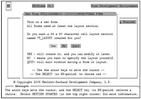
On DECforms screens, use the arrow keys to move the cursor among the options that are displayed. Then press Select to register your choice of options.
Press Select to accept the default of Yes, because the example in this tutorial uses just one layout for all types of terminals and users. DECforms next displays the FDE Main Menu, shown in Figure 7.2, ''FDE Main Menu''.
Figure 7.2. FDE Main Menu 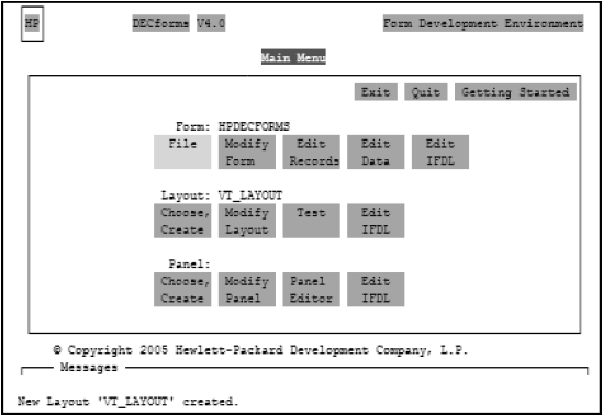
- Using the arrow keys, move the cursor to the EXIT option. Then press Select. DECforms saves all the entries you made and then displays the following messages notifying you that your form has been saved in a form source file and in a binary file:
IFDL saved in file: UDISK:[UNAME]EMPLOYEE_INFO_FORM.IFDL;1.
Form saved in file: UDISK:[UNAME]EMPLOYEE_INFO_FORM.FORM;1.
You have now created a basic form.
- Enter the
TYPEcommand and your IFDL source file name to display the IFDL source file:$
TYPE EMPLOYEE_INFO_FORM.IFDLIn the form source file, DECforms places IFDL statements that identify the form and the layout selected. By selecting the default layout, you cause DECforms to create the following lines:Form EMPLOYEE_INFO_FORM <FF> Layout VT_LAYOUT Device Terminal Type %VT100 End Device Size 24 Lines by 80 Columns End Layout End Form
To make your form useful, create a panel that produces a display on the terminal screen. The next section contains instructions for doing this.
7.3.2. Creating a Panel
- Reenter FDE by issuing the
FDEcommand and your form name:$
FDE EMPLOYEE_INFO_FORMDECforms displays the FDE Main Menu (see Figure 7.2, ''FDE Main Menu'').
Press the down-arrow key to move the cursor to the third line (the Panel line), and press Select at the first choice: Choose, Create. DECforms superimposes another panel on the FDE Main Menu (see Figure 7.3, ''Choose/Create Panel Menu'').
Press Select at the menu choice: Create Panel. DECforms displays the Create Panel screen (see Figure 7.4, ''Create Panel Screen''), containing panel attributes and their default values marked by a diamond.
Figure 7.3. Choose/Create Panel Menu 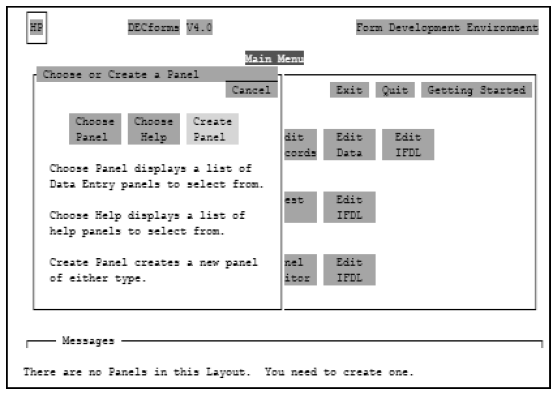
Figure 7.4. Create Panel Screen 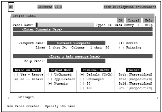
- The Panel Name field is highlighted on your screen. Type the name of the panel you are creating:
Panel Name:
EMPLOYEE_INFO_PANELPress Return. The cursor moves to the Data Entry field. The panel type specifies whether the panel is for entering data or displaying help. The diamond before Data Entry indicates that the panel is a data entry panel.
Press the down-arrow key to move the cursor to Yes-Remove under Erase on Exit. Press Select. This has the effect of removing the panel from the screen when the user finishes entering data and exits the panel.
- Press the up-arrow key to move the cursor to the OK option in the top right-hand corner. Press Select. This means that you accept all the values on the screen, including the default viewport size.
Note
DECforms displays a panel within a viewport. To specify a viewport size other than the default 24 X 80 dimension, you must first enter a viewport name on the Create Panel screen and then specify line and column numbers to indicate the size of the viewport in which the panel is to be displayed.
After you select OK, DECforms redisplays the FDE Main Menu, shown in Figure 7.2, ''FDE Main Menu''.
- Move to the Panel Editor menu choice and press Select. DECforms invokes the Panel Editor and places the cursor in the top left-hand corner of a blank screen. You are now ready to format your panel.
Note
Always use the arrow keys to move the cursor within the panel. Do not use the space bar to position the cursor; the space bar creates literal spaces on the panel.
Position the cursor with the arrow keys and type the literals on the screen as shown in Figure 7.5, ''Sample DECforms Panel''. DECforms displays the panel to users exactly as you format it.
Figure 7.5, ''Sample DECforms Panel'' is an example of a data entry panel composed only of literals. The panel includes a message to users indicating how to navigate between fields (using Return and F12), how to save the data (using Ctrl/Z), and how to quit the screen (using PF4). You define PF4 later in this chapter. Because Return, F12, and Ctrl/Z are predefined in DECforms, you do not need to define them for use in this tutorial application.
Figure 7.5. Sample DECforms Panel 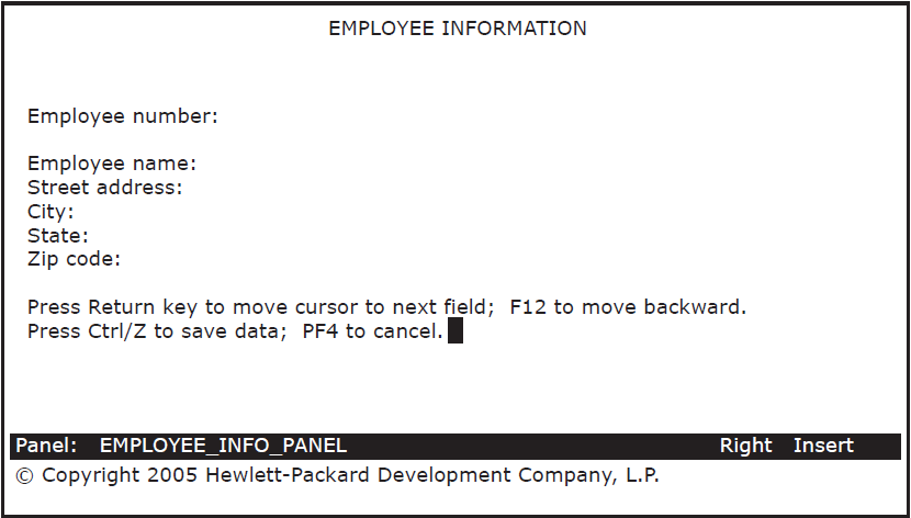
You must now create the fields that correspond to the literals. A field is that space following the literal in which the user enters the information. For example, a defined space after the Employee name literal is a field in which to enter the employee name.
Use the arrow key to position the cursor two spaces after the Employee number literal, and press Do. DECforms displays the Command> prompt.
- Type
CREATE FIELDafter the Command> prompt and press Return:Command>
CREATE FIELDDECforms then displays the Create Field Menu (see Figure 7.6, ''Create Field Menu'').
Figure 7.6. Create Field Menu 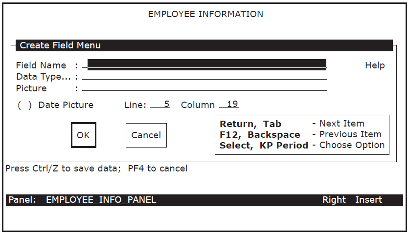
- Enter the field name and press Return:
Field Name:
EMPL_NUMBERNote
Field names that you specify must correspond to field names that you entered in the CDD record definition. In the menu, the numbers that appear after Line and Column indicate where the cursor was when you began to create the field.
Press Select at the Data Type prompt (the field is highlighted) to display a list of valid data types: atomic, character, and date/time. In the list of character types, move the cursor to Character and press Select to register your choice.
DECforms then superimposes the Data Type Character window, shown in Figure 7.7, ''Data Type Character Window'', on the menu.
Figure 7.7. Data Type Character Window 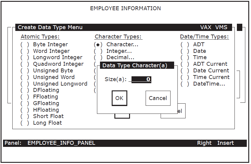
- Enter the size of the field:
Size(a):
10Use the arrow keys to move the cursor to OK, and press Select to confirm your entry.
DECforms again displays the Create Field Menu, shown in Figure 7.6, ''Create Field Menu''.
- Enter the field picture:
Picture :
X(10) Move the cursor to the OK icon and press Select.
DECforms returns you to your panel and displays a success message at the bottom of your screen. It also displays Xs to indicate the length of the character picture for that field, as shown in Figure 7.8, ''Sample Panel with One Data Field Picture''.
Figure 7.8. Sample Panel with One Data Field Picture 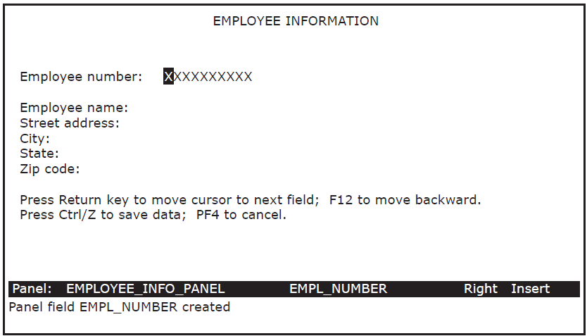
- Create character fields of the following lengths and pictures in the same manner as in steps 9 through 15:
EMPL_NAME              X(30)
EMPL_STREET_ADDRESS    X(30)
EMPL_CITY              X(20)
EMPL_STATE             X(2)
EMPL_ZIP_CODE          X(10)
Figure 7.9, ''Sample Panel with Data Field Pictures'' shows the results of defining all the fields in the panel.Note
DECforms can validate a field of data as soon as the user exits that field. For example, you can write DECforms code that checks whether the user entered a valid zip code and, if not, prompts the user to reenter the zip code. This tutorial application, however, does not perform DECforms validation. For advanced DECforms design and programming, see VSI DECforms Guide to Commands and Utilities.
Figure 7.9. Sample Panel with Data Field Pictures 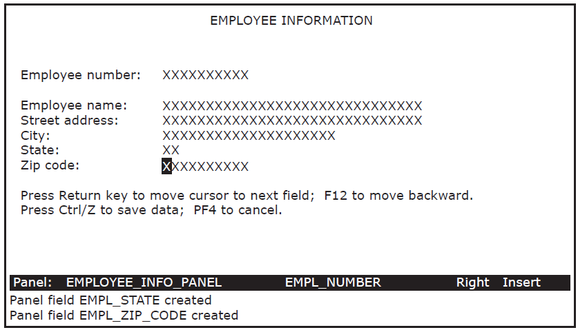
- Press Ctrl/Z to exit from the Panel Editor when you finish creating the panel. DECforms displays the following message:
Panel editing finished.
DECforms redisplays the FDE Main Menu, shown in Figure 7.2, ''FDE Main Menu''.
Test the form by selecting the Test option on the FDE Main Menu. DECforms displays a Testing Menu with three more options.
Press Select to choose the Test Panel option.
FDE displays the panel and prompts you to enter a value for the Employee number field.
Type a sample entry for each field in the panel, pressing Return after you complete each one. Press Ctrl/Z when you complete the panel.
DECforms redisplays the Main Menu, shown in Figure 7.2, ''FDE Main Menu''.
Use the arrow keys to move the cursor to the Exit icon. Press Select. DECforms displays messages indicating that it has saved the IFDL and FORM files containing your panel.
7.3.3. Editing the Form IFDL Source File
You now edit the form IFDL source file to include other definitions and special instructions. Note that DECforms automatically added a number of statements to your IFDL file when you exited FDE. For example, the Form Data section and the field descriptions in that file are a result of the data fields that you created interactively with DECforms.
- Use a text editor to open your IFDL source file named EMPLOYEE_INFO_FORM.IFDL. When using the LSE editor, for example, enter the following command:
$
LSEDIT EMPLOYEE_INFO_FORM.IFDL - Enter a form record description in the IFDL source file following the declaration of the form data items. Enter the following lines after the line "End Data":
Form Record EMPLOYEE_INFO_RECORD
    Copy
        EMPLOYEE_INFO_RECORD From Dictionary
    End Copy
End Record
The fields in the form record description here must correspond to the form data items defined above the description in the file. In this tutorial, you create a one-to-one correspondence between the form data items and the fields in EMPLOYEE_INFO_RECORD, which you previously entered in CDD. The COPY...FROM DICTIONARY clause copies that record from CDD.
This one-to-one correspondence of record fields and data items is not a requirement, however. In more complex applications, the fields in a form record description are usually a subset of the list of form data items.
- Immediately following this definition, enter another form record definition to correspond to a workspace definition that you enter later in CDD (in Section 7.3.5, ''Defining Additional CDD Records''):
Form Record CONTROL_WORKSPACE
    ERROR_STATUS_FIELD Character(4)
    MESSAGEPANEL Character(80)
End Record
In the data entry task, you need to inform users if they enter an employee number that already exists. A COBOL procedure called from the task checks for this error condition. If the error occurs, the procedure moves the value DUPL into the field ERROR_STATUS_FIELD in the record CONTROL_WORKSPACE.
In your task, you can test the field ERROR_STATUS_FIELD for the DUPL value. If this value is in the field, you can place an error message in the MESSAGEPANEL field of CONTROL_WORKSPACE. The processing step in the task definition discusses this error handling in more detail; see Section 7.4.2, ''Defining the Processing Step''.
A MESSAGEPANEL is a special field in a form record. When you specify a MESSAGEPANEL field in a form record, any data associated with this field is automatically displayed in a message panel, which appears on any panel you have created. If you do not create your own message panel (this tutorial does not), DECforms uses the default message panel, which is the last line (line 24) on a panel display.
- Enter the following lines after the line "Size 24 Lines by 80 Columns":
Function QUIT_KEY Is %PF4 End Function
This declares a function named QUIT_KEY and binds that name to PF4. By declaring a function response for QUIT_KEY in the next step, you allow the user to stop the task by pressing PF4.
- A function response describes the action you want to occur when a user presses a function key. Enter the following lines after the line "End Function". Note that there is a space before the F in FQUT.
Function Response QUIT_KEY Remove All Return " FQUT" End Response
If a user presses PF4 while entering employee information in the panel, the function response directs DECforms to remove all viewports from the screen and return the value " FQUT" to ACMS. Within ACMS, the task definition tests a control-key workspace and performs some action based on receiving that value. The space and the F in " FQUT" conform to a special DECforms format required to return a receive-control text string. The QUT in this 5-character string are arbitrary characters.
- To describe other actions that you want to occur at certain times while the application is running, enter the following response lines in the IFDL source file after the line "End Response" of the QUIT_KEY function response:
Disable Response
    Request Exit Response
        Remove All
    End Response End Response

Receive Response EMPLOYEE_INFO_RECORD
    Reset All
    Display EMPLOYEE_INFO_PANEL
    Activate Panel EMPLOYEE_INFO_PANEL
End Response

Transceive Response EMPLOYEE_INFO_RECORD EMPLOYEE_INFO_RECORD
    Display EMPLOYEE_INFO_PANEL
    Activate Panel EMPLOYEE_INFO_PANEL
    Deactivate Field EMPL_NUMBER on EMPLOYEE_INFO_PANEL
    Position to Field EMPL_NAME on EMPLOYEE_INFO_PANEL
End Response

Send Response CONTROL_WORKSPACE
    Activate Wait
    Signal
End Response
The Disable Response removes the current screen display by removing all viewports when the form is disabled. This prevents old data from appearing on the screen during transitions from one form to another.
The Receive Response prepares a DECforms panel for user input whenever the data entry task definition (Section 7.4, ''Defining the Data Entry Task'') executes its RECEIVE FORM RECORD EMPLOYEE_INFO_RECORD statement. The Receive Response resets all data fields to spaces (clearing any old data). It then displays the specified panel in its viewport and activates all the data fields on that panel (allowing user input to every field on the panel).
The Transceive Response prepares a DECforms panel for user input whenever the Inquiry/Update Task definition (Section 8.2, ''Defining the Inquiry/Update Task'') executes its TRANSCEIVE FORM RECORD EMPLOYEE_INFO_RECORD statement. The Transceive Response displays the specified panel and activates all the data fields on that panel. Because the employee number is the record's key field, it cannot be modified. The Deactivate statement prevents the user from modifying the EMPL_NUMBER field when that record is displayed. The Position statement places the cursor on the first field, EMPL_NAME, that the user is allowed to modify.
The Send Response causes DECforms to wait for the user to press a function key whenever ACMS sends DECforms a message via the record CONTROL_WORKSPACE. For example, ACMS sends DECforms an error message if the user tries to add an employee number that already exists. DECforms displays the message, activates a wait, and produces an audible signal. The user can then press PF4 to cancel the transaction, or Ctrl/Z to begin again.
Your EMPLOYEE_INFO_FORM.IFDL file is now complete. Save the edits made in the IFDL file, and exit from the text editor.
7.3.4. Creating the Binary Form File
Whenever you edit your IFDL source file, you must translate that file into an updated binary form file to reflect the edits made in the IFDL file. DECforms stores a form internally in a binary form file (with file type .FORM).
You also need to create an object module and a shareable image of the form to use in your ACMS application.
- Issue the following command to create a new binary form file:
$
FORMS TRANSLATE EMPLOYEE_INFO_FORM.IFDL$When you issue this command, DECforms uses the most recent version of your IFDL file to create a new binary file.
- Issue the
EXTRACT OBJECTcommand as the first step in creating a shareable image of a form:$
FORMS EXTRACT OBJECT EMPLOYEE_INFO_FORM.FORM$This command creates a form object module, or .OBJ file. Issue theLINK/SHAREcommand to link the form object module into a shareable image:$
LINK/SHARE EMPLOYEE_INFO_FORM.OBJ$ The result of the
LINK/SHAREcommand is an image (.EXE) of the file that can be shared by multiple users.
7.3.5. Defining Additional CDD Records
- Using a text editor, create a source file called EMPLOYEE_CONTROL_FIELDS.CDO and enter the following lines. Then exit the file:
DEFINE FIELD ERROR_STATUS_FIELD
  DATATYPE TEXT SIZE 4
  INITIAL_VALUE IS "    ".

DEFINE FIELD MESSAGEPANEL
  DATATYPE TEXT SIZE 80.
- Create a source file called EMPLOYEE_CONTROL_WKSP.CDO, enter the following lines, and exit the file:
DEFINE RECORD CONTROL_WORKSPACE.
  ERROR_STATUS_FIELD.
  MESSAGEPANEL.
END RECORD.
- Create a source file called EMPLOYEE_QUIT_FIELD.CDO, enter the following lines, and exit the file:
DEFINE FIELD QUIT_KEY DATATYPE TEXT SIZE 5 INITIAL_VALUE IS " ".
- Create a source file called EMPLOYEE_QUIT_WKSP.CDO, enter the following lines, and exit the file:
DEFINE RECORD QUIT_WORKSPACE. QUIT_KEY. END RECORD.
- Execute these four source files by issuing the following commands at the CDO> prompt:
$
CDOCDO>@EMPLOYEE_CONTROL_FIELDSCDO>@EMPLOYEE_CONTROL_WKSPCDO>@EMPLOYEE_QUIT_FIELDCDO>@EMPLOYEE_QUIT_WKSPCDO> Exit from CDO.
7.4. Defining the Data Entry Task
Exchange steps, during which information is exchanged between the terminal user and the ACMS application.
A processing step that calls a COBOL procedure to handle the I/O interactions between the application and the database (in this case, an RMS master file). The procedures that you call from processing steps are subroutines that you write and link together with a main program module supplied by ACMS.
A block step, which groups the exchange steps and processing steps into a unit.
The first exchange step displays a form where the user enters new data. The processing step adds a new record to the RMS file with the information the user supplied in the first exchange step. The second exchange step displays a message, if an error is encountered in the processing step.
To define a task, you use commands and clauses of the ACMS Application Definition Utility (ADU). The easiest way to use ADU is to create a source file of ADU commands with a text editor such as LSE. Then submit the file as a command file to ADU, which compiles the task definition.
7.4.1. Defining the First Exchange Step
SEND indicates that you want to send information from the ACMS application to the form.
RECEIVE indicates that you want to receive information in the ACMS application from the form.
TRANSCEIVE indicates that you want both to send information to the form and receive information from the form, in that order.
- Using an editor such as LSE, create a source file for your task definition. Name the source file EMPLOYEE_INFO_ADD_TASK.TDF.
$
LSEDIT EMPLOYEE_INFO_ADD_TASK.TDF - In this file, enter the following lines of this exchange step:
GET_EMPL_INFO:
  EXCHANGE
    RECEIVE FORM RECORD EMPLOYEE_INFO_RECORD
    RECEIVING EMPLOYEE_INFO_WKSP
    WITH RECEIVE CONTROL QUIT_WORKSPACE;
Use label names (such as GET_EMPL_INFO) to mark exchange and processing steps in a task. During debugging, you can then reference each step by its label name rather than by line number.
The purpose of the first exchange step in the data entry task is to obtain user input – users enter data in response to prompts displayed on the terminal screen. In this case, the ACMS application needs to receive information from the form.
A form record name or form record list name must appear after a SEND, RECEIVE, or TRANSCEIVE call to DECforms. That name must correspond to a form record defined in the form source IFDL. This tutorial application, for example, uses EMPLOYEE_INFO_RECORD here and in your form source file.
You must also include one or more workspace names after the keyword RECEIVING. DECforms uses these workspaces to pass user-entered data to ACMS.
The WITH RECEIVE CONTROL clause specifies the record containing the name of the function key defined in the form source file. In this tutorial, the function QUIT_KEY is a field in the record QUIT_WORKSPACE.
- Next, enter a CONTROL FIELD statement:
CONTROL FIELD IS QUIT_WORKSPACE.QUIT_KEY
  " FQUT" :  EXIT TASK;
END CONTROL FIELD;
The CONTROL FIELD clause tests the contents of a workspace field. Here it tests the value of the QUIT_KEY field in the record QUIT_WORKSPACE. The clause lists a value that this field can have: FQUT. If the value is FQUT, the action taken is EXIT TASK, which is the ADU clause that ends the current task.
7.4.2. Defining the Processing Step
You begin a processing step by identifying it with the keyword PROCESSING. This processing step calls a procedure that adds information to an RMS file.
- Add these clauses as the first part of your processing step:
PROCESS_EMPL_INFO:
  PROCESSING
    CALL ADD_EMPL_INFO IN EMPL_SERVER
      USING EMPLOYEE_INFO_WKSP, CONTROL_WORKSPACE;
As mentioned previously, when ACMS starts a processing step, it allocates a server process to handle the procedure in that step. A server process is a specialized OpenVMS process with a user name, privileges, and quotas, just like your own OpenVMS process. This manual often refers to a server process simply as a server.
In the CALL clause, you specify the procedure name and the name of the server in which the procedure executes. The server process (named EMPL_SERVER here) can have any name you choose. The procedure (named ADD_EMPL_INFO here) must correspond to the PROGRAM-ID name that you specify in the COBOL procedure later in this chapter.
The CALL clause also includes a USING phrase that names the two workspaces that this procedure uses: EMPLOYEE_INFO_WKSP, which stores the user input to be passed to the procedure for processing; and CONTROL_WORKSPACE, which holds status values and error messages.
- Add these clauses to your processing step to handle duplicate employee number errors:
IF (CONTROL_WORKSPACE.ERROR_STATUS_FIELD EQ "DUPL")
  THEN
   MOVE "Employee number already exists. Ctrl/Z to repeat, PF4 to quit."
           TO CONTROL_WORKSPACE.MESSAGEPANEL;
  ELSE
   EXIT TASK;
END IF;
In the data entry task, you need to include a method for reporting any errors that can occur when the processing step attempts to write the new information to the RMS file. When the ADD_EMPL_INFO procedure finishes executing, it returns a status value that indicates whether or not the procedure completed successfully.
A common error in a data entry task occurs when the user tries to enter information for a primary key that already exists. For example, in this tutorial application, every employee is uniquely identified by an employee number (the EMPL_NUMBER field of EMPLOYEE_INFO_WKSP). If a user tries to write a new record to the RMS file with an employee number that already exists, the user receives an error message on the terminal screen.
The ADD_EMPL_INFO procedure tests the return status value of the write operation. If the status value corresponds to the COBOL code for the duplicate primary key error, the procedure stores the value DUPL in a workspace field.
The processing step in this task tests the field ERROR_STATUS_FIELD, using an IF clause. If that field contains DUPL, the processing step directs ACMS to move an error message to the field MESSAGEPANEL, and the task continues to a second exchange step to display the message. Otherwise, if the DUPL value is not in the workspace field, control passes to the ELSE statement, and the task ends successfully.
7.4.3. Defining the Second Exchange Step
- The SEND statement specifies the name of the form record (CONTROL_WORKSPACE):
DISPLAY_ERROR_MESSAGE: EXCHANGE SEND FORM RECORD CONTROL_WORKSPACE - The SENDING statement specifies the name of the workspace that ACMS uses to pass the error message to the form. The RECEIVE CONTROL clause specifies the name of the record that contains the QUIT_KEY field:
     SENDING CONTROL_WORKSPACE
     WITH RECEIVE CONTROL QUIT_WORKSPACE;
The record CONTROL_WORKSPACE contains the field MESSAGEPANEL, which stores the error message corresponding to the DUPL error. DECforms receives the message from ACMS, displays the message in its default message panel, and waits for the user to take some action.
- Enter the following ACTION clause to complete the exchange step:
   ACTION IS
     IF (QUIT_WORKSPACE.QUIT_KEY EQ " FQUT")
     THEN EXIT TASK;
     ELSE REPEAT TASK;
     END IF;
The IF clause tests the value of the field QUIT_KEY. If the value is FQUT (that is, if the user presses PF4), the action is to exit the task. Otherwise, if the user executes the transmit function (presses Ctrl/Z), the action is to repeat the task, sending control back to the first exchange step. In this way, the user can read the error message and choose one of two actions: to end the task or to repeat it.
7.4.4. Defining the Block Step and Workspaces
Attributes, an optional part of the block that describes the characteristics of the steps in a block
Work, a required part of the block that comprises the exchange and processing steps of the task
Actions, an optional part of the block that describes the action to be taken after the work is done
- Enter the following lines at the beginning of your file:
REPLACE TASK EMPLOYEE_INFO_ADD_TASK
DEFAULT FORM IS EMPLOYEE_INFO_LABEL;
USE WORKSPACES
 EMPLOYEE_INFO_WKSP,
 QUIT_WORKSPACE,
 CONTROL_WORKSPACE;

BLOCK WORK WITH FORM I/O
REPLACEis an ADU command that stores a new task definition in CDD (creating a new definition or replacing an old one). Placing this command inside the task definition allows you to run this task definition (EMPLOYEE_INFO_ADD_TASK) as a command file in ADU (see Section 7.5, ''Compiling the Task Definition in ADU'').The DEFAULT FORM clause is an option that specifies a label name used within ACMS to refer to a DECforms form. EMPLOYEE_INFO_LABEL is mapped to the actual form name (EMPLOYEE_INFO_FORM) through the FORMS clause in the task group definition. This label name can be identical to the form name. If you do not enter the DEFAULT FORM clause at the beginning of a task definition, you need to include the form label name as part of each SEND, RECEIVE, and TRANCEIVE clause in the task definition. For example, RECEIVE FORM RECORD EMPLOYEE_INFO_RECORD IN EMPLOYEE_INFO_LABEL.
Those steps that you include in the block step share some characteristics such as the list of the workspaces used in the task to pass information between the task and exchange steps, and between the task and processing steps.
The BLOCK WORK clause marks the beginning of the work that takes place within the block step. Because the task communicates with DECforms for terminal I/O operations, include the words WITH FORM I/O.
- Enter the following lines at the end of your file:
END BLOCK WORK;
END DEFINITION;
The END BLOCK WORK clause ends the work done within the block step.
Your task definition for the Data Entry Task, EMPLOYEE_INFO_ADD_TASK.TDF, is now complete. Save your file and exit the editor.
7.5. Compiling the Task Definition in ADU
- Edit your login command file to define ADU as a global symbol. Then exit the editor and reinitialize your edited login command file:
$ ADU :== $ACMSADU
$
@LOGIN.COM - Invoke ADU:
$
ADU - Type the
SET LOGandSET VERIFYcommands at the ADU> prompt:ADU>
SET LOGADU>SET VERIFYSET LOG causes ADU to write the task definition to the ADULOG.LOG file as ADU compiles it, including any error messages. Each time you issue an ADU command, ADU appends log information to this file.
SET VERIFY causes ADU to display the task definition on your terminal screen as ADU compiles it. If your task definition compiles successfully (no error messages), ADU inserts it into your default CDD directory. If there are errors, messages appear in the text of the definition as ADU displays it on your terminal screen.
- Submit the file EMPLOYEE_INFO_ADD_TASK.TDF, as follows:
ADU>
@EMPLOYEE_INFO_ADD_TASK.TDFIf ADU detects syntax errors in your task definition, exit ADU and edit the source file to correct the errors. Then reenter ADU and resubmit the file. Repeat editing the source file and resubmitting it to ADU until the file processes without errors. If you get error messages, make sure you typed the definition exactly as shown. In particular, check that you used the appropriate punctuation.
- Exit from ADU:
ADU>
EXIT$ - Check that your task definition is now located in your default CDD directory. In Section 7.1, ''Defining a CDD Environment'', step 6, you defined CDD$DEFAULT in your login command file. Enter
CDOand issue the CDODIRECTORYcommand:$
CDOCDO>DIRECTORYDirectory disk:[cdd_directory]d_name . . . EMPLOYEE_INFO_ADD_TASK;1 ACMS$TASK CDO>
7.6. Defining a System Logical for Your Tutorial Directory
To complete the data entry task, you need to create a procedure that writes a new record to an RMS master file. In this tutorial, the name of this RMS file is EMPLOYEE.DAT.
So that ACMS can find this file, your COBOL procedures need to specify where EMPLOYEE.DAT is located. The easiest way to do this is to define a system logical that points to its location (your OpenVMS directory of source files). Your system logical must be unique so that it does not conflict with logicals used by others who may be entering this same tutorial on your system.
$ DEFINE/SYSTEM xxx_FILES udisk:[uname]If you do not have the necessary privileges to define a system logical, you receive an "insufficient privileges" message here. If so, see your system manager about defining your system logical.
If your account is on an OpenVMS Cluster system, you can be logged in to any of several nodes. In this case, define your logical on each node in the cluster.
$ SHOW LOGICAL xxx_FILESASSIGN TO "xxx_FILES:EMPLOYEE.DAT".
Note
If you copied the online source files to your default directory before starting this tutorial, edit each file that contains the logical xxx_FILES and substitute your unique logical. Section B.2, ''Accessing the Source Files'' lists those files that contain the term xxx_FILES.
7.7. Defining the Data Entry Procedure
This section describes how to define the COBOL procedure that, when called by the data entry task, writes a new record to the RMS master file.
- Example 7.1, ''COBOL Data Entry Procedure'' contains the COBOL procedure. Create a source file named EMPLOYEE_INFO_ADD.COB and type in the procedure as shown in this example.
Note
If you copied this file from the online source files, edit the file and substitute your unique logical for the xxx_FILES logical in the file. Section B.2, ''Accessing the Source Files'' lists other files that contain the logical xxx_FILES.
Save the file and exit the editor.
IDENTIFICATION DIVISION.
PROGRAM-ID. ADD_EMPL_INFO.

ENVIRONMENT DIVISION.
CONFIGURATION SECTION.
SOURCE-COMPUTER.  VAX-11.
OBJECT-COMPUTER.  VAX-11.
INPUT-OUTPUT SECTION.
FILE-CONTROL.
SELECT  EMPLOYEE-FILE
        ORGANIZATION INDEXED
        ACCESS RANDOM
        FILE STATUS IS FILE-STAT
        ASSIGN TO "xxx_FILES:EMPLOYEE.DAT".
I-O-CONTROL.
        APPLY LOCK-HOLDING ON EMPLOYEE-FILE.

DATA DIVISION.
FILE SECTION.
FD      EMPLOYEE-FILE EXTERNAL
        DATA RECORD IS EMPLOYEE_INFO_WKSP
        RECORD KEY EMPL_NUMBER OF EMPLOYEE_INFO_WKSP.

COPY "EMPLOYEE_INFO_WKSP" FROM DICTIONARY.

WORKING-STORAGE SECTION.
01  FILE-STAT                        PIC XX IS EXTERNAL.
    88 OK                              VALUE "00".
    88 DUPL-PRIMARY                    VALUE "22".
    88 REC-LOCK                        VALUE "92".

LINKAGE SECTION.
COPY "EMPLOYEE_INFO_WKSP" FROM DICTIONARY REPLACING
    ==EMPLOYEE_INFO_WKSP. == BY ==EMPLOYEE_INFO_LINKAGE_WKSP. ==.
COPY "CONTROL_WORKSPACE" FROM DICTIONARY.

PROCEDURE DIVISION USING EMPLOYEE_INFO_LINKAGE_WKSP, CONTROL_WORKSPACE.
DECLARATIVES.
EMPLOYEE-USE SECTION.
    USE AFTER STANDARD ERROR PROCEDURE ON EMPLOYEE-FILE.
EMPLOYEE-CHECKING.
    EVALUATE TRUE
        WHEN DUPL-PRIMARY
          MOVE "DUPL" TO ERROR_STATUS_FIELD
        WHEN OTHER
          CALL "ACMS$RAISE_NONREC_EXCEPTION" USING
          BY REFERENCE RMS-STS OF EMPLOYEE-FILE
    END-EVALUATE.
END DECLARATIVES.

MAIN SECTION.
000-SET-STATUS.
    MOVE SPACES TO ERROR_STATUS_FIELD.

010-WRITE-RECORD.
    WRITE EMPLOYEE_INFO_WKSP FROM EMPLOYEE_INFO_LINKAGE_WKSP
       ALLOWING NO OTHERS.

100-EXIT-PROGRAM.
    UNLOCK EMPLOYEE-FILE.
    EXIT PROGRAM.
The following sections discuss various elements in this COBOL program. For complete reference information on VSI COBOL, see VSI COBOL Reference Manual.
7.7.1. Identification Division
In the Identification Division of this program, you give the COBOL procedure a name to complete the PROGRAM-ID statement. This name must be unique among all the procedures that run in the same server, and it must be the same name that you specified previously in your task definition's CALL statement to this procedure.
In this tutorial, the name of the COBOL procedure is ADD_EMPL_INFO.
7.7.2. Environment Division
The Environment Division defines the RMS file named EMPLOYEE.DAT and specifies its location. EMPLOYEE-FILE is the procedure's internal name for referencing the external file EMPLOYEE.DAT, where the procedure stores the information that the user enters. The file EMPLOYEE.DAT is created by the COBOL initialization procedure defined in Chapter 9, "Building the Task Group".
You use the SELECT clause to assign the internal name to the RMS file, describe the organization and access of the file, provide a FILE STATUS buffer, and assign the OpenVMS file specification for the RMS file.
The FILE STATUS clause identifies the FILE-STAT data item, where the status value of the write operation is stored. In the I-O-CONTROL section, the APPLY statement enables record locking for EMPLOYEE-FILE.
7.7.3. Data Division
In the Data Division, you define the personnel records that make up the RMS file, naming one field as the primary key. An RMS file in an ACMS application contains records whose definitions reside in CDD. Therefore, the Data Division need not list every field in the record, but can instead include a COPY ... FROM DICTIONARY clause for the record definition.
This procedure identifies EMPLOYEE-FILE as EXTERNAL because the file is accessed externally. The RECORD KEY clause establishes the employee number field, EMPL_NUMBER, as the primary key of the record. The COPY statement directs the procedure to find the definition of EMPLOYEE_INFO_WKSP in the CDD dictionary when you compile this COBOL program.
The Data Division also sets up condition values for you to use in error handling. A user might try to add a new record to the file using an employee number that already exists. The COBOL condition code for the duplicate key error is 22. In the Data Division, you declare the FILE-STAT data item and associate it with the names of the condition values (DUPL_PRIMARY, for example) that your procedure tests during its execution.
Another possible error is when a second user tries to access the record while the procedure is processing the record for the first user. Because the procedure locks the record during I/O processing, the second user encounters a locked-record condition. The COBOL condition code for the locked-record error is 92. You must also associate FILE-STAT with the REC-LOCK condition.
The Linkage Section of this procedure lists the workspaces passed between the task and the procedure. COPY statements describe which CDD record definitions correspond to the workspaces you need. Because the linkage record and the file record must have different names, the COPY statement for EMPLOYEE_INFO_WKSP must use a REPLACING clause to assign a different name to the workspace. This new name is used only in the Procedure Division of the procedure.
7.7.4. Procedure Division
The main action of the Procedure Division is to write a new record to the RMS file. ACMS passes the user input to the procedure in the EMPLOYEE_INFO_WKSP workspace, renamed to EMPLOYEE_INFO_LINKAGE_WKSP in the Linkage Section. The procedure uses CONTROL_WORKSPACE to report any errors. As required, the USING clause lists both workspaces in the same order as the CALL clause listed them in the task definition.
The Declaratives Section handles any errors in the procedure. If a duplicate primary key error occurs when the procedure tries to write a new record to the file, FILE-STAT is assigned the condition value DUPL-PRIMARY. The EVALUATE statement tests whether the DUPL-PRIMARY condition is true. If true, the value DUPL is moved to the field ERROR_STATUS_FIELD in the record CONTROL_WORKSPACE, and the ACMS task definition takes some action (sends an error message) based on finding the DUPL value. If any other error condition is true, the procedure cancels the task with the ACMS$RAISE_NONREC_EXCEPTION service. See VSI ACMS for OpenVMS Writing Applications for information about recoverable and nonrecoverable exceptions.
Initializes the field ERROR_STATUS_FIELD to spaces (some value other than DUPL)
Writes the new record to the file, locking it to prevent any access by other users while the write action is occurring
Unlocks the record before exiting the program
This procedure does not create the RMS file, nor does it open the file once it exists. A separate initialization procedure (described in Chapter 9, "Building the Task Group") performs these operations. Also, this procedure does not handle the user's interactions with the terminal; DECforms does this.
7.7.5. Compiling the COBOL Procedure
Use the COBOL command to compile this procedure. By appending the
/DEBUG qualifier to this command, you create the capability
to debug the procedure later with the OpenVMS Debugger. By appending the
/LIST qualifier, you generate a listing of your program
showing any errors. The listing file has the file type .LIS.
$ COBOL/DEBUG/LIST EMPLOYEE_INFO_ADDIf the source file contains syntax errors, you must edit the file and recompile it until the COBOL compiler signifies that the program compiles successfully by returning to the $ prompt without any error messages. If you get error messages, make sure you typed the definition exactly as shown in Example 7.1, ''COBOL Data Entry Procedure''. In particular, check that you used the appropriate punctuation.
See the COBOL documentation for information on compiling COBOL programs and interpreting COBOL error messages.
Chapter 8. Developing the Inquiry/Update Task
This chapter describes in step-by-step detail how to write the inquiry/update task using ACMS, DECforms, and CDD definitions.
8.1. Defining a DECforms Form for Inquiry/Update
In the inquiry portion of the task, the user needs to see a panel that prompts for the employee number. In the update portion of the task, the user sees the same panel developed for the data entry task. In the update task, the fields are already filled in with employee data when the panel appears.
- Enter
FDEand type the name of your new form:$
FDE_Input_File:EMPLOYEE_INFO_PROMPT_FORMNote
If you copied the online IFDL source files to your default directory before starting this tutorial, DECforms translates the existing IFDL file here and loads the resulting FORM file. It displays the Main Menu instead of Figure 7.1, ''DECforms LAYOUT Screen''. In this case, use the arrow keys to choose the Exit option and press Select. Proceed to step 10.
- Select Yes to accept the default layout; select the panel option Choose, Create; select the option Create Panel; enter the name of your panel as show below; select Yes-Remove; and then select OK.
Panel Name:EMPLOYEE_PROMPT_PANEL Select the Panel Editor menu choice. Format your panel as shown in Figure 8.1, ''Employee Number Panel'' (remembering to use the arrow keys to position the cursor).
Figure 8.1. Employee Number Panel 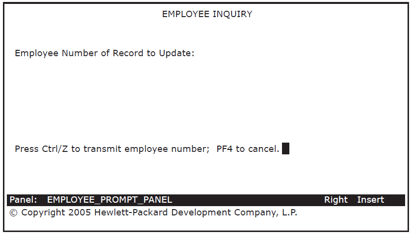
- Position the cursor after "Employee Number of Record to Update:" on the panel. Press Do and issue the
CREATE FIELDcommand to create a field there:Command>
CREATE FIELD - Enter the field name on the Create Field Menu and press Return.
Field Name :
EMPL_NUMBERAs before, press Select at the Data Type prompt, select the Character data type, and enter a size of 10. Select OK. Enter X(10) for the field picture and then select OK to leave the Create Field Menu.
Press Ctrl/Z to exit from the Panel Editor, test this panel through the Test option on the FDE Main Menu, press Ctrl/Z to exit the test, and then exit from FDE by selecting Exit.
Use a text editor to edit the IFDL source file created by DECforms. This file is named EMPLOYEE_INFO_PROMPT_FORM.IFDL.
Enter a form record description. Add the following lines after the line, "End Data":Form Record EMPLOYEE_INFO_RECORD Copy EMPLOYEE_INFO_RECORD From Dictionary End Copy End RecordEnter a function key declaration, a function response, and, to perform cleanup activities, a disable response. Add the following lines after the line, "Size 24 Lines by 80 Columns":Function QUIT_KEY Is %PF4 End Function Function Response QUIT_KEY Remove All Return " FQUT" End Response Disable Response Request Exit Response Remove All End Response End ResponseAdd the following lines under "Field EMPL_NUMBER" after the line specifying "Column ...":Entry Response Reset EMPL_NUMBER End Response
The Reset clause deletes old data that may be in the EMPL_NUMBER field.
Your EMPLOYEE_INFO_PROMPT_FORM.IFDL is now complete. Save the edits made in the IFDL file and exit from the text editor.
- Create a new binary form file to match your IFDL source file by issuing the following command:
$
FORMS TRANSLATE EMPLOYEE_INFO_PROMPT_FORM.IFDL$ - Enter the DECforms
EXTRACT OBJECTcommand to create a form object module, or .OBJ file:$
FORMS EXTRACT OBJECT EMPLOYEE_INFO_PROMPT_FORM.FORM$ - Enter the
LINK/SHAREcommand to link the form object module into a shareable image:$
LINK/SHARE EMPLOYEE_INFO_PROMPT_FORM.OBJ$The result of the
LINK/SHAREcommand is an image (.EXE) of the form that can be shared by multiple users.
8.2. Defining the Inquiry/Update Task
The inquiry/update task allows a user to display an employee record from the RMS master file EMPLOYEE.DAT. The user can then modify the contents of that record (for example, changing the employee's address) and write the revised record back to the RMS master file. This task first displays a panel to prompt the user for the employee number, then displays the employee record for that number, and then writes the modified record to the RMS file.
The first exchange step collects the employee number of the record to be updated.
The first processing step calls a COBOL procedure that retrieves the specified employee record from the RMS file.
The second exchange step collects the modified employee data from the user.
The second processing step calls a COBOL procedure that replaces the original employee record with the modified record.
The third exchange step sends error messages, if any, back to the form, where they are displayed to users.
The inquiry/update task does not cover all possible error conditions. For illustration purposes, this task contains error handling for a condition in which two users are modifying the same record at approximately the same time. The task informs one of the users that another user has changed that record and gives the notified user a chance to repeat the task with the most recent version of the record.
8.2.1. Defining the First Exchange Step
The first exchange step directs DECforms to display a panel that prompts the user for the employee number of the record to be updated. This employee number is passed to the first processing step, which retrieves the specified record from the RMS file and displays it to the user.
Use a text editor to create a source file for the inquiry/update task definition. Name the source file EMPLOYEE_INFO_UPDATE_TASK.TDF.
- Enter the first exchange step in your task definition file:
GET_EMPL_NUMBER:
EXCHANGE
  RECEIVE FORM RECORD EMPLOYEE_INFO_RECORD
  IN EMPLOYEE_INFO_PROMPT_LABEL
  RECEIVING EMPLOYEE_INFO_WKSP
  WITH RECEIVE CONTROL QUIT_WORKSPACE;
Unlike the data entry task, this exchange step explicitly states the name of the form (EMPLOYEE_INFO_PROMPT_LABEL) used to enter the employee number. Otherwise, ACMS displays the data entry form, which you specify as the default form later in the task group definition. Specifying a form here overrides the default form.
As in the data entry task, the RECEIVE CONTROL statement names the ACMS workspace (QUIT_WORKSPACE) to which DECforms returns the value FQUT when the user presses PF4.
- Add the following lines to your task definition:
CONTROL FIELD IS QUIT_WORKSPACE.QUIT_KEY
   " FQUT"  :  EXIT TASK;
END CONTROL FIELD;
The CONTROL FIELD statement associates the value FQUT with the ACMS command
EXIT TASK. Because you have already defined the field QUIT_KEY and the record QUIT_WORKSPACE in CDD for the data entry task, you do not need to define them again for the inquiry/update task.
8.2.2. Defining the First Processing Step
The first processing step calls a COBOL procedure that retrieves an employee record from the RMS master file. The retrieved record corresponds to the employee number that the user entered. The user then has an opportunity to modify employee information on the panel that displays this record.
RETRIEVE_UPDATE_INFO:
PROCESSING
  CALL GET_EMPL_INFO IN EMPL_SERVER
    USING EMPLOYEE_INFO_WKSP, EMPLOYEE_INFO_COMPARE_WKSP,
    CONTROL_WORKSPACE;
GET_EMPL_INFO is the name of the COBOL procedure that retrieves a record from the RMS file. It runs in the server EMPL_SERVER and uses three workspaces. The procedure and these workspaces are discussed later in the chapter.
8.2.3. Defining the Second Exchange Step
The second exchange step directs DECforms to display the retrieved employee record on a panel. The user can then modify that information. When the user finishes modifying employee information, this exchange step then directs DECforms to return the updated information to ACMS.
GET_UPDATE_INFO_FROM_USER:
EXCHANGE
  TRANSCEIVE FORM RECORD EMPLOYEE_INFO_RECORD, EMPLOYEE_INFO_RECORD
    IN EMPLOYEE_INFO_LABEL
  SENDING EMPLOYEE_INFO_WKSP
  RECEIVING EMPLOYEE_INFO_WKSP
  WITH RECEIVE CONTROL QUIT_WORKSPACE;

  CONTROL FIELD IS QUIT_WORKSPACE.QUIT_KEY
       " FQUT"     :  EXIT TASK;
  END CONTROL FIELD;
The second exchange step begins with a TRANSCEIVE FORM RECORD call to DECforms naming the SEND record and the RECEIVE record involved in the TRANSCEIVE operation (in both cases here, EMPLOYEE_INFO_RECORD). The name EMPLOYEE_INFO_LABEL specifies which form to use.
The SENDING clause names the workspace sent to the form: EMPLOYEE_INFO_WKSP. The RECEIVING clause names the workspace received from the form: also EMPLOYEE_INFO_WKSP. The latter workspace contains any modifications that a user makes to the data items displayed on the form.
As you did for the first exchange step, include a CONTROL FIELD clause in your task definition so that the user can press a key to exit from the task without saving any entries.
8.2.4. Defining the Second Processing Step
The second processing step calls a COBOL procedure that processes the update information and places it in the RMS file.
PROCESS_UPDATE_INFO:
PROCESSING
  CALL PUT_EMPL_INFO IN EMPL_SERVER
     USING EMPLOYEE_INFO_WKSP, EMPLOYEE_INFO_COMPARE_WKSP,
        CONTROL_WORKSPACE;
  IF (CONTROL_WORKSPACE.ERROR_STATUS_FIELD EQ "CHNG")
    THEN
      MOVE "Changed by another user.  Ctrl/Z to repeat, PF4 to quit." TO
          CONTROL_WORKSPACE.MESSAGEPANEL;
    ELSE
      EXIT TASK;
  END IF;
PUT_EMPL_INFO is the name of the COBOL procedure that writes a changed record to the RMS file. It runs in EMPL_SERVER and uses the same workspaces as the retrieval procedure. The procedure and these workspaces are discussed later in the chapter.
The procedure PUT_EMPL_INFO reads this record from the RMS file and locks it. The procedure then compares this record to a copy of the original record stored in a workspace.
If the two records do not match, the record in the RMS file has been changed since the user first saw it. In that case, the user is attempting to modify an outdated version of the record. The user is notified (by means of the "changed" message) and given the opportunity to repeat (with the current version of the record) or quit (cancel the task).
If the records do match, the procedure writes the modified record to the RMS file.
The IF THEN ELSE clause tests for the CHNG value in the field ERROR_STATUS_FIELD. If the value is present, a message is stored in the MESSAGEPANEL field, and the task moves on to the third exchange step to display the message. Otherwise, if the CHNG value is not in the workspace field, control passes to the ELSE statement and ends the task successfully.
8.2.5. Defining the Third Exchange Step
The third exchange step is nearly the same as the second exchange step in the data entry task discussed in Chapter 7, "Developing the Data Entry Task". The purpose of this step is to display an error message, if the user tries to modify a record that another user just changed.
DISPLAY_ERROR_MESSAGE:
 EXCHANGE
   SEND FORM RECORD CONTROL_WORKSPACE IN EMPLOYEE_INFO_LABEL
   SENDING CONTROL_WORKSPACE
   WITH RECEIVE CONTROL QUIT_WORKSPACE;
 ACTION IS
   IF (QUIT_WORKSPACE.QUIT_KEY EQ " FQUT")
   THEN EXIT TASK;
   ELSE REPEAT TASK;
   END IF;
8.2.6. Completing the Task Definition
- Add these lines at the beginning of your file:
REPLACE TASK EMPLOYEE_INFO_UPDATE_TASK
USE WORKSPACES
 EMPLOYEE_INFO_WKSP,
 EMPLOYEE_INFO_COMPARE_WKSP,
 QUIT_WORKSPACE,
 CONTROL_WORKSPACE;
BLOCK WORK WITH FORM I/O
REPLACEis an ADU command that stores a new task definition in CDD (creating a new definition or replacing an old one). Placing this command inside the task definition allows you to run this task definition (EMPLOYEE_INFO_UPDATE_TASK) as a command file in ADU (see Section 8.3, ''Compiling the Task Definition'').The WORKSPACES clause names the workspaces used in the task. In the processing steps, you use EMPLOYEE_INFO_COMPARE_WKSP as the workspace that stores a copy of the displayed record.
The BLOCK WORK clause marks the beginning of the work that takes place within the block step.
- Add these lines at the end of your file:
END BLOCK WORK; END DEFINITION;
The END BLOCK WORK clause ends the work done within the block step.
Your definition for the inquiry/update task, EMPLOYEE_INFO_UPDATE_TASK.TDF, is now complete. Save your file and exit the editor.
8.3. Compiling the Task Definition
- Invoke ADU:
$
ADU - When you issue the
SET LOGandSET VERIFYcommands, ADU simultaneously writes its output to the terminal screen and to the ADULOG.LOG file. Enter theSET LOGandSET VERIFYcommands:ADU>
SET LOGADU>SET VERIFY - Submit the task definition file to ADU:
ADU>
@EMPLOYEE_INFO_UPDATE_TASK.TDFIf ADU detects syntax errors in your task definition, exit ADU and edit the source file to correct the errors. Then reenter ADU and resubmit the file. Repeat editing the source file and resubmitting it to ADU until the file processes without errors. If you get error messages, make sure you typed the definition exactly as shown. In particular, check that you used the appropriate punctuation.
Exit from ADU.
8.4. Defining COBOL Procedures
The procedures used in the inquiry/update task are similar in many respects to the COBOL procedure EMPLOYEE_INFO_ADD.COB, which is called from the data entry task discussed in Chapter 7, "Developing the Data Entry Task". Consequently, this section does not discuss the basic details again. This section concentrates instead on the processing and error handling in the Procedure Division of each program.
The first processing step in the inquiry/update task calls a COBOL procedure that retrieves a record from an RMS file. You must retrieve the record before calling DECforms to display it. This COBOL procedure is called EMPLOYEE_INFO_UPDATE_GET.COB.
The second processing step calls a COBOL procedure that writes the updated record to the RMS file. This COBOL procedure is called EMPLOYEE_INFO_UPDATE_PUT.COB. The following sections explain these two procedures.
8.4.1. Defining the Retrieval Procedure
The Identification Division, the Environment Division, and the File Section of the Data Division for the retrieval procedure are almost identical to those for the data entry procedure (see Example 7.1, ''COBOL Data Entry Procedure''). The only difference is the PROGRAM-ID, which for the retrieval procedrue is GET_EMPL_INFO. Because the data entry and retrieval procedures use the same RMS file, they must define the file identically in the SELECT and FD statements.
Example 8.1, ''COBOL Retrieval Procedure'' contains the COBOL retrieval procedure. Create a source file named EMPLOYEE_INFO_UPDATE_GET.COB and type in the procedure as shown in this example.
Save the file and exit the editor.
*****************************************************************
IDENTIFICATION DIVISION.
PROGRAM-ID. GET_EMPL_INFO.
*****************************************************************
ENVIRONMENT DIVISION.
CONFIGURATION SECTION.
SOURCE-COMPUTER.       VAX-11.
OBJECT-COMPUTER.       VAX-11.

INPUT-OUTPUT SECTION.
FILE-CONTROL.
SELECT EMPLOYEE-FILE
       ORGANIZATION INDEXED
       ACCESS RANDOM
       FILE STATUS IS FILE-STAT
       ASSIGN TO "xxx_FILES:EMPLOYEE.DAT".
I-O-CONTROL.
        APPLY LOCK-HOLDING ON EMPLOYEE-FILE.

*****************************************************************
DATA DIVISION.
FILE SECTION.
FD EMPLOYEE-FILE EXTERNAL
   DATA RECORD IS EMPLOYEE_INFO_WKSP
   RECORD KEY EMPL_NUMBER OF EMPLOYEE_INFO_WKSP.
COPY "EMPLOYEE_INFO_WKSP" FROM DICTIONARY.

WORKING-STORAGE SECTION.
01  FILE-STAT   PIC XX IS EXTERNAL.
    88 OK     VALUE "00".
    88 REC-LOCK     VALUE "92".

LINKAGE SECTION.
COPY "EMPLOYEE_INFO_WKSP" FROM DICTIONARY REPLACING
    ==EMPLOYEE_INFO_WKSP. == BY ==EMPLOYEE_INFO_LINKAGE_WKSP. ==.
COPY "EMPLOYEE_INFO_WKSP" FROM DICTIONARY REPLACING
    ==EMPLOYEE_INFO_WKSP. == BY ==EMPLOYEE_INFO_COMPARE_WKSP. ==.
COPY "CONTROL_WORKSPACE" FROM DICTIONARY.

*****************************************************************
PROCEDURE DIVISION USING EMPLOYEE_INFO_LINKAGE_WKSP,
      EMPLOYEE_INFO_COMPARE_WKSP, CONTROL_WORKSPACE.
DECLARATIVES.
EMPLOYEE-USE SECTION.
    USE AFTER STANDARD ERROR PROCEDURE ON EMPLOYEE-FILE.
EMPLOYEE-CHECKING.
    EVALUATE TRUE
        WHEN REC-LOCK
           MOVE "LOCK" TO ERROR_STATUS_FIELD
    END-EVALUATE.
END DECLARATIVES.

MAIN SECTION.
000-SET-STATUS.
    MOVE SPACES TO ERROR_STATUS_FIELD.

010-GET-RECORD.
    MOVE EMPL_NUMBER OF EMPLOYEE_INFO_LINKAGE_WKSP TO EMPL_NUMBER OF
      EMPLOYEE_INFO_WKSP.
    READ EMPLOYEE-FILE INTO EMPLOYEE_INFO_LINKAGE_WKSP
      ALLOWING NO OTHERS.
    MOVE EMPLOYEE_INFO_WKSP TO EMPLOYEE_INFO_COMPARE_WKSP.

100-EXIT-PROGRAM.
    UNLOCK EMPLOYEE-FILE.
    EXIT PROGRAM.
Recall that the Linkage Section lists the workspaces that ACMS passes to the procedure. The linkage workspace and the file workspace must have different names; therefore, the COPY statement includes the REPLACING clause to assign a different name to the EMPLOYEE_INFO_WKSP workspace. Like the data entry procedure, the retrieval procedure also uses CONTROL_WORKSPACE for error handling and reporting.
In the retrieval procedure, you make a copy of the record displayed to the user and store it in another workspace. The copied record is called EMPLOYEE_INFO_COMPARE_WKSP, and ACMS passes it to the update procedure to be compared with the corresponding record in the RMS file. If the record in the RMS file has changed since this task began, ACMS notifies the user that the displayed record is no longer current.
Initializes ERROR_STATUS_FIELD with spaces
Reads the record from the RMS file, locks it, and stores it in EMPLOYEE_INFO_WKSP, which is passed to DECforms and displayed on the screen
Copies the contents of EMPLOYEE_INFO_WKSP into another workspace, EMPLOYEE_INFO_COMPARE_WKSP, so that the update procedure can later compare the record that the user saw to the record currently in the RMS file
Unlocks the record before exiting the program
8.4.2. Compiling the Retrieval Procedure
Use the COBOL command to compile the retrieval procedure. By appending the
/DEBUG qualifier to this command, you create the capability to debug
the procedure later with the OpenVMS Debugger. By appending the /LIST
qualifier, you generate a listing of your program showing any errors. The listing file has
the file type .LIS.
$ COBOL/DEBUG/LIST EMPLOYEE_INFO_UPDATE_GET
$
If the source file contains syntax errors, continue to edit the source file and recompile it until the program compiles successfully.
8.4.3. Defining the Update Procedure
Except for the PROGRAM-ID, the update procedure is identical to the retrieval procedure until the Main Section of the Procedure Division.
Example 8.2, ''COBOL Update Procedure'' contains the update procedure. Create a source file named EMPLOYEE_INFO_UPDATE_PUT.COB and type in the procedure as shown in this example.
Save the file and exit the editor.
IDENTIFICATION DIVISION. PROGRAM-ID. PUT_EMPL_INFO.
ENVIRONMENT DIVISION.
CONFIGURATION SECTION.
SOURCE-COMPUTER.  VAX-11.
OBJECT-COMPUTER.  VAX-11.
INPUT-OUTPUT SECTION.
FILE-CONTROL.
SELECT  EMPLOYEE-FILE
        ORGANIZATION INDEXED
        ACCESS RANDOM
        FILE STATUS IS FILE-STAT
        ASSIGN TO "xxx_FILES:EMPLOYEE.DAT".
I-O-CONTROL.
        APPLY LOCK-HOLDING ON EMPLOYEE-FILE.

DATA DIVISION.
FILE SECTION.
FD      EMPLOYEE-FILE EXTERNAL
        DATA RECORD IS EMPLOYEE_INFO_WKSP
        RECORD KEY EMPL_NUMBER OF EMPLOYEE_INFO_WKSP.

        COPY "EMPLOYEE_INFO_WKSP" FROM DICTIONARY.

WORKING-STORAGE SECTION.
01  FILE-STAT                        PIC XX IS EXTERNAL.
    88 OK                              VALUE "00".
    88 REC-LOCK                        VALUE "92".

LINKAGE SECTION.
COPY "EMPLOYEE_INFO_WKSP" FROM DICTIONARY REPLACING
    ==EMPLOYEE_INFO_WKSP. == BY ==EMPLOYEE_INFO_LINKAGE_WKSP. ==.
COPY "EMPLOYEE_INFO_WKSP" FROM DICTIONARY REPLACING
    ==EMPLOYEE_INFO_WKSP. == BY ==EMPLOYEE_INFO_COMPARE_WKSP. ==.
COPY "CONTROL_WORKSPACE" FROM DICTIONARY.

PROCEDURE DIVISION USING EMPLOYEE_INFO_LINKAGE_WKSP,
    EMPLOYEE_INFO_COMPARE_WKSP, CONTROL_WORKSPACE.
DECLARATIVES.
EMPLOYEE-USE SECTION.
    USE AFTER STANDARD ERROR PROCEDURE ON EMPLOYEE-FILE.
EMPLOYEE-CHECKING.
    EVALUATE TRUE
        WHEN REC-LOCK
             MOVE "LOCK" TO ERROR_STATUS_FIELD
    END-EVALUATE. END DECLARATIVES.

MAIN SECTION.
000-SET-STATUS.
    MOVE SPACES TO ERROR_STATUS_FIELD.

010-GET-RECORD.
    MOVE EMPL_NUMBER OF EMPLOYEE_INFO_LINKAGE_WKSP TO EMPL_NUMBER OF
    EMPLOYEE_INFO_WKSP.
    READ EMPLOYEE-FILE ALLOWING NO OTHERS.
    IF ERROR-STATUS_FIELD EQUAL "LOCK"
    THEN
        GO TO 100-EXIT-PROGRAM.

020-CHECK-FOR-CHANGES.
    PERFORM 070-CHECK-RECORD.
    IF ERROR-STATUS_FIELD EQUAL "CHNG"
    THEN
    MOVE EMPLOYEE_INFO_WKSP TO EMPLOYEE_INFO_LINKAGE_WKSP
    MOVE EMPLOYEE_INFO_WKSP TO EMPLOYEE_INFO_COMPARE_WKSP
    GO TO 100-EXIT-PROGRAM.

030-REWRITE-RECORD.
    REWRITE EMPLOYEE_INFO_WKSP FROM EMPLOYEE_INFO_LINKAGE_WKSP
        ALLOWING NO OTHERS.
    GO TO 100-EXIT-PROGRAM.

070-CHECK-RECORD.
    EVALUATE
        EMPLOYEE_INFO_WKSP EQUAL EMPLOYEE_INFO_COMPARE_WKSP
        WHEN FALSE MOVE "CHNG" TO ERROR_STATUS_FIELD
    END-EVALUATE.

100-EXIT-PROGRAM.
    UNLOCK EMPLOYEE-FILE.
EXIT PROGRAM.Initializes ERROR_STATUS_FIELD with spaces.
Retrieves and locks the modified record. If the record is already locked, the procedure stores an error value in ERROR_STATUS_FIELD and exits from the program.
Checks the contents of the record in the RMS file against the record displayed to the user, a copy of which was stored in EMPLOYEE_INFO_COMPARE_WKSP by the retrieval procedure. If the two records do not match, the procedure stores an error value in ERROR_STATUS_FIELD and exits from the program.
Writes the modified record back to the RMS file.
Unlocks the record before exiting the program.
8.4.4. Compiling the Update Procedure
Use the COBOL command to compile the update procedure. By appending the
/DEBUG qualifier to this command, you create the capability to debug
the procedure later with the OpenVMS Debugger. By appending the /LIST
qualifier, you generate a listing of your program showing any errors. The listing file has
the file type .LIS.
$ COBOL/DEBUG/LIST EMPLOYEE_INFO_UPDATE_PUT
$
If the source file contains syntax errors, continue to edit the source file and recompile it until the COBOL compiler completes successfully.
Chapter 9. Building the Task Group
This chapter describes how to combine the data entry task and the inquiry/update task into a task group. It also describes how to write startup and cleanup procedures, how to link the object modules into a server image, and how to test the tasks using the ACMS Task Debugger.
9.1. Defining Startup and Cleanup Procedures
Because ACMS can use one server process to handle several procedures, any startup and cleanup operations can be done just once during the lifetime of the process rather than at every processing step. The following sections have you define the initialization, termination, and cancellation procedures that perform startup and cleanup for the tasks.
9.1.1. Defining the Initialization Procedure
The initialization procedure in this tutorial performs any work that must be done before the data entry, retrieval, and update procedures in the server process can execute. For example, this initialization procedure opens an RMS file and leaves it open until the process stops. This is more efficient than opening and closing the file every time a task calls one of the three processing procedures.
Therefore, the processing procedures in this tutorial do not open and close the RMS file; instead, the file is opened in the initialization procedure and closed in the termination procedure. The initialization procedure tests the status of the open operation and stops the server process if the file was not opened successfully.
In this tutorial application, the RMS file is created the first time you use the application. Because the file being opened does not exist yet, the SELECT OPTIONAL statement in COBOL creates it.
Example 9.1, ''COBOL Initialization Procedure'' contains the COBOL initialization procedure. Create a source file named EMPLOYEE_INFO_INIT.COB and type in the procedure as shown in this example.
Save the file and exit the editor.
*******************************************************************
IDENTIFICATION DIVISION.
PROGRAM-ID.  INIT_EMPL_INFO.
*******************************************************************
ENVIRONMENT DIVISION.
CONFIGURATION SECTION.
SOURCE-COMPUTER.        VAX-11.
OBJECT-COMPUTER.        VAX-11.

INPUT-OUTPUT SECTION.
FILE-CONTROL.
SELECT  OPTIONAL EMPLOYEE-FILE
        ORGANIZATION INDEXED
        ACCESS RANDOM
        FILE STATUS IS FILE-STAT
        ASSIGN TO "xxx_FILES:EMPLOYEE.DAT".
I-O-CONTROL.
        APPLY LOCK-HOLDING ON EMPLOYEE-FILE.

*******************************************************************
DATA DIVISION.
FILE SECTION.
FD  EMPLOYEE-FILE EXTERNAL
    DATA RECORD IS EMPLOYEE_INFO_WKSP
    RECORD KEY EMPL_NUMBER OF EMPLOYEE_INFO_WKSP.

COPY "EMPLOYEE_INFO_WKSP" FROM DICTIONARY.

WORKING-STORAGE SECTION.
01  STATUS-RESULT                       PIC S9(9) COMP.
01  FILE-STAT                           PIC XX IS EXTERNAL.

*******************************************************************
PROCEDURE DIVISION GIVING STATUS-RESULT.
DECLARATIVES.
PERS-USE SECTION.
    USE AFTER STANDARD ERROR PROCEDURE ON EMPLOYEE-FILE.
PERS-CHECKING.
    MOVE RMS-STS OF EMPLOYEE-FILE TO STATUS-RESULT.
END DECLARATIVES.

MAIN SECTION.
000-SET-STATUS.
    SET STATUS-RESULT TO SUCCESS.

010-OPEN-FILES.
    OPEN I-O EMPLOYEE-FILE ALLOWING ALL.

100-EXIT-PROGRAM.
    EXIT PROGRAM.
Use the COBOL command to compile this procedure. By appending the
/DEBUG qualifier to this command, you create the capability to debug
the procedure later with the OpenVMS Debugger. By appending the /LIST
qualifier, you generate a listing of your program showing any errors. The listing file has
the file type .LIS.
$COBOL/DEBUG/LIST EMPLOYEE_INFO_INIT$
If the source file contains syntax errors, continue to edit the source file and recompile it until the program compiles successfully.
9.1.2. Defining the Termination Procedure
Note
If the server runs down because a cancel occurs, ACMS does not execute the termination procedure unless you include the statement ALWAYS EXECUTE TERMINATION PROCEDURE in the server clause of the task group definition (see Section 9.2.3, ''Naming the Procedure Server and Workspaces'').
Example 9.2, ''COBOL Termination Procedure'' contains the COBOL termination procedure. Create a source file named EMPLOYEE_INFO_TERM.COB and type in the procedure as shown in this example.
Save the file and exit the editor.
*******************************************************************
IDENTIFICATION DIVISION.
PROGRAM-ID.  TERM_EMPL_INFO.

*******************************************************************
ENVIRONMENT DIVISION.
CONFIGURATION SECTION.
SOURCE-COMPUTER.        VAX-11.
OBJECT-COMPUTER.        VAX-11.

INPUT-OUTPUT SECTION.
FILE-CONTROL.
SELECT  EMPLOYEE-FILE
        ORGANIZATION INDEXED
        ACCESS RANDOM
        FILE STATUS IS FILE-STAT
        ASSIGN TO "xxx_FILES:EMPLOYEE.DAT".
I-O-CONTROL.
        APPLY LOCK-HOLDING ON EMPLOYEE-FILE.

*******************************************************************
DATA DIVISION.
FILE SECTION
FD  EMPLOYEE-FILE EXTERNAL
    DATA RECORD IS EMPLOYEE_INFO_WKSP
    RECORD KEY EMPL_NUMBER OF EMPLOYEE_INFO_WKSP.

COPY "EMPLOYEE_INFO_WKSP" FROM DICTIONARY.

WORKING-STORAGE SECTION.
01  STATUS-RESULT                       PIC S9(9) COMP.
01  FILE-STAT                           PIC XX IS EXTERNAL.

*******************************************************************
PROCEDURE DIVISION GIVING STATUS-RESULT.
DECLARATIVES.
PERS-USE SECTION.
    USE AFTER STANDARD ERROR PROCEDURE ON EMPLOYEE-FILE.
PERS-CHECKING.
    MOVE RMS-STS OF EMPLOYEE-FILE TO STATUS-RESULT.
END DECLARATIVES.

MAIN SECTION.
000-SET-STATUS.
    SET STATUS-RESULT TO SUCCESS.

010-CLOSE-FILES.
    CLOSE EMPLOYEE-FILE.

100-EXIT-PROGRAM.
    EXIT PROGRAM.
Use the COBOL command to compile this procedure. By appending the
/DEBUG qualifier to this command, you create the capability to debug
the procedure later with the OpenVMS Debugger. By appending the /LIST
qualifier, you generate a listing of your program showing any errors. The listing file has
the file type .LIS.
$COBOL/DEBUG/LIST EMPLOYEE_INFO_TERM$
If the source file contains syntax errors, continue to edit the source file and recompile it until the program compiles successfully.
9.1.3. Defining the Cancellation Procedure
Note
Often a cancellation procedure is not recommended in more complex applications, either for design reasons, or because you can accomplish any necessary server cleanup activity in your termination procedure.
Example 9.3, ''COBOL Cancellation Procedure'' contains the COBOL cancellation procedure. Create a source file named EMPLOYEE_INFO_CANCEL.COB and type in the procedure as shown in this example.
Save the file and exit the editor.
*******************************************************************
IDENTIFICATION DIVISION.
PROGRAM-ID.  CANCEL_EMPL_INFO.

*******************************************************************
ENVIRONMENT DIVISION.
CONFIGURATION SECTION.
SOURCE-COMPUTER.        VAX-11.
OBJECT-COMPUTER.        VAX-11.

INPUT-OUTPUT SECTION.
FILE-CONTROL.
SELECT  EMPLOYEE-FILE
        ORGANIZATION INDEXED
        ACCESS RANDOM
        FILE STATUS IS FILE-STAT
        ASSIGN TO "xxx_FILES:EMPLOYEE.DAT".
I-O-CONTROL.
        APPLY LOCK-HOLDING ON EMPLOYEE-FILE.

*******************************************************************
DATA DIVISION.
FILE SECTION.
FD  EMPLOYEE-FILE EXTERNAL
    DATA RECORD IS EMPLOYEE-INFO_WKSP
    RECORD KEY EMPL_NUMBER OF EMPLOYEE_INFO_WKSP.

COPY "EMPLOYEE_INFO_WKSP" FROM DICTIONARY.

WORKING-STORAGE SECTION.
01  STATUS-RESULT                       PIC S9(9) COMP.
01  FILE-STAT                           PIC XX IS EXTERNAL.

*******************************************************************
PROCEDURE DIVISION GIVING STATUS-RESULT.
DECLARATIVES.
PERS-USE SECTION.
    USE AFTER STANDARD ERROR PROCEDURE ON EMPLOYEE-FILE.
PERS-CHECKING.
    MOVE RMS-STS OF EMPLOYEE-FILE TO STATUS-RESULT.
END DECLARATIVES.

MAIN SECTION.
000-SET-STATUS.
    SET STATUS-RESULT TO SUCCESS.

010-UNLOCK-FILES.
    UNLOCK EMPLOYEE-FILE.

100-EXIT-PROGRAM.
    EXIT PROGRAM.
Use the COBOL command to compile this procedure. By appending the
/DEBUG qualifier to this command, you create the capability to debug
the procedure later with the OpenVMS Debugger. By appending the /LIST
qualifier, you generate a listing of your program showing any errors. The listing file has
the file type .LIS.
$COBOL/DEBUG/LIST EMPLOYEE_INFO_CANCEL$
If the source file contains syntax errors, continue to edit the source file and recompile it until the program compiles successfully.
9.2. Defining and Building the Task Group
To define the task group in this tutorial, you specify the tasks that belong to the group, the server in which the tasks run, and the workspaces that the tasks use. Because the application uses DECforms to get information from the terminal user, you must also specify the form file name, form file specification, and form file label of the forms used in the task group definition.
You define a task group with commands and clauses of the Application Definition Utility (ADU) in the same manner that you created the two task definitions earlier.
9.2.1. Naming Forms
Use a text editor to create a source file for the task group definition. Name the source file EMPLOYEE_INFO_TASK_GROUP.GDF.
- Begin your file by entering the following lines:
REPLACE GROUP EMPLOYEE_INFO_TASK_GROUP
FORM IS EMPLOYEE_INFO_FORM IN "xxx_FILES:EMPLOYEE_INFO_FORM"
  WITH NAME EMPLOYEE_INFO_LABEL;
FORM IS EMPLOYEE_INFO_PROMPT_FORM
  IN "xxx_FILES:EMPLOYEE_INFO_PROMPT_FORM"
  WITH NAME EMPLOYEE_INFO_PROMPT_LABEL;
The task group definition lists the OpenVMS file specifications of DECforms form files used in the task group. These are EMPLOYEE_INFO_FORM and EMPLOYEE_INFO_PROMPT_FORM, created in Chapter 7, "Developing the Data Entry Task" and Chapter 8, "Developing the Inquiry/Update Task", and stored in the directory specified by your logical xxx_FILES.
The WITH NAME phrase specifies the form label name for each form. These names were used earlier within the ACMS task definitions to refer to the form.
9.2.2. Naming the Tasks in the Task Group
TASKS ARE
  EMPLOYEE_INFO_ADD_TASK : TASK IS EMPLOYEE_INFO_ADD_TASK;
  EMPLOYEE_INFO_UPDATE_TASK : TASK IS EMPLOYEE_INFO_UPDATE_TASK;
END TASKS;
The task name on the right hand side of the colon is as you defined it in CDD. The task name on the left hand side of the colon can be any unique name you create to identify the task and does not need to match the task name on the right hand side, but using different names is more often confusing than useful. You use the task names on the left hand side later in the application definition to assign different characteristics to individual tasks.
9.2.3. Naming the Procedure Server and Workspaces
- Add the following lines to your file:
SERVER IS
  EMPL_SERVER:
    DEFAULT OBJECT FILE IS EMPL_SERVER;
    PROCEDURE SERVER IMAGE IS "xxx_FILES:EMPL_SERVER";
    INITIALIZATION PROCEDURE IS INIT_EMPL_INFO;
    TERMINATION PROCEDURE IS TERM_EMPL_INFO;
    CANCEL PROCEDURE IS CANCEL_EMPL_INFO;
    PROCEDURES ARE
      ADD_EMPL_INFO,
      GET_EMPL_INFO,
      PUT_EMPL_INFO;
END SERVER;

WORKSPACES ARE
 EMPLOYEE_INFO_WKSP,
 EMPLOYEE_INFO_WKSP WITH NAME EMPLOYEE_INFO_COMPARE_WKSP,
 QUIT_WORKSPACE,
 CONTROL_WORKSPACE;
END DEFINITION;
The SERVER IS clause identifies the procedure server for the task group and lists all procedures that run in the server. You list each procedure by its PROGRAM-ID (for example, ADD_EMPLOYEE_INFO), including any initialization, termination, and cancellation procedures you have written.
The DEFAULT OBJECT FILE statement names the procedure server object module (.OBJ), while the PROCEDURE SERVER IMAGE statement names the executable image (.EXE). In this tutorial, the server object module and the executable image are both called EMPL_SERVER. The system logical xxx_FILES specifies the directory in which to place the procedure server image.
The WORKSPACES clause defines the workspaces used in the tasks. In the inquiry/update task, both EMPLOYEE_INFO_WKSP and EMPLOYEE_INFO_COMPARE_WKSP need to use the EMPLOYEE_INFO_WKSP definition. However, ACMS requires that workspace names be unique; therefore, you use the WITH NAME keywords in the WORKSPACES clause to rename one of the EMPLOYEE_INFO_WKSP definitions.
Your definition for the task group definition, EMPLOYEE_INFO_TASK_GROUP.GDF, is now complete. Save your file and exit the editor.
9.2.4. Compiling the Task Group Definition
- Invoke ADU:
$ADU - When you use the
SET LOGandSET VERIFYcommands, ADU simultaneously writes its output to the terminal screen and to the ADULOG.LOG file. Enter theSET LOGandSET VERIFYcommands:ADU>SET LOGADU>SET VERIFY - Submit the task group definition file to ADU:
ADU>@EMPLOYEE_INFO_TASK_GROUP.GDFIf ADU detects syntax errors in your task definition, exit ADU and edit the source file to correct the errors; then reenter ADU and resubmit the file. Repeat editing the source file and resubmitting it to ADU until the file processes without errors. If you get error messages, make sure that you typed the definition exactly as shown. In particular, check that you used the appropriate punctuation.
Exit from ADU.
DIRECTORY command to verify that these
definitions exist (a partial directory listing is as
follows).$CDOCDO>DIRECTORYCONTROL_WORKSPACE;1 RECORDEMPLOYEE_INFO_ADD_TASK;1 ACMS$TASKEMPLOYEE_INFO_TASK_GROUP;1 ACMS$TASK_GROUPEMPLOYEE_INFO_UPDATE_TASK;1 ACMS$TASKEMPLOYEE_INFO_WKSP;1 RECORD. . .CDO>
The DIRECTORY command displays the names of items in CDD and indicates the
type of each item: CDD record or field, ACMS task or task group.
9.2.5. Building the Task Group
You can now build the task group with the ADU BUILD command. This command
produces two new files: a task group database file and a procedure server object module. The
task group database is an RMS file that contains binary versions of the tasks and
information about how to process them. At run time, ACMS executes the tasks in their binary
form rather than as ADU source commands. The procedure server object module controls the
procedures that run in the same server.
BUILD command with the GROUP keyword.
Include the /DEBUG qualifier to test the task group in the ACMS Task
Debugger (described at the end of this chapter). Build the task group as
follows:$ADUADU>BUILD GROUP EMPLOYEE_INFO_TASK_GROUP/DEBUGADU>
If the BUILD command succeeds, ADU displays a "Writing TDB...object module
created" sequence of messages. When ADU processes this command, it creates the task group
database file EMPLOYEE_INFO_TASK_GROUP.TDB. It also creates a procedure server transfer
module called EMPL_SERVER.OBJ. In the following section, you link this object module with
all the procedure object modules to produce the procedure server image.
If the BUILD command fails, ADU issues error messages and redisplays the
ADU> prompt. Correct the errors and resubmit the task group definition to ADU, repeating
this sequence until the definition processes without errors.
Exit from ADU.
9.3. Linking the Server Image
LINK command. Include the
/DEBUG qualifier to test the task group in the ACMS Task Debugger
(described at the end of this
chapter):$LINK/DEBUG EMPL_SERVER, EMPLOYEE_INFO_ADD, EMPLOYEE_INFO_INIT, -_$EMPLOYEE_INFO_TERM, EMPLOYEE_INFO_CANCEL, EMPLOYEE_INFO_UPDATE_GET, -_$EMPLOYEE_INFO_UPDATE_PUT$
If your LINK command succeeds, DCL returns the $ prompt without any error
messages.
The OpenVMS Linker automatically uses the first object module listed after the
LINK command as the name of the server image. The tutorial lists the
EMPL_SERVER object module first, so that the server image has the same name as the procedure
server. This produces a server image named EMPL_SERVER.EXE.
Notice that you use the DCL file names for the COBOL procedures in the LINK
command.
9.4. Testing a Task in the ACMS Task Debugger
Note
The ACMS Task Debugger works within your OpenVMS process. To accommodate the Task Debugger, your OpenVMS account needs a minimum BYTLM quota of 50,000. Otherwise, you receive an EXBYTLM error in step 2.
If you want to create a DECforms trace file that records form processing whenever an ACMS task calls a DECforms request, turn on tracing here before entering the Task Debugger (see Section A.4, ''DECforms Trace Facility'').
- To start the Task Debugger, issue the
ACMS/DEBUGcommand followed by the name of the task group. To examine the contents of workspaces while stepping through a task, include the/WORKSPACEqualifier:$ACMS/DEBUG EMPLOYEE_INFO_TASK_GROUP /WORKSPACEACMSDBG> - Issue the
STARTcommand to start EMPL_SERVER. The Task Debugger returns several messages and the DBG> prompt:ACMSDBG>START EMPL_SERVERTerminal is in SERVER EMPL_SERVER I64 DEBUG Version ... %DEBUG-I-INITIAL, language is COBOL, module set to EMPL_SERVER DBG> - Issue the
GOcommand to run the initialization procedure, EMPLOYEE_INFO_INIT.COB:DBG>GOServer EMPL_SERVER has been startedACMSDBG>To verify that EMPL_SERVER is active as you are testing, you can enter theSHOW SERVERScommand:ACMSDBG>SHOW SERVERSEMPL_SERVER ACMSDBG> - (Optional) Set breakpoints for EMPLOYEE_INFO_ADD_TASK at the GET_EMPL_INFO and PROCESS_EMPL_INFO lines in the task, using the $ACTION symbol. Breakpoints stop a task at a specified line so that you can examine the contents of a field in one of the workspaces:
ACMSDBG>SET BREAK EMPLOYEE_INFO_ADD_TASK GET_EMPL_INFO $ACTIONACMSDBG>SET BREAK EMPLOYEE_INFO_ADD_TASK PROCESS_EMPL_INFO $ACTIONACMSDBG> - (Optional) Issue the
SHOW BREAKcommand to check the breakpoints you have set:ACMSDBG>SHOW BREAKtask breakpoint at EMPLOYEE_INFO_ADD_TASK\GET_EMPL_INFO\$ACTION task breakpoint at EMPLOYEE_INFO_ADD_TASK\PROCESS_EMPL_INFO\$ACTION
ACMSDBG> - Enter the
SELECTcommand with the name of the task that you want to start:ACMSDBG>SELECT EMPLOYEE_INFO_ADD_TASKTask is in the task debuggerThis command begins the task. The EMPLOYEE_INFO_FORM appears on your screen.
- Enter data in all the fields on the form. Make note of the employee number that you enter here to test the inquiry/update task next. Then press Ctrl/Z. If you set breakpoints, the system returns this message:
Task breakpoint at EMPLOYEE_INFO_ADD_TASK\GET_EMPL_INFO\$ACTION
If you did not set breakpoints, the message is "Task ended," and you can proceed to step 11.
- Issue the
EXAMINEcommand to check that the information you entered on the form was transmitted to the workspace EMPLOYEE_INFO_WKSP:ACMSDBG>EXAMINE EMPLOYEE_INFO_WKSPThe Task Debugger displays the employee data as it appears in the workspace.
- Enter
GOto continue to your second breakpoint:ACMSDBG>GOTask is in SERVER EMPL_SERVER Task is in the task debugger Task breakpoint at EMPLOYEE_INFO_ADD_TASK\PROCESS_EMPL_INFO\$ACTION
ACMSDBG>The Task Debugger now stops at the second breakpoint (PROCESS_EMPL_INFO) in your task.
- Enter
GOto complete the task:ACMSDBG>GOTask ended - If you wish to test EMPLOYEE_INFO_UPDATE_TASK, you can use the employee number that you just entered during the data entry test above. If you wish to set breakpoints for this task, do so before selecting the task. Enter the
SELECTcommand with the name of the task:ACMSDBG>SELECT EMPLOYEE_INFO_UPDATE_TASKTask is in the task debuggerThis command begins the task. The EMPLOYEE_INFO_PROMPT_FORM appears on your screen. Type in the employee number and press Ctrl/Z. The employee data that you entered in the data entry test should appear on your screen. You can now modify that data and save it by pressing Ctrl/Z.
- When you are finished testing your tasks ("Task ended"), issue the
STOPcommand to stop EMPL_SERVER:ACMSDBG>STOP /ALLTerminal is in SERVER EMPL_SERVER Server EMPL_SERVER stopped ACMSDBG> - Exit from the ACMS Task Debugger:
ACMSDBG>EXIT$
For more information on testing and debugging tasks, see VSI ACMS for OpenVMS Writing Server Procedures. For information on using the OpenVMS Debugger, consult the VSI OpenVMS Debugger Manual.
Chapter 10. Defining and Building the Application
In this chapter, you learn how to write the application definition. You then build this definition into an application database that ACMS uses at run time.
10.1. Defining the Application
An ACMS application controls one or more task groups, each of which contains related tasks that may share servers. In the application definition, you describe characteristics that control the tasks, the servers, and the application. ACMS provides defaults for most of the control characteristics that an application requires.
You create the application definition as a source file of ADU commands in the same manner that you created the task and task group definitions earlier.
10.1.1. Application Characteristics
Use a text editor to create a source file for the application definition. Name the file EMPLOYEE_INFO_APPL_xxx.ADF, filling in your initials or other unique characters for the xxx part of the name. Creating a unique application name avoids conflicts with the applications of others who may be entering this tutorial on your system. If you copy the file EMPLOYEE_INFO_APPL_xxx.ADF from the online source files, rename it to substitute your initials for xxx. Also, edit this file to make the same name change in the first line of the file.
- Begin your file by entering the following lines:
REPLACE APPLICATION EMPLOYEE_INFO_APPL_xxx
  AUDIT;
  APPLICATION USERNAME IS EMPLOYEE_EXC;
The AUDIT clause directs ACMS to collect audit trail information for the application. This information is useful for determining how an ACMS system and its tasks and applications are being used. The ACMS Audit Trail Logger gathers statistics about an active ACMS system and records them in the audit trail log file. This file, which is named SYS$ERRORLOG:ACMSAUDIT.LOG by default, records such information as task selections, task cancellations, user logins and logouts, and application starts and stops.
At run time, ACMS uses an OpenVMS process called an Application Execution Controller (EXC) for each application. The EXC executes the task and performs task flow control. The APPLICATION USERNAME clause specifies the user name EMPLOYEE_EXC for the Application Execution Controller. Chapter 12, "System Management Requirements for Installing the Tutorial Application" describes how your system manager creates the account EMPLOYEE_EXC.
10.1.2. Server Characteristics
Every server in an application has an OpenVMS user name. By default, a server uses the application user name as its OpenVMS user name. For most applications, however, use a different OpenVMS account for the server, because the server usually requires fewer privileges and lower quotas than an application. The application definition specifies the name EMPL_SERVER. Chapter 12, "System Management Requirements for Installing the Tutorial Application" describes how your system manager creates the account EMPL_SERVER.
SERVER DEFAULTS ARE
    AUDIT;
    USERNAME IS EMPL_SERVER;
    MINIMUM SERVER PROCESSES IS 1;
    MAXIMUM SERVER PROCESSES IS 1;
END SERVER DEFAULTS;
The AUDIT clause generates audit trail information for the server. The USERNAME clause names EMPL_SERVER as the account in which the server runs.
ACMS lets you control both the minimum and maximum number of server processes used for your application. Servers are serially reusable, so they can be created once and used several times by the application. The MINIMUM SERVER PROCESSES and MAXIMUM SERVER PROCESSES clauses specify that only one server process be created for the application. Specifying the same number for the minimum and the maximum can greatly improve the performance of your application, provided that the number of processes is adequate for the number of users.
10.1.3. Task Characteristics
- Add these lines to your source file:
TASK DEFAULTS ARE
     AUDIT;
END TASK DEFAULTS;

TASK GROUPS ARE
  EMPLOYEE_INFO_TASK_GROUP:
    TASK GROUP FILE IS "xxx_FILES:EMPLOYEE_INFO_TASK_GROUP.TDB";
END TASK GROUPS;
END DEFINITION;
Your definition for the application definition, EMPLOYEE_INFO_APPL_xxx.ADF, is now complete. Save your file and exit the editor.
10.2. Compiling the Application Definition
$ADUADU>SET LOGADU>SET VERIFYADU>@EMPLOYEE_INFO_APPL_xxx.ADF
If ADU detects syntax errors in your application definition, you must exit ADU and edit the source file to correct the errors. Then reenter ADU and resubmit the file. Repeat this sequence until the file processes without errors. If you get error messages, make sure that you typed the definition exactly as shown. In particular, check that you used the appropriate punctuation.
10.3. Building the Application
BUILD command and the
APPLICATION
keyword:ADU>BUILD APPLICATION EMPLOYEE_INFO_APPL_xxx
This command produces an application database file in your default OpenVMS directory. This file is sometimes called the ADB file because .ADB is the default file type (in this case, your EMPLOYEE_INFO_APPL_xxx.ADB file).
If the BUILD command succeeds, ADU displays a "Writing ADB"
message.
If the BUILD command fails, ADU issues error messages and
redisplays the ADU> prompt. Continue to correct the errors and resubmit the
application to ADU until the application processes without errors.
Exit from ADU.
Chapter 11. Defining and Building the Menu
This chapter describes how to write the menu definition. You then build this definition into a menu database that ACMS uses at run time.
11.1. Defining the Menu
In the menu definition, you describe the contents of the top-level menu displayed to users. You now define the ACMS menu from which terminal users can select either the data entry task or the inquiry/update task. ACMS provides a standard menu format.
To define a menu, specify a name for each entry and the name of the task (and application) to which the entry corresponds. A menu entry can also be the name of another menu, which allows you to create a hierarchy of menus for an application. However, this tutorial uses only one menu.
Create the menu definition as a source file of ADU commands in the same manner that you created previous ACMS definitions.
- Use a text editor to create a source file for the menu definition. Name the source file EMPLOYEE_INFO_MENU.MDF.
Note
If you copied this file from the online source files, edit the file to change two occurrences of EMPLOYEE_INFO_APPL_xxx to your unique application name.
- Begin your file by entering the following lines:
REPLACE MENU EMPLOYEE_INFO_MENU
  HEADER IS     "                  Personnel Administration System";
In the HEADER clause, you specify a one- or two-line title, enclosed in quotation marks, for the top of the menu. When ACMS displays the menu, the title, Personnel Administration System, preceded by the given number of spaces, appears at the top. Note that you must use spaces to center a menu title; you cannot use tabs.
- Add the following lines to your source file:
ENTRIES ARE
 "ADD"    : TASK IS EMPLOYEE_INFO_ADD_TASK IN EMPLOYEE_INFO_APPL_xxx;
            TEXT IS "Add new employee record";
 "UPDATE" : TASK IS EMPLOYEE_INFO_UPDATE_TASK IN EMPLOYEE_INFO_APPL_xxx;
            TEXT IS "Display or update employee record";
END ENTRIES;
You use the ENTRIES clause to specify the entries on the menu, the type of entry, and any explanatory text. Each entry you specify is either a task or another menu. If it is a task, ACMS runs the specified task from the specified application when the user selects that entry. In the ENTRIES clause here, you give each entry a name such as ADD, specifying each entry's type (TASK), its name in the application database, and the name of the application (the menu definition can point to tasks from different applications).
- To end the menu definition, enter the following line at the end of the file:
END DEFINITION;
Your source file for the menu definition, EMPLOYEE_INFO_MENU.MDF, is now complete. Save your file and exit the editor.
11.2. Compiling the Menu Definition
$ADUADU>SET LOGADU>SET VERIFYADU>@EMPLOYEE_INFO_MENU.MDF
If ADU detects syntax errors in your menu definition, you must edit the source file to correct the errors and resubmit it. Repeat this sequence until the file processes without errors. If you receive error messages, make sure that you typed the definition exactly as shown. In particular, check that you used the appropriate punctuation.
Exit from ADU.
DIRECTORY command to verify that these definitions
exist:$CDOCDO>DIRECTORYCONTROL_WORKSPACE;1 RECORDEMPLOYEE_INFO_ADD_TASK;1 ACMS$TASKEMPLOYEE_INFO_APPL_xxx;1 ACMS$APPLICATIONEMPLOYEE_INFO_MENU;1 CDD$MENUEMPLOYEE_INFO_RECORD;1 RECORDEMPLOYEE_INFO_TASK_GROUP;1 ACMS$TASK_GROUPEMPLOYEE_INFO_UPDATE_TASK;1 ACMS$TASKEMPLOYEE_INFO_WKSP;1 RECORDEMPL_CITY;1 FIELDEMPL_NAME;1 FIELDEMPL_NUMBER;1 FIELDEMPL_STATE;1 FIELDEMPL_STREET_ADDRESS;1 FIELDEMPL_ZIP_CODE;1 FIELDERROR_STATUS_FIELD; FIELDMESSAGEPANEL; FIELDQUIT_KEY;1 FIELDQUIT_WORKSPACE;1 RECORDCDO>
To look at the contents of a field or a record, you can use the SHOW
FIELD or SHOW RECORD command, followed by the name of
the record or field.
11.3. Building the Menu
BUILD command and the MENU
keyword:$ADUADU>BUILD MENU EMPLOYEE_INFO_MENU
This command produces a menu database file in your default OpenVMS directory. The file is named EMPLOYEE_INFO_MENU.MDB.
If the BUILD command succeeds, ADU displays a "Writing MDB"
message.
If the BUILD command fails, ADU issues error messages and
redisplays the ADU> prompt. You must correct the errors and resubmit the menu to ADU,
repeating this sequence until the menu processes without errors.
Exit from ADU.
Chapter 12. System Management Requirements for Installing the Tutorial Application
Note
If you do not have the privileges (SYSPRV) necessary to perform the steps in this chapter, your system manager must perform these steps for you.
To perform these steps, your system manager needs to know the name of your application (represented here by EMPLOYEE_INFO_APPL_xxx) and the logical for your default directory (repesented here by xxx_FILES).
12.1. System Management Overview
Creates two OpenVMS user accounts named EMPL_SERVER and EMPLOYEE_EXC. These accounts are created using the OpenVMS Authorize Utility.
Defines which users can sign in to ACMS and which menu is displayed to them when they sign in. ACMS provides the User Definition Utility (UDU) for this purpose.
Defines which terminals can be used to sign in to ACMS. ACMS provides the Device Definition Utility (DDU) for this purpose.
Defines which users can install the application in a protected directory. ACMS provides an optional utility, the Application Authorization Utility (AAU), to make it easier to protect the application
12.2. Creating the EMPL_SERVER and EMPLOYEE_EXC Accounts
To set up OpenVMS user accounts, your system manager uses the OpenVMS Authorize Utility. Here the system manager uses the OpenVMS Authorize Utility to set up the user accounts of the server and the Application Execution Controller. In the tutorial application, the server's user name is EMPL_SERVER, and the controller's user name is EMPLOYEE_EXC.
If you are not the first person at your site to use this tutorial, it is possible that the EMPLOYEE_EXC and EMPL_SERVER user names already exist in the OpenVMS User Authorization File (UAF). In that case, the system manager can check to see if the quotas are correct and can modify any that are not.
Maxjobs:         0  Fillm:       200  Bytlm:        50000
Maxacctjobs:     0  Shrfillm:      0  Pbytlm:           0
Maxdetach:       0  BIOlm:       100  JTquota:       1024
Prclm:           2  DIOlm:        22  WSdef:          512
Prio:            4  ASTlm:       100  WSquo:         1024
Queprio:         0  TQElm:       100  WSextent:      4096
CPU:        (none)  Enqlm:      2000  Pgflquo:      60000
Authorized Privileges:
  GRPNAM GROUP SETPRV TMPMBX OPER NETMBX BYPASS
Default Privileges:
  GRPNAM GROUP TMPMBX OPER NETMBX BYPASS
Maxjobs:         0  Fillm:       200  Bytlm:        50000
Maxacctjobs:     0  Shrfillm:      0  Pbytlm:           0
Maxdetach:       0  BIOlm:       100  JTquota:       1024
Prclm:           2  DIOlm:        22  WSdef:          512
Prio:            4  ASTlm:       100  WSquo:         1024
Queprio:         0  TQElm:       100  WSextent:      4096
CPU:        (none)  Enqlm:      2000  Pgflquo:      60000
Authorized Privileges:
  GRPNAM GROUP SETPRV TMPMBX NETMBX
Default Privileges:
  GRPNAM GROUP TMPMBX NETMBX
|
PQL_DASTLM |
PQL_DBIOLM |
PQL_DBYTLM |
PQL_DCPULM |
|
PQL_DDIOLM |
PQL_DENQLM |
PQL_DFILLM |
PQL_DJTQUOTA |
|
PQL_DPGFLQUOTA |
PQL_DPRCLM |
PQL_DTQELM |
PQL_DWSDEFAULT |
|
PQL_DWSEXTENT |
PQL_DWSQUOTA |
PQL_MASTLM |
PQL_MBIOLM |
|
PQL_MBYTLM |
PQL_MCPULM |
PQL_MDIOLM |
PQL_MENQLM |
|
PQL_MFILLM |
PQL_MJTQUOTA |
PQL_MPGFLQUOTA |
PQL_MPRCLM |
|
PQL_MTQELM |
PQL_MWSDEFAULT |
PQL_MWSEXTENT |
PQL_MWSQUOTA |
12.3. Authorizing ACMS Users
Authorized OpenVMS users cannot sign in to ACMS until the system manager has also authorized them as ACMS users. The User Definition Utility (UDU) provides the capability to do this. Using the UDU, the system manager creates an ACMS database named ACMSUDF.DAT, located in the SYS$SYSTEM directory. When adding a user to the database, the system manager also specifies the default menu the user sees upon signing in to ACMS.
- Define UDU as a global symbol in your login command file. Then initialize the symbol by executing your login command file:
$ UDU :== $ACMSUDU
$@LOGIN.COM - Set the default directory to SYS$SYSTEM:
$SET DEFAULT SYS$SYSTEM$ - Invoke UDU:
$UDUUDU> - Add an OpenVMS user name (the tutorial user's uname) to the ACMS database by entering the
ADDcommand:UDU>ADD uname /MDB=xxx_FILES:EMPLOYEE_INFO_MENUUDU>Include the
/MDBqualifier to specify the default menu displayed to this user when entering ACMS. Although the menu database is often located in ACMS$DIRECTORY for security reasons, this tutorial places it in the tutorial user's default directory (represented by uname's system logical xxx_FILES) to avoid conflicts with others entering this tutorial on the same system. Substitute uname's logical for xxx_FILES. - Enter the
SHOWcommand to verify this entry in the ACMSUDF.DAT database:UDU>SHOW unameUser name: UNAME DISPLAY MENUDefault menu:Default MDB: XXX_FILES:EMPLOYEE_INFO_MENU...UDU>An entry under the tutorial user's uname indicates that the uname is authorized to sign in to ACMS. The default characteristic DISPLAY MENU causes ACMS to display the top menu in uname's EMPLOYEE_INFO_MENU.MDB database.
- Enter the
SHOW SYSTEMcommand to determine if user name SYSTEM has been added to the ACMS database (it may not, if this is the first ACMS access). If you receive a "user does not exist" message, then add SYSTEM as follows:UDU>ADD SYSTEM /AGENTUDU>Although ACMS assigns the user name SYSTEM to the Command Process (CP) when you install ACMS, it does not automatically authorize the Command Process as an agent. Without this authorization, ACMS cannot sign in any users. The
/AGENTqualifier enables an agent to submit a task that has a user name different from the user name of the agent process. Exit from UDU.
Other UDU commands let the system manager tailor definitions for individual users, change and remove user definitions, and change user names. See VSI ACMS for OpenVMS Managing Applications for more information about UDU.
12.4. Authorizing ACMS Terminals
Authorized ACMS users must sign in from terminals that have been authorized for access to ACMS. With the Device Definition Utility (DDU), the system manager creates a database named ACMSDDF.DAT that contains a list of authorized ACMS devices. In the simplest case, the system manager can use one DDU definition to authorize all terminals on your system, both local and remote, to use ACMS.
- Define DDU as a global symbol in your login command file. Then initialize the symbol by executing your login command file:
$ DDU :== $ACMSDDU
$@LOGIN.COM - Set the default directory to SYS$SYSTEM:
$SET DEFAULT SYS$SYSTEM$ - Invoke DDU:
$DDUDDU> - Use the
ADDcommand to authorize a LAT terminal on your system for ACMS use. The device name LT authorizes all LAT terminals.DDU>ADD LTDDU>If the
ADD LTcommand has been performed before for a previous tutorial user, you receive the message, "device name already exists in the data base." In this case, you can exit from DDU and proceed to the next section. - Use the
SHOWcommand to display information about the LT entry:DDU>SHOW LTDevice name: LT NOT CONTROLLEDNo AutologinPrintfileDDU>When the system manager creates a new ACMSDDF.DAT database, DDU creates a DEFAULT definition that assigns all terminals the NOT CONTROLLED characteristic. From a CONTROLLED terminal, the user signs in directly to ACMS; from a NOT CONTROLLED terminal, the user first logs in to the OpenVMS operating system and then signs in to ACMS from DCL command level.
Exit from DDU.
Other DDU commands let the system manager tailor definitions for individual terminals, change and remove device definitions, and change device names. See VSI ACMS for OpenVMS Managing Applications for more information about DDU.
12.5. Authorizing ACMS Applications
ACMS requires that the application database (.ADB) file reside in the directory associated with the logical name ACMS$DIRECTORY. Because this directory can be protected from unauthorized use, all application databases in ACMS$DIRECTORY remain secure.
Your application, EMPLOYEE_INFO_APPL_xxx.ADB, is currently located in your default OpenVMS directory. However, ACMS cannot find it there. You must install your application in ACMS$DIRECTORY after your system manager uses the Application Authorization Utility (AAU) to authorize both you and your application.
- Define AAU as a global symbol in your login command file. Then initialize the symbol by executing your login command file:
$ AAU :== $ACMSAAU
$@LOGIN.COM - Set the default directory to SYS$SYSTEM:
$SET DEFAULT SYS$SYSTEM$ - Invoke AAU:
$AAUAAU>If an ACMSAAF.DAT file does not exist yet in the SYS$SYSTEM directory (that is, this is the first time invoking AAU), AAU displays a message stating that it is unable to open ACMSAAF.DAT and prompting the system manager to create a new file. If the file does exist already, AAU returns the AAU> prompt.
Creating this database is the first step of a two-step process. The system manager first uses the Application Authorization Utility (AAU) to create the database ACMSAAF.DAT in the SYS$SYSTEM directory. The system manager then adds to this file a list of applications and users who are authorized to install them.
By authorizing users to install applications, system managers can free themselves from having to install all applications and from having to give those users privileged access to ACMS$DIRECTORY. When the system manager creates a new ACMSAAF.DAT database, AAU creates a DEFAULT authorization with an empty access control list; that is, by default no users are authorized to install applications in ACMS$DIRECTORY.
Enter theADDcommand with an/ACLqualifier to authorize the application and the user who can install it:AAU>ADD EMPLOYEE_INFO_APPL_xxx /ACL=(ID=[uname],ACCESS=CONTROL)%ACMSAAU-S-APPLADD, Appl name EMPLOYEE_INFO_APPL_XXX has been added to the databaseAAU>This command authorizes application EMPLOYEE_INFO_APPL_xxx and authorizes user uname to install it. The
/ACLqualifier overrides the default access control list. Remember that uname is the tutorial user's OpenVMS account name, and EMPLOYEE_INFO_APPL_xxx represents this user's application name (check with the tutorial user for the exact name).- Enter the
SHOWcommand to verify the user's application name in the ACMSAAF.DAT database:AAU>SHOW EMPLOYEE_INFO_APPL_xxx======================================================================= Appl name: EMPLOYEE_INFO_APPL_XXX Appl Username: * Server Usernames: * Access Control List: (IDENTIFIER=[ACMS,UNAME],ACCESS=CONTROL) ======================================================================= AAU>
This display verifies that user UNAME is authorized to install the application database file EMPLOYEE_INFO_APPL_xxx.ADB. The asterisks in the application and server user name fields mean that the user names in the .ADB file are the only user names allowed for the application and the server.
Exit from AAU.
Other AAU commands let the system manager specify more characteristics of individual applications, authorize all applications with the $ALL keyword, remove authorizations, and change authorization names. See VSI ACMS for OpenVMS Managing Applications for more information about AAU.
12.6. Defining the ACMS$DIRECTORY Logical
The system manager needs to verify that the ACMS$DIRECTORY logical is associated with the device and directory where ACMS applications are to be stored. In the case of a new ACMS installation, the system manager may not yet have set up a protected directory for storing ACMS applications. If not, the system manager must first set up such a directory before defining the logical that points to it. Defining the ACMS$DIRECTORY logical must be done before the tutorial user can install the tutorial application.
- Enter the
SHOW LOGICALcommand to see whether ACMS$DIRECTORY has been defined on the tutorial user's system:$SHOW LOGICAL ACMS$DIRECTORYIf the logical is defined, the subsequent display shows the disk and directory location that the logical points to. If the display states that the logical is undefined, then proceed to the next step and define it.
- Set your default directory to SYS$MANAGER and run the
ACMS_POST_INSTALL.COMcommand procedure located there:$SET DEFAULT SYS$MANAGER$@ACMS_POST_INSTALL.COMThis command procedure defines all the standard ACMS logicals.
With the successful completion of this step, the tutorial user can proceed to install the application and run it.
Chapter 13. Installing and Running the Application
This chapter describes how to install and run your tutorial application. Before running the application, you perform steps to start the ACMS system (if not running) and to start your specific application. After running your application, you perform steps to stop your application and stop the ACMS system (if no one else is using it).
13.1. Installing the Application
When you install an application, ACMS checks the ACMSAAF.DAT database to determine whether you are authorized to install that application. If so, ACMS copies the database to ACMS$DIRECTORY, deletes any earlier versions, and changes the user identification code (UIC) of the .ADB file to [1,4].
If you are not authorized to install the application, ACMS returns an error message indicating that you are not authorized. Your system manager must have authorized you and your application with the AAU, as explained in Section 12.5, ''Authorizing ACMS Applications''.
You install your application database file in ACMS$DIRECTORY by executing the
ACMS/INSTALL command at DCL command level.
- Make sure that your system manager has defined the system logical ACMS$DIRECTORY to be associated with the device and directory where ACMS applications are to be stored. Enter the
SHOW LOGICALcommand to see whether ACMS$DIRECTORY has been defined on your system:$SHOW LOGICAL ACMS$DIRECTORYIf you receive a message stating that ACMS$DIRECTORY is undefined, ask your system manager to define it before trying to install your application.
- To perform an installation, you must be in the directory where your application (EMPLOYEE_INFO_APPL_xxx.ADB) is located. If you are not, then set the default directory to the directory where your application files are located:
$SET DEFAULT udisk:[uname] - Issue the
ACMS/INSTALLcommand to install your application:$ACMS/INSTALL EMPLOYEE_INFO_APPL_xxx%ACMSINS-S-ADBINS, Application UDISK:[UNAME]EMPLOYEE_INFO_APPL_XXX has been installed to ACMS$DIRECTORY $The message indicates that you have successfully installed your EMPLOYEE_INFO_APPL_xxx.ADB application database file in ACMS$DIRECTORY.
13.2. Starting the Application
Once all authorizations and installations are complete, you can start the ACMS system and
start your application. To start and stop the ACMS system automatically with the OpenVMS
system, you can include the ACMS/START and
ACMS/STOP operator commands in your system startup and shutdown
command files. However, in this tutorial, you start and stop ACMS interactively.
Any account from which the ACMS/START and ACMS/STOP
commands are issued must have OpenVMS OPER privilege to execute these commands.
- Issue the
SHOW SYSTEMcommand to determine if another user has already started ACMS:$ACMS/SHOW SYSTEMIf the subsequent display states that "current system state" is STOPPED, proceed to the next step and start the ACMS system. However, if the display states that the current system state is STARTED, proceed to step 3.
- Issue the
START SYSTEMcommand to start the ACMS system:$ACMS/START SYSTEMIf the ACMS system starts successfully, the dollar ($) prompt returns with no intervening error messages.
- Before you can invoke a command that runs the application, you need to start the application. Issue the
START APPLICATIONcommand with the name of your tutorial application:$ACMS/START APPLICATION EMPLOYEE_INFO_APPL_xxxIf the ACMS system starts successfully, the $ prompt returns with no intervening error messages. However, if your system logical xxx_FILES is not defined on this system, you receive an error message that states, in part, "Error opening TDB file XXX_FILES:[EMPLOYEE_EXC]..." See Section 7.6, ''Defining a System Logical for Your Tutorial Directory'' for information about defining your system logical.
If you receive an "invalid login attempt" message, your system manager may not have authorized the ACMS Command Process (CP) to run as an agent (described in Section 12.3, ''Authorizing ACMS Users''). Without this authorization, ACMS cannot sign in any users.
The audit trail log (ATL) keeps a record of when the ACMS system starts and stops, when users sign in, when applications and tasks start and stop, and what errors occur. To display this log, you can run the Audit Trail Report Utility (ATR) (see Section A.2, ''Audit Trail Logger'').
13.3. Running the Application
If your system manager has authorized you to use ACMS, and has authorized your terminal, you
can run your tutorial application by issuing the ACMS/ENTER command.
When you enter this command, ACMS checks the authorization files to determine whether
you and your terminal are authorized.
If you pass the authorization check, ACMS displays your default menu and waits for you to select a task. When you do, ACMS finds that task in the .TDB file and runs the task.
- Issue the
ENTERcommand to enter your application and display your default menu:$ACMS/ENTERIf this command is successful, ACMS displays your default menu. Figure 13.1, ''Selection Menu'' shows the selection menu displayed for this tutorial application.
Figure 13.1. Selection Menu 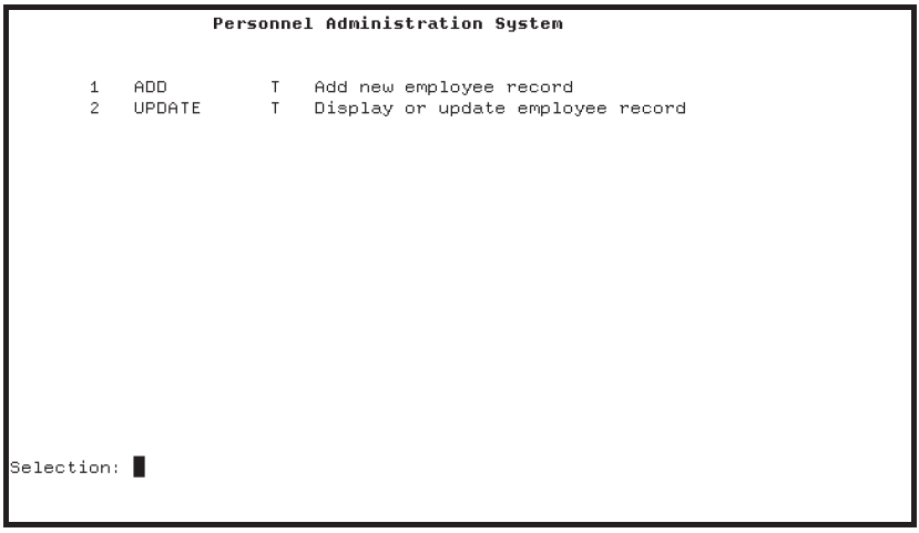
Choose an entry from the selection menu either by name or by number. For example, to select the ADD task, type either ADD or 1 at the Selection prompt and then press Return.
When you select a task, the form for that task appears on your screen. For example, when you select the ADD task, the form for filling in employee information appears. When you finish filling in the form, press Ctrl/Z to save the information in your RMS master file. To leave the form without saving the information, press PF4.
After you complete a task (by pressing Ctrl/Z or PF4), ACMS redisplays the selection menu and waits for you to select another task or exit from ACMS.
Before exiting from ACMS, you may wish to try several ADD tasks and several UPDATE tasks. You may also wish to try adding an employee number that already exists in your RMS master file so that you can see how the application responds to a duplicate-record error. Also, if you create two OpenVMS processes and run this application in each of them, you can test how the application responds when two users try to update the same employee record at the same time. The last user to save the modifications receives a message that the record has been changed since he or she began updating it.
To exit from ACMS, type
EXITat the Selection prompt and press Return.
You have now run your application and seen the results of choosing either the data entry task or the inquiry/update task. It is often helpful, especially in problem-solving, to know the various steps that ACMS takes to run one of these tasks. This information is available in Appendix A, "Utilities for Solving Problems in an ACMS Application".
Audit Trail Report (ATR), for a record of when applications start and stop
Software Event Log (SWL), for a record of internal software errors
DECforms trace facility, for a record of the form processing that occurs when the ACMS application calls a DECforms request
ACMS Help, for information about ACMS error messages
13.4. Stopping the Application and the ACMS System
ACMS/STOP command. Before you stop the system, however, issue the
SHOW SYSTEM command to see if another person is using the ACMS
system:$ACMS/SHOW SYSTEM
ACMS/STOP
commands. Otherwise, issue only the STOP APPLICATION command,
specifying the name of your
application:$ACMS/STOP APPLICATION EMPLOYEE_INFO_APPL_xxx$ACMS/STOP SYSTEM$
ACMS waits until all active tasks have finished executing before it stops the application and the system.
Other ACMS operator commands allow you to display information about your ACMS system and perform application management functions. VSI ACMS for OpenVMS Managing Applications contains a detailed discussion of ACMS operator commands.
Part III. AVERTZ Sample Application
This part provides an overview of the AVERTZ car rental sample application that ships with the ACMS software kit.
Chapter 14. Before You Begin
The AVERTZ car company is a fictional car rental company created to illustrate how transaction processing (TP) can solve a business problem. With AVERTZ, the business problem is how data entry personnel can quickly and efficiently create, access, and update car rental information.
System Manager's View
The system manager is concerned with the implementation and management of a TP application in a production environment (real use, as opposed to testing). For AVERTZ, the system manager must build the database and application, set up the AVERTZ environment, and manage users and devices.
User's View
The user is concerned with the business transaction that is taking place: namely, the rental of cars. The user could be a clerk who is taking a reservation from a customer, or tallying up the bill for a customer returning a rental; the user could also be a site manager who is responsible for the operations of a particular field unit.
Behind the Scenes
Application designers and developers work behind the scenes to create and modify running transaction processing applications. The designer is concerned with computerizing manual business transactions, or upgrading existing transaction processing systems. The developer is concerned with developing and testing the transaction processing application outlined by the designer.
Chapter 15. System Manager's View
Since the AVERTZ application is already designed and developed, the first step you should take is to set up the application so that you can try it out. This chapter helps you build, install, and set up AVERTZ.
Before you follow the instructions in this chapter, check to make sure that the ACMS$DIRECTORY logical name is defined. Check this by typing the following command at your DCL prompt:
$SHOW LOGICAL ACMS$DIRECTORY
If the logical name is defined, you can proceed with the instructions in this chapter. If the logical name is not defined, you receive the following error message:
%SHOW-S-NOTRAN, no translation for logical name ACMS$DIRECTORY
If you receive this error message, then before proceeding with the instructions in this document, you must follow the post-installation instructions in VSI ACMS Version 5.0 for OpenVMS Installation Guide.
Before you try to run the AVERTZ application, you must create a transaction log for DECdtm services. See VSI ACMS Version 5.0 for OpenVMS Installation Guide for a description of how to do this.
15.1. Building the AVERTZ Application and Databases
Source code
Data dictionary
AVERTZ databases (VEHICLE_RENTALS and VEHICLE_HISTORY)
AVERTZ images
Before you can run the AVERTZ application, you must build the databases and application. To build the databases and application, log in to an OpenVMS account that has SYSPRV privileges, and enter the following command:
$SET PROCESS/PRIVILEGE=SYSPRV
If SYSPRV is not enabled for the account you use, ask your system manager to enable that privilege using the OpenVMS Authorize Utility.
Once your account has SYSPRV enabled, enter the following command to use the directory that contains the AVERTZ sources:
$SET DEFAULT ACMS$EXAMPLES
Creates the data dictionary and database directories.
Defines the fields and records in the data dictionary.
Compiles the tasks, form, server procedures, message file, menu, and application definition.
Builds the application (task group, application, servers, message file, and form).
Installs the AVERTZ application (named VR_APPL) in the ACMS$DIRECTORY directory.
Builds the VEHICLE_RENTALS and VEHICLE_HISTORY databases.
BUILD_APPLICATION.COM
BUILD_FORM.COM
BUILD_MENU.COM
BUILD_MESSAGE_FILE.COM
BUILD_TASK_GROUP.COM
COMPILE_SERVER_PROC.COM
COMPILE_TASKS.COM
DEFINE_CDD_ENTITIES.COM
LINK_SERVERS.COM
COMPILE_SERVER_PROC.COM
When you run AVERTZ_BLD.COM, you are prompted to enter a directory location for the source code, the data dictionary, the databases, and the images.
The following example shows a sample walk-through of AVERTZ_BLD.COM. You can follow the instructions by entering the commands and responses that are provided:
To start the build procedure, enter the following command at the DCL prompt:
$@AVERTZ_BLD.COMAVERTZ_BLD.COM displays the default directory and then prompts you for the source directory. Enter the following:
SYS$COMMON:[SYSHLP.EXAMPLES.ACMS]AVERTZ_BLD.COM prompts you for the data dictionary directory. Enter the following:
SYS$COMMON:[SYSHLP.EXAMPLES.ACMS.DICTIONARY]AVERTZ_BLD.COM prompts you for the database directory. Enter the following:
SYS$COMMON:[SYSHLP.EXAMPLES.ACMS.DATABASE]AVERTZ_BLD.COM asks you if you want the object and image files in the source directory. Enter
Yor press the Return key.AVERTZ_BLD.COM then displays the directory specifications and asks you if they are correct. If the names are correct, enter
Y.You are then asked if the CDD dictionary has been created. If this is your first time building the AVERTZ application, enter
Nor press the Return key.AVERTZ_BLD.COM proceeds to create the directory structure for the data dictionary. Some informational messages are displayed and you are asked if you want to define the fields and records in the data dictionary. Enter
Y.After you enter
Y, AVERTZ_BLD.COM defines the fields and records and then asks you if you want to build the message file. EnterY.AVERTZ_BLD.COM builds the message file and then asks you if you want to compile the tasks. Enter
Y.AVERTZ_BLD.COM compiles the tasks, displaying informational messages, and then asks you if you want to build the task group. Enter
Y.AVERTZ_BLD.COM builds the task group, displaying informational messages, and then asks if you want to build the menu. Enter
Y.AVERTZ_BLD.COM builds the menu, displaying informational messages, and then asks you if you want to build the application. Enter
Y.AVERTZ_BLD.COM builds the application, displaying informational messages, and then asks you if you want to build the form. Enter
Y.AVERTZ_BLD.COM builds the form and then asks you if you want to compile the server procedures. Enter
Y.Before AVERTZ_BLD.COM compiles the server procedures, it asks you if the VEHICLE_RENTALS and VEHICLE_HISTORY databases have been built. If this is your first time building the AVERTZ application, enter
N.Finally, AVERTZ_BLD.COM builds the required databases and then asks you if you want to link the servers. Enter
Y.
15.2. Running the AVERTZ Application
In order to run the AVERTZ application successfully, you must first complete the following steps:
Add
SYSTEMto UDU with the/AGENTqualifier using the following commands:$ SET DEFAULT SYS$SYSTEM $ MCR ACMSUDU UDU> ADD SYSTEM/AGENT
Add the username of the person entering the AVERTZ application to UDU, and set their MDB to the VR_MENU.MDB, using the following commands:
$ SET DEFAULT SYS$SYSTEM $ MCR ACMSUDU UDU> ADD username /MDB=ACMS$EXAMPLES:VR_MENU.MDBAdd
$ALLto DDU using the following commands:$ SET DEFAULT SYS$SYSTEM $ MCR ACMSDDU DDU> ADD $ALL
Once you have completed the above steps, start the AVERTZ application using the following command:
$ ACMS/START APPLICATION VR_APPL
Enter AVERTZ using the following command:
$ ACMS/ENTER VR_APPL
15.3. Troubleshooting the AVERTZ Application
Should you experience issues with running or operating AVERTZ, you may find it helpful to take the following actions:
Add the following servers to SYSUAF.DAT with SETPRV/SYSPRV privileges: AVERTZ_READ, AVERTZ_LOG, and AVERTZ_UPD
Define the following two logical names:
$ DEFINE/SYSTEM AVERTZ_DEFAULT SYS$COMMON:[SYSHLP.EXAMPLES.ACMS]
$ DEFINE/SYSTEM AVERTZ_DATABASE SYS$COMMON:[SYSHLP.EXAMPLES.ACMS.DATABASE]
Run the ACMSPARAM.COM and ACMEXCPAR.COM executable files. This will add the execution controller (AVERTZ_EXC) to SYSUAF.DAT with the correct privileges.
Chapter 16. User's View
To understand how the AVERTZ application looks to the user, imagine the conversation between a reservation clerk working for AVERTZ operations in New England and a customer who needs a rental car.
16.1. Entering AVERTZ
Sparky Hartshorn (a reservation clerk at AVERTZ) enters the AVERTZ application from his OpenVMS account:
$ACMS/ENTER VR_APPL Return
AVERTZ displays the AVERTZ Rental Menu shown in Figure 16.1, ''AVERTZ Rental Menu''.
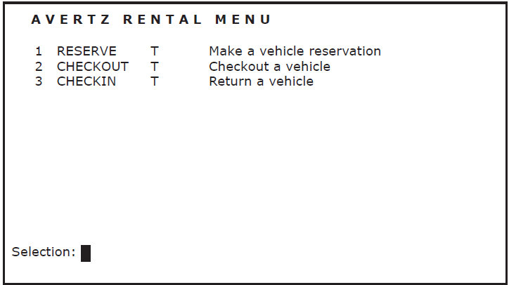
To select an option, the clerk types the option number and presses Return. For example, to reserve a car, the clerk types:
Selection:1Return
If the clerk needs online help while using AVERTZ, he can display help for any field by pressing Help when the cursor is on that field.
Reserving a car
Checking out a car (beginning the rental)
Checking in a car (ending the rental)
16.2. Customer Reserves a Car
|
Clerk |
"Hello, AVERTZ Car Rental … can I help you?" |
|
Customer |
"Oh, hi. My name is Bertram Simpson and I need to rent a car for this weekend." |
|
Clerk |
"OK, Mr. Simpson. Let me just ask you a few questions." The clerk enters the following at the AVERTZ Rental Menu:
AVERTZ displays the reservation panel shown in the table below. 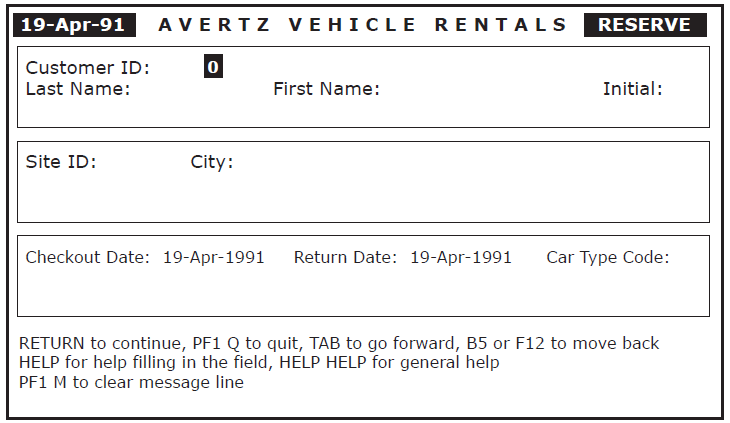
|
|
Clerk |
"Have you rented a vehicle with us before?" The clerk asks this question because, if Mr. Simpson is an existing customer, the clerk can enter his customer ID number instead of his name. | |
|
Customer |
"No, I haven't." | |
|
Clerk |
"OK, can you give me your full last name, first name, and middle initial, please?" | |
|
Customer |
"Sure. Simpson, Bertram H." | |
|
Clerk |
To move to the name field and enter the customer's name, the clerk enters the following: "OK, Mr. Simpson. And from what AVERTZ location would you like to pick up your vehicle?" | |
|
Customer |
"I'm not sure. I'll be meeting a friend in Manchester, New Hampshire. Where is the closest AVERTZ location to Manchester?" | |
|
Clerk |
"Let me get a list of the sites." The clerk enters the following to display a list of sites: AVERTZ displays the site selection panel shown in the table below. 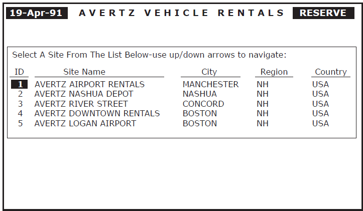
| |
|
Clerk |
"Sir, we have three sites in New Hampshire: one at the Manchester Airport, one at the Nashua Depot, and one in Concord. Is the Manchester Airport location OK with you?" | |
|
Customer |
"Great, that's perfect!" | |
|
Clerk |
The clerk enters the following: Because the site selected is the first site on the list, the clerk does not need to move the cursor. If, however, the clerk did need to move the cursor, he could press the up-arrow key or the down-arrow key to select different sites. "OK. What day would you like to start your rental?" | |
|
Customer |
"I need the car for the weekend, beginning later today." | |
|
Clerk |
"OK, you want to pick up the car today, and return it on April 22. Correct?" | |
|
Customer |
"Right." | |
|
Clerk |
The clerk enters the following: "And would you like a compact, mid-size, or full-size car, Mr. Simpson?" The clerk enters the following to display the car type codes: Help
AVERTZ displays a message listing the car types available. The following table lists the valid car type codes for this field: | |
|
1 |
Compact | |
|
2 |
Mid-Size | |
|
3 |
Full-Size | |
|
Customer |
"There will just be two people using the vehicle, so compact should be fine." | |
| Clerk |
The clerk enters the following: Because Mr. Simpson is a new customer, AVERTZ displays the new
customer panel shown in the figure below.
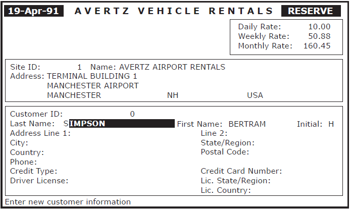 | |
|
Clerk |
If Mr. Simpson were an existing customer, the new customer panel would display information for each field, based on the data in Mr. Simpson's database record. | |
|
"OK, Mr. Simpson. Because you are a new customer, we would like to collect a few more pieces of information about where you live and how you will pay for the vehicle. First, what is your address?" | ||
|
Customer |
"901 Maple Drive, Apartment 12, Nashua, New Hampshire." | |
|
Clerk |
Based on the address the customer provided, the clerk completes the panel up to the Postal Code field by entering the following: "And what is your zip code, sir?" | |
|
Customer |
"03060." | |
|
Clerk |
The clerk enters the following: "And your phone number?" | |
|
Customer |
"603-555-9966." | |
|
Clerk |
The clerk enters the following: "Will you be paying with cash or charge?" The clerk enters the following to display the credit type codes: Help
AVERTZ displays a message listing the credit types available. The following table lists the valid credit type codes for this field: | |
|
0 |
Cash | |
|
1 |
Globetrotter | |
|
2 |
Viceroy | |
|
3 |
PlasticMoney | |
|
4 |
Gourmet Gold | |
|
Customer |
"Cash." | |
|
Clerk |
Because 0 is the code for cash, the clerk enters the following: "Your driver's license number, please?" | |
|
Customer |
"555-33-0000." | |
|
Clerk |
The clerk enters the following: "And that license is for the state of New Hampshire?" | |
|
Customer |
"Actually, no. I just moved to New Hampshire a short while ago. It is a Massachusetts license." | |
|
Clerk |
The clerk enters the following: AVERTZ processes the reservation. Since the reservation is being made on the same day as the requested checkout, AVERTZ prompts to see if the clerk wants to check out the car now (see the figure below). 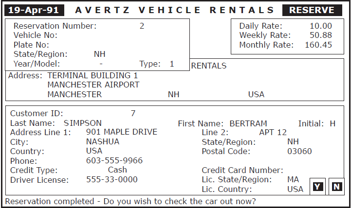
| |
|
Clerk |
"Mr. Simpson, your reservation for a compact car rental from April 19, 1991, to April 22, 1991, is confirmed, with a reservation confirmation number of 2. Please stop by our Manchester office later today to check out the car. Thank you for calling AVERTZ! Bye …" Because Mr. Simpson phoned in his reservation, the clerk knows that he is not ready to check out the car. The clerk enters the following: AVERTZ returns to the AVERTZ Rental Menu. | |
16.3. Customer Checks Out a Car (Beginning the Rental)
Bertram Simpson now has a reservation for a compact vehicle rental from April 19, 1991, until April 22, 1991. He shows up at the reservations counter at AVERTZ later in the day on April 19, after having made his reservation earlier that day. The following dialog takes place while Bertram Simpson checks out the car to begin the rental period:
|
Clerk |
"Hi, can I help you?" | |
|
Customer |
"Yes, my name is Bertram Simpson and I have a reservation for a compact car for today." | |
|
Clerk |
"OK, Mr. Simpson, let me call up your reservation." The clerk enters the following at the AVERTZ Rental Menu (Figure 16.1, ''AVERTZ Rental Menu'' shows the AVERTZ Rental Menu):
AVERTZ displays the checkout panel shown in the figure below. 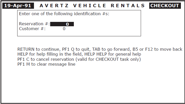
| |
|
Clerk |
"OK, Mr. Simpson, could I have your reservation number?" | |
|
Customer |
"Sure, I have reservation number 2." | |
|
Clerk |
"Thank you." The clerk enters the following: AVERTZ displays the checkout update panel shown in the figure below, with the cursor positioned at the Credit Type field. 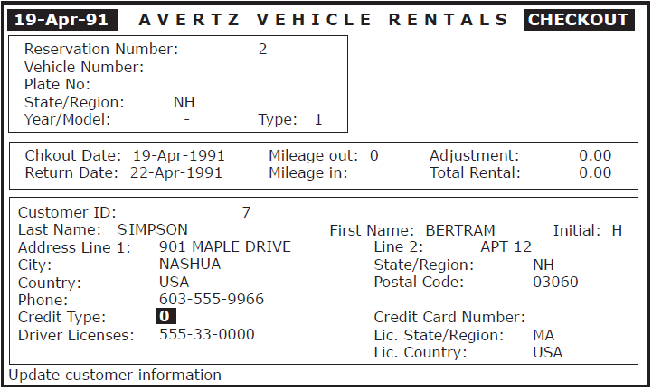
| |
|
Clerk |
"Are you still planning on paying with cash, Mr. Simpson?" | |
|
Customer |
"Yes, I am." | |
|
Clerk |
"Great." The clerk enters the following: Return
AVERTZ displays a list of available vehicles, as shown in the figure below. 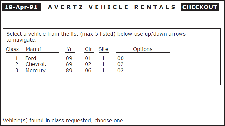
| |
|
Clerk |
"Do you have any options that you want with your vehicle?" The clerk uses the following table to determine what each option code means: | |
|
00 |
Standard transmission | |
|
01 |
Cruise control | |
|
02 |
Tape deck | |
|
03 |
Sunroof | |
|
04 |
4-wheel drive | |
|
05 |
Roof rack | |
|
06 |
Bulletproof glass and body | |
|
Customer |
"Well, I have a bit of a drive into the mountains, so if you have a car with a tape deck, that would be great." | |
|
Clerk |
The clerk presses the down-arrow key and the Select key to select the first available vehicle with option 2. AVERTZ now displays the checkout completion panel, as shown in the table below. 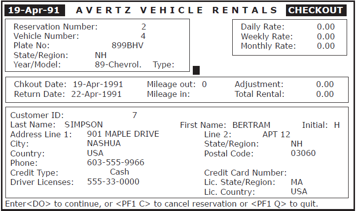
| |
|
Clerk |
The clerk enters the following to complete the checkout: AVERTZ displays a message indicating that the checkout is completed, and then prompts the clerk to press Return to continue. "OK, Mr. Simpson, you're all set. Here are the keys to a Chevrolet, NH license plate 899BHV. The vehicle does have a tape deck, and is located in the parking area just to the left of our front door. When you return the car, please record the odometer reading before you check the car back in. Do you have any questions?" | |
|
Customer |
"No, that's great. Thank you very much." | |
|
Clerk |
"You're welcome. Have a good weekend and see you on Monday." The clerk enters the following to return to the AVERTZ Rental Menu: Return
AVERTZ returns to the AVERTZ Rental Menu. | |
16.4. Customer Checks In a Car (Ending the Rental)
Bertram Simpson had a great weekend and is now ready to return the car to AVERTZ. He shows up at the reservations counter at AVERTZ on April 22. The following dialog takes place while Bertram Simpson checks in the car to end the rental period:
|
Clerk |
"Hi, can I help you?" |
|
Customer |
"Yes, my name is Bertram Simpson and I'm returning a car that I rented over the weekend." |
|
Clerk |
"OK, Mr. Simpson. Let me call up your reservation." The clerk enters the following at the AVERTZ Rental Menu (Figure 16.1, ''AVERTZ Rental Menu'' shows the AVERTZ Rental Menu):
AVERTZ displays the checkin panel shown in the table below. 
|
|
Clerk |
"OK, Mr. Simpson. Could I have your reservation number?" |
|
Customer |
"Sure, I have reservation number 2." |
|
Clerk |
"Thank you." The clerk enters the following: AVERTZ displays the checkin update panel shown in the table below, with the cursor positioned at the Credit Type field. 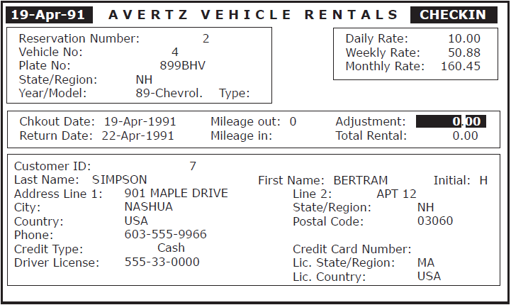
|
|
Clerk |
"Are you still planning to pay with cash, Mr. Simpson?" |
|
Customer |
"Yes, I am." |
|
Clerk |
"OK." The clerk enters the following: Return
AVERTZ moves the cursor to the Return Date field. Because that field displays the current date (22-Apr-1991), the clerk enters the following to move to the Mileage In field: Tab
"Can you tell me what the return odometer reading was, Mr. Simpson?" |
|
Customer |
"Yes, it was 357." |
|
Clerk |
The clerk enters the following: The Adjustment field allows for adjustments to the bill due to special circumstances (such as charges when customers return cars without the gas tank filled). Entering a negative amount increases the bill; a positive amount decreases the bill. There are no special circumstances associated with this rental, so the clerk enters the following to process the checkin: AVERTZ flashes the total cost of the rental. "Mr. Simpson, the total cost is $30 dollars." |
|
Customer |
"Here's the $30 and the keys. Thanks." |
|
Clerk |
"You're welcome. And thank you for renting with AVERTZ!" The clerk enters the following to return to the AVERTZ Rental Menu: AVERTZ returns to the AVERTZ Rental Menu. |
Chapter 17. Behind the Scenes
You have seen the AVERTZ application from the system manager's and user's points of view. This chapter takes a brief look at some of the work involved in designing and developing an ACMS application from the system designer's and application developer's views. The design and development details of AVERTZ are discussed extensively throughout the ACMS documentation set.
Before designing a transaction processing application, you must begin by analyzing the business problem. For AVERTZ, the business problem is how data entry personnel can quickly and efficiently create, access, and update car rental information.
Each business problem has separate business areas that must be addressed. For AVERTZ, business areas might include reservation processing, site management, car information, and customer accounts. The AVERTZ sample application focuses on the business area of reservation processing.
Reserve a car
Check out a car
Check in a car
Once the business problem has been categorized into areas and then into functions, you can begin solving the business problem with ACMS.
17.1. Applications and Procedures
An ACMS application consists of a set of tasks that relate to the functions of a business and can be selected for processing by either a terminal user or another task. Figure 17.1, ''Structure of an ACMS Application'' below shows the basic structure of an ACMS application.
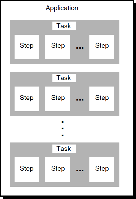
A task that checks reservation and customer information for both the CHECKOUT and CHECKIN tasks
A task that completes or cancels a reservation for both the RESERVE and CHECKOUT tasks
The ability of tasks to call other tasks means that it is easy for you to design applications to share common code.
Exchange steps coordinate I/O with a presentation service (such as a form).
Processing steps coordinate I/O with a procedure (a user-written subroutine that handles database input, output, and computations).
Block steps group exchange and processing steps into logical groups.
A considerable amount of control must take place to manage an application like AVERTZ. ACMS is designed to make such complex coordination and control easy to manage. Figure 17.2, ''Example of Execution Flow for an ACMS Task Definition'' illustrates how ACMS tasks coordinate the flow between forms that collect input from users and databases that store information.
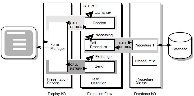
ACMS tasks are written using the ACMS Task Definition Language (TDL), which is based on a call and return model. Task definition steps perform calls to the presentation service in exchange steps, and to step procedures in processing steps. The presentation service and procedures perform their work and then return control to the task definition. Upon return to the task definition, subsequent parts of a step can evaluate the results of the call and, if necessary, handle any error conditions.
17.2. Task Definition Language
REPLACE TASK avertz_cdd_task:vr_reserve_taskUSE WORKSPACES vr_control_wksp,
vr_customers_shadow_wksp, vr_customers_wksp, vr_rental_classes_wksp, . . . DEFAULT FORM IS vr_form;
. . . get_car_now:
BLOCK WITH TRANSACTION
. . . PROCESSING
CALL PROCEDURE vr_store_cu_proc IN vr_cu_update_server USING vr_control_wksp, vr_customers_wksp, vr_trans_wksp; ACTION IS
IF (ACMS$T_STATUS_TYPE = "B") THEN GET MESSAGE INTO vr_control_wksp.messagepanel; RAISE EXCEPTION vr_update_error; END IF ; !+ ! If want to check car out now (=GTCAR) then call ! vr_complete_checkout_task to do that. !- PROCESSING
CALL TASK vr_complete_checkout_task USING vr_sendctrl_wksp, vr_control_wksp, vr_reservations_wksp, vr_trans_wksp, vr_vehicles_wksp; END BLOCK;
ACTION IS
MOVE " " TO vr_control_wksp.ctrl_key, "ACTWT" TO vr_sendctrl_wksp.sendctrl_key; COMMIT TRANSACTION; GOTO STEP disp_stat; !+ ! If the vr_store_cu_proc has an error because of constraint violation ! goto fix customer info exchange. If the transaction failed Retry the ! distributed transaction 5 times before canceling task. The retry_count ! is incremented in vr_store_cu_proc. !- EXCEPTION HANDLER
SELECT FIRST TRUE OF ( ACMS$L_STATUS = vr_update_error ): MOVE "TRAGN" TO vr_sendctrl_wksp.sendctrl_key; GOTO STEP fix_cust_info; ( (ACMS$L_STATUS = ACMS$_TRANSTIMEDOUT AND vr_control_wksp.retry_count < 5) ): REPEAT STEP; NOMATCH: GET MESSAGE INTO vr_control_wksp.messagepanel; MOVE "ACTWT" TO vr_sendctrl_wksp.sendctrl_key, " " TO vr_control_wksp.ctrl_key; GOTO STEP disp_stat; END SELECT; . . . END DEFINITION;
|
Callout |
Description |
|---|---|
|
|
The |
|
|
The USE WORKSPACES clause names one
or more workspaces to which the task needs access. Workspaces
are buffers used to pass data between steps in a task, between a
task and a procedure, between a task and a form, and between
tasks. As you see in |
|
|
The DEFAULT FORM clause names the DECforms form used by the exchange steps within the task. |
|
|
The |
|
|
The BLOCK clause groups multiple steps as a logical unit.
TRANSACTION is a block phrase that marks the start of a
distributed transaction (a distributed transaction makes more
than one database update as a single "all or nothing"
transaction). This example of the BLOCK clause consists of
multiple processing steps ( |
|
|
The PROCESSING clause identifies work that is part of a processing step. In this example, the PROCESSING clause calls the COBOL procedure named VR_STORE_CU_PROC, which resides in a server named VR_CU_UPDATE_SERVER. Procedures perform all computation and database work. The VR_STORE_CU_PROC procedure stores a customer record in the database, for example . Note that the USING keyword identifies workspaces that are passed to the procedure as parameters. |
|
|
The ACTION clause defines actions you want ACMS to take at the
end of an exchange step, processing step, or block step. In this
example, the ACTION clause tests the return status from the
procedure. If the procedure fails for some reason
(STATUS_TYPE=B), the ACTION clause uses the RAISE
EXCEPTION clause to send control to the
exception handler ( |
|
|
This PROCESSING clause calls another task, VR_COMPLETE_CHECKOUT_TASK, to check out the vehicle. Note that again workspaces are identified as parameters. |
|
|
This END BLOCK clause ends the entire block step, which consists of the two processing steps, the action parts, and the exception handler part. |
|
|
This ACTION clause performs some workspace work and then commits the transaction. The COMMIT clause signals the end of the current distributed transaction and makes permanent any changes made since the start of the distributed transaction. |
|
|
By default, if ACMS encounters an error that prevents it from
executing a task, ACMS cancels the task. The
EXCEPTION HANDLER clause lets you
handle the error and continue task execution. In this example,
if the exception was a transaction timeout, it retries the
transaction five times before cancelling the task. If the
exception was an update error, control goes to a step labelled
|
17.3. More AVERTZ
The AVERTZ sample application demonstrates an ACMS transaction processing application from many perspectives. As you learn more about ACMS, you can modify the AVERTZ application to test what you have learned. Furthermore, you can use the design model for AVERTZ as a starting point for how to approach designing your own ACMS application.
VSI ACMS for OpenVMS Concepts and Design Guidelines explains ACMS concepts and provides guidelines for designing an ACMS application.
VSI ACMS for OpenVMS Writing Applications explains how to use the ACMS Application Definition Utility (ADU) to define tasks, task groups, applications, and menus.
VSI ACMS for OpenVMS Writing Server Procedures explains how to write, debug, and run procedures for ACMS applications.
VSI ACMS for OpenVMS Systems Interface Programming describes how to write ACMS code that allows nonterminal devices (such as bar-code readers and Automatic Teller Machines) to be integrated into an ACMS system.
All these documents make extensive use of AVERTZ code examples to illustrate ACMS concepts and features.
Appendix A. Utilities for Solving Problems in an ACMS Application
This appendix describes how ACMS runs a task and introduces some utilities that are available to help you solve problems in running a new ACMS application.
A.1. How ACMS Runs a Task
It is often helpful, especially in problem-solving, to know the various steps that
ACMS takes to run a task. Figure A.1, ''Databases in an ACMS Application'' illustrates how ACMS responds to the
ACMS/ENTER command:
Checks ACMSDDF.DAT, the terminal authorization file, to verify that your terminal is authorized for use with ACMS.
Checks ACMSUDF.DAT, the user authorization file, to verify that you have been authorized to use ACMS, and to determine which menu database (.MDB) file has been assigned as your default.
Displays your default selection menu (if you and your terminal passed the authorization checks) and waits for you to select a task.
Consults the .MDB file to find out which application database (.ADB) file contains the task you selected.
Consults the .ADB file to find out which task group database (.TDB) file contains the task.
Finds the task in the .TDB file and runs it. The .TDB file also contains the file specification of the procedure server image and the entry points of the procedures in the image, as well as workspace definitions.
Returns to step 3 when the task has finished executing.
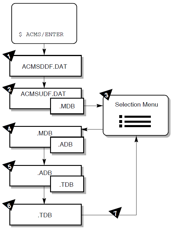
A.2. Audit Trail Logger
The Audit Trail Logger (ATL) keeps a record of when the ACMS system starts and stops, when users log in, when applications and tasks start and stop, errors signaled by processing steps, and so forth. To display this log, run the Audit Trail Report (ATR) Utility from the SYS$SYSTEM directory.
Issue either of the following commands to run ATR:
$ RUN SYS$SYSTEM:ACMSATR
ATR>
or:
$ MCR ACMSATR
ATR>
At the ATR> prompt, issue the LIST command with the
/SINCE qualifier to see today's log of your application:
ATR> LIST/APPLICATION=EMPLOYEE_INFO_APPL_xxx/SINCE=TODAY
For detailed information about the Audit Trail Logger and the ATR Utility, refer to VSI ACMS for OpenVMS Managing Applications.
A.3. Software Event Logger
The Software Event Logger (SWL) records all software errors and event messages that occur during the execution of ACMS application programs. Each time an error occurs, ACMS writes a message to the SWL log file with information such as user name, process name, condition code, and extended error descriptions.
The Software Event Log Utility Program (SWLUP) generates reports containing information recorded by the SWL. To read information in the SWL log file, you use SWLUP commands.
Issue either of the following commands to run SWLUP:
$ RUN SYS$SYSTEM:SWLUP
SWLUP>
or:
$ MCR SWLUP
SWLUP>
At the SWLUP> prompt, issue the LIST command with the
/SINCE qualifier to display today's log of events for user
JONES:
SWLUP> LIST/USER=JONES/SINCE=TODAY
To write the log of all events for user JONES to an output file instead of to the
terminal, issue the LIST command as follows:
SWLUP> LIST/USER=JONES/OUTPUT=MY_EVENTS.LIS
For detailed information about the Software Event Log and the SWLUP Utility, refer to VSI ACMS for OpenVMS Managing Applications.
A.4. DECforms Trace Facility
The DECforms trace facility logs form-processing information at run time to help you debug your application program and your form. The trace facility is useful because much of the form processing occurs each time you call a DECforms request from your ACMS application program.
You can turn tracing on before running a task in the ACMS Task Debugger (see Section 9.4, ''Testing a Task in the ACMS Task Debugger''). In this way, you can debug logic problems, debug data mismatches and other run-time errors, and observe how a user works through a series of panels.
You turn tracing on by defining the logical FORMS$TRACE as a character string value that begins with any of the following characters: T, t, Y, y, or 1. For example:
$ DEFINE FORMS$TRACE YES
Turning on the trace facility produces a trace file with the same name as your form followed by the TRACE extension (by default), for example, EMPLOYEE_INFO_FORM.TRACE. For a name other than the default, define the logical FORMS$TRACE_FILE to your own trace file specification.
The trace facility is turned off when you define the FORMS$TRACE logical as a character string value that begins with any character except those that turn tracing on. Tracing also ends when you log out (the process logical FORMS$TRACE becomes undefined then). It is advisable to turn off the trace facility when you are finished testing to avoid having your trace file become exceedingly large.
For detailed information about the DECforms trace facility, refer to VSI DECforms Programmer's Reference Manual.
A.5. ACMS Help Facility
The ACMS Help facility contains a menu of ACMS error codes, from which you can choose to view information about a specific ACMS error. For help with ACMS error messages, issue the following command:
$ HELP ACMS ERRORS
The ACMS Help facility also contains information about many other ACMS topics. For a Help menu of ACMS topics, issue the following command:
$ HELP ACMS
Appendix B. Source Files Used in the Tutorial
This appendix lists the source files created in the tutorial application in Part 2 and describes how to access the online versions of these files. You can view the online source files to verify those that you create in the tutorial, or you can copy the online source files instead of typing them yourself.
B.1. Source Files
The following list contains the names of each source file created in the tutorial. The files are listed in the order that they appear in the manual.
EMPLOYEE_FIELDS.CDO
EMPLOYEE_INFO_RECORD.CDO
EMPLOYEE_INFO_WKSP.CDO
EMPLOYEE_INFO_FORM.IFDL
EMPLOYEE_CONTROL_FIELDS.CDO
EMPLOYEE_CONTROL_WKSP.CDO
EMPLOYEE_QUIT_FIELD.CDO
EMPLOYEE_QUIT_WKSP.CDO
EMPLOYEE_INFO_ADD_TASK.TDF
EMPLOYEE_INFO_ADD.COB
EMPLOYEE_INFO_PROMPT_FORM.IFDL
EMPLOYEE_INFO_UPDATE_TASK.TDF
EMPLOYEE_INFO_UPDATE_GET.COB
EMPLOYEE_INFO_UPDATE_PUT.COB
EMPLOYEE_INFO_INIT.COB
EMPLOYEE_INFO_TERM.COB
EMPLOYEE_INFO_CANCEL.COB
EMPLOYEE_INFO_TASK_GROUP.GDF
EMPLOYEE_INFO_APPL_XXX.ADF
EMPLOYEE_INFO_MENU.MDF
B.2. Accessing the Source Files
The source files are installed by the ACMS installation procedure if your system manager chooses to install the ACMS samples. These files are located in ACMS$EXAMPLES, a logical that points to the actual directory. The following command displays the contents of that directory:
$ DIRECTORY ACMS$EXAMPLES
The following command displays the file named EMPLOYEE_FIELDS.CDO:
$ TYPE ACMS$EXAMPLES:EMPLOYEE_FIELDS.CDO
You may wish to copy these files to your default directory instead of typing them yourself. Copying the source code files saves time in performing the tutorial, but you may gain more by typing them in progressive steps while reading about what the code does. Moreover, copying the two DECforms IFDL files means that your forms and panels are already created, nullifying the portion of the tutorial that illustrates how to create them interactively within the DECforms environment.
You can copy single files using the normal method. However, if you want to copy all the source files, you can perform a wildcard copy with one command. Use the following commands to locate yourself in your default directory (filling in your disk and user name) and to copy all the tutorial source files to this directory:
$ SET DEFAULT udisk:[uname]
$ COPY ACMS$EXAMPLES:EMPLOYEE*.*  *.*
If you copy the online source files, rename the application definition file EMPLOYEE_INFO_APPL_xxx.ADF, filling in your initials or other unique characters for the xxx part of the name. Using a unique application name avoids conflicts with applications created by others who may be entering this tutorial on your system. When you rename this file, you must also edit this file to make the same name change in the first line of the file (see Section 10.1.1, ''Application Characteristics''); you must also edit the file EMPLOYEE_INFO_MENU.MDF to make the same name change there (two occurrences).
If you copy the online source files, you must edit the files that contain the logical xxx_FILES and replace that logical with the one that you defined for your directory in Section 7.6, ''Defining a System Logical for Your Tutorial Directory''. Those files that contain the xxx_FILES logical are the six .COB files (one occurrence each), EMPLOYEE_INFO_TASK_GROUP.GDF (three occurrences), and EMPLOYEE_INFO_APPL_XXX.ADF (one occurrence).