VSI DECforms Guide to Commands and Utilities
- Software Version:
- DECforms Version 4.0
- Operating System and Version:
- VSI OpenVMS IA-64 Version 8.4-1H1 or higher
VSI OpenVMS Alpha Version 8.4-2L1 or higher
Preface
VSI DECforms is a software product for applications, services, and tools that require a structured, forms-based, or menu-based user interface. DECforms is the first commercial implementation of an ANSI/ISO standard for forms-based interfaces, the CODASYL Form Interface Management System (FIMS).
This guide describes how to invoke and use the DECforms utilities needed to develop and test forms.
1. About VSI
VMS Software, Inc. (VSI) is an independent software company licensed by Hewlett Packard Enterprise to develop and support the OpenVMS operating system.
2. Intended Audience
This guide is for programmers who design and develop forms to be used as interfaces to applications.
You should know how to use the OpenVMS operating system and a text editor, such as DECTPU or DEC LSE.
3. Document Structure
|
Describes how to invoke each DECforms utility from the command level. | |
|
Explains how to use the Form Development Environment. | |
|
Chapter 3, "Editing Panel Appearance Using the Character-Cell Panel Editor (CCPED)" |
Explains how to use the Character-Cell Panel Editor (CCPED) to create panels to be used in character-cell layouts. |
|
Explains how to use the Test Utility to check the appearance of panels and to test input fields in character-cell layouts. | |
|
Explains how to use the IFDL Translator and Back Translator to translate IFDL source files and form files. | |
|
Explains how to use the Extract Objects Utility to create object modules, and how to use the Extract Appearances Utility to create a printable file showing the appearance of panels in character-cell or PRINTER layouts. | |
|
Appendix A, "CCPED Keypad, Function Keys, and Definable Keys" |
Contains a diagram and summary of the default CCPED keypad, a list of CCPED function keys, and a list of key names available for definition with the CCPED DEFINE KEY command. |
|
Provides detailed descriptions of the CCPED commands. | |
|
Describes how to the use the DEC Language Sensitive Editor (DEC LSE) with DECforms software. |
4. Related Documents
VSI DECforms Installation Guide for OpenVMS Systems—Describes how to install DECforms software on processors that are running the OpenVMS operating system.
VSI DECforms IFDL Reference Manual—Describes the syntax of the DECforms Independent Form Description Language.
VSI DECforms Style Guide for Character-Cell Devices—Describes how to develop user interfaces for DECforms applications for character-cell terminals.
VSI DECforms Programmer's Reference Manual—Describes how DECforms software operates at run time and how to call the DECforms requests from an application program.
VSI DECforms Guide to Developing an Application—explains how to create a DECforms application, including both the form and the program, and contains additional guidelines and examples for more experienced DECforms programmers.
VSI DECforms Guide to Demonstration Forms and Applications—Describes how to use various demonstration forms and applications. This guide is contained in online files named
forms$demo_guide.txtandforms$demo_guide.psin the FORMS$EXAMPLES directory on OpenVMS systems. If you cannot find this document, ask your system manager to install it in the appropriate directory.For information about displaying these forms, see the VSI DECforms Guide to Developing an Application.
VSI DECforms Guide to Converting FMS Applications—Describes how to convert a VAX FMS or DEC FMS application to a DECforms application.
DEC LSE documentation for information on how to use DEC LSE
Oracle CDD/Repository documentation set for information on Oracle CDD/Repository definitions
ISO IS 11730:1994 for information on the standard of which DECforms is an implementation.
5. OpenVMS Documentation
The full VSI OpenVMS documentation set can be found on the VMS Software Documentation webpage at https://docs.vmssoftware.com.
6. VSI Encourages Your Comments
You may send comments or suggestions regarding this manual or any VSI document by sending electronic mail to the following Internet address: <docinfo@vmssoftware.com>. Users who have VSI OpenVMS support contracts through VSI can contact <support@vmssoftware.com> for help with this product.
7. Conventions
| Symbol or Term | Meaning |
|---|---|
| layouts |
When discussing layouts, the following terms are used:
|
| Alt |
The Alt key. This key is labeled Compose Character on some keyboards. |
| Ctrl/x |
In procedures, a sequence such as Ctrl/x indicates that you must hold down the key labeled Ctrl while you press another key. |
| KPn |
Key names that begin with KP indicate keys on the numeric keypad on the right side of the terminal keyboard. For example, KP4 and KP are keys on the numeric keypad. |
| PF1-x |
A sequence such as PF1-x indicates that you must first press and release the key labeled PF1, and then press and release another key. |
| Shift+PF3 |
A sequence such as Shift+PF3 indicates that you must hold down the Shift key while pressing another key. |
... |
In examples, a horizontal ellipsis indicates one of the
following possibilities:
|
. . . |
A vertical ellipsis indicates the omission of items from a code example or command format; the items are omitted because they are not important to the topic being discussed. |
| ( ) |
In format descriptions, parentheses indicate that if you choose more than one option, you must enclose the choices in parentheses. |
| [ ] |
In format descriptions, brackets indicate that whatever is enclosed is optional; you can select none, one, or all of the choices. |
| {} |
In format descriptions, braces surround a required choice of options; you must choose one of the options listed. |
| bold type |
Bold type represents the name of an argument, an attribute, or a reason. Bold type also represents the introduction of a new term. |
| italic type | Italic type indicates important information, complete titles of manuals, or variables. Variables include information that varies in system output (Internal error number), in command lines (/PRODUCER=name), and in command parameters in text (where dd represents the predefined code for the device type). |
| $ |
The dollar sign is used to indicate the user prompt on OpenVMS systems. |
Chapter 1. DECforms Commands
This chapter describes how to start the DECforms utilities from the system command line, including how to interpret and correct error messages encountered while using the utilities.
The commands are listed in alphabetical order.
1.1. DCL Command Format
FORMS FUNCTION [/QUALIFIER...] [input-file-spec]
A DECforms command consists of the word forms followed by a
parameter (or parameters) that indicates which function of DECforms software is to be
executed.
$ FORMS TRANSLATE /LIST TAX_FORM.IFDL
$ FORMS TRANSLATE TAX_FORM.IFDL /LIST
You must place qualifiers after the function parameter; do not place them after the word FORMS. Spaces or tabs preceding a qualifier are optional.
You can abbreviate any element of a DECforms command line, providing that its abbreviation is unique. (You can abbreviate FORMS only to FORM; FOR is not an unique abbreviation because it conflicts with the FORTRAN command.)
If you do not specify a required element on the command line, DCL prompts you for it.
1.2. Error Messages
$ HELP FORMS ERRORS MESSAGE-IDENTMessage-ident (for example, WRITEFORM) is the abbreviation of the message that appears in the message format. For information on the format of error messages, see Section 1.2.1, ''Message Format''.
$ HELP/OUTPUT=FORMS_ERRORS.LIS FORMS ERRORS *This command creates a file called
forms_errors.lis that contains all the
information under the ERRORS help topic. You can substitute another file name for
forms_errors.lis. You can then print the file.1.2.1. Message Format
%FORMS-L-IDENT, Message text.The facility abbreviation, FORMS, indicates that a DECforms component issued the message. L indicates the severity level of the message, which can be one of the following:
|
S |
Success message. Indicates the operation that generated the message was completed. |
|
I |
Informational message. Either gives information about an operation being performed or gives further information when an error occurred. |
|
W |
Warning message. Indicates that the command might have performed some, but not all, of the operation, and that you might have to verify the command or component output. |
|
E |
Error message. Indicates that an error occurred during processing. The operation that generated the message may continue if the component performing the operation can recover from the error. |
|
F |
Fatal error message. Indicates that the component cannot continue the operation. |
The IDENT in the general format of messages is an abbreviation of the message (for example, CDDDIMFIE). You access messages in online help by using this abbreviation on the help command line.
1.3. Correcting Errors
The message text that appears in DECforms messages describes the problem that caused the message. You should be able to read this message text to identify the problem. Also, you can use online help to get an explanation and user action for each message.
If eligible, you can call your Customer Support Center for help. The DECforms specialists at these centers can provide you with examples and suggestions for your particular application, as well as workarounds for problems you may encounter.
1.4. DCL Command Descriptions
Overview of the command function
Format, including a list of command qualifiers and defaults
Descriptions of the required and optional parameters
Description of each qualifier
Command-line examples
FORMS BACK_TRANSLATE
FORMS BACK_TRANSLATE — Invokes the Back Translator to create an IFDL source file from a form file. For further information on the Back Translator, see Chapter 5, "Translating IFDL Source Files and Form Files".
Format
FORMS BACK_TRANSLATE input-file-spec
|
Qualifiers |
Defaults |
|---|---|
|
/[NO]LOG |
/NOLOG |
|
/OUTPUT[=file-spec] |
/OUTPUT |
|
/[NO]SHOW=[no]copy |
/SHOW=nocopy |
Parameter
input-file-spec
The name of the form file to be translated to an IFDL source file. The default
file type is .form. The Back Translator can accept an
incomplete form as input.
Qualifiers
- /LOG
/NOLOG Controls whether a message is displayed upon completion of the operation. Error messages, if any, are displayed regardless of whether you specified /LOG or /NOLOG.
The default is /NOLOG.
- /OUTPUT[=file-spec]
Specifies a name for the IFDL source file produced by the Back Translator. If you omit the file specification, the output file has the same name as the input file, with a file type of
.ifdl.- /SHOW=[no]copy
/NOSHOW Specifies how COPY FROM DICTIONARY statements are translated. If you specify /NOSHOW or /SHOW=nocopy, or if you do not specify this qualifier,the COPY FROM DICTIONARY statement is translated as it appeared in the original IFDL source file. If you specify /SHOW=copy, the expanded definitions resulting from the Oracle CDD/Repository extraction are also included as a comment in the IFDL source file produced by the Back Translator.
The default is /SHOW=nocopy.
Examples
FORMS BACK_TRANSLATE PAYROLL
Translates the form file
payroll.formto an IFDL source file namedpayroll.ifdl. No success message is displayed when the translation is complete.$ FORMS BACK_TRANSLATE/OUTPUT=NOW_ACCOUNT CHECKING_ACCOUNT
Translates the form file
checking_account.formto an IFDL source file namednow_account.ifdl.
FORMS CONVERT FMS
FORMS CONVERT FMS — Converts a DEC FMS form file or form library file to a DECforms IFDL source file. For more information on converting FMS forms, see the VSI DECforms Guide to Converting FMS Applications. This feature is supported only on Alpha platforms.
Format
FORMS CONVERT FMS input-file-spec
|
Qualifiers |
Defaults |
|---|---|
|
/[NO]LOG |
/NOLOG |
|
/OUTPUT[=file-spec] |
/OUTPUT |
Parameter
input-file-spec
The name of the FMS form file or form library to be converted. The default
file type is .frm.
Qualifiers
- /LOG
/NOLOG Controls whether an informational message is displayed upon completion of the conversion. Error messages, if any, are displayed regardless of whether you specified /LOG or /NOLOG.
The default is /NOLOG.
- /OUTPUT[=file-spec]
Specifies a name for the IFDL source file output by the FMS Converter. If you omit the file specification, the output file has the same name as the input file, with a file type of
.ifdl.
Examples
$ FORMS CONVERT FMS PAYROLL
Converts the FMS form file
payroll.frmto an IFDL source file namedpayroll.ifdl.$ FORMS CONVERT FMS/OUTPUT=NEW_EQUIPMENT EQUIPMENT.FLB
Converts the FMS form library
equipment.flbto an IFDL source filenamednew_equipment.ifdl.
FORMS DEVELOP
FORMS DEVELOP — Invokes the Form Development Environment (FDE) to create or modify a form file. For further information on the FDE, see Chapter 2, "Form Development Environment".
Format
FORMS DEVELOP input-file-spec
|
Qualifiers |
Defaults |
|---|---|
|
/[NO]CHECKPOINT[=file-spec] |
/CHECKPOINT |
|
/[NO]COMMAND[=(script[,...])] |
/COMMAND |
|
/[NO]DEPENDENCY_DATA |
/NODEPENDENCY_DATA |
|
/[NO]INCLUDE=(pathname[,...]) |
/NOINCLUDE |
|
/LAYOUT=layout-name |
See description |
|
/[NO]LOG |
/LOG |
|
/[NO]OUTPUT[=(ifdl[=file-spec],form[=file-spec])] |
/OUTPUT=(ifdl,form) |
|
/PANEL=panel-name |
See description |
|
/[NO]RECOVER |
/NORECOVER |
|
/TEXT_EDITOR={lse |tpu | "edit command "} |
/TEXT_EDITOR=tpu |
Parameter
input-file-spec
The name of the form file that you are creating or modifying. If you do not specify a file type, the FDE looks first for a form file and then for an IFDL source file. (The FDE looks at the contents of the file to determine what kind it is; it does not go by the file type.) If neither a form file nor an IFDL source file exists, the FDE creates a new form with the name you specified.
The input file parameter is required; however, the file does not have to exist. The FDE can accept an incomplete form as input.
Qualifiers
- /CHECKPOINT[=file-spec]
/NOCHECKPOINT Enables checkpointing. Checkpointing saves the known state of a form, so the form can be restored to that state following a system failure. Checkpointing protects your work when a session ends abnormally for some reason (for example, if you press Ctrl/Y or if there is a system failure).
When checkpointing is enabled, the form is written to a checkpoint file every time you make a change and return to the Main Menu. Each time a checkpoint file is written, the previous checkpoint file is deleted. When you exit from the FDE, the latest version of the checkpoint file is deleted and the output file (or files) is created. If you select the Main Menu option Quit, the checkpoint file is deleted and no output files are created.
You can designate a file specification other than the default for the checkpoint file. By default, the checkpoint information is written to a file that has the same name as the input file with a file type of
.forms$checkpointin the same directory as the input file. The checkpoint file name is also passed to the Character-Cell Panel Editor (CCPED), as though you had entered the FORMS EDIT/JOURNAL=filename command. Specifying /CHECKPOINT implies the use of FORMS EDIT/JOURNAL when you edit a panel's appearance from the FDE.The default is /CHECKPOINT.
- /COMMAND[=(script[,...])]
/NOCOMMAND Specifies a list of command scripts to pass to the Character-Cell Panel Editor. For more information, see the description of the /COMMAND qualifier under the FORMS EDIT COMMAND.
The default is /COMMAND.
- /DEPENDENCY_DATA
/NODEPENDENCY_DATA Specifies that the IFDL Translator creates dependency relationships for COPY FROM DICTIONARY statements in the IFDL source file. The dependency relationships relate the form to the data definitions that are extracted from Oracle CDD/Repository using a video display Oracle CDD/Repository object that the IFDL Translator creates in CDD$DEFAULT.
When you specify /NODEPENDENCY_DATA, COPY FROM DICTIONARY statements cause the IFDL Translator to copy information from Oracle CDD/Repository, but the IFDL Translator does not create any dependency relationships.
This qualifier affects the translation that is performed when you use DECTPU or DEC LSE from the Form Development Environment.
The default is /NODEPENDENCY_DATA.
- /INCLUDE=(pathname[,...])
/NOINCLUDE Specifies an additional level of search for an
.ifdlfile specification in a COPY statement. Each path name argument can be either a logical name or a legal directory specification. The search order is the directory containing the source file, followed by the directory specified in the qualifier.This option is passed to the FORMS TRANSLATE command when the IFDL Translator is used.
The default is /NOINCLUDE.
- /LAYOUT=layout-name
Specifies which character-cell layout in the form is selected for editing. If you use this qualifier, you must specify the character-cell layout name. If you do not use this qualifier, the FDE chooses the first character-cell layout in the form that contains all the specified panels.
If you specify a PRINTER layout, DECforms displays a message saying that editing of those layouts is not supported.
- /LOG
/NOLOG Controls whether a message is displayed upon successful completion of the FDE session.
The default is /LOG.
- /OUTPUT[=(ifdl[=file-spec],form[=file-spec])]
/NOOUTPUT Specifies the name and type of the output files. If you omit this qualifier or specify it without any keywords, the FDE produces an IFDL source file and a form file, each having the name of the input file with file types of
.ifdland.form, respectively.You can use the keywords IFDL and FORM to specify the type of output file the FDE will produce. You can specify both keywords if you want an IFDL source file and a form file. If you specify both, separate them with a comma and enclose them in parentheses. You also can provide complete file specifications with these keywords. If you specify a file name but not a file type, the output file has that file name and a type of
.ifdlor.form, depending on the keyword you specified.You also can use the File option on the Main Menu to specify output to a file from within the FDE. For more information, see Chapter 2, "Form Development Environment".
- /PANEL=panel-name
Specifies which panel in the form to edit initially. If you use this qualifier, you must specify the panel name, and that panel must exist; you cannot use this qualifier to create a new panel. If you do not use this qualifier, the FDE chooses the first panel in the chosen layout as the current initial panel.
- /RECOVER
/NORECOVER Recovers a previously aborted editing session from the checkpoint file specified with the /CHECKPOINT qualifier.
If an FDE checkpoint file and a panel editor journal file exist, and the creation date of the panel editor journal file is later than that of the FDE checkpoint file, the FDE recovers the checkpoint file first, and then recovers the panel editor journal file.
The default is /NORECOVER.
- /TEXT_EDITOR={lse |tpu | "edit command "}
Specifies which editor the FDE should use when it activates a text editor. LSE specifies that the FDE activates the DEC Language-Sensitive Editor. TPU specifies that the FDE activates DECTPU. To use another editor, specify the edit command in quotes, as you would at DCL level.
Use ’P1’ in the command as a placeholder for the name of the file you are editing. If your editor supports a starting line position (where the cursor can start on a line in the file other than line 1),you can include that syntax in your edit command by using ’P2’ to specify the line number.
You also can define a logical name, FORMS$TEXT_EDITOR, to call DEC LSE automatically when the FDE is invoked, as follows:$ DEFINE FORMS$TEXT_EDITOR CALLABLE_LSEThe default is /TEXT_EDITOR=tpu.
Examples
$ FORMS DEVELOP/TEXT_EDITOR=LSE PERSONNEL
Invokes the FDE to edit the form file
personnel.formand specifies the Language-Sensitive Editor as the text editor. Two output files are created: a form file calledpersonnel.formand an IFDL source file calledpersonnel.ifdl.$ FORMS DEVELOP/TEXT_EDITOR="MY_EDITOR/STARTING_POSITION=’P2’ - _$ ’P1’ " MYFORM
Invokes the FDE to edit the form file
myform.formusing the editor you specify. The parameter p2 is the symbol for the starting position, and p1 represents the output file. Two output files are created: aform file calledmyform.formand an IFDL source file calledmyform.ifdl.$ FORMS DEVELOP/OUTPUT=IFDL ACCOUNT.FORM /LAYOUT=ANSI_TERM/PANEL=ADDRESS
Invokes the FDE to edit the panel labeled address in the layout labeled ansi_term in the form file
account.form. The output is an IFDL source file calledaccount.ifdl. No form file will be produced.$ FORMS DEVELOP/OUTPUT=(IFDL,FORM=NEW_INVENTORY) INVENTORY
Invokes the FDE to edit the form file inventory. The output is an IFDL source file called
inventory.ifdland a form file callednew_inventory.form.$ FORMS DEVELOP/OUTPUT=FORM=STOCK.MYFORM CURRENT_STOCK.FORM
Invokes the FDE to edit the form file
current_stock.form. The outputis a form file calledstock.myform. No IFDL source file is produced.
FORMS EDIT
FORMS EDIT — Invokes one of the panel editors to create or modify the size and appearance of a form's panels and viewports. For further information on the Character-Cell Panel Editor (CCPED), see Chapter 3, "Editing Panel Appearance Using the Character-Cell Panel Editor (CCPED)".
Format
FORMS EDIT input-file-spec
|
Qualifiers |
Defaults |
|---|---|
|
/[NO]COMMAND[=(script[,...])] |
/COMMAND |
|
/[NO]JOURNAL[=file-spec] |
/JOURNAL |
|
/LAYOUT=layout-name |
See description |
|
/[NO]LOG |
/LOG |
|
/OUTPUT[=file-spec] |
/output |
|
/PANEL=panel-name |
See description |
|
/[NO]RECOVER |
/NORECOVER |
Parameter
input-file-spec
The name of the form file to be edited. This parameter is required, and the
form file must exist. The default file type is .form. The
panel editor can accept an incomplete form as input.
Qualifiers
- /COMMAND[=(script[,...])]
/NOCOMMAND Specifies whether or not an initialization script (or list of scripts) of CCPED commands is to be executed during startup procedures. For information on creating and using CCPED command scripts, see Chapter 3, "Editing Panel Appearance Using the Character-Cell Panel Editor (CCPED)".
When you specify /COMMAND, you can provide an initialization file name or a list of initialization file names. These file specifications can be logical names.
If the execution of initialization scripts is not disabled explicitly by means of the /NOCOMMAND qualifier, a script file with the logical name FORMS$EDIT_INIT is added implicitly to the beginning of the script list. All files, except FORMS$EDIT_INIT, must exist.
If you also specify the /RECOVER qualifier, the /COMMAND qualifier is ignored because the commands in the initialization scripts are recorded in the journal file.
The default is /COMMAND. The default file type for script files is .com.
- /JOURNAL[=file-spec]
/NOJOURNAL Specifies whether the editing session is to be journaled. You can specify a name for the journal file. If you omit the file specification, the journal file has the same name as the input file, with a file type of
.forms$journal.The default is /JOURNAL.
If an attempt to write to the journal file fails during journaling,system displays a warning box with a "An attempt to write to the journal file has failed. No more journaling will be attempted, but you can continue the editing session " message. This type of failure can occur because of system problems; for example, you have run out of disk space or the disk mount is dropped by the network or the file server.
- /LAYOUT=layout-name
Specifies a layout in which the panel editor searches for the initial panel to be edited. Use this qualifier when you want to edit panels in a particular layout. When you use /LAYOUT, you must specify a layout name.
- /LOG
/NOLOG Controls whether a message is displayed upon completion of the editing session.
The default is /LOG.
- /OUTPUT[=file-spec]
Specifies a name for the form file output by the panel editor. If you omit the file specification, the output file has the same name as the input file.
The default file type is
.form.- /PANEL=panel-name
Specifies the initial panel to be edited. If you are using CCPED and do not use /PANEL, the panel editor chooses the first panel found in the form, or in the specified layout if you used /LAYOUT. If there are no panels in the layout, the current panel is undefined. In this case, the panel editor displays the message "No Current Panel" in the status line and issues the
Command>prompt. You must create a panel before you can perform any other panel editor operations. You can use the CREATE PANEL command to create a panel.- /RECOVER
/NORECOVER Recovers a previously aborted editing session from the journal file specified with the /JOURNAL qualifier.
If both /RECOVER and /JOURNAL are specified, PED recovers using the file specified by the /JOURNAL qualifier. If the specified journal file does not exist, PED exits with a "Can't locate specified journal file "message.
If /RECOVER is specified but /JOURNAL is not, PED recovers using a journal file in your current working directory with the name of the form file and a file type of
.forms$journal. If there is no journal file in your current working directory, PED exits with a "Can't locate specified journal file" message.The default is /NORECOVER for CCPED.
Examples
$ FORMS EDIT/LAYOUT=COLOR_TERMINALS ACCOUNT
Invokes CCPED to edit the first panel in the layout color_terminals in the form file
account.form.$ FORMS EDIT/PANEL=STATEMENT_PANEL/LAYOUT=ANSI_TERM CHECKBOOK
Invokes CCPED to edit the panel labeled statement_panel in the layout labeled ansi_term in the form file
checkbook.form.$ FORMS EDIT PERSONNEL/COMMAND=(MOE,LARRY,CURLY)
Invokes CCPED to edit the first panel in the form file
personnel.form, and executes the initialization scriptsmoe.com,larry.com, andcurly.com.
FORMS EXTRACT APPEARANCES
FORMS EXTRACT APPEARANCES — Invokes the Extract Appearances Utility to create a file containing printable representations of panels in a character-cell or PRINTER layout. For further information on the Extract Appearances Utility, see Chapter 6, "Extracting Objects and Appearances".
Format
FORMS EXTRACT APPEARANCES input-file-spec
|
Qualifiers |
Defaults |
|---|---|
|
/LAYOUT=layout-name |
See description |
|
/[NO]LOG |
/NOLOG |
|
/OUTPUT[=file-spec] |
/OUTPUT |
|
/PANEL[=(name[,...])] |
See description |
|
/SHOW={data |picture} |
/SHOW=data |
Parameter
input-file-spec
The name of the form file containing the panels you want to print. The default
file type is .form.
Qualifiers
- /LAYOUT=layout-name
Specifies a character-cell or PRINTER layout in which the Extract Appearances Utility searches for panels to extract. When you use /LAYOUT, you must specify a layout name.
If you do not use /LAYOUT, the Extract Appearances Utility's search for a specified or default panel is limited to the first layout that contains all specified panels.
- /LOG
/NOLOG Controls whether success messages are displayed on the default output device. Error messages, if any, are displayed regardless of whether you specified /LOG or /NOLOG.
The default is /NOLOG.
- /OUTPUT[=file-spec]
Specifies a name for the output file. If you omit the file specification, the output file has the same name as the input file, with a file type of
.txt.The default is /OUTPUT.
- /PANEL[=(name[,...])]
Specifies the panel or panels to be extracted from a particular layout. You cannot specify panels on different layouts.
If you use /PANEL, and you have not specified /LAYOUT, all panels in the first layout containing the specified panels are extracted. If you do not use /PANEL, and you have not specified /LAYOUT, all panels in the first layout are extracted.
- /SHOW={data |picture}
Specifies whether initial values or text literals should appear infields in extracted panels. The /SHOW=data qualifier shows fields with their initial values. The /SHOW=picture qualifier shows fields with picture strings as they appear in the panel editor.
The default is /SHOW=data.
Examples
$ FORMS EXTRACT APPEARANCES PERSONNEL_DATA
Creates a printable file called
personnel_data.txtfrom the form filepersonnel_data.form. This file contains printable representations of all the panels in the form.$ FORMS EXTRACT APPEARANCES EQUIPMENT/LAYOUT=ANSI - _$ /PANEL=(NEW_EQUIP,CURRENT_EQUIP)
Extracts the appearances of the panels labeled new_equip and current_equip in the layout labeled ansi in the form file
equipment.form, and creates a printable file calledequipment.txt.
FORMS EXTRACT OBJECT
FORMS EXTRACT OBJECT — Invokes the Extract Object Utility to create object modules from form files. The object modules contain the information necessary to create a table of vectors to escape routines referenced within the binary form file, and to create memory-resident forms for use at runtime. For further information on the Extract Object Utility, see Chapter 6, "Extracting Objects and Appearances" and the VSI DECforms Programmer's Reference Manual.
Format
FORMS EXTRACT OBJECT input-file-spec[,input-file-spec...]
|
Qualifiers |
Defaults |
|---|---|
|
/[NO]FORM_LOAD |
/FORM_LOAD |
|
/[NO]LIST[=file-spec] |
/NOLIST This feature is supported only on Alpha platform |
|
/[NO]LOG |
/NOLOG |
|
/OBJECT[=file-spec] |
/OBJECT |
|
/OUTPUT[=file-spec] |
See description |
|
/[NO]PORTABLE_API |
/NOPORTABLE_API |
|
/REFERENCES={weak |strong} |
/REFERENCES=strong This feature is supported only on Itanium platform |
Parameter
input-file-spec
The name of the form file from which you want to create an object module. The
default file type is .form.
You can specify several input files. Separate each file name with a comma. The Extract Object Utility generates one object file, which contains an object module for each form listed on the command line.
Qualifiers
- /FORM_LOAD
/NOFORM_LOAD Specifies whether a form load, a representation of the form, is generated for the input forms, or if the content of the object module is limited to the call table only.
An
.objfile can contain the binary representation of the form and its vectors, or the vectors only. If you specify /FORM_LOAD,you get both the binary form file and the vectors in the.objfile. If you specify /NOFORM_LOAD, you get the vectors only.The default is /FORM_LOAD.
This qualifier replaces /[NO]VECTORS_ONLY.(Specifying /[NO]VECTORS_ONLY creates the call table in the object module, but a message is displayed informing you to use the /[NO]FORM_LOAD qualifier.)
- /LIST[=filespec]
/NOLIST This feature is supported only on Alpha platform Specifies whether a listing file is generated and optionally provides a name for the file. The listing file contains useful information regarding the contents of the object modules generated by the Extract Object Utility. If you do not specify a file name, the listing file has the name of the first input file with a file type of
.lis.The default is /NOLIST.
- /LOG
/NOLOG Controls whether success messages are displayed on the default output device. Error messages, if any, are displayed regardless of whether you specified /LOG or /NOLOG.
The default is /NOLOG.
- /OBJECT[=file-spec]
/OUTPUT[=file-spec] Specifies a name for the object file. If you omit the file specification, the object file has the same name as the first input file, with a file type of
.obj.The default is /OBJECT.Note
The /OBJECT and /OUTPUT qualifiers are synonymous. You cannot use them both on the same command line.
- /PORTABLE_API
/NOPORTABLE_API Specifies whether the information in the object file is configured for the DECforms portable API (application programming interface). If you specify /PORTABLE_API, global symbols for form names are generated. If you do not specify /PORTABLE_API, you must use the FORMS$AR_FORM_TABLE mechanism to enable memory-resident forms.
The default is /NOPORTABLE_API.
- /REFERENCES={weak |strong}
Controls the type of references made to escape routines by the object module. The /REFERENCES=weak qualifier specifies that the symbol references to the escape routines are weak references that the Linker does not need to resolve to run the application. The /REFERENCES=strong qualifier specifies that the symbol references to the escape routines are strong references. In this case, if the Linker cannot locate the escape routines, it issues a warning message.
The default is /REFERENCES=strong.
For more information on weak and strong symbol references, see the OpenVMS Linker documentation.
- /[NO]KEEP This is supported only on Itanium platform
Controls whether the intermediate C and header files are to be retained or not. These files are used to generate the object file. If /KEEP qualifier is specified,these intermediate files are retained in [.DECFORMS_TEMP] directory created to save these files. The default file extension for C file is '.c' and for header fileis '.h'. The default is /NOKEEP which deletes the intermediate files after .obj file is created.
Examples
$ FORMS EXTRACT OBJECT BIG_FORM
Creates an object file
(big_form.obj)containing all possible layout and device type combinations, as well as escape routine vectors, that are found in the form filebig_form.form.$ FORMS EXTRACT OBJECT SMALL_FORM/OBJECT=XYZ/LIST/NOFORM_LOAD/LOG
Creates an object file named
xyz.objthat contains only the escape routine vectors found in the form filesmall_form.form.A listing file namedsmall_form.lisis generated, and DECforms displays a success message.
FORMS TEST APPEARANCES
FORMS TEST APPEARANCES — Invokes the Test Utility so you can test a character-cell panel's appearance without writing an application program first. You cannot test a PRINTER panel's appearance. For further information on the Test Utility, see Chapter 4, "Testing a Form".
Format
FORMS TEST APPEARANCES input-file-spec
|
Qualifiers |
Defaults |
|---|---|
|
/LAYOUT=layout-name |
See description |
|
/PANEL[=(name[,...])] |
See description |
Parameter
input-file-spec
The name of the form file containing the panels to be tested. The default file
type is .form.
Qualifiers
- /LAYOUT=layout-name
Specifies a layout in which the Test Utility searches for panels to test. When you use /LAYOUT, you must specify a layout name.
If you do not use /LAYOUT, the Test Utility's search for a specified or default panel is limited to the first layout that contains all specified panels.
- /PANEL[=(name[,...])]
Specifies the panel or panels to be tested.
When you specify a list of panels, the Test Utility displays the first panel in the list. To leave the current panel, press Return to visit all the panel fields. When you press Return on the last field of the panel, the Test Utility displays the next panel.
If you do not use /PANEL, all panels are tested. The Test Utility displays the first panel in the form, and displays the next one when you leave the current panel.
If you use /PANEL and you have not specified /LAYOUT, all panels in the first layout containing the specified panels are tested. If you do not use /PANEL and you have not specified /LAYOUT, all panels in the first layout containing the panels are tested.Note
If you attempt to test a layout that is not supported on your device using the forms test appearances command, the Form Manager issues an error.
Example
$ FORMS TEST APPEARANCES MORTGAGE_SCHEDULE/PANEL=INTEREST
Invokes the Test Utility to test the appearance of the panel labeled interest
in the form mortgage_schedule.form.
FORMS TRANSLATE
FORMS TRANSLATE — Invokes the IFDL Translator to translate an IFDL source file into a form file. For further information on the IFDL Translator, see Chapter 5, "Translating IFDL Source Files and Form Files".
Format
FORMS TRANSLATE input-file-spec
|
Qualifiers |
Defaults |
|---|---|
|
/[NO]COMMENTS |
/COMMENTS |
|
/[NO]DEPENDENCY_DATA |
/NODEPENDENCY_DATA |
|
/[NO]DIAGNOSTICS[=file-spec] |
/NODIAGNOSTICS |
|
/ERROR_LIMIT=n |
/ERROR_LIMIT=30 |
|
/FLOAT=option |
See description |
|
/[NO]INCLUDE=(pathname[,...]) |
/NOINCLUDE |
|
/[NO]LIST[=file-spec] |
See description |
|
/[NO]LOG |
/NOLOG |
|
/[NO]MEMBER_ALIGNMENT[= (type=alignment,...)] |
MEMBER_ALIGNMENT |
|
/[NO]OUTPUT[=file-spec] |
/OUTPUT |
|
/[NO]PAD_RECORDS |
PAD_RECORDS |
|
/SHOW=[no]copy |
/SHOW=copy |
|
/[NO]WARNINGS |
/WARNINGS |
Parameter
input-file-spec
The name of the IFDL source file to be translated into a form file. The
default file type is .ifdl.
Qualifiers
- /COMMENTS
/NOCOMMENTS Specifies whether comments in the IFDL source file are saved in the form. If the form containing the saved comments is translated back to an IFDL source file, the Back Translator does not preserve the original positions of the comments, but places the comments as closely as possible to their original positions.
The default is /COMMENTS.
- /DEPENDENCY_DATA
/NODEPENDENCY_DATA Specifies that the IFDL Translator creates dependency relationships for COPY FROM DICTIONARY statements in the IFDL source file. The dependency relationships relate the form tothe data definitions that are extracted from Oracle CDD/Repository using a displayable Oracle CDD/Repository object that the IFDL Translator creates in CDD$DEFAULT.
When you specify /NODEPENDENCY_DATA, COPY FROM DICTIONARY statements cause the IFDL Translator to copy information from Oracle CDD/Repository, but the IFDL Translator does not create any dependency relationships.
The default is /NODEPENDENCY_DATA.
- /DIAGNOSTICS[=file-spec]
/NODIAGNOSTICS Specifies that the IFDL Translator write DEC Language-Sensitive Editor (DEC LSE) diagnostics records to a file. DEC LSE uses these records during its REVIEW phase to locate and describe translation errors. (For information on DEC LSE, see Appendix C, "Using DEC LSE with DECforms Software".)
If you omit the file specification, the output file has the same name as the input file, with a file type of
.dia.The default is /NODIAGNOSTICS.
- /ERROR_LIMIT=n
Specifies the number of errors allowed before the IFDL Translator stops the compilation. The value for n must be a positive integer.
The default error limit is 30.
- /FLOAT=option
Specifies the default precision for floating point numbers used within the form.
Prior to DECforms Version 2.1, the default precision for floating point numbers was H_FLOAT: a much higher level of precision than that required by most forms. DECforms Version 2.2 supports a default precision of G_FLOAT to be compatible with OpenVMS Alpha.
You may define the precision used in your form by specifying /FLOAT=option, where option is one of the following:- D_FLOAT
- F_FLOAT
- G_FLOAT
- H_FLOAT
- S_FLOAT
- T_FLOAT
- X_FLOAT
Note
Specifying H_FLOAT causes hfloating point emulation routines to be used on the OpenVMS Alpha platform. Specifying D_FLOAT results in reduced dfloating point precision on OpenVMS Alpha (53 bits of precision versus 56 bits).
- /INCLUDE=(pathname[,...])
/NOINCLUDE Specifies an additional level of search for an
.ifdlfile specification in a COPY statement. Each path name argument can be either a logical name or a legal directory specification. The search order is the directory containing the source file,followed by the directory specified in the qualifier.This option is passed to the FORMS TRANSLATE command when the IFDL Translator is used.
The default is /NOINCLUDE.
- /LIST[=file-spec]
/NOLIST Specifies that a listing file be created. If you omit the file specification, the output file has the same name as the input file, with a file type of
.lis.The /LIST qualifier has been enhanced in DECforms Version 4.0 to add a new section title, "Structure Layout Listing".
The Structure Layout Listing provides information on how form records are interpreted by DECforms. On OpenVMS Alpha systems, records may follow either of two defined forms specified by the OpenVMS Calling Standard: VAX compatible or aligned record layout.
The default is /NOLIST for interactive sessions and /LIST for batch jobs. See the Examples section for an example of the Structure Layout Listing.
- /LOG
/NOLOG Controls whether a message is displayed upon completion of the translation. Error messages, if any, are displayed whether you specified /LOG or /NOLOG.
The default is /NOLOG.
- /MEMBER_ALIGNMENT[=(type=alignment,...)]
/NOMEMBER_ALIGNMENT Controls the natural alignment of form records and record fields. Natural alignment is the default record layout of the program's platform. On OpenVMS VAX systems, natural alignment means that records are byte aligned. On OpenVMS Alpha systems, natural alignment specifies that records follow OpenVMS aligned record layout format.
The alignment qualifier allows you to specify what alignment multiples to use per type on fields within the record. You may specify type=alignment qualifier as one of the following data types:- ADT
- BYTE
- D_FLOAT
- F_FLOAT
- G_FLOAT
- H_FLOAT
- LONG
- QUAD
- S_FLOAT
- TEXT
- T_FLOAT
- VARYING_TEXT
- WORD
- X_FLOAT
Alignment is specified as a valid alignment multiple directive:- byte_alignment
- longword_alignment
- octaword_alignment
- quadword_alignment
- word_alignment
The default alignment multiple directives for each data type are:- ADT = quadword_alignment
- BYTE = byte_alignment
- D_FLOAT = quadword_alignment
- F_FLOAT = longword_alignment
- G_FLOAT = quadword_alignment
- H_FLOAT = octaword_alignment
- LONG = longword_alignment
- QUAD = quadword_alignment
- S_FLOAT = longword_alignment
- TEXT = byte_alignment
- T_FLOAT = quadword_alignment
- VARYING_TEXT = word_alignment
- WORD = word_alignment
- X_FLOAT = octaword_alignment
The OpenVMS Alpha language compilers can produce records in either or both of these formats. Using the alignment clause on the FORM RECORD declaration achieves similar results and overrides the /[NO]MEMBER_ALIGNMENT qualifier for that record.Note
You cannot specify the record layout on OpenVMS VAX systems. On OpenVMS VAX systems records always follow VAX record layout.
The default is /MEMBER_ALIGNMENT.
- /OUTPUT[=file-spec]
/NOOUTPUT Specifies a name for the form file produced by the IFDL Translator. If you omit the file specification, the output file has the same name as the input file, with a file type of
.form.The default is /OUTPUT.
- /PAD_RECORDS
/NOPAD_RECORDS Specifies whether to pad the record length in form records to a multiple of the record's alignment. If you are using an OpenVMS Alpha system,this qualifier assists in language-specific differences in aligned record handling.
DEC ADA and DEC COBOL compilers do not pad record lengths and require the /NOPADS_RECORDS qualifier.
The default is /PAD_RECORDS.
- /SHOW=[no]copy
Includes information in the listing file resulting from the expansion of a COPY or COPY FROM DICTIONARY statement. When you use /SHOW=copy, you must also specify /LIST; if you do not specify /LIST, the /SHOW qualifier is ignored. The default is /SHOW=copy.
- /WARNINGS
/NOWARNINGS Specifies whether the IFDL Translator signals warning and informational messages.
The default is /WARNINGS.
Examples
$ FORMS TRANSLATE/OUTPUT=NEW_CUSTOMER CUSTOMER
Translates the source file
customer.ifdlto a form file namednew_customer.form.$ FORMS TRANSLATE/LIST/SHOW=COPY CUSTOMER
Translates the source file
customer.ifdlinto the form filecustomer.form. Also generates a listing file,customer.lis. Any copied files, text library modules, or Oracle CDD/Repository information is expanded in the listing file.$ FORMS TRANSLATE/MEMBER_ALIGNMENT=ADT=LONGWORD_ALIGNMENT CUSTOMER
Translates the source file
customer.ifdlintocustomer.form. Also specifies that date fields in the source filecustomer.ifdlto be longword aligned.$ FORMS TRANSLATE/FLOAT=H_FLOAT ALPHA.IFDL
Translates the source file
alpha.ifdlintoalpha.form. Also specifies that the floating point precision inalpha.ifdlis H_FLOAT.FORMS TRANSLATE/LIST/SHOW TEST
Translates the source filetest.ifdlinto the form filetest.form. Also generates the listing file,test.lis, that follows:DECforms V4.0 DS V3.9-111 IFDL Translator Structure Layout Listing SYS$LOGIN_DEVICE:[TEST]TEST.IFDL;1 Align Offset Size ----- -------------------- -------------------- Lw 3327/3532 bytes Form Record G_REC Word 0 bytes 34 bytes CHOICE_TEXT Word 34 bytes 34 bytes CONTROL_TEXT Byte 68 bytes 1 bytes GIK_DISPLAY Word 69/70 bytes 257 bytes INT_TITLE Word 326/328 bytes 257 bytes INT_DESC Lw 583/588 bytes 8 bytes STIME Lw 591/596 bytes 4 bytes GRANULARITY Lw 595/600 bytes 4 bytes FILE_SIZE Lw 599/604 bytes 4 bytes NUM_KEYWORDS Word 603/608 bytes 13/14 bytes Group KS Occurs 200 Word 603/608 bytes 12 bytes KEYWORD Byte 615/620 bytes 1 bytes SELECTED End Group Lw 3203/3408 bytes 4 bytes NUM_KS_SELECTED Word 3207/3412 bytes 60 bytes Group KS_S Occurs 2 Word 3207/3412 bytes 12 bytes Group SW Occurs 5 Word 3207/3412 bytes 12 bytes KEYWORD End Group End Group End Record The "Size" column is the actual size of the data item. The "Offset" column is the offset from the beginning of the record. The "Align" column contains the type of data alignment required, where: Byte = byte aligned Word = word aligned Lw = longword aligned Qw = quadword aligned Ow = octaword aligned Note(s): 1. Only the first occurrence of an "OCCURS n" is represented. 2. The "/" separator denotes the "VAX/Natural" Record Alignment values. No separator indicates the values are equal or /NOMEMBER_ALIGNMENT was used.Note #1 in the example exists due to the repetitive nature of groups, because showing each instance of the OCCURS group has little true meaning. The actual size requirements of the group are determined by the group instance.
Note #2 in the example shows how differences between the aligned and VAX compatible layout schemes are represented. When they match,only a single value is shown.
All of these notes are not necessarily present in a listing file; therefore, the numbering would therefore be different. Also, only the given "Align"column values are typically expanded in the description that follows. For example, the following appears only if Qw is in the "Align" column:Qw = quadword aligned
The natural alignment of records on OpenVMS Alpha may cause the introduction of padding between the fields of the record. By rearranging the field positions within the record, this padding can be minimized. The address of a field is aligned based on its size and alignment. The listing shows the given alignment value for that data type. Generally, it is best to order the fields within a record from the largest alignment value to the smallest (from octaword to byte). In the previous example you would place the longword fields first, then the word fields, followed by the byte fields.
Many different arrangements of the fields within a record are possible. The goal is to arrange them so as to have the least amount of padding possible between fields.
Chapter 2. Form Development Environment
From the Form Development Environment (FDE)?, you can perform all form development tasks, including creating or modifying character-cell layouts and panels, editing IFDL source files, testing form appearance, extracting forms for printing, extracting objects and vectors, and creating graphic form elements. The FDE automatically produces the source and run-time formats of your form.
Beginning form developers, in particular, use the FDE because it lets them create a form interactively through a menu-driven interface.
Invoke the FDE
Specify an editor for IFDL text editing in the FDE
Use the FDE menu choices to perform form development tasks
Exit the FDE
Recover a session from abnormal termination
Note
If you intend to create forms that use a PRINTER layout, you should not try to use the FDE because you cannot create a PRINTER layout. Instead, you should create your form by creating and editing an IFDL file.
Use the FDE to create a form that uses a character-cell layout.
Use the optional DEC Language Sensitive Editor and its EXPAND command (described in Appendix C, "Using DEC LSE with DECforms Software") to produce a template that you can follow during IFDL editing.
To try tutorial exercises that introduce FDE basics, see the VSI DECforms Guide to Developing an Application.
2.1. Invoking the FDE
FORMS DEVELOP input-file-spec
Replace
input-file-spec with the name of the form to be created or
modified and the file type .form (for a form file) or
.ifdl (for a IFDL source file). If you do not specify a file
type, the FDE looks first for a form file and, if it does not find one, it looks next
for an IFDL file. If an IFDL source file is used as input to the FDE, the FDE invokes
the IFDL Translator to translate this file to a form file.
If the specified input file does not exist, the FDE creates a new form with the name you specified.
For a complete description of the FORMS DEVELOP command and its qualifiers, see Chapter 1, "DECforms Commands".
2.1.1. Specifying an Editor for IFDL Text Editing
- Specify any available editor, or a quoted string containing the editor command format, when you invoke the FDE with the FORMS Use the /TEXT_EDITOR qualifier. For example:
$ FORMS DEVELOP/TEXT_EDITOR=LSE MYFORM
- Specify the editor through the DECforms FORMS$TEXT_EDITOR. For example:
$ DEFINE FORMS$TEXT_EDITOR CALLABLE_LSE Specify no editor, in which case the FDE invokes the default text editor, which is defined according to the language setting for your system. For more information, see the FORMS DEVELOP command in Chapter 1, "DECforms Commands".
Specifying the Editor Command Format
If you are using DECTPU or DEC LSE as your editor, the FDE can determine the starting position for your editing operation (for example, the panel declaration section for the selected panel). Otherwise, you are placed at the beginning of the IFDL source file, unless you specify a quoted string containing the editor command format. (If your editor is EDT, you are placed at the beginning of the file.)
$ FORMS DEVELOP/TEXT_EDITOR="MY_EDITOR/STARTING_POSITION= ’P2’ ’P1’" MYFORM
The parameter p2 is the symbol for the starting position; the parameter p1 represents the output file. For the my_editor parameter, specify the name of your editor.
2.1.2. Using the Main Menu
When you invoke the FDE, it displays a Main Menu. Figure 2.1, ''FDE Main Menu'' shows the Main Menu displayed for the advanced sample application.
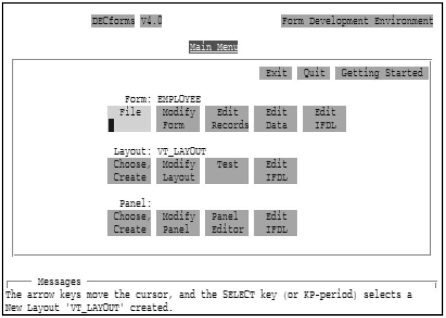
The Main Menu consists of three levels of choices: Form, Layout, and Panel. Section 2.2, ''Using Main Menu Choices at the Form Level'', Section 2.3, ''Using Main Menu Choices at the Layout Level'', and Section 2.4, ''Using Main Menu Choices at the Panel Level'' explain how to use these choices to perform FDE functions. Table 2.1, ''FDE Function Keys'' describes the FDE function keys for selecting menu choices and returning to the Main Menu.
The Main Menu also provides choices for exiting or quitting the FDE. First-time users might want to select the Getting Started choice for an overview of the FDE and of DECforms.
2.1.3. Using Function Keys
The FDE provides function keys for performing such tasks as selecting menu choices and getting help.
|
Function |
Key or Key Sequence |
|---|---|
|
Exit and save changes, or return from a submenu to the Main Menu |
F10, PF1-E |
|
Quit without saving changes, or quit from a submenu |
F8, PF1-Q |
|
Display help information |
Help, PF2 |
|
Turn automatic hinting on or off |
PF1-Help, PF1-PF2 |
|
Display next screen |
Next Screen, PF1-PF4 |
|
Display previous screen |
Prev Screen, PF1-PF3 |
|
Select a menu choice |
Select, KP-period |
|
Display a list of choices for a field in parentheses |
Select, KP-period |
|
Erase the contents of a field |
F13, Linefeed |
|
Move among menu choices, among fields, or within fields |
Arrow keys |
|
Move to the next field |
Tab, Return |
|
Move to the previous field |
F12, Backspace |
2.1.4. Creating a New Form
When you invoke the FDE to create a new form, the FDE displays the Main Menu and then overlays it with the following panel:
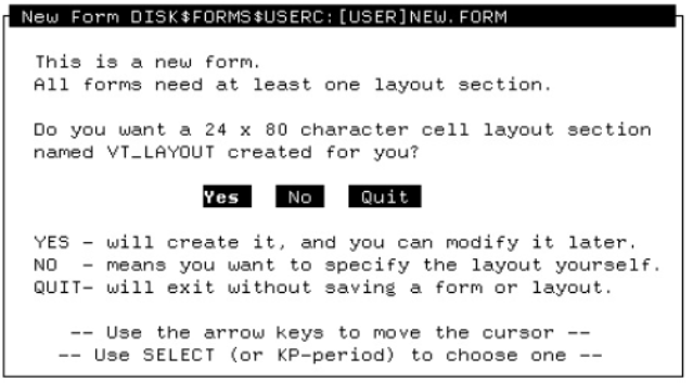
Select Yes to have the FDE create a default character-cell layout. The FDE creates the layout and then clears the New Form panel to redisplay the Main Menu.
2.1.5. Editing an Existing Form
When you invoke the FDE to work on an existing form, the FDE displays the Main Menu and includes the form name, the layout name, and a panel name, as shown in Figure 2.1, ''FDE Main Menu''.If your IFDL source file is newer than your form file (for example, if you edited the IFDL source directly and did not translate it into a form file), the FDE displays the following panel:
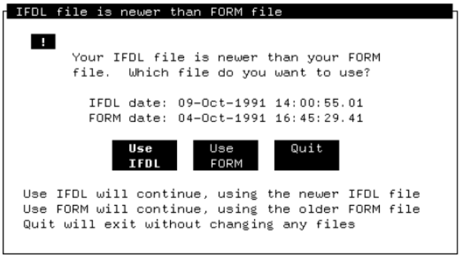
Select the appropriate choice on the panel.
2.2. Using Main Menu Choices at the Form Level
The following sections explain the choices at the Form level on the Main Menu.
2.2.1. Specifying the Output Type
IFDL, FORM
Produces an IFDL source file and a binary form file. This is the default.
IFDL only
Produces only an IFDL source file.
FORM only
Produces only a form file.
Panel Images
Uses the Extract Appearances Utility to produce a file containing panel appearances, suitable for printing. For information about the Extract Appearances Utility, see Chapter 6, "Extracting Objects and Appearances".
Another way to print panels is to use the PRINT response step in your form to print the current display. For more information, see the VSI DECforms IFDL Reference Manual and the VSI DECforms Guide to Developing an Application.
Object of Form
Uses the Extract Object Utility to produce an object module containing the entire form with strong symbol references to your procedural escapes. You can link this object module with the application program.
The object module is configured for the OpenVMS API (application programming interface). To configure the object module for the portable API, you must run the utility from the command line. For information about the Extract Object Utility, see Chapter 6, "Extracting Objects and Appearances".
Object Vectors
Uses the Extract Object Utility to produce an object module containing only procedural escape vectors with strong symbol references to your procedural escapes. You can link this object module with the application program. For information about the Extract Object Utility, see Chapter 6, "Extracting Objects and Appearances".
After you make each output choice, the cursor moves to the Return to Main Menu choice. When you return to the Main Menu, you can exit the FDE or continue working on your form.
2.2.2. Changing the Form Name
The Modify Form choice allows you to change the name of the form and to enter comments about the form. Changing the name of the form does not affect the name of the file you are editing.
2.2.3. Editing IFDL Source Code
- The Edit Records choice places the cursor at the section in the IFDL source file where you would normally enter form record declarations, as follows:
. . . End Data Form Record ACCOUNT ACCOUNT_NUMBER Unsigned Longword DATE_ESTABLISHED Datetime(8) ZIP_CODE Unsigned Longword LAST_NAME Character(20) . . . - The Edit Data choice places the cursor at the section in the IFDL source file where you would normally enter form data declarations, as follows:
. . . Form Data ACCOUNT_NUMBER Unsigned Longword AMOUNT Unsigned Longword CHECKING_BALANCE Unsigned Longword CHECK_MEMO Character(35) CHECK_NUMBER Unsigned Word . . . The Edit IFDL choice places the cursor at the FORM declaration in the IFDL source file.
For information on the syntax of form record, form data, and FORM declarations, see the VSI DECforms IFDL Reference Manual. In EVE-based editors, you can get help on IFDL syntax by pressing Do and entering the HELP FORMS command. Figure 2.2, ''DECTPU Help in the FDE'' shows the first help screen.
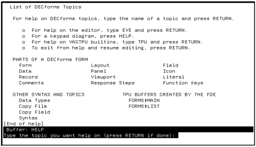
Enter the name of the topic on which you want help information. When you are finished, press Return to resume text editing.
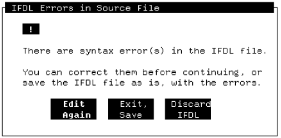
Edit Again
Select this to reenter the text editor and make the necessary corrections.
Exit, Save
Select this to exit the FDE and save the IFDL source file.
Discard IFDL
Choose this to return to the Main Menu without saving the changes that you made to the IFDL source file.
2.3. Using Main Menu Choices at the Layout Level
The following sections explain the choices at the Layout level on the Main Menu.
2.3.1. Selecting a Layout
Select Choose Layout to choose a particular character-cell layout from a list of the layouts for your form. Use the arrow keys to scroll through the list; press Select to choose the desired layout.
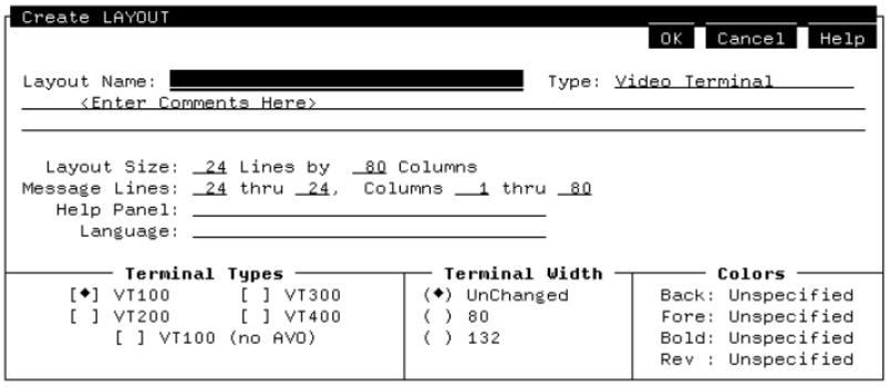
Select Create Layout to create a new character-cell layout. Figure 2.3, ''Creating a Layout in the FDE'' shows the panel that the FDE displays for you to fill in information about the new layout. Section 2.3.2, ''Creating a Layout'' explains the fields and options on this panel.
2.3.2. Creating a Layout
Enter a name for the layout. This name is required and must follow the rules for user-defined names as described in the VSI DECforms IFDL Reference Manual.
Specify a layout type. When you move the cursor to this field, parentheses appear, indicating that you can press Select to request a listing of the types available. Use the Select key to select a type: Video Terminal or Hebrew Video Terminal (for displaying Hebrew characters).
Enter comments about the layout on the lines below the layout name.
Specify new figures to override the default layout size of 24 lines by 80 columns. The layout size specifies the largest rectangular area that the form is to occupy. It also defines the size of the default viewport.
Specify new figures to override the default size of the viewport to be associated with the message panel. All error messages and all output from the MESSAGE response step are displayed on the message panel. A layout can contain only one message panel.
The FDE specifies a default message panel that consists of the bottom line on the screen. The Form Manager creates the default message panel if you do not specify a message panel in your layout.
Specify a help panel to be displayed for items that do not have help panels declared for them. When you move the cursor to this field, parentheses appear, indicating that you can press Select to request a listing of help panels created in the layout selected previously.
Any existing help panels are displayed in the Select a Help Panel submenu. Use the Select key to select a help panel from the list. You also can enter the name of a help panel directly. For information about creating help panels, see the VSI DECforms Guide to Developing an Application.
Enter the name of the natural language (for example, French or German for this layout. If you leave this field blank, the layout can be used with any language.
The Form Manager determines which natural language layout to use by translating the logical name FORMS$LANGUAGE. The definition must match the character string specified for the layout. For more information, see the VSI DECforms Programmer's Reference Manual.
Use the Select key to choose the terminals for which you want to define this layout. If you choose more than one terminal, the layout can use only those capabilities that are available in all the specified terminals. Selecting VT100 means that the layout supports VT100 or newer terminals. If you want the layout to support all current terminals, select VT100.
For more information about specifying terminals in a layout, see the description of the DEVICE declaration in the VSI DECforms IFDL Reference Manual.
- Use the Select key to choose the screen width when the form is displayed, as follows:
UnChanged—The terminal width is unchanged from the operator's setting.
80 and 132—Set the width to 80 and 132 columns, respectively, unless the width is specified explicitly for a panel.
Use the Select key to choose colors for the layout's background and foreground, and for bold and reverse display attributes. When you select the Back, Fore, Bold, or Rev option, the FDE displays the Color Choices menu shown in Figure 2.4, ''Specifying Screen Colors in the FDE''.
Figure 2.4. Specifying Screen Colors in the FDE 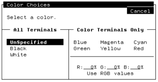 You can select a standard color or specify RGB values (percentages of red, green, and blue) to get different colors.
Note
On monochrome terminals, the Back: BLACK option means white characters on a black background. The Back: WHITE option means black characters on a white background. Do not select a color or specify RGB values.
2.3.3. Changing Layout Attributes
The Modify Layout choice lets you modify the attributes of the current layout. These attributes are the same as for the Create Layout choice (see Section 2.3.2, ''Creating a Layout'').
2.3.4. Testing Your Form
The Test choice allows you to check the appearance of your panels without having to write an application program first. You can evaluate the appearance of each panel as it is seen at run time, and you can observe the input fields as they appear to the operator.
When you select the Test choice, the FDE displays the Testing panel, shown in Figure 2.5, ''Testing a Form in the FDE''.
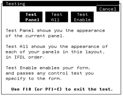
When you select Test Panel, the FDE invokes the Test Utility to display the current panel. Selecting Test All causes the Test Utility to display all panels in the layout in the sequence in which they are declared in the IFDL source file.
Use the default DECforms function keys to move around a panel. When you have finished looking at the panel or panels, press F10 or Ctrl/Z to return to the FDE. For information about the Test Utility, see Chapter 4, "Testing a Form".
In CCPED, you can use the TEST command to test panels. For more information, see Appendix B, "CCPED Commands".
Test Enable
The Test Enable choice causes the FDE to enable your form and act as the application program. When you select this choice from the Testing panel, the FDE displays the following panel: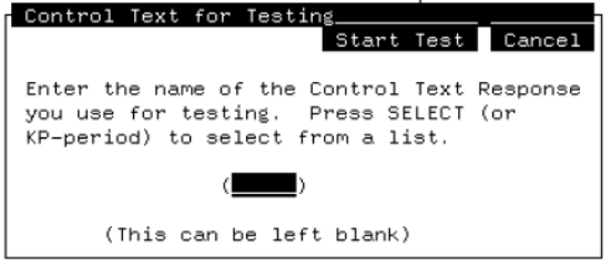 If you do not specify control text for the test, the Form Manager uses the enable response so you can do the following:
Test the initial sequence of events when the form is enabled
Test such form operations as panel navigation
If you specify control text, you can test specific pieces of the form. The control text is passed, forcing execution of a control text response in the form. For example, you might have a control text response for testing that initializes variables and activates certain panels. You can use this feature to test forms or to create demonstrations without using an application program.
For example, you might enter the following control text response in the layout section of your IFDL source file before the panel declarations:Control Text Response "TEST" Activate All End ResponseTo execute a control text response, use the following procedure:Select the Test Enable choice.
- Enter the name of the control text response in the Test Enable panel; for example:
TEST
To display a list of all the control text responses in the form, press Select, or KP. (KP-period). You then can make a selection from the list.
Select the Start Test choice.
Press F10 to end the test and return to the FDE.
If the enable (or any other) response includes a CALL response step,you must define the FORMS$IMAGE logical name to point to the shareable image, or to a search list of shareable images, containing the subroutines that are called. Otherwise the test stops when it encounters the first CALL response step. You can use Test Enable to test the execution of any escape routine, whether user-written or system-supplied. For example, if you define FORMS$IMAGE as LIBRTL, you can test calls from a form to the OpenVMS Run-Time Library routines.
2.3.5. Editing IFDL Source Code
The Edit IFDL choice invokes a text editor and places you at the LAYOUT statement for the current layout in the IFDL source file, provided the FDE can specify the starting position to your text editor. Then you can add help panel declarations, function declarations, and so on. For information about specifying an editor for text editing, see Section 2.1.1, ''Specifying an Editor for IFDL Text Editing''.
When you exit the text editor, the FDE uses the IFDL Translator to translate the IFDL source to update the current definition of the form before returning to the Main Menu. If translation errors occur, the FDE gives you the option of reentering the text editor to correct them. For more information about the IFDL Translator, see Chapter 5, "Translating IFDL Source Files and Form Files".
2.4. Using Main Menu Choices at the Panel Level
The following sections explain the choices at the Panel level on the Main Menu.
2.4.1. Selecting a Panel
Select Choose Panel to choose a particular panel from a list of the data entry panels in the current layout. Use the arrow keys to scroll through the list; press Select to choose the desired panel.
Choose Help
Select Choose Help to choose a help panel from a list of help panels in the current layout. Use the arrow keys to scroll through the list; press Select to choose the desired help panel. For information on help panels, see the VSI DECforms Guide to Developing an Application.
Create Panel
Select Create Panel to create a new panel. Figure 2.6, ''Creating a Panel in the FDE'' shows the panel the FDE displays for you to fill in information. Section 2.4.2, ''Creating a Panel'' explains the fields and options on this panel.
Figure 2.6. Creating a Panel in the FDE 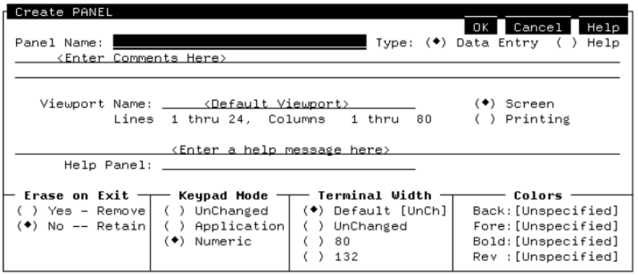
2.4.2. Creating a Panel
Enter a name for the panel. This name is required and must follow the rules for user-defined names as described in the VSI DECforms IFDL Reference Manual.
Select the type of panel: Data Entry or Help. Data entry is the default.
Enter comments about the panel on the lines below the panel name.
Specify a viewport to be associated with the panel. If you specify a viewport that does not exist, a new viewport with that name is created. If you leave this field blank, the panel is associated with the default viewport. If you use the default viewport, you cannot modify the viewport line or column values or the viewport type.
When you move the cursor to this field, parentheses appear, indicating that you can press Select to request a listing of viewports in the layout. Any existing viewports are displayed in the Select a Viewport submenu. Use the Select key to select a viewport from the list.
The submenu also indicates the line and column values of each viewport and the size of the panel. The Type column indicates Printing for printing viewports. If the viewport is a screen viewport, the Type column is left blank.
Screen or Printing
Use the Select key to select the viewport type. A screen viewport cannot be larger than the size of the layout. A printing viewport can be any size.
Lines and Columns
Specify new figures to override the default number of lines and columns the viewport is to occupy. For a printing viewport, you can enter line and column values up to 999. To specify larger printing viewports with values up to 65545, edit the IFDL file.
If the viewport is a screen viewport, the size is validated against the layout declaration for display on a CRT device.
Enter a help message here
Enter a one-line help message to be used by items in the panel that do not have any help messages explicitly declared for them. Enter this message on the line above the Help Panel field.
Use this field to specify a help panel to be displayed for items that do not have help panels declared for them. When you move the cursor to this field, parentheses appear, indicating that you can press Select to request a listing of help panels in this layout.
Any existing help panels are displayed in the Select a Help Panel submenu. Use the Select key to select a help panel from the list. You also can enter the name of a help panel directly. For information about creating help panels, see the VSI DECforms Guide to Developing an Application.
Use the Select key to specify whether the panel is to remain displayed after the operator exits the panel. The default option, No, keeps the panel on the screen after the operator exits. Select Yes to remove the panel.
If you accept the default, you can remove the panel from the screen in a response using the REMOVE response step. For information on this response step, see the VSI DECforms IFDL Reference Manual.
- Use the Select key to select the keypad mode for the operator.
UnChanged—The keypad mode is unchanged from the operator's setting when this panel is displayed.
Application—The keypad keys act as function keys.
Numeric (default)—The keypad keys enter numbers.
- Use the Select key to set the terminal width for the panel display.
Default (default)—Sets the terminal width to the viewport's width as displayed in the square brackets ([ ]).
UnChanged—The terminal width is unchanged when this panel is displayed.
80 and 132—Set the terminal width to 80 and 132 columns respectively.
Use the Select key to choose colors for the panel's background and foreground, and for bold and reverse display attributes. These selections override any you made at the Layout level.
When you select the Back, Fore, Bold, or Rev options, the FDE displays the Color Choices menu shown in Figure 2.4, ''Specifying Screen Colors in the FDE''. You can select a standard color or specify RGB values (percentages of red, green, and blue) to get different colors.Note
On monochrome terminals, the Back: BLACK option indicates white characters on a black background. The Back: WHITE option indicates black characters on a white background. Do not select a color or specify RGB values.
2.4.3. Changing Panel Attributes
The Modify Panel choice allows you to modify the attributes of the current panel. These attributes are the same as for the Create Panel choice (see Section 2.4.2, ''Creating a Panel'').
2.4.4. Editing Panel Appearance
The Panel Editor choice invokes the Character-Cell Panel Editor (CCPED) to let you edit the current panel. CCPED lets you create graphic form elements in an interactive, what-you-see-is-what-you-get fashion.
When you create a form, you need to specify the visual elements of the form's panels: background text and graphics, field attributes, such as location and size, and so on. You can use CCPED to create and modify these elements and their attributes, and you can see the results on the screen immediately.
For information on using CCPED, see Chapter 3, "Editing Panel Appearance Using the Character-Cell Panel Editor (CCPED)".
2.4.5. Editing IFDL Source Code
The Edit IFDL choice invokes a text editor and places you at the PANEL statement for the current panel in the IFDL source file, provided the FDE can specify the starting position to your text editor. Then you can add field description attributes, function responses, and so on. For information about specifying an editor for text editing, see Section 2.1.1, ''Specifying an Editor for IFDL Text Editing''.
When you exit the text editor, the FDE uses the IFDL Translator to translate the IFDL source to update the current definition of the form before returning to the Main Menu. If translation errors occur, the FDE gives you the option of reentering the text editor to correct them. For more information about the IFDL Translator, see Chapter 5, "Translating IFDL Source Files and Form Files".
2.5. Exiting the FDE
The Exit choice terminates the FDE session and saves any changes made to the form file. By default, the FDE produces a form file and an IFDL source file. You can choose to have only a form file or an IFDL source file produced for the type of output. You can specify the type of output when you invoke the FDE with the FORMS DEVELOP command (see Chapter 1, "DECforms Commands"), or by selecting the File choice at the form level on the FDE Main Menu (see Section 2.2.1, ''Specifying the Output Type''). You also can press PF1-E or F10 to exit the FDE.
The Quit choice terminates the FDE session without saving any changes you made to the form file. The FDE notifies you that the changes will not be saved and asks you to verify that you want to quit. You also can press PF1-Q or F8 to quit the FDE.
2.6. Recovering an FDE Session
The FDE uses checkpointing as a recovery mechanism. Checkpointing saves the known state of a form, so the form can be restored to that state following a failure. Checkpointing is enabled by default when you invoke the FDE. For more information on checkpointing, see the description of the FORMS DEVELOP command in Chapter 1, "DECforms Commands".
When checkpointing is enabled, the FDE writes the form file out to disk every time you return to the Main Menu after modifying the current form. Should your FDE session end abnormally for some reason (for example, if your system fails), you can recover the state of your editing session at the last checkpoint before the abnormal termination occurred. During recovery, the FDE also applies any CCPED journal files to the checkpoint.
FORMS DEVELOP input-file-spec /RECOVER
This command causes the FDE to reconstruct your FDE session up to the point when the checkpoint file was written.
Chapter 3. Editing Panel Appearance Using the Character-Cell Panel Editor (CCPED)
The DECforms Character-Cell Panel Editor (CCPED) lets you create and edit the visual appearance of form panels that will be used in character-cell layouts. With CCPED, you can create graphic form elements, such as background text and graphics and the location and size of fields, in an interactive, what-you-see-is-what-you-get fashion.
CCPED runs under the OpenVMS operating system on a character-cell terminal or in a terminal emulation window on a workstation.
Invoke and exit CCPED
Recover an editing session from abnormal termination
Use the CCPED screen display
Use CCPED commands and the default keypad
Create and edit panel appearance
Test panel appearance
$ COPY FORMS$EXAMPLES:FORMS$CHECKING_FORM.FORM SAMPLE.FORM
$ FORMS EDIT SAMPLE
For a tutorial covering some of the basics of using CCPED, see the VSI DECforms Guide to Developing an Application.
3.1. Invoking and Exiting CCPED
From the FDE Main Menu, select the Panel Editor choice at the Panel level (see Chapter 2, "Form Development Environment").
Replace form-file-spec with the name of the form file. The default input file type is
.form.For a complete description of the FORMS EDIT command and its qualifiers, see Chapter 1, "DECforms Commands".
Note
When you invoke CCPED from the FDE, an IFDL file is automatically created from the form file. When you invoke CCPED by using the FORMS EDIT command, you must back translate the form file to create the IFDL file. For information about back translating, see Chapter 5, "Translating IFDL Source Files and Form Files".
To exit CCPED, press F10 or PF1-E, or enter the EXIT or QUIT command on the CCPED command line. See Section 3.4.1, ''Entering Commands'' for information about using CCPED commands.
Upon exiting, CCPED produces as output an updated version of the form file. The default output file has the same name and file type as in the input file.
If you try to quit after making changes, CCPED displays a caution box advising you that your changes will be discarded and asking you to confirm whether or not you want to quit.
3.2. Recovering an Editing Session
If your editing session ends abnormally due to a hardware failure or some other interruption, use journaling to recover it. CCPED journals your editing session after every few commands that you enter. If the journal file is not needed, CCPED deletes it when you end your editing session.
Invoke CCPED, specifying the /RECOVER qualifier.
Open the form file that needs to be recovered.
CCPED creates the journal file in your working directory, using the default file
format form_file_name.forms$journal.
To direct journaling to a different file name or directory, use the /JOURNAL qualifier when you invoke CCPED.
3.3. CCPED Screen Display
Figure 3.1, ''CCPED Screen Display'' shows these areas.
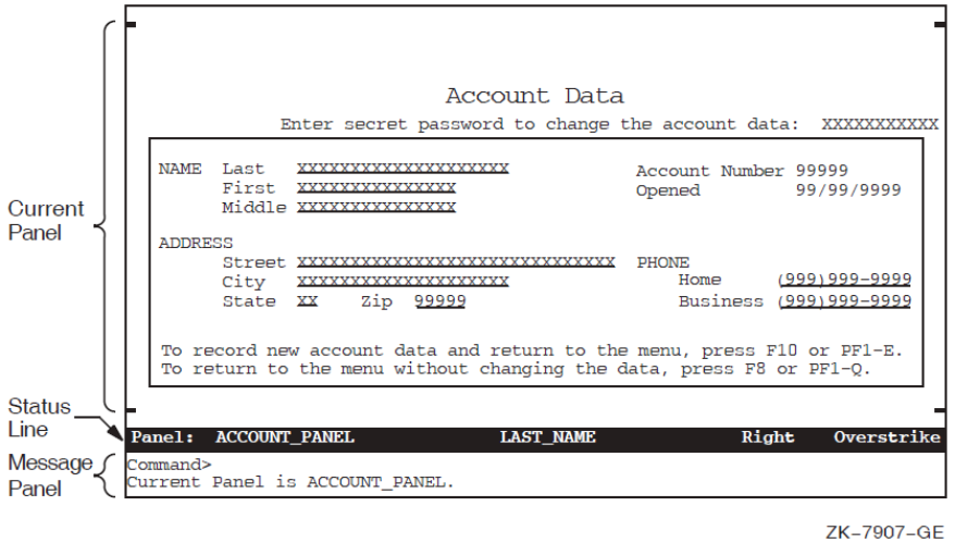
Depending on whether you are using the command interface or the menu interface, or whether you are requesting information or help, the screen display changes to show a command line, menus and submenus, an information window, or help windows.
The following sections describe all parts of the screen display.?
3.3.1. Current Panel
The current panel is the form panel currently displayed for editing. When a panel becomes the current panel, it is displayed in the area of the screen specified in its associated viewport. If a panel is not associated with a viewport, it is displayed in the default viewport (which is based on the size of the current layout).
CCPED displays markers for the viewport boundary for the current panel whenever possible. The markers are shown in Figure 3.1, ''CCPED Screen Display'' as a short line in each corner of the current panel. The boundary markers do not appear as part of the current panel, but appear one line or column outside the current panel's border. If the panel size extends to the edge of the display, CCPED does not resize the display to show the boundary markers.
If the current panel is associated with a viewport having a width greater than 80 columns or whose position is beyond column 80, CCPED changes the terminal width to 132 columns (if it is not set to that width).
3.3.2. Status Line
The status line contains information about your editing session. Such information includes the name of the current panel, the name of the current object (panel field, panel group, or icon) on which the cursor is currently positioned (if any), the text path or direction for entering text literals and fields, and the current text entry mode (insert or overstrike).
The status line is displayed in reverse video as the message panel boundary, and it moves as the message panel moves.
3.3.3. Message Panel
CCPED displays all messages in the message panel. Messages include warning and informational messages, broadcast messages, and hints—help messages that are displayed as a result of using the ENABLE HINTS command. Old messages are scrolled out of the message window as new messages are displayed.
To look at the most recently displayed message, use the Recall Message key (PF1-PF3) or enter the RECALL MESSAGE command. CCPED displays the message in the Information Window (see Section 3.3.6, ''Information Window'').
The message panel is two lines long and can appear initially at either the top or the bottom of the screen, depending on the location and size of the current panel. The message panel can move to the top or bottom of the screen during your editing session.
3.3.4. Command Line
You can create and edit panels by entering CCPED commands on the command line.
To display the Command> prompt, press Door the Command key
(PF1-KP7). The command line overlays the top line of the message panel and
disappears after a command is executed.
For information about how to enter and use CCPED commands, see Section 3.4, ''Using CCPED Commands and Keys''.
3.3.5. Menus
CCPED displays menus when you press certain keys on the CCPED default keypad or when you enter certain commands without parameters. For example, pressing the Set key (KP7) invokes the Set Display Attribute Menu; items on some menus display submenus, as shown in Figure 3.2, ''CCPED Menus and Submenus''.
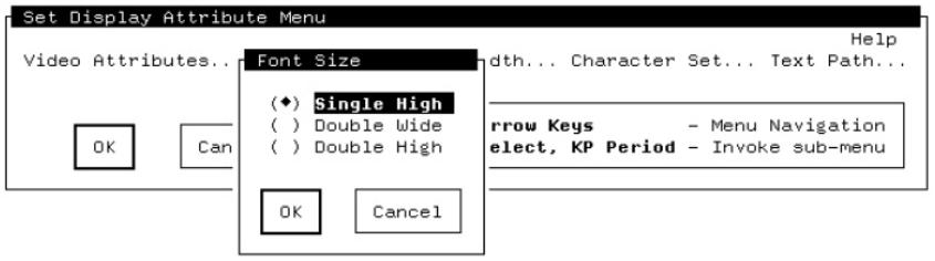
To select an item, use the arrow keys to move to the menu item you want, and then press Select.
To save and apply the selected item,select OK (or press F10 or PF1-E).To cancel the selection, select Cancel (or press F8 or PF1-Q). CCPED returns you to the previous menu or to the current panel.
3.3.6. Information Window
You can request information about your current form or editing session, such as a listing of panels or viewports. You also can ask to see the message most recently displayed in the message panel, in case the message was too long or was obscured. CCPED displays the requested information in the Information Window, shown in Figure 3.3, ''CCPED Information Window''.
For example, Figure 3.3, ''CCPED Information Window'' shows the information displayed in the Information Window when you press List Panels while editing a panel in the sample application form.
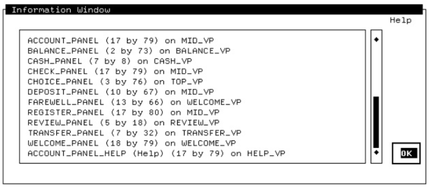
CCPED lists the panels contained in the current layout and displays additional information, including panel size and the associated viewport. If the information is too long to be displayed at once, you can use the scroll bar to the right of the window to scroll through the list of information.
Use the arrow keys to move the cursor to the diamond at the top of the scroll bar (to move down the list) or to the diamond at the bottom of the scroll bar (to move up the list).
Press Select to move through the list one line at a time, or press Next Screen or Prev Screen to scroll page by page.
For help on using the Information Window, select the Help icon. When you are finished with the Information Window, select OK. CCPED removes the Information Window and returns the cursor to its previous position in the current panel.
3.3.7. Help Windows
The Help window that results when you enter the HELP command or press the Help key (PF1-PF2) on the CCPED keypad
The top part of the window displays help information; the bottom part displays a list of additional topics.
To use this help, you can do any of the following:Use the arrow keys to choose a topic from the list of additional topics, and then press Select to display information about that topic.
Press Prev Screen and Next Screen to scroll through topic text.
Press Backspace, Ctrl/H, or F12 to go to the previous topic in the current help level.
Press PF1-Backspace, PF1-Ctrl/H, or PF1-F12 to go back one help level, and PF1-T or F11 to go back to the top help level.
Press PF1-E, F10, or F8 to exit the Help window.
The Help window that results when you select the Help icon in the upper-right corner of a CCPED menu
The window displays help information and supplies icons for moving through the information or for dismissing help.
You also can use the message panel to see brief help about the menu choice or icon on which the cursor is currently positioned. To display menu hints, enter the ENABLE HINTS command. Hints are displayed automatically as you move the cursor in the menu. Menu hints are disabled by default.
3.4. Using CCPED Commands and Keys
This section contains general information about how to use CCPED commands and keys.
You perform CCPED functions by entering a command at the Command>
prompt. Many commands also are bound to keypad keys. You can redefine these keys or
define other function keys to customize your editing session.
For a summary of the CCPED keys, see Appendix A, "CCPED Keypad, Function Keys, and Definable Keys".For a complete description of each CCPED command, see Appendix B, "CCPED Commands".
3.4.1. Entering Commands
Press Do or the Command key (PF1-KP7).
The
Command>prompt is displayed in the message panel.Enter the command at the prompt and press Return.
The command is executed, and the prompt is cleared from the screen.
To leave the command line without executing a command, leave the line blank and press Return.
Command> SELECT ALL; ORDER SELECTED OBJECTS; CHOOSE NEXT PANEL
CCPED commands that are too long to fit in the message panel are scrolled horizontally. To see the complete command line, use the left and right arrow keys.
To recall the previous command line, press Ctrl/B. You can recall up to 20 command lines.
|
Key or Key Sequence |
Command-Line Function |
Text-Entry Function |
|---|---|---|
|
Ctrl/A or F14 |
Switches text entry mode between insert and overstrike. |
Same. |
|
Ctrl/B or up arrow |
Recalls up to 20 previously entered command lines. |
Ctrl/B recalls the previously entered command. The up arrow moves the cursor up one line. |
|
Ctrl/D or left arrow |
Moves the cursor one character to the left. |
Ctrl/D ends the session. The left arrow moves the cursor one position to the left. |
|
Ctrl/E |
Moves the cursor to one character position after the last character on the line. |
Same. |
|
Ctrl/F or right arrow |
Moves the cursor one character to the right. |
Same. |
|
Ctrl/H or F12 |
Moves the cursor to the beginning of the current line. |
Same. |
|
Ctrl/I or Tab |
(N/A) |
Moves the cursor to the next tab position on the line (eight characters). |
|
Ctrl/J or F13 |
Deletes characters from the cursor position to the beginning of the current word. |
Same. |
|
Ctrl/M or Return |
Executes a command line. |
Moves the cursor to the beginning of the next line. |
|
Ctrl/R or Ctrl/W |
Refreshes the command line. |
Refreshes the screen. |
|
Ctrl/U |
Deletes characters from the cursor position to the beginning of the line. |
Deletes characters from the cursor position to the beginning of the text literal. |
|
Delete |
Deletes the previous character. |
Same. |
Specifying Qualified Names as Command Parameters
When you enter a field, icon, or group name as a parameter to certain CCPED commands, you must specify a fully qualified name. You do so by entering the name of the field, icon, or group, as well as the names of any other groups in which it is contained, separating each group item from the next with a period.
Command> SELECT NAMED GROUP_1.FIELD_1
3.4.2. Using Command Macros for Text Substitution
CCPED lets you use command macros for prompting and text substitution within the command line. You can use command macros for all command input; however, their primary usefulness is in commands bound to function keys or used in command scripts. (See Section 3.4.5, ''Defining CCPED Function Keys'' for information on defining function keys and Section 3.4.6, ''Executing a Series of Commands in a Command Script'' for information on using command scripts.)
Place a number-sign character (#) in the command line where you want the prompt or substitution to occur.
Follow the number sign with the prompt string, enclosing the string in single quotes (
' ').Execute the command.
Command> CREATE TEXT "Average " (#’Line: ’,#’Column: ’)
Line: 10
Column: 13
The following command gets executed:
CREATE TEXT "Average " (10,13)
If you do not specify a prompt string with the number sign, CCPED uses a question mark (?) as a prompt.
Command> CREATE TEXT "## of copies: " (#’Line: ’,#’Column: ’)
Line: 12
Column: 2
The following command gets executed:
CREATE TEXT "# of copies: " (12,2)
3.4.3. Using Expressions
Many commands let you use an expression in place of a numeric value. An expression consists of operands, which represent numeric values, and operators, which operate on those values.
Operands can be either numeric literals (integer or floating point) or identifiers (symbol names). If the context of the expression is such that only integer values are meaningful (for example, character-cell positions), floating point literals are truncated to an integer value. You must define a symbol before you can use it in an expression (see Section 3.4.4, ''Defining Symbols'').
|
Unary minus (–) |
Unary plus (+) |
|
Subtraction (–) |
Addition (+) |
|
Multiplication (*) |
Division (/) |
|
Exponentiation (^) |
ABS$(expression)This function returns the absolute value of the specified expression.
3.4.4. Defining Symbols
To define symbols for subsequent use in expressions, use the DEFINE SYMBOL command. CCPED enters the symbols in the CCPED symbol table, which contains predefined symbols that you also can use in symbol definitions. For example, you can use the LINE$ and COLUMN$ symbols to define symbols for the cursor's current position.
|
Symbol |
Definition |
|---|---|
|
COLUMN$ X$ |
Return the current, horizontal, character-cell position. |
|
LINE$ Y$ |
Return the current, vertical, character-cell position. |
|
COLUMN_MAX$ X_MAX$ |
Return the maximum horizontal position for the current panel. |
|
LINE_MAX$ Y_MAX$ |
Return the maximum vertical position for the current panel. |
Command> DEFINE SYMBOL This_line LINE$
Command> DEFINE SYMBOL This_column COLUMN$
  .
  .
  .
Command> POSITION TO (This_line,This_column)
3.4.5. Defining CCPED Function Keys
To associate CCPED command strings with keyboard function keys, use the DEFINE KEY command. The string can contain command-line macros as well as multiple commands. Once you associate a command with a key, the command is executed whenever you press that key.
To cancel a key definition, use the UNDEFINE KEY command.
|
Ctrl/C |
Ctrl/O |
Ctrl/Q |
Ctrl/S |
|
Ctrl/T |
Ctrl/V |
Ctrl/X |
Ctrl/Y |
For a list of the names of keys you can define, see Appendix A, "CCPED Keypad, Function Keys, and Definable Keys".
Command> DEFINE KEY F20 "CREATE RECTANGLE (1,1) (LINE_MAX$, COLUMN_MAX$)"This command creates a rectangle the size of the viewport associated with the current panel.
Note
Because you cannot specify that a viewport be bordered, you must use the preceding method to create a border around each individual panel that you want bordered.
3.4.6. Executing a Series of Commands in a Command Script
myscript.com. The exclamation mark (!) denotes a
comment:! Script to create an icon-based menu SELECT AT (LINE$,COLUMN$) CREATE ICON #’Icon Name: ’ DESELECT AT (LINE$,COLUMN$) POSITION NEXT OBJECT
Command> @MYSCRIPT
By default, CCPED looks for a file with a .com extension. Execution of a command script terminates when CCPED reaches the end of the file or when a command in the script generates an error. Recursion is not allowed; you cannot execute one command script from within another.
To control whether commands in a script are echoed during execution, use the ENABLE ECHO and DISABLE ECHO commands. Echoing is disabled by default.
To point to a script you want executed whenever you invoke CCPED, define the logical name FORMS$EDIT_INIT.
3.4.7. Using the CCPED Default Keypad
Several CCPED commands are bound to keypad keys. Appendix A, "CCPED Keypad, Function Keys, and Definable Keys" contains a list of CCPED function keys, as well as a diagram of the default keypad.
The keypad diagram also is available on line. To access the online diagram (and editing keypad on LK201 keyboards), press Help (PF2) or enter the SHOW KEYPAD command.
With the diagram displayed, you can press any key on the keypad to see which CCPED command that key reflects. To exit the diagram and return to the current panel, press PF1-E or F10.
To customize your editing session, you can redefine the default keys or define your own function keys, as described in Section 3.4.5, ''Defining CCPED Function Keys''.
3.5. Creating and Editing the Appearance of Panels
As you use CCPED, keep in mind that CCPED is an object-oriented editor. Objects include background text and graphics (literals), icons, panel fields (single or multiline text fields and single-line picture fields), and panel groups (groups of multiply occurring objects).
An object editor differs from a character-cell editor (such as the FMS Form Editor or a text editor) by manipulating the entire object, regardless of the number of character cells it occupies. A character-cell editor manipulates one character cell at a time.
Just as a single object might span multiple character cells, a single character cell might contain multiple objects (except for fields, which cannot overlap).
Note
There is one exception to the preceding description. You can edit a text literal by moving the cursor over the text and editing the individual characters. You are not creating a second text object.
To initiate CCPED operations, you can enter commands, or in many cases, you can use the CCPED keypad. For complete information about any CCPED command, see Appendix B, "CCPED Commands".
Some CCPED operations also are available through the FDE. For information about using the FDE, see Chapter 2, "Form Development Environment".
3.5.1. Moving the Cursor
To move the cursor within the current panel, use the arrow keys and the keypad keys listed in Table 3.3, ''CCPED Keys for Cursor Positioning''. You also can use some of the control key sequences listed in Table 3.1, ''CCPED Editing Keys''.
Note
Do not use the space bar to move the cursor when you are editing a panel. The space bar creates literal spaces on the panel.
| Name | Press ... | To move the cursor ... |
|---|---|---|
|
Up |
Up arrow |
Up one row in the same column. |
|
Top |
PF1-Up arrow |
To the top of the panel in the same column. |
|
Down |
Down arrow |
Down one row in the same column. |
|
Bottom |
PF1-Down arrow |
To the bottom of the panel in the same column; the message panel appears at the top of the screen. |
|
Left |
Left arrow |
One column to the left in the same line. |
|
Leftmost Column |
PF1-Left arrow |
To the leftmost column of the panel in the same line. |
|
Bottom Left |
PF1-KP4 |
To the bottom-left corner of the panel; the message panel appears at the top of the screen. |
|
Upper Left |
PF1-KP5 |
To the upper-left corner of the panel. |
|
Right |
Right arrow |
One column to the right in the same line. |
|
Rightmost Column |
PF1-Right arrow |
To the rightmost column of the panel in the same line. |
|
Bottom Right |
PF1-KP6 |
To the bottom-right corner of the panel; the message panel appears at the top of the screen. |
|
Next Word |
KP1 |
To the next word or object in a left-to-right, top-to-bottom direction. |
|
Previous Word |
PF1-KP1 |
To the previous word or object in a right-to-left, bottom-to-top direction. |
|
Next Object |
Find or KP3 |
To the next object or word in a left-to-right, top-to-bottom direction. |
|
Previous Object |
PF1-Find or PF1-KP3 |
To the previous object or word in a right-to-left, bottom-to-top direction. |
|
End of Line |
KP2 |
To the rightmost column of the panel in the same line. |
|
Beginning of Line |
PF1-KP2 |
To the leftmost column of the panel in the same line. |
|
Next Line |
KP0 |
To the beginning of the next line. |
3.5.2. Using the Repeat Key Function
Use the Repeat Key function to execute a character key or an arrow key a specific number of times.
Press Do.
Press PF1.
Enter the number of repetitions.
Press a character key or an arrow key.
For example, to move the cursor eight character-cell locations up from its current position, press PF1, the number 8, and then the up arrow. To enter nine X characters at the current cursor position,press PF1, the number 9, and the character X.
3.5.3. Creating, Deleting, and Restoring Viewports
To create a new viewport in the current layout, use the CREATE VIEWPORT command.
To delete a viewport, use the DELETE VIEWPORT command. References to the default viewport replace any references in the form to the deleted viewport.
- UNDELETE ALL VIEWPORTS
- UNDELETE LAST VIEWPORT
- UNDELETE VIEWPORT name
- LIST VIEWPORTS
- MODIFY VIEWPORT TERMINAL WIDTH
- MOVE CURRENT VIEWPORT
- MOVE VIEWPORT name
- RESIZE CURRENT VIEWPORT
- RESIZE VIEWPORT name
The List Viewports key (KP6) performs the same operation as the LIST VIEWPORTS FULL command. CCPED lists the viewports contained in the current layout and displays additional information, including the size and position of the viewports.
3.5.4. Creating, Deleting, and Restoring Panels
To create panels and associate them with viewports,use the CREATE PANEL command. Use only alphabetic characters when naming a panel.
To delete panels, use the DELETE PANEL command.
3.5.5. Choosing Panels
The CHOOSE command
- One of the following CCPED keys, depending on which panel you want to choose:
- Next Panel (Next Screen)
- Previous Panel (Prev Screen)
- First Panel (PF1-Prev Screen)
- Last Panel (PF1-Next Screen)
- LIST PANELS
- MODIFY PANEL TERMINAL WIDTH
- MODIFY PANEL VIEWPORT
- SHOW PANEL VIEWPORT
Use the List Panels key (KP5) to perform the same operation as the LIST PANELS FULL command. CCPED lists the panels contained in the current layout and displays additional information, including panel size and the associated viewport.
3.5.6. Setting and Modifying Attributes
When you create a panel, panel object, or viewport, you can assign it a set of attributes (display characteristics), such as font size or color. The following sections describe the attributes that you can set and modify using CCPED.
3.5.6.1. Setting Video Attributes
- Bolding
- Underlining
- Blinking
- Reverse video
Once you set an attribute, it is applied to any panel object that you subsequently create.
The SET VIDEO command
- The Video Attributes submenu, as follows:
Press Set (KP7) to display the Set Display Attribute Menu.
Select Video Attributes.
CCPED displays the Video Attributes submenu.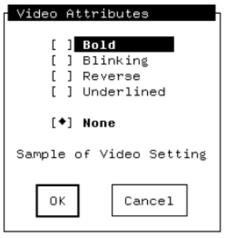
Select the attributes you want to apply to subsequent objects.
A diamond (♦) next to an attribute indicates it is selected. The text Sample of Video Setting changes to reflect the attributes chosen.
To turn off an attribute, select it again. The diamond disappears, indicating that the attribute will not be applied. To turn off all attributes, select None (the default).
Select OK to return to the Set Display Attribute Menu, where you can select another display attribute or return to panel editing.
All subsequent objects that you create will have the video attributes selected.
You also can specify different video attributes for an object based on the type of terminal on which the form will be displayed, but you must edit the form manually. Example 3.1, ''IFDL Source for Attributes Based on Terminal Type'' in Section 3.5.6.8, ''Specifying Display Attributes Based on Terminal Type'' shows sample IFDL syntax, using different font sizes as an example.
3.5.6.2. Modifying Video Attributes
The MODIFY SELECTED OBJECTS VIDEO command
- The Video Attributes submenu, as follows:
Press Modify (KP4) to display the Modify Display Attribute Menu.
This menu is the same as the Set Display Attribute Menu.
Select Video Attributes.
Select the attributes to be applied to or removed from the selected objects.
Exit the menus.
The selected objects are modified according to the attributes you chose.
3.5.6.3. Modifying the Color of Display Attributes
If your form is going to run on color terminals, you can specify background and foreground colors for all the panels in a viewport, for the current panel, or for panel objects. You also can specify colors for bold and reverse video attributes for panels.
To specify the color of display attributes for all the panels in a viewport, use the MODIFY VIEWPORT display-attribute COLOR command. The attributes apply to all panels in the viewport unless the attributes are explicitly overridden for individual panels.
To specify the color of display attributes for the current panel, use the MODIFY PANEL display-attribute COLOR command. This command does not change the viewport attributes, but does override the viewport attributes when the panel is displayed.
To set the background or foreground color for panel objects, use the SET display-attribute COLOR command. The color applies to all subsequent panel objects you create. To specify the color of display attributes for selected panel objects, use the MODIFY SELECTED display-attributes COLOR command.
For a list of the colors you can specify, see the command descriptions in Appendix B, "CCPED Commands".
3.5.6.4. Setting the Font Size
- Single-high
- Double-high
- Double-wide
Once you set an attribute, it is applied to any object that you subsequently create.
- The Font Size submenu, as follows:
Press Set (KP7) to display the Set Display Attribute Menu.
Select Font Size.
CCPED displays the Font Size submenu.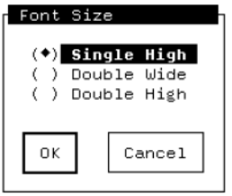
Select the font size you want to apply to subsequent objects.
A diamond (♦) next to the font size indicates that it is selected. You can select only one font size at a time.
Select OK to return to the Set Display Attribute Menu, where you can select another display attribute or return to panel editing.
All subsequent objects that you create will have the font size selected.
Restrictions
You cannot have more than one font size on the same line.
If a panel's viewport begins on an odd-numbered column, double-high and double-wide objects must begin on odd-numbered columns.
If a panel's viewport begins on an even-numbered column, double-high and double-wide objects must begin on even-numbered columns.
You cannot create double-high objects on the top line of a panel.
You also can specify different font sizes for an object based on the type of terminal on which the form will be displayed, but you must edit the form manually. Example 3.1, ''IFDL Source for Attributes Based on Terminal Type'' in Section 3.5.6.8, ''Specifying Display Attributes Based on Terminal Type'' shows the IFDL syntax.
3.5.6.5. Modifying the Font Size
The MODIFY SELECTED OBJECTS FONT SIZE command
- The Font Size submenu, as follows:
Press Modify (KP4) to display the Modify Display Attribute Menu.
This menu is the same as the Set Display Attribute Menu.
Select Font Size and choose the font size to be applied to or removed from the selected objects.
Exit the menus.
The selected objects are modified according to the font size you chose to apply or remove.
Restrictions
The restrictions that apply to setting a font size also apply to modifying a font size. See Section 3.5.6.4, ''Setting the Font Size''.
3.5.6.6. Setting Line Width
The SET LINE WIDTH command
- The Line Width submenu, as follows:
Press Set (KP7) to display the Set Display Attribute Menu.
Select Line Width.
CCPED displays the Line Width submenu.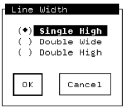
Select the line width you want to apply to subsequent objects.
A diamond (♦) next to the line width indicates that it is selected. You can set only one line width at a time.
Select OK to return to the Set Display Attribute Menu, where you can select another display attribute or return to CCPED.
All subsequent objects that you create will have the line width selected.
Restrictions
You cannot have more than one line width on the same line.
If a panel's viewport begins on an odd-numbered column, double-high and double-wide objects must begin on odd-numbered columns.
If a panel's viewport begins on an even-numbered column, double-high and double-wide objects must begin on even-numbered columns.
You cannot create double-high objects on the top line of a panel.
You also can specify different line widths for an object based on the type of terminal on which the form will be displayed, but you must edit the form manually. Example 3.1, ''IFDL Source for Attributes Based on Terminal Type'' in Section 3.5.6.8, ''Specifying Display Attributes Based on Terminal Type'' shows sample IFDL syntax, using different font sizes as an example.
3.5.6.7. Modifying Line Width
The MODIFY SELECTED OBJECTS LINE WIDTH command
- The Line Width submenu, as follows:
Press Modify (KP4) to display the Modify Display Attribute Menu.
This menu is the same as the Set Display Attribute Menu.
Select Line Width and choose the line width to be applied to or removed from the selected objects.
Exit the menus.
The selected objects are modified according to the line width you chose to apply or remove.
Restrictions
The restrictions that apply to setting a line width also apply to modifying a line width. See Section 3.5.6.6, ''Setting Line Width''.
3.5.6.8. Specifying Display Attributes Based on Terminal Type
You can specify named attributes to apply different video attributes, font sizes, or line widths to objects based on the type of terminal on which a form will be displayed. Because CCPED does not allow the specification of named attributes, you must use the ATTRIBUTE declaration and FOR clause in the IFDL. Example 3.1, ''IFDL Source for Attributes Based on Terminal Type'' shows the IFDL syntax, based on applying different font sizes.
When you use these statements to specify different font sizes and then edit the panel in CCPED, CCPED displays objects in the largest size specified in the IFDL source file. For different line widths or video attributes, CCPED displays objects by using whichever attribute occurred first in the FOR clause.
Form FOR_CLAUSE_FORM

    Layout CC
        Device
            Terminal T1
                Type %VT100
            Terminal T2
                Type %VT200
            Terminal T3
                Type %VT300
        End Device
        Size 25 Lines by 80 Columns

        Attribute MULTIPLE_SIZES
            For T1
                Is
                    Font Size Double Wide
            For T3
                Is
                    Font Size Double High
        End Attribute

  .
  .
  .
        Panel PANEL_1

            Literal Text
                Line 4
                Column 5
                Value "Object with multiple size attribute"
                Display
                    MULTIPLE_SIZES
                    Reverse
            End Literal
        End Panel
    End Layout
End Form
3.5.6.9. Setting the Character Set
|
User Preference |
ISO_8859/1 |
ISO Latin-1 |
ISO_8859/5 |
|
ISO Latin-5 |
ASCII |
UK |
Rule |
|
VT100 Set One |
VT100 Set Two |
Hebrew |
Turkish |
|
Hanyu |
Hangul |
Kanji |
Thai |
|
Katakana |
MIA-Kanji |
This attribute does not apply to graphic literals.
The SET CHARACTER SET command
- The Character Set submenu, as follows:
Press Set (KP7) to display the Set Display Attribute Menu.
Select Character Set.
CCPED displays the Character Set submenu.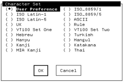
Select the character set you want to apply to subsequent objects.
A diamond (♦) next to the character set indicates that it is selected. You can set only one character set at a time.
Select OK to return to the Set Display Attribute Menu, where you can select another display attribute or return to CCPED.
All subsequent objects that you create will have the character set selected.
3.5.6.10. Modifying the Character Set
The MODIFY SELECTED OBJECTS CHARACTER SET command
- The Character Set submenu, as follows:
Press Modify (KP4) to display the Modify Display Attribute Menu.
This menu is the same as the Set Display Attribute Menu.
Select the Character Set choice and choose the character set to be applied to or removed from the selected objects.
Exit the menus.
The selected objects are modified according to the character set chosen.
3.5.6.11. Setting the Text Path
- Left to right (the default)
- Right to left (Hebrew)
The SET TEXT PATH command
- The Text Path submenu, as follows:
Press Set (KP7) to display the Set Display Attribute Menu.
Select Text Path.
CCPED displays the Text Path submenu.
Select the text path you want to apply to subsequent objects.
A diamond (♦) next to the text path indicates that it is selected. You can select only one text path at a time.
Select OK to return to the Set Display Attribute Menu, where you can select another display attribute or return to CCPED.
All subsequent objects that you create will have the text path selected.
3.5.6.12. Modifying the Text Path
The MODIFY SELECTED OBJECTS TEXT PATH command
- The Text Path submenu, as follows:
Press Modify (KP4) to display the Modify Display Attribute Menu.
This menu is the same as the Set Display Attribute Menu.
Select Text Path and choose the text path to be applied to or removed from the selected objects.
Exit the menus.
The selected objects are modified according to the text path chosen.
3.5.7. Creating and Deleting Objects
The following sections describe how to create background objects (text literals and graphic objects), icons, panel fields, and panel groups, and how to delete and restore panel objects.
3.5.7.1. Creating and Editing Text Objects
Use the CREATE TEXT command.
Enter the text directly on the panel at the location where you have positioned the cursor.
Use the line editing function keys described in Table 3.1, ''CCPED Editing Keys''.
Use the TOGGLE ENTRY MODE command to switch between insert and overstrike mode, as an alternative to using Ctrl/A.
The default is the mode to which your terminal is set when you invoke CCPED. The status line tells you the mode you are currently using.
Use the KP comma key or the DELETE CHARACTER command to delete single characters, as alternatives to using the Delete key.
Type over or insert characters in an existing text literal by using the corresponding entry mode.
Modify the display attributes of a text object by using the MODIFY command or the Modify Display Attribute Menu.
For more information, see Section 3.5.6.2, ''Modifying Video Attributes'', Section 3.5.6.5, ''Modifying the Font Size'', and Section 3.5.6.7, ''Modifying Line Width''.
3.5.7.2. Creating Graphic Objects
The MARK and CREATE MARKED OBJECT commands, interactively or in scripts
- The following commands to create specific graphic objects:
- CREATE POINT
- CREATE POLYLINE
- CREATE RECTANGLE
- The Mark (KP9) and Draw Object (KP hyphen) keys to interactively create and connect marks, as follows:
Move the cursor to a location on the panel and press Mark to create a mark at that location.
Do the same for subsequent marks.
Press Draw Object to connect the marks to create an object.
To modify the display attributes of graphic objects, use the MODIFY command or the Modify Display Attribute Menu. See Section 3.5.6.2, ''Modifying Video Attributes'', Section 3.5.6.5, ''Modifying the Font Size'', and Section 3.5.6.7, ''Modifying Line Width''.
For an example of how you can use CREATE RECTANGLE to create rectangular borders for panels, see Section 3.4.5, ''Defining CCPED Function Keys''.
3.5.7.3. Creating Icons
Command> SELECT ALL; CREATE ICON OPTION_1This command creates an icon named OPTION_1 from all background objects on the current panel. Any nonbackground objects (for example, panel fields) that you have selected are ignored. The objects composing the icon must not belong to any other icons.
After you create an icon, you can use the IFDL to declare a corresponding function response, or some other response, such as an entry or exit response. For information about writing function responses, declaring icons in panel groups, and activating icons, see the VSI DECforms Guide to Developing an Application.
For information about deleting and restoring icons, see Section 3.5.7.8, ''Deleting and Restoring Panel Objects''. For information about modifying the display attributes of an icon, see Section 3.5.6.2, ''Modifying Video Attributes'', Section 3.5.6.5, ''Modifying the Font Size'', and Section 3.5.6.7, ''Modifying Line Width''.
3.5.7.4. Creating an Icon-Based Menu
This section describes one method of creating a menu panel containing icons that function as menu choices (similar to the FDE Main Menu, for example). It also illustrates the use of CCPED command macros.
- Using the text editor of your choice, create a command script named
create_icon.comthat contains the following CCPED commands:SELECT AT (LINE$,COLUMN$) MODIFY SELECTED VIDEO REVERSE ! To highlight the icons CREATE ICON #’Icon Name: ’ DESELECT AT (LINE$,COLUMN$) POSITION NEXT OBJECT
Invoke CCPED and create the panel (possibly including a heading).
Move the cursor to the location on the panel where you want the first icon.
Enter the text (no video attributes) for the first icon.
Move the cursor to the location for the next icon and enter the text.
Repeat steps 3 to 5 until you have created text literals for all the icons.
- Position the cursor to the first icon text you created, press Do, and enter the following:
@CREATE_ICON
Name the icon in response to the icon name prompt.
CCPED adds reverse video to the text literal, creates the icon,inserts the literal in the icon, and moves the cursor to the next icon text.
Repeat steps 7 and 8 until all the icons are defined.
You can use command recall to call the command script, or you can define a CCPED key by entering the following command:Command> DEFINE KEY PF1_I "@CREATE_ICON"
You can substitute a key of your choice for PF1_I. To execute the script,press whatever key you define.
3.5.7.5. Creating Panel Fields
The CREATE FIELD command with the necessary parameters
CCPED prompts
Press the Create Field key (PF1-KP8). CCPED prompts you for the field's name and type, and creates the field at the current cursor position.
- The Create Field Menu, as follows:
Press Create Field (KP8), or enter the CREATE FIELD command with no parameters.
CCPED displays the Create Field Menu.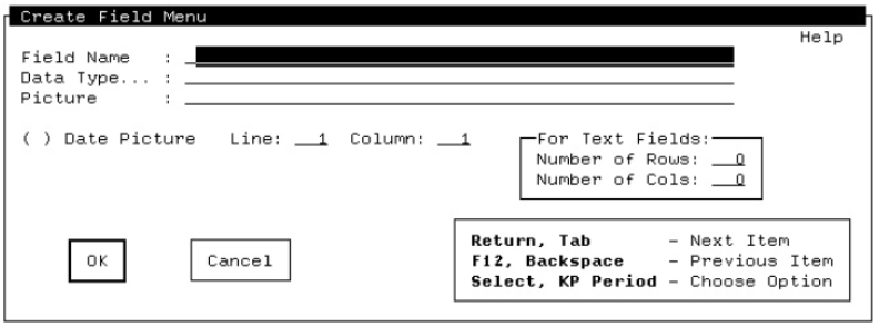
For information about filling in the menu, select the Help icon. For brief help on a menu field, press Help while the cursor is on that field. For more detailed information, press Help again.
Enter a field name in the Field Name field.
This information is required.
Enter a data type in the Data Type field.
If no existing form data item matches the field name, you must supply a data type. For a list of the valid data types you can choose from, press Select at the Data Type field. CCPED displays the Choose Data Type Menu.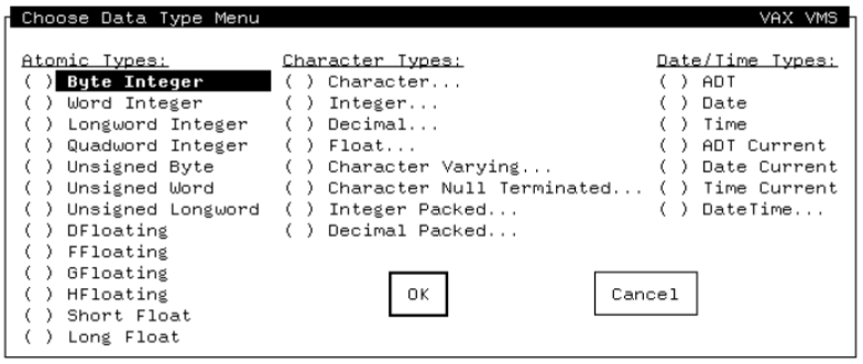
Specify a field picture in the Picture field, or let CCPED generate a default from the data type specified.
Select the Date Picture option if the field is a date.
Specify new line and column values if you want to override the values of the current cursor position.
Specify the number of rows if the field is to contain multiple lines.
Specify the number of columns to be used to display the data. For example, if you specify 10, the field will display 10 characters of data in each row. (The size of the panel field does not have to be the same as the form data item being displayed.)
When you create fields in CCPED, CCPED creates matching form data items if none currently exist. If you have a form data section(delimited by the IFDL statements FORM DATA and END DATA) that is marked TRACKED, and if that section is the last or the only form data section in your form, CCPED creates a new form data section when it creates its first new form data item or form data group. All subsequent form data items or groups that CCPED creates are placed in this new form data section.
If the last or only form data section in your form is not marked TRACKED, CCPED creates all form data items or groups in that section.
For information about form data and how to use the TRACKED clause, see the VSI DECforms Guide to Developing an Application.
When you create a field that maps to a built-in form data item that already exists and is declared as a built-in, the field is automatically marked PROTECTED. In this case, an informational message is displayed.
Command> MODIFY FIELD DESCRIPTION NOT PROTECTED NO DATA INPUT
For information about deleting and restoring panel fields, see Section 3.5.7.8, ''Deleting and Restoring Panel Objects''. For information about modifying the display attributes of a panel field, see Section 3.5.6.2, ''Modifying Video Attributes'', Section 3.5.6.5, ''Modifying the Font Size'', and Section 3.5.6.7, ''Modifying Line Width''.
3.5.7.6. Modifying Panel Field Descriptions and Pictures
The MODIFY FIELD DESCRIPTION command with the necessary parameters
- The Modify Field Description menu, as follows:
Move to the field to be modified and press Modify Field Description (PF1-Enter), or select the field and enter the MODIFY FIELD DESCRIPTION command with no parameters.
CCPED displays the Modify Field Description Menu.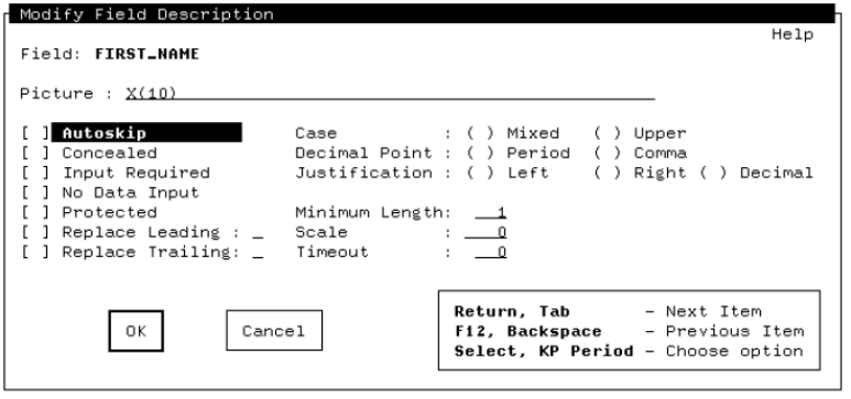
Select the attribute you want to modify.
A diamond (♦) next to the attribute indicates that it is selected. The Minimum Length, Timeout, and Scale fields require values.
Some field description attributes conflict. For information aboutsuch conflicts, see the section on ITEM DESCRIPTION Entry in the VSI DECforms IFDL Reference Manual.
To modify a panel field's picture or date picture, use the MODIFY FIELD PICTURE command.
3.5.7.7. Creating Panel Groups
To create a panel group on the current panel, use the CREATE GROUP command. You must create panel groups in a top-down sequence; you create the group first, and then create the objects inside the group.
To add literals to an existing panel group, select the objects and enter the GROUP SELECTED OBJECTS command. This command adds only background objects to a panel group; you cannot use it to group fields, icons, or other groups. You must use The CREATE FIELD, CREATE ICON, or CREATE GROUP command using a fully qualified name.
To remove background literals from an existing panel group, select the objects and enter the UNGROUP SELECTED OBJECTS command. This command has the same restrictions as the GROUP SELECTED command.
To change the horizontal or vertical display of a panel group, use the MODIFY GROUP command.
For information about using panel groups to display form data groups,and about activating and specifying navigation in panel groups, see the VSI DECforms Guide to Developing an Application.
For information about deleting and restoring panel groups, see Section 3.5.7.8, ''Deleting and Restoring Panel Objects''. For information about modifying the display attributes of a panel group, see Section 3.5.6.2, ''Modifying Video Attributes'', Section 3.5.6.5, ''Modifying the Font Size'', and Section 3.5.6.7, ''Modifying Line Width''.
3.5.7.8. Deleting and Restoring Panel Objects
Use the DELETE SELECTED OBJECTS command.
If you are deleting panel fields, icons, or panel groups, you can use the DELETE NAMED command instead.
Press Delete.
The deleted objects are added to a deletion list and are discarded when you exit CCPED.
3.5.8. Manipulating Objects
Once you have created a panel object, you can use CCPED to select and deselect the object, move it,copy it using the CCPED clipboard, and change the order in which it is accessed in a panel. The following sections describe these operations.
3.5.8.1. Selecting and Deselecting Objects
Before you can perform an operation on an object—such as modifying, moving, or deleting it—you must first select the object. Reverse highlighting indicates that an object is selected.
If you decide that you do not want an object to be selected, you can deselect the object. Some CCPED key commands automatically deselect a selected object after the command operation.
3.5.8.2. Selecting and Deselecting Compound Objects
An object that is composed of other objects (for example, a panel group or an icon) is a compound object.
- SELECT AT
- SELECT AREA
- SELECT MARKED AREA
- SELECT NAMED
- SELECT ALL OBJECTS
If you select the icon using the SELECT AT command or the Select key, CCPED adds only the individual literals to the panel's selection list.
If you use the SELECT AREA or SELECT MARKED AREA commands, the icon (and not its individual elements) is added to the selection list, provided all its components are within the specified area.
If you use the SELECT NAMED or SELECT ALL OBJECTS commands, the icon (and not its individual elements) is added to the selection list. You should consider using these commands to select a compound object, because you can be assured of capturing the whole icon.
To deselect a compound object, use either the DESELECTNAMED or DESELECT ALL OBJECTS command.
3.5.8.3. Moving Objects
The MOVE SELECTED OBJECTS command
- The Move key (PF1-KP comma), as follows:
Select the objects you want to move.
Move the cursor to the new location.
Press PF1-KP comma.
The object is moved to the new location.
You also can move and copy objects between panels using the CCPED clipboard. See Section 3.5.8.4, ''Using the Clipboard''.
3.5.8.4. Using the Clipboard
CCPED contains a clipboard for use as a storage area for selected objects. The clipboard lets you transfer or copy objects within a panel or from one panel to other panels. The objects are stored on pages. Each time you copy or remove objects to the clipboard, a new top page is created and other pages are moved down the clipboard. Only the top (most recent) page is available to you at any one time. You can move the top page to the bottom of the clipboard to make the next page available.
| Commands | Keys | Description |
|---|---|---|
|
COPY FROM CLIPBOARD |
PF1-Insert Here |
Copies the objects from the top page to the current panel and retains that page on the clipboard. |
|
COPY SELECTED OBJECTS TO CLIPBOARD |
PF1-Remove |
Copies selected objects to the top page and retains them on the current panel. This operation creates a top page and moves other pages down. |
|
INSERT FROM CLIPBOARD |
Insert Here |
Places the objects from the top page on the current panel. That page is removed from the clipboard and the next page becomes available. |
|
REMOVE SELECTED OBJECTS TO CLIPBOARD |
Remove |
Places selected objects on the top page and removes them from the current panel. This operation creates a top page and moves other pages down. |
|
ROTATE CLIPBOARD |
(N/A) |
Moves the top page to the bottom of the clipboard and makes the next page the top page. |
|
VIEW CLIPBOARD |
Enter |
Displays the top page of the clipboard. Press any key to return to editing the current panel. |
Restriction
You cannot copy or remove individual elements of a compound object to the clipboard—only the entire compound object. For information about compound objects, see Section 3.5.8.2, ''Selecting and Deselecting Compound Objects''.
The following procedure uses CCPED keypad keys to illustrate how to use the clipboard to copy objects between different panels. Use this same procedure to copy objects to another location on the current panel.
Select the objects you want to copy.
Press the Copy to Clipboard key (PF1-Remove) to copy the selected object to the clipboard.
This key sequence keeps a copy of the selected object in its current location. The Remove to Clipboard key copies the object to the clipboard while removing it from its current location.
Choose the panel where you want to copy the object.
Omit this step if you are copying the selected object to another location on the current panel.
Position the cursor to the location where you want to copy the object.
Press the Copy from Clipboard key (PF1-Insert Here) to place a copy of the object at the new location.
Note
When you copy objects, CCPED also copies any responses defined within fields, icons, or groups that you are copying. Therefore, you might need to modify the response steps ACTIVATE, DEACTIVATE, and POSITION after those objects are copied. For information about using response steps, see the VSI DECforms Guide to Developing an Application.
3.5.8.5. Changing the Order of Objects in a Panel
You can change the order in which selected objects are drawn on the screen to give the operator more flexibility in navigating a panel.
Literals, in the order in which they appear in the IFDL source file
Literals within panel groups are drawn in the IFDL order in which they appear in the groups, and panel groups are processed in IFDL order relative to other panel objects. Literals within icons are drawn in IFDL order relative to the icons.
Panel fields and icons, in the order in which they appear in the IFDL source file
Panel fields and icons within panel groups are drawn in the IFDL order in which they appear in the groups, and panel groups are processed in IFDL order relative to other panel objects.
3.6. Checking Panel Appearance
Once you have created the appearance of panels in your form, you can check panel appearance and test input fields.
To check the appearance of panels in character-cell layouts and test input fields, use the TEST command to invoke the Test Utility. To exit the Test Utility, press F10. For more information about the Test Utility, see Chapter 4, "Testing a Form".
You also can save the form and exit CCPED, and then run the Extract Appearances Utility from the system prompt to produce a file suitable for printing. For more information about the Extract Appearances Utility, see Chapter 6, "Extracting Objects and Appearances".
Chapter 4. Testing a Form
The Test Utility provides a way for you to test the appearance of panels in a character-cell layout without writing an application first. You can evaluate the appearance of each panel as it is seen at run time, and you can observe the input fields as they appear to the operator.
Invoke and exit the Test Utility
Check panel appearance
Navigate panels
Note
You cannot use the Test Utility to test the appearance of panels in PRINTER layouts. Instead, use the Extract Appearances Utility to produce a file containing printable representations of the PRINTER panels. For information about the Extract Appearances Utility, see Chapter 6, "Extracting Objects and Appearances".
4.1. Invoking and Exiting the Test Utility
FORMS TEST APPEARANCES input-file-spec
Replace input-file-spec with the name of the form file containing
the panels to be tested. The default input file type is .form.
When you have finished testing all panels, press F10 or Ctrl/Z to exit the Test Utility.
For a complete description of the FORMS TEST APPEARANCES command and its qualifiers, see Chapter 1, "DECforms Commands".
4.2. Testing Panels
Use the Test Utility to test panel appearance and field pictures. You can enter data into the accessible fields on a panel; the Test Utility performs field picture validation. It does not perform any other validation, such as function responses and WHEN clauses. You cannot test requests.
In character-cell layouts, if the panel has no fields, or if all the fields are protected, the Test Utility executes an ACTIVATE WAIT response step for that panel. Navigate to another panel, or exit the Test Utility. For information about the ACTIVATE WAIT response step, see the VSI DECforms IFDL Reference Manual.
If you have defined any help messages or help panels for a panel or fields on a panel, you can check the help information by pressing Help or PF2. (The information that is displayed is not help about the Test Utility.)
The Test Utility displays panels in the order in which they are declared in the form. You can display specific panels by naming them in the /PANEL qualifier when you invoke the Test Utility.
Figure 4.1, ''Panel Displayed by the Test Utility'' shows one of the panels in the introductory sample checking application as displayed by the Test Utility. Section 4.3, ''Navigating Panels'' describes how to navigate fields and panels.
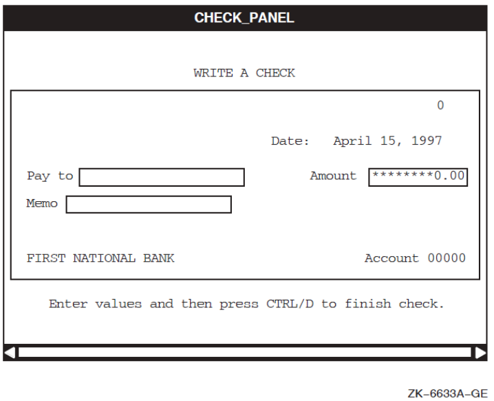
4.3. Navigating Panels
To move around each panel, use the default DECforms function keys defined for your system. Functions and function responses defined in your form have no effect.
|
To ... |
Press ... |
|---|---|
|
Move to the next field |
Return |
|
Move the previous field |
Backspace (F12) or Ctrl/H |
|
Move the cursor within a field |
Left arrow Right arrow |
|
Delete the character to the left of the cursor |
Delete |
|
Erase the current contents of a field |
Linefeed (F13) |
|
Switch between overstrike mode (for typing over characters) and insert mode (for inserting characters) |
Ctrl/A |
|
Move to the Next Panel |
Next Screen |
|
Move to the Previous Panel |
Prev Screen |
|
Exit |
F10 Ctrl/Z |
Chapter 5. Translating IFDL Source Files and Form Files
IFDL source files are text files comprised of IFDL language statements. Form files are their binary run-time equivalents.
The FDE accepts input files in either format and automatically produces output files in both formats.
The IFDL Translator to translate IFDL source files into FORM form files
The Back Translator to translate FORM form files back into IFDL source files
5.1. Translating IFDL Source Files into Form Files
The IFDL Translator translates an IFDL source file to a binary form file. The form file then can be displayed on a supported display device by the Form Manager, analyzed with the form development utilities, or edited in the FDE or by a panel editor.
Figure 5.1, ''Translating IFDL Source File to Binary Form File and Back'' illustrates the translation process.
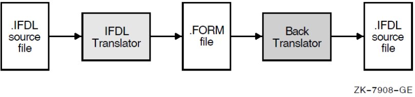
5.1.1. Invoking the IFDL Translator
FORMS TRANSLATE input-file-spec
Replace input-file-spec with the name of the IFDL source
file. The default file type is .ifdl. If the input file contains
a COPY statement, input also can come from other sources. The IFDL Translator can
produce three kinds of output, described in Section 5.1.2, ''IFDL Translator Output''.
For a complete description of the FORMS TRANSLATE command, see Chapter 1, "DECforms Commands". For a description of the COPY statement, see the VSI DECforms IFDL Reference Manual.
5.1.2. IFDL Translator Output
Form file
Listing file
Diagnostics file
5.1.2.1. Form File
The form file produced by the IFDL Translator is the binary version of the form. In general, the form file is the only file format acceptable as input to the Form Manager and the form development utilities. The FDE accepts both form files and IFDL source files as input. The Extract Object Utility can convert a form file to an object module.
If the form refers to panels or panel objects that do not yet exist (you have not yet created them in the form), the IFDL Translator produces the form file, but generates warning messages and marks the form file as incomplete.
The Form Manager cannot display incomplete forms. Also, the Extract Object Utility does not work with incomplete forms.
The FDE and the panel editors do accept incomplete forms as input so you can edit them, and the Back Translator does translate incomplete forms.
5.1.2.2. Listing File
The IFDL Translator produces a listing file when you use the /LIST qualifier in the FORMS TRANSLATE command, or when you run the IFDL Translator in batch mode.
- Heading—The heading includes:
The date and time the listing file was created
The name and version number of the IFDL Translator
The full file specification of the input file
The date and time of creation or last modification of the input file
Source code text—The body of the listing contains the source code text in consecutively numbered lines. The format of these lines (length, location of carriage returns, indentation, and so on) is the same as the format in the input file. All comments appear in the listing just as they appear in the source file.
There is no restriction on the length of an input line from a source file. The text is wrapped when written to the listing file, with the line number appearing at the beginning of the first physical line in the listing file.
Error messages—Any syntactic or semantic errors are reported immediately after the end of the full line of source language text that caused the error (or as close to the end of the line as possible). The end-of-line delimiter determines the end of the full line.
For information on the format and interpretation of error messages, see Chapter 1, "DECforms Commands".
- Compilation summary—At the end of the listing file, the IFDL Translator supplies a summary of compilation statistics and information. The summary includes:
The date and time the compilation ended
The number of lines of code parsed
The types of errors detected, and the number of errors of each type
The elapsed CPU time
The elapsed clock time
The command line executed, including input and output files used or created (whether specified or defaulted to) during the compilation
The IFDL Translator does not truncate source lines and messages that are output to the listing file.
5.1.2.3. DEC LSE Diagnostics File
The IFDL Translator produces a diagnostics file for the DEC Language Sensitive Editor (DEC LSE) when you use the /DIAGNOSTICS qualifier with the FORMS TRANSLATE command. DEC LSE uses the diagnostics file during its REVIEW phase to locate and describe translation errors.
- Enter the FORMS TRANSLATE command in the following format:
FORMS TRANSLATE/DIAGNOSTICS input-file-spec
Invoke DEC LSE to edit the IFDL source file.
Use the DEC LSE REVIEW command to display the error messages in the diagnostics file so that you can correct the errors in the IFDL source file.
For more information on DEC LSE and its REVIEW command, see Appendix C, "Using DEC LSE with DECforms Software".
5.1.3. Avoiding Translation Errors
Check for correct spelling of identifiers and DECforms keywords.
Do not use IFDL reserved words as identifiers. See the VSI DECforms IFDL Reference Manual for a list of the IFDL reserved words.
Check that attributes applied through the description or validation entries of a field default do not conflict with settings specified in the declaration of an affected field. For example, a field default specifying field protection would conflict with an item description entry specifying input required. See the VSI DECforms IFDL Reference Manual for a list of conflicting item description entries.
If you must use your normal currency or decimal point string for another purpose in a SIGN, CURRENCY, or REPLACE clause,make sure you redeclare currency and decimal point strings in EDIT clauses immediately before SIGN, CURRENCY, and REPLACE clauses.
In character-cell layouts, use relative line and column clauses in FIELD DEFAULT and LITERAL DEFAULT declarations if you want to specify a default location.
In PRINTER layouts, use absolute line and column clauses to express locations; locations cannot be specified in FIELD DEFAULT and LITERAL default declarations. Also, PRINTER layouts require full location clauses for each object in the layout,including groups. (In character-cell layouts, groups do not allow location clauses.)
PRINTER layouts require a UNITS clause in the LAYOUT declaration. In character-cell layouts, the UNITS clause is optional.
In character-cell layouts, make sure that panel objects do not extend beyond the viewport in any direction. Font sizes and picture string lengths affect the field sizes. You also can adjust the line and column coordinates to position the object farther from the viewport boundaries.
Make sure that no internal responses include themselves, even indirectly (by an internal response including a second internal response that includes the first internal response). Internal responses must not be recursive.
Verify that you did not specify a value that is too large or too small to be stored in the data item.
Complete a conditional expression by including an operator and another operand (for example: IF item_one = "TRUE"). A form data item cannot stand alone in a conditional expression.
Use the DEC Language Sensitive Editor (DEC LSE) when creating or editing a form file. DEC LSE can help you produce syntactically correct IFDL code.
5.1.4. Correcting Translation Errors
If there are errors when you translate an IFDL source file, error messages are displayed on the screen. If you used the /LIST or /DIAGNOSTICS qualifier when invoking the IFDL Translator, error messages also are displayed in the listing or diagnostics file created by the translator.
You can use online help to get an explanation and user action for each error message. See Chapter 1, "DECforms Commands" for more information about error messages and how to use online help to find error message descriptions.
5.2. Translating Form Files Back into IFDL Source Files
The Back Translator translates a form file into an IFDL source file;essentially, it performs the reverse function of the IFDL Translator. The Back Translator provides a way of translating a form created or modified from the FDE or with a panel editor into a format that can be edited with a text editor.
5.2.1. Invoking the Back Translator
FORMS BACK_TRANSLATE input-file-spec
Replace input-file-spec with the name of the form file to be
translated. The default file type is .form. The Back Translator
produces as output an IFDL file. Figure 5.1, ''Translating IFDL Source File to Binary Form File and Back'' illustrates the
translation process. You can use the IFDL Translator to translate the IFDL source
file produced by the Back Translator into a form file again.
For a complete command description, see Chapter 1, "DECforms Commands".
5.2.2. Source File Differences after Back Translation
Text formatting (indentation, capitalization, and so forth) in the original IFDL source file might be changed.
Any Format 1 COPY statements in the original IFDL source file are not preserved (the COPY statement has two formats). Instead, whatever was copied is included explicitly in the resulting IFDL source file. Format 2 COPY statements in the original IFDL source file are preserved. Record definitions originally extracted from Oracle CDD/Repository software continue to be extracted in future translations. For descriptions of the COPY statement formats, see the VSI DECforms IFDL Reference Manual.
The location of comments might be changed.
To minimize the repositioning of comments during translation,place comments inside and at the beginning of syntactic blocks, as follows:FIELD F1 /* comment placed for minimal migration */ PROTECTED END FIELDAvoid placing comments as shown in the following examples:/* comment placed before block */ FIELD F2 PROTECTED END FIELD FIELD F3 PROTECTED END FIELD /* comment placed after block */ FIELD F4 PROTECTED /* comment placed at end of block */ END FIELD
Chapter 6. Extracting Objects and Appearances
Extract object modules
Extract panel appearances
6.1. Extracting Objects from a Form File
The Extract Object Utility produces an object module, called a form object file, that you can link with your application program at run time for improved performance. The object module contains vectors to escape routines called at run time, and, optionally, the form itself.
FORMS EXTRACT OBJECT input-file-spec
Replace input-file-spec with the name of the form file from which
you want to create an object module. The default input file type is
.form.
The Extract Object Utility creates as output an object file with the file type
.obj.
For a complete description of the FORMS EXTRACT OBJECT and FORMS OBJECT commands and their qualifiers, see Chapter 1, "DECforms Commands".
6.2. Extracting Panel Appearances from a Form File
The Extract Appearances Utility produces a file containing printable representations of panels in a character-cell or PRINTER layout. You can use the file to verify the appearance of panels or for reference while you are creating other form structures.
FORMS EXTRACT APPEARANCES input-file-spec
Replace input-file-spec with the name of the form file containing
the panels you want to print. The default input file type is
.form.
The Extract Appearances Utility produces as output a file with the file type
.txt. For character-cell layouts, this is a text file, which you
can print or view online. For PRINTER layouts, this is a DDIF™ file, which you
must convert on a VAX system, using the CDA Converter, to text or PostScript® format
before printing or viewing.
For a complete description of the FORMS EXTRACT APPEARANCES command and its qualifiers, see Chapter 1, "DECforms Commands".
The Extract Appearances Utility produces one graphic representation (display or page) for each data entry panel and help panel in the layout. If a panel is larger than the size of the printer paper, the text might not appear correctly when the file is printed.
By default, fields are shown with their initial values. You can use the /SHOW qualifier to display fields with picture strings instead.
Figure 6.1, ''PRINTER Panel as Represented by Extract Appearances'' shows the appearance of a PRINTER panel extracted from the mileage reimbursement application used in the VSI DECforms Guide to Developing an Application.
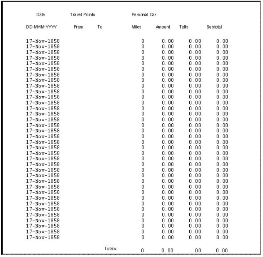
Appendix A. CCPED Keypad, Function Keys, and Definable Keys
A diagram of the CCPED default keypad and keypad summary
A table of CCPED default function keys
A list of CCPED definable function keys
A.1. CCPED Default Keypad
Figure A.1, ''CCPED Keypad'' shows the CCPED keypad. The figure also is available on line. To access it when using CCPED, press Help or enter the SHOW KEYPAD command.
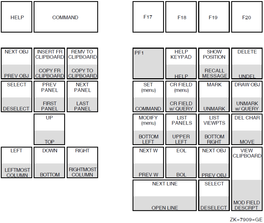
|
Name |
Press: |
Function |
|---|---|---|
|
Beginning of Line |
PF1-KP2 |
Moves cursor to the leftmost column of the panel in the same line. |
|
Bottom |
PF1-Down arrow |
Moves cursor to the bottom of the panel in the same column. |
|
Bottom Left |
PF1-KP4 |
Moves cursor to the bottom-left corner of the panel. |
|
Bottom Right |
PF1-KP6 |
Moves cursor to the bottom-right corner of the panel. |
|
Command |
PF1-KP7 |
Displays the command line prompt. |
|
Copy From Clipboard |
PF1-Insert Here |
Copies objects from the top page of the clipboard to the current panel and retains that page on the clipboard. |
|
Copy To Clipboard |
PF1-Remove |
Copies selected objects to the top page of the clipboard and retains them on the current panel. |
|
Create Field (menu) |
KP8 |
Displays the Create Field Menu. |
|
Create Field (with query) |
PF1-KP8 |
Prompts for the field name and the data type, then creates the field at the cursor position. |
|
Delete |
PF4 |
Deletes selected objects. |
|
Delete Character |
KP comma |
Deletes a single character to the right of the cursor. |
|
Deselect |
PF1-Select or PF1-KP period |
Deselects selected objects or the object where the cursor is positioned. |
|
Command Line |
Do |
Displays command line prompt. |
|
Down |
Down arrow |
Moves cursor down one row in the same column. |
|
Draw Object |
KP hyphen |
Connects marks to create an object. |
|
End of Line |
KP2 |
Moves cursor to the rightmost column of the panel in the same line. |
|
F17 to F20 |
Undefined. | |
|
First Panel |
PF1-Prev Screen |
Chooses the first panel in the current layout. |
|
PF1-PF2 |
Displays a help window about using CCPED. |
|
Help (Keypad) |
PF2 |
Displays online help for the CCPED keypad. |
|
Insert From Clipboard |
Insert Here |
Places objects from the top page of the clipboard on the current panel; that page is removed from the clipboard and the next page becomes available. |
|
Last Panel |
PF1-Next Screen |
Chooses the last panel in the current layout. |
|
Left |
Left arrow |
Moves cursor one column to the left in the same line. |
|
Leftmost Column |
PF1-Left arrow |
Moves cursor to the leftmost column of the panel in the same line. |
|
List Panels |
KP5 |
Lists panels in the current layout. |
|
List Viewports |
KP6 |
Lists viewports in the current layout. |
|
Mark |
KP9 |
Creates marks. |
|
Modify (Attr Menu) |
KP4 |
Invokes the Modify Display Attribute Menu (this is the same as the Set Display Attribute Menu). |
|
Modify Field Description (menu) |
PF1-Enter |
Invokes the Modify Field Description Menu. |
|
Move |
PF1-KP comma |
Moves selected objects to the cursor position. |
|
Next Line |
KP0 |
Moves the cursor to the beginning of the next line. |
|
Next Object |
Find or KP3 |
Moves cursor to the next object or word in a left-to-right, top-to-bottom direction. |
|
Next Panel |
Next Screen |
Chooses the next panel in the current layout. |
|
Next Word |
KP1 |
Moves the cursor to the next object or word in a left-to-right, top-to-bottom direction. |
|
Open Line |
PF1-KP0 |
Deselects all objects; selects all objects on and below the line containing the cursor; moves selected objects down one line; deselects all objects. |
|
Previous Object |
PF1-Find or PF1-KP3 |
Moves cursor to the previous object or word in a right-to-left, bottom-to-top direction. |
|
Previous Panel |
Prev Screen |
Chooses the previous panel in the current layout. |
|
Previous Word |
PF1-KP1 |
Moves the cursor to the previous objector word in a right-to-left, bottom-to-top direction. |
|
Recall Message |
PF1-PF3 |
Recalls the most recently displayed message. |
|
Remove To Clipboard |
Remove |
Places selected objects on the top page and removes them from the current panel. |
|
Right |
Right arrow |
Moves cursor one column to the right in the same line. |
|
Rightmost Column |
PF1-Right arrow |
Moves cursor to the rightmost column of the panel in the same line. |
|
Select |
Select or KP period |
Selects an object or a menu item. |
|
Set (Attr Menu) |
KP7 |
Invokes the Set Display Attribute Menu (this is the same as the Modify Display Attribute Menu). |
|
Show Position |
PF3 |
Displays the cursor's current line and column position. |
|
Top |
PF1-Up arrow |
Moves the cursor to the top of the panel in the same column. |
|
Undelete |
PF1-PF4 |
Undeletes deleted objects. |
|
Up |
Up arrow |
Move the cursor up one row in the same column. |
|
Unmark |
PF1-KP9 |
Removes the mark at the cursor location. |
|
Unmark (with query) |
PF1-KP hyphen |
Prompts to remove one or more specified marks. |
|
Upper Left |
PF1-KP5 |
Moves the cursor to the upper-left corner of the panel. |
|
View Clipboard |
Enter |
Displays the top page of the clipboard; press any key to return to editing the current panel. |
A.2. CCPED Function Keys
|
Key Sequence |
Default Function |
|---|---|
|
PF1-E |
Exit |
|
PF1-H |
Double-high font size and line width |
|
PF1-M |
Modify (menu) |
|
PF1-N |
Normal font size and line width |
|
PF1-O |
Order objects |
|
PF1-T |
Test appearance |
|
PF1-S |
Single font size and line width |
|
PF1-W |
Double-wide font size and line width |
|
PF1-Q |
Quit, save journal |
|
PF1-V |
Show version |
A.3. Names of Keys Definable in CCPED
|
Function Keys | ||
|
F17 |
PF1_F17 | |
|
F18 |
PF1_F18 | |
|
F19 |
PF1_F19 | |
|
F20 |
PF1_F20 | |
|
PF1_HELP | ||
|
PF1_DO | ||
|
PF1_DELETE | ||
|
Editing Keypad Keys | ||
|
E1 or FIND |
PF1_E1 or PF1_FIND | |
|
E2 or INSERT_HERE |
PF1_E2 or PF1_INSERT_HERE | |
|
E3 or REMOVE |
PF1_E3 or PF1_REMOVE | |
|
E4 or SELECT |
PF1_E4 or PF1_SELECT | |
|
E5 or PREV_SCREEN |
PF1_E5 or PF1_PREV_SCREEN | |
|
E6 or NEXT_SCREEN |
PF1_E6 or PF1_NEXT_SCREEN | |
|
Numeric Keypad Keys | ||
|
PF2 |
PF1_PF2 | |
|
PF3 |
PF1_PF3 | |
|
PF4 |
PF1_PF4 | |
|
KP_0 |
PF1_KP_0 | |
|
KP_1 |
PF1_KP_1 | |
|
KP_2 |
PF1_KP_2 | |
|
KP_3 |
PF1_KP_3 | |
|
KP_4 |
PF1_KP_4 | |
|
KP_5 |
PF1_KP_5 | |
|
KP_6 |
PF1_KP_6 | |
|
KP_7 |
PF1_KP_7 | |
|
KP_8 |
PF1_KP_8 | |
|
KP_9 |
PF1_KP_9 | |
|
KP_MINUS |
PF1_KP_MINUS | |
|
KP_COMMA |
PF1_KP_COMMA | |
|
KP_PERIOD |
PF1_KP_PERIOD | |
|
KP_ENTER |
PF1_ENTER | |
|
Alphabetic Characters | ||
|
PF1_A |
PF1_J |
PF1_S |
|
PF1_B |
PF1_K |
PF1_T |
|
PF1_C |
PF1_L |
PF1_U |
|
PF1_D |
PF1_M |
PF1_V |
|
PF1_E |
PF1_N |
PF1_W |
|
PF1_F |
PF1_O |
PF1_X |
|
PF1_G |
PF1_P |
PF1_Y |
|
PF1_H |
PF1_Q |
PF1_Z |
|
PF1_I |
PF1_R | |
|
Punctuation Marks and Delimiters | ||
|
PF1_AMPERSAND |
PF1_DOLLAR_SIGN |
PF1_PERCENT_SIGN |
|
PF1_APOSTROPHE |
PF1_EQUAL |
PF1_PERIOD |
|
PF1_ASTERISK |
PF1_EXCLAMATION_POINT |
PF1_PLUS_SIGN |
|
PF1_AT_SIGN |
PF1_GREATER_THAN |
PF1_QUESTION_MARK |
|
PF1_BACKSLASH |
PF1_LESS_THAN |
PF1_QUOTATION_MARKS |
|
PF1_CIRCUMFLEX |
PF1_MINUS_SIGN |
PF1_SEMICOLON |
|
PF1_CLOSE_BRACE |
PF1_NUMBER_SIGN |
PF1_SLASH |
|
PF1_CLOSE_BRACKET |
PF1_OPEN_BRACE |
PF1_SPACE |
|
PF1_CLOSE_PAREN |
PF1_OPEN_BRACKET |
PF1_TILDE |
|
PF1_COLON |
PF1_OPEN_PAREN |
PF1_UNDERLINE |
|
PF1_COMMA |
PF1_OPEN_QUOTE |
PF1_VERTICAL_LINE |
|
VSI and ISO Multinational Special Characters and Currency Signs | ||
|
PF1_ACUTE_ACCENT |
PF1_MIDDLE_DOT | |
|
PF1_ANGLE_QUOTE_LEFT |
PF1_MULTIPLICATION | |
|
PF1_ANGLE_QUOTE_RIGHT |
PF1_NO_BREAK_SPACE | |
|
PF1_BROKEN_BAR |
PF1_NOT_SIGN | |
|
PF1_CEDILLA |
PF1_PARAGRAPH_SIGN | |
|
PF1_CENT_SIGN |
PF1_PLUS_MINUS_SIGN | |
|
PF1_COPYRIGHT_SIGN |
PF1_POUND_SIGN | |
|
PF1_DEGREE_SIGN |
PF1_QUARTER_FRACTION | |
|
PF1_DIAERESIS |
PF1_REGISTERED_TRADEMARK | |
|
PF1_DIVISION_SIGN |
PF1_SECTION_SIGN | |
|
PF1_FEMININE_ORDINAL |
PF1_SHARP_S | |
|
PF1_HALF_FRACTION |
PF1_SOFT_HYPHEN | |
|
PF1_INVERT_EXCLAMATION |
PF1_SUPER_1 | |
|
PF1_INVERTED_QUESTION_ |
PF1_SUPER_2 | |
|
PF1_MACRON |
PF1_SUPER_3 | |
|
PF1_MASCULINE_ORDINAL |
PF1_THREE_QUARTERS_FRACTION | |
|
PF1_MICRO_SIGN |
PF1_YEN_SIGN | |
|
VSI and ISO Multinational Alphabetic Characters | ||
|
PF1_A_ACUTE |
PF1_O_ACUTE | |
|
PF1_A_CIRCUMFLEX |
PF1_O_CIRCUMFLEX | |
|
PF1_A_DIAERESIS |
PF1_O_DIAERESIS | |
|
PF1_A_GRAVE |
PF1_O_GRAVE | |
|
PF1_A_RING |
PF1_O_TILDE | |
|
PF1_A_TILDE |
PF1_O_SLASH | |
|
PF1_AE_DIPTHONG |
PF1_U_ACUTE | |
|
PF1_E_ACUTE |
PF1_U_CIRCUMFLEX | |
|
PF1_E_CIRCUMFLEX |
PF1_U_DIAERESIS | |
|
PF1_E_DIAERESIS |
PF1_U_GRAVE | |
|
PF1_E_GRAVE |
PF1_C_CEDILLA | |
|
PF1_I_ACUTE |
PF1_N_TILDE | |
|
PF1_I_CIRCUMFLEX |
PF1_Y_ACUTE | |
|
PF1_I_DIAERESIS |
PF1_ICELANDIC_ETH | |
|
PF1_I_GRAVE |
PF1_ICELANDIC_THORN | |
Appendix B. CCPED Commands
General description of the command
A syntax diagram
Descriptions of the required and optional parameters
Many of the command operations are available as CCPED keypad functions. Figure A.1, ''CCPED Keypad'' shows the default keypad.
For information about invoking CCPED to create and edit the appearance of panels, see Chapter 3, "Editing Panel Appearance Using the Character-Cell Panel Editor (CCPED)".
CENTER SELECTED OBJECTS
CENTER SELECTED OBJECTS — Centers selected objects vertically, horizontally, or both vertically and horizontally, in the current panel's viewport.
Format
CENTER SELECTED [OBJECTS] [HORIZONTAL | VERTICAL]
Parameters
HORIZONTAL
Horizontally centers the imaginary rectangle that encloses selected objects in the current panel's viewport.
VERTICAL
Vertically centers the imaginary rectangle that encloses selected objects in the current panel's viewport.
If you do not specify either HORIZONTAL or VERTICAL, the selected objects are centered horizontally and vertically in the current panel's viewport.
Example
Command> SELECT AREA (1,1) (10,10)
Command> CENTER SELECTED HORIZONTAL
Centers horizontally in the viewport those objects enclosed in the selected area.
CHOOSE
CHOOSE — Makes an existing panel the current panel for editing.
Format
CHOOSE {PANEL panel-name | FIRST [PANEL] | LAST [PANEL] | NEXT [PANEL] |
        PREVIOUS [PANEL]}
Parameters
PANEL panel-name
The specific panel you want to edit. This panel must already exist—you cannot use CHOOSE PANEL to create a new panel. Use CREATE PANEL to create a new panel.
If you specify a panel that is too large for the current display, the command fails.
FIRST [PANEL]
Chooses the first panel in the layout. If the first panel is too large for the current display, CCPED attempts to locate the first panel in the layout that can be edited.
LAST [PANEL]
Chooses the last panel listed in the layout. If the last panel is too large for the current display, CCPED attempts to locate the last panel in the layout that can be edited.
NEXT [PANEL]
Chooses the next panel listed in the layout. If the panel is too large for the display, CCPED skips over it, displays a warning message, and tries to find the next panel in the layout that can be edited. If CCPED does not find such a panel, the command fails.
PREVIOUS [PANEL]
Note
If you specify the /NODISPLAY qualifier to the FORMS EDIT command, CCPED does not check panel size.
Examples
Command> CHOOSE PANEL Address
Makes the panel named Address the current panel for editing.
Command> CHOOSE FIRST PANEL
Makes the first panel in the layout the current panel for editing.
Command> CHOOSE PREVIOUS
Makes the previous panel in the layout the current panel for editing.
COPY FROM CLIPBOARD
COPY FROM CLIPBOARD — Copies objects from the top page of the clipboard onto the current panel; copied objects remain on the top page of the clipboard. This command differs from INSERT FROM CLIPBOARD, which removes the top page from the clipboard. For information about using the CCPED clipboard, see Chapter 3, "Editing Panel Appearance Using the Character-Cell Panel Editor (CCPED)". Note that COPY FROM CLIPBOARD also copies any responses defined within fields, icons, or groups that you are copying. After those objects are copied, you might need to modify any ACTIVATE, DEACTIVATE, and POSITION response steps.
Format
COPY FROM CLIPBOARD [TO (l,c)]
Parameter
TO (l,c)
The line and column coordinates of the location on the panel where you want the clipboard page copied. If you do not specify coordinates, the page is inserted at the current cursor position.
These coordinates define the start position for the upper-left corner of the imaginary rectangle that encloses all objects on the clipboard page.
Example
Command> CREATE POINT (1,1); SELECT AT (1,1); COPY SELECTED TO CLIPBOARD
Command> COPY FROM CLIPBOARD TO (10,4)
Command> COPY FROM CLIPBOARD TO (8,23)
Command> COPY FROM CLIPBOARD TO (9,2)
Creates a point at line 1, column 1, selects and copies the point to the clipboard, and then copies the top clipboard page to the three specified locations on the current panel.
COPY SELECTED OBJECTS TO CLIPBOARD
COPY SELECTED OBJECTS TO CLIPBOARD — Places copies of all selected objects from the current panel onto a new page of the clipboard, leaving copies of those objects on the current panel. This command differs from REMOVE SELECTED OBJECTS TO CLIPBOARD, which removes the objects from the panel. For information about using the CCPED clipboard, see Chapter 3, "Editing Panel Appearance Using the Character-Cell Panel Editor (CCPED)". Note that COPY SELECTED OBJECTS TO CLIPBOARD also copies any responses defined within fields, icons, or groups that you are copying. After those objects are copied, you might need to modify any ACTIVATE, DEACTIVATE, and POSITION response steps.
Format
COPY SELECTED [OBJECTS] TO CLIPBOARD
Parameters
None.
Example
Command> CREATE TEXT "Copy this literal" (10,2)
Command> CREATE TEXT "and this one, too!" (12,2)
Command> SELECT ALL; COPY SELECTED TO CLIPBOARD
Creates the text literals shown and copies them to the clipboard while leaving copies on the current panel.
CREATE FIELD
CREATE FIELD — Creates a field in the current panel. Entering CREATE FIELD without any parameters causes CCPED to display the Create Field Menu. For information about using this menu, see Chapter 3, "Editing Panel Appearance Using the Character-Cell Panel Editor (CCPED)".
Format
CREATE FIELD [name [(l,c)] [TYPE data-type] [PICTURE [DATE] picture-string]
             [ROWS n] [COLUMNS n]]
Parameters
name
The qualified name of the data item that the field represents. This name must be syntactically and semantically correct. The data item does not have to exist to create a field. For syntax information, see the VSI DECforms IFDL Reference Manual.
(l,c)
The line and column coordinates for the location of the field. If you do not specify coordinates, the field is created at the current cursor position. Fields can neither overlap other fields nor extend past the boundary of any viewport in which the panel can be displayed.
TYPE data-type
The data type of the form data item to be associated with the field. If the data item does not exist, this parameter is required; if the data item exists, this parameter is optional. If a matching data item exists and you specify it, the data type must match that of the existing data item. For information about data types,see the atomic clause explanation in the VSI DECforms IFDL Reference Manual.
PICTURE [DATE] picture-string
A DATE picture or a quoted picture string other than the default generated according to the data type of the field. The picture value must be syntactically and semantically correct for the data type of the item. For syntax information, see the VSI DECforms IFDL Reference Manual.
ROWS n
The number of rows, if the field is to contain multiple lines.
COLUMNS n
The number of columns to be used to display the data.
Examples
Command> CREATE FIELD Name (3,10) TYPE Character(90) ROWS 3 COLUMNS 30
Creates a field 90 characters long called Name at line 3, column 10,and specifies the CHARACTER data type for the form data item to be associated with the field. The field will use three lines, each of which can display up to 30 characters.
Command> CREATE FIELD Phone PICTURE "’(’999’)’999’-’9999"
Creates a field called Phone at the current cursor position,and specifies a picture string for the phone number. This example assumes that the data item PHONE exists; you do not need to specify the data type in this command line. For more information on picture strings, see the VSI DECforms IFDL Reference Manual.
Command> CREATE FIELD
Displays the Create Field Menu. For information about using the Create Field Menu, see Chapter 3, "Editing Panel Appearance Using the Character-Cell Panel Editor (CCPED)".
CREATE GROUP
CREATE GROUP — Creates a group on the current panel. You must create groups in a top-down sequence (create all higher level objects before creating or inserting any lower level objects into the group).
Format
CREATE GROUP name [OCCURS expression [BASE expression] [CURRENT data-name]
                   {HORIZONTAL | VERTICAL} [DISPLAYS expression]
                   [FIRST {data-name | xpression}]]
Parameters
name
A qualified name for the group. This name must include any parent groups in which the newly created group will be placed. For example, a group name of G1.G2.G3 causes G3 to be created in group G2, which is in group G1. Both G1 and G2 must exist before G3 can be created.
If the corresponding data group for the group name does not exist, it is created.
OCCURS expression
Repeats the data group a specified number of times. If the data group is created when you enter the CREATE GROUP command, the OCCURS clause specifies the number of its occurrences; if the data group already exists, this OCCURS clause must match the previously specified number of occurrences. The default is 1 for newly created groups.
|
BASE expression |
Specifies that the value of the expression is to be considered the lowest subscript for the form data group. If you do not specify BASE, the default value is 1. |
|
CURRENT data-name |
Specifies the value of the subscript of the current data group item whenever the data group is referenced at runtime. The named data item must be numeric. |
HORIZONTAL
|
DISPLAYS expression |
Specifies how many instances of the group are to be displayed horizontally on the panel. The default is 1 for newly created groups. If you have two nested groups with multiple occurrences,you cannot specify DISPLAYS for the innermost group. |
|
FIRST {data-name | expression} |
Specifies which indexed element of the group is to be displayed at the left of the horizontal scrolled region. The contents of data-name control the index of the first element displayed at the left of the scrolled area. The value of expression specifies the index of the first element displayed at the left of the scrolled area. The named data item must be numeric. For more information, see the description of the GROUP declaration in the VSI DECforms IFDL Reference Manual. |
VERTICAL
|
DISPLAYS expression |
Specifies how many instances of the group are to be displayed vertically on the panel. The default is 1 for newly created groups. If you have two nested groups with multiple occurrences, you cannot specify DISPLAYS for the innermost group. |
|
FIRST {data-name | expression} |
Specifies which indexed element of the group is to be displayed at the top of the vertical scrolled region. The contents of data-name control the index of the first element displayed at the top of the scrolled area. The value of expression specifies the index of the first element displayed at the top of the scrolled area. The named data item must be numeric. For more information, see the description of the GROUP declaration in the VSI DECforms IFDL Reference Manual. |
Example
Command> CREATE GROUP Outer OCCURS 5 HORIZONTAL
Command> CREATE GROUP Outer.Inner OCCURS 10 VERTICAL
Command> CREATE FIELD Outer.Inner.F1 (2,10) TYPE INTEGER(3)
PICTURE "S999’ ’"
S999 S999 S999 S999 S999
S999 S999 S999 S999 S999
S999 S999 S999 S999 S999
S999 S999 S999 S999 S999
S999 S999 S999 S999 S999
S999 S999 S999 S999 S999
S999 S999 S999 S999 S999
S999 S999 S999 S999 S999
S999 S999 S999 S999 S999
S999 S999 S999 S999 S999
CREATE ICON
CREATE ICON — Creates an icon element from all selected literals. The literals on the selection list must not belong to any other icon. Any nonliteral object on the selection list is ignored. For information about using icons, see the VSI DECforms Guide to Developing an Application.
Format
CREATE ICON icon-name
Parameter
icon-name
The qualified name for the icon.
Example
Command> CREATE RECTANGLE (9,3) (13,19)
Command> CREATE TEXT "CANCEL" (11,8)
Command> SELECT AT (11,8)
Command> SELECT AT (9,3)
Command> CREATE ICON Cancel_icon
Command> DESELECT ALL
Creates an icon from a selected rectangle and a selected text object.
CREATE MARKED OBJECT
CREATE MARKED OBJECT — Creates a graphic object from coordinates designated by the MARK command.
Format
CREATE MARKED [OBJECT]
Parameters
None
Description
One mark represents a point, as though the object was specified by the CREATE POINT command.
Two marks that do not share the same row or column value define a rectangle, as though the object was specified by the CREATE RECTANGLE command.
Two marks that share the same row or column value define a polyline, as though the object was specified by the CREATE POLYLINE command.
Multiple marks define a polyline, as though the object was specified by the CREATE POLYLINE command. These marks must define vertical or horizontal line segments.
Example
Command> UNMARK ALL; MARK (20,5); MARK (20,15); CREATE MARKED OBJECT
Creates a polyline from line 20, column 5, to line 20, column 15.
CREATE PANEL
CREATE PANEL — Creates a new data entry panel or help panel in the current layout. This becomes the current panel for editing.
Format
CREATE [HELP] PANEL panel-name [ON viewport-name]
Parameters
panel-name
A name for the panel to be created.
ON viewport-name
The name of the viewport to be associated with the new panel. If you specify a viewport, it must exist; you cannot create a new viewport this way. Use the CREATE VIEWPORT command to create a new viewport. If you do not specify a viewport, the new panel is associated with the default viewport.
Examples
Command> CREATE PANEL Deposits
Creates a new panel called Deposits and associates it with the default viewport. The Deposits panel becomes the current panel for editing.
Command> CREATE HELP PANEL Account_panel_help ON Help_VP
Creates a new help panel called Account_panel_help and associates it with the viewport Help_VP. The help panel becomes the current panel for editing.
CREATE POINT
CREATE POINT — Creates a point literal at the specified position.
Format
CREATE POINT (l,c)
Parameter
(l,c)
The line and column coordinates of the point to be created.
Example
Command> CREATE POINT (20,2)
Creates a point at line 20, column 2.
CREATE POLYLINE
CREATE POLYLINE — Creates a polyline literal having the specified coordinates.
Format
CREATE POLYLINE (l,c) (l,c) [(l,c)...]
Parameters
(l,c) (l,c)
The line and column coordinate pairs that specify the points of the polyline. You must specify at least two coordinate pairs. If you specify two points, a line segment is created. If you specify more than two points, a single polyline object is created from those points. The points in a CREATEPOLYLINE command must define horizontal or vertical line segments.
Example
Command> CREATE POLYLINE (1,1) (1,40) (5,40) (5,80)
Creates a polyline having the specified points.
CREATE RECTANGLE
CREATE RECTANGLE — Creates a rectangle on the current panel at the specified position.
Format
CREATE RECTANGLE (l,c) (l,c)
Parameters
(l,c) (l,c)
The line and column coordinate pairs that specify the diagonally opposite corners of the rectangle.
Examples
Command> CREATE RECTANGLE (1,10) (10,40)
Creates a rectangle with opposite corners at the specified coordinates.
Command> CREATE RECTANGLE (1,1) (LINE_MAX$,COLUMN_MAX$)
Creates a bounding rectangle (a rectangle that outlines the panel according to the size of the current viewport).
CREATE TEXT
CREATE TEXT — Creates a text literal on the panel. You also can create a text literal by moving the cursor to the desired location on the panel and typing the text.
Format
CREATE TEXT "text-string" [(l,c)]
Parameters
"text-string"
A quoted string specifying the text for the literal. If you do not specify coordinates, the text literal is placed at the current cursor position.
(l,c)
The line and column coordinates specifying the lower-left character cell for double-sized text and the leftmost character cell for other text.
Examples
Command> CREATE TEXT "Enter badge number: " (2,5)
Creates the text literal "Enter badge number: " (including a space after the colon) at line 2, column 5, on the current panel.
Command> CREATE TEXT "How many widgets do you wish to order?"
Creates a text literal on the current panel starting at the current cursor position.
CREATE VIEWPORT
CREATE VIEWPORT — Creates a new viewport or a new printing viewport. If you create a printing viewport, CCPED does not check its size against the size of the layout.
Format
CREATE [PRINTING] VIEWPORT name (l,c) {BY | TO} (l,c)Parameters
name
A name for the viewport.
(l,c) BY (l,c)
The first coordinate pair specifies the line and column position for the upper-left corner of the viewport. The second coordinate pair specifies the size of the viewport in number of lines and number of columns.
(l,c) TO (l,c)
The line and column coordinate pairs that specify the opposite corners of the viewport. These coordinate values are in relation to the layout size.
Examples
Command> CREATE VIEWPORT Account_VP (1,1) TO (20,80)
Creates a viewport named Account_VP whose upper-left corner is at line 1, column 1, and whose lower-right corner is at line 20, column 80.
Command> CREATE PRINTING VIEWPORT Print_VP (1,1) BY (60,80)
Creates a printing viewport whose upper-left corner is at line 1, column 1, and whose size is 60 lines long and 80 columns wide.
DEFINE COLOR
DEFINE COLOR — Defines a color symbol. You can use this symbol instead of an RGB specification in any command that references a color specification. The color symbols you define are internal to your CCPED session. When you translate the form file back to an IFDL source file, the IFDL source file will contain the RGB specifications instead of the color symbol names.
Format
DEFINE {COLOR | COLOUR} color-name rgb-specificationParameters
color-name
- UNCHANGED
- BLACK
- BLUE
- CYAN
- GREEN
- MAGENTA
- RED
- WHITE
- YELLOW
Note
If you redefine one of the standard colors, that color's standard definition is no longer available to you. VSI strongly recommends that you avoid redefining standard colors.
rgb-specification
(red-expression, green-expression, blue-expression)The expressions must evaluate to whole numbers in the range 0 to 100, inclusive. They represent the percentage of the particular color component (red, green, or blue) in the overall color specification. (In the IFDL source file, the values in the RGB specification are in the range 0 to 1, inclusive.)
Examples
Command> DEFINE COLOR GRAY (50,50,50)
Defines the color symbol GRAY as a shade of gray.
Command> DEFINE COLOUR BLUE_RED (90,0,10)
Defines the color symbol BLUE_RED as a shade of red different from the standard color red.
DEFINE KEY
DEFINE KEY — Associates a CCPED command string with a keyboard function key. The string can contain command-line macros as well as multiple commands. Once you associate a command with a function key, the command is executed whenever you press that function key. If you press an undefined function key, CCPED displays an error message. To cancel a key definition, use the UNDEFINE KEY command. For information on CCPED command-line macros, see Chapter 3, "Editing Panel Appearance Using the Character-Cell Panel Editor (CCPED)".
Format
DEFINE KEY key-name key-definition [[NO]TERMINATE]
Parameters
key-name
The name of the function key you want to associate with a command string. Appendix A, "CCPED Keypad, Function Keys, and Definable Keys" contains a table of definable key names.
key-definition
A quoted string containing the text of the command. This string can be a single command, several commands, or a command-line macro (including macros for command-line substitution). The syntax of the definition is not checked until CCPED executes the command.
[NO]TERMINATE
The TERMINATE parameter specifies that the function definition is executed immediately when you press the function key. The NOTERMINATE parameter specifies that the function definition is not executed until you press Return. This allows you to edit the command line, if necessary, before executing it.
The default is TERMINATE.
Examples
Command> DEFINE KEY F20 "ROTATE CLIPBOARD" TERMINATE
Associates the ROTATE CLIPBOARD command with the F20 function key. Thereafter, CCPED executes the ROTATE CLIPBOARD command whenever you press F20.
Command> DEFINE KEY PF1_KP_8 "CREATE FIELD #"Field name?" (LINE$,
COLUMN$) TYPE #"Type?" PICTURE #"Picture?""
Defines the PF1-KP8 key sequence to prompt you when creating a field.Note
CCPED commands that are too long for the screen display are scrolled horizontally and are not continued onto the next line. This and the following examples use two lines due to the limit of the page width.
Command> DEFINE KEY PF1_ENTER "DESELECT ALL;SELECT;MODIFY FIELD
DESCRIPTION;DESELECT ALL"
Defines the key sequence PF1-Enter to select the field the cursor is on and bring up the Modify Field Description menu.
Command> DEFINE KEY F17 "DEFINE SYMBOL Save_line LINE$;
DEFINE SYMBOL Save_col COLUMN$"
Command> DEFINE KEY F18 "POSITION TO (Save_line,Save_col)"
Defines the F17 function key to save the cursor's current position by defining the symbols Save_line and Save_col. Also defines the F18 key to position the cursor to the location saved by the F17 key definition. LINE$ and COLUMN$ are CCPED predefined symbols. For a list of predefined symbols, see Chapter 3, "Editing Panel Appearance Using the Character-Cell Panel Editor (CCPED)".
DEFINE SYMBOL
DEFINE SYMBOL — Defines a symbol that you can use subsequently in expressions. CCPED enters the symbol in its symbol table. CCPED contains a set of predefined symbols. For a list of the predefined symbols, see Chapter 3, "Editing Panel Appearance Using the Character-Cell Panel Editor (CCPED)".
Format
DEFINE SYMBOL symbol-name symbol-value
Parameters
symbol-name
A name for the symbol. Do not use a dollar-sign character ($) as part of the symbol name because a symbol name containing a dollar sign can be confused with an expression function or a predefined symbol, both of which end with a dollar-sign character.
symbol-value
The expression for which you want to define the symbol.
Examples
Command> DEFINE SYMBOL My_Symbol 1+2
Assigns a value of 3 to the symbol My_Symbol, and adds it to the symbol table.
Command> DEFINE SYMBOL This_line LINE$
Command> DEFINE SYMBOL This_column COLUMN$
Command> .
         .
         .
Command> POSITION TO (This_line,This_column)
Defines symbols for the cursor's current location and later in the editing session returns the cursor to that location in the current panel,as shown by the POSITION TO command in the example. LINE$ and COLUMN$ are predefined symbols.
DELETE CHARACTER
DELETE CHARACTER — Deletes a single character from a text literal. If text entry mode is set to insert, trailing characters of the literal are shifted to the left when the specified character is deleted. If the mode is overstrike, trailing characters are not shifted and the specified character is replaced with a space. If you delete the last character in the literal, the literal is shortened whether text entry mode is set to insert or overstrike.
Format
DELETE CHARACTER [(l,c)] [PREVIOUS]
Parameters
(l,c)
The line and column coordinates of the character to be deleted. If you do not specify coordinates, the character at the current cursor position is deleted.
PREVIOUS
Deletes the character located one column to the left of the specified cursor position. The cursor then moves one character cell to the left.
Example
Command> CREATE TEXT "Total" (2,5); DELETE CHARACTER (2,6)
Creates a text literal, "Total", at line 2, column 5, and deletes the character at line 2, column 6 (the letter "o"). If the current entry mode is insert, the result is "Ttal"; if the entry mode is overstrike, the result is "T tal".
DELETE NAMED
DELETE NAMED — Deletes the named objects (which can include fields, icons, or groups) from the current panel and adds them to a deletion list. When you exit CCPED, the deleted objects are discarded. To restore deleted objects, you can use the UNDELETE LAST or UNDELETE ALLUNDELETE ALL OBJECTS command, provided you are in the same editing session during which you deleted them.
Format
DELETE NAMED name [,name...]
Parameter
name
A qualified name for the object to be deleted. If you specify more than one name, separate each name with a comma.
Example
Command> CREATE FIELD Tulip_Bulbs (LINE$+3,COLUMN$+3) TYPE UNSIGNED BYTE
Command> DELETE NAMED Tulip_Bulbs
Deletes the field Tulip_Bulbs.
DELETE PANEL
DELETE PANEL — Deletes a panel from the current layout. To restore deleted panels, you can use the UNDELETE PANEL, UNDELETE LAST, or UNDELETE ALL command, provided you are in the same editing session during which you deleted them.
Format
DELETE PANEL [panel-name]
Parameter
panel-name
The name of the panel to be deleted.
If you do not specify a name, the current panel is deleted and the next panel in the layout becomes the current panel.
If the deleted panel is the last one in the layout, the next-to-last panel (now the last panel) becomes the current panel.
If all panels in the layout are deleted, the current panel becomes undefined,and you cannot perform panel or panel content functions until you create a new panel.
Example
Command> DELETE PANEL Account_Data
Deletes the panel named Account_Data from the current layout.
DELETE SELECTED OBJECTS
DELETE SELECTED OBJECTS — Deletes all selected objects from the current panel and adds them to a deletion list. When you exit CCPED, the deleted objects are discarded. You restore deleted objects with the UNDELETE LAST OBJECT or UNDELETE ALL OBJECTS command, provided you are in the same editing session during which you deleted them.
Format
DELETE SELECTED [OBJECTS]
Parameters
None.
Examples
Command> DELETE SELECTED OBJECTS
Deletes all selected objects from the current panel.
Command> CREATE TEXT "Parquet" (1,10)
Command> CREATE TEXT "Larry Danny Chief DJ Kevin" (3,15)
Command> SELECT AT (1,10); SELECT AT (3,20)
Command> DELETE SELECTED
Deletes the selected text literals.
DELETE VIEWPORT
DELETE VIEWPORT — Deletes a viewport from the current layout. Any references in the form to the deleted viewport are replaced with references to the default viewport. You restore deleted viewports with the UNDELETE VIEWPORT, UNDELETE LAST, or UNDELETE ALL command, provided you are in the same editing session during which you deleted them.
Format
DELETE VIEWPORT viewport-name
Parameter
viewport-name
The name of the viewport to be deleted.
Example
Command> DELETE VIEWPORT Account_VP
Deletes the viewport named Account_VP from the current layout.
DESELECT ALL OBJECTS
DESELECT ALL OBJECTS — Removes all selected objects in the current panel from the selection list.
Format
DESELECT ALL [OBJECTS]
Parameters
None.
Example
Command> CREATE TEXT "Birthdate: " (10,2)
Command> SELECT AREA (9,1) (11,COLUMN_MAX$)
Command> CREATE TEXT "Place of Birth: " (15,2)
Command> SELECT AT (15,10)
Command> DESELECT ALL
Creates text at the specified locations. Selects all objects enclosed by the area defined by line 9, column 1 and line 11 and the maximum horizontal position for the current panel, and selects the object that passes through line 15, column 10. Removes all selected objects from the selection list.
DESELECT AREA
DESELECT AREA — Removes all selected objects within an area in the current panel from the selection list.
Format
DESELECT AREA (l,c) (l,c)
Parameters
(l,c) (l,c)
The line and column coordinates specifying the diagonally opposite corners of the rectangle enclosing the selected area.
Example
Command> CREATE RECTANGLE (7,3) (14,48)
Command> CREATE TEXT "16 World Championships" (10,5)
Command> SELECT ALL
Command> DESELECT AREA (9,1) (LINE_MAX$,COLUMN_MAX$)
Creates objects at the specified locations and then selects all objects on the current panel. Removes all selected objects within the area bounded by line 9, column 1 and the maximum horizontal and vertical positions defined for the current panel.
DESELECT AT
DESELECT AT — Removes an object at the specified location from the selection list.
Format
DESELECT [[AT] (l,c)]
Parameter
[AT] (l,c)
The line and column coordinates through which the selected object passes. If you do not specify coordinates, the current cursor position is used.
Example
Command> CREATE RECTANGLE (LINE$,COLUMN$) (LINE_MAX$,COLUMN_MAX$)
Command> SELECT ALL
Command> DESELECT AT (LINE$,COLUMN$)
Creates a rectangle outlining the panel, selects everything on the panel, and then deselects the object at the current cursor position (in this case, the rectangle).
DESELECT LAST
DESELECT LAST — Removes the last selected object from the selection list.
Format
DESELECT LAST
Parameters
None.
Example
Command> SELECT NAMED Icon_1
Command> SELECT NAMED Field_2
Command> DESELECT LAST
Removes FIELD_2 from the selection list.
DESELECT MARKED AREA
DESELECT MARKED AREA — Removes from the selection list all selected objects contained within an area defined by two marks. For information about marks, see the description of the MARK command.
Format
DESELECT MARKED [AREA]
Parameters
None.
Example
Command> CREATE TEXT "The Pirates of Penzance"
Command> CREATE POINT (11,30)
Command> SELECT ALL
Command> MARK (11,1); MARK (12,COLUMN_MAX$)
Command> DESELECT MARKED
Deselects the object within the marked area (in this case, the point).
DESELECT NAMED
DESELECT NAMED — Removes the named panel elements (fields, icons, or groups) from the selection list.
Format
DESELECT NAMED name [,name...]
Parameter
name
The qualified name of the object to be removed from the selection list. If you specify more than one name, separate each name with a comma.
Example
Command> CREATE GROUP Flower OCCURS 10 VERTICAL DISPLAYS 2
Command> CREATE FIELD Flower.Tulip (3,2) TYPE CHARACTER(20)
Command> SELECT AT (3,2)
Command> DESELECT NAMED Flower.Tulip
Deselects the field Tulip in the group Flower.
DISABLE BELL
DISABLE BELL — Prevents the terminal bell from ringing when CCPED signals an error. By default, the terminal bell is enabled.
Format
DISABLE BELL
Parameters
None.
DISABLE ECHO
DISABLE ECHO — Turns off CCPED echoing of commands executed in command scripts. By default, command echoing is disabled.
Format
DISABLE ECHO
Parameters
None.
Example
Command> ENABLE ECHO
%FORMS-I-ECHOENAB, echo of command script input has been enabled.
Command> @DEFINE_POSITION_KEYS
DEFINE_KEYS> Define Key PF1_Up ’Position (1,Column$)’
%FORMS-I-KEYDEF, function key PF1_UP has been defined.
DEFINE_KEYS> Define Key PF1_Down ’Position (Line_Max$,Column$)’
%FORMS-I-KEYDEF, function key PF1_DOWN has been defined.
DEFINE_KEYS> Define Key PF1_Right ’Position (Line$,Column_Max$)’
%FORMS-I-KEYDEF, function key PF1_RIGHT has been defined.
DEFINE_KEYS> Define Key PF1_Left ’Position (Line$,1)’
%FORMS-I-KEYDEF, function key PF1_LEFT has been defined.
Command> DISABLE ECHO
Command> @DEFINE_OTHER_KEYS
Command>
Turns off echoing of script commands.
DISABLE HINTS
DISABLE HINTS — Prevents CCPED from displaying help messages during the editing session. By default, hints are disabled.
Format
DISABLE HINTS
Parameters
None.
ENABLE BELL
ENABLE BELL — Causes the terminal bell to ring when CCPED signals an error.By default, the terminal bell is enabled.
Format
DISABLE HINTS
Parameters
None.
ENABLE ECHO
ENABLE ECHO — Turns on CCPED echoing of commands executed in command scripts. By default, command script echoing is disabled.
Format
ENABLE BELL
Parameters
None.
Example
Command> ENABLE ECHO
%FORMS-I-ECHOENAB, echo of command script input has been enabled.
Command> @Define_Keys
DEFINE_KEYS> Define Key PF1_Up ’Position (1,Column$)’
%FORMS-I-KEYDEF, function key PF1_UP has been defined.
DEFINE_KEYS> Define Key PF1_Down ’Position (Line_Max$,Column$)’
%FORMS-I-KEYDEF, function key PF1_DOWN has been defined.
DEFINE_KEYS> Define Key PF1_Right ’Position (Line$,Column_Max$)’
%FORMS-I-KEYDEF, function key PF1_RIGHT has been defined.
DEFINE_KEYS> Define Key PF1_Left ’Position (Line$,1)’
%FORMS-I-KEYDEF, function key PF1_LEFT has been defined.
Command>
Turns on echoing of script commands.
ENABLE HINTS
ENABLE HINTS — Causes CCPED to display help messages in the message window about the current cursor position when CCPED menus are displayed. By default, hints are disabled.
Format
ENABLE HINTS
Parameters
None.
EXIT
EXIT — Terminates the editing session and saves all changes made to the form.
Format
EXIT
Parameters
None.
GROUP SELECTED OBJECTS
GROUP SELECTED OBJECTS — Adds selected literals to an existing panel group. The literals cannot be part of any other group. The selection list must contain only literals when you use this command. You cannot use this command to add fields, icons, or other groups to a group. You must use the CREATE FIELD, CREATE ICON, or CREATE GROUP command with a fully qualified name.
Format
GROUP SELECTED [OBJECTS] INTO group-name
Parameter
group-name
The qualified name of the group to which you are adding selected literals.
Example
Command> CREATE GROUP Outer_group OCCURS 5 HORIZONTAL
Command> CREATE GROUP Outer_group.Inner_group OCCURS 10 VERTICAL
Command> CREATE FIELD Outer_group.Inner_group.F_1 (2,10) TYPE CHARACTER(5)
Command> CREATE TEXT " Value: " (2,2)
Command> SELECT (2,2)
Command> GROUP SELECTED INTO Outer_group.Inner_group
Command> DESELECT ALL
Value: XXXXX Value: XXXXX Value: XXXXX Value: XXXXX Value: XXXXX
Value: XXXXX Value: XXXXX Value: XXXXX Value: XXXXX Value: XXXXX
Value: XXXXX Value: XXXXX Value: XXXXX Value: XXXXX Value: XXXXX
Value: XXXXX Value: XXXXX Value: XXXXX Value: XXXXX Value: XXXXX
Value: XXXXX Value: XXXXX Value: XXXXX Value: XXXXX Value: XXXXX
Value: XXXXX Value: XXXXX Value: XXXXX Value: XXXXX Value: XXXXX
Value: XXXXX Value: XXXXX Value: XXXXX Value: XXXXX Value: XXXXX
Value: XXXXX Value: XXXXX Value: XXXXX Value: XXXXX Value: XXXXX
Value: XXXXX Value: XXXXX Value: XXXXX Value: XXXXX Value: XXXXX
Value: XXXXX Value: XXXXX Value: XXXXX Value: XXXXX Value: XXXXX
HELP
HELP — Invokes an online help session. CCPED displays the Help window with some help text and a list of additional topics. Use the arrow keys to choose a topic, and press Select to display information about that topic. For information about navigating within and among help topics, see Chapter 3, "Editing Panel Appearance Using the Character-Cell Panel Editor (CCPED)". To return to the panel you are editing at any time during the help session, press PF1-E.
Format
HELP [topic [subtopic...]]
Parameters
topic [subtopic...]
The topic and, optionally, subtopics on which you want help.
Example
Command> HELP Clipboard
Displays help information about the Clipboard topic.
INSERT FROM CLIPBOARD
INSERT FROM CLIPBOARD — Places objects from the top page of the clipboard onto the current panel,and removes that page from the clipboard. To place an object from the clipboard onto a panel and retain a copy of that object on the clipboard,use the COPY FROM CLIPBOARD command. For information about using the CCPED clipboard, see Chapter 3, "Editing Panel Appearance Using the Character-Cell Panel Editor (CCPED)".
Format
INSERT FROM CLIPBOARD [TO (l,c)]
Parameter
TO (l,c)
The line and column coordinates of the location on the panel where you want the clipboard page inserted. If you do not specify coordinates, the page is inserted at the current cursor position.
These coordinates define the start position for the upper-left corner of the imaginary rectangle that encloses all objects on the clipboard page.
Examples
Command> INSERT FROM CLIPBOARD
Inserts the top page of the clipboard onto the current panel at the current cursor location.
Command> INSERT FROM CLIPBOARD TO (5,15)
Inserts the top page of the clipboard onto the current panel at line 5, column 15.
LIST PANELS
LIST PANELS — Displays in the CCPED Information Window a list of panels contained in the current layout.
Format
LIST PANELS [FULL]
Parameter
FULL
Displays additional information such as panel size and associated viewport.
LIST VIEWPORTS
LIST VIEWPORTS — Displays in the CCPED Information Window a list of viewports contained in the current layout.
Format
LIST VIEWPORTS [FULL]
Parameter
FULL
Lists the position and size of each viewport.
MARK
MARK — Interactively defines graphic objects or area selections. MARK places a visual marker (a graphic box) at the specified position in the current panel. CCPED validates each mark against the positions of previous marks. To create an object specified by MARK commands, use the CREATE MARKED OBJECT command. To select objects within an area specified by MARK commands, use the SELECT MARKED AREA command.
Format
MARK [(l,c)]
Parameter
(l,c)
The line and column coordinates of the mark's position. If you do not specify coordinates, the mark is placed at the current cursor position. Two consecutive marks must be positioned horizontally or vertically, unless they are the only two marks currently specified in the panel.
Examples
Command> MARK
Places a mark at the cursor position in the current panel.
Command> MARK (1,1); MARK (LINE_MAX$,COLUMN_MAX$)
Command> CREATE MARKED OBJECT
Creates a rectangle enclosing the entire panel.
MODIFY FIELD
MODIFY FIELD — Modifies the description or picture of selected fields. You must select the fields before you can modify their description or picture. If you enter "MODIFY" without any parameters, CCPED displays the Modify Field Description Menu. This menu allows you to modify the field description interactively. For information on using this menu, see Chapter 3, "Editing Panel Appearance Using the Character-Cell Panel Editor (CCPED)".
Format
MODIFY FIELD [DESCRIPTION [field-description-entry] | PICTURE [DATE]
              "picture-string"]
Parameters
DESCRIPTION [field-description-entry]
Specifies that the field's description is to be modified.
- [NO|NOT] AUTOSKIP
- [NO|NOT] CONCEALED
- [NO|NOT] DATA INPUT
- [NO|NOT] INPUT REQUIRED
- [NO|NOT] PROTECTED
- [NO|NOT] TIMEOUT
- JUSTIFICATION {LEFT | RIGHT}
- UPPERCASE
- MIXED [CASE]
- MINIMUM LENGTH expression
- {NO|NOT} MINIMUM LENGTH
- TIMEOUT expression
- SCALE expression
- DECIMAL POINT {PERIOD | COMMA}
- REPLACE {LEADING | TRAILING} quoted-character
REPLACE LEADING " "For more information on these attributes, see the section describing ITEM DESCRIPTION Entry clauses in the VSI DECforms IFDL Reference Manual.
PICTURE [DATE] "picture-string"
Modifies the field's picture or date picture. The picture-string parameter specifies the new string for the field's picture; it must be enclosed in quotation marks. For information on the format of a picture string, see the VSI DECforms IFDL Reference Manual.
Examples
Command> CREATE FIELD Amount TYPE UNSIGNED BYTE PICTURE "999"
Command> SELECT NAMED Amount
Command> MODIFY FIELD PICTURE "99W9.99"
Modifies the picture of the field Amount.
Command> CREATE FIELD Address TYPE CHARACTER(30)
Command> SELECT NAMED Address
Command> MODIFY FIELD DESCRIPTION REPLACE TRAILING "_"
Modifies the REPLACE TRAILING character for the field Address.
MODIFY GROUP
MODIFY GROUP — Modifies the horizontal or vertical display of a panel group. If you enter "MODIFY" without any parameters, CCPED displays the Modify Field Description Menu.
Format
MODIFY GROUP name {HORIZONTAL | VERTICAL} [DISPLAYS expression]Parameters
name
Names the panel group to be modified.
HORIZONTAL
Modifies the group so that it is displayed horizontally.
VERTICAL
Modifies the group so that it is displayed vertically.
DISPLAYS expression
Specifies how many occurrences of the group are to be displayed horizontally or vertically on the panel. The number of occurrences you specify with DISPLAYS must be less than or equal to the number of data group occurrences. If you do not specify DISPLAYS, CCPED assumes a value equal to the number of data group occurrences.
The number of display occurrences must fit in all viewports in which the panel might be displayed.
Example
Command> CREATE GROUP GROUP_1 OCCURS 3 VERTICAL DISPLAYS 2
Command> CREATE FIELD GROUP_1.FIELD_1 TYPE CHAR(2) PICTURE "XX’ ’"
Command> MODIFY GROUP GROUP_1 VERTICAL DISPLAYS 3
Command> MODIFY GROUP GROUP_1 HORIZONTAL
Creates a panel group, modifies the number of occurrences in the vertical display, and changes the display so that it is horizontal.
MODIFY PANEL display-attribute COLOR
MODIFY PANEL display-attribute COLOR — Specifies colors for certain display attributes when the panel is displayed. This command overrides the attributes specified by the MODIFY VIEWPORT display-attribute COLOR command. If you enter "MODIFY" without any parameters, CCPED displays the Modify Field Description Menu.
Format
MODIFY PANEL {BACKGROUND | REVERSE FOREGROUND | BOLD FOREGROUND |
              FOREGROUND} {COLOR | COLOUR} {color-name | rgb-specification}
Parameters
color-name
- UNCHANGED
- BLACK
- BLUE
- CYAN
- GREEN
- MAGENTA
- RED
- WHITE
- YELLOW
rgb-specification
(red-expression, green-expression, blue-expression)The expressions must evaluate to whole numbers in the range 0 to 100. They represent the percentage of the particular color component (red, green, or blue) in the overall color specification. (In the IFDL source file, the values in the RGB specification are in the range 0 through 1, inclusive.)
Examples
Command> MODIFY PANEL REVERSE FOREGROUND COLOR YELLOW
Specifies that objects with the reverse attribute are yellow when the panel is displayed.
Command> MODIFY PANEL BACKGROUND COLOUR (50,50,50)
Specifies that the panel's background color is the color indicated by the RGB expression (in this case, gray) when the panel is displayed.
MODIFY PANEL TERMINAL WIDTH
MODIFY PANEL TERMINAL WIDTH — Specifies the display width for the current panel. This command overrides the attribute specified by the MODIFY VIEWPORT TERMINAL WIDTH command. If you enter "MODIFY" without any parameters, CCPED displays the Modify Field Description Menu.
Format
MODIFY PANEL TERMINAL WIDTH width
Parameter
width
|
80 |
Specifies that the panel is displayed in 80 columns. If the associated viewport is wider than 80 columns,the panel is displayed in 132-column mode. |
|
132 |
Specifies that the panel is displayed in 132 columns. |
|
UNCHANGED |
Specifies that the panel is displayed at the width determined by the operator's terminal setting. |
Example
Command> MODIFY PANEL TERMINAL WIDTH 132
Specifies a display width of 132 columns for the current panel.
MODIFY PANEL VIEWPORT
MODIFY PANEL VIEWPORT — Associates a different viewport with the current panel. This command checks whether the new viewport is larger than the current display. Note that if the panel contains double-high or double-wide objects that begin in an odd (even) column, the viewport also must begin in an odd (even) column. If you enter "MODIFY" without any parameters, CCPED displays the Modify Field Description Menu.
Format
MODIFY PANEL VIEWPORT [viewport-name]
Parameter
viewport-name
The name of the viewport with which the panel is to be associated. If you do not specify a viewport name, the panel is associated with the default viewport.
The panel after the current panel becomes the new current panel.
If there is no such panel, the panel before the current panel becomes the new current panel.
If there is no such panel, the new current panel becomes undefined.
Example
Command> MODIFY PANEL VIEWPORT Account_VP
Associates the current panel with the viewport named Account_VP.
MODIFY SELECTED display-attribute COLOR
MODIFY SELECTED display-attribute COLOR — Modifies the colors specified for the background or foreground of selected panel objects. If you enter "MODIFY" without any parameters, CCPED displays the Modify Field Description Menu.
Format
MODIFY SELECTED {BACKGROUND | FOREGROUND} {COLOR | COLOUR} color-nameParameter
color-name
- BLACK
- BLUE
- CYAN
- GREEN
- MAGENTA
- RED
- WHITE
- YELLOW
Examples
Command> MODIFY SELECTED FOREGROUND COLOR YELLOW
Changes the foreground color of selected objects to yellow.
Command> MODIFY SELECTED BACKGROUND COLOUR GREEN
Changes the background color of selected objects to green.
MODIFY SELECTED OBJECTS CHARACTER SET
MODIFY SELECTED OBJECTS CHARACTER SET — Changes the character set attribute of selected text literals and fields. This attribute does not apply to graphic literals. You must select text literals and fields before you can modify their character set. If you enter "MODIFY" without any parameters, CCPED displays the Modify Display Attribute Menu. For information on using this menu to change character set attributes, see Chapter 3, "Editing Panel Appearance Using the Character-Cell Panel Editor (CCPED)". Note that all character sets are supported on all terminals. CCPED lets you set the character set to whatever you want, but the panel's appearance depends on the display device.
Format
MODIFY SELECTED [OBJECTS] CHARACTER SET char-set
Parameter
char-set
- ASCII
- ISO_8859_1
- ISO LATIN_1 (equivalent to ISO_8859_1)
- RULE
- UK
- USER [PREFERENCE]
- VT100 SET1
- VT100 SET2
- ISO_8859_5
- ISO LATIN_5 (equivalent to ISO_8859_5)
- Hebrew
- Turkish
- Hanyu
- Hangul
- Kanji
- Thai
- Katakana
- MIA-Kanji
Examples
Command> MODIFY SELECTED OBJECTS CHARACTER SET ASCII
Changes the character set attribute of all selected text literals in the panel to ASCII.
Command> CREATE TEXT "‘" (1,1)
Command> SELECT AT (1,1)
Command> MOD SEL CHAR SET RULE
Replaces the grave accent with a diamond character from the RULE character set.
MODIFY SELECTED OBJECTS FONT SIZE
MODIFY SELECTED OBJECTS FONT SIZE — Changes the font size of selected text literals and fields. For the font size to be modified, either the selected text object must be the only object on its line or lines, or all other objects sharing the same line also must be on the selection list so that they are modified as well. This command also modifies the size of graphic objects.
Format
MODIFY SELECTED [OBJECTS] FONT SIZE font-size
Parameter
font-size
- DOUBLE HIGH
- DOUBLE WIDE
- SINGLE
- NORMAL
Description
You must select an object before you can modify its font size. No objects are modified if the modification would cause conflicting object sizes, overlapping fields, or objects that start in a wrong column.
Restrictions
Objects with different font sizes cannot be on the same line.
If the panel's viewport begins on an odd-numbered column, double-high and double-wide objects must begin on odd-numbered columns. If the panel's viewport begins on an even-numbered column, double-high and double-wide objects must begin on even-numbered columns.
Double-high objects cannot exist on the top line of the panel.
Example
Command> MODIFY SELECTED FONT SIZE SINGLE
Changes the font size of all selected text objects to SINGLE.
MODIFY SELECTED OBJECTS LINE WIDTH
MODIFY SELECTED OBJECTS LINE WIDTH — Changes the line width of selected graphic objects. For the line width to be modified, the selected object must be the only object on its line or lines, or all other objects sharing the same line also must be on the selection list (so that they are modified as well). This command also modifies the size of text objects.
Format
MODIFY SELECTED [OBJECTS] LINE WIDTH line-width
Parameter
line-width
- DOUBLE HIGH
- DOUBLE WIDE
- SINGLE
- NORMAL
Description
You must select an object before you can modify its line width. If the modification would cause conflicting object sizes, overlapping fields, or objects that start in a wrong column,no objects are modified.
Restrictions
Objects with different line widths cannot be on the same line.
If the panel's viewport begins on an odd-numbered column, double-high and double-wide objects must begin on odd-numbered columns. If the panel's viewport begins on an even-numbered column, double-high and double-wide objects must begin on even-numbered columns.
Double-high objects cannot exist on the top line of the panel.
Example
Command> MODIFY SELECTED LINE WIDTH DOUBLE HIGH
Changes the line width of all selected graphic objects to DOUBLE HIGH.
MODIFY SELECTED OBJECTS TEXT PATH
MODIFY SELECTED OBJECTS TEXT PATH — Changes the text path of selected objects to the direction specified. You must select an object before you can modify its text path. If you enter "MODIFY" without any parameters, CCPED displays the Modify Display Attribute Menu. For information on using this menu to modify the text path, see Chapter 3, "Editing Panel Appearance Using the Character-Cell Panel Editor (CCPED)".
Format
MODIFY SELECTED [OBJECTS] TEXT PATH text-path
Parameter
text-path
|
HEBREW |
Changes the text path to right-to-left. |
|
RIGHT |
Changes the text path to left-to-right. |
Example
Command> MODIFY SELECTED TEXT PATH HEBREW
Changes the text path of all selected objects to right-to-left.
MODIFY SELECTED OBJECTS VIDEO
MODIFY SELECTED OBJECTS VIDEO — Changes video attributes of selected objects. To apply video attributes to newly created objects, use the SET VIDEO command. You must select an object before you can modify its video attributes. If you enter "MODIFY" without any parameters, CCPED displays the Modify Display Attribute Menu. For information on using this menu to modify video attributes, see Chapter 3, "Editing Panel Appearance Using the Character-Cell Panel Editor (CCPED)".
Format
MODIFY SELECTED [OBJECTS] VIDEO attribute [attribute...]
Parameters
attribute
|
Changes the BLINKING video attribute of selected objects. The BLINKING attribute causes objects to blink when they are displayed. NO BLINKING and NOT BLINKING are equivalent. |
|
Changes the BOLD video attribute of selected objects. The BOLD attribute causes objects to appear in boldface when they are displayed. NO BOLD and NOT BOLD are equivalent. |
|
Same as REVERSE, NOREVERSE, and NOT REVERSE. |
|
NONE |
Turns off all attributes. |
|
NORMAL INTENSITY |
Same as NO BOLD. |
|
Changes the REVERSE video attribute of selected objects. This attribute causes an object to be displayed in reverse video. NO REVERSE and NOT REVERSE are equivalent. |
|
Changes the UNDERLINED video attribute of selected objects. This attribute causes an object to be underlined when it is displayed. NO UNDERLINED and NOT UNDERLINED are equivalent. |
Examples
Command> SELECT ALL; MODIFY SELECTED VIDEO BLINKING
Enables blinking on all objects in the current panel.
Command> SELECT ALL; MODIFY SELECTED VIDEO NO BOLD
Turns off bolding for all objects in the current panel.
Command> SELECT ALL; MODIFY SELECTED OBJECTS VIDEO REVERSE
Causes all objects in the current panel to be displayed in reverse video.
Command> SELECT ALL; MODIFY SEL VIDEO NOT UNDERLINED BOLD NOT REVERSE
Removes underlining and reverse video from all objects in the current panel, and adds bolding to them.
MODIFY VIEWPORT display-attribute COLOR
MODIFY VIEWPORT display-attribute COLOR — Specifies colors for certain display attributes for all panels displayed in the viewport. To override this command for individual panels, use the MODIFY PANEL display-attribute COLOR command.
Format
MODIFY VIEWPORT {BACKGROUND | REVERSE FOREGROUND | BOLD FOREGROUND |
                 FOREGROUND} {COLOR | COLOUR}
                {color-name | rgb-specification}
Parameters
color-name
- UNCHANGED
- BLACK
- BLUE
- CYAN
- GREEN
- MAGENTA
- RED
- WHITE
- YELLOW
rgb-specification
(red-expression, green-expression, blue-expression)The expressions must evaluate to whole numbers in the range 0 to 100. They represent the percentage of the particular color component (red, green, or blue) in the overall color specification. (In the IFDL source file, the values in the RGB specification are in the range 0 to 1, inclusive.)
Examples
Command> MODIFY VIEWPORT REVERSE FOREGROUND COLOR MAGENTA
Specifies that when panels in the viewport are displayed, objects with the reverse attribute are magenta.
Command> MODIFY VIEWPORT BACKGROUND COLOUR (90,0,10)
Specifies that when panels in the viewport are displayed, their background color is the color indicated by the RGB expression (in this case, blue-red).
MODIFY VIEWPORT TERMINAL WIDTH
MODIFY VIEWPORT TERMINAL WIDTH — Specifies the display width for the current viewport. To override this width for a specific panel, use the MODIFY PANEL TERMINAL WIDTH command.
Format
MODIFY VIEWPORT TERMINAL WIDTH width
Parameter
width
|
80 |
Specifies that panels in the viewport are displayed in 80 columns. If the viewport is wider than 80 columns,the panels are displayed in 132-column mode. |
|
132 |
Specifies that panels in the viewport are displayed in 132 columns. |
|
UNCHANGED |
Specifies that panels in the viewport are displayed at the width determined by the operator's terminal setting. |
Example
Command> MODIFY VIEWPORT TERMINAL WIDTH 132
Specifies a display width of 132 columns for panels in the current viewport.
MOVE CURRENT VIEWPORT
MOVE CURRENT VIEWPORT — Adjusts the position of the current panel's viewport.
Format
MOVE CURRENT VIEWPORT {BY (l,c) | TO (l,c)}Parameters
BY (l,c)
Moves the current viewport the specified number of lines and columns from the current position. A positive value l or c moves the viewport that number of lines down or that number of columns to the right. A negative value l or c moves the viewport that number of lines up or that number of columns to the left.
TO (l,c)
Moves the upper-left corner of the current viewport to the specified line and column.
Examples
Command> MOVE CURRENT VIEWPORT BY (-3,5)
Moves the current panel's viewport three lines up and five columns to the right.
Command> MOVE CURRENT VIEWPORT TO (5,10)
Moves the upper-left corner of the viewport to line 5, column 10.
MOVE SELECTED OBJECTS
MOVE SELECTED OBJECTS — Adjusts the position of selected objects on the current panel. This command does not change the order of objects in the IFDL source file. Therefore, if another object exists at the destination for a moved object, the moved object will be occluded by the existing object. To adjust the IFDL order of objects, use the ORDER SELECTED OBJECTS command. Note that you cannot use this command to move fields over other fields. You also cannot use this command to move objects between different panels. Use the REMOVE SELECTED OBJECTS TO CLIPBOARD and INSERT FROM CLIPBOARD commands instead.
Format
MOVE SELECTED [OBJECTS] {BY (l,c) | TO (l,c)}Parameters
BY (l,c)
Moves each selected object the specified number of lines and columns from the current position. A positive value lor c moves the objects that number of lines down or that number of columns to the right. A negative value l or c moves the objects that number of lines up or that number of columns to the left.
TO (l,c)
Moves the upper-left corner of the imaginary rectangle enclosing the selected objects to the specified line and column. All objects within the imaginary rectangle are adjusted by the same amount.
Examples
Command> MOVE SELECTED BY (-5,3)
Moves the selected objects five lines up and three columns to the right on the current panel.
Command> MOVE SELECTED TO (10,15)
Moves the corner of the imaginary rectangle enclosing the objects to line 10, column 15.
MOVE VIEWPORT
MOVE VIEWPORT — Adjusts the position of the specified viewport.
Format
MOVE VIEWPORT {BY (l,c) | TO (l,c)}Parameters
BY (l,c)
Moves the specified viewport the designated number of lines and columns from its original position. A positive value l or c moves the viewport that number of lines down or that number of columns to the right. A negative value l or c moves the viewport that number of lines up or that number of columns to the left.
TO (l,c)
Moves the upper-left corner of the specified viewport to the specified line and column.
Examples
Command> MOVE VIEWPORT PAYROLL_VP BY (-3,5)
Moves the viewport named PAYROLL_VP three lines up and five columns to the right.
Command> MOVE VIEWPORT HELP_VP TO (5,10)
Moves the upper-left corner of the viewport HELP_VP to line 5, column 10.
ORDER SELECTED OBJECTS
ORDER SELECTED OBJECTS — Modifies the order in which the Form Manager paints all selected objects to the order in which those objects were added to the selection list. The selected objects must belong to the same parent; for example, you cannot reorder selected fields that are in different groups. The new order becomes the default activation order.
Format
ORDER SELECTED [OBJECTS] [{AFTER | BEFORE} [UNSELECTED]]Parameters
AFTER [UNSELECTED]
Specifies that the reordered objects be placed after any unselected panel objects belonging to the same parent. This is the default. The keyword UNSELECTED is optional.
BEFORE [UNSELECTED]
Specifies that the reordered objects be placed before any unselected panel objects belonging to the same parent. If all panel objects are selected, the entire contents of the panel are reordered; in this case, the BEFORE option has no meaning. The keyword UNSELECTED is optional.
Examples
Command> ORDER SELECTED OBJECTS BEFORE UNSELECTED
Places selected objects before any unselected objects.
Command> DESELECT ALL; SELECT ALL; ORDER SELECTED
Selects all objects in the current panel and orders them in the order in which they appear on the selection list. Because SELECT ALL places objects on the selection list in the order in which they appear in the panel,this particular command orders the objects from left to right and top to bottom.
POSITION HORIZONTAL
POSITION HORIZONTAL — Moves the cursor the specified number of columns to the right or left of its current position.
Format
POSITION HORIZONTAL [n]
Parameter
n
A positive value n moves the cursor n columns to the right of its current position. A negative value n moves the cursor n columns to the left of its current position. If you do not specify a value, the cursor is moved one column to the right. If you specify a value that would move the cursor outside the current panel, CCPED displays an error message.
Examples
Command> POSITION HORIZONTAL 5
Moves the cursor five columns to the right of its current position.
Command> POSITION HORIZONTAL -12
Moves the cursor 12 columns to the left of its current position.
POSITION NEXT
POSITION NEXT — Moves the cursor to the next object or the next word in a text literal in the current panel.
Format
POSITION NEXT {OBJECT | WORD}Parameters
OBJECT
Moves the cursor to the next object in the panel in left-to-right, top-to-bottom order.
WORD
Moves the cursor to the next word within the current text literal or to the beginning of the next object in the current panel.
Examples
Command> POSITION NEXT OBJECT
Moves the cursor to the next object in the panel.
Command> POSITION NEXT WORD
Moves the cursor to the next word in the current text literal.
Command> CREATE TEXT "Phone Number" (1,1); POS (1,1); POS NEXT WORD
Moves the cursor to a final position at the beginning of the word "Number" on line 1, column 7, in the current panel.
POSITION PREVIOUS
POSITION PREVIOUS — Moves the cursor to the previous object on the current panel or to the previous word within the current text literal.
Format
POSITION PREVIOUS {OBJECT | WORD}Parameters
OBJECT
Moves the cursor to the previous object on the panel in right-to-left, bottom-to-top order.
WORD
Moves the cursor to the previous word within the current text literal or to the previous object in the current panel. If the previous object is a text literal, the cursor moves to the last word within that literal.
Examples
Command> POSITION PREVIOUS OBJECT
Moves the cursor to the previous object in the panel.
Command> POSITION PREVIOUS WORD
Moves the cursor to the previous word within the current text literal.
POSITION TO
POSITION TO — Moves the cursor to a specified location within the current panel.
Format
POSITION [TO] (l,c)
Parameter
(l,c)
The line and column coordinates of the location to which you want to move the cursor.
Example
Command> POSITION TO (18,66)
Moves the cursor to line 18, column 66, on the current panel.
POSITION VERTICAL
POSITION VERTICAL — Moves the cursor the specified number of lines up or down from its current position.
Format
POSITION VERTICAL [n]
Parameter
n
A positive value n moves the cursor n lines down from its current position. A negative value n moves the cursor n lines up from its current position. If you do not specify a value, the cursor is moved one line down. If you specify a value that would move the cursor outside the current panel, CCPED displays an error message.
Examples
Command> POSITION VERTICAL 10
Moves the cursor 10 lines down from its current position.
Command> POSITION VERTICAL -8
Moves the cursor eight lines up from its current position.
QUIT
QUIT — Terminates the editing session without saving any changes made to the form. If you have made changes to the form, CCPED displays a pop-up panel asking whether you really want to quit.
Format
QUIT [SAVE [JOURNAL]]
Parameter
SAVE [JOURNAL]
Does not delete the journal file upon terminating the editing session. The keyword JOURNAL is optional.
Example
Command> QUIT SAVE
Terminates the editing session without saving any changes, and saves the journal file.
RECALL MESSAGE
RECALL MESSAGE — Displays the most recently signaled message in the Information Window. This command is useful when you are unable to read the message CCPED sends to the message panel. For example, you can use RECALL MESSAGE to see a CCPED message that was obscured by a broadcast system message or one that was too long to be displayed completely.
Format
RECALL MESSAGE
Parameters
None.
REMOVE SELECTED OBJECTS TO CLIPBOARD
REMOVE SELECTED OBJECTS TO CLIPBOARD — Removes selected objects from the current panel and places them on a new clipboard page. To place objects on a clipboard page and retain copies of them in the panel, use the COPY SELECTED OBJECTS TO CLIPBOARD command. For information about using the CCPED clipboard, see Chapter 3, "Editing Panel Appearance Using the Character-Cell Panel Editor (CCPED)". Do not use the REMOVE command to delete objects from the panel; use the DELETE command instead.
Format
REMOVE SELECTED [OBJECTS] TO CLIPBOARD
Parameters
None.
Example
Command> CREATE TEXT "No cash left in that account!" (10,10)
Command> SELECT AT (10,10)
Command> REMOVE SELECTED TO CLIPBOARD
Removes the selected text from the current panel and places it on the top clipboard page.
RESIZE CURRENT VIEWPORT
RESIZE CURRENT VIEWPORT — Changes the size of the current panel's viewport.
Format
RESIZE CURRENT VIEWPORT {BY | TO} (l,c)Parameters
BY (l,c)
Adjusts the size of the viewport by the specified number of lines and columns. A positive value adds lines down or columns to the right; a negative value subtracts lines up or columns to the left.
TO (l,c)
Changes the size of the viewport by moving the lower-right corner to the coordinates specified by l and c.
Examples
Command> RESIZE CURRENT VIEWPORT BY (3,-5)
Adds three lines to and subtracts five columns from the size of the current viewport.
Command> RESIZE CURRENT VIEWPORT TO (5,10)
Changes the viewport size to five lines long and ten columns wide.
RESIZE VIEWPORT
RESIZE VIEWPORT — Changes the size of the specified viewport.
Format
RESIZE VIEWPORT viewport-name {BY | TO} (l,c)Parameters
viewport-name
The name of the viewport whose size you want to change.
BY (l,c)
Adjusts the size of the viewport by the specified number of lines and columns. A positive value adds lines down or columns to the right; a negative value subtracts lines up or columns to the left.
TO (l,c)
Changes the size of the viewport by moving the lower-right corner to the coordinates specified by l and c.
Examples
Command> RESIZE VIEWPORT HELP_VP BY (3,5)
Adds three lines and five columns to the size of the HELP_VP viewport.
Command> RESIZE VIEWPORT ACCOUNT_VP TO (5,10)
Changes the size of the ACCOUNT_VP viewport to five lines long and ten columns wide.
ROTATE CLIPBOARD
ROTATE CLIPBOARD — Moves the top page of the clipboard to the bottom of the clipboard page list. The next page becomes the top page.
Format
ROTATE [CLIPBOARD]
Parameters
None.
Example
Command> ROTATE CLIPBOARD; VIEW CLIPBOARD
Makes the second page of the clipboard the top page, and displays it.
SELECT ALL OBJECTS
SELECT ALL OBJECTS — Selects every object on the current panel. The objects are added to the selection list in the order in which they appear on the panel from left to right and top to bottom. Therefore, you can use SELECT ALL to select the entire screen and define the order of objects as they appear on the screen. If the current panel contains a compound object (an object made up of other objects), the compound object—not its individual elements—is selected. Selected objects are displayed in reverse video.
Format
SELECT ALL [OBJECTS]
Parameters
None.
SELECT AREA
SELECT AREA — Selects all objects enclosed by the rectangle specified by the position parameters. If all elements of a compound object are enclosed by the area, the compound object—not its individual elements—is selected. The objects are added to the selection list in the order in which they appear on the panel from left to right and top to bottom.
Format
SELECT AREA (l,c) (l,c)
Parameters
(l,c) (l,c)
The line and column coordinate pairs that specify the opposite corners of the rectangle to enclose the selected area.
Example
Command> SELECT AREA (1,1) (10,10)
Selects all objects that are completely within the rectangle defined by the coordinates (1,1) and (10,10).
SELECT AT
SELECT AT — Selects the topmost unselected object that passes through the specified location, provided that more than one object exists in the character cell. Only individual objects are selected. To select a compound object, use one of the other SELECT commands.
Format
SELECT [[AT] (l,c)]
Parameter
[AT] (l,c)
The line and column coordinates of a point through which the object passes. If you do not specify coordinates, the current cursor position is used. The keyword AT is optional.
Example
Command> CREATE POINT (21,16)
Command> POSITION TO (21,16); SELECT
Selects the point at line 21, column 16.
SELECT MARKED AREA
SELECT MARKED AREA — Selects all objects that are completely within an area defined by two marks. If all objects of a compound object are enclosed by the area, the compound object—not its individual elements—is selected. The objects are added to the selection list in the order in which they appear on the panel from left to right and top to bottom. For information about specifying a marked area, see the description of the MARK command.
Format
SELECT MARKED [AREA]
Parameters
None.
Example
Command> MARK (LINE$-2,COLUMN$-10)
Command> MARK
Command> SELECT MARKED
Selects all objects enclosed by the rectangle defined by the current cursor position and a point two lines up and ten columns to the left of the current cursor position.
SELECT NAMED
SELECT NAMED — Selects the named panel elements. The elements can be individual or compound (made up of other elements).
Format
SELECT NAMED name [,name...]
Parameter
name
The qualified name of the element to be selected. If you specify more than one name, separate each name with a comma.
Example
Command> SELECT NAMED Flower_Garden
Command> MODIFY FONT SIZE DOUBLE HIGH
Command> DESELECT NAMED Flower_Garden
Modifies the font size of the object Flower_Garden and removes the object from the selection list.
SET CHARACTER SET
SET CHARACTER SET — Specifies a character set attribute to apply to subsequent text objects. This attribute does not apply to graphic literals. To change the character set of existing text objects, use the MODIFY SELECTED OBJECTS CHARACTER SET command. If you enter "SET" without any parameters, CCPED displays the Set Display Attribute Menu. For information on using this menu to set character set attributes, see Chapter 3, "Editing Panel Appearance Using the Character-Cell Panel Editor (CCPED)". Note that all character sets are supported on all terminals. CCPED lets you set the character set to whatever you want, but the panel's appearance depends on the display device.
Format
SET CHARACTER SET character-set-name
Parameter
character-set-name
- ASCII
- ISO_8859_1
- LATIN_1 (equivalent to ISO_8859_1)
- RULE
- UK
- USER [PREFERENCE]
- VT100 SET1
- VT100 SET2
- ISO_8859_5
- ISO LATIN_5 (equivalent to ISO_8859_5)
- Hebrew
- Turkish
- Hanyu
- Hangul
- Kanji
- Thai
- Katakana
- MIA-Kanji
Example
Command> SET CHARACTER SET ASCII
Specifies that CCPED apply the ASCII character set attribute to subsequent text objects in the current panel.
SET display-attribute COLOR
SET display-attribute COLOR — Specifies the color for the background or foreground of subsequent panel objects. If you enter "SET" without any parameters, CCPED displays the Set Display Attribute Menu.
Format
SET {BACKGROUND | FOREGROUND} {COLOR | COLOUR} color-nameParameter
color-name
- BLACK
- BLUE
- CYAN
- GREEN
- MAGENTA
- RED
- WHITE
- YELLOW
Examples
Command> SET FOREGROUND COLOR CYAN
Changes the foreground color of subsequent panel objects to cyan.
Command> SET BACKGROUND COLOUR RED
Changes the background color of subsequent panel objects to red.
SET ENTRY MODE
SET ENTRY MODE — Determines the text entry mode for text literals. Initially, the mode is set to your current terminal setting. To switch between modes, use the TOGGLE ENTRY MODE command. If the cursor is not in an existing text literal or immediately after one when you enter a character, CCPED creates a new text literal. This command does not affect command-line editing. To change the text entry mode for CCPED command lines, press to Ctrl/A or F14 while you are entering commands. If you enter "SET" without any parameters, CCPED displays the Set Display Attribute Menu.
Format
SET ENTRY [MODE] {INSERT | OVERSTRIKE}Parameters
INSERT
Inserts characters you type in a text literal immediately before the character at the current cursor position; trailing characters in that literal are shifted to the right.
OVERSTRIKE
Replaces the character at the current cursor position with each character you type.
Example
Command> SET ENTRY MODE INSERT
Sets the text entry mode to insert mode.
SET FONT SIZE
SET FONT SIZE — Specifies a font size to apply to subsequent text objects. To change the font size of existing text objects, use the MODIFY SELECTED OBJECTS FONT SIZE command.
Format
SET FONT SIZE font-size
Parameter
font-size
- DOUBLE HIGH
- DOUBLE WIDE
- SINGLE
- NORMAL
Description
Restrictions
Objects with different font sizes cannot be on the same line.
If the panel's viewport begins on an odd-numbered column, double-high and double-wide objects must begin on odd-numbered columns. If the panel's viewport begins on an even-numbered column, double-high and double-wide objects must begin on even-numbered columns.
Double-high objects cannot exist on the top line of the panel.
Example
Command> SET FONT SIZE DOUBLE HIGH
Specifies that a font size of DOUBLE HIGH be applied to subsequent text objects in the current panel.
SET LINE WIDTH
SET LINE WIDTH — Specifies the line width to apply to subsequent graphic objects. To change the line width of existing objects, use the MODIFY SELECTED OBJECTS LINE WIDTH command.
Format
SET LINE WIDTH line-width
Parameter
line-width
- DOUBLE HIGH
- DOUBLE WIDE
- SINGLE
- NORMAL
Description
Restrictions
Objects with different line widths cannot be on the same line.
If the panel's viewport begins on an odd-numbered column, double-high and double-wide objects must begin on odd-numbered columns. If the panel's viewport begins on an even-numbered column, double-high and double-wide objects must begin on even-numbered columns.
Double-high objects cannot exist on the top line of the panel.
Example
Command> SET LINE WIDTH DOUBLE WIDE
Specifies a line width of DOUBLE WIDE be applied to subsequent graphic objects in the current panel.
SET ORIGIN MODE
SET ORIGIN MODE — Determines the default navigation order of fields in a panel during panel editing. If you enter "SET" without any parameters, CCPED displays the Set Display Attribute Menu.
Format
SET ORIGIN [MODE] {LEFT | RIGHT}Parameters
LEFT
Sets the default navigation to left-to-right, top-to-bottom order.
RIGHT
Sets the default navigation to right-to-left, top-to-bottom order.
Example
Command> SET ORIGIN MODE RIGHT
Sets the default navigation to right-to-left, top-to-bottom order.
SET TEXT PATH
SET TEXT PATH — Specifies a text path direction to apply to subsequent objects. To change the text path of existing objects, use the MODIFY SELECTED OBJECTS TEXT PATH command. If you enter "SET" without any parameters, CCPED displays the Set Display Attribute Menu. For information on using this menu to set the text path, see Chapter 3, "Editing Panel Appearance Using the Character-Cell Panel Editor (CCPED)".
Format
SET TEXT PATH text-path
Parameter
text-path
|
HEBREW |
Applies a right-to-left text path. |
|
RIGHT |
Applies a left-to-right text path. |
Example
Command> SET TEXT PATH HEBREW
Specifies that characters are entered from right to left.
SET VIDEO
SET VIDEO — Applies video attributes to all subsequent objects. To change the video attributes of existing objects, use the MODIFY SELECTED OBJECTS VIDEO command. If you enter "SET" without any parameters, CCPED displays the Set Display Attribute Menu. For information on using this menu to set video attributes, see Chapter 3, "Editing Panel Appearance Using the Character-Cell Panel Editor (CCPED)".
Format
SET VIDEO attribute [attribute...]
Parameters
attribute
|
Applies or disables the BLINKING video attribute for subsequent objects. The BLINKING attribute causes objects to blink when they are displayed. NO BLINKING and NOT BLINKING are equivalent. |
|
Applies or disables the BOLD video attribute for subsequent objects. The BOLD attribute causes objects to be displayed in boldface. NO BOLD and NOT BOLD are equivalent. |
|
Same as REVERSE, NOREVERSE, and NOT REVERSE. |
|
NONE |
Turns off all attributes. |
|
NORMAL INTENSITY |
Same as NO BOLD. |
|
Applies or disables the REVERSE video attribute for subsequent objects. This attribute causes objects to be displayed in reverse video. NO REVERSE and NOT REVERSE are equivalent. |
|
Applies or disables the UNDERLINED video attribute for subsequent objects. This attribute causes objects to be underlined when they are displayed. NOUNDERLINED and NOT UNDERLINED are equivalent. |
Examples
Command> SET VIDEO BLINKING; CREATE POINT (2,3)
Creates a blinking point at line 2, column 3, and sets the blinking attribute for subsequent objects.
Command> SET VIDEO BOLD; CREATE RECTANGLE (5,5) (10,10)
Creates a bolded rectangle at the specified location and sets the bold attribute for subsequent objects.
Command> SET VIDEO REVERSE; CREATE RECTANGLE (5,5) (10,10)
Creates a rectangle in reverse video and sets the reverse video attribute for subsequent objects.
Command> SET VIDEO UNDERLINED; CREATE TEXT "Options"
Creates an underlined text literal and sets the underlined attribute for subsequent objects.
Command> SET VIDEO REVERSE BOLD NO BLINKING
Applies reverse video and bolding to subsequent objects, and turns off blinking for subsequent objects.
SHOW KEY
SHOW KEY — Displays in the message panel the definition for a key defined with the DEFINE KEY command.
Format
SHOW KEY key-name
Parameter
key-name
The name of the key whose definition you want to see.
Example
Command> SHOW KEY E6
Value of key E6 is "Choose Next Panel" (Terminated).
Displays the definition of key E6.
SHOW KEYPAD
SHOW KEYPAD — Displays a diagram of the CCPED default keypad. For a summary of the operations available on the default keypad,see Appendix A, "CCPED Keypad, Function Keys, and Definable Keys".
Format
SHOW KEYPAD
Parameters
None.
SHOW PANEL VIEWPORT
SHOW PANEL VIEWPORT — Displays the name of the viewport associated with the specified or current panel.
Format
SHOW PANEL VIEWPORT [panel-name]
Parameter
panel-name
The name of the panel for which you want to see the name of the associated viewport. If you do not specify a panel name, CCPED displays the name of the viewport associated with the current panel.
SHOW POSITION
SHOW POSITION — Displays the line and column numbers in the message panel for the cursor's current location relative to the viewport.
Format
SHOW POSITION
Parameters
None.
Example
Command> SHOW POSITION
Current line: 10, current column: 2
Shows line 10 and column 2 as the cursor's current location.
SHOW REFERENCES
SHOW REFERENCES — Shows unresolved references in an incomplete form. For example, in a response step you might list a panel that you have not created. The SHOW REFERENCES command displays the name of that panel in the Information Window.
Format
SHOW REFERENCES
Parameters
None.
SHOW SYMBOL
SHOW SYMBOL — Displays the definition in the Information Window for symbols defined with the DEFINE SYMBOL command.
Format
SHOW SYMBOL symbol-name
Parameter
symbol-name
The name of the symbol whose definition you want displayed.
Example
Command> DEFINE SYMBOL ZILDJIAN 1+3; SHOW SYMBOL ZILDJIAN
Displays the definition of the symbol ZILDJIAN.
SHOW VERSION
SHOW VERSION — Displays the number of the current version of CCPED.
Format
SHOW VERSION
Parameters
None.
Example
Command> SHOW VERSION
DECforms Panel Editor V4.0
Displays the current version number of CCPED.
TEST
TEST — Invokes the DECforms Test Utility, letting you check the appearance of the current panel and test any input fields. To exit the Test Utility, press F10. For more information about the Test Utility, see Chapter 4, "Testing a Form".
Format
TEST
Parameters
None.
TOGGLE ENTRY MODE
TOGGLE ENTRY MODE — Switches entry mode for text literals from insert to overstrike or from overstrike to insert. For more information, see the description of the SET ENTRY MODE command. This command does not affect the mode set for command-line editing. To change the text entry mode for command lines, press Ctrl/A or F14 while you are entering commands.
Format
TOGGLE [ENTRY MODE]
Parameters
None.
UNDEFINE KEY
UNDEFINE KEY — Removes the definition of a key defined by the DEFINE KEY command.
Format
UNDEFINE KEY key-name
Parameter
key-name
The name of the key whose definition you are removing. If you press a key after you have removed its definition, CCPED displays a "key is undefined" message.
Example
Command> UNDEFINE KEY F20
Removes the definition you specified previously for the function key F20.
UNDELETE ALL
UNDELETE ALL — Restores all objects, panels, or viewports that were deleted during the current editing session.
Format
UNDELETE ALL {OBJECTS | PANELS | VIEWPORTS}Parameters
OBJECTS
Restores all objects deleted from the current panel. Objects can be restored only to the panel from which they were deleted.
PANELS
Restores all panels deleted from the current layout. Panels can be restored only during the editing session in which they were deleted.
VIEWPORTS
Restores all viewports deleted from the current layout. Viewports can be restored only during the editing session in which they were deleted. UNDELETE ALL VIEWPORTS does not restore any previous association between the viewports and any panels.
UNDELETE LAST
UNDELETE LAST — Restores the object, panel, or viewport most recently deleted during the current editing session.
Format
UNDELETE LAST {OBJECTS | PANELS | VIEWPORTS}Parameters
OBJECT
Restores the object most recently deleted from the current panel. Objects can be restored only to the panel from which they were deleted.
PANEL
Restores the panel most recently deleted during the current editing session.
VIEWPORT
Restores the viewport most recently deleted during the current editing session. UNDELETE LAST VIEWPORT does not restore any previous association between the viewport and any panels.
Example
Command> CREATE PANEL Mannheim_Steamroller
Command> DELETE PANEL Mannheim_Steamroller
Command> UNDELETE LAST PANEL
Restores the deleted panel Mannheim_Steamroller.
UNDELETE PANEL
UNDELETE PANEL — Restores a deleted panel during the same editing session in which it was deleted. The restored panel becomes the current panel.
Format
UNDELETE PANEL panel-name
Parameter
panel-name
The name of the panel to be restored.
Example
Command> UNDELETE PANEL Account_Data
Restores the panel Account_Data and makes it the current panel.
UNDELETE VIEWPORT
UNDELETE VIEWPORT — Restores a deleted viewport during the same editing session in which it was deleted. UNDELETE VIEWPORT does not restore any previous association between the viewport and any panels.
Format
UNDELETE VIEWPORT viewport-name
Parameter
viewport-name
The name of the viewport to be restored.
Example
Command> UNDELETE VIEWPORT Account_VP
Restores the viewport Account_VP.
UNGROUP SELECTED OBJECTS
UNGROUP SELECTED OBJECTS — Removes selected literals from a group. This command does not apply to fields,icons, or other groups; you cannot ungroup those objects.
Format
UNGROUP SELECTED [OBJECTS]
Parameters
None.
Example
Command> CREATE GROUP Outer_g OCCURS 5 HORIZONTAL
Command> CREATE GROUP Outer_g.Inner_g OCCURS 10 VERTICAL
Command> CREATE FIELD Outer_g.Inner_g.Field_1 (2,10) TYPE CHAR(5)
Command> CREATE TEXT " Value: " (2,2)
Command> SELECT (2,2)
Command> GROUP SELECTED INTO Outer_g.Inner_g
Command> UNGROUP SELECTED
Adds the text literal " Value: " to the group and then removes it.
UNMARK
UNMARK — Removes previously created marks from the current panel. If no marks are currently defined, or if no marks exist at the specified position, CCPED displays an error message. If you try to unmark a mark whose removal would cause other current marks not to be horizontal or vertical to each other (for example, if the remaining marks would end up diagonal to each other), CCPED displays an error message.
Format
UNMARK [position]
Parameter
position
|
[AT] (l,c) |
Removes the mark at the line and column coordinates. |
|
LAST |
Removes the last mark created. |
|
ALL |
Removes all marks created in the current panel. |
Example
Command> MARK (3,4); MARK (3,35); UNMARK (3,4)
Removes the mark at line 3, column 4.
VIEW CLIPBOARD
VIEW CLIPBOARD — Displays the top page of the clipboard. To stop the display, press any key. For information about using the CCPED clipboard, see Chapter 3, "Editing Panel Appearance Using the Character-Cell Panel Editor (CCPED)".
Format
VIEW [CLIPBOARD]
Parameters
None.
Appendix C. Using DEC LSE with DECforms Software
The optional DEC Language-Sensitive Editor (DEC LSE) is a powerful and flexible text editor designed specifically for software development. DEC LSE has important features that help you produce syntactically correct code in DECforms software.
This appendix provides an overview of DEC LSE, which can increase your productivity as a DECforms programmer. DEC LSE is not included with the DECforms software; it must be purchased separately. For information on how to purchase DEC LSE, contact your VSI sales representative.
Invoke and exit DEC LSE
Enter DECforms source code
Compile source code and review translation errors
Interpret examples of IFDL syntax expansions
For more details on advanced features of DEC LSE, see the Guide to the DEC Language-Sensitive Editor.
C.1. Invoking and Exiting DEC LSE
LSEDIT input-file-spec
Replace input-file-spec with the name of the IFDL source file to
be edited or created. The file type must be .ifdl for DEC LSE to
provide IFDL syntax expansions.
To exit DEC LSE, enter EXIT in response to the
LSE Command> prompt. DEC LSE produces as output an updated version of
the IFDL file. The default output file has the same name and file type as the input
file.
C.2. Entering Source Code Using Tokens and Placeholders
DEC LSE provides the functions of a traditional text editor, plus additional powerful features: language-specific placeholders and tokens, aliases, comment and indentation control, and templates for subroutine libraries.
Placeholders are markers in the source code that indicate locations where you can provide source text. Placeholders help you to supply the appropriate syntax in a given context. Generally, you do not need to type placeholders; rather, DEC LSE inserts them for you.
Required placeholders, which are delimited by braces ({ }), represent places in the source code where you must provide source text. Optional placeholders, which are delimited by brackets ([ ]), represent places in the source code where you can either provide additional constructs or delete the placeholder. When you erase an optional placeholder, DEC LSE also deletes any associated text before and after that placeholder.
|
Type of Placeholder |
Description |
|---|---|
|
Terminal |
Provides text that describes valid replacements for the placeholder. |
|
Nonterminal |
Expands into additional language constructs. |
|
Menu |
Provides a list of options corresponding to the placeholder. |
You can move forward or backward from placeholder to placeholder. In addition,you can delete or expand placeholders as needed. Section C.4, ''Examples''shows examples of expanding placeholders.
Tokens typically represent keywords in DECforms software. When expanded, tokens provide additional language constructs. You can type tokens directly into the buffer.
Generally, you use tokens to add language constructs when there are no placeholders in existing source code. For example, typing IF and entering the EXPAND command causes a template for an IF construct to appear on your screen. You can also use tokens to bypass long menus in cases where expanding a placeholder, such as {statement}, would result in a lengthy menu.
You can use tokens to insert text when editing an existing file by typing the name for a function or keyword and entering the EXPAND command.
|
Command |
Key Binding |
Function |
|---|---|---|
|
EXPAND |
Ctrl/E |
Expands a placeholder. |
|
UNEXPAND |
PF1-Ctrl/E |
Reverses the effect of the most recent placeholder expansion. |
|
GOTO PLACEHOLDER/FORWARD |
Ctrl/N |
Moves the cursor to the next placeholder. |
|
GOTO PLACEHOLDER/REVERSE |
Ctrl/P |
Moves the cursor to the previous placeholder. |
|
ERASE PLACEHOLDER/FORWARD |
Ctrl/K |
Erases a placeholder. |
|
UNERASE PLACEHOLDER |
PF1-Ctrl/K |
Restores the most recently erased placeholder. |
|
None |
Down arrow |
Moves the indicator down through a menu. |
|
None |
Up arrow |
Moves the indicator up through a menu. |
|
None |
{Enter | Return} |
Selects a menu option. |
You can display a list of all defined tokens and placeholders, or a particular token or placeholder, with the DEC LSE commands SHOW TOKEN and SHOW PLACEHOLDER.
- Enter the appropriate SHOW command to put the list into the $SHOW buffer; for example:
LSE> SHOW TOKEN
- Enter the following commands:
LSE> GOTO BUFFER $SHOW
LSE> WRITE filename
C.3. Translating Source Code
You can use the DEC LSE commands COMPILE and REVIEW to translate your code and review translation errors without leaving the editing session. The COMPILE command enters a DCL command in a subprocess to invoke the DECforms IFDL Translator.
The Translator then generates a file of diagnostic information that DEC LSE can use to review translation errors. The diagnostic information is generated with the /DIAGNOSTICS qualifier that DEC LSE appends to the compilation command.
USER.IFDL, the following DCL command
executes:$ FORMS TRANSLATE USER.IFDL/DIAGNOSTICS=USER.DIADEC LSE supports all the DECforms IFDL Translator's command qualifiers as well as user-supplied command procedures.
LSE> COMPILE/REVIEW $/DEPENDENCIES
DEC LSE not only provides you with the capability of collapsing or expanding source code; you can also expand or collapse IFDL trace files using DEC LSE.
LSE> COMPILE/REVIEW $/DEPENDENCIESUsing LSE with trace files will help you find errors in your IFDL source text more easily.
The REVIEW command displays any diagnostic messages that result from a translation. DEC LSE displays the translation errors in one window and the corresponding source code in a second window so that you can review your errors while examining the associated source code. This capability shortens the process and helps ensure that all the errors are corrected before you recompile your program.
|
Command |
Key Binding |
Function |
|---|---|---|
|
COMPILE |
None |
Compiles the contents of the source buffer. You can enter this command with the /REVIEW qualifier to put DEC LSE in review mode immediately after the compilation. |
|
REVIEW |
None |
Puts DEC LSE into review mode and displays any errors resulting from the last compilation. |
|
END REVIEW |
None |
Removes the buffer $REVIEW from the screen; returns the cursor to a single window containing the source buffer. |
|
GOTO SOURCE |
Ctrl/G |
Moves the cursor to the source buffer that contains the error. |
|
NEXT STEP |
Ctrl/F |
Moves the cursor to the next error in the buffer$REVIEW. |
|
PREVIOUS STEP |
Ctrl/B |
Moves the cursor to the previous error in the buffer $REVIEW. |
|
None |
{Down arrow | Up arrow} |
Moves the cursor within a buffer. |
C.4. Examples
The following sections show examples of using some common tokens and placeholders to write DECforms code. The examples are expanded to show the formats and guidelines that DEC LSE provides (although not all the examples are fully expanded).
VIEWPORT definition
PANEL declaration
GROUP declaration
Instructions and explanations precede each example, and an arrow (←) indicates the line in the code where an action has occurred.
Section C.2, ''Entering Source Code Using Tokens and Placeholders'' presents the commands that manipulate tokens and placeholders.
Braces ({ }) enclose required placeholders; brackets ([ ]) enclose optional placeholders.
When you use DEC LSE to create a new DECforms source file, the initial string, {form_definition}, appears at the top of the screen.
- Expand the initial placeholder. The following then appears on your screen:
Form {form_name} [form_data]... [form_record]... [form_record_list]... {form_layout}... End Form /* [form_name] */ - Type EXAMPLE over the placeholder {form_name}:
Form EXAMPLE               <---
    [form_data]...
    [form_record]...
    [form_record_list]...
    {form_layout}...
End Form /* EXAMPLE */
C.4.1. VIEWPORT Definition
- Move down to the {form_layout} placeholder, and expand it:
Form EXAMPLE [form_data]... [form_record]... [form_record_list]... {form_layout}... <--- End Form /* EXAMPLE */ - After you expand the {form_layout} placeholder, move down to the [viewport_declaration] placeholder and expand it:
Form EXAMPLE [form_data]... [form_record]... [form_record_list]... Layout {form_layout_name} {device_clause} [frame_declaration] [language_clause] [layout_selection_clause] [units_clause] {size_clause} [list_declaration]... [attribute_declaration]... [display_viewport_clause] [viewport_declaration]... <--- [function_declaration]... [internal_response_declaration]... [external_response_declaration]... [function_response_declaration]... [help_panel_clause] [field_default_declaration]... [literal_default_declaration]... [field_default_application] [literal_default_application] [message_panel_declaration] [panel_declaration]... [help_panel_declaration]... End Layout /* [form_layout_name] */ [form_layout]... End Form /* EXAMPLE */ - After expanding [viewport_declaration], position to the {form_viewport_name} placeholder:
Viewport {form_viewport_name} <---
[For Printing]
Lines {number} Thru {number}
Columns {number} Thru {number}
[display_viewport_clause]
End Viewport /* [form_viewport_name] */
Type USER_VIEWPORT over the required placeholder {form_viewport_name}. The viewport name is also automatically substituted for the optional placeholder at the end of the viewport declaration.
Erase the [For Printing] placeholder. Position to it, and press Ctrl/K.
- Define this viewport with lines 1 to 24, and columns 1 to 80 by typing those values over the {number} placeholders in the appropriate positions:
Viewport USER_VIEWPORT <---(Step 4) Lines {number} Thru {number} <--- Columns {number} Thru {number} <--- [display_viewport_clause] End Viewport /* USER_VIEWPORT */ - Erase the [display_viewport_clause] placeholder, as it is optional. Again position to the placeholder, and press Ctrl/K:
Viewport USER_VIEWPORT
    Lines 1 Thru 24                 <---(Step 6)
    Columns 1 Thru 80               <---(Step 6)
    [display_viewport_clause]       <---
End Viewport /* USER_VIEWPORT */
The final viewport declaration appears as follows:Viewport USER_VIEWPORT Lines 1 Thru 24 Columns 1 Thru 80 End Viewport /* USER_VIEWPORT */
C.4.2. PANEL Declaration
- Position the cursor down to the [panel_declaration] placeholder and expand it:
Form EXAMPLE

    [form_data]...

    [form_record]...

    [form_record_list]...

    Layout {form_layout_name}

        {device_clause}

        [frame-declaration]
        [language_clause]
        [language_selection_clause]
        [units_clause]
        {size_clause}

        [list_declaration]...
        [attribute_declaration]...
        [display_viewport_clause]

        Viewport USER_VIEWPORT
            Lines 1 Thru 24
            Columns 1 Thru 80
        End Viewport /*USER_VIEWPORT*/

        [viewport_declaration]...
        [function_declaration]...

        [internal_response_declaration]...
        [external_response_declaration]...
        [function_response_declaration]...

        [help_panel_clause]

        [field_default_declaration]...
        [literal_default_declaration]...

        [field_default_application]
        [literal_default_application]

        [message_panel_declaration]
        [panel_declaration]...                     <---
        [help_panel_declaration]

    End Layout /* [form_layout_name] */

    [form_layout]...

End Form /* EXAMPLE */
The placeholder [panel_declaration] expands with many more placeholders. For this panel, though, you need only declare the viewport that the panel appears in, and some display literals.
- Position to the {form_panel_name} placeholder and type USER_PANEL:
Panel USER_PANEL <--- [panel_property]... [field_default_application] [literal_default_application] [group_declaration]... [panel_object_declaration]... [literal_declaration]... End Panel /* USER_PANEL */ - Position to the placeholder [panel_property] and expand it:
Panel USER_PANEL
    [Viewport {viewport_name}]
    [display_viewport_clause]
    [display_clause]
    [post_display_clause]
    [scroll_bar_clause]
    [accept_response_declaration]

    [help_panel_clause]
    [help_message_clause]

    [field_default_application]
    [literal_default_application]

    [group_declaration]...
    [panel_object_declaration]...
    [literal_declaration]...
End Panel /* USER_PANEL */
Erase all placeholders in the panel declaration except [Viewport {viewport_name}] and [literal_declaration].
Position to the placeholder [Viewport {viewport_name}] and expand it.
- Type USER_VIEWPORT over the {viewport_name} placeholder:
Panel USER_PANEL Viewport USER_VIEWPORT <--- [literal_declaration]... End Panel /* USER_PANEL */ - Add a rectangle declaration. To do this, position the cursor at the [literal_declaration] placeholder, and expand it:
Panel USER_PANEL
    Viewport USER_VIEWPORT
    [literal_declaration]...   <---
End Panel /* USER_PANEL */
A menu is displayed.
Select the RECTANGLE menu choice. As you see, the placeholder automatically expands.
Position the cursor at the first {line_clause} and expand it. A menu is displayed.
Select the LINE1 menu choice. The placeholder is replaced with Line {number}.
- Type 3 over the {number} placeholder:
Panel USER_PANEL Viewport USER_VIEWPORT Literal Rectangle Line 3 {column_clause} <--- {line_clause} {column_clause} [literal_default_application] [display_clause] End Literal [literal_declaration]... End Panel /* USER_PANEL */ - Position to the remaining {line_clause}, and {column_clause} placeholders, expand them, and define the rectangle to have upper-left coordinates line 3, column 5, and lower-right coordinates line 12, column 30:
Panel USER_PANEL Viewport USER_VIEWPORT Literal Rectangle Line 3 Column 5 <--- Line 12 Column 30 <--- [literal_default_application] [display_clause] End Literal [literal_declaration]... End Panel /* USER_PANEL */ - Erase the [literal_default_application] and [display_clause]placeholders from the expanded rectangle declaration, and erase the [literal_declaration]... placeholder that follows the rectangle declaration. The final panel declaration appears as follows:
Panel USER_PANEL
    Viewport USER_VIEWPORT
    Literal Rectangle
        Line 3 Column 5
        Line 12 Column 30
    End Literal
End Panel /* USER_PANEL */
C.4.3. DATA GROUP Declaration
There are three different types of groups in the IFDL syntax:form data groups, record groups, and panel groups. This example declares a form data group. For the declaration to be valid within the IFDL syntax, this declaration must appear in the Form Data section of the form.
- Position to an area in the Form Data area, type GROUP, and expand it:
[form_data]...
        GROUP                  <---
   .
   .
   .
A menu is displayed with the three different group types.
- Select GROUP2, the form data group:
Buffer: Q.IFDL GROUP1 : An IFDL Panel group declaration GROUP2 : An IFDL Form Data Group Definition <--- GROUP3 : An IFDL Form Record Group Declaration Choose one or press the help key - When the GROUP declaration is displayed, position the cursor at the {form_group_name} placeholder, and type USER_GROUP:
[form_data].... Group USER_GROUP <--- [track_clause] [data_occurs_clause] [form_data_declaration]... End Group /* USER_GROUP */ . . . - Erase the [track_clause] placeholder, and expand the[data_occurs_clause]:
[form_data]...
    Group USER_GROUP
        Occurs {integer_value}
            [Base {integer_value}]
            [Current {data_name}]
         [form_data_declaration]...
    End Group /* USER_GROUP */
  .
  .
  .
Define the group to occur 20 times by typing 20 over the {integer_value} placeholder in the Occurs clause.
Expand the [Base {integer_value}] placeholder, and type 0 (zero) over the {integer_value} placeholder to give the group a base index of 0 (zero).
- Erase the [Current {data_name}] placeholder:
[form_data]...
    Group USER_GROUP
        Occurs 20
            Base 0
        [form_data_declaration]...
    End Group /* USER_GROUP */
  .
  .
  .
Position to the [form_data_declaration] placeholder and expand it. A menu of group element types is displayed.
Select the ITEM menu choice. It automatically expands another menu.
- Select the DATA_ITEM_1 menu choice:
[form_data]...
   .
   .
   .
    Group USER_GROUP
        Occurs 20
            Base 0
        {data_name} {data_type_declaration} [value_clause] [track_clause]
        [form_data_declaration]...
    End Group /* USER_GROUP */
   .
   .
   .
End Data
Position to the {data_name} placeholder and type ELEM_1.
Position to the {data_type_declaration} placeholder and expand it. A menu is displayed.
Select the DATA_TYPE_2 menu choice. This also expands to a menu listing the various types of atomic data types available.
Select "Word Integer ".
- Erase the [value_clause], [track_clause], and [form_data_declaration] placeholders.
Form Data
   .
   .
   .
    Group USER_GROUP
        Occurs 20
        Base 0
        ELEM_1 Word Integer
    End Group /* USER_GROUP */
   .
   .
   .
End Data
DECforms software was used to create the FDE user interface. The FDE menus are DECforms panels. Help in the FDE is provided by DECforms help messages and help panels and by procedural escapes that access a help library.
DECforms software was used to create the CCPED user interface. The CCPED menus are DECforms panels. Help in CCPED is provided by DECforms help messages and help panels and by procedural escapes that access a help library.