DECnet/OSI for VMS WANDD Programming
- Software Version:
- DECnet/OSI for VMS Version 5.5
- Operating System and Version:
- VSI OpenVMS Alpha Version 8.4-2L1 or higher
VSI OpenVMS IA-64 Version 8.4-1H1 or higher
Preface
1. About VSI
VMS Software, Inc. (VSI) is an independent software company licensed by Hewlett Packard Enterprise to develop and support the OpenVMS operating system.
2. Purpose of This Manual
This manual explains how to use the programming interface to the WAN device drivers.
Note
This manual describes WAN Device Driver functionality for the DECnet/OSI for VMS product; it does not refer to existing Phase IV products.
3. Intended Audience
Some readers will have experience of the QIO interface available with previous versions of this product. All readers are expected to have some experience of an assembly language, such as VSI MACRO, or a high-level programming language, to understand the examples in the manual.
4. Document Structure
The manual is organized as follows:
Part 1,''Programming Tasks'' consists of three chapters that explain how to carry out various programming tasks:
Chapter 1, "Introduction to the DECnet/OSI Drivers" introduces the DECnet/OSI drivers.
Chapter 2, "Setting Up and Using Datalinks" tells you how to set up and use datalinks.
Chapter 3, "Programming Problems" gives information that may be useful in solving problems with the programming interface.
Part II,''Programming Reference Information'' contains a single chapter that provides reference information that a programmer needs regularly. There are also five appendixes containing information that a programmer may need from time to time:
Chapter 4, "I/O Function Codes and Status Returns" gives reference information about the programming interface.
Appendix A, "VSI DEC HDLC" gives information about DEC HDLC.
Appendix B, "User-Written Datalink Protocols" gives information necessary for writing datalink protocols.
Appendix C, "Example programs" provides example programs that use both the new pseudo-driver (WANDRIVER) and the programming interface available with previous versions of the WAN Device Drivers.
Appendix D, "Obsolete Features of the $QIO Interface" describes the programming interface used for previous versions.
Appendix E, "Management" describes the differences between the DECnet/OSI drivers and previous versions, and gives information about managing the generic drivers.
5. Related Documents
DECnet/OSI for OpenVMS Installation and Configuration describes how to install and configure the WAN Device Drivers. It also provides technical specifications of the individual devices and drivers.
DECnet/OSI for OpenVMS Network Management provides information about setting up wide area connections.
6. VSI Encourages Your Comments
You may send comments or suggestions regarding this manual or any VSI document by sending electronic mail to the following Internet address: <docinfo@vmssoftware.com>. Users who have VSI OpenVMS support contracts through VSI can contact <support@vmssoftware.com> for help with this product.
7. OpenVMS Documentation
The full VSI OpenVMS documentation set can be found on the VMS Software Documentation webpage at https://docs.vmssoftware.com.
8. Conventions used in this manual
| Convention | Meaning |
|---|---|
| [ ] | Brackets in QIO requests enclose optional arguments. For example: IO$_SETCHAR P1,[P2],P3,[P6]. |
| ... |
Horizontal ellipses indicate that irrelevant characters or QIO arguments have been omitted. For example: This file defines most of the XF$... symbolic names described in this section. |
|
Vertical ellipses in coding examples indicate that irrelevant lines of code have been omitted. For example: LOGNAM: .ASCID /SYS$INPUT/ . . . ;DETERMINE TERMINAL NAME $GETDVI_S - DEVNAME=LOGNAM, - ITMLST=DVILIST |
| - | Hyphens in coding examples indicate that additional arguments in the QIO request are provided on the following line(s). See the code example above for an example of this. |
| italics | This indicates variable information. |
Special type | Indicates a literal example of system output or user input. Numbers Unless otherwise noted, all numbers in the text are decimal. |
| Numbers | Unless otherwise noted, all numbers in the text are decimal. Nondecimal radixes (binary, octal, or hexadecimal) are explicitly indicated in the coding examples. |
|
Return | Key names are shown enclosed to indicate that you must press a key on the keyboard. |
|
Ctrl/x | This symbol indicates that you must press the CTRL key at the same time as you press another key. For example, Ctrl/C , Ctrl/Y , and so on. |
Part 1. Programming Tasks
This part of the programming manual explains the concepts introduced for the VSI DECnet/OSI WAN Device Drivers, and goes through the tasks involved in programming them.
Part I contains three chapters:
Chapter 1, "Introduction to the DECnet/OSI Drivers" introduces the WAN Device Drivers (in the context of DECnet/OSI networking), and outlines the differences between this version and previous versions of the WAN Device Drivers.
Chapter 2, "Setting Up and Using Datalinks" outlines the programming tasks involved in using the interface to the WAN Device Drivers.
Chapter 3, "Programming Problems" indicates various sources of problem-solving information, explains the various loopback tests, and describes how to submit a Software Performance Report (SPR), if necessary.
Chapter 1. Introduction to the DECnet/OSI Drivers
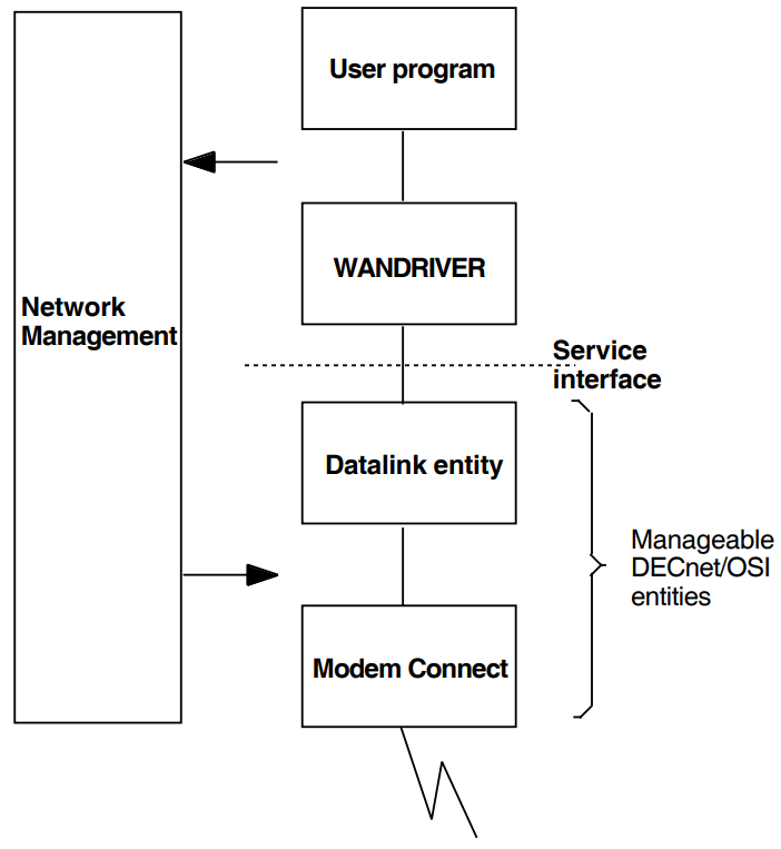
The programming interface enables you to write applications programs that use the WAN Device Drivers directly by means of $QIO calls to the pseudo-driver WANDRIVER, which passes your instructions and data on to the network management entities. The network management entities are controlled using commands in the Network Control Language (NCL).
In addition, programs written for previous versions of the WAN Device Drivers are still supported. However, VSI recommends that new programs should be written with the interface that uses WANDRIVER.
This chapter has sections that introduce:
The director-entity management model (Section 1.1, ''Understanding Modular Management'').
Writing programs to use WANDRIVER (Section 1.2, ''Writing a Program for the WAN Device Drivers'').
1.1. Understanding Modular Management
DECnet/OSI (which implements Phase V of the Digital Network Architecture) differs from DECnet Phase IV in a number of ways. In particular:
Networks can contain many more nodes.
DECnet/OSI integrates OSI architecture and protocols with DNA.
There is a more powerful and modular network model.
Suitably privileged users can manage DECnet/OSI management modules by using the Network Command Language (NCL) (documented in the VSI DECnet/OSI for OpenVMS Network Control Language Reference).
Table 1.1, ''Differences Between DECnet/OSI and Phase IV Drivers'' summarizes the ways that the DECnet/OSI drivers differ from the Phase IV drivers, and Figure 1.1, ''The Generic Drivers and DECnet/OSI'' gives an overview of the difference.
| DECnet/OSI Feature | Phase IV Feature |
|---|---|
| Works with DECnet/OSI | Independent of DECnet |
| Management of drivers and data exchange separated | Management and data exchange intermixed |
| $QIO calls go to the pseudo-driver (WANDRIVER), which uses the services of the selected datalink layer entity to exchange data with the remote system. This manual refers to these calls as generic. | $QIO calls go to individual drivers |
| Improved problem solving through increased visibility of manageable parameters | Limited information about drivers available only through SENSEMODE calls |
| The Common Trace Facility (CTF) | No tracing facility |
Figure 1.1, ''The Generic Drivers and DECnet/OSI'' illustrates the relationship between the generic device drivers and DECnet/OSI.
1.2. Writing a Program for the WAN Device Drivers
Before you use the DECnet/OSI WAN Device Drivers, the necessary management entities need to be set up on the system or systems on which your program will run. These entities are:
MODEM CONNECT.
DEVICE (only if the datalink will use a device that has loadable firmware, such as the DSV11, DSB32, DSF32, DSW21, DSW41, or DSW42).
The appropriate one or any combination of HDLC, DDCMP, and LAPB (the datalink layer entity or entities that your set up requires will depend on the communications hardware that you have installed).
FRAME (only if you are using a protocol other than those provided by the generic WAN Device Drivers).
These entities are set up during configuration both of the WAN Device Drivers and of DECnet/OSI. Check that they exist by running NCL and issuing the commands:
SHOW NODE your-node DEVICE ALL ATTRIBUTES
SHOW NODE your-node MODEM CONNECT ALL ATTRIBUTES
SHOW NODE your-node datalink-entity ALL ATTRIBUTES?
where:
your-node is the node that you want information about. You can omit
NODE your-nodeif you issue the command from that node;datalink-entity is whichever of the DECnet/OSI datalink entities you are using.
Note
The first command is necessary only if the datalink uses the DSV11, DSB32, DSF32, DSW21, DSW41, or DSW42.
If the necessary entities are not running, see the relevant chapters in the VSI DECnet/OSI for OpenVMS Network Control Language Reference for information about creating and enabling them.
When your network is appropriately set up, you can then go on to set up and manage individual datalinks, and send and receive data over those datalinks using WANDRIVER. (See Chapter 2, "Setting Up and Using Datalinks", which outlines the steps you have to take when you are setting up and using datalinks.)
Chapter 3, "Programming Problems" deals with problems you may meet in using the WAN Device Drivers.
In some cases, you may want to use a program that was written for a previous version of the WAN Device Drivers. Before doing so, see Appendix D, "Obsolete Features of the $QIO Interface".
1.2.1. Using the Obsolete Interface
The word "obsolete" is used throughout this book to refer to the interface available with previous versions of the WAN Device Drivers, which is retained for compatibility with programs that are already in use. This interface is not obsolete in the sense of not being supported.
You cannot use the generic drivers and the obsolete interface at the same time on the same unit of a device. The obsolete QIOs cannot be issued to a WAN Device Drivers unit if that unit is defined, at the time of the call, to be the COMMUNICATIONS PORT for a Modem Connect line child entity (COMMUNICATIONS PORT is a DECnet/OSI characteristic attribute). See Appendix D, "Obsolete Features of the $QIO Interface".
Chapter 2. Setting Up and Using Datalinks
This chapter explains the tasks involved in making service interface calls to WANDRIVER. Part II,''Programming Reference Information'' gives the detailed reference information that you will need to perform these tasks.
2.1. Setting Up DECnet/OSI Modules
To use the WAN Device Drivers, you need at least two DECnet/OSI management modules running on your system (three, if you are using a DSV11 or DSB32):
MODEM CONNECT
The appropriate datalink layer entity
DEVICE (for DSV11, DSB32, DSF32, DSW21, DSW41, or DSW42)
The DECnet/OSI for VMS initialization procedure creates the Modem Connect module and the necessary datalink module or modules. If your hardware requires it, you create the Device module when the installation procedure for the WAN Device Drivers runs the command file WANDD$STARTUP.COM (see VSI DECnet/OSI for Open VMS Installation and Configuration ).
You can create new modules, or reconfigure ones already created, by using NCL.
2.2. Using the Service Interface
To use a line, you use these QIOs:
IO$_CREATE
IO$_DELETE
IO$_SETMODE
IO$_SENSEMODE
IO$_READLBLK
IO$_WRITELBLK
IO$_CLEAN
Section 2.2.1, ''Setting Up Datalinks'' explains how to use the QIOs to set up the V2.0 WAN Device Drivers for data transfer. Section 2.2.2, ''Exchanging Data'' explains how to use QIOs for reading and writing data. Full reference information about using the QIOs can be found in Chapter 4, "I/O Function Codes and Status Returns". For details of the obsolete QIO interface, see Appendix D, "Obsolete Features of the $QIO Interface".
2.2.1. Setting Up Datalinks
Before using a datalink to exchange data, you must:
Assign a channel to WANDRIVER (see Section 2.2.1.1, ''Assigning a Channel'')
(Optionally) enable an attention AST (see Section 2.2.1.3, ''Enabling an Attention AST'')
Open a port (see Section 2.2.1.2, ''Opening a Port'')
Start the protocol (also explained in Section 2.2.1.4, ''Starting the Protocol'')
At any time, you may flush both the read and write buffers (see Section 2.2.1.5, ''Clearing Buffers''). You can also get information about an open port (see Section 2.2.1.6, ''Getting Information About the Port'')
To close the service interface, you must:
Enable an attention AST (see Section 2.2.1.3, ''Enabling an Attention AST'')
Shut down the protocol (see Section 2.2.1.7, ''Shutting Down the Protocol'')
Close the port when the AST completes (see Section 2.2.1.8, ''Closing the Port'')
Deassign the channel
2.2.1.1. Assigning a Channel
To use WANDRIVER, you must first assign a channel to it by calling the
$ASSIGN system service. Specify
WAN0 as the device name when assigning the
channel.
$ASSIGN creates a new Unit Control Block (UCB), and allocates a channel to it. Use the channel number returned by $ASSIGN in all subsequent $QIO operations to this device.
2.2.1.2. Opening a Port
To open a port, you use the IO$_CREATE call.
2.2.1.3. Enabling an Attention AST
You enable an attention AST in order to get information about the progress of your program and the datalink it is using. Typical events that you would need your program to take into account would be:
The link is up (and your program can continue to read and write).
The link is down (in which case you would need further information about where and why the failure occurred).
The datalink module is unavailable for some other reason.
To enable an attention AST, you use the IO$_SETMODE call with an IO$M_ ATTNAST modifier. Table 4.5, ''Meaning of Status Bits'' and Table 4.6, ''Meaning of Error Bits'' list possible return statuses and what they mean.
2.2.1.4. Starting the Protocol
To start a datalink protocol, you use the IO$_SETMODE call with an IO$M_ STARTUP modifier.
2.2.1.5. Clearing Buffers
If you are using the Frame module, you can choose to clear out either the write buffers or the read buffers or both. Do this at any time by issuing an IO$_CLEAN call, and use the modifiers to select which buffers you want cleared out.
2.2.1.6. Getting Information About the Port
To get information about an open port, you use the IO$_SENSEMODE call. The returns show you the characteristics for the port associated with the channel that you issue the QIO on.
2.2.1.7. Shutting Down the Protocol
To shut down a datalink protocol, you use the IO$_SETMODE call with an IOM_SHUTDOWN modifier.
2.2.1.8. Closing the Port
To close the port, you use the IO$_DELETE call.
2.2.2. Exchanging Data
You use the IO$_READLBLK call to receive a buffer of data. You use the IO$_WRITELBLK call to send a buffer of data.
2.2.2.1. Reading Data
To retrieve a message that has arrived in a read buffer, use the IO$_READLBLK call. Use the P1 and P2 parameters of the call to specify the address and length of the buffer.
If no received messages are available, the driver stores the receive request and returns it when a received message arrives from the datalink.
Use the IO$M_NOW qualifier to force the driver to return the receive request immediately. If there are no messages in the read buffer, the IO$READLBLK call returns with the status SS$_ENDOFFILE.
2.2.2.2. Writing Data
To put a message into a write buffer, use the IO$_WRITELBLK call. Use the P1 and P2 parameters of the call to specify the address and length of the message.
On a half-duplex line, if you are using the Frame module, use the IO$M_MORE qualifier to force the driver to keep the Request to Send (RTS) signal asserted after transmitting a message.
Chapter 3. Programming Problems
3.1. Introduction to Problem Solving
Use these new facilities to help with problem solving:
The Common Trace Facility (CTF). This tool lets you trace protocol activities at various levels in your DECnet/OSI network by specifying the appropriate tracepoint or tracepoints. For details, see the VSI DECnet/OSI for OpenVMS Common Trace Facility Use manual.
Modular network management. Many things hidden in Phase IV are visible with DECnet/OSI management. This is particularly so in the case of modem signals. Whereas in Phase IV you could not find out what modem signals were being sent, the DECnet/OSI Modem Connect module gives you:
Read access to each of the interchange circuits
Information on the state of the physical interface
3.2. Loopback
The NCL commands STARTLOOP and STOPLOOP enable you to start and stop loopback tests on a line. A parameter to the STARTLOOP command enables you to specify any one of several types of loopback test. The loopback tests you can do are:
STARTLOOP DRIVER
STARTLOOP DEVICE
STARTLOOP LOCAL
STARTLOOP REMOTE
STARTLOOP CONNECTOR
STARTLOOP EXTERNAL
Figure 3.1, ''What the Loopback Tests Do'' gives an overview of the different kinds of loopback test. Section 3.2.1, ''STARTLOOP DRIVER'' to Section 3.2.6, ''STARTLOOP EXTERNAL'' give further details about using the different tests.
3.2.1. STARTLOOP DRIVER
In this test, the software simply turns transmit data into receive data. It does not exercise the device.
3.2.2. STARTLOOP DEVICE
In this test, the data loops back inside the device, as near as possible to the line’s transmitters and receivers.
3.2.3. STARTLOOP CONNECTOR
This test tells the software that:
The network manager has physically inserted a loopback connector (somewhere between the device and the local modem).
The system under test will need to generate its own clock.
In this test the data loops back outside the distribution panel of the device and before the modem.
3.2.4. STARTLOOP LOCAL
In this test, the data loops back inside the local modem. This test requires a modem that recognizes and supports CCITT 141 (‘local loopback’).
3.2.5. STARTLOOP REMOTE
In this test, the data loops back inside the remote modem. This test requires two cooperating modems, with the local modem recognizing and supporting CCITT 140 (‘remote loopback’).
3.2.6. STARTLOOP EXTERNAL
This test tells the software that:
The network manager has physically switched the modem so that it loops back.
The system under test is receiving clock signals from some external source.
In this test the data loops back at the external device, which is in loopback mode.
Part II. Programming Reference Information
Part II gives only reference information. In order to program the WAN Device Drivers you need to read Part 1,''Programming Tasks'' first, and then refer to Part II for detailed information.
Part II is divided between information that a programmer needs regularly and information needed only occasionally.
There is one chapter:
Chapter 4, "I/O Function Codes and Status Returns" gives reference information about the $QIO interface.
There are five appendixes:
Appendix A, "VSI DEC HDLC" gives information about VSI HDLC.
Appendix B, "User-Written Datalink Protocols" gives information about writing your own datalink protocols.
Appendix C, "Example programs" gives sample programs, both for WANDRIVER and for the V1.2-like interface.
Appendix D, "Obsolete Features of the $QIO Interface" gives information on the obsolete (V1-like) interface.
Appendix E, "Management" gives information on management (particularly the Network Control Language-NCL)
Chapter 4. I/O Function Codes and Status Returns
4.1. Overview of I/O Operations
4.1.1. WANDRIVER
WANDRIVER is the pseudo-driver that supports a QIO interface to the DECnet/OSI datalink service interfaces. In V2.0 of the WAN Device Drivers, you make QIO calls to WANDRIVER which relays your instructions and I/O, through the datalink service interfaces, to the appropriate devices.
For compatibility with V1-style programs, the programming interfaces to drivers specific to individual devices are still supported (see Appendix D, "Obsolete Features of the $QIO Interface").
4.1.2. QIOs to WANDRIVER
In DECnet/OSI, the tasks of managing datalinks and using them for exchanging data are separated. You use QIO requests to the WAN Device Drivers to do the following:
Set up the service interfaces of datalinks managed by DECnet/OSI entities (see Section 4.2, ''Setting Up, Controlling, and Using Datalink Circuits'').
Exchange user data (see Section 4.3, ''$QIOs for Exchanging User Data'').
Table 4.1, ''WAN Device Drivers I/O Functions'' lists these QIO requests and their function codes.
| Function Code | Arguments | Modifiers | Function |
|---|---|---|---|
| Managing Circuits | |||
| IO$_CREATE | P1,P2 | none | Open a port |
| IO$_DELETE | none | none | Close a port |
| IO$_SETMODE | [P1,[P2],P3] |
IO$M_STARTUP IO$M_SHUTDOWN IO$M_ATTNAST | Set datalink characteristics and state for subsequent operations |
| IO$_SENSEMODE | P2 | none | Get information about an open port |
| IO$_CLEAN | none |
IO$M_ READATTNAST IO$M_WRATTNAST | For HDLC, SDLC, and LAPB, stops outstanding reads and/or writes |
| Exchanging Data | |||
| IO$_READLBLK | P1,P2 | IO$M_NOW | Read a logical block |
| IO$_WRITELBLK | P1,P2 | IO$M_MORE† | Write a logical block |
| †Only for half-duplex operation. | |||
In Section 4.2, ''Setting Up, Controlling, and Using Datalink Circuits'' and Section 4.3, ''$QIOs for Exchanging User Data'', there is a subsection for each call. In each subsection there is reference information broken down like this:
Format
Returns in R0
Arguments
Notes
In Section 4.2, ''Setting Up, Controlling, and Using Datalink Circuits'' and Section 4.3, ''$QIOs for Exchanging User Data'', there is no information on the common argument chan that must be specified in all calls. The argument chan is the channel number that the $ASSIGN system service returned when you assigned to WANA0. It is passed by value.
Section 4.4, ''Returns in the Input/Output Status Block (IOSB)'' gives information about the Input/Output Status Block (IOSB).
4.2. Setting Up, Controlling, and Using Datalink Circuits
There are three stages in managing a circuit:
Setting up a datalink entity (usually, while you are configuring your network) via the network management interface.
Creating and specifying the characteristics of a particular datalink via the service interface.
Continuing to manage the datalink entity from day to day.
To manage the datalink itself (items 1 and 3), refer to the VSI OpenVMS DECnet/OSI for Open VMS Network Control Language Reference manual. To set up, control, and use a particular datalink service interface (item 2), you use the $QIO calls detailed in:
Section 4.2.6, ''Clean''/flushing the datalink
4.2.1. Open a Port
The IO$_CREATE call creates a port to a datalink entity that has already been set up, either with NCL or with the programming calls used for management.
| Format | |
SYS$QIO chan, IO$_CREATE, [iosb], P1, P2 | |
| Returns | |
ss$_accvio | A QIO argument is not accessible to the user process. |
ss$_illiofunc | Illegal I/O function code or modifiers specified. |
ss$_insfarg | Required P1 parameter not specified. |
ss$_ivlognam | P1 datalink name not in correct format. |
ss$_insfmem | Driver failed to allocate a nonpaged pool buffer. |
ss$_exquota | Could not allocate a nonpaged pool buffer because of quota limitations. |
ss$_badparam |
Unknown datalink entity name specified. or Illegal item in P2 itemlist |
ss$_ivbuflen | The buffer size requested was too large. |
ss$_ssfail |
Your request to open a port has failed for some other reason. A code specifying the reason is given in the second longword of the IOSB. Possible reasons are given in Table 4–2. |
ss$_nosuchobj | Could not connect to specified datalink entity. |
ss$_devactive | Port is already open. |
ss$_disconnect | The port was closed down while the open was being performed. |
Notes
P2 is optional for DDCMP and FRAME ports. P2 is not optional for LAPB and HDLC ports.
For LAPB you must at least specify the preferred buffer size item (dll$k_ preferred_buffer_size) in the item list (see Table 4.4, ''Settable Open Port Items'').
For HDLC you must at least specify the protocol ID item (dll$k_protocolID) in the item list (see Table 4.4, ''Settable Open Port Items'').
| Code | Value | Reason |
|---|---|---|
dll$_no_such_entity | 8356 | You have specified an entity that does not exist. |
dll$_entity_in_use | 10500 | The entity specified in the Open Port call is in use. |
dll$_ins_res | 292 | Your system has insufficient resources to meet the request. |
dll$_unsup_profile (applicable only to LAPB ports) | 268 | The profile specified in your call is not supported. |
dll$_inval_entity | 10492 | The entity specified in the request was not of the required type. |
dll$_fatalerr | 692 | There has been an internal fatal error. Please submit an SPR. |
Arguments
| P1 |
The address of a quadword descriptor of the name (or logical name) of the datalink. The P1 parameter is mandatory. Datalink names are in this format: ProtocolModule.LinkName[./StationName]
Replace ProtocolModule with either DDCMP, HDLC, LAPB or FRAME. You must specify a LinkName. You must specify StationName for all datalinks except FRAME and LAPB. |
| P2 | If not zero, the address of a quadword descriptor of an item-list of parameters for a port on the specified datalink. For further details, see Section 4.2.1.1, ''Item-Lists for the Attributes of Ports''. |
Notes
If P1 and P2 buffers are valid, the driver opens a port with the LinkName and (except in the FRAME or LAPB entity) StationName specified in the call.
IO$_CREATE takes no modifiers.
4.2.1.1. Item-Lists for the Attributes of Ports
The P2 parameter of an IO$_CREATE call is the address of a quadword descriptor that points to an item-list in which items have the format shown in Figure 4.1, ''The Format of an Item'':
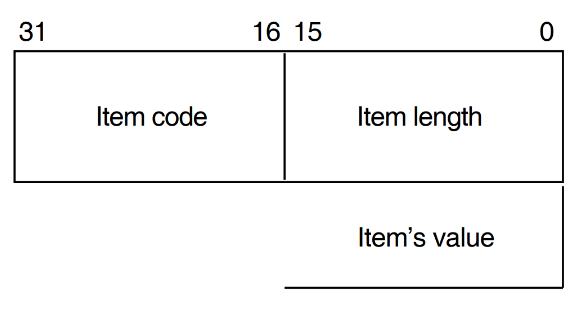
The item-list is a block of memory that is virtually contiguous. It contains one or more items, which consist of these fields:
Item length
Item code
Item value
Item Length
The Item length includes both the length of the Item length and the length of the Item type, and is expressed in bytes. For example, an item whose value was a longword would have an Item Length of 8: that is, two bytes for the Item length, two bytes for the Item type, and four bytes for the longword value itself. So although the length always depends on the value, the length of the item is not equal to the length of the value (see Table 4.3, ''Sample Item Lengths'').
| Length of Value | Length of Item |
|---|---|
| Byte | 5 |
| Word | 6 |
| Integer | 6 |
| Longword | 8 |
| String | length of string + 4 |
| Local Entity Name | A Local Entity Name is itself an item-list. |
Item Code
The Item code is any of the codes listed in Table 4.4, ''Settable Open Port Items'' or Table 4.8, ''Link Up Item-List''.
Item Value
An Item value can itself be an item-list.
| Value | Item Code | Item Type | Description |
|---|---|---|---|
| 100 |
| Byte |
A boolean value that tells the datalink to try to start automatically, after the Open Port has completed successfully. This parameter does not affect whether the datalink attempts to restart itself following a link failure. If the setting of this parameter is TRUE, the client need not issue an Initialise Protocol function after opening a port. The default setting is TRUE. |
| 101 |
| Byte |
A boolean value that tells the datalink that it should always attempt to restart the protocol itself after a link failure. The default setting is TRUE. |
| 7 | Longword | The buffer size that the client would like to use. Where negotiation takes place, this value is used as the preferred maximum data size. | |
| 6 | Longword | The minimum buffer size that the client is prepared to accept. If the datalink performs negotiation of the buffer size, it should not allow negotiation below this value. This value should be greater than or equal to 262 if you are using DEC HDLC. | |
| 8 |
| Word | The protocol ID that must be exchanged with the remote station. The link is used only if both stations use the same ID. |
| 9 |
| String | The user data to be transferred as part of the initialization sequence to the remote station, if possible. |
| 10 |
| String |
The datalink profile name that the client wants to use. The datalink checks that this matches the profile in use on this datalink. If the actual profile does not match the named profile, the datalink returns the error dll$_unsup_profile This item is optional. If it is not specified, the datalink does no checking. |
| 106 |
| Byte | This is a boolean value that the datalink may pass to the device driver. If TRUE, the driver limits the receive buffer to its initial value. If FALSE, the driver uses the initial value as a minimum, and allocates more buffers whenever it sends full buffers to the user program. The default setting is FALSE. |
4.2.2. Enable Attention AST
This function requests that an attention AST is delivered to the requesting process after one of the following events:
The driver has set or cleared any of the status or error bits. See Table 4.5, ''Meaning of Status Bits'' and Table 4.6, ''Meaning of Error Bits'' for meanings of different settings of the status and error bits.
Data has arrived and there is no read request outstanding.
The user is informed only once whenever either of these conditions occurs.
Format
SYS$QIO chan, IO$SETMODE!IO$M_ATTNAST, [iosb],P1,[P2],P3
Returns
ss$_insfmem | Driver failed to allocate a nonpaged pool buffer. |
ss$_exquota | Could not allocate a nonpaged pool buffer because of quota limitations. |
Arguments
| P1 | The address of an AST service routine (or 0 to disable ASTs). |
| P2 | User parameter for the AST routine. |
| P3 | Access mode to deliver AST (0 to 3, corresponding to the VMS access mode chosen). If you specify a more privileged access mode than the current access mode of the calling process, the AST is delivered in the current access mode. Otherwise, the AST is delivered in the access mode you have specified. |
Notes:
You may use the Enable Attention AST function at any time, regardless of the condition of the driver and port status bits.
After an AST fires, it must be reenabled by another Enable Attention AST function before an AST can fire again.
The AST quota (ASTLM) for your process limits how many ASTs can be requested.
When the attention AST service is delivered, the top byte of the AST parameter is the byte specified in the P2 parameter that set up the attention AST. The lowest three bytes contain the status and error bits, listed in Table 4.5, ''Meaning of Status Bits'' and Table 4.6, ''Meaning of Error Bits''.
| Code | Value | Meaning When Set |
|---|---|---|
dll$m_sts_active | 1 | The link is up. |
dll$m_sts_receive_data_ready | 2 | There is received data waiting in the driver for the user to read. |
dll$m_sts_physical_loopback | 4 | Data is looping back at the physical layer. |
| Code | Value | Meaning When Set |
|---|---|---|
dll$m_err_remote_restart | 256 | The remote station is restarting |
dll$m_err_insuff_resources | 512 | There are insufficient system resources to provide the service called. |
dll$m_err_physical_layer_down | 1024 | The physical layer is not available. |
dll$m_err_negotiation_failure | 2048 | There has been a negotiation failure (DEC HDLC only). |
dll$m_err_maintenance_mode | 4096 | The datalink has been set to maintenance mode. |
dll$m_err_disabled | 8192 | The physical layer communications port is disabled. |
dll$m_err_threshold_exceeded | 16384 | Datalink receive or transmit threshold exceeded. |
4.2.3. Start Up Protocol
Starts up the datalink protocol.
Format
SYS$QIO chan, IO$_SETMODE!IO$M_STARTUP [,iosb]
Returns
ss$_disconnect | The port was closed down while it was being started up. |
ss$_devinact | The port has not yet opened, or has not successfully opened. |
ss$_illiofunc | Illegal I/O function code or modifiers specified. |
ss$_insfmem | Driver failed to allocate a nonpaged pool buffer. |
ss$_exquota | Could not allocate a nonpaged pool buffer because of quota limitations. |
ss$_nosuchdev | Port has not yet been opened. |
Notes
IO$_SETMODE with the IO$M_STARTUP qualifier takes no parameters.
4.2.4. Shut Down Protocol
Shuts down the datalink protocol.
Format
$QIO chan, IO$_SETMODE!IO$M_SHUTDOWN [,iosb]
Returns
ss$_illiofunc | Illegal I/O function code or modifiers specified. |
ss$_insfmem | Driver failed to allocate a nonpaged pool buffer. |
ss$_exquota | Could not allocate a nonpaged pool buffer because of quota limitations. |
ss$_nosuchdev | Port has not yet been opened. |
ss$_disconnect | The port was closed down while it was being started up. |
ss$_devinact | The port has not yet opened, or has not successfully opened. |
Notes
IO$_SETMODE with the IO$M_SHUTDOWN qualifier takes no parameters.
4.2.5. Getting Port Information
To get information about an open port, you use the IO$_SENSEMODE call.
Format
SYS$QIO chan, IO$_SENSEMODE, [iosb], ,P2
Returns
ss$_accvio | A QIO argument is not accessible to the user process. |
ss$_illiofunc | Illegal I/O function code or modifiers specified. |
ss$_insfarg | Required P2 parameter not specified. |
ss$_bufferovf | Item-list is too large to fit into user’s buffer. |
Arguments
| P2 |
The address of a quadword descriptor. The length field of the descriptor contains the length of the buffer pointed to by the address field of the descriptor. The driver returns in the buffer described by this
descriptor the following (in the item-list format
discussed in Section 4.2.1.1):
The Link Up items will only be present if the link is up when the IO$_SENSEMODE request is received. |
| Value | Item Code | Item Type | Description |
|---|---|---|---|
| 1 |
dll$k_dl_entity | Local Entity Name | Local Entity Name of the datalink and/or logical station. |
| 5 |
dll$k_port_entity | Local Entity Name | The name of the newly created datalink port entity. |
| 2 |
dll$k_client | Local Entity Name | The local entity name of the client subentity. |
| 11 |
| Integer | The negotiated buffer size for use over the link. In the case of HDLC, the datalink returns this value in the Link Up Item-List (Table 4.8, ''Link Up Item-List''). |
| 106 |
| Byte | A boolean value that the datalink may pass to the driver. If the setting is TRUE, the driver limits its receive buffers to its initial numbers. If FALSE, the driver uses this number as a minimum, and allocates more buffers whenever it sends full buffers to the user program. The default setting is FALSE. |
| Value | Item Code | Item Type | Description |
|---|---|---|---|
| 11 |
dll$k_actual_buffer_size | Integer | The negotiated buffer size for use over the link. |
| 8 |
dll$k_protocolID | Word | The protocol ID proposed by the remote station, if supplied. |
| 9 |
dll$k_DECuserdata | String | The user data received from the remote station, if supplied. |
4.2.6. Clean
For the Frame datalink only, an IO$_CLEAN function can stop either outstanding write requests, or outstanding read requests, or both, depending on modifiers. By default, IO$_CLEAN stops outstanding Write requests only.
$QIO chan, IO$_CLEAN[!IO$M_READATTN|IO$M_WRTATTN] [, iosb]
Returns
ss$_illiofunc |
Illegal I/O function code or modifiers specified. or IO$_CLEAN not supported for this datalink. |
ss$_insfmem | Driver failed to allocate a nonpaged pool buffer. |
ss$_exquota | Could not allocate a nonpaged pool buffer because of quota limitations. |
ss$_devinact | The port has not completed opening. |
ss$_nosuchdev | The port has not been opened. |
ss$_abort | Clean already in progress. |
Notes
The modifiers work in this way:
If you specify just one modifier, an IO$_CLEAN request stops either read requests or write requests.
If you specify both modifiers, an IO$_CLEAN request stops both read requests and write requests.
If you specify neither modifier, an IO$_CLEAN request stops only write requests.
4.2.7. Close a Port
Closes a port.
SYS$QIO chan, IO$_DELETE [, iosb]
Returns
ss$_illiofunc | Illegal I/O function code or modifiers specified. |
ss$_devinact | Port has not been opened. |
Notes
IO$_DELETE takes no function code modifier.
4.3. $QIOs for Exchanging User Data
The generic drivers do not differentiate between logical, virtual, and physical I/O functions.
4.3.1. Read
A Read function transfers incoming data into the buffer you specify.
SYS$QIO chan, IO$_READLBLK[!IO$M_NOW] [,iosb], P1, P2
Returns
ss$_accvio | A QIO argument is not accessible to the user process. |
ss$_illiofunc | Illegal I/O function code or modifiers specified. |
ss$_badparam | Receive request 0 length, or greater than maximum transmit buffer size. |
ss$_bufferovf | Message was received successfully, but was too large to fit into user's buffer. |
ss$_endoffile | IO$M_NOW modifier was specified on the read QIO, but no completed reads were available. |
ss$_abort | QIO has been aborted. |
ss$_nosuchdev | The port has not been opened. |
ss$_devinact | The port has not completed opening. |
Arguments
| P1 | The address of a buffer for a message that the driver receives. |
| P2 | The length of the same buffer. |
Notes
The status return SS$_ENDOFFILE (if the IO$M_NOW modifier is specified) indicates that there is no data to be read in the driver.
4.3.2. Write
SYS$QIO chan, IO$_WRITELBLK[!IO$M_NOW], [iosb], P1, P2
Returns
ss$_accvio | A QIO argument is not accessible to the user process. |
ss$_illiofunc | Illegal I/O function code or modifiers specified. |
ss$_badparam | Transmit request 0 length, or greater than the receive buffer size. |
ss$_exquota | Could not allocate a nonpaged pool buffer due to quota limitations. |
ss$_nosuchdev | The port has not been opened. |
ss$_devinact | The port has not completed opening. |
ss$_abort | QIO has been aborted. |
ss$_ssfail | There has been some other error. Reasons are given in the second longword of the IOSB: see Table 4.9, ''Reasons for SS$_SSFAIL on a IO$_WRITELBLK Request''. |
| Code | Value | Meaning When Set |
|---|---|---|
dll$m_sts_active | 0 | The datalink is not running. |
dll$m_err_not_sent | 32768 | The buffer has not been sent because the datalink is unavailable. Try again. |
dll$m_err_physical_layer_down | 1024 | The physical layer has failed. |
dll$m_err_disabled | 8192 | The datalink port is being closed. |
dll$m_err_fatalerr | 65536 | There has been an internal fatal error. |
Arguments
| P1 | The address of a buffer that holds a message for the driver to send. |
| P2 | The length of the same buffer. |
Notes
The drivers put your data in a system buffer before transmitting it.
For the Frame datalink, on half-duplex lines, the write functions can take the modifier IO$M_MORE. This keeps Request To Send (RTS) asserted in half-duplex communications, after a message is transmitted. Without this modifier, the driver drops RTS.
If the link is unavailable, the driver does not attempt to pass data to the datalink. The driver holds the data in an internal queue until the datalink indicates that the link is available again.
4.4. Returns in the Input/Output Status Block (IOSB)
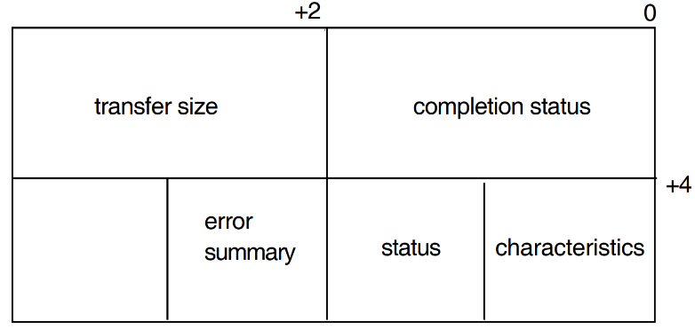
The format of the I/O Status Block (IOSB) is shown in Figure 4.2, ''The Format of the IOSB''.
As well as the completion status, the first longword of the IOSB returns the size (in bytes) of the data transfer.
The second longword of the IOSB contains the DEVDEPEND longword. See Table 4.5, ''Meaning of Status Bits'' and Table 4.6, ''Meaning of Error Bits'' for meanings of different settings of the status and error bits.
4.5. Using the $CANCEL System Service
When you call the $CANCEL system service, outstanding attention ASTs are flushed and a close port operation is initiated. A close port operation flushes back all outstanding I/O, returns resources, and disconnects and shuts down the service interface into the datalink.
Note that using $CANCEL is slightly different than what happens when using the obsolete QIO interface. If you just want to abort outstanding I/O requests, you must use the Clean operation. See Section 4.2.6, ''Clean'' for more information about the Clean operation.
Appendix A. VSI DEC HDLC
This appendix gives reference details of DEC HDLC. A DEC HDLC module can exchange data only with another DEC HDLC module, or one that uses a compatible implementation of HDLC.
Section A.1, ''Optional Functions'' lists the optional functions provided for in ISO 7809. These are implementation options. Section A.1, ''Optional Functions'' also indicates which of them are either optional (for the user), required, or not implemented in DEC HDLC. Notes give further details of functions implemented in DEC HDLC.
Section A.2, ''Classes of procedures'' lists which of the classes of procedure are available in DEC HDLC, and specifies the link type to which each class applies.
A.1. Optional Functions
| Optional Procedure Number | Additional Function Provided | DEC HDLC Implementation Details |
|---|---|---|
| 1 | Ability to exchange identification and/or characteristics | Required1 |
| 2 | Improved reporting of I frame sequence errors | Optional |
| 3 | More efficient recovery from I frame sequence errors | No2 |
| 4 | Ability to exchange information fields (whether or not operational) without affecting I frame sequence numbers | Required3 |
| 5 | Ability to initialize/request intialization | No |
| 6 | Ability to do unnumbered group and all-station polling | No4 |
| 7 | Greater than single-octet addressing | No |
| 8 | Delete I responses (limits remote station to using I frames for commands) | No |
| 9 | Delete I commands (limits remote station to using I frames for responses) | No |
| 10 | Ability to use extended sequence numbering (modulo 128) | Optional5 |
| 11 | One-way reset (for BAC only) | No |
| 12 | Ability to do basic datalink test | No |
| 13 | Ability to request logical disconnection | No |
| 14 | 32-bit frame checking sequence (FCS) | Optional6 |
The Exchange Identification (XID) function lets Datalink Layer entities exchange parameters and chacteristics of operation before or during normal working. This function has three prime uses:
Exchanging information before setting up a logical data-link for Network Layer traffic.
Accommodating a limited amount of higher-layer information (for example, in security applications).
Indicating a local change in data-link parameter values (for example, because of congestion).
Within DEC HDLC, the remote station must transmit an XID response using the general purpose XID information field identifier. The datalink parameters must be in accordance with International Standard ISO 8885, and the addresses in accordance with International Standard ISO 8471. The XID frame must itself contain a user data field in DEC HDLC format, with (at least) the HDLC protocol identifier and version.
The Improved Performance function allows for the reporting of I frames received out of sequence, by means of the REJ frame. A REJ frame requests transmission or retransmission of frames with a sequence number later than the last one successfully received.
For DEC HDLC, if the option is denied, no REJ transmission will take place. Checkpointing will be necessary to recover from line errors.
The Unnumbered Information (UI) function allows for the sending of higher- layer information at any time with no impact on the ordering of I frames. On a highly reliable, error-free line, the exclusive use of UI frames may be the logical choice.
A DEC HDLC link will not initialize if the UI support is denied. The remote station must also respond correctly to UI frames with the protocol identifier in the DEC HDLC format used by the Maintenance Operations Protocol.
It is possible to poll out of the running state, using DISC frames.
The Extended Sequence Numbering function defines the sequence numbering for I frames as modulo 128. The greater modulus value allows for larger send and receive windows. This function’s prime use is over connections where there is a long propagation delay (for example, a satellite link).
DEC HDLC selects this optional function according to the setting of the ACTUAL SEQUENCE MODULUS parameter for the datalink.
The 32-bit FCS function provides for a higher level of accuracy in error detection.
DEC HDLC selects this optional function according to the PREFERRED CRC TYPE specified and the capacity of the device in use for the datalink. Note that in V2.0 of the WAN Device Drivers only the DSF32 can support a 32-bit CRC.
A.2. Classes of procedures
For further details of the HDLC protocol, see the International Standards ISO 3309, ISO 4335 (with its DADs), and ISO 7809 (with its DADs). Programmers who need to write their own datalink protocol should refer to Appendix B.
Appendix B. User-Written Datalink Protocols
If you want to write your own datalink protocol, you must make calls to the Frame module. The Frame module does only the framing for the type of line protocol being used.
See the VSI OpenVMS DECnet/OSI for Open VMS Network Control Language Reference manual for information on manageable attributes of the frame datalink.
This appendix gives a brief description and provides usage notes for each of these framing routines:
DDCMP
HDLC
BISYNC
GENBYTE
B.1. The DDCMP Framing Routine
Note for HDLC users
This section applies only to implementations of the DDCMP protocol that are not supplied by Digital.
DDCMP (Digital Data Communications Message Protocol) is a byte-oriented protocol that can be used on synchronous or asynchronous, half- or full-duplex, serial or parallel, and point-to-point or multi-point systems.
Figure B.1, ''A DDCMP Frame'' shows the way a DDCMP frame is made up.
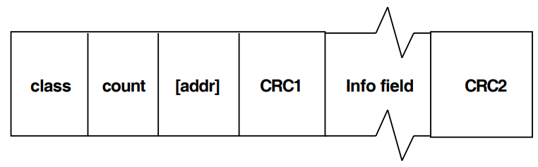
DDCMP framing checks these fields only:
CLASS
Eight bits. There are three classes of message: Data (81), Control (05), and Maintenance (90).
COUNT
This 14-bit field is used in Data and Maintenance messages to indicate the number of characters that will follow the header, forming the information part of the message. In Control messages, the first eight bits indicate the kind of Control message it is.
There are also two flag bits.
The DDCMP framing routine checks only that the two octets used by DDCMP for sequence and response are present.
ADDRESS
Not checked by the framing routine.
CRC1
This 16-bit field is a check just on the header information. In Control messages, the frame stops here.
CRC2
A second check (also 16-bits), on the Information field.
DDCMP framing also checks that the length of the frame is valid.
B.2. The HDLC and SDLC Framing Routines
Note for HDLC users
This section applies only to implementations of HDLC protocols that are not supplied by Digital.
FLAGS
A bit pattern of
01111110at the beginning and end of the frame.ADDRESS
An optional address check of the next 8 (or possibly 16) bits. (SDLC only)
CRC
A frame check that is either CRC_CCITT (16 bits) or CRC_AUTODINII (32 bits). (HDLC only)
B.3. BISYNC
BISYNC is IBM’s Binary Synchronous Communications Protocol. BISYNC is a character-oriented protocol, used for transmission between IBM computers and batch and video display terminals.
B.4. GENBYTE
Note
GENBYTE is not supported for calls to the WANDRIVER interface. It is available only to users of the obsolete interface, and is unchanged from the GENBYTE available with earlier versions of the WAN Device Drivers.
The GENBYTE protocol is supported by the DMB32 and DMF32 device drivers. GENBYTE enables receive message framing to be tailored to suit a particular user-written protocol. This facility allows protocols not specifically supported by the driver, or by the device’s firmware, to have their own rules for framing receive messages.
GENBYTE enables the users framing routine to become part of the driver’s interrupt processing context. When GENBYTE is the line protocol, incoming data is passed, character by character, to the user’s framing routine, which then decides whether the driver should:
Ignore the character completely.
Buffer the character as part of the frame being composed.
Buffer the character and overwrite the previously buffered character.
The framing routine also tells the driver whether the latest incoming character terminates the frame in the desired protocol, and if the receive frame should be posted for I/O completion.
B.4.1. The Framing Routine
You must write your own framing routine and load it into nonpaged pool. Because it is in nonpaged pool, the framing routine must be written in position- independent code. You pass the address of your routine to the driver when you start the line.
The address of the framing routine is kept in the driver’s database for the line. The driver also maintains for each GENBYTE line a context quadword, which is used by the framing interface for keeping state information while it is framing the receive message. The context quadword and the value of the incoming character constitute the total amount of information given to the framing routine. Thus, any protocol-specific context held by the framing routine must be kept in the context quadword since there is no other per-line data available to the framing routine.
The value of the context quadword at the start of the frame is defined in the SETMODE QIO P2 buffer. The framing routine can make use of the quadword in any way it wishes (for example, to hold counts and finite state machine states indicating which characters to expect next). At the end of each frame, the context quadword is reset to its initial value.
The driver calls your framing routine using a JSB instruction in the following manner:
| IPL | = | Driver’s fork IPL |
| R0 | = | Address of the framing routine context quadword for the line |
| R1 | = | Incoming character in the low byte |
Your framing routine must preserve all the registers it uses (except R0 and R1). It may update the context quadword, but must not change any other system data structures.
On return to the driver, the framing routine holds the following parameters:
| R0 | = | The incoming character |
| R1 | = | Indication of what the driver should do with the character |
Bits set in R0 signify:
| Bit 0 | If clear, buffer the character in the next position. If set, use bit 1. |
| Bit 1 | If clear, ignore the character. If set, buffer the character in the previous position (that is, overwrite the last character buffered). |
| Bit 2 | If set, complete and return the framed buffer to the user. (Buffer character according to bits 0 and 1.) If clear, ignore. |
So the following values of the least significant byte of R0 indicate:
| 0 | = | Buffer character in next position. |
| 1 | = | Ignore character. |
| 2 | = | Invalid code. |
| 3 | = | Buffer character in previous position. |
| 4 | = | Buffer character in the next position. Complete the frame. |
| 5 | = | Ignore character. Complete the frame. |
| 6 | = | Invalid code. |
| 7 | = | Buffer character in previous position. Complete the frame. |
Note that the framing routine should execute as few instructions as possible for each character, otherwise data may be lost. Ten instructions is a typical upper limit.
B.4.2. QIO Parameters Used in GENBYTE Operation
Select GENBYTE by setting the NMA$C_LINPR_PRO parameter in the SETMODE startup QIO to the value NMA$C_LINPR_BSY. (Since GENBYTE does not distinguish between line and circuit, the IO$M_CTRL subfunction modifier must always be specified in the startup QIO.)
Note that your process requires CMKRNL privilege to select GENBYTE mode, since access to system code in nonpaged pool is implied.
B.4.2.1. IO$_SETMODE P2 Parameter
Use any of the following parameters for the P2 argument to the SETMODE (controller) QIO function:
- NMA$C_PCLI_PRO (with value = NMA$C_PRO_BSY)
- NMA$C_PCLI_DUP
- NMA$C_PCLI_BFN
- NMA$C_PCLI_BUS
- NMA$C_PCLI_CON
However, there are extra parameters for the P2 argument specifically for GENBYTE. See Table B.1, ''Extra P2 Parameters for GENBYTE'' for details.
| Parameter ID | Meaning |
|---|---|
| NMA$C_PCLI_SYC | The SYNC character used by the device. Defaults to 32 hex. |
| NMA$C_PCLI_NMS | The number of SYNC characters to precede a transmit. The default is 8. |
| NMA$C_PCLI_FRA | The address of your protocol framing routine in nonpaged system address space. This parameter must be specified. |
|
NMA$C_PCLI_STI1 NMA$C_PCLI_STI2 | These two parameters contain the initial value of the framing routine context quadword. The SETMODE startup QIO sets the context quadword to this initial value. When the framing routine signals end-of-frame to the driver, the context quadword is reset to this initial value. |
B.4.2.2. IO$_WRITEBLK P4 Parameter
In GENBYTE mode, the IO$_WRITEBLK QIO function has an extra optional P4 parameter. If P4 is zero, the parameter is ignored; if P4 is nonzero, the parameter must point to an 8-byte buffer in your program. The contents of this buffer are immediately copied to the context quadword for the line. You can use this facility to indicate to the framing routine that a different type of frame is expected next. Note that the initial quadword value is always used to reset the context quadword at the end of each received frame.
B.4.3. Other Aspects of GENBYTE Operation
An IO$_CLEAN QIO stops all outstanding transmit and receive I/O operations.
The driver for a DMA device operates in a degraded mode when running in GENBYTE. This is because it has to examine repeatedly the contents of the receive buffer that is in progress to check whether there are new characters to be passed to the framing routine. Thus, the maximum line speed that the device driver supports in GENBYTE mode is less than that supported by other protocols used by the driver. An upper limit of 9.6K baud for GENBYTE is typical.
B.4.4. How to Use GENBYTE
Writing a framing routine for GENBYTE is relatively straightforward. Getting it loaded into system space, and providing the address of the framing routine, needs care. Remember that a GENBYTE framing routine effectively augments the VMS executive on line. Take great care to ensure that you have designed the GENBYTE interface correctly: an improperly designed interface can crash the system.
Example techniques you might use are as follows:
The framing routine could be loaded as part of a pseudo-device driver, which can return the framing routine entry point address in response to some I/O request, such as IO$_INITIALIZE.
Alternatively, use a suitably privileged process to allocate nonpaged pool, and copy the framing routine code into the nonpaged pool buffer. Ensure that the framing routine is written in position-independent code. This approach would enable the framing routine to be unloaded from nonpaged pool when it is no longer required and the line has been shut down.
Once the framing routine had been loaded into nonpaged pool and its entry point address has been identified, a CMKRNL-privileged process (the "starter-process") can issue an IO$_SETMODE QIO to start up the line into GENBYTE mode. If the starter-process is the only process that will perform data transfers over the line, then it can proceed to issue IO$_WRITELBLK and IO$_READLBLK QIOs. If other user-processes are required to transfer data over the line, then either they must have SHARE privilege, or else run images installed with SHARE privilege. SHARE privilege is required so that the process can assign to the line at the same time as the starter-process.
Section B.5, ''A Sample GENBYTE Macro-32 Framing Routine for a Subset of the IBM BISYNC Protocol'' contains an example GENBYTE routine.
B.5. A Sample GENBYTE Macro-32 Framing Routine for a Subset of the IBM BISYNC Protocol
        SBTTL MACROS
;
; Macro to simplify CASE instructions
;
        MACRO SELECT INDEX,VECLIST,TYPE=W,PREFIX1=<>,PREFIX2=<>,?DISPL0
;
; Inputs: Index = Case index
;     Veclist = A list of pairs of values <<val,adr>,...,<val,adr>>
;               which indicate the branch to take for various values
;               of the index. If the index value does not appear in
                the list, control goes to immediately after the macro.
;     Prefix1 = An optional prefix that will precede the ’val’ field
;               in the ’veclist’ pairs - used for abbreviating symbolic
                values in the list.
;     Prefix2 = An optional prefix that will precede the ’adr’ field
;               in the ’veclist’ pairs - used for abbreviating symbolic
;               values in the list.
;               If the ’adr’ field is null, then the address for this
;               pair is taken as the concatenation of ’val’ and ’prefix2’
;

     .MACRO $$MAX NUM,IGNORE
     .IIF   EQ $$MXSW, $$HIGH=NUM
     $$MXSW=1
     .IIF   LT $$HIGH-NUM, $$HIGH=NUM
     .ENDM $$MAX
     .MACRO $$MIN NUM,IGNORE
     .IIF   EQ $$MNSW, $$LOW=NUM
     $$MNSW=1
     .IIF   GT $$LOW-NUM, $$LOW=NUM
     .ENDM $$MIN
     .MACRO $$GENDISPL  VALUE,LABEL,PFIX1=<>,PFIX2=<>
     .IF    EQ $$DISPL-PFIX1’’VALUE
     .IIF NB <LABEL> , .SIGNED_WORD PFIX2’’LABEL-DISPL0
     .IIF B <LABEL> , .SIGNED_WORD PFIX2’’VALUE-DISPL0
     .IIF   EQ 1-$$GENSW, .ERROR ; Duplicate occurrence of VALUE
     $$GENSW=1
     .ENDC
     .ENDM $$GENDISPL
$$MXSW=0
$$MNSW=0
     .IRP   TUPLE,<VECLIST>
      $$MAX PREFIX1’’TUPLE
      $$MIN PREFIX1’’TUPLE
     .ENDR
$$BASE=$$LOW
$$LIMIT=$$HIGH-$$LOW
$$DISPL=$$BASE
     CASE’TYPE    INDEX,#$$BASE,#$$LIMIT

DISPL0:

     .REPT $$LIMIT+1
     $$GENSW=0
     .IRP   TUPLE,<VECLIST>
     $$GENDISPL TUPLE,PFIX1=<PREFIX1>,PFIX2=<PREFIX2>
     .ENDR
     .IIF   EQ $$GENSW, .WORD 2*<$$LIMIT+1>
     $$DISPL=$$DISPL+1
     .ENDR
     .ENDM SELECT

;
; Macro to define EBCDIC constants.
;
     .MACRO EBC$DEF
     EBC$_SPA   =   64
     EBC$_SOH   =   1
     EBC$_STX   =   2
     EBC$_ETX   =   3
     EBC$_ETB   =   38
     EBC$_EOT   =   55
     EBC$_DLE   =   16
     EBC$_NAK   =   61
     EBC$_ENQ   =   45
     EBC$_AK0   =   112
     EBC$_AK1   =   97
     EBC$_IGS   =   29
     EBC$_IRS   =   30
     EBC$_DC1   =   17
     EBC$_DC2   =   18
     EBC$_DC3   =   19
     EBC$_HT    =   5
     EBC$_ITB   =   31
     EBC$_NL    =   21
     EBC$_SYN   =   50
     EBC$_RVI   =   124
     EBC$_WACK  =   107
     EBC$_SLH   =   97
     EBC$_ESC   =   39
     EBC$_PAD   =   255
     .MACRO EBC$DEF
     .ENDM EBC$DEF
     .ENDM EBC$DEF


;
; Macro to define BISYNC receive states.
;
     .MACRO ST_DEF
     ST_START   =   0
     ST_NTTX    =   1
     ST_STOP1   =   2
     ST_STOP    =   3
     ST_NTTX_ITB    =   4
     ST_NTTX_ITB1   =   5
     ST_XPR =   6
     ST_XPR_DLE =   7
     ST_XPR_SYN =   8
     ST_XPR_ITB =   9
     ST_XPR_ITB1    =   10
     ST_BINARY  =   11
     ST_DLE_FIRST   =   12
     ST_XPR_NEW =   13
     ST_SLAVELOOP   =   14
     .MACRO ST_DEF
     .ENDM ST_DEF
     .ENDM ST_DEF


;
; Genbyte framing return code status bits.
;
     GENB$M_BUFFER_CHAR        = 1@0
     GENB$M_BUFFER_IN_PREV_POS = 1@
     GENB$M_COMPLETE_READ      = 1@2
;
; Set status for driver to buffer the character in R1 in the
; next position in the buffer.
;
     .MACRO    BUFFER_CURRENT
     CLRL      R0
     .ENDM     BUFFER_CURRENT

;
; Set status for driver to buffer character in R1 in previous position
; in buffer, overwriting previous character buffered.
;
     .MACRO    BUFFER_PREVIOUS
     MOVL      #GENB$M_BUFFER_CHAR!GENB$M_BUFFER_IN_PREV_POS,R0
     .ENDM     BUFFER_PREVIOUS

;
; Set status for driver to ignore the character.
;
     .MACRO    IGNORE_CHAR
     MOVL      #GENB$M_BUFFER_CHAR,R0
     .ENDM     IGNORE_CHAR


;
; Set status for driver to buffer character in current position,
; and then to complete the read.
;
     .MACRO    COMPLETE_FRAME
     MOVL      #GENB$M_COMPLETE_READ,R0
     .ENDM     COMPLETE_FRAME
;
     .SBTTL    FRAMING ROUTINE
;
     EBC$DEF                   ; EBCDIC character definitions
     ST_DEF                    ; Framing routine definitions
;
; NOTE: Framing routine assumes that the first byte of the
; state quadword is the BISYNC receive state.
;
     RCV$B_RCVSTATE = 0        ; Receive state-machine state
     RCV$B_ITBCNT = 1          ; ITB count in state quadword
     RCV$W_BIN_COUNT = 2       ; Byte count (when in binary state)

;
; Initial values of state quadword. Set up when the line is started.
; Reset when a frame completes.
;
     NY$C_INIT_STATE = ST_START!<256*7>     ; START state. Max 7 ITBs
     NY$C_BINARY_STATE = ST_BINARY          ; Binary receive start state
     NY$C_SLAVE_STATE = ST_SLAVELOOP        ; Slave receive start state
;
; ===============================================================
; = *** FRAMING ROUTINE FOR BISYNC ***  =
; ===============================================================
;
FRAMING_ROUTINE::
;
; Select what to do next based on the current state of the
; BISYNC state-machine maintained by this framing routine.
;
       SELECT (R0),TYPE=B,-
              <START,-
               NTTX,-
               STOP1,-
               STOP,-
               NTTX_ITB,-
               NTTX_ITB1,-
               XPR,-
               XPR_DLE,-
               XPR_SYN,-
               XPR_ITB,-
               XPR_ITB1,-
               BINARY,-
               DLE_FIRST,-
               XPR_NEW,-
               SLAVELOOP,-
               >,PREFIX1=<ST_>,PREFIX2=<FRAME_>

;
Start of frame
;
FRAME_START:
     CMPB    #EBC$_DLE,R1        ; Is it transparent text or a response?
     BNEQ    10$                 ; NEQ if no
     MOVB    #ST_DLE_FIRST,(R0)  ; Say first character was a DLE
     BUFFER_CURRENT              ; Buffer character in current position
     RSB                         ; Return to driver
10$: BBC     R1,RSPMASK,20$      ; 1 byte response (NAK,ENQ,EOT) ?
     BRW     FRAME_STOP          ; Complete receive with 1 byte response
20$: MOVB    #ST_NTTX,(R0)       ; Non-transparent text state

;
; Non-transparent text
;
FRAME_NTTX:
     BBS    R1,CCHRMASK,FRAME_CTRL ; BBS if control character
     BUFFER_CURRENT              ; Buffer character in current position
     RSB                         ; Return to driver
FRAME_CTRL:
     CMPB    #EBC$_ITB,R1        ; Internal CRC next?
     BNEQ    10$                 ; NEQ if no
     MOVB    #ST_NTTX_ITB,(R0    ; Signal first CRC byte next
     BUFFER_CURRENT              ; Buffer character in current position
     RSB                         ; Return to driver
10$: CMPB    #EBC$_SYN,R1        ; SYN in text?
     BNEQ    20$                 ; NEQ if no
     IGNORE_CHAR                 ; Say character is to be ignored
     RSB                         ; Return to driver
20$: CMPB    #EBC$_ENQ,R1        ; Is it a forward abort?
     BEQL    FRAME_STOP          ; Go signal end of frame
     MOVB    #ST_STOP1, (R0)     ; CRC Next
     BUFFER CURRENT              ; Buffer character in current position
     RSB                         ; Return to driver

;
; Second character of frame following DLE
;
FRAME_DLE_FIRST:
     CMPB    #EBC$_STX,R1        ; Is it a transparent text block
     BNEQ    10$                 ; NEQ if no
     MOVB    #ST_XPR,(R0)        ; Say we’re in transparent text mode
     BUFFER_CURRENT              ; Buffer character in current position
     RSB                         ; Return to driver
10$: BRB    FRAME_STOP           ; Assume last character of response

;
; Transparent text
;
FRAME_XPR:
     CMPB    #EBC$_DLE,R1        ; Is it a DLE
     BEQL    10$                 ; EQL if yes
     BUFFER_CURRENT              ; Buffer character in current position
     RSB                         ; Return to driver
10$: MOVB    #ST_XPR_DLE,(R0)    ; DLE state next
     BUFFER_CURRENT              ; Buffer character in current position
     RSB                         ; Return to driver

;
; Transparent text, DLE state
; FRAME_XPR_DLE:
     CMPB    #EBC$_ITB,R1        ; Is it an internal CRC?
     BNEQ    10$                 ; NEQ if no
     MOVB    #ST_XPR_ITB,(R0)    ; Set transparent ITB state next
     BUFFER_CURRENT              ; Buffer character in current position
     RSB                         ; Return to driver
10$: CMPB    #EBC$_SYN,R1        ; Is it a SYN in text
     BNEQ    20$                 ; NEQ if no
     MOVB    #ST_XPR_SYN,(R0)    ; Set state to overwrite previous DLE
     IGNORE_CHAR                 ; Say ignore this character
     RSB                         ; Return to driver
20$: BBS     R1,CCHRMASK,40$     ; Branch if control character
     CMPB    #EBC$_STX,R1        ; Is it an STX?
     BNEQ    30$                 ; NEQ if no
     MOVB    #ST_XPR,(R0)        ; Go back to transparent text state
     BUFFER_CURRENT              ; Buffer character in current position
     RSB                         ; Return to driver
30$: CMPB    #EBC$_DLE,R1        ; Is it a DLE
     BNEQ    FRAME_STOP          ; Abort receive for any other character
     MOVB    #ST_XPR,(R0)        ; Go back to transparent text state
     BUFFER_CURRENT              ; Have second DLE buffered
     RSB                         ; Return to driver
40$: MOVB    #ST_STOP1,(R0)      ; Say stop after two CRC bytes
     BUFFER_CURRENT              ; Buffer character in current position
     RSB                         ; Return to driver

;
; Non-transparent first internal CRC byte state
; FRAME_NTTX_ITB:
     MOVB    #ST_NTTX_ITB1,(R0)  ; Second CRC byte state next
     BUFFER_CURRENT              ; Buffer character in current position
     RSB                         ; Return to driver
;
; Non transparent second internal CRC byte state
;
FRAME_NTTX_ITB1:
     MOVB    #ST_NTTX,(R0)       ; Non-transparent text state next
     BRB     FRAME_ITB_END       ; Do common end of ITB processing
;
; End of frame
;
FRAME_STOP:
     MOVQ    #NY$C_INIT_STATE,(R0) ; Set next state to new frame
     COMPLETE_FRAME                ; End of frame, buffer character
     RSB                           ; Return to driver

;
; Transparent first CRC byte state
;
FRAME_XPR_ITB:
     MOVB    #ST_XPR_ITB1,(R0)     ; Second CRC byte next
     BUFFER_CURRENT                ; Buffer character in current position
     RSB                           ; Return to driver
;
; Transparent second CRC byte state
;
FRAME_XPR_ITB1:
     MOVB    #ST_XPR_NEW,(R0)      ; New internal record state
FRAME_ITB_END:
     DECB    RCV$B_ITBCNT(R0)      ; One more internal record received
     BLEQ    FRAME_STOP            ; LEQ if more than 7 ITBs - give up
     BUFFER_CURRENT                ; Buffer character in current position
     RSB                           ; Return to driver

;
; Transparent text, DLE SYN was received (DLE has been buffered)
;
FRAME_XPR_SYN:
     CMPB    #EBC$_DLE,R1          ; Is it a DLE
     BNEQ    10$                   ; NEQ if no
     MOVB    #ST_XPR_DLE,(R0)      ; Transparent DLE state next
     IGNORE_CHAR                   ; Ignore this DLE, one already buffered
     RSB                           ; Return to driver
10$: MOVB    #ST_XPR,(R0)          ; Go back to normal transparent text
     BUFFER_PREVIOUS               ; Buffer character, overwriting DLE
     RSB                           ; Return to driver
;
; First byte of final CRC state
;
FRAME_STOP1:
     MOVB    #ST_STOP,(R0)         ; Final byte next
     BUFFER_CURRENT                ; Buffer character in current position
     RSB                           ; Return to driver
;
; New record state
;
FRAME_XPR_NEW:
     CMPB    #EBC$_SYN,R1          ; Is it the leading SYN char
     BEQL    10$                   ; EQL if yes
     MOVB    #ST_XPR,(R0)          ; Go back to transparent text state
     BRW     FRAME_XPR             ; Go process the character
10$: IGNORE_CHAR                   ; Ignore the SYN
     RSB                           ; Return to driver
;
; Binary read - used for diagnostic QIOs - Buffer till count runs out
;
FRAME_BINARY:
     DECW    RCV$W_BIN_COUNT(R0)   ; One more byte
     BEQL    FRAME_STOP            ; EQL if done - complete buffer & reset
                                   ; state to text
     BUFFER_CURRENT                ; Buffer character in current position
     RSB                           ; And return

;
; Slaveloop read - for diagnostic slave test - Buffer till PAD received
;
FRAME_SLAVELOOP:
     CMPB    #EBC$_PAD,R1          ; Is it end of frame?
     BEQL    10$                   ; EQL if yes
     BUFFER_CURRENT                ; Buffer character in current position
     RSB                           ; And return
10$:                               ; End of slaveloop frame
     MOVL    #GENB$M_BUFFER_CHAR!GENB$M_COMPLETE_READ,R0 ; End frame, ignore char
     RSB
;
     .SBTTL Data Tables

;
; Macros to generate a table of 256 bits - all zeros
; except for the bits corresponding to the character
; codes specified in the parameter list.
;
     .MACRO  MASK_TABLE   TABLE,CHARLIST
     .IRP    CHAR,<CHARLIST>
             MASK_INCLUDE_CHAR TABLE,\CHAR
     .ENDR
TABLE:
     M$ = 0
     .REPT   8
             MASK_LONGWORD TABLE,\M$
             M$ = M$+1
     .ENDR
     .ENDM   MASK_TABLE

     .MACRO  MASK_LONGWORD TABLE,INDEX
     .IIF DF TABLE’’INDEX ,   .LONG TABLE’’INDEX
     .IIF NDF TABLE’’INDEX ,  .LONG 0
     .ENDM   MASK_LONGWORD

     .MACRO  MASK_INCLUDE_CHAR TABLE,CHAR
     M$NUM = CHAR / 32
     M$BIT = CHAR - <M$NUM * 32>
     MASK_INCLUDE_BIT TABLE,\M$NUM,\M$BIT
     .ENDM MASK_INCLUDE_CHAR

     .MACRO MASK_INCLUDE_BIT TABLE,INDEX,BIT
     .IIF NDF TABLE’’INDEX , TABLE’’INDEX = 0
     TABLE’’INDEX = TABLE’’INDEX ! <1 @ BIT>
     .ENDM MASK_INCLUDE_BIT

;
; Control character table (CCHRMASK)
;
     MASK_TABLE CCHRMASK,-
                <EBC$_ITB,EBC$_ETX,EBC$_EOT,EBC$_SYN,EBC$_ENQ,EBC$_ETB>
;
; 1 byte response table (RSPMASK)
;
     MASK_TABLE RSPMASK,-
                <EBC$_NAK,EBC$_EOT,EBC$_ENQ>

;
; End of Framing routine
; FRAMING_ROUTINE_END::
;
; Length of framing routine area
;
FRAMING_ROUTINE_LENGTH == FRAMING_ROUTINE - FRAMING_ROUTINE_END
;
;
     .END
Appendix C. Example programs
This appendix gives the listings of four programs written in C, divided between the WANDRIVER interface (Section C.1, ''Programs That Use the WANDRIVER Interface'') and the obsolete interface (Section C.2, ''Programs That Use the Obsolete Interface'').
Note that a number of example programs, written in C and Ada, are placed in the SYS$EXAMPLES directory when you install the WAN Device Drivers. See the DECnet/OSI for Open VMS Installation and Configuration manual for a list of these files.
C.1. Programs That Use the WANDRIVER Interface
Section C.1.1, ''WANDRIVER Program That Sends Data'' issues write requests to WANDRIVER; Section C.1.2, ''WANDRIVER Program That Receives Data'' issues read requests to WANDRIVER.
C.1.1. WANDRIVER Program That Sends Data
/*
**
** INCLUDE FILES
**
**/

#include  <stdio.h>
#include <starlet.h>
#include iodef
#include descrip
#include ssdef
#include "xmdef.h"
#include "nmadef.h"
#include "dl_external.h"
#include "dll_external.h"

/*
**++
**  FUNCTIONAL DESCRIPTION:
**
**  This program sends data to a device using the WANdriver interface
**  to the DECnet/OSI datalinks
**  The program requires the HDLC module with link name ’HDLCL1’ and
**  logical station name ’LS2’.
**
**  FORMAL PARAMETERS:
**
**  none
**
**  IMPLICIT INPUTS:
**
**  none
**
**  IMPLICIT OUTPUTS:
**
**  none
**
**  COMPLETION CODES
**
**  Success/Fail codes
**
**
**  SIDE EFFECTS:
**
**  none
**--
**/
void ATT_AST(long status);  /* Function declaration */
/***********************************************************************/

typedef struct                    /* Definition of structure  */
         {                        /* of io status block       */
         short cond_value;        /* Word length condition value */
         short count;             /* No of bytes of data transfered */
         int info;                /* Device specific information */
         } io_statblk;
/***********************************************************************/
typedef struct                  /* Definition of structure of item list */
         {
         short item_length;
         short item_code;
         int item_value;
         } p2_param_item;
/***********************************************************************/

p2_param_item p2_list = {       /* Initialising item list */
                        6,
                        dll$K_PROTOCOLID,
                        0x0103
                        };
int p2_desc[2]      =   {       /* Definition of P2 */
                         6,     /* descriptor of item list  */
                         &p2_list
                        };
int status;
int message_no = 0;
int i = 0;              /* loop count for write */
short assgnd_chan;
io_statblk   iosb,iosb2,iosb3,iosb4;
char secstr[12];
/**************************************************
*              MAIN ROUTINE                      *
**************************************************/
main()
{
      $DESCRIPTOR (terminal, "wan0:");
      $DESCRIPTOR (datalink, "HDLC.HDLCL1.LS2");
/*****************************************
*   ASSIGN A CHANNEL FOR QIO         *
*****************************************/
      if (((status = SYS$ASSIGN(&terminal, &assgnd_chan, 0, 0)) & 1) != 1)
           LIB$STOP( status);
/*****************************************
*   OPEN A PORT                       *
*****************************************/
      if (((status = SYS$QIOW( 0, assgnd_chan, (IO$_CREATE),
                      &iosb,0,0,&datalink,&p2_desc,0,0,0,0 )) & 1) != 1)
           LIB$STOP( status);
/*****************************************
*   START THE DATALINK PROTOCOL *
*****************************************/
      if (((status = SYS$QIOW( 0, assgnd_chan, (IO$_SETMODE | IO$M_STARTUP),
                      &iosb2,0,0,0,0,0,0,0,0 )) & 1) != 1)
           LIB$STOP( status);
/*****************************************
*   ENABLE ATTENTION AST             *
*****************************************/
      if (((status = SYS$QIOW( 0, assgnd_chan, (IO$_SETMODE | IO$M_ATTNAST),
                      &iosb3,0,0,ATT_AST,200,0,0,0,0 )) & 1) != 1)
           LIB$STOP( status);
/*****************************************
*   WRITE DATA                       *
*****************************************/

      for (i = 0; i < 20; i++) {
           sprintf(secstr,"MESSAGE %03d",i);
           if (((status = SYS$QIOW(0, assgnd_chan, IO$_WRITEVBLK, &iosb4, 0,
                          0, secstr, sizeof(secstr)-1,0, 32,0, 0)) & 1) != 1)
                 LIB$STOP( status);
           if (iosb4.cond_value != 1) {
               LIB$STOP (iosb4.cond_value);
               printf("Write not successful\n");
           }
     }
}
/*************** End of main ***************************/

/**********************************************************************
*  Attention Asynchronous System Trap routine                         *
***********************************************************************/
void ATT_AST(long status)
/*
**++
**  FUNCTIONAL DESCRIPTION:
**
**  Attention Asynchronous System Trap routine called when an
**  attention AST is posted
**
**  FORMAL PARAMETERS:
**
**  none
**
**  IMPLICIT INPUTS:
**
**  none
**
**  IMPLICIT OUTPUTS:
**
**  none
**
**  COMPLETION CODES:
**
**  none
**
**  SIDE EFFECTS:
**
**  none
**
**--
**/
{
        if ((status && dll$m_sts_active) == 1 )
             printf("LINK IS UP\n");
        else
             printf("LINK IS DOWN");
        if ((status && dll$m_sts_receive_data_ready) == 0)
             printf("There is received data waiting to be read\n");
        else
            ;
        if ((status && dll$m_sts_physical_loopback) == 0)
             printf("Data is looping back at the physical layer\n");
        else
            ;
        if ((status && dll$m_err_remote_restart) == 0)
             printf("The remote station is restarting\n");
        else
            ;
        if ((status && dll$m_err_insuff_resources) == 0)
             printf("There are insufficient system resources to provide the service called\n");
        else
            ;
        if ((status && dll$m_err_physical_layer_down) == 0)
             printf("The DECnet/OSI physical layer is not available\n");
        else
            ;
        if ((status && dll$m_err_negotiation_failure) == 0)
             printf("There has been a negotiation failure\n");
        else
            ;
        if ((status && dll$m_err_maintenance_mode) == 0) printf("The modem has been set to maintenance mode\n");
        else
            ;
        if ((status && dll$m_err_disabled) == 0)
             printf("The device is disabled\n");
        else
            ;
        if ((status && dll$m_err_threshold_exceeded) == 0)
             printf("A system resource has been exceeded\n");
        else
            ;
/*****************************************
*   RE-ENABLE ATTENTION AST *
*****************************************/
        if (((status = SYS$QIOW( 0, assgnd_chan, (IO$_SETMODE | IO$M_ATTNAST),
                       &iosb3,0,0,ATT_AST,200,0,0,0,0 )) & 1) != 1)
           LIB$STOP( status);
}
/********** End of ATT_AST routine *****************************/
/**********************************************************************/
/*  END OF PROGRAMME                                             */
/**********************************************************************/
C.1.2. WANDRIVER Program That Receives Data
/*
**
** INCLUDE FILES
**
**/

#include  <stdio.h>
#include <starlet.h>
#include iodef
#include descrip
#include ssdef
#include "xmdef.h"
#include "nmadef.h"
#include "dl_external.h"
#include "dll_external.h"
** INCLUDE FILES
/*
**++
**  FUNCTIONAL DESCRIPTION:
**
**  This program sends data to a device using the WANdriver interface
**  to the DECnet/OSI datalinks
**  The program requires the HDLC module with link name ’HDLCL1’ and
**  logical station name ’LS2’.
**
**  FORMAL PARAMETERS:
**
**  none
**
**  IMPLICIT INPUTS:
**
**  none
**
**  IMPLICIT OUTPUTS:
**
**  none
**
**  COMPLETION CODES
**
**  Success/Fail codes
**
**
**  SIDE EFFECTS:
**
**  none
**--
**/
void ATT_AST(long status);  /* Function declarations */
void ast(char *string);
/***********************************************************************/

typedef struct                    /* Definition of structure  */
         {                        /* of io status block       */
         short cond_value;        /* Word length condition value  */
         short count;             /* No of bytes of data transfered  */
         int info;                /* Device specific information  */
         } io_statblk;
typedef struct                    /* Definition of structure of item list */
         {
         short item_length;
         short item_code;
         int item_value;
         } p2_param_item;
/***********************************************************************/
p2_param_item p2_list = {
                        6,
                        dll$K_PROTOCOLID,
                        0x0103
                        };
int p2_desc[2] = {                 /* Definition of P2 */
                  6,               /* descriptor of item list   */
                  &p2_list
                 };
int i = 0;
int status;
short assgnd_chan;
io_statblk iosb,iosb2,iosb3,iosb4;
char secstr[12];
/**************************************************
*   MAIN ROUTINE                               *
**************************************************/
main()
{
      $DESCRIPTOR (pseudo_driver, "wan0:");
      $DESCRIPTOR (datalink, "HDLC.HDLCL1.LS2");
/*****************************************
*   ASSIGN A CHANNEL FOR QIO         *
*****************************************/
      if (((status = SYS$ASSIGN(&pseudo_driver, &assgnd_chan, 0, 0)) & 1) != 1)
            LIB$STOP( status);
/*****************************************
*   OPEN A PORT                       *
*****************************************/
      if (((status = SYS$QIOW( 0, assgnd_chan, (IO$_CREATE),
                     &iosb2,0,0,&datalink,&p2_desc,0,0,0,0 )) & 1) != 1)
            LIB$STOP( status);
/*****************************************
*   START THE DATALINK PROTOCOL *
*****************************************/
      if (((status = SYS$QIOW( 0, assgnd_chan, (IO$_SETMODE | IO$M_STARTUP),
                     &iosb3,0,0,0,0,0,0,0,0 )) & 1) != 1)
            LIB$STOP( status);
/*****************************************
*   ENABLE ATTENTION AST              *
*****************************************/
if (((status = SYS$QIOW( 0, assgnd_chan, (IO$_SETMODE | IO$M_ATTNAST), &iosb,0,0,ATT_AST,200,0,0,0,0 )) & 1) != 1)
LIB$STOP( status);
/*****************************************
*   READ DATA   *
*****************************************/
      if (((status = SYS$QIO(0, assgnd_chan, IO$_READVBLK, &iosb4, ast, secstr,
                     secstr, sizeof(secstr)-1,0, 0,0, 0)) & 1) != 1)
            LIB$STOP( status);
     SYS$HIBER();
}
/********** End of MAIN **********************************************/
/**********************************************************************
*  Attention Asynchronous System Trap routine                         *
***********************************************************************/
void ATT_AST(long status)
/*
**++
**  FUNCTIONAL DESCRIPTION:
**
**  Attention Asynchronous System Trap routine called when an
**  attention AST is posted
**
**  FORMAL PARAMETERS:
**
**  none
**
**  IMPLICIT INPUTS:
**
**  none
**
**  IMPLICIT OUTPUTS:
**
**  none
**
**  COMPLETION CODES:
**
**  none
**
**  SIDE EFFECTS:
**
**  none
**
**--
**/
{
        if ((status && dll$m_sts_active) == 1 )
             printf("LINK IS UP\n");
        else
             printf("LINK IS DOWN");
        if ((status && dll$m_sts_receive_data_ready) == 0)
             printf("There is received data waiting to be read\n");
        else
            ;
        if ((status && dll$m_sts_physical_loopback) == 0)
             printf("Data is looping back at the physical layer\n");
        else
            ;
        if ((status && dll$m_err_remote_restart) == 0)
             printf("The remote station is restarting\n");
        else
            ;
        if ((status && dll$m_err_insuff_resources) == 0)
             printf("There are insufficient system resources to provide the
  service called\n");
        else
            ;
        if ((status && dll$m_err_physical_layer_down) == 0)
             printf("The DECnet/OSI physical layer is not available\n");
        else
            ;
        if ((status && dll$m_err_negotiation_failure) == 0)
             printf("There has been a negotiation failure\n");
        else
            ;
        if ((status && dll$m_err_maintenance_mode) == 0)
             printf("The modem has been set to maintenance mode\n");
        else
            ;
        if ((status && dll$m_err_disabled) == 0)
             printf("The device is disabled\n");
        else
            ;
        if ((status && dll$m_err_threshold_exceeded) == 0)
             printf("A system resource has been exceeded\n");
        else
            ;
/*****************************************
*   RE-ENABLE ATTENTION AST           *
*****************************************/
        if (((status = SYS$QIOW( 0, assgnd_chan, (IO$_SETMODE | IO$M_ATTNAST),
                       &iosb3,0,0,ATT_AST,200,0,0,0,0 )) & 1) != 1)
              LIB$STOP( status);
}
/********** End of ATT_AST routine *****************************/
/**********************************************************************
*  Asynchronous System Trap routine                                   *
***********************************************************************/
void ast(char *strng)
/*
**++
**  FUNCTIONAL DESCRIPTION:
**
**  Asynchronous System Trap routine called when an AST is posted
**
**  FORMAL PARAMETERS:
**
**  none
**
**  IMPLICIT INPUTS:
**
**  none
**
**  IMPLICIT OUTPUTS:
**
**  none
**
**  COMPLETION CODES:
**
**  none
**
**  SIDE EFFECTS:
**
**  none
**
**--
**/
{
    i++;
    printf("Received data is: %s\n",strng);
/*****************************************
*   RE-ISSUE READ                     *
*****************************************/
        if (iosb4.cond_value != 1) {
            LIB$STOP (iosb4.cond_value);
            printf("Device write not successful\n");
}
        if (((status = SYS$QIO(0, assgnd_chan, IO$_READVBLK, &iosb4, ast, secstr,
               secstr, sizeof(secstr)-1,0, 0,0, 0)) & 1) != 1)
              LIB$STOP( status);
        if (i == 20) {
            SYS$WAKE();
            exit();
        }
}
/******************** End of AST routine ****************************/
/**********************************************************************/
/*  END OF PROGRAMME                                              */
/**********************************************************************/
C.2. Programs That Use the Obsolete Interface
Section C.2.1, ''QIO Program That Sends Data'' issues write requests to the obsolete interface; Section C.2.2, ''QIO Program That Receives Data'' issues read requests to the obsolete interface.
C.2.1. QIO Program That Sends Data
/*
**
** INCLUDE FILES
**
**/

#include    <stdio.h>
#include    iodef
#include    descrip
#include    ssdef
#include    "xmdef.h"
#include    "nmadef.h"
#define MAX_SIZE    1030
#define DST32_DEVICE   0
#define DMB32_DEVICE   1
#define DMF32_DEVICE   2
#define DSH32_DEVICE...3
#define DSB32_DEVICE   4
#define DSV11_DEVICE   5
#define DSF32_DEVICE   6
#define DSW_DEVICE   7
/*
**++
**  FUNCTIONAL DESCRIPTION:
**
**  This program sends data to a device using the QIO interface
**  It is an example of interfacing to the hdlc framing routine
**  and is not meant to provide a reliable datalink between two machines
**
**  FORMAL PARAMETERS:
**
**   Command line parameters: Program name set up as a symbol
**                            e.g prog :== $sys$sysroot:[sysmgr]prog.c
**                            Device name on which program is being run
**                            e.g SJA0:
**
**  IMPLICIT INPUTS:
**
**  none
**
**  IMPLICIT OUTPUTS:
**
**  none
**
**  COMPLETION CODES
**
**  Success/Fail codes
**
**
**  SIDE EFFECTS:
**
**  none
**--
**/

void get_device_name(void);     /* Declaration of functions       */
void send_data(void);           /*                                */
/*******************************************************************/
typedef struct                    /* Definition of structure */
              {                   /* of longword (6 bytes)   */
              short int device;
              unsigned char controller;
              unsigned char unit;
              }dev_name;
dev_name string_of_devices[7] = {      /* Initialisation of array */
                                ’si’,  /* of structures */
                                10,
                                1,
    ’xg’,
    10,
    1,
    ’zs’,
    1,
    2,
    ’sl’,
    10,
    2,
    ’sj’,
    5,
    2,
    ’sf’,
    10,
    2,
    ’zt’,
    3,
    2
    };
/*******************************************************************/
typedef struct                     /* Definition of structure  */
         {                         /* of io status block       */
         short cond_value;         /* Word length condition value  */
         short count;              /* No of bytes of data transfered  */
         int info;                 /* Device specific information  */
         } io_statblk;
/***********************************************************************/
typedef struct                     /* Definition of structure  */
         {                         /* of parameter P1          */
         short not_used1;          /* Un-used                  */
         short max_mess_size;      /* Max message size         */
         short characteristics;    /* Defines operational mode of driver */
         short not_used2;          /* Un-used                  */
         } p1_param;
/**********************************************************************/
typedef struct                     /* definition of structure */
         {                         /* of parameter P2 */
         short int pr_col_mode;    /* Protocol identifier */
         int pr_col_val;           /* Protocol value */
         short int dev_mode;       /* Device mode */
         int dev_value;            /* Associated mode value */
         short int cloc_gen;       /* Internal clock mode */
         int cloc_val;             /* Associated clockvalue */
         short int full_dup;       /* Full-duplex mode */
         int dup_val;              /* Associated mode value */
         short int buf_nums;       /* No of receive buffers */
         int buf_val;              /* Associated number */
         short int max_tr_rec;     /* Max transmit $ Receive size */
         int max_tr_rec_val;       /* Value */
         short int num_synchar;    /* Number of synch characters */
         int synchar_val;          /* Value */
         short int encod_tech;     /* Encoding Technique */
         int tech_val;             /* Associated value */
         short int clock_speed;    /* Clock speed */
         int speed_val;            /* Value */
         } p2_param;
/********************************************************************/
p2_param    p2 = {                         /* initialisation of P2 */
                      NMA$C_PCLI_PRO, NMA$C_LINPR_LAPB, /* p2 buffer */
                      NMA$C_PCLI_CON, NMA$C_LINCN_NOR,
                      NMA$C_PCLI_CLO, NMA$C_LINCL_EXT,
                      NMA$C_PCLI_DUP, NMA$C_DPX_FUL,
                      NMA$C_PCLI_BFN, 4,
                      NMA$C_PCLI_BUS, MAX_SIZE,
                      NMA$C_PCLI_NMS, 6,
                      NMA$C_PCLI_NRZI, NMA$C_STATE_OFF,
                      NMA$C_PCLI_LNS, 19200
                 };
io_statblk  iosb,iosb2,iosb3;       /* I/O status blocks              */
int status;                         /* holds status return value      */
short assgnd_chan;                  /* Holds channel number returned  */
                                    /* from SYS$ASSIGN                */
char str1[2] = ":",str2[6],str3[9]; /* General purpose strings       */
int device_flag = -1;
int number_of_devices = 7;
short int *input_arg;               /* Number of command line arguments */
int unit,mat;
unsigned char type_of_device[2],contrl;
int c,l = 0,i = 0;
char message_1[1024] = "This is message 1";       /* Data to be sent */
char message_2[1024] = "This is message 2";
char message_3[1024] = "This is message 3";
char message_4[1024] = "This is message 4";

struct dsc$descriptor_s p2_desc = {           /* Definition of P2 */
                                  sizeof(p2), /* descriptor */
                                  DSC$K_DTYPE_T,
                                  DSC$K_CLASS_S,
                                  &p2
                                  };
/**************************************************
*        MAIN ROUTINE                             *
**************************************************/
main(int argc, char *argv[])
{
     $DESCRIPTOR (terminal, str3);           /* Defines devic */
     for ( i=1; i<1023; i++) message_1[i]=66;
     mat=sscanf(argv[1], "%2c%c%d", &type_of_device, &contrl, &unit);
     sprintf(str3,"%c%c%c%d:",type_of_device[0],type_of_device[1],
             contrl,unit);
     terminal.dsc$w_length = strlen(str3);
     get_device_name();  /* Obtain name of device over which program */
                         /* is to be run */
/*****************************************
*      ASSIGN A CHANNEL FOR QIO         *
*****************************************/
     if (((status = SYS$ASSIGN(&terminal, &assgnd_chan, 0, 0)) & 1) != 1)
           LIB$STOP( status);
/****************************************
*     SHUT DOWN OF CONTROLLER           *
****************************************/
     if (((status =
           SYS$QIOW(0,assgnd_chan,(IO$_SETMODE|IO$M_CTRL|IO$M_SHUTDOWN),
           &iosb,0,0,0,0,0,0,0,0 )) & 1) != 1)
           LIB$STOP( status);
     if (iosb.cond_value != 1) {
         printf("Shutdown not successful\n");
         LIB$STOP (iosb.cond_value);
     }
/******************************************
*      START UP OF CONTROLLER             *
******************************************/
     if (((status =
           SYS$QIOW(0,assgnd_chan,(IO$_SETMODE|IO$M_CTRL|IO$M_STARTUP),
           &iosb,0,0,0,&p2_desc,4,0,0,0)) & 1) != 1)
           LIB$STOP( status);
     if (iosb.cond_value != 1) {               /* Check for success */
         printf("Physical layer startup not successful\n");
         LIB$STOP (iosb.cond_value);
     }
     send_data();     /* Transmit data */
}
/************** End of main ***********************************/
/**************************************************************
*         FUNCTION get_device_name                           *
**************************************************************/
void get_device_name(void)
/*
**++
**  FUNCTIONAL DESCRIPTION:
**
**  This function obtains the name of the device and sets the
**  appropriate flag. It also rejects invalid inputs
**
**  FORMAL PARAMETERS:
**
**  none
**
**  IMPLICIT INPUTS:
**
**  none
**
**  IMPLICIT OUTPUTS:
**
**  sets variable ’device_flag’
**
**  COMPLETION CODES:
**
**  none
**
**  SIDE EFFECTS:
**
**  none
**
**--
**/
{
input_arg = type_of_device;
for (i = 0; i < number_of_devices; i++) {
     if (string_of_devices[i].device == *input_arg) {
         if ((contrl >= ’a’) &&
  (contrl < (’a’+ string_of_devices[i].controller))) {
             if ((unit >= 0) && (unit < string_of_devices[i].unit)) {
                  device_flag = i;
                  break;
             }
             else {
                  printf("Invalid device unit\n");
                  break;
             }
         }
         else {
              printf("Invalid device controller\n");
              break;
         }
   }
   else if (i == (number_of_devices-1))
            printf("Invalid device name\n");
 }
if (device_flag >= 0) {
    switch(device_flag) {
           case 0: device_flag = DMB32_DEVICE;
                   break;
           case 1: device_flag = DMF32_DEVICE;
                   break;
           case 2: device_flag = DST32_DEVICE;
                   break;
           case 3: device_flag = DSB32_DEVICE;
                   break;
           case 4: device_flag = DSV11_DEVICE;
                   break;
           case 5: device_flag = DSF32_DEVICE;
                   break;
           case 6: device_flag = DSW_DEVICE;
                   break;
                  }
              }
              else
                  exit();
}
/*********** End of function get_device_name ***************/
/***********************************************************
*        FUNCTION SEND_DATA                                *
************************************************************/
void send_data(void)
/*
**++
**  FUNCTIONAL DESCRIPTION:
**
**  This function writes data to a device
**
**  FORMAL PARAMETERS:
**
**  none
**
**  IMPLICIT INPUTS:
**
**  none
**
**  IMPLICIT OUTPUTS:
**
**  none
**
**  COMPLETION CODES:
**
**  Success/fail code
**
**  SIDE EFFECTS:
**
**  none
**
**--
**/
{
           printf("Sending data: \n");     /* Send Data */
           if (((status = SYS$QIOW(0,assgnd_chan,IO$_WRITEVBLK,&iosb3,0,0,
                          message_1,sizeof(message_1)-1,0,32,0,0))&1) != 1)
                 LIB$STOP(status);
           if (((status = SYS$QIOW(0,assgnd_chan,IO$_WRITEVBLK,&iosb3,0,0,
                          message_2,sizeof(message_2)-1,0,32,0,0))&1) != 1)
                 LIB$STOP(status);
           if (((status = SYS$QIOW(0,assgnd_chan,IO$_WRITEVBLK,&iosb3,0,0,
                          message_3,sizeof(message_3)-1,0,32,0,0))&1) != 1)
                 LIB$STOP(status);
           if (((status = SYS$QIOW(0,assgnd_chan,IO$_WRITEVBLK,&iosb3,0,0,
                          message_4,sizeof(message_4)-1,0,32,0,0))&1) != 1)
                 LIB$STOP(status);
}
/**************** End of function send_data *************************/
/*********************************************************************
*              END OF PROGRAM                                        *
*********************************************************************/
C.2.2. QIO Program That Receives Data
/*
**
** INCLUDE FILES
**
**/

#include    <stdio.h>
#include    iodef
#include    descrip
#include    ssdef
#include    "xmdef.h"
#include    "nmadef.h"
#define MAX_SIZE    1030
#define DST32_DEVICE   0
#define DMB32_DEVICE   1
#define DMF32_DEVICE   2
#define DSH32_DEVICE...3
#define DSB32_DEVICE   4
#define DSV11_DEVICE   5
#define DSF32_DEVICE   6
#define DSW_DEVICE   7
/*
**++
**  FUNCTIONAL DESCRIPTION:
**
**  This program sends data from a device using the QIO interface
**  It is an example of interfacing to the hdlc framing routine
**  and is not meant to provide a reliable datalink between two machines
**
**  FORMAL PARAMETERS:
**
**   Command line parameters: Program name set up as a symbol
**                            e.g prog :== $sys$sysroot:[sysmgr]prog.c
**                            Device name on which program is being run
**                            e.g SJA0:
**
**  IMPLICIT INPUTS:
**
**  none
**
**  IMPLICIT OUTPUTS:
**
**  none
**
**  COMPLETION CODES
**
**  Success/Fail codes
**
**
**  SIDE EFFECTS:
**
**  none
**--
**/

void ast(char *);            /*                           */
void get_device_name(void);  /* Declaration of functions  */
void send_data(void);        /*                           */
void read_data();            /*                           */
/*******************************************************************/
typedef struct               /* Definition of structure */
              {              /* of longword (6 bytes)   */
              short int device;
              unsigned char controller;
              unsigned char unit;
              }dev_name;

dev_name string_of_devices[7] = {     /* Initialisation of array */
                                ’si’, /* of structures           */
                                10,
                                1,
    ’xg’,
    10,
    1,
    ’zs’,
    1,
    2,
    ’sl’,
    10,
    2,
    ’sj’,
    5,
    2,
    ’sf’,
    10,
    2,
    ’zt’,
    3,
    2
    };
/*******************************************************************/
typedef struct                    /* Definition of structure  */
         {                        /* of io status block       */
         short cond_value;        /* Word length condition value */
         short count;             /* No of bytes of data transfered */
         int info;                /* Device specific information */
         } io_statblk;

/***********************************************************************/
typedef struct                    /* Definition of structure */
         {                        /* of parameter P1         */
         short not_used1;         /* Un-used                 */
         short max_mess_size;     /* Max message size        */
         short characteristics;   /* Defines operational mode of driver */
         short not_used2;         /* Un-used                 */
         } p1_param;
/**********************************************************************/
typedef struct                    /* definition of structure */
         {                        /* of parameter P2         */
         short int pr_col_mode;   /* Protocol identifier     */
         int pr_col_val;          /* Protocol value          */
         short int dev_mode;      /* Device mode             */
         int dev_value;           /* Associated mode value   */
         short int cloc_gen;      /* Internal clock mode     */
         int cloc_val;            /* Associated clockvalue   */
         short int full_dup;      /* Full-duplex mode        */
         int dup_val;             /* Associated mode value   */
         short int buf_nums;      /* No of receive buffers   */
         int buf_val;             /* Associated number       */
         short int max_tr_rec;    /* Max transmit $ Receive size */
         int max_tr_rec_val;      /* Value                       */
         short int num_synchar;   /* Number of synch characters  */
         int synchar_val;         /* Value                       */
         short int encod_tech;    /* Encoding Technique          */
         int tech_val;            /* Associated value            */
         short int clock_speed;   /* Clock speed                 */
         int speed_val;           /* Value                       */
         } p2_param;
/********************************************************************/
p2_param       p2 = {                          /* initialisation of P2 */
                         NMA$C_PCLI_PRO, NMA$C_LINPR_LAPB, /* p2 buffer */
                         NMA$C_PCLI_CON, NMA$C_LINCN_NOR,
                         NMA$C_PCLI_CLO, NMA$C_LINCL_EXT,
                         NMA$C_PCLI_DUP, NMA$C_DPX_FUL,
                         NMA$C_PCLI_BFN, 4,
                         NMA$C_PCLI_BUS, MAX_SIZE,
                         NMA$C_PCLI_NMS, 6,
                         NMA$C_PCLI_NRZI, NMA$C_STATE_OFF,
                         NMA$C_PCLI_LNS, 19200
                    };
io_statblk   iosb,iosb2,iosb3;                 /* I/O status blocks */
int status;                                    /* Holds status return value */
short assgnd_chan;                             /* Holds channel number      */
                                               /* returned from SYS$ASSIGN */
char str1[2] = ":",str2[6],str3[9],strng[150]; /* General purpose strings */
int device_flag = -1;
int number_of_devices = 7;
short int *input_arg;          /* Number of command line arguments */
int unit,mat;
unsigned char type_of_device[2],contrl;
int c,l = 0,i = 0;

struct dsc$descriptor_s p2_desc = {            /* Definition of P2 */
                                   sizeof(p2), /* descriptor       */
                                   DSC$K_DTYPE_T,
                                   DSC$K_CLASS_S,
                                   &p2
                                  };
/**************************************************
*         MAIN ROUTINE                            *
**************************************************/
main(int argc, char *argv[])
{
     $DESCRIPTOR (terminal, str3);               /* Defines device */
     mat=sscanf(argv[1], "%2c%c%d", &type_of_device, &contrl, &unit);
     sprintf(str3,"%c%c%c%d:",type_of_device[0],type_of_device[1],
             contrl,unit);
     terminal.dsc$w_length = strlen(str3);
     get_device_name();                       /* Obtain name of device over */
                                              /* which program is to be run*/
/*****************************************
*       ASSIGN A CHANNEL FOR QIO          *
*****************************************/
     if (((status = SYS$ASSIGN(&terminal, &assgnd_chan, 0, 0)) & 1) != 1)
           LIB$STOP( status);
/****************************************
*   SHUT DOWN OF CONTROLER              *
****************************************/
     if (((status = SYS$QIOW( 0, assgnd_chan,
                              (IO$_SETMODE | IO$M_CTRL | IO$M_SHUTDOWN),
                              &iosb,0,0,0,0,0,0,0,0 )) & 1) != 1)
           LIB$STOP( status);
     if (iosb.cond_value != 1) {
         printf("Shutdown not successful\n");
         LIB$STOP (iosb.cond_value);
}
/******************************************
*   START UP OF CONTROLLER                 *
******************************************/
     if (((status = SYS$QIOW(0, assgnd_chan,
                             (IO$_SETMODE|IO$M_CTRL|IO$M_STARTUP),
                             &iosb,0,0,0,&p2_desc,4,0,0,0)) & 1) != 1)
           LIB$STOP( status);
     if (iosb.cond_value != 1) {              /* Check for success */
         printf("Physical layer startup not successful\n");
         LIB$STOP (iosb.cond_value);
     }
     read_data();      /* Read data from device */
}
/************ END OF MAIN ************************************/

/**********************************************************************
*  Asynchronous System Trap routine                                   *
***********************************************************************/
void ast(char *strng)
/*
**++
**  FUNCTIONAL DESCRIPTION:
**
**  Asynchronous System Trap routine called when an AST is posted
**
**  FORMAL PARAMETERS:
**
**  none
**
**  IMPLICIT INPUTS:
**
**  none
**
**  IMPLICIT OUTPUTS:
**
**  none
**
**  COMPLETION CODES:
**
**  none
**
**  SIDE EFFECTS:
**
**  none
**
**--
**/
{
    printf("Received data is: %s\n",strng);
}
/******************** End of AST routine ****************************/

/**************************************************************
*          FUNCTION get_device_name                            *
**************************************************************/
void get_device_name(void)
/*
**++
**  FUNCTIONAL DESCRIPTION:
**
**  This function obtains the name of the device and sets the
        appropriate flag. It also rejects invalid inputs
**
**  FORMAL PARAMETERS:
**
**  none
**
**  IMPLICIT INPUTS:
**
**  none
**
**  IMPLICIT OUTPUTS:
**
**  sets variable ’device_flag’
**
**  COMPLETION CODES:
**
**  none
**
**  SIDE EFFECTS:
**
**  none
**
**--
**/
{
    input_arg = type_of_device;
    for (i = 0; i < number_of_devices; i++) {
         if (string_of_devices[i].device == *input_arg) {
             if ((contrl >= ’a’) &&
     (contrl < (’a’+ string_of_devices[i].controller))) {
                if ((unit >= 0) && (unit < string_of_devices[i].unit)) {
                     device_flag = i;
                     break;
                }
                else {
                     printf("Invalid device unit\n");
                     break;
                }
           }
           else {
                printf("Invalid device controller\n");
                break;
           }
        }
        else if (i == (number_of_devices-1))
                 printf("Invalid device name\n");
}
        if (device_flag >= 0) {
            switch(device_flag) {
                   case 0: device_flag = DMB32_DEVICE;
                           break;
                   case 1: device_flag = DMF32_DEVICE;
                    break;
            case 2: device_flag = DST32_DEVICE;
                    break;
                  case 3: device_flag = DSB32_DEVICE;
                    break;
            case 4: device_flag = DSV11_DEVICE;
                    break;
            case 5: device_flag = DSF32_DEVICE;
                    break;
            case 6: device_flag = DSW_DEVICE;
                    break;
                   }
               }
               else
                   exit();
}
/*********** End of function get_device_name ***************/

/***********************************************************
*            FUNCTION READ_DATA                             *
*************************************************************/
void read_data(void)
/*
**++
**  FUNCTIONAL DESCRIPTION:
**
**  This function reads data from a device
**
**  FORMAL PARAMETERS:
**
**  none
**
**  IMPLICIT INPUTS:
**
**  none
**
**  IMPLICIT OUTPUTS:
**
**  none
**
**  COMPLETION CODES:
**
**  Success/fail code
**
**  SIDE EFFECTS:
**
**  none
**
**--
**/
{

               /*   Read Data   */
           if (((status = SYS$QIOW(0,assgnd_chan,IO$_READVBLK,&iosb2,
                          ast,strng,strng,sizeof(strng)-1,0,0,0,0))&1) != 1)
                 LIB$STOP(status);


           if (((status = SYS$QIOW(0,assgnd_chan,IO$_READVBLK,&iosb2,
                          ast,strng,strng,sizeof(strng)-1,0,0,0,0))&1) != 1)
                 LIB$STOP(status);
           if (((status = SYS$QIOW(0,assgnd_chan,IO$_READVBLK,&iosb2,
                          ast,strng,strng,sizeof(strng)-1,0,0,0,0))&1) != 1)
                 LIB$STOP(status);
           if (((status = SYS$QIOW(0,assgnd_chan,IO$_READVBLK,&iosb2,
                          ast,strng,strng,sizeof(strng)-1,0,0,0,0))&1) != 1)
                 LIB$STOP(status);
}
/**************** End of function read_data *************************/

/*********************************************************************
*                END OF PROGRAM                                      *
*********************************************************************/
Appendix D. Obsolete Features of the $QIO Interface
If you choose not to use the programming calls designed for management together with the $QIO interface to WANDRIVER to set up and control datalinks, you can continue to use the QIO calls that were the only option for previous versions of the WAN Device Drivers.
Section E.1.2.2, ''Using the Obsolete Interface'' explains:
How to use QIOs to start a device.
How calls to the V1.1-like interface create DECnet/OSI entities.
Table D.1, ''Obsolete I/O Functions'' lists the calls; Section D.3, ''Set Mode and Set Characteristics'' and Section D.4, ''Sense Mode'' give further details.
The key to the values in the TYPE column is as follows:
| L | Logical |
| V | Virtual |
| P | Physical |
| H | Only for half-duplex operation |
| Function Code and Arguments | Type | Modifiers | Function |
|---|---|---|---|
| L | IO$M_NOW | Read logical block |
| V | IO$M_NOW | Read virtual block |
| P | IO$M_NOW | Read physical block |
| L | IO$M_LASTBLOCK (H) | Write logical block |
| V | IO$M_LASTBLOCK (H) | Write virtual block |
| P | IO$M_LASTBLOCK (H) | Write physical block |
| L |
| Set driver characteristics and state for subsequent operations |
| P |
| Set driver characteristics and state for subsequent operations |
| L |
| Sense driver characteristics and return them in specified buffer(s) |
| IO$_CLEAN | L | None | For HDLC and SDLC, stops all outstanding transmits. For BISYNC and GENBYTE, stops all outstanding I/O operations. Not to be used with DDCMP. |
Generally, the drivers do not differentiate between logical, virtual, and physical I/O functions. However, you must have the required privilege to request a physical or logical function (for physical functions, PHY_IO privilege; for logical functions, LOG_IO privilege).
D.1. Read
A Read function transfers incoming data into the buffer you specify.
VMS provides three function codes:
IO$_READLBLK-read logical block
IO$_READVBLK-read virtual block
IO$_READPBLK-read physical block
The drivers store data as they receive it, and copy it to the buffer you specify.
The parameters for the three function codes are:
P1-The starting virtual address of the buffer to receive the data.
P2-The size of the buffer in bytes. P2 must not be larger than the maximum Receive message size (set in a previous IO$SETMODE call). If a larger message is received, a status of SS$_BUFFEROVF is returned in the I/O status block (IOSB).
The Read functions can take the modifier IO$M_NOW. This completes the read operation immediately with a received message. If no message is available when IO$M_NOW is applied, a status of SS$_ENDOFFILE is returned in the IOSB.
D.2. Write
A Write function transfers data from the buffer you specify and transmits the data down the line.
VMS provides three function codes:
IO$_WRITELBLK-write logical block
IO$_WRITEVBLK-write virtual block
IO$_WRITEPBLK-write physical block
The drivers put your data in a system buffer before transmitting it.
The parameters for the three function codes are:
P1-The starting virtual address of the buffer holding your data.
P2-The size (in bytes) of the buffer holding your data. P2 must not be larger than the maximum Send message size (set in a previous IO$SETMODE call).
On half-duplex lines, to turn the line at the end of a sequence of buffers, the Write functions use the modifier, IO$M_LASTBLOCK.
IO$M_LASTBLOCK forces the driver to drop Request To Send (RTS) after the transmit is sent. Use IO$M_LASTBLOCK with your final IO$_WRITE call to indicate the final piece of data in a transmit sequence. If the IO$_WRITE call includes IO$M_LASTBLOCK, this data (but no subsequent data) will be sent to the device for transmission.
The line direction is left indeterminate until there is an indication from the driver that Clear to Send (CTS) has been dropped and Carrier Detect (DCD) has been raised. The line direction is then set to RECEIVE and will remain so until DCD is dropped. However, if a transmit is queued before DCD is detected, the line direction is again set to TRANSMIT.
Note
IO$M_MORE is still supported to provide Phase IV compatibility for DMB32, DMF32, DUP11 and DPV11 devices.
To use IO$M_MORE on these devices, define the system-wide logical name VWDD$CUSTOM_PHASE4_dev-c-u to to be TRUE.
dev-c-u is defined as follows:
| dev | Represents the device (DMB, DMF, DUP, or DPV) |
| c | Represents the controller number |
| u | Represents the unit number of the device |
The following example shows the commands that define a DPV11 and DMB32:
$ DEFINE/SYSEM/EXECUTIVE_MODE VWDD$CUSTOM_PHASE4_DPV-0-0 TRUE
$ DEFINE/SYSEM/EXECUTIVE_MODE VWDD$CUSTOM_PHASE4_DMB-1-0 TRUE
IO$M_MORE forces the driver to keep Request To Send (RTS) asserted. Use IO$M_MORE on every block except the last. If the IO$_WRITE call includes IO$M_MORE, this data (and at least the next block of data written) will be sent to the device for transmission. If the IO$_WRITE call does not include the IO$M_MORE modifier, the RTS will be dropped on completion of the transmit.
To have the DMF32 operate as did the Phase IV driver in GENBYTE mode, you must set the logical name as previously discussed. For example:
$ DEFINE/SYSEM/EXECUTIVE_MODE VWDD$CUSTOM_PHASE4_DMF-0-0 TRUE
If this logical name is defined and if the DMF is operating in GENBYTE mode, the line will be turned at the end of each frame transmitted.
You can issue several read QIOs one after the other. These will be accepted whatever the direction of the line at the time of issue and will not be aborted if the line changes to TRANSMIT.
If there is no carrier from the receiving end, the first write QIO you issue will place the line into the TRANSMIT state. Hence, Request To Send (RTS) will be raised and, when Clear To Send (CTS) is raised, the data will be transmitted.
Any transmits are queued until DCD is dropped. RTS is then raised and the transmits queued for transmission until a transmit either without IO$M_ MORE or with IO$M_LASTBLOCK comes through.
In summary, to prevent the line being turned:
Use the IO$M_LASTBLOCK modifier on the last block only.
Use the IO$M_MORE modifier on every block except the last (but ONLYwhen the logical name VWDD$CUSTOM_PHASE4_dev-c-u is defined).
D.3. Set Mode and Set Characteristics
The Set Mode and Set Characteristics functions control driver operations. Principally, the Set Mode and Set Characteristics functions are used to:
Specify the protocol to be used
Specify the line speed
Specify full- or half-duplex operation
Specify CRC type (where applicable)
Allocate buffers
Specify message size
Request an attention AST
Specify loopback mode
Enable/disable the internal clock and set the clock speed
The functions that perform these and other tasks are described in the following sections.
VMS defines five types of Set Mode function:
Set/Start Controller mode (see Section D.3.1, ''Set Controller Mode'')
Set DDCMP mode (see Section D.3.2, ''Set DDCMP Mode'')
Shut down controller (see Section D.3.3, ''Shut Down Controller'')
Shut down DDCMP (see Section D.3.4, ''Shut Down DDCMP'')
Enable attention AST (see Section D.3.5, ''Enable Attention AST'')
VMS provides two function codes:
IO$_SETMODE-set mode
IO$_SETCHAR-set characteristics (requires physical I/O privilege)
D.3.1. Set Controller Mode
This function sets and (optionally) starts the drivers. For DDCMP operation, both the drivers and the DDCMP protocol must be initialized and started. See Section Section D.3.2, ''Set DDCMP Mode'' for instructions on starting the DDCMP protocol.
VMS provides four combinations of function code and modifier:
IO$_SETMODE!IO$M_CTRL-set driver characteristics
IO$_SETCHAR!IO$M_CTRL-set driver characteristics
IO$_SETMODE!IO$M_CTRL!IO$M_STARTUP-set driver characteristics and start the driver
IO$_SETCHAR!IO$M_CTRL!IO$M_STARTUP-set driver characteristics and start the driver
If the modifier IO$M_STARTUP is specified, the driver is started and the modem is enabled. If IO$M_STARTUP is not specified, the driver characteristics are simply modified.
The parameters for the function codes are:
P1-The virtual address of a quadword characteristics buffer. For further information, see Section D.3.1.1, ''P1 Parameter''.
P2-Optional. The address of a descriptor for an extended characteristics buffer. For further information, see Section D.3.1.2, ''P2 Parameter''.
P3-Number of Receive message blocks to allocate. For further information, see Section D.3.1.3, ''P3 Parameter''.
Note that if both the P1 and P2 parameters are specified, the P2 parameter values supersede the P1 parameter values. The P2 parameter NMA$C_PCLI_ BFN (see Table D.3, ''P2 Extended Characteristics Values'') also supersedes any P3 parameter.
Parameters P1, P2, and P3 are described in more detail in Section D.3.1.1, ''P1 Parameter'', Section D.3.1.2, ''P2 Parameter'', and Section D.3.1.3, ''P3 Parameter''.
D.3.1.1. P1 Parameter
P1 is the virtual address of a quadword characteristics buffer. This parameter is used only for DDCMP. Figure D.1, ''P1 Characteristics Buffer (Set Controller)'' shows the format of this buffer.
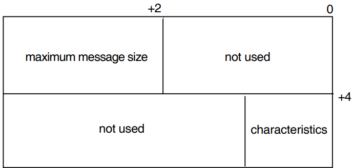
The second word of the first longword (‘maximum message size’) holds the maximum length for transmitted and received messages.
The first word of the second longword (‘characteristics’) defines the operational mode of the driver.
Table D.2, ''Driver Characteristics'' lists the driver characteristics that can be set in the second longword. The $XMDEF macro defines these values.
| Characteristic | Meaning |
|---|---|
| XM$M_CHR_LOOPB | Sets loopback mode |
| XM$M_CHR_HDPLX | Sets half-duplex operation |
D.3.1.2. P2 Parameter
P2 is optional. It is the address of a descriptor that defines an extended characteristics buffer.
The extended characteristics buffer that P2 points to consists of a series of 6-byte entries. The first word contains the parameter identifier (ID), and the longword that follows contains a value that can be associated with that parameter ID. Figure D.2, ''P2 Extended Characteristics Buffer'' shows the format of this buffer.
Table D.3, ''P2 Extended Characteristics Values'' shows the parameter IDs and possible values that can be specified in the P2 buffer (the notes referred to are at the end of the table). The $NMADEF macro defines these values.
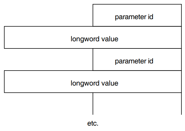
| Parameter ID | Meaning | |
|---|---|---|
| NMA$C_PCLI_PRO | Protocol mode. The following values can be specified: | |
| ||
| NMA$C_PCLI_DUP | Duplex mode (see Note 3 for defaults). The following values can be specified: | |
|
| |
| NMA$C_PCLI_CON | Device mode. The following values can be specified: | |
|
| |
| NMA$C_PCLI_BFN | Number of Receive buffers to preallocate (minimum = 1; for defaults, see Note 5). May be provided here or as P3 argument (see Section D.3.1.3, ''P3 Parameter''). If included, supersedes the P3 argument. | |
| NMA$C_PCLI_BUS | Maximum Transmit and Receive message length (for defaults and maximum values, see Note 6). | |
| NMA$C_PCLI_NMS | Number of sync characters to precede message. The number used is protocol-dependent (default = 8). | |
| NMA$C_PCLI_CODE | Character code used for IBM bisynchronous protocol. See Note 7. | |
| NMA$C_PCLI_CRC | Type of CRC. The following values can be specified: | |
| 0 | CRC–CCITT preset to 1s | |
| 1 | CRC–CCITT preset to 0s | |
| 2 | LRC/VRC odd | |
| 3 | CRC–16 | |
| 4 | VRC odd | |
| 5 | VRC even | |
| 6 | LRC/VRC even | |
| 7 | Nor error control | |
| For defaults and possible values, see Note 8. | ||
| NMA$C_PCLI_NRZI | Data encoding technique. The following values can be specified: | |
|
| |
| NMA$C_PCLI_CLO | Controls generation of a clock signal. The following values can be specified (see Note 9): | |
|
| |
| NMA$C_PCLI_LNS | Controls the speed of the clock signal enabled by NMA$C_PCLI_CLO. Values vary according to the device concerned. | |
| NMA$C_PCLI_RTT | Retransmit timer for full-duplex point-to-point mode and selection timer for half-duplex point-to-point mode. DDCMP only. Specify time in milliseconds (default = 3000). | |
| NMA$C_PCLI_TRI | Tributary mode address. Values in the range 0 to 255 are valid. Value 255 represents the multicast address and, when specified, will only allow reception of frames with an address of 255. If SDLC is operating, tributary mode is set automatically. | |
Notes:
BISYNC is supported by the DSV11, DPV11, DUP11, DMB32, DMF32, DSF32, DSH32, DST32, DSW21, DSW41, and DSW42.
GENBYTE is supported by the DMF32, DMB32, DPV, and DUP only.
- The default duplex mode for each protocol is:
- DDCMP-Full-duplex
- DDCMP-Full-duplex
- HDLC-Full-duplex (no half-duplex mode with HDLC)
- SDLC-Half-duplex
- BISYNC-Half-duplex
Default number of buffers allocated:
- DDCMP-4
- HDLC-6
- SDLC-4
- BISYNC-2
Default message length (in bytes):
- DDCMP-576
- HDLC-128
- SDLC-280
- BISYNC-280
Maximum message length (in bytes)
- DDCMP-4096
- HDLC-4106
- SDLC-4106
- BISYNC-4106
- Indicate EBCDIC character coding for the DSV11 using the value NMA$C_ CODE_EBCDIC. For the DUP11, the DPV11, the DMB32, the DMF32, and the DSF32, the following values can be specified:
Value Meaning NMA$C_CODE_ASCII ASCII character code NMA$C_CODE_EBCDIC EBCDIC character code (default) - Default values and possible values for the CRC depend on the line protocol:
- DDCMP: CRC–16 only
- HDLC: CRC-CCITT preset to 1s only
- SDLC: CRC-CCITT preset to 1s only
- BISYNC: CRC-16 only
- GENBYTE: None
Digital recommends that NMA$C_PCLI_CLO be left at its default value. Set the line speed using the NMA$C_PCLI_LNS parameter only when NMA$_ PCLI_CLO sets the internal clock. Setting the line speed with NMA$_PCLI_ LNS when NMA$_PCLI_CLO sets an external clock has no effect on the line speed used by the device. Note that there is no method of obtaining the current value of the line speed parameter.
NMA$C_PCLI_LNS controls the speed of the clock signal enabled by NMA$C_ PCLI_CLO. Table D.4, ''Clock Speed Values (hertz)'' lists the values allowed.
Table D.4. Clock Speed Values (hertz) DSB32 Values DSH32 and DST32 Values DSF32 Values DSV11 Values DSW21, DSW41, and DSW42 Values 0? 0 0 0 0 600 600 - - - 1200 1200 1200 - - 1800 - - - - 2000 2000 2000 - - 2400 2400 2400 - - 4800 4800 4800 - - 9600§ 9600 9600 9600§ 9600 14400 - - - - 19200 19200 19200 19200 19200 - 38400 38400 38400 38400? 48000 - - - - 56000 - - - - 64000 - - - - - - - 72000 - 76800 - - - - 96000 - - - - 128000 - - 128000 128000 - - - 256000 256000 - -1? -1 - -1
D.3.1.3. P3 Parameter
P3 is the number of Receive message blocks you are allocating for incoming data. This parameter is used only for DDCMP.
D.3.2. Set DDCMP Mode
The Set DDCMP Mode function allows you to set and start the DDCMP protocol. Specifically, the information in this section explains how you set up DDCMP circuit parameters (hence, the parameter ID codes described contains the PCCI identifier).
Four combinations of function doe and modifier are provided:
IO$_SETMODE-modify DDCMP characteristics
IO$_SETCHAR-modify DDCMP characteristics
IO$_SETMODE!IO$M_STARTUP-start DDCMP protocol
IO$_SETCHAR!IO$M_STARTUP-start DDCMP protocol
These codes take the following arguments:
P1-The virtual address of a quadword characteristics buffer (optional). Figure D.3, ''P1 Characteristics Buffer (Set DDCMP)'' shows the format of this buffer.
P2-The address of a descriptor for an extended characteristics buffer (optional).
The following characteristic can be set in the second longword of the P1 Characteristics Buffer:
XM$V_CHR_MOP – set DDCMP to maintenance mode
The P2 buffer consists of a series of 6-byte entries. The first word contains the parameter identifier (ID), and the longword that follows contains one of the values that can be associated with the parameter ID. Figure D.2, ''P2 Extended Characteristics Buffer'' shows the format for this buffer.
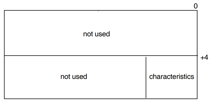
Table D.5, ''P2 Extended Characteristics Values'' lists the parameter IDs and values that can be specified in the P2 buffer.
| Parameter ID | Meaning | |
|---|---|---|
| NMA$C_PCCI_MTR? | An integer value in the range 1-100, indicating the maximum number of data messages in a row transmitted before deselecting (default = 4) | |
| NMA$C_PCCI_MST | Maintenance mode. The following values can be specified: | |
| Value | Meaning | |
|
| |
| NMA$C_PCLI_TRI | Tributary mode address. Values in the range 1 to 64 are valid (default = 1). | |
If both P1 and P2 characteristics are specified, the P2 characteristics supersede the P1 characteristics.
On receipt of the QIO request for a device, the driver starts the protocol.
D.3.3. Shut Down Controller
This function ends driver operations and halts the protocol and the line. To restart the driver, issue a IO$_SETMODE!IO$M_CTRL!IO$M_STARTUP or IO$_SETCHAR!IO$M_CTRL!IO$M_STARTUP request (see Section D.3.1, ''Set Controller Mode'').
Note that the defaults are not reset on shutdown, but only on DEASSIGN. The WAN Device Drivers use their previous settings on a restart after a shutdown. To change the settings after a shutdown, use the P2 parameter as described in Section Section D.3.1.2, ''P2 Parameter''.
VMS provides two combinations of function code and modifier:
IO$_SETMODE!IO$M_CTRL!IO$M_SHUTDOWN-shut down driver
IO$_SETCHAR!IO$M_CTRL!IO$M_SHUTDOWN-shut down driver
D.3.4. Shut Down DDCMP
This function halts the DDCMP protocol. The attached device cannot be used until DDCMP is restarted.
VMS provides two combinations of function code and modifier:
IO$_SETMODE!IO$M_SHUTDOWN-shut down DDCMP
IO$_SETCHAR!IO$M_SHUTDOWN-shut down DDCMP
These codes take no arguments.
D.3.5. Enable Attention AST
This function requests that an attention AST is delivered to the requesting process after one of the following events:
The driver has set or cleared an error summary bit.
The driver has set or cleared any of the unit status bits (see Table D.6, ''Unit and Line Status'' and Table D.7, ''Error Summary Bits'').
Data has arrived and there is no waiting IO$_READ request.
All outstanding attention ASTs are delivered after one of these events.
You may use the Enable Attention AST function at any time after the line is started, regardless of the condition of the driver and line status bits.
VMS provides two combinations of function code and modifier:
IO$_SETMODE!IO$M_ATTNAST-enable attention AST
IO$_SETCHAR!IO$M_ATTNAST-enable attention AST
The parameters for the two function codes are:
P1-The address of an AST service routine (or 0 to disable ASTs).
P2-User parameter for the AST routine.
P3-Access mode to deliver AST (0 to 3, corresponding to the VMS access mode chosen). If you specify a more privileged access mode than the current access mode of the calling process, the AST is delivered at the current access mode. Otherwise, the AST is delivered at the access mode you have specified.
After an AST occurs, it must be reenabled by another Enable Attention AST function before an AST can occur again. Note that the AST quota (ASTLM) for your process limits how many ASTs can be requested.
D.3.5.1. Status Bits
The status bits show the status of the unit and the line. They can only be read.
Table D–6 lists the status values and their meanings. The values are defined by the $XMDEF macro.
| Status | Meaning |
|---|---|
| XM$M_STS_ACTIVE | Device and selected protocol are active (does not indicate establishment of a link to the remote device) |
| XM$M_STS_DISC | Modem disconnected. This bit will be returned in the field IRP$L_IOST2 if the driver has detected an incorrect modem status (returns a fatal error with DDCMP) |
| XM$M_STS_BUFFAIL | Receive buffer allocation failed |
| XM$M_STS_DCHK | Message received with CRC error (only returned in IOSB) |
D.3.5.2. Error Summary Bits
The error summary bits are set when an error occurs. They are read-only bits. Errors (other than XM$M_ERR_LOST) cause shutdown of the DDCMP circuit. The circuit has to be restarted. Table D.7, ''Error Summary Bits'' lists the error values and their meanings.
| Error Summary Bit | Meaning |
|---|---|
| XM$M_ERR_MAINT | DDCMP maintenance message |
| XM$M_ERR_START | DDCMP start message received |
| XM$M_ERR_FATAL | Hardware or software error occurred on controller |
| XM$M_ERR_TRIB | Hardware or software error occurred on circuit |
| XM$M_ERR_LOST | Data lost when a message was received that was longer than the specified maximum message size |
| XM$M_ERR_THRESH | Receive, transmit, or select threshold errors |
D.3.6. Using Non-DDCMP Protocols
The HDLC, SDLC, BISYNC and GENBYTE protocols do not have the concept of line and circuit. Therefore, only $QIO requests that include the function modifier IO$M_CTRL are allowed. VMS does not acknowledge the characteristics set in either P1 or P3 for this mode of operation.
Note that you must have CMKRNL privilege to run either the DMF32 or the DMB32 in GENBYTE mode.
D.3.6.1. BISYNC
You must construct and pass a complete BISYNC frame to the DMB32, DSV11, DPV11, DUP11, DSF32, DSH32, DST32, DSW21, DSW41, or DSW42 when using the driver in BISYNC mode. This frame must include all framing and control characters (for example, the DLE, STX, ETB, and ETX characters). You must also correctly position space in the frame to insert checksums (if you specify no NMA$C_PCLI_CRC parameter, the driver supplies CRC-16 by default). When allowing space in the buffer, note that DLE octets inserted to maintain transparency could as much as double the received message size: in accordance with the BISYNC specification, the DLE octets are not included in the blockcheck. Other control characters are included in the blockcheck.
The read buffer contains the data received from the line. In general, control characters and CRCs are included in the buffer, except those listed in Table D.8, ''BISYNC Control Character Exceptions''.
| Control Character | Format in Read Buffer | Comments |
|---|---|---|
| SYN | Stripped (in non-transparent mode; DLE SYN stripped in transparent mode) | |
| ENQ | Included | Frames terminated by ENQ do not have their CRC checked. |
| NAK | Included | Frames terminated by NAK do not have their CRC checked. |
| EVT | Included | Frames terminated by EVT do not have their CRC checked. |
| ACK | Included | Frames terminated by ACK do not have their CRC checked. |
| ACK0 | Included | Frames terminated by ACK0 (DLE, 0) do not have their CRC checked. |
| ACK1 | Included | Frames terminated by ACK1 (DLE, 1) do not have their CRC checked. |
| WACK | Included | Frames terminated by WACK (DLE, ;) do not have their CRC checked. |
| RVI | Included | Frames terminated by RVI (DLE, <) do not have their CRC checked |
| ITB | Included | Frames with intermediate CRCs are reported as good only if all the CRCs are good. |
| DLE | Included (but DLE SYNs removed) | |
If the CRC is reported by the device as bad, the read QIO is returned with SS$_ DATACHK in the IOSB, and the XM$M_STS_DCHK error bit is set.
D.3.6.2. GENBYTE
The GENBYTE protocol allows protocols not specifically supported by the DMB32 or DMF32 firmware to have their own rules for framing receive messages.
In order to provide support for each protocol’s special framing rules, the DMB32 and DMF32 drivers provide a special framing interface. You must write your own framing routine using the facilities provided by these drivers (as described in Section D.3.6.3, ''Parameters for GENBYTE Operation'') and load this routine into nonpaged pool. Because it is in nonpaged pool, your routine must be written in position-independent code. The address of your routine is passed to the driver on startup of the device.
The purpose of your framing routine is to tell the driver how to frame each byte of the received data message and when the received message is complete and ready to be posted.
The address of your routine is kept in the driver’s UCB. The driver also maintains a quadword that is used by the framing interface for holding state information while it is framing the receive message. Your framing routine is called by the driver at FORK IPL through use of a JSB instruction. The input and the output to the framing interface are described in the Table D.9, ''GENBYTE Framing Interface Description''.
| Input | Contents | |
|---|---|---|
| R0 | Address of quadword of state information (this register is free to be used during the operation of your routine). | |
| R1 (Bits 0-7) | Character to examine. The high-order bit of R1 is set if this is the first character of a new frame. | |
| Output | Contents | |
| R0 | Status information for the driver. The following bits are defined: | |
| XG$V_BUFFER_CHAR | If clear, buffer the character in the next position; if set, action depends on value of bit XG$V_BUFFER_IN_ PREV_POS. | |
| XG$V_BUFFER_IN_PREV_ POS | If XG$V_BUFFER_CHAR clear, then ignore this bit. If clear, ignore the character. If set, overwrite the last buffered character. | |
| XG$V_COMPLETE_READ | If clear, ignore. If set, return the framed buffer to the user (character is buffered or discarded according to the state of the previous two bits). | |
After the driver has completed a framed receive data message, the driver resets the quadword of state information to the value passed on startup. This means that the driver resets error information along with success information.
The bit XM$M_STS_DISC is set if the driver times out while waiting for the CTS signal to be present on the device. This bit is in the device-dependent status returned in the second longword of the IOSB.
While a user of the generic drivers need not be aware of which driver and device is responding to the $QIOs issued, a user of the obsolete interface will be aware of differences between different drivers. Two differences between the drivers follow:
Only DMB32, DMF32, DPV, and DUP support GENBYTE.
The framing routine for the DMB32, DMF32, DPV, and DUP is found in non-paged pool and non-privileged access is denied.
D.3.6.3. Parameters for GENBYTE Operation
In GENBYTE mode, use any of the following parameters for the P2 argument to the Set Controller function (as already described in Table D.3, ''P2 Extended Characteristics Values''):
- NMA$C_PCLI_PRO
- NMA$C_PCLI_DUP
- NMA$C_PCLI_BFN
- NMA$C_PCLI_BUS
- NMA$C_PCLI_CON
However, there are extra parameters for the P2 argument, specifically for the GENBYTE mode of operation. See Table D.10, ''GENBYTE Additional Parameters'' for details.
| Parameter ID | Meaning |
|---|---|
| NMA$C_PCLI_SYC | The sync character used by the device. Defaults to 32 hexadecimal. |
| NMA$C_PCLI_NMS | The number of sync characters to precede a transmit. The default is 8. |
| NMA$C_PCLI_BPC | The number of bits per character (5,6,7, or 8). The default is 8. |
| NMA$C_PCLI_FRA | The address of your protocol framing routine (in nonpaged system address space). This parameter must be specified. |
| These two parameters contain the initial value for the quadword of framing routine state information. |
| NMA$C_PCLI_TMO | Specifies the timeout (in seconds) when waiting for CTS during transmit operations. |
D.4. Sense Mode
The Sense Mode function returns the driver characteristics (excluding the line speed characteristic) in the specified buffer(s).
VMS provides two function codes:
IO$_SENSEMODE!IO$M_CTRL – read driver characteristics
IO$_SENSEMODE!IO$M_CTRL!IO$M_RD_COUNTS – read counters
The parameters for the IO$_SENSEMODE!IO$M_CTRL function code are:
P1 – Optional. The address of a two-longword buffer for driver characteristics. See Figure D.1, ''P1 Characteristics Buffer (Set Controller)''.
P2 – Optional. The address of a descriptor that defines a driver extended characteristics buffer. See Figure D.2, ''P2 Extended Characteristics Buffer''.
If all the characteristics cannot be stored in the buffer you specify, the IOSB returns:
SS$_BUFFEROVF in the first word
The size (in bytes) of the extended characteristics buffer in the second word
Note that the size of the buffer returned may differ from the size of the buffer you specified. This happens when the sizes of the characteristics definitions do not fit exactly into the buffer. For example, if the driver has eight 6-byte characteristics to return (total 48 bytes) and the buffer is 20 bytes long, only 3 characteristics will be returned (total 18 bytes).
For a description of the IOSB, see Section D.7, ''The I/O Status Block''.
The parameters for the IO$_SENSEMODE!IO$M_CTRL!IO$M_RD_COUNTS function code are described in Part II of the VMS I/O User’s Reference Manual, in the sections describing Sense Mode and Read Internal Counters.
D.4.1. The IO$_CLEAN Function
For HDLC and SDLC, an IO$_CLEAN function stops all outstanding Transmits. In both cases, the status return is SS$_ABORT. Use of IO$_CLEAN does not affect any modem signals.
D.5. Getting Information About the Drivers
To get information about DSB32, DSF32, DSH32, DST32, DSV11, DSW21, DSW41 and DSW42 characteristics, use the Get Device/Volume Information ($GETDVI) system service. For information on $GETDVI, see the VMS System Services Manual.
For the driver concerned, $GETDVI returns the following information:
Driver device characteristics
Driver device class
Driver device type
Maximum message size
Driver status
Line status
To get the driver’s characteristics, call $GETDVI with item code DVI$_ DEVCHAR. Table D.11, ''Device Characteristics'' lists these characteristics, which are defined by the $DEVDEF macro.
| Static Bits (always set) | Meaning |
|---|---|
| DEV$M_AVL | Device available. Set when UCB (Unit Control Block) initialized |
| DEV$M_IDV | Input device |
| DEV$M_NET | Network device. Set for terminal port if it is a network device |
| DEV$M_ODV | Output device |
To get the driver’s device class, call $GETDVI with item code DVI$_DEVCLASS. The device class for DSB32, DSF32, DSH32, DST32, DSV11, DSW21, DSW41, and DSW42 drivers is DC$_SCOM.
To get the driver’s device type, call $GETDVI with item code DVI$_DEVTYPE. The drivers’ device types are:
DSB32-DT$_SL_DSB32
DSF32-DT$_SF_DSF32
DSH32-DT$_ZS_DSH32
DST32-DT$_ZS_DST32
DSV11-DT$_SJ_DSV11
DSW21-DT$_ZT_DSW
DSW41-DT$_ZT_DSW
DSW42-DT$_ZT_DSW
The $DCDEF macro defines the device class and device type names.
To get the maximum message size, call $GETDVI with item code DVI$_ DEVBUFSIZ. The maximum message size is the maximum Send- or Receive- message size you have defined for that driver. Note that, on modem-controlled lines, transmission errors increase as message size increases.
To get driver status and error information, call $GETDVI with item code DVI$_ DEVDEPEND. $GETDVI returns a longword containing this information. The format of the longword is shown in Figure D.4, ''Longword Returned by $GETDVI''.
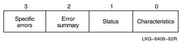
The longword contains:
Driver characteristics (byte 0)
Driver and line status (byte 1)
Driver error summary (byte 2)
Driver specific error(s) (byte 3 - not used)
The contents of these fields are described in the following sections.
D.5.1. DSB32, DSF32, DSH32, DST32, DSV11, DSW21, DSW41, and DSW42 Driver Characteristics
The driver characteristic bits govern the DDCMP operating mode. These bits are defined by the $XMDEF macro and can be set using a Set Mode function or read by a Sense Mode function).
Table D.12, ''DSB32, DSF32, DSH32, DST32, DSV11, DSW21, DSW41, and DSW42 Driver Characteristics'' lists the values and meanings of the driver characteristics.
| Characteristic | Meaning |
|---|---|
| XM$M_CHR_HDPLX | Sets half-duplex operation |
| XM$M_CHR_LOOPB | Sets loopback mode |
| XM$M_CHR_MOP | DDCMP maintenance mode |
D.5.2. DSB32, DSF32, DSH32, DST32, DSV11, DSW21, DSW41, and DSW42 Device and Line Status
These bits show the status of the driver and of the line. Set or clear these bits only when the driver and the circuit are inactive.
Table D.13, ''DSB32, DSF32, DSH32, DST32, DSV11, DSW21, DSW41, and DSW42 Device and Line Status'' lists the status values and their meanings. The values are defined by the $XMDEF macro.
| Status | Meaning |
|---|---|
| XM$M_STS_ACTIVE | Driver and selected protocol are active (indicates establishment of a link to the remote device only in full-duplex mode) |
| XM$M_STS_BUFFAIL | Receive buffer allocation failed |
| XM$M_STS_DISC | Modem disconnected. This bit is returned in the field IRP$L_IOST2 if the driver has detected an incorrect modem status. |
| XM$M_STS_DCHK | Message received with CRC error (only returned in IOSB) |
D.5.3. DSB32, DSF32, DSH32, DST32, DSV11, DSW21, DSW41, and DSW42 Error Summary
The driver error summary bits are set when an error occurs. They are read-only bits. Errors (other than XM$M_ERR_LOST) cause shutdown of the DDCMP circuit. The circuit needs to be restarted.
Table D.14, ''DSB32, DSF32, DSH32, DST32, DSV11, DSW21, DSW41 and DSW42 Error Summary'' lists the error values and their meanings.
| Error Summary Bit | Meaning |
|---|---|
| XM$M_ERR_FATAL | Hardware or software error occurred on the driver |
| XM$M_ERR_THRESH | Receive, Transmit, or Select threshold errors |
| XM$M_ERR_LOST | Data lost because longer message received than the specified maximum message size |
| XM$M_ERR_MAINT | DDCMP maintenance message received |
| XM$M_ERR_START | DDCMP start message received |
| XM$M_ERR_TRIB | Hardware or software error occurred on circuit |
D.6. Reading the Modem Signals
This function reads the current modem status. VMS provides the following combination of function code and modifier:
IO$_SENSEMODE!IO$M_CTRL!IO$M_RD_MODEM – read line unit modem status
This takes the following argument:
P1 – The address of a longword buffer which stores the modem status. One or more of the following bits can be set in the buffer:
| Bit | Meaning |
|---|---|
| XM$V_MDM_CARRDET | Receiver is active (carrier sense) |
| XM$V_MDM_CTS | Data can be transmitted (CTS) |
| XM$V_MDM_DSR | Modem is in service (DSR) |
| XM$V_MDM_RTS | Request to send data from USART (RTS) |
| XM$V_MDM_DTR | Line unit is available and on line |
D.7. The I/O Status Block
The format of the I/O status block (IOSB) for the obsolete interface is shown in Figure D.5, ''IOSB Contents''F. The format of an IOSB reporting an invalid SET MODE or SET CHAR parameter is shown in Figure D.6, ''IOSB Reporting Invalid Parameter''.
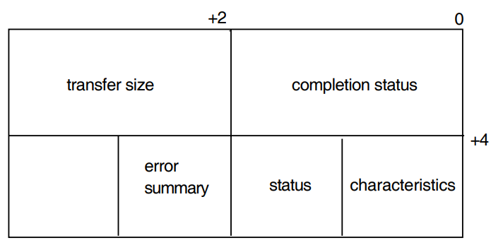
Table D.15, ''Completion Status Returns'' lists the completion status returns, and the VMS System Messages and Recovery Procedures Reference Manualprovides explanations and suggested user actions for these returns.
| SS$_ABORT | SS$_ACCVIO | SS$_BADPARAM |
| SS$_BUFFEROVF | SS$_CONNECFAIL | SS$_DEVACTIVE |
| SS$_DEVICEFULL | SS$_DEVINACT | SS$_DEVOFFLINE |
| SS$_ENDOFFILE | SS$_EXQUOTA | SS$_INSFMEM |
| SS$_NOPRIV | SS$_NOSUCHDEV | SS$_NOSUCHOBJ |
As well as the completion status, the first longword of the IOSB returns one of two values:
The size (in bytes) of the data transfer
The size (in bytes) of the extended characteristics buffer returned by a Sense Mode function
The second longword of the IOSB returns three values:
The driver characteristics (see Table D.2, ''Driver Characteristics'')
The driver and line status (see Table D.6, ''Unit and Line Status'')
The driver error summary (see Table D.7, ''Error Summary Bits'')
When the IOSB reports an invalid SET MODE or SET CHAR parameter, the format of the IOSB is as shown in Figure D.6, ''IOSB Reporting Invalid Parameter''.
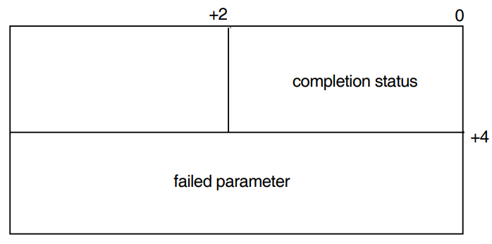
Appendix E. Management
E.1. Differences Between the V1.1 WAN Device Drivers and the V2.0 WAN Device Drivers
Many of the differences between previous versions of the WAN Device Drivers and the generic WAN Device Drivers are due to the differences between DECnet Phase IV (under which the WAN Device Drivers could not be controlled by the network manager) and DECnet/OSI (under which they can).
DECnet/OSI separates management from service. The management modules are managed by NCL, and the service interfaces are used by either Digital products or specific user programs.
The generic drivers are all controlled by a pseudo-driver (WANDRIVER) which uses the service interface to the datalink entities. There is a $QIO interface to the pseudo-driver. WANDRIVER forwards your $QIO calls through the DECnet/OSI entities to whichever device driver is applicable. For more information about WANDRIVER, see Chapter 4, "I/O Function Codes and Status Returns".
E.1.1. Integration with DECnet
Previous versions of the WAN Device Drivers were independent of DECnet: it was possible to run them without running DECnet. DECnet did not need to be involved with the drivers, although in many networks, DECnet ran over WAN Device Drivers links provided by previous versions of the WAN Device Drivers.
The generic WAN Device Drivers are integrated with DECnet. For WAN Device Drivers to run, you need only install and configure DECnet/OSI.
E.1.2. Managing the WAN Device Drivers
E.1.2.1. Using WANDRIVER
NCL gives you much more control over your network than was possible with DECnet Phase IV. The characteristics, status, and counters relating to each entity and subentity can be individually seen, and characteristics can be changed.
Because the generic WAN Device Drivers work closely with DECnet/OSI, solving operational problems with the drivers is different: NCL commands make information easier to inspect and easier to act on. In the case of modem signals, for example, in previous versions of the WAN Device Drivers (with only the obsolete interface) there was no way of reading them. With DECnet/OSI, NCL SHOW commands make information about line usage visible to the user.
E.1.2.2. Using the Obsolete Interface
Using the obsolete interface, you can, as in earlier versions, use $QIO calls to start a device in DDCMP mode (both DDCMP framing and Level 2 protocol).
- BISYNC
- HDLC
- GENBYTE
- SDLC
Starting a device creates or modifies the DECnet/OSI management entities, but this is invisible to the user. While the obsolete programming interface is in use, the network manager will be able to see (through NCL) these temporary entities:
DDCMP and MODEM CONNECT (for DDCMP-mode calls)
FRAME and MODEM CONNECT (for drivers using BISYNC, HDLC, GENBYTE or SDLC)
Note
Any attempt to manage these entities directly using NCL may lead to unpredictable failures.
E.2. NCL Commands
This section assumes that all the necessary entities (Modem Connect and any applicable datalink entity) already exist; they are created during initialization of your system. For further details about any of these commands, see the VSI OpenVMS DECnet/OSI for Open VMS Network Control Language Reference
Issuing NCL Commands for Modem Connect
To use the generic drivers by means of $QIO calls to WANDRIVER, first issue these NCL commands in order to CREATE, SET and ENABLE a Modem Connect LINE:
NCL> CREATE MODEM CONNECT LINE line-name COMMUNICATION PORT port-name
NCL> SET MODEM CONNECT LINE line-name MODEM CONTROL full|none
NCL> ENABLE MODEM CONNECT LINE line-name
Replace line-name with the name of your Modem Connect line and port-name with the name of the port that your datalink will use.
Issuing NCL Commands for DDCMP
If you are going to use the DDCMP module, you must then CREATE, SET and ENABLE a DDCMP link with a named station.
NCL> CREATE DDCMP LINK link-name PROTOCOL point|tributary
NCL> CREATE DDCMP LINK link-name LOGICAL STATION station-name
NCL> SET DDCMP LINK link-name PHYSICAL LINE MODEM CONNECT LINE line-name
NCL> ENABLE DDCMP LINK link-name LOGICAL STATION station-name
NCL> ENABLE DDCMP LINK link-name
Replace the variables like this:
| link-name | is the name you want to give to the DDCMP LINK |
| line-name | is the name of the Modem Connect LINE created with the CREATE MODEM CONNECT LINE command |
| station-name | is the name that you want to give to the LOGICAL STATION |
Doing this sets up a port. Section 2.2.1, ''Setting Up Datalinks'' and Section 2.2.2, ''Exchanging Data'' show you how to use this port.
Issuing NCL Commands for HDLC
If you are going to use the HDLC module, you must then CREATE, SET and ENABLE a HDLC link with a named station.
NCL> CREATE HDLC LINK link-name LINK TYPE balanced|primary|secondary
NCL> CREATE HDLC LINK link-name LOGICAL STATION station-name
NCL> SET HDLC LINK link-name PHYSICAL LINE MODEM CONNECT LINE line-name,-
_NCL> PREFERRED LOCAL STATION ADDRESS address
NCL> ENABLE HDLC LINK link-name LOGICAL STATION station-name
NCL> ENABLE HDLC LINK link-name
Replace the variables like this:
| link-name | is the name you want to give to the HDLC LINK |
| line-name | is the name of the Modem Connect LINE created with the CREATE MODEM CONNECT LINE command |
| address | is a number in the range 1-253 |
| station-name | is the name you want to give to the LOGICAL STATION |
Issuing NCL Commands for LAPB
If you are going to use the LAPB module, you must then CREATE, SET and ENABLE a LAPB link with a named station.
NCL> CREATE LAPB LINK link-name PROFILE profile-name
NCL> SET LAPB LINK link-name PHYSICAL LINE MODEM CONNECT LINE line-name
NCL> ENABLE LAPB LINK link-name
Replace the variables like this:
| link-name | is the name you want to give to the LAPB LINK |
| profile-name | is the name of the PROFILE you want to use |
| line-name | is the name of the Modem Connect LINE created with the CREATE MODEM CONNECT LINE command |
Issuing NCL Commands for FRAME
Even if you are using a specially written datalink protocol, you use the Frame module to integrate your datalink with DECnet/OSI.
NCL> CREATE FRAME LINK link-name PROTOCOL ddcmp|hdlc|sdlc|bisync|genbyte
NCL> SET FRAME LINK link-name PHYSICAL LINE MODEM CONNECT LINE line-name
NCL> ENABLE FRAME LINK link-name
Replace the variables like this:
| link-name | is the name you want to give to the Frame LINK |
| line-name | is the name of the Modem Connect LINE created with the CREATE MODEM CONNECT LINE command |
For further information on the Frame module, see Appendix B.
Appendix F. How to Program DSF32 Failover Sets
This section explains how to manage failover sets using the programmable interface to the SFDRIVER. The VSI DECnet/OSI for Open VMS Installation and Configuration describes failover sets and failover set management.
F.1. The $QIO Interface
The SFDRIVER supports a $QIO interface to receive system management commands. This interface is used by the WANDD$FSM utility to create and modify failover set membership information. You can use this $QIO interface to implement your own failover set management utility.
To manage a failover set, your program must first perform a $ASSIGN to allocate a channel to the appropriate SF device (the VSI DECnet/OSI for Open VMS Installation and Configuration ) describes how you create SF devices). Your program can then issue $QIO function codes to control the failover set device.
F.2. Function Codes
The SFDRIVER supports the following $QIO function codes:
IO$_CREATE
IO$_DELETE
IO$_MODIFY
IO$_ACCESS
You send a $QIO function code to the SFDRIVER to:
Describe the command you are issuing
Provide the address of a buffer (in the P1 parameter) which contains further details of the action to be performed
When calling the IO$_CREATE, IO$_DELETE, and IO$_MODIFY function codes, the address in P1 must point to a quadword buffer. When calling the IO$_ACCESS function code, the address in P1 must point to a three longword buffer.
The function codes correspond to the following Failover Set Manager commands:
IO$_CREATE for the ADD command
IO$_DELETE for the REMOVE command
IO$_MODIFY for the SET/CURRENT command
IO$_ACCESS for the SHOW command
The content of the P1 argument depends on the function code you use and this content is described in the following sections. (Where entries are ignored, the diagrams are marked with Read As Zero (RAZ).)
The symbolic codes used are supplied on the WAN Device Driver’s kit and after installation can be found in SYS$LIBRARY. The symbol files are:
WANDD$FSMDEF.MLB for MACRO programs
WANDD$FSMDEF.R32 for BLISS programs
WANDD$FSMDEF.H for C programs
F.3. Using the Failover Set Commands
This section describes how you use the failover set commands when programming the DSF32.
F.3.1. The ADD Command
The ADD command allows you to add one or two physical controllers to a failover set. Your quadword buffer must contain one entry only, detailing which physical controllers to add. Figure F.1, ''Format of Quadword Buffer'' shows the format of the quadword buffer.
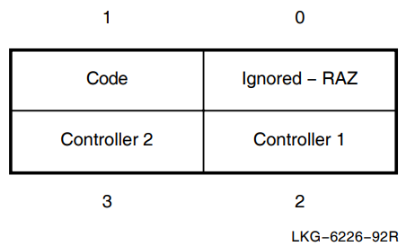
The Code byte takes the following values:
DSF$K_ITEM_PC1 where only one device is being added to the failover set.
DSF$K_ITEM_PC2 where two devices are being added to the failover set.
Use the Controller 1 and Controller 2 bytes to specify the physical controller you are adding to the failover set. When you are adding only one physical controller, the Controller 2 byte is ignored.
Use the following constants in the Controller 1 or the Controller 2 byte to specify the physical controller:
| Constant | Controller |
|---|---|
| 1 | DSF$K_PC_SMB |
| 2 | DSF$K_PC_SMC |
| 3 | DSF$K_PC_SMD |
| 4 | DSF$K_PC_SME |
| 6 | DSF$K_PC_SMG |
| 7 | DSF$K_PC_SMH |
| 8 | DSF$K_PC_SMI |
| 9 | DSF$K_PC_SMJ |
If the failover set is not empty, the SFDRIVER will ensure that only one physical controller can be added. If the failover set is already full, the SFDRIVER will reject your command. The SFDRIVER will return an invalid quadword buffer format error if any other values are found in the buffer.
F.3.2. The REMOVE Command
The REMOVE command allows you to remove one or two members from a failover set. The buffer must contain one entry, detailing which physical controllers you wish removed. The format of the quadword buffer is the same as shown in Figure F.1, ''Format of Quadword Buffer''.
The Code byte takes the following values:
DSF$K_ITEM_PC1 where only one device is being removed from the failover set. set.
DSF$K_ITEM_PC2 where two devices are being removed from the failover set.
Use the Controller 1 and Controller 2 bytes to specify the physical controller you are removing from the failover set. When you are removing only one physical controller, the Controller 2 byte is ignored.
Use the following constants in the Controller 1 or the Controller 2 byte to specify the physical controller:
| Constant | Controller |
|---|---|
| 1 | DSF$K_PC_SMB |
| 2 | DSF$K_PC_SMC |
| 3 | DSF$K_PC_SMD |
| 4 | DSF$K_PC_SME |
| 6 | DSF$K_PC_SMG |
| 7 | DSF$K_PC_SMH |
| 8 | DSF$K_PC_SMI |
| 9 | DSF$K_PC_SMJ |
F.3.3. The SET/CURRENT Command
The SET/CURRENT command allows you to change which physical controller is currently active in a failover set. The SET/CURRENT command causes a manual failover of the failover set from one physical controller to the one specified in your buffer. Figure F.2, ''Format of Individual SET/CURRENT Entry'' shows the format of the SET/CURRENT entry. Figure F.2, ''Format of Individual SET/CURRENT Entry'' shows the format of the SET/CURRENT entry.
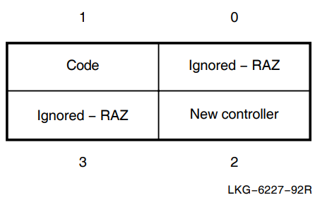
The Code byte must contain the value DSF$K_ITEM_PC.
The New Controller byte must indicate a valid physical controller: that is, one made a member of the failover set by a previous ADD command. If the New Controller byte does not indicate a valid physical controller, the SFDRIVER returns an invalid buffer error.
Use the following constants in the New Controller byte to specify the new physical controller of the failover set:
| Constant | Controller |
|---|---|
| 1 | DSF$K_PC_SMB |
| 2 | DSF$K_PC_SMC |
| 3 | DSF$K_PC_SMD |
| 4 | DSF$K_PC_SME |
| 6 | DSF$K_PC_SMG |
| 7 | DSF$K_PC_SMH |
| 8 | DSF$K_PC_SMI |
| 9 | DSF$K_PC_SMJ |
F.3.4. The SHOW Command
The SHOW command allows you to obtain information about the current state of the failover set. This command requires a three longword format item-list. The item-list consists of a series of information entries and is terminated by a longword set to zero. The format of each item-list entry is shown in Figure F.3, ''Format of Individual SHOW Entry''. The programming libraries shipped on the kit supply the structure definitions you require to access the item-list.
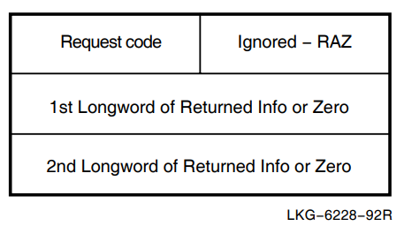
The request codes can have the following values:
DSF$K_ITEM_PC which denotes a request for Failover Set State
DSF$K_ITEM_CS which denotes a request for Cable State
DSF$K_ITEM_FS which denotes a request for Failover Set Configuration State
F.3.4.1. Failover Set State
When you request Failover Set State, the driver returns zero, one, or two longwords of information. The number of nonzero longwords returned tells you the number of members currently in the failover set. The driver will clear any longwords not used, and will not assume they are supplied as zero. The format of each longword is shown in Figure F.4, ''Failover Set State Longword''.
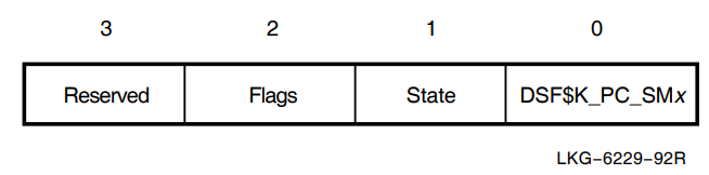
The low byte contains a constant identifying the physical device which is a member of this Failover Set. The state field contains the state of the physical unit. Possible values are listed below:
DSF$K_STANDBY which means that the physical device is standing by
DSF$K_CURRENT which means that the physical device is currently the active controller for this Failover Set
DSF$K_FAILED which means that the physical device is broken
The flags field contains the following flags:
DSF$M_INIT which means the physical device has completed its initialization successfully
F.3.4.2. Cable State
When Cable State is requested, the driver returns zero, one, or two longwords of information. One longword will be initialised for each current physical member of the failover set. The format of each longword is shown in Figure F.5, ''Cable State Longword''.
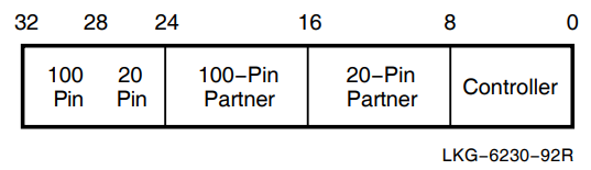
The Controller byte contains a constant identifying the physical device to which the cable state information refers.
The 20-pin Partner and 100-pin Partner bytes contain constants identifying the physical devices connected through the 20-pin and 100 pin cables, respectively.
The top byte is split into two 4-bit fields: the 20-pin field and the 100-pin field. The values in these fields indicate the current state of the 20-pin and the 100-pin connections.
For the 20-pin connection, the values are as follows:
DSF$K_20_GOOD-there is a good connection between the physical device and the partner at the other end of the 20-pin cable.
DSF$K_20_NONE-there is no 20-pin cable connection (in this case, the 20-pin byte is set to 0).
DSF$K_20_UNKNOWN-the state of the 20-pin connection is unknown (in this case, the 20-pin byte is set to 0).
For the 100-pin connection, the values are as follows:
DSF$K_100_GOOD-there is a good connection between the physical device and the partner at the other end of the 100-pin cable.
DSF$K_100_NONE-there is no 100-pin cable connection (in this case, the 100-pin byte is set to 0).
DSF$K_100_UNKNOWN-the state of the 100-pin connection is unknown (in this case, the 100-pin byte is set to 0).
F.3.4.3. Failover Set Configuration State
When Failset Configuration State is requested, the driver returns one longword of information in the second longword of the item-list. The format of this longword is shown in Figure F.6, ''Failover Set Configuration State Longword''.
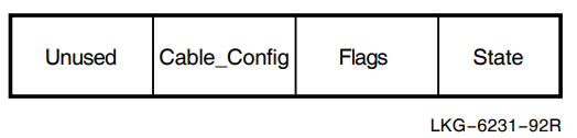
The state field describes the current state of the failover set. Possible values for this field are as follows:
DSF$K_NULL which means that the failset is empty
DSF$K_SINGLE which means that the failset contains one physical controller
DSF$K_PARTNERED which means the failset contains two physical members in separate zones
DSF$K_INVALID which means the failset state is invalid
The CABLE_CONFIG field describes the driver’s perception of the validity of the physical cabling of the failover set. Possible values which may be returned are shown below:
DSF$K_GOOD which means the cable configuration is good
DSF$K_BAD which means the cable configuration is bad
DSF$K_UNKNOWN which means the cable setup cannot be determined (for example, if one zone is stopped the cable state can not be determined)
The VSI DECnet/OSI for Open VMS Installation and Configuration describes the correct configuration of cables.
F.4. Returning Status
Figure F.7, ''Status Return IOSB'' shows the IOSB used by the driver to return its status.
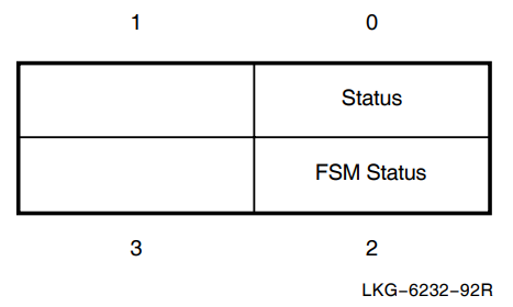
The driver returns a $QIO success (SS$_NORMAL) return status code with errors indicated in the IOSB, except for the SS$_NOOPER return, which is returned as a $QIO status.
The following status returns can be returned by the driver in the IOSB. The Status byte can return these values:
SS$_ACCVIO which means an error has been returned for an inaccessible item-list entry, as determined by a PROBEW
SS$_BADPARAM which means an error has been returned because there is a problem with the item-list format. An FSMCMD error should be returned for any error processing the item-list in the device-dependent field of the IOSB. The device dependent field of the IOSB should contain the byte offset into the item-list of the field, which is in error in the high word.
SS$_NOOPER which means that the process does not have OPER privilege
SS$_NORMAL which means successful completion of the command
If the Status byte contains SS$_BADPARAM, then the FSM Status byte contains one of these values:
FSMCMD$K_ERR_BAD_ITEMLIST which means that the item-list is in the wrong state
FSMCMD$K_ERR_BAD_LC which means invalid logical controller value
FSMCMD$K_ERR_BAD_PC which means invalid physical controller value
FSMCMD$K_ERR_DUPLICATE_INFO which means information has been requested twice in a SHOW item-list
FSMCMD$K_ERR_EMPTY_FAILSET which means you cannot remove the device from the failover set because it is already empty
FSMCMD$K_ERR_NO_LC which means that no logical controller has been specified
FSMCMD$K_ERR_NO_PC which means that no physical controller has been specified
FSMCMD$K_ERR_NOSCHDEV which means the device does not exist
FSMCMD$K_ERR_ONLY_ONE_SLOT which means two controllers are being added but there is only one slot in the failover set
FSMCMD$K_ERR_PC_ACTIVE which means the physical controller is currently active and cannot be removed
FSMCMD$K_ERR_PC_ALREADY_ACTIVE which means the physical controller is already active on a SET/CURRENT command
FSMCMD$K_ERR_PC_BROKE which means that the device driver has detected that the specified physical device is faulty
FSMCMD$K_ERR_PC_IN_USE which means that the physical controller is already in use within a failover set
FSMCMD$K_ERR_PC_NOT_IN_FAILSET which means the physical device is not in the failover set
FSMCMD$K_ERR_TOO_MANY_PCS which means there are too many PC items
FSMCMD$K_ERR_SAME_ZONE which means that same zone partnership is not allowed
Necessary only if the datalink uses the DSV11, DSB32, DSF32, DSW21, DSW41, or DSW42.
Not applicable to FRAME ports.
Applicable to FRAME Ports.
Applicable to HDLC Ports
Applicable to DDCMP Ports
Applicable to LAPB Ports
Applicable to HDLC Ports.
DEC HDLC supports Class 1 only on a full-duplex line.
DEC HDLC supports Classes 2 and 3 only on a half-duplex line.
The value of zero means that clock is disabled.
This is the default value.
The value of minus one means the highest clock speed consistent with selected protocol and cable configuration.
Not implemented by the DSF32, DSH32, DST32, DSW21, DSW41, or DSW42.