VSI DECnet-Plus for OpenVMS Network Management Guide
- Operating System and Version:
- VSI OpenVMS IA-64 Version 8.4-1H1 or higher
VSI OpenVMS Alpha Version 8.4-2L1 or higher
Preface
1. About VSI
VMS Software, Inc. (VSI) is an independent software company licensed by Hewlett Packard Enterprise to develop and support the OpenVMS operating system.
2. About This Manual
The VSI DECnet-Plus for OpenVMS Network Management Guide provides conceptual and task information about managing VSI’s DECnet-Plus product. This guide explains how to manage and monitor the network.
3. Intended Audience
This book is intended for system managers and network managers who control, monitor, or test DECnet-Plus software running on an OpenVMS operating system. This guide assumes you are familiar with your operating system, but not necessarily experienced with the DECnet-Plus product and the DECnet Phase V architecture.
4. Related Documents
DECnet-Plus for OpenVMS documentation is available in two sets:
Documentation set for DECnet-Plus for OpenVMS
Supplemental X.25 for OpenVMS documentation set
5. VSI Encourages Your Comments
You may send comments or suggestions regarding this manual or any VSI document by sending electronic mail to the following Internet address: <docinfo@vmssoftware.com>. Users who have VSI OpenVMS support contracts through VSI can contact <support@vmssoftware.com> for help with this product.
6. OpenVMS Documentation
The full VSI OpenVMS documentation set can be found on the VMS Software Documentation webpage at https://docs.vmssoftware.com.
7. Typographical Conventions
| Convention | Meaning |
|---|---|
|
Ctrl/ x |
A sequence such as Ctrl/ x indicates that you must hold down the key labeled Ctrl while you press another key or a pointing device button. |
|
PF1 x |
A sequence such as PF1 x indicates that you must first press and release the key labeled PF1 and then press and release another key or a pointing device button. |
... |
A horizontal ellipsis in examples indicates one of the
following possibilities:
|
. . . |
A vertical ellipsis indicates the omission of items from a code example or command format; the items are omitted because they are not important to the topic being discussed. |
|
( ) |
In command format descriptions, parentheses indicate that you must enclose the options in parentheses if you choose more than one. |
|
[ ] |
In command format descriptions, brackets indicate optional choices. You can choose one or more items or no items. Do not type the brackets on the command line. However, you must include the brackets in the syntax for OpenVMS directory specifications and for a substring specification in an assignment statement. |
|
[ |] |
In command format descriptions, vertical bars separate choices within brackets or braces. Within brackets, the choices are options; within braces, at least one choice is required. Do not type the vertical bars on the command line. |
|
{ } |
In command format descriptions, braces indicate required choices; you must choose at least one of the items listed. Do not type the braces on the command line. |
|
bold text |
This typeface represents the introduction of a new term. It also represents the name of an argument, an attribute, or a reason. |
|
italic text |
Italic text indicates important information, complete titles of manuals, or variables. Variables include information that varies in system output (Internal error number), in command lines (/PRODUCER= name), and in command parameters in text (where dd represents the predefined code for the device type). |
|
UPPERCASE TEXT |
Uppercase text indicates a command, the name of a routine, the name of a file, or the abbreviation for a system privilege. |
|
|
Monospace type indicates code examples and interactive screen displays. In the C programming language, monospace type in text identifies the following elements: keywords, the names of independently compiled external functions and files, syntax summaries, and references to variables or identifiers introduced in an example. |
|
- |
A hyphen at the end of a command format description, command line, or code line indicates that the command or statement continues on the following line. |
|
numbers |
All numbers in text are assumed to be decimal unless otherwise noted. Nondecimal radixes—binary, octal, or hexadecimal—are explicitly indicated. |
Chapter 1. Introduction to DECnet-Plus Network Management
Every day, a business depends on its network to exchange data in a timely, reliable fashion. A well managed network lets an enterprise accomplish common, essential, time-critical business functions. These tasks might include:
Supporting transaction processing applications, for which remote access to distributed databases is required
Disseminating corporate documents
Exchanging electronic mail messages
Whatever the task, the network is indispensable when users on multiple systems need to communicate. Consequently, understanding how to manage a DECnet Phase V network becomes vitally important to an enterprise that uses DECnet Phase V software such as DECnet-Plus for OpenVMS.
1.1. What Is Network Management?
A DECnet-Plus system needs little day-to-day management once you have installed and configured it. You might need, however, to modify the configuration occasionally to meet changing circumstances. You also need to monitor the system to make sure it is working correctly and providing the best service for its users.
This book provides information about postinstallation and postconfiguration tasks you might have to perform. For information about troubleshooting your network, refer to the VSI DECnet-Plus for OpenVMS Problem Solving Guide.
DECnet-Plus provides many network management tools you can use to manage, monitor, and troubleshoot your network. The primary tool you will use for managing your network is Network Control Language (NCL). Table 1.1, ''Network Management Tasks and Tools'' correlates major network management tasks with the appropriate tool for accomplishing that task. Table 1.1, ''Network Management Tasks and Tools'' also provides a pointer to where you can find more information about the tasks and tools.
| Task | Tool | See |
|---|---|---|
| Managing | ||
| Managing nodes in your namespace | decnet_register | Chapter 5, "Managing Name Service Searches and Information" |
| Managing the namespace | DNS$CONTROL | VSI DECnet-Plus for OpenVMS DECdns Management Guide |
| Reconfiguring network components | NET$CONFIGURE | Chapter 6, "Modifying Your Network" and VSI DECnet-Plus for OpenVMS Installation and Configuration |
| Converting Network Control Program (NCP) to NCL commands |
| |
| Setting up routing between DECnet Phase IV and Phase V areas | decnet_migrate | Chapter 4, "Managing Routing Between DECnet Phase IV and Phase V Areas" |
| Downline loading, upline dumping, and controlling remote or unattended systems | NCL and the Maintenance Operations Protocol (MOP) | Chapter 10, "Downline Loading and Upline Dumping Remote Systems" |
| Setting up network security, communications links |
NCL Network Management Graphical User Interface
( | Chapter 7, "Managing Network Security", Chapter 8, "Managing DECnet Phase V Communications", Appendix H, "Network Management Graphical User Interface (NET$MGMT)", Chapter 2, "Transitioning from NCP to NCL" |
| Setting up an OpenVMS Cluster alias |
NCL Network Management Graphical User Interface
( | Chapter 9, "Setting Up an OpenVMS Cluster Environment for DECnet-Plus", Appendix H, "Network Management Graphical User Interface (NET$MGMT)" |
| Monitoring | ||
| Reporting network events during network operation | NCL and the event dispatcher | Chapter 12, "Monitoring Network Events" |
| Collecting information about your network configuration | decnet_migrate | Chapter 3, "Checking the Network’s Configuration" |
| Displaying network status and characteristics |
NCL Network Management Graphical User Interface
( |
Chapter 11, "Monitoring the Network", Appendix H, "Network Management Graphical User Interface (NET$MGMT)" |
| Problem Solving | ||
| Testing network software and hardware by sending data through various network components and returning it | NCL and loopback tests | VSI DECnet-Plus for OpenVMS Problem Solving Guide |
| Testing network connections, disconnect messages, and interrupts and checking for data integrity | DECnet Test Sender/DECnet Test Receiver (DTS/DTR) | VSI DECnet-Plus for OpenVMS Problem Solving Guide |
| Collecting and displaying information about specific protocol exchanges between systems in the network | Common Trace Facility (CTF) | DECnet/OSI for VMS CTF Use |
1.2. Identifying Manageable Network Components
A DECnet Phase V network consists of many units (for example, systems and network components such as links) that you can manage. To allow management of large networks, the units are organized into a hierarchical structure. This structure establishes a naming scheme that allows you to deal with the complexity of large networks. It is defined here only for the purpose of uniquely identifying entities, and does not show how the entities interact with one another.
Figure 1.1, ''Entity Naming Hierarchy'' shows the DECnet entity naming hierarchy. Each computer system in a DECnet Phase V network is a top-level unit that is represented as a node entity in network management. A node entity is assigned a name that is unique throughout the network. This forms the basis for assigning names to subordinate entities in the system that will themselves have networkwide uniqueness.
Below the node entity in Figure 1.1, ''Entity Naming Hierarchy'' are module entities. Modules consist of a group of network functions that, together, provide a particular service.
Some examples of modules are Modem Connect, OSI Transport, Data Communications Message Protocol (DCMP), and High-Level Data Link Control (HDLC). There is only one occurrence of a module entity in a node.
Below the module are additional entities (or child entities of the module). These entities allow management of some part of a module’s functions. The HDLC module, for example, maintains hdlc link entities for each communications link over which the protocol operates; hdlc link is the full class name of the communication link entity. Each instance of the hdlc link entity requires further identification to allow it to be distinguished from the others. For example, in hdlc link hdlc-1, hdlc-1 is the instance name that further identifies the hdlc link.
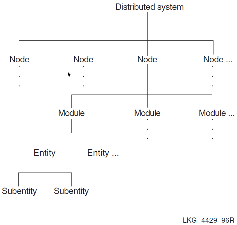
The hierarchy of entities is used to form an entity name. An entity name consists of a global part and a local part. The global part contains the node entity name, which identifies the node in the network. The local part identifies the entity within the node. The local part is derived from the class name and instance name, if applicable, of the entity itself and those of its parent entities, up to the level of the node entity.
To identify an instance of an entity, supply the information indicated by the italicized text:
| Global part | Local part |
| node node-instance | module entity-class entity-instance |
For example:
node admin hdlc link hdlc-1
This syntax is similar to a fully specified mailing address, where the order of addressing might consist of the country, state, city, street, house and individual. All the components of the mailing address are needed to uniquely identify the recipient of the mail. Regarding DECnet Phase V networks, you must include all parts of the entity name to uniquely specify the precise unit being managed.
1.3. Modules and Entities
DECnet-Plus software implements the DECnet Phase V layered model. For each layer, DECnet-Plus software provides one or more modules, each of which implements a specific protocol and provides a corresponding service within the system. Each module is divided into entities that permit management of some part of the module’s function.
Any modifications that you make to a DECnet-Plus system involve changing or adding to the network management information on the system. To perform network management tasks, you manipulate entities in the various modules.
For example, the Modem Connect module holds information for synchronous communications devices attached to a system. Figure 1.2, ''Modem Connect Module'' shows a typical module (Modem Connect) and its entities. The line entity in Modem Connect contains all the information (such as line speed, duplex, errors detected, and current state) about a particular communications line. A line entity exists for each communications line on the system.
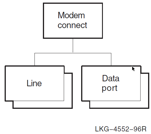
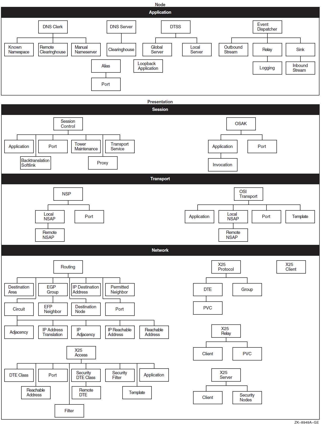
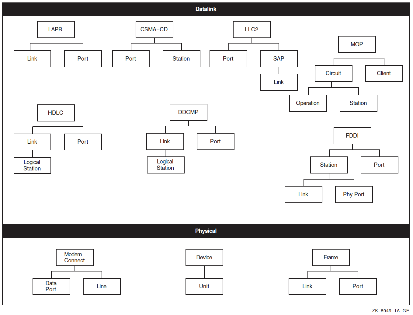
Figure 1.3, ''Entity Hierarchy and the Upper Layers'' and Figure 1.4, ''Entity Hierarchy and the Lower Layers'' show the entity hierarchy structure for each module within each layer of the DECnet Phase V layered model.
To manage a system effectively, you need to know which module and entity contain what information. Table 1.2, ''Management Tasks and Related Network Management Modules'' summarizes the main tasks you can perform with each module. It includes names of entities in the module.
| Tasks | Module | Entities |
|---|---|---|
| Enable or disable the system for networking. | Node | node |
| Manage modem connections. | Modem Connect | modem connect, call control port,
data port, line,
template |
| Manage downline loads and upline dumps of soft-loadable microcode devices, such as DSF. | Device | device, unit |
| Manage Ethernet CSMA-CD connections. | CSMA-CD | csma-cd, port, station |
| Manage fiber-optic data transmission. | FDDI | fddi, link, phy port,
station |
| Manage synchronous or asynchronous DDCMP connections. | DDCMP | ddcmp, link, link logical
station, port |
| Manage synchronous HDLC connections. | HDLC | hdlc, link, link logical
station, port |
| Manage X.25 level 2 protocol to exchange frames between a DTE and a DCE. | LAPB | lapb, link, port |
| Manage X.25 level 2 protocol for communications over a LAN. | LLC2 | llc2, port, sap, sap
link |
| Manage X.25 level 2 protocol for communications over TCP/IP connections (OpenVMS IA-64 and OpenVMS Alpha only) | XOT | xot, sap, link |
| Manage framing functions for a communications link. | Frame | frame, link, port |
| Manage routing for end node and intermediate node configurations. | Routing | routing, circuit, circuit
adjacency, circuit ip address translation,
circuit ip adjacency, circuit ip reachable
address, circuit reachable address,
destination area, destination node,
ip destination address, permitted
neighbor, port, reachable address |
| Manage downline loads and upline dumps of dedicated communications server systems. | MOP | mop, circuit, circuit
operation, circuit station,
client |
| Manage transport between DECnet Phase V nodes, and DECnet Phase V nodes and multivendor OSI systems. | OSI Transport | osi transport, application, local
nsap, local nsap remote nsap, port,
template |
| Manage transport between DECnet Phase V nodes, and between DECnet Phase V nodes and Phase IV nodes. | NSP | nsp, local nsap, local nsap remote
nsap, port |
| Manage proxies, applications, and processes using the network. | Session Control | session control, application,
port, tower maintenance, transport
service |
| Invoke loopback tests between applications on two nodes. | Loopback Application | loopback application |
| Log events about network operations. | Event Dispatcher | event dispatcher, outbound stream,
relay, relay logging, sink,
sink inbound stream |
| Manage an X.25 user interface. | X25 Access | x25 access, application, dte
class, filter, port,
reachable address, security dte class,
security dte class remote dte, security
filter, template |
| Manage how an X.25 client system operates. | X25 Client | x25 client |
| Manage DTEs, PVCs, and CUGs to control packet exchange between DTEs and DCEs. | X25 Protocol | x25 protocol, dte, dte,
pvc, group |
| Manage incoming and outgoing switched virtual calls. | X25 Relay | x25 relay, client, pvc |
| Manage how X.25 Connector systems communicate with client systems. | X25 Server | x25 server, client, security
nodes |
| Manage Open System Application Kernel (OSAK) software, VSI’s implementation of the OSI upper layers. | OSAK | osak, application, invocation,
port |
| Manage namespace and clearinghouse characteristics for the VSI DECnet-Plus Distributed Name Service (DECdns) clerk. | DNS Clerk | dns clerk, known namespace, manual
nameserver, remote clearinghouse |
| Manage clearinghouse characteristics for the DECdns server. | DNS Server | dns server, clearinghouse |
| Manage system clocks for the VSI DECnet-Plus Distributed Time Service (DECdts) server. | DTSS | dtss, decnet global server, decnet
local server |
| Establish an alias for an OpenVMS Cluster environment. | Alias | alias, port |
To manage entities, you issue directives (commands) using NCL. The commands enable you to manage local or remote network components by identifying entities throughout the network by their unique entity names. For instance, you can create, examine, and modify entities.
For definitive information about modules, entities, and supported attributes, characteristics, status, counters, and commands, refer to the VSI DECnet-Plus for OpenVMS Network Control Language Reference Guide.
Note
DECnet Phase IV and Phase V differ in how network components are managed. Chapter 2, "Transitioning from NCP to NCL" provides information on converting Network Control Program (NCP) commands to Network Control Language (NCL) commands. Appendix A, "DECnet Phase IV Components and Corresponding Phase V Entities" provides a table of Phase IV components and parameters and their equivalent DECnet Phase V entities and attributes.
1.4. DECnet Phase V Configurations
DECnet Phase V networks can be organized as local area networks (LANs) or wide area networks (WANs) or a combination of the two. A LAN provides for communications within a limited geographical area, such as a building or a cluster of buildings. A WAN permits long-distance communication over media such as dedicated, leased and dialup lines, and microwave and satellite links. A WAN can include one or more LANs.
DECnet-Plus allows you to manage the following local and wide area links:
LAN connections using Carrier Sense, Multiple Access with Collision Detect (CSMA-CD) protocol. DECnet-Plus supports the Ethernet protocol and the IEEE 802.3 standard.
LAN connections using the Fiber Distributed Data Interface (FDDI) protocols.
WAN connections using the High-Level Data Link Control (HDLC) protocol.
WAN connections using the Data Communications Message Protocol (DCMP).
1.4.1. DECnet Phase V Configurations
WAN connections using X.25 (level 2) data link capability over the Link Access Protocol Balanced (LAPB) protocol.
LAN connections using X.25 (level 2) data link capability over the Logical Link Control type 2 (LLC2) protocol.
LAN/WAN connections using X.25 (level 2) data link capability over Transmission Control Protocol/Internet Protocol networks (XOT).
For more detailed descriptions of DECnet-Plus network configurations, refer to the VSI DECnet-Plus Planning Guide and the VSI DECnet-Plus for OpenVMS Introduction and User's Guide.
Chapter 2. Transitioning from NCP to NCL
In a Phase IV network, you use the Network Control Program (NCP) to configure, control, monitor, and test the network. In a DECnet Phase V network, you use the Network Control Language (NCL) to perform the same tasks. For an introduction to NCL, refer to the VSI DECnet-Plus for OpenVMS Network Control Language Reference Guide. This chapter describes ways to convert NCP commands to NCL commands for use on DECnet Phase V nodes.
2.1. Using decnet_migrate to Convert NCP Commands to NCL Commands
Command procedures that issue NCP commands to manage the local node do not work in the DECnet Phase V environment. Similarly, command procedures that issue NCP commands to a remote node do not work if the remote node has been upgraded to DECnet Phase V software. Do the following to revise any command procedures that issue NCP commands:
To use the procedure to issue the commands to Phase IV nodes, run the procedure from NCP:
$ run sys$system:ncp NCP>
To use the procedure to issue commands to DECnet Phase V systems, change the NCP commands to NCL commands.
VSI supplies a tool, decnet_migrate, that converts NCP commands to NCL
commands when possible. The tool converts individual NCP commands to NCL commands, and
NCP commands within command procedures to NCL commands.
Three decnet_migrate convert commands convert NCP commands to NCL equivalents, where equivalents exist. The command conversion might not be complete because of the differences between NCP and NCL. You might have to edit the NCL command before you can use it. For example, this applies to Phase IV components that have new entity names for DECnet Phase V. In the output that convert generates, the parts of the commands that cannot be converted are set off in tripple curly brackets.
Table 2.1, ''NCP Commands That Are Converted to NCL'' lists the NCP commands that the
decnet_migrate convert commands can convert to NCL. Many NCP commands
have NCL equivalents or near equivalents. See Appendix A, "DECnet Phase IV Components and Corresponding Phase V Entities" for
a list of NCP commands with their nearest NCL equivalents. For an alphabetical command
reference for decnet_migrate, see Appendix C, "decnet_migrate Commands".
You may also use the Language-Sensitive Editor (LSE) to assist you when writing procedures that contain NCL commands (see Section 2.1.1.4, ''Editing a Command File That Contains NCL Commands'').
| Verb | Entity | Attribute or Argument |
|---|---|---|
tell | node_name | command_to_convert |
set
or
clear | executor |
|
show | executor |
|
loop | executor |
|
show |
|
|
trigger | node
or
via |
|
load | node
or
via |
|
loop | node |
|
set or clear |
|
|
show |
|
|
loop | circuit |
|
set
or
clear |
|
|
load |
|
|
loop | node |
|
set or clear |
|
|
show |
|
|
loop | circuit |
|
set
or
clear |
|
|
show |
|
|
show |
|
|
set
or
clear |
|
|
show |
|
|
show |
|
|
2.1.1. Running decnet_migrate on Your System
Invoke decnet_migrate by entering the following command:
$ run sys$update:decnet_migrate2.1.1.1. Converting an NCP Command to an NCL Command
The following example shows how to convert a single NCP command to its closest equivalent.
decnet_migrate> convert command "ncp-command"To convert to NCL, replace ncp-command with the NCP command exactly as if it were entered at the NCP> prompt and enclose the command in quotation marks. After you execute the command, the output of the convert command appears on your terminal.
For more information about the convert command, see Appendix C, "decnet_migrate Commands".
2.1.1.2. Converting NCP Commands in a DCL Command File to NCL
The following example shows how to convert NCP commands contained within a DCL command procedure to their closest NCL command equivalent within the procedure.
decnet_migrate> convert dcl_file input_file [to output_file]
For more information about the convert dcl_file command, see Appendix C, "decnet_migrate Commands".
2.1.1.3. Converting NCP Commands in an NCP Command File to NCL
The following example shows how to convert NCP commands contained within an NCP command procedure to their closest NCL command equivalent within the procedure.
decnet_migrate> convert ncp_file input_file [to output_file]
For more information about the convert ncp_file command, see Appendix C, "decnet_migrate Commands".
2.1.1.4. Editing a Command File That Contains NCL Commands
The following example shows how to invoke the Language-Sensitive Editor (LSE) with the edit command. You automatically set up LSE by specifying .COM or .NCL file extensions for the NCL command file that you are editing.
Note
The LSE layered product must be installed and licensed on your system. For more information about LSE, see the Guide to Language-Sensitive Editor.
The initial placeholder used to start expanding a command is {NCL_SCRIPT}.
decnet_migrate> edit file-nameFor more information about the edit command, see Appendix C, "decnet_migrate Commands".
2.2. Using the Graphical User Interface for DECnet Phase V Network Management
You can access NCL either through a command line interface or through the graphical user interface (GUI). The GUI allows network managers to view the status of network components and control those components from a Motif-based window interface located at SYS$SYSTEM:NET$MGMT.EXE.
The NET$MGMT GUI utility is a Motif application that you can use as a learning tool to ease the transition to NCL. This utility can help you become familiar with the DECnet Phase V hierarchy of manageable components (modules, entities, and subentities) and with NCL syntax.
The NET$MGMT GUI utility can also perform some task-oriented functions that involve many NCL commands or functions that are complex in some way. It provides a way to perform the equivalent of ncp show known links and ncp show known node counters on a Phase V system.
Refer to Appendix H, "Network Management Graphical User Interface (NET$MGMT)" for more information about the NET$MGMT GUI.
2.3. Using the NCP Emulator to Convert NCP Commands to NCL
Many VSI software products must register themselves with the network during their installation. Some of these products issue NCP commands during the installation. The NCP Emulator converts the NCP commands to NCL commands.
The NCP Emulator is designed to facilitate software installations on DECnet Phase V systems; it is not intended as a replacement for NCL. The NCP Emulator supports conversion for the NCP commands listed in Table 2.2, ''NCP Commands Converted by the NCP Emulator''.
To have session control applications registered when you install them, you must have the following identifiers:
NET$MANAGENET$EXAMINE
The following example shows how to set up these identifiers. This example assumes you are installing the applications from the SYSTEM account.
$ SET DEF SYS$SYSTEM $ RUN AUTHORIZE UAF> GRANT/ID NET$EXAMINE SYSTEM %UAF-I-GRANTMSG, identifier NET$EXAMINE granted to SYSTEM UAF> GRANT/ID NET$MANAGE SYSTEM %UAF-I-GRANTMSG, identifier NET$MANAGE granted to SYSTEM UAF> EXIT %UAF-I-NOMODS, no modifications made to system authorization file %UAF-I-NAFNOMODS, no modifications made to network proxy data base %UAF-I-RDBDONEMSG, rights data base modified $
In addition, ensure that the following NCP Emulator private command files are added to, and run from, the site-specific system startup file:
SYS$MANAGER:NET$NCP_MOP_CLIENTS.COMSYS$MANAGER:NET$NCP_APPLICATIONS.COMSYS$MANAGER:NET$NCP_MOP_CIRCUITS.COM
Note
The NCP Emulator attempts to communicate with the NET$MOP component
of your DECnet Phase V system. Therefore, before invoking the NCP Emulator, ensure
that the NET$MOP process is running (see Section 10.3, ''Starting MOP'' for information about starting MOP).
| Verb | Entities |
|---|---|
CLEAR |
|
DEFINE |
|
PURGE |
|
SET |
|
SHOW/LIST |
|
TELL |
All other NCP commands are unsupported and will cause an %NCP-W-SYSMGT error message. Some of these unsupported NCP commands have corresponding NCL commands that perform identical operations. Table 2.3, ''Equivalents for Unsupported NCP Commands'' lists the equivalent NCL command for each of these unsupported NCP commands.
| NCP Command | NCL Equivalent |
|---|---|
CONNECT | set host/mop |
LOAD |
load mop circuit load mop client |
LOOP CIRCUIT |
loop mop circuit loop mop client |
TRIGGER |
boot mop circuit boot mop client |
2.3.1. Information About Supported NCP Commands
This section includes special notes about the NCP commands that the NCP Emulator tool supports.
SHOW/LIST Command
In DECnet Phase IV NCP, the SHOW command displays the volatile database information (information on the running system), while the LIST command displays the permanent database information. Using the DECnet Phase V NCP Emulator, both of these commands are converted to display volatile database information. NCL has no command that displays permanent database information. In addition, the output for these commands differs slightly between DECnet Phase IV NCP and the DECnet Phase V NCP Emulator.
SET Command
The NCP SET command usually spawns an equivalent NCL command. If the NCP SET command specifies the name of a component that does not exist, usually the spawned NCL command creates an entity with that name, just as the NCP command does.
You can use node numbers as the target of the SET command, such as in the following example:
SET NODE 12.88 LOAD FILE LOAD.SYS
If you use a node number as the target, and if a mop client does not already exist with a matching PHASE IV CLIENT ADDRESS (or ADDRESSES) attribute, the NCP Emulator checks DECdns for a synonym. If a synonym is found, the NCP Emulator uses the synonym as the name of the mop client when it is created.
You can specify NAME as part of the SET command as in the following example:
SET NODE 12.88 NAME ROYK
The name is used as the mop client name.
The SET KNOWN NODE/CIRCUIT/OBJECT ALL command executes both the standard NCL startup script and the private command procedure maintained by the NCP Emulator. If you use only SET ALL on a specific named entity, the NCP Emulator executes the private command file.
DEFINE Command
The DEFINE command writes NCL commands to the private script files. When using the command to define nodes, if you specify the node address, the NCP Emulator searches the script file for a client with the corresponding address.
If the NCP Emulator does not find a corresponding address, and if you did not specify the NAME parameter in the same command, the emulator checks DECdns for a node synonym. If you specify the NAME parameter later, the mop client is renamed.
The NCP Emulator does not support the NCP DEFINE KNOWN command.
CLEAR Command
The CLEAR command clears a parameter or a set of parameters in the corresponding NCL entity instance. The CLEAR ALL command deletes the instance.
PURGE Command
The PURGE command removes the SET command for a parameter from the private script file. The PURGE ALL command removes the entire object.
The NCP Emulator does not support the NCP PURGE KNOWN command. Because the PURGE command operates only on the NCP
Emulator private command file, use NET$CONFIGURE to purge objects from the standard system applications or mop clients scripts (SYS$MANAGER:NET$APPLICATION_STARTUP.NCL and SYS$MANAGER:NET$MOP_CLIENT_STARTUP.NCL).
TELL Command
The TELL command functions as it does in DECnet Phase IV, allowing you to remotely manage Phase IV nodes. For more information on how to remotely manage Phase IV nodes by using the NCP Emulator, see Section 2.3.4, ''Remotely Managing DECnet Phase IV Nodes''.
SET EXECUTOR NODE Command
The SET EXECUTOR NODE command works as expected for managing Phase IV nodes.
2.3.2. Information About Supported NCP Components
The NCP Emulator supports all NCP components except the following:
AREALINESLINKSLOGGINGCONFIGURATORX.25/X.29modules
If you attempt an operation with one of these unsupported components, you will
receive the %NCP-W-UNRCMP error message or, with the AREA or LINKS
components, a message stating that no information exists for these components in the
database.
The remainder of this section includes special notes about the supported NCP components.
EXECUTOR Component
The NCP Emulator supports only the SHOW and LIST commands with the EXECUTOR component. It does not change or clear any EXECUTOR parameters.
The only relevant EXECUTOR parameters are NAME and ADDRESS. The Identification displayed with the SHOW EXECUTOR command indicates that the node is DECnet-Plus, but the executor type is displayed as "nonrouting IV."
NODE Component
The DECnet Phase IV NODE component usually corresponds to the NCL mop client entity, since a product installation usually requires that type of information. You can reference a node by name, which results in a look-up in the mop client database. If the NCP Emulator does not find a name, it checks DECdns for a node synonym with that name and the corresponding DECnet Phase IV address.
If you refer to a node by node number, the NCP Emulator first searches the mop client database for a client with a PHASE IV CLIENT ADDRESS attribute matching the specified node address. If it finds a client with a matching address, the corresponding client name becomes the node name. If the emulator does not find a matching address, it then searches for a client that has, as one of its ADDRESSES attributes, an address that begins with AA-00-04-00 and translates to the specified address. If it still cannot find a matching address, the emulator uses DECdns. Because referencing nodes by address is not efficient, VSI recommends that you avoid doing so.
With the NCP Emulator, KNOWN NODES refers to all NCL mop client entities. The NCP Emulator maps MOP-related parameters only. For example, it maps the following DECnet Phase IV SET NODE command parameters to the corresponding NCL mop client attributes:
DIAGNOSTIC FILEDUMP_FILEHARDWARE ADDRESSLOAD_ASSIST_AGENTLOAD_ASSIST_PARAMETERLOAD_FILEMANAGEMENT FILESECONDARY LOADERSERVICE_CIRCUITSERVICE_DEVICESERVICE_NODE_VERSIONSERVICE_PASSWORDTERTIARY LOADER
DECnet Phase IV node parameters such as ACCESS and COUNTER TIMER have nothing to do with NCL MOP, so they are ignored during the translation from NCP to NCL.
The NCP Emulator does not attempt to set, clear, purge, or define any other parameter. Permanent database operations (DEFINE, PURGE, SET ALL) manipulate the NCP private command file SYS$MANAGER:NET$NCP_MOP_CLIENTS.COM.
OBJECT Component
The NCP OBJECT component maps to the NCL session control applications entity. The permanent database for objects is the NCP private command file SYS$MANAGER:NET$NCP_APPLICATIONS.COM.
CIRCUIT Component
The NCP CIRCUIT component refers to the NCL csma-cd station and mop circuit entities. The SHOW KNOWN CIRCUITS command will list all of the csma-cd station entities currently configured.
Only two circuit characteristics are used by the NCP Emulator: STATE and SERVICE. The STATE characteristic determines whether MOP will service requests from that circuit. It is determined by the csma-cd station state attribute. The NCP Emulator can change the STATE parameter from Off to On but not from On to Off.
The SERVICE parameter indicates whether a mop circuit exists and whether the service is enabled. The parameter also is used to enable or disable the service, such as with the NCP SET CIRCUIT SERVICE ENABLED command.
The NCP Emulator uses the mop circuit entity that is linked to the data link circuit.
Circuit names are always of the form "ddd-u", where "ddd" indicates the device type (such as SVA and BNA) and "u" indicates the controller (0 or 1, for example).
The naming scheme is the same scheme used with NCP. The NCP Emulator attempts to translate a circuit name to the correct csma-cd station and mop circuit, regardless of their actual names used with NCL. For example, the circuit name SVA-0 translates to the station whose COMMUNICATIONS PORT attribute is "ESA" and to the mop circuit whose LINK NAME attribute refers to the station with "ESA". The name BNA-1 translates to the station with "ETB."
Enabling the SERVICE parameter on a circuit first creates (if necessary) the appropriate csma-cd station and/or mop circuit, and then enables the LOAD SERVER, DUMP SERVER, and CONSOLE REQUESTER functions on the mop circuit. Disabling SERVICE disables the same functions on the mop circuit.
The circuits command procedure is SYS$MANAGER:NET$NCP_MOP_CIRCUITS.COM.
2.3.3. Running the NCP Emulator on Your System
Use the following command to run the NCP Emulator. The NCP Emulator will prompt you for an NCP command, as shown in the following example:
$ run sys$system:ncp NCP>
2.3.4. Remotely Managing DECnet Phase IV Nodes
You can use the NCP Emulator tool to manage remote Phase IV nodes with the TELL and SET EXECUTOR NODE commands. For example, to zero EXECUTOR counters on a remote Phase IV node from a local Phase V node, enter the following commands:
$ run sys$system:ncp NCP> tell remnod "account password" zero exec counters
The NCP Emulator tool is not intended for management of Phase V nodes. The following error is returned when an NCP Emulator command is attempted on a Phase V system without specifying a remote Phase IV system:
NCP> zero exec counters %NCP-W-SYSMGT, System-specific management function not supported
Chapter 3. Checking the Network’s Configuration
Before you begin to change your network’s configuration, make sure you have a clear picture of the network’s current topology. Two decnet_migrate commands, collect and report, gather and organize information about the DECnet Phase IV and Phase V nodes and connections in your network. A third command, show path, displays the possible paths that node-to-node communication might take through the network, helping to determine what effect the transition has had on the network’s communication paths.
Note
You need network management privileges that allow you to display information for each remote node in the network, so the collect and show path commands can gather information from the nodes. You also need the same privilege for the local node.
3.1. Determining Your Network Topology
The collect and show path commands operate by sending network management requests. They use the Network Information and Control Exchange (NICE) Protocol and the Network Architecture Common Management Information Protocol (NA CMIP); they do not use the Simple Network Management Protocol (SNMP). The collect and show path commands can succeed only when the nodes are able to respond to either NICE or DNA CMIP network management requests. The commands do not work, for example, if the nodes respond only to SNMP requests.
For collect, if an area contains both routers that do and do not respond to NICE or
DNA CMIP requests, you can collect information about the area by using the
area=node:node_name parameter and specifying
the node name of a router that does respond to NICE or DNA CMIP requests.
This use of the area parameter is useful when an area contains only a few routers, such as cluster alias routers, that respond to NICE or DNA CMIP. The collected data will not, however, contain information on nodes that do not respond to NICE or DNA CMIP requests, other than their network addresses. Invoke decnet_migrate on OpenVMS systems by entering the following command:
$ run sys$update:decnet_migrate
3.1.1. Determining Your Network Topology
The following example shows how to collect and report information about your network configuration:
decnet_migrate> collect data_filedecnet_migrate> report report_file data=data_file
| Collects all information about your network and places it in a data file. |
| Reports information gathered with the collect command. In this example, the data is supplied from the data file and reported in a report file. |
The following example shows how to use the show path command:
decnet_migrate> show path from node-name to node-name
For more information and an example output of the collect, report, and show path commands and their associated parameters, see Appendix C, "decnet_migrate Commands".
3.1.2. Determining the DECnet Version of Your System
Either DECnet Phase IV or DECnet-Plus for OpenVMS (Phase V) can run on a particular system; thus, you cannot use the OpenVMS version to determine which software version is running. Instead, an item code for the $GETSYI system service (DECNET_VERSION) shows the version of DECnet that is running. The system cell containing the setting of this value is set by SYS$NETWORK_SERVICES when the system boots. You can read the value directly with a program or through the F$GETSYI lexical function with a command procedure. The DECNET_VERSION item has the following format:
Byte 0 = User ECO (dependent on the DECnet software ECO level)
Byte 1 = DECnet Minor (dependent on the DECnet software version)
Byte 2 = DECnet Major (4 for Phase IV, 5 for DECnet-Plus for OpenVMS)
Byte 3 = Reserved
To distinguish Phase IV from DECnet-Plus for OpenVMS, use the DECnet Major (byte 2).
For example, the lexical function F$GETSYI ("decnet_version") returns the value %X00040000 for a system running Phase IV. DECnet/OSI for OpenVMS Version 6.3 returns %X0005090F.
Note
See the footnote in Table 3.1, ''$GETSYI DECNET_VERSION Item Code Values'' for important information about the non-standard use of the DECnet Minor and User ECO fields in certain versions of DECnet-Plus.
Any program or command procedure that requires different execution based on the DECnet version should check DECNET_VERSION.
The format of the version longword is as follows:
|Reserved|DECnet Major|DECnet Minor|User ECO| 31 0
Table 3.1, ''$GETSYI DECNET_VERSION Item Code Values'' shows all the DECNET_VERSION item code values used for the various releases of DECnet/OSI and DECnet-Plus.
| Value | DECnet Version |
|---|---|
| 00051200 | DECnet-Plus Version 8.2 |
| 00051100 | DECnet-Plus Version T8.1 |
| 00051001 | DECnet-Plus Version 7.3-2 (+ ECO 01)? |
| 00051000 | DECnet-Plus Version 7.3-2? |
| 00050F03 | DECnet-Plus Version 7.3-1 (+ ECO 03)? |
| 00050500 | DECnet-Plus Version 7.3-1 (+ ECO 02)? |
| 00050E05 | DECnet-Plus Version 7.3-1 (+ ECO 01) |
| 00050E04 | DECnet-Plus Version 7.3-1 |
| 00050E07 | DECnet-Plus Version 7.3 (+ ECO 04) |
| 00050E06 | DECnet-Plus Version 7.3 (+ ECO 03) |
| 00050E02 | DECnet-Plus Version 7.3 (+ ECO 02) |
| 00050E01 | DECnet-Plus Version 7.3 (+ ECO 01) |
| 00050E00 | DECnet-Plus Version 7.3 |
| 00050D07 | DECnet-Plus Version 7.2-1 (+ ECO 06) |
| 00050D06 | DECnet-Plus Version 7.2-1 (+ ECO 05) |
| 00050D05 | DECnet-Plus Version 7.2-1 (+ ECO 04) |
| 00050D04 | DECnet-Plus Version 7.2-1 (+ ECO 03) |
| 00050D03 | DECnet-Plus Version 7.2-1 (+ ECO 02) |
| 00050D02 | DECnet-Plus Version 7.2-1 (+ ECO 01) |
| 00050D01 | DECnet-Plus Version 7.2-1 |
| 00050D00 | DECnet-Plus Version 7.2 |
| 00050C07 | DECnet-Plus Version 7.1 (+ ECO 07) |
| 00050C06 | DECnet-Plus Version 7.1 (+ ECO 06) |
| 00050C05 | DECnet-Plus Version 7.1 (+ ECO 05) |
| 00050C04 | DECnet-Plus Version 7.1 (+ ECO 04) |
| 00050C03 | DECnet-Plus Version 7.1 (+ ECO 03) |
| 00050C02 | DECnet-Plus Version 7.1 (+ ECO 02) |
| 00050C01 | DECnet-Plus Version 7.1 (+ ECO 01) |
| 00050C00 | DECnet-Plus Version 7.1 |
| 00050B02 | DECnet/OSI Version 7.0 (+ ECO 2) |
| 00050B01 | DECnet/OSI Version 7.0A MUP |
| 00050B00 | DECnet/OSI Version 7.0 |
| 0005090F | DECnet/OSI Version 6.3 (+ ECO 15) |
| 0005090E | DECnet/OSI Version 6.3 (+ ECO 14) |
| 0005090D | DECnet/OSI Version 6.3 (+ ECO 13) |
| 00050912 | DECnet/OSI Version 6.3 (+ ECO 12)? |
| 00050911 | DECnet/OSI Version 6.3 (+ ECO 11)? |
| 00050910 | DECnet/OSI Version 6.3 (+ ECO 10)? |
| 00050909 | DECnet/OSI Version 6.3 (+ ECO 09) |
| 00050908 | DECnet/OSI Version 6.3 (+ ECO 08) |
| 00050907 | DECnet/OSI Version 6.3 (+ ECO 07) |
| 00050906 | DECnet/OSI Version 6.3 (+ ECO 06) |
| 00050905 | DECnet/OSI Version 6.3 (+ ECO 05) |
| 00050904 | DECnet/OSI Version 6.3 (+ ECO 04) |
| 00050903 | DECnet/OSI Version 6.3 (+ ECO 03) |
| 00050902 | DECnet/OSI Version 6.3 (+ ECO 02) |
| 00050901 | DECnet/OSI Version 6.3 (+ ECO 01) |
| 00050900 | DECnet/OSI Version 6.3 |
Note that this table is provided for informational purposes only. The presence of a version in this table does not imply that the version is still supported by VSI.
Chapter 4. Managing Routing Between DECnet Phase IV and Phase V Areas
DECnet Phase IV routers and DECnet-Plus host-based routers use a routing vector protocol to relay messages and exchange routing information. DECnet Phase V routing also features a link state routing protocol. These two protocols can coexist in the network.
All routers within an area must use the same routing protocol at level 1. However, DECnet Phase V allows level 2 routers to run either a routing vector or a link state protocol at level 2. Routers running different protocols at level 2 can communicate through interphase links. An interphase link directly connects a level 2 router using a routing vector protocol with a level 2 router using a link state protocol. DECnet Phase V routers running link state use manually configured reachable-address tables to route information across these interphase links.
Note
Interphase links require the two areas connected by the interphase link to have different area numbers.
4.1. Setting Up Interphase Links
You can set up interphase links in one of two ways: if available, use the configuration program on your dedicated router system as described in your router documentation, or use the decnet_migrate tool’s create ipl_initialization_file command, as described in this chapter. Choose only one method, following these guidelines:
Use the configuration program on your dedicated router systems if your network configuration is simple and you have only a few interphase links to set up.
Use the decnet_migrate create ipl_initialization_file command if your network configuration is complex and you have many interphase links to set up. This command automatically produces the NCL commands to create the links.
Invoke decnet_migrate by entering the following command:
$ run sys$update:decnet_migrate
The following example shows how to create a command file that creates interphase link entries:
decnet_migrate> create ipl_initialization_file output-file
| Specifies the name of the command file you want to create. |
| Specifies the name of the DECnet Phase V level 2 routing node on which you want to create interphase link entries. |
For more information about the create ipl_initialization_file command, see Appendix C, "decnet_migrate Commands". The following sections provide more information about setting up interphase links.
4.2. Configurations That Do Not Require Manually Created Interphase Links
The simplest configuration that connects DECnet Phase V link-state subnetworks to Phase IV routing-vector subnetworks is one in which only two subnetworks are connected, with only one area in each subnetwork, as shown in Figure 4.1, ''Configuration with Adjacent Areas''.
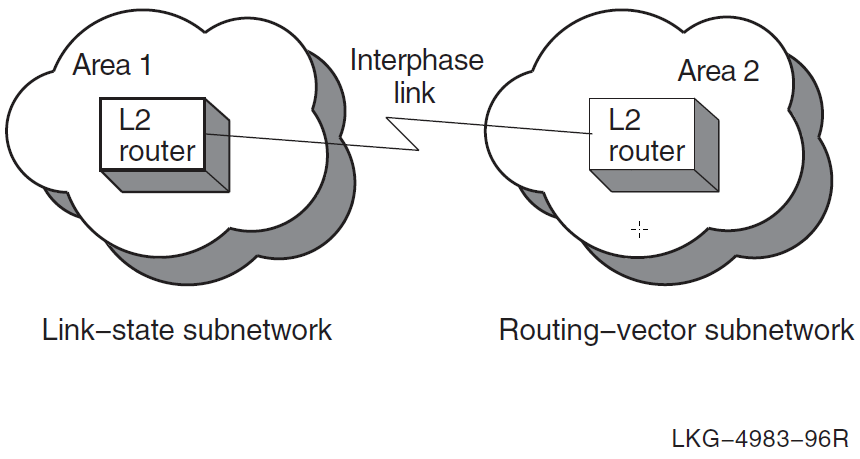
In this case, you are not required to manually create the interphase link because the adjacent areas automatically configure to each other.
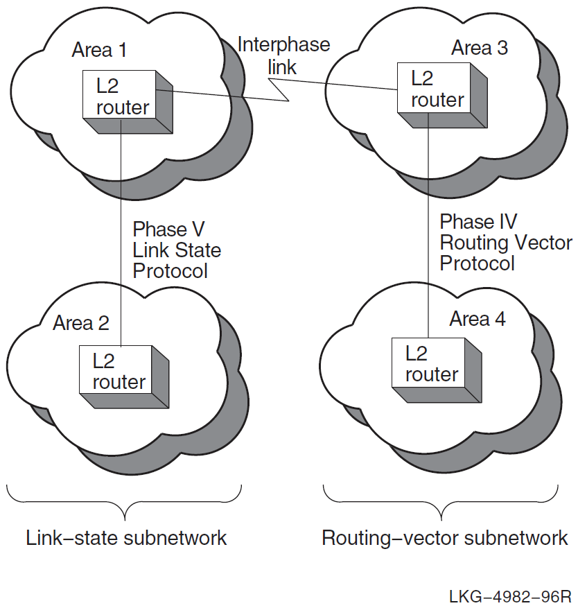
4.3. Configurations That Require Manually Created Interphase Links
If either subnetwork contains more than one area, or if multiple subnetworks are interconnected, you must create interphase links to provide routing information about the nonadjacent areas.
For small networks (for example, with three or four areas), you can enter the interphase link information into the reachable-address tables using the appropriate router configuration tools. For details, see the management documentation for your router.
For larger networks, you can use the create ipl_initialization_file command to create a DCL command file. When executed, the command file creates interphase link entries in the reachable-address table on the target DECnet Phase V level 2 router. Whenever the level 2 network configuration changes, VSI recommends that you use the create ipl_initialization_file command for every DECnet Phase V level 2 router that has interphase links.
Figure 4.2, ''Configuration Requiring Manually Created Interphase Links'' shows a level 2 network configuration that requires manually created interphase links, because areas 2 and 4 are nonadjacent and, therefore, do not exchange routing information.
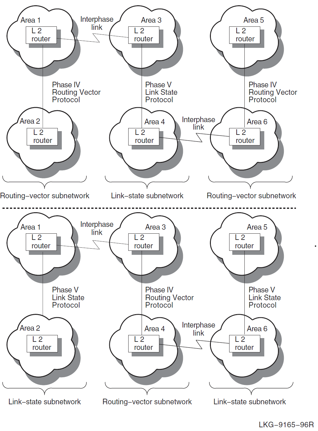
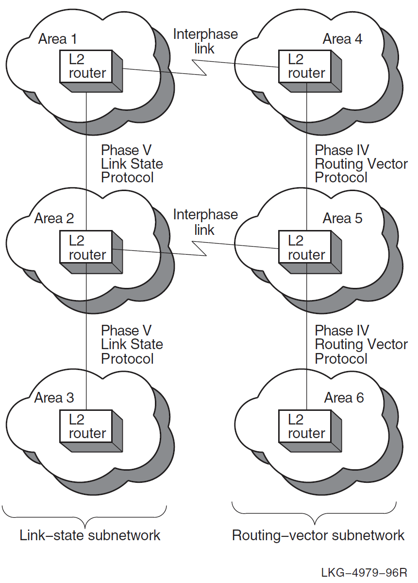
4.4. Configurations That Require Multiple Interphase Links
If your network configuration consists of multiple Phase IV routing-vector subnetworks connected by DECnet Phase V link-state subnetworks, you must run the create ipl_initialization_file command multiple times. Each time, specify the DECnet Phase V link-state level 2 router that needs interphase links. The same is true for networks that consist of multiple DECnet Phase V link-state subnetworks connected by Phase IV routing-vector subnetworks. Figure 4.3, ''Two Configurations with Multiple Interphase Links'' shows two examples of these configurations.
If you use the create ipl_initialization_file command only once for each target router, the routing information created in the target routers’ reachable- address tables is incomplete. It is incomplete because not all area routing information is available to each target router at the time the command is run. Information about nonadjacent areas becomes available only after you run the command file, created by the create ipl_initialization_file command.
For configurations with multiple interphase links, the simplest way to guarantee that routers have all required interphase links is to:
Identify all the DECnet Phase V level 2 routers that require interphase links. These are your target routers.
For each target router:
Use the create ipl_initialization_file command specifying the target router.
Run the resulting DCL command file to create the interphase link entries in the target router’s reachable-address table.
Wait at least 15 minutes for the routing information to propagate through the network.
Repeat Step 2 n times, where n is the number of target routers.
After you complete these steps, routing information for every area is available to every level 2 router in the network.
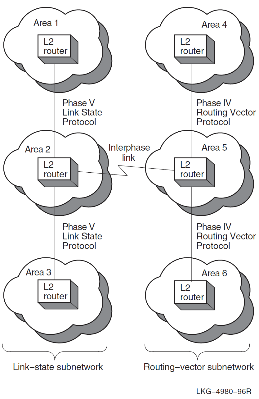
4.5. Configurations with Multiple Interphase Links Between Two Subnetworks
You can use either a single interphase link or multiple interphase links to connect two subnetworks. This section discusses the advantages and disadvantages of both methods. Figure 4.4, ''Single Interphase Link Between Two Subnetworks'' shows the use of a single interphase link.
The advantage of the configuration shown in Figure 4.4, ''Single Interphase Link Between Two Subnetworks'' is that it is easier to diagnose connectivity problems. The disadvantage is that it makes possible a single point of failure between the subnetworks.
You can use multiple interphase links to provide communication path redundancy between the subnetworks, as shown in Figure 4.5, ''Multiple Interphase Links Between Two Subnetworks''.
In Figure 4.5, ''Multiple Interphase Links Between Two Subnetworks'', the configuration solves the problem of having a single point of failure, but it can result in areas being unreachable even though there is a physical path that could be used. This makes connectivity problems more difficult to diagnose.
For example, in Figure 4.5, ''Multiple Interphase Links Between Two Subnetworks'', if the lowest cost path from area 1 to area 5 is through area 4, and the circuits connecting area 4 to area 5 go down, messages from area 1 to area 5 are still sent to area 4. This is because area 1 cannot detect the loss of connectivity between areas 4 and 5. Therefore, area 1 continues to send these messages through area 4 rather than through area 2, because the path through area 4 is the lowest cost path to area 5, but the messages never reach area 5.
4.6. Special Considerations Regarding Network Costs
When the create ipl_initialization_file command gathers the information about which areas exist and which paths to use to reach those areas, it also calculates the cost associated with each path. A network cost is then associated with each interphase link in the reachable-address table.
A restriction is built into the reachable-address tables regarding network cost. Costs of 63 or more cannot be included in the table. If a path has a network cost of 63 or greater, when you run the create ipl_initialization_file command, the commands to create the interphase link for that path are included in the command file as comments. When you run the command file, that path will not be entered into the reachable-address table.
You can, however, edit the output_file_cre command file to change the network cost values. You must have a clear picture of your network topology to be able to make good decisions about modifying network cost values.
Refer to your router management documentation for more information about network costs.
Chapter 5. Managing Name Service Searches and Information
This chapter covers the following topics:
Selecting name services and determining the order in which name services are searched
Managing the in-memory naming cache for resolving names and addresses
Managing DECdns and local namespace information using the decnet_register registration tool
Updating and creating a local node’s Phase IV database with information from a remote DECnet node’s database
5.1. The Naming Search Path
For storing name and address information, DECnet Phase V supports the local namespace, the DECdns distributed namespace, and the Domain Name System (DNS/BIND) distributed namespace. DECnet Phase V uses one or more of these namespaces to look up name or address information. The order in which DECnet Phase V searches the available namespaces is determined by the naming search path. The naming search path is set up during DECnet configuration. The naming search path applies to DECnet applications systemwide.
The ordering of the name services is important. The first name service listed is the primary name service to use on the system. The primary name service is the first choice used when looking up names and addressing information. The remaining name services listed are the secondary name services used on the system.
Note that the search path information for a system is maintained in two separate search paths:
One for forward translation or naming (node name to address translation)
One for backtranslation (address to node name translation)
5.1.1. Determining the Order for Name Service Searches
Use NET$CONFIGURE to configure DECnet-Plus and set up one or more name services for a node. From the information provided, NET$CONFIGURE creates the NET$SEARCHPATH_STARTUP.NCL script, which contains the naming search path information for the node. For example, if the ordered list of LOCAL, DECDNS, DOMAIN was chosen for the directory services at configuration time, then DECnet-Plus searches the local namespace first for forward and back translation information. If necessary, it will then search the DECdns namespace specified in the node’s DECdns name. Finally, if it still has not successfully obtained the translation information, it will use the Domain Name System.
Do not edit the NET$SEARCHPATH_STARTUP.NCL script. If you need to change the naming search path information, use NCL or rerun NET$CONFIGURE.
5.1.2. Using the Naming Search Path to Interpret Abbreviated Node Names
Besides determining the order of searches, the naming search path describes how DECnet should interpret any abbreviated node names entered by users. The search path contains an ordered list of name service keywords, each followed by a naming template that specifies a "defaulting rule" so users can enter shorter node names. In each template, the user-supplied portion of the name (usually the node’s terminating name or rightmost simple name) is indicated with an asterisk (*). For example, if the DECdns template is "ACME:.mgmt.*" and a user supplies the name accnt, then the full name ACME:.mgmt.accnt will be looked up in namespace ACME in the DECdns name service. See Section 5.1.3, ''Displaying and Modifying Search Path Information'' for more examples.
5.1.3. Displaying and Modifying Search Path Information
You can use NCL commands to display information about the search path maintained for forward or backward translation.
5.1.3.1. Displaying the Naming Search Path
To display information about the search path maintained for forward translation or naming (node name to address translation), use the following NCL command (descriptions of the display follow the example):
$ ncl show session control naming search path
Node 0 Session Control
AT 2019-03-19-10:26:03.809-05:00I49.474
Characteristics
Naming Search Path =
(
[
Directory Service = Local ,
Template = "*"
] ,
[
Directory Service = Local ,  Template = "local:.lky.*"
] ,
[
Directory Service = Local ,
Template = "local:.lky.*"
] ,
[
Directory Service = Local ,  Template = "LOCAL:*"
] ,
[
Directory Service = DECdns ,
Template = "LOCAL:*"
] ,
[
Directory Service = DECdns ,  Template = "*"
] ,
[
Directory Service = Domain ,
Template = "*"
] ,
[
Directory Service = Domain ,  Template = "*"
]
)
Template = "*"
]
)Note that each name service can have more than one entry, each template defining a different way for the name to be searched.
| The local namespace is listed first, and so it is the primary name service. This line defines the first of three rules for searching the local namespace. The template definition with an asterisk "*" specifies that the user-supplied name be passed to the local namespace exactly as entered by the user. |
| The template definition of local:.lky.* specifies that the user-specified name be searched next in the local namespace as local:.lky.name. For example, if the user specified node name plm, then the local namespace is searched for local:.lky.plm. |
| The template definition of local:* specifies that the user-specified name be searched next in the local namespace as local:name. For example, if the name is specified as .plm, then namespace search is for local:.plm. |
| This line defines the DECdns namespace search rules, specifying that the name be searched for exactly as the user specifies it. |
| This line defines the DNS/BIND namespace search rules, specifying that the name be searched for exactly as the user specifies it. |
5.1.3.2. Displaying the Backtranslation Search Path
To display information about the search path maintained for backtranslation (address to node name translation), use the following NCL command (descriptions of the display follow the example):
$ ncl show session control backtranslation search path
Node 0 Session Control
AT 2019-03-19-11:00:57.490-05:00I49.712
Characteristics
Backtranslation Search Path =
(
[
Directory Service = Local ,
Template = "*"
] ,
[
Directory Service = DECdns ,
Template = "local:.DNA_BackTranslation"
] ,
[
Directory Service = Domain ,
Template = "*"
]
)
| The template in this line specifies that the user-supplied address be searched in the local namespace exactly as specified by the user. |
| The template in this line specifies that the user-specified address be searched in the directory local:.DNA_BackTranslation. |
| The template in this line specifies that the user-supplied address next be searched in the DNS/BIND namespace exactly as specified by the user. |
5.1.3.3. Modifying the Naming and Backtranslation Search Paths
VSI recommends that you rerun NET$CONFIGURE.COM to revise the standard search path NCL script (NET$SEARCHPATH_STARTUP.NCL) whenever it is necessary to reorder access to the name services on the node. To modify the standard search path startup script, run NET$CONFIGURE.COM and use Option 2 (Change node name/namespace name).
Note
Whenever you directly edit an existing NET$SEARCHPATH_STARTUP.NCL script, or when you use NCL set commands to change the script (rather than changing the script by rerunning NET$CONFIGURE.COM), your edits are overwritten by any new NET$SEARCHPATH_STARTUP.NCL scripts you subsequently generate by rerunning NET$CONFIGURE.COM.
5.1.3.4. Using Backtranslation to Track Namespace Changes
The name of the backtranslation directory that Session Control uses is .DNA_BackTranslation with the same nickname as the node name in the current namespace. If the node name is changed, Session Control tracks the change within the number of seconds specified by Session Control’s address update interval attribute. See the backtranslation directory status attribute under the session control entity for the current full name of the backtranslation directory used by Session Control.
5.1.4. Changing the Default Namespace Name
The name of the node synonym directory that Session Control uses is .DNA_NodeSynonym with the nickname of the default namespace at the time that Session Control was first created.
{default-namespace}:.dna_nodesynonymIf you change the default namespace name without reconfiguring, you must set the name of the node synonym directory. (Section 5.1.6, ''Managing the DECdns Clerk'' describes how to change the default namespace name.) Set the node synonym directory with the node synonym directory characteristic attribute under the session control entity. For example:
ncl> set session control node synonym - _ncl> directory default-namespace:.dna_nodesynonym
5.1.5. Defining an Alternate Node Synonym Directory
In very large or widely distributed networks you can use multiple directories to store node synonym soft links, rather than the single default .DNA_NodeSynonym directory.
To use an alternate node synonym directory, edit SYS$MANAGER:NET$LOGICALS.COM and add the following line:
$ define/system/exec decnet_migrate_dir_synonym ".synonym_dir_name"
The defined directory is then used by NET$CONFIGURE, decnet_register, and decnet_migrate.
See Section 6.3, ''Defining Logical Names That Modify Network Operation'' for information about how to create and use the SYS$MANAGER:NET$LOGICALS.COM file.
5.1.6. Managing the DECdns Clerk
The DECdns namespace is the total collection of names that one or more DECdns servers know about, look up, manage, and share. You define the default namespace name during configuration of a DECdns clerk. Then, unless a user specifies otherwise, DECdns always assumes a name is in the default namespace. Use the following NCL set command to change the default namespace:
ncl> set dns clerk default namespace {namespace-name}Note that this command will affect all users of DECdns on the system, including the Session Control module. Therefore, VSI recommends that you do not use this command, but instead use the DECnet-Plus configuration procedure.
In general, to manage the namespace, use the DECdns Control Program SYS$SYSTEM:DNS$CONTROL.EXE.
For more information about managing the namespace, refer to the VSI DECnet- Plus for OpenVMS DECdns Management Guide.
5.2. Resolving Names and Addresses with the Naming Cache
DECnet Phase V software includes the common directory interface (CDI) as an interface between DECnet Phase V Session Control and all the supported name services (local namespace, DECdns, DNS/BIND). CDI performs the necessary switching between the various name services during lookups, enabling the use of multiple name services.
Prior to the addition of the CDI, the DECdns clerk was the primary interface between DECnet Session Control and DECdns servers or the local namespace. Now most all DECnet-related calls to DECdns (or to any other naming service) are first handled by CDI.
The DECdns clerk receives requests for name/address information from client applications and looks up the requested information on the appropriate DECdns server or in the local namespace. The DECdns clerk caches (saves) pointers to DECdns servers discovered during these lookups. This saves the clerk from repeatedly connecting to a server for the same information. For lookups involving applications such as DECmcc and DFS, the DECdns clerk caches results of lookups. Caching improves performance and reduces network traffic.
5.2.1. The CDI Naming Cache and DECdns
CDI uses an in-memory naming cache to improve performance of name and address resolution for the supported name services. DECnet-Plus for OpenVMS requests CDI directly for name and address resolution. DECnet-Plus uses CDI for looking up information from all three name services: local namespace, DECdns, and DNS/BIND.
The DECdns clerk cache still exists. When CDI calls DECdns for node name information, DECdns searches the clerk cache to determine where to look up the requested information. DECdns continues to use the clerk cache to determine the location of servers in the DECdns namespace. DECnet-Plus for OpenVMS uses the DECdns clerk to parse the special namespace nicknames LOCAL: and DOMAIN:. These nicknames in a node full name indicate to DECnet-Plus the name service where the name and addressing information is stored. Note that DECdns clerks do not directly cache DECnet names for any namespace. The clerk caches pointers to the servers where node names are stored.
The DECdns clerk cache continues to be used by applications other than DECnet- Plus that use DECdns directly, such as the Distributed File Service (DFS) application.
5.2.2. Managing the CDI Naming Cache
Using NCL commands, you can manage two CDI naming cache parameters, the checkpoint interval and the timeout period, and you can flush entries from the in-memory naming cache. Note that these parameters do not affect DECdns; they only affect CDI.
This section also discusses the following additional CDI topics:
Tracing naming information in the CDI cache.
Using the CDI$SYSTEM_TABLE to define node synonyms.
Using CDI enhancements to resolve IP fully-qualified names.
Using CDI_CACHE_DUMP to analyze the most recent cache checkpoint.
Controlling CDI’s use of the Local namespace database.
Automated CDI cache flushing.
5.2.2.1. Checkpoint Interval
To ensure that the information contained in the naming cache is preserved across system reboots, DECnet periodically saves (or checkpoints) a snapshot of the in-memory naming cache to disk. At system startup, the naming cache can be populated with the entries most recently saved to disk. Note that this means the naming cache is read into memory only during DECnet startup. Keep this in mind if you are copying the cache to other nodes in the network for updates.
The following NCL command changes the frequency of this checkpoint operation from the default of once every 8 hours to once every 12 hours:
$ mcr ncl set session control naming cache checkpoint interval 12:00:00
One advantage of resetting the checkpoint interval is that you force a new checkpoint to be written within the next 15 minutes, even if a checkpoint is not due at that time.
5.2.2.2. Timeout Period
The naming cache includes a mechanism to remove old cache entries. When a naming cache entry reaches a preset age, the entry times out, or expires, and is eliminated from the cache. On the first lookup request for an entry after it has timed out, when DECnet does not find the entry in the in-memory cache, DECnet will retrieve up-to-date information from the name service. In this way, cache entries are periodically refreshed to accurately reflect the current network environment.
The following NCL command changes the length of the timeout interval from the default of 30 days. For example, this command decreases the timeout interval to once every 5 days:
$ mcr ncl set session control naming cache timeout 5-00:00:00
The default timeout value of 30 days is suitable for most networks. However, for stable networks in which node names are rarely changed or swapped with other names, you can increase the value. The only benefit of keeping a lower value is that more space is freed in the cache as each timed-out entry is deleted.
Reducing the timeout value may result in the sudden loss of cached entries. Use the NCL flush command to remove specific entries, as explained below.
VSI recommends that you do not change a node name or swap names of nodes until after the naming cache timeout period has passed. This allows time for the out-of-date node and addressing information to be flushed from the cache.
Consider the following scenario. Node .mgmt.accnt is assigned address 4.234 and this name and address information is stored in the name service. After DECnet has looked up node .mgmt.accnt, it stores this node name and address combination (.mgmt.accnt and 4.234) in its in-memory cache. When node .mgmt.accnt is subsequently reassigned to address 4.235, the following events can occur:
DECnet retrieves address 4.234 for node name .mgmt.accnt from the in- memory cache.
DECnet attempts to connect to address 4.234.
When the connection fails, DECnet again looks up the address for node .mgmt.accnt, this time bypassing the naming cache and searching the name service. This new lookup for node .mgmt.accnt finds address 4.235 in the name service, updates the cache, and successfully connects to the node.
However, if after node .mgmt.accnt is assigned a new address, .mgmt.accnt’s old address, 4.234, is subsequently reassigned to node .mgmt.pers before the timeout period has elapsed, the following can occur:
DECnet retrieves address 4.234 for node name .mgmt.accnt from the in- memory cache.
DECnet attempts to connect to address 4.234.
The connection succeeds. DECnet is unable to tell that it has connected to the wrong node (mgmt.pers).
To prevent this scenario, do either of the following:
Before reassigning a node address to another node name, first deassign the node address from the current node name and wait until the cache timeout interval passes before reassigning the address to another node name. This allows time for the addresses to be flushed automatically from the in-memory cache.
Use an NCL command to manually flush one or more in-memory cache entries. When manually flushing cache entries, be sure to perform the flush command on every system with stale cache entries. If you must reassign a node before the cache timeout period has expired, you must flush all cache entries. Although entries are immediately removed from memory, the cache saved on disk will still contain these cache entries until the next checkpoint interval. To force a quicker checkpoint of the cache (within the next 15 minutes), reset the checkpoint interval to the value currently set (if you do not want to change the interval thereafter).
In the following example, the first NCL command flushes one specified entry from the cache. The second command flushes all cache entries:
$ mcr ncl flush session control naming cache entry "entry-name" $ mcr ncl flush session control naming cache entry "*"
5.2.2.3. Tracing Naming Information in the CDI Cache
You can use either the Common Trace Facility or the CDI$TRACE program to obtain naming trace information.
Use the following command to invoke the Common Trace Facility:
$ Trace Start "SESSION CDI *"
Including the CDI parameter restricts trace facility output to node name and address resolution messages.
Use the following command to run CDI$TRACE, a program located in SYS$SYSTEM:
$ run sys$system:cdi$trace
You can use the following procedure to redirect CDI$TRACE output to a file:
Define a DCL foreign command symbol:
$ cdi$trace == "$cdi$trace"
Specify the name of the file to contain the CDI$TRACE output:
$ cdi$trace trace.log
The output file may occasionally be missing the last few records of the trace. This is a known problem.
CDI$TRACE has known problems when run during a LAT terminal session (on an LT device). A workaround is to issue the DCL spawn command first.
5.2.2.4. Using the CDI$SYSTEM_TABLE To Define Node Synonyms
You can use a logical name table (CDI$SYSTEM_TABLE) to define node synonyms. You should use the following commands to create and examine logical names in the CDI$SYSTEM_TABLE logical name table. In the following command examples, the node bks.pub.dec.com has the synonym bks.
To define the CDI$SYSTEM_TABLE logical name table, enter the following command:
$ create/name_table/exec/parent=lnm$system_directory cdi$system_table
To define a synonym, enter the following command:
$ define/table=cdi$system_table bks bks.pub.dec.com
To examine a synonym, enter the following command:
$ show logical/table=cdi$system_table bks
The system displays the synonym information:
$ "bks.pub.dec.com" = "bks" (cdi$system_table)
SYSNAM system privileges are required.
5.2.2.5. Using CDI Enhancements To Resolve IP Fully-Qualified Names
The common directory interface (CDI) has been enhanced to resolve an IP fully- qualified node name to a Phase IV-style node synonym. CDI resolves the fully- qualified node name to the IP short name. For example, the fully-qualified name mynode.cmp.com resolves to the Phase IV-style node synonym mynode. Normally, CDI returns the synonym only if the following conditions are satisfied:
The local node name and the fully-qualified node name are in the same domain.
The resulting IP short name is a syntactically correct Phase IV-style node name (that is, six characters or less with a leading alphabetic character).
If the preceding conditions are not met, or if the node is using another synonym (for example, the node this.vsi.com is using the synonym that), you must make an entry for the node in the TCP/IP software’s local hosts database.
If you are using VSI TCP/IP Services for OpenVMS software, you would need to enter a command similar to the following:
$ tcpip set host mynodelong.cmp.com/address=100.50.75.20/alias=mynode
5.2.2.6. Using CDI_CACHE_DUMP To Analyze a CDI Cache Checkpoint
To view what was in the CDI cache the last time a CDI checkpoint was taken, issue the following command:
$ run sys$system:cdi_cache_dump
The dump utility first displays summary information about the cache file:
CDI Cache Checkpoint file dumper [Checkpoint filename = "SYS$SYSTEM:DECNET$CDI_CACHE.DAT;1"] Reading file... 224926 bytes (of 4) loaded from checkpoint file Computing checksum... cache size (except checksum) (in words): 56231 Checksum correct Cache checksum: file: C0E2F780, computed: C0E2F780 CDI cache successfully loaded from ckpt file... Cache id............. 950022 Cache version........ 2.4 cache_init_flag...... 1 cache_size........... 211 Cache Max Size....... 4096 Cache Increments .... 40 Total entries........ 211
Next, the dump utility displays each entry in the cache in most recently used (MRU) order (usually the local node, cluster alias, if present, and other cluster members are the first entries displayed):
*********************** Cache Entries (MRU order) ********************* - ptr - Dir s.name Ent Svc off len Input name Synonym Fullname 0 2 9 6 VSI:.MA.ASHFLD ASHFLD VSI:.MA.ASHFLD 1 | tower 1: "DNA_NODE"/"SC3"/"TP4=DEC0"/NS+49+0018AA000400246021 | tower 2: "DNA_NODE"/"SC3"/"NSP"/NS+49+0018AA000400246020 | created: Fri Sep 17 18:10:35 2019 1 3 0 6 ASHFLD ASHFLD VSI:.MA.ASHFLD 1 | tower 1: "DNA_NODE"/"SC3"/"TP4=DEC0"/NS+49+0018AA000400246021 | tower 2: "DNA_NODE"/"SC3"/"NSP"/NS+49+0018AA000400246020 | tower 3: "DNA_NODE"/"SC2"/"TP4=DEC0"/IP+123.456.789.123 | created: Fri Sep 17 18:10:36 2019 2 3 0 5 WMASS WMASS VSI:.MA.WMASS 0 | tower 1: "DNA_NODE"/"SC2"/"NSP"/NS+49+0018AA000400246020 | tower 2: "DNA_NODE"/"SC2"/"TP4=DEC0"/IP+123.456.789.120 | created: Fri Sep 17 18:10:37 2019 3 3 0 6 IP$123.456.789.123 ASHFLD ASHFLD.MA.USA | tower 1: "DNA_NODE"/"SC2"/"TP4=DEC0"/IP+123.456.789.123 | created: Fri Sep 17 18:10:37 2019 4 3 0 6 CONWAY CONWAY VSI:.MA.CONWAY 0 | tower 1: "DNA_NODE"/"SC2"/"NSP"/NS+49+0018AA000400246120 | tower 2: "DNA_NODE"/"SC2"/"TP4=DEC0"/IP+123.456.789.124 | created: Fri Sep 17 18:12:27 2019
The preceding example shows the entries for the local node ashfld under both its DECdns name and its node synonym. Next, is the entry for the cluster alias, wmass, followed by an entry for the IP address for the local node, IP$123.456.789.123. Finally, is an entry for another member of the cluster, conway.
5.2.2.7. Controlling CDI’s Use of the Local Namespace Database
The NET$LOCAL_CLOSE logical name controls whether the common directory interface (CDI) closes its local namespace database (normally, SYS$SYSTEM:NET$LOCAL_NAME_DATABASE.DAT) after each use. If CDI keeps the database open continuously, this can create problems (in the form of unwanted file merges) if the CDI database is moved to a disk other than SYS$SYSTEM: and that disk is a member of a shadow set.
If the NET$LOCAL_CLOSE logical name is defined with a value of 1, CDI closes the database after each use. The default is for the NET$LOCAL_CLOSE logical name to be undefined (that is, CDI keeps the local namespace database open continuously). See Section 6.3, ''Defining Logical Names That Modify Network Operation'' for information about how to define this logical name in the NET$LOGICALS.COM file.
5.2.2.8. Automated CDI Cache Flushing
Session Control bypasses the CDI cache when the existing cache entry causes a node unreachable condition. When the node unreachable condition is detected, Session Control makes a second call to CDI with an indication that CDI should bypass the cache and look up the name directly in the appropriate naming service. In addition, the new address is used to update the CDI cache for future lookups. Without this feature, if a node’s address changed and the CDI cache was not flushed to force the new address into the cache, CDI would return the stale address information to Session Control. Session Control would then return a node unreachable error to the caller.
5.3. Managing DECdns and Local Namespace Information with decnet_register
The decnet_register tool simplifies and centralizes management of namespace information.
The decnet_register manage command assists with setting up and managing DECdns distributed namespaces by creating the required hierarchy of directories, setting and altering access rights to these directories, and enabling and disabling autoregistration.
This section explains how to use decnet_register to manage and register node names in a DECdns or local namespace. In particular, this section explains how to use decnet_register to perform the following distributed namespace tasks. For an alphabetical command reference, see Appendix D, "decnet_register Commands".
Invoke the decnet_register utility (Section 5.3.1, ''Invoking decnet_register'').
Use the decnet_register interface (Section 5.3.2, ''Using decnet_register'').
Use an initialization command file for preset values (Section 5.3.3, ''Using an Initialization Command File for Preset Values'').
Display node registrations and verify their internal consistency (Section 5.3.4, ''Showing the Information Registered for a Node in the Namespace'').
Register and modify node names, node synonyms, and addresses in your namespaces (Section 5.3.5, ''Registering or Modifying a Node'').
Update a remote node’s registered address information with information decnet_register obtains by connecting to the node itself (Section 5.3.6, ''Updating Registered Node Addresses'').
Rename registered nodes in a namespace (Section 5.3.7, ''Renaming a Registered Node'').
Repair the synonym and address links for registered nodes (Section 5.3.8, ''Repairing a Node’s Synonym and Reverse Address Links'').
Deregister nodes from a namespace (Section 5.3.9, ''Deregistering a Node from the Namespace'').
Export node registration information from a namespace into an editable text file (Section 5.3.10.1, ''Exporting Node Information from a Name Service'').
Import node registration information from a text file into a namespace (Section 5.3.10.2, ''Importing Node Information from an Export/Import File to a Name Service'').
Convert an existing LNO text file to a Local namespace (Section 5.3.10.3, ''Converting an Existing LNO Text File to a Local Namespace'').
Set preferences and network values (Section 5.3.11, ''Setting Preferences and Network Values'').
Manage the DECdns directory service (Section 5.3.12, ''Managing the DECdns Directory Service'').
Spawn to DCL to enter one or more DCL commands and return again to decnet_register (Section 5.3.13, ''Spawning to DCL'').
Note
Do not register nodes in the DECdns namespace that do not use DECnet. Only DECnet-to-DECnet applications use node-name objects in the DECdns namespace. OSI applications use their own private naming databases, DNS/BIND, or X.500.
The decnet_register tool does not manage information in DNS/BIND.
5.3.1. Invoking decnet_register
To invoke decnet_register, enter the following run command:
$ run sys$system:decnet_register
You can also invoke decnet_register using a foreign command symbol:
$ netreg :== $sys$system:decnet_register $ netreg
Once invoked, decnet_register continues to accept commands until you enter the exit command.
If you have defined a foreign command symbol, you can include a decnet_register command on the invocation command line as follows:
$ netreg show node mynode
With this command line, decnet_register executes the included command and immediately exits.
When you invoke decnet_register from a video terminal, decnet_register starts in forms mode by default. When you invoke decnet_register from a command procedure or from a hardcopy terminal, decnet_register starts in command mode by default. You can change this default behavior permanently by defining a logical name or for a single invocation only by using the /c and /f qualifiers on the command line.
To change the default behavior permanently, define one of the following logical names:
$ define decnet_register_commands 1forces default use of the command line interface until you deassign the logical name.$ define decnet_register_forms 1forces default use of the forms interface until you deassign the logical name.
Note that only one logical name takes effect at a time. If you define both logical names, the decnet_register_forms logical name overrides the other.
To change the default behavior for the current invocation only, use one of the following switches:
$ netreg /cforces the use of the command line interface for the current invocation of decnet_register only.$ netreg /fforces the use of the forms interface for the current invocation of decnet_register only.Note
The decnet_register tool is not supported on a system booted with minimum startup.
5.3.2. Using decnet_register
The decnet_register tool has both command line and forms interfaces. When invoked from a video terminal, decnet_register is by default a forms-driven tool. You select a task and decnet_register prompts you for the information the task requires. The command line interface for decnet_register includes help information for all the tool’s commands.
The following example shows the decnet_register main menu form.
DECNET_REGISTER - Manage node registrations in network directory services Use Return, Ctrl/N, and Ctrl/P to move between input fields Use "?" to obtain help, Ctrl/Z to cancel 1 - Show information about registered node names 2 - Register or modify node names 3 - Update registered node towers using information from the nodes 4 - Rename a registered node name 5 - Repair the synonym and address links for registered node names 6 - Deregister node names 7 - Export node names to a data file 8 - Import node names from a data file 9 - Set preferences and network values 10 - Manage the directory service 11 - Spawn to DCL * Option (use Ctrl/Z to exit):
To select a task, type the appropriate number and press Return. You can cancel any task and return to this main menu by pressing Ctrl/Z.
To perform certain tasks discussed in this chapter, you need access rights. For more information about the access rights, refer to the VSI DECnet-Plus for OpenVMS DECdns Management Guide, which also contains complete information about DECdns and the namespace and provides detailed namespace planning information. Note that when you use decnet_register to manage DECdns, these access rights are stored in the DECdns namespace rather than locally on your system. So, you might not be able to use certain decnet_register commands, even if you are logged in as a system account user.
Note
If the namespace has not yet been created on your network or its root directory cannot be read from your node, then decnet_register indicates this in a message. You cannot proceed if you cannot access the namespace. See your namespace manager to find out why the existing namespace is unavailable. If the namespace has not been created yet, the namespace manager should create a namespace following the instructions in the VSI DECnet-Plus for OpenVMS Installation and Configuration and VSI DECnet-Plus for OpenVMS DECdns Management Guide.
Initializing the namespace consists of creating a backtranslation directory (commonly called .DNA_BackTranslation), a node synonym directory (commonly called .DNA_NodeSynonym), and the required DECdts directory (.DTSS_GlobalTimeServers). Some DECnet features do not work properly unless these directories exist; for example, you cannot use Phase IV node names if the node synonym directory (.DNA_NodeSynonym or equivalent) is not available.
Note
VSI strongly recommends that you create these directories immediately. See Section 5.3.12, ''Managing the DECdns Directory Service'' for a description of these directories and the initialization procedure.
5.3.3. Using an Initialization Command File for Preset Values
When it starts, decnet_register attempts to execute an initialization command file (sys$login:decnet_register.ini) if one is present. By including a set default command in your decnet_register initialization command file, you can preset parameter values before your decnet_register session begins.
If this file is found, it is executed as a command file containing decnet_register commands.
To use a different file name, specify a logical name definition as follows with initialization-command-file naming your command file:
$ define decnet_register_init initialization-command-file5.3.4. Showing the Information Registered for a Node in the Namespace
As part of your job as a network manager, you might at times need to review the information registered for a node in the namespace. This information includes the node’s address tower and, for the DECdns namespace, the names of the synonym and address-to-name backtranslation soft links.
To view this information, select Option 1 at the decnet_register main menu and respond to the prompts as they appear, one by one. Press Ctrl/Z to cancel the show operation. Output is similar to the following example:
Show registered node information Use Return, Ctrl/N, and Ctrl/P to move between input fields Use "?" to obtain help, Ctrl/Z to cancel Specify the directory service as LocalFile, DECdns, or PhaseIV * Directory service: Specify the node to show using an explicit or wildcard name, an NSAP, or a Phase IV synonym or address. * Node name or address: Specify the information to display as either brief, full, or names. Specify the output file name (a blank line indicates the terminal). * Display format: * Output file: Press Return to show the node values, Ctrl/Z to cancel
For help answering the prompts, refer to the following:
Directory Service
Identify the name service where the node’s information is stored. Name services include the local namespace, the DECdns distributed namespace, and the Phase IV database.
Node Name or Address
Enter a node name or address, as follows:
| Full name | The node’s full name, including the directory or directories. You can replace all or part of any simple name in the full name, including the directory names, with a wildcard character (*) to show multiple nodes. |
| Synonym | The node’s Phase IV synonym. This must not contain any directory names. You can replace all or part of the synonym with a wildcard character (*) to show multiple nodes. |
| NET or NSAP | The node’s network entity title (NET), which is the node’s NSAP (network service access point) with a selector field of 00 or its NSAP. You can replace the node ID field of the NET with a wildcard character (*) to show all nodes within an area. For more information about NETs, refer to the VSI DECnet-Plus for OpenVMS Introduction and User's Guide. |
| Address | The node’s Phase IV address, in the format area.id. You can replace the id field of the address with a wildcard character (*) to show all nodes within an area. |
Display Format
The tool displays the node information in brief or full format or simply displays the node full name.
Output File
Enter a file name and press Return to send the output to a file. Press Return without entering a file name to display the information on the screen.
If you specify a full name, brief format appears as follows:
Directory Service: Local name file Node name: LOCAL:.grand.sales Phase IV synonym: SALES Node address: 49::00-04:AA-00-04-00-93-10:20 (4.147) Node address: 49::00-04:AA-00-04-00-93-10:21 (4.147) Node address: 41:45418715:00-41:08-00-2B-14-2D-47:21 Node address: 41:45418715:00-41:08-00-2B-14-2D-47:20 Number of nodes reported on: 1
5.3.5. Registering or Modifying a Node
You must register all DECnet Phase V nodes and Phase IV nodes in the namespace to make them accessible to other nodes in the network.
When you register a node name, decnet_register creates a node entry by that name in the namespace you specify. For nodes in the DECdns namespace, decnet_register also creates a Phase IV synonym soft link and an address- to-name backtranslation soft link. Each object and soft link is assigned the minimally required access control. You can later add additional access control to the object manually.
To register or modify a DECnet Phase V node in the namespace, select Option 2 at the decnet_register main menu and respond to the prompts as they appear, one by one. Press Ctrl/Z to cancel the register operation. Output is similar to the following example:
Register or modify node information Use Return, Ctrl/N, and Ctrl/P to move between input fields Use "?" to obtain help, Ctrl/Z to cancel Specify the directory service as LocalFile, DECdns, or PhaseIV. * Directory service: LocalFile Specify the explicit name of the node to register or modify: * Node name: sales Attempting to look up node name * Node name: LOCAL:.grand.sales * Synonym: SALES Specify how to handle the node’s registered address towers, using either modify, keep, replace, or delete. The current number of towers is "4". * What should be done with the current address towers: Modify Register or modify node address information Use Return, Ctrl/N, and Ctrl/P to move between input fields Use ? to obtain help, Ctrl/Z to cancel The first six towers for "LOCAL:.grand.sales" are: 1) SC3/NSP/CLNS=4.147 2) SC3/TP4/CLNS=4.147 3) SC3/TP4/CLNS=41:45418715:00-41:08-00-2B-14-2D-47:21 4) SC3/NSP/CLNS=41:45418715:00-41:08-00-2B-14-2D-47:20 5) none 6) none The address must be CLNS NSAP or DECnet Phase IV address. The transport must be either TP4, TP4=tsel, or NSP. The DECdns directory service also permits towers containing IP addresses (IP=d.d.d.d) with the TP2 transport. The Session Control version (SC2 or SC3) cannot be changed. Tower number 1 * Address: CLNS=4.147 * Transport: NSP * Specify another address tower (No or Yes): No * Press Return to register the node, Ctrl/Z to cancel
For help answering the prompts, refer to the following:
Directory Service
Identify the name service where the node’s information is to be registered. Name services include the local namespace, the DECdns distributed namespace, and the Phase IV database.
Node Name
Enter an explicit node name, as follows: Enter a node full name formatted for the local namespace or for DECdns, or enter a Phase IV node name. Do not include any wildcard characters.
Synonym
Enter the node’s Phase IV synonym. You can replace all or part of the synonym with a wildcard character (*) to show multiple nodes.
Address Towers
Enter one of the specified keywords (modify, keep, replace, or delete) to indicate what you want to do with the node’s registered address towers.
To add an address tower, specify the node’s NSAP or its Phase IV address. Specify one of the following transports: TP4, TP4=tsel, or NSP.
The display continues:
Directory Service: LocalFile Registering the node LOCAL:.grand.sales Modifying the node synonym Modifying the node towers * Press Return to continue
5.3.6. Updating Registered Node Addresses
The update function establishes a network management connection to a node, reads the node’s addressing information directly from the node, and updates the node registration to contain the correct addresses. You must specify a usable address in order to establish a network connection to the node to obtain the remainder of the addressing information.
To update addressing information for the node, select Option 3 at the decnet_register main menu and respond to the prompts as they appear, one by one. Press Ctrl/Z to cancel the update operation. Output is similar to the following example:
Update node towers information using network management Use Return, Ctrl/N, and Ctrl/P to move between input fields Use "?" to obtain help, Ctrl/Z to cancel Specify the directory service as LocalFile, DECdns, or PhaseIV. * Directory service: decdns Specify the node to update using an explicit or wildcard name or Phase IV synonym. If explicitly specifying the local node name, indicate "Local", otherwise indicate "Remote" (wildcard names must always be "Remote"). * Node name: sales * Node is remote or local: remote Specify the NET, NSAP, or Phase IV address to use to access the node and obtain the node’s full tower set. If you do not specify an address, an attempt will be made to use the currently defined addresses. * Node address: 4.147 Press Return to update, Ctrl/Z to cancel
For help answering the prompts, refer to the following:
Directory Service
Identify the name service where the node’s information is to be updated. Name services include the local namespace, DECdns, and the Phase IV database.
Node Name
Enter a node name, as follows:
| Full name | The node’s full name properly formatted for the local namespace or DECdns. You can replace all or part of any simple name in the full name with a wildcard character (*) to show multiple nodes. Wildcard names must always be remote. |
| Synonym | The node’s Phase IV synonym. You can replace all or part of the synonym with a wildcard character (*) to show multiple nodes. Wildcard names must always be remote. |
Node is Remote or Local
If the node to be updated is the local node, specify Local to force use of the local network management connection. Names that include wildcard characters must always be remote.
Node Address
The node address can be the node’s network entity title (NET), which is the node’s NSAP with a selector field of 00 or its NSAP, or the node’s Phase IV address, in the format area.id. You can specify a node address only if you specified an explicit node name.
The display continues:
Directory Service: DECdns Updating the tower set for "LOCAL:.grand.sales" Number of nodes updates: 1 Number of update failures: 0 * Press Return to continue
Usage Notes
While Option 3 is is useful for updating a directory’s node tower information, at least one node address must already be correct in the namespace or you must provide a node address in the decnet_register dialog. For a wildcard operation, this requires that the directory service must contain the correct node addresses for all nodes prior to the operation.
Because of this restriction, Option 3 is most useful during the conversion from Phase IV to Phase V names. During the configuration process, the local directory is populated with information taken from any existing Phase IV database. Option 3 allows you to update the local directory to include Phase V information obtained from the individual remote nodes.
If the DECdns directory is also being configured, you can use Option 7 to export the local directory information to an export file. Then use Option 8 to import this information into the newly created DECdns namespace. Using Option 3 on the local directory first allows this export/import file to contain Phase V information instead of the default Phase IV information. This assumes that all your nodes have been configured as Phase V nodes.
Because this option was designed mainly to assist in the Phase IV to Phase V migration, it assumes that it must initially attempt a Phase IV-style connection to each node. Therefore, if this option is used at some later time, most connection attempts will initially fail because the remote nodes are now Phase V nodes. The failure results in an OPCOM message similar to the following:
%%%%%%%%%%% OPCOM 19-FEB-2019 08:27:16.51 %%%%%%%%%%%
(from node ASHFLD at 19-FEB-2019 08:27:17.33)
Message from user SYSTEM on ASHFLD
Event: Remote Protocol Error from: Node LOCAL:.ASHFLD NSP Local NSAP
490003AA000400230C20 Remote NSAP 490003AA000400220C20,
at: 2019-02-19-08:27:17.332-07:00Iinf
Reject Cause=Invalid Message Format,
Erroneous Transport PDU=’3831002700000005’H
eventUid F4BC1601-43E3-11D7-B04D-434352202020
entityUid 853F4E9F-3936-11D7-A8F6-434352202020
streamUid 8AF7A6C9-3888-11D7-8456-AA000400230CTo update the local directory after configuration, the preferred method is to use the export/import options in decnet_register. To update the directory at any time, perform the following steps:
Invoke decnet_register.
Select Option 7 --- Export node names to a data file. Be sure to specify the proper SOURCE directory and a file name.
Edit the text file as needed.
Invoke decnet_register.
Select Option 8 --- Import node names from a data file. Be sure to specify the proper TARGET directory and the same file name used in the export operation. Enter in response to the Template: and Error file name: prompts. Enter replace in response to the Function: prompt.
Update other nodes in the network as required using the export file created in Step 2. Note that decnet_register has a command line interface option that is useful when creating command procedures to automate this step.
Note
Although these steps work for the DECdns directory, DECdns has its own update mechanisms. Therefore, this procedure is usually not appropriate for the DECdns directory.
Option 3 does have limited usefulness after configuration. Using Option 3 provides direct feedback about which nodes are correctly addressed and currently reachable. (With the caveat that initial attempts are Phase IV-based which may result in numerous errors.)
5.3.7. Renaming a Registered Node
If the name of a node registered in the namespace changes, make sure to change the node name in the namespace.
To change the name of a node in the namespace without changing any other information associated with the node name, select Option 4 at the decnet_register main menu. For nodes registered in the DECdns namespace, the synonym soft link and address-to-name backtranslation soft link are updated to point to the new name. For the local namespace, this information is changed in the database.
Note
When you rename a node, you should subsequently modify any DECdns access control entry (ACE) whose principal contains the node name. If the node whose name you are changing is a DECdns server, create the new ACEs for the OpenVMS system’s system account and DNS$Server account before you change the node name. If you do not create new ACEs before renaming the node, you can lock the server out of access to the namespace. For details, refer to the chapter on managing access control in the VSI DECnet-Plus for OpenVMS DECdns Management Guide.
To change the node name, select Option 4 at the decnet_register main menu and respond to the prompts as they appear, one by one. Press Ctrl/Z to cancel the rename operation. Output is similar to the following example:
Rename a registered node Use Return, Ctrl/N, and Ctrl/P to move between input fields Use "?" to obtain help, Ctrl/Z to cancel Specify the directory service as LocalFile, DECdns, or PhaseIV. * Directory service: LocalFile Specify the current name and the new name for the node. Both names must be explicit full names. * Old node name: Local:.hiho * New node name: Local:.happy Specify the Phase IV synonym to use after the node has been renamed. Enter an asterisk (*) to keep the old synonym name. Leave the field blank to indicate no synonym. * New synonym: happy Press Return to rename, Ctrl/Z to cancel
For help answering the prompts, refer to the following:
Directory Service
Identify the name service containing information for the node to be renamed. Name services include the local namespace, DECdns, and the Phase IV database. Nodes can be renamed only within a name service. You cannot change the name service when renaming a node.
Old Node Name
Enter the node’s current full name properly formatted for the name service.
New Node Name
Enter the node’s new full name properly formatted for the name service.
New Synonym
Enter the new Phase IV synonym for the node. To keep the current synonym, enter an asterisk. To have no synonym, leave the field empty.
Directory Service: Local name file Checking the current node registration Renaming: LOCAL:.hiho To: happy * Press Return to continue
5.3.8. Repairing a Node’s Synonym and Reverse Address Links
If the synonym or reverse address mapping links for the local namespace and the DECdns name service are deleted or changed accidentally, use the repair option to restore the correct soft links. Use Option 1 of the decnet_register main menu to display the current values for a node’s synonym link and reverse address mapping link.
To repair synonym or reverse address mapping links, select Option 5 at the decnet_register main menu. The tool prompts you for the name of the directory service where the node information is stored and for the name of the node whose soft links are to be repaired. Press Ctrl/Z to cancel the repair operation. Output is similar to the following example:
Repair node synonym and reverse address mapping links Use Return, Ctrl/N, and Ctrl/P to move between input fields Use "?" to obtain help, Ctrl/Z to cancel Specify the directory service as LocalFile or DECdns. * Directory service: decdns Specify the node to repair using an explicit or wildcard full name. The only valid name for the LocalFile directory service is "*". * Node name: hiho Press Return to repair, Ctrl/Z to cancel
For help answering the prompts, refer to the following:
Directory Service
Identify the name service where synonym and reverse address mapping links need to be repaired. Specify either LocalFile or DECdns.
Node Name
Enter the node’s full name properly formatted for the DECdns name service. This argument is not used for the local namespace. You can replace all or part of any simple name with a wildcard character (*) to repair multiple nodes.
The display continues:
Directory Service: DECdns No repairs needed: Hiho Number of nodes repaired: 0 Number not needing repair: 1
5.3.9. Deregistering a Node from the Namespace
To maximize performance, keep your namespace as up-to-date and uncluttered as possible. This includes removing obsolete node registrations from the namespace.
To deregister a node from the namespace, select Option 6 at the decnet_register main menu. The tool prompts you for the node name to be removed. Press Ctrl/Z to cancel the deregister operation. Output is similar to the following example:
Deregister node names Use Return, Ctrl/N, and Ctrl/P to move between input fields Use "?" to obtain help, Ctrl/Z to cancel Specify the directory service as LocalFile, DECdns, or PhaseIV. * Directory service: LocalFile Specify the node to deregister using an explicit or wildcard name, an NSAP, or a Phase IV synonym or address. * Node name or address: hiho Specify whether or not to display node name, synonym, and NSAP information before indicating that the nodes should or should not be deregistered. * Display node information (no or yes): Press Return to deregister, Ctrl/Z to cancel
For help answering the prompts, refer to the following:
Directory Service
Identify the name service where the node’s information is stored. Name services include the local namespace, the DECdns distributed namespace, and the Phase IV database.
Node Name or Address
Enter a node name or address, as follows:
| Full name | The node’s full name, including the directory or directories. You can replace all or part of any simple name in the full name, including the directory names, with a wildcard character (*) to show multiple nodes. |
| Synonym | The node’s Phase IV synonym. This must not contain any directory names. You can replace all or part of the synonym with a wildcard character (*) to show multiple nodes. |
| NET or NSAP | The node’s network entity title (NET), which is the node’s NSAP with a selector field of 00 or its NSAP. You can replace the node ID field of the NET with a wildcard character (*) to show all nodes within an area. For more information about NETs, refer to the VSI DECnet-Plus for OpenVMS Introduction and User's Guide. |
| Address | The node’s Phase IV address, in the format area.id. You can replace the id field of the address with a wildcard character (*) to show all nodes within an area. |
Display Node Information (NO or YES)
Enter NO to deregister the node without first confirming. Enter YES to see information about the node before you deregister it.
Directory Service: Local name file Deregistering: Local:.hiho Number of nodes deregistered: 1 Press Return to continue
5.3.10. Exporting and Importing Node Information Between Name Services
Using the decnet_register tool’s export and import functions, you can transfer name and addressing information between different namespaces, including:
To or from a Phase IV local node’s database
To or from a DECdns distributed namespace
To or from the new local namespace
See Section 5.3.10.3, ''Converting an Existing LNO Text File to a Local Namespace'' for information on moving information from a Local Naming Option (LNO) database.
Use the decnet_register tool export option to create an export/import file. The following is an example export/import file created for a local namespace:
!
! DECnet-Plus node name export/import file 8-AUG-2019 11:53:24.16
!
=Type DECnet Node
=Version 1
=All Address Prefix 49::
=DECdns Name Template ???:.???.*
=DECdns Synonym Directory ???:.???
=DECdns Reverse Address Directory ???:.???
=PhaseIV Name Template *
=LocalFile Name Template LOCAL:.*
TOYBOAT TOY {Tower=SC2/NSP/CLNS=41.619}
TOPAZ TOPAZ {Tower=SC2/NSP/CLNS=40.251}
TROY TROY {Tower=SC2/NSP/CLNS=59.202}
TROUBLE TROUBLE {Tower=SC2/NSP/CLNS=31.121}During network configuration, NET$CONFIGURE.COM creates an export/import file when it determines that your node is not yet completely registered in either DECdns or the local namespace. Then, NET$CONFIGURE.COM can use the export/import file to register your node in the name service. It names the export/import file SYS$MANAGER:DECNET_REGISTER_IMPORT_FILE_SYNONYM.TXT where SYNONYM is the synonym for your node.
You can make changes to the information contained in the namespace by editing the export/import file with any text editor before importing the export/import file into a name service. The following import option functions are available:
import — Registers the listed nodes into the specified name service.
modify — Makes changes to the node information in the name service. This makes it possible to make a large number of synonym or tower changes at one time.
update — Registers the listed nodes into the name service if they do not already exist, or modifies them if they do exist. This makes it possible to make changes in one name service based on the information from another name service.
replace — Deregisters any nodes that use the same synonyms or towers as the listed nodes. Then registers the listed nodes in the name service. This makes it possible to make a number of name changes at one time.
verify — Checks whether or not the information in the name service matches the listed nodes.
deregister — Deregisters the listed nodes from the name service.
5.3.10.1. Exporting Node Information from a Name Service
Select Option 7 at the decnet_register main menu to create a text file that can be edited and contains the node information extracted from the name service. Press Ctrl/Z to cancel the export operation. Output is similar to the following example:
Export node information Use Return, Ctrl/N, and Ctrl/P to move between input fields Use "?" to obtain help, Ctrl/Z to cancel Specify the directory service as LocalFile, DECdns, or PhaseIV. * Directory service: LocalFile Specify the node names to export using a wildcard name, NSAP, Phase IV synonym, or Phase IV address. * Node name or address: T* Specify the file name to export data into. * File name: export_nodes.txt Press Return to export, Ctrl/Z to cancel Exporting node name information using: T* 1) LOCAL:.TOYBOAT 2) LOCAL:.TOPAZ 3) LOCAL:.TROY 4) LOCAL:.TROUBLE
5.3.10.2. Importing Node Information from an Export/Import File to a Name Service
Select Option 8 at the decnet_register main menu to import the node information contained in a text file in to a name service. Press Ctrl/Z to cancel the import operation. Output is similar to the following example:
Import node information Use Return, Ctrl/N, and Ctrl/P to move between input fields Use "?" to obtain help, Ctrl/Z to cancel Specify the directory service as LocalFile, DECdns, or PhaseIV. * Directory service: LocalFile Specify the file containing the data to import into the directory service. Specify the error log file (if none, errors go to the terminal). * Data file name: export_nodes.txt * Error file name: Specify the name template, with "*" where the node names should be inserted. Specify the function as either update, register, modify, replace, deregister, or verify. * Template: * Specify either update, register, modify, replace, deregister, or verify. * Import function to perform: verify Press Return to import, Ctrl/Z to cancel Directory Service: Local name file Verifying nodes listed in export_nodes.txt 1) TOYBOAT 2) TOPAZ 3) TROY 4) TROUBLE
5.3.10.3. Converting an Existing LNO Text File to a Local Namespace
DECnet-Plus includes a local namespace that replaces functionality previously provided by the LNO namespace, the DECdns Local Naming Option.
The decnet_register_lno tool translates an existing LNO text file into a new local namespace file.
Run decnet_register_lno with the following command:
$ mcr sys$system:decnet_register_lno
This tool is supplied for backward compatibility only. You must have an existing LNO text file to use this procedure.
5.3.11. Setting Preferences and Network Values
Select Option 9 at the decnet_register main menu to preset values for the most commonly used decnet_register parameters and to establish parameter values for the remainder of your current decnet_register session.
Note
By including a set default command in your decnet_register initialization command file, as explained in Section 5.3.3, you can preset parameter values before the session begins.
Press Ctrl/Z to cancel the set preferences operation. Output is similar to the following example:
Set preferences and network values Use Return, Ctrl/N, and Ctrl/P to move between input fields Use "?" to obtain help, Ctrl/Z to cancel Specify the directory service as LocalFile, DECdns, or Phase IV. * Directory service: DECdns Settings applicable to any directory service. * Phase IV address prefix: 49:: * NSAP format (DNA or OSI): DNA Settings applicable to the specific directory service. * Synonym directory: .DNA_NodeSynonym * Reverse address directory: .DNA_BackTranslation Press Return to set the values, Ctrl/Z to cancel
For help answering the prompts, refer to the following:
Directory Service
Enter a directory service keyword: Local, DECdns, or PhaseIV.
Phase IV Address Prefix
Enter the AFI (authority and format identifier), IDI (initial domain identifier), and preDSP (domain-specific part) to use when constructing an NSAP from a Phase IV address. For example, the Phase IV address 1.5 and the Phase IV prefix 39:840:800AB738 result in the following NSAP address:
39:840:800AB738-0001:AA-00-04-00-05-04:20
NSAP Format
Enter an NSAP format keyword: DNA or OSI to use when converting an NSAP address to a text representation.
DNA specifies DNA text format:
<afi>:<idi>:<predsp>-<locarea>:<nodeid>:<nsel>
OSI specifies OSI text format:
<afi><idi>+<predsp><locarea><nodeid><nsel>
Synonym Directory
For the DECdns name service, enter the synonym directory name to use when a decnet_register command does not specify a synonym directory.
Reverse Address Directory
For the DECdns name service, enter the reverse address (or backtranslation) directory name to use when a decnet_register command does not specify a backtranslation directory.
5.3.12. Managing the DECdns Directory Service
This section contains instructions for managing the DECdns distributed namespace by using the decnet_register manage function to invoke the decnet_register_decdns command procedure. This section describes how to perform the following namespace tasks:
Creating the namespace directories required by DECnet-Plus (Do this once per network, immediately after creating the namespace.)
Creating other directories in the namespace
Replicating directories
Creating access control groups and adding, removing, and showing members of an access control group
Changing the security level of directories in the namespace to allow or disallow nodes to automatically register themselves in the namespace when they are configured
To create directories and manage access control groups, you need to have access to the clearinghouses and directory in which you want to create and manage these directories and groups. You usually do this from the node and account that created the namespace. For more information about the access rights, refer to the VSI DECnet-Plus for OpenVMS DECdns Management Guide. Also, the VSI DECnet-Plus for OpenVMS DECdns Management Guide contains complete information about DECdns and the namespace and provides namespace planning information.
5.3.12.1. Initializing the DECdns Namespace for DECnet
Every DECdns namespace must be initialized for DECnet use at least once. This involves creating certain required namespace directories and the .DNA_Registrar access control group. The namespace is automatically initialized when the DECnet-Plus advanced configuration procedure creates the namespace.
Initialization creates the following directories:
Backtranslation directory
Translates an address to a name. This directory contains one child directory for each IDP (initial domain part) and preDSP in the network. Each of these child directories contains one child directory for each local area defined within that IDP and preDSP. Each local area child directory contains one soft link for each node ID defined in that local area. This is usually called .DNA_BackTranslation directory.
The decnet_register tool creates the soft link for each Phase IV node when you register the node using either Option 2 or Option 8 on the main menu form.
When you specify that the network contains Phase IV nodes, the DECnet- Plus advanced configuration procedure automatically creates the address backtranslation directories required for registering Phase IV nodes. You can create additional address backtranslation directories manually by selecting Function 3 on the decnet_register_decdns function menu.
Node Synonym directory
Translates a Phase-IV-compatible node name (called a Phase IV node synonym) to a DECnet Phase V node full name. This directory contains a soft link for each node that has a Phase IV node synonym. This is usually called the .DNA_NodeSynonym directory.
The decnet_register tool automatically creates synonym soft links for nodes when you register the nodes using either Option 2 or Option 8 on the main menu form.
The DECnet-Plus advanced configuration procedure automatically creates the node synonym directory required for registering Phase IV node synonyms. If necessary, you can recreate the node synonym directory manually by selecting Function 2 on the decnet_register_decdns function menu.
.DTSS_GlobalTimeServers
Holds the names and network locations of global time servers for DECdts.
The DECnet-Plus advanced configuration procedure automatically creates the global timer servers directory required for registering the names and network locations of global time servers for DECdts. If necessary, you can recreate the global timer servers directory manually by selecting Function 4 on the decnet_register_decdns function menu.
The DECnet-Plus advanced configuration procedure also creates the access control group .DNA_Registrar. This access control group contains a list of network users with read, write, delete, test, and control access to all namespace objects, soft links, and directories created using decnet_register and decnet_register_decdns.
You can reinitialize the namespace for DECnet at any time; if the namespace directories already exist, the tool does not overwrite them. You need to reinitialize the namespace if, for example, a backtranslation directory was accidentally deleted.
5.3.12.2. Using the Manage Option
To manage the DECdns namespace for DECnet-Plus, select Option 10 on the decnet_register main menu. The following messages and prompts appear, one by one. Enter decdns as the name service to manage. Enter ? for help. Press Ctrl/Z to cancel the operation and return to the decnet_register main menu. Output is similar to the following example:
Manage the node name storage aspects of a directory service Use Return, Ctrl/N, and Ctrl/P to move between input fields Use "?" to obtain help, Ctrl/Z to cancel Specify the directory service as DECdns. * Directory Service: decdns This function executes the "SYS$MANAGER:DECNET_REGISTER_DECDNS.COM" procedure to perform management operations for the specified directory service. This provides management of only those aspects of the directory service that affect the storage of node name data. Press Return to execute the procedure, Ctrl/Z to cancel Starting the directory management procedure for the DECdns directory service The procedure name is "@SYS$MANAGER:DECNET_REGISTER_DECDNS.COM" DECnet-Plus node directory management for DECdns Type a question mark (?) at any prompt to obtain help. Press Ctrl/Z at any prompt to exit from the function. Enter the name of the DECdns namespace to use. The default is the system default namespace (bb_ns:). * Namespace name: bb_ns: Checking the bb_ns: namespace. Choose one of the following functions by specifying its function number, or request help by typing HELP or a question mark (?). 0 - Exit 1 - Create a directory to hold registered node names 2 - Create a directory for Phase IV Synonyms 3 - Create a directory for address-to-name translations 4 - Create the directory for the DECdts Time Services 5 - Replicate a node name or synonym directory 6 - Replicate an address-to-name translation directory 7 - Create an access control group 8 - Add members to an access control group 9 - Remove members from an access control group 10 - Show members of an access control group 11 - Allow node autoregistration into a directory 12 - Disallow node autoregistration into a directory * Function to execute:
5.3.12.3. Creating Directories for Registering Node Names
Your namespace will probably include many directories in which nodes are registered. Only the smallest networks should have all nodes registered in the root directory. For a more detailed discussion of this strategy, refer to the VSI DECnet-Plus for OpenVMS DECdns Management Guide.
Note
Because decnet_register can set up any access control required by DECnet, VSI recommends that you use this tool (rather than the DECdns Control Program) to create the namespace directories you want to use for node names.
To create a directory, select Option 10 at the decnet_register main menu. Enter decdns as the name service to manage and enter the name of the DECdns namespace to use. Then select Function 1 from the decnet_register_decdns function menu.
The following messages and prompts appear, one by one. Press Ctrl/Z to exit. Output is similar to the following example:
Create a directory to hold registered node names. Press Ctrl/Z when done. Enter the name of the node name directory to create. * Directory name: .xyz Enter the name of the clearinghouse for the master copy of the directory. The default is the parent directory’s clearinghouse. * Master replica clearinghouse: .mgv460_bb_ch Enter the names of the access control groups to apply to the directory, separated by commas. * Access control groups [Def=DNA_Registrar]: .worldread_group Creating the bb_ns:.xyz directory. * Directory name:
For help answering the prompts, refer to the following:
Directory Name
Specify the full name for the directory to be created. This should not include a node or user name; for example, .Japan.Osaka.
Master Replica Clearinghouse
Specify the name of the clearinghouse where the master directory replicas should be created. Include any required directory information; for example, if your clearinghouse is in the root directory, you might type .MAS_CH.
If you do not specify a clearinghouse name, the parent directory’s clearinghouse is used (this is the DECdns default).
Access Control Groups
Enter the names of one or more DECdns access control groups that you want to include in the access control set for the directory (or directories) you create.
Using groups other than .DNA_Registrar allows you to control user access to the directories by listing those users who have read, write, delete, test, and control access to directories created using decnet_register_decdns. The specified access control groups are propagated to all node names registered in the created directories.
To specify more than one group name, separate them by commas.
The .DNA_Registrar group is included automatically in the list, whether or not you specify it.
The .DNA_Registrar group is created and populated by decnet_register_decdns. You are responsible for creating and populating any additional groups that you specify.
5.3.12.4. Creating Backtranslation Directories for New IDPs, PreDSPs, and Network Areas
When you initialize the namespace for DECnet use, the DECnet-Plus configuration procedure creates backtranslation directories in the namespace for your network IDP and preDSP and for each network area that you specify.
If you add an IDP, preDSP, or network area to your network, you must create new backtranslation directories. Also, if you plan to change the network’s IDP or preDSP or a node’s area, first create new backtranslation directories.
To create a directory for a new DECnet area or IDP and preDSP, select Function 3 at the decnet_register_decdns function menu. The following messages and prompts appear, one by one. Press Ctrl/Z to exit. Output is similar to the following example:
Create a directory tree to hold address-to-name translation information.
Press Ctrl/Z when done.
Enter the name of the base address-to-name translation directory.
The current default is ".DNA_BackTranslation".
* Directory name: .DNA_BackTranslation
* Create the base directory [y/n, def=no]: y
Enter the name of the clearinghouse for the master copy of the directory.
The default is the parent directory’s clearinghouse.
* Master replica clearinghouse: major2:.nyc_ch
Enter the names of the access control groups to apply to the directory,
separated by commas.
Enter "." to reset the default to no access control groups.
The current default is ".dna_registrar".
* Access control groups: .dna_registrar
Creating the MAJOR2:.DNA_BackTranslation directory.
Enter the OSI area prefix, using either of the formats:
<afi>:<idi>:<predsp>
<afi><idi>+<predsp>
The current default is "49::"
* OSI area prefix: 49::
* Create the OSI area prefix directory [y/n, def=no]: y
Enter the name of the clearinghouse for the master copy of the directory.
The default is the parent directory’s clearinghouse.
* Master replica clearinghouse: major2:.nyc_ch
Enter the names of the access control groups to apply to the directory,
separated by commas.
Enter "." to reset the default to no access control groups.
The current default is ".dna_registrar".
* Access control groups: .dna_registrar
Creating the MAJOR2:.DNA_BackTranslation.%X49 directory.
Enter the local area, using either of the formats:
A decimal value, from 1 to 63
A hexadecimal value, from %x0001 to %xFFFE
It is assumed that local area child directory needs to be created.
* Local area: 4
Enter the name of the clearinghouse for the master copy of the directory.
The default is the parent directory’s clearinghouse.
* Master replica clearinghouse: major2:.nyc_ch
Enter the names of the access control groups to apply to the directory,
separated by commas.
Enter "." to reset the default to no access control groups.
The current default is ".dna_registrar".
* Access control groups: .dna_registrar
Creating the MAJOR2:.DNA_BackTranslation.%X49.%X0004 directory.
Enter the local area, using either of the formats:
A decimal value, from 1 to 63
A hexadecimal value, from %x0001 to %xFFFE
It is assumed that local area child directory needs to be created.
* Local area:
| The value that you enter for the local area creates a child directory under the OSI area prefix directory created previously. |
For help answering the prompts, refer to the following:
Directory Name
Enter the name of the base backtranslation directory. This directory is commonly called .DNA_BackTranslation.
Enter YES to create the base backtranslation directory.
Master Replica Clearinghouse
Specify the name of the clearinghouse where the master directory replicas should be created. Include any required directory information; for example, if your clearinghouse is in the root directory, you might type .MAS_CH.
If you do not specify a clearinghouse name, the parent directory’s clearinghouse is used (this is the DECdns default).
Access Control Groups
Enter the names of one or more DECdns access control groups that you want to include in the access control set for the directory (or directories) you create. Using access control groups allows you to control user access to the directories by listing those users who have read, write, delete, test, and control access to directories created using decnet_register_decdns. The specified access control groups are propagated to all backtranslation soft links.
To specify more than one group name, separate them by commas. You are responsible for creating and populating any access control groups that you specify.
OSI Area Prefix
Specify the IDP (initial domain part) and preDSP (domain-specific part) value for the network. Specify either the default value (49::) or a value explicitly allocated for this network.
The format is afi:idi:predsp, where:
afi | Two decimal digits indicating the IDP allocation authority. Press question mark (?) at the prompt to obtain a complete list of all the recognized authority format identifier (AFI) values. |
idi | A string of decimal digits indicating the initial domain identifier (IDI) value. |
predsp | A string of hexadecimal digits whose use might be required for this IDP. The preDSP will be prefixed to the node’s local area value in the domain-specific part (DSP) of the node’s network service access point (NSAP). If a predsp has not been defined for your network, do not specify a value. |
Note
For more information on IDP and preDSP values, refer to the chapter describing how to create NSAP addresses in the VSI DECnet-Plus Planning Guide.
The default of 49:: means that both the idi and predsp are null. When the AFI equals 49::, the network is not to be interconnected with other OSI networks.
If you specify an IDP with an AFI other than 49::, that value appears as the default the next time the prompt appears.
Enter YES to create the OSI area prefix directory.
Local Area Value
Specify the local area to use within the IDP. This is either of the following:
A hexadecimal value from %X0040 to %XFFFF, for a DECnet Phase V extended area
A decimal value from 1 to 63, for a Phase-IV-compatible area
5.3.12.5. Creating an Access Control Group
This function creates an access control group (for example, the .DNA_Registrar access control group). The .DNA_Registrar access control group lists those users who have read, write, delete, test, and control access to all directories, objects, and soft links created using decnet_register. This group is automatically placed in the appropriate access control list for every node registered using decnet_register.
If necessary, you can also use the DECdns Control Program to add additional users and groups to individual access control lists.
To create an access control group, select Function 7 at the decnet_register_decdns function menu. The following messages and prompts appear, one by one. Press Ctrl/Z to exit. Output is similar to the following example:
Create an access control group. Press CTRL/Z when done. Enter the name of the access control group to create. * Group name: .biggroup
Creating the .WorldRead_Group
When you create a new namespace on an DECdns name server, a group called .WorldRead_Group is also created. This allows you to easily change from one namespace to another. This group allows READ and TEST access to node objects. Therefore, a node that is moving from one namespace to another can read old information from its previous namespace and move any of this information to the new namespace.
When the .WorldRead_Group is created, it contains members LOCAL:.*... and <ns>:.*..., where <ns> is the name of your namespace. The person managing the namespace determines which systems (or namespaces) will get READ and TEST access to the namespace. The namespace manager needs to explicitly remove the members from the .WorldRead_Group if the namespace manager does not want these members included.
Using the .WorldRead_Group Access Control Group
When decnet_register_decdns is first used to set up the directories for a namespace, it checks for the existence of the .WorldRead_Group access control group. This group is generally used when multiple namespaces are in use in the network (for example, multiple DECdns namespaces, or one or more DECdns namespaces plus the local namespace). The members of this group are automatically granted read access to any created directories and objects, regardless of the namespace they are in.
Without the .WorldRead_Group access control group, users in other namespaces would need to be granted access to any appropriate directories and objects individually. Members in the .WorldRead_Group group are usually of the form namespace:.*..., where namespace is your namespace nickname (for example, ACME:.*...). Individuals can also be listed.
If decnet_register_decdns does not find the .WorldRead_Group access control group, it asks whether to create the group. If so, decnet_register_decdns does the following:
Creates the .WorldRead_Group access control group
Adds the group to the root directory
Sets the group to be added by default to any subsequently created directories (and subsequently created objects within those directories)
If the access control group is not created, decnet_register_decdns does not ask this question again on subsequent invocations. To have the question repeated on a later invocation, edit the decnet_register_decdns.defaults file in the login directory, find the line that contains def_worrea or nrg_def_worrea, and remove the appropriate namespace from the value list.
It is important to note that this group affects only those directories and objects created after the group. Any directories and objects created before the group must have the access control set (ACS) explicitly set using the DECdns Control Program.
5.3.12.6. Adding Members to an Access Control Group
This function adds new members to an access control group (for example, the .DNA_Registrar access control group). The .DNA_Registrar access control group lists those users who have read, write, delete, test, and control access to all directories, objects, and soft links created using decnet_register. This group is automatically placed in the appropriate access control list for every node registered using decnet_register.
If necessary, you can also use the DECdns Control Program to add additional users and groups to individual access control lists.
To add members to an access control group, select Function 8 at the decnet_register_decdns function menu. The following messages and prompts appear. Press Ctrl/Z to exit. Output is similar to the following example:
Add members to the access control group. Press Ctrl/Z when done. Enter the name of the access control group to use. The current default is "bb_ns:.biggroup". * Group name: .DNA_Registrar Enter the name of the group member to add. * Member name: .Japan.Osaka.Sales.Yamamoto Adding member ".Japan.Osaka.Sales.Yamamoto" to ".DNA_Registrar" * Member name: GCsale::Obrien Adding member ".DNS$IV.GCsale.Obrien" to ".DNA_Registrar" * Member:
For help answering the prompt for a member name, refer to the following:
Member Name
Enter the name of the member you want to add, using the format:
node_full_name.user_name
where:
node_full_name | The DECnet Phase V full name of the node on which the user has an account. This node must be registered in the namespace. |
user_name | The account name for the user on this node. |
You can also specify members using the format:
node_name::user_name
where:
node_name | The Phase IV name of the node on which the user has an account. This node must be registered in the namespace, with this name as its Phase IV synonym. |
user_name | The account name for the user on this node. |
The preceding example shows two members being added to the access control group, the first by specifying the node’s full name, and the second by specifying the Phase IV node name.
5.3.12.7. Removing Members from an Access Control Group
This function removes members from an access control group.
To perform this task, select Function 9 at the decnet_register_decdns function menu. The following messages and prompts appear. Press Ctrl/Z to exit. Output is similar to the following example:
Remove members from the access control group. Press Ctrl/Z when finished. Note that removing a nonexistent member does not result in an error. This is also true for member names that are entered incorrectly. For this reason, it is recommended that you show the group members are finishing the remove function, to verify that all members were removed correctly. Enter the name of the access control group to use. The current default is "". * Group name: .DNA_Registrar Enter the name of the group member to remove, as displayed by the Show Member function. * Member name: .Japan.Osaka.Sales.Yamamoto Removing member ".Japan.Osaka.Sales.Yamamoto" from ".DNA_Registrar". * Member name: GCsale::Obrien Removing member ".DNS$IV.GCsale.Obrien" from ".DNA_Registrar". * Member name:
For help answering the prompt, refer to the following:
Member Name
Enter the name of the member you want to remove. Specify the member’s name exactly as it appears when you use Function 10 of decnet_register_decdns function menu to list the members of the access control group.
If the member’s name was added using the format node_name::user_name, you can use this same format to remove it.
To delete all members of the group, enter an asterisk (*) at the prompt. This command re-creates the .DNA_Registrar access control group.
The preceding example shows two members being removed from the access control group, the first using the name as shown by Function 10, and the second using the Phase IV format.
Showing Members of an Access Control Group
This function shows the members of an access control group. Specifying the .DNA_Registrar group lists those users who are allowed to manage node names in the namespace.
To perform this task, select Function 10 at the decnet_register_decdns function menu. The following messages and prompts appear. Press Ctrl/Z to exit. Output is similar to the following example:
Show members of the access control group.
Press Ctrl/Z when done.
Enter the name of the access control group to use.
The current default is "bb_ns:.biggroup".
Group name:
SHOW
GROUP bb_ns:.biggroup
AT 05-NOV-2019:14:41:25
DNS$Members (set) = :
(V) Principal = bb_ns:.mgv460.managerEnabling and Disabling Autoregistration of DECnet Phase V Nodes
Some tasks in this chapter manually register nodes in the namespace. DECnet Phase V nodes — but not Phase IV nodes — can automatically register themselves in the namespace when they are configured. This is called autoregistration. With this option you can enable or disable autoregistration of DECnet Phase V nodes. (Autoregistration of DECnet Phase V nodes is disabled by default.)
Although convenient, autoregistration of DECnet Phase V nodes presents a potential security risk because allowing autoregistration into a specific directory adds write access for the world (.*...) to the access control set (ACS) for that directory. Therefore, all users in the network can create child directories, objects, and soft links in that directory.
Note
Once a node has been registered into the directory, its registration can be modified only by the node itself or by an authorized namespace manager. The security risk applies to the directory but not to the node-name objects within the directory.
If you disallow autoregistration in a directory, the namespace is more secure because only authorized users can create entries in that directory. However, node names in that directory must be registered by an authorized namespace manager.
Allowing Autoregistration
To allow node autoregistration for a directory, select Function 11 at the decnet_register_decdns function menu. The following messages and prompts appear. Press Ctrl/Z to exit. Output is similar to the following example:
Allow node autoregistration into a directory. Press Ctrl/Z when done. Enter the name of the directory for which to allow autoregistration. The current default is ".DNA_BackTranslation.%X49". * Directory name: .Japan.Osaka Modifying world write access to allow node autoregistration in this directory.
For help answering the prompt, refer to the following:
Directory Name
Specify the full name for the directory whose access is to be modified. This should not include a node name; for example, .Japan.Osaka.
Disallowing Autoregistration
To disallow node autoregistration for a directory, select Function 12 at the decnet_register_decdns function menu. The following messages and prompts appear. Press Ctrl/Z to exit. Output is similar to the following example:
Disallow node autoregistration into a directory. Press Ctrl/Z when done. Enter the name of the directory for which to disallow autoregistration. The current default is ".DNA_BackTranslation.%X49". * Directory name: .Japan.Osaka Modifying world write access to disallow node autoregistration in this directory. * Directory name:
5.3.13. Spawning to DCL
Select Option 11 at the decnet_register main menu to create an interactive subprocess where you can enter NCL and other commands.
Enter the DCL logout command to terminate the subprocess and return to decnet_register.
Chapter 6. Modifying Your Network
This chapter provides information about four methods you can use to modify your network configuration:
Configuration procedures
Interactive Network Control Language (NCL) commands
NCL scripts
Logical names
This chapter also explains how you can create network server processes and how to delete and disable entities on all DECnet Phase V systems.
6.1. Using the Configuration Procedure
The DECnet-Plus software provides a configuration procedure, NET$CONFIGURE.COM, that you use to set up a basic, working node. The procedure produces a set of files called NCL scripts. To modify your network, rerun the configuration procedure, make the appropriate changes, and reboot the system. This modifies the configuration scripts and makes the changes permanent.
Note
VSI recommends that, whenever possible, you use the configuration procedure to modify your node.
To customize your system beyond what the configuration procedure provides, you must edit the NCL scripts produced by the configuration procedure (see Section 6.2.2, ''Editing NCL Scripts'').
6.2. Network Control Language
NCL is a command-based tool that lets you set up, modify, and display information about any DECnet-Plus entity. You may, at times, want to manage an attribute of an entity, such as a buffer size. To perform this task, you need to use NCL to make the change interactively or you need to edit the NCL scripts produced by the configuration procedure.
You should manage your DECnet-Plus system this way only if:
You cannot use the configuration program to carry out the task you want. For instance, you might need to make a temporary change to the running network (see Section 6.2.1, ''Using Interactive NCL'').
The feature you want to use is not available through the configuration procedure.
NCL supports an optional initialization file and an optional key definition file:
The initialization file contains NCL commands that are executed when you start NCL; that is, before you receive the NCL prompt (ncl>). Alternatively, the NCL commands are executed prior to executing an NCL script file that is specified as part of a DCL command line.
The key definition file associates commonly used NCL commands with keys on the keypad.
For more information, refer to the VSI DECnet-Plus for OpenVMS Network Control Language Reference Guide.
6.2.1. Using Interactive NCL
Interactive NCL is useful only for temporary changes to a configuration. When you make changes to the running node using NCL interactively, the changes become effective immediately, but last only until the system is rebooted. For example, you might want to monitor a set of counters for a particular entity or you might want to temporarily disable a link.
The following steps briefly explain how to use interactive NCL:
Run the NCL utility on your local system. Refer to the VSI DECnet-Plus for OpenVMS Network Control Language Reference Guide for information about starting NCL.
If you want to issue several commands to a remote node, you can set the default to the node with the following command:
ncl> set ncl default entity node node-idWhere node-id is the name of the remote node. You can now enter NCL commands as if you were using them on a local node.
Enter the appropriate NCL commands to accomplish your task. Refer to the VSI DECnet-Plus for OpenVMS Network Control Language Reference Guide for an explanation of all the commands and the entities and attributes that support them.
Update the NCL script if necessary. If you have made changes to the configuration of the system, and you want these changes to be permanent, use the configuration program (if possible) to update the system. If the configuration program cannot make the changes, modify the system’s NCL script (see Section 6.2.2, ''Editing NCL Scripts'').
6.2.2. Editing NCL Scripts
An NCL script is an ASCII file of NCL commands that sets up the network management entities. These commands reflect the configuration you specified in the configuration procedure. You can edit the script files with a text editor to make permanent changes to your configuration. You can also edit the NCL script to add features that are not covered by the configuration procedure.
The following example shows a typical example (Routing module) of a script file produced by a configuration procedure.
create node 0 routing type endnode set node 0 routing phaseiv address = 19.5 enable node 0 routing create node 0 routing circuit csmacd-0 type = csma-cd set node 0 routing circuit csmacd-0 data link entity = - csma-cd station csmacd-0 enable node 0 routing circuit csmacd-0
The configuration procedure produces a script file for each module that it can configure. However, the configuration procedure creates more than one script file for some tasks. Therefore, manually making some changes to your configuration might require you to edit more than one NCL script. Script files have names that indicate what modules they implement.
Some common NCL scripts are:
SYS$MANAGER:NET$CSMACD_STARTUP.NCL (CSMA-CD module)
SYS$MANAGER:NET$SESSION_STARTUP.NCL (Session Control module)
The VSI DECnet-Plus for OpenVMS Installation and Configuration provides full information about the configuration procedure and NCL scripts generated.
The following steps briefly explain how to edit NCL scripts:
Log in to a suitably privileged account on the system. Usually, this is the system account or one with equivalent privileges.
Edit the NCL scripts with any text editor. Enter the new commands in sections of their own, or in the appropriate sections that are already in the NCL script. Refer to the VSI DECnet-Plus for OpenVMS Network Control Language Reference Guide for an explanation of all the commands and the entities and attributes that support them. If possible, test the changes before you make them by interactively entering the appropriate NCL commands.
After you have completed updating your NCL scripts, disable the entity and, if possible, re-execute the script or reboot the system to have the new values take effect.
To execute an NCL script, use the following format:
ncl> do ncl_script_file
For example, to define the NSP transport service, execute the following script:
ncl> do sys$manager:net$nsp_transport_startup.ncl
If you cannot re-execute or reboot at that time, enter the NCL commands interactively so they take effect immediately (see Section 6.2.1, ''Using Interactive NCL''). Then, when you reboot the system, the changes in the NCL script take effect.
You may also need to alter DECdns or DECdts modules and entities. Refer to the VSI DECnet-Plus for OpenVMS DECdns Management Guide, VSI DECnet-Plus for OpenVMS DECdts Management, and VSI DECnet-Plus for OpenVMS Installation and Configuration for this information.
6.2.3. Using User-Defined NCL Scripts
If you want to have site-specific NCL commands in scripts, you can create the files NET$APPLICATION_LOCAL.NCL, NET$EVENT_LOCAL.NCL, and NET$MOP_CLIENT_LOCAL.NCL in the SYS$MANAGER directory. If these files exist, the network startup procedure executes these scripts immediately after the NET$APPLICATION_STARTUP.NCL, NET$EVENT_STARTUP.NCL, and NET$MOP_CLIENT_STARTUP.NCL scripts supplied by VSI are executed.
Whenever possible, you should place your site-specific NCL commands in these user-defined NCL scripts. These user-defined scripts will not be overwritten or deleted by NET$CONFIGURE.COM.
6.3. Defining Logical Names That Modify Network Operation
Prior to starting the network with NET$STARTUP.COM, you can modify components of the network by using the following system logical names:
DECNET_MIGRATE_DIR_SYNONYM
Specifies the node synonym directory to be used by NET$CONFIGURE, decnet_register, and decnet_migrate. The default is .DNA_NodeSynonym. See Section 5.1.5, ''Defining an Alternate Node Synonym Directory'' for more information about this logical name.
NET$ENTITY-NAME_STARTUP
Specifies an alternate file location for the network startup .ncl scripts (the default is SYS$MANAGER:). For example, enter the following to redefine NET$ROUTING_STARTUP:
$ define/system net$routing_startup - _$ sys$sysroot:[sysmgr.network_scripts]net$routing_startup.ncl
NET$process-name_quota
Specifies a value for one of several process quotas that NET$STARTUP.COM should use when starting the network processes NET$ACP (ACP), NET$EVD (EVD), or NET$MOP (MOP). The following table shows the relationship between the values for quota and the OpenVMS run command qualifiers and shows the default value used for each qualifier when no logical name is defined.
quota RUN Qualifier Default ASTLM/AST_LIMIT 24 BIOLM/IO_BUFFERED 18 BYTLM/BUFFER_LIMIT 65500 DIOLM/IO_DIRECT 18 ENQLM/ENQUEUE_LIMIT 200 FILLM/FILE_LIMIT 100 JTQUOTA/JOB_TABLE_ QUOTA 1024 PGFLQUO/PAGE_FILE 25000 TQELM//QUEUE_LIMIT 50 WSDEF/WORKING_SET 512 WSQUO/MAXIMUM_ WORKING_SET 9216 (1024 for OpenVMS VAX) WSEXTENT/EXTENT 2048
In addition, you can specify a value for the /PRIORITY qualifier using PRIO (default = 4) or specify a value for the /OUTPUT qualifier using OUTPUT (default = NLA0:). For example, enter the following commands to assign the NET$MOP process a direct I/O limit of 25, a default working set size of 1024, and cause NET$MOP to create a log file:
$ define/system net$mop_diolm 25 $ define/system net$mop_wsdef 1024 $ define/system net$mop_output "sys$manager:net$mop_output.log"
For information about each of these values, see the description of the OpenVMS run command qualifiers. VSI does not recommend specifying values lower than the default values.
NET$APPLICATION_SHUTDOWNSpecifies a site-specific procedure used to shut down network applications before the network itself is shut down. See Section 8.1.3.1, ''Creating a User-Defined Network Shutdown Procedure'' for more information.
NET$IGNORE_DECNETSpecifies whether DECnet-Plus should be started. Values can be either true or false.
If set to true, the network software is not started. If not defined, or set to false, the network starts normally.
NET$IGNORE_EVDSpecifies whether the Event Dispatcher should be started. Values can be either true or false.
If not defined or set to false, the Event Dispatcher is started. If set to true, the Event Dispatcher is not started.
NET$LOCAL_CLOSESpecifies whether the common directory interface (CDI) closes its local namespace database (normally, SYS$SYSTEM:NET$LOCAL_NAME_DATABASE.DAT) after each use. By default, CDI keeps the database open continuously. This can create problems (in the form of unwanted file merges) if the CDI database is moved to a disk other than SYS$SYSTEM and that disk is a member of a shadow set.
If the NET$LOCAL_CLOSE logical name is defined with a value of 1, CDI closes the database after each reference. By default, the NET$LOCAL_CLOSE logical name is undefined. This causes CDI to take the default action of leaving the database open continuously.
NET$LOCAL_NAME_DATABASESpecifies the location of the local namespace database if the database is not located in SYS$SYSTEM. The default is SYS$SYSTEM:NET$LOCAL_NAME_DATABASE.DAT.
NET$NOISY_SHUTDOWNSpecifies whether NCL displays any output during network shutdown. Values can be either true or false.
If set to false or not defined, NCL output is suppressed during the network shutdown. If set to true, all NCL output is displayed.
NET$STARTUP_MOPSpecifies whether the MOP process is started. Values can be either true or false.
If set to true, MOP is started. If not defined, or false, MOP is not started.
NET$STARTUP_QUIET_NCLSpecifies whether NCL output is displayed during network startup. Values can be either true or false.
If set to true or not defined, NCL output is suppressed during the startup sequence. A message indicates that an NCL script is being executed. If set to false, all NCL output is displayed.
See Section 10.2.5, ''MOP’s Use of Default Directories'' and Section 10.3.1, ''New MOP Receive Buffer Limit'' for several additional logical names related to MOP.
If you want the operating system to define these logical names before starting the network, place these system logical name definitions in the SYS$MANAGER:NET$LOGICALS.COM file. (If you do not have the SYS$MANAGER:NET$LOGICALS.COM file on your system, you can create one using the SYS$MANAGER:NET$LOGICALS.TEMPLATE file.)
Check the template file for any additional logical names.
6.4. Creating DECnet-Plus Network Server Processes
All DECnet Phase V applications run as processes. Unless a currently running process has declared itself to be a numbered network application or a named network application (with number 0), the network ancillary control program (NET$ACP) must invoke a process to receive the connect request.
When the logical link request comes in, a standard procedure called NET$SERVER.COM runs, which in turn causes NET$SERVER.EXE to be executed. This program works in concert with NET$ACP to invoke the proper program for the requested application. Then, when the logical link is disconnected, the application program (such as file access listener (FAL)) terminates, but the process is not deleted. Instead, control returns to the NET$SERVER.EXE program, which asks NET$ACP for another incoming logical link request to process. This cycle continues until NET$SERVER is deleted after a specified time limit. The default is 5 minutes. To use a different default time limit, define the system logical name NETSERVER$TIMEOUT in SYS$MANAGER:NET$LOGICALS.COM, using an equivalence string in the standard OpenVMS delta time format:
dddd hh:mm:ss.cc
For example, to set the time limit to 30 minutes, use the following command:
$ define/system netserver$timeout "0 0:30:0"
The effect of NET$SERVER is to reuse network server processes for more than one logical link request, eliminating the overhead of process creation for an often-used node. The network ancillary control program (NET$ACP) reuses a NET$SERVER process only if the access control on the connect request matches that used to start the process originally.
When NET$ACP creates a process to receive the connect request, the process runs like a batch job. The sequence is as follows:
The process is logged in according to information found in the user authorization file (UAF). The key to this file is the user name, which is part of the access control information. For information about access control information, see Section 7.3, ''Access Control''.
DECnet-Plus automatically creates a log file in SYS$LOGIN:NET$SERVER.LOG. Unlike the log file for a batch job, this log file is neither printed nor deleted. The log file is helpful for debugging your own network tasks. If NET$SERVER.LOG cannot be created for any reason, the network job continues running but does not produce any log file.
The login command procedure indicated in the UAF for the process is executed.
The process runs a command file to start the image that implements the DECnet Phase V application. The rules for locating this command file differ depending on whether the application has the number 0.
Because NET$SERVER.LOG files are not required for network server processes, you can explicitly inhibit all log files in your default nonprivileged DECnet-Plus account by setting the default directory for the account to a nonexistent directory. The effect of this action is to suppress all log files, while allowing network jobs to run.
6.5. Deleting Network Entities
This section explains how to delete and disable network entities, and what you must do prior to recreating a previously deleted entity. In general, the procedures are the same for most entities.
To delete an entity, you must usually disable that entity first. Disabling an entity means you are putting the entity into the off state. You must also delete entities in order. That is, you must delete a child entity before you can delete the parent entity. After deleting the child entity, you can delete the parent. Then the entity is completely deleted. In some cases, the DECnet-Plus software automatically deletes entities. The VSI DECnet-Plus for OpenVMS Network Control Language Reference Guide indicates which commands support the various entities.
The following example disables and deletes routing for end systems using csma-cd links. A similar process applies to disabling and deleting most DECnet Phase V entities.
ncl> disable routing circuit csmacd-0 reachable address reachable-address
| Disables the routing circuit reachable address child entity |
| Deletes the routing circuit reachable address child entity |
| Disables the routing circuit child entity |
| Deletes the routing circuit child entity |
| Disables the routing parent entity |
| Deletes the routing parent entity |
Chapter 7. Managing Network Security
DECnet-Plus regulates access to the network on various levels, including the following:
Rights identifiers for access to the network
Access control
Routing initialization passwords for connecting local nodes to remote nodes The following sections describe these levels of control for DECnet-Plus.
7.1. Required Rights Identifiers
To perform any kind of network activity, all network users must have TMPMBX and NETMBX privileges and certain rights identifiers enabled. You can define a user’s rights and privileges with the OpenVMS Authorize utility (see Section 7.3.4, ''Specifying a Default Nonprivileged DECnet Account''). For more information about using this utility, refer to the VSI OpenVMS System Management Utilities Reference Manual, Volume I: A–L.
Identifiers are created in the rights database during installation. Table 7.1, ''Rights Identifiers'' lists the rights identifiers that you and network users need.
| Rights Identifier | Description |
|---|---|
NET$DECLAREOBJECT | Permits an application to declare itself available for incoming connections |
NET$DECNETACCESS | Gives $IPC users access to the network in the absence of the NETMBX privilege |
NET$DIAGNOSE | Permits use of network diagnostics |
NET$EXAMINE | Permits display of the attributes of an entity and the use of the set ncl default entity and set ncl default access commands |
NET$MANAGE | Permits display, creation, or modification of an entity |
NET$POSTEVENT | Permits posting of events |
NET$REGISTERDNSOBJECT | Permits registration or deregistration of a DECdns object |
NET$SECURITY | Permits setting a user name for session control or session control application |
NET$TRACEALL | Permits tracing of entire messages on a local node |
NET$TRACEALLREMOTE | Permits tracing of entire messages on a remote node |
NET$TRACEHEADERS | Permits tracing of message headers on a local node |
NET$TRACEHEADERSREMOTE | Permits tracing of message headers on a remote node |
7.2. Network Management Security
DECnet-Plus for OpenVMS uses OpenVMS rights identifiers to perform access checks on all manageable entities. This differs from the Phase IV software, which used OpenVMS privileges for access to the permanent database and for write access. Read access to the volatile database in Phase IV was unprotected.
In DECnet-Plus for OpenVMS, the rights identifier NET$EXAMINE grants a user read access to the network configuration data. The NET$MANAGE rights identifier grants read and write access to the network configuration data, and NET$SECURITY grants the ability to set default accounts. These new rights allow the network manager to restrict access to network parameters. Access is granted to an individual user by means of the Authorize utility on OpenVMS. The following command examples grant access.
Examples
UAF> grant/id net$examine Joe ! Grant user Joe read access to local network data UAF> grant/id net$manage Joe ! Grant user Joe read/write access to local network data UAF> grant/id net$security Joe ! Grant user Joe ability to set default accounts
In lieu of NET$MANAGE rights, the BYPASS privilege will grant read and write access.
When issuing NCL commands to the local node (for example, ncl show session control all), the rights of the executing process determine whether access is granted.
Note
If the local node name is explicitly included in the NCL command (for example, ncl show node ashfld session control all or ncl show node 0 session control all), access is controlled in the same manner used when issuing a command to a remote node (see next paragraph).
When issuing NCL commands to the remote node (for example, ncl show node remote-node-name all or ncl set ncl default entity node remote-node-name), a connection is established to the Common Management Information Protocol (CMIP) Management Listener (CML) application on the remote node. Access checks performed on the remote node are discussed in Section 7.3, ''Access Control''.
7.3. Access Control
Throughout the discussion of access control, the term source node is used to mean the accessing node (that is, the node where the command is entered or the access is otherwise requested). The term target node is used to designate the node where the access is granted or denied (that is, the node where the command’s actions are performed or the requested access is otherwise granted or denied). In the case of a request using node 0 or node local_node, the source node and the target node are the same node.
Whenever a source node attempts to connect to a target node, it sends access control information to the session control entity on the target node. Access control allows you to control connections between nodes. Access control information can come from a number of sources. The following list shows the hierarchy of access control from highest to lowest priority:
The network user on the source node can supply explicit access control information to the target node. If this is the case, the target node uses the access control information. See Section 7.3.1, ''Using Explicit Access Control to Manage Remote Systems'' for information about explicit access control. However, see the item 2 for information about how explicit access control is used when a password is not supplied. Also, see item 3 for information about how explicit access control is used if the explicit access control string is null.
If the network user on the source node does not supply explicit access control information, or supplies explicit access control information that includes only a user name and no password, the source node checks to see if outgoing proxy access is enabled on the source node. If outgoing proxy access is enabled, the source node initiates a connection and the session control entity on the target node determines if the source node user has proxy access. See Section 7.3.2, ''Using Proxy Login'' for information about proxy access control.
When the target node sees that no explicit access control has been specified or that the explicit access control string is null, and that no proxy matches, it checks the target application’s definition. If the application definition includes a default account, it uses that account. See Section 7.3.3, ''Specifying Default Access Control Information for Applications'' for information about default application accounts.
If the application definition does not include a default account, the target node checks its session control entity attributes for default nonprivileged DECnet account information. If the information is there, the target node uses the default nonprivileged DECnet account. See Section 7.3.4, ''Specifying a Default Nonprivileged DECnet Account'' for information about the default nonprivileged DECnet account.
Finally, if none of these sources supply valid access control information, the connection fails.
Note
You do not need to use access control information when a connection to a program has declared an application name and has started independently of DECnet.
Instead, you need the NET$DECLAREOBJECT rights identifier to declare that you want to accept incoming connections.
7.3.1. Using Explicit Access Control to Manage Remote Systems
If you want to execute an NCL command on a target node, you can do so by supplying explicit access control information. The access control information contains a user name and password and provides access to a specific account on the target system. To supply explicit access control information, you can use either a standard OpenVMS node specification (node"username password") or you can use the NCL prepositional phrase by with a user name and password. For more information about a standard OpenVMS node specification, refer to the VSI OpenVMS DCL Dictionary: N–Z.
The following two commands show how you can display all the characteristics information about the application statistics on the target node toronto by specifying a user name and password with the prepositional phrase by and by specifying the explicit access control as part of the node specification:
ncl> show node toronto session control application - _ncl> statistics all characteristics, by user a_johnston, - _ncl> password general ncl> ncl> show node toronto"a_johnston general" session control application - _ncl> statistics all characteristics
If you supply full explicit access control information (that is, both a user name and a password), the account must exist and must be accessible using the specified password. If the password is incorrect or the account does not exist, the target node performs no further access control checking and access to the target node is denied. This is true even if a valid proxy exists or an application has default account information defined.
If you do not supply any explicit access control information, or you supply only partial explicit access control information (that is, you supply a user name but no password), the target node attempts a proxy login as described in Section 7.3.2, ''Using Proxy Login''.
If you supply a null string for the explicit access control information (""), the target node does not attempt a proxy login. Instead, it proceeds directly to attempting a login using the application’s default account information, if present, as described in Section 7.3.3, ''Specifying Default Access Control Information for Applications''.
7.3.2. Using Proxy Login
Proxy login enables a user logged in at a source node to be logged in automatically to a specific account at the target node, without having to supply explicit access control information. Note that proxy login is not the same as interactive login.
Proxy login means that specific network access operations can be executed. By contrast, interactive login requires a user to supply a user name and password before the user can perform any interactive operations.
To establish proxy login on the target node (without specifying explicit access control information), the source user must have a default proxy account on the target node that maps to a local user name on the target node. The source user assumes the same file access, same rights, and same privileges as the local user account on the target node. You can use the proxy login capability to increase security, because it minimizes the need to specify explicit access control information in node specifications passed over the network or stored in command procedures.
If you require access to more than one local account on the target node from the same source node and user name, you must indicate which account should be the default. To use any of the non-default accounts, you must supply the account name using explicit access control. For example, assuming a proxy database entry has been set up to include access to the ROBERTS account for the source user SYSTEM on node LAMCHP, the following command (executed by user SYSTEM) on node LAMCHP) would obtain proxy access to the ROBERTS account on the target node:
LAMCHP> DIR TARGET"ROBERTS"::
If no matching proxy database entry is found, an entry is found but the entry has no default local account, or an entry is found but does not include the explicitly specified account, the target node attempts to use the application’s default access control as described in Section 7.3.3, ''Specifying Default Access Control Information for Applications''.
If a matching proxy database record is found (and in the case of an explicitly specified account contains that account), the local account must exist. If the account does not exist or for some other reason is not usable, the target node performs no further access control checking and access to the target node is denied. This is true even if the target application has default account information defined.
Note that network applications can also be assigned proxy login access.
7.3.2.1. Setting Up a Proxy Database
If a source user’s connection request does not contain access control information, the following conditions must be met for proxy to be approved:
The proxy database on the target node must contain at least one entry that matches the source node’s node synonym and source user name.
The target node’s system authorization file must contain a local user name that matches the proxy database entry’s target local user name.
The session control characteristic incoming proxy must be enabled for the target node.
The session control application characteristic incoming proxy must be enabled for the target application.
Use the Authorize utility to create and modify the permanent proxy database, NETPROXY.DAT (or NET$PROXY.DAT), at your node. Each proxy database entry can map a single source user to multiple proxy user names on the target node (one default proxy user name and up to 15 additional proxy user names). The proxy database entry identifies the source user by a six-character node synonym in the form of nodename::username or nodename::[group,member]. (For information on using the Authorize utility, refer to the VSI OpenVMS System Management Utilities Reference Manual, Volume I: A–L.)
For example, to create a proxy database file at the target node and add a default proxy entry mapping source user martin on source node boston to local user allen at the target node, enter the following commands at the target node:
$ set default sys$system $ run authorize uaf> create/proxy uaf> add/proxy boston::martin allen/default uaf> exit
Note
You must include a proxy entry for each type of node name the source user may use. For example, a source user might specify the DECdns namespace name or the local namespace as part of the node name. Include a separate entry for each case. The following example sets up three proxy entries mapping source user martin to user allen at the target node:
uaf> create/proxy uaf> add/proxy boston::martin allen/default uaf> add/proxy acme:.boston.martin allen/default uaf> add/proxy LOCAL:.boston.martin allen/default uaf> exit
Refer to the VSI OpenVMS System Management Utilities Reference Manual, Volume II: M–Z for more information on establishing proxy accounts.
Using Wildcard Proxy Entries
You can use the wildcard symbol (*) when creating proxy database entries. You can use wildcards in the source user name field, the source node name field, the local user name field, and in any combination of fields.
To allow proxy access for a specific user on any source node to a specific local account, specify the wildcard symbol in the node name field. For example, the following proxy database entry allows user SYSTEM on all source nodes access to the SYSTEM account on the target node:
*::SYSTEM SYSTEM (D)
To allow proxy access for all users on a specific source node to a specific local account, specify the wildcard symbol in the source user name field. For example, the following proxy database entry allows all users from node LAMCHP access to the GUEST account on the target node:
LAMCHP::* GUEST (D)
To allow proxy access for a specific user on a specific source node to all accounts on the target node, specify the wildcard symbol in the local user name field. For example, the following proxy database entry allows user SYSTEM on source node LAMCHP access to all accounts on the target node:
LAMCHP::SYSTEM * (D)
VSI recommends this form of wildcard use only for trusted accounts.
Wildcard combinations provide further options. For example, the following proxy database entry allows all users on node LAMCHP access to all accounts an the target node:
LAMCHP::* * (D)
VSI does not recommend this form of wildcard use.
When matching source node and user information against entries in the proxy database, only one entry is used and exact matches are preferred over wildcard entries. Therefore, care must be exercised when using wildcard entries. As an example, assume the proxy database has the following entry:
*::SYSTEM * (D)
If the system manager on the target node wanted to add the alternate account USERX for user SYSTEM on source node LAMCHP while retaining the SYSTEM account as the default account, the manager would use the following command:
UAF> ADD/PROXY LAMCHP::SYSTEM SYSTEM/DEFAULT, USERX
After the ADD command, the proxy database would contain the following entries:
UAF> SHOW /PROXY *
Default proxies are flagged with (D)
*::SYSTEM
* (D)
LAMCHP::SYSTEM
SYSTEM (D) USERX If the system manager omitted the local SYSTEM account from the previous ADD command (ADD/PROXY LAMCHP::SYSTEM USERX), the proxy database would contain the following entries:
*::SYSTEM * (D) LAMCHP::SYSTEM USERX
The preceding proxy database entries allow SYSTEM on source node LAMCHP access to the USERX account (and deny access to the SYSTEM account) on the target node. This occurs because the proxy processing prefers exact matches over wildcard matches.
7.3.2.2. Enabling or Disabling Incoming Proxy
The session control entity attribute incoming proxy allows you to control proxy access to the target node. The session control application attribute incoming proxy allows you to control proxy access to a particular application.
If proxy access is disabled, the system treats the request as if proxy access were not requested. To disable proxy access on a systemwide basis, set the session control attribute incoming proxy to false. The following example shows the command you need to disable proxy access for a system:
ncl> set session control incoming proxy false
For proxy access to a particular application, you must enable proxy access to both the node and the application. For example, to enable proxy access for particular applications, set the session control attribute incoming proxy to true and set the session control application attribute incoming proxy to true for those applications to which you want to allow proxy access.
The following example shows the commands you need to enable proxy access for the application cml and to disable proxy access for the application fal:
ncl> set session control incoming proxy true ncl> set session control application cml incoming proxy true ncl> set session control application fal incoming proxy false
Note
NCL ignores any use of the by proxy=false clause.
For examples of setting up session control application entities, refer to Appendix E, "Examples of Network Management Tasks".
7.3.2.3. Removing Proxy Access
You should remove proxy access to the system when it is no longer needed. Invoke the Authorize utility and enter the following command to remove proxy access:
uaf> remove/proxy boston::martin
For information on using the Authorize utility, refer to the VSI OpenVMS System Management Utilities Reference Manual, Volume I: A–L.
7.3.3. Specifying Default Access Control Information for Applications
Another form of access control specific to network applications is default account information used by inbound connects from source nodes that send no access control information. Because the source node supplies no access control information, the target node uses the default account information you specify for the application to make the connection.
The default account information is useful to allow users to perform certain network operations, such as the exchange of electronic mail between users on different nodes, without having to supply a user name and password. The default account information is also used for file operations when access control information is not supplied. For example, it permits source users to access files on the target node which have their file protection set to allow world access. If you do not want remote users accessing your node, do not specify default account information for your applications.
Warning
For security reasons, VSI recommends that you use application access control defaults sparingly. They provide access to the system that is only as restricted as the application with which they are associated.
Use the user name attribute to store the default access control information for an application in the session control application entity. To execute this command you need NET$SECURITY rights. For example, to define default access control information for the fal application, use the following command:
ncl> set session control application fal user name jill
You can check if there is a default account for an application by using the show session control application command. For example, to check for a default account on the fal application, use the following command:
ncl> show session control application fal user name
The CMIP Management Listener (CML) application uses this method of access to allow remote users to perform NCL SHOW commands. This is why the session control application CML user name is usually set to CML$SERVER, and this account is generally granted the NET$EXAMINE right. Even if a remote user does not include explicit access control information in an NCL command, and even if the user does not possess a default proxy account with NET$EXAMINE or BYPASS, the NCL SHOW requests are still be permitted via the CML$SERVER account.
You can use the NET$CONFIGURE.COM procedure to create both the actual accounts and the default account settings for the fal, mail, mirror, phone, vpm, and cml network applications.
If no default access control is specified for an application, the target node attempts to use the Session Control nonprivileged DECnet account as described in Section 7.3.4, ''Specifying a Default Nonprivileged DECnet Account''.
If default access control is specified for an application but for some reason access fails, access is denied.
Note
NET$CONFIGURE.COM sets incoming and outgoing proxy to false for the MAIL application. If you already have a previous version of DECnet running, the proxy may be set to true. If you want to change the setting to false, you must either run NET$CONFIGURE and select Option 1 to recreate the Session Control Application startup script, or edit SYS$MANAGER:NET$APPLICATION_STARTUP.NCL to change the settings of these attributes to false.
Use the following example as a guide for setting up a default account for your own application:
$ set default sys$system $ run authorize uaf> add appxaccount/password=appxpassword/device=device-name: -
| device-name is the name of the device on which your application has its directory. |
| This example uses the directory [APPX$SERVER]. Provide the UIC information for your application. |
| Grants the NET$DECNETACCESS right that allows your application access to the network. |
For information on using the Authorize utility, refer to the VSI OpenVMS System Management Utilities Reference Manual, Volume I: A–L.
7.3.4. Specifying a Default Nonprivileged DECnet Account
The default nonprivileged DECnet account is similar to an application default account except that it is not tied to any one application. It allows all users unrestricted access to the account you designate using the non privileged user attribute of the session control entity.
Note
In DECnet-Plus, nonprivileged means having NET$DECNETACCESS rights and TMPMBX and NETMBX privileges. These are the minimal rights and privileges necessary for any network activity. Privileged means any rights and privileges in addition to NET$DECNETACCESS rights and TMPMBX and NETMBX privileges.
In Phase IV, nonprivileged means NETMBX and TMPMBX privileges only. NETMBX and TMPMBX are the minimal requirement for any network activity. Privileged means any privileges in addition to NETMBX and TMPMBX.
You can check if there is a default nonprivileged user name for session control by issuing the following command:
ncl> show session control non privileged user
If all other access methods have been attempted and the default nonprivileged DECnet account is not defined, access is denied. If the default nonprivileged DECnet account is defined and access fails for some reason, access is denied.
Caution
$ set default sys$system $ run authorize uaf> remove netnonpriv uaf> exit
7.4. Specifying Routing Initialization Passwords
For point-to-point connections, especially over dialup lines, you can use routing initialization passwords to verify that the initiating node is authorized to form a connection with your node. Each end of a point-to-point circuit can establish a verifier to transmit to the other node, and specify a verifier expected from the other node. Before the link is established, each node verifies that it received the expected verifier from the other node.
Passwords are usually optional for point-to-point connections but are required for dynamic asynchronous connections. To provide for increased security when a remote node requests a dynamic asynchronous connection (which is normally maintained only for the duration of a telephone call), the node requesting the dynamic connection supplies a password, but the node receiving the login request is prevented from revealing a password to the requesting node.
The following command example shows how to set up a routing initialization password:
ncl> create routing type endnode ncl> enable routing ncl> create routing circuit hdlc-0 - _ncl> type hdlc
| The circuit type can be one of the following:
|
| If you need to send a routing layer password to the remote node, set this attribute to the value you want to transmit. If the remote node requires a verifier and this attribute has not been set, the circuit does not come up. |
| This specifies the type of verification performed on received verifiers. If you set this attribute to true, the received verifier is checked against the value of the characteristic receive verifier for this circuit. If set to false, the received verifier is checked against the set of verifiers specified in the permitted neighbors entity. That is, the node id of the remote system is used as a search key into the permitted neighbor database to locate the verifier (password). The password is then checked against the verification data exchanged during the circuit initialization sequence. |
| This specifies the value against which the verifier transmitted by a neighbor node is checked, if explicit receive verification is set to true. If no verifier is specified, no verification is performed. |
| During connection initialization, the node id of the remote system is used to select a specific permitted neighbor. The verifier from the remote system is then compared against the verifier in the permitted neighbor. If there is a match, or the verifier in the permitted neighbor is null, then the point-to-point connection is accepted. |
| The verifier is a read-only attribute. Routing does not display it. |
Appendix E, "Examples of Network Management Tasks" provides an example of setting up a routing initialization password.
Note
If a remote node has more than one id (a DECnet Phase V address and a Phase IV address), you must specify all of the ids in the permitted neighbor entity. For example:
ncl> create routing permitted neighbor - _ncl> nashua_decnet-osi id 08-00-2b-12-34-56 ncl> set routing permitted neighbor - _ncl> nashua_decnet-osi verifier %x1234 ncl> create routing permitted neighbor - _ncl> nashua_phase_iv id aa-00-04-00-12-34 ncl> set routing permitted neighbor - _ncl> nashua_phase_iv verifier %x1234
Chapter 8. Managing DECnet Phase V Communications
This chapter explains common management tasks necessary to customize DECnet Phase V communications for your DECnet-Plus system:
Managing a node, including how to reconfigure, start up, and shut down DECnet-Plus software on your system, and how to manage remote DECnet Phase IV nodes (Section 8.1, ''Managing a Node'')
Managing Physical layer devices and modem connect lines (Section 8.2, ''Managing Physical Layer Devices and Modem Connect Lines'')
Managing data links (Section 8.3, ''Managing Data Links'')
Configuring routing (Section 8.4, ''Configuring Routing'')
Managing NSP and OSI transport services (Section 8.5, ''Managing Transport Services'')
Managing session control (Section 8.6, ''Managing Session Control'')
Managing the Open System Application Kernel (OSAK) (Section 8.7, ''Managing OSAK'')
Configuring X.25 services (Section 8.8, ''Configuring X.25 Services'')
This chapter assumes that you have configured your system and created a basic working DECnet-Plus configuration. This chapter provides the information you need to manually modify your network’s configuration. You can manually modify the configuration in the following ways:
Editing NCL script files to make permanent changes
Issuing interactive NCL commands to make temporary changes
Use the DECnet-Plus for OpenVMS configuration procedure (NET$CONFIGURE) to make permanent changes automatically. For information on using the DECnet-Plus configuration procedure, see the VSI DECnet-Plus for OpenVMS Installation and Configuration. For more information about the manual configuration methods, see Chapter 6, "Modifying Your Network".
Note
Use the methods for manually modifying your configuration only when your customization needs exceed what is provided by the configuration procedures. Use the configuration procedure to modify your node’s network configuration whenever possible.
Note that you can also define logical names to modify network operations, as explained in Chapter 6, "Modifying Your Network".
8.1. Managing a Node
Generally, your DECnet-Plus software starts at system boot time. However, in some situations, you may need to start and stop DECnet-Plus on your system, such as for testing. In some situations, you may need to reconfigure DECnet-Plus, such as after changing the hardware configuration or network management parameters. The following sections describe the tools suitable for these tasks.
8.1.1. Reconfiguring DECnet-Plus
DECnet-Plus provides configuration procedures that enable you to reconfigure your node. The procedures create new startup scripts for DECnet-Plus entities, and sometimes save any original procedures that you might have customized. Whenever possible, use the configuration procedure to reconfigure, especially if you want to significantly modify your network. Significant changes might include:
New communications hardware
A new network address
A change in the node name
Creating a new OSI transport template
These changes can affect the following or some combination of the following:
Namespace name
Node object name
Directory path in which the node object is located
For information about using the configuration procedure, refer to the VSI DECnet-Plus for OpenVMS Installation and Configuration. The procedures for configuring DECnet-Plus create NCL scripts that create and enable certain entities (as necessary and appropriate) and set appropriate network management attributes. In general, you can permanently customize an entity by including changes in the correct NCL script.
8.1.2. Starting Up DECnet-Plus
DECnet-Plus starts automatically. If you should need to restart DECnet-Plus for any reason (for example, after shutting down the network by executing SYS$STARTUP:NET$SHUTDOWN.COM), then you can restart the network using the following command:
@SYS$STARTUP:NET$STARTUP
The directory SYS$MANAGER contains the NCL scripts. Prior to starting the network, you can modify components of the network by using system logical names, as explained in Section 6.3, ''Defining Logical Names That Modify Network Operation''.
8.1.2.1. Using the NET$STARTUP_QUIET_NCL Logical Name
By default, the startup procedure displays a minimal amount of Network Control Language (NCL) information.
If you want to view the complete NCL output for troubleshooting purposes, you can define the following logical name in the SYS$MANAGER:NET$LOGICALS.COM file:
$ define/system/nolog net$startup_quiet_ncl false
For more information about the NET$LOGICALS.COM file, see Section 6.3, ''Defining Logical Names That Modify Network Operation''.
8.1.2.2. Using the SYSGEN STARTUP_P2 Parameter
NET$STARTUP.COM supports the startup_p2 SYSGEN parameter. The value is set using either SYSGEN or the SYSMAN STARTUP SET OPTIONS command. This parameter controls the output from STARTUP.COM (and now from NET$STARTUP.COM).
8.1.3. Shutting Down DECnet-Plus
Use the SYS$MANAGER:NET$SHUTDOWN.COM shutdown procedure to disable and delete the various network entities on the local node.
The shutdown procedure stops all logical links and OSI components (Open System Application Kernel (OSAK), Virtual Terminal (VT), and File Transfer Access Module (FTAM)), as well as X.25 software, if they are running. CSMA-CD stops unless the local area transport (LAT) is running. The procedure disables and deletes most DECnet Phase V entities.
8.1.3.1. Creating a User-Defined Network Shutdown Procedure
The network shutdown procedure, (NET$SHUTDOWN.COM), checks for the existence of the NET$APPLICATION_SHUTDOWN logical name. If this logical name is defined, NET$SHUTDOWN invokes the site-specific network application shutdown command procedure referenced by the logical name.
Note
VSI strongly recommends that you use this logical name. Placing network application shutdown commands in the system’s site-specific SYSHUTDWN.COM file fails to shut down the applications before the network shutdown performed by NET$SHUTDOWN. As a result, NET$SHUTDOWN can hang waiting for network applications to shut down. Most DECnet shutdown problems can be traced to shutting down applications (and any PATHWORKS Internet Protocol (PWIP) software if TCP/IP is in use) in the incorrect order. Using the NET$APPLICATION_SHUTDOWN logical name corrects these problems by specifying that NET$SHUTDOWN should shut down the indicated network applications before shutting down the network.
Support for this feature includes a template file SYS$MANAGER:NET$APPLICATION_SHUTDOWN.TEMPLATE that you can use to create a customized network application shutdown file. You should rename this file to a .COM file, edit the file as necessary for your site, and define the logical name NET$APPLICATION_SHUTDOWN to reference this file. See the template file for more information.
The NET$LOGICALS.TEMPLATE file includes this logical name. For more information about the NET$LOGICALS.TEMPLATE file, see Section 6.3, ''Defining Logical Names That Modify Network Operation''.
The NET$APPLICATION_SHUTDOWN logical name does not change the function of the NET$AUX_CONTROL logical name.
8.1.4. Enabling a Node
To manually enable the node entity, issue the following command:
ncl> enable node 0 function address watcher
This enables the address watcher, changing the system’s state from OFF to ON.
8.1.5. Renaming a Node
To rename a node in a DECdns or local namespace, use the DECnet-Plus configuration procedure to specify the new node name. The full name includes the namespace name and the names of all its directories, starting from the root. Elements within a full name are separated by periods and are known as simple names.
Some reasons for changing node names include:
The namespace name has changed (for example, XYZ_CORP:.boston.artist to ABC_CORP:.boston.artist).
The directory path has changed (for example, XYZ_CORP:.boston.artist to XYZ_CORP:.portland.artist).
The node object name has changed (for example, XYZ_CORP:.boston.artist to XYZ_CORP:.boston.poet).
Use the following steps to change the node name of a DECnet Phase V system:
Choose a new node name.
Rerun the configuration procedure, specifying the new node name (and the new synonym, if appropriate). If any other configuration parameters (such as addressing information) need to be changed, change them at this time.
The DECnet-Plus configuration procedure removes the original node name, registers the new node name, and renames the local node. The configuration procedure also updates the various entities that might be affected by the name change, including the DNS clerk and the Session Control modules.
8.1.6. Managing a Phase IV Node
From a DECnet-Plus for OpenVMS node, you can manage a remote Phase IV node by invoking the Network Control Program (NCP) Emulator and entering NCP commands. You must specify the remote Phase IV node using the tell or set executor node commands. For example:
$ run sys$system:ncp NCP> set executor node remnod"account password" NCP> zero exec counters
For more information about using the NCP Emulator for network management of remote DECnet Phase IV nodes, see Section 2.3, ''Using the NCP Emulator to Convert NCP Commands to NCL''.
8.2. Managing Physical Layer Devices and Modem Connect Lines
You can configure the device and modem control entities using WANDD$STARTUP (X25$CONFIGURE and NET$CONFIGURE automatically invoke WANDD$STARTUP if needed).
8.2.1. Managing WAN Communications Device Firmware
You can load microcode into the DSB, DSF, DSV, and DSW communications devices and dump microcode from these devices back to the host system by using the device entity. If you use the WANDD$STARTUP.COM procedure, the information discussed in this section is set up automatically.
The following example creates and enables the device unit. Characteristics associated with the device unit, such as load and dump file specifications, are created by default as part of the create command. You can specify these characteristics manually with the set command.
ncl> create device unit device-name name dsv-0 ncl> enable device unit device-name
If the communications device fails, you will need to reload it manually, unless you have set the auto load attribute for device unit to true. Use the following command:
ncl> load device unit device-nameIf you have set auto load to true, the communications device tries to load its microcode automatically.
The WANDD$STARTUP procedure sets the auto load attribute to false for the DSB, DSV, and the DSW. It sets it to true for the DSF. Therefore, if you want autoloading, you must manually specify true as in the following example:
ncl> set device unit device-name auto load true8.2.2. Managing Modem Connect Lines
To configure any synchronous link, you must first create the Modem Connect module to set up the underlying physical lines.
Note
On OpenVMS VAX systems, you can configure asynchronous modem connect lines. For information about setting up asynchronous modem connect lines, see Appendix I, "Configuring Asynchronous Connections (OpenVMS VAX)".
You can find additional information about synchronous links and about writing your own data link protocols that make calls to the Frame module in DECnet/OSI for VMS VAX WANDD Programming.
If you use the NET$CONFIGURE.COM, NET$STARTUP.COM, X25$STARTUP.COM, PSI$STARTUP.COM, and WANDD$STARTUP.COM procedures, then modem connect lines for HDLC links, DDCMP links, and X.25 links are set up automatically.
8.2.2.1. Entities Created Automatically That Might Compete for Needed Resources
Note that data link entities and other supporting entities are created automatically by certain scripts or procedures. For example, the NET$CONFIGURE.COM, NET$STARTUP.COM, and WANDD$STARTUP.COM procedures set up modem connect line and HDLC data link entities automatically. An automatically created entity can use resources needed for another entity. For instance, when you configure DECnet and X.25 together, the automatically created hdlc link entity uses the Modem Connect line, preventing you from enabling your LAPB link, which needs the modem connect line. Table 8.1, ''Files That Automatically Create Data Links on OpenVMS IA-64 and Alpha Systems'' and Table 8.2, ''Files That Automatically Create Data Links on OpenVMS VAX Systems'' list scripts and procedures that automatically create entities on OpenVMS IA-64 and Alpha systems and on OpenVMS VAX systems, respectively, and indicate how to delete these entities if they are not needed. All scripts and procedures listed here are located in SYS$STARTUP.
| Automatically Created Entity | Source File | How to Delete the Entity |
|---|---|---|
csma-cd station | NET$CONFIGURE | Edit NET$CSMACD_STARTUP.NCL? |
modem connect line | X25$CONFIGURE | Edit NET$HDLC_STARTUP.NCL? and
NET$MODEM_STARTUP.NCL? |
hdlc | NET$CONFIGURE | Edit NET$HDLC_STARTUP.NCL? |
lapb, llc2 | X25$CONFIGURE | @X25$CONFIGURE |
lapb link, llc2 sap link | X25$CONFIGURE | X25$CONFIGURE |
| Automatically Created Entity | Source File | How to Delete the Entity |
|---|---|---|
csma-cd station | NET$CONFIGURE | Edit NET$CSMACD_STARTUP.NCL? |
modem connect line | PSI$CONFIGURE or
NET$CONFIGURE | Edit NET$HDLC_STARTUP.NCL?,
NET$MODEM_STARTUP.NCL?, and
NET$DDCMP_STARTUP.NCL? |
ddcmp | NET$CONFIGURE | Edit NET$DDCMP_STARTUP.NCL? |
hdlc | NET$CONFIGURE | Edit NET$HDLC_STARTUP.NCL? |
lapb, llc2 | PSI$CONFIGURE | Edit PSI$CONFIGURE.NCL? |
lapb link, llc2 sap link | PSI$CONFIGURE | Edit PSI$CONFIGURE? |
8.2.2.2. Creating Modem Connect Lines
This section shows the commands to create the Modem Connect module to set up your lines. For the variables, substitute values appropriate to your configuration. VSI, however, recommends that you accept the default settings for the various attributes and change these only if you need to. For more information about these attributes, refer to the VSI DECnet-Plus for OpenVMS Network Control Language Reference Guide. Figure 8.1, ''Modem Connect Entity'' shows the modem connect entity and subentities.
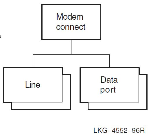
The following steps show the commands for creating the Modem Connect module to set up your lines:
If the configuration procedures have not already created the Modem Connect module, create it manually before configuring the line. (The following example shows how to create the module; for more information on configuring the module, refer to the VSI DECnet-Plus for OpenVMS Installation and Configuration.)
The following example creates, sets, and enables a modem connect line. Do this for each line:
ncl> create modem connect line hdlc-0 - _ncl> communication port comm_port_device_name,-
_ncl> profile "normal", -
_ncl> duplex full
ncl> set modem connect line hdlc-0 modem control full
ncl> enable modem connect line hdlc-0 For a synchronous line, the
communication portattribute, (comm_port_device_name), has two formats:The standard OpenVMS device format, such as sja0
The DECnet dev-c-u format, such as dsv-0-0
where dev-c-u is defined as follows:
dev The first three letters of the synchronous device controller name (such as the dsv in DSV11). c A decimal number (0 or a positive integer) designating a device’s hardware controller. If the third letter of the device name is A, c equals 0. If the third letter of the device name is B, c equals 1, and so on. For example, SJB1: has a c value of 1. u The unit number of the device name; u is always equal to 0 or a positive integer. For example, SJB1: has a u value of 1. Therefore, the second line on the second DSV11 controller could be SJB2 or dsv-1-1.
You can specify two profiles, "normal" or "datexp". (You must include the profile name within double quotes.) The profile defines the maximum, minimum, and defaults of attributes that control the way the device driver monitors and controls the physical interchange circuits connected to the local data circuit-terminating equipment (DCE). Generally, the "normal" profile is the only profile you will need.
Specify the duplex mode of the line as either half or full.
Specify modem control if you want to monitor and use the interchange circuits. You can specify values full or none. A value of none means "data leads only" operation and is incompatible with a duplex value of half.
8.3. Managing Data Links
A data link connection allows DECnet Phase V systems to communicate with other nodes.
If you want to create a new connection, or modify an existing one, you need to create,
set up, and enable appropriate data link entities. VSI recommends that you use your
DECnet-Plus configuration procedure to configure data links. To modify the
hdlc, ddcmp, csma-cd, and fddi data
links, run NET$CONFIGURE ADVANCED. To modify lapb,
llc2, and xot data links, run X25$CONFIGURE.
DECnet-Plus supports the following local area network (LAN) data link entities, as described in Section 8.3.1, ''Creating LAN Data Links'':
csma-cdfddillc2(with X.25)xot(with X.25 on OpenVMS IA-64 and OpenVMS Alpha systems)
DECnet-Plus supports the following wide area network (WAN) data link entities, as described in Section 8.3.2, ''Creating WAN Data Links'':
hdlc(VSI’s HDLC)ddcmp(OpenVMS VAX only)lapb(with X.25)xot(with X.25 on OpenVMS IA-64 and OpenVMS Alpha systems)
For each type of data link you use, you need to manage a different group of entities. For example, for each HDLC data link, you must manage the hdlc link entity plus the modem connect and device Physical layer entities (see Section 8.2, ''Managing Physical Layer Devices and Modem Connect Lines''). The type of data link you use on your node depends on the communication hardware on the system. The following sections provide examples and more detailed information about the supported data link entities.
8.3.1. Creating LAN Data Links
This section explains how to manually create LAN data links. Figure 8.2, ''LAN Data Link Entities'' shows the LAN data link entities for DECnet-Plus for OpenVMS systems:
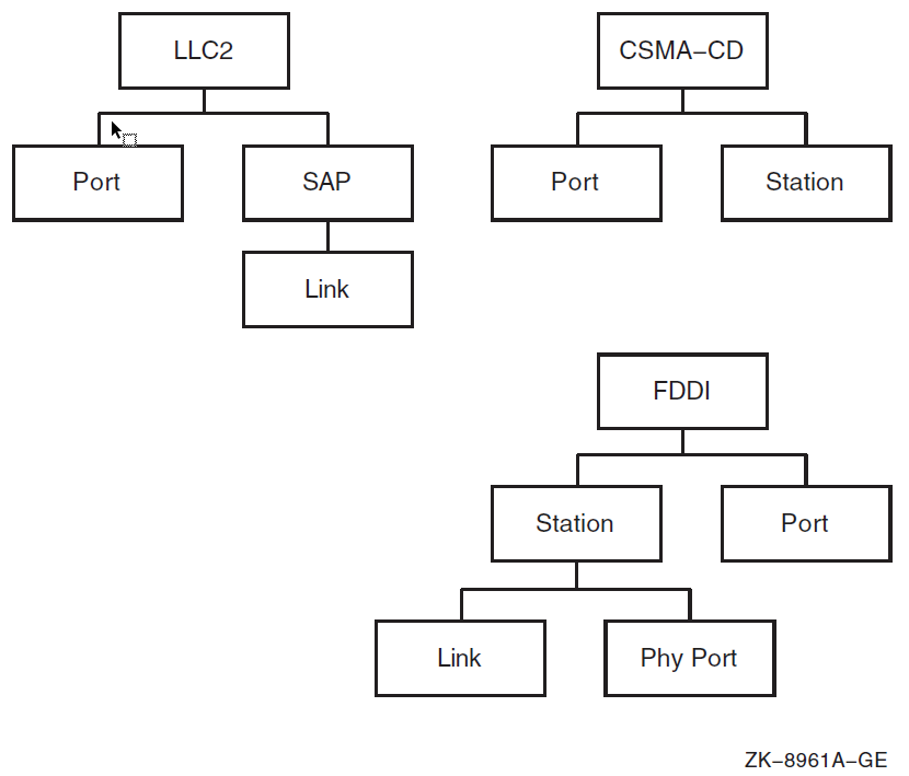
8.3.1.1. Creating CSMA-CD Data Links
The following steps show the commands to create a CSMA-CD data link for an end system. VSI, however, recommends that you accept the default settings (used in the example) for the various attributes and change these only if you need to. Refer to the VSI DECnet-Plus for OpenVMS Network Control Language Reference Guide for more information about these attributes.
Enter the following command to create and enable the csma-cd entity:
ncl> create csma-cd
Enter the following commands to create and enable a csma-cd station and communication port:
ncl> create csma-cd station csmacd-0 - _ncl> communication port port-name
ncl> enable csma-cd station csmacd-0 The port-name refers to the name assigned to the communication device by the operating system. The communication device is hardware that provides an interface between the system and network.
Note
The Routing layer uses only those CSMA-CD stations that have an associated routing circuit entity. See Section 8.4.2, ''Configuring Routing Circuit Information'' for further details.
8.3.1.2. Creating FDDI Data Links
The following steps show the commands to create an FDDI data link for an end node. VSI, however, recommends that you accept the default settings (used in the example) for the various attributes and change these only if you need to. Refer to the VSI DECnet-Plus for OpenVMS Network Control Language Reference Guide for more information about these attributes.
Enter the following command to create and enable the fddi entity:
ncl> create fddi
Enter the following commands to create and enable an fddi station (fddi-1) and communication port.
ncl> create fddi station fddi-1 - _ncl> communication port port-name
ncl> enable fddi station fddi-1 The port-name refers to the name assigned to the communication device by the operating system. It is not user settable.
Note
The Routing layer uses only those FDDI stations that have an associated routing circuit entity. See Section 8.4.2, ''Configuring Routing Circuit Information'' for further details.
8.3.1.3. Creating LLC2 and XOT Data Links
For information about creating LLC2 and X.25 over TCP/IP (XOT) data links, see the VSI X.25 for OpenVMS Management Guide.
8.3.2. Creating WAN Data Links
This section explains how to manually create WAN data links. Note that to configure any synchronous link, you must first create the Modem Connect module to set up the underlying physical lines. See Section 8.2, ''Managing Physical Layer Devices and Modem Connect Lines'' for more information. Figure 8.3, ''WAN Data Link Entities'' shows the WAN data link entities for DECnet-Plus for OpenVMS systems:
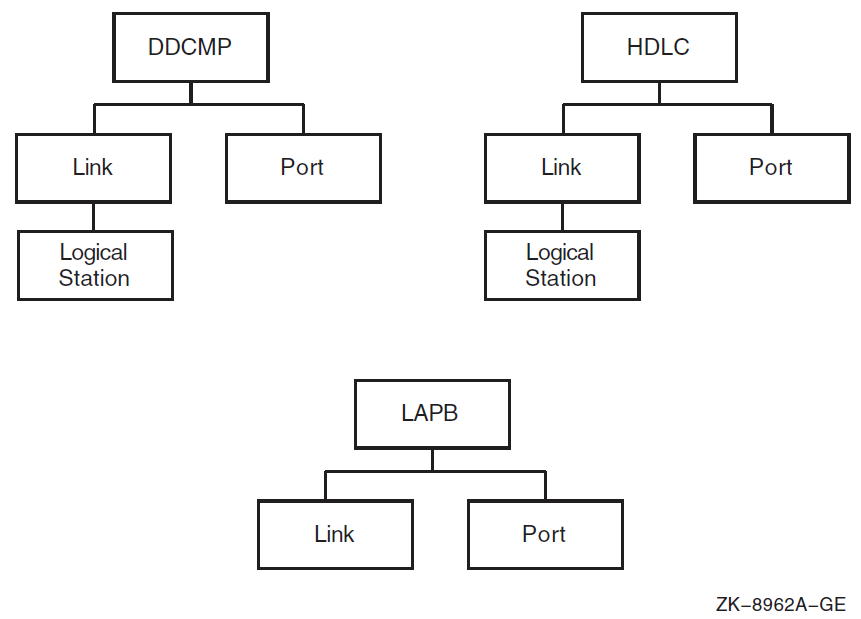
8.3.2.1. Creating HDLC Data Links
The following steps show the commands to create an HDLC data link for an end
system. (As implemented by DECnet-Plus, HDLC is VSI’s variant of the HDLC
protocol. It interoperates with some implementations of HDLC from other
vendors.) VSI recommends that you accept the default settings for the various
attributes and change these only if you need to. Refer to the
VSI DECnet-Plus for OpenVMS Network Control Language Reference Guide for more information about these attributes. You can
configure the device and modem control entities using WANDD$STARTUP
(NET$CONFIGURE automatically invokes WANDD$STARTUP
if needed).
- If the configuration procedures have not already created the HDLC module, create it manually before configuring the link. (The following example shows how to create the module; for information on configuring the module, refer to the VSI DECnet-Plus for OpenVMS Installation and Configuration.)
ncl> create node 0 hdlc
Enter the following commands to create, set, and enable an hdlc link and logical station. Enter the following for each link that you want.
ncl> create hdlc link hdlc-0 linktype balanced
ncl> create hdlc link hdlc-0 logical station hdlc-0
ncl> set hdlc link hdlc-0 physical line -
_ncl> modem connect line hdlc-0, -
_ncl> receive buffers 16, -
_ncl> preferred window size 16, -
_ncl> acknowledge timer 3000, -
_ncl> preferred local station address 2  ncl> enable hdlc link hdlc-0
 logical station hdlc-0
ncl> enable hdlc link hdlc-0
ncl> enable hdlc link hdlc-0 logical station hdlc-0 The name of the link is user settable, and it usually corresponds to the modem connect line.
linktype specifies the operational mode and the station’s role on this link. Use a balanced link for full-duplex circuits. If you are using a half-duplex circuit, you need to specify a linktype of primary or secondary. Specify primary at one end of the link and secondary at the other.
The name of the logical station is user settable, and it usually corresponds to the link.
Associates the hdlc link with a modem connect line.
Set the preferred window size, receive buffers, and acknowledge timer to account for transmission delay, line speed, line quality, and line utilization.
The acknowledge timer measures (in milliseconds) the waiting time between sending a message and receiving a response before retransmitting the message. Increase the value if using a slow link, decrease the value if using a noisy or fast link. The acknowledge timer corresponds to the hdlc t1 timer.
The preferred local station address is the address proposed for this station during xid negotiation. Any addressing conflict is resolved by the xid negotiation procedures.
The preferred local station address is also the proposed address for this local station when it is not running in balanced mode.
8.3.2.2. Creating DDCMP Data Links
The following steps show the commands to create a DDCMP data link for an end system. VSI, however, recommends that you accept the default settings for the various attributes and change these only if you need to. For more information about these attributes, refer to the VSI DECnet-Plus for OpenVMS Network Control Language Reference Guide.
If the configuration procedures have not already created the DDCMP module, create it manually before configuring the link. (The following example shows how to create the module; for information on configuring the module, refer to the VSI DECnet-Plus for OpenVMS Installation and Configuration.)
NCL> create node 0 ddcmp
Enter the following commands to create, set, and enable a ddcmp link and logical station. Enter the commands for each link that you want.
ncl> create ddcmp link ddcmp-0 protocol point
ncl> create ddcmp link ddcmp-0 -
_ncl> logical station ddcmp-0
ncl> set ddcmp link ddcmp-0 -
_ncl> physical line modem connect line ddcmp-0, -
ncl> receive buffers 16, -
_ncl> retransmit timer 3000, -
_ncl> transmit window 16
ncl> enable ddcmp link ddcmp-0
ncl> enable ddcmp link ddcmp-0 logical station ddcmp-0 The name of the link is user settable, and it usually corresponds to the modem connect line.
Protocol specifies the protocol mode of the communication. In addition to point-to-point links, you can specify multipoint links where the local station can act as a control station or a tributary.
The name of the logical station is user settable, and it usually corresponds to the link.
Associates the ddcmp link with a modem connect line.
Set the receive buffers, retransmit timer, and transmit window to account for delay, line speed, line quality, and line utilization.
The retransmit timer attribute measures the waiting time (in milliseconds) between sending a message and receiving a response before retransmitting the message. Increase the value if using a slow link, decrease the value if using a noisy or fast link.
Note
The Routing layer uses only those DDCMP links that have an associated routing circuit entity. See Section 8.4.2, ''Configuring Routing Circuit Information'' for further details.
8.3.2.3. Creating LAPB Data Links
For information about creating LAPB data links, see the VSI X.25 for OpenVMS Management Guide.
8.4. Configuring Routing
DECnet-Plus systems comply with the DECnet Phase V routing architecture. DECnet-Plus systems are normally configured as end systems with dedicated routers used to provide the routing service. DECnet-Plus end systems can communicate with DECnet Phase V routers, DECnet Phase IV routers, and OSI routers from other vendors. You can configure end systems with DECnet Phase V addresses beyond the limits of Phase IV addressing (using extended addresses) if your routing infrastructure supports DECnet Phase V routing.
In summary, DECnet-Plus end systems support:
Communication with nodes running DECnet Phase IV and OSI protocols
Full cluster alias configuration
FDDI large packets. This feature requires a Phase V FDDI router on the same LAN.
X.25 switched virtual circuits (SVCs) and permanent virtual circuits (PVCs)
Note
Review the discussion of routing in the VSI DECnet-Plus Planning Guide.
This section discusses the following three main tasks that are necessary for configuring routing on your DECnet-Plus system:
Setting up the type of routing node and routing address information
Setting up the routing circuit information
Setting up the network routes
Figure 8.4, ''Routing Entity'' shows the routing entity and subentities.
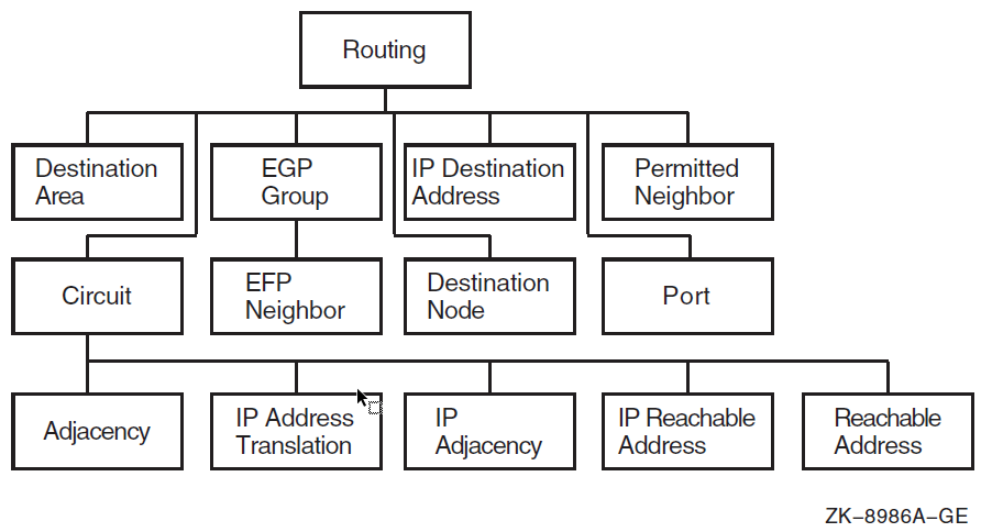
8.4.1. Configuring Routing Type, Mode, and Routing Addresses
This section explains how to set up the routing type, segregated or integrated mode, and routing addresses. It also discusses the features of host-based routing, which you can set up when configuring the DECnet-Plus software.
8.4.1.1. Routing Type
To configure routing, you first create the routing entity, specifying the routing type; set the routing attributes discussed in subsequent subsections; and then enable routing. To set up the routing type, use the routing type attribute as in the following example. The routing type attribute can be endnode, L1router, or L2router.
ncl> create routing type endnode [set routing attributes] . . . ncl> enable routing
To set up your system as a host-based router (or an end system if it is currently set up as a host-based router), use the DECnet-Plus configuration procedure. Host-based routing is explained in Section 8.4.1.2, ''Host-Based Routing''. Likewise, to modify the type of routing your system uses, integrated mode or segregated mode, use the DECnet-Plus configuration procedure or NCL (as explained in Section 8.4.1.3, ''Segregated Mode Routing and Integrated Mode Routing'').
8.4.1.2. Host-Based Routing
DECnet-Plus for OpenVMS supports host-based routing. An OpenVMS system can operate as a DECnet Phase V intermediate system in a routing domain (a collection of systems that automatically configure to each other and exchange network topology information using consistent network layer protocols).
DECnet-Plus for OpenVMS host-based routing includes support for:
Communication with nodes running DECnet Phase IV and OSI protocols.
Cluster aliases (see Section 9.2, ''Using an OpenVMS Cluster Alias''). To enable cluster alias support in environments including WANs or Phase IV nodes, at least one Phase V routing node must exist on the cluster’s LAN. A host-based routing system fulfills this requirement.
Both router levels. A host-based routing system can act as a level 1 (L1) router or a level 2 (L2) router. When configured as a level 2 router, individual circuits can be configured to carry level 2 traffic only.
Both routing algorithms (routing vector and link state) at both the L1 and L2 levels. Different routing algorithms can be used at the L1 and L2 levels. NET$CONFIGURE only supports configuring routers using the routing vector algorithm. To configure a host-based routing system using link state routing, first use the NET$CONFIGURE procedure to configure the system (which results in a routing vector router). Then, use the ISIS$CONFIGURE procedure to modify the system to use link state routing. The use of the ISIS$CONFIGURE procedure is described in the VSI DECnet-Plus for OpenVMS Installation and Configuration. Table 8.3, ''Choosing the Routing Algorithms'' describes briefly how to choose the routing algorithm that the host-based router should use.
Full control of all level 1 and level 2 routing parameters. You can assign values to all the routing characteristics associated with dedicated routing nodes. These include Phase IV characteristics (such as phaseiv maximum address, and phaseiv maximum area, Phase V characteristics (such as manual area addresses), and routing circuit characteristics (such as l1 and l2 cost and l1 and l2 router priority).
FDDI large packets. If you have configured your end node systems to use FDDI large packets, their host LAN must have at least one Phase V router that supports FDDI large packets. You can fulfill this requirement by enabling large packet support on the system’s FDDI routing circuits. To enable FDDI large packets, set the routing circuit’s type characteristic to fddi.
Data Communications Message Protocol (DCMP) (supported on OpenVMS VAX only). When configuring DDCMP links to Phase IV routers, you must set the routing circuit’s manual data link sdu size attribute and the Phase IV router’s executor buffer size parameter to the same value.
X.25 switched virtual circuits (SVCs) and permanent virtual circuits (PVCs). Note that X.25 dynamically-assigned (DA) circuits can only be used for level 2 routing. Also, X.25 DA circuits require that you configure corresponding routing circuit reachable address entities.
| If... | Then... |
|---|---|
|
There are DECnet Phase IV routers in the same area as the host-based router. |
You must configure the host-based router to use the routing vector algorithm at level 1. |
|
All the routers in the same area as the host-based router are running the link state algorithm. |
You must configure the host-based router to use the link state routing algorithm at level 1. |
|
The host-based router only communicates with level 2 routers running the routing vector algorithm. |
You should configure the host-based router to use the routing vector algorithm at level 2. |
|
The host-based router only communicates with level 2 routers running the link state algorithm. |
You should configure the host-based router to use the link state algorithm at level 2. |
|
The host-based router communicates with level 2 routers running the routing vector algorithm and with level 2 routers running the link state algorithm. |
You should configure the host-based router to use the link state algorithm at level 2. Then, configure interphase links (using routing circuit reachable address entities) to the level 2 routers running the routing vector algorithm. You can configure interphase links automatically using the create ipl_initialization_file command of the decnet_migrate utility (see Chapter 4, "Managing Routing Between DECnet Phase IV and Phase V Areas") or manually using the ISIS$CONFIGURE procedure (see the VSI DECnet-Plus for OpenVMS Installation and Configuration). |
Host-based routing is especially useful for those configurations where you need to route from a LAN to a WAN and want to use an existing system to do the routing rather than investing in a dedicated router. Host-based routing is not intended for use in network configurations that have high-throughput requirements.
The following commands were generated by NET$CONFIGURE to configure a level 2 router using the routing vector routing algorithm:
ncl> create node 0 routing type l2router ncl> set node 0 routing phaseiv address = 23.14 ncl> set node 0 routing phaseiv prefix = 49:: ncl> set node 0 routing manual l1 algorithm = routing vector ncl> set node 0 routing manual l2 algorithm = routing vector ncl> set node 0 routing default eshello timer 600 ncl> set node 0 routing maximum path splits = 2 ncl> set node 0 routing phaseiv maximum address = 1023 ncl> set node 0 routing phaseiv maximum area = 63 ncl> set node 0 routing phaseiv buffer size = 576 ncl> enable node 0 routing
The following commands were generated by ISIS$CONFIGURE to configure a level 2 router using the link state routing algorithm:
ncl> CREATE NODE 0 ROUTING TYPE L2ROUTER
ncl> SET NODE 0 ROUTING MANUAL AREA ADDRESSES = {12:234}
ncl> SET NODE 0 ROUTING MANUAL L1 ALGORITHM = LINK STATE
ncl> SET NODE 0 ROUTING MANUAL L2 ALGORITHM = LINK STATE8.4.1.3. Segregated Mode Routing and Integrated Mode Routing
For end systems, you have the option of using integrated mode routing or segregated mode routing.
Integrated mode routing works in the following way: It sends DECnet Phase IV messages across the network using DECnet Phase V Network layer protocols. Routers receiving DECnet Phase IV packets translate them to OSI CLNP format before forwarding them. Messages destined for DECnet Phase IV systems are translated to Phase IV format only on the last hop of their journey. Integrated mode routing allows routers to route both DECnet Phase IV and Phase V traffic while storing a single network topology in their internal databases.
Under integrated mode, DECnet-Plus systems attempt to send packets in DECnet Phase V format unless:
They are communicating directly to an adjacent DECnet Phase IV system.
or
No DECnet Phase V routers exist on the network to forward the packets.
Integrated mode routing is the only mode supported on OpenVMS systems preceding DECnet/OSI for OpenVMS Version 5.8.
Segregated mode routing handles DECnet Phase IV and Phase V as independent protocols. Routers do not translate messages between DECnet Phase IV and Phase V format. The routers must maintain separate network topologies in their internal databases to handle each type of protocol.
Under segregated mode, DECnet-Plus end systems transmit messages in the Phase IV address format if they have a DECnet Phase IV translatable destination address. All other messages are sent in DECnet Phase V format. If you use non-VSI routers that do not support VSI’s technique of translating DECnet Phase V addresses to DECnet Phase IV, you may want to use segregated mode routing.
Integrated mode is the default routing mode. To configure segregated mode, use the advanced configuration procedure or NCL. With NCL, you can switch from the default to segregated mode by setting the routing mode attribute, as in the following commands:
ncl> disable routing ncl> set routing routing mode = segregated ncl> enable routing
Note
If your OpenVMS system is running cluster alias, you must use integrated mode.
Use integrated routing mode in an integrated routing environment where the routers can handle Phase-IV-to-Phase-V or Phase-V-to-Phase-IV packet format conversions. Use segregated routing mode when the adjacent routers cannot perform Phase-IV-to-Phase-V or Phase-V-to-Phase-IV packet conversions.
8.4.1.4. Autoconfiguring Network Addresses
A DECnet Phase V environment is a subnetwork where OSI systems, both end systems and intermediate systems (ES-IS), adhere to the DECnet Phase V routing protocol and support DNA-structured NSAP addresses, as defined in the VSI DECnet-Plus Planning Guide. When existing in a Network Architecture (NA) environment, an end system can determine (that is, autoconfigure) its network addresses from information sent by the routers in its subnetwork. In this environment, you do not have to manually set the local network service access point (NSAP) addresses. This is the default during configuration using NET$CONFIGURE.COM. In some networks, you must manually set the network address at configuration time.
An empty set for the manual network entity titles attribute indicates the use of autoconfiguration. If the set is non-empty, autoconfiguration does not take place. To change the value of this routing attribute from an empty set to a non-empty set, or from a non-empty set to an empty set, the routing entity must be disabled.
Note
The dna address format attribute controls the interpretation of Phase IV addresses; it does not control whether autoconfiguration takes place.
8.4.1.5. Configuring a Phase IV Network Address
DECnet Phase IV nodes cannot recognize DECnet Phase V addresses. However, DECnet Phase V nodes can recognize Phase IV addresses. For a DECnet Phase V node to communicate with a Phase IV node, the DECnet Phase V node must have a Phase IV address that conforms to the normal Phase IV limits (area number less than or equal to 63 and node number less than or equal to 1023). You must configure this Phase IV address on your DECnet-Plus system.
Use the DECnet-Plus configuration procedure or the following command to set up a Phase IV address. For this command to succeed, routing must not be enabled.
ncl> set routing phaseiv address 12.1
The Phase IV address along with a Phase IV address prefix is used to construct a Phase IV-compatible NSAP address. This is done by concatenating the Phase IV address prefix, the area portion of the Phase IV address, the DECnet LAN address, and a transport selector. See Section 10.2.2 for information on how to convert the Phase IV address to a DECnet LAN address. For example, if a system’s Phase IV address is 12.1 and the Phase IV address prefix is 49::, the resulting NSAP addresses for NSP and OSI Transport are respectively (where 12 decimal is converted to 0c hexadecimal and 12.1 is converted to DECnet LAN address of aa-00-04-00-01-30):
49::00-0c:aa-00-04-00-01-30:20 49::00-0c:aa-00-04-00-01-30:21
In the same way that they learn their OSI network addresses, end systems learn their Phase IV address prefix from the routers in the subnetwork. Only if there are no DECnet Phase V routers present, does the end system use its own routing attribute phaseiv prefix to construct its Phase IV-compatible NSAP address.
For an end system to learn its Phase IV address prefix, you must configure it into the routers of the subnetwork in which the system resides. The default prefix for all systems is 49::. If you want to use a different initial domain part (IDP) and pre-DSP (domain-specific part), you can override the default by setting the phaseiv prefix attribute as follows. For this command to succeed, routing must not be enabled.
ncl> set routing phaseiv prefix 37:1234:
For example, if you configure a router in area 41 with the phaseiv prefix 37:1234:, any DECnet-Plus end system with a Phase IV address in area 41 sets its Phase IV area as follows, where 41 decimal is converted to 29 hexadecimal:
37:1234:00-29:
This results in a Phase IV-compatible NSAP address of the form:
37:1234:00-29:aa-00-04-00-nn-nn:ss
All systems in the subnetwork should have the same Phase IV prefix, but because DECnet Phase V systems autoconfigure, you only need to set the prefix on the routers used by the end system. VSI, however, recommends that you ensure that the phaseiv prefix attribute is consistently set on all DECnet Phase V systems.
Note
For DIGITAL Network Architecture (DNA) routing (via the Connectionless Network Protocol (CLNP)), DECnet-Plus does not support the configuration of NSAPs using decimal DSP (domain-specific parts) syntax. VSI supports X.121 format NSAPs (AFI=36) for the use of OSI transport over the Connection-Oriented Network Service (CONS), which requires the X.25 for OpenVMS product.
8.4.1.6. Configuring End System Network Addresses for Non-DNA Networks
If your end system is operating in an environment with one or more non-DNA routers, your DECnet-Plus end system cannot autoconfigure its network address or network entity title (NET). (The NET is the address that identifies the Network layer.) In this case, you can manually specify up to three NETs for your system. To do this, you need to know the following information about the node:
The network IDP
The area where the node resides
The node ID
The following sequence of commands specifies the NET for a system:
ncl> create routing type endnode
ncl> set routing manual network entity titles -
_ncl> { 41:45418715:00-49:08-00-2b-00-01-02:00}
ncl> enable routing
| Specifies the NET for the node so the node does not attempt to autoconfigure. For information about NETs and NSAPs, see the VSI DECnet-Plus Planning Guide. |
To make this change permanent, rerun the advanced configuration procedure or add these commands to the NET$ROUTING_STARTUP.NCL script file after the line create routing type endnode. (Replace the string (41:45418715:00-49:08-00- 2b-00-01-02:00) with the correct NET for your node.) The next time you reboot the system, DECnet-Plus uses this new information.
Note
Phase IV backward compatibility is not supported when operating in a non-DNA environment. Therefore, the routing attribute phase iv address should be set to 0.0 or left unset.
8.4.2. Configuring Routing Circuit Information
This section explains how to configure routing circuit information and how to set up a multicircuit configuration.
The following example shows how to configure routing circuit information. The first three commands set up the routing type and addressing information, as described in Section 8.4.1, ''Configuring Routing Type, Mode, and Routing Addresses''. The remaining commands set up the routing circuit, as described below.
ncl> create routing type endnode
ncl> set routing dna address format true, lifetime 63, -
_ncl> manual network entity titles {}, probe rate 20
ncl> enable routing
ncl> create routing circuit hdlc-0 type hdlc
ncl> set routing circuit hdlc-0 data link entity -
_ncl> hdlc link hdlc-0 logical station hdlc-0, -
_ncl> manual data link sdu size 1492, -
_ncl> template template-name
ncl> enable routing circuit hdlc-0
| You need to configure routing circuits:
Table 8.4, ''Routing Circuits Supported for CLNS'' lists the supported routing circuits for CLNS on your system. For information on configuring routing to use an X.25 data link, see Section 8.8.2, ''Configuring Routing Over X.25 Circuits''. |
| Associate the routing circuit with the appropriate data link entity. The data link entity attribute is valid for all circuits.
|
| The manual data link sdu size attribute is valid for all circuits. |
| The template attribute is valid for X.25 circuits and ignored for all other circuits. |
| Circuit | Description |
|---|---|
csma-cd | IEEE 802.3 LAN routing circuit |
hdlc | Synchronous HDLC circuit |
ddcmp | Synchronous DDCMP circuit |
fddi | Fiber Distributed Data Interface (FDDI) for LANs |
x25 static incoming | X.25 inward switched virtual circuit |
x25 static outgoing | X.25 outward switched virtual circuit |
x25 da | Dynamically-assigned X.25 virtual circuit |
x25 permanent | Permanent X.25 virtual circuit |
Table 8.5, ''Additional Routing Circuit Attributes for CLNS'' lists additional attributes to consider when setting up a routing circuit with CLNS. It also shows the circuits for which the attributes are valid.
| Attribute | Valid Circuit Type |
|---|---|
idle timer | x25 da |
inactive area address | csma-cd |
initial minimum timer |
|
manual routers | csma-cd |
maximum call attempts | x25 static outgoing |
maximum svc adjacencies | x25 da |
recall timer | x25 static outgoing |
reserved adjacency | x25 da |
reserve timer | x25 da |
x25 filters |
|
For inactive area address:
Each LAN circuit that supports Null Internet must specify a different inactive area address.
For circuits using only CLNS/ES-IS, this characteristic is an empty set (this is the default value).
For initial minimum timer:
On X.25 static incoming or outgoing circuits, if no adjacency has been established when this timer expires, the circuit is cleared.
8.4.2.1. Configuring Multiple Circuits for End Systems
DECnet Phase V end systems can operate over more than one data link. As such, traffic can be sent or received over any of the links, but protocol data units (PDUs) are not forwarded from one link to another. In other words, a multicircuit end system does not perform the functions of a router. Instead, this function provides network redundancy, as well as higher throughput, depending upon the configuration.
DECnet-Plus for OpenVMS supports up to 16 circuits. Hardware, OpenVMS, or WANDD software, however, can further limit the number of circuits you can have. For more information about possible limits, refer to your system and WANDD documentation.
When communicating with remote systems, data PDUs are sent over all circuits in turn. If the remote end system is directly connected on one or more circuits, only those circuits are used to reach the end system. Moreover, a single data PDU is transmitted over all circuits at the interval at which you set the probe rate.
The probe rate is a Routing module attribute that has a default value of 1000. Therefore, every thousandth data PDU bound for a specific end system is transmitted on all circuits. This helps ensure that all available paths are used.
When operating a DECnet-Plus end system in a multicircuit configuration, you must adhere to certain topology restrictions:
All the links must be in the same area. That is, the set of area addresses (a Routing module status attribute) must be the same for each circuit.
All the data links must be of similar capacity or usable bandwidth.
If an end system has multiple circuits connected to an extended LAN, only one of those circuits can have the attribute enable phase iv address set to true.
Failure to comply with these restrictions might result in unacceptable operation.
To create multiple circuits for an end system on a CSMA-CD LAN, use the DECnet-Plus configuration procedure. VSI recommends that you accept the default settings (used in the example in Section 8.4.2.2, ''Sample NCL Script for Configuring Multiple Routing Circuits'') for the various attributes and change these only if you need to. Refer to the VSI DECnet-Plus for OpenVMS Network Control Language Reference Guide for more information about these attributes.
8.4.2.2. Sample NCL Script for Configuring Multiple Routing Circuits
The following example shows the contents of the file NET$ROUTING_STARTUP.NCL, located by default in SYS$SPECIFIC:[SYSMGR]. This file is created by the DECnet-Plus for OpenVMS configuration procedure. The file enables routing, creates the Routing module, and creates CSMA-CD and FDDI circuits.
create node 0 routing type endnode set node 0 routing phaseiv address = 4.884 set node 0 routing phaseiv prefix = 49:: set node 0 routing dna address format true set node 0 routing default eshello timer 600 enable node 0 routing create node 0 routing circuit csmacd-0 type = csma-cd set node 0 routing circuit csmacd-0 data link entity = csma-cd station csmacd-0 set node 0 routing circuit csmacd-0 enable phaseiv address = false enable node 0 routing circuit csmacd-0 create node 0 routing circuit fddi-0 type = fddi set node 0 routing circuit fddi-0 data link entity = fddi station fddi-0 set node 0 routing circuit fddi-0 enable phaseiv address = true enable node 0 routing circuit fddi-0
Note
To delete and disable entities, see the information in Section 6.5, ''Deleting Network Entities''.
8.4.3. Setting Up Network Routes
The primary function of the Routing layer is to identify the best path to a given destination. DECnet Phase V systems have multiple mechanisms to determine such a path. Under most circumstances, these mechanisms work automatically without any need for special configuration. This section describes the routing mechanisms and explains how to use them to handle special circumstances.
DECnet-Plus uses the following rules in order of precedence to determine where to send each packet:
If the destination has a routing circuit inactive area address attribute set for the circuit, DECnet-Plus sends the message over the indicated circuit using the Null Internet format (Section 8.4.3.1, ''Configuring CLNS with Null Internet'').
If the route is explicitly defined in a routing circuit reachable address attribute, DECnet-Plus sends the packet to the indicated destination (Section 8.4.3.2, ''Configuring Routing Reachable Addresses'').
If the DECnet-Plus system recently communicated with a given destination, the paths to that destination are saved in the end node cache. DECnet-Plus uses one of the cached paths (Section 8.4.3.3, ''Routing Use of the End System Cache'').
If adjacent routers are known to exist on any of the attached circuits, DECnet-Plus sends the message to one of the routers (Section 8.4.3.4, ''Configuring Network Adjacencies to Non-DNA Routers'').
If the destination is within the sender’s area, DECnet-Plus broadcasts the message to all end nodes on all attached LANs.
8.4.3.1. Configuring CLNS with Null Internet
DECnet-Plus supports the inactive subset of CLNS, also known as null internet. An inactive subset PDU contains no Network layer addressing information; it is sent directly to the data link address derived from the destination NSAP address. Therefore, it cannot be routed by an intermediate system. This means that only LAN devices can support the inactive subset PDU, and the two communicating nodes must be on the same LAN. The inactive subset of CLNS allows communication with OSI systems that only implement the inactive subset.
Configuring CLNS with null internet is no different from configuring full CLNS, with the following restrictions:
The routing circuit entity must have its type attribute set to csma-cd.
You must specify a value for the inactive area address attribute of the routing circuit entity. For inactive area address, each LAN circuit that supports null internet must specify a different inactive area address. (For circuits using only CLNS/ES-IS, this attribute is an empty set (this is the default value).)
For more information on configuring CLNS OSI transport to use the null internet, see Section 8.5.2.4.3, ''Null Internet Information''.
You can turn the ability to transmit and receive inactive subset protocol data units (PDUs) on and off on a per circuit basis by defining a value for the circuit attribute inactive area address. The following example uses the default inactive area address attribute on a LAN:
ncl> create routing circuit csmacd-0 -
_ncl> type csma-cd
ncl> set routing circuit csmacd-0 -
_ncl> inactive area address {49::FF-00}
ncl> enable routing circuit csmacd-0 You must do this after the circuit is created, but before you enable it. The value is the address of an otherwise unused area in your network.
If you want to change the transport, modify the Routing module’s preset attribute, inactive selector, with the selector of the transport you want to use. Only one transport may use the inactive subset and, by default, this is OSI transport (which has a default selector value of 33). To operate NSP over the inactive subset, before enabling the Routing module (and any circuits) enter the command:
ncl> set routing inactive selector 32
When using the inactive subset, destination NSAPs must contain the inactive area address followed by the data link address of the remote machine followed by the transport selector. For example:
49::FF-00:08-00-23-00-01-02:21
8.4.3.2. Configuring Routing Reachable Addresses
Reachable addresses allow the system manager to override the automatic routing mechanisms in DECnet-Plus. You can define reachable addresses for each circuit. Two types of reachable addresses are outbound and filter, as described below. (For information about routing reachable addresses used for X.25 routing circuits, see Section 8.8.2.2, ''Configuring Routing Over X.25 Dynamically-Assigned Circuits''.)
Outbound (the default) — Defines the destination data link address for packets whose destination NSAP address start with the specified address prefix. If a packet’s destination NSAP matches multiple reachable address entities, the one with the longest address prefix is used. Outbound reachable addresses are supported on broadcast circuits and X.25 dynamically-assigned circuits. Outbound reachable addresses are necessary to transmit packets directly to nodes in other routing domains.
Filter — Reachable addresses of this type are for broadcast circuits only and specify the permitted LAN addresses of routers on the LAN. Only those routers with LAN addresses that are listed in the permitted LAN addresses attribute (described below) will be used for transmitting packets before the routing circuit establishes its reverse path cache.
You can use NCL to switch from the default (outbound) to filter by setting the reachable address entity type attribute to the value filter. You must disable the routing reachable address entity before changing the value of the type attribute.
Note
For either the outbound or filter type of reachable address, you must set the mapping attribute to manual (the default is x.121). See the command example below.
The following reachable address attributes are supported by outbound reachable addresses:
data format format, where format is either phase v (the default) or phase iv. This attribute specifies the PDU data format to be used when forwarding data network protocol data units (NPDUs) using this reachable address.block size size, where size can be in the range of 0 (the default) to 65535. This attribute defines the data link block size to be used for this prefix. If the block size is set to the default, the manual block size of the circuit will be used instead.lan address xx-xx-xx-xx-xx-xx, where xx-xx-xx-xx-xx-xx specifies the single LAN address to which an NPDU may be directed in order to reach an address that matches the address prefix of the parent reachable address entity. The default value is 00-00-00-00-00-00. You must specify a valid LAN address. This attribute applies to broadcast circuits only.
The following example shows how to use NCL commands to create an outbound type of reachable address:
ncl> create routing circuit csmacd-0 reachable address to-area4 - _ncl> address prefix 49::00-04: ncl> set routing circuit csmacd-0 reachable address to-area4 - _ncl> mapping manual ncl> set routing circuit csmacd-0 reachable address to-area4 - _ncl> type outbound ncl> set routing circuit csmacd-0 reachable address to-area4 - _ncl> data format phaseiv ncl> set routing circuit csmacd-0 reachable address to-area4 - _ncl> block size 500 ncl> set routing circuit csmacd-0 reachable address to-area4 - _ncl> lan address aa-00-04-00-xx-xx
The permitted lan addresses attribute applies to filter reachable addresses for broadcast circuits only. This attribute specifies a set of LAN addresses corresponding to routers that are permitted to forward to this prefix. The default is an empty set. You must specify at least one LAN address. Specify these LAN addresses within a pair of braces, separating the addresses by commas, as in the last command in the following example, which shows how to create a filter reachable address.
ncl> create routing circuit csmacd-0 reachable address to-area4 -
_ncl> address prefix 49::00-04:
ncl> set routing circuit csmacd-0 reachable address to-area4 -
_ncl> mapping manual
ncl> set routing circuit csmacd-0 reachable address to-area4 -
_ncl> type filter
ncl> set routing circuit csmacd-0 reachable address to-area4 -
_ncl> data format phasev
ncl> set routing circuit csmacd-0 reachable address to-area4 -
_ncl> permitted lan address {aa-00-04-00-xx-xx, aa-00-04-00-yy-yy} 8.4.3.3. Routing Use of the End System Cache
The Routing module stores information about remote systems (including NSAP addresses) to which data transfer is in progress. This information is known as the end system cache, and the data stored in this cache allows the Routing layer to quickly choose the correct data link address to which packets should be forwarded, as well as which format (Phase IV or OSI) should be used. The cache entries are created automatically, based upon the receipt of data and/or routing redirect packets, and indicate if the remote system is on-LAN (direct), or reachable by way of a router (indirect or reverse).
When an end system communicates to another node for the first time, the end system cache has no routing information for that node. The end system chooses at random an adjacent router and transmits the data to it, allowing the adjacent router to find a path to the destination node. The end system creates cache entries based on information about the routing path received from incoming data sent by routers and from advertisements sent directly from other end systems.
Cache entries are each assigned a precedence which determines the path chosen when two or more cache entries refer to the same destination. The Routing module assigns precedence as shown in Table 8–6, where 1 is the highest precedence. Direct reachability indicates the path is direct from source to destination without intermediary routers. Indirect indicates the path is through one or more intermediary routers. Reverse reachability implies the directness of the path is indeterminate at the time (whether a direct path exists will be resolved during subsequent communications).
A reverse path cache entry indicates that a data packet was received from an adjacent node on a specific circuit. The adjacent node could be the original sender or the last router that forwarded the packet. Given no other information, the most efficient path for sending response packets is usually the path the original data message followed.
Note
A static routing path that is defined by a reachable address of type outbound has the highest precedence. All other cache entries for the same destination are ignored.
| Precedence | Reachability | Blocksize |
|---|---|---|
| 1 | Direct | FDDI |
| 2 | Indirect | FDDI |
| 3 | Reverse | FDDI |
| 4 | Direct | Non-FDDI |
| 5 | Indirect | Non-FDDI |
| 6 | Reverse | Non-FDDI |
The Routing module follows these rules for making a cache entry:
If an entry for a destination NSAP address with higher precedence already exists (on any circuit), no cache entry is made.
If any entries for a destination NSAP address with lower precedence already exist on any circuit, they are deleted from the cache and a new cache entry is created.
If an entry for a destination NSAP address with the same precedence exists on the same circuit and with the same data link address (and any type), the remaining fields in the cache entry are updated.
When multiple paths with the same precedence exist for the same destination, the Routing module selects the path based on round robin. This helps balance the load on the paths. On multicircuit end systems, if no direct path to the destination node exists on a broadcast circuit, a duplicate packet is sent periodically, as determined by the probe rate.
The es cache holding time attribute determines how long an entry is held in the end system cache. The default is 600 seconds. The timer is refreshed each time a data packet is successfully received by the destination node over the path defined by the entry. The entry is deleted if no communication occurs between the source and destination nodes within the period defined by the timer. This maximizes the effectiveness of the end system cache.
Displaying Cache Entries
Use the System Dump Analyzer (SDA) to show cache entries, as in the following example:
$ analyze/system
OpenVMS (TM) System Analyzer
SDA> net show routing cache
%SDA-I-READSYM, 3361 symbols read from SYS$COMMON:[SYSEXE]NET$SYMBOLS.STB;1
DECnet-Plus for OpenVMS Routing ES Cache Dump
--------------------------------------------
Routing Prefix DataBase Address 816C63A8
Prefix Table Start: 825D5F0C , End: 825D610C, Size 0
Routing Cache DataBase Address 816C6390
Cache Table Start: 825D10CC , End: 825D12CC, Size 1
Cache Entry at Address 825D256C
NSAP:
4900 04AA0004 007F1321
OSI Transport - (4.895)
Cache Circuit Entry Count : 1, Probe Count: 992
Cache Circuit List: 8260B500
Cache Circuit Entry:
Type: BroadCast
Format: PhaseV
Reachability: Direct
Blocksize: Non-FDDI
Remaining LifeTime: 005F
Holding Time: 0258
Data Link Address:
137F 000400AA ª..... 00000000
(4.895)
SDA>8.4.3.4. Configuring Network Adjacencies to Non-DNA Routers
DECnet Phase IV and Phase V end systems and routers regularly advertise their existence on their attached data links. DECnet-Plus nodes listen for these advertisements and automatically build (autoconfigure) an adjacency database. For LANs, the adjacency database contains the list of routers attached to each circuit. For WAN circuits, the adjacency database identifies the type of node attached to the other end of the circuit, router or endnode. DECnet-Plus also automatically records OSI systems from other vendors in its adjacency database as OSI-only nodes.
If the routers in a subnetwork do not adhere to the DECnet Phase V routing protocol (in other words, they are non-DNA routers), DECnet Phase V end systems are unable to create physical connections to them.
Normally, a DECnet Phase V end system learns about its routers through the ES-IS protocol. If your LAN has only routers that do not implement the ES-IS protocol, you must identify the LAN address of the routers that the DECnet Phase V end system uses. Included in the following sequence of commands is a command needed for specifying the LAN address for a CSMA-CD data link. The command is called out (1).
Note
You do not need to do this if there are routers on the LAN that support ES-IS.
ncl> create routing type endnode
ncl> enable routing
ncl> create routing circuit csmacd-0 -
_ncl> type csmacd
ncl> set routing circuit csmacd-0 manual routers -
_ncl> { 08-00-2b-00-01-03, 08-00-2b-00-03-04 }
ncl> set routing circuit csmacd-0 -
_ncl data link entity csma-cd station csmacd-0
ncl> enable routing circuit csmacd-0
| This command identifies the LAN address of the routers that the DECnet Phase V end system uses. You can specify up to five routers in this command line. |
Displaying Adjacencies
Display routing adjacencies by using the following NCL command:
ncl> show routing circuit circuit_name adjacency * allThe following example shows two adjacencies for circuit csmacd-0:
$ mcr ncl show routing circuit csmacd-0 adj * all
Node 0 Routing Circuit CSMACD-0 Adjacency RTG$0001
at 2019-07-24-09:48:29.181-04:00I22.051
Identifiers
Name = RTG$0001
Status
Type = Autoconfigured
State = Up
LAN Address = 08-00-2B-A2-08-B9
Neighbor Node Type = Phase V Router
Router NETs =
{
47:24:02-01-0A-04:08-00-2B-A2-08-B0:00 ,
49::00-04:AA-00-04-00-F5-13:00 (DEC:.LKG.LKISL2)
}
Node 0 Routing Circuit CSMACD-0 Adjacency RTG$0002
at 2019-07-24-09:48:29.191-04:00I22.051
Identifiers
Name = RTG$0002
Status
Type = Autoconfigured
State = Up
LAN Address = AA-00-04-00-FF-13 (LOCAL:.A04NIS)
Neighbor Node Type = Phase V Router
Router NETs =
{
47:24:02-01-0A-04:08-00-2B-A0-17-90:00 ,
49::00-04:AA-00-04-00-FF-13:00 (LOCAL:.A04NIS)
}
| The adjacency type attribute can be autoconfigured or manual. An autoconfigured adjacency is one that was configured automatically by means of hello PDUs. A manual adjacency is one that was created manually, such as by the create command. |
| The neighbor node type attribute indicates whether the neighboring node is a DECnet Phase V router or a Phase IV router. |
Networking with Routers That Do Not Support Phase IV Backward Compatibility
Connectivity from a DECnet Phase V end system to a Phase IV node through a router that does not support Phase IV backward compatibility is not possible. A non-DNA OSI router does not know how to translate a DECnet Phase V address to a Phase IV address, or convert Network layer data protocol data unit (PDU) formats. The following are possible solutions to consider:
Replace the non-DNA routers with routers that understand both DECnet Phase V and Phase IV backward compatibility. If the final destination is a Phase IV end node, the router converts the OSI PDU to a Phase IV PDU that the Phase IV end node can understand and respond to.
Obtain one DECnet Phase V router and set up static routes on the non-DNA routers to route all data with Phase IV style NSAPs to the DECnet Phase V router. The DECnet Phase V router performs the Phase IV backward compatibility function that the non-DNA OSI router is unable to do.
On a LAN with both routers that support Phase IV backwards compatibility and routers that do not support Phase IV backwards compatibility, set up the end systems in segregated mode. See Section 8.4.1.3, ''Segregated Mode Routing and Integrated Mode Routing'' for details.
You can also consider the following alternative:
If the end system does not require connections to a Phase IV node, configure the end system to perform only the OSI protocol. To operate as an OSI-only node, do not set a Phase IV address. However, you may still need to set the Phase IV prefix. For further information on the Phase IV prefix, see Section 8.4.1.5, ''Configuring a Phase IV Network Address''.
If you have configured your DECnet-Plus end systems to have a Phase IV- compatible address and you are operating in a non-DNA environment, you must ensure that all level 2 non-DNA OSI routers advertise the complete set of area addresses for the level 1 networks to guarantee connectivity between your DECnet-Plus end systems.
8.5. Managing Transport Services
DECnet Phase V nodes support multiple transport protocols. DECnet Phase IV nodes have Network Services Protocol (NSP) as the only transport protocol available. DECnet Phase V nodes have NSP and OSI transport available. DECnet Phase V automatically determines a compatible transport protocol between communicating nodes.
OSI transport on DECnet Phase V systems supports the Connection-Oriented Transport Protocol specification (International Standard ISO 8073) and the Connectionless-Mode Transport Protocol specification (International Standard ISO 8602). The OSI transport can use two types of network services:
The Connection-Oriented Network Service (CONS)
The Connectionless-Mode Network Service (CLNS)
The Routing module supports CLNS. The X25 Access module supports CONS.
The OSI transport implements the RFC 1006 and RFC 1859 specifications, using TCP network services.
DECnet-Plus automatically starts with both OSI transport and NSP. If, for any reason, you want to disable either transport protocol, use disable nsp or disable osi transport.
If you do not want session control to use a particular protocol, use one of the following commands:
ncl> delete session control transport service osi ncl> delete session control transport service nsp
This section explains how to configure and manage:
NSP
OSI transport protocol
DECnet over TCP/IP
OSI over TCP/IP
8.5.1. Configuring NSP
This section explains how to configure the Network Services Protocol (NSP). The following example shows the commands to create the nsp entity on your system. VSI recommends that you accept the default settings (used in the example) for the various attributes and change these only if you need to. Refer to the VSI DECnet-Plus for OpenVMS Network Control Language Reference Guide for more information about these attributes. Figure 8.5, ''nsp Entity'' shows the nsp entity and its subentities.
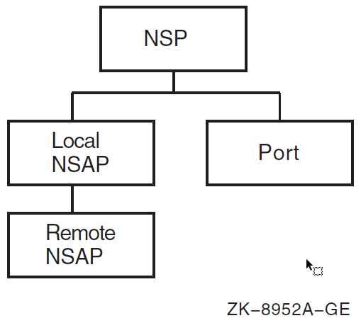
ncl> create nsp ncl> set nsp delay factor 2, delay weight 3, -
| The effect of delay factor is to increase the retransmission time by increasing the average round-trip delay time, thus allowing for additional network delay. The value of the weighting factor is given by the delay weight attribute. Basically, delay weight determines how quickly the retransmission timer responds to variations in actual round-trip delay times. A low value of delay weight means that the retransmission timer responds quickly to each sample of round-trip delay time; a delay weight of 0 means that an estimate will be nearly the same as the last actual sample of round-trip delay. A high value for delay weight will reduce the impact of recent variations in network delay; the higher the value, the closer each estimate of round-trip delay will be to the average of all estimates. The default values of delay factor and delay weight should be suitable for most networks. However, consider increasing these values if wide variations in round-trip delay times exist on your network. |
| You can save memory resources by reducing the value of maximum remote nsaps. However, you will not have access to the information provided by this entity’s counters and status attributes (except through information in event logs). The maximum remote nsaps value must be greater than the value of maximum transport connection. |
| The NSP transport receiver’s window is controlled by a combination of the maximum transport connections, maximum receive buffers, and the maximum window attributes. The receiver initial quota is determined by dividing the value of maximum receive buffers by the value of maximum transport connections. During the life of the connection, the receiver quota fluctuates, using the value of maximum receive buffers divided by the value of currently active connections. The credit window sent to the remote transmitter may be this quota value, depending on the value of the maximum window attribute. If the value of maximum window is less than the determined receiver quota, the value of the maximum window is used instead for the credit granted to the remote transmitter. The transmitter on an NSP transport connection uses the credit sent by the remote receiver as its transmit window, unless the value of maximum window is lower than this value. In that case, the value of maximum window is used for the transmitter window. By controlling the transmitter and receiver windows in this way, a dynamic balance of system resource consumption and network performance can be achieved and maintained. |
For some NSP attributes, such as maximum remote nsaps or maximum transport connections, you can raise values at any time, but you cannot lower the value without first disabling NSP.
The following is an example of how to set up NSP:
ncl> create nsp ncl> set nsp maximum window 8 ncl> set nsp maximum transport connections 200 ncl> enable nsp ncl> create session control transport service nsp protocol %x04
8.5.2. Configuring and Managing OSI Transport
This section explains how to:
Configure general osi transport attributes
Define osi transport entity templates
Configure OSI transport to use the Connection-Oriented Network Service (CONS)
Configure OSI transport to use the Connectionless-Mode Network Service (CLNS)
Configure OSI transport to use RFC 1006 or RFC 1859
Test OSI transport
Avoid OSI transport connection failures involving systems that do not conform to ISO 8073
Avoid congestion in multiprotocol networks
Configure OSI applications that don’t use the OSI Applications Kernel (OSAK)
Figure 8.6, ''osi transport Entity'' shows the osi transport entity and its subentities.
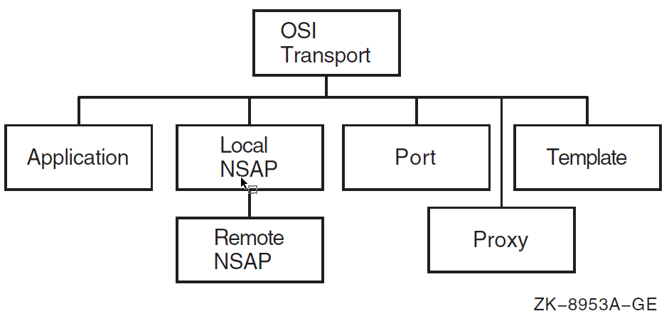
8.5.2.1. Commands for Configuring General OSI Transport Attributes
The following example shows the NCL commands you can use to create the osi transport entity on your system, setting attributes applicable to all types of network services. Section 8.5.2.3, ''Configuring OSI Transport to Use CONS'' gives examples of commands required to configure CONS support. VSI recommends that you accept the default settings used in the examples for the attributes. Change them only if necessary. For more information on these attributes, refer to the VSI DECnet-Plus for OpenVMS Network Control Language Reference Guide.
ncl> create osi transport ncl> set osi transport delay factor 4, delay weight 5,-
| The effect of delay factor is to increase the retransmission time by increasing the average round-trip delay time, thus allowing for additional network delay. The value of the weighting factor is given by the delay weight attribute. Basically, delay weight determines how quickly the retransmission timer responds to variations in actual round-trip delay times. A low value of delay weight means that the retransmission timer responds very quickly to each sample of round-trip delay time; a delay weight of 0 means that an estimate will be nearly the same as the last actual sample of round-trip delay. A high value for delay weight will reduce the impact of recent variations in network delay; the higher the value, the closer each estimate of round-trip delay will be to the average of all estimates. The default values of delay factor and delay weight should be suitable for most networks. However, consider increasing their value if wide variations in round-trip delay times exist on your network. For a complete discussion of delay factor and delay weight and how to calculate round-trip delay, refer to Appendix B, "delay factor and delay weight for NSP and OSI Transport". |
| You can save memory resources by reducing the value of maximum remote nsaps. However, you will not have access to the information provided by this entity’s counters and status attributes (except through information in event logs). The maximum remote nsaps cannot be lower than the maximum transport connections. In addition, the osi transport entity does not support a value of zero (0) for the maximum remote nsaps attribute. |
| The OSI transport receiver and transmitter windows are controlled by a combination of the maximum transport connections, maximum receive buffers, and the maximum window attributes. The OSI transport implements several algorithms that help achieve and maintain a dynamic balance of system resource consumption and network performance. You can control this balance by altering the defaults for these attributes. The OSI transport determines the receiver initial quota by dividing the value of maximum receive buffers by the value of maximum transport connections. During the life of the connection, the receiver quota fluctuates, using the value of maximum receive buffers divided by the value of currently active connections. The credit window sent to the remote transmitter may be this quota value, depending on the value of the maximum window attribute. If the value of maximum window is less than the determined receiver quota, the value of the maximum window is used instead for the credit granted to the remote transmitter. The transmitter on an OSI transport connection uses the credit sent by the remote receiver as its transmit window, unless the value of maximum window is lower than this value. In that case, the value of maximum window is used for the transmitter window. By controlling the transmitter’s and receiver’s window as above a dynamic balance of system resource consumption and network performance may be achieved and maintained. |
You must disable the osi transport entity before modifying attributes that affect operation.
8.5.2.2. Defining OSI Transport Templates
When DECnet-Plus is configured, templates are set up for the OSI Transport module. Each template is an NCL database entry that manages network access. Each template includes a group of attributes that supply default values for certain parameters that influence the operation of a port on a transport connection.
The templates store information and also may reference information located elsewhere.
Each OSI transport template corresponds to a specific type of network service to which OSI transport can direct outbound messages and from which it can receive inbound messages.
OSI transport supports three network services:
Connectionless-Mode Network Service (CLNS)
Connection-Oriented Network Service (CONS)
Null internet (inactive subset of CLNP, the Connectionless Network Protocol) OSI transport supports RFC 1006 as a service and template.
Table 8.7, ''Templates Set Up for OSI Transport on OpenVMS Systems'' describes the templates that are set up for OSI transport on your system. Note that the null internet does not require a template.
| Name | Network Service | Classes |
|---|---|---|
| Default | CLNS | 4 |
| OSIT$LOOP_CONS | CONS | 0, 2, 4 |
| OSIT$LOOP_CLNS | CLNS | 4 |
| OSIT$RFC1006 | RFC1006 | 0 |
| OSIT$RFC1006PLUS | RFC1859 | 2 |
Do not modify listed attributes of the default template. The other templates are defined in the NCL initialization script SYS$MANAGER:NET$OSI_TRANSPORT_STARTUP.NCL.
8.5.2.3. Configuring OSI Transport to Use CONS
The following sections describe how to configure the Connection-Oriented Network Service (CONS). CONS is a network service that operates according to a connection-oriented model. Before data can be exchanged, a connection must first be established. X.25 provides this type of service.
Note
This subsection and other related subsections within Section 8.5.2, ''Configuring and Managing OSI Transport'' discuss configuring OSI applications using the osi application entity. For information about using OSAK applications over CONS and for additional information about configuring the OSI transport to use X.25 CONS, see Section 8.8.1, ''OSI Transport Over X.25 CONS''.
8.5.2.3.1. Establishing Outbound Connections Using CONS
To establish an outbound transport connection that uses CONS as its network service, an OSI application makes a connection request in which it specifies:
The OSI transport address of the destination host.
The OSI transport service access point identifier (TSAP-ID) of the remote application. A TSAP-ID identifies a TSAP. A TSAP is a unique identifier for a single transport user.
Optionally, other transport connection parameters.
The OSI transport address consists of:
The name of the OSI transport template to be used in setting up the transport connection. The specified OSI transport template must have its network service characteristic set to cons.
A network address that uniquely identifies the destination host. The network address for a CONS connection is a DTE address.
OSI transport either creates a new network connection (using X.25), or uses an existing outbound network connection (provided the transport connection is class 2 or class 4). If a new connection is to be created, X.25 uses the DTE address from the OSI transport address and the X25 Access template specified in the OSI transport template to set up a network connection.
8.5.2.3.2. Establishing Inbound Connections Using CONS
To establish an inbound transport connection:
OSI transport must be listening to one or more X25 Access filters.
X.25 passes calls from these filters up to OSI transport.
OSI transport must have an OSI transport template for CONS connections with its inbound characteristic set to true. This OSI transport template must also specify an X25 Access template with the same name (including matching case) as the X25 Access filter on which a call arrives.
If a suitable OSI transport template for CONS connections is found, it is used to accept the call, using the X25 Access template specified in the OSI transport template.
The incoming transport connection can then be received. If an application is found to receive the inbound request, the application can accept or reject the request.
If the application accepts the inbound request, the OSI transport template for CONS connections is used for the accept.
For incoming connections to applications that are invoked by passive TSAP association, you must also configure one or more OSI transport application entities to represent the passive association between a TSAP-ID and an application. Refer to Section 8.5.2.9, ''Manually Configuring OSI Transport Network Applications'' for information about managing OSI transport application entities.
8.5.2.3.3. Steps for Configuring the CONS Network Service
The following steps show how to use NCL commands to configure OSI transport to support CONS. You can configure OSI transport to use X.25 CONS by using the NET$CONFIGURE ADVANCED, X25$CONFIGURE, as well as manually entering a few NCL commands, see the VSI DECnet-Plus for OpenVMS Installation and Configuration.
The attributes added or set up for OSI transport in the following examples are relevant to CONS. For the variables, substitute values appropriate to your configuration.
The following example shows how to create the OSI Transport module, set its attributes, and enable it:
ncl> create osi transport ncl> add osi transport cons filters {filter-name}
ncl> set osi transport disconnect holdback 0, -
_ncl> maximum multiplexing 65535, maximum network connections 65535
ncl> add osi transport cons nsap addresses { cons-address-set }
ncl> enable osi transport Specifies the names of one or more X.25 filters used to listen for incoming transport connection requests. Each element in the set of the
cons filtersattribute of theosi transportentity must have a corresponding X25 Access filter of the same name. By default, thecons filtersattribute of theosi transportentity is set toosi transport. Set a high value for
disconnect holdbackif you want to keep idle network connections. This will save the cost of re-establishing network connections. You should be aware, however, that this is unnecessarily costly if the network connection remains idle.Set
disconnect holdbackto 0 if you want to lose idle network connections as soon as possible.You can only use
disconnect holdbackfor transport protocol classes 2 and 4. Sets the value of
maximum multiplexing. Increasing the value saves on the cost of network connections but reduces the throughput for each transport connection that uses a multiplexed network connection.You can only use
maximum multiplexingfor transport protocol classes 2 and 4.If you set
maximum network connectionstoo low, local transport users might be unable to make transport connection requests, particularly if all the active network connections are inbound. For example, if the limit is 7 and there are seven active network connections, all inbound, then local transport users will be unable to make transport connections unless you either increase the value ofmaximum network connectionsor one of the network connections is released by a remote host. Add the CONS NSAP addresses for the local node. For additional information about the values to specify for this attribute, see Section 8.8.1, ''OSI Transport Over X.25 CONS'' and the VSI DECnet-Plus for OpenVMS Installation and Configuration.
The following example shows how to create the OSI transport templates:
ncl> create osi transport template template-name
ncl> set osi transport template template-name -
_ncl> acknowledgment delay time 1, -
_ncl> checksums false, classes {0,2,4}, -
_ncl> cons template osi transport, cr timeout 30, er timeout 30, -
_ncl> inbound true, initial retransmit time 15, loopback false, -
_ncl> keepalive time 60, maximum nsdu size 2048, -
_ncl> network service cons, retransmit threshold 8
ncl> set osi transport template template-name -
_ncl> local nsap local-nsap
ncl> enable osi transport template template-name OSI transport templates are used by OSI transport to supply connection parameters not provided by the requesting OSI transport application.
An OSI transport template name must contain only alphanumeric characters, underscores (_), hyphens (-), or dollar ($) signs. OSI transport template names should not be more than 16 characters long.
You can configure two types of OSI transport templates for CONS connections:
For outbound connections only
You can configure as many outbound OSI transport templates as you want.
For both outbound and inbound connections
Configure a single outbound-inbound OSI transport template for each X25 Access filter used by inbound transport connections.
Including checksums reduces data throughput but increases reliability of the data transmission. Use checksums only if you have reason to believe that data will be corrupted by the network.
The default value for cr timeout is adequate for most networks. However, consider increasing the value if you find that a high proportion of transport connection requests are being timed out.
The cons template attribute of the osi transport template subentity must contain a name that is an X25 Access filter and is contained in the set of cons filters of the osi transport entity. The default value of the cons template attribute of an osi transport template subentity is osi transport.
When true, inbound specifies that this OSI transport template for CONS connections can be used for inbound as well as outbound connections.
The default initial retransmit time value should be suitable for most networks. It is set to a relatively high value to reflect the fact that a transport connection request Transport layer protocol data unit (TPDU) usually has a longer round-trip delay than a data TPDU. Consider increasing the value if transport connection requests frequently time out.
You can set up different OSI transport templates to provide different values of this attribute for networks with significantly different round-trip delay. For example, round-trip delay on an X.25 PSDN is usually much greater than on an 802.3 LAN.
network service cons indicates that transport connections set up using a specified template will use CONS. An OSI transport template for CONS connections configured with the NET$CONFIGURE procedure will have this attribute set correctly. However, if you create a CONS OSI Transport template directly, you must set this attribute, since the default is clns. Note that the network service attribute does not support a value of any. If this attribute is set to any, the OSI transport is established as CLNS. The default value for retransmit threshold should be suitable for most networks. However, consider increasing the value for networks with a high probability of losing data.
Set the default local CONS NSAP address for this template. For additional information about the value to specify for this attribute, see Section 8.8.1, ''OSI Transport Over X.25 CONS'' and the VSI DECnet-Plus for OpenVMS Installation and Configuration.
Note
If you have not installed and configured X.25 for OpenVMS software, attempting to use the OSI transport over X.25 CONS will fail.
You can configure a reachable address to convert OSI NSAPs to DTE addresses, or you can force OSI applications to use DTE addresses instead of NSAPs.
8.5.2.4. Configuring OSI Transport to Use the Connectionless-Mode Network Service
By default, DECnet-Plus automatically configures OSI transport to use the Connectionless-Mode Network Service (CLNS). CLNS is a network service that operates according to a datagram model. Each message is routed and delivered to its destination independently of any other. When using CLNS, only transport protocol class TP4 is available in the default configuration.
8.5.2.4.1. Establishing Outbound Connections Using CLNS
To establish an outbound transport connection that uses CLNS as its network service, an application makes a connection request specifying the following:
The OSI transport address of the destination host.
The TSAP-ID of the responding application. A TSAP-ID identifies a transport service access point (TSAP). A TSAP is a unique identifier for a single transport user.
Optionally, other transport connection parameters.
The OSI transport address consists of:
The name of the OSI transport template for CLNS connections to be used in setting up the transport connection. The specified OSI transport template for CLNS connections must have its network service attribute set to clns.
- An address that uniquely identifies the destination host. The address can be:
- An NSAP (for a transport connection using CLNS/ES-IS)
- A LAN address (for a transport connection using CLNS with null internet)
The Routing module selects a routing circuit to be used for the underlying network connection; the basis for this selection is the area address part of the NSAP address.
8.5.2.4.2. Establishing Inbound Connections Using CLNS
To establish an inbound transport connection that uses CLNS:
The Routing module passes an incoming transport connection to OSI transport.
OSI transport must have an OSI transport template for CLNS connections with its inbound attribute set to true. If the transport connection uses null internet, the OSI transport template for CLNS connections must also have its clns inactive area address attribute set to the same area address as the inactive area address attribute of the routing circuit on which the transport connection arrived.
If a suitable OSI transport template for CLNS connections is found, an application is found to process the connection. The application can either accept or reject the connection.
If the application accepts the connection, the OSI transport template for CLNS connections is used to accept the connection.
8.5.2.4.3. Null Internet Information
A CLNS OSI transport template is configured to use either the CLNS/ES-IS or null internet routing protocol. To configure null internet OSI transport templates, you must configure one outbound-inbound OSI transport template for each inactive area address used.
A CLNS OSI transport template can specify use of the null internet routing protocol (inactive subset of CLNS). The null internet protocol only operates over LAN routing circuits. A CLNS OSI transport template for use with the null internet routing protocol can only use one routing circuit; routing circuit selection is based on its inactive area address.
The Routing module selects a routing circuit to be used for the underlying network connection; the basis for this selection is the area address part of the NSAP address.
8.5.2.4.4. Steps for Configuring the Connectionless-Mode Network Service
The following steps show the commands to configure CLNS. The attributes added or set up for OSI transport in this example are relevant to CLNS. In addition, consider setting some of the more general attributes shown in Section 8.5.2.1, ''Commands for Configuring General OSI Transport Attributes''.
For the variables, substitute values appropriate to your configuration. VSI recommends that you accept the default settings (used in the example) for the various attributes. Change them only if you need to. Refer to the VSI DECnet-Plus for OpenVMS Network Control Language Reference Guide for more information about these attributes.
The following example creates the OSI Transport module and enables it:
ncl> create osi transport ncl> set osi transport nsap selector 33
ncl> enable osi transport The network service access points (NSAP) selector (nsap selector) determines which transport service is used by a network connection. The default NSAP selector for DECnet’s OSI transport implementations is 33 (decimal). Other vendors might use different NSAP selectors and might require that the NSAP selectors match.
You can only change the NSAP selector for OSI transport when OSI transport is disabled. Valid NSAP selectors are in the range from 2 to 255, with the exception of 32. In order to maintain interoperability between DNA Phase IV and DECnet-Plus, you cannot use NSP’s NSAP selector, 32.
The following example shows how to create the OSI transport template and set its attributes:
ncl> create osi transport template template-name
ncl> set osi transport template template-name -
_ncl> acknowledgment delay time 1, -
_ncl> checksums false, classes {4}, clns inactive area address { } -
_ncl> inbound true, initial retransmit time 15, keepalive time 60, -
_ncl> loopback false, network service clns, retransmit threshold 8, -
_ncl> security empty, use clns error reports false
ncl> enable osi transport template OSI transport templates are used by OSI transport to supply connection parameters not provided by the requesting OSI transport application.
An OSI transport template name must contain only alphanumeric characters, underscores (_), hyphens (-), or dollar ($) signs. OSI transport template names should not be more than 16 characters long.
You can configure two types of OSI transport templates for CLNS connections:
For outbound transport connections only
You can configure as many outbound OSI transport templates for CLNS connections as you want.
For both outbound and inbound transport connections
A CLNS OSI transport template is configured to use either the CLNS/ES-IS or null internet routing protocol.
If you configure null internet OSI transport templates, you must configure one outbound-inbound OSI transport template for each inactive area address used.
Including checksums reduces data throughput, so you should use checksums only if you have reason to believe that data will be corrupted by the network.
Optionally, you can specify a value for the clns inactive area address attribute.
The default initial retransmit time value should be suitable for most networks. It is set to a relatively high value because a transport connection request TPDU usually has a longer round-trip delay than a data TPDU. Consider increasing the value if transport connection requests frequently time out.
The default value for retransmit threshold should be suitable for most networks. However, consider increasing the value for networks with a high probability of losing data.
OSI transport can recognize the unavailability of a remote node during connection establishment using CLNS (Routing) error reports.
This feature is disabled for all templates (used by DNA Session Control), but you can enable it by editing the OSI transport NCL initialization script, SYS$MANAGER:NET$OSI_TRANSPORT_STARTUP.NCL to set the value to true.
Set up routing and routing circuits for end systems using the Connectionless- Mode network service by following the steps outlined in Section 8.4.2, ''Configuring Routing Circuit Information''.
If you are setting up X.25 routing circuits, see additional information in Section 8.8.2, ''Configuring Routing Over X.25 Circuits''.
8.5.2.4.5. Providing Communications Between OSI Transport Systems and VOTS Systems Using CLNS
For communication between DECnet-Plus and VAX OSI Transport Service (VOTS) using the full Internet CLNS protocol, DECnet- Plus systems must use an intermediate system (router). DECnet-Plus systems have no way of finding another end system that does not support ES-IS without using an intermediate system.
The intermediate system must be configured as a link state router (see Section 8.4.1.2, ''Host-Based Routing'').
If the VOTS system and the intermediate system reside on the same LAN subnetwork and the VOTS system is configured with a DNA-compatible NSAP address, the intermediate system need only be configured as a level 1 router.
If the VOTS system does not have a DNA-compatible NSAP address, or if the VOTS system and the intermediate system do not reside on the same LAN subnetwork, the intermediate system must be configured as a level 2 router.
When using a level 1 router, you must create a manual adjacency on the router for the VOTS system. When using a level 2 router, you must create a reachable address on the router for the VOTS system. See Section 8.4.1.2, ''Host-Based Routing'' for more information about how to configure manual adjacencies and reachable addresses.
OSI transport systems and VOTS systems on the same LAN can communicate without an intermediate system, using the null internet CLNS protocol.
8.5.2.5. Configuring OSI Transport to Use RFC 1006 or RFC 1859
You can configure OSI transport to use RFC 1006, allowing use of OSI applications over TCP/IP, and to use RFC 1859, allowing use of DECnet applications over TCP/IP. For details, see Section 8.5.3, ''DECnet and OSI Applications over TCP/IP''.
8.5.2.6. Testing OSI Transport
After configuring OSI transport on an OpenVMS system, you can use the [SYS$TEST]OSIT$IVP OSI transport installation verification procedure to verify correct operation.
This procedure (the test initiator) communicates with the passive OSI transport application OSIT$IVP which invokes OSIT$IVPRESP.COM (the test responder) on the target system. The target system may be either your system or some other system running DECnet-Plus for OpenVMS. (Start the initiator by executing the SYS$TEST:OSIT$IVPINIT.COM file.)
You must supply the VOTS-address of the target system. A VOTS-address has the form template%network address, where:
template is the name of an osi transport template entity.
network address depends on the network service specified by the template, as described in Table 8.8, ''Network Addresses for VOTS Addresses''.
| Network Service Specified by Template | Format of Network | Address Example of Network Address |
|---|---|---|
| CONS | X.25 DTE address | 234273412345 |
| CLNS (Null internet) | LAN address | AA00040001FC |
| CLNS (Internet/ES-IS) | NSAP | 49004008002B56870121 |
| RFC1006 | IP address | 16.20.136.9 or acme.wolf.phil.com |
You can list the OSI transport NSAPs for a system using the following command:
ncl> show osi transport local nsap *
Note
Do not supply a CONS NSAP address to the OSIT$IVP program. If you do, the verification procedure will fail.
As an alternative to specifying a VOTS-address explicitly, you can specify a logical name defined in the table OSIT$NAMES.
8.5.2.7. Possible Connection Failure to Non-Conformant Systems Using OSI Transport
By default, the DECnet-Plus OSI transport sends the preferred maximum tpdu size, request acknowledgment, and implementation id parameters in its CR TPDU (connect request transport protocol data unit).
According to ISO 8073, OSI transport providers should ignore unknown parameters while processing a CR TPDU. However, some vendor implementations do not conform to ISO 8073. Therefore, their OSI transport does not ignore unknown parameters in a CR TPDU. This nonconformance results in a connection failure when unknown parameters are detected (such as the three parameters sent by the DECnet-Plus OSI transport). The following example provides a way to prevent issuance of these unknown parameters in a CR TPDU:
NCL> set osi transport template template-id - _NCL> send preferred maximum tpdu size false NCL> set osi transport template template-id - _NCL> send request acknowledgment false NCL> set osi transport template template-id - _NCL> send implementation id false
8.5.2.8. Avoiding Congestion in Multiprotocol Networks
One feature of OSI transport is the ability to use the Congestion Experienced field in the Connectionless-Mode Network Service (CLNS) routing header, and to implement a congestion avoidance scheme in heavily congested networks. The CLNS Congestion Experienced field is used by routers that support this feature (such as DECNIS) to give an early indication of congestion. When OSI transport receives data that passed through a network path where the Congestion Experienced bit is set, OSI transport reduces the transmit rate of the sending end system to help alleviate network congestion.
This feature works well in networks where all protocols support congestion avoidance mechanisms. However, in heavily congested multiprotocol networks that include network protocols that do not support the congestion avoidance mechanism, the performance of DECnet can be impaired. VSI recognizes that most of its customers have multiprotocol networks and that not all network protocols have congestion avoidance mechanisms. Therefore, VSI has set the default for this attribute to be disabled.
If you operate in an environment where you can take advantage of congestion avoidance mechanisms, enable this feature.
To change transport congestion avoidance values, invoke NET$CONFIGURE ADVANCED and use Option 4 (Configure Transports). Answer no to the following question:
Is this System operating in a Multi-Protocol Network? [YES] :.
8.5.2.9. Manually Configuring OSI Transport Network Applications
This section describes how to configure applications to receive connection requests from remote hosts. One of the attributes of a transport connection request is a transport service access point identifier (TSAP-ID), which uniquely identifies the transport application on the remote host to which the connection request is to be passed.
An application that expects to receive a connection request must therefore associate itself with a particular TSAP-ID, so the transport service knows which application a particular connection request is intended for.
There are two ways in which an application can associate itself with a TSAP-ID: active association or passive association.
Active association is entirely under the control of the transport user, and requires no support from you. Passive association, on the other hand, requires that you configure the osi transport application entities that describe the association between TSAP-IDs and applications.
In active association, the transport application issues a $qio(io$_acpcontrol) system service call in which it requests an association with a specified TSAP- ID. When a connection request arrives with that TSAP-ID, a mailbox message containing details of the connection request is sent to the associated application, which can then process the request, either accepting or rejecting it.
OSI transport dynamically creates the osi transport port entity so that the active association is available by means of network management.
In passive association, you create an osi transport application entity, whose characteristics specify:
A TSAP-ID.
The name of an image or command file.
The user name of an account under which the image or command file is to run.
When a connection request arrives with a TSAP-ID that is associated with an osi transport application entity, the transport service creates a new process in which it runs loginout.exe. loginout.exe validates any access control information and invokes DCL to execute the image or command file associated with that TSAP-ID. Details of the connection request are passed in the logical name sys$net.
The following command example shows the commands to configure an osi transport application entity. For the variables, substitute values appropriate to your configuration. VSI, however, recommends that you accept the default settings (used in the example) for the various attributes and change these only if you need to. Refer to the VSI DECnet-Plus for OpenVMS Network Control Language Reference Guide for more information about these attributes.
ncl> create osi transport ncl> enable osi transport ncl> create osi transport application application-name ncl> set osi transport application application-name - _ncl> called tsels set-of-hex-string,-
| called tsels specifies the set of TSAP-IDs with which this entity is to be associated. |
| file name specifies the name of the command or image file to be executed when a connection request is received with a TSAP-ID that matches one of the values of the called tsels characteristic. user name specifies the user account under which the application is to run. |
8.5.3. DECnet and OSI Applications over TCP/IP
DECnet-Plus allows OSI and DECnet applications to run over an IP network backbone. The OSI over TCP/IP (using RFC 1006) software enables OSI applications such as FTAM, Virtual Terminal, and X.400 to run over TCP/IP. The DECnet over TCP/IP (using RFC 1859) feature allows traditional DECnet applications to run over TCP/IP. Examples of traditional DECnet applications are mail, cterm, and fal.
With RFC 1006 and RFC 1859, OSI and DECnet applications can accept IP names and addresses. These names and addresses are translated by BIND servers. The DECnet and OSI applications include those supplied by VSI, third-party applications, and user-written applications.
RFC 1006 is a standard of the Internet community. It defines how to implement ISO 8073 Class 0 on top of TCP. Hosts that implement RFC 1006 are expected to listen on TCP port 102.
DECnet over TCP/IP uses RFC 1859, which defines how to implement ISO 8073, Transport Class 2 Non-Use of Explicit Flow Control on Top of TCP (RFC 1006 Extension). Hosts that implement RFC 1859 are required to listen on well known TCP port 399.
Use DECnet over TCP/IP if you need to:
Link DECnet nodes using TCP/IP
Join two existing DECnet networks without renumbering
Run IP-only traffic in part of the backbone and continue using DECnet applications and user interfaces without extra costs and retraining.
When running DECnet over TCP/IP, you can use an IP host name such as in the following command examples. For more information on making connections using DECnet over TCP/IP, see Section 8.5.3.1, ''Examples Establishing Network Connections Using DECnet over TCP/IP''.
$ set host remotehst6.acme.com
Both the source and target nodes must support DECnet over TCP/IP for this connection to work. You can configure your system to allow use of synonyms (Phase IV style names) instead of the IP host full name. The explicit use of IP addresses on a command line is not supported.
8.5.3.1. Examples Establishing Network Connections Using DECnet over TCP/IP
The following examples show how you can use DECnet over TCP/IP to connect to any of the remote hosts on the network shown in Figure 8.7, ''Sample Multiprotocol Network'', a multiprotocol network that includes OpenVMS and Tru64 UNIX systems and a PC system.
Node green is a DECnet Phase IV OpenVMS node. Node blue is a DECnet- Plus Tru64 UNIX node. To connect to node green from node blue, issue this command on node blue:
# dlogin green
Node orange is a DECnet-Plus for OpenVMS node. To connect to node green from node orange, issue this command on node orange:
$ set host green
Both node blue and node orange are DECnet-Plus nodes. To connect to node orange from node blue (Tru64 UNIX), issue this command on node blue:
# dlogin orange.toronto.acme.com
To connect to node blue from node orange (OpenVMS), issue this command on node orange:
$ set host orange.toronto.acme.com
Node red is a TCP/IP node only. To connect to node red from node orange (OpenVMS), issue this command on node orange:
$ set host/telnet red.toronto.acme.com
As an alternative, you can use this command:
$ set host/rlogin red.toronto.acme.com
To connect to node red from node blue (Tru64 UNIX), issue this command on node blue:
# telnet red.toronto.acme.com
As an alternative, you can use this command:
# rlogin red.toronto.acme.com
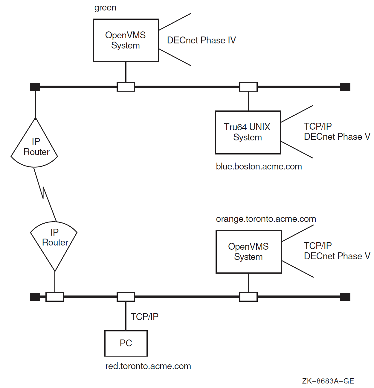
8.5.3.2. Configuring DECnet over TCP/IP (RFC 1859) and OSI over TCP/IP (RFC 1006)
If you plan to use RFC 1006 and/or RFC 1859 software, TCP/IP software is a prerequisite. The TCP/IP software used on your system must support the PATHWORKS Internet Protocol (PWIP) interface. For more information about required TCP/IP software, see the DECnet-Plus for OpenVMS Release Notes.
When DECnet over TCP/IP has successfully completed a listen on the defined rfc1006 listener ports, you will see the following OPCOM message in the OPERATOR.LOG file for each TCP Listen Port:
%%%%%%%%%%% OPCOM 30-MAR-2019 11:25:46.74 %%%%%%%%%%% Message from user TPCONS on YPP4 -- TPCONS: Listen to PWIP Done
To configure your system so you can use DECnet over TCP/IP or OSI applications over TCP/IP, use Option 4 of the advanced configuration procedure (NET$CONFIGURE.COM ADVANCED), as explained in the VSI DECnet-Plus for OpenVMS Installation and Configuration. You can then create a new OSI transport NCL script (or replace an old script). You must also include Domain in your session control naming search path as described in Section 5.1.1, ''Determining the Order for Name Service Searches''.
Use Option 4 as well for creating templates in addition to the default RFC 1006 template.
You must rename your node using a Domain secondary node name. Use Option 2 of the advanced configuration procedure to do this.
For the changes to take effect, either disable the osi transport entity and invoke the new OSI transport NCL script, or reboot the system.
ncl> disable osi transport ncl> do sys$manager:net$osi_transport_startup.ncl
When configuring RFC 1006, RFC 1859, or both, each element in the set of rfc1006 listener ports attribute corresponds to a TCP listener port. By default, NET$CONFIGURE sets the osi transport rfc1006 listener ports attribute to {102, 399}.
The rfc1006 port number attribute of the osi transport template subentity must contain a TCP port number that is one of the chosen rfc1006 listener ports.
The default value for the rfc1006 port number attribute is 102. If you create an osi transport template subentity to use with DECnet over TCP/IP (using RFC 1859), then set the rfc1006 port number attribute to 399.
8.5.3.3. Disabling DECnet Over TCP/IP
DECnet-Plus will only try to locate TCP/IP if the rfc1006 listener ports attribute set of the osi transport entity is not empty.
To disable DECnet over TCP/IP, issue the following command:
ncl> set osi transport rfc1006 listener ports {}8.5.3.4. DECnet over TCP/IP Tracing Support with Common Trace Facility (CTF)
CTF can be used to trace all PDUs transmitted and received by DECnet over TCP/IP and OSI applications. See the DECnet/OSI for VMS CTF Use for a list of events that are recognized at this trace point.
Use the following command to invoke the CTF tracing utility:
$ TRACE START "trace-point"where trace-point is the trace point to be started, such as "TPCONS TPKT *".
8.5.3.5. Recovering from Problems
If you have problems getting DECnet over TCP/IP to start up properly, check the following:
Verify that you have an OSI transport template with network service attribute defined as rfc1006.
Issue the command:
ncl> show osi transport template * with network service = rfc1006
If you do not have a template defined, then you must execute NET$CONFIGURE Option 4 and replace your OSI transport startup script.
Verify that you have your TCP/IP product started and that your product supports the PWIP interface. If you are running VSI TCP/IP Services for OpenVMS, PWIP can be configured to start automatically. If PWIP does not start automatically, run TCPIP$CONFIG and enable the PWIP interface.
Verify that the PWIP interface is properly registered. Using the management tool of the installed TCP/IP product, verify that rfc1006 listener port defined in OSI transport is known by TCP/IP. If you are running VSI TCP/IP Services for OpenVMS, use the following command:
$ tcpip show device Port Remote Device_socket Type Local Remote Service Host bg3 STREAM 23 0 TELNET 0.0.0.0 bg4 DGRAM 520 0 0.0.0.0 bg7 STREAM 399 0 0.0.0.0 bg9 STREAM 102 0 0.0.0.0In this case, look for the two listener ports 399 and 102.
If IP addresses work but IP names do not, use your TCP/IP management tool to verify that your BIND server knows about the name.
8.5.3.6. Connection Auditing
You can audit incoming connections for those connections that are made using DECnet over TCP/IP. The audit alarm is displayed as follows:
%%%%%%%%%%% OPCOM 9-FEB-2019 12:26:11.64 %%%%%%%%%%% Message from user AUDIT$SERVER on PETERB Security alarm (SECURITY) and security audit (SECURITY) on PETERB, system id: 12 331 Auditable event: DECnet logical link created Event time: 9-FEB-2019 12:26:11.59 PID: 000000A6 Process name: FAL_14010028 Username: SYSTEM Process owner: [1,3] Image name: SYS$COMMON:[SYSEXE]FAL.EXE Remote node id: 1560286224 Remote node fullname: MYNODE.LKG.ACME.COM Remote username: CAISSON DECnet logical link ID: 335609896 DECnet object name: FAL
8.5.3.7. Proxy Access
DECnet over TCP/IP allows you to use fully qualified domain names in your OpenVMS proxy database. For example:
UAF> add/proxy mynode.lkg.acme.com::caisson caisson/default
A node can have more than one full name for a node. This means that proxy records for each of the possible node names need to be added using the Authorize utility. For example, if your system is set up to use both DECdns and BIND (and you can see a remote node’s name as either of these), then you need to add proxy records for both nodes. To represent the remote node stir, you would need to add these proxy records: STIR.ENET.ACME.COM and DEC:.ZKO.STIR.
8.6. Managing Session Control
You can manage session control by adding network applications, deleting network connections, and deleting network entities.
8.6.1. Adding a Session Control Network Application
The following example shows how to add a session control network application (which was known as a session control object in Phase IV):
ncl> create session control application application-name
ncl> set session control application application-name -
_ncl> image name image-name -
_ncl> user name user-name -
_ncl> data abstraction {message} -
_ncl> accept mode {deferred } -
_ncl> programming interface {Phase IV} -
_ncl> address {number = nn,....}
| You can identify an application with an object number. Usually, applications are identified by network object number 0, but you can optionally assign it a nonzero object number, in the range from 128 to 255. A nonzero object number can be specified without an application name. Object numbers 1 through 127 are reserved for use by VSI. Specific network services are identified by nonzero object numbers; for example, 27 represents the mail utility: ncl> set session control application mail addresses {number=27} |
Table 8.9, ''NCP to NCL Command Conversions'' maps NCP characteristics to NCL attributes.
| NCP Characteristic | NCL Attribute |
|---|---|
| user | user name |
| file | image name |
| number | address |
8.6.2. Deleting a Connection
You can selectively delete connections on a local system while the network is running. For example:
ncl> delete session control port port-name8.6.3. Deleting and Recreating the OSI and NSP Entities
If after deleting any transport entities used by session control, such as the osi transport and nsp entities, you create them again, you must use NCL to notify session control that the previously disabled entities are available again. Section 8.6.3.1, ''Commands Required When Reenabling the OSI Transport Entity'' and Section 8.6.3.2, ''Commands Required When Reenabling the NSP Entity'' show the commands to use to notify session control that the osi transport and nsp entities are once again available..
8.6.3.1. Commands Required When Reenabling the OSI Transport Entity
If the osi transport entity is deleted and subsequently recreated, you must issue the following directives to inform session control that the OSI transport service is available:
ncl> delete session control transport service osi ncl> create session control transport service osi protocol %x05
You cannot issue the delete session control transport service osi command while osi transport port entities exist.
8.6.3.2. Commands Required When Reenabling the NSP Entity
If the nsp entity is deleted and subsequently recreated, you must issue the following directives to inform session control that the NSP transport service is available:
ncl> delete session control transport service nsp ncl> create session control transport service nsp protocol %x04
You cannot issue the delete session control transport service nsp command while nsp port entities exist.
8.7. Managing OSAK
Open System Application Kernel (OSAK) is the DECnet-Plus implementation of the OSI upper layers. It provides OSI session, presentation and application services. These services are used by OSI applications such as FTAM and VT. You must use NCL to manage the OSAK software on your system. For further details of the NCL commands to use, refer to the VSI DECnet-Plus for OpenVMS Network Control Language Reference Guide.
Figure 8.8, ''osak Entity'' shows the osak entity and its subentities.
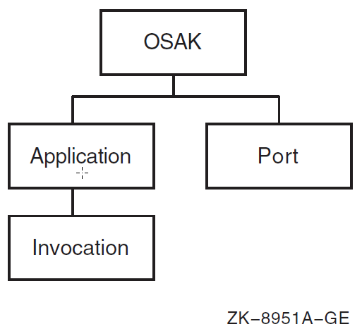
8.7.1. Managing OSAK Addresses
You can implement your OSI application using either of two types of application address: active or passive.
An active address is associated with a process that is already started on the system. A passive address is associated with a process that is started only when a connection request is received for that address.
Note
Passive application functionality requires the OSAK server component.
8.7.1.1. Registering Active and Passive Addresses
You cannot actively manage active addresses; NCL creates the necessary management entities when OSAK sends or receives an appropriate programming call. You use NCL to register passive addresses. This section describes how to register active and passive addresses.
Active
An application registers an active address by passing that address on a call to osak_open_responder or osak_open_initiator. NCL creates the appropriate entities. You can use the NCL show command to show attributes of these entities.
Passive
You register an application address using Network Control Language (NCL) commands to create an osak application entity and an osak application invocation entity. Use the startup information attribute of the osak application invocation entity to specify the values in Table 8.10, ''Startup Information Values''.
| Item | Value | Description |
|---|---|---|
| Mandatory | ||
| user |
name |
The user name of the process that will respond to Connect requests received by this application |
| file |
pathname |
The name of the file to run to start up the named application |
| Optional | ||
| account |
name |
The account that is to start the process |
| max resp |
integer |
The highest permissible number of responders, for an application with the NEW setting for startup policy |
| password |
password |
The user’s password |
| sversion |
{1}, {2}, or {1,2} |
The session version |
Further Information
For more information about the OSAK module, refer to the VSI DECnet-Plus for OpenVMS Network Control Language Reference Guide.
8.7.2. NCL and the OSAK Databases
OSAK maintains two databases: the application database and the port database. You must use NCL to inspect information held in the OSAK databases and to set attributes of entities in the OSAK module. Table 8.11, ''Mapping Between NCL and OSAK'' shows the mapping between NCL and OSAK management.
| OSAK Database | NCL Entity |
|---|---|
| Application database |
|
| Port database |
|
8.8. Configuring X.25 Services
DECnet-Plus and X.25 software can be used separately or DECnet-Plus can use X.25 software as a communications service provider.
DECnet-Plus for OpenVMS supports the following two approaches for configuring and using the features of X.25 software:
Configuring the osi transport entity to use the connection-oriented network service (CONS) interface to X.25, enabling the use of OSI transport classes 0 and 2 (TP0 and TP2).
The Connection-Oriented Network Service (CONS) is an ISO specification for a reliable and transparent end-to-end data transfer function. OSI transport can use CONS in addition to the Connectionless-Mode Network Service (CLNS) implemented by DNA routing.
Note that applications using OSI transport (for example, FTAM or Virtual Terminal) need to be configured to operate over CONS before they can use CONS functionality.
For information about configuring OSI applications over X.25 CONS, see Section 8.8.1, ''OSI Transport Over X.25 CONS''.
Configuring the routing entity, which provides Connectionless-Mode Network Service (CLNS), to use an X.25 circuit as a data link to a remote network.
Applications using routing over X.25 circuits do not require any special configuration. X.25 serves as another communications path from the local system to the remote system.
For information about configuring routing over X.25 circuits (frequently referred to as DECnet over X.25), see Section 8.8.2, ''Configuring Routing Over X.25 Circuits''.
These approaches are completely optional, but might be desirable for use with certain applications or for particular network configurations. They can function individually or together on the same system.
Once X.25 has been installed, you can use the DECnet-Plus configuration procedure (NET$CONFIGURE.COM) to first configure X.25 and then configure DECnet over X.25. You can use either the BASIC or ADVANCED configuration option. See the VSI DECnet-Plus for OpenVMS Installation and Configuration for more information about configuring X.25 support on DECnet-Plus for OpenVMS systems.
This section describes how to configure the X.25 management entities directly referenced by DECnet-Plus. These entities are mainly in the X25 Access module. Full details on how to configure all the X.25 management entities are provided in the X.25 for OpenVMS documentation. For information about configuring X.25 on OpenVMS IA-64 and OpenVMS Alpha systems, see the VSI X.25 for OpenVMS Configuration. For information about configuring X.25 on OpenVMS VAX systems, see the VSI DECnet-Plus for OpenVMS Installation and Configuration. For additional management information on all systems, see the VSI X.25 for OpenVMS Management Guide.
Although you can configure both products together, VSI recommends that you configure and test both DECnet-Plus and X.25 independently before attempting to configure DECnet-Plus to use X.25.
Figure 8.9, ''x25 access and x25 protocol Entities'' shows the x25 access and x25 protocol entities and their subentities.

8.8.1. OSI Transport Over X.25 CONS
This section describes issues concerning configuration of X.25 CONS with OSI transport.
8.8.1.1. CONS Addressing Mechanisms
Addressing mechanisms and their uses are significantly different between CONS and CLNS. This section describes the addressing mechanisms for CONS that you need to understand for configuring OSI applications using the X.25 CONS protocol stack.
OSI Application Address
An OSI application address is composed of an application process title (AP- Title), a presentation selector (PSEL), a session selector (SSEL), a transport selector (TSEL), and a network service access point (NSAP). Each of these parts corresponds to a layer of the OSI protocol stack as shown in Figure 8.10, ''OSI Application Address Model''. The data link and physical layers are not shown in this figure. The application does not specify their addresses directly.
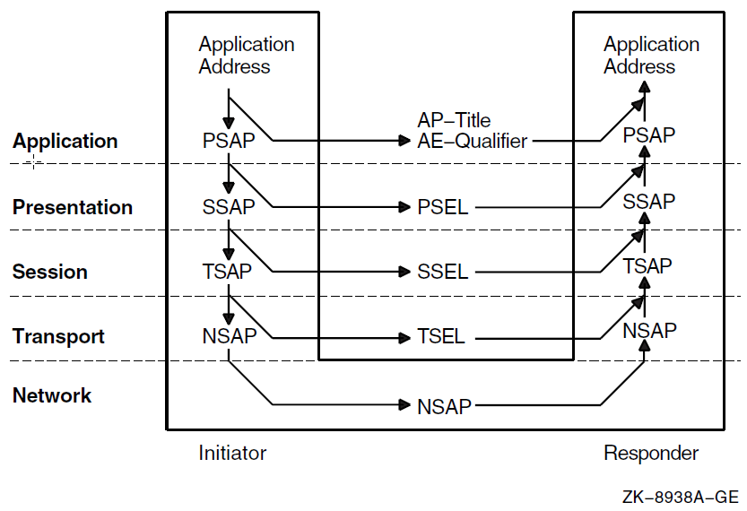
Some OSI application entities (such as FTAM) defined in the ISO specifications and described here include the association control service element (ACSE). DECnet-Plus implements ACSE in its OSAK component, independently of the rest of the OSI application entity.
An OSI application entity transfers calling and called application process (AP) titles and application entity (AE) qualifiers in ACSE PDUs. The uses of AP- Titles and AE-Qualifiers are application specific. For example, the FTAM and VT specifications do not define their use. The ISO specifications do not define their use. The DECnet-Plus FTAM and VT implementations ignore the AP-Titles and AE-Qualifiers. Other vendors’ products may check them to ensure they contain specific predefined values. An OSI application specifies addresses to the Presentation layer in the form of presentation service access points (PSAPs). The Presentation layer strips the PSEL for transfer in Presentation PDUs. It passes the remaining portion, the session service access point (SSAP), down to the Session layer. The Session layer strips the SSEL, leaving the transport service access point (TSAP) for Transport. This process continues down to the Network layer.
An OSI application entity’s PSEL, SSEL, and TSEL are arbitrary octet strings defined during configuration. The network service access point (NSAP) represents the address. It is not subdivided for lower layer addressing. However, it may be derived from a lower layer address to ensure uniqueness. Section 8.8.1.1, ''CONS Addressing Mechanisms'' explains the contents of NSAP addresses for X.25 CONS networks. A single node can have more than one NSAP address.
For a successful connection, an OSI application specifies to the Presentation layer the responder’s PSEL, SSEL, and TSEL along with one of the destination NSAPs. Table 8.12, ''OSI Application Address Components'' describes the contents of each part of an OSI application address.
| Component | Size | Required | Structure | Example |
|---|---|---|---|---|
| AP-Title |
Unrestricted |
No |
Object Identifier |
{1 3 9999 1 7} |
| AE-Qualifier |
1 - 4 octets |
No |
Integer Number |
1 |
| PSEL |
0 - 4 octets |
No |
Hexadecimal string |
%X’0001’ |
| SSEL |
0 - 16 octets |
No |
Hexadecimal string |
%X’0001’ |
| TSEL |
0 - 32 octets |
No |
Hexadecimal string |
%X’0001’ |
| NSAP |
2 - 20 octets |
Yes |
3600234212345678 |
X.25 CONS Network Connections
This section describes X.25 CONS connections and addressing. Figure 8.11, ''X.25 CONS Network'' shows a worldwide network owned and operated by interconnected PTTs and telephone companies. Connections between nodes resemble telephone calls. VSI’s X.25/WAN products allow OSI client applications to "call" services anywhere in the worldwide X.25 network (represented by the cloud in Figure 8.11, ''X.25 CONS Network'') without management intervention. The data terminal equipment (DTE) boxes are the initiator and responder nodes shown in Figure 8.10, ''OSI Application Address Model''. The Packet Switched Data Network (PSDN) and the PSDN interface software on the DTE’s together comprise the OSI network layer in an X.25 CONS network.
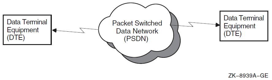
To initiate a call, a DTE sends a call request packet to the X.25 network. An X.25 call request packet contains the following fields to support addressing:
DTE address
Address extension facilities
Call user data
DTE Address Fields
The definition of a "DTE address" depends on the context. A DTE address passed at the DCE/DTE boundary can differ from a DTE address passed between two X.25 networks. In this document, the DTE address passed between an X.25 service user and an X.25 service provider at the DCE/DTE boundary is called an "X.25 network address."
The calling and called DTE address fields contain the source and destination X.25 network addresses. They are usually the only address fields used by public PSDNs to set up a call. An X.25 network address is a series of decimal digits that resembles a telephone number. A digit is encoded in a four-bit nibble with values ranging from 0000 to 1001. Two digits fit in each octet. Each address has a corresponding length field that specifies the length in digits. Some digits represent the country code, others represent the network code and local network connection. As with telephone numbers, number sequences for making local calls within a single X.25 network and long distance calls between X.25 networks vary among various PTTs and telephone companies.
An NSAP can always be mapped to an X.25 network address. Mapping an X.25 network address back to an NSAP is not always possible. See below for a discussion of address mapping and how to construct an NSAP address that can be derived from an X.25 network address.
Address Extension Facilities
X.25 supports many optional functions or "facilities" during call setup and clearing. The calling and called address extension facilities transfer upper layer addresses between X.25 users at each end of a call. For the X.25 CONS protocol stack, these facilities transfer complete NSAP addresses between the initiator and responder of a call.
Address extension facilities allow a system manager to assign any NSAP address to a node independently of the X.25 network address. All DECnet-Plus platforms support address extension facilities. However, these facilities are not universally supported by all X.25 networks nor by all other X.25 DTE implementations. Do not rely on them to pass NSAPs across the network, unless you have no other alternative, and you know that all parties in the connection support them.
The first byte of an address extension facility contains an integer representing the length of the NSAP in digits. The remaining bytes of an address extension facility contains the NSAP. For example, the NSAP 36002342123456781234 contains 20 digits. The equivalent address extension facility is %X14360023421234561234.
Call User Data
Many X.25 DTE implementations can use the call user data field of an incoming call packet to identify the intended X.25 application. The CCITT
X.224 Annex B standard requires that the call user data field for calls to OSI transport be set to %x03010100. This value represents the following:
03 — Length of PI TPDU
01 — Protocol ID code
01 — OSI transport
00 — No sharing of network
NSAP to X.25 Address Translation
OSI applications use NSAPs to address other nodes. X.25 communicates using X.25 network addresses. Addressing complications arise because various X.25 network service providers do not use a consistent X.25 network addressing scheme. CCITT X.121 is the network addressing standard that PSDNs use to communicate with each other. Some X.25 PSDN service providers use this addressing scheme directly. Others use an abbreviated form of X.121 for calls within their network.
Figure 8–12 shows the address translation steps taken from an NSAP used by OSI applications to an X.25 network address in an X.25 call packet. VSI’s X.25 software components provide mechanisms to handle all these translations.
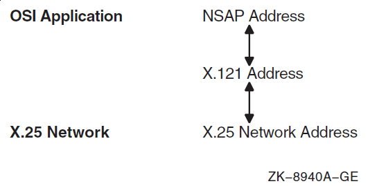
X.121 Addresses
X.121 describes the international numbering plan for public data networks (X.25 networks). Equivalent international numbering plans exist for the telephone and telex networks.
X.121 defines a four-digit data network identification code (DNIC) for identifying
X.25 networks. The DNIC is composed of a three-digit data country code (DCC) identifying the country followed by a single digit to distinguish among multiple networks within a country. X.121 allocates DCCs to countries, such as 234 and 235 for the United Kingdom, 310 to 316 for the United States of America, and 505 for Australia. Because 505 is the DCC for Australia, the two DNICs 5052 and 5054 identify two distinct X.25 networks within Australia. DNICs (and DCCs) begin with one of the digits 2 through 7 inclusive. The initial digits 0, 1, and 8 are reserved for other purposes. The maximum length of an X.121 address is 14 digits.
An X.121 address takes one of two forms:
A 4-digit DNIC followed by a network terminal number (NTN) of up to 10 digits, as shown in Figure 8.13, ''X.121 Address with Four-Digit DNIC and NTN of up to 10 Digits''.
Figure 8.13. X.121 Address with Four-Digit DNIC and NTN of up to 10 Digits 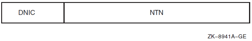
A 3-digit DCC followed by a national number (NN) of up to 11 digits, as shown in Figure 8.14, ''X.121 Address with Three-Digit DNIC and NN of up to 11 Digits''.
Figure 8.14. X.121 Address with Three-Digit DNIC and NN of up to 11 Digits 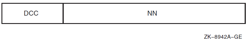
Local Subaddresses
X.25 Network providers often do not use the full 14 digits allowed for an X.121 address. They typically leave two digits at the end of the address for assignment by the service subscriber. In configurations where multiple nodes are attached to a single X.25 line, the Local Subaddress can be used to identify a particular node. For example, a subscriber to PSS in the United Kingdom with the X.25 network address 234212345678 might set up the configuration shown in Figure 8.15, ''Use of Local Subaddresses'' with an X.25 relay or switch.
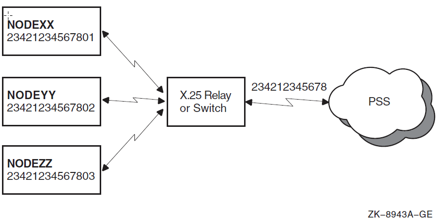
All the nodes share the same PSS X.25 network address of 234212345678, but they each have a separate local subaddress of 01, 02, and 03. A node attempting to call NODEYY would use the destination address 23431234567802.
X.25 Network Addresses
Three major types of addressing conventions are used in X.25 networks to describe the conversion between the globally unique X.121 addresses and the addresses actually used on the network. The three conventions are X.121 addresses, national number (NN-based) addresses, and national terminal number (NTN-based) numbers.
X.121 addresses — The network always uses X.121 addresses for calls within the network and calls to other networks. PSS in the U.K. uses this addressing scheme. Table 8.13, ''X.121 Addresses and Equivalent X.25 Network Addresses'' shows examples of X.121 addresses and the equivalent addresses a PSS user could call in PSS’s X.25 network address form.
Table 8.13. X.121 Addresses and Equivalent X.25 Network Addresses Call Destination X.121 Address X.25 Network Address Within PSS 234212345678
234212345678 Across networks to AUSTPAC 505287654321
505287654321 Across networks to PACNET 530187654321
530187654321 NN-based addresses — The network uses only the national number for calls within the network or any network that shares the same DCC. For calls outside the network where the DCC is different, the X.121 address is preceded by an escape digit (typically 0, 1 or 9). We refer to this digit as the international prefix. Any X.25 network address without the international prefix is assumed to have the same DCC as the network. AUSTPAC in Australia uses NN-based addressing. Table 8.14, ''NN-Based Addresses and Equivalent X.25 Network Addresses'' shows example X.121 addresses and the equivalent addresses an AUSTPAC user could call in AUSTPAC’s X.25 network address form. The DCCs are shown in bold, the NNs in italics.
Table 8.14. NN-Based Addresses and Equivalent X.25 Network Addresses Call Destination X.121 Address X.25 Network Address Across networks to PSS 234212345678 0234212345678
Within AUSTPAC 505287654321 287654321
Across networks to PACNET 530187654321 0530187654321
NTN-based addresses — The network uses only the network terminal number for calls within the network.. As with NN-based addresses, an international prefix must be specified as part of an address outside the local network. This convention is similar to the NN-based addressing scheme: just replace mentions of DNIC with DCC in the description of NN-based addressing. PACNET in New Zealand uses NTN-based addressing. Table 8.15, ''NTN-Based Addresses and Equivalent X.25 Network Addresses'' shows example X.121 addresses and the equivalent addresses a PACNET user could call in PACNET’s X.25 network address form. The DNICs are shown in bold, the NTNs in italics.
Table 8.15. NTN-Based Addresses and Equivalent X.25 Network Addresses Call Destination X.121 Address X.25 Network Address Across networks to PSS 234212345678
0234212345678
Across networks to AUSTPAC 505287654321
0505287654321
Within PACNET 530187654321
87654321
NSAP Addresses
The structure of an OSI NSAP address is defined in ISO/IEC 8348:2019 Annex A. Figure 8.16, ''NSAP Address Structure'' shows this structure.
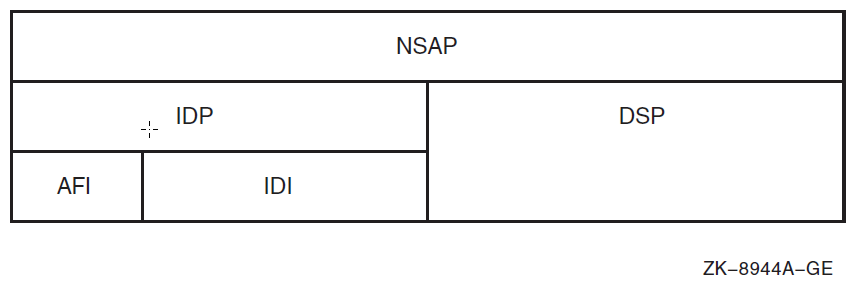
Every NSAP address has two primary fields:
Initial domain part (IDP) — The content of the IDP is standardized and assigned by an allocation authority. The IDP is further subdivided into the following parts:
Authority and format identifier (AFI) — The AFI consists of two decimal digits that identify the authority that allocated the globally unique IDP, the format of the IDI, and the syntax of the DSP. The AFI value is 36, 37, 52, or 53 for X.121-based NSAPs. VSI recommends using AFI 36 for NSAP addresses used over X.25 CONS networks. (A digit is encoded in a four-bit nibble with values ranging from 0000 to 1001. Two digits fit in each octet. For DSPs with an odd number of digits, the last octet is padded with the value 1111 to obtain an integral number of octets.)
Initial domain identifier (IDI) — The IDI identifies the subdomain from which DSP values are allocated and the authority responsible for allocating the DSP values. For X.121-based NSAPs, the IDI field contains the entire X.121 address of exactly 14 digits. X.121 addresses of less than 14 digits in length are padded on the left with zeros or ones, depending on the first digit and the AFI value, as shown in Table 8.16, ''X.121-Based NSAP Formats''.
Domain specific part (DSP) — The contents and semantics of the DSP are not specified in ISO/IEC 8348:2019. For X.121-based NSAPs, the DSP may be a decimal or binary value up to 24 digits or 12 octets long. The DSP may be null (omitted) when using a decimal format (AFI 36 or 52). VSI recommends using a null DSP for the X.25 CONS protocol stack.
| First X.121 Digit | DSP Syntax | AFI Value | IDI Padding | Example X.121 Address | Corresponding IDI |
|---|---|---|---|---|---|
| non-zero |
decimal |
36 |
zeros |
234212345678 |
00234212345678 |
| non-zero |
binary |
37 |
zeros |
234212345678 |
00234212345678 |
| zero |
decimal |
52 |
ones |
06175750100 |
11106175750100 |
| zero |
decimal |
53 |
ones |
06175750100 |
11106175750100 |
Table 8.17, ''Example NSAP Addresses'' shows example NSAP addresses using the same X.121 addresses listed in Table 8.13, ''X.121 Addresses and Equivalent X.25 Network Addresses'' for PSS, AUSTPAC, and PACNET. You can use these NSAPs over any X.25 network. The AFI is shown in bold type, the IDI in italics. The DSP was left null for these NSAPs.
| Call Destination | X.121 Address | NSAP |
|---|---|---|
| PSS | 234212345678 |
3600234212345678 |
| AUSTPAC | 505287654321 |
3600505287654321 |
| PACNET | 530187654321 |
3600530187654321 |
ISO Conversion Rules
ISO/IEC 8878:1987 defines which NSAP/X.25 network address conversions are allowed. Loosely translated, the calling node can omit the address extension facilities if the NSAP addresses map directly to X.121 addresses: the DSPs must be null, the AFIs must be those shown in Table 8.16, ''X.121-Based NSAP Formats'', and the IDIs must contain the complete X.121 addresses.
The called node must be capable of accepting a call with or without address extension facilities. If the facilities exist in the call, X.25 passes the NSAP addresses in the facilities up to the Transport layer. If the facilities do not exist, X.25 must derive the NSAP addresses from the X.121 addresses of the incoming call.
8.8.1.2. X.25 CONS Management Entities
You cannot configure the X.25 CONS protocol stack on DECnet-Plus end system products using the configuration tools alone. To successfully configure the stack, you must understand NCL and the management entities in the X.25 CONS stack. Table 8.18, ''Management Entities'' shows the management entities used at each layer of the protocol stack.
The X.25 and LAPB protocols allow many options that vary among X.25 networks. VSI’s products provide X.25 network profiles that contain all the pertinent network parameters for most PSDNs. For example, profiles contain the default value and permissible range for the X.25 window size. The system administrator specifies the profile name during system configuration. Typically, the profile name corresponds to the name of the PSDN.
The X.25 software components follow instructions from both their user applications and their management entities. You cannot control the behavior of these components entirely by management. In some cases, X.25 software ignores certain management parameters, depending on which functions an X.25 application uses.
| Protocol Layer | Management Entity | Function in CONS Stack |
|---|---|---|
|
ACSE, Presentation, and Session |
|
Defines the OSI application’s ACSE, Presentation, and Session addresses for incoming connections. |
| Transport Class 0 |
| Defines which outgoing connections pass through X.25. Routes incoming requests to OSAK based on the TSEL. |
| X.25 Packet Layer |
| Translates between NSAP and X.25 network addresses. Establishes a connection to the X.25 network service provider. Routes incoming calls to OSI transport, based on received X.25 call packet contents. Controls access from the X.25 network to the computer system. |
| LAPB Link Layer |
| Controls data link buffers and timers. |
| Modem Connect |
| Controls physical attributes of the modem connection. |
Example Configuration
The following illustrated configuration and the examples that follow help clarify the interrelationships among management entities for outgoing and incoming calls using X.25 CONS. Assume the end system implementations NCOSI and SYBILL are connected to a local X.25 packet switch, which in turn is connected to an AT&T Accunet line, as shown in Figure 8.17, ''Example Configuration''.
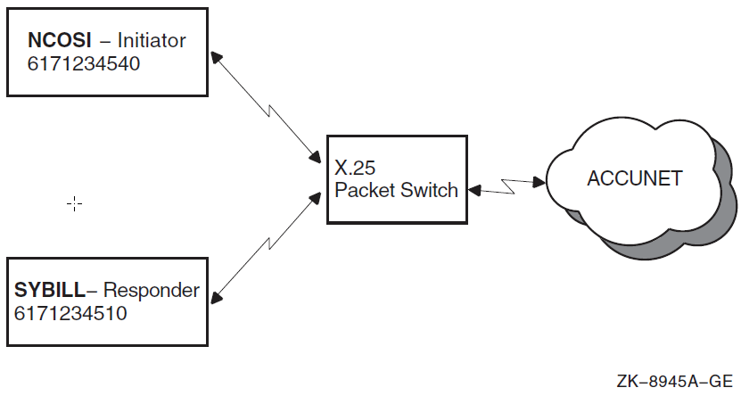
Accunet addresses are NTN-based, similar to PACNET. All addresses discussed in this section are based on conversion rules defined in international standards.
NCOSI is set up as the OSI application initiator, SYBILL as the responder. AT&T assigned a range of addresses to the line from 6171234500 to 6171234599.
The Accunet DNIC is 3134, and the international prefix is 0. NCOSI has a local subaddress of 40, and SYBILL has a local subaddress of 10. From these subaddresses, the remaining addresses are derived using the conversion rules explained in Section 8.8.1.1, ''CONS Addressing Mechanisms''. Table 8.19, ''Example Configuration Addresses'' lists these addresses.
| Source: NCOSI | Destination: SYBILL | |
|---|---|---|
| X.25 Profile |
Accunet |
Accunet |
| Accunet DNIC |
3134 |
3134 |
| Accunet International Prefix |
0 |
0 |
| Accunet Line Address |
6171234500-99 |
6171234500-99 |
| X.25 Network Address |
61712345 |
61712345 |
| Local Subaddress |
40 |
10 |
| X.121 Address |
31346171234540 |
31346171234540 |
| AFI |
36 |
36 |
| NSAP |
3631346171234540 |
3631346171234510 |
| Address Extension Facility |
103631346171234540 |
103631346171234510 |
Outgoing Connections
Figure 8.18, ''Entity Relationships for Outgoing Connections'' shows the entity relationships for outgoing connections. The following actions occur during an outgoing call:
The OSI application initiator provides the full OSI stack specification of the destination along with the osi transport template entity name to OSAK. (Note that no major OSAK management components are involved in outgoing connections; therefore, they are not shown in Figure 8.18, ''Entity Relationships for Outgoing Connections''.) OSAK passes the TSEL and NSAP on down to OSI transport.
OSI transport follows instructions in the OSI transport template to set up a connection over CONS. It uses the OSI transport CONS NSAP address for the source address.
X.25 software follows instructions in the X25 Access template to make the call. The nsap mapping attribute is true and the dte class attribute is null, forcing NSAP-to-X.25 network address conversions through X25 Access reachable addresses. The value in the local subaddress causes X.25 software to provide a calling DTE address in the outgoing X.25 call packet.
X.25 software selects the X25 Access reachable address with the longest address prefix that matches the destination NSAP. X25 Access reachable addresses provide for two types of conversions. X.121 mapping converts an X.121-translatable NSAP to an X.121 address using the rules defined in Section 8.8.1.1, ''CONS Addressing Mechanisms''. Manual mapping converts from any NSAP address directly to any specific X.25 network address. Most NSAPs in the transport/X.25 CONS stack are X.121-translatable and use X25 Access reachable address x121d. The dte class attribute indicates that the call may be placed on any X25 Protocol DTE line under X25 Access DTE class Accunet.
The X25 dte class entity defines how to translate X.121 addresses to the local X.25 network addresses. X.25 software uses these translation rules only when the original NSAP was converted through X.121 mapping.
Figure 8.18. Entity Relationships for Outgoing Connections 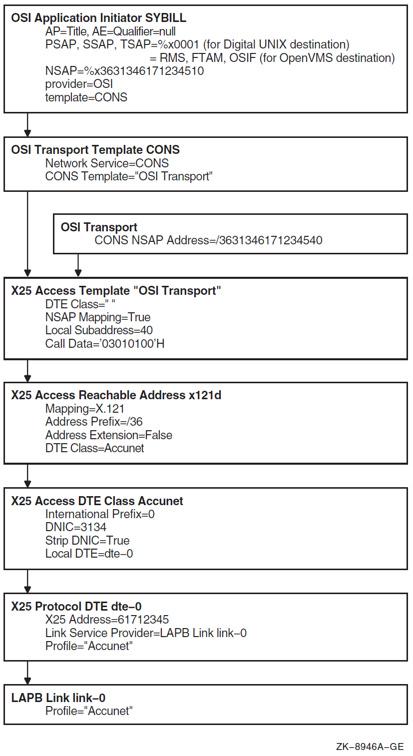
Incoming Connections
Figure 8.19, ''Entity Relationships for Incoming Connections'' shows the entity relationships for incoming connections.
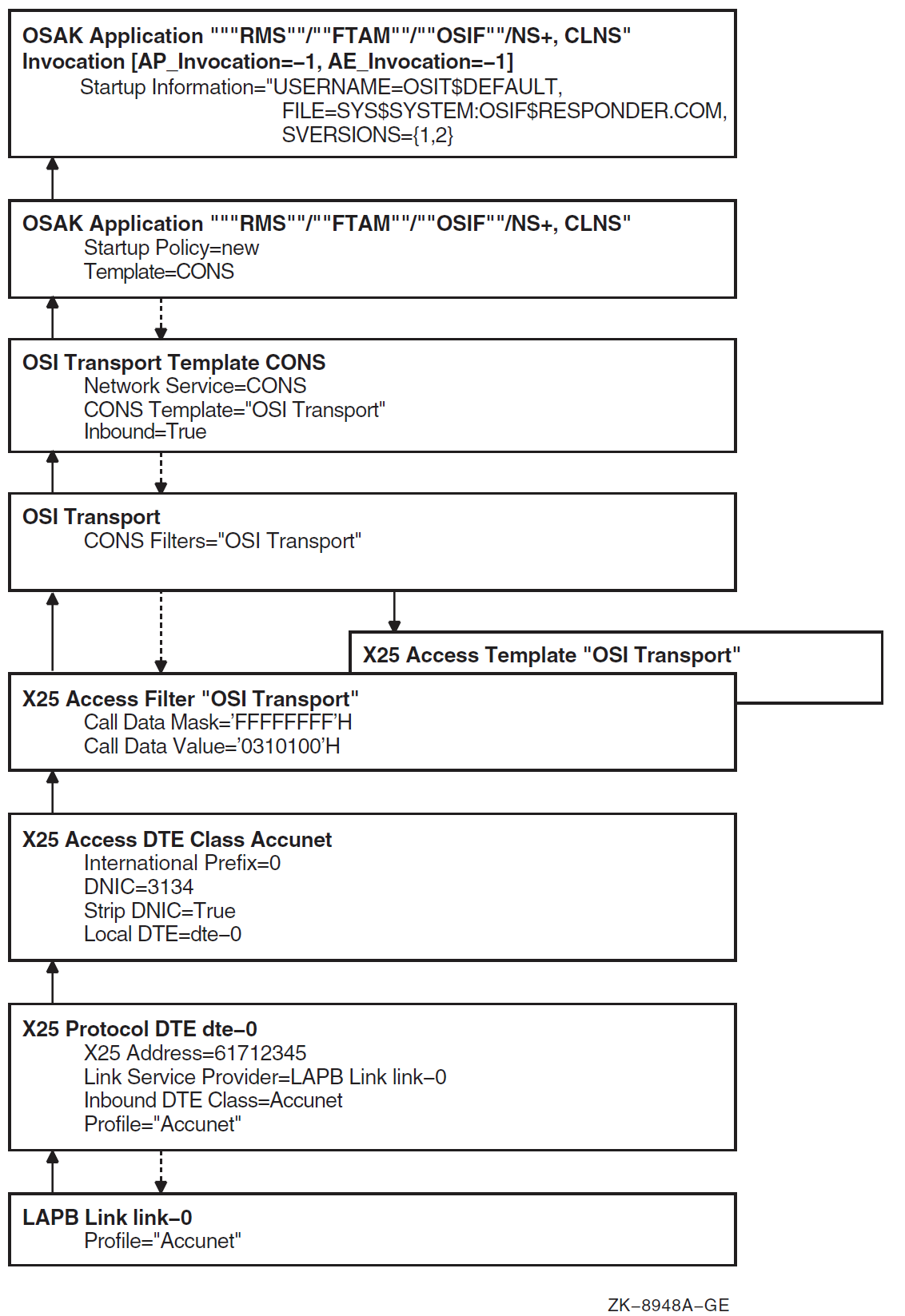
The following initialization actions take place before incoming connections can be accepted.
OSAK opens a port to OSI transport for every TSAP required by OSAK applications.
OSI transport activates any x25 access filter entities specified in the osi transport cons filters attribute.
X.25 software opens a channel to each LAPB link during initialization, and in turn, each LAPB link opens channels to its associated modem connect line entity.
The following occurs upon receipt of an incoming call on an X.25 DTE:
X.25 software uses the x25 protocol dte inbound dte class attribute to determine which X25 Access DTE class applies to the call.
X.25 software extracts the NSAP address from the address extension facilities, if they exist. If the facilities do not exist, X.25 software converts the X.25 network addresses to NSAP addresses using the x25 access dte class attributes.
X.25 software searches the X25 Access filters for a match with the attributes of the incoming call. If a match exists, X.25 software passes the message up to the application that activated the filter.
OSI transport searches for an osi transport template entity with the inbound characteristic set to true, the network service characteristic set to cons, and the cons template having the name of the X25 Access filter. If found, OSI transport accepts the X.25 call with the X25 Access template specified in the cons template attribute. With this procedure, the x25 access filter and x25 access template entities must use the same entity name.
OSI transport passes the message up to OSAK if the transport connect request PDU’s called TSAP ID field matches the TSEL specified by OSAK during initialization Step 2.
OSAK passes the message up to the OSI application if the SSEL and PSEL match those defined during initialization Step 1. OSAK ignores the AP-Title and AE-Qualifiers.
OSAK invokes the OSI application responder using the command file defined in the osak application invocation entity prior to passing the message up.
8.8.1.3. Configuring X.25 to Provide the CONS Network Service
You can configure OSI transport over X.25 support using the NET$CONFIGURE and the appropriate X.25 configuration procedure. These procedures do not completely support this configuration; therefore you have to edit certain NCL startup scripts and perform a few NCL commands manually. The VSI DECnet-Plus for OpenVMS Installation and Configuration contains an appendix which describes the process. This section discusses the NCL commands required to configure the X.25 entities needed for OSI Transport over X.25 CONS. For information about configuring the OSI transport entities, see Section 8.5.2.3.3, ''Steps for Configuring the CONS Network Service''. The following steps list the commands used to configure the X.25 templates and filters required to support OSI transport’s use of the CONS service provided by X.25.
The following example shows how to create the x25 access template and set its characteristics:
ncl> create x25 access template template-name
ncl> set x25 access template template-name -
_ncl> call data hex-string, dte class dte-class-name Outbound transport connections that use X.25 network connections use X25 Access templates to supply most of the parameters for setting up the network connection. Inbound transport connections that use X.25 connections use X25 Access templates to negotiate network connection parameters.
Each OSI transport template for CONS connections that you configure names an X25 Access template in its cons template characteristic. You must, therefore, configure each of the X25 Access templates named in your OSI transport templates for CONS connections.
When you create an X25 Access template for use with CONS, set the value of the call data characteristic to %X03010100. The destination host will recognize this value as indicating that the call should be passed to CONS.
The following example shows how to create the x25 access filter:
ncl> create x25 access filter filter-name
ncl> set x25 access filter filter-name -
_ncl> call data mask mask, call data value value,-
_ncl> inbound dte class dte-class-name,- If your system is to accept inbound transport connections over X.25 network connections, you need to configure one or more X25 Access filters. An X25 Access filter listens for incoming network connection requests and passes these requests to the appropriate destination. One or more X25 Access filters are required for each X25 Access DTE class that CONS wants to use.
Each outbound-inbound OSI transport template for CONS connections that you configure specifies the name of an X25 Access template in its cons template characteristic. This X25 Access template will be used to accept an inbound network connection. The name of this X25 Access template must be the same as the name of an X25 Access filter that is used to receive inbound network connections.
When you create an X25 Access filter for use by CONS, set call data mask to %Xffffffff.
When you create an X25 Access filter for use by CONS, set call data value to %X03010100.
8.8.2. Configuring Routing Over X.25 Circuits
DECnet-Plus supports the following approaches for configuring routing, which provides the Connectionless-Mode Network Service (CLNS), to use X.25 data links:
Configuring the routing entity to use an X.25 switched virtual circuit (SVC) as a dynamically-assigned data link to a remote network. DECnet-Plus waits until an application requests a connection to the remote network before establishing the link. DECnet-Plus disconnects the link when no applications have an open connection to the remote network. The remote network is considered outside the local routing domain. You must manually configure which CLNS addresses are reachable over the X.25 link. X.25 dynamically-assigned data links cannot be used to access a DECnet phase IV node.
Configuring the routing entity to use an X.25 switched virtual circuit (SVC) as a static data link to a remote network. This approach does not require the X.25 service provider to create a permanent channel. To establish a link, DECnet-Plus calls or receives an X.25 call from a remote system during startup. It keeps the link open until disabled by network management commands. DECnet-Plus autoconfigures itself into the remote DECnet Phase V or DECnet Phase IV network.
Configuring the routing entity to use an X.25 permanent virtual circuit (PVC) as a data link to a remote network. PVCs are permanent channels established by the X.25 service provider. DECnet-Plus establishes a link through the X.25 PVC at startup. It then autoconfigures itself into the remote DECnet Phase V or DECnet Phase IV network.
To configure routing to use X.25 circuits, use the advanced configuration procedure (invoking NET$CONFIGURE ADVANCED). If X.25 software is configured, the device configuration section gives you the option of configuring any WAN devices for DECnet’s use. Be sure to answer none when NET$CONFIGURE asks you for the WAN line’s protocol. This prohibits DECnet from using the line directly and allows the X.25 configuration procedure to configure the line for X.25 use.
After configuring all regular routing circuits, the configuration procedure asks if you want to configure DECnet over X.25. The DECnet over X.25 configuration begins with a list of choices for the type of X.25 circuit to use:
Types of X.25 circuits: [1] - X.25 Dynamic Assigned (DA) [2] - X.25 Static Incoming (IN) [3] - X.25 Static Outgoing (OUT) [4] - X.25 Permanent (PVC) * Which type of X.25 circuit do you want to use?
Select the type of X.25 you want to configure. The procedure then asks you for information about the circuit, including:
Routing circuit name to use.
Template name for the X25 Access template, which X.25 routing circuits use to make outgoing or accept incoming network connections.
Filter name for the X25 Access filter, which X.25 routing circuits use to accept incoming network connections. The filter name is required for static incoming and dynamically-assigned circuits and specifies the inbound DTE class, call data value, and call data mask.
Whether you want to configure reachable addresses, and if yes, information about reachable addresses. If you configure a dynamically-assigned X.25 routing circuit, you must configure one or more reachable addresses used for managing the circuit. Each reachable address specifies a mapping of an NSAP address to a DTE address.
For more information about using NET$CONFIGURE to configure DECnet over X.25, see the VSI DECnet-Plus for OpenVMS Installation and Configuration. The remainder of this section discusses using NCL commands to create the DECnet over X.25 routing circuits.
8.8.2.1. Commands for Configuring General X.25 Routing Circuit Information
To use NCL to manually configure X.25 routing circuits, following these steps:
Set up and enable routing:
ncl> create routing type endnode ncl> set routing dna address format true, lifetime 63, - _ncl> manual network entity titles {}, probe rate 20 ncl> enable routingCreate and set up the routing circuit with the appropriate values for its attributes, including the circuit name, type, data link entity, template, and X.25 filter:
ncl> create routing circuit x25_circuit-1 type type
ncl> set routing circuit x25_circuit-1 data link entity x25 access
ncl> set routing circuit x25_circuit-1 template template-name
ncl> set routing circuit x25_circuit-1 x25 filter { filter-name}
ncl> enable routing circuit x25_circuit-1 Select the type of X.25 routing circuit. For more information about the value to specify for the type attribute, see the subsection for the type of X.25 routing circuit being configured.
Always set the data link entity attribute to x25 access.
Specify the name of an X25 Access template. See Step 5 for more information.
For X.25 dynamically-assigned and static incoming circuits, specify the name of an X25 Access filter. See Step 6 for more information.
When configuring dynamically-assigned circuits, you must create at least one routing circuit reachable address entity. See Section 8.8.2.2, ''Configuring Routing Over X.25 Dynamically-Assigned Circuits'' for information about setting up routing circuit reachable address entities.
Create the X25 Access module and enable it:
ncl> create x25 access ncl> enable x25 access
Create one or more X25 Access templates and set their attributes:
ncl> create x25 access template template-name ncl> set x25 access template template-name - _ncl> destination dte address dte-address,- _ncl> dte class dte-class-name
Each routing circuit that you configure names an X25 Access template in its template attribute. You must, therefore, configure each of the X25 Access templates named in your X.25 routing circuits.
A routing circuit that invokes outbound X.25 calls uses an X25 Access template to supply most of the parameters for setting up the call. A routing circuit that receives inbound X.25 calls uses an X25 Access template to negotiate call parameters.
If necessary, create one or more X25 Access filters and set their attributes:
ncl> create x25 access filter filter-name ncl> set x25 access filter filter-name - _ncl> inbound dte class dte-class-name, - _ncl> sending dte address dte-address,- _ncl> call data mask %xff, - _ncl> call data value %x81 ncl> enable x25 access filter
Each routing circuit that you configure which receives inbound X.25 calls (X.25 static-incoming or X.25 dynamically-assigned circuits) names one or more X25 Access filters in its x25 filters attribute. You must, therefore, configure each of the X25 Access filters named in your X.25 routing circuits.
An X25 Access filter listens for incoming calls and passes them to the appropriate destination.
When setting up a filter for an inbound X.25 circuit, specify the following X25 Access filter values:
call data mask %xff
call data value %x81
8.8.2.2. Configuring Routing Over X.25 Dynamically-Assigned Circuits
Dynamically-assigned circuits are used for making infrequent connections to destinations outside the routing domain of your DECnet-Plus system. (A routing domain is a collection of systems that automatically configure to each other and exchange network topology information using consistent Network layer protocols.) Dynamically-assigned circuits are established upon arrival of data and are cleared when no more data is transmitted or received during a specified time (idle time).
Take the following three steps to configure a dynamically-assigned X.25 circuit:
Use the X.25 configuration procedure to define the x25 access template and x25 access filter entities with the parameters necessary to establish and accept calls with the remote system. See the appropriate X.25 documentation.
Create a routing circuit with the following commands:
NCL> create routing circuit circuit-name type x25 da
NCL> set routing circuit circuit-name template template-name
NCL> set routing circuit circuit-name x25 filter filter-name
NCL> enable routing circuit circuit-name The routing circuit type must be x25 da.
The routing circuit template attribute must contain the name of the x25 access template entity.
The routing circuit x25 filter attribute must contain the name of the x25 access filter entity.
Create one or more routing circuit reachable address entities as discussed in the two subsections that follows.
Addressing Issues for X.25 Dynamically-Assigned Circuits
When using dynamically-assigned X.25 routing circuits, the sending and receiving nodes must be in separate routing domains. The routing domain is defined with a unique AFI, IDI, and preDSP combination in the NSAP address (see Figure 8.16, ''NSAP Address Structure''). The format of the CLNS address must conform to that described in the VSI DECnet-Plus Planning Guide.
The requirement for separate routing domains places two restrictions on addressing:
The NSAP address used at the Routing layer for the source and destination can be any CLNS address except ones beginning with AFI 49.
DECnet Phase IV network traffic cannot span dynamically-assigned X.25 routing circuits. Phase IV address translations apply only within a single routing domain.
If your DECnet-Plus system is isolated from the network and uses the dynamically-assigned X.25 routing circuit for communication, you may find it convenient to assign an NSAP address to your system that is based on your X.25 network address. If you do this, you must use the binary format of an X.121 address (AFI 37 or 53), as opposed to the decimal format described in Section 8.8.1.1, ''CONS Addressing Mechanisms'' for X.25 CONS configurations. Section 8.4.1.6, ''Configuring End System Network Addresses for Non-DNA Networks'' explains how to use manual network entity titles to define the NSAP address for your system.
Configuring Routing Reachable Addresses
For each dynamically-assigned X.25 routing circuit, you must configure one or more reachable addresses. A reachable address defines a mapping between network service access points (NSAPs) and data terminal equipment (DTE) addresses used in X.25. An NSAP identifies a system in the network and is used by both the Network and Transport layers of DECnet-Plus. X.25 uses a DTE address to identify the end point of an SVC. Reachable addresses identify which NSAP or group of NSAPs should be sent over a particular X.25 circuit.
Note
Use the routing circuit reachable address entity when configuring routing over X.25 dynamically-assigned circuits. Do not use the x25 access reachable address entity. The x25 access reachable address entity applies only to OSI transport over X.25 CONS configurations, as described in Section 8.8.1, ''OSI Transport Over X.25 CONS''.
Consider the following example of two systems connected by an X.25 network:
| System A | System B | |
|---|---|---|
| NSAP |
48::00-5F:08-00-2B-16-A8-72:21 |
43:15082267643:0045:08002B16DE4F:21 |
| DTE |
075527537 |
18628935742674 |
The reachable address on System A specifies that if the destination NSAP matches the value 43:15082267643:0045:08002B16DE4F:21, then an X.25 circuit should be created by connecting to the DTE address 18628935742674. This example is a case of one-to-one NSAP-to-DTE mapping. The reachable address could also be set up such that any NSAP with the initial digits 43:15082267643 should be sent over that X.25 circuit, which would potentially cause many different NSAPs to be mapped to that particular X.25 circuit.
The NCL commands to create and initialize reachable addresses are created in the SYS$STARTUP:NET$OSI_TRANSPORT_STARTUP.NCL script (for OSI transport using CONS) and the SYS$STARTUP:NET$ROUTING_STARTUP.NCL script (for Routing using X.25).
The following example shows how to manually create a reachable address for routing using NCL. For more information on configuring routing, see Section 8.4, ''Configuring Routing''.
ncl> create routing circuit x25_circuit-1 reachable address ughh_v -
_ncl> address prefix /4145418715004108002b0ed41e
ncl> set routing circuit x25_circuit-1 reachable address ughh_v -
_ncl> dte address { 2267643 }
ncl> set routing circuit x25_circuit-1 reachable address ughh_v -
_ncl> mapping manual
ncl> enable routing circuit x25_circuit-1 reachable address ughh_v Specify the address prefix when you create the routing circuit entity. You cannot modify this attribute with the set command.
The X.25 configuration procedure automatically creates the following two X25 Access reachable addresses:
X121 with address prefix 37:
X121D with address prefix 36:
8.8.2.3. Configuring Routing Over X.25 Static Circuits
X.25 static circuits emulate a permanent point-to-point circuit over an X.25 switched virtual circuit. The underlying X.25 connection is established when DECnet-Plus starts up, and the connection remains until explicitly terminated (normally at system shutdown).
When two systems communicate using X.25 static circuits, one system must define the circuit as incoming, while the other system must define it as outgoing. The system with an incoming circuit establishes communication with the X.25 network provider and waits for a connection from the other end. The system with the outgoing circuit initiates the X.25 call to the waiting system. If the call fails, the system keeps retrying until a successful connection is made. After the X.25 connection is established, the two systems automatically exchange routing layer configuration information, autoconfigure their routing databases, and begin two-way communications.
8.8.2.3.1. Configuring Outgoing X.25 Static Circuits
Take the following two steps to configure an outgoing X.25 static circuit:
Use the X.25 configuration procedure to define an x25 access template entity with the parameters necessary to establish a call to the destination system. See the appropriate X.25 documentation.
Create a routing circuit with the following commands:
NCL> create routing circuit circuit-name type x25 static outgoing
NCL> set routing circuit circuit-name template template-name
NCL> enable routing circuit circuit-name The routing circuit type must be x25 static outgoing.
The routing circuit template attribute must contain the name of the x25 access template entity.
8.8.2.3.2. Configuring Incoming X.25 Static Circuits
Take the following three steps to configure incoming X.25 static circuits:
Use the X.25 configuration procedure to define the x25 access template and x25 access filter entities with the parameters necessary to accept a call from the source system. See the appropriate X.25 documentation.
Create a routing circuit with the following commands:
NCL> create routing circuit circuit-name type x25 static incoming
NCL> set routing circuit circuit-name template template-name
NCL> set routing circuit circuit-name x25 filter {filter-name}
NCL> enable routing circuit circuit-name The routing circuit type must be x25 static incoming.
The routing circuit template entity must contain the name of the x25 access template entity.
The routing circuit x25 filter entity must contain the name of the x25 access filter entity.
Chapter 9. Setting Up an OpenVMS Cluster Environment for DECnet-Plus
This chapter provides information about:
Configuring OpenVMS Cluster satellite nodes
Setting up an OpenVMS Cluster alias
Sharing network applications in the OpenVMS Cluster environment
9.1. Configuring OpenVMS Cluster Satellite Nodes in a DECnet-Plus Environment
The information presented in the following sections supplements the material provided by the VSI OpenVMS Cluster Systems Manual.
9.1.1. Adding, Modifying, or Deleting an OpenVMS Cluster Satellite Node
You must have planned your OpenVMS Cluster and have at least one OpenVMS Cluster boot node set up before using the information in this section. The following information is based on the CLUSTER_CONFIG.COM procedure found in the SYS$MANAGER directory. The VSI OpenVMS Cluster Systems Manual describes this procedure. VSI has modified the procedure to make it compatible with the DECnet-Plus software. In the following sections, only those portions of CLUSTER_CONFIG.COM that have been modified are discussed in detail.
You should also be familiar with the general concepts of the Maintenance Operations Protocol (MOP), and, in particular, the MOP client database, as described in Chapter 10, "Downline Loading and Upline Dumping Remote Systems".
If you are adding a new OpenVMS Cluster satellite node to your OpenVMS Cluster, see Section 9.1.1.1, ''Adding a New Satellite Node to an OpenVMS Cluster Environment''.
If you are making the transition from an existing Phase IV DECnet cluster satellite node to DECnet-Plus, see Section 9.1.2, ''Making the Transition from an Existing DECnet Phase IV OpenVMS Cluster Satellite Node''. After you have made the transition, you can invoke CLUSTER_CONFIG.COM to modify its characteristics.
You can delete a satellite node from the OpenVMS Cluster system with CLUSTER_CONFIG.COM whether or not the satellite node has made the transition to DECnet-Plus. If the satellite has not made the transition, a message appears stating that the client could not be removed from the client database. This will not cause a problem, and all root information will be deleted correctly.
By default, the satellite node information created by CLUSTER_CONFIG.COM or NET$CONFIGURE.COM is placed in the SYS$MANAGER root directory for the boot node. See Section 9.1.4, ''Customizing Your MOP Client Database for Multiple Boot Nodes'' for a discussion about making this information available to other boot nodes in your OpenVMS Cluster system.
9.1.1.1. Adding a New Satellite Node to an OpenVMS Cluster Environment
To add a new OpenVMS Cluster satellite node to an OpenVMS Cluster environment, invoke the SYS$MANAGER:CLUSTER_CONFIG.COM procedure. This procedure does the following:
Creates a root directory for the satellite node on the OpenVMS Cluster common disk.
Creates a MOP client entry for the satellite node in the MOP client database on the boot node.
Provides the satellite node with a set of SYSGEN parameters sufficient to run the DECnet-Plus software.
Enables the node to automatically invoke the NET$CONFIGURE procedure after it boots.
Refer to the VSI OpenVMS Cluster Systems Manual for general information about CLUSTER_CONFIG.COM. You can enter a "?" at any prompt to display help text that explains what information is required at the prompt.
Table 9.1, ''Information Requested for New OpenVMS Cluster Satellites'' explains the information specific to DECnet-Plus that CLUSTER_CONFIG.COM requests.
| Item | Response |
|---|---|
What is the node’s DECnet full name? |
Determine a full name with the help of your network manager. Enter a string that includes:
For example: .world.networks.mynode mega:.indiana.jones columbus:.flatworld |
What is the DECnet Phase IV compatible synonym name for
this node? |
A node synonym is a short name for the node’s full name. In an OpenVMS Cluster environment, this name is used as the value of the SYSGEN parameter SCSNODE. It must also be defined in the namespace as the synonym name for that node. Therefore, it must be a string of six or less alphanumeric characters. By default, it is the first six characters of the last simple name in the full name. For example: Full name — Synonym — Node synonyms greater than six characters in length are not supported if the node is an OpenVMS Cluster member. |
What is the node’s DECnet node address? |
Enter the node’s DECnet node address. This address is in the form area.node. Ask your network manager to help you determine this address. |
Does synonym name need to be
registered in the namespace [N]? |
Answer YES to this question if the name of the node you are adding has not been registered with the namespace. Registration makes your node "known" to the namespace. You only need to do this once. The registration might fail if your namespace has access control list (ACL) protection. If that occurs, your network manager must register the node for you. |
What is the cluster alias full name? |
The alias name is the node name of the alias: the DECdns full name of the object that stores the address towers for the alias. Do not enter a node synonym. If this node will not be participating in an OpenVMS Cluster alias, press carriage return. Determine the OpenVMS Cluster alias name with the help of your network manager. Enter a string that includes:
For example: .networks.farout mega:.proto.quikk |
What is the Phase IV address of the cluster
alias? |
The node ID of the alias could not be retrieved from the namespace, so it must be calculated from the alias’s Phase IV address. Enter the Phase IV address of the alias in the area.node format (for example, 63.137), or enter a 6-byte ID in the format AA-00-04-00-xx-xx, where xx-xx is calculated from the Phase IV node address. To determine the Ethernet physical address, proceed as follows:
|
What selection weight do you choose for this node? [0
for satellites] |
The selection weight determines the percentage of incoming connections addressed to the alias that this node will handle. If the node is a satellite, take the default value of 0. For larger nodes, select a value between 5 and 10 (or larger if you want) according to the size of the node. |
The information you enter by means of CLUSTER_CONFIG.COM is automatically entered in the boot node’s MOP client database and executed. The CLUSTER_CONFIG.COM procedure prompts you for other information. Then, it tells you when to boot your satellite node. The satellite node will run an AUTOGEN procedure shortly after booting.
After the satellite reboots, the NET$CONFIGURE procedure executes automatically. When it completes, the network starts, and the OpenVMS startup procedure continues until completion.
9.1.2. Making the Transition from an Existing DECnet Phase IV OpenVMS Cluster Satellite Node
Existing OpenVMS Cluster satellite nodes already have a root directory on the system disk. Because these satellites are already in the OpenVMS Cluster, you cannot use CLUSTER_CONFIG.COM to migrate them to DECnet-Plus. However, you can take the following actions to migrate the satellites:
Create a MOP client entry for the satellite node in the MOP client database on the boot node.
Execute the MOP client script on a boot node.
If necessary, edit SYS$SYSTEM:MODPARAMS.DAT in the satellite’s root directory.
If the OpenVMS Cluster satellite node is not already running, boot it. A boot node will downline load it.
On the OpenVMS Cluster satellite node, invoke the AUTOGEN procedure to provide the satellite node with a set of SYSGEN parameters sufficient to run the DECnet-Plus software.
After the satellite node has rebooted, invoke the SYS$MANAGER:NET$CONFIGURE procedure from the satellite and select the menu option to perform a full configuration. The network will start automatically when NET$CONFIGURE completes.
Each of these steps is fully explained in the following list:
Create a MOP client entry for the satellite node.
Your Phase IV DECnet object database on your boot node might already have been converted to DECnet-Plus. When you invoke the NET$CONFIGURE.COM procedure to perform a full configuration, you can request that it convert the Phase IV object database. Refer to the VSI DECnet-Plus for OpenVMS Installation and Configuration for more information about converting your Phase IV object database.
To determine if your Phase IV DECnet object database has been converted to DECnet-Plus, look at the contents of the NCL script file, SYS$MANAGER:NET$MOP_CLIENT_STARTUP.NCL. This is an ASCII file that you can display on your terminal. If the object database has been converted, you will find information about each OpenVMS Cluster satellite node that existed in the Phase IV DECnet object database. If some of the information needs to be modified for DECnet-Plus, you can edit the file.
If the Phase IV DECnet object database was not converted, you can add information for each OpenVMS Cluster satellite node with SYS$MANAGER:NET$CONFIGURE.COM. Refer to Section 10.2, ''Manually Configuring MOP'' for more information about the parameters needed to configure an OpenVMS Cluster satellite.
The following is a sample of the information requested when you choose Option 8 of NET$CONFIGURE.COM, "Configure MOP Client Database:"
* Which configuration option to perform? [1] : 8 * Do you wish to ADD or DELETE a MOP Client? [ADD] : * Name of the MOP Client? : tahini * Circuit for ’TAHINI’? : * Physical addresses for ’TAHINI’? : 08-00-2B-07-36-B6 * Secondary Loader for ’TAHINI’? : * Tertiary Loader for ’TAHINI’? : * System Image for ’TAHINI’? : "@net$niscs_laa(disk$v55:<sys10.>)" * Diagnostic Image for ’TAHINI’? : * Management Image for ’TAHINI’? : * Script File for ’TAHINI’? : * Dump File for ’TAHINI’? : * Verification for ’TAHINI’? [%X0000000000000000] : * Phase IV Client Address (aa.nnnn) for ’TAHINI’? [none] : 63.10 * Phase IV Client Name for ’TAHINI’? [TAHINI] : * Phase IV Host Address for ’TAHINI’? [63.61] : * Phase IV Host Name for ’TAHINI’? [CASIDY] : hummus * Do you wish to generate NCL configuration scripts? [YES] : %NET$CONFIGURE-I-CHECKSUM, checksumming NCL management scripts %NET$CONFIGURE-I-CONFIGCOMPLETED, DECnet-Plus for VMS configuration completed
The information will not take effect until you execute the NCL script SYS$MANAGER:NET$MOP_CLIENT_STARTUP.NCL. If MOP has not yet been started, starting MOP executes the script. If MOP is already running, you can stop it and then start it again to execute the script. Alternatively, if MOP is already running, you can invoke the script at the NCL prompt.
Execute the MOP client script on a boot node.
$ run sys$system:ncl ncl> @sys$manager:net$mop_client_startup.ncl
Note
One line in the file, create mop, generates an error message because the mop entity has already been created. You can ignore this message.
After the script has been executed, you can downline load the OpenVMS Cluster satellite.
The following example shows the information that network management knows about the client configured in the previous step:
ncl> show mop client tahini all Node 0 MOP Client TAHINI at 2019-04-21-18:32:38.205-04:00I0.448 Identifiers Name = TAHINI Characteristics Circuit = Addresses = {08-00-2B-07-36-B6, AA-00-04-00-0A-FC} Secondary Loader = {} Tertiary Loader = {sys$system:tertiary_vmb.exe} System Image = {"@net$niscs_laa(DISK$V55:<SYS10.>)"} Diagnostic Image = {} Management Image = {} Script File = {} Phase IV Host Name = HUMMUS Phase IV Host Address = 63.61 Phase IV Client Name = TAHINI Phase IV Client Address = 63.10 Dump File = {} Dump Address = 0 Verification = %X0000000000000000 Device Types = {}If necessary, edit SYS$SYSTEM:MODPARAMS.DAT in the satellite’s root directory. See the VSI DECnet-Plus for OpenVMS Installation and Configuration for information about when it may be necessary to edit the SYS$SYSTEM:MODPARAMS.DAT file.
When installing DECnet-Plus for OpenVMS on an OpenVMS cluster, make sure that all cluster members have the necessary SYSGEN parameters set correctly. If a node in the cluster does not have the necessary parameters, startup of the network will fail. If the network fails to start for this reason, the logical NET$STARTUP_STATUS will be set to OFF-AUTOGENREQ. Make any necessary parameter changes prior to attempting to run NET$CONFIGURE.
Check the release notes for any updates to the SYSGEN parameter recommendations Update these values by editing the SYS$SYSTEM:MODPARAMS.DAT file.
If the OpenVMS Cluster satellite node is not already running, boot it.
If the MOP client database was successfully configured and the script executed, the boot node will downline load the satellite.
On the OpenVMS Cluster satellite node, invoke the AUTOGEN procedure to provide the satellite node with a set of SYSGEN parameters sufficient to run the DECnet-Plus software.
From the OpenVMS Cluster satellite node, invoke the AUTOGEN procedure as follows:
$ @sys$update autogen getdata reboot nofeedback
This regenerates the satellite node’s SYSGEN parameters and takes into account the new minimum values.
After the satellite node has rebooted, invoke SYS$MANAGER:NET$CONFIGURE.
Invoke this procedure from the satellite and select the menu option to perform a full configuration. The network will start automatically when NET$CONFIGURE is finished.
9.1.3. Specifying Defaults for Phase IV Prefix and Node Synonym Directory
By default, a cluster satellite configures its Phase IV Prefix as 49:: and its node synonym directory as .DNA_Nodesynonym. Some clusters may want to have different values for one or both of these attributes. To change these defaults for satellites added to the cluster, define the following logicals in SYS$COMMON:[SYSMGR]NET$LOGICALS.COM before running CLUSTER_CONFIG.COM.
$ define/system/nolog net$phaseiv_prefix "<prefix value>" $ define/system/nolog decnet_migrate_dir_synonym "<synonym dir>"
To change these values for a satellite that has already been configured, run NET$CONFIGURE from that satellite.
9.1.4. Customizing Your MOP Client Database for Multiple Boot Nodes
By default, the file NET$MOP_CLIENT_STARTUP.NCL resides in SYS$SYSROOT:[SYSMGR]. In this location, however, the MOP client information is only available to the node on which the file resides. It is up to the system manager to make that information available to more boot nodes, if desired.
Both CLUSTER_CONFIG.COM and NET$CONFIGURE.COM modify the file SYS$MANAGER:NET$MOP_CLIENT_STARTUP.NCL for the node on which the procedure is invoked. If the file is found in SYS$SYSROOT:[SYSMGR], it is modified and left in that location. Similarly, if the file is found in SYS$COMMON:[SYSMGR], it is modified and left in that location.
One way of allowing more boot nodes to access NET$MOP_CLIENT_STARTUP.NCL is to move it to SYS$COMMON:[SYSMGR]NET$MOP_CLIENT_STARTUP.NCL. All nodes in the OpenVMS Cluster then have access to it.
Alternatively, you can create one file for common MOP client information. Designated boot nodes can execute this file by placing @ncl_script_name in their own SYS$MANAGER:NET$MOP_CLIENT_STARTUP.NCL file. This method requires more work by the system manager, however, because the configuration procedures does not modify the common file directly.
9.2. Using an OpenVMS Cluster Alias
All or some nodes in an OpenVMS Cluster environment can be represented in the network as a single node by establishing an alias for the OpenVMS Cluster. To the rest of the network, an alias node looks like a normal node. It has a normal node object entry in the namespace, which provides a standard address tower. The alias has a single DECnet address that represents the OpenVMS Cluster environment as a whole. The alias allows access to common resources on the OpenVMS Cluster environment without knowing which nodes comprise the OpenVMS Cluster.
Using an alias never precludes using an individual node name and address. Thus, a remote node can address the OpenVMS Cluster as a single node, as well as address any OpenVMS Cluster member individually.
You decide which nodes participate in an alias. It is not necessary for every member of an OpenVMS Cluster environment to be part of the alias. Those nodes in the OpenVMS Cluster environment that have specifically joined the alias comprise the alias members, and connections addressed to the alias are distributed among these members. You can also have multiple aliases. Multiple aliases allow end nodes to be members of more than one alias. Multiple aliases also allow a mixed architecture cluster: you can have one alias for all the nodes, one for IA-64 systems, and another for Alpha systems.
You can have a maximum of three aliases. Members of the same alias must be members of the same OpenVMS Cluster environment. Nodes joining the same alias must be in the same DECnet area.
When creating multiple aliases, the first alias created is used for outgoing connections for any applications, with the outgoing alias attribute set to TRUE. If this alias is not enabled, the local node name is used for the outgoing connection.
Finally, nodes that assume the alias should have a common authorization file.
Note
OpenVMS Cluster environments do not have routers. If all nodes on a LAN that form a complete network are DECnet Phase V end nodes, no router is required. Any member of the OpenVMS Cluster can communicate with any system on the LAN. If, however, the LAN is part of a larger network or there are Phase IV nodes on the LAN, there must be at least one adjacent DECnet Phase V router on the LAN. The adjacent DECnet Phase V router allows members of the cluster to communicate with Phase IV nodes or systems in the larger network beyond the LAN.
A single router can support multiple OpenVMS Cluster environments on a LAN. Providing alias support does not prevent a router from providing normal routing support.
9.2.1. Adding a Node to an OpenVMS Cluster Alias
To add a node in an OpenVMS Cluster environment to the alias, use the NET$CONFIGURE.COM procedure. For information about NET$CONFIGURE.COM, refer to the VSI DECnet-Plus for OpenVMS Installation and Configuration.
Note
You must run NET$CONFIGURE.COM on each node in the OpenVMS Cluster environment that you want to become a member of the alias.
9.2.2. Adding an OpenVMS Cluster Alias to the Namespace
Before an alias can be identified by name, you must create a node object entry for it in the namespace. Do this only once for each OpenVMS Cluster.
To add an object entry for an OpenVMS Cluster alias in a DECnet Phase V area, you need:
The DECdns full name (such as .site.group.my_alias)
The node id (which is a unique Phase IV-style address such as 63.135)
The decnet_register tool converts a Phase IV-style address of the form area.node into a 6-byte address when registering a Phase IV node (see Section 5.3.5, ''Registering or Modifying a Node'' and Chapter 5, "Managing Name Service Searches and Information" for decnet_register). (In Phase IV, an area has a value in the range of 1–63, and a node has a value in the range of 1–1023. For example, 63.135.) The converted 6-byte address has the form AA-00-04-00-87-FC.
If you are converting an existing Phase IV OpenVMS Cluster to DECnet Phase V, use the existing Phase IV alias address for the Node ID when configuring and registering the alias. If you are installing a new OpenVMS Cluster in a DECnet Phase V network, use any Phase IV-style address that is unique to your network for the node ID when configuring and registering the alias.
Note
The node ID you use when registering your alias in the namespace must be the same Node ID you use when configuring the alias module using NET$CONFIGURE.
9.2.3. Configuring Multiple OpenVMS Cluster Aliases
If you want to set a default outgoing alias for particular nodes in an OpenVMS Cluster, use the following command:
ncl> set alias port port-name outgoing default true
If you want to set an specific outgoing alias for an application, use the following command:
ncl> set session control application application-name - _ncl> outgoing alias true, outgoingalias name alias-name
If you define application outgoingalias name, this supersedes the setting of the alias port outgoing default attribute.
If you set the application’s outgoing alias attribute to true and you do not set the application’s outgoingalias name attribute, the alias name for which you set the alias port outgoing default attribute to true is used.
If the alias specified by the application’s outgoingalias name attribute is not enabled, the local node name is used. If neither alias port outgoing default nor application outgoingalias name is set, the first alias created is used as the default for the system. If this alias is not enabled, the local node name is used.
9.2.4. Controlling Connect Requests to the OpenVMS Cluster Alias
When a node tries to connect to an alias node, it does not know that its destination is an alias. It consults the namespace to translate the alias node name into an address, and uses the address to send data packets to the alias. Data packets can arrive at any node that is an alias member. When a node in the alias receives a request for a connection to the alias, that node selects a member node (possibly itself) to own the connection.
The node makes its selection based on the following criteria:
First, it checks to see which nodes in the alias are enabled to receive incoming alias connections for the target application in the session control application entity. For more information about connecting to network applications, see Section 9.2.4.1, ''Controlling Connections to Network Applications''.
Second, it checks that nodes have not exceeded their maximum connections as defined in the NSP or OSI transport module. For more information about the quota of alias connections, see Section 9.2.4.2, ''Controlling the Number of Connections Allowed for an Alias''.
Third, for nodes able to accept incoming connect requests, it checks which nodes have a non-zero selection weight attribute. The higher the selection weight value, the more alias connections the node can have. For more information about selection weight, refer to the VSI DECnet-Plus for OpenVMS Network Control Language Reference Guide.
Once an eligible node is selected, the incoming connect request is forwarded to that node, and the connection is established.
Note
Each connection to the alias is associated with one node, which is a member of the alias. If there is a problem with that node, the connection is lost. It is not transferred to another node in the alias.
9.2.4.1. Controlling Connections to Network Applications
If your node is in an OpenVMS Cluster environment using an alias, you can specify which network applications will use incoming and outgoing connections in the application database. If you are using the defaults as specified by VSI for the applications that are supplied with DECnet-Plus, the default is that only the MAIL application is associated with the alias (for outgoing connections). If other applications have been added to the database (such as Rdb, DQS, or your supplied application), outgoing alias for the objects associated with those applications can be enabled.
If you converted from Phase IV to Phase V (or added or changed objects prior to installing DECnet-Plus), the objects will not change back to the defaults.
When MAIL is associated with the alias, MAIL effectively treats the OpenVMS Cluster as a single node. Ordinarily, replies to mail messages are directed to the node that originated the message; the reply is not delivered if that node is not available. If the node is in an OpenVMS Cluster and uses the OpenVMS Cluster alias, an outgoing mail message is identified by the alias node address rather than the individual address of the originating node. An incoming reply directed to the alias address is given to any active node in the OpenVMS Cluster and is delivered to the originator’s mail file.
The alias permits you to set a proxy to a remote node for the whole OpenVMS Cluster rather than for each node in the OpenVMS Cluster. The proxy for the OpenVMS Cluster system can be useful if the alias node address is used for outgoing connections originated by the application file access listener FAL, which accesses the file system.
Also, do not allow applications, whose resources are not accessible clusterwide, to receive incoming connect requests directed to the alias node address. All processors in the OpenVMS Cluster must be able to access and share all resources (such as files and devices). For more information about sharing files in an OpenVMS Cluster environment, see Section 9.3, ''Sharing Network Applications in an OpenVMS Cluster Environment''.
The following example configures a session control application entity to enable or disable incoming or outgoing connect requests. Refer to VSI DECnet-Plus for OpenVMS Network Control Language Reference Guide for more information about these attributes.
ncl> create session control ncl> enable session control ncl> create session control application mail ncl> create session control application foo ncl> set session control application mail - _ncl> outgoing alias true
| Specifies that the network application, MAIL, use the OpenVMS Cluster alias rather than the node address for outgoing connections. |
| Restricts incoming connections to only those applications that are appropriate. For example, this command specifies that the network application foo is not allowed to receive incoming connect requests that are directed to the alias. |
Section E.2, ''Session Control Application'' provides more examples of setting up a session control application entity.
9.2.4.2. Controlling the Number of Connections Allowed for an Alias
The number of connections allowed for an alias equals the number of connections you have specified with the nsp maximum transport connections or osi maximum transport connections characteristic. For more information about configuring the NSP and OSI transports, refer to the VSI DECnet-Plus for OpenVMS Installation and Configuration.
9.2.4.3. Restriction When Using Applications Supported Using Cluster Aliases
Incoming connections to applications using a cluster alias are forwarded to cluster members differently depending upon whether the application entity’s address characteristic contains a number parameter (equivalent to Phase IV’s connect by object number) or a task parameter (equivalent to Phase IV’s connect by object name).
For incoming connections by object number, the Alias module has access to a cluster-wide object number table that specifies which object numbers have been defined for each cluster member and the status of their incoming alias characteristic. The result is that the connection forwarding mechanism works as expected. Connections are forwarded to cluster members correctly depending on whether the application exists on the member and on the setting of the application’s incoming alias characteristic.
For incoming connections by object name, the cluster-wide object number table cannot be used. Therefore, connections are forwarded to cluster members regardless of whether the application exists on a given member and regardless of the setting of the application’s incoming alias characteristic on the given member.
If you wish to restrict access to an application supported using a cluster alias (either by not having the application present on a member or by setting the incoming alias characteristic to false on a member), you must create the session control application entity using the number keyword for the address characteristic (that is, supplying the object number), so that the cluster-wide object number table can be used to direct the connection to the appropriate members.
9.3. Sharing Network Applications in an OpenVMS Cluster Environment
If your OpenVMS Cluster environment participates in a DECnet Phase V network, you must decide if you want nodes in the OpenVMS Cluster to share common network definitions for such items as network applications.
Sharing common network definitions simplifies updates. You change only the shared definitions rather than changing definitions for each member of the OpenVMS Cluster. To share files, copy the following script files from SYS$SPECIFIC:[SYSMGR] (where they are normally created) to SYS$COMMON:[SYSMGR]:
NET$APPLICATION_STARTUP.NCLNET$MOP_CLIENT_STARTUP.NCL
If you do not want certain files shared, keep them in SYS$SPECIFIC:[SYSMGR]. Keep communication-specific startup scripts, such as the following, that contain hardware-specific information in SYS$SPECIFIC:[SYSMGR]:
NET$ROUTING_STARTUP.NCLNET$MOP_CIRCUIT_STARTUP.NCLNET$CSMACD_STARTUP.NCL
If the application database is identical on every node in an OpenVMS Cluster environment, you can share those common definitions among all nodes in the OpenVMS Cluster by issuing the following commands:
Rename (or move) the application database on one node to the common system root, for example:
$ rename sys$specific:[sysmgr]net$application_startup.ncl - _$ sys$common:[sysmgr]net$application_startup.ncl
or
$ copy sys$specific:[sysmgr]net$application_startup.ncl - _$ sys$common:[sysmgr]net$application_startup.ncl
Delete (or rename) the application database from the private system root on each node in the OpenVMS Cluster environment, for example:
$ delete sys$specific:[sysmgr]net$application_startup.ncl;*
or
$ rename sys$specific:[sysmgr]net$application_startup.ncl;* - _$ sys$specific:[sysmgr]net$application_startup_old.ncl;*
Note
You can also use an option of the NET$CONFIGURE procedure to move the files. See the VSI DECnet-Plus for OpenVMS Installation and Configuration for more information.
Chapter 10. Downline Loading and Upline Dumping Remote Systems
A system running DECnet-Plus software can act as a host system that performs the following services for remote client systems:
Downline load a memory image to a network server, such as a wide area router or DECNIS router, or an OpenVMS Cluster satellite
Upline dump memory from a network server
Use the console carrier on a network server
Use the configuration monitor
Run loopback tests (refer to the VSI DECnet-Plus for OpenVMS Problem Solving Guide)
The Maintenance Operations Protocol (MOP) module allows you to do these tasks. You can downline load or upline dump DECnet Phase IV or Phase V nodes. Table 10.1, ''Supported Data Links and Associated Functions for MOP'' lists the data links that MOP supports and the supported functions for those links.
| CSMA-CD and FDDI IEEE 802.3 LAN | CSMA-CD Ethernet LAN | HDLC | Synchronous DDCMP | LAPB |
|---|---|---|---|---|
| Loop requester |
Loop requester |
Loop requester |
Loop requester |
Loop requester |
| Console requester |
Console requester |
Console requester |
Console requester | |
| Dump server |
Dump server |
Dump server |
Dump server | |
| Load server |
Load server |
Load server |
Load server | |
| Configuration monitor |
Configuration monitor | |||
| Console carrier |
Console carrier | |||
| Query requester | ||||
| Test requester |
10.1. Automatically Configuring MOP
You can automatically set up a basic MOP configuration by running the network configuration procedure. For more information about the configuration procedure, refer to your installation and configuration guides.
Either the configuration procedure creates MOP scripts from the information you supply to the prompts or the software provides a permanent client database:
The mop client startup script creates and enables the mop entity. Initially, this file does not define any clients.
sys$manager:net$mop_client_startup.ncl
The mop circuit startup script creates a mop circuit, links it to a data link station, and then enables the circuit.
SYS$MANAGER:NET$MOP_CIRCUIT_STARTUP.NCL
If you start MOP (see Section 10.3) after running your configuration procedure, MOP can do its various tasks provided that you supply all necessary attributes in the NCL command or in the passive load request. This includes:
An NCL command that supplies the address of the client, as well as the names of all images to be loaded
A passive load request from a device, specifying a file name to be loaded
To downline load an OpenVMS Cluster satellite or to store information about downline loads to specific network servers, you can use the mop client database. The mop client database stores information, so you do not have to enter it every time you issue an NCL command.
The mop client database is the NET$MOP_CLIENT_STARTUP.NCL script file. You can add information to or delete information from it with the NET$CONFIGURE.COM Option 8, "Configure MOP Client database." If you want to add a client, the procedure prompts you for information about the client such as the following:
Client name
Circuit name
LAN addresses
Secondary loader
Tertiary loader
System image
Diagnostic image
Script file
Management image
Note
To automatically configure an OpenVMS Cluster satellite, use the cluster configuration command procedure (CLUSTER_CONFIG.COM). For more information about CLUSTER_CONFIG.COM, refer to the VSI OpenVMS Cluster Systems Manual.
10.2. Manually Configuring MOP
The following sections show the commands to create the mop entities you need to accomplish the tasks described in this chapter. For the variables, substitute values appropriate to your configuration. Refer to the VSI DECnet-Plus for OpenVMS Network Control Language Reference Guide for more information about these attributes. Section 10.2.2, ''Setting Up a MOP Client for a Network Server'' shows how to set up the mop client for a network server, while Section 10.2.3, ''Setting Up a MOP Client for an OpenVMS Cluster Satellite'' shows how to set up the mop client for an OpenVMS Cluster satellite.
10.2.1. Configuring MOP and MOP Circuits
This section shows how to create mop and mop circuits entities. Figure 10.1, ''mop Entity'' shows the mop entity and its subentities.
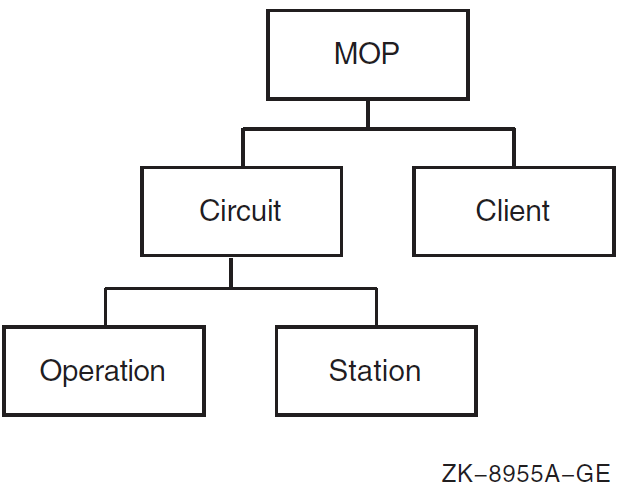
Create and enable the mop entity as follows:
ncl> create mop ncl> enable mop
Create a mop circuit entity and use the set command to customize the entity definition for the specified circuit:
ncl> create mop circuit csmacd-0 type csma-cd
ncl> set mop circuit csmacd-0 -
_ncl> link name csma-cd station csmacd-0,
_ncl> known clients only value
ncl> enable mop circuit csmacd-0 -
_ncl> functions (load server, dump server, console requester, -
_ncl> configuration monitor, loop requester, query requester, -
_ncl> test requester) Specify any name you want for circuit, but for convenience you might want to specify the same name you used for the station entity (see next callout).
For the data link station name, specify the name of the circuit you used when you created the csma-cd station entity. (For more information about the csma-cd station, see Section 8.3.1.1, ''Creating CSMA-CD Data Links''.)
Specifies whether MOP should attempt to service load requests from remote systems that do not have a corresponding client entity. Some network servers are designed to request specific software by name. In such a case, there is no need for a client entity to exist.
By default (false), MOP tries to process requests for named software from unknown clients. Set this attribute to true if you want MOP to ignore such requests.
Specify one or more functions for which you want to use MOP. For instance, specify console requester if you want to use the boot mop or load mop commands or the console carrier.
Do not enable the configuration monitor unless you plan to use it, because it consumes relatively large amounts of system resources.
Note that for each mop circuit entity, DECnet-Plus dynamically creates a mop circuit operation entity for each ongoing MOP operation. Thus, you can issue the show command for mop circuit entities to display current values of their characteristics. For example:
ncl> show mop circuit circuit-name operation * all10.2.2. Setting Up a MOP Client for a Network Server
You can have a variety of network servers on a network. Different kinds of network servers require different levels of information for downline loading and upline dumping. For instance, a terminal server requires the hardware address and the system image. A DECnet Phase V router requires the hardware address, the system image, and the management image or script file, depending on the kind of router you have.
For information about configuring a mop client for an OpenVMS Cluster satellite, see Section 10.2.3, ''Setting Up a MOP Client for an OpenVMS Cluster Satellite''.
The following command example shows how to set up and define the characteristics for the mop client subentity for a network server. The mop client is a set of characteristics that represents the target node. These collected characteristics are known as the client database. The example shows all possible information you might need to provide. Refer to your network server documentation for the exact information you need to provide.
ncl> create mop client client-name ncl> set mop client client-name - _ncl> circuit circuit-name,-_ncl> dump address address

| Specifies the name of the MOP circuit over which this client can be reached. |
| Phase IV nodes can use an extended DECnet LAN address as well as their hardware address, so you must include both of these addresses in the addresses set. Note For clients configured with To calculate the extended Phase IV LAN address, proceed as follows:
For example, to determine the Ethernet physical address of a node whose node address is 63.171, calculate the following: (63 * 1024) + 171 = 64683 decimal = FCAB hexadecimal This calculation results in the following Ethernet physical address of the node: aa-00-04-00-ab-fc |
| secondary loader, tertiary loader, system image, diagnostic image, script file, and management image all specify files that can be used during a downline load. The load sequence for a client-initiated request is as follows: The first program to run at the target node is the primary loader. Typically, this program is either executed directly from the client’s bootstrap ROM, or it is in the microcode of the load device. Usually, the primary loader requests a secondary loader program, which then might request a tertiary loader, which, in turn, might request an operating system. The final module to be loaded is the management file or the CMIP script file. In this sequence, each program or file requests the next one until the management file or CMIP script file is loaded. Refer to your network server documentation to find out which of these files you need. In some cases, the client might specify a file name when it requests to be loaded; in this instance, you do not have to specify the file when setting up the client. Fields in these file specifications are defaulted. If the file specification comes from the client database, the default device and directory are provided by the logical name MOP$LOAD. If the client specifies a file name in the load request message, the default device and directory are provided by the logical name MOP$NAMED_LOAD. These logical names are created by NET$STARTUP, but you can modify them. The default file type is .SYS for the secondary loader, tertiary loader, system image, and diagnostic image files. It is .DAT for management images and CMIP script files. |
| Specifies the verification string. The value is an octet string of up to 16 hexadecimal digits. Enter the value as "%X" followed by an even number of digits. For more information about specifying a verification string, see Section 10.2.2.1, ''Setting Up MOP Service Passwords on a Network Server''. The default is %X0000000000000000. |
| Specifies one or more device types associated with this client. Use device types and omit addresses if you want to set up a generic client entity. The entity will be used for any incoming load or dump requests that specify a matching communications device type. To discover the communications device type for a particular network server, refer to your network server documentation, or use the configuration monitor function of MOP. |
| Use phase iv client address, phase iv client name, phase iv host address, and phase iv host name to specify client and host names and addresses for Phase IV systems. Enter these in the area-number.node-number format. |
| dump file specifies the file to which MOP writes when it dumps the network server. Refer to your network server documentation for information about dump support for your server. The default device and directory are provided by the logical name MOP$DUMP. This logical name is created by NET$STARTUP but you can modify it. The default file type is .dmp. |
| dump address specifies the first location of client memory to be dumped. Specifying any value other than zero might affect your ability to use a dump analysis tool on the dump file. Change the dump address only if your client documentation suggests such action. |
10.2.2.1. Setting Up MOP Service Passwords on a Network Server
To guard against unauthorized access, some network servers require that a 16- digit hexadecimal service password be present in MOP load, boot, or remote console requests. The way the password is set up for a particular server depends on the design of that server. For example, a server might use a console command to change a password held in nonvolatile RAM.
When you attempt to boot the server using the NCL boot or load commands, or to connect to the server’s remote console using the ccr command, you must specify the correct password, or the server ignores the request. You can specify the password in the verification client attribute or command parameter.
When using NCP in a Phase IV network, the service password is interpreted as an unsigned integer of up to 16 hexadecimal digits. You can omit leading zeros. In keeping with the definition as an integer, the rightmost digits occupy lower addresses in memory than did the leftmost digits.
When using NCL in a DECnet Phase V network, the service password or verification value is interpreted as an octet string of up to 16 hexadecimal digits. You can omit trailing (rightmost) zeros on input. Leftmost digits occupy lower addresses in memory than do rightmost digits.
If a particular network server provides a command to set up the password value, the password syntax might be like NCP, treating the value as an integer, or it might be like NCL, treating the value as an octet-string. If the server’s syntax is like NCP, you need to specify the password in different ways on the server and on the host system.
To convert an NCP-style value to an NCL-style value, do the following:
Add leading zeros to make the value exactly 16 digits.
Working from right to left on the NCP-style value, copy each pair of digits to the NCL-style value.
Prefix the NCL-style value with "%X".
For example, if you have an NCP service password value of:
123456789ABCD
The NCL verification value is:
%XCDAB896745230100
Note
When using the Common Trace Facility (CTF) to trace MOP activity, the trace shows the bytes of the verification value in the order in which they are transmitted, which corresponds to the order in memory. For the NCL verification value:
%XCDAB896745230100
you would receive the following trace analysis output:
Verif=CD-AB-89-67-45-23-01-00
10.2.3. Setting Up a MOP Client for an OpenVMS Cluster Satellite
The following command example shows how to set up and define the characteristics for the mop client subentity for an OpenVMS Cluster satellite. The mop client represents the target node. You can either use the commands listed below to set up your OpenVMS Cluster satellite or you can use the command procedure CLUSTER_CONFIG.COM. For more information about CLUSTER_CONFIG.COM, refer to the VSI OpenVMS Cluster Systems Manual.
ncl> create mop client client-name ncl> set mop client client-name - _ncl> circuit circuit-name,- _ncl> addresses {lan-address}, - _ncl> system image {"@net$niscs_laa(dev:[root.])"}, -
| Specifies the load assist agent. The load assist agent is an image that supplies MOP with the initial OpenVMS load image for the OpenVMS Cluster satellite. DEV:[ROOT.] indicates that you should specify the system root for the OpenVMS Cluster satellite you are loading. For more information about OpenVMS Cluster satellites, refer to VSI OpenVMS Cluster Systems Manual. |
| Specifies the verification string. The value is an octet string of up to 16 hexadecimal digits. Enter the value as "%X" followed by an even number of digits. For more information about specifying a verification string, see Section 10.2.2.1, ''Setting Up MOP Service Passwords on a Network Server''. The default is %X0000000000000000. NoteOpenVMS Cluster satellites do not use upline dumping; rather, they write their memory image to the boot server’s disk. |
Section E.6, ''MOP'' provides an example of configuring MOP for either an OpenVMS Cluster satellite or a network server.
10.2.4. After Configuring MOP
After you have created the entities, defined their characteristics, and enabled the mop client entities and the mop circuit entities, use the load, boot, loop, query, and test commands to perform MOP operations. (For information about using the load and boot commands, see Section 10.5.1, ''Using the NCL Load Command'' and Section 10.5.2, ''Using the NCL Boot Command''.) For information about using the loop, test, and query commands, refer to the VSI DECnet-Plus for OpenVMS Problem Solving Guide. Use the show command to display information about all aspects of the mop entity and MOP operations.
10.2.5. MOP’s Use of Default Directories
MOP uses logical names to identify directories where it expects to find images or to write dump files. MOP defines the logical names shown in Table 10.2, ''MOP Logical Names and Default Definitions'' in NET$STARTUP.COM.
| Logical Name | Use | Default Definition |
|---|---|---|
MOP$LOAD | Directory that MOP searches for files specified for a client in the MOP client database, if they are specified without a directory | SYS$SYSROOT:<MOM$SYSTEM>, SYS$SYSTEM: |
MOP$NAMED_LOAD | Directory that MOP searches for files named in the software id field of a MOP request program message issued by a network server requesting a downline load | SYS$SYSROOT:<MOM$SYSTEM> |
MOP$DUMP | Directory to which MOP writes a dump file in response to a MOP request dump message issued by a network server | SYS$SYSROOT:<MOM$SYSTEM> |
Phase IV DECnet used a set of MOM$XXX logical names. Network server software already installed on your system and network server installation kits that have not yet been updated for DECnet Phase V expect these MOM$XXX logical names. For backward compatibility, NET$STARTUP.COM defines these MOM$XXX logical names to their default Phase IV values.
Some network servers, however, create a separate directory for their files. Network server instructions for a Phase IV DECnet environment tell you to redefine a MOM$XXX logical name to include that separate directory. For example, the DECserver 700 product places its files in SYS$SYSROOT:[DECSERVER], and expects MOM$LOAD to be redefined to SYS$SYSTEM,SYS$SYSROOT:[DECSERVER].
For DECnet-Plus to load such network servers, you must redefine MOP logical names to include the directories in which their files reside. Network servers that do not have a MOP client database definition always supply a software id field in the request program message they transmit when requesting a downline load. For these network servers, redefine the logical name MOP$NAMED_LOAD to include the directory. For example:
$ define mop$named_load sys$sysroot:[mom$system],sys$sysroot:[decserver]
For network servers that have a MOP client database definition, either you can modify the MOP$LOAD logical name, or you can modify the MOP client file specifications to include the directory specification. For example, if the client files reside in SYS$SYSROOT:[FOODIR], change:
ncl> set mop client fred system image {foobar.sys} to
ncl> set mop client fred system image {sys$sysroot:[foodir]foobar.sys} You must redefine these logical names after the network is started. If you start your network during system boot, edit SYS$MANAGER:NET$LOGICALS.COM to include these definitions. VSI recommends that you do not edit NET$STARTUP.COM, since that file will be replaced by a new version in future releases of DECnet-Plus.
10.3. Starting MOP
During the system boot operation NET$STARTUP.COM executes. By default, NET$STARTUP.COM does not start MOP. If you want MOP to start automatically, you can define the logical name NET$STARTUP_MOP by adding it to SYS$MANAGER:NET$LOGICALS.COM. For example:
$ define net$startup_mop true
If you do not start MOP automatically, you can start MOP manually any time after starting the network by entering the following command:
$ @sys$system:startup network mop
This command creates the process portion of MOP, NET$MOP, in a detached process. The command also executes the NET$MOP_CLIENT_STARTUP.NCL and NET$MOP_CIRCUIT_STARTUP.NCL scripts.
By default, MOP writes status messages to the file SYS$MANAGER:NET$MOP_OUTPUT.LOG. You can override the default log file by defining a logical name for it before starting MOP. The following command defines NET$MOP_OUTPUT to the file name SYS$MANAGER:MOP_APR95_STATUS.LOG:
$ define net$mop_output sys$manager:mop_apr95_status.log
10.3.1. New MOP Receive Buffer Limit
DECnet-Plus implements a MOP receive buffer limit to prevent memory depletion. The receive default is 100. You can modify this by defining the MOP$RECEIVE_LIMIT logical prior to MOP startup. A value of zero means no limit.
You must define this logical name after the network is started. If you start your network during system boot, edit SYS$MANAGER:NET$LOGICALS.COM to include this definition. VSI recommends that you do not edit NET$STARTUP.COM, since that file will be replaced by a new version in future releases of DECnet-Plus.
If NET$MOP fails because MOP memory has been exhausted by receive buffers, the next thread creation failure results in a log file containing a %MOP-F-CRETHDF error, and an OPCOM message indicates that the MOP process is no longer running. You will have to restart MOP.
10.4. Stopping MOP
You can stop the MOP process as follows:
ncl> disable mop
Determine the process id for NET$MOP, by issuing the following command:
$ show system
Then stop the process:
$ stop/id=process-idAs alternative methods for stopping MOP, you can use the following NCL command:
ncl> delete mop
Make sure you have deleted all subentities before using the delete command.
Stopping the process terminates all MOP operations. It disables and deletes all MOP circuits, and then disables and deletes the mop entity. You can restart MOP any time.
10.5. Downline Loading a Client System
Downline load operations occur in the following ways:
The client (network server or OpenVMS Cluster satellite) can initiate the downline load by starting its bootstrap ROM and sending a program load request to an eligible host. See Section 10.5.3, ''Automated Downline Loading''.
You can downline load a remote client from your host by issuing the NCL load or boot commands. See Section 10.5.1, ''Using the NCL Load Command'' and Section 10.5.2, ''Using the NCL Boot Command''.
10.5.1. Using the NCL Load Command
If you use the NCL load command, you must issue it at a load host. The NCL load command ensures that the load host at which you issue the command is the node that performs the downline load. You can specify parameters on the load mop client command lines to override current values in the load host’s database. To use the load command, you must enable the console requester and load server functions for the circuit. For example:
ncl> load mop client client-nameAlternatively, you can use the load mop circuit command, which allows you to load a client system that is not specified in the client database. For example:
ncl> load mop circuit circuit-name -
| Specifies the name of the MOP circuit over which this client can be reached. |
| You must specify circuit, address, and system image on the command line because there is no client database to supply this information. Note that the other parameters listed are optional, but that some client systems might require them. |
| Specifies the verification string. The value is an octet string of up to 16 hexadecimal digits. Enter the value as "%X" followed by an even number of digits. For more information about specifying a verification string, see Section 10.2.2.1, ''Setting Up MOP Service Passwords on a Network Server''. The default is %X0000000000000000. |
After you issue the load command on the load host, the downline load proceeds as follows:
The load host sends a mop boot message specifying that the load should occur from the host.
When the client receives this message, it sends a mop request program message directly to that load host.
The load host and the client use additional MOP messages to transfer the client’s software image or images into the client’s memory.
Note
Not all network servers support the NCL load command. If you issue a load command to a server that does not support it, the server treats the command as if it were a boot command. Refer to your network server documentation for information about load command support for your server.
10.5.2. Using the NCL Boot Command
If you use the NCL boot command, you can issue it from any supported network management host. This command simulates the operation that occurs when you push the boot button on the client node. The boot command allows you to directly start the remote node’s bootstrap ROM, which causes the client to load itself in whatever manner its primary loader is programmed to operate. Usually the client boots from the network, but it can also boot from a local disk. To use the boot command, you must enable the console requester function for the circuit. For example:
ncl> boot mop client client-nameAlternatively, you can use the boot mop circuit command, which allows you to load a client system that is not specified in the client database. For example:
ncl> boot mop circuit circuit-name -
| Specifies the name of the MOP circuit over which this client can be reached. |
| Specifies the address to which the boot message is sent. This value is required for LANs, but can be defaulted from the client entity. |
| Specifies the verification string. The value is an octet string of up to 16 hexadecimal digits. Enter the value as "%X" followed by an even number of digits. For more information about specifying a verification string, see Section 10.2.2.1, ''Setting Up MOP Service Passwords on a Network Server''. The default is %X0000000000000000. |
| Specifies the device from which the remote node is to boot itself. The interpretation and use of this parameter depends solely on the remote system. |
| Specifies the name of the software with which the remote node loads itself. The interpretation and use of this parameter depends solely on the remote system. |
| Specifies the name of the CMIP script used during the load. The interpretation and use of this parameter depends solely on the remote system. |
After you issue the NCL boot command on one of the network’s management hosts, the downline load proceeds as follows. (This system can also be one of your load hosts, but it is not required.)
The management host sends a mop boot message with the default boot option specified.
When the client receives this message, it transmits a mop request program message to all nodes on the LAN.
If communication is taking place over a synchronous link, the client sends the mop request program message to the adjacent node on the link. The adjacent node issued the boot command.
The first system that responds to the client becomes the client’s load host. The load host and the client use additional MOP messages to transfer the management host’s software image into the client’s memory. The client ignores other responders once the load is in progress.
On a synchronous link, the load host transfers the software image to the client.
10.5.3. Automated Downline Loading
Automatic load service is the means by which client systems can request to be loaded with some software, without involving an operator or network manager on the load host.
The requirements for automatic load service are twofold:
The load server function must be enabled for the circuit.
A mop client entity must usually have been created to hold the parameters that are needed during the load.
You can use the client parameters in the following ways:
Parameters to map load request to client entity
The circuit and addresses parameters must be set correctly because these parameters from the incoming request message are used to locate the client entity.
Alternatively, you can create a generic client entity by omitting addresses and using the device types parameter. Such a client entity will match any load request that specifies a communications device type that occurs in the device types set.
Files used during the load
The client system asks for software in generic terms, for example, a load request might ask for "the operating system." The various file attributes, in this case system image, are used to locate the file to be loaded. More than one file specification may be given; the first file that can be opened is used.
The design of the client system determines which of the various files (secondary loader, system image, and so forth) are needed. The configuration information for the client should give you this information.
Parameters to be given to the loaded client
These parameters are set by the phase iv client and phase iv host attributes. They are necessary if the client is to operate with Phase IV DECnet protocols, and they might also be needed for DECnet Phase V systems. Refer to your network server configuration documentation for more information.
More than one load host can be set up to load the same client system; the first to respond loads the client.
Certain client systems are designed to ask for software by name. The load request message contains the file name part of the file specification. For such requests, MOP attempts to satisfy the load even if no client entity is defined (that is, even if no client matches the incoming message’s circuit and LAN address).
MOP looks for the requested file using logical name MOP$NAMED_LOAD: as the search path, and .sys as the file type.
You can prevent MOP from loading unknown clients by setting the circuit parameter known clients only to true.
You can record MOP events showing a client-initiated downline load with the event dispatcher. To find out about the events you receive, refer to VSI DECnet-Plus for OpenVMS Network Control Language Reference Guide. For information about using the event dispatcher to record events, see Chapter 12, "Monitoring Network Events".
10.5.4. Supported Image Formats for Downline Loading
DECnet-Plus supports the following image formats for downline loading:
Native OpenVMS system image with header. MOP only loads the first image section. Use the linker qualifiers /SYSTEM/HEADER to create the file in an appropriate format.
RSX task image without task header. Use the /-HD when building the task.
VAX ULTRIX image files, in omagic, nmagic, or zmagic format. These formats correspond to the ld options -N, -n, and -z, respectively.
RISC ULTRIX image files, in omagic format only. Use the ld option -N to create a suitable image.
The correct choice of image attributes such as base address and transfer address depends on the hardware involved and on the primary ROM bootstrap loaders.
Management image and CMIP script files must be in RMS variable-length record format.
10.6. Automated Upline Dumping
Automatic dump service is the means by which client systems can request to be dumped, without involving an operator or network manager on the dumping host. When a network server detects a system failure, it sends dump request to the host, or, on the LAN, to a dump assistance multicast address if a LAN host is not available. After a host responds, the network server dumps its memory. It is a valuable tool for crash analysis because you can analyze the dump file and determine why the network server failed.
There are two requirements for automatic dump service:
The dump server function must be enabled for the circuit.
A mop client entity must usually have been created to hold the parameters that are needed during the dump.
The client parameters are used as follows:
Parameters to map dump request to client entity
The circuit and addresses parameters must be set correctly because these parameters from the incoming request message locate the client entity.
Alternatively, you can create a generic client entity by omitting addresses and using the device types parameter. Such a client entity will match any load request that specifies a communications device type that occurs in the device types set.
Parameters used during the dump
The dump file parameter names the file to be created to hold the memory dump data; more than one file can be specified, in which case the first that can be opened is used.
The dump address parameter specifies the first location to be dumped; this should be left at zero, the default value.
More than one dump host may be set up to dump the same client system; the first to respond dumps the client.
Refer to your network server documentation for information about upline dump support for your server.
OpenVMS Cluster satellites do not use upline dumping; instead, they write their memory image to the disk.
10.7. Console Carrier
The console carrier provides access to the remote console subsystem (ASCII console) of a network server on a LAN. The console carrier interface does not use NCL. Instead, you enter commands at the operating system to use the console carrier.
For information about the console carrier, see Appendix F, "Using the Console Carrier".
10.8. Using the LAN Configuration Monitor
The LAN configuration monitor listens for system id messages on the LAN and records the results. VSI-supplied LAN stations transmit a system id message every 10 minutes on average. Therefore, by listening to these messages for a long enough period of time, the configuration monitor builds a database containing details about most systems that are operational.
To enable the configuration monitor, specify the function configuration monitor when you enable the mop circuit. (See Section 10.2, ''Manually Configuring MOP''.)
The configuration monitor stores data it collects as a set of station subentities, one for each address from which a system id is received. The name of a station entity is constructed from the LAN address. Use the show command to view the contents of this database. To show the contents of the database used by the configuration monitor, use the following command:
ncl> show mop circuit csmacd-0 station * all
Chapter 11. Monitoring the Network
You can use the NCL show command or logical names to monitor the network.
11.1. Using the NCL Show Command to Monitor the Network
Use the NCL show command to monitor the following network activity:
Determine the status and characteristics of components in the network.
Obtain error and performance statistics about current network operations.
The show command allows you to monitor the operation of the running network. For example, if a circuit fails, the configuration of the running network in terms of reachable and unreachable nodes might change. NCL allows you to display information about both local and remote network entities and thereby detect existing or potential problems.
The show command lets you decide what type of information you want NCL to display about the entity you specify. You can display the following attributes about an entity:
Characteristics — describe the operating parameters of an entity as they are defined in the database.
Counters — tabulate the number of times the entity performed a particular operation, or the number of times a certain condition or event has occurred since the entity was created.
Identifiers — specify the simple name assigned to an entity when it was created.
Status attributes — record current conditions of the entity, such as its state. You need NET$EXAMINE rights to issue the show command.
11.1.1. Using Counters to Evaluate Network Operations
The counters used for the various entities in DECnet-Plus allow you to monitor network traffic. For example, you can examine the use of data links and perhaps anticipate network bottlenecks or failing links. This information can also help you plan future network configurations. To use counters effectively, you need to determine the rate of change in a counter. To do this, use the NCL snapshot command.
The following sequence of examples show how to use snapshot.
The following command shows the output for all routing circuit counters using the show command before using snapshot:
ncl> show routing circuit * all counters Node 0 Routing Circuit CSMACD-0 at 2019-02-26-08:54:51.436-05:00I0.364 Counters Data PDUs Received = 0 Data PDUs Fragmented = 0 Data PDUs Transmitted = 2772 Circuit Changes = 1 Initialization Failures = 0 Control PDUs Sent = 11694 Control PDUs Received = 0 Corrupted Hello PDUs Received = 0 Creation Time = 2019-02-25-06:29:17.389-05:00Iinf
The following command shows the output for all routing circuit counters using the snapshot command. Note that the command displays the current counters.
ncl> snapshot routing circuit * all counters Node 0 Routing Circuit CSMACD-0 at 2019-02-26-08:59:06.216-05:00I0.389 Counters Data PDUs Received = 0 Data PDUs Fragmented = 0 Data PDUs Transmitted = 2793 Circuit Changes = 1 Initialization Failures = 0 Control PDUs Sent = 11733 Control PDUs Received = 0 Corrupted Hello PDUs Received = 0 Creation Time = 2019-02-25-06:29:17.389-05:00Iinf
The following command shows the output for all routing circuit counters using the show command after issuing the snapshot command. The difference column in the table shows the difference between the actual value of the counter and the value of the counter when you used the snapshot command. Until you exit from NCL, the snapshot display appears whenever you issue the show routing circuit * all counters command.
ncl> show routing circuit * all counters Node 0 Routing Circuit CSMACD-0 at 2019-02-26-09:01:09.046-05:00I0.402 Counters Creation Time = 2019-02-25-06:29:17.389-05:00Iinf Snapshot created at 2019-02-26-08:59:06.216-05:00I0.389 Actual Value Snapshot Value Difference ------------ -------------- ---------- Data PDUs Received 0 0 0 Data PDUs Fragmented 0 0 0 Data PDUs Transmitted 2806 2805 1 Circuit Changes 1 1 0 Initialization Failures 0 0 0 Control PDUs Sent 11786 11785 1 Control PDUs Received 0 0 0 Corrupted Hello PDUs Received 0 0 0
Use this information as a baseline for comparisons with later snapshots. It shows you how much time has elapsed and lets you see how much activity the counters have recorded between show commands. The information you obtain from counters might be useful either alone or in conjunction with logging information to measure the performance of a particular entity.
Note
Snapshot information is only retained for the duration of an NCL session. Therefore, you must enter the snapshot command and subsequent show commands at the NCL> prompt rather than at the DCL prompt. To gather snapshot information from a remote node, you can either set the NCL default to the remote node entity or include the node name in each NCL command, as long as the commands are issued within the same NCL session.
For a complete summary description of all network counters, including the probable causes of particular types of occurrences, refer to the VSI DECnet-Plus for OpenVMS Network Control Language Reference Guide.
11.1.2. Displaying Addresses
An address is a tower set that describes the protocols needed to establish a connection with a node. Tower sets are stored in the namespace. Output is similar to the following display. Each line of a tower corresponds to a network protocol layer.
ncl> show node 0 address
Node 0
AT 2019-03-14-10:59:41.194-05:00I8.917
Identifiers
Address =
{
(
[ DNA_CMIP-MICE ] ,
[ DNA_SessionControlV3 , number=19 ] ,
[ DNA_OSItransportV1 , ’DEC0’H ] ,
[ DNA_OSInetwork , 49::00-0C:AA-00-04-00-50-30:21 ]
) ,
(
[ DNA_CMIP-MICE ] ,
[ DNA_SessionControlV3 , number=19 ] ,
[ DNA_NSP ] ,
[ DNA_OSInetwork , 49::00-0C:AA-00-04-00-50-30:20 ]
) ,
(
[ DNA_CMIP-MICE ] ,
[ DNA_SessionControlV3 , number=19 ] ,
[ DNA_OSItransportV1 , ’DEC0’H ] ,
[ DNA_IP , 16.20.120.120 (TRUNDY.GROUP.COMPANY.NET) ]
)
}
| Application layer protocol. |
| Session Control layer. Specifies Session Control version 3 and the application to which to connect (19 = CML). |
| OSI Transport layer identifier. Specifies OSI Transport version V1. |
| Network layer. Specifies Routing version used, the node’s DECdns full name, and NSAP. |
| Transport layer. Specifies that the transport is NSP. |
| IP Network layer address. |
11.1.3. IP Address Backtranslation
NCL attempts to backtranslate all non-zero IP addresses. Backtranslation is not attempted if the IP address is 0.0.0.0. The IP address is 0.0.0.0 whenever DECnet over TCP/IP has been enabled, but DECnet has not yet learned its IP address from the PATHWORKS Internet Protocol (PWIP) software. The IP address becomes non-zero when the first incoming or outgoing DECnet over TCP/IP or OSI over TCP/IP connection is made.
The following examples show some of the NCL displays affected by this feature:
NCL>show node 0 addr
...
[ DNA_CMIP-MICE ] ,
[ DNA_SessionControlV3 , number = 19 ] ,
[ DNA_OSItransportV1 , ’DEC0’H ] ,
[ DNA_IP , 161.114.95.148 (TRUNDY.GROUP.COMPANY.NET) ]
...
NCL>show osi transport port * remote rfc1006 ip addr ...
...
Remote RFC1006 IP Address = 161.114.94.41 (TRUE.GROUP.COMPANY.NET)
...
NCL>show osi transport local nsap ip_any remote nsap * ip addr ...
...
IP Address = 161.114.94.41 (TRUE.GROUP.COMPANY.NET)
...In some cases, the backtranslation returns only the unqualified name. For example, an NCL show command might produce the following display:
[ DNA_IP , 161.114.95.148 (TRUNDY) ]
If you want to display the fully-qualified host name, you may need to make adjustments to your DNS/BIND server or to your local hosts database. See the documentation for your DNS/BIND server implementation for information about modifying DNS/BIND information. To modify your local hosts database, you need to remove and replace node trundy in the database. If you are using VSI TCP/IP Services for OpenVMS, use commands similar to the following:
$ tcpip set nohost 161.114.95.148 $ tcpip set host trundy.group.company.net - _$ /addr=161.114.95.148/alias=trundy
To ensure that the new information is used, you must flush the existing out-of- date CDI cache entry so that the next CDI lookup returns the new value. To flush the CDI cache entry, use the following NCL command:
$ mcr ncl flush session control naming cache entry "IP$161.114.95.148"
Note that the backtranslation is done in the context of the local node. In other words, if you were to compare the output for these two commands performed on two different nodes, the two backtranslations might not be consistent:
HERE> mcr ncl show addr THERE> mcr ncl show node here addr
If IP backtranslations are inconsistent, it is possible that the nodes are using different DNS/BIND servers, that their local hosts databases may be out of sync, or that stale CDI cache entries may exist.
If an NCL command displaying backtranslation information appears to hang, the backtranslation processing may be waiting for a DNS/BIND server. If this becomes problematic, you can turn off backtranslations by defining the NCL$ENVIRONMENT logical name (include the definition in SYS$MANAGER:NET$LOGICALS.COM, see Section 6.3, ''Defining Logical Names That Modify Network Operation'') as follows:
$ define/system/nolog ncl$environment "NoBackTrans"
Note
Defining the NCL$ENVIRONMENT to "NoBackTrans" disables ALL backtranslations. VSI recommends avoiding this remedy if at all possible.
11.1.4. More Examples Using the NCL Show Command
The following examples illustrate how the show command displays information about an end node routing circuit on a LAN. You can display information about other entities in the same way.
The following example displays an identifier:
ncl> show routing circuit csmacd-0 Node 0 Routing Circuit CSMACD-0 at 2019-02-26-09:56:26.148-05:00I0.368 Identifiers Name = CSMACD-0
The following example displays entity status: ncl> show routing circuit csmacd-0 state Node 0 Routing Circuit CSMACD-0
ncl> show routing circuit csmacd-0 state Node 0 Routing Circuit CSMACD-0 at 2019-02-26-09:28:15.032-05:00I0.264 Status State = On
The following example displays a characteristic:
ncl> show routing circuit csmacd-0 manual data link sdu size Node 0 Routing Circuit CSMACD-0 at 2019-02-26-09:30:24.882-05:00I0.277 Characteristics Manual Data Link SDU Size = 1492
The following example displays a counter:
ncl> show routing circuit csmacd-0 circuit changes Node 0 Routing Circuit CSMACD-0 at 2019-02-26-09:31:29.597-05:00I0.328 Counters Circuit Changes = 1
The following example displays all counters for a named circuit:
ncl> show routing circuit csmacd-0 all counters Node 0 Routing Circuit CSMACD-0 at 2019-02-26-09:43:23.042-05:00I0.235 Counters Data PDUs Received = 0 Data PDUs Fragmented = 0 Data PDUs Transmitted = 5075 Circuit Changes = 1 Initialization Failures = 0 Control PDUs Sent = 12134 Control PDUs Received = 0 Corrupted Hello PDUs Received = 0 Creation Time = 2019-02-25-06:29:17.389-05:00Iinf
The following example displays all information about an entity:
ncl> show routing circuit csmacd-0 all Node 0 Routing Circuit CSMACD-0 at 2019-02-26-09:46:16.622-05:00I0.253 Identifiers Name = CSMACD-0 Status UID = 756F4BB0-58F3-CA11-8008-AA000400784D State = On Data Link SDU Size = 1492 Data Link Port = CSMA-CD Port ETA Characteristics Type = CSMA-CD Template = "" Data Link Entity = CSMA-CD Station CSMACD-0 Enable PhaseIV Address = True Manual Data Link SDU Size = 1492 Manual Routers = {} Inactive Area Address = {} Counters Data PDUs Received = 0 Data PDUs Fragmented = 0 Data PDUs Transmitted = 5077 Circuit Changes = 1 Initialization Failures = 0 Control PDUs Sent = 12161 Control PDUs Received = 0 Corrupted Hello PDUs Received = 0 Creation Time = 2019-02-25-06:29:17.389-05:00Iinf
11.2. Using Logical Names to Obtain Status About the Network
Use the following logical names to obtain status about network startup and configuration:
NET$STARTUP_STATUS (defined by network startup)
Possible values include:
boot — The network has just been initialized, but no components have been enabled or loaded.
off — The network is off; no components have been loaded or configured.
shutdown — The network was running previously, but has been shut down by the NET$SHUTDOWN procedure.
running — The network software is loaded and running. The running substate determines how much of the software is running.
dependent — The dependent software has been loaded, created, and enabled. Dependent software includes common trace facility, node entity, and session control entity.
data_link — The data link entities have been loaded, created, and enabled.
major — All remaining entities have been loaded, created, and enabled, except for event dispatcher, loopback application, mop, and session control application.
all — All components have been loaded, created, and enabled unless they have been disabled by logical names that can control their operation.
off-autogenreq — The network cannot be started until AUTOGEN has been run to tune the system with the appropriate parameters.
To display status, use the show logical command. For example, to show the status of the network startup and configuration, enter the following command:
$ show logical net$startup_status "NET$STARTUP_STATUS" = "RUNNING-ALL" (LNM$SYSTEM_TABLE)This command returns with a display indicating that all network software is loaded and running.
SYS$NODE (defined by network startup) — Returns the node’s synonym name.
SYS$NODE_FULLNAME (defined by network startup) — Returns the node’s full name.
11.3. Monitoring the OSAK Component of DECnet-Plus
This section describes how you can check that the OSAK component of DECnet-Plus is working correctly and support OSI applications that are running over this component.
Note
To check whether an OSI application runs over the OSAK component of DECnet-Plus, refer to the documentation for that application.
The best indication that the OSAK component is working normally is when any OSI application you are running behaves predictably and efficiently. However, there are tasks you can complete at convenient intervals to monitor the working of the software:
Check the numbers of connections, aborts, and releases that occur by examining the OSAK counters (see Section 11.3.1, ''Counting Connections, Releases, and Aborts'')
Check the occurrence of upper layer events by using the DECnet-Plus event dispatching facility (see Chapter 12, "Monitoring Network Events")
Check which ports and addresses are active (see Section 11.3.3, ''Checking Ports and Addresses'')
11.3.1. Counting Connections, Releases, and Aborts
To check the number of connections, releases, and aborts that occur while your application is running, look at the values of the OSAK counters. You can discover what is normal for your application over a period of time; abnormal values may then be an indication that something is going wrong.
You can display the values of all the OSAK counters by using the following NCL command:
ncl> show [node node_id] osak all countersYou can display the value of a specified OSAK counter by using the following command:
ncl> show [node node_id] osak counter_name
where
| node_id | The identifier of the node on which the osak entity resides |
| counter_name | The name of the counter whose value you want to check |
11.3.2. Monitoring Upper Layer Events
You can monitor the occurrence of events, and find out the rate of occurrence that is normal and acceptable for the application you are running. A more frequent occurrence might be an indication that the application you are running is not working properly.
See Chapter 12, "Monitoring Network Events" for information about the DECnet-Plus event dispatching facility.
11.3.3. Checking Ports and Addresses
You can display the following information, which may help you to check that your application is running as you expect it to:
A list of open ports, which includes the following information:
Whether a port is being used for an inbound or an outbound connection. The direction status attribute gives you this information.
Presentation address (if any) to which the port is connected. The local paddress status attribute gives you this information.
The state of the port. The connection state status attribute gives you this information.
Use the following NCL commands to get this information:Display a list of open ports:
ncl> show [node node_id] osak port *Select the port in which you are interested and display all the attributes:
ncl> show [node node_id] osak port port_id all
Here, port_id is the identifier of the port in which you are interested.
A list of the upper-layer addresses that are waiting for inbound associations. Use the following NCL command to get this information:
ncl> show [node node_id] osak port *, - _ncl> with connection state = awaiting_inbound_connection
Chapter 12. Monitoring Network Events
The DECnet-Plus software reports significant events that occur during network operation. An event is an occurrence of a normal or abnormal condition detected by an entity. You can control the types of events that DECnet-Plus records for specific or general categories of events by using NCL. These event records help you track the status of network components.
Many events are informational. They record changes to network components on both local and remote systems. Other events report potential or current problems in the physical parameters of the network.
An event report identifies the originating entity and the time when the event occurred. For those entities that report events, the VSI DECnet-Plus for OpenVMS Network Control Language Reference Guide lists the events, the reason the event occurred, and any arguments reported to the event dispatcher.
You can set up event dispatching on a particular system, between two systems, or across multiple, distributed systems. Events that occur on systems running DECnet Phase IV or Phase V software can be reported by the DECnet-Plus event dispatching function.
12.1. Event Dispatching Concepts
When an entity notices that a condition has occurred, it generates an event message. The entity posts the event message and the local event dispatcher picks it up. The event dispatcher examines the user-defined event filters for each outbound stream created on the system. The event filter lets you selectively disable or enable the reporting of events based on the entity class and event type, or the specific entity instance and event type. If the event message passes the event filter, the message is given to the corresponding outbound stream.
An outbound stream maintains a queue of event messages waiting to be sent to their destination. After passing through the filter defined for the outbound stream, the event message is sent to an event logging component, called an event sink. An event sink can be on the same system, or a different system, as the outbound streams. When the event source and the event sink are on the same system, the outbound stream forwards the event report directly to the event sink. When the event sink is on a different system, the outbound stream encodes the event report in the form of Network Architecture Common Management Information Protocol (NA CMIP) calls, and forwards the NA CMIP message to the corresponding event sink on the designated remote system.
For each outbound stream, there is a single associated event sink. However, a single event sink might process incoming event messages from more than one outbound stream. Systems can have a combination of outbound streams and event sinks (see Figure 12.1, ''Relationship of Outbound Streams and Event Sinks''). You determine the actual event dispatching configuration established in your network.
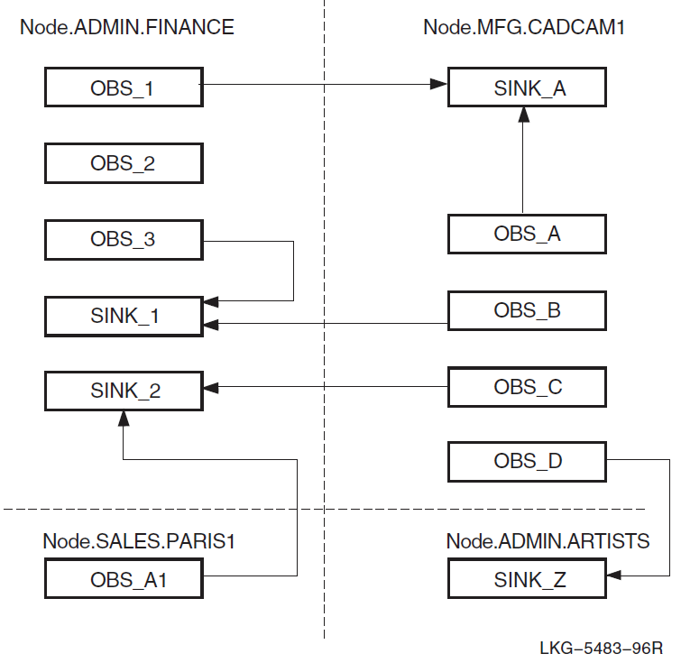
The event sink accepts the incoming connection and creates an inbound stream entity to represent the connection. A sink can have multiple inbound streams, one for every outbound steam associated with the sink. The inbound stream remains for the life of the association between the outbound stream and the event sink. This connection can receive many event messages. Inbound streams are deleted when the connection between the outbound stream and the event sink is deleted.
An event sink maintains a queue of events waiting to be processed by another event logging component called the event sink client. Event sink clients are applications that process the event messages for you. The event dispatcher provides default event sink clients.
You can record events that occur on systems running Phase IV software by defining a relay on a DECnet Phase V system.
Figure 12.2, ''Sample Event Dispatching Sequence'' follows the path of a sample event report from a source, the routing entity on the .admin.finance system, to a sink on the .admin.netmgr1 system. A numbered list follows Figure 12.2, ''Sample Event Dispatching Sequence'' and explains the event dispatching sequence.
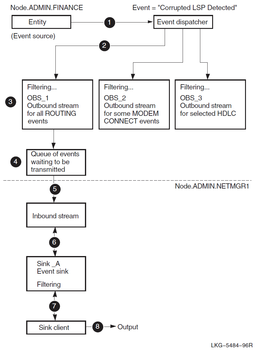
On the .admin.finance system, the routing entity detects a corrupted link state packet (LSP). The routing entity posts a corrupted lsp detected event. The system’s event dispatcher picks up the message.
The event dispatcher checks the filters associated with the outbound streams to see if the event message should be made available to the outbound streams.
Outbound stream obs_1 includes a filter setting that lets the routing corrupted lsp detected event pass onto its event stream. The filters associated with obs_2 and obs_3 block the entry of this event onto their streams. After filtering, the event report is encoded in DNA CMIP because the outbound stream defines a sink on remote system .admin.netmgr1.
The event message waits on a queue to be transmitted to system .admin.netmgr1.
On system .admin.netmgr1, the event sink, sink_a, creates an inbound stream when the outbound stream from node .admin.finance connects to the sink. The inbound stream remains until the event stream between obs_1 and sink_a is deleted by means of network management commands or connection timer expiration.
The inbound stream passes the routing corrupted lsp detected event message to event sink, sink_a. At sink_a the event can be filtered out of the event stream or passed to the sink client.
A sink client uses ASCII data to format the event message into the kind of event report that you want.
The sink client delivers the event report to the defined output destination.
12.2. Using Event Filters
You can define event filters with outbound streams, event sinks, or both outbound streams and event sinks. This section explains how the filtering process works.
Event filters let you:
Restrict event records to only those events that you consider important to your network management tasks. Those events that you exclude still occur, but information about them does not appear in the event stream’s report.
Categorize event messages into separate event streams and, consequently, each stream’s report. For example, you can use event filters on an outbound stream that only accept routing circuit events and pass it along to its event sink and the stream’s report.
You can establish filters:
At a source node by defining them with each outbound stream entity. (VSI recommends that you establish filters at the outbound stream to avoid unnecessary system overhead and network traffic.)
At a destination (sink) node by defining the filters with the event sink entity.
At both source nodes and sink nodes.
Event filters have three settings, which DECnet-Plus searches through in this order: first, specific filter setting; then, global filter setting; and finally, catch-all filter setting. The first filter that applies to an event is used to discard the event or enter it into the dispatching stream.
Specific filter setting
Contains one or more entries, each specifying what action to take if the current event matches a full event string specified in this filter. A full event string consists of a global entity instance, an event name, or all events. For example:
((node node-id routing circuit circuit-id), corrupted lsp received).
Global filter setting
The global filter is searched when no match is found in the specific filter setting, or if a match is found, but the action specified is ignore. The global filter setting contains one or more entries. Each entry specifies what action to take if the current event matches a defined global entity class, an event name, or all events. For example:
((routing, circuit), corrupted lsp received).
Catch-all filter setting
The catch-all filter is searched only when no matches are found in the specific and global filter settings, or if a match is found, but the action specified is ignore. The catch-all filter declares the single action (pass or block) that should be taken for any events that filter down to this category.
The options (from the perspective of the outbound stream entity) are to:
Prevent an event message from entering the event stream by using the block filter action.
Forward the event message to the event sink associated with this outbound stream, by using the pass filter action.
Ignore the event message and pass it to the next filter level, by using the ignore filter action. You can use the ignore filter action only with the filter’s top-level specific setting or with the filter’s second-level global filter setting.
To see which filters are currently in place, check the following files:
SYS$STARTUP:NET$EVENT_STARTUP.NCL SYS$MANAGER:NET$EVENT_LOCAL.NCL
You may not need to change the event filters at all, unless you want to handle them differently than the defaults shown in that file.
If an entity is not included in the specific or global filter display, this means that the event action for all events of that entity (instance or class) is ignore.
Figure 12.3, ''Sequence of Event Filtering'' shows the sequence of filtering through the hierarchy of event filters.
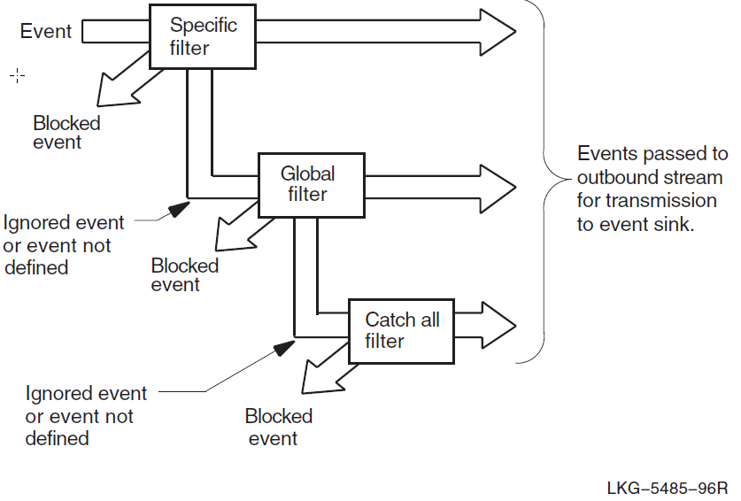
Note
You cannot use wildcard characters with the entity class name or instance name in the definition of a filter’s specific setting.
See Section 12.3.14, ''Setting Up Outbound Stream Event Filters'' for examples of using filtering with outbound stream entities, and Section 12.3.5, ''Setting Up Event Sink Filters'' for filtering examples for event sink entities.
12.3. Setting Up and Using Event Dispatching
The following sections describe how to set up and use the event dispatcher.
Section E.1, ''Event Dispatcher'' provides a simple example that takes the defaults of setting up the event dispatcher. Figure 12.4, ''event dispatcher Entity'' shows the event dispatcher entity and subentities.
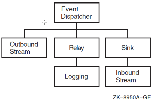
12.3.1. Creating the Event Dispatcher
By default, the event dispatcher entity is created and enabled on the local system in its script file. Thus, you may not need to start it yourself.
Use the NET$CONFIGURE.COM procedure to configure the event dispatcher. The event dispatcher usually starts as part of the NET$STARTUP procedure. If
the NET$EVENT_STARTUP.NCL script file exists, the software creates the event dispatcher, invokes the event dispatcher script file (which creates and enables outbound streams, sinks, and relay), and enables the event dispatcher.
VSI recommends that you do not disable the event dispatcher at startup. If you do not wish to receive events, you can add the following command to SYS$MANAGER:NET$EVENT_LOCAL.NCL:
set event dispatcher outbound stream * catch all filter block
This NCL script is described in Section 6.2.3, ''Using User-Defined NCL Scripts''.
Note
Before the event dispatcher is enabled, event messages are queued. The messages wait for the event dispatcher to process them. After the event dispatcher is enabled, it can begin processing events.
You can use the following commands to check if the event dispatcher and its associated outbound streams and sinks states are enabled:
ncl> show event dispatcher state ncl> show event dispatcher outbound stream * state ncl> show event dispatcher sink * state
If you attempt to use the event dispatcher, an outbound stream, or a sink that is not available, you will receive an error indicating that the command failed for the following reason:
no such object instance No such Entity instance exists
You can start the event dispatcher after running NET$STARTUP with the following command:
$ @sys$system:startup network evd
12.3.2. Setting Up Outbound Streams and Event Sinks
Each event generated on a system is filtered through each outbound stream. The stream delivers the event to a particular event sink that exists on the local system or a remote system. If you set up more than one outbound stream, each outbound stream is affiliated with one sink. An event sink can accept event reports from one or more outbound streams, which can reside on the same or different system as the event sink.
Each outbound stream is represented by an event dispatcher outbound stream entity. Each event sink is represented by an event dispatcher sink entity.
When you establish outbound streams and event sinks, you:
Indicate in the outbound stream definition which event sink will be associated with this outbound stream.
Indicate in the outbound stream definition which events you will allow to be forwarded to the event sink.
Indicate in the event sink definition which events the sink will accept. Usually, the event sink permits all the incoming events because the selection criteria was already established on the source system by the outbound streams.
Subsequent sections describe the steps you need to take to set up outbound streams and event sinks.
12.3.3. Identifying the Sink for an Outbound Stream
Before setting up the outbound stream, decide how you want to identify the associated local or remote event sink. The sink’s identifying characteristics can be any of the following parameters to the set command:
The full DECdns object name of the sink object associated with this outbound stream.
The full DECdns node name of the sink associated with this outbound stream, and the end-user specification of the associated sink.
The protocol tower of the sink associated with this outbound stream.
Note
The event sink identified in the set command need not exist when you associate the outbound stream with its sink. If the event sink does not exist, the NCL commands used to create and test the outbound streams work; however, no event messages are sent from the outbound stream until the sink exists and a connection is established.
DECdns Object Name
If .ADMIN.EVENT_SINKS.SINK_A is the DECdns object name for the sink associated with the netmgr1_obs outbound stream, the following example shows the set command used to form the affiliation:
ncl> set event dispatcher outbound stream netmgr1_obs - _ncl> sink object .admin.event_sinks.sink_a
You should identify network components by their DECdns object name. If the location of a sink object defined in the DECdns namespace changes, the namespace administrator can easily update information about the change by modifying the object’s single entry in the DECdns namespace. For more information, see the VSI DECnet-Plus for OpenVMS DECdns Management Guide. Also see Section 12.3.9, ''Using a DECdns Namespace Object Name with a Sink'' for related information about the set object name command used with the corresponding event sink.
DECdns Node Name
If you choose not to define a DECdns object entry for a sink, use the sink node name and end-user specification, or use the sink address. For example:
ncl> set event dispatcher outbound stream netmgr1_obs - _ncl> sink node 0, sink end user number = 82
In the previous example, leaving sink node 0 (zero) indicates that the event sink resides on the local system. If the event sink resides on a system that is different from the outbound stream’s system, specify the full DECdns node name.
The end-user specification for the sink consists of one of the following:
number = number (default = 82)name = nameuic= [uic-identifier]username
fullname = full-name
The end-user specification corresponds to the object number or name, and defaults to the standard event sink supplied on the node.
You must specify a matching end-user specification on the event sink to associate the outbound stream and the event sink. For more information about matching end-user specifications for outbound streams and sinks, see Section 12.3.10, ''Setting an End-User Specification for a Sink''.
Session Control Towers
If the event sink resides on a system that is different from the outbound stream’s system, you can specify the remote sink by specifying the session control towers (sink address) of the remote node.
To find the towers of the destination sink node, enter the following NCL command on that node:
ncl> show node 0 address
If the event sink resides on the same (local) node as the outbound stream, set the sink node using either the node’s full DECdns node name, or enter 0, which indicates the local node. For example:
ncl> set event dispatcher outbound stream netmgr1_obs sink node 0
If neither the sink node nor sink address attributes has been set, the events for this outbound stream will be logged to the local node sink by default.
12.3.4. Creating an Event Sink
The following example creates an event sink named netmgr1_sink_a:
ncl> create event dispatcher sink netmgr1_sink_a -
_ncl> maximum buffer size size
| Allows you to assign a maximum buffer size. The default maximum buffer size is 16384 bytes. The buffer size must be large enough to hold the event dispatcher sink entity’s events lost event. NCL returns an insufficient resources exception if the value is too low. If you notice that you receive a high events lost count, this might indicate that the maximum buffer size is too small. If over time you notice that the maximum buffer size value seems inadequate, you must delete the event sink and redefine it with a higher value. See Section 12.6.2, ''Disabling and Deleting an Event Sink'' for the steps involved in deleting an event sink. |
12.3.5. Setting Up Event Sink Filters
In most cases, the event filters defined on outbound streams sufficiently manage event reports sent to an event sink. By default, the specific and global filters are defined to pass this sink’s pseudo-events and the catch-all filter is set to pass. VSI recommends that you define the filters at each source node where the outbound streams reside because, in cases where the source and sink reside on different nodes, setting up filters at the source avoids unnecessary network traffic between the source node and the sink node. Also, a consistent network management policy about where event filtering will occur can avoid confusion, especially when several network managers work throughout the network.
You have the option of defining event filters for an event sink. The filters apply to event messages received from all outbound streams that use this sink. That is, you cannot designate selected filter entries corresponding to incoming events from a specific outbound stream. The definition of event filters for event sinks is similar to the process used with outbound streams. See Section 12.2, ''Using Event Filters'' and Section 12.3.14, ''Setting Up Outbound Stream Event Filters'' for related information.
In the following example, assume that 10 outbound streams from 10 different systems let the station running event from all hdlc link logical station entities pass into the event stream sent to a sink called netmgr1_sink_b. If you decide this information is not important for the final report, you can filter it out. For example:
ncl> block event dispatcher sink - _ncl> netmgr1_sink_b global filter = - _ncl> ((hdlc, link, logical station), station running)
12.3.6. Testing Event Sink Filters
Once you have set up the event filter for an event sink, use the testevent command to check that the filter works according to your plan. The testevent command returns a message specifying the action of the filter used. See the following example:
ncl> testevent event dispatcher sink - _ncl> netmgr1_sink_b event = - _ncl> ((node usa:.admin.artist hdlc link link-id - _ncl> logical station station-id), station running) Action = Block Filter = Global filter
Note
You cannot use a wildcard character with the testevent command’s event argument.
The testevent command might reveal an error in your logic about event filtering for this event sink. If this occurs, see Section 12.3.7, ''Modifying an Event Sink Filter''.
12.3.7. Modifying an Event Sink Filter
The specific and global filter trees can only be modified by the pass, block and ignore directives. You can enter a new definition for the event. The new definition supersedes any previous definitions.
To delete the previous filter values you set and reinitialize them to their default values when the event sink was created, use the following command:
ncl> reset event dispatcher sink netmgr1_sink_b
See Section 12.3.15.1, ''Correcting Outbound Stream Event Filters'' for related information.
Note
Modifications in the sink filters affect subsequently created inbound streams (connections from remote nodes) and not inbound streams already created.
12.3.8. Specifying the Event Report Destination
After a sink receives and filters an event, the event message is queued to the sink client. The sink client delivers the event message as an event report to a specified destination.
The client type characteristic can be set only when the event dispatcher sink entity is disabled (that is, when the sink state is off). Attempts to set the characteristic when the sink state is on result in an error message.
DECnet-Plus provides three types of sink clients or destinations:
Console sink client
Sends ASCII-formatted event reports to the system console, which is a system process that receives input from processes (like EVD) that want to inform a system operator or network manager of a particular status. Console sink client is the default.
The sink client sends ASCII-formatted event reports to OPCOM. Sometimes, events are split into two OPCOM messages when only one OPCOM message is necessary for the event. All network operator terminals (terminals enabled through specification of the DCL command reply/enable=network) display these events.
The following example specifies the console sink client. (See Figure 12.4, ''event dispatcher Entity'' for the relationship of the sink subentity in the event dispatcher entity hierarchy.)
ncl> set event dispatcher sink netmgr1_sink_a - _ncl> client type console
Device sink client
Sends ASCII-formatted event reports to devices such as terminals or line printers. The following example specifies the device sink client:
ncl> set event dispatcher sink netmgr1_sink_a - _ncl> client type device ncl> set event dispatcher sink netmgr1_sink_a - _ncl> device name "full-device-name"Formatted file sink client
Sends ASCII-formatted event reports to a file. To execute this command, you must be logged in as SYSTEM. The following example renames the default sink client file to a nondefault file name:
ncl> set event dispatcher sink netmgr1_sink_a - _ncl> client type file ncl> set event dispatcher sink netmgr1_sink_a - _ncl> file name file-specification
You should set the sink client type before the sink is enabled and inbound streams are created.
12.3.9. Using a DECdns Namespace Object Name with a Sink
The DECdns namespace administrator can use option 10 of the decnet_register utility to register each event sink as an object in the namespace. For more information about the registration process, refer to the VSI DECnet-Plus for OpenVMS DECdns Management Guide.
Once the event sink is defined as an object in the namespace, you can use the set command so that the DECnet-Plus Session Control layer on the sink node can deliver incoming event messages sent by outbound streams that used the DECdns object name for the sink. For example, if .admin.event_sinks.primary_sink is the object name in the namespace for an event dispatcher sink netmgr1_sink_a entity:
ncl> set event dispatcher sink netmgr1_sink_a - _ncl> object name .admin.event_sinks.primary_sink
12.3.10. Setting an End-User Specification for a Sink
For the event sink, you must set an end-user specification, which can be one of the following:
number = numbername = nameuic= [uic-identifier]username
fullname = full-name
The default is number = 82.
Make sure that the end-user specification for both the sink and outbound stream match.
If you issue the following command on system .admin.finance, you need to issue an additional command to associate the sink and the outbound stream when setting up the outbound stream.
ncl> set event dispatcher sink netmgr1_sink end user name = accounting
The following example shows how to issue the additional command. Specify the system where the sink is located and the same end-user name as specified for the sink.
ncl> set event dispatcher outbound stream netmgr1_obs - _ncl> sink node .admin.finance, sink end user name = accounting
12.3.11. Modifying the Display of Event UIDs
You can disable the display of UIDs as part of an event message by setting the displayUIDs attribute to false. For example:
ncl> set event dispatcher sink netmgr displayuids false
Use the following command to enable the display of UIDs:
ncl> set event dispatcher sink netmgr displayuids true
12.3.12. Enabling an Event Sink
Use the enable command to start an event sink that is ready to accept event messages from its outbound streams.
ncl> enable event dispatcher sink netmgr1_sink_a
If you receive an invalid name exception while attempting to enable an event sink, it indicates a problem with the defined object name characteristic. Compare the value of this parameter (using a show command in NCL) with the actual object’s name in the DECdns namespace.
Use Option 10 of decnet_register to examine the namespace (for more information, refer to the VSI DECnet-Plus for OpenVMS DECdns Management Guide).
The event sink generates events when it is enabled. By default, all events generated by some event dispatcher subentities, such as event sinks and outbound streams, are blocked by the sink’s global filters (as is the case with outbound stream global filters). On the other hand, the specific filter for subentities such as the sink or outbound stream pass events from only that instance of the sink or outbound stream. That is, netmgr1_sink_a passes events from netmgr1_sink_a, but from no other sink. If you have set up your sink’s filters to pass all event dispatcher sink events you might see various events posted when you enable the sink.
A sink always posts events directly to its sink client even if you do not have an outbound stream defined. If you have both sides of an event stream on the same node, you might see sink events posted twice: Once when the sink posts them to the client and again when the outbound stream delivers the event to the sink.
The sink probably will not generate many events. You can, however, eliminate redundant events by blocking the sink events at the outbound stream. For example:
ncl> block event dispatcher outbound stream netmgr1_obs - _ncl> global filter=((node, event dispatcher, sink), all)
You should block sink events at the outbound stream because:
Local sink events are reported directly by the sink.
Only events from the local sink are blocked. Any events received from remote systems are reported.
It reduces system and network overhead when you block events at the outbound stream.
12.3.13. Creating an Outbound Stream Entity
The following example creates a user-specified outbound stream named netmgr1_obs.
ncl> create event dispatcher outbound stream netmgr1_obs -
_ncl> maximum buffer size size
| Allows you to assign a maximum buffer size. The default maximum buffer size is 16384 bytes. The buffer size must be large enough to hold the event dispatcher outbound stream entity’s events lost event. NCL returns an insufficient resources exception if the value is too low. If you notice that you receive a high events lost count, this might indicate that the maximum buffer size is too small. If over time you notice that the maximum buffer size value seems inadequate, you must delete the outbound stream and redefine it with a higher value. See Section 12.6.1, ''Disabling an Outbound Stream and Its Connection'' for the steps involved in deleting an outbound stream. |
12.3.14. Setting Up Outbound Stream Event Filters
If you create an outbound stream and accept all the default settings, the filter’s specific setting is set to pass events generated by that outbound stream. The global setting is set to block for all events generated by event dispatcher entities. The filter’s catch-all setting is set to pass. For more information about using event filters, see Section 12.2, ''Using Event Filters''.
To identify events to filter for specific entity instances, define entries at the specific level. Define entries at the global level to filter for certain events, or all events, for an entity class. See the following example:
ncl> block event dispatcher outbound stream - _ncl> netmgr1_obs specific filter = - _ncl> ((node usa:.admin.art routing circuit ether-1), circuit change) ncl> pass event dispatcher outbound stream - _ncl> netmgr1_obs global filter = - _ncl> ((routing, circuit), all)
| All events generated by all routing circuit entities, except for any circuit change events reported by the routing circuit ether-1 entity, are passed on to the event stream. |
| With one exception, all events reported by the mop circuit una-0 entity are not allowed to pass. The defined exception is that any load request completed events reported by the mop circuit una-0 entity can pass, because:
|
| All events reported by all session control application entities can pass. |
| Every event reported by all other entities on this system cannot pass on to the event stream managed by outbound stream netmgr1_obs. Remember, however, that additional outbound streams can be defined on this system and one or more of those outbound streams might permit the forwarding of event messages disallowed by netmgr1_obs. The event dispatcher checks all outbound streams that are enabled on its system. |
The following is another example of filtering. It defines an additional outbound stream on the system and reports events from OSI transport entities.
ncl> pass event dispatcher outbound stream - _ncl> netmgr1_obs2 specific filter = - _ncl> ((node usa:.admin.artist osi transport local nsap aaaa), all)
| Passes all events generated by the osi transport local nsap aaaa onto the event stream. |
| Passes all events generated by the osi transport local nsap remote nsap dddd, except for the reject sent event, because in the next step it is sent to the global filter. |
| Ignores the event, osi transport local nsap remote nsap dddd reject sent, causing the event dispatcher to next check the global filter setting. |
| Blocks all osi transport local nsap events. The osi transport local nsap aaaa events have already been passed in Step 1. |
| Blocks all osi transport local nsap remote nsap events. The osi transport local nsap remote nsap dddd events, except reject sent, have already been passed in Step 2. |
| All other events reported by all other entities on this system cannot pass onto the event stream managed by outbound stream netmgr1_obs2. |
12.3.15. Testing Outbound Stream Event Filters
Once you have set up the event filter for an outbound stream, use the testevent command to check that the filter works according to your plan. The testevent command returns a message specifying the action of the filter used. For example:
ncl> testevent event dispatcher outbound stream netmgr1_obs - _ncl> event = ((node usa:.admin.artist routing circuit ether-1), - _ncl> adjacency state change) Action = Pass Filter = Specific filter
If successful, this command returns an informational message showing which filter will be used and what action will be taken if the given event is posted.
Note
You cannot use a wildcard character with the testevent command’s event argument.
The testevent command only analyzes the filter definitions for the outbound stream entity. It does not attempt to establish a connection to the event sink that will actually accept events from the specified outbound stream. Therefore, you can use the testevent command any time after you define a filter, even if the event sink does not yet exist.
The testevent command might reveal an error in your logic about event filtering for this outbound stream. If this occurs, see Section 12.3.15.1, ''Correcting Outbound Stream Event Filters''.
12.3.15.1. Correcting Outbound Stream Event Filters
You cannot directly modify an event filter definition entry. If the testevent command described in the preceding section reveals that your filtering scheme is behaving differently from your intentions, you have four options:
In limited cases, you can add a new filter definition that overrides an unwanted action at a lower level in the filtering scheme. For example, add a specific filter entry that performs the desired action, and the unwanted definition at the global filter will never be used for the event. However, this option may result in a cluttered outbound stream filter definition.
Define additional filtering on this outbound stream’s event sink. This option also may be undesirable because the event sink filters apply to the event reports from all the outbound streams associated with the sink.
Record the current valid outbound stream event filter definitions and other outbound stream parameter values, delete the outbound stream, and redefine it.
Use the reset directive to reset all three types of filters to their default values and then set the correct filter actions.
Option 1
You cannot use this option to fix filter definition logic errors made in the specific filter. Corrections for the first option cover the simple cases and apply only to overriding logic errors made in the global filter and, to a lesser extent, in the catch-all filter’s single value, pass or block. The following example shows one such definition:
ncl> block event dispatcher outbound stream netmgr1_obs - _ncl> global filter = ((routing, circuit), circuit change) ncl> set event dispatcher outbound stream netmgr1_obs catch all filter pass
If your actual intent was to block all routing circuit ether-2 circuit change events and let all other routing circuit events pass, you could enter the following subsequent commands:
ncl> block event dispatcher outbound stream netmgr1_obs - _ncl> specific filter = (node usa:.admin.artist routing circuit ether-2, - _ncl> circuit change) ncl> pass event dispatcher outbound stream netmgr1_obs - _ncl> global filter = ((routing, circuit), all)
Option 2
See Section 12.3.5, ''Setting Up Event Sink Filters'' for information about defining filters on event sinks.
Option 3
For cases where the defined filter performs an undesired action, especially at the specific filter, your best option is to record the current, valid outbound-stream event filter definitions, record the other outbound stream parameter values, delete the outbound stream, and redefine it.
Use the NCL command-logging function and the show command to record the outbound stream entity definitions you want to use again in the redefined entity. For example:
ncl> set ncl logfile netmgr1_obs.ncl ncl> enable ncl logging ncl> show event dispatcher outbound stream netmgr1_obs all characteristics . . . [output] . . . ncl> disable ncl logging ! Close the output file.
Confirm that the outbound-stream state status attribute is set to OFF:
ncl> show event dispatcher outbound stream netmgr1_obs state node 0 event dispatcher outbound stream netmgr1_obs state = off ncl>
If the state is set to ON, select an appropriate time when the outbound stream can be temporarily turned off and use the shutdown command, which is described in more detail in Section 12.5.3, ''Shutting Down a Connection''.
If the state is set to on connected, on connecting, or on shutdown requested, select an appropriate time when the outbound stream can be temporarily turned off and use the disable command described in Section 12.6.1, ''Disabling an Outbound Stream and Its Connection''.
When the outbound stream entity’s state is OFF, delete the outbound stream. For example:
ncl> delete event dispatcher outbound stream netmgr1_obs
Finally, use a text editor to modify the former outbound-stream characteristics that were recorded in the output NCL command file. Correct the event filter definitions and run the updated command file. For example:
ncl> netmgr1_obs.ncl
Option 4
To delete the old filter values and reinitialize them to their original default values when the outbound stream was created, use the following command:
ncl> reset event dispatcher outbound stream netmgr1_obs
New filter values take effect for the next event message sent by the event dispatcher to the outbound stream.
12.3.16. Enabling an Outbound Stream Entity
The following example enables a user-specified outbound stream named netmgr1_obs:
ncl> enable event dispatcher outbound stream netmgr1_obs
12.3.17. Modifying Outbound Stream Characteristics
You can modify all outbound stream characteristics at any time by using the set command. Other changes, such as changing the sink node, require you to disable and then re-enable the outbound stream before the change takes effect. The following example uses set commands to change several parameters for outbound stream netmgr1_obs. You can enter consecutive set commands or include any combination of modifiable characteristics, separating each item with a comma.
ncl> set event dispatcher outbound stream netmgr1_obs - _ncl> connect retry timer 240, -
In the previous example, the set command performed the following on the existing definition of the netmgr1_obs outbound stream:
| Doubled the connect retry timer value from its default value of 120 seconds to 240 seconds. |
| Changed the connect timer enabled from false to true. The default value is true. |
| Increased the disconnect timer value from the default of 0 (which signifies that the connection between this outbound stream and its sink partner are never disconnected automatically) to 3600 seconds. This means that the connection is disconnected whenever it has been idle for one hour. The disconnect timer disconnects the link between nodes when there are no events to transmit, thus reducing network overhead. When the outbound stream has another event to send, it re-establishes the connection to the sink. |
| Changed the catch-all filter value from block to pass. |
| Identifies an OSI transport template used by this outbound stream’s connections. |
The set command also can modify the sink address, sink end user, sink node, and sink object characteristics.
12.3.18. Enabling an Outbound Event Stream
When the outbound stream is created and its characteristics set to your satisfaction, and the corresponding event sink is created, defined, and enabled, you can enable the event stream, as the following example shows:
ncl> enable event dispatcher outbound stream netmgr1_obs
The outbound stream immediately tries to connect to the sink when you enable the outbound stream. If you cannot establish the connection to the sink, the outbound stream tries again after the connect retry timer expires. By default, the connect retry timer is enabled, and its value is 120 seconds. You can attempt an immediate connection with the connect command.
The sink can now receive event messages from the outbound stream and report them to the sink client.
12.4. Sample Event Report
The following example shows a typical event report. Note that event reports can differ because of the information they contain.
Event: PhaseIV Translation Failure
| Specifies the event. |
| Specifies the entity instance. |
| Specifies when the event occurred. |
| Specifies the argument for the event. |
| Specifies unique identification (UID) values for the various components involved. |
12.5. Managing a Connection Between an Outbound Stream and an Event Sink
You have the option of manually controlling the connection between an outbound stream and its event sink. Three NCL commands allow you to manage connections:
connectdisconnectshutdown
12.5.1. Establishing a Connection
After the outbound stream is enabled, the event dispatcher automatically attempts to establish a connection to the sink when the connect timer enabled characteristic is set to its default value of true. Set this value to false if you want to manually create the connection between an outbound stream and its sink partner. When the connect timer enabled characteristic is set to false, the connect retry timer is not used, as the following example shows:
ncl> set node node-id event dispatcher outbound stream netmgr1_obs -
_ncl> connect timer enabled false
ncl> connect node node-id event dispatcher outbound stream netmgr1_obs Note
Remember that the node-id you specify represents the node that is running the outbound stream. The node running the outbound stream might not have any association with the node running the event sink or the node upon which you are executing the connect command.
When the event dispatcher executes the connect command, it looks up the values of the following outbound stream characteristics in the order shown below and uses the first value that is not null.
The value of the sink object characteristic is used as the full DECdns namespace object name for the sink.
The values for the sink node and sink end user characteristics are used as the sink address.
The value of the sink address characteristic is used as the sink address.
If the sink object, sink node, and sink address are all null, the event dispatcher assumes the sink is on the local system and uses the sink end user characteristic when attempting a local connection.
12.5.2. Terminating a Connection
If you want idle connections disconnected automatically, assign a non-zero value to the disconnect timer attribute for the outbound stream. You can terminate the connection at any time by using the disconnect command. Note that the disconnect command deletes the connection immediately. This might cause events in transit to be lost. Issue this command only if you have problems with the sink node and want to specify an event sink on a different, functioning node.
For example, assume that the event sink for outbound stream netmgr1_obs is located on .admin.netmgr1. With little advance notice, you learn that the sink node will be unavailable starting in approximately 5 minutes. You can use an already existing event sink that resides on a different system.
This event sink can be located by DECdns using the .admin.event_sinks.alternate_sink object name, as the following example shows:
ncl> disconnect event dispatcher - _ncl> outbound stream netmgr1_obs ncl> set event dispatcher outbound stream netmgr1_obs - _ncl> sink object .admin.event_sinks.alternate_sink ncl> connect event dispatcher outbound stream netmgr1_obs
You can also locate this event sink by using the .admin.netman2 sink node name, as the following example shows:
ncl> disconnect event dispatcher outbound stream netmgr1_obs ncl> set event dispatcher outbound stream netmgr1_obs - _ncl> sink node .admin.netman2 ncl> connect event dispatcher outbound stream netmgr1_obs
12.5.3. Shutting Down a Connection
To perform an orderly shutdown of a connection between an outbound stream and its sink partner, use the shutdown command:
ncl> shutdown event dispatcher outbound stream netmgr1_obs
An orderly shutdown ensures the following:
All events posted prior to the shutdown are sent.
No events are lost in transit because of the shutdown.
The sink receives all events throughout the shutdown of an associated outbound stream.
There might be a delay before the shutdown completes. The outbound stream enters the "On Shutdown Requested" state and finishes transmitting all events on its queue to the event sink before shutting down.
An outbound stream remains enabled when there is no connection to an event sink. The absence of a connection might be caused by the following:
Issuance of a disconnect or shutdown command
Communication failures
Absence of an event sink
Connection not yet established
Because the outbound stream is enabled, it will read event messages from the event dispatcher queue, filter events, and perform all its functions when a connection is not established. Event messages queued to the outbound stream might exceed the buffers used by the outbound stream and might result in events being lost.
A special event called an events lost event is inserted into the event stream to indicate that one or more events could not be posted due to buffer overload at the outbound stream. The event dispatcher and event sink also use events lost. Examine event message to determine the source.
Use the shutdown command as part of the system’s orderly shutdown process.
12.6. Shutting Down Event Dispatching
The following sections describe how to disable and delete event dispatcher entities.
To disable the event dispatcher entity, first disable all the children/subentities, that is, outbound stream, phase IV relay and sink subentities. If any one of these subentities is enabled, the disable event dispatcher directive fails. An error message might state that the outbound stream entities are still enabled. Other subentities might be enabled besides the outbound stream entity.
12.6.1. Disabling an Outbound Stream and Its Connection
Using the disconnect (see Section 12.5.2, ''Terminating a Connection'') or shutdown (see Section 12.5.3, ''Shutting Down a Connection'') command with an outbound stream deletes only the connection between an outbound stream and its sink partner. The outbound stream is still enabled. To disable the outbound stream, use the disable command, as the following example shows:
ncl> disable event dispatcher outbound stream netmgr1_obs
When you enter the disable command, an existing connection between the outbound stream and its event sink is deleted. Simultaneously, the inbound stream is also deleted. By default, the system performs an orderly shutdown. Whenever possible, VSI recommends that you perform orderly shutdowns of event stream connections.
If necessary you can abort the connection immediately with the following command:
ncl> disable event dispatcher outbound stream - _ncl> netmgr1_obs method abort
When the disable command completes, the outbound stream’s state status attribute is set to OFF. Once this condition exists, you can activate the outbound stream again by issuing enable command, or you can delete the outbound stream.
To delete an outbound stream, its state status has to be set to OFF. Then you can issue the following command:
ncl> delete event dispatcher outbound stream netmgr1_obs
12.6.2. Disabling and Deleting an Event Sink
Before deleting an event sink, use the disable command to set the sink’s state status attribute to OFF:
ncl> disable event dispatcher sink netmgr1_sink_a
Disabling a sink terminates any existing connections with outbound streams. It also deletes all the inbound stream subentities corresponding to this sink. After disabling a sink, you can activate the event sink again by issuing the enable command. Or you can delete the event sink.
To delete an event sink, its state status has to be set to OFF. Then you can issue the following command:
ncl> delete event dispatcher sink netmgr1_sink_a
12.7. Collecting Event Reports from Phase IV Systems
To record events from a Phase IV system on a DECnet-Plus system, you need to define the relay entity and its logging subentities. The relay entity receives the events from a Phase IV node, encapsulates them, and posts them in the DECnet-Plus system event dispatcher.
To see the relayed events, you must also have created and enabled the event dispatcher entity, an outbound stream, and a sink on the DECnet-Plus system.
12.7.1. Creating and Enabling the Relay Entity
The following example creates and enables the relay entity. (See Figure 12.4, ''event dispatcher Entity'' for the relationship of the relay subentity in the event dispatcher entity hierarchy.)
ncl> create event dispatcher relay ncl> enable event dispatcher relay
Note
The relay entity is created and enabled by default when DECnet-Plus is started.
12.7.2. Disabling and Deleting the Relay Entity
To set the relay entity’s state status to OFF, use the disable command:
ncl> disable event dispatcher relay
To delete the relay entity, use the delete command:
ncl> delete event dispatcher relay
12.7.3. Enabling and Disabling Logging Entities
logging entity types can be console, file, or monitor logging. They are created and enabled by the relay. You can also explicitly enable them by using the enable command, as the following example shows:
ncl> enable event dispatcher relay logging console
logging entities are disabled and deleted by the parent relay entity. You can also explicitly disable them by using the disable command. See the following example:
ncl> disable event dispatcher relay logging console
12.7.4. Using NCP Event Logging Commands on the Phase IV Systems
Use Phase IV NCP commands (from the Phase IV local system, or from a DECnet Phase V system) to direct the event messages from a Phase IV source node to a DECnet Phase V sink node. For example:
ncp> set logging console known events sink node decnet-osi-systemFor information about using NCP event logging, refer to your Phase IV documentation.
12.7.5. Sample Relayed Phase IV Event
The following example shows a typical event relayed from a Phase IV system.
Event: Event Relayed from: Node ADMIN:.NetMgr Event Dispatcher RELAY LOGGING Console,
| Specifies the event and entity instance. |
| Specifies when the event occurred. |
| Specifies the event generated by the Phase IV system. |
| Specifies unique identification (UID) values for the various components involved. |
Appendix A. DECnet Phase IV Components and Corresponding Phase V Entities
Table A.1, ''NCP-NCL Equivalents'' lists the Phase IV components and parameters with their corresponding DECnet Phase V entities and attributes.
| Phase IV Component | Phase IV Parameter | DECnet Phase V Entity | DECnet Phase V Attribute |
|---|---|---|---|
Executor | Incoming Timer | Session | Incoming Timer |
Executor | Outgoing Timer | Session | Outgoing Timer |
Executor | Incoming Proxy | Session | Incoming Proxy |
Executor | Outgoing Proxy | Session | Outgoing Proxy |
Executor | Maximum Links | NSP | Max Transport Connections |
Executor | Delay Factor | NSP | Delay Factor |
Executor | Delay Weight | NSP | Delay Weight |
Executor | Inactivity Timer | NSP | KeepAlive Time |
Executor | Retransmit Timer | NSP | Retransmit Threshold |
Executor | Type | Routing | Type |
Executor | Broadcast Routing Timer | Routing | PhaseIV Broadcast Routing Timer |
Executor | Maximum Address | Routing | PhaseIV Maximum Address |
Executor | Maximum Circuits | Routing | Maximum Circuits |
Executor | Maximum Cost | Routing | PhaseIV Maximum Cost |
Executor | Maximum Hops | Routing | PhaseIV Maximum Hops |
Executor | Maximum Visits | Routing | PhaseIV Maximum Visits |
Executor | Maximum Area | Routing | PhaseIV Maximum Area |
Executor | Area Maximum Cost | Routing | PhaseIV Area Maximum Cost |
Executor | Area Maximum Hops | Routing | PhaseIV Area Maximum Hops |
Executor | Maximum Buffers | Routing | Maximum Buffers |
Executor | Buffer Size | Routing | PhaseIV Buffer Size |
Executor | Segment Buffer Size | Routing | PhaseIV Segment Buffer Size |
Executor | Maximum Path Splits | Routing | Maximum Path Splits |
Executor | Pipeline Quota? | ||
Node |
Service Circuit |
MOP Client |
Circuit |
Node |
Service Password |
MOP Client |
Verification? |
Node |
Hardware Address |
MOP Client |
Addresses |
Node |
Load File |
MOP Client |
System Image |
Node |
Secondary Loader |
MOP Client |
Secondary Loader |
Node |
Tertiary Loader |
MOP Client |
Tertiary Loader |
Node |
Diagnostic File |
MOP Client |
Diagnostic Image |
Node |
Management File |
MOP Client |
Management Image |
Node |
Load Assist Agent |
MOP Client |
System Image? |
Node |
Load Assist Parameter |
MOP Client |
System Image? |
Node |
Dump File |
MOP Client |
Dump File |
Node |
Dump Address |
MOP Client |
Dump Address |
Node |
Dump Count? | ||
Node |
Host |
MOP Client |
PhaseIV Host Name and Address |
Node |
Receive Password |
Routing |
Permitted Neighbor Verifier |
Node |
Loop Assistant |
MOP Circuit |
Assistant System |
| Node |
Loop Help |
MOP Circuit |
Assistance Type |
|
Line |
Receive Buffers |
CSMA-CD Station |
Receive Buffers |
|
Line |
Receive Buffers |
DDCMP Link |
Receive Buffers |
|
Line |
Service Timer |
MOP Circuit |
Retransmit Timer |
|
Line |
Duplex |
Modem Connect Line |
Duplex |
|
Line |
Clock |
Modem Connect Line |
Clock |
|
Line |
Retransmit Timer |
DDCMP Link |
Retransmit Timer |
|
Line |
Line Speed |
Modem Connect Line |
Speed |
|
Line |
Protocol |
DDCMP Link |
Protocol |
|
Object |
File ID |
Session Application |
Image Name |
|
Object |
User ID |
Session Application |
User Name |
|
Object |
Alias Outgoing |
Session Application |
Outgoing Alias |
|
Object |
Alias Incoming |
Session Application |
Incoming Alias |
| Object |
Proxy | Session Application |
Incoming Proxy |
| Object |
Proxy | Session Application |
Outgoing Proxy |
Circuit | Service | MOP Circuit | Function |
Circuit | Cost | Routing Circuit | L1/L2 Cost |
Circuit | Router Priority | Routing Circuit | L1/L2 Router Priority |
Circuit | Hello Timer | Routing Circuit | Hello Timer |
Circuit | Maximum Recalls | Routing Circuit | Maximum Call Attempts |
Circuit | Recall Timer | Routing Circuit | Recall Timer |
Circuit | Number | Routing Circuit | Neighbor DTE Address |
Circuit | Transmit Timer | Routing Circuit | Transmit Timer |
Circuit | Transmit Timer | DDCMP Logical Station | Transmit Timer |
Circuit | Verification | Routing Circuit | Transmit Verifier |
Appendix B. delay factor and delay weight for NSP and OSI Transport
The following sections provide information about using the delay factor and delay weight attributes when configuring NSP and OSI transport.
B.1. delay factor and delay weight
On class 4 transport connections, the transport service retransmits transport protocol data units (TPDUs) if the remote host does not acknowledge them within a certain period; this period is known as the retransmission time. If the remote host fails to acknowledge a TPDU after a certain number of retransmissions, the local transport service assumes that the network connection has failed, and disconnects the transport connection.
The transport service controls this aspect of its operation by using a retransmission timer. The values of the delay factor and delay weight attributes are used in the algorithm for calculating the value of the retransmission timer.
delay factor — This attribute affects the retransmission time. For example, when you increase the value of the delay factor attribute, you increase the average round-trip delay time, thus increasing network delay.
delay weight — This attribute determines the value of the weighting factor. The delay weight value determines how quickly the retransmission timer responds to variations in actual round-trip delay times. A low value of delay weight means that the retransmission timer responds very quickly to each sample of the round-trip delay time; a delay weight of 0 means that an estimate will be nearly the same as the last actual sample of the round-trip delay. A high value for delay weight reduces the impact of recent variations in network delay; the higher the value, the closer each estimate of round-trip delay will be to the average of all estimates.
The default values of delay factor and delay weight should be suitable for most networks. However, consider increasing their values if wide variations in round-trip delay times exist on your network.
The transport service uses the following algorithm to calculate the value of the retransmission timer:
Calculate an average round-trip delay for each TPDU. The round-trip delay is the time that elapses between sending a TPDU and receiving an acknowledgment of that TPDU from the remote host.
See Section B.2, ''Estimating the Round-Trip Delay'' for information on how the average round-trip delay is calculated.
Calculate the retransmission timer value using the formula:
retransmission timer = (average round-trip delay * delay factor) + remote acknowledgment time
The effect of delay factor is to increase the retransmission time by increasing the average round-trip delay time, thus allowing for additional network delay. The default value of delay factor is suitable for most networks. You might want to increase its value if there is considerable variation in round-trip delay from one TPDU to another.
The remote acknowledgment time is the maximum time for which the remote transport service will wait before acknowledging a TPDU that it has received. The remote transport service tells the local transport service the value of its acknowledgment time when the transport connection is established.
The value of the retransmission timer is, therefore, the sum of the estimated round-trip delay (weighted by the delay factor) plus the time taken for the remote transport service to acknowledge a TPDU.
B.2. Estimating the Round-Trip Delay
The transport service continuously recalculates its estimate of the average round- trip delay by taking into consideration recent samples of actual round-trip delay. This ensures that the retransmission timer is adjusted to suit current network conditions. The factors used in the calculation are:
An actual sample of a round-trip delay
The most recent calculated estimate of average round-trip delay
A weighting factor, which determines how much effect the most recent actual sample of round-trip delay has on the new estimate for average round-trip delay
When a transport connection is being set up, the initial value for an actual sample of round-trip delay is provided by the initial retransmit time attribute of the transport template used to set up the connection.
The value of the weighting factor is given by the delay weight attribute. Basically, delay weight determines how quickly the retransmission timer responds to variations in actual round-trip delay times. A low value of delay weight means that the retransmission timer responds very quickly to each sample of round-trip delay time; a delay weight of 0 means that an estimate will be nearly the same as the last actual sample of round-trip delay. A high value for delay weight reduces the impact of recent variations in network delay; the higher the value, the closer each estimate of round-trip delay will be to the average of all estimates.
The default value of delay weight should be suitable for most networks. However, consider increasing its value if there are wide variations in round-trip delay times on your network.
Appendix C. decnet_migrate Commands
This appendix provides an alphabetical command reference for the following decnet_migrate commands:
- collect
- convert
- convert dcl_file
- convert ncp_file
- create_ipl_initialization_file
- edit
- report
- show path
C.1. Running decnet_migrate on Your System
Invoke decnet_migrate by entering the following command:
$ run sys$update:decnet_migrate
collect
collect — The collect command collects information from network nodes and places
that information in a data file, which is later used by the report command. The
collect command collects information from only those nodes that are currently
reachable. You can use this command to determine the current configuration of
the network, or to track the configuration changes during transition. You must
have network management privileges that allow you to display information about
remote systems. Each time you use the collect command, a data file is created.
To consolidate multiple data files into one data file, use the convert system
utility command as follows: $ convert /merge
input_file_1[,input_file_n] output_file. The
input_files argument specifies the files to be
consolidated, and the output_file argument specifies the
name of the consolidated file. Doing this is most useful when you are
consolidating data from different areas.
Syntax
collect data_file
[ routing_type=routing_type
| areas=area_id
| nodes=node_list_ file
| status=status_report_count
| retry=connection_retry_count
| recover ]Arguments
- data_file
Specifies the name of the collection data file.
The disk and directory names default to their current values, and the file extension defaults to .DAT.
- routing_type=routing_type
Optional. Specifies the routing type of the nodes from which you want to collect information. You can specify one or more of the following:
L1_routers Only level 1 routers L2_routers Only level 2 routers routers All routers all All nodes, including routers and end nodes (the default) - areas=area_id
Optional. Specifies the area or areas from which you want to collect information. You can specify one or more of the following:
node node_name The area containing the node you specify by node_name. Use either the node’s full name or its Phase IV synonym. If you do not want to use the default namespace, specify a namespace name before the node name. If you do not use the default namespace, the tool may not be able to determine the correct full name for every node. local The area in which your node resides. all All areas (the default) The use of all is not recommended for large networks.
If you specify areas, you cannot also specify the nodes parameter. If you specify neither areas nor nodes, the default is areas=all.
- nodes=node_list_file
Optional. Names a file with a list of specific nodes from which you want to collect information. Format this file so that:
The nodes are listed one node per line.
For each node, you can use its full name, its Phase IV synonym, its network entity title (NET), or its Phase IV address.
The disk and directory for the node-list-file parameter default to the same disk and directory you specify for the collection file. The file extension defaults to .INP.
If you specify nodes, you cannot also specify the areas parameter. If you specify neither nodes nor areas, the default is areas=all.
- status=status_report_count
Optional. Specifies the number of nodes from which to collect information before displaying a collection status message. The collection status message provides information on the number of areas and nodes from which collect is obtaining information.
By default, collect provides a status message after every node. If you do not want a status report, specify status=none for this parameter.
- retry=connection_retry_count
Optional. Specifies the number of times the collect command attempts to connect to a node.
By default, collect makes two connection attempts. If you do not want the collect command to retry connections, specify retry=none for this parameter.
Retrying connections is most useful when nodes might have network resource constraints. When collect retries connections, it waits one minute between connect attempts. If a connection cannot be made within the specified number of attempts, collect assumes that it cannot connect to the node. The collect command retries a connection only if the connection error might be transient in nature, such as resource errors. Other types of errors, such as privilege violations, are not retried.
- recover
Optional. Continues an interrupted collection operation. Any parameters for nodes and areas that you specified for the interrupted operation are still in effect.
You must specify the data_file, and you cannot specify any of the other parameters.
Some interrupted collection operations cannot be recovered because the interruption corrupted the output file. In this case, you receive an error message and the recovery does not complete.
Examples
The following command collects information on all nodes in all areas of the network and puts the information in a file called netinfo.dat.
decnet_migrate> collect netinfo.dat
The following command collects information on all level 2 routers in the area containing the node boston and puts the information into a file called netinfo.dat.
decnet_migrate> collect netinfo.dat routing_type=l2 - _decnet_migrate> area=node:boston
The following command continues a collecting operation that was previously interrupted.
decnet_migrate> collect netinfo.dat recover
The following command collects information on the nodes listed in a file called decnet_vax_nodes.inp.
decnet_migrate> collect config_1_2_92.dat nodes=decnet_vax_nodes.inp
The contents of decnet_vax_nodes.inp is as follows:
net:.123.boeham netman fafnir .123.zamphir NET:.123.amaze 49::00-0C:AA-00-04-00-1D-30:00 49::00-0C:AA-00-04-00-22-30:00 49::00-0C:AA-00-04-00-0B-30:00 NET:.123.skgns1 NET:.123.mipsbx NET:.123.mouans 4.56
convert command
convert command — Converts a specified NCP command to its closest NCL equivalent. The output might consist of one or more NCL commands. See Section 2.1.1.4, ''Editing a Command File That Contains NCL Commands'' for a list of the NCP commands that the decnet_migrate convert commands can convert to NCL.
Syntax
convert command "ncp-command" Arguments
- "ncp-command"
Specifies the NCP command you are converting. Specify the command exactly as if it were entered at an NCP> prompt and enclose the command in quotation marks.
Example
In the following example, the convert command converts the NCP command show executor characteristics to its NCL equivalent:
decnet_migrate> convert command "show executor char" ! * Converting the command: ! show executor char show node 0 session all char show node 0 nsp all char show node 0 routing all char
The following example shows how to convert a command for setting a circuit’s cost:
decnet_migrate> convert command "set circuit una-0 cost 20" ! *** Converting the following NCP command to NCL: ! set circuit una-0 cost 20 create node 0 session control enable node 0 session control create node 0 nsp enable node 0 nsp create node 0 routing enable node 0 routing create node 0 routing circuit {{{una-0}}} enable node 0 routing circuit {{{una-0}}} set node 0 routing circuit {{{una-0}}} l1 cost=20The first create and enable commands are included to show how the DECnet Phase V circuit would be created and enabled. Usually, circuits are created and enabled when you bring up a DECnet Phase V node.
convert dcl_file
convert dcl_file — Converts NCP commands in a DCL command file to their closest NCL equivalents. Both the NCP and NCL commands are written to an output file.
Syntax
convert dcl_file input_file
[to output_file]Description
The NCP commands in your DCL command file must appear in one of these formats:
$ ncp ncp-command $ mcr ncp ncp-command $ run device:[directory]ncp ncp-command . . . ncp-command $ $ ncp ncp-command . . . ncp-command $ $ mcr ncp ncp-command . . . ncp-command $
Anything else in your DCL command file is copied directly to the output file.
Arguments
- input_file
Specifies the name of the DCL command file you are converting. The disk and directory names default to their current values. If you do not give a file extension, it defaults to .COM.
- output_file
Optional. Specifies the name of the command file to contain the converted commands. If you do not specify an output file, the disk, directory name, file name, and file extension all default to those specified for input_file.
Example
The following command converts the NCP commands in NCPSETUP.COM to their nearest NCL equivalents and puts the results in a file called NCLSETUP.COM. See the convert command description for examples of how the converted commands appear in the output file.
decnet_migrate> convert dcl_file ncpsetup.com to nclsetup.com
The following command converts the NCP commands in NETSTART.COM to their nearest NCL equivalents and puts the results in a file with the same name:
decnet_migrate> convert dcl_file netstart.com
convert ncp_file
convert ncp_file — Converts NCP commands in an NCP command file to their nearest NCL equivalents. Each NCP command is converted to an NCL command and both the NCP and NCL commands are written to an output file. The NCP commands are included as comments. The commands in your NCP command file must appear exactly as they would be entered at the NCP> prompt.
Syntax
convert ncp_file input_file
[to output_file]Arguments
- input_file
Specifies the name of the command file you are converting. The disk and directory names default to their current values. The file extension defaults to .COM.
- output_file
Optional. Specifies the name of the command file to contain the converted commands. The disk, directory name, file name, and file extension all default to those of input_file.
Example
The following command converts the NCP commands in the file NCPSETUP.COM to their nearest NCL equivalents and puts the results in a new file called NCLSETUP.COM. See the convert command description for examples of how the converted commands appear in the output file.
decnet_migrate> convert ncp_file ncpsetup.com to nclsetup
The following command converts the NCP commands in NETSTART.COM to their nearest NCL equivalents and puts the results in a new file with the same name:
decnet_migrate> convert ncp_file netstart
create ipl_initialization_file
create ipl_initialization_file — Creates a command file that the manager of a DECnet Phase V router product can use to create interphase link entries in the DECnet Phase V router’s reachable address table. Interphase links enable a DECnet Phase V router running the DECnet Phase V link state protocol at level 2 to communicate with adjacent routers running the Phase IV routing vector protocol at level 2. Whenever the level 2 network configuration changes, use this command to update the reachable address table on every DECnet Phase V level 2 router that has interphase links.
Syntax
create ipl_initialization_file output_file
for node_name Description
When you issue create ipl_initialization_file, the target DECnet Phase V routing node must be accessible and have a communication path to all areas in the level 2 link-state network. Additionally, the adjacent level 2 routers running the Phase IV routing vector protocol must have communication paths to all areas in their respective level 2 routing-vector networks.
The create ipl_initialization_file command creates three files:
A DCL command file (named output_file) that contains a description of all the routing information gathered when you ran the create ipl_initialization_file command. When you run this command file, you are asked if you want to create or delete interphase link entries. Depending on your answer, the command file executes one of the other two files.
An NCL command file script that creates interphase link entries in the reachable address table on the target routing node. This file is named output_file_cre.
An NCL command file script that deletes interphase link entries from the reachable address table on the target routing node. This file is named output_file_del.
The following is one method for using the resulting NCL command file to set up interphase links on, for example, a DECnet Phase V router product:
Run the DECnet-Plus router configuration program to create the NCL script for the router’s configuration.
Run the create ipl_initialization_file to create the NCL script for setting up interphase links.
Append the second NCL file to the first.
Compile the resulting NCL file into a CMIP file for loading into the router at reboot.
Before running the command file, you can edit output_file_cre to modify which interphase links are created. If you do this, you should make equivalent changes in output_file_del.
Arguments
- output_file
Specifies the name of the command file you are creating.
The disk and directory names default to their current values; the file extension defaults to .COM.
- node_name
Specifies the full name (including any directories) or the Phase IV synonym of the level 2 routing node on which the interphase link entries are to be created.
Example
In the following example, the create ipl_initialization_file command creates files called ROUTER_INI.COM, ROUTER_INI.COM_CRE, and ROUTER_INI.COM_DEL for the area09 router.
decnet_migrate> create ipl_init router_ini for area09
edit
edit — Edits a command file containing NCL commands, using the Language-Sensitive Editor (LSE) with an NCL template. The LSE layered product must be installed and licensed on your system. For more information about LSE, see the Guide to Language-Sensitive Editor. You automatically set up the language-sensitive editing features by specifying .COM or .NCL as the file extension of the file your are editing. If you do not specify one of these file extensions, you can use the LSE command set language ncl to set up the language-sensitive editing features. Syntax support is included for verbs, entities, attributes, arguments, and prepositional clauses. Menu support is included for frequently used verb, entity, attribute, argument, and preposition keywords. This support is limited to the keywords used with the DECnet Phase V NODE global entity. Some semantic support is provided in that the keywords listed in a menu depend on the previous keywords selected. If you manually enter a keyword instead of selecting from a menu, the semantic capability is lost. The initial placeholder used to start expanding a command is {NCL_SCRIPT}.
Syntax
edit ncl-command-file Arguments
- ncl-command-file
Specifies the name of the NCL command file to edit. The disk and directory names default to their current values; the file extension defaults to .NCL.
Example
In the following example, the edit command invokes LSE to edit the NCL command file nclcommands.ncl.
decnet_migrate> edit nclcommands.ncl
report
report — Reports information that was collected with the collect command. To
generate one report from multiple collect data files, combine the data files
into one file and run report on that one file. You can use the convert system
utility command as follows to merge multiple data files: $ convert /merge
input_file_1[,input_file_n] output_file,
where the input_files are the files to be combined, and the
output_file is the name of the resulting data file.
Doing this is most useful when you are consolidating data from different
areas.
Syntax
report report_file data=data_file
[ types=node_types
| routing_type=routing_type
| areas=area_id
| information=info_types
| format=format_type ]For OpenVMS systems, data=data_file is optional.
Arguments
- report_file
Specifies the name of the output file to contain the network configuration report.
The disk and directory default to their current values. If you do not give a file extension, it defaults to .LIS.
- data=data_file
Specifies the name of the file that contains the collected network configuration data, as created by the collect command.
The disk, directory, and file names default to the values specified for report_file. The file extension defaults to .DAT.
- types=node_types
Optional. Specifies the types of nodes to be contained in report_file. You can specify one or more of the following:
L1_routers Only level 1 routers L2_routers Only level 2 routers routers All routers all All nodes, including routers and end nodes (the default) If you specify a routing type for which the collect command collected no information, the report contains a "no information" error message.
- areas=area_id
Optional. Specifies the area or areas to be contained in report_file. You can specify one or more of the following:
node node_nameThe area containing the node you specify by node_name. Use either the node’s full name or its Phase IV synonym. If you do not want to use the default namespace, specify a namespace name before the node name. local The area in which your node resides all All areas (the default) - information=info_types
Optional. Specifies the information to report for each node. You can specify one or more of the following:
basic Reports the name, address, phase, routing type, and node identification string for each node. The report command always reports this information whether or not you specify basic (the default). adjacencies Reports adjacent nodes for each node. applications Called objects in Phase IV terminology. Reports defined target network applications for each node. circuits Reports circuit IDs and circuit costs for each node. routing Reports maximum hops, maximum cost, and network buffer size. areas Reports areas that are known to the level 2 routers. This information is reported once for the network as a whole and not for each node. all Reports information from all info_types. You can specify more than one info_types by placing the info_types in parentheses and separating them with commas.
This parameter defaults to basic.
- format=format_type
Optional. Specifies the format for the report. You can specify either of two formats:
full Formats the data using multiple lines for each node (the default). brief Formats the data using one line for each node, putting the reported information in columns. The full format provides the most information, whereas the brief format is useful for quick searches and sorting. If you specify brief, only basic information can be reported; you cannot use the brief format if you have specified, for example, routing.
Example
The following command reports, in a file called netinfo.lis, all information contained in the collect data file netinfo.dat:
decnet_migrate> report netinfo.lis
The following command reports information from the collect data file netinfo_1_19_92.dat; the resulting report file is named netinfo.txt. The report covers all level 2 routers. The format and information parameters default to full and basic.
decnet_migrate> report netinfo.txt data=netinfo_1_19_92.dat - _decnet_migrate> routing_type=l2_routers
The following command uses the brief format to report only basic information gathered with the collect command. The report has information about two nodes, a DECnet Phase V intermediate system and a Phase IV end node.
decnet_migrate> report netinfo.lis format=brief data=netinfo.dat decnet_migrate> exit $ type netinfo.lis MCNS:.Nodes.Crumb 49::00-0C:AA-00-04-00-05-30:00 12.0005 Ph5 L2 "" BREAD 49::00-0C:AA-00-04-00-0A-30:00 12.0010 Ph4 NR "VMS 5.4"
The following example creates a report file node_info.lis from information previously collected from the collect data file netinfo_1_19_92.dat. The report provides selected information on all nodes in all areas that were specified in the collect command.
decnet_migrate> report node_info.lis data=netinfo_1_19_92.dat - _decnet_migrate> format=full info=(adjacencies,circuits,routing)
The following example shows a typical default report:
Network Configuration Report - Generated 8-AUG-2019 11:14:46.85 Collection Data File: $DISK1:[NET_MANAGER]NETINFO.DAT;1 Parameters Applied: COLLECTION Nodes = ALL Areas = LOCAL (49::00-0C) REPORT Information = BASIC Nodes = ALL (Phase III) (Phase IV) (Phase V) Areas = ALL =================================================== Node information as of 8-AUG-2019 11:14:09.72 Node MEK_NS:.zzz.phase5 Phase: V Description: Type: Level 2 Router Routing Address: 41:45418715:00-41:08-00-2B-0F-31-8D:20 Address: 49::00-0C:AA-00-04-00-05-30:20 (12.5) =================================================== Node information as of 8-AUG-2019 11:14:23.29 Node COOCOO Phase: IV Description: DECnet-VAX V5.5, VMS V5.5 Routing Address: 49::00-0C:AA-00-04-00-0A-30:20 (12.10) Type: Non-Routing ===================================================
show path
show path — The show path command displays the possible paths that node-to-node communication might take through the network. This information helps determine the effect of the transition from DECnet Phase IV to DECnet Phase V on the network’s communication paths. Using information obtained from the starting node and from the routers in the path, show path dynamically determines what nodes might be traversed when a packet is sent from a source node to a destination node. The command then displays the identified list or lists of nodes, as more than one possible path might be displayed. All the nodes in the path must be able to respond to either NICE or DNA CMIP network management requests. You must have network management privileges that allow you to display information about remote systems.
Syntax
show path { from=start_node
| to=terminating_node } [ format=format_type
| output_file=file_name ]Arguments
- from=start_node
Specifies the starting node for when the command determines paths. As start_ node, you can specify one of the following:
The name of the node. You can specify either the node’s full DECdns name or its Phase IV synonym name, for example:
.usa.boston boston
One of the node’s network entity titles (NETs), entered in the format:
afi:idi:predsp-locarea:node-id:sel. Example: 43:15084745192:00-0C:aa-00-04-00-50-30:00
One of the node’s network areas. The first node found in the area becomes the starting node. Enter the area in the format: afi:idi:predsp-locarea. Example: 43:15084745192:00-0C
The node’s Phase IV network address, entered in the format: area.node-id. Example: 12.102
The node’s Phase IV network area. The first node that the command finds in the area becomes the starting node. Use this format: area.*.
Example: 12.*
If you do not specify from, show path uses the local node as the starting node. You must specify at least from or to; you can specify both.
- to=terminating_node
Specifies the terminating node for when the command determines paths. As the terminating node, you can specify one of the following:
The name of the node. You can specify either the node’s full DECdns name or its Phase IV synonym name, for example:
.usa.boston boston
One of the node’s network entity titles (NETs), entered in the format:
afi:idi:predsp-locarea:node-id:sel.
Example: 43:15084745192:00-0C:aa-00-04-00-50-30:00
One of the node’s network areas. The first node found in the area becomes the starting node. Enter the area in the format: afi:idi:predsp-locarea. Example: 43:15084745192:00-0C
The node’s Phase IV network address, entered in the format: area.node-id. Example: 12.102
The node’s Phase IV network area. The first node that the command finds in the area becomes the starting node. Use this format: area.*.
Example: 12.*
If you do not specify to, the command uses the local node as the terminating node. You must specify at least from or to; you can specify both.
- format=format_type
Optional. Specifies the format of the output. You can specify one of these:
brief Displays only the names of the nodes in the path (the default). full Displays the node type and the NETs for each node in the path. - output_file=file_name
Optional. Specifies a file in which to output the path information, in place of a terminal display.
Example
The following command produces a display of possible paths for packets, starting with node .USA.Boston and ending with node .FR.Cannes. These two nodes are specified by node name.
decnet_migrate> show path from .USA.Boston to .FR.Cannes
The following command produces a display of possible paths for packets, starting with a specified node and, by default, ending with the local node. The start node is specified by using one of the node’s network entity titles (NETs).
decnet_migrate> show path from - _decnet_migrate> 43:15084745192:00-0C:AA-00-04-00-50-30:00
The following command produces a display of possible paths for packets, starting with the local node and ending with the node specified by using one of the node’s network areas. The first node found in the area becomes the terminating node.
decnet_migrate> show path to 43:15084745192:00-0C
The following command produces a display of possible paths for packets, starting with the local node and ending with the node specified by using the node’s Phase IV area. The first node found in the area becomes the terminating node.
decnet_migrate> show path to 63.*
The following command produces a display of possible paths for packets, starting with node metrix and ending with node book. The format of the display (shown) is full.
% /usr/bin/decnet_migrate decnet_migrate> show path from metrix to book format full Obtaining local Phase IV address prefix Communication opened (node NET:.skg.book) Communication opened (node NET:.skg.metrix) Communication opened (node NET:.skg.phz5g8) Communication opened (node NET:.skg.phz4g8) Communication opened (node NET:.skg.lktnr7) Communication opened (node NET:.skg.lktnr4) Path Number 1 (path to last node is complete) First node: NET:.skg.metrix (METRIX) DECnet-Plus end node 49::00-0C:AA-00-04-00-50-30:00 (12.80) 41:45418715:00-41:08-00-2B-16-A8-72:00 Next node: NET:.skg.phz5g8 DECnet-Plus router (level 2) 41:45418715:00-41:08-00-2B-0F-31-8D:00 49::00-0C:AA-00-04-00-05-30:00 (12.5) Next node: NET:.skg.phz4g8 (PHZ4G8) DECnet Phase IV router (level 2) 49::00-04:AA-00-04-00-04-10:00 (4.4) Last node: NET:.skg.book (BOOK) DECnet Phase IV end node 49::00-04:AA-00-04-00-3A-11:00 (4.314) Path Number 2 (path to last node is complete) First node: NET:.skg.metrix (METRIX) DECnet-Plus end node 49::00-0C:AA-00-04-00-50-30:00 (12.80) 41:45418715:00-41:08-00-2B-16-A8-72:00 Next node: NET:.skg.lktnr7 DECnet-Plus router (level 1) 41:45418715:00-41:08-00-2B-06-9E-D7:00 49::00-0C:AA-00-04-00-62-30:00 (12.98) Next node: NET:.skg.lktnr4 DECnet-Plus router (level 2) 49::00-0C:AA-00-04-00-60-30:00 (12.96) 41:45418715:00-41:08-00-2B-0D-CA-F4:00 Next node: NET:.skg.phz5g8 DECnet-Plus router (level 2) 41:45418715:00-41:08-00-2B-0F-31-8D:00 49::00-0C:AA-00-04-00-05-30:00 (12.5) Next node: NET:.skg.phz4g8 (PHZ4G8) DECnet Phase IV router (level 2) 49::00-04:AA-00-04-00-04-10:00 (4.4) Last node: NET:.skg.book (BOOK) DECnet Phase IV end node 49::00-04:AA-00-04-00-3A-11:00 (4.314) Path Number 3 (path to last node is complete) First node: NET:.skg.metrix (METRIX) DECnet-Plus end node 49::00-0C:AA-00-04-00-50-30:00 (12.80) 41:45418715:00-41:08-00-2B-16-A8-72:00 Next node: NET:.skg.lktnr4 DECnet-Plus router (level 2) 49::00-0C:AA-00-04-00-60-30:00 (12.96) 41:45418715:00-41:08-00-2B-0D-CA-F4:00 Next node: NET:.skg.phz5g8 DECnet-Plus router (level 2) 41:45418715:00-41:08-00-2B-0F-31-8D:00 49::00-0C:AA-00-04-00-05-30:00 (12.5) Next node: NET:.skg.phz4g8 (PHZ4G8) DECnet Phase IV router (level 2) 49::00-04:AA-00-04-00-04-10:00 (4.4) Last node: NET:.skg.book (BOOK) DECnet Phase IV end node 49::00-04:AA-00-04-00-3A-11:00 (4.314) decnet_migrate> exit %The following command produces lists of possible paths for packets, starting with node metrix and ending with node book. The format is brief by default. Instead of a terminal display, the lists are placed in a text file called pages_path.txt.
decnet_migrate> show path from metrix to book output=pages_path.txt Communication opened (node NET:.skg.book) Communication opened (node NET:.skg.metrix) Communication opened (node NET:.skg.phz5g8) Communication opened (node NET:.skg.phz4g8) Communication opened (node NET:.skg.lktnr7) Communication opened (node NET:.skg.lktnr4) decnet_migrate> exit $ type pages_path.txt Path Number 1 (path to last node is complete) First node: NET:.skg.metrix (METRIX) Next node: NET:.skg.phz5g8 Next node: NET:.skg.phz4g8 (PHZ4G8) Last node: NET:.skg.book (BOOK) Path Number 2 (path to last node is complete) First node: NET:.skg.metrix (METRIX) Next node: NET:.skg.lktnr7 Next node: NET:.skg.lktnr4 Next node: NET:.skg.phz5g8 Next node: NET:.skg.phz4g8 (PHZ4G8) Last node: NET:.skg.book (BOOK) Path Number 3 (path to last node is complete) First node: NET:.skg.metrix (METRIX) Next node: NET:.skg.lktnr4 Next node: NET:.skg.phz5g8 Next node: NET:.skg.phz4g8 (PHZ4G8) Last node: NET:.skg.book (BOOK)
Appendix D. decnet_register Commands
This appendix describes decnet_register, the DECnet-Plus node registration tool, and its command line interface. Using decnet_register you can register and manage DECnet Phase V node names in the DECdns distributed name service, the local namespace, and the Phase IV node database. See Chapter 5, "Managing Name Service Searches and Information" for information about using decnet_register to perform tasks and about the decnet_register forms interface.
D.1. The Command Line Interface
The decnet_register command line interface supports the following commands:
- add
- attach
- deregister
- do
- exit
- export
- import
- manage
- modify
- register
- remove
- rename
- repair
- reset
- set
- show
- spawn
- update
D.1.1. Running decnet_register
There are several ways to invoke decnet_register:
From a video terminal, enter RUN SYS$SYSTEM:DECNET_REGISTER at the system prompt:
$ run sys$system:decnet_register
By default from a video terminal, decnet_register starts in forms mode.
From a hardcopy terminal, enter RUN SYS$SYSTEM:DECNET_REGISTER at the system prompt:
$ run sys$system:decnet_register
By default from a hardcopy terminal, decnet_register starts in command mode. Once invoked in this manner, decnet_register continues to accept commands until you exit the tool.
Define a symbol at the system prompt (or insert the symbol in your login file) and then type the symbol name at the system prompt, as in the following example, which defines the symbol netreg:
$ netreg :== $sys$system:decnet_register $ netreg netreg>
If you have defined a foreign command symbol as described above, you can enter a decnet_register command line at the system prompt:
$ netreg show node MyNode
After the command executes, you return to the system prompt.
When you invoke decnet_register from a command file, it runs in command mode until it encounters an exit command.
You can change this startup behavior in two ways:
Permanently, by defining a logical name.
For one invocation only, by using the /c and /f qualifiers on the command line.
To change the default behavior permanently, define one of the following logical names:
The following command forces default use of the command line interface until you remove the logical name:
$ define decnet_register_commands 1
The following command forces default use of the forms interface until you remove the logical name:
$ define decnet_register_forms 1
To change the default behavior for the current invocation only, use one of the following qualifiers:
The following command forces use of the command line interface for the current invocation only:
$ decnet_register /c
The following command forces use of the forms interface for the current invocation only.
$ /usr/sbin/decnet_register /f
Note
The decnet_register tool is not supported on a system booted MINIMUM.
add
add — The add command adds a new address tower to a node registration. When a new address tower is available for a node, this command adds the addressing information to the node registration in the specified name service.
Syntax
add node node-name
towers {t-set}
[ directory_service
dir-service
| phaseIV_prefix
addr-prefix
| reverse_directory
r-dir-name ]Arguments
- node-name
Specifies the fully specified name (full name) of the node whose address towers are to be added. (The full name includes any directories.) The syntax for a full name depends on the name service used by the node:
Name Service Node Full Name DECdns MyCo:.Sales.MailHub Local file MailHub Phase IV MLHUB - t-set
Specifies the set of one or more address towers to add to the node registration. Separate multiple address towers with commas. Include the set of address towers within braces.
Each address tower in the set has the following format: transport/address You can omit fields from left to right, and assume a default value as follows:
Field Possible Values Default Value transport TP4, TP4=tsel, or NSP For an N-Sel value of 20, the default is NSP. Otherwise, the default is TP4.
address NSAP value or Phase IV address value For a Phase IV address, an NSAP is constructed using the specified address and the Phase IV prefix value. The N-Sel value is always 20.
For a Phase IV address prefix value of 49::, example address towers follow:
Abbreviated Address Tower Fully Specified Address Tower 1.5 NSP/49::01:AA0004000504:20 1.5+39:840 NSP/39:840:01:AA0004000504:20 39:840:01:AA0004000504:20 NSP/39:840:01:AA0004000504:20 39:840:01:AA0004000504:21 TP4=DEC0/39:840:01:AA0004000504:21 TP4/39:840:01:AA0004000504:21 TP4=DEC0/39:840:01:AA0004000504:21 TP4=A1/39:840:01:AA0004000504:21 TP4=A1/39:840:01:AA0004000504:21 An example address tower for a DECnet Phase IV node using normal default values follows:
TOWERS={1.5}
An example address tower for a DECnet Phase V node using normal default values follows:
TOWERS={2.54, 39:840:01:080043A751F4:20, 39:840:01:080043A751F4:21}
- dir-service
Optional. Specifies the name service that contains the node registration. The dir-service must be one of the following:
Name Service Keyword DECdns decdns Local file local Phase IV phaseiv If you do not specify a name service, the default name service specified with the set default command is used.
- addr-prefix
Specifies the AFI, IDI, and preDSP to use when constructing an NSAP from a Phase IV address. The addr-prefix is used when a Phase IV address is specified in an address tower.
If you do not specify a phaseiv_prefix, the default Phase IV prefix specified with the set default command is used.
- r-dir-name
Optional. Specifies the base directory or name entry to use when creating the reverse address mapping links to the node_name. (Reverse address mapping links are also referred to as backtranslation links.) The links created under this directory are used to map NSAP values to their respective node names (node-name). These directories are used only for the DECdns name service.
If you do not specify a reverse_directory, the default reverse directory specified with the set default command is used.
attach
attach — The attach command attaches the terminal to another process. This transfers control from your current process (running decnet_register) to the specified process. Your current process is placed in a hibernation state.
Syntax
attach [process-name]Arguments
- process-name
Optional. Specifies a process to attach to. You can use the OpenVMS show process and show system commands to determine process names.
If you do not specify a process-name, the terminal is attached to the parent (owner) process for the current process.
deregister
deregister — The deregister command removes a node registration from a name service. When a node is no longer available on the network, use the deregister command to remove the node registration from the name service.
Syntax
deregister node node-id
[ directory_service dir-service
| phaseiv_prefixaddr-prefix
| reverse_directory r-dir-name
| synonym_directory
s-dir-name ]Arguments
- node-id
Identifies the node to deregister. The node-id can be one of the following:
The fully specified name for the node in the name service. The syntax for a fully specified node name depends on the name service where the name is registered.
The Phase IV synonym for the node.
One of the NET or NSAP addresses for the node.
The Phase IV address (and optional Phase IV prefix) for the node.
The syntax for a fully specified name (full name) depends on the name service where the node is registered:
Name Service Node Full Name DECdns MyCo:.Sales.MailHub Local file MailHub Phase IV MLHUB An example Phase IV synonym for all the previously mentioned full names follows: MLHUB.
You can use a single asterisk (*) wildcard character anywhere in the last part of the name as follows:
Name Service Node Full Name with Wildcard Character DECdns MyCo:.Sales.Mail* Local file node Mail* Phase IV node ML* You can specify a node’s address by using one of its NETs or NSAPs, or its Phase IV address.
A NET is an NSAP address value with an N-Sel value of "00" (indicating that it is independent of the type of transport service in use on the node). If you specify an NSAP instead of a NET, it is converted to an NET before it is used.
DNA format: <afi>:<idi>:<predsp>-<locarea>:<nodeid>:00
OSI format: <afi><idi>+<predsp><locarea><nodeid>00
If the node has a Phase IV address, you can use it instead of a NET: Format: <area>.<nodeid>
<area>.<nodeid>+<prefix>
The Phase IV address is internally converted to a NET, using the Phase IV prefix value. The Phase IV prefix value can be specified with the Phase IV address or the PhaseIV_prefix parameter, or set using the set default command.
You can use the asterisk (*) wildcard character in the NET or Phase IV address. The wildcard character must replace either the node-id or the local area and the node-id. If you specify a NET containing a wildcard character, do not also specify an N-Sel value.
NET
Wildcard the node-id:
Wildcard the local area and
node-id:
39:840:0001:*
39:840:*
Phase IV
Wildcard the node-id:
Wildcard the area and node-id:
1.*
*.*
- dir-service
Optional. Specifies the name service from which the node is to be removed. The dir-service must be one of the following:
Name Service Keyword DECdns decdns Local file local Phase IV phaseiv If you do not specify dir-service, the default name service specified with the set default command is used.
- addr-prefix
Optional. Specifies the AFI, IDI, and preDSP to use when constructing an NSAP from a Phase IV address. The addr-prefix is used only when a Phase IV address is specified for the node-id.
As an alternative, you can add the Phase IV prefix to the Phase IV address specification.
If you do not specify a phaseiv_prefix, the default Phase IV prefix specified with the set default command is used.
- r-dir-name
Optional. Specifies the base directory or name entry to use when deleting the reverse address mapping links to the node name.
- s-dir-name
Optional. Specifies the base directory or name entry to use when deleting the synonym mapping link to the node name.
If you do not specify a s-dir-name, the default synonym directory specified with the set default command is used.
do
do — The do command executes a named file containing decnet_register commands. Within the command file, the commands must appear as if entered at the decnet_register> prompt. One command file can reference another command file. Commands are processed in order until the end of the file is reached or until a command error occurs.
Syntax
do command-file-name An alternative form of the do command is:
@command-file-name Arguments
- command-file-name
Specifies the name of the file containing decnet_register commands to execute.
exit
exit — The exit command exits the decnet_register utility. You can also use the quit command.
Syntax
exit You can also use the following key sequence: Ctrl/Z
export
export — The export command extracts node registration information for a specified set of nodes and writes it to a text file, the export/import file.
Syntax
export node node-id
file file-name
[ directory_service dir-service
| phaseiv_prefix addr-prefix
| reverse_directory r-dir-name
| synonym_directory s-dir-name
| nsap_format addr-format ]Description
Once the information has been extracted to the export/import file, it can be:
Used for reporting or database maintenance.
Used to make networkwide changes, such as modifying the NSAP IDP value by first editing the export/import file and then using the MODIFY feature of the import command.
Used to move node information from one name service to another using the REGISTER or UPDATE features of the import command.
Used to verify that the addressing information in one name service is the same as in another name service, using the VERIFY feature of the import command.
Used to remove node information from a name service, using the DEREGISTER feature of the import command.
Arguments
- node-id
Identifies the nodes to export. The node-id can be one of the following:
The fully specified name for the node in the name service
The Phase IV synonym for the node
One of the NET or NSAP addresses for the node, or its Phase IV address
The Phase IV address (and optional Phase IV prefix) for the node
The syntax for a fully specified name depends on the name service where the node is registered. Example formats for fully specified names follow:
Name Service Node Full Name DECdns MyCo:.Sales.MailHub Local file node MailHub Phase IV node MLHUB An example Phase IV synonym for all the previously mentioned full names follows: node MLHUB.
You can use a single asterisk (*) wildcard character anywhere in the last part of the name as follows:
Name Service Node Full Name with Wildcard Character DECdns MyCo:.Sales.Mail* Local file node Mail* Phase IV node ML* You can specify a node’s address by using one of its NETs or NSAPs, or its Phase IV address.
A NET is an NSAP address value with an N-Sel value of "00" (indicating that it is independent of the type of transport service in use on the node). If you specify an NSAP instead of a NET, it is converted to an NET before it is used.
DNA format: <afi>:<idi>:<predsp>-<locarea>:<nodeid>:00 OSI format: <afi><idi>+<predsp><locarea><nodeid>00
If the node has a Phase IV address, you can use it instead of a NET:
Format: <area>.<nodeid>
<area>.<nodeid> +<prefix>
The Phase IV address is internally converted to a NET, using the Phase IV prefix value. The Phase IV prefix value can be specified with the Phase IV address or the PhaseIV_prefix parameter, or set using the set default command.
You can use the asterisk (*) wildcard character in the NET or Phase IV address. The wildcard character must replace either the node-id or the local area and the node-id. If you specify a NET containing a wildcard character, do not also specify an N-Sel value.
NET Wildcard the node-id:
Wildcard the local area and node-id:
39:840:0001:*
39:840:0001:*
Phase IV
Wildcard the node-id:
Wildcard the area and node-id:
1.*
*.*
- file-name
Names the text file to contain the exported information.
- dir-service
Optional. Specifies the name service from which node information is to be exported. The dir-service must be one of the following:
Name Service Keyword DECdns decdns Local file local Phase IV phaseiv If you do not specify dir-service, the default service specified with the set default command is used.
- addr-prefix
Optional. Specifies the AFI, IDI, and preDSP to use when constructing an NSAP from a Phase IV address. The addr-prefix is used only when a Phase IV address is specified for the node-id.
As an alternative, you can add the Phase IV prefix to the Phase IV address specification.
If you do not specify a phaseiv_prefix, the default Phase IV prefix specified with the set default command is used.
- r-dir-name
Optional. Specifies the base directory or name entry to use when exporting the reverse address mapping links to the node name. (These links are also called the backtranslation links.)
The links under this directory are used to map NSAP values to their respective node names. Reverse address mapping links are used only by the DECdns name service.
If you do not specify a reverse_directory, the default reverse_directory specified with the set default command is used.
- s-dir-name
Optional. Specifies the base directory or name entry to use when exporting the synonym mapping link to the node name. The links under this directory are used to map Phase IV synonyms to their respective node names. Synonym mapping links are used only by the DECdns name service.
If you do not specify a synonym_directory, the default synonym directory specified with the set default command is used.
- addr-format
Optional. Specifies the format to use when converting NSAP addresses to their text representation in the export file.
The addr-format must be one of the following:
For DNA: dna For OSI: osi
This causes the appropriate format to be used:
DNA format: <afi>:<idi>:<predsp>-<locarea>:<nodeid>:00 OSI format: <afi><idi>+<predsp><locarea><nodeid>00
If you do not specify an nsap_format, the default nsap_format specified with the set default command is used.
import
import — The import command uses exported node registration information contained in an export/import file to help maintain a name service. You can create an export/import file using the export command or using a text editor.
Syntax
import file file-name [function | error_file error-file-name | name_template template-name | directory_service dir-service | phaseiv_prefix addr-prefix | reverse_directory r-dir-name | synonym_directory s-dir-name]
Description
Using the import command and an existing export/import file, you can:
Register nodes into a name service.
Modify the node information contained in a name service.
Register nodes in a name service if they do not already exist there, or modify them if they do exist.
Replace a number of node names in one operation.
Check whether or not the information in a name service matches the listed nodes.
Deregister nodes from a name service.
Arguments
- file-name
Names the text file that contains the node information to import.
- function
Optional. Specifies one of the following import command functions:
register Registers the listed nodes into the specified name service. modify Makes changes to the node information in the name service. This makes it possible to make a large number of synonym or tower changes at one time. update Registers the listed nodes into the name service if they do not already exist, or modifies them if they do exist. This makes it possible to make changes in one name service based on the information from another name service. replace Deregisters any nodes that use the same synonyms or towers as the listed nodes. Then registers the listed nodes in the name service. This makes it possible to make a number of name changes at one time. verify Checks whether or not the information in the name service matches the listed nodes. deregister Deregisters the listed nodes from the name service. If you do not specify import command keyword, the import update function is performed.
- error-file-name
Optional. Specifies the name of the file to receive any error reports. An error file is useful since the import command is performing bulk operations that can result in errors scrolling off the screen.
Errors are written into the file as comments with each error followed by the line from the input file that resulted in the error. After correcting each error, you can use the edited error file as an export file. Using this method, only those operations that resulted in an error will be re-tried.
If you do not specify an error file, all errors are sent to the screen.
- template-name
Optional. Specifies how the import command is to use the node registration information contained in the export file name field.
The node registration information contained in the export file includes each node’s terminating name. Generally, a node’s terminating name is that part of the node name that is the same regardless of the name service. For example, MailHub is the terminating name for both of the following nodes:
For DECdns: MyCo:.Sales.MailHub
For local file: MailHub
The name template is a string that illustrates how to construct a fully specified name for a node in a specified name service. To convert a terminating name to a fully specified name for the target name service, it is combined with the name template. The name template is a string that indicates what the fully specified name is to look like, with an asterisk (*) where the terminating name goes. For example:
For DECdns: MyCo:.Sales.*
Local: *
If not specified, the name template defined in the export file for the target name service is used. If the export file does not contain a valid name template for the target name service, errors result.
- dir-service
Optional. Specifies the target name service for the import function. The dir-service must be one of the following:
Name Service Keyword DECdns decdns Local file local Phase IV phaseiv If you do not specify directory_service, the default service specified with the set default command is used.
- addr-prefix
Optional. Specifies the AFI, IDI, and preDSP to use when constructing an NSAP from a Phase IV address. The addr-prefix is used only when a Phase IV address is specified in an address tower.
If you do not specify a phaseiv_prefix, the Phase IV prefix specified in the export file is used. If the export file does not contain a phaseiv_prefix definition, the default Phase IV prefix specified with the set default command is used.
- r-dir-name
Optional. Specifies the base directory or name entry to use when creating reverse address mapping links for the node name. (These links are also called the back translation links.)
The links under this directory are used to map NSAP values to their respective node names. Reverse address mapping links are used only by the DECdns name service.
If you do not specify a reverse_directory, the reverse_directory defined in the export file is used. If the export file does not contain a reverse_directory name definition for the target name service, the default reverse_directory specified with the set default command is used.
- s-dir-name
Optional. Specifies the base directory or name entry to use when creating the synonym mapping links for the node name. The links under this directory are used to map Phase IV synonyms to their respective node names. Synonym mapping links are used only by the DECdns name service.
If you do not specify a synonym_directory, the synonym directory name defined in the export file is used. If the export file does not contain a synonym_directory name definition for the target name service, the default synonym_directory specified with the set default command is used.
manage
manage — The manage command executes the directory management procedure for a specified name service. The management procedure invoked by the manage command manages only those aspects of the name service that affect how node names are stored and used. It does not provide for general management of the name service. The management procedure is executed as a child process. Control returns to decnet_register when the execution is complete. The Phase IV nodes database and the local namespace do not require management for storage and use of names. This command does not apply to these name services. For the DECdns name service, the decnet_register manage command invokes DECNET_REGISTER_DECDNS.COM.
Syntax
manage [directory_service dir-service]Arguments
- dir-service
Optional. Specifies the name service that contains the node registration. The name service must be DECdns (specify decdns). If you do not specify a directory_ service, the default service specified with the set default command is used. Use the show default command to display the default service type.
modify
modify — The modify command changes a node’s registered address tower or Phase IV synonym information.
Syntax
modify node node-name
[ directory_service dir-service
| synonym synonym-name
| towers {t-set}
| phaseiv_prefix addr-prefix
| reverse_directory r-dir-name
| synonym_directory
s-dir-name ]Arguments
- node-name
Specifies the full name (including any directories) of the node whose address towers are to be modified in the name service. The node name must be the fully specified name for the node in the name service:
Name Service Node Full Name DECdns MyCo:.Sales.MailHub Local file node MailHub Phase IV node MLHUB - dir-service
Optional. Specifies the name service in which the node is to be registered. The dir-service must be one of the following:
Name Service Keyword DECdns decdns Local file local Phase IV phaseiv If you do not specify directory_service, the default service specified with the set default command is used.
- synonym-name
Optional. Specifies a new Phase IV synonym for the node. This replaces any current Phase IV synonym value in the node registration.
You can use a Phase IV synonym in place of a fully specified node-name, especially with applications that do not support full node names.
The synonym-name must be from one to six letters (A to Z) or digits (0 to 9). The synonym-name must contain at least one letter. To explicitly specify that a node has no Phase IV node name, specify two quotation marks ("") for the Phase IV synonym-name.
Synonym Description MLHUB Specifies the Phase IV synonym MLHUB "" Specifies that the node has no Phase IV synonym. If you omit the synonym parameter, the current synonym-name for the node is not modified.
- t-set
Optional. Specifies the set of one or more address towers for the node registration. This replaces any current tower information in the node registration.
Separate multiple address towers with commas. Include the set of address towers within braces.
Each address tower in the set has the following format: transport/address You can omit fields from left to right, and assume a default value as follows:
Field Possible Values Default Value transport TP4, TP4=tsel, or NSP For an N-Sel value of 20, the default is NSP. Otherwise, the default is TP4.
address NSAP value or Phase IV address value For a Phase IV address, an NSAP is constructed using the specified address and the Phase IV prefix value. The N-Sel value is always 20.
For a Phase IV address prefix value of 49::, example address towers follow:
Abbreviated Address Tower Fully Specified Address Tower 1.5 NSP/49::01:AA0004000504:20 1.5+39:840 NSP/39:840:01:AA0004000504:20 39:840:01:AA0004000504:20 NSP/39:840:01:AA0004000504:20 39:840:01:AA0004000504:21 TP4=DEC0/39:840:01:AA0004000504:21 TP4/39:840:01:AA0004000504:21 TP4=DEC0/39:840:01:AA0004000504:21 TP4=A1/39:840:01:AA0004000504:21 TP4=A1/39:840:01:AA0004000504:21 An example address tower for a DECnet Phase IV node using normal default values follows:
TOWERS={1.5}
An example address tower for a DECnet Phase V node using normal default values follows:
TOWERS={2.54, 39:840:01:080043A751F4:20, 39:840:01:080043A751F4:21}
- addr-prefix
Optional. Specifies the AFI, IDI, and preDSP to use when constructing an NSAP from a Phase IV address. The addr-prefix is used when a Phase IV address is specified in an address tower.
If you do not specify a phaseiv_prefix, the default Phase IV prefix specified with the set default command is used.
- r-dir-name
Optional. Specifies the base directory or name entry to use when creating the reverse address mapping links to the node name. The links created under this directory are used to map NSAP values to their respective node names. These directories are used only for the DECdns name service.
If you do not specify a reverse_directory, the default reverse directory specified with the set default command is used.
- s-dir-name
Optional. Specifies the base directory or name entry to use when creating the synonym mapping link to the node name. The links created under this directory are used to map Phase IV synonyms to their respective node names. These directories are used only for the DECdns name service.
If you do not specify a synonym_directory, the default synonym directory specified with the set default command is used.
register
register — The register command adds a node registration to a name service. When a new node is available on the network, use the register command to add the new node registration to the name service.
Syntax
register node node-name
[ directory_service dir-service
| synonym synonym-name
| towers {t-set}
| phaseiv_prefix addr-prefix
| reverse_directory r-dir-name
| synonym_directory
s-dir-name ]Arguments
- node-name
Specifies the full name (including any directories) of the new node to be registered in the name service. The node name must be the fully specified name for the node in the name service:
Name Service Node Full Name DECdns MyCo:.Sales.MailHub Local file node MailHub Phase IV node MLHUB - dir-service
Optional. Specifies the name service in which the node is to be registered. The dir-service must be one of the following:
Name Service Keyword DECdns decdns Local file local Phase IV phaseiv If you do not specify service, the default service specified with the set default command is used.
- synonym-name
Optional. Specifies the Phase IV synonym for the node. You can use a Phase IV synonym in place of a fully specified node-name, especially with applications that do not support full node names.
The synonym-name must be from one to six letters (a to z) or digits (0 to 9). The synonym-name must contain at least one letter. To explicitly specify that a node has no Phase IV node name, specify two quotation marks ("") for the synonym-name.
Synonym Description MLHUB Specifies the Phase IV synonym MLHUB "" Specifies that the node has no Phase IV synonym. If you omit the synonym parameter, a synonym name is not registered for the node.
- t-set
Optional. Specifies the set of one or more address towers for the node.
Separate multiple address towers with commas. Include the set of address towers within braces.
Each address tower in the set has the following format: transport/address You can omit fields from left to right, and assume a default value as follows:
Field Possible Values Default Value transport TP4, TP4=tsel, or NSP For an N-Sel value of 20, the default is NSP. Otherwise, the default is TP4. address NSAP value or Phase IV address value For a Phase IV address, an NSAP is constructed using the specified address and the Phase IV prefix value. The N-Sel value is always 20. For a Phase IV address prefix value of 49::, example address towers follow:
Abbreviated Address Tower Fully Specified Address Tower 1.5 NSP/49::01:AA0004000504:20 1.5+39:840 NSP/39:840:01:AA0004000504:20 39:840:01:AA0004000504:20 NSP/39:840:01:AA0004000504:20 39:840:01:AA0004000504:21 TP4=DEC0/39:840:01:AA0004000504:21 TP4/39:840:01:AA0004000504:21 TP4=DEC0/39:840:01:AA0004000504:21 TP4=A1/39:840:01:AA0004000504:21 TP4=A1/39:840:01:AA0004000504:21 An example address tower for a DECnet Phase IV node using normal default values follows:
TOWERS={1.5}
An example address tower for a DECnet Phase V node using normal default values follows:
TOWERS={2.54, 39:840:01:080043A751F4:20, 39:840:01:080043A751F4:21}
- addr-prefix
Optional. Specifies the AFI, IDI, and preDSP to use when constructing an NSAP from a Phase IV address. The addr-prefix is used when a Phase IV address is specified in an address tower.
If you do not specify a phaseiv_prefix, the default Phase IV prefix specified with the set default command is used.
- r-dir-name
Optional. Specifies the base directory or name entry to use when creating the reverse address mapping links to the node name. The links created under this directory are used to map NSAP values to their respective node names. These directories are used only for the DECdns name service.
If you do not specify a reverse_directory, the default reverse directory specified with the set default command is used.
- s-dir-name
Optional. Specifies the base directory or name entry to use when creating the synonym mapping link to the node name. The links created under this directory are used to map Phase IV synonyms to their respective node names. These directories are used only for the DECdns name service.
If you do not specify a synonym_directory, the default synonym directory specified with the set default command is used.
remove
remove — The remove command removes address towers from a node registration. This command is used when an address tower is no longer available on a node and the addressing information needs to be removed from the node registration in a name service.
Syntax
remove node node-name towers { t-set } [ directory_service dir-service
| phaseiv_ prefix addr-prefix
| reverse_directory r-dir-name
| | synonym_directory s-dir-
name ]Arguments
- node-name
Specifies the full name (including any directories) of the node whose address towers are to be removed from the name service. The node name must be the fully specified name for the node in the name service:
Name Service Node Full Name DECdns MyCo:.Sales.MailHub Local file node MailHub Phase IV node MLHUB - dir-service
Optional. Specifies the name service in which the node is to be registered. The dir-service must be one of the following:
Name Service Keyword DECdns decdns Local file local Phase IV phaseiv If you do not specify directory_service, the default service specified with the set default command is used.
- t-set
Optional. Specifies the set of one or more address towers for the node registration. This replaces any current tower information in the node registration.
Separate multiple address towers with commas. Include the set of address towers within braces.
Each address tower in the set has the following format: transport/address You can omit fields from left to right, and assume a default value as follows:
Field Possible Values Default Value transport TP4, TP4=tsel, or NSP For an N-Sel value of 20, the default is NSP. Otherwise, the default is TP4.
address NSAP value or Phase IV address value For a Phase IV address, an NSAP is constructed using the specified address and the Phase IV prefix value. The N-Sel value is always 20.
For a Phase IV address prefix value of 49::, example address towers follow:
Abbreviated Address Tower Fully Specified Address Tower 1.5 NSP/49::01:AA0004000504:20 1.5+39:840 NSP/39:840:01:AA0004000504:20 39:840:01:AA0004000504:20 NSP/39:840:01:AA0004000504:20 39:840:01:AA0004000504:21 TP4=DEC0/39:840:01:AA0004000504:21 TP4/39:840:01:AA0004000504:21 TP4=DEC0/39:840:01:AA0004000504:21 TP4=A1/39:840:01:AA0004000504:21 TP4=A1/39:840:01:AA0004000504:21 An example address tower for a DECnet Phase IV node using normal default values follows:
TOWERS={1.5}
An example address tower for a DECnet Phase V node using normal default values follows:
TOWERS={2.54, 39:840:01:080043A751F4:20, 39:840:01:080043A751F4:21}
- addr-prefix
Optional. Specifies the AFI, IDI, and preDSP to use when constructing an NSAP from a Phase IV address. The addr-prefix is used when a Phase IV address is specified in an address tower.
The advantage of specifying a phaseiv_prefix is that you specify the address prefix once and it is applied to all Phase IV addresses. You do not have to specify the phaseiv_prefix individually for each address.
If you do not specify a phaseiv_prefix, the default Phase IV prefix specified with the set default command is used.
- r-dir-name
Optional. Specifies the base directory or name entry to use when deleting the reverse address mapping links to the node name. These directories are used only for the DECdns name service.
If you do not specify a reverse_directory, the default reverse directory specified with the set default command is used.
- s-dir-name
Optional. Specifies the base directory or name entry to use when deleting the synonym mapping link to the node name. These directories are used only for the DECdns name service.
If you do not specify a synonym_directory, the default synonym directory specified with the set default command is used.
rename
rename — The rename command changes the registered name for a node within a specified name service. Use the rename command when a node’s name has been changed and that change needs to be reflected in a name service. The attribute values stored under the node name remain unchanged. You can rename a node only within a name service. You cannot rename a node from one type of name service to another. The rename command only changes the name stored in the name service; it does not directly affect the name on the node itself. Use the node’s network configuration utility to change the name on the node itself.
Syntax
rename node node-name new_name
new-node-name [ directory_service dir-service
| synonym synonym-name
| reverse_directory r-dir-name
| synonym_directory ]Arguments
- node-name
Specifies the current name of the node to be renamed. The current node-name must be the fully specified name for the node in the name service:
Name Service Node Full Name DECdns MyCo:.Sales.MailHub Local file node MailHub Phase IV node MLHUB - new-node-name
Specifies the new name for the node to be renamed. The new-node-name must be the fully specified name for the node in the name service:
Name Service Node Full Name DECdns MyCo:.Sales.MailHub Local file node MailHub Phase IV node MLHUB - dir-service
Optional. Specifies the name service that contains the node to be renamed. The dir-service must be one of the following:
Name Service Keyword DECdns decdns Local file local Phase IV phaseiv If you do not specify directory_service, the default service specified with the set default command is used.
- synonym-name
Optional. Specifies the new Phase IV synonym for the node. You can use a Phase IV synonym in place of a fully specified node-name. They are particularly useful with applications that do not support full node names.
The synonym-name must be from one to six letters (a to z) or digits (0 to 9). The synonym-name must contain at least one letter. To explicitly specify that a node has no Phase IV node name, specify two quotation marks ("") for the synonym-name.
Synonym Description MLHUB Specifies the Phase IV synonym MLHUB "" Specifies that the node has no Phase IV synonym. If you omit the synonym parameter, a synonym name is not registered for the node.
- r-dir-name
Optional. Specifies the base directory or name entry to use when redirecting the reverse address mapping links from the old node name to the new node name. The links created under this directory are used to map NSAP values to their respective node names. These directories are used only for the DECdns name service.
If you do not specify a reverse_directory, the default reverse directory specified with the set default command is used.
- s-dir-name
Optional. Specifies the base directory or name entry to use when redirecting the synonym mapping link from the old node name to the node name. The links created under this directory are used to map Phase IV synonyms to their respective node names. These directories are used only for the DECdns name service.
If you do not specify a synonym_directory, the default synonym directory specified with the set default command is used.
repair
repair — The repair command repairs the synonym and reverse address mapping links for nodes in a distributed name service. Use the repair command when a nodes synonym and reverse address mapping links are accidentally deleted or otherwise changed so that they no longer map to the correct node name. Use the Show command with the full keyword to determine whether or not a nodes synonym and reverse address mapping links are correct.
Syntax
repair node node-name
[ directory_service dir-service
| reverse_directory r-dir- name
| synonym_directory
s-dir-name ]Arguments
- node-name
Specifies the name of the node whose links are to be repaired. The node-name must be the fully specified name for the node in the name service:
Name Service Node Full Name DECdns MyCo:.Sales.MailHub Local file node MailHub Phase IV node MLHUB You can use the asterisk (*) wildcard character in node names as follows:
Name Service Node Full Name with Wildcard Character DECdns NODE MyCo:.Sales.Mail.* The wildcard character can be used anywhere in the terminating part of the name. You can use only a single wildcard character.
The local and Phase IV databases do not require or use synonym or reverse address mapping links. This command does not apply to these name services.
- directory-service
Optional. Specifies the name service whose links are to be repaired. The dir-service must be one of the following:
Name Service Keyword DECdns decdns Local file local Phase IV phaseiv The local and Phase IV databases do not require or use synonym or reverse address mapping links. This command does not apply to these name services.
If you do not specify directory_service, the default service specified with the set default command is used.
- r-dir-name
Optional. Specifies the base directory or name entry to use when repairing the reverse address mapping links (also called backtranslation links). The links created under this directory are used to map NSAP values to their respective node names. These directories are used only for the DECdns name service.
If you do not specify a reverse_directory, the default reverse directory specified with the set default command is used.
- s-dir-name
Optional. Specifies the base directory or name entry to use when repairing the synonym mapping links. The links created under this directory are used to map Phase IV synonyms to their respective node names. These directories are used only for the DECdns name service.
If you do not specify a synonym_directory, the default synonym directory specified with the set default command is used.
reset
reset — The reset command resets the default values for optional parameters to their original values.
Syntax
reset default [ all | directory_service | display_mode | nsap_format | phaseiv_ prefix | reverse_directory | synonym_directory ]Arguments
- default
Required. Specifies that the default parameter values are being modified.
- all
Optional. Resets the default values for all optional parameters to their original values.
- directory_service
Optional. Resets the default name service to its original value.
- display_mode
Optional. Resets the default display style to its original value.
- nsap_format
Optional. Resets the default NSAP display style to its original value.
- phaseiv_prefix
Optional. Resets the default Phase IV prefix value to its original value. This specifies the default AFI, IDI, and preDSP to use when constructing an NSAP from a Phase IV address.
- reverse_directory
Optional. Resets the default base directory or name entry to use for the reverse address mapping links to the node name to its original value for all name services.
- synonym_directory
Optional. Resets the default base directory or name entry to use for the synonym mapping links to its original value for all name services.
set default
set default — The set default command establishes or modifies the default values for optional parameters. This command is particularly useful when used in a decnet_register initialization command procedure or script file.
Syntax
set default [ directory_service dir-service
| display display-mode
| phaseiv_prefix addr-prefix
| reverse_directory r-dir-name
| synonym_directory s-dir-name
| nsap_format addr-format ]Arguments
- dir-service
Optional. Specifies the name service to use by default when a decnet_register command does not specify a name service. The dir-service must be one of the following:
Name Service Keyword DECdns decdns Local file local Phase IV phaseiv - display-mode
Optional. Specifies the extent of node information to display by default when a decnet_register command does not specify a display-mode keyword. The following display-mode keywords display the indicated information:
Keyword Information Displayed names The node full name. brief - The node full name
- The name of the link (if any) used to access the node information
- The Phase IV synonym name
- The NSAP addresses for the node
full - The node full name
- The name of the link (if any) used to access the node information
- The Phase IV synonym name
- The NSAP addresses for the node
- The address tower information for the node
- The link name mapping the synonym to the node name (if any)
- The link names mapping NSAP addresses to the node name (if any)
The full mode also provides consistency checking, and prints messages describing any inconsistencies it finds. For example, a missing synonym or NSAP address link, or a link that points at an incorrect name.
- s-dir-name
Optional. Specifies the default base directory or name entry to use for the synonym mapping link to the node name. This default is used when a decnet_ register command does not specify a synonym_directory. The links under this directory are used to map Phase IV synonyms to their respective node names. These directories are used only for the DECdns name service.
- r-dir-name
Optional. Specifies the default base directory or name entry to use for the reverse address mapping links to the node name. This default is used when a decnet_ register command does not specify a reverse_directory. The links created under this directory are used to map NSAP values to their respective node names.
These directories are used only for the DECdns name service.
- addr-prefix
Optional. Specifies the default AFI, IDI, and preDSP to use when constructing an NSAP from a Phase IV address. The addr-prefix is used when a Phase IV address is specified for the node-id. This default is used when a decnet_register command does not specify a addr-prefix.
- addr-format
Optional. Specifies default format to use when the format is not specified in a decnet_register command.
The addr-format must be one of the following:
Address Format Keyword DNA dna OSI osi This causes the appropriate format to be used:
DNA format: <afi>:<idi>:<predsp>-<locarea>:<nodeid>:00
OSI format: <afi><idi>+<predsp><locarea><nodeid>00
show default
show default — The show default command displays the current default values for all optional parameters. All default parameter settings are displayed. This command takes no other parameters.
Syntax
show default show node
show node — The show node command reads node registration information from a name service and displays it on the screen or writes it to a file. If you specify the FULL display keyword, show node also verifies that all reverse address mapping and synonym links are set up properly for the node.
Syntax
show node node-id Arguments
- node-id
Identifies one or more nodes whose registration information to display. The node-id can be one of the following:
The fully specified name (full name) for the node.
The Phase IV synonym for the node.
One of the NET or NSAP addresses for the node.
The Phase IV address (and optional Phase IV prefix) for the node.
The syntax for a full name depends on the name service where the node is registered:
Name Service Node Full Name DECdns MyCo:.Sales.MailHub Local file MailHub Phase IV MLHUB An example Phase IV synonym for all the previously mentioned full names follows: MLHUB.
You can use a single asterisk (*) wildcard character anywhere in the last part of the name as follows:
Name Service Node Full Name with Wildcard Character DECdns MyCo:.Sales.Mail* Local file node Mail* Phase IV node ML* You can specify a node’s address by using one of its NETs or NSAPs, or its Phase IV address.
A NET is an NSAP address value with an N-Sel value of "00" (indicating that it is independent of the type of transport service in use on the node). If you specify an NSAP instead of a NET, it is converted to an NET before it is used.
DNA format: <afi>:<idi>:<predsp>-<locarea>:<nodeid>:00
OSI format: <afi><idi>+<predsp><locarea><nodeid>00
If the node has a Phase IV address, you can use it instead of a NET:
Format: <area>.<nodeid>
<area>.<nodeid> +<prefix>
The Phase IV address is internally converted to a NET, using the Phase IV prefix value. The Phase IV prefix value can be specified with the Phase IV address or the Phaseiv_prefix parameter, or set using the set default command.
You can use the asterisk (*) wildcard character in the NET or Phase IV address. The wildcard character must replace either the node’s terminating name (or simple name) or its local area plus terminating name. If you specify a NET containing a wildcard character, do not also specify an N-Sel value.
NET Wildcard the node-id:
Wildcard the local area and node-id:
39:840:0001:*
39:840:0001:*
Phase IV
Wildcard the node-id:
Wildcard the area and node-id:
1.*
*.*
spawn
spawn — The spawn command executes a single DCL command in a subprocess, or creates an interactive subprocess in which you can enter multiple DCL commands.
Syntax
spawn [dcl-command]Arguments
- dcl-command
Optional. Specifies a DCL command to execute. The DCL command executes and then control returns to the decnet_register when command execution is complete.
If you do not specify a dcl-command, you are placed in an interactive subprocess and presented with the DCL prompt. When you log out of the subprocess, control returns to decnet_register.
update
update — The update command updates a node’s addressing information in a name service. The update command reads a node’s addressing information directly from the node using network management and modifies the node registration to contain the correct addresses. You must specify a usable address-value in the update command in order for the command to establish the network connection to obtain the remainder of the addressing information. See Section 5.3.6, ''Updating Registered Node Addresses'' for important restrictions when using this command.
Syntax
update node node-name
[ directory_service dir-service
| address addr-value
| phaseiv_prefix addr-prefix
| reverse_directory
r-dir-name ]Arguments
- node-name
Identifies the name of the node to be updated. The node identification can be one of the following:
The fully specified name for the node in the name service.
The Phase IV synonym for the node.
The syntax of the fully specified name depends on the name service being used. Examples of fully specified names follow:
Name Service Node Full Name DECdns node MyCo:.Sales.MailHub Local file node MailHub Phase IV MLHUB An example of a Phase IV synonym for any of the above names is MLHUB.
- dir-service
Optional. Specifies the name service in which the node is to be updated. The directory_service must be one of the following:
Name Service Keyword DECdns decdns Local file local Phase IV phaseiv If you do not specify directory_service, the default service specified with the set default command is used.
- addr-value
Optional. Specifies an address to use to establish a network management connection to the node. Once the connection is established, the node’s tower set is obtained and used to update the node’s name service entry. The address you supply can be any one of the following:
One of the node’s NET or NSAP addresses
The node’s Phase IV address
The keyword Local (or 0)
A NET is an NSAP address value with an N-SEL value of "00" (indicating that it is independent of the type of transport service in use on the node). If you specify an NSAP instead of a NET, it is converted to a NET before it is used.
DNA format: <afi>:<idi>:<predsp>-<locarea>:<nodeid>:00
OSI format: <afi><idi>+<predsp><locarea><nodeid>00
Examples of NETs follow:
DNA format: address 39:840:0001:AA-00-04-00-05-04:00
OSI format: address 39840+0001AA000400050400
If the node has a Phase IV address, that can be used instead of a NET:
Format: <area>.<nodeid>
<area>.<nodeid>+<prefix>
This is internally converted to a NET, using the Phase IV prefix value. The Phase IV prefix value can be specified with the Phase IV address or the phaseiv_prefix parameter, or set using the set default command.
Example Phase IV addresses follow:
address 1.5 Default Phase IV prefix
address 1.5+39:840 Explicit Phase IV prefix address 1.5 phaseiv_prefix 39:840 Explicit Phase IV prefix
If the node whose name service entry is to be updated is the local node, use LOCAL (or 0). This will force the use of the local network management connection. For example, use address LOCAL or address 0.
- addr-prefix
Optional. Specifies the AFI, IDI, and preDSP to use when constructing an NSAP from a Phase IV address. The addr-prefix is used when a Phase IV address is specified in the address parameter. For example, address 1.5 phaseiv_prefix 39:840:800AB738 results in the following NSAP representing the Phase IV address:
39:840:800AB738-0001:AA-00-04-00-05-04:20
Another way to express this address is address 1.5+39:840:800AB738.
If you do not specify a phaseiv_prefix, the default Phase IV prefix specified with the set default command is used.
- r-dir-name
Optional. Specifies the base directory or name entry to use when creating the reverse address mapping links to the node name. The links created under this
directory are used to map NSAP values to their respective node names. These directories are used only for the DECdns name service.
If you do not specify a reverse_directory, the default reverse directory specified with the set default command is used.
Appendix E. Examples of Network Management Tasks
This appendix provides additional examples for some common management tasks. It includes scripts for the following tasks:
Event dispatcher
Session control application
NSP
OSI Transport
Routing initialization password
MOP
E.1. Event Dispatcher
The following NCL script sets up the event dispatcher. The following example creates the event dispatcher.
ncl> create event dispatcher
The following example creates and enables the default local event sink.
ncl> create event dispatcher sink local_sink ncl> enable event dispatcher sink local_sink
The following example creates and enables the default local outbound stream.
ncl> create event dispatcher outbound stream local_stream ncl> enable event dispatcher outbound stream local_stream
The following example creates and enables an additional sink on the local node. Note that sales_sink_device is a logical name that corresponds to printer lpa0:. The logical name was defined with a standard DCL define/system command.
ncl> create event dispatcher sink sales_sink ncl> set event dispatcher sink sales_sink end user = number = 200 ncl> set event dispatcher sink sales_sink client type = device ncl> set event dispatcher sink sales_sink device - _ncl> name = "sales_sink_device" ncl> enable event dispatcher sink sales_sink
The following example creates an outbound stream to node usa.sales.admin by means of the end-user name, admin_sink.
ncl> create event dispatcher outbound stream admin_obs ncl> set event dispatcher outbound stream admin_obs sink node - _ncl> usa.sales.admin ncl> set event dispatcher outbound stream admin_obs sink end user - _ncl> = name = admin_sink ncl> enable event dispatcher outbound stream admin_obs
E.1.1. Event Dispatcher
The following example creates a sink corresponding to the outbound stream admin_obs on node usa.sales.admin. Note that the end-user name of both the sink and the outbound stream must correspond.
ncl> create event dispatcher sink admin_sink ncl> set event dispatcher sink admin_sink end user - _ncl> = name = admin_sink ncl> enable event dispatcher sink admin_sink
The following example creates an outbound stream to a node identified by the DECdns object name, usa.sales.finance_sink.
ncl> create event dispatcher outbound stream finance_obs ncl> set event dispatcher outbound stream finance_obs sink object - _ncl> usa.sales.finance_sink ncl> enable event dispatcher outbound stream finance_obs
The following example creates an outbound stream to a node by means of an address. The example first creates an outbound stream on route66.
ncl> create node route66 event dispatcher outbound stream sales_obs
ncl> set node route66 event dispatcher outbound stream sales_obs -
_ncl> sink address -
_ncl> { -
_ncl> ( -
_ncl> [DNA_CMIP-MICE], -
_ncl> [DNA_sessioncontrolV3, number = 82], -
_ncl> [DNA_nsp], -
_ncl> [DNA_osinetwork, 49::00-13:aa-00-04-00-8a-4f:20 (dec:.zk0.ilium)] -
_ncl> ) -
_ncl> }
ncl> enable node route66 event dispatcher outbound stream sales_obs The following example enables the event dispatcher.
ncl> enable event dispatcher
E.2. Session Control Application
The following NCL script creates and sets up several applications.
ncl> create session control application fal
ncl> set session control application fal addresses = {number=17}, -
_ncl> client, -
_ncl> incoming alias true, -
_ncl> incoming proxy true, -
_ncl> outgoing alias true, -
_ncl> outgoing proxy true, -
_ncl> node synonym true, -
_ncl> image name sys$system:fal.exe, -
_ncl> incoming osi tsel
ncl> create session control application mail
ncl> set session control application mail addresses {number=27} -
_ncl> client, -
_ncl> incoming alias true, -
_ncl> incoming proxy true, -
_ncl> outgoing alias true, -
_ncl> outgoing proxy true, -
_ncl> node synonym true, -
_ncl> image name sys$system:mail_server.exe, -
_ncl> user name "mail$server", -
_ncl> incoming osi tsel
ncl> create node 0 session control application task
ncl> set node 0 session control application task addresses {name=task} -
_ncl> client, -
_ncl> incoming alias true, -
_ncl> incoming proxy true, -
_ncl> outgoing alias true, -
_ncl> outgoing proxy true, -
_ncl> node synonym true, -
_ncl> incoming osi tsel E.3. NSP
The NCL script example creates and sets up nsp.
ncl> create nsp ncl> set nsp maximum window 8 ncl> set nsp maximum transport connections 200 ncl> set nsp maximum receive buffers 2000 ncl> enable nsp ncl> create session control transport service nsp protocol %x04
E.4. OSI Transport
The following NCL script creates and sets up OSI Transport, including connection-oriented (CONS) and connectionless (CLNS) services.
ncl> create osi transport
ncl> set osi transport cons filters {}
ncl> create osi transport application osit_ivp
ncl> set osi transport application osit_ivp -
_ncl> image name sys$test:osit$ivpresp.com, -
_ncl> user name "systest", -
_ncl> called tsels {%x564F5453495650}
ncl> create osi transport template osi_loop_clns
ncl> set osi transport template osi_loop_clns -
_ncl> network service clns, -
_ncl> classes {4}, -
_ncl> cons template "", -
_ncl> expedited data true, -
_ncl> checksums false, -
_ncl> inbound false, -
_ncl> loopback true
ncl> create osi transport template osi_loop_cons
ncl> set osi transport template osi_loop_cons -
_ncl> network service cons, -
_ncl> classes {4,2,0}, -
_ncl> cons template "", -
_ncl> expedited data true, -
_ncl> checksums false, -
_ncl> inbound false, -
_ncl> loopback true
ncl> enable osi transport E.5. Routing Initialization Password
The following NCL script shows the commands you need to set up a routing initialization password.
ncl> create routing type endnode ncl> enable routing ncl> create routing circuit hdlc-0 - _ncl> type hdlc ncl> set routing circuit hdlc-0 - _ncl> transmit verifier %x2222222 - _ncl> explicit receive verification false - _ncl> receive verifier %x5555555 ncl> enable routing circuit hdlc-0 ncl> create routing permitted neighbor - _ncl> boston id 08-00-2b-12-34-56 ncl> set routing permitted neighbor - _ncl> boston verifier %x5555555
E.6. MOP
The following NCL script sets up MOP on a VAXstation 3100 with an integral Ethernet adapter. This example assumes that the entity csma station sva-0 has already been created and enabled. For the example, the mop circuit name is identical to the csma station name, but this is not necessary. The circuit is enabled for downline loading (load server), upline dumping (dump server), and for the use of the load and boot directives (console requester).
ncl> create mop
ncl> enable mop
ncl> create mop circuit sva-0 type csma
ncl> set mop circuit sva-0 link name csma station sva-0
ncl> enable mop circuit sva-0 function {load server, dump server, -
_ncl> console requester} The following NCL commands configure an OpenVMS Cluster satellite client. Only the system image file specification characteristic is needed, and this is given in the special quoted form for an OpenVMS Cluster load. The characteristics phase iv client name, phase iv client address, phase iv host name, and phase iv host address are not required, but they are used to display information in the OpenVMS Cluster satellite banner when the downline load of the system image completes.
ncl> create mop client mopsy
ncl> set mop client mopsy -
_ncl> circuit sva-0, -
_ncl> system image {"@net$niscs_laa(sys$sysdevice:<sys10.>)"}, -
_ncl> address {08-00-2b-0d-b9-81}, -
_ncl> phase iv client name valis, -
_ncl> phase iv client address 4.620, -
_ncl> phase iv host name mu, -
_ncl> phase iv host address 4.260 The following NCL commands configure a DECnet/SNA Gateway-CT client node. The gateway runs DECnet Phase IV software, so the Phase IV client characteristics are needed. Also, the example uses two Ethernet addresses: the hardware address, and the Phase IV extended DECnet address.
ncl> create mop client valis
_ncl> set mop client valis -
_ncl> circuit sva-0, -
_ncl> phase iv client name valis, -
_ncl> phase iv client address 4.620, -
_ncl> phase iv host name mu, -
_ncl> phase iv host address 4.260, -
_ncl> system image {sys$common:<sna$csv>snacsa021.sys}, -
_ncl> diagnostic image {mop$load:snacsa$desnx.sys}, -
_ncl> dump file {sys$common:<sna$csv>valis.dmp}, -
_ncl> address {08-00-2b-0f-9e-ca, aa-00-04-00-6c-12} Appendix F. Using the Console Carrier
The console carrier provides access to the remote console subsystem (ASCII console) of a network server on a LAN. The console carrier interface does not use NCL. Instead, you enter commands at the operating system to use the console carrier.
F.1. Using the Console Carrier
To use the console carrier, specify the console requester function when you enable the mop circuit (discussed in Section 10.2, ''Manually Configuring MOP''.). The console carrier user interface does not use NCL. Instead, DECnet-Plus uses the DCL command, set host/mop, to run the console carrier requester program.
In addition, the target system must support remote console access. See your network server documentation for information about remote console access support.
The following command examples show how to invoke the set host/mop command:
$ set host/mop client-name - _$ /disconnect = disconnect-character -
| Specifies the disconnect character. The default is the backslash (\). To disconnect from the remote console, press and hold down the Control (Ctrl) key while pressing the disconnect character. Choose the disconnect character from the set a-z (except for s and q), @, [, \, ], ^, _. Other characters might work, depending on the terminal keyboard. Enclose special characters in quotes to prevent DCL from misinterpreting them. |
| Specifies the break character. The default is the right bracket (]). To send a break condition to the remote console, press and hold down the Control (Ctrl) key while pressing the break character. Choose the break character from the set a-z (except for s and q), @, [, \, ], ^, _. Other characters might work, depending on the terminal keyboard. Enclose special characters in quotes to prevent DCL from misinterpreting them. |
Alternatively, you can use the following format to access a client system that is not defined in the client database. For example:
$ set host/mop - _$ /circuit = circuit-name -
| Specifies the name of the MOP circuit over which the target system can be reached. |
| Specifies the LAN hardware address associated with this client. |
| Specifies the verification string. The value is an octet string of up to 16 hexadecimal digits. Enter the value as "%X" followed by an even number of digits. For more information about specifying a verification string, see Section 10.2.2.1, ''Setting Up MOP Service Passwords on a Network Server''. The default is %X0000000000000000. |
The console prompt for the network server to which you have connected appears on your terminal. For example:
>>>
At the server prompt, you can enter commands appropriate to your server. For information about what commands your network server supports, see your server documentation.
For example:
$ set host/mop slug /address=aa-00-04-00-33-30 Connection established to remote system AA-00-04-00-33-30 Press Ctrl/\ to disconnect, Ctrl/] to send break DEMSA Console ROM Firmware Version: 8-AUG-2019 16:08 Processor State: *RUNNING* Software state : Running >>>
Note
OpenVMS Cluster satellites do not provide remote console support.
Appendix G. Migration Guidelines for VAX P.S.I.
This appendix describes the correspondence between DECnet Phase IV (NCP) network management commands for VAX P.S.I. and DECnet Phase V (NCL) network management commands for X.25 software. It is intended for network managers who currently use VAX P.S.I. in their DECnet Phase IV networks.
The material is organized from the Phase IV network manager’s viewpoint. Each section describes the changes made in a specific area of Phase IV network management to support DECnet Phase V. For more information about DECnet Phase V network management, refer to the VSI DECnet-Plus for OpenVMS Network Control Language Reference Guide.
G.1. Terminology
The terminology used in the VAX P.S.I. product has been replaced by the terminology used in the VSI X.25 for OpenVMS product. The table below shows the correlation between VAX P.S.I. terms and their X.25 for OpenVMS counterparts.
| VAX P.S.I. | X25 for OpenVMS |
|---|---|
| VAX P.S.I. | X.25 for OpenVMS |
| Access system | X.25 Client system |
| Native system | X.25 Direct Connect system |
| Multihost system | X.25 Connector system |
| Gateway system | X.25 Connector system |
G.2. Phase IV Databases and DECnet Phase V Entities
For Phase IV VAX P.S.I. network managers, the major manageable structures are:
X25-ACCESS
X25-PROTOCOL
X25-SERVER
X29-SERVER
LINE
CIRCUIT
In DECnet Phase V, network management operates on manageable entities. These entities are organized in a hierarchical structure. The topmost entity in this structure is the node entity. Below this entity is a series of modules, each of which provides a particular network service. The following DECnet Phase V modules are used by X.25:
X25 Access
X25 Client
X25 Server
X25 Relay
X25 Protocol
LAPB
LLC2
Modem Connect
XOT (OpenVMS IA-64 and Alpha only)
G.2.1. X25 Access
The X25 Access module provides management directives for creating and deleting the entity and starting and stopping its operation.
The x25 access entity has the following subordinate entities:
template — Specifies outgoing call parameters.
filter — Defines discrimination criteria for incoming calls received by the X25 Protocol module or a local X25 Client module.
reachable address — Supports the mapping between OSI NSAP addresses and DTE addresses when using OSI Connection-Oriented Network Service (CONS).
port — Represents status information relevant to each X.25 virtual circuit currently in use.
dte class — Categorizes dte entities.
application — Specifies applications that wish to receive incoming calls.
security dte class — Controls incoming and outgoing calls. The security dte class entity has a subordinate entity, remote dte. An x25 access security dte class remote dte is a collection of access control attributes that control incoming calls from and outgoing calls to a particular remote DTE.
security filter — Defines access control information that can be applied to one or more filters. The value of the security filter attribute in an x25 access filter entity determines the required x25 access security filter.
G.2.1.1. Configuring X25 Access Filters for Use by OSI Transport (VAX Only)
You can create X25 Access filters with the X.25 configuration procedure. Use the ‘‘Declaring a Network Process Section’’, as follows:
On the introduction screen to Declaring a Network Process Section, answer YES to the question:
Do you want X.25 or X.29 programs to specify filter names in $QIO(IO$_ACPCONTROL) calls?
On the next screen, answer NO to the question:
Do you want IO$_ACPCONTROL calls issued by your programs to name any dynamic filters?
On the next screen, answer NO to the question:
Do you want IO$_ACPCONTROL calls issued by your programs to name any dynamic filters?
On the next screen, answer YES to the question:
Do you want IO$_ACPCONTROL calls issued by your programs to name any static filters?
On the following two screens you can set up the attributes for the X25 Access filter. You will be prompted to enter network process filter information. You must complete the following fields:
Filter name: OSI transport
Call data value: for example, %X03010100
Call data Mask: for example, %XFFFFFFFF
The filter name can be set to any name. However the name used must match the name entered as the X25 Access template name and as the OSI transport CONS template name. The OSI transport template attribute cons template is case sensitive and must match the OSI transport attribute cons filters exactly.
The call data value and call data mask entries are used by X.25 software to determine whether an inbound network connect should be passed to transport.
For other fields, use the default value provided.
You can set up a security filter corresponding to this X25 Access filter in the Incoming Security for Network Processes Section of the X.25 configuration procedure.
Note
On OpenVMS IA-64 and OpenVMS Alpha systems, the entities needed for OSI transport over X.25 are created automatically by the X.25 configuration utility.
G.2.2. X25 Client
The X25 Client module provides management directives for creating and deleting the entity and starting and stopping its operation.
The x25 client entity has no subordinate entities.
G.2.3. X25 Server
The X25 Server module provides management directives for creating and deleting the entity and starting (or restarting) its operation.
The x25 server entity has the following subordinate entities:
client — Describes an X.25 Client system that might use this X25 server.
security nodes — Defines a set of rights identifiers associated with calls issued by the X25 Server module (on behalf of the X.25 Client system) to the X25 Access module at the X.25 Connector system. These rights identifiers are used when making access control checks on the DTE class specified when a call is made.
G.2.4. X25 Relay (OpenVMS IA-64 and OpenVMS Alpha)
The X25 Relay module provides management directives for creating and deleting the entity and starting (or restarting) its operation.
The x25 relay entity has the following subordinate entities:
client — Defines a set of values used to set up a relay between an inbound and outbound call.
pvc — Defines a set values used to establish a connection between two permanent virtual cicuits (PVCs).
This entity represents new functionality not found in Phase IV; therefore, no migration information is provided in this appendix.
G.2.5. X25 Protocol
The X25 Protocol module provides management directives for creating and deleting the entity. Because it is essentially a collection of dte entities, it does not provide directives for starting and stopping the module as a whole.
The x25 protocol entity has the following subordinate entities:
dte — Defines the attributes of each DTE in the system that is connected to an X.25 network. The dte entity has the subordinate entity, pvc, that defines the attributes of an X.25 permanent virtual circuit in use at this DTE.
group — Defines a closed user group (CUG) used by this system.
G.2.6. LAPB
The LAPB module provides management directives for creating and deleting the entity.
The lapb entity has the following subordinate entities:
link — Defines LAPB attributes for use over a physical line.
port — Represents status information about each access point to the Data Link layer currently provided by the LAPB module.
G.2.7. LLC2
The LLC2 module provides management directives for creating and deleting the entity.
The llc2 entity has the following subordinate entities :
sap — Defines LLC2 attributes for use over a LAN station. The sap entity has a subordinate entity, link, that defines the LLC2 attributes of a link that uses this SAP.
port — Represents status information about each access point to the Data Link layer currently provided by the LLC2 module.
G.2.8. Modem Connect
The Modem Connect module provides management directives for creating and deleting the entity.
The modem connect entity has the following subordinate entities:
data port — Represents status information about each access point to the Physical layer currently provided by the Modem Connect module.
line — Defines attributes for the control and monitoring of a physical line.
G.2.9. XOT (OpenVMS IA-64 and OpenVMS Alpha Only)
The XOT module provides management directives for creating and deleting the entity. The XOT module allows X.25 communication over existing TCP/IP connections.
The xot entity has the following subordinate entities :
sap — Defines the TCP/IP interface service access point (SAP) to use when connecting with another system. The sap entity has a subordinate entity, link, that defines the attributes of a remote system with which XOT can communicate.
G.3. Attribute Mapping
The following sections show the association between Phase IV network management parameters and their equivalent DECnet Phase V attributes.
Each section contains a table listing the parameters that could be set by Phase IV network management. The columns in the table denote the following:
Phase IV Name — The name of a Phase IV network management parameter.
DECnet Phase V entity — The DECnet Phase V entity that contains the attribute that maps most closely to this parameter.
attribute — The name of the attribute that maps most closely to the Phase IV network management parameter.
type — The DECnet Phase V data type of this attribute. (Refer to the VSI DECnet-Plus for OpenVMS Network Control Language Reference Guide for a description of common data types for NCL.)
The footnotes describe additional points to consider when converting from DECnet Phase IV to DECnet Phase V network management.
G.3.1. X25-ACCESS NETWORK Database
The X25-ACCESS NETWORK database points to the X.25 protocol networks on remote X.25 Direct Connect systems. It also contains session control access control information. Table G.1, ''X25-ACCESS NETWORK Database'' shows the parameter mapping rules.
Phase IV example:
NCP> set x25-access network MYNET node GWYNOD
Phase V example:
ncl> create x25 access dte class MYNET type remote ncl> set x25 access dte class MYNET node LOCAL:.GWYNOD
G.3.2. X25-PROTOCOL NETWORK Database
The X25-PROTOCOL NETWORK database defines the base operating characteristics (including default values) for a collection of DTEs and their associated lines. The same profile can be used by more than one network name. Table G.2, ''X25-PROTOCOL NETWORK Database'' shows the parameter mapping rules.
G.3.3. X25-PROTOCOL DTE Database
The X25-PROTOCOL DTE database contains the operating characteristics of each connection to the PSDN at X.25 level 3 (packet level). Default values are taken mostly from the profile; customers can modify these values so that their system configurations match their PSDN subscription options. Table G.3, ''X25-PROTOCOL DTE Database'' shows the parameter mapping rules.
| Phase IV Name | Phase V Entity | Attribute | Type |
|---|---|---|---|
| DTE | x25 protocol dte | x25 address | DTE address |
| NETWORK | x25 access dte class |
Identifier | Simple name |
x25 protocol dte |
| Simple name | |
x25 protocol dte | profile | Latin1String | |
| LINE | x25 protocol dte | link service provider? | Local entity name |
| CALL TIMER? | x25 protocol dte | call timer | Unsigned |
| CHANNELS? | x25 protocol dte | outgoing list | Set of range of unsigned |
| CLEAR TIMER? | x25 protocol dte | clear timer | Unsigned |
| COUNTER TIMER? | N/A | ||
| DEFAULT DATA? | x25 protocol dte | default packet size | Unsigned |
| DEFAULT WINDOW? | x25 protocol dte | default window size | Unsigned |
| INTERFACE? | x25 protocol dte | interface type | Enumerated {[DTE], DCE, negotiated} |
| INTERRUPT TIMER? | x25 protocol dte | interrupt timer | Unsigned |
| MAXIMUM CIRCUITS? | x25 protocol dte | maximum active circuits | Unsigned |
| MAXIMUM CLEARS? | x25 protocol dte | maximum clear attempts | Unsigned |
| MAXIMUM DATA? | x25 protocol dte | maximum packet size | Unsigned |
| MAXIMUM RESETS? | x25 protocol dte | maximum reset attempts | Unsigned |
| MAXIMUM RESTARTS? | x25 protocol dte | maximum restart attempts | Unsigned |
| MAXIMUM WINDOW? | x25 protocol dte | maximum window size | Unsigned |
| RESET TIMER? | x25 protocol dte | reset timer | Unsigned |
| RESTART TIMER? | x25 protocol dte | restart timer | Unsigned |
| STATE? | x25 protocol dte | N/A? |
Phase IV example:
NCP> set x25-protocol network mynet profile iso8208 NCP> set x25-protocol dte 123456789 network mynet line dsv-0-0 state off NCP> set x25-protocol dte 123456789 network mynet channels 1024-1 NCP> set dte 123456789 net mynet state on
Phase V example:
ncl> create x25 access dte class mynet type local
ncl> set x25 access dte class mynet local dte {dte-0}
ncl> create x25 protocol dte dte-0 profile "ISO8208"
ncl> set x25 protocol dte dte-0 x25 address 123456789,inbound dte class mynet
ncl> set x25 protocol dte dte-0 link service provider LAPB link dsv-0
ncl> set x25 protocol dte dte-0 outgoing list {[1..1024]}
ncl> enable x25 protocol dte dte-0 G.3.4. X25-PROTOCOL GROUP Database
The X25-PROTOCOL GROUP database associates individual local DTEs (qualified by their network) with an X.25 closed user group. The Phase IV database design is less flexible than the Phase V one (which allows complicated groups to be configured as one entity). Table G.4, ''X25-PROTOCOL GROUP Database'' shows the parameter mapping rules.
| Phase IV Name | Phase V Entity | Attribute | Type |
|---|---|---|---|
| GROUP |
x25 protocol group |
Identifier |
Simple name |
| NETWORK |
N/A | ||
| DTE |
x25 protocol group |
members |
CUG member |
| NUMBER |
x25 protocol group |
members |
CUG member |
| TYPE? |
x25 protocol group |
type |
Enumeration {CUG, BCUG} |
Phase IV example:
NCP> set x25-protocol group secret dte 123456789 network mynet type bilateral - _ number 99
Phase V example:
ncl> create x25 protocol group secret
ncl> set x25 protocol group secret type bcug,members {(dte=dte-0,index=99)} G.3.5. X25-SERVER Database
The X25-SERVER database serves as the incoming call handler and controls the total number of connections on the system. In DECnet Phase V, it is replaced by three distinct modules. Table G.5, ''X25-SERVER Database'' shows the parameter mapping rules.
G.3.6. X25-SERVER Local Destination Database
The local destinations in the X25-SERVER database are identified by the lack of a NODE qualifier.
Each destination points to an entry in the Phase IV OBJECT database, which identifies a command procedure to invoke. (VAX P.S.I. does not support executable images.)
In DECnet Phase V, objects are replaced by x25 access application entities. Each application specifies a set of filters to listen for incoming calls by using the filters attribute. The file attribute identifies a command procedure to invoke when a call is received. The type attribute for these applications should be set to X25.
Table G.6, ''X25-SERVER Local Destination Database'' shows the parameter mapping rules.
| Phase IV Name | Phase V Entity | Attribute | Type |
|---|---|---|---|
| DESTINATION | x25 access filter? | Identifier |
Simple name |
x25 access application? | filters |
Set of simple name | |
x25 access application | type | X25? | |
| OBJECT | x25 access application |
Identifier |
Simple name |
| USER? | x25 access application | user |
Latin1String |
| PASSWORD? |
N/A |
N/A |
N/A |
| ACCOUNT? | x25 access application | account? |
Latin1String |
| CALL MASK? | x25 access filter | call data mask | Octet string |
| CALL VALUE? | x25 access filter | call data value | Octet string |
| CALLED ADDRESS? | x25 access filter | originally called address | DTE address |
| EXTENSION MASK? | x25 access filter | called address extension mask | Octet string |
| EXTENSION VALUE? | x25 access filter | called address extension value | Octet string |
| GROUP? | x25 access filter | group | Simple name |
| INCOMING ADDRESS? | x25 access filter | incoming dte address | DTE address |
| NETWORK? | x25 access filter | inbound dte class | Simple name |
| PRIORITY? | x25 access filter | priority | Unsigned |
| RECEIVING DTE? | x25 access filter | receiving dte address | DTE address |
| REDIRECT REASON? | x25 access filter | redirect reason | Enumerated {[Not Specified], Busy, Out of Order, Systematic} |
| SENDING ADDRESS? | x25 access filter | sending dte address | DTE address |
| SUBADDRESSES? | x25 access filter | subaddress range? | Set of range of unsigned |
Phase IV example:
NCP> define object psi_mail number 0 file sys$system:psi$mail - _ user username password secret NCP> define module x25-server destination psi_mail object psi_mail - _ call mask ffffffffffffffffffffffffffffffff - _ call value ff00000056332e30204d41494c2d3131
Phase V example:
ncl> create x25 access filter PSI_MAIL
ncl> set x25 access filter PSI_MAIL priority 3000 , -
_ncl> call data value %XFF00000056332E30204D41494C2D3131 , -
_ncl> call data mask %XFFFFFFFFFFFFFFFFFFFFFFFFFFFFFFFF
ncl> create x25 access application PSI_MAIL
ncl> set x25 access application PSI_MAIL type X25, -
_ncl> file sys$system:psi$mail.com , user "mail$server", filters {PSI_MAIL} G.3.7. X25-SERVER Remote Destination Database
Remote destinations are used when operating as an X.25 Connector system. They contain a NODE qualifier, point to the X.25 Client application at the remote X.25 Client system, and might include access control information.
Table G.7, ''X25-SERVER Remote Destination Database'' shows the parameter mapping rules.
| Phase IV Name | Phase V Entity | Attribute | Type |
|---|---|---|---|
| DESTINATION | x25 access filter? | Identifier | Simple name |
x25 server client? | Identifier | Simple name | |
x25 server client? | filters | Set of simple name? | |
| NODE | x25 server client | node? | full name |
| OBJECT? | x25 server client | application | End-user specification |
| USER? | x25 server client | user | Latin1String |
| PASSWORD? | x25 server client | password | Latin1String |
| ACCOUNT? | x25 server client | account | Latin1String |
| CALL MASK? | x25 access filter | call data mask | Octet String |
| CALL VALUE? | x25 access filter | call data value | Octet String |
| CALLED ADDRESS? | x25 access filter | originally called address | DTE address |
| EXTENSION MASK? | x25 access filter | called address extension mask | Octet string |
| EXTENSION VALUE? | x25 access filter | called address | Octet string |
| GROUP? | x25 access filter | group | Simple name |
| INCOMING ADDRESS? | x25 access filter | incoming dte address | DTE address |
| NETWORK? | x25 access filter | inbound dte class | Simple name |
| PRIORITY? | x25 access filter | priority | Unsigned |
| RECEIVING DTE? | x25 access filter | receiving dte address | DTE address |
| REDIRECT REASON? | x25 access filter | redirect reason | Enumerated {[Not Specified], Busy, Out of Order, Systematic} |
| SENDING ADDRESS? | x25 access filter | sending dte address | DTE address |
| SUBADDRESSES? | x25 access filter | subaddress range | Set of range of unsigned |
Phase IV example:
NCP> set x25-server destination host node mynode object 36 priority 200 - _ subaddresses 33-34
Phase V example:
ncl> create x25 access filter host
ncl> set x25 access filter host priority 200,subaddress range {[33..34]}
ncl> create x25 server client host
ncl> set x25 server client host filters {host} , -
_ncl> node LOCAL:.mynode G.3.8. LINE Database
The LINE database contains information about all types of lines used in DECnet Phase IV. The X.25-related information is for those lines whose protocol parameter is LAPB or LAPBE.
The X.25 entries in the LINE database contain the operating characteristics of each individual connection to the PSDN at X.25 level 2 (frame level). Default values are taken mostly from the profile. Users can modify these values so that their system configurations match their PSDN subscription options. Table G.8, ''LINE Database'' shows the parameter mapping rules.
| Phase IV Name | Phase V Entity | Attribute | Type |
|---|---|---|---|
| LINE | modem connect line | communications port | Simple name |
lapb link | Identifier | Simple name | |
| CONTROLLER? | modem connect line | N/A? | |
| COUNTER TIMER? | N/A | ||
| HOLDBACK TIMER? | lapb link | holdback timer | Unsigned |
| INTERFACE? | lapb link | interface type | Enumerated {[DTE], DCE} |
| MAXIMUM BLOCK? | lapb link | maximum data size | Unsigned |
| MAXIMUM RETRANSMITS? | lapb link | retry maximum | Unsigned |
| MAXIMUM WINDOW? | lapb link | window size | Unsigned |
| NETWORK | lapb link | profile ?? | Simple name |
| PROTOCOL | lapb link | sequence modulus | UNSIGNED 8(LAPB) or 128(LAPBE) |
| RECEIVE BUFFERS? | lapb link | receive buffers | Unsigned |
| RETRANSMIT TIMER? | lapb link | acknowledge timer | Unsigned |
| STATE? | lapb link | N/A? |
Phase IV example:
NCP> define line dsv-0-0 network mynet protocol lapb state on
Phase V example:
ncl> create modem connect line dsv-0 communication port DSV-0-0 - _ncl> , profile "NORMAL" ncl> set modem connect line dsv-0 - _ncl> modem control full, speed 9600 , suppress test indicator true ncl> create lapb link dsv-0 profile "ISO8208" ncl> set lapb link dsv-0 physical line modem connect line dsv-0 , - _ncl> acknowledge timer 2718 , holdback timer 1359 , maximum data size 1031 - _ncl> , window size 7
G.3.9. X29-SERVER Database
The X29-SERVER database serves as the incoming X.29 call handler and controls the number of incoming X.29 connections on the system. In DECnet Phase V, it is merged with the X.25 call handler (X25 Access module and x25 access application entity). Table G.9, ''X29-SERVER Database'' shows the parameter mapping rules.
G.3.10. X29-SERVER Destination Database
Each destination either points to an entry in the DECnet-VAX OBJECT database or it contains no object record. In the former case, the object identifies a command procedure to invoke. (VAX P.S.I. does not support executable images.) In the latter case, the call is considered to be for LOGINOUT.
In DECnet Phase V, objects are replaced by x25 access application entities. Each application specifies a set of filters to listen for incoming calls by using the filters attribute. The file attribute identifies a command procedure to invoke when a call is received. The type attribute for these applications should be set to X29 or X29 login if the call goes to LOGINOUT.
Table G.10, ''X29-SERVER Destination Database'' shows the parameter mapping rules.
| Phase IV Name | Phase V Entity | Attribute | Type |
|---|---|---|---|
| DESTINATION | x25 access filter? | Identifier | Simple name |
x25 access application? | filters | Set of simple name | |
x25 access application | type | X29 or X29 login? | |
| OBJECT? | x25 access application | Identifier | Simple name |
| USER | x25 access application | user | Latin1String |
| PASSWORD | N/A | N/A | N/A |
| ACCOUNT? | x25 access application | account? | Latin1String |
| CALL MASK? | x25 access filter | call data mask | Octet string |
| CALL VALUE? | x25 access filter | call data value | Octet string |
| CALLED ADDRESS? | x25 access filter | originally called address | DTE address |
| EXTENSION MASK? | x25 access filter | called address extension mask | Octet string |
| EXTENSION VALUE? | x25 access filter | called address extension value | Octet string |
| GROUP? | x25 access filter | group | Simple name |
| INCOMING ADDRESS? | x25 access filter | incoming dte address | DTE address |
| NETWORK? | x25 access filter | inbound dte class | Simple name |
| PRIORITY? | x25 access filter | priority | Unsigned |
| RECEIVING DTE? | x25 access filter | receiving dte address | DTE address |
| REDIRECT REASON? | x25 access filter | redirect reason | Enumerated {[Not Specified], Busy, Out of Order, Systematic} |
| SENDING ADDRESS? | x25 access filter | sending dte address | DTE address |
| SUBADDRESSES? | x25 access filter | subaddress range? | Set of range of unsigned |
G.3.11. X.25 Information in the CIRCUIT Database
The CIRCUIT database contains information on several distinct types of X.25 circuits. There are two major types: those used by Routing (DLM circuits) and those used by X.25 applications ("native" PVCs).
Routing circuits have the OWNER qualifier set to EXECUTOR and the TYPE qualifier set to PERMANENT, OUTGOING, or INCOMING. There are three separate types of routing circuits over X.25 in DECnet Phase IV.
Permanent: Use an X.25 permanent virtual circuit (PVC) to provide a data link service analogous to a leased line. Section G.3.11.3, ''DLM PVC Circuit'' covers this type of circuit.
Outgoing: Use an X.25 switched virtual circuit (SVC) to provide the data link service. Calls are initiated to a remote system that is identified by the NETWORK and NUMBER qualifiers. Section G.3.11.1, ''DLM Outgoing Circuit'' covers this type of circuit.
Incoming: Use an X.25 switched virtual circuit (SVC) to provide the data link service. Calls are received from one or more remote systems, with access controlled by the NETWORK and NUMBER qualifiers. Section G.3.11.2, ''DLM Incoming Circuit'' covers this type of circuit.
X.25 application PVC circuits should have the TYPE qualifier set to PERMANENT and have no OWNER qualifier specified. Section G.3.11.4, ''PVC Circuit for X.25 Application'' covers this type of circuit.
Although the PVC entities in Phase IV management are contained in the CIRCUIT database, they are invalid unless they can use an X25-PROTOCOL DTE database. This fact is important in DECnet Phase V because PVCs are child entities of x25 protocol dte entities.
Phase IV DLM circuits correspond to the X.25 static incoming, static outgoing, and permanent circuits used by DECnet Phase V routing over the Connectionless- Mode Network Service (CLNS). The following sections describe how these circuit types are configured for DECnet Phase V.
Refer to Chapter 8, "Managing DECnet Phase V Communications" for a more detailed description of how DECnet Phase V routing uses X.25.
G.3.11.1. DLM Outgoing Circuit
Phase IV DLM circuits of type OUTGOING are replaced by routing circuits of type x25 static outgoing in DECnet Phase V. The circuit’s data link entity characteristic is set to X25 access. There is an additional parameter, initial minimum timer, that clears the circuit if no adjacency has been established when this timer expires.
Parameters for the outgoing call are defined by an associated X25 Access template which is specified by the routing circuit template attribute.
Table G.11, ''DLM Outgoing Circuit DLM Database'' shows the parameter mapping rules.
| Phase IV Name | Phase V Entity | Attribute | Type |
|---|---|---|---|
| CIRCUIT | routing circuit | Identifier | Simple name |
| COST? | N/A? | ||
| COUNTER TIMER? | N/A | ||
| DTE? | N/A | ||
| HELLO TIMER? | N/A? | ||
| MAXIMUM DATA? | x25 access template? | packet size | Unsigned |
| MAXIMUM RECALLS? | routing circuit | maximum call attempts | Unsigned |
| MAXIMUM WINDOW? | x25 access template? | window size | Unsigned |
| NETWORK | x25 access template? | dte class | Simple name |
| NUMBER | x25 access template? | destination dte address | DTE address |
| OWNER | N/A | ||
| RECALL TIMER? | routing circuit | recall timer | Unsigned |
| STATE? | routing circuit | N/A? | |
| TYPE | N/A | ||
| USAGE | routing circuit | type? | 25 static outgoing |
| VERIFICATION? | routing circuit | receive verifier? | Hex string |
routing circuit | transmit verifier? | Hex string |
Phase IV example:
NCP> set circuit x25-out usage outgoing network mynet number 12345678920 - _ maximum data 256 maximum window 7 maximum recalls 10 recall timer 60 - _ state on
Phase V example:
ncl> create x25 access template rou_temp ncl> set x25 access template rou_temp dte class mynet,destination dte - _ncl> address 12345678920 ncl> set x25 access template rou_temp packet size 512,window size 7 ncl> create routing circuit x25-out type x25 static outgoing ncl> set routing circuit x25-out maximum call attempts 10, recall timer 60 ncl> set routing circuit x25-out template rou_temp ncl> enable routing circuit x25-out
G.3.11.2. DLM Incoming Circuit
Phase IV DLM circuits of type INCOMING are replaced by routing circuits of type x25 static incoming in DECnet Phase V. The circuit’s data link entity characteristic is set to X25 access. There is an additional parameter, initial minimum timer, that clears the circuit if no adjacency has been established when this timer expires.
Parameters for call negotiation can be defined by an associated X25 Access template which is specified by the routing circuit template attribute.
Parameters for incoming call capture are defined by one or more X25 Access filters which are determined by the routing circuit x25 filters attribute.
When setting up an X25 Access filter for use with this type of circuit, specify the following filter characteristics for calls originating from DECnet Phase V systems:
call data mask %xffcall data value %x81
For calls originating from a Phase IV DLM system, use the subaddress range filter characteristic to select calls on the basis of the DTE subaddress or the call data value filter characteristic to select calls on the basis of the call data string DECNET_DLM.
Table G.12, ''DLM Incoming Circuit Database'' shows the parameter mapping rules.
| Phase IV Name | Phase V Entity | Attribute | Type |
|---|---|---|---|
| CIRCUIT | routing circuit | Identifier | Simple name |
| COST? | routing circuit | N/A? | |
| COUNTER TIMER? | N/A | ||
| DTE? | x25 access filter? | N/A | |
| HELLO TIMER? | routing circuit | N/A? | |
| MAXIMUM DATA? | x25 access template? | packet size | Unsigned |
| MAXIMUM WINDOW? | x25 access template? | window size | Unsigned |
| NETWORK? | x25 access filter? | inbound dte class | Simple name |
| NUMBER? | x25 access filter | sending dte address? | DTE address |
| OWNER | N/A | ||
| STATE? | N/A? | ||
| TYPE | N/A | ||
| USAGE | routing circuit | type | x25 static incoming |
| VERIFICATION? | routing circuit | receive verifier? | Hex string |
routing circuit | transmit verifier? | Hex string |
Phase IV example:
NCP> set executor subaddresses 20-30 NCP> set circuit x25-inc usage incoming network mynet - _ maximum data 256 maximum window 7 NCP> set circuit x25-inc sta on
Phase V example:
ncl> create x25 access filter rou_filt
ncl> set x25 access filter rou_filt subaddress range {[20..30]}, inbound dte -
_ncl> class mynet
ncl> create routing circuit x25-inc type x25 static incoming
ncl> set routing circuit x25-inc x25 filters {rou_filt},template rou_temp
ncl> enable routing circuit x25-inc G.3.11.3. DLM PVC Circuit
Phase IV DLM circuits of type PERMANENT are replaced by routing circuits of type x25 permanent in DECnet Phase V. The circuit’s data link entity characteristic is set to X25 access.
The circuit’s template characteristic is set to the name of the X25 Protocol DTE PVC that will be used by this routing circuit.
Table G.13, ''DLM PVC Database'' shows the parameter mapping rules.
| Phase IV Name | Phase V Entity | Attribute | Type |
|---|---|---|---|
| CIRCUIT |
routing circuit |
Identifier |
Simple name |
|
CHANNEL? |
routing circuit |
template | |
|
x25 protocol dte pvc x? |
channel |
Unsigned | |
|
COST? |
N/A? | ||
| COUNTER TIMER? |
N/A | ||
|
DTE |
x25 protocol dte |
Identifier? |
Simple name |
|
HELLO TIMER? |
N/A? | ||
| MAXIMUM DATA? |
x25 protocol dte pvc x |
packet size |
Unsigned |
| MAXIMUM WINDOW? |
x25 protocol dte pvc x |
window size |
Unsigned |
| NETWORK |
N/A | ||
| OWNER |
N/A? | ||
| STATE? | routing circuit |
N/A? | |
| TYPE |
N/A | ||
| USAGE | routing circuit |
type |
x25 permanent |
| VERIFICATION? |
routing circuit routing circuit |
receive verifier? transmit verifier? 6 |
Hex string Hex string |
Phase IV example:
NCP> set circuit x25-perm usage permanent network mynet - _ dte 123456789 channel 9 NCP> set circuit x25-perm maximum data 256 maximum window 7 NCP> set circuit x25-perm state on owner executor
Phase V example:
ncl> create x25 protocol dte dsv-0 pvc x25-perm channel 9,packet size 256, - _ncl> window size 7 ncl> create routing circuit x25-perm type x25 permanent ncl> set routing circuit x25-perm template x25-perm ncl> enable routing circuit x25-perm
G.3.11.4. PVC Circuit for X.25 Application
Phase IV user PVCs are equivalent to the pvc subordinate entities belonging to x25 protocol dte entities in DECnet Phase V. Table G.14, ''Application PVC Database'' shows the parameter mapping rules.
| Phase IV Name | Phase V Entity | Attribute | Type |
|---|---|---|---|
| CIRCUIT |
x25 protocol dte pvc x? |
Identifier |
Simple name |
| CHANNEL? |
x25 protocol dte pvc x? |
|
Unsigned |
| COUNTER TIMER? |
N/A | ||
| DTE |
|
Identifier? |
Simple name |
| MAXIMUM DATA? |
|
|
Unsigned |
| MAXIMUM WINDOW? |
|
|
Unsigned |
|
NETWORK |
|
Identifier |
Simple name |
|
OWNER |
N/A? | ||
| STATE? |
|
N/A | |
| TYPE |
N/A | ||
| USAGE |
N/A |
Phase IV example:
NCP> set circuit x25-perm usage permanent network mynet - _ dte 123456789 channel 9 NCP> set circuit x25-perm maximum data 256 maximum window 7 NCP> set circuit x25-perm state on
Phase V example:
ncl> create x25 protocol dte dsv-0 pvc x25-perm channel 9,packet size 256, - _ncl> window size 7
G.4. Security
The basic mechanism for security is the same in both DECnet Phase IV and Phase V.
Each incoming call acquires a set of rights identifiers based on the address of the remote DTE from which the call was received.
Each user (or user process) has a set of rights identifiers acquired from the OpenVMS rights database.
Each outgoing call to an X.25 Connector system acquires a set of rights identifiers based on the identity of the X.25 Client system’s node.
Rights identifiers are then used to determine the level of access allowed to a particular X.25 object (for example, a remote DTE). The access level is defined by access control lists (ACLs).
In DECnet Phase V, an ACL is always defined as an attribute of some network management entity. The syntax of an ACL is defined as a set of access control entries (ACEs). An ACE has the following format:
{Identifiers = {simplename1,simplename2,...},Access = access level}
where the simplename1,... strings are valid OpenVMS system rights identifiers.
G.4.1. X.25-Specific Rights Identifiers
In Phase IV, VAX P.S.I. security defines the following rights identifiers:
PSI$X25_USER— The rights identifier that must be granted to any user or process that is allowed to issue anIO$_ACCESS QIOPSI$DECLNAME— The rights identifier that must be granted to any process that is allowed to declare itself as a network process by issuing anIO$_ACPCONTROL QIO
System managers can add other identifiers by the normal means.
DECnet Phase V X.25 security still uses the PSI$X25_USER and
PSI$DECLNAME rights identifiers. Other identifiers are defined
automatically by the configuration procedures. System managers can add other
identifiers by the normal means.
G.4.2. Security Access Actions
In Phase IV, VAX P.S.I. allows the following access actions:
NONE — No access to VAX P.S.I.
INCOMING — Allow incoming, non-reverse charge calls
INCOMING+REVERSE_CHARGE — Allow all incoming calls, including reverse charge calls
OUTGOING — Allow outgoing reverse charge calls
OUTGOING+CHARGE — Allow all outgoing calls, including reverse charge calls
DECnet Phase V uses the following access levels:
NONE — No access permitted.
REMOTE CHARGE — For outgoing calls, permit only those that use the reverse charge facility. For incoming calls, permit only those that do not use the reverse charge facility.
ALL — Permit all calls, whether or not they use the reverse charge facility. Since separate ACLs are used for incoming or outgoing calls, it is possible to specify different controls for each direction.
G.4.3. Database Mapping
This section discusses database mapping.
G.4.3.1. The Remote DTE Rights Database
The Phase IV remote DTE rights database contains the rights identifiers associated with remote DTEs that want to make incoming calls to your system.
In DECnet Phase V, this information is distributed among the set of x25 access security dte class remote dte entities. Each x25 access security dte class remote dte entity has a rights identifiers attribute that is the set of rights identifiers possessed by a remote DTE. These identifiers are used by X.25 security when checking the ACL against an incoming call from the remote DTE.
For example:
ncl> create x25 access security dte class default remote dte MATCHALL - _ncl> remote address prefix * ncl> set x25 access security dte class default remote dte MATCHALL - _ncl> rights identifiers (PSI$OPEN_SECURITY)
G.4.3.2. The Access Node Rights Database
Note
The following security information is relevant only to X.25 Connector nodes.
The Phase IV access node rights database contains the rights identifiers associated with X.25 Client nodes that are allowed to make outgoing calls through an X.25 Connector node.
In DECnet Phase V, this information is distributed among the set of x25 server security nodes entities at the X.25 Connector node. Each x25 server security nodes entity has a rights identifiers attribute that is the set of rights identifiers possessed by one or more X.25 Client system nodes, as defined by the nodes attribute. These identifiers are used by X.25 security when checking the ACL against an outgoing call from the X.25 Client node.
For example:
ncl> create x25 server security nodes clients
ncl> set x25 server security nodes clients nodes { ORG:.mynode }
ncl> set x25 server security nodes clients rights identifiers -
_ncl> { PSI$OPEN_SECURITY } G.4.3.3. The Local DTE Access Control Database
DECnet Phase V does not have an entity corresponding to the local DTE access control database used in Phase IV.
G.4.3.4. The Remote DTE Access Control Database
The Phase IV Remote DTE Access Control Database contains the ACLs that control the access actions associated with outgoing calls to remote DTEs.
In DECnet Phase V, this information is distributed among the set of x25 access security dte class remote dte entities. Each x25 access security dte class remote dte entity has an acl attribute that is the set of ACEs used by X.25 security when checking outgoing calls to the remote DTE.
For example:
ncl> create x25 access security dte class default remote dte MATCHALL - _ncl> remote address prefix * ncl> set x25 access security dte class default remote dte MATCHALL - _ncl> acl ((identifier = ( * ), access = ALL))
G.4.3.5. The Destination Access Control Database
The Phase IV Destination Access Control Database contains the ACLs that control the access actions associated with incoming calls to an X.25 destination.
In DECnet Phase V, this information is distributed among the set of x25 access security filter entities. Each x25 access security filter entity has an acl attribute that is the set of ACEs used by X.25 security when checking incoming calls for any filter that is using this X.25 access security filter.
For example:
ncl> create x25 access security filter DEFAULT ncl> set x25 access security filter DEFAULT acl ((identifier =( * ), - _ncl> access = ALL))
G.4.3.6. PVC and Closed User Group Security
X.25 security for DECnet Phase V allows protection for the x25 protocol dte pvc and x25 protocol group entities.
Each x25 protocol dte pvc has an acl attribute that is the set of ACEs used by X.25 security when checking access to this PVC. For example:
ncl> set x25 protocol dte dsv-0 pvc x25-perm acl { -
_ncl> (identifier =( * ), access = ALL) -
_ncl> } Each bilateral closed user group (BCUG) has a remote dte attribute. This DTE address is associated with this entity for matching x25 access security dte class remote dte entities for both incoming and outgoing calls.
For example:
ncl> set x25 protocol group secret remote dte address 123456788
Appendix H. Network Management Graphical User Interface (NET$MGMT)
A graphical user interface is available for network management on OpenVMS systems. This interface is a Motif application that is located at SYS$SYSTEM:NET$MGMT.EXE.
H.1. Network Management Graphical User Interface (NET$MGMT)
The NET$MGMT utility provides a hierarchical graphical approach to the management of DECnet Phase V. The manageable components of DECnet Phase V (modules, entities and subentities) are represented in a tree-like structure below the icon that represents the node you are managing. The NET$MGMT utility provides an easy way to familiarize yourself with the organization of these manageable entities. If you choose to enable the displaying of NCL commands from the Default Actions pulldown, NET$MGMT can also help familiarize you with NCL syntax.
In addition to issuing NCL commands on your behalf, NET$MGMT can also perform task-oriented functions which involve many NCL commands or are complex in some way. The currently supported NET$MGMT tasks are:
SHOW KNOWN LINKS SHOW KNOWN NODE COUNTERS CHECK TRANSPORTS
NET$MGMT also checks to ensure that the system display has the proper fonts available. The required font is -*-helvetica-Bold-R-Normal–12-120-75-75-P-70- ISO8859-1. If this font is not available, a message is displayed and NET$MGMT exits.
H.2. Rights Required to Run NET$MGMT
The same rights required to run NCL are also required to run NET$MGMT. The process invoking NET$MGMT must have at least one of the following rights enabled, or the process must possess BYPASS privilege:
NET$EXAMINE — Grants read access only
NET$MANAGE — Grants read and write access
NET$SECURITY — Grants the ability to modify default access control information for session control applications
H.3. How to Run NET$MGMT
The NET$MGMT utility is based on Motif. As such, it can be invoked using the same methods you use to invoke any other Motif application. Refer to the OpenVMS DECwindows Users Guide for information about how to run this application remotely. You can also run it locally by issuing the following command:
$ run sys$system:net$mgmt
The application will check for and load the Helvetica 12-point 75-pitch font. In the unlikely event that this font is not present, the application will exit with an error message.
Once you have started NET$MGMT, you can refer to the Help pull-down menus for more information.
H.4. Managing Other DECnet Phase V Nodes
You can use the NET$MGMT Set/Change Node option to manage a remote DECnet Phase V node. You have the option of providing explicit access control information. The remote account must have at least the NET$EXAMINE right in order to successfully switch management control to the remote node.
If you do not provide explicit access control information, your rights on the remote node will be determined by the rights granted to the account associated with the remote node’s session control application CML. Generally, this account will be the CML$SERVER account which will have the NET$EXAMINE right. Therefore, you will usually need to supply explicit access control information to an account having NET$MANAGE right in order to make network configuration changes on a remote node.
When you wish to return to managing the local node, it is not necessary to provide explicit access control information. Simply choose the default "0" as the node name, and your previous rights will be restored.
Appendix I. Configuring Asynchronous Connections (OpenVMS VAX)
This appendix describes how to configure asynchronous connections, which give you the option of connecting your OpenVMS system to another system by means of a low-cost, low-speed asynchronous line. Asynchronous connections are implemented in software and can be run over any directly connected terminal line that the OpenVMS system supports.
The asynchronous protocol provides for a full-duplex connection and can be used for remote asynchronous communications over a telephone line using a modem. Asynchronous connections are not supported for maintenance operations or for controller loopback testing.
I.1. Asynchronous DECnet Connections
Normally, the OpenVMS system controls lines connected to terminal ports, as in interactive logins. You can, however, switch the line so the DECnet-Plus software can use the line for an asynchronous connection to another system. You can establish two types of asynchronous DECnet connections:
A static asynchronous connection, which creates a permanent DECnet link to a single remote node. Two nodes are connected by either a dialup line or by a physical line attached to a terminal port at each end. Before the DECnet connection is made, the terminal lines must be converted to static asynchronous DDCMP lines. (See Section I.1.1.)
A dynamic asynchronous connection, which provides a temporary DECnet link. A dynamic asynchronous line is normally switched on for network use only for the duration of a dialup connection between two nodes. When the telephone is hung up, the line reverts to being a terminal line. You can establish dynamic connections to different remote nodes at different times. When using a dynamic connection, you can have the terminal line switched automatically to a DECnet line, or you can switch it to a DECnet line manually. (See Section I.1.2, ''Establishing a Dynamic Asynchronous Connection''.)
The asynchronous software is optional. You can load and configure it by using the NET$CONFIGURE.COM, NET$STARTUP.COM, and WANDD$STARTUP.COM procedures.
Note
The NET$CONFIGURE.COM, NET$STARTUP.COM, and WANDD$STARTUP.COM procedures automatically set up static asynchronous connections for you.
The information in Section I.1.1, ''Establishing a Static Asynchronous Connection'' is necessary only if you want to set up a configuration outside of the configuration provided by the procedures.
The NET$CONFIGURE.COM, NET$STARTUP.COM, and WANDD$STARTUP.COM procedures load all the necessary images and NCL files to preconfigure your system for dynamic asynchronous connections. The user making the dynamic connection needs only to log in and invoke the dynamic switch.
Most of the information in Section I.1.2, ''Establishing a Dynamic Asynchronous Connection'' is necessary only if you want to set up a configuration outside of the configuration provided by the procedures. Section I.1.2.2, ''Switching on Dynamic Asynchronous Connections'' provides information about the dynamic switch.
The asynchronous software consists of three pieces:
asydriverasyswitchasydynswitch
To switch a terminal line to a DECnet line or a DECnet line back to a terminal line, you use DCL set commands such as the following:
To switch a DECnet line back to
ttdriver:$ set terminal/nonetwork terminal-portTo switch a terminal line to a static asynchronous line (
asydriver):$ set terminal/network terminal-portTo switch a terminal line to a dynamic asynchronous line (
asydriver):$ set terminal/network/switch=decnet
To switch a terminal line to a dynamic manual asynchronous line (
asydriver):$ set terminal/network/switch=decnet/manual
Switching the line is only one step in setting up asynchronous communications. You must also configure your DECnet lines, links, and circuits. Setting up a link and circuit for asynchronous connections is the same as when you set up a synchronous link and circuit. The difference occurs when you configure your line in the Modem Connect module. The communications port attribute for the modem connect line has special significance.
To set up a dynamic asynchronous connection, you need to preconfigure the protocol stack. This means that you need to map a routing circuit to a DDCMP logical station. The logical station, in turn, uses a line created with the Modem Connect module that specifies a communications port with either a "floating" line or an explicit line for your dynamic connection. A "floating" line is not tied to a specific terminal device, while an explicit line is tied to a specific device. You must configure the protocol stack (at both ends of the link when using two DECnet-Plus for OpenVMS systems) before you set host to the remote system and switch the dynamic asynchronous line into operation.
Note
Non OpenVMS systems that support OSI standards can make asynchronous DECnet-Plus connections to OpenVMS systems. The asynchronous connection can be between two routers, a router and an end node, or two end nodes.
I.1.1. Establishing a Static Asynchronous Connection
A static asynchronous DECnet connection is a permanent connection between two nodes. This type of connection can be made in one of two ways:
The nodes can be connected by a physical line (a null modem cable) attached to a terminal port at each system. No modems are required. You can communicate with the other system at any time.
The connection can be made over a dialup line using modems at both ends of the line. For example, your OpenVMS system can establish a static asynchronous connection to a remote node over a telephone line.
Follow the steps outlined in this section to manually establish a static asynchronous connection. For the connection to be successful, the node with which you are creating a DECnet link must also establish an asynchronous DECnet connection with your node. (The line speeds at each end of the connection must be the same.)
Note
If you use the NET$CONFIGURE.COM procedure to set up
your static asynchronous lines, then the
NET$STARTUP.COM and
WANDD$STARTUP.COM procedures load
asydriver and configure the lines for you.
Log in to the SYSTEM account on your OpenVMS system.
DECnet must be running on both nodes for the remaining steps. If not already done, you and the remote system manager must start up the network by entering the following command:
$ @sys$startup:net$startup
Load the asynchronous driver,
asydriver.Enter the following commands at your terminal (or include them in the SYS$MANAGER:SYSTARTUP_VMS.COM command procedure before you boot the system):
$ run sys$system:sysgen SYSGEN> connect asy0/noadapter/driver=asydriver SYSGEN> exit
The asynchronous driver must be loaded before any asynchronous connection can be made.
Next, install the asynchronous shareable images required for a static asynchronous connection. Use the following command:
$ install add sys$library:asyswitch.exe/open/head/share
To change a terminal line into a static asynchronous DECnet line, use the DCL command set terminal terminal-port-name with the appropriate qualifiers, where terminal-port-name represents the device where you want to connect the static asynchronous DECnet line (see examples a and b.) If you have more than one terminal attached to your OpenVMS system, you must specify a set terminal command for each terminal line used for a static asynchronous DECnet connection.
Nondialup line: The following command converts the terminal line connected to the port into a DECnet line with no modem control:
$ set terminal/permanent/nomodem/notype_ahead - _$ /network terminal-port-name
The terminal-port-name, for instance, could be tta0.
Dialup line: The following command converts the terminal line connected to the port (which can be used as a dialup line) into a DECnet line with modem control:
$ set terminal/permanent/notype_ahead/network/modem - _$ /noautobaud/nohangup terminal-port-name
The terminal-port-name, for instance, could be ttb0.
You can change the line speed by resetting the line to non-network mode with the set terminal/nonetwork command. After you do this, switch the line back to network mode with the set terminal/network command. You cannot use the set command to change the line speed or any other parameters while the line is in network mode.
You can ensure that these set terminal commands execute automatically each time the network is started in the future. Modify your SYS$MANAGER:SYSTARTUP_VMS.COM command procedure to include all required set terminal commands after the network starts up but before executing the commands in the next step that configure the modem connect line.
Next, configure your line. If the configuration procedures have not already created the Modem Connect module, create it manually before configuring the line. Use the following example to set up the necessary modem connect entities.
$ run sys$system:ncl ncl> create modem connect line static_asynch - _ncl> communications port async_port_name
ncl> set modem connect line static_asynch speed 2400
ncl> enable modem connect line static_asynch For an asynchronous line or circuit, the communications port attribute, (async_port_name), has one of two formats:
devcu as in txa0:
dev-c-u as in tx-0-0
where dev-c-u is defined as follows:
dev The first two letters of the asynchronous device name (possible values are tt and tx). c A decimal number (0 or a positive integer) designating a device’s hardware controller. If the third letter of the device name is A, c equals 0. If the third letter of the device name is B, c equals 1, and so on. u The unit number of the device name; u is always equal to 0 or a positive integer. For example, dev-c-u would be tx-0-0 for unit txa0:.
The line speeds at both sides of the connection should be the same.
Next, configure your data link and routing circuit. For information about configuring your data link and routing circuit, see the chapters on managing network security and network management tasks in the VSI DECnet-Plus for OpenVMS Network Management Guide.
For security over a dialup connection, run NCL and establish optional routing initialization passwords. For more information about using verifiers, refer to the VSI DECnet-Plus for OpenVMS Network Management Guide.
I.1.1.1. Terminating a Static Asynchronous Connection
Use the following steps to terminate a static asynchronous connection:
Use NCL to disable (turn off) and delete the routing circuit and the static asynchronous line, as follows:
$ run sys$system:ncl ncl> disable modem connect line static_asynch ncl> disable ddcmp link static_asynch - _ncl> logical station static_asynch ncl> disable ddcmp link static_asynch ncl> disable routing circuit static_asynch ncl> delete modem connect line static_asynch ncl> delete ddcmp link static_asynch - _ncl> logical station static_asynch ncl> delete ddcmp link static_asynch ncl> delete routing circuit static_asynch ncl> exit
The following command switches your asynchronous line back to a terminal line:
$ set terminal/permanent/nonetwork/typeahead terminal_port_name
I.1.1.2. Reasons for Failure of Static Asynchronous Connections
If the initial set terminal command fails, check that:
WANDD started up.
The asydriver loaded (the asy0 device must be present).
The asyswitch installed.
If the logical station is in the on-starting state, check that:
The line speeds at both ends of the connection are set to the same value.
The modem control characteristic of the modem connect line at both ends of the link are the same.
The routing circuits configured correctly.
The parity is correct. Asynchronous DECnet requires the parity on the asynchronous line be set to none and the terminal line be set to use 8-bit characters. If you are using a system other than OpenVMS, the terminal line must be set to the correct parity.
If your terminal line cannot be set up as a static asynchronous DDCMP line, check whether the following condition exists:
If data is stored in a type-ahead buffer, the line appears as a terminal line even if a startup command procedure attempts to set it up as a DDCMP line. This generally occurs when the remote node is running and its asynchronous DDCMP line is on. The DDCMP start messages being transmitted are stored in the type-ahead buffer associated with your terminal line. Before you can start up your line in DDCMP mode, terminate the process that owns your terminal line.
To verify that the asynchronous line is connected properly, check the following:
For local connections, verify that the cable is a null modem cable.
For modem connections, verify that the cable is a straight-through cable and that if the modem is put in analog loopback, the circuit comes up with the local node as the adjacent node.
For both types of connections, verify that the port is operational by resetting it to terminal-type characteristics and plugging in a terminal and logging in.
If your connection is timing out or losing DDCMP packets, you might not have a sufficient number of receive buffers set up on the DDCMP link for the asynchronous line.
For more information about solving problems in your DECnet-Plus network, refer to the VSI DECnet-Plus for OpenVMS Problem Solving Guide.
I.1.2. Establishing a Dynamic Asynchronous Connection
A dynamic asynchronous DECnet connection is a temporary connection between two nodes, usually over a telephone line through the use of modems. You can switch the line at each end of the connection from a terminal line to a dynamic asynchronous DECnet line. A dynamic asynchronous connection is usually maintained only for the duration of a telephone call.
Dynamic switching of terminal lines to asynchronous DDCMP lines can occur between DECnet-Plus systems or between a DECnet-Plus system and a non DECnet-Plus system. Assuming that both the remote node and the local node are OpenVMS operating systems, the system manager at each node must have loaded the asynchronous driver, asydriver, and installed the shareable images asyswitch and asydynswitch. (If the local node is a personal computer, there is no need to load asydriver and install asydynswitch.) The system manager at the remote node must have enabled the use of virtual terminals on the system. First, the system manager must have enabled virtual terminals by issuing the sysgen connect command. The system manager must also have enabled virtual terminals on the system. The terminal devices, which you plan to use for dynamic connections, should be set up with the /disconnect qualifier.
Note
Any OpenVMS node that supports DECnet asynchronous connections can initiate a dynamic asynchronous connection to an OpenVMS node.
Setting up a dynamic asynchronous connection involves two distinct sets of steps.
At some point, you must configure your dynamic asynchronous line. See Section I.1.2.1, ''Setting Up Dynamic Asynchronous Connections'' for more information about this.
You dynamically switch the line to a DECnet line. See Section I.1.2.2, ''Switching on Dynamic Asynchronous Connections'' for more information about this.
I.1.2.1. Setting Up Dynamic Asynchronous Connections
Use the following steps to manually set up your dynamic asynchronous line any time prior to the dynamic switch. This example assumes the local OpenVMS node is originating the connection and switching the terminal line on for DECnet use. The connection must be to an OpenVMS node on which you have an account with net$decnetaccess rights.
To set up a dynamic asynchronous connection, you must execute the instructions discussed in this section at both the local and remote OpenVMS systems. If the remote system is a system other than OpenVMS, refer to the remote system’s documentation for information about setting up a dynamic asynchronous connection.
Note
If you use the NET$CONFIGURE.COM procedure to set up your dynamic asynchronous lines, then the NET$STARTUP.COM and WANDD$STARTUP.COM procedures load the asydriver, install the asynchronous shareable images, and configure the lines for you.
Log in to the SYSTEM account on your OpenVMS node.
DECnet must be running on both nodes for the remaining steps. If not already done, you and the remote system manager must start up the network by entering the following command:
$ @sys$startup:net$startup
Load the asynchronous driver, asydriver.
Enter the following commands at your terminal (or include them in the SYS$MANAGER:SYSTARTUP_VMS.COM command procedure before you boot the system):
$ run sys$system:sysgen SYSGEN> connect asy0/noadapter/driver=asydriver SYSGEN> exit
The asynchronous driver must be loaded before you can make any asynchronous connection.
Next, install the asynchronous shareable images. Use the following command:
$ install add sys$library:asyswitch.exe/open/head/share $ install add sys$library:asydynswitch.exe/open/head/share/protected
The following commands enable the use of virtual terminals for the terminal line that is to be switched, and set the disconnect characteristic for the terminal line. (The virtual terminal capability permits the process to continue running if the physical terminal you are using becomes disconnected.)
$ run sys$system:sysgen SYSGEN> connect vta0/noadapter/driver=ttdriver SYSGEN> exit $ set terminal/eight_bit/permanent/modem/disconnect terminal-port-name:terminal-port-name is the name of the terminal port on the remote node to which the dynamic asynchronous connection is made. The terminal-port-name, for instance, could be txa3.
After you load asydriver and install the asynchronous shareable images, you need to preconfigure the protocol stack for the dynamic asynchronous line. A protocol stack for a dynamic asynchronous connection is a routing circuit that is mapped to a ddcmp logical station. The ddcmp logical station uses a modem connect line created with the communications port attribute specified as either async or async-terminal_name (for example: async-tx-0-3). You must configure the protocol stack before you switch the dynamic asynchronous line into operation by means of the DCL set terminal command. The following steps explain how to do this.
If the configuration procedures have not already created the Modem Connect module, create it manually before configuring the line. Use the following example to set up the necessary modem connect entities:
$ run sys$system:ncl ncl> create modem connect line dynamic_asynch - _ncl> communications port async_port_name
ncl> set modem connect line dynamic_asynch speed 2400
ncl> enable modem connect line dynamic_asynch In dynamic asynchronous connections, you can specify the communications port attribute (async_port_name) in one of two ways when creating the modem connect line entity:
async — When you specify async, a unique number is given to the modem connect line as an "-n" extension to the async name each time a modem connect line with a communications port attribute of ASYNC is created. This creates a "floating" modem connect line, which is not tied to a specific terminal device or unit. For example:
ncl> create modem connect line dynamic_asynch - _ncl> communications port async
If you now display information about the port, you will see that the line has a new communications port name of async-n. For example:
ncl> show modem connect line dynamic_asynch communications port
async-dev-c-u — Specifying async-dev-c-u allows you to set up a dynamic protocol tower on an explicit line.
For a dynamic line or circuit, the communications port has one of two formats:
devcu as in txa0:
dev-c-u as in tx-0-0
where dev-c-u is defined as follows:
dev The first two letters of the asynchronous device name (possible values are tt and tx). c A decimal number (0 or a positive integer) designating a device’s hardware controller. If the third letter of the device name is A, c equals 0. If the third letter of the device name is B, c equals 1, and so on. u The unit number of the device name; u is always equal to 0 or a positive integer. ncl> create modem connect line dynamic_asynch - _ncl> communications port async-tx-0-3
If you request a specific device, txa3 (with the set terminal command; see Section I.1.2.2, ''Switching on Dynamic Asynchronous Connections''), for a dynamic asynchronous connection, the asydriver first searches for an available modem connect line with a communications port attribute of async-tx-0-3. If this search fails, the asydriver then searches for a "floating" modem connect line with a communications port attribute of async-n. If asydriver finds a "floating" line, it uses it. For the duration of this connection, the communications port attribute is modified to async-tx-0-3 so you can tell which terminal devices are actively running dynamic asynchronous connections.
If asydriver does not find a "floating" line, the dynamic switch fails. Either you have set up the protocol stack incorrectly, or else all modem connect lines are in use.
Next, configure your data link and routing circuit. For information about configuring your data link and routing circuit, see the chapters on managing network security and network management tasks in the VSI DECnet-Plus for OpenVMS Network Management Guide.
For security over a dialup connection, run NCL and establish optional routing initialization passwords. For more information about using verifiers, refer to the VSI DECnet-Plus for OpenVMS Network Management Guide.
I.1.2.2. Switching on Dynamic Asynchronous Connections
This section explains how to dynamically switch your line for communication.
Figure I.1, ''Dynamic Switching of Asynchronous DDCMP Lines'' shows a typical configuration in which dynamic asynchronous switching occurs over a dialup line. The local node in Figure I.1, ''Dynamic Switching of Asynchronous DDCMP Lines'' is a standalone VAXstation 3100 system; the remote node is a VAX 8800. After the user at the local node dials in to the remote node, he or she can switch the lines connected to terminal ports tta2 and txb1 to dynamic asynchronous DDCMP.
The following steps can be performed by any OpenVMS user.
Log in to your local OpenVMS system. This login creates a process (identified by Process_L in Figure I.1, ''Dynamic Switching of Asynchronous DDCMP Lines'').
Enter the following DCL command:
$ set host/dte terminal-port-name:Figure I.1. Dynamic Switching of Asynchronous DDCMP Lines 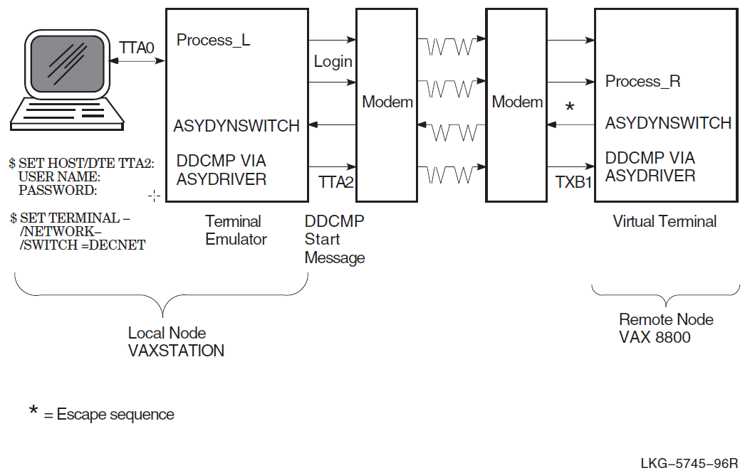
terminal-port-name is the name of your local terminal port that is connected to the modem. If both systems use modems with autodial capabilities (for example, DF03, DF112, or DF224 modems), you can optionally include the /dial qualifier on the set host/dte command to cause automatic dialing of the modem on the remote node, as follows:
$ set host/dte/dial=number:number terminal-port-name:If you do not specify the /dial qualifier in the previous step, dial the remote system manually. After the dialup connection is made and you receive the remote system welcome message, log in to your account on the remote node. In this case, you supply your user name and password to the remote OpenVMS operating system.
If you are not using automatic dialing, dial in to the remote node manually.
Once the dialup connection is made and you receive the remote OpenVMS system welcome message, log in to your account on the remote node. This process is identified by Process_R in Figure I.1, ''Dynamic Switching of Asynchronous DDCMP Lines''.
You can initiate the dynamic switch by specifying the following DCL command on the remote node:
$ set terminal/network/switch=decnet
The set terminal command is an OpenVMS DCL command. If you are on a node other than an OpenVMS node, specify the equivalent function for your system.
When the SET image on the remote system recognizes the /NETWORK and /switch=decnet qualifiers, it calls the shareable image asydynswitch (see Figure I.1, ''Dynamic Switching of Asynchronous DDCMP Lines''). The asydynswitch image verifies the link and sends an escape sequence to the terminal emulator on the local system. The escape sequence notifies the local terminal emulator that the line connected to the remote system is becoming a dynamic asynchronous line.
When the terminal emulator at the local system receives the escape sequence, it calls the asydynswitch image (see Figure I.1, ''Dynamic Switching of Asynchronous DDCMP Lines'') on the local system. The asydynswitch image verifies the line on the local system and switches it to an asynchronous DECnet line.
When the switch occurs on the local system, asydriver first searches for an explicitly named dynamic asynchronous line. For example, if the switch is on device tta1:, it searches for a line with a communications port attribute of async-tt-0-1. If asydriver cannot find that line, it searches for a "floating" line (created with a communications port attribute of async). Because a protocol stack previously had been preconfigured over this line, the data link protocol now attempts to start the link.
The local system then sends a ddcmp start message (see Figure I.1, ''Dynamic Switching of Asynchronous DDCMP Lines'') to the remote system that initiated the dynamic switch. When asydynswitch on the remote system detects the start message, it activates the preconfigured local protocol stack. (For information about the protocol stack, see Section I.1.2.1, ''Setting Up Dynamic Asynchronous Connections'', Steps 5–7.)
The remote system first searches for an explicitly named dynamic asynchronous line. When it searches for an explicitly named dynamic line, it searches for one that refers to the physical terminal over which the original switch was made. In Figure I.1, ''Dynamic Switching of Asynchronous DDCMP Lines'', the remote system searches for a line associated with port txb1. Therefore, it looks for a line with a communications port attribute of async-tx-1-1. If it does not find one, it uses a "floating" async-n line. If this fails, the dynamic switch fails.
Since both ends of the link have a preconfigured protocol stack, the DECnet link comes up over both circuits. Any preconfigured security checks also occur at this time.
The following message indicates that the terminal emulator on the local system has exited and that the DECnet link is being established:
%REM-S-END - control returned to local-nodename:: $
To check whether the communications link has come up, specify the following command on the local system:
$ run sys$system:ncl ncl> show routing circuit dynamic_asynch adjacency adjacent-node all ncl> exit
If there is an adjacency, you can start to communicate with the remote system over the asynchronous DECnet connection.
As an alternative to switching the terminal line to a DECnet line automatically, you can switch the line manually. If you originate a dynamic connection to an OpenVMS node from a system other than OpenVMS, manual switching is required; from an OpenVMS system, it is optional. If you are originating the connection from a node other than OpenVMS, follow system- specific procedures to log in to the remote OpenVMS node by means of terminal emulation.
Once you are logged in to the remote node, two steps are required for manual switching:
Using your account on the remote OpenVMS node, specify the set terminal command described in Step 7, but add the /manual qualifier. For more information see Section I.1.2.1, ''Setting Up Dynamic Asynchronous Connections'', Step 5.
$ set terminal/network/switch=decnet/manual
You will receive the following message from the remote node indicating the remote system is switching its line to DECnet use:
%SET-I-SWINPRG The line you are currently logged over is becoming a DECnet line
You should exit from the terminal emulator and switch your line manually to a DECnet line. The procedure depends on the specific operating system on which you are logged in.
The following example shows how an OpenVMS user originating a dynamic connection exits from the terminal emulator and turns on the DECnet line.
Exit from the terminal emulator: Press and hold down the Control key while you press the \ (backslash) key on your OpenVMS system.
Enter the following command to switch your terminal line to a DECnet line manually:
$ set terminal/network tta0:
tta0 is the name of the terminal port on the local node.
Next, you must manually turn on the lines, data links, and routing circuits connected to your terminal port. See Steps 5 through 7 in Section I.1.1, ''Establishing a Static Asynchronous Connection'' for information about setting up your static asynchronous link.
Asynchronous DECnet is then started on the local OpenVMS node.
I.1.2.3. Managing Dynamic Asynchronous Resources
You can define the following system logical names in SYS$MANAGER:NET$LOGICALS.COM to manage the resources used by a dynamic asynchronous connection:
asy$dynamic_maxlinesSpecifies the maximum number of dynamic asynchronous modem connect lines that can be active on a system at any one time. You can specify values in the range of 0–65534 lines. The default is 16 lines. For example:
$ define/system asy$dynamic_maxlines 16
asy$dynamic_line_timeoutSpecifies the amount of time in seconds that a dynamic asynchronous line waits before deciding that a dynamic connection has broken. When the dynamic asynchronous line decides that a link is broken, the line is automatically switched back to a terminal line. You can specify values in the range of 10–65535 seconds. The default is 300 seconds. For example:
$ define/system asy$dynamic_line_timeout 300
I.1.2.4. Terminating a Dynamic Asynchronous Connection
Take the following steps to terminate a dynamic asynchronous connection:
Disable the modem connect line and then re-enable it. For example:
$ run sys$system:ncl ncl> disable modem connect line dynamic_asynch ncl> enable modem connect line terminal_line ncl> exit
Switch your asynchronous line back to a terminal line.
$ set terminal/permanent/nonetwork/typeahead terminal_port_name
The dynamic asynchronous connection can also terminate, if the time specified by the logical name asy$dynamic_line_timeout expires. The link is considered idle if it has no input or output for the timeout interval. When this occurs, the link is broken and the line automatically switches from a DECnet line back to a terminal line. For more information about asy$dynamic_line_timeout, see Section I.1.2.3, ''Managing Dynamic Asynchronous Resources''.
I.1.2.5. Reasons for Failure of Dynamic Asynchronous Connections
If you are using dynamic switching and the asynchronous DECnet connection is not made, check that:
DECnet-Plus has been started.
WANDD has been started.
The asydriver has been loaded (the asy0 device is present).
The asyswitch has been installed.
The asydynswitch has been installed.
The modem connect lines have been configured correctly.
Virtual terminals must be enabled both on the remote node and, in particular, for the terminal at which you are logged in. The terminal line at the remote node must have the attribute disconnect set.
After you enter a set terminal command with the /manual qualifier, you must specify NCL commands to turn on the DECnet line within approximately 2 minutes or the line returns to terminal mode.
If the logical station is in the on-starting state, check that:
The routing circuits have been configured correctly.
The routing initialization passwords on each node must be set correctly. (Refer to the VSI DECnet-Plus for OpenVMS Network Management Guide.)
The parity is correct. Asynchronous DECnet requires the parity on the asynchronous line to be set to none and the terminal line to be set up to use 8-bit characters. If you are using a non OpenVMS system, you must check that the terminal line is set to the correct parity.
For more information about solving problems in your DECnet-Plus network, refer to the VSI DECnet-Plus for OpenVMS Problem Solving Guide.
Starting with V7.3-2 and any future ECOs to V7.3-1, future enhancement releases (V7.3-2 and V7.3- 1) will not use the same "DECnet Minor" identifier as the base new feature release (such as V7.3). The value shown for V7.3-1 ECO03 is provided to indicate how future numbers will be allocated. It does not represent a commitment by DECnet engineering to release this ECO kit.
A build error caused V7.3-1 ECO02 to be released with an incorrect value for DECNET_VERSION.
Early ECO releases of Version 6.3 used decimal numbers in the User ECO field. Later releases of Version 6.3 and all future ECO releases use or will use hexadecimal numbers.
To prevent automatic creation of the entity, edit the .NCL file to comment out the create and enable commands for that entity.
To prevent automatic creation of the entity, edit the .NCL file to comment out the enable and create commands for that entity.
No equivalent; not applicable.
Special form of SYSTEM IMAGE set by CLUSTER_CONFIG.COM for OpenVMS.
Of type remote. The DTE class type is specified on creation.
OpenVMS VAX only. Use the service nodes attribute on OpenVMS IA-64 and OpenVMS Alpha systems.
Optional parameter.
Not supported.
Of type local. The DTE class type is specified on creation.
All DTEs in this network must use the same profile name as the profile attribute of both the X25 Protocol DTE and LAPB Link entities.
All DTEs must have a valid inbound DTE class attribute.
The LINE qualifier points to an entry in the LINE database. The link service provider might be LAPB Link or LLC2 SAP Link.
Optional parameter.
Now controlled by the enable or disable directives.
Optional parameter.
Optional parameter.
Now controlled by the enable or disable directives.
Used for more than one attribute, due to a split of function between the X25 Access module and the X25 Access Application entity.
X25 Access application type should be X25 for this type of destination.
Optional parameter.
Not supported in all implementations.
OpenVMS VAX only. Use the incoming dte address attribute on OpenVMS I64 and OpenVMS Alpha systems.
Used for more than one attribute, due to a split of function between the x25 access and x25 server client entities.
Note that this is a set of filters, not a single value.
OpenVMS VAX only. Use the service nodes attribute on OpenVMS IA-64 and OpenVMS Alpha systems.
Optional parameter.
Optional parameter.
If the CONTROLLER mode is LOOPBACK, then the startloop directive may be issued on the modem connect line using the mode attribute.
See notes for X25-PROTOCOL NETWORK databases.
See note on NETWORK for the X25-PROTOCOL DTE database.
Now controlled by the enable or disable directives.
Optional parameter.
Used for more than one attribute, due to a split of function between the x25 access filter and x25 access application entities.
X25 Access Application type should be X29 for this type of destination unless no object is specified, in which case it is X29 login.
Optional parameter.
Not supported in all implementations.
OpenVMS VAX only. Use the incoming dte address attribute on OpenVMS IA-64 and OpenVMS Alpha systems.
Optional parameter.
Not currently supported.
Using the template identified by the routing circuit template attribute.
Now controlled by the enable or disable directives.
This attribute is for the create directive.
Should be set if the Phase IV parameter VERIFICATION is enabled.
Optional parameter.
Not currently supported.
Using the X.25 filter identified by the routing circuit template attribute.
Using the template identified by the routing circuit template attribute.
Now controlled by the enable or disable directives.
Should be set if the Phase IV parameter VERIFICATION is enabled.
Optional parameter.
This is the name of an X25 Protocol dte pvc entity.
The PVC name must be unique even though PVC is a subentity of the X25 Protocol module dte entity.
Not currently supported.
This qualifier is only used to differentiate between CIRCUIT databases used for routing and those used for X.25 applications. It is not needed in DECnet Phase V.
Now controlled by the enable or disable directives.
Should be set if the Phase IV parameter VERIFICATION is enabled.
The PVC name must be unique (for backward compatibility) even though pvc is a subentity of the X25 Protocol module dte entity.
Optional parameter.
This attribute must be specified for the create directive.
This qualifier is only used to differentiate between CIRCUIT databases used for routing and those used for X.25 applications. It is not needed in DECnet Phase V.