VSI DECnet-Plus Problem Solving
- Operating System and Version:
- VSI OpenVMS IA-64 Version 8.4-1H1 or higher
VSI OpenVMS Alpha Version 8.4-2L1 or higher
Preface
VSI DECnet-Plus for OpenVMS Problem Solving Guide describes how to use DECnet-Plus tools to isolate and correct simple DECnet-Plus problems in the OpenVMS and UNIX environments.
1. About VSI
VMS Software, Inc. (VSI) is an independent software company licensed by Hewlett Packard Enterprise to develop and support the OpenVMS operating system.
2. Intended Audience
VSI DECnet-Plus for OpenVMS Problem Solving Guide is for network managers and system managers who work in a DECnet-Plus environment.
Assumed knowledge
Readers of this book are expected to have a basic understanding of DECnet and OSI networking concepts. It is assumed that readers have experience with DECnet-Plus network management tools such as the Network Control Language (NCL), and DECnet Phase IV tools, such as the Network Control Program (NCP).
3. Related Documents
DECnet Phase IV management documentation
Phase IV network troubleshooting documentation
DECnet-Plus network management documentation
DECnet-Plus NCL reference documentation
OSI Applications Kernel (OSAK) documentation
DECdns or other name service documentation
DECdts documentation
The Common Trace Facility Use manual
X.25 problem-solving documentation
FTAM and Virtual Terminal documentation
4. VSI Encourages Your Comments
You may send comments or suggestions regarding this manual or any VSI document by sending electronic mail to the following Internet address: <docinfo@vmssoftware.com>. Users who have VSI OpenVMS support contracts through VSI can contact <support@vmssoftware.com> for help with this product.
5. OpenVMS Documentation
The full VSI OpenVMS documentation set can be found on the VMS Software Documentation webpage at https://docs.vmssoftware.com.
6. Typographical Conventions
VMScluster systems are now referred to as OpenVMS Cluster systems. Unless otherwise specified, references to OpenVMS Cluster systems or clusters in this document are synonymous with VMScluster systems.
The contents of the display examples for some utility commands described in this manual may differ slightly from the actual output provided by these commands on your system. However, when the behavior of a command differs significantly between OpenVMS Alpha and Integrity servers, that behavior is described in text and rendered, as appropriate, in separate examples.
In this manual, every use of DECwindows and DECwindows Motif refers to DECwindows Motif for OpenVMS software.
| Convention | Meaning |
|---|---|
|
Ctrl/x |
A sequence such as Ctrl/x indicates that you must hold down the key labeled Ctrl while you press another key or a pointing device button. |
|
PF1 x |
A sequence such as PF1 x indicates that you must first press and release the key labeled PF1 and then press and release another key or a pointing device button. |
|
Return |
In examples, a key name enclosed in a box indicates that you press a key on the keyboard. (In text, a key name is not enclosed in a box.) |
|
… |
A horizontal ellipsis in examples indicates one of the
following possibilities:
|
|
. |
A vertical ellipsis indicates the omission of items from a code example or command format; the items are omitted because they are not important to the topic being discussed. |
|
( ) |
In command format descriptions, parentheses indicate that you must enclose the options in parentheses if you choose more than one. |
|
[ ] |
In command format descriptions, brackets indicate optional choices. You can choose one or more items or no items. Do not type the brackets on the command line. However, you must include the brackets in the syntax for OpenVMS directory specifications and for a substring specification in an assignment statement. |
|
[|] |
In command format descriptions, vertical bars separate choices within brackets or braces. Within brackets, the choices are options; within braces, at least one choice is required. Do not type the vertical bars on the command line. |
|
{ } |
In command format descriptions, braces indicate required choices; you must choose at least one of the items listed. Do not type the braces on the command line. |
|
bold text |
This typeface represents the introduction of a new term. It also represents the name of an argument, an attribute, or a reason. |
|
italic text |
Italic text indicates important information, complete titles of manuals, or variables. Variables include information that varies in system output (Internal error number), in command lines (/PRODUCER= name), and in command parameters in text (where dd represents the predefined code for the device type). |
|
UPPERCASE TEXT |
Uppercase text indicates a command, the name of a routine, the name of a file, or the abbreviation for a system privilege. |
|
|
Monospace type indicates code examples and interactive screen displays. In the C programming language, monospace type in text identifies the following elements: keywords, the names of independently compiled external functions and files, syntax summaries, and references to variables or identifiers introduced in an example. |
|
- |
A hyphen at the end of a command format description, command line, or code line indicates that the command or statement continues on the following line. |
|
numbers |
All numbers in text are assumed to be decimal unless otherwise noted. Nondecimal radixes—binary, octal, or hexadecimal—are explicitly indicated. |
All numbers are decimal unless otherwise noted.
All Ethernet addresses are hexadecimal.
Chapter 1. Fault-Isolation Overview
A necessary part of any type of problem solving is fault isolation. Fault isolation is the process used to determine the source of a problem. Quick and efficient fault isolation is key to resolving network problems.
Topics in This Chapter
Understanding the DECnet-Plus Network Model (Section 1.1, ''Understanding the DECnet-Plus Network Model'')
Classifying Problems (Section 1.2, ''Classifying Problems'')
DECnet-Plus Component Relationships (Section 1.3, '' DECnet-Plus Component Relationships'')
Methods for Isolating Faults (Section 1.4, ''Methods for Isolating Faults'')
1.1. Understanding the DECnet-Plus Network Model
When working in the DECnet-Plus environment, it is useful to understand the network model that the DECnet-Plus software uses. Figure 1.1, ''DECnet-Plus Network Model'' illustrates the network architecture on which DECnet-Plus is based.
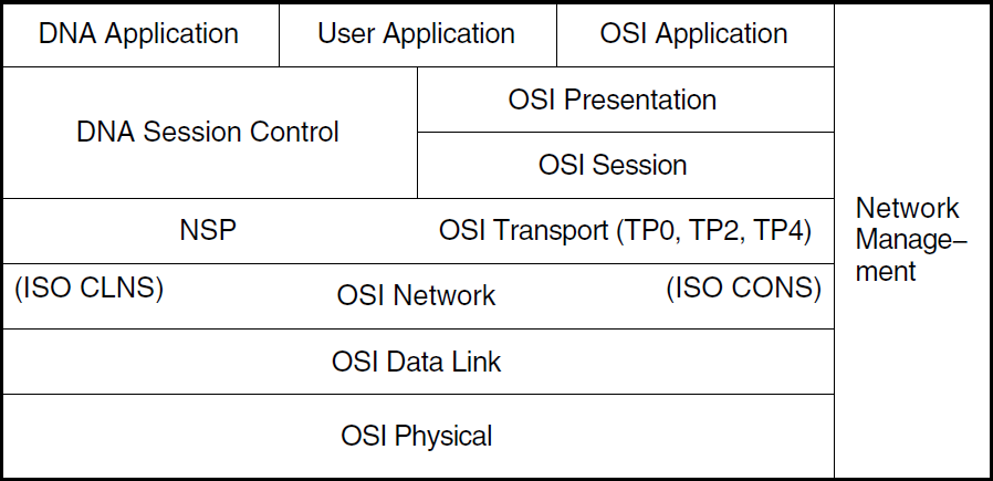
1.1.1. OSI Network Layer Functions
|
OSI Layer |
Name |
Function |
|---|---|---|
|
7 |
Application |
Contains the application services and supporting protocols that use the lower layers. Allows distributed processing and access. |
|
6 |
Presentation |
Coordinates data and data format conversion to meet the needs of individual application processes. |
|
5 |
Session |
Organizes and structures the interaction between pairs of communicating application processes |
|
4 |
Transport |
Transfers data between end systems and has error recovery
and flow control. Supported protocol classes are:
|
|
3 |
Network |
Permits communications between network entities in open systems, whether they are adjacent systems on the same subnetwork or are connected by a path that crosses multiple subnetworks and intermediate systems. DECnet-Plus supports Connection-Oriented Network Service (CONS) and Connectionless-mode Network Service (CLNS), as well as communications between Phase IV and DECnet-Plus systems. |
|
2 |
Data Link |
Specifies the technique for moving data along network links between defined points on the network, and tells how to detect and correct errors in the Physical layer. |
|
1 |
Physical |
Connects systems to the physical communications media. |
1.1.2. DNA Layer Functions
|
DNA Layer |
Name |
Function |
|---|---|---|
|
7 |
DNA Application |
Includes user-written programs and user-level services. It is used by operators and system programmers to plan, control, and maintain the operation of DECnet-Plus networks. |
|
6 and 5 |
DNA Session Control |
Allows communication between programs, regardless of either program's location through the use of DNA naming services. It also provides access control and authentication functions, and acts as a bridge between applications and the transport services. |
|
4 |
Network Services Protocol (NSP) |
Allows interoperability with Phase IV systems. |
|
3, 2, and 1 |
Same as described in Section 1.1.1, ''OSI Network Layer Functions'' | |
1.1.3. TCP/IP Interoperability
The DECnet/OSI for UNIX applications, FTAM and Virtual Terminal, support RFC 1006 and can use TCP/IP transport services. This manual does not include problem-solving information for TCP/IP networks. Refer to your TCP/IP documentation for this information.
1.2. Classifying Problems
Before you try to correct problems, try to classify the type of problem that exists. The following sections describe typical problem classifications.
1.2.1. Reproducible Problems
A reproducible problem consistently produces the same error message or symptom when reproduced under the same conditions.
Some reproducible problems produce different error messages or symptoms that can ultimately have the same underlying cause. These types of reproducible problems are considered inconsistent. Inconsistent problems generally involve several protocols or several layers of an architecture. The different error messages result from the ways different applications encounter the problem in the protocols and the architectural layers.
1.2.2. Intermittent Problems
An intermittent problem appears occasionally and displays the same error message or symptoms in the same circumstances. You can occasionally reproduce intermittent errors. Intermittent errors can occur when threshold values for various parameters are reached. Usually, during normal use, these thresholds are not reached; however, the thresholds can be reached during peak use and errors can result.
1.2.3. Transient Problems
Transient problems occur only occasionally, and can rarely be reproduced. Because you cannot reliably reproduce transient problems, they are by far the most difficult errors to isolate and fix.
As with intermittent problems, transient problems can result when threshold values for various parameters are reached. Because transient errors tend to occur at peak usage times, historical performance data is helpful in determining the cause of the problem.
1.3. DECnet-Plus Component Relationships
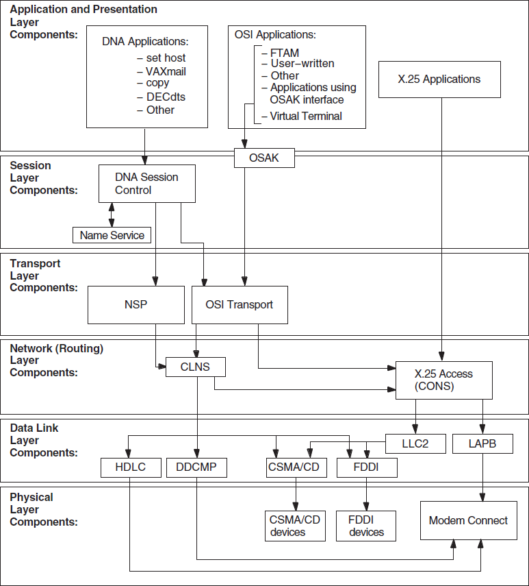
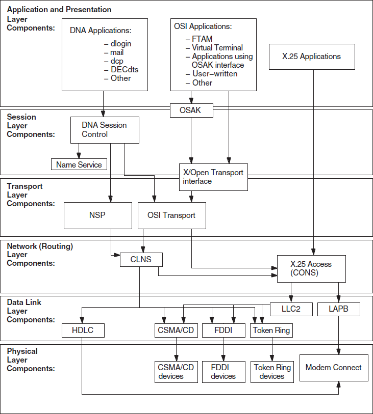
Figure 1.2, ''Component Relationships (OpenVMS)'' and Figure 1.3, ''Component Relationships (UNIX)'' show the relationships between the individual components in the DECnet-Plus environment on OpenVMS and UNIX systems. Use this information as a guide when you need to identify problems in a specific DECnet-Plus layer.
For information and problem solving procedures relating to X.400, DECdns, and DECdts software, refer to the appropriate software documentation.
1.3.1. Component Relationships (OpenVMS Only)
Figure 1.2, ''Component Relationships (OpenVMS)'' shows the OpenVMS component relationships.
1.3.2. Component Relationships (UNIX Only)
DECnet-Plus applications that use the X/Open Transport Interface (XTI) can use the TCP transport services in addition to the OSI transport services. This manual does not contain information about TCP/IP networks; refer to your TCP/IP documentation.
Figure 1.3, ''Component Relationships (UNIX)'' shows the component relationships for UNIX.
1.4. Methods for Isolating Faults
The conditions that existed when an error appeared
The relationships between DECnet-Plus components
The type of problem you have: reproducible or intermittent
The changes you made prior to the error appearing
1.4.1. Questions to Ask Yourself
Which components, systems, or applications are working correctly?
When did you first notice the problem?
Did you see any error messages?
What were you doing when the problem occurred?
Can you re-create the problem?
Did you recently add or change hardware or software?
How often has the problem occurred since you first noticed it?
1.4.2. Fault Isolation in the DECnet-Plus Environment
Problem symptoms do not always indicate which DECnet-Plus component is the cause of the problem. To clarify where the problem exists, use another operation or application that relies on the same underlying services or components as the operation that failed.
The figures in Sections 1.3.1 and 1.3.2 show the relationship between the components in the DECnet-Plus environment.
1.4.3. DECnet-Plus Fault-Isolation Methodology
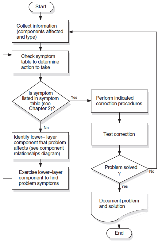
Isolating and solving network problems often requires a variety of approaches. You can use the general methodology illustrated in Figure 1.4, ''Fault-Isolation Methodology (General)'' as a starting point for fault isolation.
1.4.4. Isolating Faults for Reproducible Problems
Find network activities that are similar, where one activity succeeds and the other fails. For example; if the OpenVMS command
set hostfails, try a similar operation to the same remote node. Then try theset hostoperation from the same local node to a different remote node.Determine the most recent time when the operation succeeded. Then determine what has changed in the network since then.
1.4.5. Isolating Faults for Intermittent or Transient Problems
Collect as much information as possible regarding the state of the network when the problem appears. This information includes any type of trace information that application trace utilities provide.
Examine historical and trace data to determine if any patterns exist; for example, if the FTAM application fails only when attempting a directory operation on a specific vendor's system.
Try to reproduce the problem by re-creating the state of the system when the problem first appeared.
If you can reproduce the problem, follow the process described in Section 1.4.4, ''Isolating Faults for Reproducible Problems ''.
1.4.6. Documenting the Fault-Isolation Process and Problem Solution
Documenting the steps you used to isolate a problem makes reporting the situation to VSI representatives easier if you are unable to solve the problem yourself.
The conditions under which problems occurred
The hardware and software version numbers used in your network
The processes you used to identify problems
The information you collected about the problems
The procedures you used to solve problems
Chapter 2. Preparing for Problem Solving
This chapter describes the types of information that can help you isolate and correct DECnet-Plus problems.
Topics in This Chapter
DECnet-Plus Symptom Table (Section 2.1, '' DECnet-Plus Symptom Table'')
Types of Problem-Solving Information (Section 2.2, ''Types of Problem-Solving Information'')
Understanding Your Network Topology (Section 2.3, ''Understanding Your Network Topology'')
Recognizing Node Names and Synonyms (Section 2.4, ''Recognizing Node Names and Synonyms'')
Finding the Operating System and Version (Section 2.5, ''Finding the Operating System and Version'')
Getting DECnet-Plus Circuit Information (Section 2.6, ''Getting DECnet-Plus Circuit Information'')
Preparing to Find a Network Path (Section 2.7, ''Preparing to Find a Network Path'')
Tracing DECnet-Plus Network Paths (Section 2.8, ''Tracing DECnet-Plus Network Paths'')
2.1. DECnet-Plus Symptom Table
|
Symptom: |
Possible Cause: |
Refer To: |
|---|---|---|
|
Access control rejected |
Session Control application entities, proxy access, or node name validation | |
|
Application failed but no errors were found in the upper layers |
Transport or network error | |
|
Application too busy |
Remote application is receiving too many connection requests before it or Session Control can process them | |
|
DECnet-Plus application connection attempts fail |
Application or network problem |
Chapter 5, "Solving DECnet-Plus Application Problems" (OpenVMS only) or Chapter 8, "Solving Network Layer Problems" |
|
Entities were not available when tracing a path between a routing circuit and the physical device |
Routing circuit or data link is not enabled or created | |
|
FTAM or Virtual Terminal responder fails (OpenVMS only) |
FTAM or Virtual Terminal application | |
|
FTAM file does not look correct (OpenVMS only) |
FTAM application | |
|
Object is unknown at remote node |
Namespace problem | |
|
Remote node is shut or shutting down |
Remote DECnet process exited or remote node failed | |
|
Remote node is unreachable |
Incompatible tower information exists, or a network problem | |
|
Session Control has insufficient resources |
All available Session Control ports are in use | |
|
System configuration is correct but the routing circuit does not work |
Routing connectivity | |
|
Timed out |
Session Control, transport or network problem |
Chapter 6, "Solving Session Control Problems" |
|
Unable to communicate with any DECdns server |
DECdns problem |
DECdns manuals |
|
Unknown application at remote node |
DECnet-Plus application missing or defined incorrectly Session Control application entities or proxy access |
Chapter 5, "Solving DECnet-Plus Application Problems" (OpenVMS only) or Chapter 6, "Solving Session Control Problems" |
|
User-written application problem affects the OSAK software (OpenVMS only) |
Programming error | |
|
User-written application fails |
OSAK (OpenVMS only) or XTI programming error |
Chapter 5, "Solving DECnet-Plus Application Problems" (OpenVMS only) or XTI programming manuals |
|
User-written DECnet-Plus application terminates unexpectedly |
Remote application or OSI Transport |
Chapter 5, "Solving DECnet-Plus Application Problems" (OpenVMS only) or Chapter 7, "Solving Transport Problems" |
|
Wrong information displayed or wrong account accessed |
Proxy access problem or use of invalid username and password |
2.2. Types of Problem-Solving Information
The type of problem (see Section 1.2, ''Classifying Problems'')
- Network topology, including:
Node names and types (end node, level 1 router, level 2 router)
Operating system
Networking software in use
Types of routing circuits in use
Routing circuit adjacencies
The network path from one node to another
Naming information (node names and Phase IV node synonyms)
2.2.1. Definitions
A network topology shows the physical and logical locations of components in a network. A current map of the physical and logical locations of all of the devices on your network is important in helping you find specific devices quickly.
A Phase IV node synonym is a Phase–IV–style node name that enables applications that do not support the length of a DECnet-Plus full name to continue to use a six–character Phase–IV–style node name.
A routing circuit is a logical path between adjacent nodes. DECnet Phase IV circuit names are based on the hardware type used by the lines connecting nodes. A DECnet-Plus circuit name can be in any format.
A network path is the path data takes from one end system to another end system in the same or a different area.
2.2.2. Tools and Commands to Use
|
To Find: |
Use: |
And Refer To: |
|---|---|---|
|
Network protocol information |
Common Trace Facility |
Common Trace Facility Use manual |
|
DECnet-Plus application traces (OpenVMS only) | ||
|
Network Control Language |
NCL reference documentation | |
|
Network topology |
NCP for Phase IV nodes |
DECnet Phase IV documentation |
|
NCL for DECnet-Plus nodes |
DECnet-Plus NCL reference documentation | |
|
|
DECnet-Plus network management documentation | |
|
Routing circuit adjacencies |
NCP for Phase IV nodes |
DECnet Phase IV documentation |
|
NCL for DECnet-Plus nodes |
DECnet-Plus network management documentation | |
|
Node reachability |
The following for quick reachability tests:
| |
|
Loopback and | ||
|
DECnet software version |
For DECnet-Plus nodes, the NCL command |
DECnet-Plus NCL reference documentation |
|
For Phase IV nodes, the NCP command |
DECnet Phase IV management documentation |
2.3. Understanding Your Network Topology
Creating reports using the
decnet_migratetoolTracing potential data paths from one end system to another using the
decnet_migratetool
2.3.1. The decnet_migrate Tool
decnet_migrate tool to get the following information
for each node in your network:- Basic information, including:
Name
Address
Type of DECnet software in use (Phase IV or DECnet-Plus)
Routing type
Node identification string
Adjacent nodes for each node
Defined target network applications (or objects) for each node
Routing circuit IDs and costs for each node
Maximum routing hops, cost, and network buffer size
Areas known to level 2 routers in the network
You can also use the decnet_migrate
show path function to trace network routes between one node and
another.
2.3.2. When to Use the decnet_migrate Tool
Use this tool when you need a detailed map of parts or all of the complete network
topology. If you have routers that use the Simple Network Management Protocol
(SNMP), the decnet_migrate tool cannot collect information about them.
Use the tools those routers provide to collect network topology information.
Collecting this information with the decnet_migrate tool can take a
significant amount of time depending on the options you select.
2.4. Recognizing Node Names and Synonyms
It is useful to have node name information when trying to isolate faults. Node names reflect either a Phase IV or DECnet-Plus style.
2.4.1. Identifying Node Names
|
Characteristics |
Example |
|---|---|
|
Phase IV node names are:
|
MYNODE |
|
DECnet-Plus node names are:
|
ABC:.eng.node1 |
2.4.2. Finding Node Names and Node Synonyms
|
To Find A: |
Use This decnet_register Command: |
|---|---|
|
Phase IV synonym |
|
|
Full node name |
|
2.5. Finding the Operating System and Version
- Log in to the system and look at the system prompt.
If the Prompt Is:
Then the Operating System Is:
Username:OpenVMS
login:UNIX
- If the operating system version does not appear when you log in, enter one of the following commands:
If the Operating System Is:
Enter:
OpenVMS
$ show systemUNIX
strings /vmunix|grep '(Rev')
2.6. Getting DECnet-Plus Circuit Information
To find basic routing circuit information, use Network Control Program (NCP) commands for Phase IV nodes and Network Control Language (NCL) commands for DECnet-Plus nodes. Refer to your NCP documentation for information about NCP commands.
2.6.1. Routing DECnet-Plus Circuit Information for Problem Solving
Routing circuit name
Routing circuit type
Routing circuit state
Routing circuit adjacencies
2.6.2. Finding Routing Circuit Names, Types, States, and Adjacencies
|
To Find Routing Circuit: |
Enter This NCL Command: |
|---|---|
|
Name |
|
|
Type |
|
|
State |
|
Confirm that a routing circuit is working
Check the identity of the adjacent node
Routing circuit adjacencies exist for wide area network (WAN) circuits, and local area network (LAN) circuits. Use the following NCL command to find routing circuit adjacencies:
ncl> show node node-id routing circuit circuit-id -
_ncl> adjacency * all status
2.6.3. Considerations for Broadcast Circuit Adjacencies
When you look at broadcast circuit adjacencies, the output can be extensive because many adjacencies can exist at one time. It can be more useful to request certain types of information rather than all information.
For example, you could use the following NCL command:
ncl> show node node-id1 routing circuit circuit-1 adjacency -
_ncl> node-id2 type
2.7. Preparing to Find a Network Path
Tracing a path from one end system to another can isolate network reachability problems and also can provide network topology information. The information in this section describes the type of information you need before you trace a network path.
2.7.1. Types of Network Information to Find
|
Information |
Description | |
|---|---|---|
|
Node Addresses |
Nodes have addresses that DECnet uses when sending data through a network. Phase IV nodes only have one node address; DECnet-Plus nodes can have up to six NSAP addresses; three that NSP use and three that OSI Transport use. Phase IV node addresses and NSAP addresses are different. However, you can translate a Phase IV node address into an NSAP address. | |
|
Phase IV Node Addresses: |
NSAP Addresses: | |
|
Are called node numbers. |
Are called network service access points (NSAPs). | |
|
Are 2 bytes in length. |
Can be up to 20 bytes (40 hexadecimal digits) in length. | |
|
Contain an area number (1 – 63) and a node number (1 – 1023). |
DECnet-Plus Phase IV–compatible addresses contain:
| |
|
Network entity titles (NETs) |
Used to identify a node when it is not necessary to identify the transport software in use. A NET has the same format as an NSAP with a selector byte of %x00. | |
|
System type |
A system can be an end system, a level 1 router, or a level 2 router. | |
2.7.2. Finding Node Addresses for Node Names
|
For This Node Type: |
Enter: |
|---|---|
|
Phase IV |
The NCP command:
|
|
DECnet-Plus |
The NCL command:
|
If you cannot get the remote node's address in this manner, you need to log in to that system directly.
2.7.3. Determining Network Entity Titles for DECnet-Plus Nodes
A network entity title (NET) has the same format as a system's network service access point (NSAP), except the last two digits are set to 00. For example, if the NSAP is 49::00-0D:AA-00-04-00-7F-34:20, the NET is 49::00-0D:AA-00-04–00-7F-34:00.
2.7.4. Converting Phase IV Addresses to NSAPs
|
Step |
Action |
|---|---|
|
1 |
Ensure that the NSAP local area is in the Phase IV area in hexadecimal notation. For example, the Phase IV area 1 becomes the NSAP local area 00-01, and the Phase IV area 63 becomes the NSAP local area 00-3F. |
|
2 |
Convert the Phase IV node ID to the NSAP node ID:
|
Example of Phase IV Address Conversion
local-area:node-id:20, the Phase IV
address is 43.258, and the node uses the NSP transport. You create the NSAP as
follows:
IDP and selector   -> 41:45436192:local-area:node-id:20
43 decimal         -> 2B     hexadecimal (local area)
(43 * 1024) + 258) -> 44290  decimal
44290 decimal      -> AD02   hexadecimal
AD02  swapped      -> 02AD   hexadecimal (node ID)

Resulting NSAP     -> 41:45436192:00-2b:aa-00-04-00-02-ad:20
2.7.5. Converting NSAP Addresses to Phase IV Format
|
Step |
Action |
|---|---|
|
1 |
Check that the local area is less than or equal to 63
decimal or 3F hexadecimal and the node ID field begins with
|
|
2 |
Extract the last four digits of the node ID field. |
|
3 |
Swap the last two pairs of digits, and convert the value to decimal. |
|
4 |
Calculate the Phase IV area and ID values:
If the calculated area value is not equal to the area value obtained from the NSAP's local area field, the NSAP does not contain a valid Phase IV address. |
Example of NSAP Conversion
19 hexadecimal (from local area)  -> 25 decimal
62-64 (from node-id)              -> 6462 hexadecimal
6462 hexadecimal                  -> 25698 decimal
25698/1024                        -> area of 25
25698 - (25 * 1024)               -> node ID of 98

Resulting Phase IV address        -> 25.98
2.8. Tracing DECnet-Plus Network Paths
You can trace a network path for a pure DECnet-Plus environment and for a mixed environment that has DECnet-Plus and Phase IV nodes.
2.8.1. Tracing the Network Path of DECnet-Plus Nodes
You can trace the path from one node to another with the following command:
$ run decnet_migrate
DECNET_MIGRATE>sho path from
NAMES:.NETA.NODEA to NAMES:.NETB.NODEB
|
Step |
Action |
|---|---|
|
1 |
Find the destination NSAPs. |
|
2 |
Analyze the NSAPs to find the area addresses of the destination system. |
|
3 |
Find a DECnet-Plus router that the source node uses. Do the
following:
A DECnet-Plus router may not exist. See the procedure in Section 2.8.2, ''Tracing a Network Path in a Mixed Environment '' if the next node in the path is a Phase IV router. If the next node in the path is a third-party router, see that system's documentation. |
|
4 |
If the router you find in the previous step is in the same
area as your destination node, go to the next step. If the
router is in a different area than the destination node, do
the following:
|
|
5 |
When you find a router located in the same area as the
destination node, do the following:
|
2.8.2. Tracing a Network Path in a Mixed Environment
|
Step |
Action |
|---|---|
|
1 |
Exit NCL and invoke NCP (or invoke NCP at the NCL prompt). |
|
2 |
Use NCP to get the Phase IV node address of your destination node and the router. |
|
3 |
Find the next node in the path. Use the following NCP commands (the router-id can be the node name or the Phase IV address): ncp> tell phase_iv-node-id show node - _ncp> destination-node-address |
|
4 |
If the next node in the path is not the destination node,
repeat the commands in step 3, using the next node that the
|
|
5 |
If NCP returns an error message, the next node in the path
could be a DECnet-Plus node. Do the following:
|
2.8.3. X.25 DA Circuit Considerations
|
Step |
Action |
|---|---|
|
1 |
Find the reachable address subentity that has a prefix that best matches your required destination NSAP. |
|
2 |
Select a DTE from the DTE Addresses attribute and determine the node address (NSAP or Phase IV synonym) associated with the remote DTE address. |
|
3 |
If you cannot determine the node address, try to log in to the remote node using X.29 (PAD) and continue tracing the network path from the remote node. |
2.8.4. NCL Takes Long Time While Translating Addresses to Names
When NCL displays a node address in response to a SET or SHOW command, it uses the services of DECdns to translate the address into a node name and displays the name along with the address.
$ DEFINE NCL$ENVIRONMENT NOBACKTRANS
This causes NCL to bypass the address-to-name translation. To use this option on a systemwide basis, add this logical definition (with the /SYSTEM qualifier) to SYS$MANAGER:NET$LOGICALS.COM.
Chapter 3. Testing Network Reachability
This chapter describes the network reachability tests you can use in the DECnet-Plus environment.
Topics In This Chapter
Types of Network Reachability Tests (Section 3.1, ''Types of Network Reachability Tests'')
OSI Echo Function Overview (UNIX Only) (Section 3.2, ''OSI Echo Function Overview (UNIX Only)'')
Node-Level Loopback Tests Overview (Section 3.3, ''Node-Level Loopback Tests Overview'')
Running Node-Level Loopback Tests (Section 3.4, ''Running Node-Level Loopback Tests'')
Circuit-Level Loopback Test Overview (Section 3.5, ''Circuit-Level Loopback Test Overview'')
Preparing for Circuit-Level Loopback Tests (Section 3.6, ''Preparing for Circuit-Level Loopback Tests'')
Running Circuit-Level Loopback Tests (Section 3.7, ''Running Circuit-Level Loopback Tests'')
Running Circuit-Level Loopback Tests with Assistance (Section 3.8, ''Running Circuit-Level Loopback Tests with Assistance'')
Running LAN Loopback Tests with LLC Messages (Section 3.9, ''Running LAN Loopback Tests with LLC Messages'')
Running dts/dtr Tests (Section 3.10, ''Running dts/dtr Tests'')
Running dts/dtr Connect Tests (Section 3.11, ''Running dts/dtr Connect Tests'')
Running dts/dtr Data Tests (Section 3.12, ''Running dts/dtr Data Tests'')
Running dts/dtr Disconnect Tests (Section 3.13, ''Running dts/dtr Disconnect Tests'')
Running dts/dtr Interrupt Tests (Section 3.14, ''Running dts/dtr Interrupt Tests'')
3.1. Types of Network Reachability Tests
|
Test |
Description |
|---|---|
|
Quick reachability |
Provides a fast indication that a remote node is reachable using applications such as
For UNIX systems, you can also use OSI Echo function (OSI ping). |
|
Loopback |
Loopback tests (node level, circuit level, and LAN with LLC test messages) let you thoroughly use network software and hardware by sending data through various network components and returning that data to its source for comparison. |
|
DECnet Test Sender and Receiver ( |
Throughput tests that allow you to load test the ability of different systems to
exchange data. The Parameters are available to regulate such variables as message length, test duration, and type of data used. |
|
X.25 and OSI Transport IVP (OpenVMS systems only) |
These tests check if the X.25 or OSI transport software is working correctly. Your installation documentation describes them. |
3.1.1. Types of Loopback Tests
|
Test Type |
Description |
|---|---|
|
Node level |
Checks the logical link capabilities of a node by exchanging test data between DECnet
tasks in two different nodes or in the same node. You use NCL to run this test, which
enables you to connect to a loopback mirror application. The types of node-level tests
are:
|
|
Circuit level |
Checks a DECnet circuit by looping test data between a |
3.1.2. Using Loopback Tests on Phase IV Nodes
To perform loopback tests when logged in to a Phase IV node, use NCP commands (see your DECnet Phase IV documentation for details). To perform loopback tests when logged in to a DECnet-Plus node, use NCL commands, even if you are testing a remote Phase IV node.
3.1.3. Types of dts/dtr Tests
dts/dtr program provides the following basic tests:|
Test |
Description |
|---|---|
|
Connect test |
Verifies that the receiving node ( |
|
Data test |
Provides a full range of tests from very simple data sink operations through data integrity checking. |
|
Disconnect test |
Verifies that the receiving node ( |
|
Interrupt test |
Provides a full range of test capabilities from very simple data sink operations through data integrity checking. |
3.2. OSI Echo Function Overview (UNIX Only)
DECnet/OSI for UNIX implements an OSI Echo function (OSI ping). This function enables an ISO 8473 network-entity to generate a special type of PDU, the Echo Request PDU, also known as OSI ping, which is sent to the requested destination in order to elicit an Echo Response PDU from that destination.
This implementation supports both RFC 1139 and Amendment X to ISO 8473. It is important to realize that not all OSI systems support the OSI Echo function. Consequently, an attempt to ping such a system will not succeed even though that system is functioning normally.
3.2.1. OSI ping Command Syntax
The OSI ping command syntax is:
/usr/sbin/oping [options] host [datasize]
      [npackets]
The host is a DECnet/OSI node name, node synonym or NSAP (preceded by %x). For
example: abc:.xyz.node1 node1 %x49000caa000400192000
|
Option |
Description | |
|---|---|---|
|
Options |
|
More verbose statistics are printed, including packet sequence and round-trip time estimate. |
|
|
Uses the short term implementation of RFC 1139 (see Section 3.2.2, ''Restrictions''). Same statistics as for the | |
|
|
If no data size is specified, the default value of 64 bytes is used for the data portion. | |
|
|
If no npackets are specified and the -l option is used, | |
3.2.2. Restrictions
Several different implementations of OSI Echo function exist in the industry. Before Amendment X to ISO8473 existed, various vendors implemented RFC 1139 (an Echo function for ISO 8473).
RFC 1139 offers two possible implementation mechanisms. The first, called "The Short Term Implementation Mechanism" uses special NSAP selectors in the data PDUs conveying the echo messages. The second, called "The Long Term Implementation Mechanism," uses special PDU types for Echo request and Echo Response PDUs.
Amendment X to ISO 8473 implements the "Long Term Mechanism"which OSI ping uses by default.
To interoperate with the "Short Term Implementation Mechanism", use the -s option
if an attempt to ping a system using the default mechanism fails.
3.3. Node-Level Loopback Tests Overview
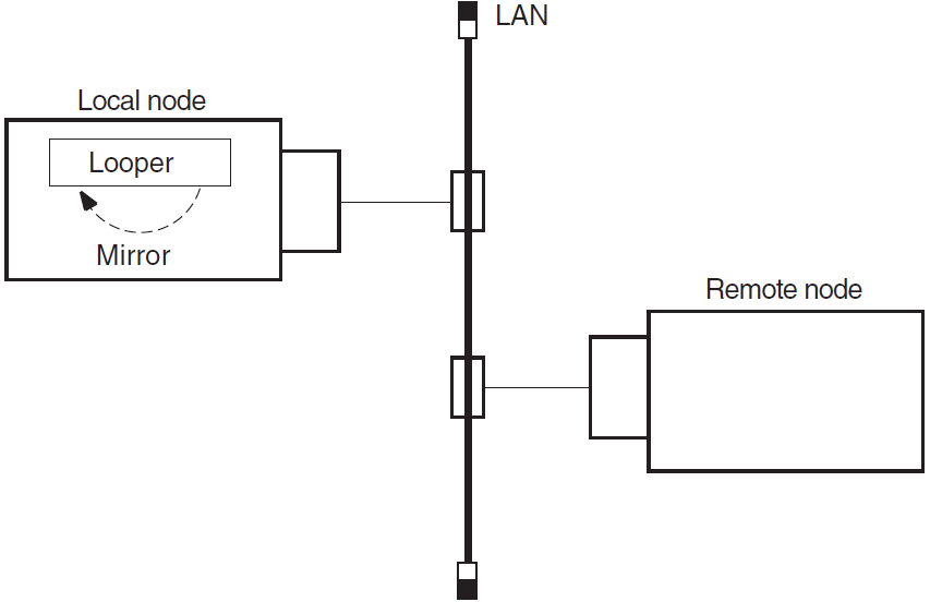
Use the node-level loopback tests first; if further testing is desired, use the circuit-level loopback tests.
3.3.1. When to Use Node-Level Loopback Tests
Use the local-to-local loopback test to verify operation of the local Network, Application, Session Control, Transport layers, and part of the Routing layer.
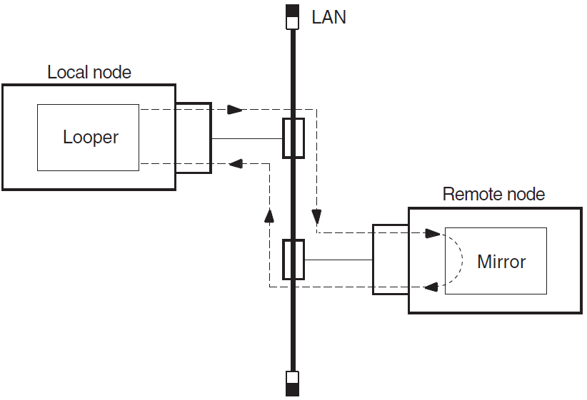
Use the local-to-remote loopback test to verify operation of all levels of network software on the local and remote nodes you are testing.
3.3.2. Analyzing Local-to-Local Node Loopback Test Results
If a looped message returns with an error, the test stops and NCL displays a message specifying the reason for the failure. If the loopback test completes successfully, there is no output.
A failure of this test indicates a problem with the local node software, such as the network being turned off or access control to the mirror not being properly established. If the local-to-local loopback test fails, check the log file for additional information on the cause of the failure.
If the local-to-local loopback test succeeds, perform a local-to-remote loopback test. If the local-to-remote test fails, try the circuit-level tests to determine if the hardware is at fault.
3.3.3. Log File for Local-to-Local Node Loopback Tests
The OpenVMS log file for local-to-local loopback test failures is
net$server.log. You find this file in the mirro$server account if you
set up a mirror account when you installed the DECnet-Plus software. If the mirror account does not
exist, the location of the net$server.log file depends on the type of account from
which the test is initiated.
For example, if the account from which the test initiates has an account on the target
system, then the net$server.log file is located in the account on the target
system. If this account does not exist on the target system, the connection is not completed.
Additionally, if the initiating system uses a proxy account to connect to the target system,
then the net$server.log file is found in the proxy account.
The UNIX log file for local-to-local loopback test failures is
/usr/adm/syslog.dated/dd-mmm-hh.mm/daemon.log.
3.3.4. Local-to-Local Node Loopback Figure
Figure 3.1, ''Local-to-Local Loopback Test'' illustrates a local-to-local loopback test.
3.3.5. Analyzing Local-to-Remote Node Loopback Test Results
If the previous local-to-local tests were successful and this test fails, a problem exists with either the remote node or the network. Try the test again with a different remote node. If the second test succeeds, a problem with the first remote node that you used probably caused the failure. If the test fails, a network problem probably caused the failure.
3.3.6. Local-to-Remote Loopback Test Figure
Figure 3.2, ''Local-to-Remote Loopback Test'' illustrates a local-to-remote loopback test.
3.4. Running Node-Level Loopback Tests
When you start this test, identify the node to which you want to loop test messages with the
node's full name. This node must be reachable over circuits that are in the On
state.
Use the following NCL command to start a node-level loopback test:
ncl> loop [node node-id] loopback application [parameter,] -
_ncl> name node-id
The node node-id parameter identifies the node from which
you start the test. The default value of this parameter is 0. The name
node-id parameter identifies the node to which you want to
loop.
3.4.1. Node-Level Loopback Command Parameters
|
Parameter |
Description |
|---|---|
|
|
Specifies the type of binary information used to perform the test. Specify this value as a pair of hexadecimal digits such as format=FF. The hexadecimal value 55, a combination of ones and zeros, is the default. |
|
|
Specifies the number of data blocks to be sent during the test. Specify a number from 1 (default) through 65,535. |
|
|
Specifies the length in bytes of each block to be looped. This value must be a decimal integer from 1 through n. The value of n must be less than the smaller buffer size of the two tasks involved in the test. The default is 40 bytes. |
3.4.2. Example of Node-Level Loopback Test
In the following test, a network manager attempts to loop 10 messages to node BOSTON. The result is that the message is not looped because node BOSTON is unreachable.
ncl> loop loopback application count 10, name boston
node 0 Loopback Application at 1991-04-22-13:00:27.725-04:00I0.212

FAILED IN DIRECTIVE: Loop DUE TO: Error specific to this entity’s class

REASON: Connection Failed
Description: The Connection to the remote mirror failed
ncl>
3.5. Circuit-Level Loopback Test Overview
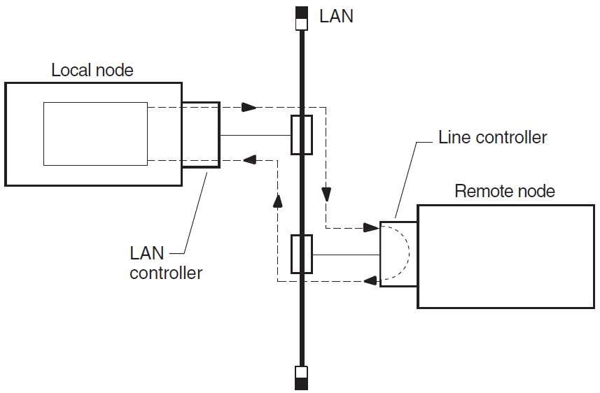
These tests use a low-level data link interface rather than the logical links used by the node-level tests. They use DECnet software to loop data through the circuit-to-circuit service software in the adjacent node and back to the local node. You can specify optional parameters for assistance in testing a remote node (see Section 3.8.4, ''Assistance Parameters'').
On non-LAN circuits, you can loop test data through a passive loopback connector or through an active remote system. On LAN circuits, the remote system ultimately returns the test data.
3.5.1. Circuit-Level Loopback Test Figure
Figure 3.3, ''Circuit-Level Loopback Test'' illustrates a circuit-level loopback test.
3.5.2. Identifying Node Addresses for Circuit-Level Loopback Tests
Unique Ethernet addresses identify nodes on Ethernet circuits. If the node is running DECnet Phase IV, or is a DECnet-Plus node that has a Phase IV node synonym, this physical address is the one that DECnet created using the DECnet node address. If the node is not running DECnet, the physical address is the default hardware address of the node.
3.6. Preparing for Circuit-Level Loopback Tests
|
Step |
Action |
|---|---|
|
1 |
Use the NCL command |
|
2 |
Use the NCL command |
|
3 |
If the |
|
This creates the MOP circuit, csmacd-0. | |
|
This customizes the entity definition for the circuit | |
|
You can also start them with an NCL command script, such as
| |
|
On an OpenVMS system, you can use: | |
|
4 |
Determine the physical device associated with a
mop circuit as
follows:
|
3.6.1. Example of Circuit-Level Loopback Preparation
The mop entity is in the
Onstate.Circuit-1, the circuit to be tested, has the loopback function enabled.
mop circuit circuit-1is associated with devicexna0.
 ncl> show mop state

Node 0 MOP
AT 1994-1-04-1-13:27:12/325-05:00I0.176

Status
   State    = On

 ncl> show mop circuit * name, function

Node 0 MOP Circuit *
AT 1994-04-1-13:27:30.095-05:00I0.178

Identifiers

   Name    = circuit-1

Status

   Functions    = {
                           Loop Requester,
                           Load Requester,
                           Load Server,
                           Dump Server
                           }

 ncl> show mop circuit circuit-1 all char

Node 0 MOP Circuit circuit-1
AT 1992-04-01-13:38:27.747-05:00I0.198

Characteristics

    Type = CSMA-CD
    Link Name = CSMA-CD Station csmacd-1
    Retransmit Timer = 4
    Known Clients Only = False

ncl> show csma-cd station csmacd-1 all status

Node 0 CSMA-CD Station csmacd-1
AT 1992-04-01-13:39:27.557-05:00I0.204

Status

    UID = 535AD8E0-F037-11C9-B60F-08002B16A872
    Communication Port = xna0
    Hardware Address        = 08-00-2b-16-a8-72
    State = On
    MAC Address = aa-00-04-00-50-30
    Receive Mode = Normal
3.7. Running Circuit-Level Loopback Tests
Use the NCL command loop mop circuit circuit-id
[parameter] or loop mop client
client-id to start a circuit-level loopback test.
Typically, you specify a client entity unless you need to test communication with a system that has no corresponding client entity. The circuit-level loopback command parameters are the same for both commands.
If you specify a LAN circuit, specify the address for the target communications hardware. For example, you enter:
ncl> loop mop circuit circuit-1 address -
_ncl> AA-00-04-00-79-34
If you specify a synchronous or asynchronous circuit (for example, HDLC or DDCMP) you do not need to specify the address.
3.7.1. Circuit-Level Loopback Command Parameters
|
Parameter |
Description | |
|---|---|---|
|
|
Specifies the type of binary information used for the test. This is specified as a pair of hexadecimal digits such as format=FF. The hexadecimal value 55, a combination of ones and zeros, is the default. | |
|
|
Specifies the number of data blocks to be sent during the test. It is a number from 1 (default) through 65,535. | |
|
|
Specifies the length (in bytes) of each block to be looped. This value must be a decimal integer in the range of 1 through n, where n is determined by the circuit and buffer sizes available on the local and remote systems. On the Ethernet, the allowable length is from 1 byte to the maximum length of the data pattern, which varies according to the level of assistance. The default is 40 bytes. | |
|
Level of Assistance |
Maximum Length | |
|
No assistance |
1486 bytes | |
|
Transmit or receive assistance |
1478 bytes | |
|
Full assistance |
1470 bytes | |
|
|
Specifies the address of the system to be used as an assistant node. An assistant node is a remote system that helps you interrogate another remote node. | |
|
|
Specifies the | |
|
|
Specifies the level of assistance you want to use (see Section 3.8.4, ''Assistance Parameters''.) | |
3.7.2. Example of Circuit-Level Loopback Test
ncl> loop mop circuit circuit-1 address aa-00-03-00-ff-08, count 10
3.8. Running Circuit-Level Loopback Tests with Assistance
DECnet supports the use of an assistant node to aid you in interrogating a remote node. You can use the assistance feature for LAN circuits only.
3.8.1. When to Use Assistance
If the target node to which you want to transmit is not receiving messages from your node, you can request assistance in transmitting messages to it.
If your node is able to transmit messages to the target node but unable to receive messages from it, you can send a message directly to the target node and request the assistant's aid in receiving a message back.
If you encounter difficulties in both sending and receiving messages, you can request the assistant's aid for both operations.
3.8.2. Using Assistance for Fault Isolation
Run a direct loopback test (with no assistance). If this test succeeds, the target system is reachable.
If the direct loopback test fails, use full assistance. If this test succeeds, the target system is reachable. The local system or the LAN could be the cause of your problem.
If the loopback test with full assistance fails, run loopback tests with transmit or receive assistance to determine if the problem occurs during transmittal or receipt of data.
3.8.3. Starting a Circuit-Level Loopback Test with Assistance
ncl> loop mop circuit circuit-id address address -
_ncl> assistance type [assistance type]
circuit-id and address parameters and just identify the client as
follows:ncl> loop mop client client-namencl> loop mop circuit circuit-id address address, -_ncl> assistance type [assistance type]
3.8.4. Assistance Parameters
assistant system or assistant address
parameter without an assistance type, you receive full assistance by default. The
following table describes the assistance type values: |
Assistance Type Value |
Description |
|---|---|
|
|
No assistance is used. |
|
|
This assistance type aids in transmitting loop messages to and receiving messages from a remote node (default value). |
|
|
This assistance type aids in receiving loop messages from a remote node. |
|
|
This assistance type aids in transmitting loop messages to a remote node. |
Example of Assistant Address Command
In this example, you request the node described by the LAN physical address
AA-00-04-00-15-04 to assist you in testing the node described by the LAN physical address
AA-00-04-00-18-04. Because assistant address is specified without the
assistant type parameter, full assistance is given.
ncl> loop mop circuit circuit-1 address aa-00-04-00-18-04, -
_ncl> assistant address aa-00-04-00-15-04
Example of Assistant System Command
In this example, you request node THRUSH to assist in testing node LOON by transmitting the loopback data to node LOON. THRUSH must already be defined in the MOP client database, with a value for its circuit and address.
ncl> loop mop client loon, assistant system -
_ncl> thrush, assistant type transmit
3.8.5. Example of Circuit-Level Loopback Test with Full Assistance
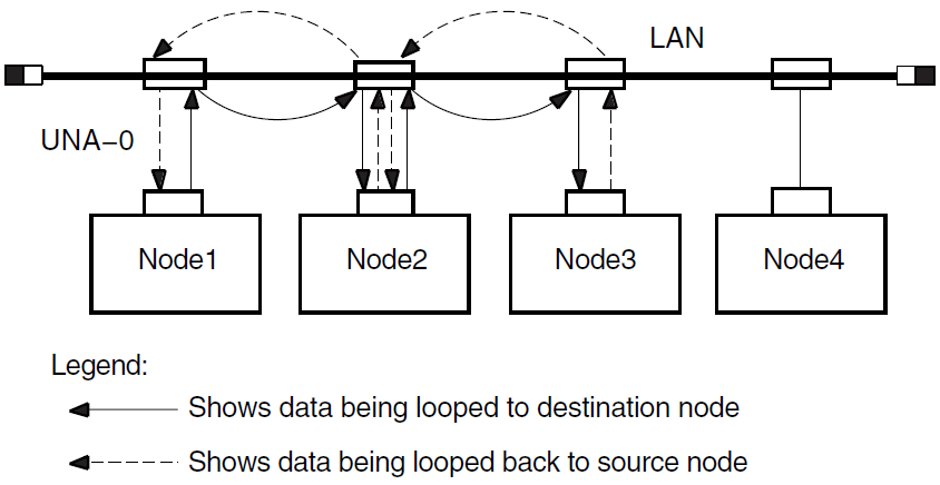
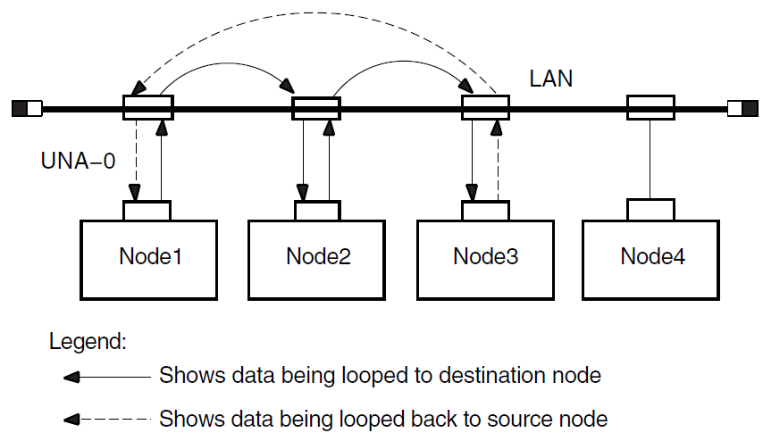
Figure 3.4, ''Circuit-Level Loopback Test with Full Assistance'' illustrates a loopback test between the circuit for Node1 and Node3, with Node2 providing assistance. The NCL command is:
ncl> loop mop client Node3, assistant system Node2
3.8.6. Example of Circuit-Level Loopback Test with Transmit Assistance
Figure 3.5, ''Circuit-Level Loopback Test with Transmit Assistance'' illustrates a loopback test between Node1 and Node3, with Node2 providing transmit assistance. The NCL command is:
ncl> loop mop client Node3, assistant system Node2, -
_ncl> assistance type transmit
3.8.7. Example of Circuit-Level Loopback Test with Receive Assistance
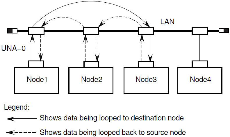
Figure 3.6, ''Circuit-Level Loopback Test with Receive Assistance'' illustrates a loopback test between Node1 and Node3, with Node2 providing receive assistance. The NCL command is:
ncl> loop mop client Node3, assistant system Node2 -
_ncl> assistance type receive
3.9. Running LAN Loopback Tests with LLC Messages
This test allows you to perform LAN loopback tests that use IEEE 802.3 logical link control (LLC) test messages.
3.9.1. Starting the LAN Loopback Test
|
Step |
Action |
|---|---|
|
1 |
Make sure the circuit you want to test has the Test Requester function enabled. |
|
2 |
Enter one of the following NCL commands: ncl> test mop circuit circuit-id address - _ncl> lan-address [ parameter] ncl>test mop client client-name [ parameter] Typically, you specify a client entity, unless you need to test communication with a system that has no corresponding client entity. The LAN loopback test command parameters are the same for both commands. |
3.9.2. LAN Loopback Test Command Parameters
test command parameters for the LAN loopback test:|
Parameter |
Description |
|---|---|
|
|
Specifies the number of messages you want to loop. The default is 1. If the test fails, NCL displays the number of messages that successfully looped. |
|
|
Specifies the length of the data part of each test message. The maximum and minimum permitted values depend on the particular data link that you use. The default is 40. |
|
|
Specifies the value of each byte in the test data message. The hexadecimal value 55, which is a pattern of alternating ones and zeros, is the default. |
|
|
Specifies the service access point on the target system to which the test message is sent as 2 hexadecimal digits. The default is 00. |
3.9.3. Determining Logical Link Control Types on a Remote Node
You can use the NCL command query to determine the logical link control (LLC)
types that a remote system supports. The query command sends an IEEE 802.2 LLC XID
command to a remote system and receives an XID response in return. The circuit must have the
Query Requester function enabled before you can use the query command.
You can apply the query command to a circuit or client entity. Typically, you
use a client entity, unless you need to query a system that has no corresponding client entity.
You can use the same attributes for either a client or a circuit. For example, you can use
either of the following commands:
ncl> query mop client client-name SAP sap
ncl> query mop circuit circuit-id SAP sap
In both commands, sap is the service access point on the
target node, specified as 2 hexadecimal digits, to which the XID message is sent. The default is
00.
3.10. Running dts/dtr Tests
The dtr program functions as a slave to dts and exists as defined
object 63 at the remote node. The dts program initiates each test by issuing a
connect request to dtr. The dts program passes parameter information
pertinent to the type of test requested to dtr in the optional data of the
connection request. You can use the dts user interface to customize the test to be
performed by issuing commands with options.
3.10.1. Starting dts/dtr Tests
dts/dtr tests:|
Step |
Action | |
|---|---|---|
|
1 |
Be sure that all of the DECnet protocol layers (Session Control, Transport, Routing,
and Data Link) are in the | |
|
2 |
Enter one of the following commands: | |
|
OpenVMS Systems: |
UNIX Systems: | |
|
|
| |
|
The system responds with a message and a prompt similar to the following:
DTS initiated on Mon Feb 26 13:06:22 1994 (DECnet/OSI for DIGITAL UNIX) DTS> | ||
|
3 |
Enter | |
|
4 |
To end testing, type | |
You can also enter dts commands with a dts command file (see
Section 3.10.4, ''Examples of Using dts/dtr Test Command Procedures''). You can press the up arrow key to recall previously entered
commands.
3.10.2. dts Command Syntax
Use the following format to enter dts commands:
test [qualifiers]
      [test-specific-qualifiers]
|
Component |
Description | |
|---|---|---|
|
|
Specifies the type of test, which must be one of the following: | |
|
|
Connect test | |
|
|
Data test | |
|
|
Disconnect test | |
|
|
Interrupt test | |
|
|
Specifies any number of the following optional qualifiers. These qualifiers remain in
effect for all applicable tests until you change them or exit from | |
| Qualifier | Description | |
|
/ |
The name or address of the DECnet node on which you want | |
|
/ |
Tells | |
|
/ |
Tells | |
|
/ |
Tells | |
|
/ |
Specifies the test line speed in bits per second (default=0); | |
|
/ |
For UNIX systems only. Specifies the transport protocol to
use, where the transport name is either | |
|
|
Specifies any number of test-specific qualifiers, as defined in the sections that describe each test. Test-specific qualifiers apply to the current test only. | |
3.10.3. General Command Syntax Conventions
dts command syntax uses the following conventions:All test names and qualifiers can be abbreviated to the first three or more unique characters.
The default values for a qualifier remain in effect until a different value is specified. The specified value then becomes the new default for all following tests until that value is changed.
3.10.4. Examples of Using dts/dtr Test Command Procedures
The following OpenVMS example shows how to instruct dts to process the
commands contained in the file dts.com and to redirect the output to the file
dts.log.
$ run sys$system:dtsend/output=dts.log
The following UNIX example shows how to instruct dts to process the
commands contained in the file dtsscript and to redirect the output to logging file
dts.log.
% dts <dtsscript >dts.log
3.11. Running dts/dtr Connect Tests
|
Test |
Description |
|---|---|
|
Connect reject without user data |
The |
|
Connect accept without user data |
The |
|
Connect reject with standard user data |
The |
|
Connect accept with standard user data |
The |
|
Connect reject with received user data used as reject user data |
The |
|
Connect accept with received user data used as accept user data. |
The |
3.11.1. dts/dtr Connect Test Command Syntax
connect test:Invoke NCL on the
dtrnode and enter the following command:ncl>set session control application dtr user name= "username"The equal sign (=) in this command is optional.
Invoke dts on the
dtsnode.Enter the following command:
connect [ qualifiers] [test-specific-qualifiers]
test-specific-qualifiers. |
Qualifier |
Description | |
|---|---|---|
|
/ |
Specifies the type of test, where | |
|
|
Connect accept test (default) | |
|
|
Connect reject test | |
|
/ |
Specifies the type of data returned by | |
|
|
Standard user data | |
|
|
Received user data | |
|
|
No optional user data returned (default) | |
|
|
For UNIX systems only. Defaults to the first available protocol tower. | |
3.11.2. Example of dts/dtr Connect Test Command
This command invokes a connect accept test (by default) with remote node
MONTRL.
dts> connect/nodename=montrl/return=received
The dtr program returns received user data as part of the test.
3.12. Running dts/dtr Data Tests
|
Test |
Description |
|---|---|
|
Sink test |
The |
|
Sequence test |
Data messages transmitted by |
|
Pattern test |
Data messages transmitted to |
|
Echo test |
Data messages received by |
3.12.1. dts/dtr Data Test Command Syntax
Invoke dts and use this command to start a data test:
data [qualifiers][test-specific-qualifiers]
On OpenVMS systems, the value of the node qualifier must be a minimum of 4
characters.
test-specific-qualifiers.|
Qualifier |
Description | |
|---|---|---|
|
/ |
Specifies the type of test, where subtest can be: | |
|
|
Sink test (default) | |
|
|
Sequence test | |
|
|
Pattern test | |
|
|
Echo test | |
|
/ |
Specifies data message length in bytes. On OpenVMS systems, On UNIX systems, The minimum value for | |
|
/ |
Specifies duration of the test in one of the following formats: | |
|
|
Range: 1 to 60 (1 to 59 on OpenVMS) | |
|
|
Range: 1 to 60 (1 to 59 on OpenVMS) | |
|
|
Range: 1 to 24 | |
|
On OpenVMS systems, the default is On UNIX systems, the default is | ||
|
/ |
Specifies type of flow control, if any, where | |
|
|
Segment flow control | |
|
|
Message flow control (default, if | |
|
If | ||
|
/ |
For UNIX systems only. Specifies the number of pending receives
for | |
|
/ |
For UNIX systems only. Specifies the number of segments between negative acknowledgments (NAKs). If the remote system is a DECnet-Plus node, this parameter is ignored. | |
|
/ |
For UNIX systems only. Specifies the number of segments before back pressuring. If the remote system is a DECnet-Plus node, this parameter is ignored. | |
|
/ |
For UNIX systems only. Defaults to the first available protocol tower. | |
3.12.2. Example of dts/dtr Data Test Command
data test with the sink subtest (by default). The
dts program sends messages to dtr on node JONES (by default from a
previous command). The message size is 512 bytes, and the test lasts 30 seconds. The transport
protocol is printed only when you specify a transport.
dts> data/size=512/seconds=30
 DTS –I– Test started at 11:23:30
 DTS –I– Test finished at 11:24:00

Test parameters:
     Target node            "jones"
     Test duration (sec)    30
     Message size (bytes)   512

Summary statistics:
     Total messages SENT     48
     Total bytes SENT        24576
     Messages per second     1.60
     Bytes per second        819.20
     Line throughput (baud)  6553
3.13. Running dts/dtr Disconnect Tests
|
Test |
Description |
|---|---|
|
Disconnect without data |
The |
|
Abort without user data |
The |
|
Disconnect with standard user data |
The |
|
Abort with standard user data |
The |
|
Disconnect with received connect user data used as disconnect user data |
The |
|
Abort with received connect user data used as abort user data |
The |
3.13.1. dts/dtr Disconnect Test Command Syntax
Invoke dts and use the following command to start a disconnect
test:
disconnect [qualifiers][test-specific-qualifiers]
test-specific-qualifiers. |
Qualifier |
Description | |
|---|---|---|
|
|
Specifies the type of test, where | |
|
|
Synchronous disconnect test for UNIX systems only | |
|
|
Disconnect abort test (default) | |
|
/ |
Specifies the type of data returned by | |
|
|
Standard user data | |
|
|
Received user data | |
|
The | ||
3.13.2. Example of dts/dtr Disconnect Test Command
This command invokes a synchronous disconnect test with remote node
PARIS.
dts> disconnect/nodename=paris/type=synchronous
The dtr program will not return any optional user data.
3.14. Running dts/dtr Interrupt Tests
|
Test |
Description |
|---|---|
|
Sink test |
The |
|
Sequence test |
Interrupt messages transmitted by |
|
Pattern test |
Interrupt messages transmitted to |
|
Echo test |
Interrupt messages received by |
3.14.1. Interrupt Test Command Syntax
Invoke dts and use this command to start an interrupt
test:
interrupt [qualifiers][test-specific-qualifiers]
test-specific-qualifiers:|
Qualifier |
Description | |
|---|---|---|
|
/ |
Specifies the type of test, where subtest can be: | |
|
|
Sink test (default) | |
|
|
Sequence test | |
|
|
Pattern test | |
|
|
Echo test | |
|
|
Specifies data message length in bytes, where
| |
|
|
Specifies duration of the test in one of the following formats: | |
|
|
Range: 1 to 60 (1 to 59 on OpenVMS) | |
|
|
Range: 1 to 60 (1 to 59 on OpenVMS) | |
|
|
Range: 1 to 24 | |
|
The default is | ||
|
/ |
For UNIX systems only. Specifies number of pending receives for
| |
3.14.2. Example of dts/dtr Interrupt Test Command
interrupt test with the pattern subtest.
The dts program sends interrupt messages to dtr on node DALLAS, where
test information is to be printed. The default message size value is used and the test lasts for
30
seconds.dts> interrupt/nodename=dallas/print/type=pat/seconds=30 DTS –I– Test started at 17:44:10 DTS –I– Test finished at 17:44:40 Test parameters: Target node "dallas" Test duration (sec) 30 Message size (bytes) 16 Summary statistics: Total messages SENT 2734 Total bytes SENT 43744 Messages per second 91.1 Bytes per second 1458 Line throughput (baud) 11665
Chapter 4. Solving Problems Using DECnet Over TCP/IP
This chapter describes solving problems using DECnet over TCP/IP.
Topics In This Chapter
Local IP Address Displays As 0.0.0.0 (Section 4.1, ''Local IP Address Displays As 0.0.0.0'')
Troubleshooting (Section 4.2, ''Troubleshooting'')
4.1. Local IP Address Displays As 0.0.0.0
Some TCP/IP products do not support a "read local address" function through the PWIP (PATHWORKS Internet Protocol) driver interface. As a workaround, OSI transport tells Session Control/Node Agent that the node local IP address is 0.0.0.0.
NCL> SHOW NODE 0 address
     Address                           =
       {
          (
          [ DNA_CMIP-MICE ] ,
          [ DNA_SessionControlV3 , number = 19 ] ,
          [ DNA_OSItransportV1 , 'DEC0'H ] ,
          [ DNA_OSInetwork , 49::00-33:AA-00-04-00-FF-FF:21 ]
          ) ,
          (
          [ DNA_CMIP-MICE ] ,
          [ DNA_SessionControlV2 , number = 19 ] ,
          [ DNA_OSItransportV1 , 'DEC0'H ] ,
          [ DNA_IP , 0.0.0.0 ]
          ) ,
          (
          [ DNA_CMIP-MICE ] ,
          [ DNA_SessionControlV3 , number = 19 ] ,
          [ DNA_NSP ] ,
          [ DNA_OSInetwork , 49::00-33:AA-00-04-00-FF-FF:20 ]
          )
       }
4.2. Troubleshooting
Verify that you have an OSI transport template with network service attribute defined as RFC 1006.
Issue the command:NCL> SHOW OSI TRANSPORT TEMPLATE * WITH NETWORK SERVICE = rfc1006
If you do not have a template defined, then you must execute NET$CONFIGURE Option 4 and replace your OSI transport startup script.
- Verify that you have started TCP/IP, and that your product supports the PWIP interface. If you are using VSI TCP/IP Services for OpenVMS, be sure that you have executed the following command procedure:
SYS$STARTUP:UCX$PWIP_STARTUP.COM
Verify that the PWIP interface is properly registered. Using the management tool of the TCP/IP product installed, verify that the RFC 1006 listener ports defined in OSI transport are known by TCP/IP.
If you are running VSI TCP/IP Services for OpenVMS, use the following command:$ UCX SHOW DEVICE Port Remote Device_socket Type Local Remote Service Host bg3 STREAM 23 0 TALENT 0.0.0.0 bg4 DGRAM 520 0 0.0.0.0 bg7 STREAM 399 0 0.0.0.0 bg9 STREAM 102 0 0.0.0.0In this case, we are looking for the two listen ports 399 and 102.
If IP addresses work and IP names do not, use your TCP/IP management tool to verify that your BIND server knows about the name.
Chapter 5. Solving DECnet-Plus Application Problems
This chapter describes how to isolate and correct common DECnet-Plus application problems.
Definition
In this chapter, the term DECnet/OSI applications refers to FTAM, Virtual Terminal (VT), and any application that uses the OSI Applications Kernel (OSAK) application programming interface (API).
This manual does not discuss other applications considered to be OSI applications, such as X.400 products.
Topics in This Chapter
Underlying Components for DECnet-Plus Applications (OpenVMS Only) (Section 5.1, ''Underlying Components for DECnet/OSI Applications (OpenVMS Only)'')
Underlying Components for DECnet-Plus Applications (UNIX Only) (Section 5.2, ''Underlying Components for DECnet/OSI Applications (UNIX Only)'')
Symptoms of DECnet-Plus Application Problems (Section 5.3, ''Symptoms of DECnet-Plus Application Problems'')
Isolating DECnet-Plus Application Faults (Section 5.4, ''Isolating DECnet-Plus Application Faults'')
Using Event Logging and Log Files (Section 5.5, ''Using Event Logging and Log Files'')
Isolating Faults Using Management Tools (OpenVMS Only) (Section 5.6, ''Isolating Faults Using Management Tools (OpenVMS Only) '')
Tracing Overview (Section 5.7, ''Tracing Overview'')
Tracing Outbound FTAM and Virtual Terminal Connections (Section 5.8, ''Tracing Outbound FTAM and Virtual Terminal Connections'')
Tracing Inbound FTAM and Virtual Terminal Connections (Section 5.9, ''Tracing Inbound FTAM and Virtual Terminal Connections'')
Reading Trace Files (Section 5.10, ''Reading Trace Files'')
Correcting FTAM Application Problems (Section 5.11, ''Correcting FTAM Application Problems'')
Correcting FTAM File-Handling Problems (Section 5.12, ''Correcting FTAM File-Handling Problems'')
Correcting General FTAM Connection Problems (Section 5.13, ''Correcting General FTAM Connection Problems'')
Correcting FTAM and Virtual Terminal Connection Problems (Only) (Section 5.14, ''Correcting FTAM and Virtual Terminal Connection Problems (UNIX Only) '')
Correcting FTAM and Virtual Terminal Responder Problems (Only) (Section 5.15, ''Correcting FTAM and Virtual Terminal Responder Problems (OpenVMS Only)'')
Correcting FTAM and Virtual Terminal Responder Problems (Only) (Section 5.16, ''Correcting FTAM and Virtual Terminal Responder Problems (UNIX Only)'')
Correcting FTAM Environment Problems (OpenVMS Only) (Section 5.17, ''Correcting FTAM Environment Problems (OpenVMS Only) '')
Correcting Target SAP Connection Problems (Section 5.18, ''Correcting Target SAP Connection Problems'')
Correcting Problems with Applications Using OSAK (Section 5.19, ''Correcting Problems with Applications Using OSAK'')
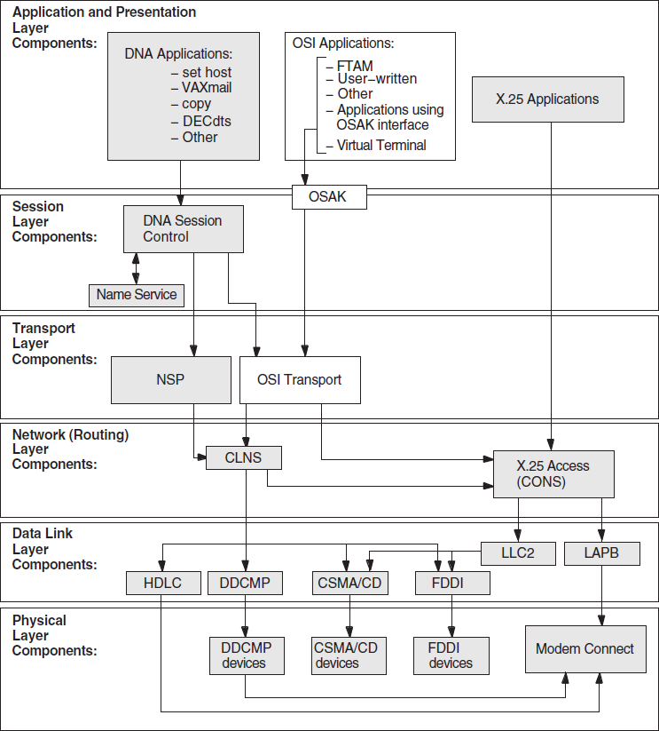
5.1. Underlying Components for DECnet/OSI Applications (OpenVMS Only)
Figure 5.1, ''Underlying DECnet/OSI Components (OpenVMS)'' shows the underlying DECnet/OSI components that DECnet/OSI applications on OpenVMS systems use. Use this information as a guide during fault isolation.
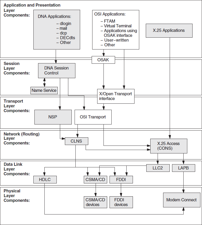
5.2. Underlying Components for DECnet/OSI Applications (UNIX Only)
Figure 5.2, ''Underlying DECnet/OSI Components (UNIX)'' shows the underlying DECnet/OSI components used by DECnet/OSI applications on UNIX systems. Use this information as a guide during fault isolation.
5.3. Symptoms of DECnet-Plus Application Problems
The following tables show the symptoms of possible DECnet-Plus application problems on both OpenVMS and UNIX systems, on OpenVMS systems only, and on UNIX systems only.
5.3.1. Problem Symptoms for All Systems
|
Symptom |
Possible Problem |
See: |
|---|---|---|
|
Connection attempts fail. |
Reasons for failure include:
| |
|
An FTAM or Virtual Terminal responder fails. |
Reasons for failure include:
| |
|
An FTAM file does not have the expected attributes. |
Requested format is not supported and must be converted. | |
|
A user-written OSI application terminates unexpectedly. |
Reasons for failure include:
|
Section 5.19, ''Correcting Problems with Applications Using OSAK'' or FTAM API documentation. |
|
A problem with a user-written application affects the OSAK software. |
There is a coding error in the application or in the way the application uses the OSAK application programming interface. |
Section 5.19, ''Correcting Problems with Applications Using OSAK'' or OSAK documentation. |
5.3.2. Problem Symptoms for OpenVMS Systems Only
|
Symptom |
Possible Problem |
See: |
|---|---|---|
|
Connection attempts fail. |
Reasons for failure include:
| |
|
An FTAM responder fails. |
There is a problem with the OSAK$SERVER_V3. |
Section 5.13, ''Correcting General FTAM Connection Problems''. |
|
A VT responder terminates unexpectedly. |
Resources are exhausted. |
Section 5.15, ''Correcting FTAM and Virtual Terminal Responder Problems (OpenVMS Only)''. |
|
A VT responder will not start. |
Another responder is already running. |
Section 5.15, ''Correcting FTAM and Virtual Terminal Responder Problems (OpenVMS Only)''. |
5.3.3. Problem Symptoms for UNIX Systems Only
|
Symptom |
Possible Problem |
See: |
|---|---|---|
|
Connection attempts fail. |
Reasons for failure include:
|
Section 5.14, ''Correcting FTAM and Virtual Terminal Connection Problems (UNIX Only) ''. |
|
An FTAM or VT responder fails. |
There is a problem with the |
Section 5.16, ''Correcting FTAM and Virtual Terminal Responder Problems (UNIX Only)''. |
5.4. Isolating DECnet-Plus Application Faults
Before trying any correction procedures, confirm that you have a DECnet-Plus
application problem. Use an application other than the one that failed, such as
dlogin or set host, to try to establish a connection to
the remote node.
If you can establish a connection, a problem with the failed application is likely the cause; use the trace utilities for further fault isolation. If you cannot establish a connection, the problem is probably not application-specific; use the network reachability tests described in Chapter 3, "Testing Network Reachability", or check the underlying components that the application uses.
5.4.1. Tools to Use
|
For Problems with: |
Use: |
And See: |
|---|---|---|
|
Any DECnet-Plus application |
Error messages:
|
OSI application documentation and Section 5.5, ''Using Event Logging and Log Files''. |
|
Tracing utility, |
Section 5.8, ''Tracing Outbound FTAM and Virtual Terminal Connections''. | |
|
DECnet-Plus applications on OpenVMS systems |
Event logging. |
OSAK, FTAM and Virtual Terminal documentation. |
|
FTAM and Virtual Terminal on OpenVMS systems |
OSAK application database and |
FTAM/VT documentation. |
|
Applications that use OSAK software |
OSAK trace utility. |
OSI application documentation or the OSAK programming documentation. |
5.4.2. References
Refer to your FTAM and Virtual Terminal documentation for further information about these applications. Refer to your OSAK documentation for information about applications that utilize the OSAK API.
5.5. Using Event Logging and Log Files
On OpenVMS systems, event logging and log files help you isolate FTAM and Virtual
Terminal problems. After you enable logging, the system writes events to the
sys$manager:operator.log file.
On UNIX systems, FTAM and Virtual Terminal error messages appear on the operator's
console. The system writes responder error messages to the
/usr/adm/syslog.dated/*/daemon.log file. You do not need to do anything
to enable error logging.
5.5.1. Enabling Network Event Logging (OpenVMS Only)
|
Step |
Action |
|---|---|
|
1 |
Enable OPER privileges with the following DCL command: $ set process/priv=oper |
|
2 |
Ensure that OPCOM is running. If you do not know how to do this, get help from your system manager. |
|
3 |
Do one of the following:
|
|
4 |
For events at the Data Link layer, specify the event types you want. For both X.25 and IEEE 802.3 events, see your NCL reference documentation. For X.25 events only, see your OSI Transport and X.25 documentation. |
5.5.2. Using the FTAM Responder Log File (OpenVMS Only)
Each FTAM responder process on an OpenVMS system creates a log file of its activity during a process. If you are trying to track the responder's operations, this log file may contain pertinent information, depending on where the problem occurs.
Normally, a responder process creates a log file in the SYS$LOGIN directory of the account specified by the user on the FTAM command line.
Responder Log Set Up
|
Step |
Action |
|---|---|
|
1 |
Check for WORLD:READ protection on
|
|
2 |
Check that the responder has WRITE access (for
|
|
3 |
If you are using an account other than the default FTAM responder account, make sure that the account has a BYTLM of more than 20,000. If not, you may experience "service provider abort" errors. |
5.6. Isolating Faults Using Management Tools (OpenVMS Only)
|
For this Connection: |
Do the Following: |
To Verify: |
|---|---|---|
|
Inbound to a given address (FTAM only) |
Use NCL commands to check inbound address in OSAK application database: show osak application |
The following values:
|
|
Outbound to a given address |
Examine
sys$system: isoapplications.dat |
The following values:
|
5.7. Tracing Overview
Tracing allows you to examine FTAM and Virtual Terminal connections to other OSI
systems. The trace operation traces the protocol data units (PDUs) that the Application,
ACSE, Presentation, and Session layers send or receive. Tracing is a two-step process.
First, you create a binary trace file during a regular FTAM or VT connection. Then you
use the ositrace utility to convert the binary file to a readable text
file.
5.7.1. Trace Files
The ositrace utility formats the binary trace information. You can
redirect output into a file using appropriate mechanisms. By default, the file is
written to the default output device.
The ositrace utility creates a new file for each trace in the default
directory of the process where tracing is enabled. It also creates a new version of
the trace file for each new connection it traces.
5.7.2. Security Information in Tracing
For either initiator or responder traces, if a file specification contains security information, the output for an FTAM or VT Protocol Control Information (PCI) trace contains the initiator identity (which maps to a user name) and the filestore password (which maps to a login password) in plain ASCII text. Trace files containing this information should be securely stored or deleted immediately after the trace data is analyzed.
5.8. Tracing Outbound FTAM and Virtual Terminal Connections
ositrace utility converts the binary file to a readable
text file.|
For OpenVMS Systems: |
For UNIX Systems: |
|---|---|
|
|
|
The trace file is created in your current working directory with the name
init_xxxx.bin, where xxxx is the time and date.
define osif$trace_enable FTAM_PCI, ACSE_PCI, PRESENTATION_PCI, SESSION
define osif$trace osif$init.trace
This creates the file osif$init.trace. It contains the same information
as the trace generated by setting OSAK_TRACE to ON, and you
can use ositrace to generate a readable form.
5.8.1. Generating a Readable Trace File
ositrace utility is:|
For OpenVMS Systems: |
For UNIX Systems: |
|---|---|
|
|
|
The input-file specifies the binary trace file
that is created when you define the trace logical names on OpenVMS systems or
specify the -T option, or define the environment variables, on UNIX
systems.
The output-file redirects the output to the
specified file instead of displaying the output on the default device or
file.
$ OSITRACE:== $OSITRACE
5.8.2. ositrace Command Options (UNIX Only)
ositrace command options on UNIX systems. |
Option |
Description |
|---|---|
|
-h |
Displays a brief help message that includes usage syntax and valid command options. |
|
-F |
Displays trace records only for the FTAM components. The trace monitors protocol control information (PCI) and file-access data unit (FADU) components. An FTAM PCI trace monitors the inbound and outbound FTAM service primitives. The trace output logs PCI octets and analyzes the FTAM PCI. An FTAM FADU trace monitors the inbound and outbound file structure data. The trace is formatted into two columns: the left column logs the octets of data and the right column logs the text equivalents of the octets. |
|
-V |
Displays trace records only for the Virtual Terminal components. The trace monitors protocol control information (PCI). A Virtual Terminal PCI trace monitors the inbound and outbound Virtual Terminal service primitives. The trace output logs PCI octets and analyzes the Virtual Terminal PCI. The trace is formatted into two columns: the right column logs the octets of data and the left column logs the text equivalents of the octets. |
|
-A |
Displays trace records only for the ACSE layer. The trace monitors the inbound and outbound ACSE service primitives. The trace output logs PCI octets and analyzes the ACSE PCI. |
|
-P |
Displays trace records only for the Presentation layer. The trace monitors the inbound and outbound presentation service primitives. The trace output logs presentation PDU (PPDU) octets and analyzes the presentation PCI. |
|
-S |
Displays trace records only for the session layer. The trace monitors the inbound and outbound session service primitives. The trace output logs session PDU (SPDU) octets and analyzes the session PCI. |
|
-f |
Filters timestamps. This option causes all timestamps to
appear as the string xx-xxx-xxxx, xx:xx:xx and allows the
comparison of two trace files using the |
5.9. Tracing Inbound FTAM and Virtual Terminal Connections
This section describes how to trace FTAM and Virtual Terminal connections from other OSI systems.
5.9.1. Inbound FTAM and VT Tracing (UNIX)
Log into the root account.
- Set the environment variable
OSAK_TRACEtoon.setenv OSAK_TRACE on
- Start a VT or FTAM listener.
vt_listener mynode-alias
This creates 10
resp_xxxx.binfiles, wherexxxxis the time and date. The default queue length is ten for the number of outstanding transport connect indications. The oldest.binfile contains the trace of the first association, the next youngest contains the second association, and so on. - To stop the trace, kill the current listener process, and unset the
OSAK_TRACEenvironment variable:ps auxw | grep ftam root 3380 0.0 ftam_listener mynode-alias kill -9 3380 unsetenv OSAK_TRACE
5.9.2. Inbound FTAM Tracing (OpenVMS)
sys$system:osif$responder.com to contain the following
line:$ define osak_trace on
The file resp_xxxx.bin is created in the default directory of the
responder process, where xxxx is the time and date.
osif$responder.com to uncomment
the following
lines:$! DEFINE /LOG osif$trace_enable FTAM-PCI,ACSE-PCI,PRESENTATION-PCI,SESSION $! DEFINE /LOG osif$trace osif$responder.trace
The next inbound connection causes an FTAM trace file called
osif$responder.trace to be created in the default login directory
(SYS$LOGIN) of the specified account.
Define
osak_tracein the filesys$system:osif$gtwy_login.com.Define
osif$traceandosif$trace_enablein the filesys$system:osif$gtwy_login.com.
The trace file will be created in the default directory of the OSIF$GTWY account.
The trace file created may then be formatted using ositrace as
discussed in Section 5.8.1, ''Generating a Readable Trace File''.
5.9.3. Inbound VT Tracing (OpenVMS)
Stop the current VT responder
(SYS$STARTUP:VT_STOP.COM).Copy
SYS$SYSTEM:VTPAD.EXEtoSYS$COMMON:[SYSEXE]VT_RESPONDER.EXE.- Define the logical name OSAK_TRACE to equate to the value ON.
$ define osak_trace on
Make sure your process has the following privileges:
CMKRNL, WORLD, SYSPRV, TMPMBX, SYSNAM, DETACH, NETMBX, SYSLCK, OPER, PRMMBX
- Issue the command:
RUN SYS$SYSTEM:VT_RESPONDER.EXE
At this point, the VT responder is executing in your process context, and eight(or
the value specified by the VT$VT_RJOBLIM logical name)
resp_xxxx.bin files will be created in your current
directory.
As each new connection made to the VT responder terminates, a new
resp_xxxx.bin file is created, and a previous
resp_xxx.bin file now contains trace information. This is done in a
first in, first out manner; the oldest .bin file contains the trace of
the first association, the next youngest contains the second association, and so
on.
Once you have collected all of the required trace data, use Ctrl/C and terminate
the VT responder. Any resp_xxxx.bin files with a size of 0 may be
deleted. Resp_xxxx.bin files which have non-zero sizes may be analyzed
using ositrace (see Section 5.8.1, ''Generating a Readable Trace File'' for more
information).
The regular VT responder may now be restarted using the SYS$STARTUP:VT_START.COM procedure.
The VT/LAT or VT/TELNET gateways may also be traced in a similar manner by copying VTPAD.EXE to VT_LAT_GTWY.EXE or VT_TELNET_GTWY.EXE respectively.
The LAT/VT or TELNET/VT gateways may be traced by copying VTPAD.EXE to
LAT_VT_GTWY.EXE or TELNET_VT_GTWY.EXE respectively. However, the trace files
produced will be named init_xxxx.bin to reflect the fact that we are
now acting as an initiator.
5.10. Reading Trace Files
Open systems transmit PCI and file data in the form of octet strings. For each component being traced, the tracing utility logs the octets of PCI, file data, or both, sent or received by that component. The trace utility transcribes the octets into a sequence of hexadecimal digits. For PCI data, the utility also translates the data into ASN.1 (abstract-syntax notation). These translations correspond to the PCI definition of the component's service primitives. PCI definitions are part of the protocol specification of each FTAM or Virtual Terminal component.
You can compare tracing output to the corresponding PCI definition, to determine whether the encoding of PCI data is correct and whether the parameter values are valid. You can also compare the actual sequences of parameters with the valid sequences defined by the protocol. For information about FTAM and VT components, see your FTAM and Virtual Terminal documentation.
5.10.1. Interpreting Trace Information
ositrace utility creates contains the
following information about the protocol data units (PDUs) for each traced layer
(see the example in this section and in Appendix B, "DECnet-Plus Application Tracing Examples"): A timestamp (day, date, and time) precedes the formatted textual output of the file that the trace utility generates. The timestamp indicates when the trace started. Another timestamp that indicates when the trace ended appears at the end of the file.
The time (hh:mm:ss) that the outbound or inbound PDUs were sent or received.
The direction of the PDUs: a left arrow (< - ) indicates inbound PDUs and a right arrow (- > ) indicates outbound PDUs.
The layer for which the PDUs are being traced: FTAM, Virtual Terminal (VT), ACSE, Presentation, or Session.
The hexadecimal dump of the PDUs formatted from left to right into eight columns of eight-character (1 octet) sequences.
The textual translation of PCI data in ASN.1 notation (columns 1-72), followed by the first three hexadecimal bytes of the hexadecimal sequence being described (columns 73-80).
Trace Example
Session
0dff0148 05061301 00160102 14020002 33028080 34020103 c1ff0130 3180a080 80010100 00a28081 02808082 020103a4 80308002 01010605 28c27b02 01308006 02510100 00000030 80020103 060528c2 7b020230 80060251 01000000 00308002 01050605 28c27b02 03308006 02510100 00000030 80020107 060528c2 7b020430 80060251 01000000 00308002 01090606 2bce0f01 02023080 06025101 00000000 30800201 0b060452 01000130 80060251 01000000 00000088 02060089 03054000 61803080 02010ba0 7b6080a1 80060528 c27b0101 0000a280 06052bce 0f070100 00a38002 01010000 be802880 020101a0 4da08082 01008302 03408403 05070085 02058086 0100a780 4e0528c2 7b05014e 0528c27b 05024e05 28c27b05 034e062b ce0f0105 09000056 0776696e 63656e74 710a1908 6e69636b 73746572 00000000 00000000 00000000 00000000
connect-spdu 0d ff 01 connect/accept-item 05 06 protocol-options = NULL 13 01 version-number = 2 16 01 02 session-user-requirements = '0000000000000010'B 14 02 00 (duplex functional unit ) calling-ssap-identifier = 33 02 80 called-ssap-identifier = 34 02 01 user-data c1 ff 01
5.11. Correcting FTAM Application Problems
|
Step |
Action |
|---|---|
|
1 |
Check that the initiator ID (user name) is a valid identifier on the responder's system. For the FTAM responder, the initiator ID must be a valid user name for that system. If the user name requires a password, it must be supplied as well. |
|
2 |
Check that the filestore password is a valid account password for the user name. For a FTAM responder, the filestore password must be the same as the login password. Not all FTAM vendors map the filestore password to the login password. If using third-party FTAM products, check the appropriate documentation for further information. |
|
3 |
If an account field is being sent to the FTAM responder on an OpenVMS system, check that the field is valid (0 to 8 characters). |
|
4 |
On OpenVMS, check that the remote account specified by the initiator has read and execute access to the responder account's login command file. On OpenVMS systems, if there is no login command file, check that the symbol LGICMD points at NL: (the null device). |
|
5 |
On OpenVMS, check that the remote account specified by the
initiator has read and execute access to the responder command
file (for example, |
|
6 |
Check that the protection on input directories and files allows remote reading. |
|
7 |
Check that the protection on output directories allows remote writing. |
|
8 |
Check the following in the local database file:
|
5.12. Correcting FTAM File-Handling Problems
This section contains suggestions for dealing with possible file-handling problems.
5.12.1. Checking Foreign Filename Formats
On OpenVMS systems, when specifying a foreign file name, you must enclose the name in double quotation marks (" "), so RMS does not parse the name. Enclose the file name in double quotation marks to preserve the case of the file name. It is best to ensure that all file names are in uppercase.
On UNIX systems, when specifying foreign file names, you must enclose the name in single quotation marks (' ').
Be aware that case sensitivity may be an issue when transferring files between OpenVMS and UNIX systems.
5.12.2. Correcting File Problems
If copied files appear to have extra characters, the remote FTAM implementation may be having problems handling the ISO 8859 character set. You can identify this problem if you display a file and see repeated escape sequences in the data. These escape sequences are the ISO 8859 character set identifiers. The remote FTAM implementation should have handled these. Refer to the supplier of that implementation for further information.
Other file problems may be related to the way the file was transferred. Problems can occur if the requested format is unsupported. The FTAM implementation must convert the file to a supported format before it can transfer it properly (see your FTAM management documentation). If an FTAM file on an OpenVMS system file does not look correct, the software probably transferred it as an FTAM-3 file, which is the default format.
|
On OpenVMS Systems: |
On UNIX Systems: |
|---|---|
|
Enter this command: $ dir/application_protocol=ftam/full filename
|
Enter this command: % ols -A application-name::file
|
Stream – FTAM-1
Variable Length – FTAM-2
Undefined – FTAM-3
5.13. Correcting General FTAM Connection Problems
|
Step |
Action |
|---|---|
|
1 |
Check that the
osak$server_v3.exe process
(OpenVMS systems only) or the ftam_listener process
(systems only) is running. Do the following:
|
|
2 |
If necessary, start the
osak$server_v3.exe
process (OpenVMS only) or the ftam_listener process
(only) by doing one of the following:
|
|
3 |
Invoke NCL and use the command ncl> show node 0 osi transport state If OSI transport is running, NCL displays a message stating
that the status state equals
on. For example:
Show Node 0 OSI Transport
  at 199201-10-15::53.63400 + 00:00 I 00.00000

Status
 State = On
If OSI transport is not running, NCL displays a message
stating that the status state equals
off. For
example:
Show Node 0 OSI Transport at 1992-01-10-15:41:53.63400 + 00:00 I 00.00000 Status State = Off |
|
4 |
If OSI transport is not running, do one of the following:
|
|
5 |
Check that the underlying DECnet software is running. From a
privileged account, type the following at the NCL prompt:
ncl> show session control state The |
|
6 |
If you want to make a connection over an X.25 or Internet network from an OpenVMS system, you must have the X.25 software installed and running. |
5.14. Correcting FTAM and Virtual Terminal Connection Problems (UNIX Only)
If no error messages appear when you try to establish a connection but the connection attempt fails, create an initiator trace for the command that failed, as described in Section 5.8, ''Tracing Outbound FTAM and Virtual Terminal Connections''.
Use the procedures in the following sections if errors appear.
5.14.1. Address in Use
Address in Use, do the following:|
Step |
Action |
|---|---|
|
1 |
Examine If you find errors, correct them and retry the operation. If the file is correct, go to step 2. |
|
2 |
Check that another process is not listening on the same
transport address. Do the following:
|
5.14.2. Network Is Unreachable
If the message is Network is unreachable, check that a
listener/responder process is running on the remote node that can accept your
connection request. There may be no way to reach the remote node.
Also, verify that the transport provider specified by the initiating entry is available on the responding entity.
5.14.3. Connection Refused
If the message is Connection refused, the Transport layer received a
disconnect from the remote system. Retry the operation or specify a different remote
node. You can also check a trace, if it exists, for a diagnostic message that
indicates why the remote system refused the connection.
5.14.4. Connection Timed Out
If the message is Connection timed out, the remote node did not
respond to your connection request. There may be no way to reach the remote node or
no responder listening on the specified address.
5.15. Correcting FTAM and Virtual Terminal Responder Problems (OpenVMS Only)
Use the procedures in this section if an FTAM or VT responder on an OpenVMS system either terminates unexpectedly or will not start.
5.15.1. Correcting Unexpected Termination Problems
|
Step |
Action |
|---|---|
|
1 |
Examine the operator log for events prior to the failure. If indicated, change system parameters. |
|
2 |
If no error exists in the operator log, or if changing system parameters does not correct the problem, perform a trace of the operation. |
|
3 |
Check that there are no problems with the OSI transport provider (see Chapter 7, "Solving Transport Problems"). |
5.15.2. Correcting Responder Starting Problems
|
Step |
Action |
|---|---|
|
1 |
Use the DCL command The application startup file usually prevents this from happening; check the startup file to see if it was incorrectly modified. |
|
2 |
Check the alias database to see if another application is using the same TSAP. |
|
3 |
Check that there are no problems with the OSI transport provider (see Chapter 7, "Solving Transport Problems"). |
5.16. Correcting FTAM and Virtual Terminal Responder Problems (UNIX Only)
|
Step |
Action |
|---|---|
|
1 |
If the responder does not start, check the
|
|
2 |
Start the responder (using |
|
3 |
Correct errors indicated by the trace file. |
|
4 |
Make sure the addresses and transport options specified in the
|
5.17. Correcting FTAM Environment Problems (OpenVMS Only)
FTAM connections to remote systems can fail if the OpenVMS environment is not set up
correctly. If any connections fail, first check that the size of the sysgen
parameter, maxbuf, is at least 2048.
|
Step |
Action |
|---|---|
|
1 |
Check the address database:
|
|
2 |
Make sure the responder's default directory has write access and sufficient space for writing log files. |
|
3 |
Check the local account where the responder runs to see that:
|
|
4 |
Check to see if maximum activity levels are being exceeded for networking processes, transport connections, X.25 connections, and other processes. |
|
5 |
Check the disk to make sure it:
|
5.18. Correcting Target SAP Connection Problems
Connections can fail if a problem with a specific service access point exists. The following procedures describe how to correct problems in the OSI layers.
5.18.1. Correcting FTAM Physical and Data Link Problems
|
Step |
Action |
|---|---|
|
1 |
On OpenVMS systems only, look at the DECnet OPCOM messages to check that the remote system is available. On UNIX systems only, check the
|
|
2 |
Check that the physical network wires are connected. |
5.18.2. Correcting Network Connection Problems
Use NCL commands to do the following:
For Direct X.25 Access:
|
Step |
Action |
|---|---|
|
1 |
Check that the X.25 address in use is correct:
|
|
2 |
Check that both systems are using the agreed-upon call value for the network. |
|
3 |
Check local DNIC usage to determine if it needs a leading zero (0) or one (1). |
|
4 |
Check to see if international DNIC usage is always required. |
|
5 |
See the X.25 problem-solving documentation for further assistance. |
For Direct IEEE 802 Access:
|
Step |
Action |
|---|---|
|
1 |
Check that the physical address in use is correct. Do the following:
|
For Internet Access:
|
Step |
Action |
|---|---|
|
1 |
Check that the NSAP addressing information is correct:
|
|
2 |
Check that the adjacency addressing is defined and is correct: |
|
For X.25 subnetwork access:
| |
|
For IEEE 802 subnetwork
access:
|
5.18.3. Correcting FTAM and VT Transport Problems
|
Step |
Action |
|---|---|
|
1 |
Check that the transport selectors for the initiator and responder match. The transport selector is the right-hand selector in an upper-layer address. On OpenVMS systems, display any upper-layer address
defined for a responder or initiator. For example:
On UNIX systems, check the
|
|
2 |
Check the format of the TSAP value to see if it is hexadecimal or ASCII. |
|
3 |
Make sure that timers are not causing a disconnect too quickly; for example, the keepalive timer of the network service should be used. |
|
4 |
Check that the correct transport template name is in use. |
|
5 |
If you use Internet, check the addresses used and routing table entry. |
|
6 |
If you use null Internet, check the OSI transport template to see if the inactive area address supplied matches the routing circuit. |
|
7 |
Look at the transport counters to see if the transport software is working. See your DECnet-Plus management documentation for further information. |
5.18.4. Correcting FTAM and VT Session Problems (OpenVMS Only)
|
Step |
Action |
|---|---|
|
1 |
Check that the session selectors for inbound and outbound connections match. The session selector is the middle selector in an upper-layer address. For inbound connections, if you need addressing
information for the FTAM responder, use the NCL command
For outbound connections, check the file
|
|
2 |
Check that the session versions of the two systems are compatible. An FTAM responder can accept either version 1 or 2. If both versions are proposed on an F-INITIALIZE indication, the responder chooses version 2. By default, an FTAM initiator proposes version 2. However, you can override the default by entering version 1 or versions 1 and 2 into the alias entry for a given remote application. To define the session version for an alias, edit the alias
entry in |
|
3 |
Check whether the values used are hexadecimal or ASCII, and whether the values are correct. |
5.18.5. Correcting FTAM and VT Presentation Problems (OpenVMS Only)
|
Step |
Action |
|---|---|
|
1 |
Check that the presentation selectors on the initiator and responder systems match. The presentation selector is the left-hand selector in an upper-layer address. For inbound connections, if you need addressing
information for the FTAM responder, use the NCL command
For outbound connections, check the file
|
|
2 |
Check if there are common syntaxes for ACSE-PCI, FTAM-PCI, FTAM-FADU, unstructured binary, and unstructured text. FTAM uses the basic encoding rules of a single ASN.1 type as its transfer syntax. |
|
3 |
Check whether the values used are hexadecimal or ASCII, and whether the values are correct. |
5.19. Correcting Problems with Applications Using OSAK
OSI application failures can indicate that a problem exists with their use of the OSI Applications Kernel (OSAK) software. Check the application's documentation to determine if the application has any dependencies on the OSAK software or uses the OSAK application programming interface.
DECnet-Plus network management documentation
OSAK Programming and Programming Reference documentation
Documentation for any applications that use the OSAK software
5.19.1. Correcting Connection Problems
|
Step |
Action |
|---|---|
|
1 |
Use the Common Trace Facility or the OSAK trace utility to
get a transport trace and examine the output for the
following:
|
|
2 |
If possible, examine the application's log file to check that the local application received the upper-layer connect. |
|
3 |
Check that quotas were not exceeded. |
5.19.2. Correcting Unexpected Termination Problems
|
Step |
Action |
|---|---|
|
1 |
Check the OSAK event sink (OpenVMS only) or the NCL event sink (UNIX only) for evidence of protocol errors. |
|
2 |
Create a transport trace using the OSAK trace utility, with the Errors option enabled. If errors exist, report them to the originator of the PDU; this is the local system for outbound messages and the remote system for inbound messages. There can be errors in the PDU that tracing cannot detect, so you cannot assume that the PDU is correct even if no errors are reported. If no errors exist, check the lower layers of your network. |
5.19.3. Correcting Programming Problems
|
Step |
Action |
|---|---|
|
1 |
Check that optional parameters are set to null. |
|
2 |
Make sure you have sufficient workspace. |
|
3 |
Check that you have allocated enough buffers. |
|
4 |
Make sure that the application checks returned status information. |
Chapter 6. Solving Session Control Problems
Application-specific problems (refer to the application's documentation)
Name service problems (see Section 6.10, ''Correcting Node Name Resolution Problems'')
Topics In This Chapter
Underlying Components for Session Control (OpenVMS Only) (Section 6.1, ''Underlying Components for Session Control (OpenVMS Only)'')
Underlying Components for Session Control (UNIX Only) (Section 6.2, ''Underlying Components for Session Control (UNIX Only)'')
Symptoms of Session Control Problems (Section 6.3, ''Symptoms of Session Control Problems'')
Isolating Session Control Faults (Section 6.4, ''Isolating Session Control Faults'')
Correcting Unknown Application Problems (Section 6.5, ''Correcting Unknown Application Problems'')
Correcting Application Too Busy Problems (Section 6.6, ''Correcting Application Too Busy Problems'')
Correcting Access Control Problems (Section 6.7, ''Correcting Access Control Problems'')
Correcting Insufficient Resource Problems (Section 6.8, ''Correcting Insufficient Resource Problems'')
Correcting Timed Out Problems (Section 6.9, ''Correcting Timed Out Problems'')
Correcting Node Name Resolution Problems (Section 6.10, ''Correcting Node Name Resolution Problems'')
Examining the DECnet-Plus Naming Cache (OpenVMS Only) (Section 6.11, ''Examining the DECnet-Plus Naming Cache (OpenVMS Only)'')
6.1. Underlying Components for Session Control (OpenVMS Only)
Figure 6.1, ''Underlying Components for Session Control (OpenVMS)'' shows the direct underlying components that the Session Control software on OpenVMS systems use. Use this information as a guide during fault isolation.
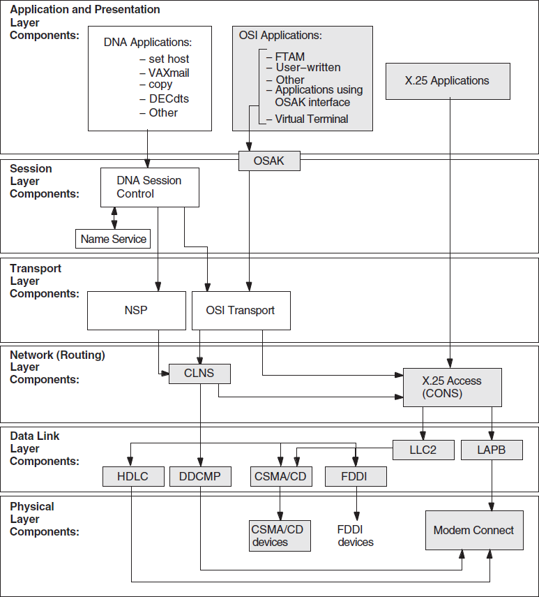
6.2. Underlying Components for Session Control (UNIX Only)
Figure 6.2, ''Underlying Components for Session Control (UNIX)'' shows the direct underlying components that the Session Control software on UNIX systems use. Use this information as a guide during fault isolation.
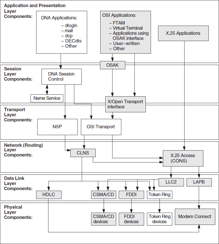
6.2.1. References
Refer to your application's documentation if you determine that an application-specific problem caused a failure. Refer to Section 6.10, ''Correcting Node Name Resolution Problems'' if you determine that a name service problem caused a failure.
6.3. Symptoms of Session Control Problems
|
Symptom |
Possible Problem |
See: |
|---|---|---|
|
Unknown application at remote node or object is unknown at remote node |
The address that the application used does not match the data in the Session Control application database on the remote node. | |
|
You attempted to connect to the wrong node. | ||
|
Access control rejected |
Proxy access is not defined correctly. | |
|
Node name validation on source node failed or an invalid user name or password was used. | ||
|
Application too busy |
The remote node is receiving too many connection requests before the application or the Session Control software can process them. | |
|
Remote node is unreachable |
Incompatible tower information exists for the source and destination node. | |
|
Session Control has insufficient resources |
Maximum number of available ports are all in use. | |
|
Timed out |
Local cache did not contain the correct information and Session Control took too long to retrieve naming information from a remote server. |
Section 6.9, ''Correcting Timed Out Problems'' or Section 6.10, ''Correcting Node Name Resolution Problems'' |
|
Outgoing or incoming request timer is set too low. | ||
|
Server application does not declare itself (for example, on an OpenVMS system, when the application used IO$ACPCONTROL, GET_CONNECTION or during process creation). | ||
|
Wrong information displayed or wrong account accessed |
Proxy entries on local node do not match those on the remote node and the system logs you in to a default user account. | |
|
Unable to obtain the address for a node |
The name service is not available. The name service search path is not correctly set up. |
6.4. Isolating Session Control Faults
Name service problems (see Section 6.10, ''Correcting Node Name Resolution Problems'')
Session Control entity problems
Transport layer problems (see Chapter 7, "Solving Transport Problems")
Network layer problems (see Chapter 8, "Solving Network Layer Problems")
|
Step |
Action |
|---|---|
|
1 |
Try to establish a connection using a different application. If the connection succeeds, an application-specific problem exists. Refer to the documentation for the application that failed. If the connection attempt fails, Session Control cannot complete the connection request. Continue fault-isolation procedures to determine if the problem is caused by the namespace operation, Session Control entity problems, or a lower-layer problem. |
|
2 |
Check whether the remote node is reachable. Use quick reachability or loopback tests or trace the network path between the nodes. Or, try using a different source node to connect to the remote node. If the source node cannot reach the remote node, check the nodes in the path to determine the problem. If the remote node is reachable, go to the next step. |
|
3 |
Attempt to connect to the remote node using the remote node's address. If the connection succeeds, check the naming information that Session Control uses. See Section 6.10, ''Correcting Node Name Resolution Problems''. If the connection fails, check the lower-layer operation on the local and remote node (see Chapters 7 and 8). |
6.4.1. Tools and Commands to Use
|
To: |
Use This Tool or Command: |
|---|---|
|
Quickly confirm that remote node is reachable. |
|
|
Confirm the remote node is reachable. |
Loopback tests, see Section 3.1.1, ''Types of Loopback Tests'' |
|
Examine the Session Control component. |
NCL Session Control commands |
|
Check naming information. |
Trace facility, see Section 6.10, ''Correcting Node Name Resolution Problems'' |
6.4.2. Fault-Isolation Methodology
Use Figure 6.3, ''Fault-Isolation Methodology (Session Control)'' as a guideline for isolating Session Control faults.
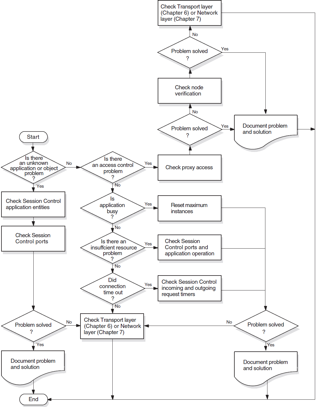
6.5. Correcting Unknown Application Problems
The end-user specifications on the target system do not match the end-user specifications that the application uses on the originating system.
The file that an application invokes on an incoming request exists and the account using it cannot execute the file.
|
Step |
Action |
|---|---|
|
1 |
Use the following NCL command to get information about applications that activate an image file or command procedure when they receive incoming requests (referred to as initiator applications): ncl> show session control application * - _ncl> all characteristics |
|
2 |
Examine the display for the following information:
|
|
3 |
Identify the applications that are daemons (referred to as declared responders). Use one of the following NCL commands: For OpenVMS systems:
For UNIX systems:
|
|
4 |
Identify the local end user address. This address is the object name or number of the application. Use the following NCL command: ncl> show session control port * - _ncl> local end user address |
|
5 |
Check the following:
|
6.6. Correcting Application Too Busy Problems
|
Step |
Action |
|---|---|
|
1 |
Refer to the application's documentation to determine if the application is configured properly. |
|
2 |
On UNIX systems: Check the ncl> show session control application -
_ncl> application-id all
If the ncl> set session control application - _ncl> application-id maximum instance value |
6.7. Correcting Access Control Problems
|
Step |
Action |
|---|---|
|
1 |
Make sure the user name that you or an application use is defined in the application or object database on the remote node. |
|
2 |
Check to see if the failed application is checking for proxy access. For OpenVMS systems, see Section 6.7.1, ''Correcting Proxy Access Problems (OpenVMS Only) ''. For UNIX systems, use an NCL command similar to one of the following to look at the session control ports in use: ncl> show session control port * proxy requested, - _ncl> with direction=listening If the |
|
3 |
Check the session control tower maintenance database to ensure the node is registered correctly. Use the following NCL command: ncl> show node node-id session control tower -
_ncl> maintenance name all
You can use an asterisk (*) instead of the
|
6.7.1. Correcting Proxy Access Problems (OpenVMS Only)
|
Step |
Action |
|---|---|
|
1 |
Invoke the uaf> show/proxy * |
|
2 |
If the proxy account is not set up correctly, use
|
|
3 |
If you cannot access the proxy account, check to see if Session Control created an intrusion record for your client account on the target node. Issue the following DCL command: $ show intrusion |
|
4 |
If login attempts exceed the set acceptable number of
times for the system, a break-in record will exist and the
system may have disabled the account. Check the account
using the |
6.7.2. Correcting Proxy Access Problems (UNIX Only)
|
Step |
Action |
|---|---|
|
1 |
Look at the Outgoing Proxy characteristic on the originating node (client system). Use the following NCL command: ncl> show session control outgoing proxy |
|
2 |
If the Outgoing Proxy characteristic on the originating node is FALSE, use the following NCL command to change it to TRUE: ncl> set session control outgoing proxy true |
|
3 |
Look at the Incoming Proxy characteristic on the target node. Use the following NCL commands: ncl> show session control incoming proxy
ncl> show session control application
_ncl> application-id incoming proxy
|
|
4 |
If the Incoming Proxy characteristic on the target node is set to FALSE, use the following NCL commands to change it to TRUE: ncl> set session control incoming proxy true ncl> set session control application - _ncl> application-id incoming proxy true |
|
5 |
Check that Session Control Proxy entities are defined correctly. Use the following NCL command: ncl> show session control proxy name -
_ncl> all characteristics
Look at the following characteristics:
|
|
6 |
If proxy entry on remote node is not defined correctly, modify existing proxy entry. Use NCL commands similar to the following: ncl> set session control proxy - _ncl> simple-name target user latin1-string, - _ncl> type default ncl> set session control proxy simple-name - _ncl> source end users - _ncl> {[Node=node-id,End User=address]} |
|
7 |
If you need to allow more than one end user to use the proxy entry, add additional source end-user information. Use the following NCL command: ncl> add session control proxy simple-name - _ncl> source end users - _ncl> {[node =node-id, EndUser=id]} |
6.7.3. Correcting Node Name Validation Problems
|
Step |
Action |
|---|---|
|
1 |
Check that the information in the namespace is correct
(see your naming service documentation). Use the
|
|
2 |
If a Phase IV system cannot connect to a DECnet-Plus system,
and the DECnet-Plus system is using DECdns:
|
|
3 |
Make sure that the correct protocol towers information exists for the Node module on the local system. |
|
4 |
Check that the node name in the synonym directory is correct. |
6.8. Correcting Insufficient Resource Problems
|
Step |
Action |
|---|---|
|
1 |
Determine if the remote node is a Phase IV system or DECnet-Plus system. |
|
2 |
If the problem occurs on a Phase IV system, use NCP to examine the maximum links (or maximum alias links). Use the following command: ncp> tell node-id show executor characteristics
If the problem occurs on a DECnet-Plus system, use NCL to look at the Session Control ports. Use the following command: ncl> show session control port * all |
|
3 |
Look at links or ports currently in use on the remote system. You can increase the links if necessary. Look at the link activity and the operation of the application to determine if you need more links or ports. Otherwise, examine the application operation to ensure it is configured properly. |
6.9. Correcting Timed Out Problems
|
Step |
Action |
|---|---|
|
1 |
If making a connection to an OpenVMS system, see if the
complete If the |
|
2 |
Look at the incoming and outgoing request timer values. Use the following NCL command: ncl> show session control all characteristics |
|
3 |
If the timer values seem too low, reset the values. Use NCL commands similar to the following: ncl> set session control incoming timer seconds
|
6.10. Correcting Node Name Resolution Problems
This section describes how to monitor DECnet-Plus node name and address resolution and search path processing.
During DECnet-Plus configuration, the system administrator sets up one or more name services on each node. This setup procedure includes generation of an NCL startup script that contains the name service search path information for the node.
The order in which the name services are to be searched for node name and address information
One or more naming templates for each name service to determine how DECnet-Plus should interpret abbreviated node names entered by users
For more information on name service configuration and search paths, refer to your DECnet-Plus installation and configuration guides.
For more information on DECdns, refer to VSI DECnet-Plus for OpenVMS DECdns Management Guide.
6.10.1. Monitoring Search Path Processing (OpenVMS Only)
You can use either the Common Trace Facility or the cdi$trace program
to obtain naming trace information.
Use the following command to invoke the Common Trace Facility:
$ Trace Start "SESSION CDI *"
Including the CDI parameter restricts trace facility output to node
name and address resolution messages.
cdi$trace, a program located in
SYS$SYSTEM. For
example:$ run sys$system:cdi$trace
cdi$trace output to a file:- Define a DCL foreign command symbol:
$ cdi$trace == "$cdi$trace"
- Specify the name of the file to contain the
cdi$traceoutput:$ cdi$trace trace.log
The output file may occasionally be missing the last few records of the trace. This is a known problem.
Although cdi$trace has known problems when run during a LAT terminal
session (on an LT device), a workaround is to issue the DCL spawn
command first.
6.10.2. Tracing Node Name Resolution Problems (UNIX Only)
You can trace DECnet-Plus node name and address resolution and search path
processing on UNIX systems by setting the environment variable CDITRACE to
a non-zero number before using DECnet-Plus applications. For example, > setenv
CDITRACE 2
6.10.3. Displaying Search Path Information
|
To: |
Use This Tool or Command: |
|---|---|
|
Display the forward translation search path. |
ncl> show session control naming - _ncl> search path |
|
Display the backtranslation search path. |
ncl> show session control backtranslation - _ncl> search path |
6.10.4. Identifying Namespace Consistency Problems
Using the decnet_register tool, you can verify that the reverse
address mapping links and the synonym links for a node are set up properly in a name
service.
decnet_register command reads the information for a
node from a name service, checks the information for consistency, and prints
messages describing any
inconsistencies:decnet_register> show node node-id full6.11. Examining the DECnet-Plus Naming Cache (OpenVMS Only)
DECnet-Plus uses an in-memory naming cache to improve performance of name and address resolution for all supported name services. This naming cache supersedes the existing DECdns cache for storage of name and addressing information.
DECnet-Plus uses this naming cache rather than the DECdns cache, for name and address resolution requests for all three name services: DECdns, Local, and DNS/BIND.
The DECdns cache still exists and DECnet-Plus continues to use it to resolve the
special namespace nicknames:, local:, and
domain:. The prefixes local: and domain: on a
node full name, indicate to DECnet-Plus the name service where the name and addressing
information is stored.
Note that the DECdns cache continues to exist. Applications other than DECnet-Plus (for example, DFS) that use DECdns directly will continue to use the existing DECdns cache.
6.11.1. Managing the Naming Cache
Using NCL commands, you can manage two naming cache parameters, the checkpoint interval and the timeout period, and flush entries from the in-memory naming cache.
Refer to your network management guide for information on managing the in-memory naming cache.
6.11.2. Dumping the Naming Cache
- Checkpoint the cache to disk. One way to force a checkpoint is by setting the checkpoint interval. For example:
$ MCR NCL Set Session Control Naming Cache Checkpoint Interval 8:0:0
For improved performance, CDI checkpointing is deferred for up to 15 minutes after a checkpoint request. Wait to examine the file until the checkpoint actually occurs. If you monitor the CDI activity with
cdi$trace, you will see the checkpoint occur. Dump the on-disk checkpoint file by running
cdi_cache_dump, a program located in SYS$SYSTEM.For example:$ run sys$system:cdi_cache_dump
Refer to your network management guide for information on managing the in-memory naming cache.
Chapter 7. Solving Transport Problems
If you determine that an application failure is neither an application-specific, Session Control, or naming service problem, the next area to examine is the Transport layer. For the DECnet-Plus product, this means a problem could exist with either the OSI transport or Network Service Protocol (NSP) software.
Topics In This Chapter
Underlying Components (OpenVMS Only) (Section 7.1, ''Underlying Components (OpenVMS Only)'')
Underlying Components (UNIX Only) (Section 7.2, ''Underlying Components (UNIX Only)'')
Symptoms of Transport Problems (Section 7.3, ''Symptoms of Transport Problems'')
Isolating Transport Layer Problems (Section 7.4, ''Isolating Transport Layer Problems'')
Correcting Connection Problems (Section 7.5, ''Correcting Connection Problems'')
Correcting OSI Transport Over CLNS Connection Problems (Section 7.6, ''Correcting OSI Transport Over CLNS Connection Problems'')
Correcting OSI Transport Over CONS (X.25) Connection Problems (Section 7.7, ''Correcting OSI Transport Over CONS (X.25) Connection Problems'')
Troubleshooting RFC 1006 (Section 7.8, ''Troubleshooting RFC 1006'')
7.1. Underlying Components (OpenVMS Only)
Figure 7.1, ''Underlying Components (OpenVMS)'' shows the direct underlying components that the NSP and OSI transport components use on OpenVMS systems. Use this information as a guide when isolating transport problems.
7.2. Underlying Components (UNIX Only)
Figure 7.2, ''Underlying Components (UNIX)'' shows the direct underlying components that the NSP and OSI transport components use on DECnet-Plus systems. Use this information as a guide when isolating transport problems.
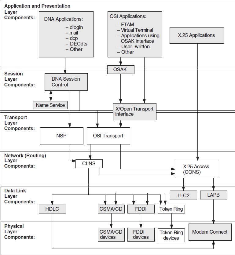
7.3. Symptoms of Transport Problems
If attempts to connect to a remote node fail or time out and you cannot find any problems in the upper layers, it is possible that a Transport layer problem is the cause of the failure.
7.4. Isolating Transport Layer Problems
If you cannot isolate an application failure at the Session Control layer, the problem could be at the Transport layer. Or, the problem could exist at the Network layer, but examining the Transport layer provides you with information that will help you isolate the problem in the Network layer.
7.4.1. Tools to Use
|
Tool |
And Refer To: |
|---|---|
|
NCL commands for the NSP and OSI transport modules |
NCL reference documentation |
|
| |
|
Common Trace Facility |
DECnet-Plus Common Trace Facility (CTF) Use |
7.4.2. Fault-Isolation Methodology
Use Figure 7.3, ''Fault-Isolation Methodology (Transport)'' as a guideline for isolating Transport layer problems.
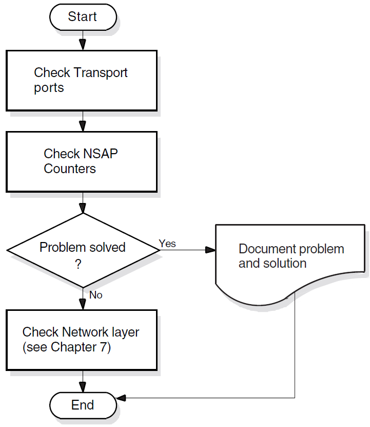
7.5. Correcting Connection Problems
If it is unclear where transport connection problems are occurring, look at the related ports and NSAP counters. You can also use the Common Trace Facility.
7.5.1. Checking Ports
|
Step |
Action |
|---|---|
|
1 |
Disable the Transport layer software that you are not checking. Use one of the following NCL commands: ncl> disable OSI transport ncl> disable NSP If you disable either transport software, any connections that are currently using it are disconnected. The user can reconnect to the remote system (which then uses the other transport) if it supports the other transport and there are no other transport problems. |
|
2 |
Initiate a connection to the target system. |
|
3 |
Use the following NCL command to identify the transport port information for the Session Control ports in which you are interested (depending on which end of the connection you are checking, you specify direction as incoming or outgoing): ncl> show session control port * all status, with -
_ncl> direction=value
|
|
4 |
Display the information for the appropriate Transport layer port with one of the following NCL commands: ncl> show NSP port port-id all attributes ncl> show OSI transport port port-id all attributes |
|
5 |
Check that the local NSAP and remote NSAP information used in the connection refers to the expected systems. Another cause of failure is incompatible NSAPs. A DECnet-Plus system needs a Phase-IV compatible address to allow communication between the DECnet-Plus system and a Phase IV system. |
|
6 |
Examine counter information (such as user PDUs received or user PDUs sent) to determine if port is actively in use. |
|
7 |
Reenable the transport software that you disabled. If you could not identify any connection problems, repeat this procedure with the transport software that you previously disabled. |
7.5.2. Checking NSAP Counters
|
Step |
Action | |
|---|---|---|
|
1 |
Determine the local NSAPs for the system you want to examine. Use one of the following NCL commands: ncl>show nsp local nsap * name ncl>show osi transport local nsap * name Each transport can have up to three NSAPs. | |
|
2 |
Determine the remote NSAPs for the system you want to examine. You need to examine all combinations of local and remote NSAPs. Use one or both of the following NCL commands: ncl> show nsp local nsap nsap-address - _ncl> remote nsap * name ncl> show osi transport local nsap nsap-address - _ncl> remote nsap * name | |
|
3 |
Check the counters on the source system. Use one of the following NCL commands: ncl> show nsp local nsap nsap-address - _ncl> remote nsap nsap-address all attributes ncl> show osi transport local nsap nsap-address - _ncl> remote nsap nsap-address all attributes | |
|
4 |
Try to establish a connection to the target system. If you cannot connect to the target system, check the remote system or try to reach the remote system from a different node. | |
|
5 |
Check the counters on the source system. | |
|
If: |
Then: | |
|
The Connects Sent counter increments, the source node initiated a connect request to the target node. |
Do one or both of the following:
| |
|
The Connects Sent counter does not increment, either a problem exists on the source system which prevents the system or application from attempting the connection, or a naming service problem exists. |
Do one of the following:
| |
|
6 |
If the source node is sending outgoing connect requests, check the counters on the target system. | |
|
If: |
Then: | |
|
The Connects Received counter increments but connection fails, there is a problem on the target node. |
Examine the remote node to determine the problem. | |
|
The Connects Received counter does not increment, a network problem may exist on either system that prevents the connections. |
Do any of the following:
| |
|
7 |
If you disabled transport entities, re-enable them, after checking the transport connection, with one of the following NCL commands: ncl> enable nsp ncl> enable osi transport | |
7.6. Correcting OSI Transport Over CLNS Connection Problems
|
Step |
Action |
|---|---|
|
1 |
Check the outgoing OSI connection. Use the following NCL command to identify the OSI transport template and network service (CONS or CLNS): ncl> show osi transport template * all attributes |
|
2 |
Check to see if the source node is sending connect requests.
Do the following:
If connect requests are not being sent, check the application or the Network layer of the source node. If connect requests are being sent, go to the next step in this procedure. |
|
3 |
Check to see if the destination node is receiving incoming
connect requests:
If incoming requests are not received, trace the network path between the source and destination node, and check the appropriate routing circuits or data links. If incoming requests are received, go to the next step in this procedure. |
|
4 |
Check the remote node to determine if an application on the
destination node is available to receive connect requests.
|
7.7. Correcting OSI Transport Over CONS (X.25) Connection Problems
|
Step |
Action |
|---|---|
|
1 |
Check that the source node is using a CONS template. Use the following NCL command: ncl> show osi transport template * all attributes |
|
2 |
Check that the CONS template exists. Use the following NCL command: ncl> show x25 access template template_id -
_ncl> all characteristics
If the template does not exist, create the appropriate template (see your DECnet-Plus network management documentation). If the template does exist, go to the next step. |
|
3 |
Check to see if the source node is sending connect requests.
Do one of the following:
If connect requests are not being sent, check the application or the network layer of the source node. See your X.25 documentation for information. If connect requests are being sent, go to the next step in this procedure. |
|
4 |
Check to see if the destination node is receiving incoming
connect requests:
If incoming requests are not received, trace the network path between the source and destination node and check the appropriate routing circuits or data links. If incoming requests are received, go to the next step in this procedure. |
|
5 |
Determine if an application on the destination node is
available to receive connect requests. Do the following:
|
7.8. Troubleshooting RFC 1006
Run the
rfc1006ddaemon in-debugmode to obtain printed information messages about the daemon's activities.Use the example programs to help you isolate the application behavior that is causing the problem. Use them to test RFC 1006 connectivity with a remote node or the local node.
During RFC 1006 application debugging, use the example programs as a way to test your assumptions about the behavior of XTI for RFC 1006 and to supplement the documentation.
RFC 1006 is layered on TCP/IP. Refer to your TCP/IP operational information for details.
7.8.1. Common Problems
While troubleshooting, you may encounter these problems:
rfc1006dappears to exit as soon as you run itNote that
rfc1006dobeys standard UNIX daemon conventions;therefore, you will see a shell prompt immediately after running the program, even ifrfc1006dis still running, becauserfc1006dwill run itself as a background process even if not explicitly directed to do so.To see if it is still running, use this command:# ps -aef | grep rfc1006d
If you start anrfc1006dprocess while anotherrfc1006dis already running, an error message will be written into thesyslogfile. The number in square brackets is the process ID. The following is an example of such an error message:Jul 20 16:25:12 itsdoa rfc1006d[408]: t_bind: errno=Address already in use, t_errno=System error
rfc1006dis not runningUnder normal conditions,
rfc1006dis started up at system boot time by a shell script named/sbin/rc3.d/S28.70rfc1006. Make sure that script is present. Run it and see whetherrfc1006dstays running. Check the system log file for error messages fromrfc1006d. (Check bothdaemon.logandkern.log.)Client cannot connect to server
Determine if the remote node can be reached by any TCP application. If it cannot, use TCP/IP network troubleshooting techniques.
If the remote node can be reached by a TCP application, make sure that the remote RFC 1006 has a daemon running and listening to the TCP port to which the local node is connected. This port should be port 102 under normal conditions.
Next, make sure that the server application is running and listening for the TSAP-ID in the client's destination RFC 1006 address.
Client gets
TSYSERRvalue int_errnovariable andENETDOWNinerrnovariableThis error is returned by the kernel to the RFC 1006 application whenever the
rfc1006ddaemon dies or is not running. Verify that therfc1006ddaemon is running. TheTSYERRandENETDOWNsymbols are defined in the<xti.h>and<errno.h>include files respectively.Connections hang
See if the RFC 1006 kernel is having trouble getting buffer space. You can do this with the command:# dbx -k /vmunixdbx) p r1006_allocb_failures0dbx)
This value is normally zero. If it is not zero, either a large number of concurrent RFC 1006 sessions or competition with other streams applications for kernel streams buffer space could be the problem.
XTI RFC 1006 application gets
TSYSERRvalue int_errnovariable andEPROTOvalue inerrnovariableThis means that a protocol error was detected by RFC 1006. A protocol error is an unexpected behavior by either the network or the remote application. An error message containing information about the protocol error should have been logged in the system log file. Forward this information to VSI, along with a method of reproducing the problem or a precise description of what was going on when the problem happened. The
TSYERRandEPROTOerrors are defined in the<xti.h>and<errno.h>include files respectively.
Chapter 8. Solving Network Layer Problems
This chapter describes how to use routing circuit and data link information to isolate and correct simple DECnet-Plus network layer problems.
Topics In This Chapter
Underlying Entities (OpenVMS Only) (Section 8.1, ''Underlying Entities (OpenVMS Only)'')
Underlying Entities (UNIX Only) (Section 8.2, ''Underlying Entities (UNIX Only)'')
Symptoms of Network Layer Problems (Section 8.3, ''Symptoms of Network Layer Problems'')
Isolating Network Layer Problems (Section 8.4, ''Isolating Network Layer Problems'')
Finding Underlying Entities (Section 8.5, ''Finding Underlying Entities'')
Correcting Configuration Problems (Section 8.6, ''Correcting Configuration Problems'')
Correcting Connectivity Problems (Section 8.7, ''Correcting Connectivity Problems'')
8.1. Underlying Entities (OpenVMS Only)
To isolate problems at the Network layer, you need to be able to identify the data link entities that the Routing layer uses and the physical entities associated with the data link entities.
Figure 8.1, ''Underlying Entities (OpenVMS)'' illustrates the users of the data links that you find in a DECnet-Plus for OpenVMS system.
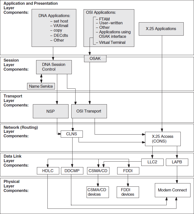
8.2. Underlying Entities (UNIX Only)
To isolate problems at the Network layer, you need to be able to identify the data link entities that the Routing layer uses and the physical entities associated with the data link entities.
Figure 8.2, ''Underlying Entities (UNIX)'' illustrates the users of the data links that you find in a DECnet-Plus for UNIX system.

8.3. Symptoms of Network Layer Problems
|
Symptom |
Possible Problem |
See |
|---|---|---|
|
Entities were not available when tracing a path between a routing circuit and the physical device. One or more of the entities had a State characteristic set to
An error appeared when you tried to enable an entity. |
Configuration | |
|
An application failed but no errors were found in the upper layers |
Configuration or connectivity | |
|
The configuration is correct but the routing circuit does not work |
Connectivity |
8.4. Isolating Network Layer Problems
If you think you have a Network layer problem, first check the physical connections between systems before you examine routing circuits and their underlying entities.
8.4.1. Tools to Use
Use NCL commands to check routing circuits in the Network layer.
8.4.2. Fault-Isolation Methodology
Use Figure 8.3, ''Fault-Isolation Methodology (Circuit Connectivity)'' as a guideline when you isolate circuit connectivity and configuration faults. The following sections in this chapter describe related correction procedures.
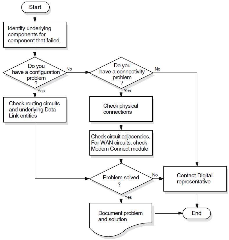
8.5. Finding Underlying Entities
To isolate routing circuits and data link problems in the Network layer, you need to be able to identify the underlying entities for specific routing circuits.
For each routing circuit type, there is a corresponding data link entity displayed with the set of circuit characteristics. The X.25 Protocol module provides information about the associated data link entities for X.25 circuits. Refer to your NCL and X.25 documentation for more details about X.25 circuits.
8.5.1. Finding the Underlying Entities for HDLC Circuits
|
Step |
Action |
|---|---|
|
1 |
Set the NCL default entity to the node whose circuits you want to check. If you cannot reach a remote node over the network, log into that system directly to check the circuits. |
|
2 |
Find the data link entity for the routing circuit that you want to check. Use the following NCL command: ncl> show routing circuit circuit-id -
_ncl> data link entity
|
|
3 |
Examine the physical line characteristic of the data link entity module. Use the following NCL command: ncl> show hdlc link link-name logical station
|
|
4 |
Examine the physical device entity to identify the communications device. Use the following NCL command: ncl> show modem connect line line-id -
_ncl> communications port
|
8.5.2. Finding the HDLC Circuits for a Physical Device
|
Step |
Action |
|---|---|
|
1 |
Find the Modem Connect entity connected to the physical device. Use the following NCL command: ncl> show modem connect line * comm port |
|
2 |
Examine the Modem Connect data port entity for the communications port. Use the following NCL command: ncl> show modem connect data port * all status |
|
3 |
Examine the HDLC port entity's attributes for one that contains the same client as displayed in the previous step. The client characteristic indicates the routing circuit. Use the following NCL command: ncl> show HLDC port * all status |
8.5.3. Finding the Underlying Entities for DDCMP Circuits (OpenVMS Only)
|
Step |
Action |
|---|---|
|
1 |
Set the NCL default entity to the node whose circuits you want to check. If you cannot reach a remote node over the network, log into that system directly to check the circuits. |
|
2 |
Find the data link entity for the routing circuit that you want to check. Use the following NCL command: ncl> show routing circuit circuit-id -
_ncl> data link entity
|
|
3 |
Examine the physical line characteristic of the data link entity module. Use the following NCL command: ncl> show ddcmp link link-name physical line
|
|
4 |
Examine the physical device entity to identify the communications device. Use the following NCL command: ncl> show modem connect line line-id comm port
|
8.5.4. Finding the DDCMP Circuits for a Physical Device (OpenVMS Only)
|
Step |
Action |
|---|---|
|
1 |
Find the Modem Connect entity connected to the physical device. Use the following NCL command: ncl> show modem connect line * comm port |
|
2 |
Examine the Modem Connect entity for the communications port. Use the following NCL command: ncl> show modem connect data port * all status |
|
3 |
Examine the DDCMP port entity's attributes for the client characteristic. The client characteristic indicates the routing circuit. Use the following NCL command: ncl> show DDCMP port * all status |
8.5.5. Finding the Underlying Entities for CSMA-CD Circuits
|
Step |
Action |
|---|---|
|
1 |
Set the NCL default entity to the node whose circuits you want to check. If you cannot reach a remote node over the network, you need to log into that system directly to check the circuits. |
|
2 |
Find the data link entity. Use the following NCL command: ncl> show routing circuit circuit-id -
_ncl> data link entity
|
|
3 |
Examine the communication port characteristic of the data link entity to identify the communications port. Use the following NCL command: ncl> show csma-cd station station-id comm port
|
8.5.6. Finding the CSMA-CD Circuit for a Physical Device
|
Step |
Action |
|---|---|
|
1 |
Find the CSMA-CD station entity connected to the physical device. Use the following NCL command: ncl> show csma-cd station * comm port |
|
2 |
Examine the CSMA-CD port entity's attributes to find the routing circuit. Use the following NCL command: ncl> show csma-cd port * client,station |
8.5.7. Finding the Underlying Entities for FDDI Circuits
|
Step |
Action |
|---|---|
|
1 |
Set the NCL default entity to the node whose circuits you want to check. If you cannot reach a remote node over the network, log into that system directly to check the circuits. |
|
2 |
Find the data link entity for the routing circuit that you want to check. Use the following NCL command: ncl> show routing circuit circuit-id -
_ncl> data link entity
|
|
3 |
Examine the physical port characteristic of the data link entity to identify the physical port. Use the following NCL command: ncl> show fddi station station-id -
_ncl> communication port
|
8.5.8. Finding the FDDI Circuit for a Physical Device
|
Step |
Action |
|---|---|
|
1 |
Find the FDDI station entity connected to the physical device. Use the following NCL command: ncl> show fddi station * - _ncl> communication port |
|
2 |
Examine the FDDI port entity's attributes to find the routing circuit. Use the following NCL command: ncl> show fddi port * client |
8.5.9. Finding the Underlying Entities for Token Ring Circuits (UNIX Only)
|
Step |
Action |
|---|---|
|
1 |
Set the NCL default entity to the node whose circuits you want to check. If you cannot reach a remote node over the network, log into that system directly to check the circuits. |
|
2 |
Find the data link entity for the routing circuit that you want to check. Use the following NCL command: ncl> show routing circuit circuit-id -
_ncl> data link entity
|
|
3 |
Examine the physical port characteristic of the data link entity to identify the physical port. Use the following NCL command: ncl> show token ring station station-id -
_ncl> communication port
|
8.5.10. Finding the Token Ring Circuit for a Physical Device (UNIX Only)
|
Step |
Action |
|---|---|
|
1 |
Find the Token Ring station entity connected to the physical device. Use the following NCL command: ncl> show token ring station * communication port |
|
2 |
Examine the Token Ring port entity's attributes to find the routing circuit. Use the following NCL command: ncl> show token ring port * client, station |
8.6. Correcting Configuration Problems
state=off, use the NCL command enable to
set the state to on.|
If: |
Then Do This: |
|---|---|
|
Error appears |
Check the characteristics of the data link entity associated with the routing circuit. |
|
No error appears |
Check that the routing circuit state remains
For HDLC circuits, if the state does not remain
|
8.6.1. Correcting DDCMP (OpenVMS Only) and HDLC Data Link Configuration Problems
Check the state of the appropriate link and logical station entities. Use the NCL commands similar to the following (use
ddcmpinstead ofhdlconly when checking DDCMP entities for OpenVMS):ncl> show hdlc link link-id statencl> show hdlc link link-id logical station station-id
- If the
state=off, use the enable command to change thestatetoon.If:
Then Do This:
Error appears
Check the characteristics of the entity indicated in the error message.
No error appears
Check that the state remains
on.For HDLC circuits, if state does not remain
on, check the Modem Connect module. - If the
state=on, check and record the value of theprotocol stateattribute of the local station entity.If Attribute Value Is:
Then:
Running
All devices and entities appear to be operating properly.
Starting or Initializing
The data link is attempting to connect with the remote system. If the link remains in this state for a significant amount of time, it could be that the data being transmitted is not received by the remote node. This indicates you have a connectivity problem.
Halted or Inoperative
One of the related entities is disabled. Check the states of the related entities.
Error
The threshold number of attempts to synchronize the link was reached. Check the counters for the logical station entity.
8.6.2. Correcting CSMA-CD Data Link Configuration Problems
|
Step |
Action |
|---|---|
|
1 |
Check that the ncl> show csma-cd station station-id state
|
|
2 |
If the device does not exist, issue the appropriate command to create the device (see your installation documentation). If an error appears when you try to create the device, check the entity specified in the message. |
|
3 |
If the device does exist, check the entity's state. If the state is If the state is |
8.7. Correcting Connectivity Problems
|
Step |
Action |
|---|---|
|
1 |
Check the physical connections. For example:
|
|
2 |
For WAN links (HDLC), check the Modem Connect status to see if the modem control leads are asserted correctly. |
|
3 |
Determine if data is being sent and received. You can:
|
|
4 |
Look to see if circuit adjacencies exist. Use the following NCL command: ncl> show circuit circuit-id * adjacency * all
|
Appendix A. Using the OSAKtrace Utility
The OSAKtrace utility captures a record of what happens during an OSI information exchange. The OSAKtrace utility is not an implementation of any OSI standard; there is no ISO standard for OSI tracing.
You can use OSAKtrace to show that application programs that use the OSAK routines conform with the standards, and to identify any problems that may arise when one OSI application works with another over a network.
Information on using the OSAKtrace utility appears in OSAK Programming, and descriptions of the trace emitter calls appear in OSAK Programming Reference.
Appendix B. DECnet-Plus Application Tracing Examples
This appendix contains an example of a trace output for the FTAM and Virtual Terminal software.
The trace output for FTAM and Virtual Terminal operations on UNIX and OpenVMS is very similar; this appendix shows the trace output as it appears on a UNIX system.
B.1. DECnet-Plus Application Trace Example
This section provides an example of the default output of the ositrace
utility. This example traces the result of the FTAM omv command on a
UNIX system.
B.1.1. Association Establishment — Initiator
10:11:57.08     OSI trace started Wed Jan 30 10:11:57 1994
10:11:58.20 –> Session
   0dff0148 05061301 00160102 14020002 33028080 34020103 c1ff0130 3180a080
   80010100 00a28081 02808082 020103a4 80308002 01010605 28c27b02 01308006
   02510100 00000030 80020103 060528c2 7b020230 80060251 01000000 00308002
   01050605 28c27b02 03308006 02510100 00000030 80020107 060528c2 7b020430
   80060251 01000000 00308002 01090606 2bce0f01 02023080 06025101 00000000
   30800201 0b060452 01000130 80060251 01000000 00000088 02060089 03054000
   61803080 02010ba0 7b6080a1 80060528 c27b0101 0000a280 06052bce 0f070100
   00a38002 01010000 be802880 020101a0 4da08082 01008302 03408403 05070085
   02058086 0100a780 4e0528c2 7b05014e 0528c27b 05024e05 28c27b05 034e062b
   ce0f0105 09000056 0776696e 63656e74 710a1908 6e69636b 73746572 00000000
   00000000 00000000 00000000

   connect-spdu                                                   0d ff 01
       connect/accept-item                                        05 06
           protocol-options  = NULL                               13 01
           version-number  = 2                                    16 01 02
       session-user-requirements  = '0000000000000010'B           14 02 00
         ( duplex functional unit )
       calling-ssap-identifier  =                                 33 02 80
       called-ssap-identifier  =                                  34 02 01
       user-data                                                  c1 ff 01
Presentation Connection — Initiator
10:11:58.20 –> Presentation
   3180a080 80010100 00a28081 02808082 020103a4 80308002 01010605 28c27b02
   01308006 02510100 00000030 80020103 060528c2 7b020230 80060251 01000000
   00308002 01050605 28c27b02 03308006 02510100 00000030 80020107 060528c2
   7b020430 80060251 01000000 00308002 01090606 2bce0f01 02023080 06025101
   00000000 30800201 0b060452 01000130 80060251 01000000 00000088 02060089
   03054000 61803080 02010ba0 7b6080a1 80060528 c27b0101 0000a280 06052bce
   0f070100 00a38002 01010000 be802880 020101a0 4da08082 01008302 03408403
   05070085 02058086 0100a780 4e0528c2 7b05014e 0528c27b 05024e05 28c27b05
   034e062b ce0f0105 09000056 0776696e 63656e74 710a1908 6e69636b 73746572
   00000000 00000000 00000000 00000000
   CP PPDU SET =                                                   31 80
   {
     [0] IMPLICIT SET =                                            a0 80
     {
       [0] IMPLICIT mode-selector INTEGER = normal-mode            80 01 01
     }
     [2] IMPLICIT SEQUENCE =                                       a2 80
     {
       [1] IMPLICIT calling-presentation-selector OCTET STRING =   81 02
         '8080'H
       [2] IMPLICIT called-presentation-selector OCTET STRING =    82 02
         '0103'H
       [4] IMPLICIT presentation-context-definition-list           a4 80
         SEQUENCE =
       {
         SEQUENCE =                                                30 80
         {
           presentation-context-identifier INTEGER = 1             02 01 01
           abstract-syntax-name OBJECT IDENTIFIER =                06 05 28
             {1 0 8571 2 1}
           SEQUENCE =                                              30 80
           {
             transfer-syntax-name OBJECT IDENTIFIER = {2 1 1}      06 02 51
           }
         }
         SEQUENCE =                                                30 80
         {
           presentation-context-identifier INTEGER = 3             02 01 03
           abstract-syntax-name OBJECT IDENTIFIER =                06 05 28
             {1 0 8571 2 2}
           SEQUENCE =                                              30 80
           {
             transfer-syntax-name OBJECT IDENTIFIER = {2 1 1}      06 02 51
           }
         }
           SEQUENCE =                                              30 80
           {
             presentation-context-identifier INTEGER = 5           02 01 05
             abstract-syntax-name OBJECT IDENTIFIER =              06 05 28
               {1 0 8571 2 3}
           SEQUENCE =                                              30 80
           {
             transfer-syntax-name OBJECT IDENTIFIER = {2 1 1}      06 02 51
           }
         }
         SEQUENCE =                                                30 80
         {
           presentation-context-identifier INTEGER = 7             02 01 07
           abstract-syntax-name OBJECT IDENTIFIER =                06 05 28
             {1 0 8571 2 4}
           SEQUENCE =                                              30 80
           {
             transfer-syntax-name OBJECT IDENTIFIER = {2 1 1}      06 02 51
           }
         }
         SEQUENCE =                                                30 80
         {
           presentation-context-identifier INTEGER = 9             02 01 09
           abstract-syntax-name OBJECT IDENTIFIER =                06 06 2b
             {1 3 9999 1 2 2}
           SEQUENCE =                                              30 80
           {
             transfer-syntax-name OBJECT IDENTIFIER = {2 1 1}      06 02 51
           }
         }
         SEQUENCE =                                                30 80
         {
           presentation-context-identifier INTEGER = 11            02 01 0b
           abstract-syntax-name OBJECT IDENTIFIER = {2 2 1 0 1}    06 04 52
           SEQUENCE =                                              30 80
           {
             transfer-syntax-name OBJECT IDENTIFIER = {2 1 1}      06 02 51
           }
         }
       }
       [8] IMPLICIT presentation-requirements BIT STRING = '00'B   88 02 06
         ( )
       [9] IMPLICIT user-session-requirements BIT STRING =         89 03 05
         '01000000000'B
         ( duplex )
       [APPLICATION 1] IMPLICIT fully-encoded-data SEQUENCE =      61 80
       {
         PDV-list SEQUENCE =                                       30 80
         {
           presentation-context-identifier INTEGER = 11            02 01 0b
           single-asn1-type [0] ANY =                              a0 7b

           – Abstract Syntax Name
           –   ACSE-PCI
           – Presentation Context Identifier
           –   11
ACSE Association Request — Initiator
10:11:58.20 –> ACSE
   6080a180 060528c2 7b010100 00a28006 052bce0f 07010000 a3800201 010000be
   80288002 0101a04d a0808201 00830203 40840305 07008502 05808601 00a7804e
   0528c27b 05014e05 28c27b05 024e0528 c27b0503 4e062bce 0f010509 00005607
   76696e63 656e7471 0a19086e 69636b73 74657200 00000000 00000000 00000000
   000000
           [APPLICATION 0] IMPLICIT aarq SEQUENCE =                60 80
           {
             application-context-name [1]                          a1 80 06
               application-context-name OBJECT IDENTIFIER =
               {1 0 8571 1 1}
             called-ap-title [2] ap-title OBJECT IDENTIFIER =      a2 80 06
               {1 3 9999 7 1}
             called-ae-qualifier [3] ae-qualifier INTEGER = 1      a3 80 02
             [30] IMPLICIT user-information SEQUENCE =             be 80
             {
               IMPLICIT EXTERNAL SEQUENCE =                        28 80
               {
                 indirect-reference INTEGER = 1                    02 01 01
                 single-asn1-type [0] ANY =                        a0 4d

                 – Abstract Syntax Name
                 –   FTAM-PCI
                 – Presentation Context Identifier
                 –   1
FTAM Initialization Request — Initiator
10:11:58.20 –> FTAM
   a0808201 00830203 40840305 07008502 05808601 00a7804e 0528c27b 05014e05
   28c27b05 024e0528 c27b0503 4e062bce 0f010509 00005607 76696e63 656e7471
   0a19086e 69636b73 74657200 00000000 00000000 00000000 000000

                 [0] IMPLICIT f-initialize-request SEQUENCE =      a0 80
                 {
                   [2] IMPLICIT present-context-management         82 01 00
                     BOOLEAN = false
                   [3] IMPLICIT service-class BIT STRING =         83 02 03
                     '01000'B                          ( management-class )
                   [4] IMPLICIT functional-units BIT STRING =      84 03 05
                     '00000111000'B
                     ( limited-file-management,
                       enhanced-file-management,
                       grouping )
                   [5] IMPLICIT attribute-groups BIT STRING =      85 02 05
                     '100'B                          ( storage )
                   [6] IMPLICIT ftam-quality-of-service            86 01 00
                     INTEGER = no-recovery
                   [7] IMPLICIT contents-type-list SEQUENCE =      a7 80
                   {
                     [APPLICATION 14] IMPLICIT document-type-name  4e 05 28
                       OBJECT IDENTIFIER = {1 0 8571 5 1}
                       (ftam-1)
                     [APPLICATION 14] IMPLICIT document-type-name  4e 05 28
                       OBJECT IDENTIFIER = {1 0 8571 5 2}
                       (ftam-2)
                     [APPLICATION 14] IMPLICIT document-type-name  4e 05 28
                       OBJECT IDENTIFIER = {1 0 8571 5 3}
                       (ftam-3)
                     [APPLICATION 14] IMPLICIT document-type-name  4e 06 2b
                       OBJECT IDENTIFIER = {1 3 9999 1 5 9}
                       (nbs-9)
                   }
                   [APPLICATION 22] IMPLICIT initiator-identity    56 07
                     GRAPHIC STRING = smith
                    filestore-password [APPLICATION 17]         71 0a 19
                     GraphicString GRAPHIC STRING = mypassword
                }
              }
            }
          }
        }
      }
    }
B.1.2. Association Establishment — Responder
10:11:58.70 <– Session
   0ee40506 13010016 01021402 00023402 0103c1d2 3180a080 80010100 00a280a5
   80308080 01008102 51010000 30808001 00810251 01000030 80800100 81025101
   00003080 80010081 02510100 00308080 01008102 51010000 30808001 00810251
   01000000 00880206 00890305 40006180 30800201 0ba06761 80a18006 0528c27b
   01010000 a2030201 00a305a1 03020100 be802880 020101a0 3fa18080 02078082
   01008302 03408403 05070085 02058086 0100a780 4e0528c2 7b05014e 062bce0f
   0105094e 0528c27b 05034e05 28c27b05 02000088 01010000 00000000 00000000
   00000000 0000

   accept-spdu                                                     0e e4
       connect/accept-item                                         05 06
           protocol-options  = NULL                                13 01
           version-number  = 2                                     16 01 02
       session-user-requirements  = '0000000000000010'B            14 02 00
         ( duplex functional unit )
       called-ssap-identifier  =                                   34 02 01
       user-data                                                   c1 d2
Presentation Connect Request — Responder
10:11:58.70 <– Presentation
   3180a080 80010100 00a280a5 80308080 01008102 51010000 30808001 00810251
   01000030 80800100 81025101 00003080 80010081 02510100 00308080 01008102
   51010000 30808001 00810251 01000000 00880206 00890305 40006180 30800201
   0ba06761 80a18006 0528c27b 01010000 a2030201 00a305a1 03020100 be802880
   020101a0 3fa18080 02078082 01008302 03408403 05070085 02058086 0100a780
   4e0528c2 7b05014e 062bce0f 0105094e 0528c27b 05034e05 28c27b05 02000088
   01010000 00000000 00000000 00000000 0000

   cpa-ppdu SET =                                                  31 80
   {
     [0] IMPLICIT SET =                                            a0 80
     {
       [0] IMPLICIT mode-selector INTEGER = normal-mode            80 01 01
     }
     [2] IMPLICIT SEQUENCE =                                       a2 80
     {
       [5] IMPLICIT presentation-context-definition-result-list    a5 80
         SEQUENCE =
       {
         SEQUENCE =                                                30 80
         {
           [0] IMPLICIT result INTEGER = acceptance                80 01 00
           [1] IMPLICIT transfer-syntax-name OBJECT IDENTIFIER =   81 02 51
             {2 1 1}
         }
         SEQUENCE =                                                30 80
         {
           [0] IMPLICIT result INTEGER = acceptance                80 01 00
           [1] IMPLICIT transfer-syntax-name OBJECT IDENTIFIER =   81 02 51
             {2 1 1}
         }
         SEQUENCE =                                                30 80
         {
           [0] IMPLICIT result INTEGER = acceptance                80 01 00
           [1] IMPLICIT transfer-syntax-name OBJECT IDENTIFIER =   81 02 51
             {2 1 1}
         }
         SEQUENCE =                                                30 80
         {
           [0] IMPLICIT result INTEGER = acceptance                80 01 00
           [1] IMPLICIT transfer-syntax-name OBJECT IDENTIFIER =   81 02 51
             {2 1 1}
         }
         SEQUENCE =                                                30 80
         {
           [0] IMPLICIT result INTEGER = acceptance                80 01 00
           [1] IMPLICIT transfer-syntax-name OBJECT IDENTIFIER =   81 02 51
             {2 1 1}
         }
         SEQUENCE =                                                30 80
         {
           [0] IMPLICIT result INTEGER = acceptance                80 01 00
           [1] IMPLICIT transfer-syntax-name OBJECT IDENTIFIER =   81 02 51
             {2 1 1}
         }
       }
       [8] IMPLICIT presentation-requirements BIT STRING = '00'B   88 02 06
         ( )
       [9] IMPLICIT user-session-requirements BIT STRING =         89 03 05
         '01000000000'B
         ( duplex )
       [APPLICATION 1] IMPLICIT fully-encoded-data SEQUENCE =      61 80
       {
         PDV-list SEQUENCE =                                       30 80
         {
           presentation-context-identifier INTEGER = 11            02 01 0b
           single-asn1-type [0] ANY =                              a0 67

           – Abstract Syntax Name
           –   ACSE-PCI
           – Presentation Context Identifier
           –   11
ACSE Association Request Accepted — Responder
10:11:58.70 <– ACSE
   6180a180 060528c2 7b010100 00a20302 0100a305 a1030201 00be8028 80020101
   a03fa180 80020780 82010083 02034084 03050700 85020580 860100a7 804e0528
   c27b0501 4e062bce 0f010509 4e0528c2 7b05034e 0528c27b 05020000 88010100
   00000000 00000000 00000000 000000
           [APPLICATION 1] IMPLICIT aare SEQUENCE =                61 80
           {
             application-context-name [1]                          a1 80 06
               application-context-name OBJECT IDENTIFIER =
               {1 0 8571 1 1}
             result [2] associate-result INTEGER = accepted        a2 03 02
             result-source-diagnostic [3] acse-service-user [1]    a3 05 a1
               INTEGER INTEGER = null
             [30] IMPLICIT user-information SEQUENCE =             be 80
             {
               IMPLICIT EXTERNAL SEQUENCE =                        28 80
               {
                 indirect-reference INTEGER = 1                    02 01 01
                 single-asn1-type [0] ANY =                        a0 3f

                 – Abstract Syntax Name
                 –   FTAM-PCI
                 – Presentation Context Identifier
                 –   1
Initialization Request Accepted — Responder
10:11:58.70 <– FTAM
   a1808002 07808201 00830203 40840305 07008502 05808601 00a7804e 0528c27b
   05014e06 2bce0f01 05094e05 28c27b05 034e0528 c27b0502 00008801 01000000
   00000000 00000000 00000000 00
                 [1] IMPLICIT f-initialize-response SEQUENCE =     a1 80
                 {
                   [0] IMPLICIT protocol-version BIT STRING =      80 02 07
                     '1'B
                     ( version-1 )
                   [2] IMPLICIT present-context-management         82 01 00
                     BOOLEAN = false
                   [3] IMPLICIT service-class BIT STRING =         83 02 03
                     '01000'B
                     ( management-class )
                   [4] IMPLICIT functional-units BIT STRING =      84 03 05
                     '00000111000'B
                     ( limited-file-management,
                       enhanced-file-management,
                       grouping )
                   [5] IMPLICIT attribute-groups BIT STRING =      85 02 05
                     '100'B
                     ( storage )
                   [6] IMPLICIT ftam-quality-of-service            86 01 00
                     INTEGER = no-recovery
                   [7] IMPLICIT contents-type-list SEQUENCE =      a7 80
                   {
                     [APPLICATION 14] IMPLICIT document-type-name  4e 05 28
                        OBJECT IDENTIFIER = {1 0 8571 5 1}
                        (ftam-1)
                     [APPLICATION 14] IMPLICIT document-type-name  4e 06 2b
                        OBJECT IDENTIFIER = {1 3 9999 1 5 9}
                        (nbs-9)
                     [APPLICATION 14] IMPLICIT document-type-name  4e 05 28
                        OBJECT IDENTIFIER = {1 0 8571 5 3}
                        (ftam-3)
                     [APPLICATION 14] IMPLICIT document-type-name  4e 05 28
                        OBJECT IDENTIFIER = {1 0 8571 5 2}
                        (ftam-2)
                   }
                   [8] IMPLICIT checkpoint-window INTEGER = 1      88 01 01
                }
              }
            }
          }
        }
      }
    }
Passing User Data — Initiator
10:11:59.05 –> Session
   01000100 61803080 020101a0 07b68080 01030000 00003080 020101a0 19a68073
   80a08019 07657861 6d706c65 00000000 43020002 00000000 30800201 01a01db0
   806880a0 80190f72 656e616d 65645f65 78616d70 6c650000 00000000 00003080
   020101a0 04a88000 00000030 80020101 a004b880 00000000 0000

   data-spdu                                                       01 00
   give-tokens-spdu                                                01 00

10:11:59.05 –> Presentation
   61803080 020101a0 07b68080 01030000 00003080 020101a0 19a68073 80a08019
   07657861 6d706c65 00000000 43020002 00000000 30800201 01a01db0 806880a0
   80190f72 656e616d 65645f65 78616d70 6c650000 00000000 00003080 020101a0
   04a88000 00000030 80020101 a004b880 00000000 0000

   [APPLICATION 1] IMPLICIT fully-encoded-data SEQUENCE =          61 80
   {
     PDV-list SEQUENCE =                                           30 80
     {
       presentation-context-identifier INTEGER = 1                 02 01 01
       single-asn1-type [0] ANY =                                  a0 07

       – Abstract Syntax Name
       –   FTAM-PCI
       – Presentation Context Identifier
       –   1
FTAM PDUs Grouping
10:11:59.05 –> FTAM
   b6808001 03000000 00308002 0101a019 a6807380 a0801907 6578616d 706c6500
   00000043 02000200 00000030 80020101 a01db080 6880a080 190f7265 6e616d65
   645f6578 616d706c 65000000 00000000 00308002 0101a004 a8800000 00003080
   020101a0 04b88000 00000000 00

       [22] IMPLICIT f-begin-group-request SEQUENCE =              b6 80
       {
         [0] IMPLICIT threshold INTEGER = 3                        80 01 03
       }
     }
     PDV-list SEQUENCE =                                           30 80
     {
       presentation-context-identifier INTEGER = 1                 02 01 01
       single-asn1-type [0] ANY =                                  a0 19

       – Abstract Syntax Name
       –   FTAM-PCI
       – Presentation Context Identifier
       –   1

10:11:59.05 –> FTAM
   a6807380 a0801907 6578616d 706c6500 00000043 02000200 00000030 80020101
   a01db080 6880a080 190f7265 6e616d65 645f6578 616d706c 65000000 00000000
   00308002 0101a004 a8800000 00003080 020101a0 04b88000 00000000 00
       [6] IMPLICIT f-select-request SEQUENCE =                    a6 80
       {
         [APPLICATION 19] IMPLICIT attributes SEQUENCE =           73 80
         {
           [0] IMPLICIT select-attributes SEQUENCE =               a0 80
           {
             filename-attribute GRAPHIC STRING = example           19 07
           }
         }
         [APPLICATION 3] IMPLICIT requested-access BIT STRING =    43 02 00
           '00000010'B
           ( change-attributes )
       }
     }
     PDV-list SEQUENCE =                                           30 80
     {
       presentation-context-identifier INTEGER = 1                 02 01 01
       single-asn1-type [0] ANY =                                  a0 1d

       – Abstract Syntax Name
       –   FTAM-PCI
       – Presentation Context Identifier
       –   1

10:11:59.05 –> FTAM
   b0806880 a080190f 72656e61 6d65645f 6578616d 706c6500 00000000 00000030
   80020101 a004a880 00000000 30800201 01a004b8 80000000 000000
       [16] IMPLICIT f-change-attributes-request SEQUENCE =        b0 80
       {
         [APPLICATION 8] IMPLICIT attributes SEQUENCE =            68 80
         {
           [0] IMPLICIT filename SEQUENCE =                        a0 80
           {
             filename-attribute GRAPHIC STRING = renamed_example   19 0f
           }
         }
       }
     }
     PDV-list SEQUENCE =                                           30 80
     {
       presentation-context-identifier INTEGER = 1                 02 01 01
       single-asn1-type [0] ANY =                                  a0 04

       – Abstract Syntax Name
       –   FTAM-PCI
       – Presentation Context Identifier
       –   1

10:11:59.05 –> FTAM
  a8800000 00003080 020101a0 04b88000 00000000 00
       [8] IMPLICIT f-deselect-request SEQUENCE =                  a8 80
      {
      }
    }
    PDV-list SEQUENCE =                                           30 80
    {
      presentation-context-identifier INTEGER = 1                 02 01 01
      single-asn1-type [0] ANY =                                  a0 04

      – Abstract Syntax Name
      –   FTAM-PCI
      – Presentation Context Identifier
      –   1

10:11:59.05 –> FTAM
  b8800000 00000000
      [24] IMPLICIT f-end-group-request SEQUENCE =                b8 80
      {
      }
    }
  }
B.1.3. Passing User Data — Responder
10:11:59.42 <– Session
   01000100 61803080 020101a0 04b78000 00000030 80020101 a028a780 7380a080
   191a2f75 73722f75 73657273 2f76696e 63656e74 2f657861 6d706c65 00000000
   00000000 30800201 01a01db1 806880a0 80190f72 656e616d 65645f65 78616d70
   6c650000 00000000 00003080 020101a0 04a98000 00000030 80020101 a004b980
   00000000 0000

   data-spdu                                                       01 00
   give-tokens-spdu                                                01 00

10:11:59.42 <– Presentation
   61803080 020101a0 04b78000 00000030 80020101 a028a780 7380a080 191a2f75
   73722f75 73657273 2f76696e 63656e74 2f657861 6d706c65 00000000 00000000
   30800201 01a01db1 806880a0 80190f72 656e616d 65645f65 78616d70 6c650000
   00000000 00003080 020101a0 04a98000 00000030 80020101 a004b980 00000000
   0000

   [APPLICATION 1] IMPLICIT fully-encoded-data SEQUENCE =          61 80
   {
     PDV-list SEQUENCE =                                           30 80
     {
       presentation-context-identifier INTEGER = 1                 02 01 01
       single-asn1-type [0] ANY =                                  a0 04

       – Abstract Syntax Name
       –   FTAM-PCI
       – Presentation Context Identifier
       –   1
Sending Responses to Requests — Responder
10:11:59.42 <– FTAM
   b7800000 00003080 020101a0 28a78073 80a08019 1a2f7573 722f7573 6572732f
   76696e63 656e742f 6578616d 706c6500 00000000 00000030 80020101 a01db180
   6880a080 190f7265 6e616d65 645f6578 616d706c 65000000 00000000 00308002
   0101a004 a9800000 00003080 020101a0 04b98000 00000000 00

      [23] IMPLICIT f-begin-group-response SEQUENCE =             b7 80
      {
      }
    }
    PDV-list SEQUENCE =                                           30 80
    {
      presentation-context-identifier INTEGER = 1                 02 01 01
      single-asn1-type [0] ANY =                                  a0 28

      – Abstract Syntax Name
      –   FTAM-PCI
      – Presentation Context Identifier
      –   1

10:11:59.42 <– FTAM
   a7807380 a080191a 2f757372 2f757365 72732f76 696e6365 6e742f65 78616d70
   6c650000 00000000 00003080 020101a0 1db18068 80a08019 0f72656e 616d6564
   5f657861 6d706c65 00000000 00000000 30800201 01a004a9 80000000 00308002
   0101a004 b9800000 00000000
     [7] IMPLICIT f-select-response SEQUENCE =                   a7 80
       {
       [APPLICATION 19] IMPLICIT attributes SEQUENCE =           73 80
       {
         [0] IMPLICIT select-attributes SEQUENCE =               a0 80
         {
           filename-attribute GRAPHIC STRING =                   19 1a
           /usr/users/smith/example
         }
       }
     }
   }
   PDV-list SEQUENCE =                                           30 80
   {
     presentation-context-identifier INTEGER = 1                 02 01 01
     single-asn1-type [0] ANY =                                  a0 1d

     – Abstract Syntax Name
     –   FTAM-PCI
     – Presentation Context Identifier
     –   1

10:11:59.42 <– FTAM
   b1806880 a080190f 72656e61 6d65645f 6578616d 706c6500 00000000 00000030
   80020101 a004a980 00000000 30800201 01a004b9 80000000 000000
       [17] IMPLICIT f-change-attributes-response SEQUENCE =       b1 80
       {
         [APPLICATION 8] IMPLICIT attributes SEQUENCE =            68 80
         {
           [0] IMPLICIT filename SEQUENCE =                        a0 80
           {
             filename-attribute GRAPHIC STRING = renamed_example   19 0f
           }
         }
       }
     }
     PDV-list SEQUENCE =                                           30 80
     {
       presentation-context-identifier INTEGER = 1                 02 01 01
       single-asn1-type [0] ANY =                                  a0 04

       – Abstract Syntax Name
       –   FTAM-PCI
       – Presentation Context Identifier
       –   1

10:11:59.42 <– FTAM
   a9800000 00003080 020101a0 04b98000 00000000 00

       [9] IMPLICIT f-deselect-response SEQUENCE =                 a9 80
       {
       }
     }
     PDV-list SEQUENCE =                                           30 80
     {
       presentation-context-identifier INTEGER = 1                 02 01 01
       single-asn1-type [0] ANY =                                  a0 04

       – Abstract Syntax Name
       –   FTAM-PCI
       – Presentation Context Identifier
       –   1

10:11:59.42<– FTAM
   b9800000 00000000
       [25] IMPLICIT f-end-group-response SEQUENCE =               b9 80
       {
       }
     }
   }
Association Termination — Initiator
finish-spdu, ACSE sends an association release request, and FTAM sends an
F-TERMINATE request.
10:11:59.53 –> Session
   092a1101 01c12561 80308002 010ba018 62808001 00be8028 80020101 a004a280
  00000000 00000000 00000000
  finish-spdu                                                     09 2a
      transport-disconnect  = '00000001'B                         11 01 01
          ( transport connection is released )
      user-data                                                   c1 25

10:11:59.53 –> Presentation
  61803080 02010ba0 18628080 0100be80 28800201 01a004a2 80000000 00000000
  00000000 00
  [APPLICATION 1] IMPLICIT fully-encoded-data SEQUENCE =          61 80
  {
    PDV-list SEQUENCE =                                           30 80
    {
      presentation-context-identifier INTEGER = 11                02 01 0b
      single-asn1-type [0] ANY =                                  a0 18

      – Abstract Syntax Name
      –   ACSE-PCI
      – Presentation Context Identifier
      –   11

10:11:59.53 –> ACSE
  62808001 00be8028 80020101 a004a280 00000000 00000000 00000000
      [APPLICATION 2] IMPLICIT rlrq-ppdu SEQUENCE =               62 80
      {
        [0] IMPLICIT reason INTEGER = normal                      80 01 00
        [30] IMPLICIT user-information SEQUENCE =                 be 80
        {
          IMPLICIT EXTERNAL SEQUENCE =                            28 80
          {
            indirect-reference INTEGER = 1                        02 01 01
            single-asn1-type [0] ANY =                            a0 04

            – Abstract Syntax Name
            –   FTAM-PCI
            – Presentation Context Identifier
            –   1

10:11:59.53 –> FTAM
  a2800000 00000000 00000000 0000
            [2] IMPLICIT f-terminate-request SEQUENCE =           a2 80
            {
            }
          }
        }
      }
    }
Association Termination — Responder
disconnect-spdu, ACSE sends an association release response, and FTAM sends
an F-TERMINATE
response.10:11:59.65 <– Session
0a27c125 61803080 02010ba0 18638080 0100be80 28800201 01a004a3 80000000
00000000 00000000 00
disconnect-spdu 0a 27
user-data c1 25
10:11:59.65 <– Presentation
61803080 02010ba0 18638080 0100be80 28800201 01a004a3 80000000 00000000
00000000 00
[APPLICATION 1] IMPLICIT fully-encoded-data SEQUENCE = 61 80
{
PDV-list SEQUENCE = 30 80
{
presentation-context-identifier INTEGER = 11 02 01 0b
single-asn1-type [0] ANY = a0 18
– Abstract Syntax Name
– ACSE-PCI
– Presentation Context Identifier
– 11
10:11:59.65 <– ACSE
63808001 00be8028 80020101 a004a380 00000000 00000000 00000000
[APPLICATION 3] IMPLICIT rlre-ppdu SEQUENCE = 63 80
{
[0] IMPLICIT reason INTEGER = normal 80 01 00
[30] IMPLICIT user-information SEQUENCE = be 80
{
IMPLICIT EXTERNAL SEQUENCE = 28 80
{
indirect-reference INTEGER = 1 02 01 01
single-asn1-type [0] ANY = a0 04
– Abstract Syntax Name
– FTAM-PCI
– Presentation Context Identifier
– 1
10:11:59.65 <– FTAM
a3800000 00000000 00000000 0000
[3] IMPLICIT f-terminate-response SEQUENCE = a3 80
{
}
}
}
}
}
10:11:59.77 OSI trace ended Wed Jan 30 10:11:59 1994