Alpha Guide to Upgrading Privileged-Code Applications
- Operating System and Version:
- VSI OpenVMS IA-64 Version 8.4-1H1 or higher
VSI OpenVMS Alpha Version 8.4-2L1 or higher
Preface
This document describes reference information for System Management utilities used with the OpenVMS Alpha operating system.
1. About VSI
VMS Software, Inc. (VSI) is an independent software company licensed by Hewlett Packard Enterprise to develop and support the OpenVMS operating system.
2. Intended Audience
This guide is intended for system programmers who use privileged-mode interfaces in their applications.
3. Document Structure
This manual is organized as follows:
Chapter 1, "Introduction" describes how to use this guide.
Chapter 2, "Upgrading Privileged Software to OpenVMS Alpha Version 7.0" and Chapter 3, "Replacements for Removed Privileged Symbols" describe the infrastructure changes that might affect privileged-code applications and provides guidelines for upgrading them to OpenVMS Alpha Version 7.0.
Chapter 4, "Modifying Device Drivers to Support 64-Bit Addressing", Chapter 5, "Modifying User-Written System Services", and Chapter 6, "Kernel Threads Process Structure" describe the changes that can be made to customer-written system services and device drivers to support 64-bit addresses and kernel threads.
Appendix A, "Data Structure Changes", Appendix B, "I/O Support Routine Changes", and Appendix C, "Kernel Threads Routines and Macros" contain descriptions of I/O routines, I/O data structures, kernel threads routines, and kernel threads macros.
4. Related Documents
OpenVMS Alpha Guide to 64-Bit Addressing and VLM Features
VSI OpenVMS Programming Concepts Manual
VSI OpenVMS Record Management Services Reference Manual
VSI OpenVMS System Services Reference Manual: A–GETUAI and VSI OpenVMS System Services Reference Manual: GETUTC–Z
5. VSI Encourages Your Comments
You may send comments or suggestions regarding this manual or any VSI document by sending electronic mail to the following Internet address: <docinfo@vmssoftware.com>. Users who have VSI OpenVMS support contracts through VSI can contact <support@vmssoftware.com> for help with this product.
6. OpenVMS Documentation
The full VSI OpenVMS documentation set can be found on the VMS Software Documentation webpage at https://docs.vmssoftware.com.
7. Typographical Conventions
| Convention | Meaning |
|---|---|
|
… |
A horizontal ellipsis in examples indicates one of the
following possibilities:
|
|
⁝ |
A vertical ellipsis indicates the omission of items from a code example or command format; the items are omitted because they are not important to the topic being discussed. |
|
( ) |
In command format descriptions, parentheses indicate that you must enclose choices in parentheses if you specify more than one. |
|
[ ] |
In command format descriptions, brackets indicate optional choices. You can choose one or more items or no items. Do not type the brackets on the command line. However, you must include the brackets in the syntax for OpenVMS directory specifications and for a substring specification in an assignment statement. |
|
| |
In command format descriptions, vertical bars separate choices within brackets or braces. Within brackets, the choices are optional; within braces, at least one choice is required. Do not type the vertical bars on the command line. |
|
{ } |
In command format descriptions, braces indicate required choices; you must choose at least one of the items listed. Do not type the braces on the command line. |
|
bold text |
This typeface represents the name of an argument, an attribute, or a reason. |
|
italic text |
Italic text indicates important information, complete titles of manuals, or variables. Variables include information that varies in system output (Internal error number), in command lines (/PRODUCER= name), and in command parameters in text (where dd represents the predefined code for the device type). |
|
UPPERCASE TEXT |
Uppercase text indicates a command, the name of a routine, the name of a file, or the abbreviation for a system privilege. |
Monospace text |
Monospace type indicates code examples and interactive screen displays. In the C programming language, monospace type in text identifies the following elements:keywords, the names of independently compiled external functions and files, syntax summaries, and references to variables or identifiers introduced in an example. |
|
- |
A hyphen at the end of a command format description, command line, or code line indicates that the command or statement continues on the following line. |
|
numbers |
All numbers in text are assumed to be decimal unless otherwise noted. Nondecimal radixes—binary, octal, or hexadecimal—are explicitly indicated. |
Chapter 1. Introduction
This manual is divided into two parts: the first, which discusses changes to privileged code on OpenVMS Alpha to support 64-bit addressing and kernel threads; and the second, which discusses the changes necessary to privileged code and to OpenVMS physical infrastructure to support the OpenVMS operating system on the Intel ® Itanium ® architecture.
This is not an application porting guide. If you are looking for information on how to port applications that run on OpenVMS Alpha to OpenVMS IA-64, see Porting Applications from VSI OpenVMS Alpha to VSI OpenVMS Industry Standard 64 for Integrity Servers.
1.1. Quick Description of OpenVMS Alpha 64-Bit Virtual Addressing
OpenVMS Alpha Version 7.0 made significant changes to OpenVMS Alpha privileged interfaces and data structures to support 64-bit virtual addresses and kernel threads.
For 64-bit virtual addresses, these changes were necessary infrastructure work to enable processes to grow their virtual address space beyond the existing 1 GB limit of P0 space and the 1 GB limit of P1 space to include P2 space, making a total of 8TB. Likewise, S2 is the extension of system space.
Support for 64-bit virtual addresses, makes more of the 64-bit virtual address space defined by the Alpha architecture available to the OpenVMS Alpha operating system and to application programs. The 64-bit address features allow processes to map and access data beyond the previous limits of 32-bit virtual addresses. Both process-private and system virtual address space now extend to 8 TB.
In addition to the dramatic increase in virtual address space, OpenVMS Alpha 7.0 significantly increases the amount of physical memory that can be used by individual processes.
Many tools and languages supported by OpenVMS Alpha (including the Debugger, run-time library routines, and DEC C)are enhanced to support 64-bit virtual addressing. Input and output operations can be performed directly to and from the 64-bit addressable space by means of RMS services, the $QIO system service, and most of the device drivers supplied with OpenVMS Alpha systems.
Underlying this are new system services that allow an application to allocate and manage the 64-bit virtual address space that is available for process-private use.
For more information about OpenVMS Alpha 64-bit virtual address features, see the OpenVMS Alpha Guide to 64-Bit Addressing and VLM Features.
As a result of these changes, some privileged-code applications might need to make source-code changes to run on OpenVMS Alpha Version 7.0 and later.
This chapter briefly describes OpenVMS Alpha Version 7.0 64-bit virtual address and kernel threads support and suggests how you should use this guide to ensure that your privileged-code application runs successfully on OpenVMS Alpha Version 7.0 and later.
1.2. Quick Description of OpenVMS Alpha Kernel Threads
OpenVMS Alpha Version 7.0 provides kernel threads features, which extend process scheduling capabilities to allow threads of a process to run concurrently on multiple CPUs in a multiprocessor system. The only interface to kernel threads is through the DECthreads package. Existing threaded code that uses either the CMA API or the POSIX threads API should run without change and gain the advantages provided by the kernel threads project.
Kernel threads support causes significant changes to the process structure within OpenVMS (most notably to the process control block (PCB)).Although kernel threads support does not explicitly change any application programming interfaces (APIs) within OpenVMS, it does change the use of the PCB in such a way that some existing privileged code may be impacted.
Kernel threads allows a multithreaded process to execute code flows independently on more than one CPU at a time .This allows a threaded application to make better use of multiple CPUs in an SMP system. DECthreads uses these independent execution contexts as virtual CPUs and schedules application threads on them. OpenVMS then schedules the execution contexts (kernel threads) onto physical CPUs. By providing a callback mechanism from the OpenVMS scheduler to the DECthreads thread scheduler, scheduling latencies inherent in user-mode-only thread managers is greatly reduced. OpenVMS informs DECthreads when a thread has blocked in the kernel. Using this information, DECthreads can then opt to schedule some other ready thread.
For more information about kernel threads, refer to the Bookreader version of the VSI OpenVMS Programming Concepts Manual and Chapter 6, "Kernel Threads Process Structure" in this guide.
1.3. Quick Description of OpenVMS Industry Standard 64
OpenVMS IA-64 8.2 has a 64-bit model and basic system functions that are similar to OpenVMS Alpha. OpenVMS Alpha and OpenVMS IA-64 are produced from a single-source code base. OpenVMS IA-64 has the same look and feel as OpenVMS Alpha. Minor changes to the operating system were made to accommodate the architecture, but the basic structure and capabilities of the operating system are the same.
1.4. How to Use This Guide
Read Part I to learn about the changes that might be required for privileged-code applications to run on OpenVMS Alpha Version 7.0 and how to enhance customer-written system services and device drivers with OpenVMS Version 7.0 features.
Refer to Part II for information about changes that might be required for privileged-code applications to run on OpenVMS IA-64. In most cases, you can change your code so that it is common code with OpenVMS Alpha.
Refer to the Appendixes for more information about some of the data structures and routines mentioned throughout this guide.
Chapter 2. Upgrading Privileged Software to OpenVMS Alpha Version 7.0
The new features provided in OpenVMS Alpha Version 7.0 have required corresponding changes in internal system interfaces and data structures. These internal changes might require changes in some privileged software.
This chapter contains recommendations for upgrading privileged-code applications to ensure that they run on OpenVMS Alpha Version 7.0. Once your application is running on OpenVMS Alpha Version 7.0, you can enhance it as described in Part II.
2.1. Recommendations for Upgrading Privileged-Code Applications
Recompile and relink your application to identify almost all of the places where source changes will be necessary. Some changes can be identified by inspection.
If you encounter compile-time or link-time warnings or errors, you must make the source-code changes required to resolve them.
See Section 2.1.1, ''Summary of Infrastructure Changes'' for descriptions of the infrastructure changes that can affect your applications and more information about how to handle them.
Refer to Chapter 3, "Replacements for Removed Privileged Symbols" for information about the data structure fields, routines, macros, and system data cells obviated by OpenVMS Alpha Version 7.0 that might affect privileged-code applications.
Once your application recompiles and relinks without errors, you can enhance it to take advantage of the OpenVMS Alpha Version 7.0 features described in Chapter 2, "Upgrading Privileged Software to OpenVMS Alpha Version 7.0" and Chapter 3, "Replacements for Removed Privileged Symbols".
2.1.1. Summary of Infrastructure Changes
Page tables have moved from the balance set slots to page table space. (Compile and link the application.)
The global page table has moved from S0/S1 space to S2 space. (Compile and link the application.)
The PFN database has moved from S0/S1 space to S2 space. (Compile C applications. Inspect MACRO applications for changes that might not cause warning messages. Link all applications.)
PFN database entry format has changed. (Compile and link the application.)
Routines MMG$IOLOCK and MMG$UNLOCK are obsolete and are replaced by MMG_STD$IOLOCK_BUF and DIOBM. (Compile and link the application.)
A buffer locked for direct I/O is now described by SVAPTE, BOFF, BCNT, and a DIOBM.
Be aware of code that clears IRP$L_SVAPTE to keep a buffer locked even after the IRP is reused or deleted. (Inspect the code for changes.)
A single IRPE can only be used to lock down a single region of pages. (Compile and link the application.)
Some assumptions about I/O structure field adjacencies may no longer be true; for example, IRP$L_QIO_P1 and IRP$L_QIO_P2 are now more than 4 bytes apart. (Compile, link, inspect the code.)
The IRP$L_AST, IRP$L_ASTPRM, and IRP$L_IOSB cells have been removed.(Compile and link the application.)
Two types of ACBs; an IRP is always in ACB64 format.(Compile, link, inspect the code.)
MMG$SVAPTECHK can longer be used for P0/P1 addresses. In addition, P2/S2 are not allowed; only S0/S1 are supported. (Inspect the code.)
Two types of buffer objects; buffer objects can be mapped into S2 space. (Inspect the code.)
Important
All device drivers, VCI clients, and inner-mode components must be recompiled and relinked to run on OpenVMS Alpha Version 7.0.
2.1.2. Changes Not Identified by Warning Messages
Pointers to a PFN database entry are now 64-bits wide. If you save or restore them, you must preserve the full 64 bits of these pointers.
The MMG[_STD]$SVAPTECHK routine can handle only S0/S1 addresses. If you pass it an address in any other space, such as P0, it will declare a bugcheck.
The various SCH$ routines that put a process (now kernel thread) into a wait state now require the KTB instead of the PCB.(This is not a 64-bit change, but it could affect drivers OpenVMS Alpha Version 7.0 device drivers.)
2.2. I/O Changes
This section describes OpenVMS Alpha Version 7.0 changes to the I/O subsystem that might require source changes to device drivers.
2.2.1. Impact of IRPE Data Structure Changes
As described in Section A.9, ''I/O Request Packet Extension (IRPE)'', the I/O Request Packet Extension (IRPE) structure now manages a single additional locked-down buffer instead of two. The general approach to deal with this change is to use a chain of additional IRPE structures.
irp$l_svapte, irp$l_boff,
and irp$l_bcnt values. For example, it is not uncommon for an IRPE to
be used in this fashion:The second buffer that will be eventually associated with the IRPE is locked first by calling EXE_STD$READLOCK with the IRP.
The
irp$l_svapte,irp$l_boff, andirp$l_bcntvalues are copied from the IRP into the IRPE. Theirp$l_svaptecell is then cleared. The locked region is now completely described by the IRPE.The first buffer is locked by calling EXE_STD$READLOCK with the IRP again.
A driver-specific error callback routine is required for the EXE_STD$READLOCK calls. This error routine calls MMG_STD$UNLOCK to unlock any region associated with the IRP and deallocates the IRPE.
This approach no longer works correctly. As described in Appendix A, "Data Structure Changes",
the DIOBM structure that is embedded in the IRP will be needed as well. Moreover, it
may not be sufficient to simply copy the DIOBM from the IRP to the IRPE. In
particular, the irp$l_svapte may need to be modified if the DIOBM is
moved.
irpe->irpe$b_type = DYN$C_IRPE;irpe->irpe$l_driver_p0 = (int) irp;
status = exe_std$readlock( irp, pcb, ucb, ccb,
buf1, buf1_len, lock_err_rtn
); if( !$VMS_STATUS_SUCCESS(status) ) return status; irpe->irpe$b_rmod = irp->irp$b_rmod;
status = exe_std$readlock( (IRP *)irpe, pcb, ucb, ccb,
buf2, buf2_len, lock_err_rtn ); if( !$VMS_STATUS_SUCCESS(status) ) return status;
| The IRPE needs to be explicitly identified as an IRPE because the error callback routine depends on being able to distinguish an IRP from an IRPE. |
| The IRPE needs to contain a pointer to the original IRP for this I/O request for potential use by the error callback routine. Here, a driver-specific cell in the IRPE is used. |
| The first buffer is locked using the IRP. |
| If EXE_STD$READLOCK cannot lock the entire buffer into memory, the
following occurs:
|
| The caller's access mode must be copied into the IRPE in preparation for locking the second buffer using the IRPE. |
| The second buffer is locked using the IRPE. If this fails, the error callback routine LOCK_ERR_RTN is called with the IRPE. |
void lock_err_rtn (IRP *const lock_irp,
| The |
| Before returning from this error callback routine, you must provide
the original IRP via the |
| If this routine has been passed an IRPE, a pointer to the original IRP
from the |
| The new EXE_STD$LOCK_ERR_CLEANUP routine does all the needed unlocking and deallocation of IRPEs. |
| Provide the address of the original IRP to the caller. |
2.2.2. Impact of MMG_STD$IOLOCK, MMG_STD$UNLOCK Changes
The interface changes to the MMG_STD$IOLOCK and MMG_STD$UNLOCK routines are described in Appendix B, "I/O Support Routine Changes".The general approach to these changes is to use the corresponding replacement routines and the new DIOBM structure.
2.2.2.1. Direct I/O Functions
OpenVMS device drivers that perform data transfers using direct I/O functions do so by locking
the buffer into memory while still in process context, that is, in a driver FDT
routine. The PTE address of the first page that maps the buffer is obtained and
the byte offset within the page to the start of the buffer is computed. These
values are saved in the IRP (irp$l_svapte and
irp$l_boff). The rest of the driver then uses values in
the irp$l_svapte and irp$l_boff cells and the byte
count in irp$l_bcntin order to perform the transfer. Eventually
when the transfer has completed and the request returns to process context for
I/O post-processing, the buffer is unlocked using the irp$l_svapte
value and not the original process buffer address.
To support 64-bit addresses on a direct I/O function, one only needs to ensure the proper handling of the buffer address within the FDT routine.
Almost all device drivers that perform data transfers via a direct I/O function use OpenVMS-supplied FDT support routines to lock the buffer into memory. Because these routines obtain the buffer address either indirectly from the IRP or directly from a parameter that is passed by value, the interfaces for these routines can easily be enhanced to support 64-bit wide addresses.
irp$l_svapte cell by device drivers prior to OpenVMS Alpha
Version 7.0.In general, there are two problems:It takes a full 64-bits to address a process PTE in page table space.
The 64-bit page table space address for a process PTE is only valid when in the context of that process. This is also known as the "cross-process PTE problem.
In most cases, both of these PTE access problems are solved by copying the PTEs that map the
buffer into nonpaged pool and setting irp$l_svapte to point to the
copies. This copy is done immediately after the buffer has been successfully
locked. A copy of the PTE values is acceptable because device drivers only read
the PTE values and are not allowed to modify them. These PTE copies are held in
a new nonpaged pool data structure, the Direct I/O Buffer Map
(DIOBM) structure. A standard DIOBM structure (also known
as a fixed-size primary DIOBM) contains enough room for a vector of 9
(DIOBM$K_PTECNT_FIX) PTE values. This is sufficient for a buffer size
up to 64K bytes on a system with8 KB pages. It is expected that most I/O
requests are handled by this mechanism and that the overhead to copy a small
number of PTEs is acceptable, especially given that these PTEs have been
recently accessed to lock the pages.
The standard IRP contains an embedded fixed-size DIOBM structure. When the PTEs that map a
buffer fit into the embedded DIOBM, the irp$l_svapte cell is set to
point to the start of the PTE copy vector within the embedded DIOBM structure in
that IRP.
If the buffer requires more than 9 PTEs, then a separate "secondary" DIOBM
structure that is variably-sized is allocated to hold the PTE copies. If such a
secondary DIOBM structure is needed, it is pointed to by the original, or
"primary" DIOBM structure. The secondary DIOBM structure is
deallocated during I/O post-processing when the buffer pages are unlocked. In
this case, the irp$l_svapte cell is set to point into the PTE
vector in the secondary DIOBM structure. The secondary DIOBM requires only 8
bytes of nonpaged pool for each page in the buffer. The allocation of the
secondary DIOBM structure is not charged against the process BYTLM quota, but it
is controlled by the process direct I/O limit (DIOLM). This is the
same approach used for other internal data structures that are required to
support the I/O, including the kernel process block, kernel process stack, and
the IRP itself.
However, as the size of the buffer increases, the run-time overhead to copy the PTEs into the DIOBM becomes noticeable. At some point it becomes less expensive to create a temporary window in S0/S1 space to the process PTEs that map the buffer. The PTE window method has a fixed cost, but the cost is relatively high because it requires PTE allocation and TB invalidates. For this reason, the PTE window method is not used for moderately sized buffers.
The transition point from the PTE copy method with a secondary DIOBM to the PTE window method
is determined by a new system data cell, ioc$gl_diobm_ptecnt_max,
which contains the maximum desirable PTE count for a secondary DIOBM. The PTE
window method will be used if the buffer is mapped by more than
ioc$gl_diobm_ptecnt_max PTEs.
When a PTE window is used, irp$l_svapte is set to the S0/S1 virtual address in
the allocated PTE window that points to the first PTE that maps the buffer. This
S0/S1 address is computed by taking the S0/S1 address that is mapped by the
first PTE allocated for the window and adding the byte offset within page of the
first buffer PTE address in page table space. A PTE window created this way is
removed during I/O post-processing.
The PTE window method is also used if the attempt to allocate the required secondary DIOBM structure fails due to insufficient contiguous nonpaged pool. With an 8 Kb page size, the PTE window requires a set of contiguous system page table entries equal to the number of 8 Mb regions in the buffer plus 1. Failure to create a PTE window as a result of insufficient SPTEs is unusual. However, in the unlikely event of such a failure, if the process has not disabled resource wait mode, the $QIO request is be backed out and the requesting process is put into a resource wait state for nonpaged pool (RSN$_NPDYNMEM ). When the process is resumed, the I/O request is retried. If the process has disabled resource wait mode, a failure to allocate the PTE window results in the failure of the I/O request.
When the PTE window method is used, the level-3 process page table pages that contain the PTEs that map the user buffer are locked into memory as well. However, these level-3 page table pages are not locked when the PTEs are copied into nonpaged pool or when the SPT window is used.
irp$l_svapte by one of the
previously described three methods. The OpenVMS-supplied FDT support routines
EXE_STD$MODIFYLOCK, EXE_STD$READLOCK, and EXE_STD$WRITELOCK use the
IOC_STD$FILL_DIOBM routine in the following way:- The buffer is locked into memory by calling the new MMG_STD$IOLOCK_BUF routine. This routine returns a 64-bit pointer to the PTEs and replaces the obsolete MMG_STD$IOLOCK routine.
status = mmg_std$iolock_buf (buf_ptr, bufsiz, is_read, pcb, &irp->irp$pq_vapte,
                         &irp->irp$ps_fdt_context->fdt_context$q_qio_r1_value);
For more information about this routine, see Section B.17, ''MMG_STD$IOLOCK, MMG$IOLOCK, MMG_STD$IOLOCK_BUF''.
- A value for the 32-bit
irp$l_svaptecell is derived by calling the new IOC_STD$FILL_DIOBM routine with a pointer to the embedded DIOBM in the IRP, the 64-bit pointer to the PTEs that was returned by MMG_STD$IOLOCK_BUF, and the address of theirp$l_svaptecell.status = ioc_std$fill_diobm (&irp->irp$r_diobm, irp->irp$pq_vapte, pte_count, DIOBM$M_NORESWAIT, &irp->irp$l_svapte);The DIOBM structure is fully described in Section A.6, ''Direct I/O Buffer Map (DIOBM)'' and this routine is described in Section B.10, ''IOC_STD$FILL_DIOBM''.
Device drivers that call MMG_STD$IOLOCK directly will need to examine their use of the returned values and might need to call the IOC_STD$FILL_DIOBM routine.
2.2.3. Impact of MMG_STD$SVAPTECHK Changes
Prior to OpenVMS Alpha Version 7.0,the MMG_STD$SVAPTECHK and MMG$SVAPTECHK routines compute a
32-bit svapte for either a process or system space address. As of
OpenVMS Alpha Version 7.0, these routines are restricted to an S0/S1 system space
address and no longer accept an address in P0/P1 space. The MMG_STD$SVAPTECHK and
MMG$SVAPTECHK routines declare a bugcheck for an input address in P0/P1 space. These
routines return a 32-bit system virtual address through the SPT window for an input
address in S0/S1 space.
The MMG_STD$SVAPTECHK and MMG$SVAPTECHK routines are used by a number of OpenVMS Alpha device drivers and privileged components. In most instances, no source changes are required because the input address is in nonpaged pool.
The 64-bit process-private virtual address of the level 3 PTE that maps a P0/P1 virtual
address can be obtained using the new PTE_VA macro. Unfortunately, this macro is not
a general solution because it does not address the cross-process PTE access problem.
Therefore, the necessary source changes depend on the manner in which the
svapte output from MMG_STD$SVAPTECHK is used.
The INIT_CRAM routine uses the MMG$SVAPTECHK routine in its computation of the physical address of the hardware I/O mailbox structure within a CRAM that is in P0/P1 space. If you need to obtain a physical address, use the new IOC_STD$VA_TO_PA routine.
If you call MMG$SVAPTECHK and IOC$SVAPTE_TO_PA, use the new IOC_STD$VA_TO_PA routine instead.
The PTE address in dcb$l_svapte must be expressible using32 bits and must be
valid regardless of process context. Fortunately, the caller's address is within the
buffer that was locked down earlier in the CONV_TO_DIO routine via a call to
EXE_STD$WRITELOCK and the EXE_STD$WRITELOCK routine derived a value for the
irp$l_svapte cell using the DIOBM in the IRP. Therefore, instead of
calling the MMG$SVAPTECHK routine, the BUILD_DCB routine has been changed to call
the new routine EXE_STD$SVAPTE_IN_BUF, which computes a value for the
dcb$l_svapte cell based on the caller's address, the original
buffer address in the irp$l_qio_p1 cell, and the address in the
irp$l_svapte cell.
2.2.4. Impact of PFN Database Entry Changes
There are changes to the use of the PFN database entry cells containing the page reference count and back link pointer.
For more information, see Section 2.3.6, ''Format of PFN Database Entry''.
2.2.5. Impact of IRP Changes
All source code references to the irp$l_ast, irp$l_astprm, and
irp$l_iosb cells have been changed. These IRP cells were removed
and replaced by new cells.
For more information, see Appendix A, "Data Structure Changes".
2.3. General Memory Management Infrastructure Changes
This section describes OpenVMS Alpha Version 7.0 changes to the memory management subsystem that might affect privileged-code applications.
For complete information about OpenVMS Alpha support for 64-bit addresses, see the OpenVMS Alpha Guide to 64-Bit Addressing and VLM Features.
2.3.1. Location of Process Page Tables
The process page tables no longer reside in the balance slot. Each process references its own page tables within page table space using 64-bit pointers.
PTE_VA — Returns level 3 PTE address of input VA
L2PTE_VA — Returns level 2 PTE address of input VA
L1PTE_VA — Returns level 1 PTE address of input VA
MAP_PTE — Returns address PTE through system space window.
UNMAP_PTE — Clears mapping of PTE through system space window.
Note that use of MAP_PTE and UNMAP_PTE requires the caller to hold the MMG spinlock across the use of these macros and that UNMAP_PTE must be invoked before another MAP_PTE can be issued.
2.3.2. Interpretation of Global and Process Section Table Index
As of OpenVMS Alpha Version 7.0, the global and process section table indexes, stored primarily in the PHD and PTEs, have different meanings. The section table index is now a positive index into the array of section table entries found in the process section table or in the global section table. The first section table index in both tables is now 1.
Add the PHD address to the value in PHD$L_PST_BASE_OFFSET.
Multiply the section table index by SEC$C_LENGTH.
Subtract the result of Step 2 from the result of Step 1.
2.3.3. Location of Process and System Working Set Lists
The base address of the working set list can no longer be found within the process PHDor the system PHD. To obtain the address of the process working set list, use the 64-bit data cell CTL$GQ_WSL To obtain the address of the system working set list, use the 64-bit data cell MMG$GQ_SYSWSL.
Note that pointers to working set list entries must be 64-bit addresses in order to be compatible with future versions of OpenVMS Alpha after Version 7.0.
2.3.4. Size of a Working Set List Entry
Each working set list entry (WSLE) residing in the process or the system working set list is now 64 bits in size. Thus, a working set list index must be interpreted as an index into an array of quadwords instead of an array of longwords, and working set list entries must be interpreted as 64 bits in size. Note that the layout of the low bits in the WSLE is unchanged.
2.3.5. Location of Page Frame Number (PFN) Database
Due to the support for larger physical memory systems in OpenVMS Alpha Version 7.0, the PFN database has been moved to S2 space, which can only be accessed with 64-bit pointers. Privileged routine interfaces within OpenVMS Alpha that pass PFN database entry addresses by reference have been renamed to force compile-time or link-time errors.
Privileged code that references the PFN database must be inspected and possibly modified to ensure that 64-bit pointers are used.
2.3.6. Format of PFN Database Entry
The offset PFN$L_REFCNT in the PFN database entry has been replaced with a different-sized offset that is packed together with other fields in the PFN database.
INCREF — Increments the PFN's reference count.
DECREF — Decrements the PFN's reference count.
As of OpenVMS Alpha Version 7.0, the offset PFN$L_PTE in the PFN database entry has been replaced with a new PTE backpointer mechanism. This mechanism can support page table entries that reside in 64-bit virtual address space.
ACCESS_BACKPOINTER — Accepts a PFN database entry address, and returns a virtual address at which you may access the PTE that maps that PFN.
ESTABLISH_BACKPOINTER — Replaces a write of a PTE address to PFN$L_PTE.
TEST_BACKPOINTER — Replaces a test for zero in PFN$L_PTE.
Note that pointers to PFN database entries must be 64 bits.
2.3.7. Process Header WSLX and BAK Arrays
Prior to OpenVMS Alpha Version 7.0, the process header contained two internal arrays of information that were used to help manage the balance slot contents (specifically, page table pages) during process swapping. These two arrays, along with the working set list index (WSLX)and backing storage (BAK) arrays, no longer are required for page table pages.
The swapper process now uses the upper-level page table entries and the working set list itself to manage the swapping of page table pages. A smaller version of the BAK array, now used only for backing storage information for balance slot pages, is located at the end of the fixed portion of the process header at the offset PHD$Q_BAK_ARRAY.
2.3.8. Free S0/S1 System Page Table Entry List
The format of a free page table entry in S0/S1 space has been changed to use index values from the base of page table space instead of the base of S0/S1 space. The free S0/S1 PTE list also uses page table space index values. The list header has been renamed to LDR$GQ_FREE_S0S1_PT.
2.3.9. Location of the Global Page Table
In order to support larger global sections and larger numbers of global sections in OpenVMS Alpha Version 7.0, the global page table has been moved to S2 space, which can be accessed only with 64-bit pointers.
Privileged code that references entries within GPT must be inspected and possibly modified to ensure that 64-bit pointers are used.
2.3.10. Free Global Page Table Entry List
The format of the free GPT entry has been changed to use index values from the base of the global page table instead of using the free pool list structure. The free GPT entry format is now similar to the free S0/S1 PTE format.
Note that pointers to GPT entries must be 64 bits.
2.3.11. Region Descriptor Entries (RDEs)
As of OpenVMS Alpha Version 7.0, each process virtual addressing region is described by a region descriptor entry (RDE). The program region (P0) and control region (P1) have region descriptor entries that contain attributes of the region and describe the current state of the region. The program region RDE is located at offset PHD$Q_P0_RDE within the process's PHD. The control region RDE is located at offset PHD$Q_P1_RDE, also within the process's PHD.
Many internal OpenVMS Alpha memory management routines accept a pointer to the region's RDE associated with the virtual address also passed to the routine.
$lookup_rde_va — Returns the address of the RDE given a virtual address.
$lookup_rde_id — Returns the address of the RDE given the region id.
2.4. Kernel Threads Changes
This section describes the OpenVMS Alpha kernel threads features that might require changes to privileged-code applications.
2.4.1. The CPU$L_CURKTB Field
The CPU$L_CURKTB field in the CPU databases contains the current kernel thread executing on that CPU. If kernel-mode codes own the SCHED spinlock, then the current KTB address can be obtained from this field. Before kernel threads implementation, this was the current PCB address.
2.4.2. Mutex Locking
No changes are necessary to kernel-mode code that locks mutexes. All of SCH$LOCK*, SCH$UNLOCK*, and SCH$IOLOCK* routines determine the correct kernel thread if it must wait because the mutex is already owned.
2.4.3. Scheduling Routines
|
EXE$KERNEL_WAIT |
SCH$WAIT_PROC |
|
EXE$KERNEL_WAIT_PS |
SCH$UNWAIT |
|
SCH$RESOURCE_WAIT |
RPTEVT macro |
|
SCH$RESOURCE_WAIT_PS |
SCH$REPORT_EVENT |
|
SCH$RESOURCE_WAIT_SETUP |
SCH$CHANGE_CUR_PRIORITY |
|
SCH$CHSE |
SCH$REQUIRE_CAPABILITY |
|
SCH$CHSEP |
SCH$RELEASE_CAPABILITY |
|
SCH$POSTEF |
SCH$WAKE |
2.4.4. New MWAIT State
A thread that is waiting for ownership of the inner-mode semaphore may be put into MWAIT. The KTB$L_EFWM field contains a process-specific MWAIT code. The low word of the field contains RSN$_INNER_MODE, and the upper word contains the process index from the PID.
2.4.5. System Services Dispatching
The system services dispatcher has historically passed the PCB address to the inner-mode services. This is still true with kernel threads. The current KTB is not passed to the services.
2.4.6. Asynchronous System Traps (ASTs)
The ACB$L_PID field in the ACB should represent the kernel thread to which the AST is targeted. All other AST context is the same.
Inner-mode ASTs can be delivered on whichever kernel thread is currently in inner mode. ASTs that have the ACB$V_THREAD_SAFE bit set will always be delivered to the targeted thread, regardless of other-inner mode activity. Use extreme care if this is used. Attempted thread-safe AST delivery to a kernel thread that has been deleted is delivered to the initial thread.
2.4.7. TB Invalidation and Macros
TBI_DATA_64
TBI_SINGLE
TBI_ALL
|
Keyword |
Value |
Meaning |
|---|---|---|
|
ADDR |
= The virtual address to be invalidated. The address can be either a 64-bit VA or a sign-extended 32-bit VA. For MACRO-32, the address must be specified in a register. | |
|
ENVIRON |
= THIS_CPU_ONLY |
Indicates that this invocation of TBIS is to be executed strictly within the context of the local CPU only. Thus, no attempt is made whatsoever to extend the TBIS request to any CPU or other "processor" that might exist within the system. |
|
= ASSUME_PRIVATE |
Indicates that this is a threads environment and that the address should be treated as a private address and not be checked. Therefore, in an SMP environment, it is necessary to do the invalidate to other CPUs that are running a kernel thread from this process. This argument is used for system space addresses that should be treated as private to the process. | |
|
= ASSUME_SHARED |
Indicates that this invocation of TBIS should be broadcast to all other CPUs in the system. ASSUME_SHARED is the opposite of THIS_CPU_ONLY. | |
|
= LOCAL |
This is now obsolete and generates an error. | |
|
= anything other than the above |
Forces the TB invalidate to be extended to all components of the system that may have cached PTEs. | |
|
PCBADDR |
= Address of current process control block. Default is NO_PCB, which means that a PCB address does not need to be specified. The default is R31 for the MACRO-32 macros. |
This argument must be specified if the address to be invalidated is process-private (either ENVIRON=ASSUME_PRIVATE or no keyword for the ENVIRON qualifier was specified). |
|
Keyword |
Value |
Meaning |
|---|---|---|
|
ENVIRON |
= THIS_CPU_ONLY |
Indicates that this invocation of TBI_ALL is to be executed strictly within the context of the local CPU. No attempt is made to extend the TBIA request to any CPU or other "processor" that might exist within the system. |
|
= LOCAL |
This is now obsolete and generates an error. | |
|
= anything other than the above |
Forces the TB invalidate to be extended to all components of the system that may have cached PTEs. |
2.4.8. New PCB/KTB Fields
|
Field |
Meaning |
|---|---|
|
PCB$K_MAX_KT_COUNT |
Maximum number of kernel threads |
|
PCB$L_ACTIVE_CPUS |
CPUs owned by this process |
|
PCB$L_TQUANTUM |
Per-user thread quantum |
|
PCB$L_MULTITHREAD |
Maximum thread count |
|
PCB$L_KT_COUNT |
Current thread count |
|
PCB$L_KT_HIGH |
Highest KTB vector entry used |
|
PCB$L_KTBVEC |
KTB vector address |
|
PCB$L_IM_ASTQFL_SPK |
Special kernel AST queue forward link (head) |
|
PCB$L_IM_ASTQBL_SPK |
Special kernel AST queue back link (tail) |
|
PCB$L_IM_ASTQFL_K |
Kernel AST queue forward link (head) |
|
PCB$L_IM_ASTQBL_K |
Kernel AST queue back link (tail) |
|
PCB$L_IM_ASTQFL_E |
Executive AST queue forward link (head) |
|
PCB$L_IM_ASTQBL_E |
Executive AST queue back link (tail) |
|
PCB$L_INITIAL_KTB |
Initial KTB, overlays KTB$L_PCB |
|
KTB$L_PCB |
PCB address, overlays PCB$L_INITIAL_KTB |
|
KTB$L_FRED |
Address of FRED block |
|
KTB$L_PER_KT_AREA |
Address of per-kernel thread data area |
|
KTB$L_TQUANT |
Remaining per-user thread quantum |
|
KTB$L_QUANT |
Remaining per-kernel thread quantum |
|
KTB$L_TM_CALLBACKS |
Address of thread manager callback vector |
2.4.9. CTL$AL_STACK and CTL$AL_STACKLIM
The two arrays containing stack bounds information are now quadwords. The arrays are now CTL$AQ_STACK and CTL$AQ_STACKLIM and are still indexed by access mode. The entries are QUADWORDS.
|
Array |
Meaning |
|---|---|
|
PKTA$Q_STACK |
STACK pointer array |
|
PKTA$Q_STACKLIM |
STACK limit pointer array |
2.4.10. Floating-Point Register and Execution Data Blocks (FREDs)
The FRED is defined by FREDDEF. The KTB$L_FRED field in the KTB points to the FRED block. The section of the PHD that contains the HWPCB and floating-point register save area for the initial thread is identical to the layout of the FRED. Therefore, no distinction is needed between the initial thread and other threads when accessing this data.
2.5. Registering Images That Have Version Dependencies
Note
- BOD
- CDRP
- CXB
- DCBE
- FDT
- IRP
- IRPE
- PFN
- PHD
- UCB
- VCRP
The need for change in any image (including device drivers, as well as privileged applications linked against SYS$BASE_IMAGE.EXE) is normally detected by a system version check. That check is designed to prevent an application that may need change from producing incorrect results or causing system failures.
The version checks do not necessarily mean that the applications require any change. VSI recommends that you perform some analysis to determine compatibility for privileged images before you run them on Version 7.0systems.
OpenVMS Alpha Version 7.0 provides an Image Registry facility that may obviate the need for relinking images when you upgrade from previous versions of OpenVMS Alpha. The Image Registry is a central registry of images (including layered products, customer applications, and third-party software) that have version dependencies but have been identified as being compatible with the OpenVMS operating system software. The products in the registry are exempted from version checking.
The Image Registry facility has several benefits, particularly when you have only image files, not source or object files. In addition, it eases version compatibility problems on mixed-version clusters because the same images can be used on all nodes. It also simplifies the addition of third-party software and device drivers to the system.
The registry is a file that contains registered images. These images include main images (images that you can run directly), shared libraries, and device drivers that are identified byname, the image identification string, and the link time of the image. The registered images bypass normal system version checking in the INSTALL, system image loader, and image activator phases. With the Image Registry facility, images for different versions of applications can be registered independently.
Images linked as part of installation need not be registered because they match the version of the running system. However, linking during installation cannot ensure the absence of system version dependencies.
2.5.1. Version Identification (ID) Number Change to Three Subsystems
The OpenVMS executive defines 18 logical subsystems. Each of these subsystems contains its own version identification (ID)number. This modularization makes it possible for OpenVMS releases to include changes to a portion of the executive, impacting only those privileged programs which use that portion of the executive.
- I/O
- Memory Management
- Process Scheduling
Developers should check privileged code (that is, any image linked against the system symbol table SYS$BASE_IMAGE.EXE) to determine whether the image is affected by the changes to the subsystems. If the code is affected, the developer should make any necessary changes.
Chapter 3. Replacements for Removed Privileged Symbols
This chapter describes the closest equivalent mechanism to a number of internal routines, data structure cells, and system data cells that have been removed in OpenVMS Alpha Version 7.0.
Important
The internal data structure fields, routines, macros, and data cells described in this chapter should not be interpreted as being part of the documented interfaces that drivers or other privileged software should routinely depend on.
If you were using the removed mechanism correctly, this chapter will assist you in using the closest equivalent in OpenVMS Alpha Version 7.0.However, you should not use this as an opportunity to start using these mechanisms. Doing so is likely to increase the work required to maintain compatibility of your privileged software with future releases of OpenVMS.
3.1. Removed Date Structure Fields
|
Removed Field |
Replacement |
Comments |
|---|---|---|
|
BOD$L_BASEPVA |
BOD$PQ_BASEPVA |
64-bit process virtual address of buffer mapped by the buffer object. See Appendix A, "Data Structure Changes". |
|
CDRP$L_AST |
cdrp$pq_acb64_ast |
Increased to a quadword and renamed. |
|
CDRP$L_ASTPRM |
CDRP$Q_A | |
|
CDRP$L_IOSB |
CDRP$PQ_IOSB | |
|
CPT$L_IOVA |
CPT$PQ_IOVA |
Increased to a quadword and renamed. |
|
DMP$M_BITS_12_15 |
Still have this field. |
Same value. |
|
DMP$S_BITS_12_15 |
Still have this field. |
Same value. |
|
DMP$V_BITS_12_15 |
Still have this field. |
Same value. |
|
DYN$C_F64_F64DATA |
TBS—Dollar | |
|
DYN$C_NET_TIM_TEB |
DYN$C_NET_TIM_NTEB |
Renamed because the DECnet structure it indicates (network timer element block) was renamed from TEB to NTEB. |
|
FDT_CONTEXT$L_QIO_R1_VALUE |
FDT_CONTEXT$Q_QIO_R1_VALUE | |
|
IRP$L_AST |
IRP$PQ_ACB64_AST |
Removed to ensure that any reference to the $QIO
astadrvia a 32-bit address and astprmas a 32-bit value are detected at compile-time or link-time. |
|
IRP$L_ASTPRM |
IRP$Q_ACB64_ASTPRM |
Removed to ensure that any reference to the $QIO
astadrvia a 32-bit address and astprmas a 32-bit value are detected at compile-time or link-time. |
|
IRP$L_IOSB |
IRP$PQ_IOSB |
Removed to ensure that any reference to the $QIO
iosbvia a 32-bit address is detected at compile-time or link-time. |
|
IRPE$L_BCNT1 |
IRPE$L_BCNT | |
|
IRPE$L_BCNT2 |
None. |
Removed. |
|
IRPE$L_BOFF1 |
IRPE$L_BOFF | |
|
IRPE$L_BOFF2 |
None. |
Removed. |
|
IRPE$L_SVAPTE1 |
IRPE$L_SVAPTE | |
|
IRPE$L_SVAPTE2 |
None. |
Removed. |
|
LCKCTX$L_CPLADR |
LCKCTX$PQ_CPLADR |
Increased in length to quadword. |
|
LCKCTX$L_CPLPRM |
LCKCTX$Q_CPLPRM |
Increased in length to quadword. |
|
LCKCTX$L_CR3 |
LCKCTX$Q_CR3 |
Increased in length to quadword. |
|
LCKCTX$L_CR4 |
LCKCTX$Q_CR4 |
Increased in length to quadword. |
|
LCKCTX$L_CR5 |
LCKCTX$Q_CR5 |
Increased in length to quadword. |
|
LCKCTX$L_CRETADR |
LCKCTX$PQ_CREADR |
Increased in length to quadword. |
|
LCKCTX$L_CTX_PRM1 |
LCKCTX$Q_CTX_PRM1 |
Increased in length to quadword. |
|
LCKCTX$L_CTX_PRM2 |
LCKCTX$Q_CTX_PRM2 |
Increased in length to quadword. |
|
LCKCTX$L_CTX_PRM3 |
LCKCTX$Q_CTX_PRM3 |
Increased in length to quadword. |
|
LCKCTX$L_RET1 |
LCKCTX$PQ_RET1 |
Increased in length to quadword. |
|
LCKCTX$L_TMP1 |
LCKCTX$Q_TMP1 |
Increased in length to quadword. |
|
LKB$C_ACBLEN |
Removed. | |
|
LKB$K_ACBLEN |
Removed. | |
|
LKB$L_AST |
LKB$PQ_AST |
Increased in length to quadword. |
|
LKB$L_ASTPRM |
LKB$Q_ASTPRM |
Increased in length to quadword. |
|
LKB$L_BLKASTADR |
LKB$PQ_CPLASTADR |
Increased in length to quadword. |
|
LKB$L_CPLASTADR |
LKB$PQ_CPLASTADR |
Increased in length to quadword. |
|
LKB$L_LKSB |
LKB$PQ_LKSB |
Increased in length to quadword. |
|
LKB$L_OLDASTPRM |
LKB$Q_OLDASTPRM |
Increased in length to quadword. |
|
LKB$L_OLDBLKAST |
LKB$PQ_OLDBLKAST |
Increased in length to quadword. |
|
LMB$C_GBL |
No name change. |
Value changed from 2 to 3. |
|
LMB$C_PROCESS |
No name change. |
Value changed from 3 to 4. |
|
LMB$C_S0 |
LMB$C_S0S1 |
Value = 1 |
|
LMB$C_SPT |
LMB$C_SPTW |
Not guaranteed to be in a dump. |
|
LMB$L_BAD_MEM_END |
LMB$PQ_BAD_MEM_END |
Supports a 64-bit address. |
|
LMB$L_BAD_MEM_START |
LMB$PQ_BAD_MEM_START |
Supports a 64-bit address. |
|
LMB$L_HOLE_START_VA |
LMB$PQ_BAD_MEM_START |
Supports a 64-bit address. |
|
LMB$L_HOLE_TOTAL_PAGES |
LMB$Q_HOLE_TOTAL_PAGES |
Supports a 64-bit address. |
|
MMG$C_PTSPACE_OFFSET MMG$K_PTSPACE_OFFSET |
MMG$GL_L1_INDEX |
Compile-time constant that defined a fixed base address for page table address space. This has been replaced by a run-time mechanism which chooses a base address for page table address space during bootstrap, with the index of level 1 page table entry used to map the page tables stored in the new data cell. |
|
PCB$L_ADB_LINK |
None |
Supported a feature that was never implemented. |
|
PCB$L_PSX_ACTPRM |
PCB$Q_PSX_ACTPRM |
Increased in length to quadword. |
|
PCB$L_TOTAL_EVTAST |
None |
Supported a feature that was never implemented. |
|
PFN$C_ENTRY_SHIFT_SIZE |
None |
The size of a single PFN database entry was formerly a power of two. As of Version 7.0, that is no longer true and the symbol was deleted. |
|
PFN$L_PTE |
This offset in the PFN database was replaced with a new PTE
backpointer mechanism that is capable of supporting page table
entries that reside in 64-bit virtual address space. Any code
that formerly touched PFN$L_PTE must be recoded to use one of
the following macros supplied in LIB.MLB:
| |
|
ACCESS_BACKPOINTER |
Accepts a PFN database entry address and returns a virtual address at which you may access the PTE that maps that PFN. This replaces a fetch of a SVAPTE from PFN$L_PTE, which would subsequently be used as an operand for a memory read or write instruction. | |
|
ESTABLISH_BACKPOINTER |
Replaces a write of a SVAPTE to PFN$L_PTE. | |
|
TEST_BACKPOINTER |
Replaces a test for zero in PFN$L_PTE. | |
|
PFN$L_REFCNT |
INCREF DECREF |
This offset in the PFN database was replaced with a differently sized offset that is packed together with other fields in the PFN database. The supplied macro INCREF should be used to replace any existing increment of the value in PFN$L_REFCNT, while DECREF should be used to replace any existing decrement. |
|
PFN$L_WSLX |
PFN$L_WSLX_QW |
This offset was renamed to reflect a fundamental change in working set list indexes. Prior to Version 7.0, the working set list index (WSLX) was a longword index. The WSLX has become a quadword index as of Version 7.0, therefore the name of the offset was changed to focus attention on existing code that must be changed to view the value stored at this offset as a quadword index rather than as a longword index. |
|
PHD$C_PHDPAGCTX |
None |
Supported a feature that was never implemented. |
|
PHD$L_BAK |
PHD$L_BAK_ARRAY |
PHD$L_BAK contained an offset to an internally maintained array which was used to support swapping of the balance slot contents. As of Version 7.0, the implementation of this array changed to better accommodate the balance slot contents. PHD$L_BAK was replaced by PHD$L_BAK_ARRRAY which is the symbolic offset from the start of the process header to where this array begins. |
|
PHD$L_L2PT_VA |
L2PTE_VA |
This process header offset formerly contained the system space address of the process's level 2 page table page that was used to map P0 and P1 spaces. As of Version 7.0, the page tables no longer reside in the balance slot, and a process is no longer limited to having only one level 2 page table page. This offset was used to derive addresses of level 2 page table entries. Use the L2PTE_VA macro to derive from a given VA the address of the level 2 PTE that maps that VA. |
|
PHD$L_L3PT_VA PHD$L_L3PT_VA_P1 |
PTE_VA |
These process header offsets formerly contained the system space addresses of the bases of the P0 and P1 page tables that resided in the process's balance slot. As of Version 7.0, the page tables no longer reside in the balance slot, and the conceptual overlap of the P0 and P1 page tables in virtual memory no longer exists. Use the PTE_VA macro to derive from a given VA the address of the level 3 PTE that maps that VA. |
|
PHD$L_P0LENGTH |
None |
Different page table layout. |
|
PHD$L_P1LENGTH |
None |
Different page table layout. |
|
PHD$L_PSTBASMAX |
PHD$L_PST_BASE_MAX |
Contains new-style section index. |
|
PHD$L_PSTBASOFF |
PHD$L_PST_BASE_OFFSET |
Name changed. |
|
PHD$L_PSTFREE |
PHD$L_PST_FREE |
Contains new-style section index. |
|
PHD$L_PSTLAST |
PHD$L_PST_LAST |
Contains new-style section index. |
|
PHD$L_PTWSLELCK PHD$L_PTWSLEVAL |
PFN database |
These process header offsets formerly contained internal bookkeeping information for managing page table pages for a process. These have been replaced by a bookkeeping mechanism that resides in the PFN database entries for page table pages. It is highly unlikely that anyone is affected by this change. |
|
PHD$L_QUANT |
KTB$L_QUANT | |
|
PHD$L_WSL |
CTL$GQ_WSL |
You can no longer count on WSL (data cell) following PHD, use pointer to WSL in CTL$GQ_WSL instead. |
|
PHD$L_WSLX |
None |
WSLX array is no longer in PHD as a result of the new swapper design. |
|
PTE$L_COUNT |
PTE$L_FREE_COUNT |
Offset to the number of free PTEs in a free PTE structure. |
|
PTE$L_LINK |
PTE$Q_INDEX |
Contains an index to the next free element in the free PTE list. The contents of the field is a quadword index off the base of page table space. Free system PTEs and free global PTEs are linked together in this manner. |
|
PTE$M_SINGLE_SPTE |
PTE$M_SINGLE_PTE |
A mask or flag denoting whether a free element describes a single PTE or multiple PTEs. |
|
PTE$V_SINGLE_SPTE |
None |
The contents of a free PTE element are AND'ed with PTE$M_SINGLE_PTE to determine whether the element describes a single PTE. |
3.2. Removed Routines
|
Removed Routine |
Replacement |
Comments |
|---|---|---|
|
MMG$ALCSTX |
MMG_STD$ALCSTX |
Returns new-style section index. |
|
MMG$ALLOC_PFN_ALGND |
MMG$ALLOC_PFN_ALGND_64 |
MMG$ALLOC_PFN_ALGND_64 should not be called directly. Instead, use the ALLOCPFN macro. Note that 64-bit virtual addresses are required to access PFN database entries. |
|
MMG$ALLOC_ZERO_ALGND |
MMG$ALLOC_ZERO_ALGND_64 |
MMG$ALLOC_ZERO_ALGND_64 should not be called directly. Instead, use the ALLOC_ZERO_PFN macro. Note that 64-bit virtual addresses are required to access PFN database entries. |
|
MMG$CREPAG |
MMG$CREPAG_64 MMG_STD$CREPAG_64 |
Accepts 64-bit addresses and has 3 new inputs: RDE (R12), page file_cache (R13) mmg_flags (R14). See mmg_routines.h for STD interface. |
|
MMG$DALCSTX |
MMG_STD$DALCSTX |
Accepts new-style section index. |
|
MMG$DECPTREF |
MMG_STD$DECPTREF_PFNDB MMG_STD$DECPTREF_GPT |
MMG$DECPTREF expected a 32-bit system space address of a PTE as an input parameter. Page table entries are now located in 64-bit addressable memory. This routine was replaced by two routines: MMG_STD$DECPTREF_PFNDB and MMG_STD$DECPTREF_GPT. MMG_STD$DECPTREF_PFNDB accepts as input a 64-bit virtual address of a PFN database entry for a page table, the reference count of which is to be decremented. MMG_STD$DECPTREF_GPT, accepts as input a 64-bit virtual address of a global page table entry, which lies within a certain global page table page, of which a reference count must be decremented. |
|
MMG$DECSECREF |
MMG_STD$DECSECREF |
Accepts new-style section index. |
|
MMG$DECSECREFL |
MMG_STD$DECSECREFL |
Accepts new-style section index. |
|
MMG$DELPAG |
MMG$DELPAG_64 MMG_STD$DELPAG_64 |
Accepts 64-bit addresses and has 2 new inputs, RDE (R12) and mmg_flags (R14). See mmg_routines.h for STD interface. |
|
MMG$DELWSLEPPG |
MMG_STD$DELWSLEPPG_64 |
Replacement reflects a change in input from a 32-bit addressable system space address of a PTE to a 64-bit address of a PTE in page table space. Other argument changes may have occurred as well. |
|
MMG$DELWSLEX |
MMG_STD$DELWSLEX_64 |
Replacement reflects a change in input from a 32-bit addressable system space address of a PTE to a 64-bit address of a PTE in page table space. Other argument changes may have occurred as well. |
|
MMG$FREWSLX |
MMG$FREWSLX_64 |
Replacement reflects a change in input from a 32-bit addressable system space address of a PTE to a 64-bit address of a PTE in page table space. Other argument changes may have occurred as well. |
|
MMG$GETGSNAM |
MMG_STD$GETGSNAM |
Converted to STD interface. (No prototype in mmg_routines.h.) |
|
MMG$GSDSCAN |
MMG_STD$GSDSCAN |
Converted to STD interface. See mmg_routines.h for interface definition. |
|
MMG$INCPTREF |
MMG_STD$INCPTREF_64 |
Replacement reflects a change in input from a 32-bit addressable system space address of a PTE to a 64-bit address of a PTE in page table space. Other argument changes may have occurred as well. |
|
MMG$INIBLDPKT |
None |
This routine was used internally only. Its symbol has been removed from the base image. |
|
MMG$ININEW_PFN |
MMG_STD$ININEWPFN_64 |
Replacement reflects a change in input from a 32-bit addressable system space address of a PTE to a 64-bit address of a PTE in page table space. Other argument changes may have occurred as well. |
|
MMG$INIT_PGFLQUOTA |
MMG_STD$INIT_PGFLQUOTA $INIT_PGFLQUOTA |
Converted to STD interface. See mmg_functions.h for interface definition. |
|
MMG$IN_REGION |
MMG_STD$IN_REGION_64 $IN_REGION_64 |
Converted to STD interface. See mmg_functions.h for interface definition. |
|
MMG$IOLOCK |
MMG_STD$IOLOCK_BUF | |
|
MMG$LOCKPGTB |
MMG_STD$LOCKPGTB_64 |
Replacement reflects a change in input from a 32-bit addressable system space address of a PTE to a 64-bit address of a PTE in page table space. Other argument changes may have occurred as well. |
|
MMG$MAKE_WSLE |
MMG_STD$MAKE_WSLE_64 |
Replacement reflects a change in input from a 32-bit addressable system space address of a PTE to a 64-bit address of a PTE in page table space. Other argument changes may have occurred as well. |
|
MMG$MORE_PGFLQUOTA |
MMG_STD$MORE_PGFLQUOTA $MORE_PGFLQUOTA |
Converted to STD interface. See mmg_functions.h for interface definition. |
|
MMG$MOVPTLOCK MMG$MOVPTLOCK1 |
None |
Page table locking redesign has obviated these routines. No replacement exists. |
|
MMG$PTEINDX |
None |
Used internally only. Obviated by design as of Version 7.0. |
|
MMG$PTEREF |
MMG$PTEREF_64 |
This replacement reflects a change in interface including MMG_STD$PTEREF acceptance as input a 64-bit virtual address. |
|
MMG$PURGEMPL |
MMG$PURGE_MPL |
Renamed because the interface changed slightly. This is a JSB entry with arguments in R0-R2. It now accepts an additional argument in R3, the PTBR of the process owning the PTEs, for range-based requests. This request type also now accepts 64-bit PTE addresses rather than 32-bit SVAPTE addresses. |
|
MMG$SUBSECREF |
MMG_STD$DECSECREFL |
Accepts new-style section index. |
|
MMG$SUBSECREFL |
MMG_STD$SUBSECREFL |
Accepts new-style section index. |
|
MMG$TBI_SINGLE_64 |
TBI_SINGLE Macro |
MMG$TBI_SINGLE_64 should not be called directly. Instead, use the TBI_SINGLE macro. |
|
MMG$TRY_ALL |
MMG_STD$TRY_ALL_64 |
Converted to STD interface. See mmg_routines.h for interface definition. |
|
MMG$ULKGBLWSL |
None |
This routine was used internally only. Its symbol has been removed from the base image. |
|
MMG$UNLOCK |
MMG_STD$IOUNLOCK_BUF | |
|
MMG_STD$ALLOC_PFN |
MMG_STD$ALLOC_PFN_64 |
This routine should not be called directly. Instead, use the ALLOCPFN macro. Note that 64-bit virtual addresses are required to access PFN database entries. |
|
MMG_STD$ALLOC_ZERO_PFN |
MMG_STD$ALLOC_ZERO_PFN_64 |
This routine should not be called directly. Instead, use the ALLOC_ZERO_PFN macro. Note that 64-bit virtual addresses are required to access PFN database entries. |
|
MMG_STD$DALLOC_PFN |
MMG_STD$DALLOC_PFN_64 |
Note that 64-bit virtual addresses are required to access PFN database entries. |
|
MMG_STD$DEL_PFNLST |
MMG_STD$DEL_PFNLST_64 |
Note that 64-bit virtual addresses are required to access PFN database entries. |
|
MMG_STD$ININEW_PFN |
MMG_STD$ININEWPFN_64 |
Note that 64-bit virtual addresses are required to access PFN database entries. |
|
MMG_STD$INS_PFNH |
MMG_STD$INS_PFNH_64 |
Note that the 64-bit virtual addresses are required to access PFN database entries. |
|
MMG_STD$INS_PFNT |
MMG_STD$INS_PFNT_64 |
Note that the 64-bit virtual addresses are required to access PFN database entries. |
|
MMG_STD$IOLOCK |
MMG_STD$IOLOCK_BUF | |
|
MMG_STD$PTEINDX |
None |
Used internally only. Obviated by design as of OpenVMS Alpha Version 7.0. |
|
MMG_STD$REL_PFN |
MMG_STD$REL_PFN_64 |
Note that the 64-bit virtual addresses are required to access PFN database entries. |
|
MMG_STD$REM_PFN |
MMG_STD$REM_PFN_64 |
Note that the 64-bit virtual addresses are required to access PFN database entries. |
|
MMG_STD$REM_PFNH |
MMG_STD$REM_PFNH_64 |
Note that the 64-bit virtual addresses are required to access PFN database entries. |
|
MMG_STD$TBI_SINGLE_64 |
TBI_SINGLE Macro |
MMG_STD$TBI_SINGLE_64 should not be called directly. Instead, use the TBI_SINGLE macro. |
|
MMG_STD$UNLOCK |
MMG_STD$IOUNLOCK_BUF | |
|
SWP$FILL_L1L2_PT |
None |
Removed. |
3.3. Removed Macros
This section lists the macros that have been removed as of OpenVMS Alpha Version 7.0.
3.3.1. Removed MACRO-32 Macros Formerly in SYS$LIBRARY:LIB.MLB
$VADEF — Moved to SYS$LIBRARY:STARLET.MLB
TBI_SINGLE_64 — MMG$TBI_SINGLE_64
3.3.2. C Header Files Removed From SYS$LIBRARY:SYS$LIB_C.TLB
msb_codec_reg.h
msb_reg.h
vadef.h — Moved to SYS$LIBRARY:SYS$STARLET_C.TLB
3.4. Removed System Data Cells
|
Removed Cell |
Replacement |
Comments |
|---|---|---|
|
CTL$AL_STACK |
CTL$AQ_STACK |
Arrays are now quadwords. |
|
CTL$AL_STACKLIM |
CTL$AQ_STACKLIM |
Arrays are now quadwords. |
|
EXE$GL_GPT |
MMG$GQ_FREE_GPT |
As of Version 7.0, free GPTEs are managed in the same manner as free system PTEs. Note that 64-bit virtual addresses are required to access GPTEs. |
|
LDR$GL_FREE_PT |
LDR$GQ_FREE_S0S1_PT |
Contains the address of the start of the free S0/S1 PTE list. The format of the free PTEs has changed for Version 7.0. |
|
MMG$GL_FRESVA |
MMG$GQ_NEXT_FREE_S0S1_VA | |
|
MMG$GL_GPTBASE |
MMG$GQ_GPT_BASE |
As of Version 7.0, free GPTEs are managed in the same manner as free system PTEs. Note that 64-bit virtual addresses are required to access GPTEs. |
|
MMG$GL_MAXGPTE |
MMG$GQ_MAX_GPTE |
As of Version 7.0, free GPTEs are managed in the same manner as free system PTEs. Note that 64-bit virtual addresses are required to access GPTEs. |
|
MMG$GL_P0_PTLEN |
None |
Obviated by the removal of the process page tables from the balance slot. |
|
MMG$GL_PX_VPN_LENGTH |
None |
This data cell is obviated by the removal of the process page tables from the balance slot. |
|
MMG$GL_RESERVED_SVA |
MMG$GQ_WINDOW_VA |
Increased in length to quadword. |
|
MMG$GL_RESERVED_SVA2 |
MMG$GQ_WINDOW2_VA |
Increased in length to quadword. |
|
MMG$GL_RESERVED_SVAPTE |
MMG$GQ_WINDOW_PTE_PFN |
64-bit pointer to PFN field of first reserved PTE. |
|
MMG$GL_RESERVED_SVAPTE2 |
MMG$GQ_WINDOW2_PTE_PFN |
64-bit pointer to PFN field of second reserved PTE. |
|
MMG$GL_SHARED_L2PT_PFN |
None |
This cell was deleted since it is possible to have more than one shared L2PT. That is system space may span over multiple L2PTs. |
|
MMG$GL_SPT_L2PTE_BIAS |
None |
This cell was deleted since it is possible to have more than one shared L2PT. That is system space may span over multiple L2PTs. |
|
MMG$GL_VA_TO_PX_VPN |
None |
This data cell has been completely obviated by the removal of the process page tables from the balance slot. |
|
MMG$GL_ZERO_SVA |
MMG$GQ_WINDOW_VA |
Increased in length to quadword. |
|
MMG$GL_ZERO_SVAPTE_PFN |
MMG$GQ_WINDOW_PTE_PFN |
64-bit pointer to PFN field of reserved PTE. |
|
MMG$GQ_PT_VA |
MMG$GQ_PT_BASE |
MMG$GQ_PT_VA was renamed to ensure that any code that had assumed a fixed location of page table space as a function of page size would be revisited. The location of page table space is now variable to meet the individual bootstrap needs of supporting Version 7.0, as well as being a function of the page size. |
|
MPW$GW_HILIM |
MPW$GL_HILIM |
Increased in length to a longword. |
|
MPW$GW_LOLIM |
MPW$GL_LOLIM |
Increased in length to a longword. |
|
PFN$GB_LENGTH |
None | |
|
PFN$PL_DATABASE |
PFN$PQ_DATABASE |
The PFN database was moved to S2 space, which is only addressable with 64-bit pointers. |
|
PHV$GL_REFCBAS |
PHV$GL_REFCBAS_LW |
The process header reference count vector has been promoted from an array of words to an array of longwords. |
|
SGN$GL_PHDAPCNT |
None |
This cell was deleted as a result of moving the process page tables out of the balance slot. |
|
SGN$GL_PHDP1WPAG |
None |
This cell was deleted as a result of moving the process page tables out of the balance slot. |
|
SGN$GL_PHDRESPAG |
None |
This cell was deleted as a result of moving the process page tables out of the balance slot. |
|
SGN$GL_PTPAGCNT |
None |
This cell was deleted as a result of moving the process page tables out of the balance slot. |
|
SWP$GL_L1PT_SVAPTE |
None |
L1 page table now mapped virtually in page table space. |
|
SWP$GL_L1PT_VA |
None |
L1 page table now mapped virtually in page table space. |
|
SWP$GW_BAKPTE |
None |
This cell was deleted as a result of moving the process page tables out of the balance slot. |
Chapter 4. Modifying Device Drivers to Support 64-Bit Addressing
This chapter describes how to modify customer-written device drivers to support 64-bit addresses.
For more information about the data structures and routines described in this chapter, see Appendix A, "Data Structure Changes" and Appendix B, "I/O Support Routine Changes".
4.1. Recommendations for Modifying Device Drivers
Before you can modify a device driver to support 64-bit addresses, your driver must recompile and relink without errors on OpenVMS Alpha Version 7.0. See Chapter 2, "Upgrading Privileged Software to OpenVMS Alpha Version 7.0". If you are using OpenVMS-supplied FDT routines, supporting 64-bitaddresses can be automatic or easily obtained. Device drivers written in C are usually easier to modify than drivers written in MACRO-32.Drives using direct I/O are usually easier to modify than those using buffered I/O.
Select the functions that you want to support 64-bit functions.
Follow your IRP$L_QIO_P1 value and promote all references to 64-bit addresses.
Declare 64-bit support for the I/O function.
The remaining sections in this chapter provide more information about these recommendations.
4.2. Mixed Pointer Environment in C
OpenVMS Alpha 64-bit virtual address space layout that applies to all processes. (There are no special 64-bit processes or 32-bit processes.)
64-bit pointer support for addressing the entire 64-bit OpenVMS Alpha address space layout including P0, P1, and P2 address spaces and S0/S1, S2, and page table address spaces.
32-bit pointer compatibility for addressing P0, P1, and S0/S1 address spaces.
Many new 64-bit system services which support P0, P1, and P2 space addresses.
Many existing system services enhanced to support 64-bit addressing.
32-bit sign-extension checking for all arguments passed to 32-bit pointer only system services.
C and MACRO-32 macros for handling 64-bit addresses.
- Compile your device driver using /POINTER_SIZE=32
$ CC/STANDARD=RELAXED_ANSI89 -
    /INSTRUCTION=NOFLOATING_POINT -
    /EXTERN=STRICT -    /POINTER_SIZE=32 -
    LRDRIVER+SYS$LIBRARY:SYS$LIB_C.TLB/LIBRARY
#pragma __required_pointer_size 32|64
- 64-bit pointer types are defined by header files; e.g.
#include <far_pointers.h> VOID_PQ user_va; /* 64-bit "void *" */ ... #include <ptedef.h> PTE * svapte; /* 32-bit pointer to a PTE */PTE_PQ va_pte; /* Quadword pointer to a PTE */PTE_PPQ vapte_p; /* Quadword pointer to a * quadword pointer to a PTE */ - Pointer size truncation warning
p0_va = p2_va;^%CC-W-MAYLOSEDATA, In this statement,
"p2_va" has   a larger data size than
"short pointer to char"
4.3. $QIO Support for 64-Bit Addresses
$QIO[W] efn,chan,func,iosb,astadr,astprm,p1,p2,p3,p4,p5,p6
These services have a 64-bit friendly interface(as described in OpenVMS Alpha Guide to 64-Bit Addressing and VLM Features),which allows these services to support 64-bit addresses.
|
Argument |
Prior Type |
New Type |
Description |
|---|---|---|---|
|
efn |
Unsigned longword |
- |
Event flag number. Unchanged. |
|
chan |
Unsigned word |
- |
Channel number. Unchanged. |
|
func |
Unsigned longword |
- |
I/O function code. Unchanged. |
|
iosb |
32-bit pointer ? |
64-bit pointer |
Pointer to a quadword I/O status block (IOSB). The IOSB format is unchanged. |
|
astadr |
32-bit pointer ? |
64-bit pointer |
Procedure value of the caller's AST routine. On Alpha systems, the procedure value is a pointer to the procedure descriptor. |
|
astprm |
Unsigned longword ? |
Quadword |
Argument value for the AST routine. |
|
P1 |
Longword ? |
Quadword |
Device-dependent argument. Often P1 is a buffer address. |
|
P2 |
Longword ? |
Quadword |
Device-dependent argument. Only the low-order 32-bits will be used by system-supplied FDT routines that use P2 as the buffer size. |
|
P3 |
Longword ? |
Quadword |
Device-dependent argument. |
|
P4 |
Longword ? |
Quadword |
Device-dependent argument. |
|
P5 |
Longword ? |
Quadword |
Device-dependent argument. |
|
P6 |
Longword ? |
Quadword |
Device-dependent argument. Sometimes P6 is used to contain the address of a diagnostic buffer. |
SS$_NOT64DEVFUNC 64-bit address not supported by device for this function
The caller has specified a 64-bit virtual address in the P1device dependent argument, but the device driver does not support64-bit addresses with the requested I/O function.
The caller has specified a 64-bit address for a diagnostic buffer, but the device driver does not support 64-bit addresses for diagnostic buffers.
Some device drivers may also return this condition value when64-bit buffer addresses are passed using the P2 through P6arguments and the driver does not support a 64-bit address with the requested I/O function.
For more information about the $QIO, $QIOW, and $SYNCH system services, see the VSI OpenVMS System Services Reference Manual: GETUTC–Z.
4.4. Declaring Support for 64-Bit Addresses in Drivers
Device drivers declare that they can support a 64-bit address by individual function. The details vary depending on the language used to code the initialization of the driver's Function Decision Table.
4.4.1. Drivers Written in C
Drivers written in C use the ini_fdt_act macro to initialize an FDT entry for an
I/O function. This macro uses the DRIVER$INI_FDT_ACT routine. Both the macro and the
routine have been enhanced for OpenVMS Alpha Version7.0.
ini_fdt_act (fdt, func, action, bufflag)
bufflag parameter must be one of the following:|
BUFFERED |
The specified function is buffered. | |
|
NOT_BUFFERED |
The specified function is direct. This is a synonym for DIRECT. | |
|
DIRECT |
The specified function is direct. This is a synonym for NOT_BUFFERED. |
bufflag parameter has been enhanced to include the declaration of
64-bit support by allowing 3 additional values:|
BUFFERED_64 |
The specified function is buffered and supports a 64-bit address in the p1 parameter. | |
|
NOT_BUFFERED_64 |
The specified function is direct and supports a 64-bit address in the p1 parameter. | |
|
DIRECT_64 |
The specified function is direct and supports a 64-bit address in the p1 parameter. |
If a driver does not support a 64-bit address on any of its functions, there is no need to
change its use of the ini_fdt_act macro.
ini_fdt_act (&driver$fdt, IO$_SENSEMODE, my_sensemode_fdt, BUFFERED);
ini_fdt_act (&driver$fdt, IO$_SETMODE,   my_setmode_fdt,   BUFFERED);
ini_fdt_act (&driver$fdt, IO$_READVBLK,  acp_std$readblk,  DIRECT_64);
ini_fdt_act (&driver$fdt, IO$_READLBLK,  acp_std$readblk,  DIRECT_64);
The interpretation of the bufflag parameter to the DRIVER$INI_FDT_ACT routine has
been enhanced to support the new values and the setting of the 64-bit support mask
in the FDT data structure.
4.4.2. Drivers Written in MACRO-32
As of OpenVMS Alpha Version 7.0,drivers written in MACRO-32 use a new FDT_64 macro to declare the set of I/O functions for which the driver supports 64-bit addresses. The use of the FDT_64 macro is similar to the use of the existing FDT_BUF macro. If a driver does not support a 64-bit address on any of its functions, there is no need to use the new FDT_64 macro.
FDT_INI   MY_FDTFDT_BUF
<SENSEMODE,SETMODE>FDT_64
<READVBLK,READLBLK>FDT_ACT   ACP_STD$READBLK,
<READVBLK,READLBLK>
4.4.3. Drivers Written in BLISS
As of OpenVMS Alpha Version 7.0,drivers written in BLISS-32 and BLISS-64 use a new optional keyword parameter, FDT_64, to the existing FDTAB macro to declare the set of I/O functions that support 64-bit addresses. The use of the new FDT_64 parameter is similar to the use of the existing FDT_BUF parameter. If a driver does not support a 64-bit address on any of its functions, there is no need to use the new FDT_64 parameter.
FDTAB (
    FDT_NAME = MY_FDT,
    FDT_BUF  = (SENSEMODE,SETMODE),
    FDT_64   = (READVBLK,READLBLK),
    FDT_ACT  = (ACP_STD$READBLK, (READVBLK,READLBLK) )
    );
4.5. I/O Mechanisms
|
Mechanism |
64-Bits |
Comments |
|---|---|---|
|
Simple buffered I/O |
Yes |
32/64-bit BUFIO packet headers |
|
Complex Buffered I/O |
No |
Used by XQP and ACPs |
|
Complex Chained Buffered I/O |
Yes |
New cells in CXB |
|
Direct I/O |
Yes |
Cross-process PTE problem |
|
LAN VCI |
Yes |
Cross-process PTE problem |
|
VMS I/O Cache |
Yes |
64-bit support is transparent to other components |
|
Buffer Objects |
Yes |
Special case of direct I/O |
|
Diagnostic buffers |
Yes |
Driver-wide attribute |
4.5.1. Simple Buffered I/O
Figure 4.1, ''32-Bit Buffered I/O Packet Header'' shows a 32-bit buffered I/O packet header.
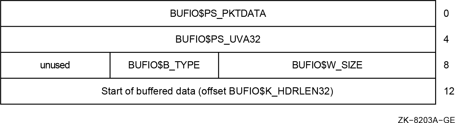 |
BUFIO$PS_PKTDATA | Contains pointer to buffered data in packet |
BUFIO$PS_UVA32 | Contains 32-bit user virtual address |
No symbolic offsets currently defined.
- Frequent use of manifest constants; for example:
MOVAB 12(R2),(R2)
Dependencies on the packet header layout can be anywhere in the driver code path.
Drivers allocate and initialize these packets.
A 64-bit buffered packet header is as shown in Figure 4.2, ''New 64-Bit Buffered I/O Packet Header''.
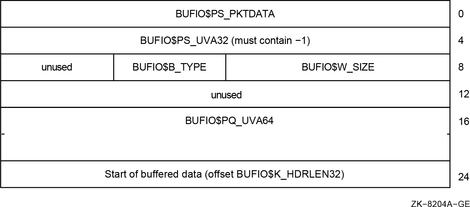 |
BUFIO$PS_PKTDATA | Contains pointer to buffered data in packet |
BUFIO$PS_UVA32 | Must contain BUFIO$K_64 (-1) value |
BUFIO$PQ_UVA64 | Contains 64-bit user virtual address |
BUFIO structures and offsets now defined.
Both 32-bit and 64-bit formats supported.
BUFIO packets are self-identifying.
New routines are EXE_STD$ALLOC_BUFIO_64, EXE_STD$ALLOC_BUFIO_32.
Used for diagnostic buffers as well.
4.5.2. Direct I/O
The caller's virtual address for the buffer is used only in FDT context.
Most of the driver identifies buffer start by IRP$L_SVAPTE and IRP$L_BOFF.
Driver "layering" in start I/O or fork environments.
Most drivers use either OpenVMS-supplied upper-level FDT routines or FDT support routines.
- The moving of the page tables has a significant impact:
Only the current process's PPTEs are available at any given time.
This is called the "cross-process PTE access" problem.
A 64-bit address is required to access page table entries in page table space: process, global, and system PTEs.
Because "SVAPTE, BOFF, BCNT" are used in many device drivers, the impact of 1 and 2 is not insignificant.
4.5.3. Direct I/O Buffer Map (DIOBM)
Figure 4.3, ''Direct I/O Buffer Map Data Structure'' shows the DIOBM data structure.
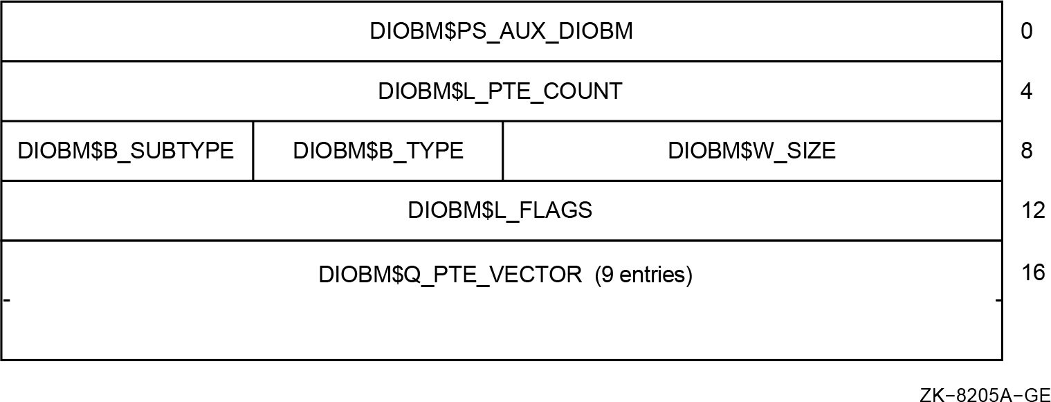 |
Use PTE vector in DIOBM for buffers up to 64 Kb
Use "secondary" DIOBM for buffers up to 5.2 Mb
Use PTE window method with DIOBM for larger buffer
DIOBM embedded in IRP, IRPE, VCRP, DCBE
MMG_STD$IOLOCK_BUF replaces MMG_STD$IOLOCK
New DIOBM routines; for example IOC_STD$FILL_DIOBM
Also of interest to LAN VCI clients
4.5.4. 64-Bit AST
Figure 4.4, ''64-Bit AST'' shows a 64-Bit AST.
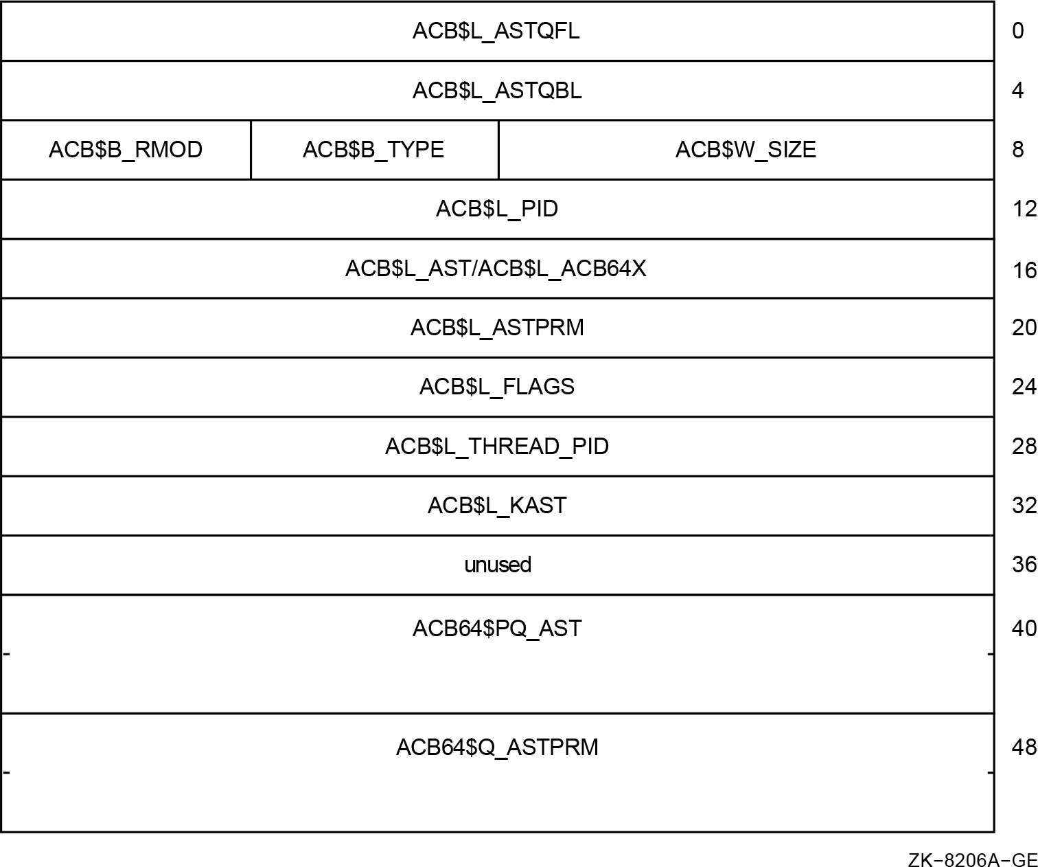 |
ACB$B_RMOD | New ACB$V_FLAGS_VALID bit (last spare bit) |
ACB$L_FLAGS | Contains ACB$V_64BITS bit (was filler space) |
ACB$L_ACB64X | Byte offset to ACB64X structure |
Both ACB and ACB64X formats are supported.
ACB packets are self-identifying.
An ACB64 is an ACB with an immediate ACB64X.
4.5.5. 64-Bit ACB Within the IRP
An embedded ACB64 at the start of the IRP is shown in Figure 4.5, ''Embedded ACB64''.
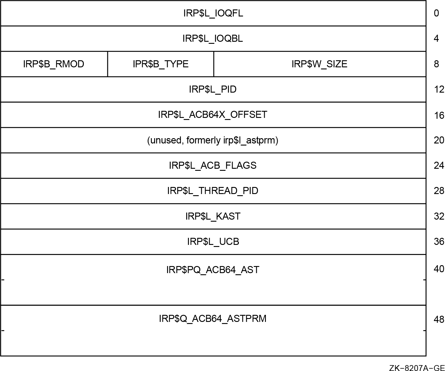 |
|
IRP$B_RMOD |
New ACB$V_FLAGS_VALID bit always set |
|
IRP$L_ACB_FLAGS |
New ACB$V_64BITS bit always set |
|
IRP$L_ACB64X_OFFSET |
Contains hex 28 |
4.5.6. I/O Function Definitions
Direct I/O, raw data transfer
Functions in this category are implemented as direct I/O operations and transfer raw data from the caller's buffer to the device without significant alteration or interpretation of the data.
Direct I/O, control data transfer
Functions in this category are implemented as direct I/O operations and transfer control information from the caller's buffer to the device driver. The device driver usually interprets the data or uses it to control the operation of the device.
Usually these functions do not support 64-bit addresses. In contrast to the raw data transfers, control data transfers tend to be smaller and are invoked less frequently. Thus, there is less need to be able to store such data in a 64-bit addressable region. The only area impacted in the driver are the corresponding FDT routines. However, control data often introduces the problem of embedded 32-bit pointers.
Buffered I/O, raw data transfer
Functions in this category are implemented as buffered I/O operations by the device driver but are otherwise the same type of raw data transfer from the caller's buffer as the first category.
Buffered I/O, control data transfer
Functions in this category are implemented as buffered I/O operations by the device driver but are otherwise the same type of control data transfer from the caller's buffer as the second category.
Control operation, no data transfer, with parameters
Functions in this category control the device and do not transfer any data between a caller's buffer and the device. Since there is no caller's buffer it does not matter whether the function is designated as a buffered or direct I/O function. The control operation has parameters that are specified in
p1throughp6however these parameters do not point to a buffer.Control operation, no data transfer, with no parameters
Functions in this category control the device and do not transfer any data between a caller's buffer and the device. Since there is no caller's buffer it does not matter whether the function is designated as a buffered or direct I/O function. In addition, there are no parameters for these functions.
|
Function Type |
64-Bits |
Area of Impact |
|---|---|---|
|
Direct I/O, raw data transfer |
Yes |
FDT only |
|
Direct I/O, control data transfer |
No |
FDT only |
|
Buffered I/O, raw data transfer |
No/yes |
Entire driver, new BUFIO packet |
|
Buffered I/O, control data transfer |
No |
Entire driver, new BUFIO packet |
|
Control, no data transfer, param |
No |
Entire path but usually simple |
|
Control, no data transfer, no params |
Moot |
None |
4.6. 64-Bit Support in Example Driver
This section summarizes changes made to the example device driver (LRDRIVER.C) to support 64-bit buffer addresses on all I/O functions.
All functions are declared as capable of supporting a 64-bit P1 parameter.
The 64-bit buffered I/O packet header defined by bufiodef.h is used instead of a privately defined structure that corresponds to the 32-bit buffered I/O packet header.
The pointer to the caller's set mode buffer is defined as a 64-bit pointer.
IRP$Q_QIO_P1 is used instead of IRP$L_QIO_P1.
The EXE_STD$ALLOC_BUF_64 routine is used instead of EXE_STD$DEBIT_BYTCNT_ALO to allocate the buffered I/O packet.
No infrastructure changes were necessary to this driver. The original version could have been simply recompiled and relinked and it would have worked correctly with 32-bitbuffer addresses.
4.6.1. Example: Declaring 64-Bit Functions
Original:
ini_fdt_act(...,IO$_WRITELBLK,lr$write,BUFFERED);
...
ini_fdt_act(...,IO$_SENSECHAR,exe_std$sensemode,
                                       BUFFERED);
ini_fdt_act(...,IO$_WRITELBLK,lr$write,BUFFERED_64);
| Source changes required to LR$WRITE routine |
| Source changes required to LR$SETMODE routine |
| No user buffer, no $QIO parameters |
4.6.2. Example: Declaring 64-Bit Buffered I/O Packet
typedef struct _sysbuf_hdr {
    char *pkt_datap;
    char *usr_bufp;
    short pkt_size;
    short :16;
SYSBUF_HDR;
64-Bit Version:#include <bufiodef.h>
| Locally defined type, SYSBUF_HDR, for a buffered I/O packet header was necessary. |
| The new bufiodef.h header file defines the BUFIO type, which includes both the 32-bit and 64-bit buffered I/O packet header cells. |
4.6.3. Example: Changes to LR$WRITE
char *qio_bufp;
| Define 32-bit pointer to caller's buffer |
| Pointer is initialized using the 32-bit $QIO P1 value |
| Size of buffered I/O packet includes header size |
| Allocate pool for buffered I/O packet |
| Connect the buffered I/O packet to IRP |
| Compute pointer to data region within packet |
CHAR_PQ qio_bufp;
| Define a 64-bit pointer to caller's buffer. |
| Pointer is initialized using the 64-bit $QIO P1 value. No source
changes on references, for
example: exe_std$writechk(irp,pcb,ucb,qio_bufp,qio_buflen); memcpy (sys_datap, qio_bufp, qio_buflen); |
| Size of buffered I/O packet includes 64-bit header size. |
| Allocate pool for a 64-bit buffered I/O packet and connect it to the IRP. |
| Get pointer to the buffered I/O packet. |
| Get pointer to data region within packet. |
4.6.4. Example: Changes to LR$SETMODE
SETMODE_BUF *setmode_bufp;
#pragma __required_pointer_size __save #pragma __required_pointer_size __long
| 32-bit pointer to a SETMODE_BUF. |
| Pointer is initialized using the 32-bit $QIO P1 value. |
| Change pointer size to 64-bits. |
| Define a type for a 64-bit pointer to a SETMODE_BUF structure. |
| Restore saved pointer size, 32-bits. |
| Define a 64-bit pointer to a SETMODE_BUF structure. |
| Pointer is initialized using the 64-bit $QIO P1 value. |
4.6.5. Example: Changes to LR$STARTIO
ucb->ucb$r_ucb.ucb$l_svapte =
                       (char *) ucb->ucb$r_ucb.ucb$l_svapte +
sizeof(SYSBUF_HDR); ucb->ucb$r_ucb.ucb$l_svapte =
(char *) ucb->ucb$r_ucb.ucb$l_svapte +
BUFIO$K_HDRLEN64;
| Skip 32-bit buffered I/O packet header. |
| Skip 64-bit buffered I/O packet header. |
Chapter 5. Modifying User-Written System Services
An application can contain certain routines that perform privileged functions, called user-written system services. This chapter describes the OpenVMS Alpha Version 7.0 changes that can affect user-written system services.
For more information about how to create user-written system services, see the VSI OpenVMS Programming Concepts Manual.
As part of the 64-bit virtual addressing support, the Alpha system service dispatcher automatically performs a sign-extension check on service arguments to ensure that only 32-bit sign extended virtual addresses are passed. This sign-extension check prevents an application from passing a 64-bit virtual address to system services that are not equipped to handle 64-bit virtual addresses. This sign-extension check occurs for the system services (regardless of mode) provided by VSI as well as for user-written system services.
|
Component |
Symbol |
Description |
|---|---|---|
|
User-supplied rundown routine for executive mode services |
PLV$PS_EXEC_RUNDOWN_HANDLER |
May contain the address of a user-supplied rundown routine that performs image-specific cleanup and resource deallocation. When the image linked against the user-written system service is run down by the system, this run-time routine is invoked. Unlike exit handlers, the routine is always called when a process or image exits. (Image rundown code calls this routine with a JSB instruction; it returns with an RSB instruction called in executive mode at IPL 0.) |
|
Kernel Routine Flags Vector |
PLV$PS_KERNEL_ROUTINE_FLAGS |
Contains either the address of an array of longwords which contain the defined flags associated with each kernel system service, or a zero. Table 5.2, ''Flags for 64-Bit User-Written Services'' contains a description of the available flags. |
|
Executive Routine Flags Vector |
PLV$PS_EXEC_ROUTINE_FLAGS |
Contains either the address of an array of longwords which contain the defined flags associated with each executive mode system service, or a zero. Table 5.2, ''Flags for 64-Bit User-Written Services'' contains a description of the available flags. |
|
Flag |
Description |
|---|---|
|
PLV$M_WAIT_CALLERS_MODE |
Informs the system service dispatcher that the service can return the status SS$_WAIT_CALLERS_MODE. This flag can only be specified for kernel mode services. |
|
PLV$M_WAIT_CALLERS_NO_REEXEC |
Informs the system service dispatcher that the service can return the status SS$_WAIT_CALLERS_MODE but should not re-execute the service. This flag can only be specified for kernel mode services. |
|
PLV$M_CLRREG |
Informs the system service dispatcher to clear the scratch integer registers before returning to the system service requester. A security-related service may set this flag to ensure that sensitive information is not left in scratch registers. This flag can be specified for both kernel and executive mode system services. |
|
PLV$M_RETURN_ANY |
Flags the system service dispatcher that the service can return arbitrary values in R0. This flag can only be specified for kernel mode system services. |
|
PLV$M_WCM_NO_SAVE |
Informs the system service dispatcher that the service has taken steps to save the contents of the scratch integer registers. In this case, the dispatcher will not take the extra steps to save and restore these registers. This flag can only be specified for kernel mode system services. |
|
PLV$M_STACK_ARGS |
Use of this flag is reserved to VSI. |
|
PLV$M_THREAD_SAFE |
Informs the system service dispatcher that the service requires no explicit synchronization. It is assumed by the dispatcher that the service provides its own internal data synchronization and that multiple kernel threads can safely execute other inner mode code in parallel. This flag can be specified for both kernel and executive mode system services. |
|
PLV$M_64_BIT_ARGS |
Informs the system service dispatcher that the service can accept 64-bit virtual addresses. When set, the dispatcher will not perform the sign-extension check on the service arguments. The sign-extension check is the method used to guarantee that only 32-bit, sign-extended virtual addresses are passed to system services. This check is enabled by default. This flag can be specified for both kernel and executive mode system services. |
|
PLV$M_CHECK_UPCALL |
Use of this flag is reserved to VSI. |
/* "Forward routine" declarations */
int     first_service(),
        second_service(),
        third_service(),
        fourth_service();
int     rundown_handler();

/* Kernel and exec routine lists: */
int (*(kernel_table[]))() = {
        first_service,
        second_service,
        fourth_service};

int (*(exec_table[]))() = {
        third_service};

/*
** Kernel and exec flags.  The flag settings below enable second_service
** and fourth_service to be 64-bit capable.  First_service and third_service
** cannot accept a 64-bit pointer.  Attempts to pass 64-bit pointers to
** these services will result in a return status of SS$_ARG_GTR_32_BITS.
** The PLV$M_64_BIT_ARGS flag instructs the system service dispatcher to
** bypass sign-extension checking of the service arguments for a particular
** service.
*/
int
    kernel_flags [] = {
        0,
        PLV$M_64_BIT_ARGS,
        0},

    exec_flags [] = {
        PLV$M_64_BIT_ARGS};

/*

** The next two defines allow the kernel and executive routine counts
** to be filled in automatically after lists have been declared for
** kernel and exec mode.  They must be placed before the PLV
** declaration and initialization, and for this module will be
** functionally equivalent to:**** #define KERNEL_ROUTINE_COUNT 3
** #define EXEC_ROUTINE_COUNT 1
**
*/

#define EXEC_ROUTINE_COUNT sizeof(exec_table)/sizeof(int *)
#define KERNEL_ROUTINE_COUNT sizeof(kernel_table)/sizeof(int *)

/*
** Now build and initialize the PLV structure.  Since the PLV must have
** the VEC psect attribute, and must be the first thing in that psect,
** we use the strict external ref-def model which allows us to put the
** PLV structure in its own psect.  This is like the globaldef
** extension in VAX C, where you can specify in what psect a global
** symbol may be found; unlike globaldef, it allows the declaration
** itself to be ANSI-compliant.  Note that the initialization here
** relies on the change-mode-specific portion (plv$r_cmod_data) of the
** PLV being declared before the portions of the PLV which are specific
** to message vector PLVs (plv$r_msg_data) and system service intercept
** PLVs (plv$r_ssi_data).
**
*/

#ifdef __ALPHA
#pragma extern_model save
#pragma extern_model strict_refdef "USER_SERVICES"
#endif
extern const PLV user_services = {
        PLV$C_TYP_CMOD,         /* type */
        0,                      /* version */
        {        {KERNEL_ROUTINE_COUNT,  /* # of kernel routines */
        EXEC_ROUTINE_COUNT,     /* # of exec routines */
        kernel_table,           /* kernel routine list */
        exec_table,             /* exec routine list */
        rundown_handler,        /* kernel rundown handler */
        rundown_handler,        /* exec rundown handler */
        0,                      /* no RMS dispatcher */
        kernel_flags,           /* kernel routine flags */
        exec_flags}             /* exec routine flags */
        }
        };
#ifdef __ALPHA
#pragma extern_model restore
#endif
Chapter 6. Kernel Threads Process Structure
Section 6.1, ''Process Control Blocks (PCBs) and Process Headers (PHDs)'' describes the process control block (PCB) and the process header (PHD).
Section 6.2, ''Kernel Thread Blocks (KTBs)'' describes the kernel thread block (KTB).
Section 6.3, ''Process Identifiers (PIDs)'' describes the process identifier (PID).
Section 6.4, ''Process Status Bits'' describes the process status bits.
For more information about kernel threads features, seethe OpenVMS Alpha Version 7.0Bookreader version of the VSI OpenVMS Programming Concepts Manual.
6.1. Process Control Blocks (PCBs) and Process Headers (PHDs)
Software process control block (PCB)
Process header (PHD)
The PCB contains fields that identify the process to the system. The PCB comprises contexts that pertain to quotas and limits, scheduling state, privileges, AST queues, and identifiers. In general, any information that must be resident at all times is in the PCB. Therefore, the PCB is allocated from nonpaged pool.
The PHD contains fields that pertain to a process's virtual address space. The PHD consists of the working set list, and the process section table. The PHD also contains the hardware process control block (HWPCB), and a floating point register save area. The HWPCB contains the hardware execution context of the process. The PHD is allocated as part of a balance set slot, and it can be outswapped.
6.1.1. Effect of a Multithreaded Process on the PCB and PHD
With multiple execution contexts within the same process, the multiple threads of execution all share the same address space but have some independent software and hardware context. This change to a multithreaded process impacts the PCB and PHD structures and any code that references them.
Before the implementation of kernel threads, the PCB contained much context that was per process. With the introduction of multiple threads of execution, much context becomes per thread. To accommodate per-thread context, a new data structure—the kernel thread block (KTB)— is created, with the per-thread context removed from the PCB. However, the PCB continues to contain context common to all threads, such as quotas and limits. The new per-kernel thread structure contains the scheduling state, priority, and the AST queues.
The PHD contains the HWPCB, which gives a process its single execution context. The HWPCB remains in the PHD; this HWPCB is used by a process when it is first created. This execution context is also called the initial thread. A single threaded process has only this one execution context. Since all threads in a process share the same address space, the PHD continues to describe the entire virtual memory layout of the process.
A new structure, the floating-point registers and execution data (FRED) block, contains the hardware context for newly created kernel threads.
6.2. Kernel Thread Blocks (KTBs)
The kernel thread block (KTB) is a new per-kernel thread data structure. The KTB contains all per-thread context moved from the PCB. The KTB is the basic unit of scheduling, a role previously performed by the PCB, and is the data structure placed in the scheduling state queues. Since the KTB is the logical extension of the PCB, the SCHED spinlock synchronizes access to the KTB and the PCB.
Typically, the number of KTBs a multithreaded process has, matches the number of CPUs on the system. Actually, the number of KTBs is limited by the value of the system parameter MULTITHREAD. If MULTITHREAD is zero, the OpenVMS kernel support is disabled. With kernel threads disabled, user-level threading is still possible with DECthreads. The environment is identical to the OpenVMS environment prior to this release that implements kernel threads. If MULTITHREAD is nonzero, it represents the maximum number of execution contexts or kernel threads that a process can own, including the initial one.
In reality the KTB is not an independent structure from the PCB. Both the PCB and KTB are defined as sparse structures. The fields of the PCB that move to the KTB retain their original PCB offsets in the KTB. In the PCB, these fields are unused. In effect, if the two structures are overlaid, the result is the PCB as it currently exists with new fields appended at the end. The PCB and KTB for the initial thread occupy the same block of nonpaged pool; therefore, the KTB address for the initial thread is the same as for the PCB.
6.2.1. KTB Vector
When a process becomes multithreaded, a vector similar to the PCB vector is created in pool. This vector contains the list of pool addresses for the kernel thread blocks in use by the process. The KTB vector entries are reused as kernel threads are created and deleted. An unused entry contains a zero. The vector entry number is used as a kernel thread ID. The first entry always contains the address of the KTB for the initial thread, which is by definition kernel thread ID zero. The kernel thread ID is used to build unique PIDs for the individual kernel threads. Section 6.3.1, ''Multithread Effects on the PID''describes PID changes for kernel threads.
PCB$L_KTBVEC
PCB$L_INITIAL_KTB
PCB$L_KT_COUNT
PCB$L_KT_HIGH
The PCB$L_INITIAL_KTB field actually overlays the new KTB$L_PCB field. For a single threaded process, PCB$L_KTBVEC is initialized to contain the address of PCB$L_INITIAL_KTB. The PCB$L_INITIAL_KTB always contains the address of the initial thread's KTB. As a process transitions from being single threaded to multithreaded and back, PCB$L_KTBVEC is updated to point to either the KTB vector in pool or PCB$L_INITIAL_KTB.
The PCB$L_KT_COUNT field counts the valid entries in the KTB vector. The PCB$L_KT_HIGH field gives the highest vector entry number in use.
6.2.2. Floating-Point Registers and Execution Data Blocks (FREDs)
To allow for multiple execution contexts, not only are additional KTBs required to maintain the software context, but additional HWPCBs must be created to maintain the hardware context. Each HWPCB has allocated with it a block of 256 bytes for preserving the contents of the floating-point registers across context switches. Another 128 bytes is allocated for per-kernel thread data. Presently, only a clone of the PHD$L_FLAGS2 field is defined.
The combined structure that contains the HWPCB, floating-point register save area, and per-kernel thread data is called the floating-point registers and execution data (FRED) block. It is 512 bytes in length. These structures reside in the process's balance set slot. This allows the FREDs to be outswapped with the process header. On the first page allocated for FRED blocks, the first 512 bytes are reserved for the inner-mode semaphore.
6.2.3. Kernel Threads Region
Much process context resides in P1 space, taking the form of data cells and the process stacks. Some of these data cells need to be per-kernel thread, as do the stacks. By calling the appropriate system service, a kernel thread region in P1 space is initialized to contain the per-kernel thread data cells and stacks. The region begins at the boundary between P0 and P1 space at address 40000000x, and it grows toward higher addresses and the initial thread's user stack. The region is divided into per-kernel thread areas. Each area contains pages for data cells and the four stacks.
6.2.4. Per-Kernel Thread Stacks
A process is created with four stacks; each access mode has one stack. All four of these stacks are located in P1 space. Stack sizes are either fixed, determined by a SYSGEN parameter, or expandable. The parameter KSTACKPAGES controls the size of the kernel stack. This parameter continues to control all kernel stack sizes, including those created for new execution contexts. The executive stack is a fixed size of two pages; with kernel threads implementation, the executive stack for new execution contexts continues to be two pages in size. The supervisor stack is a fixed size of four pages; with kernel threads implementation, the supervisor stack for new execution contexts is reduced to two pages in size.
For the user stack, a more complex situation exists. OpenVMS allocates P1space from high to lower addresses. The user stack is placed after the lowest P1 space address allocated. This allows the user stack to expand on demand toward P0 space. With the introduction of multiple sets of stacks, the locations of these stacks impose a limit on the size of each area in which they can reside. With the implementation of kernel threads, the user stack is no longer boundless. The initial user stack remains semi-boundless; it still grows toward P0 space, but the limit is the per-kernel thread region instead of P0space.
6.2.5. Per-Kernel Thread Data Cells
Several pages in P1 space contain process state in the form of data cells. A number of these cells must have a per-kernel thread equivalent. These data cells do not all reside on pages with the same protection. Because of this, the per-kernel area reserves approximately two pages for these cells. Each page has a different page protection; one page protection is user read, user write (URUW), the other is user read, executive write (UREW). The top of the user stack is used for the URUW data cells.
6.2.6. Layout of the Per-Kernel Thread
Each per-kernel thread area contains a set of stacks and two pages for data. Each area is a fixed size. For a system using the default values for the kernel stack and user stack size, each area has the layout shown in Figure 6.1, ''Default Kernel Stack and User Stack Sizes''.
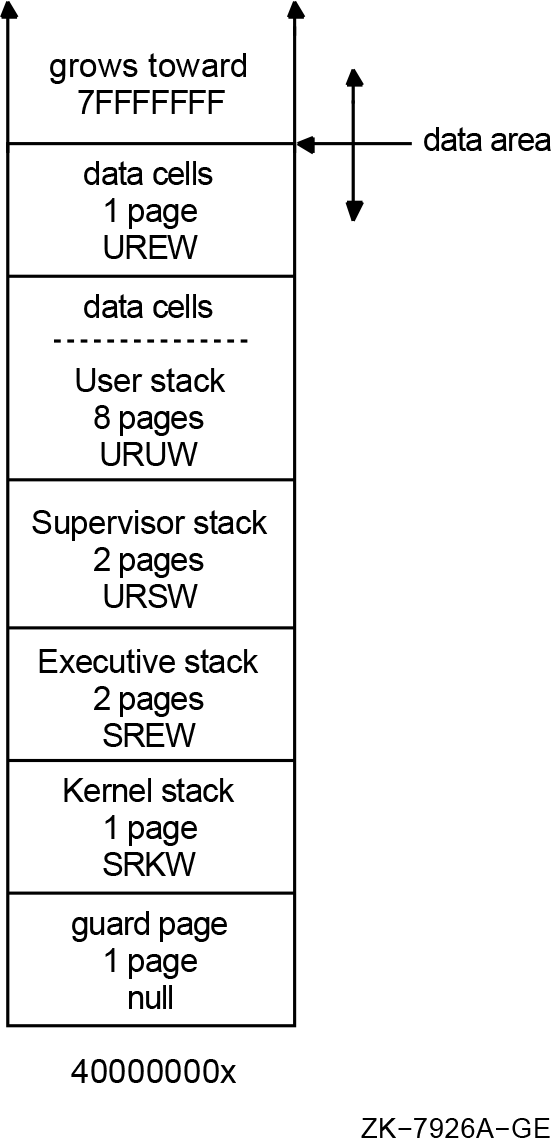 |
6.2.7. Summary of Process Data Structures
Process creation results in a PCB/KTB, a PHD/FRED, and a set of stacks. All processes have a single kernel thread, the initial thread. A multithreaded process always begins as a single threaded process. A multithreaded process contains a PCB/KTB pair and a PHD/FRED pair for the initial thread; for its other threads, it contains additional KTBs, additional FREDs, and additional sets of stacks. When the multithreaded application exists, the process returns to its single threaded state, and all additional KTBs, FREDs, and stacks are deleted.
Figure 6.2, ''Structure of a Multithreaded Process'' shows the relationships and locations of the data structures for a process.
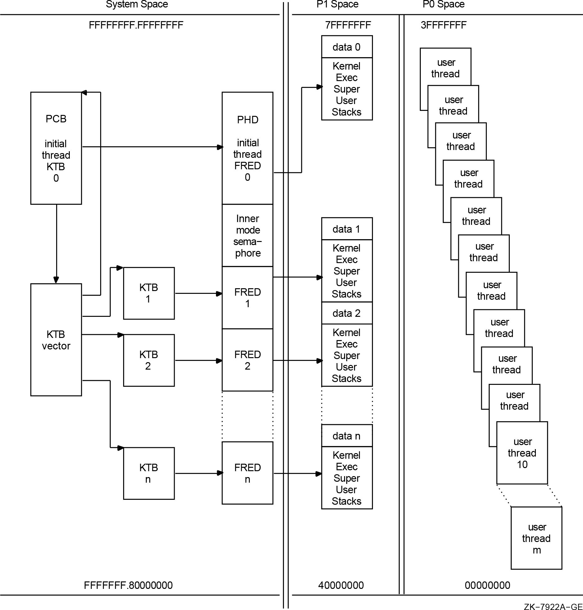 |
6.3. Process Identifiers (PIDs)
OpenVMS qualifies much context by the process ID (PID). With the implementation of kernel threads, much of that process context moves to the thread level. With kernel threads, the basic unit of scheduling is no longer the process but rather the kernel thread. Because of this, kernel threads need a method to identify them which is similar to the PID. To satisfy this need, the meaning of the PID is extended. The PID continues to identify a process, but can also identify a kernel thread within that process. An overview follows that presents the features of the PID, and the extended process ID (EPID), which is the cluster-visible extension of the PID.
The PID in this form is typically known as the internal PID (IPID). It consists of two pieces of information, both one word in length. Figure 6.3, ''Process ID (PID)'' shows the layout.
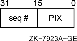 |
The low word is the process index (PIX). The PIX is used as an index into the PCB vector. This is a vector of PCB addresses. Therefore the PIX gives a quick method of determining the PCB address given a PID.
Another array, also indexed by PIX, contains a sequence number entry for each PIX. The sequence number increments every time a PIX is reused. The high word of the IPID is a copy of the value in the array for a particular PIX. This feature validates a PID to ensure that the ID is not for a process which has been deleted. The sequence number in the IPID must match the one in the sequence number array for that PIX.
The EPID is the cluster-visible PID. It consists of five parts, as Figure 6.4, ''Extended Process ID (EPID)'' shows.
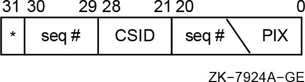 |
The EPID takes its low 21 bits from the two word IPID fields seen in Figure 6.3, ''Process ID (PID)''. The value of MAXPROCESSCNT determines the number of bits within the 21 bits used for the PIX (5 to 13 bits). The sequence number uses the remaining bits (8 to 16 bits). The PIX cannot be larger than 8192; the sequence number no larger than 32767. If the system is an OpenVMS cluster member, the next 10 bits of the EPID uniquely identify the PID within the cluster. They contain 8 bits of the cluster system ID (CSID) for the system, and a 2 bit sequence number. The system service SYS$GETJPI uses the high bit (31). If set, the bit specifies that the PID is a wildcard context value. This allows collecting information for all processes in the system.
6.3.1. Multithread Effects on the PID
MAXPROCESSCNT's maximum value is increased to 16,384.
To do this, the maximum PIX field width for the EPID is increased by one bit. This results in shrinking the sequence number field by one bit.
A redefinition of the sequence number.
The redefinition of the usage of the sequence number results in it taking on a dual meaning. It continues to be used to validate a PID; it also becomes the means for determining the kernel thread ID. Instead of a single sequence number being assigned to a PIX, a range of sequence numbers are used, one for each kernel thread. Therefore, the format of a kernel thread PID is identical to that of the PID in either its IPID, or EPID representation. The PIX and sequence number fields are in the same location, and they are the same size. In the EPID, the 10 bits used to uniquely identify the PID within the cluster remain the same; this enables kernel threads to be visible clusterwide.
6.3.2. Range Checking and Sequence Vectors
Every process has at least one kernel thread, the initial thread, which is always thread ID zero; therefore, given a particular PID, the PIX continues to be used as an index into the PCB and sequence vectors. A range check validates the sequence numbers.
Before kernel threads implementation, the sequence number vector(SCH$GL_SEQVEC) was a vector of words. After kernel threads implementation, it is a vector of longwords that enables range checking for sequence number validation. The low word in each longword is the base sequence number for a particular PIX, and the upper word is the next sequence number for that PIX. The sequence number for a single-threaded process must be equal to the base value. Kernel threads PID sequence numbers must fall within the base and next values.
Figure 6.5, ''Range Checking and Sequence Vectors''shows the flow of range checking of sequence numbers.
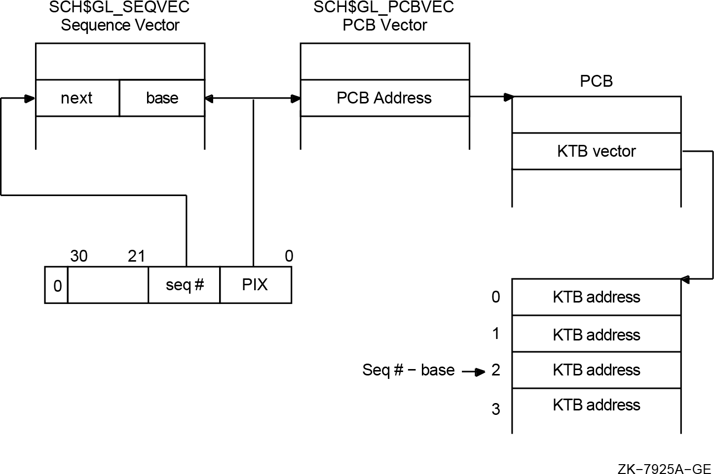 |
6.4. Process Status Bits
Similar to the fields in the PCB that migrate to the KTB, there are several status bits that need to be per thread. The interface for the SYS$GETJPI and SYS$PROCESS_SCAN system services indicates that the entire longword fields that contain the status bits can be returned. Therefore, all the status bits must remain defined as they are. The PCB specific bits are "reserved"in the KTB structure definition. Likewise, the KTB specific bits are "reserved" in the PCB. Because the PCB is really an overlaid structure with the initial thread's KTB, just the PCB status bits need to be returned for the initial thread. The status longword returned for other threads is built by first masking out the initial thread's bits, and then OR'ing the remainder with the status longword in the appropriate KTB.
If a thread in a multithreaded process requests information about itself using SYS$GETJPI (passes PID=0), then the status bits for the kernel thread it is running on are returned. Since each kernel thread has its own PID, SYS$GETJPI can be called for each of the kernel threads in a process. The return status bits are the combination of the PCB status bits and those in the KTB associated with the input PID.
Appendix A. Data Structure Changes
This appendix contains descriptions of the OpenVMS Alpha Version 7.0 I/O data structure changes made to support 64-bit addressing.
The data structures are listed in alphabetical order. However, the individual structure members are listed in the order in which they are defined within each data structure. Note, however, that the following sections only describe new or changed structure members. Existing unchanged members are not described. In addition, unused or "fill" structure members that might be added to obtain natural alignment are not listed. Thus, you can not use the following descriptions to calculate the precise memory layout of the structures. However, you can assume that any new or changed structure members will be naturally aligned within the structure.
A.1. Pointer Size Conventions
Any unqualified use of the term "pointer" implies a 32-bit pointer. All 64-bit pointers will be explicitly identified as either a 64-bit or quadword pointer.
As of OpenVMS Alpha Version 7.0,a new C compiler pragma controls the pointer size. To
facilitate the use of 64-bit pointers, a new header file, far_pointers.h in
SYS$STARLET_C.TLB, defines types for 64-bit pointers to the intrinsic C data
types.
|
Type Name |
32-Bit Analog |
Description |
Defined by |
|---|---|---|---|
|
CHAR_PQ |
char * |
64-bit pointer to a char |
far_pointers.h |
|
CHAR_PPQ |
char ** |
64-bit pointer to a CHAR_PQ |
far_pointers.h |
|
INT_PQ |
int * |
64-bit pointer to a 32-bit int |
far_pointers.h |
|
INT64_PQ |
int64 * |
64-bit pointer to a 64-bit int |
far_pointers.h |
|
UINT64_PQ |
uint64 * |
64-bit pointer to a 64-bit int |
far_pointers.h |
|
VOID_PQ |
void * |
64-bit pointer to arbitrary data |
far_pointers.h |
|
VOID_PPQ |
void ** |
64-bit pointer to a VOID_PQ |
far_pointers.h |
|
IOSB_PQ |
IOSB * |
64-bit pointer to an IOSB structure |
iosbdef.h |
|
IOSB_PPQ |
IOSB ** |
64-bit pointer to an IOSB_PQ |
iosbdef.h |
|
PTE_PQ |
PTE * |
64-bit pointer to a PTE |
ptedef.h |
|
PTE_PPQ |
PTE ** |
64-bit pointer to a PTE_PQ |
ptedef.h |
A.2. Buffer Object Descriptor (BOD)
|
Field |
Type |
Comments |
|---|---|---|
|
bod$v_s2_window |
Bit |
A bit equal to BOD$M_S2_WINDOW in the When this bit is clear, the buffer object is mapped into the
S0/S1 portion of system space and the When this bit is set, the buffer object is mapped into the S2
portion of system space and the |
|
bod$pq_basepva |
VOID_PQ |
Process virtual address for the start of the buffer object.
This cell replaces the |
|
bod$l_basepva |
- |
This cell will be removed. It will be replaced by the
|
|
bod$pq_basesva |
VOID_PQ |
System virtual address for the start of the buffer object.
This cell is overlaid on the |
|
bod$pq_va_pte |
PTE_PQ |
Virtual address for the first system PTE that maps the buffer
object. This cell is overlaid on the |
A.3. Buffered I/O (BUFIO)
The existing 32-bit Buffered I/O (BUFIO) packet format will continue to be supported. In addition, a new 64-bit BUFIO packet format will be supported. These BUFIO packets are "self identifying". That is, it is possible to distinguish a 32-bit from a 64-bit format BUFIO packet from information in the packet.
Although the structure type code DYN$C_BUFIO is defined and there is an expected layout for the header of buffered I/O packet, there currently is no formal definition of a structure. Existing code in drivers and IOCIOPOST.MAR uses numeric constants as offsets.
|
Field |
Type |
Comments |
|---|---|---|
|
bufio$ps_pktdata |
void * |
Pointer to the buffered data within the packet. |
|
bufio$ps_uva32 |
void * |
32-bit pointer to user's address space. On a read function,
data is transferred from that user virtual address to the buffer
packet during FDT processing. On a write function, data is
transferred to that user virtual address from the buffer packet
during I/O Post-processing. If this cell contains the value
BUFIO$K_64 (-1), then the pointer to the user buffer
is in |
|
bufio$w_size |
unsigned short |
Size of the BUFIO packet in bytes. |
|
bufio$b_type |
unsigned char |
Nonpaged pool packet type code, DYN$C_BUFIO |
|
BUFIO$K_HDRLEN32 |
constant |
Size in bytes of the minimal buffered I/O packet header with a 32-bit user virtual address (12). |
|
bufio$pq_uva64 |
VOID_PQ |
64-bit pointer to user's address space. On a read function,
data is transferred from that user virtual address to the buffer
packet during FDT processing. On a write function, data is
transferred to that user virtual address from the buffer packet
during I/O Post-processing. This cell contains a valid address
only if the |
|
BUFIO$K_HDRLEN64 |
constant |
Size in bytes of the minimal buffered I/O packet header with a 64-bit user virtual address (24). |
A.4. Complex Chained Buffer (CXB)
The CXB structure defines the format of entries that are linked together to build a complex chained buffered I/O packet.
|
Field |
Type |
Comments |
|---|---|---|
|
cxb$ps_pktdata |
void * |
Pointer to the buffered data within the packet. This cell will
be overlaid on the existing |
|
cxb$ps_uva32 |
void * |
32-bit pointer to user's address space. If this cell contains
the value BUFIO$K_64 (-1) then the pointer to the user
buffer is in |
|
cxb$pq_uva64 |
VOID_PQ |
64-bit pointer to user's address space. This cell contains a
valid address only if the |
A.5. Data Chain Block (DCBE)
The DCBE structure is the Data Chain Block that is used by the OpenVMS LAN driver VMS Communications Interface (VCI).A DCBE is used to connect to a VCRP all or part of the data to be transmitted. A chain of DCBEs is used when the data is contained in more than one discontinuous buffer in virtual memory.
When the
dcbe$l_buffer_addresscell contains a zero, the buffer address is specified by thedcbe$l_svapteanddcbe$l_boffcells. A fixed-size primary DIOBM structure will be added to the DCBE. This embedded DIOBM structure is available for use by an upper-level VCM if it needs to derive a 32-bit SVAPTE from a 64-bit VA_PTE for the PTEs that map the buffer. The lower-level VCM will not alter this embedded DIOBM or make any assumptions about it.When the
dcbe$l_buffer_addresscell contains the a non-zero value, this value is the system virtual address of the buffer. This method remains unchanged.
Because a VCRP can also be used as a DCBE, the named DCBE cells must be at the same offsets as their VCRP counterparts. Therefore, DCBE changes are reflected in the VCRP and changes to the common portion of the VCRP are reflected in the DCBE.
vcrp$t_internal_stack area
within the VCRP. Therefore, an increase in the size of the DCBE must be reflected by a
corresponding increase in the size of the internal stack area within the VCRP (see Table A.5, ''DCBE Structure Changes'').|
Field |
Type |
Comments |
|---|---|---|
|
dcbe$l_reserved |
int32[13] |
This existing vector of 6 filler longwords has been increased to 13 fill longwords to reflect the increased size of the common portion of the VCRP. The common portion of the VCRP has been increased to accommodate either an ACB64 or ACB structure. |
|
dcbe$pq_buffer_addr64 |
VOID_PQ |
64-bit buffer address. This cell is available for use by
upper-level VCMs only. Note that this cell does not replace the
|
|
dcbe$r_diobm |
DIOBM |
Embedded fixed-size primary "direct I/O buffer map" structure.
This DIOBM structure is available for use by upper-level VCMs
that need to lock down a buffer and provide a value for the
|
A.6. Direct I/O Buffer Map (DIOBM)
The Direct I/O Buffer Map (DIOBM) is a new structure that is used to solve the "cross-process PTE problem" for buffers that have been locked into memory for direct I/O.
To contain copies of the actual PTEs that map the buffer.
To point to a larger secondary DIOBM structure if the primary DIOBM structure has insufficient room for all the PTEs that map the user buffer.
To manage a PTE window in S0/S1 space onto the actual PTEs that map the buffer if the required PTE count exceeds the capacity of the largest allowable DIOBM structure.
Each of these methods yields a 32-bit system virtual address for the PTEs that map the buffer. This address is valid regardless of process or system context.
The fixed-size DIOBM structure contains room for exactly DIOBM$K_PTECNT_FIX (9) PTEs and is 88 bytes long. Most primary DIOBM structures are fixed-sized and embedded in other structures. For example, the IRP, IRPE, VCRP, and DCBE structures all contain an embedded fixed-sized primary DIOBM structure.
A secondary DIOBM structure can have room for up to ioc$gl_diobm_ptecnt_max PTEs
and is used only for PTE copies.
|
Field |
Type |
Comments |
|---|---|---|
|
diobm$ps_aux_diobm |
DIOBM * |
This is a pointer to a secondary DIOBM structure that is valid
if and only if DIOBM$M_AUX_INUSE in |
|
diobm$l_pte_count |
unsigned int |
If DIOBM$M_PTE_WINDOW is clear in If DIOBM$M_PTE_WINDOW is set in |
|
diobm$w_size |
unsigned short |
Size of the DIOBM packet in bytes. |
|
diobm$b_type |
unsigned char |
Nonpaged pool packet type code, DYN$C_MISC |
|
diobm$b_subtype |
unsigned char |
Nonpaged pool packet subtype code, new DYN$C_MISC subtype code DYN$C_DIOBM |
|
diobm$l_flags |
unsigned int |
Flag bits. |
|
diobm$v_rel_dealloc |
bit |
A bit equal to DIOBM$M_REL_DEALLOC in the
|
|
diobm$v_pte_window |
bit |
A bit equal to DIOBM$M_PTE_WINDOW in the
|
|
diobm$v_aux_inuse |
bit |
A bit equal to DIOBM$M_AUX_INUSE in the
|
|
diobm$v_inuse |
bit |
A bit equal to DIOBM$M_INUSE in the |
|
diobm$v_s0pte_window |
bit |
A bit equal to DIOBM$M_S0PTE_WINDOW in the
|
|
DIOBM$K_HDRLEN |
constant |
Size in bytes of the minimal DIOBM packet header excluding the
PTE vector. This is equal to the byte offset of the
|
|
diobm$q_pte_vector |
PTE[diobm$l_pte_count] |
Vector of |
|
DIOBM$K_PTECNT_FIX |
constant |
This constant specifies the number of PTE entries (9) that fit into the PTE vector in a fix-sized DIOBM structure. |
|
DIOBM$K_PTECNT_MAX_UNI |
constant |
This constant specifies the number of PTE entries (94) that fit into the PTE vector in the largest allowable DIOBM structure on an uniprocessor system. |
|
DIOBM$K_PTECNT_MAX_SMP |
constant |
This constant specifies the number of PTE entries (430) that fit into the PTE vector in the largest allowable DIOBM structure on an SMP system. |
|
diobm$ps_ptew_sva |
void * |
The lowest S0/S1 space virtual address that is mapped by the
PTEs that have been allocated for the window onto the direct I/O
buffer PTEs. This cell is used to deallocate the PTE window.
This cell is overlaid on a portion of
|
|
DIOBM$M_NORESWAIT |
constant |
This is an option bit mask for the flags parameter to the IOC_STD$FILL_DIOBM and IOC_STD$CREATE_DIOBM routines. When this option bit is set and there are insufficient resources for the needs of these routines an error status is returned to their callers instead of putting the process into a resource wait state. |
Field | Type | Comments |
|---|---|---|
diobm$ps_aux_diobm | DIOBM * | This cell must be zero in a secondary DIOBM structure. |
diobm$l_pte_count | unsigned int | Contains the number of PTEs that can fit into the |
diobm$w_size | unsigned short | Size of the DIOBM packet in bytes. |
diobm$b_type | unsigned char | Nonpaged pool packet type code, DYN$C_MISC |
diobm$b_subtype | unsigned char | Nonpaged pool packet subtype code, new DYN$C_MISC subtype code DYN$C_DIOBM |
diobm$l_flags | unsigned int | Flag bits. |
diobm$v_rel_dealloc | bit | A bit equal to DIOBM$M_REL_DEALLOC in the |
diobm$v_pte_window | bit | A bit equal to DIOBM$M_PTE_WINDOW in the |
diobm$v_aux_inuse | bit | A bit equal to DIOBM$M_AUX_INUSE in the |
diobm$v_s0pte_window | bit | A bit equal to DIOBM$M_S0PTE_WINDOW in the |
diobm$q_pte_vector | PTE[diobm$l_pte_count] | Vector of |
A.7. Function Decision Table (FDT)
|
Field |
Type |
Comments |
|---|---|---|
|
fdt$q_ok64bit |
unsigned int64 |
A 64-bit mask corresponding to the 64 possible I/O function
codes. The corresponding bit is set if the function supports a
64-bit $QIO |
A.8. I/O Request Packet (IRP)
The IRP resembles a 64-bit capable ACB64 structure instead of the existing ACB structure.
A fixed-size primary DIOBM is embedded in the IRP for use in deriving a 32-bit system virtual address for the PTEs that map a buffer locked into memory for direct I/O.
The IRP cells that contain copies of the 64-bit $QIO parameter values and the caller's IOSB address have been expanded from 32-bits to 64-bits.
Any cells overlaid on the
irp$l_ast,irp$l_astprm, orirp$l_iosbcells move to the low-order longword of their quadword replacements.Alternative cell names have been defined for the
ast,astprm, andiosbcells that can be used for arbitrary parameters in internal IRPs.
|
Field |
Type |
Comments |
|---|---|---|
|
irp$b_mode |
unsigned char |
This is an existing cell in the IRP that contains the caller's
mode in the low-order 2 bits. The |
|
irp$l_acb64x_offset |
int |
Offset to the ACB64X structure embedded in this IRP. This cell
is considered valid by SCH$QAST if and only if ACB$M_64BITS is
set in the |
|
irp$l_acb_flags |
unsigned int |
This cell has been initialized to the mask value ACB$M_64BITS
to indicate that the |
|
irp$l_thread_pid |
int |
Corresponds to the |
|
irp$pq_acb64_ast |
VOID_FUNC_PQ |
This cell corresponds to the |
|
irp$l_ast |
- |
This cell has been removed. It has been replaced by the
|
|
irp$l_shd_iofl |
IRP * |
This is an existing cell that contains the link to the cloned
shadowing IRPs. This cell was overlaid on |
|
irp$l_iirp_p0 |
int |
Generic parameter cell that is available in internal IRPs.
This cell overlays the low-order longword of the
|
|
irp$q_acb64_astprm |
int64 |
This cell corresponds to the |
|
irp$l_astprm |
- |
This cell has been removed. It is replaced by the
|
|
irp$l_shad |
SHAD * |
This is an existing cell in IRPs cloned by shadowing that
points to the SHAD structure. This cell was overlaid on
|
|
irp$l_hrb |
HRB * |
This is an existing cell in MSCP server IRPs that points to a
Host Request Block structure. This cell was overlaid on
|
|
irp$l_mv_tmo |
int |
This cell is used in internal mount verification IRPs to
contain the timeout value. This cell overlays the low-order
longword of the |
|
irp$l_iirp_p1 |
int |
Generic parameter cell that is available in internal IRPs.
This cell overlays the low-order longword of the
|
|
irp$q_user_thread_id |
uint64 |
Unique user thread identifier. Corresponds to the
|
|
irp$pq_iosb |
VOID_PQ |
64-bit pointer to the caller's IOSB. This cell replaces
|
|
irp$l_iosb |
- |
This cell has been removed. It is replaced by the
|
|
irp$l_cln_wle |
unsigned int |
This is an existing cell that contains the shadowing write log
state. This cell was overlaid on |
|
irp$l_iirp_p2 |
int |
Generic parameter cell that is available in internal IRPs.
This cell overlays the low-order longword of the
|
|
irp$pq_va_pte |
PTE_PQ |
A 64-bit pointer to the actual PTEs that map the user buffer. If the user buffer is not in shared system space, then this PTE virtual address is only valid in the caller's process context. |
|
irp$l_svapte |
PTE * |
A 32-bit pointer to PTE values that map the user buffer. The
PTE values may be copies of the actual PTEs in Page Table Space
that map the user buffer. If zero, then no PTEs have been locked
for this request. Note that for compatibility with existing
drivers, this cell remains overlaid on
|
|
irp$ps_bufio_pkt |
BUFIO * |
Pointer for the buffered I/O packet for this request. If zero,
then no packet has been allocated for this request. Note that
for compatibility with existing drivers, this cell remains
overlaid on |
|
irp$r_diobm |
DIOBM |
Embedded fixed-size primary "direct I/O buffer map"
structure. This embedded DIOBM structure is valid if and only if
|
|
irp$q_qio_p1 |
int64 |
Copy of device dependent $QIO parameter p1. The low order
32-bits of this cell remain accessible via
|
|
irp$q_qio_p2 |
int64 |
Copy of device dependent $QIO parameter p2. The low order
32-bits of this cell remain accessible via
|
|
irp$q_qio_p3 |
int64 |
Copy of device dependent $QIO parameter p3. The low order
32-bits of this cell remain accessible via
|
|
irp$q_qio_p4 |
int64 |
Copy of device dependent $QIO parameter p4. The low order
32-bits of this cell remain accessible via
|
|
irp$q_qio_p5 |
int64 |
Copy of device dependent $QIO parameter p5. The low order
32-bits of this cell remain accessible via
|
|
irp$q_qio_p6 |
int64 |
Copy of device dependent $QIO parameter p6. The low order
32-bits of this cell remain accessible via
|
A.9. I/O Request Packet Extension (IRPE)
This section describes the additions and changes to cells in the I/O Request Packet Extension (IRPE) structure. An IRPE structure can contain additional driver-specific information that needs to be associated with an IRP. It can also be used to manage additional buffers that are locked down for direct I/O.
If the IRP$M_EXTEND bit is set in irp$l_sts then the irp$l_extend
cell contains a pointer to an associated IRPE structure. Similarly, if the IRPE$M_EXTEND
bit is set in the irpe$l_sts cell, then the irpe$l_extend cell
contains a pointer to another IRPE. In general, if there is an IRPE cell with the name
irpe$X and an IRP cell with the name irp$X, then the cells
must be at the same offsets such that the IRP and the IRPE can be used interchangeably
in contexts that depend only on these common cells.
|
Field |
Type |
Comments |
|---|---|---|
|
irpe$b_rmod |
unsigned char |
Requester's access mode. This corresponds to the
|
|
irpe$l_oboff |
unsigned int |
Original byte offset into first page for buffer locked into
memory. This corresponds to the |
|
irpe$q_driver_p0 |
int64 |
Available for use by driver. This cell is overlaid on what was previously filler space. |
|
irpe$l_driver_p0 |
int |
Available for use by driver. This cell is overlaid on the
low-order 32-bits of |
|
irpe$l_driver_p1 |
int |
Available for use by driver. This cell is overlaid on the
high-order 32-bits of |
|
irpe$q_driver_p2 |
int64 |
Available for use by driver. This cell is overlaid on what was previously filler space. |
|
irpe$l_driver_p2 |
int |
Available for use by driver. This cell is overlaid on the
low-order 32-bits of |
|
irpe$l_driver_p3 |
int |
Available for use by driver. This cell is overlaid on the
high-order 32-bits of |
|
irpe$pq_va_pte |
PTE_PQ |
A 64-bit pointer to the actual PTEs that map the user buffer. If the user buffer is not in shared system space, then this PTE virtual address is only valid in the caller's process context. |
|
irpe$l_svapte |
PTE * |
A 32-bit pointer to a copy of the PTEs that map the user
buffer. If zero, then no PTEs have been locked for this request.
This cell replaces the |
|
irpe$l_svapte1 |
- |
This cell has been removed. It is replaced by the
|
|
irpe$l_bcnt |
unsigned int |
Byte count for buffer locked into memory. This cell replaces
the |
|
irpe$l_bcnt1 |
- |
This cell has been removed. It is replaced by the
|
|
irpe$l_boff |
unsigned int |
Byte offset into first page for buffer locked into memory.
This cell replaces the |
|
irpe$l_boff1 |
- |
This cell has been removed. It is replaced by the
|
|
irpe$r_diobm |
DIOBM |
Embedded fixed-size primary "direct I/O buffer map" structure.
This embedded DIOBM structure is valid if and only if the
|
|
irpe$l_svapte2 |
- |
This cell has been removed. It was used to contain a pointer to the first PTE for a second buffer that was locked into memory. If zero, then there was no second buffer. |
|
irpe$l_bcnt2 |
- |
This cell has been removed. It was used for the byte count for the second buffer locked into memory. |
|
irpe$l_boff2 |
- |
This cell has been removed. It was used for the byte offset for the second buffer locked into memory. |
A.10. Process Header (PHD)
|
Field |
Type |
Comments |
|---|---|---|
|
phd$l_iorefc |
uint32 |
Number of reasons to keep the PHD resident due to groups of pages locked for direct I/O. This count is incremented by MMG_STD$IOLOCK_BUF and decremented by MMG_STD$IOUNLOCK_BUF. On the zero-to-one transition of this cell, the slot reference count for the process in the PHV$GL_REFCBAS_LW vector is incremented. On the one-to-zero transition of this cell, the slot reference count for the process in the PHV$GL_REFCBAS_LW vector is decremented. |
A.11. SCSI-2 Diagnose Buffer (S2DGB)
For information about S2DGB 64-bit addressing support, see the OpenVMS Alpha Guide to 64-Bit Addressing and VLM Features.
A.12. VMS Communications Request Packet (VCRP)
The VCRP structure is the VMS Communications Request Packet that is used by the OpenVMS LAN driver VMS Communications Interface (VCI).A VCRP is used to transfer data between an upper- and lower-level VCM.
|
Field |
Type |
Comments |
|---|---|---|
|
vcrp$v_acb_flags_valid |
bit |
This is a new bit in the |
|
vcrp$l_acb64x_offset |
int |
Offset to the ACB64X structure embedded in this VCRP. This
cell corresponds to the |
|
vcrp$l_acb_flags |
unsigned int |
This cell corresponds to the |
|
vcrp$l_thread_id |
int |
This cell corresponds to the |
|
vcrp$pq_acb64_ast |
VOID_FUNC_PQ |
This cell corresponds to the |
|
vcrp$q_acb64_astprm |
int64 |
This cell corresponds to the |
|
vcrp$q_user_thread_id |
uint64 |
Unique user thread identifier. Corresponds to the
|
|
vcrp$pq_buffer_addr64 |
VOID_PQ |
64-bit buffer address. This cell is available for use by
upper-level VCMs only. Note that this cell does not replace the
|
|
vcrp$r_diobm |
DIOBM |
Embedded fixed-size primary "direct I/O buffer map" structure.
This DIOBM structure is available for use by upper-level VCMs
that need to lock down a buffer and provide a value for the
|
|
vcrp$t_internal_stack |
char[220] |
This existing internal stack area of 92 bytes has been increased to 220 bytes to reflect the increased size of a DCBE. SYS$PEDRIVER requires that it can place a DCBE within this stack area. This space is available for the exclusive use of upper-level VCMs |
Appendix B. I/O Support Routine Changes
This appendix contains detailed descriptions of the changes to I/O support routines and the new I/O support routines that are available to enhance device drivers to support64-bit addresses.
The routines are listed in alphabetical order.
B.1. ACP_STD$READBLK and ACP_STD$WRITEBLK
int acp_std$readblk  (IRP *irp, PCB *pcb, UCB *ucb, CCB *ccb)
int acp_std$writeblk (IRP *irp, PCB *pcb, UCB *ucb, CCB *ccb)
These routines obtain the address of the caller's buffer from irp->irp$l_qio_p1.
These routines have been modified to obtain the full 64-bit buffer address from
irp->irp$q_qio_p1 and pass it to EXE_STD$READLOCK or EXE_STD$WRITELOCK.
Note, however, that the buffer size remains a longword and is obtained from
irp->irp$l_qio_p2 without checking the upper 32-bits.
B.2. EXE_STD$ALLOC_BUFIO_32, EXE_STD$ALLOC_BUFIO_64
Routines EXE_STD$ALLOC_BUFIO_32 and EXE_STD$ALLOC_BUFIO_64 are new routines that device drivers can use to allocate and initialize simple buffered I/O (BUFIO) packets. The appropriate IRP and BUFIO header cells are initialized but it is up to the caller to copy any data into the packet.
int exe_std$alloc_bufio_32 (IRP *irp, PCB *pcb, void *uva,   int pktsiz)
int exe_std$alloc_bufio_64 (IRP *irp, PCB *pcb, VOID_PQ uva, int pktsiz)
|
Argument |
Type |
Access |
Description |
|---|---|---|---|
|
irp |
IRP * |
Input |
Pointer to the current IRP. |
|
pcb |
PCB * |
Input |
Pointer to the process PCB. |
|
uva |
VOID_PQ |
Input |
User virtual address, EXE_STD$ALLOC_BUFIO_64 |
|
|
void * |
Input |
User virtual address, EXE_STD$ALLOC_BUFIO_32 |
|
pktsiz |
int |
Input |
Required size of the packet including the packet header. |
These routines use the EXE_STD$DEBIT_BYTCNT_ALO routine to allocate the packet and charge the process for the required BYTCNT quota. Any failure status from this routine is returned to the caller.
|
Field |
Value on Successful Completion |
|---|---|
|
irp$ps_bufio_pkt |
Pointer to the allocated BUFIO packet. |
|
irp$l_boff |
Number of charged bytes and size of allocated packet. |
|
bufio$ps_pktdata |
Pointer to the packet data region in the allocated BUFIO packet. |
|
bufio$ps_uva32 |
For EXE_STD$ALLOC_BUFIO_32, value of uva. For EXE_STD$ALLOC_BUFIO_64, BUFIO$K_64. |
|
bufio$w_size |
Size of allocated packet. |
|
bufio$b_type |
DYN$C_BUFIO. |
|
bufio$pq_uva64 |
For EXE_STD$ALLOC_BUFIO_64, value of uva. |
B.3. EXE_STD$ALLOC_DIAGBUF
Routine EXE_STD$ALLOC_DIAGBUF is a new routine that allocates either a 32-bit or 64-bit diagnostic buffer packet and initializes the diagnostic buffer packet header. Diagnostic buffer packets use the same layout as BUFIO packets. This routine initializes the appropriate IRP and BUFIO header cells in the diagnostic buffer packet header but it is up to the caller to copy any data into the packet.
The allocation of a 32-bit or 64-bit format diagnostic buffer packet is controlled by a flag
bit in the packet size value that is passed to this routine. This allows callers to
simply pass in the value of the ddt$w_diagbuf cell directly to this
routine.
int exe_std$alloc_diagbuf (IRP *irp, VOID_PQ *uva, int pktsiz)
|
Argument |
Type |
Access |
Description |
|---|---|---|---|
|
irp |
IRP * |
Input |
Pointer to the current IRP. |
|
uva |
VOID_PQ |
Input |
User virtual address. |
|
pktsiz |
int |
Input |
The low-order 15-bits of this parameter specify the required size of the packet including the diagnostic packet header. If bit-16 (DDT$M_DIAGBUF64) is set a 64-bit diagnostic buffer packet is allocated. Otherwise a 32-bit diagnostic buffer packet is allocated. |
This routine uses the EXE_STD$ALLOCBUF routine to allocate the packet. Any failure status from this routine is returned to the caller of EXE_STD$ALLOC_DIAGBUF. Note that the EXE_STD$ALLOCBUF routine may put the process in a resource wait state and there is no additional process quota charge for a diagnostic buffer packet.
|
Field |
Value on Successful Completion |
|---|---|
|
irp$l_diagbuf |
Pointer to the allocated diagnostic buffer packet. |
|
irp$l_sts |
Status flag IRP$M_DIAGBUF is set to indicate that the IRP has an associated diagnostic buffer packet. |
|
bufio$ps_pktdata |
Pointer to the packet data region in the allocated diagnostic BUFIO packet. |
|
bufio$ps_uva32 |
If DDT$M_DIAGBUF64 clear, value of uva. If DDT$M_DIAGBUF64 set, BUFIO$K_64. |
|
bufio$w_size |
Size of allocated diagnostic buffer packet. |
|
bufio$b_type |
DYN$C_BUFIO |
|
bufio$pq_uva64 |
If DDT$M_DIAGBUF64 set, value of uva. |
B.4. EXE_STD$LOCK_ERR_CLEANUP
Routine EXE_STD$LOCK_ERR_CLEANUP is a new routine. This routine unlocks any previously locked down buffers that are associated with the specified IRP or any IRPEs that are attached to it. Additionally, all the attached IRPEs are deallocated.
This routine is designed to be called in a driver-supplied error callback routine that is called if any error is encountered in the EXE_STD$READLOCK, EXE_STD$WRITELOCK, or EXE_STD$MODIFY_LOCK routines.
void exe_std$lock_err_cleanup (IRP *irp)
|
Argument |
Type |
Access |
Description |
|---|---|---|---|
|
irp |
IRP * |
Input |
Pointer to the current IRP. |
|
Implicit Inputs from the IRP | |
|
Field |
Use |
|
irp$l_svapte |
If non-zero, points to the first PTE for a set of pages that will be unlocked. |
|
irp$l_bcnt |
Used only if irp$l_svapte is non-zero to calculate number of pages that will be unlocked. |
|
irp$l_boff |
Used only if irp$l_svapte is non-zero to calculate number of pages that will be unlocked. |
|
irp$v_extend |
If set, the IRPE pointed to by irp$l_extend will be processed. |
|
irp$l_extend |
Used only if irp$v_extend is set to find the first IRPE. |
|
Implicit Inputs from Each IRPE | |
|
Field |
Use |
|
irpe$l_svapte |
If non-zero, points to the first PTE for a set of pages that will be unlocked. |
|
irpe$l_bcnt |
Used only if irpe$l_svapte is non-zero to calculate number of pages that will be unlocked. |
|
irpe$l_boff |
Used only if irpe$l_svapte is non-zero to calculate number of pages that will be unlocked. |
|
irpe$v_extend |
If set, the IRPE pointed to by irpe$l_extend will be processed. |
|
irpe$l_extend |
Used only if irpe$v_extend is set to find the next IRPE. |
|
Implicit Outputs in the IRP | |
|
Field |
Value Written |
|
irp$l_svapte |
Cleared to indicate no locked pages. |
|
irp$v_extend |
Cleared to indicate no attached IRPEs. |
B.5. EXE_STD$MODIFY, EXE_STD$READ, EXE_STD$WRITE
int exe_std$modify (IRP *irp, PCB *pcb, UCB *ucb, CCB *ccb)
int exe_std$read   (IRP *irp, PCB *pcb, UCB *ucb, CCB *ccb)
int exe_std$write  (IRP *irp, PCB *pcb, UCB *ucb, CCB *ccb)
These routines obtain the address of the caller's buffer from irp->irp$l_qio_p1.
These routines have been modified to obtain the full 64-bit buffer address from
irp->irp$q_qio_p1 and pass it to EXE_STD$READLOCK or
EXE_STD$\WRITELOCK. Note, however, that the buffer size remains a longword and is
obtained from irp->irp$l_qio_p2 without checking the upper 32-bits.
B.6. EXE_STD$MODIFYLOCK, EXE_STD$READLOCK, EXE_STD$WRITELOCK
Probe the accessibility of a specified buffer by the mode contained in
irp->irp$b_modeLock the buffer into memory if the probe succeeds
Return the address of the first PTE that maps the buffer in
irp->irp$l_svapte
If an error is encountered, an optional error callback routine is invoked and the I/O request is aborted. If the entire buffer is not resident then the I/O request is backed out and a special status is returned to request a page fault of the needed page.
int exe_std$modifylock (IRP *irp, PCB *pcb, UCB *ucb, CCB *ccb,
                        void *buf, int bufsiz, void (*err_rout)(...))
int exe_std$readlock   (IRP *irp, PCB *pcb, UCB *ucb, CCB *ccb,
                        void *buf, int bufsiz, void (*err_rout)(...))
int exe_std$writelock  (IRP *irp, PCB *pcb, UCB *ucb, CCB *ccb,
void *buf, int bufsiz, void (*err_rout)(...))int exe_std$modifylock (IRP *irp, PCB *pcb, UCB *ucb, CCB *ccb,
VOID_PQ buf, int bufsiz [, void (*err_rout)(...)] )
int exe_std$readlock (IRP *irp, PCB *pcb, UCB *ucb, CCB *ccb,
VOID_PQ buf, int bufsiz [, void (*err_rout)(...)] )
int exe_std$writelock (IRP *irp, PCB *pcb, UCB *ucb, CCB *ccb,
VOID_PQ buf, int bufsiz [, void (*err_rout)(...)] )These functions now use the full 64-bits of the buffer address
bufthat is passed by value.Previously, the buffer address was a 32-bit value that was sign-extended into a 64-bit parameter value.
It is possible to omit the
err_routparameter. Currently, one can pass in the value 0 to specify that there is no error routine.The new interface supports either method of specifying that there is no error routine. Because many callers do not require an error routine, this allows them to call these routines more efficiently with six parameters.
Both of these interface changes are upwardly compatible.
B.6.1. CALL_xLOCK and CALL_xLOCK_ERR Macros
There are six MACRO-32 macros that facilitate the use of the routines described in Section B.6, ''EXE_STD$MODIFYLOCK, EXE_STD$READLOCK, EXE_STD$WRITELOCK'' by code that was originally written to use the JSB-interface counterparts for these routines. These macros have implicit register inputs and outputs that correspond to the register inputs and outputs of the JSB-interface routines.
The CALL_MODIFYLOCK, CALL_READLOCK, and CALL_WRITELOCK macros have been modified to pass the full 64-bits of R0 as the buffer address and to omit the optional error routine parameter instead of passing the value 0.
The CALL_MODIFYLOCK_ERR, CALL_READLOCK_ERR, and CALL_WRITELOCK_ERR macros have been modified to pass the full 64-bits of R0 as the buffer address.
This is an upwardly compatible change to the implementation of these macros. This change is transparent to users prior to OpenVMS Alpha Version 7.0,because R0 currently contains the 32-bit buffer address sign-extended to 64-bits.
B.7. EXE_STD$READCHK and EXE_STD$WRITECHK
The routines EXE_STD$\READCHK and EXE_STD$\WRITECHK probe the accessibility of a specified
buffer by the mode contained in irp->irp$b_mode.
int exe_std$readchk  (IRP *irp, PCB *pcb, UCB *ucb, void *buf, int bufsiz)
int exe_std$writechk (IRP *irp, PCB *pcb, UCB *ucb, void *buf, int bufsiz)
int exe_std$readchk  (IRP *irp, PCB *pcb, UCB *ucb, VOID_PQ buf, int bufsiz)
int exe_std$writechk (IRP *irp, PCB *pcb, UCB *ucb, VOID_PQ buf, int bufsiz)
The only difference in the new interface is that these functions now use the full 64-bits of
the buffer address buf that is passed by value. Previously, the buffer
address was a 32-bit value sign-extended into a 64-bit parameter value. Thus, this is an
upward compatible change to the interface.
B.7.1. CALL_xCHK and CALL_xCHKR Macros
The CALL_READCHK, CALL_READCHKR, CALL_WRITECHK, and CALL_WRITECHKRMACRO-32 macros have been modified to pass the full 64-bits of the buffer address in a similar fashion as described in Section B.6.1, ''CALL_xLOCK and CALL_xLOCK_ERR Macros''.
B.8. EXE_STD$SETCHAR and EXE_STD$SETMODE
int exe_std$setchar (IRP *irp, PCB *pcb, UCB *ucb, CCB *ccb)
int exe_std$setmode (IRP *irp, PCB *pcb, UCB *ucb, CCB *ccb)
Both of these routines use the local routine CHECK_SET to obtain and validate a pointer to the
caller's buffer from irp->irp$l_qio_p1. The routine CHECK_SET has been
modified to obtain the full 64-bit buffer address from irp->irp$q_qio_p1.
Routines EXE_STD$\SETCHAR and EXE_STD$\SETMODE has been modified to use the 64-bit
pointer returned by CHECK_SET when loading the UCB characteristics from the caller's
buffer.
B.9. IOC_STD$CREATE_DIOBM
Routine IOC_STD$CREATE_DIOBM is a new routine that is used to derive a 32-bit system virtual address for a specific number of PTEs that are pointed to by a 64-bit process virtual address. This routine allocates a "primary" DIOBM structure of sufficient size for its needs and returns a pointer to it. When the derived 32-bit system virtual address is no longer required the DIOBM must be released by calling the IOC_STD$RELEASE_DIOBM routine.
The algorithm used by this routine is very similar to the one used by IOC_STD$FILL_DIOBM as described in Section B.10, ''IOC_STD$FILL_DIOBM''.The significant difference is that IOC_STD$CREATE_DIOBM allocates a sufficiently sized primary DIOBM structure for its needs and does not depend on a preallocated fixed-size DIOBM. This routine is designed for previous users of the MMG$IOLOCK routine that do not have an embedded DIOBM to work with, but can maintain a single pointer to the external DIOBM structure that is returned by IOC_STD$CREATE_DIOBM.
int ioc_std$create_diobm (const PTE_PQ va_pte, const uint32 pte_count,
                          const uint32 flags,
                          PTE **svapte_p, DIOBM **diobm_p)
|
Argument |
Type |
Access |
Description |
|---|---|---|---|
|
va_pte |
PTE_PQ |
Input |
A 64-bit pointer to the first PTE that maps the user buffer. |
|
pte_count |
uint32 |
Input |
Number of PTEs that are required to map the entire buffer. |
|
svapte_p |
PTE ** |
Output |
Pointer to a 32-bit PTE address that is returned. The returned address is always a 32-bit system virtual address. |
|
flags |
uint32 |
Input |
Option flags. The following bit mask values can be set: DIOBM$M_NORESWAIT - Disable resource wait. All other option bits must be zero. |
|
diobm_p |
DIOBM ** |
Output |
Pointer to DIOBM address that is returned. |
This routine requires system resources, nonpaged pool and possibly SPTEs. If there are insufficient resources, this routine will, by default, place the process (kernel thread) in a kernel mode wait state for nonpaged pool and try again until it succeeds. In this case, the return value of this routine is always SS$_NORMAL because it will not return until it can do so successfully.
However, the caller can inhibit this resource wait by setting the DIOBM$M_NORESWAIT option in the flags parameter. When this is done an error status is returned to the caller if there are insufficient system resources. This capability is intended to be used in contexts where either a resource wait in kernel mode is not acceptable or the caller can readily put the process into a wait state in the requester's mode.
This routine must be called in process context and assumes that it was called at IPL 2, or minimally, that it can lower IPL to 2.
The use of the DIOBM structure by this routine is described in detail in Appendix A, "Data Structure Changes".
This routine is coded in C and is contained in the new DIOBM.C module.
B.10. IOC_STD$FILL_DIOBM
Routine IOC_STD$FILL_DIOBM is a new routine that is used to derive a 32-bit system virtual address for a specific number of PTEs that are pointed to by a 64-bit process virtual address. This routine employs a previously allocated or embedded "primary" DIOBM structure that must be supplied as one of its inputs. When the derived 32-bit system virtual address is no longer required, the DIOBM must be released by calling the IOC_STD$RELEASE_DIOBM routine.
If the PTEs are in the region of the page table space that maps S0/S1 space, a 32-bit PTE address using the SPT window is returned.
If less than or equal to DIOBM$K_PTECNT_FIX PTEs are required, the PTEs are copied into the PTE vector in the DIOBM and the 32-bit system virtual address of the PTE vector in the DIOBM is returned.
If more than DIOBM$K_PTECNT_FIX and less than or equal to
ioc$gl_diobm_ptecnt_maxPTEs are required, a secondary DIOBM is allocated, the PTEs are copied into the PTE vector in the secondary DIOBM, and the 32-bit system virtual address of the PTE vector in the secondary DIOBM is returned.If more than
ioc$gl_diobm_ptecnt_maxPTEs are required, a temporary PTE window in S0/S1 space is created that maps the necessary process level-3 page table pages. These level-3 page table pages are locked into memory and the 32-bit S0/S1 address of the PTEs through the PTE window is returned.
int ioc_std$fill_diobm (DIOBM *const diobm, const PTE_PQ va_pte,
                        const uint32 pte_count, const uint32 flags,
PTE **svapte_p)|
Argument |
Type |
Access |
Description |
|---|---|---|---|
|
diobm |
DIOBM * |
Input |
Pointer to a previously allocated but unused or uninitialized DIOBM structure. |
|
va_pte |
PTE_PQ |
Input |
A 64-bit pointer to the first PTE that maps the user buffer. |
|
pte_count |
uint32 |
Input |
Number of PTEs that are required to map the entire buffer. |
|
flags |
uint32 |
Input |
Option flags. The following bit mask values can be set: DIOBM$M_NORESWAIT - Disable resource wait. All other option bits must be zero. |
|
svapte_p |
PTE ** |
Output |
Pointer to a 32-bit PTE address that is returned. The returned address is always a 32-bit system virtual address. |
This routine may require system resources, either nonpaged pool or SPTEs, depending on the number of PTEs that are required to map the buffer. If there are insufficient resources this routine will, by default, place the process (kernel thread) in a kernel mode wait state for nonpaged pool and try again until it succeeds. In this case, the return value of this routine is always SS$_NORMAL because it will not return until it can do so successfully.
However, the caller can inhibit this resource wait by setting the DIOBM$M_NORESWAIT option in the flags parameter. When this is done, an error status is returned to the caller if there are insufficient system resources. This capability is intended to be used in contexts where either a resource wait in kernel mode is not acceptable or the caller can readily put the process into a wait state in the requestor's mode.
This routine must be called in process context and assumes that it was called at IPL 2, or minimally that it can lower IPL to 2.
The use of the DIOBM structure by this routine is described in detail in Appendix A, "Data Structure Changes".The normal version of the IOC_STD$FILL_DIOBM routine makes no assumptions about the contents of the input DIOBM structure. In contrast, the full checking version of this routine in the IO_ROUTINES_MON.EXE execlet performs some initial validation and declares an INCONSTATE bugcheck should this check fail.
B.11. IOC_STD$PTETOPFN
The routine IOC_STD$PTETOPFN allows drivers or other components to obtain the PFN for a page that has been previously locked into memory but the valid bit in its PTE is currently clear. This routine handles transition PTEs and PTEs that have reverted into GPTX format
int ioc_std$ptetopfn (PTE *pte);
int ioc_std$ptetopfn (PTE_PQ pte);
The first interface difference is that IOC_STD$PTETOPFN uses the full 64-bitsof the caller's
PTE address that is passed by value. The second interface difference is not apparent
from the above function prototype. The IOC_STD$PTETOPFN routine has been enhanced to
handle the case where the pte$v_valid bit is set in the PTE. Therefore,
drivers can use this routine without first checking the valid bit.
Both of these are upwardly compatible changes to the interface.
B.12. IOC_STD$RELEASE_DIOBM
Routine IOC_STD$RELEASE_DIOBM is a new routine that is used to release the PTE mapping resources that were set up by a prior call to either the IOC_STD$CREATE_DIOBM or IOC_STD$FILL_DIOBM routines.
int ioc_std$release_diobm (DIOBM *const diobm)
|
Argument |
Type |
Access |
Description |
|---|---|---|---|
|
diobm |
DIOBM * |
Input |
Pointer to an active primary DIOBM. |
This routine deallocates any secondary DIOBM that is connected to the primary DIOBM. If this primary DIOBM has a PTE window, the resources used for the window are deallocated. If the primary DIOBM was allocated by IOC_STD$CREATE_DIOBM, the primary DIOBM is deallocated as well. The use of the DIOBM structure by this routine is described in detail in Appendix A, "Data Structure Changes".
The returned value of this routine is always SS$_NORMAL.
This routine does not depend on process context. However, the IPL and spinlocks of the caller must allow this routine to acquire and restore the MMG spinlock.
This routine is coded in C and is contained in the new DIOBM.C module.
B.13. IOC_STD$SIMREQCOM, IOC$SIMREQCOM
The routine IOC_STD$SIMREQCOM allows drivers or other components to complete an I/O that does not have a normal IRP associated with it. Because this routine does not have an IRP, the necessary information to signal an I/O completion is passed directly in separate parameters. For example, the user's IOSB address, the event flag value, a pointer to an ACB, and the caller's access mode are among the parameters.
int ioc_std$simreqcom (int32 iosb[2], int pri, int efn, int32 iost[2],
ACB *acb, int acmode);int ioc_std$simreqcom (VOID_PQ iosb_p, int pri, int efn, int32 iost[2],
ACB *acb, int acmode);The first interface difference is that IOC_STD$SIMREQCOM uses the full 64-bitsof the caller's
IOSB address iosb_p that is passed by value. The second interface
difference is not apparent from the above function prototype. The IOC_STD$SIMREQCOM
routine has been enhanced to accept either a pointer to an ACB64 or an ACB
structure.
Both of these are upwardly compatible changes to the interface.
B.13.1. CALL_SIMREQCOM Macro
The CALL_SIMREQCOM MACRO-32 macro facilitates the use of the IOC_STD$\SIM\REQ\COM routine by code that was originally written to use the JSB-interface counterpart IOC$SIMREQCOM. The CALL_SIMREQCOM macro has implicit register inputs that correspond to the register inputs of the JSB-interface for the IOC$\SIM\REQ\COM routine.
Because this macro uses registers for its inputs, it can be altered to use the full 64-bit value of the caller's IOSB address which is passed in register R1.
B.13.2. IOC$SIMREQCOM
The IOC$SIMREQCOM routine is simply a JSB-to-CALL jacket routine around IOC_STD$SIMREQCOM. Because it is implemented through the use of the CALL_SIMREQCOM macro, IOC$SIMREQCOM transparently supports a 64-bit caller's IOSB address in the R1 parameter. Similarly, this routine allows R5 to point to either an ACB or an ACB64 structure.
B.14. IOC_STD$SVAPTE_IN_BUF
Routine IOC_STD$SVAPTE_IN_BUF is a new routine that is used to calculate a 32-bit PTE address for a virtual address within a buffer that has been previously locked for this IRP and for which a32-bit PTE address has been derived.
It is the caller's responsibility to ensure that the virtual address is a legal address within a buffer that has been locked into memory prior to calling this routine and that a 32-bit PTE address has been derived for this buffer. The IOC_STD$SVAPTE_IN_BUF routine may declare a bugcheck if either of these conditions have not been met.
int ioc_std$svapte_in_buf (IRP *irp, VOID_PQ va, PTE **svapte_p)
|
Argument |
Type |
Access |
Description |
|---|---|---|---|
|
irp |
IRP * |
Input |
Pointer to the current IRP. |
|
va |
VOID_PQ |
Input |
Virtual address within the buffer that was locked for this IRP. |
|
svapte_p |
PTE ** |
Output |
Pointer to a 32-bit PTE address that is returned. The returned address is a 32-bit system virtual address that is derived based on the values in irp$l_svapte and irp$q_qio_p1. |
|
Field |
Use |
|---|---|
|
irp$q_qio_p1 |
Virtual address of the start of the buffer that has been previously locked into memory for this IRP. |
|
irp$l_svapte |
32-bit PTE address for the PTEs that map the buffer. |
The returned value of this routine is always SS$_NORMAL.
This routine is coded in C and is contained in the new SVAPTE2.C module.
B.15. IOC_STD$VA_TO_PA
Routine IOC_STD$VA_TO_PA is a new routine that is used to derive a 64-bit physical memory address for a 64-bit virtual address. The virtual address is interpreted in the context of the current process and may be in either process-private or system space.
It is the caller's responsibility to ensure that the virtual address is a legal address and that the memory page containing the specified virtual address is locked into memory prior to calling this routine. The IOC_STD$VA_TO_PA routine may declare a bugcheck if either of these conditions have not been met.
VOID_PQ ioc_std$va_to_pa (VOID_PQ va, VOID_PPQ pa_p)
|
Argument |
Type |
Access |
Description |
|---|---|---|---|
|
va |
VOID_PQ |
Input |
A 64-bit virtual address. |
|
pa_p |
VOID_PPQ |
Output |
Pointer to a 64-bit physical address that is returned. This parameter is optional and may either be omitted entirely or specified as zero. The physical address is also returned as the value of the routine. |
Currently, the physical address for a process virtual address can be derived by calling MMG_STD$SVAPTECHK followed by IOC$SVAPTE_TO_PA. However, as described in Section 2.2.3, ''Impact of MMG_STD$SVAPTECHK Changes'', the MMG_STD$SVAPTECHK routine no longer accepts a P0/P1 address. The new IOC_STD$VA_TO_PA routine provides a direct way of computing the physical address from a process virtual address.
B.16. MMG_STD$GET_PTE_FOR_VA
Routine MMG_STD$GET_PTE_FOR_VA is a new routine that is being added for use in the Remote SDA SYSAP within SYS$SCS.
Routine MMG_STD$GET_PTE_FOR_VA attempts to obtain the Level-3 PTE containing a PFN that maps the specified virtual address for a specified process. If the requested PTE cannot be accessed either because the virtual address is not mapped or a needed page table page is not currently in physical memory, an error status is returned. Additionally, if the Level-3 PTE does not contain a useable PFN, an error status is returned.
A successful return status from this routine means that the PFN field of the returned PTE contains the physical page number for the input virtual address. Note that there are page states where the PTE contains a useable PFN but the PTE$V_VALID bit is clear. Therefore, the PTE$V_VALID bit in the returned PTE might be clear. Note also, that this routine returns a PTE from the Global Page Table when the slave PTE has reverted to GPTX format and the master PTE in the GPT still contains a PFN.
This routine is somewhat similar to MMG_STD$CALC_VAPTE except that it does not assume that the virtual address is valid or that the necessary page tables are resident in memory. Because this routine does not assume the virtual address is valid, it uses the reserved system space window to traverse the specified process' page tables in a top-down fashion. It uses this method for all process-private virtual addresses even if the specified process happens to be the current process on this CPU. This allows this routine to locate the Level-3 PTE even if some of the intervening page table pages are in transition. However, for shared system space virtual addresses this routine uses the currently active page tables instead of the reserved system window to locate the corresponding Level-3 PTE. This is possible because shared system space page table pages are not pageable and have PTE$V_VALID set if they are mapped.
This routine acquires and restores the MMG spinlock. This routine declares a bugcheck if the reserved system space window is already in use. This routine releases and invalidates the window before returning.
int mmg_std$get_pte_for_va (VOID_PQ const va, PHD *const phd, PTE_PQ pte_p)
|
Argument |
Type |
Access |
Description |
|---|---|---|---|
|
va |
VOID_PQ |
Input |
A 64-bit virtual address. |
|
phd |
PHD * |
Input |
Pointer to the PHD for the desired process address space. If zero, the current process on the current CPU is assumed. This parameter is not used, and may be zero, if the virtual address is in shared system space. |
|
pte_p |
PTE_PQ |
Output |
Address of Level-3 PTE value that is returned. A PTE value is returned only if the routine returns a successful condition value. |
|
SS$_NORMAL |
The PTE that maps the specified virtual address in the address space of the specified process contains a physical page number and was successfully returned. | |
|
SS$_ACCVIO |
The PTE that maps the specified virtual address in the address space of the specified process could not be obtained, that is, the specified virtual address is not mapped or one of the necessary page table pages is not currently resident, or the level-3 PTE did not contain a physical page number. |
B.17. MMG_STD$IOLOCK, MMG$IOLOCK, MMG_STD$IOLOCK_BUF
int mmg_std$iolock (void *buf, int bufsiz, int is_read, PCB *pcb, void **svapte_p)
This routine returns a 32-bit address by reference (the svapte_p
parameter) which, depending on the routine status, may specify the address of the
first PTE or the address of a location in the buffer that must be faulted in.
The new version of this routine must accept a 64-bit buffer address. In addition, the new version must also return either a 64-bit PTE or buffer address. This is an incompatible interface change because this return parameter is passed by reference. Thus, MMG_STD$IOLOCK has been removed and is replaced by the new MMG_STD$IOLOCK_BUF routine.
int mmg_std$iolock_buf (VOID_PQ const buf, const int bufsiz,
                        const int is_read, PCB *const pcb,
PTE_PPQ va_pte_p, VOID **fault_va_p)|
Argument |
Type |
Access |
Description |
|---|---|---|---|
|
buf |
VOID_PQ |
Input |
64-bit pointer to the buffer that is to be locked. |
|
bufsiz |
int |
Input |
Size of the buffer in bytes. |
|
is_read |
int |
Input |
Contains the value 0 if buffer will be only written to the device, 1 if the buffer will be only read from device, 5 if the buffer will be modified by the device. |
|
pcb |
PCB * |
Input |
Pointer to the process PCB. |
|
va_pte_p |
PTE_PPQ |
Output |
Pointer to a 64-bit PTE address that is returned. If the returned value of the function is successful, then the address returned is the 64-bit virtual address of the first PTE that maps the buffer. For all other function return values, the value returned in this parameter is undefined. |
|
fault_va_p |
VOID_PPQ |
Output |
Pointer to a 64-bit address that is returned. If the returned value of the function is zero, then the address returned is the 64-bit address within the buffer that must be faulted in. For all other function return values, the value returned in this parameter is undefined. |
|
Success |
A successful VMS condition value indicates that the buffer has been locked and that the 64-bit virtual address of the first PTE that maps the buffer has been returned using the va_pte_p parameter. | |
|
0 |
This return value means that a page fault is required for a page in the buffer. The virtual address of the page is returned using the fault_va_p parameter. Any portion of the buffer that may have been locked before this condition was detected has been unlocked before returning. | |
|
Failure |
Standard VMS condition value that indicates the failure. |
Just like MMG_STD$IOLOCK, the MMG_STD$IOLOCK_BUF routine must be called in process context at IPL 2 and it acquires and releases the MMG spinlock.
The 32-bit address that is returned by MMG_STD$IOLOCK in the
svapte_pparameter is valid regardless of process context. In contrast, the 64-bit address that is returned by MMG_STD$IOLOCK_BUF in theva_pte_pparameter may be valid only in the context of the current process. The new routines IOC_STD$FILL_DIOBM and IOC_STD$CREATE_DIOBM are designed to deal with this difference.The MMG_STD$IOLOCK routine locks into memory the level-3 page tables that contain the PTEs that map the buffer as well as the buffer pages. In contrast, MMG_STD$IOLOCK_BUF only locks the buffer pages. It does not lock the level-3 page tables because it would be difficult to unlock them in the absence of process context where MMG_STD$IOUNLOCK_BUF is called. Moreover, the mechanisms used by IOC_STD$FILL_DIOBM and IOC_STD$CREATE_DIOBM usually do not require the locking of the level-3 page tables. Only when the PTE window method is used by IOC_STD$FILL_DIOBM or IOC_STD$CREATE_DIOBM will these routines need to lock the level-3 page table pages into memory. When this case applies, the IOC_STD$RELEASE_DIOBM routine has enough information to unlock the level-3 page tables regardless of process context.
The existing callers of MMG_STD$IOLOCK need to be very aware of the first of these differences. The second difference is likely to be transparent to most callers.
Because the routine MMG$IOLOCK is simply a JSB-to-CALL jacket routine around MMG_STD$IOLOCK, the MMG$IOLOCK routine has also been removed.
B.17.1. CALL_IOLOCK Macro
The CALL_IOLOCK MACRO-32 macro facilitates the use of the MMG_STD$IOLOCK routine by code that was originally written to use the JSB-interface counterpart MMG$IOLOCK. The CALL_IOLOCK macro has implicit register inputs and outputs that correspond to the register inputs and outputs of the JSB-interface for the MMG$IOLOCK routine.
The full 64-bits of register R1 are now significant on return.
The returned PTE address is a 64-bit process virtual address.
Callers of MMG_STD$IOLOCK_BUF are very likely to need to call the new IOC_STD$FILL_DIOBM or IOC_STD$CREATE_DIOBM routines.
CALL_IOLOCK [ INTERFACE_WARNING=YES|NO ]
%AMAC-W-GENWARN, generated WARNING: 0 CALL_IOLOCK interface has changed for 64-bit virtual addressing; set INTERFACE_WARNING=NO to disable messages.
%AMAC-W-GENWARN, generated WARNING: 0 CALL_IOLOCK uses the 64-bit buffer address in R0
%AMAC-W-GENWARN, generated WARNING: 0 CALL_IOLOCK returns a 64-bit VA_PTE or fault VA in R1
%AMAC-W-GENWARN, generated WARNING: 0 CALL_IOLOCK does not lock the page table pages
%AMAC-W-GENWARN, generated WARNING: 0 A call to IOC_STD$FILL_DIOBM may be required to derive a SVAPTE
The compile-time warning serves to identify the existing callers of this macro. Once the invoking code has been modified, the warning can be suppressed by specifying INTERFACE_WARNING=NO.
B.18. MMG_STD$UNLOCK, MMG$UNLOCK, MMG_STD$IOUNLOCK_BUF
void mmg_std$unlock (int npages, void *svapte)
The MMG$UNLOCK routine is simply a JSB-to-CALL jacket routine around MMG_STD$\UNLOCK.
Because 32-bit PTE addresses that may point to PTE copies are sufficient for the needs of the MMG_STD$UNLOCK routine, there is no absolute requirement to change the interface of these routines. However, it is extremely likely that all callers of MMG_STD$UNLOCK and MMG$UNLOCK need to use the new DIOBM structure and need to call the new routine IOC_STD$RELEASE_DIOBM immediately after unlocking the memory buffer. Therefore, routine MMG_STD$UNLOCK has been renamed to MMG_STD$IOUNLOCK_BUF and the MMG$UNLOCK routine has been removed in order to make it difficult to miss the places where this source change is needed.
void mmg_std$iounlock_buf (const int npages, PTE_PQ const va_pte);
Just like MMG_STD$UNLOCK, the MMG_STD$IOUNLOCK_BUF routine does not depend on process context. However, the IPL and spinlocks of the caller must allow this routine to acquire and restore the MMG spinlock.
B.18.1. CALL_UNLOCK Macro
The CALL_UNLOCK MACRO-32 macro facilitates the use of the MMG_STD$UNLOCK routine by code that was originally written to use the JSB-interface counterpart MMG$UNLOCK. The CALL_UNLOCK macro has implicit register inputs that correspond to the register inputs and outputs of the JSB-interface for the MMG$UNLOCK routine.
CALL_UNLOCK [ INTERFACE_WARNING=YES|NO ]
%AMAC-W-GENWARN, generated WARNING: 0 CALL_UNLOCK interface has changed for 64-bit virtual addressing; set INTERFACE_WARNING=NO to disable messages.
%AMAC-W-GENWARN, generated WARNING: 0 CALL_UNLOCK uses the 64-bit PTE address in R3
%AMAC-W-GENWARN, generated WARNING: 0 CALL_UNLOCK does not unlock the page table pages
%AMAC-W-GENWARN, generated WARNING: 0 A call to IOC_STD$RELEASE_DIOBM may be required to derive a SVAPTE
B.19. MMG_STD$SVAPTECHK, MMG$SVAPTECHK
The current versions of the MMG_STD$SVAPTECHK and MMG$SVAPTECHK routines compute a 32-bit
svapte for either a process or system space address. As of OpenVMS
Alpha Version 7.0, these routines are be restricted to an S0/S1 system space address and
no longer accept an address in P0/P1 space. The MMG_STD$SVAPTECHK and MMG$SVAPTECHK
routines check the full 64 bits of the input address and declare a bugcheck for an input
address that is not in S0/S1 space. For S0/S1 input addresses, these routines return a
32-bit system virtual address of the PTE through the SPT window.
void mmg_std$svaptechk (void *va, PCB *pcb, PHD *phd, void **svapte_p);
void mmg_std$svaptechk (VOID_PQ va, PCB *pcb, PHD *phd, PTE **svapte_p);
The majority of callers of this routine use it with an S0/S1 address and do not need to change.
Appendix C. Kernel Threads Routines and Macros
This appendix describes the new routines and macros available implementing for kernel threads.
In addition to a few new routines to convert a PID to a KTB address, the EXE$NAM_TO_PCB routine is modified to return the KTB address in R2, which previously was a scratch register. The new routines and macros all assume the caller is executing in kernel mode.
EXE$CVT_IPID_TO_KTB Routine
EXE$CVT_IPID_TO_KTB Routine — Converts an internal PID to a KTB address.
Format
EXE$CVT_IPID_TO_KTB ipid ,ktb ,pcb
Returns
| OpenVMS usage | cond_value |
| type | longword (unsigned) |
| access | write only |
| mechanism | by value |
Status indicating the success or failure of the operation.
Arguments
| OpenVMS usage | process_id |
| type | longword (unsigned) |
| access | read |
| mechanism | by value |
This argument provides the internal PID to be converted.
ktb
| OpenVMS usage | address |
| type | quadword |
| access | write |
| mechanism | by reference |
This argument provides the KTB address.
pcb
| OpenVMS usage | address |
| type | quadword |
| access | write |
| mechanism | by reference |
This argument provides the PCB address.
Description
The EXE$CVT_IPID_TO_KTB routine converts an internal PID to a KTB address.
Return Values
|
SS$_NONEXPR |
The process does not exist. |
|
SS$_NOSUCHTHREAD |
The process exists but the thread does not. |
EXE$CVT_EPID_TO_KTB Routine
EXE$CVT_EPID_TO_KTB Routine — Converts an external PID to a KTB address.
Format
EXE$CVT_EPID_TO_KTB epid ,ktb ,pcb
Returns
| OpenVMS usage | cond_value |
| type | longword (unsigned) |
| access | write only |
| mechanism | by value |
Status indicating the success or failure of the operation.
Arguments
epid
| OpenVMS usage | process_id |
| type | longword (unsigned) |
| access | read |
| mechanism | by value |
This argument provides the external PID to be converted.
ktb
| OpenVMS usage | address |
| type | quadword |
| access | write |
| mechanism | by reference |
This argument provides the KTB address.
pcb
| OpenVMS usage | address |
| type | quadword |
| access | write |
| mechanism | by reference |
This argument provides the PCB address.
Description
The EXE$CVT_EPID_TO_KTB routine converts an external PID to a KTB address.
Return Values
|
SS$_NONEXPR |
The process does not exist. |
|
SS$_NOSUCHTHREAD |
The process exists but the thread does not. |
GET_CURKTB Macro
GET_CURKTB Macro — Obtains the current process or thread KTB address. Applicable to BLISS, C, and MACRO-32. The following three command formats are for BLISS, C, and MACRO-32, respectively.
Format
GET_CURKTB;
GET_CURKTB()
GET_CURKTB ktbreg , pcbreg, [preserve][test_multi=yes]
Arguments
ktbreg
This argument is the destination to return the KTB address. The default is R14.
pcbreg
This argument is the register containing the address of the PCB. The default is R14.
preserve
This argument is optional. The default is YES to preserve R0 and R1. Otherwise, it is NO.
test_multi
This argument is optional. The default is YES to test and validate if there is more than one KTB. If NO, it is assumed that the process is already known to be multithreaded.
Description
The GET_CURKTB macro obtains the current process or thread KTB address.
CVT_IPID_TO_PCB_KTB Macro
CVT_IPID_TO_PCB_KTB Macro — Converts a PID to PCB and KTB addresses. Applicable to MACRO-32 only.
Format
CVT_IPID_TO_PCB_KTB ipid ,ktbreg ,pcbreg ,fail
Returns
| OpenVMS usage | cond_value |
| type | longword (unsigned) |
| access | write only |
| mechanism | by value |
Status indicating the success or failure of the operation.
Arguments
ipid
This argument provides the internal PID to be converted.
ktbreg
This argument is the destination to return the KTB address. The default is R14.
pcbreg
This argument provides the register which returns the PCB. The default is R14.
preserve
This argument is not used by this macro but is passed to CVT_IPID_TO_KTB to indicate whether to preserve R0 and R1.
fail
This argument provides the address to transfer control if the ipid argument is not valid. If this transfer is taken, R0 contains one of the status values in the Return Values section.
Description
The CVT_IPID_TO_PCB_KTB macro converts a PID to PCB and KTB addresses. This macro applies to MACRO-32 only.
Return Values
|
SS$_NONEXPR |
The process does not exist. |
|
SS$_NOSUCHTHREAD |
The process exists but the thread does not. |
CVT_IPID_TO_KTB Macro
CVT_IPID_TO_KTB Macro — Converts a PID to a KTB address. Applies to MACRO-32 only.
Format
CVT_IPID_TO_KTB ipid ,ktbreg ,pcbreg ,perserve ,fail
Returns
| OpenVMS usage | cond_value |
| type | longword (unsigned) |
| access | write only |
| mechanism | by value |
Status indicating the success or failure of the operation.
Arguments
ipid
This argument provides the internal PID to be converted.
ktbreg
This argument provides the register that returns the KTB. The default is R14.
pcbreg
This argument provides the register which holds the PCB. The default is R14.
preserve
This argument's default is YES to save R0 and R1.
fail
This argument provides the address to transfer control if the ipid argument is not valid. If this transfer is taken, R0 contains one of the status values in the Return Values section.
Description
The CVT_IPID_TO_KRB macro converts a PID to a KTB address. This macro applies to MACRO-32 only.
Return Values
|
SS$_NONEXPR |
The process does not exist. |
|
SS$_NOSUCHTHREAD |
The process exists but the thread does not. |
32-bit pointer was sign-extended to 64 bits as required by the VSI OpenVMS Calling Standard.
32-bit longword value was sign-extended to 64 bits as required by the VSI OpenVMS Calling Standard.