VSI OpenVMS Calling Standard
- Operating System and Version:
- VSI OpenVMS x86-64 Version 9.2-2 or higher
VSI OpenVMS IA-64 Version 8.4-1H1 or higher
VSI OpenVMS Alpha Version 8.4-2L1 or higher
Preface
The VSI OpenVMS Calling Standard defines the requirements, mechanisms, and conventions that support procedure-to-procedure calls for OpenVMS VAX, OpenVMS Alpha, OpenVMS Industry Standard 64 (I64), and OpenVMS x86-64. The standard defines the run-time data structures, constants, algorithms, conventions, methods, and functional interfaces that enable a native user-mode procedure to operate correctly in a multilanguage environment on VAX, Alpha, Itanium®, and x86-64 systems. Properties of the run-time environment that must apply at various points during program execution are also defined.
The 32-bit user mode of OpenVMS Alpha provides a high degree of compatibility with programs written for OpenVMS VAX.
The 64-bit user mode of OpenVMS Alpha is a compatible superset of the OpenVMS Alpha 32-bit user mode.
The 32-bit and 64-bit user modes of OpenVMS I64 and x86-64 are highly compatible with OpenVMS Alpha.
The interfaces, methods, and conventions specified in this manual are primarily intended for use by implementers of compilers, debuggers, and other run-time tools, run-time libraries, and base operating systems. These specifications may or may not be appropriate for use by higher level system software and applications.
This standard is under engineering change order (ECO) control. ECOs are approved by VSI's OpenVMS Calling Standard committee.
1. About VSI
VMS Software, Inc. (VSI) is an independent software company licensed by Hewlett Packard Enterprise to develop and support the OpenVMS operating system.
2. Intended Audience
This manual primarily defines requirements for developers of compilers and debuggers, but the information can apply to procedure calling for all programmers.
3. Document Structure
This manual contains the following chapters and appendixes:
Chapter 1, "Introduction" provides an overview of the standard, defines goals, and defines terms used in the text.
Chapter 2, "OpenVMS VAX Conventions" describes the primary conventions in calling a procedure in an OpenVMS VAX environment. It defines register usage and addressing as well as vector and scalar processor synchronization.
Chapter 3, "OpenVMS Alpha Conventions" describes the fundamental concepts and conventions in calling a procedure in an OpenVMS Alpha environment. The chapter defines register usage and addressing, and focuses on aspects of the calling standard that pertain to procedure-to-procedure flow of control.
Chapter 4, "OpenVMS I64 Conventions" describes the fundamental concepts and conventions in calling a procedure in an OpenVMS I64 environment. The chapter defines register usage and addressing, and focuses on aspects of the calling standard that pertain to procedure-to-procedure flow of control.
Chapter 5, "OpenVMS x86-64 Conventions" describes the fundamental concepts and conventions in calling a procedure in an OpenVMS x86-64 environment. The chapter defines register usage and addressing, and focuses on aspects of the calling standard that pertain to procedure-to-procedure flow of control.
Chapter 6, "Signature Information and Translated Images (Alpha and IA-64 systems)" describes signature information and its role in interfacing with translated OpenVMS VAX and Alpha images on Alpha and I64 systems.
Chapter 7, "OpenVMS Argument Data Types" defines the argument-passing data types used in calling a procedure for all OpenVMS environments.
Chapter 8, "OpenVMS Argument Descriptors" defines the argument descriptors used in calling a procedure for all OpenVMS environments.
Chapter 9, "OpenVMS Conditions" describes the OpenVMS condition and exception handling requirements for all OpenVMS environments.
Appendix A, "Stack Unwinding and Exception Handling on OpenVMS I64" describes stack unwinding and exception handling for OpenVMS I64 environments.
Appendix B, "Stack Unwinding and Exception Handling on OpenVMS x86-64" describes stack unwinding and exception handling for OpenVMS x86-64 environments.
Appendix C, "Summary of Differences from Related Industry Software Conventions" contains a brief summary of the differences of this calling standard from Intel Itanium and industry x86-64 software conventions.
4. Related Documents
VAX Architecture Reference Manual
Alpha Architecture Reference Manual
OpenVMS Programming Interfaces: Calling a System Routine
Guide to POSIX Threads Library
VAX/VMS Internals and Data Structures
OpenVMS AXP Internals and Data Structures
Itanium® Software Conventions and Runtime Architecture Guide
Intel IA-64 Architecture Software Developer's Manual
Intel 64 and IA-32 Architectures Software Developer Manuals
System V Application Binary Interface, AMD64 Architecture Processor Supplement, Version 1.0
Linux Standard Base, Version 5.0
5. VSI Encourages Your Comments
You may send comments or suggestions regarding this manual or any VSI document by sending electronic mail to the following Internet address: <docinfo@vmssoftware.com>. Users who have VSI OpenVMS support contracts through VSI can contact <support@vmssoftware.com> for help with this product.
6. OpenVMS Documentation
The full VSI OpenVMS documentation set can be found on the VMS Software Documentation webpage at https://docs.vmssoftware.com.
7. Typographical Conventions
The following conventions are used in this manual:
| Convention | Meaning |
|---|---|
| Ctrl/x | A sequence such as Ctrl/x indicates that you must hold down the key labeled Ctrl while you press another key or a pointing device button. |
| PF1 x | A sequence such as PF1 x indicates that you
must first press and release the key labeled PF1 and then press and release another
key (x) or a pointing device button. |
... |
A horizontal ellipsis in examples indicates one of the following possibilities:
|
. . . | A vertical ellipsis indicates the omission of items from a code example or command format; the items are omitted because they are not important to the topic being discussed. |
| ( ) | In command format descriptions, parentheses indicate that you must enclose choices in parentheses if you specify more than one. |
| [ ] | In command format descriptions, brackets indicate optional choices. You can choose one or more items or no items. Do not type the brackets on the command line. However, you must include the brackets in the syntax for directory specifications and for a substring specification in an assignment statement. |
| | | In command format descriptions, vertical bars separate choices within brackets or braces. Within brackets, the choices are optional; within braces, at least one choice is required. Do not type the vertical bars on the command line. |
| { } | In command format descriptions, braces indicate required choices; you must choose at least one of the items listed. Do not type the braces on the command line. |
| bold type | Bold type represents the name of an argument, an attribute, or a reason. Bold type also represents the introduction of a new term. |
| italic type | Italic type indicates important information, complete titles of manuals, or variables. Variables include information that varies in system output (Internal error number), in command lines (/PRODUCER=name), and in command parameters in text (where dd represents the predefined code for the device type). |
| UPPERCASE TYPE | Uppercase type indicates a command, the name of a routine, the name of a file, or the abbreviation for a system privilege. |
Example |
This typeface indicates code examples, command examples, and interactive screen displays. In text, this type also identifies website addresses, UNIX commands and pathnames, PC-based commands and folders, and certain elements of the C programming language. |
- | A hyphen at the end of a command format description, command line, or code line indicates that the command or statement continues on the following line. |
| numbers | All numbers in text are assumed to be decimal unless otherwise noted. Nondecimal radixes—binary, octal, or hexadecimal—are explicitly indicated. |
Chapter 1. Introduction
This standard defines properties such as the run-time data structures, constants, algorithms, conventions, methods, and functional interfaces that enable a native user-mode procedure to operate correctly in a multilanguage and multithreaded environment on OpenVMS VAX, OpenVMS Alpha, OpenVMS I64, and OpenVMS x86-64 systems. These properties include the contents of key registers, format and contents of certain data structures, and actions that procedures must perform under certain circumstances.
This standard also defines properties of the run-time environment that must apply at various points during program execution. These properties vary in scope and applicability. Some properties apply at all points throughout the execution of standard-conforming user-mode code and must, therefore, be held constant at all times. Examples of such properties include those defined for the stack pointer and various properties of the call stack navigation mechanism. Other properties apply only at certain points, such as call conventions that apply only at the point of transfer of control to another procedure.
Note
In many cases, significant performance gains can be realized by selective use of nonstandard calls when the safety of such calls is known. Developers of compilers and other tools are encouraged to make full use of such optimizations.
The procedure call mechanism depends on agreement between the calling and called procedures to interpret the argument list. The argument list does not fully describe itself. This standard requires language extensions to permit a calling program to generate some of the argument-passing mechanisms expected by called procedures.
Calling sequence—instructions at the call site, entry point, and returns
Argument list—structure of the list describing the arguments to the called procedure
Function value return—form and conventions for the return of the function value as a value or as a condition value to indicate success or failure
Register usage—which registers are preserved and who is responsible for preserving them
Stack usage—rules governing the use of the stack
Argument data types—data types of arguments that can be passed
Argument descriptor formats—how descriptors are passed for the more complex arguments
Condition handling—how exception conditions are signaled and how they are handled in a modular fashion
Stack unwinding—how the current thread of execution is aborted efficiently.
1.1. Applicability
This standard defines the rules and conventions that govern the native user-mode run-time environment on OpenVMS VAX, Alpha, I64, and x86-64 systems. It is applicable to all software that executes in OpenVMS native user mode.
All externally callable interfaces in OpenVMS supported, standard system software
All intermodule calls to major software components
All external procedure calls generated by OpenVMS language processors without interprocedural analysis or permanent private conventions (such as those used for language-support run-time library [RTL] routines).
1.2. Architectural Level
This standard defines an implementation-level run-time software architecture for OpenVMS operating systems.
The interfaces, methods, and conventions specified in this document are primarily intended for use by implementers of compilers, debuggers, and other run-time tools, run-time libraries, and base operating systems. These specifications may or may not be appropriate for use by higher-level system software and applications.
Compilers and run-time libraries may provide additional support of these capabilities via interfaces that are more suited for compiler and application use. This specification neither prohibits nor requires such additional interfaces.
1.3. Goals
Applies to all intermodule callable interfaces in the native software system. Specifically, the standard considers the requirements of important compiled languages including Ada, BASIC, BLISS, C, C++, COBOL, Fortran, Pascal, LISP, PL/I, and calls to the operating system and library procedures. The needs of other languages that the OpenVMS operating system may support in the future must be met by the standard or by compatible revisions to it.
Excludes capabilities for lower-level components (such as assembler routines) that cannot be invoked from the high-level languages.
Allows the calling program and called procedure to be written in different languages. The standard reduces the need for using language extensions in mixed-language programs.
Contributes to the writing of error-free, modular, and maintainable software, and promotes effective sharing and reuse of software modules.
Provides the programmer with control over fixing, reporting, and flow of control when various types of exception conditions occur.
Provides subsystem and application writers with the ability to override system messages toward a more suitable application-oriented interface.
Adds no space or time overhead to procedure calls and returns that do not establish exception handlers, and minimizes time overhead for establishing handlers at the cost of increased time overhead when exceptions occur.
Supports a 32-bit user-mode environment that provides a high degree of compatibility with the OpenVMS VAX environment.
Supports a 64-bit user-mode environment that is a compatible superset of the OpenVMS Alpha 32-bit environment.
Simplifies coexistence with OpenVMS VAX procedures that execute under the translated image environment.
Simplifies the compilation of OpenVMS VAX assembler source to native OpenVMS Alpha object code.
Supports a multilanguage, multithreaded execution environment, including efficient, effective support for the implementation of the multithreaded architecture.
Provides an efficient mechanism for calling lightweight procedures that do not need or cannot expend the overhead of setting up a stack call frame.
Provides for the use of a common calling sequence to invoke lightweight procedures that maintain only a register call frame and heavyweight procedures that maintain a stack call frame. This calling sequence allows a compiler to determine whether to use a stack frame based on the complexity of the procedure being compiled. A recompilation of a called routine that causes a change in stack frame usage does not require a recompilation of its callers.
Provides condition handling, traceback, and debugging for lightweight procedures that do not have a stack frame.
Makes efficient use of the Alpha architecture, including effectively using a larger number of registers than is contained in a conventional VAX processor.
Minimizes the cost of procedure calls.
Extends all of the goals listed above for the OpenVMS Alpha environment to the OpenVMS I64 environment.
Supports a 64-bit user mode environment that is highly compatible with the OpenVMS Alpha 64-bit user mode environment.
Makes efficient use of the Itanium architecture, including using a larger number of registers than is contained in a conventional Alpha processor, as well as additional I64 architecture features.
Follows conventions established for Intel Itanium processor software generally except where required to preserve compatibility with OpenVMS VAX and Alpha environments.
Extends all of the goals of the earlier OpenVMS environments to x86-64 compatible systems.
Follows industry conventions established for the Intel and AMD compatible x86-64 processor software generally except where required to preserve compatibility with OpenVMS for earlier environments.
Checking of argument data types, data structures, and parameter access. The OpenVMS protection and memory management systems do not depend on correct interactions between user-level calling and called procedures. Such extended checking might be desirable in some circumstances, but system integrity does not depend on it.
Information for an interpretive OpenVMS Debugger. The definition of the debugger includes a debug symbol table (DST) that contains the required descriptive information.
1.4. Definitions
Address: On OpenVMS VAX systems, a 32-bit value used to denote a position in memory. On OpenVMS Alpha, OpenVMS I64, and OpenVMS x86-64 systems (collectively referred to as the 64-bit systems), a 64-bit value used to denote a position in memory. However, many 64-bit applications and user-mode facilities operate in such a manner that addresses are restricted only to values that are representable in 32 bits. This allows addresses on 64-bit systems often to be stored and manipulated as 32-bit longword values. In such cases, the 32-bit address value is always implicitly or explicitly sign-extended to form a 64-bit address for use by the hardware.
Argument list: A vector of entries (longwords on OpenVMS VAX, quadwords on 64-bit systems) that represents a procedure parameter list and possibly a function value.
Asynchronous software interrupt: An asynchronous interruption of normal code flow caused by some software event. This interruption shares many of the properties of hardware exceptions, including forcing some out-of-line code to execute.
Bound procedure: A type of procedure that requires knowledge (at run-time) of a dynamically determined larger enclosing scope to function correctly.
Call frame: The body of information that a procedure must save to allow it to properly return to its caller. A call frame may exist on the stack or in registers. A call frame may optionally contain additional information required by the called procedure.
Condition handler: A procedure designed to handle conditions (exceptions) when they occur during the execution of a thread.
Condition value: A 32-bit value (sign-extended to a 64-bit value on 64-bit systems) used to uniquely identify an exception condition. A condition value can be returned to a calling program as a function value or it can be signaled using the OpenVMS signaling mechanism.
Descriptor: A mechanism for passing parameters where the address of a descriptor is an entry in the argument list. The descriptor contains the address of the parameter, data type, size, and additional information needed to describe fully the data passed.
Exception condition (or condition): An exceptional condition in the current hardware or software state that should be noted or fixed. Its existence causes an interruption in program flow and forces execution of out-of-line code. Such an event might be caused by an exceptional hardware state, such as arithmetic overflows, memory access control violations, and so on, or by actions performed by software, such as subscript range checking, assertion checking, or asynchronous notification of one thread by another.
During the time the normal control flow is interrupted by an exception, that condition is termed active.
Function: A procedure that returns a single value in accordance with the standard conventions for value returning. Additional values may be returned by means of the argument list.
Function pointer: See Procedure value.
Function value: Depending on context, either 1) a value that is returned as a result of calling a procedure, or 2) a procedure value (see below).
Hardware exception: A category of exceptions that reflect an exceptional condition in the current hardware state that should be noted or fixed by the software. Hardware exceptions can occur synchronously or asynchronously with respect to the normal program flow.
IP (I64 platforms): Instruction pointer—a value that identifies a bundle of instructions in memory; the address of the first (lowest addressed) byte of an aligned 16-byte sequence that encodes three Itanium architecture instructions. See also PC.
IP (x86-64 platforms): Instruction pointer—an address that identifies an instruction in memory. See also PC.
Immediate value: A mechanism for passing input parameters where the actual value is provided in the argument list entry by the calling program.
Language-support procedure: A procedure called implicitly to implement high-level language constructs. Such procedures are not intended to be explicitly called from user programs.
Leaf procedure: A procedure that makes no outbound calls. Conversely, a non-leaf procedure is one that does make outbound calls.
Library procedure: A procedure explicitly called using the equivalent of a call statement or function reference. Such procedures are usually language independent.
Natural alignment: An attribute of certain data types that refers to the placement of the data so that the lowest addressed byte of the data has an address that is a multiple of the size of the data in bytes. Natural alignment of an aggregate data type generally refers to an alignment in which all members of the aggregate are naturally aligned.
This standard defines five natural alignments:Byte—Any byte address
Word—Any byte address that is a multiple of 2
Longword—Any byte address that is a multiple of 4
Quadword—Any byte address that is a multiple of 8
Octaword—Any byte address that is a multiple of 16
PC: A value that identifies an instruction in memory. On OpenVMS VAX, Alpha, and x86-64 systems, the address of the first (lowest addressed) byte of the sequence (unaligned on VAX and x86-64, longword aligned on Alpha) that holds the instruction. On OpenVMS I64, the IP (see above) of the bundle that contains the instruction added to the number of the slot (0, 1, or 2) for that instruction within the bundle. Sometimes used as a synonym or generic alternative to IP.
Procedure: A closed sequence of instructions that is entered from and returns control to the calling program.
Procedure value: An address value that represents a procedure. On OpenVMS VAX systems, a procedure value is the address of the entry mask that is interpreted by the CALL
xinstruction invoking the procedure. On OpenVMS Alpha systems, a procedure value is the address of the procedure descriptor for the procedure. On OpenVMS I64 systems, a procedure value is the address of a function descriptor for the procedure; it is also known as a function pointer. On OpenVMS x86-64 systems, a procedure value is a 32-bit address for either the entry point of a procedure or, if the entry point address is not representable in 32-bits, a 32-bit address for trampoline code that jumps to the actual entry point; the trampoline code may be created by the linker or be created dynamically in the case of a bound procedure value.Process: An address space and at least one thread of execution. Selected security and quota checks are done on a per-process basis.
This standard anticipates the possibility of the execution of multiple threads within a process. An operating system that provides only a single thread of execution per process is considered a special case of a multithreaded system where the maximum number of threads per process is one.
Reference: A mechanism for passing parameters where the address of the parameter is provided in the argument list by the calling program.
Routine: Synonym for procedure or function.
Signal: A POSIX defined concept used to cause out-of-line execution of code. (This term should not be confused with the OpenVMS usage of the word that more closely equates to exception as used in this document).
Standard call: Any transfer of control to a procedure by any means that presents the called procedure with the environment defined by this document and does not place additional restrictions, not defined by this document, on the called procedure.
Standard-conforming procedure: A procedure that adheres to all the relevant rules set forth in this document.
Thread of execution (or thread): An entity scheduled for execution on a processor. In language terms, a thread is a computational entity used by a program unit. Such a program unit might be a task, procedure, loop, or some other unit of computation.
All threads executing within the same process share the same address space and other process contexts, but they have a unique per-thread hardware context that includes program counter, processor status, stack pointer, and other machine registers.
This standard applies only to threads that execute within the context of a user-mode process and are scheduled on one or more processors according to software priority. All subsequent uses of the term thread in this standard refer only to such user-mode process threads.
Thread-safe code: Code that is compiled in such a way to ensure it will execute properly when run in a threaded environment. Thread-safe code usually adds extra instructions to do certain run-time checks and requires that thread local storage be accessed in a particular fashion.
Trampoline: A code fragment (often just one or a very few instructions) that forwards a jump or call.
Undefined: Referring to operations or behavior for which there is no directing algorithm used across all implementations that support this standard. Such operations may be well defined for a particular implementation, but they still remain undefined with reference to this standard. The actions of undefined operations may not be required by standard-conforming procedures.
Unpredictable: Referring to the results of an operation that cannot be guaranteed across all implementations of this standard. These results may be well defined for a particular implementation, but they remain unpredictable with reference to this standard. All results that are not specified in this standard, but are caused by operations defined in this standard, are considered unpredictable. A standard-conforming procedure cannot depend on unpredictable results.
Chapter 2. OpenVMS VAX Conventions
This chapter describes the primary conventions in calling a procedure in an OpenVMS VAX environment.
2.1. Register Usage
In the VAX architecture, there are fifteen 32-bit-wide, general-purpose hardware registers for use with scalar and vector program operations. This section defines the rules of scalar and vector register usage.
2.1.1. Scalar Register Usage
| Register | Use |
|---|---|
|
PC |
Program counter. |
|
SP |
Stack pointer. |
|
FP |
Current stack frame pointer. This register must always point at the current frame. No modification is permitted within a procedure body. |
|
AP |
Argument pointer. When a call occurs, AP must point to a valid argument list. A procedure without parameters points to an argument list consisting of a single longword containing the value 0. |
|
R1 |
Environment value. When a procedure that needs an environment value is called, the calling program must set R1 to the environment value. See bound procedure value in Section 7.3, ''Miscellaneous Data Types''. |
|
R0, R1 |
Function value return registers. These registers are not to be preserved by any called procedure. They are available as temporary registers to any called procedure. |
Registers R2 through R11 are to be preserved across procedure calls. The called procedure can use these registers, provided it saves and restores them using the procedure entry mask mechanism. The entry mask mechanism must be used so that any stack unwinding done by the condition handling mechanism restores all registers correctly. In addition, PC, FP, and AP are always preserved in the stack frame (see Section 2.2, ''Stack Usage'') by the CALLS or CALLG instruction and restored by the RET instruction. However, a called procedure can use AP as a temporary register.
If JSB routines are used, they must not save or modify any preserved registers (R2 through R11) not already saved by the entry mask mechanism of the calling program.
2.1.2. Vector Register Usage
This calling standard does not specify conventions for preserved vector registers, vector argument registers, or vector function value return registers. All such conventions are by agreement between the calling and called procedures. In the absence of such an agreement, all vector registers, including V0 through V15, VLR, VCR, and VMR are scratch registers. Among cooperating procedures, a procedure that preserves or otherwise manipulates the vector registers by agreement with its callers must provide an exception handler to restore them during an unwind.
2.2. Stack Usage
Figure 2.1, ''Stack Frame Generated by CALLG or CALLS Instruction'' shows the contents of the stack frame created for the called procedure by the CALLG or CALLS instruction.
FP always points to the call frame (the condition-handler longword) of the calling procedure. Other uses of FP within a procedure are prohibited. The bottom of stack frame (end of call stack) is indicated when the stack frame's preserved FP is 0. Unless the procedure has a condition handler, the condition-handler longword contains all zeros. See Chapter 9, "OpenVMS Conditions" for more information on condition handlers.
The contents of the stack located at addresses higher than the mask/PSW longword belong to the calling program; they should not be read or written by the called procedure, except as specified in the argument list. The contents of the stack located at addresses lower than SP belong to interrupt and exception routines; they are modified continually and unpredictably.
The called procedure allocates local storage by subtracting the required number of bytes from the SP provided on entry. This local storage is freed automatically by the return instruction (RET).
Bit <28> of the mask/PSW longword is reserved to OpenVMS for future extensions to the stack frame.
2.3. Calling Sequence
     CALLG    arglst, proc
CALLS argcnt, procargcnt onto the stack as a
longword and sets the argument pointer, AP, to the top of the stack. The complete
sequence using CALLS follows:
     push     argn
     .
     .
     .
     push     arg1
     CALLS    #n, proc
If the called procedure returns control to the calling procedure, control must return to the instruction immediately following the CALLG or CALLS instruction. Skip returns and GOTO returns are allowed only during stack unwind operations.
The called procedure returns control to the calling procedure by executing the RET instruction.
2.4. Argument List
The argument list is the primary means of passing information to and receiving results from a procedure.
2.4.1. Argument List Format
Figure 2.2, ''Argument List Format'' shows the argument list format.
The first longword is always present and contains the argument count as an unsigned integer in the low byte. The 24 high-order bits are reserved and must be zero. To access the argument count, the called procedure must ignore the reserved bits and access the count as an unsigned byte (for example, MOVZBL, TSTB, or CMPB).
An uninterpreted 32-bit value (by immediate value mechanism). If the called procedure expects fewer than 32 bits, it accesses the low-order bits and ignores the high-order bits.
An address (by reference mechanism). It is typically a pointer to a scalar data item, array, structure, record, or a procedure.
An address of a descriptor (by descriptor mechanism). See Chapter 8, "OpenVMS Argument Descriptors" for descriptor formats.
The standard permits programs to call by immediate value, by reference, by descriptor, or by combinations of these mechanisms. Interpretation of each argument list entry depends on agreement between the calling and called procedures. High-level languages use the reference or descriptor mechanisms for passing input parameters. OpenVMS system services and VAX BLISS, VAX C, VAX C++, or VAX MACRO programs use all three mechanisms.
CALLS #0, proc
A missing or null argument—for example, CALL SUB(A,,B)—is represented by an argument list entry consisting of a longword 0. Some procedures allow trailing null arguments to be omitted and others require all arguments. See each procedure's specification for details.
The argument list must be treated as read-only data by the called procedure and might be allocated in read-only memory at the option of the calling program.
2.4.2. Argument Lists and High-Level Languages
Arguments are mapped from left to right to increasing argument list offsets. The leftmost (first) argument has an address of
arglst+4, the next has an address ofarglst+8, and so on. The only exception to this is whenarglst+4specifies where a function value is to be returned, in which case the first argument has an address ofarglst+8, the second argument has an address ofarglst+12, and so on. See Section 2.5, ''Function Value Returns'' for more information.Each argument position corresponds to a single VAX argument list entry. For the C and C++ languages, a floating-point argument or a record
structthat is larger than 32 bits may be passed by value using more than one VAX argument list entry. In this case, the argument count in the argument list reflects the actual number of argument list entries rather than the number of C or C++ language arguments.
2.4.2.1. Order of Argument Evaluation
Because most high-level languages do not specify the order of evaluation of arguments (with respect to side effects), those language processors can evaluate arguments in any convenient order.
Note
The choice of argument evaluation order and code generation strategy is constrained only by the definition of the particular language. Do not write programs that depend on the order of evaluation of arguments.
2.4.2.2. Language Extensions for Argument Transmission
This calling standard permits arguments to be passed by immediate value, by reference, or by descriptor. By default, all language processors except VAX BLISS, VAX C, and VAX MACRO pass arguments by reference or by descriptor.
Language extensions are needed to reconcile the different argument-passing mechanisms. In addition to the default passing mechanism used, each language processor is required to give you explicit control, in the calling program, of the argument-passing mechanism for the data types supported by the language.
|
%VAL(arg) |
By immediate value mechanism. Corresponding
argument list entry is the value of the argument
|
|
%REF(arg) |
By reference mechanism. Corresponding
argument list entry contains the address of the
value of the argument |
|
%DESCR(arg) |
By descriptor mechanism. Corresponding
argument list entry contains the address of a
descriptor of the argument
|
CALL SUB1(%VAL(123), %REF(X), %DESCR(A))
For more information, see the VAX Fortran language documentation.
CALL SUB1 (123, X, A)
2.5. Function Value Returns
A function value is returned in register R0 if its data type can be represented in 32 bits, or in registers R0 and R1 if its data type can be represented in 64 bits, provided the data type is not a string data type (see Section 7.2, ''String Data Types'').
If the data type requires fewer than 32 bits, then R1 and the high-order bits of R0 are undefined. If the data type requires 32 or more bits but fewer than 64 bits, then the high-order bits of R1 are undefined. Two separate 32-bit entities cannot be returned in R0 and R1 because high-level languages cannot process them.
If the maximum length of the function value is known (for example, octaword integer, H_floating, or fixed-length string), the calling program can allocate the required storage and pass the address of the storage or a descriptor for the storage as the first argument.
If the maximum length of a string function value is not known to the calling program, the calling program can allocate a dynamic string descriptor. The called procedure then allocates storage for the function value and updates the contents of the dynamic string descriptor using OpenVMS Run-Time Library procedures. For information about dynamic strings, see Section 8.3, ''Dynamic String Descriptor (CLASS_D)''.
If the maximum length of a fixed-length string (see Section 8.2, ''Fixed-Length Descriptor (CLASS_S)'') or a varying string (see Section 8.8, ''Varying String Descriptor (CLASS_VS)'') function value is not known to the calling program, the calling program can indicate that it expects the string to be returned on top of the stack. For more information about the function value return, see Section 2.5.1, ''Returning a Function Value on Top of the Stack''.
Some procedures, such as operating system calls and many library procedures, return a success or failure value as a longword function value in R0. Bit <0> of the value is set (Boolean true) for a success and clear (Boolean false) for a failure. The particular success or failure status is encoded in the remaining 31 bits, as described in Section 9.1, ''Condition Values''.
2.5.1. Returning a Function Value on Top of the Stack
If the maximum length of the function value is not known, the calling program can optionally allocate certain descriptors with the POINTER field set to 0, indicating that no space has been allocated for the value. If the called procedure finds POINTER 0, it fills in the POINTER, LENGTH, and other extent fields to describe the actual size and placement of the function value. This function value is copied to the top of the stack as control returns to the calling program.
This is an exception to the usual practice because the calling program regains control at the instruction following the CALLG or CALLS sequence with the contents of SP restored to a value different from the one it had at the beginning of its CALLG or CALLS calling sequence.
This technique applies only to the first argument in the argument list. Also, the called procedure cannot assume that the calling program expects the function value to be returned on the stack. Instead, the called procedure must check the CLASS field. If the descriptor is one that can be used to return a value on the stack, the called procedure checks the POINTER field. If POINTER is not 0, the called procedure returns the value using the semantics of the descriptor. If POINTER is 0, the called procedure fills in the POINTER and LENGTH fields and returns the value to the top of the stack.
Also, when POINTER is 0, the contents of R0 and R1 are unspecified by the called procedure. Once the called procedure fills in the POINTER field and other extent fields, the calling program may pass the descriptor as an argument to other procedures.
2.5.1.1. Returning a Fixed-Length or Varying String Function Value
|
CLASS |
POINTER |
Called Procedure's Action |
|---|---|---|
|
S=1 |
Not 0 |
Copy the function value to the fixed-length area specified by the descriptor and space fill (hex 20 if ASCII) or truncate on the right. The entire area is always written according to Section 8.2, ''Fixed-Length Descriptor (CLASS_S)''. |
|
S=1 |
0 |
Return the function value on top of the stack after filling in POINTER with the first address of the string and LENGTH with the length of the string to complete the descriptor according to Section 8.2, ''Fixed-Length Descriptor (CLASS_S)''. |
|
VS=11 |
Not 0 |
Copy the function value to the varying area specified by the descriptor and fill in CURLEN and BODY according to Section 8.8, ''Varying String Descriptor (CLASS_VS)''. |
|
VS=11 |
0 |
Return the function value on top of the stack after filling in POINTER with the address of CURLEN and MAXSTRLEN with the length of the string in bytes (same value as contents of CURLEN) according to Section 8.8, ''Varying String Descriptor (CLASS_VS)''. |
|
Other |
— |
Error. A condition is signaled. |
In both the fixed-length and varying string cases, the string is unaligned. Specifically, the function value is allocated on top of the stack with no unused bytes between the stack pointer value contained at the beginning of the CALLS or CALLG sequence and the last byte of the string.
2.6. Vector and Scalar Processor Synchronization
There are two kinds of synchronization between a scalar and vector processor pair: memory synchronization and exception synchronization.
Memory synchronization with the caller of a procedure that uses the vector processor
is required because scalar machine writes (to main memory) might still be pending at
the time of entry to the called procedure. The various forms of write-cache
strategies allowed by the VAX architecture combined with the possibly independent
scalar and vector memory access paths imply that a scalar store followed by a
CALLx followed by a vector load is not safe without an
intervening MSYNC.
Within a procedure that uses the vector processor, proper memory and exception synchronization might require use of an MSYNC instruction, a SYNC instruction, or both, prior to calling or upon being called by another procedure. Further, for calls to other procedures, the requirements can vary from call to call, depending on details of actual vector usage.
An MSYNC instruction (without a SYNC) at procedure entry, at procedure exit, and
prior to a call provides proper synchronization in most cases. A SYNC instruction
without an MSYNC prior to a CALLx (or RET) is sometimes
appropriate. The remaining two cases, where both or neither MSYNC and SYNC are
needed, are rare.
Refer to the VAX MACRO and Instruction Set Reference Manual for the specific rules on what exceptions are ensured to be reported by MSYNC and other MFVP instructions.
2.6.1. Memory Synchronization
An MSYNC instruction (a form of the MFVP instruction) must be executed before the first vector load and store to synchronize with memory operations issued by the caller. While an MSYNC instruction might typically occur in the entry code sequence of a procedure, exact placement might also depend on a variety of optimization considerations.
An MSYNC instruction must be executed after the last vector load or store to synchronize with memory operations issued after return. While an MSYNC instruction might typically occur in the return code sequence of a procedure, exact placement might also depend on a variety of optimization considerations.
An MSYNC instruction must be executed between each vector load and store and each standard call to other procedures to synchronize with memory operations issued by those procedures.
Any procedure that executes vector loads or stores is responsible for synchronizing with potentially conflicting memory operations in any other procedure. However, execution of an MSYNC instruction to ensure scalar and vector memory synchronization can be omitted when it can be determined for the current procedure that all possibly incomplete vector load and stores operate only on memory not accessed by other procedures.
2.6.2. Exception Synchronization
Every procedure must ensure that no exception can be raised after the current
frame is changed (as a result of a CALLx or RET). If a
procedure executes any vector instruction that might raise an exception, then a
SYNC instruction (a form of the MFVP instruction) must be executed prior to any
subsequent CALLx or RET.
However, if the only exceptions that can occur are certain to be reported by an MSYNC instruction that is otherwise needed for memory synchronization, then the SYNC is redundant and can be omitted as an optimization.
Moreover, if the only exceptions that can occur are certain to be reported by one or more MFVP instructions that read the vector control registers, then the SYNC is redundant and can be omitted as an optimization.
Chapter 3. OpenVMS Alpha Conventions
This chapter describes the fundamental concepts and conventions for calling a procedure in an Alpha environment. The following sections identify register usage and addressing, and focus on aspects of the calling standard that pertain to procedure-to-procedure flow control.
3.1. Register Usage
Integer
Floating-point
The first 32 general-purpose registers support integer processing and the second 32 support floating-point operations.
3.1.1. Integer Registers
|
Register |
Usage |
|---|---|
|
R0 |
Function value register. In a standard call that returns a nonfloating-point function result in a register, the result must be returned in this register. In a standard call, this register may be modified by the called procedure without being saved and restored. This register is not to be preserved by any called procedure. |
|
R1 |
Conventional scratch register. In a standard call, this register may be modified by the called procedure without being saved and restored. This register is not to be preserved by any called procedure. In addition, R1 is the preferred and recommended register to use for passing the environment value when calling a bound procedure. (See Section 3.6.4, ''Simple and Bound Procedures'' and Section 6.1.2, ''Translated Images on I64 Systems''). |
|
R2—R15 |
Conventional saved registers. If a standard-conforming procedure modifies one of these registers, it must save and restore it. |
|
R16—R21 |
Argument registers. In a standard call, up to six nonfloating-point items of the argument list are passed in these registers. In a standard call, these registers may be modified by the called procedure without being saved and restored. |
|
R22—R24 |
Conventional scratch registers. In a standard call, these registers may be modified by the called procedure without being saved and restored. |
|
R25 |
Argument information (AI) register. In a standard call, this register describes the argument list. (See Section 3.6.1, ''Call Conventions'' for a detailed description). In a standard call, this register may be modified by the called procedure without being saved and restored. |
|
R26 |
Return address (RA) register. In a standard call, the return address must be passed in this register. In a standard call, this register may be modified by the called procedure without being saved and restored. |
|
R27 |
Procedure value (PV) register. In a standard call, the procedure value of the procedure being called is passed in this register. In a standard call, this register may be modified by the called procedure without being saved and restored. |
|
R28 |
Volatile scratch register. The contents of this register are always unpredictable after any external transfer of control either to or from a procedure. This applies to both standard and nonstandard calls. This register may be used by the operating system for external call fixup, autoloading, and exit sequences. |
|
R29 |
Frame pointer (FP). The contents of this register define, among other things, which procedure is considered current. Details of usage and alignment are defined in Section 3.5, ''Procedure Call Stack''. |
|
R30 |
Stack pointer (SP). This register contains a pointer to the top of the current operating stack. Aspects of its usage and alignment are defined by the hardware architecture. Various software aspects of its usage and alignment are defined in Section 3.6.1, ''Call Conventions''. |
|
R31 |
ReadAsZero/Sink (RZ). Hardware defines binary 0 as a source operand and sink (no effect) as a result operand. |
3.1.2. Floating-Point Registers
|
Register |
Usage |
|---|---|
|
F0 |
Floating-point function value register. In a standard call that returns a floating-point result in a register, this register is used to return the real part of the result. In a standard call, this register may be modified by the called procedure without being saved and restored. |
|
F1 |
Floating-point function value register. In a standard call that returns a complex floating-point result in registers, this register is used to return the imaginary part of the result. In a standard call, this register may be modified by the called procedure without being saved and restored. |
|
F2—F9 |
Conventional saved registers. If a standard-conforming procedure modifies one of these registers, it must save and restore it. |
|
F10—F15 |
Conventional scratch registers. In a standard call, these registers may be modified by the called procedure without being saved and restored. |
|
F16—F21 |
Argument registers. In a standard call, up to six floating-point arguments may be passed by value in these registers. In a standard call, these registers may be modified by the called procedure without being saved and restored. |
|
F22—F30 |
Conventional scratch registers. In a standard call, these registers may be modified by the called procedure without being saved and restored. |
|
F31 |
ReadAsZero/Sink. Hardware defines binary 0 as a source operand and sink (no effect) as a result operand. |
3.2. Address Representation
An address is a 64-bit value used to denote a position in memory. However, for compatibility with OpenVMS VAX, many Alpha applications and user-mode facilities operate in such a manner that addresses are restricted only to values that are representable in 32 bits. This allows Alpha addresses often to be stored and manipulated as 32-bit longword values. In such cases, the 32-bit address value is always implicitly or explicitly sign-extended to form a 64-bit address for use by the Alpha hardware.
3.3. Procedure Representation
One distinguishing characteristic of any calling standard is how procedures are represented. The term used to denote the value that uniquely identifies a procedure is a procedure value. If the value identifies a bound procedure, it is called a bound procedure value.
In the Alpha portion of this calling standard, all procedure values are defined to be the address of the data structure (a procedure descriptor) that describes that procedure. So, any procedure can be invoked by calling the address stored at offset 8 from the address represented by the procedure value.
Note that a simple (unbound) procedure value is defined as the address of that procedure's descriptor (see Section 3.4, ''Procedure Types''). This provides slightly different conventions than would be used if the address of the procedure's code were used as it is in many calling standards.
A bound procedure value is defined as the address of a bound procedure descriptor that provides the necessary information for the bound procedure to be called (see Section 3.6.4, ''Simple and Bound Procedures'').
3.4. Procedure Types
Stack frame procedure—Maintains its caller's context on the stack.
Register frame procedure—Maintains its caller's context in registers.
Null frame procedure—Does not establish a context and, therefore, executes in the context of its caller.
A compiler can choose which type of procedure to generate based on the requirements of the procedure in question. A calling procedure does not need to know what type of procedure it is calling.
Every procedure must have an associated structure that describes which type of procedure it is and other procedure characteristics. This structure, called a procedure descriptor, is a quadword-aligned data structure that provides basic information about a procedure. This data structure is used to interpret the call stack at any point in a thread's execution. It is typically built at compile time and usually is not accessed at run-time except to support exception processing or other rarely executed code.
Read access to procedure descriptors is done through a procedure interface described in Section 3.5.2, ''Procedure Call Tracing''. This allows for future compatible extensions to these structures.
To make invocations of that procedure visible to and interpretable by facilities such as the debugger, exception handling system, and the unwinder.
To ensure that the context of the caller saved by the called procedure can be restored if an unwind occurs. (For a description of unwinding, see Section 9.7, ''Request to Unwind from a Signal'').
3.4.1. Stack Frame Procedures
A called routine may use the stack as a means to return certain types of function values (see Section 3.7.7, ''Returning Data'' for more information).
A called routine that allocates stack space may take an exception in its routine prologue before it becomes current. This situation must be considered because the stack expansion happens in the context of the caller (see Section 3.5, ''Procedure Call Stack'' and Section 3.6.5, ''Entry and Exit Code Sequences'' for more information).
For this reason, a fixed-stack usage version of this procedure type cannot make standard calls.
The variable-stack usage version of this type of procedure is referred to as full function and can make standard calls to other procedures.
3.4.2. Procedure Descriptor for Procedures with a Stack Frame
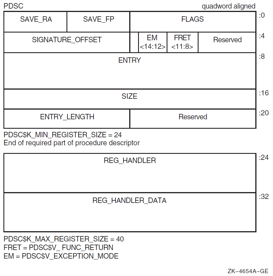
A stack frame procedure descriptor (PDSC) built by a compiler provides information about a procedure with a stack frame. The minimum size of the descriptor is 32 bytes defined by constant C. An optional PDSC extension in 8-byte increments supports exception handling requirements.
The fields defined in the stack frame descriptor are illustrated in Figure 3.1, ''Stack Frame Procedure Descriptor (PDSC)'' and described in Table 3.3, ''Contents of Stack Frame Procedure Descriptor (PDSC)''.
| Field Name | Contents | ||
|---|---|---|---|
|
PDSC$W_FLAGS |
The PDSC descriptor flag bits <15:0> are defined as follows: | ||
|
PDSC$V_KIND |
A 4-bit field <3:0> that identifies the type of procedure descriptor. For a procedure with a stack frame, this field must specify a value 9 (defined by constant PDSC$K_KIND_FP_STACK). | ||
|
PDSC$V_HANDLER_VALID |
If set to 1, this descriptor has an extension for the stack handler (PDSC$Q_STACK_HANDLER) information. | ||
|
PDSC$V_HANDLER_ |
If set to 1, the handler can be reinvoked, allowing an occurrence of another exception while the handler is already active. If this bit is set to 0, the exception handler cannot be reinvoked. Note that this bit must be 0 when PDSC$V_HANDLER_VALID is 0. | ||
|
PDSC$V_HANDLER_DATA_ |
If set to 1, the HANDLER_VALID bit must be 1, the PDSC extension STACK_HANDLER_DATA field contains valid data for the exception handler, and the address of PDSC$Q_ STACK_HANDLER_DATA will be passed to the exception handler as defined in Section 9.2, ''Condition Handlers''. | ||
|
PDSC$V_BASE_REG_IS_FP |
If this bit is set to 0, the SP is the base register to which PDSC$L_SIZE is added during an unwind. A fixed amount of storage is allocated in the procedure entry sequence, and SP is modified by this procedure only in the entry and exit code sequence. In this case, FP typically contains the address of the procedure descriptor for the procedure. A procedure for which this bit is 0 cannot make standard calls. If this bit is set to 1, FP is the base address and the procedure has a minimum amount of stack storage specified by PDSC$L_SIZE. A variable amount of stack storage can be allocated by modifying SP in the entry and exit code of this procedure. | ||
|
PDSC$V_REI_RETURN |
If set to 1, the procedure expects the stack at entry to be set, so an REI instruction correctly returns from the procedure. Also, if set, the contents of the RSA$Q_SAVED_RETURN field in the register save area are unpredictable and the return address is found on the stack (see Figure 3.4, ''Register Save Area (RSA) Layout''). | ||
|
Bit 9 |
Must be 0 (reserved). | ||
|
PDSC$V_BASE_FRAME |
For compiled code, this bit must be set to 0. If set to 1, this bit indicates the logical base frame of a stack that precedes all frames corresponding to user code. The interpretation and use of this frame and whether there are any predecessor frames is system software defined (and subject to change). | ||
|
PDSC$V_TARGET_INVO |
If set to 1, the exception handler for this procedure is invoked when this procedure is the target invocation of an unwind. Note that a procedure is the target invocation of an unwind if it is the procedure in which execution resumes following completion of the unwind. For more information, see Chapter 9, "OpenVMS Conditions". If set to 0, the exception handler for this procedure is not invoked. Note that when PDSC$V_HANDLER_VALID is 0, this bit must be 0. | ||
|
PDSC$V_NATIVE |
For compiled code, this bit must be set to 1. | ||
|
PDSC$V_NO_JACKET |
For compiled code, this bit must be set to 1. | ||
|
PDSC$V_TIE_FRAME |
For compiled code, this bit must be 0. Reserved for use by system software. | ||
|
Bit 15 |
Must be 0 (reserved). | ||
|
PDSC$W_RSA_ |
Signed offset in bytes between the stack frame base (SP or FP as indicated by PDSC$V_BASE_REG_IS_FP) and the register save area. This field must be a multiple of 8, so that PDSC$W_RSA_OFFSET added to the contents of SP or FP (PDSC$V_BASE_REG_IS_FP) yields a quadword-aligned address. | ||
|
PDSC$V_FUNC_ |
A 4-bit field <11:8> that describes which registers are used for the function value return (if there is one) and what format is used for those registers. Table 6.4, ''Function Return Signature Encodings'' lists and describes the possible encoded values of PDSC$V_FUNC_RETURN. | ||
|
PDSC$V_ |
A 3-bit field <14:12> that encodes the caller's desired exception-reporting behavior when calling certain mathematically oriented library routines. These routines generally search up the call stack to find the desired exception behavior whenever an error is detected. This search is performed independent of the setting of the Alpha FPCR. The possible values for this field are defined as follows: | ||
|
Value |
Name |
Meaning | |
| 0 |
PDSC$K_EXC_ |
Raise exceptions for all error conditions except for underflows producing a 0 result. This is the default mode. | |
| 1 |
PDSC$K_EXC_ |
Raise exceptions for all error conditions (including underflow). | |
| 2 |
PDSC$K_EXC_ |
Raise no exceptions. Create only finite values (no infinities, denormals, or NaNs). In
this mode, either the function result or the C language | |
| 3 |
PDSC$K_EXC_ |
Raise no exceptions except as controlled by separate IEEE exception enable bits. Create infinities, denormals, or NaN values according to the IEEE floating-point standard. | |
| 4 |
PDSC$K_EXC_ |
Perform the exception-mode behavior specified by this procedure's caller. | |
|
PDSC$W_ |
A 16-bit signed byte offset from the start of the procedure descriptor. This offset designates the start of the procedure signature block (if any). A 0 in this field indicates that no signature information is present. Note that in a bound procedure descriptor (as described in Section 3.6.4, ''Simple and Bound Procedures''), signature information might be present in the related procedure descriptor. A 1 in this field indicates a standard default signature. An offset value of 1 is not otherwise a valid offset because both procedure descriptors and signature blocks must be quadword aligned. | ||
|
PDSC$Q_ENTRY |
Absolute address of the first instruction of the entry code sequence for the procedure. | ||
|
PDSC$L_SIZE |
Unsigned size, in bytes, of the fixed portion of the stack frame for this procedure. The size must be a multiple of 16 bytes to maintain the minimum stack alignment required by the Alpha hardware architecture and stack alignment during a call (defined in Section 3.6.1, ''Call Conventions''). PDSC$L_SIZE cannot be 0 for a stack-frame type procedure, because the stack frame must include space for the register save area. The value of SP at entry to this procedure can be calculated by adding PDSC$L_SIZE to the value SP or FP, as indicated by PDSC$V_BASE_REG_IS_FP. | ||
|
PDSC$W_ENTRY_ |
Unsigned offset, in bytes, from the entry point to the first instruction in the procedure code segment following the procedure prologue (that is, following the instruction that updates FP to establish this procedure as the current procedure). | ||
|
PDSC$L_IREG_MASK |
Bit vector (0-31) specifying the integer registers that are saved in the register save area on entry to the procedure. The least significant bit corresponds to register R0. Never set bits 31, 30, 28, 1, and 0 of this mask, because R31 is the integer read-as-zero register, R30 is the stack pointer, R28 is always assumed to be destroyed during a procedure call or return, and R1 and R0 are never preserved registers. In this calling standard, bit 29 (corresponding to the FP) must always be set. | ||
|
PDSC$L_FREG_MASK |
Bit vector (0-31) specifying the floating-point registers saved in the register save area on entry to the procedure. The least significant bit corresponds to register F0. Never set bit 31 of this mask, because it corresponds to the floating-point read-as-zero register. | ||
|
PDSC$Q_STACK_ |
Absolute address to the procedure descriptor for a run-time static exception handling procedure. This part of the procedure descriptor is optional. It must be supplied if either PDSC$V_HANDLER_VALID is 1 or PDSC$V_HANDLER_DATA_VALID is 1 (which requires that PDSC$V_HANDLER_VALID be 1). If PDSC$V_HANDLER_VALID is 0, then the contents or existence of PDSC$Q_STACK_HANDLER is unpredictable. | ||
|
PDSC$Q_STACK_ |
Data (quadword) for the exception handler. This is an optional quadword and needs to be supplied only if PDSC$V_HANDLER_DATA_VALID is 1. If PDSC$V_HANDLER_DATA_VALID is 0, then the contents or existence of PDSC$Q_STACK_HANDLER_DATA is unpredictable. | ||
3.4.3. Stack Frame Format
Fixed size
Variable size
Even though the exact contents of a stack frame are determined by the compiler, all stack frames have common characteristics.
When PDSC$V_BASE_REG_IS_FP is 0 and PDSC$L_SIZE is 0, then the procedure utilizes no stack storage and SP contains the value of SP at entry to the procedure. (Such a procedure must be a register frame procedure).
When PDSC$V_BASE_REG_IS_FP is 0 and PDSC$L_SIZE is a nonzero value, then the procedure has a fixed amount of stack storage specified by PDSC$L_SIZE, all of which is allocated in the procedure entry sequence, and SP is modified by this procedure only in the entry and exit code sequences. (Such a procedure may not make standard calls).
When PDSC$V_BASE_REG_IS_FP is 1 and PDSC$L_SIZE is a nonzero value, then the procedure has a fixed amount of stack storage specified by PDSC$L_SIZE, and may have a variable amount of stack storage allocated by modifying SP in the body of the procedure. (Such a procedure must be a stack frame procedure).
The combination when PDSC$V_BASE_REG_IS_FP is 1 and PDSC$L_SIZE is 0 is illegal because it violates the rules for R29 (FP) usage that requires R29 to be saved (on the stack) and restored.
3.4.3.1. Fixed-Size Stack Frame
Figure 3.2, ''Fixed-Size Stack Frame Format'' illustrates the format of the stack frame for a procedure with a fixed amount of stack that uses the SP register as the stack base pointer (when PDSC$V_BASE_REG_IS_FP is 0). In this case, R29 (FP) typically contains the address of the procedure descriptor for the current procedure (see Section 3.5.1, ''Current Procedure'').
Some parts of the stack frame are optional and occur only as required by the particular procedure. As shown in the figure, the field names within brackets are optional fields. Use of the arguments passed in memory field appending the end of the descriptor is described in Section 3.4.3.3, ''Fixed Temporary Locations for All Stack Frames'' and Section 3.7.2, ''Argument List Structure''.
For information describing the fixed temporary locations and register save area, see Section 3.4.3.3, ''Fixed Temporary Locations for All Stack Frames'' and Section 3.4.3.4, ''Register Save Area for All Stack Frames''.
3.4.3.2. Variable-Size Stack Frame
Figure 3.3, ''Variable-Size Stack Frame Format'' illustrates the format of the stack frame for procedures with a varying amount of stack when PDSC$V_BASE_REG_IS_FP is 1. In this case, R29 (FP) contains the address that points to the base of the stack frame on the stack. This frame-base quadword location contains the address of the current procedure's descriptor.
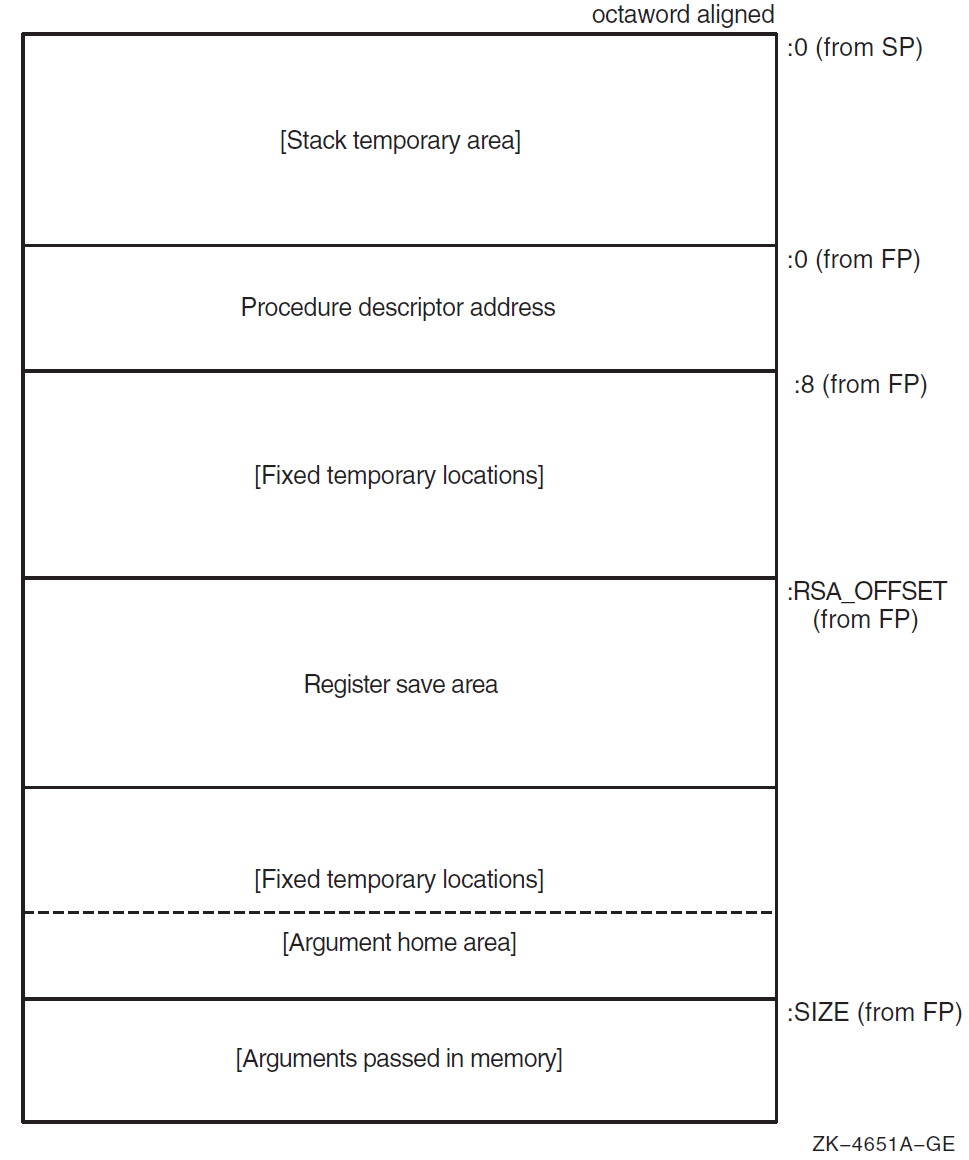
Some parts of the stack frame are optional and occur only as required by the particular procedure. In Figure 3.3, ''Variable-Size Stack Frame Format'', field names within brackets are optional fields. Use of the arguments passed in memory field appending the end of the descriptor is described in Section 3.4.3.3, ''Fixed Temporary Locations for All Stack Frames'' and Section 3.7.2, ''Argument List Structure''.
For more information describing the fixed temporary locations and register save area, see Section 3.4.3.3, ''Fixed Temporary Locations for All Stack Frames'' and Section 3.4.3.4, ''Register Save Area for All Stack Frames''.
A compiler can use the stack temporary area pointed to by the SP base register for fixed local variables, such as constant-sized data items and program state, as well as for dynamically sized local variables. The stack temporary area may also be used for dynamically sized items with a limited lifetime, for example, a dynamically sized function result or string concatenation that cannot be stored directly in a target variable. When a procedure uses this area, the compiler must keep track of its base and reset SP to the base to reclaim storage used by temporaries.
3.4.3.3. Fixed Temporary Locations for All Stack Frames
The fixed temporary locations are optional sections of any stack frame that contain language-specific locations required by the procedure context of some high-level languages. This may include, for example, register spill area, language-specific exception handling context (such as language-dynamic exception handling information), fixed temporaries, and so on.
The argument home area (if allocated by the compiler) can be found with the PDSC$L_SIZE offset in the last fixed temporary locations at the end of the stack frame. It is adjacent to the arguments passed in memory area to expedite the use of arguments passed (without copying). The argument home area is a region of memory used by the called procedure for the purpose of assembling in contiguous memory the arguments passed in registers, adjacent to the arguments passed in memory, so all arguments can be addressed as a contiguous array. This area can also be used to store arguments passed in registers if an address for such an argument must be generated. Generally, 6 * 8 bytes of stack storage is allocated for this purpose by the called procedure.
If a procedure needs to reference its arguments as a longword array or construct a structure that looks like an in-memory longword argument list, then it might allocate enough longwords in this area to hold all of the argument list and, optionally, an argument count. In that case, argument items passed in memory must be copied to this longword array.
The high-address end of the stack frame is defined by the value stored in PDSC$L_SIZE plus the contents of SP or FP, as indicated by PDSC$V_BASE_REG_IS_FP. The high-address end is used to determine the value of SP for the predecessor procedure in the calling chain.
3.4.3.4. Register Save Area for All Stack Frames
The register save area is a set of consecutive quadwords in which registers saved and restored by the current procedure are stored (see Figure 3.4, ''Register Save Area (RSA) Layout''). The register save area begins at the location pointed to by the offset PDSC$W_RSA_OFFSET from the frame base register (SP or FP as indicated by PDSC$V_BASE_REG_IS_FP), which must yield a quadword-aligned address. The set of registers saved in this area contain the return address followed by the registers specified in the procedure descriptor by PDSC$L_IREG_MASK and PDSC$L_FREG_MASK.
All registers saved in the register save area (other than the saved return address) must have the corresponding bit set in the appropriate procedure descriptor register save mask even if the register is not a member of the set of registers required to be saved across a standard call. Failure to do so will prevent the correct calculation of offsets within the save area.
Figure 3.4, ''Register Save Area (RSA) Layout'' illustrates the fields in the register save area (field names within brackets are optional fields). Quadword RSA$Q_SAVED_RETURN is the first field in the save area and it contains the contents of the return address register. The optional fields vary in size (8-byte increments) to preserve, as required, the contents of the integer and floating-point hardware registers used in the procedure.
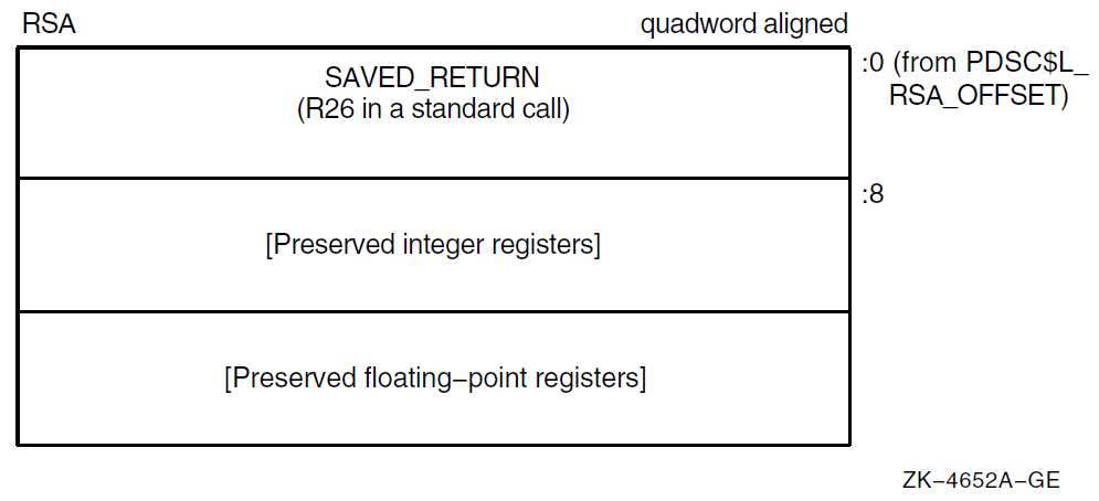
The return address is saved at the lowest address of the register save area (offset 0).
All saved integer registers (as indicated by the corresponding bit in PDSC$L_IREG_MASK being set to 1) are stored, in register-number order, in consecutive quadwords, beginning at offset 8 of the register save area.
- All saved floating-point registers (as indicated by the corresponding bit in PDSC$L_FREG_MASK being set to 1) are stored, in register-number order, in consecutive quadwords, following the saved integer registers.
Note
Floating-point registers saved in the register save area are stored as a 64-bit exact image of the register (for example, no reordering of bits is done on the way to or from memory). Compilers must use an STT instruction to store the register regardless of floating-point type.
The preserved register set must always include R29 (FP), because it will always be used.
If the return address register is not to be preserved (as is the case for a standard call), then it must be stored at offset 0 in the register save area and the corresponding bit in the register save mask must not be set.
However, if a nonstandard call is made that requires the return address register to be saved and restored, then it must be stored in both the location at offset 0 in the register save area and at the appropriate location within the variable part of the save area. In addition, the appropriate bit of PDSC$L_IREG_MASK must be set to 1.
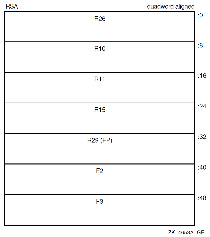
The example register save area shown in Figure 3.5, ''Register Save Area (RSA) Example'' illustrates the register packing when registers R10, R11, R15, FP, F2, and F3 are being saved for a procedure called with a standard call.
3.4.4. Register Frame Procedure
A register frame procedure does not maintain a call frame on the stack and must, therefore, save its caller's context in registers. This type of procedure is sometimes referred to as a lightweight procedure, referring to the expedient way of saving the call context.
Such a procedure cannot save and restore nonscratch registers. Because a procedure without a stack frame must use scratch registers to maintain the caller's context, such a procedure cannot make a standard call to any other procedure.
Note
Lightweight procedures have more freedom than might be apparent. By using appropriate agreements with callers of the lightweight procedure, with procedures that the lightweight procedure calls, and by the use of unwind handlers, a lightweight procedure can modify nonscratch registers and can call other procedures.
Such agreements may be by convention (as in the case of language-support routines in the RTL) or by interprocedural analysis. However, calls employing such agreements are not standard calls and might not be fully supported by a debugger; for example, the debugger might not be able to find the contents of the preserved registers.
Because such agreements must be permanent (for upwards compatibility of object code), lightweight procedures should, in general, follow the normal restrictions.
3.4.5. Procedure Descriptor for Procedures with a Register Frame
A register frame procedure descriptor built by a compiler provides information about a procedure with a register frame. The minimum size of the descriptor is 24 bytes (defined by PDSC$K_MIN_REGISTER_SIZE). An optional PDSC extension in 8-byte increments supports exception handling requirements.
The fields defined in the register frame procedure descriptor are illustrated in Figure 3.6, ''Register Frame Procedure Descriptor (PDSC)'' and described in Table 3.4, ''Contents of Register Frame Procedure Descriptor (PDSC)''.
|
Field Name |
Contents | ||
|---|---|---|---|
|
PDSC$W_FLAGS |
The PDSC descriptor flag bits <15:0> are defined as follows: | ||
|
PDSC$V_KIND |
A 4-bit field <3:0> that identifies the type of procedure descriptor. For a procedure with a register frame, this field must specify a value 10 (defined by constant PDSC$K_KIND_FP_REGISTER). | ||
|
PDSC$V_HANDLER_VALID |
If set to 1, this descriptor has an extension for the stack handler (PDSC$Q_REG_HANDLER) information. | ||
|
PDSC$V_HANDLER_ |
If set to 1, the handler can be reinvoked, allowing an occurrence of another exception while the handler is already active. If this bit is set to 0, the exception handler cannot be reinvoked. This bit must be 0 when PDSC$V_HANDLER_VALID is 0. | ||
|
PDSC$V_HANDLER_ |
If set to 1, the HANDLER_VALID bit must be 1 and the PDSC extension STACK_HANDLER_DATA field contains valid data for the exception handler, and the address of PDSC$Q_STACK_HANDLER _DATA will be passed to the exception handler as defined in Section 9.2, ''Condition Handlers''. | ||
|
PDSC$V_BASE_REG_IS_FP |
If this bit is set to 0, the SP is the base register to which PDSC$L_SIZE is added during an unwind. A fixed amount of storage is allocated in the procedure entry sequence, and SP is modified by this procedure only in the entry and exit code sequence. In this case, FP typically contains the address of the procedure descriptor for the procedure. Note that a procedure that sets this bit to 0 cannot make standard calls. If this bit is set to 1, FP is the base address and the procedure has a fixed amount of stack storage specified by PDSC$L_SIZE. A variable amount of stack storage can be allocated by modifying SP in the entry and exit code of this procedure. | ||
|
PDSC$V_REI_RETURN |
If set to 1, the procedure expects the stack at entry to be set, so an REI instruction correctly returns from the procedure. Also, if set, the contents of the PDSC$B_SAVE_RA field are unpredictable and the return address is found on the stack. | ||
|
Bit 9 |
Must be 0 (reserved). | ||
|
PDSC$V_BASE_FRAME |
For compiled code, this bit must be 0. If set to 1, this bit indicates the logical base frame of a stack that precedes all frames corresponding to user code. The interpretation and use of this frame and whether there are any predecessor frames is system software defined (and subject to change). | ||
|
PDSC$V_TARGET_INVO |
If set to 1, the exception handler for this procedure is invoked when this procedure is the target invocation of an unwind. Note that a procedure is the target invocation of an unwind if it is the procedure in which execution resumes following completion of the unwind. For more information, see Chapter 9, "OpenVMS Conditions". If set to 0, the exception handler for this procedure is not invoked. Note that when PDSC$V_HANDLER_VALID is 0, this bit must be 0. | ||
|
PDSC$V_NATIVE |
For compiled code, this bit must be set to 1. | ||
|
PDSC$V_NO_JACKET |
For compiled code, this bit must be set to 1. | ||
|
PDSC$V_TIE_FRAME |
For compiled code, this bit must be 0. Reserved for use by system software. | ||
|
Bit 15 |
Must be 0 (reserved). | ||
|
PDSC$B_SAVE_FP |
Specifies the number of the register that contains the saved value of the frame pointer (FP) register. In a standard procedure, this field must specify a scratch register so as not to violate the rules for procedure entry code as specified in Section 3.6.5, ''Entry and Exit Code Sequences''. | ||
|
PDSC$B_SAVE_RA |
Specifies the number of the register that contains the return address. If this procedure uses standard call conventions and does not modify R26, then this field can specify R26. In a standard procedure, this field must specify a scratch register so as not to violate the rules for procedure entry code as specified in Section 3.6.5, ''Entry and Exit Code Sequences''. | ||
|
PDSC$V_FUNC_ |
A 4-bit field <11:8> that describes which registers are used for the function value return (if there is one) and what format is used for those registers. Table 6.4, ''Function Return Signature Encodings'' lists and describes the possible encoded values of PDSC$V_FUNC_RETURN. | ||
|
PDSC$V_ |
A 3-bit field <14:12> that encodes the caller's desired exception-reporting behavior when calling certain mathematically oriented library routines. These routines generally search up the call stack to find the desired exception behavior whenever an error is detected. This search is performed independent of the setting of the Alpha FPCR. The possible values for this field are defined as follows: | ||
|
Value |
Name |
Meaning | |
| 0 |
PDSC$K_EXC_ |
Raise exceptions for all error conditions except for underflows producing a 0 result. This is the default mode. | |
| 1 |
PDSC$K_EXC_ |
Raise exceptions for all error conditions (including underflows). | |
| 2 |
PDSC$K_EXC_ |
Raise no exceptions. Create only finite values (no infinities, denormals, or NaNs). In
this mode, either the function result or the C language | |
| 3 |
PDSC$K_EXC_ |
Raise no exceptions except as controlled by separate IEEE exception enable bits. Create infinities, denormals, or NaN values according to the IEEE floating-point standard. | |
| 4 |
PDSC$K_EXC_ |
Perform the exception-mode behavior specified by this procedure's caller. | |
|
PDSC$W_ |
A 16-bit signed byte offset from the start of the procedure descriptor. This offset designates the start of the procedure signature block (if any). A 0 in this field indicates no signature information is present. Note that in a bound procedure descriptor (as described in Section 3.6.4, ''Simple and Bound Procedures''), signature information might be present in the related procedure descriptor. A 1 in this field indicates a standard default signature. An offset value of 1 is not otherwise a valid offset because both procedure descriptors and signature blocks must be quadword aligned. | ||
|
PDSC$Q_ENTRY |
Absolute address of the first instruction of the entry code sequence for the procedure. | ||
|
PDSC$L_SIZE |
Unsigned size in bytes of the fixed portion of the stack frame for this procedure. The size must be a multiple of 16 bytes to maintain the minimum stack alignment required by the Alpha hardware architecture and stack alignment during a call (defined in Section 3.6.1, ''Call Conventions''). | ||
|
PDSC$W_ENTRY_ |
Unsigned offset in bytes from the entry point to the first instruction in the procedure code segment following the procedure prologue (that is, following the instruction that updates FP to establish this procedure as the current procedure). | ||
|
PDSC$Q_REG_ |
Absolute address to the procedure descriptor for a run-time static exception handling procedure. This part of the procedure descriptor is optional. It must be supplied if either PDSC$V_HANDLER_VALID is 1 or PDSC$V_HANDLER_DATA_VALID is 1 (which requires that PDSC$V_HANDLER_VALID be 1). If PDSC$V_HANDLER_VALID is 0, then the contents or existence of PDSC$Q_REG_HANDLER is unpredictable. | ||
|
PDSC$Q_REG_ |
Data (quadword) for the exception handler. This is an optional quadword and needs to be supplied only if PDSC$V_HANDLER_DATA_VALID is 1. If PDSC$V_HANDLER_DATA_VALID is 0, then the contents or existence of PDSC$Q_REG_HANDLER_DATA is unpredictable. | ||
3.4.6. Null Frame Procedures
A procedure may conform to this standard even if it does not establish its own context if, in all circumstances, invocations of that procedure do not need to be visible or debuggable. This is termed executing in the context of the caller and is similar in concept to a conventional VAX JSB procedure. For the purposes of stack tracing or unwinding, such a procedure is never considered to be current.
For example, if a procedure does not establish an exception handler or does not save and restore registers, and does not extend the stack, then that procedure might not need to establish a context. Likewise, if that procedure does extend the stack, it still might not need to establish a context if the immediate caller either cannot be the target of an unwind or is prepared to reset the stack if it is the target of an unwind.
The circumstances under which procedures can run in the context of the caller are complex and are not fully specified by this standard.
As with the other procedure types previously described, the choice of whether to establish a context belongs to the called procedure. By defining a null procedure descriptor format, the same invocation code sequence can be used by the caller for all procedure types.
3.4.7. Procedure Descriptor for Null Frame Procedures
The null frame procedure descriptor built by a compiler provides information about a procedure with no frame. The size of the descriptor is 16 bytes (defined by PDSC$K_NULL_SIZE).
The fields defined in the null frame descriptor are illustrated in Figure 3.7, ''Null Frame Procedure Descriptor (PDSC) Format'' and described in Table 3.5, ''Contents of Null Frame Procedure Descriptor (PDSC)''.
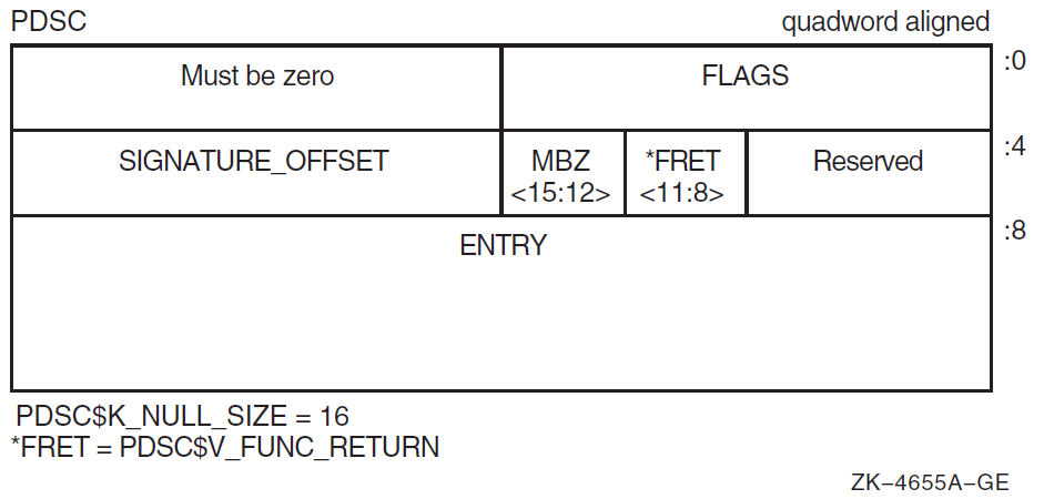
|
Field Name |
Contents | |
|---|---|---|
|
PDSC$W_FLAGS |
The PDSC descriptor flag bits <15:0> are defined as follows: | |
|
PDSC$V_KIND |
A 4-bit field <3:0> that identifies the type of procedure descriptor. For a null frame procedure, this field must specify a value 8 (defined by constant PDSC$K_KIND_NULL). | |
|
Bits 4—7 |
Must be 0. | |
|
PDSC$V_REI_ |
Bit 8. If set to 1, the procedure expects the stack at entry to be set, so an REI instruction correctly returns from the procedure. Also, if set, the contents of the PDSC$B_SAVE_RA field are unpredictable and the return address is found on the stack. | |
|
Bit 9 |
Must be 0 (reserved). | |
|
PDSC$V_BASE_ |
For compiled code, this bit must be 0. If set to 1, indicates the logical base frame of a stack that precedes all frames corresponding to user code. The interpretation and use of this frame and whether there are any predecessor frames is system software defined (and subject to change). | |
|
Bit 11 |
Must be 0 (reserved). | |
|
PDSC$V_NATIVE |
For compiled code, this bit must be set to 1. | |
|
PDSC$V_NO_JACKET |
For compiled code, this bit must be set to 1. | |
|
PDSC$V_TIE_FRAME |
For compiled code, this bit must be 0. Reserved for use by system software. | |
|
Bit 15 |
Must be 0 (reserved). | |
|
PDSC$V_FUNC_RETURN |
A 4-bit field <11:8> that describes which registers are used for the function value return (if there is one) and what format is used for those registers. Table 6.4, ''Function Return Signature Encodings'' lists and describes the possible encoded values of PDSC$V_FUNC_RETURN. | |
|
PDSC$W_SIGNATURE_ |
A 16-bit signed byte offset from the start of the procedure descriptor. This offset designates the start of the procedure signature block (if any). A 0 in this field indicates that no signature information is present. Note that in a bound procedure descriptor (as described in Section 3.6.4, ''Simple and Bound Procedures''), signature information might be present in the related procedure descriptor. A 1 in this field indicates a standard default signature. An offset value of 1 is not otherwise a valid offset because both procedure descriptors and signature blocks must be quadword aligned. | |
|
PDSC$Q_ENTRY |
The absolute address of the first instruction of the entry code sequence for the procedure. | |
3.5. Procedure Call Stack
Except for null-frame procedures, a procedure is an active procedure while its body is executing, including while any procedure it calls is executing. When a procedure is active, it may handle an exception that is signaled during its execution.
Associated with each active procedure is an invocation context, which consists of the set of registers and space in memory that is allocated and that may be accessed during execution for a particular call of that procedure.
When a procedure begins to execute, it has no invocation context. The initial instructions that allocate and initiallize its context, which may include saving information from the invocation context of its caller, are termed the procedure prologue. Once execution of the prologue is complete, the procedure is said to be active.
When a procedure is ready to return to its caller, the instructions that deallocate and discard the procedure's invocation context (which may include restoring state of the caller's invocation context that was saved during the prologue), are termed a procedure epilogue. A procedure ceases to be active when execution of its epilogue begins.
A procedure may have more than one prologue if there are multiple entry points. A procedure may also have more than one epilogue if there are multiple return points. One of each will be executed during any given invocation of the procedure.
Some procedures, notably null frame procedures (see Section Section 3.4.6, ''Null Frame Procedures''), never have an invocation context of their own and are said to execute in the body of their caller. A null frame procedure has no prologue or epilogue, and consists solely of body instructions. Such a procedure never becomes current or active in the sense that its handler may be invoked.
A call stack (for a thread) consists of the stack of invocation contexts that exists at any point in time. New invocation contexts are pushed on that stack as procedures are called and invocations are popped from the call stack as procedures return.
The invocation context of a procedure that calls another procedure is said to precede or be previous to the invocation context of the called procedure.
3.5.1. Current Procedure
The current procedure is the active procedure whose execution began most recently; its invocation context is at the top of the call stack. Note that a procedure executing in its prologue or epilogue is not active, and hence cannot be the current procedure. Similarly, a null frame procedure cannot be the current procedure.
In this calling standard, R29 is the frame pointer (FP) register that defines the current procedure.
Pointer to the procedure descriptor for that procedure.
Pointer to a naturally aligned quadword containing the address of the procedure descriptor for that procedure. For purposes of finding a procedure's procedure descriptor, no assumptions must be made about the quadword location. As long as all other requirements of this standard are met, a compiler is free to use FP as a base register for any arbitrary storage, including a stack frame, provided that while the procedure is current, the quadword pointed to by the value in FP contains the address of that procedure's descriptor.
If 0(FP)<2:0> = 0, then FP points to a quadword that contains a pointer to the procedure descriptor for the current procedure.
If 0(FP)<2:0> ≠ 0, then FP points to the procedure descriptor for the current procedure.
By examining the first quadword of the procedure descriptor, the procedure type can be determined from the PDSC$V_KIND field.
        LDQ     R0,0(FP)        ;Fetch quadword at FP
        AND     R0,#7,R28       ;Mask alignment bits
        BNEQ    R28,20$         ;Is procedure descriptor pointer
        LDQ     R0,0(R0)        ;Was pointer to procedure descriptor
10$:    AND     R0,#7,R28       ;Do sanity check
        BNEQ    R28,20$         ;All is well

        ;Error - Invalid FP

20$:    AND     R0,#15,R0       ;Get kind bits

        ;Procedure KIND is now in R0
IF PDSC$V_KIND is equal to PDSC$K_KIND_FP_STACK, the current procedure has a stack frame.
If PDSC$V_KIND is equal to PDSC$K_KIND_FP_REGISTER, the current procedure is a register frame procedure.
Either type of procedure can use either type of mechanism to point to the procedure descriptor. Compilers may choose the appropriate mechanism to use based on the needs of the procedure involved.
3.5.2. Procedure Call Tracing
To provide the context of a procedure invocation
To walk (navigate) the procedure call stack
To refer to a given procedure invocation
This section describes the data structure mechanisms. The routines that support these functions are described in Section 3.5.3, ''Invocation Context Access Routines''.
3.5.2.1. Referring to a Procedure Invocation from a Data Structure
When referring to a specific procedure invocation at run-time, an invocation context handle, shown in Figure 3.8, ''Invocation Context Handle Format'', can be used. Defined by constant LIBICB$K_INVO_HANDLE_SIZE, the structure is a single-field longword called HANDLE. HANDLE describes the invocation handle of the procedure.
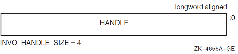
If PDSC$V_BASE_REG_IS_FP is set to 1 in the corresponding procedure descriptor, then set INVO_HANDLE to the contents of the FP register in that invocation.
If PDSC$V_BASE_REG_IS_FP is set to 0, set INVO_HANDLE to the contents of the SP register in that invocation. (That is, start with the base register value for the frame).
Shift the INVO_HANDLE contents left one bit. Because this value is initially known to be octaword aligned (see Section 3.6.1, ''Call Conventions''), the result is a value whose 5 low-order bits are 0.
If PDSC$V_KIND = PDSC$K_KIND_FP_STACK, perform a logical OR on the contents of INVO_HANDLE with the value 1F16, and then set INVO_HANDLE to the value that results.
If PDSC$V_KIND = PDSC$K_KIND_FP_REGISTER, perform a logical OR on the contents of INVO_HANDLE with the contents of PDSC$B_SAVE_RA, and then set INVO_HANDLE to the value that results.
Note
So you can distinguish an invocation of a register frame procedure that calls another register frame procedure (where the called procedure uses no stack space and therefore has the same base register value as the caller), the register number that saved the return address is included in the invocation handle of a register frame procedure. Similarly, the number 3110 in the invocation handle of a stack frame procedure is included to distinguish an invocation of a stack frame procedure that calls a register frame procedure where the called procedure uses no stack space.
3.5.2.2. Invocation Context Block
The context of a specific procedure invocation is provided through the use of a data structure called an invocation context block. The minimum size of the block is 528 bytes and is system defined using the constant LIBICB$K_INVO_CONTEXT_BLK_SIZE. The size of the last field (LIBICB$Q_SYSTEM_DEFINED[n]) defined by the host system determines the total size of the block.
The fields defined in the invocation context block are illustrated in the following figure and described in Table 3.6, ''Contents of the Invocation Context Block''.
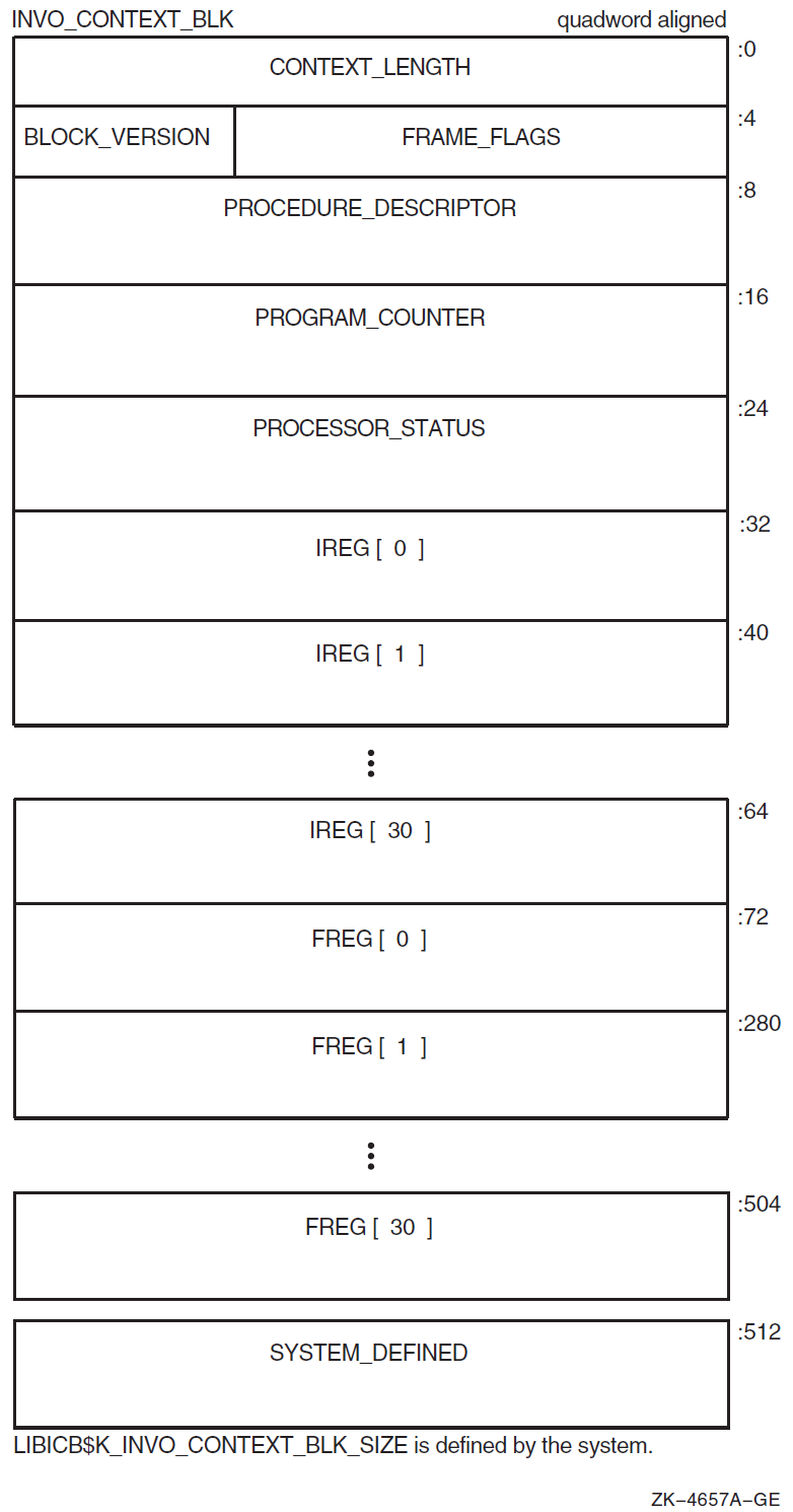
|
Field Name |
Contents | |
|---|---|---|
|
LIBICB$L_CONTEXT_LENGTH |
Unsigned count of the total length in bytes of the context block; this represents the sum of the lengths of the standard-defined portion and the system-defined section. | |
|
LIBICB$R_FRAME_FLAGS |
The procedure frame flag bits <23:0> are defined as follows: | |
|
LIBICB$V_EXCEPTION_ |
Bit 0. If set to 1, the invocation context corresponds to an exception frame. | |
|
LIBICB$V_AST_FRAME |
Bit 1. If set to 1, the invocation context corresponds to an asynchronous trap. | |
|
LIBICB$V_BOTTOM_OF_ |
Bit 2. If set to 1, the invocation context corresponds to a frame that has no predecessor. | |
|
LIBICB$V_BASE_FRAME |
Bit 3. If set to 1, the BASE_FRAME bit is set in the FLAGS field of the associated procedure descriptor. | |
|
LIBICB$B_BLOCK_VERSION |
A byte that defines the version of the context block. Because this block is currently the first version, the value is set to 1. | |
|
LIBICB$PH_PROCEDURE_ |
Address of the procedure descriptor for this context. | |
|
LIBICB$Q_PROGRAM_ |
Quadword that contains the current value of the procedure's program counter. For interrupted procedures, this is the same as the continuation program counter; for active procedures, this is the return address back into that procedure. | |
|
LIBICB$Q_PROCESSOR_ |
Contains the current value of the processor status. | |
|
LIBICB$Q_IREG[ |
Quadword that contains the current value of the integer register in the procedure
(where | |
|
LIBICB$Q_FREG[ |
Quadword that contains the current value of the floating-point register in the
procedure (where | |
|
LIBICB$Q_SYSTEM_ |
A variable-sized area with locations defined in quadword increments by the host environment that contains procedure context information. These locations are not defined by this standard. | |
3.5.2.3. Getting a Procedure Invocation Context with a Routine
A thread can obtain its own context or the current context of any procedure invocation in the current stack call (given an invocation handle) by calling the run-time library functions defined in Section 3.5.3, ''Invocation Context Access Routines''.
3.5.2.4. Walking the Call Stack
During the course of program execution, it is sometimes necessary to walk the call stack. Frame-based exception handling is one case where this is done. Call stack navigation is possible only in the reverse direction (in a latest-to-earliest or top-to-bottom sequence).
Given a program state (which contains a register set), build an invocation context block.
For the current routine, an initial invocation context block can be obtained by calling the LIB$GET_CURR_INVO_CONTEXT routine. See Section 3.5.3.2, ''LIB$GET_CURR_INVO_CONTEXT''.
Repeatedly call the LIB$GET_PREV_INVO_CONTEXT routine until the end of the chain has been reached (as signified by 0 being returned). See Section 3.5.3.3, ''LIB$GET_PREV_INVO_CONTEXT''.
The bottom of stack frame (end of the call chain) is indicated (LIBICB$V_BOTTOM_OF_STACK) when the target frame's saved FP value is 0.
Compilers are allowed to optimize high-level language procedure calls in such a way that they do not appear in the invocation chain. For example, inline procedures never appear in the invocation chain.
Make no assumptions about the relative positions of any memory used for procedure frame information. There is no guarantee that successive stack frames will always appear at higher addresses.
3.5.3. Invocation Context Access Routines
A thread can manipulate the invocation context of any procedure in the thread's virtual address space by calling the following run-time library functions.
3.5.3.1. LIB$GET_INVO_CONTEXT
LIB$GET_INVO_CONTEXT(invo_handle, invo_context)|
Argument |
OpenVMS Usage |
Type |
Access |
Mechanism |
|---|---|---|---|---|
|
invo_handle |
invo_handle |
longword (unsigned) |
read |
by value |
|
invo_context |
invo_context_blk |
structure |
write |
by reference |
|
|
Handle for the desired invocation. |
|
|
Address of an invocation context block into which the procedure context of the frame
specified by |
|
|
Status value. A value of 1 indicates success; a value of 0 indicates failure. |
Note
If the invocation handle that was passed does not represent any procedure context in the active call stack, the value of the new contents of the context block is unpredictable.
3.5.3.2. LIB$GET_CURR_INVO_CONTEXT
LIB$GET_CURR_INVO_CONTEXT(invo_context)|
Argument |
OpenVMS Usage |
Type |
Access |
Mechanism |
|---|---|---|---|---|
|
invo_context |
invo_context_blk |
structure |
write |
by reference |
|
|
Address of an invocation context block into which the procedure context of the caller will be written. |
|
Zero |
This is to facilitate use in the implementation of the C language unwind
|
3.5.3.3. LIB$GET_PREV_INVO_CONTEXT
LIB$GET_PREV_INVO_CONTEXT(invo_context)|
Argument |
OpenVMS Usage |
Type |
Access |
Mechanism |
|---|---|---|---|---|
|
invo_context |
invo_context_blk |
structure |
modify |
by reference |
|
|
Address of an invocation context block. The given invocation context block is updated to represent the context of the previous (calling) frame. The LIBICB$V_BOTTOM_OF_STACK flag of the invocation context block is set if the target frame represents the end of the invocation call chain or if stack corruption is detected. |
|
|
Status value. A value of 1 indicates success. When the initial context represents the bottom of the call stack, a value of 0 is returned. If the current operation completed without error, but a stack corruption was detected at the next level down, a value of 3 is returned. |
3.5.3.4. LIB$GET_INVO_HANDLE
LIB$GET_INVO_HANDLE(invo_context)|
Argument |
OpenVMS Usage |
Type |
Access |
Mechanism |
|---|---|---|---|---|
|
invo_context |
invo_context_blk |
structure |
read |
by reference |
|
|
Address of an invocation context block. Here, only the frame pointer and stack pointer fields of an invocation context block must be defined. |
|
|
Invocation handle of the invocation context that was passed. If the returned value is LIB$K_INVO_HANDLE_NULL, the invocation context that was passed was invalid. |
3.5.3.5. LIB$GET_PREV_INVO_HANDLE
LIB$GET_PREV_INVO_HANDLE(invo_handle)|
Argument |
OpenVMS Usage |
Type |
Access |
Mechanism |
|---|---|---|---|---|
|
invo_handle |
invo_handle |
longword (unsigned) |
read |
by value |
|
|
An invocation handle that represents a target invocation context. |
|
|
An invocation handle for the invocation context that is previous to that which was specified as the target. |
3.5.3.6. LIB$PUT_INVO_REGISTERS
LIB$PUT_INVO_REGISTERS(invo_handle, invo_context, invo_mask)|
Argument |
OpenVMS Usage |
Type |
Access |
Mechanism |
|---|---|---|---|---|
|
invo_handle |
invo_handle |
longword (unsigned) |
read |
by value |
|
invo_context |
invo_context_blk |
structure |
read |
by reference |
|
invo_mask |
mask_quadword |
quadword (unsigned) |
read |
by reference |
|
|
Handle for the invocation to be updated. |
|
|
Address of an invocation context block that contains new register contents. Each register that is set in the |
|
|
Address of a 64-bit bit vector, where each bit corresponds to a register field in
the passed |
|
|
Status value. A value of 1 indicates success. When the initial context represents
the bottom of the call stack or when bit 30 of the |
Caution
While this routine can be used to update the frame pointer (FP), great care must be taken to assure that a valid stack frame and execution environment result; otherwise, execution may become unpredictable.
3.6. Transfer of Control
This standard states that a standard call (see Section 1.4, ''Definitions'') may be accomplished in any way that presents the called routine with the required environment. However, typically, most standard-conforming external calls are implemented with a common sequence of instructions and conventions. Because a common set of call conventions is so pervasive, these conventions are included for reference as part of this standard.
One important feature of the calling standard is that the same instruction sequence can be used to call each of the different types of procedure. Specifically, the caller does not have to know which type of procedure is being called.
3.6.1. Call Conventions
Procedure value
The calling procedure must pass to the called procedure its procedure value. This value can be a statically or dynamically bound procedure value. This is accomplished by loading R27 with the procedure value before control is transferred to the called procedure.
Return address
The calling procedure must pass to the called procedure the address to which control must be returned during a normal return from the called procedure. In most cases, the return address is the address of the instruction following the one that transferred control to the called procedure. For a standard call, this address is passed in the return address register (R26).
Argument list
The argument list is an ordered set of zero or more argument items that together constitute a logically contiguous structure known as an argument item sequence. This logically contiguous sequence is typically mapped to registers and memory in a way that produces a physically discontiguous argument list. In a standard call, the first six items are passed in registers R16—21 or registers F16—21. (See Section 3.7.2, ''Argument List Structure'' for details of argument-to-register correspondence). The remaining items are collected in a memory argument list that is a naturally aligned array of quadwords. In a standard call, this list (if present) must be passed at 0(SP).
The calling procedure must pass to the called procedure information about the argument list. This information is passed in the argument information (AI) register (R25). Defined by AI$K_AI_SIZE, the structure is a quadword as shown in Figure 3.10, ''Argument Information Register (R25) Format'' with the fields described in Table 3.7, ''Contents of the Argument Information Register (R25)''.
Figure 3.10. Argument Information Register (R25) Format 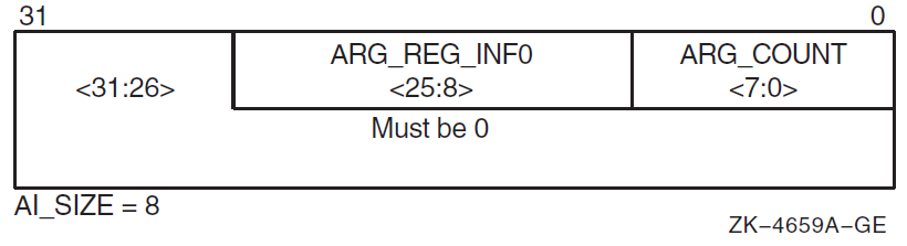
Table 3.7. Contents of the Argument Information Register (R25) Field Name
Contents
AI$B_ARG_COUNT
Unsigned byte <7:0> that specifies the number of 64-bit argument items in the argument list (known as the "argument count").
AI$V_ARG_REG_
INFOAn 18-bit vector field <25:8> divided into six groups of 3 bits that correspond to the six arguments passed in registers. These groups describe how each of the first six arguments are passed in registers with the first group <10:8> describing the first argument. The encoding for each group for the argument register usage follows:
Value
Name
Meaning
0 AI$K_AR_I64
64-bit or 32-bit sign-extended to 64-bit argument passed in an integer register (including addresses). or Argument is not present.
1 AI$K_AR_FF
F_floating argument passed in a floating register.
2 AI$K_AR_FD
D_floating argument passed in a floating register.
3 AI$K_AR_FG
G_floating argument passed in a floating register.
4 AI$K_AR_FS
S_floating argument passed in a floating register.
5 AI$K_AR_FT
T_floating argument passed in a floating register.
6, 7
— Reserved.
Bits 26—63
Reserved and must be 0.
Function result
If a standard-conforming procedure is a function and the function result is returned in a register, then the result is returned in R0, F0, or F0 and F1. Otherwise, the function result is returned via the first argument item or dynamically as defined in Section 3.7.7, ''Returning Data''.
Stack usage
Whenever control is transferred to another procedure, the stack pointer (SP) must be octaword aligned; at other times there is no stack alignment requirement. (A side effect of this is that the in-memory portion of the argument list will start on an octaword boundary). During a procedure invocation, the SP (R30) can never be set to a value higher than the SP at entry to that procedure invocation.
The contents of the stack located above the portion of the argument list that is passed in memory (if any) belongs to the calling procedure and is, therefore, not to be read or written by the called procedure, except as specified by indirect arguments or language-controlled up-level references.
Because SP is used by the hardware in raising exceptions and asynchronous interrupts, the contents of the next 2048 bytes below the current SP value are continually and unpredictably modified. Software that conforms to this standard must not depend on the contents of the 2048 stack locations below 0(SP).Note
One implication of the stack alignment requirement is that low-level interrupt and exception-fielding software must be prepared to handle and correct the alignment before calling handler routines, in case the stack pointer is not octaword aligned at the time of an interrupt or exception.
3.6.2. Linkage Section
Because the Alpha hardware architecture has the property of instructions that cannot contain full virtual addresses, it is sometimes referred to as a base register architecture. In a base register architecture, normal memory references within a limited range from a given address are expressed by using displacements relative to the contents of a register containing that address (base register). Base registers for external program segments, either data or code, are usually loaded indirectly through a program segment of address constants.
The fundamental program section containing address constants that a procedure uses to access other static storage, external procedures, and variables is termed a linkage section. Any register used to access the contents of the linkage section is termed a linkage pointer.
A procedure's linkage section includes the procedure descriptor for the procedure, addresses of all external variables and procedures referenced by the procedure, and other constants a compiler may choose to reference using a linkage pointer.
When a standard procedure is called, the caller must provide the procedure value for that procedure in R27. Static procedure values are defined to be the address of the procedure's descriptor. Because the procedure descriptor is part of the linkage section, calling this type of procedure value provides a pointer into the linkage section for that procedure in R27. This linkage pointer can then be used by the called procedure as a base register to address locations in its linkage section. For this reason, most compilers generate references to items in the linkage section as offsets from a pointer to the procedure's descriptor.
Compilers usually arrange (as part of the environment setup) to have the environment setup code (for bound procedures) load R27 with the address of the procedure's descriptor so it can be used as a linkage pointer as previously described. For an example, see Section 3.6.4, ''Simple and Bound Procedures''.
Although not required, linkages to external procedures are typically represented in the calling procedure's linkage section as a linkage pair. As shown in Figure 3.11, ''Linkage Pair Block Format'' and described in Table 3.8, ''Contents of the Linkage Pair Block'', a linkage pair (LKP) block with two fields should be octaword aligned and defined by LKP$K_SIZE as 16 bytes.
|
Field Name |
Contents |
|---|---|
|
LKP$Q_ENTRY |
Absolute address of the first instruction of the called procedure's entry code sequence. |
|
LKP$Q_PROC_VALUE |
Contains the procedure value of the procedure to be called. Normally, this field is the absolute address of a procedure descriptor for the procedure to be called, but in certain cases, it could be a bound procedure value (such as for procedures that are called through certain types of transfer vectors). |
In general, an object module contains a procedure descriptor for each entry point in the module. The descriptors are allocated in a linkage section. For each external procedure Q that is referenced in a module, the module's linkage section also contains a linkage pair denoting Q (which is a pointer to Q's procedure descriptor and entry code address).
      LDQ  R26,Q_DESC-MY_DESC(R4)   ;Q's entry address into R26
      LDQ  R27,Q_DESC-MY_DESC+8(R4) ;Q's procedure value into R27
      MOVQ #AI_LITERAL,R25          ;Load Argument Information register
      JSR  R26,(R26)                ;Call to Q. Return address in R26
Because Q's procedure descriptor (statically defined procedure value) is in Q's linkage section, Q can use the value in R27 as a base address for accessing data in its linkage section. Q accesses external procedures and data in other program sections through pointers in its linkage section. Therefore, R27 serves as the root pointer through which all data can be referenced.
3.6.3. Calling Computed Addresses
Most calls are made to a fixed address whose value is determined by the time the program starts execution. However, certain cases are possible that cause the exact address to be unknown until the code is finally executed. In this case, the procedure value representing the procedure to be called is computed in a register.
      LDQ  R26,8(R4)       ;Entry address to scratch register
      MOV  R4,R27          ;Procedure value to R27
      MOV  #AI_LITERAL,R25 ;Load Argument Information register
      JSR  R26,(R26)       ;Call entry address.
For interoperation with translated images, see Chapter 6, "Signature Information and Translated Images (Alpha and IA-64 systems)".
3.6.4. Simple and Bound Procedures
Simple procedure
Bound procedure
A simple procedure is a procedure that does not need direct access to the stack of its execution environment. A bound procedure is a procedure that does need direct access to the stack of its execution environment, typically to reference an up-level variable or to perform a nonlocal GOTO operation. Both a simple procedure and a bound procedure have an associated procedure descriptor, as described in previous sections.
When a bound procedure is called, the caller must pass some kind of pointer to the called code that allows it to reference its up-level environment. Typically, this pointer is the frame pointer for that environment, but many variations are possible. When the caller is executing its program within that outer environment, it can usually make such a call directly to the code for the nested procedure without recourse to any additional procedure descriptors. However, when a procedure value for the nested procedure must be passed outside of that environment to a call site that has no knowledge of the target procedure, a bound procedure descriptor is created so that the nested procedure can be called just like a simple procedure.
Bound procedure values, as defined by this standard, are designed for multilanguage use and utilize the properties of procedure descriptors to allow callers of procedures to use common code to call both bound and simple procedures.
3.6.4.1. Bound Procedure Descriptors
Bound procedure descriptors provide a mechanism to interpose special processing between a call and the called routine without modifying either. The descriptor may contain (or reference) data used as part of that processing. Between native and translated images, the OpenVMS Alpha operating system uses linker and image-activator created bound procedure descriptors to mediate the handling of parameter and result passing (see Section 6.2, ''Signature Information Blocks''). Language processors on OpenVMS Alpha systems use bound procedure descriptors to implement bound procedure values (see Section 3.6.4.2, ''Bound Procedure Value''). Other uses are possible.
The minimum size of the descriptor is 24 bytes (defined by PDSC$K_MIN_BOUND_SIZE). An optional PDSC extension in 8-byte increments provides the specific environment values as defined by the implementation.
The fields defined in the bound procedure descriptor are illustrated in Figure 3.12, ''Bound Procedure Descriptor (PDSC)'' and described in Table 3.9, ''Contents of the Bound Procedure Descriptor (PDSC)''.
|
Field Name |
Contents | |
|---|---|---|
|
PDSC$W_FLAGS |
Vector of flag bits <15:0> that must be a copy of the flag bits (except for KIND bits) contained in the quadword pointed to by PDSC$Q_PROC_VALUE. | |
|
PDSC$V_KIND |
A 4-bit field <3:0> that identifies the type of procedure descriptor. For a procedure with bound values, this field must specify a value of 0. | |
|
PDSC$V_FUNC_RETURN |
A 4-bit field <11:8> that describes which registers are used for the function value return (if there is one) and what format is used for those registers. PDSC$V_FUNC_RETURN in a bound procedure descriptor must be the same as the PDSC$V_FUNC_RETURN of the procedure descriptor for the procedure for which the environment is established. Table 6.4, ''Function Return Signature Encodings'' lists and describes the possible encoding values of PDSC$V_FUNC_RETURN. | |
|
Bits 12—15 |
Reserved and must be 0. | |
|
PDSC$W_SIGNATURE_OFFSET |
A 16-bit signed byte offset from the start of the procedure descriptor. This offset designates the start of the procedure signature block (if any). In a bound procedure, a 0 in this field indicates the actual signature block must be sought in the procedure descriptor indicated by the PDSC$Q_PROC_VALUE field. A 1 in this field indicates a standard default signature. (An offset value of 1 is not a valid offset because both procedure descriptors and signature blocks must be quadword aligned. See Section 6.2, ''Signature Information Blocks'' for details of the procedure signature block). Note that a nonzero signature offset in a bound procedure value normally occurs only in the case of bound procedures used as part of the implementation of calls from native OpenVMS Alpha code to translated OpenVMS VAX images. In any case, if a nonzero offset is present, it takes precedence over signature information that might occur in any related procedure descriptor. | |
|
PDSC$Q_ENTRY |
Address of the transfer code sequence. | |
|
PDSC$Q_PROC_VALUE |
Value of the procedure to be called by the transfer code. The value can be either the address of a procedure descriptor for the procedure or possibly another bound procedure value. | |
|
PDSC$Q_ENVIRONMENT |
An environment value to pass to the procedure. The choice of environment value is system implementation specific. For more information, see Section 3.6.4.2, ''Bound Procedure Value''. | |
3.6.4.2. Bound Procedure Value
The procedure value for a bound procedure is a pointer to a bound procedure descriptor that, like all other procedure descriptors, contains the address to which the calling procedure must transfer control at offset 8 (see Figure 3.12, ''Bound Procedure Descriptor (PDSC)''). This transfer code is responsible for setting up the dynamic environment needed by the target nested procedure and then completing the transfer of control to the code for that procedure. The transfer code receives in R27 a pointer to its corresponding bound procedure descriptor and thus can fetch any required environment information from that descriptor. A bound procedure descriptor also contains a procedure value for the target procedure that is used to complete the transfer of control.
When the transfer code sequence addressed by PDSC$Q_ENTRY of a bound procedure descriptor is called (by a call sequence such as the one given in Section 3.6.3, ''Calling Computed Addresses''), the procedure value will be in R27, and the transfer code must finish setting up the environment for the target procedure. The preferred location for this transfer code is directly preceding the code for the target procedure. This saves a memory fetch and a branching instruction and optimizes instruction caches and paging.
Q_TRANSFER:
        LDQ     R1,24(R27)      ;Environment value to R1
        LDQ     R27,16(R27)     ;Procedure descriptor address to R27
Q_ENTRY::                       ;Normal procedure entry code starts here
After the transfer code has been executed and control is transferred to Q's entry address, R27 contains the address of Q's procedure descriptor, R26 (unmodified by transfer code) contains the return address, and R1 contains the environment value.
When a bound procedure value such as this is needed, the bound procedure descriptor is usually allocated on the parent procedure's stack.
3.6.5. Entry and Exit Code Sequences
To ensure that the stack can be interpreted at any point during thread execution, all procedures must adhere to certain conventions for entry and exit as defined in this section.
3.6.5.1. Entry Code Sequence
All registers specified by this standard as saved across a standard call must contain their original (at entry) contents.
No standard calls may be made.
Note
If an exception is raised or if an exception occurs in the entry code of a procedure, that procedure's exception handler (if any) will not be invoked because the procedure is not current yet. Therefore, if a procedure has an exception handler, compilers may not move code into the procedure prologue that might cause an exception that would be handled by that handler.
If PDSC$L_SIZE is not 0, set register SP = SP − PDSC$L_SIZE.
If PDSC$V_BASE_REG_IS_FP is 1, store the address of the procedure descriptor at 0(SP).
If PDSC$V_KIND = PDSC$K_KIND_FP_REGISTER, copy the return address to the register specified by PDSC$B_SAVE_RA, if it is not already there, and copy the FP register to the register specified by PDSC$B_SAVE_FP.
If PDSC$V_KIND = PDSC$K_KIND_FP_STACK, copy the return address to the quadword at the RSA$Q_SAVED_RETURN offset in the register save area denoted by PDSC$W_RSA_OFFSET, and store the registers specified by PDSC$L_IREG_MASK and PDSC$L_FREG_MASK in the register save area denoted by PDSC$W_RSA_OFFSET. (This step includes saving the value in FP).
Execute TRAPB if required (see Section 9.5.3.2, ''Exception Synchronization (Alpha Only)'' for details).
If PDSC$V_BASE_REG_IS_FP is 0, load register FP with the address of the procedure descriptor or the address of a quadword that contains the address of the procedure descriptor.
If PDSC$V_BASE_REG_IS_FP is 1, copy register SP to register FP.
The ENTRY_LENGTH value in the procedure descriptor provides information that is redundant with the setting of a new frame pointer register value. That is, the value could be derived by starting at the entry address and scanning the instruction stream to find the one that updates FP. The ENTRY_LENGTH value included in the procedure descriptor supports the debugger or PCA facility so that such a scan is not required.
Entry Code Example for a Stack Frame Procedure
This is a stack frame procedure
Registers R2—4 and F2—3 are saved and restored
PDSC$W_RSA_OFFSET = 16
The procedure has a static exception handler that does not reraise arithmetic traps
The procedure uses a variable amount of stack
If the code sequence in Example 3.1, ''Entry Code for a Stack Frame Procedure'' is interrupted by an asynchronous software interrupt, SP will have a different value than it did at entry, but the calling procedure will still be current.
      LDA     SP,-SIZE(SP)  ;Allocate space for new stack frame
      STQ     R27,(SP)      ;Set up address of procedure descriptor
      STQ     R26,16(SP)    ;Save return address
      STQ     R2,24(SP)     ;Save first integer register
      STQ     R3,32(SP)     ;Save next integer register
      STQ     R4,40(SP)     ;Save next integer register
      STQ     FP,48(SP)     ;Save caller's frame pointer
      STT     F2,56(SP)     ;Save first floating-point register
      STT     F3,64(SP)     ;Save last floating-point register
      TRAPB                 ;Force any pending hardware exceptions to
                            ; be raised
      MOV     SP,FP         ;Called procedure is now the current procedure
Entry Code Example for a Register Frame
      MOV     FP,R22        ;Save caller's FP.
      MOV     R27,FP        ;Set FP to address of called procedure's
                            ; descriptor. Called procedure is now the
                            ; current procedure.
3.6.5.2. Exit Code Sequence
If PDSC$V_BASE_REG_IS_FP is 1, then copy FP to SP.
If PDSC$V_KIND = PDSC$K_KIND_FP_STACK, and this procedure saves or restores any registers other than FP and SP, reload those registers from the register save area as specified by PDSC$W_RSA_OFFSET.
If PDSC$V_KIND = PDSC$K_KIND_FP_STACK, load a scratch register with the return address from the register save area as specified by PDSC$W_RSA_OFFSET. (If PDSC$V_KIND = PDSC$K_KIND_FP_REGISTER, the return address is already in scratch register PDSC$B_SAVE_RA).
Execute TRAPB if required (see Section 9.5.3.2, ''Exception Synchronization (Alpha Only)'' for details).
If PDSC$V_KIND = PDSC$K_KIND_FP_REGISTER, copy the register specified by PDSC$B_SAVE_FP to register FP.
If PDSC$V_KIND = PDSC$K_KIND_FP_STACK, reload FP from the saved FP in the register save area.
If a function value is not being returned using the stack (PDSC$V_STACK_RETURN_VALUE is 0), then restore SP to the value it had at procedure entry by adding the value that was stored in PDSC$L_SIZE to SP. (In some cases, the returning procedure will leave SP pointing to a lower stack address than it had on entry to the procedure, as specified in Section 3.7.7, ''Returning Data'').
Jump to the return address (which is in a scratch register).
The called routine does not adjust the stack to remove any arguments passed in memory. This responsibility falls to the calling routine that may choose to defer their removal because of optimizations or other considerations.
Exit Code Example for a Stack Frame
      MOV     FP,SP       ;Chop the stack back
      LDQ     R28,16(FP)  ;Get return address
      LDQ     R2,24(FP)   ;Restore first integer register
      LDQ     R3,32(FP)   ;Restore next integer register
      LDQ     R4,40(FP)   ;Restore next integer register
      LDT     F2,56(FP)   ;Restore first floating-point register
      LDT     F3,64(FP)   ;Restore last floating-point register
      TRAPB               ;Force any pending hardware exceptions to
                          ; be raised
      LDQ     FP,48(FP)   ;Restore caller's frame pointer
      LDA     SP,SIZE(SP) ;Restore SP (SIZE is compiled into PDSC$L_SIZE)
      RET     R31,(R28)   ;Return to caller's code
Interruption of the code sequence in Example 3.3, ''Exit Code Sequence for a Stack Frame'' by an asynchronous software interrupt can result in the calling procedure being the current procedure, but with SP not yet restored to its value in that procedure. The discussion of that situation in entry code sequences applies here as well.
Exit Code Example for a Register Frame
      MOV     R22,FP      ;Restore caller's FP value
                          ; Caller is once again the current procedure.
      RET     R31,(R26)   ;Return to caller's code
3.7. Data Passing
This section defines the OpenVMS Alpha calling standard conventions of passing data between procedures in a call stack. An argument item represents one unit of data being passed between procedures.
3.7.1. Argument Passing Mechanisms
Immediate value
Reference
Descriptor
Argument items are not self-defining; interpretation of each argument item depends on agreement between the calling and called procedures.
This standard does not dictate which passing mechanism must be used by a given language compiler. Language semantics and interoperability considerations might require different mechanisms in different situations.
Immediate value
An immediate value argument item contains the value of the data item. The argument item, or the value contained in it, is directly associated with the parameter.
Reference
A reference argument item contains the address of a data item such as a scalar, string, array, record, or procedure. This data item is associated with the parameter.
Descriptor
A descriptor argument item contains the address of a descriptor, which contains structural information about the argument's type (such as array bounds) and the address of a data item. This data item is associated with the parameter.
3.7.2. Argument List Structure
The argument list in an OpenVMS Alpha call is an ordered set of zero or more argument items, which together comprise a logically contiguous structure known as the argument item sequence. An argument item is specified using up to 64 bits.
A 64-bit argument item can be used to pass arguments by immediate value, by reference, and by descriptor. Any combination of these mechanisms in an argument list is permitted.
Although the argument items form a logically contiguous sequence, they are in practice mapped to integer and floating-point registers and to memory in a method that can produce a physically discontiguous argument list. Registers R16—21 and F16—21 are used to pass the first six items of the argument item sequence. Additional argument items must be passed in a memory argument list that must be located at 0(SP) at the time of the call.
|
Item |
Integer Register |
Floating-Point Register |
Stack |
|---|---|---|---|
|
1 |
R16 |
F16 | |
|
2 |
R17 |
F17 | |
|
3 |
R18 |
F18 | |
|
4 |
R19 |
F19 | |
|
5 |
R20 |
F20 | |
|
6 |
R21 |
F21 | |
|
7—n |
0(SP) - (n-7)*8(SP) |
All argument items are passed in the integer registers or on the stack, except for argument items that are floating-point data passed by immediate value.
Floating-point data passed by immediate value is passed in the floating-point registers or on the stack.
Only one location (across an item row in Table 3.10, ''Argument Item Locations'') can be used by any given argument item in a list. For example, if argument item 3 is an integer passed by value, and argument item 4 is a single-precision floating-point number passed by value, then argument item 3 is assigned to R18 and argument item 4 is assigned to F19.
A single- or double-precision complex value is treated as two arguments for the purpose of argument-item sequence rules. In particular, the real part of a complex value might be passed as the sixth argument item in register F21, in which case the imaginary part is then passed as the seventh argument item in memory.
An extended precision complex value is passed by reference using a single integer or stack argument item. (An extended precision complex value is not passed by immediate value because the component extended precision floating values are not passed by value. See also Section 3.7.5.1, ''Sending Mechanism'').
The argument list that includes both the in-memory portion and the portion passed in registers can be read from and written to by the called procedure. Therefore, the calling procedure must not make any assumptions about the validity of any part of the argument list after the completion of a call.
3.7.3. Argument Lists and High-Level Languages
Arguments are mapped from left to right to increasing offsets in the argument item sequence. R16 or F16 is allocated to the first argument, and the last quadword of the memory argument list (if any) is allocated to the last argument.
Each source language argument corresponds to one or more contiguous Alpha calling standard argument items.
Each argument item consists of 64 bits.
A null or omitted argument—for example, CALL SUB(A,,B)—is represented by an argument item containing the value 0.
Arguments passed by immediate value cannot be omitted unless a default value is supplied by the language. (This is to enable called procedures to distinguish an omitted immediate argument from an immediate value argument with the value 0).
Trailing null or omitted arguments—for example, CALL SUB(A,,)—are passed by the same rules as for embedded null or omitted arguments.
3.7.4. Unused Bits in Passed Data
Whenever data is passed by value between two procedures in registers (for the first six input arguments and return values), or in memory (for arguments after the first six), the bits not used by the data are sign-extended or zero-extended as appropriate.
|
Data Type |
Type Designator |
Data Size (bytes) |
Register Extension Type |
Memory Extension Type |
|---|---|---|---|---|
|
Byte logical |
BU |
1 |
Zero64 |
Zero64 |
|
Word logical |
WU |
2 |
Zero64 |
Zero64 |
|
Longword logical |
LU |
4 |
Sign64 |
Sign64 |
|
Quadword logical |
QU |
8 |
Data64 |
Data64 |
|
Byte integer |
B |
1 |
Sign64 |
Sign64 |
|
Word integer |
W |
2 |
Sign64 |
Sign64 |
|
Longword integer |
L |
4 |
Sign64 |
Sign64 |
|
Quadword integer |
Q |
8 |
Data64 |
Data64 |
|
F_floating |
F |
4 |
Hard |
Data32 |
|
D_floating |
D |
8 |
Hard |
Data64 |
|
G_floating |
G |
8 |
Hard |
Data64 |
|
F_floating complex |
FC |
2 * 4 |
2*Hard |
2*Data32 |
|
D_floating complex |
DC |
2 * 8 |
2*Hard |
2*Data64 |
|
G_floating complex |
GC |
2 * 8 |
2*Hard |
2*Data64 |
|
S_floating |
FS |
4 |
Hard |
Data32 |
|
T_floating |
FT |
8 |
Hard |
Data64 |
|
X_floating |
FX |
16 |
N/A |
N/A |
|
S_floating complex |
FSC |
2 * 4 |
2*Hard |
2*Data32 |
|
T_floating complex |
FTC |
2 * 8 |
2*Hard |
2*Data64 |
|
X_floating complex |
FXC |
2 * 16 |
N/A |
N/A |
|
Small structures of 8 bytes or less |
N/A |
≤8 |
Nostd |
Nostd |
|
Small arrays of 8 bytes or less |
N/A |
≤8 |
Nostd |
Nostd |
|
32-bit address |
N/A |
4 |
Sign64 |
Sign64 |
|
64-bit address |
N/A |
8 |
Data64 |
Data64 |
|
Sign Extension Type |
Defined Function |
|---|---|
|
Sign64 |
Sign-extended to 64 bits. |
|
Zero64 |
Zero-extended to 64 bits. |
|
Data32 |
Data is 32 bits. The state of bits <63:32> is unpredictable. |
|
2*Data32 |
Two single-precision parts of the complex value are stored in memory as independent floating-point values (each handled as Data32). |
|
Data64 |
Data is 64 bits. |
|
2*Data64 |
Two double-precision parts of the complex value are stored in memory as independent floating-point values (each handled as Data64). |
|
Hard |
Passed in the layout defined by the hardware SRM. |
|
2*Hard |
Two floating-point parts of the complex value are stored in a pair of registers as independent floating-point values (each handled as Hard). |
|
Nostd |
State of all high-order bits not occupied by the data is unpredictable across a call or return. |
Because of the varied rules for sign extension of data when passed as arguments, both calling and called routines must agree on the data type of each argument. No implicit data-type conversions can be assumed between the calling procedure and the called procedure.
3.7.5. Sending Data
This section defines the OpenVMS Alpha calling standard requirements for mechanisms to send data and the order of argument evaluation.
3.7.5.1. Sending Mechanism
- By immediate value. An argument may be passed by immediate value only if the argument is one of the following:
One of the noncomplex scalar data types with a size known (at compile time) to be ≤ 64 bits
Either single or double precision complex
A record with a known size (at compile time)
A set, implemented as a bit vector, with a size known (at compile time) to be ≤ 64 bits
No form of string or array data type may be passed by immediate value in a standard call.
Unused high-order bits must be zero or sign-extended, as appropriate depending on the date type, to fill all bits of each argument list item (as specified in Table 3.11, ''Unused Bits in Passed Data'').
A single- or double- precision complex value is passed as two single or double precision floating-point values, respectively. Note that the argument count reflects that two argument positions are used rather than just one actual argument.
A record value, which may be larger than 64 bits, is passed by immediate value as follows:Allocate as many fully occupied argument item positions to the argument value as are needed to represent the argument.
The value of the unoccupied bits is undefined in a final, partially occupied argument item position, if any.
If an argument position is passed in one of the registers, it can only be passed in an integer register (never in a floating-point register).
Other argument values that are larger than 64 bits can be passed by immediate value using nonstandard conventions, typically using a method similar to those for passing records. Thus, for example, a 26-byte string can be passed by value in four integer registers.
By reference. Nonparametric arguments (arguments for which associated information such as string size and array bounds are not required) can be passed by reference in a standard call. This includes extended precision floating and extended precision complex values.
By descriptor. Parametric arguments (arguments for which associated information such as string size and array bounds must be passed to the caller) are passed by a single descriptor in a standard call.
Note that extended floating values are not passed using the immediate value mechanism; rather, they are passed using the by reference mechanism. (However, when by value semantics is required, it may be necessary to make a copy of the actual parameter and pass a reference to that copy in order to avoid improper alias effects).
Also note that when a record is passed by immediate value, the component types are not material to how the argument is aligned; the record will always be quadword aligned.
3.7.5.2. Order of Argument Evaluation
Because most high-level languages do not specify the order of evaluation (with respect to side effects) of arguments, those language processors can evaluate arguments in any convenient order. The choice of argument evaluation order and code generation strategy is constrained only by the definition of the particular language. Programs should not depend on the order of evaluation of arguments.
3.7.6. Receiving Data
When it cannot be determined at compile time whether a given in-register argument item is passed in a floating-point register or an integer register, the argument information register can be interpreted at run-time to establish where the argument was passed. (See Section 3.6.1, ''Call Conventions'' for details).
3.7.7. Returning Data
Immediate value
Reference
Descriptor
These mechanisms are the only standard means available for returning function values, and they support the important language-independent data types. Functions that return values by any mechanism other than those specified here are nonstandard, language-specific functions.
3.7.7.1. Function Value Return by Immediate Value
Nonfloating function value return
Floating function value return
Nonfloating Function Value Return by Immediate Value
Nonfloating-point scalar data type with size known to be ≤ 64 bits
Record with size known to be ≤ 64 bits
Set, implemented as a bit vector, with size known to be ≤ 64 bits
No form of string or array can be returned by immediate value, and two separate 32-bit entities cannot be combined and returned in R0.
A function value of less than 64 bits returned in R0 must be zero-extended or sign-extended as appropriate, depending on the data type (see Table 3.11, ''Unused Bits in Passed Data''), to a full quadword.
Floating Function Value Return by Immediate Value
A function value is returned by immediate value in register F0 only if it is a noncomplex single- or double-precision floating-point value (F, D, G, S, or T).
A function value is returned by immediate value in registers F0 and F1 only if it is a complex single or double-precision floating-point value (complex F, D, G, S, or T).
Note that extended floating-point and extended complex values are returned by reference as described next.
3.7.7.2. Function Value Return by Reference
Its size is known to both the calling procedure and the called procedure, but the value cannot be returned by immediate value. (Because the function value requires more than 64 bits, the data type is a string or an array type).
It can be returned in a contiguous region of storage.
The actual-argument list and the formal-argument list are shifted to the right by one argument item. The new, first argument item is reserved for the function value. This hidden first argument is included in the count and register usage information that is passed in the argument information register (see Section 3.6.1, ''Call Conventions'' for details).
The calling procedure must provide the required contiguous storage and pass the address of the storage as the first argument. This address must specify storage naturally aligned according to the data type of the function value.
The called function must write the function value to the storage described by the first argument.
The this Pointer
For C++, when the this pointer is passed as an implicit first parameter
and a pointer to a return value buffer is also required, then the this
pointer becomes the first parameter, the buffer pointer becomes the second parameter, and the
remaining normal parameters are shifted two slots to make this possible.
3.7.7.3. Function Value Return by Descriptor
It cannot be returned by immediate value. (Because the function value requires more than 64 bits, the data type is a string or an array type, and so on).
Its size is not known to either the calling procedure or the called procedure.
It can be returned in a contiguous region of storage.
Noncontiguous function values are language specific and cannot be returned as a standard-conforming return value.
Records, noncontiguous arrays, and arrays with more than one dimension cannot be returned by descriptor in a standard call.
Both 32-bit and 64-bit descriptor forms can be used for function values returned by descriptor. See Chapter 8, "OpenVMS Argument Descriptors", for details of the descriptor forms.
Dynamic text—Heap-managed strings of arbitrary and dynamically changeable length
Return objects created by the calling routine—Function values that are to be returned in an object allocated by and having attributes (bounds, lengths, and so on) specified by the calling routine
Return objects created by the called routine—Function values that are returned in an object allocated by and having attributes (bounds, lengths, and so on) specified by the called routine
For correct results to be obtained from this type of function return, the calling and called routines must agree by prior arrangement which of these three major cases applies, and whether 64-bit descriptor forms may be used.
The following paragraphs describe the specialized requirements for each major case:
Dynamic Text
For dynamic text return by descriptor, the calling routine passes a valid (completely initialized) dynamic string descriptor (DSC$B_CLASS = DSC$K_CLASS_D). The called routine must assign a value to the variable represented by this descriptor using the same rules that apply to a dynamic text descriptor used as an ordinary parameter.
Return Object Created by Calling Routine
For a return object created by the calling routine, the calling routine passes a descriptor in which all fields are completely loaded.
The called routine must supply a return value that satisfies that description. In particular, the called routine must truncate or pad the returned value to satisfy the requirements of the descriptor according to the semantics of the language in which the called routine is written.
The calling and called routines must agree by prior arrangement on the DSC$B_CLASS and DSC$B_DTYPE of descriptor to be used.
Return Object Created by Called Routine
DSC$A_POINTER field is set to 0.
DSC$B_CLASS field is loaded.
DSC$B_DTYPE field is loaded.
DSC$B_DIMCT field is loaded and the DSC$B_AFLAGS field is set to 0 if the descriptor is an array descriptor.
All other fields are unpredictable.
If the passed descriptor is an array descriptor, it must contain space for bounds information to be returned even though the DSC$B_AFLAGS field is set to 0.
The called routine must return the function value using stack return conventions and load the DSC$A_POINTER field to point to the returned data. Other descriptor information, such as origin, bounds (if supplied), and DSC$B_AFLAGS fields must be filled in appropriately to correspond to the returned data.
An important implication of a call that uses this kind of value return is that the stack pointer normally is not restored to its value prior to the call as part of the return from the called procedure. The returned value typically (but not necessarily) is left by the called routine somewhere on the stack. For that reason, this mechanism is sometimes known as the stack return mechanism.
After a return of this type, the calling routine must assume that the stack has been extended by some unknown amount (or possibly none) by the called procedure. In particular, the stack cannot be cut back until the returned value is no longer needed (which may be ensured by copying it to another location).
However, this type of return does not imply that the actual storage used by the called routine to hold the returned value must be at the address pointed to by the stack pointer; it need not even be on the stack. It could be in some read-only, static memory. (This latter case might arise when the returned value is constant or is obtained from some constant structure). For this reason, the calling routine must not assume that the data described by the return descriptor is writable.
3.8. Data Allocation
This section describes the standard static data requirements that define the Alpha alignment of data structures, record formats, and record layout. These conventions help to ensure proper data compatibility with all OpenVMS Alpha and VAX languages.
3.8.1. Data Alignment
In the Alpha environment, memory references to data that is not naturally aligned can result in alignment faults, which can severely degrade the performance of all procedures that reference the unaligned data.
|
Data Type |
Alignment Starting Position |
|---|---|
|
8-bit character string |
Byte boundary |
|
16-bit integer |
Address that is a multiple of 2 (word alignment) |
|
32-bit integer |
Address that is a multiple of 4 (longword alignment) |
|
64-bit integer |
Address that is a multiple of 8 (quadword alignment) |
|
Address that is a multiple of 4 (longword) |
|
Address that is a multiple of 8 (quadword) |
|
Address that is a multiple of 8 (quadword) |
|
Address that is a multiple of 4 (longword) |
|
Address that is a multiple of 8 (quadword) |
|
Address that is a multiple of 16 (octaword) |
For aggregates such as strings, arrays, and records, the data type to be considered for purposes of alignment is not the aggregate itself, but rather the elements of which the aggregate is composed. The alignment requirement of an aggregate is that all elements of the aggregate be naturally aligned. For example, varying 8-bit character strings must start at addresses that are a multiple of at least 2 (word alignment) because of the 16-bit count at the beginning of the string; 32-bit integer arrays start at a longword boundary, irrespective of the extent of the array.
The rules for passing a record in an argument that is passed by immediate value (see Section 3.7.5.1, ''Sending Mechanism'') always provide quadword alignment of the record value independent of the normal alignment requirement of the record. If deemed appropriate by an implementation, normal alignment can be established within the called procedure by making a copy of the record argument at a suitably aligned location.
3.8.2. Record Layout Conventions
The OpenVMS Alpha calling standard rules for record layout are designed to provide good run-time performance on all implementations of the Alpha architecture and to provide the required level of compatibility with conventional VAX operating environments.
Those optimized for optimal access characteristics (referred to as aligned record layouts)
Those compatible with conventions that are traditionally used by VAX languages (referred to as VAX compatible record layouts)
Only these two record layouts may be used across standard interfaces or between languages. Languages can support other language-specific record layout conventions, but such layouts are nonstandard.
The aligned record layout conventions should be used unless interchange is required with conventional VAX applications that use the OpenVMS VAX compatible record layouts.
3.8.2.1. Aligned Record Layout
All components of a record or subrecord are naturally aligned.
Layout and alignment of record elements and subrecords are independent of any record or subrecord in which they are embedded.
Layout and alignment of a subrecord is the same as if it were a top-level record.
Declaration in high-level languages of standard records for interlanguage use is straightforward and obvious, and meets the requirements for source-level compatibility between Alpha and VAX languages.
The components of a record must be laid out in memory corresponding to the lexical order of their appearance in the high-level language declaration of the record.
The first bit of a record or subrecord must be directly addressable (byte aligned).
Records and subrecords must be aligned according to the largest natural alignment requirements of the contained elements and subrecords.
Bit fields (packed subranges of integers) are characterized by an underlying integer type that is a byte, word, longword, or quadword in size together with an allocation size in bits. A bit field is allocated at the next available bit boundary, provided that the resulting allocation does not cross an alignment boundary of the underlying type. Otherwise, the field is allocated at the next byte boundary that is aligned as required for the underlying type. (In the later case, the space skipped over is left permanently not allocated). In addition, if necessary, the alignment of the record as a whole is increased to that of the underlying integer type.
Unaligned bit strings, unaligned bit arrays, and elements of unaligned bit arrays must start at the next available bit in the record. No fill is ever supplied preceding an unaligned bit string, unaligned bit array, or unaligned bit array element.
All other components of a record must start at the next available naturally aligned address for the data type.
The length of a record must be a multiple of its alignment. (This includes the case when a record is a component of another record).
Strings and arrays must be aligned according to the natural alignment requirements of the data type of which the string or array is composed.
The length of an array element is a multiple of its alignment, even if this leaves unused space at its end. The length of the whole array is the sum of the lengths of its elements.
3.8.2.2. OpenVMS VAX Compatible Record Layout
The components of a record must be laid out in memory corresponding to the lexical order of their appearance in the high-level language declaration of the record.
Unaligned bit strings, unaligned bit arrays, and elements of unaligned bit arrays must start at the next available bit in the record. No fill is ever supplied preceding an unaligned bit string, unaligned bit array, or unaligned bit array element.
All other components of a record must start at the next available byte in the record. Any unused bits following the last-used bit in the last-used byte of each component must be filled out to the next byte boundary so that any following data starts on a byte boundary.
Subrecords must be aligned according to the largest alignment of the contained elements and subrecords. A subrecord always starts at the next available byte unless it consists entirely of unaligned bit data and it immediately follows an unaligned bit string, unaligned bit array, or a subrecord consisting entirely of unaligned bit data.
Records must be aligned on byte boundaries.
3.9. Multithreaded Execution Environments
This section defines the conventions to support the execution of multiple threads in a multilanguage Alpha environment. Specifically defined is how compiled code must perform stack limit checking. While this standard is compatible with a multithreaded execution environment, the detailed mechanisms, data structures, and procedures that support this capability are not specified in this manual.
There can be one or more threads executing within a single process.
The state of a thread is represented in a thread environment block (TEB).
The TEB of a thread contains information that determines a stack limit below which the stack pointer must not be decremented by the executing code (except for code that implements the multithread mechanism itself).
Exception handling is fully reentrant and multithreaded.
3.9.1. Stack Limit Checking
A program that is otherwise correct can fail because of stack overflow. Stack overflow occurs when extension of the stack (by decrementing the stack pointer, SP) allocates addresses not currently reserved for the current thread's stack.
Detection of a stack overflow situation is necessary because a thread, attempting to write into stack storage, could modify data allocated in that memory for some other purpose. This would most likely produce unpredictable and undesirable results or irreproducible application failures.
The requirements for procedures that can execute in a multithread environment include checking for stack overflow. This section defines the conventions for stack limit checking in a multithreaded program environment.
In the following sections, the term new stack region refers to the region of the stack from one less than the old value of SP to the new value of the SP.
Stack Guard Region
In a multithread environment, the memory beyond the limit of each thread's stack is protected by contiguous guard pages, which form the stack's guard region.
Stack Reserve Region
In some cases, it is desirable to maintain a stack reserve region, which is a minimum-sized region that is immediately above a thread's guard region. A reserve region may be desirable to ensure that exceptions or asynchronous system traps (ASTs) have stack space to execute on a thread's stack, or to ensure that the exception dispatcher and any exception handler that it might call have stack space to execute after detection of an invalid attempt to extend the stack.
This standard does not require a reserve region.
3.9.1.1. Methods for Stack Limit Checking
Because accessible memory may be available at addresses lower than those occupied by the guard region, compilers must generate code that never extends the stack past the guard pages into accessible memory that is not allocated to the thread's stack.
Note
An access can be performed by using either a load or a store operation; however, be sure
to use an instruction that is guaranteed to make an access to memory. For example, do not use
an LDQ R31,* instruction, because the Alpha architecture does not allow
any memory access, even a read access, whose result is discarded because of the R31
destination.
This standard defines two methods for stack limit checking: implicit and explicit.
Implicit Stack Limit Checking
If the lowest addressed byte of the new stack region is guaranteed to be accessed prior to any further stack extension, then the stack can be extended by an increment that is equal in size to the guard region (without any further accesses).
If some byte (not necessarily the lowest) of the new stack region is guaranteed to be accessed prior to any further stack extension, then the stack can be extended by an increment that is equal in size to one-half the guard region (without any further accesses).
The stack frame format (see Section 3.4.3, ''Stack Frame Format'') and entry code rules (see Section 3.6.5, ''Entry and Exit Code Sequences'') generally do not ensure access to the lowest address of a new stack region without introducing an extra access solely for that purpose. Consequently, this standard uses the second strategy. While the amount of implicit stack extension that can be achieved is smaller, the check is achieved at no additional cost.
This standard requires that the minimum guard region size is 8192 bytes, the size of the smallest memory protection granularity allowed by the Alpha architecture.
Explicit stack limit checking must be performed unless the amount by which the SP is decremented is known to be less than or equal to 4096 and a reserve region is not required.
Some byte in the new stack region must be accessed before the SP can be decremented for a subsequent stack extension.
This access can be performed either before or after the SP is decremented for this stack extension, but it must be done before the SP can be decremented again.
No standard procedure call can be made before some byte in the new stack region is accessed.
The system exception dispatcher ensures that the lowest addressed byte in the new stack region is accessed if any kind of asynchronous interrupt occurs after the SP is decremented, but before the access in the new stack region occurs.
These conventions ensure that the stack pointer is not decremented so that it points to accessible storage beyond the stack limit without this error being detected (either by the guard region being accessed by the thread or by an explicit stack limit check failure).
As a matter of practice, the system can provide multiple guard pages in the guard region. When a stack overflow is detected as a result of access to the guard region, one or more guard pages can be unprotected for use by the exception handling facility, and one or more guard pages can remain protected to provide implicit stack limit checking during exception processing. However, the size of the guard region and the number of guard pages is system defined and is not defined by this standard.
Explicit Stack Limit Checking
If the stack is being extended by an amount of unknown size or by a known size greater than the maximum implicit check size (4096), then a code sequence that follows the rules for implicit stack limit checking can be executed in a loop to access the new stack region incrementally in segments lesser than or equal to the minimum page size (8192 bytes). At least one access must occur in each such segment.
The first access must occur between SP and SP-4096 because, in the absence of more specific information, the previous guaranteed access relative to the current stack pointer may be as much as 4096 bytes greater than the current stack pointer address.
The last access must be within 4096 bytes of the intended new value of the stack pointer. These accesses must occur in order, starting with the highest addressed segment and working toward the lowest addressed segment.
Perform a read access using the intended new value of the stack pointer. This is nondestructive, even if the read is beyond the stack guard region, and may facilitate OS mapping of new stack pages, if appropriate, in a single operation.
Proceed with sequential accesses as just described.
Note
A simple algorithm that is consistent with this requirement (but achieves up to twice the minimum number of accesses) is to perform a sequence of accesses in a loop starting with the previous value of SP, decrementing by the minimum no-check extension size (4096) to, but not including, the first value that is less than the new value for the stack pointer.
Note
An explicit stack limit check can be performed either by inline code that is part of a prologue or by a run-time support routine that is tailored to be called from a procedure prologue.
Stack Reserve Region Checking
The size of the reserve region must be included in the increment size used for stack limit checks, after which it is not included in the amount by which the stack is actually extended. (Depending on the size of the reserve region, this may partially or even completely eliminate the ability to use implicit stack limit checking).
3.9.1.2. Stack Overflow Handling
Exception SS$_ACCVIO may be raised.
The system may transparently extend the thread's stack, reset the TEB stack limit value appropriately, and continue execution of the thread.
Note that if a transparent stack extension is performed, a stack overflow that occurs in a called procedure might cause the stack to be extended. Therefore, the TEB stack limit value must be considered volatile and potentially modified by external procedure calls and by handling of exceptions.
Chapter 4. OpenVMS I64 Conventions
This chapter describes the fundamental concepts and conventions for calling a procedure in an OpenVMS I64 environment.
4.1. I64 Register Usage
General
Floating-point
Predicate
Branch
Application
4.1.1. I64 Register Classes
Scratch registers—may be modified by a procedure call; the caller must save these registers before a call if needed (caller save).
Preserved registers—must not be modified by a procedure call; the callee must save and restore these registers if used (callee save). A procedure using one of the preserved general registers must save and restore the caller's original contents, including the NaT bits associated with the registers, without generating a NaT consumption fault.
One way to preserve a register is not to use it at all.
Automatic registers—saved and restored automatically by the hardware call/return mechanism.
Constant or Read-only registers—contain a fixed value that cannot be changed by the program.
Special registers—used in the calling standard call/return mechanism.
Global registers—shared across a set of cooperating routines as global static storage that happens to be allocated in a register. (Details regarding the dynamic lifetime of such storage are not addressed here).
Special registers—used in the calling standard call/return mechanism. (These are the same as the set of special registers in the preceding list of registers used within a procedure).
Input registers—may be used to pass information into a procedure (in addition to the normal stacked input registers).
Output registers—may be used to pass information back from a called procedure to its caller (in addition to the normal return value registers).
Volatile registers—may be used as scratch registers within a procedure and are not preserved across a call; may not be used to pass information between procedures either as input or output.
4.1.2. I64 General Register Usage
|
Register |
Class |
Usage |
|---|---|---|
|
R0 |
Constant |
Always 0. |
|
R1 |
Special |
Global data pointer (GP). Designated to hold the address of the currently addressable
global data segment. Its use is subject to the following conventions:
The effect of these rules is that GP must be treated as a scratch register at a point of call (that is, it must be saved by the caller), and it must be preserved from entry to exit. |
|
R2 |
Volatile |
May not be used to pass information between procedures, either as inputs or outputs. See also Section 4.1.9, ''Additional Register Usage Information''. |
|
R3 |
Scratch |
May be used within and between procedures in any mutually consistent combination of ways under explicit user control. See also Section 4.1.9, ''Additional Register Usage Information''. |
|
R4—R7 |
Preserved |
General-purpose preserved registers. Used for any value that needs to be preserved across a procedure call. May be used within and between procedures in any mutually consistent combination of ways under explicit user control. See also Section 4.1.9, ''Additional Register Usage Information''. |
|
R8—R9 |
Scratch |
Return Value. Can also be used as input (whether or not the procedure has a return value), but not in any additional ways. In addition, R9 is the preferred and recommended register to use when passing the environment value when calling a bound procedure. (See Section 4.7.7, ''Simple and Bound Procedures'' and Section 6.1.2, ''Translated Images on I64 Systems''). |
|
R10—R11 |
Scratch |
May be used within and between procedures in any mutually consistent combination of ways under explicit user control. See also Section 4.1.9, ''Additional Register Usage Information''. |
|
R12 |
Special |
Memory stack pointer (SP). Holds the lowest address of the current stack frame. At a call, the stack pointer must point to a 0 mod 16 aligned area. The stack pointer is also used to access any memory arguments upon entry to a function. Except in the case of dynamic stack allocation, code can use the stack pointer to reference stack items without having to set up a frame pointer for this purpose. |
|
R13 |
Special |
Reserved as a thread pointer (TP). |
|
R14—R18 |
Volatile |
May not be used to pass information between procedures, either as inputs or outputs. See also Section 4.1.9, ''Additional Register Usage Information''. |
|
R19—R24 |
Scratch |
May be used within and between procedures in any mutually consistent combination of ways under explicit user control. See also Section 4.1.9, ''Additional Register Usage Information''. |
|
R25 |
Special |
Argument information (see Section 4.7.5.3, ''Argument Information (AI) Register''). |
|
R26—R31 |
Scratch |
May be used within and between procedures in any mutually consistent combination of ways under explicit user control. See also Section 4.1.9, ''Additional Register Usage Information''. |
|
IN0—IN7 |
Automatic |
Stacked input registers. Code may allocate a register stack frame of up to 96 registers with the ALLOC instruction, and partition this frame into three regions: input registers (IN0, IN1, ...), local registers (LOC0, LOC1, ...), and output registers (OUT0, OUT1, ...). R32—R39 (IN0—IN7) are used as incoming argument registers. Arguments beyond these registers appear in memory, as explained in Section 4.7.4, ''Parameter Passing''. |
|
LOC0—LOC95 |
Automatic |
Stacked local registers. Code may allocate a register stack frame of up to 96 registers with the ALLOC instruction, and partition this frame into three regions: input registers (IN0, IN1, ...), local registers (LOC0, LOC1, ...), and output registers (OUT0, OUT1, ...). LOC0-LOC95 are used for local storage. See Section 4.7.4, ''Parameter Passing'' for more information. |
|
OUT0—OUT7 |
Scratch |
Stacked output registers. Code may allocate a register stack frame of up to 8 registers with the ALLOC instruction, and partition this frame into three regions: input registers (IN0, IN1, ...), local registers (LOC0, LOC1, ...), and output registers (OUT0, OUT1, ...). OUT0-OUT7 are used to pass the first eight arguments in calls. See Section 4.7.4, ''Parameter Passing'' for more information. |
4.1.3. I64 Floating-Point Register Usage
|
Register |
Class |
Usage |
|---|---|---|
|
F0 |
Constant |
Always 0.0. |
|
F1 |
Constant |
Always 1.0. |
|
F2-F5 |
Preserved |
Can be used for any value that needs to be preserved across a procedure call. A procedure using one of the preserved floating-point registers must save and restore the caller's original contents without generating a NaT consumption fault. |
|
F6—F7 |
Scratch |
May be used within and between procedures in any mutually consistent combination of ways under explicit user control. |
|
F8—F9 |
Scratch |
Argument/Return values. See Section 4.7.4, ''Parameter Passing'' and Section 4.7.6, ''Return Values'' for the OpenVMS specifications for use of these registers. |
|
F10—F15 |
Scratch |
Argument values. See Section 4.7.4, ''Parameter Passing'' for the OpenVMS specifications for use of these registers. |
|
F16—F31 |
Preserved |
Can be used for any value that needs to be preserved across a procedure call. A procedure using one of the preserved floating-point registers must save and restore the caller's original contents without generating a NaT consumption fault. |
|
F32—F127 |
Scratch |
Rotating registers or scratch registers. |
Note
VAX floating-point data is never loaded or manipulated in the Itanium floating-point registers. However, VAX floating-point values may be converted to IEEE floating-point values, which are then manipulated in the I64 floating-point registers.
4.1.4. I64 Predicate Register Usage
|
Register |
Class |
Usage |
|---|---|---|
|
P0 |
Constant |
Always 1. |
|
P1—P5 |
Preserved |
Can be used for any predicate value that needs to be preserved across a procedure call. A procedure using one of the preserved predicate registers must save and restore the caller's original contents. |
|
P6—P13 |
Scratch |
Can be used within a procedure as a scratch register. |
|
P14—P15 |
Volatile |
May not be used to pass information between procedures, either as input or output. See also Section 4.1.9, ''Additional Register Usage Information''. |
|
P16—P63 |
Preserved |
Rotating registers. |
4.1.5. I64 Branch Register Usage
|
Register |
Class |
Usage |
|---|---|---|
|
B0 |
Scratch |
Contains the return address on entry to a procedure; otherwise a scratch register. |
|
B1—B5 |
Preserved |
Can be used for branch target addresses that need to be preserved across a procedure call. |
|
B6—B7 |
Volatile |
May not be used to pass information between procedures, either as input or output. See also Section 4.1.9, ''Additional Register Usage Information''. |
4.1.6. I64 Application Register Usage
|
Register |
Class |
Usage |
|---|---|---|
|
AR.FPSR |
See Usage |
Floating-point status register. This register is divided into the following fields:
|
|
AR.RNAT |
Automatic |
RSE NaT collection register. Holds the NaT bits for values stored by the register stack engine. These bits are saved automatically in the register stack backing store. |
|
AR.UNAT |
Preserved |
User NaT collection register. Holds the NaT bits for values stored by the ST8.SPILL instruction. As a preserved register, it must be saved before a procedure can issue any ST8.SPILL instructions. The saved copy of AR.UNAT in a procedure's frame holds the NaT bits from the registers spilled by its caller; these NaT bits are thus associated with values local to the caller's caller. |
|
AR.PFS | Special |
Previous function state. Contains information that records the state of the caller's register stack frame and epilogue counter. It is overwritten on a procedure call; therefore, it must be saved before issuing any procedure calls, and restored prior to returning. |
|
AR.BSP |
Read-only |
Backing store pointer. Contains the address in the backing store corresponding to the base of the current frame. This register may be modified only as a side effect of writing AR.BSPSTORE while the Register Stack Engine (RSE) is in enforced lazy mode. |
|
AR.BSPSTORE | Special |
Backing store pointer. Contains the address of the next RSE store operation. It may be read or written only while the RSE is in enforced lazy mode. Under normal operation, this register is managed by the RSE, and application code should not write to it, except when performing a stack switching operation. |
| AR.RSC |
See Usage |
RSE control; the register stack configuration register. This register is divided into
the following fields:
|
|
AR.LC |
Preserved |
Loop counter. |
|
AR.EC |
Automatic |
Epilogue counter (preserved in AR.PFS). |
|
AR.CCV | Scratch |
Compare and exchange comparison value. |
|
AR.ITC |
Read-only |
Interval time counter. |
|
AR.K0—AR.K7 |
Read-only |
Kernel registers. |
|
AR.CSD | Scratch |
Reserved for use as implicit operand registers in future extensions to the Itanium architecture. To ensure forward compatibility, OpenVMS considers these registers as part of the thread and process state. |
| AR.SSD |
Scratch |
Reserved for use as implicit operand registers in future extensions to the Itanium architecture. To ensure forward compatibility, OpenVMS considers these registers as part of the thread and process state. |
4.1.7. Floating-Point Status
The AR.FPSR hardware register
A supplementary software register (a quadword)
SYS$IEEE_SET_FP_CONTROL
SYS$IEEE_SET_PRECISION_MODE
SYS$IEEE_SET_ROUNDING_MODE
The AR.FPSR hardware register is described in the Intel IA-64 Architecture Software Developer's Manual. The supplementary software register is internal to OpenVMS and is not documented for general use. This register holds information used by OpenVMS to implement the three system services and floating-point exception handling generally. It can only be accessed indirectly using the system services.
Floating-point control status bits are those bits or flags that control the operation of floating-point arithmetic operations. These bits include the trap disable flags (traps.vd, .dd, .zd, .od, ud, and .id) as well as the the ftz, wre, pc, rc, and td fields in each of the status fields (sf0, sf1, sf2, and sf3) of the AR.FPSR hardware register.
Floating-point information status bits are those bits or flags that record summary information about the execution of previous floating-point arithmetic operations. These bits include the v, d, z, o, u, and i flags in each of the status fields (sf0, sf1, sf2, and sf3).
Note
The floating-point control status is sometimes informally also called the floating-point mode or IEEE mode.
Using a compiler or linker switch, you can associate a floating-point control status with the main procedure of a program to set the floating-point state prior to the beginning of program execution. If no control status is explicitly set, a default status appropriate for full IEEE computation is used.
Full IEEE-format floating-point control status—the default, unless the status is explicitly set to another value.
VAX-format floating-point control status—can be set for programs that use VAX-format floating-point processing.
|
Status Field |
Flags |
td |
rc |
pc |
wre |
ftz |
|---|---|---|---|---|---|---|
|
sf0 |
000000 |
0 |
00 |
11 |
0 |
0 |
|
sf1 |
000000 |
1 |
00 |
11 |
1 |
0 |
|
sf2 and sf3 |
000000 |
1 |
00 |
11 |
0 |
0 |
|
global trap disable bits: .id, .ud, .od, .zd, .dd, .vd |
111111 | |||||
|
inherit floating-point mode on thread creation |
0 |
|
Status Field |
Flags |
td |
rc |
pc |
wre |
ftz |
|---|---|---|---|---|---|---|
|
sf0 |
000000 |
0 |
00 |
11 |
0 |
0 |
|
sf1 |
000000 |
1 |
00 |
11 |
1 |
0 |
|
sf2 and sf3 |
000000 |
1 |
00 |
11 |
0 |
0 |
|
global trap disable bits: .id, .ud, .od, .zd, .dd, .vd |
110010 | |||||
|
inherit floating-point mode on thread creation |
0 |
For both IEEE-format and VAX-format floating-point processing, additional floating-point status settings may be available. See your compiler documentation for other optional settings.
It is generally assumed that the initial floating-point control status will remain unchanged throughout execution of the whole program. However, a procedure (or cooperating group of procedures) may temporarily modify the floating-point control status provided the control status is restored to its value on entry. The control status can be restored by one of three methods: a normal return, resignalling, or unwinding for an exception. See Section 9.5.3.4, ''Floating-Point Control Status (I64 and x86-64)'' for additional information.
Because the floating-point control status can vary and can be changed dynamically (even if later restored), the state of the floating-point control status is generally indeterminate when a routine (especially a shared library routine) is called. Usually this is acceptable. For example, returning a NaN or raising an exception are both valid ways to handle exceptional conditions. However, if correct operation of a routine depends on a particular floating-point control setting, then the called routine must save the control status on entry, set the needed control status, perform its operation, and restore the control status when it exits. (Whether the informational status is similarly saved and restored is unspecified).
4.1.8. User Mask
BE (Big Endian Memory Access Enable) — This bit must never be set on OpenVMS.
UP (User Performance Monitor Enable) — This bit is reserved.
AC (Alignment Check) — The application may set or clear this bit as desired. If the AC bit is clear, an unaligned memory reference may cause the system to deliver an exception to the application, or the system may emulate the unaligned reference. If the AC bit is set, an unaligned reference will always cause the system to deliver an exception to the application. At program start, the value of this bit on OpenVMS is clear.
MFL/MFH (Lower/Upper floating-point registers written) — The application should not clear either of these bits unless the values in the corresponding registers are no longer needed (for example, it may clear the MFH bit when returning from a procedure, because the upper set of floating-point registers is all scratch). Doing so otherwise may cause unpredictable behavior.
4.1.9. Additional Register Usage Information
As described in earlier sections, some registers are volatile and cannot be used to communicate information between routines (see Tables 4.1, 4.3, and 4.4). For example, B6 is used by OTS$JUMP_TO_BPV (see Section 4.7.7, ''Simple and Bound Procedures'').
Static general registers R17—R18
Predicate register P15
Branch register B7
For example, R17 and R18 are used by OTS$CALL_PROC (see Section 6.1.2.3, ''Indirect Calls From Native to Translated Code'').
R3—R7
R10—R11
R19—R24
R26—R31
The normal or default use for these registers is shown in the Class column of Table 4.1, ''I64 General Register Usage''. However, using suitable programming language features, it is valid for any of these registers to be used as preserved, scratch, input, output, global or not used. Of course, the unwind information (see Section A.4, ''Data Structures'') for each procedure must accurately describe the actual usage.
Registers R8 and R9 may also be used as inputs (whether or not the procedure has a return value), but not in any additional ways.
General registers whose class is described as constant, special, volatile or automatic in Section 4.1.1, ''I64 Register Classes'' cannot be used in any other way.
Floating-point, predicate, branch, and application registers can be used only according to the class described in Sections 4.1.2 through 4.1.6.
4.2. Address Representation
An address is a 64-bit value used to denote a position in memory. However, for compatibility with OpenVMS VAX and Alpha, many OpenVMS applications and user-mode facilities operate in such a manner that addresses are restricted to values that are representable in 32 bits. This means that OpenVMS addresses can often be stored and manipulated as 32-bit longword values. In such cases, the 32-bit address value is always implicitly or explicitly sign-extended to form a 64-bit address for use by the Itanium hardware.
4.3. Procedure Representation
A procedure value, sometimes called a function pointer, is a value that uniquely identifies a procedure and can be used to call it.
For OpenVMS, a procedure value is the address of a function descriptor, which consists of at least two quadword fields: the address of the entry point and the GP value required by that procedure.
Every procedure whose address is taken, or might be taken, must have a unique official function descriptor. The address of this function descriptor is used for the procedure value that is passed as a parameter or when two procedure values are compared. For other purposes, additional local function descriptors may be used for efficiency (notably in images other than the image that contains the procedure).
An official function descriptor for any procedure which might be callable from a VAX or Alpha translated image must include signature information. A local function descriptor used to call a procedure that might be part of a VAX or Alpha translated image must also include additional fields to facilitate the call. Both of these cases are described in Section 6.1.2, ''Translated Images on I64 Systems''.
A function descriptor for a bound procedure uses a special pseudo-GP value and includes an uplevel frame pointer. Such function descriptors are described in Section 4.7.7, ''Simple and Bound Procedures''.
|
Kinds and Roles |
Size (Quadwords) |
|---|---|
|
Local function descriptor without translated image support |
2 |
|
Local function descriptor with translated image support (jacket function descriptor) |
4 |
|
Official function descriptor without translated image support |
3 |
|
Official function descriptor with translated image support |
3 |
|
Bound function descriptor |
6 |
Note that the different kinds of function descriptor are not self-identifying (that is, they do not contain any form of tag or kind field).
4.4. Procedure Types
Memory stack procedure—allocates a memory stack and may maintain part or all of its caller's context on that stack.
Register stack procedure—allocates only a register stack and maintains its caller's context in registers.
- Null frame procedure—allocates neither a memory stack nor a register stack and therefore preserves no context of its caller.
Note
Unlike an Alpha null frame procedure (see Section 3.4, ''Procedure Types'' and Section 3.4.6, ''Null Frame Procedures''), an I64 null frame procedure does not execute in the context of its caller because the Intel® Itanium® call instruction (br.call) changes the register set so that only the caller's output registers are accessible in the called routine. The caller's input and local registers cannot be accessed at all. The call instruction also changes the previous frame state (PFS) of the Itanium processor.
A compiler may choose which type of procedure to generate based on the requirements of the procedure in question. A calling procedure does not need to know what type of procedure it is calling.
Every memory stack procedure or register stack procedure must have an associated unwind description (see Appendix A, "Stack Unwinding and Exception Handling on OpenVMS I64") which describes what type of procedure it is and other procedure characteristics. A null frame procedure may also have an associated unwind description. (A default description applies if not). This data structure is used to interpret the call stack at any given point in a thread's execution. It is typically built at compile time and usually is not accessed at run-time except to support exception processing or other rarely executed code.
Read access to unwind descriptions is provided through the procedural interfaces described in Section 4.8, ''Procedure Call Stack'' and Section A.6, ''Default Unwind Information''.
To make invocations of that procedure visible to and interpretable by facilities such as the debugger, exception handling system, and the unwinder.
To ensure that the context of the caller saved by the called procedure can be restored if an unwind occurs. (For a description of unwinding, see Section 9.7, ''Request to Unwind from a Signal'').
4.5. Memory Stack
The memory stack is used for local dynamic storage, spilled registers, and parameter passing. It is organized as a stack of procedure frames, beginning with the main program's frame at the base of the stack, and continuing towards the top of the stack with nested procedure calls. At the top of the stack is the frame for the currently active procedure. (There may be some system-dependent frames at the base of the stack, prior to the main program's frame, but an application program may not make any assumptions about them).
The memory stack begins at an address determined by the operating system, and grows towards lower addresses in memory. The stack pointer register (SP) always points to the lowest address in the current, top-most, frame on the stack.
Each procedure creates its frame on entry by subtracting its frame size from the stack pointer, and removes its frame from the stack on exit by restoring the previous value of SP (usually by adding its frame size, but a procedure may save the original value of SP when its frame size may vary).
Because the register stack is also used for the same purposes as the memory stack, not all procedures need a memory stack frame. However, every non-leaf procedure must save at least its return link and the previous frame marker, either on the register stack or on the memory stack. This ensures that there is an invocation context for every non-leaf procedure on one or both of the stacks.
4.5.1. Procedure Frames
A memory stack procedure frame consists of five regions, as illustrated in Figure 4.1, ''Procedure Frame''.
Scratch area. This 16-byte region is provided as scratch storage for procedures that are called by the current procedure. Leaf procedures need not allocate this region. A procedure may use the 16 bytes pointed to by the stack pointer (SP) as scratch memory, but the contents of this area are not preserved by a procedure call.
Outgoing parameters. Parameters in excess of those passed in registers are stored in this region of the stack frame. A procedure accesses its incoming parameters in the outgoing parameter region of its caller's stack frame.
Frame marker (optional). This region may contain information required for unwinding through the stack (for example, a copy of the previous stack pointer).
Dynamic allocation. This variable-sized region (initially zero length) can be created as needed.
Local storage. A procedure can store local variables, temporaries, and spilled registers in this region. For conventions affecting the layout of this area for spilled registers, see Section A.3, ''Coding Conventions for Reliable Unwinding''.
Note
A stack pointer that is not octaword aligned is valid only in a variable-sized frame (see below) because the unwind descriptor (MEM_STACK_F, see Section A.4.1.3, ''Descriptor Records for Prologue Regions'') for a fixed-size frame specifies the size in 16-byte units.
An application may not write to memory addresses lower than the stack pointer, because this memory area may be written to asynchronously (for example, as a result of exception processing).
Most procedures are expected to have a fixed-size frame, and the conventions are biased in favor of this. A procedure with a fixed-size frame may reference all regions of the frame with a compile-time constant offset relative to the stack pointer. Compilers should determine the total size required for each region, and pad the local storage area to make the total frame size a multiple of 16 bytes. The procedure can then create the frame by subtracting an immediate constant from the stack pointer in the prologue, and remove the frame by adding the same immediate constant to the stack pointer in the epilogue.
If a procedure has a variable-size frame (for example, a C routine that calls the alloca built-in), it should make a copy of SP to serve as a frame pointer before subtracting the initial frame size from the stack pointer. The procedure can then restore the previous value of the stack pointer in the epilogue without regard for how much dynamic storage has been allocated within the frame. It can also use the frame pointer to access the local storage region, because offsets from SP will vary.
The procedure uses an equivalent method of addressing the local storage region correctly before and after dynamic allocation.
The code satisfies the conditions imposed by the stack unwind mechanism.
To expand a stack frame dynamically, the scratch area, outgoing parameters, and frame marker regions (which are always located relative to the current stack pointer), must be relocated to the new top of stack. If the scratch area and outgoing parameter area are both clear of any live values, there is no actual work involved in relocating these areas. For procedures with dynamically-sized frames, it is recommended that the previous stack pointer value be stored in a local stacked general register instead of the frame marker, so that the frame marker is also empty. If the previous stack pointer is stored in the frame marker, the code must take care to ensure that the stack is always unwindable while the stack is being expanded (see Appendix A, "Stack Unwinding and Exception Handling on OpenVMS I64").
Other issues depend on the compiler and the code being compiled. The standard calling sequence does not define a maximum stack frame size, nor does it restrict how a language system uses any stack frame region beyond those purposes described here. For example, the outgoing parameter region can be used as scratch storage whenever it is not needed for passing parameters.
4.5.2. Stack Overflow Detection
This section defines the conventions to support the execution of multiple threads in a multilanguage OpenVMS environment. Specifically defined is how compiled code must perform stack limit checking. While this standard is compatible with a multithreaded execution environment, the detailed mechanisms, data structures, and procedures that support this capability are not specified in this manual.
There can be one or more threads executing within a single process.
The state of a thread is represented in a thread environment block (TEB).
The TEB of a thread contains information that determines a stack limit below which the stack pointer must not be decremented by the executing code (except for code that implements the multithreaded mechanism itself).
Exception handling is fully reentrant and multithreaded.
4.5.2.1. Stack Limit Checking
A program that is otherwise correct can fail because of stack overflow. Stack overflow occurs when extension of the stack (by decrementing the stack pointer, SP) allocates addresses not currently reserved for the current thread's stack. This section defines the conventions for stack limit checking in a multithreaded environment.
In the following sections, the term new stack region refers to the region of the stack from one less than the old value of SP to the new value of SP.
Stack Guard Region
In a multithreaded environment, the address space beyond each thread's stack is protected by contiguous guard pages, which trap on any access. These pages form the stack guard region.
Stack Reserve Region
Exceptions or asynchronous system traps (ASTs, analogous to asynchronous signals) have stack space to execute on a thread's stack.
The exception dispatcher and any exception handler that it might call have stack space to execute after detection of an invalid attempt to extend the stack.
This calling standard does not require a stack reserve region, but it does allow a language (for example, Ada) and its run-time system to implement one.
4.5.2.1.1. Methods for Stack Limit Checking
Because accessible memory may be available at addresses lower than those occupied by the stack guard region, compilers must generate code that never extends the stack past the stack guard region into accessible memory that is not allocated to the thread's stack.
A general strategy to prevent extending the stack past the stack guard region is to access each page of memory down to and possibly including the page corresponding to the intended new value of the SP. If the stack is to be extended by an amount larger than the size of a memory page, then a series of accesses is required that works from higher to lower addressed pages. If any access results in a memory access violation, then the code has made an invalid attempt to extend the stack of the current thread.
This calling standard defines two methods for stack limit checking, implicit and explicit, which are explained in the following sections.
Implicit Stack Limit Checking
If a byte (not necessarily the lowest) of the new stack region is guaranteed to be accessed prior to any further stack extension, then the stack can be extended by an increment that is up to one-half the stack guard region (without any additional accesses).
This standard requires that the minimum stack guard region size is 8192 bytes.
Explicit stack limit checking must be performed unless the amount by which the SP is decremented is known to be less than or equal to 4096 and the application does not use a stack reserve region.
Some byte in the new stack region must be accessed before the SP can be further decremented for a subsequent stack extension.
This access can be performed either before or after the SP is decremented for this stack extension, but it must be done before the SP can be decremented again.
No standard procedure call can be made before some byte in the new stack region is accessed.
The system exception dispatcher ensures that the lowest addressed byte in the new stack region is accessed if any kind of asynchronous interrupt occurs both after the SP is decremented and before the access in the new stack region occurs.
These conventions ensure that the stack pointer is not decremented so that it points to accessible storage beyond the stack limit without this error being detected (either by the guard region being accessed by the thread or by an explicit stack limit check failure).
As a matter of practice, the system can provide multiple guard pages in the stack guard region. When a stack overflow is detected as a result of access to the stack guard region, one or more guard pages can be unprotected for use by the exception handling facility, as long as one or more guard pages remain protected to provide implicit stack limit checking during exception processing.
Explicit Stack Limit Checking
If the stack is being extended by an unknown amount or by a known amount that is greater than the maximum implicit check size 4096, then a code sequence that follows the rules for implicit stack limit checking can be executed in a loop to access the new stack region incrementally in segments that are less than or equal to the minimum stack guard region size 8192. At least one access must occur in each such segment.
The first access must occur between SP and SP-4096, because in the absence of more specific information, the previous guaranteed access relative to the current stack may be as much as 4096 bytes greater than the current stack pointer address.
The last access must be within 4096 of the intended new value of the stack pointer. These accesses must occur in order, starting with the highest addressed segment and working toward the lowest addressed segment.
Perform a read access using the intended new value of the stack pointer. This is nondestructive, even if the read is beyond the stack guard region, and may facilitate OS mapping of new stack pages, if appropriate, in a single operation.
Proceed with sequential accesses as just described.
Note
A simple algorithm that is consistent with this requirement (but achieves up to twice the minimum number of accesses) is to perform a sequence of accesses in a loop starting with the previous value of SP, decrementing by the minimum no-check extension size (4096) to, but not including, the first value that is less than the new value for the stack pointer.
Note
An explicit stack limit check can be performed either by inline code that is part of a prologue or by a run-time support routine that is tailored to be called from a procedure prologue.
Stack Reserve Region Checking
The size of the stack reserve region must be included in the increment size used for stack limit checks, after which it is not included in the amount by which the stack is actually extended. (Depending on the size of the stack reserve region, this may partially or even completely eliminate the ability to use implicit stack limit checking).
4.6. Register Stack
General registers R32 through R127 form a register stack that is automatically managed across procedure calls and returns. Each procedure frame on the register stack is divided into two dynamically-sized regions: one for input parameters and local variables, and one for output parameters.
On a procedure call, the registers are automatically renamed by the hardware so that the caller's output registers form the base of the register stack frame of the callee. On return, the registers are restored to the previous state, so that the input and local registers are preserved across the call.
The ALLOC instruction is used at the beginning of a procedure to allocate the input, local, and output regions; the sizes of these regions are supplied as immediate operands. A procedure is not required to issue an ALLOC instruction if it does not need to store any values in its register stack frame. It may write to the first N stacked registers, where N is the value of the argument count passed in the argument information (AI) register (see Section 4.7.5.3, ''Argument Information (AI) Register''). It may not write to any other stack register without first issuing an ALLOC instruction.
ALLOC R36=rspfs, 4, 6, 5, 0
The actual registers to which the stacking registers are physically mapped are not directly addressable by the application software.
4.6.1. Input and Local Registers
The hardware makes no distinction between input and local registers. The caller's output registers automatically become the callee's register stack frame on a procedure call, with all registers initially allocated as output registers. An ALLOC instruction may increase or decrease the total size of the register stack frame, and may adjust the boundary between the input and local region and the output region.
The software conventions specify that up to eight general registers are used for parameter passing. Any registers in the input and local region beyond those eight may be allocated for use as preserved locals. Floating-point parameters may produce holes in the parameter list that is passed in the general registers; those unused input registers may also be used for preserved locals.
The caller's output registers do not need to be preserved for the caller. Once an input parameter is no longer needed, or has been copied elsewhere, that register may be reused for any other purpose within the procedure.
4.6.2. Output Registers
Up to eight output registers are used for passing parameters. If a procedure call requires fewer than eight general registers for its parameters, the calling procedure does not need to allocate more than are needed. If the called procedure expects more parameters, it will allocate extra input registers; these registers will be uninitialized.
A procedure may also allocate more than eight registers in the output region. While the extra registers may not be used for passing parameters, they can be used as extra scratch registers. On a procedure call, they will show up in the called procedure's output area as excess registers, and may be modified by that procedure. The called procedure may also allocate few enough total registers in its stack frame that the top of the called procedure's frame is lower than the caller's top-of-frame, but those registers will become available again when control returns to the caller.
4.6.3. Rotating Registers
A subset of the registers in the procedure frame may be designated as rotating registers. The rotating register region always starts with R32, and may be any multiple of eight registers in number, up to a maximum of 96 rotating registers. The renaming is under control of the Register Rename Base (RRB).
If the rotating registers include any or all of the output registers, software must be careful when using the output registers for passing parameters, because a non-zero RRB will change the virtual register numbers that are part of the output region. In general, software should ensure either that the rotating region does not overlap the output region, or that the RRB is cleared to zero before setting output parameter registers.
4.6.4. Frame Markers
The current application-visible state of the register stack is stored in an architecturally inaccessible register called the current frame marker. On a procedure call, this register is automatically saved by copying it to an application register, the previous function state (AR.PFS). The current frame marker is modified to describe a new stack frame whose input and local area is initially zero size, and whose output area is equal in size to the previous output area. On return, the previous frame state register is used to restore the current frame marker to its earlier value, and the base of the register stack is adjusted accordingly.
It is the responsibility of a procedure to save the previous function state register before issuing any procedure calls of its own, and to restore it before returning.
4.6.5. Backing Store for Register Stack
When the depth of the procedure call stack exceeds the capacity of the physical register file, the hardware frees physical registers by saving them into a memory stack. This backing store is distinct from the memory stack described in Section 4.5, ''Memory Stack''.
As returns unwind the procedure call stack, the hardware also restores previously-saved physical registers from the backing store.
The operation of this register stack engine (RSE) is mostly transparent to application software. While the RSE is running, application software may not examine the contents of the backing store, and may not make any assumptions about how much of the register stack is still in physical registers or in the backing store. In order to examine previous stack frames, application software must synchronize the RSE with the FLUSHRS instruction. Synchronizing the RSE forces all stack frames up to, but not including, the current frame to be saved in backing store, allowing the software to examine the contents of the backing store without asynchronous operations modifying the memory. Modifications to the backing store require setting the RSE to enforced lazy mode after synchronizing it, which prevents the RSE from doing any operations other than those required by calls and returns. The procedure for synchronizing the RSE and setting the mode is described in the Itanium® Software Conventions and Runtime Architecture Guide.
The backing store grows towards higher addresses. The top of the stack, which corresponds to the top of the previous procedure frame, is available in the Backing Store Pointer (BSP) application register. The BSP must always point to a valid backing store address, because the operating system may need to start the RSE to process an exception.
Backing store overflow is automatically detected by the OpenVMS operating system, which will either extend the backing store to allow continued operation or will raise an exception. Unlike for the memory stack (see Section 4.5, ''Memory Stack''), there are no specific rules or requirements that must be satisfied to facilitate detection of backing store overflow.
A NaT collection register is stored into the backing store following each group of 63 physical registers. The NaT bit of each register stored is shifted into the collection register. When the BSP reaches the quadword just before a 64-quadword boundary, the RSE stores the collection register. Software can determine the position of the NaT collection registers in the backing store by examining the memory address. This process is described in greater detail in the Intel IA-64 Architecture Software Developer Manual.
4.7. Procedure Linkage
This calling standard states that a standard call (see Section 1.4, ''Definitions'') can be accomplished in any way that presents the called routine with the required environment. However, typically, most standard-conforming external calls are implemented with a common sequence of instructions and conventions. Because a common set of call conventions is so pervasive, these conventions are included for reference as part of this standard.
4.7.1. The GP Register
Every procedure that references statically-allocated data or calls another procedure requires a pointer to an associated short data segment in the GP register, so that it can access its static data and its linkage tables. Typically, an image has one such data segment, and the GP register must be set correctly prior to calling any entry point within that image. Optionally, an image may be partitioned into subcomponents called clusters in which case each cluster may have its own associated data segment (clusters may also share a common data segment). For further information on images and clusters, see the VSI OpenVMS Linker Utility Manual.
Throughout this chapter, rules regarding the use of the GP register are described in terms of images. However, these same rules apply between clusters within an image (keeping in mind that clusters within an image may share a common GP address and short data segment, while images cannot share a common GP address and short data segment).
The linkage conventions require that each image (or cluster) define exactly one GP value to refer to a location within its short data segment. This location should be chosen to maximize the usefulness of short-displacement immediate instructions for addressing scalars and linkage table entries. The image activator determines the absolute value of the GP register for each image after loading its data segment into memory.
Because the GP register remains unchanged for calls within an image, calls known to be local can be optimized accordingly. For calls between images, the GP register must be initialized with the correct GP value for the new image, and the calling function must ensure that its own GP value is saved and restored.
Note that there is a small set of compiler run-time support procedures that take a special pseudo-GP value as a kind of input parameter. See Section 4.7.7, ''Simple and Bound Procedures'' for more information about support for bound function descriptors. See Section 6.1.2, ''Translated Images on I64 Systems'' for information about support for translated images.
4.7.2. Types of Calls
Direct local calls. Direct calls within the same image can be made directly to the entry point of the target procedure. In this case, the GP register does not need to be changed.
Direct non-local calls. Calls made outside the same image are routed through an import stub (which can be inlined at compile time if the call is known or suspected to be to another image). The import stub obtains the address of the main entry point and the GP register value from the linkage table. Although coded in source as a direct call, a dynamically-linked call therefore becomes indirect.
Indirect calls. A function pointer points to a descriptor that contains both the address of the function entry point and the GP register value for the target function. The compiler must generate code for an indirect call that sets the new GP value before transferring control to the target procedure.
Special calls. Other special calling conventions are allowed to the extent that the compiler and the run-time library agree on the conventions, and provided that the stack can be unwound through such a call. Such calls are outside the scope of this document. See Section A.3.1, ''Requirements for Unwinding the Stack'' for a discussion of stack unwind requirements.
4.7.3. Calling Sequence
Direct and indirect procedure calls are described in the following sections. Because the compiler is not required to know whether any given call is local or to a dynamically linked image, the two types of direct calls are described together in Section 4.7.3.1, ''Direct Calls''.
4.7.3.1. Direct Calls
Direct procedure calls follow the sequence of steps shown in the following figure. The following paragraphs describe these steps in detail.
Caller: Prepare call. Values in scratch registers that must be kept live across the call must be saved. They can be saved by copying them into local stacked registers, or by saving them on the memory stack. If the NaT bits associated with any live scratch registers must be saved, the compiler should use ST8.SPILL or STF.SPILL instructions. The User NaT collection register itself is preserved by the call, so the NaT bits need no further treatment at this point.
If the call is not known (at compile time) to be within the same image, the GP register must be saved.
The parameters must be set up in registers and memory as described in Section 4.7.4, ''Parameter Passing''.
Caller: Call. All direct calls are made with a BR.CALL instruction, specifying B0 for the return link.
For direct local calls, the PC-relative displacement is computed at link time. Compilers may assume that the standard displacement field in the BR.CALL instruction is sufficiently wide to reach the target of the call. If the displacement is too large, the linker must supply a branch stub at some convenient point in the code; compilers must guarantee the existence of such a point by ensuring that code sections in the relocatable object files are no larger than the maximum reach of the BR.CALL instruction. With a 25-bit displacement, the maximum reach is 16 megabytes in either direction from the point of call.
Because direct calls to other images cannot be statically bound at link time, the linker must supply an import stub for the target procedure; the import stub obtains the address of the target procedure from the linkage table. The BR.CALL instruction can then be statically bound to the import stub using the PC-relative displacement.
The BR.CALL instruction performs the following actions:Saves the return link in the return branch register
Saves the current frame marker in the AR.PFS register
Sets the base of the new register stack frame to the beginning of the output region of the old frame
Caller: Import stub (direct non-local calls only). The import stub is allocated in the image of the caller, so that the BR.CALL instruction can be statically bound to the address of the import stub. It must access the linkage table via the current GP (which means that GP must be valid at the point of call), and obtain the address of the target procedure's entry point and its GP value. The import stub then establishes the new GP value and branches to the target entry point.
If the compiler knows or suspects that the target of a call is in a separate image, it can generate calling code that performs the functions of the import stub, which saves an extra branch.
When the target of a call is in the same image, an import stub is not used (which also means that GP must be valid at the point of call).
Callee: Entry. The prologue code in the target procedure is responsible for allocating the register stack frame. It is also responsible for allocating a frame on the memory stack when necessary. It may use the 16 bytes at the top of its caller's stack frame as a scratch area.
A non-leaf procedure must save the return branch register and previous function state, either in the memory stack frame or in a local stacked general register.
The prologue must also save any preserved registers to be used in this procedure. The NaT bits for those registers must be preserved as well, by copying the NaT bits to local stacked general registers, or by using ST8.SPILL or STF.SPILL instructions. However, the User NaT collection register (AR.UNAT) must be saved first because it is guaranteed to be preserved by the call.
Callee: Exit. The epilogue code is responsible for restoring the return branch register and previous function state, if necessary, and any preserved registers that were saved. The NaT bits must be restored using the LD8.FILL or LDF.FILL instructions. The User NaT collection register must also be restored if it was saved.
If a memory stack frame was allocated, the epilogue code must deallocate it.
Finally, the procedure exits by branching through the return branch register with the BR.RET instruction.
Caller: After the call. Any saved values (including GP) should be restored.
4.7.3.2. Indirect Calls
Indirect procedure calls follow nearly the same sequence as direct calls (see Section 4.7.3.1, ''Direct Calls''), except that the branch target is established indirectly. This sequence is illustrated in Figure 4.4, ''Indirect Procedure Calls''.
Caller: Function Pointer. A function pointer is always the address of a function descriptor for the target procedure (see Section 4.3, ''Procedure Representation''). An indirect call loads the GP value into the GP register before branching to the entry point address.
In order to guarantee the uniqueness of a function pointer, and because its value is determined at program invocation time, code must materialize function pointers only by loading a pointer from the data segment.
Caller: Prepare call. Indirect calls are made by first loading the function pointer into a general register, loading the entry point address and the new GP value, and using the Move to Branch Register operation to move the address of the procedure entry point into the branch register to be used for the call.
Values in scratch registers that must be kept live across the call must be saved. They can be saved by copying them into local stacked registers, or by saving them on the memory stack. If the NaT bits associated with any live scratch registers must be saved, the compiler should use ST8.SPILL or STF.SPILL instructions. The User NaT collection register itself is preserved by the call, so the NaT bits need no further treatment at this point.
Unless the call is known (at compile time) to be within the same image, the GP register must be saved before the new GP value is loaded.
The parameters must be set up in registers and memory as described in Section 4.7.4, ''Parameter Passing''
Caller: Call. All indirect calls are made with the indirect form of the BR.CALL instruction, specifying B0 for the return link.
The BR.CALL instruction saves the return link in the return branch register, saves the current frame marker in the AR.PFS register, and sets the base of the new register stack frame to the beginning of the output region of the old frame. Because the indirect call sequence obtains the entry point address and new GP value from the function descriptor, control flows directly to the target procedure, without the need for any intervening stubs.
Callee: Entry; Exit. The remainder of the calling sequence is the same as for direct calls (see Section 4.7.3.1, ''Direct Calls'').
4.7.4. Parameter Passing
Parameters are passed in a combination of general registers, floating-point registers, and memory, as described below, and as illustrated in Figure 4.5, ''Parameter Passing in Registers and Memory''.
The parameter list is formed by placing each individual parameter into fixed-size elements of the parameter list, referred to as parameter slots. Each parameter slot is 64 bits wide; parameters larger than 64 bits are placed in as many consecutive parameter slots as are needed to contain the entire parameter. The rules for allocation and alignment of parameter slots are described in Section 4.7.5.1, ''Allocation of Parameter Slots''.
The contents of the first eight parameter slots are always passed in registers, while the remaining parameters are always passed on the memory stack, beginning at the caller's stack pointer plus 16 bytes. The caller uses up to eight of the registers in the output region of its register stack for integer and VAX floating-point parameters, and up to eight floating-point registers for IEEE floating-point parameters. The maximum number of registers used is eight.
To accommodate variable argument lists in the C language, there is a fixed correspondence between parameter slots; the first parameter slot is always in either the first general output register or the first floating-point register (never both), the second parameter slot is always in the second general output register or the second floating-point register (never both), and so on. This allows a procedure to spill its register parameters easily to memory to form the argument home area before stepping through the parameter list with a pointer. The Argument Information register (AI) makes this possible, as explained in Section 4.7.5.3, ''Argument Information (AI) Register''.
A procedure can assume that the NaT bits on its incoming general register arguments are clear, and that the incoming floating-point register arguments are not NaTVals. A procedure making a call must ensure only that registers containing actual parameters are clear of NaT bits or NaTVals; registers not used for actual parameters are undefined.
4.7.5. Parameter Passing Mechanisms
Immediate value
Reference
Descriptor
Argument items are not self-defining; interpretation of each argument item depends on agreement between the calling and called procedures.
This standard does not dictate which passing mechanism must be used by a given language compiler. Language semantics and interoperability considerations might require different mechanisms in different situations.
Immediate value
An immediate value argument item contains the value of the data item. The argument item, or the value contained in it, is directly associated with the parameter.
Reference
A reference argument item contains the address of a data item such as a scalar, string, array, record, or procedure. This data item is associated with the parameter.
Descriptor
A descriptor argument item contains the address of a descriptor, which contains structural information about the argument's type (such as array bounds) and the address of a data item. This data item is associated with the parameter.
- By immediate value. An argument may be passed by immediate value only if the argument is one of the following:
One of the noncomplex scalar data types with a size known (at compile time) to be ≤ 64 bits
Either single or double precision complex
A record with a known size (at compile time)
A set, implemented as a bit vector, with a size known (at compile time) to be ≤ 64 bits
No form of string or array data type may be passed by immediate value in a standard call.
Unused high-order bits must be zero or sign-extended, as appropriate depending on the date type, to fill all bits of each argument list item (as specified in Table 4.10, ''Unused Bits in Passed Data'').
A single-precision or double-precision complex value is passed as two single- or double-precision floating-point values, respectively. Note that the argument count reflects that two argument positions are used rather than just one actual argument.
A record value, which may be larger than 64 bits, is passed by immediate value as follows:Allocate as many fully occupied argument item positions to the argument value as are needed to represent the argument.
If the final argument position is only partially occupied by the argument, the contents of the remaining bits are undefined.
If an argument position is passed in one of the registers, it can only be passed in an integer register (never in a floating-point register).
Other argument values that are larger than 64 bits can be passed by immediate value using nonstandard conventions, typically using a method similar to those for passing records. Thus, for example, a 26-byte string can be passed by value in four integer registers.
By reference. Nonparametric arguments (arguments for which associated information such as string size and array bounds are not required) can be passed by reference in a standard call. This includes extended precision floating and extended precision complex values.
By descriptor. Parametric arguments (arguments for which associated information such as string size and array bounds must be passed to the caller) are passed by a single descriptor in a standard call.
Note that extended floating values are not passed using the immediate value mechanism; rather, they are passed using the by reference mechanism. (However, when by value semantics is required, it may be necessary to make a copy of the actual parameter and pass a reference to that copy in order to avoid improper alias effects).
Also note that when a record is passed by immediate value, the component types are not material to how the argument is aligned; the record will always be quadword aligned.
4.7.5.1. Allocation of Parameter Slots
|
Type |
Size (Bits) |
Number of Slots |
|---|---|---|
|
Integer, small set |
1-64 |
1 |
|
Address/pointer (including all types passed by reference or descriptor) |
64 |
1 |
|
IEEE single-precision floating-point (S_floating) |
32 |
1 |
|
IEEE single-precision floating-point complex (S_floating) |
64 |
2 |
|
IEEE double-precision floating-point (T_floating) |
64 |
1 |
|
IEEE double-precision floating-point complex (T_floating) |
128 |
2 |
|
IEEE quad-precision floating-point (X_floating) |
64 (by reference) |
1 |
|
IEEE quad-precision floating-point complex (X_floating) |
64 (by reference) |
1 |
|
Aggregates (noncomplex) |
any |
(size+63)/64 |
|
VAX single-precision floating-point (F_floating) |
32 |
1 |
|
VAX single-precision floating-point complex (F_floating) |
64 |
2 |
|
VAX double-precision floating-point (D_ & G_floating) |
64 |
1 |
|
VAX double-precision floating-point complex (D_ & G_floating) |
128 |
2 |
Note
These rules are applied based on the type of the parameter after any type-promotion rules specified by the language have been applied. For example, a short integer passed without a function prototype in C is promoted to the int type, and is then passed according to the rules for the int type.
OpenVMS does not support passing the Itanium double-precision extended
floating-point type (__float80), although that type may be used from time to
time in code generation sequences.
This placement policy does not ensure that parameters greater than 64 bits in size will fall on a natural alignment boundary if passed in memory. Such parameters may need to be copied by the called procedure into an aligned temporary prior to use, or accessed in a way that does not depend on natural alignment.
4.7.5.2. Normal Register Parameters
These eight argument slots are associated, one-to-one, with the stacked output general registers, as shown in Figure 4.5, ''Parameter Passing in Registers and Memory''.
Integral scalar parameters, (including addresses and pointers), VAX floating-point parameters, and aggregate parameters in these slots are passed only in the corresponding output general registers.
Aggregate parameters in these slots are passed by value only in the corresponding output general registers. The aggregate is treated as a sequence of 64-bit integral values, with each value allocated into the next available slot in aggregate memory address order. If the size of the aggregate is not an even multiple of 64 bits, then the unused bits in the last slot are undefined.
If an aggregate or VAX floating-point complex parameter straddles the boundary between slot 7 and slot 8, the part that lies within the first eight slots is passed in general registers, and the remainder is passed in memory, as described in Table 4.10, ''Unused Bits in Passed Data''.
Complex values (other than IEEE quad-precision floating-point complex), in those languages that include complex types, are passed as a pair of floating-point values (either single-precision or double-precision as appropriate). It is possible for the first of the two floating-point values in a complex value to occupy the last output register slot; in this case, the second floating-point value is passed in memory. IEEE quad-precision floating-point complex values are passed by reference.
IEEE single-precision and double-precision floating-point scalar parameters are passed in the corresponding floating-point register slot. IEEE quad-precision floating-point scalar parameters are passed by reference in the corresponding output general registers.
When IEEE floating-point parameters are passed in floating-point registers, they are passed in the register format, rounded to the appropriate precision. They are never passed in the general registers unless part of an aggregate, in which case they are passed in the aggregate memory format. When VAX floating-point parameters are passed in general registers, they are passed in memory format.
Parameters allocated beyond the eighth parameter slot are never passed in registers.
Note
Bit 31 is replicated in bits 32—63, even for unsigned 32-bit integers.
|
Data Type |
Type Designator? |
Data Size (bytes) |
Register Extension Type |
Memory Extension Type |
|---|---|---|---|---|
|
Byte logical |
DSC$K_DTYPE_BU |
1 |
Zero64 |
Zero64 |
|
Word logical |
DSC$K_DTYPE_WU |
2 |
Zero64 |
Zero64 |
|
Longword logical |
DSC$K_DTYPE_LU |
4 |
Sign64 |
Sign64 |
|
Quadword logical |
DSC$K_DTYPE_QU |
8 |
Data64 |
Data64 |
|
Byte integer |
DSC$K_DTYPE_B |
1 |
Sign64 |
Sign64 |
|
Word integer |
DSC$K_DTYPE_W |
2 |
Sign64 |
Sign64 |
|
Longword integer |
DSC$K_DTYPE_L |
4 |
Sign64 |
Sign64 |
|
Quadword integer |
DSC$K_DTYPE_Q |
8 |
Data64 |
Data64 |
|
F_floating |
DSC$K_DTYPE_F |
4 |
VAXF64 |
Data32 |
|
D_floating |
DSC$K_DTYPE_D |
8 |
VAXDG64 |
Data64 |
|
G_floating |
DSC$K_DTYPE_G |
8 |
VAXDG64 |
Data64 |
|
F_floating complex |
DSC$K_DTYPE_FC |
2 * 4 |
2*VAXF64 |
2*Data32 |
|
D_floating complex |
DSC$K_DTYPE_DC |
2 * 8 |
2*VAXDG64 |
2*Data64 |
|
G_floating complex |
DSC$K_DTYPE_GC |
2 * 8 |
2*VAXDG64 |
2*Data64 |
|
S_floating |
DSC$K_DTYPE_FS |
4 |
Hard |
Data32 |
|
T_floating |
DSC$K_DTYPE_FT |
8 |
Hard |
Data64 |
|
X_floating |
DSC$K_DTYPE_FX |
16 |
N/A |
N/A |
|
S_floating complex |
DSC$K_DTYPE_FSC |
2 * 4 |
2*Hard |
2*Data32 |
|
T_floating complex |
DSC$K_DTYPE_FTC |
2 * 8 |
2*Hard |
2*Data64 |
|
X_floating complex |
DSC$K_DTYPE_FXC |
2 * 16 |
N/A |
N/A |
|
Small structures of 8 bytes or less |
N/A |
≤8 |
Nostd |
Nostd |
|
Small arrays of 8 bytes or less |
N/A |
≤8 |
Nostd |
Nostd |
|
32-bit address |
N/A |
4 |
Sign64 |
Sign64 |
|
64-bit address |
N/A |
8 |
Data64 |
Data64 |
|
Sign Extension Type |
Defined Function |
|---|---|
|
Sign64 |
Sign-extended to 64 bits. |
|
Zero64 |
Zero-extended to 64 bits. |
|
Data32 |
Data is 32 bits. The state of bits <63:32> is unpredictable. |
|
2*Data32 |
Two single-precision parts of the complex value are stored in memory as independent floating-point values (each handled as Data32). |
|
Data64 |
Data is 64 bits. |
|
2*Data64 |
Two double-precision parts of the complex value are stored in memory as independent floating-point values (each handled as Data64). |
|
VAXF64 |
Data is 64 bits. Low-order 32 bits are the same as the F_floating memory format and the high-order 32 bits are zero. (Used only in a general register, never in a floating-point register). |
|
VAXDG64 |
Data is 64 bits. Uses the corresponding D_floating or G_floating memory format. (Used only in a general register, never in a floating-point register). |
|
2*VAXF64 |
Two single-precision parts of the complex value are stored in memory as independent floating-point values (each handled as VAXF64). |
|
2*VAXDG64 |
Two double-precision parts of the complex value are stored in memory as independent floating-point values (each handled as VAXDG64). |
|
Hard |
Passed in the layout defined by the hardware SRM. |
|
2*Hard |
Two floating-point parts of the complex value are stored in a pair of registers as independent floating-point values (each handled as Hard). |
|
Nostd |
State of all high-order bits not occupied by the data is unpredictable across a call or return. |
4.7.5.3. Argument Information (AI) Register
In addition to the normal parameters, an implicit argument information value is passed in register R25, the Argument Information (AI) register. This value is shown in Figure 4.6, ''Argument Information Register Representation''.
Argument Count is an unsigned byte that specifies the number of 64-bit argument slots used for the argument list. (Note that single and double-precision complex values use two slots, which is reflected in this count).
|
Value |
OpenVMS Name |
Meaning |
|---|---|---|
|
0 |
AI$K_AR_I64 |
64-bit or 32-bit sign-extended to 64-bit argument passed in an integer register (including addresses). or Argument is not present. |
|
1 |
AI$K_AR_FF |
F_floating (also known as VAX single-precision floating-point) argument passed in a general register. |
|
2 |
AI$K_AR_FD |
D_floating (also known as VAX double-precision floating-point) argument passed in a general register. |
|
3 |
AI$K_AR_FG |
G_floating (also known as VAX double-precision floating-point) argument passed in a general register. |
|
4 |
AI$K_AR_FS |
S_floating (also known as IEEE single-precision floating-point) argument passed in a floating-point register. |
|
5 |
AI$K_AR_FT |
T_floating (also known as IEEE double-precision floating-point) argument passed in a floating-point register. |
|
6,7 |
— |
Reserved. |
4.7.5.4. Memory Stack Parameters
The remainder of the parameter list, beginning with slot 8, is passed in the outgoing parameter area of the memory stack frame, as described in Section 4.5.1, ''Procedure Frames''. Parameters are mapped directly to memory, with slot 8 placed at location SP+16, slot 9 placed at location SP+24, and so on. Each argument is stored in memory as a series of one or more 64-bit storage units, with unused bits in the last unit undefined.
4.7.5.5. Variable Argument Lists
The rules above support variable-argument list functions in both the K&R and the ANSI dialects of the C language. (Note that argument location is independent of whether a prototype is in scope).
The nth argument is in either Rn or Fn regardless of the type of parameter in the preceding register slot. Therefore, a function with variable arguments may assume that the variable arguments that lie within the first eight argument slots can be found in either the stacked input integer registers (IN0-IN7), or in the floating-point parameter registers (F8-F15). Using the information codes from the AI (Argument Information) register (see Table 4.12, ''Argument Information Register Codes''), the function can then store these registers to memory using the 16-byte scratch area for IN6/F14 and IN7/F15, and up to 48 bytes at the base of its own stack frame for IN0/F8-IN5/F13, as necessary. This arrangement places all of the variable parameters in one contiguous block of memory.
4.7.5.6. Pointers to Formal Parameters
Whenever the address is formed of a formal parameter that is passed in a register, the compiler must store the parameter to the stack, as it would for a variable argument list.
4.7.5.7. Languages Other than C
The placement of arguments in general registers versus floating-point registers does not depend on any notion or concept of a prototype being in scope. It is therefore applicable to all languages at all times.
4.7.5.8. Rounding Floating-point Values
There must be no difference in behavior between a floating-point parameter passed directly in a register and a floating-point parameter that has been stored to memory and reloaded. In either case, the floating-point value must be the same. This implies that floating-point parameters passed in floating-point registers must be explicitly rounded to the proper precision by the caller.
4.7.5.9. Order of Argument Evaluation
Because most high-level languages do not specify the order of evaluation (with respect to side effects) of arguments, those language processors can evaluate arguments in any convenient order. The choice of argument evaluation order and code generation strategy is constrained only by the definition of the particular language. Programs should not depend on the order of evaluation of arguments.
4.7.5.10. Examples
The following examples illustrate the parameter passing conventions. Floating-point types are IEEE floating-point representations.
Scalar Integers and Floats, With or Without Prototype
extern int func(int, double, double, int);
func(i, a, b, j);
|
Slot |
Variable |
Allocation |
Argument Register Information |
|---|---|---|---|
|
0 |
i |
OUT0 |
AI$K_AR_I64 |
|
1 |
a |
F9 |
AI$K_AR_FT |
|
2 |
b |
F10 |
AI$K_AR_FT |
|
3 |
j |
OUT3 |
AI$K_AR_I64 |
Aggregates Passed by Value
extern int func();
struct { int array[20]; } a;
func(i, a);|
Slot |
Variable |
Allocation |
Argument Register Information |
|---|---|---|---|
|
0 |
i |
OUT0 |
AI$K_AR_I64 |
|
1-7 |
a.array[0—13] |
OUT1—OUT7 |
AI$K_AR_I64 (all 7 slots) |
|
8-24 |
a.array[14—19] |
In memory, at SP+16 through SP+39 |
Not applicable |
extern int func();
struct { __float128 x; int array[20]; } a;
func(i, a);
|
Slot |
Variable |
Allocation |
Argument Register Information |
|---|---|---|---|
|
0 |
i |
OUT0 |
AI$K_AR_I64 |
|
1-2 |
a.x |
OUT1—OUT2 |
AI$K_AR_I64 (both slots) |
|
3-7 |
a.array[0—9] |
OUT3—OUT7 |
AI$K_AR_I64 (all 5 slots) |
|
8-21 |
a.array[10—19] |
In memory, at SP+16 through SP+55 |
Not applicable |
Floating-Point Aggregates, With or Without Prototype
struct s { float a, b, c; } x;
extern func();
func(x);|
Slot |
Variable |
Allocation |
Argument Register Information |
|---|---|---|---|
|
0 |
x.a & x.b |
OUT0 |
AI$K_AR_I64 |
|
1 |
x.c |
OUT1 |
AI$K_AR_I64 (low 32 bits) |
4.7.6. Return Values
Values up to 128 bits are returned directly in the registers, according to the rules in Table 4.13, ''Rules for Return Values''.
Integer, enumeration, record, and set values (bit vectors) smaller than 64 bits must be zero-filled (unsigned integers, enumerations, records, sets) or sign-extended (signed integrals) to a full 64 bits. However, for unsigned 32-bit integers, bit 31 is replicated in bits 32—63.
When floating-point values are returned in floating-point registers, they are returned in the register format, rounded to the appropriate precision. When they are returned in the general registers (for example, as part of a record), they are returned in their memory format.
|
Type |
Size (Bits) |
Location of Return Value |
Alignment |
|---|---|---|---|
|
Integer/Pointer, small Record, Set |
1—64 |
R8 |
LSB |
|
IEEE single-precision floating-point (S_floating) |
32 |
F8 |
N/A |
|
IEEE double-precision floating-point (T_floating) |
64 |
F8 |
N/A |
|
IEEE single-precision complex (S_floating) |
64 |
F8, F9 |
N/A |
|
IEEE double-precision complex (T_floating) |
128 |
F8, F9 |
N/A |
|
VAX single-precision floating-point (F_floating) |
32 |
R8 |
N/A |
|
VAX double-precision floating-point (D_ and G_floating) |
64 |
R8 |
N/A |
|
VAX single-precision floating-point complex (F_floating) |
64 |
R8, R9 |
N/A |
|
VAX double-precision floating-point complex (D_ and G_floating) |
128 |
R8, R9 |
N/A |
Note
X_floating and X_floating complex are not included in this table because they are returned using the hidden parameter method (see below).
The rules in Table 4.13, ''Rules for Return Values'' are expressed in more detail in Table 4.10, ''Unused Bits in Passed Data''. F_floating and F_floating complex values in the general registers are zero-extended (Zero64), because this most closely approximates the effect of using the Alpha register format.
Hidden Parameter
Return values other than those covered by Table 4.13, ''Rules for Return Values'' are returned in a buffer allocated by the caller. A pointer to the buffer is passed to the called procedure as a hidden first parameter, and all normal parameters are shifted one slot to make this possible. The return buffer must be aligned at a 16-byte boundary.
4.7.7. Simple and Bound Procedures
Simple procedure
Bound procedure
A simple procedure is a procedure that does not need direct access to the stack of its execution environment. In order to call a simple procedure, a simple function descriptor is created, as shown in Figure 4.7, ''Simple Function Descriptor'', and described in Table 4.14, ''Simple Function Descriptor''.
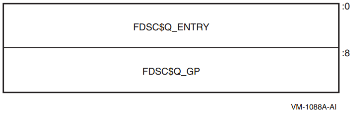
|
FDSC$Q_ENTRY |
Entry code address for the procedure to be called. |
|
FDSC$Q_GP |
GP value for the procedure to be called. |
A bound procedure is a procedure that does need direct access to the stack of its execution environment, typically to reference an up-level variable or to perform a nonlocal GOTO operation.
When a bound procedure is called, the caller must pass some kind of pointer to the called code that allows it to reference its up-level environment. Typically, this pointer is a frame pointer for that environment, but many variations are possible. When the caller itself is executing within that outer environment, it can usually make such a call directly to the code for the nested procedure without recourse to any additional function descriptors. However, when a procedure value for the nested procedure must be passed outside of that environment to a call site that has no knowledge of the target procedure, a bound function descriptor is created so that the nested procedure can be called just like a simple procedure.
Bound procedure values, as defined by this standard, are designed for multilanguage use and utilize the properties of function descriptors to allow callers of procedures to use common code to call both bound and simple procedures.
A bound function descriptor is similar to a simple function descriptor, with several additional fields as shown in Figure 4.8, ''Bound Function Descriptor'' and described in Table 4.15, ''Contents of Bound Function Descriptor''.
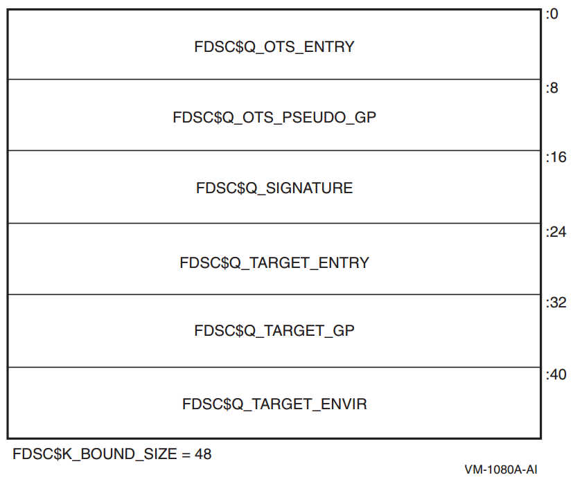
| Field Name | Contents |
|---|---|
|
FDSC$Q_OTS_ENTRY |
Code address for a suitable library helper routine, for example, OTS$JUMP_TO_BPV |
|
FDSC$Q_OTS_PSEUDO_GP |
Address of this bound function descriptor |
|
FDSC$Q_SIGNATURE |
Signature information field (see Section 6.1.3, ''Signature Information Fields in Function Descriptors'') |
|
FDSC$Q_TARGET_ENTRY |
Entry code address for the procedure to be called |
|
FDSC$Q_TARGET_GP |
GP value for the procedure to be called |
|
FDSC$Q_TARGET_ENVIR |
Environment value for the procedure to be called |
A bound procedure descriptor is inherently dynamic because the environment value must be determined at runtime by code executing within the bound procedure environment. Therefore, when a bound procedure descriptor such as this is needed, it is usually allocated on the creating procedure's stack.
Load the "real" target entry address into a volatile branch register, for example, B6.
Load the dynamic environment value into the appropriate uplevel-addressing register for the target function, for example, OTS$JUMP_TO_BPV uses R9.
Load the "real" target GP address into the GP register
Transfer control (branch, not call) to the target entry address.
Control arrives at the real target procedure address with both the GP and environment register values established appropriately.
OTS$JUMP_TO_BPV::
     add     gp=gp,24        ; Adjust GP to point to entry address
     ld8     r9=[gp],16      ; Load target entry address
     mov     b6=r9
     ld8     r9=[gp],-8      ; Load target environment value
     ld8     gp=[gp]         ; Load target GP
     br      b6              ; Transfer to target
Because the address of a bound function descriptor is a valid function pointer, it may be passed to translated code which uses it to call back into native code; therefore, the value of the signature information field must be the same as that in the official function descriptor for the real target procedure (see Section 6.1.2, ''Translated Images on I64 Systems'').
Note that there can be multiple OTS$JUMP_TO_BPV-like support routines, corresponding to different target registers where the environment value should be placed. The code that creates the bound function descriptor is also necessarily compiled by the same compiler that compiles the target procedure, thus can correctly select an appropriate support routine.
4.8. Procedure Call Stack
A procedure is an active procedure while its body is executing, including while any procedure it calls is executing. When a procedure is active, its designated condition handler may handle an exception that is signaled during its execution.
Associated with each active procedure is an invocation context, informally called a frame, which consists of the set of registers and space in memory that is allocated and that may be accessed during execution for a particular call of that procedure.
When a procedure begins to execute, it has a limited invocation context that includes the output registers of its caller (which have been "shifted" to start at register R32). The initial instructions may allocate and initialize additional context, including possibly saving information from the invocation context of its caller. Such instructions, if any, are termed a procedure prologue. Once execution of the prologue is complete, the procedure is said to be active.
When a procedure is ready to return to its caller, the procedure ceases to be active after it begins to execute the instructions that deallocate and discard the procedure's invocation context (which may include restoring state of the caller's invocation context that was saved during the prologue). These instructions are termed a procedure epilogue.
A null frame procedure has no prologue and no epilogue, and consists solely of body instructions. Such a procedure becomes active immediately.
A procedure may have more than one prologue if there are multiple entry points. A procedure may also have more than one epilogue if there are multiple return points. One of each will be executed during any given invocation of the procedure.
A procedure call stack (for a thread) consists of the stack of invocation contexts that exists at any point in time. New invocation contexts are pushed on that stack as procedures are called and invocations are popped from the call stack as procedures return.
The invocation context of a procedure that calls another procedure is said to precede or be previous to the invocation context of the called procedure.
4.8.1. Current Procedure
The current procedure is the active procedure whose execution began most recently; its invocation context is at the top of the call stack. Note that a procedure executing in its prologue or epilogue is not active, and hence cannot be the current procedure.
For OpenVMS, the PC (instruction pointer) register in combination with associated unwind information determines what procedure is current (for exception handling purposes). See Section A.4, ''Data Structures'' for a description of the unwind information data structures.
The PC is in a range described by any body region unwind descriptor but not in an epilogue
The PC is in a range not described by any unwind descriptor, and therefore by default must be within a null frame procedure (see Section A.4.1, ''Unwind Table and Unwind Information Block''):
4.8.2. Procedure Call Tracing
To provide the context of a procedure invocation
To walk (navigate) the procedure call stack
To refer to a given procedure invocation
To examine or modify the register context of an active procedure
This section describes the data structure mechanisms. The run-time library functions that support these functions are described in Section 4.8.3, ''Invocation Context Block Access Routines''
4.8.2.1. Invocation Context Block
The context of a specific procedure invocation is provided through the use of a data structure called an invocation context block (ICB). Table 4.16, ''Contents of the Invocation Context Block'' describes the contents of the OpenVMS IA-64 invocation context block.
|
Field |
Size |
Description |
|---|---|---|
|
LIBICB$L_CONTEXT_LENGTH |
Longword |
Unsigned total length in bytes of the invocation context block. See Section 4.8.3.1, ''Initializing the Invocation Context Block''. |
|
LIBICB$V_FRAME_FLAGS |
3 Bytes |
See Table 4.17, ''Flags in LIBICB$V_FRAME_FLAGS Field of the Invocation Context Block''. |
|
LIBICB$B_BLOCK_VERSION |
Byte |
ICB version; initial value of 2 for OpenVMS IA-64 (1 is for OpenVMS Alpha). See Section 4.8.3.1, ''Initializing the Invocation Context Block''. |
|
LIBICB$IH_IREG |
128 Quadwords |
Array of general registers (only those allocated; unallocated registers are uninitialized).
|
|
LIBICB$IH_GRNAT |
2 Quadwords |
General register NaT collection.? |
|
LIBICB$FO_F2_F31 |
30 Octawords |
Floating-point registers F2-F31. Array of floating-point register values in register format, as saved by a SPILL instruction. |
|
LIBICB$PH_F32_F127 |
Quadword |
Pointer to array of floating-point values in register format for registers F32-F127, as saved by SPILL instruction. A pointer value of 0 indicates that the contents of registers F32-F127 are not defined. |
|
LIBICB$IH_BRANCH |
8 Quadwords |
Array of branch registers. |
|
LIBICB$IH_RSC |
Quadword |
Register Stack Configuration register. |
|
LIBICB$IH_BSP |
Quadword |
Backing store pointer. |
|
LIBICB$IH_BSPSTORE |
Quadword |
Backing store write pointer. |
|
LIBICB$IH_RNAT |
Quadword |
RSE NaT collection register. |
|
LIBICB$IH_CCV |
Quadword |
Compare and Exchange Value register. |
|
LIBICB$IH_UNAT |
Quadword |
User NaT collection register. |
|
LIBICB$IH_PFS |
Quadword |
Previous function state. |
|
LIBICB$IH_LC |
Quadword |
Loop count register. |
|
LIBICB$IH_EC |
Quadword |
Epilogue Count register. |
|
LIBICB$IH_CSD |
Quadword |
Copy of the AR.CSD. |
|
LIBICB$IH_SSD |
Quadword |
Copy of the AR.SSD. |
|
LIBICB$Q_PRED |
Quadword |
Predicate collection register, P0—P63. This field is a bitvector with bit 0 reserved. |
|
LIBICB$IH_PC |
Quadword |
Current instruction pointer; the slot number overlays <1:0>. |
|
LIBICB$IH_CFM |
Quadword |
Current Frame Marker. |
|
LIBICB$IH_UM |
Quadword |
User mask bits from PSR. |
|
LIBICB$O_GR_VALID |
Octaword |
General Register validity mask.? |
|
LIBICB$L_FR_VALID |
Longword |
Floating-Point Register validity mask for registers F2-F31.? |
|
LIBICB$Q_BR_VALID |
Quadword |
Branch Register validity mask.? |
|
LIBICB$Q_AR_VALID |
Quadword |
Application Register validity mask.? |
|
LIBICB$Q_OTHER_VALID |
Quadword |
PC and CFM validity mask.? |
|
LIBICB$Q_PR_VALID |
Quadword |
Predicate Register validity mask.? |
|
LIBICB$IH_ORIGINAL_ |
Quadword |
Original address of the general register spill area (normally &icb->LIBICB$IH_IREG[0]).? |
|
LIBICB$IH_PSP |
Quadword |
Previous stack pointer. |
|
LIBICB$IH_RETURN_PC |
Quadword |
Return PC. |
|
LIBICB$IH_PREV_BSP |
Quadword |
Previous BSP |
|
LIBICB$PH_CHFCTX_ADDR |
Quadword |
Pointer to condition handler facility context block. |
|
LIBICB$IH_OSSD |
Quadword |
Copy of OSSD from Unwind Information Block. |
|
LIBICB$IH_HANDLER_FV |
Quadword |
Condition Handler Function Value. |
|
LIBICB$PH_LSDA |
Quadword |
Address of the Language Specific Data Area of the Unwind Information Block |
|
Beginning of User Override Parameters (offset LIBICB$R_UO_BASE) | ||
|
LIBICB$Q_UO_FLAGS |
Quadword |
Operational flags: LIBICB$V_UO_FLAG_CACHE_UNWIND – Cache unwind information during a walk of the call stack. See Section 4.8.3.2, ''Walking the Call Stack''. |
|
LIBICB$IH_UO_IDENT |
Quadword |
User context variable; passed by value to the callback routines. See Section 4.8.5, ''Invocation Context Callback Routines''. |
|
LIBICB$PH_UO_READ_MEM |
Quadword |
Pointer to user read memory routine. See Section 4.8.5.3, ''The Read Memory Routine''. |
|
LIBICB$PH_UO_GETUEINFO |
Quadword |
Pointer to user get unwind entry information routine. See Section 4.8.5.1, ''The Get Unwind Information Routine''. |
|
LIBICB$PH_UO_GETCONTEXT |
Quadword |
Pointer to user get initial context routine. See Section 4.8.5.2, ''The Get Initial Context Routine''. |
|
LIBICB$PH_UO_WRITE_MEM |
Quadword |
Pointer to user write memory routine. See Section 4.8.5.4, ''The Write Memory Routine''. |
|
LIBICB$PH_UO_WRITE_REG |
Quadword |
Pointer to user write register routine. See Section 4.8.5.5, ''The Write Register Routine''. |
|
LIBICB$PH_UO_MALLOC |
Quadword |
Pointer to user memory allocate routine. See Section 4.8.5.6, ''The Memory Allocation Routine''. |
|
LIBICB$PH_UO_FREE |
Quadword |
Pointer to user memory free routine. See Section 4.8.5.7, ''The Memory Deallocation Routine''. |
|
End of user override parameters (length of LIBICB$K_UO_LENGTH) | ||
|
LIBICB$L_ALERT_CODE |
Longword |
Stack walk detailed status. Alert codes are enumerated in the LIBICB include files. See Section 4.8.3.7, ''LIB$I64_GET_CURR_INVO_CONTEXT''. |
|
LIBICB$IH_SYSTEM_ |
n Quadwords |
Variable-sized area; unused and undefined at this time. |
|
Flag |
Description |
|---|---|
|
LIBICB$V_BOTTOM_OF_STACK |
Set to 1 if this is the bottom of the stack and there is absolutely no previous frame. |
|
LIBICB$V_HANDLER_PRESENT |
Set to 1 if this frame has a condition handler. |
|
LIBICB$V_IN_PROLOGUE |
Set to 1 if the PC is in a prologue region. |
|
LIBICB$V_IN_EPILOGUE |
Set to 1 if the PC is in an epilogue region. |
|
LIBICB$V_HAS_MEM_STK_FRAME |
Set to 1 if this frame has a memory stack. |
|
LIBICB$V_HAS_REG_STK_FRAME |
Set to 1 if this frame has a register stack. |
Static scratch registers, unless saved and described in the unwind table information, are not realizable except for an invocation context preceding an exception or AST frame.
4.8.2.2. Invocation Context Handle
To refer to a specific procedure invocation at run-time, an invocation context handle (ICH) can be used. The invocation context handle is a quadword that uniquely identifies any one of the active frames on a call stack, even when one or more of the frames correspond to procedures that have no associated stack storage.
The characteristics of the caller are used to determine the invocation context handle. If the caller has a register frame, then the RSE Backing Store Pointer (BSP) is used as the handle; otherwise, the caller's Stack Pointer is used. (The caller's Stack Pointer is sometimes called Stack Pointer on Entry or Previous Stack Pointer (PSP)).
4.8.3. Invocation Context Block Access Routines
Note
The OpenVMS I64 stack tracing routines use heap storage during the analysis of unwind descriptors. The default heap storage mechanism uses a LIBRTL implementation of the C RTL function malloc, the use of which may result in virtual memory being expanded using the $EXPREG system service. See Section 4.8.5, ''Invocation Context Callback Routines'' on how to override the defaults. See also Section 4.8.3.12, ''LIB$I64_PREV_INVO_END''.
4.8.3.1. Initializing the Invocation Context Block
Allocate the block on an octaword (16-byte) boundary.
Clear (set to all zero bytes) the entire block.
Initialize the LIBICB$L_CONTEXT_LENGTH field to LIBICB$K_INVO_CONTEXT_BLK_SIZE and the LIBICB$B_BLOCK_VERSION field to LIBICB$K_INVO_CONTEXT_VERSION.
Set any required parameters in the user override portion of the invocation context block.
Set the LIBICB$V_UO_FLAG_CACHE_UNWIND flag if appropriate. See also Section 4.8.3.2, ''Walking the Call Stack'' and Section 4.8.3.12, ''LIB$I64_PREV_INVO_END'' regarding subsequent use of LIB$I64_PREV_INVO_END.
Failure to do so will cause these routines to return an error status. Note that this is a change from Alpha, where initialization was not necessary.
LIB$I64_CREATE_INVO_CONTEXT (see Section 4.8.3.3, ''LIB$I64_CREATE_INVO_CONTEXT'')
LIB$I64_FREE_INVO_CONTEXT (see Section 4.8.3.4, ''LIB$I64_FREE_INVO_CONTEXT'')
LIB$I64_INIT_INVO_CONTEXT (see Section 4.8.3.5, ''LIB$I64_INIT_INVO_CONTEXT'')
4.8.3.2. Walking the Call Stack
During the course of program execution, it is sometimes necessary to walk the call stack. Frame-based exception handling is one case where this is done. Call stack navigation is possible only in the reverse direction (in a latest-to-earliest or top-to-bottom sequence).
Given a program state (which contains a register set), build an invocation context.
For the current routine, an initial invocation context block can be obtained by calling the LIB$I64_GET_CURR_INVO_CONTEXT routine (see Section 4.8.3.7, ''LIB$I64_GET_CURR_INVO_CONTEXT'').
Repeatedly call the LIB$I64_GET_PREV_INVO_CONTEXT routine (see Section 4.8.3.8, ''LIB$I64_GET_PREV_INVO_CONTEXT'') until the desired invocation context, or the end of the call chain, has been reached.
LIB$I64_GET_PREV_INVO_CONTEXT indicates the end of the invocation call chain if either of the following conditions is true:The OSSD$V_BOTTOM_OF_STACK flag is set for the target frame (see Table A.14, ''Operating System-Specific Data Area'').
The return address (IP) of the target frame is zero.
To make the stack walk more efficient, you can set the LIBICB$V_UO_FLAG_CACHE_UNWIND flag. This causes unwind information to be carried over from one call to LIB$I64_GET_PREV_INVO_CONTEXT to the next. At the conclusion of the stack walk, you must call LIB$I64_PREV_INVO_END to free any cached unwind information. This is the recommended practice, but not the default behavior.
Compilers are allowed to optimize high-level language procedure calls in such a way that they do not appear in the invocation chain. For example, inline procedures never appear in the invocation chain.
Make no assumptions about the relative positions of any memory used for procedure frame information. There is no guarantee that successive stack frames will always appear at higher addresses.
4.8.3.3. LIB$I64_CREATE_INVO_CONTEXT
This convenience routine simplifies creating and properly initializing an invocation context block. The routine allocates an invocation context block from heap storage and initializes it according to the steps described in Section 4.8.3.1, ''Initializing the Invocation Context Block''. Users of this routine should call LIB$I64_FREE_INVO_CONTEXT when the invocation context block is no longer required.
LIB$I64_CREATE_INVO_CONTEXT ([malloc] [, free] [, ident])|
Argument |
OpenVMS Usage |
Type |
Access |
Mechanism |
|---|---|---|---|---|
|
malloc |
function_value |
procedure |
read |
by value |
|
free |
function_value |
procedure |
read |
by value |
|
ident |
user_value |
quadword |
read |
by value |
|
|
A procedure reference for a user callback routine that allocates memory. See Section 4.8.5.6, ''The Memory Allocation Routine'' for details of this routine. This is an optional argument. The default is to use an implementation of the C RTL routine malloc. If specified, this routine is used to allocate the invocation context block and is also placed in the invocation context block field LIBICB$PH_UO_MALLOC for use during the stack walk. |
|
|
A procedure reference for a user callback routine that deallocates memory. This value is placed in the invocation context block field LIBICB$PH_UO_FREE. See Section 4.8.5.7, ''The Memory Deallocation Routine'' for details on this routine. This is an optional argument; however, it must be specified if malloc is specified. The default is to use an implementation of the C RTL routine free. |
|
|
Specifies a user ident value to be placed in the invocation context block LIBICB$IH_UO_IDENT field. In turn, this value is passed to the malloc and free routines, described in Section 4.8.5.6, ''The Memory Allocation Routine'' and Section 4.8.5.7, ''The Memory Deallocation Routine'' respectively. This is an optional argument; the default value is zero. |
|
|
A non-zero value represents the address of the invocation context block allocated. A value of 0 indicates failure. |
4.8.3.4. LIB$I64_FREE_INVO_CONTEXT
LIB$I64_FREE_INVO_CONTEXT (invo_context)|
Argument |
OpenVMS Usage |
Type |
Access |
Mechanism |
|---|---|---|---|---|
|
invo_context |
invo_context_blk |
structure |
modify |
by reference |
|
|
Address of an invocation context block. |
|
None. |
4.8.3.5. LIB$I64_INIT_INVO_CONTEXT
LIB$I64_INIT_INVO_CONTEXT
  (invo_context, invo_version [, cache_unwind_flag])
|
Argument |
OpenVMS Usage |
Type |
Access |
Mechanism |
|---|---|---|---|---|
|
invo_context |
invo_context_blk |
structure |
modify |
by reference |
|
invo_version |
version_number |
byte |
read |
by value |
|
cache_unwind_flag |
flag |
longword |
read |
by value |
|
|
Address of an invocation context block. |
|
|
The value LIBICB$K_INVO_CONTEXT_VERSION. This is used to verify the operating environment. |
|
|
A flag indicating if the cache unwind flag, LIBICB$V_UO_FLAG_CACHE_UNWIND, should be set in the invocation context block. A value of zero clears the flag; a value of one sets the flag. This is an optional argument. The default is zero. |
|
|
A value of 1 indicates success. A value of 0 indicates a version number mismatch. |
4.8.3.6. LIB$I64_GET_INVO_CONTEXT
LIB$I64_GET_INVO_CONTEXT(invo_handle, invo_context)|
Argument |
OpenVMS Usage |
Type |
Access |
Mechanism |
|---|---|---|---|---|
|
invo_handle |
invo_handle |
quadword |
read |
by reference |
|
invo_context |
invo_context_blk |
structure |
modify |
by reference |
|
|
Address of the location that contains the handle for the desired invocation. |
|
|
Address of an invocation context block into which the procedure context of the frame
specified by |
Note
The invocation context block must be properly initialized as described in Section 4.8.3.1, ''Initializing the Invocation Context Block'' before calling this routine.
|
|
Status value. A value of 1 indicates success; a value of 0 indicates failure. |
Note
If the invocation handle that was passed does not represent any procedure context in the active call stack, the new contents of the context block is unpredictable.
4.8.3.7. LIB$I64_GET_CURR_INVO_CONTEXT
LIB$I64_GET_CURR_INVO_CONTEXT(invo_context)|
Argument |
OpenVMS Usage |
Type |
Access |
Mechanism |
|---|---|---|---|---|
|
invo_context |
invo_context_blk |
structure |
modify |
by reference |
|
|
Address of an invocation context block into which the procedure context of the caller will be written. |
Note
The invocation context block must be properly initialized as described in Section 4.8.3.1, ''Initializing the Invocation Context Block'' before calling this routine.
|
Zero |
This facilitates use in the implementation of the C language unwind
|
4.8.3.8. LIB$I64_GET_PREV_INVO_CONTEXT
LIB$I64_GET_PREV_INVO_CONTEXT(invo_context)|
Argument |
OpenVMS Usage |
Type |
Access |
Mechanism |
|---|---|---|---|---|
|
invo_context |
invo_context_blk |
structure |
modify |
by reference |
|
|
Address of a valid invocation context block. The given invocation context block is updated to represent the context of the previous (calling) frame. The LIBICB$V_BOTTOM_OF_STACK flag of the invocation context block is set if the target frame represents the end of the invocation call chain or if stack corruption is detected. |
|
|
Status value. A value of 1 indicates success. When the initial context represents the bottom of the call stack, a value of 0 is returned. |
4.8.3.9. LIB$I64_GET_INVO_HANDLE
LIB$I64_GET_INVO_HANDLE(invo_context, invo_handle)|
Argument |
OpenVMS Usage |
Type |
Access |
Mechanism |
|---|---|---|---|---|
|
invo_context |
invo_context_blk |
structure |
read |
by reference |
|
invo_handle |
invo_handle |
quadword |
write |
by reference |
|
|
Address of a valid invocation context block. |
|
|
Address of the location into which the invocation context handle is to be written. If the call fails, the value of the invocation context handle is LIB$K_INVO_HANDLE_NULL. |
|
|
A value of 1 indicates success. A value of 0 indicates failure. |
4.8.3.10. LIB$I64_GET_CURR_INVO_HANDLE
LIB$I64_GET_CURR_INVO_HANDLE(invo_handle)|
Argument |
OpenVMS Usage |
Type |
Access |
Mechanism |
|---|---|---|---|---|
|
invo_handle |
invo_handle |
quadword |
write |
by reference |
|
|
Address of a quadword into which the invocation handle of the caller will be written. |
|
|
A value of 1 indicates success. A value of 0 indicates failure. |
4.8.3.11. LIB$I64_GET_PREV_INVO_HANDLE
LIB$I64_GET_PREV_INVO_HANDLE (invo_handle_in, invo_handle_out)|
Argument |
OpenVMS Usage |
Type |
Access |
Mechanism |
|---|---|---|---|---|
|
invo_handle_in |
invo_handle |
quadword |
read |
by reference |
|
invo_handle_out |
invo_handle |
quadword |
write |
by reference |
|
|
The address of an invocation handle that represents a target invocation context. |
|
|
Address of the location into which the invocation context handle of the previous context is to be written. If the call fails, the value of the previous invocation context handle is LIB$K_INVO_HANDLE_NULL. |
|
|
A value of 1 indicates success. A value of 0 indicates failure. |
Note
Each call to this routine involves a stack walk from the top of the stack to find the procedure matching the input handle. Consequently, using this routine repeatedly is an inefficient way to walk the stack, compared to using LIB$I64_GET_PREV_INVO_CONTEXT.
4.8.3.12. LIB$I64_PREV_INVO_END
This routine should be called at the conclusion of call tracing operations to free the memory used to process unwind descriptors. The call tracing routines are LIB$I64_GET_INVO_CONTEXT, LIB$I64_GET_PREV_INVO_CONTEXT, LIB$I64_GET_CURR_INVO_CONTEXT.
To provide efficient call tracing, some unwind information is tracked in heap storage from one call to the next. This heap storage should be freed before you release or reuse the invocation context block.
LIB$I64_PREV_INVO_END (invo_context)|
Argument |
OpenVMS Usage |
Type |
Access |
Mechanism |
|---|---|---|---|---|
|
invo_context |
invo_context_blk |
structure |
modify |
by reference |
|
|
Address of a valid invocation context block previously used for call tracing. |
|
|
A value of 1 indicates success. A value of 0 indicates failure. |
4.8.3.13. LIB$I64_PUT_INVO_REGISTERS
LIB$I64_PUT_INVO_REGISTERS
  (invo_handle, invo_context [,gr_mask] [,fr_mask] [,br_mask]
  [,pr_mask] [,misc_mask])
|
Argument |
OpenVMS Usage |
Type |
Access |
Mechanism |
|---|---|---|---|---|
|
invo_handle |
invo_handle |
quadword |
read |
by reference |
|
invo_context |
invo_context_blk |
structure |
read |
by reference |
|
gr_mask |
mask_octaword |
128-bit vector |
read |
by reference |
|
fr_mask |
mask_octaword |
128-bit vector |
read |
by reference |
|
br_mask |
mask_byte |
8-bit vector |
read |
by reference |
|
pr_mask |
mask_quadword |
64-bit vector |
read |
by reference |
|
misc_mask |
mask_quadword |
64-bit vector |
read |
by reference |
|
|
Handle for the invocation to be updated. |
|
|
Address of a valid invocation context block that contains new register contents. |
|
At least one of the
following mask arguments ( | |
|
|
Address of a 128-bit bit vector, where each bit corresponds to a register field in
the
|
|
|
Address of a 128-bit bit vector, where each bit corresponds to a register field in
the passed |
|
|
Address of a 8-bit bit vector, where each bit corresponds to a register field in the
passed |
|
|
Address of a 64-bit bit vector, where each bit corresponds to a register field in
the passed |
|
|
Address of a 64-bit bit vector, where each bit corresponds to a register field in
the passed
invo_context as follows:
Note that PC can only be updated when the invocaton in question has been interrupted (either by exception or by an interrupt) and is logically previous to an invocation with the OSSD$V_EXCEPTION_FRAME bit set. |
|
|
A value of 1 indicates success. A value of 0 is returned (and nothing is changed) in
the following circumstances:
|
Caution
Great care must be taken to assure that a valid stack frame and execution environment result; otherwise, execution may become unpredictable.
4.8.4. Supplemental Invocation Context Access Routines
The routines described in this section can be used to perform some of the more common operations involving invocation contexts.
4.8.4.1. LIB$I64_GET_FR
Given an invocation context block and floating-point register index such that 0 <=
index < 128, copy the register value to
fr_copy. For example, an index value of 4
fetches the value, which represents the contents of F4 for the context.
LIB$I64_GET_FR returns failure status if the index represents a scratch register whose contents have not been realized.
LIB$I64_GET_FR (invo_context, index, fr_copy)|
Argument |
OpenVMS Usage |
Type |
Access |
Mechanism |
|---|---|---|---|---|
|
invo_context |
invo_context_blk |
structure |
read |
by reference |
| index | index | longword | read | by value |
| fr_copy | floating-point value | octaword | write |
by reference |
|
|
Address of a valid invocation context block. |
index |
Floating-point register index. |
fr_copy |
Address of an octaword to receive the contents of the specified floating-point register. |
|
|
A value of 1 indicates success. A value of 0 indicates failure. |
4.8.4.2. LIB$I64_SET_FR
Given an invocation context block, a floating-point register index, and a floating-point
register value in fr_copy, writes the corresponding invocation context
block FREG entry, and calls LIB$I64_PUT_INVO_REGISTERS to write the
actual context. The invocation context block remains unchanged if the routine fails.
LIB$I64_SET_FR fails if LIB$I64_PUT_INVO_REGISTERS fails.
LIB$I64_SET_FR (invo_context, index, fr_copy)|
Argument |
OpenVMS Usage |
Type |
Access |
Mechanism |
|---|---|---|---|---|
|
invo_context |
invo_context_blk |
structure |
modify |
by reference |
| index | index | longword | read | by value |
| fr_copy | floating-point value | octaword | read |
by reference |
|
|
Address of a valid invocation context block. |
index |
Index into the FREG array of the invocation context block. |
fr_copy |
Address of an octaword that contains the floating-point value to be written to the invocation context block. |
|
|
A value of 1 indicates success. A value of 0 indicates failure. |
4.8.4.3. LIB$I64_GET_GR
Given an invocation context block and general register index such that 0 <=
index < 128, copy the register value to
gr_copy, for example, index 4 fetches the
invocation context block IREG[4] value, which represents the contents of R4 for the
context.
If the register represented by index has its corresponding NaT bit
set, the read succeeds and the return status is set to 3. If the register represented by
index lies beyond the allocated general registers, the read fails and
gr_copy is unchanged. That is, the highest allowed
index is 32 + ICB.CFM.SOF - 1.
LIB$I64_GET_GR fails if the index represents a scratch register whose contents have not been realized.
LIB$I64_GET_GR (invo_context, index, gr_copy)|
Argument |
OpenVMS Usage |
Type |
Access |
Mechanism |
|---|---|---|---|---|
|
invo_context |
invo_context_blk |
structure |
read |
by reference |
| index | index | longword | read | by value |
| gr_copy | integer value | quadword | write |
by reference |
|
|
Address of a valid invocation context block. |
index |
Index into the IREG array of the invocation context block. |
gr_copy |
Address of a quadword to receive the value from the invocation context block. |
|
|
A value of 3 indicates success, and the NaT bit was set. A value of 1 indicates success, and the NaT bit was clear. A value of 0 indicates failure. |
4.8.4.4. LIB$I64_SET_GR
Given an invocation context block, a general register index such that 1 <=
index < 128, and a quadword value gr_copy,
writes the corresponding invocation context block general register, clears the corresponding
NaT bit and uses LIB$I64_PUT_INVO_REGISTERS to write to the actual
context. The invocation context block remains unchanged if the routine fails.
LIB$I64_SET_GR fails if LIB$I64_PUT_INVO_REGISTERS fails.
LIB$I64_SET_GR (invo_context, index, gr_copy)|
Argument |
OpenVMS Usage |
Type |
Access |
Mechanism |
|---|---|---|---|---|
|
invo_context |
invo_context_blk |
structure |
modify |
by reference |
| index | index | longword | read | by value |
| gr_copy | integer value | quadword | read |
by reference |
|
|
Address of a valid invocation context block. |
index |
Index into the IREG array of the invocation context block. |
gr_copy |
Address of a quadword that contains the value to be written to the invocation context block. |
|
|
A value of 1 indicates success. A value of 0 indicates failure. |
4.8.4.5. LIB$I64_SET_PC
Given an invocation context block and a quadword PC value in
pc_copy, write the pc_copy value to the
invocation context block PC and then use LIB$I64_PUT_INVO_REGISTERS to
write to the actual context. The invocation context block remains unchanged if the routine
fails.
LIB$I64_SET_PC fails if LIB$I64_PUT_INVO_REGISTERS fails.
LIB$I64_SET_PC (invo_context, pc_copy)|
Argument |
OpenVMS Usage |
Type |
Access |
Mechanism |
|---|---|---|---|---|
|
invo_context |
invo_context_blk |
structure |
modify |
by reference |
| pc_copy | PC value | quadword | read |
by reference |
|
|
Address of a valid invocation context block. |
pc_copy |
Address of a quadword that contains the PC value to be written to the invocation context block. |
|
|
A value of 1 indicates success. A value of 0 indicates failure. |
4.8.4.6. LIB$I64_GET_UNWIND_LSDA
Given a pc_value, find the address of the unwind information block
language specific data area (LSDA), and write it to unwind_lsda_p. If
not present, then write 0 to unwind_lsda_p.
LIB$I64_GET_UNWIND_LSDA (pc_value, unwind_lsda_p)|
Argument |
OpenVMS Usage |
Type |
Access |
Mechanism |
|---|---|---|---|---|
| pc_value | PC value | quadword | read |
by reference |
| unwind_lsda_p | address | quadword | write | by reference |
|
|
Address of a location that contains the PC value. |
unwind_lsda_p |
Address of a quadword to receive the address of the language-specific data area, if there is one. |
|
|
A value of 1 indicates success. A value of 0 indicates failure. |
4.8.4.7. LIB$I64_GET_UNWIND_OSSD
Given a pc_value, find the address of the unwind information block
operating system-specific data area, if present, and write it to
unwind_ossd_p. If not present, then write 0 to
unwind_ossd_p.
LIB$I64_GET_UNWIND_OSSD (pc_value, unwind_ossd_p)|
Argument |
OpenVMS Usage |
Type |
Access |
Mechanism |
|---|---|---|---|---|
|
pc_value |
PC value |
quadword |
read |
by reference |
| unwind_ossd_p | address | quadword | write |
by reference |
|
|
Address of a location that contains the PC value. |
unwind_ossd_p |
Address of a quadword to receive the address of the operating system-specific data area. |
|
|
A value of 1 indicates success. A value of 0 indicates failure. |
4.8.4.8. LIB$I64_GET_UNWIND_HANDLER_FV
Given a pc_value, find the function value (address of the procedure
descriptor) for the condition handler, if present, and write it to
handler_fv. If not present, then write 0 to
handler_fv.
LIB$I64_GET_UNWIND_HANDLER_FV (pc_value, handler_fv)|
Argument |
OpenVMS Usage |
Type |
Access |
Mechanism |
|---|---|---|---|---|
|
pc_value |
PC value |
quadword |
read |
by reference |
| handler_fv | address | quadword | write |
by reference |
|
|
Address of a location that contains the PC value. |
handler_fv |
A quadword to receive the function value of the procedure descriptor for the condition handler, if there is one. |
|
|
A value of 1 indicates success. A value of 0 indicates failure. |
4.8.4.9. LIB$I64_IS_EXC_DISPATCH_FRAME
Used to determine whether a given PC value represents an exception dispatch frame.
LIB$I64_IS_EXC_DISPATCH_FRAME (pc_value)|
Argument |
OpenVMS Usage |
Type |
Access |
Mechanism |
|---|---|---|---|---|
|
pc_value |
PC value |
quadword |
read |
by reference |
|
|
Address of a quadword that contains the PC value. The
|
|
|
Returns 1 if the operating system-specific data area is present and the EXCEPTION_FRAME flag is set. Returns 0 if the operating system-specific data area is present and the EXCEPTION_FRAME flag is clear. Returns 0 if the operating system-specific data area is not present. |
4.8.4.10. LIB$I64_IS_AST_DISPATCH_FRAME
Used to determine whether a given PC value represents an AST dispatch frame.
LIB$I64_IS_AST_DISPATCH_FRAME (pc_value)|
Argument |
OpenVMS Usage |
Type |
Access |
Mechanism |
|---|---|---|---|---|
|
pc_value |
PC value |
quadword |
read |
by reference |
|
|
Address of a quadword that contains the PC value. The
|
|
|
Returns 1 if the operating system-specific data area is present and the AST_FRAME flag is set. Returns 0 if the operating system-specific data area is present and the AST_FRAME flag is clear. Returns 0 if the operating system-specific data area is not present. |
4.8.5. Invocation Context Callback Routines
Perform a call trace on a process other than the current process.
Override the heap storage mechanism used to allocate memory used during the analysis of unwind descriptors.
The user override callback mechanism provides a user ident value that is passed to each callback routine. The user ident value is stored in the LIBICB$IH_UO_IDENT field of the invocation context block.
Note
LIB$I64_GET_CURR_INVO_HANDLE
LIB$I64_GET_PREV_INVO_HANDLE
4.8.5.1. The Get Unwind Information Routine
int (* getueinfo) (uint64 pc, void *get_ue_block, void *name, ...);
This routine should mimic SYS$GET_UNWIND_ENTRY_INFO for the target process. See Section A.7, ''System Unwind Routines'' for detailed argument descriptions and return status, with the following notes:
The name argument is not used, and can be ignored. If a read memory callback has been specified, the contents of LIBICB$PH_UO_READ_MEM are passed as a fourth argument, and the contents of LIBICB$PH_UO_IDENT are passed as a fifth argument, otherwise the routine is called with three arguments.
4.8.5.2. The Get Initial Context Routine
Place a function pointer for this routine in the LIBICB$PH_UO_GETCONTEXT field of the invocation context block.
int (* getcontext) (void *invo_context, uint64 ident);
|
Argument |
OpenVMS Usage |
Type |
Access |
Mechanism |
|---|---|---|---|---|
|
invo_context |
invo_context_blk |
structure |
modify |
by reference |
|
ident |
user_value |
quadword |
read |
by value |
|
|
The address of the invocation context block. |
|
|
Specifies a user ident value from the invocation context block. |
|
|
A value of 1 indicates success. A value of 0 indicates failure. |
4.8.5.3. The Read Memory Routine
Place a function pointer for this routine in the LIBICB$PH_UO_READ_MEM field of the invocation context block.
int (* read_mem) (void *dst, uint64 src, size_t length, uint64 ident);
|
Argument |
OpenVMS Usage |
Type |
Access |
Mechanism |
|---|---|---|---|---|
|
dst |
memory_access |
byte_array |
write |
by reference |
|
src |
memory_address |
quadword |
read |
by value |
|
length |
size_t |
longword |
read |
by value |
|
ident |
user_value |
quadword |
read |
by value |
|
|
A local memory address and the destination for the read operation. |
|
|
An address in the target process to be read. |
|
|
The length in bytes to be read. |
|
|
Specifies a user ident value from the invocation context block. |
|
|
A value of 1 indicates success. A value of 0 indicates failure. |
4.8.5.4. The Write Memory Routine
Place a function pointer for this routine in the LIBICB$PH_UO_WRITE_MEM field of the invocation context block.
int (* write_mem) (void *src, uint64 dst, size_t length, uint64 ident);
|
Argument |
OpenVMS Usage |
Type |
Access |
Mechanism |
|---|---|---|---|---|
|
src |
memory_access |
byte_array |
read |
by value |
|
dst |
memory_address |
quadword |
write |
by reference |
|
length |
size_t |
longword |
read |
by value |
|
ident |
user_value |
quadword |
read |
by value |
|
|
A local memory address and the source for the write operation. |
|
|
An address in the target process to be written. |
|
|
The length in bytes to be written. |
|
|
Specifies a user ident value from the invocation context block. |
|
|
A value of 1 indicates success. A value of 0 indicates failure. |
4.8.5.5. The Write Register Routine
Place a function pointer for this routine in the LIBICB$PH_UO_WRITE_REG field of the invocation context block.
The write register routine is used to write a register in the target process. It is used by LIB$I64_PUT_INVO_REGISTERS for a register that has not been saved in memory.
int (* write_reg)
(int whichReg, uint64 value_1, uint64 value_2, uint64 ident);|
Argument |
OpenVMS Usage |
Type |
Access |
Mechanism |
|---|---|---|---|---|
|
whichReg |
enumeration |
longword |
read |
by value |
|
value_1 |
register_value |
quadword |
read |
by value |
|
value_2 |
register_value |
quadword |
read |
by value |
|
ident |
user_value |
quadword |
read |
by value |
|
|
Indicates the register to be written (see enum in libicb.h). |
|
|
Specifies the register contents, or lower quadword for a FR fill operation. |
|
|
Specifies the NaT bit for GRs, or upper quadword for a FR fill. |
|
|
Specifies a user ident value from the invocation context block. |
|
|
A value of 1 indicates success. A value of 0 indicates failure. |
4.8.5.6. The Memory Allocation Routine
void * (* malloc) (size_t size, uint64 ident);
|
Argument |
OpenVMS Usage |
Type |
Access |
Mechanism |
|---|---|---|---|---|
|
length |
size_t |
longword |
read |
by value |
|
ident |
user_value |
quadword |
read |
by value |
|
|
The length in bytes of memory to be allocated. The returned memory block should be aligned on a 16-byte boundary. |
|
|
Specifies a user ident value from the invocation context block. |
|
|
Address of the memory block allocated, or 0 for failure. |
One Unwind Context block of size LIBICB$K_CONTEXT_BLK_SIZE
One Unwind Descriptor block of size LIBICB$K_DESCRIPTOR_BLK_SIZE
Several Unwind region blocks of size LIBICB$K_REGION_BLK_SIZE
Several Unwind region label blocks of size LIBICB$K_REGIONLABEL_BLK_SIZE
The number of the last two required depends on the complexity of the unwind descriptors for a given procedure being traced.
4.8.5.7. The Memory Deallocation Routine
void (* free) (void * ptr, uint64 ident);
|
Argument |
OpenVMS Usage |
Type |
Access |
Mechanism |
|---|---|---|---|---|
|
ptr |
address |
quadword |
read |
by value |
|
ident |
user_value |
quadword |
read |
by value |
|
|
Address of a memory block previously allocated by a call to the user malloc routine. |
|
|
Specifies a user ident value from the invocation context block. |
Function Value Returned:
None.
4.9. Data Allocation
A linkage table, containing pointers to imported data and functions, and to data in the code segments and long data segments. This area is generally protected by OpenVMS against being written after image activation is complete.
A read-only short data area, containing small initialized own data items. This area is generally protected by OpenVMS against being written after image activation is complete. (This area is optional).
A read-write short data area, containing small initialized own data items.
A read-write short bss area, containing small uninitialized own data items.
One or more long data areas, which contain large initialized data items, and initialized non-own data items of any size.
One or more long bss areas, which contain large uninitialized data items, and uninitialized non-own data items of any size.
Own data items are those that are either local to an image, or are such that all references to these items from the same image will always refer to these items. Because non-own variables cannot be referenced directly, there is no benefit to placing them in the short data area or bss area. Small own data items are placed in the short bss area or short data areas, and are guaranteed to be within 2 megabytes (in either direction) of the GP address; this allows compilers to use a short direct addressing sequence (using the add with 22-bit immediate instruction) to access any data item allocated in these areas.
The compiler should place all own data items that are 8 bytes or less in size (regardless of structure) in one of the short data areas or the short bss area. All other data items, including items that are larger than 8 bytes in size, must be placed in one of the long data areas or long bss areas. The compiler must address these items indirectly, using a linkage table entry. Linkage table entries are typically allocated by the linker in response to a relocation request generated by the compiler; an entry in the linkage table is either a pointer to a data item, or a function descriptor. A function descriptor placed in the linkage table is a local copy of an official function descriptor that is generally allocated by the linker or image activator.
This design allows for a maximum size of 4 megabytes for the short data segment, because everything must be addressable via the GP register using the 22-bit add immediate instruction. This allows for up to 256,000 individually-named variables and functions. If an image requires more than this, linker options may be used to divide the image into multiple clusters (see Section 4.7.1, ''The GP Register'').
4.9.1. Data Alignment
On Itanium hardware, memory references to data that is not naturally aligned can result in alignment faults, which can severely degrade the performance of all procedures that reference the unaligned data. To avoid such performance degradation, all data values should be naturally aligned, as shown in Table 4.18, ''Natural Alignment Requirements''.
malloc), and global data items greater than 8 bytes must be aligned on a
16-byte boundary.|
Data Type |
Alignment Starting Position |
|---|---|
|
8-bit character string |
Byte boundary |
|
16-bit integer |
Address that is a multiple of 2 (word alignment) |
|
32-bit integer |
Address that is a multiple of 4 (longword alignment) |
|
64-bit integer |
Address that is a multiple of 8 (quadword alignment) |
|
Address that is a multiple of 4 (longword) |
|
Address that is a multiple of 8 (quadword) |
|
Address that is a multiple of 8 (quadword) |
|
Address that is a multiple of 4 (longword) |
|
Address that is a multiple of 8 (quadword) |
|
Address that is a multiple of 16 (octaword) |
For aggregates such as strings, arrays, and records, the data type to be considered for purposes of alignment is not the aggregate itself, but rather the elements of which the aggregate is composed. The alignment requirement of an aggregate is that all elements of the aggregate be naturally aligned. For example, varying 8-bit character strings must start at addresses that are a multiple of at least 2 (word alignment) because of the 16-bit count at the beginning of the string; 32-bit integer arrays start at a longword boundary, irrespective of the extent of the array.
The rules for passing a record in an argument that is passed by immediate value (see Section 4.7.4, ''Parameter Passing'') always provide quadword alignment of the record value independent of the normal alignment requirement of the record. If deemed appropriate by an implementation, normal alignment can be established within the called procedure by making a copy of the record argument at a suitably aligned location.
4.9.2. Global Data
Access to global variables that are not known (at compile time) to be defined in the same image must be indirect. Each image has a linkage table in its data segment, pointed to by the GP register; code must load a pointer to the global variable from the linkage table, then access the global variable through the pointer. Access to global variables known to be defined in the same image or to static locals that are placed in the short data area may be made with a GP-relative offset.
4.9.3. Local Static Data
Access to short local static data can be made with a GP-relative offset; access to long local static data must be indirect.
4.9.4. Constants and Literals
Constants and literals may be placed in the text segment or in the data segment. If placed in the text segment, the access must be PC-relative or indirect using a linkage table entry. Literals placed in the data segment may be placed in the short initialized data area if they are 8 bytes or less in size. Larger literals must be placed in the long initialized data area or in the text segment. Literals in the long initialized data area require an indirect access using a linkage table entry.
4.9.5. Record Layout Conventions
The OpenVMS I64 calling standard rules for record layout are designed to provide good run-time performance on all implementations of the Itanium architecture and to provide the required level of compatibility with conventional VAX and Alpha operating environments.
Those optimized for optimal access characteristics (referred to as aligned record layouts)
Those compatible with conventions that are traditionally used by VAX languages (referred to as VAX compatible record layouts)
Only these record layouts may be used across standard interfaces or between languages. Languages can support other language-specific record layout conventions, but such layouts are nonstandard.
The aligned record layout conventions should be used unless interchange is required with conventional VAX applications that use the OpenVMS VAX compatible record layouts.
4.9.5.1. Aligned Record Layout
All components of a record or subrecord are naturally aligned.
Layout and alignment of record elements and subrecords are independent of any record or subrecord in which they are embedded.
Layout and alignment of a subrecord is the same as if it were a top-level record.
Declaration in high-level languages of standard records for interlanguage use is straightforward and obvious, and meets the requirements for source-level compatibility between OpenVMS I64 languages and OpenVMS Alpha and VAX languages.
The components of a record must be laid out in memory corresponding to the lexical order of their appearance in the high-level language declaration of the record.
The first bit of a record or subrecord must be directly addressable (byte aligned).
Records and subrecords must be aligned according to the largest natural alignment requirements of the contained elements and subrecords.
Bit fields (packed subranges of integers) are characterized by an underlying integer type that is a byte, word, longword, or quadword in size together with an allocation size in bits. A bit field is allocated at the next available bit boundary, provided that the resulting allocation does not cross an alignment boundary of the underlying type. Otherwise, the field is allocated at the next byte boundary that is aligned as required for the underlying type. (In the later case, the space skipped over is left permanently not allocated). In addition, if necessary, the alignment of the record as a whole is increased to that of the underlying integer type.
Unaligned bit strings, unaligned bit arrays, and elements of unaligned bit arrays must start at the next available bit in the record. No fill is ever supplied preceding an unaligned bit string, unaligned bit array, or unaligned bit array element.
All other components of a record must start at the next available naturally aligned address for the data type.
The length of a record must be a multiple of its alignment. (This includes the case when a record is a component of another record).
Strings and arrays must be aligned according to the natural alignment requirements of the data type of which the string or array is composed.
The length of an array element is a multiple of its alignment, even if this leaves unused space at its end. The length of the whole array is the sum of the lengths of its elements.
4.9.5.2. OpenVMS VAX Compatible Record Layout
The components of a record must be laid out in memory corresponding to the lexical order of their appearance in the high-level language declaration of the record.
Unaligned bit strings, unaligned bit arrays, and elements of unaligned bit arrays must start at the next available bit in the record. No fill is ever supplied preceding an unaligned bit string, unaligned bit array, or unaligned bit array element.
All other components of a record must start at the next available byte in the record. Any unused bits following the last-used bit in the last-used byte of each component must be filled out to the next byte boundary so that any following data starts on a byte boundary.
Subrecords must be aligned according to the largest alignment of the contained elements and subrecords. A subrecord always starts at the next available byte unless it consists entirely of unaligned bit data and it immediately follows an unaligned bit string, unaligned bit array, or a subrecord consisting entirely of unaligned bit data.
Records must be aligned on byte boundaries.
4.9.6. Sample Code Sequences
In the sample code sequences in this section, register names of the form t1, t2, and so on, are temporary registers, and may be assigned to any available scratch register. The code sequences show necessary cycle breaks, but no other scheduling considerations have been made. It is assumed that these code sequences will be scheduled with surrounding code to make best use of the processor resources.
4.9.6.1. Addressing Own Data in the Short Data Area
    addl   t1=@gprel(var),gp ;;   // calc. address of var
ld8 loc0=[t1] // load contents of var movl t1=@gprel(var) ;; // form gp-relative offset of var
add t2=t1,gp ;; // calc. address of var
ld8 loc0=[t2] // load contents of var4.9.6.2. Addressing External Data or Data in a Long Data Area
    addl   t1=@ltoff(var),gp ;;   // calc. address of LT entry
    ld8    t2=[t1] ;;             // load address of var
    ld8    loc0=[t2]              // load contents of var
4.9.6.3. Addressing Literals in the Text Segment
L1: mov    r3=ip ;;                 // get current IP
    addl   loc0=litbase-L1,r3 ;;    // calc. addr. of lit. area
    adds   t2=(lit-litbase),loc0 ;; // calc. address of lit.
    ld8    loc1=[t2]                // load value of literal
Note
The first two instructions can be moved towards the beginning of the procedure, and the base address of the literal area (in LOC0) can be shared by other literal references in the same procedure.
4.9.6.4. Materializing Function Pointers
Function pointers must always be obtained from the data segment, either as an initialized quadword or through the linkage table, as shown in the following examples:
Materializing function pointers through linkage table:
    addl   t1=@ltoff(@fptr(func)),gp ;; // calc address of LT entry
    ld8    loc0=[t1]                    // load function pointer
Materializing function pointers in data:
fptr:
    data8  @ftpr(func)                  // initialize function ptr
4.9.6.5. Jump Tables
High-level language constructs such as case and switch statements, where there are several possible local targets of a branch, may use a number of different code generation strategies, ranging from sequential conditional branches to a direct-lookup branch table.
Two branch table methods are described: The first places the branch table in a read-only segment separate from the code segment. The second places the branch table in the code segment. The advantage of the first is that it allows the code segment to have execute-only access, while the second may require the code segment to allow read access as well. The advantage of the second is that it does not require addressing the branch table via the GP and hence may be slightly faster. Both methods avoid the need for relocation during image activation.
The branch table method descriptions that follow include examples that use 64-bit entries. It is also valid to use 32-bit, 16-bit or even 8-bit entries providing it is known that the smaller entry size is sufficient to allow the required displacement to be represented (without overflow).
Preferred Method
If a branch table is placed in a data segment separate from the code, each entry should be a byte displacement from a dispatch address located in the code segment to the branch target for that entry.
   //
   // Assume case index in loc0
   //
         addl    loc1=@ltoff($DSPTBL1), gp // addr of GOT entry
         ld8     loc2=[loc1]               // load addr of dsp table
         shladd  loc3=loc0,3,loc2          // calc addr of dsp entry
         ld8     loc4=[loc3]               // load dsp table entry
   $DA1: mov     loc5=ip                   // get "dispatch address"
         add     loc6=loc5,loc4            // calc target address
         mov     b6=loc6
         br.cond b6                        // perform dispatch

   $L1:  {target for case 1}
         ...
   $L2:  {target for case 2}
         ...
    ...   etc

   // The dispatch table is in the linkage section. It consists
   // of only constants (no relocations involved)
   //
   $DSPTBL1:
          .data8  $L1-$DA1
          .data8  $L2-$DA1
            .
            .
            .
Alternative Method
If a branch table is placed in the same segment as the code, each table entry should be a 64-bit byte displacement from the base of the branch table to the branch target for that entry.
      addl loc1=@ltoff(brtab),gp      // calc. address of
      ;;                              // linkage table entry
      ld8 loc2=[loc1] ;;              // load addr. of br. table
      shladd loc3=loc0,3,loc2 ;;      // calc. address of branch
                                      // table entry
      ld8 loc4=[loc3] ;;              // load branch table entry
      add loc5=loc4,loc2 ;;           // calc. target address
      mov b6=loc5 ;;                  // move address to B6...
      br.cond b6 ;;                   // ...and branch
Chapter 5. OpenVMS x86-64 Conventions
This chapter describes the fundamental concepts and conventions for calling a procedure in an OpenVMS x86-64 environment. These conventions are based on industry standards with extensions to be compatible with other OpenVMS systems. See Section C.2, ''Differences from Industry x86-64 Software Conventions'' for additional information.
5.1. x86-64 Register Usage
General-purpose
Floating-point and related control/status
Segment
Legacy pseudo-registers
5.1.1. x86-64 Register Classes
Scratch registers—may be modified by a procedure call; the caller must save these registers before a call if needed (caller save).
Preserved registers—must not be modified by a procedure call; the callee must save and restore these registers if used (callee save). A procedure using one of the preserved general-purpose registers must save and restore the original content of the caller.
One way to preserve a register is not to use it at all.
Special registers—used in the calling standard call/return mechanism.
Volatile registers—may be used as scratch registers within a procedure and are not preserved across a call; may not be used to pass information between procedures either as input or output.
5.1.2. x86-64 General-Purpose Register Usage
| Register | Class | Usage |
|---|---|---|
%rax %eax %ax %al %ah | Scratch |
|
%rbx %ebx %bx %bl %bh | Preserved | Callee-saved registers. |
%rcx %ecx %cx %cl %ch | Scratch | Pass the 4th argument to procedures. |
%rdx %edx %dx %dl %dh | Scratch |
|
%rsi %esi %si %sil | Scratch | Pass the 2nd argument to procedure. |
%rdi %edi %di %dil | Scratch | Pass the 1st argument to procedures. |
%rbp %ebp %bp %bpl | Preserved | Used as a frame pointer, if manifested in a register. |
%rsp %esp %sp %spl | Special | Stack pointer. |
%r8 %r8d %r8w %r8l | Scratch | Pass the 5th argument to procedures. |
%r9 %r9d %r9w %r9l | Scratch | Pass the 6th argument to procedures. |
%r10 %r10d %r10w %r10l | Scratch | Pass the environment value when calling a bound procedure. |
%r11 %r11d %r11w %r11l | Volatile | Available for use in call stubs, trampolines, and other constructs. |
| Preserved | Callee-saved registers. |
| RFLAGS | Preserved | The Direction Flag (DF) bit must be zero at procedure call and return. |
| Scratch | All other bits. | |
%rip | Special | Instruction pointer, not directly addressable by software. |
5.1.3. x86-64 Floating-Point Register Usage (SSE)
The base x86-64 architecture provides 16 SSE floating-point registers, each 128 bits wide.
Intel AVX (Advanced Vector Extensions) option provides 16 256-bit wide AVX registers
(%ymm0—%ymm15). The lower 128 bits of
%ymm0—%ymm15 are aliased to the respective 128-bit SSE
registers (%xmm0—%xmm15?).
Intel AVX-512 option provides 32 512-bit wide SIMD registers
(%zmm0—%zmm31). The lower 128 bits of
%zmm0—%zmm31 are aliased to the respective 128-bit SSE
registers (%xmm0—%xmm31). The lower 256 bits of
%zmm0—%zmm31 are aliased to the respective 256-bit AVX
registers (%ymm0—%ymm31?).
In addition, Intel AVX-512 also provides 8 vector mask registers
(%k0—%k7), each 64 bits wide.
For the purposes of parameter passing and function return, %xmmN,
%ymmN, and %zmmN refer to the same register. Only one of
them can be used at a time.
Vector register is used to refer to either an SSE, AVX, or AVX-512 register (but not a vector mask register). This document often uses the name SSE to refer collectively to the SSE registers together with either the AVX or AVX-512 options.
| Register | Class | Usage |
|---|---|---|
%xmm0 %ymm0 %zmm0 | Scratch |
|
%xmm1 %ymm1 %zmm1 | Scratch |
|
%xmm2 %ymm2 %zmm2 | Scratch | Pass the 3rd argument to procedures. |
%xmm3 %ymm3 %zmm3 | Scratch | Pass the 4th argument to procedures. |
%xmm4 %ymm4 %zmm4 | Scratch | Pass the 5th argument to procedures. |
%xmm5 %ymm5 %zmm5 | Scratch | Pass the 6th argument to procedures. |
%xmm6 %ymm6 %zmm6 | Scratch | Pass the 7th argument to procedures. |
%xmm7 %ymm7 %zmm7 | Scratch | Pass the 8th argument to procedures. |
| Scratch | Temporary registers. |
| MXCSR |
Preserved | The control flags (bits 6-15) are preserved. |
| Scratch | The other bits are scratch. |
| Register | Class | Usage |
|---|---|---|
%k0—%k7 | Scratch | Temporary registers |
5.1.4. x86-64 Floating-Point Register Usage (FPU)
OpenVMS x86-64 applications may use the x87 registers though there is little reason to do so. Packed, single- and double-precision floating-point operations are usually performed in the SSE registers, while the 80-bit extended-precision floating-point format is not supported by the OpenVMS compilers or run-times.
| Register | Class | Usage |
|---|---|---|
%st0 | Scratch | 1st return value register. |
%st1 | Scratch | 2nd return value register. |
%st2—%st7 | Scratch | Temporary registers. |
%mm0—%mm7 | Scratch | The MMX registers. Overlay the x87 floating-point
(%st0—%st7) registers. |
| Control Word | Preserved | Stores the value of the control word. |
| Status Word | Scratch | Stores the value of the status word. |
| — | Not used by applications. |
The CPU should be in x87 mode, not MMX mode, on procedure entry and exit.
5.1.5. Floating-Point Status Management on OpenVMS
The floating-point hardware registers
A supplementary software register (a quadword)
The floating-point status is normally managed by three OpenVMS system services:
SYS$IEEE_SET_FP_CONTROL
SYS$IEEE_SET_PRECISION_MODE
SYS$IEEE_SET_ROUNDING_MODE
The supplementary software register is internal to OpenVMS and is not documented for general use. This register holds information that is used by OpenVMS to implement the three system services and handle floating-point exceptions in general. It can only be accessed indirectly using the system services.
Floating-point control status bits are bits or flags that control the floating-point arithmetic operations.
Floating-point information status bits are bits or flags that record summary information about the execution of previous floating-point arithmetic operations.
Note
The floating-point control status is sometimes informally called the floating-point mode or IEEE mode.
Full IEEE-format floating-point control status is the default, unless the status is explicitly set to another value.
VAX-format floating-point control status can be set for programs that use VAX-format floating-point processing.
| Bit | Field | IEEE-format setting | VAX-format setting | |
|---|---|---|---|---|
| 0 | Invalid Operation | Flags | 0 | 0 |
| 1 | Denormal | 0 | 0 | |
| 2 | Zero Divide | 0 | 0 | |
| 3 | Overflow | 0 | 0 | |
| 4 | Underflow | 0 | 0 | |
| 5 | Inexact | 0 | 0 | |
| 6 | Denormals are Zeros | 0 | 0 | |
| 7 | Invalid Operation | Masks | 1 | 0 |
| 8 | Denormal | 1 | 1 | |
| 9 | Zero Divide | 1 | 0 | |
| 10 | Overflow | 1 | 0 | |
| 11 | Underflow | 1 | 1 | |
| 12 | Inexact | 1 | 1 | |
| 14:13 | Rounding Control | 00 (nearest) | 00 | |
| 15 | Flush to Zero | 0 | 0 | |
| 31:16 | Reserved | 0 | 0 | |
Note
VAX floating-point data is never loaded or manipulated in the x86-64 floating-point registers. However, VAX floating-point values may be converted to IEEE floating-point values, which are then manipulated in the x86-64 floating-point registers.
| Bit | Field | IEEE-format setting | VAX-format setting | |
|---|---|---|---|---|
| 0 | Invalid Operation | Masks | 1 | 0 |
| 1 | Denormal | 1 | 1 | |
| 2 | Zero Divide | 1 | 0 | |
| 3 | Overflow | 1 | 0 | |
| 4 | Underflow | 1 | 1 | |
| 5 | Inexact | 1 | 1 | |
| 7:6 | Reserved | 0 | 0 | |
| 9:8 | Precision Control | 11 | 11 | |
| 11:10 | Rounding Control | 00 (nearest) | 00 | |
| 15:13 | Reserved | 0 | 0 | |
Using a compiler or linker switch, you can associate a floating-point control status with the main procedure of a program to set the floating-point state prior to the beginning of program execution. If no control status is explicitly set, a default status appropriate for full IEEE computation is used.
5.1.6. x86-64 Segment Register Usage
| Register | Class | Usage |
|---|---|---|
%cs %ds %ss %es | — | Managed by OpenVMS and implicitly used by applications |
%fs | — | Reserved to OpenVMS |
%gs | — | Reserved to OpenVMS |
5.1.7. x86-64 Bound Register Usage
Use of the x86-64 bound registers is deprecated on OpenVMS. The only support provided is to context switch the contents of the bound registers as part of the normal application context; they are otherwise unused and unsupported.
5.1.8. Legacy Pseudo-Registers
The OpenVMS MACRO compiler for x86-64 (XMACRO) generates code that uses a set of pseudo-registers to emulate the Alpha register set. The pseudo-register set consists of 32 64-bit registers (R0—R31). The contents of these pseudo-registers are well defined only at procedure calls and returns; otherwise, XMACRO uses pseudo-registers at its discretion. No special semantics are associated with the pseudo-registers, even for the registers that would otherwise be considered special or part of the Alpha hardware.
The pseudo-registers are invisible to high-level languages, except for BLISS and VSI C. BLISS linkage attributes and VSI C linkage pragmas may be used to access pseudo-registers on calls and returns. See Chapter 3, "OpenVMS Alpha Conventions" for more information regarding Alpha register conventions and usage.
Use of such registers for other than legacy applications from other OpenVMS environments is deprecated.
The pseudo-registers are stored as a per-thread vector of quadwords in memory.
alpha_reg_vector_t* LIB$GET_ALPHA_REG_VECTOR ();Arguments:
| None. |
ptr | Pointer to the Alpha pseudo-register vector for the current thread. |
LIB$GET_ALPHA_REG_VECTOR preserves all
registers other than the return value register %rax.
Any procedure that accesses the pseudo-registers must make its own call to LIB$GET_ALPHA_REG_VECTOR to obtain the array address. Passing the array address to another procedure by any means is an error that may result in undefined behavior.
5.2. Address and Pointer Representation
An address is a 64-bit value that is used to denote a position in memory. However, for compatibility with OpenVMS VAX and Alpha, many OpenVMS applications and user-mode facilities operate in such a manner that addresses are restricted to values that are representable in 32 bits. This means that OpenVMS addresses can often be stored and manipulated as 32-bit longword values. In such cases, the 32-bit address value is always implicitly or explicitly sign-extended to form a 64-bit address for use by the x86-64 hardware.
The OpenVMS run-time environment supports a mix of 32- and 64-bit pointers. For backward compatibility, the default pointer size is 32 bits. A 32-bit pointer is converted to a 64-bit pointer by sign-extending its value. A 64-bit pointer can be converted to a valid 32-bit pointer only if the high-order 33 bits are all zero or all one.
5.3. Procedure Values
An x86-64 procedure value (a function pointer) is a pointer to code. To call through a procedure value, call through the value itself, not through a location in the memory pointed to by the value.
All procedure values must be representable in 32 bits. Because 32-bit addresses and pointers are always sign-extended before use (see Section 5.2, ''Address and Pointer Representation''), this means that the code they point to must reside in either the (hexadecimal) range 0..00000000 7FFFFFFF or FFFFFFFF 80000000..FFFFFFFF FFFFFFFF (see the VSI OpenVMS Programming Concepts Manual, Volume I for discussion of the structure of the OpenVMS address space). If the code is not in either of these regions, the linker creates a 32-bit-addressable trampoline for it. The trampoline code simply jumps to the procedure. The address of this trampoline becomes the value for that procedure.
Unbound procedures normally do not require an associated trampoline. They need a trampoline only if code in the same image takes the address of the procedure, or if it is a universal symbol.
Bound procedure values always point to trampolines. These trampolines are created by the containing procedure at the time it is called. When the bound procedure value trampolines pass control to the procedure, they pass an environment pointer (a pointer to the containing procedure stack frame) as an additional hidden parameter to the procedure. (See Section 5.6.5, ''Indirect Calls to a Bound Procedure'' regarding creation and deletion of bound procedure values).
5.4. Procedure Types
Variable-size stack procedure (sometimes known as a normal procedure in industry x86-64 documentation)—allocates a memory stack that is addressable using either
%rbp(the frame pointer register) or%rsp(the stack pointer register). The size of the stack may vary during the procedure execution. The called procedure may maintain a part or the whole context of its caller on that stack.Fixed-size stack procedure (sometimes known as a framepointerless procedure in industry x86-64 documentation)—allocates a memory stack that is addressable only using
%rsp(the stack pointer register). The size of the stack is fixed during the procedure execution. The called procedure may maintain a part or the whole context of its caller on that stack.Null frame procedure (sometimes known as a frameless procedure in industry x86-64 documentation)—allocates no memory stack (other than the implicit saving of the caller return address that is a part of the CALL instruction). No context of its caller is saved.
All types of procedures allow use of 128 bytes of temporary storage below the address given in the stack pointer. This so-called red zone is not preserved across procedure calls, but is preserved by signal and condition handlers. Outside of the kernel, procedures may use this for temporary storage. Because hardware interrupts do not preserve the red zone, kernel code cannot use it. The use of the red zone can be disabled with a compiler option or pragma.
The red zone is useful in frameless leaf procedures (that call no other procedures). It gives them 128 bytes of scratch storage without the performance overhead of setting up and taking down a stack frame.
A compiler chooses which type of procedure to generate based on the requirements of the procedure in question. A calling procedure does not need to know what type of procedure it is calling.
Every variable-size stack or fixed-size stack procedure must have an associated unwind description (see Appendix B, "Stack Unwinding and Exception Handling on OpenVMS x86-64") that provides information on the procedure type and its characteristics. A null frame procedure may also have an associated unwind description. (The default description applies if there is no unwind description). This data structure is used to interpret the call stack at any given point in a thread execution. It is built at compile time and usually is not accessed at run-time except to support exception processing or other rarely executed code.
5.4.1. Variable-Size Stack Procedures
Variable-size stack procedures allocate the stack that grows towards lower addresses. The
stack pointer (SP) is contained in the %rsp register. The frame pointer (FP)
is contained in the %rbp register. The stack pointer is normally 0mod16
aligned and must be 0mod16 aligned when making a call. Because the return address is pushed on
the stack by the caller, the stack pointer is 8mod16 aligned on entry to a procedure. The
%rbp register is saved immediately below the return address. The frame
pointer points to the saved %rbp.
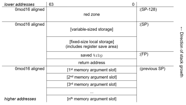
5.4.2. Fixed-Size Stack Procedures
Fixed-size stack procedures allocate the stack that grows towards lower addresses. The
stack pointer (SP) is contained in the %rsp register. No frame pointer (FP)
is used, so that the %rbp register is available as an additional preserved
register. The stack pointer is normally 0mod16 aligned and must be 0mod16 aligned when making a
call. Because the return address is pushed on the stack by the caller, the stack pointer is
8mod16 aligned on entry to a procedure.
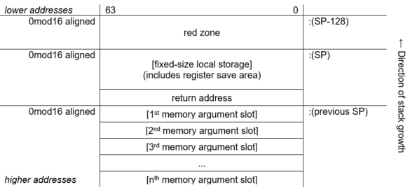
5.4.3. Null Frame Procedures
A null frame procedure is almost a special case of a fixed-size stack procedure. It is like a fixed-size stack which has no local storage other than the return address that is pushed on the stack as a result of the call. Because no additional stack is allocated it is unlike a fixed-size stack in that the alignment of the stack pointer is 8mod16 (not 0mod16).
A null frame procedure is necessarily a leaf procedure because the stack pointer must be 0mod16 aligned in order to make a call.
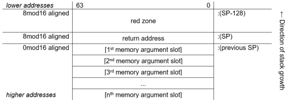
5.5. Stack Overflow Detection on OpenVMS x86-64
This section defines the conventions to support the execution of multiple threads in a multilanguage OpenVMS environment. Specifically defined is how compiled code must perform stack limit checking. While this standard is compatible with a multithreaded execution environment, the detailed mechanisms, data structures, and procedures that support this capability are not specified in this manual.
There can be one or more threads executing within a single process.
The state of a thread is represented in a thread environment block (TEB).
The TEB of a thread contains information that determines a stack limit below which the stack pointer must not be decremented by the executing code (except for code that implements the multithreaded mechanism itself).
Exception handling is fully reentrant and multithreaded.
5.5.1. Stack Limit Checking
A program that is otherwise correct can fail because of stack overflow. Stack overflow occurs when extension of the stack (by decrementing the stack pointer, SP) allocates addresses not currently reserved for the current thread's stack. This section defines the conventions for stack limit checking in a multithreaded environment.
Stack Guard Region
In a multithreaded environment, the address space beyond each thread's stack is protected by contiguous guard pages, which trap on any access. These pages form the stack guard region.Stack Reserve Region
In some cases, it is useful to maintain a stack reserve region, which is a minimum-sized region that is between the current top of stack and the stack guard region. A stack reserve region can ensure that the following conditions exist:Exceptions or asynchronous system traps (ASTs, analogous to asynchronous signals) have stack space to execute on a thread's stack.
The exception dispatcher and any exception handler that it might call have stack space to execute after detection of an invalid attempt to extend the stack.
This calling standard does not require a stack reserve region, but it does allow a language and its run-time system to implement one.
5.5.1.1. Methods for Stack Limit Checking
Because accessible memory may be available at addresses lower than those occupied by the stack guard region, compilers must generate code that never extends the stack past the stack guard region into accessible memory that is not allocated to the thread's stack.
A general strategy to prevent extending the stack past the stack guard region is to access
each page of memory down to and possibly including the page corresponding to the intended new
value of %rsp. If the stack is to be extended by an amount larger than the
size of a memory page, then a series of accesses is required that works from higher to lower
addressed pages. If any access results in a memory access violation, then the code has made an
invalid attempt to extend the stack of the current thread.
For the purposes of this section, the amount by which the stack is to be extended must include the size of the red zone in addition to the size of the needed stack extension for the executing procedure.
This calling standard defines two methods for stack limit checking, implicit and explicit, which are explained in the following sections.
Implicit Stack Limit Checking
If a byte (not necessarily the lowest) of the new stack region is guaranteed to be accessed prior to any further stack extension, then the stack can be extended by an increment that is up to one-half the stack guard region (without any additional accesses).
This standard requires that the minimum stack guard region size is 8192 bytes.
Explicit stack limit checking must be performed unless the amount by which
%rspis decremented is known to be less than or equal to 4096 and the application does not use a stack reserve region.Some byte in the new stack region must be accessed before
%rspcan be further decremented for a subsequent stack extension.This access can be performed either before or after
%rspis decremented for this stack extension, but it must be done before%rspcan be decremented again.No standard procedure call can be made before some byte in the new stack region is accessed.
The system exception dispatcher ensures that the lowest addressed byte in the new stack region is accessed if any kind of asynchronous interrupt occurs both after
%rspis decremented and before the access in the new stack region occurs.
These conventions ensure that the stack pointer is not decremented so that it points to accessible storage beyond the stack limit without this error being detected (either by the guard region being accessed by the thread or by an explicit stack limit check failure).
As a matter of practice, the system can provide multiple guard pages in the stack guard region. When a stack overflow is detected as a result of access to the stack guard region, one or more guard pages can be unprotected for use by the exception handling facility, as long as one or more guard pages remain protected to provide implicit stack limit checking during exception processing.
Explicit Stack Limit Checking
If the stack is being extended by an unknown amount or by a known amount that is greater than the maximum implicit check size 4096, then a code sequence that follows the rules for implicit stack limit checking can be executed in a loop to access the new stack region incrementally in segments that are less than or equal to the minimum stack guard region size 8192. At least one access must occur in each such segment.
The first access must occur between %rsp and
%rsp-4096, because in the absence of more specific information, the previous
guaranteed access relative to the current stack may be as much as 4096 bytes greater than the
current stack pointer address.
The last access must be within 4096 of the intended new value of the stack pointer. These accesses must occur in order, starting with the highest addressed segment and working toward the lowest addressed segment.
Perform a read access using the intended new value of the stack pointer. This is nondestructive, even if the read is beyond the stack guard region, and may facilitate OS mapping of new stack pages, if appropriate, in a single operation.
Proceed with sequential accesses as just described.
Note
A simple algorithm that is consistent with this requirement (but achieves up to twice
the minimum number of accesses) is to perform a sequence of accesses in a loop starting with
the previous value of %rsp, decrementing by the minimum no-check extension
size (4096) to, but not including, the first value that is less than the new value for the
stack pointer.
The stack must not be extended incrementally in procedure prologues.
A procedure prologue that needs to extend the stack by an amount of unknown size or known size
greater than the minimum implicit check size must test new stack segments as just described in
a loop that does not modify %rsp, and then update the stack with one
instruction that copies the new stack pointer value into %rsp.
Note
An explicit stack limit check can be performed either by inline code that is part of a prologue or by a run-time support routine that is tailored to be called from a procedure prologue.
5.6. Procedure Call and Return
Calls may be direct, which are performed directly to the entry point of a target procedure, or indirect, which are performed through a procedure value. The target of a call may be either an unbound or a bound procedure. Returns are the same for all types of calls.
From the perspective of a compiler or assembly language programmer, all calls are local, that is, the call target is always assumed to be in the same segment as the caller. In case a call resolves to a procedure in a different segment or image, the linker creates a local code stub that forwards that call to the target.
5.6.1. Direct Local Calls to an Unbound Procedure
Within a single segment, direct local calls to an unbound procedure can be performed with a simple CALL instruction using a 32-bit PC-relative displacement. This is sufficient in the small and medium memory models (see Section 5.10.1, ''Memory Models'').
If the code in a single segment grows beyond 2GB, the segment can be broken up into multiple segments.
5.6.2. Direct Local Calls to a Bound Procedure
Direct local calls to a bound procedure can only come from somewhere within the containing
scope; which is why this type of calls can be performed with the CALL instruction using a 32-bit
PC-relative displacement. The only difference between direct local calls to a bound procedure
and direct local calls to an unbound procedure is that a bound procedure requires an additional
implicit parameter, the procedure’s environment pointer, to be passed in
%r10.
5.6.3. Direct Local Calls to a Non-Local Procedure
Calls between images, or between segments in a single image, are performed via an entry in the Global Offset Table (GOT) that points to the target procedure. In most cases, compilers do not know whether a call target is local or external to the image or segment, and so generate a local call. The linker creates a trampoline and redirects this local call to it. The trampoline forwards the call to the target procedure via an indirect jump through the GOT entry. In cases where a compiler knows that a call target is external, it can generate an indirect call via a GOT entry itself.
5.6.4. Indirect Calls to an Unbound Procedure
Indirect calls to an unbound procedure transfer control to the address that is specified by a procedure value.
5.6.5. Indirect Calls to a Bound Procedure
There is no distinction between the unbound and bound procedure values, so the caller does not know whether the called procedure is bound or not. Therefore, the called side must make special arrangements to pass the environment pointer to the called procedure.
When code takes the address of a bound procedure, the value is not the address of the
procedure itself, but a trampoline. This trampoline loads the environment pointer into
%r10 and then jumps to the actual procedure.
The trampoline is created when the value of the environment pointer becomes known during run-time. Since a bound procedure value is specific to a particular activation of the containing scope, multiple recursive invocations create multiple trampolines. This means that the storage for the bound procedure trampolines must be dynamically allocated either on the stack or from the heap.
Allocating bound procedure trampolines on the stack is the common industry practice on x86-64, but this is deprecated on OpenVMS because the stack is normally non-executable by default. To use this method on OpenVMS, applications have to explicitly make stack memory executable either with a flag in the object file that has a .note.GNU-stack option or with a run-time call.
The preferred method of creating and allocating bound procedure trampolines on OpenVMS is to call a run-time routine. This routine dynamically allocates and manages a linked list of executable memory pages where the trampolines reside. A second routine must be called to deallocate a bound procedure trampoline. This should be done when the containing procedure exits.
void* LIB$X86_ALLOC_BOUND_PROC_VALUE (size)
|
Argument |
OpenVMS Usage |
Type |
Access |
Mechanism |
|---|---|---|---|---|
|
size |
integer |
quadword |
read |
by value |
|
|
Number of bytes needed to hold a bound procedure value. |
|
Pointer to a block of memory of the given size |
The returned memory must be initialized by the caller to complete the creation of the bound
procedure value. Typically the contents will consist of an instruction to copy the appropriate
invocation context (which might be saved in the same block) into %r10
followed by an instruction to transfer control to the entry point of the target
procedure.
Storage for bound procedure values is local to the thread in which they are created.
Bound procedure values logically form a stack on which any newly allocated value is added and one or more of the most recently added entries may be deleted (as a group).
LIB$X86_DELETE_BOUND_PROC_VALUE (bpv)
|
Argument |
OpenVMS Usage |
Type |
Access |
Mechanism |
|---|---|---|---|---|
|
bpv |
address |
quadword |
read |
by value |
|
|
Pointer to a bound procedure value (created by LIB$X86_ALLOC_BOUND_PROC_VALUE). |
|
None. |
The effect of calling LIB$X86_FREE_BOUND_PROC_VALUES is to delete an existing bound procedure value, as well as any additional bound procedure values that were created subsequent to it.
5.6.6. Returns
All calls push a 64-bit return address on the stack. When the called procedure returns, it uses the RET instruction to pop the return address from the stack and jump to that address.
5.7. Parameter and Return Value Passing
On OpenVMS x86-64, procedure parameters are passed in registers and/or on the stack. Procedures can return results in registers or in a memory location designated by the caller.
All calls use %rax as an argument information register as described in
Section 5.7.4, ''Argument Information Register (AI)''.
5.7.1. Scalar Argument Types
the six general-purpose registers (
%rdi,%rsi,%rdx,%rcx,%r8, and%r9)the eight XMM registers (
%xmm0—%xmm7)the stack.
|
Nominal Type | Argument Location | Return Value Location |
|---|---|---|
| Pointer [Q] |
The next available general-purpose register. Otherwise, in the next argument slot on the stack. | General-purpose register %rax |
| Boolean [B, BU] | ||
| Integers (size ≤ 64 bits) [B, W, L, Q, BU, WU, LU, QU] | ||
| Integers (64 < size ≤ 128 bits) [O, OU] |
The next two available general-purpose registers. Otherwise, in the next two argument slots on the stack. | General-purpose registers %rax (low half) and
%rdx (high half) |
| VAX float (F_floating, D_floating, and G_floating) [F, D, G] |
The next available general-purpose register. Otherwise, in the next argument slot on the stack. | General-purpose register %rax |
| IEEE single-precision float (S_floating) [FS] |
Bits 31:0 of the next available XMM register. Otherwise, in the next argument slot on the stack. | Bits 31:0 of register %xmm0 |
| IEEE double-precision float (T_floating) [FT] |
Bits 63:0 of the next available XMM register. Otherwise, in the next argument slot on the stack. | Bits 63:0 of register %xmm0 |
| IEEE quadruple-precision float (X_floating) [FX] |
The next available XMM register. Otherwise, in the next two argument slots on the stack. | Register %xmm0 |
| VAX complex single-precision float (F_floating) [FC] |
The next available general-purpose register. Otherwise, in the next argument on the stack. |
General-purpose register |
| VAX complex double-precision float (D_floating and G_floating) [DC, GC] |
The next two available general-purpose registers. Otherwise, in the next two argument slots on the stack. | Registers %rax (the real part of a value) and
%rdx (the imaginary part of a value) |
| IEEE complex single-precision float [FSC] |
In the next available XMM register, real part in bits 31:0, imaginary part in bits 63:32. Otherwise, in the next argument slot on the stack. | Register %xmm0, the real part of a value in bits 31:0, the
imaginary part in bits 63:32 |
| IEEE complex double-precision float [FTC] |
In bits 63:0 of the next two available XMM registers. Otherwise, the next two argument slots on the stack. | Bits 63:0 of registers %xmm0 (the real part of a value) and
%xmm1 (the imaginary part of a value) |
| IEEE complex quadruple-precision float [FXC] | In the next four available argument slots on the stack. | In a caller-allocated memory buffer whose address is passed as a hidden first argument |
An argument that requires two registers is never split so that the first part is in a register and the second part is on the stack. Either both parts are in registers or both parts are on the stack.
For example, a procedure that takes ten integer scalar arguments will find the first six arguments in the general-purpose registers, and the last four on the stack. A procedure that takes ten IEEE double-precision floating-point scalars as arguments will find the first eight arguments in the XMM registers, and the last two on the stack. And, a procedure that takes six integer arguments and eight floating-point arguments, regardless of how the integer and floating-point arguments are intermixed, will find all 14 arguments in registers.
5.7.2. Aggregate Argument Types
This section describes how the aggregate argument types are passed to procedures.
First, the argument types are assigned in the appropriate classes and then the registers are allocated for passing them.
INTEGER class consists of integral types that fit in one of the general-purpose registers including pointers.
SSE class consists of types that fit in a floating-point register.
SSEUP class consists of types that fit into a floating-point register and can be passed and returned in the upper bytes of it.
X87, X87UP, COMPLEX_X87 classes consist of types that can be returned via the x87 FPU.
NO_CLASS is used as initializer in the algorithms. It is used for padding as well as empty structures and unions.
MEMORY class consists of types that are passed and returned in memory via the stack.
The size of each argument is rounded up to a quadword (8 bytes). Therefore, the stack will always be 8-byte aligned.
|
Nominal Type | Equivalent C/C++ Type(s) | Argument Passing Class |
|---|---|---|
| Pointer [Q] | * | INTEGER |
| Boolean [B, BU] | _Bool (bool) | |
| Integers (size ≤ 64 bits) [B, W, L, Q, BU, WU, LU, QU] | char, short, int, long (signed and unsigned) | |
| Integers (64 < size ≤ 128 bits) [O, OU] | __int128 (signed and unsigned) | Split into two 8-byte chunks. Both belong to class INTEGER. |
| VAX floating-point types (up to 64 bits) [F, D, G] | INTEGER | |
| VAX floating-point complex (64 bits) [FC] | INTEGER | |
| VAX floating-point complex (128 bits) [DC, GC] | Split into two 8-byte chunks. Both belong to class INTEGER. | |
| IEEE binary floating-point types (up to 64 bits) [FS, FT] | float, double | SSE |
| IEEE extended binary floating-point type (128 bits) [FX] | __float128 | Split into two halves. The first (lower addressed) 64-bits belong to class SSE and the second half to class SSEUP. |
| IEEE binary floating-point complex (64 bits) [FSC] | complex float | Treat as two successive binary floating-point values, each treated as a scalar of half the size (see above). |
| IEEE binary floating-point complex (128 bits) [FTC] | complex double | |
| IEEE binary floating-point complex (256 bits) [FXC] | complex long double |
If the size of an object is larger than eight quadwords (64 bytes), or it contains unaligned fields, it belongs to the MEMORY class.
If a C++ object is non-trivial for the purpose of calls, as specified in the C++ ABI?, it is passed by an invisible reference—that is, the object is replaced in the parameter list by a pointer that has the INTEGER class.?
If the size of the aggregate exceeds a single quadword, each quadword is classified separately. Each quadword is initialized to the NO_CLASS class.
- Each field of an object is classified recursively so that always two fields are considered. The two fields are the containing quadword as a whole and the lowest level field components of the quadword, considered in order:
If both classes are equal, this is the resulting class.
If one of the classes is NO_CLASS, the resulting class is the other class.
If one of the classes is MEMORY, the result is the MEMORY class.
If one of the classes is INTEGER, the result is the INTEGER class.
If one of the classes is X87, X87UP, or COMPLEX_X87, the result is the MEMORY class.
Otherwise the result is the SSE class.
- Then a post merger cleanup is done:
If one of the classes is MEMORY, the whole argument is passed in memory.
If X87UP is not preceded by X87, the whole argument is passed in memory.
If the size of the aggregate exceeds two quadwords and the first quadword is not SSE or any other quadword is not SSEUP, the whole argument is passed in memory.
If SSEUP is not preceded by SSE or SSEUP, it is converted to SSE.
If the class is MEMORY, the argument is passed on the stack.
If the class is INTEGER, the next available register of the sequence
%rdi,%rsi,%rdx,%rcx,%r8, and%r9is used.If the class is SSE, the argument is passed in the next available floating-point register. The registers are taken in order from
%xmm0to%xmm7.If the class is SSEUP, the quadword is passed in the next available 8-byte chunk of the last used floating-point register.
If the class is X87, X87UP, or COMPLEX_X87, the argument is passed in memory.
When a value of a boolean type is returned or passed in a register or on the stack, bit 0 contains the truth value, bits 1 to 7 must be zero, and all other bits are left unspecified. A consumer of such values can rely on it being 0 or 1 only when truncated to the low byte.
If there are no registers available for any quadword of an argument, the whole argument is passed on the stack. If registers have already been assigned for some quadwords of such an argument, the assignments are reverted.
Once registers are assigned, the arguments passed in memory are pushed on the stack in reversed (right-to-left?) order.
|
Nominal Type | Equivalent C/C++ Type(s) | Argument Passing Class |
|---|---|---|
| IEEE binary floating-point vector (up to 64 bits) [M64] | __m64 | SSE |
| IEEE extended binary floating-point vector (128 bits) [M128] | __m128 | Split into two halves. The first (lower addressed) 64-bits belong to class SSE and the second half to class SSEUP. |
| IEEE binary floating-point vector (256 bits) [M256] | __m256 | Split into four 8-byte chunks. The first chunk belongs to class SSE and the rest to class SSEUP. |
| IEEE binary floating-point vector (512 bits) [M512] | __m512 | Split into eight 8-byte chunks. The first chunk belongs to class SSE and the rest to class SSEUP. |
When passing the __m256 or __m512 arguments to
functions that use varargs or stdarg, function prototypes must be provided. Otherwise, the
run-time behavior is undefined.
5.7.3. Unused Bits in Passed Data
Note
Bit 31 is replicated in bits 32—63, even for unsigned 32-bit integers.
This rule applies to the argument types described in Section 5.7.1, ''Scalar Argument Types'' as well as the individual elements of aggregate types passed in general-purpose registers as described in Section 5.7.2, ''Aggregate Argument Types''.
|
Data Type |
Type Designator? |
Data Size (bytes) |
Register Extension Type |
Memory Extension Type |
|---|---|---|---|---|
|
Byte logical |
DSC$K_DTYPE_BU |
1 |
Zero64 |
Zero64 |
|
Word logical |
DSC$K_DTYPE_WU |
2 |
Zero64 |
Zero64 |
|
Longword logical |
DSC$K_DTYPE_LU |
4 |
Sign64 |
Sign64 |
|
Quadword logical |
DSC$K_DTYPE_QU |
8 |
Data64 |
Data64 |
|
Byte integer |
DSC$K_DTYPE_B |
1 |
Sign64 |
Sign64 |
|
Word integer |
DSC$K_DTYPE_W |
2 |
Sign64 |
Sign64 |
|
Longword integer |
DSC$K_DTYPE_L |
4 |
Sign64 |
Sign64 |
|
Quadword integer |
DSC$K_DTYPE_Q |
8 |
Data64 |
Data64 |
|
F_floating |
DSC$K_DTYPE_F |
4 |
VAXF64 |
Data32 |
|
D_floating |
DSC$K_DTYPE_D |
8 |
VAXDG64 |
Data64 |
|
G_floating |
DSC$K_DTYPE_G |
8 |
VAXDG64 |
Data64 |
|
F_floating complex |
DSC$K_DTYPE_FC |
2 * 4 |
2*VAXF64 |
2*Data32 |
|
D_floating complex |
DSC$K_DTYPE_DC |
2 * 8 |
2*VAXDG64 |
2*Data64 |
|
G_floating complex |
DSC$K_DTYPE_GC |
2 * 8 |
2*VAXDG64 |
2*Data64 |
|
S_floating |
DSC$K_DTYPE_FS |
4 |
Hard |
Data32 |
|
T_floating |
DSC$K_DTYPE_FT |
8 |
Hard |
Data64 |
|
X_floating |
DSC$K_DTYPE_FX |
16 |
N/A |
N/A |
|
S_floating complex |
DSC$K_DTYPE_FSC |
2 * 4 | Hard? |
2*Data32 |
|
T_floating complex |
DSC$K_DTYPE_FTC |
2 * 8 |
2*Hard |
2*Data64 |
|
X_floating complex |
DSC$K_DTYPE_FXC |
2 * 16 |
N/A |
N/A |
|
Small structures of 8 bytes or less |
N/A |
≤8 |
Nostd |
Nostd |
|
Small arrays of 8 bytes or less |
N/A |
≤8 |
Nostd |
Nostd |
|
32-bit address |
N/A |
4 |
Sign64 |
Sign64 |
|
64-bit address |
N/A |
8 |
Data64 |
Data64 |
|
Sign Extension Type |
Defined Function |
|---|---|
|
Sign64 |
Sign-extended to 64 bits. |
|
Zero64 |
Zero-extended to 64 bits. |
|
Data32 |
Data is 32 bits. The state of bits <63:32> is unpredictable. |
|
2*Data32 |
Two single-precision parts of the complex value are stored in memory as independent floating-point values (each handled as Data32). |
|
Data64 |
Data is 64 bits. |
|
2*Data64 |
Two double-precision parts of the complex value are stored in memory as independent floating-point values (each handled as Data64). |
|
VAXF64 |
Data is 64 bits. Low-order 32 bits are the same as the F_floating memory format and the high-order 32 bits are zero. (Used only in a general register, never in a floating-point register). |
|
VAXDG64 |
Data is 64 bits. Uses the corresponding D_floating or G_floating memory format. (Used only in a general register, never in a floating-point register). |
|
2*VAXF64 |
Two single-precision parts of the complex value are stored in memory as independent floating-point values (each handled as VAXF64). |
|
2*VAXDG64 |
Two double-precision parts of the complex value are stored in memory as independent floating-point values (each handled as VAXDG64). |
|
Hard |
Passed in the layout defined by the hardware SRM. |
|
2*Hard |
Two floating-point parts of the complex value are stored in a pair of registers as independent floating-point values (each handled as Hard). |
|
Nostd |
State of all high-order bits not occupied by the data is unpredictable across a call or return. |
5.7.4. Argument Information Register (AI)
%rax is used as
the AI register. It must contain the argument information that is presented in Table 5.13, ''Contents of the Argument Information Register (%rax)''.%rax)| Bit | Contents |
|---|---|
7:0 (%al) | Upper bound on the number of XMM registers that are used to pass arguments |
15:8 (%ah) | Total number of passed argument slots |
| 47:16 | Argument Info Offset relative to the return address of the caller, or zero |
| 63:48 |
Reserved and must be either 0x0000 or 0xFFFF? |
If the Argument Info Offset field is non-zero, it contains a signed byte offset to an Argument Info Block (AIB). This byte offset is relative to the return address of the caller, that is, an offset from the location of the instruction after the call instruction. The Argument Info Block must be close enough to the call site for the offset to fit in 32 bits. If the AIB is in the same section as the code, this offset can be calculated at compile time.
| Bit | Name | Usage |
|---|---|---|
| 7:0 | version | Format version. This format is version 1. |
| 15:8 | arg info count | Number of argument slots represented in this block. |
| 19:16 | 1st arg info | Information on the 1st argument slot. |
| 23:20 | 2nd arg info | Information on the 2nd argument slot. |
|
. | ||
| Information on the nth argument slot. |
The arg info count may be less than, equal to, or greater than the actual number of passed arguments. If it is less, the missing argument information fields are assumed to be 0 (AI$K_AR_I64). If it is greater, the extra entries in this block are ignored.
If all the passed arguments are integers and pointers, there is no need to pass an Argument Info Block. Instead, the Argument Info Offset should be set to zero.
| Value | Name | Meaning |
|---|---|---|
| 0 | AI$K_AR_I64 |
Argument is passed in a general-purpose register, if one is available, otherwise on the stack. or Argument is not present. |
| 1 | AI$K_AR_FF | F_floating argument is passed in a general-purpose register. |
| 2 | AI$K_AR_FD | D_floating argument is passed in a general-purpose register. |
| 3 | AI$K_AR_FG | G_floating argument is passed in a general-purpose register. |
| 4 | AI$K_AR_FS | Argument is passed in bits 31:0 of an XMM register. |
| 5 | AI$K_AR_FT | Argument is passed in bits 63:0 of an XMM register. |
| 6 | AI$K_AR_FXL | Low half of argument is passed in bits 63:0 of an XMM register. |
| 7 | AI$K_AR_FXH | High half of argument is passed in bits 127:64 of an XMM register. |
| 8 | AI$K_AR_MEM | Argument is pushed on the stack. |
| 9—15 | — | Reserved. |
5.7.5. Variable Argument Lists
The x86-64 industry standards define how C-style variable argument lists (va_start, va_arg and so on) are implemented. OpenVMS also allows variable argument lists to be accessed as arrays. On prior OpenVMS architectures, a single common mechanism supports both. On OpenVMS x86-64, different mechanisms are implemented.
5.7.5.1. Standard Variable Arguments
| Offset | Register | Usage |
|---|---|---|
| 0 | %rdi | 1st general-purpose argument register |
| 8 | %rsi | 2nd general-purpose argument register |
| 16 | %rdx | 3rd general-purpose argument register |
| 24 | %rcx | 4th general-purpose argument register |
| 32 | %r8 | 5th general-purpose argument register |
| 40 | %r9 | 6th general-purpose argument register |
| 48 | %xmm0 | 1st floating-point argument register |
| 64 | %xmm1 | 2nd floating-point argument register |
| 80 | %xmm2 | 3rd floating-point argument register |
| 96 | %xmm3 | 4th floating-point argument register |
| 112 | %xmm4 | 5th floating-point argument register |
| 128 | %xmm5 | 6th floating-point argument register |
| 144 | %xmm6 | 7th floating-point argument register |
| 160 | %xmm7 | 8th floating-point argument register |
The register save area is always allocated in the stack frame of the called function. Any
function that contains an invocation of the va_start macro must save argument registers in the
register save area. The six general-purpose registers are always saved. The number of
floating-point registers to be saved depends on the value passed in the %al
register. In theory, code should not save more registers than indicated in
%al, but in practice, it either saves none (if %al is
zero) or all the registers.
The standard requires the caller to pass a floating-point register argument count in the
%al register whenever the called function uses the C variable arguments.
This includes not only functions explicitly declared with the variable arguments, but all
unprototyped functions as well.
Note that the OpenVMS “arginfo notused” linkage does not influence whether this value is
passed in the %al or not. The passed value does not need to be absolutely
correct, but should at least be an upper bound on the number of arguments passed in
floating-point registers.
| Offset | Field | Usage |
|---|---|---|
| 0 | gp_offset | Byte offset from the start of the register save area of the next available saved integer argument register |
| 4 | fp_offset | Byte offset from the start of the register save area of the next available saved floating-point argument register |
| 8 | overflow_arg_area | Pointer to the first available stack argument |
| 16 | reg_save_area | Pointer to the register save area |
gp_offset is the byte offset within the register save area of the first unused general-purpose register.
fp_offset is the byte offset within the register save area of the first unused floating-point register.
overflow_arg_area points to the first unused stack argument.
reg_save_area points to the register save area that is already initialized.
printf(const char *fmt, ...) function, the va_list
structure is initialized as follows:gp_offset is set to +8, the offset of the second general-purpose argument; the first argument (
fmt) is already used.fp_offset is set to +48, the offset of the first floating-point argument.
overflow_arg_area is set to FP+16, the location of the first stack argument.
When the va_arg macro is invoked, it fetches the argument from a saved register or the stack and increments one field on the va_list structure accordingly. For example, if an integer argument is requested, the va_arg macro will compare the value of gp_offset against 48. If gp_offset is less than 48, the va_arg macro will return a saved integer register and increment gp_offset. Otherwise, it will return a stack argument and increment overflow_arg_area.
5.7.5.2. OpenVMS Variable Argument Lists
ARGPTR, ACTUALPARAMETER and ACTUALCOUNT in BLISS
[list], argument, and argument_list_length in VSI Pascal
va_count in VSI C
All rely on OpenVMS extensions to the standard calling conventions.
On OpenVMS standard calls, the caller passes argument information in the
%rax register that specifies the total number of the used argument slots
and location of each register argument. In theory, this information only needs to be passed if
the called procedure uses one of the above mentioned language constructs, but since the caller
is not able to determine this, the argument information is passed in %rax on
all OpenVMS standard
calls.
%ah. If a
called procedure requests an argument list, the called procedure performs the following:Allocates the storage in its own stack frame for the entire arglist (8 *
%ah).Copies all general-purpose registers, floating-point registers, and memory arguments to the arglist as indicated by the values in
%rax.
Unlike the prior OpenVMS architectures, on OpenVMS x86-64 it is not possible to create a register “home” on the stack that is contiguous with the incoming memory arguments.
5.7.6. Procedure Return Values
If the class is MEMORY, then the caller provides the space for the return value and passes the address of this storage in
%rdias if it were the first argument to the function. In effect, this address becomes a hidden first argument. This storage must not overlap any data visible to the callee through the other parameters in this argument list.On return
%raxwill contain the address that was passed in%rdiby the caller.If the class is INTEGER, the next available register of the sequence
%rax,%rdxis used.If the class is SSE, the next available floating-point register of the sequence
%xmm0,%xmm1is used.If the class is SSEUP, the quadword is returned in the next available 8-byte chunk of the last used floating-point register.
If the class is X87, the value is returned on the X87 stack in
%st0as an 80-bit x87 number.If the class is X87UP, the value is returned together with the previous X87 value in
%st0.If the class is COMPLEX_X87, the real part of the value is returned in
%st0and the imaginary part in%st1.
As a result scalar values and complex floating-point values are returned in registers
%rax, %rax and %rdi,
%xmm0, or %xmm0 and %xmm1. The
exception is an IEEE complex quadruple precision value which is returned in a caller-provided
temporary location.
5.7.7. Parameter Passing and Return Result Examples
This section includes examples that illustrate the parameter passing and return result rules.
Example 1
As an example of the register passing conventions, consider the declarations and function call shown in Figure 5.4, ''Parameter Passing Example 1''. The corresponding register allocation is given in Figure 5.5, ''Register Allocation Example 1'' where the stack frame offset given shows the frame before calling the function.
typedef struct {
    int a, b;
    double d;
} structparm;
structparm s;
int e, f, g, h, i, j, k;
long double ld;
double m, n;
__m256 y;
__m512 z;

extern void func (int e,
                  int f,
                  structparm s,
                  int g,
                  int h,
                  long double ld,
                  double m,
                  __m256 y,
                  __m512 z,
                  double n,
                  int i,
                  int j,
                  int k);

func (e, f, s, g, h, ld, m, y, z, n, i, j, k);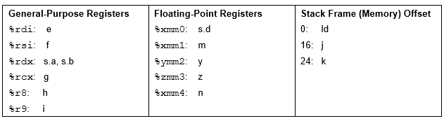
Example 2
An int (4 bytes) or a long (8 bytes) named a.
A short (2 bytes) named b.
A float (4 bytes) or a double (8 bytes) named c.
All four alternatives are included. This structure is followed by a declaration for a function that returns a value of that structure type and a function that has one parameter of that structure type.
// Part A Declarations: Fields of type int, short, double
typedef struct {
      int a;
      short b;
      double c;
      } structparm_isd;
structparm_isd s_isd;
extern structparm_isd set_isd();
extern void func_isd (structparm_isd p_isd);

// Part B Declarations: Fields of type long, short, double
typedef struct {
      long a;
      short b;
      double c;
      } structparm_lsd;
structparm_lsd s_lsd;
extern structparm_lsd set_lsd();
extern void func_lsd(structparm_lsd p_lsd);
// Part C Declarations: Fields of type int, short, float
typedef struct {
      int a;
      short b;
      float c;
      } structparm_isf;
structparm_isf s_isf;
extern structparm_isf set_isf();
extern void func_isf(structparm_isf p_isf);

// Part D Declarations: Fields of type long, short, float
typedef struct {
      long a;
      short b;
      float c;
      } structparm_lsf;
structparm_lsf s_lsf;
extern structparm_lsf set_lsf();
extern void func_lsf(structparm_lsf p_lsf);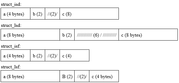
| Call | Field a | Field b | Field c |
|---|---|---|---|
| func_isd(s_isd) | %rdi | %xmm0 | |
| func_lsd(s_lsd) | memory (stack) | ||
| func_isf(s_isf) | %rdi | %xmm0 | |
| func_lsf(s_lsf) | %rdi | %rsi | |
| Call | Field a | Field b | Field c |
|---|---|---|---|
| set_isd(s_isd) | %rax | %xmm0 | |
| set_lsd(s_lsd) | memory pointed to by %rax
(passed in %rdi) | ||
| set_isf(s_isf) | %rax | %xmm0 | |
| set_lsf(s_lsf) | %rax | %rdx | |
5.8. Procedure Call Stack
A procedure is an active procedure while its body is executing, including while any procedure it calls is executing. When a procedure is active, its designated condition handler may handle an exception that is signaled during its execution.
Associated with each active procedure is an invocation context, informally called a frame, which consists of the set of registers and space in memory that is allocated and that may be accessed during execution for a particular call of that procedure.
When a procedure begins to execute, it has a limited invocation context that includes the parameter passing registers of its caller. The initial instructions may allocate and initialize additional context, including possibly saving information from the invocation context of its caller. Such instructions, if any, are termed a procedure prologue. Once execution of the prologue is complete, the procedure is said to be active.
When a procedure is ready to return to its caller, the procedure ceases to be active after it begins to execute the instructions that deallocate and discard the procedure's invocation context (which may include restoring state of the caller's invocation context that was saved during the prologue). These instructions are termed a procedure epilogue.
A null frame procedure has no prologue and no epilogue, and consists solely of body instructions. Such a procedure becomes active immediately.
A procedure may have more than one prologue if there are multiple entry points. A procedure may also have more than one epilogue if there are multiple return points. One of each will be executed during any given invocation of the procedure.
A procedure call stack (for a thread) consists of the stack of invocation contexts that exists at any point in time. New invocation contexts are pushed on that stack as procedures are called and invocations are popped from the call stack as procedures return.
The invocation context of a procedure that calls another procedure is said to precede or be previous to the invocation context of the called procedure.
5.8.1. Current Procedure
The current procedure is the active procedure whose execution began most recently; its invocation context is at the top of the call stack. Note that a procedure executing in its prologue or epilogue is not active, and hence cannot be the current procedure.
For OpenVMS x86-64, the IP (instruction pointer) register in combination with associated unwind information determines what procedure is current (for exception handling purposes). See Section B.3, ''Data Structures'' for a description of the unwind information data structures.
5.8.2. Procedure Call Tracing
Mechanisms for each of the following functions are needed to support procedure call tracing:
To provide the context of a procedure invocation
To walk (navigate) the procedure call stack
To refer to a given procedure invocation
To examine or modify the register context of an active procedure
This section describes the data structure mechanisms. The run-time library functions that support these functions are described in Section 5.8.3, ''Invocation Context Block Access Routines''.
5.8.2.1. Invocation Context Block
The context of a specific procedure invocation is provided through the use of a data structure called an invocation context block (ICB). Table 5.20, ''Contents of the Invocation Context Block'' describes the contents of the OpenVMS x86-64 invocation context block.
|
Field |
Size |
Description |
|---|---|---|
|
LIBICB$L_CONTEXT_LENGTH |
Longword |
Unsigned total length in bytes of the invocation context block. See Section 5.8.3.1, ''Initializing the Invocation Context Block''. |
|
LIBICB$V_FRAME_FLAGS |
3 Bytes |
See Table 5.21, ''Flags in LIBICB$V_FRAME_FLAGS Field of the Invocation Context Block''. |
|
LIBICB$B_BLOCK_VERSION |
Byte |
ICB version; initial value of 3 for OpenVMS x86-64. (1 is for OpenVMS Alpha, 2 is for OpenVMS I64). See Section 5.8.3.1, ''Initializing the Invocation Context Block''. |
| 2 Quadwords |
Internal (opaque) unwind context data. |
|
LIBICB$IH_IREG |
16 Quadwords |
Array of general registers.
|
|
LIBICB$IH_IP | Quadword |
Current instruction pointer (IP). |
|
LIBICB$IH_PSEUDO_REGS | 32 Quadwords |
Array of Alpha pseudo-registers. |
|
LIBICB$IH_RFLAGS | Quadword | Processor RFLAGS register. |
|
LIBICB$IH_FSGS | Quadword |
|
|
LIBICB$IH_XSAVE_STATE | Quadword |
XSAVE state control register value indicating what information is contained in the XSAVE area. This is the state-component bit map needed by the XRSTOR to restore the floating-point state from the XSAVE area (0 if the XSAVE pointer is null). |
|
LIBICB$PH_XSAVE | Quadword |
Pointer to an XSAVE area (null if floating-point is not in use). |
|
LIBICB$L_XSAVE_LENGTH | Longword | The number of bytes in the block pointed to by LIBICB$PH_XSAVE (0 if LIBICB$PH_XSAVE is null). |
|
LIBICB$PH_CHFCTX_ADDR | Quadword |
Pointer to condition handler facility context block. |
|
LIBICB$IH_OSSD | Quadword |
Copy of OSSD from unwind information. |
|
LIBICB$IH_HANDLER_PV | Quadword |
Condition Handler Procedure Value (if any). |
|
LIBICB$PH_LSDA | Quadword |
Address of the Language Specific Data Area (if any). |
| Beginning of User Override Parameters (offset LIBICB$R_UO_BASE) | ||
|
LIBICB$Q_UO_FLAGS | Quadword |
Operational flags: LIBICB$V_UO_FLAG_CACHE_UNWIND – Cache unwind information during a walk of the call stack. See Section 5.8.3.2, ''Walking the Call Stack''. |
|
LIBICB$IH_UO_IDENT | Quadword | |
|
LIBICB$PH_UO_READ_MEM | Quadword | |
|
LIBICB$PH_UO_GETUEINFO | Quadword | |
|
LIBICB$PH_UO_GETCONTEXT | Quadword | |
|
LIBICB$PH_UO_WRITE_MEM | Quadword | |
|
LIBICB$PH_UO_WRITE_REG | Quadword | |
|
LIBICB$PH_UO_MALLOC | Quadword | |
|
LIBICB$PH_UO_FREE | Quadword | |
| End of user override parameters (length of LIBICB$K_UO_LENGTH) | ||
|
LIBICB$L_ALERT_CODE | Longword |
Stack walk detailed status. Alert codes are enumerated in the LIBICB include files (see Section 5.8.3.7, ''LIB$X86_GET_CURR_INVO_CONTEXT''). |
|
LIBICB$IH_SYSTEM_ | n Quadwords |
Variable-sized area; unused and undefined at this time. |
| Flag | Description |
|---|---|
|
LIBICB$V_EXCEPTION_FRAME |
Set to 1 if this is an exception frame. |
|
LIBICB$V_AST_FRAME | Set to 1 if this is an AST frame. |
|
LIBICB$V_BOTTOM_OF_STACK |
Set to 1 if this is the bottom of the stack and there is absolutely no previous frame. |
|
LIBICB$V_HANDLER_PRESENT |
Set to 1 if this frame has a condition handler. |
|
LIBICB$V_IN_PROLOGUE |
Set to 1 if the IP is in a prologue region. |
|
LIBICB$V_IN_EPILOGUE |
Set to 1 if the IP is in an epilogue region. |
5.8.2.2. Invocation Context Handle
To refer to a specific procedure invocation at run-time, an invocation context handle (ICH) can be used. The invocation context handle is a quadword that uniquely identifies any one of the active frames on a call stack.
On OpenVMS x86-64, the invocation context handle for a frame is simply the stack pointer value at procedure entry (that is, the address of the caller’s return address on the stack).
5.8.3. Invocation Context Block Access Routines
Note
The OpenVMS x86-64 stack tracing routines use heap storage during the analysis of unwind descriptors. The default heap storage mechanism uses a LIBRTL implementation of the C RTL function malloc, the use of which may result in virtual memory being expanded using the $EXPREG system service. See Section 5.8.5, ''Invocation Context Callback Routines'' on how to override the defaults. See also Section 5.8.3.12, ''LIB$X86_PREV_INVO_END''.
5.8.3.1. Initializing the Invocation Context Block
Allocate the block on an octaword (16-byte) boundary.
Clear (set to all zero bytes) the entire block.
Initialize the LIBICB$L_CONTEXT_LENGTH field to LIBICB$K_INVO_CONTEXT_BLK_SIZE and the LIBICB$B_BLOCK_VERSION field to LIBICB$K_INVO_CONTEXT_VERSION.
Set any required parameters in the user override portion of the invocation context block.
Set the LIBICB$V_UO_FLAG_CACHE_UNWIND flag if appropriate. See also Section 5.8.3.2, ''Walking the Call Stack'' and Section 5.8.3.12, ''LIB$X86_PREV_INVO_END'' regarding subsequent use of LIB$X86_PREV_INVO_END.
Failure to do so will cause these routines to return an error status. Note that this is a change from Alpha, where initialization was not necessary.
LIB$X86_CREATE_INVO_CONTEXT (see Section 5.8.3.3, ''LIB$X86_CREATE_INVO_CONTEXT'')
LIB$X86_FREE_INVO_CONTEXT (see Section 5.8.3.4, ''LIB$X86_FREE_INVO_CONTEXT'')
LIB$X86_INIT_INVO_CONTEXT (see Section 5.8.3.5, ''LIB$X86_INIT_INVO_CONTEXT'')
5.8.3.2. Walking the Call Stack
During the course of program execution, it is sometimes necessary to walk the call stack. Frame-based exception handling is one case where this is done. Call stack navigation is possible only in the reverse direction (in a latest-to-earliest or top-to-bottom sequence).
Given a program state (which contains a register set), build an invocation context.
For the current routine, an initial invocation context block can be obtained by calling the LIB$X86_GET_CURR_INVO_CONTEXT routine (see Section 5.8.3.7, ''LIB$X86_GET_CURR_INVO_CONTEXT'').
Repeatedly call the LIB$X86_GET_PREV_INVO_CONTEXT routine (see Section 5.8.3.8, ''LIB$X86_GET_PREV_INVO_CONTEXT'') until the desired invocation context, or the end of the call chain, has been reached.
LIB$X86_GET_PREV_INVO_CONTEXT indicates the end of the invocation call chain if either of the following conditions is true:The OSSD$V_BOTTOM_OF_STACK flag is set for the target frame (see Table A.14, ''Operating System-Specific Data Area'').
The return address (IP) of the target frame is zero.
To make the stack walk more efficient, you can set the LIBICB$V_UO_FLAG_CACHE_UNWIND flag. This causes unwind information to be carried over from one call to LIB$X86_GET_PREV_INVO_CONTEXT to the next. At the conclusion of the stack walk, you must call LIB$X86_PREV_INVO_END to free any cached unwind information. This is the recommended practice, but not the default behavior.
Compilers are allowed to optimize high-level language procedure calls in such a way that they do not appear in the invocation chain. For example, inline procedures never appear in the invocation chain.
Make no assumptions about the relative positions of any memory used for procedure frame information. There is no guarantee that successive stack frames will always appear at higher addresses.
5.8.3.3. LIB$X86_CREATE_INVO_CONTEXT
This convenience routine simplifies creating and properly initializing an invocation context block. The routine allocates an invocation context block from heap storage and initializes it according to the steps described in Section 5.8.3.1, ''Initializing the Invocation Context Block''. Users of this routine should call LIB$X86_FREE_INVO_CONTEXT when the invocation context block is no longer required.
This routine sets the cache unwind flag LIBICB$V_UO_FLAG_CACHE_UNWIND in the invocation context block to speed the stack walk. Do not use this routine in conjunction with LIB$X86_INIT_INVO_CONTEXT, as the same initialization is performed by both routines.
LIB$X86_CREATE_INVO_CONTEXT ([malloc] [, free] [, ident])|
Argument |
OpenVMS Usage |
Type |
Access |
Mechanism |
|---|---|---|---|---|
|
malloc |
function_value |
procedure |
read |
by value |
|
free |
function_value |
procedure |
read |
by value |
|
ident |
user_value |
quadword |
read |
by value |
|
|
A procedure value for a user callback routine that allocates memory. See Section 5.8.5.6, ''The Memory Allocation Routine'' for details of
this routine. This is an optional argument. The default is to use an implementation of
the C RTL routine |
|
|
A procedure value for a user callback routine that deallocates memory. This value is
placed in the invocation context block field LIBICB$PH_UO_FREE.
See Section 5.8.5.7, ''The Memory Deallocation Routine'' for
details on this routine. This is an optional argument; however, it must be specified if
|
|
|
Specifies a user ident value to be placed in the invocation context block
LIBICB$IH_UO_IDENT field. In turn, this value is passed to the
|
|
|
A non-zero value represents the address of the invocation context block allocated. A value of 0 indicates failure. |
5.8.3.4. LIB$X86_FREE_INVO_CONTEXT
Deallocates an invocation context block that was previously allocated using LIB$X86_CREATE_INVO_CONTEXT. This routine calls LIB$X86_PREV_INVO_END as a convenience.
LIB$X86_FREE_INVO_CONTEXT (invo_context)|
Argument |
OpenVMS Usage |
Type |
Access |
Mechanism |
|---|---|---|---|---|
|
invo_context |
invo_context_blk |
structure |
modify |
by reference |
|
|
Address of an invocation context block. |
|
None. |
5.8.3.5. LIB$X86_INIT_INVO_CONTEXT
Initializes an invocation context block that the user has already allocated (on the stack, or from heap, or other storage) in accordance with Section 5.8.3.1, ''Initializing the Invocation Context Block''. Use this routine as an alternative to LIB$X86_CREATE_INVO_CONTEXT, which both allocates and initializes an invocation context block.
LIB$X86_INIT_INVO_CONTEXT
  (invo_context, invo_version [, cache_unwind_flag])
|
Argument |
OpenVMS Usage |
Type |
Access |
Mechanism |
|---|---|---|---|---|
|
invo_context |
invo_context_blk |
structure |
modify |
by reference |
|
invo_version |
version_number |
byte |
read |
by value |
|
cache_unwind_flag |
flag |
longword |
read |
by value |
|
|
Address of an invocation context block. |
|
|
The value LIBICB$K_INVO_CONTEXT_VERSION. This is used to verify the operating environment. |
|
|
A flag indicating if the cache unwind flag, LIBICB$V_UO_FLAG_CACHE_UNWIND, should be set in the invocation context block. A value of zero clears the flag; a value of one sets the flag. This is an optional argument. The default is zero. |
|
|
A value of 1 indicates success. A value of 0 indicates a version number mismatch. |
5.8.3.6. LIB$X86_GET_INVO_CONTEXT
LIB$X86_GET_INVO_CONTEXT(invo_handle, invo_context)
|
Argument |
OpenVMS Usage |
Type |
Access |
Mechanism |
|---|---|---|---|---|
|
invo_handle |
invo_handle |
quadword |
read |
by reference |
|
invo_context |
invo_context_blk |
structure |
modify |
by reference |
|
|
Address of the location that contains the handle for the desired invocation. |
|
|
Address of an invocation context block into which the procedure context of the frame
specified by |
Note
The invocation context block must be properly initialized as described in Section 5.8.3.1, ''Initializing the Invocation Context Block'' before calling this routine.
|
|
Status value. A value of 1 indicates success; a value of 0 indicates failure. |
Note
If the invocation handle that was passed does not represent any procedure context in the active call stack, the new contents of the context block is unpredictable.
5.8.3.7. LIB$X86_GET_CURR_INVO_CONTEXT
LIB$X86_GET_CURR_INVO_CONTEXT(invo_context)|
Argument |
OpenVMS Usage |
Type |
Access |
Mechanism |
|---|---|---|---|---|
|
invo_context |
invo_context_blk |
structure |
modify |
by reference |
|
|
Address of an invocation context block into which the procedure context of the caller will be written. |
Note
The invocation context block must be properly initialized as described in Section 5.8.3.1, ''Initializing the Invocation Context Block'' before calling this routine.
|
Zero |
This facilitates use in the implementation of the C language unwind
|
5.8.3.8. LIB$X86_GET_PREV_INVO_CONTEXT
LIB$X86_GET_PREV_INVO_CONTEXT(invo_context)|
Argument |
OpenVMS Usage |
Type |
Access |
Mechanism |
|---|---|---|---|---|
|
invo_context |
invo_context_blk |
structure |
modify |
by reference |
|
|
Address of a valid invocation context block. The given invocation context block is updated to represent the context of the previous (calling) frame. The LIBICB$V_BOTTOM_OF_STACK flag of the invocation context block is set if the target frame represents the end of the invocation call chain or if stack corruption is detected. |
|
|
Status value. A value of 1 indicates success. When the initial context represents the bottom of the call stack, a value of 0 is returned. |
5.8.3.9. LIB$X86_GET_INVO_HANDLE
LIB$X86_GET_INVO_HANDLE(invo_context, invo_handle)|
Argument |
OpenVMS Usage |
Type |
Access |
Mechanism |
|---|---|---|---|---|
|
invo_context |
invo_context_blk |
structure |
read |
by reference |
|
invo_handle |
invo_handle |
quadword |
write |
by reference |
|
|
Address of a valid invocation context block. |
|
|
Address of the location into which the invocation context handle is to be written. If the call fails, the value of the invocation context handle is LIB$K_INVO_HANDLE_NULL. |
|
|
A value of 1 indicates success. A value of 0 indicates failure. |
5.8.3.10. LIB$X86_GET_CURR_INVO_HANDLE
LIB$X86_GET_CURR_INVO_HANDLE(invo_handle)|
Argument |
OpenVMS Usage |
Type |
Access |
Mechanism |
|---|---|---|---|---|
|
invo_handle |
invo_handle |
quadword |
write |
by reference |
|
|
Address of a quadword into which the invocation handle of the caller will be written. |
|
|
A value of 1 indicates success. A value of 0 indicates failure. |
5.8.3.11. LIB$X86_GET_PREV_INVO_HANDLE
LIB$X86_GET_PREV_INVO_HANDLE(invo_handle_in, invo_handle_out)|
Argument |
OpenVMS Usage |
Type |
Access |
Mechanism |
|---|---|---|---|---|
|
invo_handle_in |
invo_handle |
quadword |
read |
by reference |
|
invo_handle_out |
invo_handle |
quadword |
write |
by reference |
|
|
The address of an invocation handle that represents a target invocation context. |
|
|
Address of the location into which the invocation context handle of the previous context is to be written. If the call fails, the value of the previous invocation context handle is LIB$K_INVO_HANDLE_NULL. |
|
|
A value of 1 indicates success. A value of 0 indicates failure. |
Note
Each call to this routine involves a stack walk from the top of the stack to find the procedure matching the input handle. Consequently, using this routine repeatedly is an inefficient way to walk the stack, compared to using LIB$X86_GET_PREV_INVO_CONTEXT.
5.8.3.12. LIB$X86_PREV_INVO_END
This routine should be called at the conclusion of call tracing operations to free the memory used to process unwind descriptors. The call tracing routines are LIB$X86_GET_INVO_CONTEXT, LIB$X86_GET_PREV_INVO_CONTEXT, and LIB$X86_GET_CURR_INVO_CONTEXT.
To provide efficient call tracing, some unwind information is tracked in heap storage from one call to the next. This heap storage should be freed before you release or reuse the invocation context block.
Calling this routine is necessary if the LIBICB$V_UO_FLAG_CACHE_UNWIND flag is set in the LIBICB$Q_UO_FLAGS field of the invocation context block. If this flag is not set, unwind information is released and recreated at each call, and calling this routine is not required.
LIB$X86_PREV_INVO_END (invo_context)|
Argument |
OpenVMS Usage |
Type |
Access |
Mechanism |
|---|---|---|---|---|
|
invo_context |
invo_context_blk |
structure |
modify |
by reference |
|
|
Address of a valid invocation context block previously used for call tracing. |
|
|
A value of 1 indicates success. A value of 0 indicates failure. |
5.8.3.13. LIB$X86_PUT_INVO_REGISTERS
LIB$X86_PUT_INVO_REGISTERS
  (invo_handle, invo_context [,gr_mask] [,xmm_mask]
  [,ymm_mask] [,zmm_mask] [,apr_mask] [,misc_mask])
|
Argument |
OpenVMS Usage |
Type |
Access |
Mechanism |
|---|---|---|---|---|
|
invo_handle |
invo_handle |
quadword |
read |
by reference |
|
invo_context |
invo_context_blk |
structure |
read |
by reference |
|
gr_mask |
mask_word |
16-bit vector |
read |
by reference |
|
xmm_mask |
mask_word |
16-bit vector |
read |
by reference |
|
ymm_mask |
mask_word |
16-bit vector |
read |
by reference |
|
zmm_mask |
mask_longword |
32-bit vector |
read |
by reference |
|
apr_mask |
mask_longword |
32-bit vector |
read |
by reference |
|
misc_mask |
mask_quadword | 64-bit vector |
read |
by reference |
|
|
Handle for the invocation to be updated. |
|
|
Address of a valid invocation context block that contains new register contents. |
|
At least one of the following register masks must be specified and contain a
non-zero value. Each register that is set in the | |
|
|
Address of a 16-bit bit vector, where each bit corresponds to a register field in
the Bits 0 through 15 correspond to IREG[0] through IREG[15]. Bit 0 corresponds to the argument information register (AI). If bit 7, which corresponds to SP, is set, then no changes are made. |
|
|
Address of a 16-bit bit vector, where each bit corresponds to an SSE XMM register
field in the XSAVE area, pointed to from the passed |
|
|
Address of a 16-bit bit vector, where each bit corresponds to an SSE YMM register
field in the XSAVE area, pointed to from the passed |
|
|
Address of a 32-bit bit vector, where each bit corresponds to an SSE ZMM register
field in the XSAVE area, pointed to from the passed |
|
Note that if the same bit position is set in more than one of the
| |
|
|
Address of a 32-bit bit vector, where each bit corresponds to a register field in the pointed to Alpha pseudo-register area passed. Bits 0 through 31 correspond to Alpha registers R0 through R31. If bit 30, which corresponds to SP, or 31, which corresponds to RZ are set, then no changes are made. |
|
|
Address of a 64-bit bit vector, where each bit corresponds to a register field in
the passed
invo_context as follows:
Note that IP can only be updated when the invocaton in question has been interrupted (either by exception or by an interrupt) and is logically previous to an invocation with the OSSD$V_EXCEPTION_FRAME bit set. Note that MXCSR, FCW, and FSW can only be updated when there is a valid address and
an XSAVE area in the |
|
|
A value of 1 indicates success. A value of 0 is returned (and nothing is changed) in
the following circumstances:
|
Caution
Great care must be taken to assure that a valid stack frame and execution environment result; otherwise, execution may become unpredictable.
5.8.4. Supplemental Invocation Context Access Routines
The routines described in this section can be used to perform some of the more common operations involving invocation contexts.
5.8.4.1. LIB$X86_GET_GR
Given an invocation context block and general-purpose register index such that 0 <=
index < 16, copy the register value to
gr_copy, for example, index 4 fetches the
invocation context block IREG[4] value, which represents the contents of
%rsi for the context.
LIB$X86_GET_GR fails if the index represents a scratch register whose contents have not been realized.
LIB$X86_GET_GR (invo_context, index, gr_copy)|
Argument |
OpenVMS Usage |
Type |
Access |
Mechanism |
|---|---|---|---|---|
|
invo_context |
invo_context_blk |
structure |
read |
by reference |
| index | index | longword | read | by value |
| gr_copy | integer value | quadword | write |
by reference |
|
|
Address of a valid invocation context block. |
index |
Index into the IREG array of the invocation context block. |
gr_copy |
Address of a quadword to receive the value from the invocation context block. |
|
|
A value of 1 indicates success. A value of 0 indicates failure. |
5.8.4.2. LIB$X86_SET_GR
Given an invocation context block, a general-purpose register index such that 1 <=
index < 16, and a quadword value gr_copy,
writes the corresponding invocation context block general register and uses
LIB$X86_PUT_INVO_REGISTERS to write to the actual context. The
invocation context block remains unchanged if the routine fails.
LIB$X86_SET_GR (invo_context, index, gr_copy)
|
Argument |
OpenVMS Usage |
Type |
Access |
Mechanism |
|---|---|---|---|---|
| invo_context | invo_context_blk | structure | modify | by reference |
| index | index | longword | read | by value |
| gr_copy | integer value | quadword | read | by reference |
|
|
Address of a valid invocation context block. |
index |
Index into the IREG array of the invocation context block. |
gr_copy |
Address of a quadword that contains the value to be written to the invocation context block. |
5.8.4.3. LIB$X86_GET_XMM
Given an invocation context block and a register index that is 0 <= index
< 16 for SSE (Streaming SIMD Extensions) or 0 <= index < 32 for AVX-512
(512-bit Advanced Vector Extensions), copy the register value to
xmm_copy. For example, an index value of 4
fetches the value, which represents the contents of xmm4.
LIB$X86_GET_XMM returns failure status if there is no
corresponding XSAVE area in the invo_context or if the
index represents a register or register set not saved in the XSAVE
area.
LIB$X86_GET_XMM (invo_context, index, xmm_copy)|
Argument |
OpenVMS Usage |
Type |
Access |
Mechanism |
|---|---|---|---|---|
|
invo_context |
invo_context_blk |
structure |
read |
by reference |
|
index |
index |
longword |
read |
by value |
|
xmm_copy | register contents |
16 bytes |
write |
by reference |
|
|
Address of a valid invocation context block. | |
index |
Index into the virtual array of XMM registers constructed from the XSAVE area. The
XSAVE area is pointed to from the invocation context block.
NoteIn case of CPUs implementing the AVX-512 or AVX10 Advanced Vector Extensions, the additional XMM/YMM registers are part of the ZMM registers. For more information on Advanced Vector Extensions, refer to the official documentation on the Intel website. | |
xmm_copy |
Address of a 16-byte buffer to receive the contents of the specified register. | |
|
|
A value of 1 indicates success. A value of 0 indicates failure. |
5.8.4.4. LIB$X86_SET_XMM
Given
an invocation context block, a register index that is 0 <= index < 16 for
SSE (Streaming SIMD Extensions) or 0 <= index < 32 for AVX-512 (512-bit
Advanced Vector Extensions), and a register value in xmm_copy, writes the
corresponding entry in the XSAVE area pointed to from the invocation context block, and calls
LIB$X86_PUT_INVO_REGISTERS to write the actual context. The
XSAVE area remains unchanged if the routine fails.
LIB$X86_SET_XMM fails if LIB$X86_PUT_INVO_REGISTERS fails.
LIB$X86_SET_XMM (invo_context, index, xmm_copy)|
Argument |
OpenVMS Usage |
Type |
Access |
Mechanism |
|---|---|---|---|---|
|
invo_context |
invo_context_blk |
structure |
modify |
by reference |
| index | index | longword | read | by value |
| xmm_copy | register contents | 16 bytes | read |
by reference |
|
|
Address of a valid invocation context block. | |
index |
Index into the virtual array of XMM registers constructed from the XSAVE area. The XSAVE area is pointed to from the invocation context block. NoteIn case of CPUs implementing the AVX-512 or AVX10 Advanced Vector Extensions, the additional XMM/YMM registers are part of the ZMM registers. For more information on Advanced Vector Extensions, refer to the official documentation on the Intel website. | |
xmm_copy |
Address of a 16-byte buffer that contains the value to be written to the invocation context. | |
|
|
A value of 1 indicates success. A value of 0 indicates failure. |
5.8.4.5. LIB$X86_GET_YMM
Given an invocation context block and a register index that is 0 <= index
< 16 for AVX (Advanced Vector Extensions) or 0 <= index < 32 for AVX-512
(512-bit Advanced Vector Extensions), copy the register value to
ymm_copy. For example, an index value of 4
fetches the value, which represents the contents of ymm4.
LIB$X86_GET_YMM returns failure status if there is no
corresponding XSAVE area in the invo_context or if the index represents
a register or register set not saved in the XSAVE area.
LIB$X86_GET_YMM (invo_context, index, ymm_copy)|
Argument |
OpenVMS Usage |
Type |
Access |
Mechanism |
|---|---|---|---|---|
| invo_context | invo_context_blk | structure | read | by reference |
| index | index | longword | read | by value |
| ymm_copy | register contents | 32 bytes | write | by reference |
|
|
Address of a valid invocation context block. |
|
|
Index into the virtual array of YMM registers constructed from the XSAVE area. The XSAVE area is pointed to from the invocation context block. NoteIn case of CPUs implementing the AVX-512 or AVX10 Advanced Vector Extensions, the additional XMM/YMM registers are part of the ZMM registers. For more information on Advanced Vector Extensions, refer to the official documentation on the Intel website. |
|
|
Address of a 32-byte buffer to receive the contents of the specified register. |
|
|
A value of 1 indicates success. A value of 0 indicates failure. |
5.8.4.6. LIB$X86_SET_YMM
Given an invocation context block, a register index that is 0 <= index
< 16 for AVX (Advanced Vector Extensions) or 0 <= index < 32 for AVX-512
(512-bit Advanced Vector Extensions), and a register value in ymm_copy, writes the
corresponding entry in the XSAVE area pointed to from the invocation context block, and calls
LIB$X86_PUT_INVO_REGISTERS to write the actual context. The XSAVE
area remains unchanged if the routine fails.
LIB$X86_SET_YMM fails if LIB$X86_PUT_INVO_REGISTERS fails.
LIB$X86_SET_YMM (invo_context, index, ymm_copy)
|
Argument |
OpenVMS Usage |
Type |
Access |
Mechanism |
|---|---|---|---|---|
| invo_context | invo_context_blk | structure | modify | by reference |
| index | index | longword | read | by value |
| ymm_copy | register contents | 32 bytes | read | by reference |
|
|
Address of a valid invocation context block. |
|
|
Index into the virtual array of YMM registers constructed from the XSAVE area. The XSAVE area is pointed to from the invocation context block. NoteIn case of CPUs implementing the AVX-512 or AVX10 Advanced Vector Extensions, the additional XMM/YMM registers are part of the ZMM registers. For more information on Advanced Vector Extensions, refer to the official documentation on the Intel website. |
|
|
Address of a 32-byte buffer that contains the value to be written to the invocation context. |
|
|
A value of 1 indicates success. A value of 0 indicates failure. |
5.8.4.7. LIB$X86_GET_ZMM
Given an invocation context block and a register index that is 0 <= index
< 32 for for AVX-512 (512-bit Advanced Vector Extensions), copy the register value to
zmm_copy. For example, an index value of 4
fetches the value, which represents the contents of zmm4.
LIB$X86_GET_ZMM returns failure status if there is no
corresponding XSAVE save area in the invo_context or if the index
represents a register or register set not saved in the XSAVE save area.
LIB$X86_GET_YMM (invo_context, index, zmm_copy)
|
Argument |
OpenVMS Usage |
Type |
Access |
Mechanism |
|---|---|---|---|---|
| invo_context | invo_context_blk | structure | read | by reference |
| index | index | longword | read | by value |
| zmm_copy | register contents | 64 bytes | write | by reference |
|
|
Address of a valid invocation context block. |
|
|
Index into the virtual array of ZMM registers constructed from the XSAVE area. The XSAVE area is pointed to from the invocation context block. |
|
|
Address of a 64-byte buffer to receive the contents of the specified register. |
|
|
A value of 1 indicates success. A value of 0 indicates failure. |
5.8.4.8. LIB$X86_SET_ZMM
Given an invocation context block, a register index that is 0 <= index
< 32 for AVX-512 (512-bit Advanced Vector Extensions), and a register value in
zmm_copy, writes the corresponding entry in the XSAVE area pointed to from the
invocation context block, and calls LIB$X86_PUT_INVO_REGISTERS to
write the actual context. The XSAVE area remains unchanged if the routine fails.
LIB$X86_SET_ZMM fails if LIB$X86_PUT_INVO_REGISTERS fails.
LIB$X86_SET_ZMM (invo_context, index, zmm_copy)
|
Argument |
OpenVMS Usage |
Type |
Access |
Mechanism |
|---|---|---|---|---|
| invo_context | invo_context_blk | structure | modify | by reference |
| index | index | longword | read | by value |
| zmm_copy | register contents | 64 bytes | read | by reference |
|
|
Address of a valid invocation context block. |
|
|
Index into the virtual array of ZMM registers constructed from the XSAVE area. The XSAVE area is pointed to from the invocation context block. |
|
|
Address of a 64-byte buffer that contains the value to be written to the invocation context. |
|
|
A value of 1 indicates success. A value of 0 indicates failure. |
5.8.4.9. LIB$X86_SET_IP
Given an invocation context block and a quadword IP value in
ip_copy, write the ip_copy value to the
invocation context block IP and then use LIB$X86_PUT_INVO_REGISTERS to
write to the actual context. The invocation context block remains unchanged if the routine
fails.
LIB$X86_SET_IP fails if LIB$X86_PUT_INVO_REGISTERS fails.
LIB$X86_SET_IP (invo_context, ip_copy)
|
Argument |
OpenVMS Usage |
Type |
Access |
Mechanism |
|---|---|---|---|---|
|
invo_context |
invo_context_blk |
structure |
modify |
by reference |
| ip_copy | integer value | quadword | read |
by reference |
|
|
Address of a valid invocation context block. |
ip_copy |
Address of a quadword that contains the IP value to be written to the invocation context block. |
|
|
A value of 1 indicates success. A value of 0 indicates failure. |
5.8.4.10. LIB$X86_GET_UNWIND_LSDA
Given an ip_value, find the address of the unwind information block
language specific data area (LSDA), and write it to unwind_lsda_p. If
not present, then write 0 to unwind_lsda_p.
LIB$X86_GET_UNWIND_LSDA (ip_value, unwind_lsda_p)|
Argument |
OpenVMS Usage |
Type |
Access |
Mechanism |
|---|---|---|---|---|
| ip_value | IP value | quadword | read |
by reference |
| unwind_lsda_p | address | quadword | write | by reference |
|
|
Address of a location that contains the IP value. |
unwind_lsda_p |
Address of a quadword to receive the address of the language-specific data area, if there is one. |
|
|
A value of 1 indicates success. A value of 0 indicates failure. |
5.8.4.11. LIB$X86_GET_UNWIND_OSSD
ip_value, find the address of the unwind information block
operating system-specific data area, if present, and write it to
unwind_ossd_p. If not present, then write 0 to
unwind_ossd_p.LIB$X86_GET_UNWIND_OSSD (ip_value, unwind_ossd_p)|
Argument |
OpenVMS Usage |
Type |
Access |
Mechanism |
|---|---|---|---|---|
|
ip_value |
IP value |
quadword |
read |
by reference |
| unwind_ossd_p | address | quadword | write |
by reference |
|
|
Address of a location that contains the IP value. |
unwind_ossd_p |
Address of a quadword to receive the address of the operating system-specific data area. Note that the OSSD value is contained in the FDE unwind information (see Section B.3.2.3, ''Frame Description Entry'') and is therefore not writable. |
|
|
A value of 1 indicates success. A value of 0 indicates failure. |
5.8.4.12. LIB$X86_GET_UNWIND_HANDLER_PV
Given an ip_value, find the procedure value for the condition
handler, if present, and write it to handler_pv. If not present, then
write 0 to handler_pv.
LIB$X86_GET_UNWIND_HANDLER_PV (ip_value, handler_pv)|
Argument |
OpenVMS Usage |
Type |
Access |
Mechanism |
|---|---|---|---|---|
|
ip_value |
IP value |
quadword |
read |
by reference |
| handler_pv | address | quadword | write |
by reference |
|
|
Address of a location that contains the IP value. |
handler_pv |
A quadword to receive the procedure value for the condition handler, if there is one. |
|
|
A value of 1 indicates success. A value of 0 indicates failure. |
5.8.4.13. LIB$X86_IS_EXC_DISPATCH_FRAME
Used to determine whether a given IP value represents an exception dispatch frame.
LIB$X86_IS_EXC_DISPATCH_FRAME (ip_value)|
Argument |
OpenVMS Usage |
Type |
Access |
Mechanism |
|---|---|---|---|---|
|
ip_value |
IP value |
quadword |
read |
by reference |
|
|
Address of a quadword that contains the IP value. The
|
|
|
Returns 1 if the operating system-specific data area is present and the EXCEPTION_FRAME flag is set. Returns 0 if the operating system-specific data area is present and the EXCEPTION_FRAME flag is clear. Returns 0 if the operating system-specific data area is not present. |
5.8.4.14. LIB$X86_IS_AST_DISPATCH_FRAME
Used to determine whether a given IP value represents an AST dispatch frame.
LIB$X86_IS_AST_DISPATCH_FRAME (ip_value)|
Argument |
OpenVMS Usage |
Type |
Access |
Mechanism |
|---|---|---|---|---|
|
ip_value |
IP value |
quadword |
read |
by reference |
|
|
Address of a quadword that contains the IP value. The
|
|
|
Returns 1 if the operating system-specific data area is present and the AST_FRAME flag is set. Returns 0 if the operating system-specific data area is present and the AST_FRAME flag is clear. Returns 0 if the operating system-specific data area is not present. |
5.8.5. Invocation Context Callback Routines
Perform a call trace on a process other than the current process.
Override the heap storage mechanism used to allocate memory used during the analysis of unwind descriptors.
The user override callback mechanism provides a user ident value that is passed to each callback routine. The user ident value is stored in the LIBICB$IH_UO_IDENT field of the invocation context block.
Note
LIB$X86_GET_CURR_INVO_HANDLE
LIB$X86_GET_PREV_INVO_HANDLE
5.8.5.1. The Get Unwind Information Routine
Place a procedure value for this routine in the LIBICB$PH_UO_GETUEINFO field of the invocation context block.?
int (* getueinfo) (uint64 ip, void *get_ue_block, void *name, ...);
This routine should mimic SYS$GET_UNWIND_ENTRY_INFO for the target process. See Section B.5, ''System Unwind Routines'' for detailed argument descriptions and return status, with the following notes:
The name argument is not used, and can be ignored. If a read memory callback has been specified, the contents of LIBICB$PH_UO_READ_MEM are passed as a fourth argument, and the contents of LIBICB$PH_UO_IDENT are passed as a fifth argument, otherwise the routine is called with three arguments.
5.8.5.2. The Get Initial Context Routine
Place a function pointer for this routine in the LIBICB$PH_UO_GETCONTEXT field of the invocation context block.
The get initial context routine is used to seed the invocation context block from the target process. This routine should initialize the invocation context block structure with the preserved registers, as well as applicable control and status registers, from the target process. This callback routine is used by LIB$X86_GET_CURR_INVO_CONTEXT and should be followed by at least one call to LIB$X86_GET_PREV_INVO_CONTEXT to generate a working context.
int (* getcontext) (void *invo_context, uint64 ident);
|
Argument |
OpenVMS Usage |
Type |
Access |
Mechanism |
|---|---|---|---|---|
|
invo_context |
invo_context_blk |
structure |
modify |
by reference |
|
ident |
user_value |
quadword |
read |
by value |
|
|
The address of the invocation context block. |
|
|
Specifies a user ident value from the invocation context block. |
|
|
A value of 1 indicates success. A value of 0 indicates failure. |
5.8.5.3. The Read Memory Routine
Place a function pointer for this routine in the LIBICB$PH_UO_READ_MEM field of the invocation context block.
The read memory routine is used to transfer data from the target process.
int (* read_mem) (void *dst, uint64 src, size_t length, uint64 ident);
|
Argument |
OpenVMS Usage |
Type |
Access |
Mechanism |
|---|---|---|---|---|
|
dst |
memory_access |
byte_array |
write |
by reference |
|
src |
memory_address |
quadword |
read |
by value |
|
length |
size_t |
longword |
read |
by value |
|
ident |
user_value |
quadword |
read |
by value |
|
|
A local memory address and the destination for the read operation. |
|
|
An address in the target process to be read. |
|
|
The length in bytes to be read. |
|
|
Specifies a user ident value from the invocation context block. |
|
|
A value of 1 indicates success. A value of 0 indicates failure. |
5.8.5.4. The Write Memory Routine
Place a procedure value for this routine in the LIBICB$PH_UO_WRITE_MEM field of the invocation context block.
The write memory routine is used to transfer data to the target process. It is used by LIB$X86_PUT_INVO_REGISTERS for a register that has been saved in memory.
int (* write_mem) (void *src, uint64 dst, size_t length, uint64 ident);
|
Argument |
OpenVMS Usage |
Type |
Access |
Mechanism |
|---|---|---|---|---|
|
src |
memory_access |
byte_array |
read |
by value |
|
dst |
memory_address |
quadword |
write |
by reference |
|
length |
size_t |
longword |
read |
by value |
|
ident |
user_value |
quadword |
read |
by value |
|
|
A local memory address and the source for the write operation. |
|
|
An address in the target process to be written. |
|
|
The length in bytes to be written. |
|
|
Specifies a user ident value from the invocation context block. |
|
|
A value of 1 indicates success. A value of 0 indicates failure. |
5.8.5.5. The Write Register Routine
Place a procedure value for this routine in the LIBICB$PH_UO_WRITE_REG field of the invocation context block.
The write register routine is used to write a register in the target process. It is used by LIB$X86_PUT_INVO_REGISTERS for a register that has not been saved in memory.
This routine is optional, or a subset of registers can be implemented, in this case LIB$X86_PUT_INVO_REGISTERS will return an error if this routine is not present, or is unable to write the desired register.
int (* write_reg)
(int whichReg, uint64 value_1, uint64 value_2, uint64 ident);|
Argument |
OpenVMS Usage |
Type |
Access |
Mechanism |
|---|---|---|---|---|
|
whichReg |
enumeration |
longword |
read |
by value |
|
value_p |
address |
quadword |
read |
by value |
|
ident |
user_value |
quadword |
read |
by value |
|
|
Indicates the register to be written (see enum in libicb.h). |
|
|
Specifies the address of the register contents to be written. The number of bytes written is determined by the size of the register. |
|
|
Specifies a user ident value from the invocation context block. |
|
|
A value of 1 indicates success. A value of 0 indicates failure. |
5.8.5.6. The Memory Allocation Routine
The memory allocation routine is used to allocate heap storage required during the analysis of unwind descriptors. This routine should mimic the behavior of the C RTL routine malloc.
void * (* malloc) (size_t size, uint64 ident);
|
Argument |
OpenVMS Usage |
Type |
Access |
Mechanism |
|---|---|---|---|---|
|
length |
size_t |
longword |
read |
by value |
|
ident |
user_value |
quadword |
read |
by value |
|
|
The length in bytes of memory to be allocated. The returned memory block should be aligned on a 16-byte boundary. |
|
|
Specifies a user ident value from the invocation context block. |
|
|
Address of the memory block allocated, or 0 for failure. |
One Unwind Context block of size LIBICB$K_CONTEXT_BLK_SIZE
One Unwind Descriptor block of size LIBICB$K_DESCRIPTOR_BLK_SIZE
Several Unwind region blocks of size LIBICB$K_REGION_BLK_SIZE
Several Unwind region label blocks of size LIBICB$K_REGIONLABEL_BLK_SIZE
The number of the last two required depends on the complexity of the unwind descriptors for a given procedure being traced.
5.8.5.7. The Memory Deallocation Routine
The memory deallocation routine is used to free heap storage allocated by the memory allocation routine (see Section 5.8.5.6, ''The Memory Allocation Routine''). This routine should mimic the behavior of the C RTL routine free.
void (* free) (void * ptr, uint64 ident);
|
Argument |
OpenVMS Usage |
Type |
Access |
Mechanism |
|---|---|---|---|---|
|
ptr |
address |
quadword |
read |
by value |
|
ident |
user_value |
quadword |
read |
by value |
|
|
Address of a memory block previously allocated by a call to the user malloc routine. |
|
|
Specifies a user ident value from the invocation context block. |
Function Value Returned:
None.
5.9. Data Alignment and Layout
On x86-64 hardware, a memory reference to data that is not naturally aligned does not result in alignment faults. However, natural alignment is nonetheless generally more efficient and recommended on OpenVMS x86-64.
In addition, common blocks, dynamically allocated (heap) regions (for example from malloc), and global data items greater than 8 bytes should be aligned on a 16-byte boundary.
5.9.1. Scalars
|
Data Type |
Alignment Starting Position |
|---|---|
|
8-bit character string |
Byte boundary |
|
16-bit integer |
Address that is a multiple of 2 (word alignment) |
|
32-bit integer |
Address that is a multiple of 4 (longword alignment) |
|
64-bit integer |
Address that is a multiple of 8 (quadword alignment) |
|
Address that is a multiple of 4 (longword) |
|
Address that is a multiple of 8 (quadword) |
|
Address that is a multiple of 8 (quadword) |
|
Address that is a multiple of 4 (longword) |
|
Address that is a multiple of 8 (quadword) |
|
Address that is a multiple of 16 (octaword) |
For aggregates such as strings, arrays, and records, the data type to be considered for purposes of alignment is not the aggregate itself, but rather the elements of which the aggregate is composed. The alignment requirement of an aggregate is that all elements of the aggregate be naturally aligned. For example, varying 8-bit character strings must start at addresses that are a multiple of at least 2 (word alignment) because of the 16-bit count at the beginning of the string; 32-bit integer arrays start at a longword boundary, irrespective of the extent of the array.
However, some languages allow definition of aggregate types with an alignment that is
greater than that of any of its components, or provide predefined types with such an alignment
(for example, the __m128, __m256, and
__m512 types in C/C++ for x86-64). The alignment of such types becomes the
natural alignment for elements of those types when included in a containing aggregate.
The rules for passing a record in an argument that is passed by immediate value (see Section 5.7, ''Parameter and Return Value Passing'') always provide quadword alignment of the record value independent of the normal alignment requirement of the record. If deemed appropriate by an implementation, normal alignment can be established within the called procedure by making a copy of the record argument at a suitably aligned location.
5.9.2. Record Layout Conventions
The OpenVMS x86-64 calling standard rules for record layout are designed to provide good run-time performance on all implementations of the x86-64 architecture and to provide the required level of compatibility with conventional VAX, Alpha, and I64 operating environments.
Those optimized for optimal access characteristics (referred to as aligned record layouts)
Those compatible with conventions that are traditionally used by VAX languages (referred to as VAX compatible record layouts)
Only these record layouts may be used across standard interfaces or between languages. Languages can support other language-specific record layout conventions, but such layouts are nonstandard.
The aligned record layout conventions should be used unless interchange is required with conventional VAX applications that use the OpenVMS VAX compatible record layouts.
5.9.2.1. Aligned Record Layout
All components of a record or subrecord are naturally aligned.
Layout and alignment of record elements and subrecords are independent of any record or subrecord in which they are embedded.
Layout and alignment of a subrecord is the same as if it were a top-level record.
Declaration in high-level languages of standard records for interlanguage use is straightforward and obvious, and meets the requirements for source-level compatibility between OpenVMS x86-64 languages and OpenVMS I64, Alpha, and VAX languages.
The components of a record must be laid out in memory corresponding to the lexical order of their appearance in the high-level language declaration of the record.
The first bit of a record or subrecord must be directly addressable (byte aligned).
Records and subrecords must be aligned according to the largest natural alignment requirements of the contained elements and subrecords.
Bit fields (packed subranges of integers) are characterized by an underlying integer type that is a byte, word, longword, or quadword in size together with an allocation size in bits. A bit field is allocated at the next available bit boundary, provided that the resulting allocation does not cross an alignment boundary of the underlying type. Otherwise, the field is allocated at the next byte boundary that is aligned as required for the underlying type. (In the later case, the space skipped over is left permanently not allocated). In addition, if necessary, the alignment of the record as a whole is increased to that of the underlying integer type.
Unaligned bit strings, unaligned bit arrays, and elements of unaligned bit arrays must start at the next available bit in the record. No fill is ever supplied preceding an unaligned bit string, unaligned bit array, or unaligned bit array element.
All other components of a record must start at the next available naturally aligned address for the data type.
The length of a record must be a multiple of its alignment. (This includes the case when a record is a component of another record).
Strings and arrays must be aligned according to the natural alignment requirements of the data type of which the string or array is composed.
The length of an array element is a multiple of its alignment, even if this leaves unused space at its end. The length of the whole array is the sum of the lengths of its elements.
5.9.2.2. OpenVMS VAX Compatible Record Layout
The OpenVMS VAX compatible record layout is defined by the following conventions:
The components of a record must be laid out in memory corresponding to the lexical order of their appearance in the high-level language declaration of the record.
Unaligned bit strings, unaligned bit arrays, and elements of unaligned bit arrays must start at the next available bit in the record. No fill is ever supplied preceding an unaligned bit string, unaligned bit array, or unaligned bit array element.
All other components of a record must start at the next available byte in the record. Any unused bits following the last-used bit in the last-used byte of each component must be filled out to the next byte boundary so that any following data starts on a byte boundary.
Subrecords must be aligned according to the largest alignment of the contained elements and subrecords. A subrecord always starts at the next available byte unless it consists entirely of unaligned bit data and it immediately follows an unaligned bit string, unaligned bit array, or a subrecord consisting entirely of unaligned bit data.
Records must be aligned on byte boundaries.
5.10. Addressing
Industry standard conventions for x86-64 Position Independent Code (PIC) generally make use of a Global Offset Table (GOT) to facilitate addressing code and data that is not known or assured to be within a 32-bit offset of the reference. The GOT is itself a data segment that is assured “near” the code so that PC-relative addressing with a 32-bit offset is sufficient to access that GOT. The GOT holds 64-bit addresses that allow access to any location in the system 64-bit address space.
5.10.1. Memory Models
The small code model—all code and data is within 2 GB.
The large code model—code and data is not limited to be within 2 GB.
The medium code model—code and data is assumed within 2 GB while specifically marked large model data may not.
OpenVMS compilers generate small model position-independent code using indirect addressing of all data to allow static data to be farther than 2 GB away from code. Because direct addressing is used only for entries in the Global Offset Table, OpenVMS compilers do not distinguish between the small and medium memory models. In effect, OpenVMS compilers support the medium data model for applications.
Foreign compilers and object modules may use any memory model. The OpenVMS linker and image activator support all memory models.
5.10.2. Inter-Segment Addressing
In industry standards for x86-64, shareable images may be loaded anywhere, but all segments within a shared library must have the same positions relative to each other that they were assigned by the linker. On OpenVMS x86-64, the image activator may map (logically load) segments of a shareable image independently of each other.
The independent loading of segments influences the way code addresses data. Industry standard x86-64 code uses PC-relative addressing to access not only the Global Offset Table, but also any other data that is known to be local to the image. Because segments may be mapped independently, this standard requires that code use indirect addressing to access all data except for the Global Offset Table. With this scheme, the code segment and the Global Offset Table (linkage) segment are the only segments whose relative positions have to be maintained.
In an image with multiple code segments, each code segment has its own Global Offset Table.
Non-VSI compilers and object modules may assume a small code model and use PC-relative data addressing exclusively. Both the linker and the image activator maintain the relative positions of code segments, Global Offset Tables, and other segments that are referenced in a PC-relative manner. In theory, the code could be adjusted with image relocations; in practice, the limited address range of the small code model (±2 GB) precludes this.
Chapter 6. Signature Information and Translated Images (Alpha and IA-64 systems)
To support interoperation between images built from native OpenVMS Alpha code and images translated from OpenVMS VAX code, native Alpha compilers can optionally generate information that describes the parameters and result of a procedure. Similarly, for interoperation between images built from native OpenVMS I64 code and images translated from VAX or Alpha code, I64 compilers can also optionally generate information that describes the parameters and result of a procedure. This auxiliary information is called signature information.
Translated VAX code on Alpha and I64 systems uses VAX argument list and function return conventions as described in Section 2.4, ''Argument List'' and Section 2.5, ''Function Value Returns''.
Translated Alpha code on I64 systems uses Alpha argument list and function return conventions as described in Chapter 3, "OpenVMS Alpha Conventions".
The following sections describe the conventions for using signature information to control the passing of arguments and returning a function value when a native procedure passes control to a translated procedure and vice versa.
Mediates calls between native and translated code
Controls execution of translated code
Performs interpretation where necessary
6.1. Overview
OpenVMS compilers for Alpha and I64 provide a compilation option that causes signature information to be included in the resulting object file. To support interoperation between OpenVMS native and translated code, the native code must contain signature information.
With one exception related to indirect calls (see Section 6.1.1.3, ''Indirect Calls From Native to Translated Code'' and Section 6.1.2.3, ''Indirect Calls From Native to Translated Code''), code generation is not affected by the presence or absence of translated code support.
The operation of translated images on OpenVMS Alpha and I64 systems is very similar, though different in certain details.
6.1.1. Translated VAX Images on Alpha Systems
When a VAX image is translated to an Alpha image, the VAX registers R0—15 are represented using the lower half of the corresponding Alpha registers R0—15 at call interface boundaries. No "type conversion" is performed in making parameters from either native or translated code available to each other.
6.1.1.1. Direct Calls From Translated to Native Code
When the TIE encounters a call in translated code that passes control to native Alpha code, it obtains signature information for the target procedure using the PDSC$W_SIGNATURE_OFFSET field of the target procedure descriptor (see Section 3.4.1, ''Stack Frame Procedures'').
If the value in the PDSC$W_SIGNATURE_OFFSET is zero, then no signature information is available, the call cannot be performed, and the TIE signals an error.
Otherwise, the TIE uses the signature information to create an appropriate Alpha argument list (in the integer registers and stack as appropriate), then calls the native procedure. When control returns, the TIE obtains the returned result (if any), makes it available to translated code, and resumes translated code execution.
6.1.1.2. Direct Calls From Native to Translated Code
Calls from native Alpha code to a routine in a translated image depend on special linker and image activator support. If the linker can confirm that the target of the call is also in native code (because the target is local to the same image), then the call is resolved normally. Otherwise, the linker passes the compiler generated signature information for use by the image activator.
If the image activator can determine that the target of the call is also in native code, then the call is resolved normally. Otherwise, the image activator creates a bound procedure descriptor (see Section 3.6.4, ''Simple and Bound Procedures'') and resolves the procedure value to that descriptor. This descriptor is setup to pass control to a special TIE entry point which obtains the target VAX procedure value and signature information from that same descriptor.
6.1.1.3. Indirect Calls From Native to Translated Code
If interoperation with translated images is not required, then an indirect call is made as described in Section 3.6.3, ''Calling Computed Addresses''. If interoperation with translated images must be considered, the procedure value (in R4 in the following example) might be the address of a VAX entry point or the address of an Alpha procedure descriptor.
A VAX entry point can be dynamically distinguished from an Alpha procedure descriptor by examining bits 12 and 13 of a VAX entry call mask, which are required to be 0 by the VAX architecture. For an Alpha procedure, bit 12 corresponds to the PDSC$V_NATIVE flag, which is required to be set in all Alpha procedure descriptors. Bit 13 corresponds to the PDSC$V_NO_JACKET flag, which is currently required to be set but reserved for enhancements to this standard in all Alpha procedure descriptors.
If the procedure value is determined to correspond to an Alpha procedure, then the call can be completed as discussed. If the procedure value is determined to correspond to a VAX procedure, then the call must be completed using system TIE facilities that will effect the transition into and out of the code of the translated image.
    LDL     R28,0(R4)             ;Load the flags field of the target PDSC
    MOV     #AI_LITERAL,R25       ;Load Argument Information register
    SRL     R28,#PDSC$V_NO_JACKET,R26;Position jacket flag
    BLBC    R26,CALL_JACKET       ;If clear then jacket needed
    LDQ     R26,8(R4)             ;Entry address to scratch register
    MOV     R4,R27                ;Procedure value to R27
    JSR     R26,(R26)             ;Call entry address.
back_in_line:
    ...                           ;Rest of procedure code goes here

TRANSLATED:                       ;Generated out of line, R2 contains a
    LDQ     R26,N_TO_T_LKP(R2)    ;Entry address to scratch register
    LDQ     R27,N_TO_T_LKP+8(R2)  ;Load procedure value
    MOV     R4,R23                ;Address of routine to call to R23
    JSR     R26,(R26)             ;Call jacket routine
    BR      back_in_line          ;Return to normal code path

CALL_JACKET:                      ;
    SRL     R28,#PDSC$V_NATIVE,R28;Jacketing for translated or native?
    LDA     R24,PSIG_OUT(R2)      ;Pass address of our argument
                                  ; signature information in R24
    BLBC    R28,TRANSLATED        ;If clear, then translated jacketing
    (Native Jacketing Reserved for Future Use)
BR back_in_line ;Return to normal code pathR23 contains the procedure value for the target VAX procedure.
- R24 contains the address of a signature information block for the call, as described in Section 6.2, ''Signature Information Blocks''. There are two special address values:
The value zero (null) indicates that no signature information is available. As a result, if the call is to a translated image, then the call will fail.
The value one indicates a default signature applies, based on information in the argument information register (see Section 6.2.5, ''Default Signature Information'').
The conventions just described are normally accomplished using the special service routine OTS$CALL_PROC . The actual parameters to the target function are passed to OTS$CALL_PROC as though the target routine is native code that is being invoked directly. In addition, OTS$CALL_PROC receives two additional parameters in registers R23 and R24 as described above for SYS$NATIVE_TO_TRANSLATED .
6.1.2. Translated Images on I64 Systems
|
VAX/Alpha Register |
I64 Register |
|---|---|
|
R0 |
R8 |
|
R1 |
R9 |
In the case of a VAX image, the lower half of the corresponding I64 register is used.
For example, at the time of a call from an Alpha to an I64 image, the contents of the Alpha R1 register become the initial contents of the I64 R9 register when native execution begins. Similarly, at the time of a call from an I64 image to a VAX image, the contents of the lower half of the I64 R8 register become the initial contents of the VAX R0 register.
For calls between a translated VAX and a translated Alpha image on I64 systems, the rules for calls between translated VAX and native Alpha images apply and make use of signature information in the translated Alpha image.
Allows an address corresponding to a translated image to be identified
Specifies whether it is an Alpha or VAX translated image
However, the means for creating and accessing this mapping is not part of this calling standard.
It is not possible for dynamically generated non-native code to be reflected in this mapping. As a result, OpenVMS does not support translated images that dynamically generate non-native code and call the in-memory result.
6.1.2.1. Calls From Translated to Native I64 Code
When the TIE encounters a call in translated code that passes control to native I64 code, it obtains signature information for the target routine from the function descriptor for that routine.
If the value in the signature information field is zero, then no signature information is available, the call cannot be performed, and the TIE signals an exception.
Otherwise, the TIE uses the signature information to create an appropriate I64 argument list (in the stacked registers and memory stack as appropriate), then calls the target native function. When control returns, the TIE obtains the returned result (if any), makes it available to the translated code, and resumes translated code execution.
To assure that any routine that can potentially be called from translated code has either signature information or a zero indicating the lack of signature information, it is necessary that every official function descriptor be allocated with room for the signature information field.
6.1.2.2. Direct Calls From Native I64 Code to Translated Code
Calls from native I64 code to a routine in a translated image depend on special linker and image activator support. If the linker can confirm that the target of a call is also in native code (because the target is local to the same image), then the call is resolved normally. Otherwise, the linker creates an import stub and an associated local function descriptor in the linkage table in the normal way. However, in this case the local function descriptor must be a jacket function descriptor, as described in the following paragraphs.
The linker also passes through the compiler generated signature information for use by the image activator. If the image activator can determine that the target of a call is also in native code, then the jacket function descriptor is initialized as for a simple function descriptor (the extra space in the jacket descriptor is unused). Otherwise, the image activator initializes the jacket function descriptor so that the call using that descriptor will transfer control into the TIE.
A jacket function descriptor is similar to a bound function descriptor (see Section 4.7.7, ''Simple and Bound Procedures'') except that it initially transfers control to an entry point in the TIE. The TIE uses the signature information field together with other information in the descriptor to construct an appropriate parameter list for the translated code and effects the transfer of control into that code. When the call completes, control returns to the TIE, which sets up the return value for the native code and returns to normal execution.
Entry (code) address of the TIE entry point that handles transfers of control into translated code
Pseudo-GP value, which is the address of the jacket function descriptor
Signature information for the call (see Section 6.1.3, ''Signature Information Fields in Function Descriptors'')
Function pointer to the official function descriptor for the entry point in the translated image (or other unique identification that can be interpreted by the TIE)
More complete details are beyond the scope of this Standard.
Calls made by translated code to other entry points in translated code are not visible to the OpenVMS I64 calling standard. From the outside, a call from native I64 code to translated code looks like a single call to the TIE entry point, regardless of how many calls are made within the translated image.
6.1.2.3. Indirect Calls From Native to Translated Code
When translated code support is not requested, the code generated for calling a dynamic function value follows the I64 conventions. In particular, the target code address and target global pointer value are obtained from the function pointer and used in the standard way (see Section 4.7.3.2, ''Indirect Calls'').
R17 contains the address of a signature information block for the call (see Section 6.1.3, ''Signature Information Fields in Function Descriptors'').
R18 contains the function pointer for the target of the call.
OTS$CALL_PROC first determines whether the target routine is part of a translated image or not using the static mapping mentioned earlier.
If the target is in native code, then OTS$CALL_PROC completes the call in a way that makes its mediation transparent (that is, control need not pass back through it for the return). The native parameters are used without modification.
If the target is in translated code, then OTS$CALL_PROC passes control to the TIE which handles the call as described in Section 6.1.2.2, ''Direct Calls From Native I64 Code to Translated Code ''.
6.1.3. Signature Information Fields in Function Descriptors
|
Tag Value |
Meaning |
|---|---|
|
0 |
The signature information field as a whole (including the tag bits) is the address of a signature information block (see Section 6.2, ''Signature Information Blocks''). However, if the address is null, no signature information is available. |
|
1 |
Default signature information applies, which is based on the information in the argument information register (see Section 6.2.5, ''Default Signature Information''). In this case the rest of the field must be zero. |
|
2 |
The field as a whole is a signature information block (see Section 6.2, ''Signature Information Blocks'') that is immediately contained in the function descriptor. This can only be used for a signature information block whose size is less than or equal to 64 bits (which can represent up to 12 arguments). |
|
3—7 |
Reserved. |
6.2. Signature Information Blocks
Signature information blocks are associated with the corresponding Alpha procedure descriptor or I64 function descriptor differently (see Section 6.1, ''Overview'').
Signature information fields are arranged in different orders.
An I64 signature information block includes control information that is not present in an Alpha signature information block (see Section 6.1.3, ''Signature Information Fields in Function Descriptors'').
6.2.1. Signature Information on Alpha Systems
If a procedure is compiled with signature information, PDSC$W_SIGNATURE_OFFSET contains a byte offset from the procedure descriptor to the start of a signature information block. The maximum size of the signature information block is 72 bytes (defined by constant PSIG$K_MAX_SIZE). The fields defined in the signature information block are illustrated in Figure 6.1, ''Alpha Signature Information Block (PSIG)'' and described in Table 6.2, ''Contents of the Signature Information Block (PSIG)''.
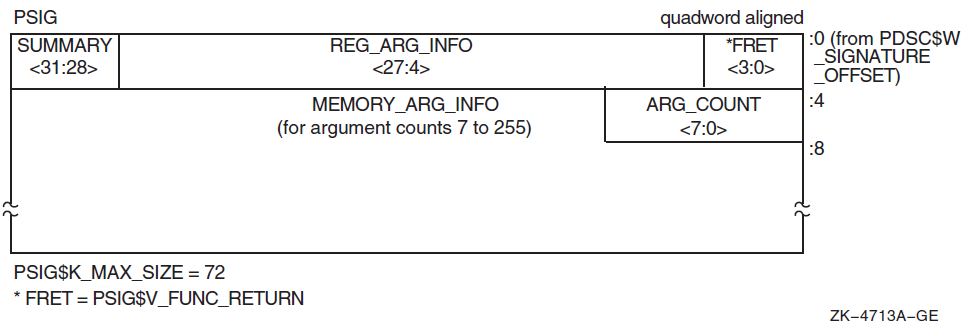
6.2.2. Signature Information on I64 Systems
Signature information is represented in Figure 6.2, ''I64 Signature Information Block (PSIG)'', and is explained in Table 6.2, ''Contents of the Signature Information Block (PSIG)'', Table 6.3, ''Register Argument Signature Encodings'', and Table 6.4, ''Function Return Signature Encodings''.
Signature information is defined only for standard calls, that is, for normal parameters passed using standard mechanisms and locations as defined in this calling standard. For all other cases, the signature information will be null so that an attempted call between native and translated code will fail.
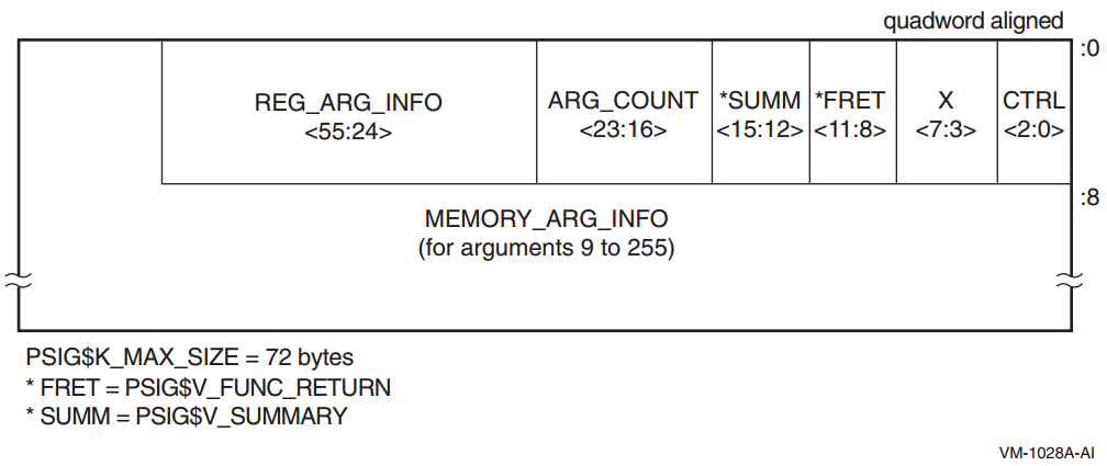
6.2.3. Signature Information Block Content
The content of Alpha and I64 signature information blocks is described in Tables 6.2, 6.3, and 6.4. Table 6.2, ''Contents of the Signature Information Block (PSIG)'' omits reference to particular bit positions. In these tables and subsequence sections, the following logical names are used to refer to corresponding Alpha and Intel Itanium registers:
|
Name |
Interpretation |
Alpha Register |
Itanium Register |
|---|---|---|---|
|
RetVal |
First (or only) integer return register |
R0 |
R8 |
|
RetVal2 |
Second integer return register |
R1 |
R9 |
|
RetFlt |
First (or only) floating-point return register |
F0 |
|
|
RetFlt2 |
Second floating-point return register |
F1 |
|
|
Field Name |
Contents | ||
|---|---|---|---|
|
PSIG$V_CTRL |
(I64 systems only) A 3-bit control information field. Not used in a signature information block. Contents are unspecified. Allows a signature information block to occur as an immediate value in the signature information field of a function descriptor (see Section 6.1.3, ''Signature Information Fields in Function Descriptors''). | ||
|
PSIG$V_X |
(I64 systems only) A 5-bit unused field. Must be zero. | ||
|
PSIG$V_FUNC_RETURN |
A 4-bit field that describes which registers are used for the function value return (if there is one) and what format is used for those registers. Table 6.4, ''Function Return Signature Encodings'' lists and describes the possible encoded values of PSIG$V_FUNC_RETURN. | ||
|
PSIG$V_REG_ARG_INFO |
A field that is divided into groups of 4 bits that correspond to the arguments that can be passed in registers. There are six groups for a total of 24 bits on Alpha systems and eight groups for a total of 32 bits on I64 systems. The first group (lowest order bits) describes the first register argument, the second group (next lowest order bits) describes the second register argument, and so on. Table 6.3, ''Register Argument Signature Encodings'' lists the possible codes. | ||
|
PSIG$V_SUMMARY |
A 4-bit field that contains coded argument signature information as follows: | ||
|
Bit |
Name |
Meaning | |
|
0, 1 |
PSIG$M_SU_ASUM |
On Alpha, summary of arguments 7 through
PSIG$B_ARG_COUNT.
On Itanium, summary of arguments 9
through PSIG$B_ARG_COUNT:
| |
| 2 |
PSIG$M_SU_VLIST |
VAX formatted argument list expected | |
| 3 |
Must be 0 (reserved) | ||
|
PSIG$M_SU_ASUM values of 00 and 01 (binary) allow a quick test for the occurrence of either an all 32-bit or an all 64-bit argument list. The values for the PSIG$V_MEMORY_ARG_INFO field must be valid even when these occurrences apply. | |||
|
PSIG$B_ARG_COUNT |
Unsigned byte (bits 0—7) that specifies the number of 64-bit argument items described in the argument signature information. This count includes the initial arguments that are passed in registers. | ||
|
PSIG$V_MEMORY_ |
Array of 2-bit values that describe each of the arguments through PSIG$B_ARG_COUNT that are passed in memory (rather than registers). PSIG$S_MEMORY_ARG_INFO data is only defined for the arguments described by PSIG$B_ARG_COUNT. These memory argument signature bits are defined as follows: | ||
|
Value |
Name |
Meaning? | |
| 0 |
MASE$K_MA_Q |
64-bit argument | |
| 1 |
Reserved | ||
| 2 |
MASE$K_MA_I32 |
32-bit sign-extended argument | |
| 3 |
Reserved | ||
|
Value |
Name | |
|---|---|---|
|
0 |
RASE$K_RA_NOARG |
Argument is not present |
|
1 |
RASE$K_RA_Q |
64-bit argument passed in an integer register |
|
2 |
RASE$K_RA_I32 |
32-bit argument sign-extended to 64 bits passed in an integer register |
|
3 |
RASE$K_RA_U32 |
32-bit unsigned argument zero-extended to 64 bits passed in an integer register |
|
4 |
RASE$K_RA_FF |
F_floating argument passed in a floating-point register on Alpha or a general register on I64 systems |
|
5 |
RASE$K_RA_FD |
D_floating argument passed in a floating-point register on Alpha or a general register on I64 systems |
|
6 |
RASE$K_RA_FG |
G_floating argument passed in a floating-point register on Alpha or a general register on I64 systems |
|
7 |
RASE$K_RA_FS |
S_floating argument passed in a floating-point register |
|
8 |
RASE$K_RA_FT |
T_floating argument passed in a floating-point register |
|
9—15 |
Reserved for future use |
|
Value |
Name | |
|---|---|---|
|
0 |
PSIG$K_FR_I64 |
|
|
1 |
PSIG$K_FR_D64 |
64-bit result with low 32 bits sign-extended in RetVal and high 32 bits sign-extended in RetVal2 |
|
2 |
PSIG$K_FR_I32 |
32-bit sign-extended to 64-bit result in RetVal |
|
3 |
PSIG$K_FR_U32 |
32-bit unsigned result (zero-extended) in RetVal |
|
4 |
PSIG$K_FR_FF |
F_floating result in RetFlt |
|
5 |
PSIG$K_FR_FD |
D_floating result in RetFlt |
|
6 |
PSIG$K_FR_FG |
G_floating result in RetFlt |
|
7 |
PSIG$K_FR_FS |
S_floating result in RetFlt |
|
8 |
PSIG$K_FR_FT |
T_floating result in RetFlt |
|
9, 10 |
Reserved for future use | |
|
11 |
PSIG$K_FR_FFC |
F_floating complex result in RetFlt and RetFlt2 |
|
12 |
PSIG$K_FR_FDC |
D_floating complex result in RetFlt and RetFlt2 |
|
13 |
PSIG$K_FR_FGC |
G_floating complex result in RetFlt and RetFlt2 |
|
14 |
PSIG$K_FR_FSC |
S_floating complex result in RetFlt and RetFlt2 |
|
15 |
PSIG$K_FR_FTC |
T_floating complex result in RetFlt and RetFlt2 |
6.2.4. Call Parameter PSIG Conversions
Note that for the purposes of translated images, an address on OpenVMS Alpha or I64 is described using RASE$K_RA_I32 or MASE$K_MA_I32 as appropriate.
6.2.4.1. Native-Alpha-to-Translated-VAX PSIG Conversions
|
Name |
Description |
|---|---|
|
PSIG$V_REG_ARG_INFO Field Conversions | |
|
RASE$K_RA_Q |
The low-order 32 bits of the native integer register contents are used to fill the first of two longword entries in the VAX formatted argument list, while the high-order 32 bits are used to fill the second longword entry. This counts as two arguments in the VAX formatted argument list. |
|
The low-order 32 bits of the integer register contents are used to fill one longword entry in the VAX formatted argument list passed to the translated procedure. The high-order 32 bits are ignored. This counts as one argument in the VAX formatted argument list. |
|
RASE$K_RA_FF |
The single-precision contents of a floating-point register are used to fill one longword entry in the VAX formatted argument list passed to the translated procedure. This counts as one argument in the VAX formatted argument list. The Alpha store instruction STF (or an equivalent sequence on Itanium systems) is used to place the register contents into memory. |
|
The double-precision contents of a floating-point register are used to fill two longword entries in the VAX formatted argument list passed to the translated procedure. This counts as two arguments in the VAX formatted argument list. The Alpha store instruction STG (or an equivalent sequence on Itanium systems) is used to place the register contents into memory. |
|
Undefined. |
|
PSIG$V_MEMORY_ARG_INFO Field Conversions | |
|
These convert like the RASE$K_RA_Q and RASE$K_RA_I32 field conversions, except that the native argument list entry is stored in memory (rather than in a register). |
|
PSIG$V_FUNC_RETURN Field Conversions | |
|
PSIG$K_FR_I64 |
The translated code is returning a 64-bit result split between VAX R0 and R1. The low-order 32 bits of R1 are shifted left and combined with the low-order 32 bits of R0 to form the 64-bit result that is returned to the native caller in RetVal. |
|
PSIG$K_FR_D64 |
The translated code is returning a 64-bit result split between VAX R0 and R1. Both R0 and R1 are sign-extended from 32 to 64 bits and returned to the native caller in RetVal and RetVal2. |
|
The translated code is returning a 32-bit result in VAX R0. R0 is sign-extended from 32 to 64 bits and returned to the native caller in RetVal. |
|
PSIG$K_FR_FF |
The single-precision contents of the result in VAX R0 is loaded into native register RetFlt. |
|
The double-precision contents in VAX registers R0 and R1 are combined and loaded into native register RetFlt. |
|
Undefined. |
|
PSIG$K_FR_FFC |
The single-precision complex contents in VAX registers R0 and R1 are loaded into native registers RetFlt and RetFlt2. |
|
The translated code is returning a double-precision complex result using the hidden first parameter method (by reference). The storage for the result is allocated prior to the call and the address is passed as the extra parameter. Upon return, the result is copied from the temporary storage into the native floating-point return registers and returned to the native caller. |
|
Undefined. |
In all 64-bit cases, the longword at the lower memory address forms the earlier argument in the VAX formatted argument list. Also, for single-precision floating-point types, the unused 32 bits of an native 64-bit argument list entry are undefined.
6.2.4.2. Translated-VAX-to-Native-Alpha PSIG Conversions
|
Name |
Description |
|---|---|
|
PSIG$V_REG_ARG_INFO Field Conversions | |
|
RASE$K_RA_Q |
The contents of two successive longwords from the VAX formatted argument list are combined to form a single quadword value that is placed in an integer register. This counts as one argument in the native argument list. |
|
The contents of one longword entry from the VAX formatted argument list is sign-extended and placed in the integer register. This counts as one argument in the native argument list. |
|
RASE$K_RA_FF |
A single longword entry from the VAX formatted argument list is used to form a floating-point value in a floating-point register. This counts as one argument in the native argument list. The Alpha load instruction LDF (or an equivalent sequence on I64 systems) is used to place the argument in the floating-point register. |
|
Two longword entries from the VAX formatted argument list are combined to form a single floating-point value in a floating-point register. This counts as one argument in the native argument list. The Alpha load instruction LDG (or an equivalent sequence on I64 systems) is used to place the argument in the floating-point register. |
|
Undefined. |
|
PSIG$V_MEMORY_ARG_INFO Field Conversions | |
|
These convert like RASE$K_RA_Q and RASE$K_RA_I32 field conversions, except that the native argument list entry is stored in memory (rather than a register).? |
|
PSIG$V_FUNC_RETURN Field Conversions | |
|
PSIG$K_FR_I64 |
The native code is returning a 64-bit result in RetVal. The high 32 bits of RetVal are moved to the VAX R1 register and the low 32 bits of RetVal are moved to the VAX R0 register. The 64-bit result is then returned to the translated caller in VAX R0 and R1. |
|
PSIG$K_FR_D64 |
The native code is returning a 64-bit result split between RetVal and RetVal2. Both are returned to the translated caller in place. |
|
The native code is returning a 32-bit result in RetVal. The low 32 bits of RetVal are returned to the translated caller. |
|
PSIG$K_FR_FF |
The single-precision result in native register RetFlt is returned in the VAX register R0.? |
|
The double-precision result in native register RetFlt is returned in VAX registers R0 and R1. |
|
Undefined. |
|
PSIG$K_FR_FFC |
The single-precision complex result in native registers RetFlt and RetFlt2 is returned in the VAX registers R0 and R1.? |
|
The native code is returning a double-precision complex result in the native floating-point registers. The result is copied into the storage given by the hidden first parameter passed by the translated caller. |
|
Undefined. |
6.2.4.3. Native-I64-to-Translated-Alpha PSIG Conversions
Conversion of native I64 arguments and results and translated Alpha arguments and results is trivial; it is concerned solely with moving the already properly formatted data to the appropriate location for the target environment.
6.2.4.4. Translated-Alpha-to-Native-I64 PSIG Conversions
Conversion of translated Alpha arguments and results and native I64 arguments and results is trivial; it is concerned solely with moving the already properly formatted data to the appropriate location for the target environment.
6.2.5. Default Signature Information
Default signature information is defined for common special cases. Such a default is a short-hand description that can always be represented explicitly but may sometimes be more compact than the corresponding explicit representation.
Translated VAX Image Calling a Native Alpha Procedure
The number of parameters is taken from the count byte in the VAX argument list.
All parameters (if any) are 32-bit sign-extended (RASE$K_RA_I32 for register arguments, MASE$K_MA_I32 for memory arguments).
The function result (if any) is 32-bit sign-extended (PSIG$K_FR_I32).
Native Alpha Procedure Calling a Translated VAX Image
The number of parameters passed is contained in the AI (R25) register.
The register parameters (if any) are described in the AI register.
The memory parameters (if any) are 32-bit sign-extended (MASE$K_MA_I32).
The function result (if any) is 32-bit sign-extended (PSIG$K_FR_I32).
Translated VAX or Alpha Image Calling a Native I64 Procedure
The number of parameters is taken from the count byte in the VAX argument list or the argument count in the Alpha AI register (R25) as appropriate.
All parameters (if any) are 32-bit sign-extended (RASE$K_RA_I32 for register arguments, MASE$K_MA_I32 for memory arguments).
The function result (if any) is 32-bit sign-extended (PSIG$K_FR_I32).
Native I64 Procedure Calling a Translated VAX or Alpha Image
The number of parameters is contained in the I64 AI (R25) register.
The register parameters (if any) are described in the AI register.
The memory parameters (if any) are 32-bit sign-extended (MASE$K_MA_I32).
The function result (if any) is 32-bit sign-extended (PSIG$K_FR_I32).
Chapter 7. OpenVMS Argument Data Types
This chapter defines the argument-passing data types that are used to call a procedure for OpenVMS environments. All features defined here apply to all OpenVMS systems unless otherwise noted.
Atomic
String
Miscellaneous
When existing data types fail to satisfy the semantics of a language, new data types, including certain language-specific ones, are added to this standard. These data types can generally be passed by immediate value, by reference, or by descriptor.
Each data type code presented in this chapter indicates a unique data format. Use these encodings whenever you need to identify data types to achieve greater commonality across user software.
The encoding given in Section 7.1, ''Atomic Data Types'' and Section 7.2, ''String Data Types'' can help you to identify data types, such as in a descriptor. However, in addition to their use in descriptors, these data type codes are also useful for identifying OpenVMS hardware and software data types in areas outside the scope of the calling standard. Therefore, each data-type code indicates a unique data format independent of its use in descriptors.
Some data types are composed of a record-like structure consisting of two or more elementary data types. For example, the F_floating complex (FC) data type is made up of two F_floating (F) data types, and the varying character string (VT) data type is made up of a word (unsigned, WU) data type followed by a character string (T) data type.
Unless stated otherwise, all data types in this standard represent signed quantities. The unsigned quantities do not allocate space for the sign; all bit or character positions are used for significant data.
7.1. Atomic Data Types
|
Symbol |
Code |
Name/Description |
|---|---|---|
|
DSC$K_DTYPE_Z |
0 |
|
|
DSC$K_DTYPE_BU |
2 |
|
|
DSC$K_DTYPE_WU |
3 |
|
|
DSC$K_DTYPE_LU |
4 |
|
|
DSC$K_DTYPE_QU |
5 |
|
|
DSC$K_DTYPE_OU |
25 |
|
|
DSC$K_DTYPE_B |
6 |
|
|
DSC$K_DTYPE_W |
7 |
|
|
DSC$K_DTYPE_L |
8 |
|
|
DSC$K_DTYPE_Q |
9 |
|
|
DSC$K_DTYPE_O |
26 |
|
|
DSC$K_DTYPE_F? |
10 |
|
|
11 |
| |
|
DSC$K_DTYPE_G? |
27 |
|
|
28 |
| |
|
DSC$K_DTYPE_FC? |
12 |
|
|
DSC$K_DTYPE_DC? |
13 |
|
|
DSC$K_DTYPE_GC? |
29 |
|
|
30 |
| |
|
DSC$K_DTYPE_FS? |
52 |
|
|
DSC$K_DTYPE_FT? |
53 |
|
|
DSC$K_DTYPE_FSC? |
54 |
|
|
DSC$K_DTYPE_FTC? |
55 |
|
|
DSC$K_DTYPE_FX? |
57 |
|
|
DSC$K_DTYPE_FXC? |
58 |
|
7.2. String Data Types
|
Symbol |
Code |
Name/Description |
|---|---|---|
|
DSC$K_DTYPE_T |
14 |
Character string A single 8-bit character (atomic data type) or a sequence of 0 to 216 − 1 8-bit characters (string data type). |
|
DSC$K_DTYPE_VT |
37 |
Varying character string A 16-bit unsigned count of the current number of 8-bit characters in the following string, followed by a string of 0 to 216 − 1 8-bit characters (see Section 7.5, ''Varying Character String Data Type (DSC$K_DTYPE_VT)'' for details). When this data type is used with descriptors, it can only be used with the varying string and varying string array descriptors, because the length field is interpreted differently from the other 8-bit string data types. (See Section 7.5, ''Varying Character String Data Type (DSC$K_DTYPE_VT)'', Section 8.8, ''Varying String Descriptor (CLASS_VS)'', and Section 8.9, ''Varying String Array Descriptor (CLASS_VSA)'' for further discussion). |
|
DSC$K_DTYPE_NU |
15 |
Numeric string, unsigned |
|
DSC$K_DTYPE_NL |
16 |
Numeric string, left separate sign |
|
DSC$K_DTYPE_NLO |
17 |
Numeric string, left overpunched sign |
|
DSC$K_DTYPE_NR |
18 |
Numeric string, right separate sign |
|
DSC$K_DTYPE_NRO |
19 |
Numeric string, right overpunched sign |
|
DSC$K_DTYPE_NZ |
20 |
Numeric string, zoned sign |
|
DSC$K_DTYPE_P |
21 |
Packed-decimal string |
|
DSC$K_DTYPE_V |
1 |
Aligned bit string A string of 0 to 216 − 1 contiguous bits. The first bit is bit <0> of the first byte, and the last bit is any bit in the last byte. Remaining bits in the last byte must be 0 on read and are cleared on write. Unlike the unaligned bit string (VU) data type, when the aligned bit string (V) data type is used in array descriptors, the ARSIZE field is in units of bytes, not bits, because allocation is a multiple of 8 bits. |
|
DSC$K_DTYPE_VU |
34 |
Unaligned bit string The data is 0 to 216 − 1 contiguous bits located arbitrarily with respect to byte boundaries. See also aligned bit string (V) data type. Because additional information is required to specify the bit position of the first bit, this data type can be used only with the unaligned bit string and unaligned bit array descriptors (see Section 8.10, ''Unaligned Bit String Descriptor (CLASS_UBS)'' and Section 8.11, ''Unaligned Bit Array Descriptor (CLASS_UBA)''). |
7.3. Miscellaneous Data Types
|
Symbol |
Code |
Name/Description |
|---|---|---|
|
DSC$K_DTYPE_ZI? |
22 |
Sequence of instructions |
|
DSC$K_DTYPE_ZEM? |
23 |
Procedure entry mask |
|
DSC$K_DTYPE_DSC |
24 |
Descriptor This data type allows a descriptor to be a data type; thus, levels of descriptors are allowed. |
|
DSC$K_DTYPE_BPV? |
32 |
Bound procedure value (for VAX environment only) A two-longword entity in which the first longword contains the address of a procedure entry mask and the second longword is the environment value. The environment value is determined in a language-specific manner when the original bound procedure value is generated. When the bound procedure is called, the calling program loads the second longword into R1. When the environment value is not needed, this data type can be passed using the immediate value mechanism. In this case, the argument list entry contains the address of the procedure entry mask and the second longword is omitted. |
|
DSC$K_DTYPE_BLV |
33 |
Bound label value A two-longword entity in which the first longword contains the address of an instruction and the second longword is the language-specific environment value. The environment value is determined in a language-specific manner when the original bound label value is generated. |
|
DSC$K_DTYPE_ADT |
35 |
Absolute date and time A 64-bit unsigned, scaled, binary integer representing a date and time in 100-nanosecond units offset from the OpenVMS operating system base date and time, which is 00:00 o'clock, November 17, 1858 (the Smithsonian base date and time for astronomical calendars). The value 0 indicates that the date and time have not been specified, so a default value or distinctive print format can be used. Note that the ADT data type is the same as the OpenVMS date format for positive values only. |
7.4. Reserved Data-Type Codes
All codes from 0 through 191 not otherwise defined in this standard are reserved to OpenVMS. Codes 192 through 255 are reserved for OpenVMS custom systems and for customers for their own use.
|
Symbol |
Code |
Purpose |
|---|---|---|
|
DSC$K_DTYPE_CIT |
31 |
Reserved to COBOL (intermediate temporary) |
|
No symbol defined |
36 |
Obsolete |
|
DSC$K_DTYPE_T2 |
38 |
Obsolete |
|
DSC$K_DTYPE_VT2 |
39 |
Obsolete |
|
DSC$K_DTYPE_TF |
40 |
Reserved to DEBUG (Boolean true/false) |
|
DSC$K_DTYPE_SV |
41 |
Reserved to DEBUG (signed bit-field, aligned) |
|
DSC$K_DTYPE_SVU |
42 |
Reserved to DEBUG (signed bit-field, unaligned) |
|
DSC$K_DTYPE_FIXED |
43 |
Reserved to DEBUG (fixed binary — fixed point in Ada and fixed binary in PL/I) |
|
DSC$K_DTYPE_TASK |
44 |
Reserved to DEBUG (task type in Ada) |
|
DSC$K_DTYPE_AC |
45 |
Reserved to DEBUG (ASCIC text) |
|
DSC$K_DTYPE_AZ |
46 |
Reserved to DEBUG (ASCIZ text) |
|
DSC$K_DTYPE_M68_S |
47 |
Reserved to DEBUG (Motorola 68881 single precision, 32-bit)? |
|
DSC$K_DTYPE_M68_D |
48 |
Reserved to DEBUG (Motorola 68881 double precision, 64-bit)? |
|
DSC$K_DTYPE_M68_X |
49 |
Reserved to DEBUG (Motorola 68881 extended precision, 96-bit)? |
|
DSC$K_DTYPE_1750_S |
50 |
Reserved to DEBUG (1750 single precision, 32-bit) |
|
DSC$K_DTYPE_1750_X |
51 |
Reserved to DEBUG (1750 extended precision, 48-bit) |
|
DSC$K_DTYPE_WC |
56 |
Reserved to DEBUG ( |
|
DSC$K_DTYPE_F80 |
59 |
Reserved to DEBUG (Intel Itanium extended precision, 80-bit) |
|
DSC$K_DTYPE_F80C |
60 |
Reserved to DEBUG (Intel Itanium extended precision complex, two 80-bit) |
|
DCS$K_DTYPE_FIR |
61 |
Reserved to DEBUG (Intel Itanium floating-point Register format, 84-bit) |
|
DCS$K_DTYPE_FIRC |
62 |
Reserved to DEBUG (Intel Itanium floating-point Register format complex, two 84-bit) |
|
DSC$K_DTYPE_CIT2 |
64 |
Reserved to COBOL (intermediate temporary alternative 2) |
|
DSC$K_DTYPE_M64 |
65 | Reserved to DEBUG (array of eight IEEE 32-bit binary floating-point) |
|
DSC$K_DTYPE_M128 |
66 |
Reserved to DEBUG (array of 16 IEEE 32-bit binary floating-point) |
|
DSC$K_DTYPE_M256 |
67 |
Reserved to DEBUG (array of 32 IEEE 32-bit binary floating-point) |
|
DSC$K_DTYPE_M512 |
68 |
Reserved to DEBUG (array of 64 IEEE 32-bit binary floating-point) |
7.4.1. Facility-Specific Data-Type Codes
Data-type codes 160 through 191 are reserved to OpenVMS for facility-specific purposes. These codes must not be passed between facilities because different facilities can use the same code for different purposes. These codes might be used by compiler-generated code to pass parameters to the language-specific run-time support procedures associated with that language or with the OpenVMS Debugger.
7.5. Varying Character String Data Type (DSC$K_DTYPE_VT)
|
CURLEN |
An unsigned word specifying the current length in bytes of the immediately following string. |
|
BODY |
A fixed-length area containing the string that can vary from 0 to a maximum length defined for each instance of string. The range of this maximum length is 0 to 216 − 1. |
When passed by reference or by descriptor, the address of the varying character string (VT) data type is always the address of the CURLEN field, not the BODY field.
When a called procedure modifies a varying character string data type passed by reference or
by descriptor, it writes the new length, n, into CURLEN and can modify all
bytes of BODY, even those beyond the new length.
For example, consider a varying string with a maximum length of seven characters. To represent the string ABC, CURLEN will have a value of 3 and the last four bytes will be undefined, as shown in Figure 7.2, ''Varying Character String Data Type (DSC$K_DTYPE_VT) Format''.
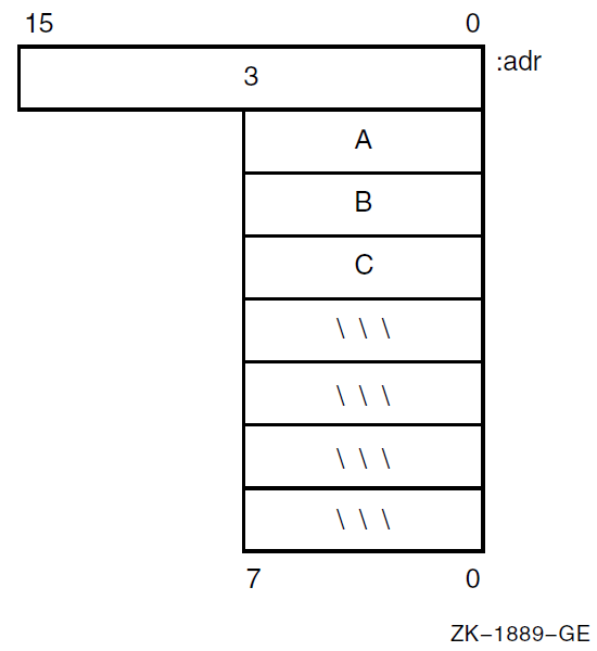
Chapter 8. OpenVMS Argument Descriptors
This chapter describes the argument descriptors used in calling a procedure on OpenVMS.
A uniform descriptor mechanism is defined for use by all procedures that conform to the OpenVMS calling standard. Descriptors are self-describing and the mechanism is extensible. When existing descriptors fail to satisfy the semantics of a language, new descriptors are added to this standard.
Note
Unless stated otherwise, all fields in descriptors represented as unsigned quantities are read-only from the point of view of the called procedure, and can be allocated in read-only memory at the option of the calling program.
If a language processor implements a language-specific data type that is not added to this standard (see Chapter 7, "OpenVMS Argument Data Types"), the processor is not required to use a standard descriptor to pass an array of such a data type. However, if a language processor passes an array of such a data type using a standard descriptor, the language processor fills in the DSC$B_DTYPE field with the value 0, indicating that the data-type field is unspecified, rather than using a more general data-type code.
For example, an array of PL/I POINTER data types has the DTYPE field filled in with the value 0 (unspecified data type), rather than with the value 4 (longword [unsigned] data type). The remaining fields are filled in as specified by this standard; for example, DSC$W_LENGTH is filled in with the size in bytes. Because the language-specific data type might be added to the standard in the future, generic application procedures that examine the DTYPE field should be prepared for 0 and for additional data types.
Table 8.1, ''Argument Descriptor Classes'' identifies the classes of argument descriptors for use in standard environments. Each class has two synonymous names—one for 32-bit environments (DSC$) and one for 64-bit environments (DSC64$). Descriptions and formats of each of these descriptors follow.
|
Descriptor |
Code |
Class |
|---|---|---|
|
1 |
Fixed-length scalar/string |
|
2 |
Dynamic string |
|
4 |
Contiguous array |
|
5 |
Procedure argument descriptor | |
|
9 |
Decimal (scalar) string |
|
10 |
Noncontiguous array |
|
11 |
Varying string |
|
12 |
Varying string array |
|
13 |
Unaligned bit string |
|
14 |
Unaligned bit array |
|
15 |
String with bounds |
|
16 |
Unaligned bit string with bounds |
8.1. Descriptor Prototype
Figure 8.1, ''Descriptor Prototype Format'' shows the descriptor prototype format. There are two forms: one for use with 32-bit addresses and one for use with 64-bit addresses. The two forms are compatible in that the forms can be distinguished dynamically at run-time and, except for the size and consequential placement of fields, 32-bit and 64-bit descriptors are identical in content and interpretation.
The 32-bit descriptors are used on all OpenVMS systems. When used on 64-bit OpenVMS systems, 32-bit descriptors provide full compatibility with their use on OpenVMS VAX systems. The 64-bit descriptors are used on all 64-bit OpenVMS systems—they have no counterparts and are not recognized on OpenVMS VAX systems.
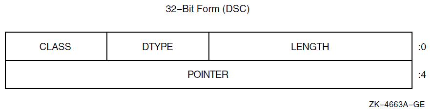
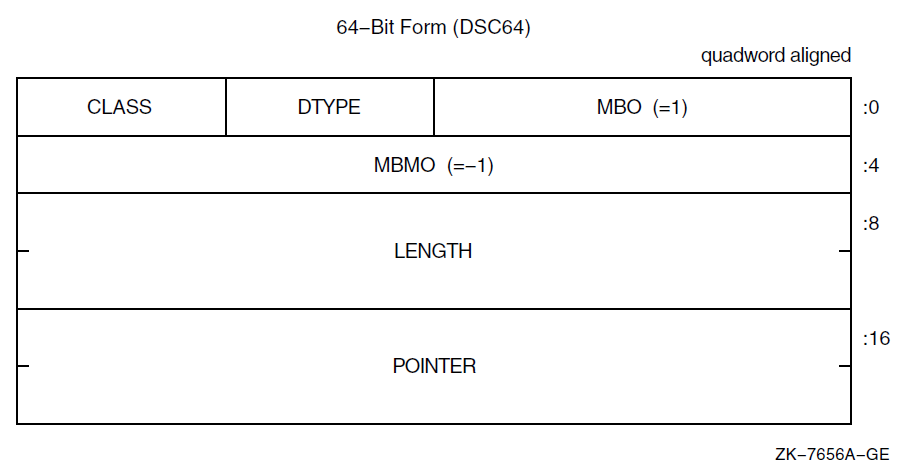
The 32-bit descriptors on 64-bit OpenVMS systems have no required alignment for compatibility with OpenVMS VAX systems; however, longword alignment generally promotes performance. The 64-bit descriptors on 64-bit OpenVMS systems must be quadword aligned.
Table 8.2, ''Contents of the Prototype Descriptor'' describes the fields of the descriptor. In this table and the similar tables for descriptors in later sections, note that most fields have two symbols and one description. The symbol that begins with the prefix DSC$ is used with 32-bit descriptors, while the symbol that begins with the prefix DSC64$ is used with 64-bit descriptors.
In this chapter, it is generally the practice to use only the main part of a field name, without either of the prefixes used in actual code. For example, the length field is referred to using LENGTH rather than mentioning both DSC$W_LENGTH and DSC64$Q_LENGTH. The DSC$ and DSC64$ prefixes are used only when referring to a particular form of descriptor.
The CLASS and DTYPE fields occupy the same offsets in both 32-bit and 64-bit descriptors. Thus, the symbols DSC$B_CLASS and DSC64$B_CLASS have the same definition, as do DSC$B_DTYPE and DSC64$B_DTYPE. Furthermore, these fields are permitted to contain the same values with the same meanings in both 32-bit and 64-bit forms.
The DSC$W_LENGTH and DSC$A_POINTER fields in the 32-bit descriptors correspond in placement to the DSC64$W_MBO (must be 1) and DSC64$L_MBMO (must be -1) fields in the 64-bit descriptors. The values of these fields are used to distinguish whether a given descriptor has the 32-bit or 64-bit form as described later in this section.
|
Symbol |
Description |
|---|---|
|
Defines the data item length specific to the descriptor class. |
|
DSC64$W_MBO |
In a 64-bit descriptor, this field must contain the value 1. This field overlays the DSC$W_LENGTH field of a 32-bit descriptor and the value 1 is necessary to correctly distinguish between the two forms (see below). |
|
A data-type code. Data-type codes are listed in Section 7.1, ''Atomic Data Types'' and Section 7.2, ''String Data Types''. |
|
A descriptor class code that identifies the format and interpretation of the other fields of the descriptor as specified in the following sections. This interpretation is intended to be independent of the DTYPE field, except for the data types that are made up of units less than a byte (packed-decimal string [P], aligned bit string [V], and unaligned bit string [VU]). The CLASS code can be used at run-time by a called procedure to determine which descriptor is being passed. |
|
The address of the first byte of the data element described. |
|
DSC64$L_MBMO |
In a 64-bit descriptor, this field must contain the value -1 (all 1 bits). Note that this field overlays the DSC$A_POINTER field of a 32-bit descriptor and the value -1 is necessary to correctly distinguish between the two forms (see below). |
Confirm that the MBO field contains 1
Confirm that the MBMO field contains -1
Note
It may seem sufficient to test just the MBMO field. However, that allows a 32-bit descriptor with a length of 0 and an undefined pointer to be inadvertently treated as a 64-bit descriptor.
If the MBMO field contains -1, then 0 and 1 are the only values of the MBO field that have defined interpretations.
8.2. Fixed-Length Descriptor (CLASS_S)
A single descriptor class is used for scalar data and fixed-length strings. Any OpenVMS data type, except data type 34 (unaligned bit string), can be used with this descriptor. Figure 8.2, ''Fixed-Length Descriptor Format'' shows the format of a fixed-length descriptor. Table 8.3, ''Contents of the CLASS_S Descriptor'' describes the fields of the descriptor.
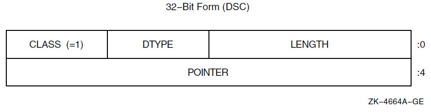
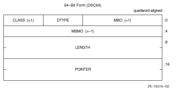
|
Symbol |
Description |
|---|---|
|
Length of the data item in bytes, unless the DTYPE field contains the value 1 (aligned bit string) or 21 (packed-decimal string). Length of the data item is in bits for bit string. Length of the data item is the number of 4-bit digits (not including the sign) for a packed-decimal string. |
|
DSC64$W_MBO |
Must be 1. See Section 8.1, ''Descriptor Prototype''. |
|
A data-type code. Data-type codes are listed in Section 7.1, ''Atomic Data Types'' and Section 7.2, ''String Data Types''. |
|
Defines the descriptor class code that must be equal to 1 for CLASS_S. |
|
Address of first byte of data storage. |
|
DSC64$L_MBMO |
Must be -1. See Section 8.1, ''Descriptor Prototype''. |
If the data type is 14 (character string) and the string must be extended in a string comparison or is being copied to a fixed-length string containing a greater length, the space character (hexadecimal 20 if ASCII) is used as the fill character.
8.3. Dynamic String Descriptor (CLASS_D)
A class D descriptor is used for dynamically allocated strings. When a string is written, either the length field, pointer field, or both can be changed. The OpenVMS Run-Time Library provides procedures for changing fields. As an input parameter, this format is interchangeable with class 1 (CLASS_S). Figure 8.3, ''Dynamic String Descriptor Format'' shows the format of a dynamic string descriptor. Table 8.4, ''Contents of the CLASS_D Descriptor'' describes the fields of the descriptor.
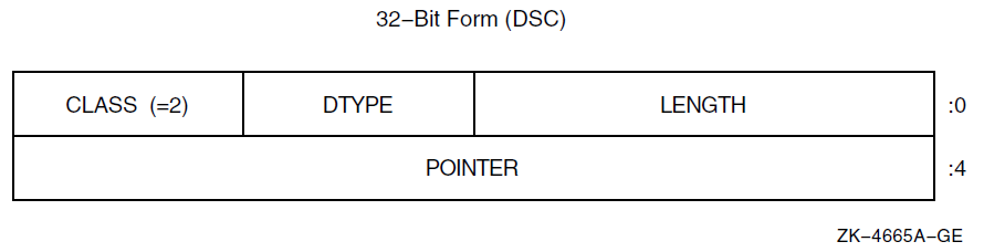
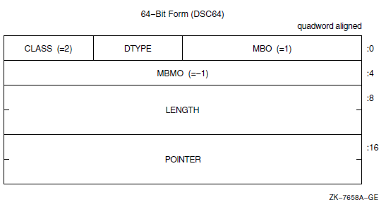
|
Symbol |
Description |
|---|---|
|
Length of the data item in bytes, unless the DTYPE field contains the value 1 (aligned bit string) or 21 (packed-decimal string). Length of the data item is in bits for the bit string. Length of the data item is the number of 4-bit digits (not including the sign) for a packed-decimal string. |
|
DSC64$W_MBO |
Must be 1. See Section 8.1, ''Descriptor Prototype''. |
|
A data-type code. Data-type codes are listed in Section 7.1, ''Atomic Data Types'' and Section 7.2, ''String Data Types''. |
|
DSC$B_CLASS DSC64$B_CLASS |
Defines the descriptor class code that must be equal to 2 for CLASS_D. |
|
Address of first byte of data storage. |
|
DSC64$L_MBMO |
Must be -1. See Section 8.1, ''Descriptor Prototype''. |
8.4. Array Descriptor (CLASS_A)
The array descriptor shown in Figure 8.4, ''Array Descriptor Format'' is used to describe contiguous arrays of atomic data types or contiguous arrays of fixed-length strings. An array descriptor consists of three contiguous blocks. The first block contains the descriptor prototype information and is part of every array descriptor. The second and third blocks are optional. If the third block is present, so is the second. Table 8.5, ''Contents of the CLASS_A Descriptor'' describes the fields of the descriptor.
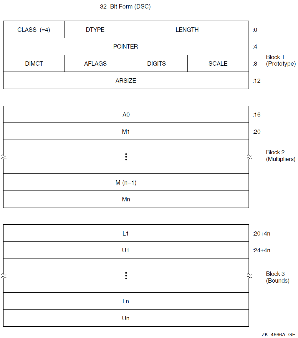
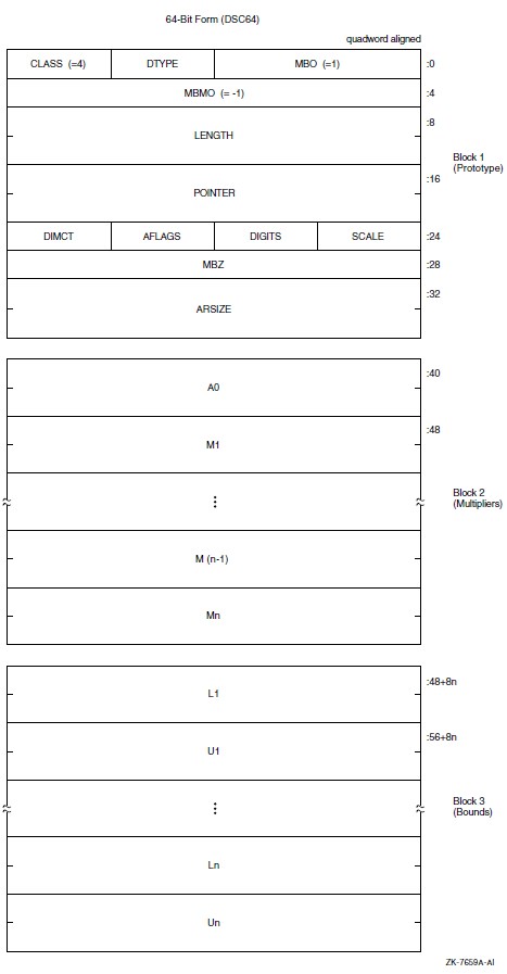
|
Symbol |
Description | |
|---|---|---|
|
Length of an array element in bytes, unless the DTYPE field contains the value 1 (aligned bit string) or 21 (packed-decimal string). Length of an array element is in bits for the bit string. Length of an array element is the number of 4-bit digits (not including the sign) for a packed-decimal string. | |
|
DSC64$W_MBO |
Must be 1. See Section 8.1, ''Descriptor Prototype''. | |
|
A data-type code. Data-type codes are listed in Section 7.1, ''Atomic Data Types'' and Section 7.2, ''String Data Types''. | |
|
Defines the descriptor class code that must be equal to 4 for CLASS_A. | |
|
Address of the first actual byte of data storage. | |
|
DSC64$L_MBMO |
Must be -1. See Section 8.1, ''Descriptor Prototype''. | |
|
Signed power-of-two or power-of-ten multiplier, as specified by FL_BINSCALE, to convert the internal form to external form. (See Section 8.6, ''Decimal String Descriptor (CLASS_SD)''). | |
|
If nonzero, the unsigned number of decimal digits in the internal representation. If 0, the number of digits can be computed based on LENGTH. This field should be 0 unless the TYPE field specifies a string data type that could contain numeric values. | |
|
Array flag bits <23:16>: | |
|
Bits <18:16> |
Reserved and must be 0. | |
|
If set, the scale factor specified by SCALE is a signed power-of-two multiplier to convert the internal form to external form. If not set, SCALE specifies a signed power-of-ten multiplier. (See Section 8.6, ''Decimal String Descriptor (CLASS_SD)''). | |
|
If set, the array can be redimensioned; that is, A0, Mi, Li, and Ui can be changed. The redimensioned array cannot exceed the size allocated to the array ARSIZE. | |
|
If set, the elements of the array are stored by columns (FORTRAN). That is, the leftmost subscript (first dimension) is varied most rapidly, and the rightmost subscript (nth dimension) is varied least rapidly. If not set, the elements are stored by rows (most other languages). That is, the rightmost subscript is varied most rapidly and the leftmost subscript is varied least rapidly. | |
|
If set, the multiplicative coefficients in block 2 are present. Must be set if FL_BOUNDS is set. | |
|
If set, the bounds information in block 3 is present and requires that FL_COEFF be set. | |
|
Number of dimensions, n. | |
|
Total size of array (in bytes, unless the TYPE field contains the value 21; see the description for LENGTH). A redimensioned array can use less than the total size allocated. For data type 1 (aligned bit string), LENGTH is in bits while ARSIZE is in bytes because the unit of length is bits, while the unit of allocation is aligned bytes. | |
|
Address of element A(0,0,…,0). This need not be within the actual array. It is the same as POINTER for zero-origin arrays. | |
|
Addressing coefficients ( Mi = Ui − Li + 1 ). | |
|
Lower bound (signed) of ith dimension. | |
|
Upper bound (signed) of ith dimension. | |
Caution
Modification of the following formulas is required if DTYPE contains a 1 or 21, because LENGTH is given in bits or 4-bit digits rather than in bytes.
   E = A0 + I*LENGTH
= POINTER + [I - L1]*LENGTH E = A0 + [I1*M2 + I2]*LENGTH
= POINTER + [[I1 - L1]*M2 + I2 - L2]*LENGTH E = A0 + [I2*M1 + I1]*LENGTH
= POINTER + [[I2 - L2]*M1 + I1 - L1]*LENGTHE = A0 + [[[[...[I1]*M2 + ...]*Mn-2 + In-2]*Mn-1 + In-1]*Mn + In]*LENGTH = POINTER + [[[[...[I1 - L1]*M2 + ...]*Mn-2 + In-2 - Ln-2]*Mn-1 + In-1 - Ln-1]*Mn + In - Ln]*LENGTH
   E = A0 + [[[[...[In]*Mn-1 + ...]
   *M3 + I3]*M2 + I2]*M1 + I1]*LENGTH
     = POINTER + [[[[...[In - Ln]*Mn-1 + ...]*M3 + I3
       - L3]*M2 + I2 - L2]*M1 + I1 - L1]*LENGTH
8.5. Procedure Argument Descriptor (CLASS_P)
A descriptor for a procedure argument identifies a procedure and its result data type, if any.
On OpenVMS VAX systems, the descriptor for a procedure argument specifies its entry address and function value data type. On OpenVMS Alpha systems, the procedure argument descriptor is a pointer to the procedure descriptor, which is described in Section 3.4, ''Procedure Types''. On OpenVMS IA-64 systems, the procedure argument descriptor is a pointer to the function descriptor, which is described in Section 4.7.7, ''Simple and Bound Procedures''. On OpenVMS x86-64 systems, the procedure argument descriptor is a pointer to a function value, which is described in Section 5.3, ''Procedure Values''. Figure 8.5, ''Procedure Argument Descriptor Format'' shows the format of a procedure argument descriptor. Table 8.6, ''Contents of the CLASS_P Descriptor'' describes the fields of the descriptor.
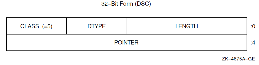
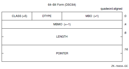
|
Symbol |
Description |
|---|---|
|
Length associated with the function value, or 0 if no function value is returned. |
|
DSC64$W_MBO |
Must be 1. See Section 8.1, ''Descriptor Prototype''. |
|
Function value data-type code. Data-type codes are listed in Section 7.1, ''Atomic Data Types'' and Section 7.2, ''String Data Types''. |
|
Defines the descriptor class code that must be equal to 5 for CLASS_P. |
|
Address of entry mask to the procedure for VAX environments. Address of the procedure descriptor of the procedure for Alpha environments. Address of the function descriptor of the procedure for I64 environments. Procedure value for x86-64 environments. |
|
DSC64$L_MBMO |
Must be -1. See Section 8.1, ''Descriptor Prototype''. |
Section 2.5, ''Function Value Returns'' for VAX systems
Section 3.7.7, ''Returning Data'' for Alpha systems
Section 4.7.6, ''Return Values'' for IA-64 systems
Section 5.7.6, ''Procedure Return Values'' for x86-64 systems
8.6. Decimal String Descriptor (CLASS_SD)
Figure 8.6, ''Decimal String Descriptor Format'' shows the format of a decimal string descriptor. Decimal size and scaling information for both scalar data and simple strings is given in this descriptor form. Table 8.7, ''Contents of the CLASS_SD Descriptor'' describes the fields of the descriptor.
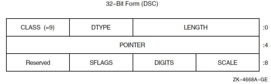
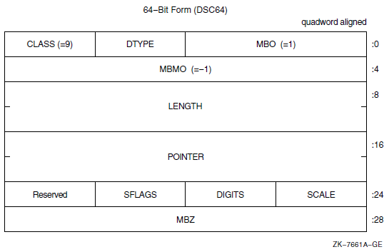
|
Symbol |
Description | |
|---|---|---|
|
Length of the data item in bytes, unless the DTYPE field contains the value 1 (aligned bit string) or 21 (packed-decimal string). Length of the data item is in bits for the bit string. Length of the data item is the number of 4-bit digits (not including the sign) for packed-decimal string. | |
|
DSC64$W_MBO |
Must be 1. See Section 8.1, ''Descriptor Prototype''. | |
|
A data-type code. Data-type codes are listed in Section 7.1, ''Atomic Data Types'' and Section 7.2, ''String Data Types''. | |
|
Defines the descriptor class code that must be equal to 9 for CLASS_SD. | |
|
Address of the first byte of data storage. | |
|
DSC64$L_MBMO |
Must be -1. See Section 8.1, ''Descriptor Prototype''. | |
|
Signed power-of-two or power-of-ten multiplier, as specified by FL_BINSCALE, to convert the internal form to external form. (See examples in Table 8.8, ''Internal-to-External BINSCALE Conversion Examples''). | |
|
If nonzero, the unsigned number of decimal digits in the internal representation. If 0, the number of digits can be computed based on LENGTH. This field should be 0 unless the TYPE field specifies a string data type that could contain numeric values. | |
|
Scalar flag bits <23:16>: | |
|
Bits <18:16> |
Reserved and must be 0. | |
|
If set, the scale factor specified by SCALE is a signed power-of-two multiplier to convert the internal form to external form. If not set, SCALE specifies a signed power-of-ten multiplier. (See examples in Table 8.8, ''Internal-to-External BINSCALE Conversion Examples''). | |
|
Bit <23:20> |
Reserved and must be 0. | |
|
Internal Value |
SCALE |
FL_BINSCALE |
External Value |
|---|---|---|---|
|
123 |
+1 |
0 |
1230 |
|
123 |
+1 |
1 |
246 |
|
200 |
-2 |
0 |
2 |
|
200 |
-2 |
1 |
50 |
8.7. Noncontiguous Array Descriptor (CLASS_NCA)
The noncontiguous array descriptor describes an array in which the storage of the array elements can be allocated with a fixed, nonzero number of bytes separating logically adjacent elements. Two elements are said to be logically adjacent if their subscripts differ by 1 in the most rapidly varying dimension only. The difference between the addresses of two adjacent elements is termed the stride. You can align elements by row or column, because the accessing algorithm in the called procedure handles both alignments.
This array descriptor is to be used where the calling program, at its option, can pass a slice of an array that contains noncontiguous allocations. This standard indicates no preference between the noncontiguous array descriptor (NCA) and the contiguous array descriptor (A), as described in Section 8.4, ''Array Descriptor (CLASS_A)'', for language processors that always allocate contiguous arrays. Figure 8.7, ''Noncontiguous Array Descriptor Format'' shows the format of a noncontiguous array descriptor, which consists of three contiguous blocks. Table 8.9, ''Contents of the CLASS_NCA Descriptor'' describes the fields of the descriptor.
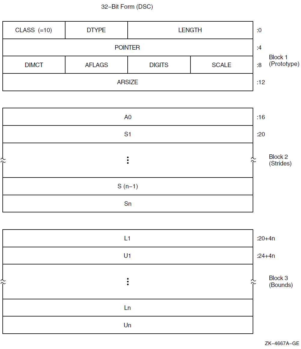
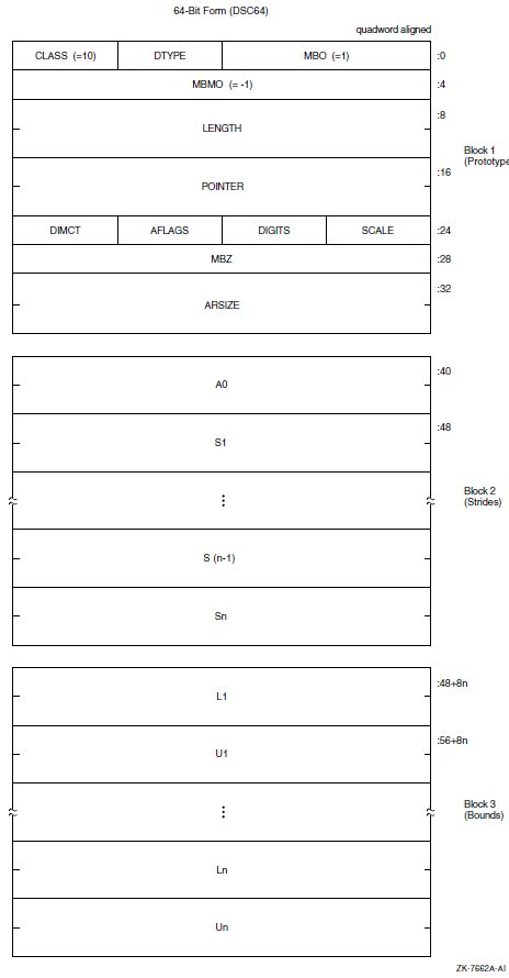
|
Symbol |
Description | |
|---|---|---|
|
Length of an array element in bytes, unless the DTYPE field contains the value 1 (aligned bit string) or 21 (packed-decimal string). Length of an array element is in bits for the bit string. Length of an array element is the number of 4-bit digits (not including the sign) for a packed-decimal string. | |
|
DSC64$W_MBO |
Must be 1. See Section 8.1, ''Descriptor Prototype''. | |
|
A data-type code. Data-type codes are listed in Section 7.1, ''Atomic Data Types'' and Section 7.2, ''String Data Types''. | |
|
DSC$B_CLASS |
Defines the descriptor class code that must be equal to 10 for CLASS_NCA. | |
|
Address of first actual byte of data storage. | |
|
DSC64$L_MBMO |
Must be -1. See Section 8.1, ''Descriptor Prototype''. | |
|
Signed power-of-two or power-of-ten multiplier, as specified by FL_BINSCALE, to convert the internal form to external form. (See Section 8.6, ''Decimal String Descriptor (CLASS_SD)''). | |
|
If nonzero, the unsigned number of decimal digits in the internal representation. If 0, the number of digits can be computed based on LENGTH. This field should be 0 unless the TYPE field specifies a string data type that could contain numeric values. | |
|
Array flag bits <23:16>: | |
|
Bits <18:16> |
Reserved and must be 0. | |
|
If set, the scale factor specified by SCALE is a signed power-of-two multiplier to convert the internal form to external form. If not set, SCALE specifies a signed power-of-ten multiplier. (See Section 8.6, ''Decimal String Descriptor (CLASS_SD)''). | |
|
Must be 0. | |
|
If set, the storage for the array described by this descriptor has not been allocated; the POINTER field must contain 0. If not set, storage for the array described by this descriptor has been allocated; the POINTER field may or may not be 0, depending on the bounds of the array. (If the POINTER field contains a nonzero value, then this flag must not be set). | |
|
DSC$V_FL_NODEALLOC |
If set, the storage for the array described by this descriptor must not be deallocated. (The POINTER and other fields of this descriptor may be cleared or otherwise set to eliminate access to the described storage, but the storage itself belongs to some other descriptor which must be used to deallocate that storage). | |
|
Bit <23:23> |
Reserved and must be 0. | |
|
Number of dimensions, n. | |
|
If the elements are contiguous, ARSIZE is the total size of the array (in bytes, unless the DTYPE field contains the value 21; see the description of LENGTH). If the elements are not allocated contiguously or if the program unit allocating the descriptor is uncertain whether the array is actually contiguous, the value placed in ARSIZE might be meaningless. For data type 1 (aligned bit string), LENGTH is in bits while ARSIZE is in bytes because the unit of length is in bits while the unit of allocation is in bytes. | |
|
Address of element A(0,0,…,0). This need not be within the actual array. It is the same as POINTER for zero-origin arrays. A0 = POINTER − ( S1*L1 + S2*L2 + …+ Sn*Ln) | |
|
Stride of the ith dimension. The difference between the addresses of successive elements of the ith dimension. | |
|
Lower bound (signed) of the ith dimension. | |
|
Upper bound (signed) of the ith dimension. | |
The following formulas specify the effective address, E, of an array element.
   E = A0 + S1*I
= POINTER + S1*[I - L1] E = A0 + S1*I1 + S2*I2
= POINTER + S1*[I1 - L1] + S2*[I2 - L2]E = A0 + S1*I1 + . . . + Sn*In = POINTER + S1*[I1 - L1] + . . . + Sn*[In - Ln]
8.8. Varying String Descriptor (CLASS_VS)
A class VS descriptor is used for varying string data types (see Section 7.5, ''Varying Character String Data Type (DSC$K_DTYPE_VT)'').
As an input parameter, this format is not interchangeable with class 1 (CLASS_S) or with class 2 (CLASS_D). When a called procedure modifies a varying string passed by reference or by descriptor, it writes the new length, n, into CURLEN and can modify all bytes of BODY. Figure 8.8, ''Varying String Descriptor Format'' shows the format of a varying string descriptor. Table 8.10, ''Contents of the CLASS_VS Descriptor'' describes the fields of the descriptor.
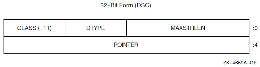
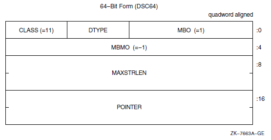
|
Symbol |
Description |
|---|---|
|
Maximum length of the BODY field of the varying string in bytes in the range 0 to 216 − 1. |
|
DSC64$W_MBO |
Must be 1. See Section 8.1, ''Descriptor Prototype''. |
|
A data type code that has the value 37, which specifies the varying character string data type (see Section 7.2, ''String Data Types'' and Section 7.5, ''Varying Character String Data Type (DSC$K_DTYPE_VT)''). The use of other data types is reserved. |
|
Defines the descriptor class code that must be equal to 11 for CLASS_VS. |
|
Address of the first field (CURLEN) of the varying string. |
|
DSC64$L_MBMO |
Must be -1. See Section 8.1, ''Descriptor Prototype''. |
The following figure illustrates the use of a 32-bit varying string descriptor to present a variable that is capable of holding a string value of up to five characters in length and that is currently holding the string value ABCD. As shown in the figure, MAXSTRLEN contains five, CURLEN contains four, string is currently ABCD, and the remaining byte is currently undefined.
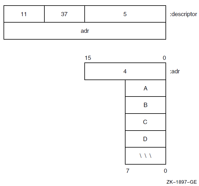
8.9. Varying String Array Descriptor (CLASS_VSA)
A variant of the noncontiguous array descriptor is used to specify an array of varying strings where each varying string has the same maximum length. Each array element is of the varying string data type (see Section 7.5, ''Varying Character String Data Type (DSC$K_DTYPE_VT)'').
When a called procedure modifies a varying string in an array of varying strings
passed to it by reference or by descriptor, it writes the new length,
n, into CURLEN and can modify all bytes of BODY. The
format of this descriptor is the same as the noncontiguous array descriptor
except for the first two longwords. Figure 8.10, ''Varying String Array Descriptor Format'' shows the format of a varying
string array descriptor. Table 8.11, ''Contents of the CLASS_VSA Descriptor'' describes the
fields of the descriptor.
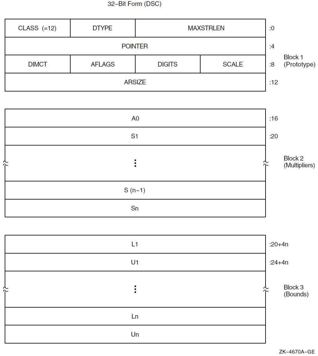
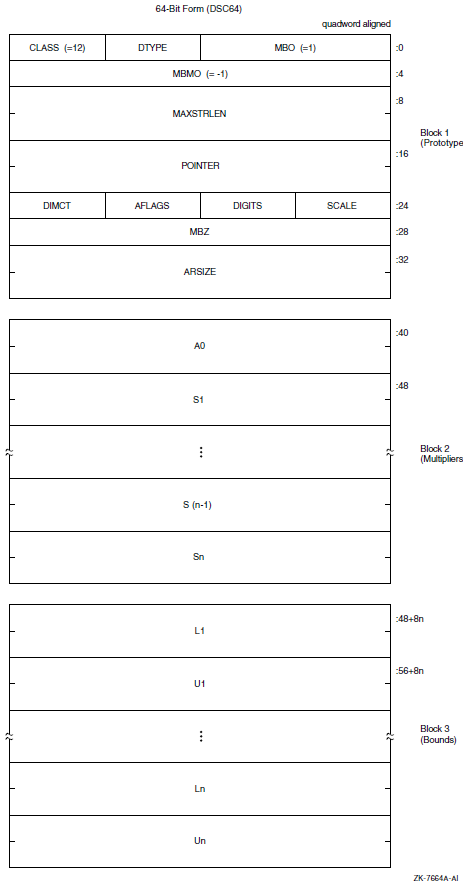
|
Symbol |
Description |
|---|---|
|
Maximum length of the BODY field of an array element in bytes in the range 0 to 216 − 1. |
|
DSC64$W_MBO |
Must be 1. See Section 8.1, ''Descriptor Prototype''. |
|
A data-type code that has the value 37, which specifies the varying character string data type (see Section 7.2, ''String Data Types'' and Section 7.5, ''Varying Character String Data Type (DSC$K_DTYPE_VT)''). The use of other data types is reserved. |
|
Defines the descriptor class code that must be equal to 12 for CLASS_VSA. |
|
Address of the first actual byte of data storage. |
|
DSC64$L_MBMO |
Must be -1. See Section 8.1, ''Descriptor Prototype''. |
The remaining fields in the descriptor are identical to those in the noncontiguous array descriptor (NCA). The effective address computation of an array element produces the address of CURLEN of the desired element.
8.10. Unaligned Bit String Descriptor (CLASS_UBS)
A descriptor is used to pass an unaligned bit string (DSC$K_DTYPE_VU) that starts and ends on an arbitrary bit boundary. The descriptor provides two components: a base address and a signed relative bit position. Figure 8.11, ''Unaligned Bit String Descriptor Format'' shows the format of an unaligned bit string descriptor. Table 8.12, ''Contents of the CLASS_UBS Descriptor'' describes the fields of the descriptor.
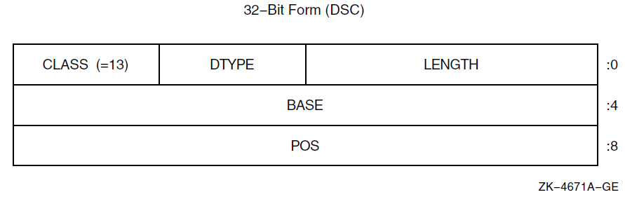
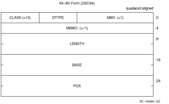
|
Symbol |
Description |
|---|---|
|
Length of data item in bits. |
|
DSC64$W_MBO |
Must be 1. See Section 8.1, ''Descriptor Prototype''. |
|
A data-type code that has the value 34, which specifies the unaligned bit string data type (see Section 7.1, ''Atomic Data Types'' and Section 7.2, ''String Data Types''). The use of other data types is reserved. |
|
Defines the descriptor class code that must be equal to 13 for CLASS_UBS. |
|
Base of the address relative to which the signed relative bit position, POS, is used to locate the bit string. The base address need not be the first actual byte of data storage. |
|
DSC64$L_MBMO |
Must be -1. See Section 8.1, ''Descriptor Prototype''. |
|
Relative bit position with respect to BASE of the first bit of unaligned bit string. |
8.11. Unaligned Bit Array Descriptor (CLASS_UBA)
A variant of the noncontiguous array descriptor is used to specify an array of unaligned bit strings. Each array element is an unaligned bit string data type (DSC$K_DTYPE_VU) that starts and ends on an arbitrary bit boundary. The length of each element is the same and is 0 to 216 − 1 bits. In the OpenVMS VAX environment, you can access elements of the array directly by using the VAX variable bit field instructions. Therefore, the descriptor provides two components: a byte address, BASE, and a means to compute the signed bit offset, EB, with respect to BASE of an array element.
The unaligned bit array descriptor consists of four contiguous blocks that are always present. The first block contains the descriptor prototype information. Figure 8.12, ''Unaligned Bit Array Descriptor Format'' shows the format of an unaligned bit array descriptor. Table 8.13, ''Contents of the CLASS_UBA Descriptor'' describes the fields of the descriptor.
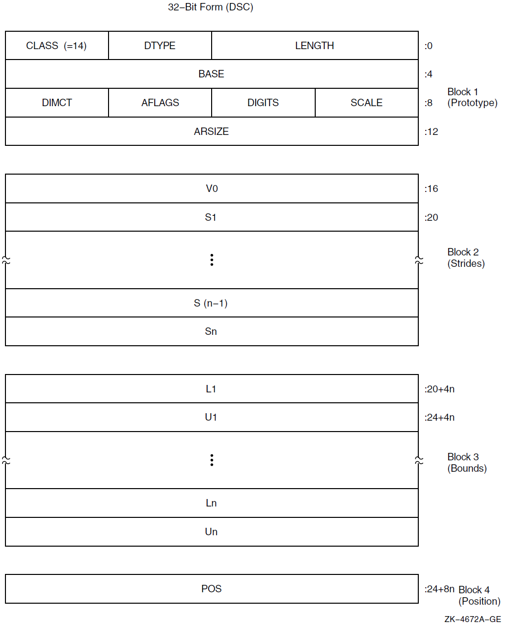
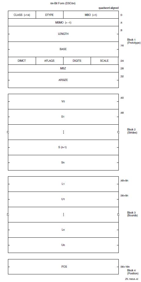
|
Symbol |
Description | |
|---|---|---|
|
Length of an array element in bits. | |
|
DSC64$W_MBO |
Must be 1. See Section 8.1, ''Descriptor Prototype''. | |
|
A data-type code that must have the value 34, which specifies the unaligned bit string data type (see Section 7.1, ''Atomic Data Types'' and Section 7.2, ''String Data Types''). The use of other data types is reserved. | |
|
Defines the descriptor class code that must be equal to 14 for CLASS_UBA. | |
|
Base address relative to the effective bit offset, EB, that is used to locate elements of the array. The base address need not be the first actual byte of data storage. | |
|
DSC64$L_MBMO |
Must be -1. See Section 8.1, ''Descriptor Prototype''. | |
|
Reserved and must be 0. | |
|
If nonzero, the unsigned number of decimal digits in the internal representation. If 0, the number of digits can be computed based on LENGTH. This field should be 0 unless the TYPE field specifies a string data type that could contain numeric values. | |
|
Array flag bits <23:16>: | |
|
Bits <18:16> |
Reserved and must be 0. | |
|
Must be 0. | |
|
Must be 0. | |
|
Bits <23:21> |
Reserved and must be 0. | |
|
Number of dimensions, n. | |
|
If the elements are contiguous, ARSIZE is the total size of the array in bits. If the elements are not allocated contiguously or if the program unit allocating the descriptor is uncertain whether the array is actually contiguous, the value placed in ARSIZE might be meaningless. | |
|
Signed bit offset of element A(0,…,0) with respect to BASE. V0 = POS − [S1*L1 + … + Sn*Ln]. | |
|
Stride of the ith dimension. The difference between the bit (not byte) addresses of successive elements of the ith dimension. | |
|
Lower bound (signed) of the ith dimension. | |
|
Upper bound (signed) of the ith dimension. | |
|
Relative bit position with respect to BASE of the first actual bit of the array, that is, element A(L1,…,Ln). | |
The following formulas specify the signed effective bit offset, EB, of an array element:
   EB = V0 + S1*I1
= POS + S1*[I1 - L1] EB = V0 + S1*I1 + S2*I2
= POS + S1*[I1 - L1] + S2*[I2 - L2]EB = V0 + S1*I1 + ... + Sn*In = POS + S1*[I1 - L1] + ... + Sn*[In - Ln]
Note that EB is computed ignoring integer overflow.
On VAX systems, EB is used as the position operand, and the content of BASE is used as the base address operand in the VAX variable-length bit field instructions. Therefore, BASE must specify a byte within 228 bytes of all bytes of storage in the bit array.
For example, consider a single-origin, one-dimensional, five-element array consisting of 3-bit elements allocated adjacently (therefore, S1 = 3). Assume BASE is byte 1000 and the first actual element, A(1), starts at bit <4> of byte 1001.
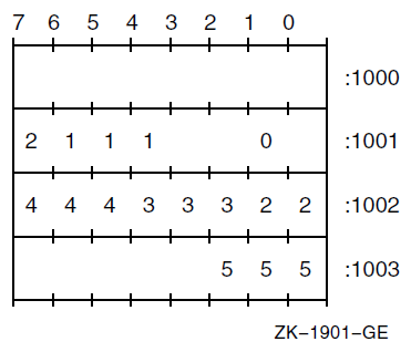
The following dependent field values occur in the descriptor:
   POS = 12
   V0  = 12 - 3*1 = 9
8.12. String with Bounds Descriptor (CLASS_SB)
A variant of the fixed-length string descriptor is used to specify strings where the string is viewed as a one-dimensional array with user-specified bounds. The following figure shows the format of a string with bounds descriptor. Table 8.14, ''Contents of the CLASS_SB Descriptor'' describes the fields of the descriptor.
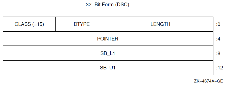
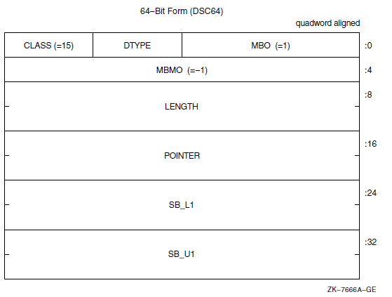
|
Symbol |
Description |
|---|---|
|
Length of the string in bytes. |
|
DSC64$W_MBO |
Must be 1. See Section 8.1, ''Descriptor Prototype''. |
|
A data-type code that must have the value 14, which specifies the character string data type (see Section 7.1, ''Atomic Data Types'' and Section 7.2, ''String Data Types''). The use of other data types is reserved. |
|
Defines the descriptor class code that must be equal to 15 for CLASS_SB. |
|
Address of the first byte of data storage. |
|
DSC64$L_MBMO |
Must be -1. See Section 8.1, ''Descriptor Prototype''. |
|
Lower bound (signed) of the first (and only) dimension. |
|
Upper bound (signed) of the first (and only) dimension. |
E = POINTER + [I - SB_L1]
If the string must be extended in a string comparison or assignment, the space character (hexadecimal 20 if ASCII) is used as the fill character.
8.13. Unaligned Bit String with Bounds Descriptor (CLASS_UBSB)
A variant of the unaligned bit string descriptor is used to specify bit strings where the string is viewed as a one-dimensional bit array with user-specified bounds. Figure 8.14, ''Unaligned Bit String with Bounds Descriptor Format'' shows the format of an unaligned bit string with bounds descriptor. Table 8.15, ''Contents of the CLASS_UBSB Descriptor'' describes the fields of the descriptor.
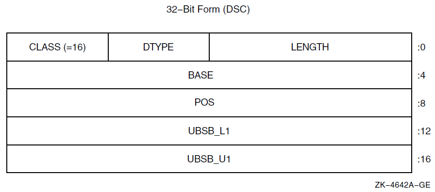
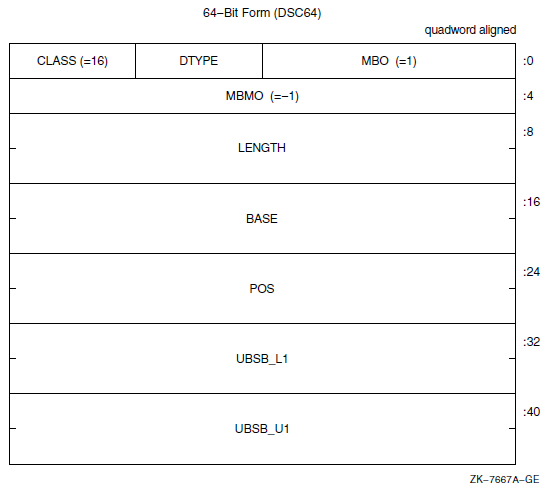
|
Symbol |
Description |
|---|---|
|
Length of the data item in bits. |
|
DSC64$W_MBO |
Must be 1. See Section 8.1, ''Descriptor Prototype''. |
|
A data-type code that must have the value 34, which specifies the unaligned bit string data type (see Section 7.1, ''Atomic Data Types'' and Section 7.2, ''String Data Types''). The use of other data types is reserved. |
|
Defines the descriptor class code that must be equal to 16 for CLASS_UBSB. |
|
Base address relative to the signed relative bit position, POS, used to locate the bit string. The base address need not be the first actual byte of data storage. |
|
DSC64$L_MBMO |
Must be -1. See Section 8.1, ''Descriptor Prototype''. |
|
Signed longword that defines the relative bit position of the first bit of the unaligned bit string to the BASE address. |
|
Lower bound (signed) of the first (and only) dimension. |
|
Upper bound (signed) of the first (and only) dimension. |
EB = POS + [I - UBSB_L1]
8.14. Reserved Descriptor Class Codes
All descriptor class codes from 0 through 191 not otherwise defined in this standard are reserved to OpenVMS. Classes 192 through 255 are reserved for OpenVMS custom systems and for customers for their own use.
|
Descriptor |
Code |
Class |
|---|---|---|
|
DSC$K_CLASS_V |
3 |
Obsolete (variable buffer) |
|
DSC$K_CLASS_PI |
6 |
Obsolete (procedure incarnation) |
|
DSC$K_CLASS_J |
7 |
Reserved to DEBUG (label) |
|
DSC$K_CLASS_JI |
8 |
Obsolete (label incarnation) |
|
DSC$K_CLASS_CT |
17 |
Reserved to ACMS (compressed text) |
|
DSC$K_CLASS_BFA |
191 |
Reserved to BASIC (file array) |
8.14.1. Facility-Specific Descriptor Class Codes
Descriptor class codes 160 through 191 are reserved for facility-specific purposes. These codes must not be passed between facilities, because different facilities might use the same code for different purposes. These codes can be used by compiler-generated code to pass parameters to the language-specific, run-time support procedures associated with that language or to the OpenVMS Debugger.
Chapter 9. OpenVMS Conditions
An OpenVMS condition is a hardware-generated synchronous exception or a software event that is to be processed in a manner similar to a hardware exception.
Floating-point overflow exception, memory access violation exception, and reserved operation exception are examples of hardware-generated conditions. An output conversion error, an end of file, and the filling of an output buffer are examples of software events that might be treated as conditions.
Ignore the condition.
For example, if an underflow occurs in a floating-point operation, continuing from the point of the exception with a zero result might be sufficient.
Take some special action and continue from the point at which the condition occurred.
For example, if the end of a buffer is reached while a series of data items are being written, the special action is to start a new buffer.
End the operation and branch from the sequential flow of control.
For example, if the end of an input file is reached, the branch exits from a loop that is processing the input data.
Treat the condition as an unrecoverable error.
For example, when the floating divide-by-zero exception condition occurs, the program exits after writing (optionally) an appropriate error message.
When an unusual event or error occurs in a called procedure, the procedure can return a condition value to the caller indicating what has happened (see Section 9.1, ''Condition Values''). The caller tests the condition value and takes the appropriate action.
When an exception is generated by the hardware, a branch out of the program's flow of control occurs automatically. In this case, and for certain software-generated events, it is more convenient to handle the condition as soon as it is detected rather than to program explicit tests.
9.1. Condition Values
Indicate the success or failure of a called procedure as a function value.
Describe an exception condition when an exception is signaled.
Identify system messages.
Report program success or failure to the command language level.
A condition value is a longword that includes fields to describe the software component that generates the value, the reason the value was generated, and severity status of the condition value. Figure 9.1, ''Format of a Condition Value'' shows the format of a condition value. Table 9.1, ''Contents of the Condition Value'' describes the fields of a condition value.
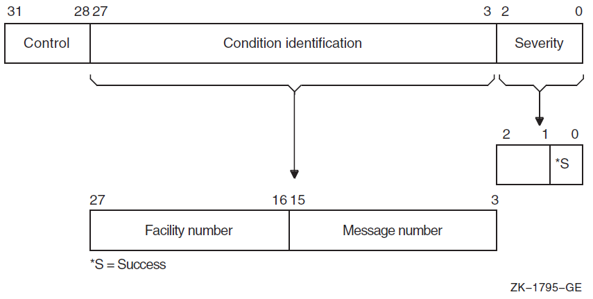
| Symbol | Description | ||
|---|---|---|---|
|
Severity |
Indicates success or failure. The severity code bit <0> is set for success (logical true) and is clear for failure (logical false); bits <1> and <2> distinguish degrees of success or failure. Bits <2:0>, when taken as an unsigned integer, are interpreted as shown in the following table: | ||
|
Symbol | Value |
Description | |
|
STS$K_WARNING | 0 |
Warning | |
|
STS$K_SUCCESS | 1 |
Success | |
|
STS$K_ERROR | 2 |
Error | |
|
STS$K_INFO | 3 |
Information | |
|
STS$K_SEVERE | 4 |
Severe error | |
| 5 |
Reserved to OpenVMS | ||
| 6 |
Reserved to OpenVMS | ||
| 7 |
Reserved to OpenVMS | ||
|
Section 9.1.1, ''Interpretation of Severity Codes'' more fully describes severity codes. | |||
|
Condition identification |
Identifies the condition uniquely on a systemwide basis. | ||
|
Message number |
Describes the status, which can be a hardware exception that occurred or a software-defined value. Message numbers with bit <15> set are specific to a single facility. Message numbers with bit <15> clear are systemwide status codes. | ||
|
Facility number |
Identifies the software component generating the condition value. Bit <27> is set for customer facilities and is clear for OpenVMS facilities. | ||
|
Control |
Controls the printing of the message associated with the condition value. Bit <28> inhibits the message associated with the condition value from being printed by the SYS$EXIT system service. This bit is set by the system default handler after it has output an error message using the SYS$PUTMSG system service. It should also be set in the condition value returned by a procedure as a function value, if the procedure has also signaled the condition (so the condition has been printed or suppressed). Bits <31:29> must be 0; they are reserved for future use. | ||
Table 9.2, ''Value Symbols for the Condition Value Longword'' lists the possible software symbols that are defined for the various fields of the condition-value longword.
|
Symbol |
Value |
Meaning |
Field |
|---|---|---|---|
|
STS$V_COND_ID |
3 |
Position of <27:3> |
Condition identification |
|
STS$S_COND_ID |
25 |
Size of <27:3> |
Condition identification |
|
STS$M_COND_ID |
Mask |
Mask for <27:3> |
Condition identification |
|
STS$V_INHIB_MSG |
1@28 |
Position for <28> |
Inhibit message on image exit |
|
STS$S_INHIB_MSG |
1 |
Size for <28> |
Inhibit message on image exit |
|
STS$M_INHIB_MSG |
Mask |
Mask for <28> |
Inhibit message on image exit |
|
STS$V_FAC_NO |
16 |
Position of <27:16> |
Facility number |
|
STS$S_FAC_NO |
12 |
Size of <27:16> |
Facility number |
|
STS$M_FAC_NO |
Mask |
Mask for <27:16> |
Facility number |
|
STS$V_CUST_DEF |
27 |
Position for <27> |
Customer facility |
|
STS$S_CUST_DEF |
1 |
Size for <27> |
Customer facility |
|
STS$M_CUST_DEF |
1@27 |
Mask for <27> |
Customer facility |
|
STS$V_MSG_NO |
3 |
Position of <15:3> |
Message number |
|
STS$S_MSG_NO |
13 |
Size of <15:3> |
Message number |
|
STS$M_MSG_NO |
Mask |
Mask for <15:3> |
Message number |
|
STS$V_FAC_SP |
15 |
Position of <15> |
Facility-specific |
|
STS$S_FAC_SP |
1 |
Size for <15> |
Facility-specific |
|
STS$M_FAC_SP |
1@15 |
Mask for <15> |
Facility-specific |
|
STS$V_CODE |
3 |
Position of <14:3> |
Message code |
|
STS$S_CODE |
12 |
Size of <14:3> |
Message code |
|
STS$M_CODE |
Mask |
Mask for <14:3> |
Message code |
|
STS$V_SEVERITY |
0 |
Position of <2:0> |
Severity |
|
STS$S_SEVERITY |
3 |
Size of <2:0> |
Severity |
|
STS$M_SEVERITY |
7 |
Mask for <2:0> |
Severity |
|
STS$V_SUCCESS |
0 |
Position of <0> |
Success |
|
STS$S_SUCCESS |
1 |
Size of <0> |
Success |
|
STS$M_SUCCESS |
1 |
Mask for <0> |
Success |
9.1.1. Interpretation of Severity Codes
|
Severity Code |
Meaning |
|---|---|
|
0 |
Indicates a warning. This code is used whenever a procedure produces output, but the output produced might not be what the user expected (for example, a compiler modification of a source program). |
|
1 |
Indicates that the procedure generating the condition value completed successfully, as expected. |
|
2 |
Indicates that an error has occurred but the procedure did produce output. Execution can continue, but the results produced by the component generating the condition value are not all correct. |
|
3 |
Indicates that the procedure generating the condition value completed successfully but has some parenthetical information to be included in a message if the condition is signaled. |
|
4 |
Indicates that a severe error occurred and the component generating the condition value was unable to produce output. |
The calling program typically performs a low-bit test, so it treats warnings, errors, and severe errors as failures, and treats success and information as successes.
If the condition value is signaled (see Section 9.4.3, ''Signaling a Condition''), the default handler treats severe errors as reason to terminate and treats all the others as the basis for continuation.
When the program image exits, the command interpreter by default treats errors and severe errors as the basis for stopping the job, and treats warnings, information, and successes as the basis for continuation.
|
Severity |
Routine |
Signal |
Default at Program Exit |
|---|---|---|---|
|
Success |
Normal |
Continue |
Continue |
|
Information |
Normal |
Continue |
Continue |
|
Warning |
Failure |
Continue |
Continue |
|
Error |
Failure |
Continue |
Stop job |
|
Severe error |
Failure |
Exit |
Stop job |
The default for signaled messages is to output a message on SYS$OUTPUT. In addition, for severities other than success (STS$K_SUCCESS), a copy of the message is made on SYS$ERROR. At program exit, success and information completion values do not generate messages; however, warning, error, and severe error condition values do generate messages to SYS$OUTPUT and SYS$ERROR unless bit <28> (STS$V_INHIB_MSG) is set.
Unless there is a good basis for another choice, a procedure should use success or severe error as its severity code for each condition value.
9.1.2. Use of Condition Values
OpenVMS software components return condition values when they complete execution. When a severity code in the range of 0 through 4 is generated, the status code describes the nature of the problem. This value can be tested to change the flow of control of a procedure, can be used to generate a message, or both.
User procedures can also generate condition values to be examined by other procedures and by the command interpreter. User-generated condition values should have bits <27> and <15> set so they do not conflict with values generated by OpenVMS.
9.2. Condition Handlers
To handle hardware- or software-detected exceptions, the OpenVMS Condition Handling Facility (CHF) allows you to specify a condition handler procedure to be called when an exception condition occurs.
An active procedure can establish a condition handler to be associated with it. When an event occurs that is to be treated using the Condition Handling Facility, the procedure detecting the event signals the event by calling the facility and passing a condition value that describes the condition. This condition value has the format and interpretation described in Section 9.1, ''Condition Values''. All hardware exceptions are signaled.
When a condition is signaled, the Condition Handling Facility looks for a condition handler associated with the current procedure's stack frame. If a handler is found, it is entered. If a handler is not associated with the current procedure, the immediately preceding stack frame is examined. Again, if a handler is found, it is entered. If a handler is not found, the search of previous stack frames continues until the default condition handler established by the system is reached or until the stack runs out.
The default condition handler prints messages, indicated by the signal argument list, by calling the put message (SYS$PUTMSG) system service, followed by an optional symbolic stack traceback. Success conditions with STS$K_SUCCESS result in messages to SYS$OUTPUT only. All other conditions, including informational messages (STS$K_INFO), produce messages on SYS$OUTPUT and SYS$ERROR.
For example, if a procedure needs to keep track of the occurrence of the floating-point underflow exception, it can establish a condition handler to examine the condition value passed when the handler is invoked. Then, when the floating-point underflow exception occurs, the condition handler is entered and logs the condition. The handler returns to the instruction immediately following the instruction that was executing when the condition was reported by the hardware. On a VAX or I64 processor, or on an x86-64 processor when the underflow was caused by an SSE instruction, this instruction is the one immediately following the instruction that caused the underflow; on an Alpha processor, or on an x86-64 processor when the underflow was caused by an x87 instruction, this instruction might occur later.
If floating-point operations occur in many procedures of a program, the condition handler can be associated with the program's main procedure. When the condition is signaled, successive stack frames are searched until the stack frame for the main procedure is found, at which time the handler is entered. If a user program has not associated a condition handler with any of the procedures that are active at the time of the signal, successive stack frames are searched until the frame for the system program invoking the user program is reached. A default condition handler that prints an error message is then entered.
9.3. Condition Handler Options
Return to the instruction immediately following the signal. Note that such a return is not always possible.
Resignal the same or a modified condition value. A new search for a condition handler begins with the immediately preceding stack frame.
Signal a different condition.
Unwind the stack.
OpenVMS Alpha, I64, or x86-64 systems, perform a nonlocal GOTO operation (see Section 9.4, ''Operations Involving Condition Handlers'') that transfers control from one procedure invocation and continues execution in a prior one.
9.4. Operations Involving Condition Handlers
Establish a condition handler.
A condition handler is associated with a procedure in various ways, depending on the language in which the procedure is written. Some languages provide specific syntax for defining a handler and its possible actions; others allow dynamic specification of a routine to act as a handler.
On VAX systems, revert to the caller's handling.
If a condition handler has been established on a VAX system, you can remove it.
Enable or disable certain arithmetic exceptions.
The software can enable or disable the following hardware exceptions: floating-point underflow, integer overflow, and decimal overflow. No signal occurs when the exception is disabled.
On VAX systems, exceptions are enabled or disabled dynamically at every procedure entry or by directly manipulating the processor status longword.
On Alpha systems, exceptions are enabled or disabled statically during compilation; this is reflected in the code that is compiled.
On I64 and x86-64 systems, exceptions are enabled or disabled dynamically by directly manipulating the appropriate status register or by calling a system service (the latter is preferred on IA-64).
Signal a condition.
Signaling a condition initiates the search for an established condition handler.
Unwind the stack.
Upon exiting from a condition handler, it is possible to remove one or more frames that occur before the signal from the stack. During the unwinding operation, the stack is scanned; if a condition handler is associated with a frame, the handler is entered before the frame is removed. Unwinding the stack allows a procedure to perform application-specific cleanup operations before exiting.
On 64-bit systems, perform a nonlocal GOTO unwind.
A GOTO unwind operation is a transfer of control that leaves one procedure invocation and continues execution in a prior (currently active) procedure. This unified GOTO operation gives unterminated procedure invocations the opportunity to clean up in an orderly way.
9.4.1. Establishing a Condition Handler
On VAX systems, the association of a handler with a procedure invocation is dynamic and can be changed or reverted to the caller's handler during execution, but this is not supported for languages that implicitly provide their own handlers.
Each procedure activation can have an associated condition handler, using the first longword in its stack frame. Initially, the first longword (longword 0) contains the value 0, indicating no handler. You establish a handler by moving the address of the handler's procedure entry point mask to the establisher's stack frame.
MOVAB handler_entry_point,0(FP)
On 64-bit systems, the association of a handler with a procedure is static and must be specified at the time a procedure is compiled (or assembled). However, some languages that lack their own exception handling syntax can support emulation of dynamically specified handlers by means of built-in routines.
Each procedure, other than an Alpha or I64 null frame procedure, can have a condition handler potentially associated with it, which is identified by the presence of the procedure value of the handler in a field of the associated procedure descriptor on Alpha (see Section 3.4, ''Procedure Types'') or unwind information on I64 (see Section A.4.1, ''Unwind Table and Unwind Information Block'') and x86-64 (see Section B.3.2.2, ''Common Information Entry'' and Section B.3.4, ''Compact Unwind Descriptor Structure'').
In addition, the OpenVMS operating system on all processors provides three statically allocated exception vectors for each access mode of a process. Two of them can be used to establish handlers that are considered before any frame-based handlers, and the third can be used to establish a handler that is considered after all frame-based handlers (see Section 9.4.6, ''Condition Handler Search'' for further details). For example, the vectors are used to allow a debugger to monitor all exceptions and for the system to establish a last-chance handler. Because these handlers do not obey the procedure nesting rules, do not use them with modular code. Instead, use frame-based handlers.
9.4.2. Reverting to the Caller's Handling
On VAX systems, reverting to the caller's handling deletes the condition handler associated with the current procedure activation. You do this by clearing the handler address in the stack frame.
CLRL 0(FP)
On 64-bit systems, there is no means to revert to a caller's handler (unless a language provides emulation of dynamically specified handlers).
9.4.3. Signaling a Condition
LIB$SIGNAL(condition-value, argn...)LIB$STOP(condition-value, argn...)|
Argument |
OpenVMS Usage |
Type |
Access |
Mechanism |
|---|---|---|---|---|
|
condition-value |
condition |
longword |
read |
by value |
|
argn |
integer |
quadword |
read |
by value |
|
|
An OpenVMS condition value. |
|
|
Zero or more integer arguments that become the additional arguments of a signal argument vector (see Section 9.5.1.1, ''Signal Argument Vector'') |
|
None. |
In both cases, the condition-value argument indicates the condition
that is signaled. However, LIB$STOP sets the severity of the
condition-value argument to be a severe error. The remaining arguments
describe the details of the exception. These are the same arguments used to issue a system
message.
9.4.4. Signaling a Condition Using GENTRAP (64-Bit Systems)
Alpha, I64, and x86-64 systems each have a special instruction that provides an efficient means to raise a hardware-like exception. These are intended for use especially in low levels of the operating system or in the bootpath sequence when only a limited execution environment is available. Compiled code can also use these instructions to raise common generic exceptions more simply and compactly than by executing a complete LIB$SIGNAL procedure call.
In each case, the special instruction takes an exception code
(excp_code) parameter that is passed in a general register; that
parameter specifies the particular exception to be raised.
On Alpha systems, the GENTRAP PALcall instruction is used. The
excp_code parameter is passed in R16. Interpretation of that parameter
is described below.
On I64 systems, the BREAK instruction with an immediate operand of 100001 (hex) is
used to implement a GENTRAP operation. The excp_code parameter is passed
in R17. Interpretation of that parameter is described below.
On x86-64 systems, the INT 32
instruction together with BREAK$C_SYS_GENTRAP (100001 (hex) or 1048577
(decimal)) in %rdi is used to implement a GENTRAP operation. The exception
code parameter is passed in %rsi. This parameter is described below.
If the excp_code value is one of the small integers shown in the
first column of Table 9.4, ''Exception Codes and Symbols for the GENTRAP Parameter'', then that value is mapped to a
corresponding OpenVMS condition code as shown in the third (Symbol) column of the Table. If the
value is negative but not one of the values shown in Table 9.4, ''Exception Codes and Symbols for the GENTRAP Parameter'',
then SS$_GENTRAP is raised with the unmapped value included in the
signal vector as the first and only qualifier value. Otherwise, a positive value is used
directly to raise an exception using that value as the condition value. Note that there is no
means to associate any parameters with an exception raised by GENTRAP.
the Alpha GENTRAP PALcall, see the Alpha Architecture Reference Manual
the BREAK instruction on the Intel Itanium processors, see the Intel IA-64 Architecture Software Developer's Manual
Itanium Conventions Defined Codes, see Section 9.4.5, ''Signaling a Condition Using BREAK (I64 Only)''
the x86-64 INT instruction, see the Intel 64 and IA-32 Architectures Software Developer Manuals
|
OpenVMS GENTRAP |
Corresponding Intel Itanium Conventions Defined Codes (High Bits 000), not used in calls to GENTRAP |
Symbol |
Meaning |
|---|---|---|---|
|
64‑bit Systems | |||
|
–1 |
2 |
SS$_INTOVF |
Integer overflow |
|
–2 |
1 |
SS$_INTDIV |
Integer divide by zero |
|
–3 |
|
SS$_FLTOVF |
Floating overflow |
|
–4 |
|
SS$_FLTDIV |
Floating divide by zero |
|
–5 |
|
SS$_FLTUND |
Floating underflow |
|
–6 |
|
SS$_FLTINV |
Floating invalid operand |
|
–7 |
|
SS$_FLTINE |
Floating inexact result |
|
–8 |
6 |
SS$_DECOVF |
Decimal overflow |
|
–9 |
7 |
SS$_DECDIV |
Decimal divide by zero |
|
–10 |
8, 9, 10 |
SS$_DECINV |
Decimal invalid operand |
|
–11 |
0 |
SS$_ROPRAND |
Reserved operand |
|
–12 |
|
SS$_ASSERTERR |
Assertion error |
|
–13 |
4 |
SS$_NULPTRERR |
Null pointer error |
|
–14 |
11 |
SS$_STKOVF |
Stack overflow |
|
–15 |
|
SS$_STRLENERR |
String length error |
|
–16 |
|
SS$_SUBSTRERR |
Substring error |
|
–17 |
|
SS$_RANGEERR |
Range error |
|
–18 |
3 |
SS$_SUBRNG |
Subscript range error |
|
–19 |
|
SS$_SUBRNG1 |
Subscript 1 range error |
|
–20 |
|
SS$_SUBRNG2 |
Subscript 2 range error |
|
–21 |
|
SS$_SUBRNG3 |
Subscript 3 range error |
|
–22 |
|
SS$_SUBRNG4 |
Subscript 4 range error |
|
–23 |
|
SS$_SUBRNG5 |
Subscript 5 range error |
|
–24 |
|
SS$_SUBRNG6 |
Subscript 6 range error |
|
–25 |
|
SS$_SUBRNG7 |
Subscript 7 range error |
|
IA-64 systems Only | |||
|
–26 |
|
SS$_CALLUNDEFSYM |
Call using undefined function symbol |
|
–27 |
|
SS$_ARGTYP1 |
Argument 1 type error |
|
–28 |
|
SS$_ARGTYP2 |
Argument 2 type error |
|
–29 |
|
SS$_ARGTYP3 |
Argument 3 type error |
|
–30 |
|
SS$_ARGTYP4 |
Argument 4 type error |
|
–31 |
|
SS$_ARGTYP5 |
Argument 5 type error |
|
–32 |
|
SS$_ARGTYP6 |
Argument 6 type error |
|
–33 |
|
SS$_ARGTYP7 |
Argument 7 type error |
|
–34 |
|
SS$_ARGTYP8 |
Argument 8 type error |
|
|
5 |
SS$_UNALIGNED |
Unaligned parameter |
9.4.5. Signaling a Condition Using BREAK (I64 Only)
Immediate operands whose three highest-order bits are 000, which is the range 000000 through 03FFFF (hex). These values are reserved for architected software interrupt codes. The defined software interrupt codes are listed in the second column of Table 9.4, ''Exception Codes and Symbols for the GENTRAP Parameter''. Immediate operands in this range, but not listed in the table, are reserved for future use.
A code shown in the second column of Table 9.4, ''Exception Codes and Symbols for the GENTRAP Parameter'' is mapped to a corresponding OpenVMS condition code as shown in the third (Symbol) column, which is then raised. (This handling is similar to the handling of a negative
excp_codeparameter for GENTRAP as described in Section 9.4.4, ''Signaling a Condition Using GENTRAP (64-Bit Systems)'').Immediate operands whose three highest-order bits are 001, which is the range 040000 (hex) through 07FFFF (hex).
Operands in this range are reserved for use by applications. If one of these occurs, then SS$_BREAK_APPL is raised with the operand value included as the first (and only) additional argument in the signal argument vector (see Section 9.5.1.1, ''Signal Argument Vector'').
Immediate operands whose two highest-order bits are 01, which is the range 080000 (hex) through 0FFFFF (hex).
Operands in this range are reserved for use by debuggers. OpenVMS debugger software uses only immediate operands in the range 080000 (hex) through 0BFFFF (hex). Other debugger software is encouraged, but not required, to use immediate operands in the range 0C0000 (hex) through 0FFFFF (hex).
Immediate operands whose highest-order bit is 1, which is the range 100000 (hex) through 1FFFFF (hex).
Operands in this range are reserved for use within OpenVMS. The value 100001, however, is used to implement an Alpha-compatible GENTRAP operation as described in Section 9.4.4, ''Signaling a Condition Using GENTRAP (64-Bit Systems)''.
For more information on the Itanium software conventions, see the Itanium® Software Conventions and Runtime Architecture Guide.
9.4.6. Condition Handler Search
The signal procedure examines the two exception vectors first, then examines a system-defined maximum number of previous stack frames, and, if necessary, examines the last-chance exception vector. The exception vectors have three procedure value locations per access mode.
As part of image startup, the system declares a default last-chance handler. This handler is used as a last resort when the normal handlers are not performing correctly. The debugger can replace the default system last-chance handler with its own.
On 64-bit systems, note that the default catchall handler in user mode can be a list of handlers and is not in conflict with this standard.
On OpenVMS systems, in some frame before the call to the main program, the system
establishes a default catchall condition handler that issues system messages. In a subsequent
frame before the call to the main program, the system usually establishes a traceback handler.
These system-supplied condition handlers use the condition-value argument
to get the message and then use the remainder of the argument list to format and output the
message through the SYS$PUTMSG system service.
If the severity field of the condition-value argument (bits
<2:0>) does not indicate a severe error (that is, a value of 4), these default condition
handlers return with SS$_CONTINUE. If the severity is a severe error,
these default handlers exit the program image with the condition value as the final image
status.
The stack search ends when the old frame address is 0 or is not accessible, or when a system-defined maximum number of frames have been examined. If a condition handler is not found, or if all handlers return with a SS$_RESIGNAL or SS$_RESIGNAL64, then the vectored last-chance handler is called.
If a handler returns SS$_CONTINUE or SS$_CONTINUE64, and LIB$STOP was not called, control returns to the signaler. Otherwise, LIB$STOP issues a message indicating that an attempt was made to continue from a noncontinuable exception and exits with the condition value as the final image status.
IMPROPERLY HANDLED CONDITION, ATTEMPT TO CONTINUE FROM STOP.
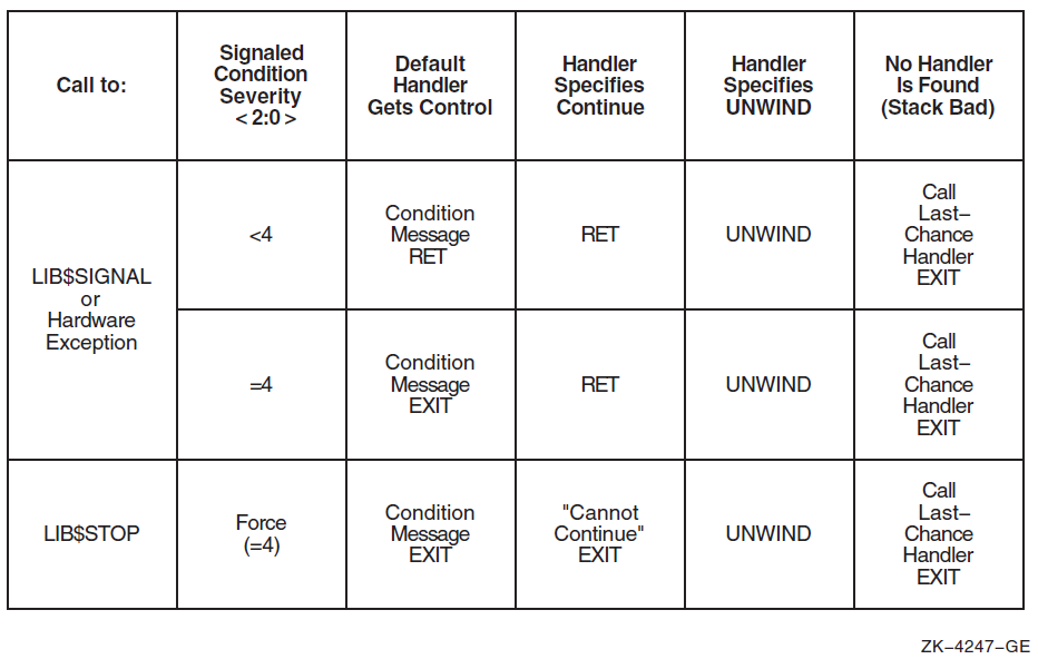
9.5. Properties of Condition Handlers
This section describes the properties of condition handlers for all OpenVMS environments.
9.5.1. Condition Handler Parameters and Invocation
(*handler)(signal_args, mechanism_args)
|
Argument |
OpenVMS Usage |
Type |
Access |
Mechanism |
|---|---|---|---|---|
|
signal_args |
signal vector |
structure |
modify |
by reference |
|
mechanism_args |
mechanism |
structure |
modify |
by reference |
|
|
A 32-bit signal argument vector (see Section 9.5.1.1, ''Signal Argument Vector'') |
|
|
A mechanism argument vector (see Section 9.5.1.2, ''Mechanism Argument Vector'') |
|
One of the following status codes: SS$_CONTINUE, SS$_RESIGNAL, SS$_CONTINUE64, SS$_RESIGNAL64. This value is used by the Condition Handling Facility to determine how to proceed next in processing the condition. (See Section 9.6, ''Returning from a Condition Handler''). |
9.5.1.1. Signal Argument Vector
There are two forms of signal argument vector (or signal vector for short): one for use with 32-bit addresses and one for use with 64-bit addresses. The two forms are compatible in that the forms can be distinguished dynamically at run-time and, except for the size and offset of fields, are identical in content and interpretation.
The 32-bit signal argument vectors are used on all OpenVMS systems. When used on 64-bit systems, 32-bit signal argument vectors provide full compatibility with their use on VAX systems. The 64-bit signal argument vectors are used only on 64-bit systems—they have no counterpart and are not recognized on VAX systems.
When a condition handler is called by the Condition Handling Facility (CHF) on 64-bit systems, both forms of signal argument vector are available. The first argument is always a reference to a 32-bit form of signal argument vector. A handler that chooses to operate using the 64-bit form must obtain the address of the corresponding 64-bit signal argument vector from the CHF$PH_MCH_SIG64_ADDR field of the mechanism argument vector (see Section 9.5.1.2, ''Mechanism Argument Vector'').
Both forms of signal vector include a length field, a condition value, zero or more parameters that further qualify the condition value, and finally a processor program counter (PC) and program status (PS). For hardware-detected exceptions, the condition value indicates which exception was taken. The PC value gives the address of the instruction that caused the exception or the address of the next instruction, depending on whether the exception was a fault or a trap. For software-detected conditions, the condition value and any associated parameters are copies of the parameters to the call of LIB$SIGNAL or LIB$STOP that initiated exception handling, while the PC is the return address to the caller of that routine.
Note that bits <2:0> of a condition value indicate severity and not what condition is being signaled. Therefore, a handler should examine only the condition identification, that is, condition value bits <27:3>, to determine the cause of the exception. The setting of severity bits <2:0> may vary from time to time even for the same condition. In fact, some handlers might only change the severity of a condition in the signal vector and resignal.
Generally, a handler may validly modify any field of a signal argument vector except for the CHF$L_SIG_ARGS length field or, in the case of a 64-bit signal vector, the CHF64$L_SIGNAL64 field. In particular, a modified signal vector is passed to a subsequent handler if the current handler completes by resignaling. (If the length is modified, the modification is ignored; CHF restores the original length). It is invalid for a handler to modify both forms of signal argument vector—the effect of doing so is undefined.
The remainder of this section is organized as follows. First, the 32-bit form of signal argument vector is described. Second, the 64-bit form of signal argument is described. Finally, the relationship between the two forms is discussed.
The following figure shows the format of the 32-bit form of signal argument vector. The CHF$L_SIG_ARGS longword contains the argument vector count, which is the number of remaining longwords in the vector. The CHF$L_SIG_NAME longword contains the condition value. Next are 0 or more longwords that contain additional parameters appropriate to the condition. The remaining two longwords contain the PC and PS values.
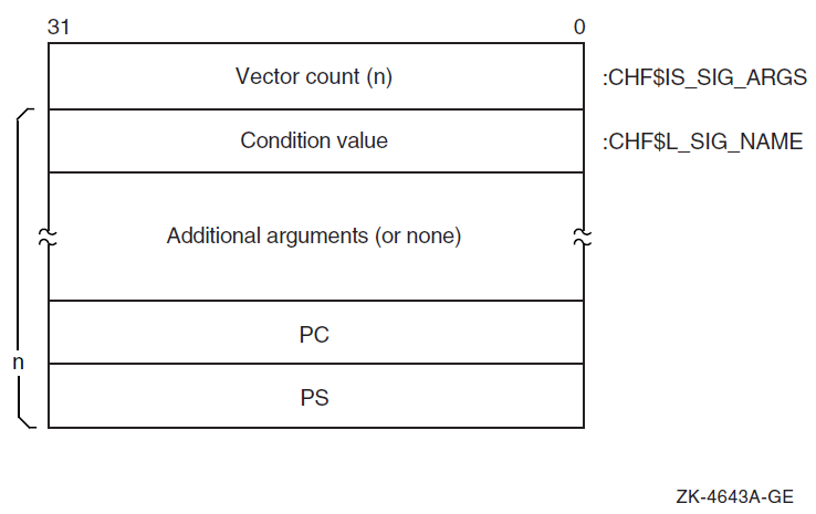
On VAX systems, the value used for the PS is the contents of the VAX processor status longword (PSL).
On Alpha systems, the value used for the PS is the low half of the Alpha processor status register. Furthermore, CHF$IS_SIG_ARGS and CHF$IS_SIG_NAME are aliases for CHF$L_SIG_ARGS and CHF$L_SIG_NAME, respectively.
on IA-64 and x86-64 systems, the value used for the PS is the low half of a fabricated Alpha-like processor status register that contains IPL, CM, CSW, and IP fields.
on IA-64 systems, code may be loaded into 64-bit address space by using a LINK qualifier. On x86-64 systems, code is loaded into 64-bit address space by default unless overridden with a LINK qualifier. In these cases, the value used for the PC is the bottom 32-bits of the actual IP value. In order to access the full IP value, it is necessary to examine the 64-bit format signal vector using the CHF$PH_MCH_SIG64_ADDR field in the mechanism argument vector.
Figure 9.4, ''Signal Argument Vector — 64-Bit Format'' shows the format of the 64-bit form of signal argument vector. The address of this form of signal argument is available only from the CHF$PH_MCH_SIG64_ADDR field of the mechanism argument vector (see Section 9.5.1.2, ''Mechanism Argument Vector''). The CHF64$L_SIG_ARGS field is a longword that contains the number of remaining quadwords in the vector (following the CHF64$L_SIGNAL64 field). The CHF64$L_SIGNAL64 longword contains a special code named SS$_SIGNAL64 whose value is key to distinguishing between a 32-bit and 64-bit form of signal argument vector. The CHF64$Q_SIG_NAME quadword contains a sign-extended condition value. Next are zero or more quadwords that contain additional parameters appropriate to the condition. The remaining two quadwords contain the PC and PS values.
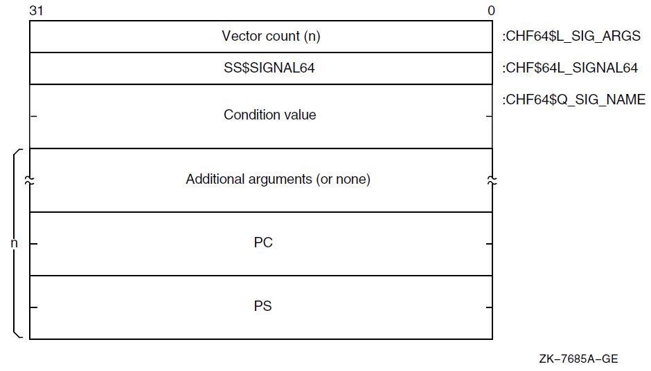
The value of the length field in the 64-bit form (the number of quadwords following the CHF64$L_SIGNAL64 field) is equal to the value of the length field in the 32-bit form (the number of longwords following the CHF$L_SIG_ARGS field).
The condition value, any related arguments, and the PC and PS values in the 32-bit form are the same as the values in the 64-bit form truncated to 32 bits.
Note that given a 64-bit signal vector, it is possible to create the corresponding 32-bit signal vector by fetching the low-order longword of each quadword of the 64-bit vector and packing the results together contiguously into a 32-bit vector; other than using the length, no interpretation of the contents is required.
Assuming a 32-bit form, compare the contents of the CHF$L_SIG_NAME field (equivalently CHF64$L_SIGNAL64) with the value SS$_SIGNAL64. If equal, then the 64-bit form is present; otherwise, the 32-bit form is present.
Assuming a 64-bit form, compare the contents of the CHF64$L_SIGNAL64 field with the value SS$_SIGNAL64. If equal, then the 64-bit form is present; otherwise, the 32-bit form is present.
9.5.1.2. Mechanism Argument Vector
The mechanism argument vector for the argument mechanism_args
contains information about the machine state when an exception occurs or when a condition is
signaled. Therefore, the mechanism argument vector is highly specific to the underlying machine
architecture.
9.5.1.2.1. VAX Mechanism Vector Format
On VAX systems, the mechanism format for the argument vectors is shown in Figure 9.5, ''VAX Mechanism Vector Format''. The first longword contains the argument vector count, which is the number of remaining longwords in the vector. The frame longword contains the contents of the FP in the establisher's context. If the restrictions described in Section 9.5.3.1, ''Use of Memory'' are met, the frame can be used as a base from which to access the local storage of the establisher.
The depth longword is a positive count of the number of procedure-activation stack frames between the frame in which the exception occurred and the frame depth that established the handler being called. (For more information about depth, see Section 9.5.1.3, ''Mechanism Depth'').
The CHF$L_MCH_SAVR0 and CHF$L_MCH_SAVR1 longwords save the state of the R0 and R1 registers, respectively, at the time of the call to LIB$SIGNAL or LIB$STOP. If not modified by a handler during CHF processing, these values will become the values of those registers after completion of CHF processing (either by continuation or by unwinding). These two fields may be modified by a handler to establish different values to be used at CHF completion. Note that the contents of other registers are not available in the mechanism vector and can only be accessed by analysis of the stack. (See Section 9.7.1, ''Signaler's Registers'').
CHF$L_MCH_SAVR0 and CHF$L_MCH_SAVR1 are the only fields of a VAX mechanism vector that can be validly modified by a handler. The effect of any other modification is undefined.
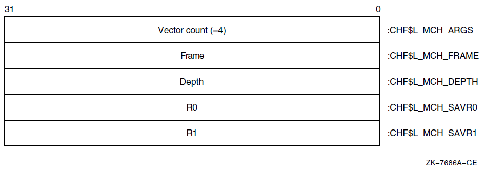
Note
The 64-bit systems use more generic names (beginning in Version 8.2), for example, CHF$IH_MCH_RETVAL and CHF$IH_MCH_RETVAL, for the registers that are used to hold function results.
If the VAX vector hardware or emulator option is in use, then for hardware-detected exceptions, the vector state is implicitly saved before any condition handler is entered and restored after the condition handler returns. (Save and restore is not required for exceptions initiated by calls to LIB$SIGNAL or LIB$STOP, because there can be no useful vector state at the time of such calls in accordance with the rules for vector register usage in Section 2.1.2, ''Vector Register Usage''). Thus, a condition handler can make use of the system vector facilities in the same manner as mainline code.
The VAX saved vector state is not directly available to a condition handler. A condition handler that needs to manipulate the vector state to carry out agreements with its callers can call the SYS$RESTORE_VP_STATE service. This service restores the saved state to the vector registers (whether hardware or emulated) and cancels any subsequent restore. The vector state can then be manipulated directly in the normal manner by means of vector instructions. (This service is normally of interest only during processing for an unwind condition).
9.5.1.2.2. Alpha Mechanism Vector Format
Note
The following table lists variable name equivalence for VSI OpenVMS Version 8.2 and earlier and VSI OpenVMS Version 8.2 and later. Although VSI OpenVMS Version 8.2 and later offer backward compatibility, it is recommended that you use the new names for that version of the operating system.
|
VSI OpenVMS Version 8.2 and earlier |
VSI OpenVMS Version 8.2 and later |
|---|---|
|
MCH_SAVR0 |
MCH_RETVAL |
|
MCH_SAVR1 |
MCH_RETVAL2 |
|
MCH_SAVF0 |
MCH_RETVAL_FLOAT |
|
MCH_SAVF1 |
MCH_RETVAL2_FLOAT |
The CHF$IH_MCH_RETVALx and
CHF$FH_MCH_RETVALx_FLOAT quadwords save the state
of the nonpreserved general and floating registers, respectively, at the time of the call to
LIB$SIGNAL or LIB$STOP. If not modified by
a handler during CHF processing, these values will become the values of those registers after
completion of CHF processing (either by continuation or by unwinding). These fields may be
modified by a handler to establish different values to be used at CHF completion.
The CHF$IH_MCH_RETVALx and
CHF$FH_MCH_RETVALx_FLOAT fields are the only
fields of an Alpha mechanism vector that can be validly modified by a handler. The effect of
any other modification is undefined. (See also Section 9.7.2, ''Unwind Completion''). Note that
the contents of the normally preserved registers are not available in the mechanism vector and
can only be accessed by analysis of the stack. (See Section 9.7.1, ''Signaler's Registers'').
The recommended method for modifying return values in a procedure's invocation context (CHF$IH_MCH_RETVAL, CHF$IH_MCH_RETVAL2, CHF$IH_MCH_RETVAL_FLOAT, and CHF$IH_RETVAL2_FLOAT) is by using routine SYS$SET_RETURN_VALUE (see Section 9.7.2, ''Unwind Completion''). The recommended method for modifying all other registers in a procedure's invocation context is by using routine LIB$PUT_INVO_REGISTERS (see Section 3.5.3.6, ''LIB$PUT_INVO_REGISTERS'').
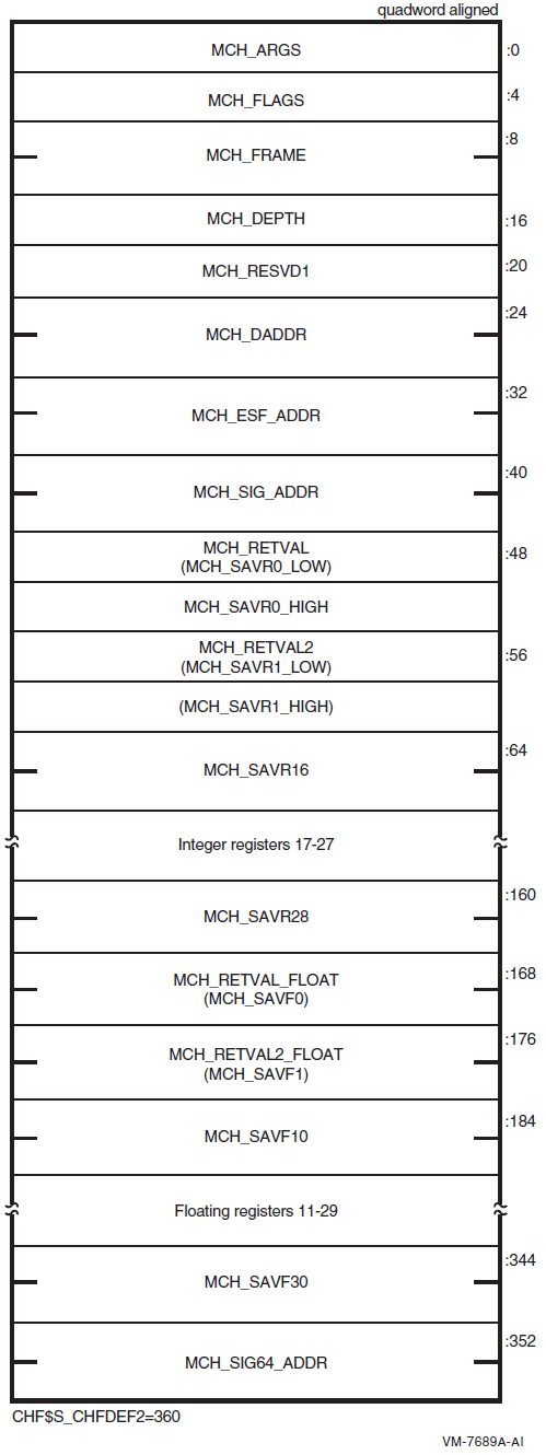
|
Field Name |
Contents | |
|---|---|---|
|
CHF$IS_MCH_ARGS |
Count of quadwords in this array starting from the next quadword, CHF$PH_MCH_FRAME (not counting the first quadword that contains this longword). This value is always 44. | |
|
CHF$IS_MCH_FLAGS |
Flag bits <31:0> for related argument-mechanism information defined as follows: | |
|
CHF$V_FPREGS_VALID |
Bit 0. When set, the process has already performed a floating-point operation and the floating-point registers stored in this structure are valid. If this bit is clear, the process has not yet performed any floating-point operations and the values in the floating-point register slots in this structure are unpredictable. | |
|
CHF$PH_MCH_FRAME |
Contains the frame pointer in the procedure context of the establisher. | |
|
CHF$IS_MCH_DEPTH |
Positive count of the number of procedure activation stack frames between the frame in which the exception occurred and the frame depth that established the handler being called (see Section 9.5.1.3, ''Mechanism Depth''). | |
|
CHF$IS_MCH_RESVD1 |
Reserved to OpenVMS. | |
|
CHF$PH_MCH_DADDR |
Address of the handler data quadword if the exception handler data field is present (as indicated by PDSC$V_HANDLER_DATA_VALID); otherwise, contains 0. | |
|
CHF$PH_MCH_ESF_ADDR |
Address of the exception stack frame (see the Alpha Architecture Reference Manual). | |
|
CHF$PH_MCH_SIG_ADDR |
Address of the 32-bit form of signal array. This array is a 32-bit wide (longword) array. This is the same array that is passed to a handler as the signal argument vector. | |
|
CHF$IH_MCH_RETVAL |
Contains a copy of R0 at the time of the exception. | |
|
CHF$IH_MCH_RETVAL2 |
Contains a copy of R1 at the time of the exception. | |
|
CHF$IH_MCH_SAVRnn |
Contain copies of the saved integer registers at the time of the exception. The following registers are saved: R16 through R28. Registers R2 through R15 are implicitly saved in the call stack. | |
|
CHF$FH_MCH_RETVAL_FLOAT |
Contains a copy of F0 at the time of the exception, or is unpredictable as described for the field CHF$IS_MCH_FLAGS. | |
|
CHF$FH_MCH_RETVAL2_FLOAT |
Contains a copy of F1 at the time of the exception, or is unpredictable as described for the field CHF$IS_MCH_FLAGS. | |
|
CHF$FH_MCH_SAVFnn |
Contain copies of the saved floating-point registers at the time of the exception, or are unpredictable as described at field CHF$IS_MCH_FLAGS. If the floating-point register fields are valid, the following registers are saved: F10 through F30. Registers F2 through F9 are implicitly saved in the call. | |
|
CHF$PH_MCH_SIG64_ADDR |
Address of the 64-bit form of signal array. This array is a 64-bit wide (quadword) array. | |
9.5.1.2.3. I64 Mechanism Vector Format
On I64 systems, the 64-bit-wide mechanism array is the argument mechanism in the handler call. The array is shown in Figure 9.7, ''I64 Mechanism Vector Format''.
The CHF$IH_MCH_RETVAL and
CHF$FH_MCH_RETVAL2 quadwords save the state of registers R8 and R9
at the time of the call to LIB$SIGNAL or
LIB$STOP. The CHF$FH_MCH_RETVAL_FLOAT,
CHF$FH_MCH_RETVAL2_FLOAT, and
CHF$FH_MCH_SAVFnn octawords save the state of the
floating-point registers at the time of the call to LIB$SIGNAL or
LIB$STOP. If not modified by a handler during CHF processing (as
described below), these values will become the values of those registers after completion of
CHF processing (either by continuation or by unwinding).
The only supported method for modifying return values in a procedure's invocation context (CHF$IH_MCH_RETVAL, CHF$IH_MCH_RETVAL2, CHF$FH_MCH_RETVAL_FLOAT, CHF$FH_MCH_RETVAL2_FLOAT) is by using routine SYS$SET_RETURN_VALUE (see Section 9.7.2, ''Unwind Completion''). The only supported method for modifying all other registers in a procedure invocation context is by using routine LIB$I64_PUT_INVO_REGISTERS (see Section 4.8.3.13, ''LIB$I64_PUT_INVO_REGISTERS'').
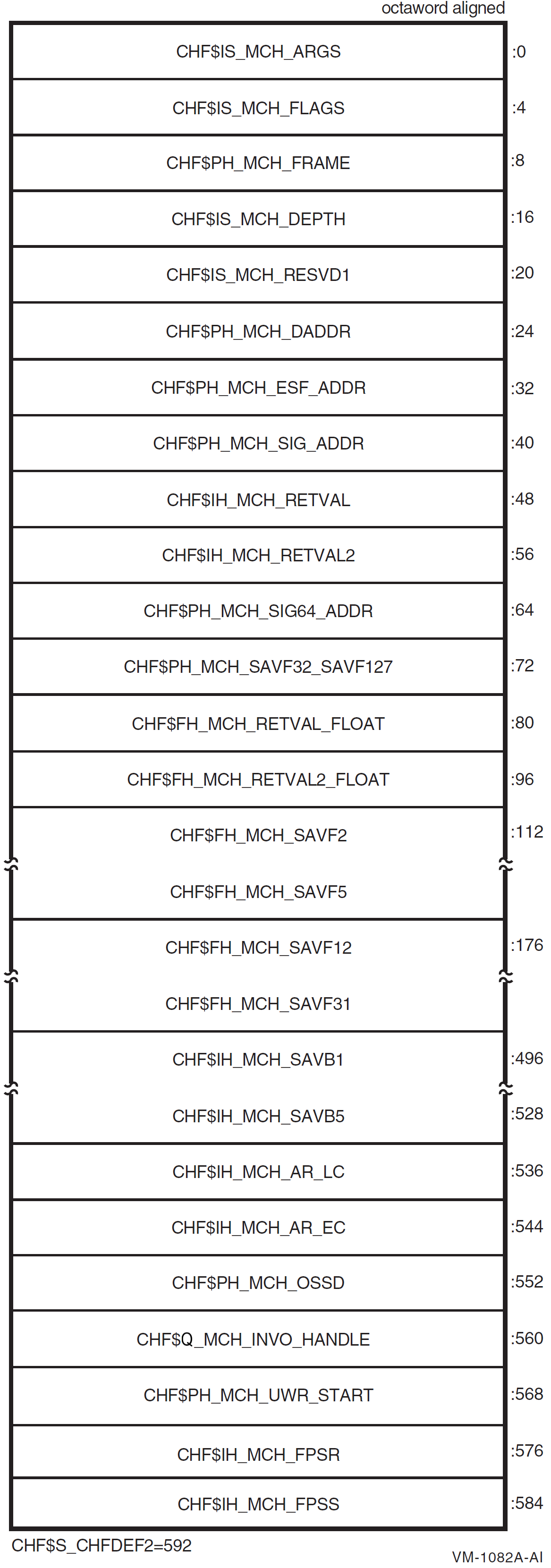
|
Field Name |
Contents | |
|---|---|---|
|
CHF$IS_MCH_ARGS |
Count of quadwords in this array starting from the next quadword, CHF$PH_MCH_FRAME (not counting the first quadword that contains this longword). This value is 73 if CHF$V_FPREGS2_VALID is clear, and 265 if CHF$V_FPREGS2_VALID is set. | |
|
CHF$IS_MCH_FLAGS |
Flag bits <31:0> for related argument-mechanism information defined as follows: | |
|
CHF$V_FREGS_VALID |
Bit 0. When set, the process has already performed a floating-point operation in registers F2-F31 and the contents of the CHF$FH_MCH_SAVFnn fields of this structure are valid. When this bit is clear, the contents of the CHF$FH_MCH_SAVFnn fields are undefined. | |
|
CHF$V_FPREGS2_VALID |
Bit 1. When set, the process has already performed a floating-point operation in registers F32-F127 and the floating-point registers stored in the extension to this structure are valid. If this bit is clear, the process has not yet performed any floating-point operations in registers F32-F127, and the pointer to the extension area (CHF$FH_MCH_SAVF32_SAVF127) will be zero. | |
|
CHF$PH_MCH_FRAME |
Contains the Previous Stack Pointer, PSP, (the value of the SP at procedure entry) for the procedure context of the establisher (see Section 4.5.1, ''Procedure Frames''). | |
|
CHF$IS_MCH_DEPTH |
Positive count of the number of procedure activation stack frames between the frame in which the exception occurred and the frame depth that established the handler being called (see Section 9.5.1.3, ''Mechanism Depth''). | |
|
CHF$IS_MCH_RESVD1 |
Reserved to OpenVMS. | |
|
CHF$PH_MCH_DADDR |
Address of the handler data quadword (start of the Language Specific Data area, LSDA, see Section A.4.1, ''Unwind Table and Unwind Information Block'' and Section A.4.4, ''Language-Specific Data Area'') if the exception handler data field is present in the unwind information block (as indicated by OSSD$V_HANDLER_DATA_VALID); otherwise, contains 0. | |
|
CHF$PH_MCH_ESF_ADDR |
Address of the exception stack frame. | |
|
CHF$PH_MCH_SIG_ADDR |
Address of the 32-bit form of signal array. This array is a 32-bit wide (longword) array. This is the same array that is passed to a handler as the signal argument vector. | |
|
CHF$IH_MCH_RETVAL |
Contains a copy of R8 at the time of the exception. | |
|
CHF$IH_MCH_RETVAL2 |
Contains a copy of R9 at the time of the exception. | |
|
CHF$PH_MCH_SIG64_ |
Address of the 64-bit form of signal array. This array is a 64-bit wide (quadword) array. | |
|
CHF$FH_MCH_ |
Address of the extension to the mechanism array that contains copies of F32-F127 at the time of the exception. | |
|
CHF$FH_MCH_RETVAL_ |
Contains a copy of F8 at the time of the exception. | |
|
CHF$FH_MCH_RETVAL2_ |
Contains a copy of F9 at the time of the exception. | |
|
CHF$FH_MCH_SAVFnn |
Contain copies of floating-point registers F2-F5 and F12-F31. Registers F6-F7 and F10-F11 are implicitly saved in the exception frame. | |
|
CHF$IH_MCH_SAVBnn |
Contains copies of branch registers B1-B5 at the time of the exception. | |
|
CHF$IH_MCH_AR_LC |
Contains a copy of the Loop Count Register (AR65) at the time of the exception. | |
|
CHF$IH_MCH_AR_EC |
Contains a copy of the Epilog Count Register (AR66) at the time of the exception. | |
|
CHF$PH_MCH_OSSD |
Address of the operating system-specific data area. | |
|
CHF$Q_MCH_INVO_ |
Contains the invocation handle of the procedure context of the establisher (see Section 4.8.2.2, ''Invocation Context Handle''). | |
|
CHF$PH_MCH_UWR_ |
Address of the unwind region. | |
|
CHF$IH_MCH_FPSR |
Contains a copy of the hardware floating-point status register (AR.FPSR) at the time of the exception. | |
|
CHF$IH_MCH_FPSS |
Contains a copy of the software floating-point status register (which supplements CHF$IH_MCH_FPSR) at the time of the exception. | |
9.5.1.2.4. x86-64 Mechanism Vector Format
On x86-64 systems, the 64-bit-wide mechanism array is the argument mechanism in the handler call. The array is shown in Figure 9.8, ''x86-64 Mechanism Vector Format''.
The CHF$IH_MCH_RETVAL and
CHF$FH_MCH_RETVAL2 quadwords are set to
SS$_NORETVALS and 0, respectively, by the signal processing software
at the time of the call to LIB$SIGNAL or
LIB$STOP. (The standard return registers, %rax and
%rdx, are not used here because they are changed by making the call itself, so
they have no useful or reliable contents as an implicit return
value).
The CHF$FH_MCH_RETVAL_FLOAT and
CHF$FH_MCH_RETVAL2_FLOAT quadwords save the state of floating-point
registers %xmm0 and %xmm1, respectively, at the time of
the call to LIB$SIGNAL or LIB$STOP. If not
modified by a handler during CHF processing (as described below), the values of these
registers will become the values of those registers after completion of CHF processing (either
by continuation or by unwinding).
The only supported method for modifying return values in a procedure's invocation context (CHF$IH_MCH_RETVAL, CHF$IH_MCH_RETVAL2, CHF$FH_MCH_RETVAL_FLOAT, and CHF$FH_MCH_RETVAL2_FLOAT) is by using routine SYS$SET_RETURN_VALUE (see Section 9.7.2, ''Unwind Completion''). The only supported method for modifying all other registers in a procedure invocation context is by using routine LIB$X86_PUT_INVO_REGISTERS (see Section 5.8.3.13, ''LIB$X86_PUT_INVO_REGISTERS'').
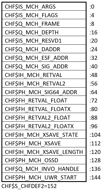
| Field Name | Contents | |
|---|---|---|
| CHF$IS_MCH_ARGS |
Count of quadwords in this array starting from the next quadword, CHF$Q_MCH_FRAME (not counting the first quadword that contains this longword). | |
| CHF$IS_MCH_FLAGS |
Flag bits <31:0> for related argument-mechanism information defined as follows: | |
| CHF$V_FPREGS_VALID |
Bit 0. When set, the process has already performed a floating-point operation in floating-point registers and the contents of the CHF$IH_MCH_XSAVE_STATE and CHF$PH_MCH_XSAVE fields of this structure are valid. When this bit is clear, the contents of the CHF$IH_MCH_XSAVE_STATE and CHF$PH_MCH_XSAVE fields are zero. | |
| CHF$Q_MCH_FRAME |
Contains the Previous Stack Pointer, PSP, (the value of the SP at procedure entry) for the procedure context of the establisher (see Section 5.4, ''Procedure Types''). | |
| CHF$Q_MCH_DEPTH |
Positive count of the number of procedure activation stack frames between the frame in which the exception occurred and the frame depth that established the handler being called (see Section 9.5.1.3, ''Mechanism Depth''). | |
| CHF$IS_MCH_RESVD1 |
Reserved to OpenVMS. | |
| CHF$Q_MCH_DADDR |
Address of the handler data quadword (start of the Language Specific Data area, LSDA, see Section B.3.2.3.1, ''FDE_augmentation_section'') if the exception handler data field is present in the unwind information block; otherwise, contains 0. | |
| CHF$Q_MCH_ESF_ADDR |
Address of the exception stack frame. | |
| CHF$Q_MCH_SIG_ADDR |
Address of the 32-bit form of signal array. This array is a 32-bit wide (longword) array. This is the same array that is passed to a handler as the signal argument vector. | |
| CHF$IH_MCH_RETVAL | Contains a copy of %rax at the time
of the exception. | |
| CHF$IH_MCH_RETVAL2 |
Contains a copy of
| |
| CHF$PH_MCH_SIG64_ADDR |
Address of the 64-bit form of signal array. This array is a 64-bit wide (quadword) array. | |
| CHF$FH_RETVAL_FLOAT |
Contains a copy of | |
| CHF$FH_RETVAL_FLOATX | Contains a copy of %xmm0 bits
<127:64> at the time of the exception. | |
| CHF$FH_RETVAL2_FLOAT |
Contains a copy of | |
| CHF$FH_RETVAL2_FLOATX | Contains a copy of %xmm1 bits
<127:64> at the time of the exception. | |
|
CHF$IH_MCH_XSAVE_ |
Contains a copy of the XSAVE state control value indicating what information is contained in the XSAVE area. This is the state-component bit map needed by the XRSTOR instruction to restore the floating-point state from the XSAVE area (0 if the CHF$PH_MCH_XSAVE pointer is null). | |
| CHF$PH_MCH_XSAVE |
Contains a pointer to the XSAVE area described by CHF$IH_MCH_XSAVE_STATE (0 if none). | |
|
CHF$IH_MCH_XSAVE_ | The number of bytes in the block pointed to by CHF$PH_MCH_XSAVE (0 if CHF$PH_MCH_XSAVE is null). | |
| CHF$PH_MCH_OSSD |
Address of the operating system-specific data area. | |
|
CHF$Q_MCH_INVO_ |
Contains the invocation handle of the procedure context of the establisher (see Section 5.8.2.2, ''Invocation Context Handle''). | |
| CHF$PH_MCH_UWR_START |
Address of the unwind region (FDE). | |
9.5.1.3. Mechanism Depth
For all argument mechanisms, the depth field has the value 0 for an exception that is handled by the procedure activation invoking the exception. The exception procedure contains the instruction that either causes the hardware exception or calls LIB$SIGNAL. The depth field of the argument mechanism has positive values for procedure activations calling the one having the exception, for example, 1 for the immediate caller.
If a system service gives an exception, the immediate caller of the service is notified at depth = 1. The depth field has a value of −2 when the condition handler is established by the primary exception vector, a value of −1 when it is established by the secondary vector, and a value of −3 when it is established by the last-chance vector.
Condition dispatcher in the call stack
Jacket frames, if there are any translated routines in the call stack
Multiple active signals
Compiler use of no frame procedures or inline code expansion of calls
9.5.2. System Default Condition Handlers
If one of the default condition handlers established by the system is entered, the handler calls the SYS$PUTMSG system service to interpret the signal argument list and to output the indicated information or error message. See the description of SYS$PUTMSG in the VSI OpenVMS System Services Reference Manual: GETUTC–Z for the format of the signal argument list.
9.5.3. Coordinating the Handler and Establisher
This section describes the requirements for use of memory, exception synchronization, and continuation of the handler.
9.5.3.1. Use of Memory
Exceptions can be raised and unwind operations (which cause exception handlers to be called) can occur when the current value of one or more variables is in registers rather than in memory. Because of this, a handler, and any descendant procedure called directly or indirectly by a handler, must not access any variables except those explicitly passed to the procedure as arguments or those that exist in the normal scope of the procedure.
This rule can be violated for specific memory locations only by agreement between the handler and all procedures that might access those memory locations. A handler that makes such agreements does not conform to this standard.
9.5.3.2. Exception Synchronization (Alpha Only)
The Alpha hardware architecture allows instructions to complete in a different order than that in which they were issued, and for exceptions caused by an instruction to be raised after subsequently issued instructions have been completed.
Because of this, the state of the machine when a hardware exception occurs cannot be assumed with the same precision as it can be assumed on VAX or other 64-bit processors unless such precision has been guaranteed by bounding the exception range with the appropriate insertion of TRAPB instructions.
If a procedure has an exception handler that does not simply reraise all arithmetic traps caused by code that is not contained directly within that procedure, the procedure must issue a TRAPB instruction before it establishes itself as the current procedure.
If a procedure has an exception handler that does not simply reraise all arithmetic traps caused either by code that is not contained directly within that procedure or by any procedure that might have been called while that procedure was current, the procedure must issue a TRAPB instruction in the procedure epilogue while it is still the current procedure.
If a procedure has an exception handler that is sensitive to the invocation depth, the procedure must issue a TRAPB instruction immediately before and after any call. Furthermore, the handler must be able to recognize exception PC values that represent either epilogue code in called procedures or TRAPB instructions immediately after a call, and adjust the depth appropriately (see Section 3.6.5, ''Entry and Exit Code Sequences'').
These rules ensure that exceptions are detected in the intended context of the exception handler.
These rules do not ensure that all exceptions are detected while the procedure within which the exception-causing instruction was issued is current. For example, if a procedure without an exception handler is called by a procedure that has an exception handler not sensitive to invocation depth, an exception detected while that called procedure is current may have been caused by an instruction issued while the caller was the current procedure. This means the frame, designated by the exception handling information, is the frame that was current when the exception was detected, not necessarily the frame that was current when the exception-causing instruction was issued.
9.5.3.3. Continuation from Exceptions (Alpha Only)
The Alpha architecture guarantees neither that instructions are completed in the same order in which they were fetched from memory nor that instruction execution is strictly sequential. Continuation is possible after some exceptions, but certain restrictions apply.
By definition, software-raised general exceptions are synchronous with the instruction stream and can have a well-defined continuation point. Therefore, a handler can request continuation from a software-raised exception. However, since compiler-generated code typically relies on error-free execution of previously executed code, continuing from a software-raised exception might produce unpredictable results and unreliable behavior unless the handler has explicitly fixed the cause of the exception so that it is transparent to subsequent code.
Hardware faults on Alpha processors follow the same rules as the strict interpretation of the VAX or Itanium rules. Loosely paraphrased, these rules state that if the offending exception is fixed, reexecution of the instruction (as determined from the supplied PC) will yield correct results. This does not imply that instructions following the faulting instruction have not been executed. Therefore, hardware faults can be viewed as similar to software-raised exceptions and can have well-defined continuation points.
Arithmetic traps cannot be restarted because all the information required for a restart is not available. The most straightforward and reliable way in which software can guarantee the ability to continue from this type of exception is by placing appropriate TRAPB instructions in the code stream. Although this technique does allow continuation, it must be used with extreme caution because of the negative effect on application performance.
9.5.3.4. Floating-Point Control Status (I64 and x86-64)
Normally the floating-point control status (see Section 4.1.7, ''Floating-Point Status'') of a program is established at the beginning of program execution and remains unchanged throughout execution of the whole program.
Save the floating-point control status in effect on entry and restore that status when it returns.
- Establish a handler that will restore the floating-point control status if either an exception is resignalled or if the routine terminates due to an unwind operation.
Note
The means by which the saved floating-point control status of the establisher is communicated to its handler is not specified here.
9.6. Returning from a Condition Handler
Condition handlers are invoked by the OpenVMS Condition Handling Facility (CHF). Therefore, the return from the condition handler is to the CHF.
To continue from the instruction following the signal, the handler must return with a function value of either SS$_CONTINUE or SS$_CONTINUE64 (both of which have bit <0> set). If, however, the condition is signaled with a call to LIB$STOP, the image exits. To resignal the condition, the condition handler returns with a function value of either SS$_RESIGNAL or SS$_RESIGNAL64 (both of which have the bit <0> clear).
The difference between SS$_CONTINUE and SS$_CONTINUE64, and similarly between SS$_RESIGNAL and SS$_RESIGNAL64, is of significance only if the handler has made an alteration to the signal vector that is intended to be taken into account by the CHF. When SS$_CONTINUE or SS$_RESIGNAL is returned, then any modification to the 32-bit signal vector is propagated (in sign-extended form) to the corresponding position in the 64-bit vector. When SS$_CONTINUE64 or SS$_RESIGNAL64 is returned, any modification in the 64-bit signal vector is propagated (in truncated form) to the corresponding position in the 32-bit vector. If no modification has been made, then the two forms of continuation or resignal are equivalent.
For SS$_CONTINUE64 and SS$_RESIGNAL64, the 32-bit signal vector is simply derived again from the 64-bit signal vector. In particular, no hidden copy of the 64-bit signal vector is kept. It is not necessary to determine if there was a change or not—if there was, it is properly reflected in the 32-bit vector.
- For SS$_CONTINUE and SS$_RESIGNAL, let SIGVEC32[I] and SIGVEC64[I] be corresponding entries in the two vectors, for I from 1 to length. (Recall that the length[s] cannot be changed). For each entry, do the following:
        if SIGVEC32[I] /= SIGVEC64[I]<0,32>
        then
            SIGVEC64[I] = sign-extend(SIGVEC32[I])
That is, if the 32-bit entry is still the same as the low-order 32 bits of the 64-bit entry, then it did not change and thus the 64-bit entry is not changed. Otherwise, update the 64-bit entry with the sign-extended contents of the 32-bit entry.
To alter the severity of the signal, the handler modifies the low-order three bits of the
condition value longword in the signal_args vector and resignals. If the
condition handler wants to alter the defined control bits of the signal, the handler modifies
bits <31:28> of the condition value and resignals.
To unwind, the handler calls SYS$UNWIND and then returns. In this case, the handler function value is ignored.
For I64 or x86-64, if the establisher of the handler changes the floating-point control status and either the handler resignals an exception or the handler is called for an unwind exception (see Section 9.7, ''Request to Unwind from a Signal''), the handler must reset the floating-point control status to the value saved by the establisher.
9.7. Request to Unwind from a Signal
SYS$UNWIND(depadr, new_PC)|
Argument |
OpenVMS Usage |
Type |
Access |
Mechanism |
|---|---|---|---|---|
|
depadr |
integer |
longword |
read |
by reference |
|
new_PC |
address |
longword |
read |
by reference |
|
|
Optional number of presignal frames (depth) to be removed. |
|
|
Optional address of the location to receive control after the unwind operation is completed. |
|
Success or failure status (see text that follows). |
The depadr argument specifies the address of the longword that
contains the number of presignal frames (depth) to be removed. The deepest procedure invocation
whose frame is not removed is called the target invocation of the unwind.
If that number is less than or equal to 0, nothing is to be unwound. The default (address = 0) is
to return to the caller of the procedure that established the handler that issued the
$UNWIND service. To unwind to the establisher, specify the depth from
the call to the handler, which can be found in the CHF$IS_MCH_DEPTH
field of the Mechanism Array. When the handler is at depth 0, it can achieve the equivalent of an
unwind operation to an arbitrary place in its establisher by altering the PC in its
signal_args vector and returning with
SS$_CONTINUE, or SS$_CONTINUE64 if the 64-bit
signal vector is altered, instead of performing an unwind.
The new_PC argument specifies the location to receive control when
the unwinding operation is complete. The default is to continue at the instruction following the
call to the last procedure activation that is removed from the stack.
No signal active (SS$_NOSIGNAL)
Already unwinding (SS$_UNWINDING)
Insufficient frames for depth (SS$_INSFRAME)
If SYS$UNWIND is invoked by a handler that has already invoked SYS$UNWIND, then the effect of the second invocation is undefined.
The unwinding operation occurs when the handler returns to the CHF. Unwinding is done by scanning back through the stack and calling each handler associated with a frame. The handler is called with the exception SS$_UNWIND to perform any application-specific cleanup. If the depth specified includes unwinding the establisher's frame, the current handler is recalled with this unwind exception.
When the target invocation is reached on 64-bit systems, unwind completion depends on the PDSC$V_TARGET_INVO flag of the associated procedure descriptor or unwind information, respectively. If that flag is set to 1, then the handler for that procedure invocation is called; otherwise, no handler is called. Control then resumes in the target invocation.
signal_args: for a handler for a procedure other than the target invocation of the unwind—an argument count (CHF$L_SIG_ARGS) of 1 and a condition value (CHF$L_SIG_NAME) of SS$_UNWIND.For a handler on 64-bit systems for a procedure that is the target invocation of the unwind—an argument count (CHF$L_SIG_ARGS) of 2 and two condition values consisting of SS$_UNWIND followed by SS$_TARGET_UNWIND.
mechanism_args: same as for the original call except for a depth of 0 (that is, unwinding self) and any other changes made by prior handlers.
After each handler is called, the stack is logically cut back to the previous frame.
On 64-bit systems, the stack is not actually cut back until after the last handler is called.
The exception vectors are not checked because they are not being removed. Any function value from the handler is ignored.
To specify the value of the top-level function being unwound, the handler must establish
the function result using the appropriate saved register locations in the
mechanism_args vector as described in Section 9.7.2, ''Unwind Completion''. These locations are part
of the register values restored from the mechanism_args vector at the end
of the
unwind.
|
SYS$UNWIND (0,0) |
Unwind to the establisher's caller. |
|
SYS$UNWIND (depth,0) |
Unwind to the establisher at the point of the call that resulted in the exception. |
|
SYS$UNWIND (depth,location) |
Unwind to the specified procedure activation and transfer to a specified location. |
The only recommended values for depth are the default (address of 0), which unwinds to the caller of the establisher, and the value of depth taken from the mechanism vector, which unwinds to the establisher. Other values depend on implementation details that can change at any time.
You can call SYS$UNWIND whether the condition was a software exception signaled by calling LIB$SIGNAL or LIB$STOP or was a hardware exception. Calling SYS$UNWIND is the only way to continue execution after a call to LIB$STOP.
9.7.1. Signaler's Registers
Because the handler is called and can in turn call routines, the actual register values in use at the time of the signal or exception can be scattered on the stack.
|
R0, R1 |
In |
|
R2—11 |
Last frame saving it |
|
AP |
Old AP of SYS$CALL_HANDL+4 frame |
|
FP |
Old FP of SYS$CALL_HANDL+4 frame |
|
SP |
Equal to end of |
|
PC, PSL |
At end of |
On 64-bit systems, to find the contents of the registers, use the invocation context routines described in Section 3.5.3, ''Invocation Context Access Routines'' (Alpha systems), Section 4.8.3, ''Invocation Context Block Access Routines'' (I64 systems), or Section 5.8.3, ''Invocation Context Block Access Routines'' (x86-64 systems).
9.7.2. Unwind Completion
On VAX systems, the values that exist in R0 and R1 when the unwind completes are the values passed implicitly to the unwinder in the mechanism array (see Section 9.5.1.2.1, ''VAX Mechanism Vector Format''). If desired, these values can be modified by an exception handler before the unwind is initiated.
On Alpha systems, the values that exist in R0, R1, F0, and F1 when the unwind completes are the values passed implicitly to the unwinder in the mechanism array (see Section 9.5.1.2.2, ''Alpha Mechanism Vector Format''). If desired, these values can be modified by an exception handler using SYS$SET_RETURN_VALUE before the unwind is initiated. Note that, unlike VAX systems, an Alpha system does not use R1 for returning any type of return values.
On I64 systems, the values that exist in R8, R9, F8, and F9 when the unwind completes are the values passed implicitly to the unwinder in the mechanism array (see Section 9.5.1.2.3, ''I64 Mechanism Vector Format''). If desired, these values can be modified by an exception handler using SYS$SET_RETURN_VALUE before the unwind is initiated.
On x86-64 systems, the values that exist in %xmm0 and
%xmm1 when the unwind completes are the values passed implicitly to the
unwinder in the mechanism array (see Section 9.5.1.2.4, ''x86-64 Mechanism Vector Format''). However, unlike earlier 64-bit systems,
%rax and %rdx cannot usefully be implicitly established
in this way because they are set as part of making the call to
LIB$SIGNAL or LIB$STOP (being the AI and
third parameter registers, respectively). To preclude inadvertent use of these values as the
ultimate return result of an unwind, LIB$SIGNAL and
LIB$STOP both set the CHF$IH_MCH_RETVAL and
CHF$IH_MCH_RETVAL2 fields in the mechanism_args
vector to SS$_NORETVALS and 0, respectively. If desired, these values
can be modified by an exception handler using SYS$SET_RETURN_VALUE
before the unwind is initiated.
On 64-bit systems, as an alternative to using SYS$SET_RETURN_VALUE, a handler may also set new values directly in fields CHF$IH_MCH_RETVAL, CHF$IH_MCH_RETVAL2, CHF$IH_MCH_RETVAL_FLOAT, or CHF$IH_MCH_RETVAL2_FLOAT as appropriate.
Note
For code intended to be portable across all types of 64-bit systems, the use of implicit parameters as described above for Alpha and I64 cannot be used. Use of implicit parameters is really only viable and reliable in code written in MACRO code in any case, not in any high-level language. As a general rule, handlers must explicitly establish the ultimate function result.
The effect of handler modification of any mechanism vector field other than described above is undefined.
SYS$SET_RETURN_VALUE (64‑bit Systems)
SYS$SET_RETURN_VALUE(mechanism_arg, return_type, return_value)
|
Argument |
OpenVMS Usage |
Type |
Access |
Mechanism |
|---|---|---|---|---|
|
mechanism_arg |
mechanism vector address |
quadword (unsigned) |
read |
by value |
|
return_type |
integer |
longword (unsigned) |
read |
by reference |
|
return_value |
buffer |
scalar |
read |
by reference |
|
|
Address of mechanism vector. If zero, the mechanism vector for the currently active signal will be used.? |
|
|
Address of a longword that contains one of the function return signature codes found in Table 6.4, ''Function Return Signature Encodings''.? |
|
|
Address of a value of the appropriate type. The referenced value will be read as a longword, quadword, or octaword, depending on the return_type.? |
|
|
(Success or failure) The given return value is placed in the appropriate fields of the specified mechanism vector, according to the return type. |
9.8. GOTO Unwind Operations (64-bit Systems)
A GOTO unwind is a transfer of control that leaves one procedure invocation and continues execution in a prior, currently active procedure invocation. Modular and reliable support of the nonlocal GOTO requires procedure invocations that are terminated to have an opportunity to clean up in an orderly way (just like a procedure that is terminated as a result of an unwind from a condition handler).
Performing a GOTO unwind operation in a thread causes a transfer of control from the location at which the GOTO unwind operation is initiated to a target location in a target invocation. This transfer of control also results in the termination of all procedure invocations, including the invocation in which the unwind request was initiated, up to the target procedure invocation. Thread execution then continues at the target location.
Before control is transferred to the unwind target location, the unwind support code invokes all frame-based handlers that were established by procedure invocations being terminated. These handlers are invoked with an indication of an unwind in progress. This gives each procedure invocation being terminated the chance to perform cleanup processing before its context is lost.
When the target invocation is reached, unwind completion depends on the TARGET_INVO flag in the respective unwind information (this symbol has different prefixes on the respective systems).
After all the relevant frame-based handlers have been called and the appropriate frames have been removed from existence, the target invocation's saved context is restored and execution is resumed at the specified location.
Note
|
Symbol |
Alpha Systems |
I64 Systems |
x86-64 Systems |
|---|---|---|---|
|
RetVal |
R0 |
R8 | rax |
|
RetVal2 |
R1 |
R9 | rdx |
|
NewRetVal |
New_R0 |
New_R8 | New_rax |
|
NewRetVal2 |
New_R1 |
New_R9 | New_rdx |
SYS$GOTO_UNWIND_64(target_invo, target_pc, NewRetVal, NewRetVal2)SYS$GOTO_UNWIND(target_invo, target_pc, New_R0, New_R1)|
Argument |
OpenVMS Usage |
Type |
Access |
Mechanism |
|---|---|---|---|---|
|
target_invo |
invo_handle |
longword or quadword (unsigned)? |
read |
by reference |
|
target_pc |
address |
longword or quadword (unsigned)? |
read |
by reference |
|
NewRetVal |
quadword_unsigned |
quadword (unsigned) |
read |
by reference |
|
NewRetVal2 |
quadword_unsigned |
quadword (unsigned) |
read |
by reference |
|
|
Address of a location that contains a handle for the target invocation. If omitted or the address of the handle is zero, then the effect of the call is undefined. |
|
|
Address of a location that contains the address at which execution should continue in the target invocation. If omitted or if the address is 0, then execution resumes at the location specified by the return address for the call frame of the target procedure invocation. |
|
|
Address of a location that contains the value to place in the saved RetVal location of the mechanism argument vector. The contents of this location are then loaded into RetVal at the time that execution continues in the target invocation. If this argument is omitted, then the contents of RetVal at the time of the call to SYS$GOTO_UNWIND_64 are used. This argument is called New_R0 in SYS$GOTO_UNWIND for compatibility with Alpha. |
|
|
Address of a location that contains the value to place in the saved RetVal2 location of the mechanism argument vector. The contents of this location are then loaded into RetVal2 at the time that execution continues in the target invocation. If this argument is omitted, then the contents of RetVal2 at the time of the call to SYS$GOTO_UNWIND_64 are used. This argument is called New_R1 in SYS$GOTO_UNWIND for compatibility with Alpha. |
|
|
An invalid address was given. |
When a GOTO unwind is initiated, control almost never returns to the point at which the unwind was initiated. Control returns with an error status only if a GOTO unwind cannot be started. If SYS$GOTO_UNWIND_64 (or SYS$GOTO_UNWIND) is invoked by a handler that has already invoked SYS$UNWIND, then the effect of calling SYS$GOTO_UNWIND_64 (or SYS$GOTO_UNWIND) is undefined.
9.8.1. Handler Invocation During a GOTO Unwind
When an unwind operation takes place, all frame-based exception handlers are invoked that were established by any procedure invocation being terminated. In addition, the handler for the target procedure invocation is called if the PDSC$V_TARGET_INVO flag is set in the corresponding procedure descriptor or unwind information (see Sections 3.4.2, 3.4.5, and A.4.3). These handlers are invoked in the reverse order from which they were established.
Because primary, last-chance handlers, and the system catchall handler are not associated with a normal procedure invocation, these handlers are never invoked during an unwind (but they are invoked if an exception is raised during the unwind operation).
(* handler) (signal_args, mechanism_args)
|
Argument |
OpenVMS Usage |
Type |
Access |
Mechanism |
|---|---|---|---|---|
|
signal_args |
signal vector |
structure |
modify |
by reference |
|
mechanism_args |
mechanism vector |
structure |
modify |
by reference |
|
|
Argument count of 2, followed by a condition value of
SS$_UNWIND, followed by:
|
|
|
Mechanism argument corresponding to the frame being unwound, as defined in Section 9.5.1.2, ''Mechanism Argument Vector''. |
For information about signal argument and mechanism argument vectors, see Section 9.5.1.1, ''Signal Argument Vector'' and Section 9.5.1.2, ''Mechanism Argument Vector''.
9.8.2. Unwind Completion
The target procedure invocation is the most current invocation in the procedure invocation chain.
The environment of the target invocation is restored to the state when that invocation was last current, except for the contents of all scratch registers.
The two integer return value registers contain the respective values (if any) that were passed by the routine that invoked the unwind.
Execution continues at the target location.
9.9. Multiple Active Signals
A signal is said to be active until the signaler gets control again or is unwound. A signal can occur while a condition handler or a procedure it has called is executing in response to a previous signal. For example, procedures A, B, and C establish condition handlers Ah, Bh, and Ch. If A calls B and B calls C, which signals S, and Ch resignals, then Bh gets control.
If Bh calls procedure X, and X calls procedure Y, and Y signals T, the stack is as follows:
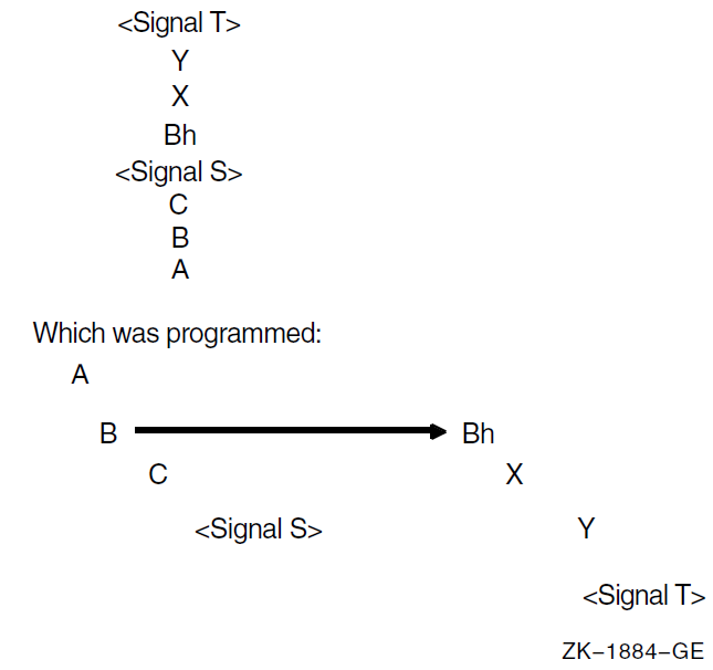
The handlers are searched for in the following order: Yh, Xh, Bhh, Ah. Bh is not called again because it is not appropriate to assume that a routine is able to be its own handler. However, Bh can establish itself or another procedure as its handler (Bhh).
On VAX systems, Ch is not checked or called because it is a structural descendant of B.
On 64-bit systems, the search does check handlers Ch and Bh between calling Bhh and Ah. These handlers will be reinvoked only if enabled by the HANDLER_REINVOCABLE flag of the establisher's procedure descriptor (see Section 3.4.1, ''Stack Frame Procedures'' and Section 3.4.4, ''Register Frame Procedure'') or unwind information (see Section A.4.3, ''Operating System-Specific Data Area'').
For all systems, the following algorithm is used on the second and subsequent signals that occur before the handler for the original signal returns to the Condition Handling Facility. The primary and secondary exception vectors are checked. However, the search backward in the process stack is then modified. On a VAX processor, the stack frames traversed in the first search are skipped, in effect, during the second search, while on a 64-bit system, the stack frames are skipped unless they explicitly enable handler reinvocation. Therefore, the stack frame preceding the first condition handler, up to and including the frame of the procedure that has established the handler, is skipped. In the VAX environment, frames that are skipped are not counted in the depth. In a 64-bit environment, all frames are counted in the depth.
For example, the stack frames traversed in the first and second searches are skipped in a third search. Note that if a condition handler signals, it is not automatically invoked recursively. However, if a handler itself establishes a handler, the second handler is invoked. Therefore, a recursive condition handler should start by establishing itself. Any procedures invoked by the handler are treated in the normal way; that is, exception signaling follows the stack up to the condition handler.
If an unwind operation is requested while multiple signals are active, all the intermediate handlers are called for the operation. For example, in the preceding diagram, if Ah specifies unwinding to A, the following handlers are called for the unwind: Yh, Xh, Bhh, Ch, and Bh.
For proper hierarchical operation, an exception that occurs during execution of a condition handler established in an exception vector should be handled by that handler rather than propagating up the activation stack. To prevent such propagation, the vectored condition handler should establish a handler in its stack frame to handle all exceptions.
9.10. Multiple Active Unwind Operations
During an unwind operation (resulting from a call of SYS$GOTO_UNWIND_64, SYS$GOTO_UNWIND, or SYS$UNWIND), another unwind operation can be initiated (using SYS$GOTO_UNWIND_64, SYS$GOTO_UNWIND, or SYS$UNWIND). This can occur, for example, if a handler that is invoked for the original unwind initiates another unwind, or if an exception is raised in the context of such a handler and a handler invoked for that exception initiates another unwind operation. However, SYS$UNWIND cannot be called from a handler that is invoked as part of an unwind (see Section 9.7, ''Request to Unwind from a Signal''), but it can be called from a handler for a nested exception.
An unwind that is initiated while a previous unwind is active is either a nested unwind or an overlapping unwind.
A nested unwind is an unwind that is initiated while a previous unwind is active and whose target invocation in the procedure invocation chain is not a predecessor of the most current active unwind handler. A nested unwind does not terminate any procedure invocation that would have been terminated by the previously active unwind.
When a nested unwind is initiated, no special rules apply. The nested unwind operation proceeds as a normal unwind operation, and when execution resumes at the target location of the nested unwind, the nested unwind is complete and the previous unwind is once again the most current unwind operation.
An overlapping unwind is an unwind that is initiated while a previous unwind is active and whose target invocation in the procedure invocation chain is a predecessor of the most current active unwind handler. An overlapping unwind terminates one or more procedure invocations that would have been terminated by the previously active unwind.
An overlapping unwind is detected when the most current active unwind handler is terminated. This detection of an overlapping unwind is termed an unwind collision.
When a GOTO unwind collides with a GOTO unwind, the later unwind supersedes the earlier unwind, which is abandoned. The later unwind then continues from the point of the collision.
The result of any other collision is undefined.
Appendix A. Stack Unwinding and Exception Handling on OpenVMS I64
Stack unwinding is the process of tracing backwards through the stack of invocation contexts of a thread. Every active procedure has one invocation context. An invocation context has memory (a frame) on the register stack, the memory stack, or both. To trace backwards through the stack of invocation contexts, it must be possible to identify each invocation context and its associated frames. Exception handling often requires the ability to trace backwards through a number of invocation contexts and then to transfer control to an exception handling routine.
For the register stack, the state of the current register stack frame together with the AR.PFS register provides sufficient information to identify the previous frame. However, this works for only one level of nesting, because there is no hardware stack of AR.PFS registers. To make it possible to unwind the register stack, this calling standard defines a convention for saving and recovering the AR.PFS register in each frame.
For the memory stack, it is expected that most procedures will allocate a frame that does not change in size while the procedure is active. For these procedures, the fixed frame size is recorded in a static unwind table, and the instruction pointer (PC) is used as a key into this table.
To make it possible to unwind frames that vary in size, this calling standard defines a convention for saving and recovering the SP value for the previous frame on the stack.
So that debuggers have access to correct values of local variables
So that exception handlers can operate correctly
To provide values needed for further unwinding
The previous register stack frame
The memory stack frames
The previous PC
Unwinding the stack is done using system routines (see Section 4.8.3, ''Invocation Context Block Access Routines'') that can be called from the thread itself, from a debugger, or for exception handling. Stack unwinding operates on context records; the primary routine reconstructs the context for a previous frame given the context for its descendent frame.
The framework for unwinding the stack and for processing exceptions
The format of the static unwind tables
The code generation conventions required to perform the above tasks
A.1. Unwinding the Stack
The process of unwinding the stack begins with an initial context record that describes the process state in the most recent procedure invocation at the point of interruption. From this initial state, the stack is unwound one invocation context at a time, using static information generated by the compilers about each procedure to reconstruct a context record that describes the previous procedure (which is suspended at a point just after the procedure call or an asynchronous interruption).
A.1.1. Initial Context
There is only one way to get an initial context: call LIB$I64_GET_CURR_INVO_CONTEXT (see Section 4.8.3.7, ''LIB$I64_GET_CURR_INVO_CONTEXT'').
A.1.2. Step to Previous Frame
Find the return link in the current context, and set PC in the previous context to that address.
Find the previous frame marker in the current context (for example, in the AR.PFS register), and copy it to the current frame marker (CFM) in the previous context.
Determine the value of GP for the new PC, and set GP in the previous context to that value.
Set SP in the previous context to SP from current context plus the current size of the memory frame.
Set AR.BSP in the previous context to AR.BSP from the current context minus the size of the input/local region of the frame (taking into account NaT collections that may have been saved to the backing store). The frame size can be calculated from the frame marker.
Find the saved copies of the preserved registers in the current context, and copy them to the previous context.
Find any OpenVMS-specific Caller Spill Register information (see Section A.4.3.2, ''Caller Spill Register Information'') in the unwind information associated with the PC that was determined in Step 1 and restore any applicable registers saved in the previous frame.
The bottom of the call stack is identified by a BOTTOM_OF_STACK flag in the context block.
The information needed to execute these steps correctly is recorded in static unwind information that is associated with each code segment of the program itself. The structure of this information is described in Section A.4, ''Data Structures''. Each code segment has an associated table of static unwind information, and the operating system provides an API for finding the unwind table, given a known PC (see Section A.7, ''System Unwind Routines'').
When a thread receives an asynchronous interruption, the thread context is saved so that the thread can continue executing correctly once the interruption has been handled. This context is saved on the memory stack, and a new procedure frame is constructed for the interruption handler. The first procedure frame in the interruption handler is marked in such a way that the unwind routine can recognize that unwinding past the point of interruption requires a restoration of the full context.
A.2. Exception Handling Framework
Note
For compatibility with the OpenVMS VAX and Alpha calling standards, this document uses the terms condition handler and personality routine interchangeably—they mean the same thing.
The exception handling model is oriented around procedure invocation contexts. Each invocation context corresponds to an activation of a procedure, which may or may not have associated exception handling requirements. A language typically uses a single condition handler for all procedures, but this is not a requirement.
Exceptions are signalled by invoking a routine in the language-independent component called the exception dispatcher, which initiates the process of handling the exception. Synchronous exceptions can be signalled directly by the application through a language-specific construct; asynchronous exceptions can be signalled in response to hardware-detected traps or faults.
The exception dispatcher walks the stack of invocation contexts non-destructively beginning with the most recent invocation, searching for the first invocation context with a condition handler. When a condition handler is found, the exception dispatcher invokes the condition handler.
Ignore the condition.
Take some special action and continue from the point at which the condition occurred.
End the operation and branch from the sequential flow of control.
Treat the condition as an unrecoverable error.
Resignal the exception to the next condition handler.
Invoke a user-written condition handler.
Perform language-specific exception handling actions (for example, C++ try region processing).
If the condition handling facility finds a handler for the exception that requests an unwind, it invokes the dispatcher to walk the stack a second time. During the second walk, the dispatcher invokes the condition handler for each frame again to execute cleanup actions as necessary. When the dispatcher reaches the frame that contains the condition handler, control is transferred to the condition handler.
For more details about OpenVMS condition handling, see Chapter 9, "OpenVMS Conditions".
A.3. Coding Conventions for Reliable Unwinding
This section describes the coding conventions that must be observed to guarantee that the stacks can be unwound from every point in the program. For the purposes of unwinding, this calling standard divides every procedure into one or more regions, which are classified as either prologue or body regions.
A prologue region is one where the register stack and memory stack frames are established and where key registers are saved. To unwind correctly when the PC is one of these regions, the unwinder must have a detailed description of the order of operations within the region, so that it knows what state has changed, and which registers have been saved at any given point in that region.
A body region is one for which the register stack and the memory stack are fully formed and initialized. Although a body region can change the state of the stack frame and save and restore preserved registers (for example, to shrink-wrap the save and restore of a register), the unwind data structures are tuned for body regions that have few such operations.
A.3.1. Requirements for Unwinding the Stack
The previous function state register (AR.PFS) must be preserved prior to any call. The compiler must record, in the unwind data structures, where this register is stored, and over what range of code the saved value is valid.
For special calls using a return branch register other than B0, the compiler must record the branch register number used for the return link.
The return branch register must be preserved prior to any call involving the same branch register. The compiler must record where the return branch register is stored and over what range of code the saved value is valid.
If a preserved register is saved, the compiler must record where the preserved register is stored and over what range of code the saved value is valid.
If a procedure has a memory stack frame, the compiler must record either: (1) how large the frame is, or (2) that a previous frame pointer is stored on the stack or in a general register.
The return branch register must contain an address that can be used to determine the unwind state of the calling procedure. For example, a compiler may choose to optimize calls to procedures that do not return. If it does so, however, it must ensure that the unwind information for the procedure properly describes the unwind state at the return point, even though the return pointer will never be used. This may require the insertion of an otherwise unnecessary NOP or BREAK instruction.
The following sections provide detailed conventions for satisfying these requirements.
A.3.2. Conventions for Prologue Regions
Allocate a new register stack frame. The order of this step is not important to the unwind process (although it must precede any other operations in the prologue that require the use of local stack registers).
Allocate a new memory stack frame. For fixed-size frames, the stack pointer (SP) must be modified in a single instruction (either with a single add immediate, or by performing intermediate calculations in a scratch register before modifying SP). The location of this instruction and the size of the fixed-frame must be recorded in the unwind descriptor (see Section A.4.1.1, ''Unwind Descriptor Area'').
For variable-size frames, the stack pointer must be saved in a general register that is kept valid throughout the remainder of the prologue region and the following body regions. This copy of the previous stack pointer is called PSP. The location of the copy instruction and the general register number must be recorded in the unwind descriptor.
Save the previous function state (AR.PFS), either in a general register or on the memory stack. The location of this instruction and the general register number (or stack offset) must be recorded in the unwind descriptor. Normally, the previous function state is copied to a general register by the ALLOC instruction that allocates a new register stack frame. However, if the previous function state is to be stored in the memory stack, the location of the instruction that stores the general register to the memory stack must be recorded, and the original PFS must not be modified until after the store.
- Save the return pointer (RP), either in a general register or on the memory stack. The location of this instruction and the general register number (or stack offset) must be recorded in the unwind descriptor. Saving RP to the memory stack requires the following steps:
Copy it to a general register.
Store it (the location of this store is the one to record). The original RP must not be modified before the store.
- Save the preserved registers, either on the memory stack or in local registers in the current register stack frame. In general, the location of each instruction used to save a preserved register and the general register number (or stack offset) must be recorded. There are five groups of registers:
General registers
Floating-point registers
Branch registers
Predicate registers
Application registers
The predicate registers must be copied as a whole to a general register with a single Move from Predicates instruction; if they are to be stored on the memory stack, the Store instruction is the one to record. Any arbitrary subset of preserved general registers, floating-point registers, and branch registers can be saved in a prologue, but they must be saved in ascending order by register number within each group (saves from different register groups may be interleaved). Saving a branch register to memory (other than RP) requires the following steps:Move to general register.
Store it (the location of this store is the one to record). The value of the branch register must not be modified until the store is completed.
The unwinder must also know where preserved registers are saved in the memory stack frame, because it must reconstruct the values of these registers as it unwinds the stack. The conventions for the spill area are discussed in Section A.3.5, ''Conventions for the Spill Area in the Memory Stack Frame ''.
Keep the size of the prologue region as small as possible.
End the prologue immediately after allocating stack frames and saving registers.
When OpenVMS semantics apply (see Section A.4.1, ''Unwind Table and Unwind Information Block''), a condition handler will not be called for an exception that occurs in a prologue or epilogue because the procedure is not current (see Section 4.8.1, ''Current Procedure''), but a condition handler of the caller will be considered. Therefore, a prologue region can not occur in the interior of a procedure, except for a zero-length prologue that describes the initial state for noncontiguous code segments. General unwind descriptors must be used in the interior of a procedure instead of prologue descriptors (see Section A.4.1.3, ''Descriptor Records for Prologue Regions'') to describe needed changes in unwind state.
For a routine that has no condition handler, there is no restriction on the use of prologue descriptors, even interior to the body.
A.3.3. Conventions for Body Regions
If its memory stack frame is fixed in size, a body region must not modify the SP register.
If its memory stack frame is variable in size, a body region can modify SP at any point, but the unwind descriptors must indicate where a valid PSP value can be found at any point while the body region is executing.
The unwind descriptors must indicate where a valid copy of the previous frame marker can be found at any point while the body region is executing. The body region code must not make a procedure call while the previous frame marker remains only in AR.PFS.
The unwind descriptors must indicate where a valid copy of the return PC can be found at any point while the body region is executing. The body region code must not make a procedure call while the saved return PC remains only in B0.
The unwind descriptors must indicate where a valid copy of each preserved register can be found at any point while the body region is executing.
At every point in a body region, the unwind descriptors identify a single location where a valid value for SP, PSP, AR.PFS, PC, and each preserved register can be found. The body region must not modify a register or memory location while the unwind descriptors indicate that one of these items (SP, PSP, AR.PFS, PC, preserved register) is stored there.
The locations of these saved values (SP, PSP, AR.PFS, PC, preserved registers) generally remain constant throughout the body region in locations specified in the prologue descriptor records. However, when this is not the case, the unwind descriptors described in Table A.13, ''General Unwind Descriptors'' can be used to mark changes in the unwind state within a body region. A body region can restore AR.PFS, RP, and any preserved registers.
A.3.4. Conventions for Epilogues
The memory stack pointer (SP) is typically restored just before executing a return branch. In a normal epilogue at the end of a body region, the instruction that restores the previous SP value can be anywhere within a few instructions of the end of the region; the unwind descriptor format provides a place to record the exact location of this instruction. If the procedure has a memory stack frame and has return instructions in the middle of the body, the procedure must be divided into separate body regions, each ending at the point of each return instruction.
The unwinder does not need a specific epilogue region that is distinct from the body region.
A.3.5. Conventions for the Spill Area in the Memory Stack Frame
The spill area for preserved general, floating-point, and branch registers is near the base of the stack frame, in a continuous range ending (by default) at the base of the stack frame plus 16 bytes (PSP+16). In other words, the 16-byte scratch area in the caller's stack frame is normally included in the spill area. If the scratch area is needed to save register parameters for a variable-argument list procedure, the spill area can be moved so that it ends at a lower address, but the ending address must be a fixed location relative to the base of the frame (PSP).
Locations in the spill area are reserved for each preserved general, floating-point, and branch register that is saved anywhere within the procedure (including shrink-wrapped regions). Locations are allocated, from low address to high, for (in order) general registers, then branch registers, and then floating-point registers. Registers are saved in numerical order, lower-numbered registers at lower addresses. The spill area must end at a 16-byte boundary, so that all the floating-point spill locations are 16-byte aligned.
It is not required that all registers preserved in the spill area be consecutive from each register file. If, for example, R4 and R7 are preserved, but R5 and R6 are not, space is allocated only for R4 and R7.
Code may need to spill scratch registers in addition to preserved registers. There are no conventions for spilling scratch registers, because they do not need to be recovered during a stack unwind. To make the best use of the User NaT collection register, general register spills should be adjacent to the preserved general register spill area.
Normally, the unwinder expects to find the NaT bits for the preserved registers in the User NaT collection register, AR.UNAT. If the total spill area for general registers (scratch and preserved registers combined) exceeds 64 quadwords, it is necessary to save the User NaT collection register in order to spill up to an additional 64 general registers. In this overflow situation, two or more NaT collections are managed by swapping them in and out of the single collection register. The NaT collection that contains the NaT bits for the preserved registers is called the primary UNaT collection, and the unwinder must know where to find these bits. In procedures where the NaT collection register is multiplexed, the location of the primary UNaT collection is recorded in the unwind information.
If the primary UNaT collection is saved, then the location of the primary UNaT value must be recorded, as well as when that value is restored. The only way to do the latter is by using one of the general unwind descriptors found in Section A.4.1.1, ''Unwind Descriptor Area''.
Note
In this regard, the UNaT restore operation is analogous to a stack restore operation. It forms a barrier after which saved state has been lost. As a result, some or all of the state restoration cannot be reperformed.
A.4. Data Structures
A master unwind table, which allows the unwinder and dispatcher to associate a PC value with an image
An unwind table for each image, which allows the dispatcher and unwinder to associate a PC value with a procedure and its unwind and exception handling information
A set of unwind descriptors
(Optional) A pointer to a condition handler
(Optional) An operating system-specific data area
(Optional) A language-specific data area for each procedure
Given a PC value, the dispatcher and unwinder both use the unwind table to locate an unwind entry for a procedure. The unwinder also uses the unwind descriptor list to unwind the stack from any point in the procedure.
The operating system-specific data area contains information about a routine as a whole that is not otherwise expressible using the unwind descriptors, independent of whether the routine has a condition handler.
The language-specific data area contains information specific to the condition handler that uses it. The address of the language-specific data area is passed to the condition handler whenever the condition handler is invoked by the dispatcher.
A.4.1. Unwind Table and Unwind Information Block
The unwind table is a sequence of sorted unwind table entries. Unwind table entries contain three fields, as illustrated in Figure A.1, ''Unwind Table and Unwind Information Block''; each field is a 64-bit quadword. The first two fields define the starting and ending addresses of the region, respectively. The third field points to a variable-size information block that contains the unwind descriptor list and language-specific data area. The ending address is the address of the first bundle beyond the end of the procedure. Because these values are all segment-relative offsets rather than absolute addresses, they do not require run-time relocations. The unwind table entries are sorted by the region start address. The shaded area in the figure represents the language-specific data area.
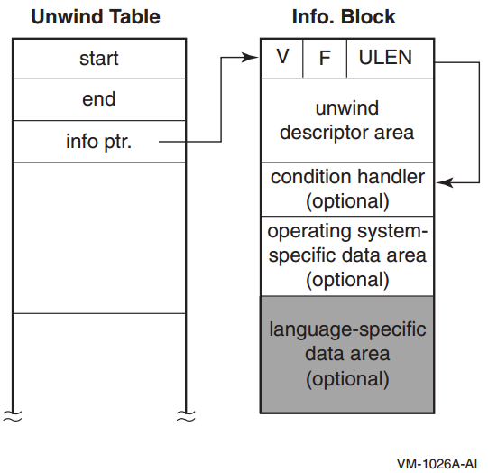
Note that a leaf procedure may have no unwind table entry (see Section A.6, ''Default Unwind Information'').
The unwind table and the unwind information block must each be aligned at an 8-byte boundary. Within the information block, the condition handler pointer must also be aligned at an 8-byte boundary.
ULEN, a 32-bit longword field that contains the length in quadwords of the unwind descriptor area (zero is a legitimate value).
F, a 16-bit flag field (see Table A.1, ''F (Flags) Field of the Information Block''). Four bits are set aside for operating system-specific use. Two of these bits are defined by the Itanium software conventions, and the remaining bits are reserved.
In this version, OpenVMS uses only the two low-order bits of the four bits available for operating system-specific use. These OpenVMS-specific bits can be accessed using the following:#define UNW_IVMS_MODE(x) (((x) >> 44) & 0x3L)
These two bits form an enumeration code, which is interpreted as shown in Table A.1, ''F (Flags) Field of the Information Block''.Note
For OpenVMS I64, the value of UNW_IVMS_MODE field must be 2 or 3. Otherwise, exception handling behaviour is undefined.
The EHANDLER flag is set if the condition handler must be called during search for an exception handler. The UHANDLER flag is set if this routine must be called during the second unwind. (Note that for OpenVMS I64, the EHANDLER and UHANDLER flags are both set or both not set). If neither bit is set, there is no frame handler for this procedure, and the condition handler identifier must be omitted along with the entire language-specific data area.
V, a 16-bit version number that identifies the version of the unwind descriptor format. For this specification, the version number is 1.
#define UNW_LENGTH(x)           ((x) & 0x00000000ffffffffL)
#define UNW_FLAG_UHANDLER(x)    ((x) & 0x0000000200000000L)
#define UNW_FLAG_EHANDLER(x)    ((x) & 0x0000000100000000L)
#define UNW_FLAG_OSMASK         0x0000f00000000000L
#define UNW_FLAG_MASK           0x0000ffff00000000L
#define UNW_VER(x)              ((x) >> 48)
|
Field |
Bit Position |
Description | |
|---|---|---|---|
|
EHANDLER |
<0> |
Set if there is an exception-processing handler established (for this region). (Note that for OpenVMS I64, the EHANDLER and UHANDLER flags are both set or both not set). | |
|
UHANDLER |
<1> |
Set if there is an exception cleanup (second/unwind pass) handler established. (Note that for OpenVMS I64, the EHANDLER and UHANDLER flags are both set or both not set). | |
|
UNUSED |
<11:2> |
Reserved | |
|
UNW_IVMS_MODE |
<13:12> |
Value |
Description |
| 0 |
Reserved.? | ||
| 1 |
Reserved.? | ||
| 2 |
OpenVMS handler semantics.? | ||
| 3 |
Both OpenVMS handler semantics? and OpenVMS-specific data area are present. | ||
|
OS_SPECIFIC_FLAGS |
<15:14> |
Reserved and must be zero. | |
A.4.1.1. Unwind Descriptor Area
The unwind descriptor area contains a contiguous sequence of records describing the unwind regions in the procedure. Each group of records begins with a region header record that identifies the type and length of the region. The region header record is followed by any number of descriptor records that supply additional unwind information about the region.
Region header records
Descriptor records for prologue regions
Descriptor records for body regions
This section describes the record types in each of these categories, lists rules for using unwind descriptor records, and explains how the records must be processed.
The information is encoded in variable-length records with a record type and one or more additional fields. The length of each record is implicit from the record type and its fields. All records are an integral number of bytes in length. In the descriptor record tables in the next three sections, the third column lists the format of each record type. These record formats are described in Section A.5, ''Unwind Descriptor Record Format''.
Because the unwind descriptor area must be a multiple of 8 bytes, the last unwind descriptor must be followed by zero bytes as necessary to pad the area to an 8-byte boundary. These zero bytes will be interpreted as prologue region header records, specifying a zero-length prologue region, and serve as no-ops.
A.4.1.2. Region Header Records
|
Record Type |
Fields |
Format |
Description |
|---|---|---|---|
|
BODY |
RLEN |
R1/R3 |
Defines a body region. |
|
PROLOGUE |
RLEN |
R1/R3 |
Defines a general prologue region. |
|
PROLOGUE_GR |
RLEN, MASK, GRSAVE |
R2 |
Defines a prologue region with a mask of saved registers, and a set of general registers used for saving preserved registers. |
RLEN — Contains the length of the region, measured in instruction slots (three slots per bundle, counting X-unit instructions as two slots).
MASK — Indicates which registers are saved in the prologue. The PROLOGUE_GR region type is used for entry prologues that save one or more preserved registers in the local register area of the register stack frame. This field defines what combination of RP, AR.PFS, PSP, and the predicate registers are preserved in standard general registers in the local area of the register stack frame. This mask is four bits; see Section A.5, ''Unwind Descriptor Record Format'' for the allocation of these bits. Other registers may be preserved in the prologue, but additional descriptor records are required for registers other than these four.
GRSAVE — Identifies the first general register used to save the preserved registers identified in the mask field. Normally, this identifies a register in the procedure's local stack frame (that is, it should be greater than or equal to 32). However, leaf procedures can choose to use any consecutive sequence of scratch registers.
The entry state for a region matches the exit state of the preceding region, except for body regions that contain a COPY_STATE descriptor record, which is described in Table A.12, ''Body Region Descriptor Records''.
For prologue regions, and body regions with no epilogue code, the exit state is the logical combination of the entry state with the modifications described by the descriptor records for the region.
For body regions with epilogue code, the exit state is the same as the entry state of the corresponding prologue region whose effect is being undone. When shrink-wrap regions are nested, it is possible to reverse the effects of multiple prologues at once.
A.4.1.3. Descriptor Records for Prologue Regions
This section lists the descriptor records that can be used to describe prologue regions. In addition, the descriptor records described in Section A.4.1.5, ''Descriptor Records for Body or Prologue Regions '' can also be used. In the absence of any descriptor records or information in the region header record, a prologue region is assumed to create no memory stack frame and save no registers. Descriptors need be supplied only to override these defaults.
|
Record Type |
Fields |
Format |
Description |
|---|---|---|---|
|
MEM_STACK_F |
T, SIZE |
P7 |
Specifies a fixed-size memory stack frame, when SP is modified, and size of frame. |
|
MEM_STACK_V |
T |
P7 |
Specifies a variable-size memory stack frame, and when PSP is saved. |
|
PSP_GR |
GR |
P3 |
Specifies the general register where PSP is saved. |
|
PSP_SPREL |
SPOFF |
P7 |
Specifies (as an SP-relative offset) the memory location where PSP is saved. |
T — Describes a time, T, when a particular action occurs within the prologue. The time is specified as an instruction slot number, counting three slots per bundle. The first instruction slot in the prologue is numbered zero.
For procedures with a memory stack frame, the instruction that modifies SP (fixed-size frame) or that saves PSP (variable-size frame) must be identified with either a MEM_STACK_F or a MEM_STACK_V record.
In all other cases, if the time is not specified, the unwinder can assume that both of the following are true:The original contents of the register is valid through the end of the prologue region.
The saved copy of the register is valid by the end of the prologue region.
In a zero-length prologue region, the time parameter is irrelevant, and must be specified as zero.
SIZE — Contains the fixed size of the memory stack frame, measured in 16-byte units.
GR — Identifies a general register, or the first in a consecutive group of general registers, that is used for preserving the value of another register (as implied by the record type). Typically, this field identifies a general register in the procedure's local stack frame. A leaf procedure, however, can choose to use scratch registers. (A non-leaf procedure can also use scratch registers through a body region that makes no calls, but then it must move any values saved in scratch registers to a more permanent save location prior to making any calls, and needs a second prologue region to describe this process).
SPOFF — Identifies a location in the memory stack where a register or group of registers are spilled to memory. This location is specified relative to the current stack pointer. See Section A.5, ''Unwind Descriptor Record Format'' for the encoding of this field.
|
Record Type |
Fields |
Format |
Description |
|---|---|---|---|
|
RP_WHEN |
T |
P7 |
Specifies when RP is saved. |
|
RP_GR |
GR |
P3 |
Specifies the general register where RP is saved. |
|
RP_BR |
BR |
P3 |
Specifies the alternate branch register used as return pointer. |
|
RP_PSPREL |
PSPOFF |
P7 |
Specifies (as a PSP-relative offset) the memory location where RP is saved. |
|
RP_SPREL |
SPOFF |
P8 |
Specifies (as an SP-relative offset) the memory location where RP is saved. |
BR — Identifies a branch register that contains the return link, when the return link is not either in B0 or saved to another location.
PSPOFF — Identifies a location in the memory stack where a register or group of registers is spilled to memory. The location is specified relative to the previous stack pointer (which is equal to the current stack pointer plus the frame size). See Section A.5, ''Unwind Descriptor Record Format'' for the encoding of this field.
|
Record Type |
Fields |
Format |
Description |
|---|---|---|---|
|
PFS_WHEN |
T |
P7 |
Specifies when AR.PFS is saved. |
|
PFS_GR |
GR |
P3 |
Specifies general register where AR.PFS is saved. |
|
PFS_PSPREL |
PSPOFF |
P7 |
Specifies (as a PSP-relative offset) the memory location where AR.PFS is saved. |
|
PFS_SPREL |
SPOFF |
P8 |
Specifies (as an SP-relative offset) the memory location where AR.PFS is saved. |
|
Record Type |
Fields |
Format |
Description |
|---|---|---|---|
|
PREDS_WHEN |
T |
P7 |
Specifies when the predicate registers are saved. |
|
PREDS_GR |
GR |
P3 |
Specifies the general register where predicate registers are saved. |
|
PREDS_PSPREL |
PSPOFF |
P7 |
Specifies (as a PSP-relative offset) memory location where predicate registers are saved. |
|
PREDS_SPREL |
SPOFF |
P8 |
Specifies (as an SP-relative offset) memory location where predicate registers are saved. |
|
Record Type |
Fields |
Format |
Description |
|---|---|---|---|
|
FR_MEM |
RMASK |
P6 |
Specifies (as a bit mask) which preserved floating-point registers are spilled to memory by this prologue. |
|
FRGR_MEM |
GRMASK, FRMASK |
P5 |
Specifies (as a bit mask) which preserved general and floating-point registers are spilled to memory by this prologue. |
|
GR_GR |
GRMASK, GR |
P9 |
Specifies (as a bit mask) which preserved general registers are saved in other general registers, and the general register where first preserved general register is saved. |
|
GR_MEM |
RMASK |
P6 |
Specifies (as a bit mask) which preserved general registers are spilled to memory by this prologue. |
|
BR_MEM |
BRMASK |
P1 |
Specifies (as a bit mask) which preserved branch registers are spilled to memory by this prologue. |
|
BR_GR |
BRMASK, GR |
P2 |
Specifies (as a bit mask) which preserved branch registers are saved in general registers by this prologue, and the general register where first branch register is saved. |
|
SPILL_BASE |
PSPOFF |
P7 |
Specifies (as a PSP-relative offset) end of (first byte following the) spill area in memory stack frame. |
|
SPILL_MASK |
IMASK |
P4 |
Specifies (as a bit mask) when preserved registers are spilled. |
RMASK, FRMASK, GRMASK, BRMASK — Identify which preserved floating-point registers, general registers, and branch registers are saved by the prologue region. The fr_mem record uses a short RMASK field, which can be used when a subset of floating-point registers from the range F2-F5 is saved. The FRGR_MEM record can be used for any number of saved floating-point and general registers. The GR_MEM record can be used when only general registers (R4-R7) are saved.
IMASK — Identifies when each preserved floating-point, general, and branch register is saved. It contains a two-bit field for each instruction slot in the prologue, that indicates whether the instruction in that slot saves one of these preserved registers. The length of this field is implied by the size of the prologue region as given in the region header record. It contains two bits for each instruction slot in the region, and the length of the field is rounded up to the next whole byte boundary.
The original contents of these preserved registers are valid through the end of the prologue region.
The saved copies of the registers are valid by the end of the prologue region.
There can be only one SPILL_BASE and one SPILL_MASK record per prologue region. Each GR_GR and BR_GR record describes a set of registers that is saved to a consecutive set of general registers (typically in the local register stack frame). To represent registers saved to nonconsecutive general registers, two or more of each of these records can be used.
|
Record Type |
Fields |
Format |
Description |
|---|---|---|---|
|
UNAT_WHEN |
T |
P7 |
Specifies when AR.UNAT is saved. |
|
UNAT_GR |
GR |
P3 |
Specifies the general register where AR.UNAT is saved. |
|
UNAT_PSPREL |
PSPOFF |
P7 |
Specifies (as a PSP-relative offset) the memory location where AR.UNAT is saved. |
|
UNAT_SPREL |
SPOFF |
P8 |
Specifies (as an SP-relative offset) the memory location where AR.UNAT is saved. |
|
Record Type |
Fields |
Format |
Description |
|---|---|---|---|
|
LC_WHEN |
T |
P7 |
Specifies when AR.LC is saved. |
|
LC_GR |
GR |
P3 |
Specifies general register where AR.LC is saved. |
|
LC_PSPREL |
PSPOFF |
P7 |
Specifies (as a PSP-relative offset) the memory location where AR.LC is saved. |
|
LC_SPREL |
SPOFF |
P8 |
Specifies (as an SP-relative offset) the memory location where AR.LC is saved. |
Note
The FPSR-related descriptor records (FPSR_WHEN, FPSR_GR, FPSR_PSPREL, FPSR_SPREL) defined in the Itanium® Software Conventions and Runtime Architecture Guide are not supported on OpenVMS IA-64.
|
Record Type |
Fields |
Format |
Description |
|---|---|---|---|
|
PRIUNAT_WHEN_GR |
T |
P8 |
Specifies when the primary UNaT collection is copied to a general register. |
|
PRIUNAT_WHEN_ |
T |
P8 |
Specifies when the primary UNaT collection is saved in memory. |
|
PRIUNAT_GR |
GR |
P3 |
Specifies the general register where the primary UNaT collection is copied. |
|
PRIUNAT_PSPREL |
PSPOFF |
P8 |
Specifies (as a PSP-relative offset) the memory location where the primary UNaT collection is saved. |
|
PRIUNAT_SPREL |
SPOFF |
P8 |
Specifies (as an SP-relative offset) the memory location where the primary UNaT collection is saved. |
|
Record Type |
Fields |
Format |
Description |
|---|---|---|---|
|
BSP_WHEN |
T |
P8 |
Specifies when AR.BSP is saved. The backing store pointer can be saved, along with the AR.BSPSTORE pointer and the AR.RNAT register, to indicate a discontinuity in the backing store. |
|
BSP_GR |
GR |
P3 |
Specifies the general register where AR.BSP is saved. |
|
BSP_PSPREL |
PSPOFF |
P8 |
Specifies (as a PSP-relative offset) the memory location where AR.BSP is saved. |
|
BSP_SPREL |
SPOFF |
P8 |
Specifies (as an SP-relative offset) the memory location where AR.BSP is saved. |
|
BSPSTORE_WHEN |
T |
P8 |
Specifies when AR.BSPSTORE is saved. |
|
BSPSTORE_GR |
GR |
P3 |
Specifies the general register where AR.BSPSTORE is saved. |
|
BSPSTORE_PSPREL |
PSPOFF |
P8 |
Specifies (as a PSP-relative offset) the memory location where AR.BSPSTORE is saved. |
|
BSPSTORE_SPREL |
SPOFF |
P8 |
Specifies (as an SP-relative offset) the memory location where AR.BSPSTORE is saved. |
|
RNAT_WHEN |
T |
P8 |
Specifies when AR.RNAT is saved. |
|
RNAT_GR |
GR |
P3 |
Specifies the general register where AR.RNAT is saved. |
|
RNAT_PSPREL |
PSPOFF |
P8 |
Specifies (as a PSP-relative offset) the memory location where AR.RNAT is saved. |
|
RNAT_SPREL |
SPOFF |
P8 |
Specifies (as an SP-relative offset) the memory location where AR.RNAT is saved. |
A.4.1.4. Descriptor Records for Body Regions
|
Record Type |
Fields |
Format |
Description |
|---|---|---|---|
|
EPILOGUE |
T, ECOUNT |
B2/B3 |
Body region contains epilogue code for one or more prologues. |
|
LABEL_STATE |
LABEL |
B1/B4 |
Labels the entry state for future reference. |
|
COPY_STATE |
LABEL |
B1/B4 |
Use the labeled entry state as entry state for this region. |
T — Indicates the location (relative to the end of the region) of the instruction that restores the previous SP value. The number is a count of the remaining instruction slots to the end of the region (thus, a value of zero indicates the final slot in the region).
ECOUNT — Indicates how many additional levels of nested shrink-wrap regions are being popped at the end of a body region with epilogue code. A value of zero indicates that one level must be popped. When OpenVMS handler semantics apply, this value must be zero.
LABEL — Identifies a previously-specified body region, whose entry state must be copied for this body region.
Prologue regions nest within other prologue regions, and are balanced by body regions with an epilogue descriptor. An epilogue descriptor with an ECOUNT of n serves to balance (n+1) earlier prologue regions. When OpenVMS handler semantics apply, prologue nesting is not allowed.
When the LABEL_STATE descriptor is used to label an entry state, it must appear prior to any general unwind descriptors in the same body region.
A COPY_STATE descriptor must appear prior to any general unwind descriptors in the same body region.
Prologue region A
Body region B (no epilogue)
Prologue region C
Body region C (label_state 1, epilogue count 2)
Body region D (copy_state 1, epilogue count 2)
The effect of the COPY_STATE in body region D restores the entry state of body region C, as well as the two prologue regions within which the body region is nested.
The scope of a label is restricted to a single unwind descriptor area.
A.4.1.5. Descriptor Records for Body or Prologue Regions
This section lists the descriptor records that can be used to describe either prologue or body regions. These descriptors provide complete generality for compilers to perform register spills and restores anywhere in the procedure, without creating an arbitrary boundary between prologue and body.
|
Record Type |
Fields |
Format |
Description |
|---|---|---|---|
|
SPILL_PSPREL |
T, REG, PSPOFF |
X1 |
Specifies (as a PSP-relative offset) when and where REG is saved. |
|
SPILL_SPREL |
T, REG, SPOFF |
X1 |
Specifies (as an SP-relative offset) when and where REG is saved. |
|
SPILL_REG |
T, REG, TREG |
X2 |
Specifies when and where REG is saved in another register, TREG, or restored. |
|
SPILL_PSPREL_P |
QP, T, REG, PSPOFF |
X3 |
Specifies (as a PSP-relative offset) when and where REG is saved, under predicate QP. |
|
SPILL_SPREL_P |
QP, T, REG, SPOFF |
X3 |
Specifies (as an SP-relative offset) when and where REG is saved, under predicate QP. |
|
SPILL_REG_P |
QP, T, REG, TREG |
X4 |
Specifies when and where REG is saved in another register, TREG, or restored, under predicate QP. |
T — Describes a time, T, when a particular action occurs within the prologue or body. The time is specified as an instruction slot number, counting three slots per bundle. The first slot in the containing prologue or body is numbered zero.
REG — Identifies the register being spilled or restored at the given point in the code. This field may indicate any of the preserved general registers, floating-point registers, branch registers, application registers, predicate registers, previous SP, primary UNaT collection, or return pointer. See Section A.5, ''Unwind Descriptor Record Format'' for the encoding of this field.
TREG — Identifies a target register to which the value being spilled is copied. This field may indicate any general register, floating-point register, or branch register; it may also contain the special Restore target, indicating the point at which a register is restored. See Section A.5, ''Unwind Descriptor Record Format'' for the encoding of this field.
QP — Identifies a qualifying predicate register, which determines whether the indicated spill or restore instruction executes. The qualifying predicate register must be a preserved predicate if there are any procedure calls in the range between the spill and restore, and it must remain live throughout the range.
If a body region contains any general descriptors and an epilogue descriptor, the effects of the general descriptors are undone when the unwind state is restored by popping one or more prologues. By the end of the body region, the code must have restored any preserved registers that the new unwind state indicates are restored. It is not necessary, however, to record the points at which registers are restored unless the locations used to save the values are modified before the end of the region.
A.4.1.6. Rules for Using Unwind Descriptors
PROLOGUE_GR (RP, AR.PFS, PSP, and the predicate registers)
MEM_STACK_V (PSP is saved in a general register)
RP_WHEN, RP_GR, RP_PSPREL, or RP_SPREL (RP)
PFS_WHEN, PFS_GR, PFS_PSPREL, or (AR.PFS)
UNAT_WHEN, UNAT_GR, UNAT_PSPREL, or UNAT_SPREL (AR.UNAT)
LC_WHEN, LC_GR, LC_PSPREL, or LC_SPREL (AR.LC)
FR_MEM, FRGR_MEM, or GR_MEM (floating-point registers and general registers)
BR_MEM or BR_GR (branch registers)
SPILL_PSPREL, SPILL_SPREL, SPILL_REG, SPILL_PSPREL_P, SPILL_SPREL_P, SPILL_REG_P (any register)
Certain descriptor records explicitly name a save location for a register (records whose names end with _GR, PSPREL, or _SPREL). If a register is described by one of these records, the unwinder uses the named location.
Some descriptor records specify that registers are saved to the spill area (FR_MEM, FRGR_MEM, GR_MEM, BR_MEM). These locations are determined by the conventions for the spill area.
- Any remaining registers that are named as saved but do not have an explicit save location are assigned consecutive general registers, beginning with the general register identified by the PROLOGUE_GR region header record. If the prologue region uses a prologue header record, the first general register is assumed to be R32. The registers are saved as needed in the following order:
Return pointer, RP
Previous function state, AR.PFS
Previous stack pointer, PSP
Predicate registers
User NaT collection register, AR.UNAT
Loop counter, AR.LC
Primary UNaT collection
Note
Without explicitly specifying a save location, the only way to indicate that any of the last four groups of registers (e through h) is saved is to use one of the corresponding _WHEN descriptor records.
A.4.1.7. Processing Unwind Descriptors
The unwind process for a frame begins by locating the unwind table entry for a given PC. (A leaf procedure may have no unwind table entry; see Section A.4, ''Data Structures'').
If there is an unwind table entry, the unwinder then locates the unwind information block and checks the size of the unwind descriptor area. If this area is zero length, the unwinder must use the default conditions as above.
In preparation for reading the unwind descriptor records, the unwinder must start with an initial current state record, and an empty stack of state records. A state record describes the locations of all preserved registers at entry to a region. The initial value of the current state record must describe the frame in its default condition.
The unwind descriptor records must be read and processed sequentially, beginning with the first descriptor record for a procedure, continuing until the PC is contained within the current region. For each prologue region header, the current state record must be pushed on the stack, and the descriptor records for the prologue region must be applied to the current state record. When a body region with epilogue code is seen, one or more states must be popped from the stack, and the entry state for the next region is taken as the last state popped. This restores the current state to the entry state of the matching prologue.
When a body region contains a LABEL_STATE descriptor, the unwind processor must replicate the current unwind state, including the current stack of prologues. When a body region contains a COPY_STATE descriptor, the unwind processor must discard the current state and stack, and restore the replicated state and stack that corresponds with the label.
When the current PC is within a body region, the unwinder can generate the context of the previous frame by restoring registers as indicated by the current state record. If the body region has epilogue code and the PC is beyond the indicated point where SP is restored, the unwinder must assume that SP has already been restored, and that all registers spilled to the memory stack frame (except those between PSP and PSP+16) have also been restored. Registers spilled to the scratch area in the caller's frame may not have been restored at that point, and the unwinder must use the values in memory.
When the current PC is within a prologue region, the unwinder must look for descriptor records that specify a time parameter that is at or beyond the current PC. The unwinder must ignore these state modifications when applying descriptor records to the current state. If a register is saved but does not have a specified time, the unwinder can assume that the original value is not modified within the prologue and can ignore it.
The layout and size of the preserved register spill area cannot be determined without reading all the prologue region descriptor records in the procedure, and merging the save masks for the general, floating-point, and branch registers.
A.4.2. Condition Handler
The condition handler identifier is accessed by adding the size of the unwind descriptor area (ULEN, which is the count of quadwords), plus the size of the header quadword, to the information block pointer. The value in that location is the GP-relative offset for the global offset table entry that contains the function pointer (address of a function descriptor) for the condition handler. The dispatcher calls this routine during the first unwind only if the EHANDLER bit is set, and during the second unwind only if the UHANDLER bit is set.
Because the operating system-specific data area immediately follows the condition handler identifier, the address of this area must be made available to the condition handler.
A.4.3. Operating System-Specific Data Area
If an operating system-specific data area is present, it is located immediately following the condition handler (if any) and before the language-specific data area (if any). If there is no condition handler, the operating system-specific data area is located immediately following the unwind descriptors (where the condition handler would have been). The operating system-specific data area must be aligned at a quadword boundary.
|
CHF$PH_MCH_OSSD |
The virtual address of the operating system-specific data area. |
The OpenVMS-specific data area is present if the UNW_IVMS_MODE field in the unwind information block has the value 3 (see Table A.1, ''F (Flags) Field of the Information Block'').
An OpenVMS-specific data area consists of one or more segments, where each segment begins with a 15-bit TYPE code field followed by a 1-bit SUCCESSOR flag as shown in the following figure.
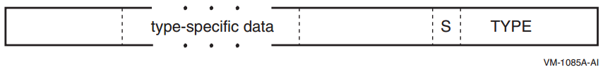
|
Name |
Value |
Use |
|---|---|---|
|
OSSD$K_GENERAL_INFO |
1 |
General information |
|
OSSD$K_CALL_SPILL_INFO |
2 |
Caller spill register information |
Unless otherwise stated, each kind of segment data can occur at most once in any given data area.
A.4.3.1. General Information Segment
The OpenVMS general information segment contains various flags and general exception handling information, and is described in Table A.14, ''Operating System-Specific Data Area''.
A general information segment may be omitted if all of its fields would have their default values.
|
Field |
Bit Position |
Description | ||
|---|---|---|---|---|
|
OSSD$V_TYPE |
<14:0> |
A 15-bit type field that identifies the segment as a general information segment. The value of this field is OSSD$K_GENERAL_INFO (=1). | ||
|
OSSD$V_S |
<15> |
If set to 1, another segment immediately follows this one. If set to 0, there are no further segments in this area. | ||
|
OSSD$V_ |
<18:16> |
A 3-bit field that encodes the caller's desired exception-reporting behavior when calling certain mathematically oriented library routines. These routines generally search up the call stack to find the desired exception behavior whenever an error is detected. However, if no floating-point exceptions are enabled in the I64 FPSR, then no stack search is performed and the exception mode SIGNAL_SILENT is assumed.? | ||
|
Value |
Name |
Meaning | ||
| 0 |
OSSD$K_EXC_ |
Raise exceptions for all error conditions except for underflows producing a 0 result. This is the default mode. | ||
| 1 |
OSSD$K_EXC_ |
Raise exceptions for all error conditions (including underflows). | ||
| 2 |
OSSD$K_EXC_ |
Raise no exceptions. Create only finite values (no
infinities, denormals, or NaNs). In this mode, either
the function result or the C language
| ||
| 3 |
OSSD$K_EXC_ |
Raise no exceptions except as controlled by separate IEEE exception enable bits. Create infinities, denormals, or NaN values according to the IEEE floating-point standard. | ||
| 4 |
OSSD$K_EXC_ |
Perform the exception-mode behavior specified by this procedure's caller. | ||
|
OSSD$V_TARGET_ |
<19> |
If set to 1, the exception handler for this procedure is invoked when this procedure is the target invocation of an unwind. Note that a procedure is the target invocation of an unwind if it is the procedure in which execution resumes following completion of the unwind. The default value is 0. | ||
|
OSSD$V_BASE_ |
<20> |
This bit must be zero except in operating system routines whose documented purpose is to provide the base frame marker. If set to 1, this bit indicates the logical base frame of a stack that precedes all frames corresponding to user code. The interpretation and use of this frame and whether there are any predecessor frames is system software defined (and subject to change). The default value is 0. | ||
|
OSSD$V_HANDLER_ |
<21> |
If set to 1, the handler can be reinvoked, allowing an occurrence of another exception while the handler is already active. If this bit is set to 0, the exception handler cannot be reinvoked. The default value is 0. | ||
|
OSSD$V_AST_ |
<22> |
If set to 1, then this is an AST dispatch frame. The interrupted procedure is the predecessor frame on the stack and much of its context is saved in this procedure's memory stack frame. The default value is 0. | ||
|
OSSD$V_ |
<23> |
If set to 1, then this is an exception dispatch frame. The excepting procedure is the predecessor frame on the stack and much of its context is saved in this procedure's memory stack frame. The default value is 0. | ||
|
OSSD$V_TIE_FRAME |
<24> |
If set to 1, this is a frame created by the Translated Image Executive for use during the execution of translated images. The default value is 0. | ||
|
OSSD$V_BOTTOM_ |
<25> |
A value of 1 indicates that this frame has no predecessor frames (that is, this frame is the end of the invocation call chain). The default value is 0. | ||
|
OSSD$V_HANDLER_ |
<26> |
A value of 1 indicates that an exception handler data field is present in the unwind information block. The default value is 0. | ||
|
OSSD$V_SS_ |
<27> |
If set to 1, then this is the System Service dispatch frame. Much of the context for a procedure calling a system service is saved on an inner mode stack. The default value is 0. | ||
|
OSSD$V_KP_ |
<28> |
Internal use only. | ||
|
OSSD$V_ |
<29> |
Tags code executing in context of another routine whose IP is in B0 | ||
|
RESERVED |
<63:30> |
Reserved; must be zero. | ||
A.4.3.2. Caller Spill Register Information
The OpenVMS caller spill register information segment encodes information to emulate the effects of callee register saving conventions even when caller save/restore conventions are in use. The key difference between this and the more general unwind information described in other parts of Section A.4 is that the information described here must be applied in the frame with which it is associated in order to complete that frame whereas other information is applied in order to unwind to the previous frame.
|
Field |
Bit Position |
Description |
|---|---|---|
|
OSSD$V_TYPE |
<14:0> |
A 15-bit type field that identifies the segment as a caller spill register information segment. The value of this field is OSSD$K_CALLER_SPILL_INFO (=2). |
|
OSSD$V_S |
<15> |
If set to 1, another segment immediately follows this one. If set to 0, there are no further segments in this area. |
|
OSSD$W_LENGTH |
<31:16> |
A two-byte field that specifies the number of quadwords in this segment (including OSSD$V_TYPE, OSSD$V_S and OSSD$W_LENGTH itself). |
|
OSSD$T_SPILL_DATA |
<...> |
See below. |
The OSSD$T_SPILL_DATA field in a spill register segment consists of a sequence of triples encoded as shown in Figure A.3, ''Format of OSSD$T_SPILL_DATA''.
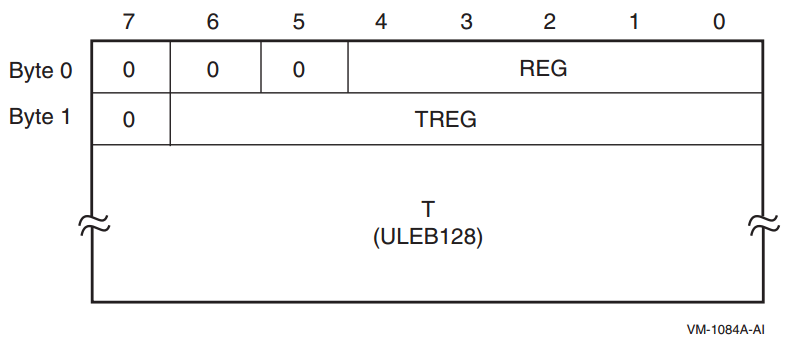
|
OSSD$V_REG |
A 5-bit field that identifies the saved static general register. Bits <7:5> of byte 0 are reserved and must be zero. A REG value of zero indicates that there is no more spill data; one or more zero bytes are used to pad the end of the spill data if needed to fill out the specified length. |
|
OSSD$V_TREG |
A 7-bit field that identifies one of the general registers. Bit <7> of byte 1 is reserved and must be zero. A TREG value other than zero indicates that the contents of register REG is saved in register TREG. A TREG value of zero indicates that register REG is restored, that is, is no longer saved elsewhere. |
|
OSSD$T_T |
A ULEB128 slot offset from the start address given in the corresponding unwind table (see Section A.4.1, ''Unwind Table and Unwind Information Block'') to the instruction that performs the save or restore. It is valid for save actions to occur in a prologue and restore events to occur in an epilogue. (Save actions events will never occur in an epilogue and restore events will never occur in an prologue because these would require a call to occur in either the prologue or epilogue, which is forbidden). |
It is valid for two or more save actions for the same register REG to occur without an intervening restore of that register. In this case, the later save register location TREG supercedes the earlier one as the save location for register REG beginning at the specified offset T.
When unwinding to a frame, the unwind information of the called frame is first used to construct the frame of the caller; the unwind operation must then be completed by using any spill register information for that caller.
A.4.4. Language-Specific Data Area
The language-specific data area contains information whose format and interpretation need be known only by the condition handler that uses it. As such, this area is not described in this document.
To preserve sharability of the image of which language-specific data is a part, that data should be read-only and position-independent. For example, an address within the associated procedure might be represented as an offset relative to the starting address given in the unwind table for the routine.
|
CHF$PH_MCH_UWR_START |
The virtual address of an unwind region. May be used together with an offset in the language specific data to encode an address within a procedure. |
|
CHF$PH_MCH_DADDR |
The virtual address of the language-specific data area. |
A.5. Unwind Descriptor Record Format
Note
For compatibility with the VAX and Alpha calling standards, this appendix describes big-endian values stored in little-endian bytes.
The unwind descriptor records are encoded in variable-length byte strings. The various record formats are described in this appendix. The first byte of each record is sufficient to determine its format. The high-order bit of this byte determines whether it is a header record (if the bit is zero), or a region descriptor record (if the bit is one). The remaining bits and any subsequent bytes are divided into separate fields. In most formats, the first field, R, identifies the record type. The record formats are listed by the bit pattern of the first byte in Table A.17, ''Record Formats''.
|
Region Header Records |
Prologue Descriptor Records |
Body Descriptor Records | |||
|---|---|---|---|---|---|
|
Bit Pattern |
Format |
Bit Pattern |
Format |
Bit Pattern |
Format |
00-- ---- |
R1 |
100- ---- |
P1 |
10-- ---- |
B1 |
0100 0--- |
R2 |
1010 ---- |
P2 | ||
0110 00-- |
R3 |
1011 0--- |
P3 | ||
1011 1000 |
P4 | ||||
1011 1001 |
P5 | ||||
110- ---- |
P6 |
110- ---- |
B2 | ||
1110 ---- |
P7 |
1110 0000 |
B3 | ||
1111 0000 |
P8 |
1111 -000 |
B4 | ||
1111 0001 |
P9 | ||||
1111 1001 |
X1 |
1111 1001 |
X1 | ||
1111 1010 |
X2 |
1111 1010 |
X2 | ||
1111 1011 |
X3 |
1111 1011 |
X3 | ||
1111 1100 |
X4 |
1111 1100 |
X4 | ||
1111 1111 |
P10 | ||||
Divide the number into groups of 7 bits, beginning at the low-order end.
Discard all groups of leading zeroes, but keep at least the first (low-order) group if the number is all zeroes.
Place a 1 bit to the left of of all but the last group; place a 0 bit to the left of the last group. This forms one or more 8-bit groups.
|
Value |
Encoding |
Interpretation |
|---|---|---|
|
0 |
|
0 |
|
127 |
|
127 |
|
128 |
|
0 + (1 << 7) |
|
1544 |
|
8 + (12 << 7) |
|
49,802 |
|
10 + (5 << 7) + (3 << 14) |
Fields in the ULEB128 format always follow the fixed fields, and begin on a byte boundary.
A.5.1. Region Header Records
The PROLOGUE and BODY region header records can appear in either format R1 or R3, depending on the magnitude of the region length field. If the region length is no greater than 31 instruction slots, the R1 format may be used; otherwise, format R3 must be used.
A.5.1.1. Format R1
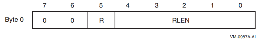
|
Record Type |
R |
|---|---|
|
PROLOGUE |
0 |
|
BODY |
1 |
A.5.1.2. Format R2
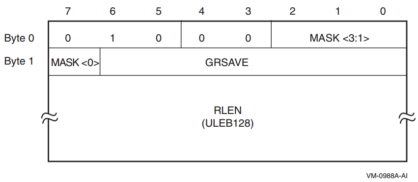
|
Mask bit |
Meaning when bit is set |
|---|---|
|
Byte 0, bit 2 |
RP is saved in a standard general register. |
|
Byte 0, bit 1 |
AR.PFS is saved in a standard general register. |
|
Byte 0, bit 0 |
PSP is saved in a standard general register. |
|
Byte 1, bit 7 |
Predicate registers are saved in a standard general register. |
The GRSAVE field identifies the general register in which the first of these values is stored. Additional general registers are used as needed. For example, assume that RP, AR.PFS, and the predicate registers are stored, but not PSP. The mask bits would be 1101, and GRSAVE might be set to 39, indicating that the three values are stored in R39, R40, and R41, respectively.
A.5.1.3. Format R3
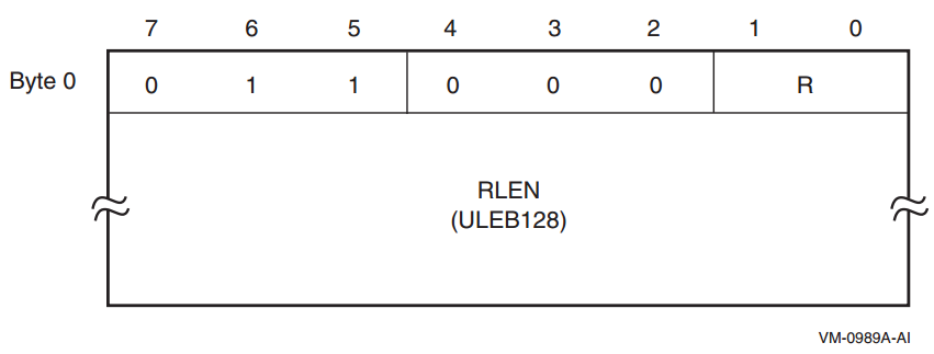
|
Record Type |
R |
|---|---|
|
PROLOGUE |
00 |
|
BODY |
01 |
A.5.2. Descriptor Records for Prologue Regions
A.5.2.1. Format P1
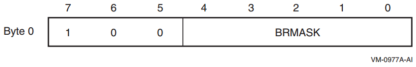
This format is used only for the BR_MEM descriptor record.
The five bits in the BRMASK field are used to indicate which of the five preserved branch registers (B1-B5) are saved in the prologue. Bit 0 corresponds to B1; bit 4 corresponds to B5. If the bit is clear, the corresponding register is not saved; if the bit is set, the corresponding register is saved.
A.5.2.2. Format P2
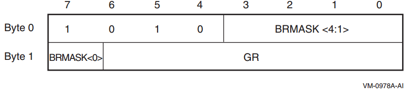
This format is used only for the BR_GR descriptor record.
The five bits in the BRMASK field are used to indicate which of the five preserved branch registers (B1-B5) are saved in the prologue. Bit 7 of byte 1 corresponds to B1; bit 3 of byte 0 corresponds to B5. If the bit is clear, the corresponding register is not saved; if the bit is set, the corresponding register is saved.
The GR field identifies the general register in which the first of these registers is stored. Additional general registers are used as needed. For example, assume that B1, B4, and B5 are stored. The mask bits would be 11001, and GR might be set to 37, indicating that the three branch registers are stored in R37, R38, and R39, respectively.
A.5.2.3. Format P3
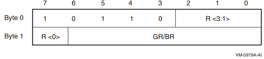
|
Record Type |
R |
Notes |
|---|---|---|
|
PSP_GR |
0 | |
|
RP_GR |
1 | |
|
PFS_GR |
2 | |
|
PREDS_GR |
3 | |
|
UNAT_GR |
4 | |
|
LC_GR |
5 | |
|
RP_BR |
6 | |
|
RNAT_GR |
7 | |
|
BSP_GR |
8 | |
|
BSPSTORE_GR |
9 | |
|
FPSR_GR |
10 |
Not supported on OpenVMS |
|
PRIUNAT_GR |
11 |
A.5.2.4. Format P4
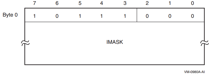
This format is used only by the SPILL_MASK descriptor record. The first byte is followed by the IMASK field, whose length is determined by the length of the current prologue region as given by the region header record. The IMASK field contains two bits for each instruction slot in the region, and the size is rounded up to the next whole number of bytes, if necessary.
|
Bit Pair |
Meaning |
|---|---|
|
00 |
The instruction slot does not save one of these registers. |
|
01 |
The instruction slot saves the next floating-point register. |
|
10 |
The instruction slot saves the next general register. |
|
11 |
The instruction slot saves the next branch register. |
A.5.2.5. Format P5
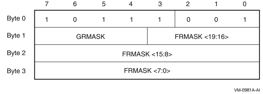
This format is used only by the FRGR_MEM descriptor record.
The bits in the GRMASK field correspond to the preserved general registers (R4-R7). The bits are read from right to left: bit 4 of byte 1 corresponds to R4, and bit 7 corresponds to R7.
The bits in the FRMASK field correspond to the preserved floating-point registers (F2-F5 and F16-F31). The bits are read from right to left: bit 0 of byte 3 corresponds to F2, and bit 3 of byte 1 corresponds to F31.
A value of 1 in each bit position indicates that the corresponding register is saved.
A.5.2.6. Format P6
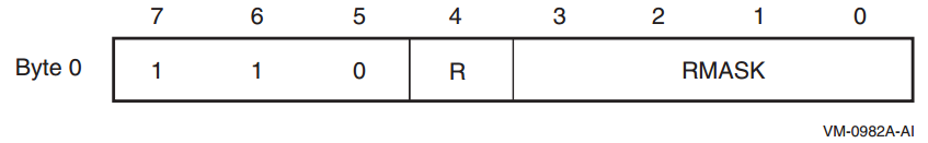
|
Record Type |
R |
|---|---|
|
FR_MEM |
0 |
|
GR_MEM |
1 |
The bits in the RMASK field correspond to either the preserved general registers (R4-R7) or the set of the first four preserved floating-point registers (F2-F5). The bits are read from right to left: bit 0 corresponds to R4 or F2, and bit 3 corresponds to R7 or F5. A value of 1 in each bit position indicates that the corresponding register is saved.
A.5.2.7. Format P7
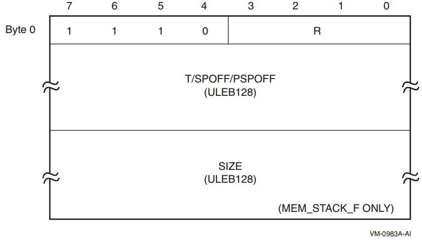
|
Record Type |
R |
Additional ULEB128 Fields |
Notes |
|---|---|---|---|
|
MEM_STACK_F |
0 |
T, SIZE | |
|
MEM_STACK_V |
1 |
T | |
|
SPILL_BASE |
2 |
PSPOFF | |
|
PSP_SPREL |
3 |
SPOFF | |
|
RP_WHEN |
4 |
T | |
|
RP_PSPREL |
5 |
PSPOFF | |
|
PFS_WHEN |
6 |
T | |
|
PFS_PSPREL |
7 |
PSPOFF | |
|
PREDS_WHEN |
8 |
T | |
|
PREDS_PSPREL |
9 |
PSPOFF | |
|
LC_WHEN |
10 |
T | |
|
LC_PSPREL |
11 |
PSPOFF | |
|
UNAT_WHEN |
12 |
T | |
|
UNAT_PSPREL |
13 |
PSPOFF | |
|
FPSR_WHEN |
14 |
T |
Not supported on OpenVMS |
|
FPSR_PSPREL |
15 |
PSPOFF |
Not supported on OpenVMS |
Stack pointer offsets (SPOFF) are represented as positive longword offsets from the top of the stack frame (that is, the location is SP + 4 * SPOFF). Previous stack pointer offsets (PSPOFF) are encoded as positive numbers representing a negative longword offset relative to PSP+16 (that is, the location is PSP + 16 - 4 * PSPOFF).
A.5.2.8. Format P8
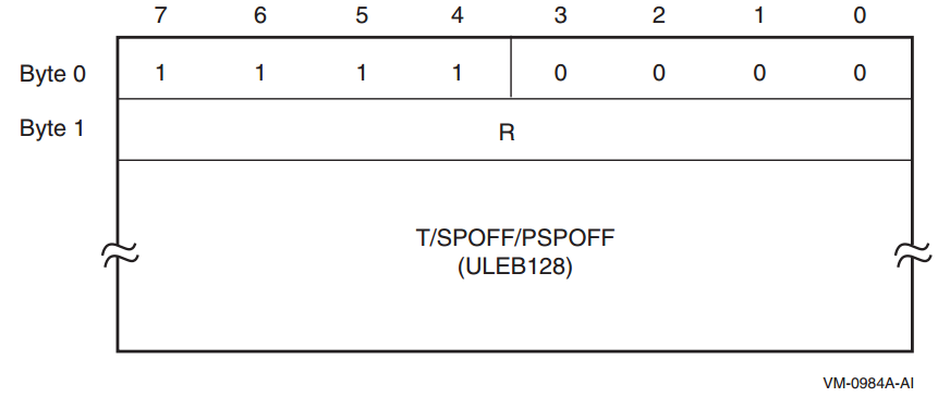
|
Record Type |
R |
Additional ULEB128 Fields |
Notes |
|---|---|---|---|
|
RP_SPREL |
1 |
SPOFF | |
|
PFS_SPREL |
2 |
SPOFF | |
|
PREDS_SPREL |
3 |
SPOFF | |
|
LC_SPREL |
4 |
SPOFF | |
|
UNAT_SPREL |
5 |
SPOFF | |
|
FPSR_SPREL |
6 |
SPOFF |
Not supported on OpenVMS |
|
BSP_WHEN |
7 |
T | |
|
BSP_PSPREL |
8 |
PSPOFF | |
|
BSP_SPREL |
9 |
SPOFF | |
|
BSPSTORE_WHEN |
10 |
T | |
|
BSPSTORE_PSPREL |
11 |
PSPOFF | |
|
BSPSTORE_SPREL |
12 |
SPOFF | |
|
RNAT_WHEN |
13 |
T | |
|
RNAT_PSPREL |
14 |
PSPOFF | |
|
RNAT_SPREL |
15 |
SPOFF | |
|
PRIUNAT_WHEN_GR |
16 |
T | |
|
PRIUNAT_PSPREL |
17 |
PSPOFF | |
|
PRIUNAT_SPREL |
18 |
SPOFF | |
|
PRIUNAT_WHEN_MEM |
19 |
T |
Stack pointer offsets (SPOFF) are represented as positive longword offsets from the top of the stack frame (that is, the location is SP + 4 * SPOFF). Previous stack pointer offsets (PSPOFF) are encoded as positive numbers representing a negative longword offset relative to PSP+16 (that is, the location is PSP + 16 -4 * PSPOFF).
A.5.2.9. Format P9
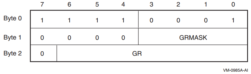
This format is used only by the GR_GR descriptor record.
The bits in the GRMASK field correspond to the preserved general registers (R4-R7). The bits are read from right to left: bit 0 of byte 1 corresponds to R4, and bit 3 corresponds to R7. The GR field identifies the general register in which the first of these registers is stored. Additional general registers are used as needed. For example, assume that R4, R5, and R7 are stored. The mask bits would be 1011, and GR might be set to 37, indicating that the three preserved general registers are stored in R37, R38, and R39, respectively.
A.5.2.10. Format P10
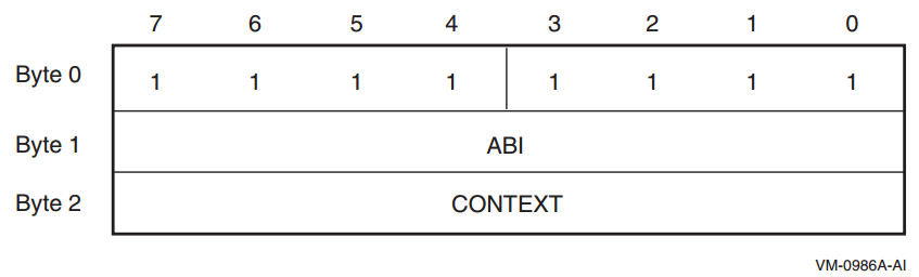
This format is reserved for ABI-specific unwind descriptor records, typically to identify a region whose stack frame indicates some saved context record (for example, a Unix signal context).
The value defined to indicate the OpenVMS ABI is 13. Codes for other operating systems are defined in the Itanium documentation.
The interpretation of the CONTEXT field is ABI dependent. No codes or interpretations are currently defined for OpenVMS. All codes are reserved for future use.
A.5.3. Descriptor Records for Body Regions
The EPILOGUE, LABEL_STATE, and COPY_STATE descriptor records can each appear in two formats, depending on the magnitudes of their fields.
A.5.3.1. Format B1
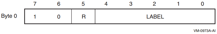
|
Record Type |
R |
|---|---|
|
label_state |
0 |
|
copy_state |
1 |
A.5.3.2. Format B2
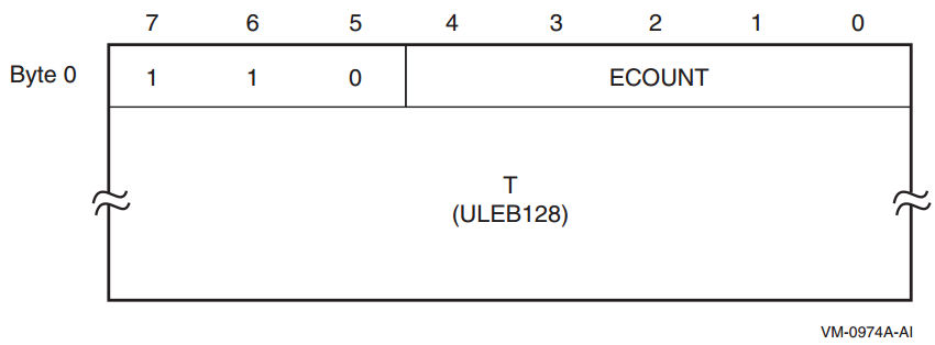
This format is used only for the short form of the EPILOGUE descriptor record. If the ECOUNT field is no greater than 31, this format may be used; otherwise, format B3 must be used.
A.5.3.3. Format B3
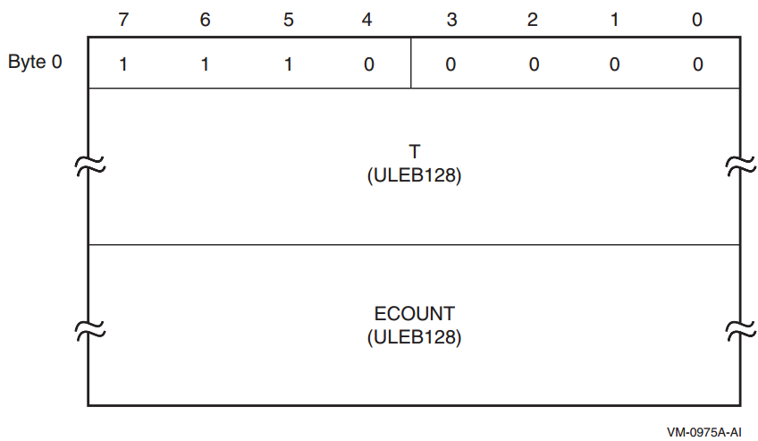
This format is used only for the long form of the EPILOGUE descriptor record.
A.5.3.4. Format B4
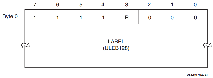
|
Record Type |
R |
|---|---|
|
label_state |
0 |
|
copy_state |
1 |
A.5.4. Descriptor Records for Body or Prologue Regions
The record formats listed here describe general spills and restores, and may appear in either body or prologue regions.
A.5.4.1. Format X1
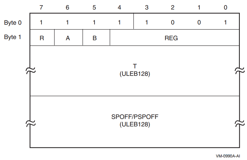
|
Record Type |
R |
|---|---|
|
SPILL_PSPREL |
0 |
|
SPILL_SPREL |
1 |
|
Register |
A |
B |
REG |
Notes |
|---|---|---|---|---|
|
R3-R31 |
0 |
0 |
GR | |
|
F2-F5 or F16-F31 |
0 |
1 |
FR | |
|
B1-B5 |
1 |
0 |
BR | |
|
P1-P63 |
1 |
1 |
0 | |
|
PSP |
1 |
1 |
1 | |
|
PRIUNAT |
1 |
1 |
2 | |
|
RP |
1 |
1 |
3 | |
|
AR.BSP |
1 |
1 |
4 | |
|
AR.BSPSTORE |
1 |
1 |
5 | |
|
AR.RNAT |
1 |
1 |
6 | |
|
AR.UNAT |
1 |
1 |
7 | |
|
AR.FPSR |
1 |
1 |
8 |
Not supported on OpenVMS |
|
AR.PFS |
1 |
1 |
9 | |
|
AR.LC |
1 |
1 |
10 |
A.5.4.2. Format X2
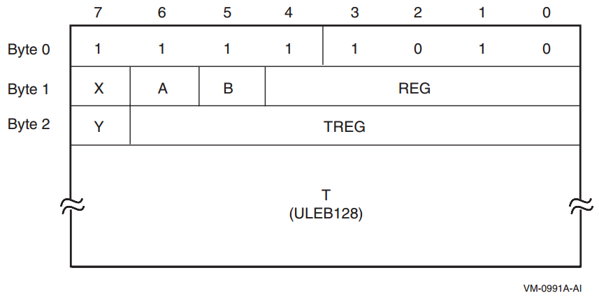
|
Register |
X |
Y |
TREG |
|---|---|---|---|
|
Restore |
0 |
0 |
0 |
|
R1-R127 |
0 |
0 |
GR |
|
F2-F127 |
0 |
1 |
FR |
|
B0-B7 |
1 |
0 |
BR |
A.5.4.3. Format X3
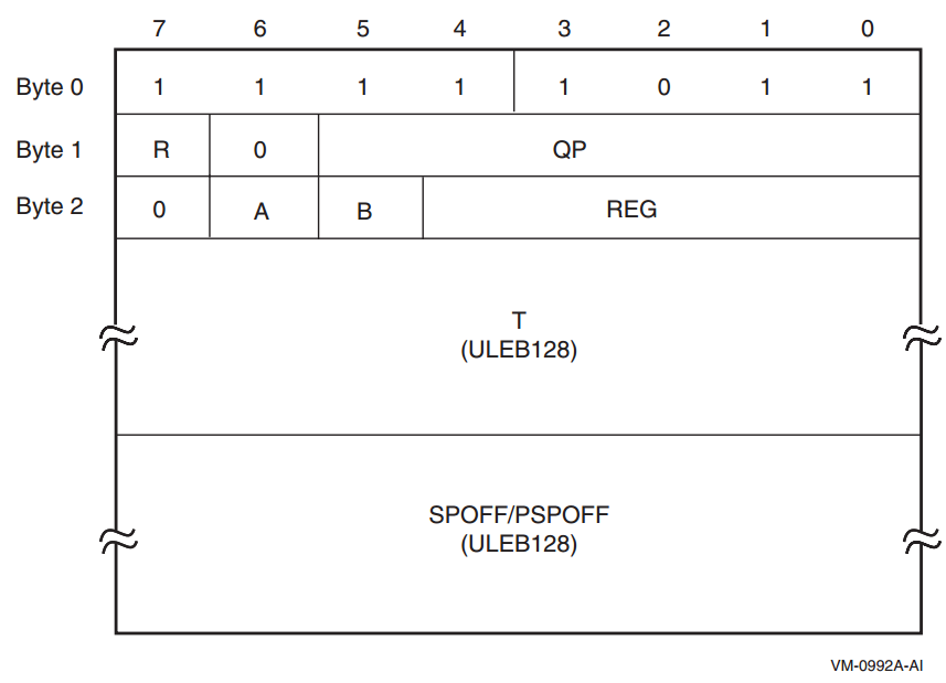
|
Record Type |
R |
|---|---|
|
SPILL_PSPREL_P |
0 |
|
SPILL_SPREL_P |
1 |
The QP field identifies the controlling predicate register. The remaining fields are encoded the same as Format X1.
A.5.4.4. Format X4
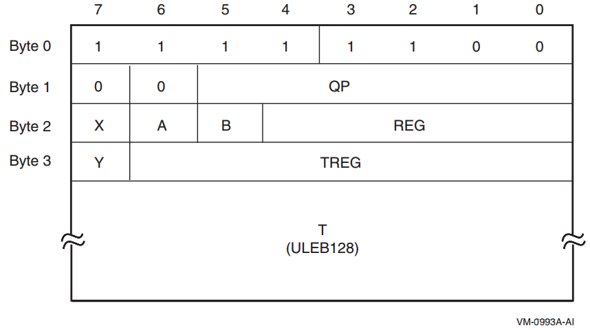
This format is used only by the SPILL_REG_P descriptor record, which identifies when a register is saved to another register under control of a predicate register, or when a register is restored under control of a predicate register. The QP field identifies the controlling predicate register. The remaining fields are encoded the same as Formats X1 and X2.
A.6. Default Unwind Information
It has no memory stack, no register stack and preserves no context of its caller (these are properties of all null frame procedures), hence requires no unwind descriptors. Note in particular that this means that B0 and AR.PFS are unchanged throughout the execution of the procedure. (See Section A.4, ''Data Structures'' and Section A.4.4, ''Language-Specific Data Area'').
It has no condition handler, hence also no language-specific data area. (See Section 4.4, ''Procedure Types'' and Section A.4.4, ''Language-Specific Data Area'').
It has no operating system-specific data area. (See Section A.4.3, ''Operating System-Specific Data Area'').
Such a procedure is necessarily a leaf procedure, that is, a procedure that makes no calls, either explicitly or implicitly. (To make a call, a procedure must preserve at least B0 and AR.PFS).
Conversely, if the dispatcher or unwinder encounters a PC for the top-most procedure on the call stack that is not represented in the unwind tables, it assumes that the PC corresponds to a null frame leaf procedure that satisfies the properties described above.
A.7. System Unwind Routines
SYS$SET_UNWIND_TABLE
SYS$CLEAR_UNWIND_TABLE
SYS$GET_UNWIND_ENTRY_INFO
See the VSI OpenVMS RTL Library (LIB$) Manual for a description of the LIB$GET_UIB_INFO routine.
Appendix B. Stack Unwinding and Exception Handling on OpenVMS x86-64
Stack unwinding is the process of tracing backwards through the stack of invocation contexts (frames) of a thread. Every active procedure has one invocation context. An invocation has memory on the processor memory stack, including at minimum a return address pushed as part of being called. Exception handling often requires the ability to trace backwards through a number of invocation contexts and then to transfer control to an exception handling routine.
The values of preserved registers
The previous stack frame
The previous IP
Unwinding the stack is done using system routines (see Section B.5, ''System Unwind Routines'') that can be called from the thread itself, from a debugger, or for exception handling. Stack unwinding operates on context records; the primary routine reconstructs the context for a previous frame given the context for its descendent frame.
The framework for unwinding the stack and for processing exceptions
The format of the static unwind tables
The code generation conventions required to perform the above tasks
B.1. Unwinding the Stack
The process of unwinding the stack begins with an initial context record that describes the process state in the most recent procedure invocation at the point of interruption. From this initial state, the stack is unwound one invocation context at a time, using static information generated by the compilers about each procedure to reconstruct a context record that describes the previous procedure (which is suspended at a point just after the procedure call or an asynchronous interruption).
B.1.1. Initial Context
There is only one way to get an initial context: call LIB$X86_GET_CURR_INVO_CONTEXT (see Section 5.8.3.7, ''LIB$X86_GET_CURR_INVO_CONTEXT'').
B.1.2. Step to Previous Frame
Find the saved copies of the preserved registers in the current context, and copy them to the previous context (this includes pseudo-registers).
Determine the kind of current frame. Then
For a fixed-size frame, set the stack pointer in the previous context to the stack pointer from current context plus the current size of the frame.
For a varying-size frame, set the stack pointer in the previous context to the saved frame pointer.
Find the return address in the current context, and set the instruction pointer in the previous context to that address (which will further adjust the stack pointer in the previous context to its final value).
The bottom of the call stack is identified by a BOTTOM_OF_STACK flag in the unwind descriptor block.
The information needed to execute these steps correctly is recorded in static unwind information that is associated with each code segment of the program itself. The structure of this information is described in Section B.3, ''Data Structures''. The operating system provides an API for finding the unwind table, given a known IP (see Section B.5, ''System Unwind Routines'').
When a thread receives an asynchronous interruption, the thread context is saved so that the thread can continue executing correctly once the interruption has been handled. This context is saved on the stack, and a new procedure frame is constructed for the interruption handler. The first procedure frame in the interruption handler is marked in such a way that the unwind routine can recognize that unwinding past the point of interruption requires a restoration of the full context.
B.2. Exception Handling Framework
Note
For compatibility with the OpenVMS VAX and Alpha calling standards, this document uses the terms condition handler and personality routine interchangeably—they mean the same thing.
The exception handling model is oriented around procedure invocation contexts. Each invocation context corresponds to an activation of a procedure, which may or may not have associated exception handling requirements. A language typically uses a single condition handler for all procedures, but this is not a requirement.
Exceptions are signaled by invoking a routine in the language-independent component called the exception dispatcher, which initiates the process of handling the exception. Synchronous exceptions can be signaled directly by the application through a language-specific construct; asynchronous exceptions can be signaled in response to hardware-detected traps or faults.
The exception dispatcher walks the stack of invocation contexts non-destructively beginning with the most recent invocation, searching for the first invocation context with a condition handler. When a condition handler is found, the exception dispatcher invokes the condition handler.
A condition handler may perform the following actions:
Ignore the condition.
Take some special action and continue from the point at which the condition occurred.
End the operation and branch from the sequential flow of control.
Treat the condition as an unrecoverable error.
Resignal the exception to the next condition handler.
Invoke a user-written condition handler.
Perform language-specific exception handling actions (for example, C++ try region processing).
If the condition handling facility finds a handler for the exception that requests an unwind, it invokes the dispatcher to walk the stack a second time. During the second walk, the dispatcher invokes the condition handler for each frame again to execute cleanup actions as necessary. When the dispatcher reaches the frame that contains the condition handler, control is transferred to the condition handler.
For more details about OpenVMS condition handling, see Chapter 9, "OpenVMS Conditions".
B.3. Data Structures
The condition handling mechanism uses the following data structures:
A master unwind table, which allows the unwinder and dispatcher to associate an IP value with an image executable segment.
An unwind dispatch table for each segment (there can be more than one per image), which allows the dispatcher and unwinder to associate an IP value with a procedure and its unwind and exception handling information
One or two unwind descriptor tables, which allow the system unwind software to perform unwind and exception processing.
The mapping from an address to the corresponding top-level code segment unwind dispatch structure is not specified in this document. It is private to the linker, image activator and condition handling facility.
The unwind dispatch table (see Section B.3.1, ''Unwind Dispatch Table'') is created by the linker using information in the unwind descriptors (see Section B.3.2, ''DWARF Unwind Descriptors'' and Section B.3.3, ''Compact Unwind Description'') provided by compilers. The linker may use the provided unwind descriptors directly or replace them with equivalent optimized forms based on its optimization strategies.
OpenVMS x86-64 compilers use two unwind descriptor formats.
The first is based on the DWARF Debugging Information Format, with extensions based on the System V Application Binary Interface, AMD64 Architecture Processor Supplement, Version 1.0 together with extensions for compatibility with the OpenVMS family of systems.
The second is based on the compact unwind descriptor format developed as part of the LLVM compiler infrastructure project.
DWARF descriptors are fully general and support handling of asynchronous exceptions (ASTs). Compact unwind descriptors are specialized to be small and easy to interpret but do not support exceptions that may occur in prologue or epilogue code. OpenVMS combines the two in order to achieve the benefits of each.
Every procedure (except some leaf procedures) has one entry in the DWARF unwind descriptor table. (If the compiler has generated more than one noncontiguous region of code for a procedure, there is one entry in this table for each region). It may also have an entry in the compact unwind descriptor table.
A description of the procedure frame (registers saved and where, size of allocated stack, and so on)
(Optional) A pointer to a condition handler
(Optional) A pointer to a language-specific data area for each procedure
(Optional) An operating system-specific data area
Given a PC value, the dispatcher and unwinder both use the unwind tables to locate an unwind entry for a procedure. The unwinder also uses the unwind descriptor list to unwind the stack from any point in the procedure.
The language-specific data area contains information specific to the condition handler that uses it. The address of the language-specific data area is passed to the condition handler whenever the condition handler is invoked by the dispatcher.
The operating system-specific data area contains information about a routine as a whole that is not otherwise expressible using the unwind descriptors, independent of whether the routine has a condition handler.
When an OpenVMS compiler provides both DWARF and compact unwind information for the same procedure, the DWARF information is used for prologue and epilogue regions of the code, while the compact unwind information is used for the body (where the procedure is current).
B.3.1. Unwind Dispatch Table
Corresponding to each code segment is a top-level structure that is used to map addresses to corresponding unwind information. This structure is created by the linker based on the unwind information contained in each object file that contributes to that segment together with optional linker directives.
Simple
Fast lookup to find the unwind information corresponding to a function (or part of a function)
Flexibility to easily extend and evolve the forms of unwind information that are supported
Ability to simultaneously support multiple unwind information formats on a (roughly) function by function basis
A header
A vector of unwind dispatch elements (UDEs)
A trailer
The unwind dispatch element header is illustrated in Figure B.1, ''Unwind Dispatch Element Header'' and described in Table B.1, ''Description of Unwind Dispatch Element Header''.
 |
| Field Name | Size | Description |
|---|---|---|
| UDE$W_VERSION | Word | Version number for the unwind dispatch table format, currently 1. |
| UDE$W_COUNT | Word | The number of unwind dispatch elements that follow, including the trailer UDE. |
| RESERVED | Longword | Reserved and must be 0. |
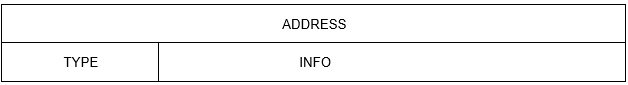 |
| Field Name | Size | Description |
|---|---|---|
| UDE$Q_ADDRESS | Quadword | Offset within the associated code segment for a range of addresses that extends to one less than the offset contained in the following UDE. (The special case of the last UDE is described below). |
| UDE$V_INFO | 6 Bytes | Either an immediate value or a (truncated) pointer to unwind information. |
| UDE$W_TYPE | Word | A code that indicates how to interpret the contents of the UDE$V_INFO field. |
A trailer unwind dispatch element is a special form of unwind dispatch element that occurs as the last UDE of an unwind dispatch table. Unlike other UDEs, the UDE$Q_ADDRESS field does not begin a new range, but it does provide (one more than) the ending of the range begun by the preceding UDE. For this UDE, UDE$W_TYPE and UDE$V_INFO contain zero.
Table B.3, ''Summary of Unwind Dispatch Information Types'' provides a summary of the types of unwind information that are codified. They are grouped as they are presented and defined in the following sections.
A key property of every type of unwind information is whether or not it is asynchronous unwind safe. Asynchronous unwind safe means that it is safe to propagate an asynchronous exception from an exception (AST) frame into the type of frame in question even when the asynchronous exception occurs during function prologue or epilogue code. Note that some exception handling conventions and environments are designed only to support call-based exceptions. This support will often fail to work if an asynchronous exception is propagated from an asynchronous frame. Accordingly, attempting to unwind from an asynchronous frame into a frame that is not known to be safe is considered a severe error.
|
Type Code | General Meaning | Immediate vs Pointer | Async Safe | INFO Field |
|---|---|---|---|---|
| Safe DWARF CFI | ||||
| TYPE_CFI_SAFE |
Industry standard DWARF CFI + AMD extensions (safe) + (optionally) OpenVMS extensions | Pointer | Y | Address of FDE |
| Extended DWARF CFI + Compact Unwind Descriptors | ||||
| TYPE_VMS_PROLOG | Like TYPE_CFI_SAFE, but limited to prologue | Pointer | Y | Address of FDE |
| TYPE_VMS_CUD | Industry (LLVM) CUD with OpenVMS extensions | Pointer | Y | Address of CUD |
| TYPE_VMS_EPILOG | Like TYPE_CFI_SAFE, but limited to epilogue | Pointer | Y | Address of FDE |
| Useful Helpers | ||||
| TYPE_NULL_FRAME | NULL_FRAME | Immediate | Y | Location of return address |
| TYPE_NO_UNWIND | No UNWIND possible — Fatal Program Error | — | — | — |
| Unsafe (Imported) Object Files? | ||||
| TYPE_CFI_UNSAFE | Industry standard DWARF CFI + AMD extensions (unsafe) | Pointer | N | Address of FDE |
B.3.2. DWARF Unwind Descriptors
DWARF supports virtual unwinding by defining an architecture independent basis for recording how subprograms save and restore registers during their lifetimes.
- LOC CFA R0 R1 ... RN
- L0
- L1
- ...
- LN
The first column indicates an address for every location that contains code in a program. (In OpenVMS x86-64 object files, this is a code-segment relative offset). The remaining columns contain virtual unwinding rules that are associated with the indicated location.
The CFA column defines the rule which computes the Canonical Frame Address value; it may be either a register and a signed offset that are added together, or a DWARF expression that is evaluated.
The remaining columns are labeled by register number. This includes some registers that have special designation on some architectures, such as the PC and the stack pointer register. (The actual mapping of registers for a particular architecture is defined by the augmenter). The register columns contain rules that describe whether a given register has been saved and the rule to find the value for the register in the previous frame.
| undefined | A register that has this rule has no recoverable value in the previous frame. (By convention, it is not preserved by a callee). |
| same value | This register has not been modified from the previous frame. (By convention, it is preserved by the callee, but the callee has not modified it). |
| offset(N) |
The previous value of this register is saved at the address CFA+N where CFA is the current CFA value and N is a signed offset. |
| val_offset(N) | The previous value of this register is the value CFA+N where CFA is the current CFA value and N is a signed offset. |
| register(R) |
The previous value of this register is stored in another register numbered R. |
| expression(E) | The previous value of this register is located at the address produced by executing the DWARF expression E. |
| val_expression(E) | The previous value of this register is the value produced by executing the DWARF expression E. |
| architectural | The rule is defined externally to this specification by the augmenter. |
The virtual unwind information is encoded in a self-contained section called .eh_frame?. Entries in an .eh_frame section are aligned on a multiple of the address size relative to the start of the section and come in two forms: a Common Information Entry (CIE) and a Frame Description Entry (FDE).
If the range of code addresses for a function is not contiguous, there may be multiple CIEs and FDEs corresponding to the parts of that function.
B.3.2.1. 32-bit vs 64-bit DWARF Formats
DWARF defines two closely related file formats. In the 32-bit format, all values that represent lengths of DWARF sections and offsets relative to the beginning of a DWARF section are represented using 32 bits. In the 64-bit format, all such values are represented using 64-bit. This affects only the DWARF sections and their references to each other as such—either format can describe 32- or 64-bit addresses in the target architecture.
OpenVMS x86-64 supports only the 32-bit DWARF format, using 64-bit target addresses. This is reflected in the descriptions in the following sections.
B.3.2.2. Common Information Entry
length (unsigned longword)
A constant that gives the number of bytes of the CIE structure, not including the length field itself. The size of the length field plus the value of length must be an integral multiple of the address size.
CIE_id (unsigned longword)
A constant that is used to distinguish CIEs from FDEs.
The value of the CIE id in the CIE header is 0.
version (unsigned byte)
A version number. This number is specific to the call frame information and is independent of and not related to the DWARF version number.
The value of the CIE version number is 1.
augmentation (sequence of UTF-8 characters)
A null-terminated UTF-8 string that identifies the augmentation to this CIE or to the FDEs that use it. If a reader encounters an augmentation string that is unexpected, then only the following fields can be read:CIE: length, CIE_id, version, augmentation
FDE: length, CIE_pointer, initial_location, address_range
If there is no augmentation, this value is a zero byte.
OpenVMS x86-64 supports augmentation strings beginning with the letter ‘v’ or ‘z’ followed by zero or more letters from the set {‘P’, ‘R’, ‘L’} (in any order but without repetition). The presence of an OpenVMS augmentation string requires the presence of a CIE augmentation section field later in this same CIE. If the augmentation string contains the character ‘L’, there will also be a FDE augmentation section in any FDE that refers to this CIE.
Interpretation of an OpenVMS augmentation string and its related augmentation sections is given in Section B.3.2.2.1, ''CIE_augmentation_section''.
code_alignment_factor (unsigned LEB128)
A constant that is factored out of all advance location instructions. The resulting value is (operand * code_alignment_factor).
data_alignment_factor (signed LEB128)
A constant that is factored out of certain offset instructions (see below). The resulting value is (operand * data_alignment_factor).
return_address_register (unsigned LEB128)
An unsigned LEB128 constant that indicates which column in the rule table represents the return address of the function. Note that this column might not correspond to an actual machine register.
CIE_augmentation_section (array of bytes)
This field is present (has a size greater than 0) if an augmentation string is present that begins with either ‘v’ or ‘z’.
Interpretation of an OpenVMS CIE augmentation section is given in Section B.3.2.2.1, ''CIE_augmentation_section''.
initial_instructions (array of unsigned byte)
A sequence of rules that are interpreted to create the initial setting of each column in the table.
On OpenVMS x86-64, the default rule for all columns before interpretation of the initial instructions is the undefined rule.
padding (array of unsigned byte)
Enough DW_CFA_nop instructions to make the size of this entry match the length value above.
B.3.2.2.1. CIE_augmentation_section
size (unsigned LEB128)
The size field gives the size in bytes of the CIE_augmentation_section excluding itself.
personality_enc (byte)
The personality_enc specifies the encoding used for the address of the personality routine that follows. This field is present if and only if there is a ‘P’ in the augmentation field. (See Section B.3.2.4, ''Address/Pointer Encodings'').
personality_routine (encoded address)
The personality_routine is the address of an associated personality routine that handles any exception that occurs while any associated procedure is current (augmentation begins with ‘v’) or active (augmentation begins with ‘z’). This field is present if and only if there is a ‘P’ in the augmentation field.
code_enc (byte)
The code_enc field specifies the (non-default) encoding used for any code address that occurs in the initial_location or address_range fields of an associated FDE and the operand for any DW_CFA_set_loc instruction that may occur either in this CIE or an associated FDE. This field is present if and only if there is a ‘R’ in the augmentation field. (See Section B.3.2.4, ''Address/Pointer Encodings'').
lsda_enc (byte)
The lsda_enc field specifies the encoding used for any language specific data area address that occurs in the LDSA field of an associated FDE. This field is present if and only if there is a ‘L’ in the augmentation field. (See Section B.3.2.4, ''Address/Pointer Encodings'').
B.3.2.3. Frame Description Entry
length (unsigned longword)
A constant that gives the number of bytes of the header and instruction stream for this function, not including the length field itself. The size of the length field plus the value of length must be an integral multiple of the address size.
CIE_pointer (unsigned longword)
Offset from this field to the nearest preceding CIE (the value is subtracted from the current address). Note that this value can never be zero and thus can be used to distinguish CIE’s and FDE’s when scanning the .eh_frame section.
initial_location (segment selector and target address)
The address of the first location associated with this table entry. Recall that the implicit segment_selector_size field has value 0. (See Section B.3.2.2, ''Common Information Entry'').
address_range (target address)
The number of bytes of program instructions described by this entry.
FDE_augmentation_section (array of bytes)
This field is present (has a size greater than 0) if an augmentation string is present in the related CIE that begins with either ‘v’ or ‘z’ and that includes the letter ‘L’. Interpretation of an OpenVMS FDE augmentation section is given in Section B.3.2.3.1, ''FDE_augmentation_section''.
instructions (array of unsigned byte)
A sequence of table defining instructions that are described in the next section.
padding (array of unsigned byte)
Enough DW_CFA_nop instructions to make the size of this entry match the length value above.
B.3.2.3.1. FDE_augmentation_section
length (unsigned LEB128)
The length field gives the size in bytes of the FDE_augmentation_section excluding itself.
LDSA (encoded address)
The LSDA field gives the address of an associated language specific data area to be passed to the handler (personality routine) for any exception that occurs during the execution of the associated procedure.
B.3.2.4. Address/Pointer Encodings
Four bits encoding the size of an offset value
Three bits encoding the base address to which the offset is added
One bit indicating whether to fetch indirectly for the above formed address
| Name | Value | Use |
|---|---|---|
| Offset encodings… | ||
| DW_EH_PE_uleb128 | 0x01 | Offset is an unsigned LEB128 integer |
| DW_EH_PE_udata2 | 0x02 | Offset is an unsigned 2-byte integer |
| DW_EH_PE_udata4 | 0x03 | Offset is an unsigned 4-byte integer |
| DW_EH_PE_udata8 | 0x04 | Offset is an unsigned 8-byte integer |
| DW_EH_PE_sleb128 | 0x09 | Offset is an signed LEB128 integer |
| DW_EH_PE_sdata2 | 0x0a | Offset is an signed 2-byte integer |
| DW_EH_PE_sdata4 | 0x0b | Offset is an signed 4-byte integer |
| DW_EH_PE_sdata8 | 0x0c | Offset is an signed 8-byte integer |
| Base encodings… | ||
| DW_EH_PE_pcrel | 0x10 | Offset is PC-relative |
| DW_EH_PE_textrel | 0x20 | Offset is text (code) section relative |
| DW_EH_PE_datarel | 0x30 | Offset is data section relative |
| DW_EH_PE_funcrel | 0x40 | Offset is relative to start of the function |
| Other special encodings… | ||
| DW_EH_PE_absptr | 0x00 | Address is an absolute 8-byte pointer |
| DW_EH_PE_signed | 0x08 | Offsets are signed |
| DW_EH_PE_aligned | 0x50 | Address is an absolute 8-byte pointer that must be aligned before use |
| DW_EH_PE_indirect | 0x80 | Address is indirect through the given base + offset |
| DW_EH_PE_omit | 0xff | No address is given |
B.3.2.5. Call Frame Instructions
Each call frame instruction is defined to take 0 or more operands. Some of the operands may be encoded as part of the opcode. The instructions are defined in Sections B.3.2.5.1 through B.3.2.5.6.
Some call frame instructions have operands that are encoded as DWARF expressions. The following DWARF operators cannot be used in such operands:
DW_OP_addrx, DW_OP_call2, DW_OP_call4, DW_OP_call_ref, DW_OP_const_type, DW_OP_constx, DW_OP_convert, DW_OP_deref_type, DW_OP_regval_type, and DW_OP_reinterpret operators are not allowed in an operand of these instructions because the call frame information must not depend on other debug sections.
DW_OP_push_object_address is not meaningful in an operand of these instructions because there is no object context to provide a value to push.
DW_OP_call_frame_cfa is not meaningful in an operand of these instructions because its use would be circular.
Call frame instructions to which these restrictions apply include DW_CFA_def_cfa_expression, DW_CFA_expression and DW_CFA_val_expression.
B.3.2.5.1. Row Creation Instructions
DW_CFA_set_loc
The DW_CFA_set_loc instruction takes a single operand that represents a target address. The required action is to create a new table row using the specified address as the location. All other values in the new row are initially identical to the current row. The new location value is always greater than the current one. If the segment_selector_size field of this FDE’s CIE is non-zero, the initial location is preceded by a segment selector of the given length.
DW_CFA_advance_loc
The DW_CFA_advance_loc instruction takes a single operand (encoded with the opcode) that represents a constant delta. The required action is to create a new table row with a location value that is computed by taking the current entry’s location value and adding the value of delta * code_alignment_factor. All other values in the new row are initially identical to the current row.
DW_CFA_advance_loc1
The DW_CFA_advance_loc1 instruction takes a single unsigned byte operand that represents a constant delta. This instruction is identical to DW_CFA_advance_loc except for the encoding and size of the delta operand.
DW_CFA_advance_loc2
The DW_CFA_advance_loc2 instruction takes a single unsigned word operand that represents a constant delta. This instruction is identical to DW_CFA_advance_loc except for the encoding and size of the delta operand.
DW_CFA_advance_loc4
The DW_CFA_advance_loc4 instruction takes a single unsigned longword operand that represents a constant delta. This instruction is identical to DW_CFA_advance_loc except for the encoding and size of the delta operand.
B.3.2.5.2. CFA Definition Instructions
DW_CFA_def_cfa
The DW_CFA_def_cfa instruction takes two unsigned LEB128 operands representing a register number and a (non-factored) offset. The required action is to define the current CFA rule to use the provided register and offset.
DW_CFA_def_cfa_sf
The DW_CFA_def_cfa_sf instruction takes two operands: an unsigned LEB128 value representing a register number and a signed LEB128 factored offset. This instruction is identical to DW_CFA_def_cfa except that the second operand is signed and factored. The resulting offset is factored_offset * data_alignment_factor.
DW_CFA_def_cfa_register
The DW_CFA_def_cfa_register instruction takes a single unsigned LEB128 operand representing a register number. The required action is to define the current CFA rule to use the provided register (but to keep the old offset). This operation is valid only if the current CFA rule is defined to use a register and offset.
DW_CFA_def_cfa_offset
The DW_CFA_def_cfa_offset instruction takes a single unsigned LEB128 operand representing a (non-factored) offset. The required action is to define the current CFA rule to use the provided offset (but to keep the old register). This operation is valid only if the current CFA rule is defined to use a register and offset.
DW_CFA_def_cfa_offset_sf
The DW_CFA_def_cfa_offset_sf instruction takes a signed LEB128 operand representing a factored offset. This instruction is identical to DW_CFA_def_cfa_offset except that the operand is signed and factored. The resulting offset is factored_offset * data_alignment_factor. This operation is valid only if the current CFA rule is defined to use a register and offset.
DW_CFA_def_cfa_expression
The DW_CFA_def_cfa_expression instruction takes a single operand encoded as a DW_FORM_exprloc value representing a DWARF expression. The required action is to establish that expression as the means by which the current CFA is computed.
B.3.2.5.3. Register Rule Instructions
DW_CFA_undefined
The DW_CFA_undefined instruction takes a single unsigned LEB128 operand that represents a register number. The required action is to set the rule for the specified register to “undefined.”
DW_CFA_same_value
The DW_CFA_same_value instruction takes a single unsigned LEB128 operand that represents a register number. The required action is to set the rule for the specified register to “same value.”
DW_CFA_offset
The DW_CFA_offset instruction takes two operands: a register number (encoded with the opcode) and an unsigned LEB128 constant representing a factored offset. The required action is to change the rule for the register indicated by the register number to be an offset(N) rule where the value of N is factored offset * data_alignment_factor.
DW_CFA_offset_extendedThe DW_CFA_offset_extended instruction takes two unsigned LEB128 operands representing a register number and a factored offset. This instruction is identical to DW_CFA_offset except for the encoding and size of the register operand.
DW_CFA_offset_extended_sf
The DW_CFA_offset_extended_sf instruction takes two operands: an unsigned LEB128 value representing a register number and a signed LEB128 factored offset. This instruction is identical to DW_CFA_offset_extended except that the second operand is signed and factored. The resulting offset is factored_offset * data_alignment_factor.
DW_CFA_val_offset
The DW_CFA_val_offset instruction takes two unsigned LEB128 operands representing a register number and a factored offset. The required action is to change the rule for the register indicated by the register number to be a val_offset(N) rule where the value of N is factored_offset * data_alignment_factor.
DW_CFA_val_offset_sf
The DW_CFA_val_offset_sf instruction takes two operands: an unsigned LEB128 value representing a register number and a signed LEB128 factored offset. This instruction is identical to DW_CFA_val_offset except that the second operand is signed and factored. The resulting offset is factored_offset * data_alignment_factor.
DW_CFA_register
The DW_CFA_register instruction takes two unsigned LEB128 operands representing register numbers. The required action is to set the rule for the first register to be register(R) where R is the second register.
DW_CFA_expression
The DW_CFA_expression instruction takes two operands: an unsigned LEB128 value representing a register number, and a DW_FORM_block value representing a DWARF expression. The required action is to change the rule for the register indicated by the register number to be an expression(E) rule where E is the DWARF expression. That is, the DWARF expression computes the address. The value of the CFA is pushed on the DWARF evaluation stack prior to execution of the DWARF expression.
DW_CFA_val_expression
The DW_CFA_val_expression instruction takes two operands: an unsigned LEB128 value representing a register number, and a DW_FORM_block value representing a DWARF expression. The required action is to change the rule for the register indicated by the register number to be a val_expression(E) rule where E is the DWARF expression. That is, the DWARF expression computes the value of the given register. The value of the CFA is pushed on the DWARF evaluation stack prior to execution of the DWARF expression.
DW_CFA_restore
The DW_CFA_restore instruction takes a single operand (encoded with the opcode) that represents a register number. The required action is to change the rule for the indicated register to the rule assigned it by the initial_instructions in the CIE.
DW_CFA_restore_extended
The DW_CFA_restore_extended instruction takes a single unsigned LEB128 operand that represents a register number. This instruction is identical to DW_CFA_restore except for the encoding and size of the register operand.
B.3.2.5.4. Row State Instructions
DW_CFA_remember_state
The DW_CFA_remember_state instruction takes no operands. The required action is to push the set of rules for every register onto an implicit stack.
DW_CFA_restore_state
The DW_CFA_restore_state instruction takes no operands. The required action is to pop the set of rules off the implicit stack and place them in the current row.
B.3.2.5.5. Padding Instruction
DW_CFA_nop
The DW_CFA_nop instruction has no operands and no required actions. It is used as padding to make a CIE or FDE an appropriate size.
B.3.2.5.6. OpenVMS-Specific Instructions
DW_CFA_VMS_set_current
The DW_CFA_VMS_set_current instruction takes a single unsigned LEB128 operand that represents whether the routine is current for exception handling purposes. The value 0 indicates the routine is not current and the value 1 indicates the routine is current.
DW_CFA_VMS_set_ossd
The DW_CFA_VMS_set_ossd instructions takes a word (16-bit) operand that specifies the OpenVMS-specific data applicable to the routine. This value is encoded as specified for the 16 low-order bits defined in Section A.4.3.1, ''General Information Segment''.
B.3.2.6. Call Frame Instruction Usage
Initialize a register set by reading the initial_instructions field of the associated CIE. Set L2 to the value of the initial_location field from the FDE header.
Read and process the FDE’s instruction sequence until a DW_CFA_advance_loc, DW_CFA_set_loc, or the end of the instruction stream is encountered.
If a DW_CFA_advance_loc or DW_CFA_set_loc instruction is encountered, then compute a new location value (L2). If L1 ≥ L2 then process the instruction and go back to step 2.
The end of the instruction stream can be thought of as a DW_CFA_set_loc (initial_location + address_range) instruction. Note that the FDE is ill-formed if L2 is less than L1.
The rules in the register set now apply to location L1.
B.3.2.7. Call Frame Encoding
| Instruction | Used In LLVM | High 2 Bits | Low 6 Bits | Operand 1 | Operand 1 |
|---|---|---|---|---|---|
| DW_CFA_advance_loc | * | 0x1 | delta | ||
| DW_CFA_offset | * | 0x2 | register | ULEB128 offset | |
| DW_CFA_restore | 0x3 | register | |||
| DW_CFA_nop | * | 0 | 0 | ||
| DW_CFA_set_loc | 0 | 0x01 | address | ||
| DW_CFA_advance_loc1 | * | 0 | 0x02 | 1-byte delta | |
| DW_CFA_advance_loc2 | * | 0 | 0x03 | 2-byte delta | |
| DW_CFA_advance_loc4 | * | 0 | 0x04 | 4-byte delta | |
| DW_CFA_offset_extended | 0 | 0x05 | ULEB128 register | ULEB128 offset | |
| DW_CFA_restore_extended | 0 | 0x06 | ULEB128 register | ||
| DW_CFA_undefined | * | 0 | 0x07 | ULEB128 register | |
| DW_CFA_same_value | * | 0 | 0x08 | ULEB128 register | |
| DW_CFA_register | * | 0 | 0x09 | ULEB128 register | ULEB128 register |
| DW_CFA_remember_state | * | 0 | 0x0a | ||
| DW_CFA_restore_state | * | 0 | 0x0b | ||
| DW_CFA_def_cfa | * | 0 | 0x0c | ULEB128 register | ULEB128 offset |
| DW_CFA_def_cfa_register | * | 0 | 0x0d | ULEB128 register | |
| DW_CFA_def_cfa_offset | * | 0 | 0x0e | ULEB128 offset | |
| DW_CFA_def_cfa_expression | 0 | 0x0f | BLOCK | ||
| DW_CFA_expression | 0 | 0x10 | ULEB128 register | BLOCK | |
| DW_CFA_offset_extended_sf | 0 | 0x11 | ULEB128 register | SLEB128 offset | |
| DW_CFA_def_cfa_sf | 0 | 0x12 | ULEB128 register | SLEB128 offset | |
| DW_CFA_def_cfa_offset_sf | 0 | 0x13 | SLEB128 offset | ||
| DW_CFA_val_offset | 0 | 0x14 | ULEB128 | ULEB128 | |
| DW_CFA_val_offset_sf | 0 | 0x15 | ULEB128 | SLEB128 | |
| DW_CFA_val_expression | 0 | 0x16 | ULEB128 | BLOCK | |
| DW_CFA_lo_user | 0 | 0x1c | |||
| (reserved)? | 0 | 0x2d | |||
| 0 | 0x2e | ||||
| 0 | 0x2f | ||||
| 0 | 0x34 | ||||
| DW_CFA_VMS_set_ossd | 0 | 0x3d | word (16-bit) | ||
| DW_CFA_VMS_set_current | 0 | 0x3e | ULEB128 | ||
| (reserved) | 0 | 0x3f | |||
| DW_CFA_hi_user | 0 | 0x3f |
B.3.2.8. DWARF Register Number Mapping
| Register Name(s) | Number(s) | Abbreviation |
|---|---|---|
| General-purpose register RAX | 0 | %rax |
| General-purpose register RDX | 1 | %rdx |
| General-purpose register RCX | 2 | %rcx |
| General-purpose register RBX | 3 | %rbx |
| General-purpose register RSI | 4 | %rsi |
| General-purpose register RDI | 5 | %rdi |
| Frame pointer register RBP | 6 | %rbp |
| Stack pointer register RSP | 7 | %rsp |
| Extended integer registers 8–15 | 8-15 | %r8–%r15 |
| Return address RA | 16 | |
| Vector registers 0–7 | 17-24 | %xmm0–%xmm7 |
| Extended vector registers 8–15 | 25-32 | %xmm8-%xmm15 |
| Floating-point registers 0–7 | 33-40 | %st0–%st7 |
| MMX registers 0–7 | 41-48 | %mm0–%mm7 |
| Flag register | 49 | %rflags |
| Segment register ES | 50 | %es |
| Segment register CS | 51 | %cs |
| Segment register SS | 52 | %ss |
| Segment register DS | 53 | %ds |
| Segment register FS | 54 | %fs |
| Segment register GS | 55 | %gs |
| Reserved | 56-57 | |
| FS base address | 58 | %fs.base |
| GS base address | 59 | %gs.base |
| Reserved | 60-61 | |
| Task register | 62 | %tr |
| LDT register | 63 | %ldtr |
| 128-bit Media Control and Status | 64 | %mxcsr |
| x87 Control Word | 65 | %fcw |
| x87 Status Word | 66 | %fsw |
| Upper vector registers 16–31 | 67-82 | %xmm16–%xmm31 |
| Reserved | 83-117 | |
| Vector mask registers 0–7 | 118-125 | %k0–%k7 |
| Bound Registers 0-3 | 126-129 | %bnd0-%bnd3 |
| Reserved | 130-16351 | |
| Alpha pseudo-registers 0–31 |
| %apr0–%apr31 |
B.3.2.9. Related Assembler Directives and Implementation Notes
The following .cfi directives map directly and one-to-one to corresponding DWARF frame instructions: .cfi_advance_loc{|1|2|4}, .cfi_def_cfa{|_register|_offset}, .cfi_offset, .cfi_same_value, .cfi_remember_state, .cfi_restore_state, .cfi_restore, .cfi_undefined, .cfi_register and .cfi_set_ossd (OpenVMS-specific).
| CFI Directive | Effect |
|---|---|
| .cfi_startproc | Establishes the starting address in the FDE. |
| .cfi_endproc | Ends the current FDE and establishes the length value in the FDE. |
| .cfi_personality | Adds ‘P’ to the CIE augmentation string and includes the personality routine address in the CIE augmentation field. |
| .cfi_lsda | Adds ‘L’ to the CIE augmentation string and includes the LSDA address in the FDE augmentation field. |
| .cfi_rel_offset | Adjusts the offset to be used in a subsequent DW_CFA_offset command. |
| .cfi_adjust_cfa_offset | Adjusts the offset to be used in a subsequent DW_CFA_def_cfa_offset. |
| .cfi_escape | Allows the following data to be appended to the DWARF information. Useful for OS-specific entries. |
| .cfi_signal_frame | Marks the current function as a signal trampoline. Not applicable to OpenVMS. |
| .cfi_sections | Determines whether output goes to section .eh_frame, .dwarf_frame or both. |
| .cfi_end_prologue | Generates DW_CFA_VMS_set_current with operand 1 to mark the end of a prologue. |
| .cfi_begin_epilogue | Generates DW_CFA_VMS_set_current with operand 0 to mark the beginning of an epilogue. |
| .cfi_set_ossd | Adds ‘v’ (instead of ‘z’) to the CIE augmentation string and sets the initial currency state to 0. |
B.3.3. Compact Unwind Description
An OpenVMS x86-64 compact unwind description is a group of three to six fields that describe how to unwind from the body of one procedure frame to the frame of the caller together with the address of an exception handler and associated data, if any, (in industry documentation also known as a personality routine and language-specific data area, respectively) that is called to process any exception that occurs in that body.
The compact unwind description applies only to the body of a procedure; thus on OpenVMS x86-64 it is always used in combination with a simplified form of DWARF unwind descriptors which apply to the prologue and epilogue regions of code in a procedure.
The heart of the description is the compact_unwind_encoding field, which is described first. This is followed by the compact unwind description as a whole, then the related simplified DWARF descriptors.
B.3.3.1. Compact Unwind Encoding
 |
| Field Name | Bit Position | Description |
|---|---|---|
| CUE$V_FLAGS | <31:28> | Flags that indicate what additional fields are part of the containing compact unwind description (see Table B.9, ''Description of CUE Top-Level Flags''). |
| CUE$V_MODE | <27:24> | A tag that indicates what information is encoded in the low-order 24 bits. |
| Field | Bit Position | Description |
|---|---|---|
| RESERVED | <31> | Reserved and must be zero. |
|
CUE$V_UNWIND_ | <30> | An LSDA field is included as part of the containing description. |
|
CUE$V_UNWIND_ | <29> | A personality routine address is included as part of the containing description. |
|
CUE$V_UNWIND_ | <28> | OpenVMS OSSD information is included as part of the containing information. |
| Name | Value | Use |
|---|---|---|
|
CUE$K_X86_64_ | 1 | Variable-size frame. The frame uses the RBP register as a frame pointer. The size of the frame can vary during execution. |
|
CUE$K_X86_64_ | 2 | Fixed-size frame. The frame uses RSP as the frame pointer. The size of the frame is fixed (at compile-time). |
|
CUE$K_X86_64_ | 3 | Large fixed-size frame. The frame uses RSP as the frame pointer, The size of the frame is fixed (at compile-time); however, that size is too large to express within this 32-bit encoding. |
|
CUE$K_X86_64_ | 4 | DWARF escape. The frame, for whatever reason, cannot be adequately described using the compact unwind frame description. The remaining 24‑bits are an offset in the DWARF section to a DWARF FDE entry. |
All other values are reserved to OpenVMS.
These uses and the interpretation of the remaining 24 bits that go with them are described in the following sections.
B.3.3.2. Preserved Register Enumeration
| Name | Value | Use |
|---|---|---|
| CUE$K_REG_NONE | 0 | No register |
| CUE$K_REG_RBX | 1 | RBX register (%rbx) |
| CUE$K_REG_R12 | 2 | R12 register (%r12) |
| CUE$K_REG_R13 | 3 | R13 register (%r13) |
| CUE$K_REG_R14 | 4 | R14 register (%r14) |
| CUE$K_REG_R15 | 5 | R15 register (%r15) |
| CUE$K_REG_RBP | 6 | RBP register (%rbp) |
B.3.3.3. Variable-Size Frame (MODE=1)
 |
| Field Name | Bit Position | Description |
|---|---|---|
|
CUE$V_RBP_FRAME_ | <23:16> | The offset (in units of quadwords) relative to RBP to the base of the register save area (that is, from RBP-8 to RBP-2040). |
| RESERVED | <15> | Reserved and must be zero. |
| CUE$V_RBP_REGISTERS | <14:0> | The registers saved are encoded as five 3-bit entries (see below). |
The RBP register is pushed on the stack immediately after the return address, after which RSP is moved to RBP. To unwind, RSP is restored with the current RPB value, then RBP is restored by popping off the stack, and the return is done by popping the stack once more into the instruction pointer.
If one register is saved, its code is specified in <2:0>. If two registers are saved, the first is specified in <2:0> and the next in <5:3>. And so on.
B.3.3.4. Fixed-Size Frame (MODE=2)
 |
| Field Name | Bit Position | Description |
|---|---|---|
| CUE$V_RSP_STACK_SIZE | <23:16> | The size of the stack (in units of quadwords). |
| RESERVED | <15:13> | Reserved and must be zero. |
| CUE$V_RSP_REG_CNT | <12:10> | The number of registers that are saved (up to six). |
| CUE$V_RSP_REG_PERM | <9:0> | The registers that are saved, encoded using a permutation-based representation (see Section B.3.3.7, ''Register Permutation Encoding''). |
B.3.3.5. Large Fixed-Size Frame (MODE=3)
 |
This case is like the previous, except the stack size is too large to encode in the compact unwind encoding. Instead, the target function must include a "subq $nnnnnnnn, RSP" instruction in its prologue to allocate the stack. The offset from the entry point of the function to the nnnnnnnn value in the function is given in the CUE$V_RSP_STACK_SIZE field.
| Field Name | Bit Position | Description |
|---|---|---|
| CUE$V_RSP_STACK_SIZE | <23:16> | Offset from the beginning of the containing description to the 8-byte offset in the instruction that allocates the stack. |
| CUE$V_RSP_STK_ADJ | <15:13> | Additional stack size adjustment over and above the STACK_SIZE instruction offset to determine the actual stack size. |
| CUE$V_RSP_REG_CNT | <12:10> | The number of registers that are saved (up to six). |
| CUE$V_RSP_REG_PERM | <9:0> | The registers that are saved, encoded using a permutation-based representation (see Section B.3.3.7, ''Register Permutation Encoding''). |
B.3.3.6. DWARF Escape (MODE=4)
The frame, for whatever reason, cannot be adequately described using a compact unwind frame description. The remaining 24‑bits are an offset in the DWARF section to a DWARF FDE entry.
While supported in OpenVMS x86-64, this mode is not needed and is therefore deprecated.
B.3.3.7. Register Permutation Encoding
The compact unwind encoding uses a ten-bit integer together with a three-bit count to indicate which subset of up to six (integer) registers are preserved and in what order. The encoding is based on the number of permutations that exist for up to six registers taken 0, 1, 2, …, 6 at a time. In particular, six items taken six at a time have just 6! = 720 possible orders, which can be named in just 10 bits (210=1024). If not all of the registers are preserved, then the number of permutations is smaller. The general rule is the number of permutations of N items taken M at a time is N!/M!.
A permutation number (PN) is defined to identify which of the possible permutations describes a given register save sequence. The computation of the PN proceeds as follows: Initially PN is zero. Number the registers in a standard order from 0 to N-1. Select a register from 0 to N-1; there are, of course, just N possibilities. Multiply the previous PN by N and add the selected number to compute the new PN. Renumber the remaining N-1 registers from 0 to N-2, keeping the same order as previously. Select a register from 0 to N-2 (there are N-1 possibilities), multiply the previous PN number by N-1 and add the selected number result to compute the new PN. Proceed in similar fashion until the last preserved register is encoded.
Consider an example using the set of six preserved registers RBX, R12, R213, R14, R15, RBP. For this example, suppose that the registers R13, RBX, and RBP are preserved in that order. There are 6!/3! = 6*5*4 = 120 possible orders of these 6 items taken 3 at a time.
In step 1, R13 has position 2 in the possible selections sequence. Multiply the previous PN (0) by the number of possible selections (6), add this position (2) and assign the result (2) to PN. That leaves possible selections RBX, R12, R14, R15, RBP (in that order) which we then encode as 0..4.
In step 2, RBX has position 0. Multiply the previous PN (2) by the number of possible selections (5), add this position (0) and assign the result (10) to PN. That leaves possible selections R12, R14, R15, RBP (in that order) which we then encode as 0..3.
In step 3, RBP has position 3. Multiply the previous PN (10) by the number of possible selections (4), add this position (3) and assign the result (43) to PN.
That completes computation of the permutation encoding.
These steps are summarized as follows.
| Step | Registers to be Encoded in Order | Selection |
(Prior PN* | PN | |||
|---|---|---|---|---|---|---|---|
| 0 | 0 | ||||||
| 1 | RBX=0, | R12=1, | R13=2, | R14=3, R15=4, RBP=5 | R13=2 | (0*6)+2 | 2 |
| 2 | RBX=0, | R12=1, | R14=2, R15=3, RBP=4 | RBX=0 | (2*5)+0 | 10 | |
| 3 | R12=0, | R14=1, R15=2, RBP=3 | RBP=3 | (10*4)+3 | 43 | ||
B.3.3.8. Operating System Specific Extensions for OpenVMS
Encodes information that helps guide the flow of execution during OpenVMS handling for an exception.
Provides a register save mask to describe which pseudo-registers are saved in the current region.
Optionally provides a description of certain epilogue code sequences that may occur at the end (exclusive of any inter-procedure gap) of the containing region. This may permit certain size optimizations in the run-time exception handling lookup tables. Details are beyond the scope of this Appendix.
 |
| Field | Bit Position | Description |
|---|---|---|
| RESERVED | <63:32> | Reserved and must be zero. |
|
OSSD$W_EXCEPTION_ | <31:16> | Additional exception handling information. The contents of this field (including field names, position and description) is the same as bits <31:16> as shown in Table A.14, ''Operating System-Specific Data Area''. |
|
OSSD$W_PSDO_REG_ | <15:0> | Bit mask indicating which pseudo-registers are saved. |
B.3.4. Compact Unwind Descriptor Structure
 |
| Field | Description |
|---|---|
| CUD$Q_START_ADDRESS | The lowest address of a region of code, often a complete procedure. |
| CUD$L_LENGTH | The number of bytes included in this region, often all and only the code of a procedure. |
| CUD$L_CUE | The compact unwind encoding information for a procedure (see Section B.3.3, ''Compact Unwind Description''). |
| CUD$Q_HANDLER | A procedure value that points to the personality routine applicable to this region. This field is present if and only if the CUE$V_UNWIND_HAS_HANDLER flag is set in the compact unwind encoding (CUD$L_CUE). |
| CUD$Q_LSDA | The address of a language specific data area to be passed to the handler (personality routine) for this region. This field is present if and only if the CUE$V_UNWIND_HAS_LSDA flag is set in the compact unwind encoding (CUD$L_CUE). See Section B.3.3.1, ''Compact Unwind Encoding''. |
| CUD$Q_OSSD | OpenVMS-specific data that extends the compact unwind encoding information. This field is present if and only if the CUE$V_OSSD flag is set in the compact unwind encoding (CUD$L_CUE). See Section B.3.3.1, ''Compact Unwind Encoding''. |
B.4. Default Unwind Information
It has no stack and preserves no context of its caller (these are properties of all null frame procedures), hence requires no unwind descriptors. The only preserved state is the return address which is pushed on the top of the stack as a result of the CALL instruction.
It has no condition handler, hence also no language-specific data area.
It has no operating system-specific data area.
Such a procedure is necessarily a leaf procedure, that is, a procedure that makes no calls, either explicitly or implicitly.
Conversely, if the dispatcher or unwinder encounters a PC for the top-most procedure on the call stack that is not represented in the unwind tables, it assumes that the PC corresponds to a null frame leaf procedure that satisfies the properties described above. The presumed return address is (virtually or actually) popped from the top of the IP stack and looked up. This second attempted lookup must succeed, in which case processing continues normally. A failed lookup is a severe error.
B.5. System Unwind Routines
SYS$SET_UNWIND_TABLE
SYS$CLEAR_UNWIND_TABLE
SYS$GET_UNWIND_ENTRY_INFO
See the VSI OpenVMS RTL Library (LIB$) Manual for a description of the LIB$GET_UIB_INFO routine.
Appendix C. Summary of Differences from Related Industry Software Conventions
The OpenVMS Calling Standard originated with OpenVMS on the Digital Equipment Corporation (DEC) 32-bit VAX computer architecture. It was later adapted and extended to the DEC 64-bit Alpha computer architecture in a way that provided high forward and backward compatibility. These architectures were both proprietary to DEC so that compatibility with other competitive architectures was not a significant design influence.
The OpenVMS Calling Standard was adapted and extended again when OpenVMS was ported to the Intel Itanium architecture (referred to as I64 in this manual). And it has now been adapted and extended for the OpenVMS port to the 64-bit variant of the Intel 64 and IA-32 architecture (referred to as x86-64 in this manual). In both of these cases, software conventions originally developed outside of OpenVMS served as a starting point; these were adapted and extended to achieve and maintain a high degree of forward and backward compatibility across all variants of OpenVMS, as well as with their industry origins.
C.1. Differences from Intel Itanium Software Conventions
The OpenVMS Calling Standard on the Intel Itanium processor family is designed to follow the Intel Itanium software conventions as much as possible while avoiding user-visible differences from the OpenVMS VAX and Alpha conventions. The design methodology was basically to start with the Intel Itanium conventions and make changes only where it was deemed necessary to maintain compatibility with the historical OpenVMS design in ways that minimize the cost and difficulty of porting applications and OpenVMS itself to the Intel Itanium architecture.
Following is a brief summary of the differences between the Itanium® Software Conventions and Runtime Architecture Guide and this calling standard. This summary assumes the reader is already familiar with the Intel Itanium processor family and related software specifications.
C.1.1. Changes from Intel Itanium Software Conventions
Data Model—OpenVMS on Alpha systems is deliberately ambiguous about the data model in use: many programs are compiled using what appears to be an ILP32 model, but most of the system operates as though using either a P64 or LP64 model. The sign extension rules for integer parameters play a key role in making this more or less transparent. OpenVMS IA-64 preserves this characteristic, while the Itanium conventions define a pure LP64 data model.
Data Terminology—This specification uses the terms word and quadword to mean 2 bytes and 8 bytes, respectively, while the Itanium terminology uses these words to mean 4 bytes and 16 bytes respectively.
R8 and R9 (only) are used for return values.
R10 and R11 are used as scratch registers and not for return values.
R25 is used for an AI (argument information) register.
F8 and F9 (only) are used for return values.
F10 through F15 are used as scratch registers and not for return values.
Add an argument information register (for argument count and parameter type information).
No argument is ever duplicated in both general and floating-point registers.
For parameters that are passed in registers, the first parameter is passed in either the first general register slot (R32) or the first floating-point register slot (F8), the second parameter in either the second general register slot (R33) or second floating register (F9) slot, and so on. Floating-point parameters are not packed into the available floating-point registers and at most eight parameters total are passed in registers.
For 32-bit parameters passed in the general registers, the 32-bit value is sign-extended to the full 64-bit width of the parameter slot by replicating bit 31 (even for unsigned types).
There is no even slot alignment for arguments larger than 64-bits.
There is no special handling for HFA (homogeneous floating-point aggregates) in general, although some rules for complex types have a similar benefit.
OpenVMS implements
__float128pass-by value semantics using a reference mechanism.OpenVMS supports only little-endian representations.
OpenVMS supports three additional VAX floating-point types for backward compatibility: F_floating (32 bits), D_floating (64 bits), and G_floating (64 bits). Values of these types are passed using the general registers.
Return Values—Return values up to at most 16 bytes in size may be returned in registers; larger return values are returned using a hidden parameter method using the first or second parameter slot.
C.1.2. Extensions to Intel Itanium Software Conventions
Some differences are not changes but rather additions or extensions. These include:
Floating-Point Data Types — The calling standard for OpenVMS I64 includes support for the VAX F_floating (32-bit), D_floating (64-bit) and G_floating (64-bit) data types found on VAX and Alpha systems; it omits support for the Itanium 80-bit double-extended floating-point type.
VAX Compatible Record Layout—The OpenVMS standard adds a user optional VAX compatible record layout.
Linkage Options—OpenVMS allows additional flexibility and user control in the use of the static general registers as inputs, outputs, global registers and whether used at all.
Memory Stack Overflow Checking—OpenVMS defines how memory stack overflow checking should be performed.
Function Descriptors—OpenVMS defines extended forms of function descriptors to support additional functionality for bound procedure values and translated image support.
Unwind Information—OpenVMS adds an operating system-specific data area to the Itanium unwind information block. The presence of an operating system-specific data area is indicated by a flag in the unwind information header.
Handler Invocation—OpenVMS does not invoke a handler while control is in either a prologue or epilogue region of a routine. This difference in behavior is indicated by a flag in the unwind information header.
Translated Images—OpenVMS adds support (signature information and special ABIs) for calls between native and translated VAX or Alpha images.
C.2. Differences from Industry x86-64 Software Conventions
The OpenVMS Calling Standard on the Intel 64 and AMD64 processor families is designed to closely follow the industry Linux Standard Base, Version 5.0 and System V Application Binary Interface, AMD64 Architecture Processor Supplement, Version 1.0 software conventions as much as possible while avoiding user-visible differences from earlier OpenVMS conventions. The design methodology was basically to start with the industry conventions and make changes only where deemed necessary to maintain compatibility with the historical OpenVMS design in ways that minimize the cost and difficulty of porting applications and OpenVMS itself to the Intel 64 architecture.
Following is a brief summary of the differences between the industry software conventions and this calling standard. This summary assumes the reader is already familiar with the x86-64 processor family and related software specifications.
C.2.1. Changes from Industry x86-64 Software Conventions
Memory Model—OpenVMS uses a memory model distinct from the small, medium and large models described in the AMD64 specification. It is basically a small memory model combined with indirect addressing of both code and data outside of the same module; the combination gives the power and benefits of the medium model.
Data Model—OpenVMS on Alpha and Itanium systems is deliberately ambiguous about the data model in use: many programs are compiled using what appears to be an ILP32 model, but most of the system operates as though using either a P64 or LP64 model. The sign extension rules for integer parameters play a key role in making this more or less transparent. OpenVMS x86-64 preserves this characteristic flexibility.
Image Base Address—An OpenVMS image may be composed of more than one segment, which may be independently relocated by the system loader. This means there may not be a unique base address for an image; rather each segment has its own base address. As a result, the PC-relative addressing may not be used between segments and (the GOT-mediated) indirect addressing must be used instead.
Data Terminology—This specification uses the terms word, longword and quadword to mean 2 bytes, 4 bytes and 8 bytes, respectively, while the Intel and AMD64 terminology is different.
Procedure Terminology—This specification uses the terms variable-size stack, fixed-size stack and null frame procedure for consistency with historical OpenVMS usage instead of the industry terms normal, framepointerless and frameless procedures, respectively.
C.2.2. Extensions to Industry x86-64 Software Conventions
Some differences are not changes but rather additions or extensions. These include:
Floating-Point Data Types—The calling standard for OpenVMS x86-64 includes support for the VAX F_floating (32-bit), D_floating (64-bit) and G_floating (64-bit) data types found on VAX and Alpha systems. The calling standard does not preclude use of the Intel 80-bit double-extended floating-point type, but OpenVMS does not provide any direct or run-time support for this type.
VAX Compatible Record Layout—The OpenVMS standard adds a user optional VAX compatible record layout.
Extended argument information in %rax (for argument count and parameter type information).
For 32-bit parameters passed in the general-purpose registers, the 32-bit value is sign-extended to the full 64-bit width of the parameter slot by replicating bit 31 (even for unsigned types).
OpenVMS supports three additional VAX floating-point types for backward compatibility: F_floating (32 bits), D_floating (64 bits), and G_floating (64 bits). Values of these types are passed using the general-purpose registers.
Procedure (Function) Values—OpenVMS procedure values are always representable in 32 bits (even bound procedure values). Linker and run-time support achieve this transparently. This facilitates flexible intermixing of code compiled for 32-bit environments and 64-bit environments.
Legacy Pseudo-Registers—OpenVMS adds 32 general-purpose pseudo-registers (memory locations that are managed like general-purpose registers) to emulate the behavior of Alpha general-purpose registers. Use of these registers is limited to compiled MACRO code as well as BLISS and VSI C code that uses non-default linkages. Use of such registers other for legacy applications from other OpenVMS environments is deprecated.
Memory Stack Overflow Checking—OpenVMS defines how memory stack overflow checking should be performed.
OpenVMS adds an operating system-specific data area to the DWARF unwind information. The possible presence of an operating system-specific data area is indicated by the letter ‘v’ instead of ‘z’ in the augmentation string of a call frame information descriptor.
OpenVMS augments DWARF unwind information with a form of compact unwind descriptor that improves performance of exception handling.
Asynchronous Exceptions—OpenVMS requires that unwind information provide a complete and accurate state of each procedure frame in both prologue and epilogue regions, in addition to the body of a procedure. Without this, foreign object modules may not function correctly during an unwind in asynchronously invoked code.
Handler Invocation—OpenVMS does not invoke a handler while control is in either a prologue or epilogue region of a routine, based on the unwind information.
For languages that support the bound procedure value data type, a language extension is required to pass it by immediate value in order to be able to interface with OpenVMS system services and other software. See Section 7.3, ''Miscellaneous Data Types''.
OpenVMS also provides symbols of the form DSC64$K_DTYPE_xxx for each type designator.
- uint64 * spill = (uint64 *)icb->LIBICB$IH_ORIGINAL_SPILL_ADDR;
- uint64 bitpos = (((uint64)&spill[n]) >> 3) & 63;
- uint64 bitmask = 1LL << bitpos;
The valid bit mask indicates which registers have been realized for a given invocation context. Normally, scratch registers are not realizable except for a context immediately preceding an exception or AST frame. Refer to the LIBICB include files to find the bit position for the Application Registers, AR.RSC being bit 0.
%xmm15—%xmm31 are only available with Intel
AVX-512.
%ymm15—%ymm31 are only available with Intel
AVX-512.
its class has no virtual functions and no virtual base classes, and
all the direct base classes of its class have trivial de/constructors, and
for all the nonstatic data members of its class that are of class type (or array thereof), each such class has a trivial de/constructor.
An object whose type is non-trivial for the purpose of calls cannot be passed by value because such objects must have the same address in the caller and the callee. Similar issues apply when returning an object from a function.
Right-to-left order on the stack makes the handling of functions that take a variable number of arguments simpler. The location of the first argument can always be computed statically, based on the type of that argument. It would be difficult to compute the address of the first argument if the arguments were pushed in left-to-right order.
OpenVMS also provides symbols of the form DSC64$K_DTYPE_xxx for each type designator.
This consists of both real and imaginary parts in the same register.
In many cases, the Argument Info Offset is so small that it fits in 16 bits. This
means that the MOVL instruction can be used to set %rax rather than
the MOVABSQ instruction. Since the MOVL instruction sign-extends its 32-bit immediate
operand, bits 63:48 could contain either value.
Routine descriptions in this section use a C-like function prototype notation.
For a more detailed description of these conversions, see Section 6.2.4, ''Call Parameter PSIG Conversions''.
For a more detailed description of these conversions, see Section 6.2.4, ''Call Parameter PSIG Conversions''.
The X_floating and X_floating complex data types do not appear in this table because these types are not passed using the by value mechanism (see Section 3.7.5.1, ''Sending Mechanism'' and Section 4.7.5.1, ''Allocation of Parameter Slots'').
Note that for single-precision floating-point types, the unused 32 bits of a native 64-bit argument list entry are undefined.
OpenVMS IA-64 and x86-64 support the VAX floating-point types by converting VAX format values to IEEE format to perform an operation and converting the resulting IEEE format values back to VAX format for storing the result. Intermediate results may remain in IEEE format.
While the calling standard supports the manipulation of D_floating and D_floating complex data, compiled code support will invoke conversion from D_floating to G_floating as needed for Alpha arithmetic operations, and conversion of G_floating intermediate results back to D_floating when needed for stores to memory or parameter passing. This allows D_floating data to be used in 64-bit arithmetic operations without required source changes but with results limited to G_floating precision.
OpenVMS VAX specific.
H_floating data is not supported for general use on OpenVMS 64-bit systems. However, conversion routines are supplied to allow users to convert existing H_floating data to other storage representations.
Not supported on OpenVMS VAX.
VAX specific.
Differs from IEEE floating because of byte ordering.
Differs from IEEE floating because of byte ordering and size.
The pointer field usage for this descriptor differs from VAX usage (see Section 8.5, ''Procedure Argument Descriptor (CLASS_P)'').
If the address of the return_type argument is zero, then the
return_value argument is fetched by value and is treated as
return-type PSIG$K_FR_U32. This combination of arguments can be
used to set a condition code such as SS$_ACCVIO as a return
value.
Type is longword (unsigned) for SYS$GOTO_UNWIND; quadword (unsigned) for SYS$GOTO_UNWIND_64.
Must not be used — exception handling behavior is undefined.
OpenVMS handler semantics means that handlers are not called in prologue or epilogue regions.
This is different than on Alpha, where a stack search is performed even when no floating-point exceptions are enabled in the Alpha FPCR (see the description of PDSC$V_EXCEPTION_MODE in Table 3.3, ''Contents of Stack Frame Procedure Descriptor (PDSC)'' and Table 3.4, ''Contents of Register Frame Procedure Descriptor (PDSC)'').
Whether unwind information in an object file is asynchronous unwind safe or not may not be determinable solely by examination of that information or the object file in which it is contained. Linker option switches can be used to explicitly set this property.
The .eh_frame section corresponds to the .debug_frame section in the DWARF Standard.
Known to be used on systems other than OpenVMS.