DECnet for OpenVMS Guide to Networking
- Operating System and Version:
- VSI OpenVMS IA-64 Version 8.4-1H1 or higher
VSI OpenVMS Alpha Version 8.4-2L1 or higher
Preface
This book summarizes information that a user or manager needs to function in a networking environment. It introduces basic DECnet for OpenVMS networking concepts, summarizes user and manager network operations, and describes the procedures.
1. About VSI
VMS Software, Inc. (VSI) is an independent software company licensed by Hewlett Packard Enterprise to develop and support the OpenVMS operating system.
2. Intended Audience
The guide addresses users who want to know about DECnet on the OpenVMS system:
General users of the DECnet network
Advanced DECnet users and programmers
Managers of networks or individual DECnet systems
The guide provides an overview of DECnet networking capabilities that will be helpful to new users of DECnet for OpenVMS and experienced users not accustomed to a networking environment.
3. Document Structure
The VSI OpenVMS DECnet Guide to Networking provides the following information in four chapters:
Chapter 1, "Overview of DECnet for OpenVMS Networking": Provides an introduction to networking and a summary of how the DECnet network operates. Diagrams showing examples of DECnet configurations are included.
Chapter 2, "What You Can Do over the Network": Describes the functions that OpenVMS users can perform over the network. File-handling commands and programming examples are included, along with a summary of system management tasks.
Chapter 3, "Getting Started on the Network": Gives the basic instructions for logging on to an existing network. Explains how a system manager brings a system up as a node on an existing network. A complete procedure for installing DECnet for OpenVMS on the system is included.
Chapter 4, "Keeping the Network Running": Offers suggestions for effectively running the network, including monitoring tools, test procedures, frequently encountered message displays, and basic troubleshooting procedures.
4. Related Documents
The DECnet for OpenVMS manuals provide the following information:
The VSI OpenVMS DECnet Networking Manual includes concept and use information for system and network managers and for DECnet for OpenVMS users and programmers.
The VSI OpenVMS DECnet Network Management Utilities provides information on how to use the Network Control Program (NCP) utility. It also includes information for testing the network using DECnet Test Sender/Receiver commands, formerly presented in a separate manual.
In addition to the manuals, the latest operating system release notes may include DECnet for OpenVMS information.
The following functional specifications define Network Architecture (NA) protocols to which all implementations of DECnet Phase IV adhere:
DECnet Network Architecture General Description
Data Communications Message Protocol Functional Specification
Network Services Protocol Functional Specification
Maintenance Operation Protocol Functional Specification
Data Access Protocol Functional Specification
Routing Layer Functional Specification
DNA Session Control Functional Specification
DNA Phase IV Network Management Functional Specification
Ethernet Node Product Architecture Specification
Ethernet Data Link Functional Specification
5. VSI Encourages Your Comments
You may send comments or suggestions regarding this manual or any VSI document by sending electronic mail to the following Internet address: <docinfo@vmssoftware.com>. Users who have VSI OpenVMS support contracts through VSI can contact <support@vmssoftware.com> for help with this product.
6. OpenVMS Documentation
The full VSI OpenVMS documentation set can be found on the VMS Software Documentation webpage at https://docs.vmssoftware.com.
7. Conventions
In this manual, every use of OpenVMS AXP means the OpenVMS AXP operating system, every use of OpenVMS VAX means the OpenVMS VAX operating system, and every use of OpenVMS means both the OpenVMS AXP operating system and the OpenVMS VAX operating system.
The following conventions are used to identify information specific to OpenVMS AXP or to OpenVMS VAX:
| Convention | Meaning |
|---|---|
|
AXP | The AXP icon denotes the beginning of information specific to OpenVMS AXP. |
|
VAX | The VAX icon denotes the beginning of information specific to OpenVMS VAX. |
|
♦ | The diamond symbol denotes the end of a section of information specific to OpenVMS AXP or to OpenVMS VAX. |
| Convention | Meaning |
|---|---|
|
Ctrl/ x |
A sequence such as Ctrl/ x indicates that you must hold down the key labeled Ctrl while you press another key or a pointing device button. |
|
PF1 x |
A sequence such as PF1 x indicates that you must first press and release the key labeled PF1 and then press and release another key or a pointing device button. |
|
Return |
In examples, a key name enclosed in a box indicates that you press a key on the keyboard. (In text, a key name is not enclosed in a box.) |
|
… |
A horizontal ellipsis in examples indicates one of the
following possibilities:
|
|
. . . |
A vertical ellipsis indicates the omission of items from a code example or command format; the items are omitted because they are not important to the topic being discussed. |
|
( ) |
In command format descriptions, parentheses indicate that you must enclose the options in parentheses if you choose more than one. |
|
[ ] |
In command format descriptions, brackets indicate optional choices. You can choose one or more items or no items. Do not type the brackets on the command line. However, you must include the brackets in the syntax for OpenVMS directory specifications and for a substring specification in an assignment statement. |
|
[ |] |
In command format descriptions, vertical bars separate choices within brackets or braces. Within brackets, the choices are options; within braces, at least one choice is required. Do not type the vertical bars on the command line. |
|
{ } |
In command format descriptions, braces indicate required choices; you must choose at least one of the items listed. Do not type the braces on the command line. |
|
bold text |
This typeface represents the introduction of a new term. It also represents the name of an argument, an attribute, or a reason. |
|
italic text |
Italic text indicates important information, complete titles of manuals, or variables. Variables include information that varies in system output (Internal error number), in command lines (/PRODUCER= name), and in command parameters in text (where dd represents the predefined code for the device type). |
|
UPPERCASE TEXT |
Uppercase text indicates a command, the name of a routine, the name of a file, or the abbreviation for a system privilege. |
|
|
Monospace type indicates code examples and interactive screen displays. In the C programming language, monospace type in text identifies the following elements: keywords, the names of independently compiled external functions and files, syntax summaries, and references to variables or identifiers introduced in an example. |
|
- |
A hyphen at the end of a command format description, command line, or code line indicates that the command or statement continues on the following line. |
|
numbers |
All numbers in text are assumed to be decimal unless otherwise noted. Nondecimal radixes—binary, octal, or hexadecimal—are explicitly indicated. |
All numbers are decimal unless otherwise noted.
All Ethernet addresses are hexadecimal.
Chapter 1. Overview of DECnet for OpenVMS Networking
A system running DECnet for OpenVMS can be linked to other systems in a network, greatly expanding the power and capability available on the system. Within a DECnet network, all systems can communicate with each other, and, through special communications products, can communicate with selected systems of other vendors. An OpenVMS system participates in a DECnet network through its networking interface, DECnet for OpenVMS.
This chapter provides an introduction to the DECnet network and DECnet for OpenVMS. It also presents an overview of basic networking concepts and explains briefly how a DECnet network operates. Descriptions of typical networking environments indicate the variety of ways in which networks can be set up.
1.1. The DECnet Network
DECnet is the collective name for the family of communications products (software and hardware) that allow operating systems to participate in a network. An OpenVMS operating system can use its networking software interface to become part of a DECnet network. As a part of a network, the system can communicate with a full range of computer systems that use DECnet software.
All systems connected to a DECnet network are peers or equals. Systems can communicate with each other without having to go through a central or master system. Any system in the network can communicate with any other system in the network, not merely with those systems to which it is directly attached. Network users can gain access to software facilities that do not exist on their particular system, and can communicate freely over the whole network.
A DECnet network links computers into flexible configurations to exchange information, share resources, and perform distributed processing. DECnet distributed processing capabilities allow information to be originated anywhere in the network. VMS systems can be placed at locations where they are required while still having access to the facilities of other widely dispersed systems. Access to the network is available wherever it is needed: executive offices, factory floors, laboratories, field locations. Information can be exchanged between all parts of an organization or institution efficiently in a stable, integrated networking environment. An entire organization can be connected into a single unit by means of the network.
1.1.1. How a DECnet Network Operates
A DECnet network consists of two or more computing systems linked for the purpose of exchanging information and sharing resources. Network activity involves the flow of information between the systems. Data originated on one system is routed through the network until it reaches its destination on another system.
1.1.1.1. How Systems Communicate over a Network
Each system on the network is called a node. Every node has a unique name and address. Nodes in the network are connected by lines over which circuits operate (see Figure 1.1, ''Network Nodes, Circuits and Lines'').
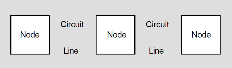
A line is a physical path over which data passes from one node to another in the network. (The path can be over a cable or telephone line, or possibly a microwave or satellite link.)
A circuit can be thought of as a higher-level logical connection that operates over the physical connection. The circuit is the communications data path that carries information from one node to another. All input and output (I/O) activity between nodes occurs over circuits. Multiple users can use each circuit.
VAX: You can design a node to have active circuits operating over a number of lines that connect the node to the other nodes in the network.♦
A computing system can run many different processes and programs. For two processes to communicate with each other, they have to have a way to establish contact and exchange data. DECnet permits computer processes running on the same or different nodes to communicate with each other over logical links. A logical link connects two processes and carries a stream of two-way communications traffic between the processes over one or more circuits.
The process or program to which a logical link is connected is called an object. On an OpenVMS node, some objects are DECnet for OpenVMS system programs (for example, the MAIL object); other objects can be user-written programs. For two programs to communicate over the network, the program on one node establishes a logical link with the object on the other node.
1.1.1.2. How the Network Routes Messages
In a DECnet network, the process of directing a data message from a source node to a destination node is called routing. The route the data travels over the circuits in the network is called the path.
Messages can be exchanged between any two nodes in the DECnet network, even if they are not directly connected to each other. In order for nodes that are not directly connected to be able to communicate, an intervening node along the data path must forward the data received from the source to the destination. Intervening nodes that receive data and forward it to another node are known as routing nodes (or routers). Nodes that cannot forward data are called end nodes. Both routers and end nodes can send messages to and receive messages from other nodes, but only the router can forward messages on behalf of another node. A router can have more than one active circuit connecting it to the network; an end node can only have one.
A router maintains an database about the availability of paths to the destination node and keeps it up-to-date by regularly exchanging routing information with other routers. The routing information includes the cost and the number of hops involved in sending data down a path to a destination node. The circuit cost is a number that the system manager assigns to a circuit between two nodes; the path cost is the sum of the circuit costs along the path to a given node. A hop is the distance between two directly connected nodes; the path length is the number of hops along the path between two nodes.
The router uses current information from its database to choose a data path through the network. The router determines the path to the destination based on the least cost. By changing the cost of a circuit, the manager of a network node can affect the flow of data through the network.
DECnet performs "adaptive routing"– that is, routing that adapts to changing conditions in the network. DECnet selects the best path currently available from the source to the destination. If network conditions change and the primary path becomes unavailable, DECnet redirects the data over the next best alternative path. DECnet automatically reroutes messages if a circuit becomes disabled or a lower-cost path becomes available.
Because adaptive routing in a DECnet network permits messages to be routed over the most cost-effective path currently available, a general user of the network need not be concerned with the path to the destination. Users need only specify the name of the remote node with which they want to communicate.
1.1.1.3. Network Size
A DECnet network can vary in size from a small to a very large network. A typical small network might consist of two to four nodes. A maximum of 1023 nodes is possible in an undivided DECnet network; an optimum number is approximately 300 to 500 nodes, depending on the network topology (the way the nodes and lines are arranged in the network).
Very large DECnet networks can be divided into multiple areas: up to 63 areas, each containing a maximum of 1023 nodes. In a multiple-area network, the network manager groups nodes into separate areas, with each area functioning as a subnetwork. Nodes in any area can communicate with nodes in other areas. DECnet supports routing within each area and a second, higher level of routing that links the areas, resulting in less routing traffic throughout the network. Nodes that perform routing within a single area are referred to as level 1 routers; nodes that perform routing between areas as well as within their own area are called level 2 routers (or area routers).
Note
AXP: DECnet for OpenVMS AXP supports level 1 routing on only one circuit and does not support level 2 (area) routing.♦
1.1.1.4. DECnet Software Design and Structure
DECnet Phase IV software design is based on the Network Architecture (NA). The structured design permits a DECnet network to be extended easily and to incorporate new developments in data communications. DECnet nodes can communicate with any system that supports the same DECnet protocols.
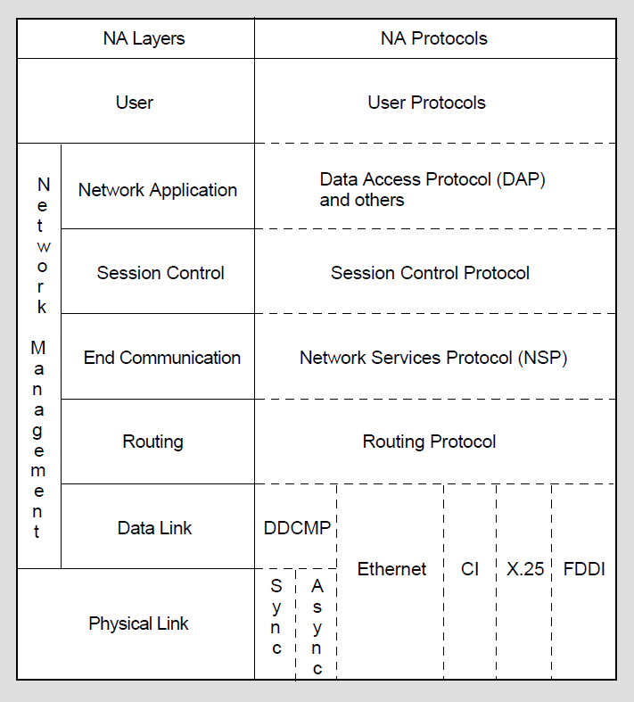
NA specifications govern the interrelationship of the components that make up the DECnet software. The specific functional boundaries between DECnet software components residing at each node are structured as a hierarchical set of layers. Each NA layer is a client of the next lower layer and does not function independently.
NA specifies the functional layers in which DECnet software is arranged on each node, and the communications protocols through which the corresponding layers at different nodes communicate with each other. Each protocol is a set of messages with specific formats and the rules for exchanging the messages. Protocols govern the operation of a communications link.
Figure 1.2, ''DECnet Network Architecture (NA) Layers and Protocols'' illustrates NA layers and the related NA protocols that provide DECnet network functions at each layer. DECnet functions are described elsewhere in this guide. The types of lines that can be configured using DECnet data link protocols are discussed briefly later in this chapter. For a complete description of NA, refer to the NA specifications.
1.1.2. How DECnet for OpenVMS Serves as the OpenVMS Network Interface
DECnet for OpenVMS is an implementation of DECnet software that allows an OpenVMS system to function as a network node. As the network interface, DECnet for OpenVMS supports both the protocols necessary for communicating over the network and the functions necessary for configuring, controlling, and monitoring the network.
DECnet for OpenVMS networking software can be configured on any OpenVMS system. In a DECnet network, DECnet for OpenVMS nodes can communicate with any other operating system that supports DECnet. In addition, a DECnet node can:
Use a packet switching network to communicate with DECnet nodes on other networks.
Use gateways and other communications software and hardware products to communicate with nodes on other networks.
DECnet for OpenVMS is completely integrated into the operating system and provides a natural extension of local input/output operations to remote systems.
OpenVMS users can use the network almost transparently. Implementing network applications is straightforward, and network operations are efficient. Because DECnet for OpenVMS is a part of the system, you can use DECnet for OpenVMS interfaces as standard parts of a local, standalone system (not connected to a network). For example, you can develop application programs that communicate directly with each other at the task level on your system, and then use them in a network environment without modification.
Note
Before you bring up your system as a node in a multinode environment, you must have a DECnet for OpenVMS license and register a DECnet for OpenVMS PAK on your system.
1.2. What a DECnet Network Looks Like
DECnet allows users to plan computer networks of any size and arrangement, from a few workstations linked together in one room to a very large network of powerful computers distributed around the world. The DECnet network is designed to permit growth without disruption. The network can grow from a minimum of two nodes to a maximum of over 64,000 nodes.
DECnet configurations are flexible and can be expanded easily. Nodes can be located wherever required. Individual nodes can be added or relocated without impact on existing nodes or interruption of network operation.
DECnet supports many different kinds of network connections. Nodes located in a building or a complex of buildings can be connected in a local area network (LAN).
The network can be expanded to include nodes at more geographically dispersed locations, connected in a wide area network (WAN). In addition, systems on a DECnet network can use other communications products to communicate with certain systems that do not use DECnet, and networks in an integrated network environment.
The following describes the systems that can be connected in a DECnet network, the types of communications media used to link the systems, and the variety of network environments in which the systems can be configured.
1.2.1. How DECnet Systems Communicate
The smallest desktop workstation
Low-end systems
Mid-sized systems
Largest systems
Because all OpenVMS systems are compatible, the user can maintain a consistent computing environment, and can carry out most networking operations without concern for the way the network operates.
An OpenVMS system can also communicate with other operating systems on the network. For example, a system running DECnet for OpenVMS software can communicate with an ULTRIX system running DECnet–ULTRIX software.
PATHWORKS personal computers can join the DECnet network.
DECnet for OpenVMS nodes can communicate over a packet switching network by means of an X.25 router. Packet switching networks are often used for communication over very long distances involving common carriers and satellite links.
Through special interconnect products, such as gateways and emulators, DECnet nodes can communicate with third party systems and networks. The DECnet /SNA Gateway products permit a DECnet network to connect to an IBM System Network Architecture (SNA) network.
1.2.2. The Communications Media DECnet Uses
Nodes in a DECnet network can be linked by various types of data transmission media. LAN configurations include the following:
Ethernet using standard coaxial cable, ThinWire, or 10BaseT-compliant unshielded twisted-pair cable.
Fiber Distributed Data Interface (FDDI) fiber optic cable.
VAX: Wide area networks use dedicated lines, telephone lines, microwave and satellite links, and fiber optic links. Telephone lines may be leased to provide for permanent connections, or may be used as dialup lines for specific periods of time.
Communication over telephone lines normally involves the use of modems at each end of the connection to perform conversion between the digital signals used by the computer and the analog signals used on the telephone line. For a microwave link, a message is converted into microwave signals at the transmitting site and reconverted at the receiving location, which can be some distance away. Satellite links are usually used for very long-distance communication, such as transoceanic communication.♦
1.2.3. Network Environments Supported by DECnet
DECnet networks support a variety of network connections, permitting computers to be linked in flexible configurations. The basic kinds of environments in which a network can be configured are the local area network and the wide area network. A local area network provides for communications within a limited geographical area, while a wide area network permits long-distance communication. The two kinds of environments can be integrated into a single large network.
1.2.3.1. Local Area Networks
A LAN provides a communications channel designed to connect information processing equipment in a limited area such as a room, a building, or a cluster of buildings (for example, a campus). On the Ethernet, a single, shared network channel LAN, all nodes have equal access. Because Ethernet is a multiaccess medium, new nodes can be added without affecting existing nodes on the Ethernet.
An Ethernet is a coaxial cable, to which each system or device is connected by a single line. In an office or other area where personal computers and workstations are located, ThinWire Ethernet cabling is usually used. The Ethernet supports data transmission at speeds up to 10 million bits per second in a limited area. The standard limit on the distance between any two nodes on the Ethernet is 1.74 miles (2.8 kilometers).
Local area networks can be configured in a variety of arrangements. Two Ethernets can be connected by means of a bridge, a relay that controls network traffic between the Ethernets it connects. Use of a bridge can extend a local area network beyond the distance limitation imposed on a single Ethernet. Routers can also be used to connect two Ethernets. In addition, routing nodes on an Ethernet can be connected to wide area network nodes to form a large, integrated network.
Individual systems can either be connected directly to an Ethernet or gain access to an Ethernet by means of a local area interconnect device, such as a DELNI. A DELNI serves as a concentrator, grouping systems together.
Individual users can optionally gain access to the nodes in a LAN through a terminal server, if one is connected to the network. A user at a terminal connected to the terminal server can access any service node that implements the local area transport (LAT) protocol and is known to the server. A user logged into a node by means of a terminal server can perform the same functions as a user logged in on a terminal directly connected to the node.
Nodes in a VMScluster (a group of systems organized to share processor and storage resources) require DECnet for OpenVMS connections. Each node in a cluster can be connected to an Ethernet or FDDI that provides the DECnet data link for the cluster.
VAX: If an Ethernet is not available, you can configure the VAXcluster computer interconnect (CI) as the DECnet data link between the cluster nodes.♦
Figure 1.3, ''Example of a Small Ethernet Configuration'' illustrates a small Ethernet configuration of four nodes. The Ethernet connects two VAXstations, a VAX 9000, and a DEC 300 AXP series system.
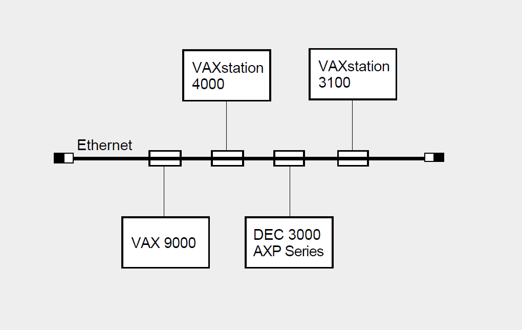
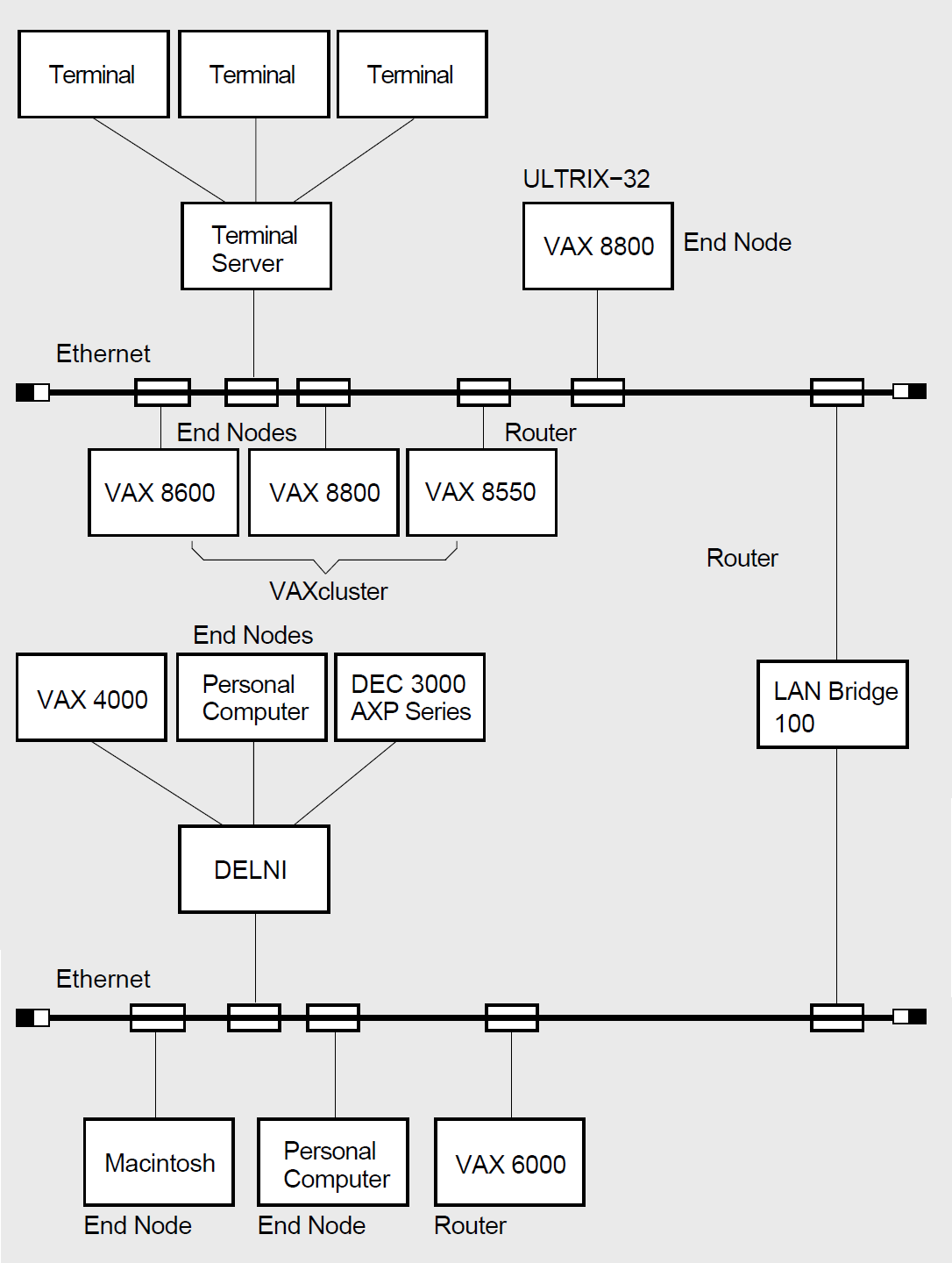
Figure 1.4, ''Example of a Large Ethernet Configuration'' shows a larger LAN configuration in which two Ethernets are connected by a LAN bridge. Nodes running various operating systems, including the nodes in a VMScluster, are connected directly to the Ethernet. In the figure, a group of small systems is connected to the Ethernet by means of a DELNI. Individual terminal users can gain access to Ethernet nodes through a terminal server.
1.2.3.2. FDDI Local Area Network Configuration
The Fiber Distributed Data Interface (FDDI) LAN provides 100 Mb/s network communications with complete 802.3/Ethernet interoperability. Figure 1.5, ''Example of an FDDI LAN'' shows an FDDI configuration in which two cascading trees of concentrators are connected by a dual ring. A VAX 6000 and a VAX 9000 are connected to concentrators. A bridge connects the FDDI LAN to an Ethernet LAN.
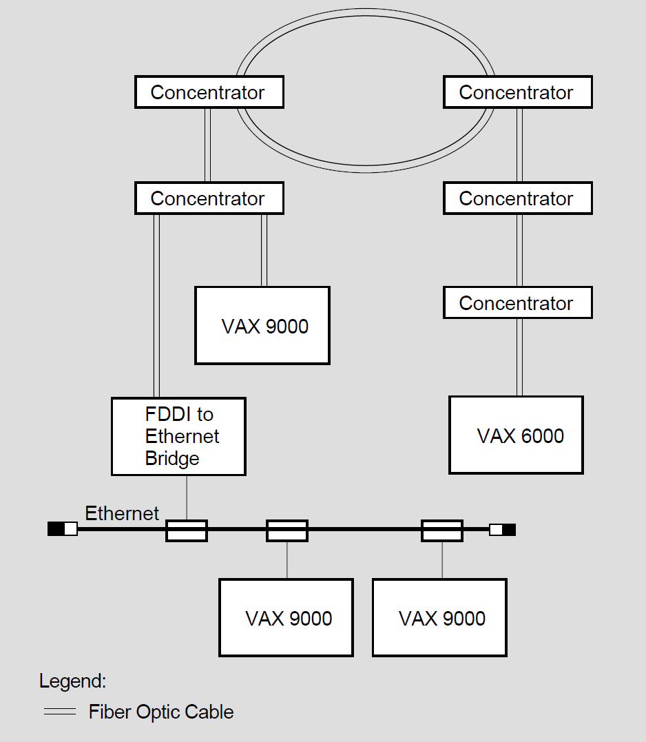
FDDI provides a reliable high-speed multiaccess communications channel, optimized to connect information processing equipment in a limited geographic area, such as an office, a building, or a complex of buildings (for example, a campus). As implemented by VSI, FDDI has the following features:
Uses a dual ring of trees topology; using one ring as the primary ring, the second ring as a backup, and the tree configuration for increased network flexibility, manageability, and availability.
Employs multimode and single-mode fiber optic cable for the transmission medium.
Uses reliable light emitting diodes (LEDs) as the optical transmitters, photo diodes (PINs) as the optical receivers for multimode fiber, and laser technology for single-mode fiber transmission.
Supports a maximum of 500 network devices, a maximum ring circumference of 100 kilometers (62 miles), a maximum distance between multimode fiber stations of 2 km (1.2 m) for flexible network connections and configurations; and 40 km (25 m) distance between stations using single-mode fiber.
Ensures interoperability with existing and future multivendor networks because it is based on standards.
FDDI is implemented in three ways:
As a high-speed backbone connecting mid-speed LANs such as Ethernet
As a high-speed LAN connecting workstations or other devices
As a high-speed connection between host computers or host computers-toperipheral equipment, such as those found in a data center
The FDDI concentrator provides for the attachment of FDDI devices such as VAX and AXP nodes or FDDI-Ethernet bridges to the FDDI LAN.
In the dual ring of trees topology, FDDI concentrators cascade from other FDDI concentrators connected to a dual ring. (You can also implement cascading concentrators without the dual ring.) This configuration provides a high degree of fault tolerance and increases the availability of the backbone ring.
The dual ring of trees topology is also flexible: You make the tree branch out by simply adding concentrators that connect to the primary ring through upper-level concentrators attached to the dual ring. You can extend tree branches as long as you do not exceed the station number or ring distance limits.
If stations are attached to concentrators connected to the dual ring or configured in tree topologies, you can remove these stations from the FDDI LAN as needed. Concentrators can then bypass inactive or defective stations without disrupting the network.
FDDI multimode fiber has varying light transmission capabilities; singlemode fiber has only one mode of transmission and is useful for long-distance applications.
1.2.3.3. Wide Area Networks
A WAN provides for communication over broader geographic areas. DECnet supports long-distance communication with systems located anywhere in the world.
VAX: A wide variety of communications media can be used: examples include dedicated, leased, dialup lines, microwave, and satellite links. Nodes in a wide area network can be connected by point-to-point or multipoint lines. These lines use the data communications message protocol (DCMP).
Figure 1.6, ''Examples of DCMP Connections'' illustrates the different kinds of DCMP connections.
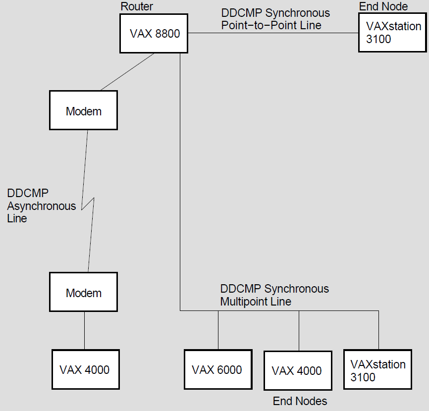
Point-to-point connections are synchronous or asynchronous. Synchronous devices provide high-speed connections over dedicated lines or telephone lines (using modems).
Asynchronous devices provide low-speed, low-cost connections over terminal lines that are switched on for network use either permanently (a static connection) or temporarily (a dynamic connection). For example, a user on a MicroVAX can configure a dialup line (a telephone line) to another computer as a dynamic asynchronous DECnet line for the duration of a telephone call.
A multipoint line is a special form of point-to-point line: two or more nodes connected by a synchronous DCMP communications channel, with one node controlling the channel.♦
Packet switching networks, such as TYMNET and Telenet, provide communication services between nodes on the same or different networks, often in widely dispersed geographic areas connected by satellite links.
A DECnet for OpenVMS node can access a packet switching data network through an X.25 router to establish communication with a remote DECnet node.
A DECnet for OpenVMS node connected to a LAN can also use a DECnet/SNA gateway on the same LAN to communicate with IBM systems in an SNA network.
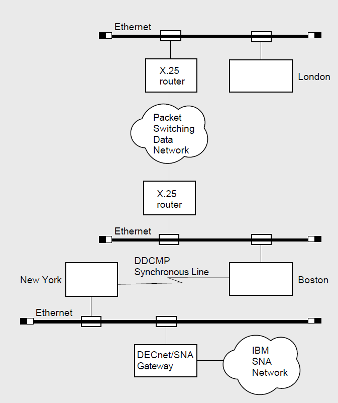
Figure 1.7, ''Examples of WAN Connections'' shows wide area network connections, as follows:
VAX: A DCMP synchronous line connecting two nodes at different locations (Boston and New York).♦
A packet switching data network enabling nodes Boston and London to communicate by way of X.25 routers.
A node located in New York communicating with IBM systems on an SNA network by means of a DECnet/SNA gateway.
1.2.3.4. Integrated Networks
DECnet LANs and WANs can be integrated to provide comprehensive network support. Wide area network connections can be used to connect individual local area networks, and can provide access to systems from other vendors.
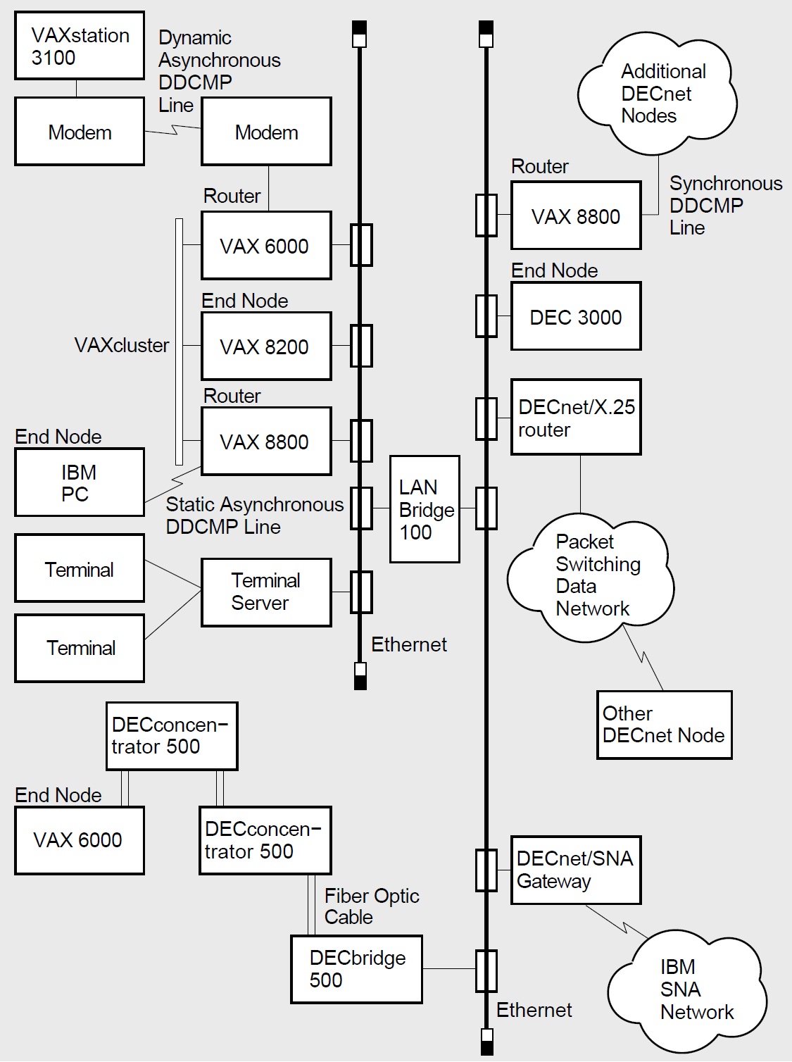
DECnet for OpenVMS systems can be configured to use the full possibilities of integrated DECnet networks. Figure 1.8, ''Example of a Large Integrated DECnet Configuration'' is an example of a large DECnet configuration that illustrates a variety of ways in which DECnet end nodes and routers can be connected to the network.
Figure 1.8, ''Example of a Large Integrated DECnet Configuration'' shows two Ethernet LANs linked by a LANbridge and an FDDI LAN connected to an Ethernet by a bridge. It shows a terminal server connected to the Ethernet; individual terminal users can log in to any node on the extended Ethernet by means of the terminal server, provided the server is aware of the service offered by the node.
The Ethernet connects a VAXcluster including three systems.
A synchronous DCMP point-to-point line provides a connection to additional DECnet nodes at a remote location.
Asynchronous DCMP lines provide permanent (static) and temporary (dynamic) connections between nodes in the network.♦
In the figure, nodes on either Ethernet can communicate with DECnet nodes at distant locations through a packet switching data network and can access an IBM SNA network by means of a gateway node.
Chapter 2. What You Can Do over the Network
This chapter summarizes the functions that DECnet for OpenVMS general users, advanced users, and system managers can perform in a DECnet network environment. It describes the file and mail operations that a general user can conduct over the network. It explains how an advanced user can develop command procedures and application programs to run over the network. The chapter also outlines the responsibilities of the system manager of each network node, and indicates briefly how a system manager could serve as overall manager for a larger DECnet network.
2.1. Network Options for the General User
As a DECnet for OpenVMS user, you can use the DECnet network in an almost transparent manner. Because DECnet capability is completely integrated into the operating system, you can perform network operations as a natural extension of the input/output operations you perform on your local system.
Log in to another network node on which you have an account.
Access public directories or databases located on any node on the network.
Display locally the contents of remote directories and files to which you have access.
Copy files from node to node or append files on one node to a file on another node.
Print files at the remote node where they reside, copy them to a remote printing device, or copy them to the local node for printing.
Using an editor, access and edit a file on a remote node.
Create a new file in a remote directory.
With the appropriate access, delete or purge files from directories, search files, and compare the contents of files on different nodes.
Perform sort and merge operations on remote files.
Analyze the structure of files, convert their organization and format, and dump their contents in a specific format.
Back up local files by using a remote save set on disk.
Create, display, and delete logical names for nodes and devices that are to be included in remote file specifications.
Any user on a DECnet for OpenVMS node can send electronic mail to, and receive mail from, a user on any other node in the DECnet network, by means of the Mail utility.
Users can also communicate interactively over the network by means of the Phone utility.
2.1.1. How to Gain Access to the Network
You can perform general network operations if you have an account on a DECnet for OpenVMS system that is connected to a DECnet network and have the minimum privileges TMPMBX and NETMBX. To gain access to the network, simply log in to your account on the remote system. (For a complete description of the procedure for accessing the network, see Chapter 3, "Getting Started on the Network".)
Before you perform an operation over the network, you can check the availability of the network by entering the DCL command SHOW NETWORK. If you are connected to the network, the command display shows the name and address of your node. If your system is not connected to the network, the display indicates that the network is not currently available. (The SHOW NETWORK command display is described in detail in Chapter 3, "Getting Started on the Network".)
After you log in to a network node, you may be able to log in to other nodes on the same network. If you are authorized to access an account on another node that supports the DECnet remote command terminal facility (as described in Chapter 3, "Getting Started on the Network"), you can log in to that node over the network. To log in to the other node, enter the DCL command SET HOST, specifying the remote node name, and follow the login procedure the remote node uses. Once you are logged in to the remote node, you can perform all general user operations on that system as though it were the local node.
2.1.2. How to Access Remote Files
This section describes the format of the remote file specification and the access controls that affect access to a remote file. This section also explains how to use logical names in specifying remote directories and files, and how to specify remote files located in VAXclusters.
2.1.2.1. Remote File Specification Format
You can use DCL commands to access remote files by simply including in the file specification the name of the remote node on which the file is located, if the File Access Listener (FAL) object is enabled on the remote system (see Chapter 3, "Getting Started on the Network").
You can access files that are protected against general access if the owner has granted you access, either by a proxy account or by providing you with the name and password of the account (see Section 2.1.2.2, ''Remote File Access Controls'').
The full format for a remote file specification is as follows:
node"username password"::device:[directory]filename.type;version
For example, to identify the file EXAMPLE.LIS residing in the directory INFORMATION on device DBA1, which belongs to user PADRAIC whose password is MIACOMET, at node BOSTON, you would use the following file specification:
BOSTON"PADRAIC MIACOMET"::DBA1:[INFORMATION]EXAMPLE.LIS
U32"user password"::"/usr/users/user/Foobar"
Note
Unlike OpenVMS, an ULTRIX file specification is case sensitive.
2.1.2.2. Remote File Access Controls
The owner of a file can use the SET PROTECTION command to protect a file or directory against unauthorized access. One way to access a protected remote file is to supply the user name and password of a user on the remote system who does have access to the file. If the user BLACK, who has the password LX2431, has access to the file, you could use the following file specification:
BOSTON"BLACK LX2431"::DBA1:[INFORMATION]EXAMPLE.LIS
TUCSON::WORK:[PROJECT]TASKS.LIS
For more information on the use of proxy accounts over the network, see Chapter 3, "Getting Started on the Network".
LONDON""::DBA0:[MARKET]TRENDS.DAT
A user name that you supply explicitly in an access control string included in the remote file specification. (If you specify a null access control string, the user name in the default DECnet account, if one exists, is used.)
The user name in your proxy account at the remote node, if one exists.
The user name in the default access account, if one exists, for the FAL object at the remote node.
The user name in the default DECnet account, if one exists, at the remote node (by default, that user name is DECNET).
2.1.2.3. Logical Names in Remote File Specifications
$DEFINE CITY BOSTON::DBA1:$TYPE CITY:[INFORMATION]EXAMPLE.LIS
$DEFINE CITY "BOSTON""BLACK LX2431""::DBA1:"
Note
Passwords embedded in logical names are not protected. Anyone who can access the file in which the logical names are stored can read the passwords. Embedding passwords in logical names is appropriate only for networks with very low security requirements.
You can also use the logical name commands ASSIGN and DEASSIGN to indicate portions of remote file specifications. Logical name translation is performed locally and does not affect the network file operation.
If you do not specify the name of a device or directory in a remote file specification, the remote system supplies a default name.
2.1.2.4. VMScluster File Specifications
In a VMScluster, cluster members must have DECnet connections, but directories or files can be shared by users on different nodes in the cluster without actually using DECnet. In a cluster, disk volumes can be mounted on all cluster nodes, and node names need not be used to access directories or files.
$DIRECTORY SOURCE::DATA:[COMMON]
2.1.3. Network File Operations
Note
These examples assume that the remote node has enabled default access for FAL (see Chapter 3, "Getting Started on the Network") or that the user has a proxy account on the remote node.
2.1.3.1. Displaying Remote Directories and Files
$DIRECTORY ALBANY::DISK1:[COMMENTS.PUBLIC]
You can also use the DIRECTORY command to list all versions of a particular file in a remote directory, or all attributes of a specific file or files.
$TYPE ALBANY::DISK1:[CLUB]MEMBERS
$TYPE NWYORK::[ACCOUNT]USERDATA
$DEFINE PUBLIC ALBANY::DISK1:[COMMENTS.PUBLIC]
$DIRECTORY PUBLIC$TYPE PUBLIC::APPROVALS.TXT
They can also copy the file to the local node and then print it, as described in the next section.
2.1.3.2. Copying and Printing Remote Files
Use the COPY command to copy a file from one node to another. As part of the copy operation, you can create a new file from existing files.
$COPY BOSTON::DISK:TEST.DAT;2_To:LONDON::DBA0:[PRODUCT]TEST.DAT
$COPY NAMES.LIS ALBANY::DISK1:[CLUB]NAMES.LIS$COPY NAMES.LIS ALBANY::DISK1:[CLUB]
$COPY *.* NWYORK::[ACCOUNT]*.*
$COPY USER1.DAT,USER2.DAT NWYORK::[ACCOUNT]USERS.DAT
$COPY NWYORK"BROWN CHECKING"::[STATISTICS]SUMMARY.LIS *
$APPEND NWYORK"BROWN CHECKING"::[TESTING]DATA1.LIS,DATA2.LIS_To:LONDON::DBA0:[PRODUCT]RESULTS.LIS
$COPY REPORT.LIS TUCSON::WORK:[PROJECT]$PRINT/REMOTE TUCSON::WORK:[PROJECT]REPORT
$COPY REPORT.LIS TUCSON::LPA0:
The /REMOTE qualifier is required in the PRINT command whenever a remote file is specified, and you cannot include any other qualifiers in this command. The PRINT/REMOTE command supplies a default file type of LIS.
2.1.3.3. Creating and Editing Remote Files
Using an editor, you can create a file at a remote node and modify the file. You can also edit an existing file on a remote node. To perform editing on a remote file, simply include the node name of the remote file when you invoke the editor.
$EDIT ZURICH::[MANUSCRIPT]STORY.TXT
You can then perform all normal editing operations on the file STORY.TXT. In the same way, you can invoke any other VMS-supported editor to edit a remote file.
$CREATE NWYORK"BROWN CHECKING"::[STATISTICS]INPUT.DAT1,046,2142,307,6251,988,723^Z$
2.1.3.4. Deleting and Purging Remote Files
If you have access to a remote directory, you can delete or purge files from the directory. Use the DELETE command to delete one or more files from a mass storage volume on a remote node. In the DELETE command, you must supply an explicit version number in any file specification that is not enclosed in quotation marks. If you want to delete the highest-numbered version, specify a version number of zero ( ;0 ). To delete all versions, specify the wildcard character as the version number ( ;* ).
$DELETE BOSTON"BLACK LX2431"::DBA1:[INFORMATION]DETAILS.LIS;2
$DELETE TUCSON::WORK:[SUGGESTIONS]*.*;*
$PURGE TUCSON::WORK:[PROPOSALS]*.LIS/KEEP=2
2.1.3.5. Searching, Comparing, and Sorting Remote Files
DCL commands permit you to search remote files for specific information, compare two remote files to determine any differences, and sort and merge remote files.
$SEARCH ALBANY::DISK1:[CLUB]MEMBERS.LIS,DATA.LIS_String(s):NAME
$DIFFERENCES BOSTON::TEST.DAT
$DIFFERENCES BOSTON::TEST.DAT LONDON::DBA0:[PRODUCT]TEST.DAT
To perform sort and merge operations on remote files, invoke the Sort/Merge utility. Use the SORT command to reorder records in a remote file and create a new output file (or an address file that you can use to access the reordered records). Use the MERGE command to combine two or more sorted files into a single output file that the utility program creates. The files to be combined must be similarly sorted, but can reside at different DECnet for OpenVMS nodes.
$SORT/KEY=(POSITION:1,SIZE:7) -_$BOSTON::DBA1:[RECORDS]RANDOM.FIL ALPHANM.SRT
$MERGE/KEY=(POSITION:1,SIZE:30) -_$TUCSON::WORK:[PROJECT]FILE1.SRT,FILE2.SRT/CHECK_SEQUENCE -_$MERGEFILE.DAT
2.1.3.6. Examining Remote Files and Records
DCL commands that analyze the internal structure of certain files, convert the organization and record format of files, and dump the contents of files in specific data formats are supported in a network environment.
$ANALYZE/RMS_FILE TUCSON::WORK:[PRODUCTION]RUN.DAT
The CONVERT command allows you to transfer records from a source data file to a second data file, that can differ in file organization and format from the first. You can use this command to transfer files to or from a remote node while altering file attributes.
If the output file exists, the Convert utility changes the organization and format of the data from the input file to that of the output file. If the output file does not exist, the utility creates it from the file attributes specified in an FDL file. You can also use the CONVERT command to copy files to a remote node or to retrieve them without modifying file attributes. However, CONVERT transfers a file record by record, not using block I/O.
$CONVERT/APPEND SALES.TMP BOSTON::DBA1:[RECORDS]SALES.CMD
$DUMP/RECORDS/OCTAL/WORD_File(s):BOSTON::DBA1:[RECORDS]CALC.DAT/PRINTER
2.1.3.7. Backing Up Files over the Network
You can use the BACKUP command to save local files in a BACKUP save set residing on a remote DECnet for OpenVMS node. You can also use this command to restore files on the local node that were previously saved in a save set on a remote DECnet for OpenVMS node. Use BACKUP/LIST to display the names and attributes of files cataloged in a remote save set. The BACKUP save set cannot be on magnetic tape.
$BACKUP_From:DB1:[SCHED]*.*_To:MIAMI::DBA2:[SAVE]SCH.BCK/SAVE_SET
2.1.3.8. Error Messages Displayed During Remote File Operations
When you enter a DCL command to perform a network file operation that does not complete successfully, one or more error messages are displayed. Typically, the sequence of error messages includes a primary error message generated by the DCL command interpreter and a secondary error message generated by Record Management Services (RMS). These messages can optionally be followed by an additional error message associated with the secondary RMS error (from a facility involved in the network file operation).
$COPY INDEX.DAT SYDNEY::TEMP.DAT
%COPY-E-OPENOUT, error opening _SYDNEY::TEMP.DAT; as output
-RMS-F-SUPPORT, network operation not supported
-FAL-F-ORG, file organization field rejected
2.1.4. Using MAIL and PHONE in a Network Environment
Note
To receive mail on your system, default access must be provided either by a default access account for the Mail utility or by the default DECnet account (see Chapter 3, "Getting Started on the Network").
$MAIL>SENDTo:NWYORK::SMITH
_SYSTEM-F-UNREACHABLE, remote node is not currently reachable
From: BOSTON::JONES
New mail on node 'local-nodename' from 'remote-nodename::username'
New mail on node PURPLE from BOSTON::JONES
You can send either messages or files over the network. If you are composing a long message for transmission to a remote node, you may prefer to use an editor to create the message file and then invoke MAIL to transmit the file. This method permits you to avoid the possibility of losing the network connection before you complete your message.
The Mail utility normally permits cluster alias node names and addresses to be used for incoming and outgoing messages. The use of the cluster alias permits MAIL to treat a cluster as though it were a single node. When you send mail to someone whose node is a member of a cluster that uses an alias node name, you can specify either the cluster alias or the user’s node name.
If you are logged in to a VMScluster node that uses an alias node name, the Mail utility uses the alias node name, rather than the name of your individual node, to identify any mail message you send. An incoming reply directed to the alias node name is given to any active node in the cluster and then delivered to your mail file. Consequently, if you are on a cluster node that uses an alias, the notification of incoming mail on your screen indicates the name of the cluster node that received the message.
From:  BOSTON::JONES
To:    CLUST1::ALLEN
New mail on node GREEN from BOSTON::JONES
To contact DECnet for OpenVMS users over the network, you can also use the Phone utility, which allows you to have an online conversation with a user on another node that supports Phone.
To receive messages from the Phone utility, one of the following conditions must be satisfied:
Default access must be provided by a default access account for the Phone utility
Default access must be provided by the default DECnet account
The sender must have a proxy account on your system
The sender must include in the command the name and password for an account on your system (see Chapter 3, "Getting Started on the Network").
To address a user on a remote node, use the format nodename::username. Your outgoing connection identifies your local node. During your conversation, Phone creates a number of incoming links addressed to your node. Do not use a cluster alias node name with the Phone utility because links addressed to a cluster alias node name can be assigned to any node in the VMScluster.
2.2. Network Options for the Advanced User
Advanced DECnet for OpenVMS users and programmers can write command procedures and programs that make the network seem transparent to the user. Accessing a file on a remote node is conceptually the same as accessing a file on the local system. To access a remote file in a command procedure or application program, you need only include in your file specification the name of the remote node and any required access control information.
You can execute command procedures locally that access remote files. You can also submit command procedures for batch execution on remote nodes. Additionally, you can prepare command procedures that cause tasks to be executed at remote nodes.
You can access remote files by means of standard I/O statements in higher-level language programs (for example, programs written in FORTRAN, BASIC, PL/1, Pascal, COBOL, and C). Regardless of the higher-level language in which a program is written, you can access remote files exactly as you would access local files.
You can access remote files within programs by means of standard RMS or system service calls; no DECnet-specific calls are required.
Task-to-task communications, a feature common to all DECnet implementations, allows two application programs running on the same or different operating systems to communicate with each other regardless of the programming languages used. Examples of network applications are distributed processing applications, transaction processing applications, and applications providing connection to servers.
2.2.1. Remote Command Procedures
Within command procedures to be executed locally, you can use DCL commands to open and close remote files, and read and write records in these files, using the same qualifiers as for local files. You can also use lexical functions that return information about remote files.
You can submit DCL command procedures residing on remote nodes for execution as batch jobs on those nodes.
You can write command procedures to cause tasks to be run at remote nodes.
The following sections summarize ways that you can use command procedures over the network.
2.2.1.1. Accessing Remote Files with Command Procedures
In a command procedure to be executed locally, you can use DCL commands that access remote files. You can use the same command and file qualifiers in the DCL commands OPEN, CLOSE, READ, and WRITE that you would normally use in command procedures to access local files.
$ OPEN/WRITE OUTPUT_FILE BOSTON::DBA1:[INFORMATION]EXAMPLE.LIS
$ WRITE OUTPUT_FILE "Preliminary examples to be supplied"
|
F$FILE_ATTRIBUTES |
Returns attribute information about a remote file |
|
F$PARSE |
Returns a partial or a full file specification for a remote node |
|
F$SEARCH |
Returns the full file specification for the next remote file that matches the given wildcard file specification |
2.2.1.2. Submitting Command Procedures for Remote Execution
To submit a command procedure for execution at a remote node, use the DCL command, SUBMIT/REMOTE. This command causes a command procedure residing at a remote node to be entered in the batch job queue for execution at the remote node.
The SUBMIT/REMOTE command does not copy the files to the remote node; you must enter a separate COPY command if the file is not already located at the remote node. The /REMOTE qualifier is required in the SUBMIT command if a node name is included in the file specification. No other qualifiers are allowed in the SUBMIT/REMOTE command. The default file type is COM.
$SUBMIT/REMOTE TUCSON::WORK:[PROJECT]SCHEDULE
$COPY JOB.COM TUCSON::WORK:[PROJECT]$SUBMIT TUCSON::WORK:[PROJECT]JOB.COM/REMOTE
2.2.1.3. Using Command Procedures to Run Remote Tasks
node-specification::"TASK=taskname"
Additional information on specifying tasks to be executed at remote nodes is given in Section 2.2.2, ''Network Applications Using Task-to-Task Communication''.
$TYPE NWYORK"BROWN CHECKING"::"TASK=SHOWSUM"
 $!             S H O W U S . C O M
$ if f$mode() .eqs. "NETWORK" then define/user sys$output sys$net
$ show user
$TYPE BOSTON::"TASK=SHOWUS"
           VAX/VMS User Processes at 31-JUL-1992 15:45:23.07
        Total number of users = 3, number of processes = 4
Username   Node     Process Name   PID      Terminal
BILL_M    ORIOLE    BILL_M       20A02ED5   RTA4:    (BIRCH11::BILL_M)
ROSE       LARK     ROSE         21401C63   TWA210:
WING       SWAN     WING         20A02E93   RTA2:    (OAK::WING)
WING       SWAN     WING_1       20A0762C   (subprocess of 20A02E93)
2.2.2. Network Applications Using Task-to-Task Communication
DECnet task-to-task communication allows an application program on a network node to exchange data with another program running on a remote node. Task-to- task communications can be transparent or nontransparent. Transparent communication allows users to move data across the network without necessarily knowing they are using DECnet software. Nontransparent communication involves using network-specific features in the communication process.
For DECnet for OpenVMS, task-to-task communication is performed as though a remote file were being accessed. In DECnet terms, a task is an image running in the context of a process. A special quoted string, the task specification string, is used in a remote node specification to indicate the remote task to which you attempt to connect.
The task can be identified in the program either by name or object number. A user-defined task is usually identified by network object number 0, but it can optionally be assigned a nonzero object number, in the range from 128 to 255. A nonzero object number can be specified without a task name. (Specific network services are also identified by nonzero object numbers; for example, 27 represents the Mail utility object.)
n is any nonzero object number):
node-specification::"TASK=taskname"
node-specification::"0=taskname"
node-specification::"n="
BOSTON::"TASK=TEST2"
BOSTON::"0=TEST2"
In transparent task-to-task communication applications, a task can access a remote task and exchange information. To access the remote task, a program can use standard high-level language I/O statements that include a remote task specification identifying the task. Transparent communication using system services provides all the basic functions necessary for two tasks to exchange messages over the network, without requiring any DECnet-specific calls.
The system manager can define two general kinds of DECnet objects:
Objects with a 0 object type. These objects (also known as named objects) are usually user-defined images for special-purpose applications.
Nonzero objects. Nonzero objects (also known as numbered objects) serve as known objects that provide specific network services such as FAL (used for file access) or NML (used for network management).
Nontransparent task-to-task communication extends this basic set of functions to allow a nontransparent task to receive multiple inbound connections and to use additional network protocol features such as optional user data and interrupt messages. The nontransparent program includes additional system service and I/O functions supported by DECnet for OpenVMS. Nontransparent task-to-task communication allows you to coordinate a more controlled communication environment for exchanging information.
Online examples in DB_REQUESTER.C and DB_SERVER.C, found in the directory SYS$EXAMPLES, illustrate a nontransparent communications application, written in the C programming language.
The examples permit a user at one node to submit an inquiry to a database at a remote node and receive a response. The application consists of two nontransparent task-to-task programs. The first program is the database request program on the local node; the other is the database server program on the remote node. A user at the local node provides input in the form of a name key to the requesting program. This program transmits the key to the database server program, which executes a database inquiry and sends the response back to the user.
Two additional example programs, DB_USER.C and DB_READ.C, create and read the database file USER.IDX, which is needed to run DB.SERVER.C.
In the examples mentioned, DB_REQUESTER is a nontransparent source task on the local node that communicates with a nontransparent target task, DB_SERVER, on the specified node.
The task DB_SERVER executes a database inquiry at the target node using key information that is input at the originating node. The source task uses a network connect block (NCB) and assigns a channel to establish communication with the target task. DB_SERVER declares itself to be a network object to permit it to receive more than one connection request at a time. DB_SERVER also uses a mailbox to receive notifications of network status.
2.3. System and Network Manager Responsibilities
The system manager of a DECnet for OpenVMS node is responsible for establishing the system as a node in the network, and controlling and monitoring the node.
Configuring your system as a network node requires supplying information at the local node about network components, including the characteristics of the local node, remote nodes, circuits, lines, and objects. This information constitutes what is called the configuration database for the local node. Each node in the network has such a database. As manager of your system, you supply information about the configuration database using the Network Control Program (NCP) utility.
If you are configuring a DECnet for OpenVMS node for the first time or rebuilding the configuration database for your local node, you can use the interactive NETCONFIG.COM procedure to configure your node. Once you bring up your node and verify its connection to the network, you can use the NCP utility to control and monitor local network operation, and to test network software operation. See Chapter 3, "Getting Started on the Network" for the procedure for bringing up your node on the network, and Chapter 4, "Keeping the Network Running" for the techniques for maintaining the network.
Planning for configuration of your node in an existing network usually involves coordinating with the system managers of other nodes in the network or with the manager of the network (if a manager has been designated) to ensure uniform parameter settings.
To create a new network, two or more system managers connect their systems by means of communications lines; each manager then brings up his or her system as a network node.
A system manager of a network node may be called upon to provide DECnet host services for other DECnet nodes. Host services include the downline loading of system images to diskless remote nodes, and the receiving of upline dumps of system images from nodes that have crashed. For example, DECnet for OpenVMS permits you to load an operating system image or a terminal server image downline to a target node. Another host service involves connecting to an unattended remote node (for example, a diskless communications server) to act as its console.
For a larger network, one person, who may be the manager of a network node, is usually designated as the manager of the network. The network manager is responsible for planning, building, and fine tuning a whole network to run with maximum efficiency. The network manager makes network-wide configuration decisions, such as the kinds of paths to be established, which nodes should be routers or end nodes, and whether the network should be divided into areas. The network manager also sets values for network parameters that should be the same across the network.
Managing a large network usually involves regular monitoring to detect patterns of usage and error conditions on the network, and performing remote configuration of the network to control traffic patterns and accommodate network growth.
System and network managers also perform maintenance procedures to prevent serious problems from developing, and carry out troubleshooting procedures to resolve problems quickly. Using network software, the manager can obtain statistics on network usage and routing parameters. Network logging files provide error statistics useful in diagnosing potential problems. NCP commands display the status of nodes, lines and circuits in the network.
Some of the considerations involved in developing a network are summarized at the end of Chapter 3, "Getting Started on the Network". Maintenance and troubleshooting procedures are summarized in Chapter 4, "Keeping the Network Running". For a complete description of managing and maintaining systems in a DECnet network, refer to the VSI OpenVMS DECnet Networking Manual. NCP commands and DTS/DTR are specified in the VSI OpenVMS DECnet Network Management Utilities.
Chapter 3. Getting Started on the Network
Log in to an existing network node: If you are a general user with an account on a system that is connected to an existing network, you have access to the network as soon as you log in to your account, provided you have the privileges NETMBX and TMPMBX. (See the description in Section 3.1, ''Accessing an Existing DECnet for OpenVMS Network Node''.)
Bring up your VMS system as a network node: If you are the manager of a DECnet for OpenVMS system, you can physically connect your system to an existing DECnet network by means of a communications line, and bring your system up as a network node by performing the DECnet for OpenVMS installation procedure. The DECnet for OpenVMS installation procedure you perform on your system involves registering the DECnet for OpenVMS Product Authorization Key (PAK) using the OpenVMS License Management utility, configuring your node as part of the network, starting the network, and verifying that you are connected to the network. (Section 3.2, ''Preparing to Bring Up Your System as a Node on an Existing Network'' and Section 3.3, ''Installing DECnet for OpenVMS on Your System'' describe the steps involved.)
Create a new network: If there is no existing network to which you can connect, you can cooperate with the managers of other systems to create a new network. A network is formed when two or more systems are connected by communications lines and each system is brought up as a network node. For larger networks, a network manager may be appointed. (Section 3.4, ''Network-wide Considerations'' indicates some considerations involved in establishing a large network.)
3.1. Accessing an Existing DECnet for OpenVMS Network Node
Once your DECnet for OpenVMS node appears on the network, you can access the network simply by logging in to the node. The node at which you log in is called the local node; other nodes on the network are called remote nodes.
The following section describes the minimum privileges required to access the network for general user operations, how to display network information about your node, and how to log in to another node on the network from your local node.
3.1.1. Logging In to a Network Node
If you are a user with an account on a system that is a node on a DECnet network, you can gain access to the network by logging in to your account on the node, provided you have the privileges required by the network. The minimum privileges required to access the network for general user operations are TMPMBX and NETMBX. To verify that you have these privileges, enter the DCL command SHOW PROCESS/PRIVILEGES. For example, enter the following:
$ SHOW PROCESS/PRIVILEGES

 2-SEP-1992 15:46:38.24   User: WING     Process ID: 2020024E
                          Node: RON      Process name: "WING"

Process privileges:
 TMPMBX         may create temporary mailbox
 NETMBX         may create network device

Process rights:
 INTERACTIVE
 REMOTE

System rights:
 SYS$NODE_RON
If necessary, ask the system manager to provide you with the required privileges.
To log in to the system, follow the standard login procedure (see VSI OpenVMS User's Manual). You can now perform all general user operations on the network, including sending and receiving mail and accessing remote files. Network user operations are described in Chapter 2, "What You Can Do over the Network".
To display the name of your local node, use the DCL command SHOW LOGICAL SYS$NODE. For example, to display the name of the local node ORANGE, enter the following:
$ SHOW LOGICAL SYS$NODE

"SYS$NODE" = "ORANGE::" (LNM$SYSTEM_TABLE)
To learn how your node relates to the rest of the network, you can enter the DCL command SHOW NETWORK. The command display includes the address and name of your local node.
If your node is a routing node, the SHOW NETWORK display lists the other nodes (in your area) to which your node has access and provides routing information about the path to each node. In a multiple-area network, the display also indicates the path to the area router through which your node has access to nodes in other areas. (See Chapter 1 for a discussion of routing over the network.)
The following example is the network display for routing node ORANGE connected to Ethernet circuit SVA-0.
$ SHOW NETWORK

VAX/VMS Network status for local node 2.5 ORANGE on 15-JUN-1992 10:10:10

The next hop to the nearest area router is node 2.2 VIOLET:

             Node         Links  Cost Hops  Next Hop to Node

             2.5 ORANGE     0      0    0   Local →   2.5 ORANGE
             2.2 VIOLET     1      1    1   SVA-0 →   2.2 VIOLET
             2.3 PURPLE     0      1    1   SVA-0 →   2.3 PURPLE
             2.4 YELLOW     0      1    1   SVA-0 →   2.4 YELLOW
If your node is an end node, the SHOW NETWORK display identifies your node by name and address, but does not provide a list of accessible nodes. If your end node is connected to a multiaccess Ethernet circuit, however, the display identifies a particular router designated to perform routing services for the end node. The following example shows the display for end node YELLOW on an Ethernet.
$ SHOW NETWORK

VAX/VMS Network status for local node 2.4 YELLOW on 15-JUN-1992 10:15:00

This is a nonrouting node, and does not have any network information.
The designated router for YELLOW is node 2.5 ORANGE.
If the network is not available at the time you enter the SHOW NETWORK command (for example, if DECnet for OpenVMS is temporarily turned off), the message ‘‘Network unavailable’’ is displayed.
You can obtain additional information about the network by means of the Network Control Program (NCP) utility. The NCP commands you can use to monitor the network are described in Chapter 4, "Keeping the Network Running".
3.1.2. Accessing a Remote Node Interactively
You can also log in to other nodes on the network from your local system. DECnet for OpenVMS provides a network command terminal facility that permits you to log in to a remote node on which you have an account, and use the facilities of that system while you are physically connected to the local system. (The network command terminal facility is also referred to as the network virtual terminal facility.)
To access a remote node, enter the DCL command SET HOST and specify the remote node name or address. If the network link cannot be established, you will receive an error message. Otherwise, you can log in using the login procedure required by the remote node (which need not be a DECnet for OpenVMS node).
For example, user JONES on node ORANGE can access DECnet for OpenVMS system YELLOW, on which he has an account, as follows:
$ SET HOST YELLOW
USERNAME: JONES
PASSWORD:
            Welcome to VAX/VMS Version V5.5 on node YELLOW
$
If you attempt to gain access to another DECnet for OpenVMS node using invalid access information, the host system responds with the message ‘‘User authorization failure.’’ If you want to try to access the node again, press RETURN and you will again be prompted for a user name and password. After a number of unsuccessful attempts, the link will be disconnected. If you want to abort the login procedure, enter Ctrl/Z at the user name or password prompt (or enter Ctrl/Y twice, as described below).
Once you are logged in to a remote node using the SET HOST command, you can perform any operation on the remote node as though you were logged in to that node locally.
You can terminate the remote session in two ways:
Using the remote system's logout procedure. (On an OpenVMS system, enter the command LOGOUT.)
By pressing Ctrl/Y twice. The remote system responds by asking ‘‘Are you repeating ^Y to abort the remote session?’’ Answering Y or y aborts the remote session.
The message ‘‘%REM-S-END, control returned to node _nodename::’’ is displayed and you are returned to the local node.
If DECnet cannot maintain a connection to the remote node, the remote session is terminated, the message ‘‘Path lost to partner’’ may be displayed, and you are returned to the local node. The path may have been lost because the other node (or an intermediate node on the path to that node) went down temporarily, or a transient network error occurred. If the SHOW NETWORK display indicates that the remote node is still reachable, you can try to log in to that node again. (For a discussion of network messages, see Chapter 4, "Keeping the Network Running".)
3.2. Preparing to Bring Up Your System as a Node on an Existing Network
If you are the system manager, you can install DECnet for OpenVMS and configure your system as a node on an existing network. You can be connected permanently to the network, or you can optionally choose to establish a temporary connection to the network over a telephone line. A temporary DECnet connection exists only for the duration of the telephone call.
Before you begin the procedure for installing DECnet for OpenVMS on your system, check your hardware and connect any required communications lines. Prepare your operating system for the network environment and make some basic decisions about how you want to configure your node. These preparations are discussed in the following subsections.
3.2.1. Connecting the Communications Hardware on Your System
A network is a flexible configuration of computers and terminals interconnected by communications lines. Identify the equipment you need to connect your computer to an existing network. For each connection, this equipment normally includes
A communications controller device (line device) that contains one or more interface points called ports. (The line device is installed on your processor.)
A communications line to connect the port to the network.
Consult your sales support representative if you are not familiar with the equipment that you require, or if you need to install such equipment. Following the instructions in the hardware user manuals included with the equipment, you should be able to connect each network communications line to the appropriate port.
A computer can be connected to the network by means of a local area network (LAN) such as Ethernet or FDDI.
VAX: A system can also be connected to a network by means of a synchronous point-to- point line or a low-speed, low-cost asynchronous line. An asynchronous point-to-point connection can be established over any terminal line between a DECnet for OpenVMS system and another system that supports the DCMP, data communications message protocol over asynchronous lines. An asynchronous connection can optionally be made over a dialup line (for example, a telephone line) if a modem is used at each end of the connection. A modem is a device that connects the terminal line to the telephone line.♦
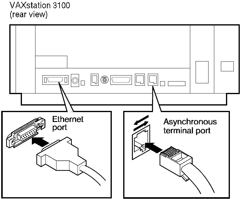
A processor can have a number of communications ports, depending on the model. For example, the VAXstation 3100 illustrated in Figure 3.1, ''Ethernet Transceiver and Asynchronous Connection'' has two asynchronous terminal ports and one Ethernet port.
You can connect this Ethernet port by means of a transceiver cable to an H4000 transceiver that is attached to an Ethernet coaxial cable.
VAX: You can use one of the asynchronous terminal ports as an asynchronous DECnet dialup line.♦
Note
If you configure your system as an end node with primary and secondary Ethernet controllers, only one circuit at a time can be active.
Figure 3.2, ''ThinWire Ethernet Connection'' illustrates a processor unit with an Ethernet port in the upper right corner to which you can connect a ThinWire Ethernet T–connector. Be sure a ThinWire Ethernet cable connection for the VAXstation 3100 is available in your office and that the ThinWire segment is properly terminated.
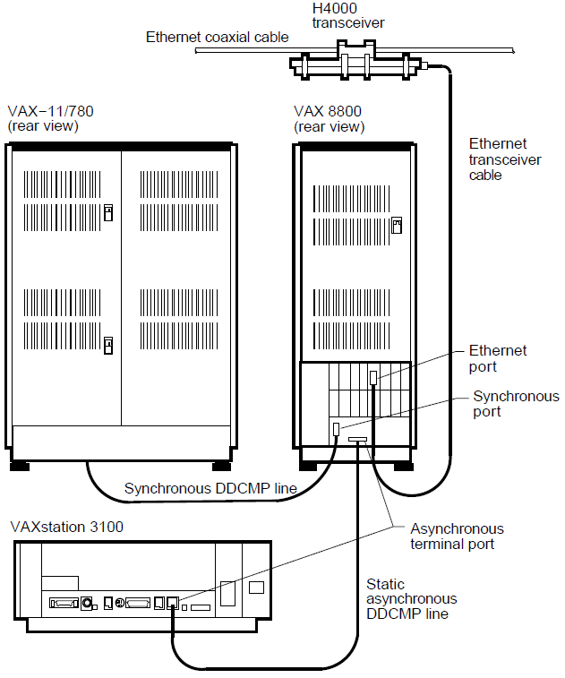
As an example of a large VAX system, Figure 3–3 shows a VAX 8800 processor. The system has three network connections:
Connection to an Ethernet cable by means of an H4000 transceiver.
Figure 3.2. ThinWire Ethernet Connection 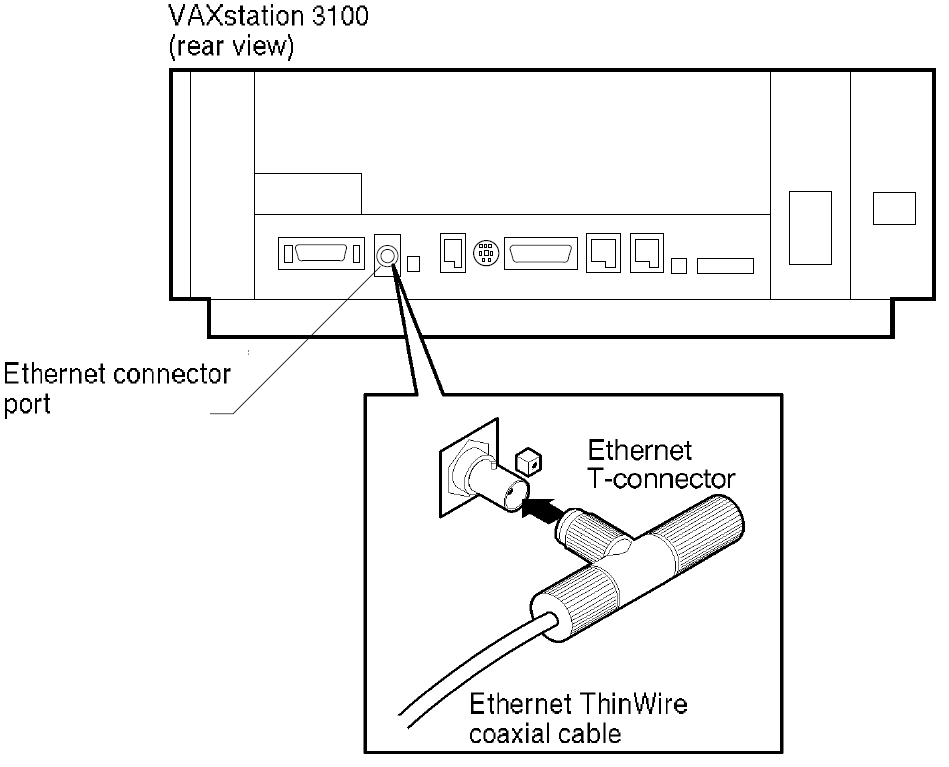
VAX: Connection to a VAXstation 3100 by means of a static asynchronous DCMP line.
Connection to a VAX–11/780 at a remote location by means of a synchronous DCMP line.♦
3.2.2. Preparing Your System for the Network Environment
Before you bring up DECnet for OpenVMS on your system, take the following steps to prepare your system to function as part of the network:
Check to see if you have the privileges you need to perform network operations.
If necessary, tune your system to accommodate DECnet for OpenVMS software.
Decide the level of default access that you want for your system.
3.2.2.1. Privileges Required for Network Operations
The minimum privileges that a system manager normally requires to configure and control the network and run network programs are SYSPRV, OPER, TMPMBX, NETMBX and BYPASS. Refer to VSI OpenVMS DECnet Networking Manual for more information about the privileges required to perform network operations.
Specify the DCL command SHOW PROCESS/PRIVILEGES to determine which of your authorized privileges are currently enabled. Then specify the command SET PROCESS/PRIVILEGES to enable any additional privileges, for which you are authorized, that are required for network operations.
3.2.2.2. System Tuning
If you need to update system parameters and quotas, see the system manager who establishes system configuration guidelines. See Section 3.4, ''Network-wide Considerations'' for a summary description of considerations involved in establishing a network.
3.2.2.3. Default Access for Your System
Default access enables certain objects supplied by VSI and user-written programs and procedures on remote nodes to communicate with your system, without requiring a proxy account or knowledge of a user name and password of an account on your system.
Default access on your system is enabled by one or more accounts, which you can create with the interactive network configuration procedure, NETCONFIG.COM. Refer to VSI OpenVMS DECnet Networking Manual for more information about default access.
3.2.3. Planning the Configuration of Your DECnet for OpenVMS Node
Before you specify how your node is to be configured as part of an existing network, make the following decisions:
Select a unique node name and node address for your system. If a network manager has been designated for your network, request a node name and address from the network manager.
Each node in the network is identified by a specific name and a numeric address by which the node is known to other nodes in the network. The node name can be no more than six alphanumeric characters (including at least one alphabetic character). The node address consists of an area number (in the range from 1 to 63, with a default value of 1) and a node number (in the range from 1 to 1023) separated by a period (for example, 2.2).
If your node is a member of a VMScluster, obtain your node name and address from the cluster manager. (The cluster node name must be set in the system parameter SCSNODE and the node address in SCSSYSTEMID. Refer to the VSI OpenVMS System Management Utilities Reference Manual).
If your node is a member of a VMScluster that uses an alias node identifier (an alias name or address), you can obtain the alias identifier from the cluster manager and use it, as well as your own node name, to communicate with other nodes in the network. An alias node identifier, common to some or all nodes in a cluster, permits remote nodes to treat the cluster nodes that use the alias as a single node. Individual nodes in a cluster can optionally assume the alias, while retaining their individual node names.
Determine the node names and addresses of all other nodes in your network to which you wish to connect. To obtain the correct node name and address of each node, you can contact the network manager or, if necessary, the individual system managers of the other nodes. You must enter this remote node information in your network node database. Alternatively, you can determine whether the names and addresses of the nodes that you wish to define are already defined in the network database of another node. If you have the appropriate privileges, you can copy the node database information from a remote node into your node database. (The procedure is described in Section 3.3.2.2, ''Configuring Your Node Automatically''.)
Decide whether your system is to be a router or an end node. If your DECnet license is for the end node capability, you can only configure your system as an end node.
If you have a DECnet full function license and the accompanying DECnet for OpenVMS Product Authorization Key (PAK), and your processor supports routing, you have the option of configuring your system as either a router or an end node.
Check the DECnet for OpenVMS Software Product Description to determine if routing is supported on your processor.
Note
AXP: DECnet for OpenVMS AXP supports level 1 routing on only one circuit and does not support level 2 (area) routing.♦
Determine the types of connections that will be made to the network:
Ethernet
FDDI
VAX: On DECnet for OpenVMS VAX, you can also make the following types of connections:
Synchronous DCMP
Asynchronous DCMP
CI (computer interconnect) is the medium used in VAXcluster communications, but it can also be used to provide DECnet for OpenVMS connections for nodes in the cluster.♦
You can use the network configuration procedure NETCONFIG.COM (described in Section 3.3.2, ''Configuring Your DECnet for OpenVMS Node'') to configure all circuits and lines automatically except for asynchronous circuits and lines, and CI circuits.
3.3. Installing DECnet for OpenVMS on Your System
This section describes the procedure for installing DECnet for OpenVMS. Use this installation procedure to bring up your system as a node on an existing DECnet network. (If there is no existing DECnet network available, see Section 3.4, ''Network-wide Considerations''.)
To perform the installation procedure, log in to the account used for system management on your node and perform the following steps:
Register the DECnet for OpenVMS PAK (See Section 3.3.1, ''Getting a DECnet for OpenVMS License and PAK''.)
Configure your DECnet for OpenVMS node and define the remote node names. You can configure your node and turn on the network at your node either automatically or manually. (Follow the steps in Section 3.3.2, ''Configuring Your DECnet for OpenVMS Node''.)
VAX: If you plan to use an asynchronous DECnet connection or CI connection, perform any steps needed to establish the connection. (See Section 3.3.3, ''Establishing Asynchronous DECnet Connections to Other Systems'' for the procedure for establishing asynchronous connections. Refer to the VSI OpenVMS DECnet Networking Manual for information on establishing CI connections.)♦
Verify that your node is connected to the network. (See Section 3.3.4, ''Verifying Successful Connection to the Network''.)
3.3.1. Getting a DECnet for OpenVMS License and PAK
To permit your node to communicate with other nodes on the network, you must have a DECnet for OpenVMS license and you must register the accompanying DECnet for OpenVMS PAK on your system using the OpenVMS License Management utility. You can purchase either an end node license or a full function license for systems that support routing. The end node PAK permits you to configure your node only as an end node.
The full function PAK permits you to configure your node as either a routing node or an end node. You can also use the full function PAK to upgrade from end node to full function capability. Check the DECnet for OpenVMS Software Product Description to determine if routing is supported on your processor.
Note
AXP: DECnet for OpenVMS AXP supports level 1 routing on only one circuit and does not support level 2 (area) routing.♦
Refer to the VSI OpenVMS License Management Utility Guide for additional information on licensing.
You can register the DECnet for OpenVMS PAK before or after you configure DECnet for OpenVMS, as described in the following section.
3.3.2. Configuring Your DECnet for OpenVMS Node
You are now ready to configure your DECnet for OpenVMS system. You can configure the node automatically or manually:
Use the automatic configuration procedure when you first bring up the node or when you reconfigure it completely. (See Section 3.3.2.2, ''Configuring Your Node Automatically''.)
Use manual configuration techniques to bring up a new node, reconfigure a node, or modify an existing configuration. (See Section 3.3.2.1, ''Configuring Your Node Manually''.)
The system manager at each node in the network is responsible for the DECnet for OpenVMS configuration database for the node. The database includes files that describe the local (executor) node and the other nodes in the network with which the local node can communicate, as well as the circuits and lines that connect the local node to the network. The network database also includes information on the logging collection points (such as the logging monitor) to which network events are reported. In addition, DECnet for OpenVMS provides a default object database describing all objects (such as MAIL) known to the network. Each node in the network has such a database.
The configuration database comprises the volatile database (the working copy of the database that reflects current network conditions) and the permanent database (which provides the initial values for the volatile database when you start the network). Modifications to the volatile database exist only while the network is running. Changes made to the permanent database remain after the network is shut down, but do not affect the current system.
As system manager, you provide network component information, from the point of view of the local node, in the configuration database at the local node. Use the Network Control Program (NCP) to supply this information in the form of parameter values, which determine how the various components of the network function together. Use NCP DEFINE commands to establish the contents of the permanent database and SET commands to specify the contents of the volatile database. Use PURGE commands to delete permanent database entries and CLEAR commands to delete or reset volatile database entries.
3.3.2.1. Configuring Your Node Manually
You can always configure your node manually; however, you have the option of doing it automatically (see the next section) if you are configuring a new node or completely reconfiguring a node.
If you decide to configure your node manually, you must enter NCP commands to establish the permanent configuration database and then turn on the network manually, causing the contents of the permanent database to be entered in the volatile database. For a detailed description of how to configure DECnet for OpenVMS nodes, refer to the VSI OpenVMS DECnet Networking Manual.
If you configure your node manually, you can optionally create accounts for default access for objects such as MAIL and MIRROR, or a default nonprivileged DECnet account for your node. (Establishment of default access accounts, including the default DECnet account, is described in Section 3.3.7.2, ''Controlling Access to Your Node''.)
3.3.2.2. Configuring Your Node Automatically
To configure your system automatically, use the interactive command procedure SYS$MANAGER:NETCONFIG.COM. NETCONFIG.COM configures all required permanent database entries except for remote nodes, asynchronous circuits and lines, and CI circuits. NETCONFIG.COM also sets up and turns on event logging. You can also use the command procedure to create accounts for default access or for a default nonprivileged DECnet account on your system.
Because the NETCONFIG.COM procedure deletes any existing permanent database entries on your system (except for remote node entries), use it only if you are bringing up your node for the first time, or want to reconfigure your node completely. If you run NETCONFIG.COM to re-create the configuration database on an existing system, it will ask if you want to purge this database.
Note
Do not set the LOCKPWD flag for the account from which you intend to run NETCONFIG.COM or in any of the DECnet object accounts.
If you use the NETCONFIG.COM command procedure to configure your node automatically, perform the following steps. (Default values appear in brackets ([ ]) after certain questions in the interactive dialog. To accept a default, press the RETURN key.)
Log in to the SYSTEM account on your node.
Invoke NETCONFIG.COM. Enter the following command at the dollar sign ( $ ) prompt:
$ @SYS$MANAGER:NETCONFIG
The following message is displayed:
    DECnet for OpenVMS network configuration procedure

This procedure will help you define the parameters needed to get
DECnet running on this machine. You will be shown the changes before
they are actually executed, in case you wish to perform them manually.
Provide the node name. You will be prompted as follows:
What do you want your DECnet node name to be?
Enter the node name you have selected (or have been assigned by the network manager). Your node name must be unique among all node names in the network and must be composed of six or less alphanumeric characters, one of which must be alphabetic.
If you are on a VMScluster node, press the RETURN key to accept the default node name that appears in brackets at the end of the prompt. This default node name is based on the SYSGEN parameter SCSNODE. If no default node name is displayed, exit the procedure and use SYSGEN to set up a value for SCSNODE, then restart the procedure. The DECnet node name of a cluster node must match the value of SCSNODE.
Provide the node address. You will be prompted as follows:
What do you want your DECnet address to be?
Enter the node address you have selected (or been assigned by the network manager). The node address is a numeric value in the following format:
area-number.node-number
Area-number (1 to 63) designates the area in which the node is grouped and node-number (1 to 1023) designates the node's unique address within the area. If you do not specify an area number, the system will supply a default area number (the default value is 1).
If you are on a VMScluster node, press the RETURN key to accept the default node address that appears in brackets at the end of the prompt. This default node address is based on the SYSGEN parameter SCSSYSTEMID. If no default node address is displayed, exit the procedure and use SYSGEN to set up a value for SCSSYSTEMID, then restart the procedure. The DECnet node address of a cluster node must match the value of SCSSYSTEMID.
Specify router or nonrouter type. On processors that support routing, you will be prompted as follows:
Do you want to operate as a router? [NO (nonrouting)]:
Press the RETURN key to operate as a nonrouter (that is, as an end node).
Type YES and press the RETURN key if you want your system to be a router and if you have registered the DECnet for OpenVMS function PAK or will register it before you start up the network.Note
AXP: DECnet for OpenVMS AXP supports level 1 routing on only one circuit and does not support level 2 (area) routing.♦
Note that the question does not appear when using processors that support only end-node configurations. In that case, the procedure sets the executor type parameter to nonrouting IV.
Retain or purge the object database. The network configuration procedure displays the location of your object database file and asks if you want to purge it.
The network object database file is SYS$COMMON:[SYSEXE]NETOBJECT.DAT;4.

Do you want to purge the object database?     [YES]:
The default is to purge the database. However, if the node shares an object database with other nodes (as is commonly done with nodes in a cluster), and you want to preserve the common object database, answer NO to this question.
Set up default access accounts for objects supplied by VSI or the nonprivileged default DECnet account. You will be prompted as follows:
Do you want a default DECnet account? [NO]
Press RETURN to accept the default of NO. If you want to set up the default DECnet account, type YES, and press RETURN. (For a description of these default access accounts and the default DECnet account, see Section 3.2.2.3, ''Default Access for Your System''.) If you respond YES, you will then be prompted as follows:
Do you want default access to the TASK object disabled? [YES]
Press RETURN to accept the default of YES. If you want the TASK object enabled, type NO, and press RETURN.
Regardless of how you responded to the previous questions, you will be prompted for four default access accounts. These accounts are optional if you requested a default DECnet account.
Do you want a default account for the MAIL object? [YES]
If you want a default account for the MAIL object, press RETURN. If you do not want one, type NO, and press RETURN.
Next, you will be prompted as follows:
Do you want a default account for the FAL object? [NO]
VSI advises against creating a default account for the FAL object, except for systems with very low security requirements. If you do not want this account, press RETURN. If you want it, type YES and press RETURN.
Next, you will be prompted as follows:
Do you want a default account for the PHONE object? [YES]
If you want a default account for the PHONE object, press RETURN. If you do not want one, type NO, and press RETURN.
Next, you will be prompted as follows:
Do you want a default account for the NML object? [YES]
If you want this account, press RETURN. If you do not want it, type NO, and press RETURN.
If you did not create a default DECnet account, you will be prompted for two more default access accounts, as follow:
Do you want a default account for the MIRROR object? [YES]
If you want a default account for the MIRROR object, press RETURN. If you do not want one, type NO and press RETURN.
Do you want a default account for the VPM object? [YES]
If you want a default account for the VPM object, press RETURN. If you do not want one, type NO and press RETURN.
Apply the configuration. The network configuration procedure displays the list of commands necessary to start up your network. (An example showing the commands appears later in this section.)
You will be prompted as follows:
Do you want these commands to be executed? [YES]
Press RETURN to configure the network; type NO and press RETURN to cancel the configuration operation.
If you run NETCONFIG.COM to re-create the configuration database on an existing system, it will purge any existing information from the permanent executor, line, circuit, logging, and module configurator databases. It will ask if you want to purge the object database.s
If you choose to configure the network, the procedure displays a series of information messages and the following statement:
The changes have been made.
If necessary, modify the amount of BYTLM quota. NETCONFIG.COM estimates the amount of BYTLM quota the NETACP process will require to start your lines and circuits. NETCONFIG.COM issues a warning if the NETACP$BUFFER_LIMIT logical should be defined before DECnet is started; for example:
WARNING: NETACP will require more BYTLM process quota to start your
lines and circuits properly. Before starting DECnet, define the
NETACP$BUFFER_LIMIT system logical to be at least 33460. Define
an even higher BYTLM value if you will be raising the number of
line receive buffers, increasing line buffer sizes, or enabling
service on any circuits.
Turn on the network. You will then receive the following messages, ending in a prompt:
If you have not already registered the DECnet for OpenVMS PAK,
then do so now. After the PAK has been registered,
invoke the procedure SYS$MANAGER:STARTNET.COM to start up
DECnet for OpenVMS with these changes.
(If the key is already registered) Do you want DECnet started? [YES]:
You can respond to this prompt in either of the following ways:
Type NO and press RETURN in response to the last prompt if you need to register the PAK on your system at this point. Register the PAK using the OpenVMS License Management utility. Once the DECnet for OpenVMS PAK is registered, you can then start up DECnet for OpenVMS manually with these configuration changes by entering the following command:
$ @SYS$MANAGER:STARTNET
You can also type NO and press RETURN in response to the last prompt if the PAK is already registered but you do not want to start the network until a later time.
Press RETURN in response to the last prompt if you want to start the network at this time and the PAK is already registered. The procedure turns on the network and displays the identification numbers of the created processes. When the dollar sign ( $ ) prompt appears, you have successfully configured and turned on the DECnet for OpenVMS network.
If you want the network to be started automatically each time the operating system is booted, enable the following command in the site-specific startup procedure (by deleting the exclamation point at the beginning of this command line in the site-specific startup procedure):
$ @SYS$MANAGER:STARTNET
Note that you can optionally press RETURN to start the network without the PAK being registered, if you want to use DECnet for OpenVMS only at your local node. The PAK is required if you want to establish connections to other nodes in the network.
Example below shows the interactive dialog that is displayed when you invoke NETCONFIG.COM to configure VAX node URSUS with address 2.3 as an end node with a default DECnet account. In this example, node URSUS is connected to Ethernet circuit BNA-0.
Example 3.1. Sample NETCONFIG.COM Dialogue for an End Node DECnet for OpenVMS network configuration procedure This procedure will help you define the parameters needed to get DECnet running on this machine. You will be shown the changes before they are actually executed, in case you wish to perform them manually. What do you want your DECnet node name to be? : URSUS Return What do you want your DECnet address to be? : 2.3 Return Do you want to operate as a router? [NO (nonrouting)]: Return The network object database file is SYS$COMMON:[SYSEXE]NETOBJECT.DAT;4. Do you want to purge the object database? [YES]: Return Do you want a default DECnet account? [NO]: Return Do you want a default account for the MAIL object? [YES]: Return Do you want a default account for the FAL object? [NO]: Return Do you want a default account for the PHONE object? [YES]: Return Do you want a default account for the NML object? [YES]: Return Do you want a default account for the MIRROR object? [YES]: Return Do you want a default account for the VPM object? [YES]: Return Here are the commands necessary to set up your system. $ RUN SYS$SYSTEM:NCP PURGE EXECUTOR ALL PURGE KNOWN LINES ALL PURGE KNOWN CIRCUITS ALL PURGE KNOWN LOGGING ALL PURGE KNOWN OBJECTS ALL PURGE MODULE CONFIGURATOR KNOWN CIRCUITS ALL $ DEFINE/USER SYS$OUTPUT NL: $ DEFINE/USER SYS$ERROR NL: $ RUN SYS$SYSTEM:NCP ! Remove existing entry, if any PURGE NODE 2.3 ALL PURGE NODE URSUS ALL $ RUN SYS$SYSTEM:NCP DEFINE EXECUTOR ADDRESS 2.3 STATE ON DEFINE EXECUTOR NAME URSUS DEFINE EXECUTOR MAXIMUM ADDRESS 1023 DEFINE EXECUTOR TYPE NONROUTING IV DEFINE OBJECT TASK NUMBER 0 USER ILLEGAL PASSWORD DISABLED DEFINE OBJECT MAIL NUMBER 27 USER MAIL$SERVER PASSWORD yadnifaj $ DEFINE/USER_MODE SYSUAF SYS$SYSTEM:SYSUAF.DAT $ RUN SYS$SYSTEM:AUTHORIZE ADD MAIL$SERVER /OWNER="MAIL$SERVER DEFAULT" - /PASSWORD=yadnifaj - /UIC=[376,374] /ACCOUNT=DECNET - /DEVICE=SYS$SPECIFIC: /DIRECTORY=[MAIL$SERVER] - /PRIVILEGE=(TMPMBX,NETMBX) - /DEFPRIVILEGE=(TMPMBX,NETMBX) - /FLAGS=(nocaptive,RESTRICTED,NODISUSER) /LGICMD=NL: - /NOBATCH /NOINTERACTIVE MODIFY MAIL$SERVER /PASSWORD=yadnifaj $ CREATE/DIRECTORY SYS$SPECIFIC:[MAIL$SERVER] /OWNER=[376,374] $ RUN SYS$SYSTEM:NCP DEFINE OBJECT PHONE NUMBER 29 USER PHONE$SERVER PASSWORD dogbasow $ DEFINE/USER_MODE SYSUAF SYS$SYSTEM:SYSUAF.DAT $ RUN SYS$SYSTEM:AUTHORIZE ADD PHONE$SERVER /OWNER="PHONE$SERVER DEFAULT" - /PASSWORD=dogbasow - /UIC=[376,372] /ACCOUNT=DECNET - /DEVICE=SYS$SPECIFIC: /DIRECTORY=[PHONE$SERVER] - /PRIVILEGE=(TMPMBX,NETMBX) - /DEFPRIVILEGE=(TMPMBX,NETMBX) - /FLAGS=(NOCAPTIVE,RESTRICTED,NODISUSER) /LGICMD=NL: - /NOBATCH /NOINTERACTIVE MODIFY PHONE$SERVER /PASSWORD=dogbasow $ CREATE/DIRECTORY SYS$SPECIFIC:[PHONE$SERVER] /OWNER=[376,372] $ RUN SYS$SYSTEM:NCP DEFINE OBJECT NML NUMBER 19 USER NML$SERVER PASSWORD kenrooka $ DEFINE/USER_MODE SYSUAF SYS$SYSTEM:SYSUAF.DAT $ RUN SYS$SYSTEM:AUTHORIZE ADD NML$SERVER /OWNER="NML$SERVER DEFAULT" - /PASSWORD=kenrooka - /UIC=[376,371] /ACCOUNT=DECNET - /DEVICE=SYS$SPECIFIC: /DIRECTORY=[NML$SERVER] - /PRIVILEGE=(TMPMBX,NETMBX) - /DEFPRIVILEGE=(TMPMBX,NETMBX) - /FLAGS=(NOCAPTIVE,RESTRICTED,NODISUSER) /LGICMD=NL: - /NOBATCH /NOINTERACTIVE MODIFY NML$SERVER /PASSWORD=kenrooka $ CREATE/DIRECTORY SYS$SPECIFIC:[NML$SERVER] /OWNER=[376,371] $ RUN SYS$SYSTEM:NCP DEFINE OBJECT MIRROR NUMBER 25 USER MIRRO$SERVER PASSWORD ewxgamula $ DEFINE/USER_MODE SYSUAF SYS$SYSTEM:SYSUAF.DAT $ RUN SYS$SYSTEM:AUTHORIZE ADD MIRRO$SERVER /OWNER="MIRRO$SERVER DEFAULT" - /PASSWORD=ewxgamula - /UIC=[376,367] /ACCOUNT=DECNET - /DEVICE=SYS$SPECIFIC: /DIRECTORY=[MIRRO$SERVER] - /PRIVILEGE=(TMPMBX,NETMBX) - /DEFPRIVILEGE=(TMPMBX,NETMBX) - /FLAGS=(NOCAPTIVE,RESTRICTED,NODISUSER) /LGICMD=NL: - /NOBATCH /NOINTERACTIVE MODIFY MIRRO$SERVER /PASSWORD=ewxgamula $ CREATE/DIRECTORY SYS$SPECIFIC:[MIRRO$SERVER] /OWNER=[376,367] $ RUN SYS$SYSTEM:NCP DEFINE OBJECT VPM NUMBER 51 USER VPM$SERVER PASSWORD galesobu $ DEFINE/USER_MODE SYSUAF SYS$SYSTEM:SYSUAF.DAT $ RUN SYS$SYSTEM:AUTHORIZE ADD VPM$SERVER /OWNER="VPM$SERVER DEFAULT" - /PASSWORD=galesobu - /UIC=[376,370] /ACCOUNT=DECNET - /DEVICE=SYS$SPECIFIC: /DIRECTORY=[VPM$SERVER] - /PRIVILEGE=(TMPMBX,NETMBX) - /DEFPRIVILEGE=(TMPMBX,NETMBX) - /FLAGS=(NOCAPTIVE,RESTRICTED,NODISUSER) /LGICMD=NL: - /NOBATCH /NOINTERACTIVE MODIFY VPM$SERVER /PASSWORD=galesobu $ CREATE/DIRECTORY SYS$SPECIFIC:[VPM$SERVER] /OWNER=[376,370] $ RUN SYS$SYSTEM:NCP DEFINE LINE BNA-0 STATE ON DEFINE CIRCUIT BNA-0 STATE ON COST 3 DEFINE LINE DMB-0 STATE ON DEFINE CIRCUIT DMB-0 STATE ON COST 5 DEFINE LOGGING MONITOR STATE ON DEFINE LOGGING MONITOR EVENTS 0.0-9 DEFINE LOGGING MONITOR EVENTS 2.0-1 DEFINE LOGGING MONITOR EVENTS 4.2-13,15-16,18-19 DEFINE LOGGING MONITOR EVENTS 5.0-18 DEFINE LOGGING MONITOR EVENTS 128.0-4 Do you want these commands to be executed? [YES]: Return The changes have been made. If you have not already registered the DECnet for OpenVMS key, then do so now. After the key has been registered, invoke the procedure SYS$MANAGER:STARTNET.COM to start up DECnet for OpenVMS with these changes. (If the key is already registered) Do you want DECnet started?[YES]: Return
Define the other node names. At the dollar sign ( $ ) prompt, invoke the Network Control Program (NCP) by entering the following command:
$ RUN SYS$SYSTEM:NCP
For each remote node in the network that you want to identify by node name, enter the following command to define the node address and name in your permanent node database:
NCP>DEFINE NODE address NAME name
Address is the existing node address in the form area-number.node-number and name is the node name. If you omit the area number from the node address, the area number of your local node is used. The network manager or the system manager of the remote node you wish to define can provide you with the correct name and address.
If a node that you can access on your network has a node database that contains all the node names and addresses you want to define and you have the appropriate privileges to access that database, you can enter the following command at the NCP prompt (provided the network is turned on):
NCP>COPY KNOWN NODES FROM node-id TO PERMANENT
In this command, node-id is the node name or address of the remote node from which you are copying the information. If you specify the node name, that name must be in your volatile database. All the node names and addresses are copied to your permanent node database from the volatile node database of the remote node.
If your node belongs to a VMScluster that uses an alias node identifier (an alias node name and address), your node can adopt the alias. Specify the following commands to define the alias node address and name in the permanent node database, and associate the alias identifier with your node:
NCP>DEFINE NODE address NAME name
NCP>DEFINE EXECUTOR ALIAS NODE node-id
For the node-id, you can specify either the alias node address or name that you have defined. Your node can then be identified by the alias node name and address as well as by its unique node name and address when DECnet is running.
Then enter the following commands to create the volatile node database for your node:
NCP>SET KNOWN NODES ALL
The other nodes on the network should define your node name and node address in their node databases in order to be able to communicate with your node by node name. If a network manager assigned the unique node name and address to your node, the manager can define your node name in a master network node database.
For additional information on using NCP to tailor the configuration database, refer to Section 3.3.6.
Determine how to proceed. You have completed the network startup procedure. If you plan to use asynchronous DECnet, continue to the next section, which describes how to establish asynchronous connections. Otherwise, go to Section 3.3.4, ''Verifying Successful Connection to the Network''.
3.3.3. Establishing Asynchronous DECnet Connections to Other Systems
Note
If your system is configured as an end node, it can have only one circuit active at a time, regardless of how many network devices or terminal lines exist on the end node.
The two types of asynchronous DECnet connections you can establish are:
A static asynchronous DECnet connection, which creates a permanent DECnet link to a single remote node. (See Section 3.3.3.1, ''Establishing a Static Asynchronous Connection''.)
A dynamic asynchronous DECnet connection, which provides a temporary DECnet link. You can establish dynamic connections to different remote nodes at different times. (See Section 3.3.3.2, ''Establishing a Dynamic Asynchronous Connection''.)
The asynchronous connection can be between two routers, a router and an end node, or two end nodes. If you are on an end node and want to make an asynchronous connection, it will be your only connection to the network, because an end node can have only one active circuit.♦
3.3.3.1. Establishing a Static Asynchronous Connection
VAX: On systems that support it, a static asynchronous DECnet connection is a permanent connection between two nodes. This type of connection can be made in one of two ways:
The nodes can be connected by a physical line (a null modem cable) attached to a terminal port at each system. No modems are required. You can communicate with the other system at any time.
The connection can be made over a dialup line using modems at both ends of the line. For example, your system can establish a static asynchronous connection to a remote node over a telephone line.
You can configure your static asynchronous line as soon as you have executed NETCONFIG.COM, and then turn on the network manually. If your system is brought up as a routing node, you can establish a static asynchronous connection at any time, no matter how many network connections you already have.
Follow the steps outlined in this section to establish a static asynchronous connection. For the connection to be successful, the node with which you are creating a DECnet link must also establish an asynchronous DECnet connection with your node. (The line speeds at each end of the connection must be the same.)
Log in to the SYSTEM account on your node.
Load the asynchronous DCMP driver, NODRIVER (NOA0). Enter the following commands at your terminal (or include them in the site-specific startup procedure before you boot the system):
$ RUN SYS$SYSTEM:SYSGEN
SYSGEN>  CONNECT NOA0/NOADAPTER
SYSGEN>  EXIT
The asynchronous driver must be loaded before any asynchronous connection can be made.
To set up the terminal line to become a static asynchronous DECnet line, use the DCL command SET TERMINAL device-name, with the appropriate qualifiers, as shown in the following examples. Device-name represents the name of the terminal port to which the line that you want to make a static asynchronous DECnet line is connected. (All references to a device in this section refer to the terminal port.) If there is more than one terminal attached to your system, you must specify a SET TERMINAL command for each terminal line that will be used for a static asynchronous DECnet connection.
Nondialup line: For a nondialup configuration, enter the following SET TERMINAL command to convert a terminal line to a static asynchronous line:
$ SET TERMINAL/PERMANENT/PROTOCOL=DDCMP device-name:
For example, to set up a 2400-baud terminal line connected to port TTA0 on your system to be a static asynchronous DECnet line, enter the following command:
$ SET TERMINAL/PERMANENT/PROTOCOL=DDCMP TTA0:
Dialup line: For a dialup configuration, enter the following SET TERMINAL command to convert the terminal line to a static asynchronous DECnet line with modem control:
$ SET TERMINAL/PERMANENT/MODEM/NOAUTOBAUD -
_$ /NOTYPE_AHEAD/PROTOCOL=DDCMP device-name:
For example, if the line connected to terminal port TTB0 is connected to a 2400-baud modem, specify this command:
$ SET TERMINAL/PERMANENT/MODEM/NOAUTOBAUD -
_$ /NOTYPE_AHEAD/PROTOCOL=DDCMP TTB0:
You can ensure that these SET TERMINAL commands will be executed automatically each time the network is started in the future by modifying your site-specific startup procedure to include all required SET TERMINAL commands before the command @SYS$MANAGER:STARTNET.
After configuring your node, configure the asynchronous lines and circuits in the network database. Use NCP commands to define each asynchronous line and accompanying circuit as being in the ON state. (The line and circuit are turned on when SYS$MANAGER:STARTNET.COM is executed.) Enter the following commands:
$ RUN SYS$SYSTEM:NCP
NCP>DEFINE LINE dev-c-u STATE ON RECEIVE BUFFERS 4 -
    _LINE SPEED baud-rate
NCP>DEFINE CIRCUIT dev-c-u STATE ON
NCP>EXIT
Baud-rate is the speed at which the line sends and receives data. For an asynchronous line or circuit, dev-c-u is defined as follows:
dev The first two letters of the asynchronous device name (possible values are TT and TX). c A decimal number (0 or a positive integer) designating a device's hardware controller. If the third letter of the device name is A, c equals 0. If the third letter of the device name is B, c equals 1, and so on. u The unit number of the device name; u is always equal to 0 or a positive integer. An example is the device identifier TT-0-0, which represents the asynchronous device name TTA0.
A minimum of four buffers should be allocated for data reception over the line. An insufficient number of receive buffers can result in timeouts and loss of packets (see VSI OpenVMS DECnet Networking Manual).
For example, to use a line connected to port TTA0 at 2400 baud, run NCP and enter the following commands to define the line and circuit:
$ RUN SYS$SYSTEM:NCP
NCP>DEFINE LINE TT-0-0 STATE ON RECEIVE BUFFERS 4 -
    _LINE SPEED 2400
NCP>DEFINE CIRCUIT TT-0-0 STATE ON
NCP>EXIT
If the line speed at the other end of the connection is changed after the initial static asynchronous connection is made, you can use the DEFINE LINE command to change the line speed for your end of the connection to match the line speed at the other end. The line speed will be changed the next time the line is turned on.
For security over a dialup connection, you can run NCP and establish optional transmit and receive passwords for the local end of the static asynchronous dialup link. The transmit password is the password sent to the other node during connection startup; the receive password is the password expected from the other node during connection startup. You must also use NCP to specify that your asynchronous circuit is to verify the password supplied by the other node. If the correct passwords are not supplied, the asynchronous connection cannot be made.
Although transmit and receive passwords are not mandatory for static asynchronous dialup links, they add to the security of your DECnet connection. Passwords can contain from one to eight alphanumeric characters and must be delimited with quotation marks if they contain spaces. Specify the following commands:
$ RUN SYS$SYSTEM:NCP
NCP>DEFINE CIRCUIT dev-c-u VERIFICATION ENABLED
NCP>DEFINE NODE node-id TRANSMIT PASSWORD transmit-password -
    _RECEIVE PASSWORD receive-password
NCP>EXIT
Node-id is the name of the remote node to which your node will be connected.
In the following example, the name of your local node is LOCALA, the name of the remote node is REMOTB, your asynchronous circuit is TT-0-0, the transmit password is PASSA, and the receive password is PASSB. Enter the following on node LOCALA:
$ RUN SYS$SYSTEM:NCP
NCP>DEFINE CIRCUIT TT-0-0 VERIFICATION ENABLED
NCP>DEFINE NODE REMOTB TRANSMIT PASSWORD PASSA -
    _RECEIVE PASSWORD PASSB
NCP>EXIT
If you have defined passwords for the local end of the link, you must notify the remote node system manager to establish transmit and receive passwords for the remote end of the static asynchronous DECnet dialup link. For the previous example, the remote system manager should enter these commands:
$ RUN SYS$SYSTEM:NCP
NCP>DEFINE CIRCUIT TT-1-0 VERIFICATION ENABLED
NCP>DEFINE NODE LOCALA TRANSMIT PASSWORD PASSB -
    _RECEIVE PASSWORD PASSA
NCP>EXIT
If the network is not already on, turn on the network at your node by entering the following command:
$ @SYS$MANAGER:STARTNET
This command starts the network and causes the permanent database entries defined above to be entered in the volatile database on the running network. If the network was already running before you began the static asynchronous connection procedure, enter the following commands to cause the permanent database entries to be entered in the volatile database.
$ RUN SYS$SYSTEM:NCP
NCP>SET LINE dev-c-u ALL
NCP>SET CIRCUIT dev-c-u ALL
NCP>SET NODE node-id ALL
NCP>EXIT
If the line and circuit could not be set to ON in the volatile database, causing DECnet to fail to gain control of the line, the following error message appears:
% NCP-I-NMLRSP, LISTENER RESPONSE - Operation failure
If the static asynchronous connection cannot be made, refer to the section on asynchronous connection problems. (See Chapter 4, "Keeping the Network Running".)
If you want to turn off the asynchronous lines temporarily, run NCP and enter the following commands:
$ RUN SYS$SYSTEM:NCP
NCP>SET LINE dev-c-u STATE OFF
NCP>SET CIRCUIT dev-c-u STATE OFF
NCP>CLEAR LINE dev-c-u ALL
NCP>CLEAR CIRCUIT dev-c-u ALL
NCP>EXIT
To turn the static asynchronous DECnet line back on, enter the following NCP commands:
$ RUN SYS$SYSTEM:NCP
NCP>SET LINE dev-c-u ALL
NCP>SET CIRCUIT dev-c-u ALL
NCP>EXIT
If you want to switch an asynchronous DECnet line back to a terminal line with DECnet running, you must clear the line and circuit entries from the network volatile database. To clear the entries, enter these commands:
$ RUN SYS$SYSTEM:NCP
NCP>SET LINE dev-c-u STATE OFF
NCP>SET CIRCUIT dev-c-u STATE OFF
NCP>CLEAR LINE dev-c-u ALL
NCP>CLEAR CIRCUIT dev-c-u ALL
NCP>EXIT
To switch the line for which modem control was not enabled back to a terminal line, use this command:
$ SET TERMINAL/PERMANENT/PROTOCOL=NONE device-name:
For example, to switch the nondialup line connected to port TTA0 back to a terminal line, enter the command:
$ SET TERMINAL/PERMANENT/PROTOCOL=NONE TTA0:
To switch the line for which modem control was enabled back to a terminal line, use this command:
$ SET TERMINAL/PERMANENT/MODEM/AUTOBAUD -
_$ /TYPE_AHEAD/PROTOCOL=NONE device-name:
For example, to switch the dialup line connected to port TTB0 back to a terminal line, enter the command:
$ SET TERMINAL/PERMANENT/MODEM/AUTOBAUD -
_$ /TYPE_AHEAD/PROTOCOL=NONE TTB0:
Example 3.2, ''Sample Commands for a Static Asynchronous Dialup Connection'' lists the commands that the system managers of two nodes must put into the permanent databases to cause a static asynchronous connection to be established over the dialup line shown in Figure 3–4 when the network is turned on at each node.
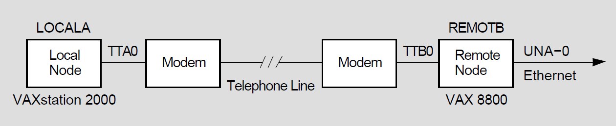
Commands issued at the local node (LOCALA):

$ RUN SYS$SYSTEM:SYSGEN
SYSGEN> CONNECT NOA0/NOADAPTER
SYSGEN> EXIT
$ SET TERMINAL/PERMANENT/MODEM/DIALUP/NOAUTOBAUD/NOTYPE_AHEAD -
_$ /PROTOCOL=DDCMP TTA0:
$ RUN SYS$SYSTEM:NCP
NCP>DEFINE LINE TT-0-0 STATE ON RECEIVE BUFFERS 4 LINE SPEED 2400
NCP>DEFINE CIRCUIT TT-0-0 STATE ON VERIFICATION ENABLED
NCP>DEFINE NODE REMOTB TRANSMIT PASSWORD PASSB RECEIVE PASSWORD PASSA
NCP>EXIT

Commands issued at the remote node (REMOTB):

$ RUN SYS$SYSTEM:SYSGEN
SYSGEN> CONNECT NOA0/NOADAPTER
SYSGEN> EXIT
$ SET TERMINAL/PERMANENT/MODEM/NOAUTOBAUD/NOTYPE_AHEAD -
_$ /PROTOCOL=DDCMP TTB0:
$ RUN SYS$SYSTEM:NCP
NCP>DEFINE LINE TT-1-0 STATE ON RECEIVE BUFFERS 4 LINE SPEED 2400
NCP>DEFINE CIRCUIT TT-1-0 STATE ON VERIFICATION ENABLED
NCP>DEFINE NODE LOCALA TRANSMIT PASSWORD PASSA RECEIVE PASSWORD PASSB
NCP>EXIT
Note that if an asynchronous connection is made to a system that does not support DECnet for OpenVMS, the commands issued at the remote node must be appropriate for that system.♦
3.3.3.2. Establishing a Dynamic Asynchronous Connection
Note
A dynamic asynchronous connection to a node can be initiated from any node with lines that support the DECnet asynchronous DCMP protocol.
On a DECnet for OpenVMS node, you have the option of performing the initial steps of the dynamic asynchronous connection process (steps 1 and 2 below) before you turn on the network at your node (step 3). The later steps of the process (starting with step 4) must occur when the line is being switched to DECnet.
Use the steps outlined in the following list to establish a dynamic asynchronous DECnet connection. This procedure assumes the local node is originating the connection and switching the terminal line on for DECnet use. The connection must be to a DECnet for OpenVMS node on which you have an account with NETMBX privilege. The steps that the system manager at the remote node must perform in order for the dynamic asynchronous DECnet link to be established successfully are also indicated in the list.
Log in to the system management account and enter the following commands interactively (or include them in the site-specific startup procedure before you boot the system). These commands load the asynchronous driver NODRIVER (NOA0) and install DYNSWITCH software on your system.
$ RUN SYS$SYSTEM:SYSGEN
SYSGEN> CONNECT NOA0/NOADAPTER
SYSGEN> EXIT
$ INSTALL:=$SYS$SYSTEM:INSTALL
$ INSTALL/COMMAND
INSTALL> CREATE SYS$LIBRARY:DYNSWITCH/SHARE -
_ /PROTECT/HEADER/OPEN
INSTALL> EXIT
The system manager of the remote node must also enter these commands.
Additionally, the system manager at the remote node must enter the commands given below. These commands enable the use of virtual terminals for the terminal line that is to be switched, and set the DISCONNECT characteristic for the terminal line. The virtual terminal capability permits the process to continue running if the physical terminal you are using becomes disconnected.
$ RUN SYS$SYSTEM:SYSGEN
SYSGEN> CONNECT VTA0/NOADAPTER/DRIVER=TTDRIVER
SYSGEN> EXIT
$ SET TERMINAL/EIGHT_BIT/PERMANENT/MODEM/DIALUP -
_$ /DISCONNECT device-name:
Device-name is the name of the terminal port to which the dynamic asynchronous connection is made.
You must establish the required transmit password at the originating end of the dynamic asynchronous dialup link. The transmit password is the password sent to the remote node during connection startup. Use NCP to enter a command to define the transmit password for the remote node. The password can contain one to eight alphanumeric characters and should not contain any spaces. Specify the following commands:
$ RUN SYS$SYSTEM:NCP
NCP>DEFINE NODE node-id TRANSMIT PASSWORD password
NCP>EXIT
Node-id is the name of the remote node with which your node is forming a connection.
In the following example, the node name of your local node is LOCALA, the transmit password is PASSA, and the remote node with which you are creating a dynamic asynchronous dialup link is REMOTC.
$ RUN SYS$SYSTEM:NCP
NCP>DEFINE NODE REMOTC TRANSMIT PASSWORD PASSA
NCP>EXIT
For each remote node with which you will create a dynamic asynchronous DECnet dialup link, you must define a transmit password in a separate command.
The system manager for the node at the other end of the connection must define that same password as a receive password for your node (the password expected to be received from your node). The remote system manager should also specify the parameter INBOUND ROUTER or INBOUND ENDNODE, to indicate the type of node (router or end node) that is expected to initiate the dynamic connection. These are the commands the remote manager should enter:
$ RUN SYS$SYSTEM:NCP
NCP>DEFINE NODE node-id -
_ RECEIVE PASSWORD password INBOUND node-type
NCP>EXIT
For example, if your node LOCALA is an end node and your transmit password is PASSA, the manager at REMOTC should issue the following command:
$ RUN SYS$SYSTEM:NCP
NCP>DEFINE NODE LOCALA RECEIVE PASSWORD PASSA INBOUND ENDNODE
NCP>EXIT
DECnet must be running on both nodes for the remaining steps. If you have not already done so, turn on the network by entering the following command (and request that the remote system manager do so also):
$ @SYS$MANAGER:STARTNET
If the network was already running before you began the dynamic asynchronous connection procedure, enter these commands to cause the permanent database entry to be entered in the volatile database:
$ RUN SYS$SYSTEM:NCP
NCP>SET NODE node-id ALL
NCP>EXIT
The remaining steps can be performed by any user with NETMBX privilege. Log in to your local system and enter the following DCL command on your terminal to cause your process to function as a terminal emulator (which makes the remote terminal appear to be a local terminal connection):
$ SET HOST/DTE device-name:
Device-name is the name of your local terminal port that is connected to the modem. If both systems use modems with autodial capabilities (for example, DF03, DF112 or DF224 modems that support an autodial protocol), you can optionally include the /DIAL qualifier on the SET HOST/DTE command to cause automatic dialing of the modem on the remote node, as follows:
$ SET HOST/DTE/DIAL=number device-name:
If you are not using automatic dialing, dial in to the remote node manually.
Once the dialup connection is made and you receive the remote system welcome message, log in to your account on the remote node.
While logged in to your account on the remote node, enter the following command to cause the line to be switched to a DECnet line automatically:
$ SET TERMINAL/PROTOCOL=DDCMP/SWITCH=DECNET
The following message indicates that the DECnet link is being established:
%REM-S-END - control returned to local-nodename::
$
To check whether the communications link has come up, specify the following command on the local system:
$ RUN SYS$SYSTEM:NCP
NCP>SHOW KNOWN CIRCUITS
NCP>EXIT
The resulting display should list a circuit identified by the mnemonic TT or TX, depending on the asynchronous device, and indicate that it is in the ON state.
When the DCL prompt ($, by default) appears on your terminal screen, you can begin to communicate with the remote node over the asynchronous DECnet connection.
If the dynamic connection is not made successfully, refer to the section on asynchronous connection problems. (See Chapter 4, "Keeping the Network Running".)
As an alternative to switching the terminal line to a DECnet line automatically (as described in the previous step), you can switch the line manually. If you originate a dynamic connection to a DECnet for OpenVMS node from a system that does not support DECnet for OpenVMS, manual switching is required; from a DECnet for OpenVMS system, it is optional. If you are originating the connection from a node that does not support DECnet for OpenVMS, follow system-specific procedures to log in to the remote DECnet for OpenVMS node by means of terminal emulation.
Once you are logged in to the remote node, two steps are required to perform manual switching:
Using your account on the remote DECnet for OpenVMS node, specify the SET TERMINAL command described in step 7, but add the /MANUAL qualifier:
$ SET TERMINAL/PROTOCOL=DDCMP/SWITCH=DECNET/MANUAL
You will receive the following message from the remote node indicating the remote system is switching its line to DECnet use:
%SET-I-SWINPRG The line you are currently logged over is becoming
                           a DECnet line
Exit from the terminal emulator and switch your line manually to a DECnet line. The procedure depends on the specific operating system on which you are logged in.
MS–DOS procedure: The following procedure illustrates how an MS–DOS system user on a personal computer, who is originating a dynamic connection to a DECnet for OpenVMS system, exits from the terminal emulator and turns on the DECnet line.
Exit from the terminal emulator by pressing CONTROL/F10 (the control key and function key 10).
When an MS–DOS prompt (C>) is displayed on the screen, enter the following commands to turn on the line to DECnet and verify that the line is up:
C> NCP SET LINE STATE ON
C> NCP READ LOGGING
After a short interval, a display should appear, showing that the line state is on and the adjacency is up, indicating that DECnet is started at the MS–DOS node.
DECnet for OpenVMS procedure: The following example shows how a DECnet for OpenVMS user originating a dynamic connection would perform this procedure.
Exit from the terminal emulator by pressing the backslash ( \ ) key and the Ctrl key simultaneously on your system.
Enter the following command to switch your terminal line to a DECnet line manually:
$ SET TERMINAL/PROTOCOL=DDCMP TTA0:
TTA0 is the name of the terminal port on the local node.
Enter NCP commands to turn on the line and circuit connected to your terminal port TTA0 manually, as in the following example:
$ RUN SYS$SYSTEM:NCP
NCP>SET LINE TT-0-0 RECEIVE BUFFERS 4 -
_ LINE SPEED 2400 STATE ON
NCP>EXIT
Asynchronous DECnet is then started on the local node.
You can terminate the dynamic asynchronous link in one of two ways:
Break the telephone connection.
Run NCP and turn off either the asynchronous line or circuit. The two commands you can use are as follows:
$ RUN SYS$SYSTEM:NCP
NCP>SET LINE dev-c-u STATE OFF
NCP>SET CIRCUIT dev-c-u STATE OFF
NCP>EXIT
If either of the above NCP commands is entered at the remote node, the line returns to terminal mode immediately. If the command is entered at the local (originating) node, the remote line and circuit remain on for approximately four minutes and then the line returns to terminal mode.
An illustration of the establishment of a dynamic asynchronous connection is shown in Figure 3.5, ''A Typical Dynamic Asynchronous Connection''. The commands that must be entered at each end of the connection are shown in Example 3.3, ''Sample Commands for a Dynamic Asynchronous Connection''.
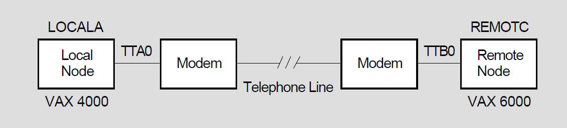
Commands issued at both the local node (LOCALA) and the remote node
(REMOTC):

$ RUN SYS$SYSTEM:SYSGEN
SYSGEN> CONNECT NOA0/NOADAPTER
SYSGEN> EXIT
$ INSTALL:=$SYS$SYSTEM:INSTALL
$ INSTALL/COMMAND
INSTALL> CREATE SYS$LIBRARY:DYNSWITCH/SHARE/PROTECT/HEADER/OPEN
INSTALL> EXIT

Commands issued at the remote node (REMOTC):

$ RUN SYS$SYSTEM:SYSGEN
SYSGEN> CONNECT VTA0/NOADAPTER/DRIVER=TTDRIVER
SYSGEN> EXIT
$ SET TERMINAL/EIGHT_BIT/PERMANENT/MODEM/DIALUP/DISCONNECT TTB0:
$ RUN SYS$SYSTEM:NCP
NCP>DEFINE NODE LOCALA RECEIVE PASSWORD PASSA INBOUND ENDNODE
NCP>SET NODE LOCALA ALL
NCP>EXIT

Commands issued at the local node (LOCALA):

$ RUN SYS$SYSTEM:NCP
NCP>DEFINE NODE REMOTC TRANSMIT PASSWORD PASSA
NCP>SET NODE REMOTC ALL
NCP>EXIT
$ SET HOST/DTE/DIAL=8556543 TTA0:

! After dialing in automatically to REMOTC, log in to your account on REMOTC.

$ SET TERMINAL/PROTOCOL=DDCMP/SWITCH=DECNET
%REM-S-END - control returned to LOCALA:
$♦
3.3.4. Verifying Successful Connection to the Network
To verify your connection to the network, you can optionally perform the following tests. These tests demonstrate whether your node can communicate with an adjacent node, that is, a node connected to your node by a single physical line. (Your node can reach an adjacent node directly, without data having to be routed through an intermediate node.)
Run the User Environment Test Package (UETP), if it is available, to test DECnet hardware and software on your node and an adjacent node.
Note
To run the UETP on your system, the MIRROR object must have default access to your system (see Section 3.2.2.3, ''Default Access for Your System'').
Log in to the SYSTEST account using the password UETP and enter the following command:
$ @SYS$TEST:UETP Return
Run "ALL" UETP phases or a "SUBSET" [ALL]? S Return
You can choose one or more of the following phases:
DEVICE, LOAD, DECNET, CLUSTER
Phase(s): DECNET Return
The DECnet phase performs tests on the following:
The local node (the node on which the UETP software is running)
All circuits in sequence
All adjacent nodes, and all circuits in parallel
A test on an adjacent node should normally last no more than 2 minutes. The DECnet node and circuit counters are zeroed at the beginning of the test to permit failure monitoring. The UETP output displays the condition of the circuit to the adjacent node and any response timeouts or errors indicated by the counters.
Copy a file to an adjacent DECnet for OpenVMS node (if one is available), copy it back to your node, and compare the two files. Arrange with the system manager of the adjacent node to obtain an account with NETMBX privilege that will permit you to access a directory on that node. Then perform the steps given below. (Refer to Chapter 2 for a description of how to perform file operations over the network.)
Create a temporary file for the test. To create the file, copy one of your files and name it TEST1.TMP.
Copy your test file to the directory on the remote node.
Issue a DIRECTORY command specifying the test file TEST1.TMP in the remote directory, to verify that the file has been copied.
Copy the file back to your own node, using the file name TEST2.TMP.
Issue a DIRECTORY command specifying the name of the file (TEST2.TMP) in your own directory, to verify that the file has been copied back to your node.
Issue a DIFFERENCES command to compare the original file (TEST1.TMP) and the file copied back from the remote node (TEST2.TMP).
If the files are the same, delete all test files on both nodes.
The DCL commands in Example 3.4, ''Sample Commands to Verify Connection to Another Node'' show how a system manager copies a file (named LOCALFILE.LIS) to TEST1.TMP locally and then copies the TMP file to a remote directory (RNODE::DISK1:[GENERAL]) and back again, comparing the results to verify that the local node is connected to the network. If you use the commands in this example, substitute the name of your own file for the file name LOCALFILE.LIS, and the name of the remote directory to which you have access in place of the directory name (RNODE::DISK1:[GENERAL]).
Example 3.4. Sample Commands to Verify Connection to Another Node $ COPY LOCALFILE.LIS TEST1.TMP $ COPY TEST1.TMP RNODE::DISK1:[GENERAL]* $ DIRECTORY RNODE::DISK1:[GENERAL]TEST1.TMP $ COPY RNODE::DISK1:[GENERAL]TEST1.TMP TEST2.TMP $ DIRECTORY TEST2.TMP $ DIFFERENCES TEST1.TMP TEST2.TMP $ DELETE TEST1.TMP;*,TEST2.TMP;* $ DELETE RNODE::DISK1:[GENERAL]TEST1.TMP;*
Send mail to and receive mail from another node that supports the Mail utility. To carry out this test, arrange with the system manager of a remote node on your network to have access to an account (with WRITE and DELETE privileges) on that node. Then follow the steps given below. (For a discussion of using MAIL over the network, see Chapter 2, "What You Can Do over the Network".)
Using the Mail utility, send a mail message to the account on the remote node.
Log in to the account on the remote node using the SET HOST command.
Read the mail message as received on the remote node, forward it back to the sender, exit from MAIL on the remote node, and log out of the remote system.
Check that you have received the mail message on your local node.
If these tests are successful and you do not receive an error message from DECnet, you have verified that DECnet for OpenVMS is installed correctly. If you are not able to carry out the verification tests successfully, the problem may be software or hardware errors, or possibly transient network problems, as described below.
Software or hardware errors: If you receive DECnet error messages, refer to the section on common error messages. (See Section 4.3.1, ''Common Error Messages and Meanings''.)
You can review the DECnet for OpenVMS installation procedure to ensure that you followed all instructions in installing the software. You can also check the communications hardware to be sure it is set up and connected properly, according to the instructions in the hardware user manuals.
To test the hardware, perform controller loopback tests to determine if the communications controller in your processor is working. Also check the controller on the remote node. For a summary description of controller loopback testing, refer to the section on testing the network. (See Chapter 4, "Keeping the Network Running".)
If these tests fail, contact your network manager.
Transient network problems: If you cannot verify connectivity because a node is not reachable or the network is slow to respond, try to rerun the tests at a time when you are sure the nodes are available or when computer usage is not at a peak. DECnet messages indicate when a remote node is not reachable.
3.3.5. Shutting Down and Restarting the Network
The network shuts down automatically as part of the normal system shutdown procedure. If your system is running, you can shut down the network at your local node without destroying any active logical links by entering the following commands:
$ RUN SYS$SYSTEM:NCP
NCP>SET EXECUTOR STATE SHUT
NCP>EXIT
When this command sequence is issued, no new links are allowed; when all existing links are disconnected, the network is turned off.
While your system is running, you can stop the network at your node by entering the following commands:
$ RUN SYS$SYSTEM:NCP
NCP>SET EXECUTOR STATE OFF
NCP>EXIT
All logical links are terminated immediately and the network is stopped.
To turn the network on manually, specify the following:
$ @SYS$MANAGER:STARTNET
To start the network if it is not currently active, you must be logged in to the SYSTEM account or have the privileges listed at the beginning of the STARTNET.COM command procedure.
To cause the network to be started each time the operating system is booted, enable the following command in the site-specific startup procedure:
$ @SYS$MANAGER:STARTNET
3.3.6. Using NCP to Create and Tailor the Configuration Database
The system manager is responsible for configuring the node for network operation by supplying information in the DECnet for OpenVMS configuration database about the following network components:
The local (executor) node
Remote nodes with which the local node can communicate
Local circuits
Local lines
Network objects
Network event logging
The configuration database is actually two databases: a permanent database that establishes the default parameter values for node startup, and a volatile database that contains the current parameter values.
You can use the Network Control Program (NCP) utility to build the network configuration database manually or to modify its contents. If you are configuring the node for the first time, you can use the automatic configuration command procedure, NETCONFIG.COM, to establish parameters needed to get DECnet running. The procedure for using NETCONFIG.COM is described in an earlier section. (See Section 3.3.2.2, ''Configuring Your Node Automatically''.)
When you run NCP and enter a command, NCP will prompt you for selected parameters if you do not supply them. NCP also provides a HELP facility with information about each command, which you can access as follows:
$ RUN SYS$SYSTEM:NCP
NCP>HELP [topic...]
Refer to the VSI OpenVMS DECnet Network Management Utilities for a complete description of the NCP command language.
Use NCP SET commands to establish the contents of the volatile database, and DEFINE commands to establish the contents of the permanent database. You must have OPER privilege to change the volatile database and SYSPRV privilege to change the permanent database.
The permanent database information is supplied to the volatile database when the network is started (that is, the STARTNET.COM command procedure is executed). You can also use the ALL parameter with the SET command to cause all permanent database entries for a network component to be loaded into the volatile database.
The basic NCP commands required to define the network components in the permanent configuration database are shown in the following list. Some of these commands must be used multiple times, such as DEFINE EXECUTOR to define several parameters and DEFINE NODE to list all the nodes in the network.
$ RUN SYS$SYSTEM:NCP
NCP>DEFINE EXECUTOR executor-parameter [...]
NCP>DEFINE NODE node-id
NCP>DEFINE CIRCUIT circuit-id
NCP>DEFINE LINE line-id
NCP>DEFINE OBJECT object-name
NCP>DEFINE LOGGING MONITOR STATE ON
NCP>DEFINE LOGGING MONITOR EVENTS event-list
NCP>EXIT
In an NCP command, node-id can be a node name a maximum of six alphanumeric characters long, or a node address in the form area-number.node-number, where the area number can be from 1 to 63 and the node number can be from 1 to 1023. If no area number is specified, the area number of the executor node is used. The default area number for the executor is 1. The object-name can be up to 16 characters long.
The circuit-id and line-id values are in the form dev-c[-u], defined as follows:
| dec | A device name |
| c | A decimal number (0 or a positive integer) designating a device's hardware controller |
| u | The unit number of the device name (0 or a positive integer); included if more than one unit is associated with the controller |
Reference DECnet for OpenVMS Network Management Utilities for a list of device names.
For example, the circuit and line identification for an Ethernet SVA device is in the form SVA-c (such as SVA-0); an example for a QNA device is QNA-0. An example of a synchronous DCMP device identifier is DSV-2, and an example of an asynchronous device identifier is TT-1-0.
NCP commands also recognize the plural forms of the network component names: KNOWN NODES, KNOWN CIRCUITS, KNOWN LINES, KNOWN OBJECTS.
To modify the current configuration of your node, you can issue SET commands for any network component. For example, to add circuit and line entries for the Ethernet UNA device (the DEUNA), specify the following commands:
$ RUN SYS$SYSTEM:NCP
NCP>SET LINE UNA-0 STATE ON
NCP>SET CIRCUIT UNA-0 STATE ON
NCP>EXIT
To determine the contents of your network configuration database, use the NCP commands LIST and SHOW. The LIST command displays information in the permanent database; the SHOW command displays volatile database entries. (For more information on monitoring the network using the network databases, see Chapter 4.) To delete entries from the configuration database, use the PURGE and CLEAR commands. The PURGE command deletes permanent database entries; the CLEAR command deletes or resets volatile database entries.
For example, to list the permanent name and address of a node, enter the following commands:
$ RUN SYS$SYSTEM:NCP
NCP>LIST NODE node-id
NCP>EXIT
To delete a node from the permanent database, enter the following commands:
$ RUN SYS$SYSTEM:NCP
NCP>PURGE NODE node-id ALL
NCP>EXIT
Node-id can be either the node name or the node address. You can also delete an individual parameter for a node. For example, to purge the RECEIVE PASSWORD parameter for node PURPLE, enter the following commands:
$ RUN SYS$SYSTEM:NCP
NCP>PURGE NODE PURPLE RECEIVE PASSWORD
NCP>EXIT
Because the PURGE command does not affect the volatile (memory-resident) copy of the DECnet database, you can access a node deleted with the PURGE command until DECnet is started again. If you use the CLEAR command to delete a node entry, the node entry will reappear in the volatile database after DECnet is started again.
3.3.7. Providing Security for Your DECnet for OpenVMS Node
Some of the security measures that you can use to protect your files and system in a network environment are summarized in this section.
As manager of a node, you can protect your system against unauthorized access by users on other nodes in the network by setting passwords for any accounts that you may create. Otherwise, users on other nodes could gain full access to your system by using the SET HOST command to log in to one of the accounts on your node. (Logging in to a node using the SET HOST command is described in Section 3.1.2, ''Accessing a Remote Node Interactively''.)
3.3.7.1. Protecting Files and Using Proxy Accounts
You can protect the files in your directory against unauthorized access. To set limits on who can access the files in your account, specify the DCL command SET PROTECTION. If your file is protected, a DECnet for OpenVMS user on a remote node who wants to access your file must be able to specify the user name and password of a local account that has the appropriate privileges to access the file. A remote user to whom you have given this information must then include the authorization information in the form of an access control string, username password, in the file specification used to access your file:
node"username password"::device:[directory]filename.type;version
For example, if Jones on remote node MIAMI wants to obtain a copy of the file TEST.DAT from user Smith's directory (on the device WORK1) at local node BOSTON, he should specify the following command, which includes Smith's password:
$ COPY BOSTON"SMITH ABCDEF"::WORK1:[SMITH]TEST.DAT *
See Chapter 2, "What You Can Do over the Network" for a description of network file operations.
Establishing proxy accounts. As system manager of your node, you can maintain the security of passwords by preventing their transmission over the network. You can permit selected outside users to access particular accounts on your node without having to send any explicit access control information over the network. To do this, you must create a proxy account that allows a remote user to have access privileges on your node without having a private account on your node. If the remote user is assigned a proxy account on your local node that maps into a local user account, the remote user assumes the same access privileges as the owner of the local account. For example, if Jones on a remote node has a proxy account that maps into Smith's account at local node BOSTON, Jones can copy Smith's file TEST.DAT over the network by specifying the following command:
$ COPY BOSTON::WORK1:[SMITH]TEST.DAT *
The system manager controls the use of proxy accounts at the local node. Use the Authorize utility to create and modify the permanent proxy database, NETPROXY.DAT, at your node. Each NETPROXY.DAT entry can map a single remote user to multiple proxy accounts on the local node (one default proxy account and up to 15 additional proxy accounts). The proxy database entry identifies the user by nodename::username or nodename::group,member.
For example, to create a NETPROXY.DAT file at local node BOSTON and add a default proxy entry mapping user MARTIN on remote node MIAMI to user ALLEN at the local node, enter the following commands:
$ SET DEFAULT SYS$SYSTEM
$ RUN AUTHORIZE
UAF> CREATE/PROXY
UAF> ADD/PROXY MIAMI::MARTIN ALLEN/DEFAULT
UAF> EXIT
When DECnet is started up, the information in NETPROXY.DAT is used to construct a volatile proxy database. If changes are made to the permanent proxy database by means of the Authorize utility, the volatile proxy database is updated automatically.
Similarly, the system manager at a remote node can create and maintain a proxy database of network users having proxy access to specific accounts on that node.
Controlling proxy login access. For proxy login to be successful, one node must be able to initiate proxy login access and the other node must allow proxy login access. To control proxy login for your local (executor) node, use Network Control Program commands to modify the proxy parameters in the executor and object databases. The NCP parameters that specify whether a node can initiate proxy login are the outgoing proxy parameters; the parameters that specify whether a node allows proxy login access are the incoming proxy parameters.
By default, both the local node and the remote node can initiate proxy login and allow proxy access.
Defaults for objects supplied by VSI are set in the object database. For example, the object FAL has neither incoming nor outgoing proxy access set by default. To specify or modify the proxy parameter for a network object, use the NCP command SET OBJECT. Use the following command to permit outgoing proxy access for a network object:
$ RUN SYS$SYSTEM:NCP
NCP>SET OBJECT object-name PROXY OUTGOING
NCP>EXIT
Proxy can be disabled on an object-by-object basis by setting the proxy parameter for a particular object to NONE.
To restrict incoming and/or outgoing proxy login access at your local node, specify the NCP commands SET EXECUTOR and SET OBJECT with the appropriate proxy parameters. The proxy setting for the object overrides the executor proxy setting. For example, if incoming proxy login access to your local node is disabled but incoming proxy access to a specific object on the local node is permitted, connection to the object through a proxy account is allowed.
The following commands indicate that proxy access to the object represented by object-name is permitted:
$ RUN SYS$SYSTEM:NCP
NCP>SET EXECUTOR INCOMING PROXY DISABLED
NCP>SET OBJECT object-name PROXY INCOMING
NCP>EXIT
See the VSI OpenVMS Guide to System Security for more information on establishing proxy accounts and the VSI OpenVMS DECnet Networking Manual for information on using proxies.
3.3.7.2. Controlling Access to Your Node
In general, the system manager can control access to the local node at two levels:
Node-level access control: To control the establishment of logical links with remote nodes, you can specify in your network database access control parameters that indicate which of the following logical link connections are permitted: INCOMING, OUTGOING, BOTH, or NONE. Use the NCP commands that follow to specify access parameters for a specific node, and the executor parameter DEFAULT ACCESS that applies to any node for which a specific access parameter is not specified:
$ RUN SYS$SYSTEM:NCP
NCP>DEFINE NODE node-id ACCESS option
NCP>DEFINE EXECUTOR DEFAULT ACCESS option
NCP>EXIT
System-level access control: When a remote user requests access to an object on the local node, the following means of authorization are checked:
Is an explicit access control string available?
Does the user have a proxy account on the local node?
Is there a default access account for the object at the local node?
Is there a default nonprivileged DECnet account at the local node?
VAX: On DECnet for OpenVMS VAX, the system manager can also control access to the local node by using circuit-level access control on DCMP circuits.
For point-to-point connections, especially over dialup lines, you can use passwords to verify that the initiating node is authorized to form a connection with your node. Passwords are usually optional for point-to-point connections but are required for dynamic asynchronous connections.
Each end of a point-to-point circuit can establish a password to transmit to the other node, and specify a password expected from the other node.
Before the link is established, each node verifies that it received the expected password from the other node.
Added security is provided for a dynamic asynchronous connection (which is normally maintained only for the duration of a telephone call): the node requesting the dynamic connection is required to supply a password, but the node receiving the login request is prevented from revealing a password to the requesting node. The steps needed to use passwords in establishing asynchronous DECnet connections are given in Section 3.3.3, ''Establishing Asynchronous DECnet Connections to Other Systems''.♦
If no explicit access control information or proxy account is available, DECnet for OpenVMS will use access control information specified for the object in the local network database.
If neither explicit access control information, nor a proxy account, nor a default access account for the object exists, DECnet for OpenVMS will attempt to use the default nonprivileged DECnet account, if one exists, to access the system. The default DECnet account provides default access to all objects supplied by VSI, user-written procedures and programs, and DCL file operation requests.
Note
The default DECnet account, like the default access account for the FAL object, is only appropriate for networks with very low security requirements. In place of this account, VSI recommends creating default access accounts for those objects, such as MAIL, that require default access to operate on the network. VSI recommends enabling access to remote files only through proxy accounts (see Section 3.3.7.1, ''Protecting Files and Using Proxy Accounts'').
You can establish default access accounts or the default DECnet account automatically with the DECnet for OpenVMS configuration command procedure, NETCONFIG.COM, (see Section 3.3.2.2, ''Configuring Your Node Automatically'') or you can establish the accounts and directories manually with the AUTHORIZE and NCP utilities. The following example shows how to create the default DECnet account manually.
$ SET DEFAULT SYS$SYSTEM
$ RUN AUTHORIZE
UAF>ADD NETNONPRIV/PASSWORD=DLB9191A/DEVICE=device-name: -
_ /DIRECTORY=[NETUSER]/UIC=[376,376] -
_ /PRIVILEGE=(TMPMBX,NETMBX)/FLAGS=(RESTRICTED,NODISUSER) -
_ /NOBATCH/NOINTERACTIVE/LGICMD=NL:
UAF>EXIT

$ CREATE/DIRECTORY device-name:[NETUSER]/OWNER_UIC=[376,376]
Device-name is the name of the device on which you have your directory. (The Authorize utility is described in the VMS Authorize Utility Manual.)
This section is a brief summary of some of the access controls available over the network. For a complete description of DECnet for OpenVMS access controls, see the VSI OpenVMS DECnet Networking Manual. See also the VSI OpenVMS Guide to System Security for additional suggestions on protecting your system.
3.4. Network-wide Considerations
To create a network, the managers of the individual systems involved are responsible for connecting the systems by means of communications lines. The system managers must then configure their nodes and start the network on their systems. For a large network, one manager, called the network manager, may serve as the central focus for the development and establishment of the network.
The initial step in creating a new network is planning the network configuration. The system managers or the network manager, if one is designated, must design the network topology: the arrangement and relationship of nodes, circuits and lines. Some of the decisions involved in designing a large network are as follows:
Will the network be divided into areas? If so, which nodes are to be in each area?
Which nodes will be routers and which will be end nodes?
What will the unique node address of each node be?
What is the maximum node address possible in the network?
How will the nodes be connected? What paths will be followed? What lines and circuits will be used? What costs will be assigned to the various circuits? Will satellite links be used?
If the network includes a cluster, will the nodes in the cluster share a cluster alias (a special node identifier by which the nodes in a cluster can optionally be accessed)?
In addition, the manager of a large network should define the values of NCP parameters that must be the same for all nodes in the network. The network manager should establish uniform values for data transmission and routing control parameters. Routing control parameters control the path that the data being transmitted is likely to take through the network, and are used to minimize traffic congestion at particular nodes in the network. The manager should also define network logging to provide for adequate monitoring and control of network operation.
The network manager should work with the system managers of individual nodes in the network to ensure that all nodes are properly tuned for the network environment. For example, the manager should determine if certain critical routing nodes in large networks need adjustments to system parameters to accommodate networking software.
For a complete description of the process of developing a network, refer to the VSI OpenVMS DECnet Networking Manual.
Chapter 4. Keeping the Network Running
After you configure your system as a network node, you can use a variety of software techniques to monitor and test the network. You can also use troubleshooting techniques to resolve problems related to keeping the network running. The tools used to monitor and test the network are summarized below. Common problems encountered during network operation are indicated, along with advice on troubleshooting. (Refer to the VSI OpenVMS DECnet Networking Manual for information on maintaining, controlling and testing the network. Refer to the VSI OpenVMS DECnet Network Management Utilities for usage information for the Network Control Program (NCP) utility and the DECnet Test Sender/Receiver network test commands.
4.1. Monitoring the Network
You can monitor network activity using network management tools. Analyzing the information you collect can help you to determine whether the network is running properly or whether any changes are required to resolve problems or improve performance. Major network monitoring tools include the following:
NCP commands you can use to display the status and characteristics of components in the network. (See Section 4.1.1, ''Using NCP to Display Information About Network Components''.)
NCP counters you can read to obtain error and performance statistics on current network operations. (See Section 4.1.2, ''Using NCP Counters''.)
Network events logged by DECnet that can be reported to you as they happen. (See Section 4.1.3, ''Using DECnet Event Logging''.)
Other software tools, such as the Ethernet configurator and the DECnet Test Sender/DECnet Test Receiver (DTS/DTR) utility, that permit you to learn more about network operation. (See DECnet for OpenVMS Network Management Utilities.)
4.1.1. Using NCP to Display Information About Network Components
You can use the NCP commands SHOW and LIST to monitor network activity by displaying the following:
Information about the current condition of network components (using SHOW commands) and the startup values assigned to the components (using LIST commands)
Counter information about circuits, lines, remote nodes, and the local node (using SHOW COUNTER commands)
Information about the range of network events being logged by the DECnet event logging facility (using SHOW LOGGING commands)
You do not need any privileges to issue SHOW commands, but you need the privilege SYSPRV to issue LIST commands.
Use the SHOW command to monitor the operation of the running network. You can display the characteristics and current status of network circuits, lines and nodes, including the local (executor) node. This information is useful in detecting any changes in the network configuration or operation. For example, if a circuit failure causes some nodes to become unreachable, you can use SHOW commands to check the status of the circuit and the nodes.
In general, the SHOW and LIST commands permit you to indicate what type of information you want NCP to display about the particular component you specify. The display types include the following:
CHARACTERISTICS: Static information that does not normally change during network operations (for example, the identification of the local node and the circuits connected to the local node, and relevant routing parameters such as circuit cost).
STATUS: Dynamic information that usually indicates network operation for the running network (for example, the operational state of the local node, circuits, lines and remote nodes).
SUMMARY: Only the most useful information from both static and dynamic sources; usually a condensed list of information provided for the CHARACTERISTICS and STATUS display types. SUMMARY is the default if you do not specify a display type.
COUNTERS: Counter information about circuits, lines, remote nodes, and the local node. (See Section 4.1.2 for a description of the use of counters.)
EVENTS: Information about which network events are currently being logged to which logging collection point. (See Section 4.1.3 for a description of the use of network events.)
When you display information about network components, you can specify either the singular or plural form of the component in the NCP command. Plural forms of component names are KNOWN (all components available to the local node), ACTIVE (all circuits, lines and logging not in the OFF state), and ADJACENT (all nodes directly connected to the local node).
Typical examples of NCP display commands follow:
$ RUN SYS$SYSTEM:NCP
NCP>SHOW EXECUTOR CHARACTERISTICS
NCP>SHOW KNOWN LINES STATUS
NCP>SHOW ACTIVE CIRCUITS
NCP>SHOW ADJACENT NODES STATUS
NCP>LIST KNOWN NODES
NCP>EXIT
Using the NCP SHOW and LIST commands, you can direct the information displayed to a specified output file. For example:
$ RUN SYS$SYSTEM:NCP
NCP>SHOW KNOWN NODES TO NODES.DAT
NCP>EXIT
This command creates the file NODES.DAT that contains summary information on all nodes known to the local system. If the specified output file exists, NCP appends the display information to that file. The default file type is LIS and the default output file is SYS$OUTPUT.
You can display information about network components on remote nodes using the TELL prefix in the NCP command. The format of the command is TELL node-id SHOW component. For example, to look at remote node counters, specify the following command sequence:
$ RUN SYS$SYSTEM:NCP
NCP>TELL node-id SHOW EXECUTOR COUNTERS
NCP>EXIT
4.1.2. Using NCP Counters
You can use NCP commands to display error and performance statistics about network components at any time while the network is running. DECnet software uses counters to collect statistics for the executor node, remote nodes, circuits and lines automatically. To display the contents of counters, use NCP SHOW COUNTER commands, as in the following typical examples of the commands:
$ RUN SYS$SYSTEM:NCP
NCP>SHOW EXECUTOR COUNTERS
NCP>SHOW NODE TRNTO COUNTERS
NCP>SHOW KNOWN CIRCUITS COUNTERS
NCP>SHOW KNOWN LINES COUNTERS
NCP>SHOW LINE SVA-0 COUNTERS
NCP>EXIT
For the local node and remote nodes, counter statistics cover such subjects as connection requests, user data traffic, timeouts, and errors. Circuit counters cover such topics as the transmission of data packets over the circuit, timeouts, and errors. Line counters cover such information as the transmission of bytes and data blocks over the line and relevant errors. For a complete summary description of all network counters, including the probable causes of particular types of occurrences, refer to the DECnet for OpenVMS Network Management Utilities.
Use NCP commands to control counter usage. You may want to reset counters to zero if you are establishing a controlled environment for test purposes. To reset counters to zero, use the NCP command ZERO COUNTERS (the ZERO command requires the OPER privilege). You can zero counters for the executor node and individual nodes, circuits and lines, or all nodes, circuits and lines, as shown:
$ RUN SYS$SYSTEM:NCP
NCP>ZERO EXECUTOR COUNTERS
NCP>ZERO NODE TRNTO
NCP>ZERO KNOWN CIRCUITS
NCP>ZERO LINE SVA-0 COUNTERS
NCP>EXIT
You can regulate the frequency with which specific counters are logged by issuing the following command sequence:
$ RUN SYS$SYSTEM:NCP
NCP>SET component COUNTER TIMER nn
NCP>EXIT
The variable nn is in seconds. Expiration of the counter timer causes the contents of the counter to be logged and the counter reset to zero. For example, use the following commands to cause a node counter logging event to occur every 600 seconds for the local node:
$ RUN SYS$SYSTEM:NCP
NCP>SET EXECUTOR COUNTER TIMER 600
NCP>EXIT
4.1.3. Using DECnet Event Logging
Use the DECnet event logging facility to monitor significant network events, such as circuit failures or lost packets, on a continuous basis. Whenever a network error or other meaningful event occurs, the DECnet event logger will log an event message to a terminal or file that you specify. Examples of network events that are logged as they happen include the following:
Changes in circuit and line states (for example, a circuit failure)
A node becoming reachable or unreachable
Circuit and node counter values, logged before the counter is automatically reset to zero
Errors in data transmission
Use of invalid data link passwords
Collection and analysis of network events can provide insight into why a particular error condition exists or why network performance may vary.
As events are detected, the event logger sends them to a collection point for analysis. Collection points are called logging sinks; they can be located on the local node or at a remote node. Event data can go to one or more sinks. Each of the following types of event sinks handles event data in a slightly different way:
Logging monitor. A program that receives and processes events. Events sent to the logging monitor are displayed on the screen of any terminal declaring itself a ‘‘network operator’’ by means of the Operator Communication Manager (OPCOM). Directing events to the OPCOM terminal is very useful for applications where the operator needs to know what is happening on the network as it happens. For example, it may be useful to know that a circuit is going down as it happens.
The automatic configuration command procedure (NETCONFIG.COM, described in Chapter 3) enables the logging monitor. The OPCOM process is started when the system starts. You can enable a terminal as a network operator terminal by specifying the DCL command REPLY /ENABLE=NETWORK. Usually the operator console (OPA0) is one of the OPCOM terminals.
Logging console. A terminal or file that receives events in a readable format. The default logging console is the operator console.
Logging file. A user-specified file that receives events in binary format, possibly for later analysis.
In order for logging to occur at your node, logging must be enabled and the events to be logged must be identified. If you use the automatic configuration command procedure, NETCONFIG.COM, logging will be established automatically.
Otherwise, you can use the NCP command SET or DEFINE LOGGING to set the logging sink state to be ON. To identify a remote location for a logging sink, specify the SINK node-id parameter in the command. Use one or more separate commands to define the events to be logged. For example, issue the following commands to cause all network events to be logged to OPCOM and displayed at your network operator terminal:
$ RUN SYS$SYSTEM:NCP
NCP>SET LOGGING MONITOR STATE ON
NCP>SET LOGGING MONITOR KNOWN EVENTS
NCP>EXIT
Alternatively, for each event class, you can specify the specific events to be logged, as follows:
$ RUN SYS$SYSTEM:NCP
NCP>SET KNOWN LOGGING EVENTS event-list
NCP>EXIT
Events in the event list are identified by class and type (in the form class.type). An event class refers to the DECnet software functional layer in which the event occurred. (DECnet layers are described in Chapter 1 and summarized in Section 4.3.2.1, ''Troubleshooting Techniques Based On NA Layers''.) Event classes logged by DECnet include those listed in Table 4.1, ''DECnet Event Classes''. The event type is a decimal number representing a unique event within the class. You can use the asterisk ( * ) wildcard character for event types, and you can specify a single event type or a range of types.
| Event Class | DECnet Functional Layer |
|---|---|
| 0 | Network Management |
| 1 | Application |
| 2 | Session Control |
| 3 | End Communication |
| 4 | Routing |
| 5 | Data Link |
| 6 | Physical Link |
| 7 | X.25 packet-level events |
|
128–159 | DECnet for OpenVMS system-specific |
An example of the command to specify event types 5 through 7 in event class 4 is as follows:
$ RUN SYS$SYSTEM:NCP
NCP>DEFINE LOGGING MONITOR EVENTS 4.5-7
NCP>EXIT
Additional examples of commands to define logging events are included in the NETCONFIG.COM example shown in Example 3.1, ''Sample NETCONFIG.COM Dialogue for an End Node''. A complete description of network events, including explanations of probable causes of particular events, is given in the VSI OpenVMS DECnet Network Management Utilities.
The event message displayed by OPCOM is in the following form:
EVENT TYPE class.type, event-text
From node-address (node name) Occurred (date and time)
component type and identifier
descriptive text
An example of a network event message display on the operator terminal at node RED is as follows:
%%%%%%%%%%% OPCOM 15-JUN-1992 11:36:48.83 %%%%%%%%%%%
Message from user DECNET
DECnet event 4.14, node reachability change
From node 2.5 (RED), 15-JUN-1992 11:10:05.16
Node 2.4 (YELLOW), Reachable
Use the SHOW LOGGING command to show what logging is being performed. For example, to display complete information on all logging being conducted at all nodes, use these commands:
$ RUN SYS$SYSTEM:NCP
NCP>SHOW ACTIVE LOGGING KNOWN SINKS
NCP>EXIT
To stop monitoring at the network operator terminal, issue the following commands:
$ RUN SYS$SYSTEM:NCP
NCP>SET LOGGING MONITOR STATE OFF
NCP>CLEAR LOGGING MONITOR ALL
NCP>EXIT
To turn monitoring back on, issue these commands:
$ RUN SYS$SYSTEM:NCP
NCP>SET LOGGING MONITOR STATE ON
NCP>EXIT
To permanently disable logging at the network operator terminal, enter the following commands:
$ RUN SYS$SYSTEM:NCP
NCP>PURGE LOGGING MONITOR ALL
NCP>EXIT
4.1.4. Other Monitoring Tools
Additional tools are available to determine network activity or exercise network operations. The following is a brief list of some of these tools:
Ethernet Configurator. The Ethernet configurator module permits you to obtain a list of all systems on an Ethernet circuit or circuits. The configurator runs as a separate process available to all users on the system once it has been started. To obtain information on the current configuration of nodes on Ethernet circuits, use the NCP command SHOW MODULE CONFIGURATOR. To start or stop the configurator, specify the SURVEILLANCE ENABLED or DISABLED parameter in the SET MODULE CONFIGURATOR command. (The Ethernet configurator is described in the VSI OpenVMS DECnet Networking Manual.)
DTS/DTR. The DECnet Test Sender and DECnet Test Receiver programs are cooperating tasks that perform various functions to exercise network task-to-task capabilities. (See VSI OpenVMS DECnet Network Management Utilities for a complete description of the DTS/DTR utility.)
OpenVMS Monitor utility. Use the Monitor utility to monitor DECnet and to display information about the use of system resources. If you issue the DCL command MONITOR DECNET, the display shows statistics on current DECnet activity at the local node. The information can be of value in determining how much of the system’s resources is being used for networking activity.
4.2. Testing the Network
You can use the NCP utility to perform a series of tests to help determine whether the network is operating properly. The tests exercise hardware and networking software at various functional layers. Each test repeatedly sends data through various network components which return the data to its source. These tests are called loopback tests, because the data is looped through a loopback mirror (that is, a cooperating process or device that returns data to the originator).
If messages cannot be looped successfully, or if the data is returned in a corrupted state, NCP indicates that the test failed, and includes the reason for the failure and the number of messages not looped.
Loopback tests check the operation of DECnet software at various functional layers. DECnet for OpenVMS software functional layers are indicated in the section on troubleshooting the network. (See Section 4.3.2.1, ''Troubleshooting Techniques Based On NA Layers''.) DECnet architectural design is described in Chapter 1, "Overview of DECnet for OpenVMS Networking". For a complete description of network testing, refer to the VSI OpenVMS DECnet Networking Manual.
Loopback tests can be performed at two levels:
Node-level loopback tests check the operation of logical links, routing, and other software.
Circuit-level loopback tests evaluate the operation of circuits. (You cannot perform circuit-level loopback tests on asynchronous circuits or lines.)
The types of tests and the commands used in each test are summarized briefly in the following sections.
4.2.1. Node-Level Tests
Node-level loopback tests determine whether the DECnet for OpenVMS software can form logical links and exchange data with a DECnet process on a remote node or on the local node. If no error messages are generated, the test is successful. If a test fails, you can perform the next test in sequence to help isolate the cause of the failure.
Remote loopback test: Verifies local and remote node network operation up to the user layer on the remote node. Loops information to a loopback mirror process on a remote node. The COUNT parameter in the LOOP NODE command specifies the number of messages the test will attempt to send. Use the following commands:
$ RUN SYS$SYSTEM:NCP
NCP>SET LINE SVA-0 STATE ON
NCP>SET CIRCUIT SVA-0 STATE ON
NCP>LOOP NODE TRNTO COUNT 10
NCP>EXIT
Local-to-remote loopback test using a loop node name: Verifies network operation of the local and adjacent nodes over a logical link on a circuit that you specify. This test checks the operation of software on the local and remote nodes up to and including the Routing layer. Specify a loop node name (such as TESTER) to loop information to the local node and a remote node. The loop node name does not identify an actual node; it is a special loopback node name associated with a specific circuit. When DECnet recognizes the special node name, it transmits test data over the circuit associated with the name.
To perform this test, use the following commands:
$ RUN SYS$SYSTEM:NCP
NCP>SET LINE SVA-0 STATE ON
NCP>SET CIRCUIT SVA-0 STATE ON
NCP>SET NODE TESTER CIRCUIT SVA-0
NCP>LOOP NODE TESTER COUNT 10
NCP>EXIT
VAX:
Local-to-local controller loopback test: On devices that support controller loopback testing, verifies Routing and Data Link layer software at the local node.
Note
DECnet for OpenVMS does not support controller loopback testing on all devices.
To start this test, turn off the line, set the device controller to loopback mode, specify a loop node name (TESTER), and turn the line on. Loop the test messages over the circuit associated with the test node. Use the following commands:
$ RUN SYS$SYSTEM:NCP
NCP>SET LINE DMC-0 STATE OFF
NCP>SET LINE DMC-0 CONTROLLER LOOPBACK
NCP>SET LINE DMC-0 STATE ON
NCP>SET CIRCUIT DMC-0 STATE ON
NCP>SET NODE TESTER CIRCUIT DMC-0
NCP>LOOP NODE TESTER COUNT 10 LENGTH 32
NCP>EXIT
The LENGTH parameter specifies the length of each block to be sent.♦
Local loopback test: Verifies the operation of local (executor) node software from the User layer to the Routing layer. The local DECnet software is tested by looping messages to the loopback mirror on the local node. Use the following commands:
$ RUN SYS$SYSTEM:NCP
NCP>LOOP EXECUTOR COUNT 10
NCP>EXIT
If the node-level tests are successful, return the line and circuit to the working state (as described at the end of the next section). Otherwise, continue with the circuit-level tests.
4.2.2. Circuit-Level Tests
If you are unable to perform a loopback test at the node level, perform circuitlevel tests to determine whether the circuit is functioning properly. These tests loop test data through a remote node or through a hardware loopback device on the circuit (called a controller loopback device), depending on the test. (You cannot perform circuit-level loopback tests on asynchronous circuits or lines.)
Software loopback test: Loop data to an adjacent node on the circuit to test whether the circuit is operational up to the adjacent node’s controller. To loop data through the circuit to the adjacent node and back to the local node use the following commands:
$ RUN SYS$SYSTEM:NCP
NCP>SET LINE SVA-0 STATE OFF
NCP>SET CIRCUIT SVA-0 STATE OFF
NCP>SET LINE SVA-0 CONTROLLER NORMAL
NCP>SET LINE SVA-0 STATE ON
NCP>SET CIRCUIT SVA-0 STATE ON
NCP>LOOP CIRCUIT SVA-0 COUNT 10 NODE BOSTON
NCP>EXIT
For an Ethernet or FDDI circuit, you must specify the PHYSICAL ADDRESS or NODE parameter in the LOOP CIRCUIT command.
VAX:
Controller loopback test for point-to-point synchronous circuits: If you are unable to communicate with an adjacent node, perform a controller loopback test to determine whether the communications controller on your system is functioning properly. While looping the data to the device on the circuit, the device must be in loopback mode to determine whether the controller works properly.
Note
DECnet for OpenVMS does not support controller loopback testing on all devices.
Set the communications controller to loopback mode and make the controller loop network messages back to your machine. Use the following commands:
$ RUN SYS$SYSTEM:NCP
NCP>SET LINE DMC-0 STATE OFF
NCP>SET LINE DMC-0 CONTROLLER LOOPBACK
NCP>SET LINE DMC-0 STATE ON
NCP>SET CIRCUIT DMC-0 STATE ON
NCP>LOOP CIRCUIT DMC-0 COUNT 10 LENGTH 32
NCP>SET LINE DMC-0 STATE OFF
NCP>SET LINE DMC-0 CONTROLLER NORMAL
NCP>SET LINE DMC-0 STATE ON
NCP>SET CIRCUIT DMC-0 STATE ON
NCP>EXIT
For additional information on loopback tests, refer to the VSI OpenVMS DECnet Networking Manual.
4.3. Common Problems
Once you have brought up your system as a network node, you may receive messages related to networking errors. Other problems that can occur at any time during network operation may not result in messages being displayed. This section explains the causes of error messages, suggests troubleshooting techniques, and describes the problems that you might experience in establishing asynchronous connections.
4.3.1. Common Error Messages and Meanings
When using DECnet for OpenVMS, you may receive network-related messages indicating software or hardware problems, transient conditions, or errors in your input. The following lists some common network-related messages, explains what condition may be causing each message, and suggests actions you can take. (All messages displayed on a system, including those generated by DECnet for OpenVMS, are described in the OpenVMS system messages documentation.)
SYSTEM-F-EXQUOTA, exceeded quota
If this message appears when you are attempting to turn on a line, the NETACP process does not have adequate BYTLM to complete the operation. You can take either of the following courses of action:
Increase the amount of BYTLM quota allocated to the NETACP process by defining the NETACP$BUFFER_LIMIT system logical and restarting DECnet. (Reference the VSI OpenVMS DECnet Networking Manual for details on how to estimate the amount of BYTLM required by NETACP.)
Decrease the amount of BYTLM quota in use by lowering the number of receive buffers associated with one or more lines.
SYSTEM-F-IVADDR, invalid media address
This message appears when you are attempting to turn on a line, and a duplicate physical address is detected on the LAN. Select a unique DECnet address.
SYSTEM-F-INVLOGIN, login information invalid at remote node
You receive this message if you attempt to access a remote node using an access control string that contains an invalid user name or password, or if you do not specify any access control information and no default DECnet account or proxy account is available at the remote node.
For example, if you enter this command specifying an invalid user password in the access control string that is part of the file specification, you receive this error message:
$ DIRECTORY BOSTON"SMITH GHIJKL"::WORK1:[SMITH]
%SYSTEM-F-INVLOGIN, login information invalid at remote node
Retry the file operation with the correct login information.
NCP-W-INVPVA, invalid parameter value
This message is displayed if you specify a parameter value in an NCP command that is not a valid value for the specified parameter. For example, the following command generates this error message:
NCP>SET LINE SVA-0 PROTOCOL DDCMP POINT
_%NCP-W-INVPVA, Invalid parameter value, Protocol
The value for the indicated parameter is invalid because the SVA device uses the ETHERNET protocol. The name of the parameter for which the value was invalid is displayed at the end of the error message. Reissue the command with the correct value for the parameter.
If an Ethernet or FDDI device is already in use by another protocol and cannot be reset to use the DECnet address, you receive this message when you enter the following command:
NCP>SET LINE SVA-0 ALL
_%NCP-W-INVPVA, Invalid parameter value, Physical Ethernet address
Line = SVA-0
To fix this problem, change the system startup procedures to start DECnet before the application using the other protocol.
SYSTEM-I-LINKEXIT, network partner exited
This message is displayed if the process on the remote node exited before completing the logical link to your node. The remote process might have exited prematurely, a timeout may have occurred at the remote node, or there may be a problem as indicated in the log file on the remote node. You can retry the operation.
To help diagnose the problem, read the NETSERVER.LOG file in the directory of the account you are attempting to access at the remote node. DECnet for OpenVMS automatically creates a NETSERVER.LOG file and places it in the directory for the appropriate account when it receives a connect request.
SYSTEM-F-NOLINKS, maximum network logical links exceeded
This message appears if the maximum number of links that the remote node allows has been exceeded. Wait and try again later.
SYSTEM-F-NOSUCHOBJ, network object unknown at remote node
You receive this message if you attempt to access a network object at a remote node and the object is not specified in the remote node database. For example, if you attempt to use the Phone utility from a node that supports PHONE and try to reach a node that does not have an entry for the network object PHONE in its configuration database, you receive the above message.
SYSTEM-F-NOSUCHNODE, remote node is unknown
You receive this message if you attempt to issue a command to access a remote node (for example, the DCL command SET HOST) and the remote node represented by node-id is not identified in the local volatile database. Verify that the node identifier is correct, enter the node name in your node database, and retry the operation.
SYSTEM-F-PATHLOST, path to network partner lost
You receive this message if you logged in to another node over the network (for example, using the DCL command SET HOST) and the path to the remote node is lost.
The path may be lost because of too much network activity or communications problems, or because DECnet was turned off at the remote node. Wait, then check to see if the node is still reachable. If so, try again to log in.
SYSTEM-F-SHUT, remote node no longer accepting connects
You receive this message if you attempt to access the remote node using a DCL command (such as the SET HOST command) under either of these conditions:
The executor parameter DEFAULT ACCESS on the remote node has been set to NONE and the node parameter ACCESS is not set to allow access to the node. The default access at the remote node must be set to permit incoming and outgoing access before you can connect to the node.
The command SET EXECUTOR STATE SHUT was executed on the remote system. The network must be restarted on the remote node.
SYSTEM-F-UNREACHABLE, remote node is not currently reachable
This message is displayed when you attempt to connect to a node that is unreachable. For example, when you address a mail message to a user at remote node PURPLE using the Mail utility, if MAIL cannot create a link to the remote node, you may receive the following message:
%MAIL-E-LOGLINK, error creating network link to node PURPLE
_SYSTEM-F-UNREACHABLE, remote node is not currently reachable
You can try to access the remote node again at a later time.
The message is also displayed even if the remote node does not exist, as long as you have indicated a node address or a node name that you previously defined in your node database.
You also receive notice that the node is unreachable if the value of the executor parameter MAXIMUM ADDRESS in your network database is lower than the address of the remote node you are attempting to access. Increase the value of the NCP executor parameter MAXIMUM ADDRESS in your database to be at least as high as the highest address of any node that you want to contact.
4.3.2. Problems Related to Network Operation
Problems in maintaining the proper functioning of the running network can be difficult to resolve. This section describes the technique for isolating a problem to a particular DECnet software functional layer or layers, and provides troubleshooting suggestions to determine the specific network problem. As system manager of the local node, work with the network manager (if one is available for your network) to resolve these problems. (Refer to the VSI OpenVMS DECnet Networking Manual for information on maintaining a DECnet for OpenVMS node.)
4.3.2.1. Troubleshooting Techniques Based On NA Layers
Techniques for troubleshooting DECnet for OpenVMS problems are based on the layered network design of DECnet Phase IV as specified in the Network Architecture (NA). The NA layers are illustrated in Figure 4.1, ''DECnet for OpenVMS Design Based On NA Layers''. Each layer performs particular services as part of the overall network capability provided at the node. (For more information on DECnet for OpenVMS software design, see Chapter 1, "Overview of DECnet for OpenVMS Networking".)
During troubleshooting, it is useful to distinguish among the network layers in localizing the cause of a particular problem. For example, some problems are characteristic of the Data Link layer, while others are related to the Routing or the End Communications layer (which provides logical link services).
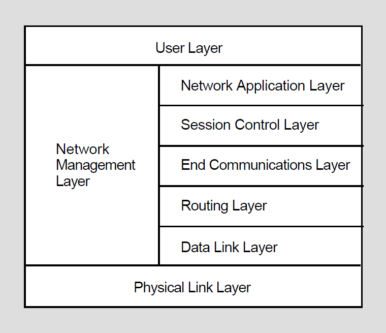
4.3.2.2. Network Problems and Suggested Actions
The following discussion of network difficulties identifies typical problems originating at the various layers, and actions you can take to locate the source of the problem. The problems are grouped into those related to data links, routing, and logical links.
Data link problems. Inability to reach an active node is a common problem on the network. The problem can be either a data link or routing problem.
To determine whether the problem is a data link problem, examine both the remote node and the circuit. The data link layer causes data to be moved over physical devices, so it affects only adjacent nodes (an adjacent node is connected to the local node by a single physical line). To learn if the unreachable node is an adjacent node that is available, check with the network manager or the system manager of the unreachable node.
Also check the state of the circuit which may be stuck in the ON-SYNCHRONIZING stateare report. The problem may be with the datalink if the circuit does not start up correctly or is up but the adjacent node is not reachable. (Circuit startup can also be affected by incorrect setting of the transmit and receive passwords, as described in the following section on routing problems.)
To locate a data link problem, examine the appropriate counters, line and circuit parameters, and network events.
Use NCP SHOW commands to display the contents of the circuit and line counters to see if they are reporting errors. (See Section 4.1.2, ''Using NCP Counters'' for an explanation of how to use NCP counters. Descriptions of all counters, including probable causes of particular types of occurrences, appear in the VSI OpenVMS DECnet Network Management Utilities.)
Use NCP SHOW commands to check the values of line and circuit parameters in the network configuration database.
Then look at the network events DECnet logged for event class 4 (for the Routing layer) and event class 5 (for the Data Link layer) to determine whether any events affecting the data link have occurred. (See Section 4.1.3, ''Using DECnet Event Logging'' for a description of how to use DECnet event logging. Network events are summarized by event class and type in the VSI OpenVMS DECnet Network Management Utilities; explanations of probable causes of network events are included as applicable.) Ensure that NETACP has enough BYTLM quota. (Reference the VSI OpenVMS DECnet Networking Manual for details on how to estimate the amount of BYTLM required by NETACP.)
Routing problems. Routing layer problems can involve nodes that are not reachable or circuits that are not stable. The circuit may be up and the adjacent node may be reachable, but one or more intermediate nodes (along the communications path) that should be reachable are not.
To isolate such Routing layer problems, examine the appropriate counters and transmit and receive passwords, and try to check the nodes along the routing path.
Check the contents of the node and circuit counters at your node and, if possible, arrange for the node and circuit counters at the remote node to be examined.
Examine network events logged for event class 4 (for the Routing layer).
Check the settings of the transmit and receive passwords for the local node and the adjacent node to see if they match (these passwords affect circuit startup).
Finally, you can use NCP commands with the TELL prefix to try to trace the routing path from one node to another, to determine if an intermediate node is down and to examine the parameter values for all nodes on the communications path. (See Section 4.1.1, ''Using NCP to Display Information About Network Components'' for an explanation of how to use the TELL prefix in an NCP command.)
If erratic routing behavior occurs (for example, constant changes in the reachability of nodes, or connection to a node other than the one you expect to reach), check whether two or more nodes with the same node address are connected to the network. If routing seems to be functioning properly, you can look at executor parameters related to routing (such as cost and hops). For additional information on routing layer parameters, refer to the VSI OpenVMS DECnet Networking Manual.
Logical link problems. The End Communications layer, which provides logical link services, can also be the source of common problems. Typical symptoms of logical link problems include
Link timeout
Network partner exited
Invalid account
Problems with performance and response time
To identify logical link problems, check the following:
The default DECnet nonprivileged account and directory on the remote node, to determine if they have been created properly.
Incoming and outgoing timers at both ends of the logical link, to ensure the links are not timing out prematurely because the timers are set too low.
The accounting log (using the OpenVMS Accounting utility), to determine whether the correct process was ever created and, if so, it exited prematurely.
The load on the local and remote nodes, to determine whether the load is preventing the link from being created.
The path over the network to the remote node. If using a broadcast circuit, check the line buffer size parameter to ensure the proper setting.
The NETSERVER timeouts, by having someone examine the NETSERVER.LOG file at the remote node.
The proxy settings for your node and for the objects being accessed. (To determine the default proxy access setting for your executor node, specify the NCP command SHOW EXECUTOR CHARACTERISTICS. To examine the proxy access setting for network objects, use the NCP command SHOW KNOWN OBJECTS CHARACTERISTICS.)
The disk quota, to ensure it is sufficient to create the NETSERVER.LOG file.
The SYS$LOGIN file, to determine whether the file protection is set to WORLD:READ.
If a logical link connection is unsuccessful, the link may have timed out for one of the following reasons:
A heavily loaded node can cause creation of a logical link to take a long time.
Incoming and outgoing timers may be set too low.
To prevent link timeouts, you can reset the executor parameters INCOMING TIMER and OUTGOING TIMER to higher values at both nodes.
A logical link problem may cause the message ‘‘network partner exited’’ to be displayed. This message indicates that the remote node exited before the logical link was established. Check the following:
The networking load on the nodes at each end of the logical connection
The accounting log on the remote node
Netserver timeouts on the remote node
If you receive a message indicating an invalid account, check that you have the proper authorization to make the logical link connection. However, an invalid account condition can also be reported by the message ‘‘network partner exited.’’ If so, try to have someone check the NETSERVER.LOG file on the remote node.
If performance and response time over the logical link become degraded, the cause may be too much traffic on a path to the target node. If you encounter this problem, consult with the network manager.
Configuration problems. The main reason for network errors may be improper configuration of the system. Check your DECnet for OpenVMS configuration, and check the communications cables and connections.
4.3.3. Asynchronous Connection Problems
VAX: On systems that support asynchronous connections, attempts to establish asynchronous DECnet connections with other nodes can fail for a variety of reasons. This section describes some reasons for failing to make a static or dynamic connection.♦
4.3.3.1. Problems with Static Asynchronous Connections
VAX: A static asynchronous connection has failed if the static asynchronous DECnet line is started but remains in the ON-STARTING state. To isolate the cause of the problem, check whether the following conditions exist:
Are the line speeds at both ends of the connection set to the same value?
If you are using a dialup line, is the modem characteristic set on the terminal? (This must be done before the line is set to asynchronous DCMP use.)
Are the two nodes being connected located in the same area in the network (that is, do their node addresses have the same area number) or are both nodes area routers?
Is the parity on the asynchronous DECnet line set to NONE? If your system is not a DECnet for OpenVMS system, is the terminal line set to the correct parity?
Is the terminal line set up to use 8-bit characters?
If the node already has an active circuit, is the node a routing node?
If verification is enabled for the circuit, are the transmit and receive passwords set correctly at the two nodes?
If you are unsuccessful in setting up your terminal line as a static asynchronous DCMP line, check the following:
Is the /NOTYPE_AHEAD qualifier specified for your terminal before you attempt to set up the static asynchronous line? If a type-ahead buffer is associated with your terminal, you may not be able to bring up your terminal line as an asynchronous DECnet line until you terminate any process started at the remote node that may own your terminal line.♦
4.3.3.2. Problems with Dynamic Asynchronous Connections
VAX:
If dynamic switching is being performed and the asynchronous DECnet connection is not made, first check the following:
Is DECnet started on both nodes?
Is the asynchronous DCMP class driver (NODRIVER) loaded by means of SYS$SYSTEM:SYSGEN at each node?
Is the dynamic switch image (DYNSWITCH) installed by means of SYS$SYSTEM:INSTALL at each node?
Are virtual terminals enabled on the remote node and, in particular, for the terminal over which you are logged in to the remote node?
If the dynamic asynchronous lines are started but are left in the ‘‘ON - STARTING’’ state, make the following checks:
Are the two nodes that are being connected located in the same area (that is, do their addresses have the same area number) or are they both area routers?
Are the routing initialization passwords (transmit and receive passwords) set appropriately at each node?
Is the INBOUND parameter for the initiating node set correctly in the node database at the node receiving the connection request? Is the parity on the asynchronous DECnet line set to NONE? If your system is not a DECnet for OpenVMS system, is the terminal line set to the correct parity?
Is the terminal line at the remote node set up to use 8-bit characters?
If the node already has an active circuit, is the node defined as a routing node?♦