VSI DECnet-Plus for OpenVMS Installation and Configuration
- Operating System and Version:
- VSI OpenVMS IA-64 Version 8.4-1H1 or higher
VSI OpenVMS Alpha Version 8.4-2L1 or higher
Preface
This book describes how to install and configure VSI DECnet-Plus for OpenVMS using the three available configuration options (FAST, BASIC, and ADVANCED). It also discusses how to use the configuration procedure to modify existing DECnet-Plus for OpenVMS configurations. The book also describes how to install and configure:
X.25 functionality on OpenVMS VAX systems (formally known as VAX P.S.I. software)
X.25 for OpenVMS on OpenVMS IA-64 and OpenVMS Alpha systems
The optional OSI layered applications software components:
OSI Applications Kernel (OSAK)
File Transfer, Access, and Management (FTAM)
Virtual Terminal (VT)
Note
DECnet-Plus for OpenVMS must be installed on your system before you can install X.25, FTAM, VT, or OSAK software.
1. About VSI
VMS Software, Inc. (VSI) is an independent software company licensed by Hewlett Packard Enterprise to develop and support the OpenVMS operating system.
2. Intended Audience
OpenVMS system managers
DECnet-Plus software installers
Network planners and managers
3. Document Structure
|
Chapter 1, "Preparing to Install DECnet-Plus for OpenVMS" | Describes the prerequisite steps necessary to install the DECnet-Plus for OpenVMS software and the installation dialog used to install the software. |
|
Chapter 4, "Configuration Options" Chapter 5, "Using the FAST Configuration Option" Chapter 6, "Using the BASIC and ADVANCED Configuration Options" | Provides help to determine which configuration option to use: FAST, BASIC or ADVANCED. It describes using each of the configuration options to configure a new DECnet-Plus node. It also discusses using the BASIC or ADVANCED configuration option to modify an existing configuration. |
| Describes the steps necessary to configure X.25 functionality on DECnet-Plus for OpenVMS VAX systems. This functionality was previously a separate product known as VAX P.S.I. | |
|
Chapter 9, "Preparing to Install X.25 for OpenVMS" Chapter 10, "Installing X.25 for OpenVMS" Chapter 11, "X.25 Post-Installation and Configuration Tasks" | Describes the prerequisite steps necessary to install the X.25 for OpenVMS software on an OpenVMS IA-64 or OpenVMS Alpha system and the installation dialog used to install the software. It also serves as an introduction to the configuration tasks discussed in the VSI X.25 for OpenVMS Configuration manual. |
|
Chapter 12, "Preparing to Install the OSI Applications" | Describes the prerequisite steps necessary to install the optional OSI applications software components and the installation dialog used to install the software. It also describes how to configure the FTAM and VT applications. |
|
Appendix A, "System Files Loaded During Installation" Appendix C, "Configuring OSI Transport Over X.25 CONS" Appendix D, "Configuring Link State Routing Nodes Using the | Reference appendixes useful to the installation and configuration process. |
4. Terminology
Transition and migration
Phase IV and DECnet Phase IV
End system and end node
Intermediate system and router
DECnet-Plus and Phase V
5. Related Documents
DECnet-Plus for OpenVMS documentation is available in two sets:
Documentation set for DECnet-Plus for OpenVMS
Supplemental X.25 for OpenVMS documentation set
Table 1, ''DECnet-Plus for OpenVMS Documentation'' lists the documentation that supports this version of the DECnet-Plus for OpenVMS software.
| Document | Contents |
|---|---|
| DECnet-Plus for OpenVMS Documentation Set | |
| VSI DECnet-Plus for OpenVMS Introduction and User's Guide | Describes the manuals in the documentation sets, outlines the DECnet-Plus for OpenVMS features and tools, explains how to use and manage an end system, and provides a comprehensive glossary of DECnet terminology. |
| DECnet-Plus for OpenVMS Release Notes |
Describes changes to the software; installation, upgrade, and compatibility information; new and existing software problems and restrictions; and software and documentation corrections. NotePrint this file at the beginning of the installation procedure and read it before you install DECnet-Plus for OpenVMS. |
| VSI DECnet-Plus Planning Guide | Provides configuration and planning guidelines, including namespace planning information, to help you transition a network from the DECnet Phase IV to DECnet Phase V architecture. |
| DECnet-Plus for OpenVMS Applications Installation and Advanced Configuration Guide |
Explains how to install and configure the DECnet-Plus for OpenVMS software using the three configuration options (FAST, BASIC, and ADVANCED). Also explains how to modify an existing configuration. Explains how to configure the X.25 functionality included with the DECnet-Plus for OpenVMS VAX software (formerly provided by the VAX P.S.I. Access and VAX P.S.I. products). Explains how to install the separate X.25 for OpenVMS software product available for OpenVMS IA-64 and OpenVMS Alpha systems. For configuration information, see the VSI X.25 for OpenVMS Configuration manual. Explains how to install and configure the optional OSI applications software components (OSI Applications Kernel (OSAK), OSI File Transfer, Access, and Management (FTAM), and OSI Virtual Terminal (VT)). |
| VSI DECnet-Plus for OpenVMS Network Management Guide | Provides in-depth information about how to monitor and manage DECnet-Plus for OpenVMS systems using various tools and Network Control Language (NCL) commands. Explains how to set up and use event dispatching and how to perform all day-to-day management tasks for the local DECnet- Plus for OpenVMS node, including setting up OpenVMS clusters, managing security, downline loading, and monitoring the network. |
| DECnet-Plus for OpenVMS Network Management and Quick Reference Card | Provides quick-reference information about the tools that help you manage and monitor a DECnet-Plus network. Use this guide with the VSI DECnet-Plus for OpenVMS Network Management Guide. |
| VSI DECnet-Plus for OpenVMS Network Control Language Reference Guide | Outlines command descriptions and examples for all Network Control Language (NCL) commands that you execute to manage, monitor, and troubleshoot the network. Begins with an orientation chapter that contains information about how to execute NCL commands, followed by a command chapter for each module in the DECnet Phase V layered model. |
| VSI DECnet-Plus for OpenVMS Problem Solving Guide | Explains how to isolate and solve DECnet problems in an OpenVMS environment that can occur while the network is in operation. Includes information about how to perform loopback tests and how to use the DTS/DTR utility to solve problems. |
| VSI DECnet-Plus for OpenVMS DECdns Management Guide | Explains VSI DECnet-Plus Distributed Name Service (DECdns) concepts and how to manage a DECdns distributed namespace. Use this manual with the VSI DECnet-Plus Planning Guide. |
| VSI DECnet-Plus for OpenVMS DECdts Management | Introduces VSI DECnet-Plus Distributed Time Service (DECdts) concepts and describes how to manage the software and system clocks. |
| VSI DECnet-Plus DECdts Programming | Contains DECdts time routine reference information and describes the time-provider interface (TPI). |
| VSI DECnet-Plus OSAK Programming | Explains how to use the OSAK (OSI Applications Kernel) interface to create OSI (Open Systems Interconnection) applications for any supported operating system. |
| VSI DECnet-Plus OSAK SPI Programming Reference Manual | Provides reference information about using the OSAK session programming interface (SPI) to create OSI applications on any supported operating system. |
| VSI DECnet-Plus FTAM and Virtual Terminal Use and Management | Explains how to use and manage FTAM (File Transfer, Access, and Management) software for remote file transfer and management and VT (Virtual Terminal) for remote login to OSI-compliant systems. |
| VSI DECnet-Plus FTAM Programming | Explains how to access the FTAM protocol through FTAM’s API (application programming interface). |
| VSI DECnet-Plus for OpenVMS Programming | Contains information about how to design and write an application that follows a client/server model and uses the OpenVMS Interprocess Communication ($IPC) system service and the transparent and nontransparent communication with the queue Input/Output ($QIO) system service. Explains how to write programs using the OpenVMS system services to communicate with OSI transport services. Provides information about the Common Management Information Service (CMISE) API. |
| DECnet/OSI for VMS CTF Use | Explains how use the Common Trace Facility (CTF) troubleshooting tool to collect and analyze protocol data from networking software. |
| Supplemental X.25 Documentation Set | |
| VSI X.25 for OpenVMS Configuration | Discusses how to configure X.25 for OpenVMS on an OpenVMS IA-64 or OpenVMS Alpha system. For information about how to configure the X.25 functionality on OpenVMS VAX systems, see the VSI DECnet-Plus for OpenVMS Installation and Configuration manual. |
| VSI X.25 for OpenVMS Management Guide | Explains how to manage and monitor an X.25 system using network tools. |
| VSI X.25 for OpenVMS Security Guide | Explains the X.25 security model and the tasks required to set up and manage X.25 security. |
| VSI X.25 for OpenVMS Problem Solving | Provides guidance on how to solve problems that can occur while using an X.25 system. |
| X.25 for OpenVMS Utilities | Explains how to use and manage the X.25 Mail and X.29 communications utilities. |
| X.25 for OpenVMS Accounting | Explains how to use X.25 accounting to obtain performance records and information about how X.25 is being used. |
| X.25 for OpenVMS Programming | Explains how to write X.25 and X.29 programs to perform network operations. |
| X.25 for OpenVMS Programming Reference | Provides reference information for X.25 and X.29 programmers. |
| DECnet/OSI for VMS VAX WANDD Programming | Provides information about using the programming interface for the WANDD devices. |
6. VSI Encourages Your Comments
You may send comments or suggestions regarding this manual or any VSI document by sending electronic mail to the following Internet address: <docinfo@vmssoftware.com>. Users who have VSI OpenVMS support contracts through VSI can contact <support@vmssoftware.com> for help with this product.
7. OpenVMS Documentation
The full VSI OpenVMS documentation set can be found on the VMS Software Documentation webpage at https://docs.vmssoftware.com.
8. Typographical Conventions
| Convention | Meaning |
|---|---|
special type | Indicates a literal example of system output or user input. In text, indicates command names, keywords,node names, file names, directories, utilities and tools. |
| UPPERCASE |
Indicates keywords that you enter. You can type the characters in uppercase or lowercase. You can abbreviate command keywords to the smallest number of characters that OpenVMS, NCP, NCL, or the other tools accept. Uppercase also indicates the names of files, directories, utilities, tools, commands, parameters, and procedures. |
| italic type | Indicates a variable. |
| bold | Indicates a new term defined in the text or important information. |
|
Return | Indicates that you press the Return key. |
| Ctrl/ x | Indicates that you press the Control key while you press the key noted by x. |
| [YES] | Brackets indicate that the enclosed item is a default value in an installation prompt. |
| { } | In command format descriptions, indicates you must enter at least one listed element. |
Chapter 1. Preparing to Install DECnet-Plus for OpenVMS
This chapter describes the tasks you must perform before installing and configuring the VSI DECnet-Plus for OpenVMS software.
1.1. Locating the Distribution Kit
Complete the following steps:
To obtain the kit directory location of the DECnet-Plus distribution files on the appropriate CD–ROM. View the CD–ROM master index file on the media CD–ROM.
To determine if the appropriate CD–ROM is already mounted on your system, enter the following command:
$ show device dka400:
Note
The device DKA400 is used in examples in this document as the device where the appropriate CD–ROM has been mounted.
If the media CD–ROM containing the DECnet-Plus kit is not mounted, insert the appropriate CD–ROM (write down the volume label) into an available CD–ROM drive. Enter the appropriate mount command to mount the media CD–ROM (omit the /FOREIGN qualifier):
$ mount dka400: label
where label is the volume label of the media CD–ROM.
Define the logical name PCSI$SOURCE to reference the appropriate kit directory. For example, if the DECnet-Plus kit is located in the [DECNETPLUS083] directory on device DKA400, enter the following command:
$ define pcsi$source dka400:[decnetplus083]
To verify the DECnet-Plus kit name, use a directory command specifying the PCSI$SOURCE logical name:
$ directory pcsi$source:*.pcsi
The distribution kit contains the following component kit files:
Base components software
DECnet-Plus for OpenVMS base kit
Optional software
OSI Applications Kernel kit (OSAK software)
OSI File Transfer, Access, and Management application kit (FTAM software)
OSI Virtual Terminal kit (VT software)
For a more detailed list, see Chapter 3, "Installing DECnet-Plus for OpenVMS".
Note
Before installing any of the software, read the VSI DECnet-Plus Planning Guide. This guide contains installation planning information, including namespace planning instructions.
1.2. Accessing the Online Release Notes
You should review the release notes for a description of new features, differences between multiple versions of DECnet-Plus, and changes in the installation procedure.
To access the release notes, issue the following command:
$ product extract release_notes decnet_osi /file=filename
In the above example, it is assumed that the logical name PCSI$SOURCE properly references the directory location of the DECnet-Plus kit. Details on how to determine the directory location of the DECnet-Plus kit are provided in Section 1.1, ''Locating the Distribution Kit''.
The product selected is displayed and you are prompted to continue with the extraction.
To extract the release notes, type YES and press Return. The release notes are written to the specified file, which you can display or print.
If you do not use the /FILE qualifier to define the required location of the extracted
release notes, the release notes are extracted into the file
default.pcsi$release_notes in the current directory.
To cancel the extraction, type NO and press Return.
Note
After DECnet-Plus is installed, the release notes file is located in
sys$help in the form
decnet-plus-v*.release_notes.
1.3. Time Required for Installation and Configuration
Configuration option used (FAST, BASIC, or ADVANCED)
Optional software installed
CPU on the system
The time required to install and configure DECnet-Plus can vary from 30 minutes to 2 hours, depending on the combination of choices you make from the above list.
1.4. Required Hardware
The DECnet-Plus for OpenVMS installation process requires the following hardware:
A CD–ROM reader
A terminal
You can use either a hardcopy or video terminal to communicate with the operating system and respond to prompts from the installation procedure.
Refer to the OpenVMS Operating System for I64, Alpha and VAX Software Product Description for hardware requirements and processor support for the DECnet-Plus software.
1.5. Prerequisite Software
Before you can install and configure the software, the system must have the required operating system software. In addition, if you intend to use any optional software supported by DECnet-Plus for OpenVMS, you must use the supported versions of these software products.
For specific information about the required versions of prerequisite software, see the DECnet-Plus for OpenVMS Software Product Description (SPD).
1.5.1. Checking the Operating System Version
To determine the OpenVMS operating system version number, enter the following DCL command:
$ show system
1.5.2. DECnet and OSI Applications over TCP/IP
If you plan to use the DECnet-Plus over TCP/IP feature, then TCP/IP software is a prerequisite. Your system will be able to operate over TCP/IP if and only if the TCP/IP product used on your system supports the PATHWORKS Internet
Protocol (PWIP) interface. For more information about required TCP/IP software, see the DECnet-Plus for OpenVMS Release Notes.
Note
For more information on using DECnet over TCP/IP or the OSI applications over TCP/IP, refer to the VSI DECnet-Plus for OpenVMS Network Management Guide.
1.6. License Requirements
DECnet-Plus for OpenVMS uses three licenses. The specific license required on your system is determined by the functions you want to use and your CPU type:
Basic function license (DVNETEND) — provides end system support.
Extended function license (DVNETEXT) for OpenVMS IA-64 and OpenVMS Alpha systems — provides end system support, host-based routing support, DECdns server, DECdts server, cluster alias, and OSI applications gateways.
Extended function license (DVNETRTG) for OpenVMS VAX systems — provides end system support, host-based routing support, DECdns server, DECdts server, cluster alias, and OSI applications gateways.
License Requirements for OpenVMS for IA-64 systems
VSI DECnet-Plus for OpenVMS Version 8.3 for IA-64 systems requires the Foundation Operating Environment (FOE) license. This license includes the basic function license (DVNETEND). If you intend to configure your system as a DECdns server, you must obtain a separate DVNETEXT license.
At least one node of an OpenVMS Cluster system requires the appropriate extended function license (DVNETEXT or DVNETRTG) to use the cluster alias feature.
If you install the DECnet-Plus software without the appropriate extended function
license and then attempt to configure your system as a DECdns server, the DECdns server
will fail and the configuration utility (net$configure.com) will
exit.
In addition to the three DECnet-Plus for OpenVMS licenses, you may need additional licenses to use certain features of DECnet-Plus.
In addition to the appropriate DECnet-Plus extended function license, the TELNET/VT gateway also requires an HP TCP/IP Services for OpenVMS license.
In addition to the DECnet-Plus base function license, certain X.25 wide area network features on OpenVMS Alpha and OpenVMS IA-64 systems require a separate X.25 for OpenVMS license. For more information, see Section 9.7, ''License Requirements''.
In addition to the DECnet-Plus base function license, certain X.25 wide area network features on OpenVMS VAX systems require an X.25 license. For more information, see Section 8.3.1, ''Configuring Client, Direct Connect, and Connector Systems''.
1.6.1. Checking Licenses
To determine if a DECnet-Plus license is registered, enter the following DCL command:
$ show license dvnet*
If the system does not have the required licenses, obtain the Product Authorization Key (PAK) and register the license. For instructions on registering a license, refer to the VSI OpenVMS License Management Utility Guide.
1.7. System Requirements
Before you install the DECnet-Plus for OpenVMS software, make sure that your system meets the requirements discussed in the following sections.
1.7.1. Disk Space
If this is the first time you are installing DECnet-Plus on a particular system, ensure that you have enough free space on the system disk. You need enough space to install the DECnet-Plus Base components and any options you select.
If you already have DECnet-Plus installed, you need considerably less free space for the installation because the earlier installation has already allocated most of the space that a subsequent installation needs.
Table 1.1, ''DECnet-Plus Disk Space Requirements'' shows the amount of disk space needed to install the DECnet-Plus software components. Make sure you have enough free space to install the required software and the optional software.
| Component | Blocks for I64 | Blocks for Alpha | Blocks for VAX |
|---|---|---|---|
| Base components | 160000 | 92000 | 77000 |
| DECdts server | 3500 | 1600 | 1800 |
| DECdns server? | 15000 | 15000 | 3000 |
| WANDD | 10000 | 5000 | 5500 |
| X.25 for OpenVMS | 20000 | 10000 | 10000 |
| OSAK | 12300 | 6600 | 6000 |
| FTAM | 42700 | 31800 | 12000 |
| Virtual Terminal | 9800 | 3300 | 2000 |
| Totals | 273300 | 165300 | 117300 |
To find out how many free blocks exist on the system disk, enter the following command:
$ show device sys$sysdevice
If the number of required blocks exceeds the number of free blocks, you must clear space on the system disk.
1.7.2. Required Memory
The minimum amount of memory required is 512 MB for OpenVMS IA-64 systems, 64 MB for OpenVMS Alpha systems, and 24 MB for OpenVMS VAX systems.
To check the amount of memory on your system, enter the following command:
$ show memory/full
1.7.3. Required System Parameters
This section provides information about system parameters, their values, and how to modify them.
Table 1.2, ''Minimum System Parameters Required — Base Software Installation'' lists the minimum system parameters required for the base software.
| Parameter | Minimum Value |
|---|---|
| For OpenVMS IA-64 Systems: | |
| ARB_SUPPORT | 3 |
| MIN_CLISYMTBL | 750 |
| MIN_GBLPAGES | 100000 |
| MIN_GBLPAGFIL | 1024 |
| MIN_GBLSECTIONS | 512 |
| MIN_KSTACKPAGES | 2 |
| For OpenVMS Alpha Systems: | |
| ARB_SUPPORT | 3 |
| MIN_CLISYMTBL | 750 |
| MIN_GBLPAGES | 100000 |
| MIN_GBLPAGFIL | 1024 |
| MIN_GBLSECTIONS | 512 |
| MIN_KSTACKPAGES | 2 |
| MIN_NPAGEDYN | 2100000 |
| For OpenVMS VAX Systems: | |
| MIN_CLISYMTBL | 500 |
| MIN_GBLPAGES | 50000 |
| MIN_GBLPAGFIL | 4096 |
| MIN_GBLSECTIONS | 400 |
| MIN_VIRTUALPAGECNT | 35000 |
In addition to the minimum system parameter values, DECnet-Plus also requires several ADD_ parameter values to ensure adequate resources are available.
These values are listed in Table 1.3, ''ADD_ System Parameter Values''.
| Parameter | Value |
|---|---|
| For OpenVMS IA-64 Systems: | |
| ADD_GBLPAGES | 75000 |
| ADD_GBLPAGFIL | 512 |
| ADD_GBLSECTIONS | 200 |
| ADD_GH_EXEC_CODE | 256 |
| ADD_NPAGEDYN | 3800000 |
| For OpenVMS Alpha Systems: | |
| ADD_GBLPAGES | 55000 |
| ADD_GBLPAGFIL | 256 |
| ADD_GBLSECTIONS | 100 |
| For OpenVMS VAX Systems: | |
| ADD_GBLPAGES | 55000 |
| ADD_GBLSECTIONS | 100 |
Important
For most DECnet installations, it is not necessary for you to add the preceding system parameters to the modparams.dat file. These parameters are automatically taken into consideration when DECnet is installed or upgraded.
If necessary, prior to installing this release of DECnet-Plus, you should edit modparams.dat and remove any entries that you may have made for previous DECnet-Plus installations. Use the preceding tables as a guide.
Different versions of DECnet-Plus have had different parameter values; however, the parameter list has remained consistent for most recent releases.
See the VSI DECnet-Plus for OpenVMS DECdns Management Guide for examples of when it might still be necessary to make DECnet-related changes to modparams.dat. Note that any ADD_values you place in modparams.dat are added to the standard ADD_values in Table 1.3, ''ADD_ System Parameter Values''.
DECnet and AUTOGEN use two files, newparams.dat and
clu$params.dat, to support this automatic system parameter
setting.
The DECnet-Plus installation procedure creates a newparams.dat file to provide
AUTOGEN with the DECnet-Plus system parameter requirements. When AUTOGEN is run,
it first renames any existing clu$params.dat file to
clu$params.old. Then it takes the values found in all existing
newparams.dat files and creates a new clu$params.dat file
containing the results of its newparams.dat scan. AUTOGEN then
renames the newparams.dat files to newparams.done. During AUTOGEN,
the parameters found in clu$params.dat are used in much the same
fashion as parameters found in modparams.dat.
To check any system parameter, invoke the SYSGEN utility and enter the show command. For example, to view the current value for GBLSECTIONS, enter the following command:
$ mcr sysgen
SYSGEN> show gblsections
If any of the system parameters need to be modified, follow these steps:
Edit the modparams.dat file by entering:
$ edit sys$system:modparams.dat
Enter the values into the file in the following format:
ADD_GBLSECTIONS=512
.
.
.
ADD_GBLPAGFIL=1024
Exit from the editor.
Run AUTOGEN by entering the following command:
$ @sys$update:autogen getdata reboot
Warning
In the unlikely event that the required minimum system parameter requirements are no longer met by the current system parameter settings, the network startup will fail. If the network fails to start for this reason, the logical name NET$STARTUP_STATUS is set to OFF-AUTOGENREQ. If this occurs you must edit the modparams.dat file directly and set the parameters to the values shown in Table 1.2, ''Minimum System Parameters Required — Base Software Installation'' and Table 1.3, ''ADD_ System Parameter Values''.
1.7.3.1. SYSGEN Parameters for OpenVMS Cluster Members
When installing DECnet-Plus for OpenVMS on an OpenVMS Cluster, make sure that you apply any custom SYSGEN parameter values you may have added to all cluster members.
1.7.4. Required Privileges and Rights Identifiers
HP recommends that you install and configure DECnet-Plus from the SYSTEM account. If you are configuring from another account, make sure the account has the following privileges and rights identifiers in place before you begin.
Required account privileges are as follows:
CMKRNL
NETMBX
SYSPRV
TMPMBX
OPER
SYSNAM
WORLD
Note
The account cannot have the locked password (LOCKPWD) flag set.
Required rights identifiers are as follows:
NET$MANAGE
NET$SECURITY
NET$REGISTERDNSOBJECT
Note
If your account has the BYPASS privilege, then you do not need to grant these rights identifiers.
To determine the default privileges of the installing account, log in and enter the following DCL command:
$ show process/privileges
1.8. Backing Up the System Disk
Use the OpenVMS BACKUP utility to make a copy of the system disk.
1.9. Notifying Users
Inform users on the system that you plan to install a product and that they must log out.
First, prevent nonprivileged users from logging in to the system:
$ set logins/interactive=0
Next, use the reply/all command and be sure to indicate the exact time you plan to begin running the POLYCENTER Software Installation utility. For example:
$ reply/all "Installing DECnet-Plus software at 18:00; Please log out."
If possible, give users an estimated time when they will be able to log in to the system.
Chapter 2. Pre-Installation Tasks
Before installing the software, complete the installation planning checklist in this chapter. This ensures that you have the information you need to complete the installation and configuration in the minimum amount of time. In addition to identifying necessary information and directing you to sources of help, the checklist also assists you in choosing optional software.
2.1. Information Required to Complete the Installation Planning Checklist
System's full name (you may have a DECdns full name, a Local namespace full name, and a fully qualified host name for the Domain Name System [DNS/BIND])
Node synonym
Phase IV-compatible address to interface with Phase IV nodes
Phase IV prefix
Network address
2.2. Installation Planning Checklist
|
Question |
Yes |
No |
For More Information |
|---|---|---|---|
|
Have you backed up your system disk? If not, then do so before you start the installation. | |||
|
Will the system get network addresses from a DECdns name server? If yes, what is the system's DECdns node name (for example, ACME:.BOSTON)? |
See Section 6.4.1, ''Specifying Directory Name Services'' and Section 6.4.2, ''Specifying Node Full Names'' | ||
|
Will the system store network addresses in a Local database? If yes, what is the system's Local node name (for example, LOCAL:.BOSTON)? |
See Section 6.4.1, ''Specifying Directory Name Services'' and Section 6.4.2, ''Specifying Node Full Names'' | ||
|
Is TCP/IP installed on the system? Will the system store network addresses in the DNS/BIND database? If yes, what is the system's DNS/BIND name (for example, BOSTON.ACME.COM)? |
See Section 6.4.1, ''Specifying Directory Name Services'' and Section 6.4.2, ''Specifying Node Full Names'' | ||
| What is the system's node synonym (for example, BOSTON)? | |||
|
Will the system communicate with Phase IV nodes?
|
See Section 6.5.3, ''Specifying a DECnet Phase IV Address'' and Section 6.5.4, ''Specifying a Phase IV Prefix'' | ||
|
Will the system autoconfigure its network addresses? If not, you will need network entity titles (for example, 47:24:02-01-0A-04:08-00-2B-93-ED-99:00). | |||
|
Do you want to install DECdts server software? |
Refer to the VSI DECnet-Plus Planning Guide. | ||
|
Do you want to install DECdns server software? |
Refer to the VSI DECnet-Plus Planning Guide. | ||
|
(For VAX only.) Do you want to install X.25 functionality and WANDD software for VAX? You must install this software if you want to use any of the
following:
| |||
|
(For OpenVMS IA-64 and Alpha only.) Do you want to install X.25 software for OpenVMS? You must install this software if you want to use any of the
following:
|
See Chapter 9, "Preparing to Install X.25 for OpenVMS", Chapter 10, "Installing X.25 for OpenVMS", Chapter 11, "X.25 Post-Installation and Configuration Tasks" | ||
|
Do you want to install DECnet-Plus for OpenVMS OSAK software? If you plan to use an OSI application such as FTAM or Virtual Terminal, you must install this software. |
See Chapter 12, "Preparing to Install the OSI Applications", Chapter 13, "Installing the OSI Applications", Chapter 14, "Configuring the OSI Applications" | ||
|
Do you want to install DECnet-Plus for OpenVMS FTAM software? If you plan to copy files to and from other OSI-compliant systems or manage such files, you must install this software. |
See Chapter 12, "Preparing to Install the OSI Applications", Chapter 13, "Installing the OSI Applications", Chapter 14, "Configuring the OSI Applications" | ||
|
Do you want to install DECnet-Plus for OpenVMS Virtual Terminal (VT) software? If you plan to support remote logins and access to remote applications on OSI-compliant systems, you must install this software. |
See Chapter 12, "Preparing to Install the OSI Applications", Chapter 13, "Installing the OSI Applications", Chapter 14, "Configuring the OSI Applications" |
Chapter 3. Installing DECnet-Plus for OpenVMS
The DECnet-Plus for OpenVMS distribution software is provided on compact disc (CD–ROM). The software consists of the following components:
Components for OpenVMS IA-64 and OpenVMS Alpha Systems
- Base Components
DECnet-Plus for OpenVMS base kit
DECdns server
DECdts server
X.25 for OpenVMS (separate kit; requires a separate license)
Wide Area Network Device Drivers (WANDD) for OpenVMS IA-64 and OpenVMS Alpha
- Optional OSI applications software components (included with the base kit but must be installed separately)
OSI Applications Kernel (OSAK)
OSI File Transfer, Access, and Management (FTAM)
OSI Virtual Terminal (VT)
Components for OpenVMS VAX Systems
- Base Components
DECnet-Plus for OpenVMS base kit
X.25 functionality for OpenVMS VAX (formerly VAX P.S.I.)
WANDD for OpenVMS VAX
DECdns server
DECdts server
- Optional OSI applications software components (included with the base kit but must be installed separately)
OSAK
FTAM
VT
Note
The DECnet-Plus base components, FTAM, OSAK, and VT, are all packaged as separate installation kits on the distribution CD-ROM. They are usually located in the same directory. The X.25 for OpenVMS kit, however, is a separately licensed product and as such is in a different directory on the distribution CD-ROM. Consult the documentation with your distribution CD-ROM for the location of the kits you desire.
Use the POLYCENTER Software Installation utility to install the base components and any combination of optional components. See VSI OpenVMS System Management Utilities Reference Manual for information on using the DCL interface with the POLYCENTER Software Installation utility.
3.1. Recommended Order for Installing Software
The following sections describe the order in which you should install the DECnet-Plus for OpenVMS software.
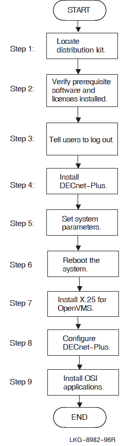
3.1.1. Installing DECnet-Plus on an OpenVMS IA-64 or an OpenVMS Alpha System
Locate the distribution kit. Access the online Release Notes. Verify required hardware.
See Section 1.1, ''Locating the Distribution Kit'' through Section 1.4, ''Required Hardware''.
Verify that all prerequisite software and licenses are installed.
See Section 1.5, ''Prerequisite Software'' and Section 1.6, ''License Requirements''.
Back up the system disk. Shut down all network-related applications and tell users to log out. See Section 1.8, ''Backing Up the System Disk'' and Section 1.9, ''Notifying Users''.
Install DECnet-Plus for OpenVMS.
See Section 3.3, ''Installing DECnet-Plus Using the POLYCENTER Software Installation Utility''.
If necessary, set any required system parameters. See Section 1.7, ''System Requirements''.
Reboot the system.
Configure DECnet-Plus for OpenVMS. See Chapter 4, "Configuration Options" to determine which configuration option to choose: FAST, BASIC, or ADVANCED. For a FAST configuration, see Chapter 5, "Using the FAST Configuration Option". For a BASIC or ADVANCED configuration, see Chapter 6, "Using the BASIC and ADVANCED Configuration Options".
Configure X.25 functionality (formerly VAX P.S.I.). See Chapter 8, "Configuring X.25 for OpenVMS VAX".
Install and configure the optional OSI applications software component (OSAK, FTAM, and VT). See Chapter 12, "Preparing to Install the OSI Applications" and Chapter 13, "Installing the OSI Applications".
3.1.2. Installing DECnet-Plus for a VAX System
Locate the distribution kit. Access the online Release Notes. Verify required hardware.
See Section 1.1, ''Locating the Distribution Kit'' through Section 1.4, ''Required Hardware''.
Verify that all prerequisite software and licenses are installed.
See Section 1.5, ''Prerequisite Software'' and Section 1.6, ''License Requirements''.
Back up the system disk. Shut down all network-related applications and tell users to log out. See Section 1.8, ''Backing Up the System Disk'' and Section 1.9, ''Notifying Users''.
Install DECnet-Plus for OpenVMS.
See Section 3.3, ''Installing DECnet-Plus Using the POLYCENTER Software Installation Utility''.
Note
Note If you want to install X.25 functionality (formerly VAX P.S.I.), select the option now while installing DECnet-Plus for OpenVMS.
If necessary, set any required system parameters. See Section 1.7, ''System Requirements''.
Reboot the system.
Install X.25 for OpenVMS and WANDD, if necessary.
See Chapter 9, "Preparing to Install X.25 for OpenVMS" and Chapter 10, "Installing X.25 for OpenVMS".
Configure DECnet-Plus for OpenVMS. See Chapter 4, "Configuration Options" to determine which configuration option to choose: FAST, BASIC, or ADVANCED.
For a FAST configuration, see Chapter 5, "Using the FAST Configuration Option". For BASIC or ADVANCED configurations, see Chapter 6, "Using the BASIC and ADVANCED Configuration Options".
Configure X.25 for OpenVMS. See the VSI X.25 for OpenVMS Configuration manual.
Install and configure the optional OSI applications software components (OSAK, FTAM, and VT). See Chapter 12, "Preparing to Install the OSI Applications" and Chapter 13, "Installing the OSI Applications".

3.2. PCSI Process Account Quotas
The POLYCENTER Software Installation utility requires that the installation account has, as a minimum, the quotas shown in Table 3.1, ''Process Quotas for the Installing Account''.
| Quota | Value |
|---|---|
| ASTLM | 24 |
| BIOLM | 18 |
| BYTLM | 32768 |
| DIOLM | 18 |
| ENQLM | 200 |
| FILLM | 100 |
Use the OpenVMS Authorize utility to verify and change process quotas for the
installation account in the user authorization file (sysuaf.dat). (Some
sites may restrict the use of the OpenVMS Authorize utility to certain accounts or
people.)
For example, to verify and then change the BYTLM quota for the
account-name installation account, enter the following command
sequence:
| To... | Enter... |
|---|---|
| Invoke the Authorize utility |
$ run sys$system:authorize |
| Show the account quotas |
UAF> show account-name |
| Modify the BYTLM quota |
UAF> modify account-name /BYTLM = 32768 |
| Exit from the Authorize utility |
UAF> exit |
| Log out |
$ logout |
After you verify and change the quotas for the installation account, log out of the installation account and log in again. The new quotas will take effect and you can proceed with the installation.
User account quotas are stored in the sysuaf.dat file. For more
information about modifying account quotas, see the description of the Authorize utility
in the OpenVMS system management documentation subkit.
3.3. Installing DECnet-Plus Using the POLYCENTER Software Installation Utility
This section describes the steps for installing DECnet-Plus software using the POLYCENTER Software Installation utility. You must have SYSPRV privileges on the local or remote node where you want to run this utility.
Note
Kits included on the OpenVMS Version 8.3 distribution media are signed using Secure Delivery.
3.3.1. DECnet-Plus for OpenVMS IA-64 Installation Dialog
Log in to the SYSTEM account.
Mount the Software Products Library media CD–ROM, locate the DECnet- Plus distribution directory, and define the PCSI$SOURCE logical name to reference the directory. See Section 1.1, ''Locating the Distribution Kit'' for information about locating the distribution kit.
- Enter the following command:
$ product install DECNET_PLUS
For a description of all the features you can request when starting an installation (such as purging files and using a product configuration file), refer to DCL help for the
product installcommand.The actual kit location may change with new releases. See Section 1.1, ''Locating the Distribution Kit'' for information about locating the distribution kit.
 ,
,  ,
,
 , …) guide you through the sequence of steps
that require your
response.
, …) guide you through the sequence of steps
that require your
response.Performing product kit validation ...
%PCSI-I-VALPASSED, validation of
DKB200:[KITS]VSI-I64VMS-DECNET_PLUS-V0803--1.PCSI$COMPRESSED;1 succeeded
The following product has been selected:
VSI I64VMS DECNET_PLUS V8.3 Layered Product
Do you want to continue? [YES] return
Configuration phase starting ...
You will be asked to choose options, if any, for each selected product and for
any products that may be installed to satisfy software dependency requirements.
VSI I64VMS DECNET_PLUS V8.3: DECnet-Plus V8.3 for OpenVMS I64
Copyright © 2020 VMS Software, Inc., (VSI). All rights reserved.
VMS Software, Inc.
This product requires one of two PAKs: DVNETEND or DVNETEXT.
Do you want the defaults for all options? [YES] NO return
VSI I64VMS VMS V8.3 [Installed]
* Configuration options for this referenced product cannot
* be changed now because the product is already installed.
* (You can use PRODUCT RECONFIGURE later to change options.)
DECdns Server software [NO] YES
DECdts Server software [NO] YES
Do you want to review the options? [NO] YES return
VSI I64VMS DECNET_PLUS V8.3: DECnet-Plus V8.3 for OpenVMS I64
VSI I64VMS VMS V8.3 [Installed]
DECdns Server software: YES
DECdts Server software: YES
 Are you satisfied with these options? [YES] return
Execution phase starting ...
The following product will be installed to destination:
VSI I64VMS DECNET_PLUS V8.3 DISK$XBAI:[VMS$COMMON.]
Portion done: 0%...10%...20%...30%...40%...50%...60%...80%...90%...100%
The following product has been installed:
VSI I64VMS DECNET_PLUS V8.3 Layered Product
$
Are you satisfied with these options? [YES] return
Execution phase starting ...
The following product will be installed to destination:
VSI I64VMS DECNET_PLUS V8.3 DISK$XBAI:[VMS$COMMON.]
Portion done: 0%...10%...20%...30%...40%...50%...60%...80%...90%...100%
The following product has been installed:
VSI I64VMS DECNET_PLUS V8.3 Layered Product
$
| At this point, you can stop the installation process. If you want to continue, press Return. If you want to stop, type NO, then press Return. |
| This question allows you to select which optional parts of the DECnet- Plus base components product you want to install. If you want to take the installation defaults, press Return. If you want to select each optional DECnet-Plus base component (for example, DECdns Server), type NO and press Return. The procedure then displays a list of choices for you. |
| This question allows you to review and change your current selections. Type YES if you are satisfied with the current selected options. Type NO if you want to make changes. |
| Responding NO to this question causes the procedure to reprompt you to enter values for each of the installation options. If you are satisfied with the options, press Return to accept the default YES response. |
3.3.2. DECnet-Plus for OpenVMS Alpha Installation Dialog
To start the installation, follow these steps:
Log in to the SYSTEM account.
Mount the Software Products Library media CD–ROM, locate the DECnet-Plus distribution directory, and define the PCSI$SOURCE logical name to reference the directory. See Section 1.1, ''Locating the Distribution Kit'' for information about locating the distribution kit.
Enter the following command:
$ product install DECnet_OSI
For a description of all the features you can request when starting an installation (such as purging files and using a product configuration file), refer to DCL help for the product install command.
The actual kit location may change with new releases. See Section 1.1, ''Locating the Distribution Kit'' for information about locating the distribution kit.
You are then prompted for installation information as in the following example. In
this example, numbered callouts (, , , ...) guide you
through the sequence of steps that require your response.
Performing product kit validation ... %PCSI-I-VALPASSED, validation of DKB500:[KITS]DEC-AXPVMS-DECNET_OSI-V0803--1.PCSI$COMPRESSED;1 succeeded The following product has been selected: DEC AXPVMS DECNET_OSI V8.3 Layered Product
| At this point, you can stop the installation process. If you want to continue, press Return. If you want to stop, type NO, then press Return. |
| This question allows you to select which optional parts of the DECnet-Plus base components product you want to install. If you want to take the installation defaults, press Return. If you want to select each optional DECnet-Plus base component (for example, DECdns Server), type NO and press Return. The procedure then displays a list of choices for you. |
| This question allows you to review and change your current selections. Type YES if you are satisfied with the current selected options. Type NO if you want to make changes. |
3.3.3. Sample DECnet-Plus for OpenVMS VAX Installation
Log in to the SYSTEM account.
Mount the Software Products Library media CD–ROM, locate the DECnet- Plus distribution directory, and define the PCSI$SOURCE logical name to reference the directory. See Section 1.1, ''Locating the Distribution Kit'' for information about locating the distribution kit.
- Enter the following command:
$ product install DECnet_OSI
For a description of all the features you can request when starting an installation (such as purging files and using a product configuration file), refer to DCL help for the
product installcommand.The actual kit location may change with new releases. See Section 1.1, ''Locating the Distribution Kit'' for information about locating the distribution kit.
, ,
, …) guide you through the sequence of steps
that require your
response.The following product has been selected: DEC VAXVMS DECnet_OSI V7.3 Layered Product
| At this point, you can stop the installation process. If you want to continue, press Return. If you want to stop, type NO, then press Return. |
| This question allows you to select which optional parts of the DECnet- Plus base components product you want to install. If you want to take the installation defaults, press Return. If you want to select each optional DECnet-Plus base component (for example, VAX P.S.I.), type NO and press Return. The procedure then displays a list of choices for you. |
| This question allows you to review and change your current selections. Type YES if you are satisfied with the current selected options. Type NO if you want to make changes. |
3.4. Rights Identifiers Added to the System
During the final phase of the installation process, several rights identifiers are created in the rights identifiers database. If you are installing from the system console and have the Audit Server properly enabled, it alerts you as these rights are added. In addition, the NET$MANAGE rights identifier is granted to the SYSTEM account.
Table 3.2, ''Rights Identifiers'' lists the rights identifiers added during the installation. See the VSI DECnet-Plus for OpenVMS Network Management Guide for more information about these rights identifiers.
| Rights Identifier | Description |
|---|---|
NET$DECLAREOBJECT | Declares an application |
NET$DECNETACCESS | Gives $IPC users access to the network in the absence of the NETMBX privilege |
NET$DIAGNOSE | Permits use of network diagnostics |
NET$EXAMINE | Permits display of the attributes of an entity |
NET$MANAGE | Permits display, creation, or modification of an entity |
NET$POSTEVENT | Permits posting of events |
NET$REGISTERDNSOBJECT | Permits registration or deregistration of a DECdns object |
NET$SECURITY |
Permits setting a user name for |
NET$TRACEALL | Permits tracing of entire messages on a local node |
NET$TRACEALLREMOTE | Permits tracing of entire messages on a remote node |
NET$TRACEHEADERS | Permits tracing of message headers on a local node |
NET$TRACEHEADERSREMOTE | Permits tracing of message headers on a remote node |
3.5. Files Installed on the System
The DECnet-Plus installation procedure installs a number of files on your system. To list the files, enter one of the following commands (see also Appendix A, "System Files Loaded During Installation"):
$ product show object /product=decnet_plus
3.6. Rebooting the System
After completing the installation of the DECnet-Plus for OpenVMS software, you must reboot your system before beginning the configuration process. Because the system has not been configured yet, you may see the following messages during system startup:
   Copyright © 2020 VMS Software, Inc., (VSI). All rights reserved.
%NET$STARTUP-W-NONETCONFIG, this node has not been configured to run
   DECnet-Plus for OpenVMS
          use SYS$MANAGER:NET$CONFIGURE.COM if you wish to configure DECnet
%NET$STARTUP-I-OPERSTATUS, DECnet-Plus for OpenVMS operational status is OFF
Proceed to Chapter 4, "Configuration Options" for information about selecting the configuration option appropriate for your system.
Chapter 4. Configuration Options
This chapter explains the three configuration options you can use to configure your system for the VSI DECnet-Plus for OpenVMS software. These configuration options enable you to configure the DECnet-Plus for OpenVMS base components so that the system becomes a DECnet-Plus node on a network.
sys$manager:net$configure.com. You can use any of the following
net$configure configuration options:FAST configuration option (see Chapter 5, "Using the FAST Configuration Option")
The FAST configuration allows you to quickly upgrade a non-clustered system from DECnet Phase IV to DECnet Phase V.
BASIC configuration option (see Chapter 6, "Using the BASIC and ADVANCED Configuration Options")
The BASIC option configuration allows you to configure your system for DECnet-Plus by answering a few questions and using the default answers on others.
ADVANCED configuration option (see Chapter 6, "Using the BASIC and ADVANCED Configuration Options")
The ADVANCED configuration option allows you to customize your system’s network configuration.
Selecting a configuration option
Running
net$configure
See Section 1.7.4, ''Required Privileges and Rights Identifiers'' for a list of account privileges you need to run
net$configure.
4.1. Choosing an Initial Configuration Option
If you installed the required software, you can configure your system using the
net$configure configuration option for the FAST configuration, using
the net$configure basic configuration option for the BASIC configuration,
or using the net$configure advanced configuration option for the ADVANCED
configuration.
Table 4.1, ''Choosing Your Configuration Option'' provides some guidelines for making your configuration choice.
| Option... | Choose if... |
|---|---|
| FAST | You are upgrading from a DECnet Phase IV node and you plan to use the existing Phase IV configuration. The node is not in an OpenVMS cluster. You are running the configuration procedure for the first time. |
| BASIC |
The node is in an OpenVMS cluster. You are upgrading to DECnet-Plus. You need to access a DECdns server for network addresses. You have only one communications device, or you have multiple devices, all of which will be used for DECnet-Plus communications. You want to use the default names for all devices and routing circuits. You want to autoconfigure your network addresses only. You want to configure both the NSP and OSI transports and only want to create default OSI templates. You want to enable DECnet over TCP/IP (RFC 1859) or OSI applications over TCP/IP (RFC 1006). You do not want to enable FDDI large packet support (if you have an FDDI-type circuit). You want to set the routing characteristic DNA Address Format to TRUE (to control the interpretation of address structuring). You want to use integrated mode routing. |
| ADVANCED | Your configuration is complex. You need to customize your network's configuration. Your system has multiple communication devices, and you want them to run a mix of protocols. You want to configure a cluster with both DECnet Phase IV and DECnet Phase V nodes. You want the option to give specific names to all devices and routing circuits. You also want the option of not configuring all of your devices for DECnet-Plus. You want the option of manually entering your network addresses. You want to configure either the NSP transport or the OSI transport (or both). You want the option to create additional OSI templates. You want the option of enabling/disabling DECnet over TCP/IP or OSI applications over TCP/IP. You want the option of enabling FDDI large packet support (if you have an FDDI-type circuit). You want the option of setting the routing characteristic DNA Address Format to TRUE or FALSE (to control the interpretation of address structuring). You want the option of using either integrated mode routing or segregated mode routing. You want the option to provide default accounts for FAL. |
4.2. How to Run NET$CONFIGURE
The net$configure.com procedure configures the DECnet-Plus software. This
command creates or modifies the Network Control Language (NCL) startup scripts required
to run DECnet-Plus on your node.
net$configure.com procedure is an interactive procedure that displays
a series of questions. After each question, the default response, if there is one,
appears in brackets ([ ]). At the end of each question, a colon (:) appears. Respond in
one of the following ways: To get help after a question, type a question mark (?). After the help display, the same question reappears.
To select the default response, press Return.
To enter information, type it immediately after the colon or question mark; then press Return.
Type Y for YES and N for NO.
To terminate the procedure, press Ctrl/Z.
To invoke net$configure with the BASIC option, enter the following:
$ @sys$manager:net$configure basic
To invoke net$configure with the ADVANCED option, enter the following:
$ @sys$manager:net$configure advanced
If you execute net$configure without specifying basic or advanced, the
BASIC configuration option is invoked by default.
Note
If you are running the configuration procedure for the first time on a system that
was previously configured for Phase IV and you do not specify basic or
advanced, the initial default is the FAST configuration
option.
However, the FAST configuration option can only be run once on a system, and after that the BASIC configuration option automatically becomes the default.
4.2.1. Local and Global Symbols
The net$configure procedure deletes all of your local and global
symbols at the beginning of the procedure in order to free the symbol table. This
action is required because net$configure creates and uses a large
number of symbols. If the symbols were not deleted at the beginning of the
procedure, net$configure could run out of symbol table space to use
while configuring the system. In most cases, the configuration procedure restores
your symbols as it exits.
4.2.2. Running the Procedure from Different Processes
Although net$configure can be run simultaneously on different nodes
in a cluster, it should not be run simultaneously from different processes on the
same node.
Chapter 5. Using the FAST Configuration Option
Note
If you have already run the FAST configuration procedure once on your system, the configuration procedure automatically defaults to the BASIC configuration option.
5.1. Invoking the FAST Configuration Option
net$configure procedure using the FAST configuration option, enter
the following
command:$ @sys$manager:net$configure
Copyright © 2020 VMS Software, Inc., (VSI). All rights reserved.
        DECnet-Plus for OpenVMS network configuration procedure
    This procedure will help you create or modify the management scripts needed to operate DECnet on this machine. You may receive help about most questions by answering with a question mark '?'.
%NET$CONFIGURE-I-SETUPNEW, setting up for new configuration
%NET$CONFIGURE-I-PHASEIVDATA, Phase IV DECnet database found
                   FAST CONFIGURATION OPTION
     *** Not supported on cluster nodes.
     You have the option of using the existing Phase IV information to quickly configure DECnet-Plus. This provides full network access and uses a local file to hold naming information. Very few questions will be asked.
     If you want to use the fast configuration option, answer YES to the next question.
     If you are running a DNS Server on this system, or plan to run a DNS Server on this system, you *must* answer NO to the next question.
     If you want more flexibility when configuring DECnet-Plus, also answer NO.
     Answering NO will cause some additional questions to be asked regarding configuration.
* Do you want the fast default configuration?          [YES] :
Press Return to continue with the FAST configuration option.
%NET$CONFIGURE-I-PHASEIVCOMPL, Phase IV database conversion complete

Determining DTSS timezone rules from OpenVMS information...

%NET$CONFIGURE-I-CREDEFOSITEMPLATE, created default OSI templates
%NET$CONFIGURE-I-EVDDEFAULT, providing default Event Dispatcher configuration
%NET$CONFIGURE-I-MAKEACCOUNT, this procedure creates user account CML$SERVER
%NET$CONFIGURE-I-MAKEACCOUNT, this procedure creates user account VPM$SERVER
%NET$CONFIGURE-I-MAKEACCOUNT, this procedure creates user account MIRRO$SERVER
The procedure continues by displaying the current system configuration and asking if you want to apply the configuration:
       Summary of Configuration
Node Information:
       Directory Services Chosen: LOCAL
       Primary Directory Service: LOCAL
       Node Synonym:              ASHFLD
       Phase IV Address:          4.260
       Phase IV Prefix:           49::
       Session Control Address Update Interval: 10
       Routing Node Type:         ENDNODE
       Autoconfiguration of Network Addresses: Enabled
       Routing ESHello Timer:     600
       Routing ES Cache Size:     512
Device Information:
       Device: EWA (TULIP):
              Data Link name: EWA-0
              Routing Circuit Name: EWA-0
Transport Information:
       NSP Transport:                     Configured
          Maximum number of logical links:     200
          Maximum Transmit and Receive Window: 20
          Maximum Receive Buffers:             4000
          Flow Control Policy:                 Segment Flow Control
       Congestion Avoidance Disabled
Event Dispatcher Configuration:
       Sinks:             local_sink
       Outbound Streams:  local_stream
       Phase IV Relay:    Enabled
* Do you want to apply this configuration? [YES] : Return
Answer YES to apply this configuration. If you answer NO, the procedure defaults to the BASIC configuration option.
%NET$CONFIGURE-I-CHECKSUM, checksumming NCL management scripts
The procedure then asks if you want to start the network:
* Do you want to start the network? [YES] : Return
Answer YES if you want to start the network and complete your system’s network configuration.
********************************************************************
You have decided not to start the network. NET$CONFIGURE.COM
cannot complete your system’s network configuration since it needs
the network to be partially started in order to perform certain
operations. As a result, your system may be left in an inconsistent
state if you try to startup the network manually or if you decide
to reboot your system.
Once you are ready to start the network, please invoke the
NET$CONFIGURE.COM procedure, choose menu Option 2 (Change node
name/namespace name), and respond YES to starting the network so
that the configuration procedure can finish your system’s network
configuration.
********************************************************************
VSI recommends that you answer YES and start the network.
net$startup messages are shown and that OPCOM
messages have been
omitted):Copyright © 2020 VMS Software, Inc., (VSI). All rights reserved. %NET-I-LOADED, executive image LES$LES_V30.EXE loaded %NET-I-LOADED, executive image NET$ALIAS.EXE loaded %NET-I-LOADED, executive image NET$SESSION_CONTROL.EXE loaded . . . %NET$STARTUP-I-EXECUTESCRIPT, executing NCL script SYS$SYSROOT:[SYSMGR]NET$NODE_STARTUP.NCL %NET$STARTUP-I-EXECUTESCRIPT, executing NCL script SYS$SYSROOT:[SYSMGR]NET$CSMACD_STARTUP.NCL . . . %NET$STARTUP-I-OPERSTATUS, DECnet-Plus for OpenVMS operational status is RUNNING-MAJOR Directory Service: Phase IV database Exporting node name information using: * ASHFLD Number of nodes exported: 1 Directory Service: Local name file Updating nodes listed in SYS$MANAGER:NET$PHASEIV_NODES.DAT ASHFLD Number of nodes registered: 1 Number of nodes modified: 0 %NET$CONFIGURE-I-CONVERTNODEDB, converted the Phase IV node database %NET$CONFIGURE-I-NODERENAMED, node successfully renamed to LOCAL:.ASHFLD %NET$CONFIGURE-I-FLUSHCACHE, flushing selected cache entries Copyright © 2020 VMS Software, Inc., (VSI). All rights reserved. %NET$STARTUP-I-STARTPROCESS, starting process EVD %NET$STARTUP-I-EXECUTESCRIPT, executing NCL script SYS$SYSROOT:[SYSMGR]NET$EVENT_STARTUP.NCL . . . %NET$STARTUP-I-OPERSTATUS, DECnet-Plus for OpenVMS operational status is RUNNING-ALL %NET$CONFIGURE-I-CONFIGCOMPLETED, DECnet-Plus for OpenVMS configuration completed $
You have just completed the initial configuration of DECnet-Plus. It should now be operational as an end node on the network.
See Figure 3.1, ''Installation and Configuration Flowchart (Alpha Only)'' and Figure 3.2, ''Installation and Configuration Flowchart (VAX Only) '' to determine your next step. According to the flowcharts, you have just completed configuring DECnet-Plus.
5.2. Modifying a Current DECnet-Plus System Configuration
You can use the net$configure procedure to modify the current
configuration. Depending on which menu option you select, net$configure
either modifies the configuration automatically or produces modified NCL startup scripts
that you can use to modify the system’s configuration.
See Chapter 7, "Modifying a Current Configuration" for information about running the net$configure BASIC or ADVANCED options to modify your DECnet-Plus configuration.
Chapter 6. Using the BASIC and ADVANCED Configuration Options
This chapter describes the BASIC and ADVANCED options of the
net$configure.com procedure. Most sections begin with a general explanation
of the configuration dialog discussed in the section. When the configuration dialog is
common to both options, no special presentation is used.
BASIC
If a portion of the configuration dialog description is unique to the BASIC option, the description is preceded by a BASIC subheading as shown here.
ADVANCED
If a portion of the configuration dialog description is unique to the ADVANCED option, the description is preceded by an ADVANCED subheading as shown here.
BASIC and ADVANCED
In certain rare cases, the BASIC and ADVANCED subheading is used to denote that the description is common to both options.
6.1. Invoking the Configuration Procedure
Begin by invoking the configuration procedure.
BASIC
To invoke the net$configure procedure using the BASIC configuration option, enter the following command:
$ @sys$manager:net$configure basic
ADVANCED
To invoke the net$configure procedure using the ADVANCED configuration
option, enter the following command:
$ @sys$manager:net$configure advanced
6.2. Opening Messages
The procedure prints an opening message dependent on the configuration option you choose.
BASIC
   Copyright © 2020 VMS Software, Inc., (VSI). All rights reserved.

   DECnet-Plus for OpenVMS BASIC network configuration procedure

This procedure will help you create or modify the management scripts needed to operate DECnet on this machine. You may receive help about most questions by answering with a question mark ’?’.
You have chosen the BASIC configuration option. This option enables you to quickly configure your system by answering a few questions and using most of the default answers. If you would rather do some specific tailoring of your system’s network configuration, you should invoke NET$CONFIGURE.COM with the ADVANCED configuration option, ie:
      @SYS$MANAGER:NET$CONFIGURE ADVANCED
ADVANCED
   Copyright © 2020 VMS Software, Inc., (VSI). All rights reserved.

   DECnet-Plus for OpenVMS ADVANCED network configuration procedure

This procedure will help you create or modify the management scripts needed to operate DECnet on this machine. You may receive help about most questions by answering with a question mark ’?’.
You have chosen the ADVANCED configuration option. This option enables you to do some specific tailoring of your system’s network configuration by answering some specific questions. If you do not want to do specific tailoring of your system’s network configuration but instead want to quickly configure your system using most of the default answers, you should invoke NET$CONFIGURE.COM with the BASIC configuration option, ie:
      @SYS$MANAGER:NET$CONFIGURE BASIC
BASIC and ADVANCED
If the procedure detects that the DECnet-Plus software has not been properly installed, it displays the following warning:
The base DECnet system components are not yet properly loaded.
DECnet cannot be started until the DECnet software has been successfully installed and the system has been rebooted.

NET$CONFIGURE may fail if you answer YES to the next question. That is because it may be necessary to start the network to establish certain configurations. Hewlett-Packard recommends that you reboot before attempting to configure the network.
Next, the procedure asks if you want to proceed with the configuration.
* Do you want to continue? [YES] :
Press Return to continue with the configuration.
The procedure now checks for the privileges and rights identifiers required to run the
net$configure procedure. For a list of required privileges and rights
identifiers, see Section 1.7.4, ''Required Privileges and Rights Identifiers''.
If the procedure finds insufficient process privileges, it displays the following messages and exits:
%NET$CONFIGURE-E-NOREQPRIV, privilege-list privileges are required
%NET$CONFIGURE-E-NOPRIV, insufficient privileges to run this procedure.
If the procedure finds insufficient rights identifiers, it displays the following messages and exits:
NET$CONFIGURE-E-NOREQRIGHTSID, rights id rights-identifier not granted
%NET$CONFIGURE-E-NORIGHTSID, insufficient rights identifiers to run this procedure
If you have the required privileges and rights identifiers and if this is the first time that you have run the configuration procedure, the procedure informs you that you are configuring your DECnet-Plus system for the first time:
%NET$CONFIGURE-I-SETUPNEW, setting up for new configuration
   Now you will be asked a few questions. If you need more information to answer a question, you can type ? at the prompts, or consult the DECnet-Plus for OpenVMS Installation and Configuration guide. To configure DECnet, you need to know your node’s full name and network address(es). Please review the Installation and Configuration guide, and the checklists in particular, before continuing.
6.3. Specifying Phase IV Conversion Options
If a Phase IV database exists on the system, the procedure displays the following a message and asks if you want to convert the database:
%NET$CONFIGURE-I-PHASEIVDATA, Phase IV DECnet database found
   A Phase IV database exists on your system. You have the option of using the existing Phase IV database to generate the NCL scripts and configure the system. If you do not want to use the existing Phase IV database to generate the NCL scripts and configure the system, then net$configure will configure the system based on your answers to the configuration questions.
* Do you want to convert Phase IV databases? [YES] :
If you answer NO, the net$configure procedure does not use the system’s
existing Phase IV database to generate the NCL startup scripts and proceeds to ask all
the configuration questions. Proceed to Section 6.4, ''Configuring Node and Session Control Information''.
If you answer YES, the net$configure procedure uses the system’s existing
Phase IV database to generate the NCL startup scripts and configure the system. The
procedure asks the following question to determine the Phase IV prefix to use during the
conversion:
* Enter Phase IV Prefix [49::] :
Usually, when a Phase IV database is found, a Phase IV local node name database is also found. The procedure continues by asking if you want to convert the Phase IV local node name database:
   You may convert your Phase IV node database to a local node name database. This will provide node name translation if you opt to use LOCAL in the list of directory services to be used on this system. This is unnecessary if you do not intend to include LOCAL in your directory service search list.
* Do you want to convert the Phase IV node name database? [YES] :
Answer YES if you want the configuration procedure to use the entries in the existing Phase IV node name database to generate a Phase V Local namespace database. (See Section 6.4.1, ''Specifying Directory Name Services'' for information about directory services and the Local namespace.) Answer NO if you do not want to convert the database.
The procedure converts the Phase IV databases immediately. However, the conversion of the Phase IV node name database is delayed until the namespace modification section (see Section 6.16, ''Namespace Modification''). The procedure indicates that it has successfully converted the Phase IV databases with the following message:
%NET$CONFIGURE-I-PHASEIVCMPL, Phase IV database conversion complete
Note
The conversion process enables all FDDI and CSMA-CD stations found in the Phase IV configuration, regardless of their previous line states.
6.4. Configuring Node and Session Control Information
The process for configuring node and session control information consists of the following items:
Directory name services
Node full names
Node synonym
Naming cache timeout interval
Session control address update interval
Naming cache checkpoint interval
If you have installed the DECdns Server option during the DECnet-Plus installation process, the procedure begins by informing you that the DECdns server startup file is being renamed and that you must configure the node as a DECdns clerk before you can configure the node as a DECdns server:
A SYS$STARTUP:DNS$SERVER_STARTUP.COM file has been located.
This file is being renamed because the node must be configured as a DNS clerk before it can be re-configured as a DNS server.

After the node has been configured as a DNS clerk, you may choose to re-run NET$CONFIGURE Option 2 to rename the node into a DNS server.
Once you have configured the node as a DECdns clerk, see Section 7.6.5, ''Converting a DECdns Clerk System to a DECdns Server System'' for an example of converting the node from a DECdns clerk to a DECdns server.
6.4.1. Specifying Directory Name Services
DECnet-Plus provides access to the node name and addressing information stored in one or more name services. DECnet-Plus supports the following directory name services:
Local namespace — A discrete, nondistributed namespace that stores name and address information locally in database files.
DECdns — The VSI DECnet-Plus Distributed Name Service, a distributed, global name service.
Domain Name System — The Domain Name System (DNS/BIND), a global name service for the storage of IP addresses.
The sections that follow give a short introduction to each of the name services. For more information on name services, refer to the VSI DECnet-Plus Planning Guide.
6.4.1.1. The Local Namespace
DECnet-Plus includes a Local namespace, independent of DECdns, that is designed to scale to at least 100,000 nodes. The actual number of nodes that the Local namespace can hold depends on the space available on your system.
The Local namespace is a discrete, nondistributed namespace that exists on a
single node and provides that node with a local database of name and address
information. The prefix LOCAL: (or local:) is reserved
to indicate that the information for the node is stored in the Local
namespace.
DECnet-Plus recognizes that when a node full name begins with
LOCAL:, information for that node is stored in a Local
namespace. The following are typical node full names properly formatted for the
Local namespace: LOCAL:.ma.ashfld and
local:.ashfld.
Unlike DECdns, the Local namespace does not employ backtranslation directories for address-to-node-name translation.
6.4.1.2. The VSI DECnet-Plus Distributed Name Service (DECdns)
DECdns is a networkwide service that makes it possible to use network
resources without knowing their physical location. Users and applications can
assign DECnet-Plus names to resources such as nodes. The creator of a name also
supplies other relevant information, such as the resource’s network address, for
DECdns to store. Users then need to remember only the name, and DECdns acts as a
lookup service, providing the rest of the data when necessary. The following are
typical node full names properly formatted for the DECdns namespace:
XYZ_CORP:.usa.ma.ashfld and
CMP:.accounting.recv.paul.
6.4.1.3. The Domain Name System
The Domain Name System (DNS/BIND) is supported for storage of IP addresses. Refer to your BIND server documentation for specific installation and configuration instructions. For a list of supported vendors, see the DECnet-Plus for OpenVMS Software Product Description (SPD). Any properly constructed DNS/BIND node name is supported by DECnet-Plus.
DECnet-Plus recognizes that when a node full name begins with DOMAIN:,
information for that node is stored in a DNS/BIND server. In most cases, the
configuration procedure also accepts fully-qualified host names for the node’s
full name. The following are typical node full names properly formatted for the
DOMAIN namespace: DOMAIN:ashfld.ma.com. and
ashfld.ma.com.
6.4.1.4. The Name Service Search Path
The name service search path applies systemwide and allows DECnet-Plus to search a list of name services in a predetermined order when looking up names or addressing information. The search path includes naming templates that tell DECnet-Plus how to interpret any abbreviated node names entered by users.
The ordering of the name services is very important. The first name service listed is the primary name service to use on the system. The primary name service is the first choice used when looking up names and addressing information. The remaining name services listed are the secondary name services used on the system.
The search path contains a list of name service keywords, each followed by a naming template that specifies a defaulting rule so users can enter shorter node names.
To create the node’s name service search path, begin by entering an ordered list of the directory name services you want to use on the system. At the prompt, you can choose the following name services for the system: LOCAL, DECDNS, and DOMAIN. If you enter more than one name service, separate the name services with commas.
* Enter the directory services to use on the system [DECdns,Local,Domain] :
For example, entering DECDNS,LOCAL,DOMAIN at the prompt, means the following:
You want to use the name services DECdns, Local, and DNS/BIND.
The primary name service is DECdns.
The secondary name services are Local and DNS/BIND, in that order.
Note
If you intend to make this node a DECdns server, you must first configure
the node with only the Local name service or as a clerk in an existing
DECdns namespace. After completing the initial configuration, reinvoke the
net$configure procedure and select Option 2 — Change Naming
Information. At this point, net$configure will give you the
option of converting the node to a DECdns server.
All members in a cluster should have identical name service search paths configured. This helps to ensure that nodes are recognized in the various services you have identified. For example, if you receive mail on one node in the cluster, the "From" node name may be LOCAL:.NODE::SMITH. If you attempt to reply to this node from a node in the cluster that does not have the Local namespace configured, the system would indicate that there is no such node.
6.4.2. Specifying Node Full Names
After requesting the ordered list of directory name services, the configuration procedure prompts you for one or more node full names. You can enter a DECdns full name, a Local namespace full name, a fully qualified host name for the Domain Name System (DNS/BIND), or all three.
Use the following guidelines for selecting a node full name:
For DECdns and Local, the node full name has the format
NamespaceNickname:[.DirectoryPath].NodeObject. Note that the name must begin with the namespace nickname and a colon (:). The nickname for the Local namespace is always LOCAL: (or local:). The namespace nickname LOCAL is reserved for the Local namespace and cannot be used for a DECdns namespace. The namespace nickname and the node object cannot be null strings.For DECdns and Local, the directory path must begin with a dot (.).
The full name can be up to 512 characters long, the namespace nickname can be up to 255 characters, and the directory path and node object can be up to 255 characters. The full name can be any combination of letters, digits, and certain punctuation characters from the ISO Latin-1 character set. Some other characters are allowed as long as they are enclosed in quotation marks. For a list of all allowable characters, refer to the VSI DECnet-Plus for OpenVMS DECdns Management Guide.
For DNS/BIND, enter a fully qualified IP host name.
The following are some examples of suitable node full names:
Local namespace - LOCAL:.TomThumb
DECdns          - ACME:.wabbit.Elmer
Domain          - elmer.wabbit.acme.edu
Note
If you plan to use a Local namespace and you are converting a Phase IV system
to DECnet-Plus, VSI recommends that you use the system’s Phase IV node name in
the DECnet-Plus full name (for example, LOCAL:.PASTRY).
You should plan node full names carefully and make sure they are unique within the namespace. If your network administrator has not assigned a unique node full name for your system, be sure to read the VSI DECnet-Plus Planning Guide before you assign a node name for your system.
The prompts used by the configuration procedure depend on the directory name services you entered. For example, if you enter LOCAL,DECDNS,DOMAIN at the directory services prompt, the configuration dialog asks for a Local full name, a DECdns full name, and a fully qualified host name for DNS/BIND.
* Enter the full name for directory service LOCAL : LOCAL:.ELMER
* Enter the full name for directory service DECDNS : ACME:.WABBIT.ELMER
* Enter the fully qualified host name for DNS/BIND : ELMER.WABBIT.ACME.EDU
6.4.3. Specifying the Node Synonym
The node synonym is an alphanumeric character string between one and six characters long. The first character must be an alphabetic character; after the first character, the string can contain either alphabetic or numeric characters.
The node synonym is primarily a transition tool that allows you to use a Phase IV-style node name for your DECnet-Plus node. Other users can then find your node by using this synonym rather than your full name. If you are transitioning from DECnet Phase IV, consider using your Phase IV node name as your synonym. The synonym is required for Phase IV applications that can only handle Phase IV-style node names. If your network has only DECnet-Plus or OSI (Open Systems Interconnection) systems, you may not need a node synonym.
The default node synonym is the first six characters of the system’s last simple
name. The last simple name is the string that follows the last period of your full
name. For example, if you specify
XYZ_CORP:.sales.east_coast.BrianMacKrill as a node full name, the
default node synonym is BrianM.
If this system had previously been running DECnet Phase IV software, then you should use the old Phase IV node name as the synonym. If this system is joining a DECnet network for the first time, you can use any name for the synonym, as long as it meets the criteria listed above, and is unique within the network.
* What is the synonym name for this node? [ELMER] :
For information on node synonym directories, see Section B.2, ''Node Synonym Directories''.
6.4.4. Specifying the Naming Cache Timeout Value
A naming cache is used to improve the performance of node name to address resolution. This naming cache supersedes the DECdns cache in older DECnet-Plus versions and is used when looking for addresses in the Domain and Local services, in addition to DECdns. Note that other applications that directly use DECdns will continue to use the DECdns cache instead of the naming cache.
The naming cache includes a mechanism to time out old entries. In this way, these entries are refreshed periodically to reflect the actual network environment.
BASIC
The BASIC option sets the naming cache timeout value to the default value of 30 days (30-00:00:00).
ADVANCED
The ADVANCED option prompts for the naming cache value:
* Naming cache timeout value? [30-00:00:00] :
To choose the default value of 30 days, press Return. Otherwise, enter any legal OpenVMS delta time value.
6.4.5. Specifying the Session Control Address Update Interval
The session control address update interval is the time, in seconds, between updates of local tower address information.
BASIC
The BASIC option sets the session control address update interval to the default value of 10 seconds.
ADVANCED
The ADVANCED option prompts for the session control address update interval:
* Session Control Address Update Interval ? [10] :
To choose the default value of ten seconds, press Return. Otherwise, enter an interval value in seconds and press Return.
6.4.6. Specifying the Naming Cache Checkpoint Interval
Periodically, DECnet-Plus saves a snapshot of the in-memory naming cache to disk. This allows systems, during startup, to have a naming cache that is already populated with entries, thereby preserving the contents of the naming cache across system reboots.
BASIC
The BASIC option sets the naming cache checkpoint interval to the default value of 8 hours.
ADVANCED
The ADVANCED option prompts for the naming cache checkpoint interval:
* Naming cache checkpoint interval? [08:00:00] :
To choose the default value of eight hours, press Return. Otherwise, enter any legal OpenVMS delta time value.
6.5. Configuring Routing Parameters
The process for configuring routing parameters consists of the following items:
Node type (end node or router)
Router information
Router type
Maximum path splits
Phase IV maximum address
Phase IV maximum area
Phase IV address
Phase IV prefix
End node information
Network addresses
DNA address format
Routing mode
Default ES Hello Timer
ES Cache Size
6.5.1. Specifying the Node Type
DECnet-Plus for OpenVMS allows an OpenVMS system to run integrated IS-IS, thus providing host-based routing functionality. Answer ROUTER if you want this system to support the host-based routing functionality. If you answer ROUTER, you must have the extended function license (see Section 1.6, ''License Requirements'') for the host-based routing software to function. Answer ENDNODE if this system will depend on other nodes to provide routing.
* What type of node (Endnode or Router)? [ENDNODE] :
To configure an end node system, press Return. Otherwise, enter the node type.
6.5.2. Specifying Router Information
This section only applies if you chose to configure your system as a router.
6.5.2.1. Routing Type
A DECnet-Plus router can provide intra-area routing capability (known as level 1 routing) or inter-area level routing capability (known as level 2 routing).
* Type of routing node (L1 or L2)? [L1] :
To configure a level 1 router, press Return. Otherwise, enter L2 for level 2 routing capability.
Note
Immediately preceding this question, the procedure displays an
informational message explaining that net$configure always
generates a router that uses the routing vector protocol:
NET$CONFIGURE will assume that the MANUAL L1 ALGORITHM and
the MANUAL L2 ALGORITHM (if present) will be ROUTING VECTOR.

If LINK STATE is to be designated as the preferred routing
algorithm at either level, the DCL command file
SYS$MANAGER:ISIS$CONFIGURE.COM must be invoked AFTER this
procedure to correctly configure the NET$ROUTING_STARTUP.NCL.
For information about using the isis$configure procedure to
configure a router that uses the link state routing protocol, see Appendix D, "Configuring Link State Routing Nodes Using the isis$configure
Procedure".
6.5.2.2. Maximum Path Splits
A routing node may use multiple paths of equal cost to route traffic. The answer to this question specifies the maximum number of these paths between which the traffic is split.
BASIC
The BASIC option sets maximum path splits to the default value of 2.
ADVANCED
The ADVANCED option prompts for the maximum path splits value:
* Maximum path splits [2] :
To choose the default value of 2, press Return. Otherwise, enter a number between 1 and 32.
6.5.2.3. Phase IV Maximum Address and Maximum Area
The next two questions control which Phase IV packets are forwarded by a router. The Phase IV maximum address characteristic prohibits Phase IV packet forwarding to any node with a higher address than the specified value. The Phase IV maximum area characteristic prohibits Phase IV packet forwarding to any area with a higher area number than the specified value. The Phase IV maximum area question is asked only for level 2 routers. VSI recommends that both defaults be taken to prevent any unintended packet loss.
BASIC
The BASIC option sets the Phase IV maximum address to the default value of 1023. If the system is a level 2 router, the BASIC option sets Phase IV maximum area to the default value of 63.
ADVANCED
The ADVANCED option prompts for the Phase IV maximum address value:
* PhaseIV Maximum Address [1023] :
To choose the default value of 1023, press Return. Otherwise, enter a number between 1 and 1023.
If the router is a level 2 router, the ADVANCED option also prompts for the Phase IV maximum area value:
* PhaseIV Maximum Area [63] :
To choose the default value of 63, press Return. Otherwise, enter a number between 1 and 63.
6.5.3. Specifying a DECnet Phase IV Address
If you want your system to communicate with Phase IV nodes, you must specify a Phase IV address and a Phase IV prefix. DECnet-Plus systems reference all network addresses (including Phase IV addresses) using the OSI Network Service Access Point (NSAP) address formats. The Phase IV address and a Phase IV prefix are used to construct a complete NSAP address.
A DECnet Phase IV-compatible address is a DECnet-Plus address, in the form
area-number.node-number, that conforms to the Phase IV area and
node limits; that is, the area number is from 1 to 63, and the node number is from 1
to 1023.
If there are no Phase IV systems on your network or you do not want to communicate with Phase IV systems, you do not need a Phase IV-compatible address. Entering a Phase IV address of 0.0 at configuration time indicates that this DECnet-Plus system does not have a Phase IV-compatible address, and will not communicate with Phase IV nodes.
* Enter PhaseIV Address [15.27] :
Enter the Phase IV address you want to use, or enter 0.0 if you do not want to communicate with Phase IV nodes.
6.5.4. Specifying a Phase IV Prefix
Note
If you are using a Phase IV prefix other than 49::, it must be assigned by an authorized standards organization, such as ANSI, or you must construct a Phase IV prefix that you know is globally unique (based on your telephone number, for instance). If your organization has allocated its own Phase IV prefix, you can enter that value instead of 49::. The VSI DECnet-Plus Planning Guide contains a detailed description of how to construct an IDP and how to apply to a standards organization for an IDP.
BASIC
The BASIC option sets the Phase IV prefix to its default value of 49::. If you do not enter a Phase IV-compatible address, the BASIC option does not assign a Phase IV prefix value.
ADVANCED
If you entered a Phase IV-compatible address, the ADVANCED option prompts for the Phase IV prefix value:
* Enter Phase IV Prefix [49::] :
To choose the default value of 49::, press Return. Otherwise, enter a valid IDP value.
6.5.5. Specifying End Node Information
This section applies only if you chose to configure your system as an end node.
6.5.5.1. Network Addresses
Your system must have at least one unique network address in order to use DECnet-Plus communications features. DECnet-Plus systems can be multihomed; that is, they can have more than one network address. You can assign up to three network addresses to your system.
Having multiple addresses allows you to have both a DECnet-Plus extended address and a Phase IV-compatible address, so you can communicate with both Phase IV and DECnet-Plus systems on the same network. It also allows you to belong to more than one OSI network. This feature is particularly useful when you want to combine two (or more) networks. Rather than assign new addresses to all systems in both networks to reflect the new combined network, those systems that participate in both networks can have an address in each network.
Network addresses are sometimes referred to in OSI terminology as network entity titles (NETs). NETs are network service access points (NSAPs) with a selector of 00.
BASIC
The BASIC option autoconfigures one network address for you.
ADVANCED
The ADVANCED option prompts you for the method to create network addresses:
* Autoconfigure network addresses? [YES] :
There are two ways to configure NETs: by autoconfiguring addresses or by manually configuring addresses. To choose to autoconfigure network addresses, press Return. Otherwise, enter NO. The two methods are described in detail in the following paragraphs.
Autoconfiguring Network Addresses
Answer YES to have your system autoconfigure its network address. To use this option, you must be using only Phase V (OSI) addressing.
If you have an OSI router from a supplier other than VSI adjacent to your system, do not choose autoconfiguration unless you know that the router uses NETs with a selector of 00. This restriction applies even if you have a WANrouter as well as another supplier’s OSI router on the same LAN. OSI routers that specify NETs differently can cause you to autoconfigure your network addresses incorrectly. If you have such a router, you must choose to manually configure your NETs by answering NO to the autoconfiguration question.
Manually Configuring Addresses
If you answer NO, the procedure prompts you to manually enter network entity titles. If you configured a DECnet Phase IV-compatible address the procedure precedes the prompt with a message informing you that it is including that address in the list of NETs:
%NET$CONFIGURE-I-PHASEIVNETINCL, the Phase IV N.E.T. will be included: phaseiv-net
* Enter Manual Network Entity Titles [ ]:
You can assign a maximum of three network addresses to the system, including the Phase IV-compatible network address. If you enter multiple addresses, separate the addresses using commas.
To create a NET manually, you need to know your system’s network IDP, network local area, and node ID.
For example, given the following information:
A network IDP of 41:45436192:
A network local area of 43
A node ID of 258
The NET is constructed as follows:
IDP and selector  = 41:45436192:local-area:node-id:00
43 decimal        = 2B hexadecimal (local area)
(43 * 1024) + 258 = 44290 decimal
44290 decimal     = AD02 hexadecimal
AD02 swapped      = 02AD hexadecimal (node ID)
The resulting NET is 41:45436192:00-2B:AA-00-04-00-02-AD:00
Note
NETs can be entered in OSI format, DNA format, or hexadecimal format. Make sure you include the 00 selector when you manually specify a NET.
For more information on how to construct DNA and OSI NETs, see the VSI DECnet-Plus Planning Guide.
6.5.5.2. DNA Address Format
The Network Architecture (NA) Address Format attribute controls the interpretation of address structuring. It does not control autoconfiguration. To control autoconfiguration, you need to use the Manual Network Entity Titles attribute by manually adding or removing NETs.
BASIC
The BASIC option sets the routing characteristic DNA address format to TRUE.
ADVANCED
The ADVANCED option prompts you for the DNA address format setting:
* DNA Address Format [TRUE] :
To choose the default value of TRUE, press Return. Otherwise, enter FALSE, and enter at least one manual network entity title. See Section 6.5.5.1, ''Network Addresses''.
6.5.5.3. Segregated Mode Routing and Integrated Mode Routing
You have the option of using integrated mode routing or segregated mode routing.
Integrated mode routing — sends DECnet Phase IV messages across the network using DECnet Phase V Network layer protocols. Routers receiving DECnet Phase IV packets translate them to OSI CLNP format before forwarding them. Messages destined for DECnet Phase IV systems are translated to Phase IV format only on the last hop of their journey. Integrated mode routing allows routers to route both DECnet Phase IV and Phase V traffic while storing a single network topology in their internal databases.
Under integrated mode, DECnet-Plus systems attempt to send packets in DECnet Phase V format unless one of the following is true:
They are communicating directly to an adjacent DECnet Phase IV system.
No DECnet Phase V routers exist on the network to forward the packets.
Segregated mode routing — handles DECnet Phase IV and Phase V as independent protocols. Routers do not translate messages between DECnet Phase IV and Phase V formats. The routers must maintain separate network topologies in their internal databases to handle each type of protocol.
Under segregated mode, DECnet-Plus end systems transmit messages in the Phase IV address format if they have a DECnet Phase IV translatable destination address. All other messages are sent in DECnet Phase V format. If you use routers that do not support the technique of translating DECnet Phase V addresses to DECnet Phase IV, you must use segregated mode routing.
On OpenVMS systems, integrated mode is the default routing mode. Use integrated routing mode in an integrated routing environment where the routers can handle Phase-IV-to-Phase-V or Phase-V-to-Phase-IV packet format conversions. Use segregated routing mode when the adjacent routers cannot perform Phase-IV-to-Phase-V or Phase-V-to-Phase-IV packet conversions.
Note
If your OpenVMS system is using a cluster alias, you must use integrated mode.
BASIC
The BASIC option selects the integrated routing mode.
ADVANCED
The ADVANCED option prompts you for the routing mode setting:
* Do you want to use segregated mode routing? [NO] :
To choose the default value of integrated routing mode, press Return. Otherwise, enter YES to choose segregated routing mode.
6.5.6. Specifying the Default ES Hello Timer
The default ES Hello timer value determines the interval, in seconds, that the end system (ES) uses when sending out its Hello messages. This interval multiplied by 3 is the amount of time the other end of a routing adjacency waits before determining that this system is no longer able to accept connections.
BASIC
The BASIC option sets the ES Hello timer value to 600.
ADVANCED
The ADVANCED option prompts you for the ES Hello timer setting:
* Routing Default ES Hello Timer? [600] :
To select the default of 600, press Return. Otherwise, choose your own value and press Return.
6.5.7. Specifying the ES Cache Size
The routing ES Cache Size attribute specifies the maximum number of entries in the ES cache.
BASIC
The BASIC option sets the ES cache size value to 512.
ADVANCED
The ADVANCED option prompts you for the ES cache size setting:
* Routing ES Cache Size? [512] :
To select the default of 512, press Return. Otherwise, choose your own value and press Return.
6.6. Configuring Devices
The net$configure procedure checks for network devices on the system that
are supported by net$configure and then configures them.
6.6.1. Configuring WANDD Device Support
The net$configure procedure begins device configuration by checking
to see if the Wide Area Network Device Drivers (WANDD) software has been installed
but not configured. The WANDD software provides synchronous device support for
DECnet-Plus.
If it finds the WANDD configuration file
(sys$startup:wandd$configure.com), it displays a short message and
asks if you want to add WANDD devices to your configuration:
You have installed wide area device support, but it has not been
configured. You may configure it now if you want.
* Do you want to configure Wide Area devices? [YES] :
To add WANDD devices to your configuration, press Return. To skip over the WANDD device configuration, enter NO and press Return.
If you select WANDD device configuration, the net$configure procedure
invokes the WANDD configuration file,
(sys$startup:wandd$configure.com). The next two sections describe the
WANDD configuration dialog on OpenVMS IA-64 and OpenVMS Alpha systems and on OpenVMS
VAX systems.
6.6.1.1. WANDD Device Configuration on OpenVMS IA-64 and OpenVMS Alpha Systems
If you select WANDD device configuration on an OpenVMS IA-64 or OpenVMS Alpha system, the WANDD configuration procedure displays the following messages and asks the indicated questions:
Configuring WANDD... [’?’ for HELP]

%WANDD$CONFIGURE-I-WANDDNOTCONFIG, WANDD has not been configured.
Configure WANDD? [YES]

    All installed autoconfigurable synchronous device drivers
    will be configured. However, the built-in serial port will
    only be configured if you answer "YES" to the next question.

Configure built-in serial port as synchronous? [YES]
Are you satisfied with your answers? [YES]
By default, when the WANDD configuration procedure is called for the first time, the procedure does the following:
Loads the appropriate synchronous device drivers which enable connection to a wide area network via a serial port.
If the processor supports the built-in serial port (TTA1), a question is displayed asking if you want to configure the port for wide area network use. The built-in serial port supports both asynchronous and synchronous communications. If you elect to configure the built-in port, it will be available for synchronous wide area network communications only.
The dialog displays the following text if the port is present but unavailable:
The built-in serial port is currently unavailable for
synchronous communications. This is possibly because the
console has been configured to use it. You are still able to
reserve this port for synchronous communications but be aware
that it will only be made available when the console is not
making use of it.
6.6.1.2. WANDD Device Configuration on OpenVMS VAX Systems
If you select WANDD device configuration on an OpenVMS VAX system, the WANDD configuration procedure displays the following messages and asks the indicated questions:
    This is the Configuration Procedure for the
    ===========================================
    VAX Wan Device Drivers for DECnet-Plus for VMS
    =============================================
  The Wide Area Network Datalinks and Drivers are a prerequisite
  for DECnet-Plus. They also provide synchronous datalinks in
  systems that do not use DECnet-Plus for networking.

  Access to DECnet-Plus datalinks (created by NCL) is possible via
  the QIO interface to the WAN pseudo-driver, WANDRIVER. Layered
  products that use synchronous devices do not normally require
  programming access to WANDRIVER. For further information, see
  the "DECnet/OSI for VMS WANDD Programming" guide.

Do you wish to use WANDRIVER [N] ?
Will you use DEC HDLC [Y] ?
Will you use LAPB/E (VAX P.S.I. requires LAPB/E) [Y] ?

  The DSV11 (Q-bus), DIV32 (Q-bus), DSB32 (BI-bus), DSF32 (MI-bus) and
  DSW devices are soft-loadable. The WANDD startup procedure will load
  the microcode for these devices if required.

Do you have any soft-loadable microcode devices on this system [N] ?
Will you use the VAXft DSF32 device driver [N] ? Y

  The VAXft DSF32 software supports the pairing of physical
  controllers to provide a fault-tolerant configuration. Such a
  pairing is called a Failover Set. The DSF32 device does not
  automatically create the failover sets, so you will need to pair
  controllers using the Failover Set Manager software.

  This management software can be invoked during system startup
  from within the command procedure WANDD$STARTUP_SF.COM, which is
  placed in the SYS$STARTUP directory by the kit installation
  procedure. If you want to have these Failover Sets automatically
  configured when the system starts up you will need to modify
  WANDD$STARTUP_SF.COM to include Failover Set Manager commands
  that you require.

Are you satisfied with the answers you have given [Y] ?
  If you have already started up the WAN Drivers and Datalinks
  (that is, if you have already successfully run
  SYS$STARTUP:WANDD$STARTUP.COM since your system was last
  booted), then you will need to reboot your system for your new
  configuration to take effect.
6.6.2. The Configuration Procedure Device Scan
After adding the WANDD devices, the net$configure procedure does a
complete system device scan:
%NET$CONFIGURE-I-SCANCONFIG, scanning device configuration - please wait
If no devices are found, the procedure displays a message and asks if you want to perform an autoconfigure operation to create a new set of available devices:
%NET$CONFIGURE-W-NODEVICES, no devices found
Should devices be autoconfigured? [YES] :
If you want to have the procedure autoconfigure devices, press Return. If you
enter NO, the configuration procedure continues without autoconfiguring devices.
However, if you do not autoconfigure devices, no devices will be available. On
OpenVMS IA-64 and OpenVMS Alpha systems, the autoconfiguration is done using the
command mcr sysman io auto. On OpenVMS VAX systems, the
autoconfiguration is done using the command mcr sysgen autoconfigure
all.
6.6.3. Configuring Asynchronous Data Link Support (OpenVMS VAX Only)
Normally, the OpenVMS system controls lines connected to terminal ports, as in interactive logins. You can, however, switch the line so that the DECnet-Plus software can use the line for an asynchronous data link to another system. Asynchronous data links are implemented in software and can be run over any directly connected terminal line that the OpenVMS system supports.
The asynchronous protocol provides for a full-duplex data link and can be used for remote asynchronous communications over a telephone line using a modem. Asynchronous data links are not supported for maintenance operations or for controller loopback testing.
Note
For more information about asynchronous data link support on VAX systems, see the VSI DECnet-Plus for OpenVMS Network Management Guide.
BASIC
The BASIC option does not offer the choice of configuring asynchronous devices. Proceed to Section 6.6.4, ''Configuring Data Links and Routing Circuits''.
ADVANCED
The ADVANCED option asks whether you want to configure asynchronous data links:
* Do you want asynchronous datalink support? [YES] :
Answer NO if you do not want to configure any asynchronous data links. Proceed to Section 6.6.4, ''Configuring Data Links and Routing Circuits''.
If you answer YES, the procedure verifies that the asynchronous device driver
(sys$ldr:asydriver.exe) is available. If the file is not found, the
procedure displays a warning that you must install the WANDD software:
****************************************************************
                            WARNING
The WANDD software is not installed on the system. If you want
asynchronous datalink support, make sure that the WANDD software
is installed and configured on your system.
****************************************************************
The procedure allows you to continue. However, you must install the WANDD software or the data links you configure will be unusable.
6.6.3.1. Static Data Links
A static asynchronous data link creates a permanent DECnet link to a single remote node. Two nodes are connected either by a dialup line or by a physical line attached to a terminal port at each end. Before the DECnet connection is made, the terminal line must be converted to a static asynchronous DDCMP line (see Section 6.6.3.3, ''Preparing the Terminal Lines for DECnet Use'').
The procedure begins by asking if you want to configure any static data links:
* Do you want to configure static lines? [YES]:
Answer NO if you do not want to configure any static asynchronous data links. Proceed to Section 6.6.3.2, ''Dynamic Data Links''.
If you answer YES, the procedure asks you for the device names of the terminal lines that you want to configure as static asynchronous data links:
* Terminal device name (ex: TXA0,TXA2,...)? []:
Enter the OpenVMS device names of one or more available terminal lines. If you want to configure multiple devices enter two or more device names separated by commas. The configuration procedure displays the following dialog for each device you enter.
First, the procedure checks for the presence of the device. If the procedure is unable to find the indicated terminal device, it displays a warning message and asks if you want to continue:
%NET$CONFIGURE-W-NOSUCHDEV, no such device found - device-name
Do you want to continue configuring this line? [YES]:
Answer NO to quit the configuration of this line. Answer YES if you want to continue.
If you answer YES, the procedure continues the device configuration by asking you for the device’s line speed:
Line speed for TTA0? [2400]:
Next, the procedure asks you about the modem control requirements for the device:
Will this line require full modem control? [YES]:
When all devices in the device list have been configured, the procedure begins the dynamic data link configuration section.
6.6.3.2. Dynamic Data Links
A dynamic asynchronous data link provides a temporary DECnet link. A dynamic asynchronous line is normally switched on for network use only for the duration of a dialup connection between two nodes. When the telephone is hung up, the line reverts to being a terminal line. An advantage of dynamic data links is that you can establish connections to different remote nodes at different times.
When using a dynamic data link, you can use an explicit line or you can use a floating line. An explicit line is tied to a specific OpenVMS terminal device. A floating line is not tied directly to a specific terminal device. Before the DECnet connection is made, the terminal line must be converted to a dynamic asynchronous DDCMP line (see Section 6.6.3.3, ''Preparing the Terminal Lines for DECnet Use'').
The procedure begins by asking if you want to configure any dynamic data links:
Do you want to configure dynamic lines? [YES]:
Answer NO if you do not want to configure any dynamic asynchronous data links. Answer YES if you want to configure either explicit or floating dynamic data links.
Explicit Dynamic Data Links
The procedure then asks if you want to create any explicit dynamic lines:
* Do you want to configure explicit dynamic lines? [YES]:
Answer NO if you do not want to configure any explicit dynamic asynchronous data links. Proceed to the section called “Floating Dynamic Data Links”.
If you answer YES, the procedure uses the same questions discussed in Section 6.6.3.1, ''Static Data Links'' to obtain the list of terminal device names, and then the line speed and modem control requirements of each device. When all devices in the device list have been configured, the procedure proceeds to the floating dynamic data link configuration section.
Floating Dynamic Data Links
The procedure next asks if you want to create any floating dynamic lines:
* Do you want to configure floating dynamic lines? [YES]:
Answer NO if you do not want to configure any floating dynamic asynchronous data links. If you answer NO, the procedure asks if you want to configure any more asynchronous data links at this time:
* Do you want to configure any more asynch lines? [NO]:
Answer YES to return to the static asynchronous lines dialog (see Section 6.6.3.1, ''Static Data Links''). If you answer NO, proceed to Section 6.6.4, ''Configuring Data Links and Routing Circuits''.
If you answer YES to the floating dynamic lines question, the procedure begins their configuration. Floating dynamic lines are configured in groups based on line speed and modem control requirements. First, the configuration procedure asks you the line speed and modem control requirements for the data link group using the line speed and modem questions discussed in Section 6.6.3.1, ''Static Data Links'':
* Line speed for device-name? [2400]:
* Will this line require full modem control [YES]:
Next, the procedure asks you for the number of floating lines to configure with these characteristics:
* Number of floating speed bps control modem ctrl lines? [1]:
Enter the number of floating data lines you want to configure with the indicated device characteristics.
The procedure then asks if you want to configure another set of floating dynamic lines with different speed and modem characteristics:
* Do you want to configure any more floating lines? [YES]:
If you answer YES, the procedure asks another series of speed, modem control, and number questions for the next group of floating dynamic lines. Answer NO if you are finished configuring floating dynamic lines.
If you answer NO, the procedure asks if you want to configure any more asynchronous data links at this time:
* Do you want to configure any more asynch lines? [NO]:
Answer YES to return to the static asynchronous lines dialog (see Section 6.6.3.1, ''Static Data Links''). If you answer NO, proceed to Section 6.6.4, ''Configuring Data Links and Routing Circuits''.
6.6.3.3. Preparing the Terminal Lines for DECnet Use
The configuration procedure configures all the network entities to support asynchronous data links. However, it does not enable or disable the individual terminal devices themselves.
To switch a terminal line to a DECnet line or a DECnet line back to a terminal line, use DCL set commands such as the following:
To switch a terminal line to a static asynchronous line:
$ set terminal/protocol=ddcmp device-name
To switch a terminal line to a floating dynamic asynchronous line:
$ set terminal/protocol=ddcmp/switch=decnet device-name
To switch a terminal line to an explicit dynamic asynchronous line:
$ set terminal/protocol=ddcmp/switch=decnet/manual device-name
To switch a DECnet line back to OpenVMS terminal driver use:
$ set terminal/protocol=noddcmp device-name
6.6.4. Configuring Data Links and Routing Circuits
You now need to supply names for the data links and routing circuits you have on your system.
For HDLC and synchronous links, you also need to select which protocol should be used on the link (HDLC, DDCMP, or NONE).
DDCMP (Digital Data Communications Message Protocol) provides synchronous point-to-point connections and asynchronous static or dynamic point-to-point connections.
HDLC (High-Level Data Link protocol) conforms to ISO standards. HDLC provides synchronous point-to-point connections.
NONE indicates that you do not want DECnet-Plus to configure this line directly. You may still configure this line for X.25 and then configure DECnet over X.25 for the line (see Section 6.6.5, ''Configuring DECnet over X.25'' for information about using DECnet over X.25 data links).
BASIC
The BASIC option automatically configures all available network devices. It uses the default naming conventions for all data links and routing circuits. It also uses built-in defaults for the protocol on all HDLC and synchronous links.
ADVANCED
The ADVANCED option prompts you for the simple name that you want to use for each data link and routing circuit. For HDLC and synchronous lines, the procedure precedes the link and routing circuit name questions with a question about which protocol should be used on the link (HDLC, DDCMP, or NONE):
* Data Link protocol for ZR-0-0 (SSCC)            [HDLC] :
* Data Link name to use for ZR-0-0 (SSCC)?      [HDLC-0] :
* Routing Circuit Name for Data Link ’HDLC-0’?  [HDLC-0] :
The ‘‘Data Link name’’ question can take on several slightly different forms depending on the device being configured.
6.6.4.1. FDDI Large Packet Support
For each FDDI-type circuit on your system, you have the option of enabling FDDI large packet support. (A large packet is 4 KB in size, where an Ethernet packet is 1500 bytes in size.) FDDI large packet support allows you to fully utilize the bandwidth of FDDI. (A Phase V router on the LAN, preferably on the FDDI, is required before you can enable large packet support.)
If you choose not to enable FDDI large packet support on the circuit, the FDDI circuit uses the bandwidth of Carrier Sense, Multiple Access with Collision Detection (CSMA-CD) instead.
BASIC
The BASIC option automatically selects the CSMA-CD packet size instead of the FDDI large packet size.
ADVANCED
For each FDDI-type circuit on the system, the ADVANCED option displays the following message and prompt:
You have the option of enabling FDDI large packet support on this
routing circuit. Note that a Phase V router on the LAN (preferably
on the FDDI) is required in order to use FDDI large packet support.
* Use large packets on Routing Circuit FDDI-0? [YES] :
If you want to enable FDDI large packet support, press Return. Otherwise, answer NO.
6.6.4.2. Circuit Cost and Routing Priority
The following applies only if your DECnet-Plus system is a routing node.
For each data link and routing circuit pair entered, specify the circuit cost and router priority at level 1. If your node is a level 2 router, the procedure also asks you for the level 2 cost and router priority.
Cost indicates the cost of traffic on a particular circuit. Priority refers to the priority for becoming a designated router on a LAN at level 1 or level 2.
BASIC
The BASIC option assigns the level 1 and level 2 routing cost based on link type:
Asynchronous data links are assigned a cost of (38400/line-speed) + 48.
Synchronous and HDLC data links are assigned a cost of 20.
All other data links are assigned a cost of 8.
The level 1 and level 2 routing priorities are always set to 64.
ADVANCED
The ADVANCED option prompts you for the routing cost and priority information:
* Level 1 Cost for Routing Circuit ’CSMACD-0’?             [8] :
* Level 1 Router Priority for Routing Circuit ’CSMACD-0’? [64] :
* Level 2 Cost for Routing Circuit ’CSMACD-0’?             [8] :
* Level 2 Router Priority for Routing Circuit ’CSMACD-0’? [64] :
Press Return to take the defaults or enter you own values.
6.6.4.3. Enabling Phase IV Addressing on Routing Circuits
If you previously specified a Phase IV-compatible address for your node in order to communicate with other Phase IV nodes (as in Section 6.5.3, ''Specifying a DECnet Phase IV Address''), you must specify for each circuit whether you want to enable Phase IV addressing on that circuit. If the node has multiple connections to a LAN, enable Phase IV addressing on only one circuit for that LAN.
BASIC
The BASIC option enables Phase IV addressing on the first broadcast circuit that the procedure encounters. The device list is structured so that if both FDDI and CSMA-CD circuits are available, Phase IV addressing is allowed on the first FDDI circuit in preference to the first CSMA-CD circuit.
If you have multiple broadcast circuits and you are performing a Phase IV migration (that is, you elected to convert the Phase IV database (see Section 6.3, ''Specifying Phase IV Conversion Options''), the procedure displays the following information about enabling additional broadcast circuits:
NET$CONFIGURE has determined that you have multiple broadcast circuits.
Your system has been configured to enable Phase IV addressing on only
one of those circuits. When Phase IV addressing is enabled, the
datalink MAC address is set according to Phase IV addressing rules
(i.e. AA-00-04-00-nn-nn).

It is undesirable (and invalid) for more than one circuit using
Phase IV addressing to be connected to the same LAN. However, if
your circuits are on distinct and separate LANs, and the Phase IV
style MAC address is desired on more circuits, you may edit the
SYS$MANAGER:NET$ROUTING_STARTUP.NCL script prior to starting your
network. For example, you would change the following command:

SET NODE 0 ROUTING CIRCUIT SVA-1 ENABLE PHASEIV ADDRESS = FALSE

to this in order to enable Phase IV addressing on the circuit:

SET NODE 0 ROUTING CIRCUIT SVA-1 ENABLE PHASEIV ADDRESS = TRUE
ADVANCED
The ADVANCED option prompts you whether you want to enable Phase IV addressing on a circuit:
* Enable Phase-IV Addressing on Routing Circuit ’CSMACD-0’? [YES] :
Entering YES allows Phase IV messages to be transmitted on that circuit. Answering NO indicates that no Phase IV messages will be transmitted on that circuit.
6.6.5. Configuring DECnet over X.25
If you have configured X.25 for OpenVMS on an I64 or OpenVMS Alpha system or the X.25 functionality provided by DECnet-Plus on an OpenVMS VAX system (formerly known as VAX P.S.I.), the configuration procedure now gives you the option of configuring DECnet-Plus to use any previously configured X.25 data links.
The procedure begins by displaying a message indicating that X.25 software has been installed.
For an OpenVMS IA-64 or OpenVMS Alpha system, the procedure displays the following information:
X.25 for OpenVMS software has been installed on this system.
You have the option of configuring DECnet to run over X.25.
For an OpenVMS VAX system, the procedure displays the following information:
The VAX P.S.I. software has been installed on this system.
You have the option of configuring DECnet over P.S.I.
(i.e., configuring DECnet over X.25 or data link mapping).
Next, the procedure asks if you want to configure DECnet-Plus to use X.25:
* Do you want to configure DECnet over X.25? [NO] :
Answer YES if you want to configure DECnet over X.25. If you answer NO, proceed to Section 6.7, ''Configuring Transports''.
Routing supports four types of X.25 circuits:
A dynamically assigned routing circuit operates over a number of X.25 switched virtual circuits (SVCs), both incoming and outgoing.
A static incoming routing circuit operates over a single incoming X.25 switched virtual circuit (SVC).
A static outgoing routing circuit operates over a single outgoing X.25 switched virtual circuit (SVC).
A permanent routing circuit uses a permanent virtual circuit (PVC) instead of an SVC.
The procedure asks you which type of X.25 routing circuit you want to configure:
Types of X.25 circuits:
[1] - X.25 Dynamic Assigned (DA)
[2] - X.25 Static Incoming (IN)
[3] - X.25 Static Outgoing (OUT)
[4] - X.25 Permanent (PVC)
* Which type of X.25 circuit do you want to use? : 4
Enter the number for the type of circuit you want.
The procedure asks for a name to use for the routing circuit:
* Routing Circuit Name to use? [X25-PVC-0] :
Specify the simple name you want to use for the routing circuit. The default circuit names are derived from the circuit type (X25-DA-x, X25-IN-x, X25-OUT-x, or X25-PVC-x). You can use the default or you can supply a name (for example, X25-STATICIN-0).
All X.25 routing circuits use an X.25 access template to make or accept a network connection.
For a static outgoing (OUT) circuit, the X.25 access template must specify DTE class, destination DTE address, and call data. The X.25 access template can also specify other call characteristics to make the outbound network connection.
For a static incoming (IN) routing circuit, the X.25 access template can specify call characteristics to accept the inbound network connection.
For a dynamically assigned (DA) routing circuit, the X.25 access template must specify DTE class and call data. The X.25 access template can also specify other call characteristics to make the outbound or accept the inbound network connections.
Use the appropriate X.25 configuration program to configure X.25 access templates.
The procedure asks for a template name to use for the circuit:
* Template name? [X25-PVC-0] :
Specify the simple name of an X.25 access template. A default name is provided or you may enter your own name (for example, X25-DA-1).
Static incoming and dynamically assigned X.25 circuits use an X.25 access filter to receive inbound network connections.
For a static incoming circuit, the X.25 access filter must specify inbound DTE class, sending DTE address, call data value, and call data mask.
For a dynamically assigned circuit, the X.25 access filter must specify inbound DTE class, call data value, and call data mask.
Use the appropriate X.25 configuration program to configure X.25 access filters.
If you chose to configure an X.25 dynamically assigned (DA) circuit or an X.25 static incoming (IN) circuit, the procedure asks for a filter name:
* Filter name? [X25-DA-0] :
Specify the simple name of an X.25 access filter. You may accept the default or you may enter your own name (for example, X25-IN-0).
If you chose to configure an X.25 dynamic assigned (DA) circuit, the procedure asks if you want to configure any routing circuit reachable addresses:
* Do you want to configure any reachable addresses? [NO] :
If you answer NO, the procedure omits the remaining questions discussed here. Proceed to Step 8.
If you want to configure any routing circuit reachable address entities, answer YES. The procedure displays a series of prompts to request a set of reachable addresses.
The procedure prompts for the name you want to assign to this set of reachable addresses:
* Reachable address name? :
Specify the simple name of the reachable address subentity that you want to create (for example, ACCOUNTS_DEPT).
The reachable address subentity name is used to select the remote DTE address to where a routing packet is sent. The selection is done by finding a reachable address subentity that has an address prefix matching the beginning of the remote NSAP in the routing packet.
The procedure asks for the reachable address prefix for this set of reachable addresses:
* Reachable address prefix? :
Specify the address prefix for this reachable address entity. The address prefix is a string of characters that is the valid beginning of an NSAP (for example, 41:45436192:). The address prefix matches all NSAPs.
You can configure a reachable address subentity with one or more DTE addresses. If more than one DTE address is configured, then only one is selected each time a packet is sent. All the remote DTE addresses must be accessible by the DTE class configured in the X25 Access template already configured for the associated dynamic assigned circuit.
The procedure asks for the reachable address data terminal equipment (DTE) list for this set of reachable addresses:
* Reachable address dte list? :
Specify the list of remote DTE addresses for this reachable address entity. A DTE address consists of 1 to 15 decimal characters. The DTE addresses in the list should be separated by commas (for example, 2,3,4).
The procedure then asks if you want to configure additional reachable addresses:
* Any more reachable addresses you wish to configure? [NO] :
If you want to configure another reachable address subentity for this circuit, answer YES. The procedure returns you to the reachable address name prompt (Step 7a).
When you have entered the circuit, template, and filter names and you have specified the appropriate reachable address information, the procedure asks if you want to configure any other X.25 routing circuits.
* Configure another X.25 routing circuit for DECnet? [NO] :
Press Return if you do not want to configure any other X.25 routing circuits. Answer YES if you want to configure another X.25 routing circuit. The procedure returns you to Step 4. After you complete the configuration of all X.25 routing circuits, the configuration procedure continues with the transport section.
6.7. Configuring Transports
Next, the configuration procedure configures the NSP and OSI transports.
BASIC
The BASIC option configures the NSP and OSI transports using default values. See Section 6.7.1, ''Specifying the Network Service Protocol (NSP) Transport Configuration'' for the default values for the NSP transport. See Section 6.7.2, ''Specifying the OSI Transport Configuration'' for the default values for the OSI transport.
ADVANCED
The ADVANCED option begins the transport configuration by displaying the following message:
You have the option of configuring the NSP and OSI Transports.
Configure the NSP Transport if you want the system to communicate
with DECnet Phase IV nodes. Configure the OSI Transport if you want
the system to communicate with DECnet-Plus nodes; if you want to run
DECnet or OSI applications over TCP/IP; or if you plan to install
OSI Applications such as OSAK, FTAM, or VT software.
Warning
If you do not configure one of the two transports, the procedure issues a warning and asks you to confirm your decision:
%NET$CONFIGURE-W-NOTRANSPORTS, no transports selected
* Are you sure? [NO] : y
If you answer YES, no transport configuration information is generated. The configuration procedure creates empty NCL startup script files for both transports. To create a usable configuration, you will have to run the configuration procedure again to create valid transport scripts.
6.7.1. Specifying the Network Service Protocol (NSP) Transport Configuration
BASIC
The BASIC option configures the NSP transport using the default values discussed in this section. Proceed to Section 6.7.2, ''Specifying the OSI Transport Configuration''.
ADVANCED
The ADVANCED option begins the NSP transport configuration with following question:
* Configure the NSP Transport? [YES] :
Answer YES if you want the system to communicate with DECnet Phase IV nodes If you
answer NO, the procedure still loads the NSP transport image. However, NSP transport
is not configured or usable until you run the net$configure procedure
and answer YES to the preceding question.
Note
If you answer NO to this question and you specified a valid Phase IV address for the node (that is, not 0.0), the procedure overrides your decision. Instead, it uses the default values to configure the NSP transport. The procedure displays the following message to indicate this action:
%NET$CONFIGURE-I-NSPCONFIG, NSP will be configured since a Phase
IV address is being used
The procedure then displays a series of prompts for three interrelated settings of the NSP transport configuration:
* Maximum number of logical links?     [200] :
* Maximum transmit and receive window? [20] :
* Maximum receive buffers?             [4000] :
The first question determines the maximum number of active transport connections (logical links) allowed at any one time to the NSP transport. Press Return to select the default value or enter a number from 1 to 65535.
The second question determines the value of the transport’s maximum window attribute. VSI recommends setting a value of 20 for the maximum transmit and receive window option. Press Return to select the default value or enter a number from 1 to 65535.
The third question prompts for the number of receive buffers to preallocate. In a typical network environment, VSI recommends setting a value for maximum receive buffers that is no more than the value you entered for the maximum window option multiplied by the value you specified for the maximum number of logical links.
Note
Selecting values for the maximum transmit and receive window option or maximum receive buffers option other than those recommended by VSI can significantly alter the behavior of your system and network and should only be done after a thorough analysis of your network traffic and application requirements.
Selecting a high value for maximum receive buffers may require considerable buffering capacity on your node; therefore, non-paged pool should be allocated accordingly. If your node does not have enough nonpaged pool, you may want to set maximum receive buffers to a smaller value than the recommended value.
For additional information about these parameters, see the VSI DECnet-Plus for OpenVMS Network Management Guide.
6.7.1.1. Flow Control Policy
The NSP transport configuration finishes with a question about NSP’s flow control policy. Flow control is the mechanism that determines when to send normal and expedited data messages. During connection establishment, each end of the connection uses this setting to determine when to expect data when acting as the receiver. It is not required that both ends of a connection use the same flow control policy.
BASIC
The BASIC option configures NSP with segment flow control. Proceed to Section 6.7.2, ''Specifying the OSI Transport Configuration''.
ADVANCED
The ADVANCED option prompts for the flow control policy:
* NSP flow control policy (SEGMENT, NO)? [SEGMENT] :
Enter SEGMENT to choose segment flow control. Enter NO to disable flow control.
6.7.2. Specifying the OSI Transport Configuration
BASIC
The BASIC option configures the OSI transport using the default values discussed in this section (including enabling OSI applications over TCP/IP and DECnet over TCP/IP). Proceed to Section 6.7.3, ''Specifying Transport Congestion Avoidance''.
ADVANCED
The ADVANCED option begins the OSI transport configuration with following question:
* Configure the OSI Transport or run over TCP/IP? [YES] :
Answer YES if you want the system to communicate with DECnet-Plus nodes, OSI nodes
of other vendors, or if you plan to install the OSAK, FTAM, or VT software. Also
answer YES if you want to use DECnet over TCP/IP or OSI applications over TCP/IP. If
you answer NO, the procedure still loads the OSI transport images. However, OSI
transport is not configured or usable until you run the net$configure
procedure and answer YES to the preceding question.
The procedure then displays a series of prompts for three interrelated settings of the OSI transport configuration:
* Maximum number of logical links? [200] :
* Maximum transmit and receive window? [20] :
* Maximum receive buffers? [4000] :
The first question determines the maximum number of active transport connections (logical links) allowed at any one time to the OSI transport. Press Return to select the default value or enter a number from 1 to 65535.
The second question determines the value of the transport’s maximum window attribute. VSI recommends setting a value of 20 for the maximum transmit and receive window option. Press Return to select the default value or enter a number from 1 to 65535.
The third question prompts for the number of receive buffers to preallocate. In a typical network environment, VSI recommends setting a value for maximum receive buffers that is no more than the value you entered for the maximum window option multiplied by the value you specified for the maximum number of logical links.
Note
Selecting values for the maximum transmit and receive window option or maximum receive buffers option other than those recommended by VSI can significantly alter the behavior of your system and network and should only be done after a thorough analysis of your network traffic and application requirements.
Selecting a high value for maximum receive buffers may require considerable buffering capacity on your node; therefore, non-paged pool should be allocated accordingly. If your node does not have enough nonpaged pool, you may want to set maximum receive buffers to a smaller value than the recommended value.
For additional information about these parameters, see the VSI DECnet-Plus for OpenVMS Network Management Guide.
6.7.2.1. Enabling OSI Applications over TCP/IP and DECnet over TCP/IP
If you configure the OSI transport, you have the option of allowing OSI applications and DECnet to use the services provided by VSI TCP/IP Services for OpenVMS (or any other vendor’s TCP/IP product that supports the PATHWORKS Internet Protocol (PWIP) interface) to run OSI or DECnet applications over a TCP/IP network.
Enabling OSI applications over TCP/IP includes port 102 in the set of OSI transport RFC 1006 listener ports and builds the appropriate RFC 1006 template. However, to fully support OSI applications over TCP/IP you must also ensure the following:
VSI TCP/IP Services for OpenVMS (or any other vendor’s TCP/IP product that supports the PWIP interface) is configured and running on both the local and remote system.
The remote node also has OSI applications over TCP/IP enabled (that is, it is listening on port 102).
Enabling DECnet over TCP/IP includes port 399 in the set of OSI transport RFC 1006 listener ports and builds the appropriate RFC 1859 template (considered an RFC 1006-type template). However, to fully support DECnet over TCP/IP you must also ensure the following:
VSI TCP/IP Services for OpenVMS (or any other vendor’s TCP/IP product that supports the PWIP interface) is configured and running on both the local and remote system.
The remote node also has DECnet over TCP/IP enabled (that is, it is listening on port 399).
BASIC
The BASIC option enables OSI applications over TCP/IP and DECnet over TCP/IP.
ADVANCED
The ADVANCED option begins by asking whether you want to enable OSI applications over TCP/IP:
* Run OSI Applications over TCP/IP? [YES] :
Answer YES to this question if you want to run OSI applications over TCP/IP.
Next, the procedure asks if you want to enable DECnet over TCP/IP:
* Run DECnet over TCP/IP? [YES] :
Answering YES to this question enables DECnet-Plus to run over a TCP/IP network to any system that has enabled this same feature.
* Interface(s) for DECnet/OSI over TCP/IP ? [ALL] :
Answering ALL to this question enables DECnet-Plus to listen on ALL IP configured interfaces. If you do not wish to listen on all interfaces, then you can specify the static IP address of the interface(s) on which DECnet-Plus should listen for inbound DECnet/OSI connections over TCP/IP.
BASIC and ADVANCED
If OSI applications over TCP/IP or DECnet over TCP/IP are configured, the
net$configure procedure checks for the availability of the
DOMAIN name service and the PWIP driver.
If the DOMAIN name service is not available, the procedure displays the following message:
NET$CONFIGURE-W-NODOMAIN, DECnet over IP requires DOMAIN in the directory services list
If the PWIP driver is not available, the procedure displays the following message:
NET$CONFIGURE-W-NOPWIP, DECnet over IP requires the PWIP driver to be enabled
Both of these messages are warnings; the configuration continues. As long as
the functionality is not required the configuration need not be changed. If you
need the DOMAIN name service, run net$configure again and include
DOMAIN in the directory service list and enter a DOMAIN node name.
6.7.3. Specifying Transport Congestion Avoidance
One feature of both transports is the ability to use the Congestion Experienced field in the Connectionless-mode Network Service (CLNS) routing header, and to implement a Congestion Avoidance scheme in heavily congested networks. The CLNS Congestion Experienced field is used by routers that support this feature (such as DECNIS) to give an early indication of congestion. When the transport receives data that passed through a network path where the Congestion Experienced bit is set, the transport reduces the transmit rate of the sending end system to help alleviate network congestion.
This feature works well in networks where all protocols support Congestion Avoidance mechanisms. However, it has been noted that in some heavily congested multi-protocol networks, this feature can negatively impact the performance of DECnet compared to other protocols.
VSI recognizes that most of its customers have multi-protocol networks. In this environment, not all network protocols have Congestion Avoidance mechanisms. Therefore, the default for this option is to disable Congestion Avoidance.
If you operate in an environment where you can take advantage of Congestion Avoidance mechanisms, VSI recommends that you enable the feature.
BASIC
The BASIC option configures each transport with congestion avoidance disabled.
ADVANCED
The ADVANCED option asks the following question about your network environment:
* Is this system operating in a multi-protocol network? [YES] :
If you take the default answer of YES, then both transport’s Congestion Avoidance characteristics are set to FALSE and this option is disabled. Answer NO to this question to set the characteristics to TRUE and enable the option.
6.7.4. Configuring Slow-Speed NSP Transport Connections
NSP connections over slow-speed point-to-point lines require adjustments to NSP’s delay factor and maximum window settings. The configuration utility asks the following question if you have configured point-to-point devices that have the potential to operate at very slow line speeds:
* Are the point-to-point lines utilizing line speeds less than 9600 BPS? [NO] :
Answer YES if you have slow-speed point-to-point device. Otherwise, press Return to accept the default answer.
6.7.5. Specifying the OSI Loopback Test Application Account
If the OSI transport is configured, a test program
(sys$test:osit$ivp) is installed. You can use this program to verify
OSI transport operation. For more information about the OSI test program, see the
VSI DECnet-Plus for OpenVMS Network Management Guide.
BASIC
The BASIC option selects the user name SYSTEST for the test account.
ADVANCED
The ADVANCED option asks for the user name to use when running the OSI test program:
* Username for OSI loopback test application to use? [SYSTEST] :
Press Return to accept the default user name for the application loopback test account or enter a user name.
6.7.6. Configuring OSI Templates
If you configured the OSI transport, net$configure automatically
creates the default OSI templates required by the OSAK and FTAM installation
verification procedures (IVPs). The procedure displays a message stating that these
default OSI templates have been created:
%NET$CONFIGURE-I-CREDEFOSITEMPLATE, created default OSI templates
The default templates created are osit$loop_clns,
osit$loop_cons, osit$rfc1006, and, if DECnet over
TCP/IP was chosen, osit$rfc1006plus.
In addition, a template with the name DEFAULT is created when the OSI transport entity is enabled. This template is used when no template is specified.
BASIC
The BASIC option does not provide the opportunity to create additional OSI templates. You will not be able to use OSI applications to make connections to other OSI systems unless you use the ADVANCED option to create additional OSI templates. You can do this at a later time. Proceed to Section 6.8, ''Configuring Time Zone Differential Factors''.
ADVANCED
The ADVANCED option provides the opportunity to create additional OSI templates. The dialog begins by asking if you want to create additional templates:
* Do you want to create additional OSI templates? [NO] : yes
If you answer YES, the procedure uses the prompts discussed in this section to obtain the information required to configure the OSI templates. If you answer NO, you can create additional templates at a later time. Proceed to Section 6.8, ''Configuring Time Zone Differential Factors''.
6.7.6.1. Common Template Parameters
The template questions begin with the parameters common to all templates for all transport service types:
The procedure asks for the type of template you want to create:
Connectionless-mode Network Service (CLNS)
There are two forms of CLNS: Internet/ES-IS and Null Internet. Both forms support only one transport class: Class 4.
CLNS with Internet/ES-IS
The communicating end systems may be on the same subnetwork or on different subnetworks. This network service is provided by the implementation of the ES-IS (end system to intermediate system) Internet routing protocols, which route packets from the end system to an intermediate system on the same subnetwork. The intermediate system ensures that packets reach their final destination. Two end systems that implement ES-IS on the same subnetwork may communicate without an intervening intermediate system.
CLNS with Null Internet
The communicating end systems must be on the same 802.3 local area network. This network service is provided by the inactive subset of the Internet protocol. No intermediate system is involved in the network connection.
Connection Oriented Network Service (CONS)
In DECnet-Plus, CONS is supported by X.25 connections. CONS supports all transport classes (class 0, 2, and 4). The underlying X.25 network connection can be any of the following:
A connection between two systems attached to an X.25 Packet Switching Data Network (PSDN), either directly or via a connector system.
A point-to-point connection between two end systems using the LAPB protocol as the data link protocol.
A direct connection between two end systems attached to the same IEEE 802.3 local area network, using the LLC2 protocol.
A connection between two systems using the X.25 over TCP/IP (XOT) protocol as described in RFC 1613.
RFC 1006 Network Service (RFC 1006)
Indicates that the OSI transport should use the TCP/IP protocol stack. This service supports transport classes 0 and 4. When using DECnet applications over RFC 1006 connections, the OSI transport template
osit$rfc1006is used for inbound connections; the default template is used for outbound connections.
Enter the template type you want to create:
* Type of network service (CLNS/CONS/RFC1006)? [CLNS] :
If you want to use Connectionless-mode Network Service (CLNS), press Return. Otherwise, enter the network service for which you want to define the template.
Depending on which network service you select, the procedure displays one of the following prompts:
* Name of the OSI template?       [OSIT$CLNS_Default0] :
* Name of the OSI template?       [OSIT$CONS_Default0] :
* Name of the OSI template?    [OSIT$RFC1006_Default0] :
Enter the name you want to use for the OSI template (for example, OSI_TEMPLATE_1) or press Return to accept the default OSI template name.
Next, the procedure asks if the template will be used exclusively for inbound packets. Templates for inbound connections provide OSI transport characteristics required for inbound transport connections. If no other template can be found with the inbound characteristic set, OSI transport uses the template with the name DEFAULT. For more information about how an inbound template is selected, see the VSI DECnet-Plus for OpenVMS Network Control Language Reference Guide.
Indicate if this template will be used exclusively for inbound connections:
* Will this template be used for inbound packets? [YES] :
If you want this template to be used for inbound connections, enter YES. If you want this template to be used for outbound connections, enter NO.
DECnet-Plus supports three transport classes: 0, 2, and 4. The following list provides a short summary of the services provided by each transport class:
Class 0 — The most basic transport service. This service does not support flow control, multiplexing, or error detection and recovery.
Class 2 — Supports class 0 functions plus multiplexing and flow control. The OSI transport always uses the flow control capabilities.
Class 4 — Supports class 2 functions plus error detection and recovery. If you selected CONS as the network service type, the default is 0, 2, 4. If you selected CLNS, the default is 4.
If you selected RFC1006, the default is 0, 2. Enter the numbers of the transport protocol classes you want to allow for connections that use this template:
* Transport Classes to support? [4] :
For more information about transport protocol classes, refer to the VSI DECnet-Plus for OpenVMS Network Management Guide.
The following two questions are common to all templates. However, the order in which they appear varies depending on the network service type.
Note
For CLNS and RFC 1006 template definitions, enter the information discussed in this step, proceed to the appropriate service-specific subsection, and then return to Step 6 in this section.
For CONS template definitions, proceed to the CONS-specific section Section 6.7.6.3, ''CONS Network Service Template Parameters'' and then return to this step after entering the CONSspecific information.
The configuration procedure asks if you want to allow expedited data on transport connections using this template:
* Allow use of expedited data? [YES] :
If you want to support the use of expedited data, answer YES.
The configuration procedure asks if you want to allow checksums on transport connections using this template:
* Allow use of Checksums? [YES] :
If you want to use the error correction feature, answer YES.
All template definitions end with a question asking if you want to create additional templates:
* Do you want to create additional OSI templates? [NO] :
This prompt allows you to create additional customized OSI templates. If you answer YES to this prompt, the template questions are repeated (starting with the ‘‘Name of the OSI template?’’ prompt discussed in Step 2). If you answer NO, proceed to Section 6.8, ''Configuring Time Zone Differential Factors''.
6.7.6.2. CLNS Network Service Template Parameters
A CLNS OSI transport template can specify the use of Internet/ES-IS routing protocols or Null Internet routing protocol. The Null Internet protocol only operates over LAN routing circuits (CSMA-CD and FDDI data links).
A CLNS OSI transport template for use with Internet/ES-IS routing protocols can use any routing circuits configured; the Routing module determines the most suitable circuit to use. A CLNS OSI transport template for use with Null Internet routing protocol can only use one routing circuit; routing circuit selection is based on its inactive area address.
Specify the CLNS routing protocol supported by this template:
* Use full CLNP or Null Internet? [Full CLNP] :
Press Return to accept the default of full clnp or enter null internet.
Warning
If you specify the Null Internet option and no LAN circuits are available, the configuration procedure terminates with the following message:
%NET$CONFIGURE-E-ERRINRTGCIRC, error in accessing a default routing circuit name
If you answer Null Internet, the procedure asks two additional questions. The first question asks for the routing circuit you want to use for this CLNS Null Internet template:
* Which routing circuit is this Null Internet template for? [CSMACD-0] :
Warning
If you specify either a nonexistent routing circuit or a non-LAN routing circuit, the configuration procedure terminates with the following message:
%NET$CONFIGURE-E-RTGCIRCNOTFND, routing circuit name circuit-name not found in the routing circuit list
A CLNS OSI transport template that specifies the Null Internet routing protocol selects the routing circuit based on the inactive area address of the routing circuit.
If this templates supports Null Internet routing, you must configure an inactive area address for the circuit. The inactive area address for the circuit must be different from any area addresses used by DECnet-Plus routers on the same LAN. If you plan to configure more than one LAN routing circuit on this system, and you need Null Internet on each circuit, then each circuit should have a different inactive area address.
The CLNS inactive area must be the same as the inactive area set in routing for Null Internet to be used.
Specify the CLNS inactive area address to use for this template:
* Which CLNS Inactive Area to use? [49::FF-00] :
6.7.6.3. CONS Network Service Template Parameters
For CONS transport connections, you must specify the name of the X.25 Access template that transport should use when making outgoing calls using this transport template.
Enter the name of the X.25 Access template to use for outgoing calls:
* CONS template name? [OSI Transport] :
If the CONS template is used for inbound packets, you must specify the name of the X.25 Access filter that transport should use when receiving incoming calls using this transport template.
Enter the name of the X.25 Access filter to use for incoming calls:
* CONS filter name? [OSI Transport] :
6.7.6.4. RFC 1006 Network Service Template Parameters
OSI applications over TCP/IP (RFC 1006) and DECnet over TCP/IP (RFC 1859) connections use RFC 1006 templates. For more information on configuring OSI applications over TCP/IP and DECnet-Plus over TCP/IP, refer to the VSI DECnet-Plus for OpenVMS Network Management Guide.
For RFC 1006 templates, you must define the local TCP/IP port number to use for outgoing transport connections using this template.
Enter the port number to use for outgoing RFC 1006-type connections:
* Local RFC1006 port number? [102] :
For OSI applications over TCP/IP, use 102 as the port number. For DECnet over TCP/IP connections, use 399 as the port number. If the RFC 1006 template is used for inbound packets, you must define the local TCP/IP port number to be used as the listener port for incoming transport connections using this template. If the listener port number does not match the outgoing port number, this template will not be used for incoming connections.
Enter the port number to use for incoming RFC 1006-type connections:
* RFC1006 listener port number? [102] :
For OSI applications over TCP/IP, use 102 as the port number. For DECnet over TCP/IP connections, use 399 as the port number.
6.8. Configuring Time Zone Differential Factors
The UTC (Coordinated Universal Time) is calculated automatically by using the OpenVMS UTC. No messages are displayed.
6.9. Configuring the Event Dispatcher
BASIC
The procedure displays a message stating that it is providing the default Event Dispatcher configuration:
%NET$CONFIGURE-I-EVDDEFAULT, providing default Event Dispatcher configuration
Proceed to Section 6.10, ''Configuring the Application Database''.
ADVANCED
If you are configuring the Event Dispatcher on a cluster member, the procedure asks if you want the resultant event NCL script file created in the cluster common directory:
   There is no EVENT startup script present on your system.
   Would you like this script to be made common to all systems in
   this cluster, or private to this system? If you answer YES to
   this question, the script will be made common.
* Create a cluster common EVENT startup script? [YES] :
Answer YES to create an event NCL script file common to all cluster members. Answer NO
to create an event NCL script file unique to the cluster member on which you are running
net$configure.
The procedure begins the Event Dispatcher configuration by asking if you want to customize the event dispatcher configuration:
* Do you want to customize the Event Dispatcher? [NO] :
If you answer YES, proceed to Section 6.9.1, ''Configuring Event Sinks''. If you answer NO, the procedure displays a message stating that it is providing the default Event Dispatcher configuration:
%NET$CONFIGURE-I-EVDDEFAULT, providing default Event Dispatcher configuration
You have the option of blocking the display of events targeted for this system’s console. The procedure asks if you want to display events on the console:
* Display events logged to the console of this machine? [YES] :
Answer YES if you want to see the events targeted for the console on this system. Answer NO if you want to block the display of events on your system’s console.
Proceed to Section 6.10, ''Configuring the Application Database''.
6.9.1. Configuring Event Sinks
The procedure begins the customization of the event dispatcher by asking if you want to configure any event sinks. Event sinks manage incoming event connections and maintain a set of filters (global, specific, and catch-all) that are applied to all data streams assigned to the sink.
Indicate if you want to configure a custom sink:
* Configure a Sink? [YES] :
If you want to create a customized sink, answer YES (for example, if you want to change where to send the output: a terminal, a printer, or a file). If you do not want to configure a customized sink, answer NO and proceed to Section 6.9.2, ''Outbound Streams''.
If you indicate that you want to create a custom sink, the procedure asks you for the sink’s name:
* Sink name? :
Specify the name of the sink you want to create.
Next, specify the maximum buffer size (in octets) that the sink can use to process events:
* Maximum buffer size? :
Specify an integer value.
You have the option of associating a DECdns full name with the sink being created. To allow outbound streams to connect to this sink, you must specify either a DECdns object name or an end-user name. If you specify a DECdns object name it must match the sink object you supply when you create any outbound streams using this sink.
Next, the procedure asks you for the sink’s object name:
* Object name? :
If you will be using an object name when defining outbound streams associated with this sink, specify the sink’s object name:
You have the option of associating a session control end-user specification with the sink being created. This is equivalent to specifying the addresses characteristic of a session control application. To allow outbound streams to connect to this sink, you must specify either a DECdns object name or an end-user specification. If you specify an end-user specification it must match the sink end-user specification you supply when you create any outbound streams using this sink.
If desired, specify the sink’s end-user specification:
* End user specification? :
Enter an end-user specification in the form
number=number,name=name, oruic=[uic-identifier]username.If no other filter actions match an event, or if all other filter actions for an event are set to ignore, the actions specified for the catch-all filter are used.
Specify the action that the catch-all filter should use:
* Catch all filter action? :
The choices are:
BLOCK — Discard the event.
PASS — Report the event.
You have the option of entering an informational string to describe the sink:
* Description? :
Enter informational string.
You can specify that an entity’s unique identifier be displayed with each event.
* Display UIDs? :
Answering YES displays the entity’s unique identifier.
You can specify how the application is to accept the events received by the sink. The choices are:
CONSOLE — Events go the operator’s console (OPCOM).
DEVICE — Events go to a device.
FILE — Events go to a file.
Enter your choice for the sink’s client type:
* Client type? :
If you answer FILE to the ‘‘Client type?’’ prompt, the procedure asks you for the file name to use:
* File name? :
Enter the file specification you want to use to capture events (for example,
sys$manager:evd_events.log).If you answer DEVICE to the ‘‘Client type?’’ prompt, the procedure asks you for the device to use:
* Device name? :
Enter the device you want to use to capture events (for example, TWA1:).
The sink’s configuration is now complete.
Next, the procedure asks if you want to create another sink:
* Configure another Sink? [NO] :
If you do not want to configure another sink, press Return to proceed to Section 6.9.2, ''Outbound Streams''. If want to configure another sink, enter YES and press Return. The procedure returns you to the ‘‘Sink name?’’ prompt discussed in Step 1 and repeats the prompts required to configure another sink.
6.9.2. Outbound Streams
The procedure continues the customization of the event dispatcher by asking if you want to configure any outbound streams. Outbound streams represent an outgoing connection to an event sink. An outbound stream manages the connection to the sink and it filters, processes, and transmits events to the sink.
Indicate if you want to configure a custom outbound stream:
* Configure an Outbound Stream? [YES] :
If you want to create a customized outbound stream, answer YES (for example, if you want to change where to send the event data stream). If you do not want to create a customized outbound stream, answer NO and proceed to Section 6.9.3, ''Phase IV Relay''.
If you indicate that you want to create a custom outbound stream, the procedure asks you for the outbound stream’s name:
* Outbound Stream name? :
Specify the name of the outbound stream you want to create.
Next, specify the maximum buffer size (in octets) that the outbound stream can use to process events:
* Maximum buffer size? :
Specify an integer value.
The connect retry timer operates continuously from the time the outbound stream is enabled until the stream is disabled or until the connect timer enabled characteristic is set to FALSE. If the outbound stream is already connected to the sink when the timer expires, no connection is attempted at that time. The timer resets and connection attempts continue whenever the timer expires.
Specify the number of seconds to wait between connection attempts:
* Connect retry timer? :
Specify an integer value.
If you intend to have the outbound stream use the retry timer value you provided in the previous question, you must enable the connect retry timer.
Specify if you want to enable the connect retry timer:
* Connect timer enabled? :
Answer YES to have the connect retry timer operational. Answer NO to disable it.
The disconnect timer is the number of seconds to wait before shutting down an idle connection. A value of 0 indicates that the no disconnect timer is used and that connections are never disconnected automatically.
Specify the number of seconds to wait before shutting down an idle connection:
* Disconnect timer? :
Specify an integer value.
The catch-all filter specifies the action to take if neither the specific filter setting nor the global filter setting matches an event or if a filter setting that matches an event is set to Ignore. The choices are:
BLOCK — Discard the event.
PASS — Report the event.
Enter the action to take for the catch-all filter:
* Catch all filter action? :
You have the option of specifying the DECdns full name of the event sink. For an outbound stream to connect with an event sink, you must specify the sink’s DECdns object name, the sink’s node name/end-user pair, or the sink’s address tower. If you specify a DECdns object name, it must match the object name you used when you created the event sink.
* Sink object? :
If desired, enter the full DECdns object name of the sink associated with this outbound stream.
You have the option of specifying a sink node/sink end-user pair to identify the event sink. For an outbound stream to connect with an event sink, you must specify the sink’s DECdns object name, the sink’s node name/end-user pair, or the sink’s address tower.
If you are specifying a sink by its node name/end-user pair, enter the full node name (namespace name included) of the sink associated with outbound stream:
* Sink node? :
If you are specifying a sink by its node name/end-user pair, enter the Session Control end-user specification of the sink associated with this outbound stream (for example, number=82):
* Sink end user? :
Enter an end-user specification in the form number=number, name=name or uic=[uic-identifier]username.
You have the option of specifying a sink address tower to identify the event sink. For an outbound stream to connect with an event sink, you must specify the sink’s DECdns object name, the sink’s node name/end-user pair, or the sink’s address tower.
If you are specifying a sink by its address tower, enter the sink address tower of the sink associated with this outbound stream:
* Sink address? :
The outbound stream’s configuration is now complete.
Next, the procedure asks if you want to create another outbound stream:
* Configure another Outbound Stream? [NO] :
If you do not want to configure another outbound stream, press Return to proceed to the Phase IV Relay section. If you want to configure another outbound stream, enter YES and press Return. The procedure returns you to the ‘‘Outbound Stream name?’’ prompt discussed in Step 1 and repeats the prompts required to configure another outbound stream.
6.9.3. Phase IV Relay
A Phase IV relay allows you to record and process events that occur on an OpenVMS system running DECnet Phase IV software. The Phase IV Relay entity receives the events from a Phase IV node, encapsulates them, and posts them in the DECnet-Plus system Event Dispatcher.
Indicate if you want to include a Phase IV relay:
* Configure Phase IV Relay? [YES] :
Answer YES to create the Phase IV Relay.
6.10. Configuring the Application Database
This configuration section sets up the default accounts used by the following DECnet-Plus applications:
File access listener (FAL) — provides authorized access to the file system of a DECnet node on behalf of processes executing on any DECnet node in the network. FAL communicates with the initiating node by means of the Data Access Protocol (DAP).
CMIP Management Listener (CML) — is the DECnet-Plus management module that implements the Common Management Information Protocol (CMIP). CML enables the system to respond to remote management commands.
MAIL — allows users to send and receive messages.
VMScluster Performance Monitor (VPM) — supports the OpenVMS Monitor utility command monitor cluster.
MIRROR — supports particular forms of loopback testing.
PHONE — allows users on the same or different OpenVMS systems to communicate interactively.
BASIC
The BASIC option includes the DECnet-Plus default applications in the application database. The procedure creates default user accounts for the CML, MAIL, VPM, MIRROR, and PHONE applications (no account is created for FAL).
The procedure displays the following messages as it creates the default accounts:
%NET$CONFIGURE-I-MAKEACCOUNT, this procedure creates user account CML$SERVER
%NET$CONFIGURE-I-MAKEACCOUNT, this procedure creates user account MAIL$SERVER
%NET$CONFIGURE-I-MAKEACCOUNT, this procedure creates user account VPM$SERVER
%NET$CONFIGURE-I-MAKEACCOUNT, this procedure creates user account MIRRO$SERVER
%NET$CONFIGURE-I-MAKEACCOUNT, this procedure creates user account PHONE$SERVER
Note
The procedure also assigns certain process privileges and rights identifiers to each account. If you have the audit server enabled during configuration, it displays several OPCOM messages related to this process.
Proceed to Section 6.11, ''Configuring the MOP Client''.
ADVANCED
The ADVANCED option allows you to control the default accounts for all the DECnet applications.
If you are configuring a cluster member, the procedure asks if you want the resultant applications NCL script file created in the cluster common directory:
   There is no APPLICATION startup script present on your system.
   Would you like this script to be made common to all systems in
   this cluster, or private to this system? If you answer YES to
   this question, the script will be made common.

* Create a cluster common APPLICATION startup script? [YES] :
Answer YES to create an applications NCL script file common to all cluster members.
Answer NO to create an applications NCL script file unique to the cluster member on
which you are running net$configure.
The procedure begins the applications configuration by asking you for the default account to use for FAL:
* Do you want to use a default account for the ’FAL’ application? [NO] :
If you want an account set up and used for FAL, answer YES.
If you answer YES, the procedure displays the following message:
%NET$CONFIGURE-I-MAKEACCOUNT, this procedure creates user account FAL$SERVER
The procedure then asks if you want to set up a default account for CML:
* Do you want to use a default account for the ’CML’ application? [YES] :
If you want an account set up and used for CML, answer YES.
If you answer YES, the procedure displays the following message:
%NET$CONFIGURE-I-MAKEACCOUNT, this procedure creates user account CML$SERVER
Next, the procedure asks if you want to set up a default account for MAIL:
* Do you want to use a default account for the ’MAIL’ application? [YES] :
If you want an account set up and used for MAIL, answer YES.
If you answer YES, the procedure displays the following message:
%NET$CONFIGURE-I-MAKEACCOUNT, this procedure creates user account MAIL$SERVER
The procedure continues by asking if you want to set up a default account for VPM:
* Do you want to use a default account for the ’VPM’ application? [YES] :
Answer YES if the system is part of an OpenVMS Cluster. Answer NO if the system is to be a non-cluster end system.
If you answer YES, the procedure displays the following message:
%NET$CONFIGURE-I-MAKEACCOUNT, this procedure creates user account VPM$SERVER
Next, the procedure asks if you want to set up a default account for the MIRROR application:
* Do you want to use a default account for the ’MIRROR’ application? [YES] :
If you want to use MIRROR, answer YES.
If you answer YES, the procedure displays the following message:
%NET$CONFIGURE-I-MAKEACCOUNT, this procedure creates user account MIRRO$SERVER
Finally, the procedure asks if you want set up a default account for PHONE:
* Do you want to use a default account for the ’PHONE’ application? [YES] :
If you intend to use the OpenVMS PHONE utility, answer YES.
If you answer YES, the procedure displays the following message:
%NET$CONFIGURE-I-MAKEACCOUNT, this procedure creates user account PHONE$SERVER
Note
The procedure also assigns certain process privileges and rights identifiers to each account. If you have the audit server enabled during configuration, it displays several OPCOM messages related to this process.
6.11. Configuring the MOP Client
By default, MOP is not started by net$startup. To enable this system to service MOP
requests, the NET$STARTUP_MOP logical name must be defined to signal
net$startup to load the MOP software. This logical name is normally
defined in sys$startup:net$logicals.com. Based on your input, the procedure
modifies net$logicals.com by adding or removing the definition of the NET$STARTUP_MOP
logical name. This section of the procedure also generates a short NCL startup script
file containing the NCL commands to create and enable the MOP entity.
The procedure asks if you want MOP loaded:
* Load MOP on this system? [YES] :
Answer YES to enable MOP service on this system. Answer NO to disable MOP service on this system. Note that your answer will have no effect if the NET$STARTUP_MOP logical name is defined elsewhere.
If you are configuring a cluster member, the procedure asks if you want the resultant MOP NCL startup script file created in the cluster’s common directory:
   There is no MOP_CLIENT startup script present on your system.
   Would you like this script to be made common to all systems in
   this cluster, or private to this system? If you answer YES to
   this question, the script will be made common.

* Create a cluster common MOP_CLIENT startup script? [YES] :
Answer YES to create a MOP NCL startup script file common to all cluster members.
Answer NO to create a MOP NCL startup script file unique to the cluster member on which
you are running net$configure.
6.12. Configuring a Cluster Alias
All of the nodes or a subset of the nodes that are members of an OpenVMS Cluster can be represented in the network as a single node by establishing an alias for the cluster members. The alias allows users access to common resources on the OpenVMS Cluster members without knowing which nodes are members of the alias. Refer to the VSI DECnet-Plus for OpenVMS Network Management Guide for more information about setting up an OpenVMS Cluster alias.
If the node is an OpenVMS Cluster member or if net$configure finds an
alias NCL startup script file on the system, the procedure prompts you to enter the full
name of the cluster alias:
* Full name of Cluster Alias :
If you do not want the node to participate in a cluster alias, press Return. Proceed to Section 6.13, ''Summary Display''.
If you want the node to participate in a cluster alias, specify the full name that uniquely identifies the cluster alias node (for example, ACME:.WABBIT.HELP).
Note
If you create a cluster alias, you must manually enter the alias information into the appropriate namespace. See the VSI DECnet-Plus for OpenVMS Network Management Guide for more information.
If you entered a cluster alias, you must associate a unique address with the cluster alias. Do not use your node’s address for the cluster alias. If you are unsure which address to enter, consult your network manager. Use either a DECnet Phase IV node address or Ethernet physical address for the alias.
The Phase IV node address has the format area-number.node-number (for example, 12.139).
The Ethernet physical address has the format AA-00-04-00-xx-xx, where xx-xx is calculated from the Phase IV node address. To determine the Ethernet physical address, proceed as follows:
Convert the Phase IV node address to its decimal equivalent as follows:
(area-number * 1024) + node-number = decimal equivalent
(For example, (12 * 1024) + 139 = 12427 decimal)
Convert the decimal node address to its hexadecimal equivalent and reverse the order of the bytes to form the hexadecimal node address. For example:
(12427 decimal = 308B hex, reversed = 8B30 hexnodeaddress)
Incorporate the hexadecimal node address in the following format:
AA-00-04-00-hexnodeaddress
(For example, AA-00-04-00-8B-30)
Enter the unique address to associate with the cluster alias:
* Cluster Alias Phase IV Address (aa.nnnn OR AA-00-04-00-xx-xx) : 12.139
If you entered a cluster alias full name, you need to specify the selection weight for this node. The selection weight determines the number of sequential incoming connects passed to this alias member node in the round-robin sequence before proceeding to the next member node in the sequence. A value of zero means this node is not eligible to receive incoming connections to this alias address. Selection weight apportions incoming alias connections according to the capacity of each alias member. For example, nodes with greater capacity should have larger values for the selection weight, while OpenVMS Cluster satellites should generally have a value of zero.
Specify a nonzero selection weight if this node is connected locally to a dualported disk, or if it will be serving any multihost disks, such as RFxx or HSC-connected disks, to other cluster members. Setting a selection weight that is too low encourages needless connection delay because each incoming connection is treated in a round-robin fashion. That is, as each new connection comes in, it must be passed to the next cluster member. VSI recommends values between 5 and 10.
Enter the selection weight for this cluster member:
* Selection weight for this cluster node [0 for satellites] :
6.13. Summary Display
At this point, the procedure has asked all questions related to the node’s
configuration. The procedure displays a summary of most of the information gathered by
the net$configure dialog:
                Summary of Configuration

Node Information
    Directory Services Chosen:     DECDNS,LOCAL,DOMAIN
    Primary Directory Service:     DECDNS
    DECdns Full name:              ACME:.WABBIT.ELMER
    Local Full name:               LOCAL:.ELMER
    Fully Qualified
    Host name:                     ELMER.WABBIT.ACME.EDU
    Node Synonym:                  ELMER
    Phase IV Address:              15.27
    Phase IV Prefix:               49::
    Session Control Address Update Interval: 10
    Routing Node Type:             ENDNODE
    Autoconfiguration of Network Addresses:  Enabled
    Routing ESHello Timer:         600
    Routing ES Cache Size:         512

    Alias Name: ACME:.WABBIT.HELP

Device Information:
    Device: ESA0 (DESVA):
        Data Link name:         CSMACD-0
        Routing Circuit Name:   CSMACD-0

Transport Information:
    NSP Transport:                         Configured
        Maximum number of logical links:     200
        Maximum Transmit and Receive Window: 20
        Maximum Receive Buffers:             4000
        Flow Control Policy:                 Segment Flow Control
    OSI Transport:                         Configured
        Maximum number of logical links:     200
        Maximum Transmit and Receive Window: 20
        Maximum Receive Buffers:             4000
        OSI applications over TCP/IP:        Enabled
        DECnet Applications over TCP/IP:     Enabled
    Congestion Avoidance Disabled

Event Dispatcher Configuration:
    Sinks:            local_sink
    Outbound Streams: local_stream
    Phase IV Relay:   Enabled
6.14. Generating the NCL Scripts
After displaying the configuration summary, the procedure asks if you want to create the NCL startup scripts based on the information you entered:
* Do you want to generate NCL configuration scripts? [YES] :
Answer YES to accept the configuration you just specified. The procedure automatically
generates a collection of NCL startup scripts in the sys$manager directory
(all with the name net$function_startup.ncl). These scripts are invoked by
the net$startup process when the network is started. You can see each script being
invoked by watching for the NET$STARTUP-IEXECUTESCRIPT messages during network startup.
For more information about starting up the network, see the
VSI DECnet-Plus for OpenVMS Network Management Guide.
The procedure also performs a checksum process on the scripts so that it can be aware
if any of the scripts have changed when you run net$configure again. It
displays a message indicating that the checksum process is in progress:
%NET$CONFIGURE-I-CHECKSUM, checksumming NCL management scripts
Note
The net$configure procedure only provides checksums of those NCL
management scripts it creates or modifies. It does not provide checksums of
user-modified NCL scripts.
6.15. Starting the Network
To complete the configuration, the net$configure procedure must start the
network. Although it can complete most of the network configuration without an active
network, it must start the network to complete the registration of the node in the
various name services.
The procedure displays the following prompt:
* Do you want to start the network? [YES] :
Answer YES if you want to start the network and complete your system’s network configuration.
If you want to postpone starting the network, answer NO. When you answer NO, the procedure displays the following message:
********************************************************************
You have decided not to start the network. NET$CONFIGURE.COM
cannot complete your system’s network configuration since it needs
the network to be partially started in order to perform certain
operations. As a result, your system may be left in an inconsistent
state if you try to startup the network manually or if you decide
to reboot your system.

Once you are ready to start the network, please invoke the
NET$CONFIGURE.COM procedure, choose menu Option 2 (Change node
name/namespace name), and respond YES to starting the network so
that the configuration procedure can finish your system’s network
configuration.
********************************************************************
Network Startup Incomplete
VSI strongly recommends that you answer YES to start the network.
When you choose to start the network, net$configure invokes the
sys$startup:net$startup.com procedure to start the network. The
net$startup procedure displays information similar to the
following:
   Copyright © 2020 VMS Software, Inc., (VSI). All rights reserved.
%NET-I-LOADED, executive image LES$LES_V30.EXE loaded
%NET-I-LOADED, executive image NET$ALIAS.EXE loaded
%NET-I-LOADED, executive image NET$SESSION_CONTROL.EXE loaded
    .
    .
    .
%NET$STARTUP-I-EXECUTESCRIPT, executing NCL script
    SYS$SYSROOT:[SYSMGR]NET$NODE_STARTUP.NCL;
%NET$STARTUP-I-EXECUTESCRIPT, executing NCL script
    SYS$SYSROOT:[SYSMGR]NET$CSMACD_STARTUP.NCL;
%NET$STARTUP-I-EXECUTESCRIPT, executing NCL script
    SYS$SYSROOT:[SYSMGR]NET$FDDI_STARTUP.NCL;
    .
    .
    .
%NET$STARTUP-I-OPERSTATUS, DECnet-Plus for OpenVMS operational status is
RUNNING-MAJOR
Although the system parameters process has been automated, you may still see the
following message if net$startup is not able to start the network due to
insufficient system resources:
%NET$STARTUP-I-OPERSTATUS, DECnet-Plus for OpenVMS operational status is OFF-AUTOGENREQ
6.16. Namespace Modification
Based on your answers about Phase IV database conversion, the directory service path, and the node’s full name for each specified name service, the configuration procedure now performs a series of actions to register your node in the appropriate namespaces. The exact actions taken depend on the information you supplied, the existence of former node identification information for your node, and the state of the network and any DECdns name servers used during the namespace modification process.
The following series of messages is for a Local namespace-only configuration (including a Phase IV database conversion which includes the local node ASHFLD):
Directory Service: Phase IV database

Exporting node name information using: *

CONWAY
HEATH
ASHFLD
Number of nodes exported: 3

Directory Service: Local name file

Updating nodes listed in SYS$MANAGER:NET$PHASEIV_NODES.DAT

CONWAY
HEATH
ASHFLD
Number of nodes registered: 3
Number of nodes modified: 0

%NET$CONFIGURE-I-CONVERTNODEDB, converted the Phase IV node database

Directory Service: Local name file

Modifying the node: LOCAL:.ASHFLD
Modifying the node towers

%NET$CONFIGURE-I-NODERENAMED, node successfully renamed to LOCAL:.ASHFLD
%NET$CONFIGURE-I-FLUSHCACHE, flushing selected cache entries
Note
For sets of namespace modification messages for different name service and network configurations, see Section 7.6, ''Changing the Node Name/Namespace Name''.
After namespace information is updated, the net$configure procedure calls
net$startup a second time to start the event dispatcher, DECdts, the
DECnet applications, and MOP (if enabled). It also enables the cluster alias at this
time. During this phase of the startup, the procedure displays several messages similar
to the following:
   Copyright © 2020 VMS Software, Inc., (VSI). All rights reserved.
%NET$STARTUP-I-STARTPROCESS, starting process EVD
%RUN-S-PROC_ID, identification of created process is 00000117
%NET$STARTUP-I-EXECUTESCRIPT, executing script
    SYS$SYSROOT:[SYSMGR]NET$EVENT_STARTUP.NCL
    .
    .
    .
(a series of event messages are displayed by OPCOM)
    .
    .
    .
%NET$STARTUP-I-STARTPROCESS, starting process DTSS
%RUN-S-PROC_ID, identification of created process is 00000118
%DTSS-I-SETTDF DTSS$SERVICE set new timezone differential
%NET$STARTUP-I-EXECUTESCRIPT, executing script
    SYS$SYSROOT:[SYSMGR]NET$APPLICATION_STARTUP.NCL
%NET-I-LOADED, executive image NET$LOOP_APPLICATION.EXE loaded
Finally, net$configure indicates that the configuration process is
complete:
%NET$CONFIGURE-I-CONFIGCOMPLETED, DECnet-Plus for OpenVMS configuration
completed
$
You have just completed the initial configuration of a DECnet-Plus for OpenVMS system. It should now be operational as a system on the network.
See Figure 3.1, ''Installation and Configuration Flowchart (Alpha Only)'' and Figure 3.2, ''Installation and Configuration Flowchart (VAX Only) '' to determine your next step. According to the flowcharts, you have just completed configuring DECnet-Plus.
6.17. Modifying a Current DECnet-Plus System Configuration
You can use the net$configure procedure to modify the current
configuration. Depending on which menu option you select, net$configure
either modifies the configuration automatically or produces modified NCL scripts that
you can use to modify the system’s configuration.
See Chapter 7, "Modifying a Current Configuration" for information about running the
net$configure BASIC or ADVANCED options to modify your DECnet-Plus
configuration.
Chapter 7. Modifying a Current Configuration
This chapter describes the steps necessary to modify a current configuration.
7.1. Choosing a Configuration Option
If your system has already been configured, you can modify it with the
net$configure basic configuration option (the default) or with the
net$configure advanced configuration option.
Table 7.1, ''Choosing a Configuration Option to Modify a Current Configuration'' provides some guidelines for making your configuration choice.
| Option... | Choose if... |
|---|---|
| BASIC |
The node is in an OpenVMS Cluster. You are upgrading or reconfiguring DECnet-Plus. You need to access a DECdns server for network addresses. You have only one communications device, or you have multiple devices, all of which will be used for DECnet-Plus communications. You want to use the default names for all devices and routing circuits. You want to autoconfigure your network addresses only. You want to configure both the NSP and OSI transports and only want to create default OSI templates. You want to enable DECnet over TCP/IP (RFC 1859) or OSI applications over TCP/IP (RFC 1006). You do not want to enable FDDI large packet support (if you have an FDDI-type circuit). You want to set the routing characteristic DNA address format to TRUE (to control the interpretation of address structuring). You want to use integrated mode routing. |
| ADVANCED |
Your configuration is complex. You need to customize your network's configuration. Your system has multiple communication devices, and you want them to run a mix of protocols. You want to configure an OpenVMS Cluster with both DECnet Phase IV and DECnet Phase V nodes. You want the option to give specific names to all devices and routing circuits. You also want the option of not configuring all of your devices for DECnet-Plus. You want the option of manually entering your network addresses. You want to configure either the NSP transport or the OSI transport (or both). You want the option to create additional OSI templates. You want the option of enabling/disabling DECnet over TCP/IP or OSI applications over TCP/IP. You want the option of enabling FDDI large packet support (if you have an FDDI-type circuit). You want the option of setting the routing characteristic DNA address format to TRUE or FALSE (to control the interpretation of address structuring). You want the option of using either integrated mode routing or segregated mode routing. You want the option to provide default accounts for FAL. |
7.2. Invoking the Configuration Procedure
Begin by invoking the configuration procedure.
BASIC
To invoke the net$configure.com procedure using the BASIC
configuration option, enter the following command:
$ @sys$manager:net$configure basic
ADVANCED
To invoke the net$configure.com procedure using the ADVANCED
configuration option, enter the following command:
$ @sys$manager:net$configure advanced
7.3. Opening Messages
The procedure prints an opening message dependent on the configuration option you chose.
BASIC
   Copyright © 2020 VMS Software, Inc., (VSI). All rights reserved.

   DECnet-Plus for OpenVMS BASIC network configuration procedure

This procedure will help you create or modify the management scripts
needed to operate DECnet on this machine. You may receive help about
most questions by answering with a question mark ’?’.
You have chosen the BASIC configuration option. This option enables
you to quickly configure your system by answering a few questions and
using most of the default answers. If you would rather do some specific
tailoring of your system’s network configuration, you should invoke
NET$CONFIGURE.COM with the ADVANCED configuration option, ie:
   @SYS$MANAGER:NET$CONFIGURE ADVANCED
ADVANCED
   Copyright © 2020 VMS Software, Inc., (VSI). All rights reserved.

   DECnet-Plus for OpenVMS ADVANCED network configuration procedure

This procedure will help you create or modify the management scripts
needed to operate DECnet on this machine. You may receive help about
most questions by answering with a question mark ’?’.

You have chosen the ADVANCED configuration option. This option enables
you to do some specific tailoring of your system’s network configuration
by answering some specific questions. If you do not want to do specific
tailoring of your system’s network configuration but instead want to
quickly configure your system using most of the default answers, you
should invoke NET$CONFIGURE.COM with the BASIC configuration option, ie:
   @SYS$MANAGER:NET$CONFIGURE BASIC
BASIC and ADVANCED
Next, the procedure asks if you want to proceed with the configuration.
* Do you want to continue? [YES] :
Answer YES if you want to continue. The procedure displays the date that the checksum file for the NCL startup scripts was last modified:
Configuration last run by SYSTEM on 18-SEP-2004 16:04:24.19
If previous configurations resulted in cluster-common NCL startup script files, the procedure uses one or more of the following messages to tell you which cluster-common script files are in use (see Section 7.16, ''Configuring Cluster-Common Script Locations'' for more information about cluster-common script files):
%NET$CONFIGURE-I-USECOMMON, using cluster common APPLICATION script
%NET$CONFIGURE-I-USECOMMON, using cluster common EVENT script
%NET$CONFIGURE-I-USECOMMON, using cluster common MOP_CLIENT script
If both cluster-common script files and system-specific script files exist, the procedure uses one or more of the following messages to tell you which system-specific script files are overriding the cluster-common script files:
%NET$CONFIGURE-I-OVERRIDECOMMON, node specific APPLICATION script overrides the cluster common settings
%NET$CONFIGURE-I-OVERRIDECOMMON, node specific EVENT script overrides the cluster common settings
%NET$CONFIGURE-I-OVERRIDECOMMON, node specific MOP_CLIENT script overrides the cluster common settings
The configuration procedure maintains a lock file
(sys$common:[sysmgr]net$configure-lock.dat;1) to prevent
multiple users from running the procedure at the same time. If another process is using
the procedure, it displays the following message:
%NET$CONFIGURE-I-WAITFORLOCK, the configuration database is in use by another process, waiting...
If the configuration procedure is unable to access the checksum file, or it can access the file but experiences a read error, the procedure displays one of the following two messages:
%NET$CONFIGURE-E-CKSOPENERR, error opening checksum file
%NET$CONFIGURE-E-CKSREADERR, error reading checksum file
If one of these error messages is displayed, the procedure exits. Determine the cause
for the error and rerun net$configure.
7.4. The Main Options Menu
The configuration procedure now displays the main options menu that you can use to modify the current configuration:
   Configuration Options for Node node-name:
[0]    Exit this procedure
[1]    Perform an entire configuration
[2]    Change naming information
[3]    Configure Devices on this machine
[4]    Configure Transports
[5]    Configure Timezone Differential Factor
[6]    Configure Event Dispatcher
[7]    Configure Application database
[8]    Configure MOP Client database
[9]    Configure Cluster Alias
[10]   Replace MOP Client configuration
[11]   Configure satellite nodes
[12]   Configure cluster script locations
* Which configuration option to perform? [1] :
Note
If this is the first time you are invoking the net$configure
procedure, or if you have deleted the checksum file, the main menu is not displayed.
Instead, the procedure begins the full configuration dialog discussed in Chapter 6, "Using the BASIC and ADVANCED Configuration Options".
Choose the option you want. Selecting an option allows you to modify either the entire configuration or a particular portion. Based on your menu selection, proceed to the section indicated in the following table.
Note
The procedure displays Options 11 or 12 only if the procedure is executing on a cluster member. Option 12 is displayed only if you invoke the procedure in ADVANCED mode. See Section 7.15, ''Configuring Satellite Nodes'' and Section 7.16, ''Configuring Cluster-Common Script Locations'' for more information.
7.5. Changing an Entire Configuration
* Which configuration option to perform? [1] :
In most sections, the procedure displays the same prompts that were displayed during the initial configuration dialog. However, in some dialog sections there are differences. For this reason, you should see the following sections for the resulting dialog:
Phase IV database conversion — Section 6.3, ''Specifying Phase IV Conversion Options''
Node naming service and name information — Section 7.6, ''Changing the Node Name/Namespace Name''
Routing information — Section 6.5, ''Configuring Routing Parameters''
Device information — Section 6.6, ''Configuring Devices''
Transport information — Section 7.8, ''Configuring the NSP and OSI Transports''
Event Dispatcher information — Section 7.10, ''Configuring the Event Dispatcher''
Applications information — Section 7.11, ''Configuring the Application Database''
MOP information — Section 6.11, ''Configuring the MOP Client''
Configuration summary display — Section 7.17, ''Summary Display''
NCL script generation — Section 7.18, ''Generating New NCL Startup Scripts''
Network startup — Section 7.19, ''Starting the Network''
Because it is highly likely that you will do a reconfiguration while the network is running using a previous configuration, you will probably not see the prompts related to starting the network. Therefore, to implement the new NCL scripts, you must reboot the system.
The system displays the same prompts that were displayed for the initial configuration. In most cases, the prompts now show the current configuration values as the default. If you do not want to change the current values, accept the default value. Refer to the sections indicated above for an explanation of the prompts.
7.6. Changing the Node Name/Namespace Name
* Which configuration option to perform? [1] :2
Although the basic dialog questions are identical to those documented in Section 6.4, ''Configuring Node and Session Control Information'', there are many possible variants and many possible final configuration outcomes based on the answers you provide in this section and the current status of your system. After a discussion of some processing topics common to all configuration variants, the remainder of this section discusses several possible configuration modifications for name services and node names:
Changing the node from the Local-only namespace to a DECdns namespace as the primary with the Local namespace as the secondary (see Section 7.6.3, ''Changing a Node to Use DECdns as the Primary Namespace'').
Changing the node as in the previous item except using a DECdns server on a WAN instead of on a LAN (see Section 7.6.4, ''Configuring a DECdns Clerk System to Use a WAN DECdns Server'').
Changing a DECdns clerk system to a DECdns server system (see Section 7.6.5, ''Converting a DECdns Clerk System to a DECdns Server System'').
Changing a DECdns server system back to a DECdns clerk system (see Section 7.6.6, ''Converting a DECdns Server to a DECdns Clerk System'').
Changing a DECdns clerk system with a previous DECdns server configuration back to a DECdns server system (see Section 7.6.7, ''Reverting a DECdns Clerk System Back to a DECdns Server System'').
Modifying a DECdns server system to use the DECdns namespace as a secondary namespace (see Section 7.6.8, ''Using the DECdns Namespace as Secondary on a DECdns Server System'').
For each of the modifications in the previous list, the
net$configure procedure processing occurs in three
steps:
Configuration dialog processing — occurs as you provide the configuration information. Based on the information you provide and the status of the current configuration, the procedure customizes the configuration dialog to each task.
Namespace selection processing — occurs after all configuration dialog processing has finished and before the actual namespace configuration processing begins. Based on the information you provide, the procedure places the system in a condition suitable for the namespace configuration processing. This processing usually involves calling the
dns$configure.comprocedure to configure the DNS clerk to use the new namespace. It may also involve namespace creation.Namespace configuration processing — occurs after any necessary namespace selection processing. This processing actually registers the new node information in the appropriate namespace.
7.6.1. Common Namespace Selection Processing
When configuring a local system (versus a satellite system), all configuration
changes made by using option 2 are executed directly. For this reason, the network
must be running. During namespace selection processing,
net$configure always begins by verifying that the
network is running. If the network is not running, the procedure asks you if you
want to start the network:
* Do you want to start the network ? [YES]:
Answer YES to start the network and continue the node’s configuration. If you answer NO, or if the procedure fails in it’s attempt to start the network, the procedure warns you that you must elect to start the network or correct the problem that is causing the start attempt to fail and then reinvoke option 2:
%NET$CONFIGURE-E-NETNOTSTARTED, network not started
%NET$CONFIGURE-DNSNOTCONFIG, DNS could not be configured
 **********************************************************************
 NET$CONFIGURE.COM cannot complete your system’s network configuration.
 As a result, your system may be left in an inconsistent state if you
 try to startup the network manually or if you decide to reboot your
 system.
 When the problem is rectified and you are ready to start the network,
 please invoke the NET$CONFIGURE.COM procedure and choose menu option 2
 (Change naming information) so that the configuration procedure can
 finish your system’s network configuration before starting the network.
 **********************************************************************
After displaying this warning, the procedure aborts the transaction and returns to the main options menu:
%NET$CONFIGURE-I-LASTTRANSABORT, last transaction aborted
     Configuration Options for Node ASHFLD
    [0] Exit this procedure
    [1] Perform an entire configuration
    [2] Change naming information
.
.
.
* Which configuration option to perform? [0] :
Note
The remaining tasks in this section assume that the network is running or that
net$configure can successfully start it.
7.6.2. Modifying Node Information on Satellite Systems
During satellite node configurations (see Section 7.15, ''Configuring Satellite Nodes''), the
procedure does only configuration dialog processing. Rather than actually manipulate
the namespace, the procedure generates a node rename file
(net$startup_rename.com) in the satellite’s
sys$manager: directory. To apply the node name change,
you must reboot the satellite node. During startup, the
net$startup.com procedure searches for the node rename
file and executes the file if located.
Important
When configuring a satellite node, you must register the node before rebooting
the satellite. The net$configure procedure does not
register the node for you.
7.6.3. Changing a Node to Use DECdns as the Primary Namespace
This section describes how to add the DECdns namespace as the primary namespace to a system formerly configured exclusively in the Local namespace.
Note
This task discussion assumes that no DECdns server software exists on the system being configured. If the DECdns server software exists on the system but has never been configured, see Section 7.6.5, ''Converting a DECdns Clerk System to a DECdns Server System''. If the DECdns server software exists on the system and has been configured, see Section 7.6.7, ''Reverting a DECdns Clerk System Back to a DECdns Server System''.
Configuration Dialog Processing
The following example shows a typical dialog to change the node from a Local namespace-only node to a node using both the DECdns and Local namespaces (with DECdns as the primary name service):
* Which configuration option to perform?                [1] : 2
* Enter the directory services to use on the system [LOCAL] : decdns,local
* Enter the full name for directory service          DECDNS : VSI:.ashfld
* Enter the full name for directory service LOCAL [LOCAL:.ASHFLD] :
* What is the synonym name for this node?          [ASHFLD] :
* Naming cache timeout value?                 [30-00:00:00] :
* Session Control Address Update Interval ?            [10] :
* Naming cache checkpoint interval?              [08:00:00] :
Namespace Selection Processing
Based on the answer provided during configuration dialog processing, the
configuration procedure verifies that it can communicate with the server containing
the DECdns directory and then calls the dns$configure.com
procedure to configure the clerk for this namespace:
sys$manager:net$dns_clerk_startup.ncl changed to use the new default namespace.
Your default namespace nickname is VSI.
Your default namespace NSCTS is AA-00-04-00-DE-11-A0-AA-F9-6F-56-DE-8E-00.
If the configuration procedure cannot communicate with the DECdns server containing the DECdns directory, the procedure displays the following message:
%NET$CONFIGURE-E-DNSNOSHOW, unable to show directory directory
Namespace Configuration Processing
Based on the answers provided during configuration dialog processing, the configuration procedure executes the new name service searchpath NCL script, renames the node, modifies the Local namespace entry, registers the node in the DECdns namespace, flushes the CDI cache, updates the node’s address towers, and updates the backtranslation softlink for the node:
%NET$CONFIGURE-I-NODERENAMED, node successfully renamed to VSI:.ASHFLD

Directory Service: Local name file

Modifying the node: LOCAL:.ASHFLD
Modifying the node towers

Finished obtaining address tower information
%NET$CONFIGURE-I-IMPORTFILECREATED, created the DECNET_REGISTER import file

Directory Service: DECdns

Updating nodes listed in SYS$MANAGER:DECNET_REGISTER_IMPORT_FILE_ASHFLD.TXT
   1) VSI:.ASHFLD

Number of nodes registered: 1
Number of nodes modified: 0

%NET$CONFIGURE-I-REGSUCCESS, node has been successfully registered in the DECdns directory service
%NET$CONFIGURE-I-FLUSHCACHE, flushing selected cache entries
%NET$CONFIGURE-I-CHECKPOINTWAIT, waiting for CDI to write the node name to the CDI cache file
%NET$CONFIGURE-I-CHECKPOINTDONE, the node name has been written to SYS$SYSTEM:DECNET$CDI_CACHE.DAT
%NET$CONFIGURE-I-TOWERSUPDATED, updated address towers for node
%NET$CONFIGURE-E-BCKTRNUPDATED, updated backtranslation softlink for node
The procedure then displays the configuration summary, recalculates the NCL script file checksums, and redisplays the main options menu:
   Summary of Configuration
Node Information:
   Directory Services Chosen:               DECDNS,LOCAL
   Primary Directory Service:               DECDNS
   DECdns Full name:                        VSI:.ASHFLD
   Local Full name:                         LOCAL:.ASHFLD
   Node Synonym:                            ASHFLD
   Phase IV Address:                        24.66
   Phase IV Prefix:                         49::
   DECdns Node Type:                        Clerk
   Session Control Address Update Interval: 10
   Routing Node Type:                       ENDNODE
   Autoconfiguration of Network Addresses:  Enabled
   Routing ESHello Timer:                   600
   Routing ES Cache Size:                   512
.
.
.
%NET$CONFIGURE-I-MODCHECKSUM, checksumming NCL management scripts modified by NET$CONFIGURE
%NET$CONFIGURE-I-CONFIGCOMPLETED, DECnet-Plus for OpenVMS configuration complete

   Configuration Options for Node ASHFLD
   [0] Exit this procedure
   [1] Perform an entire configuration
   [2] Change naming information
.
.
.
* Which configuration option to perform? [0] :
Note
If you are joining a Distributed Name Service (DNS) Version 1.1 namespace,
make sure you have access to the remote server’s
sys$library:dns$ns_def_file.dat file.
Invoke the procedure sys$manager:dns$configure.com
and use Option 2 on the DECdns configuration menu to connect to a remote DNS
Version 1 server. Make sure the SYSTEM account on your DECdns Version 2 clerk
has DECnet_FAL access or proxy access to the
sys$library:dns$ns_def_file.dat file on the remote
Version 1 server. These accounts need this access to successfully copy the
Version 1 server information contained in the
sys$library:dns$ns_def_file.dat file. If you are
running the DECdns configuration program under a privileged account other than
SYSTEM, the account still requires the appropriate access.
7.6.4. Configuring a DECdns Clerk System to Use a WAN DECdns Server
This section discusses the same task as the previous section (adding a DECdns namespace name to a system formerly configured exclusively in the Local namespace). However, it shows the extra processing that occurs when you join a namespace that is not available on your node’s LAN.
Configuration Dialog Processing
For the purposes of this discussion, the configuration dialog processing is assumed to be identical to the processing shown in Section 7.6.3, ''Changing a Node to Use DECdns as the Primary Namespace''.
Namespace Selection Processing
If your node is a DECdns clerk and the net$configure procedure
detects that the namespace you identified in the system’s DECdns full name is not
served by a DECdns server on the LAN, it displays a list of all the namespaces that
do exist on the LAN:
The namespace you specified was VSI.
%DNS-E-NOMATNS, The specified namespace is not being served on your LAN.
         Please choose from the following list:
[ 1] APOLLO
[ 2] IAF
[ 3] MIDAS_NS
[ 0] - Reject this list -
  Pick a number from the list: 0
When you see this display, type 0 and press Return to reject the list of namespaces currently known on your LAN.
  Attempts to configure DECdns via a LAN have failed.
  Type Y to attempt a WAN connection to a remote DECdns
  server. To stop DECdns Configuration and return
  control to the NET$CONFIGURE utility, type N at the
  following prompt:
Do you want to connect to a remote DECdns server via a WAN [y]:
  Attempting to configure a clerk via a WAN connection.
  Enter the NSAP or Phase IV compatible address or IP address of the server
  you want to connect to: 24.16
  Getting server data, please wait...
If the procedure successfully connects with the server, the remainder of the namespace selection processing is identical to Section 7.6.3, ''Changing a Node to Use DECdns as the Primary Namespace''.
If the procedure cannot connect to the remote server, the procedure displays the following messages, aborts the transaction, and displays the main options menu:
Could not get information from server. Both Phase IV and Phase V
connection attempts failed. Use the following information to help correct
the problem.

Could not connect to remote Phase V server
Could not connect to remote Phase IV server:

The WAN configuration attempt failed. Do you wish to retry? [y]: N

%DNS-E-NOCONFIG, DECdns clerk is not configured.
%NET$CONFIGURE-I-LASTTRANSABORT, last transaction aborted
Correct the problem preventing the connection to the WAN server and run
net$configure again.
Namespace Configuration Processing
The namespace configuration processing is identical to the namespace configuration processing shown in Section 7.6.3, ''Changing a Node to Use DECdns as the Primary Namespace''. When performing the actual namespace configuration processing, it makes no difference whether the DECdns server is on a LAN or on a WAN.
7.6.5. Converting a DECdns Clerk System to a DECdns Server System
This section describes how to convert a DECdns clerk system into a DECdns server system.
Note
This description assumes that the DECdns namespace name that you specify in the dialog section is not currently configured in your network and that it is your intention to configure the first occurrence of this namespace on your system.
Configuration Dialog Processing
To convert a DECdns clerk system to a DECdns server, you must install the DECdns server component using the PCSI installation procedure (see Chapter 3, "Installing DECnet-Plus for OpenVMS"). You can install the DECdns server before or after the initial network configuration.
If you installed the DECdns server software before you did the initial configuration, the
net$configureprocedure renamed thesys$startup:dns$server_startup.comfile todns$server_startup.com-disabledduring the initial configuration. The procedure informs you that this was done and asks if you want to change the system into a DECdns server:A SYS$STARTUP:DNS$SERVER_STARTUP.COM-DISABLED file has been located. This indicates that the DECdns server software has been installed, but this system was previously configured as a DECdns clerk. Answer YES to the next question if you want to rename this file to DNS$SERVER_STARTUP.COM and configure the node as a DNS Server. If you take the default, this node will remain a DNS Clerk. * Do you want to change this system into a DECdns server? [NO]:
Answer NO to leave your system configured as a DECdns clerk system.
Answer YES to rename the
sys$startup:dns$server_startup.com-disabledfile tosys$startup:dns$server_startup.comand configure your system as a DECdns server.If you installed the DECdns server option after the initial configuration, the procedure indicates that it has found a
sys$startup:dns$server_startup.comfile and asks you if you want to rename the file tosys$startup:dns$server_startup.com-disabled:A SYS$STARTUP:DNS$SERVER_STARTUP.COM file has been located. If you do not want to configure this node as a DECdns server, you may now choose to rename that file to DNS$SERVER_STARTUP.COM-DISABLED. Answer YES to the next question if you want to configure this node as a DECdns clerk. If you take the default, this node will be configured as a DECdns server. * Do you want to rename DNS$SERVER_STARTUP.COM to .COM-DISABLED? [NO]:
Answer YES to rename the
sys$startup:dns$server_startup.comfile tosys$startup:dns$server_startup.com-disabledand to leave your system configured as a DECdns clerk system. Answer NO to leave thesys$startup:dns$server_startup.comas is and to configure your system as a DECdns server.
Whether you installed the DECdns server software before or after the initial configuration, if you elect to create a new DECdns server system, the procedure warns you that you must specify DECdns as the primary name service when you configure a DECdns server for the first time:
Your node will be configured as a DNS Server. Since you are configuring this DNS server for the first time, you must specify DECdns as the primary naming service.
If you did not enter DECdns as the primary name service, the procedure displays the following warning and gives you a chance to re-enter the name service list with DECdns as the primary name service:
You must specify DECdns as the primary naming service while configuring a DECdns server for the first time. If you answer NO to the next question, then NET$CONFIGURE will rename the SYS$STARTUP: DNS$SERVER_STARTUP.COM file to .COM-DISABLED so that the node will not boot as a DNS server until it has been configured properly. * Do you want to re-enter your list of directory services? [YES]:
If you specify DECdns as the primary naming service, configuration dialog processing continues as shown in the configuration dialog processing section of Section 7.6.3, ''Changing a Node to Use DECdns as the Primary Namespace''.
If you do not re-enter the list of directory services with DECdns as the first
name service, the procedure renames the DECdns server startup file back to
.com-disabled and the conversion to a DECdns server is
aborted.
If you do not have a proper license for the DECdns server software (DVNETEXT for
OpenVMS IA-64 and OpenVMS Alpha systems or DVNETRTG for OpenVMS VAX systems), the
procedure displays a message explaining that you need a license, renames the
dns$server_startup.com file to
dns$server_startup.com-disabled, and reprompts you for
a list of directory services:
OpenVMS I64 and OpenVMS Alpha DECdns servers require the DVNETEXT license. This license is not yet loaded so this system will be configured as a DECdns clerk. To reconfigure this system as a server, please load this license and run NET$CONFIGURE again choosing Option 2. %RENAME-I-RENAMED, SYS$SYSROOT:[SYS$STARTUP]DNS$SERVER_STARTUP.COM;1 renamed to SYS$SYSROOT:[SYS$STARTUP]DNS$SERVER_STARTUP.COM-DISABLED;1 * Enter the directory services to use on the system [LOCAL] :
Note
For the purposes of this example, the DECdns full name was specified using a null directory path:
* Enter the full name for directory service DECDNS : VSI:.ASHFLD
The net$configure procedure does not support automatic creation
of any directories in the directory path of the node’s DECdns full name; only
node object creations in the root directory ( . ) are supported. If you need to
specify a directory path, enter it in the dialog. When the automatic node
registration fails, use the DECdns Control Program (DNSCP) to create the
directories in the directory path (see the VSI DECnet-Plus for OpenVMS DECdns Management Guide) and then use
decnet_register to register the node (see the
VSI DECnet-Plus for OpenVMS Network Management Guide).
Namespace Selection Processing
To configure a new namespace, the net$configure procedure
calls dns$configure.com twice: first to configure the
system with the Local namespace as primary (this is a requirement for namespace
creation), then to configure the system with the new namespace as primary:
sys$manager:net$dns_clerk_startup.ncl changed to use the new default namespace. Your default namespace nickname is LOCAL. Your default namespace NSCTS is 08-00-2B-0D-C0-9D-5F-FA-A9-88-43-46-95-00. The namespace you specified was VSI.
When dns$configure.com is called with the new namespace,
it indicates that the namespace is not currently being served on the LAN, displays a
list of all the known namespaces, and asks you to choose a known namespace or reject
the list entirely:
%DNS-E-NOMATNS, The specified namespace is not being served on your LAN. please choose from the following list [ 1] AUTUMN [ 2] DEC [ 3] DOMAIN [ 0] - Reject this list - Pick a number from the list: 0
When you see this display, enter 0 and press Return to reject the list of known namespaces. The procedure then asks if you want to create a new namespace:
If you are installing DECnet-Plus for OpenVMS for the first time and you want to create a namespace, type Y. If you want to attempt a WAN connection to a remote DECdns server, type N (default) at the following prompt: * Do you want to proceed with creating a new namespace [n]: y
If you answer NO, the dns$configure.com procedure returns
an error to the net$configure procedure. The transaction is
aborted and the main options menu is redisplayed.
If you answer YES, the dns$configure.com procedure asks
you for the clearinghouse name to use for the new namespace, starts the DECdns
server process, and informs you that the default namespace has been set to the new
namespace:
Your next input will determine the name of the clearinghouse in your namespace VSI. Enter the clearinghouse name as alphanumeric and/or underscore characters. Enter a simple name for the clearinghouse: VSI_CH Node 0 at 2003-03-28-17:40:35.901-04:00I675.395 Creating DECdns Server process ... %RUN-S-PROC_ID, identification of created process is 00000082 Your default namespace nickname is VSI. Node 0 at 2003-03-28-17:40:46.777-04:00I675.396
Namespace Configuration Processing
During namespace selection processing, the dns$configure.com
procedure only creates the new namespace. The net$configure procedure
now populates the namespace with the initial groups and directories required of all
namespaces (see the VSI DECnet-Plus Planning Guide for more information about how DECnet-Plus
uses the DECdns namespace):
%NET$CONFIGURE-I-NEWNAMESPACE, a new namespace has been created %NET$CONFIGURE-I-ADDGROUP, adding .WorldRead_Group to the new namespace Create the initial namespace directories. Press Ctrl/Z at any question to cancel the initialization. * Phase IV prefix value [afi:idi:predsp, Def=49::]: * Maximum Phase IV area to use [1-63, Def=63]: The DECdns namespace groups and directories will now be created. This might take up to 67 minutes or more, depending on the speed of the DECdns server system and the amount of traffic on the network. Creating the VSI:.DNA_Registrar group. Creating the VSI:.DNA_BackTranslation directory. Creating the VSI:.DNA_BackTranslation.%X49 directory. Creating the VSI:.DNA_BackTranslation.%X49.%X0001 directory. Creating the VSI:.DNA_BackTranslation.%X49.%X0002 directory. . . . Creating the VSI:.DNA_NodeSynonym directory. Creating the VSI:.DTSS_GlobalTimeServers directory. DECdns namespace initialization for DECnet use is complete.
The procedure then gives you a summary of further actions you must take to make the namespace fully functional and displays a summary of the directories it created (and any errors encountered during their creation):
If this is the first time you have initialized the namespace for DECnet use, use SYS$SYSTEM:DECNET_REGISTER.EXE to: * Press Return to continue - Create a command file to automatically register previously defined Phase IV nodes. Execute this command file before you manually register any other nodes using SYS$SYSTEM:DECNET_REGISTER.EXE. - Create any directories you need for node names that should be registered immediately, according to your namespace design. This includes the node you are currently running on. - Be sure to add backtranslation directories for any non Phase IV areas/IPDs. Failure to do so will lead to Backtranslation Failures. Once you’ve added the necessary backtranslation directories, you may need to use the ncl flush session control naming cache entry "*" command. - Change the local node’s registered name from its default name to its final full name. The local node will be registered as a Phase IV node with a default name when you execute the Phase IV node registration command file above. - Change the currently registered names of other nodes from their default names to their final full names when appropriate (for example, when they are upgraded to run DECnet-Plus software). Continue to use SYS$SYSTEM:DECNET_REGISTER.EXE to: - Create any additional directories you need for node names, as new nodes are brought up on the network. - Register new nodes as they are brought up on the network. - Add members to the VSI:.DNA_Registrar access control group. * Press Return to continue Additionally, you can use the DECdns control utility to: - Add specific access control to individual directories, objects, and soft links. - Create replicas of directories. The following were created: Group: VSI:.DNA_Registrar Directory: VSI:.DNA_BackTranslation Directory: VSI:.DNA_BackTranslation.%X49 Directories: VSI:.DNA_BackTranslation.%X49.* Directory: VSI:.DNA_NodeSynonym Directory: VSI:.DTSS_GlobalTimeServers * Press Return to continue %NET$CONFIGURE-I-CREATEINITDIR, created initial namespace directories
Now that the new namespace is properly configured for DECnet-Plus use, the procedure registers your system in the new namespace using the information you supplied during configuration dialog processing:
Directory Service: DECdns Registering the node: VSI:.ASHFLD %NET$CONFIGURE-I-REGSUCCESS, node has been successfully registered in the VSI: directory service
Based on the answers provided during configuration dialog processing, the configuration procedure executes the new name service searchpath NCL script, renames the node, modifies the Local namespace entry, flushes the CDI cache, updates the node’s address towers, and updates the backtranslation softlink for the node:
%NET$CONFIGURE-I-NODERENAMED, node successfully renamed to VSI:.ASHFLD Directory Service: Local name file Modifying the node: LOCAL:.ASHFLD Modifying the node towers %NET$CONFIGURE-I-FLUSHCACHE, flushing selected cache entries %NET$CONFIGURE-I-TOWERSUPDATED, updated address towers for node %NET$CONFIGURE-I-BCKTRNUPDATED, updated backtranslation softlink for node
The procedure then displays the configuration summary, recalculates the NCL script file checksums, and redisplays the main options menu:
Summary of Configuration Node Information: Node Type: ENDNODE Directory Services Chosen: DECDNS Primary Directory Service: DECDNS DECdns Full name: VSI:.ASHFLD DECdns Node Type: Server Node Synonym: ASHFLD Phase IV Address: 24.121 Phase IV Prefix: 49:: Autoconfiguration of Network Addresses: Enabled Session Control Address Update Interval: 10 Routing ESHello Timer: 600 Routing ES Cache Size: 512 . . . %NET$CONFIGURE-I-MODCHECKSUM, checksumming NCL management scripts modified by NET$CONFIGURE %NET$CONFIGURE-I-CONFIGCOMPLETED, DECnet-Plus for OpenVMS configuration completed Configuration Options for Node ASHFLD [0] Exit this procedure [1] Perform an entire configuration [2] Change naming information
Note
If the node registration fails, use the
decnet_register tool to register the node (the
procedure does not create a decnet_register import file
when creating a local namespace):
$ net_register = "$sys$system:decnet_register"
$ net_register register node VSI:.ASHFLD directory DECDNS -
_$ towers {SC3/NSP/phaseiv-address,SC3/TP4/phaseiv-address} SYNONYM ASHFLD7.6.6. Converting a DECdns Server to a DECdns Clerk System
This section describes how to convert a DECdns server system to a DECdns clerk system.
Configuration Dialog Processing
The procedure checks for the existence of a valid DECdns server configuration (by
searching for the sys$manager:dns_files.txt file). If it
finds the file and the file passes verification testing, the procedure displays the
following message and asks if you want to convert the server to a clerk:
The directory pointed to by SYS$MANAGER:DNS_FILES.TXT is valid. This indicates that the node has been previously configured as a DECdns server. Answer YES to the next question if you would like to rename the the DNS$SERVER_STARTUP.COM file to .COM-DISABLED to change this node to a DECdns clerk. If you take the default, the node will be configured as a DECdns server. * Do you want to rename DNS$SERVER_STARTUP.COM to .COM-DISABLED.COM? [NO]:
Answer NO to leave your system configured as a DECdns server system. Answer YES to
rename the sys$startup:dns$server_startup.com file to
sys$startup:dns$server_startup.com-disabled and
configure your system as a DECdns clerk. In both cases, configuration dialog
processing continues as shown in the configuration dialog processing section of
Section 7.6.3, ''Changing a Node to Use DECdns as the Primary Namespace''.
Note
Except for renaming the dns$server_startup.com file,
the net$configure procedure does not delete any
configuration information associated with the existing DECdns server
configuration. Therefore, when you follow the procedures given in Section 7.6.7, ''Reverting a DECdns Clerk System Back to a DECdns Server System'', the DECdns server is fully restored to its
former configuration.
The net$configure procedure does not shut down the
DECdns server.
To shut down the server without having to reboot the system, invoke the
sys$startup:dns$server_shutdown.com
procedure.
Namespace Selection Processing
Assuming that no other changes are made during configuration dialog processing,
namespace selection processing verifies that it can communicate with another DECdns
server containing the same namespace and then calls the
dns$configure procedure to reconfigure the clerk for
the namespace:
sys$manager:net$dns_clerk_startup.ncl changed to use the new default namespace. Your default namespace nickname is VSI. Your default namespace NSCTS is AA-00-04-00-DE-11-A0-AA-F9-6F-56-DE-8E-00.
Namespace Configuration Processing
The procedure reruns the name service searchpath NCL script. Whenever a DECdns namespace is involved the process renames the node, flushes the cache, updates the address towers, and updates the backtranslation softlink:
%NET$CONFIGURE-I-NODERENAMED, node successfully renamed to VSI:.ASHFLD %NET$CONFIGURE-I-FLUSHCACHE, flushing selected cache entries %NET$CONFIGURE-I-TOWERSUPDATED, updated address towers for node %NET$CONFIGURE-I-BCKTRNUPDATED, updated backtranslation softlink for node
The procedure then displays the configuration summary, recalculates the NCL script file checksums, and redisplays the main options menu:
Summary of Configuration Node Information: Node Type: ENDNODE Directory Services Chosen: DECDNS Primary Directory Service: DECDNS DECdns Full name: VSI:.ASHFLD DECdns Node Type: Clerk Node Synonym: ASHFLD Phase IV Address: 24.121 Phase IV Prefix: 49:: Autoconfiguration of Network Addresses: Enabled Session Control Address Update Interval: 10 Routing ESHello Timer: 600 Routing ES Cache Size: 512 . . . %NET$CONFIGURE-I-MODCHECKSUM, checksumming NCL management scripts modified by NET$CONFIGURE %NET$CONFIGURE-I-CONFIGCOMPLETED, DECnet-Plus for OpenVMS configuration completed Configuration Options for Node ASHFLD [0] Exit this procedure [1] Perform an entire configuration [2] Change naming information
7.6.7. Reverting a DECdns Clerk System Back to a DECdns Server System
This section describes how to revert back to a previous DECdns server configuration after converting a DECdns server system to a DECdns clerk system.
Configuration Dialog Processing
When you previously converted the system to a DECdns clerk system, the
net$configure procedure renamed the
sys$startup:dns$server_startup.com file to
dns$server_startup.com-disabled during the conversion.
The procedure informs you that this was done and asks if you want to change the
system back into a DECdns server:
  A SYS$STARTUP:DNS$SERVER_STARTUP.COM-DISABLED file has been located.
  This indicates that the DECdns server software has been installed,
  but this system was previously configured as a DECdns clerk.
  Answer YES to the next question if you want to rename this file
  to DNS$SERVER_STARTUP.COM and configure the node as a DNS Server.
  If you take the default, this node will remain a DNS Clerk.

* Do you want to change this system into a DECdns server? [NO]:
Answer NO to leave your system configured as a DECdns clerk system. Answer YES to
rename the sys$startup:dns$server_startup.com-disabled file
to sys$startup:dns$server_startup.com and reconfigure your
system as a DECdns server.
If you choose to convert the system back to a DECdns server, the procedure checks
for the existence of a valid DECdns server configuration (by searching for the
sys$manager:dns_files.txt file). If it finds the file
and the file passes verification testing, the procedure displays the following
message:
The directory pointed to by SYS$MANAGER:DNS_FILES.TXT is valid. This indicates that the node has been previously configured as a DECdns server.
If the procedure does not find the configuration file or the file does not pass verification testing, the procedure treats this configuration as a new conversion to a DECdns server. See the configuration dialog processing section in Section 7.6.5, ''Converting a DECdns Clerk System to a DECdns Server System'' for information about limitations on the directory service list in this case (see the information directly following the bulleted list).
Assuming that the configuration file is found and that it passes verification testing, the procedure begins the standard directory service/node name dialog by asking for the directory services to use and, based on the answer, the DECdns full name:
* Enter the directory services to use on the system [LOCAL] : decdns,local * Enter the full name for directory service DECDNS : VSI:.ashfld
Because you have specified a DECdns name on a system that already has a DECdns server configuration, the procedure checks the server’s clearinghouses to make sure that you are specifying a namespace already served by this system:
NET$CONFIGURE is searching for pre-existing clearinghouses on this DNS Server. Clearinghouse: VSI:.VSI_CH
Note that this check requires that the net$configure
procedure start the DECdns server using the newly renamed
sys$startup:dns$server_startup.com file. If you are
running net$configure on the console and you have events
enabled, you should see one or more Clearinghouse Enabled events as the DECdns
server enables the existing clearinghouses on the server.
The net$configure procedure does not support creation of
more than one namespace on a system. If it cannot find a clearinghouse for the
namespace you entered, it displays the following message:
There is no clearinghouse on this DNS Server for the namespace you specified in your DECdns fullname. To proceed with this rename, you may now provide a different DECdns fullname -- one that is in a namespace displayed above. If you wish to use a namespace or clearinghouse name not previously known to this DNS Server, then this rename cannot proceed until you have manually ensured that the existing clearinghouse has been deleted. * Do you want to provide a different DECdns fullname? [YES]:
If you answer YES, the procedure returns to the DECdns fullname prompt and, after you enter a DECdns full name using the proper namespace, configuration dialog processing continues:
* Enter the full name for directory service LOCAL [LOCAL:.ASHFLD] : * What is the synonym name for this node? [ASHFLD] : * Naming cache timeout value? [30-00:00:00] : * Session Control Address Update Interval ? [10] : * Naming cache checkpoint interval? [08:00:00] :
If you answer NO, the procedure displays the following message and aborts the rename operation:
Please refer to the DECnet-Plus DECdns Management manual, for instructions on Deleting a Clearinghouse before invoking NET$CONFIGURE again to rename this DNS Server. %NET$CONFIGURE-I-LASTTRANSABORT, last transaction aborted
Namespace Selection Processing
The procedure calls dns$configure.com twice: first, to
ensure that the system is configured with the Local namespace as primary, then to
configure the system with the DECdns namespace as primary:
sys$manager:net$dns_clerk_startup.ncl changed to use the new default namespace. Your default namespace nickname is LOCAL. Your default namespace NSCTS is 08-00-2B-0D-C0-9D-5F-FA-A9-88-43-46-95-00. sys$manager:net$dns_clerk_startup.ncl changed to use the new default namespace. Your default namespace nickname is VSI. Your default namespace NSCTS is 00-00-F8-25-5A-72-D1-9D-2D-09-04-3C-A3-00.
Namespace Configuration Processing
Based on the answers provided during configuration dialog processing, the configuration procedure executes the new name service searchpath NCL script, renames the node, modifies the Local namespace entry, flushes the CDI cache, updates the node’s address towers, and updates the backtranslation softlink for the node:
%NET$CONFIGURE-I-NODERENAMED, node successfully renamed to VSI:.ASHFLD Directory Service: Local name file Modifying the node: LOCAL:.ASHFLD Modifying the node towers %NET$CONFIGURE-I-FLUSHCACHE, flushing selected cache entries %NET$CONFIGURE-I-CHECKPOINTWAIT, waiting for CDI to write the node name to the CDI cache file %NET$CONFIGURE-I-CHECKPOINTDONE, the node name has been written to SYS$SYSTEM:DECNET$CDI_CACHE.DAT %NET$CONFIGURE-I-TOWERSUPDATED, updated address towers for node %NET$CONFIGURE-E-BCKTRNUPDATED, updated backtranslation softlink for node
The procedure then displays the configuration summary, recalculates the NCL script file checksums, and redisplays the main options menu:
   Summary of Configuration
Node Information:
   Node Type:                 ENDNODE
   Directory Services Chosen: DECDNS
   Primary Directory Service: DECDNS
   DECdns Full name:          VSI:.ASHFLD
   DECdns Node Type:          Server
   Node Synonym:              ASHFLD
   Phase IV Address:          24.121
   Phase IV Prefix:           49::
   Autoconfiguration of Network Addresses:  Enabled
   Session Control Address Update Interval: 10
   Routing ESHello Timer:     600
   Routing ES Cache Size:     512

.
.
.
%NET$CONFIGURE-I-MODCHECKSUM, checksumming NCL management scripts modified by NET$CONFIGURE
%NET$CONFIGURE-I-CONFIGCOMPLETED, DECnet-Plus for OpenVMS configuration completed

   Configuration Options for Node ASHFLD
   [0] Exit this procedure
   [1] Perform an entire configuration
   [2] Change naming information
7.6.8. Using the DECdns Namespace as Secondary on a DECdns Server System
This section describes how to configure a DECdns server to run with the primary directory service set to a namespace other than DECdns.
Configuration Dialog Processing
The following example shows the first portion of the dialog used to change the node from using DECdns as the primary directory service to using the Local namespace as the primary directory service (DOMAIN as primary is virtually identical):
* Which configuration option to perform? [1] : 2 * Enter the directory services to use on the system [DECDNS,LOCAL] : local,decdns
At this point, the configuration procedure displays a message indicating that VSI strongly recommends using DECdns as the primary directory service on DECdns servers:
Hewlett-Packard recommends that you specify DECdns as the primary naming service on a DECdns server, but the list of directory services you entered does not start with DECdns. Answer NO to the following question if you want to ignore this recommendation and proceed using the list of directory services you just entered. If you take the default, you will be prompted to re-enter your list of directory services so that you may enter DECdns as the first service in that list. * Do you want DECdns as the primary naming service on this DECdns server? [YES]:
If you answer YES, the procedure again prompts you for the directory services list. If you answer NO, your original order is accepted and the dialog continues:
* Enter the full name for directory service LOCAL [LOCAL:.ASHFLD] : * Enter the full name for directory service DECDNS [VSI:.ASHFLD]:
Because you have specified a DECdns name on a system that is already configured as a DECdns server, the procedure checks the server’s clearinghouses to make sure that you are specifying a namespace already served by this system:
NET$CONFIGURE is searching for pre-existing clearinghouses on this DNS Server.

Clearinghouse: VSI:.VSI_CH
The net$configure procedure does not support creation of
more than one namespace on a system. If it cannot find a clearinghouse for the
namespace you entered, it displays the following message:
There is no clearinghouse on this DNS Server for the namespace
you specified in your DECdns fullname. To proceed with this rename,
you may now provide a different DECdns fullname -- one that is
in a namespace displayed above.

If you wish to use a namespace or clearinghouse name not
previously known to this DNS Server, then this rename cannot
proceed until you have manually ensured that the existing
clearinghouse has been deleted.

* Do you want to provide a different DECdns fullname? [YES]:
If you answer YES, the procedure returns to the DECdns fullname prompt and, after entering a DECdns full name using the proper namespace, configuration dialog processing continues:
* Enter the full name for directory service DECDNS [VSI:.ASHFLD]:
* What is the synonym name for this node? [ASHFLD] :
* Naming cache timeout value? [30-00:00:00] :
* Session Control Address Update Interval ? [10] :
* Naming cache checkpoint interval? [08:00:00] :
If you answer NO, the procedure displays the following message and aborts the rename operation:
  Please refer the DECnet-Plus DECdns Management manual,
  for instructions on Deleting a Clearinghouse before invoking
  NET$CONFIGURE again to rename this DNS Server.

%NET$CONFIGURE-I-LASTTRANSABORT, last transaction aborted
Namespace Selection Processing
If you choose to configure the DECdns name service as a secondary service, the configuration procedure modifies the DECdns namespace on the system to allow access by the renamed server. It does this by adding access for the LOCAL or DOMAIN namespace based on which namespace is primary. The procedure displays the following message:
NET$CONFIGURE is searching for pre-existing clearinghouses on this DNS Server in order to set up access control.
The procedure then calls the dns$configure.com procedure
to configure the DECdns clerk for the new primary namespace:
sys$manager:net$dns_clerk_startup.ncl changed to use the new default namespace.
Your default namespace nickname is LOCAL.
Your default namespace NSCTS is 08-00-2B-0D-C0-9D-5F-FA-A9-88-43-46-95-00
If the net$configure procedure is not successful in
setting the new access information, it displays the following message and aborts the
transaction:
   ERROR: NET$CONFIGURE did not succeed in setting up access
   control for pre-existing clearinghouses on this DNS Server.
%NET$CONFIGURE-I-LASTTRANSABORT, last transaction aborted

   Configuration Options for Node ASHFLD
   [0] Exit this procedure
   [1] Perform an entire configuration
   [2] Change naming information
.
.
.
Namespace Configuration Processing
Based on the answers provided during configuration dialog processing, the configuration procedure executes the new name searchpath NCL script, modifies the Local namespace entry, renames the node, and flushes the cache:
Directory Service: Local name file

Modifying the node: LOCAL:.ASHFLD
Modifying the node towers

%NET$CONFIGURE-I-NODERENAMED, node successfully renamed to LOCAL:.ASHFLD
%NET$CONFIGURE-I-FLUSHCACHE, flushing selected cache entries
The procedure then displays the configuration summary, recalculates the NCL script file checksums, and redisplays the main options menu:
   Summary of Configuration
Node Information:
   Directory Services Chosen: LOCAL,DECDNS
   Primary Directory Service: LOCAL
   DECdns Full name: VSI:.ASHFLD
   Local Full name: LOCAL:.ASHFLD
   Node Synonym: ASHFLD
   Phase IV Address: 24.900
   Phase IV Prefix: 49::
   DECdns Node Type: Server
   Session Control Address Update Interval: 10
   Routing Node Type: ENDNODE
   Autoconfiguration of Network Addresses: Enabled
   Routing ESHello Timer: 600
   Routing ES Cache Size: 512

.
.
.
%NET$CONFIGURE-I-MODCHECKSUM, checksumming NCL management scripts modified by NET$CONFIGURE
%NET$CONFIGURE-I-CONFIGCOMPLETED, DECnet-Plus for OpenVMS configuration completed

   Configuration Options for Node ASHFLD
   [0] Exit this procedure
   [1] Perform an entire configuration
   [2] Change naming information
.
.
.
7.6.9. Configuring a DECdns Server System in an Existing Namespace
To configure additional DECdns servers into an existing namespace, you must use
the DECdns configuration program, sys$system:dns$configure.exe. Be sure
to refer to the VSI DECnet-Plus for OpenVMS DECdns Management Guide for DECdns access control information and for complete
information about using the DECdns configuration program to configure a DECdns
server into an existing namespace.
7.6.9.1. Configuring a DECdns Server in a DNS Version 1 Namespace
Note
The DECdns configuration program allows you to convert your DNS Version 1 clearinghouses to DECdns Version 2 format. By doing so, you get the improved performance offered by the DECdns Version 2 server while using your existing DNS Version 1 namespace. If you intend to convert your DNS Version 1 clearinghouses to DECdns Version 2 format, VSI strongly recommends that you do not configure DECnet-Plus for OpenVMS on any of your DNS Version 1 server nodes until you have prepared your DNS Version 1 namespace for use by DECnet-Plus.
7.7. Configuring Devices
* Which configuration option to perform? [1] :3
The dialog for a configuration modification is identical to the initial dialog. See Section 6.6, ''Configuring Devices'' for the entire device dialog. As with the initial configuration dialog, if X.25 or WANDD components are found and have not been configured, the procedure gives you a chance to configure them.
Once you have completed the device dialog, the procedure displays a summary of the configuration and asks if you want to configure the new NCL scripts. Proceed to Section 7.17, ''Summary Display'' for more information.
7.8. Configuring the NSP and OSI Transports
To configure the NSP transport, the OSI transport, or both transports, select option 4 from the main options menu:
* Which configuration option to perform? [1] : 4
BASIC
The BASIC option begins by asking if you want to configure the NSP transport:
* Configure the NSP Transport? [YES] :
If you answer YES, the procedure displays the DEFAULT transport settings for the NSP transport and asks if you want to replace the existing transport values with the default values:
Since you are using the BASIC option, if you answer YES to
the next question, the NSP transport will be reconfigured
using the default values which are:
Maximum number of logical links: 200
Maximum Transmit and Receive Window: 20
Maximum Receive Buffers: 4000
Flow Control Policy: Segment Flow Control
If you intend to customize the transports, then use
the ADVANCED option instead.

* Do you want to replace the existing NSP transport script? [NO] :
If you answer YES, the NSP transport is reconfigured with the default values shown in the display. If you answer NO, the NSP configuration is left unchanged.
Next, the procedure asks the same question for the OSI transport:
* Configure the OSI Transport or run over TCP/IP? [YES] :
If you answer YES, the procedure displays the DEFAULT transport settings for the OSI transport and asks if you want to replace the existing transport values with the default values:
Since you are using the BASIC option, if you answer YES to
the next question, the OSI transport will be reconfigured
using the default values which are:
Maximum number of logical links: 200
Maximum Transmit and Receive Window: 20
Maximum Receive Buffers: 4000
OSI applications over TCP/IP: Enabled
DECnet applications over TCP/IP: Enabled
If you intend to customize the transports, then use
the ADVANCED option instead.

* Do you want to replace the existing OSI transport script? [NO] :
If you answer YES, the OSI transport is reconfigured with the default values shown in the display. If you answer NO, the OSI configuration is left unchanged.
Once you have completed the transport dialog, the procedure displays a summary of the configuration and asks if you want to configure the new NCL scripts. Proceed to Section 7.17, ''Summary Display'' for more information.
ADVANCED
The ADVANCED option begins by asking if you want to configure the NSP transport:
* Configure the NSP Transport? [YES] :
If you answer YES, the procedure displays the CURRENT transport settings for the NSP transport and asks if you want to reconfigure the existing transport values:
Answer YES to the next question if you wish to
change the current NSP transport configuration:
Maximum number of logical links: 200
Maximum Transmit and Receive Window: 20
Maximum Receive Buffers: 4000
Flow Control Policy: Segment Flow Control

* Do you want to replace the existing NSP transport script? [NO] :
If you answer YES, you are prompted for the new values. If you answer NO, the NSP configuration is left unchanged.
Next, the procedure asks the same question for the OSI transport:
* Configure the OSI Transport or run over TCP/IP? [YES] :
If you answer YES, the procedure displays the CURRENT transport settings for the OSI transport and asks if you want to reconfigure the existing transport values:
Answer YES to the next question if you wish to
change the current NSP transport configuration:
Maximum number of logical links: 200
Maximum Transmit and Receive Window: 20
Maximum Receive Buffers: 4000
OSI applications over TCP/IP: Enabled
DECnet applications over TCP/IP: Enabled

* Do you want to replace the existing OSI transport script? [NO] :
If you answer YES, you are prompted for the new values. If you answer NO, the OSI configuration is left unchanged.
With the exception of the additional dialog shown here, the questions asked during a reconfiguration are identical to the initial configuration questions, including the section used to create additional OSI templates. If you elect to reconfigure either or both transports, see Section 6.7, ''Configuring Transports'' for the prompts used in this section and for information about how to respond to the prompts. Note that the ADVANCED option of the reconfiguration dialog omits the opening message shown at the beginning of Section 6.7, ''Configuring Transports''.
Warning
If you select this option and then indicate that you don’t want to configure either transport, the procedure issues a warning and asks you to confirm your decision:
%NET$CONFIGURE-W-NOTRANSPORTS, no transports selected
* Are you sure? [NO] : y
If you answer YES, all transport configuration information is lost. The configuration procedure creates empty NCL startup script files for both transports. To create a usable configuration, you must run the configuration procedure again to create valid transport scripts.
Once you have completed the transport dialog, the procedure displays a summary of the configuration and asks if you want to configure the new NCL scripts. Proceed to Section 7.17, ''Summary Display'' for more information.
7.9. Configuring the Time Zone Differential Factor (DECdts)
To configure DECdts, select option 5 from the main options menu:
* Which configuration option to perform? [1] : 5
7.9.1. DECdts Overview
DECdts binary time values are based on Coordinated Universal Time (UTC), an international time standard that has largely replaced Greenwich Mean Time (GMT) as a reference. For most measurement purposes, UTC is the equivalent of GMT. Time zones are still determined by their relationship to the prime meridian in Greenwich, England. The local time in each time zone or locale is determined by its offset, or differential, from the Greenwich time zone. This value is commonly expressed as a time differential factor (TDF) of a positive or negative number of hours.
When you initially configure an OpenVMS system, you must determine its geographical location and designate its time zone rule (TZR), which is based on the location. The TZR contains the abbreviated name of the system’s time zone and the applicable TDF, so that DECdts can calculate UTC from the system (local) time during the initial configuration of the DECdts software. The TZR also contains information on any seasonal adjustments to the TDF that normally apply in the selected time zone.
If you want to select the commonly accepted TZR for a given area and system, you
can use the net$configure procedure menus to select the geographical
location of the system. Based on your selection, the net$configure
procedure automatically sets the TZR. After you configure your system, it displays
the local time even though the DECdts software uses UTC in the background. Because
the default value of the DECdts management attribute Automatic TDF Change is set to
TRUE, DECdts also changes the displayed local time automatically if there is a
seasonal adjustment to the system’s TDF.
Additionally, when you reconfigure the DECdts software, you are given the option of setting the system’s time to UTC time.
The following resources provide additional information about time management and use on OpenVMS systems:
VSI DECnet-Plus for OpenVMS DECdns Management Guide — discusses what DECdts is and how it works, managing DECdts, troubleshooting DECdts, and provides a command reference for all commands used to manage DECdts.
VSI OpenVMS System Manager’s Utility Guide — discusses how time is managed on OpenVMS systems that do not use DECdts. Much of the information about how to configure DECdts is common to DECdts and OpenVMS and is documented in this manual. Specifically, this chapter discusses using the
utc$time_setupcommand procedure to set your system’s time zone information. This procedure is used by the DECdts time zone configuration procedure.VSI C Run-Time Library Utilities Reference Manual — discusses using the Zone Information Compiler (ZIC) to create the binary time zone files required by OpenVMS and DECdts.
VSI C Run-Time Library Reference Manual for OpenVMS Systems — describes how C programs can make use of the date and time functions in the C run-time library. The tzset function description is useful in understanding the syntax used in the SYS$TIMEZONE_RULE logical name.
7.9.2. Selecting the DECdts Configuration Option
net$configure procedure
invokes the dtss$config procedure. The
dtss$config procedure begins by displaying messages
indicating that it is deassigning the four current SYS$TIMEZONE_xxx logical names
and shutting down DECdts (the "Node 0 DTSS" messages come from the NCL commands used
by the
procedure):DTSS$CONFIG-I-LOGS Deassigning system timezone logicals DTSS$CONFIG-I-STOPDTS Deleting the DTSS Entity Node 0 DTSS at 1995-08-04-18:36:19.740+00:00Iinf Node 0 DTSS at 1995-08-04-18:36:23.960+00:00Iinf
The dtss$config procedure then invokes the
dtss$install_timezone_rule procedure. This procedure is
also invoked during the initial system configuration. However, during initial
configuration the procedure usually gets the time zone rule from the SYS$LOCALTIME
system logical name so no menu is displayed. In a reconfiguration, the procedure is
called with a parameter that forces it to override the SYS$LOCALTIME system logical
name and display an options menu:
Timezone Options:

[0] Exit Timezone Configuration
[1] Choose a timezone using menus
[2] Use Universal Coordinated Time (UTC)
[3] Define your own timezone rule

* Enter an option number [1] :
Note
Changes made to DECdts take effect immediately.
7.9.3. Choosing a Time Zone Using Menus
Option 1 of the Timezone Options menu invokes the OpenVMS
sys$manager:utc$time_setup procedure to allow you to
choose the time zone rule for the system by using a hierarchy of
geographically-based menus. DECdts uses the time zone you select to determine the
time zone rule it should use to automatically convert UTC to the local time whenever
the time is displayed.
To specify a time zone rule by choosing your geographical region, select option 1 from the timezone options menu:
* Enter an option number [1] :
The procedure displays a menu of continental regions:
Configuring the Local Time Zone
TIME ZONE SPECIFICATION -- MAIN Time Zone Menu    "*" indicates a menu
0* GMT
1* AFRICA     17) EST       33) IRAN       49) PORTUGAL
2* AMERICA    18) EST5EDT   34) ISRAEL     50) PRC
3* ANTARCTICA 19* ETC       35) JAMAICA    51) PST8PDT
4* ARCTIC     20* EUROPE    36) JAPAN      52) ROC
5* ASIA       21) FACTORY   37) KWAJALEIN  53) ROK
6* ATLANTIC   22) GB-EIRE   38) LIBYA      54) SINGAPORE
7* AUSTRALIA  23) GB        39) MET        55* SYSTEMV
8* BRAZIL     24) GMT-0     40* MEXICO     56) TURKEY
9* CANADA     25) GMT       41* MIDEAST    57) UCT
10) CET       26) GMT0      42) MST        58) UNIVERSAL
11* CHILE     27) GMTPLUS0  43) MST7MDT    59* US
12) CST6CDT   28) GREENWICH 44) NAVAJO     60) UTC
13) CUBA      29) HONGKONG  45) NZ-CHAT    61) W-SU
14) EET       30) HST       46) NZ         62) WET
15) EGYPT     31) ICELAND   47* PACIFIC    63) ZULU
16) EIRE      32* INDIAN    48) POLAND

Press "Return" to redisplay, enter "=" to search or "?" for help, or
Select the number above that best represents the desired time zone: 59

US Time Zone Menu "*"     indicates a menu
0* RETURN TO MAIN TIME ZONE MENU
1) ALASKA     5) EAST-INDIANA     9) MICHIGAN    13) SAMOA
2) ALEUTIAN   6) EASTERN         10) MOUNTAIN
3) ARIZONA    7) HAWAII          11) PACIFIC-NEW
4) CENTRAL    8) INDIANA-STARKE  12) PACIFIC

Press "Return" to redisplay, enter "=" to search or "?" for help, or
Select the number above that best represents the desired time zone: 6

You selected US / EASTERN as your time zone.
Is this correct? (Yes/No) [YES]:
Enter the option (and, if necessary, the suboption) corresponding to the region where the system resides. In the example, the system is in the eastern United States. After you make a selection, the following actions occur:
The
utc$time_setupprocedure sets theSYS$LOCALTIMEsystem logical name and returns control to thedtss$install_timezone_ruleprocedure.Using the value in the
SYS$LOCALTIMEsystem logical name, thedtss$install_timezone_ruleprocedure creates thedtss$utc_startup.comprocedure. This procedure defines the fourSYS$TIMEZONE_xxxsystem logical names. The procedure is invoked each time the system reboots. Thedtss$install_timezone_ruleprocedure returns control to thedtss$configprocedure.The
dtss$configprocedure invokes the newly-createddtss$utc_startup.comprocedure to define the fourSYS$TIMEZONE_xxxsystem logical names on the running system.The procedure then sets the local clock.
Next, it executes the
sys$startup:dtss$startup.comfile to start DECdts.After the DTSS entity is created, it sets the
automatic tdf
                            change
characteristic (after first disabling the DTSS entity).It then deletes the DTSS entity.
Finally, it restarts DECdts.
These actions result in the following display:
DTSS$CONFIG-I-LOGS Defining system timezone logicals
DTSS-I-SETTDF DTSS$SERVICE set new timezone differential
DTSS$CONFIG-I-SETLCL Setting Local Clock

%RUN-S-PROC_ID, identification of created process is 00000059
Node 0 DTSS at 1995-02-25-08:17:29.520-05:00Iinf
Node 0 DTSS at 1995-02-25-08:17:30.790-05:00Iinf
Node 0 DTSS at 1995-02-25-08:17:39.978-05:00I0.327
Node 0 DTSS at 1995-02-25-08:17:45.868-05:00I0.328
Characteristics
Automatic TDF Change = True
Node 0 DTSS at 1995-02-25-08:17:51.898-05:00I0.328
DTSS$CONFIG-I-STARTDTS Restarting the DTSS Entity

%RUN-S-PROC_ID, identification of created process is 0000006B
Node 0 DTSS at 1995-02-25-08:18:06.138-05:00Iinf
Node 0 DTSS at 1995-02-25-08:18:07.488-05:00Iinf
Note
If you are running on the console, several OPCOM messages are displayed during this sequence displaying entity status changes and clock synchronization events.
This completes changes to the DECdts configuration using option 1. The
net$configure procedure returns to the main options
menu.
7.9.4. Using Universal Coordinated Time (UTC)
If your system is located in the GMT time zone or Antarctica, or if you do not
want to make seasonal adjustments to the TDF, you may want to use UTC as your
system’s local time. You can also configure all network systems with UTC if you
consider local time irrelevant for your applications. If you select UTC as the local
time and later enter the NCL command show dtss current
time, the local time displayed has a TDF of 0 (zero).
To use UTC as your system’s local time, select option 2:
* Enter an option number [1] : 2
The subsequent actions are identical to those shown following the selection of a time zone in the previous section.
This completes changes to the DECdts configuration using option 2. The
net$configure procedure returns to the main options
menu.
7.9.5. Defining Your Own Time Zone Rule
The net$configure procedure no longer allows you to create a
customized time zone rule. To create a customized time zone rule, refer to the
additional documentation resources referenced in Section 7.9.2, ''Selecting the DECdts Configuration Option''. In particular, the VSI C Run-Time
Library Utilities Reference Manual discusses using the Zone
Information Compiler (ZIC) to create new binary time zone files. Once you have
created a new file and moved it to the appropriate place in the time zones
directory, you can select the time zone in the same manner you would select any
other time zone.
If you select option 3, the procedure displays a short description of the process used to create a custom time zone rule.
7.10. Configuring the Event Dispatcher
To configure the Event Dispatcher, select option 6 from the main options menu:
* Which configuration option to perform? [0] : 6
The procedure asks if you want to replace the existing event dispatcher NCL startup script:
%NETCONFIGURE-I-EVDFND, Event dispatcher NCL script already exists
* Replace Event Dispatcher NCL script file? [NO] :
If you want to create a new Event Dispatcher NCL startup script file, answer YES. If you want to keep the previously generated Event Dispatcher NCL startup script file, answer NO.
BASIC
If you answered YES, the BASIC option informs you that the procedure automatically creates the default Event Dispatcher configuration for you:
%NET$CONFIGURE-I-EVDDEFAULT, providing default Event Dispatcher configuration
ADVANCED
If you answered YES, the ADVANCED option uses the same prompts used during the initial configuration. See Section 6.9, ''Configuring the Event Dispatcher'' for the prompts used in this section and for information about how to respond to the prompts.
BASIC and ADVANCED
Once you have completed the Event Dispatcher dialog, the procedure displays a summary of the configuration and asks if you want to configure the new NCL startup scripts. Proceed to Section 7.17, ''Summary Display'' for more information.
7.11. Configuring the Application Database
When you configure the application database, you can either delete an existing application (including any of the default applications installed during the initial configuration), or you can include a new application.
To configure the application database, select option 7 from the main options menu:
* Which configuration option to perform? [1] : 7
* Do you want to ADD or DELETE an Application? [ADD] :
Answer ADD to create a new application entity on the local node, allocate resources for it, and open the service interface. Answer DELETE to delete an existing entity and reclaim associated resources.
* What is the name of the Application? : NOTES
If you are deleting an application, proceed to Section 7.11.1, ''Deleting an Application''. If you are adding an application, proceed to Section 7.11.2, ''Adding an Application''.
Once you have completed the applications dialog, the procedure asks if you want to configure the new NCL startup scripts. Proceed to Section 7.18, ''Generating New NCL Startup Scripts'' for more information.
Note
Each invocation of option 7 adds or deletes one application. If you wish to add or delete multiple applications, invoke option 7 again.
7.11.1. Deleting an Application
If you are deleting an application, the procedure displays the following prompt:
* Are you sure you want to DELETE this application? [NO]:
Answer YES if you want to delete the application. Answer NO if you want to keep the application. If you answer NO, the procedure informs you it has canceled the delete operation:
%NET$CONFIGURE-I-DELETECAN, delete operation canceled
7.11.2. Adding an Application
If you are adding an application, the configuration procedure asks a series of questions to define the application:
To add an application, the procedure must create one or more addresses (also known as end-user specifications) for the application. Incoming connections provide the application’s address in the destination name field of the connection request. Table 7.2, ''Application End-User Specification Types'' lists the supported types of end-user specifications (referred to in the dialog as destination types).
Table 7.2. Application End-User Specification Types Type Description NAME The local name of the application (for example, NOTES). The name must be 1 to 16 characters in length. NUMBER The unique number assigned to the application. Application numbers must be in the range of 1 to 255. Well-known applications such as MAIL and FAL have application numbers that are recognized throughout the network. See Table 7.3, ''Application Numbers'' for application number preassigned or reserved by VSI. User-defined images can have unique object numbers; numbers between 128 and 255 are reserved for this purpose. In Phase IV terms, the application number was known as the application’s object number. FULLNAME The DECdns full name assigned to the application (for example, IAF:.SALES.BOSTON.APP3). The full name must be 1 to 512 characters in length and in the format NamespaceNickname:[.DirectoryPath].NodeObject.Table 7.3, ''Application Numbers'' lists the application numbers used or reserved by VSI.
Table 7.3. Application Numbers Number Mnemonic Description 0 Task User program 1–16 Reserved for VSI use 17 FAL File access listener for remote file and record access 18 HLD Host loader for RSX-11S downline task loading requests 19 CML CMIP Management Listener object 20 RSTS/E media transfer program (NETCPY) 21–22 Reserved for VSI use 23 REMACP Network terminal handler (host side) 24 Network terminal handler (terminal side) 25 MIRROR Loopback mirror 26 EVL Event receiver 27 MAIL OpenVMS Mail utility
28 Reserved for VSI use 29 PHONE OpenVMS Phone utility and RSX-11M/M-PLUS Phone utility 30 Reserved for VSI use 31 X.25 Server 32–35 Reserved for VSI use 36 X.25 Client 37–41 Reserved for VSI use 42 CTERM Network terminal handler 43 Reserved for VSI use 44 DNSCLERK Used by DNS Server to receive connects from DNS clerks 45 DNSCLERK Used by DNS Server to receive connects from DNS servers 46–62 Reserved for VSI use 63 DTR DECnet Test Receiver object 64–85 Reserved for VSI use 86 Used by DNS$ADVER for remote-to-local cache transfers 87–127 Reserved for VSI use 128–255 Reserved for customer use The procedure begins by asking you for the application’s destination type:
* What is the destination type for ’notes’? [NAME] :
Select NAME, NUMBER, FULLNAME, or UIC. The NOTES application is a well-known application with an VSI-reserved application number. Therefore, enter NUMBER.
Next, based on the value you entered for the destination type, the procedure asks you for the required value for that destination type:
* What is the destination destination-type for ’notes’? :
Enter the appropriate value based on the destination type you entered.
You have the option of specifying multiple addresses for an application. The procedure asks if you want to assign another address to this application:
* Do you want to specify another application address? [NO]:
If the application has more than one application address, enter YES and the previous prompts are repeated.
The client name specifies the name of the local entity that you want activated upon receipt of the connect request containing a destination name matching one of the destination values you specified in Step 1.
* What is the name of the Client for ’notes’? :
The image name specifies the file name of the program you want invoked upon receipt of a Connect Request containing a destination name matching one of the destination values you specified in Step 1.
* What is the Image name for ’notes’? :sys$system:notes$server.exe
Specify the full file name of the application’s image.
The answer to the following question specifies whether or not the application should respond to incoming connect requests directed to the alias node address. FALSE indicates that the application should not accept incoming connect requests that have been directed to the alias node address. TRUE indicates that the application should accept such requests.
* Incoming Alias for ’notes’ enabled? [TRUE] :
Specify TRUE or FALSE.
The answer to the following question specifies whether or not incoming proxy requests for the application are honored. FALSE indicates that incoming proxy requests for the application are ignored. TRUE indicates that incoming proxy requests are allowed. This value overrides the global Session Control value.
* Incoming Proxy for ’notes’ enabled? [TRUE] :
Specify TRUE or FALSE.
The answer to the following question specifies whether or not the application should use the alias node address in its outgoing connect requests. FALSE indicates that the application should not use the alias node address in its outgoing connect requests. TRUE indicates that the application should use the alias node address.
* Outgoing Alias for ’notes’ enabled? [TRUE] :
Specify TRUE or FALSE.
The answer to the following question specifies whether or not the application should use a proxy by default if the application does indicate whether to use a proxy. FALSE indicates that, by default, this application does not use an outgoing proxy. TRUE indicates that, by default, this application uses an outgoing proxy.
* Outgoing Proxy for ’notes’ enabled? [TRUE] :
Specify TRUE or FALSE.
The answer to the following question specifies whether or not the remote node name is passed to the application in synonym form. If a synonym is not available, the full name is always used. FALSE indicates that the full name is passed to the application. TRUE indicates that the node synonym, if available, is passed to the application.
* Require node synonym for ’notes’ enabled? [TRUE] :
Specify TRUE or FALSE.
The OSI TSEL is used for applications that do not use the DNA Session Control protocol. The TSEL is roughly equivalent to a DNA Session Control address. The TSEL must be a hexadecimal number of 2 to 64 digits and must contain an even number of digits.
* What is the Incoming OSI TSEL for ’notes’? :
Note
This function is currently not implemented. Press Return to continue to the next prompt.
You have the option of creating an OpenVMS account under which the application should run. To create the account, begin by entering the user name that you want to use when creating the account. If you do not want to create an account for the application, you can either enter NONE and press Return, or press the space bar and press Return.
* What is the User Name for ’notes’? [NOTES$SERVER] :
If you decide to create an account for the application (by providing an account name in the previous question), you must provide a UIC for the account and assign any rights identifiers associated with the account. Answer the following two questions to enter the UIC and any rights identifiers for the application:
* What UIC should ’notes’ use? [[200,200]] : [376,377]
* Rights identifiers for ’NOTES$SERVER’? :net$examine, net$declareobject,net$decnetaccess
If there are two or more rights identifiers, separate them with commas.
If you have entered account information in the previous three questions, the procedure then creates the account for the application and displays the following message:
%NET$CONFIGURE-I-MAKEACCOUNT, this procedure creates user account NOTES$SERVER
7.12. Configuring the MOP Client Database
* Which configuration option to perform? [1] : 8
* Do you want to ADD or DELETE a MOP Client? [ADD] :
Answer ADD to create a new MOP client entity on the local node, allocate resources for it, and open the service interface. Answer DELETE to delete an existing entity and reclaim associated resources.
* Name of the MOP Client? : SUPERX
Specify the simple name of the client (for example, SUPERX).
If you are deleting a MOP client, proceed to Section 7.12.1, ''Deleting a MOP Client''. If you are adding a MOP client, proceed to Section 7.12.2, ''Adding a MOP Client''.
Once you have completed the MOP client dialog, the procedure asks if you want to configure the new NCL startup scripts. Proceed to Section 7.18, ''Generating New NCL Startup Scripts'' for more information.
Note
Each invocation of option 8 adds or deletes one MOP client. If you wish to add or delete multiple MOP clients, invoke option 8 again.
7.12.1. Deleting a MOP Client
If you want to delete a MOP client, the procedure displays the following prompt:
* Are you sure you want to DELETE this client? :
Answer YES if you want to delete the MOP client. Answer NO if you want to keep the MOP client. If you answer NO, the procedure informs you it has canceled the delete operation:
%NET$CONFIGURE-I-DELETECAN, delete operation canceled
7.12.2. Adding a MOP Client
If you are adding a MOP client, the configuration procedure asks a series of questions to define the MOP client:
The procedure begins by asking you for the MOP circuit to be used for all operations involving the client:
* Circuit for ’superx’? :
Specify a MOP circuit name.
For LAN circuits, you must also specify a set of LAN addresses for this client:
* Physical addresses for ’superx’? :
Specify a set of LAN addresses separated by commas.
The next three questions describe the files that are loaded onto the MOP client system during a downline load operation. The primary loader is assumed to be the resident code on the system that activates the client’s network interface and prepares the system for downline loaded software. Depending on the system, you may need to specify a secondary loader and a tertiary loader that are loaded before the system image. All file specifications are complete file specifications for files on the local node.
* Secondary Loader for ’superx’? :
* Tertiary Loader for ’superx’? :
* System Image for ’superx’? :
Specify the files you want loaded when the client requests the various images. If necessary, you can specify multiple files for each question.
In addition to the system image file and its associated secondary and tertiary loaders, MOP has the capability to respond to downline load requests for special system images used for diagnostics and system management. System management images can take the form of system-specific management files or CMIP script files containing network management commands in CMIP form. All file specifications are complete file specifications for files on the local node.
* Diagnostic Image for ’superx’? :
* Management Image for ’superx’? :
* Script File for ’superx’? :
Specify the files you want loaded when the client requests diagnostic and management images. If necessary, you can specify multiple files for each question.
The next two questions control upline dump actions involving the client system. You can specify the file on the local system used to contain the upline dump and the memory address in the client system at which to begin the dump operation.
* Dump File for ’superx’? :
* Dump Address for ’superx’? [0] :
Specify the dump file and the starting address.
You can specify a verification string you want sent in a boot message to the specified client:
* Verification for ’superx’? [%X0000000000000000] :
The next four questions define Phase IV information that is passed to the client in a downline load operation. Some client software needs this information. You can specify the Phase IV client address and name and the Phase IV host address and name. The client information defines the client’s own Phase IV identity; the host information identifies the client’s load host Phase IV identity.
* Phase IV Client Address (aa.nnn) for ’superx’? :
* Phase IV Client Name for ’superx’? [] :
* Phase IV Host Address for ’superx’? :
* Phase IV Host Name for ’superx’? [] :
Specify the Phase IV information appropriate for the software being loaded on the client system.
7.13. Configuring a Cluster Alias
To configure a cluster alias, select option 9 from the main options menu:
* Which configuration option to perform? [1] : 9
The procedure begins by asking if you want to add or delete an alias:
* Do you want to ADD or DELETE an alias? [ADD] :
Answer ADD to create an alias on the local node; answer DELETE to delete an existing alias.
Next, the procedure asks for the full name of the alias:
* Full name of Cluster Alias :
Specify the full name of the alias (for example,
IAF:.sales.boston).
If you are deleting an alias, proceed to Section 7.13.1, ''Deleting an Alias''. If you are adding an alias, proceed to Section 7.13.2, ''Adding an Alias''.
Once you have completed the alias dialog, the procedure displays a summary of the configuration and asks if you want to configure the new NCL startup scripts. Proceed to Section 7.17, ''Summary Display'' for more information.
7.13.1. Deleting an Alias
If you are removing a node from the specified alias, the procedure displays the following prompt:
* Are you sure you want to DELETE this alias? [NO]:
Answer YES if you want to remove the system from this alias. Answer NO if you want the system to remain a member of this alias. If you answer NO, the procedure informs you it has canceled the delete operation:
%NET$CONFIGURE-I-DELETECAN, delete operation canceled
7.13.2. Adding an Alias
If you are adding a node to a cluster alias, the dialog for a configuration modification is identical to the initial dialog. See Section 6.12, ''Configuring a Cluster Alias'' for the entire alias dialog.
7.14. Replacing a MOP Client Configuration
* Which configuration option to perform? [1] : 10
Warning
Using this option deletes the existing MOP client NCL startup script file. In the initial configuration, this file contains two NCL commands: one to create MOP and one to enable MOP. If you have modified the initial configuration by using option 8 to add MOP client definitions, these definitions exist in the MOP Client NCL startup script file. Therefore, choosing to replace the existing MOP client file deletes all the MOP client information you added by using option 8.
For information about how you can create a MOP client database not subject to this deletion, see Section 7.20.1, ''Creating User-Defined Scripts''.
By default, MOP is not started by net$startup. To make this
system service MOP requests, the NET$STARTUP_MOP logical name
must be defined to signal net$startup to load the MOP software.
This symbol is normally defined in
sys$startup:net$logicals.com. Based on your input, the
procedure modifies net$logicals.com by adding or removing the
definition of the NET$STARTUP_MOP logical name. This section of
the procedure also generates a short NCL startup script file containing the NCL commands
to create and enable the MOP entity.
The procedure asks if you want MOP loaded:
* Load MOP on this system? [YES] :
Answer YES to enable MOP service on this system. Answer NO to disable MOP service on
this system. Note that your answer will have no effect if the
NET$STARTUP_MOP logical name is defined elsewhere.
Regardless of your answer, the procedure displays the following message and asks it you want to replace the MOP client NCL startup script file:
%NET$CONFIGURE-I-MOPCLIENTFND, MOP client NCL script already exists
* Replace MOP Client script file? [NO] : yes
Answer YES to create a new MOP Client NCL startup script file, otherwise press Return.
Once you have completed the MOP dialog, the procedure displays a summary of the configuration and asks if you want to configure the new NCL startup scripts. Proceed to Section 7.18, ''Generating New NCL Startup Scripts'' for more information.
7.15. Configuring Satellite Nodes
This section of the dialog allows you to configure satellite nodes that are members of
your system’s OpenVMS Cluster. Before using this feature, you must first fully configure
the system on which you are now running the net$configure
procedure.
Caution
If your cluster is running mixed versions of DECnet-Plus, you cannot use this
feature. Instead, you must configure the nodes independently by running
net$configure on each system.
BASIC
This option is not available when using the BASIC option.
ADVANCED
To configure satellite nodes, select option 11 from the main options menu:
* Which configuration option to perform? [1] : 11
The procedure displays a submenu:
Configuration Options:

[0] Return to main menu
[1] Autoconfigure Phase IV cluster nodes
[2] Configure cluster node scripts
[3] Configure local node

* Which configuration option to perform? [1] :
Table 7.4, ''Satellite Configuration Options'' gives a brief description of the satellite configuration options.
| Option | Description |
|---|---|
| 1 | Autoconfigure Phase IV cluster nodes
— Use this option to perform the initial configuration of a Phase IV
cluster member. This option can be used only for cluster members that
have not yet been configured (either by using this option or by running
net$configure directly on the cluster
member). |
| 2 | Configure cluster node scripts — Use this option to set up the configuration utility to reference a satellite node in all future configuration tasks. You can use this option to further refine the configuration automatically created by option 1. |
| 3 | Configure local node — Use this option to delete the satellite selection made in option 2 and return to configuring the local node in all future configuration tasks. |
7.15.1. Autoconfiguring Phase IV Cluster Nodes
To autoconfigure a Phase IV cluster member, select option 1 from the satellite options menu:
* Which configuration option to perform? [1] : 1
If you select this option, the procedure creates a short command file that invokes
net$configure with the parameters necessary to complete
the initial configuration. This command file is invoked the next time that the
satellite system is rebooted. Most of the parameters are derived from the defaults
within the net$configure procedure. However, you must
supply a small number of parameters directly.
The procedure begins by asking you to enter the full name of a cluster alias in which you want the cluster member to participate:
* Fullname of cluster alias: :
Supply the full node name of the cluster alias. If none is supplied, no cluster alias is configured for the systems being upgraded.
If you entered a cluster alias name in the previous question, the next two prompts ask for the address and selection weight for the alias:
* Cluster Alias Phase IV Address (aa.nnnn OR AA-00-04-00-xx-xx) :
* Selection weight for this cluster node [0 for satellites] :
Enter a Phase IV address or a MAC address. For more information about these two questions, see the alias dialog in Section 6.12, ''Configuring a Cluster Alias''.
3. To configure the cluster satellite systems, the configuration procedure needs
to know the system root directories from which the satellites boot. Normally, the
system root directories are on sys$sysdevice. The device
given in response to this question is searched for all system roots. Those found
that do not contain a Phase V checksum database are assumed to be Phase IV nodes and
are candidates for autoconfiguration. Enter the device containing the system roots
for cluster members:
* Device containing system roots [SYS$SYSDEVICE:] :
The procedure displays the following message as it scans the indicated system root device for system root directories:
Scanning SYS$SYSDEVICE: for Phase IV system root directories...
If it finds a directory it does some additional checking to verify that it has found a valid system root directory. If the directory is valid, it uses the member’s modparams.dat file to obtain the default values for some of the following questions. If no roots are found on the device supplied (or if all the roots found have already been autoconfigured), the procedure asks if it should scan any additional devices for system roots:
* Are there any more disk devices containing system roots? [NO] :
Answer YES if any additional devices contain system root directories. Answer NO to return to the satellite configuration menu.
If a system root is found and the system has not been autoconfigured (that is, does not contain a DECnet-Plus checksum database), the procedure asks if you want to upgrade the cluster member:
* Upgrade Phase IV cluster member FASTER? [Yes] :
If you answer YES,
net$configurecreates the filesys$specific:[sys$startup]net$autoconfigure.com. If this file is present when the cluster member reboots, it causes the cluster member to automatically runnet$configureusing the information you supply in this section. Answer NO if you do not want the system autoconfigured.If the procedure finds a root that contains a
net$autoconfigure.comfile but has not yet been configured, it precedes the upgrade question with a message indicating that you have already created the autoconfiguration file:%NET$CONFIGURE-I-ALREADYMARKED, FASTER is already marked for upgrade
In you answered YES to the upgrade question, the procedure needs to complete the information required for the
net$autoconfigure.comfile. The procedure asks you for the node’s full name. The full name can be a name in the Local, DECdns, or Domain name service. See Section 6.4.1, ''Specifying Directory Name Services'' and Section 6.4.2, ''Specifying Node Full Names'' for more information about name services and full names.Enter the full name of the satellite node:
* Enter the full name [VSI:.FASTER] :
Enter the node’s full name. The nickname you use determines the name service. If you fail to provide the nickname (or namespace name if specifying a Local or Domain full name), the procedure informs you that you must enter the nickname:
NET$CONFIGURE-E-NONAMESPACENAME, namespace nickname required
Next, enter the node synonym to use for the satellite:
* What is the synonym name for this system? [FASTER] :
Enter the node’s synonym. See Section 6.4.3, ''Specifying the Node Synonym'' for more information about node synonyms.
The procedure resumes the scan of the system root device. If any more system roots are found, the procedure repeats the previous three questions for each satellite system root found.
Once the procedure completes the scan of system roots on the device you indicated, it asks you if there are any other devices containing system roots:
* Are there any more disk devices containing system roots? [No] :
Answer YES if you wish to specify another device containing system roots. Answer NO if there are no more devices containing system roots.
Note
This dialog forces all satellites to join a common alias. If the cluster supports more than one alias you can select this option again and supply a different cluster alias. In this manner, you can configure some of the satellite nodes in one alias and other satellite nodes in a second alias.
After completing all requested autoconfigurations, the procedure returns to the satellite options menu.
7.15.2. Electing To Configure Cluster Node Scripts
Normally, the configuration procedure is used to configure the local node. You can
use the procedure to modify satellite nodes that have already been configured
(either by using option 1 and rebooting the satellite or by running
net$configure directly on the node). This option allows
you to direct the configuration procedure to perform all future operations on a
satellite node instead of the local node. Note that not all configuration options
are available when configuring a satellite node.
To direct the configuration procedure to perform all future operations on a satellite node, select option 2 from the satellite options menu:
* Which configuration option to perform? [1] : 2
The procedure asks you for the name of the cluster member that you want to configure:
* Cluster node name to be configured: : FASTER
Enter the simple name of the cluster member you want to configure.
Note
The net$configure procedure attempts to find the
system root for that cluster member (by scanning the
net$mop_client_startup.ncl startup script file on
the local system) to supply defaults for the two questions that follow.
The next two questions determine the location of the satellite’s system root. The
first question asks for the disk device on which the cluster member’s system root
resides. The default is either sys$sysdevice or the root
device found for that system in the local system’s
net$mop_client_startup.ncl script file.
* Device for FASTER root: [SYS$SYSDEVICE] :
Enter the device containing the system’s root.
Next, the procedure asks you for the system root directory from which the member loads:
* Directory for FASTER root: : SYS2
Enter the system root directory in the form SYSxxxx, where xxxx is a hexadecimal number.
The procedure verifies that the cluster member has been configured (either through
the autoconfigure option discussed in suboption 1 or by running
net$configure directly on the satellite). If the
autoconfigure file created by suboption 1 is found but no other configuration files
are found, the procedure displays the following message:
********************************************************************
This cluster member has been flagged for autoconfiguration of
OSI/DECnet Phase V, but has not yet executed the autoconfiguration
procedure. In order to do this, the system must be rebooted, or
SYS$STARTUP:NET$STARTUP.COM must be executed.
********************************************************************
If the procedure finds no configuration files and no autoconfigure file, it displays the following message:
********************************************************************
This cluster member has not yet been configured for OSI/DECnet
Phase V. You may either select option [1] to autoconfigure this
system, or run NET$CONFIGURE on this system.
********************************************************************
If the proper configuration information is found, the procedure returns to the
main options menu to allow you to modify the cluster member’s configuration. Before
net$configure returns to the main options menu, it warns you that
all subsequent options will be applied to the cluster member you specified:
%NET$CONFIGURE-I-VERCHECKSUM, verifying checksums
All configuration options will be applied to cluster node FASTER
Note that the following main menu options are not available when configuring satellite nodes: option 1 (Perform an entire configuration), option 3 (Configure Devices on this machine), and option 5 (Configure Timezone Differential Factor).
7.15.3. Electing to Configure the Local Node
If you select option 3, it clears the action of option 2; that is, all subsequent
net$configure modifications are made to the local
system (as when net$configure was started).
To direct the configuration procedure to perform all future operations on the local node, select option 3 from the satellite options menu:
* Which configuration option to perform? [1] : 3
All subsequent configuration tasks now affect the local node. All options in the main options menu are again available.
7.15.4. Exiting the Satellite Options Menu
To exit the satellite options menu, enter 0 and press Return. The procedure returns you to the main options menu.
7.16. Configuring Cluster-Common Script Locations
If you did not already elect to do so, this option allows you to make the event,
application, and MOP client NCL startup scripts
(net$event_startup,
net$application_startup, and
net$mop_client_startup) common for all cluster nodes. That
is, a single copy of each script is shared by all systems in the cluster.
This ensures that all systems have the same event logging, application, and MOP client configuration.
The configuration procedure does this by moving the NCL startup scripts from the
node’s sys$specific directory to it’s
sys$common directory.
Note
The configuration procedure deletes the existing system-specific NCL startup
scripts in sys$specific only on the node where
net$configure is currently running. It does not delete
the system-specific script files from the sys$specific
directories of the other cluster members. You must do this explicitly by selecting
this option (either after using suboption 2 of option 11 to select the cluster
member or by running net$configure directly on the cluster
member) on all cluster members where you want to delete the
sys$specific scripts.
BASIC
This option is not available when using the BASIC option.
ADVANCED
To select this option, you must have already configured the system using the ADVANCED
configuration option, and net$configure must be executing on a
cluster system.
To manage the location of the cluster-common NCL startup script files, select option 12 from the main options menu:
* Which configuration option to perform? [1] : 12
The remainder of this section contains an example of how this option can be used to manage the location of the scripts files for EVENT, APPLICATION, and MOP_CLIENT. This example assumes that you elect to create cluster-common script files for all three scripts. It is assumed that you previous elected to create system-specific scripts. These cluster-common scripts are created from the system-specific scripts on the currently selected system. (To make the dialogs in this section more clear, some additional formatting has been added to the example output.)
Begin by selecting option 12.
* Which configuration option to perform? [1] : 12
For each script, the procedure asks if you want to move the script and then displays a message indicating that the script has been moved if you answer YES:
* Move the APPLICATION startup script to the cluster common area? [YES] :
%NET$CONFIGURE-I-MOVESCRIPT, created cluster common APPLICATION startup script from SYS$SPECIFIC:[SYSMGR]NET$APPLICATION_STARTUP.NCL;

* Move the EVENT startup script to the cluster common area? [YES] :
%NET$CONFIGURE-I-MOVESCRIPT, created cluster common EVENT startup script from SYS$SPECIFIC:[SYSMGR]NET$EVENT_STARTUP.NCL;

* Move the MOP_CLIENT startup script to the cluster common area? [YES] :
%NET$CONFIGURE-I-MOVESCRIPT, created cluster common MOP_CLIENT startup script from SYS$SPECIFIC:[SYSMGR]NET$MOP_CLIENT_STARTUP.NCL;
Note
Although the example shows all three scripts being moved, you do not have to treat all scripts in the same manner.
After moving the scripts, new checksums are created and the procedure returns to the main options menu (after informing you that it is using the cluster-common scripts):
%NET$CONFIGURE-I-MODCHECKSUM, checksumming NCL management scripts modified by NET$CONFIGURE
%NET$CONFIGURE-I-CONFIGCOMPLETED, DECnet-Plus for OpenVMS configuration completed
%NET$CONFIGURE-I-USECOMMON, using cluster common APPLICATION script
%NET$CONFIGURE-I-USECOMMON, using cluster common EVENT script
%NET$CONFIGURE-I-USECOMMON, using cluster common MOP_CLIENT script
However, these cluster-common scripts will not be used by the satellite system FASTER because it still has system-specific copies. To change this, select option 11 to manage cluster nodes and then suboption 2 to manage the configuration for node FASTER:
Configuration Options:

[0] Exit this procedure
[1] Perform an entire configuration
.
.
.
[11] Configure satellite nodes
[12] Configure cluster script locations

* Which configuration option to perform? [0] : 11

Configuration Options:

[0] Return to main menu
[1] Autoconfigure Phase IV cluster nodes
[2] Full configuration of cluster node
[3] Configure local node

* Which configuration option to perform? [0] : 2
* Cluster node name to be configured: : FASTER
* Device for FASTER root: [SYS$SYSDEVICE] :
* Directory for FASTER root: : SYS10
The configuration procedure informs you that FASTER has system-specific versions of these scripts that override the cluster-common scripts:
%NET$CONFIGURE-I-OVERRIDECOMMON, node specific APPLICATION script overrides the cluster common settings
%NET$CONFIGURE-I-OVERRIDECOMMON, node specific EVENT script overrides the cluster common settings
%NET$CONFIGURE-I-OVERRIDECOMMON, node specific MOP_CLIENT script overrides the cluster common settings
All configuration options will be applied to cluster node FASTER
Select option 12 to delete the system-specific scripts so that FASTER will use the cluster-common versions:
Configuration Options:

[0] Exit this procedure
[1] Perform an entire configuration
.
.
.
[11] Configure satellite nodes
[12] Configure cluster script locations

* Which configuration option to perform? [0] : 12
The procedure asks you if each system-specific script should be deleted and displays a message indicated that it is deleting the system-specific version when you answer YES:
* Delete the local APPLICATION startup script? [NO] : yes
%NET$CONFIGURE-I-DELETEDOVERRIDE, deleted system specific copy of the APPLICATION startup script

* Delete the local EVENT startup script? [NO] : yes
%NET$CONFIGURE-I-DELETEDOVERRIDE, deleted system specific copy of the EVENT startup script

* Delete the local MOP_CLIENT startup script? [NO] : yes
%NET$CONFIGURE-I-DELETEDOVERRIDE, deleted system specific copy of the MOP_CLIENT startup script
After deleting the system-specific scripts, new checksums are created and the procedure returns to the main menu (after informing you that it is using the cluster-common scripts):
%NET$CONFIGURE-I-MODCHECKSUM, checksumming NCL management scripts modified by NET$CONFIGURE
%NET$CONFIGURE-I-CONFIGCOMPLETED, DECnet-Plus for OpenVMS configuration completed
%NET$CONFIGURE-I-USECOMMON, using cluster common APPLICATION script
%NET$CONFIGURE-I-USECOMMON, using cluster common EVENT script
%NET$CONFIGURE-I-USECOMMON, using cluster common MOP_CLIENT script

All configuration options will be applied to cluster node FASTER
After the initial creation of cluster-common scripts, option 12 always allows you to alternate the status of the system-specific scripts. That is, if the system currently has system-specific scripts, you are given the opportunity to delete them. If the system does not currently have system-specific scripts, you are given the opportunity to create them.
For example, if you now wanted to restore system-specific scripts to node FASTER, again select option 12 (this time to restore the system-specific scripts so that FASTER will use these scripts instead of the cluster-common versions):
Configuration Options:

[0] Exit this procedure
[1] Perform an entire configuration
.
.
.
[11] Configure satellite nodes
[12] Configure cluster script locations
* Which configuration option to perform? [0] : 12

* Override the cluster common default APPLICATION startup script? [NO] : y
%NET$CONFIGURE-I-CREATEDOVERRIDE, created system specific copy of the APPLICATION startup script
* Override the cluster common default EVENT startup script? [NO] : y
%NET$CONFIGURE-I-CREATEDOVERRIDE, created system specific copy of the EVENT startup script
* Override the cluster common default MOP_CLIENT startup script? [NO] : y
%NET$CONFIGURE-I-CREATEDOVERRIDE, created system specific copy of the MOP_CLIENT startup script
After creating the system-specific scripts, new checksums are created and the procedure returns to the main menu (after informing you that it is using the system-specific scripts):
%NET$CONFIGURE-I-MODCHECKSUM, checksumming NCL management scripts modified by NET$CONFIGURE
%NET$CONFIGURE-I-CONFIGCOMPLETED, DECnet-Plus for OpenVMS configuration completed
%NET$CONFIGURE-I-OVERRIDECOMMON, node specific APPLICATION script overrides the cluster common settings
%NET$CONFIGURE-I-OVERRIDECOMMON, node specific EVENT script overrides the cluster common settings
%NET$CONFIGURE-I-OVERRIDECOMMON, node specific MOP_CLIENT script overrides the cluster common settings
If you choose not to delete the system-specific files, the procedure gives you the option to delete the cluster-common files instead:
* Delete the local APPLICATION startup script? [NO] :
* Delete the cluster common APPLICATION script? [NO] : yes
%NET$CONFIGURE-I-DELETECOMMON, deleted the cluster common APPLICATION startup script
* Delete the local EVENT startup script? [NO] :
* Delete the cluster common EVENT script? [NO] : yes
%NET$CONFIGURE-I-DELETECOMMON, deleted the cluster common EVENT startup script
* Delete the local MOP_CLIENT startup script? [NO] :
* Delete the cluster common MOP_CLIENT script? [NO] : yes
%NET$CONFIGURE-I-DELETECOMMON, deleted the cluster common MOP_CLIENT startup script
After deleting the cluster-common scripts, new checksums are created and the procedure returns to the main menu:
%NET$CONFIGURE-I-MODCHECKSUM, checksumming NCL management scripts modified by NET$CONFIGURE

%NET$CONFIGURE-I-CONFIGCOMPLETED, DECnet-Plus for OpenVMS configuration completed
All configuration options will be applied to cluster node FASTER
7.17. Summary Display
With the exceptions of options 5, 7, 8, 11, and 12, the configuration procedure displays an updated summary of the node’s configuration.
Summary of Configuration
Node Information
   Directory Services Chosen:   DECDNS,LOCAL,DOMAIN
   Primary Directory Service:   DECDNS
   DECdns Full name:            ACME:.WABBIT.ELMER
   Local Full name:             LOCAL:.ELMER
   Fully Qualified
   Host name:                   ELMER.WABBIT.ACME.EDU
   Node Synonym:                ELMER
   Phase IV Address:            15.27
   Phase IV Prefix:             49::
   DECdns Node Type:            Server
   Session Control Address Update Interval: 10
   Routing Node Type:           ENDNODE
   Autoconfiguration of Network Addresses: Enabled
   Routing ESHello Timer:       600
   Routing ES Cache Size:       512
   Alias Name: ACME:            .WABBIT.HELP
.
.
.
7.18. Generating New NCL Startup Scripts
With the exception of options 2 and 12, the procedure asks if you want generate new NCL startup scripts based on the new configuration information:
* Do you want to generate NCL configuration scripts? [YES] :
Answer YES to accept the new configuration you just specified. The procedure
automatically generates any required NCL scripts in the
sys$manager directory.
Note
Option 2 (Change naming information) does not ask if you want to generate new NCL scripts. It always generates new scripts. The naming operations are complex and are performed throughout the dialog. Therefore, if you need to retract a change, you must run the configuration dialog again with the old information.
The procedure performs a checksum process on the modified scripts to check if any of
the scripts have changed when you run net$configure again. It
displays a message indicating that the checksum process is in progress:
%NET$CONFIGURE-I-MODCHECKSUM, checksumming NCL management scripts modified by NET$CONFIGURE
If the procedure is unable to access the existing checksum file, it displays the following error messages:
%NET$CONFIGURE-E-WRITECKERR, error writing checksum file
   .
   .
   .
%NET$CONFIGURE-I-LASTTRANSABORT, last transaction aborted
Exit the procedure (select option 0), determine why the configuration procedure was not able to write a new checksum file, and retry the operation.
The LASTTRANSABORT message is also displayed whenever you cancel an option. The configuration procedure returns to the main menu. Under these circumstances, you can continue with other configuration options.
7.19. Starting the Network
When modifying a configuration, the configuration procedure does not restart a running network. If you selected option 1 (Perform an entire configuration) and the network is not started, the procedure starts the network as discussed in Section 6.15, ''Starting the Network''. If you selected option 2 (Change naming information), the procedure also starts the network to enable it to make namespace modifications. See Section 7.6, ''Changing the Node Name/Namespace Name'' for more information about processing that occurs during option 2 modifications.
In the case of all other options that affect the local node, if the network is running when you modify the node’s configuration, you can execute the modified NCL startup scripts in two ways:
Reboot the system.
Disable the entity to which the script applies and execute the modified script.
To execute the NCL script, use the format
ncl> do
                        script-file
. For example:ncl> do sys$manager:net$nsp_transport_startup.ncl
Note
Although, the
net$configureprocedure does not automatically execute the modified NCL scripts for you, it does execute the search path NCL script (net$searchpath_startup.ncl).
7.20. Customizing the Network Configuration
To customize your system beyond what the net$configure procedure
provides, you must edit the NCL scripts produced by net$configure (refer to
the VSI DECnet-Plus for OpenVMS Network Management Guide). VSI recommends that you use the net$configure
procedure for major modifications involving an entire entity.
7.20.1. Creating User-Defined Scripts
You can use user-defined site-specific NCL scripts for the Event Dispatcher, MOP client, application, and search path entities. (See Section B.1.1, ''Creating a Site-Specific Search Path NCL Script'' for further information about creating the site-specific search path script.)
The network startup procedure (net$startup.com) calls
four site-specific NCL scripts (if they exist) when the network is started. These
scripts must be in sys$manager. They are called immediately
after their net$configure generated counterparts are
executed. The following table lists the scripts and their counterparts.
| User-Defined Site-Specific Script | Generated Script |
|---|---|
net$event_local.ncl |
net$event_startup.ncl |
net$application_local.ncl |
net$application_startup.ncl |
net$mop_client_local.ncl |
net$mop_client_startup.ncl |
net$searchpath_local.ncl |
net$searchpath_startup.ncl |
Such user-defined scripts are user-maintained and thus are not overwritten or
deleted by net$configure. VSI recommends that, whenever possible, you
place your site-specific changes in these user-defined NCL scripts.
VSI provides a template for the net$event_local.ncl file. The
template is located in the sys$manager: directory with the file name
net$event_local.template. Simply copy the file to
net$event_local.ncl and make any changes for your system.
Note
If you invoke net$configure to edit a standard NCL
script (net$entity_startup.ncl), the standard NCL
script is superseded and renamed to
net$entity_startup.ncl-old (where entity is a
particular entity name).
If you must make changes to the standard NCL scripts and you want to retain your
modifications after invoking net$configure, you can either
manually edit the NCL script to replace the user modifications or rename the
appropriate net$entity_startup.ncl-old script back to
net$entity_startup.ncl. Be sure to incorporate any new
changes as well. The net$configure procedure flags these
modifications the next time it checksums the scripts.
Chapter 8. Configuring X.25 for OpenVMS VAX
OpenVMS VAX systems (this functionality was formerly provided by a separate product known as VAX P.S.I.). The functionality formerly provided by VAX P.S.I. is now included with the DECnet-Plus for OpenVMS VAX software.
Note
You must elect to install this functionality during installation of the DECnet-Plus for OpenVMS VAX software (see Section 3.1.2, ''Installing DECnet-Plus for a VAX System'').
8.1. Terminology
The terminology used in the VAX P.S.I. product has been replaced by the terminology used in the documentation for the separate X.25 for OpenVMS product used on OpenVMS IA-64 and OpenVMS Alpha systems. Table 8.1, ''X.25 Terminology'' shows the correlation between VAX P.S.I. terms and their X.25 for OpenVMS counterparts.
| VAX P.S.I. | X.25 for OpenVMS |
|---|---|
| VAX P.S.I. | X.25 for OpenVMS VAX |
| Access system | X.25 Client system |
| Native system | X.25 Direct Connect system |
| Multihost system | X.25 Connector system |
| Gateway system | X.25 Connector system |
8.2. Steps in Configuring X.25 for OpenVMS VAX
See Figure 8.1, ''Installation and Configuration Flowchart'' and take the following steps to configure X.25 functionality on your OpenVMS VAX system:
Plan your configuration (see the VSI DECnet-Plus Planning Guide and Section 8.3, ''Planning the X.25 Configuration'').
Make a list of the information you need during the configuration program, using Section 8.6, ''Required Configuration Data''.
Run the X.25 configuration program (see Section 8.4, ''Using the Configuration Program'').
Run the net$configure program (in either BASIC or ADVANCED mode) to configure your network.
Carry out the postconfiguration tasks: starting X.25 and testing your configuration (see Section 8.7, ''Verifying the Configuration'').
8.3. Planning the X.25 Configuration
This section introduces the aspects of your proposed configuration that you need to consider before you run the configuration program.
8.3.1. Configuring Client, Direct Connect, and Connector Systems
There are three types of X.25 for OpenVMS systems:
Client (formerly known as Access)
Direct Connect (formerly known as Native)
Connector (formerly known as Multihost)
Note
The older system type names are still used by the X.25 configuration utility. The newer terms are used here for compatibility with the remainder of the X.25 for OpenVMS documentation set.
Refer to the VSI DECnet-Plus for OpenVMS Introduction and User’s Guide for an explanation of X.25 fundamentals.
The types of systems you can configure depend on the licenses that you have installed. Table 8.2, ''X.25 for OpenVMS VAX Configurations and License Requirements'' summarizes the various possible configurations.
| Licenses | Possible X.25 Configurations |
|---|---|
| DECnet-Plus only | Client system |
| X.25 | Direct Connect system |
| DECnet-Plus and X.25 |
Client Direct Connect Connector Client and Direct Connect Client and Connector |
8.4. Using the Configuration Program
To configure X.25 functionality on your OpenVMS VAX system, you need to run the
psi$configure.com command program.
This program allows you to set up the permanent configuration database for X.25 functionality on an OpenVMS VAX system.
8.4.1. Invoking the Configuration Program
To start the X.25 configuration program, log in to any account that has OPER and SYSPRV privileges and enter the command:
$ @sys$manager:psi$configure
8.4.2. Common Operations
The configuration program consists of a number of sections, each corresponding to a logical group of information. Each section consists of one or more screens on which you can enter data. All sections (with the exception of the X.29 and Mail support section) also have an introductory information screen.
Most sections are optional. These sections begin with a question of the form: "Do you want to set up X?" If you select Yes, you go through the rest of the section. If you select No, you go directly to the next new section, although you can decide at a later stage to complete that section (See Section 8.4.5, ''Accessing the Options Menu'').
8.4.2.1. Entering Information
The program prompts you for information in two ways:
For some questions, you choose your answer from a menu by using the arrow keys and pressing Return.
For other questions, you type data into a field and press Return.
When you have entered all the required information on a screen, a new screen appears automatically. You cannot move forward until you have completed the required fields.
Note
The configuration program indicates it is processing input by flashing the message working in the bottom left-hand corner of the screen.
Horizontal Scrolling
Usually, when you type data into a field, you can see the entire field on the screen.
However, in some cases, the maximum length of the data you are allowed to type is too long to fit into the field shown on the screen; for example, a node name, which may be up to 400 characters. In such cases, the field scrolls horizontally as you enter data.
Note that horizontal scrolling works only if the keyboard is in Insert mode.
Data Entry Mode
By default, each data entry screen is invoked in Overstrike mode. In this mode, any characters entered overwrite any characters currently displayed in the data entry field. If required, a data entry screen can be placed in Insert mode. In this mode, any characters entered are inserted into the characters currently displayed; any previously entered characters are moved to the right. To change from one mode to the other, press Ctrl/A . The current mode is displayed in the upper right–hand corner of the data entry screen.
8.4.2.2. Moving Within a Section
To move backward within a section, press the Prev Screen key. You are allowed to move backward within a section whether you have finished it or not. However, you can move backward only as far as the first screen of the section. To reach another section, use the Sections Menu (see Section 8.4.5, ''Accessing the Options Menu'').
If you have moved back to look at completed screens, you can move forward again by pressing the Next Screen key. Do this until you reach an incomplete screen.
Then complete the required fields on that screen before moving on.
8.4.3. Moving Between Sections
The methods available for moving between sections depend on whether you are creating or modifying a configuration.
When creating a configuration, an Options Menu is displayed when you complete the last data entry screen in a section. This menu includes options that allow you to move to the next uncompleted section or to move to a previously completed section (via the Sections Menu):
To move to the next uncompleted section, select the option ‘‘Continue to a new section’’.
To move to a previously completed section, select the option ‘‘Go to Sections Menu’’.
Full details of the Options Menu are provided in Section 8.4.5, ''Accessing the Options Menu''.
When modifying a configuration, a specific section can be selected from the Sections Menu. The Sections Menu is displayed automatically after you select the option Modify an existing configuration script, or can be accessed from the Options Menu of the current section by selecting the option ‘‘Go to Sections Menu’’ (refer to Section 8.4.5, ''Accessing the Options Menu'').
8.4.4. Keys Used in the Configuration Program
Table 8.3, ''Available Keys Used by the X.25 Configuration Program'' lists the keys you can use when running the configuration program.
Note that if your terminal does not support cursor keys, you cannot move between fields, and therefore you cannot run the configuration program from the terminal.
To use the cursor keys, you must ensure that the terminal device type is set correctly so that it reflects the terminal being emulated.
To set the terminal device type, enter the command:
$ SET TERM/DEVICE=terminal_type
where terminal_type is specified as VT300, VT200, and so on.
Note
If you intend to run the configuration program in a DECterm window, the terminal type must be set to VT320. To set the correct terminal type:
Select the Options pull–down menu.
Select the General... option.
Select VT300 Mode, 7--Bit Control and Terminal ID VT320 ID.
Select OK.
| DEC Terminal (VT200 or higher) Keys | Function |
|---|---|
| Movement Keys | |
| UP and DOWN arrow keys | Moves cursor between fields |
| LEFT and RIGHT arrow keys | Moves cursor within a field |
Prev Screen | Takes you to the previous screen in the current section |
Next Screen | Takes you to the next screen in the current section |
Ctrl/E | Moves cursor to end of input field |
Ctrl/H | Moves cursor to start of input field |
| Edit Keys | |
Return, Select or
Enter | Enters or selects a value |
Remove or Ctrl/U | Deletes all characters from a field |
Delete | Deletes previous character |
| Action Keys | |
Help | Provides help on the current field |
F9 | Return to Program Help menu |
F10 | Exit Help |
F8 or Ctrl/Z | Quit |
Ctrl/A | Toggle Insert/Overstrike Mode |
Ctrl/W | Redraw screen |
8.4.5. Accessing the Options Menu
When you leave the last screen in a section, an Options menu appears.
Generally, the Options menu for a section provides the following choices:
Continue to new section
Add an x
Modify an x
Delete an x
Go to Sections menu
where x is the item you created in that section.
For example, the PVC Options menu provides the following choices:
Continue to a new section
Add a PVC
Modify a PVC
Delete a PVC
Go to Sections menu
These options are described here.
Continue to a new section
Choose this option when you finish entering or modifying information in the current section. The configuration program then displays the first screen in the next unseen section.
Add an X
Choose this option to add another item in this section.
For example, when you finish entering data for a PVC and you want to add another PVC, choosing this option takes you back to the first data entry screen for PVCs.
Modify an X
Choose this option to modify some or all of the information you provided previously about an item.
For example, if you choose this option from the PVC Options menu, the next screen lists all the PVCs defined so far. You select one of these (PVC1, for example), and then go back to the first data entry screen for PVCs. The fields contain the information you provided when you first set up PVC1. You can modify any of this information. Use the Next Screen key and the Prev Screen key to move between screens that you do not want to alter.
Delete an X
Choose this option to delete an item in this section.
For example, if you choose this option from the PVC Options menu, a list of all PVCs defined on your system so far appears on the screen. Select one of these (PVC2, for example), and you are asked for confirmation that this is the one you want to delete.
Go to Sections Menu
Choose this option to go to the Sections menu. From there you can go on to the Options menu of a different section.
8.4.6. Obtaining Help
You can get help at any time during the program by pressing the Help key.
8.4.6.1. Obtaining Help on the Program
You can get help on the configuration program (for example, which keys you can use or how to navigate between screens) by pressing the Help key while you are on any other Help screen.
8.4.6.2. Obtaining General Help
If you press the Help key while on any of the introductory screens, the screen is replaced by general information about that section. For example, pressing the Help key while on the PVC introduction screen brings up general information on PVCs.
You can also reach this section help from the Options menu for any particular section.
8.4.6.3. Obtaining Help on a Specific Field or Menu Choice
If you press the Help key while the cursor is on a particular field or menu choice, three lines of text appear near the bottom of the screen. These lines tell you what sort of value is expected in that field or what the implications are of making that choice.
If you press the Help key again, the screen is replaced by additional information about that field or menu choice. Press the F10 key to leave help and return to the screen from which you pressed the Help key originally.
8.4.7. Creating the Configuration File
The final section in the configuration program is Create the NCL Script. You are asked if you want to create the NCL script.
If you answer YES, the configuration program uses the information you have entered to create two files of NCL commands.
If you answer NO, you see a Sections menu, showing all the completed sections. At this point, you can return to any of these sections and modify, add, or delete information. When you want to create an NCL script, go to the
Sections menu from any of the Options menus, and select Create the NCL Script.
After the NCL scripts are created, you are asked if you want to run a command file called
psi$security_identifiers.com.This file is created by the configuration program, to add certain rights identifiers to the system rights database on your system. The rights to be added depend on the security information you have supplied.
You can run the command file from within the configuration program, or you can exit from the configuration program and run the command file later. Note that you cannot start the X.25 software until you have run this command file. This is true even if you have selected not to set up X.25 security for your system.
If you edit the command procedure before running it, you must make corresponding changes to the NCL scripts before attempting to start the X.25 software.
If, for some reason, the program cannot create the NCL script, an error message appears at the foot of the screen and the cursor stays on the question, "Do you wish to create the NCL scripts now?" You must correct the problem before you answer YES to this question.
8.4.8. Quitting from the Configuration Program
Caution
Quitting from the configuration program deletes all information entered since the NCL script was last created or since the configuration data was last saved. This action should therefore be performed only if you do not want to retain the entered data.
To quit from the configuration program without creating an NCL script:
Press F8.
A warning message is displayed and you are prompted to confirm that you want to quit the configuration program.
To quit the program, enter YES. The system prompt is redisplayed.
To return to the program, enter NO. The screen from which you chose to quit the configuration program is redisplayed.
8.4.9. Leaving the Program
Once the configuration program has created the configuration file containing the NCL scripts, the Main Menu is redisplayed.
To leave the configuration program, select the option Exit this program.
8.5. Configuration Sections
The X.25 configuration program has many sections, but not all sections are relevant to all types of systems. Table 8.4, ''Configuration Sections Applicable to Client, Direct Connect, and Connector Systems'' shows the sections that apply to each type of system.
| Section | Applies to Client? | Applies to Direct Connect? | Applies to Connector? |
|---|---|---|---|
| Lines and DTEs1? | No | Yes | Yes |
| Set Up PVCs | No | Yes | Yes |
| Set Up Groups | No | Yes | Yes |
| Set Up LLC21? | Yes | Yes | Yes |
| Set Up Remote DTE Classes | Yes | No | No |
| Choose X.29 and P.S.I. Mail Support | Yes | Yes | Yes |
| Set Up Server Clients | No | No | Yes |
| Set Up Applications | Yes | Yes | Yes |
| Set Up Templates | Yes | Yes | Yes |
| Declaring a Network Process | Yes | Yes | Yes |
| Select X.25 Security Option | Yes | Yes | Yes |
| Set Up Incoming Security for Applications | Yes | Yes | Yes |
| Set Up Outgoing Security for Local Processes | Yes | Yes | Yes |
| Set Up Incoming Security for Network Processes | Yes | Yes | Yes |
| Set Up Incoming Security for Server Clients | No | No | Yes |
| Set Up Outgoing Security for Client Systems | No | No | Yes |
| Create the NCL Script | Yes | Yes | Yes |
The X.25 configuration program automatically skips sections that do not apply to your type of system.
Lines and DTEs
Choose a line on your system to configure for X.25 communications. You must configure at least one synchronous line unless you intend to use LLC2 exclusively.
PVCs
Your DTE can communicate with a remote DTE using either an SVC (switched virtual circuit) or a PVC (permanent virtual circuit). A PVC is a permanent association between two specific DTEs.
Two DTEs connected by a PVC can communicate without the need for call clearing or call setup.
Complete this section if you have requested this facility from your packet switching data network (PSDN).
Groups
If your DTE belongs to a closed user group (CUG), it can communicate freely with remote DTEs that are also members of that CUG. Its communications with other DTEs may be restricted, depending on your PSDN subscription options.
You must complete this section if you have requested this facility from your PSDN.
LLC2 DTEs
LLC2 is a data link protocol used on LANs, over which the X.25 Packet-Level Protocol (PLP) is run.
You must set up an LLC2 DTE for each remote system to which you want to connect on the LAN. You can set up one or more LLC2 DTEs per LAN connection.
Remote DTE Classes
Use this section to specify the connector systems that your client system uses.
X.29 and P.S.I. Mail
This section allows you to add support for X.29 communications and for P.S.I. Mail.
You need X.29 support if your X.25 system is to communicate with character-mode terminals.
P.S.I. Mail is an extension of OpenVMS Mail that lets you send mail messages to and receive them from other P.S.I. Mail systems across a PSDN.
Server Clients
You must create server clients to allow your connector system to pass incoming calls to the correct client system. A server client identifies a client system or group of client systems that use this connector system to receive incoming calls.
In this section, you also set up filters for server clients. You must set up at least one filter for each server client. See the section called “Filters” for more about filters.
Filters
Filters are sets of characteristics that can be matched to fields in an incoming call request packet. If the characteristics in an incoming call match the characteristics you set in a filter, then the call is passed to the server client or the application associated with that filter.
You must supply a filter name and a priority for each filter. You may leave all the other parameters unspecified.
The more parameters you specify in a filter, the more specific the filter. To handle unexpected calls, for example, you could create a filter with most of its parameters unspecified and with a low priority to act as a catchall for unexpected calls.
Applications
You must specify any X.25 or X.29 applications on your system to allow incoming calls for those applications to succeed.
You must supply the name of the command file that starts the application. You may also supply a user name for the application.
Do not specify any applications that do not receive calls.
In this section, you also set up filters for applications. You must set up at least one filter for each application. See the section called “Filters” for more about filters.
Templates
Your system uses a template to make outgoing calls. A template sets various parameters for each call made using that template.
A template called default is created automatically on your system.
Declaring a Network Process
X.25 and X.29 programs on your system can issue $QIO(IO$_ACPCONTROL) calls to declare themselves as network processes. Each $QIO(IO$_ACPCONTROL) specifies a filter used to determine which calls are able to access the program.
The filter specified by $QIO(IO$_ACPCONTROL) can be one of two types:
Static
In this case, $QIO(IO$_ACPCONTROL) names a filter that already exists on your system. Complete this section if you want to create static filters for use by $QIO(IO$_ACPCONTROL).
Dynamic
In this case, the filter characteristics are specified in the $QIO(IO$_ACPCONTROL) call. The filter created in this way by the $QIO(IO$_ACPCONTROL) call ceases to exist when the program exits.
Complete this section if you want to name the dynamic filters created by $QIO(IO$_ACPCONTROL).
If your programs issue only $QIO(IO$_ACPCONTROL) calls that use unnamed dynamic filters, you do not need to complete this section.
Security
This section allows you to choose to set up X.25 security to prevent unauthorized use of your X.25 system. If you do not set up X.25 security, any remote DTE can make a call to your system (provided it matches one of your filters), and any user on your system can make outgoing calls to any remote DTE. If you choose to set up X.25 security, you will see the following five security sections.
Incoming Security for Applications
You see this section only if you have an X.25 system on which you have set up applications.
Complete this section if you want your applications to be able to receive calls from remote systems.
Outgoing Security for Local Processes
Complete this section if you want users on your system to be able to make calls to remote systems.
Incoming Security for Network Processes
Complete this section if you have X.25 or X.29 programs that issue $QIO(IO$_ACPCONTROL) calls to declare themselves as network processes.
Incoming Security for Server Clients
You see this section only if you have a connector system on which you have set up server clients.
Complete this section if you want your system to be able to pass incoming calls to client systems.
Outgoing Security for Client Systems
You see this section only if you have a connector system.
Complete this section if you want your system to be able to make outgoing calls on behalf of client systems.
NCL Script
When you are satisfied that all the information you entered is complete and correct, the configuration program creates two NCL scripts using the information you provided. See Section 8.4.7, ''Creating the Configuration File'' for additional information.
8.6. Required Configuration Data
This section details the information you need to provide during the configuration program.
Table 8.5, ''Configuration Information: Lines and DTEs (Direct Connect and Connector Systems Only)'' to Table 8.20, ''Configuration Information: Outgoing Security for Client Systems (Connector Systems Only)'' list all the information required during the configuration.
Table 8.5, ''Configuration Information: Lines and DTEs (Direct Connect and Connector Systems Only)'' lists the information you need to complete the Lines and DTEs section of the configuration program.
| Information required | Form in which it is required | Where to find it | Default |
|---|---|---|---|
| Select device | – | You select | – |
| Select line speed | – | Supplier of line | 4.8 Kbits/s |
| DTE name | Max. 32 characters | You supply | DTE–n |
| DTE address | Max. 15 digits | PSDN subscription information | – |
| Logical channel ranges | Numbers or ranges of numbers | PSDN subscription information | – |
| Profile name | As supplied by VSI | PSDN/VSI | – |
| Flow control negotiation? | Yes or No | You select | No |
| Extended packet sequence numbering? | Yes or No | You select | No |
| Minimum packet size? | Decimal number | You supply (subject to PSDN restrictions) | Profile dependent |
| Maximum packet size? | Decimal number | You supply (subject to PSDN restrictions) | Profile dependent |
| Default packet size | Decimal number | You supply (subject to PSDN restrictions) | Profile dependent |
| Minimum window size (packet level)? | Decimal number | You supply (subject to PSDN restrictions) | Profile dependent |
| Maximum window size (packet level)? | Decimal number | You supply (subject to PSDN restrictions) | Profile dependent |
| Default window size (packet level) | Decimal number | You supply (subject to PSDN restrictions) | Profile dependent |
| Interface mode? | DTE or DCE | You select | DTE |
| Extended frame sequence numbering? | Yes or No | You select | No |
| Window size (frame level) | Decimal number | You supply (subject to PSDN restrictions) | Profile dependent |
| DTE Class | Max. 32 characters | You supply | Profile name |
Table 8.6, ''Configuration Information: PVCs (Direct Connect and Connector Systems Only)'' lists the information you need to complete the PVCs section of the configuration program.
| Information required | Form in which it is required | Where to find it | Default |
|---|---|---|---|
| Select a DTE | – | You select | – |
| PVC name | Max. 32 characters | You supply | PVC-n |
| Channel number | Decimal number | PSDN subscription information | – |
| PVC packet size | Decimal number | PSDN subscription information | Default DTE packet size |
| PVC window size | Decimal number | PSDN subscription information | Default DTE window size |
Table 8.7, ''Configuration Information: Groups (Direct Connect and Connector Systems Only)'' lists the information you need to complete the Groups section of the configuration program.
| Information required | Form in which it is required | Where to find it | Default |
|---|---|---|---|
| Group name | Max. 32 characters | You supply | GROUP-n |
| Group type | BCUG or CUG | PSDN subscription information | BCUG |
| DTE name? | – | You select | – |
| CUG number? | Decimal number | PSDN subscription information | – |
| Remote DTE address? | Max. 15 digits | PSDN subscription information | – |
Table 8.8, ''Configuration Information: LLC2 DTEs (Direct Connect and Connector Systems Only)'' lists the information you need to complete the LLC2 section of the configuration program.
| Information required | Form in which it is required | Where to find it | Default |
|---|---|---|---|
| Choose LAN device | – | You select | – |
| LLC2 DTE name | Max. 32 characters | You select | DTE-n |
| LLC2 DTE address | Max. 15 digits | You select | – |
| Logical channel ranges | Numbers or ranges of numbers | PSDN subscription information | – |
| Local LSAP | 2 hexadecimal digits | You supply | 7E |
| Remote MAC address | LAN hardware address | Remote system | – |
| Remote LSAP address | 2 hexadecimal digits | Remote system | 7E |
| Flow control negotiation | Yes or No | You select | No |
| Extended packet sequence numbering | Yes or No | You select | No |
| Minimum packet size? | Decimal number | You supply | 16 |
| Maximum packet size? | Decimal number | You supply | 1024 |
| Default packet size | Decimal number | You supply | 128 |
| Level 3 minimum window size (packet level)? | Decimal number | You supply | 1 |
| Level 3 maximum window size (packet level)? | Decimal number | You supply | 7 |
| Level 3 default window size (packet level) | Decimal number | You supply | 2 |
| DTE class | Max. 32 characters | You supply | LLC2-CLASS-n |
Table 8.9, ''Configuration Information: Remote DTE Classes (Client Systems Only)'' lists the information you need to complete the Remote DTE Classes section of the configuration program.
| Information required | Form in which it is required | Where to find it | Default |
|---|---|---|---|
| Name | Max. 32 characters | You supply | REMOTECLASS-n |
| Gateway node names | Max. 6 characters | You supply | – |
Table 8.10, ''Configuration Information: X.29 and P.S.I. Mail Support (All Systems)'' lists the information you need to complete the X.29 and P.S.I. Mail Support section of the configuration program.
| Information required | Form in which it is required | Where to find it | Default |
|---|---|---|---|
| X.29 support | Yes or No | You select | Yes |
| P.S.I. Mail support | Yes or No | You select | Yes |
| P.S.I. Mail account user name? | Max. 31 characters | You supply | No |
Table 8.11, ''Configuration Information: Server Client Nodes (Connector Systems Only)'' lists the information you need to complete the Server Clients section of the configuration program.
| Information required | Form in which it is required | Where to find it | Default |
|---|---|---|---|
| Name | Max. 32 characters | You supply | CLIENT-n |
| Node name | Max. 32 characters | You supply | – |
| Filter names | Max. 32 characters | You supply | – |
Table 8.12, ''Configuration Information: Applications (All Systems)'' lists the information you need to complete the Applications section of the configuration program.
| Information required | Form in which it is required | Where to find it | Default |
|---|---|---|---|
| Name | Max. 32 characters | You supply | APPLICATION-n |
| Type X.25, X.29, or X.29 | Login | You select | X.25 |
| Command file to start application? | OpenVMS file name | You supply | – |
| User name for application? | You supply | – | |
| Filter names | Max. 32 characters | You supply | – |
Table 8.13, ''Configuration Information: Declaring a Network Process (All Systems)'' lists the information you need to complete the Declaring a Network Process section of the configuration program.
| Information required | Form in which it is required | Where to find it | Default |
|---|---|---|---|
| Dynamic filters? | Yes or No | You supply | Yes |
| Dynamic filter names | Max. 32 characters | You supply | – |
| Static filters? | Yes or No | You supply | Yes |
| Filter names | Max. 32 characters | You supply | |
| – |
Table 8.14, ''Configuration Information: Filters — for Applications and Network Processes (All Systems) and Server Clients (Connector Systems Only)'' lists the information you need to supply when you create filters in the Applications, Declaring a Network Process, and Server Clients sections of the configuration program.
| Information required | Form in which it is required | Where to find it | Default |
|---|---|---|---|
| Name | Max. 32 characters | You supply | FILTER-n |
| Priority | Decimal number | You supply | 1 |
| Incoming DTE address | Max. 15 digits | You supply | – |
| Call data value | Hexadecimal digits | You supply | – |
| Call data mask | Hexadecimal digits | You supply | – |
| Subaddress range | Range of numbers | You supply | – |
| DTE class | Max. 32 characters | You supply | – |
| Sending DTE address | Max. 15 digits | You supply | – |
| Receiving DTE address | Max. 15 digits | You supply | – |
| Group name | Max. 32 characters | You supply | – |
| Originally called address | Max. 15 digits | You supply | – |
| Redirect reason |
One of: Not specified Busy Out of order Systematic | You supply | Not specified |
| Called address extension value | Hexadecimal digits | You supply | – |
| Called address extension mask | Hexadecimal digits | You supply | – |
| Called NSAP | Hexadecimal digits | You supply | – |
Table 8.15, ''Configuration Information: Templates (All Systems)'' lists the information you need to complete the Templates section of the configuration program.
| Information required | Form in which it is required | Where to find it | Default |
|---|---|---|---|
| Name | Max. 32 characters | You supply | TEMPLATE-n |
| DTE class | Max. 32 characters | You supply | – |
| Call data | Hexadecimal digits | You supply | – |
| Packet size | Hexadecimal digits | You supply | – |
| Window size | Decimal number | You supply | – |
| Destination DTE address | Max. 15 digits | You supply | – |
| Fast select option |
One of: Not specified Fast select With response No fast select | You supply | Not specified |
| Reverse charging | Yes or No | You supply | No |
| Selected group | Max. 32 characters | You supply | – |
| Throughput class request | A range of values, the max. and min. to be chosen from: 0, 75, 150, 300, 600, 1200, 2400, 4800, 9600, 19200, 48000 | You supply | {0..0} |
| Network user identity | Max. 32 characters | You supply | – |
| Local facilities | Max. 32 characters | You supply | – |
| Charging information | Yes or No | You supply | No |
| RPOA sequence | Decimal number | You supply | – |
| Local subaddress | Decimal number | You supply | – |
| Target address extension | Hexadecimal digits | You supply | – |
| NSAP mapping | Yes or No | You supply | No |
| Calling address extension | Hexadecimal digits | You supply | – |
| Transit delay selection | Decimal number | You supply | – |
| End-to-end delay | Decimal number | You supply | – |
| Quality of service | Max. 32 characters | You supply | – |
| Expedited data option |
One of: Not specified Use Do not use | You supply | Not specified |
Table 8.16, ''Configuration Information: Incoming Security for Applications (All Systems)'' lists the information you need to complete the Incoming Security for Applications section of the configuration program.
| Information required | Form in which it is required | Where to find it | Default |
|---|---|---|---|
| Select an application | – | You supply | – |
| DTE addresses of systems that can call this application only if the remote system is charged for the call | Max. 15 digits? | You supply | – |
| DTE addresses of systems that can call this application irrespective of who pays for the call | Max. 15 digits? | You supply | – |
| DTE addresses of systems that cannot call this application | Max. 15 digits? | You supply | *? |
Table 8.17, ''Configuration Information: Outgoing Security for Local Processes (All Systems)'' lists the information you need to complete the Outgoing Security for Local Processes section of the configuration program.
| Information required | Form in which it is required | Where to find it | Default |
|---|---|---|---|
| Enter a rights identifier | – | You supply | – |
| DTE addresses of systems that can be called by processes with this rights identifier only if they pay for the call | Max. 15 digits? | You supply | – |
| DTE addresses of systems that can be called by processes with this rights identifier irrespective of who pays for the call | Max. 15 digits? | You supply | – |
| Names of PVCs that can be accessed by processes with this rights identifier? | Max. 32 characters | You supply | – |
| DTE addresses of systems that cannot be called by processes with this rights identifier? | Max. 15 digits? | You supply | *? |
| Names of PVCs that cannot be accessed by processes with this rights identifier? | Max. 32 characters | You supply | *? |
Table 8.18, ''Configuration Information: Incoming Security for Network Processes (All Systems)'' lists the information you need to complete the Incoming Security for Network Processes section of the configuration program.
| Information required | Form in which it is required | Where to find it | Default |
|---|---|---|---|
| Select a filter | – | You supply | – |
| DTE addresses of systems that can call access this filter only if remote system is charged for the call | Max. 15 digits? | You supply | – |
| DTE addresses of systems that can access this filter irrespective of who pays for the call | Max. 15 digits? | You supply | – |
| DTE addresses of systems that cannot access this filter | Max. 15 digits? | You supply | *? |
Table 8.19, ''Configuration Information: Incoming Security for Server Clients (Connector Systems Only)'' lists the information you need to complete the Incoming Security for Server Clients section of the configuration program.
| Information required | Form in which it is required | Where to find it | Default |
|---|---|---|---|
| Select a server client | – | You supply | – |
| DTE addresses of systems that can call the client systems associated with this server client only if remote system is charged for the call | Max. 15 digits? | You supply | – |
| DTE addresses of systems that can call the client systems associated with this server client irrespective of who pays for the call | Max. 15 digits? | You supply | – |
| DTE addresses of systems that cannot call the client systems associated with this server client | Max. 15 digits? | You supply | *? |
Table 8.20, ''Configuration Information: Outgoing Security for Client Systems (Connector Systems Only)'' lists the information you need to complete the Outgoing Security for Client Systems section of the configuration program.
| Information required | Form in which it is required | Where to find it | Default |
|---|---|---|---|
| Client system | Max. 400 characters | You supply | – |
| Security name for client system | Max. 32 characters | You supply | – |
| DTE addresses of systems that can be called by this client system only if the remote systems pay for the call | Max. 15 digits? | You supply | – |
| DTE addresses of systems that can be called by this client system irrespective of who pays for the call | Max. 15 digits? | You supply | – |
| Names of PVCs that can be accessed by this client system? | Max. 32 characters | You supply | – |
| DTE addresses of systems that cannot be called by this client system? | Max. 15 digits? | You supply | *? |
| Names of PVCs that cannot be accessed by this client system? | Max. 32 characters | You supply | –? |
8.7. Verifying the Configuration
This section explains how to run the X.25 configuration test program (CTP).
Note
Before you can test the X.25 configuration, you must run the
net$configure configuration procedure (in either BASIC or ADVANCED
mode) to configure the system on the network.
You use the configuration test program (CTP) to check any synchronous DTEs (and associated PVCs) that your system uses to make or receive calls.
You can operate the CTP in one of three modes:
Send/Receive
Receive Only
Send Only
In Send/Receive mode, you can do two types of testing:
Loopback testing, in which calls are sent to the PSDN and then looped back to your system. The PSDN used for the CTP must allow loopback from the network to your system.
Testing to a remote DTE, in which calls are sent to and received from a remote DTE.
In Receive Only and Send Only modes, you can only test to a remote DTE.
8.7.1. Preparing to Run the CTP
This section describes the checks you must make before running the CTP.
Privileges Required
NETMBX
TMPMBX
WORLD
CMKRNL
DETACH
SYSPRV
System Quotas Required
ASTLM = 100
BIOLM = 100
BYTLM = 40000
BIOLM = 100
TQELM = 30
X.25 Software
The X.25 optional software must be configured and running on your system.
The DTE you want to use to make and receive calls must be up and running.
To check, enter the following commands.
Direct Connect or Connector system:
ncl> show x25 protocol dte dte-name state
Client system:
ncl> show node connector-node-id -
_ncl> x25 protocol dte dte-name state
If the status of your DTE is not shown as RUNNING, wait for 2 minutes and try again. If your DTE is still not RUNNING, refer to the VSI X.25 for OpenVMS Problem Solving.
Remote System
The remote system must have VAX P.S.I. V4.3 or later configured and running.
You must know the DTE address and subaddress of the remote system.
8.7.2. Running the CTP
You can run the CTP either interactively or as a network object. When the CTP is set up as a network object, it can only handle incoming calls (either from a remote system or calls that have been looped back from the PSDN).
8.7.2.1. Running the CTP Interactively
Enter the following command:
$ run sys$test:psi$ctp
After some introductory screens, you are asked if you want to run the CTP in Send/Receive mode, Receive Only mode, or Send Only mode.
If you run the CTP in Send/Receive mode, you can test your system’s ability to communicate with a PSDN (loopback testing) or with remote systems.
If you run the CTP in Receive Only mode or Send Only mode, you can test your system’s ability to make calls to or receive calls from remote systems.
8.7.2.2. Running the CTP as a Network Object
Enter the following command:
$ mcr ncl @sys$test:psi$ctp_add_netobj
To run the CTP as a network object automatically when you start the X.25 software, you should add the above line to psi$startup.com.
To remove the CTP as a network object, enter the following command:
$ mcr ncl @sys$test:psi$ctp_rem_netobj
8.8. Modifying the Configuration
To modify an existing configuration:
Run
psi$configure(Section 8.4.1, ''Invoking the Configuration Program'').At the main menu, choose Modify an existing configuration script.
The next screen is the Sections Menu, from which you can modify, add to, or delete any of the information entered previously.
Note
When you run the configuration program to modify your existing configuration, the configuration program retrieves the information you supplied the last time you ran the program.
If you manually changed the NCL script produced by the configuration program, or if you dynamically changed your configuration by issuing NCL commands interactively, this changed information is lost when you modify an existing configuration, unless you quit the program (by pressing the F8 key) before asking it to create the NCL script.
8.9. Creating a New X.25 Configuration
To delete your existing configuration and create a new set of NCL scripts:
Run
psi$configure.com(Section 8.4.1, ''Invoking the Configuration Program'').At the main menu, choose Create a new configuration script.
Chapter 9. Preparing to Install X.25 for OpenVMS
9.1. Product Description
The VSI X.25 for OpenVMS software enables appropriately configured systems to connect to an X.25 packet switched data network (PSDN) via an X.25 relay node on the same local area network (LAN), via an X.25 connector node, or directly using a synchronous communications device. Full details of the features and facilities provided by X.25 for OpenVMS are provided in the Software Product Description. For more conceptual information on PSDNs, refer to the VSI DECnet-Plus for OpenVMS Introduction and User's Guide.
Throughout the rest of this section, the product X.25 for OpenVMS is referred to as X.25.
9.2. Locating the Distribution Kit
To obtain the directory location of the X.25 or OpenVMS kit on the CD–ROM, refer to the OpenVMS Software Product Library CD-ROM User's Guide that accompanies the CD–ROM distribution kit.
Alternatively, complete the following steps:
To obtain the kit directory location of the X.25 for OpenVMS distribution files on the appropriate OpenVMS Software Product Library CD–ROM (media CD–ROM), do one of the following:
Use the CDMENU utility provided on the media CD–ROM.
View the CD–ROM master index file on the media CD–ROM.
For information about using the CDMENU utility and the CD–ROM files on the media CD–ROM, see the OpenVMS Software Product Library CD-ROM User's Guide which accompanies the media CD–ROM distribution kit. The media CD–ROM user guide and CD–ROM master index file are provided as online files in the [README] directory on the first media CD–ROM.
To determine if the appropriate CD–ROM is already mounted on your system, enter the following command:
$ show device dka400:
Note
The device DKA400 is used in examples in this document as the device where the appropriate CD–ROM has been mounted.
If the media CD–ROM containing the X.25 for OpenVMS kit is not mounted, insert the appropriate CD–ROM (write down the volume label) into an available CD–ROM drive. Enter the appropriate mount command to mount the media CD–ROM (omit the /FOREIGN qualifier):
$ mount dka400: label
where label is the volume label of the media CD–ROM.
Define the logical name PCSI$SOURCE to reference the appropriate kit directory on the Software Product Library Compact Disk. For example, if the X.25 for OpenVMS kit is located in the [X25020] directory on device DKA400, enter the following command:
$ define pcsi$source dka400:[x25020]
To verify the X.25 for OpenVMS kit name, use a directory command specifying the PCSI$SOURCE logical name:
$ directory pcsi$source:*.pcsi
9.3. Accessing the Online Release Notes
You should review the release notes for a description of new features, differences between multiple versions of X.25, and changes in the installation procedure.
To access the release notes, issue the following command:
$ product extract release_notes x25 /file=filename
In the above example, it is assumed that the logical name PCSI$SOURCE properly references the directory location of the X.25 kit. Details on how to determine the directory location of the X.25 kit are provided in Section 9.2, ''Locating the Distribution Kit''.
The product selected is displayed and you are prompted to continue with the extraction.
To extract the release notes, type YES and press Return. The release notes are written to the specified file, which you can display or print.
If you do not use the /FILE qualifier to define the required location of the extracted
release notes, the release notes are extracted into the file
default.pcsi$release_notes in the current directory.
To cancel the extraction, type NO and press Return.
Note
After X.25 and WANDD are installed, the release notes file is located in
sys$help in the form of:
x25*release_notes.*
wandd*release_notes.*
9.4. Time Required for Installation and Configuration
The time required to complete the X.25 for OpenVMS installation and configuration procedures depends on the configuration option used (BASIC or ADVANCED), the CPU type, and your system configuration.
The time required to install and configure X.25 for OpenVMS can vary from 15 minutes to 1 hour, depending on the combination of choices you make from the above options.
9.5. Required Hardware
A CD reader
A terminal
You can use either a hard copy or video terminal to communicate with the operating system and respond to prompts from the installation procedure.
Refer to the OpenVMS Operating System for I64, Alpha and VAX Software Product Description for hardware requirements and processor support for the hardware requirements for the X.25 for OpenVMS software.
If you intend to access a PSDN directly, an appropriate synchronous interface card is required. For details of the synchronous communications devices supported, refer to the System Support Addendum (SSA).
9.6. Required Software
For information about the latest version of X.25 for OpenVMS and its software dependences, see the VSI X.25 for OpenVMS Software Product Description (SPD).
During the installation of X.25, the process checks for the required DECnet-Plus and WANDD software. If the DECnet-Plus software is not present, you are prompted to install it before proceeding. If the WANDD software is not present, the X.25 installation procedure automatically installs it. Note that X.25 cannot be run without the DECnet-Plus for OpenVMS software.
9.7. License Requirements
Before you run X.25 on a newly licensed node, you must first register a License Product Authorization Key (License PAK) using the License Management Facility (LMF). The License PAK may be shipped along with the kit if you ordered the license and media together; otherwise, it is shipped separately to a location based on your license order. If you are installing X.25 as an update on a node already licensed for this software, you have already completed the License PAK registration requirements.
For information on using LMF, refer to the VSI OpenVMS License Management Utility Guide.
If you are installing prerequisite or optional software along with X.25, review the PAK status and install the PAKs for any prerequisite or optional software before you install X.25.
You must register and load your license for X.25 to use the software. The X.25 license is required if you want to:
Use X.25 applications.
Allow incoming X.29 logins.
Use X.25 over a synchronous communications line.
A DECnet-Plus license allows the use of:
X.25 over LLC2 for DECnet routing over X.25 or to provide Connection-Oriented Network Service (CONS) for OSI transport
DECnet routing over DEC HDLC (High-level Data Link Control) over a synchronous communications line
The X.25 product can be installed and used on a system using the PAK associated with the retired X.25 Client product. If you are installing the X.25 product on such a system, remove the X.25 Client product before installing the X.25 product.
Full details of the licensing requirements are provided in the VSI X.25 for OpenVMS Software Product Description (SPD).
9.7.1. Checking Licenses
To determine if an X.25 license is registered, enter the following DCL command:
$ show license x25*
If the system does not have the required licenses, obtain the Product Authorization Key (PAK) and register the license. For instructions on registering a license, refer to the VSI OpenVMS License Management Utility Guide.
9.8. System Requirements
Before you install the X.25 for OpenVMS software, make sure that your system meets the following requirements.
9.8.1. Disk Space
Installing X.25 and WANDD on your system requires approximately 30,000 blocks of
free disk storage space (15,000 blocks for OpenVMS Alpha). This figure includes
space to store the Release Notes in sys$help:.
To determine the amount of free disk space on the current system disk, enter the following command at the DCL prompt:
$ show device sys$sysdevice
If necessary, create enough free disk space to accommodate the installation of X.25.
9.8.2. Required System Parameters
The X.25 for OpenVMS software shares the same system parameter requirements as the DECnet-Plus for OpenVMS software. See Section 1.7.3, ''Required System Parameters'' for a list of DECnet-Plus for OpenVMS system requirements.
9.8.3. Required Privileges and Rights Identifiers
VSI recommends that you install and configure X.25 for OpenVMS from the SYSTEM account. If you are configuring from another account, make sure the account has the following privileges and rights identifiers in place before you begin.
Required account privileges are as follows:
CMKRNL
NETMBX
SYSPRV
TMPMBX
OPER
SYSNAM
WORLD
Note
The account cannot have the locked password (LOCKPWD) flag set.
Required rights identifiers are as follows:
NET$MANAGE
NET$SECURITY
Note
If your account has the BYPASS privilege, then you do not need to grant these rights identifiers.
To determine the default privileges of the installing account, log in and enter the following DCL command:
$ show process/privileges
9.9. Backing Up the System Disk
Use the OpenVMS BACKUP utility to make a copy of the system disk.
9.10. Notifying Users
Inform users on the system that you plan to install a product and that they must log out.
First, prevent nonprivileged users from logging in to the system:
$ set logins/interactive=0
Next, use the reply/all command and be sure to indicate the exact time you plan to begin running the POLYCENTER Software Installation utility. For example:
$ reply/all "Installing X.25 software at 18:00; Please log out."
If possible, give users an estimated time when they will be able to log in to the system.
Chapter 10. Installing X.25 for OpenVMS
This chapter describes the tasks necessary for installing the VSI X.25 for OpenVMS software on an OpenVMS IA-64 or OpenVMS Alpha system. It also describes how to display a list of the files installed on your system during X.25 installation.
10.1. Recommended Order for Installing Software
The following list describes the order in which you should install the DECnet-Plus for OpenVMS and X.25 for OpenVMS software.
If you choose to install all the software products at the same time, install and configure the OpenVMS operating system and layered products in the following order, referring to the appropriate documentation. For a quick reference, see Figure 10.1, ''Installation and Configuration Flowchart''. After OpenVMS has been installed, perform the following steps:
Locate the distribution kit. Access the online Release Notes. Verify required hardware.
See Section 9.2, ''Locating the Distribution Kit'' through Section 9.5, ''Required Hardware''.
Verify that all prerequisite software and licenses are installed.
See Section 9.6, ''Required Software'' and Section 9.7, ''License Requirements''.
Back up the system disk. Shut down all network-related applications and tell users to log out.
See Sections Section 9.9, ''Backing Up the System Disk'' and Section 9.10, ''Notifying Users''.
Install DECnet-Plus for OpenVMS.
See Section 3.3, ''Installing DECnet-Plus Using the POLYCENTER Software Installation Utility''.
If necessary, set any required system parameters.
Reboot the system.
Install X.25 for OpenVMS and WANDD, if necessary.
See Chapter 9, "Preparing to Install X.25 for OpenVMS" and this chapter.
Configure DECnet-Plus for OpenVMS.
See Chapter 4, "Configuration Options" to determine which configuration option to choose: FAST, BASIC, or ADVANCED.
For a FAST configuration, see Chapter 5, "Using the FAST Configuration Option". For BASIC or ADVANCED configurations, see Chapter 6, "Using the BASIC and ADVANCED Configuration Options".
Configure X.25 for OpenVMS.
See the VSI X.25 for OpenVMS Configuration manual. See Chapter 11, "X.25 Post-Installation and Configuration Tasks" for a quick summary.
Install and configure the OSI Applications (FTAM, VT, and OSAK). See Chapter 12, "Preparing to Install the OSI Applications" and Chapter 13, "Installing the OSI Applications".
10.2. PCSI Process Account Quotas
The POLYCENTER Software Installation (PCSI) utility requires that the installation account has, as a minimum, the quotas shown in Table 10.1, ''Process Quotas for the Installing Account''.
| Quota | Value |
|---|---|
| ASTLM | 24 |
| BIOLM | 18 |
| BYTLM | 32768 |
| DIOLM | 18 |
| ENQLM | 200 |
| FILLM | 100 |
Use the OpenVMS Authorize utility to verify and change process quotas for the
installation account in the user authorization file
(sysuaf.dat). (Some sites may restrict the use of the OpenVMS
Authorize utility to certain accounts or people.)
For example, to verify and then change the BYTLM quota for the account-name installation account, enter the following command sequence:
| To... | Enter... |
|---|---|
| Invoke the Authorize utility |
$ run sys$system:authorize |
| Show the account quotas |
UAF> showaccount-name |
| Modify the BYTLM quota |
UAF> modify account-name /BYTLM = 32768 |
| Exit from the Authorize utility |
UAF> exit |
| Log out |
$ logout |
After you verify and change the quotas for the installation account, log out of the installation account and log in again. The new quotas will take effect and you can proceed with the installation.
User account quotas are stored in the file sysuaf.dat. For more information about modifying account quotas, see the description of the Authorize utility in the OpenVMS system management documentation subkit.
10.3. Installing VSI X.25 for OpenVMS Using PCSI
This section describes the steps for installing X.25 software using the POLYCENTER Software Installation (PCSI) utility. You must have SYSPRV privileges on the local or remote node where you want to run this utility.
This section also provides an annotated example that shows the prompt and response sequence presented when the POLYCENTER Software Installation utility is run to de-install X.25.
10.3.1. X.25 for OpenVMS IA-64 Installation Dialog
This example shows a typical prompt and response sequence when installing both the X.25 software and the WANDD software on an OpenVMS IA-64 system. It assumes that OpenVMS and DECnet-Plus are already installed on the target system.
To start the installation, follow these steps:
Log in to the SYSTEM account.
Mount the Software Products Library media CD–ROM, locate the X.25 distribution directory, and define the PCSI$SOURCE logical name to reference the directory. See Section 9.2, ''Locating the Distribution Kit'' for information about locating the distribution kit.
Enter the following command:
$ product install x25,wandd
For a description of all the features you can request when starting an installation (such as purging files and using a product configuration file), refer to DCL help for the product install command.
The actual kit location may change with new releases. See Section 9.2, ''Locating the Distribution Kit'' for information about locating the distribution kit.
You are then prompted for installation information as in the following example. In this example, numbered callouts (1, 2, 3, ...) guide you through the sequence of steps that require your response.
$ product install wandd,x25 The following product has been selected: VSI I64VMS WANDD V2.0 Layered Product VSI I64VMS X25 V2.0 Layered ProductThis product uses the PAKs: <X25> or <X25-CLIENT> An X.25 License PAK should be loaded before continuing installation
| At this point, you can stop the installation process. If you want to continue, press Return. If you want to stop, type NO, then press Return. |
| To accept the default values for the available installation options, press Return. To enter values other than the default values, type NO and press Return. In this case, the installation procedure prompts you to enter values for each of the installation options. |
| Responding YES to this question displays the currently selected values for the installation options and prompts you to verify that the selections are correct. If you do not want to view and confirm the options selected, press Return to accept the default NO response. |
| Responding NO to this question causes the procedure to reprompt you to enter values for each of the installation options. If you are satisfied with the options, press Return to accept the default YES response. |
| The X.25 License PAK must be registered and loaded before X.25 can be
started. Details about registering the X.25 License PAK are given in Section 9.7, ''License Requirements''. If the X.25 License PAK is not loaded
before completing the installation, |
10.3.2. X.25 for OpenVMS Alpha Installation Dialog
This example shows a typical prompt and response sequence when installing both the X.25 software and the WANDD software on an OpenVMS Alpha system. It assumes that OpenVMS and DECnet-Plus are already installed on the target system.
To start the installation, follow these steps:
Log in to the SYSTEM account.
Mount the Software Products Library media CD–ROM, locate the X.25 distribution directory, and define the PCSI$SOURCE logical name to reference the directory. See Section 9.2, ''Locating the Distribution Kit'' for information about locating the distribution kit.
Enter the following command:
$ product install x25,wandd
For a description of all the features you can request when starting an installation (such as purging files and using a product configuration file), refer to DCL help for the product install command.
The actual kit location may change with new releases. See Section 9.2, ''Locating the Distribution Kit'' for information about locating the distribution kit.
You are then prompted for installation information as in the following example. In this example, numbered callouts (1, 2, 3, ...) guide you through the sequence of steps that require your response.
$ product install wandd,x25 The following product has been selected: DEC AXPVMS WANDD V2.0 Layered Product DEC AXPVMS X25 V2.0 Layered Product
| At this point, you can stop the installation process. If you want to continue, press Return. If you want to stop, type NO, then press Return. |
| To accept the default values for the available installation options, press Return. To enter values other than the default values, type NO and press Return. In this case, the installation procedure prompts you to enter values for each of the installation options. |
| Responding YES to this question displays the currently selected values for the installation options and prompts you to verify that the selections are correct. If you do not want to view and confirm the options selected, press Return to accept the default NO response. |
| Responding NO to this question causes the procedure to reprompt you to enter values for each of the installation options. If you are satisfied with the options, press Return to accept the default YES response. |
| The X.25 License PAK must be registered and loaded before X.25 can be started. Details about registering the X.25 License PAK are given in Section 9.7, ''License Requirements''. If the X.25 License PAK is not loaded before completing the installation, X25$STARTUP (which is normally run automatically at the end of the installation) must be run manually after loading the License PAK. The WANDD software does not require a separate license PAK. |
10.3.3. X.25 for OpenVMS De-Installation Example
This example shows a typical prompt and response sequence when de-installing X.25.
| This command invokes the de-installation procedure for X.25 for OpenVMS. |
| Whenever all the dependencies on a product are removed, that product can also be removed. In this example, de-installing X.25 removes all the dependencies on DECnet-Plus for OpenVMS. You are, therefore, prompted whether to remove the specified version of DECnet-Plus in addition to X.25. To remove the specified product, type YES and press Return. Otherwise, press Return to accept the default NO response and leave DECnet-Plus installed on your system. This example assumes that you want to leave the DECnet-Plus software installed. |
| To continue with the de-installation, press Return. To terminate the deinstallation, type NO and press Return. Type NO only if you decide not to de-install the product. |
| As is the case with the DECnet-Plus software, de-installing X.25 removes all the dependencies on the WANDD software. You are, therefore, prompted whether to remove the WANDD software in addition to X.25. To remove the specified product, type YES and press Return. Otherwise, press Return to accept the default NO response and leave the WANDD software installed on your system. This example assumes that you want to remove the WANDD software in addition to the X.25 software. |
10.4. Files Installed on Your System
The X.25 installation procedure installs a number of files on your system. To list the files, enter the following command:
$ product show object /product=x25
Chapter 11. X.25 Post-Installation and Configuration Tasks
This chapter describes the tasks to complete after the HP X.25 for OpenVMS software has been installed on an OpenVMS IA-64 or OpenVMS Alpha system.
11.1. Configuring X.25 for OpenVMS
After X.25 has been installed, you need to configure your system.
You can use the DECnet-Plus configuration procedure (net$configure.com) to first
configure X.25 and then configure DECnet over
X.25. You can use either the BASIC or ADVANCED
configuration option.
Start the
net$configureprocedure.Select "Perform the entire configuration." This steps you through to the X.25 series of configuration steps.
Select the defaults for each of the questions by pressing Return after each one. When you see the question, "Do you want to configure X.25?" type YES and press Return.
Answer YES to the next several questions, then select either the X25 BASIC or X25 ADVANCED configuration.
Provide responses to the questions when prompted by the configurator. This sets up your system using the information given to you by your X.25 provider (the X.25 Access service you are using).
When you have entered all the information required to configure your X.25 system, the X.25 configurator saves all your information in a CONFIG.DAT file (for example,
sys$startup:x25$basic_config.dat).After the X.25 configurator saves your information, that portion of the configuration is complete. The X.25 configurator then returns to the
net$configureprocedure, which is still in progress.Enter the appropriate data link and routing circuit names to use as they are requested (you can also use the defaults by pressing Return).
When the
net$configureprocedure asks, "Do you want to configure DECnet over X.25?" type YES and press Return.Select the type of X.25 circuit you want to use.
Enter the routing circuit name to use (or press Return for the default).
Enter the template name (or press Return for the default).
The
net$configureprocedure then continues with other configuration questions for different transports.
When you have provided answers to all of the configuration questions, the procedure displays a summary of configuration. It then redisplays the Configuration Options menu. At this point, the procedure is complete and you can exit.
Full details on how to configure the product are provided in the X.25 for OpenVMS Alpha Configuration Guide.
11.2. Restart DECnet-Plus
$ @sys$startup:net$startup
11.3. Rebooting the System
After you have completed the required post-installation tasks, reboot the system.
X.25 software starts automatically when you reboot the system on which it is installed.
$ @sys$startup:x25$startup.com
11.4. De-installing X.25 for OpenVMS
$ product remove x25
Invoking this command automatically removes the product files. Complete shutdown of X.25 does not occur until the system is next rebooted. An annotated example of the de-installation prompt and response sequence is provided in Section 10.3.3, ''X.25 for OpenVMS De-Installation Example''.
$ @sys$startup:x25$shutdown.com
Note
You do not have to remove X.25 before re-installing the same or a different version. If a version of the product exists on the system where you are attempting to install the same or another version of the product, the PCSI utility warns you that a version of the product is already installed. You can then choose whether to continue with the installation.
Chapter 12. Preparing to Install the OSI Applications
12.1. Product Descriptions
OSAK
Open System Application Kernel (OSAK) is the DECnet-Plus implementation of the Open Systems Interconnection (OSI) upper layers. It provides OSI Session, Presentation, and Application services. These services are used by OSI applications such as FTAM, VT, X.400, and X.500. In addition, by using the OSAK programming interfaces that provide access to OSI Session, Presentation and Application layers, users can develop applications that layer on the DECnet-Plus implementation of the OSI stack.
FTAM
FTAM is an OSI product that implements the OSI File Transfer, Access, and Management standard ISO 8571 developed by the International Organization for Standards (ISO). Using FTAM, you can copy, append, delete, rename, and inspect the file attributes of local files, remote files, or both.
Virtual Terminal
DECnet-Plus Virtual Terminal is the DECnet-Plus implementation of the OSI Virtual Terminal standard. Virtual Terminal (VT) enables applications and systems supporting different types of terminals to interoperate with each other.
Using VT, you can use your terminal to access any other system running VT, regardless of the type of system. You can also use the VT gateways for access to and from non-OSI systems.
12.2. Locating the Distribution Kit
To obtain the directory location of the DECnet-Plus kit on the CD–ROM, refer to the OpenVMS Software Product Library CD-ROM User's Guide that accompanies the CD–ROM distribution kit.
Alternatively, complete the following steps:
To obtain the kit directory location of the DECnet-Plus distribution files on the appropriate OpenVMS Software Product Library CD–ROM (media CD–ROM), do one of the following:
Use the CDMENU utility provided on the media CD–ROM.
View the CD–ROM master index file on the media CD–ROM.
For information about using the CDMENU utility and the CD–ROM files on the media CD–ROM, see the OpenVMS Software Product Library CD-ROM User's Guide which accompanies the media CD–ROM distribution kit. The media CD–ROM user guide and CD–ROM master index file are provided as online files in the [README] directory on the first media CD–ROM.
To determine if the appropriate CD–ROM is already mounted on your system, enter the following command:
$ show device dka400:
Note
The device DKA400 is used in examples in this document as the device where the appropriate CD–ROM has been mounted.
If the media CD–ROM containing the DECnet-Plus kit is not mounted, insert appropriate CD–ROM (write down the volume label) into an available CD–ROM drive. Enter the appropriate mount command to mount the media CD–ROM (omit the /FOREIGN qualifier):
$ mount dka400: label
where label is the volume label of the media CD–ROM.
Define the logical name PCSI$SOURCE to reference the appropriate kit directory on the Software Product Library Compact Disk. For example, if the DECnet-Plus kit is located in the [DECNETPLUS083] directory on device DKA400, enter the following command:
$ define pcsi$source dka400:[decnetplus083]
To verify the DECnet-Plus kit name, use a directory command specifying the PCSI$SOURCE logical name:
$ directory pcsi$source:*.pcsi
12.3. Accessing the Online Release Notes
The release notes for the OSI applications are provided as part of the DECnet-Plus release notes. You should review these release notes prior to installation because they describe new features and differences among multiple versions, as well as changes to the installation procedure.
To access the release notes, issue the command:
$ product extract release_notes decnet_osi /file=filename
In the above example, it is assumed that the logical name PCSI$SOURCE properly references the directory location of the DECnet-Plus kit. Details on how to determine the directory location of the DECnet-Plus kit are provided in Section 12.2, ''Locating the Distribution Kit''.
The product selected is displayed and you are prompted whether to continue with the extraction.
To extract the release notes, type YES and press Return. The release notes are written to the specified file, which you can display or print.
To cancel the extraction, type NO and press Return.
Note
After DECnet-Plus is installed, the release notes file is located in
sys$help:decnet_plus-v*.release_notes.
12.4. Time Required for Installation and Configuration
The time required to install and configure the OSI applications depends on the CPU type and your system configuration. In general, the procedure should require less than 15 minutes.
12.5. Required Hardware
The OSI applications installation procedure requires the following hardware:
A CD–ROM reader
A terminal
You can use either a hard copy or video terminal to communicate with the operating system and respond to prompts from the installation procedure. Refer to the OpenVMS Operating System for I64, Alpha and VAX Software Product Description for hardware requirements and processor support for the OSI applications software.
12.6. Prerequisite Software
You must use the POLYCENTER Software Installation utility to install the OSI applications installation kit. This utility is provided as part of the operating system software.
To install FTAM and VT, you must first install DECnet-Plus, and then install OSAK. For information about software requirements for DECnet-Plus, see Section 1.5, ''Prerequisite Software''.
To run the VT/Telnet gateways, you must have the VSI TCP/IP Services for OpenVMS installed on your system.
For specific information about the required versions of prerequisite software, see the DECnet-Plus for OpenVMS Software Product Description (SPD).
12.7. License Requirements
If you are installing prerequisite or optional software along with OSI applications, review the PAK status and install the PAKs for any prerequisite or optional software before you install the OSI applications.
The DVNETEND PAK is required to install DECnet-Plus. This PAK also allows you to install and run the base FTAM, VT, and OSAK applications.
To use the FTAM and VT gateways, you need the extended function license. The PAK names are:
For I64 and Alpha systems: DVNETEXT
For VAX systems: DVNETRTG
For additional information about the DECnet-Plus licenses (including the Foundation Operating Environment (FOE) license on OpenVMS for IA-64 systems), see Section 1.6, ''License Requirements''.
12.7.1. Checking Licenses
To determine whether a DECnet-Plus license is registered, enter the following DCL command:
$ show license dvnet*
If the system does not have the required licenses, obtain the Product Authorization Key (PAK) and register the license. For instructions on registering a license, refer to the VSI OpenVMS License Management Utility Guide.
12.8. System Requirements
Before you install the OSI application software, make sure that your system meets the following requirements.
12.8.1. Disk Space
Table 12.1, ''Minimum Disk Space Requirements'' shows the approximate minimum disk space required to install the individual OSI applications.
| Component | Blocks for I64 | Blocks for Alpha | Blocks for VAX |
|---|---|---|---|
| OSAK | 12300 | 6600 | 6000 |
| FTAM | 42700 | 31800 | 12000 |
| VT | 9800 | 3300 | 2000 |
| TOTAL | 64800 | 41700 | 20,000 |
To determine the number of free disk blocks on the current system disk, enter the following command at the DCL prompt:
$ show device sys$sysdevice
If necessary, create enough free disk space to accommodate the installation of the OSI applications.
12.8.2. Memory Requirements
To install and run the OSI applications, you must have sufficient free global memory. Table 12.2, ''Required Global Pages, Global Pagelets and Sections'' shows the global memory requirements:
| Software | I64 | Alpha | VAX |
|---|---|---|---|
| OSAK |
7056 global pagelets 11 global sections |
3296 global pagelets 6 global sections |
1344 global pages 13 global sections |
| FTAM |
29440 global pagelets 38 global sections |
5068 global pagelets 24 global sections |
4402 global pages 19 global sections |
| VT |
5504 global pagelets 26 global sections |
1136 global pagelets 8 global sections |
422 global pages 14 global sections |
You must first find out your available system resources, and then use the AUTOGEN utility if you need to increase the global pages, global pagelets, or global sections system parameters. Do this as follows:
Use the WRITE command with the F$GETSYI lexical function to find the number of free global pages and global sections. The following example shows how to get this information at your terminal (the default for sys$output):
$ write sys$output f$getsyi("contig_gblpages")
15848
$ write sys$output f$getsyi("free_gblsects")
24
Compare the values displayed with those required for the OSI applications:
If the values displayed by the system are greater than the values required for the OSI applications, you do not need to change the system parameter settings.
If one of the values is less than the value required for OSI applications, you must increase the system parameter setting using the AUTOGEN utility. Proceed to the next section.
12.8.3. Required Privileges
VSI recommends that you install and configure OSI applications from the SYSTEM account. If you are configuring from another account, make sure the account has the following privileges in place before you begin.
Required account privileges are as follows:
For OSAK:
CMKRNL
SETPRV
For FTAM and VT:
SETPRV
To determine the default privileges of the installing account, log in and enter the
following DCL command:
$ show process/privileges
12.8.4. Process Quotas for OSAK$SERVER_V3 Account
The number of available global sections on the system limits the number of simultaneous connect requests that the OSAK software can support. OSAK buffers store each connect request in a global section until the intended application has either accepted or rejected it or does not accept an inbound connection within a given period, in which case the OSAK software rejects the connection on behalf of the application.
Table 12.3, ''OSAK$SERVER_V3 Process Account Quotas'' summarizes the required process account quotas for the OSAK$SERVER_V3 process.
| Quota | Value |
|---|---|
| ASTLM | 2 units for each global section + 10 |
| ENQLM | 1 unit for each OSI process |
| TQELM | 2 units for each global section + 10 |
Note
The process running the OSAK software, OSAK$SERVER_V3, is started
automatically by the installation procedure. Therefore, the installing account
requires the process quotas shown in Table 13.1, ''Process Quotas for the Installing Account'', as
does the SYSTEM account if you start OSAK$SERVER_V3 in
systartup_vms.com.
OSAK$SERVER_V3 Process Account Calculation Example
The following calculations determine the correct process account quota values for 20 global sections:
For ASTLM: 20 global sections multiplied by 2 units + 10 = 50
For TQELM: 20 global sections multiplied by 2 units + 10 = 50
Table 12.4, ''Account Quotas for Processes that use OSAK Software'' summarizes the minimum process account quotas required for processes that use the OSAK software.
| Quota | Value |
|---|---|
| ASTLM | 10 |
| ENQLM | 2 |
| TQELM | 10 |
Users of the OSI applications also need a minimum TMPMBX and NETMBX privileges.
Use the OpenVMS Authorize utility to verify and change process quotas and user
privileges for the installation and user accounts in the user authorization file
(sysuaf.dat). (Some sites may restrict the use of the OpenVMS
Authorize utility to certain accounts or users.)
After you have changed the quotas for the installation account, log out of the installation account and log in again for the new quotas to take effect.
For more information on modifying account quotas, refer to the description of the Authorize utility in the OpenVMS system management documentation subkit.
12.9. Backing Up the System Disk
Use the OpenVMS BACKUP utility to make a copy of the system disk.
12.10. Notifying Users
Inform users on the system that you plan to install a product and that they must log out.
First, prevent nonprivileged users from logging in to the system:
$ set logins/interactive=0
Use the reply/all command and be sure to indicate the exact time you plan to begin running the POLYCENTER Software Installation utility. For example:
$ reply/all "Installing OSI applications software at 18:00; Please log out."
If possible, give users an estimated time when they will be able to log in to the system.
Chapter 13. Installing the OSI Applications
OSI Applications Kernel (OSAK)
OSI File Transfer, Access, and Management (FTAM)
OSI Virtual Terminal (VT)
It also includes how to list the files installed on your system during the OSI applications installation. See Section 13.9, ''Files Installed on Your System'' for the list of commands.
Note
Install the OSI applications only after you have installed DECnet-Plus for OpenVMS, rebooted, and configured the DECnet-Plus for OpenVMS base components.
13.1. PCSI Process Account Quotas
The POLYCENTER Software Installation utility requires that the installation account have the minimum the quotas shown in Table 13.1, ''Process Quotas for the Installing Account''.
| Quota | Value |
|---|---|
| ASTLM | 24 |
| BIOLM | 18 |
| BYTLM | 32768 |
| DIOLM | 18 |
| ENQLM | 200 |
| FILLM | 100 |
13.2. Starting Installation of the OSI Applications
Install the OSI applications using the POLYCENTER Software Installation DCL interface.
For a description of all the features you can request when starting an installation
(such as purging files and using a product configuration file), refer to DCL help for
the product install command.
To install the OSI applications, choose from the following commands.
$ product install osak
$ product install ftam,vt
$ product install ftam
$ product install vt
13.3. Installing the OSI Applications
If you have previously installed the OSI applications on your system, be sure to shut down any FTAM, VT, or OSAK processes currently running by executing the appropriate shutdown procedures.
You must shut down FTAM and VT first, before shutting down OSAK.$ @sys$startup:osif$stop
$ @sys$startup:vt_stop
$ @sys$startup:osak$stop
De-install the OSI applications.
If you have previously installed the OSI applications on your system, then de-install the applications, using theproduct removecommand:$ product remove applicationapplicationisFTAM,VT,orOSAK.Note that you must de-install FTAM and VT before de-installing OSAK. See Section 13.11, ''De-installing OSI Applications'' for more information.
Mount the software CD–ROM.
Mount the Software Products Library media CD–ROM, locate the DECnet- Plus distribution directory, and define the PCSI$SOURCE logical name to reference the directory. See Section 12.2, ''Locating the Distribution Kit'' for information about locating the distribution kit.
Decide which products to install. You must install OSAK before installing FTAM or VT. You can install FTAM and VT either together or separately.
See Section 13.2, ''Starting Installation of the OSI Applications'' for the OSAK, FTAM, and VT installation commands.
- To install FTAM and VT together, type:
$ product install ftam,vt
Note
The following code examples are from an Alpha installation. A VAX installation varies slightly in the PAK name and in disk space requirements.
- The POLYCENTER Software Installation utility displays the selected products and requests confirmation. Press Return to continue, or enter NO to exit. The utility enters the configuration phase.
The following products have been selected:
   DEC AXPVMS FTAM V3.2-P Layered Product
   DEC AXPVMS VT V2.1-K Layered Product

Do you want to continue? [YES]

Configuration phase starting ...

You will be asked to choose options, if any, for each selected product and for
any products that may be installed to satisfy software dependency requirements.
- The POLYCENTER Software Installation utility displays the pre-installation messages for FTAM including the copyright notice, license notice, and OSAK notice, and asks if you want to continue.
DEC AXPVMS FTAM V3.2-P: DECnet-Plus for OpenVMS OSI File Transfer, Access, and Management (FTAM) Copyright © 2020 VMS Software, Inc., (VSI). All rights reserved. This product uses the PAKS: DVNETEND and the Gateway requires DVNETEXT. * This product does not have any configuration options. The DECnet-Plus OSAK software must be installed and started before running FTAM. Do you want to continue? [YES] - The POLYCENTER Software Installation utility displays the pre-installation messages for VT including the copyright notice, license notice, OSAK notice, and gateway notice, and asks if you want to continue.
DEC AXPVMS VT V2.1-K: DECnet-Plus for OpenVMS Virtual Terminal Copyright © 2020 VMS Software, Inc., (VSI). All rights reserved. VT requires the PAK DVNETEND, and the VT Gateways require DVNETEXT also. * This product does not have any configuration options. OSAK must be installed and started before you can run VT. Do you want to continue? [YES] VT Gateways startup requires LAT and VSI TCP/IP Services started first. Do you want to continue? [YES] - The POLYCENTER Software Installation utility enters the execution phase, in which it installs the products, executes the startup command files and runs the VT installation verification procedure (IVP). Note that the FTAM IVP is not run during this installation, and must be run separately.
Execution phase starting ...

The following products will be installed to destination:
   DEC AXPVMS FTAM V3.2-P DISK$OVMSSYSTEM
   DEC AXPVMS VT V2.1-K DISK$OVMSSYSTEM

Portion Done: 0%...10%...20%...30%...40%...70%...80%...90%...100%

The following products have been installed:
   DEC AXPVMS FTAM V3.2-P Layered Product
   DEC AXPVMS VT V2.1-K Layered Product

%PCSI-I-IVPEXECUTE, execute test procedure for DEC AXPVMS VT V2.1 ...
%PCSI-I-IVPSUCCESS, test procedure completed successfully
- The POLYCENTER Software Installation utility displays the post-installation messages for FTAM and lists required system resources, configuration and IVP tasks you must complete, release notes location, and completion message.
DEC AXPVMS FTAM V3.2-P: DECnet-Plus for OpenVMS OSI File Transfer, Access,
and Management (FTAM)

   The following messages are informational and indicate the amount of
   each resource used by FTAM.

   This product requires the following SYSGEN parameters:
   GBLSECTIONS add 24

   This product requires the following SYSGEN parameters:
   GBLPAGES add 5068

   After installing DECnet-Plus FTAM you must do
"$ @SYS$STARTUP:OSIF$CONFIGURE.COM" to setup necessary accounts.

   The DECnet-Plus FTAM IVP may be run at any time by doing
"$ @SYS$TEST:OSIF$IVP.COM"

   To start FTAM on your system, do "@SYS$STARTUP:OSIF$STARTUP.COM".
   Release notes are available in SYS$HELP:DECNET*.RELEASE_NOTES
   DECnet-Plus for OpenVMS FTAM Installation Completed
- The POLYCENTER Software Installation utility displays the VT post-installation messages and lists release notes location, and completion message.
DEC AXPVMS VT V2.1-K: DECnet-Plus for OpenVMS Virtual Terminal
   Previous VT_SYSTART.COM changes are in SYS$STARTUP:VT_SYSTART.COM_OLD
   You can start VT by doing "@SYS$STARTUP:VT_START.COM"
   Release notes are available in SYS$HELP:DECNET*.RELEASE_NOTES
   DECnet-Plus for OpenVMS Virtual Terminal Installation Completed
13.4. Starting Up and Shutting Down OSI Applications
The installation procedure for each OSI application executes the startup procedure automatically.
sys$manager:systartup_vms.com) and add the
following command lines to the file, beginning with the OSAK
command:$ @sys$startup:osak$start.com ! OSAK startup command file $ @sys$startup:osif$startup.com ! FTAM startup command file $ @sys$startup:vt_start.com ! VT startup command file
See Section 13.3, ''Installing the OSI Applications'', Step 1, for instructions on shutting down the OSI applications.
13.5. The OSAK Installation Verification Procedure
$ @sys$test:osak_ivp
Starting OSAK Installation Verification Procedure ...
OSAK Installation Verification Procedure completed successfully
OSAK Installation Verification Procedure completed with errors
In both cases, the OSAK software produces a log file called OSAK$IVP.LOG in the default directory, SYS$TEST. If the IVP fails during installation, you can check the log file to help you identify the source of the problem. You can also forward the log file to VSI to assist you when discussing the problem.
When you have finished running the IVP and you are sure that the OSAK software is properly installed, back up the system disk. Save the distribution kit for future installations.
13.6. Running the OSIF$CONFIGURE.COM Procedure
Following the FTAM POLYCENTER Software Installation utility installation, you should execute
the osif$configure.com procedure located in SYS$STARTUP. This procedure
first verifies the existence of the OSIT$DEFAULT and OSIGTWY accounts, then asks whether
you want to run the installation verification procedure (IVP).
If the procedure finds that either of the OSIT$DEFAULT and OSIGTWY accounts are not present, the procedure creates the accounts and prompts for user input. The IVP question is asked whether or not it was necessary to create accounts.
$ @sys$startup:osif$configure.com
 This setup procedure will verify the existence of the OSIT$DEFAULT
 and OSIGTWY accounts.  If these accounts are not present, you will
 be asked some questions about UIC and default device, as well as
 being required to choose passwords from a computer generated list.
 Do you wish to continue with this procedure [Yes] :

 The OSIT$DEFAULT and OSIGTWY accounts are present.  The OSIT$DEFAULT
 account is useful as an account to specify when running the DECnet-Plus
 FTAM IVP.  The OSIGTWY account is the mechanism by which users may access
 the DAP/FTAM Gateway.  For more information about this Gateway, see the
 FTAM Use and Management Guide.

DECnet-Plus FTAM setup complete.

Would you like to run the IVP [Yes] : No
13.7. The FTAM Installation Verification Procedure
You can verify the FTAM installation by running the FTAM installation verification procedure (IVP). The IVP is an internal test of the FTAM initiator and responder using the underlying OSI layers of the local system through the Network layer. This testing verifies that your installation can set up and accept an application association and its underlying presentation and session connections. The IVP tests the FTAM DCL commands on the local system and also exercises the DAP-FTAM Gateway.
The POLYCENTER Software Installation utility does not automatically run the IVP. You must do this manually.
COPY/APPLICATION_PROTOCOL=FTAM
DIRECTORY/APPLICATION_PROTOCOL=FTAM
DELETE/APPLICATION_PROTOCOL=FTAM
RENAME/APPLICATION_PROTOCOL=FTAM
13.7.1. Preparing for the FTAM IVP
Ensure that the OSI transport is running and enabled. It should be running if you answered YES to the "Configure Transport?" question during the
net$configureprocedure.If you are running the IVP for the first time, be sure to run the OSIF$CONFIGURE.COM beforehand. Instructions on running this procedure are in Section 13.6, ''Running the OSIF$CONFIGURE.COM Procedure''. The last question in the procedure asks if you want to run the IVP. To do so, type YES and press Return.
13.7.2. Running the FTAM IVP
$ @sys$test:osif$ivp.com

DECnet-Plus FTAM Installation Verification Procedure

It is 20-APR-1995 at 10:50.

The DECnet-Plus FTAM IVP assigns the LOCAL_FTAM alias to be:
   :::RMS.FTAM.OSIF.%x21,template=osit$loop_clns:

The DECnet-Plus FTAM IVP copies a small data file, SYS$TEST:OSIF$IVP.TMP,
to LOCAL_FTAM::OSIFILE.TMP. The IVP requests a directory listing
of the new file, before copying it back to SYS$LOGIN:OSIF$IVP.CPY.
Next, the IVP requests a difference of the original file,
SYS$TEST:OSIF$IVP.TMP, and the second new file, SYS$LOGIN:OSIF$IVP.CPY.
The LOCAL_FTAM::OSIFILE.TMP file, that was originally copied is then
renamed to LOCAL_FTAM::OSIFILE.RNM. The IVP then deletes the two
new files.

To perform these actions, a valid username and password with
the following privileges must be supplied by the user:
   NETMBX, TMPMBX, SYSNAM, SYSLCK, PRMMBX

Please enter the USERNAME for use by the IVP: osit$default

Please enter the PASSWORD for use by the IVP:

   $ COPY /APPLICATION_PROTOCOL=FTAM /LOG SYS$TEST:OSIF$IVP.TMP
     LOCAL_FTAM"OSIT$DEFAULT password"::OSIFILE.TMP

%COPY-S-COPIED, SYS$COMMON:[SYSTEST]OSIF$IVP.TMP;1 copied to
:::RMS.FTAM.OSIF.%x21,template=osit$loop_clns:"OSIT$DEFAULT password"::
SYS$COMMON:[OSIT$DEFAULT]OSIFILE.TMP;1 (403 records)

   $ DIRECTORY /APPLICATION_PROTOCOL=FTAM -
     LOCAL_FTAM"OSIT$DEFAULT password"::OSIFILE.TMP

Directory :::RMS.FTAM.OSIF.%x21,template=osit$loop_clns:::
   "OSIT$DEFAULT password"

SYS$COMMON:[OSIT$DEFAULT]OSIFILE.TMP;1

Total of 1 file.

   $ COPY /APPLICATION_PROTOCOL=FTAM /LOG -
     LOCAL_FTAM"OSIT$DEFAULT password"::OSIFILE.TMP -
     SYS$LOGIN:OSIF$IVP.CPY

%COPY-S-COPIED, :::RMS.FTAM.OSIF.%x21,template=osit$loop_clns:"OSIT$DEFAULT
password"::SYS$COMMON:[OSIT$DEFAULT]OSIFILE.TMP;1 copied
to DKA100:[SMITH]OSIF$IVP.CPY;8 (403 records)

   $ DIFFERENCE SYS$TEST:OSIF$IVP.TMP SYS$LOGIN:OSIF$IVP.CPY
Number of difference sections found: 0
Number of difference records found: 0

DIFFERENCES /IGNORE=()/MERGED=1-
   SYS$COMMON:[SYSTEST]OSIF$IVP.TMP;1-
   DKA100:[SMITH]OSIF$IVP.CPY;8

   $ DELETE/LOG SYS$LOGIN:OSIF$IVP.CPY;
   $ RENAME /APPLICATION_PROTOCOL=FTAM /LOG -
     LOCAL_FTAM"OSIT$DEFAULT password"::OSIFILE.TMP -
     OSIFILE.RNM
%RENAME-I-RENAMED, :::RMS.FTAM.OSIF.%x21,template=osit$loop_clns:
     "OSIT$DEFAULT password"::SYS$COMMON:[OSIT$DEFAULT]OSIFILE.TMP;1
     renamed to OSIFILE.RNM

   $ DELETE /APPLICATION_PROTOCOL=FTAM /LOG -
     LOCAL_FTAM"OSIT$DEFAULT password"::OSIFILE.RNM
%DELETE-I-FILDEL, :::RMS.FTAM.OSIF.%x21,template=osit$loop_clns:
"OSIT$DEFAULT password"::SYS$COMMON:[OSIT$DEFAULT]OSIFILE.RNM;1
deleted (0 blocks)

Would you like to test the DAP Gateway (this requires the OSIGTWY password)? Y

Checking SYS$SYSTEM:ISOAPPLICATIONS.DAT for OSINOD...

Please enter the PASSWORD for the OSIGTWY account:

   $ COPY /APPLICATION_PROTOCOL=FTAM /LOG SYS$TEST:OSIF$IVP.TMP
     LOCAL_FTAM"OSIT$DEFAULT password"::GTWYFILE.TMP

%COPY-S-COPIED, SYS$COMMON:[SYSTEST]OSIF$IVP.TMP;1 copied to
:::RMS.FTAM.OSIF.%x21,template=osit$loop_clns:"OSIT$DEFAULT password"::
SYS$COMMON:[OSIT$DEFAULT]GTWYFILE.TMP;1 (403 records)

   $ DIR 0"OSIGTWY password"::OSINOD"OSIT$DEFAULT password"::
     SYS$LOGIN:GTWYFILE.TMP

Directory 0"OSIGTWY password"::

OSINOD"OSIT$DEFAULT OSIT$DEFAULT"::SYS$COMMON:[OSIT$DEFAULT]GTWYFILE.TMP;1
     24 20-APR-1995 10:53:47.00 (RWED,RWED,RWED,RWED)

Total of 1 file, 24 blocks.

   $ DELETE /LOG 0"OSIT$DEFAULT password"::GTWYFILE.TMP;
%DELETE-I-FILDEL, 0"OSIT$DEFAULT
password"::SYS$COMMON:[OSIT$DEFAULT]GTWYFILE.TMP;1 deleted (24 blocks)

   DECnet-Plus FTAM Installation Verification Procedure
   completed successfully at 10:53.
13.8. The VT Installation Verification Procedure
$ @sys$test:vt_ivp
VT_IVP: Test successful
%IVP-S-END, IVP ended
VT_IVP: <Failure message>
%IVP-S-END, IVP ended
In both cases, the VT software produces a log file called VT_IVP.LOG in the SYS$SCRATCH directory. You can check the log file to help you identify the source of the problem. You can also forward the log file to VSI to assist you when discussing the problem.
13.9. Files Installed on Your System
$ product show object /product=application13.10. Sample OSI Application Installations
This section provides sample OSI applications installations.
13.10.1. Sample OSAK Installation
$ prod install osak

Performing product kit validation ...
%PCSI-I-VALPASSED, validation of
VINVIN$DKB200:[000000.KITS.SIGN_KIT]VSI-I64VMS-OSAK-V0300-U-1.PCSI$COMPRESSED;1 succeeded

The following product has been selected:
   VSI I64VMS OSAK V3.0-U               Layered Product

Do you want to continue? [YES]

Configuration phase starting ...

You will be asked to choose options, if any, for each selected product and for any products that may be installed to satisfy software dependency requirements.

VSI I64VMS OSAK V3.0-U: VSI OSAK V3.0 for OpenVMS

   Copyright © 2020 VMS Software, Inc., (VSI). All rights reserved.
   VMS Software, Inc.

* This product does not have any configuration options.

   OSAKserver and OSAK network management will be stopped.
   Do you want to continue? [YES]
Execution phase starting ...
The following product will be installed to destination:
   VSI I64VMS OSAK V3.0-U DISK$TEST:[VMS$COMMON.]

Portion done: 0%...10%...20%...30%...60%...70%...80%...90%...100%

The following product has been installed:
   VSI I64VMS OSAK V3.0-U Layered Product
%PCSI-I-IVPEXECUTE, executing test procedure for VSI I64VMS OSAK V3.0-U ...
%PCSI-I-IVPSUCCESS, test procedure completed successfully

VSI I64VMS OSAK V3.0-U: VSI OSAK V3.0 for OpenVMS
   OSAKserver and OSAK network management processes have not been started.
   To start OSAK and OSAKserver, do "@SYS$STARTUP:OSAK$START.COM"
13.10.2. Sample FTAM Installation
$ product install ftam

Performing product kit validation ...
%PCSI-I-VALPASSED, validation of
VINVIN$DKB200:[000000.KITS.SIGN_KIT]VSI-I64VMS-FTAM-V0401-A-1.PCSI$COMPRESSED;1 succeeded

The following product has been selected:
   VSI I64VMS FTAM V4.1-A                Layered Product
Do you want to continue? [YES]
Configuration phase starting ...
You will be asked to choose options, if any, for each selected product and for any products that may be installed to satisfy software dependency requirements.

VSI I64VMS FTAM V4.1-A: DECnet-Plus for OpenVMS OSI File Transfer, Access, and Management (FTAM)

      Copyright © 2020 VMS Software, Inc., (VSI). All rights reserved.
   This product uses the PAKS: DVNETEND and the Gateway requires DVNETEXT.

   * This product does not have any configuration options.
   The DECnet-Plus OSAK software must be installed and started before running FTAM.

   Do you want to continue? [YES]

Execution phase starting ...

The following product will be installed to destination:

   VSI I64VMS FTAM V4.1-A DISK$TEST:[VMS$COMMON.]

Portion done: 0%...10%...20%...30%...40%...50%...60%...70%...90%...100%

The following product has been installed:
   VSI I64VMS FTAM V4.1-A Layered Product

VSI I64VMS FTAM V4.1-A: DECnet-Plus for OpenVMS OSI File Transfer, Access, and Management (FTAM)

   The following messages are informational and indicate the amount of each resource used by FTAM.

   This product requires the following SYSGEN parameters:
      GBLSECTIONS add 24

   This product requires the following SYSGEN parameters:
      GBLPAGES add 5068

   After installing DECnet-Plus FTAM you must do
   "$@SYS$STARTUP:OSIF$CONFIGURE.COM" to setup necessary accounts.

   The DECnet-Plus FTAM IVP may be run at any time by doing "$@SYS$TEST:OSIF$IVP.COM"

   To start FTAM on your system, do "$ @SYS$STARTUP:OSIF$STARTUP.COM".
   Release notes are available in SYS$HELP:DECNET*.RELEASE_NOTES DECnet-Plus for OpenVMS FTAM Installation Completed
13.10.3. Sample Virtual Terminal Installation
$ prod install vt

Performing product kit validation ...
%PCSI-I-VALPASSED, validation of
VINVIN$DKB200:[000000.KITS.SIGN_KIT]VSI-I64VMS-VT-V0201-K-1.PCSI$COMPRESSED;1 succeeded

The following product has been selected:
   VSI I64VMS VT V2.1-K                  Layered Product

Do you want to continue? [YES]

Configuration phase starting ...

You will be asked to choose options, if any, for each selected product and for any products that may be installed to satisfy software dependency requirements.

VSI I64VMS VT V2.1-K: DECnet-Plus for OpenVMS Virtual Terminal

      Copyright © 2020 VMS Software, Inc., (VSI). All rights reserved.
   VT requires the PAK DVNETEND, and the VT Gateways require DVNETEXT also.
* This product does not have any configuration options.
   OSAK must be installed and started before you can run VT.
   Do you want to continue? [YES] Return
   VT Gateways startup requires LAT and DEC TCP/IP Services started first.
   Do you want to continue? [YES]
Execution phase starting ...
The following product will be installed to destination:
   VSI I64VMS VT V2.1-K DISK$TEST:[VMS$COMMON.]

Portion done: 0%...40%...60%...70%...80%...90%...100%
The following product has been installed:
   VSI I64VMS VT V2.1-K Layered Product

%PCSI-I-IVPEXECUTE, executing test procedure for VSI I64VMS VT V2.1-K ...
%PCSI-I-IVPSUCCESS, test procedure completed successfully

VSI I64VMS VT V2.1-K: DECnet-Plus for OpenVMS Virtual Terminal
   Previous VT_SYSTART.COM changes are in SYS$STARTUP:VT_SYSTART.COM_OLD
   You can start VT by doing "@SYS$STARTUP:VT_START.COM"
   Release notes are available in SYS$HELP:DECNET*.RELEASE_NOTES
   DECnet-Plus for OpenVMS Virtual Terminal Installation Completed
13.11. De-installing OSI Applications
To de-install the OSI applications, you must be logged into an account with the same privileges required to install the OSI applications. See Section 12.8.3, ''Required Privileges'' for this list of privileges.
You may optionally shut down the OSI applications before de-installing them. See Section 13.3, ''Installing the OSI Applications'' for instructions.
Note that you must de-install FTAM and VT before you de-install OSAK.
$ product remove applicationapplication is FTAM, VT,
or OSAK.
Note
You do not have to remove a product before re-installing the same version, or installing a different version. If the product is already installed on the system, the POLYCENTER Software Installation utility removes it automatically before beginning the installation.
13.12. Sample OSI Application De-installations
This section provides sample OSI applications de-installations.
13.12.1. Sample Virtual Terminal De-installation
$ product remove vt

The following product has been selected:
   DEC AXPVMS VT V2.1-K Layered Product

Do you want to continue? [YES] Return

The following product will be removed from destination:
   DEC AXPVMS VT V2.1-K DISK$OVMSSYSTEM

Portion Done: 0%
%PCSI-I-PRCOUTPUT, output from subprocess follows...
%%% VT_RESPONDER is running in process 0000050D
%%% Process will be stopped
%%% VT_LAT_GTWY is running in process 00000518
%%% Process will be stopped
%%% LAT_VT_GTWY is running in process 00000519
%%% Process will be stopped
%%% VT_TELNET_GTWY is running in process 0000029E
%%% Process will be stopped
%%% TELNET_VT_GTWY is running in process 0000029F
%%% Process will be stopped
Portion Done: 20%
Portion Done: 50%...60%...70%...80%...90%...100%

The following product has been removed:
   DEC AXPVMS VT V2.1-K Layered Product
13.12.2. Sample FTAM De-installation
$ product remove ftam

The following product has been selected:
   DEC AXPVMS FTAM V4.1-A Layered Product

Do you want to continue? [YES] Return

The following product will be removed from destination:
   DEC AXPVMS FTAM V3.2-P DISK$OVMSSYSTEM

Portion Done: 0%...20%...40%...50%...60%...70%...80%...90%...100%
The following product has been removed:
DEC AXPVMS FTAM V3.2-P Layered Product
13.12.3. Sample OSAK De-installation
$ product remove osak

The following product has been selected:
   DEC AXPVMS OSAK V3.0-U Layered Product

Do you want to continue? [YES] Return

The following product will be removed from destination:
   DEC AXPVMS OSAK V3.0-T DISK$OVMSSYSTEM

Portion Done: 0%...20%
%PCSI-I-PRCOUTPUT, output from subprocess follows...
%%% OSAK$SERVER_V3 is running in process 0000054A
%%% Process will be stopped
%%% OSAK$NETMAN is running in process 0000054B
%%% Process will be stopped
Portion Done: 40%...50%...60%...70%...80%...90%...100%

The following product has been removed:
   DEC AXPVMS OSAK V3.0-T Layered Product
Chapter 14. Configuring the OSI Applications
This chapter describes how to configure FTAM and Virtual Terminal (VT) on an OpenVMS system.
14.1. FTAM and Virtual Terminal Terminology
An initiator, or client, is the program on one system that initiates a request to a program on another system and awaits a response.
A responder, or server, is the program on a system providing a response to a request initiated on another system.
A listener is a job running on the responding system that fulfills incoming requests from an initiating system.
14.2. About the OSI Application Entity Database
The FTAM and VT applications require you to manage the OSI application entity database. This database stores addressing information for aliases that represent FTAM and VT applications and listeners.
sys$system:isoapplications.dat
The entries in the isoapplications database define aliases and
contain information about local listeners, remote responders, and source
addresses for local initiators. The aliases are used by local FTAM and VT
initiators and listeners and by users who specify these aliases in FTAM and
VT commands.
isoapplications
database. They are:Address – Information on local listeners, remote applications, and local initiator source address.
Distinguished Name – X.500 Directory Service fixed entries.
Pattern – X.500 Directory Service variable entries.
The isoapplications database can contain any combination of these
formats.
For detailed information on the Address, Distinguished Name and Pattern formats, refer to the VSI DECnet-Plus FTAM and Virtual Terminal Use and Management manual.
14.3. Getting Started Configuring Initiating and Responding Entities
This section provides basic configuration task checklist items and examples for setting up the initiating and responding systems or entities.
Refer to the VSI DECnet-Plus FTAM and Virtual Terminal Use and Management for detailed information about managing initiating and responding systems.
If you are already familiar with configuring FTAM and VT, you can continue the configuration procedure starting at Section 14.4, ''About Responding Entities''.
14.3.1. Setting Up Responding Entities
On OpenVMS, the FTAM and VT installation and startup procedures provide default FTAM and VT
responders. When the vt_start.com and
osif$startup.com command procedures
are run, these responders are started automatically.
14.3.2. Setting Up Initiating Entities
A responding entity needs to be defined in the isoapplications database before
you can access it. To get the information you need for an alias, you
must contact the person responsible for configuring and managing the
remote OSI system running FTAM or VT. The remote FTAM or VT
implementation may be a DECnet-Plus system or a system from another
vendor.
isoapplications database for a specific remote FTAM or VT
application as follows:Determine the available transports between your DECnet-Plus system and the remote OSI system and select one.
- Collect the information needed to define an alias. Complete the Address Format Worksheet Form shown in Table 14.3, ''Address Format Worksheet'' as follows:
Choose an alias name for the remote responder. This name is local to your system and can be any name you choose.
Specify whether the remote application is FTAM or VT.
Obtain the AP-title and the AE-qualifier that the remote application requires, if any. If they are not required, leave these fields blank.
Obtain the SAP selectors (PSEL, SSEL, TSEL) that the remote application requires.
- Obtain the NSAP of the remote application. The format of this field depends upon which transport provider you are using.
For OSI transport: Obtain the remote NSAP.
For RFC 1006: Obtain the remote Internet address and RFC 1006 daemon port.
For CONS over X.25: Obtain the remote X.25 NSAP.
Specify the transport provider you selected in Step 1.
- Determine the local transport template you want to use.
For OSI transport: Default template is
default.For RFC 1006: Default template is
osit$rfc1006.For CONS over X.25: Use a CONS template.
Define the alias in the
isoapplicationsdatabase in Address format with the information you collected in the prior steps. You can edit this database using a text editor.
Once the setup is complete, you can invoke initiator requests using the alias.
14.3.3. Example: Performing An FTAM File Copy
Use the task list from Section 14.3.2, ''Setting Up Initiating Entities'' to configure your system to perform an FTAM file copy.
In this example, you copy remote file system_a_filename on
System-A, to file
system_b_filename on
System-B.
System-A is the responding entity, and
System-B is the initiating entity.
System-A and
System-B are OpenVMS
systems.
System-A:username: system_a_user password: system_a_pwd
Use the default FTAM responder on System-A. There is no setup
required on System-A.
System-B from a privileged account: Determine available transports and choose one. For this example, use OSI transport.
- Perform the following steps:
Choose an alias. For this example, use
system_a_alias.Specify FTAM or VT. For this example, the remote application is FTAM.
Obtain the AP-title and AE-qualifier. For this example, the responder does not require this information.
Obtain the SAP selectors. The FTAM responder on OpenVMS uses RMS.FTAM.OSIF.
Obtain the remote NSAP. For this example, the responder's OSI transport NSAP is %X410004AA000400001321.
Specify transport provider. For this example, use OSI. Note that because OSI is the default provider, you can omit it for this example.
Determine the transport template. For this example, use
default. Note that becausedefaultis the default template, you can omit it for this example.
- Define the alias in the
isoapplicationsdatabase:system_a_alias :FTAM:::RMS.FTAM.OSIF. %X410004AA000400001321, \ provider=osi,template=default:
$ copy/application=ftam - system_a_alias"system_a_user system_a_pwd"::system_a_filename - system_b_filename
14.3.4. Example: Performing A Virtual Terminal Login
Use the task list from Section 14.3.2, ''Setting Up Initiating Entities'' to configure your system to perform a Virtual Terminal login.
In this example, you perform a VT set host/vtp from
System-B to
System-A.
System-A is the responding entity, and
System-B is the initiating entity.
System-A and
System-B are OpenVMS
systems.
System-A:
username: system_a_user
password: system_a_pwd
Use the default VT responder on responding entity System-A. There is
no setup required on System-A.
System-B from a privileged account: Determine available transports and choose one. For this example, use RFC 1006.
- Perform the following steps:
Choose an alias. For this example, use
system_a_alias.Specify FTAM or VT. For this example, the remote application is VT.
Obtain the AP-title and AE-qualifier. For this example, the responder does not require this information.
Obtain the SAP selectors. The VT responder on OpenVMS uses %x0001.%x0001.%x0002.
Obtain the remote NSAP. For this example, the responder's RFC 1006 internet address is 16.20.8.42 and the daemon port is 102.
Specify transport provider. For this example, use RFC 1006.
Determine the transport template. For this example, use
osit$rfc1006. Note that becauseosit$rfc1006is the default template, you can omit it for this example.
- Define the alias in the
isoapplicationsdatabase:system_a_alias :VT:::%x0001.%x0001.%x0002. 16.20.8.42.102, \ provider=rfc1006:
set host/vtp
command:$ set host/vtp system_a_alias Username: SYSTEM_A_USER Password: system_a_pwd
14.4. About Responding Entities
As stated in Section 14.3.1, ''Setting Up Responding Entities'', default FTAM and VT responders are provided on
OpenVMS. The installation also supplies an initial
isoapplications database with local aliases
used by the FTAM and VT responders, gateways, and initiators.
| Gateway/Responder | Default Address |
|---|---|
| FTAM Responder | RMS.FTAM.OSIF |
| VT Responder | %x0001.%x0001.%x0002 |
| VT/LAT Gateway | %x0001.%x0001.%x0003 |
| VT/TELNET Gateway | %x0001.%x0001.%x0004 |
Each of these responders and gateways can accept connections through all of the transports that FTAM and VT support: OSI transport, RFC 1006, and X.25/CONS.
You can set up your own responder for FTAM in addition to or instead of the default one. You cannot set up your own responder for VT; however, you can change the aliases and change the local addresses (PSEL, SSEL, TSEL) that the VT responder and gateways use. For these operations, refer to the VSI DECnet-Plus FTAM and Virtual Terminal Use and Management manual.
14.5. Configuring Addresses for Remote FTAM and VT Applications
The primary job of configuring FTAM and VT on OpenVMS is to add entries to the
isoapplications database for the remote
FTAM and VT applications on your network. On OpenVMS, you add entries to the
isoapplications database by using a text
editor.
Refer to the VSI DECnet-Plus FTAM and Virtual Terminal Use and Management for a complete description of managing the
isoapplications database.
isoapplications database has one of three database formats:Address format
Distinguished Name format
Pattern format
If you have the DEC X.500 Directory Service product installed, you have the option of adding entries of the Distinguished Name format and the Pattern format. You have the option of adding entries of the Address format regardless of whether X.500 is installed.
If you are not using X.500, complete an Address Format Worksheet as shown in Table 14.3, ''Address Format Worksheet'' for each remote application. If you are using X.500, complete the checklist in Table 14.2, ''X.500 Configuration Checklist''.
| Question | Yes | No |
|---|---|---|
|
Do you want to register the local listeners in the X.500 Directory? If yes, you need an X.500 Distinguished Name
to identify each of the local listeners. Specify a
Distinguished Name for each local listener.
| ||
|
Do you want to add
entries to
If yes, then continue on with this checklist to add entries of the Distinguished Name, Pattern, and Address formats. | ||
|
Do you want to add entries of the Distinguished Name format? If yes, complete the following information
for each remote application:
| ||
|
Do you want to add entries of the Pattern format? If yes, you need to determine what your patterns should look like. You may be able to get this information from your network administrator, or you may be able to use the DEC X.500 Administration Utility (DXIM) to examine the structure of the X.500 Directory Information Tree for your organization to determine what your Pattern format entries should be. Complete the following information for each
pattern entry. The Distinguished Name should be
incomplete (contain at least one *).
| ||
|
Do you want to add entries of the Address format? If yes, complete a form in Table 14.3, ''Address Format Worksheet'' for each remote application. |
14.5.1. Adding Address Format Entries
alias   :application:ap-title:ae-qualifier:psel.ssel.tsel.
                                           nsap,transport_options;
                                           nsap,transport_options;
 ...
nsap,transport_options:remote1 :VT:::psap.ssap.tsap.%x4145418715004108002B23569821,
provider=osi,template=default:Note that you can enter more than one NSAP per alias.
14.5.2. Adding Distinguished Name Format Entries
alias :application:template_list:x500_distinguished_name:
remote2 :FTAM:template=default:/c=us/o=org/ou=org_unit/cn=remote2/cn=ftam:
14.5.3. Adding Pattern Format Entries
* :application:template_list:incomplete_distinguished_name:
You need only one Pattern format entry in the isoapplications database for each
application (FTAM or VT). Use the information you completed in the
configuration checklist to add the Pattern format entries.
isoapplications
entries:* :VT:template=default:/c=us/o=org/ou=org_unit/cn=*/cn=vt: * :FTAM:template=default:/c=us/o=org/ou=org_unit/cn=*/cn=ftam:
14.6. Registering Responders in the X.500 Directory
If you have DEC X.500 Directory Service available to you, you have the option of storing the addresses of the local FTAM and VT responders in the X.500 Directory database. Use the information you completed in the configuration checklist to register your local responders.
srchr, assuming that
srchr already exists in the database as an application
process:dxim> create /c=us/o=local_org/ou=local_org_unit/cn=srchr/cn=ftam - _dxim> attributes objectclass=applicationentity, - _dxim> presentationaddress="RMS"/"FTAM"/"OSIF"/NS+410004AA000400001321
Appendix A. System Files Loaded During Installation
This appendix lists the system files that are placed on the system or copied to the system disk during the DECnet-Plus installation procedure.
| Directory/Files | |
|---|---|
| [SYS$LDR] | |
|
LES$CHECK_LICENSE.EXE | LES$LES_V30.EXE |
| LES$NETMAN.EXE | LES$NETMANLDR.EXE |
| LES$PROFILE.EXE | NET$ALIAS.EXE |
| NET$ALIAS.STB | NET$DRIVER.EXE |
| NET$DRIVER.STB | NET$LOOP_APPLICATION.EXE |
| NET$MOPS0.EXE | NET$MOPS0.STB |
| NET$OSDRIVER.EXE | NET$OSDRIVER.STB |
| NET$OSVCM.EXE | NET$OSVCM.STB |
| NET$ROUTING_ES.EXE | NET$ROUTING_ES.STB |
| NET$ROUTING_VCM.EXE | NET$SESSION_CONTROL.EXE |
| NET$SESSION_CONTROL.STB | NET$TPCONS.EXE |
| NET$TPCONS.STB | NET$TRACER.EXE |
| NET$TRANSPORT_NSP.EXE | NET$TRANSPORT_NSP.STB |
| NET$TRANSPORT_OSI.EXE | NET$TRANSPORT_OSI.STB |
| SYS$NAME_SERVICES.EXE | SYS$NAME_SERVICES.STB |
| SYS$NETWORK_SERVICES.STB | NET$MESSAGE.EXE |
| NET$ROUTING_IS.EXE | SYS$NETWORK_SERVICES.EXE |
| [SYS$STARTUP] | |
| DNS$CLERK_STARTUP_V.COM | DNS$CLERK_STOP_V.COM |
| DTSS$STARTUP.COM | NET$LES_STARTUP.COM |
| NET$ROUTING_STARTUP.COM | NET$STARTUP.COM |
| [SYSEXE] | |
| ALIAS$SYMBOLS.STB | CDI$TRACE.EXE |
| CDI_CACHE_DUMP.EXE | CML.EXE |
| CTF$DCP.EXE | CTF$SERVER.EXE |
| CTF$SYMBOLS.STB | CTF$UI.EXE |
| CTI$SYMBOLS.STB | DECNET_LOC_REGISTER.EXE |
| DECNET_REGISTER.EXE | DECNET_REGISTER_LNO.EXE |
| DNS$ADVER_V.EXE | DNS$ANALYZE_V.EXE |
| DNS$CONFIGURE.EXE | DNS$CONTROL.EXE |
| DNSBROWSER.EXE | DNSCP.BPT |
| DNSCP.MBF | DSMDECDNS.EXE |
| DTSS$SERVICE.EXE | DTSS$SET_TIMEZONE.EXE |
| ESIS$SYMBOLS.STB | LES$ACP_V30.COM |
| LES$ACP_V30.EXE | LES$FINDPTMAX.EXE |
| LES$STARTUP_V30.EXE | NCL.EXE |
| NET$ACP.EXE | NET$ACP.STB |
| NET$CCR.EXE | NET$DEBUG.EXE |
| NET$EVENT_DISPATCHER.EXE | NET$LES_CONTROL.DAT |
| NET$LOAD.EXE | NET$MGMT.EXE |
| NET$MIRROR.EXE | NET$MOP.EXE |
| NET$MOP.STB | NET$QIO_SYMBOLS.STB |
| NET$SERVER.COM | NET$SERVER.EXE |
| NET$SYMBOLS.STB | NSPTP$SYMBOLS.STB |
| OSITP$SYMBOLS.STB | OSVCM$SYMBOLS.STB |
| SCL$SYMBOLS.STB | TPCONS$SYMBOLS.STB |
| CTF$CONFIG.EXE | NCP.EXE |
| [SYSHLP.EXAMPLES.DNVOSI] | |
| DNS_ADD_VALUE_TO_ATTRIBUTE.C | |
| [SYSHLP.EXAMPLES.DNVPLUS] | |
| DNS_CREATE_OBJECT.C | IPC_SERVER.C |
| DNS_READ_ATTRIBUTE.C | IPC_BACKTRANSLATE.C |
| IPC_BUILD.COM | IPC_CLIENT.C |
| IPC_COMMON.C | IPC_DEF.H |
| [SYSHLP.EXAMPLES] | |
| CX.C | NSAPS.DAT |
| OSIT$CMD_EXECUTOR.COM | OSIT$CMD_EXECUTOR.MAR |
| OSIT$CMD_SOURCE.CLD | OSIT$CMD_SOURCE.MAR |
| OSIT$ECHO.FOR | OSIT$RANDOM.C |
| OSIT$RECEIVER.PAS | OSIT$RECORD_STRUCTURES.FOR |
| OSIT$STORAGE.FOR | OSIT$TRANSMITTER.PAS |
| SETUP_NCL_KEYPAD.COM | SUBX.C |
| SX.C | VMS_OSI.H |
| XTIUTIL.C | XTI_EXAMPLES.COM |
| [SYSHLP] | |
| CTF$HELP.HLB | DECNET_LOC_REGISTER.HLB |
| DECNET_MIGRATE.HLB | DECNET_REGISTER_COMMANDS.HLB |
| DECNET_REGISTER_FORMS.HLB | DNS$CPHELP.HLB |
| DSMDECDNS.DECW$BOOK | LES$SDAHELP.HLB |
| NCLHELP.HLB | NET$CONFIGURE_HELP.HLB |
| NET$MGMT_HELP.HLB | NET$SDA.HLB |
| DECNET-PLUS-V8_2.RELEASE_NOTES | |
| [SYSLIB] | |
| CDI$SHR.EXE |
CDI$SHR.STB |
| CML.OLB | CTF$ALIAS_ANALYZE.EXE |
| CTF$CSMA-CD_TRACEPOINTS.DAT | CTF$CTI_ANALYZE.EXE |
| CTF$DECNET_TRACEPOINTS.DAT | CTF$DNA_ANALYZE.EXE |
| CTF$DUMP_ANALYZE.EXE | CTF$ESEVENT_ANALYZE.EXE |
| CTF$IEEE8022_ANALYZE.EXE | CTF$IEEE8023_ANALYZE.EXE |
| CTF$KEY.INIT | CTF$KEY.TEMPLATE |
| CTF$MOP_ANALYZE.EXE | CTF$NSPTP_ANALYZE.EXE |
| CTF$NSP_ANALYZE.EXE | CTF$NSP_TRACEPOINTS.DAT |
| CTF$OSITP_ANALYZE.EXE | CTF$OSVCM_ANALYZE.EXE |
| CTF$ROUTING_ANALYZE.EXE | CTF$ROUTING_TRACEPOINTS.DAT |
| CTF$SCL_ANALYZE.EXE | CTF$TPCONS_ANALYZE.EXE |
| CTF$VOTS_ANALYZE.EXE | DNS$RTL_V.EXE |
| DNSDEF_V.ADA | DNSDEF_V.BAS |
| DNSDEF_V.FOR | DNSDEF_V.H |
| DNSDEF_V.MAR | DNSDEF_V.PAS |
| DNSDEF_V.PLI | DNSDEF_V.R32 |
| DNSMSG_V.ADA | DNSMSG_V.BAS |
| DNSMSG_V.FOR | DNSMSG_V.H |
| DNSMSG_V.MAR | DNSMSG_V.PAS |
| DNSMSG_V.PLI | DNSMSG_V.R32 |
| DSMDECDNS.DAT | DSMDECDNS.UID |
| DTSS$RUNDOWN.EXE | DTSS$SHR.EXE |
| DTSS$SHRD.EXE | LES$ACP_CODE_V30.EXE |
| LES$NETMANSHR.EXE | LES$SDA.EXE |
| NCL$GLOBALSECTION.DAT | NCLSHR.EXE |
| NET$CMISE.EXE | NET$EVD_RELAY_FORMATTER.EXE |
| NET$NISCS_LAA.EXE | NET$NISCS_LAA.STB |
| NET$PROCESS_EMAA.EXE | NET$ROUTING_ACPSHR.EXE |
| NET$SDA.EXE | NET_CMISE.H |
| NET_EXTERNALS.ADA | NET_EXTERNALS.BAS |
| NET_EXTERNALS.FOR | NET_EXTERNALS.H |
| NET_EXTERNALS.L32 | NET_EXTERNALS.MLB |
| NET_EXTERNALS.PAS | NET_EXTERNALS.PLI |
| OSIT$LIBRARY.EXE | OSIT$LIBRARY.OLB |
| OSIT.ADA | OSIT.FOR |
| OSIT.H | OSIT.L32 |
| OSIT.MAR | OSIT.MLB |
| OSIT.PAS | OSIT.PEN |
| OSIT.PLI | OSIT.R32 |
| OSIT.SDI | UTC.H |
| XTI$DNETSHR.EXE | XTI$OSISHR.EXE |
| XTI$UCXSHR.DECNET-PLUS | XTI.DECNET-PLUS |
| OSITMSG.H | |
| [SYSMGR] | |
| CTF$STARTUP.COM | NET$AUTOGEN.COM |
| DECNET_DNS_REGISTER.COM | DECNET_DNS_TOWERS.COM |
| DECNET_LOC_REGISTER.COM | DECNET_REGISTER_DECDNS.COM |
| DNS$CLERK_CLUSTER.NCL | DNS$CONFIGURE.COM |
| DTSS$CONFIG.COM | DTSS$CONFIG_TEMPLATE.DAT |
| NET$CONFIGURE.COM | NET$DNS_CLERK_STARTUP.NCL |
| NET$DTSS_CLERK_STARTUP.NCL | NET$EVENT_LOCAL.TEMPLATE |
| NET$LOGICALS.TEMPLATE | NET$SHUTDOWN.COM |
| [SYSMSG] | |
| CTF$MESSAGES.EXE | DNS$MSG_V.EXE |
| LES$ACP_MESSAGES_V30.EXE | LES$NM_MESSAGES.EXE |
| OSIT$VOTS_MSG.EXE | |
| [SYSTEST] | |
| OSIT$IVP.CLD | OSIT$IVP.EXE |
| OSIT$IVPINIT.COM | OSIT$IVPRESP.COM |
| OSIT$IVP_SUPPORT.COM | |
| [SYSUPD] | |
| CTF.CLD | |
| DECNET_MIGRATE.EXE | DECNET_MIGRATE_LSE.ENV |
| DTSS$INSTALL_TIMEZONE_RULE.COM | DTSS$TIMEZONE_RULES.DAT |
| NCP_EMULATOR.TXT | NET$CONFIGURE_UPGRADE.COM |
| NET$CONVERT_DATABASE.EXE | NET$PARSE_PREFIX.EXE |
| NET$FIXUP_IDENTIFIERS.EXE | NET$PCSI_INSTALL.COM |
| NET$REMOVE_EMU.COM | NET_ISHFILTER.EXE |
Appendix B. Name Services
This appendix contains information not presented in the chapters describing the configuration of DECnet-Plus. This chapter discusses the following topics:
Modifying the name service search path
Node synonym directories
Using Version 1 DECdns namespaces
Registering nodes in a namespace
For a complete description of name service tasks, see the VSI DECnet-Plus for OpenVMS Network Management Guide.
B.1. Modifying the Search Path Information
See Section 6.4.1.4, ''The Name Service Search Path'' for general information on the name service
search path and how to configure it using the net$configure procedure. This
section contains topics about the name service search path that provide additional
information on what the name service path is and how to configure it.
VSI recommends that you rerun net$configure.com to revise the standard
search path NCL script (net$searchpath_startup.ncl) whenever it is
necessary to reorder access to the name services on the node. To modify the standard
search path startup script, run net$configure and use Option 2 ("Change
node name/namespace name").
Note
Whenever you directly edit an existing net$searchpath_startup.ncl
5script, or when you use the NCL set command to change the script (rather
than changing the script by rerunning net$configure), your edits are
overwritten by any new net$searchpath_startup.ncl scripts you
subsequently generate by rerunning net$configure. You can overcome this
restriction by creating a site-specific search path NCL script file as discussed in
the next section.
B.1.1. Creating a Site-Specific Search Path NCL Script
VSI recommends that you allow net$configure (and in some cases
net$startup) to create and use the standard NCL search path script
(net$searchpath_startup.ncl).
However, if you need to make site-specific changes to your search path NCL script
and you do not want net$configure to overwrite these changes, you can
create a site-specific search path NCL script by renaming the standard search path
script (net$searchpath_startup.ncl) to
net$searchpath_local.ncl and making your changes to the new
file.
For example, you might want to use the NCL set command described in Section B.1.3
to create site-specific naming templates in
net$searchpath_local.ncl.
The net$configure and net$startup command procedures
check for the presence of a site-specific search path script
(net$searchpath_local.ncl) on the node. If
net$searchpath_local.ncl is present on the node, it is invoked
instead of the standard script. A message similar to the following is
displayed:
**************************************************************
A site-specific searchpath NCL script has been found on the
system (SYS$SYSROOT:[SYSMGR]NET$SEARCHPATH_LOCAL.NCL;). The
configuration procedure will use this script to set the
searchpath instead of using the standard searchpath script
that is created by net$configure (NET$SEARCHPATH_STARTUP.NCL).
**************************************************************
%net$configure-I-SITESEARCHPATH, invoking site-specific searchpath
NCL script found on system
The net$configure and net$startup command procedures do
not modify the site-specific search path NCL script; rather, they invoke the
site-specific search path script as it currently exists. Therefore, when using a
site-specific search path NCL script, you must modify it prior to invoking
net$configure whenever you change any of the following name service
information:
The number of name services used on the node
The order of the name services used on the node
The specific name services used on the node
B.1.2. Using the Search Path to Ease Migration
A search path can be used to simplify migration from one name service to another. The system administrator can create a search path designating the currently used name service as the primary name service (to be searched first) and the new name service as the secondary name service (to be searched second, after the primary name service is searched).
As the secondary name service becomes populated with node and addressing
information, the system administrator can rerun net$configure and
select Option 2 to reverse the positions of the name services in the search path.
This causes the current secondary service to become primary, to be searched first
for node and addressing information.
B.1.3. Setting Up Naming Templates
In each template, the user-supplied portion of the name (usually the node’s terminating name or rightmost simple name) is indicated with an asterisk (*).
For example, if the DECdns template is: "ABCDE:.xyz.*" and a user supplies the name fin, then the following full name: ABCDE:.xyz.fin is looked up in namespace ABCDE in the DECdns name service.
You should specify only one asterisk per template. Only the first occurrence of an asterisk (*) in the template is substituted with the user-supplied name. Any additional asterisks are passed to the name service as part of the full name.
When you specify a template without an asterisk, the template string is passed to the name service unchanged.
If you want the user-supplied name to be passed to the name service as entered by the user, the template should be specified as follows: "*".
DECnet-Plus provides an NCL set command for modifying the naming templates associated with the naming and backtranslation search paths. Do not use the NCL set command to modify aspects of the search path other than the naming templates.
The following net$searchpath_local.ncl script creates typical naming
and backtranslation search paths. In this script ABCDE represents the namespace
nickname. Your namespace nickname will appear in your NCL script:
SET NODE 0 SESSION CONTROL NAMING SEARCH PATH -
([DIRECTORY SERVICE = LOCAL, TEMPLATE = "*"], -
[DIRECTORY SERVICE = LOCAL, TEMPLATE = "local:*"], -
[DIRECTORY SERVICE = LOCAL, TEMPLATE = "LOCAL:.*"], -
[DIRECTORY SERVICE = DECDNS, TEMPLATE = "*"], -
[DIRECTORY SERVICE = DECDNS, TEMPLATE = "ABCDE:*"], -
[DIRECTORY SERVICE = DECDNS, TEMPLATE = "ABCDE:.xyz.*"], -
[DIRECTORY SERVICE = DECDNS_SYNONYM, TEMPLATE = "ABCDE:.DNA_NodeSynonym.*"], -
[DIRECTORY SERVICE = DOMAIN, TEMPLATE = "*"], -
[DIRECTORY SERVICE = DOMAIN, TEMPLATE = "*.xyz.ABCDE.com"])
SET NODE 0 SESSION CONTROL BACK SEARCH PATH -
([DIRECTORY SERVICE = LOCAL, TEMPLATE = ""], -
[DIRECTORY SERVICE = DECDNS, TEMPLATE = "ABCDE:.DNA_BackTranslation"], -
[DIRECTORY SERVICE = DOMAIN, TEMPLATE = ""])
B.1.4. Domain Synonyms
Support for the Domain Name System (DNS/BIND) provides for the use of node synonyms. This allows for backward compatibility with older applications that cannot use long domain names.
There are two ways to configure node synonyms for use with DNS/BIND:
By constructing an appropriate set of naming search path templates
By defining local aliases
B.1.4.1. Search Path Naming Template Support for Domain Synonyms
You can provide synonym support for entire domains by constructing an appropriate set of search path templates. Note that excessively long search paths (search paths with many entries) can increase the time it takes to look up node addresses.
Entering the following NCL command sets up a search path for a system using DNS/BIND:
$ mcr ncl set session control naming search path = -
{ [Directory Service = Domain, Template = "*"], -
[Directory Service = Domain, Template = "*.finbar.com"], -
[Directory Service = Domain, Template = "*.abc.finbar.com"], -
[Directory Service = Domain, Template = "*.xyz.finbar.com"]}
This NCL command results in the following DNS/BIND naming templates:
*
*.finbar.com
*.abc.finbar.com
*.xyz.finbar.com
When DECnet-Plus receives a connection from node
koi.abc.finbar.com, it determines that koi is a
usable synonym for this node, and DECnet-Plus will return the name
koi to applications that require Phase IV style node
names.
Using search path naming templates for synonym support allows the user to
enter any of the following node names: koi, koi.abc,
or koi.abc.finbar.com for node koi.
B.1.4.2. Local Aliases
Another way to define a node synonym for a particular node is by adding DNS/BIND alias names to the local host’s database. The following is an example using VSI TCP/IP Services for OpenVMS:
$ tcpip set host koi.abc.finbar.com/address=aa.bb.cc.dd/alias=koi
DECnet-Plus returns the node synonym koi to applications that require Phase IV-style node names.
B.2. Node Synonym Directories
The default node synonym directory is .DNA_NodeSynonym. If you plan to
use a node synonym directory other than this default directory, you must define the
logical name DECNET_MIGRATE_DIR_SYNONYM to the synonym directory name you want to use in
sys$manager:net$logicals.com. (If you do not have a
net$logicals procedure on your system, you can create one using
sys$manager:net$logicals.template.) This makes the definition permanent
(that is, it will not be deleted when you reboot the system).
B.2.1. Defining an Alternate Node Synonym Directory
Use the following format to define an alternate node synonym directory:
$ define decnet_migrate_dir_synonym "alt-directory-name"
If you use a synonym directory name that includes special characters or three or more dots, the system might produce an error. To avoid this, enclose the synonym directory name in quotes. For example:
$ define/system decnet_migrate_dir_synonym ".ch.noun.synonym"
The net$configure procedure needs this logical name to be defined at
all times if you wish to use a synonym directory other than
.DNA_NodeSynonym. Be sure to add this definition to
net$logicals.com to ensure that the definition of the synonym
directory will be permanent.
B.2.2. When to Use the Logical Name
You can use the logical name described in Section B.2.1, ''Defining an Alternate Node Synonym Directory'' with either the BASIC or the ADVANCED configuration option.
You must define this logical name before you use any of the following procedures:
net$configure.com
decnet_register.exe
decnet_migrate.exe
If synonym lookup fails in the namespace, the software does one of the following:
The startup procedure defines
SYS$NODE, SYS$CLUSTER_NODE, or both to be the first six characters of the last simple name of the respective node full name or cluster full name.The configuration procedure defines SYS$NODE to be the node synonym name that was entered during configuration.
The system displays a message that it has redefined the logical names.
B.3. Using a DNS Version 1 Namespace with DECdns Version 2
If you are already using a namespace created with Version 1 of the VAX Distributed Name Service (DNS) (running on DECnet Phase IV), you can continue to use this namespace when you upgrade your networking software to DECnet-Plus for OpenVMS. However, because of differences in the way that DNS Version 1 and DECdns Version 2 handle access control, you must prepare your DNS Version 1 namespace for use by DECnet-Plus. DNS Version 1 and DECdns Version 2 interpret principal specifications in access control entries (ACEs) differently.
In DNS Version 1, servers recognize principals only in the form nodename::username. In
DECdns Version 2, servers recognize principals primarily in the form nodename.username.
To have DECdns Version 2 clerks and servers interpret and process existing DNS Version
1-style access control entries in the namespace, you need to create a backtranslation
directory (.DNA_BackTranslation) and a node synonym directory
(.DNA_NodeSynonym) in the root directory of the namespace. You must
then populate these directories by registering all the nodes participating in the
Version 1 namespace.
B.3.1. Preparing a DNS Version 1 Namespace for Use by DECdns Version 2
To prepare a namespace created with DNS Version 1 for use by DECnet-Plus, follow these steps:
Install and configure DECnet-Plus for OpenVMS on any node in your namespace that is not currently functioning as a DNS Version 1 server.
Configure the node as a DECdns Version 2 clerk. See Chapter 3, "Installing DECnet-Plus for OpenVMS" and Chapter 6, "Using the BASIC and ADVANCED Configuration Options".
From any node running DNS Version 1 server software, use the DNS Version 1 control program (DNS$CONTROL) add access command to grant the following DNS Version 1-style access on behalf of the SYSTEM account on the new Version 2 clerk node that you configured in Step 1:
Read, write, delete, test, and control access to the root directory of the namespace
Read, write, delete, test, and control access to the clearinghouse that stores the master replica of the root directory
For example, if the DECnet-Plus full name of the new clerk is .pastry, and the master replica of the Version 1 namespace is stored in the .paris_ch clearinghouse, enter the following two commands:
DNS> add access pastry::system directory . /rights=(r,w,d,t,c)
DNS> add access pastry::system clearinghouse .paris_ch /rights=(r,w,d,t,c)
You need to grant this access to ensure that the SYSTEM account on the new Version 2 clerk has sufficient access to run the
decnet_registerutility.The Version 2 clerk must also have permission to create and populate a backtranslation directory (
.DNA_BackTranslation) and node synonym directory (.DNA_NodeSynonym) in the root directory of the namespace during the next step of this procedure.Note
If the node you configured as a Version 2 clerk in Step 1 is a new node, or if it is being assigned a new DECnet Phase IV-compatible address, you should update the DECnet node databases on all Version 1 servers in the namespace to include the new address before you proceed.
Log in to the new Version 2 clerk node under the SYSTEM account and invoke the
sys$manager:decnet_register_decdns.comcommand procedure.Do the following:
Choose Option 3 on the decnet_register_decdns menu to create and populate a backtranslation directory (.DNA_BackTranslation).
Choose Option 2 to create a node synonym directory (.DNA_NodeSynonym).
Choose Option 2 on the
decnet_registermenu to register the new Version 2 clerk node (the node you are logged in to) and to register all other DECnet Phase IV nodes in the namespace including all nodes that are currently functioning as DNS Version 1 servers.
Refer to the VSI DECnet-Plus for OpenVMS Network Management Guide for complete information on how to use the
decnet_register utility and the decnet_register_decdns
command procedure to perform these steps.
B.3.2. Using the DNS Version 1 Namespace
When you have completed this step, the DNS Version 1 namespace is ready for use by other nodes running DECdns Version 2 on DECnet-Plus for OpenVMS software.
Perform this procedure only once to prepare a DNS Version 1 namespace for use with DECnet-Plus. After the node synonym and backtranslation directories are populated, you can configure new DECdns clerks, new DECdns servers (for VAX only) into an existing namespace (see Section 7.6.9, ''Configuring a DECdns Server System in an Existing Namespace''), or convert existing DNS Version 1 servers to DECdns Version 2 format in the normal manner. Refer to the VSI DECnet-Plus for OpenVMS DECdns Management Guide for information on how to convert a DNS Version 1 clearinghouse to DECdns Version 2 format.
B.4. Registering a Node in the Namespace
The net$configure procedure creates an Export/Import file to register
your node in the appropriate namespace. If your node is already registered, the
decnet_register Export/Import file is not created.
B.4.1. Export/Import File Format
The decnet_register Export/Import file is a text file that has the
following format where <synonym> is the node synonym name you
selected during configuration:
sys$manager:decnet_register_import_file_<synonym>.TXT
B.4.2. Problems Registering a Node
If you encounter problems registering your node in the Local namespace or in the DECdns namespace, you will see information similar to the following:
.
.
.
Updating nodes listed in SYS$MANAGER:DECNET_REGISTER_IMPORT_FILE_ELMER.TXT
1) local:.elmer
Error - Node registration was unsuccessful
Please correct any problems and re-register the node LOCAL:.elmer
The specified node name is already in use as a synonym
Used by node: LOCAL:.WABBIT.ELMER
Synonym: elmer
You can choose to stop processing this command, continue executing this
command until completion or until the next error, or ignore further errors
and continue to completion.
Number of nodes registered: 0
Number of nodes modified: 0
Number of update failures: 1
%net$configure-E-COULDNOTREG, could not automatically register node in the LOCAL
directory service
**********************************************************************
WARNING
This node could not be registered in one or more of the directory
services you have chosen. When this procedure completes you or your
network manager will have to manually register this node in the directory
services for which the error occurred. See the DECnet-Plus Installation
and Configuration guide for more details, or contact your network manager.
Once the problem has been rectified, you or your namespace manager can
use the following decnet_register commands to register your node in the
appropriate directory services:
For the LOCAL directory service:
DECNET_REGISTER IMPORT DIRECTORY LOCAL FILE -
SYS$MANAGER:DECNET_REGISTER_IMPORT_FILE_ELMER.TXT
Once the node has been successfully registered in the appropriate
directory services, invoke option 2 of net$configure.COM (Change
node name/namespace name) to complete the node’s network configuration
and startup.
**********************************************************************
If net$configure cannot access the DECdns namespace you have
selected, it is most likely because:
The namespace is not available at the moment.
Your node does not have proper access to the DECdns namespace.
The namespace you are using is new and the directories have not been created yet.
When this happens, you will see the following message (this example uses ACME: as the namespace that is not accessible):
*************************************************************************
WARNING
net$configure.COM cannot access the ACME: namespace, either because
the namespace is not available at the moment, your node does
not have proper access to the namespace, or because the namespace
you are using is new and the directories have not been created yet.
Therefore, the decnet_register tool cannot attempt to look up or register
your node into the ACME: namespace.
When the problem is rectified, please use the decnet_register import file
to register your node into the ACME: namespace.
*************************************************************************
If you receive this message because the namespace you are using is new and the
namespace directories have not been created yet, use the
decnet_register manage command to invoke the
decnet_register_decdns command procedure (located in
sys$manager:) to create the proper directories. For more details,
refer to the VSI DECnet-Plus for OpenVMS Network Management Guide.
If you see the preceding warning messages, net$configure will display
another message indicating how you or your namespace manager can attempt node
registration once the problem is resolved. For example:
**********************************************************************
WARNING
This node could not be registered in one or more of the directory
services you have chosen. When this procedure completes you or your
network manager will have to manually register this node in the directory
services for which the error occurred. See the DECnet-Plus Installation
and Configuration guide for more details, or contact your network manager.
Once the problem has been rectified, you or your namespace manager can
use the following decnet_register commands to register your node in the
appropriate directory services:
For the DECdns directory service:
DECNET_REGISTER IMPORT DIRECTORY DECDNS FILE -
DECNET_REGISTER_IMPORT_FILE_ELMER.TXT
For the LOCAL directory service:
DECNET_REGISTER IMPORT DIRECTORY LOCAL FILE -
DECNET_REGISTER_IMPORT_FILE_ELMER.TXT
Once the node has been successfully registered in the appropriate
directory services, invoke option 2 of net$configure.COM (Change
node name/namespace name) to complete the node’s network configuration
and startup.
**********************************************************************
You may see the previous messages if you enter LOCAL for the primary directory service and DECDNS for the secondary directory service and your primary Local node full name does not have the proper access necessary to look up or register your secondary DECdns node full name.
If this is the case, you or your namespace manager need to perform the following steps on the node that has the DECdns server in order for your primary Local node to obtain this access to the DECdns namespace:
Make sure the
.WorldRead_Groupis created on the DECdns server node. If the.WorldRead_Grouphas not been created yet, use thedecnet_registermanage command to invoke thedecnet_register_decdnscommand procedure (located insys$manager:) to create the.WorldRead_Group. For more details, refer to the VSI DECnet-Plus for OpenVMS Network Management Guide.Once you or your namespace manager knows that the
.WorldRead_Grouphas been created, invoke the DNS$CONTROL utility on the node with the DECdns server and enter the following commands:$ mcr dns$control DNS> add group <ns>:
.WorldRead_Groupmember local:.*... DNS> add clear <ns>:.<ch_name> access <ns>:.WorldRead_Groupas group for r,twhere
<ns>is the DECdns namespace name to which you want your LOCAL node to have access and<ch_name>is the clearinghouse name of the DECdns namespace you are using.These commands will give your primary Local node full name the proper access it needs to look up information regarding the secondary DECdns full name you have chosen.
Note
If you use DECDNS for the primary directory service and LOCAL for the secondary directory service, these steps are not necessary.
Appendix C. Configuring OSI Transport Over X.25 CONS
This appendix describes the steps necessary to configure the OSI transport to use the Connection-Oriented Network Service (CONS) provided by X.25 for OpenVMS. This appendix assumes that you are familiar with OSI application addressing, network service access points (NSAPs), and NSAP-to-X.25 address translation. For a complete explanation of these topics see the VSI DECnet-Plus for OpenVMS Network Management Guide.
For most synchronous (WAN) devices, the net$configure procedure configures the devices to
use the HDLC protocol. This blocks X.25 access to the same devices. Use the advanced
configuration procedure to override this default by specifying none when prompted for the
protocol to use with the device.
The net$configure procedure always configures the CLNS stack. You cannot use this
procedure to configure the CONS stack alone. In addition, you must manually add specific NCL
commands to the user-specified NCL startup scripts to complete the configuration, as shown
in the following examples.
DECnet-Plus uses the x25 access reachable address entities to map network service access points (NSAPs) to their corresponding DTE classes. Set the default configuration to perform X.121 mapping without address extension facilities, as shown in this document. Use manual X.25 access reachable addresses only for destinations with non-X.121-based NSAPs.
Note
X.25 software provides controls to screen incoming calls with the x25 access filter and x25 access security filter entities. These mechanisms allow you to define access to the system based on call data such as source and destination addresses. The examples below do not use them. See the VSI X.25 for OpenVMS Management Guide and VSI X.25 for OpenVMS Security Guide for more information.
The following subsections show examples from procedures used to configure OpenVMS IA-64 and Alpha systems and OpenVMS VAX systems. The procedures were performed on pristine systems that include only the base operating system and the minimum appropriate licenses. The examples are based on a sample configuration discussed in the VSI DECnet-Plus for OpenVMS Network Management Guide.
The sample configuration includes two end system implementations ncosi and sybill connected to a local X.25 packet switch, which in turn is connected to an AT&T Accunet line in the US, as shown in Figure C.1, ''Example OSI Transport over X.25 CONS Configuration''. The examples show the configuration process on node ncosi.
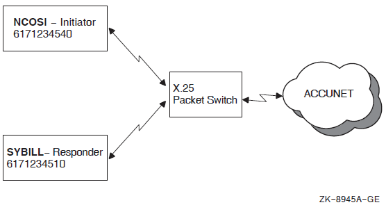
A summation of the pertinent configuration information is provided in Table C.1, ''Sample X.25 Configuration Information''.
| Parameter | Initiator | Responder |
|---|---|---|
| Node name | ncosi | sybill |
| X.25 profile | Accunet | Accunet |
| Accunet DNIC | 3134 | 3134 |
| Accunet international prefix | 0 | 0 |
| Accunet line addresses | 6171234500-99 | 6171234500-99 |
| X.25 network address | 61712345 | 61712345 |
| Local subaddress | 40 | 10 |
| X.121 address | 31346171234540 | 31346171234510 |
| AFI | 36 | 36 |
| NSAP | 3631346171234540 | 3631346171234510 |
Note
The addresses shown in these examples differ from the ones listed in Table C.1, ''Sample X.25 Configuration Information''. DECnet-Plus for OpenVMS requires an extra octet containing the NSAP length in digits to precede the actual NSAP value.
C.1. OpenVMS IA-64 and Alpha Configuration of OSI Transport Over X.25 CONS
Take the following steps to configure FTAM (and other OSI applications) with OSI Transport over X.25 CONS on an OpenVMS IA-64 or OpenVMS Alpha system.
For more information on FTAM configuration, see the VSI DECnet-Plus FTAM and Virtual Terminal Use and Management guide.
Install the DECnet-Plus base kit, as follows:
$ product install decnet_osi (decnet_plus on OpenVMS I64)
Configure DECnet-Plus with WAN drivers and an additional OSI template for the CONS protocol stack. Do not configure WAN devices for routing.
$ @net$configure advanced
Respond to the prompts as shown in this edited example:
. . . (Answer node, session control, and routing information questions)
* Do you want to configure Wide Area devices? Y
Configuring WANDD... [’?’ for HELP]
%WANDD$CONFIGURE-I-WANDDNOTCONFIG, WANDD has not been configured.
Configure WANDD? Y
Configure built in serial port as synchronous? Y
Are you satisfied with your answers? [YES]
Available Synchronous Communication Ports:
1. ZRA0 - SSCC-0-0
%net$configure-I-SCANCONFIG, scanning device configuration - please wait
. . . (Configure any data links used for CLNS connections)
* Data Link protocol for ZR-0-0 (SSCC)? NONE
* Do you want to configure DECnet over X.25? N
* Configure the NSP Transport? Y or N
. . . (If needed, configure all NSP transport parameters)
* Configure the OSI Transport or run over TCP/IP? Y
. . . (Configure all OSI transport parameters)
* Do you want to create additional OSI templates? Y
* Type of network service (CLNS/CONS/RFC1006)? CONS
* Name of the OSI template? CONS
* Will this template be used for inbound packets?
* Transport classes to support? 0,2,4
* CONS template name? OSI Transport
* Allow use of expedited data ?
* Allow use of Checksums?
* Do you want to create additional OSI templates? N
. . . (Continue with configuration until completed)
Install X.25 for OpenVMS, as follows:
$ product install x.25
Configure and start X.25, as follows:
$ @x25$configure advanced
Respond to the prompts as shown in this edited example:
Configuring WANDD... [’?’ for HELP] %WANDD$CONFIGURE-I-WANDDCONFIG, WANDD is already configured. Current Configuration: 1. Autoconfigure device drivers : YES Change your current configuration? [NO] Are you satisfied with your answers? [YES] The screen will be cleared. Press RETURN to continue... . . . (View Introduction screen) Create a new configuration script (from Main Menu screen) . . . (View CREATE Introduction screens) Do you want to configure any Remote DTE Classes? N Do you want to configure any synchronous lines? Y Select a synchronous line to configure: SCC-0-0 . . . (Enter the line’s speed) Link Name: link-0 DTE Name: dte-0 X.25 Address: 61712345 Profile Name: ACCUNET DTE Interface Type: DTE Incoming Logical Channel Range: {[1..127]} Outgoing Logical Channel Range: {[1..127]} . . . (Change any DTE characteristics from profile values as needed) Do you want to use LLC2 communications? N Do you want to use XOT communications? N Do you want to set up any PVCs? N Do you want to create Closed User Groups? N Do you want X.29 support? N Do you want to use X.25 Mail? Do you want to create any applications? N Do you want to configure any X.25 Relay Clients? N Do you want to set up additional filters? N Do you want to set up additional templates? N Do you want to specify reachable addresses? N Do you want to configure any Server Clients? N Allow all X.25 calls (from X.25 Security menu) Do you want to modify your answers? NThe configuration procedures in steps 2 and 4 do not account for local X.25 address formats. Modify the configuration by adding the following NCL commands to the
sys$startup:x25$extra_set.nclstartup script file:set lapb link link-0 sequence modulus 8 ! ! Add ACCUNET profile characteristics to DTE Class accunet set x25 access dte class accunet international prefix 0 set x25 access dte class accunet dnic 3134 set x25 access dte class accunet strip dnic true ! ! Add dte class characteristic to stock DTE Class x121d set x25 access reachable address x121d dte class accunet ! ! Add local subaddress characteristics to stock Template "OSI Transport" set x25 access template "OSI Transport" local subaddress 40
Install FTAM and the other OSI applications so that you can use these applications with the OSI transport over CONS, as follows:
$ product install osak, ftam, vt
Configure FTAM, as follows (see Section 13.6, ''Running the OSIF$CONFIGURE.COM Procedure''):
$ @osif$configure
Add FTAM service aliases to the OSI applications database, as follows (see Chapter 14, "Configuring the OSI Applications"):
$ edit/edt sys$system:isoapplications.dat
Start OSAK and FTAM, as follows (see Section 13.4, ''Starting Up and Shutting Down OSI Applications''):
$ @sys$startup:osak$start $ @sys$startup:osif$startup
Manually enter the following NCL commands to provide the local NSAP information for OSI Transport entities:
ncl> add osi transport cons nsap addresses {/103631346171234540 } ncl> set osi transport template cons local nsap /103631346171234540
C.2. OpenVMS VAX Configuration of OSI Transport Over X.25 CONS
Take the following steps to configure FTAM (and other OSI applications) with OSI Transport over X.25 CONS on OpenVMS VAX systems. For more information on FTAM configuration, see the VSI DECnet-Plus FTAM and Virtual Terminal Use and Management guide.
Install DECnet-Plus base kit with the X.25 software, as follows:
$ product install decnet_osi
Configure DECnet-Plus with WAN drivers and an additional OSI template for the CONS stack. Do not configure WAN devices for routing.
$ @net$configure advanced
Respond to the prompts as shown:
. . . (Answer node, session control, and routing information questions) * Do you want to configure Wide Area devices? Y This is the Configuration Procedure for the =========================================== VAX Wan Device Drivers for DECnet-Plus for VMS ==============================================
The Wide Area Network Datalinks and Drivers are a prerequisite for DECnet-Plus. They also provide synchronous datalinks in systems that do not use DECnet-Plus for networking.
Do you wish to use WANDRIVER? Y Will you use DEC HDLC? N Will you use LAPB/E? Y Do you have any soft-loadable microcode devices on this system? Y Will you use the VAXft DSF32 device driver? N Are you satisfied with the answers you have given? Y %net$configure-I-SCANCONFIG, scanning device configuration - please wait * Do you want asynchronous datalink support? N . . . (Configure any data links used for CLNS connections) * Data Link protocol for DSV-0-0 (DSV-11)? NONE * Data Link protocol for DSV-0-1 (DSV-11)? NONE * Do you want to configure DECnet over X.25? N * Configure the NSP Transport? Y or N . . . (If needed, configure all NSP transport parameters) * Configure the OSI Transport or run over TCP/IP? Y . . . (Configure all OSI transport parameters) * Do you want to create additional OSI templates? Y * Type of network service (CLNS/CONS/RFC1006)? CONS * Name of the OSI template? CONS * Will this template be used for inbound packets? * Transport classes to support? 0,2,4 * CONS template name? OSI Transport * Allow use of expedited data ? * Allow use of Checksums? * Do you want to create additional OSI templates? N . . . (Continue with configuration until completed)
If you did not install the X.25 software (by selecting the VAX P.S.I. or P.S.I.
Access software and VAX Wide Area Device Drivers installation options), install them now.
Configure and start the X.25 software, as follows:
$ @psi$configure
Respond to the prompts as shown:
Create a new configuration (from the Main Menu) . . . (View CREATE Introduction screens) Configuration Type: Native Do you want to configure any synchronous lines? Y . . . (Enter the line’s speed) X.25 DTE Address: 61712345 Logical Channel Ranges: [[1..127]] Profile Name: ACCUNET . . . (Change any DTE characteristics from profile values as needed) DTE Class: ACCUNET Do you wish to set up any PVCs? N Do you wish to create any Closed User Groups? N Do you wish to use LLC2 communications? N Do you want to use P.S.I. Mail? N Do you want X.29 support? N Do you wish to set up any applications? N Do you wish to set up additional templates? Y Template Name: "OSI Transport" DTE Class: ACCUNET Call Data: %x03010100 . . . (Except for the following fields, take the defaults) Charging Information: NO Local Subaddress: 40 NSAP Mapping: YES Do you want X.25 or X.29 programs to specify filter names in $QIO calls? YES Do you want IO$_ACPCONTROL calls issued by your programs to name any dynamic filters? NO Do you want IO$_ACPCONTROL calls issued by your programs to name any static filters? YES Filter Name: "OSI Transport" Call Data Value: %x03010100 Call Data Mask: %xFFFFFFFF Do you want to set up X.25 Security? NO Do you wish to create an NCL script now? Yes
The configuration procedures in steps 2 and 4 do not account for local X.25 address formats. In addition, when using X.25 for OpenVMS VAX, you must create the X.25 reachable address x121d. Modify the configuration by adding the following NCL commands to the
sys$startup:psi$enable_decnet_clients.nclstartup script file:! ! Add ACCUNET profile characteristics to DTE Class accunet set x25 access dte class accunet international prefix 0 set x25 access dte class accunet dnic 3134 set x25 access dte class accunet strip dnic true $! $! Create X.25 Reachable Address x121d create x25 access reachable address x121d address prefix /36 set x25 access reachable address x121d mapping x.121 set x25 access reachable address x121d dte class accunet set x25 access reachable address x121d address extensions true
Install FTAM and the other OSI applications, as follows:
$ product install osak, ftam, vt
Configure FTAM, as follows (see Section 13.6, ''Running the OSIF$CONFIGURE.COM Procedure''):
$ @osif$configure
Add FTAM service aliases to the OSI applications database, as follows (see Chapter 14, "Configuring the OSI Applications"):
$ edit/edt sys$system:isoapplications.dat
Start OSAK and FTAM, as follows (see Section 13.4, ''Starting Up and Shutting Down OSI Applications''):
$ @sys$startup:osak$start $ @sys$startup:osif$startup
Manually enter the following NCL commands to provide the local NSAP information for OSI Transport entities:
ncl> add osi transport cons nsap addresses {/103631346171234540 } ncl> set osi transport template cons local nsap /103631346171234540
Appendix D. Configuring Link State Routing Nodes Using the isis$configure
Procedure
This appendix describes how to use the isis$configure procedure to configure
routing. The net$configure procedure supports configuring host-based routing
nodes that use the routing vector routing algorithm. If you want to create a host-based
routing node that uses the link state routing algorithm, you must use the
isis$configure procedure.
D.1. Prerequisites
The isis$configure procedure requires the following be in place before
you invoke the procedure:
The user account has SYSPRV and OPER privileges. VSI recommends that you invoke the procedure from the SYSTEM account.
The
net$routing_startup.nclscript file created by thenet$configureprocedure must be available in thesys$manager:directory and must include configuration information for all LAN routing circuits (both CSMA-CD and FDDI) that you want to include in your host-based routing configuration.Also, the associated
net$csmacd_startup.ncllandnet$fddi_startup.nclscript files must be present.WANDD software must be installed. This installation creates the
wandd$devices.datin thesys$manager:directory. This file is not required if your configuration does not include any synchronous devices.
D.2. Dialog Structure
The isis$configure procedure begins by configuring the node’s routing
parameters. These parameters include the following:
Type of router required (Level 1 or Level 2)
Routing protocol to use at each routing level
Phase IV address (0.0 if no Phase IV address is required)
Zero or more Phase V area addresses (one or more if no Phase IV address)
When the routing dialog completes, the procedure displays a menu of routing circuit
types. You must select and configure all desired routing circuits. This is true even
though you configured these circuits using net$configure. If you fail to
configure a routing circuit using the isis$configure procedure, it will not
be present in the final configuration.
In addition to configuring the routing circuits, you must also create routing reachable addresses for any X.25 dynamically-assigned circuits you configure.
You will also be given the option of creating interphase circuits for all synchronous, asynchronous, and X.25 routing circuits. See the VSI DECnet-Plus for OpenVMS Network Management Guide for more information about interphase circuits. This manual describes the preferred method of creating these circuits if your network is complex.
D.3. Outputs
The isis$configure procedure generates a new
net$routing_startup.ncl script. The existing
net$csmacd_startup.ncll and net$fddi_startup.ncl scripts
are retained. The copy of the net$routing_startup.ncl file created by the
net$configure procedure is renamed to *.ncl-old. If synchronous or
asynchronous routing circuits are created, all necessary Modem Connect, DDCMP, and HDLC
NCL commands are placed in the new net$routing_startup.ncl script; any
existing net$modem_startup.ncl, net$ddcmp_startup.ncl, and
net$hdlc_startup.ncl files are renamed to *.ncl-old.
D.4. Dialog
The dialog begins with an opening screen:
IS-IS Routing for OpenVMS configuration procedure ------------------------------------------------- This command procedure creates a script for use by IS-IS Routing. The procedure assumes that you have performed a basic configuration of your DECnet-Plus for OpenVMS system, and that you now have the following: - A basic routing script (SYS$MANAGER:net$routing_startup.ncl) - A CSMA-CD script (SYS$MANAGER:net$csmacd_startup.ncll). NOTE If you are setting up X.25 circuits, you must install X.25 software and use the X.25 configuration procedure to define the templates and filters required by X.25 routing circuits. If you are setting up synchronous circuits, you must install WANDD. This command procedure prompts you for the following information: Press RETURN to continue
The opening screen continues:
- Type of system being configured (Level 1 or Level 2) - Your Phase IV Address and Prefix - One or more Manual Area Addresses - Routing subentities - Circuits and Reachable Addresses (Use the menu displayed) To obtain help for any question, enter ? as the answer. Time is 10:20 29-OCT-2004. _Press RETURN to continue:
The dialog begins the routing configuration by asking what type of router you want to configure (Level 1 or Level 2).
Level 1 routers route packets between systems in the local area. Level 1 routing is carried out by both Level 1 and Level 2 routers.
Level 2 routers route packets to other areas of the network as well as within the local area. Level 2 routing is only carried out by Level 2 routers.
Enter the type of router you require:.
_Enter type of Router required (L1 or L2) [L1]:
Next, the procedure asks for the routing protocols to use. Table D.1, ''Routing Protocol Options'' discusses the possible configurations and the reasons for selecting them.
|
Level 1 Phase IV Level 2 Phase IV |
If the entire routing domain uses Phase IV routing. |
|
Level 1 Phase IV Level 2 Phase V |
If the local area uses Phase IV routing and Phase V routing is used between areas. |
|
Level 1 Phase V Level 2 Phase IV |
If the local area uses Phase V routing and Phase IV routing is used between areas. |
|
Level 1 Phase V Level 2 Phase V |
If the entire routing domain uses Phase V routing. |
Enter the routing protocols to use:
Select the routing options: [1] Level 1 Phase IV, Level 2 Phase IV [2] Level 1 Phase IV, Level 2 Phase V [3] Level 1 Phase V, Level 2 Phase IV [4] Level 1 Phase V, Level 2 Phase V _Type [4]: ?
The procedure asks for the node’s Phase IV address. Enter the value 0.0 if you do not want this node to have a Phase IV compatible address. Note that if you have chosen to run the Phase IV routing algorithm at any level you MUST enter a Phase IV address; if you have chosen to use the Phase V link state routing algorithm at all levels you CANNOT enter a Phase IV address.
Enter the node’s Phase IV address or 0.0:
_Enter the Phase IV address [24.66]:
If you have indicated you want to use Phase V link state routing at any level, you must enter at least one, and up to three, manual area addresses. If you have entered a Phase IV address, the procedure automatically converts that address to a Phase V area address. Optionally, you can enter up to two more Phase V area addresses.
You must enter the Phase V area address in DNA format:
aa:[ii...i]:[pp-....-pp-]ll-ll
where aa is the AFI, ii...i is the IDI (null for AFI 49), pp-...-pp is the pre-DSP (usually null), and ll-ll is the local area (00-01 to 00-3F [1 - 63] used for Phase IV compatible addresses). For example, 49::00-4F is valid Phase V area address using the private AFI value of 49 and the local area 79. For more information about the format of area addresses and NSAPs, see the VSI DECnet-Plus Planning Guide.
Enter a Phase V area address (press return when you are finished entering the addresses):
_Enter Phase V area address:
The procedure now displays the routing circuit menu:
Routing configuration menu -------------------------- Configured node type: L2Router Please select an option [1]: LAN circuits [2]: Synchronous circuits [3]: X.25 circuits [4]: Reachable Addresses [5]: Generate script and exit [6]: Quit (no script) [7]: Asynchronous circuits _Option [5]:
Enter your selection as follows:
Select 1 to configure CSMA-CD and FDDI routing circuits.
Select 2 to configure WANDD device (synchronous) routing circuits. The WANDD software must be installed if you select this option.
Select 3 to configure X.25 routing circuits.
Select 4 to configure reachable addresses if you have configure an X.25 dynamically-assigned routing circuit.
Select 5 to generate the NCL startup scripts and exit the configuration procedure.
Select 6 to quit the configuration procedure and lose all configuration data entered. The NCL startup scripts created by
net$configureare left untouched.Select 7 to create asynchronous DDCMP routing circuits on OpenVMS VAX systems.
If you select one of the circuit configuration options or the reachable address configuration option, the procedure returns to this menu after configuring the requested item. You must select either 5 or 6 to exit the procedure. You can select an option you already selected. If you have already configured a routing entity, the procedure asks if you want to reconfigure the entity.
D.4.1. LAN and Synchronous Circuit Dialogs
If you select option 1 or 2, the procedure begins the individual LAN or synchronous routing circuit dialogs. Each dialog begins with a display of the devices available for configuration:
This section configures CSMA-CD and FDDI circuits for use by Routing. Select a device to be configured Device Circuit Name Data Link Entity ------ ------------ ---------------- [1] FRA FDDI Station FDDI-0 [2] Return to main menu _Option [2]:
For LAN circuits, the data link entity name is taken from the existing NCL startup
scripts generated by net$configure. For all other circuits, the data
link entity name is created by the isis$configure procedure.
Select the circuit to configure.
After you select a circuit, the procedure asks for the name to use when creating the circuit:
_Circuit name [FDDI-0]:
Next, the procedure asks if you want the circuit enabled on system startup:
_Enable circuit on system startup [yes]:
The procedure then asks if you want to take the defaults for the circuit:
_Do you wish to accept the default circuit configuration [yes]:
The default configuration sets the following characteristics:
Data link protocol (synchronous circuits only)
Level 1 circuit cost
Level 1 router priority (LAN circuits only)
Level 2 circuit cost (if Level 2 router)
Level 2 router priority (LAN circuits only, if Level 2 router)
If you decide to manually configure the circuit, the procedure asks you for values for the same characteristics.
D.4.2. X.25 Routing Circuit Dialog
If you select option 3, the procedure begins the individual X.25 routing circuit dialog. The X.25 routing circuit dialog begins with the following introductory screen (it’s actually more than a screen, so scroll back to see the entire introduction):
There are four types of X.25 routing circuits: static outgoing, static incoming, permanent, and dynamically assigned. Dynamically assigned circuits are only supported on Level 2 Router configurations. Static outgoing, and static incoming circuits operate over a single X.25 switched virtual circuit (SVC). A permanent circuit operates over a single X.25 permanent virtual circuit (PVC). A dynamically assigned circuit operates over a number of X.25 switched virtual circuits (SVCs). Use the X.25 configuration program to configure X25 Access templates and filters along with PVCs, following these guidelines: - Set the X25 Access template call data attribute to %X81 - Set the X25 Access filter call data value attribute to %X81 - Set the X25 Access filter call data mask attribute to %XFF. Select the type of X.25 circuit required: [1] Static Outgoing [2] Static Incoming [3] Permanent [4] Dynamic Assigned [5] Return to main menu _Option [5]:
Enter your selection.
After you select a circuit type, the procedure asks for the name to use when creating the circuit:
_Circuit name [X25-OUT-0]:
For permanent circuits, the procedure asks for the name of the X.25 PVC you want to use when creating the routing circuit:
_X25 PVC name [X25-PVC-0]:
For static and dynamically-assigned circuits, the procedure asks for the name of the X.25 template you want to use when making or accepting a connection:
_X25 Access template name [X25-OUT-0]:
For static incoming and dynamically-assigned circuits, the procedure asks for the name of the X.25 filter you want to use when accepting a connection:
_X25 Access filter name [X25-IN-0]:
The procedure asks if you want the circuit enabled on system startup:
_Enable circuit on system startup [yes]:
For all circuit types except the dynamically-assigned type, the procedure then asks if you want to take the defaults for the circuit:
_Do you wish to accept the default circuit configuration [yes]:
The default configuration sets the following characteristics:
Level 1 circuit cost
Level 2 circuit cost (if Level 2 router)
If you decide to manually configure the circuit, the procedure asks you for values for the same characteristics.
D.4.3. Reachable Address Dialog
If you select option 4, the procedure begins the individual reachable address dialog. The dialog begins with a display of the circuits available for creating reachable addresses:
Select the circuit which connects to the routing domain
Name Type
---- ----
[1] X25-DA-0 X25 DA
[2] X25-DA-1 X25 DA
[3] Return to main menu
_Circuit [3]:Select the circuit for which you want to create a reachable address.
The procedure asks for the name to use when creating the reachable address:
_Reachable Address name:
Next, the procedure asks for the address prefix to use. Enter the leading digits of an NSAP address, or a full NSAP address.
The address you enter is entered in a reachable-address table. This table tells the IS-IS router about non-DECnet-Plus systems that are reachable from the local domain.
When a Level 2 router receives a packet with a destination address that matches an address prefix in its reachable address table, the packet is forwarded to another Level 2 router, which can send it to its destination.
Enter the prefix in DNA format (see the VSI DECnet-Plus Planning Guide):
_Reachable Address prefix:
The procedure asks for the routing cost associated with this reachable address:
_Reachable Address cost [20]:
Next, the procedure asks for the list of DTE addresses associated with this reachable address (separate addresses using commas):
_Destination DTE address list:
Approximate amount — actual amount depends on the size of the namespace, the number of logs created, and so forth. The amount of required disk space could double when running tests, then return to original amount when duplicate files are deleted.
You must set up at least one synchronous line and associated DTE or at least one LLC2 DTE.
You need to make this choice only if the profile you entered supports the facility.
You need to enter values here only if you chose to use packet-level negotiation.
You need to make this choice only if the profile you entered is ISO 8208 or NPSI.
You may specify more than one DTE/CUG number pair for groups of type CUG.
You need to supply this information only if the Group type is BCUG.
You need to supply these values only if you chose to use packet-level negotiation.
You are asked for this information only if you request P.S.I. Mail support.
1You are not asked for this information if the application type is X.29 login
The value required is a remote address prefix (RAP). This can be a full DTE address, or it can be an address prefix, which would stand for all DTEs with an address beginning with this prefix.
The wildcard character (*) means all unspecified DTEs. If you enter the wildcard character to stand for DTEs that have Remote Charge or All access, there is no default for this value, and the only DTEs that are not allowed access are those that you specify explicitly.
The value required is a remote address prefix (RAP). This can be a full DTE address, or it can be an address prefix, which would stand for all DTEs with an address beginning with this prefix.
You are asked for this information only if PVCs have been set up.
The wildcard character (*) means all unspecified DTEs or PVCs. If you enter the wildcard character to stand for DTEs or PVCs that have Remote Charge or All access, there is no default for these values, and the only DTEs or PVCs that are not allowed access are those that you specify explicitly.
The value required is a remote address prefix (RAP). This can be a full DTE address, or it can be an address prefix, which would stand for all DTEs with an address beginning with this prefix.
The wildcard character (*) means all unspecified DTEs. If you enter the wildcard character to stand for DTEs that have Remote Charge or All access, there is no default for this value, and the only DTEs that are not allowed access are those that you specify explicitly.
The value required is a remote address prefix (RAP). This can be a full DTE address, or it can be an address prefix, which would stand for all DTEs with an address beginning with this prefix.
The wildcard character (*) means all unspecified DTEs. If you enter the wildcard character to stand for DTEs that have Remote Charge or All access, there is no default for this value, and the only DTEs that are not allowed access are those that you specify explicitly.
The value required is a remote address prefix (RAP). This can be a full DTE address, or it can be and address prefix, which would stand for all DTEs with an address beginning with this prefix.
The wildcard character (*) means all unspecified DTEs or PVCs. If you enter the wildcard character to stand for DTEs or PVCs that have Remote Charge or All access, there is no default for these values, and the only DTEs or PVCs that are not allowed access are those that you specify explicitly.
You are asked for this information only if PVCs have been set up.