DECnet-Plus for OpenVMS Introduction and User’s Guide
- Operating System and Version:
- VSI OpenVMS IA-64 Version 8.4-1H1 or higher
VSI OpenVMS Alpha Version 8.4-2L1 or higher
VSI OpenVMS x86-64 Version 9.2-2 or higher
Preface
This book introduces the DECnet-Plus for OpenVMS (formerly DECnet/OSI) product, providing an overview of the product's features and a conceptual overview of DECnet-Plus software. Also described are common end-user tasks such as how to use the remote file, remote login, and mail utilities. A complete glossary of DECnet-Plus terminology is also included.
See your Software Product Description (SPD) for detailed information about new features and product requirements.
1. About VSI
VMS Software, Inc. (VSI) is an independent software company licensed by Hewlett Packard Enterprise to develop and support the OpenVMS operating system.
2. Intended Audience
Network planners and managers, both DECnet for OpenVMS (Phase IV) users and new DECnet-Plus (Phase V) users
OpenVMS system managers
Installers of OpenVMS
Namespace planners and managers
DECdts planners and managers
- Managers of these Open Systems Interconnection (OSI) features:
OSI Transport connections
X.25 communications
Wide area network device drivers (WANDD)
Remote OSI file operations
DECnet-Plus virtual terminal
Writing and running additional OSI applications
3. Document Structure
- Chapter 1, "Introducing DECnet-Plus for OpenVMS" and Chapter 2, "DECnet-Plus for OpenVMS Components" provide an overview of:
Transitioning to DECnet-Plus
Features and components of the DECnet-Plus for OpenVMS product
- Chapter 3, "DECnet-Plus for OpenVMS Concepts" and Chapter 4, "X.25 Networking Concepts" provide conceptual information about:
DECnet-Plus for OpenVMS
X.25 networking
- Chapter 5, "DECnet Network Operations" and Chapter 6, "File Operations to and from Other DECnet and DECnet-Plus Nodes" provide user information on:
Using remote files with DECnet-Plus
Using the DECnet-Plus login utility
Sending mail to DECnet-Plus nodes
4. Guide to Documentation
|
Document |
Contents |
|---|---|
|
Documentation Sets: OpenVMS Integrity, Alpha, and VAX Systems | |
|
VSI DECnet-Plus for OpenVMS Introduction and User's Guide |
This manual. Describes the manuals in the documentation sets, outlines the DECnet-Plus for OpenVMS features and tools, explains how to use and manage an end system, and provides a comprehensive glossary of DECnet terminology. |
|
DECnet-Plus for OpenVMS Release Notes |
Print this text file at the beginning of the installation procedure and read it before you install DECnet-Plus for OpenVMS. Volume 1 of the DECnet-Plus for OpenVMS distribution kit contains the Release Notes. Describes changes to the software; installation, upgrade, and compatibility information; new and existing software problems and restrictions; and software and documentation corrections. |
|
DECnet-Plus for OpenVMS Installation and Basic Configuration Manual |
Explains how to install and configure the DECnet-Plus for OpenVMS software and how to perform postinstallation tasks. |
|
DECnet-Plus for OpenVMS Installation and Quick Reference |
Provides quick-reference information to help you install DECnet-Plus software on an OpenVMS node. Use this card with the DECnet-Plus for OpenVMS Installation and Basic Configuration Manual. |
|
DECnet-Plus for OpenVMS Applications Installation and Advanced Configuration Guide |
Explains how to install X.25 for OpenVMS Alpha, X.25 Access and X.25 Native Mode for OpenVMS VAX (formerly VAX P.S.I. Access and VAX P.S.I.), FTAM, VT, and OSAK software. Includes information about how to configure DECnet-Plus for OpenVMS using the Advanced configuration option and how to modify an existing configuration. |
|
VSI DECnet-Plus for OpenVMS Network Management Guide |
Provides in-depth information about how to monitor and manage DECnet-Plus for OpenVMS systems using various tools and Network Control Language (NCL) commands. Explains how to set up and use event dispatching and how to perform all day-to-day management tasks for the local DECnet-Plus for OpenVMS node, including setting up OpenVMS clusters, managing security, downline loading, and monitoring the network. |
|
DECnet-Plus for OpenVMS Network Management and Quick Reference Card |
Provides quick-reference information about the tools that help you manage and monitor a DECnet-Plus network. Use this guide with the VSI DECnet-Plus for OpenVMS Network Management Guide. |
|
VSI DECnet-Plus for OpenVMS Network Control Language Reference Guide |
Outlines command descriptions and examples for all Network Control Language (NCL) commands that you execute to manage, monitor, and troubleshoot the network. Begins with an orientation chapter that contains information about how to execute NCL commands, followed by a command chapter for each module in the DECnet Phase V layered model. |
|
VSI DECnet-Plus Planning Guide |
Provides configuration and planning guidelines, including namespace planning information, to help you transition a network from the DECnet Phase IV to DECnet Phase V architecture. |
|
VSI DECnet-Plus for OpenVMS Problem Solving Guide |
Explains how to isolate and solve DECnet problems in an OpenVMS environment that can occur while the network is in operation. Includes information about how to perform loopback tests and how to use the DTS/DTR utility to solve problems. |
|
VSI DECnet-Plus for OpenVMS DECdns Management Guide |
Explains DECdns concepts and how to manage a DECdns distributed namespace. Use this manual with the VSI DECnet-Plus Planning Guide. |
|
VSI DECnet-Plus for OpenVMS DECdts Management |
Introduces DIGITAL Distributed Time Service (DECdts) concepts and describes how to manage the software and system clocks. |
|
VSI DECnet-Plus DECdts Programming |
Contains DECdts time routine reference information and describes the time-provider interface (TPI). |
|
VSI DECnet-Plus OSAK Programming |
Explains how to use the OSAK (OSI Applications Kernel) interface to create OSI (Open Systems Interconnection)applications for any supported operating system. |
|
DECnet-Plus OSAK Programming Reference |
Provides reference information on using the OSAK interface to create OSI applications on any supported operating system. |
|
VSI DECnet-Plus OSAK SPI Programming Reference Manual |
Provides reference information about using the OSAK session programming interface (SPI) to create OSI applications on any supported operating system. |
|
VSI DECnet-Plus FTAM and Virtual Terminal Use and Management |
Explains how to use and manage FTAM (File Transfer, Access, and Management) software for remote file transfer and management and VT (Virtual Terminal) for remote login to OSI-compliant systems. |
|
VSI DECnet-Plus FTAM Programming |
Explains how to access the FTAM protocol through FTAM API (application programming interface). |
|
VSI DECnet-Plus for OpenVMS Programming |
A three-part manual. Contains information about how to design and write an application that follows a client/server model and uses the OpenVMS Interprocess Communication ($IPC) system service and the transparent and nontransparent communication with the queue Input/Output ($QIO) system service. Explains how to write programs using the OpenVMS system services to communicate with OSI transport services. Provides information about the Common Management Information Service (CMISE) API. |
|
DECnet/OSI for VMS CTF Use |
Explains how use the Common Trace Facility (CTF) troubleshooting tool to collect and analyze protocol data from networking software. |
|
DECnet/OSI for VMS X.25 Management |
For OpenVMS VAX systems only. Provides X.25 and X.29 information for X.25 Access and X.25 Native Mode (formerly VAX P.S.I. Access and VAX P.S.I.). Provides information about wide area network device driver (WANDD) software. |
|
VSI X.25 for OpenVMS Management Guide |
For OpenVMS Alpha systems only. Explains how to manage and monitor an X.25 system using network tools. |
|
VSI X.25 for OpenVMS Security Guide |
For OpenVMS Alpha systems only. Explains the X.25 security model and the tasks required to set up and manage X25 security. |
|
VSI X.25 for OpenVMS Problem Solving |
For OpenVMS Alpha systems only. Provides guidance on how to solve problems that can occur while using an X.25 system. |
|
Supplemental X.25 Documentation Set (OpenVMS Alpha Systems) | |
|
X.25 for OpenVMS Accounting |
Explains how to use X.25 accounting to obtain performance records and information about how X.25 is being used. |
|
VSI X.25 for OpenVMS Configuration |
Discusses how to configure X.25 on an OpenVMS Alpha system. |
|
X.25 for OpenVMS Programming |
Explains how to write X.25 and X.29 programs to perform network operations. |
|
X.25 for OpenVMS Programming Reference |
Provides reference information for X.25 and X.29 programmers. |
|
X.25 for OpenVMS Utilities |
Explains how to use and manage X.25 Mail and X.29 communications. |
5. Terminology
Transition and migration
Phase IV and DECnet Phase IV
Phase V and DECnet Phase V
System and node
End system and end node
Intermediate system and router
Multivendor
- Link state and:
Link state routing algorithm
Link state protocol
DECnet-Plus routing algorithm
DECnet-Plus routing
Name service and directory service
6. VSI Encourages Your Comments
You may send comments or suggestions regarding this manual or any VSI document by sending electronic mail to the following Internet address: <docinfo@vmssoftware.com>. Users who have VSI OpenVMS support contracts through VSI can contact <support@vmssoftware.com> for help with this product.
7. OpenVMS Documentation
The full VSI OpenVMS documentation set can be found on the VMS Software Documentation webpage at https://docs.vmssoftware.com.
8. Typographical Conventions
VMScluster systems are now referred to as OpenVMS Cluster systems. Unless otherwise specified, references to OpenVMS Cluster systems or clusters in this document are synonymous with VMScluster systems.
The contents of the display examples for some utility commands described in this manual may differ slightly from the actual output provided by these commands on your system. However, when the behavior of a command differs significantly between OpenVMS Alpha and Integrity servers, that behavior is described in text and rendered, as appropriate, in separate examples.
In this manual, every use of DECwindows and DECwindows Motif refers to DECwindows Motif for OpenVMS software.
| Convention | Meaning |
|---|---|
|
Ctrl/ x |
A sequence such as Ctrl/ x indicates that you must hold down the key labeled Ctrl while you press another key or a pointing device button. |
|
PF1 x |
A sequence such as PF1 x indicates that you must first press and release the key labeled PF1 and then press and release another key or a pointing device button. |
|
Return |
In examples, a key name enclosed in a box indicates that you press a key on the keyboard. (In text, a key name is not enclosed in a box.) |
|
… |
A horizontal ellipsis in examples indicates one of the
following possibilities:
|
|
. |
A vertical ellipsis indicates the omission of items from a code example or command format; the items are omitted because they are not important to the topic being discussed. |
|
( ) |
In command format descriptions, parentheses indicate that you must enclose the options in parentheses if you choose more than one. |
|
[ ] |
In command format descriptions, brackets indicate optional choices. You can choose one or more items or no items. Do not type the brackets on the command line. However, you must include the brackets in the syntax for OpenVMS directory specifications and for a substring specification in an assignment statement. |
|
[ |] |
In command format descriptions, vertical bars separate choices within brackets or braces. Within brackets, the choices are options; within braces, at least one choice is required. Do not type the vertical bars on the command line. |
|
{ } |
In command format descriptions, braces indicate required choices; you must choose at least one of the items listed. Do not type the braces on the command line. |
|
bold text |
This typeface represents the introduction of a new term. It also represents the name of an argument, an attribute, or a reason. |
|
italic text |
Italic text indicates important information, complete titles of manuals, or variables. Variables include information that varies in system output (Internal error number), in command lines (/PRODUCER= name), and in command parameters in text (where dd represents the predefined code for the device type). |
|
UPPERCASE TEXT |
Uppercase text indicates a command, the name of a routine, the name of a file, or the abbreviation for a system privilege. |
|
|
Monospace type indicates code examples and interactive screen displays. In the C programming language, monospace type in text identifies the following elements: keywords, the names of independently compiled external functions and files, syntax summaries, and references to variables or identifiers introduced in an example. |
|
- |
A hyphen at the end of a command format description, command line, or code line indicates that the command or statement continues on the following line. |
|
numbers |
All numbers in text are assumed to be decimal unless otherwise noted. Nondecimal radixes—binary, octal, or hexadecimal—are explicitly indicated. |
Chapter 1. Introducing DECnet-Plus for OpenVMS
DECnet-Plus network is a family of hardware and software products that allows operating systems to communicate with each other and with systems produced by other vendors.
The DECnet-Plus network supports remote system communication, resource sharing, and distributed processing. Network users can access resources on any system in the network as well as the resources of other vendors' systems on multivendor networks.
DECnet-Plus networking software provides true network independence. You get the full functionality of DECnet Phase IV, as well as DECnet enhancements plus full TCP/IP compatibility and OSI functionality.
The Open Systems Interconnection (OSI) communications specifications, as defined by the International Organization for Standardization (ISO).
Communications architecture, Network Architecture Phase V, which is also backward compatible with the Phase IV architecture.
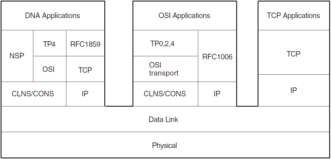
Phase V integrates the DNA and OSI layers. The DNA Phase V reference model is the architectural model on which DECnet-Plus networking implementations are based. DECnet-Plus also includes support for the internet standards RFC 1006 and RFC 1859, which allow you to run OSI and DECnet Phase IV applications over TCP/IP.
|
Phase I |
Limited to two nodes |
|
Phase II |
Up to 32 nodes: file transfer, remote file access, task-to-task programming interfaces, network management |
|
Phase III |
Up to 255 nodes: adaptive routing, downline loading, record access |
|
Phase IV |
Up to 64,449 nodes: Ethernet local area networks, area routing, host services, OpenVMS Cluster support |
|
Phase V |
Virtually unlimited number of systems: OSI protocol support, transparent transport level links to TCP/IP, multivendor networking, local or distributed name service, distributed network management |
DECnet-Plus for OpenVMS integrates DECnet and OSI network protocols which provides continued support for DECnet applications and enables support for OSI applications on OpenVMS. With separate TCP/IP software running on the same system, DECnet-Plus supports a multivendor, multiprotocol network environment. DECnet applications can be run over NSP, CLNP, or TCP/IP transports. OSI applications can be run over CLNP or TCP/IP transports.
Note
Chapter 3, "DECnet-Plus for OpenVMS Concepts" contains more conceptual information on the OSI Reference Model, OSI terminology (protocols, stacks, dialogues, entities, services), and how each specific layer relates to DECnet-Plus for OpenVMS.
1.1. Preparing for a Migration to DECnet-Plus
A number of automated tools (DECnet migration utilities and the NCP Emulator) and simplified configuration procedures are available to help you migrate to DECnet-Plus.
The complexity of the transition from Phase IV to Phase V architecture varies depending on the complexity of your existing network. In general, the smaller the network, the easier the transition. For larger networks, more planning is required. Nevertheless, whether your network is large or small, you can accomplish the transition without disrupting day-to-day operations.
DECnet-Plus now supports the fast configuration option, which a system or network manager can
use to configure DECnet-Plus quickly on an OpenVMS system by invoking the
net$configure.com procedure.
With the Fast Configuration option, you can configure a Phase IV system for network connectivity by answering a few questions. This feature is useful when you upgrade a DECnet Phase IV node to a DECnet-Plus node at some time in the future.
For information about how to configure your network using the Fast Configuration option, see the DECnet-Plus for OpenVMS Installation and Basic Configuration Manual.
1.1.1. Differences Between DECnet Phase IV and DECnet-Plus Phase V
DECnet-Plus is the implementation of the fifth phase of the DIGITAL Network Architecture (DNA). Phase V integrates the Open System Interconnection (OSI) protocols with DECnet protocols. In addition, Phase V includes support for the Internet standard RFC 1006 and the Internet draft RFC 1859, allowing OSI and DECnet applications to run over TCP/IP. Thus, applications that use DECnet-Plus can communicate with peer OSI and DECnet applications on any DECnet Phase IV-based system or OSI-based system, whether from VSI or from other vendors.
Global naming/directory services — In large networks, the number of nodes and users makes it difficult to manage any form of local directory service. Global (or distributed) name services allow large networks to easily store, manage, and access addressing information for (potentially) millions of network objects, such as end systems, users, printers, files, and disks. With the explosion of PCs as the desktop device of choice, networks containing millions of nodes have become a reality.
Optional local naming/directory services — Smaller networks do not have as critical a need for global directory services.
Expanded network management capabilities via the Network Control Language (NCL) — As networks become more complex, the management of networks has also become more complex. NCL enables network managers to access a wide range of manageable entities in the network for a wide range of management tasks.
An improved routing algorithm (link state routing) — The larger a network becomes, the more overhead is generated by passing routing information between routers and between routers and end systems. Link state routing provides a more efficient algorithm for passing routing information while keeping the overhead traffic to a minimum. Link state routing is supported only on dedicated routers.
Host-based routing — You can configure your network to enable host-based routing using the routing vector protocol. Host-based routing allows an OpenVMS system to operate as a DECnet-Plus intermediate system (IS). This feature is useful for those configurations where you need to route from a local area network (LAN) to a wide area network (WAN) and want to use an existing system to do the routing rather than investing in a dedicated router.
Increased addressing — Networks can now grow to include potentially millions of nodes. DECnet-Plus uses the OSI standard address format. This format is designed to allow each node in a universal network to have a unique address. In other words, networks can now grow well beyond the bounds of any other addressing format currently in use. Existing Phase IV addresses can continue to be used for upgraded systems. The Phase IV address is moved into the OSI address format.
Address autoconfiguration — DECnet-Plus nodes can take advantage of the address autoconfiguration feature where the adjacent router configures the node address for you.
Single installation/configuration for OSI components — X.25, the Wide Area Device Drivers (WANDD), FTAM and Virtual Terminal (VT) applications are included in the DECnet-Plus H-Kit.
Network addressing — Will users on the DECnet-Plus network have the ability to communicate with users on other OSI networks, either through electronic mail, EDI, FTAM, VTP, or other internetwork utilities? If yes, you must obtain a unique network identifier (IDP) from an authorized authority such as ANSI. If not, a default IDP is provided with DECnet-Plus that you can use at installation/configuration time.
Name services — Will name services be provided locally to each node or distributed throughout the network? Larger networks can benefit greatly from a distributed name service. The local service option is similar to Phase IV.
DNA Phase V architecture has an overall management architecture called the Enterprise Management Architecture (EMA). EMA defines a framework for the management of heterogeneous, multivendor distributed computing environments and the communications facilities that link them. EMA covers the entire distributed system, not just the communications aspects. The enterprise network comprises communication networks, computing systems, databases, and applications.
In conformance with EMA, DECnet-Plus provides distributed network management facilities that allow you to manage the network both in a local and distributed manner. The network management design is based on the director-entity framework and models defined by EMA. For an introduction to DECnet-Plus network management, see Section 3.10, ''Network Management''.
The DECnet-Plus network management protocol is based on DNA Common Management Information Protocol (DNA CMIP) draft standard for network management operations. CMIP is used for encoding network management operations that can be performed on an entity. CMIP permits the exchange of information between a director and an agent. CMIP supersedes the Phase IV Network Information and Control Exchange (NICE) protocol.
DECnet-Plus for OpenVMS provides a callable interface for management operations. This interface, the CMIP Management Listener (CML), consists of CML$ run-time routines. CML$ routines perform the encoding of management data into CMIP and the decoding of data from CMIP, as well as interfacing to the entities.
DECnet Phase IV applications that have been written to create logical links to the Phase IV Network Management Listener (NML) and then parse the returned NICE protocol messages are not supported for managing DECnet-Plus for OpenVMS systems. To run on a network composed of DECnet-Plus systems, those applications must be rewritten to use DECnet-Plus network management software and protocols, such as CML and CMIP.
1.2. OSI and IETF Standards Supported
The International Telegraph and Telephone Consultative Committee (CCITT)
The Institute for Electrical and Electronic Engineers (IEEE)
The Internet Engineering Task Force (IETF)
|
Layer |
Standard |
Description |
|---|---|---|
|
ISO 7498 |
Basic Reference Model | |
|
Application |
ISO 8571 |
File Transfer, Access and Management (FTAM) |
|
ISO 8649 |
Service Definition — Association Control | |
|
ISO 8650 |
Association Control Service Element (ACSE) | |
|
ISO 9041 |
Virtual Terminal Protocol | |
|
ISO 9072 |
Remote Operations Service Element | |
|
Presentation |
ISO 8822 |
Presentation Service |
|
ISO 8823 |
Presentation (Kernel) | |
|
Session |
ISO 8326 |
Connection-Oriented Network Service (CONS) |
|
ISO 8327 |
Connection-Oriented Network Service Protocol | |
|
ISO 9595 |
Common Management Information Service Element (CMISE) | |
|
Transport |
ISO 8072 |
Connection-Oriented Transport Service (COTS) Definition |
|
ISO 8073 |
Connection-Oriented Transport Service (COTS) Protocol | |
|
RFC 1006 |
Defines how to implement ISO 8073 Transport Class 0 on top of TCP | |
|
RFC 1006 Extension (Internet Draft) |
Defines how to implement ISO 8073 Transport Class 2 non-use of Explicit Flow Control on top of TCP | |
|
Network |
ISO 7498 Addendum 1 |
Connectionless-Mode Transmission |
|
ISO 8208 |
X.25 Packet Level Protocol (PLP) | |
|
ISO 8348 |
Service definition: Connection-Oriented Network Service (CONS) | |
|
ISO 8348 Addendum 2 |
OSI addressing formats | |
|
ISO 8473, 8348 Addendum 1 |
Connectionless-Mode Network Service (CLNS) | |
|
ISO 8878 |
X.25/Connection-Oriented Network Service (CONS) | |
|
ISO 8881 |
X.25 Packet Level Protocol in local area networks | |
|
ISO 9542 |
End-system to intermediate-system routing exchange protocol | |
|
Data Link |
ISO 3309, 4335, 7809, 8471, 8885 |
Point-to-point data links (HDLC) |
|
ISO 7776 |
Point-to-point X.25 data links (only with an X.25 license; LAPB, one possible user) | |
|
ISO 8802-1 (IEEE 802.1) ? |
Ethernet support (CSMA-CD) | |
|
ISO 8802-2 (IEEE 802.2) |
Frame formats for 8802-3 LANs (CSMA-CD logical link control (LLC1)) | |
|
X.25 logical link control (LLC2) (one possible user) | ||
|
ISO 8802-3 (CSMA/CD) |
LAN support (CSMA-CD) | |
|
ISO 9314 |
Fiber Distributed Data Interface (FDDI) | |
|
Physical |
ISO 8802-3 (IEEE 802.3) |
CSMA-CD devices |
|
ISO 9314 |
Fiber Distributed Data Interface (FDDI) | |
|
EIA RS-232-C |
HDLC point-to-point devices | |
|
EIA RS-422 |
HDLC point-to-point devices | |
|
EIA RS-423 |
HDLC point-to-point devices | |
|
CCITT V.35 |
HDLC point-to-point devices | |
1.3. Dependencies and Licenses
The DECnet-Plus for OpenVMS software has several related dependencies outlined in the following sections.
1.3.1. DECnet Licenses
| Operating System | License | Included Functionality |
|---|---|---|
| VSI OpenVMS Alpha |
ALPHA-LP | All DECnet Phase IV and DECnet-Plus functionality. |
| VSI OpenVMS IA-64 and x86-64 |
DVNETEXT |
|
|
BOE |
| |
|
HAOE |
|
1.3.2. Name Services
Local namespace
DECdns
DNS/BIND
A DECnet-Plus network can use one name service exclusively, or it can have a mixture of systems using one or more of the name services. While configuring DECnet-Plus,you specify one or more of the three available name services to use on the node. To determine which name service(s) to use, check which name services are already being used by other nodes in your network. For example, if the other nodes in your network are already using DECdns, you will most likely want to use DECdns and join the existing namespace. The following sections include additional criteria and dependencies on the name services.
1.3.2.1. Choosing the Local Namespace
Choose the Local namespace if you have a small network and do not wish to use a distributed namespace. The Local namespace is similar to the permanent node database (NETNODE_REMOTE.DAT), used on DECnet Phase IV systems. With the Local namespace, name-to-address mapping information has to be administered separately on each node. To use the Local namespace, no additional software is required.
1.3.2.2. Choosing DECdns
With DECdns, all node names in the network can be administered from one location. The mapping information is stored on two or more DECdns servers and kept up-to-date networkwide automatically. DECnet-Plus requires at least two DECdns servers in the network. DECdns server software must be installed and configured on these systems (the server software is optional software included with the DECnet-Plus for OpenVMS software kit). The VSI DECnet-Plus Planning Guide describes planning considerations and the DECnet-Plus for OpenVMS Applications Installation and Advanced Configuration Guide and VSI DECnet-Plus for OpenVMS DECdns Management Guide include installation and configuration instructions.
1.3.2.3. Choosing DNS/BIND
DNS/BIND, the distributed name service for TCP/IP, supports the storage of IP addresses and the use of node synonyms. Node synonyms allow for backward compatibility with older applications that cannot use long domain names. (Note that DECnet-Plus also allows for node synonyms to provide backward compatibility with DECnet Phase IV node names.) DNS/BIND is needed if you want DECnet-Plus to run applications over TCP/IP. To use the DNS/BIND name service, DECnet-Plus requires one or more DNS/BIND servers in the network. DNS/BIND must be selected as one of the name services if you plan to use the DECnet over TCP/IP or OSI over TCP/IP features. See the appropriate TCP/IP documentation for more information on DNS/BIND.
1.3.3. DECdts Time Server
The DIGITAL Distributed Time Service (DECdts) synchronizes the system clocks in computers connected by a network. The DECnet-Plus for OpenVMS configuration procedure autoconfigures the DECdts clerk. If your network uses multiple DECdns servers, or if you need network clock synchronization, VSI recommends that you install at least three DECdts servers on each LAN. See the VSI DECnet-Plus for OpenVMS DECdts Management guide for more information.
1.3.4. Intermediate System
In large networks and networks requiring high throughput, one or more dedicated routers are recommended for the network. VSI recommends using host-based routers to replace DECnet Phase IV host-based routers or in environments not requiring high throughput.
1.3.5. X.25
The DECnet-Plus for OpenVMS VAX systems license includes the right to use X.25 Access software (formerly known as VAX P.S.I. Access) or X.25 Native mode software (formerly known as VAX P.S.I.), which requires an additional license.
The X.25 software in DECnet-Plus for OpenVMS is backwards compatible with systems running the older VAX P.S.I. products. For further information on X.25, refer to Chapters 2 and 4.
To run CONS over LLC2 or CLNS over HDLC, a DECnet-Plus for OpenVMS Alpha license is required.
To use LAPB to a WAN and to use any of the X.25 APIs or utilities over either LAN or WAN, an X.25 for OpenVMS Alpha systems license is required.
1.3.6. OSI Application Development
To develop OSI applications, you need to use the OSI application development interfaces (API) installed with the base system. These tools allow you to build network applications that adhere to the OSI standards defined by the International Organization for Standardization (ISO).
An application programming interface (API) to the File Transfer, Access and Management (FTAM) services within the Application layer
- The OSI Applications Kernel (OSAK) API, which provides access to:
Presentation layer services
The Association Control Service Element (ACSE) of the Application layer
The Remote Operations Service Element (ROSE) of the Application layer
Where ISO standards exist, the APIs conform to these standards.
|
Operating System |
Components |
|---|---|
|
UNIX |
FTAM, OSAK (Presentation and ACSE) |
|
OpenVMS |
FTAM, OSAK (Presentation and ACSE), ROSE (VAX only) |
1.4. Distributed Networking
A DECnet-Plus network can be viewed as a distributed processing system. The major functions of the network, such as network management and routing, are not centralized in a single system. Each system can manage both itself and remote systems. Adaptive routing eliminates the need to set up network data paths.
Optional use of distributed system services for networkwide names and synchronized time
Support for distributed network applications
1.4.1. Distributed System Services
Global naming (see the DECnet-Plus Planning Guide)
Time synchronization (see the DECnet-Plus Planning Guide)
1.4.2. Distributed Network Applications
In the DECnet-Plus distributed processing environment, you can physically distribute multiple resources or tasks that perform various functions between systems on the network.
A distributed application is a collection of processes that use resources, such as processing elements, databases, and physical devices, located on other systems in the network. As a single logical application, the elements or tasks are physically divided. A task is a modular component of work that the application programmer defines within an application. The work of a distributed application is divided among tasks that can communicate with each other.
In an OpenVMS operating system, a task is executed within the context of a process. The process context defines the environment in which the task executes. OpenVMS software controls the access and allocates the resources required by the task, based on the process context.
In a distributed application, each task is distinct and can be placed in different locations in the network. The system interface for the application allows you to run the application locally or remotely without any apparent difference.
You can distribute an application so that each task is assigned to a system with appropriate resources. For instance, one task computes on a powerful processor while another stores the information in a database on a system with extensive disk storage capabilities. A common example of a distributed application is an implementation of the client/server model, such as DECdns, in which the client task(on the DECdns clerk system) requests service from the server task on a different system (the DECdns server).
Interprocess communication is the movement of data and control from one task running within a process to another task in the network. Interprocess communication allows the various tasks on the different processes to cooperate and communicate with each other, exchanging message packets over the connection established between the tasks.
Load and resource sharing
Reduced communication costs
Modular, incremental growth capabilities
Configuration flexibility capabilities
1.5. OpenVMS Cluster Systems
An OpenVMS cluster configuration is an organization of OpenVMS operating systems that communicate over a high-speed communications path and share processor resources as well as disk storage. DECnet connections are required for certain OpenVMS cluster tools and configurations. DECnet-Plus for OpenVMS software provides support for OpenVMS cluster systems.
1.5.1. DECnet-Plus OpenVMS Cluster Alias
DECnet-Plus for OpenVMS supports the use of multiple cluster aliases. The alias node identifier (a node name or node address) is common to some or all nodes in the cluster and permits users to address it as though it were one node.
For management purposes, the cluster alias is viewed by the DECnet-Plus software as a separate Node entity that is manageable through NCL commands. The Alias entity differs from a regular Node entity in some characteristics; for example, the Alias entity does not support a Circuit entity. The cluster alias appears to the network as a multicircuit end node, which is an end node with several active circuits. In an OpenVMS cluster system that consists of DECnet-Plus for OpenVMS systems on a LAN, the alias node appears as an end node with multiple points for attachment to the LAN.
DECnet-Plus for OpenVMS supports the ability to access nodes in an OpenVMS cluster using a separate alias node address, while retaining the ability to address each node in the cluster individually. Not all network objects may be accessed using this mechanism. The maximum number of nodes supported for a cluster alias is 96. The maximum number of cluster aliases for a single node is three.
1.5.2. OpenVMS Cluster Configuration Procedure
The cluster_config.com command procedure for performing a OpenVMS
cluster configuration invokes the DECnet-Plus for OpenVMS
net$configure.com command procedure to perform any required
modifications to NCL initialization scripts. Use cluster_config.com to
create a configuration for each satellite node in the cluster.
Chapter 2. DECnet-Plus for OpenVMS Components
2.1. Features of DECnet-Plus for OpenVMS
DECnet-Plus for OpenVMS is an implementation of Phase V of the network architecture for the OpenVMS operating system.
DECnet-Plus integrates DECnet and OSI network protocols allowing both stacks to share integrated network functions up to the Transport layer. Upper layers have been implemented as separate "towers," allowing existing DECnet and OSI applications to share the integrated Transport layer. Existing DECnet Phase IV and new DECnet and OSI applications are supported by DECnet-Plus. In combination with TCP/IP protocol stacks, OpenVMS systems can participate in multivendor, multiprotocol networks adhering to Open Networking standards.
For details on specific upgrades and enhancements, refer to the DECnet-Plus for OpenVMS Release Notes.
Refer to Figure 2.1, ''DNA Phase V DECnet-Plus for OpenVMS'', which illustrates the integrated DNA Phase V Reference Model.
2.1.1. OpenVMS Software Components
DECnet-Plus for OpenVMS offers task-to-task communications, file management, and downline system and task loading. Network WAN connectivity is provided by WAN device drivers supporting host-based synchronous communications options for wide area networking.
DECnet-Plus for OpenVMS is available in two forms: End System and Extended Function. Extended Function provides all the features of End System plus the OSI application gateways (FTAM–DAP Gateway, VT-Telnet, LAT/VT and VT/LAT), the DECdns server (on VAX platforms), and host-based routing, and cluster alias.
DECdts server – Software that synchronizes the system clocks in computers connected by a network.
WAN device drivers – Software that links a hardware device and layered software for synchronous communications over wide area networks.
X.25 – Allows suitably configured DECnet-Plus systems to connect to Packet Switching Data Networks (PSDNs) conforming to CCITT recommendation X.25 (1980 or 1984) and/or to International Standards (ISO) 7776 and 8208. This allows a DECnet-Plus system to function as data terminal equipment (DTE) or be addressed as data circuit terminating equipment (DCE). On Alpha systems, X.25 is obtained separately from the DECnet-Plus software kit.
Open System Application Kernel (OSAK) software – implementation the OSI network architecture components that provide services for OSI applications.
- File Transfer, Access, and Management (FTAM) software – OSI application that allows you to perform file operations between OSI-compliant systems.
DAP–FTAM gateway – Allows your DECnet-Plus node to participate in an OSI network in a simplified manner; for example, you can issue DIGITAL Command Language (DCL) commands to communicate with remote OSI systems through the gateway. Communication with a remote FTAM application is handled the same as any DECnet dialogue.
- Virtual Terminal (VT) – OSI application that enables application and systems supporting different types of terminals to interoperate with each other. Using VT, you can use your terminal to access any other system running VT, regardless of the type of system. You can also use the VT gateways for access to and from non-OSI systems.
LAT/VT and VT/LAT gateways – Allows connections between a LAT terminal and OSI systems.
VT/Telnet and Telnet/VT gateways – Allows communications between OSI and Internet systems.
|
Function |
Software (and other dependencies) |
|---|---|
|
OSI Transport Service classes 0, 2, 4 (TP 0, TP 2, TP 4) |
Base system (configuration of OSI Transport software) |
|
RFC 1006 RFC 1006 Extension (Internet Draft) |
Base system (configuration of OSI Transport software) TCP/IP software |
|
RFC 1859 |
ISO Transport Class 2 Non-use of Explicit Flow Control over TCP RFC 1006 extension |
|
Routing (ES-IS) |
Base system (and, to communicate beyond the local subnetwork, a DECnet-Plus-compliant intermediate system) |
|
File operations to and from remote OSI systems |
FTAM, OSAK software |
|
VT to OSI systems |
VT, OSAK software |
|
Function as OSI end system |
FTAM, VT, VSI-provided OSI application, or customer-written applications |
|
Run any OSI application other than FTAM, VT |
OSAK software |
|
ACSE Presentation and Session |
OSAK software |
|
OSAK server (inbound connection handler) |
OSAK software |
|
WAN X.25 communications on local system |
X.25 software |
|
WAN X.25 communications via a connector node? |
X.25 software |
|
LAN X.25 communications (LLC2) |
X.25 software |
|
DECnet-Plus for OpenVMS network management |
Base system |
|
Network management support tools |
Base system |
|
Node-name management support tools |
Base system |
|
FTAM and VT gateways |
Gateways software (included in FTAM), Extended Function license; for Telnet/VT gateway, also VSI TCP/IP Services for OpenVMS |
|
DECdns clerk, DECdts clerk |
Base system |
|
DECdts server |
Base system |
2.2. DECnet-Plus for OpenVMS Base System
The DECnet-Plus for OpenVMS base system software allows an OpenVMS system to perform as both a DECnet end node and an OSI end system. It can communicate using ISO 8802-3 (CSMA-CD) or ISO 8802-5 (FDDI) broadcast lines, either Data Communications Message Protocol (DCMP) or point-to-point through HDLC lines.
End system implementation of the first four layers of the OSI Reference Model and all the layers of DNA
Host-based routing (that replaces DECnet Phase IV routing vector host-based environments not requiring high throughput)
- Application, Presentation, and Session layers
File Transfer, Access, and Management (FTAM) application
Virtual Terminal (VT) application
Application Service Elements (ASEs), including ACSE (Association Control Service Element)
- DNA Session Control layer (see Section 3.5, ''DNA Session Control Layer'')
Interprocess Communication ($IPC) programming interface
Queue Input/Output ($QIO) programming interface
Common Management Information Service Element (CMISE) programming interface
Support for network-architecture-based, VSI and user applications
- Transport layer, classes 0, 2, 4 (see Section 3.6, ''Transport Layer'')
OSI Transport Service
Network Services Protocol (NSP) Transport Service
RFC 1006 and RFC 1006 Extension (Internet Draft)
- Lower layers
OSI addressing formats, supporting very large network topologies
End-system-to-intermediate-system (ES-IS) routing
Connectionless-mode Network Service (CLNS) over local area network (LAN), wide area network (WAN), and X.25
Logical link control type 2 (LLC2) for Connection-Oriented Network Service (CONS) over LAN
- Network layer (see Section 3.7, ''Network Layer'')
OSI-compliant addressing formats; virtually unlimited network size
ES-IS routing
CLNS which supports OSI Transport class 4 over ISO 8802-3 and X.25 connections
Internetwork Protocol to support CLNS
CONS which supports OSI Transport classes 0, 2, and 4 over ISO 8802-3 and X.25 connections
- Data Link layer (see Section 3.8, ''Data Link Layer'')
Supports High-level Data Link Control (HDLC) for wide area communications, ISO 8802-3 (Ethernet CSMA-CD) and FDDI LANs, and Data Communications Message Protocol (DCMP) for backwards compatibility. HDLC support includes the Link Access Protocol Balanced (LAPB) protocol for X.25 communications.
ISO 8802-2 logical link control type 1 (LLC1)
FDDI driver support
Network management (see Section 3.10, ''Network Management'')
Network management support tools (see Section 2.8, ''Management Tools and Utilities'')
Node-name management support tools (see Section 2.8, ''Management Tools and Utilities'')
2.2.1. DECnet Over TCP/IP
The DECnet over TCP/IP feature allows users to run standard DECnet applications in an Internet Protocol (IP) routing environment.
$ set host node.site.company.com
$ COPY/FTP myfile *
For more information on running DECnet over TCP/IP, refer to the DECnet-Plus Network Management and the installation and configuration guides. This feature requires any valid DECnet license and a licensed and installed TCP/IP product that supports the PATHWORKS Internet Protocol (PWIP) interface.
2.2.2. VSI-Supplied Session Control Applications
Task — Image that provides full Phase-IV compatibility.
File Access Listener (FAL) — Image that provides authorized access to the file system of a DECnet-Plus system on behalf of processes executing on any network system. FAL communicates with the initiating system by means of the Data Access Protocol (DAP).
CMIP Management Listener (CML) — Image that allows remote management of the local system.
Loopback mirror (MIRROR) — Image used for some loopback testing.
OpenVMS Mail — Image that provides mail service for DECnet-Plus for OpenVMS systems.
OpenVMS Phone — Image that allows you to communicate with other users on your system or with any other connected DECnet-Plus system.
OpenVMS Cluster Performance Monitor (VPM) Server — Image used to run Open VMS Cluster monitoring features of the Monitor utility (MONITOR).
2.2.3. Programming Interfaces
Common Management Information Element Service (CMISE) interface
DECnet-Plus for OpenVMS CMISE application programming interface provides the mechanism for user-written applications to perform OSI network management, and implements the ISO 9595 Common Management Information Service specification on OpenVMS. Two cooperating management applications in an OSI network are known as CMISE service users. These service users establish an association and exchange management information by means of the CMISE interface.
The CMISE interface provides three types of management services:Management Association Services for the establishment and release of associations between service users
Management Operation Services for the transfer of management information between service users
Management Notification Services for the reporting of events between service users
Interprocess Communication ($IPC) interface
DECnet-Plus for OpenVMS $IPC system service is an OpenVMS operating system interface to the Session Control layer that can be used to perform interprocess communication. This interface is a standard OpenVMS system service call.
With the $IPC system service, distributed applications can run in a variety of environments without modification. $IPC operates over both local area and wide area connections. $IPC provides for efficient communication within a single DECnet-Plus for OpenVMS system, and between a DECnet-Plus for OpenVMS system and any other system running DECnet-Plus software in either a DECnet-Plus or multivendor network environment.
$IPC provides basic connection, data transfer, and information management services. It permits an association to be opened between the application and the DNA Session Control layer. The $IPC interface can then create or accept connections over the opened association. $IPC can receive and process multiple inbound connection requests destined for a single application.
Connection to the remote target can be made through specification of:The DECdns object name of the target application, if your network uses the distributed DECdns namespace. For this connection, Session Control transparently selects the protocol tower information to be used based on the protocol and address information supplied by DECdns for the application service.
Protocol towers for the target application (as stored in the
DNA$Towersattribute) that specify which address and protocol is to be used to communicate with the application.A Phase IV or DECnet-Plus node name and application identification. (The target application can be identified by the internal version of a DECnet-Plus full name properly formatted for the Local namespace on DECdns or by a Phase IV object number or task name.)
The primary functions of $IPC include:Connection setup services — Opens an association between an application and Session Control and declares an application name for incoming connections. (Also performs the function of shutting or closing associations.)
Connection services — Requests a logical connection to a target task, identifying the target application in the connect initiate request.
Control services — Receives incoming connect initiate requests, associates the requests with the calling process, and accepts or rejects the connection. (Also disconnects or aborts connections.)
Data transfer services — Transmits and receives messages, including expedited data messages (messages that bypass flow control mechanisms). Receives unsolicited network events, such as third-party disconnects.
General services for managing information about the system and connections — Resolves names, obtains information about a current connection, enumerates local towers, and supports backward translation of an address.
Queue Input/Output ($QIO) interface
DECnet-Plus for OpenVMS continues to support transparent and nontransparent task-to-task communications applications that use $QIO system service calls in the same way as for Phase IV. If a 6-character limit on node names is encoded in the Phase IV application, use a Phase IV-style node synonym for both incoming and outgoing connections.
In addition, DECnet-Plus for OpenVMS supports $QIO calls that are specifically required for applications coded to the OSI Transport Service.
Remote Access Interfaces
With DECnet-Plus for OpenVMS, you can perform network operations as a natural extension of the input/output operations on the local system. In addition, a DECnet-Plus for OpenVMS programmer can write command procedures and programs that make the network transparent to users.
You can access remote files and tasks using DCL commands and command procedures, higher-level language input/output statements, or OpenVMS Record Management Services (RMS). For example, programs written in COBOL, C, Ada, MACRO, Fortran, BASIC, Pascal, or PL/1 can access remote files.
2.2.4. OSI Transport Service
A DECnet-Plus for OpenVMS system functions as an OSI end node if, during configuration, you configure OSI Transport. An application can set up a transport connection to another application on any other system, either VSI or multivendor, running software that implements the OSI Transport Protocol.
2.2.5. NSP Transport Service
DECnet-Plus for OpenVMS software includes the Network Services Protocol (NSP) for DECnet Phase IV compatibility. You can use the proprietary NSP and the open OSI Transport Protocols simultaneously.
2.2.5.1. End-System-to-Intermediate-System (ES-IS) Routing
The ISO End-System-to-Intermediate-System (ES-IS) Routing Exchange Protocol provides the process by which end systems communicate with intermediate systems (routers), or with each other, to exchange configuration information.
You can configure a LAN with all end systems. In end-system-only configurations, the DECnet-Plus systems use ES-IS routing to communicate directly with each other. They use a specific multicast address to which all end systems listen. With this routing process, the concept of adjacency does not exist.
2.2.6. Network Management
Consistency across the network architecture, which in turn allows products developed by different sources to be managed in a consistent way.
A modular design, which allows systems to be as simple or as complex as appropriate to the services they provide their users.
Extendibility, which allows new functions to be added to DNA and managed consistently with existing functions.
Controlling the network
Providing host services to other DECnet-Plus systems
Providing host services to DECnet Phase IV nodes
Establishing DECnet-Plus configurations
Section 3.10, ''Network Management'' introduces the concepts of DECnet-Plus network management.
2.2.7. Name Service
The DECnet-Plus Session Control layer requires a name service to map node names to addresses. A DECnet-Plus network can use one namespace exclusively, or it can have a mixture of systems using the Local namespace, the DECdns distributed namespace, and/or DNS/BIND.
The Local namespace is a discrete, nondistributed namespace that stores name and address information locally in database files. It maintains a database of names and addresses on the local node. Use a Local namespace if you decide not to use a distributed namespace, or if you decide to delay full planning and implementation of a distributed namespace. The Local namespace is designed to scale up to at least 100,000 nodes depending on the number of address towers stored.
The DIGITAL Distributed Name Service (DECdns) software is a distributed, global name service that allows users and applications to assign unique names to resources and then use these resources without knowing their physical location.
With DECdns, each DECnet-Plus for OpenVMS system that does not use a Local namespace will be configured as a DECdns clerk. DECdns clerks request servers to provide address mapping for them. Because DECnet-Plus for OpenVMS does not contain DECdns server software, servers running on UNIX or OpenVMS systems must handle clerk requests.
The DECnet-Plus for OpenVMS configuration procedure autoconfigures the DECdns clerk software.
The Domain Name System (DNS/BIND) is the distributed name service for TCP/IP and supports the storage of IP addresses. In addition, support for DNS/BIND provides for the use of node synonyms. This allows for backward compatibility with older applications that cannot use long domain names.
There are two ways to configure node synonyms for use with DNS/BIND:By constructing an appropriate set of naming search path templates.
By defining local aliases.
While configuring DECnet-Plus, the system administrator specifies one or more of the following name services to use on the node: the Local namespace, DECdns, or Domain (for DNS/BIND).
DECnet-Plus includes a new in-memory naming cache to improve performance of name and address resolution for all supported name services.
DECnet-Plus includes features to ease namespace management including
decnet_register (a namespace management tool), numerous NCL
commands, and Common Trace Facility (CTF) support for monitoring node name and
address resolution. In some instances, this simplified access to multiple name
services is referred to as CDI or the common directory interface.
In addition to the Local namespace and DECdns, for node-name-to-address mapping your network can use, if it has one, an existing VAX Distributed Name Service (DNS) Version 1 namespace.
2.2.7.1. Local Namespace
The Local namespace is a discrete, nondistributed namespace that exists on a single node and provides that node with a local database of name and addressing information. Depending on the number of address towers stored, the Local names are designed to scale to at least 100,000 nodes.
The DECdns distributed namespace is not a requirement of DECnet-Plus, and is
not dependent on DECdns. However, the DECdns clerk software is still required on
each node. Use decnet_register to manage the node name and address
information stored in your namespace. The decnet_register tool is
described in the DECnet-Plus for OpenVMS Network Management
guide.
2.2.8. Time Service
The DIGITAL Distributed Time Service (DECdts) synchronizes the system clocks in computers connected by a network. DECdts enables distributed applications to execute in the proper sequence even though they run on different systems.
The DECnet-Plus for OpenVMS configuration procedure autoconfigures the DECdts clerk software. If your network uses multiple DECdns servers, or if you need network clock synchronization, VSI recommends that you install at least three DECdts servers on each LAN.
2.3. X.25
X.25 is a CCITT recommendation that specifies the interface to packet switching data networks (PSDNs). It implements the lower three layers of the OSI Reference Model. Conceptual information about X.25 is provided in Chapter 4, and platform-specific information is provided in the X.25 for OpenVMS Management Guide.
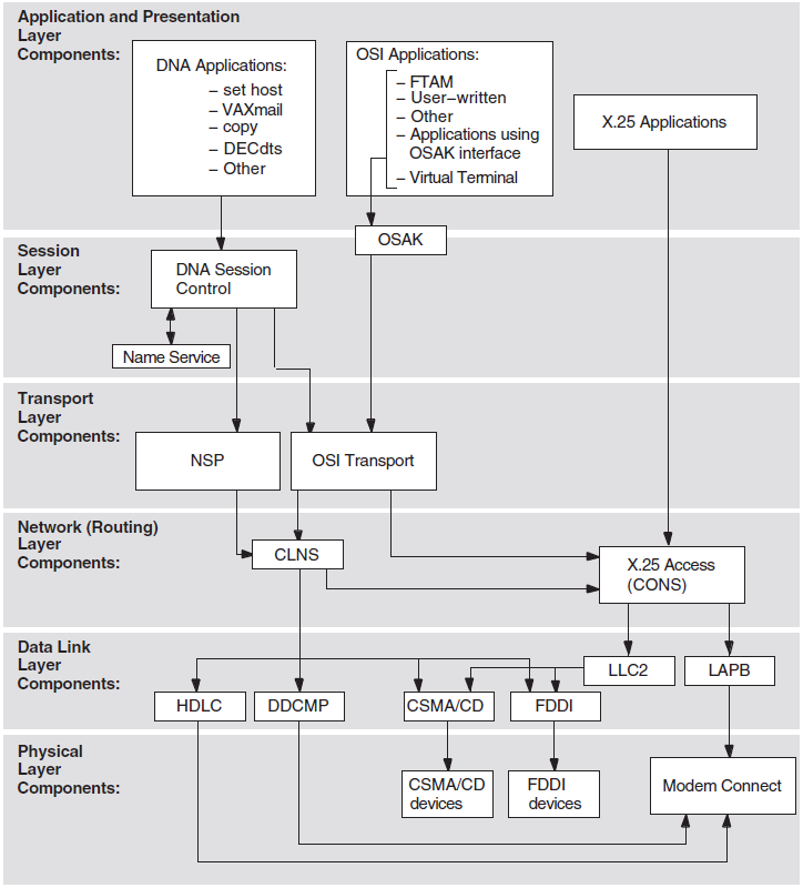
Figure 2.2, ''Component Relationships'' shows the relationship between the individual components in the DECnet-Plus environment on an OpenVMS system.
2.3.1. X.25 Native Software
A packet-mode DTE connected to a supported PSDN conforming to CCITT Recommendation X.25 (1980, 1984)
A packet-mode DTE connected to a CSMA-CD LAN conforming to ISO 8802-3 using ISO logical link control type 2 (LLC2) as specified in ISO 8881
A packet-mode DTE/DCE connected to a DCE/DTE conforming to ISO 7776 and 8208
X.25 can be configured for native operation to support direct connections from a VAX system to one or more PSDNs, each of which may have one or more DTEs. It also allows communication with any non-VSI X.25 system on the same LAN that supports the ISO logical link control type 2 (LLC2) protocol.
2.3.2. X.25 Access Software
X.25 Access uses a connector node to provide the physical connection to a PSDN. A connector node can be a DECNIS router 500 or 600 or X.25 configured in multihost mode.
DECnet-Plus logical links are established by OpenVMS to connect the X.25 Access system to the X.25 Connector system. These links may use any supported DECnet-Plus communications path between the X.25 Access system and the Connector system, provided they themselves do not use an X.25 connection. X.25 Access uses these links to transmit X.25 or X.29 messages between the Connector system and the X.25 Access system.
X.25 software provides Connection-Oriented Network Service (CONS) to allow mapping between a destination NSAP address and a destination DTE address according to ISO 8348.
Process-to-process (X.25) communications
Process-to-terminal (X.29) communications
Terminal-to-process (X.29) communications
2.4. Wide Area Network Device Drivers
The WAN device drivers included in DECnet-Plus for OpenVMS support synchronous communications. The device drivers all offer a supported user ($QIO) interface.
The device drivers all support full-duplex and half-duplex operation, where appropriate to the protocol. See the Software Product Description (SPD) for supported device drivers.
WAN device drivers include a pseudodriver (WANDRIVER) that provides a programming interface to the data link level for the LAPB, HDLC, and DDCMP protocols.
2.5. OSAK
The OSI Applications Kernel (OSAK) software allows you to run applications that can communicate with other applications running in an OSI environment. These applications can be VSI products, or they can be applications that you have written specifically for an OSI environment using the OSAK API. Writing OSI applications requires the OSI Application Developer's Toolkit which is installed with the base system.
To run an application using OSAK software, install the OSAK software wherever you run the application. For example, an application running on two DECnet-Plus systems uses the OSAK software on both systems, as shown in Figure 2.3, ''OSAK Software on DECnet-Plus for OpenVMS Systems''.

2.5.1. OSAK API
The Session layer
The Presentation layer
The Association Control Service Element (ACSE) of the Application layer
A set for making outbound requests and responses
A set for receiving inbound indications and confirmations
A set of housekeeping routines, which do not result in protocol exchanges
All calls to OSAK services are nonblocking because the OSAK API allows data to be
passed to OSAK either in a single call or spread over osak_select,
which you can use to block until a service request is complete.
You can check for completion of a nonblocking call by polling or, on an OpenVMS system, by asynchronous event notification. Asynchronous event notification is not available on an ULTRIX or UNIX system.
The OSAK programming guides contain more information about blocking and nonblocking calls.
OSAK uses a parameter block interface. You can allocate memory for the parameter block and the data structures it contains either statically or dynamically. The parameter block contains all possible parameters for all possible services. OSAK uses only the relevant parameters in each service call.
You must always pass parameters between your application and OSAK in encoded form. On OpenVMS or UNIX systems, you can use an ASN.1 (Abstract Syntax Notation One) compiler to help you do this.
2.5.2. OSAK Software and Management Facilities
An OSI upper layer protocol machine (see Section 2.5.2.1, ''Protocol Machine'')
Network control and management facilities (see Section 2.5.2.2, ''Network Control and Management Facilities'')
OSAK trace utility (see Section 2.5.2.3, ''OSAK Trace Utility'')
2.5.2.1. Protocol Machine
|
Standard |
Title |
|---|---|
|
ISO 8327 |
Information Processing Systems — Open Systems Interconnection — Basic Connection Oriented Session Protocol Specification |
|
ISO 8823 |
Information Processing Systems — Open Systems Interconnection — Connection Oriented Presentation Protocol |
|
ISO 8650 |
Information Processing Systems — Open Systems Interconnection — Protocol Specification for the Association Control Service Element |
|
ISO 9072–1 |
Information Processing Systems — Text Communication — Remote Operations — Part 1 |
|
NIST Version 3 |
NIST Special Publication 500-177 — Stable Implementation Agreements for Open Systems Interconnection Protocols, Version 3, Edition, 1 December 1989 |
2.5.2.2. Network Control and Management Facilities
Monitoring the OSI network
Creating a passive address (see Section 2.5.3, ''Active and Passive Addresses'')
You can use Network Control Language (NCL) commands to manage the OSAK software.
Address management facilities for applications that run over OSI Applications
Kernel software are provided through the OSAK module entity. The OSAK module
entity is an immediate subordinate of the global entity node. Note
that OSAK does not provide facilities for managing the applications
themselves.
You can find details of NCL command syntax for the OSAK module entity and its subordinate entities in the DECnet-Plus Network Control Language Reference guide or in the NCL on-line help.
2.5.2.3. OSAK Trace Utility
The OSAK trace utility consists of two components: the trace emitter and the trace analyzer. This utility enables you to trace the activity of the protocol machine, and can help you track the source of any problems that occur when applications are running.
At the ACSE level, trace information includes the ACSE protocol control information (ACSE-PCI) and user data. User data is traced in either hexadecimal or generic ASN.1 form.
At the Presentation layer, you can trace session service data units (SSDUs) containing user data and presentation protocol control information (PPCI).
At the Session layer, you can trace transport service data units (TSDUs) passed between the OSAK software and the transport service, which contain session protocol control information (SPCI) and user data.
2.5.3. Active and Passive Addresses
Active
An active address is available continuously to receive incoming connections. As soon as the OSAK software receives an incoming connection, the software passes the contents of the call directly to the appropriate application.
Passive
A passive address is registered in NCL in an
osak application
                                invocation
subentity. As soon as the OSAK software receives an incoming connection, the software confirms the transport connection and creates a process to handle the call. See the DECnet-Plus Network Control Language Reference guide for details of setting up a passive address. Also see the VSI DECnet-Plus OSAK Programming guide for details of the advantages and disadvantages of active and passive addresses.
2.6. FTAM
The File Transfer, Access, and Management (FTAM) software in DECnet-Plus for OpenVMS implements several standards that define the upper three OSI layers of the OSI Reference Model, including FTAM and ACSE components of the Application layer.
FTAM performs file operations and management between OSI-compliant systems. When implemented by different vendors, the FTAM standard enables the use of files on these vendors' systems. FTAM can transfer unstructured files with binary data and sequential text files with either a stream or variable record format.
To create and manage local files, FTAM uses the OpenVMS Record Management Services (RMS).
FTAM operates on files stored on both local FTAM systems (local files) and remote FTAM systems (remote files).
Using the DCL interface, you can copy, append, delete, rename, and inspect the file attributes of files on OSI-compliant FTAM systems.
Journaling supports FTAM's recovery and restart capability by maintaining a docket of recovery information. In the event of a recoverable error, FTAM tries to negotiate with the peer FTAM system for a recovery or restart.
2.6.1. FTAM Gateway
The DAP–FTAM gateway allows a DECnet-Plus node to participate in an OSI network in a simplified way. You can think of this software as a server that receives Data Access Protocol (DAP) messages through DECnet and uses that information to establish and maintain a connection with a remote FTAM system.
The DAP–FTAM gateway simplifies communications for DECnet-Plus nodes because users can issue DCL commands to communicate with remote OSI systems through the gateway. For the DCL user, communication with a remote FTAM application is handled the same as any DECnet dialogue.
2.7. Virtual Terminal (VT)
ISO 9040 Virtual Terminal Basic Class Service
ISO 9041-1 Virtual Terminal Basic Class Protocol — Part 1: Specification
VTP is an Applications layer protocol. This protocol allows remote logins and access to remote applications between DECnet-Plus systems and any remote systems, including multivendor systems, that also run an ISO-compliant VT implementation.
Entering a DCL command at your terminal
Using the Telnet/VT gateway
Using the VT/Telnet gateway
Using the LAT/VT gateway
Using the VT/LAT gateway
For VT concepts information, see the DECnet-Plus FTAM and Virtual Terminal Use and Management guide.
2.7.1. VT Gateways
Telnet/VT gateway — Telnet messages are received and translated into VTP messages.
VT/Telnet gateway — VTP messages are received and translated into Telnet protocol messages.
LAT/VT gateway — LAT messages are received and translated into VTP messages.
VT/LAT gateway — VTP messages are received and translated into LAT protocol messages.
With the VT gateways, systems that do not have a VT implementation can access systems that do.
2.7.1.1. LAT/VT and VT/LAT Gateways
Any computer terminal
Any personal computer running MS-DOS, OS/2, or Macintosh
Any OpenVMS or VMS V5.5 (or later) system
Any VMS V5.4 (or later) system, running the optional LAT software
You can also use the appropriate command from a remote OSI VT system to access a system using the LAT protocol.
2.7.1.2. VT/Telnet and Telnet/VT Gateways
If you have a VT/Telnet gateway on your network, you can use the
telnet command from an Internet system to access a remote OSI
system that has a Virtual Terminal responder installed. If you have a Telnet/VT
gateway, you can access the OSI system using the set host/vtp gateway
alias name command line.
2.8. Management Tools and Utilities
Network management is provided with the Network Control Language (NCL). Network management implements the DECnet-Plus layered model, based on the hierarchical structure called Enterprise Management Architecture (EMA).
System or network managers to control and monitor the operation of a network and provide information related to network traffic and performance.
Network operating parameters to be configured.
The manager to start up and shut down network components as needed once repaired.
In addition, network management software can provide information warning network managers of faulty or failing network components, both hardware and software.
2.8.1. Network Control Language (NCL)
NCL is the DECnet-Plus network management command-line interface. The structure and syntax of NCL reflects the DECnet-Plus internal structure of the network management components. NCL directives, or commands, let you manage DECnet-Plus entities by means of their unique network entity names.
NCL can also be used to test specific components of the network. NCL enables transmission and reception of test messages either between systems or through controller loopback arrangements. The messages can then be compared for possible errors. NCL aids in isolating network problems.
2.8.1.1. Network Management Graphical User Interface (NET$MGMT)
$ run sys$system:net$mgmt
The application will check for and load the Helvetica 12-point 75-pitch font. In the unlikely event that this font is not present, the application will exit with an error message.
Once you have started NET$MGMT, you can refer to the on-line help
pull down menus for more information. Also, refer to the
VSI DECnet-Plus for OpenVMS Network Management Guide.
2.8.2. Network Control Program (NCP)
DECnet-Plus for OpenVMS allows the use of NCP for the remote management of DECnet Phase IV nodes.
To aid the transition from DECnet Phase IV to DECnet-Plus for OpenVMS, the NCP emulator tool provides a necessary interface for the installation and use of layered products that issue DECnet Phase IV NCP commands.
The NCP emulator tool is not intended for management of DECnet-Plus for OpenVMS. It may be used to manage remote DECnet Phase IV nodes with the TELL and SET EXECUTOR NODE commands.
Because some NCP commands do not have equivalent NCL commands, VSI cannot guarantee that all layered products can be installed and used. For information on support for specific layered products, contact VSI.
The installation procedure places documentation for the NCP emulator tool in the file SYS$UPDATE:NCP_EMULATOR.TXT.
During installation, the DECnet Phase IV version of NCP is renamed
SYS$COMMON:[SYSEXE]NCP_PHASEIV.EXE and the NCP emulator tool is
placed in the file SYS$COMMON:[SYSEXE]NCP.EXE.
2.8.3. Common Trace Facility (CTF)
Suspected configuration problems
Failures while establishing or using network links
Network overload
Interoperability problems
Problems with name and address resolution
CTF is not supported by all DECnet-Plus software products. Refer to your Software Product Description (SPD) for further information.
2.8.4. CMISE API
DECnet-Plus for OpenVMS supports an ISO CMISE application programming interface (API) conforming to the Service Definitions in ISO 9595. The API allows for development of applications that can communicate with other management applications conforming to ISO 9595 on remote nodes in the network.
2.8.5. Network Management Support Tools
The decnet_register tool assists with setting up Local namespaces,
DECdns distributed namespaces, and managing the node names and addressing
information they contain. The decnet_migrate tool helps you perform
network management tasks and learn NCL.
- The
decnet_registertool manages node names in the namespaces used within your network.Registers node names, node synonyms, and addresses in your namespaces.
Adds addresses to a node registration.
Removes addresses from a node registration.
Modifies a node registration's synonym or addresses.
Displays a node registration and verifies its internal consistency.
Exports node registration information from a namespace to a text file.
Imports node registration information from a text file into a namespace.
Updates a node's registered address information with information it obtains from the node itself.
Renames a registered node in a namespace.
Deregisters a node from a namespace.
The
decnet_register managecommand invokes thedecnet_register_decdns.comcommand procedure (located insys$manager:) to create and manage the required DECdns namespace directories and to set their protections. - The
decnet_migratetool is useful for network management support:Converts NCP commands to NCL commands.
Creates and edits NCL files using a Language-Sensitive Editor (LSE).
Gathers and reports detailed information about the network's current configuration.
Sets up interphase routing link-creation commands for use by Phase V routers.
2.8.6. DECnet-Plus Event Dispatcher (EVD)
The DECnet-Plus for OpenVMS Event Dispatcher (EVD) software reports significant events that occur during network operation. An event is an occurrence of a normal or abnormal condition that an entity detects. As directed by you, DECnet-Plus for OpenVMS maintains records of specific or general categories of events. These records can help you track the status of network components.
Many events are informational. They record changes that you or the DECnet-Plus for OpenVMS software makes to components of the local system, or to those remote system entities that the local system's Event Dispatcher is tracking. Other events report potential or current problems in the physical parameters of the network.
You can set up event dispatching on a particular system, between two systems, or across multiple, distributed systems. The event-dispatching component can report events that occur on any system that runs DECnet-Plus software, and it is also capable of logging the events of remote Phase IV nodes via the DECnet-Plus Event Dispatcher relay.
2.8.7. CMIP Management Listener (CML)
The CMIP Management Listener (CML) is the DECnet-Plus management module that implements DNA Common Management Information Protocol (DNA CMIP). CMIP defines the exchange of network management information.
CML provides access to CMIP. NCL accesses management directives defined for DECnet-Plus entities using CMIP.
Chapter 3. DECnet-Plus for OpenVMS Concepts
All Open Systems Interconnection (OSI) communications software implements global standards that are developed by the International Organization for Standardization (ISO). An OSI standard specifies a protocol or defines a service for one functional layer of the OSI Reference Model.
This chapter introduces OSI architecture, protocols, and standards, and how they apply to DECnet-Plus for OpenVMS.
3.1. Communications Architecture: The OSI Reference Model
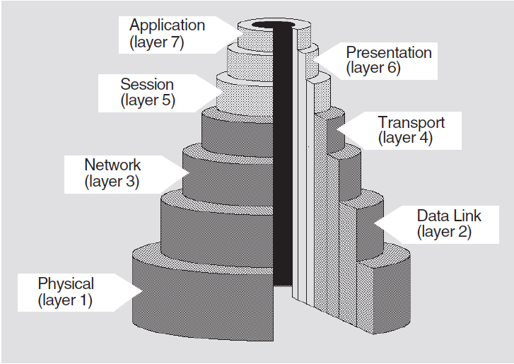
The OSI Reference Model is a hierarchical architecture of seven layers for data exchange between systems with incompatible operating systems. The architecture provides standard protocols, services, and interfaces so systems that implement these standards can communicate. Figure 3.1, ''OSI Reference Model'' shows the OSI layers.
|
Layer |
Name |
Responsibilities |
|---|---|---|
|
Upper Layers | ||
|
7 |
Application |
Provides for distributed processing and access; contains the application programs and supporting protocols (including File Transfer, Access, and Management (FTAM) and the Association Control Service Element (ACSE)) that use the lower layers; has no formal upper boundary, since it includes application programs and their individual user interfaces. |
|
6 |
Presentation |
Coordinates the conversion of data and data formats to meet the needs of the individual application processes. |
|
5 |
Session |
Organizes and structures the interactions between pairs of communicating application processes. |
|
Lower Layers | ||
|
4 |
Transport |
Provides reliable, transparent transfer of data between end systems, with error recovery and flow control. |
|
3 |
Network |
Permits communications between network entities in open systems on a subnetwork, intermediate systems, or both. |
|
2 |
Data Link |
Specifies the technique for moving data along network links between defined points on the network, and how to detect and correct errors in the Physical layer. |
|
1 |
Physical |
Connects systems to the physical communications media. |
3.1.1. Comparison of DNA Phases
|
DNA Phase IV |
DNA Phase V |
|---|---|
|
DECnet and User Application layer |
DECnet, OSI and User Application layer |
|
Session Control layer |
Presentation, Session layers |
|
End Communications layer |
Transport layer |
|
Routing layer |
Network layer |
|
Data Link layer |
Data Link layer |
|
Physical Link layer |
Physical layer |
3.2. Data Flow
Except for the Application layer, each layer provides a service to the layer immediately above (its user). Every layer is supported by all the lower layers, and adds functional value to the service available from the layer immediately below. For example, the Transport layer adds in-sequence delivery of data and also retransmission of data lost by the lower layers. Figure 3.2, ''OSI Reference Model: Data Flow'' shows how data flows during communications.
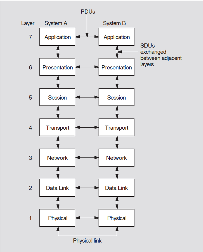
Entities within each layer on one system use the services provided by its next lower layer to communicate with other (peer) entities on a second system.
3.3. OSI Terminology
The Reference Model is a network design of layers that work together. Each layer is an independent and self-contained group of interconnected functions with its own purpose and protocols. Layers also provide services. Each layer uses the services provided by the layer beneath it.
Protocol specification — defines the protocol rules and formats.
Service definition — describes the capabilities of the protocol or the service it provides.
3.3.1. Protocols
A protocol is a set of rules and procedures. Protocols govern the behavior of open systems at each layer. Some layers (for example, the Application layer) have several protocols.
A protocol machine is software that implements a particular protocol.
A protocol data unit (PDU) is information made up of protocol control information (PCI) from the current layer and, possibly, user data from the layer above. PDUs are exchanged between peer protocol machines using service primitives. A given service primitive can correspond to zero, one, or more PDUs. The integrity and identity of a PDU remains intact while it is being exchanged.
The underlying layer places each PDU received from the above layer into a service data unit (SDU). The SDU becomes user data in the PDU of its underlying layer. PDUs remain intact until they arrive at the protocol machine of the peer entity. The peer's protocol machine separates the PCI from user data and processes the PCI. Figure 3.3, ''The Relationship of PDUs, User Data, and SDUs'' shows the relationships among the PCI, user data, SDUs, and PDUs.
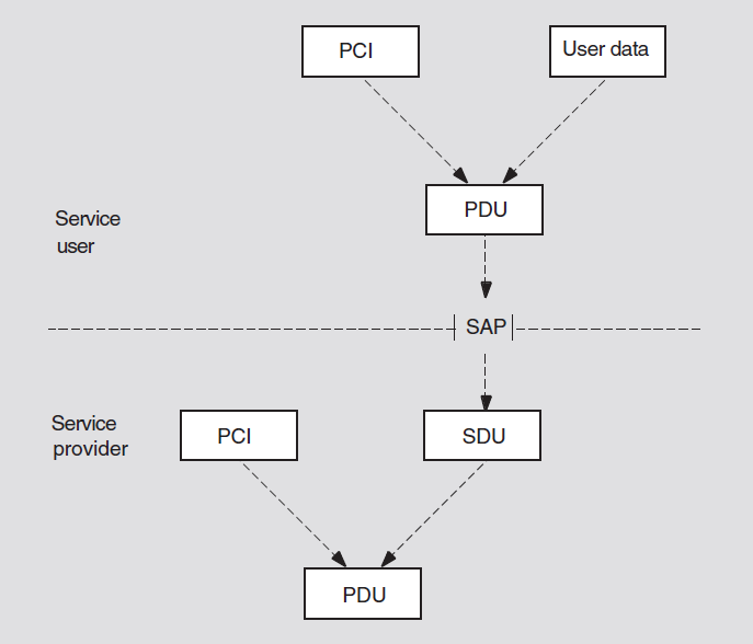
3.3.2. Protocol Stacks (Towers)
Applications can communicate with each other only if they agree on the protocols they both will use and the operational parameters of these protocols. Also, exact address information is needed to indicate to each layer of protocol where to deliver data. This required information is encoded in a protocol stack or protocol tower, which is a data structure for encoding address and protocol information about a service user (application). The tower is a protocol sequence (an ordered list of protocol identifiers for each layer from the Network layer upward) with associated address and protocol-specific information.
3.3.3. Dialogues
OSI protocol machines ensure that open systems can establish message exchanges, called dialogues. Though many dialogues can occur simultaneously, each dialogue is independent of other dialogues. Protocol machines cooperate to conduct a dialogue through a predictable sequence of states. The portion of a dialogue conducted at the Application layer is called an association; the portions of dialogues conducted at other layers are called connections.
Associations or connections are established between service users by their peer service providers; for example, the Association Control Service Element (ACSE) establishes FTAM associations. Connections use the name of the service provider that establishes them; for example, a connection established by Presentation for ACSE is called a presentation connection.
3.3.4. Entities
Protocol machines operate within system-specific implementations, or processes. For every dialogue, one or more processes activate the protocol machines of each layer independently. An instance of such protocol-machine activity is called an entity. OSI entities, which are the manageable components that make up the network, relate to entities on other systems for example, a routing circuit. The relationship between processes and entities is implementation-specific.
Each entity communicates with equivalent entities on different systems, called peer entities.
3.3.5. Services
A service is an interface provided by a service element or a layer for accessing one or more functions. An application service element (ASE) is a component that provides an application-level function. FTAM and ACSE are examples of service elements.
The service element or layer that provides a service is called a service provider. An application program, service element, or layer that uses a service is called the service user.
3.3.5.1. Service Primitives
Request and indication primitives — exist for all services
Response and confirm primitives — exist for confirmed services
Each pair of service primitives generates only one unit of user data, a protocol data unit (PDU).
Request and response primitives begin with service users, which use those primitives to request services and negotiate parameter values.
Indication and confirm primitives begin with service providers, which use those primitives to pass on information that comes in for their users.
3.3.5.2. Service Access Points (SAPs)
A service provider delivers services to a service user at an interface called a service access point (SAP). A SAP is the point at which an entity provides a service to a user entity in the layer above.
Figure 3.4, ''Service User, Service Provider, and SAP Interaction'' shows how a service user, a service provider, and a SAP interact.
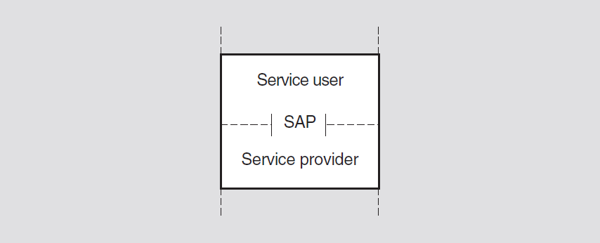
Except for the Application and Physical layers, SAPs exist at the boundaries of all OSI layers. SAPs are named according to the layer providing the services. For example, transport services are provided at a Transport SAP (TSAP) at the top of the Transport layer and any SAP that the Presentation layer provides is called a Presentation SAP (PSAP). Figure 3.5, ''SAPs at Different OSI Layers'' illustrates SAP nomenclature.
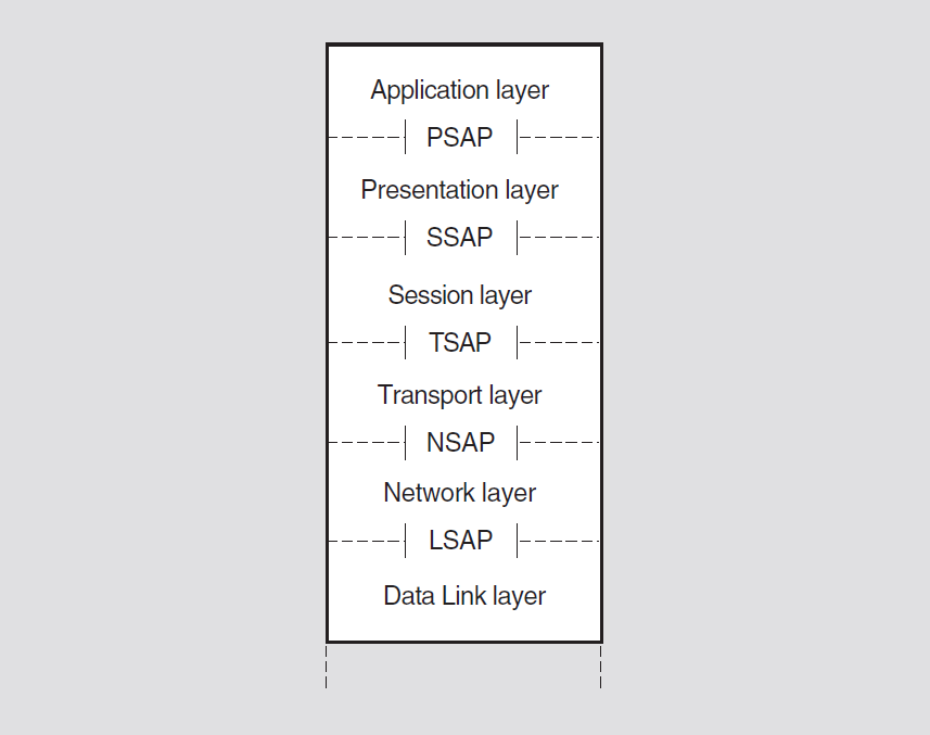
SAPs are logical constructs defined by an identifier called a SAP selector. To create a SAP, a system manager or application user defines a unique SAP selector for a specific layer. SAP selectors are the building blocks of addresses.
A given address takes the name of the uppermost SAP that contributes a selector to the address. For example, a presentation address accesses the Application layer.
A presentation address (p-address) contains one or more SAP selectors at the upper layers. The composition of a given address depends on the purpose of the address. For example, an address that allows the Transport layer to access the Application layer has SAPs at three layers: Transport, Session, and Presentation. A p-address is used for upper-layer addressing and has SAPs at four layers: Network, Transport, Session, and Presentation.
SSAP — 1-byte field in an LLC frame that identifies the link service access point (LSAP) of the sending client protocol. (The LSAP is the ISO 8802-2 (LLC) protocol identifier that identifies a Network layer entity.)
DSAP — 1-byte field in a LLC frame that identifies the LSAP of the receiving client protocol.
3.4. The Upper Three OSI Layers
Each of the upper three layers provides services for user and application processes.
The Session layer service is used by a pair of communicating application processes to structure and control their dialogue, conducted over the transport connection.
The Presentation layer works in conjunction with the Session layer to provide a specialized data transfer service to the Application layer. It coordinates any necessary conversion of data between a pair of communicating application processes.
Because the semantics and syntax used by one application are unlikely to be the same as those used by another on a different system, the Presentation layer transfers data in a system-independent way. The data must be in a form that both applications can recognize; for example, data with floating-point numbers can pass between two systems even if each system has a different internal representation of floating-point numbers.
The Application layer contains many different entities, including the parts of an application program that interact with the communications environment on a system. The Application layer has a mixture of standard protocols. Some directly support application processes, others support those that give direct support to the application processes, and some do both, such as the ACSE protocol.
3.4.1. Presentation and Session Entities
Presentation and Session entities provide the Presentation and Session connections. To form an association, an OSI application entity requires a corresponding Presentation entity and Session entity. For the FTAM software, for example, these Presentation and Session entities occur within the same process as the FTAM entity.
Presentation handles syntax transformation and also establishes Presentation contexts and manages them, if necessary.
Presentation and Session both perform connection management functions for their own connections.
Session also transfers information and manages each dialogue between peer Application entities.
Presentation supports this use of Session services by providing the Application layer with a set of services that correspond to the data-transfer and dialogue-management services of the Session layer.
3.5. DNA Session Control Layer
The Session Control layer provides the DNA user and application interfaces. Session Control performs address resolution and selection, connection control,and manages transport connections on behalf of applications. It also supports the applications environment, including $IPC and $QIO programming interfaces.
3.5.1. Objects and Applications
A Phase IV object (also referred to as a Phase IV application) is a VSI or user-written component that is identified by a number and associated name (for example, object number 27 for mail). This information is stored in an object database at each Phase IV node.
A DECnet-Plus application is equivalent to a Phase IV object. DECnet-Plus applications are identified by program name and can be specified in the application database at the system.
A DECnet-Plus object or object entry is a resource name stored in a namespace. The resource can be a system, a service made available by an application, or some other resource.
3.5.2. Protocol Towers
The sequence of protocol identifiers in a protocol tower typically extends from the Network layer up to the DNA application. Session Control builds and maintains multiple towers for the local node object: one tower for each protocol and each address through which Session Control can access the object. A protocol tower set includes all the protocol towers that the system builds for the object.
When a DNA application on one node requests a connection to another node, Session
Control requests that DECdns provides DNA$Towers attribute information
for the remote node. Session Control compares the tower information with the tower
information it maintains for the local node and selects a protocol tower common to
both nodes. The connection is then made automatically without a user or application
needing to know what lower-layer protocols the nodes are using.
3.5.3. Address Resolution
- Maintains, in the namespace, the following information in the
DNA$Towersattribute for local objects:Protocols supported on the local system
DECnet-Plus network address of the local system
Obtains information about the remote object from the namespace to determine the sequences of protocols and address information required to communicate with the remote node or application.
Selects all common towers and passes this information to the address selection function.
You can autoconfigure addresses for DECnet-Plus systems, which can change over time. Session Control creates and maintains the protocol and address information in the towers in the namespace for the node object entry.
Session Control supports a RegisterObject function to maintain the
address attribute of an object entry if the underlying protocol tower address
element of the node changes. Applications can request that Session Control perform
this function for their objects.
3.5.4. Address Selection
The Session Control layer initiates a connection based on the address of a system and the Session Control application being connected to that system. It receives a list of common protocol towers with the address-resolution function and looks for a set of mutually supported protocols. It tries to make a connection using all towers in common; the connection fails if all towers are tried and none works. The selected protocols and address information are used for communication with the remote system.
3.5.5. Connection Control
The Session Control layer performs connection services for Session Control applications. It requests, maintains, and disconnects or aborts transport connections. Session Control can request a connection using the destination address. It can receive a connect request, validate the access control information supplied with the request, and identify the remote application making the request. The Session Control layer sends and receives data over transport connections.
The Session Control layer forms the interface between all DNA applications and the Transport layer. It allows use of the NSP Transport and OSI Transport protocols.
3.5.6. VSI-Supplied Session Control Layer Applications
Session Control applications in DECnet-Plus for OpenVMS provide general-purpose network services. A Session Control layer application is identified by application type, which is a discrete numeric identifier for either a user task or a DECnet-Plus program, such as file access listener (FAL). DECnet-Plus for OpenVMS uses application type numbers to enable logical link communications using the NSP Transport Service or the OSI Transport Service.
Applications with a 0 application type
These applications are usually user-defined images for special-purpose applications. They are named when a user requests a connection.
Nonzero applications
Nonzero applications are known applications that provide specific network services such as FAL. They can also be user-defined tasks; these applications should be for user-supplied known services. Application type numbers for all nonzero applications range from 1 to 255. The number serves as a standard addressing mechanism across a heterogeneous network.
3.6. Transport Layer
The Transport layer ensures the reliable transfer of data. Each Transport protocol provides for the establishment of a transport connection, which carries a stream of two-way communications traffic between two processes on the same or different systems. A transport connection is a temporary logical connection that normally exists until one of the processes terminates the connection.
The Transport layer offers an interface to the service user at the Session layer. DNA applications can use either the $IPC or $QIO programming interface to make a connection request through the proprietary Session Control layer to the Transport layer. OSI applications can make connection requests through ACSE, the Presentation layer, and the Session layer to the Transport layer.
3.6.1. Transport Layer Ports and Session Layer Ports
DECnet-Plus uses a mechanism called logical link for communication between processes. A Phase IV logical link in DECnet-Plus terms is either a Transport layer port or a Session layer port.
A logical link is a temporary connection either between processes on source and destination systems or between two processes on the same system. A logical link carries a stream of regular data and interrupt data of full-duplex traffic between two user-level processes. Each logical link is a temporary data path that exists until one of the two processes terminates the connection.
3.6.2. Supported Transport Protocols
The OSI Transport Protocol, the implementation of which provides the OSI Transport Service, bridges the gap between the service provided by the network and the service desired by the transport user.
The Transport layer supports both the NSP and the OSI Transport Protocols. An OSI application makes a connection request to the Transport layer to access the OSI transport. The choice of protocol for a non-OSI connection is made during connection establishment: either the connect request specifies a Transport protocol, or the Session layer selects an appropriate Transport Protocol. Multiple transport connections, using any of the Transport Protocols, can be made simultaneously.
3.6.2.1. OSI Transport Protocol
The OSI Transport Protocol permits communication between DECnet-Plus systems and other vendors' systems that also implement the OSI Transport Protocol.
The OSI Transport Protocol conforms to the ISO 8072 Service Definition and the ISO 8073 Protocol Standard. They define OSI Transport Protocol classes 0, 2 and 4 (TP 0, TP 2, and TP 4).
Connection-Oriented Network Service (CONS)
Connectionless-Mode Network Service (CLNS)
The OSI transport conforms to the RFC 1006 Standard and to the RFC 1006 extension Internet Draft. They define how to implement ISO 8073 Transport Class 0 on top of TCP (RFC 1006) and how to implement ISO 8073 Transport Class 2, non-use of Explicit Flow Control on top of TCP (RFC 1006 extension).The network service used is provided by TCP.
|
Protocol Class |
Functions |
Network Service |
|---|---|---|
|
TP 0 |
Provides a basic transport service. |
CONS and RFC 1006 |
|
TP 2 |
Provides all functions of TP 0 plus multiplexing of more than one transport connection over a network connection or TCP connection. Also provides flow control over CONS. |
CONS and RFC 1006 extension |
|
TP 4 |
Provides all functions of TP 2 plus error detection and recovery. |
CONS and CLNS |
TP 0 relies on the upper layers to do its error correction. This class is disconnected if the underlying Network layer is disconnected.
TP 2 and 4 use disconnect requests.
TP 4 reassigns the OSI transport connection to another Network layer connection if the existing one fails.
VSI recommends TP 4 for both DNA and OSI applications because it has the greatest set of capabilities suitable for all purposes, unless when using RFC 1006 or RFC 1006 extension.
When a transport user sets up a transport connection, a preferred protocol class for the connection is specified in the connection request. The responding transport user must either agree to this protocol class, or suggest an alternative protocol class that is acceptable to the initiating user. If no such agreement is possible,the transport connection cannot be set up.
3.6.2.2. Network Services Protocol (NSP)
The proprietary NSP provides a transport service that supports error detection and recovery and uses CLNS. NSP capabilities are similar to those of OSI Transport Protocol class 4 for CLNS connections.
NSP makes a transport connection between two DECnet-Plus systems or between a DECnet-Plus system and a Phase IV system. NSP is the only transport that can connect to Phase IV systems.
NSP establishes transport connections by exchanging control messages with a peer NSP module. The connection comprises two data subchannels, one for normal data exchange and one for other data (such as expedited data messages and flow control messages). NSP transfers data in segments, if necessary. The segments are then reassembled in correct sequence at the destination.
3.6.3. OSI Transport Service
The Transport layer provides the OSI transport service, which fulfills communications requirements for clients in the higher layers. The OSI transport service software implements the OSI Transport Protocol, allowing two OSI transport users to set up and use an OSI transport connection. A transport user uses the OSI transport service to set up a transport connection with another transport user.
The OSI transport service is a consistent interface to transport users, regardless of the type of network over which they make OSI transport connections.
DECnet-Plus for OpenVMS offers three classes of OSI transport service, each of which is appropriate to a particular network service because each provides the additional functions not provided by that service. TP 0, 2, and 4 identify the different classes of OSI transport service offered in DECnet-Plus for OpenVMS (see Table 3.3, ''Functions of the OSI Transport Protocol Classes'').
3.6.3.1. OSI Transport Service Functions
Mapping OSI transport connections to transport users
When making an OSI transport connection, the transport user provides a unique reference for each of the two communicating transport users. This reference is a called a transport service access point (TSAP). Messages sent over an OSI transport connection include the TSAP of the transport user to which they are addressed. The OSI transport service uses this TSAP information to route messages to their proper destination.
Multiplexing OSI transport connections
The OSI transport service uses a single network connection to send and receive message traffic for several OSI transport connections. This process is called multiplexing.
Splitting and recombining data
The OSI transport service software cannot split an OSI transport connection among several network connections. However, the software does recombine incoming data from multiple Network connections for a particular transport connection.
Concatenating Transport layer protocol data units
Messages sent over an OSI transport connection are in the form of Transport layer protocol data units (TPDUs). To reduce the traffic between the Transport and Network layers, the OSI transport service software concatenates certain TPDUs to make one network service data unit (NSDU). The software does this with one AK (acknowledge) TPDU and one data TPDU from the same transport connection. The software never concatenates other types of TPDUs, nor TPDUs from different transport connections. The OSI transport service software processes incoming NSDUs if the combination of TPDUs is within the Transport Protocol standard.
Controlling flow
The transport users at either end of an OSI transport connection might operate at different speeds. The OSI transport service software uses flow control to stem the output from a local user when the user at the other end cannot process the data at the required rate to keep up. Without flow control, one user could send messages over the connection faster than the other user could receive and process them, leading to the receiving user running out of buffers and discarding the messages.
The OSI transport service software in DECnet-Plus for OpenVMS always uses flow control with class 2 connections when operating over CONS.
Providing error detection and recovery
In addition to setting up the OSI transport connection for data transfer, the OSI transport service ensures that the message exchange occurs without corruption or loss of data, and that the messages are delivered in sequence. The OSI transport service keeps a record of all the messages sent and received and their sequence, and, if they have not been received by the other end, retransmits them.
The software calculates the retransmission timers for each network. An X.25 network, for example, is very likely to need a longer retransmission timer than a LAN.
3.6.3.2. OSI Transport Templates
When a transport user makes a connection request, one of the parameters of this request is the name of a transport template, which is a predefined set of parameters for setting up the OSI transport connection. An OSI transport template specifies the type of network service to be used for the OSI transport connection, and the preferred protocol class.
You can use an OSI transport template to provide defaults for any parameters not included in the connection request.
3.6.3.3. OSI Transport Connections
Setting up the connection — an OSI transport user (the initiating user) on one end system (the initiating host) sends a connection request TPDU to another OSI transport user (the responding user) on a second end system (the responding host). When a successful connection is made, data transfer can take place in either direction.
- Using the connection through which to transfer data — OSI transport connections support two kinds of data transfer:
Normal data transfer for usual message exchange or
Expedited data transfer which bypasses any blockage due to the flow control applied to normal data; only for sending small amounts of data; has its own type of TPDU and transmission rules.
Releasing the connection — either transport user can release the OSI transport connection by sending a disconnect TPDU.
Between two systems on the same ISO 8802-3 LAN.
Between two systems that are connected, either directly or via an X.25 connection.
Between two systems that are connected directly by an X.25 point-to-point link.
Between two systems on different subnetworks, where the linking subnetworks might mix technologies.
Between two systems that are connected via TCP/IP.
3.7. Network Layer
ISO 8473 — Internetwork Protocol (Inactive Network Layer Protocol)
ISO 8208 — X.25 Packet-Level Protocol (PLP)
ISO 8878 — X.25 to provide CONS
ISO 9542 — ES-IS Routing Exchange Protocol
ISO 10589 — IS-IS Routing Protocol
3.7.1. Network Services
Broadcast subnetworks, such as ISO 8802-3 LANs
Nonbroadcast subnetworks of permanent point-to-point links,such as leased or private links
Nonbroadcast subnetworks
Dynamically assigned X.25 data links
An OSI transport connection between two OSI transport users is supported by a network connection between the end systems on which the OSI transport users are running. This network connection is set up and maintained by the Network layers of the two end systems. The Network layer, therefore, provides a network service to the OSI transport service.
Connectionless-Mode Network Service (CLNS)
Connection-Oriented Network Service (CONS)
Similarities: Peer entities communicate according to an agreed protocol through the services provided by the lower layer.
- Differences:
In connection-oriented transmission, resources have to be reserved to support data exchange on the connection that are not needed in connectionless transmission.
In connectionless transmission, each access to a data service needs additional addressing information. This overhead is avoided when the data exchange takes place using a connection-oriented service.
The connectionless service offers greater flexibility for implementing routing techniques.
Service-type conversion takes place only in the Transport and Network layers. This means, for example, that a presentation connection must be supported by a session connection, but that a change to using the connectionless network service can be done through the functions of the Transport layer.
The type of network service used depends on the topology of the network between the two end systems. The transport user selects the type of network service for a transport connection by supplying in the connection request a transport template that specifies the desired service.
3.7.1.1. Connectionless-Mode Network Service (CLNS)
X.25 static circuits
An X.25 virtual circuit is permanently assigned to the circuit. Network management enables the circuit and establishes and clears the calls. The connection is maintained until the circuit is turned off.
X.25 dynamically assigned circuits
An X.25 virtual circuit is created only when data needs to be transferred. These circuits are similar to Phase IV data link mapping (DLM) circuits.
To exchange data, users do not first set up and subsequently release a connection. Data exchange is achieved with each access to a service.
Each data transfer is entirely self-contained. All the information needed to deliver the data is given when the service is invoked.
Broadcast circuits
Circuits on which multiple systems are connected. A message can be transmitted to multiple receivers and all systems are adjacent, for example, ISO 8802-3 (CSMA-CD) LANs.
Point-to-point (nonbroadcast) circuits
Circuits that connect only two systems. A point-to-point configuration requires a separate physical connection between each pair of systems that communicate directly with each other. Examples are HDLC, DDCMP, and X.25 static circuits.
X.25 dynamically assigned (DA) circuits
Circuits used to exchange Internet (ISO 8473) PDUs over a PSDN to another system, either DECnet-Plus or multivendor. The ES-IS Protocol (ISO 9542) does not run over an X.25 DA circuit.
CLNS with Internet/ES-IS (end-system-to-intermediate-system routing)
Any transport connection can use CLNS with Internet/ES-IS. The communicating end systems can be on the same or different subnetworks. This network service is provided by the implementation of the ES-IS Internet routing protocols, which route packets from the end system to an intermediate system on the same subnetwork. The intermediate system ensures that packets reach their final destination. Two end systems that implement ES-IS on the same subnetwork can communicate without an intervening intermediate system.
CLNS with the Inactive Network Layer Protocol
A transport connection can use CLNS with the Inactive Network Layer Protocol (ISO 8473) when the two end systems are on the same LAN. This network service is provided by the inactive subset of the Internet Protocol. No intermediate system is involved in the network connection.
Both forms of CLNS support only TP 4 connections.
3.7.1.2. Connection-Oriented Network Service (CONS)
Connection-Oriented Network Service is provided to OSI transport and operates according to a connection-oriented model. A connection is set up between two communicating end users, is used for data exchange, and is then broken by either end. SDUs sent over the connection do not have to contain a destination address. For example, X.25 provides this type of service.
The users, supported by their service providers, set up a connection by negotiating the context for data transfer.
The connection has a definite lifetime because after it is set up and data exchange has taken place, it is released by the users (or the service providers).
The connection exists specifically between two users, allowing them to make multiple data transfers without specifying the destination on each transfer.
Between two systems attached to a PSDN, either directly or via an X.25 gateway.
A point-to-point connection to a DTE using the Link Access Protocol Balanced(LAPB) as the data link protocol.
A direct connection between two systems on the same IEEE 802.3LAN, using the logical link control (LLC) type 2 (LLC2) protocol.
Note that in each of these cases, the two end systems are on the same subnetwork.
3.7.2. Broadcast Network Connections: The Routing Process
With CLNS, the Network layer receives user data from the Transport layer and determines the path along which the data travels to its destination. This decision process is the main function of routing. The Network layer provides end-to-end data transfer, or routing, as a service to clients in the Transport layer. This data transfer between the two communicating systems is called a network connection.
An end system (ES) is either the source or destination of data sent over a network connection. An end system receives data units, called packets, addressed to it and sends data units to other systems on the same subnetwork. DECnet Phase IV calls this type of system an "end node" and the "subnetwork" an area.
An intermediate system (IS) is a routing system that receives data packets from a source end system, or from the previous intermediate system on the route, and passes them on to the destination end system, or to the next intermediate system on the route. (DECnet Phase IV calls this type of system a "router.")
An intermediate system interconnects two subnetworks. A subnetwork is a network, within a group of interconnected networks, of OSI systems that all use a common addressing format. A subnetwork forms an autonomous whole, for example: ISO 8802-3 (CSMA-CD) LAN, HDLC data link, or X.25 connections.
In the Network layer, the ES-IS protocol (ISO 9542) provides the communication between an end system and the nearest intermediate system. ES-IS is a connectionless protocol. IS-IS protocol (ISO 10589) provides the communication between two intermediate systems. The Internet standard provides the end-to-end connectionless link between end systems. Figure 3.6, ''ES-IS and IS-IS Protocols'' shows how ES-IS relates to other ISO protocols.
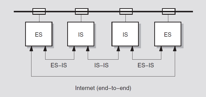
Routing circuit — connection between the Network layer and the Data Link layer below. Routing circuits operate over physical lines. A routing circuit is a logical (virtual) link.
Routing port — connection between the Network layer and the Transport layer above.
For additional information on routing, see the VSI DECnet-Plus Planning Guide.
3.7.2.1. Compliance with OSI Packet Formats and Addressing
An OSI administrative domain consists of a combination of end systems, intermediate systems, and subnetworks. You can also subdivide the administrative domain into routing domains, in which all systems and subnetworks use the same routing protocols.
The Network layer complies with the ISO standards for network packet formats and addressing. Data messages are forwarded through the network in self-contained packets that include the source and destination addresses.
DECnet-Plus for OpenVMS systems support the packet format that is specified in ISO standard 8473, and can exchange data with other vendors' systems that also conform to the ISO packet format standard.
The Network layer accepts messages from the Transport layer and encloses them in packets called network protocol data units (NPDUs). The NPDU includes the Network layer header that contains the source and destination addresses for the data. The Network layer address for a system is called the network service access point(NSAP). The NSAP is located at the boundary between the Network layer and the Transport layer, where communication between the layers takes place. For complete information about NSAPs, see the VSI DECnet-Plus Planning Guide.
The Network layer uses the destination NSAP address to forward the NPDUs to the destination system. The Network layer also provides compatibility with Phase IV.
3.8. Data Link Layer
The Data Link layer provides a communications path between directly connected systems in a network. It controls the movement of information between systems, including the transmission and receipt of data. In providing delivery of data to the adjacent node, the Data Link layer performs some or all of the following functions: establishment of the link (initializing and conditioning the line), error detection and recovery, data flow control, data framing control, and packet sequence control.
DECnet-Plus for OpenVMS uses synchronous, asynchronous (VAX only), Ethernet, and FDDI communications controllers to interface with other network nodes.
LAN connectivity is provided by the CSMA-CD and FDDI controllers and drivers supporting ISO 8802-2 logical link control (LLC) type 1 connectionless service and ISO 8802-3 LLC type 2. DECnet-Plus also supports Ethernet V2 packets on CSMA-CD devices.
Use of FDDI packets larger than 1500 bytes requires a Phase V router on the FDDI LAN. As with cluster alias support, the Phase V router may be configured to run the Phase IV distance vector routing protocol or the Phase V Link State Routing Protocol.
WAN connectivity is provided by WAN device drivers supporting host-based synchronous communications options for wide area networking.
All the data link devices support DDCMP, HDLC/LAPB and SDLC protocols. BISYNC and GENBYTE (VAX only) protocols are also supported on some options. WAN device drivers are required by X.25 to establish host-based wide area connections.
Synchronous controllers use DDCMP or HDLC, either when directly connected or when connected via modems, to provide full- or half-duplex communications over point-to-point lines. Synchronous DDCMP multipoint tributary connections are also supported. Asynchronous controllers (on VAX systems) use DDCMP, either when directly connected or when connected via modems, to provide only full-duplex communications over point-to-point lines. Error correcting and data suppression modems are not supported.
Asynchronous lines (on VAX systems) are supported only to other systems running DECnet-Plus for OpenVMS VAX, DECnet-VAX, DECnet-RSX, and DECnet-DOS.
DDCMP operation (on VAX systems) is not supported in cases where an asynchronous physical communications line is emulated by lower-level protocols or communications subsystems. Examples of this include X.29 virtual terminals, asynchronous connections as emulated by terminal servers, and connections via data switches.
DECnet-Plus for OpenVMS allows up to four circuits to be defined and operational on an end system. This capability allows a single end system to be connected to up to four separate LANs or WANs. Note that all circuits must be equal in capacity and connectivity.
3.8.1. Support for CSMA-CD Protocol on a LAN
The Data Link layer allows the transmission of data over a local area network cable by means of the CSMA-CD (Carrier Sense Multiple Access with Collision Detection) protocol. CSMA-CD ensures equal access to multiple systems connected to the LAN. DECnet-Plus for OpenVMS supports both the existing Ethernet protocol and the protocol that complies with ISO 8802 (also known as IEEE 802).
The Ethernet and ISO 8802 protocols are compatible, with only slight differences in packet format. A DECnet-Plus system transmits in both ISO and Ethernet formats, and listens for frames in ISO and Ethernet formats. If a Phase IV system is connected to the LAN, the DECnet-Plus system also transmits in Ethernet format.
CSMA-CD LANs are similar to LANs defined by ISO 8802-3. LANs are privately owned, reliable, high-speed networks that connect information-processing systems in a limited geographic area, such as an office, a building, or a complex of buildings. It is a best-effort delivery system.
CSMA-CD allows multiple stations to access the broadcast channel at will, avoids contention by means of carrier sense and deference, and resolves contention by means of collision detection and retransmission. Each station awaits an idle channel before transmitting and can detect overlapping transmissions by other stations.
CSMA-CD stations provide for multiaccess connection between a number of systems on the same broadcast circuit. This kind of routing circuit is a path to many systems. Each system on one CSMA-CD station is considered adjacent to every other system on that station and equally accessible.
The media is passive coaxial cable or shielded twisted-pair cable that uses Manchester-encoded, digital baseband signaling, with interconnections containing all active components so that no switching logic or central computer is needed to establish or control communications.
At the Data Link layer, network control for the LAN is multiaccess, fairly distributed to all systems. The frame length allocation is from 64 to 1518 bytes (including an 18-byte envelope).
A LAN communications controller
A transceiver
A transceiver cable
When manufactured, LAN controllers are given a 48-bit hardware address.
A particular ISO 8802-3 system is identified by the hardware address of its station (line); this hardware address is stored in read-only memory in the LAN controller. When DECnet-Plus starts a CSMA-CD station, it constructs a physical address for the system. When you shut off machine power or change the state of the CSMA-CD station to off, the LAN controller resets the physical address to the original hardware address.
- When no intermediate system is on the LAN:
An end system trying to communicate with another end system sends the data by using a specific multicast address.
Only a system whose link service access point (LSAP) matches the destination DSAP in the multicast packet will respond. The destination system responds with an end system hello, sent directly to the originating system, informing the source system of its address. (For definitions of LSAP and DSAP, see Section 3.3.5.2, ''Service Access Points (SAPs)''.)
The source system and the destination system speak directly because each knows the LAN address of the other.
- When one or more intermediate systems is on the LAN:
The first message from the source is sent to a randomly selected intermediate system.
The intermediate system detects that both the source and destination systems are on the same LAN.
The intermediate system forwards that first message to the destination and also sends a redirect message to the source system.
In this way, end systems learn the LAN addresses of other end systems so they can speak directly.
ISO 8802-3 (CSMA-CD) LANs support a bus topology, a single communications medium to which all the systems are attached as equals. The single network cable replaces the numerous interconnecting cables usually required in traditional WANs. This type of network is also called a broadcast LAN. The maximum possible distance between systems on the LAN is 2.8 kilometers (1.74 miles).
3.8.1.1. Extended LANs
A repeater simply extends the LAN by retransmitting all network traffic that originates on one segment onto the attached segment, enabling connected segments to function as one cable.
A bridge, in addition to extending the LAN, filters network traffic between segments.
If data packets are addressed to a destination system on the attached segment, the bridge transmits the packet to the segment. If data packets are addressed to a local destination system, the packets are confined to the segment to which the source system is attached. The primary benefit of bridges is to reduce network traffic.
3.8.1.2. Intermediate System
If the end systems communicate only with each other, you do not need an intermediate system on a LAN, but can use host-based routing. Optionally, you can use one to limit multicast traffic. To route messages off the LAN over other routing circuits, you must configure an intermediate system such as DDCMP circuits.
If a LAN is operating with more than one area and with one or more level 1 intermediate systems, you need a level 2 intermediate system to transport messages between areas.
3.8.1.3. Multicircuit End Systems
DECnet-Plus for OpenVMS allows multiple circuits to be active and usable simultaneously on an end system. For example, you can connect an end system to two LAN cables. Both routing circuits are used and traffic is split between the circuits, but no routing occurs over these circuits. A DECnet-Plus for OpenVMS end system can support a maximum of three circuits. This feature provides for redundancy and increased data throughput without requiring an intermediate system.
3.8.1.4. Areas and Multihomed Systems
Multihomed systems, which have more than one area address
Single-area LANs
A node can be in only one area in a network. DECnet-Plus systems, however, can have more than one area address. Such a system is a multihomed system. You can assign up to three area addresses to a DECnet-Plus system.
A DECnet-Plus area is a set of systems that all share the same area address (or addresses). An area (and the systems within the area) can have more than one area address. For example, if an area in a DECnet-Plus network is connected to an X.25 public network, a system in that area of the network would have two addresses: one for the DECnet-Plus network and one for the X.25 network. A system cannot have addresses on two networks that are not connected.
If you connect two areas to a DECnet-Plus LAN, the level 2 intermediate systems automatically combine themselves into one area with two area addresses. Phase IV LANs can be divided into several areas. Mixed Phase IV and DECnet-Plus LANs can also include several areas.
3.8.2. Support for the HDLC Protocol
High-level Data Link Control (HDLC) protocol data links are ISO, synchronous, point-to-point links that are basically the same in function as existing DDCMP synchronous links. However, HDLC is a bit-oriented protocol, whereas DDCMP is a byte-oriented protocol.
HDLC operates over synchronous, switched, or nonswitched communications links. HDLC supports a broad range of existing subsets, including the subset used in X.25 networks.
Balanced mode — Operational mode used over full-duplex links
Normal mode — Operational mode used over half-duplex links
HDLC links use UI frames and XID frames. A UI frame is an unnumbered, information frame that carries data not subject to flow control or error recovery. An XID frame exchanges operational parameters between participating stations.
3.8.2.1. LAPB Support
DECnet-Plus for OpenVMS also supports a modified form of HDLC called link access protocol balanced (LAPB). LAPB is the CCITT-approved link level protocol for X.25 connections. LAPB defines the procedure for link control in which the DTE/DCE interface is defined as operating in two-way asynchronous balanced mode (ABM). LAPB is for the reliable transfer of a packet from a host to an X.25 packet switch, which then forwards the packet on to its destination.
3.8.3. Support for the DDCMP Protocol
DDCMP is designed to provide an error-free communications path between adjacent systems. It operates over serial lines, delimits frames by a special character, and includes checksums at the link level.
Synchronous point-to-point
Synchronous tributary multipoint
Asynchronous point-to-point
Asynchronous static (permanent)
Asynchronous dynamic (switched temporary)
DDCMP provides a low-level communications path between systems. The protocol detects any bit errors that are introduced by the communications channel and requests retransmission of the block. The DDCMP module provides for framing, link management, and message exchange (data transfer). Framing involves synchronization of bytes and messages.
DDCMP pipelining permits several packets to be sent before an acknowledgment is received. Piggybacking permits an acknowledgment to be transmitted on a data packet.
The DDCMP protocol moves information blocks over an unreliable communication channel and guarantees delivery of routing messages. Individual systems on DDCMP routing circuits are addressed directly because no multicast or broadcast addressing capability is available.
The Data Link layer supports point-to-point, DDCMP links, either synchronous or asynchronous. The two types of asynchronous links are static (permanent) and dynamic (switched temporary).
3.8.3.1. Synchronous DDCMP
Synchronous links provide the medium to high-speed point-to-point communication. The synchronous DDCMP Protocol can run in full- or half-duplex mode. This allows DDCMP the flexibility of being used for local synchronous communications or for remote synchronous communications over a telephone line using a modem.
DDCMP is implemented in the driver software (WANDD) for the synchronous communications port.
3.8.3.2. Asynchronous DDCMP
Asynchronous links provide a low-speed, low-cost media for point-to-point communication. Asynchronous DDCMP can run over any directly connected station that the DECnet-Plus for OpenVMS system supports. Asynchronous DDCMP provides for a full-duplex connection. You can use it for remote asynchronous communications over a telephone line using a modem. Asynchronous connections are not supported for maintenance operations or for controller loopback testing.
Asynchronous DDCMP does not need to be predefined for dynamic connections. It is established automatically when a dynamic asynchronous DDCMP link is made.
Static connection — The asynchronous station is permanently configured as a communications link.
A static asynchronous DDCMP connection is a permanent DECnet-Plus connection between two systems physically connected by stations. You convert them to static asynchronous DDCMP stations by issuing NCL commands to set the stations to support the DDCMP protocol. The user at each system then turns the appropriate routing circuits and stations on for DECnet-Plus use. After the communications link is established, it remains available until a user turns off the routing circuit and station and clears the entries from the appropriate NCL script file.
Static asynchronous DDCMP configurations require the asynchronous DDCMP driver to be connected. The asynchronous DDCMP protocol can run in full-duplex operation on local asynchronous communication links.
You can configure a dial-up line as either a static or dynamic asynchronous station, but the dynamic connection may be more secure and convenient to use.
Dynamic connection — A station connected to a terminal port is switched to an asynchronous communications station for the duration of a call.
A dynamic asynchronous connection is a temporary connection between two systems, generally over a telephone line using modems. The stations at both ends of the connection can be switched to asynchronous DDCMP communications stations and then switched back to terminal lines.
You can use dynamic asynchronous connections to establish a DECnet-Plus link to another system for a limited time or to create links to different systems at different times.
3.8.3.3. Converting DDCMP Links to HDLC Links
Align DECnet-Plus more closely with international standards
Support new industry-standard communications controller chips with higher-level capability
Continuing support for existing controllers that cannot use HDLC
Use over asynchronous lines
3.9. Physical Layer
The Physical layer is responsible for the transmission and receipt of data on the physical media that connects systems. It transparently moves data between the system and the communications path signaling equipment. The Physical layer can include part of the device driver for a communications device and for communications hardware: interface devices, modems, and communication lines.
3.9.1. CSMA-CD LAN Interface
The Physical layer supports the CSMA-CD interface, which complies with ISO standard 8802-3 and the IEEE 802.3 standard. The Physical layer also allows CSMA-CD LAN connections based on the DECnet Phase IV Ethernet interface.
3.9.2. Modem Connect Module
Synchronous and asynchronous connections
Point-to-point lines
Tributary multipoint lines
Leased lines
Electronic Industries Association (EIA) RS-232-C, RS-422, and RS-423
CCITT V.24
CCITT V.25 and V.25bis for auto call and auto answer
CCITT V.35
Data transfer services
Network management of the port and line entities
Line profile identification which defines any nonstandard operation of the line
3.10. Network Management
The director-entity model.
A command line management interface, the Network Control Language (NCL), which replaces the Phase IV Network Control Program (NCP).
Remote management of Phase IV nodes using the NCP Emulator.
DNA Common Management Information Protocol (DNA CMIP).
DECnet-Plus for OpenVMS initialization scripts support.
Maintenance operations: downline load, upline dump, remote console connection, and loopback testing support.
An enhanced event logging (EVD).
Common Trace Facility (CTF) for troubleshooting.
Network management graphical user interface (NET$MGMT), an enhanced Motif-based windows interface.
3.10.1. Network Management Components
The structure of DECnet-Plus network management defines formal relationships between the management software at the various layers and the directors that communicate with the layers on behalf of network managers.
The two major components of network management are directors and entities. Directors are interfaces for managing the entities. They are typically used by the network manager and usually involve a command language. NCL management entities, which are the manageable components that make up the network, relate to other entities on the same system.
nodeentity — Top-level entity in the entity hierarchy; identified by a globally unique node name, which represents an individual computer system.Module — The next level of entity on a node; a group of network functions that provide a service. Each module includes the entities that make up the module. An example of a module is a protocol, for example HDLC, and the entities used to manage that protocol. Each entity defines the management functions, characteristics, status, and attributes that are pertinent for its operation.
There is only one occurrence, or instance, of a module entity in a node. For this reason, modules can be uniquely identified within a node by their class name.
Entities — The next level down in the hierarchy; defined with NCL commands to allow management of some part of a module's functions. The LAPB module, for example, maintains
lapb linkentities for each communications link over which the protocol operates;lapb linkis the full class name of the entity. Each instance of thelapb linkentity requires further identification to allow it to be distinguished from the others.
For further information on NCL commands, refer to the VSI DECnet-Plus for OpenVMS Network Control Language Reference Guide.
3.10.2. How the Director Works
The Network Control Language (NCL) is a command line interface to the director, which interprets the input NCL commands, sends these commands to a target entity for processing, and presents the results back to the network manager.
Directors use common mechanisms to communicate with the entities they manage. The same director can manage both local and remote entities. If the managed entity resides on the local system, the director uses the local interface to access it. If the managed entity resides on a remote system, the director converts the NCL message to CMIP and sends the converted message to the entity agent on the remote system.
Directives — The management commands issued by a director to an entity. They allow a director to read and alter an entity's management attributes, or to request it to perform a specific action.
- Attributes — A piece of management information maintained by an entity. Each attribute has a name allowing it to be accessed by management. The four types of attributes are:
Identification: identifies an entity to network management.
Characteristics: allows control of the operating parameters of an entity. In general, characteristic attributes take default values when the entity is created, but you can change them with NCL commands.
Status: allows you to inspect the current state of an entity. Unlike characteristic attributes, status attributes can change without management intervention.
Counters: values that indicate the number of times an operation has been performed by an entity or a particular condition has been detected.
Events — an occurrence of a specific normal or abnormal condition.
3.10.2.1. Management Access Relationship
The management access relationship between a parent entity and a child entity indicates that the parent is capable of passing directives to its child entities. A parent entity is an entity that has created another entity (the child entity); a child entity is a lower class of entity that receives directives forwarded from its parent entity.
The DECnet-Plus director does not directly access the agents of local
entities. To access a local entity's management interface, the director accesses
the appropriate global node entity that is the parent of the target
local entity. That node entity forwards the directive down the
entity hierarchy; the forwarding process continues from higher to lower entities
until the correct target entity receives the directive. The agent access point is the place of connection between
a director or a parent entity and an agent.
3.10.2.2. Management of Remote DECnet Phase IV Nodes
The DECnet-Plus network management protocol is based on DNA Common Management Information Protocol (DNA CMIP) draft standard for network management operations. CMIP is used for encoding network management operations that can be performed on an entity. CMIP permits the exchange of information between a director and an agent. CMIP supersedes the Phase IV Network Information and Control Exchange (NICE) protocol.
DECnet-Plus software supports remote management of Phase IV nodes by continuing to support Phase IV NCP and the Phase IV network management protocol (NICE).
However, Phase IV applications that have been written to create logical links to the Phase IV Network Management Listener (NML) and then parse the returned NICE protocol messages are not supported for managing DECnet-Plus for OpenVMS systems. To run on a network composed of DECnet-Plus systems, those applications must be rewritten to use DECnet-Plus network management software and protocols. For example, the application may be rewritten to use the DECnet-Plus CML callable interface into network management. Also, Phase IV applications that use NCP to configure the application need to be converted to use NCL.
3.10.2.3. Support for Phase IV NCP and the NICE Protocol
DECnet-Plus software supports remote management of DECnet Phase IV nodes by use of NCP.EXE. This utility supports a significant range of NCP commands. It is not designed as a replacement for NCL.
3.10.2.4. Maintenance Operation Protocol (MOP) Support
Downline load and upline dump
Connection to remote consoles
Loopback testing
DECnet-Plus for OpenVMS provides enhanced support for concurrent downline loads.
3.10.3. Configuration Procedure for DECnet-Plus for OpenVMS
net$configure.com configuration procedure offers you several
options for configuring DECnet-Plus:The FAST configuration option allows you to configure DECnet-Plus quickly, with a minimal number of questions. This new option is especially useful when you want your DECnet-Plus (Phase V) system to operate in the same way as a DECnet Phase IV system. Use this option when you are not completely familiar with the DECnet-Plus product and are upgrading a DECnet Phase IV node to DECnet-Plus. With the fast configuration option,you can quickly and easily configure a DECnet-Plus system with full network connectivity. The DECnet-Plus system configures itself by determining the Phase IV and OpenVMS operating system parameters. A local database holds naming information. You can reconfigure the system at a later time to include additional functionality.
Currently, the fast configuration option is not supported on a node that is running in an OpenVMS cluster or on a node that is a DECdns server.
You invoke the fast configuration feature by specifying the following command:$ @sys$manager:net$configure
- The Basic configuration option (DECnet-Plus for OpenVMS Installation and Basic Configuration Manual) allows you to configure your system for DECnet-Plus by answering a few questions and using the default answers on others. For example, use the Basic configuration option if you want to:You invoke the Basic configuration option by specifying the following command:
Configure one communications device, or multiple communications devices used for DECnet-Plus communications
Configure default names for all devices and routing circuits
Autoconfigure your network addresses
$ @sys$manager:net$configure basic
- The Advanced configuration option (DECnet-Plus for OpenVMS Applications Installation and Advanced Configuration Guide) allows you to customize your system's network configuration, such as to:
Use DECnet over TCP/IP or OSI over TCP/IP
Support multiple communications devices with a mix of protocols
Add more flexibility in how you run X.25 services
Specify your own names for certain network components rather than accepting the defaults
Configure DECnet-Plus for OpenVMS Virtual Terminal, OSAK, and/or FTAM software
Configure your system as a DECdns server
Configure your own network addresses (NETs) rather than have them autoconfigured
You invoke the Advanced configuration option by specifying the following command:$ @sys$manager:net$configure advanced
You can also use net$configure.com to reconfigure all or some of the
DECnet-Plus for OpenVMS system. Rerunning the configuration procedure modifies or
replaces relevant initialization script files but does not affect running systems.
You then execute the modified initialization script files to effect these
changes.
The initialization scripts create and enable all required entities. Each entity is initialized through execution of a separate NCL script file. Using NCL scripts to initialize DECnet-Plus for OpenVMS systems replaces the Phase IV requirement of establishing a DECnet permanent configuration database at each node. Remote node information resides in either a local or distributed DECdns namespace.
For further information, refer to the VSI DECnet-Plus for OpenVMS Network Management Guide.
Chapter 4. X.25 Networking Concepts
4.1. Introduction
This chapter introduces basic X.25 networking concepts and how they fit into the DECnet standards for system interconnection as illustrated in Figure 2.2, ''Component Relationships''. Refer to the VSI X.25 for OpenVMS Management Guide for specific information on managing and monitoring an X.25 system as well as descriptions of specific parts of an X.25 system (call handling, templates, application filters, server and relay clients, and addressing).
X.25 is a recommendation made by the Comité Consultatif International Téléphonique et Télégraphique (CCITT). The CCITT is a United Nations committee that makes recommendations on data communications services. The CCITT has made several recommendations to ensure that different networks are compatible in their operation. Many of its recommendations have been implemented widely by major network providers.
The X.25 recommendation specifies the interface between data terminal equipment (DTE) and data circuit-terminating equipment (DCE) for equipment operating in the packet mode on public data networks.
4.1.1. Packet Switching Data Networks (PSDN)
Packet switching is a method of sending data across a network. In this method, data is divided into blocks, called packets, which are then sent across a network. Networks using this method are referred to as packet switching data networks (PSDNs) or X.25 networks.
Figure 4.1, ''Packet Switching Equipment'' shows an example of the equipment involved in sending data across a PSDN. PSDNs are made up of packet switching exchanges(PSEs), and high-speed links that connect the PSEs. Each PSE contains data circuit-terminating equipment (DCE). The DCE is the point where all data enters and leaves a PSDN.
The user's computer that sends data to the DCE, and receives data from the DCE, is known as the data terminal equipment (DTE). Outside a PSDN, packets travel between the DTE and DCE. Inside a PSDN, packets travel between PSEs.
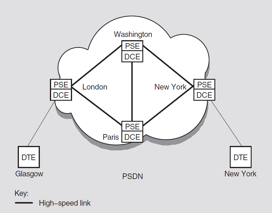
A PSDN is either owned by a country's Postal, Telegraph, and Telephone (PTT), Authority or it is privately run. Public PSDNs can be used by anyone, on payment of connection fees and regular bills. Private PSDNs are used to serve a single body, such as a large corporation.
Public and private PSDNs can be interconnected. It is, therefore, possible to pass data packets from one DTE to another no matter where in the world the DTEs are located.
The PSDN sends each packet to its destination by the best available route at the time. The packets that make up a data message may take different routes to reach the same destination; this will occur if certain routes are busy or if there is a line failure within the PSDN. Figure 4.2, ''Packets Traveling Over a PSDN'' shows an example of packets traveling by different routes across a PSDN.
When the packets reach their destination, they are reassembled so that the original order of the packets in the data message is maintained.
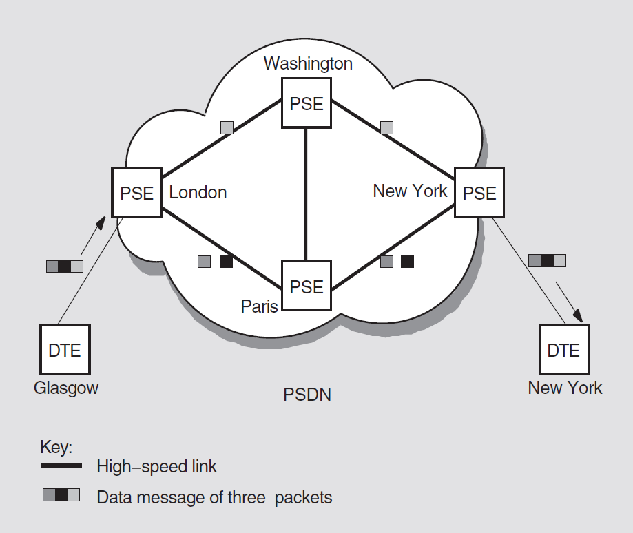
Packet-mode DTEs
These DTEs communicate directly with PSDNs using X.25 packets; for example, a computer system.
Character-mode DTEs
These DTEs cannot assemble or disassemble packets and have no X.25communication capability. An example of a character-mode DTE is an asynchronous terminal. Character-mode DTEs communicate with a PSDN through a device known as a packet assembler/disassembler (PAD). Character-mode DTEs are often referred to as X.29 terminals.
4.1.2. PADs and Character-Mode Terminals
Assembles a terminal's outgoing characters into packets for transmission across a PSDN, and disassembling incoming packets (that is, packets arriving from a PSDN) into individual characters.
Controls the transmission and receipt of packets.
Sets up virtual circuits.
Dial-in PADs provided by PSDNs for public use. This type of PAD allows users to dial in to a PSDN via a modem and from that PSDN access other DTEs. PAD functionality is provided by software in the PAD.
PADs that allow the connection of character-mode terminals to a PSDN without the need to dial in via a modem. These PADs are typically one separate, dedicated piece of hardware to which both the character-mode terminals and the PSDN are connected. This type of PAD allows multiple character-mode terminals to be connected to the PSDN. PAD functionality is provided by software in the PAD.
Host-based PADs, where the PAD functionality is implemented solely in the software installed on the host.
DTE A is connected to the PSDN via a modem.
DTEs B and C are connected to the PSDN via a dedicated PAD.
DTE D is connected to the PSDN through its own, host-based PAD.
DTE E is a packet-mode DTE, which can connect directly to the PSDN without a PAD.
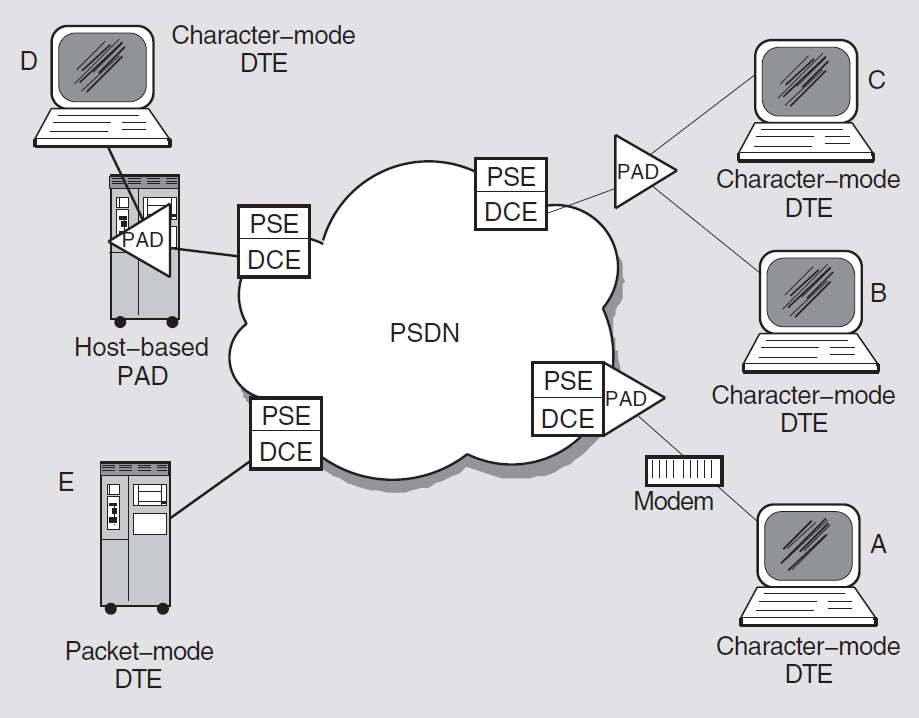
4.2. X.25 Protocols
Packet level
Frame level
Physical level
Figure 4.4, ''X.25 Protocol Levels'' shows the three protocol levels.
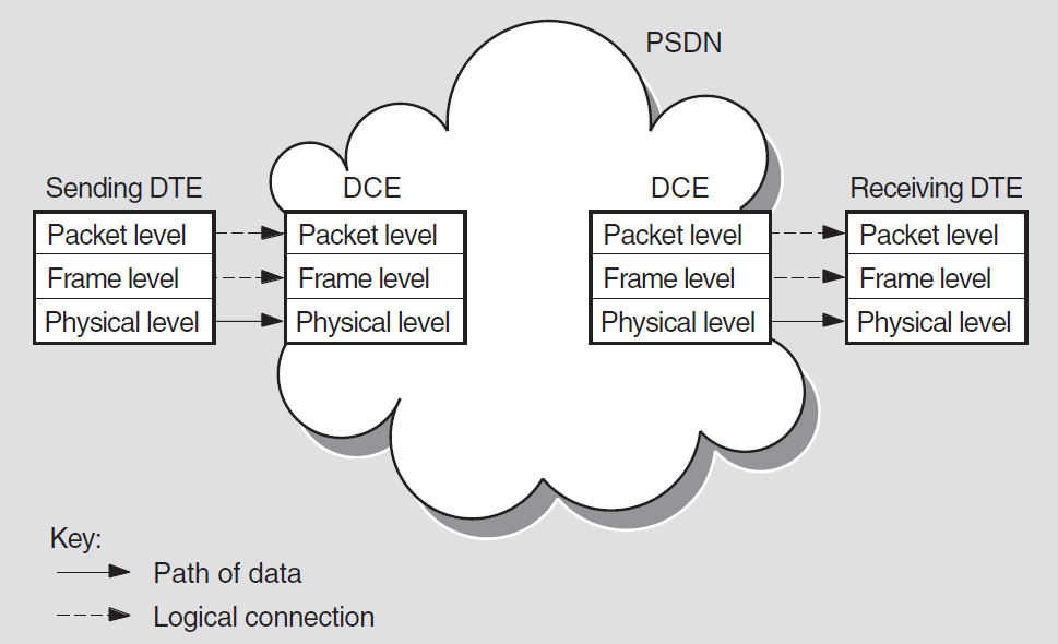
At the sending DTE, data passes down through the levels and each level adds its own control information. When it reaches the physical level, the data is transmitted to the DCE.
At the DCE, the relevant control information is removed as the data passes up through the levels. When it reaches the packet level, data is in the form of X.25 packets, which can now be sent across a PSDN.
When the packets reach the remote DCE, they pass down through the levels and pick up control information. The DCE then sends them to the receiving DTE. At the receiving DTE, the data passes up through the levels.
Each level on the DTE communicates with the corresponding level on the DCE by using the same protocols; therefore, there are logical connections between corresponding levels. They are referred to as logical connections because data is not actually transmitted until it reaches the physical level.
Two DTEs implementing X.25 protocols can exchange data in packets, regardless of the DTE manufacturer. However, once the data is re-assembled in its original format, the receiving DTE may not be able to interpret the message. In this case, additional software may be required to make the data meaningful to the receiving DTE.
4.2.1. Packet Level
This level defines the procedures for formatting packets, sequencing packets, and establishing virtual circuits. Virtual circuits are the logical connections between two DTEs (see Section 4.4.2.1, ''Virtual Circuits''). Most packets contain user data, but some are for control purposes. Control packets are used for functions such as initiating and terminating virtual circuits between two DTEs and for interrupt messages.
The amount of user data allowed in a packet is known as the packet size. The maximum amount of user data allowed in a packet is set by the PSDN you use. A typical packet size is 128 bytes.
The packet header contains a logical channel number (LCN), and a packet type identifier. The LCN identifies the virtual circuit between the calling DTE and the called DTE (see Section 4.4.2, ''Logical Channels''). The packet type identifier labels the packet as containing either user data packet or control information.
The remainder of each packet contains either user data or control information.

4.2.2. Frame Level
This level initiates communications between the DTE and the DCE and ensures that data is transferred between DTE and DCE without errors.
Flags that indicate the start and end of the frame.
A frame header, which indicates whether the frame contains user data or control information.
A packet from the packet level (provided that the frame does not contain control information).
A 16-bit frame check sequence (FCS), which is used to determine whether the whole frame has been received without error after transmission.
Figure 4.6, ''Structure of a Frame'' shows the structure of a typical frame.
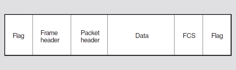
4.2.3. Physical Level
This level defines the mechanical and electrical connections between a DTE and a DCE. It specifies electrical characteristics, data transmission speeds, and connector types.
4.3. Implemented Standards
X.25 is a CCITT recommendation that describes a standard for connecting to packet switching networks. The lower three layers of the OSI Reference Model correspond to the three levels in the Comité Consultatif International Téléphonique et Télégraphique (CCITT) X.25 recommendation.
The X.25 standard describes the protocols for the DTE-DCE interface.
4.3.1. Related CCITT Standards
X.3 — Defines the service provided to the terminal by the PAD. The service is described in terms of PAD parameters.
X.28 — Defines the user interface to the PAD.
X.29 — Defines the procedure for the exchange of control information and user data between a PAD and a remote packet-mode DTE using X.25.
X.75 — Defines the protocols for communication between two PSDNs.
X.121 — Defines the address encoding used in PSDNs.
Figure 4.7, ''CCITT Packet-Switching Recommendations'' illustrates the main packet switching recommendations.
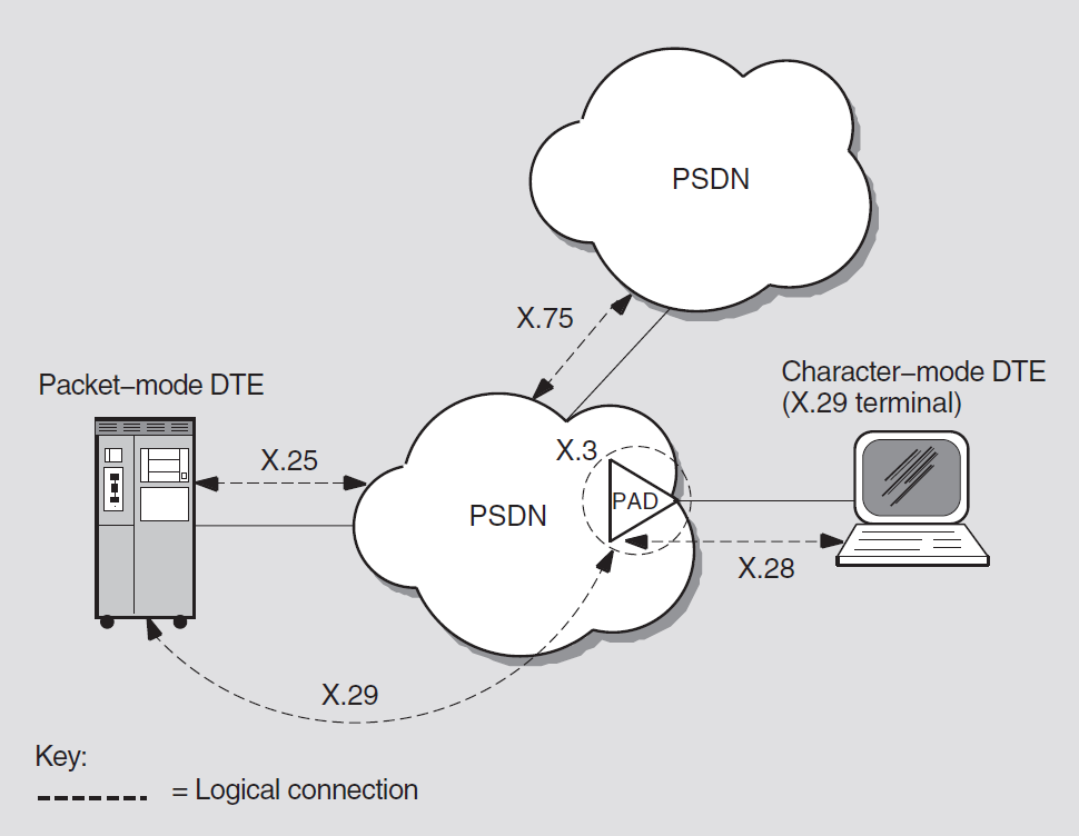
4.3.2. Related OSI Standards
Connection-Oriented Network Service (CONS) — OSI Transport Classes 0, 2, and 4 over X.25 subnetworks
Connectionless-mode Network Service (CLNS) — OSI Transport Class 4 over X.25 subnetworks
Link Access Protocol Balanced (LAPB) to exchange frames between a DTE and a DCE
LLC Type 2 (LLC2) for communications over a LAN
4.4. How Connections Are Made and Data Is Transferred
To establish a call and transfer data between DTEs via a PSDN, physical and logical connections must be made between the calling and called DTE.
4.4.1. Physical Connections
Leased lines
These are for the exclusive use of one DTE and are available only for communication between that DTE and the PSDN.
Leased lines are also known as dedicated or private lines.
Data transmission over leased lines is always synchronous and is usually full-duplex. Typical speeds of data transmission are in the range of 2400 to 64 000 bits/s. Packet-mode DTEs are usually connected to DCEs by leased lines.
Dial-up lines
These are similar to public telephone lines and are available to more than one DTE.
Dial-up lines are also known as switched lines or telephone lines.
Data transmission over dial-up lines is usually asynchronous. Typical speeds of data transmission are in the range of 100 to 2400 bits/s. Character-mode DTEs are usually connected to DCEs by dial-up lines via a PAD.
4.4.2. Logical Channels
The physical line between a DTE and a DCE is divided into a number of logical channels. Logical channels allow many virtual circuits to exist on the physical line. Each logical channel is identified by a logical channel number (LCN), contained in the packet header of every packet sent across a PSDN.
Before data can be sent across a PSDN, a virtual circuit must be established between a logical channel at the calling DTE and a logical channel at the called DTE. The circuits are referred to as "virtual" because a number of virtual circuits may use the same physical circuit to transmit packets from the calling DTE to the called DTE.
It is important to realize that the logical channel used between a DTE and DCE only has local significance. It is the responsibility of the PSDN to map the logical channels used by the calling and called DTEs into an end-to-end virtual circuit. This means that although a virtual circuit has end-to-end significance between the DTEs, different logical channels can be used by the virtual circuit on each side of the PSDN.
This concept is illustrated in Figure 4.8, ''Virtual Circuits Versus Logical Channels'' in which two virtual circuits are depicted. Virtual Circuit A establishes an end-to-end connection using LCN 2 between the calling DTE and its associated DCE, and LCN 1 between the called DTE and its associated DCE. Similarly, Virtual Circuit B establishes an end-to-end connection using LCN 4 on both sides of the PSDN.
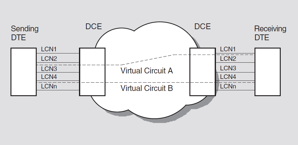
4.4.2.1. Virtual Circuits
Switched virtual circuits (SVCs)
SVCs are temporary circuits that require call setup and call clearing procedures. SVCs are established using call request packets that contain the DTE address of the remote DTE. Once established, the two DTEs can carry out two-way communications until the SVC is cleared. SVCs are cleared with clear request packets. Establishing an SVC is similar to making a telephone call.
Permanent virtual circuits (PVCs)
PVCs are permanent circuits between two DTEs that need no call setup or call clearing procedures. Allocation of PVCs must be arranged with the supplier of the PSDN to be used. Once allocated, the use of a PVC can be requested using a management command. An allocated PVC is available for use until it is de-allocated.
A DTE may have many virtual circuits active at the same time over a single DTE-DCE interface. These circuits can be any combination of PVCs and SVCs.
4.4.2.2. Logical Channel Numbers
Permanent virtual circuits (PVCs)
Incoming (to the DTE) switched virtual circuits (ISVCs)
Outgoing (from the DTE) switched virtual circuits (OSVCs)
Incoming and outgoing (both ways) switched virtual circuits (SVCs)
An LCN is a 12-bit number. Some PSDNs use the first 4 bits as a logical channel group number (LCGN) to represent the use of the channel, and the remaining 8 bits to represent the LCN. Some PSDNs use the full 12 bits to represent the LCN.
4.4.3. DTE Addresses
A Data Network Identification Code (DNIC), which identifies the country and distinguishes the PSDN from other PSDNs within the same country. This is usually the first four digits of the number.
A national number, which identifies the DTE within the PSDN.
An optional subaddress, which gives extra identification between the calling DTE and the called DTE. If included, this is usually the last two digits of the address.
DTE addresses may consist of up to 15 digits. However, for internetworking X.121 restricts international data numbers (that is, DTE addresses) to 14 digits.
An example of an X.121 format DTE address is shown in Figure 4.9, ''DTE Address Example''.
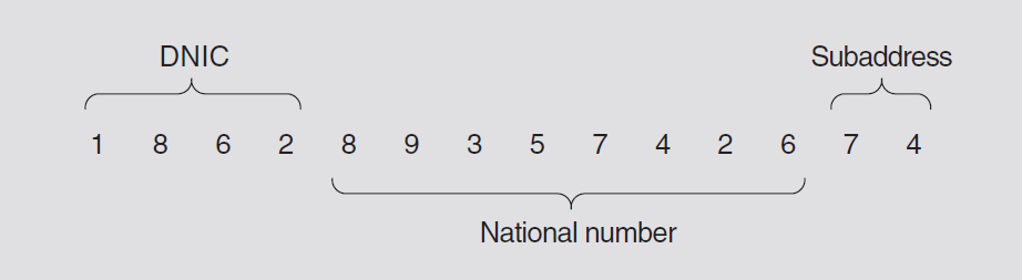
Some networks use an abbreviated form of addressing to refer to DTEs on the same network. In such networks, an extra digit is often prefixed to the DTE address to indicate that the address of the called DTE is on a different network to the calling DTE.
4.4.4. Controlling the Flow of Packets
When a packet has been received by a called (remote) DTE, the PSDN sends a message to the calling (sending) DTE. This message is known as an acknowledgment. Because of the time it takes a packet to travel across a network, it is inefficient to wait for the acknowledgment of the packet before sending more. For this reason, PSDNs let you send a number of packets before you receive acknowledgment for the first one.
The maximum number of unacknowledged packets you are allowed to have on a virtual circuit is called the window size. Once the window size is reached, and acknowledgments for previously sent packets are received, more packets can be sent. Acknowledgments are often carried by incoming packets of data.
You can specify the window size you want to use, up to the maximum set by the PSDN. You may want to subscribe to larger window sizes if you have large amounts of data, or if there is a long delay between sending a packet and receiving the acknowledgment of that packet.
4.5. Optional Facilities of Public and Private PSDNs
As well as switching packets, each PSDN offers optional facilities to its users. Some must be subscribed to, and others must be requested at the time the call is set up. A specific PSDN may support additional facilities that are not defined by the CCITT. A full list of such facilities can be obtained from the PSDN supplier.
General Optional User Facilities
The optional user facilities that fall into this category allow tasks such as call redirection, barring of incoming calls, packet retransmission, and reverse charging to be performed. Refer to the VSI X.25 for OpenVMS Management Guide for descriptions of the general optional user facilities supported.
Closed User Groups (CUGs)
A CUG is a group of DTEs that are restricted to communicating with each other. The members of the CUG can prevent unwanted calls from non-CUG members (who are on the open network). Members of a CUG receive calls only from other members of that CUG.
Several optional facilities are available to CUGs. For example, within a CUG, one DTE can subscribe to facilities that allow it to make outgoing calls and receive incoming calls from the open network. This provides access to the open network for the specified DTE, but still prevents calls from the open network to other CUG members. Refer to the VSI X.25 for OpenVMS Management Guide for descriptions of the optional facilities available to CUG members.
Bilateral Closed User Groups (BCUGs)
A BCUG is a CUG consisting of only two DTEs. Access to BCUGs from the open network is more restricted than with normal CUGs because there is no optional facility allowing incoming access. Members of BCUGs can subscribe to a facility allowing outgoing access. Refer to the VSI X.25 for OpenVMS Management Guide for descriptions of the optional facilities available to BCUG members.
4.5.1. DTE Parameters
DTE parameters govern the frame- and packet-level operation of DTEs. They specify properties such as window size and packet size. Various PSDNs support different parameters. For more information on the parameters supported, contact your PSDN supplier.
4.5.2. PAD Parameters
PSDNs offer optional PAD facilities that are represented by variables known as PAD parameters. You can set PAD parameters to indicate that you want to use a PAD facility and how you want to use it.
A set of PAD parameters is a profile; most networks define several profiles to suit different types of character-mode DTEs (X.29 terminals). When you connect to a PAD, you can select a profile to control the actions of the PAD. During a call, you can read and reset most of the PAD parameters.
Refer to the VSI X.25 for OpenVMS Management Guide which describes the CCITT-defined PAD parameters, all supported by DECnet-Plus for OpenVMS.
4.6. Network Profiles
VSI supports the use of its X.25 products with a number of public and private PSDNs. A network profile contains the information necessary to support a particular PSDN including network parameters pertinent to a specific network. For example, it contains the default value and permissible range of values for the X.25 window size.
Details of the PSDNs supported by VSI X.25 products can be obtained from VSI. For details of the permissible network parameters for a specific network, refer to the documentation provided by your PSDN supplier.
4.7. PSDNs Supported by VSI X.25 Products
Before a PSDN is supported by VSI, it has to go through a testing procedure. This is necessary to determine the network parameters to store in the associated network profile. The testing procedure produces a network profile for each PSDN. If you use the correct profile for the PSDN you are connecting to then your communications will be successful, and VSI will provide you with support in the event of any problems.
If you want to use a PSDN that is not currently supported by VSI, you can ask VSI to provide support for the network. VSI will then test the PSDN and produce a network profile for use with the PSDN.
Chapter 5. DECnet Network Operations
This chapter explains the functions you can perform in a DECnet network environment including remote login, file, and mail operations. It also explains how to develop command procedures and application programs that run over the network.
5.1. How You Can Use DECnet
You perform network operations as a natural extension of the input/output operations you perform on your own local system, because DECnet-Plus for OpenVMS networking capabilities are completely integrated into the operating system.
With appropriate access on a remote node, you can carry out general user operations over the network as easily as at the local node. Most DECnet-Plus for OpenVMS file-handling commands permit you to access files on remote systems in the same way as files on your own system as long as you have appropriate access.
5.1.1. Performing Operations using DCL Commands
Log in to another node on which you have an account.
Access public directories or databases located on remote nodes.
Display locally the contents of remote directories and files to which you have access.
Copy files from node to node or append files on one node to a file on another node.
Print files at the remote node where they reside, copy them to a remote printing device, or copy them to the local node for printing.
Access and edit a file on a remote node using an OpenVMS editor.
Create a new file in a remote directory.
Delete or purge files from directories, search files, and compare the contents of files on different nodes.
Perform sort and merge operations on remote files.
Analyze the structure of files, convert their organization and format, and dump their contents in a specific format.
Back up local files by using a remote save set on disk.
Create, display, and delete logical names for nodes and devices that are to be included in remote file specifications.
Send electronic mail to, and receive mail from, a user on any other node in the DECnet network, by means of the Mail utility.
Communicate interactively over the network by means of the Phone utility.
- Invoke help for DECnet-Plus by entering the following command:
$ help decnet_osi
5.2. Specifying Node Names
Node synonyms are required for layered products and utilities that do not yet support DECnet-Plus full names. Full name support is available for the SET HOST and Mail utilities, and for most DCL commands that use file specifications (such as COPY, DIRECTORY, etc.) and some utilities that use RMS.
5.2.1. Phase IV-Style Node Synonyms
Because a full name consists of the complete directory path from the root directory to the target object entry, directory, or soft link, full names can be long if a namespace has several levels of directories.
DECnet-Plus supports a 6-character Phase IV-style node name called the node synonym. A node synonym is a soft link that points to the full name of a node object entry. Node synonym soft links enable applications that do not support the length of full names to continue to use 6-character node names.
Node synonyms should not be viewed as a way for users to avoid typing the full name of a node. Logical names, and a feature called the local root, are faster and more convenient methods of shortening names. Both logical names and local roots are for use only on the system where they are defined; unlike node synonyms, they do not have global meaning throughout the namespace. Also, logical names and local roots can be used to name any resource (such as a disk or an application), not just node names.
5.2.2. Name Abbreviation Using Local Roots
The local root is a prefix that DECnet-Plus obtains automatically by stripping off the
rightmost simple name of the local node's DECnet-Plus full name. For example, a node
named IAF:.DIST.QA01 would have IAF:.DIST as its local
root. Users will likely want to refer frequently to other names in the hierarchy in
which their local node is named. The local root capability makes such name
references more convenient by allowing users to omit the part of the full name that
is also part of their node's full name.
DECnet-Plus Session Control creates the local root under the fixed name dnsroot
in the dns$system logical name table.
5.2.3. Logging In to Other DECnet Nodes
$ show logical net$startup_status
   "net$startup_status" = "running-all" (lnm$system_table)
This command returns with a display indicating that all network software is loaded and running.
After you log in to a network node, you may be able to log in to other nodes on the same network. If you are authorized to access an account on another OpenVMS node or on a non-OpenVMS node that supports DECnet, you can log in to that node over the network. To log in to the other node, enter the DCL command SET HOST, specifying the remote node name, and follow the login procedure the remote node uses. Once you are logged in to the remote node, you can perform all general user operations on that system as though it were the local node:
$ set host node-name$ set host node-name$ set host namespace:.abc.xyz5.3. Accessing Remote Files
This section describes the format of the remote file specification and the access controls that affect access to remote files. This section also explain show to use logical names in specifying remote directories and files, and how to specify remote files located on OpenVMS clusters.
5.3.1. Specifying Files
You can access remote files by simply including in the file specification the name of the remote node on which the file is located. You can access files that are protected if the owner has granted you access, either by a proxy account or by providing you with the name and password of the account.
node"username password"::device:[directory]filename.type;version
example.lis residing in the directory
information on device dba1, which belongs to user
cmiller whose password is techwriter, at node
boston, you would use the following file
specification:boston"cmiller techwriter"::dba1:[information]example.lis
5.3.2. Specifying Files on a Non-OpenVMS System
U32"user password"::"/usr/users/user/test"
Note
DECnet-Plus for UNIX file specification is case sensitive.
5.3.3. Protecting Files
walker, who has the password projmgr, has access to
the file, you could use the following file specification:
boston"walker projmgr"::DBA1:[INFORMATION]EXAMPLE.LIS
tasks.lis in
the directory project on device work at remote node
austin, at which you have a proxy account:
austin::work:[project]tasks.lis
trends.dat at remote
node london to be accessed using the default DECnet-Plus for OpenVMS
account:london""::dba0:[market]trends.dat
A user name that you supply explicitly in an access control string included in the remote file specification. If you specify a null access control string, the user name in the default DECnet-Plus for OpenVMS account, if one exists, is used.
The user name in your proxy account at the remote node, if one exists.
The user name in the default access account, if one exists, for the file access listener (FAL) object at the remote node.
The user name in the default DECnet-Plus for OpenVMS account, if one exists, at the remote node (by default, that user name is
decnet).
5.4. File Operations
The following sections illustrate ways you can use DECnet-Plus for OpenVMS commands.
5.4.1. Displaying Remote Directories and Files
[comments.public] at remote node
concord:$ directory concord::disk1:[comments.public]
members.lis in directory [patriots] at remote node
concord, use the following
command:$ type concord::disk1:[patriots]members
redcoats.lis in
directory [british] on the default device at node
lexington:$ type lexington::[british]redcoats
5.4.2. Public Directories
public
to define the public directory [comments.public] at remote node
concord:$ define public concord::disk1:[comments.public]
freedom.txt located in the directory
[comments.public], for example:
$ directory public$ type public::freedom.txt)
They can also copy the file to the local node and then print it, as described in the next section.
5.4.3. Copying and Printing Remote Files
Use the COPY command to copy a file from one node to another. As part of the copy operation, you can create a new file from existing files.
5.4.3.1. The COPY Command
liberty.dat on node
boston to a new file of the same name on remote node
britain:$ copy boston::disk:liberty.dat;2 _To: britain::dba0:[product]liberty.dat
liberty from UNIX
node boston to a new file on local node
britain:$ copy boston::"/usr/users/user/test" liberty.dat
traitors.lis from
the local node to a file with the same name at remote node
concord:$ copy traitors.lis concord::disk1:[patriots]traitors.lis $ copy traitors.lis concord::disk1:[patriots]
lexington.
$ copy *.* lexington::[british]*.*
user1.dat and
user2.dat, to a single new file, users.dat, at
remote node
lexington:$ copy user1.dat,user2.dat lexington::[british]users.dat
$ copy lexington"revere silver"::[statistics]summary.lis *
5.4.3.2. The APPEND Command
data1.lis and data2.lis at
remote node lexington to the end of the file
results.lis at node britain, use the following
command:$ append lexington"revere silver"::[liberty]data1.lis,data2.lis _To: britain::dba0:[product]results.lis
5.4.3.3. The PRINT/REMOTE Command
witches.lis to be copied to the default DECnet directory at
remote node salem and queued for printing at node
salem:
$ copy witches.lis salem::work:[project]
$ print/remote salem::work:[project]report
salem under the default nonprivileged DECnet
account:$ copy report.lis salem::lpa0:
Note that the /REMOTE qualifier is required in the PRINT command whenever a remote file is specified, and that you cannot include any other qualifiers with this command. The PRINT/REMOTE command supplies a default file type of LIS.
5.4.4. Other Remote File Operations
Edit
Delete
Purge
Search
Compare
Sort
Merge
Examine
Back up
5.4.4.1. Edit
story.txt in the
directory [manuscript] on remote node london,
enter:$ edit/edt london::[manuscript]story.txt
5.4.4.2. Delete
details.lis;2 in the directory
information at remote node boston, use this
command:$ delete boston"walker projmgr"::dba1:[information]details.lis;2
suggestions on remote node austin, you can delete
all files in that directory, as follows:
$ delete austin::work:[suggestions]*.*;*
5.4.4.3. Purge
proposals at remote node austin,
use this
command:$ purge austin::work:[proposals]*.lis/keep=2
5.4.4.4. Search
members.lis and
data.lis at remote node concord to be searched for
all occurrences of the character string
name:$ search concord::disk1:[club]members.lis,data.lis _String(s): name
5.4.4.5. Compare
test.dat in the nonprivileged default DECnet account on remote
node
boston:$ differences boston::test.dat
test.dat at remote node
boston and the second file is test.dat at remote
node
london.$ differences boston::test.dat london::dba0:[product]test.dat
5.4.4.6. Sort
random.fil at remote node boston. The SORT
program sorts the records on the basis of the contents of the first seven
characters in each record and writes the sorted list into the output file
alphanm.srt created in the default directory at the local
node.$ sort/key=(position:1,size:7) - _$ boston::dba1:[records]random.fil alphanm.srt
5.4.4.7. Merge
The example of a merge command shown below causes two identically sorted
files, file1.srt and file2.srt, on the directory
project at remote node austin to be merged into an
output file. This output file, mergefile.dat, is created at the
current default directory at the local node.
$ merge/key=(position:1,size:30) -
_$ austin::work:[project]file1.srt,file2.srt/check_sequence -
_$ mergefile.dat)
5.4.4.8. Examine
run.dat
at remote node austin:
$ analyze/rms_file austin::work:[production]run.dat
sales.tmp at
the local node to be added sequentially to the end of the output file
sales.cmd at remote node boston. The file
sales.tmp is sequential with variable-length record format, and
the file sales.cmd is sequential with stream record format. When
the Convert utility loads records from the input file to the output file, it
changes the record format.
$ convert/append sales.tmp boston::dba1:[records]sales.cmd
calc.dat, which resides at
remote node boston. The command formats the output both in octal
words and in character strings, and queues the output to the system printer at
the local
node.$ dump/records/octal/word _File(s): boston::dba1:[records]calc.dat/printer
5.4.4.9. Back Up
sched on
disk DB1 at the local node in the BACKUP save set sch.bck at remote
node miami. The /SAVE_SET qualifier is required to identify the
output specifier as a save set on a Files-11
medium.$ backup _From: db1:[sched]*.* _To: miami::dba2:[save]sch.bck/save_set
5.5. Using the Mail and Phone Utilities
Any user can send electronic mail to, and receive mail from, any other user on the network. Mail can be exchanged between all DECnet and DECnet-Plus nodes.
5.5.1. The MAIL Command
longfellow on remote node salem, invoke
mail and enter the
following:$ mail MAIL> send To: salem::longfellow
_SYSTEM-F-UNREACHABLE, remote node is not currently reachable
alcott at node
concord sends you a mail message over the network, the sender is
identified in the following
way:From: CONCORD::ALCOTT
New mail on node 'local-nodename' from 'remote-nodename::username'
alcott on node concord sends you
mail on node literature, this notice is
displayed:New mail on node LITERATURE from CONCORD::ALCOTT
bronte is logged in to node literature
in a cluster that uses the alias CLUST1. When she receives a reply to a
message she sent user alcott at remote node concord, the
message will indicate the cluster node name CLUST1 (rather than the node name
literature), as in the
following:From: CONCORD::ALCOTT To: CLUST1::BRONTE
New mail on node BOOKS from CONCORD::ALCOTT
5.5.1.1. Sending Files and Long Messages
You can send either messages or files over the network. If you are composing a long message for transmission to a remote node, you may prefer to use an editor to create the message file and then invoke MAIL to transmit the file. This method permits you to avoid the possibility of losing the network connection before you complete your message.
5.5.2. The Phone Utility
To contact OpenVMS users over the network, you can also use the Phone utility, which allows you to have an "online" conversation with a user on another OpenVMS node that supports Phone.
Default access must be provided by a default access account for the Phone utility or by the default DECnet account.
The sender must have a proxy account on your system or include, in the command, the name and password for an account on your system.
To address a user on a remote node, use the format nodename::username. Your outgoing connection identifies your local node. During your conversation, Phone creates a number of incoming links addressed to your node. You should not use a cluster alias node name with the Phone utility because links addressed to a cluster alias node name can be assigned to any node in the cluster.
Chapter 6. File Operations to and from Other DECnet and DECnet-Plus Nodes
OpenVMS to UNIX or ULTRIX
OpenVMS to MS-DOS
OpenVMS to RSX using RMS-based FAL
OpenVMS to OpenVMS
The chapter is organized by operating-system type: one section for each system with which your OpenVMS operating system running DECnet-Plus for OpenVMS can communicate. Each section describes differences in file system operation between the two systems and constraints on the use of OpenVMS file processing commands. The restrictions on the remote file operations you can perform from a DECnet-Plus for OpenVMS node to a particular node result from file system design differences and DECnet implementation restrictions between the systems.
The appropriate section for each remote system itemizes the OpenVMS Record Management Services (RMS) features that are supported between DECnet-Plus for OpenVMS systems, but are not supported when accessing files on a different system. The chapter also discusses limitations on the DCL commands that you can use when communicating with the remote node. Throughout this chapter, comments are provided to help you handle the differences in file system design.
6.1. General DECnet Restrictions
- The following OpenVMS RMS service calls are not supported for network use:
$ENTER
$NXTVOL
$REMOVE
The Terminal XAB is not supported for network operations; it is ignored.
Protection XAB fields that support access control lists are ignored for network operations.
Only one data stream per open file is allowed. That is, the multistream (MSE) bit option of the file sharing (SHR) field of the FAB is not supported for network use.
Access to files on magnetic tapes mounted on a remote OpenVMS operating system is not supported. You can, however, copy files from a local magnetic tape to disk on a remote node.
When multiple Allocation XABs are linked to the FAB, they must be in ascending order by area number (AID field). Similarly, when multiple Key Definition XABs are used, they must be in ascending order by key of reference(REF field).
File protection information may not be completely preserved if the two nodes do not fully support each other's protection attributes. An example of this incompatibility occurs between RSX–11M–PLUS and OpenVMS operating systems. Although both systems represent their protection masks as RWED, RSX–11M–PLUS interprets that as Read, Write, Extend, and Delete, while the OpenVMS operating system interprets RWED as Read, Write, Execute, and Delete. This results in the "E" protection field being unmappable between these two systems.
The Journalling XABs are not supported.
File monitoring is not supported.
The user file open (FAB$V_UFO) file processing option is not supported.
6.2. OpenVMS to UNIX or ULTRIX Network Operations
This section pertains to an OpenVMS node communicating with a UNIX or ULTRIX node running DECnet-Plus for UNIX or ULTRIX. The discussion focuses on file operations initiated from the OpenVMS node, to access remote files by means of the FAL at the UNIX or ULTRIX node.
6.2.1. File System Constraints
The file systems used by UNIX or ULTRIX and OpenVMS are dissimilar in many respects. A fundamental difference between them involves the handling of file attribute information. When you create a file on an OpenVMS operating system, attribute information about the file is stored in a header block on disk for use when the file is subsequently opened.
The implication is that the structure of an established file cannot change. In contrast, UNIX or ULTRIX does not save attribute information such as file format with a file; it expects you to provide this information when you open the file. File attribute information, however, is not an input to OpenVMS RMS when a file is opened.
To provide transparent access to files on a remote UNIX or ULTRIX operating system, OpenVMS RMS restricts the types of files you can create and open on the remote node. When you access a UNIX or ULTRIX file in record mode, OpenVMS RMS treats the file as having STREAM_LF (STMLF) format.
6.2.1.1. File Formats and Access Modes
- File organizations and record formats
Sequential
Fixed length (FIX) without implied carriage control
STREAM_CR (STMCR)
Stream (STM)
Variable length (VAR) without implied carriage control
Variable with fixed control (VFC)
Relative
All formats
Indexed
All formats
- Record attributes
- FORTRAN carriage control (FTN)
- Print file carriage control (PRN)
- None specified (embedded carriage control)
- Record access modes
- Random access by relative record number
- Random access by key value
- Random access by record file address
- Block I/O
For record mode access, the only file type in common between the two systems is a sequential file in STMLF (STREAM_LF) format. For convenience, however, when you are transferring a file to a UNIX or ULTRIX node, OpenVMS RMS automatically converts an OpenVMS sequential file with fixed or variable format and implied carriage control to a sequential file with stream format and embedded carriage control. This automatic conversion is performed during a file create operation, and OpenVMS RMS returns an alternate success code (RMS$_CVT_STM) to indicate that the file format has been modified.
Note also that when a STREAM-LF format file is retrieved from a UNIX or ULTRIX node, OpenVMS RMS automatically changes the record attribute from embedded carriage control to implied carriage control.
$ CONVERT/FDL=STMLF.FDL input-file output-file
FILE
        ORGANIZATION          sequential
RECORD
        FORMAT                STREAM_LF
        CARRIAGE_CONTROL      none
The CONVERT command and associated FDL control file transform the input file to stream format with embedded carriage control and then copy it to the remote node according to the output file specification.
6.2.1.2. OpenVMS RMS Interface
- OpenVMS RMS service calls
$DELETE
$DISPLAY
$EXTEND
$FIND
$FREE
$RELEASE
$RENAME
$REWIND
$TRUNCATE
$UPDATE
- RMS extended attribute blocks
- Allocation XAB
- Key Definition XAB
- Summary XAB
- Significant fields and bit options of the FAB
- ALQ (allocation quantity) field
- DEQ (default extend quantity) field
- CBT (contiguous-best-try) bit of FOP field
6.2.1.3. File Specifications
The general format of a file specification for naming a file on a remote UNIX
or ULTRIX operating system is as follows:node::name
No explicit device names are allowed. Instead, UNIX or ULTRIX has a concept of special files.
File names on UNIX or ULTRIX are case sensitive (uppercase or lowercase).
Because of these differences, most accesses to a UNIX or ULTRIX operating system require a foreign file specification. Without the foreign file specification syntax, the name is converted to uppercase by OpenVMS, and is then unlikely to match files on the UNIX or ULTRIX operating system. The OpenVMS concepts of device and directory do not match the UNIX or ULTRIX concept of path, nor does UNIX or ULTRIX support separate file type or version fields. Therefore, OpenVMS-related name processing does not work with UNIX or ULTRIX file names.
6.2.2. DCL Considerations
ANALYZE/RMS_FILE
BACKUP
OPEN/WRITE
RENAME
6.2.2.1. COPY
The /ALLOCATION and /EXTENSION qualifiers to the COPY command are not supported and are ignored if specified.
6.2.2.2. DIRECTORY
The file owner is displayed as [0,0] to indicate that this information is not available.
The file REVISION number is not shown and file REVISION date and time information is not available from the UNIX or ULTRIX operating system.
6.3. OpenVMS to MS-DOS Network Operations
This section pertains to an OpenVMS node communicating with a PC running the DECnet feature of PATHWORKS for DOS. The discussion focuses on file operations initiated from the OpenVMS node, to access remote files by means of the FAL at the MS-DOS node.
6.3.1. File System Constraints
The file systems used by MS-DOS and OpenVMS are dissimilar in many respects. A fundamental difference between them involves the handling of file attribute information. When you create a file on an OpenVMS operating system, attribute information about the file is stored in a header block on disk for use when the file is subsequently opened. The implication is that the structure of an established file cannot change. In contrast, MS-DOS does not save attribute information such as file format with a file; it expects you to provide this information when you open the file. File attribute information, however, is not an input to OpenVMS RMS when a file is opened.
To provide transparent access to files on a remote MS-DOS system, OpenVMS RMS restricts the types of file that you can create and open on the remote node. When you access an MS-DOS file in record mode, OpenVMS RMS treats the file as having stream format.
6.3.1.1. File Formats and Access Modes
- File organizations and record formats
Sequential
Fixed length (FIX) without implied carriage control
Stream_CR (STMCR)
Stream_LF (STMLF)
Variable length (VAR) without implied carriage control
Variable with fixed control (VFC)
Relative
All formats
Indexed
All formats
- Record attributes
- FORTRAN carriage control (FTN)
- Print file carriage control (PRN)
- None specified (embedded carriage control)
- Record access modes
- Random access by relative record number
- Random access by key value
- Random access by record file address
For record mode access, the only file type in common between the two systems is a sequential file in STM (stream) format. For convenience, however, when you are transferring a file to an MS-DOS node, OpenVMS RMS automatically converts an OpenVMS sequential file with fixed or variable format and implied carriage control to a sequential file with stream format and embedded carriage control. This automatic conversion is performed during a file create operation, and OpenVMS RMS returns an alternate success code (RMS$_CVT_STM) to indicate that the file format has been modified.
Note also that when a stream format file is retrieved from an MS-DOS node, OpenVMS RMS automatically changes the record attribute from embedded carriage control to implied carriage control.
$ CONVERT/FDL=STM.FDL input-file output-file
FILE
        ORGANIZATION          sequential
RECORD
        FORMAT                stream
        CARRIAGE_CONTROL      none
The CONVERT command and associated FDL control file transform the input file to stream format with embedded carriage control and then copy it to the remote node according to the output file specification.
6.3.1.2. OpenVMS RMS Interface
- OpenVMS RMS service calls
$DELETE
$DISPLAY
$EXTEND
$FIND
$FREE
$RELEASE
$RENAME
$REWIND
$TRUNCATE
$UPDATE
$WRITE
- RMS extended attribute blocks
- Allocation XAB
- Key Definition XAB
- Summary XAB
- Significant fields and bit options of the FAB
- ALQ (allocation quantity) field
- DEQ (default extend quantity) field
- CBT (contiguous-best-try) bit of FOP field
6.3.1.3. File Specifications
The general format of a file specification for naming a file on a remote
MS-DOS operating system is as follows:
node::"device:\directory\name"
The major difference in syntax between file specifications on MS-DOS and on
OpenVMS is that the directory components of an MS-DOS file specification are in
an incompatible format. For example: \directory\
As a result, you must use quoted strings when you access these MS-DOS files from an OpenVMS operating system.
$ DIRECTORY PC::[REPORT]
$ DIRECTORY PC::\report\*.*
DOS file specifications are restricted to file names of eight characters, file extensions of three characters, and do not support version numbers.
6.3.2. DCL Considerations
ANALYZE/RMS_FILE
APPEND
BACKUP
OPEN/WRITE
RENAME
6.3.2.1. COPY
The /ALLOCATION and /EXTENSION qualifiers to the COPY command are not supported and are ignored if specified.
6.3.2.2. DIRECTORY
The file owner identifier is displayed as [0,0] to indicate that this information is not available.
The file ID identifier is displayed as NONE to indicate that this information is not available.
The file attributes version limit identifier is displayed as 0 to indicate that this information is not available.
The file REVISION number is not shown and file REVISION date and time information is not available from the MS-DOS operating system.
6.4. OpenVMS to RSX Network Operation Using RMS-based FAL
This section pertains to an OpenVMS node communicating with an RSX node running either DECnet-11M or DECnet-11M-PLUS where the RSX file access listener (FAL) calls RMS-11 to perform local file operations. The discussion focuses on file operations initiated from the OpenVMS node, to access remote files by means of the FAL at the RSX node.
The following restrictions are related to incompatible features in file system design between the two systems.
6.4.1. File Formats and Access Modes
- File organizations and record formats
Sequential
Stream_CR (STMCR)
Stream_LF (STMLF)
Indexed
All prologue three formats
With 64-bit binary (BN8) key types
With 64-bit integer (IN8) key types
With collating (COL) key types
With descending key types (DSTG, DIN2, DBN2, DIN4, DBN4, DIN8, DBN8, DPAC, DCOL)
- Record attributes
- Record attributes are compatible.
- File access modes
- Modes are compatible.
6.4.2. OpenVMS RMS Interface
- OpenVMS RMS service call:
$RELEASE
Significant fields and bit options of the FAB and CBT (contiguous-best-try) bit of FOP
6.4.3. File Specifications
node::device:[directory]name.type;version
RSX operating systems do not support dollar sign ($), underscore (_) and hyphen (-) characters in file name components.
The directory component in an RSX file specification cannot be a named directory list, such as [A.B.C]; it must be in UIC (user identification code) format, such as [15,1].
The file name component has a maximum length of nine characters and the file type cannot exceed three characters. RSX operating systems return an error if you specify a longer file name or file type.
RSX operating systems use octal version numbers in file specifications whereas the OpenVMS operating system uses decimal version numbers.
6.4.4. DCL Considerations
Of the OpenVMS DCL commands that you can use over the network, the OPEN/WRITE command is not supported between OpenVMS and an RMS-based RSX node.
6.4.4.1. COPY
$ copy a.dat;9 rsx::*.*
%COPY-E-OPENOUT, error opening rsx::a.dat;9 as output
-RMS-F-FNM, error in file name
$ copy a.dat;9  rsx::a.dat;11
$ copy b.dat;28 rsx::*.*;
$ copy b.dat;28 rsx::*.*;0
$ copy *.dat    rsx::*.*;0
DECnet-Plus supports only the addressing specifications in this standard.
The connector node can be a DECNIS router 500 or 600, or X.25 configured in multihost mode.