VSI DECnet-Plus for OpenVMS Network Control Language Reference
- Operating System and Version:
- VSI OpenVMS IA-64 Version 8.4-1H1 or higher
VSI OpenVMS Alpha Version 8.4-2L1 or higher
Preface
This book describes the syntax and features of the Network Control Language (NCL), and the NCL commands that you use for network management modules.
1. About VSI
VMS Software, Inc. (VSI) is an independent software company licensed by Hewlett Packard Enterprise to develop and support the OpenVMS operating system.
2. Intended Audience
This book is written for network managers responsible for managing DECnet-Plus for OpenVMS networks. It also contains NCL syntax for management entities and management options supported by DECnet-Plus for UNIX.
3. Document Structure
| Provides an overview of the functions provided by NCL. | |
| Describes the Node module. | |
| Chapter 3, "Alias Module (OpenVMS)" | Describes the Alias module. |
| Chapter 4, "CSMA-CD Module" | Describes the CSMA-CD module. |
| Chapter 5, "DCMP Module (OpenVMS)" | Describes the DCMP module. |
| Chapter 6, "Device Module" | Describes the Device module. |
| Chapter 7, "DECdns Modules" | Describes the DECdns modules. |
| Chapter 8, "DECdts Module" | Describes the DECdts module. |
| Chapter 9, "Event Dispatcher Module" | Describes the Event Dispatcher module. |
| Chapter 10, "FDDI Module" | Describes the FDDI module. |
| Chapter 11, "Frame Module (OpenVMS)" | Describes the Frame module. |
| Chapter 12, "HDLC Module" | Describes the HDLC module. |
| Chapter 13, "LAPB Module" | Describes the LAPB module. |
| Chapter 14, "LLC2 Module" | Describes the LLC2 module. |
| Chapter 15, "Loopback Application Module" | Describes the Loopback Application module. |
| Chapter 16, "Modem Connect Module" | Describes the Modem Connect module. |
| Chapter 17, "MOP Module" | Describes the MOP module. |
| Chapter 18, "NSP Module" | Describes the NSP module. |
| Chapter 19, "OSAK Module" | Describes the OSAK module. |
| Chapter 20, "OSI Transport Module" | Describes the OSI Transport module. |
| Chapter 21, "Routing Module" | Describes the Routing module. |
| Chapter 22, "Session Control Module" | Describes the Session Control module. |
| Chapter 23, "Token Ring Module (UNIX)" | Describes the Token Ring module. |
| Chapter 24, "X.25 Access Module" | Describes the X.25 Access module. |
| Chapter 25, "X.25 Client Module (OpenVMS)" | Describes the X.25 Client module. |
| Chapter 26, "X.25 Protocol Module" | Describes the X.25 Protocol module. |
| Chapter 27, "X.25 Relay Module" | Describes the X.25 Relay module. |
| Chapter 28, "X.25 Server Module" | Describes the X.25 Server module. |
| Chapter 29, "XOT Module (OpenVMS IA-64 and OpenVMS Alpha)" | Describes the XOT module. |
| Appendix A, "Interpreting NCL Error Messages" |
Lists common error messages. |
| Appendix B, "Common Data Types for NCL" | Describes common data types. |
4. Related Documents
DECnet-Plus for OpenVMS documentation is available in two sets:
Documentation set for DECnet-Plus for OpenVMS
Supplemental X.25 for OpenVMS documentation set
Table below lists the documentation that supports this version of the DECnet-Plus for OpenVMS software.
| Document | Contents |
|---|---|
| DECnet-Plus for OpenVMS Documentation Set | |
| VSI DECnet-Plus for OpenVMS Introduction and User's Guide | Describes the manuals in the documentation sets, outlines the DECnet-Plus for OpenVMS features and tools, explains how to use and manage an end system, and provides a comprehensive glossary of DECnet terminology. |
| VSI DECnet-Plus for OpenVMS Release Notes | Describes changes to the software; installation, upgrade, and compatibility information; new and existing software problems and restrictions; and software and documentation corrections. |
| VSI DECnet-Plus Planning Guide | Provides configuration and planning guidelines, including namespace planning information, to help you transition a network from the DECnet Phase IV to DECnet Phase V architecture. |
| VSI DECnet-Plus for OpenVMS Installation and Configuration |
Explains how to install and configure the DECnet-Plus for OpenVMS software using the three configuration options (FAST, BASIC, and ADVANCED). Also explains how to modify an existing configuration. Explains how to configure the X.25 functionality included with the DECnet- Plus for OpenVMS VAX software (formerly provided by the VAX P.S.I. Access and VAX P.S.I. products). Explains how to install the separate X.25 for OpenVMS software product available for OpenVMS IA-64 and OpenVMS Alpha systems. For configuration information, see the VSI X.25 for OpenVMS Configuration manual. Explains how to install and configure the optional OSI applications software components (OSI Applications Kernel (OSAK), OSI File Transfer, Access, and Management (FTAM), and OSI Virtual Terminal (VT)). |
| VSI DECnet-Plus for OpenVMS Network Management Guide | Provides in-depth information about how to monitor and manage DECnet-Plus for OpenVMS systems using various tools and Network Control Language (NCL) commands. Explains how to set up and use event dispatching and how to perform all day-to-day management tasks for the local DECnet- Plus for OpenVMS node, including setting up OpenVMS clusters, managing security, downline loading, and monitoring the network. |
| DECnet-Plus for OpenVMS Installation and Quick Reference | Provides quick-reference information about the tools that help you manage and monitor a DECnet-Plus network. Use this guide with the VSI DECnet-Plus for OpenVMS Network Management Guide. |
| VSI DECnet-Plus for OpenVMS Network Control Language Reference Guide | Outlines command descriptions and examples for all Network Control Language (NCL) commands that you execute to manage, monitor, and troubleshoot the network. Begins with an orientation chapter that contains information about how to execute NCL commands, followed by a command chapter for each module in the DECnet Phase V layered model. |
| VSI DECnet-Plus for OpenVMS Problem Solving Guide | Explains how to isolate and solve DECnet problems in an OpenVMS environment that can occur while the network is in operation. Includes information about how to perform loopback tests and how to use the DTS/DTR utility to solve problems. |
| VSI DECnet-Plus for OpenVMS DECdns Management Guide | Explains VSI DECnet-Plus Distributed Name Service (DECdns) concepts and how to manage a DECdns distributed namespace. Use this manual with the VSI DECnet-Plus Planning Guide. |
| VSI DECnet-Plus for OpenVMS DECdts Management | Introduces VSI DECnet-Plus Distributed Time Service (DECdts) concepts and describes how to manage the software and system clocks. |
| VSI DECnet-Plus DECdts Programming | Contains DECdts time routine reference information and describes the time-provider interface (TPI). |
| VSI DECnet-Plus OSAK Programming | Explains how to use the OSAK (OSI Applications Kernel) interface to create OSI (Open Systems Interconnection) applications for any supported operating system. |
| DECnet-Plus OSAK Programming Reference | Provides reference information on using the OSAK interface to create OSI applications on any supported operating system. |
| VSI DECnet-Plus OSAK SPI Programming Reference Manual | Provides reference information about using the OSAK session programming interface (SPI) to create OSI applications on any supported operating system. |
| VSI DECnet-Plus FTAM and Virtual Terminal Use and Management | Explains how to use and manage FTAM (File Transfer, Access, and Management) software for remote file transfer and management and VT (Virtual Terminal) for remote login to OSI-compliant systems. |
| VSI DECnet-Plus FTAM Programming | Explains how to access the FTAM protocol through FTAM’s API (application programming interface). |
| VSI DECnet-Plus for OpenVMS Programming | Contains information about how to design and write an application that follows a client/server model and uses the OpenVMS Interprocess Communication ($IPC) system service and the transparent and nontransparent communication with the queue Input/Output ($QIO) system service. Explains how to write programs using the OpenVMS system services to communicate with OSI transport services. Provides information about the Common Management Information Service (CMISE) API. |
| DECnet/OSI for VMS CTF Use | Explains how use the Common Trace Facility (CTF) troubleshooting tool to collect and analyze protocol data from networking software. |
| Supplemental X.25 Documentation Set | |
| VSI X.25 for OpenVMS Configuration | Discusses how to configure X.25 for OpenVMS on an OpenVMS IA-64 or OpenVMS Alpha system. For information about how to configure the X.25 functionality on OpenVMS VAX systems, see the VSI DECnet-Plus for OpenVMS Installation and Configuration manual. |
| VSI X.25 for OpenVMS Management Guide | Explains how to manage and monitor an X.25 system using network tools. |
| VSI X.25 for OpenVMS Security Guide | Explains the X.25 security model and the tasks required to set up and manage X25 security. |
| VSI X.25 for OpenVMS Problem Solving | Provides guidance on how to solve problems that can occur while using an X.25 system. |
| X.25 for OpenVMS Utilities | Explains how to use and manage X.25 Mail and X.29 communications. |
| X.25 for OpenVMS Accounting | Explains how to use X.25 accounting to obtain performance records and information about how X.25 is being used. |
| X.25 for OpenVMS Programming | Explains how to write X.25 and X.29 programs to perform network operations. |
| X.25 for OpenVMS Programming Reference | Provides reference information for X.25 and X.29 programmers. |
| DECnet/OSI for VMS VAX WANDD Programming | Provides information about using the programming interface for the WANDD devices. |
5. Terminology
An adjacent node is a node connected to the local node by a single physical line.
Transition and migration
Phase IV and DECnet Phase IV
Phase V and DECnet Phase V
End system and end node
Intermediate system and router
Running database and operational database
Sink node and logging node
6. VSI Encourages Your Comments
You may send comments or suggestions regarding this manual or any VSI document by sending electronic mail to the following Internet address: <docinfo@vmssoftware.com>. Users who have VSI OpenVMS support contracts through VSI can contact <support@vmssoftware.com> for help with this product.
7. OpenVMS Documentation
The full VSI OpenVMS documentation set can be found on the VMS Software Documentation webpage at https://docs.vmssoftware.com.
8. Typographical Conventions
VMScluster systems are now referred to as OpenVMS Cluster systems. Unless otherwise specified, references to OpenVMS Cluster systems or clusters in this document are synonymous with VMScluster systems.
The contents of the display examples for some utility commands described in this manual may differ slightly from the actual output provided by these commands on your system. However, when the behavior of a command differs significantly between OpenVMS Alpha and Integrity servers, that behavior is described in text and rendered, as appropriate, in separate examples.
In this manual, every use of DECwindows and DECwindows Motif refers to DECwindows Motif for OpenVMS software.
| Convention | Meaning |
|---|---|
|
Ctrl/ x |
A sequence such as Ctrl/ x indicates that you must hold down the key labeled Ctrl while you press another key or a pointing device button. |
|
PF1 x |
A sequence such as PF1 x indicates that you must first press and release the key labeled PF1 and then press and release another key or a pointing device button. |
|
Return |
In examples, a key name enclosed in a box indicates that you press a key on the keyboard. (In text, a key name is not enclosed in a box.) |
|
… |
A horizontal ellipsis in examples indicates one of the
following possibilities:
|
|
. |
A vertical ellipsis indicates the omission of items from a code example or command format; the items are omitted because they are not important to the topic being discussed. |
|
( ) |
In command format descriptions, parentheses indicate that you must enclose the options in parentheses if you choose more than one. |
|
[ ] |
In command format descriptions, brackets indicate optional choices. You can choose one or more items or no items. Do not type the brackets on the command line. However, you must include the brackets in the syntax for OpenVMS directory specifications and for a substring specification in an assignment statement. |
|
[ |] |
In command format descriptions, vertical bars separate choices within brackets or braces. Within brackets, the choices are options; within braces, at least one choice is required. Do not type the vertical bars on the command line. |
|
{ } |
In command format descriptions, braces indicate required choices; you must choose at least one of the items listed. Do not type the braces on the command line. |
|
bold text |
This typeface represents the introduction of a new term. It also represents the name of an argument, an attribute, or a reason. |
|
italic text |
Italic text indicates important information, complete titles of manuals, or variables. Variables include information that varies in system output (Internal error number), in command lines (/PRODUCER= name), and in command parameters in text (where dd represents the predefined code for the device type). |
|
UPPERCASE TEXT |
Uppercase text indicates a command, the name of a routine, the name of a file, or the abbreviation for a system privilege. |
|
|
Monospace type indicates code examples and interactive screen displays. In the C programming language, monospace type in text identifies the following elements: keywords, the names of independently compiled external functions and files, syntax summaries, and references to variables or identifiers introduced in an example. |
|
- |
A hyphen at the end of a command format description, command line, or code line indicates that the command or statement continues on the following line. |
|
numbers |
All numbers in text are assumed to be decimal unless otherwise noted. Nondecimal radixes—binary, octal, or hexadecimal—are explicitly indicated. |
9. Acronyms
|
ACSE |
Association Control Service Element |
|
ASE |
application service element |
|
ASN.1 |
Abstract Syntax Notation One |
|
BER |
basic encoding rules |
|
CMIP |
Common Management Information Protocol |
|
CML |
CMIP Management Listener |
|
DAP |
Data Access Protocol |
|
DCS |
defined context set |
|
DDCMP |
Data Communications Message Protocol |
|
DECdns |
Distributed Name Service |
|
NA |
Network Architecture |
|
DTR |
DECnet Test Receiver |
|
DTS |
DECnet Test Sender |
|
ES–IS |
end system to intermediate system protocol |
|
EVL |
Event Dispatcher |
|
EVL |
event logger |
|
FAL |
file access listener |
|
FTAM |
File Transfer, Access, and Management |
|
HDLC |
High-Level Data Link Control |
|
MIR |
loopback mirror |
|
MOP |
Maintenance Operations Protocol |
|
NSAP |
network service access point |
|
NCL |
Network Control Language |
|
NSP |
Network Services Protocol |
|
OSI |
Open Systems Interconnection |
|
OSUL |
Open Systems Upper Layer |
|
PCI |
protocol control information |
|
PDU |
protocol data unit |
|
PPCI |
presentation protocol control information |
|
PSDN |
packet switching data network |
|
SPCI |
Session Protocol Control Information |
|
SPDU |
session protocol data unit |
|
SSDU |
session service data unit |
|
TCP/IP |
Transmission Control Protocol/Internet Protocol |
|
TPDU |
transport protocol data unit |
|
TSDU |
transport service data unit |
| XOT | X.25 over TCP/IP |
Chapter 1. Introduction to NCL
This reference guide describes how to use the Network Control Language (NCL) command line interface. You should be familiar with the concepts and terminology of the entity model of network management, as described in the VSI DECnet-Plus for OpenVMS Network Management Guide.
Invoke, use, and exit the Network Control Language
Issue NCL commands from your terminal
Define common data types for NCL
Interpret NCL error messages
1.1. Rights Identifiers Required for Use of NCL
DECnet-Plus for OpenVMS uses OpenVMS rights identifiers to check access on all manageable entities. This differs from the Phase IV software, which used OpenVMS privileges for access to the permanent database and for write access. Read access to the volatile database in Phase IV was unprotected.
1.1.1. Access to Local Network Data
UAF> grant/id net$examine Joe  ! Grant user Joe read access to local network data
UAF> grant/id net$manage  Joe  ! Grant user Joe read/write access to local network data
UAF> grant/id net$security Joe  ! Grant user Joe ability to set default accounts
In lieu of NET$MANAGE rights, the BYPASS privilege grants read and write access.
When issuing NCL commands to the local node (for example, NCL SHOW ALL or NCL SHOW NODE 0 ALL), the rights of the executing process determine whether access is granted.
1.1.2. Access to Remote Network Data (OpenVMS)
If explicit access control is specified, the specified account is used.
If there is a default account for the application receiving the request, it is used.
If a proxy account is specified, or there is a default proxy account for the remote user, it is used.
If none of the above are specified, the session entity is checked for a default nonprivileged account to use.
If the account that runs the CML application does not have the NET$EXAMINE for read access, or NET$MANAGE identifier for read and write access, then the access is denied by the management agent.
Run the Authorize utility and grant an account the proper rights
Run Authorize and create a proxy account and grant the proxy account the proper rights
Determine the user name associated with the SESSION CONTROL APPLICATION CML. Run the Authorize utility to ensure that the account has NET$EXAMINE for read-only access.
The last option is one of the selections offered by NET$CONFIGURE when configuring the application database. If you select a default account for the CML application, NET$CONFIGURE grants NET$EXAMINE right to that account by default.
1.2. Network Management Graphical User Interface
You can access NCL through either a command line interface or graphical user interface
(GUI). The GUI allows network managers to view the status of network components and
control those components from a Motif-based window interface. The GUI interface is
located at sys$system:net$mgmt.exe (NET$MGMT).
This utility provides a hierarchical graphical approach to the management of DECnet-Plus. The manageable components of DECnet-Plus (modules, entities, and subentities) are represented in a tree-like structure below the icon that represents the node you are managing. This provides an easy way to familiarize yourself with the organization of these manageable entities. If you choose to enable the displaying of NCL commands from the Default Actions pull-down menu, this utility can also help familiarize you with NCL syntax.
- show known links
- show known node counters
- check transports
The same rights required to run NCL are also required to run this utility.
For further information, refer to the VSI DECnet-Plus for OpenVMS Network Management Guide.
1.3. Getting Started with NCL
You can issue NCL commands from a terminal or from a command file. You can use NCL to manage
network entities on local and remote nodes. If you are familiar with Phase IV network
management and the Network Control Program (NCP), you can use the
decnet_migrate utility as an option to map NCP commands to their NCL
equivalents. See the VSI DECnet-Plus for OpenVMS Network Management Guide for further details.
1.3.1. Invoking NCL
There are several methods of invoking the interactive NCL utility:
- Type run
sys$system:nclat the DCL prompt $:$ run sys$system:ncl ncl>
Define a symbol at the DCL prompt (or insert the symbol in your LOGIN.COM file) and then type NCL at the DCL prompt as follows:
$ ncl :== $ sys$system:ncl
$ ncl
ncl>
- Enter an NCL command line.
$ ncl any ncl command
The system executes the command and returns you to the $ prompt.
Note
The third method works only if you define a symbol at the DCL prompt or insert the symbol in your LOGIN.COM file.
Enter MCR at the DCL prompt:
$ mcr ncl
ncl>
- Enter an MCR command:
$ mcr ncl any ncl command
$
The ncl> prompt indicates that you are using the NCL utility. When
you receive this prompt, you can enter NCL commands.
Other NCL operations include:
To abort an NCL operation, press Ctrl/C or Ctrl/Y.
To continue a long command to the next line, use a hyphen as the last character in the line. Place the continuation hyphen between attributes in a list. The
_ncl>prompt is displayed on continuation lines:ncl> show node 0 osi transport delay factor, delay weight,- _ncl> maximum receive buffers, maximum network connections,- _ncl> maximum remote nsaps
To indicate comments that are not to be read by the system, use an exclamation point (!) anywhere in a command line.
To exit from NCL, type
exitor press Ctrl/Z at thencl>prompt.
1.3.2. Accessing Online NCL Help Information
When you enter Help, you enter a standard help library containing descriptions of the network management entities and their attributes. NCL online help is a quick reference in addition to this book.
help at the
ncl> prompt. For UNIX, type a question mark (?). A
list of available topics immediately appears, for
example:ncl> help or ? Information available: add advertise block boot change clear connect create define_(Tru64_UNIX) delete Directory_Module disable disconnect dump echo enable Entity_Hierarchy Event_Messages flush_(OpenVMS) getnif getsif ignore limit load loop NCL_Introduction Network_Management pass ping_(IP_Routers) Please_Read_Me query read_(Tru64_UNIX) remove rename reset restrict set show shut shutdown snapshot SNA_Peer_Server_Module start startloop stop stoploop synchronize test testevent undefine_(Tru64_UNIX) unlimit update zero Topic?
Topic? add

ADD

  Additional information available:
  modem_connect    mop         osi_transport  routing
  session_control  x25_access  x25_protocol   x25_relay
  x25_server

ADD Subtopic?x25_relay:ADD Subtopic? x25_relay
ADD
x25_relay
Additional information available:
client pvc
ADD x25_relay Subtopic?client:
ADD x25_relay Subtopic? client

ADD

  x25_relay

    client

         add  [node  node-id] x25 relay client client-name
               filters
               rights identifiers


      Additional information available:

      Characteristics       Identifiers

ADD x25_relay client Subtopic?
Continue down the hierarchy exactly as it appears in the syntax section of each entity module, as illustrated in Part 2 of this book.
NCL help includes several non-verb help topics that provide additional information about using NCL. The following display shows these help topics and their subtopics:
Entity_Hierarchy
  Additional information available:

  Node       DNS_Clerk  DNS_Server DSA        DTSS       Event_Dispatcher
  Alias_(OpenVMS)       Session_Control       OSAK       NSP
  OSI_Transport         Routing    X25_Protocol          X25_Access
  X25_Client_(OpenVMS)  X25_Relay_(Alpha)     X25_Server XOT_(OpenVMS_Alpha)
  LAPB       CSMA-CD    LLC2       MOP        HDLC       DDCMP_(OpenVMS_VAX)
  FDDI       Modem_Connect         Device     Frame_(OpenVMS)
  Token_Ring_(Tru64_UNIX)          Loopback_Application

Event_Messages
  Additional information available:

  csma-cd_station       ddcmp_link_(OpenVMS_VAX)         device_unit
  dtss       event_dispatcher      fddi_station          hdlc_link  lapb_link
  llc2_sap   modem_connect_line    mop_circuit           node       nsp
  osak       osi_transport         routing    session_control
  token_ring_(Tru64_UNIX)          x25_access x25_client_(OpenVMS)
  x25_protocol          x25_relay_(Alpha)     x25_server xot_(OpenVMS_Alpha)

NCL_Introduction
  Additional information available:

  Invoking_NCL                     Creating_Logs         Common_Commands
  Abbreviation_of_Commands         Syntax     Recalling_Commands    Output
  Specifying_Access_Control        Default_Context       Using_Snapshot
  Customizing_NCL

Network_Management
  Additional information available:
  Access_Control        Naming_Service_Management
  Remote_Node_Management           Logical_Names_(OpenVMS)
  Startup_Scripts_(OpenVMS)        Shutdown_and_Restart_(OpenVMS)
  MOP_(OpenVMS)         Event_Dispatcher_(OpenVMS)       Running_Over_TCP-IP
  Tools

Please_Read_Me
  Additional information available:

  Using_NCL_Help        Overview_of_NCL_Help Entity_Organization
  Managing_Entities_Using_NCL
$ help decnet-plus
1.3.3. Creating Log Files
To keep a record of the commands entered during an NCL session, use the NCL logging facility.
All information printed out in an NCL session is stored in the log file after logging is enabled. This information includes commands, output, and error messages. All information except the commands are preceded in the file by a comment symbol, so this file can be used as an NCL script in another session.
set ncl logfile and enable ncl logging commands
to begin NCL logging. For example:
ncl> set ncl logfile filename.ncl
ncl> enable ncl logging
ncl> show node 0 session control application fal all attributes
   .
   .
   .
After saving the NCL commands to a log file, use the NCL log file as an indirect
command file to be invoked (during subsequent NCL sessions) with the do
control verb or the at sign (@) symbol.
ncl> enable node 0 session control
ncl> do setup_applications.ncl
   .
   .
   .
To display the name of the log file, enter show ncl logfile. The
default file extension for an NCL log file is .ncl. The utility returns
an error message if a log file does not exist.
Use the disable ncl logging command at any time to turn off NCL
logging or to exit NCL.
You can execute commands saved in an NCL log file during subsequent NCL utility sessions. However, you must ensure that the proper context for the commands in the log file has been established. Check the contents of an NCL log file before running it in later utility sessions.
1.3.4. Connecting to a Remote Node by Address
Under normal conditions, you can identify the remote node by name in the NCL command. However, if the name service is interrupted or unavailable, you can still reach remote nodes to perform management functions. You can use either the remote node's Phase IV address (if the remote node is configured to have one), or the remote node's network services access point (NSAP). Refer to the VSI DECnet-Plus Planning Guide for UNIX or OpenVMS NSAP format to use.
ncl> show node 12.5 routing circuit syn-0-0
ncl> show node net$49000CAA000400053020 routing circuit syn-0-0
1.4. Common NCL Commands
addandremovecreateanddeletedisableandenablesetshow
These commands have the same effect on any entity to which they are applied; they are described here to prevent unnecessary repetition throughout the book.
In addition to these NCL commands, there are a number of commands that apply only to
specific entities; for example, the rename command for the
Node entity, or the dump and load commands
for the Device Unit entity.
1.4.1. add and remove
add command to add one or more new values to a set
value:ncl> add node 0 osi transport cons filters {filter_2,filter_3}This command line adds two new values, filter_2 and
filter_3, to the set of values represented by the cons
filters characteristic of the OSI Transport entity. The values are
enclosed in { }, and if more than one value is to be added in the same command, each
value is separated from the previous value by a comma.
To specify the empty set (that is, a set with no values), specify { } as the value.
remove command to remove one or more values from a
set
value:ncl> remove node 0 osi transport cons filters {filter_3}This command line removes the value filter_3 from the set.
Use the add and remove commands only on characteristics
with set values (as indicated in the description of the characteristic).
You can also use the set command to change the values of a set-valued
characteristic. However, the set command replaces the current contents
of the set with the values you specified.
1.4.2. create and delete
Use the create command to create a new instance of an entity. Most
entities support the create command; however, some entities are created
automatically by software, and so do not support the create command.
For example, entities that correspond to communications links are usually created
dynamically as these links are opened.
Use the delete command to delete an instance of an entity. As with
create, most entities support the delete command;
however, some entities are deleted automatically by software, and so do not support
the delete command. For example, entities that correspond to
communications links are usually deleted dynamically as these links are closed. You
cannot delete an entity if it has child entities; you must delete all child entities
before you can delete the parent entity. It is usually, though not always, the case
that you must disable an entity before you can delete it.
1.4.3. disable and enable
state, whose value
reflects the current operational state of the entity. The value of
state is usually either:|
|
The entity is disabled. In this state, the entity exists and can be manipulated in various ways (for example, by having its characteristics modified), but will not perform its primary functions. |
|
|
The entity is enabled. In this state, the entity is fully operational. |
disable command to place the entity in its disabled
(off) state. Many entities do not permit you to modify their
characteristics while they are enabled, so you must use the disable
command before using the add, remove, or set
commands. Also, it is often the case that you cannot delete an entity while it is
enabled, so you must use the disable command before using the
delete command:
ncl> disable modem connect line line-1
This command line disables the entity to suspend its operation temporarily and suspends operation of the corresponding physical line.
Use the enable command to place the entity in its enabled
(on) state. Most entities do not become operational immediately
when you create them; you must use the enable command after the
create command. If you disable an entity to modify its
characteristics or to suspend its operation for a time, you must use the
enable command to make the entity operational again.
1.4.4. set
set command to modify one or more attributes of an
entity:ncl> set node 0 osi transport delay factor=6,delay weight=10
This command line modifies two characteristics of the OSI Transport entity. If you
specify more than one characteristic in a set command, use a comma to
separate each characteristic and its value.
delay factor to its
default value,
4:ncl> set node 0 osi transport delay factor
set to give a value to a characteristic whose value is a set, for
example:
ncl> set node 0 osi transport cons filters={filter_2,filter_3}ncl> add node 0 osi transport cons filters={filter_2,filter_3}The set command gives the cons filters characteristic a
set value with two components: filter_2 and filter_3; if
the set previously had other values, these are lost. The add command,
on the other hand, adds the values filter_2 and filter_3
to whatever values the characteristic already has; any other current values are
retained.
To specify the empty set (that is, a set with no values), specify { } as the value.
You can change the set of attributes called characteristics only by direct
management commands and not by the system or indirect commands. For example, you can
change characteristics by the set command, but not by the
create or enable commands. However, some
characteristics are read-only and never change. Each entity section gives complete
information about the entity's characteristics, if any, and explains if and how they
are modified.
Sequences, sets, and similar constructed data types must be explicitly stated in a
set command.
set to modify characteristics:Some characteristics can be modified only while the entity is disabled.
A few characteristics can be modified only while the entity is disabled, and can then have only their value increased, not decreased.
1.4.5. show
show command to display the value of one or more
attributes of an entity. The general form of a show command
is:ncl> show entity-name attribute-specifier,...attribute-specifier can be the name of a particular attribute; for
example:ncl> show node 0 ddcmp link link-5 protocol, transmit underruns, state
ddcmp link
link-5:The characteristic
protocolThe counter
transmit underrunsThe status
state
attribute-specifier can also specify an entire class of
attributes, as follows:all [attributes]
all characteristics
all counters
all identifiers
all status
ddcmp link
link-5:ncl> show node 0 ddcmp link link-5 all counters, all status
ncl> show node 0 ddcmp link link-5 protocol, all counters
This example displays the value of the characteristic protocol and
the value of all counters.
There are a few attributes whose value cannot be displayed. These are usually attributes that represent secure information, such as passwords.
1.5. NCL Command Syntax
An NCL command can contain the following elements, in the order shown:
verb [entity name] [,argument/attribute] [,prep-phrase]ncl> show node .mass.boston.welder routing circuit ethernet-1 - _ncl> all status,by user=harry, password=truman
.mass.boston.welder with access control information
supplied. The components of this command are:Verb (or directive):
show- Entity name:
node .mass.boston.welderrouting circuit ethernet-1, where:nodeis the global entity class.mass.boston.welderis the instance name for classnoderoutingidentifies the module to which this entity belongscircuitis the entity classethernet-1is the instance name for classcircuit. The entity name reflects the full naming hierarchy for the entity.
all status, an attribute specifierby(preceded by a comma), a prepositional phraseuser=harry, password=truman, user name and password used for access control on the remote node
ncl> show node moosie session control port * all status, all counters, with - _ncl> direction = outgoing
node entity's class/instance in the command. For example, the following
command creates the specified entity on the local
node:ncl> create routing type csma-cd
1.5.1. Verbs
Control commands (such as
set ncl default, exit, help) enable the user to perform certain tasks within the NCL utility environment. These commands perform no network management functions.Database commands (such as
show, set, add, remove) modify or display characteristics for existing entities, but may not immediately affect the network configuration or operation.- Action commands (such as
create, delete, enable, disable) have an immediate impact on the operation of the network, often causing a state change to an entity. There are many entity-specific action commands (see the individual entity description sections for details). Any command that is not a control command or a database command is an action command. For example:ncl> disable routing circuit circuit-1
This command line sets that circuit's state to
off, and causes an event to be logged to indicate this change.
1.5.2. Entity Name
routing circuit reachable
address entity is one of the subentities that comprises the Routing
module. The reachable address entity is subordinate to the
routing circuit entity, which is subordinate to the top-level
routing entity in the Routing module. An example of the entity's
full name
is:node 0 routing circuit ether-1 reachable address foo
Node 0 is a class/instance pair for the global Node entity. Node 0 is a designation for the local system and is the default value for NCL commands. The "node node-name" element in an NCL command is thus not required when the operation to be performed is for an entity on the local system.
1.5.3. Attribute Specifiers
Certain NCL commands, such as show, can include one or more attribute
specifiers. The following sections describe the five basic attribute
specifiers.
1.5.3.1. Attribute Groups
You can specify one or several attribute groups, separated by commas, in a
show command. If you specify all, this is
equivalent to specifying all the attribute groups that are legal for a
command.
all [attributes]
all characteristics
all counters
all identifiers (default)
all status
See the individual show command descriptions to see which
attribute groups are legal for each command.
1.5.3.2. Characteristics
Characteristics describe the operating parameters of an entity as they are
currently defined. You can modify the value of some characteristics by using the
set, add, or remove command. Some characteristics
have read-only values; their values are set by software and cannot be
altered.
Each entity section gives complete information about that entity's characteristics, if any, and explains if and how they can be modified.
1.5.3.3. Counters
Counters record the number of times the entity performed a particular operation or the number of times a certain condition or event has occurred since the entity was created. In some cases, a counter counts the number of times a similarly named event has occurred. Counter values are maintained dynamically by the system and cannot be reset by the system manager.
1.5.3.4. Identifiers
In most cases, an entity has one identifier: the simple name that is assigned to it when it is created. This identifier is a unique instance name within the entity class and cannot be modified except by deleting the current entity and recreating it with a new name. See specific entity description sections for more information on entities that have multiple identifiers.
1.5.3.5. Status Attributes
Status attributes record current conditions of the entity, such as its state. Usually status attributes are set dynamically by the system to reflect current conditions set up by different operations. You can display current status values, but you cannot directly modify them. However, certain network management actions (such as enabling or disabling an entity) may alter the values of status attributes.
1.5.4. Arguments
Certain NCL commands have required or optional arguments. Arguments can indicate values to be set, data to be operated on, or instructions for performing a specified task.
1.5.5. Prepositional Phrases
Most NCL commands accept two types of prepositional phrases:
Use "by phrase" to specify an access control string for remote system management.
Use "with qualifying-phrase" to limit the action of an NCL command to those entities that match the qualifying condition.
You can specify one or both prepositional phrases in any NCL command that accepts them. Separate the prepositional phrases by a comma. See individual command descriptions to determine which commands support the use of prepositional phrases.
1.5.5.1. Qualifying NCL Commands
with prepositional phrase to qualify an NCL command to
limit the scope of its operation. Also called filtering,
this process is useful in displaying or acting upon only certain information.
The expression supplied as part of the with clause must be an
attribute of the entity (or entities) specified in the
command.ncl> show node 0 session control application *, with maximum instances>0
For every session control application entity on node
0 (the local system), NCL finds the entities with maximum instances
greater than zero, and returns the identifying information about those
session control application entities.
with prepositional phrase is a Boolean expression that can
use the relational operators shown in Table 1.1, ''Relational Operators for a with Clause ''.|
Symbol |
Meaning |
|---|---|
|
= |
Equals |
|
<> |
Not equals |
|
< |
Less than |
|
<= |
Less than or equal to |
|
> |
Greater than |
|
>= |
Greater than or equal to |
1.5.5.2. Restrictions of With Clause
with
clause value and the time the directive is actually issued to the entity. This
limitation can lead to cases such as the
following:ncl> show 0 session control port *, with send queue > 0
Node 0 Session Control Port %XCC354000
AT 1991-11-13-16:32:03.249-05:00I0.269
Status
Send Queue = 0In this case, the attribute briefly goes non-zero, then immediately returns to zero again. Unfortunately, the attribute changed value between the time it was sampled by the entity filtering software in the CML and the time that the Show directive was issued to that entity instance. This is generally not a problem. Most attributes are stable so this rarely happens.
1.5.6. Using Abbreviations
All NCL commands are made up of the same components: keywords, values, and punctuation. Keywords and punctuation are the parts of the NCL syntax that remain the same for every network; values are the parts that change depending on the particular configuration of a network. Values include entity instance identifiers and attribute/argument values. In general, you cannot abbreviate values, but you can abbreviate keywords as long as the abbreviation is unique. A misspelling may cause NCL to treat an entity name as if it were an attribute name. However, if spelled correctly, it recognizes multiword keywords.
For example, the following command lines are equivalent:
ncl> show node finance routing circuit * ncl> sho no finance ro ci *
finance, cannot be abbreviated. In
fact, identifiers anywhere in a command cannot be abbreviated. For example, the
following two commands are not equivalent:
ncl> show node finance name ncl> show node f name
The latter command tries to communicate with node f, not node
finance.
ncl> s n finance r c * probe rate
The command is ambiguous because the abbreviation s could stand for
either the set or show command.
However, if the value itself consists of keywords, then it can be abbreviated. For
example, the data type EntityClass, by definition, contains keywords
representing the various entity class names. These keywords can be abbreviated in
the same way as normal keywords, as long as the abbreviations are unique
(unambiguous). See Appendix B for more information on data types and
keywords.
routing
entity.ncl> pass ev d out s local_stream gl f ((r), all) ncl> pass event dispatcher outbound stream local_stream global filter - _ncl> (( routing ), all)
1.5.7. Specifying Full Names in an NCL Request
You can substitute an unqualified name for a full name in an NCL command only when the remote node specified in the command and the local node use the same primary naming service and their full names are identical except for the unqualified names themselves.
LOCAL NODE REMOTE NODE Full name: ns:.lkg.localnode ns:.lkg.remotenode Unqualified name: localnode remotenode Synonym: locnod remnod Full name: local:.localnode local:.remotenode Unqualified name: localnode remotenode Synonym: locnod remnod
ncl> set event dispatcher outbound stream ost_1 sink node remote node
LOCAL NODE REMOTE NODE Full name: ns:.uct.localnode ns:.lkg.remotenode Unqualified name: localnode remotenode Synonym: locnod remnod Full name: ns:.localnode local:.remotenode Unqualified name: localnode remotenode Synonym: locnod remnod Full name: local:.uct.localnode local:.remotenode Unqualified name: localnode remotenode Synonym: locnod remnod
ncl> set event dispatcher outbound stream ost_1 - _ncl> sink node ns:.lkg.remotenode
ncl> set session control proxy dth source end user = -
_ncl> { [ node=local:.remotenode , end user=uic=[0,0]dan ] }You cannot substitute the node synonym for a full name in the NCL command. However, in most cases, because the unqualified name and the node synonym are usually identical, it may appear that the synonym substitution was successful.
1.5.8. Specifying Hex Strings
You must use the %X format to specify hex strings in NCL foreign commands. You can
issue commands using the ’’H format for hex strings only at the ncl>
prompt.
1.5.9. Using Wildcard Characters in a Command
Using an asterisk (*) as a wildcard character in an NCL command is helpful when
the target of a command, particularly a show command, is not easily
identifiable. The asterisk wildcard represents one or more characters. You can also
use a question mark (?) as a wildcard. This represents a single character, and can
only be used in certain data types, such as simplename.
Use wildcards only within an entity name (the class name or the instance name) in an NCL command. Do not use wildcards within NCL verbs, attributes, or prepositional phrases. In addition, do not use wildcards in attribute values unless the use of wildcards is explicitly called out in the attribute description.
- In all cases, wildcard characters can appear only in the last class name or last instance value. You cannot use a wildcard for the global entity
node name. All NCL commands that affect entities include at least two class/instance pairs (the first being "node node-name" even if it is not specified). For example:ncl> show node 0 routing circuit * all status ncl> show node 0 session control application tp?_appl ncl> show node 0 session control application ma* all attributes
The first command requests a list of all status information about all defined circuits. The second command requests a listing of all applications that begin with
tpand end with_appland have only one character betweentpand_appl. The third command asks for information about all applications that start withmaand end with any combination of characters. Do not use wildcard characters with NCL control commands.
If you use wildcard characters with an entity instance name, a display of all the instances of a class appears.
NCL supports the use of wildcards for any directive except
create.If you use a wildcard in an entity
instance name, an operation occurs on all the instances of a class. For example,show node 0 session control application *shows the identities of all session control applications.
1.5.10. Recalling a Command
To recall previously entered NCL commands, press the up-arrow key. After recalling an NCL command, modify it by using Ctrl/A to switch between insert and overstrike modes of editing. You can also use the Delete key to edit a command line. Re-enter the command by pressing the Return key. Press the down-arrow key to recall the next (most recent) command in the NCL command recall buffer.
1.5.11. NCL Command Output
After you enter a command, the system responds with a display that includes a
summary of the command you entered, the UID of the entity (if enabled) referred to
in the command, and a timestamp showing when the command was executed. With some
commands (for example, show), the output also includes a display of
certain values.
show command and the
resulting
display:ncl> show nsp all
Node 0 NSP
AT 1992-06-03-10:35:12.234-04:00I0.277
Status
UID = 9AF8477A-407E-11CB-800B-AA000400784D
State = On
Currently Active Connections = 14
Characteristics
Maximum Transport Connections = 200
Maximum Receive Buffers = 2000
Delay Weight = 3
Delay Factor = 2
Maximum Window = 8
DNA Version = T4.2.1
Acknowledgment Delay Time = 3
Maximum Remote NSAPS = 201
NSAP Selector = 32
Keepalive Time = 60
Retransmit Threshold = 5
Congestion Avoidance = False
ncl>A command that executes appropriately and completes its assigned task produces a success response. Success responses are not documented in the command description sections of this book unless the success response contains arguments or the response indicates that something other than the expected action has occurred.
OpenVMS NCL error messages; that is, errors that occur at the level where OpenVMS is processing NCL commands.
Common NCL exception messages; that is, errors that occur within NCL and which apply to more than one command.
Command-specific exception messages, which are described with the commands that can produce them.
Each command description in this manual includes at least one example that shows a typical successful command with possible resulting output.
1.5.12. Displaying Unique Identification (UID) Values
Any entity that has counters or generates events is assigned a unique identification (UID) value. A UID is a 16-byte entity attribute that is unique throughout the network and for all time; that is, because the creation time of the entity is included as a portion of the UID, no two identical UIDs will ever be created.
A UID identifies a unique instance of an entity. For network management, UIDs provide a guaranteed way to track the characteristic sand status of that precise entity instance. Each entity having counter attributes also has a creation timestamp identifying when the entity was created.
The UID is included in any response or event from an entity that has a UID. Any entity that generates events or has counters must have a UID, which is also visible as a status attribute.
Both the UID and the creation timestamp are included in any event logging report that returns one or more counters in its argument list.
The UID value for an entity is not always needed and can clutter a
show display or an event-logging report. By default, UID values are
not displayed. Use the enable ncl uid display command if you wish to
see this attribute. To turn UID displays back off, type disable ncl uid
display.
1.5.13. Specifying Access Control Information
Use the
byprepositional phrase.Thebyprepositional phrase authenticates that an account or proxy account for a particular user has been set up with the proper access control information. Use of thebypreposition is portable to other DECnet-Plus systems. Use the following format to append access control information using thebypreposition.by user=username, password=password, account=account, proxy={TRUE/FALSE}
For Tru64 UNIX, NCL ignores any use of the
by proxyclause so that the modifier"by proxy=true"(that is, proxy access allowed) is always in effect.If userj_smithhas privileges to access thesession control application graphics_exchangeon the remote node,j_smithcan use thebypreposition as follows:ncl> ! On node .admin.finance ncl> show node .admin.artists session control application - _ncl> graphics_exchange all counters, by user=j_smith, password=DoNotUse . . .
Specify an access control string.
The access control string (ACS) consists of a user name and password for an account on the remote system.
Enter the user name and password immediately following the node name, surrounded by quotes:
ncl> show node .admin.artists"j_smith DoNotUse" session control application - _ncl> graphics_exchange all counters
On remote OpenVMS systems, to do a
showoperation you need the NET$EXAMINE right when specifying access control information. For write access (for example,set,disable,enableetc.), you need NET$MANAGE right or BYPASS privilege on the remote system.On remote Tru64 UNIX systems, you do not need privileges to do a show operation when specifying access control information. However, for write access, you must have superuser access to the system.
The use of proxy accounts is a more manageable method of establishing access control schemes between two systems. The VSI DECnet-Plus for OpenVMS Network Management Guide contains more information about controlling remote network access through the use of proxy accounts.
1.5.14. Establishing Default Context
set default commands discussed in this section.) Use the set
ncl default entity command to set up a default entity. For
example:ncl> set ncl default entity node .mfg.cadcam session control ncl> show ncl default entity ncl default entity = node .mfg.cadcam session control
set ncl default access command sets up default access control
independently of the default entity. Once established, the default access control is
applied to any command where an explicit by prepositional phrase is
omitted and no user information is given with the node
name.ncl> ! on node .admin.finance
ncl> set ncl default access by user=j_smith, password=DoNotUse
ncl> show ncl default access
ncl Default access = user name=j_smith
account=
proxy=false
ncl> show node .admin.artists session control application -
_ncl> graphics_exchange all countersThe set ncl default access overrides an access control string
specified with an entity.
1.5.14.1. Default Context Usage Notes
When supplying access information, VSI recommends that you provide both the
username and password in a single command. In addition, the command should
include a default node entity. Here are two recommended forms of
the set ncl default command:
ncl> set ncl default entity - _ncl> node nodename"username password" [subentity | subentities] ncl> set ncl default entity node nodename [subentity | subentities], - _ncl> access by user=username, Password=password
Once established, default entity and access control information remains in
effect for the duration of the NCL session or until it is modified by subsequent
set ncl default commands.
When a set ncl default command contains new access information
but lacks a default node entity, the new access information is stored, but is
not used until some subsequent set ncl default entity node command
is issued. For example, the following two commands set new access information
but do not specify a default node entity:
ncl> set ncl default access by user=username, password=password ncl> set ncl default entity [subentity | subentities], - _ncl> access by user=username, password=password
The following example shows the result of using a command of this type.
ncl> show ncl default No NCL Default Access has been set NCL Default Entity () ncl> set ncl default access by user=user1, password=goodpassword ncl> show ncl default NCL Default Access by User user1, Password xxx NCL Default Entity ()
Note that the access control information created in the preceding commands
remains unused until the default node entity is modified. The
following set command would then result in the establishment of a
connection to node remnod using the user1
account:
ncl> set ncl default entity node remnod ncl> show ncl default NCL Default Access by User user1, Password xxx NCL Default Entity Node remnod
Once you have set a default node entity, all subsequent set ncl default
entity commands apply to that node until the user modifies the
default node entity. For example, with the default node entity set
to remnod, you can set the default entity to session
control on node remnod without respecifying the
node entity:
ncl> set ncl default entity session control ncl> show ncl default NCL Default Access by User user1, Password xxx NCL Default Entity Node remnod Session Control
To change to another subentity on the remote node, you must include (or
respecify) any subentities beneath the node entity. Even though the current
default entity in this example is node remnod session control, you
must re-specify the subentity session control if you want to set
default to a lower subentity on that node. For example, NCL does not parse the
following command because the entity session control is not
respecified:
ncl> set ncl default entity application fal %NCL-E-INVALIDCOMMAND, unrecognized command SET NCL DEFAULT ENTITY \Application\ fal ncl> show ncl default NCL Default Access by User user1, Password xxx NCL Default Entity Node remnod Session Control
Since NCL could not parse the command, the NCL defaults remained unchanged.
Instead, the following command would be necessary to change the default to a
lower subentity on node remnod:
ncl> set ncl default entity session control application fal ncl> show ncl default NCL Default Access by User user1, Password xxx NCL Default Entity Node remnod Session Control Application fal
Note that in the preceding example the instance identifier fal
specified a particular instance of a session control application
entity. But it is also acceptable to use wildcards to specify the default
entity. In the example below, the wildcard "*" is used as an instance identifier
to refer to all session control applications on the default node.
ncl> set ncl default entity session control application * ncl> show ncl default NCL Default Access by User user1, Password xxx NCL Default Entity Node remnod Session Control Application *
Note that if the default access control information and the default entity are
now modified, but no node entity is specified, the old default
access control remains in effect.
ncl> set ncl default access by user=user2, password=badpassword, _ncl> entity session control ncl> show ncl default NCL Default Access by User user2, Password xxx NCL Default Entity Node remnod Session Control Application *
In the preceding example, the new default access information is stored, but
contrary to the default access information displayed by SHOW NCL DEFAULT, the
connection to node remnod through the user1 account
will remain in use until the default node entity is changed.
This next command would request a new connection to node remnod
using the latest default access information (through the user2
account), but the connection would fail because the password information
provided earlier for the user2 account was incorrect:
ncl> set ncl default entity node remnod %NCL-E-REQUESTFAILED, command failed due to: -CML-E-SESSPROB, error returned from session control -IPC-E-BADUSER, access control rejection -NET-F-REMOTEDISCONN, connection disconnected by remote user %NCL-E-NOCONNECTION, cannot establish CMIP connection to remote node set ncl default entity node remnod
Whenever a connection to a default node entity fails, the default
node entity is reset to the local node. Default subentity
information is cleared as well because subentities are node-specific. The
default access information is left as is, but it remains unused until the
default node entity is reset. For example, after the above failure
to modify the default node entity, the NCL defaults would look like
this:
ncl> show ncl default NCL Default Access by User user2, Password xxx NCL Default Entity ()
1.6. Using Snapshot
The snapshot function saves the counters’ values and displays those values. After you
issue the snapshot command, you can use the show command to
display a comparison of the current values and the registered values at later
times.
The following command activates snapshot for the entity and produces the snapshot output:
ncl> snap nsp port nsp$port_0000200f all counters Snapshot node 0 NSP Port NSP$PORT_0000200F at 1995-09-18-19:49:11.76078 - 04:00 I 52.08425 Counters Creation Time = 1995-09-18-18:55:25.59899 - 04:00 I 52.08425 User Octets Received = 932 User Octets Sent = 246 User PDUs Received = 22 User PDUs Sent = 10 . . .
The following show command displays the snapshot for the entity for which
snapshot was activated:
ncl> show nsp port nsp$port_0000200f all counters
Show node 0 NSP Port NSP$PORT_0000200F
at 1995-09-18-19:49:11.76078 - 04:00 I 52.08425
Counters
Creation Time = 1995-09-18-18:55:25.59899 - 04:00 I 52.08425
Snapshot created at 1995-09-18-19:49:11.76078 - 04:00 I 52.08425
Actual Value Snapshot Value Difference
------------- --------------- ---------
User Octets Received 2414 932 1482
User Octets Sent 262 246 16
User PDUs Received 25 22 3
User PDUs Sent 11 10 1
. . . .
. . . .
. . . . Note
Snapshot information is only retained for the duration of an NCL session.
Therefore, you must enter the snapshot command and subsequent show
commands at the ncl> prompt rather than at the DCL prompt. To gather
snapshot information from a remote node, you can either set the NCL default to the
remote node entity or include the node name in each NCL command, as long as the
commands are issued within the same NCL session.
1.7. Setting Up Optional Initialization or Key Definition Files
- The initialization file contains NCL commands that are executed when you start NCL; that is, before you receive the NCL prompt
ncl>. Alternatively, the initialization file is executed prior to executing an NCL script file that is specified as part of a DCL command line. In the following example, the initialization file is executed before the ROUTING.NCL script:$ ncl @routing.ncl
The key definition file associates commonly used NCL commands with keys on the keypad. Use the
define/keycommand to create the definition.
|
File Type |
Default |
Logical Name |
|---|---|---|
|
Initialization |
SYS$LOGIN:NCL$INIT.COM |
NCL$INIT |
|
Key definition |
SYS$LOGIN:NCL$KEYDEF.INIT |
NCL$KEYDEF |
define
command:$ define ncl$init ncl$nodea_init.com
When NCL starts up, it checks for the file NCL$NODEA_INIT.COM, and if it exists, executes the NCL commands within the file.
1.7.1. KEYPAD Definition for NCL
$ @sys$examples:setup_ncl_keypad
This command file creates Keypad definitions files for NCL
to be used with the DECnet-Plus for OpenVMS products. It creates
files in SYS$MANAGER: and SYS$HELP:. All files begin with
NCL$KEYDEF. A copy of this file will be made in SYS$UPDATE:
In a cluster environment, NCL scripts are created in SYS$SPECIFIC:
directories for each node on this system disk.
This file may be copied to any system running DECnet-Plus for
OpenVMS.
Note: Please add
"$ DEFINE/SYSTEM NCL$KEYDEF SYS$MANAGER:NCL$KEYDEF.INIT"
to your OpenVMS startup procedure.
Continue? [Y/N Def: Y]:
Creating NCL Key Definition Init File...
Creating NCL Key Definition Help Text Files...
Installing in a cluster environment. Scripts created for each member...
%SYSMAN-I-ENV, current command environment:
Clusterwide on local cluster
Username SYSTEM will be used on nonlocal nodes
%SYSMAN-I-OUTPUT, command execution on node NODEA
NSP Show Nodes Complete...
OSI Show Nodes Complete...
Show Routing Adjacencies Complete...
%SYSMAN-I-OUTPUT, command execution on node NODEB
NSP Show Nodes Complete...
OSI Show Nodes Complete...
Show Routing Adjacencies Complete...
%SYSMAN-I-OUTPUT, command execution on node NODEA
%SYSMAN-I-OUTPUT, command execution on node NODEB
$Once in NCL, keypad PF4 displays an introduction and keypad PF2 provides help on the keypad layout.
1.8. Accessing Name Service Information
The decnet_register tool is an executable image located in SYS$SYSTEM:.
It centralizes and simplifies namespace management tasks by replacing functionality
previously provided by both the decnet_dns_register and
decnet_loc_register command procedures located in SYS$MANAGER:.
The decnet_register tool manages information in both the DECdns
distributed name service and the Local namespace. The decnet_register
Manage command assists with setup tasks for the DECdns name service. For
example, it creates namespace directories and access groups, and enables
autoregistration.
The decnet_register tool has both command line and forms interfaces.
Online help information is provided with the tool.
See the VSI DECnet-Plus for OpenVMS Network Management Guide manual for more information and instructions on
registering, deregistering, modifying, and renaming node names. See the
VSI DECnet-Plus for OpenVMS DECdns Management Guide for information about dnscp and for detailed
instructions on managing the namespace and its contents.
1.9. Using NCP for Remote Network Management
DECnet-Plus lets you manage remote systems running Phase IV software from a system running DECnet-Plus network management. To execute an NCP command, follow the specific platform instructions.
Because NCL is not backwards compatible with NCP, NCP scripts do not work under the
NCL utility. To run NCP scripts, you need to use the convert command in the
decnet_migrate utility. For more information on this utility, see the
VSI DECnet-Plus for OpenVMS Network Management Guide.
tell and set executor node commands. For example, to zero
the executor counters on a remote Phase IV node from a local Phase V node, enter the
following:$ run sys$system:ncp NCP> tell remnod"account password" zero exec counters
The NCP emulator tool is not intended for management of Phase V nodes. Refer to VSI DECnet-Plus for OpenVMS Network Management Guide for more information about the NCP emulator tool. For example, the following error is returned when an NCP emulator command is attempted on a Phase V system without specifying a remote Phase IV system:
NCP> zero exec counters %NCP-W-SYSMGT, System-specific management function not supported
1.10. Console Carrier
The console carrier provides access to the remote console subsystem (ASCII console) of a network server on a LAN. The console carrier interface does not use NCL. Instead, you can enter commands at the operating system to use the console carrier.
For further information about the console carrier, consult the VSI DECnet-Plus for OpenVMS Network Management Guide.
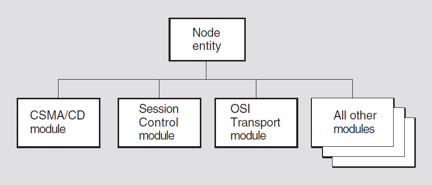
Chapter 2. Node Module
The Node module has one entity, the global node entity, which crowns the
hierarchy represented in the entity model described by the Network Architecture (NA). All
other modules described in this book are subordinate to the Node module. When enabled, each
node is visible to all other nodes on the network. Access to a node’s entities must be made
through the node.
Figure 2.1, ''The Node Global Entity in the NA Entity Hierarchy'' shows the hierarchical relationship of the Node global entity to all of the other (local) entities that are described in this book.
2.1. node
The node entity is the only entity in the Node module. All other entities
described in this book are subordinate to the node entity, as demonstrated
by the components of their entity names.
Syntax
enable [node node-id] function
function
disable [node node-id] function
function (OpenVMS)
rename [node node-id] new name
full-name
show [node node-id] [all [attributes] | all
characteristics | all counters | all identifiers | all status]
2.1.1. Entity Name
Commands that manage a node entity specify the node using this
format:
node node-id
Node being managed by the command.
If you want to operate on the local node, you can either omit the node identifier
in your NCL command, or you can specify node 0, which identifies the
local node.
2.1.2. Commands
enable
Turns on the node entity with or without the address watcher.
rename
Changes the node's name within the node and does not affect the name server
directly. It uses the new name and an immediate keep me here
transaction with the name servers which then update themselves based on the node's
new name.
2.1.3. Arguments
function function
enable
command, the function argument is optional. Specifying one, both, or neither has the
effect of changing the state to on.|
address watcher |
Enables the address watcher function. Enabling this function allows the node to update its address identifier when a change of address is detected. Disabling this function causes the state attribute to be
set to |
|
CMIP listener |
Enabled automatically by the software. This function permits the node to respond to management through its CMIP listener interface. The CMIP listener function is only supported on Tru64 UNIX. |
new name full-name
Specifies the new name to be assigned to the node.
2.1.4. Characteristic Attributes
implementation
Particular DECnet implementation of the node. You cannot modify this characteristic.
listener template (Tru64 UNIX)
Name of the OSI Transport template to be passed through the CMIP listener to Session Control. You cannot modify this characteristic.
maximum listeners (Tru64 UNIX)
Maximum number of CMIP listeners that the node supports. Zero specifies an unlimited number of listeners. You cannot modify this characteristic.
version
Version number of the network management architecture specification to which the implementation conforms. You cannot modify this characteristic.
2.1.5. Counter Attributes
changes of address
Number of times the node's address has changed.
changes of id
Number of times the node's ID has changed.
creation time
Time at which the entity was created. This time reflects the time at which the node was first booted.
idrom check failures
Number of times an IDROM was checked for consistency and was found to be in error.
renames
Number of times the node has been renamed (see the rename
command).
2.1.6. Identifier Attributes
address
Set of protocol towers that together form a Session Control application address for the node's CMIP listener.
name
Full name of the node as it is registered in your namespace; name is
the primary identifier.
2.1.7. Status Attributes
functions enabled
Functions that are currently enabled for the node (see the enable
command).
id
Indicates the unique 48-bit ID of the node.
state
|
booting |
The node is attempting to downline load. You cannot manage
the node in this state. If the boot process is successful,
the node enters the |
|
dead |
The node is unusable and unmanageable as the result of a power failure or similar event. The node must be rebooted. This function is only supported on OpenVMS. |
|
off |
The node is manageable, but not all of its functions are enabled. |
|
on |
All of the node's functions are enabled and the node is
fully manageable. The |
uid
Node's unique identifier, which is generated when the node is created.
2.1.8. Event Messages (Tru64 UNIX)
address changed
Generated each time the node address changes.
|
old address |
Protocol tower set that constituted the old node address. |
|
new address |
Protocol tower set that constitutes the new node address. |
id changed
Generated each time the node's ID status attribute changes value.
|
old id |
Node's old 48-bit ID. |
|
new id |
Node's new 48-bit ID. |
idrom check failure
Generated each time an IDROM was checked and failed the test.
|
contents |
Value of the failed IDROM. |
|
owner |
Name of the device on which the failed IDROM address exists. |
renamed
Generated each time the node's name changes.
|
old name |
Old full name of the node. |
|
new name |
New full name of the node. |
2.1.9. Exception Messages (Tru64 UNIX)
For rename:
update of backtranslation soft links failed
Update of backtranslation soft links failed on the rename directive.
update of new name failed
New name update has failed on the rename directive.
unregistered name
The attempt to rename the node failed because the name and/or UID were not registered in DNS.
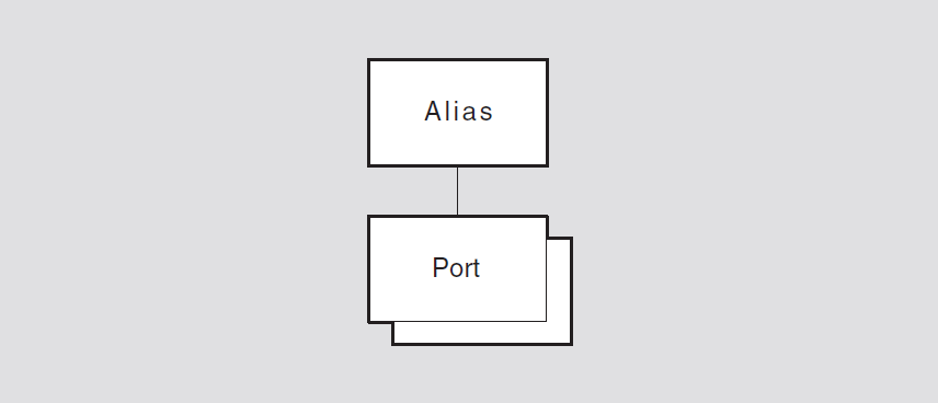
Chapter 3. Alias Module (OpenVMS)
This chapter describes all the commands you can use to manage the entities that constitute the Alias module. The Alias module provides the means to define an alternate network address that is shared by multiple nodes in the same OpenVMS cluster. This makes it possible to treat an OpenVMS cluster, or several nodes within an OpenVMS cluster, as though it were a single node in the network.
Figure 3.1, ''Hierarchy of Alias Module Entities'' shows the hierarchical relationship of the entities that constitute the Alias module.
3.1. alias
The alias entity is the top-level entity in the hierarchy belonging to
the Alias module. The entity is the root from which alias port subentities
may be defined.
Syntax
create [node node-id] alias
delete [node node-id] alias
show [node node-id] alias [all [attributes] | all
counters]
3.1.1. Counter Attributes
creation time
Specifies the time at which the entity was created.
3.1.2. Exception Messages
For create:
already exists
An alias entity already exists.
wrong node type
An alias entity cannot be created on an alias node.
For delete:
module enabled
Disable the alias entity before trying to delete it.
3.2. alias port
An alias port entity provides the means to define an alternate network
address for this node, which is shared by other nodes in the same OpenVMS cluster. When
the alias port entity is enabled, this node becomes an active member of the
OpenVMS cluster alias it specifies.
create an alias port for a
particular alias address causes that alias to be created. Subsequent nodes that
create an alias port for the same alias establish connections (ports)
to that alias. The alias becomes active when the first node enables its alias port for
that alias. The port-name refers to the port managed by this command.Note
When a node enables an alias port, that node registers itself with other members of the alias.
Syntax
create [node node-id] alias port port-name [node id ID802]
delete [node node-id] alias port port-name
disable [node node-id] alias port port-name
enable [node node-id] alias port port-name
set [node node-id] alias port port-name { outgoing default boolean |
selection weight integer }
show [node node-id] alias port port-name [all [attributes] | all
characteristics | all counters | all identifiers | all status]
shut [node node-id] alias port port-name
3.2.1. Commands
shut
Places the specified alias port entity in the shut
state. Note that other nodes participating in the alias will continue to accept
connections for the alias after this command is executed.
3.2.2. Arguments
node id
The LAN address to assign to the alias. Use the node id argument for
the first cluster member to create the alias. Omit the argument for subsequent
cluster members.
3.2.3. Characteristic Attributes
outgoing default
Specifies whether this alias should be used as the default alias for this node. If
set to true, this alias name is used for connect requests on all
outgoing connections from session control applications with their outgoing
alias attribute set to true. Only one alias port can have
this characteristic set to true.
selection weight
| Default: None | Value: 1-255 |
The number of sequential incoming connects to be passed to this member node in the round-robin sequence before proceeding to the next member node in the sequence. A value of zero means this node is not eligible to receive incoming connections to this alias address. Selection weight is used to apportion incoming alias connections according to the capacity of each alias member. Nodes with greater capacity should have larger values of selection weight, while local area OpenVMS cluster satellites should generally have a value of zero. Setting the selection weight to a very low non-zero number, such as 1, encourages needless connection delay because each incoming connection is treated in a round-robin fashion. That is, as each new connection comes in, it must be passed to the next cluster member. We recommend values between 5 and 10.
Note
The nsp maximum transport connection value determines the number
of connections on an alias member. If the alias port is enabled, changing the
nsp maximum transport connection value has no effect.
3.2.4. Counter Attributes
creation time
Specifies the time at which the entity was created.
3.2.5. Identifier Attributes
name
This string is the port identifier and is also the DECdns-registered node object name of the Alias psuedo-node.
3.2.6. Status Attributes
node-id
The 6-byte node-id field in the Alias pseudo-node's NSAP.
state
alias port entity. |
off |
The |
|
on |
The |
|
shut |
The |
3.2.7. Exception Messages
For create:
already exists
An alias port entity already exists.
too many alias port entities
The maximum number of alias port entities has been exceeded.
For delete:
cannot delete the entity while it is enabled
Disable the alias port entity before trying to delete it.
Chapter 4. CSMA-CD Module
This chapter describes all the commands you can use to manage the entities that constitute the CSMA-CD module. A Carrier Sense Multiple Access with Collision Detection (CSMA-CD) local area network (LAN) provides high-speed communications channels for connecting computers and other digital devices located within a moderate-sized geographic area. Like other LANs, the CSMA-CD LAN falls between long-distance, low-speed networks that carry data for hundreds or thousands of kilometers, and specialized, high-speed intercommunications that are generally limited to tens of meters. The CSMA-CD LAN is intended for use primarily in such areas as office automation, distributed data processing, terminal access, distributed systems, and other situations that require economical connection to a local communication medium with sporadic traffic at high-peak data rates.
Figure 4.1, ''Hierarchy of CSMA-CD Module Entities'' shows the hierarchical relationship of the entities that constitute the CSMA-CD module.
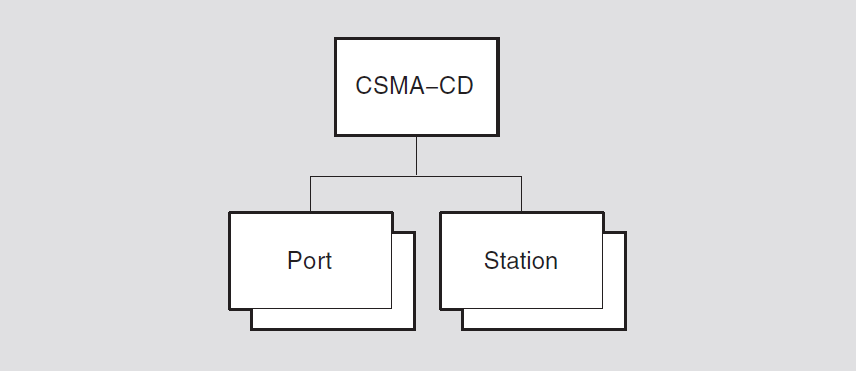
The Network Architecture CSMA-CD module incorporates the functions and operations defined in the Ethernet Specification Version 2.0 and the ISO 8802-3 (IEEE 802.3) CSMA-CD Access Method and Physical Layer specification as well as parts of the ISO8802-1 (IEEE 802.1) Addressing, Internet working, and Network Management and the ISO 8802-2 (IEEE 802.2) Logical Link Control specifications. To this, the Network Architecture CSMA-CD module adds features often needed by users of the datalink. A typical such data link user is the Network layer of the Network Architecture.
4.1. csma-cd
The csma-cd entity is the top-level entity in the hierarchy of entities
belonging to the CSMA-CD module.
Syntax
create [node node-id] csma-cd
delete [node node-id] csma-cd
show [node node-id] csma-cd [all [attributes] | all
characteristics]
4.1.1. Characteristic Attributes
version
Default: Current version number
Version number of the CSMA-CD data link architecture specification to which the implementation conforms. You cannot modify this characteristic.
4.1.2. Exception Messages
For create:
already exists
A csma-cd entity already exists.
For delete:
has children (Tru64 UNIX)
Cannot delete while subentities exist.
cannot delete while subentities exist (OpenVMS)
Cannot delete while subentities exist.
4.2. csma-cd port
A csma-cd port entity represents an access point to the service offered
by the CSMA-CD module. A client transmits and receives data through a port. Ports are
created and deleted by client use of open and close service interface procedures. The
port-name refers to the port managed by this command.
Syntax
show [node node-id] csma-cd port
port-name [all [attributes] | all counters | all
identifiers | all status]
4.2.1. Counter Attributes
Unless stated otherwise, counts include both normal and multicast traffic and all protocol types, service access points (SAPs), and protocol identifiers.
creation time
Time at which the port was created.
multicast octets received
Number of multicast data octets that were received successfully and made available
to the port user. The count is the number of octets in the CSMA-CD user data field
and does not include MAC (media access control, a sublayer of the CSMA-CD Data Link
layer) headers. Comparing this count to the octets received count
yields the gross percentage of bandwidth that was consumed (over time) by multicast
PDUs received by the port.
multicast octets sent
Number of multicast data octets that were sent successfully through the port. The
count is the number of octets in the MAC user data field, including any padding or
length fields; it does not include MAC headers. Comparing this count to the
octets sent count yields the gross percentage of bandwidth that was
consumed (over time) by multicast PDUs transmitted by the port.
multicast pdus received
Number of multicast PDUs that were received successfully and made available to the
port user. Counted PDUs passed address and protocol filtering and were received
without errors. Comparing this count to the pdus received count yields
a gross percentage of CSMA-CD usage for multicast pdus received by this
port.
multicast pdus sent
Number of multicast PDUs that were sent successfully through the port. Comparing
this count to the pdus sent count yields a gross percentage of CSMA-CD
usage for multicast pdus sent by this port.
octets received
Total number of MAC user data octets that were received successfully and made
available to the port user. Counted frames passed address and protocol filtering for
both individual and multicast MAC addresses and were received without errors. The
count is the number of octets in the CSMA-CD user data field plus any padding,
Ethernet length fields, or logical link control (LLC) header fields; it does not
include MAC headers. Adding the octets received count to the protocol
overhead calculated from the pdus received count yields the amount of
CSMA-CD bandwidth consumed by frames received by the port.
octets sent
Total number of user data octets that were sent successfully through the port. The
count is the number of octets in the MAC user data field including any padding or
length fields; it does not include MAC headers. Adding the octets sent
count to the protocol overhead calculated from the pdus sent count
yields the amount of CSMA-CD bandwidth consumed (over time) by frames sent by the
port.
pdus received
Total number of PDUs that were received successfully and made available to the port user. Counted PDUs passed address and protocol filtering and were received without errors. The count provides a gross measurement of incoming CSMA-CD usage by the port.
pdus sent
Total number of PDUs that were sent successfully through the port. The count provides a gross measurement of outgoing CSMA-CD usage by the port.
unavailable user buffers
Number of times that no user buffer was available at the port for an incoming
frame that passed all filtering for the port. Used in conjunction with the
pdus received count, this counter can indicate the rate of user
buffer receive problems.
4.2.2. Identifier Attributes
name
Simple name assigned to the port when it is created.
4.2.3. Status Attributes
client
Name specified by the data link user when the port was opened.
ethernet protocol types
Set of Ethernet protocol types that are currently recognized for this port.
length present
false, the data link does not add and remove length fields. This
attribute is irrelevant for ISO 8802-3 formatted frames, which always have a length field.|
false |
The data link does not add and remove length fields. |
|
true |
The data link adds and removes length fields. |
llc sap addresses
Set of individual and group logical link control (LLC) service access point (SAP) addresses that are currently recognized for this port.
llc service
|
class 1 |
The data link provides class 1, type 1 service. |
|
user-supplied |
The user is responsible for handling the LLC protocol. |
mac addresses
Set of individual and multicast MAC (medium access control) addresses that are currently recognized for this port.
receive mode
|
normal |
The port receives only those frames that meet the normal address and protocol filtering requirements requested by the user. |
|
promiscuous |
The port receives all frames regardless of format and MAC address. |
snap protocol identifiers
Set of subnetwork access protocol (SNAP) identifiers that are currently recognized for this port.
station
Name of the station associated with this port as specified by the user when the port was opened.
uid
Entity's unique identifier, which is generated when the port is created.
4.3. csma-cd station
A csma-cd station entity manages a CSMA-CD controller. Wherever Phase IV
DECnet manages a line, DECnet-Plus manages a station. Each station corresponds to a
particular logical link control (LLC), medium access control (MAC), and physical
attachment. The station-name refers to the station managed by this
command.
Syntax
create [node node-id] csma-cd station
station-name communication port
port-id
delete [node node-id] csma-cd station
station-name
disable [node node-id] csma-cd station
station-name
enable [node node-id] csma-cd station
station-name mac address
ID802
set [node node-id] csma-cd station
station-name station buffers integer
(OpenVMS)
show [node node-id] csma-cd station
station-name [all [attributes] | all characteristics | all
counters | all identifiers | all status]
4.3.1. Arguments
communication port
The system device name assigned to this station.
On OpenVMS systems, the name must be in the format ddc, where dd is the OpenVMS device name prefix and c is the controller letter. For a complete list of CSMA-CD devices and their OpenVMS device names, see the DECnet-Plus for OpenVMS Release Notes.
On Tru64 UNIX systems, the name must be in the format ddn, where dd is the Tru64 UNIX device name prefix and n is the device number.
This argument determines the value of the communication port
characteristic and is required.
mac address
Individual medium access control (MAC) address for the station. If you do not
specify a MAC address, the network uses the address specified in the first
EnableMacAddress user interface call directed to this
station.
4.3.2. Characteristic Attributes
|
Default: 4 |
Value: 1–64 |
Number of receive buffers reserved for the station. You cannot modify this characteristic.
4.3.3. Counter Attributes
Unless stated otherwise, counts include both normal and multicast traffic and all protocol types, service access points (SAPs), and protocol identifiers.
alignment errors
Number of times a received frame did not contain an integral number of octets.
carrier check failures
Number of times the data link did not sense the receive carrier signal or detected an error in the receive carrier signal during transmission of a frame.
collision detect check failures
Number of times the collision detect test signal was not sensed after a transmission. If this count approximates the number of frames sent, either the collision detect circuitry is not working correctly or the test signal is not implemented.
creation time
Time at which the station was created.
data overruns
Number of times the hardware lost one or more consecutive, partially complete,
incoming frames because it could not keep up with the incoming frame rate. Used in
conjunction with pdus received, this count provides a measure of
hardware resource and bandwidth failures.
excessive collisions
Number of times a transmission failed because the maximum allowable number of retransmission attempts all culminated in collisions.
frame check errors
Number of times a received frame containing an integral number of octets failed the frame check sequence (FCS).
frame size errors
Number of times the user requested transmission of a frame outside the range of valid frame sizes.
frames too long
Number of times a received frame exceeded the maximum length allowed by CSMA-CD medium access control.
initially deferred pdus sent
Number of times a PDU was deferred by the station access algorithm on the first
attempt at transmission, but was then transmitted successfully without collision.
Used in conjunction with pdus sent, this count measures the rate of
CSMA-CD contention with no collisions.
late collisions
Number of times a collision was detected after the allotted time for collisions had expired.
multicast octets received
Number of multicast data octets that were received successfully. The count is the
number of octets in the CSMA-CD user data field and does not include MAC headers.
Comparing this count to the octets received count yields the gross
percentage of bandwidth that was consumed (over time) by multicast frames received
by the local system.
multicast octets sent
Number of multicast data octets that were sent successfully. The count is the
number of octets in the MAC user data field, including any padding or length fields;
it does not include MAC headers. Comparing this count to the octets
sent count yields the gross percentage of bandwidth that was consumed
(over time) by multicast frames transmitted by the local system.
multicast pdus received
Number of multicast PDUs that were received successfully. Comparing this count to
the pdus received count yields a gross percentage of CSMA-CD usage for
multicast PDUs received by this system.
multicast pdus sent
Number of multicast PDUs that were sent successfully. Comparing this count to the
pdus sent count yields a gross percentage of CSMA-CD usage for
multicast PDUs sent by this system.
multiple collisions pdus sent
Number of times a PDU was transmitted successfully on the third or later attempt
by the station access algorithm after normal collisions on previous attempts. Used
in conjunction with pdus sent, this count provides a measure of CSMA-CD
media contention at a level where there are collisions and the backoff algorithm no
longer works efficiently.
octets received
Total number of MAC user data octets that were received successfully from frames
that passed address and protocol filtering for both individual and multicast MAC
addresses. The count is the number of octets in the CSMA-CD user data field plus any
padding, Ethernet length fields, or LLC header fields; it does not include MAC
headers. Adding the octets received count to the protocol overhead
calculated from the pdus received count yields the amount of CSMA-CD
bandwidth consumed by frames received by the local system.
octets sent
Total number of user data octets that were sent successfully. The count is the
number of octets in the MAC user data field including any padding or length fields;
it does not include MAC headers. Adding the octets sent count to the
protocol overhead calculated from the pdus sent count yields the amount
of CSMA-CD bandwidth consumed (over time) by frames sent by the local system.
pdus received
Total number of PDUs that passed address and protocol filtering and were received without errors. The count provides a gross measurement of incoming CSMA-CD usage by the local system; this information can be used with other counters to approximate the average receive frame size or to determine the ratio of errors to successful receives.
pdus sent
Total number of PDUs successfully sent. The count provides a gross measurement of outgoing CSMA-CD usage by the local system; this information can be used with other counters to approximate the average transmit frame size or to determine the ratio of errors to successful transmissions.
receive data length errors
Number of times a frame was received with a length field value that was invalid for the number of octets actually received by medium access control.
send data length errors
Number of times the user requested transmission of an 802.3 frame with a length field value that was not valid for the number of octets actually passed.
single collision pdus sent
Number of times a PDU was successfully transmitted on the second attempt by the
station access algorithm after a normal collision occurred on the first attempt.
Used in conjunction with pdus sent, this count provides a measure of
CSMA-CD media contention at a level where there are collisions, but the backoff
algorithm still works efficiently.
station failures
Number of times the station self-testing procedures reported failure.
unavailable station buffers
Number of times a complete, fully received PDU was discarded because no station
buffer was available. Used with pdus received, this count provides a
measure of receive problems related to the station buffer.
unavailable user buffers
Number of times no user buffer was available for an incoming frame that passed all
filtering for the port. Used with the pdus received count, this counter
can indicate the rate of user buffer receive problems.
unrecognized individual destination pdus
Number of times a received PDU with an individual destination MAC address was discarded because there was no port with the correct Ethernet protocol type, SNAP protocol identifier, or link logical control SAP address enabled.
unrecognized multicast destination pdus
Number of times a received PDU with a multicast destination MAC address was discarded because there was no port with the correct Ethernet protocol type, SNAP protocol identifier, or link logical control SAP address enabled.
4.3.4. Identifier Attributes
name
Simple name assigned to the station when it is created.
4.3.5. Status Attributes
address filters
All individual MAC addresses currently enabled by any of the ports on the station.
communication port
DECnet-Plus device name for the station.
hardware address
Individual medium access control (MAC) address that was assigned during manufacture of the communications hardware that is associated with the station.
mac address
Current MAC address (if any) of the station. For more information about the MAC
address, refer to the enable command.
receive mode
|
normal |
The station receives only those frames (individual and multicast) that meet the normal format, protocol, and access control requirements. |
|
all multicast |
The station receives all individual-addressed frames that meet the normal format, protocol, and address requirements, and all multicast-addressed frames regardless of their format, protocol, and address types. This function is only supported on OpenVMS. |
|
promiscuous |
The station receives all frames (individual and multicast) regardless of format, Ethernet protocol type, SNAP identifier, LLC SAP address, or MAC address. This function is only supported on OpenVMS. |
state
|
failed |
Either an attempt to enable the station failed during the self-test or the station was on and the data link determined that the station would now fail the self-test. |
|
initializing |
The station is currently being initialized and tested by the data link. |
|
off |
The station is disabled. |
|
on |
The station is enabled and available for use. |
For more information on station states, refer to the appropriate network management guide.
uid
Entity's unique identifier, which is generated when the station is created.
4.3.6. Event Messages
alignment error
This event is generated whenever an incoming frame does not contain an integral number of octets. This error can be caused by several conditions, such as electromagnetic interference, late collisions, or improperly set hardware parameters (for example, receiver squelch).
carrier check failure
This event is generated on a transmission that failed, either because the data link did not sense the receive carrier signal that must accompany transmission of a frame, or because the data link did not detect an error. This error indicates a failure in either the transmitting or receiving hardware, such as the transceiver or transceiver cable.
data overrun
This event is generated whenever an incoming frame is lost because of a hardware resource failure such as insufficient hardware buffers or insufficient CPU time.
excessive collision
This event is generated whenever a transmission fails because the medium access algorithm reached the maximum number of allowable retransmission attempts resulting from collisions. This error can occur when too many systems are trying to transmit at the same time or when there are cable problems.
frame check error
This event is generated whenever an incoming frame fails the frame check sequence (FCS) test. This error can be caused by several conditions, such as electromagnetic interference, late collisions, or improperly set hardware parameters (for example, receiver squelch).
frame too long
This event is generated whenever a remote system sends a frame that exceeds the CSMA-CD MAC maximum length.
late collision
This event is generated whenever a transmission fails because a collision was detected after the allowed window for collisions had elapsed. This error indicates either a problem with another system's carrier sense or a weak local transmitter.
receive data length error
This event is generated whenever a remote system sends an 802.3 frame having a length field value that is not valid for the number of octets actually received by the MAC.
unavailable station buffer
This event is generated whenever an incoming frame is discarded because there is no station buffer available to receive it. This error indicates a lack of local station buffers; that is, a lack of buffers between the cable and the user buffers.
unavailable user buffer
This event is generated whenever an incoming frame is discarded because there is no user buffer queued to the appropriate port to receive it. This error indicates a lack of buffers in the user process; that is, the buffers supplied by the user for the Receive function.
unrecognized individual destination pdu
This event is generated whenever an incoming frame that matches an enabled individual MAC address is discarded because the frame does not satisfy the filter criteria of any port. This error indicates that a remote system is using a protocol that is locally unsupported or that the local system has not enabled a protocol type, protocol identifier, or LLC SAP address that it should have.
unrecognized multicast destination pdu
This event is generated whenever an incoming frame that matches an enabled multicast MAC address is discarded because the frame does not satisfy the filter criteria of any port. This error indicates that the local system has not enabled an Ethernet protocol type, SNAP identifier, or LLC SAP address that it should have, or that a remote system is sending traffic that is invalid for the combination of multicast and the currently specified protocol type, SNAP identifier, or LLC SAP.
4.3.7. Exception Messages
For create:
already exists
A csma-cd station entity already exists.
communication port in use
Failure to create the csma-cd station entity because the
communications port is already reserved by another entity.
invalid communications port
Failure to create the csma-cd station entity because you cannot run
CSMA-CD data link on this communications port.
For delete:
station in use (UNIX)
Attempt to delete the csma-cd station entity failed because there is
at least one active port still associated with this station. You must wait until the
ports go away to delete this station.
wrong state
Failure to delete the csma-cd station because the station must be
disabled before deletion.
Chapter 5. DCMP Module (OpenVMS)
This chapter describes all the commands you can use to manage the entities that constitute the Data Communications Message Protocol (DCMP) module. The DCMP module is a data link control procedure that ensures a reliable data communication path between communication devices connected by data links. DCMP has been designed to operate over full- and half-duplex synchronous and asynchronous channels in both point-to-point and multipoint modes. It can be used in a variety of applications such as distributed computer networking, host/front-end processing, remote terminal concentration, and remote job entry-exit system operation.
Figure 5.1, ''Hierarchy of DCMP Module Entities'' shows the hierarchical relationship of the entities that constitute the DCMP module.
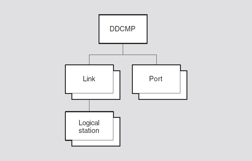
5.1. dcmp
The dcmp entity is the top-level entity in the hierarchy of
entities belonging to the DCMP module.
Syntax
create [node node-id] dcmp
delete [node node-id] dcmp
show [node node-id] dcmp [all [attributes] | all
characteristics]
5.1.1. Characteristic Attributes
dna version
Version number of the DCMP architecture specification to which the implementation conforms. You cannot modify this characteristic.
5.1.2. Exception Messages
For create:
already exists
A DCMP entity already exists.
5.2. dcmp link
The dcmp link entity defines the attributes of a link to a
communications port that uses DCMP. The link-name
refers to the link managed by this command.
Syntax
create [node node-id] dcmp link
link-name protocol
protocol-type
delete [node node-id] dcmp link
link-name
disable [node node-id] dcmp link
link-name
enable [node node-id] dcmp link
link-name
set [node node-id] dcmp link
link-name {dead timer integer | delay
timer integer | physical line local-entity-name | receive buffers
integer | retransmit timer integer | scheduling timer integer |
stream timer integer}
show [node node-id] dcmp link
link-name [all [attributes] | all
characteristics | all counters | all identifiers | all
status]
5.2.1. Arguments
protocol protocol-type
|
point |
The local station is one end of a point-to-point link. This is the default and only supported value. |
|
tributary |
The local station acts as a tributary of a multipoint link. |
5.2.2. Characteristic Attributes
|
Default: 10000 |
Value: 1–65535 |
Specifies the delay, in milliseconds, between polls of one of the set
of dead tributaries. This attribute is supported only if the
characteristic protocol is set to
control.
|
Default: 0 |
Value: 0–65535 |
Specifies the minimum delay, in milliseconds, between polls. You can
use this timer to limit the effect of a fast control station on
slower tributaries. A value of 0 means that no delay is added. This
attribute is supported only if the characteristic
protocol is set to control.
|
Default: No name |
Value: Local-entity-name |
Name of the Physical layer entity over which the link operates. A
value for this characteristic must be set before the
link entity is enabled. You can modify this
characteristic only when the entity is disabled.
|
Default: Point |
Value: See description |
Protocol mode used by the local station. You cannot modify this characteristic.
The value of this characteristic is a copy of the
protocol argument specified when the dcmp
link entity is created. The default value is
point and is the only permissible value.
|
Default: 4 |
Value: 1–255 |
Number of receive buffers reserved for the link. You can modify this characteristic only when the entity is disabled. Also, you can only increase the characteristic value.
|
Default: 3000 |
Value: 1–65535 |
Maximum time, in milliseconds, to wait between sending a message and receiving a valid response. If this time expires, the local station takes error recovery action. On full-duplex point-to-point links, the timer is started immediately when a message is sent.
|
Default: 200 |
Value: 50–65535 |
Time, in milliseconds, between the recalculation of tributary polling
priorities. This attribute is supported only if the characteristic
protocol is set to control.
|
Default: 6000 |
Value: 0–65535 |
Time, in milliseconds, for which a tributary or the remote station (on
a half-duplex, point-to-point link) can hold the line. This
characteristic is not supported if the characteristic
protocol is set to
tributary.
5.2.3. Counter Attributes
creation time
Time at which this entity was created.
naks received indicating message header format error
Number of NAK messages received that report errors in message headers sent from the local station.
naks received indicating receive overrun
Number of NAK messages received that report a receive overrun at the remote station.
pdus received with message header format error
Number of times the local station detected an error in a message header.
receive overruns
Number of times the local station detected a receive overrun.
selection address errors
Number of times the controller of a multipoint link received a message
with an address other than that of the currently selected station.
This counter is supported only if the characteristic
protocol is set to control.
streaming tributaries
Number of times the remote station (or a tributary station) exceeded
the maximum transmission interval without releasing the line, or
failed to release the line after sending a message with the
select flag set. This counter is present only
on half-duplex, point-to-point links, or when the local station is a
controller of a multipoint link. This counter is not supported if
the protocol characteristic is set to
tributary.
transmit underruns
Number of times the local station detected a transmit underrun.
5.2.4. Identifier Attributes
name
Simple name assigned to the link when it is created.
5.2.5. Status Attributes
physical port
Name of the port entity in the Physical layer returned when the port is opened. If this is null, the port is not open.
state
enable and disable commands.|
off |
The entity is disabled. |
|
on |
The entity is enabled. |
In addition, the link is disabled and its state is set to
off if the Physical layer port that the link
uses is deleted.
uid
Entity's unique identifier, which is generated when the entity is created.
5.2.6. Event Messages
pdu received with header format error
Invalid
selectflagInvalid
addrvaluefillfields not zeroInvalid control
typeorsubtypefields
|
address |
Address of the remote station that caused the event. | |
|
message header |
Message header that contains the error. | |
selection address error
Generated each time the controller of a multipoint link receives a
message that contains an address other than that of the currently
selected tributary. This event is supported only on half-duplex,
point-to-point links, or if the protocol characteristic
is set to tributary.
|
current address |
Address of the currently selected tributary station. | |
|
previous address |
Address of the previously selected tributary station. | |
|
received address |
Address contained in the received message. | |
streaming tributary
When a remote station exceeds a maximum transmission interval without releasing the channel.
When a remote station fails to release a channel after sending a message with the
selectflag set.When the jamming condition is cleared.
|
previous address |
Address of the previously selected tributary station. | |
|
received address |
Address contained in the message received after transmission should have ended. This argument is not present if no message is received. | |
|
type |
Type of jamming that the local station detected, or indicates that jamming has now cleared. | |
|
continued transmission after deselection |
The remote station continued to send
information after it sent a message with the
| |
|
continued transmission after timeout |
The remote station continued to send information after exceeding the maximum transmission interval. | |
|
streaming cleared |
A previous | |
|
streaming tributary |
The remote station continued to send valid control messages or headers to data message after exceeding the maximum transmission interval. | |
5.2.7. Exception Messages
For create:
already exists
A dcmp link entity already exists.
For delete:
cannot delete while subentities exist
Cannot delete while subentities exist.
wrong state
Failure to delete the dcmp link entity because the link
must be disabled before deletion.
For enable:
device constraint
The value of an attribute is not supported by the type of device used on the communications line. Modify the attribute to a suitable value, and retry the operation.
open physical port failed
The opening of the port in the Physical layer failed. The exception includes an argument that gives more information about the failure.
5.3. dcmp link logical station
The dcmp link logical station entity manages a link to a remote
station. The link-name is the DCMP link associated with
the logical station and the station-name refers to the
logical station managed by this command.
Syntax
create [node node-id] dcmp link
link-name logical station
station-name
delete [node node-id] dcmp link
link-name logical station
station-name
disable [node node-id] dcmp link
link-name logical station
station-name
enable [node node-id] dcmp link
link-name logical station
station-name
set [node node-id] dcmp link
link-name logical station
station-name {active base integer |
active increment integer | address address | babble timer integer |
buffer source source | dead threshold integer | dying base integer |
dying increment integer | dying threshold integer | holdback timer
integer | inactive base integer | inactive increment integer |
inactive threshold integer | maximum buffers integer | maximum
transmit integer | polling state effect | transmit timer integer |
transmit window integer }
show [node node-id] dcmp link
link-name logical station
station-name [all [attributes] | all
characteristics | all counters | all identifiers | all status
]
5.3.1. Characteristic Attributes
|
Default: 255 |
Value: 0–255 |
Base priority to which an active tributary is reset after it has been polled.
This characteristic is supported only if the characteristic
protocol of the owning dcmp link
entity is set to control.
|
Default: 0 |
Value: 0–255 |
Value to be added to the active tributary priority each time the scheduling timer expires.
This characteristic is supported only if the characteristic
protocol of the owning dcmp link
entity is set to control.
|
Default: 1 |
Value: 1–255 |
Data link address of the remote station or tributary. You can modify this characteristic only when the entity is disabled.
|
Default: 6000 |
Value: 1–65535 |
Time, in milliseconds, for which a selected tributary or remote station is allowed to transmit. This characteristic is not used on full-duplex links.
This characteristic is not supported if the characteristic
protocol of the owning dcmp link
entity is set to tributary.
|
Default: Implementation-specific |
Value: See description |
|
client supplied |
Buffers are provided by the client entity. |
|
common pool |
Buffers are assigned from the common buffer pool. |
This characteristic is supported only if the characteristic
protocol of the owning dcmp link
entity is set to control. You can modify this
characteristic only when the entity is disabled.
|
Default: 8 |
Value: 0–255 |
Number of times an active, inactive, or dying tributary is polled
before its status attribute polling substate is changed
to dead because of receive timeouts.
This characteristic is supported only if the characteristic
protocol of the owning dcmp link
entity is set to control.
|
Default: 0 |
Value: 0–255 |
Base priority to which a dying tributary is reset after being polled.
This characteristic is supported only if the characteristic
protocol of the owning dcmp link
entity is set to control.
|
Default: 16 |
Value: 0–255 |
Value to be added to a dying tributary's priority each time the scheduling timer expires.
This characteristic is supported only if the characteristic
protocol of the owning dcmp link
entity is set to control.
|
Default: 2 |
Value: 0–255 |
Number of times an active or inactive tributary is polled before its
status attribute polling substate is changed to
dying because of receive timeouts.
This characteristic is supported only if the characteristic
protocol of the owning dcmp link
entity is set to control.
|
Default: 0 |
Value: 0–13000 |
Maximum time, in milliseconds, that the local station can delay acknowledging a received message if there is no data to send.
The value of this characteristic is linked to the retransmit
timer used on the remote station. A suggested value
is between 10% and 20% of that timer. However, the actual values you
can use may be limited by the communications product.
The default value indicates that no holdback is used and the local station must acknowledge immediately.
|
Default: 0 |
Value: 0–255 |
Specifies the priority to which an inactive tributary is reset after it has been polled.
This characteristic is supported only if the characteristic
protocol of the owning dcmp link
entity is set to control.
|
Default: 64 |
Value: 0–255 |
Value to be added to an inactive tributary's priority each time the scheduling timer expires.
This characteristic is supported only if the characteristic
protocol of the owning dcmp link
entity is set to control.
|
Default: 8 |
Value: 0–255 |
Number of times an active tributary is polled before its status
attribute polling substate is changed to
inactive because of no data response.
This characteristic is supported only if the characteristic
protocol of the owning dcmp link
entity is set to control.
|
Default: 4 |
Value: Implementation specific |
Maximum number of buffers that a tributary can use from the common
buffer pool. A value of 0 means that there is no limit to the number
of buffers that can be used. This characteristic is supported only
if the buffer source characteristic is set to
common pool.
This characteristic is supported only if the characteristic
protocol of the owning dcmp link
entity is set to control. You can modify this
characteristic only when the entity is disabled. Also, you can only
increase the characteristic value.
|
Default: 4 |
Value: 1–255 |
Maximum number of messages that a tributary or a remote half-duplex
station can send at one time. The value of this characteristic must
be greater than or equal to that of transmit window on
the selected station.
The characteristic
protocolof the owningdcmp linkentity is set totributary.The communications link is full-duplex and point-to-point.
You cannot modify this characteristic.
|
Default: Automatic |
Value: See description |
polling substate.|
active |
The state is locked to active. |
|
automatic |
The state varies according to the operation of the polling algorithm. |
|
dead |
The state is locked to dead. |
|
dying |
The state is locked to dying. |
|
inactive |
The state is locked to inactive. |
This characteristic is supported only if the characteristic
protocol of the owning dcmp link
entity is set to control.
|
Default: 0 |
Value: 0–65535 |
Time, in milliseconds, that the local station waits between data transmissions.
This characteristic is supported only if the characteristic
protocol of the owning dcmp link
entity is set to control.
|
Default: 1 |
Value: 1–255 |
Maximum number of data messages that the local station can send
without receiving an acknowledgment. This characteristic applies
only when the remote station is a control station or on a
half-duplex, point-to-point link. The value of this characteristic
must be less than or equal to the equivalent of the maximum
transmit characteristic on the control station or
remote station.
5.3.2. Counter Attributes
buffers temporarily unavailable
Number of times the local station could not service messages from the remote station because there were no receive buffers available.
buffers too small
Number of times the local station could not service messages from the remote station because the receive buffers were not large enough.
creation time
Time at which this entity was created.
incomplete replies to select
Number of selection intervals that were not properly terminated (that is, by a message with the Select bit set in the header), during which a transmission was received or an attempt at transmission was detected.
This counter is supported only if the protocol
characteristic of the owning dcmp link entity is set to
control, or when the link is a half-duplex,
point-to-point link.
local reply timeouts
Number of times the local station failed to receive an acknowledgment before the reply timer expired.
locally initiated state changes
Number of times the station protocol state changed through action of the local station.
naks received indicating buffer too small
Number of times the remote station reported that it could not service a message because the receive buffer was not large enough.
naks received indicating buffers temporarily unavailable
Number of times the remote station reported that it could not service a message because no receive buffer was available.
naks received indicating data field block check error
Number of times the remote station reported that a block check error was detected in the data field of an incoming message.
naks received indicating header block check error
Number of times the remote station reported that a block check error was detected in the header block of an incoming message.
naks received indicating rep response
Number of times the remote station reported that it did not receive all the messages sent from the local station.
naks sent with rep response
Number of times the local station detected that not all of the messages sent from the remote station were received correctly.
no replies to select
No valid control message was received.
No valid header to a data message was received.
No valid header to a maintenance message from the selected station was received.
No transmission from the remote station was received.
This counter is supported only if the protocol
characteristic of the owning dcmp link entity is set to
control, or when the link is a half-duplex,
point-to-point link.
pdus received with data field check block error
Number of messages received with a check error in the data field.
pdus received with header block check error
Number of messages received with a check error in the header block.
receive error thresholds reached
Number of times the receive error threshold has been reached.
remote reply timeouts
Number of times the local station received a REP message and sent an acknowledgment in return. This sequence indicates that all messages sent from the remote station have been correctly received.
remotely initiated state changes
Number of changes in the station protocol state caused by action of the remote station.
sdu octets received
Number of data octets received from the remote station.
sdu octets sent
Number of data octets sent to the remote station.
sdus received
Number of data messages received from the remote station (not including retransmissions).
sdus sent
Number of data messages sent to the remote station (not including retransmissions).
selection error thresholds reached
Number of times the selection error threshold has been reached.
This counter is not supported if the characteristic
protocol of the owning dcmp link
entity is set to tributary.
selection intervals
Number of times the local station selected the remote or a tributary
station. The counter does not appear if the link uses the
tributary protocol. In addition, the counter
appears only when the local station is the control station for a
number of tributaries, or is operating over a half-duplex,
point-to-point link.
This counter is supported only if the protocol
characteristic of the owning dcmp link entity is set to
control, or when the link is a half-duplex,
point-to-point link.
send error thresholds reached
Number of times the send error threshold has been reached.
strts received while in maintenance
Number of times the local station received a STRT
protocol message while in the Maintenance state.
5.3.3. Identifier Attributes
name
Simple name assigned to the link logical station when it is created.
5.3.4. Status Attributes
polling substate
protocol characteristic is set to
control. The value of this attribute is
affected by the value of the characteristic polling
state. If the characteristic polling
state is set to automatic, the value of
this status attribute reflects the current state of the polling
algorithm. For all other values of the polling state
characteristic, the values of both attributes are the same. |
active |
The tributary is active and responds with data when selected. |
|
dead |
The tributary did not respond when selected within the appropriate timeout period, when already in the Dying or Inactive state. The tributary is ignored until the station reinitializes. |
|
dying |
The tributary, currently in the Inactive or Active state, has not responded within the appropriate timeout period when selected. |
|
inactive |
The tributary has not sent any data when selected by the control station. However, the tributary has responded with an appropriate message when selected. |
protocol state
|
halted |
The protocol is stopped and no messages are being exchanged with the remote station. |
|
maintenance |
The protocol is off line and dealing with maintenance messages only. |
|
running |
The protocol is on line and exchanging messages with the remote station. |
|
starting |
There is an attempt to initialize the protocol between the local and remote stations. This uses the STRT and STACK PDUs. |
state
|
off |
The station is disabled. |
|
on |
The station is enabled. |
uid
Entity's unique identifier, which is generated when the entity is created.
5.3.5. Event Messages
buffer too small
Generated each time a message is received whose data field is larger than the buffers available on the local station.
|
buffer size |
Size of the receive buffer at the local station. | |
|
count |
Size of the received data message as specified in the message header. | |
locally initiated state change
Generated each time the state of the local station changes as a result of action on the local node.
|
new state |
New value of the logical station's
| |
|
old state |
Previous value of the logical station's
| |
receive error threshold reached
Generated each time the number of consecutive receive-related errors reaches the receive error threshold limit of 7.
remotely initiated state change
Generated each time the state of the link changes as a result of action on the remote node.
|
new state |
New value of the logical station's
| |
|
old state |
Previous value of the logical station's
| |
selection error threshold reached
Generated each time the number of consecutive selection-related errors
reaches the selection error threshold limit of 7. This event is
supported only when the protocol characteristic of the
owning dcmp link entity is set to control,
or when the link is half-duplex, point-to-point.
send error threshold reached
Generated each time the number of consecutive transmit-related errors reaches the transmit error threshold limit of 7.
strt received while in maintenance
Generated each time a strt message is received while the
value of the status attribute protocol state of the
local station is set to maintenance.
5.3.6. Exception Messages
For create:
already exists
A dcmp link logical station entity already exists.
maximum stations exceeded
The station cannot be created because there are already the maximum stations defined for this link. This can occur when there is already one logical station defined for that link.
For delete:
wrong state
Failure to delete the DCMP link logical station because
the logical station must be disabled before deletion.
5.4. dcmp port
A dcmp port entity represents an access point to the Data Link
layer service offered by dcmp. Ports are created and deleted
automatically when a client of dcmp uses the link. The
port-name refers to the port managed by this
command.
Syntax
show [node node-id] dcmp port
port-name [all [attributes] | all
identifiers | all status]
5.4.1. Identifier Attributes
name
Simple name assigned to the port when it is created.
5.4.2. Status Attributes
client
Name of the client entity.
link
Name of the DCMP link that the client is using.
logical station
Name of the DCMP link logical station supplied by the client when the port was opened.
state
|
call attached |
The port is assigned to a client and the link is associated with the current call on the line. Applies only when the link operates over a switched line. |
|
open |
The port is assigned to a client. |
|
open disabled |
The port is assigned to a client, but the link or logical station entity used by the port is disabled. |
type
|
normal |
For normal data communications. |
|
service |
For service operations. This is the value that modules such as MOP would use. |
Chapter 6. Device Module
This chapter describes all the commands you can use to manage the entities that constitute the Device module. The Device module provides management of physical devices attached to a network system that must load microcode from a host system before it is operational.
Figure 6.1, ''Hierarchy of Device Module Entities'' shows the hierarchical relationship of the entities that constitute the Device module.
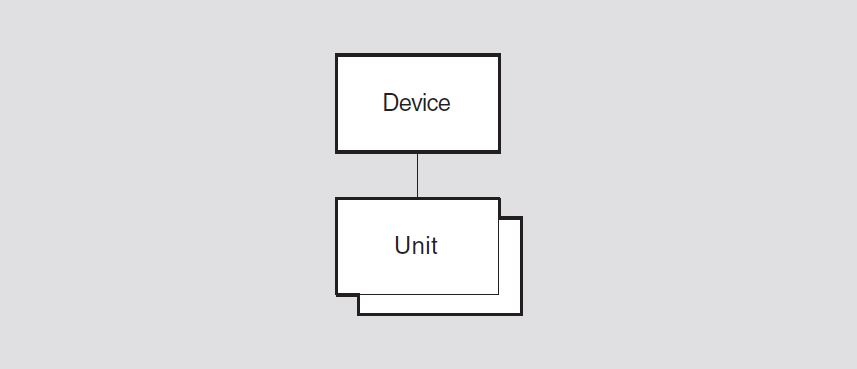
6.1. device
The device entity is the top-level entity in the hierarchy of entities
belonging to the Device module.
Syntax
create [node node-id] device
delete [node node-id] device
show [node node-id] device [all [attributes] | all
characteristics | all status]
6.1.1. Characteristic Attributes
version
Version of the device architecture to which the implementation conforms. You cannot modify this characteristic.
6.1.2. Status Attributes
uid
Entity's unique identifier, which is generated when the entity is created.
6.1.3. Exception Messages
For create:
already exists
A device entity already exists.
For delete:
has children
Cannot delete while subentities exist.
6.2. device unit
The device unit entity controls the loading and dumping of microcode for
a specific communications device. The simple-name refers to the
device unit managed by this command.
Syntax
create [node node-id] device unit
simple-name name
device-name
delete [node node-id] device unit
simple-name
dump [node node-id] device unit
simple-name
enable [node node-id] device unit
simple-name
load [node node-id] device unit
simple-name
set [node node-id] device unit
simple-name {auto load boolean | dump destination filespec
| dump on error boolean | load source filespec }
show [node node-id] device unit
simple-name [all [attributes] | all characteristics | all
counters | all identifiers | all status ]
6.2.1. Commands
dump
Dumps the device corresponding to the unit subentity.
load
Loads the device corresponding to the unit subentity.
6.2.2. Arguments
name device-name
The physical device this device unit entity controls.
6.2.3. Characteristic Attributes
|
Default: True |
Value: True or false |
Specifies whether the device should try to load its microcode without management intervention. Autoloading would occur after initialization, a failure, or a dump.
device
Physical device to which this device unit entity is related. The
value of this characteristic is a copy of the name argument specified
when this entity is created.
dump destination
|
Default: None |
Value: File destination |
File specification to hold the contents of the device's microcode when a dump occurs.
|
Default: False |
Value: True or false |
Whether a device should try to dump its microcode after a device failure. Set this characteristic only for those devices that support the dump operation.
|
Default: None |
Value: File specification |
File specification that contains the device's microcode. This is used during a load operation.
6.2.4. Counters
creation time
Time at which this entity was created.
device failures
Number of times the unit has failed.
failed dumps
Number of times an attempt to dump the device's microcode has failed.
failed loads
Number of times an attempt to load the device's microcode has failed.
forced dumps
Number of times the dump command has been used to force the device to
dump its microcode.
forced loads
Number of times the load command has been used to load the device's
microcode.
successful dumps
Number of times the device has successfully dump edits microcode.
successful loads
Number of times the device has successfully loaded its microcode.
6.2.5. Identifier Attributes
name
Simple name assigned to the device unit when it is created.
6.2.6. Status Attributes
firmware identifier
Implementation-specific string that identifies the firmware loaded into a device.
operational communication port (OpenVMS)
Specifies which channels of a multiple-line device unit are determined to be working by the module self-test. Each name identifies a working device communication port. Channels that are not named are not operational.
state
|
disabled |
The |
|
dump failed |
An attempt to dump the device's microcode has failed. This
value appears only if the characteristic |
|
dumping |
An attempt to dump the device's microcode is in progress. |
|
load failed |
An attempt to load the device's microcode has failed. This
value appears only if |
|
loading |
An attempt to load the device's microcode is in progress. |
|
running |
The device's microcode has been loaded and the device is ready to send and receive data. |
|
stopped |
This state can occur in one of the following circumstances:
|
uid
Entity's unique identifier, which is generated when the entity is created.
6.2.7. Event Messages
device failure
Generated each time a failure is detected on a device.
|
failure reason |
Reason for the device failure. The values of this argument are implementation specific. | |
|
firmware identifier |
Identifier of the device's microcode. | |
|
next state |
Next state of the device. This depends on the values of
the | |
|
dumping |
The entity will try to dump the device's microcode. | |
|
loading |
The entity will try to load the device's microcode. | |
|
stopped |
The entity will stop, awaiting a | |
failed dump
Generated each time there is a failure to dump the device's microcode.
|
dump destination |
Destination that the dump operation used. | |
|
dump reason |
Reason for the dump failure. | |
|
directive |
In response to a | |
|
failure |
In response to a device failure while in the running state. | |
|
failure reason |
Reason why the dump failed. The values of this argument are device specific. | |
failed load
Generated each time there is a failure to load the device's microcode.
|
failure reason |
Reason for the load failure. The values of this argument are device dependent. | |
|
load reason |
Reason for the load operation. | |
|
directive |
In response to a | |
|
dump |
After completion of a dump operation. | |
|
failure |
After a device failure. | |
|
initial |
Initial loading of the device at | |
|
load source |
Source used to retrieve the microcode during the load operation. | |
successful load
Generated each time the device's microcode is loaded successfully.
|
firmware identifier |
Firmware identifier of the loaded microcode. | |
|
load reason |
Reason for the load operation. | |
|
directive |
In response to a | |
|
dump |
After completion of a dump operation. | |
|
failure |
After a device failure. | |
|
initial |
Initial loading of the device at | |
|
load source |
Source used to retrieve the microcode during the load operation. | |
6.2.8. Exception Messages (OpenVMS)
For dump:
dump failure
The dump operation failed.
illegal dump destination
The value of the dump destination characteristic is not a valid file
specification. Check the value of the character, correct as necessary, and reissue
the dump command.
For load:
illegal load source
The value of the load source characteristic is not a valid file
specification. Check the value of the characteristic, correct as necessary, and
reissue the load command.
load failure
The load operation failed.
Chapter 7. DECdns Modules
The VSI DECnet-Plus Distributed Name Service (DECdns) is a networkwide service that makes it possible to use network resources without having to know their physical location. DECdns has two NCL modules: DNS Server and DNS Clerk.
7.1. DNS Server Module
The DNS Server module maintains a distributed database for use by the client modules on other nodes of the network. The responsibilities of this entity include responding to lookup requests, managing the namespace, and updating object entries.
Figure 7.1, ''Hierarchy of DNS Server Module Entities'' shows the hierarchical relationship of entities that constitute the DNS Server module.
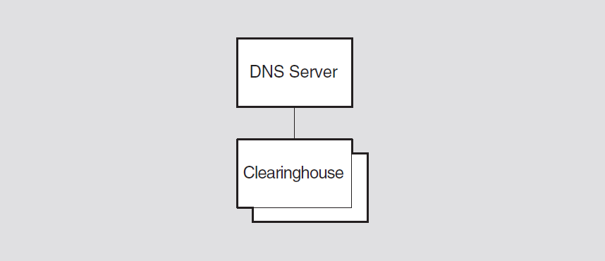
Note
You can manage the DECdns entities from either NCL or the DECdns Control Program (DNSCP). The commands are the same for both interfaces and are documented in the VSI DECnet-Plus for OpenVMS DECdns Management Guide.
7.2. DNS Clerk Module
The DNS Clerk is the module of the Network Architecture Naming Service that interfaces directly with client applications. A clerk module is required on every DECnet-Plus node whether or not that node also functions as a DECdns name server. The clerk is created during configuration of the network software.
Figure 7.2, ''Hierarchy of DNS Clerk Module Entities'' shows the hierarchical relationship of entities that constitute the DNS Clerk module.
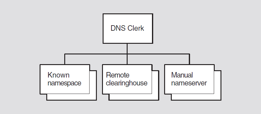
Note
You can manage the DECdns entities from either NCL or the DECdns Control Program (DNSCP). The commands are the same for both interfaces and are documented in the VSI DECnet-Plus for OpenVMS DECdns Management Guide.
Chapter 8. DECdts Module
The VSI DECnet-Plus Distributed Time Service (DECdts) is a networkwide time service that enables you to synchronize and manage the system clocks in a distributed network.
Figure 8.1, ''Hierarchy of DECdts Module Entities'' shows the hierarchical relationship of the entities that constitute the DECdts module.
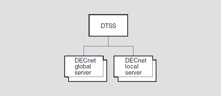
Chapter 9. Event Dispatcher Module
This chapter describes all the commands you can use to manage the entities that constitute the Event Dispatcher module. The event dispatcher is an integral component of the Network Architecture (NA) that processes events generated by entities in the network. Each component layer architecture of the Phase V NA architecture, such as Routing, NSP, and ISO Transport, may define certain occurrences, actions, transitions, or conditions as events that are reported and may be logged to assist network or system management. The Event Dispatcher module allows these conditions to be logged and monitored to allow a system manager to view the state of the network. Individual messages are listed and described throughout this manual with the entities that produce them.
Figure 9.1, ''Hierarchy of Event Dispatcher Module Entities'' shows the hierarchical relationship of the entities that constitute the Event Dispatcher module.
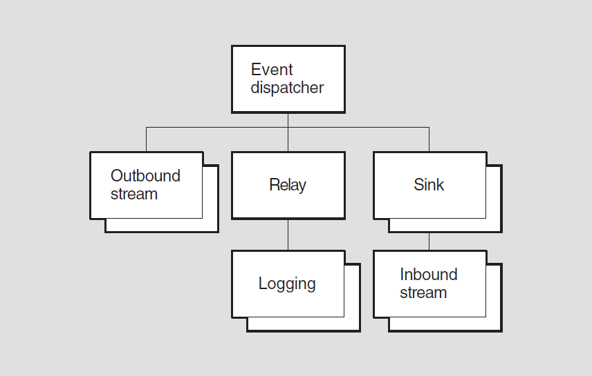
9.1. event dispatcher
The event dispatcher entity is the top-level entity in the hierarchy of
entities belonging to the Event Dispatcher module. Each NA node must implement an event
dispatcher.
Syntax
create [node node-id] event dispatcher
disable [node node-id] event dispatcher
enable [node node-id] event dispatcher
show [node node-id] event dispatcher [all [attributes] |
all characteristics | all counters | all status ]
test [node node-id] event dispatcher
9.1.1. Commands
test
The test command is used by the manager to request that an event be
logged to test the entire event logging subsystem. This directive tests the complete
event logging system from entity to manager and causes the test
requested event to be logged.
9.1.2. Characteristic Attributes
NA version
Default: Current version number
Version number of the NA event-logging architecture specification to which the implementation conforms. You cannot modify this characteristic.
9.1.3. Counter Attributes
creation time
Time at which this entity was created.
events lost
Number of events lost at the event dispatcher queue.
test requested (UNIX)
Number of events being generated with the test directive.
9.1.4. Status Attributes
state
event dispatcher entity.|
off |
The |
|
on |
The |
uid
Entity's unique identifier, which is generated when the entity is created.
9.1.5. Event Messages
events lost
Generated whenever the event dispatcher cannot allocate resources to queue more events for processing. The event-logging function guarantees that this event cannot be lost. Also, you cannot block this event unless all events for all modules are blocked.
This event is placed at the end of the queue. If another event cannot be queued
because of resource limitations while this event is still the last event in the
queue, the number argument is updated to reflect the latest total of
lost events.
|
number |
Number of consecutive events lost. |
test requested
Logged when the test directive is issued.
9.1.6. Exception Messages (UNIX)
For enable:
children in wrong state
Another Event Dispatcher module entity is still enabled. Retry the command after you have disabled all of these entities:
event dispatcher outbound streamevent dispatcher relayevent dispatcher relay loggingevent dispatcher sinkevent dispatcher sink inbound stream
9.2. event dispatcher outbound stream
An event dispatcher outbound stream entity represents an outgoing
connection to a sink on a local or remote node. An outbound stream entity
manages the connection to the sink, and it filters, processes, and transmits events to
the sink.
Syntax
block [node node-id] event dispatcher outbound stream
stream-name {global filter class-name, event-name | specific filter instance-name,
event-name }
connect [node node-id] event dispatcher outbound stream
stream-name
create [node node-id] event dispatcher outbound stream
stream-name [maximum buffer size integer]
delete [node node-id] event dispatcher outbound stream
stream-name
disable [node node-id] event dispatcher outbound stream
stream-name method method
disconnect [node node-id] event dispatcher outbound
stream stream-name
enable [node node-id] event dispatcher outbound stream
stream-name
ignore [node node-id] event dispatcher outbound stream
stream-name {global filter class-name, event-name | specific filter instance-name,
event-name }
pass [node node-id] event dispatcher outbound stream
stream-name {global filter class-name, event-name | specific filter instance-name,
event-name }
reset [node node-id] event dispatcher outbound stream
stream-name
set [node node-id] event dispatcher outbound stream
stream-name {catch all filter action | connect retry timer integer | connect timer
enabled boolean | disconnect timer integer | sink address sink-address-tower | sink
end user end-user-spec | sink node full-name | sink object full-name | template
simple-name (UNIX) }
show [node node-id] event dispatcher outbound stream
stream-name [all [attributes] | all characteristics | all counters | all identifiers
| all status ]
shutdown [node node-id] event dispatcher outbound stream
stream-name
testevent [node node-id] event dispatcher outbound
stream stream-name event instance-name, event-name
9.2.1. Commands
block
Sets the filters to block the specified events for the entity instance or class. It causes the named events to be blocked.
connect
Causes the outbound stream entity to request a connection to its sink
partner. This directive causes the entity to issue a single session
connect request to its sink partner, unless the state is already On
Connected, in which case the directive has no effect and returns the
success response.
disconnect
Disconnects the outbound stream connection to its sink partner. The
disconnect directive aborts the entity's outbound
stream connection to the sink.
ignore
Sets the filters to ignore the specified events for the entity instance or class.
The ignore directive causes the named events to be ignored.
pass
Sets the filter to pass the specified events for the entity instance or class. The
pass directive causes the named events to be passed.
reset
Resets the catch all, specific and global
filters to the default value. It causes these filters to be reset to the values they
had when the entity was created. It is equivalent to setting the values for these
filters to their defaults.
shutdown
Requests an orderly shutdown of the connection to the sink partner. The
shutdown directive attempts an orderly shutdown of the connection
in cooperation with the sink.
testevent
Tests the filter action state for the specified event. This directive applies the
filtering algorithm to the named event instance returning the applicable
Filter Action, and an indication of whether the search was resolved
by the Specific Filter, Global Filter, or Catch All
Filter attribute.
9.2.2. Arguments
global filter, class-name, event-name
Specifies a global event filter. The class-name variable
specifies a class name, excluding all instance names (for example,
node, mop, circuit), The
event-name variable identifies the event to be blocked,
ignored, or passed. To block, ignore, or pass all events for the class, specify
all instead of an individual event.
maximum buffer size integer
Optional argument that specifies the maximum number of octets to be used for event
processing of this stream. The current value is displayed in the buffer
size status attribute. You can specify a size smaller than the
implementation's default, provided it is still sufficient to hold the events
lost event. We recommend that you use the default buffer size.
method method
|
abort |
The stream calls the disconnect operation to abort the
connection immediately. (This process is described under the
|
|
orderly |
The stream calls the shutdown operation to perform an
orderly shutdown of the connection. (This process is
described under the |
specific filter, instance-name, event-name
Specifies a specific event filter. The instance-name variable
specifies a full entity name, including the node name and including a specific
instance (for example, (node usa:.wmass.ashfld mop circuit una-0), The
event-name variable identifies the event to be blocked,
ignored, or passed. To block, ignore, or pass all events for the class, specify
all instead of an individual event.
9.2.3. Characteristic Attributes
|
Default: Pass |
Value: Block or pass |
|
block |
Discard the event. |
|
pass |
Report the event. |
|
Default: 120 |
Value: 0–65535 |
Number of seconds to wait after a disconnect or connection reject before
reattempting a connection. Connection attempts continue until a connection is made
or until the connect timer enabled attribute is set to
false or the outbound stream is disabled. If the outbound stream is
already connected to the sink when the timer expires, no connection is attempted at
that time. The timer resets and connection attempts continue whenever the timer
expires.
|
Default: True |
Value: True or false |
Specifies whether the connect timer is operational (see connect retry
timer).
|
Default: 0; see description |
Value: 0–4294967295 |
Number of seconds to wait before disconnecting an idle connection. Zero indicates that there is no disconnect timer and connections are never automatically disconnected.
global filter
Current global filter as it has been constructed by block,
ignore, and pass commands for this stream. By default,
the global filter is set to block all events for the following entities: event
dispatcher, event dispatcher sink, and event
dispatcher sink inbound stream and to pass all events for the event
dispatcher outbound stream entity. You cannot modify this
characteristic.
|
Default: No address |
Value: Sink address tower set |
Sink address tower for this stream. Modifying this characteristic affects only subsequent connect requests; existing connections are unaffected.
|
Default: Number = 82 |
Value: End-user-specification |
Sink Session Control end-user specification for this stream.
|
Default: Local node |
Value: Full-name |
Full DNS node name of the sink for this stream. Modifying this characteristic affects only subsequent connect requests; existing connections are unaffected. This full name is used in combination with the sink end-user characteristic to establish the sink connection.
|
Default: No sink object |
Value: Full-name |
Full DNS object name of the sink for this stream. Modifying this characteristic affects only subsequent connect requests; existing connections are unaffected. This full name should match the object name characteristic of the target sink.
specific filter
Default: No specific filter
Current specific filter setting as constructed by block,
ignore and pass commands for this stream. You cannot
modify this characteristic.
|
Default: No template |
Value: Simple-name |
Transport template (see osi transport template) for this stream's
connections.
9.2.4. Counters Attributes
confidence changes
Number of times the confidence variable has changed while connections were in the open state.
connect requests
Number of times a connection to a remote node was requested by this stream, either by an explicit command or by the connection timer.
connections accepted
Number of times an outbound connection request was accepted by the sink partner.
creation time
Time at which this entity was created.
disabled
Number of disable events for this stream.
enabled
Number of enable events for this stream.
events lost
Number of events lost because of outbound stream buffer overrun.
filter changes
Number of times the filter has changed.
shutdowns
Number of times a shutdown command or operation was issued.
9.2.5. Identifier Attributes
name
Simple name assigned to the outbound stream when it was created.
9.2.6. Status Attributes
buffer size
Maximum number of octets allowed for event processing of this stream. This value
is defined in the create command for the stream.
state
|
off |
The stream is disabled. |
|
on |
The stream is enabled. |
|
onconnected |
The stream is enabled and has an established connection. |
|
onconnecting |
The stream is enabled and is in the process of establishing a connection. |
|
ondisconnecting |
The stream is enabled, but is in the process of disconnecting from a connection. |
|
onshutdownrequested |
The stream is enabled and has an established connection,
but is in the process of shutting down;the stream will
disconnect after it transmits all events that were
outstanding when the |
uid
Entity's unique identifier, which is generated when the entity is created.
9.2.7. Event Messages
change confidence
Generated each time the transport service detects a change in the connection's confidence value. (The confidence value indicates whether the Transport layer expects a transmit operation to succeed.) This event suggests a change in the connectivity between the outbound stream and the sink.
|
confidence |
New transport confidence value. | |
|
false |
It is unlikely that a transmit operation would succeed under the current circumstances. | |
|
true |
It is likely that a transmit operation would succeed under the current circumstances. | |
change filter
Generated each time the filter for a stream is changed, whether it is changed by a
block, ignore, or pass command or by
using set to change the value of the catch all filter
characteristic. The initial values of the filters for a stream are reported as
arguments in the enable stream event. A filter change
event is filtered according to its new values.
|
new catch all filter |
Current catch-all filter setting. | |
|
new global filter |
Current global filter setting. | |
|
new specific filter |
Current specific filter setting. | |
|
old catch all filter |
Previous catch-all filter setting. | |
|
old global filter |
Previous global filter setting. | |
|
old specific filter |
Previous specific filter setting. | |
disable
Generated each time an outbound stream is disabled by a disable
command.
disconnect
Generated each time a connection is closed on an outbound stream. The disconnect can be caused by the event dispatcher closing idle connections, a management command, a network failure, a sink crash, or a sink disconnect.
|
disconnect data |
Identifies the cause of the disconnect. | |
|
0 |
remote disconnect | |
|
2 |
shutdown requested (OpenVMS) | |
|
3 |
management directive | |
|
reason |
Session Control layer reason for the disconnect. | |
enable
Generated each time an outbound stream is enabled by an enable
command.
|
catch all filter |
Value of the catch-all filter when the stream is enabled. | |
|
global filter (optional) |
Value of the global filter when the stream is enabled. | |
|
specific filter (optional) |
Value of the specific filter when the stream is enabled. | |
events lost
Generated whenever the outbound stream cannot allocate resources for event transmission. The event-logging function guarantees that this event cannot be lost. Also, you cannot block this event unless all events for all modules are blocked.
This event is placed at the end of the queue. If another event cannot be queued because of resource limitations while this event is still the last event in the queue, the number argument is updated to reflect the latest total of lost events.
|
number |
Number of consecutive events lost. | |
shutdown
Generated each time a shutdown operation results in an orderly disconnect. You
cannot block shutdown events for an outbound stream.
|
reason |
canceled |
The shutdown was "neutralized" by an intervening disconnect; therefore, the receiver should not shut down. |
|
disconnect timer |
The shutdown was caused by the disconnect timer. | |
|
disable directive |
The shutdown was caused by a | |
|
shutdown directive |
The shutdown was caused by a |
9.2.8. Exception Messages
For connect:
connection failed
The connection attempt failed. The exception may include additional arguments that give more information about the failure.
|
reason |
The connection failed at the Session Control layer. | |
|
data |
This field can include optional data that describes the reason the connection attempt failed. | |
no sink specified
All of the sink specifier attributes are null.
wrong state
The operation failed because the entity was not in off, onconnecting,
or ondisconnecting state.
For block and ignore:
illegal block
The attempted block operation is illegal; for example, the command
attempted to block the event dispatcher outbound stream
events lost or shutdown events.
illegal element
The command did not include a class-name or
instance-name argument, or an argument contained one of the
following illegal elements: wildcard, node name, node class, illegal class.
For delete:
wrong state
The operation failed because the entity was not in an off
state.
For disable:
incomplete
Orderly disable could not be completed due to lack of transport
confidence.
9.3. event dispatcher relay
The event dispatcher relay entity processes events from Phase IV
DECnet-Plus systems. It receives Phase IV format events and posts them into the
DECnet-Plus logging system.
Syntax
create [node node-id] event dispatcher
relay
delete [node node-id] event dispatcher
relay
disable [node node-id] event dispatcher
relay
enable [node node-id] event dispatcher
relay
show [node node-id] event dispatcher relay [all
[attributes] | all status ]
9.3.1. Status Attributes
state
event dispatcher relay entity.|
off |
The |
|
on |
The |
9.3.2. Exception Messages
For delete:
entity has children
Cannot delete while subentities exist.
wrong state
Failure to delete the event dispatcher relay entity because the relay
must be disabled before deletion.
9.4. event dispatcher relay logging
Three event dispatcher relay logging entities are created and enabled
automatically whenever an event dispatcher relay entity is enabled. The
logging entities (console, file, and monitor) control the destination of Phase IV
events. Each logging entity can be disabled and reenabled individually. All three
logging entities are deleted automatically when the Phase IV relay entity
is disabled.
Syntax
disable [node node-id] event dispatcher relay logging
logging-name
enable [node node-id] event dispatcher relay logging
logging-name
show [node node-id] event dispatcher relay logging
logging-name [all [attributes] | all counters | all
identifiers | all status ]
9.4.1. Counter Attributes
creation time
Time at which this entity was created.
events relayed
Number of Phase IV events relayed for this logging type.
9.4.2. Identifier Attributes
name
Logging type is console, monitor, or
file.
9.4.3. Status Attributes
state
event dispatcher relay logging entity.|
off |
The |
|
on |
The |
uid
Entity's unique identifier, which is generated when the entity is created.
9.4.4. Event Messages
event relayed
Generated whenever a Phase IV event is received. It relays the Phase IV event into the DECnet-Plus Event Logging Architecture. The entire DECnet-Plus NICE message is encapsulated into the NICE (Network Information and Control Exchange) data argument.
|
NICE data |
Phase IV event display |
9.5. event dispatcher sink
An event dispatcher sink entity represents a sink. A sink manages
incoming connections and filters incoming events. Each sink maintains a filter that is
applied to all streams that are assigned to that sink. The
simple-name refers to the sink managed by this command.
block [node node-id] event dispatcher sink
simple-name {global filter class-name,
event-name | specific filter instance-name,
event-name}
create [node node-id] event dispatcher sink
simple-name maximum buffer size
integer
delete node node-id] event dispatcher sink
simple-name
disable [node node-id] event dispatcher sink
simple-name
enable [node node-id] event dispatcher sink
simple-name
ignore [node node-id] event dispatcher sink
simple-name {global filter class-name,
event-name | specific filter instance-name,
event-name}
pass [node node-id] event dispatcher sink
simple-name {global filter class-name,
event-name | specific filter instance-name,
event-name}
reset [node node-id] event dispatcher sink
simple-name
set [node node-id] event dispatcher sink
simple-name {catch-all filter action |
client type sink-type | device name
filespec | description latin1string |
display uids boolean | end user
end-user-spec | file name filespec |
object name full-name | template
simple-name | user client
end-user-spec}
show [node node-id] event dispatcher sink
simple-name [all [attributes] | all characteristics | all
counters | all identifiers | all status]
testevent [node node-id] event dispatcher sink
simple-name event instance-name,
event-name
9.5.1. Commands
block
Sets the filters to block the specified events for the entity instance or class. It causes the named events to be blocked.
ignore
Sets the filters to ignore the specified events for the entity instance or class.
The ignore directive causes the named events to be ignored.
pass
Sets the filter to pass the specified events for the entity instance or class. The
pass directive causes the named events to be passed.
reset
Resets the catch-all, specific and global
filters to the default value. It causes these filters to be reset to the values they
had when the entity was created. It is equivalent to setting the values for these
filters to their defaults.
testevent
Tests the filter action state for the specified event. This directive applies the
filtering algorithm to the named event instance returning the applicable
FilterAction, and an indication of whether the search was resolved
by the SpecificFilter, GlobalFilter, or
CatchAllFilter attribute.
9.5.2. Arguments
global filter, class-name, event-name
Specifies a global event filter. The class-name variable
specifies a class name, excluding all instance names (for example, node, mop,
circuit), The event-name variable identifies the event to be
blocked, ignored, or passed. To block, ignore, or
pass all events for the class, specify all instead of
an individual event.
maximum buffer size integer
This optional argument specifies the maximum number of octets to be used for event
processing of this sink. The current value is displayed in the buffer
size status attribute. You can specify a size smaller than the
implementation's default, provided it is still sufficient to hold the events
lost event. If the value specified in this argument is inadequate for the
events lost event, an insufficient resources exception
is returned.
specific filter, class-name, event-name
Specifies a specific event filter. The instance-name variable
specifies a full entity name, including the node name and including a specific
instance (for example, (node usa:.wmass.ashfld mop circuit una-0). The
event-name variable identifies the event to be
blocked, ignored, or passed. To block,
ignore, or pass all events for the class, specify all instead of an
individual event.
9.5.3. Characteristic Attributes
|
Default: Pass |
Value: Block or pass |
|
block |
Discard the event. |
|
pass |
Report the event. |
|
Default: Console |
Value: See description |
event dispatcher sink entity is disabled (when the sink
state is off).|
console |
Events go to the operator's console. |
|
device |
Events go to a device (refer to the |
|
file |
Events go to a file (refer to the |
|
Default: Null |
Value: Latin1String |
Application description string.
|
Default: Null |
Value: Latin1String |
Name of the device to which events are going to be logged, if the
client type of the sink is
device.
|
Default: True |
Value: Boolean |
A Boolean value indicating whether to include the UIDs when displaying an event.
|
Default: Number = 82 |
Value: End-user-specification |
Sink Session Control end-user specification for this sink. For UNIX, do not modify this characteristic.
|
Default for UNIX: /usr/adm/event_file |
Value: File specification |
|
Default for OpenVMS: SYS$MANAGER:NET$EVD_SINK_sinkname.LOG |
Value: File specification |
Name of the file to which events are going to be logged if the client
type of the sink is file.
global filter
Current global filter as it has been constructed by block,
ignore, and pass commands for this sink. By default,
the global filter is set to block all events for the following entities: event
dispatcher, event dispatcher sink, and event
dispatcher sink inbound stream. You cannot modify this
characteristic.
|
Default: No sink object |
Value: Full-name |
Full DNS object name of the sink. Modifying this characteristic affects only subsequent connect requests; existing connections are unaffected.
specific filter
Default: No specific filter
Current specific filter setting as constructed by block, ignore and
pass commands for this sink. You cannot modify this
characteristic.
|
Default: No template |
Value: Simple-name |
Transport template (see the osi transport template entity) for this
sink's connections.
|
Default: Null |
Value: End-user-specification |
Session Control end-user specification for a user program that has been set to receive events.
9.5.4. Counter Attributes
creation time
Time this entity was created.
connections accepted
Number of times a sink connection request was accepted by the sink partner.
events filtered
Number of events for this sink that were filtered by its sink filter.
events lost
Number of events lost due to sink queue overflow.
filter changes
Number of times the filter has changed.
9.5.5. Identifier Attributes
name
Simple name assigned to the sink when it is created.
9.5.6. Status Attributes
buffer size
Maximum number of octets allowed for event processing of this sink. This value is
defined in the create command for the sink. This value is limited by
the value specified in the maximum buffer size argument of the
create command.
state
|
off |
The sink is disabled. |
|
on |
The sink is enabled. |
uid
Entity's unique identifier, which is generated when the entity is created.
9.5.7. Event Messages
change filter
Generated each time the filter for a sink is changed, whether it is changed by a
block, ignore, or pass command or by
using set to change the value of the catch all filter
characteristic. The initial values of the filters for a sink may be reported as
arguments in the enable sink event. A filter change event
is filtered according to its new values.
|
new catch all filter |
Current catch-all filter setting. | |
|
new global filter |
Current global filter setting. | |
|
new specific filter |
Current specific filter setting. | |
|
old catch all filter |
Previous catch-all filter setting. | |
|
old global filter |
Previous global filter setting. | |
|
old specific filter |
Previous specific filter setting. | |
events lost
Generated whenever the sink cannot allocate resources for event transmission. The event-logging function guarantees that this event cannot be lost. Also, you cannot block this event unless all events for all modules are blocked.
This event is placed at the end of the queue. If another event cannot be queued because of resource limitations while this event is still the last event in the queue, the number argument is updated to reflect the latest total of lost events.
|
number |
Number of consecutive events lost. | |
9.5.8. Exception Messages
For delete (UNIX):
has children
Cannot delete while subentities exist.
wrong state
The attempt to delete the event dispatcher sink entity failed because
the sink must be disabled before deletion.
For block, pass, and ignore:
illegal element
The command did not include a class or instance
argument, or an argument contained one of the following illegal elements: wildcard,
node name, node class, illegal class.
For enable:
invalid name
Invalid name for NA session.
9.6. event dispatcher sink inbound stream
The event dispatcher sink inbound stream entity is the sink-side end of
communication between an event dispatcher and a sink. An inbound stream entity is
dynamically created, enabled, disabled, and deleted in tandem with the connection it
represents.
Syntax
disconnect [node node-id] event dispatcher sink
simple-name inbound stream
simple-name
show [node node-id] event dispatcher sink
simple-name inbound stream simple-name
[all [attributes] | all counters | all identifiers | all status ]
9.6.1. Commands
disconnect
Requests the disconnection of the entity's stream connection. It disconnects the entity's stream connection immediately. Event reports in transit are lost and the sink cannot perform an orderly shutdown on a stream.
9.6.2. Counter Attributes
creation time
Time at which this entity was created.
change confidence
Number of times the confidence variable has changed while connections were in the
on state.
9.6.3. Identifier Attributes
name
Local name assigned to the entity by its sink parent when it is dynamically created.
9.6.4. Status Attributes
source end user
Source end-user specification, as provided by Session Control.
source node name
Name of the source node, as provided by Session Control.
state
|
off |
The stream is disabled. |
|
on connected |
The stream is enabled and connected to the outbound stream. |
uid
Entity's unique identifier, which is generated when the entity is created.
9.6.5. Event Messages
change confidence
Generate when the underlying transport service detects that the connection's confidence variable has changed to the new value reported by the confidence parameter. This suggests a change in the connectivity between the outbound stream and the sink.
|
confidence |
The new transport confidence value. | |
|
false |
It is unlikely that a transmit operation would succeed under the current circumstances. | |
|
true |
It is likely that a transmit operation would succeed under the current circumstances. | |
disconnect
Generated each time the sink detects that an inbound stream connection has been closed. The disconnect can be caused by a management command, a sink disconnect, a network failure, or by receiving notice that the associated outbound stream entity has been shut down.
|
disconnect data |
Identifies the cause of the disconnect. | |
|
reason |
Specifies the Session Control layer reason for the disconnect. | |
|
shutdown received |
Inbound stream disconnected because of a shutdown event. | |
Chapter 10. FDDI Module
This chapter describes all the commands you can use to manage the entities that constitute the FDDI module. The FDDI module implements one of multiple possible Link level/Network level modules in the OSI layered architecture model.
The Network Architecture (NA) Fiber Distributed Data Interface (FDDI) is the basis for the second generation of network interconnect architecture for VSI. The FDDI module implements one of the multiple possible Link level/Physical level modules in the OSI layered architecture model. The FDDI Physical level includes high-speed, 125-megabaud, fiber-optic links that may be many kilometers in length. The FDDI Link level provides a high-bandwidth, 100-megabit-per-second local area network (LAN), and uses the ANSI standard FDDI Token Ring.
Figure 10.1, ''Hierarchy of FDDI Module Entities'' shows the hierarchical relationship of the entities that constitute the FDDI module.
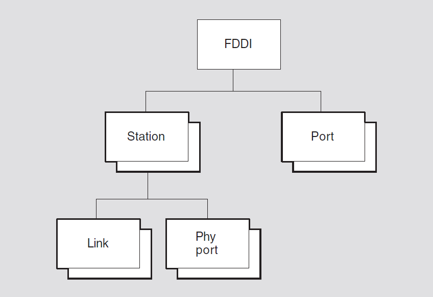
The FDDI module incorporates the functions and operations defined in the ANSI FDDI Token Ring media access control (MAC), the ANSI FDDI Token Ring Physical Layer Protocol (PHY), FDDI Physical Layer Medium Dependent (PMD), Station Management (SMT) specifications, parts of the ISO 8802-1 (IEEE 802.1) addressing, internet working and network management, and parts of the ISO8802-2 (IEEE 802.2) logical link control (LLC) specifications.
10.1. fddi
The fddi entity is the top-level entity in the hierarchy of entities
belonging to the FDDI module.
create [node node-id] fddi
delete [node node-id] fddi
show [node node-id] fddi [all [attributes] | all
characteristics]
10.1.1. Characteristic Attributes
|
Default: |
Current version number |
Version number of the FDDI architecture specification to which the implementation conforms. You cannot modify this characteristic.
10.1.2. Exception Messages
For create:
already exists
An fddi entity already exists.
For delete:
has children
Cannot delete while subentities exist.
10.2. fddi station
An fddi station entity represents an access point to the service offered
by the FDDI module. The FDDI data link can be monitored and controlled through NA
network management. The station-name refers to the station managed
by this command.
create [node node-id] fddi station
station-name communication port
device-name
delete [node node-id] fddi station
station-name
disable [node node-id] fddi station
station-name
enable [node node-id] fddi station
station-name mode {normal | internal
loopback}
show [node node-id] fddi station
station-name [all [attributes] | all characteristics | all
counters | all identifiers | all status]
10.2.1. Arguments
communication port
The system device name assigned to this station.
On OpenVMS systems, the name must be in the format ddc, where dd is the OpenVMS device name prefix and c is the controller letter. For a complete list of FDDI devices and their OpenVMS device names, see the DECnet-Plus for OpenVMS Release Notes.
On UNIX systems, the name must be in the format ddn, where dd is the UNIX device name prefix and n is the device number.
This argument determines the value of the communications port characteristic and is required.
10.2.2. Characteristic Attributes
communication port
Name of the hardware port associated with this station, taken from the
corresponding argument in the create directive. You cannot modify this
characteristic.
smt maximum version id
Highest SMT version ID this station supports. You cannot modify this characteristic.
smt minimum version id
Lowest SMT version ID this station supports. You cannot modify this characteristic.
smt station id
SMT station ID for this station. You cannot modify this characteristic.
smt version id
Currently active SMT version ID for this station. You cannot modify this characteristic.
type
SMT station type for this station. You cannot modify this characteristic.
10.2.3. Counter Attributes
Unless stated otherwise, counts include both normal and multicast traffic and all protocol types, service access points (SAPs), and protocol identifiers.
configuration changes
Number of times the internal configuration of this station changed. (Not present in single attached stations (SAS)).
creation time
Time at which the port was created.
selftest failures
Total number of times a self-test of the station detected an error.
traces received
Number of times the ECM state machine for this station entered the
trace state due to a received trace signal.
10.2.4. Identifier Attributes
name
Simple name assigned to the station when it is created.
10.2.5. Status Attributes
last set station id
The station ID of the station that last performed an SMT Change/Add/Remove (PMF frame) operation.
|
Default: None |
Value: Off, on or loopback |
Operational state of the station.
uid
Entity's unique identifier, which is generated when the entity is created.
10.2.6. Event Messages
configuration change
Internal configuration of the station changed.
selftest failure
An implementation-specific code giving the reason for the station failure. Values are listed in the NA registry.
trace received
ECM state machine of the station entered the trace state due to a
trace signal received on any PHY port.
10.2.7. Exception Messages
For create:
already exists
An fddi station entity already exists.
For enable:
communication port in use
Communication port already reserved by another entity.
invalid communication port
Cannot run FDDI data link on this communications port.
For delete:
wrong state
Failure to delete the fddi station entity because the station must be
disabled before deletion.
10.3. fddi station link
The fddi station link entity is a subentity of the fddi
station entity. The fddi station link subentity provides the
management view of LLC and the FDDI MAC. FDDI allows stations to be either single MAC or
dual MAC and therefore there can be up to two link subentities for each
station. In most cases, a station has at least one link entity.
Concentrators may have no link entity and are not addressable on the FDDI,
though they may be using other communications channels.
disable [node node-id] fddi station
station-name link
link-index
echo [node node-id] fddi station
station-name link link-index target
ID802 timeout integer-16 data
octet-string
enable [node node-id] fddi station
station-name link
link-index
getnif [node node-id] fddi station
station-name link link-index target
ID802 timeout
integer-16
getsif [node node-id] fddi station
station-name link link-index target
ID802 timeout integer-16type
{configuration | operation}
show [node node-id] fddi station
station-name link link-index[all
[attributes] | all characteristics | all counters | all identifiers | all
status]
10.3.1. Commands (UNIX)
echo
Causes the link subentity to transmit an SMT Echo request frame and
await the response. If a response is received, it is displayed.
getnif
Causes the link subentity to transmit an SMTNIF (Neighbor
Information) request frame and await the response. If a response is received, it is
displayed.
getsif
Causes the link subentity to transmit an SMT SIF (Station
Information) request frame and await the response. If a response if received, it is
displayed.
10.3.2. Arguments
data
Data to transmit in echo request.
target
|
Default: None |
Value: ID802 |
48-bit LAN address of the target.
|
Default: None |
Value: 1–65535 |
Timeout in seconds.
|
Default: None |
Value: Configuration or operation |
SIF configuration or SIF operation request.
10.3.3. Characteristic Attributes
link address
MAC address assigned during manufacture of the communication hardware that is associated with the station (read-only).
|
Default: 8 |
Value: 1–65535 |
Requested token rotation timer. For OpenVMS, the default is determined by the operating system, and this characteristic cannot be set.
|
Default: 1000 |
Value: 1–65535 |
Length limit of a restricted token dialog. For OpenVMS, the default is determined by the operating system, and this characteristic cannot be set.
|
Default: True |
Value: True or false |
Controls whether this station is eligible to be a ring purger and should participate in the ring purger election. For OpenVMS, the default is determined by the operating system, and this characteristic cannot be set.
|
Default: 3.4 |
Value: 1–65535 |
Valid transmission time. For OpenVMS, the default is determined by the operating system, and this characteristic cannot be set.
10.3.4. Counter Attributes
block check errors
Number of times a received frame containing an integral number of octets failed the FCS check.
creation time
Time at which the station was created.
directed beacons received
Number of times the link detected the directed beacon process.
duplicate address test failures
Number of times the duplicate address test failed (detected that the link address was a duplicate).
duplicate tokens detected
Number of times the MAC address test failed (detected that the link address was a duplicate).
error count
Total number of frames that were in error with the E indicator reset,
indicating that the error occurred between the upstream MAC and this one.
fci strip errors
Number of times a frame content independent strip operation (bridge
strip) was terminated by receipt of a token.
frame count
Total number of frames seen by this link, other than tokens.
frame status errors
Number of times a received frame had the E indicator in error (missing or set) and the FCS was correct.
lost count
Counter lost count.
multicast octets received
Number of multicast data octets that were received successfully in multicast frames of type LLC, implementer, reserved, or SMT. The count does not include the MAC envelope.
multicast octets sent
Number of multicast data octets that were sent successfully in multicast frames of type LLC, implementer, reserved, or SMT. The count does not include the MAC envelope.
multicast pdus received
Number of multicast frames that were received successfully of type LLC, implementer, reserved, or SMT.
multicast pdus sent
Number of multicast frames that were sent successfully of type LLC, implementer, reserved, or SMT.
octets received
Number of octets received successfully in frames of type LLC, implementer, reserved, or SMT. The count does not include the MAC envelope.
octets sent
Number of octets sent successfully in frames of type LLC, implementer, reserved, or SMT. The count does not include the MAC envelope.
pdu length errors
Number of times a received frame had an invalid length, either too long or short for the type, or had an alignment error (odd number of symbols).
pdus received
Number of frames received successfully in frames of type LLC, implementer, reserved, or SMT.
pdus sent
Number of frames sent successfully in frames of type LLC, implementer, reserved, or SMT.
receive data overruns
Number of times the hardware lost one or more consecutive, only partially complete incoming frames because it was unable to keep up with the medium rate. An example is overrun of a bit or octet FIFO queue because of inability to copy data from adapter to host promptly. In conjunction with total frames received, provides a measure of hardware resource and bandwidth failures.
ring beacons initiated
Number of times the ring beacon process was initiated by this link.
ring initializations initiated
Number of times a ring reinitialization was initiated by this link.
ring initializations received
Number of times a ring reinitialization was initiated by some other link.
ring purge errors
Number of times the ring purger received a token while still in the ring purge state.
token count
Number of times a token has been seen by this link.
traces initiated
Number of times the pc_trace process was initiated by this
link.
transmit failures
Number of times a transmit error, other than underrun, occurred. This does not include errors in transmitting MAC type frames.
transmit underruns
Number of times a transmit underrun occurred. This indicates the transmit FIFO became empty during frame transmission.
unavailable link buffers
Number of times a complete, fully received frame was discarded because no link buffer was available. In conjunction with total frames received, provides a measure of station-buffer-related receive problems.
unavailable user buffers
Number of times no user buffer was available for an incoming frame that passed all
filtering for the port. These are the buffers supplied by users on
receive requests. In conjunction with total frames received,
provides a measure of user-buffer-related receive problems.
unrecognized individual destination pdus
Number of times a received LLC frame with an individual destination MAC address was discarded because there was no port with the Ethernet protocol type, SNAP protocol identifier, or LLC SAP address enabled. Only frames containing individual destination MAC addresses are counted.
unrecognized multicast destination pdus
Number of times a received LLC frame with a multicast destination MAC address was discarded because there was no port with the Ethernet protocol type, SNAP protocol identifier, or LLC SAP address enabled. Only frames containing multicast destination MAC addresses are counted.
10.3.5. Identifier Attributes
index
An integer that uniquely identifies this link to the parent station
entity.
10.3.6. Status Attributes
downstream neighbor
MAC address of the downstream neighbor, if known.
duplicate address flag
Summary output of the duplicate address test algorithm.
frame strip mode
|
SA match |
Source address match mode of the frame stripping algorithm matches the source address of the frame with the MAC's MyLongAddress (MLA), and if a match is found, the frame is removed from the token ring. |
|
FCI strip |
The FCI strip mode counts the number of frames transmitted since the reception of a token, and strips equal number of frames. |
loopback
This is true if the link has been set up to receive frames
transmitted by it. This allows loopback testing either on the ring or with one of
the PHY port loopback modes.
negotiated trt
Negotiated token rotation timer.
old downstream neighbor
Previous value of the downstream neighbor.
old upstream neighbor
Previous value of the upstream neighbor.
ring error reason
|
directed beacon received |
Link received particular beacon data. |
|
duplicate address detected |
Duplicate address algorithm detected a duplicate address. |
|
duplicate token detected |
A duplicate token was detected on the ring. |
|
FCI strip error |
Frame content independent strip operation was terminated by the receipt of a token. |
|
no error |
No errors have occurred on this ring. |
|
PC trace initiated |
PC-trace was initiated by this link. |
|
PC trace received |
PC-trace was initiated by some other link. |
|
ring beaconing initiated |
Ring beaconing process was initiated by this link. This process is initiated as a result of serious ring failure, such as loss of signal or jabbering station transmitting in violation of the protocol. This indicates to other links on the LAN that corrective action may be required. |
|
ring init initiated |
Ring initialization was initiated by this link to initialize the ring and create a token. |
|
ring init received |
Ring initialization was initiated by some other link to initialize the ring and create a token. |
|
ring op oscillation |
Ring state has been changing continually from operational to initializing. |
|
ring purge error |
Link received a token while performing a ring purge operation. |
ring latency
Current ring latency as measured by this linkentity.
ring purger state
|
candidate |
The link's ring purger process is participating in the ring purger election algorithm as a candidate to become the ring purger. |
|
nonpurger |
The link's ring purger process is in an idle state listening for periodic purger hello frames. |
|
off |
The link's ring purger process is disabled. |
|
purger |
The link's ring purger process is performing the function of removing no owner frames and duplicate token from the ring. In this state, the process transmits periodic purger hello frames. |
state
link entity.|
broken |
Attempt to turn the link on failed the initialization test, or link was on, but failure was detected. |
|
off-fault recovery |
State entered when a |
|
off-ready |
FDDI data link communication services are not available. |
|
on-ring init |
Physical layer service is available and the
|
|
on-ring run |
Link detected that the ring initialization has been completed successfully and the ring is operational. |
uid
Entity's unique identifier, which is generated when the entity is created.
upstream neighbor address
MAC address of the upstream neighbor, if known.
|
Default: None |
Value: True or false |
Upstream neighbor's reported result of its duplicate address test.
10.3.7. Event Messages
block check error
Frame with FCS error was received.
directed beacon received
A directed beacon was received.
duplicate address test failure
Duplicate address algorithm detected a duplicate.
duplicate token detected
Duplicate token is detected.
fci strip error
Frame content independent strip was terminated by a token.
frame status error
Frame with good FCS, but E indicator set was received.
link buffer unavailable
No buffer was available to receive a frame.
pdu length error
Frame of invalid length or odd number of symbols was received.
receive data overrun
A receive overrun hardware error was detected.
ring beacon initiated
Link started the beacon process.
ring initialization initiated
Ring is reinitialized by this link.
ring initialization received
Ring is reinitialized by some other link.
ring purge error
Ring purger received a token while purging.
trace initiated
PC-trace was initiated by this link.
transmit failure
Failure to transmit operation other than underrun.
transmit underrun
Transmit failed due to underrun.
unrecognized individual pdu destination
Frame with unrecognized DSAP or port-id.
unrecognized multicast pdu destination
Frame with unrecognized DSAP or port-id.
user buffer unavailable
Data link user did not supply a receive buffer.
10.3.8. Exception Messages
For GetSIF, GetNIF, and echo (UNIX):
reject
Request was rejected by the target station.
timeout
No response was received.
10.4. fddi station phy port
An fddi station phy port entity provides the management view of the
fddi station phy port and the fddi pmd. Each station has
at least one physical port and a concentrator is a device that has at least one physical
port of type M. A dual-attached station or dual-attached concentrator has a phy
port type A and type B. A single-attached station has a phy port
of type B. The port-id is an integer that represents the physical
port to be managed by the command.
disable [node node-id] fddi station
station-name phy port
port-id
enable [node node-id] fddi station
station-name phy port port-id mode
{normal | internal loopback}
show [node node-id] fddi station
station-name phy port port-id {all
[attributes] | all characteristics | all counters | all identifiers | all
status}
10.4.1. Characteristic Attributes
|
Default: None |
Value: For n, 10 -n |
Link error monitor threshold. This characteristic cannot be set.
phy type
Type of physical port (A, B, S, or M). This characteristic cannot be set.
pmd type
|
ANSI multimode |
Low power |
|
ANSI multimode type 1 |
ThinWire |
|
ANSI single mode type 2 |
Shielded twisted-pair |
|
ANSI SONET |
Unshielded twisted-pair |
10.4.2. Counter Attributes
creation time
Time at which the port was created.
connections completed
Number of times the physical port entered the in use state, having
completed the initialization process.
elasticity buffer errors
Number of times the elasticity buffer function had an overflow or underflow.
lct rejects
Number of times a connection was rejected due to failure of the link confidence test at either end of the physical connection.
lem rejects
Number of times an active connection was disconnected due to rejection by the link error monitor at this end of the physical connection, or by expiration of the Noise timer.
link errors
Total number of raw link error input events seen by the link error
monitor.
10.4.3. Identifier Attributes
index
An integer that uniquely identifies this physical port to the parent
station entity.
10.4.4. Status Attributes
broken reason
Reason phy port is in broken state, or if in
broken state, none.
|
Default: None |
Value: 1–256 |
Link error monitor current estimate of error rate.
neighbor phy type
Status may be A, B, S, M or unknown.
reject reason
phy port is in a failed or watch
state. This is not meaningful when phy port is in some other state.|
LCT both sides |
link confidence test failed on both sides of the physical connection. |
|
LCT protocol error |
Neighboring physical port has been detected to have prematurely exited the link confidence test (LCT). |
|
LEM reject |
Link error monitor disconnected this connection due to the error rate exceeding the LEM threshold. |
|
local LCT |
Link confidence test failed on this end of the physical connection. |
|
noise reject |
Noise timer expired because a single noise event lasted for more than 1.31072 ms. |
|
none |
No reason. |
|
remote LCT |
Link confidence test failed on the other end of the physical connection. |
|
remote reject |
Neighboring physical port broke the connection for an unknown reason. |
|
standby |
Physical port and its neighboring physical port form a redundant physical connection (dual-homing feature). In a dual-homed configuration, the B to M connection is the higher priority physical connection, and the A to M connection is the standby physical connection. The standby connection will become active if the B to M connection is lost. |
|
topology reason |
Neighboring physical port's physical port type is an illegal match for this physical port's physical port type. |
|
trace in progress |
Physical port was initializing when a pc-trace occurred. When a pc-trace occurs, any physical ports that have not yet established a physical connection are shutdown to prevent the topology from changing. |
|
trace received-disabled |
Physical port was momentarily disabled because it received a pc-trace when its own pc-trace function was disabled. The pc-trace function is enabled by default. The trace disable switch is not remotely manageable. |
state
phy port entity (nonsettable). |
broken |
The physical port has failed initialization tests and is not available for use. |
|
failed |
Same as |
|
internal loopback |
The physical port has been configured to internally present all transmitted symbols to the receive interface. The network connector is inactive. This allows internally generated test frames to be looped back for test purposes. |
|
in use |
The physical port has established a connection and is fully operational. Communications services are now available. |
|
off-ready |
The physical port is waiting to be enabled or has been disabled by management request. |
|
starting |
The physical port has received a response from the neighboring physical port and is exchanging information and performing the link confidence test (LCT) prior to completing the connection. |
|
waiting |
The physical port is beginning to establish a connection and is waiting for a response from the neighboring physical port. |
|
watch |
Same as |
uid
Entity's unique identifier, which is generated when the entity is created.
10.4.5. Event Messages
link confidence test reject
Counted as LCT rejects.
link elasticity buffer error
Counted as elasticity buffer errors.
link error monitor reject
Counted as LEM rejects.
10.4.6. Exception Messages
For enable:
invalid mode
Specified mode conflicts with station mode.
10.5. fddi port
An fddi port entity represents an access point to the service offered by
the FDDI module. A client transmits and receives data through a port. Ports are created
and deleted by client use of open and close service interface procedures. The
port-name refers to the port managed by this command.
Syntax
show [node node-id] fddi port
port-name [all [attributes] | all counters | all
identifiers | all status]
10.5.1. Counter Attributes
creation time
Time at which the port was created.
multicast octets received
Number of multicast user data octets received successfully and available to the data link user.
multicast octets sent
Number of multicast user data octets transmitted successfully using the port.
multicast pdus received
Number of multicast frames received successfully and available to the data link user.
multicast pdus sent
Number of multicast frames transmitted successfully using the port.
octets received
Number of user data octets received successfully and available to the data link user.
octets sent
Number of user data octets transmitted successfully using the port.
pdus received
Number of frames received successfully and available to the datalink user.
pdus sent
Number of frames transmitted successfully using the port.
unavailable user buffers
Number of times no user buffer was available at the port for an incoming frame.
10.5.2. Identifier Attributes
name
Simple name assigned to the port when it is created.
10.5.3. Status Attributes
client
Name specified by the data link when the port is opened.
ethernet protocol types
Set of Ethernet protocol types that are recognized for this port. Protocol types for a port may be enabled and disabled by the user at anytime during the port's existence.
|
Default: None |
Value: True or false |
Indicates whether or not the data link adds a length field on transmit, assumes
the presence of the length field, and removes the length field on receive for
Ethernet frames. This attribute is irrelevant for ISO 8802-3 formatted frames
because the length field is always present. This is specified by the user when the
port is opened. The value true means length fields are added and
removed by the data link.
link
Name of the link subentity associated with this port, specified by
the user when the port is opened.
llc sap addresses
Set of SNAP protocol identifiers that are recognized for this port. LLC SAP addresses for a port may be enabled and disabled by the user at any time during the port's existence.
|
Default: None |
Value: Class 1 or user supplied |
LLC PDU processing the data link user requires from the port, specified by the user when the port is opened. This is either LLC Class 1, where the entire LLC protocol is handled by the data link, or user-supplied LLC, where the user is responsible for operating part of the LLC protocol.
mac addresses
Set of individual and multicast MAC addresses that are recognized for this port. MAC addresses for a port may be enabled and disabled by the user at any time during the port's existence.
|
Default: None |
Value: Normal or promiscuous |
Indicates if the port is to receive all frames regardless of format, Ethernet protocol type, SNAP protocol identifier, LLC SAP address, or MAC address. Promiscuous receipt is enabled and disabled by the user. Support of promiscuous mode is optional.
snap protocol identifiers
Set of SNAP protocol identifiers that are recognized for this port. Protocol identifiers for a port may be enabled and disabled by the user at any time during the port's existence.
type
Type of port (LLC or SMT).
uid
Entity's unique identifier, which is generated when the entity is created.
Chapter 11. Frame Module (OpenVMS)
This chapter describes all the commands you can use to manage the entities that constitute the Frame module. The Frame module provides framing functions for a communications link. It enables those who implement their own level 2 protocols to manage the links that use those protocols.
Figure 11.1, ''Hierarchy of Frame Module Entities'' shows the hierarchical relationship of the entities that constitute the Frame module.
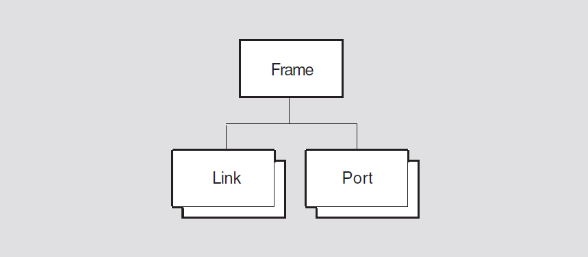
11.1. frame
The frame entity is the top-level entity in the hierarchy belonging to
the Frame module. The entity provides framing functions for a communications link. The
entity does not provide any data link protocol capabilities, and is used by those who
want or need to operate their own level 2 protocols.
Syntax
create [node node-id] frame
delete [node node-id] frame
disable [node node-id] frame
enable [node node-id] frame
show [node node-id] frame [all [attributes] | all
characteristics | all status]
11.1.1. Characteristic Attributes
version
Version of the frame architecture to which the implementation conforms. You cannot modify this characteristic.
11.1.2. Status Attributes
state
frame entity. |
off |
The |
|
on |
The |
11.2. frame link
A frame link entity is associated with a physical line, and controls the
framing protocol used on that line. There is one frame link entity for each
physical line.
Syntax
create [node node-id] frame link
frame-link-id {control mode mode |
protocol protocol-type}
delete [node node-id] frame link
frame-link-id
disable [node node-id] frame link
frame-link-id
enable [node node-id] frame link
frame-link-id
set [node node-id] frame link
frame-link-id {bisync code
character-code | bits per character
number-of-bits | buffer size integer |
crc type crc type | framing timer integer
| initial state one state-info | initial state two
state-info | local station address
address | match station address
boolean | number of buffers integer |
physical line local-entity-name | sync character
hexadecimal | sync count
integer}
show [node node-id] frame link
frame-link-id [all [attributes] | all characteristics | all
counters | all identifiers | all status]
11.2.1. Arguments
control mode
|
multipoint master | |
|
multipoint tributary | |
|
point-to-point |
protocol
|
bisync |
hdlc |
|
chips |
sdlc |
|
ddcmp |
swift |
|
genbyte |
11.2.2. Characteristic Attributes
|
Default: EBCDIC |
Value: ASCII or EBCDIC |
Character code to be used on the link. This characteristic is supported only when
the characteristic protocol is set to one of the following:
bisync, chips, genbyte, or swift. You can modify this
characteristic only when the entity is disabled.
|
Default: 8 |
Value: 5–8 |
Number of bits in each character. This characteristic is supported only when the
characteristic protocol is set to genbyte. You can modify
this characteristic only when the entity is disabled.
|
Default: 512 |
Value: 0–65535 |
Size, in octets, of each receive buffer for the link. You can modify this characteristic only when the entity is disabled. Also, you can only increase the characteristic value.
|
Default: Point-to-point |
Value: See description |
point to point argument to the create
command. You cannot modify this characteristic.|
multipoint master | |
|
multipoint tributary | |
|
point-to-point |
|
Default: See description |
Value: See description |
|
AUTO_DIN | |
|
CRC_16 | |
|
CRC_CCITT | |
|
CRC_CCITT0 | |
|
LRC_EVEN | |
|
LRC_ODD | |
|
LRC_VRC_EVEN | |
|
LRC_VRC_ODD | |
|
NONE |
|
BISYNC |
CRC_16 |
|
CHIPS |
LRC_EVEN |
|
DDCMP |
CRC_16 |
|
GENBYTE |
NONE |
|
HDLC |
CRC_CCITT |
|
SDLC |
CRC_CCITT |
|
SWIFT |
CRC_16 |
genbyte crc checking is done in the genbyte framing
routine.
|
Default: 25 |
Value: 10–1000 |
Maximum length of time, in milliseconds, to wait for the next character to arrive.
This characteristic is supported only when the characteristic protocol
is set to genbyte.
|
Default: 0 |
Value: See description |
First 32 bits of state information. This characteristic is supported only when the
characteristic protocol is set to genbyte. You can modify
this characteristic only when the entity is disabled.
|
Default: 0 |
Value: See description |
Last 32 bits of state information. This characteristic is supported only when the
characteristic protocol is set to genbyte. You can modify
this characteristic only when the entity is disabled.
|
Default: 255 |
Value: 0–255 |
Address of the local station. The default value means that only broadcast messages
are accepted. The interpretation of this characteristic is controlled by the value
of the characteristic match station address.
This attribute is supported only if the characteristic protocol is
set to sdlc. You can modify this characteristic only when the entity is
disabled.
|
Default: False |
Value: True or false |
Specifies whether the value of the characteristic local station
address is to be interpreted as a valid address. This attribute is
supported only if the characteristic protocol is set to
sdlc. You can modify this characteristic only when the entity is
disabled.
|
Default: 4 |
Value: 0–255 |
Number of receive buffers reserved for the link. You can modify this characteristic only when the entity is disabled. Also, you can only increase the characteristic value.
|
Default: None |
Value: Local-entity-name |
Name of the Physical layer line entity on which the link operates. You must provide a value for this characteristic before you enable the link. You can modify this characteristic only when the entity is disabled.
protocol
protocol argument to the create command. You cannot
modify this characteristic.|
bisync |
hdlc |
|
chips |
sdlc |
|
ddcmp |
swift |
|
genbyte |
|
Default: See description |
Value: 0–FF |
sync character to be used on the link. The
default value depends on the value of the characteristic protocol, as follows:|
bisync |
32 |
|
chips |
32 |
|
ddcmp |
96 |
|
genbyte |
32 |
|
swift |
32 |
This attribute is supported only if the characteristic protocol is
set to bisync, chips, ddcmp, genbyte, or swift. You can
modify this characteristic only when the entity is disabled.
|
Default: 4 |
Value: 0–255 |
Number of sync characters that precedes each message. This attribute
is supported only if the characteristic protocol is set to
bisync, chips, ddcmp, genbyte, or swift. You can
modify this characteristic only when the entity is disabled.
11.2.3. Counter Attributes
abort characters received
Number of times the link was prematurely terminated by the remote station. This
counter is supported only if the characteristic protocol is set to
either hdlc or sdlc.
creation time
Time at which this entity was created.
data block check errors
Number of messages received with an error in the data field block check.
header block check errors
Number of messages received with an error in the header block check. This counter
is supported only if the characteristic protocol is set to
ddcmp.
invalid characters received
Number of times an invalid character was received from the remote station. This
counter is supported only if the characteristic protocol is set to
either bisync or ddcmp.
receive buffer overflows with good crc
Number of times the local station received a message too large for the receive buffer and the message had a valid CRC.
receive overruns
Number of times the host memory was notable to handle all the data received from the communications channel.
sdus received
Number of data messages received from the remote station.
sdus sent
Number of data messages sent to the remote station.
service octets received
Number of data octets received from the remote station.
service octets sent
Number of data octets sent to the remote station.
transmit underruns
Number of times the host memory could not supply data fast enough to satisfy the communications channel.
11.2.4. Identifier Attributes
name
Simple name assigned to the link when it is created.
11.2.5. Status Attributes
physical port name
Name of the Physical layer port returned when the port is opened. If this value is missing, the port has yet to be opened.
state
frame link entity.|
off |
The link is disabled. |
|
on |
The link is enabled. |
uid
Entity's unique identifier, which is generated when the entity is created.
11.2.6. Exception Messages
For create:
parent is disabled
The frame entity was disabled when you issued this
create command. Enable the frame entity and then
reissue this command.
For enable:
device constraint
The value of an attribute is not supported by the device type servicing the protocol state machine.
open physical port failure
The open operation on the port in the Physical layer failed.
|
reason |
Specifies why the open operation failed. | |
|
invalid argument |
The open port call was improperly formed. | |
|
line not available |
The line managed by the Physical layer entity is already
allocated to another data link entity. Modify the
| |
|
no such line |
The entity specified in the | |
Note
Only the DSF32 device supports SWIFT and CHIPS framing.
11.3. frame port
A frame port entity represents an access point to the data link service
offered by the Frame module. Ports are created and deleted automatically when a client
of DDCMP uses the link.
Syntax
show [node node-id] frame port port-name [all [attributes] | all identifiers
| all status ]
11.3.1. Identifier Attributes
name
Simple name assigned to the port when it is created.
11.3.2. Status Attributes
client
Name of the client entity that opened the port.
link
Name of the frame link entity that the client supplied when the port
was opened.
state
frame port entity.|
open |
The port is assigned to a client. |
|
open disabled |
The port is assigned to a client, but the appropriate link entity has been disabled. |
Chapter 12. HDLC Module
This chapter describes all the commands you can use to manage the entities that constitute the HDLC module. The HDLC module implements one of the protocols in the Data Link layer. The HDLC (High-level Data Link Control) protocol is intended to cover a wide range of applications. This includes one-way, two-way alternate or two-way simultaneous data communication between data stations that are usually buffered, including operations on different types of data circuits; such as, multipoint/point-to-point, duplex/half-duplex, and switched/non-switched. This implementation uses HDLC to offer reliable communication at the Data Link layer for point-to-point synchronous data lines over a wide area network link. The HDLC module typically runs as a Data Link module under the CLNS (Connectionless-Mode Network Service) network protocol.
Figure 12.1, ''Hierarchy of HDLC Module Entities'' shows the hierarchical relationship of the entities that constitute the HDLC module.
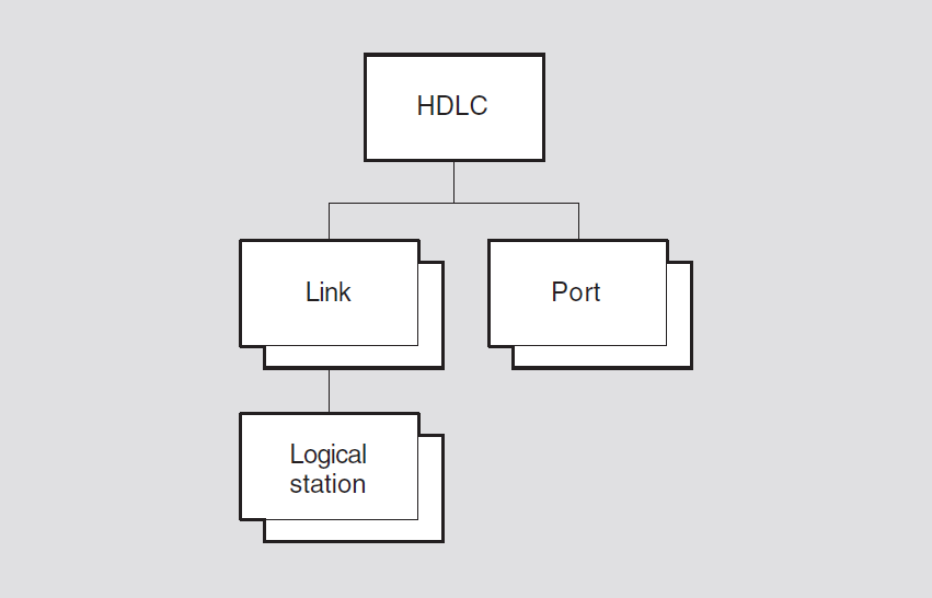
12.1. hdlc
The hdlc entity is the top-level entity in the hierarchy of entities belonging
to the HDLC module.
Syntax
create [node node-id] hdlc
delete [node node-id] hdlc
show [node node-id] hdlc [all [attributes] | all
characteristics]
12.1.1. Characteristic Attributes
version
Version of the HDLC architecture specification to which the implementation conforms. You cannot modify this characteristic.
12.2. hdlc link
An hdlc link entity is associated with a port of the supporting physical layer
module. It contains attributes common to local HDLC operations for all logical stations on the
line. The link-name refers to the HDLC link managed by this command.
Syntax
create [node node-id] hdlc link
link-name{linktype link-type | profile
latin1string}
delete [node node-id] hdlc link
link-name
disable [node node-id] hdlc link
link-name
enable [node node-id] hdlc link
link-name
set [node node-id] hdlc link link-name
{acknowledge timer integer | holdback timer integer |
maximum data size integer | maximum unsequenced pdus
integer | minimum data size integer | physical line
local-entity-name | preferred crc type CRC-type |
preferred local station address integer | preferred maximum data size
integer | preferred window size integer | receive
buffers integer (OpenVMS) | retry maximum integer |
sequence modulus [8 or 128]}
show [node node-id] hdlc link link-id
[all [attributes] | all characteristics | all counters | all identifiers | all
status]
12.2.1. Arguments
linktype link-type
link
type characteristic.|
balanced |
The logical station operates in asynchronous response balanced mode. This is the default value of the argument. |
|
primary |
The logical station is the primary and operates in normal response mode. |
|
secondary |
The logical station is a secondary and operates in normal response mode. |
profile latin1string
A string of information that can be used when the HDLC protocol is dependent on network
subscription time commitments pertinent to the Data Link layer. When specified, the values of
some link characteristics may be overridden. This argument determines the value of the
profile characteristic. The default value of this argument is a null string,
meaning that no profile is used.
12.2.2. Characteristic Attributes
|
Default: 3000 |
Value: 1–60000 |
Time, in milliseconds, to wait for an acknowledgment before using error recovery procedures. The value of this characteristic corresponds to the T1 parameter of HDLC. You can modify this characteristic only when the entity is disabled.
|
Default: 0 |
Value: 1–60000 |
Maximum time, in milliseconds, to wait before sending an acknowledgment supervisory frame if no other frames carry the acknowledgment. A value of zero means that the frame will be sent immediately if no I-frame can be sent. You can modify this characteristic only when the entity is disabled.
link type
Operational mode of the HDLC link. The value of this characteristic is a copy of the
link type argument specified when the entity is created. You cannot modify this
characteristic.
|
Default: 1500 |
Value:262–65532 |
Maximum number of bytes that users of the data link can specify. This number applies to both transmit and receive frames.
The value of this characteristic must be greater than or equal to the value of the
minimum data size characteristic. You can modify this characteristic only when the
entity is disabled.
|
Default: 1 |
Value: 1–127 |
Maximum number of unsequenced I-frames that a primary or secondary station can send in a
single transmission. This characteristic is not used if the link type
characteristic is balanced.
|
Default: 576 |
Value: 262–65532 |
Minimum number of bytes that users of the data link can specify. This number applies to both transmit and receive frames.
The value of this characteristic must be less than or equal to the value of the
maximum data size characteristic. You can modify this characteristic only when the
entity is disabled.
|
Default: None |
Value: Local-entity-name |
Local entity name of the Physical layer entity over which the HDLC protocol is to operate.
This characteristic must have a value before the HDLC link is enabled. You can modify this characteristic only when the entity is disabled.
|
Default: Either |
Value: 16-bit, 32-bit, or either |
CRC types available for negotiation. If the value of this characteristic is
either, the station will try to use 32-bit but will use
16-bit if that is all that the remote station supports.
|
Default: 2 |
Value: 1–253 |
Address proposed for the local logical station during negotiation. If there is no negotiation, the value of this characteristic is the value that is used. If negotiation is necessary, the value of this characteristic must be between 2 and 253. You can modify this characteristic only when the entity is disabled.
|
Default: 1500 |
Value: 262–65532 |
Default size, in octets, of frames that the station receives and transmits. This value is used only if the link initialization does not specify a buffer value.
The value of this characteristic must lie between those of the maximum data
size and minimum data size characteristics. You can modify this
characteristic to a lower value only when the entity is disabled.
|
Default: 2 |
Value: 1–127 |
Window size to be offered during negotiation for both receive and transmit frames. The
value of this characteristic must be compatible with that for the sequence modulus
characteristic.
profile (OpenVMS)
Simple name that can be used when the HDLC protocol is dependent on network subscription
time commitments pertinent to the Data Link layer. The value of this characteristic is a copy of
the profile argument specified when the entity is created. You cannot modify this
characteristic.
|
Default: 4 |
Value: 1–128 |
Number of receive buffers reserved for the link. This characteristic can only be set to a lower value when the entity is disabled.
|
Default: 10 |
Value: 1–255 |
Maximum number of times that a frame will be retransmitted before the local station assumes that a fatal error has occurred. This characteristic can be modified only when the entity is disabled.
|
Default: 128 |
Value: 8 or 128 |
Whether modulo-8 or modulo-128 sequence numbering is allowed on the HDLC link. The value 8 means that only normal sequence numbering is allowed. The value 128 means that both extended and normal sequence numbering are supported for negotiation.
12.2.3. Counter Attributes
buffer unavailable errors (OpenVMS)
Number of times the Physical layer reported that no buffer was available to hold a message. This counter is not supported in all implementations.
crc errors received
Number of frames received that had a bad CRC.
creation time
Time at which this entity was created.
times pdu receive overrun
Number of times a physical line indicated an overrun condition to the Data Link layer. This counter is not supported in all implementations.
times pdu transmit failed
Number of times an attempt to send a frame failed.
up transitions
Number of times the entity's status attribute state has changed from
off to on.
12.2.4. Identifier Attributes
name
Simple name assigned to the HDLC link when it is created.
12.2.5. Status Attributes
actual sequence modulus
sequence modulus is
8, the modulus always appears as the value 8.|
8 |
Indicates that modulo-8 numbering is in use. Allows frame sequence values 0 through 7. |
|
128 |
Indicates that modulo-128 numbering is in use. Allows frame sequence values 0 through 127. |
|
Default: None |
Value: 0-- 10 9 |
Time required between frames to enable the local station to successfully receive them.
|
Default: None |
Value: Switched or nonswitched |
Defines whether the underlying physical line is switched or nonswitched. This status affects the subset of port states that are related to a given link.
|
Default: None |
Value: 1–65535 |
Maximum frame size (in octets) that can be used on the link. Until negotiation is complete,
the value of this status attribute is the same as the characteristic preferred maximum
data size.
negotiated crc type
CRC mode that has been negotiated with the remote station. This mode will not be used until
the station is next enabled. Until negotiation is complete, the value of this is
16-bit.
physical port
Name of the port in the Physical layer associated with the communications link.
response address
Address that the remote station puts in response frames.
state
enable or disable
command issued.|
off |
The link is disabled. |
|
on |
The link is enabled. |
uid
Entity's unique identifier, which is generated when the entity is created.
|
Default: None |
Value: 1–127 |
Maximum number of I-frames that can be outstanding before an acknowledgment must be
received. Until negotiation is complete, the value of this status attribute is the same as the
characteristic preferred window size.
12.2.6. Event Messages
buffer unavailable error (OpenVMS)
Generated each time a frame is discarded because there is no receive buffer available.
link down
Generated each time the entity is disabled.
link up
Generated each time the entity is enabled.
pdu receive overrun
Generated each time the Physical layer entity reports a receive overrun.
pdu transmit failed
Generated each time an attempt to send a frame fails.
|
pdu transmit failed reason |
Failure reason received from the Physical layer entity. | |
|
disabled |
The network manager has disabled the line. | |
|
line down |
The line is in the failed state. | |
|
no service |
The Physical layer service is not available. | |
12.2.7. Exception Messages
For delete:
has children
Cannot delete while subentities exist.
link enabled
The link is still enabled. Disable the link and reissue the delete
command.
wrong state
Failure to delete the hdlc link logical station subentity because the logical
station must be disabled before deletion.
For enable:
client data size not supportable
Client's buffer size is larger than the HDLC software can support.
incompatible communications mode
The value of the link type argument specified in the create
command is incompatible with the actual type of link.
|
reason |
Feature of the line that is incompatible with the link type. | |
|
CRC mode not supported |
The line does not support CRC selected by the preferred CRC type characteristic attribute. | |
|
full-duplex mode |
The line is full-duplex and the link type is primary/secondary. | |
|
half-duplex mode |
The line is half-duplex and the link type is balanced. | |
|
protocol not supported |
The line does not support HDLC framing. | |
Correct the value of the link type argument, or use a line that supports the
appropriate protocol. Then reissue the enable command.
open physical port failed
Attempt to open a port to the Physical layer failed.
|
reason |
Specifies why the Physical layer rejected the open operation. | |
|
invalid argument |
The call to the Physical layer was improperly formed. | |
|
insufficient resources |
The Physical layer had insufficient system resources to be able to open the port. | |
|
line not available |
The line specified as the value to the | |
|
no such physical line |
The entity specified in the | |
12.3. hdlc link logical station
The hdlc link logical station entity controls the characteristics of an HDLC
logical station. There is one station for each remote termination of a line associated with the
HDLC link. The link-name is the link entity within the HDLC
module and the logical-station-name refers to the logical station managed by
this command.
Syntax
create [node node-id] hdlc link
link-namelogical station
logical-station-name
delete [node node-id] hdlc link
link-namelogical station
logical-station-name
disable [node node-id] hdlc link
link-namelogical station
logical-station-name
enable [node node-id] hdlc link
link-namelogical station
logical-station-name
limit [node node-id] hdlc link
link-namelogical station
logical-station-name
show [node node-id] hdlc link
link-namelogical station logical-station-name [all
[attributes] | all counters | all identifiers | all status]
unlimit [node node-id] hdlc link
link-name logical station
logical-station-name
12.3.1. Commands
limit
Limits station exclusively to unsequenced data service.
unlimit
Enables sequenced and unsequenced data service.
12.3.2. Counter Attributes
creation time
Time at which this entity was created.
data octets received
Total number of octets received in the I-field of I-frames and UI-frames. This total excludes protocol ID information in UI-frames and frame retransmissions.
data octets sent
Total number of octets sent in the I-field of I-frames and UI-frames. This total excludes protocol ID information in UI-frames and frame retransmissions.
data pdus received
Total number of I-frames and UID-frames received. This number does not include frames that had to be retransmitted.
data pdus sent
Total number of I-frames and UID-frames sent. This number does not include frames that had to be retransmitted.
frmrs generated
Number of FRMRs (frame rejects) sent.
frmrs received
Number of FRMRs (frame rejects) received.
invalid mode commands
Number of command frames (SABME, SABM, SNRME, SNRM, SARM, and SIM) received that are not applicable to this station.
negotiation failures
Number of times that the XID negotiation with the remote station has failed.
polls received
Number of frames received with the poll bit set.
rejs received
Number of REJ frames (rejects) received.
rejs sent
Number of REJ frames (rejects) sent.
rnrs received
Number of RNR (receive not ready) supervisory frames received from the remote station.
rnrs sent
Number of RNR (receive not ready) supervisory frames transmitted.
times acknowledge timer expired
Number of times the acknowledge timer has expired.
times station halted
Number of times the station halt event has occurred.
times station initializing
Number of times the station initialized event has occurred.
times station inoperative
Number of times the entity's status attribute state became
inoperative.
times station maintenance
Number of times the entity's status attribute state became
maintenance.
times station resetting
Number of times the station reset event has occurred.
times station running
Number of times the station running event has occurred.
times station setup failed
Number of times the station setup failure event has occurred.
unknown ui pdus received
Number of UI-frames the local station received whose protocol ID does not match that of any open port.
xids received
Number of XID (identification) command or response frames received.
12.3.3. Identifier Attributes
name
Simple name assigned to the logical station when it is created.
12.3.4. Status Attributes
command address
Address the local station uses when sending command frames to the remote station.
maintenance mode
Whether the station is in maintenance mode. When set to true, the
station will be used exclusively for maintenance operations. When set to false, the
station operates in normal fashion.
The limit command sets the value of this attribute to true, and
the unlimit to false.
protocol state
|
error |
A protocol error occurred. For instance, the logical station received an invalid frame. |
|
halted |
The protocol could not start. For example, there is no client. |
|
initializing |
The protocol is being initialized. |
|
inoperative |
The protocol cannot be started because no contact has been established with the remote station. |
|
maintenance |
The logical station is in maintenance mode. |
|
resetting |
The protocol is resetting after an error. |
|
running |
The protocol is running and capable of exchanging frames with the remote station. |
remote version
Version number of the HDLC protocol that the remote station is using. This is received as part of an XID message from the remote station.
state
|
off |
The logical station is off because of a |
|
on |
The logical station is on because of an |
uid
Entity's unique identifier, which is generated when the entity is created.
12.3.5. Event Messages
frmr generated
Generated each time the logical station rejected a received frame.
|
frmr |
Contents of the frame reject frame that is returned to the remote station. | |
|
frmr reason |
Reason for rejecting the frame. | |
|
control |
One of the control fields is undefined or not implemented by the local station. | |
|
format |
The frame's control field is invalid because the frame contained information that is not allowed, the frame is supervisory, or the frame is unnumbered and has the wrong length. | |
|
length |
The information field of the frame exceeds the maximum capacity. | |
|
nonspecific |
The received frame contains an unspecified number or type of error. | |
|
nr |
The frame's control field contains an invalid N(R). | |
|
received pdu |
Header of the frame that caused the generation of the event. | |
frmr received
Generated each time the remote station rejected a frame.
|
frmr |
Contents of the frame reject frame that is returned to the remote station. | |
|
frmr reason |
Reason for rejecting the frame. | |
|
control |
One of the control fields is undefined or not implemented by the local station. | |
|
format |
The frame's control field is invalid because the frame contained information that is not allowed, the frame is supervisory, or the frame is unnumbered and has the wrong length. | |
|
length |
The information field of the frame exceeds the maximum capacity. | |
|
nonspecific |
The received frame contains an unspecified number or type of error. | |
|
nr |
The frame's control field contains an invalid N(R). | |
|
received pdu |
Received FRMR that caused the generation of the event. | |
negotiation failed
Generated each time XID negotiation fails.
|
local xid |
The XID that the local station used during the failed negotiation. | |
|
negotiation failure reason |
Reason that negotiation with the remote station failed. | |
|
address id not unique |
The preferred addresses and the address-negotiation unique IDs were identical. | |
|
incompatible address modes |
The remote station wanted to use HDLC's extended addressing which the Network Architecture's implementation does not support. | |
|
incompatible crc types |
Incompatible CRC types were specified by the two stations. | |
|
incompatible sequence moduli |
Incompatible sequence moduli were specified by the two stations. | |
|
link type mismatch |
There has been an attempt to initialize using classes of procedures that are not
appropriate for the specified | |
|
maximum pdu size too small |
The negotiated maximum frame size is less than the value of the | |
|
negotiation error |
The remote station performed an illegal negotiation operation. | |
|
no response |
There has been no valid response from the remote station to the generated XID within
the number of times specified by the | |
|
parameter id not unique |
The parameter IDs that should be unique are not so. | |
|
protocol id mismatch |
An attempt has been made to initialize sequenced data ports with different protocol IDs. | |
|
transmission type mismatch |
Mismatch in the sync/async bit in the XID. | |
|
ui not supported |
An attempt has been made to initialize without the UI optional function, which is required when running MOP over an HDLC link. | |
|
remote xid |
The XID that the remote station used (if any) during the failed negotiation. | |
station halted
Generated each time the logical station's status attribute protocol state
becomes halted.
|
station haltedreason |
Reason for the logical station to halt its protocol. | |
|
disc |
A DISC frame was received from the remote station. | |
|
dm |
A DM frame was received from the remote station. | |
|
fbit error |
A frame was received from the remote station with an error in the F-bit. | |
|
frmr |
An FRMR frame was received from the remote station. | |
|
local |
The initialization was as a result of the | |
|
maximum retry |
The number of times a frame has been sent has exceeded the value of the
| |
|
physical |
There was a failure in the Physical layer. | |
|
unsolicited ua |
An unsolicited UA frame was received from the remote station. | |
|
user |
The initialization was as a result of local user action. | |
|
window error |
The initialization occurred as part of the recovery from a windowing error. | |
station initializing
Generated each time the logical station's protocol is successfully initialized or reinitialized.
|
station initializing reason |
Reason for the logical station to initialize its protocol. | |
|
disc |
A DISC frame was received from the remote station. | |
|
dm |
A DM frame was received from the remote station. | |
|
fbit error |
A frame was received from the remote station with an error in the F-bit. | |
|
frmr |
An FRMR frame was received from the remote station. | |
|
local |
The initialization was as a result of the | |
|
maximum retry |
The number of times a frame has been sent has exceeded the value of the
| |
|
physical |
There was a failure in the Physical layer. | |
|
unsolicited ua |
An unsolicited UA frame was received from the remote station. | |
|
user |
The initialization was as a result of local user action. | |
|
window error |
The initialization occurred as part of the recovery from a windowing error. | |
|
xid |
An XID frame was received from the remote station. | |
station inoperative
Generated each time the status attribute protocol state becomes
inoperative.
station maintenance
Generated each time the status attribute protocol state becomes
maintenance.
station resetting
Generated each time the status attribute protocol state becomes
resetting.
|
station resettingreason |
Reason for the logical station to perform a reset operation. | |
|
fbit error |
A frame was received from the remote station with an error in the F-bit. | |
|
frmr |
An FRMR frame was received from the remote station. | |
|
maximum retry |
The number of times a frame has been sent has exceeded the value of the entity's
| |
|
sabm |
A SABM frame was received from the remote station. | |
|
unsolicited ua |
An unsolicited UA frame was received from the remote station. | |
|
window error |
The initialization occurred as part of the recovery from a windowing error. | |
station running
Generated each time the logical station's protocol has been initialized successfully. In
addition, the status attribute protocol state changes to
running.
station setup failed
The expiration of the entity's
maximum retrycharacteristic when in theinitializingstateA forced disconnection from the remote station
unknown ui pdu received
Generated each time an unsequenced frame is received specifying a protocol ID to which a port has not been opened on this station.
|
received pdu |
Received UI frame which caused this event to be generated. | |
12.4. hdlc port
The hdlc port entity represents one end of an HDLC connection. The entity
maintains information about that link. Ports are created and deleted automatically when a client
of HDLC uses the link. The port-name refers to the port managed by this
command.
Syntax
show [node node-id] hdlc port port-name
[all [attributes] | all identifiers | all status]
12.4.1. Identifier Attributes
name
Simple name assigned to the port when it is created.
12.4.2. Status Attributes
client
Name of the client using the port.
logical station
hdlc link logical station entity that the port is operating over.
protocol id
Protocol ID that the port is using. For sequenced ports, this value is decided during negotiation. For unsequenced ports, the value is sent in every UI-frame.
state
|
open |
The port is assigned to a client. If the communications line is unswitched, data transfer can begin. For switched lines, an association must be made with the line before data transfer can begin. |
|
open disabled |
The port is associated with a client, but the link or logical station associated with it is disabled. |
type
|
sequenced |
The port can send and receive sequenced and unsequenced data. |
|
unsequenced |
The port can send and receive unsequenced data only. |
Chapter 13. LAPB Module
This chapter describes all the commands you can use to manage the entities that constitute the Link Access Protocol Balanced (LAPB) module. The LAPB module implements one of the protocols in the Link layer described by the Network Architecture (NA).
Figure 13.1, ''Hierarchy of LAPB Module Entities'' shows the hierarchical relationship of the entities that constitute the LAPB module.
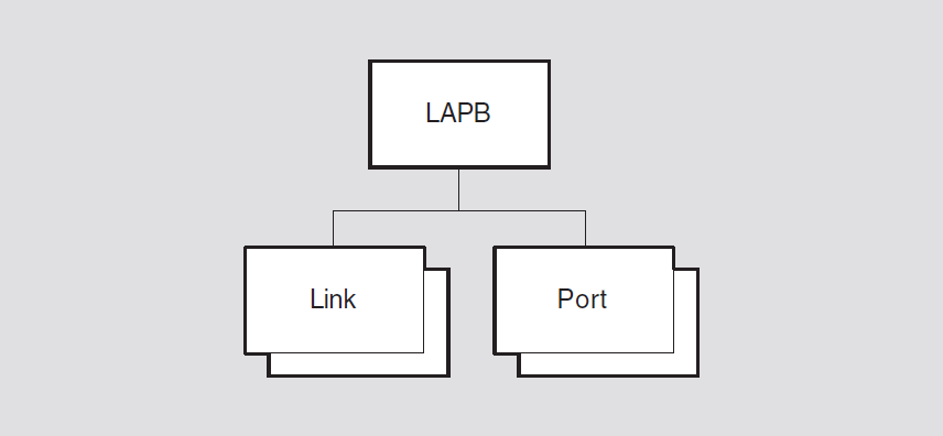
13.1. lapb
The lapb entity is the top-level entity in the LAPB module hierarchy of
entities. The LAPB module implements the LAPB link level protocol which is a variation
of the High-level Data Link Control (HDLC) link level protocol.
Syntax
create [node node-id] lapb
delete [node node-id] lapb
show [node node-id] lapb [all [attributes] | all
characteristics]
13.1.1. Characteristic Attributes
|
Default: None |
Version: Current version number |
Version number of the NA HDLC architecture to which this implementation conforms. You cannot modify this characteristic.
13.2. lapb link
A lapb link entity is associated with a port of the supporting Physical
layer, and contains attributes that describe local LAPB operation.
Syntax
create [node node-id] lapb link
simple-name profile
string
delete [node node-id] lapb link
simple-name
disable [node node-id] lapb link
simple-name
enable [node node-id] lapb link
simple-name
set [node node-id] lapb link
simple-name {acknowledge timer
milliseconds | holdback timer
milliseconds | interface type [DTE or
DCE] | maximum data size integer | physical line
line-name | poll timer seconds |
receive buffers integer (OpenVMS) | retry maximum
integer | sequence modulus [8- or
128-modulus] | window size
integer}
show [node node-id] lapb link
simple-name [all [attributes] | all characteristics | all
counters | all identifiers | all status ]
13.2.1. Arguments
profile
Name of the X.25 Level 2 Profile that defines subscription details associated with
the PSDN to which this DTE is connected. This argument is mandatory and is used to
set the profile characteristic.
13.2.2. Characteristic Attributes
|
Default: Supplied by profile |
Value: 1–60000 |
Time, in milliseconds, to wait for an acknowledgment before initiating recovery action. This attribute corresponds to the LAPB parameter T1. You can modify this characteristic only when the entity is disabled.
|
Default: Implementation specific |
Value: 0–60000 |
Delay, in milliseconds, before an acknowledgment must be sent. This characteristic corresponds to the LAPB parameter T2. You can modify this characteristic only when the entity is disabled.
|
Default: DTE |
Value: DCE or DTE |
|
dce |
Use DCE address mode. |
|
dte |
Use DTE address mode. |
You can modify this characteristic only when the entity is disabled.
|
Default: Supplied by profile |
Value: 1–65532 |
Maximum frame size, in octets, of an information field in an I-frame.
|
Default: No default |
Value: Local-entity-name |
Name of the Physical layer and line entity over which the LAPB protocol is to operate. You must give this characteristic a value before you enable the link.
|
Default: Implementation specific |
Value: Supplied by profile |
Maximum period, in seconds, that may elapse without frames being exchanged on the data link. On expiration, an RR(P) is sent to elicit a response from the other end.
|
Default: No default |
Value: String |
Name of the X.25 Level 2 Profile that defines subscription details associated with
the PSDN to which this DTE is connected. You cannot modify this characteristic. This
characteristic is set by means of an argument to the create
command.
|
Default: Implementation specific |
Value: 1–128 |
Specifies the number of receive data buffers.
|
Default: Supplied by profile |
Value: 1–255 |
Maximum number of times a frame will be retransmitted before assuming a fatal error, at which point more drastic error recovery action will be attempted. This characteristic corresponds to the LAPB parameter N2.
|
Default: Supplied by profile |
Value: 8 or 128 |
|
8 |
Use normal sequence numbering. |
|
128 |
Use extended sequence numbering. |
|
Default: Supplied by profile |
Value: 1–127 |
Window size for transmitting and receiving I-frames. This characteristic corresponds to the LAPB parameter K.
13.2.3. Counter Attributes
buffer unavailable errors (OpenVMS)
Number of times the underlying framing level has indicated system buffer unavailability to the Data Link layer.
crc errors received
Number of frames received with a bad CRC.
creation time
Time at which the entity was created.
data octets received
Number of data octets received from the remote station. This value does not include retransmissions.
data octets sent
Number of data octets sent to the remote station. This value does not include retransmissions.
data pdus received
Number of I-frames received from the remote station. This value does not include retransmissions.
data pdus sent
Number of I-frames sent to the remote station. This value does not include retransmissions.
frmrs received
Number of FRMR frames received.
frmrs sent
Number of FRMR frames generated as a result of invalid incoming frames.
polls received
Number of command frames received with the P-bit set.
rejs received
Number of REJ frames received.
rejs sent
Number of REJ frames transmitted.
rnrs received
Number of RNR frames received.
rnrs sent
Number of RNR frames transmitted.
times acknowledge timer expired
Number of times the local acknowledge timer has expired.
times link halted
Number of times the link halt event has been generated.
times link initializing
Number of times the link initializing event has been
generated.
times link inoperative
Number of times the link inoperative event has been generated.
times link maintenance
Number of times the link maintenance event has been generated.
times link resetting
Number of times the link reset event has been generated.
times link running
Number of times the link running event has been generated.
times link setup failed
Number of times the link setup failure event has been
generated.
times link state changed
Number of times a link state transition has occurred.
times pdu receive overrun
Number of times a physical line indicated an overrun condition to the Data Link layer.
times pdu transmit failed
Number of times an attempt to transmit a frame has failed.
13.2.4. Identifier Attributes
name
Simple name assigned to the link when it is created.
13.2.5. Status Attributes
line type
|
nonswitched |
The line is a nonswitched line. |
|
switched |
The line is a switched line. |
maximum pdu size
Maximum frame size, in octets, that this station will receive and transmit. This value includes the frame header.
physical port
Name of the Physical layer port with which the link is associated.
protocol state
|
error |
The protocol is in a recognized error state. |
|
halted |
The protocol has halted. |
|
initializing |
The protocol is being initialized. |
|
inoperative |
The protocol cannot be started without connectivity to the remote station. |
|
maintenance |
The link is in maintenance mode. |
|
resetting |
The protocol is undergoing a reset operation. |
|
running |
The protocol is running normally. |
state
lapb link entity.|
off |
The link is disabled. |
|
on |
The link is enabled. |
uid
Entity's unique identifier, which is generated when the entity is created.
13.2.6. Event Messages
buffer unavailable error (OpenVMS)
Generated when a frame is discarded because there is no buffer available.
frmr received
Generated when an FRMR (frame reject) frame is received from the remote station.
|
frmr |
Contents of the header of the FRMR frame. | |
|
frmr reason |
Reason why the FRMR frame was generated. See possible
reasons described under the | |
frmr sent
Generated when the receipt of a frame causes an FRMR (frame reject) frame to be generated and transmitted to the remote station.
|
received pdu |
Header of the frame that caused the event to be generated. | |
|
frmr |
Contents of the generated FRMR frame. | |
|
frmr reason |
Reason why the FRMR frame was generated. | |
|
control |
A received control field is either undefined or is not implemented. | |
|
format |
The received control field is invalid either because the frame contained an unallowed information field, or because the frame is a supervisory or unnumbered frame of incorrect length. | |
|
length |
The received information field is longer than the maximum established capacity. | |
|
nonspecific |
The received frame has an unspecified number or types of errors. | |
|
nr |
The received control field contains an invalid N(R). | |
link halted
Generated when the status attribute protocol state is set to
halted.
|
link halted reason |
Reason why the LAPB protocol entered the
| |
|
disc |
Link halt caused by remote end. | |
|
dm |
Link halt caused by remote end. | |
|
fbit error |
Link halt caused by remote end. | |
|
frmr |
Link halt caused by remote end. | |
|
implementation specific |
Link halt caused by implementation-specific error. | |
|
local |
Link halt due to local management action. | |
|
maximum retry |
Link halt due to the number of retries reaching the
maximum specified in the characteristic | |
|
physical |
Link halt due to failure of the Physical layer. | |
|
unsolicited ua |
Link halt caused by remote end. | |
|
user |
Initialization was result of local user action. | |
|
window error |
Link halt caused by remote end. | |
link initializing
Generated when the protocol has been successfully initialized or reinitialized.
|
link initializing reason |
Reason why the LAPB protocol entered the
The reasons are the same as described for the | |
link inoperative
Generated when the status attribute protocol state is set to
inoperative.
link maintenance
Generated when the status attribute protocol state is set to
maintenance.
link resetting
Generated when the LAPB protocol is being reset successfully.
|
link resetting reason |
Reason why the link is resetting. | |
|
fbit error |
Link reset caused by remote end. | |
|
frmr |
Link reset caused by remote end. | |
|
implementation specific |
Link reset is due to implementation-specific error. | |
|
maximum retry |
Link reset due to the number of retries reaching the value
specified in the characteristic | |
|
sabm |
Link reset caused by remote end. | |
|
unsolicited ua |
Link reset caused by remote end. | |
|
window error |
Link reset caused by remote end. | |
link running
Generated when the LAPB protocol has been initialized successfully and the status
attribute protocol state has been set to running.
link setup failed
Generated when the LAPB protocol has failed to initialize correctly after the maximum number of allowed attempts.
link state changed
Generated for each link state transition. The link state
shows the new link state.
|
final state |
The new setting of the | |
pdu receive overrun
Generated each time the underlying physical layer indicates that a receive overrun has been detected.
pdu transmit failed
Generated when a call to transmit a frame at the Physical layer via the internal framing interface fails.
|
pdu transmit failure reason |
Failure reason returned by the Physical layer. | |
|
disabled |
The line has been disabled by network management action. | |
|
line down |
The line is in the | |
|
no service |
The Physical layer service is not available. | |
13.2.7. Exception Messages
For enable:
client data size not supportable
The data size specified on opening the port cannot now be supported.
incompatible communications mode
The protocol cannot be operated because of an incompatible line.
|
reason |
Reason why the line is incompatible with the protocol. | |
|
asynchronous mode |
The physical line does not support asynchronous mode. | |
|
crc not supported |
The physical line does not support the physical link for CRC operation. | |
|
half-duplex mode |
The physical line needs to be in full-duplex mode. | |
open physical port failed
The open port failed at the Physical layer.
|
reason |
Reason why the open port failed. | |
|
insufficient resources |
A physical port cannot be created due to a lack of system resources. | |
|
invalid argument |
An illegal data type or value was supplied to the called routines. | |
|
line not available |
The physical line has already been assigned to another port. | |
|
no such physical line |
A physical line having the specified name does not exist. | |
13.3. lapb port
A lapb port entity represents an access point for LAPB module clients to
Data Link layer services. The port-name refers to the port managed
by this command.
Syntax
show [node node-id] lapb port
port-name [all [attributes] | all identifiers | all status
]
13.3.1. Identifier Attributes
name
Simple name assigned to the port when it is created.
13.3.2. Status Attributes
client name
Name of the client with which the port is associated.
link
Name of the link with which the port is associated.
state
lapb port entity.|
open |
The port is assigned to a client. |
|
open disabled |
The port is assigned to a client, but the associated link is disabled. |
type
|
sequenced |
The port is used for sending LAPB data. |
|
unsequenced |
The port is used for sending loopback data. This is only
possible if the |
Chapter 14. LLC2 Module
This chapter describes all the commands you can use to manage the entities that constitute the LLC2 module. The LLC2 module implements one of the protocols in the Data Link layer described by the Network Architecture (NA).
Figure 14.1, ''Hierarchy of LLC2 Module Entities'' shows the hierarchical relationship of the entities that constitute the LLC2 module.
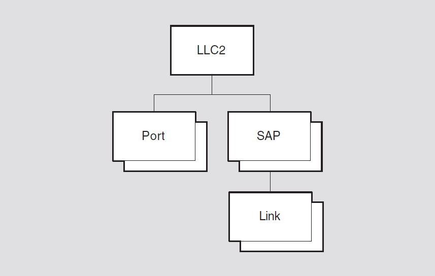
14.1. llc2
The llc2 entity is the top-level entity in the LLC2 module hierarchy of
entities. The LLC2 module controls the operation of the logical link control (LLC) Type
2 data link protocol for local area networks (LANs).
Syntax
create [node node-id] llc2
delete [node node-id] llc2
show [node node-id] llc2 [all [attributes] | all
characteristics]
14.1.1. Characteristic Attributes
version
Version number of the NA LLC2 architecture to which this implementation conforms. You cannot modify this characteristic. To display this attribute, specify all or version.
14.2. llc2 port
An llc2 port entity represents an access point to the services offered to
clients by the LLC2 module.
Syntax
show [node node-id] llc2 port
simple-name [all [attributes] | all identifiers | all
status]
14.2.1. Identifier Attributes
name
Simple name assigned to the port when it is created.
14.2.2. Status Attributes
client
Name of the client that opened the port.
link name
Name of the llc2 sap link entity with which this port is
associated.
state
llc2 port entity.|
open |
The port is assigned to a client and is enabled. |
|
open disabled |
The port is assigned to a client but is disabled. |
14.3. llc2 sap
Each llc2 port entity has an llc2 sap (service access point)
entity associated with it. An llc2 sap entity allows links to be
multiplexed over its associated port.
Syntax
create [node node-id]llc2 sap
sap-name
delete [node node-id] llc2 sap
sap-name
disable [node node-id] llc2 sap
sap-name
enable [node node-id] llc2 sap
sap-name
set [node node-id] llc2 sap
sap-name {lan station
local-entity-name | local lsap address
hex-number}
show [node node-id] llc2 sap
sap-name [all [attributes] | all characteristics | all
counters | all status | all identifiers]
14.3.1. Characteristic Attributes
|
Default: No entity name |
Value: Local-entity-name |
Name of the LAN station entity used by the SAP. You must specify a value for this attribute before you enable the SAP.
|
Default: 7E |
Value: Hex-number |
Address of the local link service access point (LSAP) to be used. The lowest significant bit of this value must be clear; that is, the address must be an individual address.
14.3.2. Counter Attributes
creation time
Time at which this entity was created.
times sap state changed
Number of times the status attribute state has changed from
on to off, or from off to
on.
14.3.3. Identifier Attributes
name
Simple name assigned to the llc2 sap when it is created.
14.3.4. Status Attributes
lan port
Name of the LAN port that is opened and enabled when this SAP is successfully enabled. If the SAP is not enabled, this status has a null value.
maximum pdu size
Largest frame size, in octets, that can be used to send or receive data on this SAP.
state
llc2 sap entity.|
off |
The SAP is disabled. |
|
on |
The SAP is enabled. |
uid
Entity's unique identifier, which is generated when the entity is created.
14.3.5. Event Messages
sap state changed
Generated when the status attribute state changes from
on to off, or from off to
on.
|
new sap state |
New state of the SAP. | |
14.3.6. Exception Messages
For enable:
enable lan port failed
The LAN port could not be enabled.
|
reason |
Specifies why the | |
|
invalid argument |
Software error. | |
|
insufficient resources |
There are insufficient system resources to enable the port. | |
|
SAP address not available |
The SAP address specified by the LSAP (local service access point) address characteristic is already being used, or is invalid. | |
link data size not supportable
The data size specified by the maximum data size characteristic of
one of the sap link entities cannot be supported by the SAP.
open lan port failed
A LAN port could not be opened.
|
reason |
Why the port could not be opened. | |
|
invalid argument |
Software error. | |
|
insufficient resources |
There are insufficient system resources to open the port. | |
|
LAN station not available |
The LAN station specified by the | |
|
no such LAN station |
The LAN station specified by the | |
14.4. llc2 sap link
An llc2 sap link entity represents one of the links that operates over a
particular SAP (service access point).
Syntax
create [node node-id] llc2 sap link
sap-name link
link-name
delete [node node-id] llc2 sap link
sap-name link
link-name
disable [node node-id] llc2 sap link
sap-name link
link-name
enable [node node-id] llc2 sap link
sap-name link
link-name
set [node node-id] llc2 sap link
sap-name link link-name {acknowledge
timer milliseconds | busy timer
milliseconds | holdback timer
milliseconds | local receive window size
integer | maximum data size octets |
poll timer milliseconds | reject timer
milliseconds | remote lsap address
hex-number | remote mac address
lan-address | retry maximum
integer}
show [node node-id] llc2 sap link
sap-name link link-name [all
[attributes] | all characteristics | all counters | all identifiers | all
status]
14.4.1. Characteristic Attributes
|
Default: 1000 |
Value: 1–60000 |
Time, in milliseconds, that the link waits for an acknowledgment before initiating recovery action. The granularity of this timer is 10 milliseconds. Values that are not multiples of 10 are rounded up.
|
Default: 10000 |
Value: 1–60000 |
Time, in milliseconds, that the link waits for indication of the clearance of a busy condition at the remote station. The granularity of this timer is 10 milliseconds. Values that are not multiples of 10 are rounded up.
|
Default: 500 |
Value: 0–60000 |
Delay, in milliseconds, before an acknowledgment must be sent. The granularity of this timer is 10 milliseconds. Values that are not multiples of 10 are rounded up.
|
Default: 127 |
Value: 1–127 |
Window size used by the link for receiving frames.
|
Default: 1028 |
Value: 1–65531 |
Largest frame size, in octets, that the link can use to send or receive data. This value does not include the size of the frame header.
|
Default: 1000 |
Value: 1–60000 |
Time, in milliseconds, that the link waits for a response with the F-bit set. The granularity of this timer is 10 milliseconds. Values that are not multiples of 10 are rounded up.
|
Default: 3000 |
Value: 1–60000 |
Time, in milliseconds, that the link waits for a reply to a REJ (reject) frame. The granularity of this timer is 10 milliseconds. Values that are not multiples of 10 are rounded up.
|
Default: 7E |
Value: hex-number |
Address of the destination LSAP (link service access point) to be used by the link. The lowest significant bit must be clear; that is, the address must be an individual address.
|
Default: 00-00-00-00-00-00 |
Value: ID802 |
Destination MAC address to be used by the link. The lowest significant bit of the first octet must be clear; that is, the address must be an individual address.
|
Default: 10 |
Value: 1–255 |
Maximum number of times that the link retransmits a frame before assuming a fatal error and taking more drastic recovery action.
14.4.2. Counter Attributes
creation time
Time at which this entity was created.
data octets received
Number of data octets received in I-frames and UI-frames from the remote end of the link. This value does not include data octets in retransmissions.
data octets sent
Number of data octets transmitted in I-frames and UI-frames to the remote end of the link. This value does not include data octets in retransmissions.
data pdus received
Number of I-frames and UI-frames received from the remote end of the link. This value does not include retransmissions.
data pdus sent
Number of I-frames and UI-frames transmitted to the remote end of the link. This value does not include retransmissions.
frmrs received
Number of FRMR (frame reject) frames received.
frmrs sent
Number of FRMR (frame reject) frames generated as a result of invalid incoming frames.
polls received
Number of command frames received with the P-bit set.
rejs received
Number of REJ (reject) frames received.
rejs sent
Number of REJ (reject) frames transmitted.
rnrs received
Number of RNR (receive not ready) frames received.
rnrs sent
Number of RNR (receive not ready) frames transmitted.
times acknowledge timer expired
Number of times the local acknowledge timer has expired.
times busy timer expired
Number of times the local busy timer has expired.
times link halted
Number of times the link's status attribute protocol state was set to
halted.
times link initializing
Number of times the link's status attribute protocol state was set to
initializing.
times link inoperative
Number of times the link's status attribute protocol state was set to
inoperative.
times link resetting
Number of times the link's status attribute protocol state was set to
resetting.
times link running
Number of times the link's status attribute protocol state was set to
running. When the link enters the running state, the
protocol has been successfully initialized or reset.
times link setup failed
Number of times the LLC2 protocol fails to initialize correctly after the maximum number of retries.
times link state changed
Number of times the link's status attribute STATE changed from on to
off, or from off to on.
times poll timer expired
Number of times the local poll timer has expired.
times reject timer expired
Number of times the local reject timer has expired.
xids received
Number of XID frames received.
xids sent
Number of XID frames transmitted.
14.4.3. Identifier Attributes
name
Simple name assigned to the link when it is created.
14.4.4. Status Attributes
protocol state
|
error |
The protocol is in a recognized error state. |
|
halted |
The protocol has halted. |
|
initializing |
The protocol is being initialized. |
|
inoperative |
The protocol cannot be started because the LAN station cannot provide a connection to a remote system. |
|
resetting |
The protocol is being reset. |
|
running |
The protocol is running normally. |
remote llc class
|
1 |
Class 1 LLC. Only type 1 operation is supported. |
|
2 |
Class 2 LLC. Both type 1 and type 2 operations are supported. |
|
unknown |
The class has not yet been established. The class is not established until XID frames have been exchanged between the local and remote LLC implementations. |
remote receive window size
Window size used by the remote station for receiving frames. The local station uses this value as its window for transmitting frames.
state
llc2 link entity.|
off |
The link is disabled. |
|
on |
The link is enabled. |
uid
Entity's unique identifier, which is generated when the entity is created.
14.4.5. Event Messages
frame reject generated
Generated when the receipt of a frame causes an FRMR (frame reject) frame to be generated and transmitted to the remote station.
|
frame |
Contents of the header of the frame that caused the FRMR frame to be generated. | |
|
frame reject reason |
Why the FRMR frame was rejected. | |
|
control |
A received control field is undefined or is not implemented. | |
|
format |
The frame contains an unallowed information field, or contains a supervisory or unnumbered field of incorrect length. | |
|
length |
A received information field exceeds the maximum length. | |
|
nr |
A received control field contains an invalid N(R). | |
|
ns |
A received control field contains an invalid N(S). | |
|
nonspecific |
The frame contains an unspecified number or type of errors. | |
|
generated frmr |
Contents of the generated FRMR frame that is sent to the remote station. | |
frame reject received
Generated when an FRMR (frame reject) frame is received from the remote station.
|
frame |
Contents of the header of the received FRMR frame. |
|
frame reject reason |
Why the frame was rejected. See possible reasons described
under the |
link halted
Generated when the status attribute protocol state is set to
halted.
|
link halted reason |
Why the protocol halted. | |
|
disc |
A DISC frame was received. The remote end has disconnected the link. | |
|
dm |
A DM frame was received. The remote end has disconnected the link. | |
|
frmr |
A FRMR frame was received. The remote end has detected a frame error. | |
|
implementation specific |
The cause is unknown. | |
|
LAN |
The LAN station has failed. | |
|
local |
Local management action on the | |
|
maximum retry |
A PDU had to be retransmitted the maximum number of times without response from the remote end. | |
|
user |
Local client action has halted the link. | |
link initializing
Generated when the protocol has been successfully initialized or reinitialized.
|
link initializing reason |
Why the protocol was initialized or reinitialized. See
possible reasons described under the |
link inoperative
Generated when the status attribute protocol state is set to
inoperative.
link resetting
Generated when the status attribute protocol state is set to
resetting.
|
link resetting reason |
Why the protocol is being reset. | |
|
frmr |
A FRMR frame was received. The remote end has detected a frame error. | |
|
implementation specific |
The reason is unknown. | |
|
maximum retry |
A PDU had to be retransmitted the maximum number of times without response from the remote end. | |
|
sabme |
A SABME frame was received. The remote end has reset the link. | |
link running
Generated when the status attribute protocol state is set to
running. This means that the protocol has been successfully
initialized or reset.
link setup failure
Generated when LLC2 protocol initialization has failed after the maximum number of retries.
link state changed
Generated when the status attribute state changes from
on to off, or from off to
on.
14.4.6. Exception Messages
For enable:
client data size not supportable
The data size specified by a client that has opened an LLC2 port to use this link cannot be supported.
link data size not supportable
The data size specified by the characteristic maximum data size
cannot be supported by the SAP that owns this link.
remote address in use
The remote MAC address and remote link service access point (hex-number LSAP) address are already being used by another link.
Chapter 15. Loopback Application Module
The Loopback Application module allows a network manager to invoke a loopback test between applications on two nodes, thus testing all the supporting layers of the Network Architecture (NA).
The loop access module, which initiates the loopback test.
The loop mirror module, which accepts connections from the remote loop access modules and mirrors any data sent to it back to the sender.
Figure 15.1, ''Hierarchy of Loopback Application Module Entities'' shows the hierarchical relationship of the entities that constitute the Loopback Application module.

15.1. loopback application
The loopback applicationentity describes features of the Loopback
Application module which allows you to run a loopback test between two nodes or itself.
The loopback application entity is created and deleted automatically with
the node entity, and is always enabled.
Syntax
loop [node node-id] loopback application {address
tower-set | count integer | format
hex-string | length integer | maximum
data integer | maximum mirrors integer |
name full-name}
set [node node-id] loopback application {maximum mirrors
integer}
show [node node-id] loopback application [all
[attributes] | all characteristics]
15.1.1. Commands
loop
Starts a loop test between the loopback applications on the specified source and
destination nodes. The node keyword specifies the node from which the
loop messages are sent. If you omit this keyword, the test is performed from the
node on which you issue the loop command. The name or
address argument specifies the node whose loop mirror is used to
reflect the messages back to the originator. Specify either the name or
address (but not both).
15.1.2. Characteristic Attributes
address tower-set
Number of the destination for loopback messages, in the form of a protocol tower.
Specify either this argument or the name argument.
|
Default: 1 |
Value: 0–4294967295 |
Number of loop messages to be sent to the loop mirror. The test is complete when this number of loop messages has been reflected back by the loop mirror.
|
Default: 55 |
Value: 00–FF |
Content of the data field of a loop message. Enter a pair of hexadecimal digits. Each octet in the data field of a loop message has this value.
|
Default: 40 |
Value: 0–65534 |
Length, in octets, of the data field in each loop message.
maximum data
The maximum size, in octets, of the loop message data field that the loop mirror can reflect. If the loop mirror receives a loop message with a longer data field, an error occurs.
For UNIX, to limit the number of loop mirrors, use the maximum
instances characteristic of the session control application
mir entity.
|
Default: 0 |
Value: 0–4294967295 |
Enter the maximum number of loop mirrors supported. If you enter the value 0, the node supports an unlimited number of mirrors.
For UNIX, to limit the number of loop mirrors, use the maximum
instances characteristic of the session control application
mir entity.
name full-name
DNS name of the node to which loopback messages are sent. Specify either this
argument or the address argument, but not both.
15.1.3. Exception Messages
For loop:
bad data at mirror
The local node sent a loop message with a data field that was too long.
The first octet of the loop message was corrupted when it arrived at the mirror module.
|
count |
Requested number of messages in the loopback test (that
is, the value of the |
|
message number |
Number of the loop messages in which the error occurred. |
|
start time |
Time at which the loopback test began. |
both name and address specified
Both the name and address arguments have been specified.
You must specify one of these arguments, but not both.
connection failed
The Session Control connection to the loop mirror failed.
|
reason |
Reason why the connection failed. This is the reason code provided by Session Control. |
|
start time |
Time the loopback test began. |
data returned differs from data sent
The data field in a loop message reflected back by the loop mirror is not the same as the data field in the loop message that was sent.
|
count |
Requested number of messages in the loopback test (that
is, the value of the |
|
format |
Value for each octet of the data field of the loop message
(that is, the value of the |
|
length |
Length of the data field of the loop message, as requested
by the |
|
message number |
Number of the loop message in which the error occurred. |
|
message returned |
Contents of the reflected loop message. |
|
start time |
Time the loopback test began. |
disconnected
The link to the loop mirror was disconnected before the loopback test was completed.
|
count |
Requested number of messages in the loopback test (that
is, the value of the |
|
message number |
Number of the loop message in which the error occurred. |
|
reason |
Reason why the link was disconnected. This is the reason code returned by Session Control. |
|
start time |
Time the loopback test began. |
length too long
The requested length of the data field is greater than the maximum data field length that the loop mirror can handle.
|
length |
Data field length requested, in octets. |
|
maximum data |
Maximum data field length supported by the loop mirror. |
|
start time |
Time at which the loopback test began. |
neither name nor address specified
You have not specified the name or the address argument.
You must specify one of these arguments, but not both.
Chapter 16. Modem Connect Module
This chapter describes all the commands you can use to manage the entities that constitute the Modem Connect module. The Modem Connect module implements one of the protocols in the Physical layer described by the Network Architecture (NA).
Figure 16.1, ''Hierarchy of Modem Connect Module Entities'' shows the hierarchical relationship of the entities that constitute the Modem Connect module.
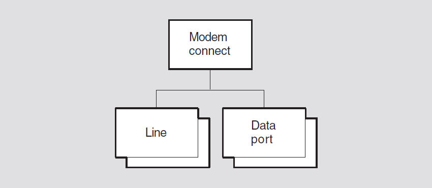
16.1. modem connect
The modem connect entity is the top-level entity in the hierarchy of
entities belonging to the Modem Connect module.
Syntax
create [node node-id] modem connect
delete [node node-id] modem connect
show [node node-id] modem connect [all [attributes] |
all characteristics]
16.1.1. Characteristic Attributes
NA version
Version number of the NA Modem Connect architecture to which the implementation conforms. You cannot modify this characteristic.
16.2. modem connect data port
The modem connect data port entity is associated with aline and handles
the transfer of data. Data ports are created and deleted automatically when a client of
the Modem Connect module uses a line. The port-name refers to data
port managed by this command.
Syntax
show [node node-id] modem connect data port
port-name [all [attributes] | all identifiers | all status
]
16.2.1. Identifier Attributes
name
Simple name assigned to the data port when it is created.
16.2.2. Status Attributes
client
Name supplied by the client when the port was opened. This defines which client owns the port.
line
Name of the modem connect line entity that the client supplied when
the port was opened.
state
|
open |
The port is assigned to a client. |
|
open disabled |
The port is assigned to aclient, but the line entity that port refers to is disabled. |
16.3. modem connect line
A modem connect line entity is associated with a physical circuit on the
node. Usually, there is one line entity for each circuit. The
line-name refers to the line managed by this command.
Syntax
add [node node-id] modem connectline
line-name modem options [set]
create [node node-id] modem connectline
line-name {communications mode
comm-mode | communication port
port-name | connection type conn-type
(UNIX) | duplex full-or-half | profile
profile-name | rate select rate
(OpenVMS)}
delete [node node-id] modem connect line
line-name
disable [node node-id] modem connectline
line-name
enable [node node-id] modem connectline
line-name
remove [node node-id] modem connectline
line-name modem options [set]
set [node node-id] modem connectline
line-name {alternate speed
bits-per-second | call accept timer
integer | carrier loss timer integer |
clock clock-source | encoding normal-nrzi
| initial hold timer integer (UNIX) | maximum call setup timer
integer | maximum disable transmit timer
integer | maximum dsr de-assertion timer
integer | maximum enable transmit timer
integer | minimum dtr de-assertion timer
integer | modem control [full or none] | modem options [
modem-option] | modem protocol format
type (UNIX) | modem protocol type
prot-type (UNIX) | rate select [high or low] | speed
bits-per-second | successful call indication timer
seconds | suppress test indicator
boolean | transmit holdoff timer
integer}
show [node node-id] modem connect line
line-name mode [all [attributes] | all characteristics |
all counters | all identifiers | all status ]
startloop [node node-id] modem connectline
line-name mode {driver or device | local or remote |
connector or external }
stoploop [node node-id] modem connectline
line-name
16.3.1. Commands
startloop
Causes a Physical layer to place the line in loopback mode.
stoploop
Opens a previously closed Physical layer loop to take it out of loopback mode.
16.3.2. Arguments
communications mode mode
Communications method used on the link. This argument determines the value of the
communications mode characteristic. The default value is taken from
the device capability. If that is unknown, the default is synchronous.
communications port port-name
The system device name assigned to this line.
On OpenVMS systems, the name must be in the format ddc, where dd is the OpenVMS device name prefix and c is the controller letter. For a complete list of CSMA-CD devices and their OpenVMS device names, see the DECnet-Plus for OpenVMS Release Notes.
On UNIX systems, the name must be in the format ddn, where dd is the UNIX device name prefix and n is the device number.
This argument determines the value of the communications port
characteristic and is required.
duplex duplex
Specifies whether the line is full-duplex or half-duplex. This argument determines
the value of the duplex characteristic. The default value is taken from
the device capability. If that is unknown, the default is set to full.
mode mode
|
connector |
Data is looped through a loopback connector attached to the communications device. |
|
device |
Data is looped in the communications device. |
|
driver |
Data is looped in the driver of the communications device. |
|
external |
Data is looped through a null modem or a modem in loopback mode. |
|
local |
Communications device has switched its local modem into loopback mode. |
|
null |
Line is not in loopback mode. This argument only applies to UNIX. |
|
remote |
Communications device has switched the remote modem into loopback mode. |
profile latin1string
Name of a local profile to be used with the line. This argument determines the
value of the profile characteristic.
16.3.3. Characteristic Attributes
|
Default: 0 |
Alternate (low) speed, in bits per second, to operate the line. You can modify
this characteristic only when the entity is disabled. This characteristic is
supported only when the characteristic communications mode is
asynchronous, the characteristic modem control is
full, the characteristic modem options includes
rateselect, the characteristic clock is
internal, and when the alternate line speed is needed.
|
Default: 0 |
Minimum time, in milliseconds, between the assertion of data set
ready and accepting a call by asserting request to send.
This attribute is maintained only if the characteristic modem control
is set to none.
|
Default: 15000 |
Maximum time, in milliseconds, that the carrier detect signal can be
absent before the loss of carrier event is generated. This attribute is
not supported if the characteristic modem control is set to
none.
clock
|
external |
The modem provides the clock. |
|
internal |
The communications device provides the clock. |
|
reflected |
The DTE transmit clock is are flection of the DCE transmit clock. This minimizes the clock to data skew that the DCE encounters when high line speeds are used. |
The default value depends on the setting of the characteristic
communications mode. If communications mode is
asynchronous, the default value of this characteristic is
internal. Otherwise, the default value is
external.
The value of this attribute has no effect when the communications line is in loopback mode. In this case, the type of loopback determines the type of clock. This characteristic can only be modified when the entity is disabled.
|
Default: Synchronous |
Value: Asynchronous or synchronous |
Communications method to be used on the line. The value of this characteristic is
a copy of the communications mode argument specified when the entity is
created. You cannot modify this characteristic.
|
Default: None |
Name of the communications port. The value of this characteristic is a copy of the
communications port argument specified when the entity is
created.
|
Default: Nonswitched |
Value: Nonswitched or switched |
Indicates whether the line is switched or nonswitched.
The value of this characteristic is a copy of the connection type
argument specified when the entity is created. You cannot modify this
characteristic.
|
Default: Full |
Value: Full or half |
Indicates whether the line is full- or half-duplex. The
value of this characteristic is a copy of the duplex argument specified
when the entity is created.
|
Default: Normal |
Value: Normal or nrzi |
Encoding technique used on the line. This characteristic can only be modified when the entity is disabled.
|
Default: 10 |
Maximum time, in seconds, that the entity waits for an incoming call to be accepted.
|
Default: 60 |
Maximum time, in seconds, that the entity waits for the outgoing call to connect.
|
Default: 500 |
Value: 0–60000 |
Maximum time, in milliseconds, that clear to send can remain asserted
before the line is disconnected after request to send is de-asserted.
This attribute is not supported if the characteristic modem control is
set to none.
|
Default: 5000 |
Value: 0–60000 |
Maximum time, in milliseconds, the entity will wait for data set
ready to be de-asserted after it has de-asserted data terminal
ready. If this timer expires, the entity assumes it can assert data
terminal ready once again. This attribute is not supported if the
characteristic modem control is set to none.
|
Default: 2000 |
Value: 1–5000 |
Maximum time, in milliseconds, between the assertion of the request to
send signal and receiving the assertion of the clear to send
signal. This attribute is not supported if the characteristic modem
control is set to none.
|
Default: 1000 |
Value: 0–60000 |
Minimum time, in milliseconds, that the DTE will de-assert data terminal
ready during a disconnection. This attribute is not supported if the
characteristic modem control is set to none.
|
Default: Full |
Value: Full or none |
Indicates whether the interchange circuits are to be monitored and used. The value
none means that only the data leads are monitored.
The value full must be used when the value of the characteristic
duplex is half. This characteristic is supported only
if the characteristic connection type is switched.
|
Default: No options |
Value: Set of options |
|
dialout |
The modem can dial the remote modem. Supported only if the
value of |
|
direct |
The modem is directly connected to the remote modem
through a nonswitched line. Supported only if accompanied
with |
|
rate select |
The modem is capable of data rate selection. |
|
Default: See description |
Value: See description |
modem protocol type is v25bis or
dmcl.|
asynchronous |
Use the asynchronous format. |
|
hdlc |
Use the HDLC format. |
|
synchronous |
Use the synchronous format. |
The default value depends on the value of the characteristic communications
mode. If communications mode is asynchronous,
the default value of this characteristic is also asynchronous. If the
value of communications mode is synchronous, the default
value of this characteristic is hdlc.
|
Default: V25bis |
Value: See description |
|
at |
A set of automatic calling procedures used in the Hayes Smart Modem 2400. |
|
dmcl |
The Modem Control Language, based on V.25bis. |
|
v25 |
A set of automatic calling and answering procedures defined by CCITT. These procedures use the 200-series circuits defined in the CCITT recommendation V.24. The V.25 procedures are also known as parallel automatic calling procedures. |
|
v25bis |
A set of automatic calling and answering procedures defined by CCITT. These procedures use the 100-series circuits defined in the CCITT recommendation V.24. The V.25bis procedures are also known as serial automatic calling procedures. |
|
Default: None |
Name of the local profile to be used with the line. This profile is used to
restrict the range of various line attributes, and to change the defaults for those
attributes. The value of this characteristic is a copy of the profile
argument specified when the entity is created.
|
Default: High |
Value: High or low |
|
high |
The value of the |
|
low |
The value of the |
This characteristic is supported only if the characteristic modem
control is full, and if the characteristic modem
options includes rateselect.
|
Default: 0 |
When the value of the
clockcharacteristic isinternal.When a null modem cable is detected.
When using a loopback mode that uses internal clocking.
|
Default: 30 |
Maximum time, in seconds, that the entity will wait for indication of a successful
call before disconnecting the line. This attribute is not supported if the
characteristic modem control is set to none.
|
Default: False |
Value: True or false |
Specifies whether the test mode signal is to be monitored. If the value is
false, a change in the circuit will be monitored and will cause a
Test Indication event to be generated.
You should set this characteristic to true in cases where the
transitions of this signal are not produced by entering the test mode, so that this
signal should be ignored.
|
Default: 0 |
Necessary delay, in milliseconds, between the transmitter being disabled and then
reenabled. The value 0 means that the request to send signal can be
asserted as soon as the client requests it. This attribute is not supported if the
characteristic modem control is set to none.
16.3.4. Counter Attributes
cable faults
Total number of times the communications cable was detected as missing or invalid.
creation time
Time at which this entity was created.
device errors
Total number of times a potential device error has been reported.
framing errors
Total number of framing errors detected on the line. This counter is not supported
if the characteristic communications mode is
synchronous.
losses of carrier
Total number of times the carrier on the line was lost. This attribute is not
supported if the characteristic modem control is set to none.
losses of clock
Total number of times the transmit or receive clock was lost.
outgoing call failures (UNIX)
Total number of times an outgoing call failed to connect.
rate fallbacks
Number of times the DTE changed from the high data rate to the low (alternate)
rate. This counter is supported only if the characteristic modem
options includes rate select, and if the characteristic
modem control is full.
test indications
Number of times the DCE was put into test mode by the remote system. This
attribute is not supported if the characteristic modem control is set
to none.
times cable detected
Total number of times a valid communications cable was detected following a an
error counted by the counter cable faults.
times dce not ready
Total number of times a dce not ready event occurred. This attribute
is not supported if the characteristic modem control is set to
none.
times reset (OpenVMS)
Number of times the data link client has performed a line reset.
transmit enable timeouts
Number of times the DCE failed to assert clear to send in response to
request to send. This attribute is not supported if the
characteristic modem control is set to none.
16.3.5. Identifier Attributes
name
Simple name assigned to the line when it is created.
16.3.6. Status Attributes
actual speed
Actual speed of the line, in bits per second. For internal clocking on some microcoded devices, a value of 0 indicates that the device has selected a speed appropriate for the connected interface. For external clocking, a value of 0 indicates that the speed is unknown.
device availability (OpenVMS)
Indicates whether the hardware device associated with the named communications
port is installed. Support is mandatory on systems that support line card hot swap.
When device availability has the value no device, the
interface state takes the value pending DTE Ready and the interface type attribute
takes the value unknown.
interface state
|
connected |
A switched line is connected but not ready to transmit or receive data. |
|
connecting |
Call setup on a switched line is in progress. |
|
disconnecting |
Call clear on a switched line is in progress. |
|
dte not ready |
The entity is disabled. |
|
dte ready |
The DTE is ready, but the DCE is not ready. |
|
full enabled |
The line is enabled for data transmission and reception. |
|
pending dte ready |
The entity is enabled but the ready state cannot be entered. For example, the communications cable is not connected. |
|
ready |
Both DTE and DCE are ready. |
|
receive enabled |
The line is ready to receive data. |
|
transmit enabled |
The line is ready for data transmission. |
interface type
|
loopback |
A loopback connector has been detected onthe interface. |
|
no cable |
No cable is connected to the interface. |
|
null modem |
A null modem cable is connected to the interface. |
|
rs232c |
A cable conforming to the RS-232-C standard is attached. |
|
rs422 |
A cable conforming to the RS-422 standard is attached. |
|
rs423-v24 |
This value appears where a cable is attached but the connector cannot distinguish between the RS-423 and V.24 standards. |
|
rs449 |
A cable conforming to the RS-449 standard is attached. |
|
unknown |
A cable is attached but its type is not known |
|
v28 |
A cable conforming to any of the CCITTV.24, V.28 standards, the IS 2110 standard, or the EIA-232-D standard. |
|
v35 |
A cable conforming to the V.35 standard is attached. |
|
x21 |
A cable conforming to the X.21 standard is attached. |
loopback mode
startloop and stoploop commands.|
connector |
Data is looped through a loopback connector attached to the communications device. |
|
device |
Data is looped in the communications device. |
|
driver |
Data is looped in the driver of the communications device. |
|
external |
Data is looped through a null modem or a modem in loopback mode. |
|
local |
The communications device has switched its local modem into loopback mode. |
|
null |
The line is not in loopback mode. |
|
remote |
The communications device has switched the remote modem into loopback mode. |
modem type
String identifying the local modem. If this status attribute has no value, the type could not be determined.
state
modem connect line entity.|
off |
The line has been disabled. |
|
on |
The line has been enabled. |
uid
Entity's unique identifier, which is generated when the entity is created.
16.3.7. Interchange Circuit Attributes
The modem connect line entity in the Modem Connect module has an
extra set of status attributes that let you examine the instantaneous status of the
interchange circuits on the line.
These circuit attributes are known by different names in the various interface
standards. Table 16.1, ''Modem Connect Line Interchange Circuits'' shows how the attribute names used
in NCL correspond to those used in the interface standards. For instance, the
data terminal ready attribute is the name used for the CCITT V.24
circuit 108/2, the EIA-232-D CD circuit, the RS-499 TR circuit, and so on.
|
asserted |
The circuit is asserted. |
|
not applicable |
The circuit does not exist on the interface. |
|
not asserted |
The circuit is not asserted. |
|
unknown |
The modem cable is not connected or is invalid. |
|
NCL Attribute Name |
Circuit |
Description |
|---|---|---|
|
CCITT V.24 | ||
|
carrier detect |
109 |
Data channel received line signal detector |
|
clear to send |
106 |
Ready for sending |
|
data set ready |
107 |
Data set ready |
|
data terminal ready |
108/2 |
Data terminal ready |
|
local loopback |
141 |
Local loopback |
|
remote loopback |
140 |
Loopback/maintenance test |
|
request to send |
105 |
Request to send |
|
ring indicator |
125 |
Calling indicator |
|
signaling rate indicator |
112 |
Data signal rate selector (DCE) |
|
signaling rate selector |
111 |
Data signal rate selector (DTE) |
|
test mode |
142 |
Test indicator |
|
DIN 66020 Blatt 1 | ||
|
carrier detect |
M5 |
— |
|
clear to send |
M2 |
— |
|
data set ready |
M1 |
— |
|
data terminal ready |
S1.2 |
— |
|
local loopback |
PS3 |
— |
|
remote loopback |
PS2 |
— |
|
request to send |
S2 |
— |
|
ring indicator |
M3 |
— |
|
signaling rate indicator |
Not supported |
— |
|
signaling rate selector |
S4 |
— |
|
test mode |
PM1 |
— |
|
EIA-232-D | ||
|
carrier detect |
CF |
Received line signal detector |
|
clear to send |
CB |
Clear to send |
|
data set ready |
CC |
DCE ready |
|
data terminal ready |
CD |
DTE ready |
|
local loopback |
LL |
Local loopback |
|
remote loopback |
RL |
Remote loopback |
|
request to send |
CA |
Request to send |
|
ring indicator |
CE |
Ring indicator |
|
signaling rate indicator |
CI |
Data signal rate selector (DCE) |
|
signaling rate selector |
CH |
Data signal rate selector (DTE) |
|
test mode |
TM |
Test mode |
|
RS-232-C | ||
|
carrier detect |
— |
Received line signal detector |
|
clear to send |
— |
Clear to send |
|
data set ready |
— |
Data set ready |
|
data terminal ready |
— |
Data terminal ready |
|
local loopback |
— |
Not supported |
|
remote loopback |
— |
Not supported |
|
request to send |
— |
Request to send |
|
ring indicator |
— |
Ring indicator |
|
signaling rate indicator |
— |
Data signal rate selector (DCE) |
|
signaling rate selector |
— |
Data signal rate selector (DTE) |
|
test mode |
— |
not supported |
|
RS-449 | ||
|
carrier detect |
RR |
Receiver ready |
|
clear to send |
CS |
Clear to send |
|
data set ready |
DM |
Data mode |
|
data terminal ready |
TR |
Terminal ready |
|
local loopback |
LL |
Local loopback |
|
remote loopback |
RL |
Remote loopback |
|
request to send |
RS |
Request to send |
|
ring indicator |
IC |
Incoming call |
|
signaling rate indicator |
SI |
Signaling rate indicator |
|
signaling rate selector |
SR |
Signaling rate selector |
|
test mode |
TM |
Test mode |
16.3.8. Event Messages
cable detected
Generated when a valid communication cable is detected following a cable
fault event.
|
current interface type |
Type of cable detected. | |
|
loopback |
A loopback connector has been detected. | |
|
null modem |
A null modem has been detected. | |
|
rs232c |
A cable conforming to the RS-232-C standard has been detected. | |
|
rs449 |
A cable conforming to the RS-449 standard has been detected. | |
|
rs422 |
A cable conforming to the RS-422 standard has been detected. | |
|
rs423-v24 |
A cable is attached, but the connector cannot distinguish whether it conforms to RS-423 or V.24 standards. | |
|
v.28 |
A cable conforming to any of the CCITTV.24, CCITT V.28, IS2110, or EIA-232-D standards has been detected. | |
|
v.35 |
A cable conforming to the V.35 standard has been detected. | |
|
x.21 |
A cable conforming to the X.21 standard has been detected. | |
|
previous interfacetype |
Previous type of cable detected. | |
|
no cable |
No cable was attached to the interface. | |
|
unknown |
A cable was attached, but its type was unknown. | |
cable fault
Generated each time the communications cable is detected as missing or invalid.
call reference
argument is present only if the characteristic connection type is
switched.|
call reference |
The call reference number of the call that was disconnected because of the fault. | |
|
previous interface type |
Type of cable that was connected before the error was detected. | |
|
loopback |
A loopback connector. | |
|
null modem |
A null modem cable. | |
|
rs232c |
A cable conforming to the RS-232-Cstandard. | |
|
rs422 |
A cable conforming to the RS-422 standard. | |
|
rs423-v24 |
A cable is attached, but the connector cannot distinguish whether it conforms to RS-423 or V.24 standards. | |
|
rs449 |
A cable conforming to the RS-449 standard. | |
|
unknown |
A cable was connected but its type was unknown. | |
|
v.28 |
A cable conforming to any of the CCITT V.24, CCITT V.28, IS2110, or EIA-232-D standards. | |
|
v.35 |
A cable conforming to the V.35 standard. | |
|
x.21 |
A cable conforming to the X.21 standard. | |
|
reason |
Reason that caused the event to occur. | |
|
invalid cable |
A cable is attached but it is not one of those recognized. | |
|
no cable |
No cable can be detected. | |
clock loss
Generated each time a loss of the transmit or receive clock is detected. Once this
event occurs, the value of the interface state attribute changes to
pending dte ready.
dce not ready
Generated each time a dce not ready condition is detected. Once this
event occurs, the value of the interface state attribute changes to
dte ready. This event does not occur if the characteristic
modem control is set to none.
device error
A potential device error has been detected. This may be a temporary condition that means the device can continue to be used.
|
reason |
Reason for the failure. This is device specific. | |
framing error
Generated each time an asynchronous framing error occurs.
loss of carrier
Generated each time the carrier frequency is lost while receiving data. This event
is not supported if the characteristic modem control is
none.
rate fallback
Generated each time the DCE indicates that it is changing from the high data rate
(as indicated by the speed characteristic) to the low data rate (as
indicated by the alternate speed characteristic. This can occur if
there is excessive noise when operating at the high data rate. This event is
supported only when the modem has a rate selection capability.
reset (OpenVMS)
Generated each time the Data Link client represents a line reset by means of the service interface.
test indication
Generated each time the remote system tests the DCE. When this event occurs, the
value of the interface state attribute changes to dte
ready. This event is not supported if the characteristic modem
control is none.
transmit enable timeout
Generated whenever the time to assert the clear to send signal (after
receiving the request to send signal) is greater that specified in the
maximum enable transmit timer characteristic. This event is not
supported if the characteristic modem control is
none.
16.3.9. Exception Messages
For startloop:
already in loopback
The modem connect line entity specified in the command is already in
loopback mode. Check that you specified the correct entity. Reissue the command with
the correct name.
constraint violation
The implementation does not support the requested loopback mode.
The requested loopback mode is incompatible with the communications interface type.
The line is half-duplex.
line disabled
This modem connect line entity is disabled.
For create:
communications port in use
Another entity has reserved the communications port specified in the command. Check that you specified the correct port. Reissue the command specifying another port or modify the other entity to use a different port.
For enable:
high speed mode selected
The line cannot be used while high-speed mode is selected.
Chapter 17. MOP Module
This chapter describes all the commands you can use to manage the entities that constitute the Maintenance Operations Protocol (MOP) module. The MOP module is located in the Application layer described by the Network Architecture (NA). MOP has a direct connection with the Data Link layer; thus, for certain functions, MOP can bypass the higher layers in the NA protocol tower. This is useful for nodes that do not (yet) have all the higher layers of NA protocol towers installed. Functions provided by the MOP module include downline loading, upline dumping, and communications testing.
Figure 17.1, ''Hierarchy of MOP Module Entities'' shows the hierarchical relationship of the entities that constitute the MOP module.
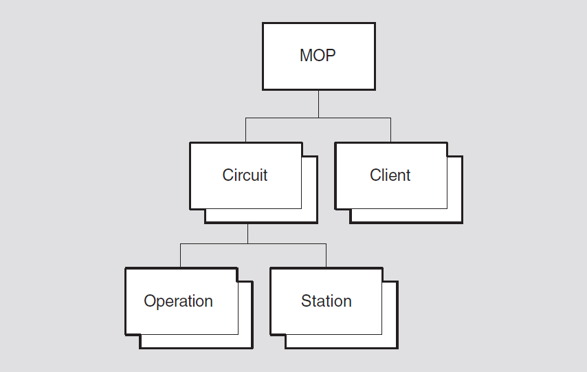
17.1. mop
The mop entity is the top-level entity in the hierarchy of entities
belonging to the MOP module.
Syntax
create [node node-id] mop
delete [node node-id] mop
disable [node node-id] mop
enable [node node-id] mop
show [node node-id] mop [all [attributes] | all
characteristics | all status]
17.1.1. Characteristic Attributes
supported functions
|
configuration monitor |
load server |
|
console requester |
loop requester |
|
dump server |
query requester |
|
load requester (UNIX) |
test requester |
|
Default: Current version number |
Version number of the Maintenance Operations Protocol specification to which the implementation conforms. This is a read-only attribute.
17.1.2. Status Attributes
state
mop entity. This is a read-only attribute.|
off |
The |
|
on |
The |
17.1.3. Exception Messages
For create:
already exists
A mop module already exists.
For delete:
has children
Cannot delete while subentities exist.
17.2. mop circuit
A mop circuit entity is a data link circuit on which MOP services are
available. The status attribute functions specifies the services enabled on
the circuit.
Syntax
boot [node node-id] mop circuit
circuit-name {address ID802 | client
client-name | device latin1string |
script id latin1string | software id
latin1string | verification
hex-string}
create [node node-id] mop circuit
circuit-name type
type-1
delete [node node-id] mop circuit
circuit-name
disable [node node-id] mop circuit
circuit-name functions[ func_name1,
func_name2...]
enable [node node-id] mop circuit
circuit-name functions[ func_name1,
func_name2...]
load [node node-id] mop circuit
circuit-name {address ID802 | client
client-name | management image
filespec | script file filespec |
secondary loader filespec | system image
filespec | tertiary loader filespec |
verification hex-string}
loop [node node-id] mop circuit
circuit-name {address ID802 |
assistance type help-type | assistant address
ID802 | assistant system client-name |
client client-name | count integer |
format octet | length
integer}
query [node node-id] mop circuit
circuit-name {address ID802 | client
client-name | sap
octet}
set [node node-id] mop circuit
circuit-name {known clients only
boolean | link name local-entity-name
| retransmit timer integer }
show [node node-id] mop circuit
circuit-name [all [attributes] | all characteristics | all
counters | all identifiers | all status ]
test [node node-id] mop circuit
circuit-name {address ID802 | client
client-name | count integer | format
octet | length integer | sap
octet}
17.2.1. Commands
boot
Causes the system specified by node-id to send a boot message to an adjacent system.
load
Initiates a downline load from the system specified by node-id to a target system specified by the arguments or by a client.
loop
Performs a loop operation with another system.
query
Initiates an XID exchange between the system specified by node-id and the system specified by the arguments or a client.
test
Initiates an XID test between the system specified by the arguments or by a client.
17.2.2. Arguments
For a complete list of arguments, refer to the corresponding command in the
mop client description.
functions func_name1, func_name2...
enable command).|
configuration monitor |
load server |
|
console requester |
loop requester |
|
dump server |
query requester |
|
load requester (UNIX) |
test requester |
type type-1
Circuit type, which is set when the circuit is created (see the
create command). You cannot modify this characteristic.
17.2.3. Characteristic Attributes
|
Default: False |
Value: True or false |
Specifies whether MOP attempts to service load requests from remote systems that
do not have a corresponding client entity. Some network servers are designed to
request specific software by name, and in such a case there is no need for a client
entity to exist. By default, MOP tries to process requests for named software from
unknown clients. Set this attribute to true if you wish MOP to ignore
such requests.
|
Default: No name |
Value: Data Link entity name |
Name of a station entity in the Data Link layer module indicated by the
type characteristic. This name is passed to the Data Link layer
module when MOP opens a portal for the circuit.
|
Default: 4 |
Value: 1–30 |
Time, in seconds, to wait for a response before retransmitting a MOP message.
type
Specifies the circuit type. This characteristic is set when the circuit is created
(see the create command). The possible types are CSMA-CD, FDDI, HDLC
(UNIX loop only), DDCMP (OpenVMS only), and LAPB (OpenVMS only). You cannot modify
this characteristic.
17.2.4. Counter Attributes
creation time
Time this entity was created.
dump requests completed
Number of dump service requests that completed successfully.
failed dump requests
Number of dump service requests that could not be completed.
failed load requests
Number of load service requests that could not be completed.
load requests completed
Number of load service requests that completed successfully.
unrecognized dump clients
Number of dump service requests that could not be processed because a required client database entry could not be found.
unrecognized load clients
Number of load service requests that could not be processed because a required client database entry could not be found.
17.2.5. Identifier Attributes
name
Simple name assigned to the circuit when it is created.
17.2.6. Status Attributes
functions
Which optional MOP functions are currently enabled for this circuit (see the
functions argument).
uid
Entity's unique identifier, which is generated when the entity is created.
17.2.7. Event Messages
dump request completed
Generated each time a remote dump service request completes successfully.
Arguments: See the address,
client, and file arguments described under the
load request failed event.
dump request failed
Generated each time a remote dump request tries and fails. When a request is never
started because of insufficient client information, the unrecognized dump
client event is reported.
Arguments: See the address,
client, file, and reason arguments
described under the load request failed event.
load request completed
Generated each time a remote load service request completes successfully.
Arguments: See the address,
client, file, and program type arguments
described under the load request failed event.
load request failed
Generated each time a remote load request tries and fails. When a request is never
started because of insufficient client information, the unrecognized load
client event is reported.
|
address |
Data link address of the remote system. This argument is supplied only for LAN data links. | |
|
client |
Name of the client that corresponds to the remote system. | |
|
file |
Name of the file being dumped or loaded. | |
|
program type |
Program type requested by the remote system on a load operation. | |
|
cmip script |
A file containing initialization data encoded as network management directives in CMIP form. | |
|
diagnostic |
A file containing diagnostic test procedures. | |
|
management |
A file containing initialization data encoded in a product-specific format. | |
|
secondary loader |
A secondary file containing software to be downline loaded. | |
|
system |
The primary file containing the system image to be downline loaded. | |
|
tertiary loader |
A third file containing software to be downline loaded. | |
|
reason |
Reason for the failure. | |
|
file i/o error |
Unable to read load file or write dump file. | |
|
file open error |
Unable to open load or dump file requested. | |
|
no resources |
Insufficient network management or system resources. | |
|
operation aborted |
Unexpected error prevents completion of request. | |
|
protocol error |
A violation of MOP occurred. | |
|
receive error |
Error or timeout receiving data from the network. | |
|
transmit error |
Error reading data to the network. | |
|
unknown client |
Client requesting load or dump is not found in MOP client database. | |
unrecognized dump client
Generated each time a remote dump service request was not accepted because a required client database entry could not be found.
Argument: See the address argument
described under the load request failed event.
unrecognized load client
Generated each time a remote load service request was not accepted because a required client database entry could not be found.
Arguments: See the address and
program type arguments described under the load request
failed event.
17.2.8. Exception Messages
For create:
already exists
A mop circuit subentity already exists.
unsupported circuit type
Type of argument value is not supported in this implementation.
For delete:
has children
Cannot delete while subentities exist.
For enable:
non-existent data link
Specified data link entity does not exist.
open port failed
Open port operation failed.
unsupported
Specified function is not supported by this system.
For boot, load, loop, test, and query:
data link error
An error was reported by the Data Link layer on the loop
command.
unrecognized circuit
There is no circuit with the specified identification on the loop
command.
unrecognized client
There is no client with the specified identification on the loop
command.
For loop:
invalid assistant
The assistant address is either a multicast address, or assistant system was
specified, and the corresponding client subentity has the default value for its
address on the loop command.
unrecognized assistant
There is no assistant with the specified identification on the loop
command.
For load, loop, test and query:
data link error
An error was reported by the Data Link layer.
timeout
Operation has timed out on the loop command.
unrecognized client
There is no client with the specified identification.
For load:
protocol error
A protocol error occurred during the load.
17.3. mop circuit operation
The mop circuit operation entities are created automatically by MOP for
all operations, including those initiated by NCL action directives and those initiated
by automatic load and dump service. They are deleted when the corresponding operation is
complete.
Syntax
show [node node-id] mop circuit
circuit-name operation operation-name
[all [attributes] | all identifiers | all status]
17.3.1. Identifier Attributes
name
Simple name of the operation entity that is generated automatically by MOP. The simple name is derived from the operation being performed (load or dump) and a numeric suffix added to ensure uniqueness.
17.3.2. Status Attributes
address
For LANs only, specifies the address of the client system.
client
Client name of the client entity associated with the operation, if such an entity exists.
operation
The operation being performed (boot, dump, load, loop, query, or test).
17.4. mop circuit station
mop circuit station entities are created automatically by the
Configuration Monitor. They are deleted when the circuit entity is deleted.Note
The Configuration Monitor function must be enabled to obtain the status
information used by the show mop circuit station command.
Syntax
show [node node-id] mop circuit
circuit-name station station-name [all
[attributes] | all identifiers | all status]
17.4.1. Identifier Attributes
name
Name of the station entity, generated automatically by the Configuration Monitor. The name is identical to the source LAN address for the System ID message.
17.4.2. Status Attributes
command size
Maximum acceptable console command size. A zero value means it is not applicable.
console user
LAN address of the system that currently has the console reserved; all zeroes if the console is not in use.
data link
Data Link protocol used by the remote station.
device
Type of communication device used by the remote station.
dsdu size
Maximum allowed size for a MOP message, not including data link protocol overhead.
functions
The set of functions supported: loop server, dump requester, primary loader, secondary loader, boot, console carrier, and counters.
hardware address
Default data link address for the circuit on which the system ID was transmitted by the remote station.
last report
Time at which the most recent system ID message was received.
mop version
Highest version of the MOP supported by the remote station.
node id
Node ID for the remote station. If not reported, the null ID (00-00-00-00-00-00) is displayed.
node name
Node name for the remote station, as a DECdns full name. If not reported by the remote station, the null name is used; this is displayed as "0:.".
reservation timer
Console reservation timer, in seconds. A zero values means it is not applicable.
response size
Maximum acceptable console response size. A zero value means it is not applicable.
17.5. mop client
A mop client entity is a set of default characteristics used by several
MOP functions: dump/load server, load requester, loop
requester, and console requester. When a command or a request
for one of these services does not supply all of the required arguments, the values
stored by the client are used to perform the operation. The
client-name refers to the client managed by this
command.
Syntax
add [node node-id] mop client
client-name {addresses
{ID802[,ID802...]} | device types
{type[,type...]}}
boot [node node-id] mop client
client-name {address ID802 | circuit
circuit-id | device latin1string |
script id latin1string | software id
latin1string | verification
hex-string}
create [node node-id] mop client
client-name
delete [node node-id] mop client
client-name
load [node node-id] mop client
client-name {address ID802 | circuit
circuit-name | management image
filespec | script file filespec |
secondary loader filespec | system image
filespec | tertiary loader filespec |
verification hex-string}
loop [node node-id] mop client
client-name {address ID802 |
assistance type help-type | assistant address
ID802 | assistant system client-name |
circuit circuit-name | count integer |
format octet | length
integer}
query [node node-id] mop client
client-name {address ID802 | circuit
circuit-name | sap
octet}
set [node node-id] mop client
client-name {addresses
{ID802[,ID802...]} | circuit
circuit-name | device types
{type[,type...]} (OpenVMS) | diagnostic image
filespec | dump address integer | dump
file filespec | management image filespec
| phase iv client address phase4-address | phase iv client name
phase4-name | phase iv host address
phase4-address | phase iv host name
phase4-name | script file filespec |
secondary loader filespec | system image
filespec | tertiary loader filespec |
verification hex-string}
show [node node-id] mop client
client-name [all [attributes] | all characteristics | all
identifiers ]
test [node node-id] mop client
client-name {address ID802 | circuit
circuit-name | count integer | format
octet | length integer | sap
octet}
17.5.1. Commands
boot
Causes the system specified by node-id to send a boot message to an adjacent system.
load
Initiates a downline load from the system specified by node-id to a target system specified by the arguments or by a client.
loop
Performs a loop operation with another system.
query
Initiates an XID exchange between the system specified by node-id and the system specified by the arguments or a client.
test
Initiates an XID test between the system specified by the arguments or by a client.
17.5.2. Arguments
address lan-address
LAN address of the circuit named in the circuit argument. This
argument is required for LAN circuits. If you do not supply this information as an
argument for this command, you must specify a client set of parameters to provide
this data (see the client argument).
assistance type help-type
Degree of loopback assistance required, for LAN circuits only. Valid values are
none, transmit, receive, and full.
assistant address lan-address
LAN address to be used as a loopback assistant. The involvement of the assistant
depends on the assistance type parameter. For assistance of type
none, no assistant is needed, and is ignored if specified. For
other values, an assistant is required. If not specified, an assistant is located by
first sending a request to the loopback assistant multicast address.
assistant system client-name
A client entity, from which an assistant address is obtained. Meaningful for LAN
circuits only, see assistant address.
circuit circuit-id
A client entity to be used for this operation. This parameter must be specified,
either directly or via the client entity. For boot, specifies the name
of the circuit over which the boot operation is to occur. For load,
specifies the name of the MOP circuit over which the downline load is to take place.
This information is required.
client client-name
A client entity to be used for this operation. The client is used to provide
defaults for address, circuit, and verification
parameters.
count integer
Number of messages to be looped. Note, on failure of the loop test, NCL will display the count of messages successfully looped.
device latin1string
Provides some information required by the target system for the boot operation.
device types type (OpenVMS)
Specifies one or more device types associated with this client. Use device
type and omit the address if you want to set up a generic client entity.
The entity will be used for any incoming load and dump requests that specify a
matching communication device type.
format octet
Value of each byte in the test data part of each loop message. The default results in alternating 0 and 1 bits.
length integer
Length of the test data part of each loop message. The maximum and minimum permitted values depend on the particular data link in use.
management image filespec
A file containing initialization data for the node;data is encoded in a
product-specific format. (Also see the script file argument.) This
argument may be required by the target system.
sap octet
The service access point (on the target system) to which the XID message is to be sent.
script file filespec
A file containing initialization data for the node; data is encoded as a sequence
of network management commands in CMIP form. (Also see the management
image argument.) This argument may be required by the target
system.
script id latin1string
Script file required by the target system for boot.
secondary loader filespec
The name of a second file containing the software to be downline loaded. This argument may be required by the target system.
software id latin1string
System image required by the target system for boot.
system image filespec
The file containing the system image to be downline loaded. This argument is
required for LAN circuits. If you do not supply this information as an argument for
this command, you must specify a client set of parameters to provide this data. See
the client argument.
tertiary loader filespec
The name of a third file containing the software to be downline loaded. This argument may be required by the target system.
verification hex-string
A string that must match a verification code at the receiving system in order to trigger the bootstrap mechanism so that the downline load can be performed (default: %x00-00-00-00-00-00-00-00). The value must have an even number of hexadecimal digits from 2 to 16.
17.5.3. Characteristic Attributes
|
Default: Empty set |
Value: Set of LAN addresses |
Set of LAN addresses for this client on the circuit specified by the
circuit characteristic.
For OpenVMS, Phase IV nodes can use an extended DECnet LAN address in addition to
their hardware address, so you must include both of these addresses in the
addresses set. To calculate the extended DECnet address, express
the Phase IV node address as a four-digit hex integer, then add the prefix
AA-00-04-00.
4.260 => 4 * 1024 + 260 => 4356 (decimal) => 1104 (hex) => AA-00-04-00-04-11
|
Default: No circuit |
Value: Circuit-id |
Name of the MOP circuit that corresponds to the data link circuit that is to be used for communicating with this client.
|
Default: No device types |
Value: Set of device types |
Specifies one or more device types associated with this client. Use device
types and omit addresses if you want to set up a generic
client entity; the entity will be used for any incoming load or dump requests that
specify a matching communications device type.
To determine the communications device type for a particular network server, consult the server documentation, or use the Configuration Monitor function of the MOP.
|
Default: No file |
Value: Sequence of file specifications |
Files to be loaded when the client requests a diagnostic image during a downline load operation. File identifications are interpreted according to the file system of the local system.
|
Default: 1 |
Value: 0 to 232−1 |
Memory address at which to begin an upline dump.
|
Default: No file |
Value: Sequence of file specifications |
Files to write to when the client is upline dumped. File identifications are interpreted according to the file system of the local system.
|
Default: No file |
Value: Sequence of file specifications |
Files to be loaded when the client requests a management image during a downline load operation. File identifications are interpreted according to the file system of the local system.
|
Default: 0.0 |
Value: Phase IV address |
Phase IV node address given to the client system when it is downline loaded. This address is passed in a load parameters message; whether it is needed depends on the software being loaded.
|
Default: No name |
Value: Phase IV name |
Phase IV node name given to the client system when it is downline loaded. This name is passed in a load parameters message; whether it is needed depends on the software being loaded.
|
Default: 0.0 |
Value: Phase IV address |
Phase IV node address to be passed as the host node address when a client is downline loaded. This address is passed in a load parameters message; whether it is needed depends on the software being loaded.
|
Default: No name |
Value: Phase IV name |
Phase IV node name that is passed as the host name when the client is downline loaded. This name is passed in a load parameters message; whether it is needed depends on the software being loaded.
|
Default: No file |
Value: Sequence of file specifications |
Files to be loaded when the client requests a CMIP initialization script during a downline load operation. File identifications are interpreted according to the file system of the local system.
|
Default: No file |
Value: Sequence of file specifications |
Files to be loaded when the client requests a secondary loader during a downline load operation. File identifications are interpreted according to the file system of the local system.
|
Default: No file |
Value: Sequence of file specifications |
Files to be loaded when the client requests an operating system image during a downline load operation. File identifications are interpreted according to the file system of the local system.
|
Default: No file |
Value: Sequence of file specifications |
Files to be loaded when the client requests a tertiary loader during a downline load operation. File identifications are interpreted according to the file system of the local system.
|
Default: %x00-00-00-00-00-00-00-00 |
Value: Hex-string |
Verification string to be sent in a boot message to this client. The value must have an even number of hexadecimal digits from 2 to 16.
17.5.4. Identifier Attributes
name
Simple name assigned to the client when it is created.
17.5.5. Exception Messages
For create:
already exists
The mop client subentity already exists.
For boot, load, loop, query
and test:
data link error
An error was reported by the Data Link layer.
unrecognized circuit
There is no circuit with the specified identification.
For load, loop, query and
test:
timeout
The operation has timed out.
For load:
protocol error
A protocol error occurred during the load operation.
For loop:
invalid assistant
The assistant address is either a multicast address, or the assistant system was
specified, and the corresponding client subentity has the default value for its
address on the loop command.
unrecognized assistant
There is no assistant with the specified identification on the loop
command.
Chapter 18. NSP Module
This chapter describes all the commands you can use to manage the entities that constitute the NSP module. The NSP module implements one of the protocols in the NA Transport layer.
Figure 18.1, ''Hierarchy of NSP Module Entities'' shows the hierarchical relationship of the entities that constitute the NSP module.
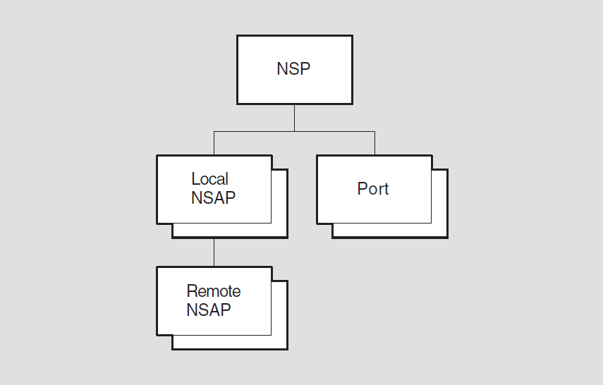
Enables the creation and destruction of transport connections used for sending messages within a network node and between network nodes.
Manages the movement of expedited and normal data from transmit buffers to receive buffers, using flow control mechanisms.
Breaks up normal data messages into segments that can be transmitted individually, and reassembles these segments into correct order after they have been received.
Guarantees the delivery of data and control messages to a specified destination using an error correction mechanism.
18.1. nsp
The nsp entity is the top-level entity in the hierarchy of entities
belonging to the NSP module.
Syntax
create [node node-id] nsp
delete [node node-id] nsp
disable [node node-id] nsp
enable [node node-id] nsp
set [node node-id] nsp {congestion avoidance
boolean (UNIX) | delay factor integer
| delay weight integer | flow control policy | keepalive time
seconds | maximum remote nsaps integer
| maximum receive buffers integer (OpenVMS) | maximum transport
connections integer | retransmit threshold
integer}
show [node node-id] nsp [all [attributes] | all
characteristics | all status]
18.1.1. Characteristic Attributes
|
Default: 3 |
Value for UNIX: 3 |
|
Default: 3 |
Value for OpenVMS: 0–65 |
Maximum amount of time (in seconds) that an acknowledgment is to be withheld. You cannot modify this characteristic.
|
Default: True |
Value: True or false |
Enables the use of the automatic congestion avoidance mechanism. This mechanism reduces the transport window size in response to an indication from the Network layer.
|
Default: 2 |
Value: 2–15 |
Factor by which to multiply the current value of the roundtrip delay
estimate status attribute in order to set a value for the retransmission
timer.
Note, the roundtrip delay estimate is an attribute of the
nsp port entity.
|
Default: 3 |
Value: 0–255 |
Relative weighting to apply to the current estimate and to a new sample when estimating round-trip delay.
|
Default: current version number |
Version number of the NA NSP architecture specification to which the implementation conforms. You cannot modify this characteristic.
|
Default: Segment flow control |
Value: Segment flow control, no flow control |
Determines NSP flow control policy used. This attribute may not be changed
when NSP state is on.
Flow control is the mechanism that determines when to send a data or expedited messages. Flow control is performed separately for normal and expedited data. During transport connection formation, each end of the connection determines the kind of flow control policy it expects when acting as a data receiver. It is not required that both ends operate with the same flow control policy.
|
Default for UNIX: 30 |
Value: 1–65535 |
|
Default for OpenVMS: 60 |
Value: 1–65535 |
Time (in seconds) that NSP waits for data to be transmitted or received before testing a transport connection. When this timer expires, NSP sends a data request PDU to the remote NSP. This PDU does not change the flow control parameters, but does require acknowledgment. For UNIX, you can modify this characteristic to a lower value only when the entity is disabled.
|
Default: 2000 |
Value: 1–65535 |
Maximum number of receive buffers that can store received transport PDUs. You may not decrease the value while NSP is enabled.
|
Default for UNIX: 160 |
Value: 1–65535 |
|
Default for OpenVMS: 201 |
Value: 1–65535 |
Maximum number of remote Network Services Access Points (NSAPs) that can exist
concurrently. Must be greater than the current value of maximum transport
connections. You can modify this characteristic to a lower value only
when the entity is disabled. For UNIX, this characteristic can be increased when
enabled.
|
Default for UNIX: 128 |
Value: 0–1023 |
|
Default for OpenVMS: 200 |
Value: 0–65535 |
Maximum number of active transport connections allowed at one time. Must not be less than the current value of maximum remote NSAPs. You may not decrease the value while NSP is enabled.
|
Default for UNIX: 32 |
Value: 1–65535 |
|
Default for OpenVMS: 8 |
Value: 1–2047 |
Maximum credit window that can be granted on a transport connection. This is
used for control of the number of data segments (PDUs) allowed to be transmitted
over a particular transport connection before at least one acknowledgment must be
returned from the destination system. If the number of PDUs already transmitted
equals the maximum window and no corresponding acknowledgments have
been received, transport stops sending PDUs over the transport connection and waits
for an acknowledgment message. You cannot modify this characteristic.
|
Default: 32 |
Value: 0–255 |
NSAP selector used by the nsp entity when opening a port to a
network service. You cannot modify this characteristic.
|
Default: 12 |
Value: 1–65535 |
Maximum number of times a source nsp entity is to restart an
expired retransmission timer before the remote node is to be considered
unreachable. When the threshold is reached, NSP sets the confidence variable to
false.
18.1.2. Status Attributes
currently active connections
Number of active transport connections.
state
nsp entity.|
off |
The |
|
on |
The |
uid
Entity's unique identifier, which is generated when the entity is created.
18.1.3. Exception Messages
For create:
already exists
An nsp module already exists.
For delete:
wrong state
You cannot delete the entity while it is enabled.
For enable:
routing unavailable
You cannot enable the entity until routing has been created.
18.2. nsp local nsap
An nsp local nsap entity is created automatically for each NSAP address
used by the nsp entity. Local NSAPs are used primarily to group together
remote NSAPs (see the nsp local nsap remote nsap entity). The
nsap-address refers to the local NSAP managed by this
command.
Syntax
show [node node-id] nsp local nsap
nsap-address [all [attributes] | all counters | all
identifiers | all status]
18.2.1. Counter Attributes
creation time
Time this entity was created.
deleted remote nsaps
Number of times a remote NSAP has been deleted in order to reclaim resources.
18.2.2. Identifier Attributes
name
Simple name assigned to the local NSAP when it is created.
nsap address
Address assigned to the local NSAP when it was created.
18.2.3. Status Attributes
uid
Entity's unique identifier, which is generated when the entity is created.
18.2.4. Event Messages
deleted remote nsap
Generated each time a remote NSAP is deleted.
Arguments:
The event message lists all attributes for the deleted entity.
18.3. nsp local nsap remote nsap
An nsp local nsap remote nsap entity maintains the transport counters and
generates events resulting from interactions between its superior local NSAP and a
remote transport service. The local nsap nsap-address refers to the
local NSAP associated with the specified remote NSAP. The remote nsap
nsap-address refers to the remote NSAP managed by this command.
Syntax
show [node node-id] nsp local nsap
nsap-address remote nsap nsap-address
[all [attributes] | all counters | all identifiers | all status]
18.3.1. Counter Attributes
connects received
Total number of connect initiated (CI) messages, regardless of their disposition, that the local service provider has received from the remote service provider.
connects sent
Total number of connect initiated (CI) messages sent by the local service provider to the remote service provider, including retransmissions.
creation time
Time this entity was created.
duplicate pdus received
Total number of all types of detected duplicate transport PDUs received from the remote service provider.
pdus received
Total number of all types of transport PDUs received from the remote service provider (excluding detected duplicates).
pdus sent
Total number of all types of transport PDUs sent to the remote service provider (excluding retransmissions).
rejects received
Number of detected reject received events.
rejects sent
Number of detected reject sent events.
remote protocol errors
Number of detected remote protocol error events.
retransmitted pdus
Total number of all types of retransmitted transport PDUs sent to the remote service provider.
total octets received
Total number of octets of all types of transport PDUs received from the remote service provider, regardless of their disposition. This count includes detected duplicates.
total octets sent
Total number of octets of all types of transport PDUs sent to the remote service provider, including retransmissions.
user octets received
Total number of user data octets received from the remote service provider, including normal, expedited, connect, accept, and disconnect data. This count does not include duplicates such as data retransmitted by the remote service provider.
user octets sent
Total number of user data octets sent to the remote service provider, including normal, expedited, connect, accept, and disconnect data. This count does not include data retransmitted by the local service provider.
user pdus discarded
Number of PDUs received from the remote service provider that were discarded because of insufficient buffer space.
user pdus received
Total number of transport PDUs containing user data received from the remote service provider, including normal, expedited, connect, accept, and disconnect data. This count does not include duplicates such as transport PDUs retransmitted by the remote service provider.
user pdus sent
Total number of transport PDUs containing user data sent to the remote service provider, including normal, expedited, connect, accept, and disconnect data. This count does not include retransmitted transport PDUs.
18.3.2. Identifier Attributes
name
Simple name assigned to the remote NSAP when it is created.
nsap address
Address assigned to the remote NSAP when it was created.
18.3.3. Status Attributes
uid
Entity's unique identifier, which is generated when the entity is created.
18.3.4. Event Messages
reject received
Generated when a connection attempt initiated by the local service provider is
rejected by the remote service provider. This does not include rejects initiated by
the remote user of the transport service. The rejects received counter
is incremented.
|
additional information |
If applicable, contains additional information from the variable part of the PDU. | |
|
reason |
Reason why the event was generated. | |
|
no resources |
Transport rejected the connection attempt because of insufficient resources. | |
reject sent
Generated when a connection attempt initiated by the remote service provider is
rejected by the local service provider. This does not include rejects requested by
the local user of the transport service. The rejects sent counter is
incremented.
|
additional information |
If applicable, contains additional information from the variable part of the PDU. | |
|
reason |
Reason why the event was generated. | |
|
no resources |
Transport rejected the connection attempt because of insufficient resources. | |
remote protocol error
Generated when a transport PDU received from the remote service provider violates
the NSP protocol. The remote protocol errors counter is
incremented.
|
erroneous transport data unit |
Includes some, none, or all of the PDUs causing the event. | |
|
reason |
Reason why the event was generated. | |
|
invalid flow control |
A PDU was discarded because it contained flow control
information that, when used to compute the request count,
would produce a result that exceeds the limits. The entire
PDU is provided in the | |
|
invalid message format |
A PDU was discarded because reserved bits or values were
used in the PDU. The beginning of the PDU is provided in the
| |
18.4. nsp port
An nsp port entity represents one end of a transport connection and
maintains status information about that connection. A port is visible to the network
only when it is assigned to a transport connection. The port-name
refers to the port managed by this command.
Syntax
show [node node-id] nsp port
port-name [all [attributes] | all counters | all
identifiers | all status ]
18.4.1. Counter Attributes
creation time
Time the port was assigned.
duplicate pdus received
Number of all types of detected duplicate transport PDUs received from the remote service provider.
pdus received
Number of all types of transport PDUs received from the remote service provider (excluding detected duplicates).
pdus sent
Number of all types of transport PDUs sent to the remote service provider (excluding retransmissions).
retransmitted pdus
Number of all types of retransmitted transport PDUs sent to the remote service provider.
total octets received
Number of octets of all types of transport PDUs received from the remote service provider, regardless of their disposition. This count includes detected duplicates.
total octets sent
Number of octets of all types of transport PDUs sent to the remote service provider, including retransmissions.
user octets received
Number of user data octets received from the remote service provider, including normal, expedited, connect, accept, and disconnect data. This count does not include duplicates such as data retransmitted by the remote service provider.
user octets sent
Number of user data octets sent to the remote service provider, including normal, expedited, connect, accept, and disconnect data. This count does not include data retransmitted by the local service provider.
user pdus received
Number of transport PDUs containing user data received from the remote service provider, including normal, expedited, connect, accept, and disconnect data. This count does not include duplicates such as transport PDUs retransmitted by the remote service provider.
user pdus sent
Number of transport PDUs containing user data sent to the remote service provider, including normal, expedited, connect, accept, and disconnect data. This count does not include retransmitted transport PDUs.
18.4.2. Identifier Attributes
name
Simple name assigned to the port when it is created.
18.4.3. Status Attributes
|
Default: None |
Value: Local-entity-name |
Name designated by the port user when the port was opened.
|
Default: None |
Value: 0–255 |
Network priority encoded in NPDU header for all received packets.
|
Default: None |
Value: Segment flow control, no flow control |
Local flow control policy selected when acting as a data receiver.
|
Default: None |
Value: NSAP address |
Local NSAP address being used for the transport connection.
|
Default: None |
Value: 0–65535 |
Unique reference number assigned to the transport connection by the local transport service provider.
|
Default: None |
Value: Local-entity-name |
Name of the port being used.
|
Default: None |
Value: 0–255 |
Remote priority encoded in NPDU header for all transmitted packets.
|
Default: None |
Value: Segment flow control, no flow control |
Remote flow control policy selected when remote end is acting as a data receiver.
|
Default: None |
Value: NSAP address |
Remote NSAP address being used for the transport connection.
|
Default: None |
Value: 0–65535 |
Reference number assigned to the transport connection by the remote transport service provider.
|
Default: None |
Value: 0–65535 |
Amount of time, in milliseconds, of the round-trip delay on the transport connection.
|
Default: None |
Value: uid |
Entity's unique identifier, which is generated when the entity is created.
Chapter 19. OSAK Module
Note
For UNIX, you cannot modify any counter, identifier, or status attributes within the OSAK module.
Figure 19.1, ''Hierarchy of OSAK Module Entities'' shows the hierarchical relationship of the entities that make up the OSAK module.
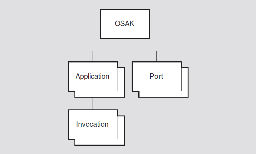
19.1. osak
The osak entity is the top-level entity in the OSAK module hierarchy of
entities. The osak entity is concerned with address management for
applications that use the OSAK software for their communications requirements.
Syntax
create [node node-id] osak
disable [node node-id] osak
delete [node node-id] osak
enable [node node-id] osak
set [node node-id] osak disconnect timer
integer (OpenVMS)
show [node node-id] osak [all [attributes] | all
characteristics | all counters | all status]
19.1.1. Commands
delete
Deletes an osak entity and reclaims the resources associated with
it. The entity must be in the NotAvailable state before it can be
deleted.
disable
Puts the osak entity in the NotAvailable state in
which it does not accept any more inbound or outbound association requests, and
existing associations are aborted. If the osak entity is already in
the NotAvailable state, the command has no effect.
enable
Starts operation of the services provided by the osak entity. If
the osak entity is already operational, the command has no effect.
On completion of the command, the state of the entity is operational. You should
not issue this command when the osak entity is in the shutting
state.
19.1.2. Characteristic Attributes
|
Default: 30 seconds |
Value: Time in seconds |
Length of time that the OSAK software waits when it expects the remote peer to
disconnect a transport connection. If the timer expires and the remote peer has not
disconnected the connection, the OSAK software disconnects the connection. You can
modify this attribute using the set command.
|
Default: {ACSE = {1}, presentation ={1}, session = {1,2} } |
Value: Set of protocol versions |
Specifies the ACSE, presentation and session protocol versions being used by the
osak entity.
- {ACSE = {1}, presentation = {1}, session = {1,2} }
- {ACSE = {1}, presentation = {1}, session = {1} }
- {ACSE = {1}, presentation = {1}, session = {2} }
You cannot modify this attribute.
19.1.3. Counter Attributes
aborts received
Number of aborts received by this osak entity since its
creation.
aborts sent
Number of aborts sent by this osak entity since its creation.
connects accepted
Number of connection requests accepted by this osak entity since its
creation.
connects initiated
Number of connection requests initiated by this osak entity since its
creation.
connects rejected
Number of connection requests rejected by this osak entity since its
creation.
creation time
Time at which the osak entity was created, in binary absolute time
format.
releases received
Number of release requests received by this osak entity since its
creation.
releases sent
Number of release requests sent by this osak entity since its
creation.
unknown ae-titles
Number of connection requests received that contain an unknown application-entity
title. This counter is incremented each time an unknown ae-title event
occurs.
unknown invocations
Number of connection requests received that contain an unknown invocation
identifier. This counter is incremented each time an unknown
invocations event occurs.
unknown paddresses
Number of connection requests received that contain an unknown presentation
address. This counter is incremented each time an unknown paddress
event occurs.
19.1.4. Status Attributes
state
osak entity. The value is one of the following:|
noinbound |
|
|
notavailable |
|
|
operational |
|
|
shutting |
|
uid
Entity's unique identifier, which is generated when the entity is created.
19.1.5. Event Messages
unknown ae title
Generated when an inbound association request specifies an unknown
application-entity title. Increments the unknown ae-titles
counter.
|
ae title |
The unknown application entity title. |
unknown invocation
Generated when an inbound association request specifies an unknown
application-process invocation identifier or an unknown application-entity
invocation identifier. Increments the unknown invocations
counter.
|
invocation |
The unknown application-process or application-entity invocation identifier. |
unknown paddress
Generated when an inbound association request specifies an unknown presentation
address. Increments the unknown paddresses counter.
|
paddress |
The unknown presentation address. |
19.1.6. Exception Messages
For create:
entity exists
An osak entity already exists.
For delete and enable:
sub entity exists
Cannot delete while subentities exist.
wrong state
The osak entity is in the wrong state for the command you have tried
to use on it. The text accompanying the exception message specifies which command
has failed. For UNIX, the only possible wrong state is
NotAvailable.
19.2. osak application
An osak application entity represents an OSI application and is created
each time an OSI application that is running over the OSAK software opens an initiator
or a responder. The entity also records information about the name and address of an
application.
For OpenVMS, an osak application entity has zero or more
application-entity invocations, each represented by an osak application
invocation entity (see Section 19.3, ''osak application invocation''). In addition to
recording information about the name and address of an application, it also records
information that controls the way in which inbound association requests for that
application are handled by the OSAK software.
For OpenVMS, you should create an osak application and an osak
application invocation for each passive application that you want to run,
identifying the application by its presentation address. Also, an osak
application entity is created automatically for an active application and
deleted at the end of the connection.
Syntax
create [node node-id] osak application"
presentation address" (OpenVMS)
delete [node node-id] osak application"
presentation address" (OpenVMS)
set [node node-id] osak application "presentation address" (OpenVMS) { ae
titles set of record|startup policy policy| template simple-name})
show [node node-id] osak application"
presentation address" [all [attributes] | all
characteristics | all counters | all identifiers | all status]
19.2.1. Characteristic Attributes
|
Default: None |
Value: See description |
The application-entity titles that map to this application's presentation address
in Form 2 (object identifier) format. If the application entity titles are in Form 1
(directory name) format, they are not displayed. A null object identifier is
displayed instead (ObjectIdentifier = "").
|
Default: Existing |
Value: New or existing |
Defines the startup policy for invocations of this application. For UNIX, the value is always existing. This indicates that a listener process must exist for an inbound connection to be processed. No new process is started up when an inbound connection arrives.
|
new |
Indicates that, when no process is available to handle an inbound connection, a new process is started up. |
|
existing |
Indicates that one process handles all inbound connections. No new process is started up if the existing process is busy when an inbound connection arrives. |
For OpenVMS, you can modify this attribute using the set
command.
|
Default: Default OSI transport template |
Value: See description |
The transport template used for inbound association requests. For OpenVMS, you can
modify this attribute using the set command.
19.2.2. Counter Attributes
creation time
The time at which the application is created.
invalid mode failure
The number of times an inbound connection request is rejected because of a
mismatch of modes. This counter is incremented each time an invalid
mode event occurs.
The possible modes are normal and X.410-1984. An
application is running in normal mode if it uses the upper layers of
the OSI stack. An application is running in X.410-1984 mode if it does
not use the upper layers of the OSI stack.
resource failures
The number of times an inbound connection request was rejected due to insufficient system resources.
total invocations
The number of times this application has been invoked.
19.2.3. Identifier Attributes
paddress
The presentation address of this OSAK application.
19.2.4. Status Attributes
active invocations
The number of existing invocations of this application.
uid
Entity's unique identifier, which is generated when the entity is created.
19.2.5. Event Messages
invalid mode
Generated when an inbound connection request is rejected due to a mismatch of
modes. Increments the invalid mode failures counter.
19.2.6. Exception Messages
For delete:
wrong state
Disable the osak application before trying to delete it.
19.3. osak application invocation
An osak application invocation entity represents one invocation of an
application.
For UNIX, an osak application invocation entity is created each time an
OSI application that is running over the OSAK software opens an initiator or a
responder. You can use only the show command with the osak
application invocation entity on UNIX systems, and you cannot modify any of
the attributes.
osak application invocation entity can be created in two ways:Automatically, each time an OSI application that is running over the OSAK software opens an initiator or a responder (as for UNIX).
Manually, when you use the
createcommand.
The create command creates a passive application,
which becomes active only when your OpenVMS system receives an OSI call for that
particular application invocation.
Syntax
create [node node-id] osak application
"presentation address" invocation "invocation
identifier" (OpenVMS)
delete [node node-id] osak application
"presentation address" invocation "invocation
identifier" (OpenVMS)
set [node node-id] osak application "presentation address" invocation
"invocation identifier" (OpenVMS) startup information latin1string
)
show [node node-id] osak application
"presentation address" invocation "invocation
identifier" [all [attributes] | all characteristics (OpenVMS) | all
counters | all identifiers | all status ]
19.3.1. Characteristic Attributes (OpenVMS)
startup information
Invocation startup information that is system-specific. This information is needed only for passive applications.
set
command. You can specify the items in any order. Note that when you modify this
attribute, any item for which you do not specify a value is set to its default, not
to its previous value. For example, you could set up non-default values for all four
items in this attribute using the following NCL
command:set [node "node-id"] osak application "presentation address" invocation "invocation identifier" startup information "password= password, username= username, file= file name, sversion= sversion"
set [node "node-id"] osak application "presentation address" invocation "invocation identifier" startup information "password= new password, username= username file= file name, sversion= sversion"
| Item | Value | Description |
|---|---|---|
| Mandatory | ||
| user | name | The user name of the process that will respond to connect requests received by this application. |
| file | pathname | The name of the file to run to start up the named application. The file is a command file or an executable image that is run each time a passive process starts. We recommend that you use a command file for this purpose. |
| Optional | ||
| account | name | The account that is to start the process. |
| max resp | integer | The highest permissible number of responders, for an
application with the new setting for startup
policy. |
| password | password | The user's password. |
| sversion | {1}, {2}, or {1,2} | The session version. |
19.3.2. Counter Attributes
creation time
Time at which this invocation was registered with OSAK.
total associations
Number of associations set up to this invocation.
19.3.3. Identifier Attributes
ids
The identifier of the invocation. For OpenVMS, you cannot modify this attribute.
19.3.4. Status Attributes
port list
A list of the OSAK ports referenced by this application invocation
entity.
state
The state of the application invocation entity. For UNIX, the value
is always active.
|
active |
An active application invocation is using an active process. |
|
passive |
A passive application invocation is waiting for inbound connection requests on its presentation address. |
uid
Entity's unique identifier, which is generated when the entity is created.
19.3.5. Exception Messages
For delete:
wrong state
You cannot delete an osak application invocation entity when it still
has open ports.
19.4. osak port
Each osak port entity describes one association opened in an OSI
application. A port is opened each time an application opens an initiator or a
responder.
You can use only the show command with the osak port entity.
You cannot modify any of the attributes.
Syntax
show [node node-id] osak port
"port_identifier" [all [attributes] | all characteristics |
all counters | all identifiers | all status]
19.4.1. Characteristic Attributes
|
Default: Default OSI transport template |
Value: See description |
The name of the transport template used when establishing an association.
19.4.2. Counter Attributes
creation time
Time at which the association was set up, in binary absolute time format.
19.4.3. Identifier Attributes
name
Simple name assigned to the port when it is created.
19.4.4. Status Attributes
application context
Name of the application context for this association.
connection state
|
awaiting_associate_confirm |
A |
|
awaiting_associate_response |
A |
|
awaiting_inbound_connection |
A |
|
awaiting_redirection |
A |
|
connected |
A |
|
not_connected |
A |
|
disconnected |
A |
|
redirected |
A |
direction
Specifies whether an association is inbound (the port was opened by a responder) or outbound (the port was opened by an initiator).
invocation
UID of the invocation that opened this port.
local ae title
Local application-entity title in Form 2 (object identifier) format. If the local
ae title is in Form 1 (directory name) format, it is not displayed. A null object
identifier is displayed instead (ObjectIdentifier = "").
local ae invocation id
Local application-entity invocation identifier.
local ap invocation id
Local application-process invocation identifier.
local paddress
Local presentation address.
owner id
Process id of the OSAK application.
remote ae title
Remote application-entity title in Form 2 (object identifier) format. If the
remote ae title is in Form 1 (directory name) format, it is not displayed. A null
object identifier is displayed instead (ObjectIdentifier = "").
remote ae invocation id
Remote application-entity invocation identifier.
remote ap invocation id
Remote application-process invocation identifier.
remote paddress
Remote presentation address.
uid
Entity's unique identifier, which is generated when the entity is created.
Chapter 20. OSI Transport Module
This chapter describes all of the commands you can use to manage the entities that constitute the OSI transport module. This module implements the OSI Connection-Oriented Transport Protocol specification (International Standard ISO 8073); and for UNIX, the Connectionless-Mode Transport Service Protocol (International Standard ISO 8602). These protocols implement the OSI Reference Model Transport layer 4. For OpenVMS, this module also implements RFC 1006 and RFC 1859. These protocols, as well as the NSP protocol, implement the transport protocols in the Network Architecture (NA).
Figure 20.1, ''Hierarchy of OSI Transport Module Entities'' shows the hierarchical relationship of the entities that constitute the OSI transport module.
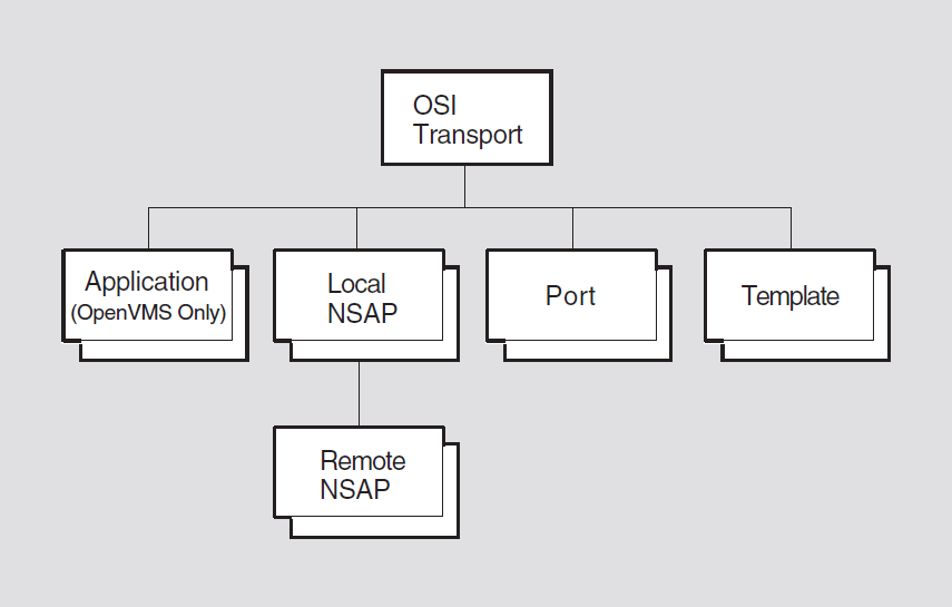
The following sections further describe the OSI transport protocol and OSI transport service. For more information, refer to the VSI DECnet-Plus for OpenVMS Introduction and User's Guide.
The OSI transport protocol permits communication between DECnet-Plus systems and other vendors' systems that also implement the OSI transport protocol.
The OSI transport protocol conforms to the ISO 8072 Service Definition and the ISO 8073 Protocol Standard. They define OSI transport protocol classes 0, 2 and 4 (TP 0, TP 2, and TP 4).
Connection-Oriented Network Service (CONS)
Connectionless-Mode Network Service (CLNS)
The OSI transport conforms to the RFC 1006 Standard and to the RFC 1859. They define how to implement ISO 8073 Transport Class 0 on top of TCP (RFC1006) and how to implement ISO 8073 Transport Class 2 Non-Use of Explicit Flow Control on top of TCP (RFC 1859). RFC 1006 and RFC 1859 use a CONS connection over TCP to provide network service.
|
Protocol Class |
Functions |
Network Service |
|---|---|---|
|
TP 0 |
Provides a basic transport service. |
CONS and RFC 1006 |
|
TP 2 |
Provides all functions of TP 0. Provides multiplexing of more than one transport connection over a network connection or TCP connection. Provides flow control over CONS. |
CONS and RFC 1859 |
|
TP 4 |
Provides all functions of TP 2. Provides error detection and recovery. |
CONS and CLNS |
TP 0 relies on the upper layers to do its error correction. This class is disconnected if the underlying Network layer is disconnected.
TP 2 and 4 use disconnect requests.
TP 4 reassigns the OSI transport connection to another Network layer connection if the existing one fails.
When a transport user sets up a transport connection, a preferred protocol class for the connection is specified in the connection request. The responding transport user must either agree to this protocol class, or suggest an alternative protocol class that is acceptable to the initiating user. If no such agreement is possible, the transport connection cannot be set up.
Setting up the connection — an OSI transport user (the initiating user) on one end system (the initiating host) sends a connection request TPDU to another OSI transport user (the responding user) on a second end system (the responding host). When a successful connection is made, data transfer can take place in either direction.
- Using the connection to transfer data — OSI transport connections support two kinds of data transfer:
Normal data transfer — for usual message exchange
Expedited data transfer — bypasses any blockage due to the flow control applied to normal data; only for sending small amounts of data; has its own type of TPDU and transmission rules.
Releasing the connection — either transport user can release the OSI transport connection by sending a disconnect TPDU.
Between two systems on the same ISO 8802-3 LAN.
Between two systems that are connected, either directly or via an X.25 connection.
Between two systems that are connected directly by an X.25 point-to-point link.
Between two systems on different subnetworks, where the linking subnetworks might mix technologies.
Between two systems that are connected via TCP/IP.
The Routing module provides a Connectionless-mode Network Service (CLNS); for more information, refer to the Routing chapter.
The X.25 Access module, if configured into the system, provides a reliable Connection-Oriented Network Service (CONS); for more information, refer to the X.25 Access chapter.
For RFC 1006 and RFC 1859 on OpenVMS, this feature requires an installed TCP/IP product that supports the PATHWORKS Internet Protocol (PWIP) interface.
For UNIX, any attributes that are specific to CONS will only be accessible if X.25/CONS has been installed and configured into the system. See Section 20.1.4, ''X.25/CONS Configuration '' for more information. The Connectionless Transport Service, known as CLTS or CLTP, allows for the transfer of data between correspondent transport service users on a connectionless basis. The service provides for single-access data transfer for corresponding transport service users, without the overhead of establishing a connection. This protocol benefits those applications that require a one-time, one-way transfer of data toward one transport service user. CLTS runs over CLNS.
|
Port Attributes |
Class 4 (COTS) over CLNS |
Class 4 (COTS) over CONS |
Class 2 (COTS) over CONS |
Class 0 (COTS) over CONS |
CLTS over CLNS ? |
RFC 1006 ? |
RFC 1859 ? |
|---|---|---|---|---|---|---|---|
|
acknowledgment delay time |
* |
* | |||||
|
checksums |
* |
* | |||||
|
client |
* |
* |
* |
* |
* |
* | |
|
CONS template |
* |
* |
* | ||||
|
cr timeout |
* |
* |
* |
* | |||
|
direction |
* |
* |
* |
* |
* |
* | |
|
er timeout |
* |
* |
* |
* | |||
|
expedited data |
* |
* |
* |
* | |||
|
extended format |
* |
* |
* | ||||
|
inactivity time |
* |
* | |||||
|
initial retransmit time |
* |
* | |||||
|
keepalive time |
* |
* | |||||
|
local DTE address |
* |
* |
* | ||||
|
local nsap |
* |
* |
* |
* |
* | ||
|
local reference |
* |
* |
* |
* |
* |
* | |
|
local RFC 1006 IP address |
* |
* | |||||
|
local RFC 1006 port number |
* |
* | |||||
|
local transport selector |
* |
* |
* |
* |
* |
* |
* |
|
maximum nsdu size |
* |
* |
* |
* |
* | ||
|
name |
* |
* |
* |
* |
* |
* |
* |
|
negotiable classes ? |
* |
* |
* |
* | |||
|
negotiated tpdu size |
* |
* |
* |
* |
* |
* | |
|
network port |
* |
* |
* |
* | |||
|
network service |
* |
* |
* |
* |
* |
* |
* |
|
protocol class |
* |
* |
* |
* |
* |
* | |
|
remote DTE address |
* |
* |
* | ||||
|
remote identifier |
* |
* |
* |
* | |||
|
remote nsap |
* |
* |
* |
* | |||
|
remote reference |
* |
* |
* |
* |
* |
* | |
|
remote RFC 1006 IP address |
* |
* | |||||
|
remote RFC 1006 port number |
* |
* | |||||
|
remote transport selector |
* |
* |
* |
* |
* |
* | |
|
request acknowledgment |
* |
* | |||||
|
retransmit threshold |
* |
* | |||||
|
roundtrip delay estimate |
* |
* | |||||
|
type |
* |
* |
* |
* |
* |
* |
* |
|
uid |
* |
* |
* |
* |
* |
* |
* |
|
use CLNS error reports |
* | ||||||
|
Template Attributes | |||||||
|
acknowledgment delay time |
* |
* | |||||
|
checksums |
* |
* | |||||
|
classes |
* |
* |
* |
* | |||
|
CONS template |
* |
* |
* | ||||
|
cr timeout |
* |
* |
* |
* | |||
|
er timeout |
* |
* |
* |
* | |||
|
expedited data |
* |
* |
* |
* |
* | ||
|
inbound |
* |
* |
* |
* |
* |
* |
* |
|
initial retransmit time |
* |
* |
* |
* | |||
|
keepalive time |
* |
* | |||||
|
local nsap |
* |
* |
* |
* |
* | ||
|
maximum nsdu size |
* |
* |
* |
* |
* | ||
|
name |
* |
* |
* |
* |
* |
* |
* |
|
network service |
* |
* |
* |
* |
* |
* |
* |
|
retransmit threshold |
* |
* | |||||
|
RFC 1006 port number |
* |
* | |||||
|
security |
* |
* |
* |
* | |||
|
use CLNS error reports |
* |
20.1. osi transport
The osi transport entity is the top-level entity in the hierarchy of
entities belonging to the OSI transport module.
Syntax
add [node node-id] osi transport {nsap addresses [set] |
cons filters [set] | RFC1006 listener ports [set] (OpenVMS)}
create [node node-id] osi transport
delete [node node-id] osi transport
disable [node node-id] osi transport
enable [node node-id] osi transport
enable [node node-id] osi transport [cons filters [set]
(UNIX)
remove [node node-id] osi transport {cons nsap addresses
[set] | cons filters [set] | RFC1006 listener ports [set]
(OpenVMS)}
set [node node-id] osi transport {cltp nsap selector
integer (UNIX) | congestion avoidance
boolean | CONS filters [set] | CONS nsap address [set] |
delay factor integer | delay weight
integer | disconnect holdback seconds
| maximum cltp ports integer (UNIX) | maximum listeners
integer (UNIX) | maximum multiplexing
integer | maximum network connections
integer | maximum receive buffers
integer (OpenVMS) | maximum remote nsaps
integer | maximum transport connections
integer | maximum window integer |
nsap selector integer | RFC1006 listener ports [set]
(OpenVMS)}
show [node node-id] osi transport [all [attributes] |
all characteristics | all status ]
20.1.1. Characteristic Attributes
|
Default: Class {4} |
Value: Bit-set |
Set of protocol classes supported on the Connectionless Network Service (CLNS). You cannot modify this characteristic.
|
Default: 0 |
Value: 0–255 (except 32) |
The NSAP selector to use for CLTS when running over CLNS. If the value is 0 or
1, a single NSAP is shared between the Connection-Oriented Transport Service (COTS),
and the connectionless transport protocol according to the osi
transport attribute nsap selector. If both nsap
selectors are 0 or 1, then COTS and CLTS over CLNS are disabled.
This attribute cannot be set either to 32, which is the value of the NSP NSAP
selector, or to the current setting of the
osi transportattribute,
nsap selector, if the attribute has a value
other than 0 or 1.
This attribute cannot be modified when transport is enabled.
|
Default: True |
Value: True or false |
Enables the use of the automatic congestion avoidance mechanism to reduce the transport window size in response to an indication from the Network layer when operating on the Connectionless Network Service (CLNS).
|
Default: Classes {0, 2, 4} |
Value: Bit-set |
Set of protocol classes supported on the Connection-Oriented Network Service (CONS). You cannot modify this characteristic. See Section 20.1.4, ''X.25/CONS Configuration '' for more information.
|
Default: { } |
Value: Set of simple names |
The names of X.25 Access module filters used to determine which inbound
network connection requests should be directed to the transport entity. To modify
this characteristic with the remove and set commands, you
must first disable the entity. You can modify this characteristic with the
add command while the osi transport entity is enabled.
For each cons filter, there must be a corresponding x25
access template with the same name. One or more of these filters must be
specified in order to run COTS over CONS. The X.25 access filter osi
transport is typically used. See Section 20.1.4, ''X.25/CONS Configuration '' for more
information.
|
Default: { } |
Value: Set of NSAP addresses |
The set of valid NSAP addresses for use with CONS. One or more NSAPs must be specified to run COTS over CONS. See the DECnet-Plus Planning Guide for more information.
|
Default: 4 |
Value: 2–15 |
Factor by which to multiply the current value of the round trip delay
estimate status attribute in order to set a value for the retransmission
timer. This attribute works with protocol class 4 only.
|
Default: 5 |
Value: 0–255 |
Relative weighting to apply to the current estimate and to a new sample when estimating round-trip delay. This attribute works with protocol class 4 only.
|
Default: 0 |
Value for UNIX: 0-- (2 31 − 1) |
|
Default: 0 |
Value for OpenVMS: 0-- (232 − 1) |
When operating over the Connection-Oriented Network Service (CONS), the length of the time to maintain a network connection for possible reuse after all transport connections multiplexed upon it have been disconnected. Specified in seconds. This characteristic may not be changed while the transport entity is enabled. See Section 20.1.4, ''X.25/CONS Configuration '' for more information.
|
Default: None |
Value: 1 |
Version number of ISO 8073 to which the implementation conforms. You cannot modify this characteristic.
|
Default: 128 |
Value: 0-- (232 −1) |
Maximum number of CLTS ports at one time. This characteristic can be increased only while transport is enabled. You can modify this characteristic to a lower value only when the entity is disabled.
|
Default: 32 |
Value: 1–65535 |
Maximum number of listeners at one time. This characteristic can be increased only while transport is enabled. You can modify this characteristic to a lower value only when the entity is disabled.
|
Default for UNIX: 1023 |
Value: 1–1023 |
|
Default for OpenVMS: (2 32 − 1 ) |
Value: 1-- (232 − 1) |
When operating over the Connection-Oriented Network Service (CONS), the maximum number of transport connections that can be multiplexed on any single network connection. This characteristic can be increased only when the transport entity is enabled. You can modify this characteristic to a lower value only when the entity is disabled. See Section 20.1.4, ''X.25/CONS Configuration '' for more information.
|
Default for UNIX: 1023 |
Value: 0–1023 |
|
Default for OpenVMS: (232 − 1) |
Value: 0-- (232 − 1) |
When operating over the Connection-Oriented Network Service (CONS), the maximum number of network connections that can be in use concurrently by NA OSI transport. This characteristic can be increased only when the transport entity is enabled. See Section 20.1.4, ''X.25/CONS Configuration '' for more information.
|
Default: 2000 |
Value: 1-- (232 − 1) |
Maximum number of receive buffers that can store received DT transport PDUs. You can modify this characteristic only when the entity is disabled. Also, you can only increase the characteristic value.
|
Default for UNIX: 160 |
Value: 1-65536 |
|
Default for OpenVMS: 201 |
Value: 0-- (232 − 1) |
Maximum number of remote NSAPs that can exist concurrently. This value must be
greater than the current value of maximum transport connections. You
can modify this characteristic to a lower value only when the entity is disabled.
This characteristic can be increased when enabled.
|
Default for UNIX: 128 |
Value: 0–1023 |
|
Default for OpenVMS: 200 |
Value: 0-- (232 − 1) |
Maximum number of active transport connections allowed at one time. Must be
less than the current value of maximum remote nsaps. You can modify
this characteristic to a lower value only when the entity is disabled.
|
Default for UNIX: 20 |
Value: 1–65535 |
|
Default for OpenVMS: 8 |
Value: 1–65535 |
Maximum credit window that can be granted on a transport connection. This is
used for control of the number of data segments (PDUs) allowed to be transmitted
over a particular transport connection before at least one acknowledgment must be
returned from the destination system. If the number of PDUs already transmitted
equals the maximum window and no corresponding acknowledgments have
been received, transport stops sending PDUs over the transport connection and waits
for an acknowledgment message. You can modify this characteristic to a lower value
only when the entity is disabled.
|
Default: 33 |
Value: 0–255 (except 32) |
The NSAP selector to use for the Connection-Oriented Transport Service (COTS)
when running over CLNS. If 0 or 1, COTS over CLNS is not enabled. This attribute
cannot be set to 32, which is the value of the NSP NSAP selector. Or, on UNIX,
to the current setting of the osi transport
attribute cltp nsap selector if it is other
than 0 or 1.
This attribute cannot be modified when transport is enabled.
|
Default: {102, 399} |
Value: Set of TCP/IP port numbers |
The names of the TCP listener ports used to receive inbound RFC 1006 connection requests. Port 102 is applicable for RFC 1006 (OSI over TCP/IP) connections, and port 399 is applicable for RFC 1859 (DECnet over TCP/IP) connections. You can only remove RFC 1006 listener ports when the entity is disabled.
|
Default: None |
Value: False |
Specifies whether the implementation supports the MAP (Manufacturing Automation Protocol) entity. You cannot modify this characteristic.
|
Default: None |
Value: V1.1.0 |
Version number of the NA OSI transport architecture specification to which the implementation conforms. You cannot modify this characteristic.
20.1.2. Status Attributes
currently active cltp ports (UNIX)
Number of active CLTS ports.
currently active connections
Number of active transport connections.
currently active listeners (UNIX)
Number of active listeners. The Session Control listener (local transport selector
'DEC0'H) can exist even when osi transport is disabled. All other
listeners are deactivated when transport is disabled.
state
osi transport entity.|
off |
The |
|
on |
The |
uid
Entity's unique identifier, which is generated when the entity is created.
20.1.3. Exception Messages
For create:
already exists
An osi transport entity already exists.
For delete:
wrong state
Disable the osi transport entity before trying to delete it.
For enable:
CONS filters unavailable
Attempt to enable the OSI transport module failed because the X.25 access filters,
specified by the cons filters attribute, either do not exist or are
already in use.
OSI transport disabled (UNIX)
Cannot enable a set of cons filters unless OSI transport has already
been enabled.
routing unavailable
Attempt to enable the OSI transport module failed because the port to routing (CLNS) could not be opened.
20.1.4. X.25/CONS Configuration
Certain transport attributes apply only when X.25 is installed and configured in the system. These attributes are indicated by references in each attribute description.
osi transport over X.25:Set the
osi transportentity attributecons filters. Verify that an X.25 access filter with the same name exists.Set the
osi transportentity attributecons nsap addresses.Create one or more OSI transport templates for use over CONS.
In the new OSI transport template, set the
inboundcharacteristic to true.In the new OSI transport template, set the
network servicetoconsorany(allowed for incoming connections only).In the new OSI transport template, check the
cons template. Verify that an X.25 access template with the same name exists.To write a program that uses OSI transport over CONS, see the VSI DECnet-Plus Planning Guide.
20.1.5. RFC 1006 and RFC 1859 Configuration (OpenVMS)
Set the OSI transport entity attribute RFC 1006 listener ports to 102 (for RFC 1006) and 399 (for RFC 1859). Verify that the installed TCP/IP provider has TCP port 102 and 399 bound.
Create one or more OSI transport templates for use over RFC 1006.
In the new OSI transport template, set the network service to RFC 1006 and the inbound characteristic to true.
20.2. osi transport application (OpenVMS)
An osi transport application entity stores information about an end user
that is activated for receipt of an incoming connection request when the request
contains that end user's name in its Destination Name field. The
application-name refers to the application managed by this
command.
Syntax
create [node node-id] osi transport application
application-name
delete [node node-id] osi transport application
application-name
set [node node-id] osi transport application
application-name {called tsels TSEL |
file name filespec | username
"username"}
show [node node-id] osi transport application
application-name [all [attributes] | all characteristics |
all counters | all identifiers]
20.2.1. Characteristic Attributes
|
Default: No tsap |
Value: TSEL |
A TSEL is a string of hexadecimal digits, the length of that string should be an even number between 2 and 64, inclusive. This attribute cannot have more than one member.
Transport service access point (TSAP) for which the image specified by the
image name characteristic accepts connections. This characteristic,
which is similar to the addresses characteristic, is used by
applications that do not use the NA Session Control protocol (for example, VOTS
applications).
|
Default: No file name |
Value: File specification |
File name of the program to be invoked upon receipt of a connect request containing a TSEL matching the "Called TSELS" attribute of the application entity.
|
Default: No user name |
Value: "User name" |
User name portion of the access control information that identifies the account under which the application is to run. If invalid information or no user name is specified, system defaults are used to select the user.
20.2.2. Counter Attributes
creation time
Time at which the entity was created.
20.2.3. Identifier Attributes
name
Simple name assigned to the application when it is created.
20.3. osi transport local nsap
An OSI transport local NSAP entity is automatically created for each NSAP
address used by the osi transport entity. Local NSAPs are used primarily to
group together remote NSAPs (see the OSI transport local NSAP remote NSAP
entity). The nsap-address refers to the local NSAP managed by this
command.
Syntax
show [node node-id] osi transport local nsap
address [all [attributes] | all counters | all identifiers
| all status]
20.3.1. Counter Attributes
creation time
Time this entity was created.
deleted remote nsaps
Number of times a remote NSAP has been deleted in order to reclaim the resources.
20.3.2. Identifier Attributes
name
Simple name assigned to the local NSAP when it is created.
20.3.3. Status Attributes
|
Default: Entity DTE address |
Value: DTE address |
Address assigned to the DTE when it is created.
|
Default: Entity IP address |
Value: IP address |
Address assigned to the IP when it is created.
|
Default: CLNS |
Value: Any, CLNS, CONS, or RFC 1006 (OpenVMS) |
Type of network service being used.
|
Default: Entity NSAP Address |
Value: NSAP address |
NSAP address corresponding to entity.
uid
Entity's unique identifier, generated when the entity is created.
20.3.4. Event Messages
deleted remote nsap
This event is generated each time a remote NSAP is deleted.
Arguments: The event message lists all attributes for the deleted entity.
20.4. osi transport local nsap remote nsap
An osi transport local nsap remote nsap entity maintains the transport
counters and generates events resulting from interactions between its superior local
NSAP and a remote transport service. The nsap-address refers to the
remote NSAP managed by this command.
Syntax
show [node node-id] osi transport local nsap
address remote nsap address [all
[attributes] | all counters | all identifiers | all status]
20.4.1. Counter Attributes
connectionless bytes received (UNIX)
Number of bytes received in UD TPDUs from this remote service provider.
connectionless bytes sent (UNIX)
Number of bytes sent in UD TPDUs to this remote service provider.
connects received
Total number of CR (connection request) TPDUs, regardless of their disposition, that the local NSAP has received from the remote NSAP.
connects sent
Total number of CR (connection request) TPDUs sent by the local NSAP to the remote NSAP, including retransmissions.
creation time
Time this entity was created.
duplicate pdus received
Total number of all types of detected duplicate TPDUs received from the remote NSAP.
failed checksums
Number of checksum failure events detected.
local protocol errors
Number of reported local protocol error events. This event is generated whenever an ER (error) TPDU is received from the remote NSAP.
pdus received
Total number of all types of TPDUs received from the remote NSAP (excluding detected duplicates).
pdus sent
Total number of all types of TPDUs sent to the remote NSAP (excluding retransmissions).
rejects received
Number of detected reject received events.
rejects sent
Number of detected reject sent events.
remote protocol errors
Number of reported invalid tpdu received events. This event is
generated whenever the remote NSAP violates the Transport Protocol.
retransmitted pdus
Total number of all types of retransmitted TPDUs sent to the remote NSAP.
total octets received
Total number of octets of all types of TPDUs received from the remote NSAP, regardless of their disposition. This count includes detected duplicates.
total octets sent
Total number of octets of all types of TPDUs sent to the remote NSAP, including retransmissions.
ud pdus received (UNIX)
Number of UD TPDUs received from this remote service provider.
ud pdus sent (UNIX)
Number of UD TPDUs sent to this remote service provider.
user octets received
Total number of user data octets received from the remote NSAP, including normal, expedited, connect, accept, and disconnect data. This count does not include duplicates such as data retransmitted by the remote NSAP.
user octets sent
Total number of user data octets sent to the remote NSAP, including normal, expedited, connect, accept, and disconnect data. This count does not include data retransmitted by the local NSAP.
user pdus discarded
Number of PDUs received from the remote NSAP that were discarded because of insufficient buffer space.
user pdus received
Total number of TPDUs containing user data received from the remote NSAP, including normal, expedited, connect, accept, and disconnect data. This count does not include duplicates such as TPDUs retransmitted by the remote NSAP.
user pdus sent
Total number of TPDUs containing user data sent to the remote NSAP, including normal, expedited, connect, accept, and disconnect data. This count does not include retransmitted TPDUs.
20.4.2. Identifier Attributes
name
Simple name assigned to the remote NSAP when it is created.
20.4.3. Status Attributes
DTE address
Address assigned to the DTE when it is created.
IP address
Address assigned to the IP when it is created.
nsap address
Address assigned to the NSAP when it is created.
uid
Entity's unique identifier, generated when the entity is created.
20.4.4. Event Messages
checksum failure
Generated each time a checksum validation fails on a received TPDU.
er tpdu received
Generated whenever an ER (error) TPDU is received from the remote NSAP. The
local protocol error counter will be incremented.
|
NA error (OpenVMS) |
The unique error number used to unambiguously distinguish
between different errors. This number is completely
independent of the |
|
erroneous transport PDU |
The portion of the |
|
reject cause |
The value of the |
invalid tpdu received
Generated when a TPDU received from the remote NSAP is in violation of the OSI
transport protocol. If the error occurred during connection establishment, a DR
(disconnect request) TPDU will be sent in response to the protocol error. If the
error occurred on an established transport connection, an ER (error) TPDU will be
sent in response to the protocol error. The remote protocol error
counter will be incremented.
|
NA error |
The unique error number used to unambiguously distinguish
between different errors. This number is completely
independent of the |
|
erroneous transport PDU (OpenVMS) |
The portion of the |
|
reject cause |
If an ER TPDU was transmitted or received, this is the
value of the |
local transport disconnection
reject sent
counter will be incremented.|
NA error |
This is the value transmitted in the |
remote transport disconnection
Generated each time a connection attempt initiated from the local NSAP is rejected
by the remote NSAP. This does not include rejects requested by the remote user of
the transport service. Thus, this event is generated on the receipt of a DR TPDU in
which the reason parameter has a value other than 128 (which is a normal
disconnect). The reject received counter will be incremented.
|
reason |
Reason why the event was generated and it is the value
received in the | |
|
additional information |
The value received in the | |
|
'01'H |
Too much user data in CR (connection request) or CC (connection confirm) TPDU | |
|
'02'H |
Proposed TPDU size invalid | |
|
'05'H |
Invalid protocol class requested | |
|
'07'H |
Illegal negotiation attempted | |
|
'08'H |
Invalid parameter in TPDU | |
|
'09'H |
TPDU header length invalid | |
|
'0A'H |
Parameter length error in TPDU header | |
|
'0B'H |
TPDU longer than negotiated maximum | |
|
'0C'H |
Segmentation of expedited data illegal | |
|
'0D'H |
Invalid parameter value | |
|
'10'H |
Invalid TPDU type | |
|
'12'H |
Expedited data out of sequence | |
|
'40'H |
Unknown transport selector | |
|
'41'H |
Proposed protocol class(es) unavailable | |
|
'42'H |
Insufficient resources | |
|
'43'H |
Maximum connections already active | |
|
'80'H |
Unknown reference | |
|
'81'H |
Connection timed out | |
|
'82'H |
Idle connection timed out | |
|
'83'H |
Unacknowledged ER TPDU | |
20.5. osi transport port
An osi transport port entity represents one end of a transport connection
and maintains status information about that connection. Although the connectionless
transport protocol does not create transport connections, ports are still used to
maintain status information.
On UNIX, a port can also represent a listener, which is a passive end point awaiting connect requests from the remote transport service provider. Normally, ports exist only when OSI transport is enabled. However, the port that represents the Session Control listener (local transport selector 'DEC'0'H) is a special case. This port can exist even when OSI transport is disabled.
The port attributes type, and for UNIX direction, can be
used to distinguish the various uses of ports.
The port-name refers to the name of the port managed by this command.
Syntax
delete [node node-id] osi transport port
port-name
show [node node-id] osi transportport
port-name [all [attributes] | all counters | all
identifiers | all status ]
20.5.1. Commands
delete
The delete command disconnects the connection if the port direction
is either incoming or outgoing, and deletes the port. A local transport
disconnection event will also be generated.
The port that represents the Session Control listener (local transport selector 'DEC0'H) is a special case and cannot be deleted. An error is not returned if an attempt is made to delete the session control listener.
20.5.2. Counter Attributes
creation time
Time the port was assigned to a transport connection.
duplicate pdus received
Total number of all types of detected duplicate TPDUs received from the remote NSAP. This attribute applies only to COTS.
failed checksum
Number of checksum failure events detected.
pdus received
Total number of all types of TPDUs received from the remote NSAP (excluding detected duplicates).
pdus sent
Total number of all types of TPDUs sent to the remote NSAP (excluding retransmissions).
retransmitted pdus
Total number of all types of retransmitted TPDUs sent to the remote NSAP. For UNIX, this attribute applies to CLTS only.
total octets received
Total number of octets of all types of TPDUs received from the remote NSAP, regardless of their disposition. This count includes detected duplicates.
total octets sent
Total number of octets of all types of TPDUs sent to the remote NSAP, including retransmissions.
user octets received
Total number of user data octets received from the remote NSAP, including normal, expedited, connect, accept, and disconnect data. This count does not include duplicates such as data retransmitted by the remote NSAP.
user octets sent
Total number of user data octets sent to the remote NSAP, including normal, expedited, connect, accept, and disconnect data. This count does not include data retransmitted by the local NSAP.
user pdus received
Total number of PDUs containing user data received from the remote NSAP, including normal, expedited, connect, accept, and disconnect data. This count does not include duplicates such as TPDUs retransmitted by the remote NSAP.
user pdus sent
Total number of TPDUs containing user data sent to the remote NSAP, including normal, expedited, connect, accept, and disconnect data. This count does not include retransmitted TPDUs.
20.5.3. Identifier Attributes
name
Simple name assigned to the port when it is created.
20.5.4. Status Attributes
|
Default: None |
Value: 0–65 |
Maximum amount of time, in seconds, that an AK TPDU is to be withheld. This attribute applies to protocol class 4 only.
|
Default: None |
Value: True or false |
Indicates whether checksums are in use on the transport connection. This attribute is supported only for class 4 protocol.
|
Default: None |
Value: Local-entity-name |
Name designated by the port user when the port was opened. If NA session control is being used, this is the name of the session control port being used.
CLNS inactive area address (OpenVMS)
Specifies the inactive area address used by the transport template associated with this port.
|
Default: None |
Value: Simple-name |
When operating over the CONS, the name of the X.25 Access module's template specified when establishing the underlying network connection.
|
Default: None |
Value for UNIX: 1-- (231 −1) |
|
Default: None |
Value for OpenVMS: 1-- (232 − 1) |
Amount of time, in seconds, to wait for a response to a CR TPDU before assuming that the remote transport service provider will not respond. This attribute is valid for protocol classes 0 and 2 only.
direction
|
incoming |
Transport connection initiated by remote transport service. |
|
listening |
Listening for incoming connection requests. |
|
outgoing |
Transport connection initiated by this transport service. |
|
unknown |
Port direction is not known. |
|
Default: None |
Value for UNIX: 1-- (231 − 1) |
|
Default: None |
Value for OpenVMS: 1-- (232 − 1) |
Amount of time, in seconds, to wait for a response to an ER TPDU before disconnecting the network connection. This attribute is valid for protocol classes 0 and 2 only.
|
Default: None |
Value: True or false |
Indicates whether the expedited data option is in use for the transport connection. This attribute is supported only for class 2 and class 4 protocols.
|
Default: None |
Value: True or false |
Indicates whether the use of extended formats should be negotiated for a transport connection which operates the class 2 or 4 protocol.
|
Default: None |
Value: 0–255 |
When operating over CLNS, indicates network priority encoded in NPDU header for all received packets.
|
Default: None |
Value: 4–65532 |
Time, in seconds, being used for the inactivity timer. This value is the product
of multiplying the keepalive time by the inactivity factor
(architectural constant = 4). This attribute is valid for protocol class 4
only.
|
Default: None |
Value for UNIX: 1-- (231 − 1) |
|
Default: None |
Value for OpenVMS: 1-- (232 − 1) |
Time, in seconds, used for the retransmission timer when sending the first TPDU on the transport connection. The value of this attribute is derived from the template used when the port was initialized. This attribute applies to COTS only.
|
Default: None |
Value: 1–16383 |
Time, in seconds, being used for the window timer. The value of this attribute is derived from the template used when the port was initialized. This attribute is valid for protocol class 4 only.
|
Default: None |
Value: DTE address |
Local DTE address being used for the transport connection. This attribute applies if network service is CONS.
|
Default: None |
Value: NSAP address |
Local NSAP address being used for the transport connection. This attribute applies if network service is CLNS or CONS.
|
Default: None |
Value: IP address |
Local IP address being used for the transport connection. This attribute applies if network service is RFC 1006.
|
Default: None |
Value: TCP port number |
Local RFC 1006 port number being used for the transport connection. This attribute applies if network service is RFC 1006.
|
Default: None |
Value: 1–65535 |
Unique reference number assigned to the transport connection by the local transport service provider. This attribute applies to COTS only.
|
Default: None |
Value: TSEL |
Local transport selector for this port.
|
Default: None |
Value for UNIX: 128-- (232 − 1) |
|
Default: None |
Value for OpenVMS: 2048 |
When operating over the CONS, the maximum NSDU size for transmitting and receiving buffers. Expressed as a number of octets. This attribute isvalid for CONS, or RFC 1006 (OpenVMS).
|
Default: None |
Value: Bit-set |
Protocol classes that may be sent in response to an incoming connect request. This
attribute is valid if direction = listening and applies to COTS
only.
|
Default: None |
Value: 128-- (232 − 1) |
The TPDU size that was negotiated for this transport connection. This attribute applies to COTS only.
|
Default: None |
Value: Local-entity-name |
Name of the network service port being used.
|
Default: None |
Value: CLNS, CONS, or RFC 1006 (OpenVMS) |
|
CLNS |
Connectionless Network Service |
|
CONS |
Connection-Oriented Network Service |
|
RFC 1006 |
ISO Transport Service on top of TCP |
|
Default: None |
Value: 0–255 |
When operating over CLNS, indicates network priority encoded in NPDU header for all transmitted packets.
|
Default: None |
Value: 0, 2, or 4 |
Protocol class operating on the transport connection. This attribute is not valid for CLTS.
|
Default: None |
Value: DTE address |
Remote DTE address being used for the transport connection. This attribute applies to COTS and if the network service is CONS.
|
Default: None |
Value: Latin1String |
Implementation identity and version of the remote NSAP. When present, this value is received in the identification of implementation parameter of the CR or CC TPDU. This attribute applies to COTS only.
|
Default: None |
Value: NSAP address |
Remote NSAP address used for the transport connection. This attribute applies to COTS and if network service is either CONS or CLNS.
|
Default: None |
Value: 0–65535 |
Reference number assigned to the transport connection by the remote transport service provider. The value is 0 if the transport connection is operating the class 0 protocol. This attribute applies to COTS only.
|
Default: None |
Value: TCP port number |
Remote TCP port number used for the transport connection. This attribute applies to COTS and if the network service is RFC 1006.
|
Default: None |
Value: IP address |
Remote IP address used for the transport connection. This attribute applies to COTS and if the network service is RFC 1006.
|
Default: None |
Value: Hex-string |
Remote transport selector that identifies the remote transport service user. This attribute applies to COTS only.
|
Default: None |
Value: True or false |
Indicates whether request acknowledgment was negotiated for this transport connection. This attribute is valid for class 4 protocol only.
|
Default: None |
Value: 0-- (232 − 1) |
Number of times a TPDU requiring acknowledgment is to be retransmitted without acknowledgment before the transmission completes with an error. This attribute is valid for class 4 protocol only.
|
Default: None |
Value for UNIX: 1-- (232 − 1) |
|
Default: None |
Value for OpenVMS: 0-- (232 − 1) |
Current estimate, in milliseconds, of the round-trip delay on the transport connection. This attribute is valid for protocol class 4 only.
|
Default: None |
Value: True or false |
Indicates whether the implementation id will be sent in the CR. It is always returned in the CC if it is present in the CR.
|
Default: None |
Value: True or false |
Indicates whether the preferred maximum TPDU size parameter was sent in the CR or CC TPDU.
|
Default: None |
Value: True or false |
Indicates whether the request acknowledgment parameter was sent in the CR or CC TPDU.
|
Default: None |
Value: CO or CL |
|
CL |
Connectionless Transport Service |
|
CO |
Connection-Oriented Transport Service |
|
Default: None |
Value: uid |
Entity's unique identifier, which is generated when the entity is created.
|
Default: None |
Value: True or false |
When operating over CLNS, indicates whether the network Routing layer's error reporting facility should be used when performing connection establishment. This attribute applies to COTS only.
20.6. osi transport template
An osi transport template entity provides a collection of characteristics
that supply default values for certain parameters that influence the operation of a port
on a transport connection. One template, with the reserved identifier
default, is automatically created when the osi transport
entity is created. This template is used by default when a user does not specify a
template identifier in a call to establish a connection. The default
template is deleted automatically when the osi transport entity is deleted.
Similarly, the initial values of the attributes in a template are the same as the
current values in the default template. The template-name refers to
the template managed by this command.
For UNIX, the only attributes that apply to CLTS are checksum, network
service, and local nsap.
Syntax
add [node node-id] osi transport template
template-name classes
bit-set
create[node node-id] osi transport template
template-name
delete [node node-id] osi transport template
template-name
remove [node node-id] osi transport template
template-name classes
bit-set
set [node node-id] osi transport template
template-name{acknowledge delay time
integer | checksums boolean | classes
bit-set | CLNS inactive area address
set-of-area-address (OpenVMS) | CONS template
simple-name | cr timeout seconds | er
timeout integer | expedited data boolean |
extended format boolean | inbound boolean
(OpenVMS) | initial retransmit time integer | keepalive time
integer | local nsap nsap-address |
loopback boolean (OpenVMS) | maximum nsdu size
octets | network service type |
network priority (OpenVMS) | retransmit threshold integer | RFC
1006 port number (OpenVMS) | security octet string | send
implementation id boolean | send preferred maximum TPDU size
boolean | send request acknowledgment
boolean | use CLNS error reports
boolean}
show [node node-id] osi transport template
template-name[all [attributes] | all characteristics | all
identifiers]
20.6.1. Characteristic Attributes
|
Default: 1 |
Value: 0–65 |
Maximum amount of time, in seconds, that an AK TPDU is to be withheld. This attribute is valid for protocol class 4 only.
|
Default: False |
Value: True or false |
Specifies whether the use of checksums should be negotiated for a transport connection. This attribute is valid for protocol class 4 only.
|
Default: {4} |
Value: Bit-set |
Set of protocol classes that can be negotiated for use on a transport connection.
If the value of the network service attribute is CLNS, the class must be a subset of
the classes supported by the OSI transport attribute clns classes
supported. If the value is CONS, the classes must be a subset of the
classes supported by the OSI transport attribute cons classes
supported. If the value of the network service attribute is ANY, the classes
must be a subset of the combined classes in the clns classes supported
and cons classes supported attributes.
|
Default: Empty set |
Value: Set of area-address |
Specifies the inactive area address to be used by transport connections that use this template. This characteristic is relevant only for connections that use CLNS with null internet. The set must contain no more than one area address.
|
Default: OSI transport |
Value: Simple-name |
Name of the X.25 Access module template to be used when establishing a network
connection over the CONS. Used only when the value of the network service attribute
is cons.
|
Default: 30 |
Value for UNIX: 1-- (231 − 1) |
|
Default: 30 |
Value for OpenVMS: 1-- (232 − 1) |
During connection establishment, the amount of time, in seconds, to wait for a response to a CR TPDU before assuming that the remote transport service provider will not respond. This attribute is valid for protocol classes 0 and 2 only.
|
Default: 30 |
Value for UNIX: 1-- (231 − 1) |
|
Default: 30 |
Value for OpenVMS: 1-- (232 − 1) |
The amount of time, in seconds, to wait for a response to an ER TPDU before disconnecting the network connection. This attribute is used for protocol classes 0 and 2 only.
|
Default: True |
Value: True or false |
Specifies whether use of the expedited data option should be negotiated for the transport connections. This attribute is not valid for protocol class 0.
|
Default: None |
Value: True or false |
Specifies whether the use of extended TPDU format should be negotiated for the transport connections. Normal format gives 7-bit sequence numbers and 4-bit credit fields; extended format gives 31-bit sequence numbers and 16-bit credit fields. This attribute is supported only for class 2 and class 4 protocols.
|
Default: True |
Value: True or false |
Indicates whether this template may be used as the template for an inbound
transport connection. The algorithm of selection of the inbound template is
different depending on the type of network service over which the transport
connection is made. If an inbound template cannot be found for an inbound transport
connection, then the template called default will be selected as the
default. For the CLNS network service, the inbound template selected is the first
template found that has the Inbound attribute set to true, the Network Service
attribute set to CLNS, and the CLNS Inactive Area Address attribute set to empty
set.
For the CLNS network service (using the inactive subset, that is, null internet), the incoming template selected is the first template found that has the Inbound attribute set to True, the Network Service attribute set to CLNS and the CLNS Inactive Area Address attribute matches the Inactive Area Address attribute of the Routing Circuit entity that the transport connection is using. For the CONS network service, the inbound template selected is the first template found that has the inbound attribute set to true, the network service attribute set to CONS and the CONS template attribute (that is, an X.25 Access template name) matches the name of the X.25 Access filter that was used to accept the inbound network connection.
|
Default: 5 |
Value for UNIX: 1-- (231 − 1) |
|
Default: 5 |
Value for OpenVMS: 1-- (232 − 1) |
Amount of time, in seconds, to wait for an acknowledgment before retransmitting the first TPDU over the transport connection.
|
Default: 60 |
Value: 1–16383 |
Time, in seconds, to be used for the window timer. When the transport service provider has no TPDUs to send over a transport connection, it retransmits the last AK TPDU at the specified frequency to prevent expiration of the remote NSAP's inactivity timer. This attribute is valid for protocol class 4 only.
|
Default: System dependent, determined at run-time |
Value: NSAP address |
A local NSAP address to be used by default if one is not supplied across the service interface.
|
Default: False |
Value: True or false |
Specifies whether transport connections using this template are looped back locally in the Transport layer.
|
Default: 2048 |
Value for UNIX: 128 -- (232 − 1) |
|
Default: 2048 |
Value for OpenVMS: 2048 |
When operating over the CONS, the maximum NSDU size to use for transmit and receive buffers. Expressed as a number of octets.
|
Default: 0 |
Value: 0–255 |
When operating over CLNS, indicates network priority encoded in NPDU header for all transmitted packets. It may be used by intermediate systems to assign the packets to queues of appropriate priority.
|
Default: CLNS |
Value: Any, CLNS, CONS, or RFC 1006 (OpenVMS) |
template network
service cannot be set to any. The
network service chosen must be compatible with the value of the protocol
class attribute.|
any |
Either |
|
CLNS |
Connectionless Network Service |
|
CONS |
Connection-Oriented Network Service |
|
RFC 1006 |
ISO transport service on top of TCP |
|
Default: 8 |
Value: 0 -- (232 − 1) |
Number of times a TPDU requiring acknowledgment is to be retransmitted before it is assumed that network connectivity has failed. This attribute is valid for protocol class 4 only.
|
Default: 102 |
Value: TCP port number |
Specifies the TCP port number to use. Only applicable if the network service is RFC 1006.
|
Default: Null value |
Value: Octet string |
An octet string to be transmitted in the security parameter of a CR or CC TPDU. A null value causes the security parameter to be omitted from the TPDU. For security reasons, this attribute cannot be displayed.
|
Default: True |
Value: True or false |
Indicates whether the implementation id should be sent in the CR if the proposed protocol class is 2 or 4. It is always returned in the CC if it is present in the CR.
|
Default: True |
Value: True or false |
Indicates whether the preferred maximum TPDU size parameter should be sent in the CR TPDU.
Note
The default value of this characteristic should not be changed unless the remote implementation does not conform to ISO 8073.
|
Default: True |
Value: True or false |
Indicates whether the request acknowledgment parameter should be sent in the CR TPDU.
Note
The default of this characteristic should not be changed unless the remote implementation does not conform to ISO 8073.
|
Default: False |
Value: True or false |
Indicates whether the network Routing layer's error report facility should be used
when performing connection establishment. If set to true, this may
result in faster detection of an unreachable node at the time of connection
establishment. This characteristic should not be set to true on an end
system that is either dual-railed or connected to a network that has a high
probability of duplication. This is valid only if network service equals
CLNS.
20.6.2. Identifier Attributes
name
Simple name assigned to the template when it is created. The name
default is reserved.
20.6.3. Exception Messages
For create:
already exists
An osi transport template entity already exists.
For delete:
cannot delete default template
Attempt to delete the osi transport template entity failed because
the template named default cannot be deleted.
Chapter 21. Routing Module
This chapter describes all the commands you can use to manage the entities that constitute the Routing module. The Routing module implements the Network Routing layer described by the Network Architecture (NA).
Figure 21.1, ''Hierarchy of Routing Module Entities'' shows the hierarchical relationship of the entities that constitute the Routing module.
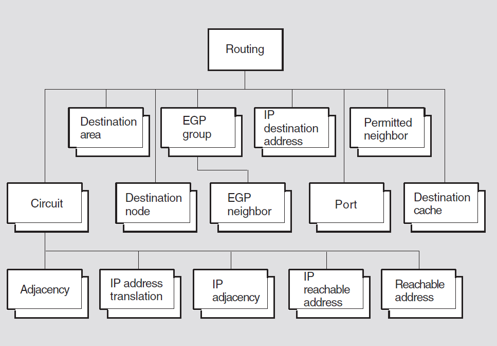
- Routing – determines packet paths. A path is the sequence of connected nodes and links between a source node and a destination node. The combined knowledge of all the network Routing layer modules of all the nodes in a network is used to determine the existence of a path, and route the packet to its destination. The routing component at a routing node has the following specific functions:
Extracts and interprets the route header in a packet.
Performs packet forwarding based on the destination address.
Performs packet fragmentation where necessary.
Manages the characteristics of the path and if a node or link fails on a path, finds an alternate route.
Interfaces with the Network Routing Subnetwork Dependent sublayer to receive reports concerning a circuit or node that has failed or the subsequent recovery of a circuit or node.
Performs packet reassembly at the destination.
Returns error reports to the source where necessary, for instance when the destination is unreachable or when the packet would have needed to be fragmented but segmentation permitted was not set in the packet. Segmentation permitted is always set in data packets generated by NA nodes. However, non-NA nodes may do otherwise.
Congestion control – manages the resources used at each packet switching node (each node that permits route-through).
Packet lifetime control – bounds the amount of time a packet can exist in the network.
Initialization – identifies the adjacent node and the adjacent node's network routing layer. It also performs node verification, if required.
Dynamic circuit management – determines when to dial calls, when to hangup calls, and (on dynamically assigned circuits) which DTE address to dial. It exists only on dynamically established data links.
21.1. Support for Attributes and Events
|
L1 |
The attribute is supported only for level 1 routers. |
|
L2 |
The attribute is supported only for level 2 routers. |
|
L1, L2 |
The attribute is supported only for level 1 or level 2 routers. |
|
End |
The attribute is supported only for end nodes. |
|
IP |
The attribute is supported only for routers that support dual routing (that is, both OSI and IP routing). |
|
All |
The attribute is supported by all implementations. |
21.2. routing
The routing entity is the top-level entity in the Routing module
hierarchy of entities. The Routing module controls the operation of network routing
within a node.
Syntax
add [node node-id] routing {manual area addresses
set of area-address | manual network entity titles
[set]}
create [node node-id] routing {type
routing-type | protocols protocol-set
}
delete [node node-id] routing
disable [node node-id] routing
enable [node node-id] routing
ping [node node-id] routing {destination
ip-address | size integer | timeout
integer}
remove [node node-id] routing {manual area addresses
[set] | manual network entity titles [set]}
set [node node-id] routing {area authentication type
none or simple | area receive passwords
hex-string | area send password
hex-string | autonomous system number | dna address format
boolean | domain authentication type none or
simple | domain receive passwords hex-string |
domain send password hex-string | generate checksums
boolean | lifetime integer | manual
area addresses [set] | manual L1 algorithm string | manual L2
algorithm string | manual network entity titles [set] | maximum
buffers integer | maximum path splits
integer | phaseiv address ph4-address
| phaseiv prefix address-prefix | phaseiv area maximum cost
integer | phaseiv area maximum hops
integer | phaseiv broadcast routing timer
integer | phaseiv buffer size integer
| phaseiv maximum address integer | phaseiv maximum area
integer | phaseiv maximum cost integer
| phaseiv maximum hops integer | phaseiv maximum visits
integer | probe rate integer |
protocols | routing mode integrated or segregated | redirect
holding time integer | segment buffer size
integer | send source quench boolean |
source quench interval boolean | summary addresses
set of summary-address | time to live
integer }
show [node node-id] routing [all [attributes] | all
characteristics | all counters | all status]
21.2.1. Arguments
destination ip-address
Destination to which an ICMP Echo Request message is to be sent. This argument is mandatory.
protocols protocol-set
Protocols supported by this router. The value of this argument is a set
containing either or both of the values IP or ISO 8473. This argument determines the
value of the protocols characteristic. The default value of this
argument depends on the value of the type argument.
size integer
Size, in bytes, of the data part of the ICMP Echo Request message. The default is 64 bytes.
timeout integer
Time, in seconds, for which the Routing module will wait for an ICMP Echo Reply message. The default is 5 seconds.
type routing-type
type characteristic attribute. For information on the available
routing types, see the Characteristic Attributes section.|
endnode |
The node is an end system. |
|
L1router |
The node is a level 1 router. |
|
L2router |
The node is a level 2 router. |
21.2.2. Characteristic Attributes
|
Support: L1, IP | |
|
Default: None |
Value: None or simple |
Type of authentication to be used for level 1 LSPs, PSNPs, and CSNPs.
|
Support: L1, IP | |
|
Default: No passwords |
Value: Set of hex-string |
Set of passwords that are valid in level 1 LSPs, PSNPs,and CSNPs when simple
authentication is in use. You cannot use the show command to display
the value of this attribute.
|
Support: L1, IP | |
|
Default: No password |
Value: Hex-string |
Password to be sent in level 1 LSPs, PSNPs, and CSNPs when simple authentication
is in use. You cannot use the show command to display the value of this
attribute.
|
Support: IP | |
|
Default: 0 |
Value: 0–65535 |
Autonomous system number of the local system. This characteristic is supported
only if the value of the routing protocols supported characteristic
includes EGP. You can modify this characteristic only when the status attribute
routing state is off.
|
Support: End | |
|
Default: True |
Value: True or false |
If true, specifies that NSAP addresses are NA structured, and that
NSAP address autoconfiguring is possible. If false, specifies that NSAP
addresses for this node are constructed from the characteristic manual network
entity titles and the selectors supplied by the Transport
Protocol module (NSP and/or OSI transport).
The NA address format attribute controls only the interpretation of
address structuring and no longer controls autoconfiguration. To control
autoconfiguration, you need to use the manual network entity titles
attribute by manually adding or removing NETs.
|
Support: L2, IP | |
|
Default: None |
Value: None or simple |
Type of authentication to be used for level 2 LSPs, PSNPs, and CSNPs.
|
Support: L2,IP | |
|
Default: No passwords |
Value: Set of hex-string |
Set of passwords that are valid in level 2 LSPs, PSNPs, and CSNPs when simple
authentication is in use. You cannot use the show command to display
the value of this attribute.
|
Support: L2, IP | |
|
Default: No password |
Value: Hex-string |
Password to be sent in level 2 LSPs, PSNPs, and CSNPs when simple authentication
is in use. You cannot use the show command to display the value of this
attribute.
|
Support: All | |
|
Default: False |
Value: True or false |
If true, specifies that checksums are generated for data, error
report, and ES-IS PDUs initiated by this node. If false, these
checksums are not generated. It is strongly recommended that, for performance
reasons, you use the default value (indicating no checksum generation).
|
Support: IP | |
|
Default: 10 |
Value: 1–255 |
Maximum time, in seconds, for which IP fragments are held while awaiting reassembly.
|
Support: All | |
|
Default: 63 |
Value: 2–255 |
Value to be placed in the "lifetime" field of originating data packets. This value should be greater than the maximum number of hops in any path in the network, plus the maximum packet lifetime in half-seconds.
|
Support: L1, L2 | |
|
Default: No area addresses |
Value: Set of area addresses |
Area addresses to be used for this node. An area address cannot be a Phase IV
address or the address DefaultArea.
If the characteristic manual L1 algorithm has the value routing
vector, this set must be empty, and the characteristic phaseiv
address must not be 0.0. If the characteristic phaseiv
address is 0.0, there must be at least one area address.
|
Support: L1 | |
|
Default: Routing vector |
Value: See description |
|
link state |
The DECnet Phase V link-state algorithm is used. |
|
routing vector |
The Phase IV routing-vector algorithm is used. |
|
Support: L2 | |
|
Default: Routingvector |
Value: See description |
|
link state |
The DECnet Phase V link-state algorithm is used. |
|
routing vector |
The Phase IV routing-vector algorithm is used. |
|
Support: End | |
|
Default: No NETs |
Value: Set of NETs |
Network entity titles (NETs) to be used for this node. If the characteristic
dna address format is set to false, there must be at
least one NET.
|
Default: 100 |
Value: 1–500 |
Specifies the number of buffers preallocated for forwarding purposes. This characteristic specifies only the number of preallocated buffers; more buffers maybe allocated if adequate system resources are available. You can only increase the characteristic value.
|
Support: L1,L2 | |
|
Default: 2 |
Value: 1–32 |
Maximum number of equal cost paths to split traffic between. You can modify this characteristic only when the entity is disabled.
|
Support: L1,L2 |
Specifies the minimum interval (in seconds) between transmissions of an LSP from a particular source. When changed the timer must be reset.
|
Support: All | |
|
Default: 0.0 |
Value: Phase IV address |
Specifies a Phase IV compatible address for communication with other Phase IV nodes. The default address, 0.0, indicates that no Phase IV compatible address is provided for the node. You can modify this characteristic only when the entity is disabled.
|
Support: L2 | |
|
Default: 1022 |
Value: 1–1022 |
Maximum cost of a path to a reachable Phase IV area. This characteristic is only used by the Phase IV routing algorithm (that is, the routing-vector algorithm).
|
Support: L2 | |
|
Default: 30 |
Value: 1–30 |
Maximum number of hops in a path to a reachable Phase IV area. This characteristic is only used by the Phase IV routing algorithm (that is, the routing-vector algorithm).
|
Support: L1,L2 | |
|
Default: 10 |
Value: 1–65535 |
Maximum interval, in seconds, between broadcast routing messages on broadcast circuits. This characteristic is only used by the Phase IV routing algorithm (that is, the routing-vector algorithm).
|
Support: All | |
|
Default: 576 |
Value: 1–65535 |
Size, in octets, of buffers used for routing to adjacent Phase IV nodes. This value is actually six octets greater than the maximum buffer size, and does not include the headers for the Routing and Data Link layers.
|
Support: L1,L2 | |
|
Default: 1023 |
Value: 1–1023 |
Maximum node number within the Phase IV area. This characteristic is only used by the Phase IV routing algorithm (that is, the routing-vector algorithm).
|
Support: L2 | |
|
Default: 63 |
Value: 1–63 |
Maximum Phase IV area number. This characteristic is only used by the Phase IV routing algorithm (that is, the routing-vector algorithm).
|
Support: L1,L2 | |
|
Default: 1022 |
Value: 1–1022 |
Maximum cost of a path to a reachable node within the Phase IV area. This characteristic is only used by the Phase IV routing algorithm (that is, the routing-vector algorithm).
|
Support: L1,L2 | |
|
Default: 30 |
Value: 1–30 |
Maximum number of hops in a path to a reachable node within the Phase IV area. This characteristic is only used by the Phase IV routing algorithm (that is, the routing-vector algorithm).
|
Support: All | |
|
Default: 63 |
Value: 1–63 |
Maximum number of visits a packet can make to this node before Routing assumes that the packet is looping. This characteristic is only used by the Phase IV routing algorithm (that is, the routing-vector algorithm).
|
Support: All | |
|
Default: Hex 49 |
Value: Address prefix |
Prefix for Phase IV addresses. If the characteristic phaseiv address
is not 0.0, a DECnet-Plus area address is formed by adding the area portion of the
Phase IV address to this prefix. You can modify this characteristic only when the
entity is disabled.
|
Support: End | |
|
Default: 20 |
Value for UNIX: 1–65535 |
|
Default: 1000 |
Value for OpenVMS: 1–65535 |
Number of packets after which a probe is sent. This characteristic is used only on multilink end systems, on circuits without cache entries for the destination.
|
Support: IP | |
|
Default: |
Value: IP or ISO 8473 |
The protocol stacks that are enabled on this system. These can be either or both
of the above values. The value of this characteristic derives from an argument to
the create command. You cannot modify this characteristic.
|
Support: L1,L2 | |
|
Default: 600 |
Value: 1–65535 |
Holding time, in seconds, to be specified in Redirect PDUs generated by this node.
|
Support: L2,IP | |
|
Default: External |
Value: External or internal |
The class to be associated with routes received through RIP. This value may be
overridden by a routing receive route entity. This characteristic is
supported only if the routing protocols supported characteristic
includes the RIP routing protocol.
|
Support: L2,IP | |
|
Default: 1 |
Value: 0–16 |
The metric value used by RIP when announcing routes derived from local
information. This value is used unless it is overridden by a routing send
route entity. This characteristic is supported only if the routing
protocols supported characteristic includes the RIP routing
protocol.
|
Support: L2,IP | |
|
Default: Internal |
Value: Set of external, internal |
Routes received through routing protocols other than RIP with metric classes in this set are candidates for announcement in RIP messages (subject to the route propagation policy in force). Routes with metric classes not in this set will not be announced.
Each value in this set may be overridden separately by a more specific propagation
policy specified by a routing send route or routing send route
source entity. This characteristic is supported only if the routing
protocols supported characteristic includes the RIP routing
protocol.
|
Support: L2,IP | |
|
Default: 1 |
Value: 0–16 |
The metric value used by RIP when announcing routes derived through other routing
protocols. This value is used unless it is overridden by a routing send
route entity. This characteristic is supported only if the routing
protocols supported characteristic includes the RIP routing
protocol.
|
Support: L2,IP | |
|
Default: No route propagation |
Value: Set of protocol pairs (see below) |
|
EGP to IS-IS |
IS-IS to RIP |
|
EGP to RIP |
RIP to EGP |
|
IS-IS to EGP |
If a particular value is not present in the set, routes are not propagated between
those two protocols in that direction. This characteristic is supported only if the
routing protocols supported characteristic includes either of the
EGP or RIP routing protocols.
|
Support: End | |
|
Default: Integrated propagation |
Value: Segregated or Integrated |
Determines the behavior of the forwarding algorithm. When the routing mode is set to Segregated, data being transmitted to Phase IV destination addresses is sent in Phase IV format packets, to the adjacent Phase IV router, if available. In Integrated mode, data is sent to Phase V (OSI) router adjacencies in CLNP packets, if possible.
NCL> disable routing NCL> set routing routing mode = segregated NCL> enable routing NCL> enable routing circuit *
|
Support: L2,IP |
|
EGP | |
|
IS-IS | |
|
RIP |
|
Support: All | |
|
Default: 570 |
Value: 0–65535 |
Maximum segment size, in octets, to be used by the Transport layer. A value of zero means that the segment size is unlimited.
|
Support: L1,L2,IP | |
|
Default: False |
Value: True or false |
Specifies whether an ICMP source quench packet is sent when an IP packet is
discarded because of congestion. If false, ICMP source quench packets
are never sent.
|
Support: L1,L2,IP | |
|
Default: 100 |
Value: 1–65535 |
Minimum time, in milliseconds, between transmission of successive ICMP source quench packets.
|
Support: L2,IP | |
|
Default: No addresses |
Value: Set of summary addresses |
Summary address information to be included in level 2 link state packets sent by this node.
|
Support: IP | |
|
Default: 35 |
Value: 1–255 |
Specifies the value to be placed in the time to live field of originating IP packets. This value should be greater than the maximum number of hops in any path on the network.
|
Support: All | |
|
Default: No default |
Value: See description |
|
endnode |
The node is an end node. |
|
L1router |
The node is a level 1 router. |
|
L2router |
The node is a level 2 router. |
|
Default: Current version number |
Version number of the NA Network Routing layer architecture specification to which this implementation conforms. You cannot modify this characteristic.
21.2.3. Counter Attributes
|
Support: All |
Number of data PDUs that have been discarded because the destination was unreachable.
|
Support: IP |
Number of IP packets that have been discarded because their lifetime has expired.
|
Support: L1,L2 |
Number of data PDUs that have been discarded because their lifetime has expired.
|
Support: L1,L2 |
Number of times an attempt was made to increase the sequence number of a link state packet beyond the maximum allowed.
|
Support: L1,L2 |
Number of times the corrupted lsp detected event has been
generated.
|
Support: All |
Time this entity was created.
|
Support: All |
Number of error report PDUs (or Phase IV data packets with RTS set)
that have been generated.
|
Support: IP |
Number of ICMP Address Mask Reply messages received.
|
Support: IP |
Number of ICMP Address Mask Reply messages sent.
|
Support: IP |
Number of ICMP Address Mask Request messages received.
|
Support: IP |
Number of ICMP Address Mask Request messages sent.
|
Support: IP |
Number of ICMP Destination Unreachable messages received.
|
Support: IP |
Number of ICMP Destination Unreachable messages sent.
|
Support: IP |
Number of ICMP Echo Reply messages received.
|
Support: IP |
Number of ICMP Echo Reply messages sent.
|
Support: IP |
Number of ICMP Echo Request messages received.
|
Support: IP |
Number of ICMP Echo Request messages sent.
|
Support: IP |
Number of ICMP messages that could not be sent because of problems in the ICMP layer. Note that this value does not include errors that occur outside the ICMP layer, such as forwarding errors.
|
Support: IP |
Number of ICMP messages received. This value includes messages counted by the
icmp received message errors counter.
|
Support: IP |
Number of ICMP messages of all types that the node has attempted to send. Note
that this figure includes the value of the icmp message send errors
counter.
|
Support: IP |
Number of ICMP Parameter Problem messages received.
|
Support: IP |
Number of ICMP Parameter Problem messages sent.
|
Support: IP |
Number of ICMP messages received with any type of error.
|
Support: IP |
Number of ICMP Redirect messages received.
|
Support: IP |
Number of ICMP Redirect messages sent.
|
Support: IP |
Number of ICMP Source Quench messages received.
|
Support: IP |
Number of ICMP Source Quench messages sent.
|
Support: IP |
Number of ICMP Time Exceeded messages received.
|
Support: IP |
Number of ICMP Time Exceeded messages sent.
|
Support: IP |
Number of ICMP Timestamp Reply messages received.
|
Support: IP |
Number of ICMP Timestamp Reply messages sent.
|
Support: IP |
Number of ICMP Timestamp Request messages received.
|
Support: IP |
Number of ICMP Timestamp Request messages sent.
|
Support: IP |
Number of ICMP messages received with an unknown message type.
|
Support: IP |
Number of IP packets discarded because their destination was unreachable.
|
Support: IP |
Number of IP packets discarded because of an invalid destination address or the address of an unsupported class.
|
Support: IP |
Number of IP packets discarded because of a format error in the IP header.
|
Support: IP |
Error in the IP header, such as bad checksum or version number mismatch. Note, however, that format errors and time to live expired are excluded.
Packet received through data link broadcast when forwarding is not allowed.
|
Support: IP |
Number of IP packets received for the local system and discarded because there was no port with the protocol type specified in the IP datagram PROTO field.
|
Support: IP |
Number of IP packets discarded because of an invalid source address or the address of an unsupported class.
|
Support: L1,L2 |
Number of times the lsp level 1 database overload event has been
generated.
|
Support: L2 |
Number of times the lsp level 2 database overload event has been
generated.
|
Support: L1,L2 |
Number of times an address in the manual area addresses set is
ignored when computing an area address. (Each address that is ignored is counted
separately.)
|
Support: L1,L2 |
Number of times the own lsp purged event has been generated.
|
Support: All |
Number of data PDUs that have been discarded because of format errors.
|
Support: All |
Number of times the phaseiv translation failures event has been
generated.
|
Support: L1,L2 |
Number of times the sequence number skipped event has been
generated.
|
Support: All |
Number of data PDUs that have been discarded because they specified unsupported options in their header.
21.2.4. Preset Attributes
Preset attributes are similar to characteristics in that their values control the
way in which the Routing module operates. However, unlike characteristics, you
cannot alter preset attribute values using the set command.
|
Support: L1,L2 | |
|
Default: 33 |
Value: 1–65535 |
Interval, in milliseconds, between the transmission of link state packets (LSPs) on a broadcast circuit.
|
Support: L1,L2 | |
|
Default: 10 |
Value: 1–600 |
Interval, in seconds, between generation of complete sequence number packets (CSNPs) by a designated router on a broadcast circuit.
|
Support: All | |
|
Default: 600 |
Value: 1–65535 |
Value to be used for the current suggested Hello timer, in the absence of any suggested value from the intermediate system (IS).
On routers, this is the value to be suggested when the router is not required to poll the ES configuration. In routers, this value is suggested by the Suggested ES Configuration Timer option in IS Hellos.
|
Support: L1,L2 | |
|
Default: 1 |
Value: 1–65535 |
Interval, in seconds, between the generation of IS-IS Hello PDUs by the designated router.
|
Support: End | |
|
Default: 600 |
Value: 1–65535 |
Holding time, in seconds, for an entry in the node's end-node cache database.
|
Support: End | |
|
Default: 3 |
Value for UNIX: 1–4294967295 |
|
Default: 3 |
Value for OpenVMS: 1–65535 |
Maximum number of LAN address entries in the node's end-node cache database on a broadcast circuit.
|
Support: All | |
|
Default: 3 |
Value: 2–63 |
Value by which to multiply the Hello timer to obtain the holding timer value for ES and IS Hellos and for point-to-point, router-to-router Hellos.
|
Support: All | |
|
Default: 33 |
Value: 2-255 |
This is the selector value identifying the port to which incoming Inactive Subset PDUs are to be sent.
|
Support: All | |
|
Default: 6 |
Value: 1–63 |
Delay, in seconds, between initialization of a data link and sending a DECnet-Plus message on a DDCMP circuit.
|
Support: L1,L2 | |
|
Default: 0 (ISO) |
Value: (ISO) or 1 (NA Private) |
This attribute controls the protocol identification to be used for "NA Private" PDUs. On broadcast circuits, this characteristic also controls the SAP on which they are transmitted.
|
Support: L1,L2 | |
|
Default: 10 |
Value: 2–63 |
Value by which to multiply the IS-IS Hello timer to obtain the value of the holding timer for LAN level 1 and level 2 router-to-router Hellos.
|
Support: L1,L2 | |
|
Default: 1200 |
Value: 1–65535 |
Number of seconds before an LSP is considered to be expired.
|
Support: L1,L2 | |
|
Default: 900 |
Value: 60–900 |
Maximum interval, in seconds, between link state packets (LSPs) generated by this node.
|
Support: L1,L2 | |
|
Default: 30 |
Value: 1–65535 |
Minimum time, in seconds, between generation of LSPs by this node.
|
Support: L1,L2 | |
|
Default: 5 |
Value: 5–30 |
Minimum interval, in seconds, between retransmissions of an LSP.
|
Support: End | |
|
Default: 10 |
Value: 1–65535 |
Value to be used for the current suggested Hello timer on a multicircuit end node with more than one circuit enabled, in the absence of any suggested values from the IS.
|
Support: L1,L2 | |
|
Default: 1492 |
Value: 128–1492 |
Maximum size of level 1 LSPs and SNPs originated at this node.
|
Support: L2 | |
|
Default: 1492 |
Value: 128–1492 |
Maximum size of level 2 LSPs and SNPs originated at this node.
|
Support: L1,L2 | |
|
Default: 2 |
Value: 1–65535 |
Minimum interval, in seconds, between sending partial SNPs.
|
Support: All | |
|
Default: 50 |
Value: 1–65535 |
Interval, in seconds, between ES Hellos when a router requires to poll the ES configuration.
|
Support: L1,L2 | |
|
Default: 1 |
Value: 1–63 |
Average queue length at a router, above which the "congestion experienced" bit will be set in a forwarded data PDU.
|
Support: L1,L2 | |
|
Default: 60 |
Value: 1–65535 |
Delay, in seconds, between routing databases being in the waiting
state and entering the on state.
|
Support: L1,L2 | |
|
Default: 60 |
Value: 1–65535 |
Time, in seconds, for which the purge header of an expired LSP is retained.
21.2.5. Status Attributes
|
Support: All |
A set of area addresses. If the node is an end node, these are the area address portions of the NETs of all adjacent routers. If the node is a level 1 or level 2 router, this set is the union of the sets of manual area addresses reported in all level 1 LSPs received by this router.
|
Support: IP |
Name of the routing port entity used for sending and receiving EGP
messages. This attribute is set when a routing egp group entity is
enabled.
|
Support: IP |
Name of the routing port entity used for sending and receiving ICMP
messages. This attribute is set when the routing module is enabled and
the protocols characteristic includes the value IP.
|
Support: L1,L2 |
|
off |
Routing is disabled. |
|
on |
Routing is enabled and operating correctly. |
|
waiting |
Routing has received routing information that it cannot store and is waiting for the overload to be removed. |
|
Support: L2 |
|
off |
Routing is disabled. |
|
on |
Routing is enabled and operating correctly. |
|
waiting |
Routing has received routing information that it cannot store and is waiting for the overload to be removed. |
|
Support: L1,L2 |
Names of adjacencies to be used for forwarding to the nearest level 2 router. If the node is a level 2 router adjacent to other areas, or if it is a level 1 router in an area with no attached level 2 routers, this set is empty.
|
Support: IP |
Name of the udp port entity used by the routing module for sending
and receiving RIP messages. This attribute is set when a routing
circuit entity is enabled with its rip state characteristic
set to any value other than off.
|
Support: All |
routing entity. |
off |
The entity is disabled. |
|
on |
The entity is enabled. |
uid
Entity's unique identifier, which is generated when the entity is created.
21.2.6. Event Messages
|
Support: All |
Generated when a data PDU is discarded because the destination address is unreachable.
|
discard reason |
Reason why the PDU was discarded. | |
|
destination address unknown |
The destination address is unknown. | |
|
destination address unreachable |
The destination address is currently unreachable. | |
|
duplicate option |
An optional PDU field occurs twice. | |
|
header syntax error |
There is a format error in the PDU header. | |
|
incomplete pdu received |
The received data did not contain a complete PDU. | |
|
incorrect checksum |
The checksum is incorrect. | |
|
lifetime expired during reassembly |
The PDU's lifetime expired while it was being reassembled. | |
|
lifetime expired while data unit intransit |
The PDU's lifetime expired while it was in transit. | |
|
pdu discarded due to congestion |
No buffers were available to forward the packet. | |
|
protocol procedure error |
Unable to translate a DECnet Phase V format PDU into a Phase IV format PDU. | |
|
reason not specified |
No further information available. | |
|
reassembly interference |
Insufficient memory available to reassemble a PDU. | |
|
segmentation required, but not permitted |
The PDU requires fragmentation, but the originator did not permit this. | |
|
unsupported option not specified |
The PDU contained an unrecognized and unsupported PDU option. | |
|
unsupported protocol version |
The PDU version is not supported. | |
|
unsupported recording of route option |
The sender requested an unsupported form of route recording. | |
|
unsupported source routing option |
The sender requested an unsupported form of source routing. | |
|
forwarding address |
Destination NSAP address. | |
|
phaseiv forwarding address |
Phase IV destination address of the Phase IV data packet. | |
|
phaseiv source address |
Phase IV source address of the Phase IV data packet. | |
|
receiving adjacency |
Name of the adjacency on which the PDU was received. For an end node, only the circuit may be specified. | |
|
source address |
Source NSAP address of the data NPDU. | |
|
Support: IP |
Generated when an IP packet is discarded because the interval specified in its time to live field has expired.
|
Support: L1,L2 |
Generated when a data PDU is discarded because its lifetime has expired.
|
discard reason |
Reason why the PDU was discarded: See possible reasons
described under the | |
|
phaseiv pdu header |
Phase IV header of the Phase IV packet causing this event. | |
|
pdu header |
Contents of the header of the data PDU that was discarded. | |
|
Support: L1,L2 |
Generated when an attempt is made to increase the sequence number of a link state packet beyond the maximum allowed sequence number.
|
Support: L1,L2 |
Generated when a corrupted link state packet is detected in memory.
|
Support: All |
Generated when EGP message is discarded.
|
Support: IP |
Generated when an IP packet is discarded because its destination is unreachable.
|
forwarding IP address |
IP address on which the forwarding decision for the IP packet was taken. This is usually the destination IP address. | |
|
icmp discard reason |
Value of the code field of the corresponding ICMP destination unreachable message. | |
|
Host unreachable | ||
|
Network unreachable | ||
|
Source route failed | ||
|
LAN address |
Data link address of the broadcast circuit that is the
previous hop for the packet. This argument is present only
if the | |
|
receiving entity |
Local name of the | |
|
source ip address |
Source IP address of the IP packet. | |
|
Support: IP |
Generated when an IP packet is discarded because the destination IP address is invalid (that is, it has an invalid format, or it refers to an unsupported network class).
|
destination ip address |
Destination IP address in the IP packet. | |
|
LAN address |
Data link address of the broadcast circuit that is the
previous hop for the packet. This argument is present only
if the | |
|
receiving entity |
Local name of the circuit entity corresponding to the previous hop for the packet. | |
|
source ip address |
Source IP address of the IP packet. | |
|
Support: IP |
Generated when an IP packet is discarded because of version number mismatch or bad checksum.
|
ip discard reason |
Reason why the IP packet was discarded. See the | |
|
ip header |
IP header of the PDU that caused the event. | |
|
receiving entity |
Local name of the circuit entity corresponding to the previous hop for the packet. | |
|
Support: IP |
Generated when an IP packet is discarded because it contains a format error.
|
ip discard reason |
Reason why the IP packet was discarded: | |
|
duplicate option | ||
|
header syntax error | ||
|
incomplete packet received | ||
|
incorrect checksum | ||
|
incorrect header length | ||
|
incorrect total length | ||
|
option error | ||
|
protocol procedure error | ||
|
reason not specified | ||
|
received via broadcast | ||
|
unsupported option not specified | ||
|
unsupported protocol version | ||
|
unsupported security option | ||
|
ip header |
IP header of the PDU that caused the event. | |
|
LAN address |
Data link address of the broadcast circuit that is the
previous hop for the packet. This argument is present only
if the | |
|
pointer |
Offset of the octet in the IP header that caused the format error. | |
|
receiving entity |
Local name of the circuit entity corresponding to the previous hop for the packet. | |
|
Support: IP |
Generated when an IP packet is discarded because there was no port on the local system for the protocol type specified in the IP header.
|
destination protocol |
Value of the protocol field in the IP packet. | |
|
icmp discard reason |
Value of the code field of the corresponding ICMP destination unreachable message. | |
|
Port Unreachable | ||
|
Protocol Unreachable | ||
|
LAN address |
Data link address of the broadcast circuit that is the
previous hop for the packet. This argument is present only
if the Receiving Entity argument identifies a
| |
|
receiving entity |
Local name of the | |
|
source ip address |
Source IP address of the IP packet. | |
|
Support: IP |
Generated when an IP packet is discarded because the source IP address is invalid (that is, it has an invalid format, or it refers to an unsupported network class).
|
destination ip address |
Destination IP address in the IP packet. | |
|
LAN address |
Data link address of the broadcast circuit that is the
previous hop for the packet. This argument is present only
if the Receiving Entity argument identifies a
| |
|
receiving entity |
Local name of the | |
|
source ip address |
Source IP address of the IP packet. | |
|
Support: L1,L2 |
Generated when the status attribute L1 state changes from
on to waiting, or vice versa.
|
source id |
Source ID of the link state packet. | |
|
state change |
Current state. | |
|
recovered |
Router operating normally. | |
|
waiting |
Router has failed to store alink state packet, and is operating in restricted mode. | |
|
Support: L2 |
Generated when the status attribute L2 state changes from
on to waiting, or vice versa.
|
source id |
Source ID of the link state packet. | |
|
state change |
Current state. | |
|
recovered |
Router is operating normally. | |
|
waiting |
Router has failed to store a link state packet, and is operating in restricted mode. | |
|
Support: L1,L2 |
Generated when one of the addresses in the manual area addresses set
is ignored when computing an area address. The event is generated once for each
address that is dropped.
|
area address |
Area address that caused the maximum number of area addresses to be exceeded. | |
|
Support: L1,L2 |
Generated when a zero-aged copy of a node's own link state packet is received from some other node. This represents an invalid attempt to purge the local node's link state packet.
|
Support: All |
Generated when a data PDU is discarded because of a format error.
|
discard reason |
Reason why the PDU was in error. See possible reasons
described under the | |
|
pdu header |
Contents of the header of the data PDU that was discarded. | |
|
phaseiv pdu header |
Phase IV header of the Phase IV packet causing this event. | |
|
receiving adjacency |
Name of the adjacency on which the PDU was received. For an end node on a LAN, only the circuit may be specified for UNIX. | |
|
Support: All |
Generated when a PDU is discarded because it cannot be translated to Phase IV format.
|
pdu header |
Data PDU header causing the event. | |
|
receiving adjacency |
Local entity name of the adjacency upon which the PDU was received. For an end node on a LAN, only the circuit may be specified for UNIX. | |
|
Support: L1,L2 |
Generated when the sequence number of a link state packet is incremented by more than 1. This usually occurs when a router is reenabled while its previous link state packets are still stored in the network.
unsupported option
Generated when a data packet is received that contains an unsupported option in its header.
|
discard reason |
Reason why the event was generated. See possible reasons
described under the | |
|
pdu header |
Contents of the header of the data PDU that caused the event. | |
|
receiving adjacency |
Name of the adjacency on which the PDU was received. For an end node on a LAN, only the circuit may be specified. | |
21.2.7. Exception Messages
For create:
already exists
A routing entity already exists.
invalid router type
The type argument specifies an invalid router type on the
create command.
For delete:
wrong state
Routing module cannot be deleted when it is enabled.
has children
Cannot delete while subentities exist.
For ping:
ip not enabled
IP routing is not enabled on this system.
21.3. routing circuit
A routing circuit entity represents a data link to another node. The
circuit-name refers the circuit managed by this command.
Syntax
add [node node-id] routing circuit
circuit-name manual routers set of
ID802
create [node node-id] routing circuit
circuit-name type
circuit-type
delete [node node-id] routing circuit
circuit-name
disable [node node-id] routing circuit
circuit-name
enable [node node-id] routing circuit
circuit-name
remove [node node-id] routing circuit
circuit-name manual routers set of
ID802
set [node node-id] routing circuit
circuit-name {data link entity
local-entity-name | dna neighbor
boolean | enable phaseiv address
boolean | explicit receive verification
boolean | hello timer integer | idle
timer integer | inactive area address [set] | initial minimum
timer integer | isis hello timer integer |
L1 cost integer | L1 router priority
integer | L2 cost integer | L2 router
priority integer | manual data link sdu size
integer | manual L2only mode boolean |
manual routers set of ID802 | maximum call attempts
integer | maximum svc adjacencies
integer | originating queue limit
integer | recall timer integer |
receive verifier hex-string | reserved adjacency
boolean | reserve timer integer |
template template-id | transmit verifier
hex-string | x.25 filters set of
ID802}
show [node node-id] routing circuit
circuit-name [all [attributes] | all characteristics | all
counters | all identifiers | all status]
21.3.1. Arguments
type circuit-type
Type of circuit applicable to create only. For information on the
available circuit types, see the type characteristic attribute
description in the Characteristic Attributes section.
21.3.2. Characteristic Attributes
|
Support: L1,L2,IP | |
|
Default: No addresses |
Value: Set of subnet-address |
A set of alternative IP addresses and subnet masks for this interface. You can modify this characteristic only when the entity is disabled.
|
Support: IP | |
|
Default: 600 |
Value: 30–65535 |
Number of seconds to hold on to a routing circuit ip address
translation entity. This characteristic is supported only if the
circuit's type characteristic is csma-cd.
|
Support: IP | |
|
Default: 3 |
Value: 1–10 |
Number of seconds to wait for an ARP response when an ARP request has been sent.
This characteristic is supported only if the circuit's type
characteristic is csma-cd.
|
Support: L1,L2,IP | |
|
Default: None |
Value: None or simple |
Type of authentication to be used for LAN L1 Hellos, LAN L2 Hellos, or PtPt Hellos on this circuit.
data link entity
|
Support: All | |
|
Default: No data link name |
Value: Local-entity-name |
Name of the entity within the Data Link module to be created when a port is opened
for that data link type. You can modify this characteristic only when the entity is
disabled. This attribute is supported for all types of circuits; however, for X.25
circuits set the attribute to x25 access.
|
Support: L1,IP | |
|
Default: On |
Value: Off or On |
|
off |
Discard the packet silently. |
|
on |
Broadcast the packet using data level link
broa that either of the following
conditions is true:
|
This characteristic is supported only if the characteristic type is
set to csma-cd.
|
Support: L1,L2 | |
|
Default: True |
Value: True or false |
If true, specifies that the neighbor is expected to be NA compliant,
and so proprietary mechanisms are possible. If false, no
router-to-router Hellos or link state packets (LSPs) will be sent over this circuit.
This characteristic is supported only if the characteristic type is not
x25 da. You can modify this characteristic only when the entity is
disabled.
|
Support: All | |
|
Default: True |
Value: True or false |
Specifies whether the physical LAN address is to be set to the Phase IV style LAN
address (that is, AA-00-04-00- xx- xx).
The LAN address is set only if this attribute is true and the value of
the phaseiv address characteristic is not 0.0. If phaseiv
address is not 0.0 and there are multiple adaptors to the same LAN, only
one circuit may have this attribute set to true. This characteristic is
supported only if the characteristic type is set to
csma-cd.
|
Support: All | |
|
Default: True |
Value: True or false |
Type of password verification performed at circuit initialization. If
true, the received verifier is checked against the value of the
characteristic receive verifier for this circuit, if any. If
false, the received verifier is checked against the set of
verifiers specified in the routing permitted neighbor entities. This
attribute is supported only if the characteristic type is set to
ddcmp, hdlc, x25 static incoming, x25 static outgoing, and
x25 permanent.
|
Support: L1,L2 | |
|
Default: 10 |
Value: 1–32767 |
Interval, in seconds, between IS Hello messages.
|
Support: All | |
|
Default: 30 |
Value: 1–65535 |
Number of seconds of idle time before a call is cleared. This attribute is
supported only if the characteristic type is x25
da.
|
Support: All | |
|
Default: No area address |
Value: Set of area addresses |
Area address associated with the use of the inactive subnet of ISO 8473. Maximum
area address that may be present is 1. This characteristic is supported only if the
characteristic type is set to csma-cd.
|
Support: All | |
|
Default: 55 |
Value: 1–65535 |
Period, in seconds, for which an X.25 call remains connected after being
established, irrespective of traffic. This should be set small enough that the call
is cleared before the start of the next charging interval. This attribute is
supported only if the characteristic type is x25
da.
|
Support: L1,L2 | |
|
Default: 3 |
Value: 1–32767 |
Interval, in seconds, between LAN level 1 and level 2 router-to-router Hello messages. This value is also used as the interval between IS Hello messages when polling the ES configuration.
|
Support: L1,L2 | |
|
Default: 20 |
Value: 1–63 |
Cost of this circuit for level 1 traffic.
|
Support: L1,L2 | |
|
Default: 64 |
Value: 1–127 |
Priority for becoming LAN level 1 designated router. This attribute is supported
only if the circuit's characteristic type is
csma-cd.
|
Support: L2 | |
|
Default: 20 |
Value: 1–63 |
Cost of this circuit for level 2 traffic.
|
Support: L2 | |
|
Default: 64 |
Value: 1–127 |
Priority for becoming LAN level 2 designated router. This attribute is supported
only if the circuit's characteristic type is
csma-cd.
|
Support: All | |
|
Default: 1492 |
Value: 128–65535 |
Preferred maximum data link block size, in octets. You can modify this
characteristic only when the entity is disabled. If the characteristic
type is csma-cd, this characteristic is a read-only
attribute whose value is fixed at 1492. If the characteristic type is
fddi, this characteristic is a read-only attribute whose value is
fixed at 4352.
|
Support: IP | |
|
Default: See description |
Value:128–65535 |
|
CSMA-CD |
1500 |
|
DDCMP |
1500 |
|
HDLC |
1500 |
|
X.25 (all types) |
576 |
You can modify this characteristic only when the entity is disabled.
|
Support: L2 | |
|
Default: False |
Value: True or false |
If true, specifies that this circuit is to be used only for level 2
traffic. If false, the circuit may be used for both level 1 and level 2
traffic. You can modify this characteristic only when the entity is disabled.
|
Support: End | |
|
Default: No router IDs |
Value: Set of LAN addresses |
Manually entered IDs of routers. If this set is empty, the circuit will
auto-configure the routers. This characteristic is supported only if the circuit's
characteristic type is csma-cd. For UNIX, a maximum of
five routers can be in the set.
|
Support: IP | |
|
Default: 3 |
Value: 1–10 |
Maximum number of times an ARP request can be sent for the same IP address. This
characteristic is supported only if the circuit's characteristic type
is set to csma-cd.
|
Support: All | |
|
Default: 10 |
Value: 0–255 |
Maximum number of successive X.25 call failures before the circuit is regarded as being halted. A value of zero means that there is no limit to the number of retries.
This attribute is supported only if the characteristic type is set to
x25 static outgoing. You can modify this characteristic only when
the entity is disabled. Also, you can only increase the characteristic value.
|
Support: All | |
|
Default: 1 |
Value: 1–65535 |
Number of routing circuit adjacency entities to reserve for switched
virtual circuits (SVCs) on this circuit. This is effectively the maximum number of
simultaneous calls possible on this circuit. This attribute is supported only if the
characteristic type is x25 da.
|
Support: L1,L2 | |
|
Default: 50 |
Value: 1–255 |
Maximum number of data PDUs originated by this node that can be on this circuit's transmit queue. This should be set to the minimum number required to keep the data link from idling. You can modify this characteristic to a higher value when the entity is disabled; you can never modify it to a lower value.
|
Support: All | |
|
Default: 60 |
Value: 0–65535 |
Interval, in seconds, that must elapse between a call failure and a recall. This
attribute is supported only if the characteristic type is set to
x25 static outgoing, x25 da, hdlc, or ddcmp.
|
Support: L1,L2,IP | |
|
Default: No passwords |
Value: Set of hex-string |
Set of passwords that are valid in received LAN L1 Hellos, LAN L2 Hellos, and PtPt
Hellos when simple authentication is in use on this circuit. You cannot use the
show command to display the value of this attribute.
|
Support: All | |
|
Default: No verifier |
Value: Hex string, length 0–38 |
Value against which a neighbor node's received verifier is to be checked. If no
verifier is specified, no verification is performed. This attribute is supported
only if the characteristic type is ddcmp, hdlc, x25 static
incoming, x25 static outgoing, or x25 permanent. You cannot
display this characteristic.
|
Support: All | |
|
Default: 600 |
Value: 1–65535 |
Interval, in seconds, during which the SVC remains reserved for the previous DTE
address after a call is cleared due to lack of traffic. This attribute is supported
only if the characteristic type is x25 da.
|
Support: End | |
|
Default: False |
Value: True or false |
If true, specifies that one SVC must be reserved for connection to a
router. If false, no SVC needs to be reserved for this purpose. This
characteristic is supported only if the circuit's characteristic type
is x25 da. You can modify this characteristic only when the entity is
disabled.
|
Support: L1,L2,IP | |
|
Default: False |
Value: True or false |
If true, this specifies that the default route is announced in RIP
messages sent on this circuit, with the metric value specified in the RIP
generated default route metric characteristic. If
false, the default route is not generated.
|
Support: L1,L2,IP | |
|
Default: 1 |
Value: 0–16 |
The metric to be used when announcing a generated default route through RIP on this circuit.
|
Support: L2,IP | |
|
Default: No addresses |
Value: Set of IP addresses |
IP addresses of neighboring systems with which RIP will be exchanged on this circuit.
If the circuit is a point-to-point circuit, this set must contain a single IP
address if the rip state characteristic is to be set to send and
receive. Also, you must disable the entity before altering this
characteristic.
If the rip send type characteristic is set to broadcast,
only RIP messages from addresses specified in this set will be received; other
messages will be silently discarded.
This characteristic is supported only if the routing protocols
supported characteristic of the routing entity includes the
RIP routing protocol.
|
Support: L2,IP | |
|
Default: True |
Value: True or false |
Specifies whether poisoned reverse routes are to be sent in RIP messages on this
circuit. If false, poisoned reverse routes are not sent.
This characteristic is supported only if the routing protocols
supported characteristic of the routing entity includes the
RIP routing protocol.
|
Support: L2,IP | |
|
Default: True |
Value: True or false |
Specifies whether the default route is accepted from RIP messages on this circuit.
If false, the default route from RIP messages on this circuit is
discarded.
This characteristic is supported only if the routing protocols
supported characteristic of the routing entity includes the
RIP routing protocol.
|
Support: L2,IP | |
|
Default: Broadcast |
Value: Broadcast or point-to-point |
|
broadcast |
RIP messages are sent by means of data link broadcast. |
|
point-to-point |
RIP messages are sent directly to each IP address
specified in the |
This characteristic is supported only if the routing protocols
supported characteristic of the routing entity includes the
RIP routing protocol and if the circuit's type characteristic is
csma-cd.
|
Support: L2,IP | |
|
Default: Off |
Value: See description |
|
off |
RIP messages cannot be sent or received on this circuit. |
|
receive |
RIP messages can be received but not sent on this circuit. |
|
send and receive |
RIP messages can be sent and received on this circuit. |
This characteristic is supported only if the routing protocols
supported characteristic of the routing entity includes the
RIP routing protocol.
|
Support: L1,L2,IP | |
|
Default: No password |
Value: Hex-string |
Password to be sent in LAN L1 Hellos, LAN L2 Hellos, and PtPt Hellos when simple
authentication is used on this circuit. You cannot use the show command
to display the value of this attribute.
|
Support: IP | |
|
Default: 0.0.0.0 |
Value: Subnet address |
IP address and subnet mask of this interface. You can modify this characteristic only when the entity is disabled.
|
Support: All | |
|
Default: No template name |
Value: Template-id |
Name of the template to be used when a port is opened for this data link type. If no template name is specified, no template is used. You can modify this characteristic only when the entity is disabled.
|
Support: All | |
|
Default: No verifier |
Value: Hex-string, length 0–38 |
Value to be transmitted for verifying the identity of this node. If no verifier is
specified, no verifier is transmitted. This characteristic is supported only if the
characteristic type is ddcmp, hdlc, x25 static outgoing, x25
static incoming, or x25 permanent. You cannot display this
characteristic.
|
Support: All |
create command.|
csma-cd |
The circuit is a broadcast circuit. |
|
ddcmp |
The circuit is a DDCMP circuit. |
|
fddi |
The circuit is an FDDI large packet circuit. |
|
hdlc |
The circuit is an HDLC circuit. |
|
x25 da |
The circuit is a dynamically allocated X.25 circuit. |
|
x25 permanent |
X.25 permanent virtual circuit. |
|
x25 static incoming |
Static incoming X.25 circuit. |
|
x25 static outgoing |
Static outgoing X.25 circuit. |
|
Default: See description |
Value: Set of simple names |
Specifies the set of X.25 filters to be used when a port is opened to the X.25
module. Typically, there will be two sets: one to specify the selection on the Call
User Data field for Phase V, and the other to specify the selection on the
subaddress for Phase IV. This attribute is valid only if the characteristic type is
x25 static incoming or x25 da.
21.3.3. Counter Attributes
|
Support: L1,L2,IP |
Number of times a PDU has been received on this circuit with an Authentication Information field that is incompatible with the PDU type.
|
Support: All |
Number of unsuccessful call attempts on this circuit. This attribute is supported
only if the characteristic type is x25 da.
|
Support: All |
Number of call attempts (successful and unsuccessful) on this circuit. This
attribute is supported only if the characteristic type is x25
da.
|
Support: All |
Number of times the status attribute state of an adjacency belonging
to this circuit changes from Up to Down (or Initializing), or the reverse.
|
Support: IP |
Number of times the status attribute state of an IP adjacency
belonging to this circuit changes from Up to some other state, or the
reverse.
|
Support: L2,IP |
Number of times the RIP state of IP adjacencies belonging to this circuit have
changed. This attribute is supported only if the routing entity's
characteristic routing protocols supported includes the routing
protocol RIP.
|
Support: All |
Number of times the status attribute state has changed from
on to off, or vice versa.
|
Support: L1,L2 |
Number of data- and error-report NPDUs that have been discarded, before or after fragmentation, because of congestion. Any other discarding will already have been done by the forwarding process. This number includes all PDUs recognized by the receive process as data PDUs (Phase V data- and error-report PDUs and Phase IV data packets), even though they may subsequently be discarded for some reason.
|
Support: All |
Number of control PDUs that have been received on this circuit. This number includes all Network layer PDUs, with the exception of DECnet-Plus data and error report PDUs and Phase IV data PDUs.
|
Support: All |
Number of control PDUs that have been sent on this circuit.
|
Support: All |
Number of times an ES-IS (end system to intermediate system) or IS-IS (intermediate system to intermediate system) Hello PDU has been received on this circuit that either cannot be parsed or contains an incorrect checksum.
|
Support: L1,L2 |
Number of times a corrupted link state packet has been received on this circuit.
|
Support: All |
Time this entity was created.
|
Support: All |
Number of DA adjacency change events that have been generated.
|
Support: L1,L2 |
Number of data- and error-report NPDUs that have been forwarded onto this circuit (either from another circuit or from a local port). This number includes all PDUs recognized by the receive process as data PDUs (Phase V data- and error-report PDUs and Phase IV data packets), even though they may subsequently be discarded for some reason.
|
Support: All |
Number of data NPDUs that have been fragmented on this circuit.
|
Support: All |
Number of data- and error-report NPDUs that have been received on this circuit. This number includes all PDUs recognized by the receive process as data PDUs (DECnet-Plus data and error report PDUs and Phase IV data packets), even though they may subsequently be discarded for some reason.
|
Support: All |
Number of data- and error-report NPDUs, after fragmentation, that have been delivered to the port for transmission on this circuit. This number includes all PDUs recognized by the receive process as data PDUs (DECnet-Plus data- and error-report PDUs and Phase IV data packets), even though they may subsequently be discarded for some reason.
|
Support: End,L2 |
Number of exceeded maximum svc adjacency events that have been
generated. This counter is supported only if the circuit's type is set
to x25 da; only for nodes that are end nodes; and if the system
supports dual routing (both DECnet and IP routing).
|
Support: All |
Number of ID reachability change events that have been generated.
|
Support: All |
Number of times that an attempt to initialize an adjacent node over this circuit has failed, either because of version skew or area mismatch.
|
Support: IP |
Number of IP packets discarded because fragmentation was required to transmit them, but the IP header requested "do not fragment."
|
Support: IP |
Number of IP fragments created for transmission on this circuit.
|
Support: IP |
Number of IP packets forwarded on this circuit before fragmentation. These IP
packets may be from another circuit or from a local port. Note that this value
includes those IP packets counted in the ip send discards
counter.
|
Support: IP |
Number of IP packets that have been fragmented on this circuit.
|
Support: IP |
Number of IP packets received on this circuit. This value includes all types of IP packet (control, data, etc.), and those that may subsequently be discarded for any reason.
|
Support: IP |
Number of IP packets that have been received and then discarded because of congestion.
|
Support: IP |
Number of IP packets for transmission that have been discarded because of congestion.
|
Support: All |
Number of times that the number of re-call attempts on this circuit has become
equal to the value of the characteristic maximum call attempts. This
attribute is supported only if the characteristic type is set to
x25 static outgoing.
|
Support: L1,L2 |
Number of times the local node has either elected itself or resigned as the LAN
level 1 designated router on this circuit. This attribute is supported only if the
circuit's characteristic type is set to csma-cd.
|
Support: L2 |
Number of times the local node has either elected itself or resigned as the LAN level 2 designated router on this circuit.
|
Support: L1,L2 |
Number of times the local node has either elected itself or resigned as the LAN Phase IV designated router on this circuit.
|
Support: End |
Number of Redirect PDUs that have been discarded because of insufficient cache memory.
|
Support: All |
Number of times an attempt to create a new adjacency using this circuit has failed because of insufficient resources.
|
Support: L2,IP |
Number of times an attempt to automatically create a new IP adjacency to an IP router has failed because of lack of resources.
|
Support: L2,IP |
Number of RIP messages received with any kind of received error on this circuit.
This attribute is supported only if the routing entity's characteristic
routing protocols supported includes the routing protocol
RIP.
|
Support: L1,L2 |
Number of data NPDUs that have been discarded because segmentation was required to send them on this circuit but was not permitted in the NPDU header.
verification reject events
Number of verification reject events that have been generated. This attribute is
supported only if the characteristic type is set to ddcmp, hdlc,
x25 static incoming, x25 static outgoing, or x25
permanent.
21.3.4. Identifier Attributes
name
Simple name assigned to the circuit when it is created.
21.3.5. Status Attributes
|
Support: All |
Name of the data link port used for this circuit. Not supported on DA circuits.
|
Support: All |
Maximum size, in octets, of a Data Link SDU for this circuit. This includes the
Network layer header, but excludes the Data Link layer header. The value of this
status is the lesser of the value of the characteristic manual data link sdu
size and any limit imposed by the Data Link layer.
|
Support: L1,L2 |
LAN ID allocated by the LAN level 1 designated router. This attribute is supported
only if the circuit's characteristic type is
csma-cd.
|
Support: L2 |
LAN ID allocated by the LAN level 2 designated router. This attribute is supported
only if the circuit's characteristic type is
csma-cd.
|
Support: L1,L2 |
ID of the DECnet Phase V level 1 designated router on this circuit. This attribute
is supported only if the circuit's characteristic type is
csma-cd. If this node does not participate in the router election
process, the value returned is 00-00-00-00-00-00.
|
Support: L2 |
ID of the DECnet Phase V level 2 designated router on this circuit. This attribute
is supported only if the circuit's characteristic type is
csma-cd. If this node does not participate in the router election
process, the value returned is 00-00-00-00-00-00.
|
Support: L1,L2 |
ID of the Phase IV designated router on this circuit. This attribute is supported
only if the circuit's characteristic type is csma-cd. If
this node does not participate in the router election process, the value returned is
00-00-00-00-00-00.
|
Support: L1,L2 |
ID allocated to the circuit during its initialization. This attribute is supported
only if the circuit's characteristic type is hdlc,
ddcmp, or x25 static.
state
routing circuit entity.|
Support: All | |
|
off |
The circuit is disabled. |
|
on |
The circuit is enabled. |
uid
Entity's unique identifier, which is generated when the entity is created.
21.3.6. Event Messages
|
Support: All |
Generated when the status attribute state of a routing circuit
adjacency entity belonging to the circuit changes from up to
down, or vice versa. For the purposes of this event, the state
up/dormant is considered to be the same as up, and the
state initializing is considered to be the same as down.
For end nodes, this event is generated for point-to-point links only.
|
adjacency name |
The name of the adjacency to which the event refers. | |
|
adjacent node |
Node IDs of the adjacent node. | |
|
new adjacency state |
Current state of the adjacency. | |
|
down |
Adjacency | |
|
up |
Adjacency | |
|
reason |
Reason why the adjacency state changed to
| |
|
address out of range |
The adjacency address is invalid. | |
|
area mismatch |
The adjacent node's area address is incorrect. | |
|
call rejected |
An X.25 call to the adjacent node failed. | |
|
checksum error |
A PDU's checksum was invalid. | |
|
circuit disabled |
The circuit has been disabled by network management. | |
|
configuration fault |
The adjacency has been configured incorrectly. | |
|
datalink failure |
Exceeded maximum call attempts; configuration fault. | |
|
exceeded maximum call attempts |
The value of the characteristic | |
|
holding timer expired |
No Hello traffic has been received during the period of the Hello timer. | |
|
maximum broadcast end nodes exceeded |
There are more adjacent nodes than can be supported on a LAN. | |
|
maximum broadcast routers exceeded |
There are more adjacent nodes than can be supported on a LAN. | |
|
neighbor node change |
The address(es) in the hello has/have changed. | |
|
one way connectivity |
The connectivity between two LAN routers appears to permit traffic in one direction only. | |
|
reserve timer expired |
This may occur temporarily during a change of designated router. Repeated occurrences indicate a configuration or hardware error. | |
|
version skew |
The adjacent node is the wrong version. | |
|
wrong node type |
The adjacent routing node is of the wrong type. | |
|
Support: L1,L2,IP |
Generated when a PDU is received that contains an Authentication Information field that is incompatible with the PDU type.
|
adjacent node |
Node ID of the adjacent node. | |
|
authentication level |
Authentication level of the PDU: area, circuit, domain. | |
|
pdu type |
Type of the PDU. | |
|
L1 LSP |
L2 PSNP | |
|
L1 CSNP |
LAN L1 Hello | |
|
L1 PSNP |
LAN L2 Hello | |
|
L2 LSP |
PtPt Hello | |
|
L2 CSNP | ||
|
Support: All |
Generated when the status attribute state of the circuit changes from
off to on, or vice versa.
|
disable reason |
The reason that the circuit status changed from
| |
|
new circuit state |
Current state of the circuit. | |
|
off |
Circuit | |
|
on |
Circuit | |
|
Support: All |
Generated when an ES-IS (end system to intermediate system) or IS-IS (intermediate system to intermediate system) Hello PDU is received that either cannot be parsed or contains an incorrect checksum.
|
Support: L1,L2 |
Generated when a corrupted link state packet is received.
|
adjacent node |
Node IDs of adjacent nodes. | |
|
Support: L1,L2 |
Generated when a corrupted Phase IV routing packet is received.
|
phaseiv id |
Phase IV ID of the Phase IV routing message that caused the event to be generated. | |
|
Support: All |
Generated when the state of a DA adjacency on the circuit changes from
up to down or from down to
up. For these purposes, the states up and
up/dormant are considered up and any other state is
considered down. This attribute is supported only if the circuit type
is x25 da.
|
adjacency name |
Name of the adjacency to which the event refers. | |
|
new adjacency state |
Current state of the adjacency. | |
|
down |
Adjacency | |
|
up |
Adjacency | |
|
reason |
Reason why the adjacency state changed to
| |
|
Support: End,L2 (DA circuits only) |
Generated when there is no free adjacency on which to establish an SVC for a new destination.
|
Support: All |
Generated when an ID is added to or removed from the endnodeID status
of an adjacency on this circuit. For end nodes, this event is generated for
point-to-point links only.
|
adjacency name |
Name of the adjacency to which the event refers. | |
|
adjacent node |
Node IDs of the adjacent node. | |
|
reason |
Reason why the adjacency state changed to
| |
|
Support: All |
Generated when an attempt to initialize with an adjacent node fails, either because of version skew or area mismatch.
|
adjacent node |
Node IDs of adjacent nodes. | |
|
reason |
Reason why the event was generated. See possible reasons
described under the | |
|
Support: IP |
Generated when the status attribute state of a routing circuit
ip adjacency entity belonging to this circuit changes from
up (or up/dormant) to some other value, or the
reverse.
|
neighbor IP address |
IP address of the neighbor. | |
|
new IP adjacency state |
New state of the IP adjacency. | |
|
up |
Either up or up/dormant | |
|
down |
Any other state | |
|
reason |
Reason for the state change. | |
|
Support: IP |
Generated when an IP packet that requires fragmentation in order to be transmitted has an IP header that requests "do not fragment".
|
destination IP address |
Destination IP address of the IP packet. | |
|
source IP address |
Source IP address of the IP packet. | |
|
Support: All |
recall count becomes equal to maximum call
attempts. This attribute is supported only if the circuit type is
x25 static outgoing.|
reason |
Reason why the adjacency state changed to
| |
|
Support: L1,L2 |
Generated when the local node either elects itself or resigns as the LAN level 1 designated router on this circuit.
|
designated routerchange |
New state of the designated router. | |
|
elected |
Router | |
|
resigned |
Router | |
|
Support: L2 |
Generated when the local node either elects itself or resigns as the LAN level 2 designated router on this circuit.
|
designated router change |
New state of the designated router. | |
|
elected |
Router | |
|
resigned |
Router | |
|
Support: L1,L2 |
Generated when the local node either elects itself or resigns as the LAN Phase IV designated router on this circuit.
|
designated router change |
New state of the designated router. | |
|
elected |
Router | |
|
resigned |
Router | |
|
Support: End |
Generated when a Redirect packet is discarded because of insufficient cache space.
|
Support: All |
Generated when an attempt to create a new adjacency fails because of insufficient resources.
|
adjacent node |
Node IDs of adjacent nodes. | |
|
reason |
Reason for the failure. See possible reasons described
under the | |
|
Support: IP |
Generated when an attempt to automatically create an IP adjacency to an IP router fails because of lack of resources.
|
neighbor IP address |
IP address of the neighbor. | |
|
reason |
Reason why the attempt failed. See the description of the Reason argument of the IP Adjacency State Change event. | |
|
Support: L2,IP |
Generated when any kind of error is detected in a received RIP packet. This event
is generated only if the routing entity's characteristic routing
protocols supported includes the value RIP.
|
neighbor IP address |
IP address of the neighbor. | |
|
RIP reason |
Type of error that was detected in the RIP packet. | |
|
format error | ||
|
version skew | ||
|
RIP version |
RIP version number of the RIP packet. This argument is present only if the RIP reason is version skew. | |
verification reject
Generated when a verification attempt fails.
21.3.7. Exception Messages
For create:
invalid circuit type
The specified circuit type is invalid.
|
reason |
Reason why the circuit type is invalid. |
|
1 |
A dynamically allocated X.25 circuit type is not permitted for a level 1 router. |
maximum circuits exceeded
An attempt has been made to create more than the maximum number of circuits allowed.
For enable:
enable mac address failed
The attempt to enable the MAC address failed on a broadcast circuit with a nonzero Phase IV address.
no such data link
Data link specified for this circuit does not exist.
open port failed
A port cannot be opened on the specified data link.
open rip port failed
The UDP port for RIP (port 520) could not be created.
routing not enabled
The Routing module is not in the on state.
subnet address not unique
One of the subnet addresses for this circuit is the same as the subnet address for another circuit.
21.4. routing circuit adjacency
A routing circuit adjacency entity describes an adjacency, which is a
neighboring node that is accessible through a particular circuit. The
circuit-name refers to the circuit associated with the
specified adjacency. The adjacency-name refers to the adjacency
managed by this command.
The create and delete commands are allowed only if
circuit is csma-cd and type is
L1router or L2router. In addition, the delete
command is allowed on end systems only for x25 da circuit
adjacencies.
Syntax
create [node node-id] routing circuit
circuit-name adjacency adjacency-name
{data format format-type | endnode ids set
| LAN address ID802}
delete [node node-id] routing circuit
circuit-name adjacency
adjacency-name
show [node node-id] routing circuit
circuit-name adjacency adjacency-name
[all [attributes] | all identifiers | all status]
21.4.1. Arguments
data format format-type
Format of the reachable address. This argument is optional.
endnode ids set
Set of source system IDs. This argument is mandatory.
LAN address ID802
Data link address from which the adjacency receives end system hellos. This argument is mandatory.
21.4.2. Identifier Attributes
name
Simple name assigned to the adjacency when it is created.
21.4.3. Status Attributes
|
Support: All |
Name of the data link port used for this X.25 data adjacency. This attribute is
supported only if the owning routing circuit entity's characteristic
type is set to x25 da.
|
Support: All |
DTE address of the neighboring node on an X.25 circuit. This status is supported
only if the owning circuit entity's characteristic type is
x25 da.
|
Support: All |
System IDs of neighboring end nodes. This attribute is supported only if the node
is an end node and the owning circuit entity's characteristic
type is not x25 da.
|
Support: All |
NETs computed from the system IDs in the endnode ids status and the
set of area addresses in the owning routing entity's manual area
addresses set. This attribute is supported only if the node is an end
node and the owning circuit entity's characteristic type
is not x25 da.
|
Support: L1,L2 |
Holding time for this adjacency, updated from the router-to-router Hello messages. This attribute is supported only if both the node and the adjacency are routers.
|
Support: IP |
IP addresses of the neighbor node. If these are not known, the set is empty.
lan address
Data link address of the neighboring node on a broadcast circuit. This status is
supported only if the owning circuit entity's characteristic
type is csma-cd.
|
Support: L1,L2 |
Priority of the neighbor of this adjacency for becoming the LAN level 1 designated router (if the adjacency is a DECnet-Plus level 1 router) or the LAN level 2 designated router (if the adjacency is a DECnet-Plus level 2 router).
This status is supported only if the owning circuit entity's
characteristic type is csma-cd; and the adjacency is a
router rather than an end node.
|
Support: L1,L2 |
|
Level 1 |
The adjacency is used for level 1 routing. |
|
Level 2 |
The adjacency is used for level 2 routing. |
|
Level 1 & 2 |
The adjacency is used for level 1 and level 2 routing. |
|
Level 0 (undefined) |
The usage is undefined. |
|
Support: L1,L2 |
Area addresses of the neighboring node. This attribute is supported only if both
the node and the adjacency are routers and the owning circuit entity's
characteristic type is not x25 da.
|
Support: L1,L2 |
Node ID of the neighboring node.
|
Support: All |
circuit entity's characteristic type is not x25
da.|
DECnet Phase V endnode |
The node is a DECnet-Plus end node. |
|
DECnet Phase V level 1 router |
The node is a DECnet Phase V level 1 router. |
|
DECnet Phase V level 2 router |
The node is a DECnet Phase V level 2 router. |
|
DECnet Phase V router |
The node is a DECnet Phase V router. |
|
non-dna router |
The node is not a NA router. |
|
phaseiv endnode |
The node is a Phase IV end node. |
|
phaseiv level 1 router |
The node is a Phase IV level 1 router. |
|
phaseiv level 2 router |
The node is a Phase IV level 2 router. |
|
phaseiv router |
The node is a Phase IV router. |
|
unknown |
The node type is unknown. |
|
Support: IP |
Network protocols supported by the neighboring node (either IP or ISO-8473).
|
Support: End |
Network Entity Title(s) (NETs) of a neighboring router. This status is supported
only if the adjacency is a level 1 or level 2 router, and the owning
circuit entity's characteristic type is not x25
da.
|
Support: All |
routing circuit adjacency entity. May be one of the following:|
failed | |
|
initializing | |
|
up | |
|
up/dormant |
type
|
autoconfigured |
Created by autoconfiguration. |
|
manual |
Created manually by a |
This attribute indicates whether the adjacency has been manually created,or
whether the adjacency was created by means of Hello PDUs. It will always have the
value manual when it has been created by the create
command; otherwise, it will have the value autoconfigured.
21.4.4. Exception Messages
For create:
invalid lan address
The specified LAN address is invalid.
non broadcast circuit
Manual adjacencies can be treated only on broadcast circuits.
reserved identifier
You have attempted to create a manual adjacency with an identifier that is reserved for automatic adjacencies.
For delete:
deletion not permitted
An attempt has been made to delete an automatic adjacency, or an adjacency on a circuit that is not a dynamically assigned X.25 circuit.
21.5. routing circuit ip address translation
A routing circuit ip address translation entity describes the mapping
between the IP address of an IP adjacency on a broadcast circuit and its LAN address.
This entity is supported only on systems that support dual routing. All ip address
translation entities are created automatically, but can be deleted
manually.
Syntax
delete [node node-id] routing circuit
circuit-name ip address translation
ip-address
show [node node-id] routing circuit
circuit-name ip address translation
ip-address [all [attributes] | all identifiers | all
status]
21.5.1. Identifier Attributes
ip address
IP address of the neighbor.
21.5.2. Status Attributes
|
Support: IP |
LAN address that corresponds to the IP address of this neighbor.
21.6. routing circuit ip reachable address
A routing circuit ip reachable address entity describes a manually
entered subnet address that is accessible by way of a specified circuit. An IP reachable
address allows a level 2 router at the boundary of a routing domain to include
information about the address and reachability of subnetworks outside the domain. IP
reachable addresses exist only on level 2 routers that support dual routing.
{add | remove | set} [node node-id] routing circuit
circuit-name ip reachable address address-name
create [node node-id] routing circuit
circuit-name ip reachable address
address-name destination
subnet-address
delete [node node-id] routing circuit
circuit-name ip reachable address
address-name
disable [node node-id] routing circuit
circuit-name ip reachable address
address-name
enable [node node-id] routing circuit
circuit-name ip reachable address
address-name
set [node node-id] routing circuit circuit-name ip reachable address
address-name{DTE addresses set of dte-address| metric integer| metric class
metric-type| next hop ip-address}
show [node node-id] routing circuit
circuit-name ip reachable address
address-name [all [attributes] | all characteristics | all
identifiers | all status]
21.6.1. Arguments
destination subnet-address
Specifies the IP address and subnet mask to which this IP reachable address
corresponds. This argument determines the value of the destination
characteristic. Note that if the subnet address is for an IP host, this argument
also determines the value of the next hop characteristic.
21.6.2. Characteristic Attributes
|
Support: L2,IP |
The IP address and subnet mask to which this reachable address refers. This value
is derived from the destination argument of the create
command. You cannot modify this characteristic.
|
Support: L2,IP | |
|
Default: No DTE addresses |
Value: Set of DTE addresses |
A set of DTE addresses to which a call may be directed in order to reach an
address that matches the subnet address given by the subnet address
characteristic. You can modify this characteristic only when the entity is
disabled.
This characteristic is supported only if the owning circuit is an X.25 circuit.
|
Support: L2,IP | |
|
Default: 20 |
Value: 1–maximum link cost |
Default metric value for reaching the specified subnet over this circuit. You can modify this characteristic only when the entity is disabled.
|
Support: L2,IP | |
|
Default: External |
Value: External or internal |
|
external |
The I/E bit for the default metric in the External Reachability Information option of level 2 link state packets is set to 1. The subnet address specified by this IP reachable address will have the same preference as level 2 external routes. |
|
internal |
The I/E bit for the default metric in the External Reachability Information option of level 2 link state packets is set to 0. The subnet address specified by this IP reachable address will have the same preference as level 2 internal routes. |
You can modify this characteristic only when the entity is disabled.
|
Support: L2,IP | |
|
Default: 0.0.0.0 |
Value: IP-address |
IP address of the neighboring node through which the destination is reachable.
When you create this entity, this characteristic is set to the value of the IP
address component of the destination argument of the
create command if the IP reachable address is to an IP host.
This characteristic is not used on circuits of type x25 da. You can
modify this characteristic only when the entity is disabled.
21.6.3. Identifier Attributes
name
Simple name assigned to the IP reachable address when it is created.
21.6.4. Status Attributes
state
routing circuit reachable address entity.|
off |
The IP reachable address is disabled. |
|
on |
The IP reachable address is enabled. |
21.6.5. Exception Messages
For create:
destination not unique
An IP reachable address already exists with the specified destination.
wrong circuit type
If the subnet address if for an IP host, it must be on an x25 da
circuit.
For enable:
invalid next hop
The Next Hop IP address has not been changed from the default value.
invalid snpa address
The DTE address has not been changed from the default value and the parent circuit
entity (that is the Routing Circuit entity to which this entity is subordinate) has
type x25 da.
21.7. routing circuit reachable address
A routing circuit reachable address entity contains information about a
manually entered address prefix accessible over that circuit. It exists only on L2
routers and end nodes. On L2 routers the type may be outbound or inbound.
A reachable address of type outbound (default)
describes address prefixes in an external domain that are reachable by outbound traffic
over this circuit. For end systems, the circuit can be either an X.25 DA circuit or a
broadcast circuit. The routing information contained in the reachable address is entered
directly into the L2 decision process. When ManualL2Algorithm has the value
routing vector,only reachable addresses with address prefixes
corresponding to Phase IV areas are fed into the decision process.
On an L2 router, an inbound reachable address describes address prefixes corresponding to Phase IV areas that are reachable through the local node by inbound traffic over this circuit. The routing information contained in the reachable address (area and cost) is entered into a Phase IV routing vector message, which is transmitted periodically over this circuit.
On an end system, the type may be outbound or (for a broadcast circuit only) filter. A reachable address of type outbound behaves in a way similar to that on an L2 router except that the routing information is used to control the operation of the ES cache. A reachable address of type filter (for a broadcast circuit only) specifies the permitted LAN addresses of routers on the LAN that will be used by the reverse path cache algorithm. To switch between outbound and filter types, the reachable address must first be disabled.
For either outbound or filter type, the mapping attribute should be set
to manual because the default is X.121.
The circuit-name refers to the circuit associated with the specified reachable address. The address-prefix refers to the reachable address managed by this command.
add [node node-id] routing circuit
circuit-name reachable address
simple-name {DTE addresses set of
dte-address | permitted LAN address ID802}
create [node node-id] routing circuit
circuit-name reachable address
simple-name address prefix
address-prefix
delete [node node-id] routing circuit
circuit-name reachable address
simple-name
disable [node node-id] routing circuit
circuit-name reachable address
simple-name
enable [node node-id] routing circuit
circuit-name reachable address
simple-name
remove [node node-id] routing circuit
circuit-name reachable address
simple-name {DTE addresses set of
dte-address | permitted LAN address ID802}
set [node node-id] routing circuit
circuit-name reachable address
simple-name {address prefix
address-prefix | block size integer |
cost integer | data format PhaseIV or
PhaseV | DTE addresses set of
dte-address | lan address ID802 | ISDN address
isdn-address | metric type metric-type
| mapping mapping-type | modem addresses
modem-address | modem address prefix
modem-address-prefix | modem address suffix
modem-address-suffix | permitted lan address set
of ID802 | type address-type}
show [node node-id] routing circuit
circuit-name reachable address
simple-name [all [attributes] | all characteristics | all
identifiers | all status]
21.7.1. Arguments
address prefix address-prefix
Address prefix to which this reachable address corresponds.
21.7.2. Characteristic Attributes
|
Support: L2,End | |
|
Default: None |
Value: Address prefix |
Address prefix to which this reachable address refers. You cannot modify this
characteristic. This characteristic is set by means of an argument to the
create command.
The value of this characteristic derives from an argument to the
create command. This characteristic is supported only if the owning
circuit has type set to x25da.
|
Support: End, type outbound | |
|
Default: 0 |
Value: 0–65536 |
The data link block size to be used for this prefix for an end system. If the
block size is set to the default, the manual block size of the circuit will be used
instead. This attribute is supported only if the type characteristic is
set to outbound.
|
Support: L2 | |
|
Default: 20 |
Value: 1–63 |
Cost of reaching this address prefix over this circuit.
|
Support: L2,End | |
|
Default: PhaseV |
Value: Phase IV (1) or Phase V (0) |
The PDU data format to be used when forwarding data (or error report) NPDUs using
this reachable address.
This attribute is supported only if the type characteristic is set to
outbound. You can modify this characteristic only when the entity
is disabled.
|
Support: End,L2 | |
|
Default: No DTE addresses={ } |
Value: Set of DTE addresses |
A set of DTE addresses to which a call may be directed in order to reach an address that matches the address prefix of this reachable address.
This characteristic is supported if the node is a level 2 router, where the owning
circuit's characteristic type is one of the X.25 circuit types, and the
reachable address's characteristic type is outbound. It is
also supported by end nodes operating over an x25 da circuit. You can
modify this characteristic only when the entity is disabled.
|
Support: L1,L2 | |
|
Default: { } |
Value: Set of ISDN Addresses |
A full set of E.164 ISDN network addresses to which a call may be directed in
order to reach a network number that matches the address prefix of the parent
reachable address entity. Associated with each ISDN network
address, but not visible to network management, is a variable last failure of type
binary absolute time. This attribute is supported only if access type is ISDN
DA.
|
Support: L2,End | |
|
Default: 00-00-00-00-00-00 |
Value: ID |
A single LAN address to which an NPDU can be directed in order to reach an address
that matches the address prefix of the parent reachable address entity.
This attribute is supported only if the type characteristic is set to
outbound on broadcast circuits only. A valid address is required
here.
You can modify this characteristic only when the entity is disabled.
|
Support: End,L2 | |
|
Default: X.121 |
Value: Manual or X.121 |
manual.|
manual |
The mapping uses the set of addresses in the
characteristic |
|
X.121 |
The mapping uses the X.121 address extraction algorithm. |
The node is a level 2 router or an end node, and the owning circuit's characteristic
typeis one of the X.25 circuit types.The node is a level 2 router, the owning circuit's characteristic
typeiscsma-cd, and the reachable address's characteristictypeisoutbound.
|
Support: L2 | |
|
Default: Internal |
Value: Internal, external |
The metric type of the cost metric for the circuits. If internal, the I/E bit for the metric in the Prefix Neighbors option of L2 LSPs is set to 0, otherwise (external) is set to 1.
|
Support: L1,L2 | |
|
Default: { } |
Value: Set of modem addresses |
A set of full dial sequence that contains the address (PSTN or ISDN) to which a
call may be directed in order to reach a network number that matches the address
prefix of the parent reachable address entity. Associated with each
modem address, but not visible to network management, is a variable last failure of
type binary absolute time. This is valid only if mapping is manual and the parent
circuit entity's access time is Modem DA.
|
Support: L1,L2 | |
|
Default: L1,L2 |
Value: Address string |
The address that is to be inserted to the beginning of the address extracted from
the NSAP address. This is valid only if mapping is not manual and the parent
circuit entity's access type is Modem DA. It is used in conjunction
with modem access suffix to form the complete dial sequence.
|
Support: L1,L2 | |
|
Default: L1,L2 |
Value: Address string |
The address that is to be inserted to the end of the address extracted from the
NSAP address. This is valid only if mapping is not manual and the parent
circuit entity's access type is Modem DA. It is used in conjunction
with modem access prefix to form the complete dial sequence.
|
Support: End | |
|
Default: { } |
Value: Set of ID802 |
The set of LAN addresses corresponding to routers that are permitted to be used
for forwarding to this prefix. This attribute is supported only if the
type characteristic is set to filter on broadcast
circuits only. The default is an empty set, and at least one LAN address is
required.
|
Support: L2,End | |
|
Default: Outbound |
Value: Inbound, outbound, or filter |
|
inbound |
For L2 only, the address prefix corresponds to a Phase IV area that is reachable through this node and circuit by inbound traffic. |
|
outbound |
The address prefix is in an external domain that is
reachable over this circuit by outbound traffic. The
|
|
filter |
The address prefix defines a set of addresses that should
be reached via the set of routers listed in the
|
21.7.3. Identifier Attributes
name
Simple name assigned to the reachable address when it is created.
21.7.4. Status Attributes
state
routing circuit reachable address entity.|
off |
The reachable address is disabled. |
|
on |
The reachable address is enabled. |
21.7.5. Exception Messages
For create:
address prefix not unique
A reachable address already exists with the specified address prefix.
invalid address prefix
Specified address prefix has more than two digits, and does not correspond to a valid AFI.
non DA circuit
A reachable address on an end node can only be created on a DA circuit.
For enable:
invalid address
The DTE address or LAN address has not been changed from the default value.
21.8. routing destination area
A routing destination area entity contains information about a
destination area or reachable address prefix. These entities are created and deleted
dynamically by the Routing module.
Destination areas exist only on nodes that are level 2 routers. The address-prefix is the destination area managed by this command.
show [node node-id] routing destination area
address-prefix [all [attributes] | all identifiers | all
status]
21.8.1. Identifier Attributes
name
Address prefix associated with this destination area.
21.8.2. Status Attributes
|
Support: L2 |
Cost of the least cost path(s) to this destination area.
|
Support: L2 |
Set of routing circuit and routing circuit adjacency (or
routing circuit reachable address) entity names that represent the
forwarding decisions for this destination area.
21.9. routing destination cache
routing destination cache entity contains a collection of information
corresponding to each remote system with which the local system is communicating,
identified by the NSAP of the remote system. The set of information includes one or more
collections of the following information, which reflect the network path taken by user
data. Each record includes the following information: Circuit name – The name of the circuit over which data was received.
Data link address – The data link address of the system that passed the data to the local system. This may be the address of the actual source of the data, or it could the address of a router.
Remaining Time – The amount of time (in seconds) this data will be considered valid. If it is not updated by the end of that time (by the arrival of more data, for example), it will be deleted.
- Reachability – There are three values possible:
Reverse – Data has arrived from the indicated data link address, with no further indication of the source's location.
Indirect – One or more routers (IS) have sent redirect packets to indicate that the specified data link address is the best path to use.
Direct – The remote system has been shown to be directly connected or on the same LAN segment.
Data format – Indicates if Phase IV or ISO CLNP packets are being used for communications with the remote system.
Block size – Shows what sized packets are being used, which for LAN circuits would be either Ethernet or FDDI frame sizes.
show [node node-id] routing destination cache
address-prefix [all [attributes] | all identifiers | all
status] (UNIX only)
21.9.1. Identifier Attributes
name
Address prefix associated with this destination area.
21.9.2. Status Attributes
information
The set of records containing cache information relating to this address.
21.10. routing destination node
A routing destination node entity contains information about a particular
destination node within the same area as this node. These entities are created and
deleted automatically by the Routing module. Destination nodes exist only on nodes that
are level 1 or level 2 routers.
show [node node-id] routing destination node
node-id [all [attributes] | all identifiers | all
status]
21.10.1. Identifier Attributes
name
System ID associated with this destination node.
21.10.2. Status Attributes
|
Support: L1,L2 |
Cost of the least cost path(s) to this destination node.
|
Support: L1,L2 |
Set of NETs computed from the system ID that is the entity's name and the area
addresses in the routing entity's manual area addresses
set.
|
Support: L1,L2 |
Set of routing circuit and routing circuit adjacency
entity names representing the forwarding decisions for this destination node.
21.11. routing egp group
A routing egp group entity defines a set of systems in the same
autonomous system with which this system may exchange EGP messages. This entity is
supported only on level 2 routers that support dual routing (and,in particular, the EGP
routing protocol).
create [node node-id] routing egp group
group-name
delete [node node-id] routing egp group
group-name
disable [node node-id] routing egp group
group-name
enable [node node-id] routing egp group
group-name
set [node node-id] routing egp group
group-name {autonomous system number
integer | external routes set of
send,receive | maximum active neighbors integer
| receive metric class class | send local metric
integer | send metric classes set of
classes | send replacement metric
integer}
show [node node-id] routing egp group
group-name [all [attributes] | all characteristics | all
identifiers | all status]
21.11.1. Characteristic Attributes
|
Support: L2,IP | |
|
Default: 0 |
Value: 0–65535 |
The autonomous system number common to members of this group. You can modify this characteristic only when the entity is disabled. This attribute is supported only if the node is a level 2 router, and if the system supports dual routing (both DECnet and IP routing).
|
Support: L2,IP | |
|
Default: Receive |
Value: Set of send, receive |
If the set includes receive, external gateway routes are accepted
from neighbors in the group; if the set does not include receive, external gateway
routes are discarded. If the set includes send, external gateway routes
will be sent to neighbors in this group; if the set does not include
send, external gateway routes are not sent. You can modify this
characteristic only when the entity is disabled.
|
Support: L2,IP | |
|
Default: 1 |
Value: 0–255 |
The maximum number of neighbor systems in the group that this system will attempt to acquire and maintain in the Up state at any given time. You can modify this characteristic only when the entity is disabled.
|
Support: L2,IP | |
|
Default: External |
Value: Internal or external |
The class to be associated with routes received from EGP neighbors in this group
(unless overridden by a routing receive route entity). You can modify
this characteristic only when the entity is disabled.
|
Support: L2,IP | |
|
Default: 1 |
Value: 0–255 |
The metric value to be used when announcing routes derived from local information
(unless overridden by a routing send route entity). You can modify this
characteristic only when the entity is disabled.
|
Support: L2,IP | |
|
Default: Internal |
Value: Set of external,internal |
Routes received through routing protocols other than EGP with metric classes in this set are candidates for announcement in EGP messages sent to neighbors in this group, subject to route propagation policy. Routes with metric classes not specified in this set will not be announced. You can modify this characteristic only when the entity is disabled.
|
Support: L2,IP | |
|
Default: 1 |
Value: 0–255 |
Specifies the metric value to be used when announcing routes derived from non-EGP
routing protocols (unless overridden by a routing send route entity).
You can modify this characteristic only when the entity is disabled.
21.11.2. Identifier Attributes
name
Simple name assigned to the EGP group when it is created.
21.11.3. Status Attributes
state
routing egp group entity.|
off |
The entity is disabled. |
|
on |
The entity is enabled. |
21.11.4. Exception Messages
For enable:
invalid autonomous system number
The autonomous system number characteristic has not been changed from
its default value.
open port failed
The routing EGP port could not be opened.
21.12. routing egp group egp neighbor
A routing egp group egp neighbor entity defines one of the systems in the
autonomous group defined by the owning egp group entity. This entity is
supported only on level 2 routers that support dual routing (and, in particular, the EGP
routing protocol).
create [node node-id] routing egp group
group-name egp neighbor neighbor-name
ip address ip-address
delete [node node-id] routing egp group
group-name egp neighbor
neighbor-name
disable [node node-id] routing egp group
group-name egp neighbor
neighbor-name
enable [node node-id] routing egp group
group-name egp neighbor
neighbor-name
show [node node-id] routing egp group
group-named egp neighbor neighbor-name
[all [attributes] | all characteristics | all counters | all identifiers | all
status]
start [node node-id] routing egp group
group-name egp neighbor
neighbor-name
stop [node node-id] routing egp group
group-name egp neighbor
neighbor-name
21.12.1. Arguments
ip address ip-address
The IP address of the EGP neighbor.
21.12.2. Characteristic Attributes
|
Default: None |
Value: Circuit name |
Simple name of the circuit.
|
Support: L2,IP |
Internet address of this EGP neighbor. The value of this characteristic is derived
from the ip address argument of the create command. You
cannot modify this characteristic.
|
Default: 0.0.0.0 |
Value: IP address |
IP address and the next routing node.
|
Default: 0.0.0.0 |
Value: Network number |
Network number to query.
21.12.3. Counter Attributes
|
Support: L2,IP |
Time at which this entity was created.
|
Support: L2,IP |
Number of EGP error messages received from this neighbor.
|
Support: L2,IP |
Number of EGP error messages sent to this neighbor.
|
Support: L2,IP |
Number of EGP messages received without error from this neighbor.
|
Support: L2,IP |
Number of EGP messages sent to this neighbor. Note that this value does not
include EGP messages counted by the counter send messages
discarded.
|
Support: L2,IP |
Number of EGP messages received from this neighbor with any kind of error.
|
Support: L2,IP |
Number of EGP messages not sent to this neighbor because of resource limitations
within the egp entity.
|
Support: L2,IP |
Number of times the EGP neighbor has been manually started.
|
Support: L2,IP |
Number of times the EGP neighbor has been manually stopped.
21.12.4. Identifier Attributes
name
Simple name assigned to the EGP neighbor when it is created.
21.12.5. Status Attributes
|
Support: L2,IP |
|
acquisition |
idle |
|
cease |
up |
|
down |
|
Support: L2,IP |
Interval, in hundredths of a second, between retransmissions of EGP Hellos. This value represents the t1 timer defined in RFC 904.
|
Support: L2,IP |
|
start |
The last event was a start. |
|
stop |
The last event was a stop. This is the value with which an
EGP neighbor is created, before either a |
|
Support: L2,IP |
Polling mode of the EGP entity with respect to this neighbor as either active or passive.
|
Support: L2,IP |
Interval, in hundredths of a second, between retransmissions of EGP polls. This value represents the t3 timer defined in RFC 904.
state
routing egp group egp neighbor entity.|
off |
The entity is disabled. |
|
on |
The entity is enabled. |
uid
Entity's unique identifier, which is generated when the entity is created.
21.12.6. Event Messages
|
Support: L2,IP |
Generated when an EGP error response message is received.
|
neighbor ip address |
IP address of this neighbor. | |
|
reason |
Reason why the error message occurred: | |
|
autonomous system number rejected | ||
|
bad EGP data field format | ||
|
bad EGP header format | ||
|
excessive polling rate | ||
|
no response | ||
|
reachability information unavailable | ||
|
Support: L2,IP |
Generated when an EGP error response message is sent.
|
neighbor ip address |
IP address of this neighbor. | |
|
reason |
Reason why the error message occurred. See the description of the Reason argument of the Error Message Received event. | |
|
Support: L2,IP |
Generated when a received EGP message is discarded for some reason.
|
neighbor ip address |
IP address of this neighbor. | |
|
reason |
Reason why the error message occurred. See the description of the Reason argument of the Error Message Received event. | |
|
Support: L2,IP |
Generated when an EGP message for transmission is discarded for some reason.
|
neighbor ip address |
IP address of this neighbor. | |
|
reason |
Reason why the error message occurred. See the description of the Reason argument of the Error Message Received event. | |
|
Support: L2,IP |
Generated when a start command completes successfully.
|
neighbor ip address |
IP address of this neighbor. | |
|
Support: L2, EGP |
Generated when the status attribute egp state changes to some other
state.
|
neighbor ip address |
IP address of this neighbor. | |
|
Support: L2,IP |
Generated when a stop command completes successfully.
|
neighbor ip address |
IP address of this neighbor. | |
21.12.7. Exception Messages
For create:
duplicate ip address
An EGP neighbor with this IP address already exists in this EGP group.
21.13. routing ip destination address
A routing ip destination address entity describes IP routing information
in the shortest paths database. This entity is supported only on routers that support
dual routing.
show [node node-id] routing ip destination address
address-name [all [attributes] | all identifiers | all
status]
21.13.1. Identifier Attributes
name
Subnet address of a destination subnetwork.
21.13.2. Status Attributes
|
Support: L1,L2,IP |
|
Level 1 | |
|
Level 2 External | |
|
Level 2 Internal |
|
Support: L1,L2,IP |
Default metric value for the shortest path to the destination subnetwork.
|
Support: L1,L2,IP |
The name of the entity pair that represents the forwarding decision for this path (circuit and one of adjacency, IP adjacency, or IP reachable address).
- The routing mechanism through which the route was learned:
Local – the route is derived from the
subnet addressoralternative subnet addressescharacteristics of a local circuit.Net mgnt – the route is derived from manually configured information on the local system.
The number of seconds since the route was last updated.
21.14. routing permitted neighbor
A routing permitted neighbor entity represents a neighboring node on a
nonbroadcast circuit that is permitted to connect to this node. The
neighbor-name is the name of the permitted neighbor managed by
this command.
create [node node-id] routing permitted neighbor
neighbor-name id
node-id
delete [node node-id] routing permitted neighbor
neighbor-name
set [node node-id] routing permitted neighbor
neighbor-name
show [node node-id] routing permitted neighbor
neighbor-name [all [attributes] | all characteristics | all
identifiers]
21.14.1. Characteristic Attributes
|
Support: All | |
|
Default: No default |
Value: Node ID |
Node ID of a potential neighbor node. You cannot modify this characteristic. This
characteristic is set by means of an argument to the create
command.
|
Support: All | |
|
Default: No verifier |
Value: Hex-string, length 0–38 |
Verifier to be checked from this neighbor. You may change this characteristic at any time; however, the change will not take effect until the circuit is next initialized. You cannot display this characteristic.
If the verifier is not set, then a connection to the neighboring node whose ID matches the ID in this entry is allowed. If the verifier is set, the connection is allowed only if the verifier sent by the remote node matches the one in this entry.
21.14.2. Identifier Attributes
name
Simple name assigned to the permitted neighbor when it is created.
21.14.3. Exception Messages
For create:
duplicate node id
A routing permitted neighbor entity with the specified node ID
already exists.
|
name |
The name of the permitted neighbor that already has this node ID. |
permitted neighbor already exists
A routing permitted neighbor entity with the specified name already
exists.
21.15. routing port
A routing port entity represents a client of the Routing module, and
presents information associated with that client. The port-name
refers to the port managed by this command.
show [node node-id] routing port
port-name [all [attributes] | all counters | all
identifiers | all status]
21.15.1. Counter Attributes
|
Support: All |
Time the entity was created.
|
Support: All |
Number of data NSDUs delivered across transport interface (after reassembly).
|
Support: All |
Number of error report PDUs delivered across transport interface.
|
Support: All |
Number of segments discarded because lifetime expired during reassembly.
|
Support: IP |
Number of IP packets reassembled successfully from fragments.
|
Support: All |
Number of data NSDUs requested for transmission across transport interface.
|
Support: All |
Number of segments (data- or error-report) discarded before delivery across the Transport interface,including segments discarded for any reason other than lifetime expiration during reassembly.
|
Support: All |
Number of data- and error-report NPDUs received before reassembly.
21.15.2. Identifier Attributes
name
Simple name assigned to the port when it is created.
21.15.3. Status Attributes
|
Support: All |
Name given by the user of the port when the port was opened.
|
Support: All |
Set of NSAP addresses to be received at this port. This attribute is supported
only if the status attribute type is not set to IP.
|
Support: All |
Network service access point (NSAP) selector octet supplied by the client. This
attribute is supported only if the status attribute type is not set to
ip.
|
Support: IP |
Value of the IP protocol field specified by the client.
|
Support: IP |
Type of connectionless network service to be used: IP or ISO 8473.
uid
Entity's unique identifier, which is generated when the entity is created.
Chapter 22. Session Control Module
This chapter describes all of the commands you can use to manage the entities that constitute the Session Control module. The Session layer implements the user interface to the network.
Figure 22.1, ''Hierarchy of Session Control Module Entities'' shows the hierarchical relationship of the entities that constitute the Session Control module.
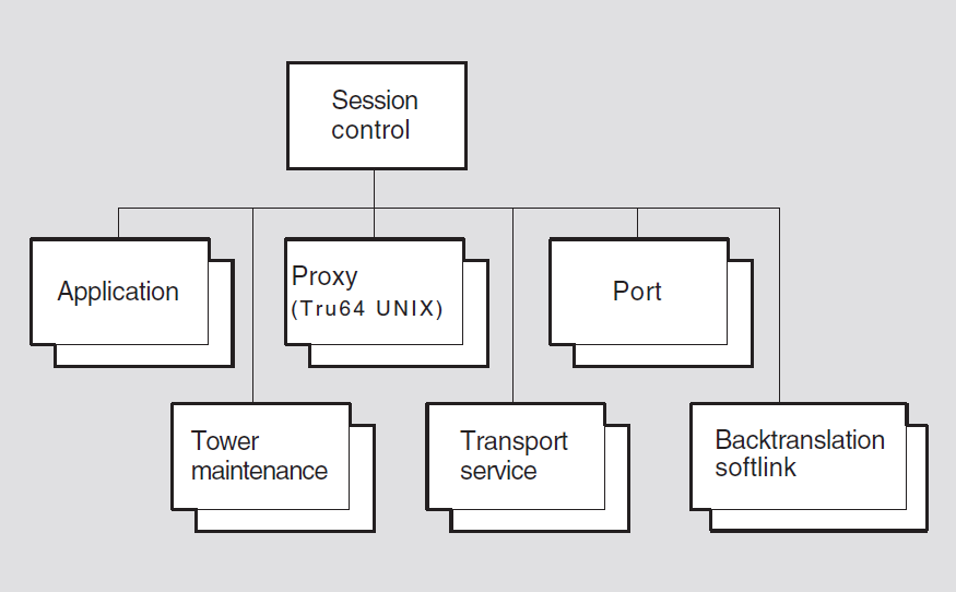
Manages transport connections on behalf of Session Control users.
Enforces access control policies to restrict communication between users and between Session Control modules.
Maps from a NA Naming Service object name to protocols and addresses.
Selects from the set of protocols supporting Session Control to attempt connection establishment.
Maintains in the namespace the protocol and address information corresponding to objects that reside in the same node as the local Session Control module.
22.1. session control
The session control entity is the top-level entity in the hierarchy of
entities belonging to the Session Control module.
create [node node-id] session control
delete [node node-id] session control
(UNIX)
disable [node node-id] session control
enable [node node-id] session control
flush [node node-id] session control naming cache entry
"*" (OpenVMS)
restrict [node node-id] session control
set [node node-id] session control {address update
interval integer | backtranslation search path
search-path-information | decnet-internet gateway enabled
boolean (UNIX) | decnet-internet gateway user latin1string (UNIX) | incoming proxy
boolean | incoming timer integer |
maintain backward soft links boolean | naming cache checkpoint
interval integer (OpenVMS) | naming cache entry (OpenVMS) |
naming cache timeout integer (OpenVMS) | naming search path
search-path-information | modify acs
boolean | node synonym directory
full-name (DIGITAL UNIX) | non privileged user
session-control (OpenVMS) | outgoing proxy
boolean | outgoing timer integer |
soft link timer binary-relative-time (UNIX) | update retry
interval integer | transport precedence sequence of
simple-name}
show [node node-id] session control [all [attributes] |
all characteristics | all counters | all status ]
shut [node node-id] session control
22.1.1. Commands
flush (OpenVMS)
Removes one or more entries from the in-memory, local naming cache. Use the syntax parenthesis-asterisk-parenthesis.
restrict
Places the module in the restrict state. In this state, outgoing
connection requests are accepted. Incoming connection requests are not accepted,
unless the client has sufficient privilege to override.
shut
Places session control in the shut state. In this state, no
further connection requests are honored. It continues to service existing
connections. When all connections have been closed by their clients, it is placed in
the off state.
22.1.2. Characteristic Attributes
|
Default: 10 |
Values: 1–4294967296 |
Minimum time, in seconds, allowed between updates of address information. More frequent modification to the set of local towers is prohibited.
|
Default: None |
Value: Search-path-information |
Describes the order in which name services will be searched for address-to-node-name translation requests (when more than one name service is in use on a node) and any associated naming templates for each directory service.
|
Default: False |
Value: True or false |
If true, the DECnet-Internet Gateway is enabled.
decnet-internet gateway user (UNIX)
Name of a user under whose account to run gateway applications.
|
Default: True |
Value: True or false |
Specifies whether to honor incoming proxy requests. If this attribute is set to
false, requests to invoke proxies on incoming requests are
ignored.
|
Default: 45 |
Values: 0–65535 |
Time, in seconds, to wait for a user module to issue an accept/reject
call after a port enters a state indicating that a connection request was received.
If the timer expires, Session Control aborts the transport connection with a
timed out error. For OpenVMS, a zero (0) value directs Session
Control to wait indefinitely without aborting the connection.
|
Default: False |
Value: True or false |
Specifies whether Session Control should attempt to update the backward
translation soft links when it detects an address change. If this attribute is set
to false, Session Control will add no new backward translation soft
links and it may delete any that it has created.
|
Default: True |
Value: True or false |
Specifies whether Session Control should attempt to update the ACS (access control set) of the node object whenever it attempts to update the towers attribute for the node in the namespace.
|
Default: 8 |
Value: Time |
Amount of time, in hours, between times when the address and node name information is checkpointed to disk from the in-memory, local naming cache.
|
Default: None |
Value: Name |
Address and node name information for a node that has been retrieved from a name service and is currently stored in the in-memory, local naming cache.
|
Default: 7 |
Value: Time |
Amount of time, in days, after which the address and node name information for a node is deleted from the in-memory, local naming cache.
|
Default: None |
Value: Search-path-information |
Describes the order in which name services will be searched for node-name-to-address translation requests (when more than one name service is in use on a node), and any associated naming templates for each name service.
|
Default: .DNA_NodeSynonym |
Value: Full-name |
Full name of a DECdns directory that contains node synonyms.
non privileged user (OpenVMS)
Specifies the Session Control on a non-privileged user account.
|
Default: True |
Value: True or false |
Specifies whether to invoke a proxy on outgoing connection requests when the user
does not explicitly specify to do so. If this attribute is set to
false, no proxy is invoked.
|
Default: 60 |
Values: 0–65535 |
Time, in seconds, to wait for an outgoing transport connection to be accepted
before Session Control aborts the connection with a timed out error.
For OpenVMS, a zero (0) value directs Session Control to wait indefinitely without
aborting the connection.
|
Default: 30 days |
Value: Binary relative time |
Interval of time, in days, DECdns checks that an object pointed to by a backward translation soft link still exists.
|
Default: 60 |
Values: 1–4294967296 |
Time to wait before Session Control retries a failed attempt to update information in the namespace. The default is 60 minutes.
|
Default: OSI |
Value: Set of OSI or NSP |
Note: On the DECnet/OSI for ULTRIX and DECnet/OSI for UNIX V1.0 products, the default was tp4 rather than OSI.
Sets the order in which transports are selected when establishing a connection.
The default order is to try OSI, then NSP. The command takes a set as input. Valid
items in the set are session control transport service entity
names.
|
Default: Current version number |
Session Control Protocol version number. You cannot modify this characteristic.
22.1.3. Counter Attributes
access control violations
Number of times Session Control has detected an access control
violation event.
backtranslation deletions
Number of times Session Control has detected a backtranslation
deletion event.
bad backtranslation links
Number of times Session Control has generated a bad backtranslation
link event.
creation time
Time this entity was created and all counters are zero.
dangling link
Number of times Session Control has detected a dangling link
event.
deleted maintained objects
Number of times Session Control has detected a deleted maintained
object event.
verification failures
Number of times Session Control has detected a verification failure
event.
22.1.4. Status Attributes
backtranslation directory
Name of the root directory of the backtranslation tree.
state
session control entity.|
off |
The entity is disabled. |
|
on |
The entity is enabled. |
|
restricted |
The entity is enabled and supports existing transport connections; it initiates outgoing transport connections, but it refuses incoming connections unless the request meets system privilege requirements. This function is only supported on UNIX. |
|
shut |
The entity is enabled and supports existing transport
connections, but it refuses any new connection requests.
After all transport connections disappear, the
|
uid
Entity's unique identifier, generated when the entity is created.
22.1.5. Event Messages
access control violation
Generated each time Session Control detects an access control violation. The arguments provide information about the source and destination.
|
destination |
End-user specification of the destination account. | |
|
destination account |
Destination account information. | |
|
destination user |
Destination user name. | |
|
node name |
Name of the source node. | |
|
nsap address |
Network address of the source node. | |
|
source |
End-user specification at the source node. | |
backtranslation deletion
Generated each time a backward translation name is discarded because of an irrecoverable error.
|
name |
Deleted name. | |
|
reason |
DECdns error that caused the deletion. | |
bad backtranslation link
Generated when an attempt to access a backward translation soft link results in a clerk exception indicating that some attribute in the soft link chain was improperly configured.
|
name |
Name improperly configured. | |
|
reason |
Reason for the exception. | |
dangling link
Generated each time an attempt to access an attribute of a backward translation soft link results in a clerk. Dangling exception.
|
name |
Full name of the soft link. | |
deleted maintained object
Generated each time a tower maintenance entity is discarded because of an irrecoverable error.
|
client |
Network management name of the user who issued the
| |
|
creation time |
Time this entity was created. | |
|
higher towers |
Set of higher towers that was passed in the
| |
|
last failure reason |
A DECdns error code that indicates the reason for the last update failure. | |
|
last successful update |
Time of the last successful update to the
| |
|
last update completed |
Time that the last attempt to update the
| |
|
last update started |
Time that the last attempt to update the
| |
|
name |
Full name of the deleted entity. | |
|
reason |
DECdns error that caused the deletion. | |
|
uid |
Entity's unique identifier, generated when the entity is created. | |
|
update failures |
Generated each time an attempt to update a
| |
|
update successes |
Generated each time an attempt to update a
| |
verification failure
Generated each time Session Control is unable to verify that the addresses and
protocols of an incoming connection request are consistent with the
DNA$Towers attribute of the source node name.
|
address |
Unverified protocol address sequence. | |
|
node |
Full name of the source node. | |
22.1.6. Exception Messages
For create:
already exists
A session control entity already exists.
For delete (UNIX):
wrong state
Disable the session control entity before trying to delete it.
22.2. session control application
A session control application entity stores information about an end user
that is activated for receipt of an incoming connection request when the request
contains that end user's name in its destination name field. The
application-name refers to the application managed by this
command.
add [node node-id] session control application
application-name addresses [set of end-user
specifications]
create [node node-id] session control application
application-name
delete [node node-id] session control application
application-name
remove [node node-id] session control application
application-name addresses [set of end-user
specifications]
set [node node-id] session control application
name {accept mode (UNIX) | address [set] | allow
decnet-internet gateway access (UNIX) | client client-id | data
abstraction (UNIX) | image name file-spec | incoming alias
boolean (OpenVMS) | incoming osi tsel
boolean (OpenVMS) | incoming proxy
boolean | maximum instances (UNIX) | network priority
(OpenVMS) | node synonym boolean | outgoing alias
boolean (OpenVMS) outgoing alias name
fullname (OpenVMS) | outgoing proxy
boolean (OpenVMS) | programming interface (UNIX) | user
name username}
show [node node-id] session control application
application-name [all [attributes] | all characteristics |
all counters | all identifiers | all status]
22.2.1. Characteristic Attributes
|
Default: Immediate |
Value: Immediate or deferred |
If accept mode is immediate, then Session Control will
automatically accept the connection before activating the end user. If accept
mode is deferred, then it is up to the program to accept or
reject the connection.
|
Default: Empty set |
Value: Set of end-user specifications |
A set of end-user specifications, any one of which, when specified in the destination name field of an incoming connection request, causes applications defined by this entity to be invoked.
|
Default: False |
Value: True or false |
If true, this application supports gateway access. If the user name
supplied by the incoming connect request contains a @ or !, the application spawner
starts up the application under the session control DECnet-Internet Gateway
user.
|
Default: None |
Value: Entity name |
Identifies the name of the local user that will be activated upon receipt of a connect request containing a destination name matching one of the values in the destination names attribute.
|
Default: Message |
Value: Message or stream |
Type of data transfer interface the application will be using: message type or stream type. The message data abstraction is identical to the sequenced-packet socket concept of the Phase IV session control. When writing applications, you should use the same data abstraction as that used by the program to which you connect.
|
Message Type |
Stream Type |
|---|---|
|
Preserves message boundaries |
Does not preserve message boundaries |
|
OpenVMS default abstraction |
Commonly used for UNIX applications |
|
Not available on TCP/IP |
Available on TCP/IP |
|
Supported by XTI |
Supported by XTI |
|
Default: No image name |
Value: File specification |
File name of a program to be invoked upon receipt of a connection request
containing an address that matches one of the values contained in the set described
by the addresses characteristic.
incoming alias (OpenVMS)
|
Default: True |
Value: True or False |
Specifies how a particular application responds to incoming connect requests
directed to the alias node address. If false, the application does not
allow a specified application to receive incoming connect requests that have been
directed to the alias node address.
incoming osi tsel (OpenVMS)
A TSEL is a string of hexadecimal digits, and the length of that string should be an even number between 2 and 64, inclusive.
The TSEL this image will accept connections for. This is similar to the destination names attribute. However, applications using this access point for in-connection matching do not use NA Session Control Protocol.
|
Default: True |
Value: True or false |
Specifies whether to honor incoming proxy requests. If this attribute is set to
false, requests to invoke proxies on incoming requests are ignored.
The setting of this characteristic overrides the setting of the session
control incoming proxy characteristic for the specified
application.
|
Default: 0 |
Value: None |
Maximum number of simultaneous instances of this application allowed. If a connect
request comes in for this application while the maximum number of instances exist,
the connect request will be rejected with ObjectTooBusy. A value of 0
indicates no maximum.
|
Default: 0 |
Value: 0–225 |
When operating over Connectionless Network Service (CLNS), indicates network priority encoded in the NPDU (network protocol data unit) header for all transmitted packets. It can be used by intermediate systems to assign the packets to queues of appropriate priority.
|
Default: False |
Value: True or false |
|
false |
The full node name is used. |
|
true |
The node synonym is used; if no synonym is available, the full name is used. |
|
Default: True |
Value: True or false |
Specifies whether a particular object uses the alias node identifier in its
outgoing connect requests. If false, the specified object is not
allowed to use the alias node address in its out going connect requests.
|
Default: None |
Value: Full-name |
Specifies the alias full name to use as the outgoing alias node identifier in its
outgoing connect requests on a system with multiple aliases configured and the
outgoing alias characteristic set to true.
If you do not set an application’s outgoing alias name characteristic
and the application has its outgoing alias characteristic set to
true, the alias name for which you set in the alias port’s
outgoing default characteristic to true is used for
outgoing connect requests.
If no alias port has its outgoing default characteristic set to
true and the application’s outgoing alias name
characteristics is not set, the first alias created is used as the default for the
system. If this alias is not enabled, the local nodename is used.
|
Default: True |
Value: True or false |
Default action to execute when user does not explicitly specify whether or not to invoke a proxy.
|
Default: Phase IV |
Value: Phase IV or Phase V |
Programming interface used by the DECnet application (socket interface).
|
Default: None |
Value: Latin1String |
Identifies the default account under which the application is to run. For OpenVMS, if null then system defaults are used to select the user.
22.2.2. Counter Attributes
access control violations (UNIX)
Number of connect requests for this application entity for which access could not be granted.
creation time
Time the entity was created.
resource failures (UNIX)
Number of times a connect request for this application was rejected due to a
resource failure. Resource failures include ObjectTooBusy (for example,
due to Maximum Instances reached) and File is nonexistent
or not executable.
total invocations (UNIX)
Number of instances of this application entity that have been invoked.
22.2.3. Identifier Attributes
name
Simple name assigned to the application when it is created.
22.2.4. Status Attributes
active instances (UNIX)
Number of active instances of this application that are currently running.
last request (UNIX)
Time the last connect request for this application was received.
process identifiers (UNIX)
Specifies a set of processes that are active instances of the specified application.
uid
UID allocated upon creation of this application subentity instance.
22.2.5. Exception Messages
For create:
already exists
A session control application entity already exists.
22.3. session control backtranslation softlink
A session control backtranslation softlink entity stores information
about entries in the backtranslation soft link database. The
name is the unique name among the set of backtranslation
soft link subentities maintained by Session Control.
delete [node node-id] session control backtranslation
softlink name
show [node node-id] session control backtranslation
softlink name [all [attributes] | all counters | all
identifiers | all status]
update [node node-id] session control backtranslation
softlink name
22.3.1. Commands
update
Updates a backtranslation soft link entity.
22.3.2. Counter Attributes
creation time
Time when this subentity was created.
update failures
Number of times an update for this subentity failed.
update successes
Number of times an update for this subentity succeeded.
22.3.3. Identifier Attributes
name
Simple name assigned to the transport service when it is created.
22.3.4. Status Attributes
last failure reason
Failure reason for the most recent update failure.
last successful update
Most recent time an update for this subentity succeeded.
last update completed
Most recent time an update for this subentity completed.
last update started
Most recent time an update for this subentity was initiated.
network entity title
Network entity title for this soft link.
state
Status of this entity instance. Values include create, delete, exist
and retarget.
target
Target for soft link.
uid
Entity's unique identifier, generated when the entity is created.
22.3.5. Event Messages
deleted
The given backtranslation softlink subentity instance was
deleted.
|
creation time |
Time this subentity was created. | |
|
network entity title |
Network entity title for this soft link. | |
|
state |
Status of the entity. | |
|
target |
Target for soft link. | |
|
update failures |
Times an update for this subentity failed. | |
|
update success |
Times an update for this subentity succeeded. | |
update failure
Signals an attempt to create, delete, or retarget a backtranslation has failed.
|
reason |
Reason for the failure. | |
22.4. session control port
A session control port entity stores Session Control information about
the transport connection. The port-name refers to the port managed
by this command.
delete [node node id] session control port
port-name
show [node node id] session control port
port-name [all [attributes] | all counters | all
identifiers | all status ]
22.4.1. Counter Attributes
creation time
Time the entity was created.
22.4.2. Identifier Attributes
name
Simple name assigned to the port when it is created. This name is passed to the Transport layer as the client name in a call to open a port.
22.4.3. Status Attributes
|
Default: None |
Value: Immediate or deferred |
If accept mode is immediate, Session Control automatically accepts
the connection before activating the end user. If accept mode is
deferred, it is up to the end user to accept or reject the
connection.
|
Default: None |
Value: True or false |
True if Session Control will abort the transport connection for this
port if Transport determines the network is partitioned.
|
Default: None |
Value: Local-entity-name |
Network management name specified by the user of the port when it was opened.
|
Default: None |
Value: Message or stream |
Type of data transfer interface the application uses.
direction
|
incoming |
Port was opened to handle an incoming transport connection. |
|
outgoing |
Port is open to initiate an outgoing transport connection. |
|
unknown |
The port status is unknown at this time. |
|
listening |
The port is open to receive incoming transport connections. |
|
Default: None |
Value: 0–255 |
Incoming network priority value received with incoming connect events.
|
Default: None |
Value: Local-entity-name |
Name of the Session Control port that this port came from as the result of a
PollIncoming on the parent port.
local end user address
Address assigned by the user of the port when it was opened. On outgoing
connections this value is sent in the source name field of the connection request;
on incoming connections this value is received in the destination name
field of the request.
node name sent
Node name that was received or sent in the connect request.
|
Default: None |
Value: 0–255 |
Outgoing network priority value passed to transport.
|
Default: None |
Value: Hex string |
The process ID (PID) of the process that owns the session port.
|
Default: None |
Value: Phase IV or DECnet-Plus |
Programming interface the DECnet application uses. For UNIX, this is the socket interface.
|
Default: None |
Value: True or false |
True if the request proxy bit was turned on in the connect request
that was received or sent.
|
Default: None |
Value: Integer |
Number of connect requests pending that PollIncoming has not dequeued
yet.
|
Default: None |
Value: Integer |
Number of octets of unread data queued.
remote end user address
Address of the remote end user of the port. This value was either sent in the
destination name field of an outgoing connection request or
received in the source name field of an incoming connection request. If
the value of the direction attribute is incoming or
unknown and no connection request has been received, the value of
this attribute is null.
|
Default: None |
Value: Integer |
Number of octets of unsent data queued.
|
Default: None |
Value: Local-entity-name |
Network management name of the transport port being used by this session control port.
version sent
Version that was received or sent in the connect request.
22.5. session control proxy (UNIX)
A session control proxy entity stores the information that grants remote
users proxy access to given application subentity instances. See Chapter 4, "CSMA-CD Module" for further information about proxy access.
add [node node-id] session control proxy
name {application [set of simple names] | source end users
[set of records] }
create [node node-id] session control proxy
name
delete [node node-id] session control proxy
name
remove [node node-id] session control proxy
name {applications [set of simple names] | source end users
[set of records] }
set [node node-id] session control proxy
name
show [node node-id] session control proxy
name [all [attributes] | all characteristics | all counters
| all identifiers | all status ]
22.5.1. Characteristic Attributes
|
Default: None |
Value: Set of simple name |
Set of application identifiers, one of which must match the application requested. If this attribute value is null, any requested application will match.
|
Default: None |
Value: Set of record |
Set of remote end users for whom this proxy entry applies. An unspecified end user implies all end users on the node specified in the same record. The record format has two fields: node which has a data type of full name, and end user which has a data type of end-user-specification.
|
Default: None |
Value: Latin1String |
Local user name under which access is granted.
|
Default: Explicit |
Value: Explicit or default |
Type of proxy entry: explicit means that the destination the user
requested in the connect request must match the target user for this entry;
default means if no explicit entry matches, this entry
will be tried. An explicit proxy entry matches before a
default one.
22.5.2. Counter Attributes
creation time
Time the entity was created and associated counter attributes were zero.
used
Number of times this proxy entry was used to gain access to one of the applications.
22.5.3. Identifier Attributes
name
Simple name assigned to a particular entity instance. The name is the management identifier for the proxy database entry and is kept unique among the entries in this database maintained by Session Control.
22.5.4. Status Attributes
last time used
Last time this proxy entry was used to gain access to one of the applications.
22.5.5. Exception Messages
For create:
already exists
A session control proxy entity already exists.
22.6. session control tower maintenance
A session control tower maintenance entity stores information about
entries in the tower maintenance database. A tower maintenance entity is created
automatically when a client issues a dnaKeepMeHere call, using the
programming interface. The name refers to the tower maintenance
entity managed by this command.
delete [node node-id] session control tower maintenance
name
show [node node-id] session control tower maintenance
name [all [attributes] | all counters | all identifiers |
all status ]
update [node node-id] session control tower maintenance
name
22.6.1. Commands
update
Updates tower maintenance entity.
22.6.2. Counter Attributes
creation time
Time this entity was created.
update failures
Number of times this entity detected an update failure event.
update successes
Number of times the DNA$Towers attribute of the DECdns object name
associated with this entity has been successfully updated.
22.6.3. Identifier Attributes
name
Full-name assigned to the tower maintenance entity when it is created.
22.6.4. Status Attributes
client
Network management name of the user who issued the keepmehere call
that resulted in the creation of this entity.
higher towers
Set of higher towers that was passed in the keepmehere call that
created this entity.
last failure exception (UNIX)
Reason for the most recent update failure. If no update for this subentity ever failed, then it is zero.
last failure reason
DECdns error code that indicates the reason for the last update failure.
last successful update
Time of the last successful update to the DNA$Towers attribute for
the specified entity. On OpenVMS, if no update for this subentity ever failed, then
it is zero.
last update completed
Time that the last attempt to update the DNA$Towers attribute
completed (successfully or not).
last update started
Time that the last attempt to update the DNA$Towers attribute for the
specified entity was initiated.
uid
Entity's unique identifier, which is generated when the entity is created.
user (UNIX)
User name of the user who created this tower maintenance subentity with the
keepmehere procedure call. This is different from client, which
refers to a local entity name.
22.6.5. Event Messages
update failure
Generated each time an attempt to update a DNA$Towers attribute
fails.
22.7. session control transport service
A session control transport service entity stores information about
modules in the Transport layer that support Session Control. The
transport-name refers to the transport service managed by this
command.
create [node node-id] session control transport service
transport-name {protocol protocol-id |
tsel hex-string }
delete [node node-id] session control transport service
transport-name
show [node node-id] session control transport service
transport-name [all [attributes] | all counters | all
identifiers | all status]
22.7.1. Arguments
These arguments apply only to the create directive.
protocol protocol-id
|
'04'H |
This transport service uses the NSP transport protocol. |
|
'05'H |
This transport service uses version 1 of the OSI transport protocol. |
tsel hex-string
Transport selector used by the OSI transport module to bind incoming connection requests to Session Control. The default value is the hexadecimal representation of "DEC0." This argument is not applicable for NSP transport.
22.7.2. Counter Attributes
creation time
Time the entity was created.
22.7.3. Identifier Attributes
name
Simple name assigned to the transport service when it is created.
22.7.4. Status Attributes
protocol
Transport protocol used by this transport service, as specified by the user when
this service was created. (See the create command description for a
list of possible values.)
tsel
Transport selector used by the OSI Transport Module to bind incoming connection
requests to Session Control. For UNIX, The TSEL value is specified in a
create command. This attribute is not applicable for NSP
transport.
22.7.5. Exception Messages
For create:
already exists
The session control transport service entity already exists.
duplicate protocol
The session control transport service entity fails on creation
because the protocol already exists.
protocol not supported
The session control transport service entity fails on creation
because the protocol is not supported by this module.
wrong state (UNIX)
This entity cannot be deleted while there are connections using this transport.
Chapter 23. Token Ring Module (UNIX)
This chapter describes all the commands you can use to manage the entities that constitute the IEEE 802.5/Token Ring module. The Token Ring module implements one of multiple possible Link level/Physical level modules in the OSI layered architecture model.
The NA IEEE 802.5/Token Ring Data Link provides either a 4- or 16-Mb/s local area network (LAN). It provides communication services for multiple concurrent users. The services provided are logical link control (LLC), mapped Ethernet and station management (SMT) services.
Figure 23.1, ''Hierarchy of Token Ring Module Entities'' shows the hierarchical relationship of the entities that constitute the Token Ring module.
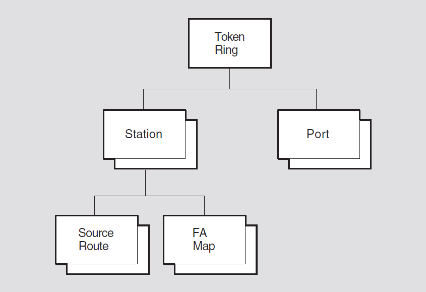
The NA IEEE 802.5/Token Ring module incorporates the functions and operations defined in the IEEE 802.5 Token Ring Access Method, parts of the ISO 8802-1 (IEEE 802.1) Addressing, Internet working and Network Management, and parts of the ISO 8802-2 (IEEE 802.2) Logical Link Control (LLC) specifications. To this, the NA 802.5/Token Ring Data Link adds features often needed by users of the data link. A typical such user is the Network layer of the Network Architecture (NA).
23.1. token ring
The token ring entity is the top-level entity in the hierarchy of
entities belonging to the Token Ring module.
Syntax
create [node node-id] token ring
delete [node node-id] token ring
show [node node-id] token ring [all [attributes] | all
characteristics]
23.1.1. Characteristic Attributes
|
Default: Current version number |
Version number of the Token Ring architecture specification to which the implementation conforms. You cannot modify this characteristic.
23.1.2. Exception Messages
For create:
already exists
A token ring entity already exists.
For delete:
has children
Cannot delete while subentities exist.
23.2. token ring station
A token ring station entity manages a Token Ring controller. Each station
corresponds to a particular instance of logical link control (LLC), medium access
control (MAC), and physical attachment. The Token Ring data link can be monitored and
controlled through NA network management. The station-name refers
to the station managed by this command.
Syntax
create [node node-id] token ring station
station-name communication port
device-name
delete [node node-id] token ring station
station-name
disable [node node-id] token ring station
station-name
enable [node node-id] token ring station
station-name mode station-mode
transparent source routing function-mode
show [node node-id] token ring station
station-name [all [attributes] | all characteristics | all
counters | all identifiers | all status]
23.2.1. Arguments
communication port device-name
|
Device |
device-name |
|---|---|
|
DETRA |
tra0 |
mode station-mode
The mode this station will be enabled to. Can be either normal (default) or loopback.
transparent source routing function-mode
Indicates whether the transparent source routing functionality will be enabled.
The default is enabled. This value cannot be disabled.
23.2.2. Characteristic Attributes
|
Default: 60 seconds |
Value: 1–65535 |
Controls the timeout of the source routing information for nodes with which the local node has not recently communicated.
communication port
Name of the hardware port associated with this station, taken from the
corresponding argument in the create directive. You cannot modify this
characteristic.
|
Default: 1 second |
Value: 1–255 |
Controls the timeout of the source routing discovery process.
|
Default: True |
Value: True or false |
Determines if Early Token Release (ETR) is in use on this station. ETR may be
supported only on 16-Mb/s media. This attribute can only be set in the
off state.
|
Default: 1024 |
Value: 256–2048 |
The maximum number of source route subentities this station will buffer. Can only
be set in the off state.
|
Default: False |
Value: True or false |
Determines if the station will try to become the active monitor, if a lower
addressed station starts the monitor contention process. This attribute can only be
set in the off state.
|
Default: Unknown |
Value: 4 or 16 Mbps |
The data rate of the media. Can only be set in the off state.
|
Default: Hardware ROM address |
Value: None |
The desired station address. The bits in each byte of an address must be reversed,
for example, 08-00-2b-11-22-33 would become 10-00-d4-88-44-cc. This attribute can
only be set in the off state.
23.2.3. Counter Attributes
Unless stated otherwise, counts include both normal and multicast traffic and all protocol types, service access points (SAPs), and protocol identifiers.
abort delimiters sent
Number of times an abort delimiter was sent while transmitting.
auto-removal failures
Number of times a failure during the beacon auto-removal process was detected and the station removed itself from the ring.
burst errors
Number of times a lack of transitions was detected on the physical media.
creation time
Time at which the station entity was created.
explorer frames received
Number of source routing (SR) explorer frames received by the source
route entities.
explorer frames sent
Number of source routing (SR) explorer frames sent by the source
route entities.
frame copied errors
Number of individually addressed frames received with the Address Recognized status bit = 1.
frequency errors
Number of times an error was detected in the incoming signal frequency.
insertion failures
Number of times a ring insertion operation has failed.
internal errors
Number of times a recoverable internal error was recognized.
line errors
Number of times a CRC error or a non-data symbol in a frame or token with the E bit = 0 was detected.
lobe wire faults
Number of times an open or shorted lobe data path was detected and the station removed itself from the ring.
lost frames
Number of times this station has transmitted a frame and has failed to receive it for stripping before the Timer Return to Repeat (TRR) timer expired.
multicast octets received
Number of octets successfully received in multicast frames of type LLC. The count does not include the MAC envelope.
multicast octets sent
Number of octets successfully sent in multicast frames of type LLC. The count does not include the MAC envelope.
multicast pdus received
Number of multicast frames successfully received of type LLC.
multicast pdus sent
Number of multicast frames successfully sent of type LLC.
octets received
Number of octets successfully received in frames of type LLC.
octets
                    sent
Number of octets successfully sent in frames of type LLC.
pdus received
Number of frames successfully received of type LLC.
pdus sent
Number of frames successfully sent of type LLC.
receive data overruns
Number of times a frame was lost due to system or adapter transfer failure.
receiver congestions
Number of frames recognized as matching one of this station's individual, group, or functional addresses, but could not be received for lack of buffers in the adapter.
remove frames received
Number of times a remove MAC frame has been received and the station removed itself from the ring.
ring beaconings
Number of times the condition of receiving or transmitted beacon frames was detected due to a hard error.
ring failures
Number of times the station left the ring due to failure.
ring recoveries
Number of times detected the ring is in the monitor contention process. Indicates that the ring has attempted to recover from a soft error problem.
ring poll errors
Number of times an error was detected in the A and C bits during the ring poll process.
route discovery failures
Number of times the route discovery process failed to find a route to another station.
selftest failures
Total number of times a self-test of the station detected an error.
signal losses
Number of times detected loss of signal on the physical media.
single station conditions
Number of times detected being the only station in the ring.
soft error reports sent
Number of times sent a report error MAC frame to the ring error monitor.
unavailable station buffers
Number of times a frame was discarded because no station level buffers were available.
unavailable user buffers
Number of times a frame was discarded because no user buffer was available.
unrecognized individual destination pdus
Number of times a received individually addressed LLC frame was discarded because there was no data link port with a matching SAP, SNAP PID, or Ethernet protocol type.
unrecognized multicast destination pdus
Number of times a received LLC frame addressed to an enabled group or functional address was discarded because there was no data link port with a matching SAP, SNAP PID, or Ethernet protocol type.
token errors
Number of times when this station (when Active Monitor [AM]) has transmitted a new token due to errors on the ring.
transmit failures
Number of times a transmit error, other than underrun occurred. Transmit error reasons can be tracked by event reasons, or by observing other 802.5 counters.
transmit underruns
Number of times a transmit underrun occurred.
transmitting beacons
Number of times initiated transmitting beacon frames.
23.2.4. Identifier Attributes
name
Simple name assigned to the station when it is created.
23.2.5. Status Attributes
authorized access priority
The maximum transmit priority allowed for this station. The value is set by the ring parameter server.
authorized function classes
The bit map of the authorized function classes for this station.
functional address
The functional address bit map enabled in the adapter for the reception on this station.
group addresses
The set of group addresses enabled in the adapter for reception on this station.
insert error reason
insertion successful if no error.|
no open |
An error occurred during the insertion phase. |
|
bad parameters |
Invalid options specified to the adapter to insert into the ring. |
|
lobe fault |
Lobe test fault or MAC frames were received before physical insertion. |
|
signal loss |
Signal loss condition was detected during the insertion phase. |
|
timeout |
Logical insertion onto the ring failed before insertion timer expired. |
|
ring failure |
Unable to receive its own ring purge MAC frames after becoming the active monitor. |
|
ring beaconing |
A beacon MAC frame was received after physical insertion onto the ring. |
|
duplicate address |
Another station on the ring already has the address this station wishes to use. |
|
parameter server error |
A ring parameter server (RPS) is present on the ring but does not respond to a request initialization MAC frame. |
|
remove frame received |
A remove station MAC frame was received during the insertion process. |
|
insertion successful |
The insertion phase was successful. |
link state
|
off |
Station is not on the ring. |
|
running |
Station is available to the user for processing. |
|
initializing |
Station is in process of inserting into the ring. |
|
recovery |
Station is beaconing. |
|
contending |
Station is participating in the monitor contention process. |
|
broken |
Station has failed the insertion process. |
MAC address
The currently active station address value for which the data link is receiving an individually addressed frame.
nearest upstream neighbor
The MAC address of the last known upstream ring neighbor as heard from the ring poll process.
physical drop number
The physical drop number assigned by the ring parameter server.
receive mode
The receive mode of the station. Normal or promiscuous.
ring error reason
no
error if none has occurred.|
no error |
Successful operation, no error has occurred. |
|
ring in recovery |
Claim token MAC frames were observed on the ring. |
|
single station |
It sensed this is the only station on the ring. |
|
remove frame received |
A remove ring station MAC frame request was received and the station has deinserted from the ring. |
|
auto-removal failure |
The auto-removal process has failed and the station has deinserted from the ring. |
|
lobe fault |
An open or short circuit in the lobe wire cable was detected. |
|
transmitting beacon |
Beacon frames are transmitted to the ring. |
|
soft error frame sent |
A report error MAC frame has been transmitted. |
|
beaconing condition |
Beacon frames are presently transmitted or received to or from the ring. |
|
signal loss |
A loss of signal was detected on the ring. |
|
open in progress |
Station is in process of inserting into the ring. |
ring number
The local ring number as received from the ring parameter server.
ROM address
The IEEE universally administered address present in the ROM of the adapter.
transparent source routing
State of transparent source routing support.
state
Operational state of the station.
uid
Entity's unique identifier, which is generated when the entity is created.
23.2.6. Event Messages
abort delimiter sent
Station has transmitted an abort delimiter.
auto-removal failure
Self-test failed following a beacon auto-removal process.
burst error
Absence of transitions on the physical media.
frame copied error
This station received a frame addressed to its MAC address with the A and C bits set.
internal error
Station has detected an internal error.
line error
CRC error or Manchester violation detected in a token or frame with the E bit = 0.
lobe wire fault
Short or open circuit detected on cable.
lost frame error
TRR timer expired while this station was transmitting.
receive data overrun
A receive overrun hardware error was detected.
remove frame received
Remove ring station MAC frame received.
ring beacon initiated
The station started the beacon process.
ring beaconing
Beacon MAC frames being sent or received.
ring poll error
Failure to properly set A and C bits during the ring poll process.
ring recovery
Station is receiving or transmitting claim token MAC frames.
route discovery failure
Route discover timer expired.
selftest failure
The implementation-specific self-test procedures have detected a failure.
signal loss
Loss of signal on the physical media.
single station detected
The only station participating in the ring poll process.
soft errors reported
Soft error report MAC frame sent to ring error monitor.
station buffer unavailable
No buffer was available to receive a frame.
token error
This station, as active monitor, has had to transmit a new token following an error condition.
transmit failed
Failure to transmit operation other than underrun.
transmit underrun
Transmit failed due to underrun.
unrecognized individual pdu destination
An individually addressed frame with unrecognized DSAP or protocol ID.
unrecognized multicast pdu destination
A globally addressed frame with unrecognized DSAP or protocol ID.
user buffer unavailable
Data link user did not supply a receive buffer.
23.2.7. Exception Messages
For create:
already exists
A token ring station entity already exists.
communication port in use
A communication port is already reserved by another entity.
invalid communication port
Cannot run Token Ring data link on this communication port.
For delete:
wrong state
Failure to delete the token ring station entity because the station
must be disabled before deletion.
23.3. token ring port
A token ring port entity represents an access point to the service
offered by the Token Ring module. A client transmits and receives data through a port.
Ports are created and deleted by client use of open and close service interface
procedures. The port-name refers to the port managed by this
command.
Syntax
show [node node-id] token ring port
port-name [all [attributes] | all counters | all
identifiers | all status]
23.3.1. Counter Attributes
creation time
Time at which the port subentity was created.
multicast octets received
Number of multicast user data octets successfully received and available to the data link user. This counter is optional.
multicast octets sent
Number of multicast user data octets successfully transmitted using the port. This counter is optional.
multicast pdus received
Total number of multicast frames successfully received and available to the data link user.
multicast pdus sent
Number of multicast frames successfully transmitted using the port. This counter is optional.
octets received
Total number of user data octets successfully received and available to the data link user. This counter is optional.
octets sent
Number of user data octets successfully transmitted using the port. This counter is optional.
pdus received
Total number of frames successfully received and available to the data link user.
pdus sent
Total number of user frames successfully transmitted using the port.
unavailable user buffers
Number of times no user buffer was available at the port for an incoming frame.
23.3.2. Identifier Attributes
name
Simple name assigned to the port when it is created.
23.3.3. Status Attributes
client
Name specified by the data user link when the port is opened.
ethernet protocol types
Set of Ethernet protocol types that are recognized for this port.
FA map mode
If set to enabled, indicates that functional address mapping is being performed. Specified by the user when the port is opened.
FA-GA map
Set of functional-to-group address/PID mappings for this port.
length present
Indicates whether a length field is used in Ethernet format frames sent or received on this port.
llc sap addresses
Set of individual and group LLC SAP addresses that are recognized for this port.
llc service
The LLC PDU processing the data link user requires from the port. Specified by the user when the port is opened.
mac addresses
Set of individual and multicast MAC addresses that are recognized for this port.
receive mode
If set to promiscuous, indicates if the port is to receive all frames
regardless of MAC address. Or, on ports of type LLC, regardless of Ethernet protocol
type, SNAP protocol identifier, or LLC SAP address.
station
Name of the station subentity associated with this port. Specified by the user when the port is opened.
SNAP protocol identifiers
Set of SNAP protocol identifiers that are recognized for this port.
source routing mode
If set to transparent, indicates that transparent source routing is
in effect. Specified by the user when the port is opened.
type
Type of port specified by the user when the port is opened.
uid
Entity's unique identifier, which is generated when the entity is created.
23.4. source route
A source route entity describes an entry in the source routing database.
In transparent source routing, the source route entities are typically
created and enabled by the parent Station entity. The source
route-id refers to the source route entity managed by this
command.
delete [node node-id] token ring station
station-name source route source
route-id
reset [node node-id] token ring station
station-name source route source
route-id
show [node node-id] token ring station
station-name source route source
route-id [all [attributes] | all counters | all identifiers | all
status]
23.4.1. Commands
reset
Resets the source route entity. It causes the state of the
entity/database entry to become STALE. This will typically cause a source route
discovery to occur upon the next transmitted frame with this destination.
23.4.2. Counter Attributes
creation time
Time at which the source route entity was created.
23.4.3. Identifier Attributes
LAN address
The MAC address of the entity's destination station.
23.4.4. Status Attributes
routing information
Source routing information to be used when communicating with the entity's destination station.
state
source route entity.|
no route |
No path known to the entity's destination address. |
|
on ring |
Destination station on the local Token Ring. No source routing information needed. |
|
have route |
Destination station on a remote Token Ring. Entity contains valid source routing information. |
|
rediscovering |
Route discovery on the extended Token Ring is in progress. |
|
stale |
Had source route but the aging timer expired. |
|
weak route |
Entity was created as a result of a spanning tree explorer multicast frame. |
uid
Entity's unique identifier, which is generated when the entity is created.
23.5. FA map
The functional address mapping (FA map) entities describe the default functional
address-global address mapping to be applied to ports that are created with the same
protocol identifiers. The famap-id refers to the FA
map entity managed by this command.
Syntax
create [node node-id] token ring station
station-name FA map
famap-id
delete [node node-id] token ring station
station-name FA map
famap-id
show [node node-id] token ring station
station-name FA map famap-id [all
[attributes] | all characteristics | all counters | all identifiers | all
status]
23.5.1. Characteristic Attributes
functional address
Functional address used to send or receive frames on the Token Ring.
group address
Group address used for sending or receiving frames.
SAP address
LLC SAP address protocol of frames to be mapped. If SNAP SAP (AA) then the SNAP PID applies.
SNAP PID
SNAP protocol identifier for SNAP SAP frames.
23.5.2. Counter Attributes
creation time
Time at which the FA map entity was created.
23.5.3. Identifier Attributes
name
Simple name assigned to the FA map entity when it is created.
23.5.4. Status Attributes
uid
Entity's unique identifier, which is generated when the entity is created.
23.5.5. Exception Messages
For create:
already exists
An FA map entity with the same identifier already exists.
Chapter 24. X.25 Access Module
This chapter describes all the commands you can use to manage the entities that constitute the X.25 Access module. The X.25 Access module resides in the Application layer of the Network Architecture (NA). It interfaces with the X.25 Protocol, X.25 Client, and X.25 Server modules to provide X.25 services and functions as described in the NA X.25 Access Architecture.
Figure 24.1, ''Hierarchy of X.25 Access Module Entities'' shows the hierarchical relationship of the entities that constitute the X.25 Access module.
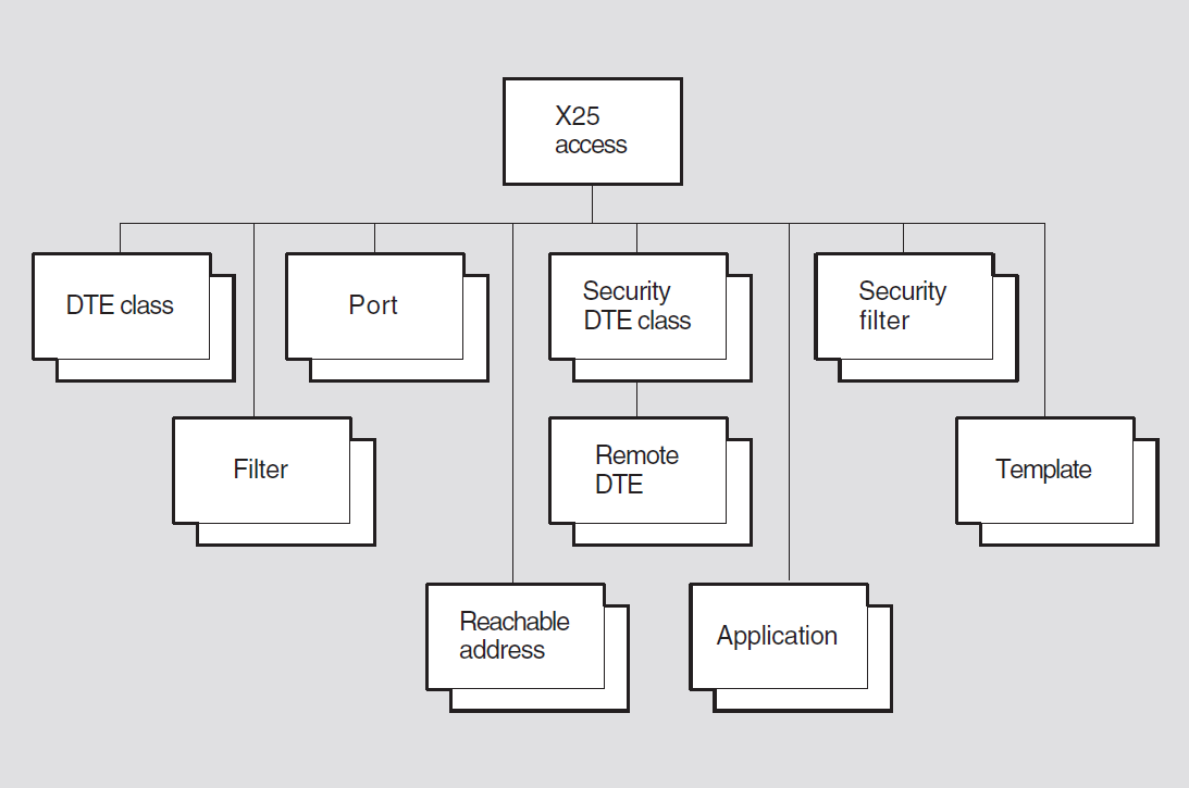
24.1. x25 access
The x25 access entity is the top-level entity in the X.25 Access module
hierarchy of entities.
Syntax
create [node node-id] x25 access [maximum active ports
integer]
delete [node node-id] x25 access
disable [node node-id] x25 access
enable [node node-id] x25 access
show [node node-id] x25 access [all [attributes] | all
characteristics | all counters | all status ]
24.1.1. Arguments
maximum active ports
Maximum number of ports that can be created on this system. This argument is optional.
24.1.2. Characteristic Attributes
|
Default: Implementation specific |
Value: Implementation specific |
Total number of ports that can be active simultaneously. You cannot modify this
characteristic. It is supplied as an argument to the create
directive.
|
Default: Current version number |
Version number of the X.25 architecture specification to which the implementation conforms. You cannot modify this characteristic.
24.1.3. Counter Attributes
creation time
Time at which this entity was created.
incoming calls blocked
Number of incoming calls that have been cleared at the X.25 Access module because of security failures.
incoming calls failed
Number of incoming calls that have been cleared at the X.25 Access module for reasons other than security failures.
outgoing call configuration errors
Number of calls that have failed due to misconfiguration of security management databases.
outgoing calls blocked
Number of outgoing calls that have been cleared at the X.25 Access module because of security failures.
pvc accesses blocked (UNIX)
Number of PVC accesses that have failed due to security blocking.
times port terminated
Number of times the port terminated event has occurred.
24.1.4. Status Attributes
active ports
Sum of the number of SVCs on which a call is either being set up or is in the data phase. The number of permanent virtual circuits (PVCs) that have been allocated to users.
state
x25 access entity.|
off |
The |
|
on |
The |
uid
Entity's unique identifier, which is generated when the entity is created.
24.1.5. Event Messages
incoming call blocked
Generated when an incoming call from the X.25 Protocol module (or from the X.25 Client module in an accessing system) is blocked and cleared by the X.25 Access module's security mechanisms.
|
filter |
Name of the selected filter. | |
|
group |
Name of the | |
|
inbound dte class |
Name of the DTE (data terminal equipment) class associated
with the incoming call by the | |
|
security dte class |
This DTE class identifies the | |
|
remote dte |
Name of the | |
|
sendingdte |
DTE address of the calling DTE. This argument is not present when the call is delivered by means of a BCUG. | |
incoming call failed
Generated when an incoming call from the X.25 Protocol module (or from the X.25 Client module in an accessing system) is cleared by the X.25 Access module.
|
group |
Name of the | |
|
reason |
Reason why the call failed. | |
|
insufficient resources |
The X.25 Access module has insufficient resources to handle the call. | |
|
no filters |
The incoming call failed to match any of the active filters. | |
|
security dte class not found |
The DTE class of the incoming call has an invalid security DTE class associated with it. | |
|
security filter not found |
The filter on which the incoming call was matched has an invalid security filter associated with it. | |
|
security dte class |
Name of the | |
|
security filter |
Name of the | |
|
sending dte |
DTE address of the remote DTE. | |
in use filter deleted
Generated when an active filter has been deleted by the use of the NCL
delete x25 access filter command.
|
filter |
The name of the deleted filter. | |
|
listener |
The name of the application associated with the filter. | |
outgoing call blocked
Generated when the X.25 Access module's security mechanisms prevent a client from making an outgoing call.
|
blocked by |
Specifies where the security blocking occurred. | |
|
gateway security |
Blocked by the connector system. | |
|
local security |
Blocked by the accessing system. | |
|
client |
Name of the entity that made the call. | |
|
destination dte |
Specifies the called DTE address. This argument is not present if the call specifies a bilateral closed user group (BCUG). | |
|
dte class |
Name of the DTE class specified in the call. This argument is not present if the call specifies a bilateral closed user group (BCUG). | |
|
group |
Name of the | |
|
remote port |
DNS name of the entity that made the call. If the call is blocked by gateway security, this identifies the X.25 access client on the accessing system. This argument is mandatory only if the client of X.25 access is the X.25 Server module. | |
|
security DTE class remote DTE |
Name of the | |
|
source |
(OpenVMS only) Name of the entity that made the call. This identifies the client of X.25 Access at the accessing system when the call is blocked by security on a gateway system. This argument is mandatory only when the client of X.25 Access is the X.25 Server module. | |
outgoing call configuration error
Generated when a call fails because of misconfiguration of the security databases.
|
reason |
Specifies why the call failed. | |
|
security dte class not found |
The DTE class of the outgoing call must have a valid security DTE class associated with it. | |
|
security dte class |
Name of the | |
port terminated
Generated whenever a port is closed. The event arguments simply reflect the attributes of the port at the time it was terminated.
|
call association |
Name of the | |
|
call direction |
Direction of the call on the SVC (incoming or outgoing).
This attribute is supported only if the status attribute
| |
|
calling address extension |
Calling NSAP address that is carried transparently in an
incoming or outgoing call packet. This attribute is
supported only if the status attribute | |
|
calling dte address |
Calling DTE address in a call request or incoming call
packet (depending on the value of the status attribute
| |
|
channel |
Channel number of the underlying virtual circuit. This
status is valid only if the port is at a connector system
and the status attribute | |
|
client |
Name of the entity that made or accepted the call. | |
|
data octets received |
Number of data octets received at the port. | |
|
data octets sent |
Number of data octets sent by the port. | |
|
dte class |
Name of the DTE class to which the DTE of the underlying
virtual circuit belongs. This attribute is supported only if
the status attribute | |
|
fast select |
Specifies whether | |
|
group |
Name of the | |
|
incoming packet size |
Packet size, in octets, for incoming data on a virtual
circuit. This attribute is supported only if the status
attribute | |
|
incoming throughput class |
Throughput class for incoming data on a virtual circuit. | |
|
incoming window size |
Window size for incoming data on a virtual circuit. | |
|
local dte |
Name of the DTE entity associated with the call. | |
|
originally called address |
If a call is redirected, this is the DTE address from
which the call was redirected; otherwise, the address is
null. This status is valid only if the status attribute
| |
|
outgoing packet size |
Packet size, in octets, for outgoing data on a virtual
circuit. This attribute is supported only if the status
attribute | |
|
outgoing throughput class |
Throughput class for outgoing data on a virtual circuit. | |
|
outgoing window size |
Window size for outgoing data on a virtual circuit. This
attribute is supported only if the status attribute
| |
|
pdus received |
Number of PDUs received at the port. | |
|
pdus sent |
Number of PDUs sent by the port. | |
|
protocol identifier |
First four octets of call data in the call. This attribute
is supported only if the status attribute | |
|
pvc |
Name of the PVC to which this port belongs. This attribute
is present only if the status attribute | |
|
redirect reason |
Specifies whether a call has been redirected and, if so,
the reason for the redirection. This attribute is supported
only if the status attribute | |
|
reference time |
Time at which the port was created (if the circuit is a PVC), or the time at which the port was first used to send or receive a call at the X.25 user interface (if the circuit is an SVC). | |
|
remote port |
Name of the peer entity with which this port is communicating. | |
|
reserved |
If the port is associated with a reserved logical channel
number (LCN), this specifies the name of the local DTE
entity on which the LCN is reserved. A null string indicates
that the port is not associated with a reserved LCN. This
attribute is supported only if the status attribute
| |
|
reverse charging |
Specifies whether reverse charging is in operation for the
call. This attribute is supported only if the status
attribute | |
|
segments received |
Number of segments of data received by this port. | |
|
segments sent |
Number of segments of data sent by this port. | |
|
state |
Status of the | |
|
target address extension |
Called NSAP address that is transparently carried in an
incoming or outgoing call packet. This attribute is
supported only if the status attribute | |
|
target dte address |
Called DTE address in a call request or incoming call.
This attribute is supported only if the status attribute
| |
|
type |
Specifies that the port represents an SVC (switched or permanent). | |
pvc access blocked
Generated when a client of X.25 Access is not allowed to access a PVC.
|
blocked by |
Where the blocking occurred. | |
|
gateway security |
At the gateway system | |
|
local security |
At the accessing system | |
|
client |
Name of the entity that attempted to use the PVC. | |
|
pvc |
Name of the PVC. | |
|
source |
Name of the entity that attempted to use the PVC. This identifies the client of X.25 Access module at the accessing system when the call is blocked by security on a gateway system. This argument is mandatory only when the client of the X.25 Access module is the X.25 Server module. | |
24.2. x25 access application
X25 access application entity defines an application to be executed
for an incoming call. The application-name refers to the
application managed by this command. An application type may be one of the following:X.25
X.29
X.29 Login
Syntax
add [node node-id] x25 access application
application-name filters set of
simple-name
create [node node-id] x25 access application
application-name
delete [node node-id] x25 access application
application-name
disable [node node-id] x25 access application
application-name
enable [node node-id] x25 access application
application-name
remove [node node-id] x25 access application
application-name filters set of
simple-name
set [node node-id] x25 access application application-name {account
latin1string (UNIX) |activation data
latin1string (UNIX) | file filespec |
filters set of simple-name| maximum activations integer (UNIX)
| template simple-name (UNIX) | type application-type | user
latin1string}
show [node node-id] x25 access application
application-name [all [attributes] | all characteristics |
all identifiers | all status ]
24.2.1. Characteristic Attributes
|
Default: No service/account data |
Value: Latin1String |
Default service or account identifier to be used when starting the applications process.
|
Default: None |
Value: Latin1String |
Data required to start the application process. This characteristic is optional.
This attribute is not valid for an application of type X29
login.
|
Default: None |
Value: Filename |
Indicates the file name or command that is associated with starting a process for
the represented application. This attribute is not valid for an application of type
X29 login.
|
Default: None |
Value: Set of simple-names |
Set of filters that are associated with filtering calls for either X.25 or X.29 applications represented by this entity.
|
Default: 1 |
Value: 1–65535 |
Maximum number of concurrent activations of the represented application that are possible. This characteristic is optional.
|
Default: No template |
Value: Simple-name |
Template used by the application process to accept the incoming call. Attempting
to set this attribute for an application of type X25 is not valid, and
will generate a constraint error.
|
Default: X25(0) |
Value: Enumerated (see description) |
|
X25(0) |
This application operates in X.25 mode |
|
X29(1) |
This application operates in character mode. |
|
X29 login(2) |
This is an application of X.29 type devoted specifically to login sessions. |
|
Default: No user ID |
Value: Latin1String |
Default user identification to be used to start the application process. This
attribute is not valid for an application of type X29 login.
24.2.2. Identifier Attributes
name
Simple name assigned to the application when it is created.
24.2.3. Status Attributes
|
Default: None |
Value: On(0), Off(1) |
State of the application. This state can be changed by invoking the
enable and disable directives.
24.2.4. Exception Messages
For enable:
filter in error
One or more of the filters named in the filters characteristic does
not exist, or is in use.
insufficient information
One or more characteristics have not been specified.
non null file value
If type is X29 login, the file
characteristic must have a null value.
non null user value
If type is X29 login, the user
characteristic must have a null value.
no resource available (UNIX)
The X.25 application daemon is not running.
24.3. x25 access dte class
x25 access dte class entity defines a named class of DTEs. The
class-name refers to the class managed by this command. A DTE
class may refer to either of the following:A group of local DTEs.
A group of DTEs on a remote connector system.
Syntax
add [node node-id] x25 access dte class
class-name local dtes set of
simple-name
create [node node-id] x25 access dte class
class-name, type class-type profile
profile-name
delete [node node-id] x25 access dte class
class-name
remove [node node-id] x25 access dte class
class-name local dtes set of
simple-name
set [node node-id] x25 access dte class
class-name {account latin1string
(OpenVMS) | DNIC DTE address | international prefix
DTE address | local dtes set of
simple-names | local prefix DTE address | node
full-name (OpenVMS VAX) | outgoing session template
simple-name (OpenVMS) | profile
latin1string | security dte class name
| service nodes set of simple-name (OpenVMS IA-64, OpenVMS Alpha,
and UNIX) | strip DNIC boolean | type
class-type | user latin1string
(OpenVMS)}
show [node node-id] x25 access dte class
class-name [all [attributes] | all characteristics | all
identifiers | all status ]
24.3.1. Arguments
profile profile-name (UNIX)
Profile used to supply default values for the X.121 mapping attribute in this entity. This argument is optional.
type class-type
Type of DTE class. Can be specified as either local or remote. This argument is required.
24.3.2. Characteristic Attributes
|
Default: No service/account data |
Value: Latin1String |
Default service or account data to be used when connecting to the X.25 server on
the connector system specified by the node characteristic or
service node characteristic.
This characteristic is supported only for DTE classes with type
characteristic set to remote.
|
Default: Supplied by profile |
Value: DTE address of 3 or 4 digits length |
The first part of the network user address (NUA). This takes one of two forms: Either it is in the form of the data network identification code (DNIC) and is specified by four digits, or it is in the form of a data country code (DCC) and is specified by three digits. If no profile is specified, the default is null.
|
Default: Supplied by profile |
Value: DTE address of 1 digit only. |
First digit of an X.121 address to indicate an international or internetwork call. If no profile is specified, the default is a null DTE address.
|
Default: No names |
Value: Set of names |
Names of the local x25 protocol dte entities that belong to this DTE
class. Note that these DTE entities need not exist when their names are entered in
this set; DTEs that do not exist when the DTE class is used are not considered when
the DTE class is used for an outgoing call.
If an x25 protocol dte entity has status attribute state
set to running when its name is added to local dtes, you
must disable the DTE entity and reenable it (see the disable x25 protocol
dte and enable x25 protocol dte commands)in order for the
DTE to be considered when this DTE class is used for an outgoing call.
This characteristic is supported only for DTE classes with type
characteristic set to local.
|
Default: Supplied by profile |
Value: DTE address of 1 digit only. |
First digit of a DTE address to indicate a local call. If no profile is specified, the default is a null DTE address.
|
Default: No name |
Value: Full-name |
Node name of the remote connector system on which the DTEs in this DTE class
reside. Note that this characteristic is supported only if the service
nodes characteristic is not supported.
This characteristic is supported only for DTE classes with type
characteristic set to remote.
|
Default: Default or no name (see description) |
Value: Simple-name |
Name of the OSI transport template to be used by the X.25 client to connect to the
X.25 server on the connector system. The default value default is valid
only if OSI Session Control is being used.
This characteristic is supported only for DTE classes with characteristic
type set to remote.
|
Default: No profile |
Value: Latin1String |
Name of the profile that supplies the information required to perform X.121
mapping to or from a simple DTE address. The profile supplies the default values for
the International prefix, Local prefix, DNIC and strip DNIC characteristics. This
characteristic is specified by the profile argument in the
create command.
|
Default: Default |
Value: Name |
Name of the x25 access security dte class entity that controls
inbound and outbound access using this DTE class.
|
Default: No records |
Value: Set of records |
Names of the nodes that may be used as candidate X.25 gateway systems and their associated ratings. Each record consists of a full name that describes the candidate node and an integer that indicates its ratings. The records are listed in order of descending rating. Values are entered as [node=nodename, rating=integer]. The rating represents the maximum number of Session Control connections to the node pair.
This characteristic is supported only for DTE classes with type
characteristic set to remote.
|
Default: False |
Value: True or false |
Defines whether the first part of the NUA (the DNIC or DCC specified by the DNIC characteristic) should be stripped for outgoing calls, and whether the network strips the first portion of the NUA from addresses it presents to the DTE.
type
|
local |
The DTE class consists of local DTEs. |
|
remote |
The DTE class consists of DTEs on a remote connector system. |
The value of this characteristic is specified by the type argument in
the create command. You cannot modify this characteristic.
|
Default: No user ID |
Value: Latin1String |
Default user identification to be used when connecting to the connector system
specified by the service nodes characteristic.
This characteristic is supported only for DTE classes with type
characteristic set to remote.
24.3.3. Identifier Attributes
name
Simple name assigned to the DTE class when it is created. For DTE classes with the
type characteristic set to remote, this name must
match the name used for the DTE class on the connector system.
24.3.4. Status Attributes
usable dtes
Set of DTEs that are enabled and belong to this DTE class. For outgoing calls, a
DTE is picked from this set if it is eligible (that is, if its status attribute
state is set to running). If there is more than one
eligible DTE, a round-robin algorithm is used to select one of the eligible DTEs. A
DTE is added to the set when it is enabled, and is removed from the set when it is
disabled (see the enable x25 protocol dte and disable x25protocol
dte commands).
24.3.5. Exception Messages
For delete:
inbound DTE class
The DTE class is referenced by an enabled DTE.
24.4. x25 access filter
An x25 access filter entity defines the criteria by which the destination
of an incoming call is determined. The filter-name refers to the
filter managed by this command.
Syntax
create [node node-id] x25 access filter
filter-name
delete [node node-id] x25 access filter
filter-name
set [node node-id] x25 access filter
filter-name {call data mask hex-string
| call data value hex-string | called address extension mask
hex-string | called address extension value
hex-string | called nsap nsap-address
(UNIX) | group simple-name | inbound dte class
simple-name | incoming dte address
dte-address | originally called address
dte-address | priority integer |
receiving dte address dte-address | redirect reason
redirect-reason | security filter
filter-name | sending dte address
dte-address | subaddress range
one-range-set (OpenVMS VAX)}
show [node node-id] x25 access filter
filter-name [all [attributes] | all characteristics | all
counters | all identifiers | all status ]
24.4.1. Characteristic Attributes
|
Default: No mask |
Value: Hex-string |
Mask to be applied to call user data in an incoming call. The result is compared,
octet by octet, with the call data value characteristic.
|
Default: No call userdata |
Value: Hex-string |
Call user data value to be matched by this filter. This value is compared, octet
by octet, with the masked call user data in the call request. This string must have
the same length as the string specified for the call data mask
characteristic.
|
Default: No called address extension mask |
Value: Hex-string |
Mask to be applied to the called address extension in an incoming call. The result
is compared, octet by octet, with the called address extension value
characteristic.
|
Default: No called address extension value |
Value: Hex-string |
Called address extension value to be matched by this filter. This value is
compared, octet by octet, with the masked called address extension value. This
string must have the same length as the string specified in the called address
extension mask characteristic.
|
Default: No NSAP address |
Value: NSAP address |
Value to be matched against the called address extension field of an
incoming call packet when the field contents are encoded in ISO format.
|
Default: No group name |
Value: Simple-name |
Name of the x25 protocol group entity to be matched by this filter.
The DTE must belong to this group for the filter to match. Wildcards can be used in
the group name.
|
Default: No DTE class |
Value: Simple-name |
Name of the DTE class to be matched by this filter. The DTE must belong to this
DTE class for the filter to match. This is the DECnet-Plus mechanism for specifying
a local receiving DTE; see also the description of the receiving dte
address characteristic. Wildcards can be used in the class name.
|
Default: No DTE address |
Value: DTE address |
Value to be matched with the "called address" field of an incoming call packet. Wildcards can be used in the incoming DTE address.
|
Default: No address |
Value: DTE address |
Value to be matched with the "originally called address" field of an incoming call that has been redirected. Wildcards can be used in the originally called DTE address.
|
Default: 1 |
Value: 0–65535 |
Filter's position in an ordered set of filters used for matching incoming calls.
|
Default: No DTE address |
Value: DTE address |
Address that is used to match the DTE address of the local receiving DTE. This
characteristic is included for backward compatibility with Phase IV; the DECnet-Plus
mechanism uses the dte class characteristic. Wildcards can be used in
the receiving DTE address.
|
Default: Not specified |
Value: See description |
|
busy |
The original destination was busy. |
|
not specified |
Redirection was not checked. |
|
out of order |
The original destination was not operational. |
|
systematic |
Calls to the original destination are systematically redirected. |
This value must be the same as the redirect reason in the call request for the filter to match.
|
Default:Default |
Value: Security filter |
Name of the x25 access security filter entity that controls access to
this filter. Wildcards can be used in the security filter name.
|
Default: No DTE address |
Value: DTE address |
Value to be compared with the "calling address" field of an incoming call packet. These values must be the same for the filter to match. Wildcards can be used in the sending DTE address.
|
Default: No range |
Value: Set of one range |
Subaddress range value to be matched by this filter. Format the values to specify this subaddress range. This set must either be empty or contain exactly one value. This attribute has been retired; it has been included to allow the value of the attribute to be seen, but it cannot be modified.
24.4.2. Counter Attributes
creation time
Time at which this entity was created.
incoming calls blocked
Number of times an incoming call that matched this filter has been cleared by security.
24.4.3. Identifier Attributes
name
Simple name assigned to the filter when it is created.
24.4.4. Status Attributes
listener
When the status attribute state is set to in use, this
specifies the name of the entity that is the listener with which this filter is
associated. When the status attribute state is set to
free, this status is undefined.
state
x25 access filter entity.|
free |
The filter is not associated with a listener, and is, therefore, not currently used in matching incoming calls. |
|
in use |
The filter is associated with a listener, and is currently being used to match incoming calls. |
uid
Entity's unique identifier, which is generated when the entity is created.
24.5. x25 access port
An x25 access port entity represents an X.25 virtual circuit. Ports are
created and deleted automatically as circuits are established and cleared. The
port-name refers to the port managed by this command.
Syntax
clear [node node-id] x25 access port
port-name
show [node node-id] x25 access port
port-name [all [attributes] | all counters | all
identifiers | all status]
24.5.1. Counter Attributes
data octets received
Number of data octets received at the port.
data octets sent
Number of data octets sent by the port.
pdus received
Number of PDUs received at the port.
pdus sent
Number of PDUs sent by the port.
reference time
Time at which the port was created (if the circuit is a PVC), or the time at which the port was first used to send or receive a call at the X.25 user interface (if the circuit is an SVC).
segments sent
Number of segments of data sent by this port.
segments received
Number of segments of data received by this port.
24.5.2. Identifier Attributes
name
Simple name assigned to the port when it is created.
24.5.3. Status Attributes
call association
Name of the x25 access filter entity that matched an incoming call,
or the name of the x25 access template entity used in making an
outgoing call. This attribute is supported only if the status attribute port
type is set to switched and the status attribute state is
not set to open.
call direction
|
incoming |
The call is an incoming call. |
|
outgoing |
The call is an outgoing call. |
This attribute is supported only if the status attribute port type is
set to switched and the status attribute state is not set to
open.
calling address extension
Calling NSAP address that is carried transparently in an incoming or outgoing call
packet. This attribute is supported only if the status attribute port
type is set to switched and the status attribute state is
not set to open.
calling dte address
Calling DTE address in a call request or incoming call packet (depending on the
value of the status attribute call direction). This attribute is
supported only if the status attribute port type is set to switched and
the status attribute state is not set to open.
channel
Channel number of the underlying virtual circuit. This status is valid only if the
port is at a connector system and the status attribute state is not
open.
client
Name of the entity that opened the port.
dte class
Name of the DTE class to which the DTE of the underlying virtual circuit belongs.
This attribute is supported only if the status attribute state is not
set to open.
fast select
fast select is in operation for the call.|
fast select |
Fast select in operation. |
|
no fast select |
Fast select not in operation. |
|
not specified |
Facility not requested. |
|
with response |
Fast select with response in operation. |
This attribute is supported only if the status attribute port type is
set to switched and the status attribute state is not set to
open.
group
Name of the x25 protocol group entity (that is, closed user group
(CUG)) associated with an incoming or outgoing call. This attribute is supported
only if the status attribute port type is set to switched and the
status attribute state is not set to open.
incoming packet size
Packet size, in octets, for incoming data on a virtual circuit. This attribute is
supported only if the status attribute state is not set to open.
incoming throughput class
Throughput class for incoming data on a virtual circuit. This attribute is
supported only if the status attribute state is not set to
open.
incoming window size
Window size for incoming data on a virtual circuit. This attribute is supported
only if the status attribute state is not set to
open.
local dte
Name of the DTE entity associated with the call. This attribute is supported only
if the status attribute state is not set to open.
originally called address
If a call is redirected, this is the DTE address from which the call was
redirected; otherwise, the address is null. This status is valid only if the status
attribute redirect reason is not not redirected. This
attribute is supported only if the status attribute port type is set to
switched and the status attribute state is not set to open.
outgoing packet size
Packet size, in octets, for outgoing data on a virtual circuit. This attribute is
supported only if the status attribute state is not set to open.
outgoing throughput class
Throughput class for outgoing data on a virtual circuit. This attribute is
supported only if the status attribute state is not set to open.
outgoing window size
Window size for outgoing data on a virtual circuit. This attribute is supported
only if the status attribute state is not set to open.
protocol identifier
First four octets of call data in the call. This attribute is supported only if
the status attribute port type is set to switched and the status
attribute state is not set to open.
pvc
Name of the PVC to which this port belongs. This attribute is present only if the
status attribute port type is set to permanent.
redirect reason
|
busy |
The call has been redirected because the original destination was busy. |
|
not redirected |
The call has not been redirected. |
|
out of order |
The call has been redirected because the original destination was not operational. |
|
systematic |
The call has been redirected because all calls to the original destination have been systematically redirected. |
This attribute is supported only if the status attribute port type is
set to switched and the status attribute state is not set to
open.
remote port
Port at the source (that is, accessing) node (when the client is an X.25 server).
reserved
If the port is associated with a reserved logical channel number (LCN), this
specifies the name of the local DTE entity on which the LCN is reserved. A null
string indicates that the port is not associated with a reserved LCN. This attribute
is supported only if the status attribute port type is set to switched
and the status attribute state is not set to open.
reverse charging
Specifies whether reverse charging is in operation for the call. This attribute is
supported only if the status attribute port type is set to switched and
the status attribute state is not set to open.
state
x25 access port entity.|
called |
A call has been received and taken by a user. |
|
calling |
A user is making a call. |
|
cleared |
A Clear Indication or Clear Confirmation packet has been received, or the X.25 Protocol module has detected an error. |
|
cleared by directive |
The port was cleared by network management. |
|
clearing |
A user has requested that the call should be cleared. |
|
no communication |
Communications with the PSDN have been lost. |
|
open |
The port is open. |
|
running |
The associated virtual circuit is available for data transfer. |
|
synchronizing |
A user has requested a reset, but the network has not yet responded with a Reset Confirmation or Reset Indication packet. |
|
unsynchronized |
A Reset Indication packet has been received, or the X.25 Protocol module has detected an error and the user has not yet responded with a reset request. |
target address extension
Called NSAP address that is transparently carried in an incoming or outgoing call
packet. This attribute is supported only if the status attribute port
type is set to switched and the status attribute state is
not set to open.
target dte address
Called DTE address in a call request or incoming call.
This attribute is supported only if the status attribute port type is
set to switched and the status attribute state is not set to
open.
type
|
switched |
The circuit is an SVC. |
|
permanent |
The circuit is a PVC. |
24.6. x25 access reachable address
An x25 access reachable address entity maps a destination network service
access point (NSAP) address in an outgoing call to a DTE class/DTE address pair.
The address-name refers to the address managed by this command.
Syntax
create [node node-id] x25 access reachable address
address-name address prefix
address-prefix
delete [node node-id] x25 access reachable address
address-name
set [node node-id] x25 access reachable address
address-name {address extensions
boolean | address prefix
address-prefix | destination
dte-address | dte class simple-name |
mapping mapping-type}
show [node node-id] x25 access reachable address
address-name [all [attributes] | all characteristics | all
identifiers]
24.6.1. Arguments
address prefix address-prefix
Leading substring of an NSAP address associated with this reachable address entity.
24.6.2. Characteristic Attributes
|
Default: True |
Value: True or false |
Specifies whether the "called address extension" and "calling address extension" fields are to be included in the outgoing call packet.
address prefix
Address prefix to trigger the use of DTE class and destination. Supplied as an
argument to the create command. You cannot modify this
characteristic.
|
Default: No DTE address |
Value: DTE address |
Manually entered DTE address. This address is used only if the
mapping characteristic has the value manual.
|
Default: No class name |
Value: Simple-name |
Name of the DTE class to be used in making the outgoing call. If not specified, any DTE class may be used.
|
Default: X.121 |
Value: Manual or X.121 |
|
manual |
The destination DTE address is supplied manually by means
of the |
|
X.121 |
The destination DTE address is derived by an algorithm from an NSAP address in X.121 format. X.121 address mapping may only be specified with address prefixes of 36, 37, 49, 52 and 53. |
24.6.3. Identifier Attributes
name
Simple name assigned to the reachable address when it is created.
24.6.4. Exception Messages
For create:
address prefix not unique
A reachable address with the specified prefix already exists.
24.7. x25 access security dte class
An x25 access security dte class entity is used to control inbound and
outbound calls. The class-name refers to the class managed by this
command.
Syntax
create [node node-id] x25 access security dte class
class-name
delete [node node-id] x25 access security dte class
class-name
show [node node-id] x25 access security dte class
class-name [all [attributes] | all identifiers | all
status]
24.7.1. Identifier Attributes
name
Simple name assigned to the security DTE class when it is created.
24.7.2. Status Attributes
guarded dte classes
Names of the DTE classes that are protected by this security DTE class.
24.8. x25 access security dte class remote dte
An x25 access security dte class remote dte entity is a collection of
access control attributes that control inbound calls from and outbound calls to a set of
remote DTEs.
Syntax
add [node node-id] x25 access security dte class
class-name remote dte dte-name rights
identifiers set of simple-name
create [node node-id] x25 access security dte class
class-name remote dte dte-name remote
address prefix dte-address-prefix
delete [node node-id] x25 access security dte class
class-name remote dte
dte-name
remove [node node-id] x25 access security dte class
class-name remote dte dte-name rights
identifiers set of simple-name
set [node node-id] x25 access security dte class
class-name remote dte dte-name {acl
access-control-list | rights identifiers set of
simple-name}
show [node node-id] x25 access security dte class
class-name remote dte dte-name [all
[attributes] | all characteristics | all counters | all identifiers | all
status]
24.8.1. Arguments
remote address prefix remote-address-prefix
Leading substring of a DTE address associated with this remote address entity. Wildcards may be used in the address prefix.
24.8.2. Characteristic Attributes
|
Default: No acl |
Value: Access control list |
Access control list (ACL) that is used when checking outbound calls to the set of DTE addresses that this remote DTE represents. Wildcards may be used in the identifiers that form part of each access control entry (ACE) in an access control list.
remote address prefix
DTE address prefix for this remote DTE. The value of this characteristic is
specified by the remote address prefix argument in the
create command. You cannot modify this characteristic.
|
Default: No rights identifiers |
Value: Set of names |
Rights identifiers possessed by this remote DTE. It is used for incoming call
checking against the ACL attribute of a security filter entity that is
used to guard a filter.
24.8.3. Counter Attributes
creation time
Time at which the entity was created.
incoming calls blocked
Number of times an incoming call that matched the remote address prefix for this remote DTE has been blocked by security.
outgoing calls blocked
Number of times an outgoing call that matched the remote address prefix for this remote DTE has been blocked by security.
24.8.4. Identifier Attributes
name
Simple name assigned to the remote DTE when it is created.
24.8.5. Status Attributes
uid
Entity's unique identifier, which is generated when the entity is created.
24.9. x25 access security filter
An x25 access security filter entity is a collection of access control
attributes that controls access to one or more filters. The
filter-name refers to the filter managed by this
command.
Syntax
create [node node-id] x25 access security filter
filter-name
delete [node node-id] x25 access security filter
filter-name
set [node node-id] x25 access security filter
filter-name acl
access-control-list
show [node node-id] x25 access security filter
filter-name [all [attributes] | all characteristics | all
identifiers | all status]
24.9.1. Characteristic Attributes
|
Default: No acl |
Value: Access control list |
Access control list (ACL) that is used for checking inbound calls for all filters using this security filter. Wildcards may be used in the identifiers that form part of each access control entry (ACE) in an access control list.
24.9.2. Identifier Attributes
name
Simple name assigned to the security filter when it is created.
24.9.3. Status Attributes
guarded filters
Names of the x25 access filters that are protected by this security
filter.
24.10. x25 access template
An x25 access template entity is used to supply default values for call
parameters when an outgoing call is made. Values in a template can be overridden by
user-supplied values.
Syntax
add [node node-id] x25 access template
template-name rpoa sequence sequence of
hex-string
create [node node-id] x25 access template
template-name
delete [node node-id] x25 access template
template-name
remove [node node-id] x25 access template
template-name rpoa sequence sequence of
hex-string
set [node node-id] x25 access template
template-name {call data hex-string |
calling address extension nsap-address | charging information
boolean | destination dte address
dte-address | dte class class-name |
end-to-end delay range | expedited data
string | fast select string | local
facilities hex-string | local subaddress
dte-address | network user identity
hex-string | nsap mapping boolean |
packet size integer | quality of service
hex-string | reverse charging boolean
| rpoa sequence [set] | selected group group-name | target
address extension nsap-address | throughput class request
range | transit delay selection range
| window size integer}
show [node node-id] x25 access template
template-name [all [attributes] | all characteristics | all
identifiers]
24.10.1. Characteristic Attributes
|
Default: No call user data |
Value: Hex-string |
Call user data to be sent in the call.
|
Default: No NSAP address |
Value: NSAP address |
Calling network service access point (NSAP) address is to be passed to a higher-level entity within the called DTE. A null address indicates that this facility is not included in the outgoing call.
|
Default: False |
Value: True or false |
Specifies whether charging information is requested for this call.
|
Default: No DTE address |
Value: DTE address |
Address of the remote DTE, including the remote subaddress (if any), to which the call is directed.
|
Default: No DTE class name |
Value: Simple-name |
Name of the DTE class to be used for the call.
|
Default: [0..0] |
Value: Range (see description) |
Lower and upper bounds of the acceptable end-to-end delay for the call. A zero value for either bound indicates that no range is included in the outgoing call.
|
Default: Not specified |
Value: See description |
|
do not use |
Expedited data is not in use. |
|
not specified |
Expedited data is not requested. |
|
use |
Expedited data is in use. |
|
Default: Not specified |
Value: See description |
|
fast select |
Fast select is in use. |
|
no fast select |
Fast select is not in use. |
|
not specified |
Fast select is not requested. |
|
with response |
Fast select with response is in use. |
|
Default: No facilities |
Value: Hex-string |
Non-CCITT facilities that are available from the local PSDN. The string is placed in the outgoing call request packet without modification. The contents and interpretation of this string are implementation-dependent.
|
Default: No DTE address |
Value: DTE address |
Local subaddress to be appended to the calling DTE address in the call.
|
Default: No network user identity |
Value: Hex-string |
Network user identity to be included in the call packet. The format of the network user identity is specified by the PSDN administration.
|
Default: False |
Value: True or false |
Specifies whether an x25 access reachable address entity is used to
map the supplied NSAP address to a destination DTE class/DTE address pair.
|
Default: Supplied by profile |
Value: 0–4096 |
Packet size, in octets, for transmitted and received data packets. The value must be a power of 2 in the range 0 to 4096. The value zero indicates that no packet size is included in the outgoing call.
|
Default: No data |
Value: Hex-string |
Quality of service data. The contents and interpretation of this string are implementation-dependent.
|
Default: False |
Value: True or false |
Specifies whether reverse charging is requested for the call.
|
Default: No DTE addresses |
Value: Set of DTE addresses |
Private operating agency sequence of transit networks to be used in setting up the call. Format the values to specify a set of DTE addresses. Each DTE address is four digits long. An empty set indicates that no sequence is included in the outgoing call.
|
Default: No group name |
Value: Group name |
Name of the x25 protocol group entity that represents the closed user
group (CUG) selected for the call. The index for group is included in the facility
field of the call request packet.
|
Default: No NSAP address |
Value: NSAP address |
Called NSAP address to be sent to the called DTE should be supplied by a higher-level entity in the calling DTE. A null address indicates that this facility is not required.
|
Default: [0..0] |
Value: Range (see description) |
|
0 |
2400 |
|
75 |
4800 |
|
150 |
9600 |
|
300 |
19200 |
|
600 |
48000 |
|
1200 |
The range 0–0 indicates that no throughput class is included in the outgoing call.
|
Default: 0 |
Value: Range of integer (see Description) |
Lower and upper bounds of the desired transit delay. A zero value indicates that no value is included in the outgoing call.
|
Default: Supplied by profile |
Value: 0–127 |
Window size for transmitted and received data packets. A zero value indicates that no window size is included in the outgoing call.
24.10.2. Identifier Attributes
name
Name assigned to the template when it is created.
Chapter 25. X.25 Client Module (OpenVMS)
This chapter describes all the commands used to manage the X.25 Client module. The X.25 Client module resides in the Application layer of the Network Architecture (NA). It interfaces with the X.25 Access module to establish communications with its X.25 Server system over a NA Session Control connection using the Gateway Access Protocol (GAP).
Figure 25.1, ''Hierarchy of X.25 Client Module Entities'' shows the hierarchical relationship of the entities that constitute the X.25 Client module.

25.1. x25 client
The x25 client entity describes the X.25 client interface in an accessing
system, through which X.25 clients gain access to a PSDN via an X.25 server in a
connector system.
Syntax
create [node node-id] x25 client {incoming session
template simple-name | maximum session connections
integer}
delete [node node-id] x25 client
disable [node node-id] x25 client
enable [node node-id] x25 client
show [node node-id] x25 client [all [attributes] | all
characteristics | all counters | all status]
25.1.1. Arguments
maximum session connections integer
Maximum number of concurrent Session Control connections that can be supported by
the X.25 Client module. This argument determines the value of the maximum
session connections characteristic. If not specified, the
implementation-specific default value of the characteristic maximum session
connections is used.
25.1.2. Characteristic Attributes
incoming session template
The Session Control template specified for an open/incoming connection at the
end-user Session Control interface. This characteristic is an optional argument on
the create command.
|
Default: None |
Value: 1–65535 |
Maximum number of Session Control connections supported by this module. This
characteristic is an optional argument on the create command. You
cannot modify this characteristic.
|
Default: Current version number |
Version number of the X.25 Gateway Access Protocol (GAP) to which the implementation conforms. You cannot modify this characteristic.
25.1.3. Counter Attributes
connection attempts failed
Number of Session Control connect requests that have failed prematurely or that have been rejected by the X.25 server at the connector system.
creation time
Time at which this entity was created.
times session control unavailable
Number of times Session Control was not found or state of Session Control was not enabled.
25.1.4. Status Attributes
active inbound session connections
Number of inbound Session Control connections to the X.25 Client module.
active outbound session connections
Number of outbound Session Control connections to the X.25 Client module.
state
Current state of the entity (on or off).
uid
Entity's unique identifier, which is generated when the entity is created.
25.1.5. Event Messages
server connect rejected
Generated when a requested connection to an X.25 connector system is rejected.
|
application |
Address of the X.25 application that has rejected a connect request. | |
|
node |
Address of a node that has rejected a connect request. | |
|
server |
Address of the X.25 server that has rejected a connect request. | |
session control unavailable
Generated when the X.25 Client module detects the absence of the Session Control module, or when it detects that Session Control is disabled.
|
module extant |
Whether the Session Control module is unavailable or
merely disabled. If | |
|
Session Control port state |
State of the Session Control port. | |
|
null |
The Session Control module is unavailable. | |
|
off |
The Session Control port is in the Off state. | |
|
restricted |
The Session Control port is in the Restricted state. | |
|
shut |
The Session Control port is in the Shut state. | |
25.1.6. Exception Messages
For enable:
session control no resources
The Session Control module does not have sufficient resources to handle the call.
session control unavailable
The Session Control module either does not exist or is disabled.
Chapter 26. X.25 Protocol Module
This chapter describes all the commands you can use to manage the entities that constitute the X.25 Protocol module. The X.25 Protocol module resides in the Network layer of the Network Architecture (NA). It provides the X.25 packet level interface into the packet switching data network (PSDN).
Figure 26.1, ''Hierarchy of X.25 Protocol Module Entities'' shows the hierarchical relationship of the entities that constitute the X.25 Protocol module.
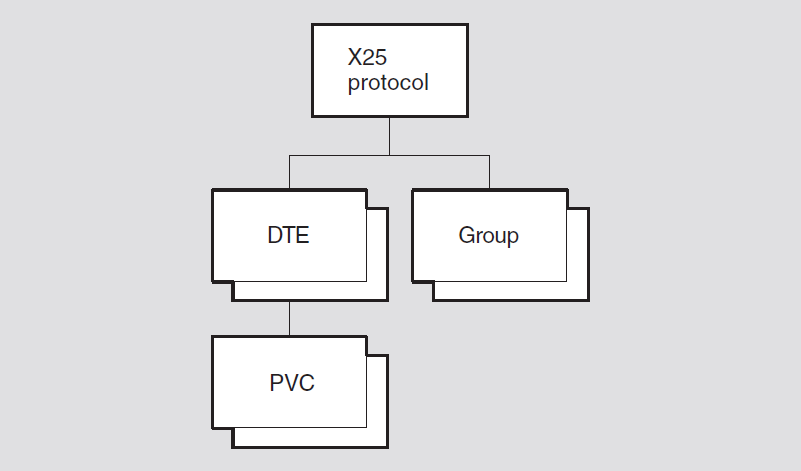
26.1. x25 protocol
The x25 protocol entity is the top-level entity in the X.25 Protocol
module hierarchy of entities. The X.25 Protocol module operates the packet level
protocol interface to a PSDN, as defined by the CCITT and ISO specifications.
Syntax
create [node node-id] x25 protocol
delete [node node-id] x25 protocol
show [node node-id] x25 protocol [all [attributes] | all
characteristics]
26.1.1. Characteristic Attributes
|
Default: Current version number |
Version of NA X.25 architecture to which this implementation conforms. You cannot modify this characteristic.
26.2. x25 protocol dte
An x25 protocol dte entity describes a local DTE.
Syntax
add [node node-id] x25 protocol dte
dte-name outgoing list set of range of
integer
create [node node-id] x25 protocol dte
dte-name {maximum active circuits
integer | profile
profile-name}
delete [node node-id] x25 protocol dte
dte-name
disable [node node-id] x25 protocol dte
dte-name
enable [node node-id] x25 protocol dte
dte-name
remove [node node-id] x25 protocol dte
dte-name outgoing list set of range of
integer
set [node node-id] x25 protocol dte
dte-name {call timer integer | ccitt
version integer | clear timer integer |
default packet size integer | default window size
integer | extended packet sequencing
boolean | inbound dte class
simple-name | incoming list set of range of
integer | interface type interface-mode |
interrupt timer integer | link service provider
full-name | maximum active circuits
integer | maximum clear attempts
integer | maximum packet size integer
| maximum reset attempts integer | maximum restart attempts
integer | maximum throughput classes
integer | maximum window size integer
| minimum packet size integer | minimum throughput classes
integer | minimum window size integer
| outgoing list set of range of integer | reset timer
integer | restart timer integer |
segment size integer | x25 address
DTE-address}
show [node node-id] x25 protocol dte
dte-name [all [attributes] | all characteristics | all
counters | all identifiers | all status ]
The x25 protocol dte enable command starts the operation of the specified
DTE. When the procedure completes, the status attribute state may be
running, synchronizing, or unsychronized.
enable command will fail if the inbound dte class, link service
provider, or x25 address characteristics are not set. The
command will also fail if: There is a mismatch between the protocol profile and the link service provider profile.
The link service provider either does not exist or is in use by someone else.
The link service provider does not provide a maximum data size of the greater of 260, DTE maximum packet size + 4.
26.2.1. Arguments
profile profile-name
Name of the profile that supplies subscription details of the PSDN to which the
DTE is connected. This argument is mandatory, and is used to set the
profile characteristic.
maximum active circuits integer
Maximum number of virtual circuits that can be active at any time on the DTE for
SVCs and PVCs . This argument determines the value of the maximum active
circuits characteristic. This argument is optional.
26.2.2. Characteristic Attributes
|
Default: Supplied by profile |
Value: Bounded by profile |
Elapsed time, in seconds, before which a clear packet is sent for outgoing calls from the DTE that have received no response. A zero value indicates that no clear is sent.
|
Default: 1984 |
Value: 1–9999 |
Version of the CCITT X.25 recommendations to which the DTE conforms.
|
Default: Supplied by profile |
Value: Bounded by profile |
Value of the retransmit timer for outgoing clear packets from the DTE. The default value is profile dependent.
|
Default: 128 |
Value: 16–40962 |
Default packet size, in octets, for all virtual circuits on the DTE. The value
must not be less than the value of the minimum packet size
characteristic.
|
Default: 2 |
Value: 1–127 |
Default window size for all virtual circuits on the DTE; that is, the default
number of unacknowledged packets. This value must not be greater than the value of
the maximum window size characteristic, and must not be less than the
value of the minimum window size characteristic.
description
Manufacturer, product name, and version of the hardware platform of the DTE.
|
Default: False |
Value: True or false |
Specifies whether the extended packet sequencing facility is subscribed to, in
which modulo 128 packet numbering is used. If false, extended packet
sequencing is not used. The profile may provide overriding default or legal
values.
|
Default: No DTE class name |
Value: Simple-name |
Name of the DTE class to be associated with all incoming calls to the DTE. You
must specify this characteristic before you enable the DTE. The x25 access dte
class entity to which the name refers must exist when you enable the
DTE.
|
Default: (1–4095) ranges |
Value: Set of range (1–4095) |
Channel number ranges that define the logical channel numbers (LCNs) that are available for calls on incoming or both way channels. Format the values to specify a set of channel number ranges. Each channel number is the concatenation of the logical channel group number and logical channel number of an SVC on the DTE.
|
Default: DTE |
Value: See description |
|
dce |
DCE mode. |
|
dte |
DTE mode. |
|
negotiated |
The interface mode is negotiated with the other end to be either DTE or DCE. This value applies only to point-to-point links. |
|
Default: Supplied by profile |
Value: Bounded by profile |
Value of the interrupt timer. This timer is started when an interrupt packet is sent. If no interrupt confirmation packet is received before the timer expires, a reset is caused. A zero value indicates that there is no timer.
|
Default: No link service provider name |
Value: Full-name |
Name of the link service provider entity used by the DTE. You must
give this characteristic a value before you enable theDTE.
|
Default: 4096 |
Value: 1–4096 |
Maximum number of virtual circuits that can be active at any time on the DTE. This characteristic cannot be set.
|
Default: Supplied by profile |
Value: Bounded by profile |
Number of times that sending a clear packet can be attempted on a virtual circuit on the DTE. The value 1 indicates that a clear packet is sent only once; that is, there are no retries.
|
Default: 128 |
Value: 16–40962 |
Maximum packet size, in octets, for all virtual circuits on the DTE. This value
must be greater than or equal to the value of the minimum packet size
and default packet size characteristics.
|
Default: Supplied by profile |
Value: Bounded by profile |
Number of times the DTE attempts to send a reset packet. The value 1 indicates that a reset packet is sent only once; that is, there are no retries.
|
Default: Supplied by profile |
Value: Bounded by profile |
Number of times that any virtual circuit on the DTE attempts to send a restart packet. The value 1 indicates that a restart packet is sent only once; that is, there are no retries.
|
Default: 4800 |
Value: See description |
Maximum value for the throughput class (65535) of any virtual circuit on the DTE.
The value specified must be one of the following: 0, 75, 150, 300, 600, 1200, 2400,
4800, 9600, 48000, or 64000. The value must be greater than or equal to the value of
the minimum throughput class characteristic.
|
Default: 2 |
Value: 1–127 |
Maximum number of unacknowledged packets for all virtual circuits on the DTE. This
value must be greater than or equal to the value of the minimum window
size and default window size characteristics.
|
Default: 128 |
Value: 16–40962 |
Minimum packet size, in octets, for all virtual circuits on the DTE. This value
must be less than or equal to the value of the maximum packet size and
default packet size characteristics.
|
Default: Supplied by profile |
Value: Bounded by profile |
Minimum throughput class for any virtual circuit on the DTE. The value specified
must be one of the following: 0, 75, 150, 300, 600, 1200, 2400, 4800, 9600, 48000,
or 64000. The value must be less than or equal to the value of the maximum
throughput class characteristic.
|
Default: 2 |
Value: 1–127 |
Minimum window size for all virtual circuits on the DTE. This value must be less
than or equal to the value of the maximum window size
characteristic.
|
Default: [1...4095] |
Value: Set of range (1–4095) |
Channel number ranges that define the LCNs that are available for calls on outgoing or two-way channels. Format the values to specify a set of channel number ranges. Each channel number is the concatenation of the logical channel group number and logical channel number of an SVC on the DTE.
|
Default: No profile name |
Name of the profile that provides subscription details of the PSDN to which the DTE is connected. This characteristic cannot be set; it is specified when the DTE is created.
|
Default: Supplied by profile |
Value: Bounded by profile |
Value of the retransmit timer for outgoing reset packets from the DTE. The default value is profile-dependent.
|
Default: Supplied by profile |
Value: Bounded by profile |
Value of the retransmit timer for outgoing restart packets from the DTE. The default value is profile-dependent.
segment size
|
Default: Supplied by profile |
Value: Bounded by profile |
Segment size specified for data sent at this DTE.
|
Default: No DTE address |
Value: DTE-address |
Full address of the DTE. You must give this characteristic a value before you enable the DTE.
26.2.3. Counter Attributes
allocated pvc failures (OpenVMS)
Number of times allocated PVCs have failed.
calls failed
Number of outgoing or incoming calls on the DTE that were either rejected or disconnected during the data phase.
creation time
Time at which this entity was created.
data octets received
Number of data octets received on all virtual circuits on the DTE.
data octets sent
Number of data octets sent on all virtual circuits on the DTE.
data PDUs received
Number of data packets received on all virtual circuits on the DTE.
data PDUs sent
Number of data packets sent on all virtual circuits from the DTE.
diagnostic packets
Number of diagnostic packets received on all virtual circuits on the DTE.
down transitions
Number of times the status attribute state has changed from
on to off, synchronizing, or
unsynchronized.
fast selects received
Number of fast select requests received at the DTE.
fast selects sent
Number of fast select requests sent from the DTE.
illegal packets
Number of illegal packets received at the DTE.
incoming calls connected
Number of successful call requests received at the DTE.
locally initiated resets
Number of times a reset was initiated by the local X.25 Protocol module.
locally initiated restarts
Number of times a restart was initiated by the local X.25 Protocol module.
network initiated resets
Number of times a reset was received.
network initiated restarts
Number of times a restart was received.
outgoing calls connected
Number of successful call requests sent from the DTE.
protocol errors
Number of protocol errors detected at the DTE.
reject packets
Number of reject packets received at the DTE.
retry failures
One of the maximum retry counts has been reached.
up transitions
Number of times the status attribute state has changed from
off, synchronizing, or unsynchronized to
on.
26.2.4. Identifier Attributes
name
Simple name assigned to the DTE when it is created.
26.2.5. Status Attributes
available outgoing channels
Number of LCNs enumerated by the outgoing list characteristic that
are available for use.
dte class
DTE classes to which the DTE belongs.
groups
Groups to which the DTE belongs.
interface mode
Mode in which the DTE is operating.
last state change
Time at which the last change of state occurred.
state
x25 protocol dte entity.|
off |
The DTE is disabled, and all virtual circuits are terminated. |
|
running |
The DTE is enabled and synchronized at Protocol layer 3. |
|
synchronizing |
A restart operation initiated at the packet level is in progress. |
|
unsynchronized |
The line between the DTE and DCE is not synchronized at Protocol layer 2. |
uid
Entity's unique identifier, which is generated when the entity is created.
26.2.6. Event Messages
diagnostic packet received
Generated when the DTE receives a diagnostic packet from the network.
|
cause |
Cause code provided by the DCE on reset. | |
|
channel |
Concatenated logical channel group and logical channel number of the virtual circuit associated with the event. | |
|
diagnostic |
Diagnostic code provided by the DCE on reset. | |
dte down
Generated when the status attribute state changes from
on to off, synchronizing, or
unsychronized.
|
configuration error |
Specifies whether or not there has been a configuration error. | |
|
lapb link deleted |
DTE state has changed due to the deletion of the underlying link service provider entity. | |
dte up
Generated when status attribute state changes to on from
off, synchronizing, or
unsychronized.
|
configuration |
Specifies the DTE configuration. | |
|
dce |
The DTE has initialized as a packet-mode DCE. | |
|
dte |
The DTE has initialized as a packet-mode DTE. | |
|
negotiated dce |
The DTE has negotiated to operate as a packet-mode DCE. | |
|
negotiated dte |
The DTE has negotiated to operate as a packet-mode DTE. | |
illegal packet received
Generated when the DTE receives an illegal packet from the network.
|
call time |
Time at which the call request was made. | |||
|
ccitt state |
CCITT state. | |||
|
channel |
Concatenated logical channel group and logical channel number for the virtual circuit associated with the event. | |||
|
direction |
Direction of the call. | |||
|
incoming |
The call was incoming. | |||
|
outgoing |
The call was outgoing. | |||
|
failure reason |
Specifies why the packet was flagged as illegal. | |||
|
header error |
Error in the received block header. | |||
|
invalid gfi |
Invalid general format identifier. | |||
|
invalid state |
The packet is invalid in the current state of the protocol. | |||
|
no interrupt sent |
No interrupt packet was sent. | |||
|
too long |
The packet is too long. | |||
|
too short |
The packet is too short. | |||
|
unacknowledged interrupt |
There is an outstanding interrupt. | |||
|
unrecognized |
The packet is unrecognizable to the DTE. | |||
|
header |
Header contents of the packet that caused the event. | |||
|
packet type |
Type of illegal packet. | |||
|
remote dte |
Address of the DTE that is the source of an incoming call or the destination of an outgoing call. | |||
network initiated reset
Generated when the DTE receives a Reset packet from the network.
|
cause |
Cause code provided by the DCE on reset. | |
|
ccitt state |
CCITT state. See possible reasons described under the
| |
|
channel |
Concatenated logical channel group and logical channel number of the virtual circuit associated with the event. | |
|
diagnostic |
Diagnostic code provided by the DCE on reset. | |
|
direction |
Direction of the call. | |
|
incoming |
The call was incoming. | |
|
outgoing |
The call was outgoing. | |
network initiated restart
Generated when the DTE receives a Restart packet from the network.
|
cause |
Cause code provided by the DCE on reset. | |
|
ccitt state |
CCITT state. See possible reasons described under the
| |
|
channel |
Concatenated logical channel group and logical channel number of the virtual circuit associated with the event. | |
|
diagnostic |
Diagnostic code provided by the DCE on reset. | |
protocol error detected
Generated when a protocol error is detected.
|
call time |
Time at which the call request was made. | |
|
ccitt state |
CCITT state. See possible reasons described under the
| |
|
channel |
Concatenated logical channel group and logical channel number for the virtual circuit associated with the event. | |
|
failure reason |
Reason for the protocol error. | |
|
bad p(r) received |
Invalid receive packet sequence number received. | |
|
bad p(s) received |
Invalid transmit packet sequence number received. | |
|
invalid lcn |
Invalid Logical Channel Number. | |
|
invalid packet size |
Error in negotiated or requested packet size. | |
|
invalid throughput class |
Error in negotiated or requested throughput class. | |
|
invalid window size |
Error in negotiated or requested window size. | |
|
no fast select |
Fast select is not supported. | |
|
receiver not ready |
Data received while in | |
|
header |
Header contents that caused the event. | |
|
remote dte |
Address of the DTE that is the source of an incoming call or the destination of an outgoing call. | |
reject packet received
Generated when the DTE receives a reject packet from the network.
|
call time |
Time at which the call request was made. | |
|
ccitt state |
CCITT state. See possible reasons described under the
| |
|
channel |
Concatenated logical channel group and logical channel number of the virtual circuit associated with the event. | |
|
direction |
Direction of the call. | |
|
incoming |
The call was incoming. | |
|
outgoing |
The call was outgoing. | |
|
remote dte |
Address of the DTE that is the source of an incoming call or the destination of an outgoing call. | |
retry failed
Generated when one of the DTE's maximum retry counts has been reached.
|
ccitt state |
CCITT state. See possible reasons described under the
| |
|
channel |
Concatenated logical channel group and logical channel number for the virtual circuit associated with the event. | |
|
remote dte |
Address of the DTE that is the source of an incoming call or the destination of an outgoing call. | |
|
retry |
Specifies which retry counter has generated the event by reaching its maximum value. | |
|
clear |
The | |
|
reset |
The | |
|
restart |
The | |
switched virtual circuit failed
Generated when an incoming or outgoing call fails in the setup or data phase.
|
call time |
Time at which the call request was made. | |
|
cause |
Cause code provided by the DCE on reset. | |
|
channel |
Concatenated logical channel group and logical channel number for the virtual circuit associated with the event. | |
|
diagnostic |
Diagnostic code provided by the DCE on reset. | |
|
direction |
Direction of the call. | |
|
incoming |
The call was incoming. | |
|
outgoing |
The call was outgoing. | |
|
failure reason |
Reason why the circuit failed. | |
|
call cleared |
The call was cleared by an invocation of the interface function. | |
|
call collision |
Call collision occurred. | |
|
call timeout |
The call timer expired for an outgoing call attempt. | |
|
dte disabled |
The local DTE was disabled by network management. | |
|
level 2 failure |
A failure occurred at the Frame level link or below. | |
|
local reject |
The X.25 Access module rejected an incoming call attempt. | |
|
network clear |
A Clear packet with a network cause code was received. | |
|
no resources |
Insufficient resources to handle call. | |
|
no taker |
Incoming call attempt rejected on timeout with no response from X.25 Access module. | |
|
remote reject |
Disconnect initiated by network or remote DTE. | |
|
restart received |
A Restart packet was sent by the DCE. | |
|
security |
An implementation-specific access criterion was violated. | |
|
remote dte |
Address of the DTE that is the source of an incoming call or the destination of an outgoing call. | |
26.2.7. Exception Messages
For enable:
incompatible data sizes
The level 2 link service provider has not been configured for a sufficiently large data size. The level 2 link service data size must be at least 260 and at least the DTE maximum packet size + 4.
incompatible profiles
There is a mismatch between the x.25 Protocol DTE profile and the link service provider profile.
insufficient information
inbound dte class, link service provider or x25 address
characteristics necessary for the successful completion of the operation has not
been set.
link service provider error
Level 2 link service provider has flagged an error.
link service provider in use
Another Network layer entity is already using the specified link service provider.
no such link service provider
The link service provider specified in the DTE does not exist.
26.3. x25 protocol dte pvc
An x25 protocol dte pvc entity describes a permanent virtual circuit
(PVC).
Syntax
create [node node-id] x25 protocol dte pvc
pvc-name {channel integer | packet
size integer | window size
integer}
delete [node node-id] x25 protocol dte pvc
pvc-name
set [node node-id] x25 protocol dte pvc
pvc-name {acl access-control-list |
channel integer | packet size octets |
window size integer}
show [node node-id] x25 protocol dte pvc
pvc-name [all [attributes] | all characteristics | all
counters | all identifiers | all status]
26.3.1. Arguments
channel integer
Concatenated logical channel group and logical channel number for the PVC. It
should be a unique value among PVCs on this DTE. This channel number
must not be present in the incoming list or outgoing list
of the parent DTE. This argument determines the value of the channel
characteristic.
packet size integer
Packet size, in octets, for the PVC. This argument determines the value of the
packet size characteristic. This value should be within the
maximum and minimum packet size specified for the
parent DTE.
window size integer
Window size for the PVC. This argument determines the value of the window
size characteristic. This value should be within the maximum
and minimum window size specified for the parent DTE.
26.3.2. Characteristic Attributes
|
Default: No access control list |
Value: Access-control-list |
Access control list that controls access to this PVC.
|
Default: No default |
Value: 0–4095 |
Concatenated logical channel group and logical channel number for the PVC. The
value of this characteristic derives from an argument to the create
command.
|
Default: No default |
Value: 16–4096 |
Packet size for the PVC, in octets. The value must be a power of 2 in the range 16
to 4096. The value of this characteristic derives from an argument to the
create command.
|
Default: No default |
Value: 1–127 |
Window size for the PVC. The value of this characteristic derives from an argument
to the create command.
26.3.3. Counter Attributes
These counters record values over the lifetime of a PVC. For counters that refer
to use of the PVC by individual clients, see the x25 access port
entity.
accesses blocked
Number of times an attempt to open a PVC has failed because of security.
creation time
Time at which this entity was created.
data octets received
Number of octets received by the PVC since it was created.
data octets sent
Number of octets sent by the PVC since it was created.
data pdus received
Number of data PDUs received by the PVC since it was created.
data pdus sent
Number of data PDUs sent by the PVC since it was created.
pvc failures
Number of times the PVC has failed while the entity has been allocated.
26.3.4. Identifier Attributes
name
Simple name assigned to the PVC when it is created.
26.3.5. Status Attributes
allocated
True if the PVC is allocated to a user. False if otherwise.
port
X.25 Access port with which the PVC is associated.
uid
Entity's unique identifier, which is generated when the entity is created.
26.3.6. Event Messages
pvc failed
Generated when an allocated PVC fails during the data phase.
|
cause |
Cause code provided by some DCEs on some failures. | |
|
diagnostic |
Diagnostic code provided by some DCEs on some failures. | |
|
failure reason |
Why the PVC failed. | |
|
DTE disabled |
The local DTE was disabled by network management. | |
|
level 2 failure |
A failure occurred at the Frame level link or below. | |
|
PVC deleted |
The | |
|
restart |
Restart initiated by network or remote DTE, or sent by this DTE. | |
26.3.7. Exception Messages
For create:
name not unique
The PVC entity is not unique at the gateway system. PVCs with the same name cannot exist under separate DTEs on a gateway system.
26.4. x25 protocol group
An x25 protocol group entity specifies a number of DTEs that make up a
closed user group (CUG).
Syntax
add [node node-id] x25 protocol group
group-name {members set of
simple-names | remote dte set of simple-names
}
create [node node-id] x25 protocol group
group-name
delete [node node-id] x25 protocol group
group-name
remove [node node-id] x25 protocol group {members
set of simple-names | remote dte set of
simple-names}
set [node node-id] x25 protocol group
group-name {members set of
simple-names |remote dte set of simple-names |
type string}
show [node node-id] x25 protocol group
group-name [all [attributes] | all characteristics | all
counters | all identifiers | all status]
26.4.1. Characteristic Attributes
|
Default: No DTEs |
Value: Set of records |
DTEs on the local system that are members of the group. Format the values to
specify a set of records. Each record consists of a name that identifies an
X25 protocol dte entity and an integer (in the range 0 to 9999)
that identifies the CUG number assigned by the network. If a DTE is already created
and enabled and is then added to the set of members, it must be disabled and
re-enabled to service the specified CUG number or bilateral closed user group
(BCUG).
|
Default: No DTE address |
Value: DTE-address |
DTE address to be associated with this entity for matching x25 access
security dte class remote dte entities for both incoming and outgoing
calls. This characteristic is only supported if the characteristic type
is bcug.
|
Default: BCUG |
Value: CUG, BCUG, or CUGOA |
|
cug |
Normal CUG. |
|
bcug |
Bilateral CUG (BCUG). |
|
cugoa |
CUG outgoing access. |
26.4.2. Counter Attributes
creation time
Time at which this entity was created.
incoming calls blocked
Number of times an incoming call to a BCUG has been blocked by security from accessing a filter.
outgoing calls blocked
Number of times a call has been blocked by security from accessing this BCUG.
26.4.3. Identifier Attributes
name
Simple name assigned to the group when it is created.
26.4.4. Status Attributes
uid
Entity's unique identifier, which is generated when the entity is created.
26.4.5. Exception Messages
For delete:
referenced dte enabled
One or more of the DTEs referenced by this group is still enabled.
Chapter 27. X.25 Relay Module
This chapter describes all the commands you can use to manage the entities that constitute the X.25 Relay module. The X.25 Relay module resides in the application layer of the Network Architecture (NA). It interfaces with the X.25 Access module to receive an incoming switched virtual call and then makes an outgoing call through the X.25 Access module. Facilities also exist for relaying permanent virtual circuits (PVCs).
Figure 27.1, ''Hierarchy of X.25 Relay Module Entities'' shows the hierarchical relationship of the entities that constitute the X.25 Relay module.
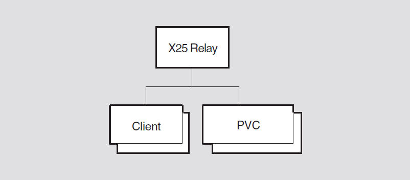
27.1. x25 relay
The x25 relay entity accepts an incoming call from one client and
redirects it to another client.
Syntax
create [node node-id ] x25 relay [maximum active
connections integer]
delete [node node-id ] x25 relay
show [node node-id ] x25 relay [all [attributes] | all
characteristics]
27.1.1. Arguments
maximum active connections
Maximum number of active connections supported.
27.1.2. Characteristic Attributes
maximum active connections
Maximum number of active connections supported by this module. This characteristic
is an optional argument on the create command. You cannot modify this
characteristic.
version
Version number of the X.25 Relay architecture to which this implementation conforms. You cannot modify this attribute.
27.2. x25 relay client
An x25 relay client entity provides a set of default values to be used to
set up a relay between an incoming call and an outgoing call.
Syntax
add [node node-id ] x25 relay client
client-name {filters simple-name|
rights identifiers set of simple-name (UNIX) }
create [node node-id ] x25 relay client
client-name
delete [node node-id ] x25 relay client
client-name
disable [node node-id ] x25 relay client
client-name
enable [node node-id ] x25 relay client
client-name
remove [node node-id ] x25 relay client
client-name {filters simple-name|
rights identifiers set of simple-name (UNIX) }
set [node node-id ] x25 relay client
client-name {dte class | filters
simple-name| rights identifiers set of
simple-name (UNIX) }
show [node node-id ] x25 relay client
client-name [all [attributes] | all characteristics | all
counters | all identifiers | all status]
27.2.1. Characteristic Attributes
|
Default: No dte class |
Value: Simple-name |
Name of the x25 access dte class entity to use when making the
outgoing call.
|
Default: No filters |
Value: Set of simple-names |
Set of filters that are listened to by this client. Each name is the name of an
x25 access filter entity. For the add and
set commands, the x25 relay client entity must be in
the Off state before the filters attribute can be modified.
|
Default: No rights identifiers |
Value: Set of simple-names |
Set of rights identifiers that this client possesses. It is used when placing the outgoing call.
|
Default: No template |
Value: Simple-name |
Name of the x25 access template entity to be used for the outgoing
call.
27.2.2. Counter Attributes
connections failed
Number of times a connection setup has failed.
connections lost
Number of times a successfully established connection has been abnormally terminated.
connections made
Number of connections that have been made successfully.
creation time
Time at which this entity was created.
27.2.3. Identifier Attributes
name
Simple name assigned to the client when it is created.
27.2.4. Status Attributes
active connections
Number of connections that are currently active on this client. A connection is a pair of incoming/outgoing calls. This value does not include connections that are still waiting to be established.
state
x25 relay client entity.|
off |
The entity is disabled. |
|
on |
The entity is enabled. |
uid
Entity's unique identifier, which is generated when the entity is created.
27.2.5. Event Messages
connection failed
Generated when a connection cannot be established.
|
call accept reason |
Error returned when attempting to accept the incoming
call. Only present if the
| |
|
destination dte |
DTE address of the called DTE. | |
|
destination nsap |
Called address extension supplied in the Call packet. | |
|
outgoing failure reason |
Error returned when attempting to make the outgoing call.
Only present if the
| |
|
reason |
Whether the connection failed at the incoming or outgoing stage. | |
|
call accept failure |
The client could not accept the incoming call. | |
|
outgoing call failure |
The client could not make the outgoing call. | |
|
sending dte |
DTE address of the calling DTE. | |
|
sending nsap |
Calling address extension supplied in the Call packet. | |
connection lost
Generated when a connection that has been successfully established is abnormally terminated.
|
cause |
X.25 cause code provided by the clearing DTE. Only present
if the | |
|
destination dte |
DTE address of the called DTE. | |
|
destination nsap |
Called address extension supplied in the Call packet. | |
|
diagnostic |
X.25 diagnostic code provided by the clearing DTE. Only
present if the | |
|
network error reason |
Reason why the connection was lost. This argument is
present only if | |
|
reason |
Reason for the loss of the connection. | |
|
called dte clear |
The remote call was abnormally terminated. | |
|
calling dte clear |
The local call was abnormally terminated. | |
|
network error |
The cause of the connection loss is given by | |
|
sending dte |
DTE address of the calling DTE. | |
|
sending nsap |
Called address extension supplied in the Call packet. | |
27.2.6. Exception Messages
For enable:
filter in error
filters characteristic cannot be used
for one of the following reasons:|
filters in use |
The named filters are already in use. | |
|
no such filters |
The named filters do not exist. | |
insufficient information
One or more characteristics have not been specified.
|
reason |
Specifies which characteristics have not been specified. | |
|
dte class |
The DTE class characteristic has not been specified. | |
|
filters |
The filters characteristic has not been specified. | |
For delete:
has active connections
One or more active connections exist on this client.
27.3. x25 relay pvc
An x25 relay pvc entity provides a set of default values to be used to
establish a connection to a client over a permanent virtual circuit (PVC).
Syntax
add [node node-id ] x25 relay pvc
pvc-name rights identifiers set of
simple-name
create [node node-id] x25 relay pvc
pvc-name type
pvc-type
delete [node node-id] x25 relay pvc
pvc-name
disable [node node-id] x25 relay pvc
pvc-name
enable [node node-id] x25 relay pvc
pvc-name
remove [node node-id] x25 relay pvc
pvc-name rights identifiers set of
simple-name
set [node node-id] x25 relay pvc
simple-name {local pvc pvc-name |
remote dte class simple-name (connector nodes only) | relayed
pvc simple-name | retry limit integer
(connector nodes only) | retry timer integer (connector nodes
only) | rights identifiers set of simple-name}
show [node node-id] x25 relay pvc
pvc-name [all [attributes] | all characteristics | all
counters | all identifiers | all status]
27.3.1. Arguments
type pvc-type
Type of PVC, either local or remote. Only local PVCs are supported.
27.3.2. Characteristic Attributes
|
Default: No PVC name |
Value: Simple-name |
Name of the x25 protocol dte pvc entity that represents the local end
of the connection. A value for this characteristic must be specified before enabling
the relay PVC.
|
Default: No PVC name |
Value: Simple-name |
Name of the x25 protocol dte pvc entity entity that represents the
relayed end of the connection. A value for this characteristic must be specified
before enabling the relay PVC.
|
Default: No dte class |
Value: Simple-name |
DTE class to be used when setting up the remote end of the connection. It is only specified if the relayed PVC does not reside on the local system. This attribute is only applicable to connector nodes, and will not be visible in other implementations.
|
Default: 10 |
Value: 0–65535 |
Number of attempts that will be made to set up the PVC connection following the
failure of an enable command. This attribute is only applicable to
connector nodes, and will not be visible in other implementations.
|
Default: 60 |
Value: 1–65535 |
Interval, in seconds, between retries. This attribute is only applicable to connector nodes, and will not be visible in other implementations.
|
Default: No rights identifiers |
Value: Set of simple-names |
Rights identifiers possessed by this entity. These rights are used to access the local PVC and relayed PVC if it resides on the local system.
27.3.3. Counter Attributes
connections made
Number of successful connections made by this entity.
creation time
Time at which this entity was created.
times connections lost
Number of times that a successfully established PVC connection has been abnormally terminated.
times retry limit exceeded
Number of times that the retry limit has been reached when trying to set up a PVC connection.
27.3.4. Identifier Attributes
name
Simple name assigned to the PVC when it is created.
27.3.5. Status Attribute
state
x25 relay pvc entity. |
failed |
The retry mechanism has failed to set up the connection. |
|
off |
The PVC is disabled. |
|
on |
The PVC is enabled. |
|
retrying |
The Retry timer is running. |
uid
Entity's unique identifier, which is generated when the entity is created.
27.3.6. Event Messages
connection lost
Generated when a successfully established PVC connection fails for some other reason than being disabled.
|
reason |
Error returned by the X.25 Access module when notifying the X.25 Relay module of the disconnection. |
retry limit exceeded
Generated when an attempt to set up a PVC connection fails.
|
local pvc status |
State of the local end of the PVC connection. | |
|
relayed pvc status |
State of the relayed end of the PVC connection. | |
27.3.7. Exceptions
For enable:
insufficient information
One or more characteristics have not been specified.
|
reason |
Specifies which characteristics have not been specified. | |
|
local pvc |
The | |
|
relayed pvc |
The | |
|
remote dte class |
The | |
dte class not type remote
The DTE class specified is not of type remote (connector nodes only).
pvc error
An error has occurred attempting to open either the local or the relayed PVC.
|
reason |
Specifies the reason for failing to open the local or relayed pvcs. | |
|
local pvc in use |
The specified | |
|
relayed pvc in use |
The specified | |
|
local pvc security block |
Attempt to open the | |
|
relayed pvc security block |
Attempt to open the | |
|
no such local pvc |
The specified | |
|
no such relayed pvc |
The specified | |
Chapter 28. X.25 Server Module
This chapter describes all the commands you can use to manage the entities that constitute the X.25 Server module. The X.25 Server module resides in the Application layer of the Network Architecture (NA). This module interfaces with the X.25 Access module to listen for incoming calls for X.25 Client systems, and to make outgoing calls on behalf of X.25 clients.
Figure 28.1, ''Hierarchy of X.25 Server Module Entities'' shows the hierarchical relationship of the entities that constitute the X.25 Server module.
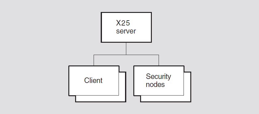
28.1. x25 server
The x25 server entity represents the X.25 server that runs on a connector
system. The X.25 server serves X.25 clients on accessing systems, providing X.25 access
to systems that do not have a direct connection to a PSDN.
Syntax
create [node node-id] x25 server {incoming session
template simple-name | maximum session connections
number]
delete [node node-id] x25 server
disable [node node-id] x25 server
enable [node node-id] x25 server
show [node node-id] x25 server [all [attributes] | all
characteristics | all counters | all status ]
28.1.1. Arguments
incoming session template (UNIX)
Optional argument that specifies the Session Control template used to filter incoming Session Control connection requests.
maximum session connections
Optional argument that specifies the number of incoming and outgoing connections that may be supported concurrently.
28.1.2. Characteristic Attributes
incoming session template (UNIX)
The Session Control template specified on an Open Incoming invocation
at the end user Session Control interface. You cannot modify this
characteristic.
|
Default: 512 |
Value: [1..65535] |
Maximum number of Session Control connections with clients that the entity can support. This includes both incoming and outgoing connections. You cannot modify this characteristic.
|
Default: Current version number |
Version number of the X.25 Gateway Access Protocol (GAP) to which the implementation conforms. You cannot modify this characteristic.
28.1.3. Counter Attributes
connection attempts failed
Number of Session Control connection requests to clients that have failed, due either to exceeding the maximum number of connections or rejection by X.25 clients in accessing systems.
creation time
Time at which this entity was created.
times session control unavailable
Number of times the Session Control unavailable event was
raised.
28.1.4. Status Attributes
active inbound session connections
Current number of active inbound Session Control connections with clients.
active outbound session connections
Current number of active outbound Session Control connections with clients.
state
x25 server entity.|
off |
The |
|
on |
The |
uid
Specifies the entity's unique identifier, which is generated when the entity is created.
28.1.5. Event Messages
client connect failed
Generated when the X.25 server is unable to make a connection to an X.25 client
(or to any of an alternative set of X.25 clients if the service nodes
characteristic is supported for the x25 server client entity).
|
client |
Full name of the | |
|
nodes |
The node or set of nodes associated with the | |
|
application |
Application type in the client entity. | |
session control unavailable
Generated when the X.25 server detects the absence of the Session Control module
or when it detects that the state of Session Control is not set to
on.
|
module extent |
| |
|
session control port state |
| |
28.1.6. Exceptions
For enable:
session control no resources
The Session Control module does not have sufficient resources to handle the call.
session control unavailable
The Session Control module either does not exist or is disabled.
28.2. x25 server client
An x25 server client entity provides a set of default values to be used
to establish a Session Control connection with an X.25 client when an incoming call
arrives for that client. You should create an x25 server client entity for
each X.25 client with which the connector system is associated.
Syntax
add [node node-id] x25 server client
client-name filters set of
simple-names
create [node node-id] x25 server client
client-name
delete [node node-id] x25 server client
client-name
disable [node node-id] x25 server client
client-name
enable [node node-id] x25 server client
client-name
remove [node node-id] x25 server client
client-name filters set of
simple-names
set [node node-id] x25 server client
client-name {account latin1string
(OpenVMS) | application end-user-specification | destination
fullname (OpenVMS) | filters set of
simple-names | node fullname | outgoing session
template simple-name (OpenVMS) | password
latin1string | service nodes set of
record | user latin1string}
show [node node-id] x25 server client
client-name [all [attributes] | all characteristics | all
identifiers | all status]
28.2.1. Characteristic Attributes
|
Default: No service/account data |
Value: String |
Default service or account data to be used when connecting to the system hosting the X.25 client.
|
Default: 36 |
Value: End-user-specification |
Address information used by the destination Session Control module to select the X.25 client that will receive the connection request.
|
Default: No client name |
Value: Fullname |
Name of the X.25 client to which a connection is to be made when delivering a "filtered" call.
|
Default: No default |
Value: Set of simple-names |
Set of filters to be used by the server to filter calls for this X.25 client. Each
name is the name of an x25 access filter entity.
|
Default: No node name |
Value: Fullname |
Name of the node that hosts the X.25 client to which connection is to be made.
This characteristic is supported only if the service nodes
characteristic is not supported.
|
Default: Default template |
Value: Simple-name |
Transport template to be used by the X.25 server to set up a Session Control
connection to the X.25 client. The name is the name of an osi transport
template entity.
|
Default: No password |
Value: String |
Default password to be used for verification when connecting to the system that
hosts the X.25 client. You cannot display this characteristic with the
show command.
|
Default: Empty set |
Value: Set of candidate records |
Set of nodes that host the x25 client entities to which connections
can be made.
|
Default: No user id |
Value: String |
Default user identification to be used in access verification when connecting to the system that hosts the X.25 client.
28.2.2. Identifier Attributes
name
Simple name assigned to the client when it is created.
28.2.3. Status Attributes
state
x25 server client entity.|
off |
The |
|
on |
The |
28.2.4. Exception Messages
For enable:
filter in error
One or more of the specified filters does not exist, or is in use.
filter in use
One or more of the specified filters is already being used by another client.
insufficient information
Before enabling the client you must ensure that the following characteristics have
been given values of: application, filters and node or
service nodes.
28.3. x25 server security nodes
An x25 server security nodes entity defines the set of rights identifiers
associated with calls issued by the X.25 Server module (on behalf of the X.25 Client
module at an accessing system) to the X.25 Access module at the connector system. These
rights identifiers are used when making access control checks on the DTE class specified
when a call is made.
Syntax
add [node node-id] x25 server security nodes
fullname {nodes set of simple-names |
rights identifiers set of simple-names }
create [node node-id] x25 server security nodes
simple-name
delete [node node-id] x25 server security nodes
simple-name
remove [node node-id] x25 server security nodes
fullname {nodes set of simple-names |
rights identifiers set of simple-names }
set [node node-id] x25 server security nodes
fullname {nodes set of simple-names |
rights identifiers set of simple-names }
show [node node-id] x25 server security nodes
simple-name [all [attributes] | all characteristics | all
counters | all identifiers | all status]
28.3.1. Characteristic Attributes
|
Default: No node names |
Value: Set of full names |
DNS full names of accessing systems, or the wildcard full name.
|
Default: No rights identifiers |
Value: Set of simple-names |
Set of rights identifiers to be associated with the set of nodes named in the
nodes characteristic for purposes of access control to DTE classes
at the connector node.
28.3.2. Counter Attributes
creation time
Time at which this entity was created.
outgoing calls blocked
Number of times that an attempt to establish a call or use a PVC has failed for security reasons.
28.3.3. Identifier Attributes
name
Simple name assigned to the security node when it is created.
28.3.4. Status Attributes
uid
Entity's unique identifier, which is generated when the entity is created.
Chapter 29. XOT Module (OpenVMS IA-64 and OpenVMS Alpha)
This chapter describes all the commands you can use to manage the entities that constitute the X.25 over TCP/IP (XOT) module. The XOT module enables transmission of X.25 packets over a wide area network composed of TCP/IP connections using the methods described in RFC1613. The XOT module and its associated data links can be used as another data link service provider in place of the LAPB data links normally used with X25 PROTOCOL DTE entities.
Figure 29.1, ''Hierarchy of XOT Module Entities'' shows the hierarchical relationship of the entities that constitute the XOT module.
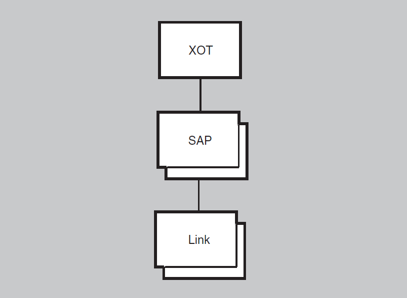
29.1. xot
The xot entity is the top-level entity in the hierarchy of entities
belonging to the XOT module.
Syntax
create [node node-id] xot
delete [node node-id] xot
set [node node-id] xot maximum connections
integer
show [node node-id] xot [all [attributes] | all
characteristics | all status]
29.1.1. Characteristic Attributes
maximum connections
| Default: 256 | Value: 1–65535 |
Maximum number of connections allowed. Note that each xot sap link
entity is limited to 4095 connections. The maximum connections
attribute sets the limit for connections over all existing xot sap link
entities.
version
Version of the implementation, initially "1.0.0" (a read-only characteristic). You cannot modify this attribute.
29.1.2. Status Attributes
currently active connections
Number of currently active XOT connections.
uid
Entity’s unique identifier, which is generated when the entity is created.
29.2. xot sap
The xot sap entity specifies the point at which the XOT module gains
access to the TCP/IP environment for the purposes of listening for inbound XOT
connections.
Syntax
create [node node-id] xot sap
sap-name
delete [node node-id] xot sap
sap-name
enable [node node-id] xot sap
sap-name
disable [node node-id] xot sap
sap-name
set [node node-id] xot sap sap-name
{ local IP address ip-address | local RFC1613 port number
integer}
show [node node-id] xot sap
sap-name [all [attributes] | all characteristics | all
counters | all identifiers | all status]
29.2.1. Characteristic Attributes
local IP address
| Default: 0.0.0.0 | Value: IP Address |
IP interface (identified by the address) where the sap entity will
listen. (Any available interface is specified with the address of 0.0.0.0). This
characteristic is mainly set when a system has multiple TCP/IP interfaces.
Note
By default, XOT’s single sap entity is configured to listen on
any available IP interface (as specified by the IP address 0.0.0.0). You can
create multiple sap entities, each listening on a unique IP
address. However, if you create more than one sap entity, you must
assign each entity a unique IP address; no sap entity can use the
0.0.0.0 address.
local RFC1613 port number
| Default: 1998 | Value: TCP port number |
Port number on which the sap entity will listen for inbound XOT
connections. We strongly recommend that you use the value 1998 as specified in
RFC1613.
29.2.2. Counter Attributes
creation time
Time this entity was created.
connects rejected
Number of times an inbound connection was rejected.
SAP state changed
Number of times that the SAP’s state changed.
29.2.3. Identifier Attributes
name
Simple name assigned to the SAP when it was created.
29.2.4. Status Attributes
state
Status of the sap entity.
| on | The entity is enabled. |
| off | The entity is disabled. |
| connecting to PWIP | The entity is connecting to the PWIP driver and TCP/IP. |
uid
Entity’s unique identifier, which is generated when the entity is created.
29.2.5. Event Messages
sap state changed
Generated when the SAP changes state.
Arguments:
| new sap state | New state of the SAP. |
29.3. xot sap link
The xot sap link entity represents a remote system with which XOT is
allowed to communicate. In the case of an inbound XOT connection, there must be a
link entity with a matching remote IP address and remote port number in
order for XOT to accept the TCP/IP connection. In the case of an outbound connection,
the link entity specifies the remote IP address and remote port number of
the system with which to attempt the TCP/IP connection.
Syntax
create [node node-id] xot sap
sap-name link
link-name
delete [node node-id] xot sap
sap-name link
link-name
enable [node node-id] xot sap
sap-name link
link-name
disable [node node-id] xot sap
sap-name link
link-name
set [node node-id] xot sap sap-name
link link-name { remote IP address
ip-address | remote RFC1613 port number
integer}
show [node node-id] xot sap
sap-name link link-name [all
[attributes] | all characteristics | all counters | all identifiers | all
status]
29.3.1. Characteristic Attributes
remote IP address
| Default: None | Value: IP address |
Remote IP address of the cooperating XOT system; specified as a numeric address in the form a.b.c.d. Specify the address 127.0.0.1 for loopback testing. For more information on TCP/IP loopback testing, see the TCP/IP Services for OpenVMS documentation.
remote RFC1613 port number
| Default: 1998 | Value: TCP port number |
Specifies the TCP port number to use for an outgoing connection. The remote system must be listening for inbound XOT connections on this port.
29.3.2. Counter Attributes
creation time
Time this entity was created.
connects failed
Number of times an attempt to establish an outgoing connection failed.
connects sent
Number of connection requests sent.
connects received
Number of connection requests received.
disconnects sent
Number of disconnect requests sent.
disconnects received
Number of disconnects received.
link state changed
Number of times that the link has changed state from enabled to disabled or disabled to enabled.
octets received
Number of data octets received from TCP/IP for all ports on the link.
octets sent
Number of data octets sent to TCP/IP for all ports on the link.
pdus received
Number of data pdus (X.25 packets) received from TCP/IP for all ports on the link.
pdus sent
Number of data pdus (X.25 packets) sent to TCP/IP for all ports on the link.
protocol errors
Number of protocol errors that occurred on the link.
29.3.3. Identifier Attributes
name
Simple name assigned to the link when it was created.
29.3.4. Status Attributes
state
Status of the link entity.
| on | The link is enabled. |
| off | The link is disabled. |
uid
Entity’s unique identifier, which is generated when the entity is created.
29.3.5. Event Messages
link state changed
Generated when the link changes state.
Arguments:
| new link state | New state of the link. |
outbound connect failed
Generated when an attempt to establish an outbound connection with a remote system fails.
Arguments:
| failure reason | Specifies why the outbound connection failed. | |
| remote system unreachable | Requested remote system is not currently reachable. | |
| connection rejected | The remote system denied the connection request. | |
| pwip error | During the connection establishment, the PWIP software returned an error. | |
| no reason specified | No additional information is available. | |
| remote ip address | IP address of the remote system. | |
| remote port number | Port number used when attempting to access the remote system. | |
| pwip error code | Error code returned by the Pathworks (PWIP) if the failure reason code is pwip error. | |
protocol error
Generated when an error occurs in the XOT protocol during a XOT protocol exchange with the remote system.
Arguments:
| error reason | Indicates the type of protocol error. | |
| invalid xot header | The XOT header was not valid. | |
| invalid pvc setup packet | For outgoing connections, the remote system returned an invalid response PDU. For incoming connections, the remote system’s PVC connection PDU is invalid. | |
| remote ip address | IP address of the remote system. | |
| remote port number | Port number used when attempting to access the remote system. | |
| received pdue | Contents of the invalid response PDU. | |
Appendix A. Interpreting NCL Error Messages
This appendix offers general guidelines for interpreting any NCL error messages you may receive.
A.1. How Errors Are Reported
NCL uses error messages to report and describe errors that occur in both the user interface and the entity.
For some errors, only one message is returned, even if a group of entities was targeted by the directive. The requested entity name is returned as part of the exception if specified. For other errors, if the entities determine that none of the target entities can perform the directive, the entity may return a single exception reply containing the requested entity name. The entity may return an exception or response for each target entity. In this case, the entity name returned is that of the entity performing the directive. The entity may stop forwarding the directive to further entities when an error occurs, providing it responds for each entity performing the directive.
A.2. NCL Error Messages for OpenVMS
This section describes NCL error messages that can be returned by the user interface. These errors occur during the parsing of the NCL command and are returned before a command is sent to the entity being managed. All messages are preceded by %NCL-E-. For example:
%NCL-E-INVALIDCOMMAND, unrecognized command
ACCESSSTRINGTOOLLONG, access control string too long
Explanation: The username/password/account string is longer than 255 characters.
User Action: Use shorter username/password/account string.
ALLOCFAILURE, memory allocation failure
Explanation: NCL could not allocate the required memory.
User Action: Increase the users' quotas or the values for the system generation parameters to allow a larger virtual image. The most likely parameters are BYTLIM, VIRTUALPAGENT, or MAXBUF.
AMBIGUOUS, ambiguous command
Explanation: A keyword in the command is not specified with enough characters to distinguish it from another keyword acceptable in this context. The offending keyword is displayed between backslashes.
User Action: Reenter the command using enough characters to uniquely identify all keywords.
BADNCLENVIRONMENT, syntax error interpreting the NCL$ENVIRONMENT variable
Explanation: The NCL$ENVIRONMENT logical name could not be parsed because of a syntax error in its translation.
User Action: Redefine the NCL$ENVIRONMENT logical name to correct the syntax.
BADPARSERFIELD, unknown datatype or corrupt parse tables
Explanation: The parser encountered corrupted parse tables (NCL$GLOBALSECTION) or an unknown data type.
User Action: (1) If the NCL$GLOBALSECTION file is fragmented (DUMP/HEADER/BLOCK=COUNT:0), try making it contiguous (COPY/CONTIG). (2) Contact Support.
BADVALUE, bad command argument value
Explanation: The command contains an illegal argument value. The illegal value is displayed between backslashes.
User Action: Reenter the command using a legal argument value (if arguments are permitted).
BRACKETNESTING, brackets nested too deeply
Explanation: The command contains too many levels of bracket nesting. The offending bracketed data is displayed between backslashes.
User Action: Reenter the command using fewer nested brackets.
CMLINPUTOOSMALL, CML input item list too small
Explanation: The CML input item list buffer that is passed to the internal CML interface is too small.
User Action: Contact your Support representative.
CMLRCVFAILED, error receiving command request
Explanation: The call to CML$ReceiveW failed.
User Action: Contact your Support representative.
CMLSENDFAILED, error sending command request
Explanation: The call to CML$SendW failed.
User Action: See Secondary Status for the reason for the failure.
CMLTEMPLATETOOSMALL, CML template item list too small
Explanation: The CML template item list buffer that is passed to the internal CML interface is too small.
User Action: Contact your Support representative.
DICTIONARYCORRUPT, NCL data dictionary is corrupt
Explanation: The NCL data dictionary returned corrupt data.
User Action: Save NCL$GLOBALSECTION.DAT file. Restore the file and contact your Support representative with the bad file and a description of what was done.
DISPLAYBUFFEROVERFLOW, display data too large for buffers
Explanation: The display data returned by CML is too large for NCL's display buffer.
User Action: Contact your Support representative.
DTETOOLONG, DTE address string is longer than 15 characters
Explanation: The DTE address contains more than 15 characters. The offending address is displayed between backslashes.
User Action: Reenter the command specifying no more than 15 characters for the DTE address.
DUPLICATEARGUMENT, duplicate arguments not allowed
Explanation: The command contains duplicate arguments. The duplicated argument is displayed in parentheses.
User Action: Reenter the command specifying each argument only once.
FULLNAMETOOLONG, FullName string longer than 400 characters
Explanation: The full name string is longer than the architected maximum length of 400 characters. The offending full name is displayed between backslashes.
User Action: Reenter the command specifying a full name of 400 or fewer characters.
ILLEGALCHARACTER, illegal character in input command
Explanation: The command line contains an illegal character. The illegal character is displayed between backslashes.
User Action: Reenter the command line using only legal characters.
IMAGETOOLONG, end user specification image field is too long
Explanation: The image field in the end user specification is too long. The offending data is displayed between backslashes.
|
NUMBER = n |
0 ≤ n ≤ 255 |
|
NAME = "string" |
string ≤ 16 characters |
|
UIC = [g,u]"string" |
string ≤ 12 characters |
|
FULLNAME = fullname |
fullname ≤ 400 characters |
INVALIDABSTIME, invalid absolute time, use DDDD-HH:MM:SS I SSS
Explanation: Absolute time format is invalid.
User Action: Reenter the time in correct format.
INVALIDACCESSCONTROL, invalid syntax for access control information
Explanation: The access control information is formatted incorrectly. The offending data is displayed between backslashes.
User Action: Reenter the command specifying the access control information in the correct format.
INVALIDADDRESSPREFIX, invalid syntax for an address prefix string
Explanation: The address prefix string contains illegal characters or invalid syntax. The offending data is displayed between backslashes.
User Action: Reenter the command specifying a correct address prefix string.
INVALIDAREAADDRESS, invalid syntax for an area address
Explanation: The area address string contains illegal characters or is incorrectly formatted. The offending data is displayed between backslashes.
User Action: Reenter the command specifying a correct area address.
INVALIDCMLDATA, return data corrupt or incorrectly encoded
Explanation: The data returned by CML is incorrectly formatted or corrupt.
User Action: Contact your Support representative.
INVALIDCOMMAND, unrecognized command
Explanation: NCL does not recognize the command. The unrecognized command is displayed between backslashes.
User Action: Correct the command and reenter it.
INVALIDDNSTS, invalid syntax for a name server timestamp
Explanation: The DECdns timestamp string is incorrectly formatted.
User Action: Reenter in correct format.
INVALIDFULLNAME, invalid syntax for FullName string
Explanation: A full name string is incorrectly formatted. The offending full name is displayed between backslashes.
User Action: Reenter the command specifying the full name string correctly.
INVALIDHEXSTRING, invalid syntax for a hex string
Explanation: A hexadecimal string contains illegal characters. The offending data is displayed between backslashes.
User Action: Reenter the command specifying only legal characters for the hexadecimal string.
INVALIDIPADDRESS, invalid syntax for an IP address
Explanation: The IP address contains illegal characters.
User Action: Reenter with correct syntax (length was equal to zero or contained illegal characters). Valid characters are 0 to 9 and the period (.).
INVALIDLANADDRESS, invalid syntax for LAN Address
Explanation: A LAN address contains illegal characters. The offending data is displayed between backslashes.
User Action: Reenter the command specifying a legal LAN address.
INVALIDLATIN1STRING, invalid characters in Latin1 String
Explanation: A Latin1 string contains invalid characters (usually control characters). The offending data is displayed between backslashes.
User Action: Reenter the command specifying only valid characters in the Latin1 string.
INVALIDNET, invalid syntax for a Network Entity Title
Explanation: The network entity title (NET) string contains illegal characters or is formatted incorrectly. The offending network entity title is displayed between backslashes.
User Action: Reenter the command specifying a legal network entity title string.
INVALIDNSAP, invalid syntax for an NSAP Address string
Explanation: The NSAP address string contains illegal characters or is formatted incorrectly. The offending data is displayed between backslashes.
User Action: Reenter the command specifying a legal NSAP address.
INVALIDOCTETSTRING, invalid syntax for octet or octet string
Explanation: An octet does not contain two hexadecimal digits. The offending data is displayed between backslashes.
User Action: Reenter the command specifying two hexadecimal digits for each octet.
INVALIDPHASE4ADDR, invalid syntax for a Phase IV node address
Explanation: A Phase IV node address has been specified incorrectly. The invalid address is displayed between backslashes.
User Action: Reenter the command specifying a correct Phase IV node address.
INVALIDPHASE4NAME, invalid syntax for a Phase IV node name
Explanation: A Phase IV node-name string contains illegal characters, does not contain at least one alpha character, or is too long. The offending data is displayed between backslashes.
User Action: Reenter the command specifying a legal Phase IV node-name string.
INVALIDPID, invalid syntax for a process identifier
Explanation: The process identifier string does not look like a hexadecimal PID or a process name string. The offending process identifier is displayed between backslashes.
User Action: Reenter the command specifying a valid process identifier.
INVALIDRELOP, invalid syntax for an entity filter relational operator
Explanation: The relational operator in the entity filter is invalid.
User Action: Reenter with valid operator. Valid operators are =, <>, <, <=, >, and >=.
INVALIDSIMPLENAME, invalid syntax for SimpleName string
Explanation: A simple name string is incorrectly formatted. The offending data is displayed between backslashes.
User Action: Reenter the command specifying a valid simple-name string.
INVALIDTIME, invalid syntax for a date/time
Explanation: The binary/character absolute/relative time contains illegal characters or bad syntax.
User Action: Reenter correct absolute or relative time.
INVALIDUID, invalid syntax for an unique identifier
Explanation: The unique identifier contains illegal characters or bad syntax.
User Action: Reenter hexadecimal string with "-" separators.
INVALIDVERSION, invalid syntax for a version number
Explanation: The version number contains illegal characters. The offending data is displayed between backslashes.
User Action: Reenter the command specifying a valid version number.
MISSINGARGUMENT, missing required command arguments
Explanation: The command line was terminated before all required command arguments were specified.
User Action: Reenter the command including all of the required arguments.
MISSINGEDITNUMBER, missing edit number for version number with edit
Explanation: The version number with edit is missing the edit number. The offending data is displayed between backslashes.
User Action: Reenter the command specifying the required edit number.
MISSINGLEFTBKT, missing left bracket
Explanation: The left bracket character is missing. The offending string is displayed between backslashes.
User Action: Reenter the command including the left bracket character.
MISSINGRIGHTBKT, missing right bracket
Explanation: The right bracket character is missing. The offending string is displayed between backslashes.
User Action: Reenter the command including the right bracket character.
NOCONNECTION, cannot establish CMIP connection to remote node
Explanation: The call to CML$InitializeW failed.
User Action: See Secondary Status for the reason for the failure.
NODENAMETOOLONG, node name and/or access control information too long
Explanation: The node name and access control string are too long for NCL's parsed data buffer. The offending data is displayed between backslashes.
User Action: Reenter the command specifying data that does not exceed the allowable limits.
NOGLOBALENTITY, no global NODE entity found in the data dictionary
Explanation: The NCL$GLOBALSECTION.DAT file does not have any entities in it.
User Action: Contact your Support representative.
NOGLOBALSECTION, cannot open and map the parse table global section file
Explanation: The NCL$GLOBALSECTION.DAT file could not be opened.
User Action: See Secondary Status for the reason for the failure.
NOLINKID, no LinkID returned by CML
Explanation: The call to CML$Initialize returned successfully, but did not return a LinkID value.
User Action: Contact your Support representative.
NOSUCHPROCESS, no such process name or insufficient privilege
Explanation: Either the specified process does not exist or you have insufficient privileges to use it. The process name is displayed between backslashes.
User Action: Reenter the command specifying a different process name or retry the command from a privileged account.
PHASE4AREA, Phase IV area number is not between 1 and 63
Explanation: The Phase IV node address contains an area number outside the legal range. The illegal data is displayed between backslashes.
User Action: Reenter the command specifying an area number within the range 1 through 63.
PHASE4NODE, Phase IV node number is not between 1 and 1023
Explanation: The Phase IV node address contains a node number outside the legal range. The illegal data is displayed between backslashes.
User Action: Reenter the command specifying a node number within the range 1 through 1023.
PROMPTNOTFOUND, prompt string not found in message file, using default
Explanation: The initial or continuation prompt string was not found in the NCL message file. The default prompt is being used.
User Action: Contact your Support representative.
REQUESTFAILED, Command failed due to: 'reason code'
Explanation: The CMIP request failed for the reason specified.
User Action: Correct the problem stated by the reason code and retry the command.
SCRIPTNESTED, too many levels of nested NCL scripts
Explanation: Nested NCL scripts are not allowed.
User Action: Nest the scripts no more then 10 levels.
SCRIPTNOTFOUND, Cannot open script file, check spelling and/or file specification.
Explanation: Cannot open the script file for input.
User Action: See the Secondary Status for the reason.
SIMPLENAMETOOLONG, SimpleName string longer than 255 characters
Explanation: The simple name string is longer than the architected maximum length of 255 characters. The offending string is displayed between backslashes.
User Action: Reenter the command specifying a simple name of 255 characters or fewer.
TOKENTOOLONG, command line item too long
Explanation: A command line token is too long to fit into the token buffer. The offending item is displayed between backslashes.
User Action: Reenter the command specifying a shorter command line token.
TSELTOOLONG, transport selector octet string is longer than 32 octets
Explanation: The transport selector string exceeds the 32-octet maximum. The illegal string is displayed between backslashes.
User Action: Reenter the command specifying a transport selector string that does not exceed the 32-octet maximum.
UNEXPECTEDRESPONSE, response function from CML does not match requested function
Explanation: CML returned a response with a function code that does not match that of the request.
User Action: Contact your Support representative.
UNKNOWNAFI, unknown authority and format identifier in NSAP
Explanation: The NSAP or address-prefix string contains an illegal or unknown authority and format identifier (AFI) value. The offending data is displayed between backslashes.
User Action: Reenter the command specifying a valid AFI value.
VERSIONMISMATCH, incompatible NCL parse table (Version !UL), expected Version !UL
Explanation: The NCL parse table section (NCL$GlobalSection.DAT) version number did not match that which NCL was built for, and this version is not compatible.
User Action: Resinstall the kit with the proper NCL.EXE andNCL$GlobalSection.DAT.
WRONGBRACKET, mismatched right bracket
Explanation: The right bracket character does not match the corresponding left bracket character. The offending string is displayed between backslashes.
User Action: Reenter the command using matching bracket characters.
A.3. NCL Exception Messages
A.3.1. Standard Format for NCL Exception Messages
This section describes the standard format for all NCL exception messages. Exception messages represent errors that occur at the entity under management.
For example:
# ncl set routing phaseiv prefix = 49::Node 0 Routing
AT 2003-09-08-13:28:43.800-04:00I0.178
command failed due to: constraint violation Characteristics PhaseIV Prefix = 49::
Routing Mode = Integrated ES Cache Size = 512
| The NCL command in this example attempts to set the current node’s routing Phase IV prefix to 49. |
| This field includes the entity instance, which describes the specific entity of the directive. In this example, the entity was the Routing layer of the current node. |
| Each message includes a timestamp. The timestamp is taken by the entity as soon as possible after the error occurs. Often this field includes the note, "no timestamp from agent," indicating that the entity did not supply the timestamp. |
| The command failed due to: field lists the key phrase of the error message. When you look through specific exception messages, look for this key phrase. In this example, "constraint violation" indicates that the command somehow violated a constraint built into the command. Certain error messages also contain a secondary DUE TO line pertaining to a particular attribute (or qualifier). |
| This describes the reason for the error. In this example, you cannot set the Phase IV prefix to 49 because the Routing layer is enabled (State = On). You must disable the Routing layer before attempting to change the Phase IV prefix. |
A.3.2. Common NCL Exception Messages
Access Denied
Explanation: You are not authorized to perform the specified command.
Access Violation
Explanation: You have performed an illegal operation for the specified command.
Already Exists
Explanation: You have tried to create an entity that already exist.
Constraint Violation
Explanation: The setting of one or more attributes violates a constraint defined for the entity.
Create With Wildcard
Explanation: You have used a wildcard to create an entity name that is not supported.
Directive Not Supported
Explanation: You have entered an NCL command that is not supported for this entity.
Duplicate Argument
Explanation: You have entered an NCL command with two or more of the same argument.
Duplicate Attribute
Explanation: You have entered an NCL command with two or more of the same attribute.
Entity Class Not Supported
Explanation: You have specified an entity class that is not supported or has not been created.
Entity Is In The Wrong State
Explanation: Due to the state of the entity, it would not accept one of the attribute values in the command.
Filter Invalid For Action
Explanation: You have specified a filter that is invalid for the specified command.
Filter Specified With Wildcarded Class
Explanation: You have specified a filter by using a wildcard. It is an invalid use of a wildcard.
Get List Error
Explanation: An error was detected while getting one or more of the requested attributes.
Has Children
Explanation: You have attempted action on a parent entity that requires you to delete the children entities first.
Invalid Argument Value
Explanation: You have specified one or more arguments with values outside the permitted range.
Invalid Attribute Value
Explanation: You have specified one or more attributes with values outside the permitted range.
Invalid Directive
Explanation: You have attempted to issue an unsupported command.
Invalid Entity Name Format
Explanation: You have specified an illegal entity name.
Invalid Filter
Explanation: You have specify a filter that is invalid for one or more of the entities named.
Invalid Invocation Identifier
Explanation: You have specified an unsupported identifier.
Invalid Item List Format
Explanation: You have specified an illegal item list format.
Invalid Operator
Explanation: You have specified an unsupported operator.
Invalid Use Of Wildcards
Explanation: You have specified wildcards in an entity name where this is not supported.
No Resources Available
Explanation: The entity could not complete the requested operation due to lack of resources. Typically, this refers to memory or if a resource like maximum links has been exceeded. If you receive this message on startup, try raising the PQL_MBYTLM SYSGEN parameter.
No Responses Ready
Explanation: The entity could not complete the requested operation because the entity received no response.
No Such Action Verb
Explanation: The specified action verb is not supported by the entity.
No Such Argument
Explanation: You have specified one or more arguments that are not supported by the entity for the specified action.
No Such Attribute ID
Explanation: You have specified one or more attribute IDs that are not supported by the entity for the specified action.
No Such Entity
Explanation: The entity instance specified in the command does not exist.
No Such Object Instance
Explanation: The object instance specified in the command does not exist.
Not a Universal Attribute Group
Explanation: You have specified an unsupported attribute group.
Operation Failure
Explanation: You have specified an illegal operation.
Operation Not Supported
Explanation: You have specified an operation that is not supported by NCL.
Overflow While Filling Buffer
Explanation: The specified operation has resulted in a buffer overrun. Try increasing MAXBUF or the process quota.
Process Failure
Explanation: The entity raised an action-specific exception while attempting the specified action.
Read-only Attribute
Explanation: You have specified a non-read operation on a read-only attribute.
Requested Attribute Is Not Active
Explanation: You have specified action on an attribute that is not enabled.
Required Argument Omitted
Explanation: You have omitted one or more required arguments in the specified command.
Set List Error
Explanation: An error was detected while setting one or more of the requested attributes or a set value is improperly specified. For further information, refer to Section 1.4.3, ''disable and enable'' in the Introduction of this manual.
Unknown CMIP Error Status
Explanation: The remote system is running a CMIP protocol that is not compatible with NCL, and/or you have mismatched versions of NCL, CML, or EMAA, or you are using an older version of DECnet-Plus to manage a new one.
Unknown EMAA Error Status
Explanation: The remote system is running an EMAA that is not supported by NCL, and/or you have mismatched versions of NCL, CML, or EMAA, or you are using an older version of DECnet-Plus to manage a new one.
Unknown Response Failure Code
Explanation: The operation has produced an error code that NCL does not support, and/or you have mismatched versions of NCL, CML, or EMAA, or you are using an older version of DECnet-Plus to manage a new one.
Write-only Attribute
Explanation: You have specified a non-write operation on a write-only attribute.
Wrong State
Explanation: The entity is in a state that is illegal for the attempted operation. For specific information on legal states, see the command description for the specified entity.
Appendix B. Common Data Types for NCL
B.1. Overview of Data Types
This appendix defines each supported NCL data type. The definitions include the values allowed for the type, any relations defined on each type (including equality and ordering relation), and any wildcard symbols that are allowed. Before going into the details of each data type, it is helpful to understand the ideas and terminology underlying the definitions.
B.1.1. What Is a Data Type?
The term data type is used throughout the computer industry. Commonly, a data type represents a set of values to which any given value must belong. This set may be represented either explicitly, by enumeration, or implicitly, by rules. For example, the data type boolean may be represented explicitly as the set (true or false). The data type latin1string, however, has an infinite number of possible values and must be described as a set of rules. The rules consist of restrictions on characters used and methods of quotation.
In the DECnet-Plus Enterprise Management Architecture (EMA) model, data type includes the object-oriented interpretation. The description of a data type also defines rules for implementing commonly used operations on values of that same data type. For example, the definition of the simple-name data type includes a description of how to test two values of this type for equality. Since simple-name values should be compared in a case-insensitive way, they cannot be treated as a string of bytes or some other generalization. Simple-name values, however, may be entered with a format similar to a latin1string data type.
Parsing – the conversion from text to internal form
Display – the conversion from internal form to text
Management protocol encoding
Equality testing (optional)
Ordering (optional)
Wildcard matching (optional)
Construction rules (optional)
All base data types support parse, display, and protocol encoding.
Optional operations may not be supported for a given data type. For example, it is impossible to order values of the unique identifiers (UID) data type, because they were not designed for this purpose. You can, however, test for equality of entity UIDs, and order binary absolute time (or timestamp) values.
B.1.2. Kinds of Data Types
Base data types
Constructed data types
B.1.2.1. Base Data Types
Base data types cannot be defined in terms of other data types. For example, the octet string data type contains printable strings. The latin1string data type is a subset of octet string; however, the latin1string data type exists independently of the octet string and is not printable.
However, the method of printing latin1string values, which are just text strings, is quite different from the method of printing octet string values. Octet string values are displayed as hexadecimal strings (see Section B.1.22, ''Octet and Octet String '' for details). Therefore, the latin1string data type is defined as an entirely separate base data type.
For another example, the data type IPAddress is the representation of a TCP/IP network address. The IPAddress type cannot be defined in terms of the octet string type, for instance, because IP addresses do not parse or display in the same manner as octet string values. Here is the same string of bytes in both IPAddress format, and octet-string format:
IPAddress: 16.20.0.10 octet string: '1014000a'H
Since none of the previously existing base types can support the desired user representation of an IPAddress, a new base type with the appropriate rules for parse, display, and other operations is defined for this purpose.
B.1.2.2. Constructed Data Types
type attribute of the routing entity.
This attribute is registered with the following
syntax:ATTRIBUTE Type = 1: RouterType ... END ATTRIBUTE Type;
RouterType is the data type of the attribute. This
constructed type is registered elsewhere as:
TYPE RouterType = 8 (
Endnode = 0 ,
L1Router = 1 ,
L2Router = 2 ) ;This data type declaration is an enumeration. If you are
familiar with the C programming language, then you have encountered similar
constructs. The type declaration here means that the
type attribute may only be set to one of the values
shown in the RouterType declaration above.
TYPE IntegerSet = 2002 : SET OF Integer;
IntegerSet is defined as a set of integers. This data type is a constructed type because it contains two base types, SET OF and Integer. The parse, display, and other operational rules for the SET OF data type are not altered by the fact that the set contains values of type Integer. The operational values of the type Integer remain unaffected as well. Therefore, the constructed data type IntegerSet is a SET OF Integer.
Any data type may be used in defining a constructed data type, but only some data types actually define methods for these constructions. In the example of the constructed data type SET OF Integer, the Integer data type definition does not actually state that it can be used inside a SET OF data type. The SET OF data type, however, does state that any other data type can be used as the contents of the set. Thus, it is the SET OF data type that includes the rules for constructing new types from it.
New base types are defined when the entity designer needs a value that cannot be defined as a constructed type (as some subset or supported combination of existing base types). The existing set of base types represents an engineering trade off between consistency of user interface and adherence to existing conventions for network management.
B.1.3. Data Types and Supported Operations
Table B.1, ''Base Data Type and Supported Operations'' shows which optional operations are supported for each of the base types. The table uses the following symbols:
Y – Yes
N – No
Y-IF – Yes, if all requirements are met (see type description)
I – Implementation dependent
|
Data Type |
Equality |
Ordering |
Wildcard |
Construction |
|---|---|---|---|---|
|
Boolean |
Y |
N |
N |
N |
|
Integer (8,16,32) |
Y |
Y |
N |
Y |
|
Unsigned (8,16,32) |
Y |
Y |
N |
Y |
|
Octet |
Y |
Y |
N |
N |
|
Octet string |
Y |
Y |
N |
N |
|
Hex-string |
Y |
Y |
N |
N |
|
Null |
Y |
N |
N |
N |
|
Latin1String |
Y |
I |
N |
N |
|
Filespec |
I |
I |
I |
N |
|
ObjectIdentifier |
Y |
N |
N |
N |
|
UID |
Y |
I |
N |
N |
|
NSCTS |
Y |
I |
N |
N |
|
Counter (64,32,16) |
Y |
Y |
N |
N |
|
Simple-name |
Y |
I |
Y |
N |
|
Phase4Name | ||||
|
Fullname |
Y |
I |
Y |
N |
|
BinAbsTime |
Y |
Y |
N |
N |
|
BinRelTime |
Y |
Y |
N |
N |
|
CharAbsTime |
Y |
Y |
N |
N |
|
CharRelTime |
Y |
Y |
N |
N |
|
ID802 |
Y |
Y |
N |
N |
|
EthernetProtocolType |
Y |
Y |
N |
N |
|
IEEE802SNAPPID |
Y |
Y |
N |
N |
|
DTEAddress |
Y |
I |
Y |
N |
|
NSAPAddress |
Y |
N |
N |
N |
|
NetworkEntityTitle |
Y |
N |
N |
N |
|
AreaAddress |
Y |
N |
N |
N |
|
Phase4Address | ||||
|
IPAddress | ||||
|
AddressPrefix |
Y |
N |
N |
N |
|
TransportSelector |
Y |
Y |
N |
N |
|
End-user-specification |
Y |
N |
N |
N |
|
TowerSet |
Y |
N |
N |
N |
|
ProtocolTower |
Y |
N |
N |
N |
|
Floor |
Y |
N |
N |
N |
|
Local-entity-name |
Y |
N |
Y |
N |
|
Full-entity-name |
Y |
N |
Y |
N |
|
Version |
Y |
Y |
N |
N |
|
VersionWithEdit |
Y |
Y |
N |
N |
|
Implementation |
Y |
N |
N |
N |
|
ComponentName |
Y |
N |
N |
N |
|
Enumeration |
Y |
Y |
N |
Y |
|
Bit-set |
Y |
Y |
N |
Y |
|
Range |
Y |
N |
N |
Y |
|
Record |
Y |
Y–IF |
Y–IF |
Y |
|
SequenceOf |
Y |
N |
Y |
Y |
|
SetOf |
Y |
Y–IF |
N |
Y |
B.1.4. Definitions of Base Data Types
The following sections describe data types. Many of the data types listed in the per-entity documentation are not base types, but constructed types. Look in the beginning of the per-entity documentation to find the definition of these constructed types.
|
Type |
Definition |
|---|---|
|
Boolean |
True or false. |
|
Counter |
A positive number. |
|
DTE address |
X.25 address that consists of up to 15 decimal digits; wildcards are allowed. |
|
Entity name |
A text string that identifies an entity. |
|
Filespec |
A text string that is the name and/or location of a file. |
|
Hex-string |
A string of zero or more hexadecimal digits. |
|
Integer |
A number, either negative or positive. |
|
Latin1String |
A general, printable text string. |
|
Nodename |
The name of a node. |
|
Octet |
A hexadecimal digit, the length of which is variable, without a maximum, and may be zero. |
|
Octet string |
An arbitrary length string of hexadecimal digits. |
|
Phase4Name |
An alphanumeric string of 1–6 characters that names a Phase IV node. |
|
Simple-name |
A string of characters; unquoted, quoted, or possibly binary representation. |
|
Set |
A collection of elements where order is not important; elements of a set are enclosed in braces and separated by commas. |
|
Record |
A data type containing one or more fields, each with its own predefined data type; order is significant. |
|
Bit-set |
A data type using bits rather than larger fields to hold data; syntax is the same as for a set. |
B.1.5. Boolean
The boolean data type has two values, true and
false, in an undefined order.
On output, the strings appear as true and false. On
input, the words true or false may be abbreviated to a
single character and are not case-sensitive. The boolean data
type does not support the use of wildcard symbols.
B.1.6. Counters
|
Type |
Modulus |
|---|---|
|
Counter16 |
216 |
|
Counter32 |
232 |
|
Counter64 |
264 |
If no modulus is specified, or if the type Counter is specified
without reference to a modulus, the modulus 264 is
assumed. The counter is displayed as an unsigned integer. It cannot be set to
zero.
In DECnet-Plus, when a counter reaches its maximum value, its next value is zero. Counters never latch (as they did in Phase IV). Consequently, there is never any need to reset or zero the counters. This is called "wrapping counters" because the values wrap around to zero (they are like true modulo 2**n integer values).
NCL and other network management applications are able to cope with wrapping counters and can still compute counter differences, even if the second sampled value of the counter is less than the first because of counter wrap. The implicit assumption is that any counter with n (where n is a power of 2) distinct possible values cannot be changed more than n times between samples. Since all DECnet-Plus counters are 64-bit counters, the number of possible values is 2 raised to the 64th power, which is a 20-digit decimal number. Very few counters will ever exceed 32 bits, and it does not appear likely that a 64-bit counter will ever wrap once, let alone twice.
B.1.7. DTE Address
A DTE Address is an x.25-defined address of some data terminal equipment (DTE). It is represented as a latin1string whose length is 0 to 15 digits or wildcard characters. Wildcard characters can be embedded: the asterisk (*) matches any sequence of zero or more digits; the question mark (?) and percent sign (%) match any single digit.
The user-visible syntax of a DTE address is {digit-wildcard}. For example, 5084865322 is a DTE address.
B.1.8. Entity Name
The entity name data type holds an arbitrary name of an entity. It is usually used as a pointer, so that an attribute (or argument) can refer to another entity.
Entity names appear in two forms: as a full-entity-name, which includes both the global and the local portion of the entity's name, and as a local-entity-name, which includes only the local portion of the entity's name. A local-entity-name is always assumed to be subordinate to the node executing the directive. A local-entity-name is a convenient method of describing the configuration of the components that comprise a node.
Entity names can be accessed by wildcards.
An entity class (the sequence of classes) is also a defined type, both as a full
class name and as a local class name. For example, routing circuit
csmacd-c2 is a local entity name. Neither the full nor local class name
has a defined order, but allow the use of wildcards in the same manner as an entity
name.
B.1.9. EthernetProtocol
The EthernetProtocol data type consists of two octets, Octet #0 and #1. Octet #0 is transmitted first.
The user-visible representation is a pair of octets (each a hex-digit) separated by a hyphen (-). For example 60-03 is a valid Ethernet data type.
B.1.10. Filespec
Wildcard symbols may be supported, as defined by the target implementation.
Simple File Specification
A file specification is a simple file specification if it consists solely of the following characters:alphanumeric Aa to Zz and 1 to 9
hyphen -
dollar sign $
underscore _
period .
brackets [ ]
angle brackets <>
backslash and slash
/asterisk *
percent sign %
question mark ?
colon :
semicolon ;
The file specification may be input directly as a quoted file specification or as a binary file specification. On output, it is displayed directly.
Quoted File Specification
When the file specification consists of any of the latin1string character set, but is not a simple file specification, then the file is a quoted file specification. On input, a quoted file specification is displayed as a latin1string or as a binary file specification. On output it is displayed as a latin1string.
Binary File Specification
If the file specification is not a simple or quoted file specification, it is a binary file specification. Binary file specifications are entered and displayed as an octet-string. For example,'01'H (a^A)
The filespec data type for a file specification should be compatible with the transference of file specifications in the DECnet Data Access Protocol (DAP). Since file specifications are interpreted according to the file system at the target entity, there is no guarantee that a file specification for one operating system will be acceptable to another. The target implementation defines the ordering of filespec.
B.1.11. Fullname
The fullname data type represents globally distinct names and
does not have a defined ordering. It does support the use of wildcards. The
supported symbols include the asterisk (*), which matches any sequence of zero or
more characters, and the question mark (?), which matches any single character. For
example, phasev_nsp.usa.mass.admin.fred is a full name.
For more information, refer to the VSI DECnet-Plus for OpenVMS DECdns Management Guide.
B.1.12. Hex-String
A hex-string represents a string of zero or more hexadecimal digits (also called semi-octets or nibbles). A hex-string differs from an octet-string only in that it allows for an odd number of hexadecimal digits. Two hex-strings are equal if they have the same length and hexadecimal digits. Ordering is defined as with an octet-string, except the comparison is by hexadecimal digit rather than by octet. The hex-string data type does not support wildcards.
' {hex-digit} ' h | % x { hex-digit } On output, the hex digits A to F are displayed in uppercase. For example, 'AABBCC'h is a hex-string.
B.1.13. ID802
An ID (or System ID or LAN Address), is a 48-bit quantity, uniquely assigned over space and used as an Ethernet or IEEE 802.3 CSMA-CD address (and for other purposes).
An ID consists of six octets (48 bits) numbered from 0 to 5. When transmitted on an 802.3 LAN, the least significant bit of Octet 0 is transmitted first and the most significant bit of Octet 5 is transmitted last.
08-00-2B-02-B0-C0
B.1.14. IEEE802SNAPPID (Protocol Identification)
The IEEE802SNAPPID (IEEE 802 Sub-Network Access Protocol (SNAP), Protocol Identification) consists of five octets numbered from 0 to 4. When transmitted on an 802.3 LAN, the least significant bit of Octet 0 is transmitted first, and most significant bit of Octet 4 is transmitted last.
01-23-45-67-89
B.1.15. Implementation and Component Name
An implementation data type identifies the components that make up an entity and their implementation versions. An implementation is a set of components, where each component is a record containing a registered component name and a version. The version field may be of any base type, although it is recommended that the common version or version-with-edit data type be used. The data type used for the version field is registered with the component name.
{ [Name=component-name, Version=version_number] }{[Name=DECnet VAX, Version=V5.0.0-123],
[Name=VMS, Version=T5.1.0],
[Name=VAX 780, Version=V3.1.7]}B.1.16. Integer
Both signed and unsigned integers may be represented in 4 bytes.
Accepted integer syntax should be followed when entering the integer values.
Wildcard symbols are not supported.
Ordering is supported.
B.1.17. Latin1String
The Latin1String type represents general, printable text strings. These strings can be of any length (including zero). The characters in the Latin 1 set are described in ISO DIS 8859/1 Latin Alphabet Nr 1.
Only printable characters appear in a Latin1String. ASCII control characters (00 to 1F, 7F, and 80 to 9F (hex)) cannot appear.
On input and output, the string is embedded either quote characters (") or apostrophe characters ('). Double the quote character to embed a quote within a string delimited by the same type of quote character.
B.1.18. Network Layer Addresses
Complete network service access point (NSAP) address.
Network entity title (NET)-NSAP address with the selector set to 00.
Area address-NSAP address minus the last seven octets.
Address prefix-leading substring of an area address.
None of these data types have a defined ordering or support the use of wildcards. Refer to the VSI DECnet-Plus for OpenVMS Introduction and User's Guide for a description of the parts of a DECnet-Plus Network layer address.
B.1.19. Nodename
The nodename is used to represent names of nodes using either a full-name or a Phase IV node name. The only difference between a node-name and a full-name is that a nodename must also be a Phase IV synonym.
B.1.20. Null
The null data type is used when the set of possible values is empty. This is used only to indicate that an entity class has no instance identifier, and then (to make the CMIP protocol complete) a null value is sent.
The null type cannot be assigned to an attribute or argument.
B.1.21. Object-Identifier
The object-identifier data type represents registered values of the ISO object identifier. Ordering is undefined and wildcarding symbols are not supported. For example, 1.2.3.4.5.6 represents a registered value.
B.1.22. Octet and Octet String
The octet string data type is used to represent arbitrary data (octets). It is displayed as a hexadecimal string (that is, HI-n in old NICE form). The length of an octet string is variable, without a maximum, and may be zero.
The octet data type represents a single byte (8 bits) of data. While similar to an octet-string of length 1, it has a slightly different user-visible representation. The ordering of octet is defined by considering an octet as an unsigned 8-bit quantity. Two octets are equal only if they have the same length and the same octets.
On output, the hexadecimal digits A to F are uppercase.
The octet data types do not support the use of wildcard symbols.
' {octet} ' h | % x {octet}For example, %x89ABCDEF or '89ABCDEF'h are valid representations.
B.1.23. Phase4Name
The Phase4Name data type is used for Phase IV-style nodenames. It is a Latin1String whose length is restricted from 1 to 6 characters from the set A to Z, or 0 to 9, at least one of which is a letter. The type is ordered as a normal character string. Node names can contain wildcard symbols: the asterisk (*) matches a sequence of zero or more characters; the percent sign (%) matches any single character.
For example, LEAF97 is a Phase4Name.
B.1.24. Phase4Address
The Phase4Address data type is used for Phase IV-style node addresses. It is an unsigned, 16-bit integer where the least significant ten bits (bits 0 to 9) encode the local address and the most significant six bits (bits 10 to 15) encode the area number. Local address is an integer from 1 to 1023 and area number is an integer from 1 to 63. The area number zero and the local address zero are reserved to represent all areas and all local addresses, respectively, and are represented by the asterisk (*) character when user-visible. Phase4Address data types are ordered by the value of the equivalent unsigned integer.
For example, 4.83 is a Phase4Address.
B.1.25. Presentation-Address
The presentation-address data type defines the format that should be used for all presentation addresses in OSI applications.
<presentation-address> ::= [[[ <psel> "/" ] <ssel> "/" ]
<tsel> "/" ] <network-address-list>
<psel> ::= <selector>
<ssel> ::= <selector>
<tsel> ::= <selector>
<selector> ::= '"' <otherstring> '"'
| "#" <digitstring>
| "'" <hexstring> "'H"
| ""
<network-address-list> ::= <network-addr> [ "|" <network-addr> ]
| <network-addr>
<network-addr> ::= <network-address> ["," <network-type> ]
<network-type> ::= "CLNS" | "CONS" | "RFC1006"
<network-address> ::= "NS" "+" <dothexstring>
| <afi> "+" <idi> ["+" <dsp>]
| <idp> "+" <hexstring>  | RFC1006 "+" <ip> ["+" <port>]
  <idp> ::= <digitstring>
<dsp> ::= "d" <digitstring>
<idp> ::= <digitstring>
<dsp> ::= "d" <digitstring>  | "x" <dothexstring>
  | "l" <otherstring>
  | "RFC1006" "+" <prefix> "+" <ip> ["+" <port>
["+" <tset>]]
| "X.25(80)" "+" <prefix> "+" <dte>
[ "+" <cudf-or-pid> "+" <hexstring> ]
| "ECMA-117-Binary"
"+" <hexstring> "+" <hexstring>
"+" <hexstring>
| "ECMA-117-Decimal"
"+" <digitstring> "+" <digitstring>
"+" <digitstring>
<idi> ::= <digitstring>
<afi> ::= "X121" | "DCC" | "TELEX" | "PSTN"
| "ISDN" | "ICD" | "LOCAL"
<prefix> ::= <digit> <digit>
<ip> ::= <domainstring>
| "RFC1006" "+" <prefix> "+" <ip> ["+" <port>
["+" <tset>]]
| "X.25(80)" "+" <prefix> "+" <dte>
[ "+" <cudf-or-pid> "+" <hexstring> ]
| "ECMA-117-Binary"
"+" <hexstring> "+" <hexstring>
"+" <hexstring>
| "ECMA-117-Decimal"
"+" <digitstring> "+" <digitstring>
"+" <digitstring>
<idi> ::= <digitstring>
<afi> ::= "X121" | "DCC" | "TELEX" | "PSTN"
| "ISDN" | "ICD" | "LOCAL"
<prefix> ::= <digit> <digit>
<ip> ::= <domainstring>  <port> ::= <digitstring>
  <tset> ::= "TCP" | "IP" | <digitstring>
  <dte> ::= <digitstring>
<cudf-or-pid> ::= "CUDF" | "PID"
<decimaloctet> ::= <digit> | <digit> <digit>
| <digit> <digit> <digit>
<digit> ::= [0-9]
<digitstring> ::= <digit> <digitstring>
| <digit>
<domainchar> ::= [0-9a-zA-Z-.]
<domainstring> ::= <domainchar> <otherstring>
| <domainchar>
<dotstring> ::= <decimaloctet> "." <dotstring>
| <decimaloctet> "." <decimaloctet>
<dothexstring> ::= <dotstring>
| <hexstring>
<hexdigit>:: ::= [0-9a-fA-F]
<hexoctet> ::= <hexdigit> <hexdigit>
<hexstring> ::= <hexoctet> <hexstring>
| <hexoctet>
<other> ::= [0-9a-zA-Z+-.]
<otherstring> ::= <other> <otherstring>
| <other>
<dte> ::= <digitstring>
<cudf-or-pid> ::= "CUDF" | "PID"
<decimaloctet> ::= <digit> | <digit> <digit>
| <digit> <digit> <digit>
<digit> ::= [0-9]
<digitstring> ::= <digit> <digitstring>
| <digit>
<domainchar> ::= [0-9a-zA-Z-.]
<domainstring> ::= <domainchar> <otherstring>
| <domainchar>
<dotstring> ::= <decimaloctet> "." <dotstring>
| <decimaloctet> "." <decimaloctet>
<dothexstring> ::= <dotstring>
| <hexstring>
<hexdigit>:: ::= [0-9a-fA-F]
<hexoctet> ::= <hexdigit> <hexdigit>
<hexstring> ::= <hexoctet> <hexstring>
| <hexoctet>
<other> ::= [0-9a-zA-Z+-.]
<otherstring> ::= <other> <otherstring>
| <other>
| Value restricted to printed characters |
| U.S. GOSIP requirement |
| Network type identifier (the default is CLNS) |
| Concrete binary representation of network (NSAP) address value |
| ISO 8348 compatibility |
| RFC 1006 preferred format |
| Abstract decimal format for domain specific part (DSP) |
| Abstract binary for DSP |
| Printable character format for DSP (for local use only) |
| Dotted decimal notation (10.0.0.6) or domain name
|
| TCP port number (the default is 102) |
| Internet transport protocol identifier (1 = TCP and 2 = UDP) |
Keywords can be specified in either uppercase or lowercase. However, selector values are case sensitive. Spaces are significant.
Note that you can find more information about network (NSAP) addresses in the VSI DECnet-Plus for OpenVMS Introduction and User's Guide.
"my_psel"/"my_ssel"/"my_tsel"/LOCAL++x0001aa000400d90621
"my_psel"/"my_ssel"/"my_tsel"/NS+490001aa000400d90621,CLNS
These examples both specify the same presentation address. The first example uses the LOCAL authority and format identifier (AFI), which does not have an initial domain identifier (IDI). The two plus signs (++) indicate that the IDI is missing. By default, the network type is CLNS. The second example uses the value of the LOCAL AFI, which is 49.
"256"/NS+a433bb93c1,CLNS|NS+aa3106,CONS
This is a presentation address that has a transport selector (no presentation or session selector) and two network addresses. The first network address is CLNS (for a connectionless network) and the second is CONS (for a connection-oriented network). These network addresses are specified in concrete binary form. This form can be used only when the concrete binary representation of the network address is known.
#63/#41/#12/X121+234219200300,CONS
This presentation address has presentation, session and transport selectors, and a single network address which consists of an AFI (X121) and an IDI (234219200300). There is no domain-specific part.
'3a'H/TELEX+00728722+X.25(80)+02+00002340555+CUDF+"892796"
This is a network address for X.25. Note that, because CONS is not specified, the network type defaults to CLNS.
RFC1006+10.0.0.6519,RFC1006
This is an RFC 1006 address. The address is not an ISO network address but the combination of an IP address and a TCP port number, which is 519 in this example. The IP address can be specified as either a DNS domain name or an IP address. For an RFC 1006 address, the network type can be omitted.
B.1.26. Simple-Name
This base data type allows most names to be represented as unquoted strings. The simple-name data type also allows some values to be expressed as quoted strings and other values as binary data.
The simple-name data type does not have a defined ordering but it does support the use of wildcards. The supported symbols include the asterisk (*), which matches any sequence of zero or more characters, and the question mark (?), which matches any single character.
For example, tweedle_dee, "tweedle dee", and
%x4700050020AA0004005310 are simple names.
B.1.27. Time
CharacterAbsoluteTime
BinaryAbsoluteTime
CharacterRelativeTime
BinaryRelativeTime
For example, 1995-08-18-14:47:47-05:00I0.168 is a time datatype of
the BinaryAbsoluteTime data type.
ncl> show node busy session control port * all, with creation time > 16:45
B.1.28. TransportSelector (TSEL)
The TransportSelector (or TSEL) data type is used by OSI Transport to identify a particular OSI Transport port.
A TransportSelector is an octet string, of 0 to 32 octets in length.
The user-visible representation, ordering, and use of wildcards is the same as for an octet-string (Section B.1.22, ''Octet and Octet String '').
B.1.29. UID
The UID data type provides unique space and time identifiers
and does not support wildcard symbols. No two UIDs are ever the same. A UID is
hexadecimal. For example, 7834E80-E519-1119-8D8D-08002B16A872 is a
valid UID.
UIDTime UIDVersion UIDClock UIDNodeID
UIDTimeisInstantaneousTimeUIDVersionisIntegerUIDClockisIntegerUIDNodeIDisID
B.1.30. Version
The version data type is used to encode a version number of a particular entity (usually a module or node entity) in a standard way. Wildcard symbols are not supported.
The version number contains the four subfields: status, major version, minor version, and an edit or revision number.
The version status subfield indicates whether the version is Approved (V), Field Test (T), or Draft (X).
Major
Minor
Status (with V > T > X)
Revision Number
version-status.major.minor.eco
For example, T5.0.2 is a valid version number.
B.1.31. Version-With-Edit
The version number with an edit number is commonly used and is represented as a separate type called version-with-edit.
version_number-edit_number
X5.0.13-967
B.2. Definitions of Constructed Data Types
B.2.1. Bit-Set
The bit-set data type is an efficient means of describing small quantities of a base type's sets of values.
The order of a bit-set is defined by A <= B if A is a subset of B. A = B means normal set equality. No wildcard symbols are defined for bit sets.
The user-visible representation of a set is to enclose the set values in bracketing characters, with the values separated by commas. Braces are used as bracketing characters for both input and output. For example, {0,2,3,5}.
B.2.2. End-User-Specification
An end-user-specification is defined by session control and used as an address of a particular end user. This is generally equivalent to Phase IV object name and number.
The user-visible syntax is the standard syntax for a record. For example,
Number=25 and Name=FAL are valid.
Note that end-user-specification does not work as a filter attribute in a with clause.
B.2.3. Enumeration
The enumeration data type represents a collection of defined, named values, (for example, Sunday, Monday...Saturday). A keyword, which may be one or more words, names each value. An integral number code represents each value in the protocol and in the interfaces. The architect constructing this type assigns the codes and keywords.
Codes and keywords as defined here also identify entity classes, attributes, directives, responses, exceptions, event reports, and arguments.
On output, the keyword is presented as defined. The case used in the definition is preserved.
On input, any legal abbreviation of the keyword is allowed. Legal abbreviation is determined by the director architecture, allowing for some flexibility depending on the parser.
B.2.4. Range
The range type constructor defines a new type whose value is a set of values selected from a base type. The set is defined by specifying an upper and lower boundary of the set. The base type must have a well-defined ordering of values. Ranges can be defined for integers, enumerated types, latin1strings, and so forth. The order of a range type is undefined. range values may not contain wildcards.
For example, if a value type is defined as a range of integers, an example might be: [10...100].
B.2.5. Record
A record is a data type containing one or more fields, each with its own pre-defined data type. Recursive definitions are not allowed. The fields can be either a fixed collection, that is, all the fields always appear and always in the defined order, or a variant record (described in Section B.2.10, ''Variant Records '').
A record type's order is defined by the order of the fields defined in the records.
[node=usa:.boston.admin, EndUser=michael]
The brackets are optional.
B.2.6. Sequence of A-Type
A-type can be replaced by any one type, such as a LIST OF type. Sequence is used where the number of elements in a list varies, the order of the elements in the list has meaning, and the elements of a list are repeated. The syntax for declaring a sequence is:
SEQUENCE OF element-type
The order of two sequences is undefined. Wildcard symbols are allowed within the elements of the list, as allowed by the base type.
{ Diane, Patty, Mark, Cyndi, Carly }Note that sequences do not work as filter attributes in a with clause.
B.2.7. Set of A-Type
Set is used where the number of elements in the set varies, the order of the elements in the set has no meaning, two copies of an element value are equivalent to a single copy of the element, and the element type has more possible values than can be efficiently represented using a bit-set.
Set A <= set B if A is a subset of B. A < B is not defined on Sets. A = B means normal set equality. Wildcard symbols are not allowed within the set.
On output, braces bracket the elements.
Note that sets do not work as filter attributes in a with clause.
B.2.8. Subranges of a Base
New types can be constructed by limiting the values of an existing type to a subset in the new type. The mechanism used to specify the subset depends upon the base type. The user-visible representation is identical to the base type. The order of a subrange type is inherited from the base type.
TYPE
CircuitCost = Integer [1...32];Integer 8, [-27...27-1]
Integer 16, [-215...215-1]
Integer 32, [-231...231-1]
Unsigned, [0...232-1]
Unsigned 8, [0...28-1]
Unsigned 16, [0...216-1]
Unsigned 32, [0...232-1]
B.2.9. TowerSet
|
TowerSet |
A set of |
|
ProtocolTower |
A sequence of |
|
Floor |
(Protocol ID, address) pair |
|
Protocol ID |
Name or number of a network protocol |
|
Address |
Address of this service with respect to a protocol |
A ProtocolTower specifies a layering of protocols that can be used to access the network service. The top floor in a ProtocolTower corresponds to the highest-level protocol and the bottom floor to the lowest-level protocol. Usually the Network layer (layer 3 in the OSI model) is the lowest level of protocol needed.
A Floor is a particular (protocol, address) pair used within a ProtocolTower to access a remote service. The data type of the address is a function of the protocol. For example, the DNA_OSI network protocol uses an NSAP as the address, whereas DNA_SessionControlV3 uses an end-user-specification. Some protocols do not require an address; for example, the Application layer (top layer) does not require an address.
A protocol ID is the name or number of a protocol.
An address value specifies the SAP (service access point) to be used by the application for this particular protocol.
node entity's address attribute
is given by NCL as:
Address =
{
(
[ DNA_CMIP-MICE ] ,
[ DNA_SessionControlV3 , number=19 ] ,
[ DNA_OSItransportV1 , ’DEC0’H ] ,
[ DNA_OSInetwork , 41:45418715:00-41:08-00-2B-16-A8-72:21 ]
) ,
(
[ DNA_CMIP-MICE ] ,
[ DNA_SessionControlV3 , number=19 ] ,
[ DNA_OSItransportV1 , ’DEC0’H ] ,
[ DNA_OSInetwork , 49::00-0C:AA-00-04-00-50-30:21 ]
) ,
(
[ DNA_CMIP-MICE ] ,
[ DNA_SessionControlV2 , number = 19 ] ,
[ DNA_OSItransportV1 , ’DEC0’H ] ,
[ DNA_IP , 161.114.94.62 ]
) ,
(
[ DNA_CMIP-MICE ] ,
[ DNA_SessionControlV3 , number=19 ]
[ DNA_NSP ] ,
[ DNA_OSInetwork , 41:45418715:00-41:08-00-2B-16-A8-72:20 ] ,
) ,
(
[ DNA_CMIP-MICE ] ,
[ DNA_SessionControlV3 , number=19 ] ,
[ DNA_NSP ] ,
[ DNA_OSInetwork , 49::00-0C:AA-00-04-00-50-30:20 ]
)
}The above example shows all the possible methods of connecting to the CML (CMIP Management Listener) on a DECnet-Plus node. There are four ProtocolTower values in this TowerSet because there are two possible transport protocols that can be used:
{ DNA_OSItransportV1, DNA_NSP }
There are also two possible network addresses where this node can be reached:
{ 49::00-0C:AA-00-04-00-50-30:20, 41:45418715:00-41:08-00-2B-16-A8-72:20 }
All possible combinations of members of these two sets will produce four combinations. The upper two floors of each ProtocolTower are identical.
Usually, the node registers its TowerSet automatically with the naming service; the end user would not enter it. However, if the naming service is unreachable from the network manager's node, it may be necessary to manually enter a TowerSet. Enter a single ProtocolTower. It may be possible to omit the upper floor since it is not yet used by applications.
If the node entity identifier is formally defined to be a
TowerSet, NCL allows the end user to enter the identifier
by Phase IV address and by NSAP. In such cases, NCL infers the
TowerSet from a much more abbreviated form of
address.
B.2.10. Variant Records
Variant records extend the record type constructor by allowing the structure of a record to vary, depending upon the value of one of the nonvarying fields.
The user-visible representation is the same as that for a record (Section B.2.5, ''Record ''.)
UNIX
OpenVMS