VSI DECnet-Plus OSAK Programming
- Operating System and Version:
- VSI OpenVMS IA-64 Version 8.4-1H1 or higher
VSI OpenVMS Alpha Version 8.4-2L1 or higher
Preface
This book describes how to use the OSAK interface to create OSI applications for any supported operating system.
The OSAK interface comprises three separate programming interfaces, as follows:
The application programming interface (API)
The Remote Operations Service Element (ROSE) API
The session programming interface (SPI)
This book describes how to use each of the three programming interfaces.
1. About VSI
VMS Software, Inc. (VSI) is an independent software company licensed by Hewlett Packard Enterprise to develop and support the OpenVMS operating system.
2. Intended Audience
The audience for this manual is OSI application programmers who require a basic understanding of the upper-layer standards implemented by OSAK product.
3. Prerequisites
You have installed DECnet-Plus and the OSAK software on your system.
The DECnet-Plus for OpenVMS Applications Installation and Advanced Configuration Guide explains how to install the OSAK software.
You have a copy of either the VSI DECnet-Plus OSAK Programming Reference Manual for the API and ROSE API, or the VSI DECnet-Plus OSAK SPI Programming Reference Manual for the SPI. This book refers to both of these books as the VSI DECnet-Plus OSAK Programming Reference Manual.
You understand the parts of the OSI standards that apply to the protocols your application uses. Appendix A, "Standards Information" lists the relevant standards.
This book (and the VSI DECnet-Plus OSAK Programming Reference Manual) assumes that you understand the terminology and concepts used in the relevant standards.
4. Document Structure
Chapter 1: "OSI Networking Concepts"
This chapter contains information about OSI networking concepts such as connections and associations, data types, and information exchange protocols.
This chapter also describes the OSI seven-layer model. You may choose not to read this information if you are already familiar with the seven-layer model.
Chapter 2: "Introduction to the OSAK Interface"
This chapter describes the three OSAK programming interfaces; the API, the ROSE API, and the SPI.
Chapter 3: "Planning Your Application"
This chapter describes the decisions you need to make and the information you need to plan before you set up your application to work with the OSAK interface.
This chapter describes how to use the API.
Chapter 5: "Using the ROSE API"
This chapter describes how to use the ROSE API.
This chapter describes how to use the SPI.
- The last three chapters describe OSAKtrace:
5. Related Documents
Appendix A, "Standards Information" lists relevant international standards. VSI DECnet-Plus OSAK Programming Reference Manual includes detailed information on the OSAK software that you will need when writing an application that uses the OSAK interface. You may also need to refer to the DECnet-Plus introductory and planning documentation for general information on OSI networking and DECnet-Plus.
6. VSI Encourages Your Comments
You may send comments or suggestions regarding this manual or any VSI document by sending electronic mail to the following Internet address: <docinfo@vmssoftware.com>. Users who have VSI OpenVMS support contracts through VSI can contact <support@vmssoftware.com> for help with this product.
7. OpenVMS Documentation
The full VSI OpenVMS documentation set can be found on the VMS Software Documentation webpage at https://docs.vmssoftware.com.
8. Typographical Conventions
VMScluster systems are now referred to as OpenVMS Cluster systems. Unless otherwise specified, references to OpenVMS Cluster systems or clusters in this document are synonymous with VMScluster systems.
The contents of the display examples for some utility commands described in this manual may differ slightly from the actual output provided by these commands on your system. However, when the behavior of a command differs significantly between OpenVMS Alpha and Integrity servers, that behavior is described in text and rendered, as appropriate, in separate examples.
In this manual, every use of DECwindows and DECwindows Motif refers to DECwindows Motif for OpenVMS software.
| Convention | Meaning |
|---|---|
|
Ctrl/x |
A sequence such as Ctrl/ x indicates that you must hold down the key labeled Ctrl while you press another key or a pointing device button. |
|
PF1 x |
A sequence such as PF1 x indicates that you must first press and release the key labeled PF1 and then press and release another key or a pointing device button. |
|
Return |
In examples, a key name enclosed in a box indicates that you press a key on the keyboard. (In text, a key name is not enclosed in a box.) |
|
… |
A horizontal ellipsis in examples indicates one of the
following possibilities:
|
|
. |
A vertical ellipsis indicates the omission of items from a code example or command format; the items are omitted because they are not important to the topic being discussed. |
|
( ) |
In command format descriptions, parentheses indicate that you must enclose the options in parentheses if you choose more than one. |
|
[ ] |
In command format descriptions, brackets indicate optional choices. You can choose one or more items or no items. Do not type the brackets on the command line. However, you must include the brackets in the syntax for OpenVMS directory specifications and for a substring specification in an assignment statement. |
|
[ |] |
In command format descriptions, vertical bars separate choices within brackets or braces. Within brackets, the choices are options; within braces, at least one choice is required. Do not type the vertical bars on the command line. |
|
{ } |
In command format descriptions, braces indicate required choices; you must choose at least one of the items listed. Do not type the braces on the command line. |
|
bold text |
This typeface represents the introduction of a new term. It also represents the name of an argument, an attribute, or a reason. |
|
italic text |
Italic text indicates important information, complete titles of manuals, or variables. Variables include information that varies in system output (Internal error number), in command lines (/PRODUCER= name), and in command parameters in text (where dd represents the predefined code for the device type). |
|
UPPERCASE TEXT |
Uppercase text indicates a command, the name of a routine, the name of a file, or the abbreviation for a system privilege. |
|
|
Monospace type indicates code examples and interactive screen displays. In the C programming language, monospace type in text identifies the following elements: keywords, the names of independently compiled external functions and files, syntax summaries, and references to variables or identifiers introduced in an example. |
|
- |
A hyphen at the end of a command format description, command line, or code line indicates that the command or statement continues on the following line. |
|
numbers |
All numbers in text are assumed to be decimal unless otherwise noted. Nondecimal radixes—binary, octal, or hexadecimal—are explicitly indicated. |
9. Abbreviations
|
ACSE |
Association Control Service Element |
|
APDU |
application protocol data unit |
|
API |
application programming interface |
|
ASE |
application service element |
|
ASN |
Abstract Syntax Notation |
|
ASN.1 |
Abstract Syntax Notation One |
|
BER |
basic encoding rules |
|
CCITT ? |
International Telegraph and Telephone Consultative Committee |
|
CLNS |
Connectionless-Mode Network Service |
|
CONS |
Connection-Oriented Network Service |
|
DCS |
defined context set |
|
FTAM |
File Transfer, Access, and Management |
|
ISO |
International Organization for Standardization |
|
NSAP |
network service access point |
|
OSAK |
OSI Applications Kernel |
|
OSI |
Open Systems Interconnection |
|
PCI |
protocol control information |
|
PDU |
protocol data unit |
|
PDV |
presentation data value |
|
PSEL |
presentation selector |
|
ROSE |
Remote Operations Service Element |
|
SPI |
session programming interface |
|
SSEL |
session selector |
|
TCP/IP |
Transmission Control Protocol/Internet Protocol |
|
TLV |
tag, length, and value |
|
TPDU |
transport protocol data unit |
|
TSDU |
transport service data unit |
|
TSEL |
transport selector |
Chapter 1. OSI Networking Concepts
Communications software that conforms to the OSI standards follows a model of layers. Each layer provides a service to the layer immediately above it. The layer that provides the service is called the provider; the layer that uses the service is called the user. Note this use of the term `user' in this book, in the OSI standards, and in other books that deal with the OSAK software; a `user' is not a person.
The protocols relating to layers below and including the Transport layer are concerned with the mechanics of data transmission. The upper-layer protocols are concerned with information exchange. They consist of command structures to synchronize and manage information exchange between two applications. The OSAK software implements upper-layer standards. See Chapter 2, "Introduction to the OSAK Interface" for details.
This chapter explains the OSI networking concepts you need to understand in order to use the OSAK programming software.
1.1. The OSI Seven-Layer Model
The OSI seven-layer model defines the way in which peer systems can communicate and cooperate to provide services to users. Each layer of the model uses the services provided by the layer below it and provides services to the layer above it.
Figure 1.1, ''The OSI Seven-Layer Model'' shows the OSI seven-layer model.
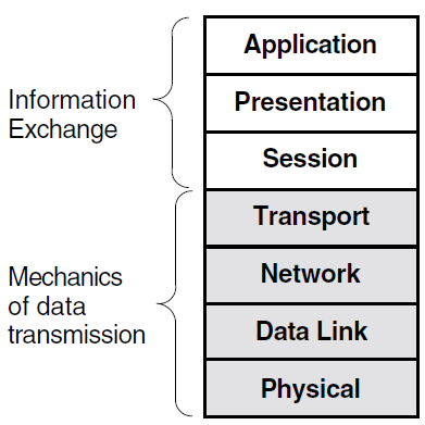
Application
Provides for distributed processing and access; contains the application programs and supporting protocols that use the lower layers.
Presentation
Coordinates the conversion of data and data formats to meet the needs of the individual application processes.
Session
Organizes and structures the interactions between pairs of communicating application processes.
Transport
Provides reliable, transparent transfer of data between end systems, with error recovery and flow control.
Network
Moves data across network links and between end systems.
Data Link
Specifies the technique for moving data along network links between defined points on the network, and how to detect and correct errors in the physical layer.
Physical
Connects systems to the physical communications media.
The top three layers of this model (Application layer, Presentation layer, and Session layer) are collectively called the upper layers. The OSAK interface is an implementation of the upper layers of the OSI model.
The following sections describe the upper layers of the OSI model in more detail.
1.1.1. The Application Layer
The Application layer is the part of the OSI model where applications operate. It contains application processes (APs) and each application process provides the resources for one or more application entities (AEs).
An application process is a component that carries out a particular function on a computer system using an application entity. An application entity is a set of resources (for example, programs and process slots) that perform a communication function. An application entity can serve only one application process. However, an application process can be served by more than one application entity.
An application-entity invocation is the active use of the resources of an application entity. An application entity is identified by a unique name, called the application-entity title (AE-title). This consists of an application-process title (AP-title), and an application-entity qualifier (AE-qualifier).
Figure 1.2, ''Application Entities, Application Processes, and Computer Systems'' shows the relationship between application entities, application processes, and computer systems.
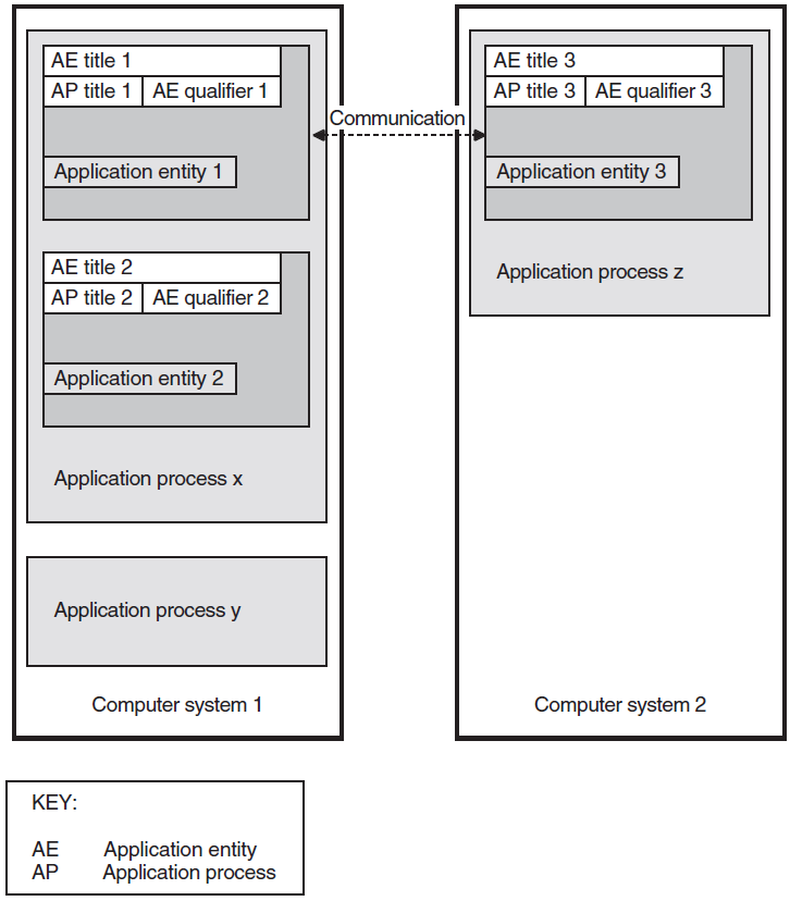
The application entities at each end of an association are peer entities. These peer entities use OSAK services to set up an association between them, to transfer data, and to close down the association.
OSI applications are uniquely identified by an application-entity title. One application-entity title corresponds with only one presentation address, but one presentation address can correspond with more than one application entity title.
1.1.2. Presentation Layer
The Presentation layer ensures that the information content of data is preserved during transfer of the data across a connection.
1.1.2.1. Syntax Conversion
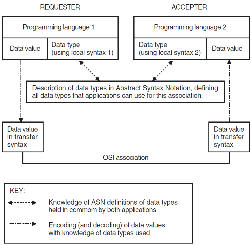
Different computer systems use different formats for storing data. These formats are called local syntaxes. For example, some systems store characters in ASCII format, but others do not. In open systems communication, the type and value of data passing between systems are preserved by a transfer syntax.
A transfer syntax is a representation of data from the Application layer that is independent of the machine being used. Transfer syntax is used to transmit data between peer entities. The Presentation layer converts local syntax to transfer syntax at the sending end of a connection and converts transfer syntax to local syntax at the receiving end.
1.1.2.2. Presentation Context
A presentation context defines the information transfer requirements of an application. A presentation context consists of an abstract syntax and a transfer syntax. The Presentation layer uses the abstract syntax definitions of data types to convert transfer syntax to local syntax.
Abstract syntax is the semantics of data from the Application layer. You need to encode all the data you pass to the OSAK interface into transfer syntax. Section 4.2.3, ''Presentation PCI and ACSE-PCI Syntaxes'' gives the definitions of user data used in presentation protocol control information (PCI) syntax and Association Control Service Element (ACSE) abstract syntax.
Peer entities must agree on which presentation contexts to use on an association. They can only use presentation contexts that both of them can support. The group of presentation contexts that both peer entities agree to support is called the Defined Context Set (DCS) for the association.
A default context is the presentation context used when the DCS is empty. It is set by negotiation between the peer entities, and it remains the same throughout the life of an association.
The context management functional unit was not accepted
All proposed presentation contexts except ACSE PCI were rejected
Data is fully encoded if you define more than one presentation context for an association, or if the default context is in use.
Section 1.1.2.4, ''Abstract Syntax Notation'' describes more fully the problem of data representation when peer entities are exchanging data, and Section 1.1.2.5, ''ASN.1 Compiler'' explains the role of the ASN.1 compiler in solving the problem.
1.1.2.3. Transfer Syntax
A transfer syntax is a set of rules for encoding values from a set of abstract data types into an implementation-independent representation and for decoding the implementation-independent representation back into the original set of abstract data types. It provides a mapping between the ASN.1 representation of a set of abstract data types and a sequence of octets encoding their values.
An application needs a concrete way to represent the group of data types it needs to use. This is the form in which the data types pass between the two peer entities connected by the application. This concrete representation is called a transfer syntax.
A tag specifying the type (T)
A value specifying the length of the encoding (L)
The value being encoded (V)
Refer to ISO 8825 for a full specification of BER.
1.1.2.4. Abstract Syntax Notation
Abstract Syntax Notation (ASN) is an important part of how the Presentation layer ensures that information is preserved during its transfer across a connection.
Abstract Syntax Notation (ASN) is the notation in which an abstract syntax is described. The rules of ASN are independent of the encoding techniques used to represent them.
ASN.1 is a widely used abstract syntax notation that uses standard Backus-Naur form (BNF) notation to describe application syntaxes. ASN.1 is defined in ISO 8824.
If your application runs on platforms with different internal formats (local syntaxes), you need to define an abstract syntax for your application. Using ASN.1 makes your syntax platform-independent and hence makes your application more widely usable.
Figure 1.3, ''Relationship Between Data Type, Abstract Syntax, and Transfer Syntax'' shows the relationship between a programming language data type, its representation in abstract syntax, and its representation in transfer syntax.
1.1.2.5. ASN.1 Compiler
Writing routines to encode and decode values defined by ASN.1 requires significant effort. Use of an ASN.1 compiler can reduce the required effort considerably. Most compilers support a particular programming language.
An ASN.1 compiler takes as its input a file of ASN.1 definitions of data types. The definitions may be specific to your application or they may be a standard set of definitions, such as the File Transfer, Access, and Management (FTAM) definitions.
A set of data structures in the target language of the compiler
A set of functions that operates on the data structures
The compiler you use may generate some encoding and decoding routines particularly for standard or widely used data types. If the compiler does not generate encode and decode routines, or if your application uses complex data types, you should write your own routines. Refer to ISO 8824 for a full specification of ASN.1.
1.1.3. Session Layer
The Session layer sets up, maintains, and releases a logical connection between peer entities.
1.1.3.1. Session Layer Services
Sets up and releases connections
Transfers data
Structures the exchange of information
Inserts synchronization points into the dialogue
Recovers to a given synchronization point
Session version 1 (defined in the original session standard)
Session version 2 (as defined by an addendum to the original standard, allowing for unlimited user data)
See Appendix A, "Standards Information" for details.
P-TOKEN-GIVE request
P-CONTROL-GIVE request
P-ACTIVITY-INTERRUPT request
P-ACTIVITY-INTERRUPT response
P-ACTIVITY-DISCARD request
P-ACTIVITY-DISCARD response
Session version 2 operates in accordance with published agreements of the National Institute of Standards and Technology (NIST). Under this standard, you can send a maximum of 10,240 octets of user data on a non-data service, and you can send user data on any service.
The applications agree which session version to use in the course of negotiation. The OSAK software implements both session versions and — when session version 2 is negotiated — imposes no limit on the amount of data you send on the user data service.
1.2. Connections and Associations
Note
OSI networks use different terminology to refer to links between systems at different levels. A link between two systems at the application layer (for example, a link set up by the application programming interface (API) or the ROSE API) is called an association. A link between two systems at the Session layer (for example, a link set up by the SPI) is called a connection. Apart from terminology there is little difference between associations and connections. This chapter uses the term association to refer to both associations and connections. Except where indicated, the information regarding to associations also applies to connections.
1.2.1. Services
A service is a task that an application can carry out. You request a service by calling one or more routines. The end of the connection that calls a service is the requester of that service. The end of the connection that receives the service is the accepter of the service. The arrival of a data unit carrying a service to a peer entity is known as an event.
Confirmed
Unconfirmed
In a confirmed service, the requester calls a routine that requests the service. In consequence, the local service provider generates an event known as an indication. The accepter receives this event and calls another routine that responds to the request, so the remote service provider generates an event known as a confirm. A confirmed service is complete when the requester receives the confirm. Figure 1.4, ''Confirmed Service'' shows a confirmed service.
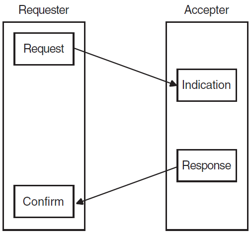
In an unconfirmed service, the requester asks for a service and the accepter receives an indication. However, there is no response and consequently no confirm. An unconfirmed service is complete when the accepter receives the indication. However, because the requester does not know when the accepter receives the indication, the requester considers the service to be complete as soon as the service provider sends the request.
1.2.2. Phases of an Association
An association can have the following phases:
Setup and negotiation (Section 1.2.2.1, ''Setup and Negotiation'')
Data exchange (Section 1.2.2.2, ''Data Exchange'')
Release or abort (Section 1.2.2.3, ''Release or Abort'')
Note that if the peer entity rejects the association, only setup occurs.
1.2.2.1. Setup and Negotiation
During this phase, the processes involved in an exchange of information over an OSI network establish an association. They negotiate the scope and parameters of the association. The end that requests an association is called the initiator. The end that receives the request for an association is called the responder. The initiator can propose values for certain parameters. The responder sends back a response that is either an acceptance or a rejection of the association request.
When accepting an association, the responder indicates the parameters it agrees with, and the initiator must operate using those parameters and no others. If the initiator cannot do so, it aborts or releases the association. Section 1.2.2.3, ''Release or Abort'' explains the difference between releasing and aborting. When rejecting an association, a responder must give a reason for doing so.
Application context (API and ROSE)
An application context is a statement of which application service elements (ASEs) your application supports. An ASE is an Application layer element that supplies a service to an application process. The application context provides a set of rules governing the exchange of information between cooperating applications. This agreement is not a result of the negotiation, but is agreed (usually on paper) before any electronic dealings. The rules specified for the application context are common to both ends of the connection.
For some applications, the application context is defined in a standard. For example, MHS (message-handling system) application contexts and FTAM (File Transfer, Access, and Management) application contexts are defined by ISO standards. If no standard exists for the application you are developing, you should define the application context yourself.
This parameter is mandatory and the OSAK interface does not supply a default. Note that an application context bears no relation to a presentation context, which is discussed in Section 1.1.2.2, ''Presentation Context''.
Protocol versions
For the API and ROSE API, the peer entities should agree on which version of the various OSI protocols they can both support. For the SPI, only the session version is relevant for this parameter.
Functional units
Functional units define the groups of services you require for the association. Section 1.4.2, ''Functional Units'' lists and describes the functional units that the OSAK interface provides.
Synchronization points
Synchronization points are markers that you can position in the data that you are sending. These markers provide known points that help in recovery when data is lost or corrupted. Section 1.4.3, ''Synchronization Points and Resynchronization'' describes synchronization points.
Tokens
Tokens determine which end of an association can initiate certain services. Section 1.4.4, ''Tokens'' describes tokens.
1.2.2.2. Data Exchange
Activity management (Section 1.4.1, ''Activities'')
Synchronization points and resynchronization (Section 1.4.3, ''Synchronization Points and Resynchronization'')
Token management (Section 1.4.4, ''Tokens'')
An application can transfer data without using activities. However, if you do not use activities, it is difficult to resynchronize data transfer.
1.2.2.3. Release or Abort
This phase of an association results in the termination of an association. You can release or abort an association.
A release is an orderly termination, which means that the peer entities negotiate the release of the association. A release does not result in loss of user data. The accepter may refuse a request for an orderly release, but only if the negotiated release functional unit has been selected. Section 1.4.2, ''Functional Units'' gives further information about functional units. Normal data transfer can start again after the refusal, following the rules imposed by the existing positions of tokens. Section 1.4.4, ''Tokens'' gives further information about tokens.
User abort – Either of the peer entities can initiate a user abort. A peer entity issuing an abort request should specify the reason for the abort.
Provider abort – The request for a provider abort comes from the service provider. In this case, the requester and the accepter both receive a message giving the reason for the abort.
1.3. Types of Data
Use the user data service and typed data service for sending user information. You can send an unlimited amount of user information on these services.
1.3.1. User Data
User information
User PCI
User information is the information that the user want to transfer between applications, for example, a mail message or the contents of a file.
User PCI consists of data the user application needs to process the user information correctly.
For example, if an application is a file transfer system, the user data consists of both the contents of the file and the file transfer control information that you send.
You can send user data on any request or response service. This includes the association request service, which you use to set up an association. The user can also send user data on the abort request service.
1.3.2. Capability Data
If you are using activities, you can use the capability data service to transfer data from one peer entity to the other between activities. For example, you can use this service to send information about the capabilities of the local system to the remote system. Section 1.4.1, ''Activities'' explains what activities are and how to manage them.
You can use the capability data service only when there is no activity in progress over an association. This service has a maximum size of 64K bytes, covering the entire contents of the data unit (including PCI).
1.3.3. Expedited Data
You can use the expedited data service to transfer data between peer entities without regard to the positioning of tokens (Section 1.4.4, ''Tokens''). For example, you can use the service to send an urgent message. You cannot segment data when you use the expedited data service. The maximum length of user data allowed is 14 octets.
You can use the expedited data service only if the transport expedited service is available.
1.3.4. Typed Data
You can use the typed data service to send data from the peer entity that does not hold the data token. Typed data is not subject to the control of the data token (Section 1.4.4, ''Tokens''). Typed data is relevant only when you have selected the half-duplex functional unit (see Section 1.4.2, ''Functional Units'').
1.4. OSI Information Exchange
Activities (Section 1.4.1, ''Activities'')
Functional units (Section 1.4.2, ''Functional Units'')
Synchronization points and resynchronization (Section 1.4.3, ''Synchronization Points and Resynchronization'')
Tokens (Section 1.4.4, ''Tokens'')
1.4.1. Activities
An activity is a logical piece of work done by an application. For example, if your application is a mailing system and you want to send 10 mail messages, sending this set of messages could be an activity.
One activity should finish before another can start. However, you can interrupt an activity after you start it. For example, you can interrupt an activity that consists of sending 10 mail messages, before all the messages have been sent, in order to send some urgent data on the capability data service. You can resume the interrupted activity after sending the urgent data.
You can stop an activity either by discarding it or by ending it in an orderly fashion. If you discard an activity, you lose any work that was done during the activity's lifetime. If you end an activity, you save all the work that was done during the activity's lifetime. Note that using activity management may slow down your application, but it can simplify procedures for recovery of data when a connection fails.
1.4.1.1. Phases of an Activity
Start
Interrupt
Resume
Discard or end
1.4.1.2. Relationship to Associations
One activity lasting the lifetime of an association
One activity lasting the lifetimes of several associations
Several consecutive activities during the lifetime of a single association
If an activity is interrupted, it can later be resumed on the same association or on another association.
1.4.2. Functional Units
A functional unit is a logical grouping of services. Your application can use a service only if both peer entities agree to use the required functional unit. ISO 8327 and ISO 8823 define functional units.
The kernel functional unit is mandatory for all activities, thus the services that the kernel functional unit supports are always available to both peers. The kernel functional unit supports the basic protocol elements of procedure required to setup an association, to transfer data, and to release the association.
1.4.2.1. Presentation Functional Units
The OSAK software, and most other OSI service providers, support the context management functional unit at the Presentation layer. The context management functional unit is optional. It supports the context addition and deletion services and its use is negotiable.
The ISO standard for the Presentation layer also specifies the context restoration functional unit, which is optional.
1.4.2.2. Session Functional Units
The Session layer is concerned with dialogue management and data flow.
|
Functional Unit |
Associated Token |
|---|---|
|
Negotiated release |
Release token |
|
Half-duplex |
Data token |
|
Minor synchronize |
Synchronize-minor token |
|
Major synchronize |
Major activity token |
|
Activity management |
Major activity token |
Selecting the functional unit makes the indicated token available, for example, if you select the minor synchronize functional unit, the synchronize-minor token is available.
A token allows its holder to initiate the services included in the functional unit. If a session functional unit is associated with a token, the peer entities must agree on which end of the connection holds the token before they can use the services included in the functional unit.
1.4.3. Synchronization Points and Resynchronization
You can use synchronization points and resynchronization to enable recovery when user information is lost or corrupted during transfer. You can issue synchronization points at any time during the transfer of user information. The provider numbers synchronization points sequentially; an application may be able to specify the first number, depending on the functional units negotiated.
Major and Minor Synchronization
Major
Major synchronization points break up the data into a series of dialogue units, within an activity or within an association. Each dialogue unit is separate from all other dialogue units.
Minor
Minor synchronization points occur within a dialogue unit.
You decide how frequently major and minor synchronization points occur in your application.
Resynchronization
If a peer entity does not receive all the data being sent, or if the data is corrupted, that peer entity can request a resynchronization to the most recently confirmed synchronization point.
Either peer entity can start resynchronization. Resynchronization sets the association to the state it was in at the synchronization point specified in the request to resynchronize. Resynchronization includes reassignment of tokens and purging of all undelivered data currently being processed in the lower layers.
1.4.4. Tokens
Peer entities of an association use tokens to determine which of them can call certain services. One peer entity at a time holds a token. A token exists for the lifetime of an association. A token is available if the associated functional unit has been selected (see Table 1.1, ''Session Functional Units and Associated Tokens'').
|
Service |
Tokens Required |
|---|---|
|
Transfer of a data unit in half-duplex mode |
Data token |
|
Major synchronization |
Major activity token, synchronize-minor token if available, and data token if available |
|
Minor synchronization with minor synchronize functional unit selected |
Synchronize-minor token and, if available, data token |
|
Minor synchronization with symmetric synchronize functional unit selected |
Synchronize-minor token must not be available |
|
Release request |
All available tokens |
|
Release refuse |
Release token must be available but will be assigned to the user who requested the release |
|
Start activity |
Major activity token, data token if available, synchronize-minor token if available |
|
Resume activity |
Major activity token, data token if available, synchronize-minor token if available |
|
End activity |
Major activity token, data token if available, synchronize-minor token if available |
|
Interrupt activity |
Major activity token |
|
Discard activity |
Major activity token |
|
Capability data |
Major activity token, data token if available, synchronize-minor token if available |
|
Exception request |
Data token must be available but not assigned to the user |
1.4.5. Data Segmentation
Segmentation is the division of user data into smaller units, known as segments, for transfer across a connection. The OSAK interface imposes no limit on the amount of data transmitted in a single call to an Application layer service, and it is more efficient to pass data in a single call if possible. However, a programming environment (hardware, implementations of lower-layer protocols, implementation of a particular application) sometimes imposes limits. In this case, segmentation may be necessary or advisable.
Segmentation allows you to run your application with limited memory capacity. You can segment your user data as you pass it to the OSAK interface, and the provider may (without the knowledge of the application) segment the user data across the session interface. You can use the OSAK interface to request that (subject to negotiation between the service providers) session segmentation should take place, but you cannot use the OSAK interface to control whether session segmentation does in fact take place. Session segmentation is under the control of the session service provider.
1.5. Exception Reports
The OSI standards provide for an exception reporting service that you can use to signal problems within your application that do not cause the service provider to abort the association. You can define the problems that fall into this category according to the needs of your application. You can also define how your application responds to an exception report. The application must then clear the error condition by issuing an interrupt, a discard, an abort, or are synchronization, or by giving the data token to the peer.
To use the exception reporting service, you should select the exceptions functional unit.
During the data transfer phase of an association
After making a request for the release of an association
The exception reporting service is defined in ISO Standard 8327.
Chapter 2. Introduction to the OSAK Interface
This chapter describes the three OSAK programming interfaces: the application programming interface (API), the ROSE API, and the session programming interface (SPI).
2.1. The Application Programming Interface
The Session layer
The Presentation layer
The ACSE (Association Control Service Element) protocol of the Application layer
Associate
Release
Abort
Redirect
The redirect service is not an ACSE service. It allows applications to redirect an incoming association to another process on the local system.
Alter-Context
Data
Capability-Data
Expedited-Data
Typed-Data
Token-Please
Token-Give
Control-Give
Sync-Major
Sync-Minor
Resynchronize
Exception-Report
Activity-Start
Activity-Interrupt
Activity-Resume
Activity-Discard
Activity-End
2.2. The ROSE API
The ROSE (Remote Operations Service Element) API enables user applications to access services provided by an implementation of the ROSE protocol of the Application layer.
ROSE supports interactive applications in a distributed open systems environment. It is a service for multivendor distributed processing.
Invoke
Result
Error
Reject
2.3. The Session Programming Interface
The SPI enables user applications to access services provided by an implementation of the OSI Session layer.
The Session layer supports ISO session version 1 and version 2. Session version 1 allows up to 512 octets of user data on a service. Session version 2 supports the restrictions imposed by the National Institute of Standards and Technology, allowing up to 10,240 octets of data on a service.
Connect
Release
Abort
Redirect
The Redirect service is not a Session service. It allows applications to redirect an incoming connection to another process on the local system.
Data
Capability-Data
Expedited-Data
Typed-Data
Token-Please
Token-Give
Control-Give
Sync-Major
Sync-Minor
Resynchronize
Exception-Report
Activity-Start
Activity-Interrupt
Activity-Resume
Activity-Discard
Activity-End
2.4. The OSAK Parameter Block
The OSAK interface has a parameter block interface. You can allocate memory for the parameter block and the data structures it contains statically or dynamically. Figure 2.1, ''Structure of the Parameter Block'' shows the structure of the parameter block.
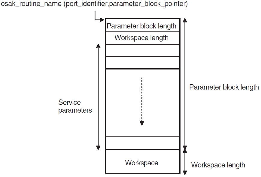
All OSAK routines that provide outbound services, as well as osak_get_event (API
and ROSE) or spi_get_event (SPI) have parameter_block as one of their arguments. The parameter
block argument contains all possible parameters for all services. The
OSAK interface uses only the relevant parameters in each service call. Most of the
parameters specify ACSE, presentation, and session protocol control information (PCI)
for ROSE and API, or session PCI only for SPI.
VSI DECnet-Plus OSAK Programming Reference Manual also describes the structure of the parameter_block argument in detail and gives information about each parameter.
2.4.1. Outbound Calls
On outbound calls, you pass user data and other parameters that the OSAK interface uses to build the session, presentation and ACSE PCI (ROSE and API) or session PCI only (SPI), to the OSAK interface. You should encode certain presentation and ACSE parameters before passing them to the OSAK interface (ROSE and API). The routine descriptions in VSI DECnet-Plus OSAK Programming Reference Manual specify the parameters that you should encode. You do not need to encode session parameters.
The ASN.1 compiler has facilities to help you write encoding and decoding routines.
2.4.2. Inbound Events
On inbound events, the OSAK interface passes user data to the receiving application entity.
- API and ROSE
The OSAK interface decodes the session, presentation, and ACSEPCI, checks their validity, and passes them to your application in the other OSAK parameters. However, your application should check those parameters that relate to presentation contexts.
- SPI
The OSAK interface decodes the session PCI, checks it for validity, and passes it to your application in the other OSAK parameters.
If the initiator does not propose values for certain parameters, the OSAK interface supplies default values. VSI DECnet-Plus OSAK Programming Reference Manual lists the parameters for which the OSAK interface supplies defaults.
2.5. Management of User Buffers
Your application exchanges data with the OSAK interface in user buffers. On outbound calls, you pass user data (including user information if required) in the user_data parameter. Section 4.3, ''Building a User Buffer'' (API) or Section 6.3, ''Building a User Buffer'' (SPI) explains the structure and use of the buffer list.
When you call an OSAK routine, the ownership of the parameter block as well as all user buffers attached to the parameter block passes to the OSAK interface. The OSAK interface may be able to process your call, transfer all data to the transport provider, and return the parameter block and user buffers to you immediately. In this case, the status of the call is OSAK_S_NORMAL.
If the OSAK interface is unable to process your call immediately, it puts the call on a queue and retains control of the parameter block and user buffers. In this case, provided there is no API segmentation, the status of the call is OSAK_S_QUEUED.
Sometimes the status of a routine is OSAK_S_FREE. This means that the routine call completed normally and that there are parameter blocks and user buffers available to be reclaimed. These parameter blocks and user buffers are from a previous routine call of which the return value was OSAK_S_QUEUED.
To reuse parameter blocks and user buffers, you should reclaim them from the OSAK interface. Section 3.2.2, ''Deciding How to Reclaim Memory'' describes the strategies you can use for reclaiming memory.
osak_give_buffers (API
and ROSE) or spi_give_buffers (SPI) to pass a linked list of buffers to the
OSAK interface. Section 4.4.2, ''Passing Buffers to the OSAK Interface'' (API), and Section 6.4.2, ''Passing Buffers to the OSAK Interface'' (SPI) explain how to use these buffers. When
you call osak_get_event (API and ROSE) or spi_get_event (SPI)
to receive an event, the OSAK interface does the following:Removes a buffer from the list you passed previously when you called
osak_give_buffers(API and ROSE) orspi_give_buffers(SPI)Writes an incoming data unit in the buffer
If there is room in the buffer, the OSAK interface writes the incoming data unit in its entirety.
If you do not supply the OSAK interface with enough buffers, the remote peer entity eventually becomes constrained by lower-layer flow control, with transport service data units (TSDUs) queuing up on the remote system, waiting to be sent. When this happens, an
osak_get_event(API and ROSE) orspi_get_event(SPI) call will complete with a status of OSAK_S_NOBUFFERS. You can useosak_give_buffers(API and ROSE) orspi_give_buffers(SPI) to control transport flow, but do so with caution, to avoid adversely affecting the performance of your application.Adds the buffer or lists of buffers to the list pointed to by the tsdu_ptr parameter
If more than one buffer is needed to receive the data unit, the OSAK interface links
sufficient buffers together. On OpenVMS systems, a single call to
osak_get_event (API and ROSE) or spi_get_event (SPI)
retrieves all the linked buffers. On UNIX systems, a separate
osak_get_event (API andROSE) or spi_get_event is needed
for each buffer.
The peer_data parameter points to any user data or user information in the user buffer list. Other parameters in the parameter block point to ACSE, presentation, and session PCI (API or ROSE) or session PCI only (SPI).
If there is no inbound event, or if too little of the inbound protocol data unit (PDU) has
arrived, the OSAK interface completes the osak_get_event (API and ROSE) or
spi_get_event (SPI) call with a status of OSAK_S_NOEVENT. The parameter
block is returned, but the buffers containing the partial PDU are retained.
2.6. Redirecting an Association
Open Redirect
Redirect
The redirect service is specific to the OSAK interface. It is not an ACSE service. You can use it to redirect an association from one local process to another, either immediately after setting up an association or during data transfer.
You can use the redirect service to implement an application server. You do this by receiving all incoming connection requests in the same process, and then using the redirect service to distribute them among a number of other processes.
You can ensure that none of the processes your application is using is overloaded.
You can map one remote peer entity's invocation identifier to one or more process. You can then use the invocation identifier as part of a recovery mechanism (if, for example, a connection is lost).
You have more control over incoming connection requests.
Section 4.8, ''Redirecting an Association'' (API), or Section 6.8, ''Redirecting a Connection'' (SPI) gives details of which calls to use to redirect a process.
2.7. Outbound Addressing
Presentation address (p-address)
The p-address is the upper-layer address. It consists of three values, each addressing the access points between two layers, as follows:p-selector (ACSE and Presentation)
s-selector (Presentation and Session)
t-selector (Session and Transport)
Transport Template
A transport template specifies information that is not provided by OSAK over the interface. The transport template specifies which network service is to be used (CONS, CLNS or RFC 1006), and other characteristics for the connection. Transport templates are set up by the system manager. For more information about transport templates, see Section 2.7.2, ''Specifying Transport Templates''.
Network service access point (NSAP)
The NSAP is the network address of the machine to which you are trying to connect.
DECnet-Plus allows any one node to have a maximum of three NSAPs. Therefore, when you are setting up an association, you do not need to specify more than these three NSAPs, plus an IP address if TCP/IP is available, that is, four NSAPs altogether.
However, the OSAK interface allows you to specify an unlimited number of NSAPs in the data structure osak_nsap. The more NSAPs you include, the slower the speed of connection establishment, because OSAK tries every NSAP until it finds one that works.
Refer to VSI DECnet-Plus OSAK Programming Reference Manual for information about the structure of an application entity title and a presentation address.
2.7.1. Making a Connection to a Specified Application
- API and ROSE
If you need to ensure that every connection you request is to a particular application, you should specify values in the aptitle and ae_qualifier fields of the called_aei parameter, as well as a presentation address, specified in the paddress field.
If you do not need to make a connection to a particular application, or if you are using the SPI, you only need to specify a value for the presentation address to which you want to connect. You specify this value in the paddress field of the called_aei parameter.
2.7.2. Specifying Transport Templates
Specify the addresses on which you want to make an outbound connection in the
paddress field of the called_aei
parameter in the osak_associate_req (API and ROSE) or
spi_connect_req (SPI) call.
|
Desired Transport Template |
Set transport_templateto: |
|---|---|
|
Default |
Null |
|
One named template |
Template name |
|
List of templates |
List of template names |
If you supply a list of transport templates in the transport_template parameter, the OSAK interface uses those templates in the order in which you specify them. The interface tries to establish a connection with the NSAPs in the called_aei parameter that have the same network type as the network type specified in the transport template being used. This is called multihoming (see Section 2.7.3, ''Specifying a Multihomed Address'' for more information).
To indicate that you want to connect to a named peer entity on any one of several available addresses, you should specify a list of transport templates in the transport_template parameter and a corresponding list of NSAPs in the called_aei parameter.
For more information about transport templates, refer to VSI DECnet-Plus for OpenVMS Network Management Guide and VSI DECnet-Plus for OpenVMS Network Control Language Reference Guide.
2.7.3. Specifying a Multihomed Address
The OSAK interface supports outbound multihoming. Inbound multihoming is not supported. This means that you can direct an outbound call to a named peer entity on any available NSAP address.
The OSAK software tries the transport templates in the order that the
osak_associate_req (API and ROSE) or spi_connect_req
(SPI) request specifies. Note that the connection attempts end when a transport
connection is established, not when the upper-layer association is established. If
the transport providers can establish a connection, but the peer provider refuses
the upper-layer connection, the OSAK software makes no further connection attempts.
The application itself must detect and handle this case.
For OSI transport, if you do not specify a transport template, the OSAK interface uses the default transport template, default. The OSAK interface tries to connect only with NSAPs in the called_aei parameter that have the same network type as the default transport template. Note that an outbound transport template must not have a network type of ANY: the only supported network types for outbound connections are CLNS, CONS, and RFC 1006. You can mix NSAPs with different network types in a single presentation address.
If the network type in a transport template is unknown, or if none of the NSAPs in the called_aei parameter has a network type that matches the one in the transport template, the OSAK interface ignores that template and tries the next. Note that the OSAK interface does not supply a default network type.
Example 4.5, ''Code for Calling osak_associate_req'' (API) or Example 6.5, ''Code for Calling spi_connect_req'' (SPI) are examples of addressing. Note that the addresses used in the examples contain no ACSE information, and that the local address does not need to specify an NSAP.
Specify an OSI NSAP or a list of OSI NSAPs
Specify an OSI transport template or a list of templates
2.8. Inbound Addressing
For receiving connection requests, an application on OpenVMS needs to specify a presentation address (p-address). OpenVMS ignores the transport template for responder processes. On UNIX, an application needs to specify a p-address and a transport template. The p-address must be unique to the system, and the transport template must be unique to that process.
On UNIX systems, you need to open two OSAK ports if you want your application to listen on both RFC 1006 and OSI. You must use RFC 1006 to listen, rather than ANY.
2.9. Segmentation Across the OSAK Interface
Segmentation across the OSAK interface (application segmentation) allows an initiator and a responder to use different buffer sizes when exchanging data.
You cannot segment ACSE, presentation, and session PCI. When you send data, you should send
all the necessary ACSE, presentation, and session PCI on the sending service. You can
send all the user data on that service as well. With one exception, there is no limit to
the amount of user data you can send on one service call. The exception is the
osak_associate_req (API and ROSE) or spi_connect_req
(SPI), which has a limit of 10K. Alternatively, you can segment the userdata, sending
some of it on the original service call, and the rest on one or more calls to the
routine osak_send_more (API and ROSE) or spi_send_more
(SPI).
An application can receive data in a single buffer or in several smaller buffers. The receiving application decides on the size of buffers it makes available for incoming data. Whether the data is sent in one block or in segments does not affect the way in which the receiving application chooses to receive data.
2.9.1. Segmentation at the Session Layer
Note
The OSAK software does not use session segmentation if it is using session version 1, except when sending normal data or typed data. See VSI DECnet-Plus OSAK Programming Reference Manual for details of how the OSAK software implements the Session layer standards.
The OSAK software can use session segmentation if it is using session version 2.
Depending on whether the negotiation has settled on session segmentation, the OSAK software responds to incoming data differently.
Example of Session Segmentation
The OSAK software immediately generates a single TSDU, 2048 octets long, but retains the remaining 1952 octets.
If the next buffer has fewer than 96 octets, the OSAK software can send another segment, made up of the remainder from the first data buffer's contents together with the contents of the new shorter buffer.
If session segmentation is not negotiated, the OSAK software emits data buffers as they are received, regardless of their size.
2.10. OSAK Status Codes
2.10.1. The Status of a Call
The call fails.
The OSAK interface immediately returns ownership of the parameter block and of any user buffers to your application. The failure of a call is indicated by its status code; VSI DECnet-Plus OSAK Programming Reference Manual gives details of all of them.
The call succeeds, and the OSAK interface is able to complete the requested service immediately.
The status of the call is OSAK_S_NORMAL, and the OSAK interface immediately returns ownership of the parameter block and user buffers to your application. This can happen only if you are sending unsegmented user data, because a segmented call will not return OSAK_S_NORMAL.
The call succeeds, but the OSAK interface is not able to complete the requested service immediately. The interface places the service on the queue for the transport provider. The status is OSAK_S_QUEUED or OSAK_S_FREE. Section 2.5, ''Management of User Buffers'' explained the difference in meaning between these two codes.
- OpenVMS
If you are using completion routines, the completion routine on a service starts to run when the service is completed. This indicates that the parameter block and any user buffers that you passed on the service are available for you to use again.
When your call specifies a completion routine, the only non-error status code that the OSAK software returns is OSAK_S_QUEUED.
When you call the osak_collect_pb (API and ROSE) or spi_collect_pb
(SPI) routine, the OSAK software uses the port_id field to
associate a parameter block with a specific port. It is essential to specify the
port, so that the OSAK software knows which parameter block to collect.
2.10.2. Order of Completion of Calls
In general, requests that return OSAK_S_QUEUED complete in the order they were issued. Note that the OSAK interface imposes no preset maximum number of requests that return OSAK_S_QUEUED, but this depends on the resources available locally.
If your application uses completion routines on some but not all calls, the order of return of the parameter blocks may not be the same as the order in which they were issued.
See Section 3.7.1, ''Advantages and Disadvantages of Asynchronous and Synchronous Notification'' for a comparison of methods of collecting inbound events with and without completion routines.
Any service that is sent on the expedited channel may overtake a service on the normal channel.
Although a service on the expedited channel may complete ahead of another service, for any one service, the OSAK interface always returns parameter blocks in the same order as they were passed down.
2.11. Restrictions
The OSAK software does not support the session disconnect timer.
The OSAK interface includes data type definitions for all supported programming languages but only provides language bindings for the C programming language.
If the OSAK interface passes to the application an NSAP preceded by a zero, the zero can be ignored. This additional digit is added during the translation process if a NSAP has an odd number of characters.
The OSAK API interface does not always correctly decode the mode selector 'SET' in a CP-PPDU (A-ASSOCIATE indication) or a CPA-PPDU (A-ASSOCIATE-ACCEPT confirm). If '[0] IMPLICIT Mode-selector' comes after '[2] IMPLICIT SEQUENCE', the OSAK interface does not decode the mode selector but passes it to your application as user data.
- You should not use the same transport selector (TSEL) on more than one process. Any TSEL that your application uses should be unique. Re-use of a TSEL results in one of two secondary status codes in the status_block parameter. The primary status in each case is OSAK_S_INVAEI. The two possible secondary codes are:
OSAK_S_TSELINUSE, T-selector is already in use.
Indicates that a TSEL in the local_aei or calling_aei parameter is already being used on another port or by another application.
OSAK_S_MULTADDR, multiple upper layer addresses for one T-selector.
Indicates that you have opened more than one OSAK responder port within the same process using the same TSEL, but a different SSEL or PSEL. This is not allowed. If you want to specify a different SSEL or PSEL, you should also specify a different TSEL.
For OpenVMS only: if you need to use an ASCII string in an NSAP, you should define the string as a logical name in the table OSIT$NAMES and then pass the logical name as an input parameter in the call to the routines osak_associate_req or spi_connect_req. NSAPspassed to the OSAK interface directly in the call to the routines osak_associate_req or spi_connect_req must be in hexadecimal format.
For OpenVMS only: if you call the API routine osak_accept_rsp or the SPI routine spi_accept_rsp with a responding session selector greater than 16 octets, user-mode asynchronous system traps (ASTs) remain disabled when the routine exits. To ensure that user-mode ASTs are re-enabled when the routine exits, do not specify a responding session selector of more than 16 octets.
The OSAK software does not support session segmentation on OpenVMS or UNIX systems. This does not hinder segmentation by the user, as explained in Section 2.9, ''Segmentation Across the OSAK Interface''.
Chapter 3. Planning Your Application
Note
This chapter uses the word association to refer either to an association or a connection. This is because the API and ROSE interfaces use associations but the SPI uses connections. Conceptually, associations and connections are the same.
3.1. Decision Checklist
- What is your strategy for managing memory? You need to consider the following aspects of memory management:
- Allocating memory
Size of workspace
Size of user buffers
Number of user buffers
Choosing between static and dynamic memory allocation
Reclaiming memory
See Section 3.2, ''Managing Memory'' for more information.
What addresses do you want to reach? See Section 3.3, ''Considering Your Application's Addressing Needs'' for more information.
Do you want a simple application that deals with only one peer, or a more complex one? See Section 3.4, ''Choosing Between Single and Multiple Associations'' for more information.
Do you want your application to be an active or a passive process? (OpenVMS systems only) See Section 3.5, ''Choosing Between Active and Passive Associations (OpenVMS Systems Only)'' for more information.
Do you want your application to be portable? See Section 3.6, ''Making an Application Portable'' for more information.
What do you want the application to do while waiting to receive data? See Section 3.7, ''Waiting to Receive Data'' for more information.
3.2. Managing Memory
This section describes how to allocate and reclaim memory. See Section 4.3, ''Building a User Buffer'' (API) or Section 6.3, ''Building a User Buffer'' (SPI) for information on the use of buffers for an outgoing call and Section 4.4.2, ''Passing Buffers to the OSAK Interface'' (API) or Section 6.4.2, ''Passing Buffers to the OSAK Interface'' (SPI) for information on the use of buffers for receiving incoming events.
3.2.1. Deciding How Much Memory to Allocate
The size of the workspace in each parameter block that you build. Section 3.2.1.1, ''Deciding on the Parameter Block Workspace Size'' gives further information.
The number and size of user buffers to pass to the OSAK interface. Section 3.2.1.2, ''Deciding on the Size and Number of User Buffers'' gives further information.
3.2.1.1. Deciding on the Parameter Block Workspace Size
Decodes incoming data units (the workspace stores the data structures describing the incoming data)
Stores data values for reference parameters with write access on outbound service calls
The amount of workspace needed by a parameter block in a given call is roughly proportional to the number of parameters you are passing in that call. However, you cannot always determine in advance the size of a parameter arriving on an inbound service. If the workspace you provide is not large enough, the OSAK interface returns the status code OSAK_S_INSFWS.
Some of the data structures that OSAK uses to handle inbound events (such as
the osak_mem_descriptor in a P-ACTIVITY-START (API and ROSE) or
S-ACTIVITY-START (SPI) indication) are contained in the workspace. There is a
pointer to osak_mem_descriptor in the parameter block passed with
the call, and after completion of the call, you can reclaim all memory used by
the OSAK software by reclaiming the OSAK parameter block. For further
information about building an OSAK parameter block, see Section 4.2, ''Using Parameter Blocks'' (API) or Section 6.2, ''Using Parameter Blocks'' (SPI).
In the case of outbound calls (for example, osak_act_start_req
(API and ROSE) or spi_act_start_req (SPI), you must reclaim
individual buffers used for data structures such as
osak_mem_descriptor. Then reclaim the parameter block.
The minimum permitted size for the workspace is 512 octets. This default is sufficient for most applications. However, if a routine returns with the status OSAK_S_INSFWS, you should call the routine again with a workspace at least double the size you originally specified.
3.2.1.2. Deciding on the Size and Number of User Buffers
The amount of data that your application is transferring
The frequency with which your application transfers data
You should also consider the flow of data in your application. For example, if you are using the duplex functional unit, but you are alternating the transfer of data between the peer entities, you need to pass only one user buffer at a time.
You can base the size and number of user buffers on the maximum number of events for which your application can wait before it should begin processing them.
You should aim to use the minimum amount of resources and avoid delays in processing. You can do this by preparing for standard cases. For example, if your application is a file transfer application and you know the standard size of file to be received and the maximum segment size, pass sufficient buffers to accommodate the standard file size. If you try to receive an exceptionally large file, the OSAK interface returns status OSAK_S_NOBUFFERS. You can increase the buffer capacity for this exceptional case.
Data transfer time
If data transfer time is the limiting factor, pass several buffers to the OSAK interface to ensure that lack of buffers on the local side of an association does not prevent the remote peer entity from sending data.
Data processing time
If data processing time is the limiting factor, you may find it more efficient to pass a minimum number of user buffers, so that memory is not wasted.
You can reuse a buffer that you have passed to the OSAK interface. Section 3.2.2, ''Deciding How to Reclaim Memory'' describes how to reclaim a buffer so that you can reuse it.
3.2.2. Deciding How to Reclaim Memory
If your application runs on demand, you can reclaim memory when you close down an
association, by calling osak_close_port (API and ROSE) or
spi_close_port (SPI). The routine returns all the parameter blocks
and user buffers passed in routine calls during the association.
If your application runs continuously, you should plan an efficient strategy for reclaiming memory.
If you are sending unsegmented data on a service, the OSAK interface may return the parameter block and user buffers to your application on completion of the service call. This is indicated by a return value of OSAK_S_NORMAL. You can reuse the parameter block and user buffers immediately.
However, if you are sending segmented data on a service, or if you are writing your application with asynchronous notification (OpenVMS systems only), you need to plan how to reclaim the memory allocated to parameter blocks and user buffers.
Regular calls to
osak_collect_pb(API and ROSE) orspi_collect_pb(SPI).Static allocation of memory (see Section 3.2.4, ''Choosing Between Static and Dynamic Allocation of Memory'')
3.2.3. Keeping Track of Buffers Used for Outbound Calls
Maintain a table linking parameter block addresses to requests.
Use the user-context field of the parameter block to point to a data structure of your own.
Create a data structure that includes the parameter block. Then, when the event is returned, you can use the known offset of the parameter block to find the start of your data structure.
Use the func parameter in the parameter block to determine which type of service request has completed.
- OpenVMS
On OpenVMS systems, you can use the completion_rtn parameter. A completion routine can let you keep track of which routines have completed.
3.2.4. Choosing Between Static and Dynamic Allocation of Memory
Your application may be such that you can send only a certain number of transmissions before you require a reply. If your application is like this, you may be able to determine in advance the maximum memory that the application needs at any one time. You can then allocate memory statically for the parameter blocks and user buffers.
|
Method |
Advantages |
Disadvantages |
|---|---|---|
|
Static |
Memory requirements predictable Fast |
Inflexible |
|
Dynamic |
Flexible |
Memory requirements not predictable Slow Harder to manage than static memory |
3.3. Considering Your Application's Addressing Needs
Before writing an application, decide on the address or addresses (or, for a general-purpose application, the sorts of address) with which the application will communicate. You must also decide whether to use more than one address simultaneously for either inbound or outbound connections. For information on addressing, see Section 2.7, ''Outbound Addressing''.
3.4. Choosing Between Single and Multiple Associations
If your application handles one association at a time, its structure is simple but inflexible. The time it takes to process a request to completion is less than the time taken by an application that interleaves multiple associations. However, the initial response time of an application that handles one association at a time is longer, because the application puts each association request on a queue pending the completion of any previous association requests.
How important is the individual association?
How often do you set up an association?
3.5. Choosing Between Active and Passive Associations (OpenVMS Systems Only)
If your application is rarely used, and you do not need an immediate response, you may find it advantageous to make it a passive application. A passive application creates a process to handle incoming connections only when they arrive. This uses few system resources, but the initial response to association requests is generally slow.
If your application is used often, or requires rapid responses to multiple association attempts, you may find it better to create one or more active processes. These consume system resources but the initial response to an association request is generally fast.
|
Point of Comparison |
Active |
Passive |
|---|---|---|
|
System resources required |
Considerable |
Negligible |
|
Response time |
For practical purposes, immediate |
Relatively slow |
3.6. Making an Application Portable
Do not use completion routines, because they work only on operating systems that support asynchronous event notification, such as an OpenVMS system.
Do not rely on proprietary, system-dependant, functionality, for example, OSAK server.
Use ASN.1 to encode your data. For details about ASN.1, see Section 1.1.2.4, ''Abstract Syntax Notation''.
Use active rather than passive processes.
Allocate a workspace of 1K byte.
3.7. Waiting to Receive Data
While your application is waiting to receive data, it can poll for incoming event and data.
Polling does not interrupt the processing of the application. To poll in this way, you
must call osak_get_event (API and ROSE) or spi_get_event
(SPI). If an event is waiting, the call completes with the return status OSAK_S_NORMAL;
if there is no event, the return status is OSAK_S_NOEVENT.
Polling gives you the flexibility to decide when your application processes incoming data and
enables the application to do other useful work if no data has arrived. However, if you
use polling, you may have to make several calls to osak_get_event (API and
ROSE) or spi_get_event (SPI) that all return OSAK_S_NOEVENT.
If, at any time, your application can do no useful work until it receives some data, you can
choose to block the process until new incoming data arrives. To do this, call
osak_select (API and ROSE) or spi_select (SPI). You can
choose to wait indefinitely, or set a time limit, after which the call completes even if
no data has arrived.
- OpenVMS
You can also use asynchronous event notification on platforms that support it, for example, asynchronous system traps (ASTs). Specify a completion routine in the
osak_get_event(API and ROSE) orspi_get_event(SPI) call. If you do this, the return is OSAK_S_ QUEUED and your completion routine will be called whenever data arrives.However, note that using completion routines affects the portability of your application because not all operating systems support asynchronous event notification. Portability between OpenVMS VAX and OpenVMS Alpha, though, is not affected.
See also Section 4.4.3.1, ''Polling and Blocking'' (API) or Section 6.4.3.1, ''Polling and Blocking'' (SPI), for more information about receiving events.
3.7.1. Advantages and Disadvantages of Asynchronous and Synchronous Notification
Note that you only have a choice if you are using the OpenVMS operating system, because the UNIX operating system does not support asynchronous event notification.
- OpenVMS
If you use
osak_select(API and ROSE) orspi_select(SPI) calls to provide your application with a blocking interface, you can specify multiple associations in the call, and easily maintain flow control in your application. However, a disadvantage to this is that processing is halted until an event arrives or until the time limit you set in the call is reached. Before callingosak_select(API and ROSE) orspi_select(SPI), ensure that you have done all possible processing.If you use asynchronous event notification, processing is not delayed by the call to
osak_get_event(API and ROSE) orspi_get_event(SPI) and no time is wasted. However, the disadvantage is that you cannot determine in advance the order in which you need to call the OSAK routines. You should write your application so that routines are called when they are needed in response to the arrival of an event. Section 4.4.3, ''Preparing to Receive and Examining Inbound Events'' or Section 6.4.3, ''Preparing to Receive and Examining Inbound Events'' shows how to use blocking and asynchronous interfaces.
Chapter 4. Using the API
4.1. Writing an OSAK Application
Prepare a parameter block (Section 4.2, ''Using Parameter Blocks'')
Build user buffers (Section 4.3, ''Building a User Buffer'')
Set up the association (Section 4.4, ''Setting Up an Association'')
Transfer data (Section 4.5, ''Sending Data'')
Release the association (Section 4.6, ''Releasing an Association'')
Reclaim memory (Section 4.7, ''Reclaiming Memory'')
Code examples in this chapter are extracts from the example program:
- UNIX:
usr/examples/osak/osak_example_init.c
usr/examples/osak/osak_example_resp.c
- OpenVMS:
SYS$EXAMPLES:OSAK_EXAMPLE_INIT.C
SYS$EXAMPLES:OSAK_EXAMPLE_RESP.C
4.2. Using Parameter Blocks
Construct a parameter block and allocate values to all the parameters you require for the routine you want to call. Alternatively, you can re-use a parameter block that was previously used on a call to another routine, if there is such a parameter block available.
4.2.1. Preparing to Construct a Parameter Block
Decide what ACSE, presentation, and session protocol control
information (PCI) you need to specify and pass it all on the first
service request, because you can send only user data on subsequent
spi_send_more calls. Refer to the routine descriptions in
VSI DECnet-Plus OSAK Programming Reference Manual for details of which parameters in the parameter block are
mandatory and which ones are optional. Note that the OSAK interface defines the
classifications mandatory, optional, and ignored as shown in Table 4.1, ''Classifications of Parameters''.
| Classification | Meaning |
|---|---|
| mandatory | You must supply an explicit value. |
| optional | You must either supply an explicit value or set the parameter to zero. You must set a parameter to zero or null to apply default setting. |
| ignored | The OSAK interface ignores the parameter, as permitted by the relevant ISO standard. The parameter must not have any value (not even zero or null). |
You should pass the parameters that require encoding in one of the following syntaxes:
Presentation PCI syntax
ACSE abstract syntax
Section 4.2.2, ''Constructing a Parameter Block'' lists the tasks needed to construct a parameter block , and Section 4.2.3, ''Presentation PCI and ACSE-PCI Syntaxes'' describes the syntaxes needed for the parameters in it.
4.2.2. Constructing a Parameter Block
When you construct a parameter block, do the following:
Specify a value for every parameter that is mandatory on the service you are calling.
Specify a value for any optional parameter you want to use.
Set to zero or null any optional parameter for which you want the OSAK interface to use the default value.
Ensure that the workspace you allocate is at least the minimum size allowed, which is 512 octets. You should initialize the workspace to zero when you allocate it. If you re-use a workspace for an outbound call, you must reinitialize the workspace.
Ensure that the workspace length and parameter block length parameters are correctly set up.
Example 4.1, ''Constructing a Parameter Block'' is an example of the sort of code needed to construct a parameter block.
/* initialize parameter block */
memset ((void *)pb, ’\0’,
        sizeof(struct osak_parameter_block) + OSAK_EXAMPLE_WS_SIZE ) ;
pb->pb_length = sizeof (struct osak_parameter_block) ;
pb->ws_length = OSAK_EXAMPLE_WS_SIZE ;
pb->api_version = OSAK_C_API_VERSION_3 ;
pb->protocol_versions = NULL ; /* Use default value */
pb->local_aei = &local_address ;
pb->transport_template = NULL ; /* Use default value */
pb->alloc_rtn = (osak_rtn) alloc_memory ;
pb->dealloc_rtn = (osak_rtn) free_memory ;
pb->alloc_param = 0 ;
pb->completion_rtn = NULL ;
pb->completion_param = 0 ;
4.2.3. Presentation PCI and ACSE-PCI Syntaxes
Presentation PCI syntax defines user data as:
User-data ::= CHOICE { [APPLICATION 0] IMPLICIT Simply-encoded-data
                       [APPLICATION 1] IMPLICIT Fully-encoded data }
The user data passed to and from your application on presentation services is the encoding of:
[APPLICATION 0] IMPLICIT Simply-encoded-data
or:
[APPLICATION 1] IMPLICIT Fully-encoded-data
ACSE abstract syntax defines user information as follows:
user-information [30] IMPLICIT Association-information OPTIONAL

Association-information ::= SEQUENCE OF EXTERNAL
The user data passed to and from your application on ACSE services is the encoding of:
user-information
4.3. Building a User Buffer
Figure 4.1, ''User Buffers on an Outbound Call'' shows the structure of user buffers on an outbound call.
Set the buffer_ptr field to point to the start of the buffer. Set the buffer_length field to value of the length of the buffer. You must set both these parameters.
Set the data_ptr field to point to the start of the user data within the buffer. Set the data_length field to the value of the length of the user data. You must set both these parameters.

When you pass a list of user buffers to the OSAK interface, Digital recommends that you leave space for PCI at the beginning of the first buffer and the end of the last buffer. Leaving this space improves the performance of the OSAK software, which does not need to allocate memory apart from the memory you have already allocated. However, you do not need to leave any space at the beginning of the first user buffer, or at the end of the last user buffer.
The amount of space that Digital recommends you to leave depends on the OSAK service you are using. About 50 octets at the beginning of the first buffer is sufficient for most services. You can leave less space at the end of the last buffer.
You do not have to initialize the PCI portions of your user buffers. The OSAK interface does not alter the user data portions of your buffers, but it may alter the contents of the PCI portions of the buffers.
If your application leaves space at the head of the first buffer, the OSAK interface may use this part of the buffer for encoded session, presentation, and ACSE PCI. In the user data part of the buffer, include the following:
For association establishment and release, and for user aborts:
[30], then the length, followed by anEXTERNAL(see Section 4.2.3, ''Presentation PCI and ACSE-PCI Syntaxes'') if you need to send data on the service.For all other services: a PDV header, including a tag indicating whether the data is simply encoded or fully encoded.
[APPLICATION 0]indicates simply encoded data
[APPLICATION 1]indicates fully encoded data
This header is required only once, at the head of the user data. You do not need to use it on calls to
osak_send_more.The data you want to send encoded in the transfer syntax you are using.
If you do not leave enough space for the OSAK interface to encode the PCI, the interface allocates a buffer for this purpose and deallocates it when the transfer of data is complete. By leaving space at each end of your buffer, you reduce the number of dynamic memory allocations that the OSAK interface makes. This improves the performance of your application.
4.4. Setting Up an Association
This section explains the sequence of calls you should make to set up an association. The initiating and responding processes make different sequences of calls; Table 4.2, ''Sequence of Routine Calls Used by Responder During Setup'' shows the calls that the responder uses and Table 4.3, ''Sequence of Routine Calls Used by Initiator During Setup'' shows the calls that the initiator uses. Note that these are the recommended sequences for OpenVMS systems; others may be required for other circumstances.
| Routine Call | See Section |
|---|---|
osak_open_responder | Section 4.4.1, ''Getting an Identifier for the Association'' |
osak_give_buffers | Section 4.4.2, ''Passing Buffers to the OSAK Interface'' |
osak_select followed by
spi_get_event | Section 4.4.3, ''Preparing to Receive and Examining Inbound Events'' |
osak_connect_rsp | Section 4.4.4, ''Requesting an Association and Responding to a Request'' |
| Routine Call | See Section |
|---|---|
osak_open_initiator | Section 4.4.1, ''Getting an Identifier for the Association'' |
osak_give_buffers | Section 4.4.2, ''Passing Buffers to the OSAK Interface'' |
osak_connect_req | Section 4.4.4, ''Requesting an Association and Responding to a Request'' |
osak_select followed by osak_collect_pb or
osak_get_event | Section 4.4.3, ''Preparing to Receive and Examining Inbound Events'' |
Figure 4.2, ''Setting up an Association'' shows a sequence of routines you can use to set up an
association on any operating system. This figure does not give detailed information. For
example, the responder may need to make additional calls to
osak_give_buffers (inside the loop within braces) if it receives the
return OSAK_S_NOBUFFERS. For detailed information on particular points raised by this
diagram, see the rest of this section.
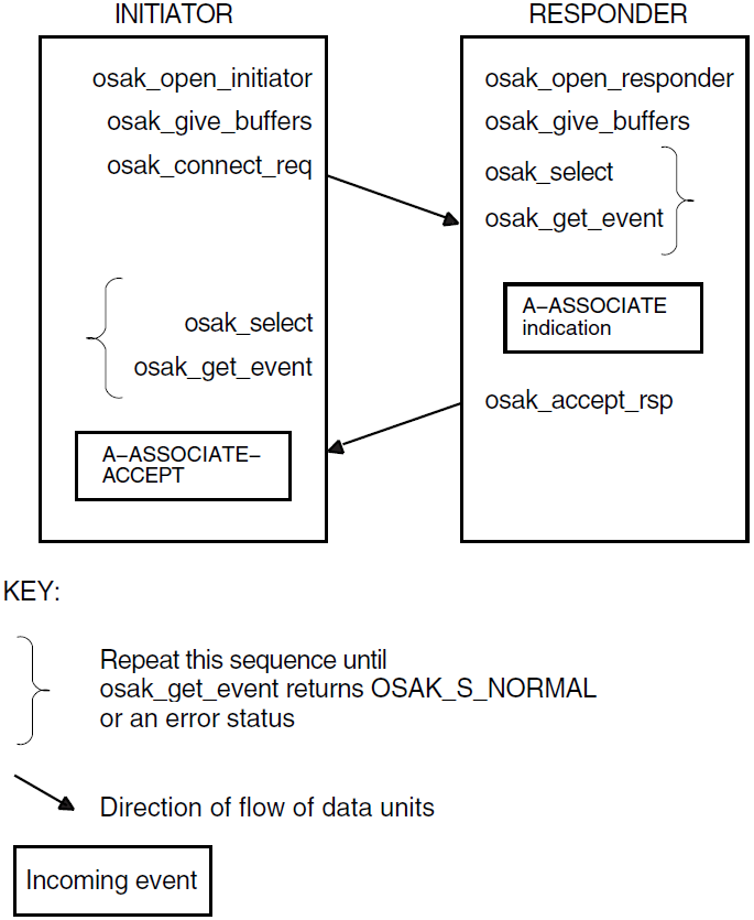
OpenVMS:
Figure 6.3, ''Setting up a Connection Using Asynchronous Event Notification (OpenVMS
only)'' shows a sequence of routines you can use to set up
an association if you are using asynchronous event notification. The sequence uses
osak_get_event with asynchronous event notification.
Note that osak_get_event is not the only routine call that can use
completion routines. See VSI DECnet-Plus OSAK Programming Reference Manual for details.
Figure 4.3, ''Setting up an Association Using Asynchronous Event Notification (OpenVMS only)'' does not give detailed information. For detailed information on particular points raised by this diagram, see the rest of this section.
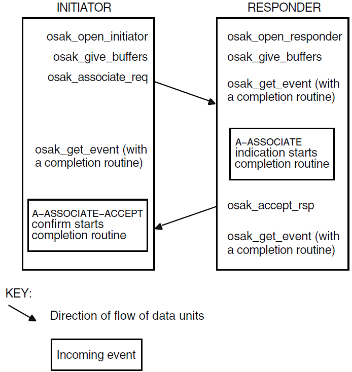
It is essential that the responder issue an osak_open_responder call
before the initiator issues an osak_connect_req call (so that a responding
process is ready to deal with an incoming A-ASSOCIATE-request). Sections Section 4.4.1, ''Getting an Identifier for the Association'' to Section 4.4.4, ''Requesting an Association and Responding to a Request'' follow the sequence of steps
taken.
4.4.1. Getting an Identifier for the Association
The first call should be one of the following:
osak_open_responderosak_open_initiator
Both of these routine calls allocate a port identifier, which the OSAK interface
writes into the port parameter. The port identifier is the
local identifier of the association. If an initiator process uses the
osak_connect_req call to request an association to an address that
does not have an associated responder process listening for incoming associations
(osak_open_responder call), the initiator’s call fails with the
status OSAK_S_INVAEI.
If your application handles several concurrent associations on the same address,
you must make another call to osak_open_responder as soon as an
A-ASSOCIATE indication arrives. This minimizes the possibility of losing a
connection due to transport timeouts.
4.4.2. Passing Buffers to the OSAK Interface
Before requesting any services, use the routine osak_give_buffers to
pass a user buffer or a list of user buffers to the OSAK interface for receiving
incoming events. You need to do this for an initiator and for a responder. You
cannot receive any inbound events until you pass one or more buffers to the
interface.
VSI recommends that your application has at least one buffer available at all
times to receive inbound events. If an ABORT indication arrives during an
association, your application needs a buffer to receive it in. Example 4.2, ''Code for Calling spi_give_buffers'' shows code for calling spi_give_buffers. Note that code examples in
this chapter sometimes rely on global declarations made in the complete example
programs (osak_example_init.c and
osak_example_resp.c).
/***************************************************************************/
/* FUNCTION: give_buffer                                                   */
/*                                                                         */
/* This routine is called to pass a buffer to OSAK for OSAK to use to      */
/* receive inbound events.                                                 */
/*                                                                         */
/* A list of unused buffers is maintained. One buffer from this list is    */
/* passed to OSAK using osak_give_buffers. If the list is empty a new      */
/* buffer is allocated.                                                    */
/****************************************************************************/
void give_buffer (osak_port port)
{
    unsigned long int status ;
    struct osak_buffer *give_buf ;

    /* Give a buffer to OSAK */
    if (free_buffers == NULL)
    {

        give_buf = (struct osak_buffer *)malloc (sizeof(struct osak_buffer)) ;
        if (give_buf == NULL)
        {
            printf ("Failed to allocate an osak_buffer.\n");
            exit (0) ;
        }
        give_buf -> next = NULL ;
        give_buf -> buffer_length = OSAK_EXAMPLE_BUFFER_SIZE ;
        give_buf -> buffer_ptr =
             (unsigned char *) malloc (OSAK_EXAMPLE_BUFFER_SIZE) ;
        if (give_buf -> buffer_ptr == NULL)
        {
            printf ("Failed to allocate buffer.\n") ;
            exit (0) ;
        }
    }

    else
    {
        give_buf = free_buffers ;
        free_buffers = free_buffers -> next ;
        give_buf -> next = NULL ;
    }

    status = osak_give_buffers (port, give_buf) ;
    if (status != OSAK_S_NORMAL)
    {
        printf ("osak_give_buffers failed\n");
        exit (0) ;
    }
}
Example 4.3, ''Code for Reusing Buffers'' shows code for reusing buffers placed by the OSAK software on the list of unused buffers.
/****************************************************************************/
/* FUNCTION: reuse_buffers                                                  */
/*                                                                          */
/* This routine is called to place buffers returned by OSAK onto the list   */
/* of unused buffers.                                                       */
/****************************************************************************/
void reuse_buffers (struct osak_buffer **buf_ptr)
{
    struct osak_buffer *buf, *last_buf ;

    buf = *buf_ptr ;
    if (buf == NULL)
        return ;

    last_buf = buf ;
    while (last_buf->next != NULL)
        last_buf = last_buf -> next ;

    if (free_buffers == NULL)
    {
        free_buffers = buf ;
    }
    else
    {
        free_buffers_end->next = buf ;
    }
    free_buffers_end = last_buf ;
    *buf_ptr = NULL ;
}
4.4.3. Preparing to Receive and Examining Inbound Events
There are two ways to receive notification of inbound events:
Polling and blocking
Use the
osak_get_eventroutine (preceded, if you choose, by anosak_selectroutine). See Section 4.4.3.1, ''Polling and Blocking'' for further information.Asynchronous event notification (OpenVMS systems only)
Use the
osak_get_eventroutine with a completion routine. See Section 4.4.3.2, ''Asynchronous Event Notification (OpenVMS only)'' for further information.
VSI recommends that an application use only one of these methods of receiving events throughout.
Section Section 4.4.3.3, ''Using the Request Mask in the osak_select Routine'' shows you how to distinguish between events that indicate something happening on the network (for example, some data arriving) and events that indicate something happening in the local processor (for example, a routine call completing).
4.4.3.1. Polling and Blocking
Call the routine osak_get_event to check for the arrival of an
inbound event. If the routine returns a status code of OSAK_S_NOEVENT, there is
no event waiting to be collected.
In a blocking interface, an application that makes a call cannot make another call until the first one completes. If your application can do no useful work until an event arrives, you may prefer to block until the OSAK software receives the event.
To do this, call the routine osak_select and wait for an inbound
event to arrive. If you specify a time limit, control returns to your
application either when an event arrives or when the time specified runs out,
whichever comes first. If you do not specify a time limit, control remains with
the OSAK interface until an event arrives.
The osak_select call may return a status code of OSAK_S_NORMAL
(indicating that an event is waiting) but the osak_get_event call
may still return a status code of OSAK_S_NOEVENT. There are two common
causes:
The arrival of a transport event instead of an upper-layer event. One upper-layer event may map to several transport events.
The arrival of incomplete PCI in a data unit. In this case, the OSAK interface does not have enough information to decode the incoming data unit.
To allow for these possibilities in your application, you should repeatedly
call osak_select followed by spi_get_event until the
return value of osak_get_event is OSAK_S_NORMAL.
You can do this using code similar to the following:
do
{
    status = osak_select(port_count, port_list, time_out);
    if (status != OSAK_S_NORMAL
    {
    /* error-handling routine ... */
    }
    status = osak_get_event(port,parameter_block);
    switch(status)
    {
        case OSAK_S_NORMAL:
            /* event arrived - leave loop */
            break;
        case OSAK_S_NOBUFFERS:
            /* Give more buffers to the OSAK software*/
            /* by calling osak_give_buffers()...*/
            .
            .
            .
            break;
        case OSAK_S_NOEVENT:
            /* no event arrived - go round loop again*/
            break;
        default:
            /* Some error returned - call error-handling routine ...*/
    }
} while (status != OSAK_S_NORMAL);
See also Section 3.7, ''Waiting to Receive Data'' for more information about receiving events.
4.4.3.2. Asynchronous Event Notification (OpenVMS only)
Call osak_get_event with a completion routine. The completion
routine starts automatically when osak_get_event receives an event.
The OSAK interface returns a value in the status_block parameter
indicating whether or not an event is present. VSI recommends that you always
leave a call to osak_get_event outstanding when you are using
asynchronous event notification. If you leave more than one call to
osak_get_event outstanding, these calls are completed as events
arrive, in the order in which you issue them.
4.4.3.3. Using the Request Mask in the osak_select Routine
An initiator may wait for an A-ASSOCIATE-confirm rather than use
osak_select or osak_get_event on the assumption
that the OSAK software sent the A-ASSOCIATE-request successfully. But an
initiator uses the osak_select and osak_get_event
routines after receiving the A-ASSOCIATE-confirm (to receive data), and should
ideally make a buffer available for the provider’s notification in case the
osak_associate_req fails.
When you use the routine call osak_select, set the WRITE bit as
well as the READ bit. Set the WRITE bit to require the OSAK software to inform
your application about its own processing of the application’s routine calls.
Set the READ bit to require the OSAK software to inform your application when
incoming data arrives on the network. If the return from the
osak_select routine indicates activity on the local processor
and not on the network, issue an osak_collect_pb call to find out
the return status.
4.4.3.4. Examining Incoming Data Units
When an event arrives, the OSAK interface writes the values contained in the
incoming data units into the parameter block that the application supplied when
it called osak_get_event and user buffers that the application
supplied when it called osak_give_buffers. You should examine the
values that the data unit contains, and take appropriate action in your
application.
Figure 4.4, ''User Buffers After the Arrival of an Event (OpenVMS only)'' shows a list of user buffers after the arrival of an
event on an OpenVMS system. On UNIX systems, user data is separated into
multiple user buffers but the OSAK interface does not return a list of buffers.
Instead, the user data is included in a single user buffer that also contains
the PCI if possible. If the data does not fit into a single user buffer, the
more_flag parameter is set to true. The application
then needs to call osak_get_event repeatedly, in order to receive
the next user buffer. When the more_flag parameter is set
to false, all the data has been transmitted.
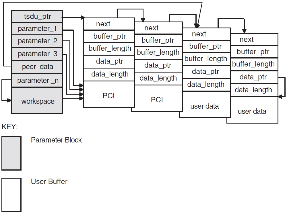
If a user buffer contains only PCI, its data_ptr field is a null pointer. If a buffer contains user data, or a mixture of PCI and user data, its data_ptr field points to the beginning of the user data.
The OSAK interface passes by reference those optional parameters and parameters that can have a default value. The OSAK interface sets these parameters to null if there is no value for that parameter in the incoming data unit.
Note that a setting of true in the more_flag parameter on
an event indicates that the incoming data is segmented and that there is more
data to receive. To make sure you receive all incoming user data, continue
making calls to osak_get_event until the
more_flag parameter is set to false. For an explanation
of segmentation, see Section 1.4.5, ''Data Segmentation''.
Example 4.4, ''Code for Calling osak_select'' shows code for calling
osak_select.
/****************************************************************************/
/* FUNCTION: wait_for_event                                                 */
/*                                                                          */
/* This routine waits for an inbound event to occur. If there is also a     */
/* queued parameter block from a previous call to OSAK then it also waits   */
/* for that parameter block to be returned by OSAK. osak_select is used to  */
/* wait for the inbound event and outbound completion. osak_get_event is    */
/* used to receive the inbound event and osak_collect_pb is used to get the */
/* parameter block returned by OSAK when the outbound event has completed.  */
/*                                                                          */
/* The example osak_example_resp.c does this differently. It has two        */
/* routines to do the same job as this one routine:                         */
/* wait_for_outbound_completion and wait_for_inbound. This routine shows    */
/* how osak_select can be used to combine those two routines.               */
/****************************************************************************/
void wait_for_event (osak_port port, struct osak_parameter_block *pb,
                  int queued)
{
    struct osak_parameter_block *ret_pb ;
    osak_handle_count handlecount ;
    osak_handle handle ;
    unsigned long int status ;
    int readevent = TRUE ;
    int writeevent = queued ;
    osak_time select_time = OSAK_EXAMPLE_TIMEOUT ;

    /* Give a buffer to OSAK to get inbound event */
    give_buffer (port) ;

    /* Loop until not waiting for any more events */
    do
    {
    /* Set up parameters to call osak_select() */
        handlecount = 1 ;
        handle.id = (unsigned long int) port ;
        handle.request_mask = 0;
        if (readevent)
            handle.request_mask |= OSAK_C_READEVENT ;
        if (writeevent)
            handle.request_mask |= OSAK_C_WRITEEVENT ;
        handle.returned_mask = 0 ;

        status = osak_select (handlecount, &handle, &select_time) ;
        if (status != OSAK_S_NORMAL)
        {
            printf ("Call to osak_select failed\n") ;
            exit (0) ;
        }

    /* See if the queued parameter block has been returned */
    if (writeevent && (handle.returned_mask & OSAK_C_WRITEEVENT))
    {
        ret_pb = NULL ;
        status = osak_collect_pb (port, &ret_pb) ;
        if ((status != OSAK_S_NORMAL) && (status != OSAK_S_NOEVENT))
        {
            printf ("Call to osak_collect_pb failed\n") ;
            exit (0) ;
        }

        if (status == OSAK_S_NORMAL && ret_pb != NULL)
        {
            writeevent = FALSE ;
           /* Look at the status block in the PB returned to see if an */
           /* error occurred                                           */
            if (ret_pb->status_block.osak_status_1 != OSAK_S_NORMAL)
            {
              printf ("error in status block of PB returned from collect pb\n");
              exit (0) ;
            }
        }
    }

    /* See if there is an inbound event. If so call osak_get_event() */
    if (readevent && (handle.returned_mask & OSAK_C_READEVENT))
    {
        do
        {
            /* Initialize parameter block ...*/
            .
            .
            .

            status = osak_get_event (port, pb) ;

            /* If OSAK needs more buffer to decode the event then give */
            /* more buffers. */
            if (status == OSAK_S_NOBUFFERS)
            {
                give_buffer (port) ;
            }
        } while (status == OSAK_S_NOBUFFERS) ;

        if ((status != OSAK_S_NORMAL) && (status != OSAK_S_NOEVENT))
        {
            printf ("osak_get_event failed\n") ;
            exit (0) ;
        }

        if (status == OSAK_S_NORMAL)
            {
                readevent = FALSE ;
            }
        }
    } while (readevent || writeevent) ;
}
4.4.4. Requesting an Association and Responding to a Request
Request an association by calling osak_associate_req. You can send
the ACSE, presentation, and session PCI as well as all the user information on the
service. Alternatively, you can segment the user data before you pass it to the OSAK
interface and send the ACSE, presentation, and session PCI and none or some of the
user information. In either case, you must include all the PCI when you call the
osak_associate_req routine.
If you use segmentation, you should set the more_flag
parameter to true and use osak_send_more as many times as necessary to
send the remaining user information, setting the last segment’s
more_flag parameter to false.
When sending an A-ASSOCIATE-request, the initiator should specify the presentation contexts that it supports in the pcontext_list parameter. When sending the A-ASSOCIATE-accept response, the responder should specify the presentation contexts that it supports in the parameter pcontext_res_list. The PCI for each individual routine call shows which presentation context applies at the time for the current association.
Presentation contexts and other PCI should be passed to the OSAK interface in ASN.1 encoded form. You can use the ASN.1 compiler to help you do this at run time. Alternatively, you can set up the encodings before you compile your application. For example, to specify the ACSE abstract syntax, you can do either of the following:
Write a routine to encode object identifiers, giving it the object identifier for the ACSE abstract syntax as its input. The routine returns the encoded form of the object identifier.
Encode the object identifier for ACSE abstract syntax by hand, and insert the encoded form into a buffer.
Example 4.5, ''Code for Calling osak_associate_req'' shows code for requesting an association, and Example 4.6, ''Code for Calling osak_accept_rsp'' shows code for responding to a request for an association.
/****************************************************************************/
/* FUNCTION: assoc_req                                                      */
/*                                                                          */
/* This routine sets up the parameters for a call to osak_associate_req and */
/* makes the call.                                                          */
/*                                                                          */
/****************************************************************************/
unsigned long int
assoc_req (osak_port port, struct osak_parameter_block *pb)
{
    unsigned long int status ;

    /* Set up application context name */
    application_context.size = 7 ;
    application_context.pointer = a_context_buf ;

    /* Set up presentation context proposal list */

    /* Transfer syntax list */
    transfer1.next = NULL ;
    transfer1.ts_name.size = 4 ;
    transfer1.ts_name.pointer = ber ;

    context1.pcontext_id.size = 3 ;
    context1.pcontext_id.pointer = pcid_1 ;
    context1.ts_list = &transfer1 ;
    context1.as_name.size = 6 ;
    context1.as_name.pointer = abstract_1 ;
    context1.next = &context2 ;

    context2.pcontext_id.size = 3 ;
    context2.pcontext_id.pointer = pcid_3 ;
    context2.ts_list = &transfer1 ;
    context2.as_name.size = 8 ;
    context2.as_name.pointer = abstract_2 ;
    context2.next = NULL ;

    /* Set up local address */
    local_address.aetitle.aptitle.size = 0 ;
    local_address.aetitle.aptitle.pointer = NULL ;
    local_address.aetitle.ae_qualifier.size = 0 ;
    local_address.aetitle.ae_qualifier.pointer = NULL ;
    local_address.aeiid.apiid.size = 0 ;
    local_address.aeiid.apiid.pointer = NULL ;
    local_address.aeiid.aeiid.size = 0 ;
    local_address.aeiid.aeiid.pointer = NULL ;
    local_address.paddress.psel.size = 9 ;
    local_address.paddress.psel.pointer = (unsigned char *)"INIT-PSEL" ;
    local_address.paddress.ssel.size = 9 ;
    local_address.paddress.ssel.pointer = (unsigned char *)"INIT-SSEL" ;
    local_address.paddress.tsel.size = 9 ;
    local_address.paddress.tsel.pointer = (unsigned char *)"INIT-TSEL" ;
    local_address.paddress.nsap.next = NULL ;
    local_address.paddress.nsap.id.size = 0 ;
    local_address.paddress.nsap.id.pointer = 0 ;
    local_address.paddress.nsap.type = OSAK_C_CLNS ;

    /* Set up peer address (the responder’s address) */
    remote_address.aetitle.aptitle.size = 0 ;
    remote_address.aetitle.aptitle.pointer = NULL ;
    remote_address.aetitle.ae_qualifier.size = 0 ;
    remote_address.aetitle.ae_qualifier.pointer = NULL ;
    remote_address.aeiid.apiid.size = 0 ;
    remote_address.aeiid.apiid.pointer = NULL ;
    remote_address.aeiid.aeiid.size = 0 ;
    remote_address.aeiid.aeiid.pointer = NULL ;
    remote_address.paddress.psel.size = 9 ;
    remote_address.paddress.psel.pointer = (unsigned char *)"RESP-PSEL" ;
    remote_address.paddress.ssel.size = 9 ;
    remote_address.paddress.ssel.pointer = (unsigned char *)"RESP-SSEL" ;
    remote_address.paddress.tsel.size = 9 ;
    remote_address.paddress.tsel.pointer = (unsigned char *)"RESP-TSEL" ;
    remote_address.paddress.nsap.next = NULL ;
    remote_address.paddress.nsap.id.size = sizeof(remote_nsap) ;
    remote_address.paddress.nsap.id.pointer = remote_nsap ;
    remote_address.paddress.nsap.type = OSAK_C_CLNS ;

    /* Set up transport template */
    transport_template.next = NULL ;
    transport_template.name.size = 7 ;
    transport_template.name.pointer = (unsigned char *)"Default" ;

    /* Set up protocol versions */
    /* Select session version 2 */
    protocol_versions.acse_version.version1 = 1 ;
    protocol_versions.pversion.version1 = 1 ;
    protocol_versions.sversion.version1 = 0 ;
    protocol_versions.sversion.version2 = 1 ;

    /* Set up functional units */
    /* Zero out all functional units before setting those required */
    memset ((void *)&fus, ’\0’, sizeof(struct osak_fus)) ;

    /* Request either duplex or half duplex. In this example we are */
    /* actually expecting the responder to accept with duplex. */
    fus.duplex = 1 ;
    fus.half_duplex = 1 ;

    /* Set up the buffer containing the data to send */
    send_buffer.next = NULL ;
    send_buffer.buffer_ptr = &user_information[0] ;
    send_buffer.buffer_length = sizeof(user_information) ;
    send_buffer.data_ptr = &user_information[0] ;
    send_buffer.data_length = sizeof(user_information) ;

    /* initialize parameter block ...*/
    .
    .
    .

    status = osak_associate_req (port, pb) ;
    return status ;
}
/****************************************************************************/
/* FUNCTION: accept_rsp                                                     */
/*                                                                          */
/* This routine sets up the parameters for a call to osak_accept_rsp and    */
/* makes the call.                                                          */
/*                                                                          */
/* It does not do any of the parameter negotiation that a real application  */
/* would need to do. For example, it does not check the functional units    */
/* or the presentation contexts proposed in the A-ASSOCIATE-indication.     */
/*                                                                          */
/****************************************************************************/
unsigned long int
accept_rsp (osak_port port, struct osak_parameter_block *pb)
{
    unsigned long int status ;

    /* Set up the presentation context result list */

    /* A real application would need to go through the contexts received in */
    /* the A-ASSOCIATE-indication and decide whether to accept or reject */
    /* each context. Because this is a simple example it assumes that only */
    /* two contexts were proposed, and it will accept both of the contexts. */

    context_res1.result = OSAK_C_ACCEPT ;
    context_res1.ts_name.size = 4 ;
    context_res1.ts_name.pointer = ber ;
    context_res1.next = &context_res2 ;
    context_res2.result = OSAK_C_ACCEPT ;
    context_res2.ts_name.size = 4 ;
    context_res2.ts_name.pointer = ber ;
    context_res2.next = NULL ;

    /* Set up functional units. */

    /* A real application would need to check which functional units were */
    /* proposed by the initiator and negotiate a common set of functional */
    /* units. This simple example assumes that the duplex functional unit */
    /* was proposed. It is only going to accept the duplex functional unit.*/

    fus.duplex = 1 ;
    fus.half_duplex = 0 ;
    fus.expedited = 0 ;
    fus.syncminor = 0 ;
    fus.syncmajor = 0 ;
    fus.resynchronize = 0 ;
    fus.activities = 0 ;
    fus.negotiated_release = 0 ;
    fus.capability_data = 0 ;
    fus.exceptions = 0 ;
    fus.typed_data = 0 ;
    fus.data_separation = 0 ;
    fus.context_management = 0 ;

    /* initialize parameter block ...*/
    .
    .
    .

    status = osak_accept_rsp (port, pb) ;
    return status ;
}
4.5. Sending Data
After the association is established, you can send and receive data using the OSAK services. Chapter 1 gives details of the services defined by the OSI standards.
4.6. Releasing an Association
The calls you need to use to release an association are often similar to the calls
needed to set up the association. This section, therefore, does not contain detailed
information on osak_give_buffers, osak_select, and
osak_get_event, which are discussed in Section 4.4.2, ''Passing Buffers to the OSAK Interface'' and
Section 4.4.3, ''Preparing to Receive and Examining Inbound Events''.
The initiator of a release and the responder to the release (not necessarily the initiator and responder respectively of the association), use different calls. Table 4.4, ''Sequence of Routine Calls Used in Releasing an Association'' lists the calls used by the initiator of the release and Table 4.5, ''Sequence of Routine Calls Used in Responding to a Request for Release'' lists the calls used by the responder to the A-RELEASE-request.
| Routine Call | Section |
|---|---|
osak_release_req | Section 4.6.1, ''Issuing the Release Request'' |
osak_select followed by
osak_get_event | Section 4.4.2, ''Passing Buffers to the OSAK Interface'' and Section 4.4.3, ''Preparing to Receive and Examining Inbound Events'' |
osak_close_port | Section 4.6.3, ''Closing the Port'' |
| Routine Call | Section |
|---|---|
osak_select followed by
osak_get_event | Section 4.4.2, ''Passing Buffers to the OSAK Interface'' and Section 4.4.3, ''Preparing to Receive and Examining Inbound Events'' |
osak_release_rsp (followed by
osak_get_event on UNIX only) | Section 4.6.2, ''Responding to a Release Request'' |
osak_close_port | Section 4.6.3, ''Closing the Port'' |
Figure 4.5, ''Releasing an Association'' shows a sequence of routines you can use to release an association on the OpenVMS operating system.
Figure 4.6, ''Releasing an Association Using Asynchronous Event Notification'' shows a sequence of routines you can use to release an
association if you are using asynchronous event notification. The example uses
osak_get_event with asynchronous event notification.
Note that Figure 4.5, ''Releasing an Association'' and Figure 4.6, ''Releasing an Association Using Asynchronous Event Notification'' do not give detailed information. For detailed information on particular points raised by these diagram, see the rest of this section.
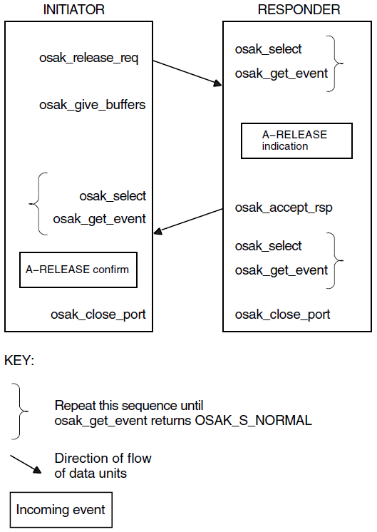
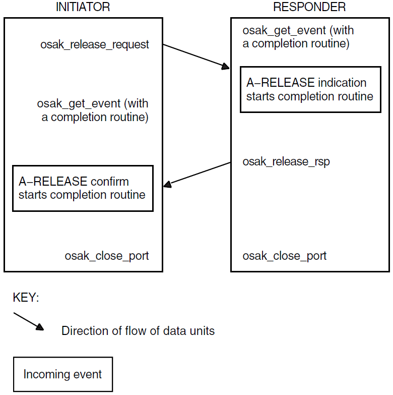
4.6.1. Issuing the Release Request
Set the release_reason in the call to
osak_release_request to whatever is appropriate;
VSI DECnet-Plus OSAK Programming Reference Manual lists the options.
The initiator must call osak_select and osak_get_event
to receive the A-RELEASE-confirm from the responder. The initiator may also check
whether the OSAK software sent the A-RELEASE-request by calling
osak_select and osak_collect_pb.
Note
You may send user data on the A-RELEASE-request service. Make sure, however, that you set the user_data field in the OSAK parameter block to null in case a release does not use the user_data parameter.
Example 4.7, ''Code for Calling osak_release_req'' shows code for releasing an association.
/****************************************************************************/
/* FUNCTION: release_req                                                    */
/*                                                                          */
/* This routine sets up the parameters for a call to osak_release_req and   */
/* makes the call.                                                          */
/*                                                                          */
/****************************************************************************/
unsigned long int
release_req (osak_port port, struct osak_parameter_block *pb)
{
    unsigned long int status ;

    /* initialize parameter block */
    memset ((void *)pb, ’\0’,
        sizeof(struct osak_parameter_block) + OSAK_EXAMPLE_WS_SIZE ) ;
    pb->pb_length = sizeof (struct osak_parameter_block) ;
    pb->ws_length = OSAK_EXAMPLE_WS_SIZE ;
    pb->release_reason = OSAK_C_RLRQ_NORMAL ;

    status = osak_release_req (port, pb) ;
    return status ;
}
/****************************************************************************/
/* FUNCTION: release_rsp                                                    */
/*                                                                          */
/* This routine sets up the parameters for a call to osak_release_rsp and   */
/* makes the call.                                                          */
/*                                                                          */
/****************************************************************************/
unsigned long int
release_rsp (osak_port port, struct osak_parameter_block *pb)
{
    unsigned long int status ;
    /* Initialize parameter block... */
        .
        .
        .
    status = osak_release_rsp (port, pb) ;
    return status ;
}
4.6.2. Responding to a Release Request
The responder must check whether an inbound event is an A-RELEASE-indication. Call
osak_get_event (preceded, if you choose, by
osak_select), and if an A-RELEASE-indication arrives, call
osak_release_rsp, with the appropriate
release_resp_reason parameter set.
UNIX: The responder must collect a transport
disconnect indication as well as the A-RELEASE-indication, using
osak_give_buffers, osak_select, and
osak_get_event calls.
Example 4.8, ''Code for Calling osak_release_rsp'' shows code for responding to a request for a release and Example 4.9, ''Code for Calling osak_get_event After Releasing an Association'' shows code for waiting for a transport disconnect.
/****************************************************************************/
/* FUNCTION: wait_for_TDISind                                               */
/*                                                                          */
/* This routine uses osak_select to wait for a transport disconnect         */
/* indication after the release-response has been sent.                     */
/*                                                                          */
/* It does not check the event since OSAK_S_NOEVENT may be returned. This   */
/* would be the case when the peer did not send a disconnect. osak_select   */
/* would return either when it has timed out, or (on OpenVMS only) when the */
/* session disconnect timer fired.                                          */
/****************************************************************************/
void wait_for_TDISind (osak_port port, struct osak_parameter_block *pb)
{
    osak_handle_count handlecount ;
    osak_handle handle ;
    unsigned long int status ;
    osak_time select_time ;

    /* Give a buffer to OSAK to get inbound event */
    give_buffer (port) ;

    /* Set up parameter to call osak_select() */
    handlecount = 1 ;
    handle.id = (unsigned long int) port ;
    handle.request_mask = OSAK_C_READEVENT ;
    handle.returned_mask = 0 ;
    select_time = OSAK_EXAMPLE_TIMEOUT ;

    status = osak_select (handlecount, &handle, &select_time) ;
    if (status != OSAK_S_NORMAL)
    {
        printf ("call to osak_select failed\n") ;
        exit (0) ;
    }

    /* See if there is an inbound event. If so call osak_get_event() */
    if (handle.returned_mask & OSAK_C_READEVENT)
    {
        /* Initialize parameter block ...*/
        .
        .
        .

        status = osak_get_event (port, pb) ;

        if ((status != OSAK_S_NORMAL) && (status != OSAK_S_NOEVENT))
        {
            printf ("call to osak_get_event failed\n");
            exit (0) ;
        }
    }
}
4.6.3. Closing the Port
Both the initiator and the responder must call osak_close_port to
signal to the OSAK software that they have finished with the association. This makes
the OSAK software release any memory allocated to the association and return any
parameter blocks and user buffers that have not already been returned to the
application.
In normal operation, an application calls osak_close_port with the
OSAK_C_NON_DESTRUCTIVE flag set. This indicates to the OSAK software that the port
has no connection at any level with any remote system.
An application can call osak_close_port when its association with its
peer is still in progress, by setting the OSAK_C_DESTRUCTIVE flag. This causes the
OSAK software to:
Discontinue the connection immediately
Return all parameter blocks and buffers
Return to the application any memory allocated to the port
This can cause loss of data, and the OSAK software informs the remote application that the association was terminated abnormally.
To avoid disrupting an association, we recommend that you use the nondestructive form except in the following circumstances:
Your application runs out of virtual memory and cannot free enough memory to send an upper-layer abort.
Your application becomes constrained by lower-layer flow control, and is unable to continue. For more information about flow control, refer to the OSI standards.
A remote system does not disconnect on receipt of the A-RELEASE-request.
If you want to close a port from within an asynchronous system trap (AST), for
example, a completion routine, use the async_close_port routine. Do not
use the osak_close_port routine. For more information on the
async_close_port routine, refer to VSI DECnet-Plus OSAK Programming Reference Manual.
4.7. Reclaiming Memory
This section describes how to reclaim memory allocated to outbound parameter blocks
and user buffers. Note that it is always safer to delete incoming data in buffers you
are reclaiming by using the tsdu_ptr parameter rather than the data
pointers, because the first buffer may contain nothing but PCI. In that case, the
peer_data (or, in the case of a REDIRECT indication,
rcv_data_list) parameter would not point to the first buffer in the
linked list of buffers.
You can reclaim memory in the following ways:
Wait until your association closes down.
The routine
osak_close_port, which you should call after you release an association, returns ownership of all parameter blocks and user buffers, and any unused inbound buffers, to the application.Supply a completion routine with all outbound services (OpenVMS systems only).
When the completion routine starts, it indicates that the parameter block and any associated user buffers are available for reuse.
If you are using a blocking
osak_selectroutine, specify both WRITE and READ events in the request mask. If a WRITE event is indicated, callosak_collect_pbto reclaim the available parameter blocks and buffersCall
osak_collect_pbwhenever your application is running short of memory.
4.8. Redirecting an Association
You can use the osak_redirect parameter to redirect an association from
one local process to another, either immediately after setting up an association, or
during data transfer. Figure 4.7, ''Using the OSAK Redirection Service'' shows how to use the OSAK redirection
service immediately after setting up an association. You can use
osak_redirect to implement a server that receives association requests
and immediately hands them on to other applications.
Call these routines in the application that starts the redirection (the server, in the case of a process that simply receives inbound associate requests and passes them on to processes that can handle them):
osak_give_buffersosak_selectfollowed byosak_get_eventosak_redirectosak_close_port
Note that process 1 in Figure 4.7, ''Using the OSAK Redirection Service'' must close its port. Until the port is
closed, the OSAK software wastes resources associated with that port. The association
then belongs to process 2, which uses the port returned in the call to
osak_open_redirect.
Call the following routines in the application that responds to the redirection call:
osak_open_redirectosak_give_buffersosak_selectfollowed byosak_get_eventosak_accept_rsp
In Figure 4.7, ''Using the OSAK Redirection Service'', the process that redirects the association is not the
initiator of the association. However, in some cases (an outbound connection-handler for
example), an application may use osak_redirect after initiating an
association.
4.9. Linking on UNIX Systems
Link your application against the following libraries:
/usr/lib/libosak.so
/usr/lib/libxtiosi.a
/usr/lib/libxti.a
Example
To link your application, you should use a command similar to the following:
/bin/cc -o osak_example_init osak_example_init.o -losak -lxtiosi -lxti
In the above example, osak_example_init is the executable version of your
application, and osak_example_init.o is the object file.
It is important that you specify the libraries in the order shown.

4.10. Linking on ULTRIX Systems
Link your application against the following libraries:
/usr/lib/libosak.a
/usr/lib/libxti.a
Example
To link your application, you should use a command similar to the following:
/bin/cc -o osak_example_init osak_example_init.o -losak -lxti
In the above example, osak_example_init is the executable version of your
application, and osak_example_init.o is the object file.
It is important that you specify the libraries in the order shown.
4.11. Linking on OpenVMS Systems
Link your application against the following shareable image:
SYS$SHARE:OSAK$OSAKSHR.EXE
To link your application, you can either specify SYS$INPUT in place of an options file, and specify the OSAK$OSAKSHR library, or specify the OSAK$OSAKSHR library in an options file. The default filename for the options file is OPTIONS_FILE.OPT.
Examples
If you have no options file, use a command similar to the following:
LINK OSAK_EXAMPLE_INIT, SYS$INPUT/OPTIONS
SYS$SHARE:OSAK$OSAKSHR/SHAREABLE
Ctrl/Z
If you have an options file called OPTIONS_FILE.OPT, containing the line SYS$SHARE:OSAK$OSAKSHR/SHAREABLE, use a command similar to the following:
LINK OSAK_EXAMPLE_INIT, OPTIONS_FILE/OPTIONS
4.12. Using Abstract Syntax Notation
Applications communicating in an OSI network need to agree on the data types they are going to use. An abstract syntax is the formal definition of this agreement. Section 1.1.2.4, ''Abstract Syntax Notation'' gives further information on abstract syntax.
Abstract Syntax Notation One (ASN.1) is the ISO’s standardized abstract syntax. Using ASN.1 is essential for portability. For input to your application, you need files containing the data structures and the functions that an ASN.1 compiler generates.
In addition to your compiler, you will also need the following:
A routine to encode ASN.1-defined values
A routine to decode ASN.1-defined values
You use a compiler to produce these encoding and decoding routines, and you use the routines to process information exchanged over an OSI network. You are not required to use any particular ASN.1 compiler.
4.12.1. Using an ASN.1 Compiler
In order to use an ASN.1 compiler, do the following:
Design a syntax for your application, using ASN.1. You can register this syntax with a registration authority — either the ISO, CCITT, or your national registration authority (often, but not always, your national standards authority). ISO 8824 explains how to do this.
Create an input file of ASN.1-defined data types.
Examine the encoding and decoding routines that the compiler produces, and note the data structures that they use.
Link the files generated by the compiler, including the encode and decode routines, and the compiler’s run-time library (RTL) routines, into your application.
4.12.2. Notes on Using Another Method of Encoding
If you need your application to work only with other applications that use an agreed syntax, there is no need to register the syntax.
Write encode and decode routines if the compiler you are using does not do this for you.
Link the files generated by the compiler, the encode and decode routines, and the compiler’s run-time library (RTL) routines, into your application.
Chapter 5. Using the ROSE API
Define the ROSE operations to be used in your application (Section 5.2, ''Making the Definitions for a ROSE-Based Application'')
Write an application service entity (ASE) based on the ROSE protocol (Section 5.3, ''Writing a ROSE-Based ASE'')
5.1. Functions Provided by the ROSE Programming Interface
|
Function |
ROSE Routine |
Description |
|---|---|---|
|
Invoke |
osak_ro_invoke |
Requests the server to perform a certain operation. |
|
Result |
osak_ro_result |
Tells the client that an operation has been a success, and gives the result of the operation. |
|
Error |
osak_ro_error |
Tells the client that an operation has failed, and gives the reason why it failed. |
|
Reject |
osak_ro_reject_u |
Rejects an application protocol data unit (APDU) carrying a ROSE operation request, because the APDU is in some way incorrect. |
|
Decode |
osak_ro_decode |
Decodes incoming ROSE PCI. |
Note that osak_ro_invoke, osak_ro_result, osak_ro_error, and osak_ro_reject_u are all encoding routines. They encode only ROSE PCI. You need to encode ROSE user data by some other means (for example, using an ASN.1 compiler – Section 5.3, ''Writing a ROSE-Based ASE'' explains the choices you make between using the osak_ro_... routines and using an ASN.1 compiler). Similarly, the osak_ro_decode routine decodes only ROSE PCI.
5.1.1. The ROSE Parameter Block
Figure 5.1, ''ROSE Parameter Block'' shows the parameters in a ROSE parameter block.
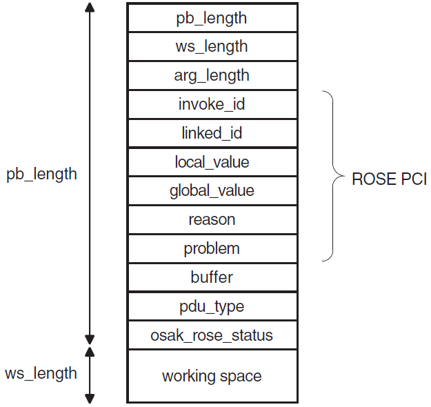
Section 5.1.1.1, ''ROSE Parameter Block Before and After Decoding'' and Section 5.1.1.2, ''Structure of an APDU Containing ROSE Data'' give further information about the contents of the ROSE parameter block.
5.1.1.1. ROSE Parameter Block Before and After Decoding
Figure 5.2, ''ROSE Parameter Block Before an Encoding Routine'' shows ROSE PCI and user data being passed to a ROSE encoding routine. In this example, the buffer already contains one ROSE PDU with its PCI, and another application PDU with its PCI.
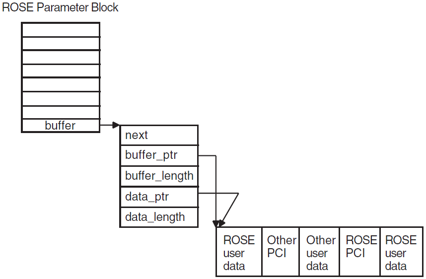
Figure 5.3, ''ROSE Parameter Block After an Encoding Routine'' shows the situation after the encode call. In this example, the application buffer is not large enough to accommodate the encoded ROSE PCI. The ROSE interface allocates an extra buffer, using the application's memory allocation routine.
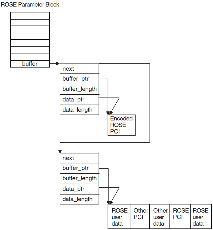
5.1.1.2. Structure of an APDU Containing ROSE Data
A header specifying the transfer syntax and presentation context used in the PDU
ROSE PCI
Zero or more ROSE PDUs (a ROSE PDU contains ROSE user data)
Example 5.1, ''Structure of an APDU'' shows the ASN.1 definition for the Invoke function APDU.
See ISO Standard 9072 for ASN.1 definitions of other function APDUs.
    ROIVapdu ::= SEQUENCE
    {
        invokeID Integer Integer
        linkedID [0] IMPLICIT integer OPTIONAL,
        operation-value CHOICE
        {
            local_value integer,
            global_value object identifier,
        }
        argument ANY OPTIONAL
        – DEFINED BY operation-value,
        – ANY is filled by a single ASN.1 data type following the
        – keyword ARGUMENT in the type definition of a particular
        – operation
    }
5.2. Making the Definitions for a ROSE-Based Application
Some definitions that you use in a ROSE-based application are mandatory (see Section 5.2.1, ''Mandatory Definitions''), and some are optional (see Section 5.2.2, ''Optional Definitions''). The following descriptions use client to refer to the application that sends requests, and server to refer to the application that responds.
5.2.1. Mandatory Definitions
Define all the operations a client can ask a server to perform.
For each operation, define an operation code. The client and the server must both use the same definitions of operation codes.
An operation code can be either locally defined or globally defined. A locally defined operation code is unique within a given abstract syntax, and is represented by an ASN.1 encoded integer (a tag, length, and value, or TLV). A globally-defined operation code is unique within a group of abstract syntaxes, and is represented by an ASN.1 encoded object identifier.
- For each operation, define the following:
Each argument that can be input
Each result that can be output
Each error that can occur
Note that not all operations need to have arguments, results, or errors.
For each error that can occur, define an error code for each of its output parameters. The ROSE interface includes a number of constants indicating errors and problems. You should use these constants, and define meanings for them appropriate to your application.
5.2.2. Optional Definitions
- An operation class, which specifies the following:
Whether operations are to be completed synchronously or asynchronously.
What response the client expects from the server. The client may expect a response when an operation fails or succeeds, if an operation fails, or it may not expect a response at all.
The relative priority for the Reject function, if your ROSE application uses a two-way alternative communication mechanism. If you need to define priority in your application, you should do so before you call any encoding routine.
You can include these items of information indirectly in the formal definition of the application service entity (ASE) you are using. Note that the OSAK software does not enforce the ROSE protocol. The ROSE-based ASE must ensure that characteristics of a defined operation class are observed. For example, if an agreed operation class requires synchronous completion of calls, the OSAK interface does not automatically select synchronous completion.
5.3. Writing a ROSE-Based ASE
When using the ROSE interface, you also need to use some OSAK services, to set up and release associations and to send application protocol data units (APDUs) containing ROSE data.
Before your application sets up an association, make sure that the ASE you use is included in the application context you have agreed. (See Section 1.2.2.1, ''Setup and Negotiation'' for more about application contexts.) This agreement is on paper; the service providers do not negotiate application contexts as part of the electronic information exchange.
The application context you use when setting up the association must include your ASE. Although the inclusion is implicit (not part of the electronic information exchange), you should avoid using application contexts defined in the OSI standards.
5.3.1. Considerations for Both the Client and the Server
Passing Data
You must prepare for the ROSE protocol exchange by passing unencoded ROSEPCI and user data (if any) to the ROSE routines in a ROSE parameter block. The user data can be any information required by the client or the server in your application.
You can send any number of ROSE PDUs in an APDU. You can send other application
PCI and PDUs in the same APDU. You pass the ROSE PCI and user data (encoded either
by the osak_ro_invoke routine or by an ASN.1 compiler) to the OSAK
interface in the user_data parameter of an OSAK
parameter block. The OSAK interface then sends the APDU to the client or
server.
ROSE and Memory
ROSE PCI is usually about 19 octets long. If the buffer that you pass in the buffer parameter is too small to accommodate the encoded ROSE PCI, the ROSE interface uses your OSAK memory allocation routine to allocate a buffer for the ROSE PCI. The ROSE interface then chains this buffer in front of the buffer that you pass in the buffer parameter.
The ROSE interface can use your memory allocation routine, because you pass the port identifier of an association on all calls to ROSE routines. It is mandatory to supply a memory allocation routine when you set up an association using the OSAK interface. The application is responsible for deallocating the memory when it is no longer required.
Encoding with the ROSE Routines
If your application uses a protocol with an order of requests and responses that
changes rarely or never, you may choose to use the osak_ro_... routines
in cases where, for example, you are simply maintaining a ROSE-based application,
most of which is encoded already.
With the osak_ro_... calls, you can produce very efficient routines
for encoding and decoding, but at the cost of significant development effort.
Decoding Data
Your application should examine each incoming APDU, and decode its presentation data value (PDV). This tells you the transfer syntax and presentation context used in the APDU. The ROSE interface does not decode the PDV for you.
Use either the osak_ro_decode routine or call the routine produced by
your compiler to decode the ROSE PCI received in an incoming APDU. The OSAK
interface passes the decoded ROSE PCI and user data back to your application, in the
buffer parameter of the ROSE parameter block.
5.3.2. Implementing the Client
Construct an OSAK parameter block.
Set up an association by calling
osak_open_initiatorandosak_associate_request.Call
osak_give_buffers.Construct a ROSE parameter block.
- Call
osak_ro_invoke, passing the following arguments:Port identifier returned by the call to
osak_open_initiatorROSE PCI and user data in ROSE parameter block
The Invoke identifier is a unique identifier issued by the initiator of each ROSE dialogue. Your application should be sure to check for the uniqueness of all Invoke identifiers, so that it is always clear which exchange of ROSE-based protocol a call belongs to.
The ROSE interface returns the encoded ROSE PCI in the buffer parameter of the ROSE parameter block.
Add information about the transfer syntax and presentation context used to the encoded ROSE PCI.
Define the buffer containing the APDU as user data in the OSAK parameter block.
Call
osak_data_reqto send the APDU to the server.Call
osak_get_eventto receive any response expected from the server.
5.3.3. Implementing a ROSE Server
Construct an OSAK parameter block.
Establish a responder.
Call
osak_give_buffers,osak_select, andosak_get_event.Decode the presentation data value (PDV) from the APDU. Examine the PDV information from the APDU, to find out which transfer syntax and which presentation context is in use.
Call
osak_ro_decodeto decode the ROSE PCI. The ROSE interface returns the decoded ROSE PCI and user data in the buffer parameter of the ROSE parameter block.Examine the incoming Invoke indication. Call
osak_ro_reject_uto reject the incoming APDU if it is in any way incorrect.Check the Invoke identifier. If it is a duplicate, call
osak_ro_reject_uto reject the incoming ROSE request.Decode the user data, using the same abstract syntax that was used to encode it.
Attempt the operation requested by the client.
Encode any user data that you want to send back to the client.
Call
osak_ro_resultorosak_ro_errorto encode the ROSEPCI if you need to inform the client of the result of the attempted operation. Callosak_ro_resultto inform the client of a successful operation; callosak_ro_errorto inform the client of a failed operation.Add to the encoded ROSE PCI information about the transfer syntax and presentation context used.
Send encoded user data and ROSE PCI back to the client in a call to
osak_data_req.
5.4. Linking on UNIX Systems
/usr/lib/librose.a/usr/lib/libxtiosi.a/usr/lib/libxti.a
Example
/bin/cc -o rose_example_init rose_example_init.o -losak -lxtiosi -lxti -lrose
In the above example, rose_example_init is the executable version of your
application, and rose_example_init.o is the object file.
It is important that you specify the libraries in the order shown.
5.5. Linking on ULTRIX Systems
/usr/lib/librose.a/usr/lib/libxti.a
Example
/bin/cc -o rose_example_init rose_example_init.o -losak -lxti -lrose
In the above example, rose_example_init is the executable version of your
application, and rose_example_init.o is the object file.
It is important that you name the libraries in the order shown.
5.6. Linking on OpenVMS Systems
SYS$SHARE:OSAKSHR_ROSE.EXE
To link your application, you can either specify SYS$INPUT in place of an options file, and specify the OSAK$OSAKSHR library, or specify the OSAK$OSAKSHR library in an options file. The default filename for the options file is OPTIONS_FILE.OPT.
Examples
LINK OSAK_EXAMPLE_INIT, SYS$INPUT/OPTIONS
SYS$SHARE:OSAK$OSAKSHR/SHAREABLE
Ctrl/Z
LINK OSAK_EXAMPLE_INIT, OPTIONS_FILE/OPTIONS
5.7. Using Abstract Syntax Notation
Applications communicating in an OSI network need to agree on the data types they are going to use. An abstract syntax is the formal definition of this agreement. Section 1.1.2.4, ''Abstract Syntax Notation'' gives further information on abstract syntax.
Abstract Syntax Notation One (ASN.1) is the ISO's standardized abstract syntax. Using ASN.1 is essential for portability. For input to your application, you need files containing the data structures and the functions that an ASN.1 compiler generates.
A routine to encode ASN.1-defined values
A routine to decode ASN.1-defined values
You use a compiler to produce these encoding and decoding routines, and you use the routines to process information exchanged over an OSI network. You are not required to use any particular ASN.1 compiler.
5.7.1. Using an ASN.1 Compiler
Design a syntax for your application, using ASN.1. You can register this syntax with a registration authority — either the ISO, CCITT, or your national registration authority (often, but not always, your national standards authority). ISO 8824 explains how to do this.
Create an input file of ASN.1-defined data types.
Examine the encoding and decoding routines that the compiler produces, and note the data structures that they use.
Link the files generated by the compiler, including the encode and decode routines, and the compiler's run-time library (RTL) routines, into your application.
5.7.1.1. Notes on Using Another Method of Encoding
Write encode and decode routines if the compiler you are using does not do this for you.
Link the files generated by the compiler, the encode and decode routines, and the compiler's run-time library (RTL) routines, into your application.
Chapter 6. Using the SPI
6.1. Writing an OSAK Application
Prepare a parameter block (Section 6.2, ''Using Parameter Blocks'')
Build user buffers (Section 6.3, ''Building a User Buffer'')
Set up the connection (Section 6.4, ''Setting Up a Connection'')
Transfer data (Section 6.5, ''Sending Data'')
Release the connection (Section 6.6, ''Releasing a Connection'')
Reclaim memory (Section 6.7, ''Reclaiming Memory'')
Code examples in this chapter are extracts from the example program:
- UNIX
usr/examples/osak/osak_example_init.c
usr/examples/osak/osak_example_resp.c
- OpenVMS
SYS$EXAMPLES:OSAK_EXAMPLE_INIT.C
SYS$EXAMPLES:OSAK_EXAMPLE_RESP.C
6.2. Using Parameter Blocks
Construct a parameter block and allocate values to all the parameters you require for the routine you want to call. Alternatively, you can re-use a parameter block that was previously used on a call to another routine, if there is such a parameter block available.
6.2.1. Preparing to Construct a Parameter Block
Decide what session protocol control information (PCI) you
need to specify and pass it all on the first service request, because you can send
only user data on subsequent spi_send_more calls. Refer to the routine
descriptions in VSI DECnet-Plus OSAK Programming Reference Manual for details of which parameters in the
parameter block are mandatory and which ones are optional. Note that the OSAK
interface defines the classifications mandatory, optional, and ignored as shown in
Table 6.1, ''Classifications of Parameters''.
|
Classification |
Meaning |
|---|---|
|
mandatory |
You must supply an explicit value. |
|
optional |
You must either supply an explicit value or set the parameter to zero. You must set a parameter to zero or null to apply a default setting. |
|
ignored |
The OSAK interface ignores the parameter, as permitted by the relevant ISO standard. The parameter must not have any value (not even zero or null ). |
Section 6.2.2, ''Constructing a Parameter Block'' lists the tasks needed to construct a parameter block.
6.2.2. Constructing a Parameter Block
Specify a value for every parameter that is mandatory on the service you are calling.
Specify a value for any optional parameter you want to use.
Set to zero or null any optional parameter for which you want the OSAK interface to use the default value.
Ensure that the workspace you allocate is at least the minimum size allowed, which is 512 octets. You should initialize the workspace to zero when you allocate it. If you re-use a workspace for an outbound call, you must reinitialize the workspace.
Ensure that the workspace length and parameter block length parameters are correctly set up.
Example 6.1, ''Constructing a Parameter Block'' is an example of the sort of code needed to construct a parameter block.
/* initialize parameter block */
memset ((void *)pb, ’\0’,
        sizeof(struct osak_parameter_block) + OSAK_EXAMPLE_WS_SIZE ) ;
pb->pb_length = sizeof (struct osak_parameter_block) ;
pb->ws_length = OSAK_EXAMPLE_WS_SIZE ;
pb->api_version = OSAK_C_API_VERSION_3 ;
pb->protocol_versions = NULL ; /* Use default value */
pb->local_aei = &local_address ;
pb->transport_template = NULL ; /* Use default value */
pb->alloc_rtn = (osak_rtn) alloc_memory ;
pb->dealloc_rtn = (osak_rtn) free_memory ;
pb->alloc_param = 0 ;
pb->completion_rtn = NULL ;
pb->completion_param = 0 ;
6.3. Building a User Buffer
Figure 6.1, ''User Buffers on an Outbound Call'' shows the structure of user buffers on an outbound call.
Set the buffer_ptr field to point to the start of the buffer. Set the buffer_length field to value of the length of the buffer. You must set both these parameters.
Set the data_ptr field to point to the start of the user data within the buffer. Set the data_length field to the value of the length of the user data. You must set both these parameters.
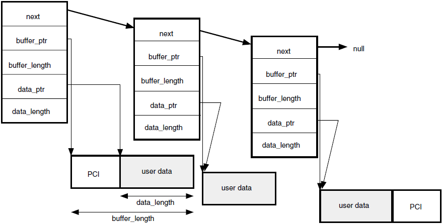
When you pass a list of user buffers to the OSAK interface, we recommend that you leave space for PCI at the beginning of the first buffer and the end of the last buffer. Leaving this space improves the performance of the OSAK software, which does not need to allocate memory apart from the memory you have already allocated. However, you do not need to leave any space at the beginning of the first user buffer, or at the end of the last user buffer.
The amount of space that we recommend you to leave depends on the OSAK service you are using. About 50 octets at the beginning of the first buffer is sufficient for most services. You can leave less space at the end of the last buffer.
You do not have to initialize the PCI portions of your user buffers. The OSAK interface does not alter the user data portions of your buffers, but it may alter the contents of the PCI portions of the buffers.
If your application leaves space at the head of the first buffer, the OSAK interface may use this part of the buffer for encoded session PCI.
If you do not leave enough space for the OSAK interface to encode the PCI, the interface allocates a buffer for this purpose and deallocates it when the transfer of data is complete. By leaving space at each end of your buffer, you reduce the number of dynamic memory allocations that the OSAK interface makes. This improves the performance of your application.
6.4. Setting Up a Connection
This section explains the sequence of calls you should make to set up a connection. The initiating and responding processes make different sequences of calls; Table 6.2, ''Sequence of Routine Calls Used by Responder During Setup'' shows the calls that the responder uses and Table 6.3, ''Sequence of Routine Calls Used by Initiator During Setup'' shows the calls that the initiator uses. Note that these are the recommended sequences for OpenVMS systems; others may be required for other circumstances.
Figure 6.2, ''Setting up a Connection'' shows a sequence of routines you can use to set
up a connection on any operating system. This figure does not give detailed information.
For example, the responder may need to make additional calls to
spi_give_buffers (inside the loop within braces) if it receives the
return OSAK_S_NOBUFFERS. For detailed information on particular points raised by this
diagram, see the rest of this section.
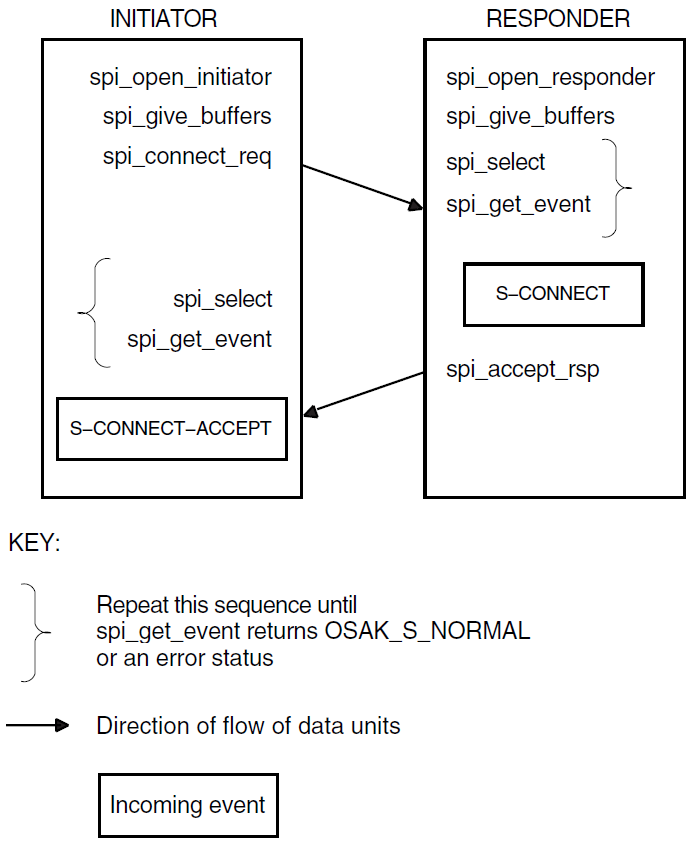
OpenVMS: Figure 6.3, ''Setting up a Connection Using Asynchronous Event Notification (OpenVMS
only)'' shows a
sequence of routines you can use to set up a connection if you are using asynchronous
event notification. The sequence uses spi_get_event with asynchronous event
notification.
Note that spi_get_event is not the only routine call that can use
completion routines. See VSI DECnet-Plus OSAK Programming Reference Manual for details.
Figure 6.3, ''Setting up a Connection Using Asynchronous Event Notification (OpenVMS only)'' does not give detailed information. For detailed information on particular points raised by this diagram, see the rest of this section.
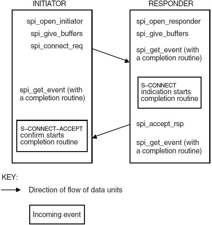
It is essential that the responder issue an spi_open_responder call
before the initiator issues an spi_connect_req call (so that a responding
process is ready to deal with an incoming S-CONNECT-request). 6.4.1 to 6.4.4 follow the sequence of
steps taken.
6.4.1. Getting an Identifier for the Connection
spi_open_responderspi_open_initiator
Both of these routine calls allocate a port identifier, which the OSAK interface
writes into the port parameter. The port identifier is the
local identifier of the connection. If an initiator process uses the
spi_connect_req call to request a connection to an address that
does not have an associated responder process listening for incoming connections
(spi_open_responder call), the initiator's call fails with the
status OSAK_S_INVAEI.
If your application handles several concurrent connections on the same address,
you must make another call to spi_open_responder as soon as an
S-CONNECT indication arrives. This minimizes the possibility of losing a connection
due to transport timeouts.
6.4.2. Passing Buffers to the OSAK Interface
Before requesting any services, use the routine spi_give_buffers to
pass a user buffer or a list of user buffers to the OSAK interface for receiving
incoming events. You need to do this for an initiator and for a responder. You
cannot receive any inbound events until you pass one or more buffers to the
interface.
VSI recommends that your application has at least one buffer available at all
times to receive inbound events. If an ABORT indication arrives during a connection,
your application needs a buffer to receive it in. Example 6.2, ''Code for Calling spi_give_buffers''
shows code for calling spi_give_buffers. Note that code examples in
this chapter sometimes rely on global declarations made in the complete example
programs (osak_example_init.c and
osak_example_resp.c).
/****************************************************************************/
/* FUNCTION: give_buffer                                                    */
/*                                                                          */
/* This routine is called to pass a buffer to OSAK for OSAK to use to       */
/* receive inbound events.                                                  */
/*                                                                          */
/* A list of unused buffers is maintained. One buffer from this list is     */
/* passed to OSAK using spi_give_buffers. If the list is empty a new        */
/* buffer is allocated.                                                     */
/****************************************************************************/
void give_buffer (osak_port port)
{
    unsigned long int status ;
    struct osak_buffer *give_buf ;

    /* Give a buffer to OSAK */
    if (free_buffers == NULL)
    {
        give_buf = (struct osak_buffer *)malloc (sizeof(struct osak_buffer)) ;
        if (give_buf == NULL)
        {
            printf ("Failed to allocate an osak_buffer.\n");
            exit (0) ;
        }
        give_buf -> next = NULL ;
        give_buf -> buffer_length = OSAK_EXAMPLE_BUFFER_SIZE ;
        give_buf -> buffer_ptr =
            (unsigned char *) malloc (OSAK_EXAMPLE_BUFFER_SIZE) ;
        if (give_buf -> buffer_ptr == NULL)
        {
            printf ("Failed to allocate buffer.\n") ;
            exit (0) ;
        }
    }
    else
    {
        give_buf = free_buffers ;
        free_buffers = free_buffers -> next ;
        give_buf -> next = NULL ;
    }

    status = spi_give_buffers (port, give_buf) ;
    if (status != OSAK_S_NORMAL)
    {
        printf ("spi_give_buffers failed\n");
        exit (0) ;
    }
}
Example 6.3, ''Code for Reusing Buffers'' shows code for reusing buffers placed by the OSAK software on the list of unused buffers.
/****************************************************************************/
/* FUNCTION: reuse_buffers                                                  */
/*                                                                          */
/* This routine is called to place buffers returned by OSAK onto the list   */
/* of unused buffers.                                                       */
/****************************************************************************/
void reuse_buffers (struct osak_buffer **buf_ptr)
{
    struct osak_buffer *buf, *last_buf ;

    buf = *buf_ptr ;
    if (buf == NULL)
        return ;

    last_buf = buf ;
    while (last_buf->next != NULL)
        last_buf = last_buf -> next ;

    if (free_buffers == NULL)
    {
        free_buffers = buf ;
    }
    else
    {
        free_buffers_end->next = buf ;
    }
    free_buffers_end = last_buf ;
    *buf_ptr = NULL ;
}
6.4.3. Preparing to Receive and Examining Inbound Events
Polling and blocking
Use the
spi_get_eventroutine (preceded, if you choose, by anspi_selectroutine). See Section 6.4.3.1, ''Polling and Blocking'' for further information.Asynchronous event notification (OpenVMS systems only)
Use the
spi_get_eventroutine with a completion routine. See Section 6.4.3.2, ''Asynchronous Event Notification (OpenVMS only)'' for further information.
VSI recommends that an application use only one of these methods of receiving events throughout.
Section 6.4.3.3, ''Using the Request Mask in the spi_select Routine'' shows you how to distinguish between events that indicate something happening on the network (for example, some data arriving) and events that indicate something happening in the local processor (for example, a routine call completing).
6.4.3.1. Polling and Blocking
Call the routine spi_get_event to check for the arrival of an
inbound event. If the routine returns a status code of OSAK_S_NOEVENT, there is
no event waiting to be collected.
In a blocking interface, an application that makes a call cannot make another call until the first one completes. If your application can do no useful work until an event arrives, you may prefer to block until the OSAK software receives the event.
To do this, call the routine spi_select and wait for an inbound
event to arrive. If you specify a time limit, control returns to your
application either when an event arrives or when the time specified runs out,
whichever comes first. If you do not specify a time limit, control remains with
the OSAK interface until an event arrives.
spi_select call may return a status code of OSAK_S_NORMAL
(indicating that an event is waiting) but the spi_get_event call
may still return a status code of OSAK_S_NOEVENT. There are two common causes:The arrival of a transport event instead of an upper-layer event. One upper-layer event may map to several transport events.
The arrival of incomplete PCI in a data unit. In this case, the OSAK interface does not have enough information to decode the incoming data unit.
To allow for these possibilities in your application, you should repeatedly
call spi_select followed by spi_get_event until the
return value of spi_get_event is OSAK_S_NORMAL.
do
{
    status = osak_select(port_count, port_list, time_out);
    if (status != OSAK_S_NORMAL
    {
    /* error-handling routine ... */
    }
    status = osak_get_event(port,parameter_block);
    switch(status)
    {
        case OSAK_S_NORMAL:
            /* event arrived - leave loop */
            break;
        case OSAK_S_NOBUFFERS:
            /* Give more buffers to the OSAK software*/
            /* by calling osak_give_buffers()...*/
            .
            .
            .
            break;
        case OSAK_S_NOEVENT:
            /* no event arrived - go round loop again*/
            break;
        default:
            /* Some error returned - call error-handling routine ...*/
    }
} while (status != OSAK_S_NORMAL);
See also Section 3.7, ''Waiting to Receive Data'' for more information about receiving events.
6.4.3.2. Asynchronous Event Notification (OpenVMS only)
Call spi_get_event with a completion routine. The completion
routine starts automatically when spi_get_event receives an event.
The OSAK interface returns a value in the status_block
parameter indicating whether or not an event is present. VSI recommends that you
always leave a call to spi_get_event outstanding when you are using
asynchronous event notification. If you leave more than one call to
spi_get_event outstanding, these calls are completed as events
arrive, in the order in which you issue them.
6.4.3.3. Using the Request Mask in the spi_select Routine
An initiator may wait for an S-CONNECT-confirm rather than use
spi_select or spi_get_event on the assumption that
the OSAK software sent the S-CONNECT-request successfully. But an initiator uses
the spi_select and spi_get_event routines after
receiving the S-CONNECT-confirm (to receive data), and should ideally make a
buffer available for the provider's notification in case the
spi_connect_req fails.
When you use the routine call spi_select, set the WRITE bit as
well as the READ bit. Set the WRITE bit to require the OSAK software to inform
your application about its own processing of the application's routine calls.
Set the READ bit to require the OSAK software to inform your application when
incoming data arrives on the network. If the return from the
spi_select routine indicates activity on the local processor
and not on the network, issue an spi_collect_pb call to find out
the return status.
6.4.3.4. Examining Incoming Data Units
When an event arrives, the OSAK interface writes the values contained in the
incoming data units into the parameter block that the application supplied when
it called spi_get_event and user buffers that the application
supplied when it called spi_give_buffers. You should examine the
values that the data unit contains, and take appropriate action in your
application.
Figure 6.4, ''User Buffers After the Arrival of an Event (OpenVMS only)'' shows a list of user buffers after
the arrival of an event on an OpenVMS system. On UNIX systems, user data is
separated into multiple user buffers but the OSAK interface does not return a
list of buffers. Instead, the user data is included in a single user buffer that
also contains the PCI if possible. If the data does not fit into a single user
buffer, the more_flag parameter is set to true. The
application then needs to call spi_get_event repeatedly, in order
to receive the next user buffer. When the more_flag
parameter is set to false, all the data has been transmitted.
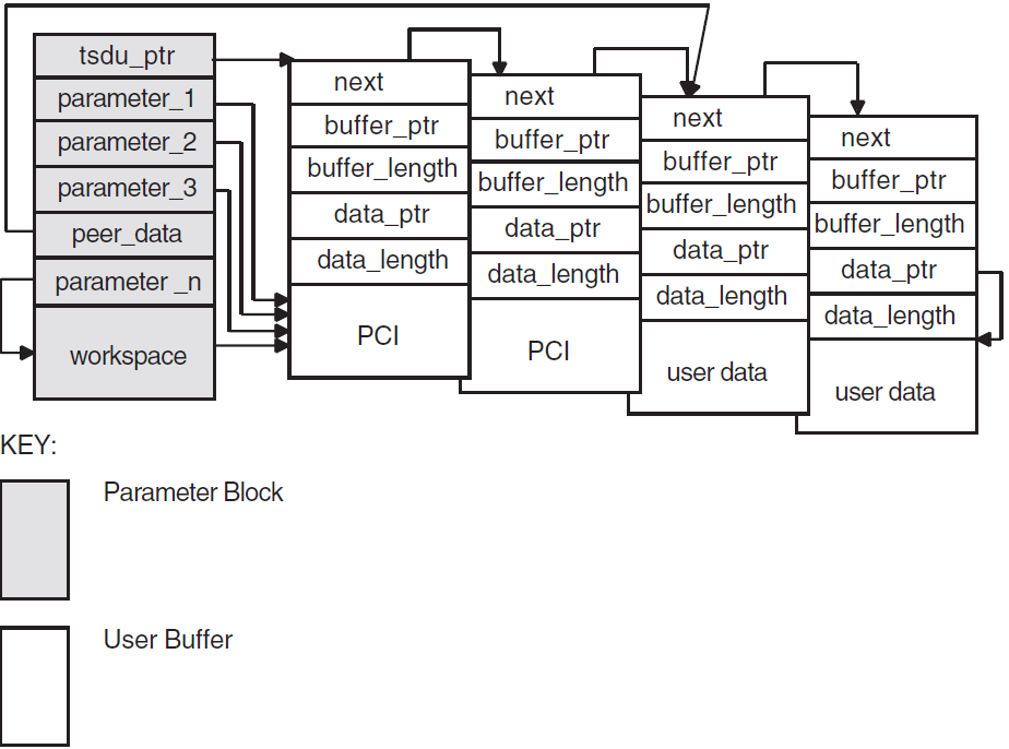
If a user buffer contains only PCI, its data_ptrfield is a null pointer. If a buffer contains user data, or a mixture of PCI and user data, its data_ptr field points to the beginning of the user data.
The OSAK interface passes by reference those optional parameters and parameters that can have a default value. The OSAK interface sets these parameters to null if there is no value for that parameter in the incoming data unit.
Note that a setting of true in the more_flagparameter on
an event indicates that the incoming data is segmented and that there is more
data to receive. To make sure you receive all incoming user data, continue
making calls to spi_get_event until the
more_flag parameter is set to false. For an explanation
of segmentation, see Section 1.4.5, ''Data Segmentation''.
Example 6.4, ''Code for Calling spi_select'' shows code for calling
spi_select.
/****************************************************************************/
/* FUNCTION: wait_for_event                                                 */
/*                                                                          */
/* This routine waits for an inbound event to occur. If there is also a     */
/* queued parameter block from a previous call to OSAK then it also waits   */
/* for that parameter block to be returned by OSAK. spi_select is used to   */
/* wait for the inbound event and outbound completion. spi_get_event is     */
/* used to receive the inbound event and spi_collect_pb is used to get the  */
/* parameter block returned by OSAK when the outbound event has completed.  */
/*                                                                          */
/* The example osak_example_resp.c does this differently. It has two        */
/* routines to do the same job as this one routine:                         */
/* wait_for_outbound_completion and wait_for_inbound. This routine shows    */
/* how spi_select can be used to combine those two routines.                */
/****************************************************************************/
void wait_for_event (osak_port port, struct osak_parameter_block *pb,
                  int queued)
{
    struct osak_parameter_block *ret_pb ;
    osak_handle_count handlecount ;
    osak_handle handle ;
    unsigned long int status ;
    int readevent = TRUE ;
    int writeevent = queued ;
    osak_time select_time = OSAK_EXAMPLE_TIMEOUT ;

    /* Give a buffer to OSAK to get inbound event */
    give_buffer (port) ;

    /* Loop until not waiting for any more events */
    do
    {
        /* Set up parameters to call spi_select() */
        handlecount = 1 ;
        handle.id = (unsigned long int) port ;
        handle.request_mask = 0;
        if (readevent)
            handle.request_mask |= OSAK_C_READEVENT ;
        if (writeevent)
            handle.request_mask |= OSAK_C_WRITEEVENT ;
        handle.returned_mask = 0 ;

        status = spi_select (handlecount, &handle, &select_time) ;
        if (status != OSAK_S_NORMAL)
        {
            printf ("Call to spi_select failed\n") ;
            exit (0) ;
        }

        /* See if the queued parameter block has been returned */
        if (writeevent && (handle.returned_mask & OSAK_C_WRITEEVENT))
        {
            ret_pb = NULL ;
            status = spi_collect_pb (port, &ret_pb) ;
            if ((status != OSAK_S_NORMAL) && (status != OSAK_S_NOEVENT))
            {
                printf ("Call to spi_collect_pb failed\n") ;
                exit (0) ;
            }
            if (status == OSAK_S_NORMAL && ret_pb != NULL)
            {
                writeevent = FALSE ;

                /* Look at the status block in the PB returned to see if an */
                /* error occurred */
                if (ret_pb->status_block.osak_status_1 != OSAK_S_NORMAL)
                {
                  printf ("error in status block of PB returned from collect pb\n");
                  exit (0) ;
                }
            }
        }

        /* See if there is an inbound event. If so call spi_get_event() */
        if (readevent && (handle.returned_mask & OSAK_C_READEVENT))
        {
            do
            {
                /* Initialize parameter block ...*/
                .
                .
                .
                status = spi_get_event (port, pb) ;
                /* If OSAK needs more buffer to decode the event then give */
                /* more buffers. */
                if (status == OSAK_S_NOBUFFERS)
                {
                    give_buffer (port) ;
                }
            } while (status == OSAK_S_NOBUFFERS) ;

            if ((status != OSAK_S_NORMAL) && (status != OSAK_S_NOEVENT))
            {
                printf ("spi_get_event failed\n") ;
                exit (0) ;
            }

            if (status == OSAK_S_NORMAL)
            {
                readevent = FALSE ;
            }
        }
    } while (readevent || writeevent) ;
}
6.4.4. Requesting an Association and Responding to a Request
Request a connection by calling spi_connect_req. You can send the
session PCI and all the user information on the service. Alternatively, you can
segment the user data before you pass it to the OSAK interface and send the session
PCI and none or some of the user information. In either case, you must include all
the PCI when you call the spi_connect_req routine.
If you use segmentation, you should set the more_flag
parameter to true and use spi_send_more as many times as necessary to
send the remaining user information, setting the last segment's
more_flag parameter to false.
Example 6.5, ''Code for Calling spi_connect_req'' shows code for requesting a connection, and Example 6.6, ''Code for Calling spi_accept_rsp'' shows code for responding to a request for a connection.
/****************************************************************************/
/* FUNCTION: connect_req                                                    */
/*                                                                          */
/* This routine sets up the parameters for a call to spi_connect_req and    */
/* makes the call.                                                          */
/*                                                                          */
/****************************************************************************/
unsigned long int
connect_req (osak_port port, struct osak_parameter_block *pb)
{
    unsigned long int status ;

    /* Set up local address */
    local_address.paddress.ssel.size = 9 ;
    local_address.paddress.ssel.pointer = (unsigned char *)"INIT-SSEL" ;
    local_address.paddress.tsel.size = 9 ;
    local_address.paddress.tsel.pointer = (unsigned char *)"INIT-TSEL" ;
    local_address.paddress.nsap.next = NULL ;
    local_address.paddress.nsap.id.size = 0 ;
    local_address.paddress.nsap.id.pointer = 0 ;
    local_address.paddress.nsap.type = OSAK_C_CLNS ;

    /* Set up peer address (the responder’s address) */
    remote_address.paddress.ssel.size = 9 ;
    remote_address.paddress.ssel.pointer = (unsigned char *)"RESP-SSEL" ;
    remote_address.paddress.tsel.size = 9 ;
    remote_address.paddress.tsel.pointer = (unsigned char *)"RESP-TSEL" ;
    remote_address.paddress.nsap.next = NULL ;
    remote_address.paddress.nsap.id.size = sizeof(remote_nsap) ;
    remote_address.paddress.nsap.id.pointer = remote_nsap ;
    remote_address.paddress.nsap.type = OSAK_C_CLNS ;

    /* Set up transport template */
    transport_template.next = NULL ;
    transport_template.name.size = 7 ;
    transport_template.name.pointer = (unsigned char *)"Default" ;

    /* Set up protocol versions */
    /* Select session version 2 */
    protocol_versions.sversion.version1 = 0 ;
    protocol_versions.sversion.version2 = 1 ;

    /* Set up functional units */
    /* Zero out all functional units before setting those required */
    memset ((void *)&fus, ’\0’, sizeof(struct osak_fus)) ;

    /* Request either duplex or half duplex. In this example we are */
    /* actually expecting the responder to accept with duplex. */
    fus.duplex = 1 ;
    fus.half_duplex = 1 ;

    /* Set up the buffer containing the data to send */
    send_buffer.next = NULL ;
    send_buffer.buffer_ptr = &user_information[0] ;
    send_buffer.buffer_length = sizeof(user_information) ;
    send_buffer.data_ptr = &user_information[0] ;
    send_buffer.data_length = sizeof(user_information) ;

    /* initialize parameter block ...*/
    .
    .
    .

    status = spi_connect_req (port, pb) ;
    return status ;
}
/****************************************************************************/
/* FUNCTION: accept_rsp                                                     */
/*                                                                          */
/* This routine sets up the parameters for a call to osak_accept_rsp and    */
/* makes the call.                                                          */
/*                                                                          */
/* It does not do any of the parameter negotiation that a real application  */
/* would need to do. For example, it does not check the functional units    */
/* or the presentation contexts proposed in the A-ASSOCIATE-indication.     */
/*                                                                          */
/****************************************************************************/
unsigned long int
accept_rsp (osak_port port, struct osak_parameter_block *pb)
{
    unsigned long int status ;

    /* Set up functional units. */

    /* A real application would need to check which functional units were  */
    /* proposed by the initiator and negotiate a common set of functional  */
    /* units. This simple example assumes that the duplex functional unit  */
    /* was proposed. It is only going to accept the duplex functional unit.*/

    fus.duplex = 1 ;
    fus.half_duplex = 0 ;
    fus.expedited = 0 ;
    fus.syncminor = 0 ;
    fus.syncmajor = 0 ;
    fus.resynchronize = 0 ;
    fus.activities = 0 ;
    fus.negotiated_release = 0 ;
    fus.capability_data = 0 ;
    fus.exceptions = 0 ;
    fus.typed_data = 0 ;
    fus.data_separation = 0 ;
    /* initialize parameter block ...*/
    .
    .
    .
    status = spi_accept_rsp (port, pb) ;
    return status ;
}
6.5. Sending Data
After the connection is established, you can send and receive data using
the OSAK services. Chapter 1, "OSI Networking Concepts" gives details of the services defined by
the OSI standards.
6.6. Releasing a Connection
The calls you need to use to release a connection are often similar to the calls
needed to set up the connection. This section, therefore, does not contain detailed
information on spi_give_buffers, spi_select, and
spi_get_event, which are discussed in Section 6.4.2, ''Passing Buffers to the OSAK Interface'' and Section 6.4.3, ''Preparing to Receive and Examining Inbound Events''.
The initiator of a release and the responder to the release (not necessarily the initiator and responder respectively of the connection), use different calls. Table 6.4, ''Sequence of Routine Calls Used in Releasing a Connection'' lists the calls used by the initiator of the release and Table 6.5, ''Sequence of Routine Calls Used in Responding to a Request for Release'' lists the calls used by the responder to the request.
Figure 6.5, ''Releasing a Connection'' shows a sequence of routines you can use to release a connection on the OpenVMS operating system.
Figure 6.6, ''Releasing a Connection Using Asynchronous Event Notification'' shows a sequence of routines you can use to
release a connection if you are using asynchronous event notification. The example uses
spi_get_event with asynchronous event notification.
Note that Figure 6.5, ''Releasing a Connection'' and Figure 6.6, ''Releasing a Connection Using Asynchronous Event Notification'' do not give detailed information. For detailed information on particular points raised by these diagram, see the rest of this section.
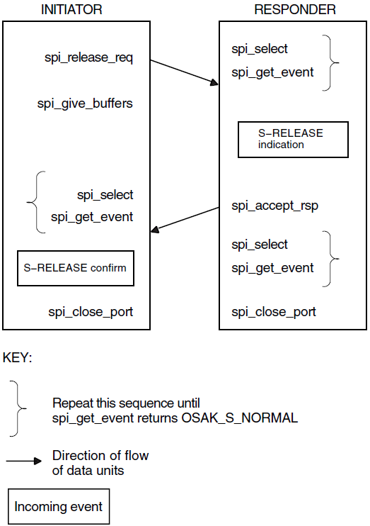
6.6.1. Issuing the Release Request
Set the release_reason in the call to
spi_release_request to whatever is appropriate;
VSI DECnet-Plus OSAK Programming Reference Manual lists the options.
The initiator must call spi_select and spi_get_event to
receive the S-RELEASE confirm from the responder. The initiator may also check
whether the OSAK software sent the S-RELEASE-request by calling
spi_select and spi_collect_pb.
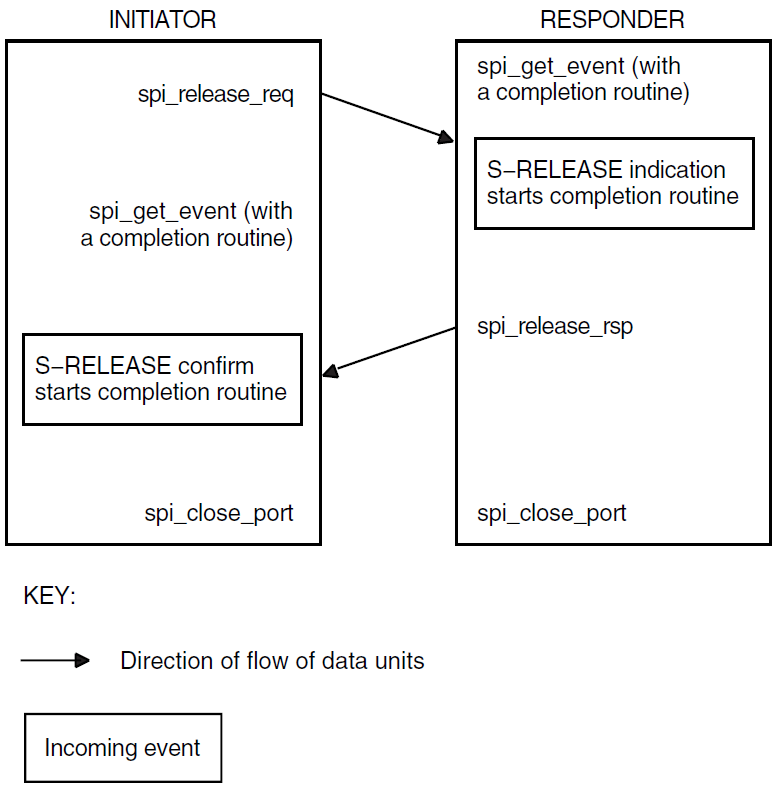
Note
You may send user data on the service. Make sure, however, that you set the user_data field in the OSAK parameter block to null in case a release does not use the user_data parameter.
Example 6.7, ''Code for Calling spi_release_req'' shows code for releasing a connection.
6.6.2. Responding to a Release Request
The responder must check whether an inbound event is an S-RELEASE indication. Call
spi_get_event (preceded, if you choose, by
spi_select), and if an S-RELEASE-indication arrives, call
spi_release_rsp.
UNIX: The responder must collect a transport
disconnect indication as well as the S-RELEASE-indication, using
spi_give_buffers, spi_select, and
spi_get_event calls.
/****************************************************************************/
/* FUNCTION: release_req                                                    */
/*                                                                          */
/* This routine sets up the parameters for a call to spi_release_req and    */
/* makes the call.                                                          */
/*                                                                          */
/****************************************************************************/
unsigned long int
release_req (osak_port port, struct osak_parameter_block *pb)
{
    unsigned long int status ;

    /* initialize parameter block */
    memset ((void *)pb, ’\0’,
        sizeof(struct osak_parameter_block) + OSAK_EXAMPLE_WS_SIZE ) ;
    pb->pb_length = sizeof (struct osak_parameter_block) ;
    pb->ws_length = OSAK_EXAMPLE_WS_SIZE ;
    pb->release_reason = OSAK_C_RLRQ_NORMAL ;

    status = spi_release_req (port, pb) ;
    return status ;
}
/****************************************************************************/
/* FUNCTION: release_rsp                                                    */
/*                                                                          */
/* This routine sets up the parameters for a call to spi_release_rsp and    */
/* makes the call.                                                          */
/*                                                                          */
/****************************************************************************/
unsigned long int
release_rsp (osak_port port, struct osak_parameter_block *pb)
{
    unsigned long int status ;
    /* Initialize parameter block... */
        .
        .
        .
    status = spi_release_rsp (port, pb) ;
    return status ;
}
Example 6.8, ''Code for Calling spi_release_rsp'' shows code for responding to a request for a release and Example 6.9, ''Code for Calling spi_get_event After Releasing a Connection'' shows code for waiting for a transport disconnect.
6.6.3. Closing the Port
Both the initiator and the responder must call spi_close_port to
signal to the OSAK software that they have finished with the connection. This makes
the OSAK software release any memory allocated to the connection and return any
parameter blocks and user buffers that have not already been returned to the
application.
In normal operation, an application calls spi_close_port with the
OSAK_C_NON_DESTRUCTIVE flag set. This indicates to the OSAK software that the port
has no connection at any level with any remote system.
/****************************************************************************/
/* FUNCTION: wait_for_TDISind                                               */
/*                                                                          */
/* This routine uses spi_select to wait for a transport disconnect          */
/* indication after the release-response has been sent.                     */
/*                                                                          */
/* It does not check the event since OSAK_S_NOEVENT may be returned. This   */
/* would be the case when the peer did not send a disconnect. spi_select    */
/* would return either when it has timed out, or (on OpenVMS only) when the */
/* session disconnect timer fired.                                          */
/****************************************************************************/
void wait_for_TDISind (osak_port port, struct osak_parameter_block *pb)
{
    osak_handle_count handlecount ;
    osak_handle handle ;
    unsigned long int status ;
    osak_time select_time ;

    /* Give a buffer to OSAK to get inbound event */
    give_buffer (port) ;

    /* Set up parameter to call spi_select() */
    handlecount = 1 ;
    handle.id = (unsigned long int) port ;
    handle.request_mask = OSAK_C_READEVENT ;
    handle.returned_mask = 0 ;
    select_time = OSAK_EXAMPLE_TIMEOUT ;

    status = spi_select (handlecount, &handle, &select_time) ;
    if (status != OSAK_S_NORMAL)
    {
        printf ("call to spi_select failed\n") ;
        exit (0) ;
    }

    /* See if there is an inbound event. If so call spi_get_event() */
    if (handle.returned_mask & OSAK_C_READEVENT)
    {
        /* Initialize parameter block ...*/
        .
        .
        .

        status = spi_get_event (port, pb) ;

        if ((status != OSAK_S_NORMAL) && (status != OSAK_S_NOEVENT))
        {
            printf ("call to spi_get_event failed\n");
            exit (0) ;
        }
    }
}spi_close_port when its connection with its
peer is still in progress, by setting the OSAK_C_DESTRUCTIVE flag. This causes the
OSAK software to:Discontinue the connection immediately
Return all parameter blocks and buffers
Return to the application any memory allocated to the port
To avoid disrupting a connection, we recommend that you use the nondestructive form except in the following circumstances:
Your application runs out of virtual memory and cannot free enough memory to send an upper-layer abort.
Your application becomes constrained by lower-layer flow control, and is unable to continue. For more information about flow control, refer to the OSI standards.
A remote system does not disconnect on receipt of the S-RELEASE-request.
6.7. Reclaiming Memory
This section describes how to reclaim memory allocated to outbound parameter blocks
and user buffers. Note that it is always safer to delete incoming data in buffers you
are reclaiming by using the tsdu_ptr parameter rather than the data
pointers, because the first buffer may contain nothing but PCI. In that case, the
peer_data (or, in the case of a REDIRECT indication,
rcv_data_list) parameter would not point to the first buffer in the
linked list of buffers.
Wait until your connection closes down.
The routine
spi_close_port, which you should call after you release a connection, returns ownership of all parameter blocks and user buffers, and any unused inbound buffers, to the application.Supply a completion routine with all outbound services (OpenVMS systems only).
When the completion routine starts, it indicates that the parameter block and any associated user buffers are available for reuse.
If you are using a blocking
spi_selectroutine, specify both WRITE and READ events in the request mask. If a WRITE event is indicated, callspi_collect_pbto reclaim the available parameter blocks and buffers.Call
spi_collect_pbwhenever your application is running short of memory.
6.8. Redirecting a Connection
You can use the spi_redirect parameter to redirect a connection from one
local process to another, either immediately after setting up a connection, or during
data transfer. Figure 6.7, ''Using the OSAK Redirection Service'' shows how to use the OSAK redirection
service immediately after setting up a connection. You can use spi_redirect
to implement a server that receives connection requests and immediately hands them on to
other applications.
Call these routines in the application that starts the redirection (the server, in the case of a process that simply receives inbound connect requests and passes them on to processes that can handle them):
spi_give_buffersspi_selectfollowed byspi_get_eventspi_redirectspi_close_port
Note that process 1 in Figure 6.7, ''Using the OSAK Redirection Service'' must close its port. Until
the port is closed, the OSAK software wastes resources associated with that port. The
connection then belongs to process 2, which uses the port returned in the call to
spi_open_redirect.
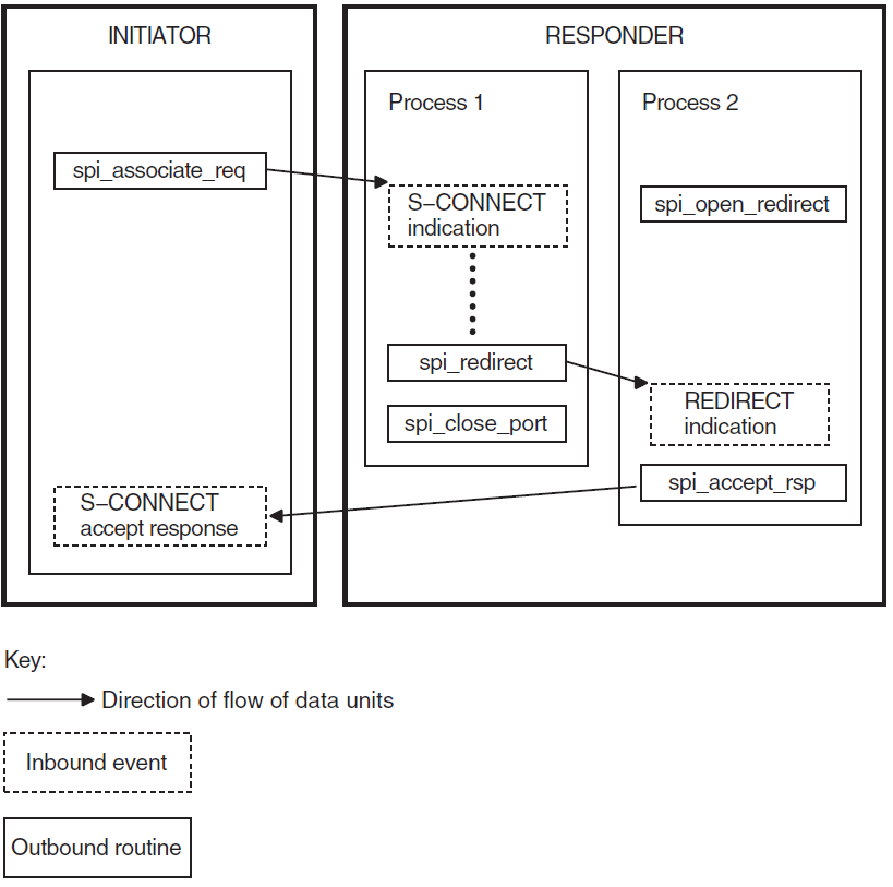
Call the following routines in the application that responds to the redirection call:
spi_open_redirectspi_give_buffersspi_selectfollowed byspi_get_eventspi_accept_rsp
In Figure 6.7, ''Using the OSAK Redirection Service'', the process that redirects the connection is
not the initiator of the connection. However, in some cases (an outbound
connection-handler for example), an application may use spi_redirect after
initiating a connection.
6.9. Linking on UNIX Systems
Link your application against the following libraries:
/usr/lib/libspi.a

/usr/lib/libxtiosi.a
/usr/lib/libxti.a
Example
To link your application, you should use a command similar to the following:
/bin/cc -o osak_example_init osak_example_init.o -lspi -lxtiosi -lxti
In the above example, osak_example_init is the executable version of your
application, and osak_example_init.o is the object file.
It is important that you specify the libraries in the order shown.
6.10. Linking on OpenVMS Systems
SYS$SHARE:OSAK$OSAKSHR.EXE
To link your application, you can either specify SYS$INPUT in place of an options file, and specify the OSAK$OSAKSHR library, or specify the OSAK$OSAKSHR library in an options file. The default filename for the options file is OPTIONS_FILE.OPT.
Examples
LINK OSAK_EXAMPLE_INIT, SYS$INPUT/OPTIONS
SYS$SHARE:OSAK$OSAKSHR/SHAREABLE
Ctrl/Z
LINK OSAK_EXAMPLE_INIT, OPTIONS_FILE/OPTIONS
Chapter 7. Introduction to OSAKtrace
The OSAK trace utility (OSAKtrace) captures a record of what happens during an OSI information exchange. OSAKtrace is not an implementation of any OSI standard; there is no ISO standard for OSI tracing. You can use OSAKtrace to show that application programs using the OSAK routines conform with the standards, and to identify any problems that may arise when one OSI application works with another over a network.
7.1. The Components of OSAKtrace
A trace emitter, built into the OSAK software
The trace emitter generates trace binary files. You can enable the trace emitter by defining a logical name (on OpenVMS systems) or environment variable (on UNIX or ULTRIX systems). Section 8.2.1, ''Enabling Tracing by Defining a Logical Name or an Environment Variable'' describes this. The OSAK interface includes routines that you can use as another method of enabling the trace emitter.
A trace analyzer
The trace analyzer runs independently of the trace emitter. It analyzes trace binary files and produces trace text files from them. To find out which data units are being exchanged during an association, and in what order, you need to interpret the output of the trace analyzer (see Chapter 9, "Interpreting OSAKtrace Output").
Figure 7.1, ''Components of OSAKtrace'' shows the components of OSAKtrace.
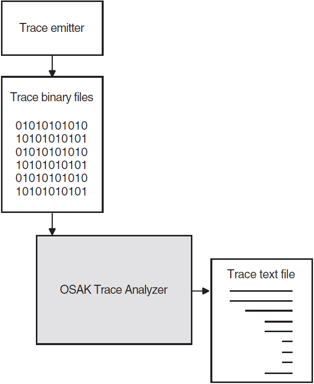
7.2. What OSAKtrace Captures
Service data units (SDUs) SDUs are exchanged by adjacent layers on a single computer system.
Protocol data units (PDUs) PDUs are exchanged between peer entities on separate computer systems, and stay within a single layer.
A layer in the upper layers creates a PDU by adding its own protocol control information (PCI) to an SDU (or, in the case of an APDU, by adding its own PCI to user data).
A TSDU contains one or more session PDUs. Figure 7.2, ''The Contents of a TSDU'' shows the contents of a TSDU that contains two SPDUs.
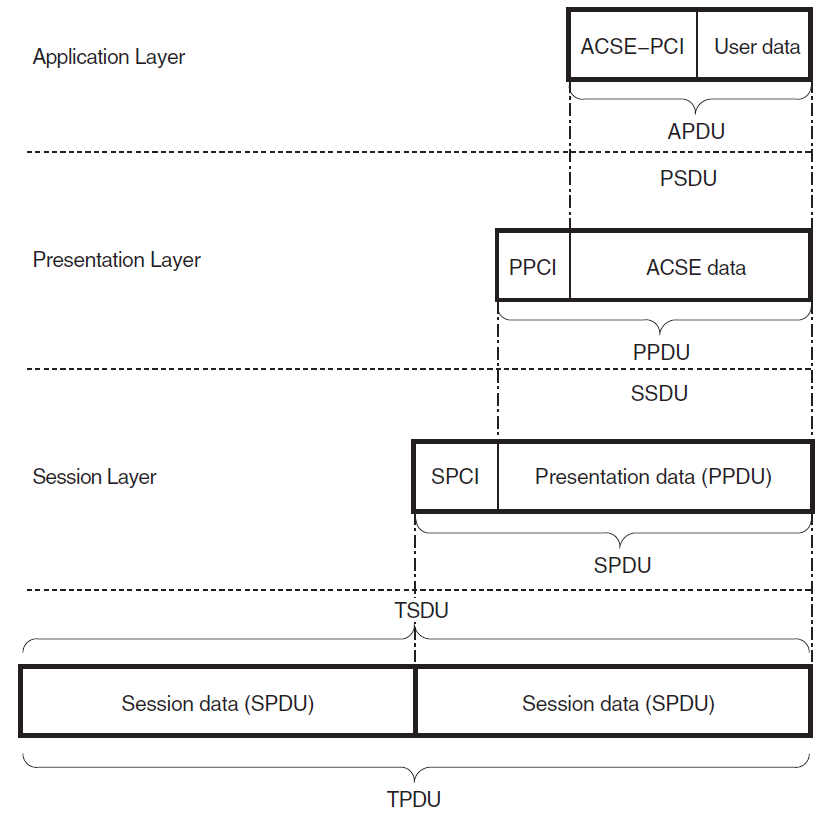
7.3. OSAKtrace Output
7.3.1. Output from the Trace Emitter
init_****_****.binif the port is for an initiatorresp_****_****.binif the port is for a responderredir_****_****.binif the port is for a redirected process
The asterisks (_****_****) represent a timestamp and some digits derived from the
process identifier, inserted by the operating system to make the file name
unique.
The trace binary file is written in the directory where the application starts up.
7.3.2. Output from the Trace Analyzer
This section describes the output you can expect at each level of the OSI stack. Note that a PDU becomes an SDU to the next layer down the OSI stack, and that an SDU becomes a PDU to the next layer up the OSI stack. The SDU is whatever is passed across the interface between the layers.
Transport Level
OSAKtrace traces events in the Transport layer, for example T-CONNECT, T-DISCONNECT, and T-WAIT-FOR-CONNECT events.
Session Level
The output consists of decoded inbound and outbound SPDUs. The session trace includes some information about the T-CONNECT and T-DISCONNECT services that the OSAK software uses to support the session connection.
Presentation Level
ACSE PDUs
User data PDUs
OSAKtrace outputs a formatted display of presentation PCI (if presentation PCI is present). Presentation PCI tracing consists of the session SDU octets and an analysis of the presentation PCI. The display is embedded in the trace of the session PCI.
ACSE Level
The output consists of a formatted display of the ACSE PCI contained within the ACSE PDUs (if present). The display is embedded in the trace of the presentation PCI, if you choose to trace presentation PCI.
User Level
OSAKtrace attempts to generically decode user data contained within presentation data, or within other user data. By default, the user data is embedded in the presentation PCI or ACSE PCI. The trace utility can do the decoding only if the userdata is encoded according to the basic encoding rules (BER) for ASN.1. If the trace utility cannot decode the user data, the output is in hexadecimal format.
Chapter 8. Using OSAKtrace
8.1. Using the Trace Utility
Enable trace by following the instructions in Section 8.2, ''Enabling OSAKtrace''.
Run the application again, to create a trace output file.
Run the trace analyzer using the
osaktracecommand with the appropriate options, as detailed in Section 8.3, ''Running the OSAKtrace Analyzer''.
Trace output is sent to standard output unless you explicitly send it elsewhere. When you have produced a trace file and run the trace analyzer, you must read and interpret the analysis. Chapter 9, "Interpreting OSAKtrace Output" describes output from the trace analyzer.
8.2. Enabling OSAKtrace
By defining a logical name (OpenVMS) or environment variable (UNIX). See Section 8.2.1, ''Enabling Tracing by Defining a Logical Name or an Environment Variable'' for further information.
Through the OSAK interface. See Section 8.2.2, ''Enabling Tracing Through the Programming Interface'' for further information.
|
Advantages |
Disadvantages |
|---|---|
|
Logical name or environment variable ? | |
|
No need to modify application. |
Cannot choose which connections to trace. |
|
Can be used with all applications. |
Traces all connections in their entirety. |
|
Interface routines | |
|
Can selectively start and stop tracing. |
Cannot be used for an application that has not been modified or originally written to include trace calls. |
|
Can trace specific connections or parts of connections. | |
8.2.1. Enabling Tracing by Defining a Logical Name or an Environment Variable
osak_trace,
as follows:Stop the application.
Enter the following command:
OpenVMS:
$ DEFINE OSAK_TRACE ONUNIX: either
% setenv OSAK_TRACE onor% setenv OSAK_TRACE ONStart the application.
8.2.2. Enabling Tracing Through the Programming Interface
The OSAK interface includes routines that allow you to control the trace emitter from within your OSI application. You can selectively start and stop tracing at any point in the protocol activity on a specified connection.
osak_trace_openOpens a trace output file.
osak_trace_startEnables tracing.
osak_trace_stopDisables tracing.
osak_trace_dcs_verifyVerifies the DCS and the default context on the given connection.
osak_trace_closeCloses the trace output file.
If you enable tracing before protocol activity begins on a connection, OSAKtrace builds a table of the presentation contexts in use on the connection. This table includes the DCS and the default context.
If you enable tracing at any other point in the protocol activity on a connection, OSAKtrace
cannot build a table of presentation contexts. In this case, when you call
(osak_trace_start), you must pass to the trace utility the
identifiers of the defined context set and the default context for the connection
you want to trace.
If you try to call osak_trace_start or osak_trace_open
when you have already defined a logical name (OpenVMS) or environment variable
(UNIX) as described in Section 8.2.1, ''Enabling Tracing by Defining a Logical Name or an Environment Variable'', you get an error message,
OSAK_S_INVFUNC.
Stop tracing by calling
osak_trace_stop.Close the existing trace files by calling
osak_trace_close.Delete the existing trace files.
Deassign the logical name (OpenVMS) or environment variable (UNIX).
Start tracing again, by calling
osak_trace_openandosak_trace_start.
VSI DECnet-Plus OSAK Programming Reference Manual describes all the OSAKtrace routine calls in detail.
8.3. Running the OSAKtrace Analyzer
Use the osaktrace command to run the trace analyzer and analyze a trace
binary file.
UNIX:
osaktrace [options] input_file
OpenVMS:
osaktrace input_file [qualifiers]
Ensure that you specify the input_file
|
Switch (UNIX and ULTRIX systems) |
Qualifier (OpenVMS systems) |
Description |
|---|---|---|
|
t |
/TRANSPORT_EVENTS |
Trace transport events |
|
h |
/HEADERS_ONLY |
Trace transport events without analyzing contents of TSDU |
|
s |
/SESSION_PCI |
Trace session PCI |
|
p |
/Presentation_PCI |
Trace presentation PCI |
|
a |
/ACSE_PCI |
Trace ACSE_PCI |
|
u |
/USER_DATA |
Trace user data |
|
e ? |
/ERRORS |
Trace errors |
|
d |
/DCS |
Trace DCS setup and verification information |
|
f |
/FILTER |
Replace time and date strings with |
|
o? |
/OUTPUT= filename |
Send output to the named file |
8.3.1. Default Options
If you do not specify any options, OSAKtrace uses a default set of options:
UNIX:
-t -s -p -a
The default set of options applies automatically if you choose any of the
-f, -d and -e options.
OpenVMS:
/TRANSPORT_EVENTS/SESSION_PCI/PRESENTATION_PCI/ACSE_PCI
The default set of options applies automatically if you choose any of the /FILTER, /DCS and /ERRORS qualifiers.
These options affect only what appears in the trace analysis file (readable text), not the original trace output (binary). The binary trace output file contains all the OSAKtrace information about the association traced.
8.3.2. Examples
UNIX:
% osaktrace -s -p -a -u -e intrace > outtrace
This example analyzes session PCI, presentation PCI, ACSE PCI, user data and
errors. The trace binary file is called intrace. The output from the
trace analyzer is redirected to a file called outtrace.
% osaktrace -s -p -a -e -o outtrace intrace
This example analyzes session PCI, presentation PCI, ACSE PCI, and errors. The
trace binary file is called intrace. The output from the trace analyzer
is directed to a file called outtrace.
OpenVMS:
$ osaktrace intrace /SESSION/PRES/ACSE/USER/ERRORS
This example analyzes session PCI, presentation PCI, ACSE PCI, user data and
errors. The trace binary file is called intrace.
$ osaktrace intrace /SESSION/PRES/ACSE/ERRORS/OUT=outtrace
This example analyzes session PCI, presentation PCI, ACSE PCI, and errors. The
trace binary file is called intrace. The output from the trace analyzer
is directed to a file called outtrace.
8.3.3. Interpreting the OSAKtrace Analysis File
Having enabled OSAKtrace, run your application, and then run the trace analyzer to isolate the sort of information in which you are interested. You must then interpret the OSAKtrace analysis file, as described in Chapter 9, "Interpreting OSAKtrace Output".
To understand what the trace output tells you about problems in your OSI applications, you may need to consult the appropriate ISO standards for detailed information on OSI communications. Consult the state tables in the protocol specifications for the services in which you are interested.
Check, for example, that a particular PDU arrived in the correct presentation context, that it is encoded correctly, and that its parameter values are allowed. You can then check that the parameter values are correct.
Chapter 9. Interpreting OSAKtrace Output
This chapter explains the layout of the trace information produced by the trace analyzer, and gives other information to help you interpret the contents of a trace output file.
The amount of information in the trace file depends on the options you specify when you
use the osaktrace command. If the syntax is ASN.1-defined and has been
encoded according to the ASN.1 basic encoding rules (BER), the trace output can include an
analysis of the user data.
9.1. Layout of a Trace Text File
The trace binary file name
The trace text file name (if any output file is specified)
A list of the trace options selected
The time the trace utility started tracing (or
XX-XX-XX-XX on
                            XX-XXX-XXXX
if you filtered the output)
Input Trace File Name : init_2222_2699.bin
Trace Options Selected : SPCI PPCI ACSEPCI UserData Errors DCS

09:22:30.94 on 5-JUN-1993 : Trace started
If, in the osaktrace command, you specify the tracing of defined
context set (DCS) information (with the /DCS qualifier on OpenVMS systems or the
-d option on ULTRIX or UNIX systems), the next item of trace
information is a table showing the DCS for the connection at the time tracing started.
This table contains meaningful information only if the connection is already established
when tracing starts.
Each table entry consists of a presentation context identifier, and the related abstract syntax and transfer syntax names or object identifiers.
09:22:30.94 on 5-JUN-1991 : DCS Initialized/Modified

   OSAKtrace DCS contents:

   +-----------------------------------------------+
   | PC ID   |       AS NAME           |  TS NAME  |
   +-----------------------------------------------+
   |    1    |     ACSE-PCI            |  BER      |
   |    3    |     {1  0  8571 2 1}    |  BER      |
   |    5    |     {1  0  8571 2 2}    |  BER      |
   |    7    |     {1  0  8571 2 3}    |  BER      |
   | Default |     ACSE-PCI            |  BER      |
+-----------------------------------------------+09:22:40.86 on 5-JUN-1991 : Issued T-CONNECT request
Calling Transport Selector = "TRANI" Called Transport Selector = "TRANR" Network SAP = '49002AAA00040052A821'H Transport Options = {default = yes, tpdu max length = 128, reassignment time = -1, principal class = class4, alternative class = class4, extended format = yes, flow control = yes, checksum = no}
09:23:08.54 on 5-JUN-1991 : Received T-CONNECT confirmation Calling Transport Selector = "TRANI" Called Transport Selector = "TRANI" Network SAP = '4900CA08002B08F5C121'H Transport Options = {default = yes, tpdu max length = 128, reassignment time = -1, principal class = class4, alternative class = class4, extended format = yes, flow control = yes, checksum = no} 09:23:08.67 on 5-JUN-1991 : Issued T-DATA request
0D FF 02 04 05 09 13 01 00 16 01 02 17 01 31 14 02 06 A5 33 05 53 45 53 53 49 34 05 53 45 53 53 52 C1 FF 01 E3 31 82 01 DF A0 03 80 01 01 A2 82 01 D6 80 02 07 80 81 05 50 52 45 53 49 82 05 50 52 45 53 52 A4 5F 30 0F 02 01 01 06 04 52 01 00 01 30 04 06 02 51 01 30 (Remainder of hexadecimal dump not shown) . . .
CN-SPDU = 0D FF 02 {
Connect/Accept Item = 05 09 { Protocol Options = { } 13 01 00 Version Number = {version-2} 16 01 02 Init Serial Number = 1 17 01 31 } Session User Requirements = {half-duplex, 14 02 06 expedited-data, resynchronize, negotiated-release, exceptions, typed-data} Calling Session Selector = "SESSI" 33 05 53 Called Session Selector = "SESSR" 34 05 53
User Data = 31 82 01 DF A0 03 80 01 01 (More) C1 FF 01
CP-type SET = 31 82 { [0] IMPLICIT Mode-selector SET = A0 03 . . . (Analysis of PPCI) . . .
PDV-list SEQUENCE = 30 82 { – Abstract Syntax Name = ACSE-PCI – Presentation Context Identifier = 1 – Transfer Syntax Name = BER AARQ-apdu [APPLICATION 0] IMPLICIT SEQUENCE = 60 82 { protocol-version [0] IMPLICIT BITSTRING = 80 02 07 {version-1} . . . (Analysis of ACSE-PCI) . . .
{ [22] [0] IMPLICIT '02'H B6 82 00 EXTERNAL = 28 80 { direct-reference OBJECT IDENTIFIER = {2 1 1} 06 02 51 indirect-reference INTEGER = 7 02 01 07 single-ASN1-type [0] ANY = A0 80 { – Abstract Syntax = {1 0 8571 2 3} – Presentation Context Identifier = 7 – Transfer Syntax Name = BER [5] SEQUENCE = A5 80 30 { [0] IMPLICIT '00'H 80 01 00 [1] INTEGER = 21 A1 03 02 [2] IMPLICIT ... = A2 0D { [0] IMPLICIT '01'H 80 01 01 [1] IMPLICIT '283001'H 81 03 28 [2] [APPLICATION 5] IMPLICIT '0C'H A2 03 45 } [3] IMPLICIT '00'H 83 01 00 } } } } } }
Similar layout for other TSDUs
| Date and time at which transport connection was requested. |
| Transport information. |
| Date and time at which transport connection confirmation was received. |
| Hexadecimal dump of the TSDU. |
| Trace information on the connection session PDU begins. Note the correspondence between this information and the hexadecimal dump. |
| Analysis of session PCI begins. |
| Analysis of session SDU begins (this is session user data). |
| Analysis of presentation PCI begins. |
| Analysis of ACSE PCI begins. |
| Analysis of user data begins. |
Only the first three octets of the TLV (tag, length, and value) structure in the TSDU are displayed. However, OSAKtrace records the full TLV structure.
In a presentation PDU, presentation PCI encloses the user data. For this reason, the trace output always includes an analysis of the closing part of the presentation PCI. However, because user data is often the last data embedded in presentation PCI, the analysis of the closing part of the presentation PCI is usually made up of a sequence of closing braces (}).
In ASN.1, data for presentation contexts is encoded as user data. In the trace output, a user-data termination indicates the start of each presentation context.
Abstract syntax name
Presentation context identifier
Transfer syntax name
PDV-list SEQUENCE =
{
Presentation-context-identifier
9.2. Rules for the Display of User Data
If you choose to trace data from a presentation context (an abstract syntax and a transfer syntax) that is not included in the DCS, the user data is displayed as a hexadecimal dump.
If the presentation context that you choose to trace is included in the DCS, the user data is displayed in generic ASN.1 if the transfer syntax is BER. If the transfer syntax is not BER, the user data is displayed in hexadecimal format.
9.3. Layout of Headers-Only Transport and Session Trace Data
If you use the headers-only option, OSAKtrace traces transport events, but does not analyze them.
-h or /HEADERS_ONLY. Input trace file name : resp_0759_388.bin Trace options selected : EventHeaders 18:07:59.69 on 4-SEP-1991 : Trace started 18:07:59.69 on 4-SEP-1991 : Waiting for T-CONNECT indication 18:08:16.12 on 4-SEP-1991 : Received T-CONNECT indication 18:08:16.15 on 4-SEP-1991 : Issued T-CONNECT response 18:08:23.33 on 4-SEP-1991 : Received T-DATA indication 18:08:27.70 on 4-SEP-1991 : Issued T-DATA request 18:08:43.25 on 4-SEP-1991 : Received T-DATA indication 18:08:49.11 on 4-SEP-1991 : Received T-DATA indication 18:08:55.10 on 4-SEP-1991 : Issued T-DATA request 18:09:05.41 on 4-SEP-1991 : Received T-DISCONNECT indication 18:09:07.66 on 4-SEP-1991 : Trace stopped
Appendix A. Standards Information
This appendix lists the internationally recognized standards and agreements that OSAK implements.
A.1. Protocol Specifications (ISO Standards)
ISO 8327 Information Processing Systems — Open Systems Interconnection — Basic Connection Oriented Session Protocol Specification
ISO 8823 Information Processing Systems — Open Systems Interconnection — Connection Oriented Presentation Protocol Specification
ISO 8650 Information Processing Systems — Open Systems Interconnection — Protocol Specification for the Association Control Service Element
A.2. Service Definitions (ISO Standards)
ISO 8326 Information Processing Systems — Open Systems Interconnection — Basic Connection Oriented Session Service Definition
ISO 8822 Information Processing Systems — Open Systems Interconnection — Connection Oriented Presentation Service Definition
ISO 8649 Information Processing Systems — Open Systems Interconnection — Service Definition for the Association Control Service Element
A.3. Abstract Syntax Notation (ISO Standards)
ISO 8824 Information Processing Systems — Open Systems Interconnection — Specification of Abstract Syntax Notation One (ASN.1)
ISO 8825 Information Processing Systems — Open Systems Interconnection — Specification of Basic Encoding Rules for Abstract Syntax Notation One (ASN.1)
A.4. ROSE Documents (CCITT Recommendations)
CCITT Recommendation X.219 ROSE Service Definition (ISO 9072–1)
CCITT Recommendation X.229 ROSE Protocol Definition (ISO 9072–2)
A.5. NIST Agreements
NIST Special Publication 500-177, Stable Implementation Agreements for Open Systems Interconnection Protocols Version 3 Edition 1 December 1989
A.6. Ordering Documents
You can obtain these documents from the national standards body in your own country. To find the name and address of your national standards body, write to the following address:
U.N. Bookstall
United Nations Assembly Building
New York
NY 11017
USA
Appendix B. PresentationAddress Data Type Used in Network Management
The PresentationAddress data type defines the format that should be
used for all presentation addresses in OSI applications. It is also the format in which
presentation addresses are displayed by OSI network management.
<presentation-address> ::= [[[ <psel> "/" ]<ssel> "/" ]<tsel> "/" ] <network-address-list> <psel> ::= <selector> <ssel> ::= <selector> <tsel> ::= <selector> <selector> ::= ’"’ <otherstring> ’"<tset> ::= "TCP" | "IP" | <digitstring>
<dte> ::= <digitstring> <cudf-or-pid> ::= "CUDF" | "PID" <decimaloctet> ::= <digit> | <digit> <digit> | <digit> <digit> <digit> <digit> ::= [ 0-9 ] <digitstring> ::= <digit> <digitstring> | <digit> <domainchar> ::= [ 0-9 | a-z | A-Z | - | . ] <domainstring> ::= <domainchar> <otherstring> | <domainchar> <dotstring> ::= <decimaloctet> "." <dotstring> | <decimaloctet> "." <decimaloctet> <dothexstring> ::= <dotstring> | <hexstring> <hexdigit> ::= [ 0-9 | a-f | A-F ] <hexoctet> ::= <hexdigit> <hexdigit> <hexstring> ::= <hexoctet> <hexstring> | <hexoctet> <other> ::= [ 0-9 | a-z | A-Z | + | - | . ] <otherstring> ::= <other> <otherstring> | <other>
Notes
| Value restricted to printed characters |
| US GOSIP requirement |
| Network type identifier (the default is Connectionless-Mode Network Services (CLNS)) |
| Concrete binary representation of network service access point (NSAP) address value |
| ISO 8348 compatibility |
| RFC 1006 preferred format |
| Abstract decimal format for domain specific part (DSP) |
| Abstract binary for DSP |
| Printable character format for DSP (for local use only) |
| Dotted decimal notation (for example, 10.0.0.6) or domain name (for example, twg.com) |
| TCP port number (the default is 102) |
| Internet transport protocol identifier 1 = TCP and 2 = UDP |
Keywords can be specified in either uppercase or lowercase. However, <selector> values are case-sensitive. Spaces are significant.
You can find more information about network (NSAP) addresses in the DECnet-Plus introductory and planning documentation.
The CCITT is now the ITU–T (International Telephone Union — Telecommunications Standards Sector ).Their published documents still have CCITT identification material, and to avoid confusion this book still uses the term CCITT.
This is processwide rather than systemwide.
If you select the errors option, OSAKtrace attempts to detect protocol errors. This option is most likely to be useful when you are tracing presentation PCI and ACSE PCI.
The name of the output file, if you supply one, must
immediately follow the -o option. You
can supply the other options in any order.