I/O User’s Reference Manual
- Operating System and Version:
- VSI OpenVMS Alpha Version 8.4-2L1 or higher
VSI OpenVMS IA-64 Version 8.4-1H1 or higher
Preface
1. About VSI
VMS Software, Inc. (VSI) is an independent software company licensed by Hewlett Packard Enterprise to develop and support the OpenVMS operating system.
2. Intended Audience
This manual is intended for system programmers who want to take advantage of the time and space savings that result from direct use of I/O drivers. OpenVMS users who do not require such detailed knowledge of I/O drivers can use the device-independent services described in the VSI OpenVMS Record Management Services Reference Manual.
Users of this manual are expected to obtain and reference any additional documentation specific to their hardware. Users are expected to know how to identify the various devices involved in their installation and be familiar with the console commands that are available on their system.
3. Document Structure
This manual is organized into the following chapters and appendixes:
Chapter 1, "ACP-QIO Interface" describes the Queue I/O (QIO) interface to file system ancillary control processes (ACPs).
Chapters 2 through 9 describe the use of file-structured and real-time I/O device drivers, the drivers for storage devices such as disks and magnetic tapes, and supported devices:
Chapter 2, "Disk Drivers" discusses the disk drivers.
Chapter 3, "Magnetic Tape Drivers" discusses the magnetic tape drivers.
Chapter 4, "Mailbox Driver" discusses the mailbox driver.
Chapter 5, "Terminal Driver" discusses the terminal driver.
Chapter 6, "Pseudoterminal Driver" discusses the pseudoterminal driver.
Chapter 7, "Shadow-Set Virtual Unit Driver" discusses the shadow-set virtual unit driver.
Chapter 8, "Using the OpenVMS Generic SCSI Class Driver" discusses the Generic Small Computer System Interface (SCSI) class driver.
Chapter 9, "Local Area Network (LAN) Device Drivers" discusses the local area network (LAN) device drivers.
Chapter 10, "Optional Features for Improving I/O Performance" describes optional features to improve OpenVMS Alpha I/O performance.
Appendix A, "I/O Function Codes" summarizes the QIO function codes, arguments, and function modifiers used by the drivers listed previously.
Appendix B, "IO$_DIAGNOSE Function for SCSI Class Drivers" describes the enhanced IO$_DIAGNOSE function for SCSI class drivers.
Appendix C, "DEC Multinational Character Set and Terminal Escape Sequences/Modes" lists the DEC Multinational character set and the ANSI and DIGITAL private escape sequences for terminals.
Appendix D, "Control Connection Routines" describes the calling conventions for the pseudoterminal driver's control connection routines.
Appendix E, "DDT Intercept Establisher Routines and Device Configuration Notification Routines" describes the DDT intercept establisher routines and device configuration notification routines that enable third-party applications to run in an OpenVMS SCSI or Fibre Channel multipath configuration.
Appendix F, "Programming USB Generic Drivers" describes the SYS$UGDRIVER.EXE generic driver, which allows users to support USB devices such as scanners and smart-card readers without writing a USB device driver.
4. Device Driver Support for OpenVMS Alpha and IA-64 servers 64-Bit Addressing
The OpenVMS Alpha and IA-64 server operating systems provide support for 64-bit virtual memory addressing, which makes the 64-bit virtual address space defined by the architecture available to the OpenVMS Alpha and IA-64 server operating systems and to application programs. In the 64-bit virtual address space, both process-private and system virtual address space extend beyond 2 GB. By using 64-bit addressing features, programmers can create images that map and access data beyond the limits of 32-bit virtual addresses.
Input and output operations can be performed directly to and from the 64-bit addressable space by means of RMS services, the $QIO system service, and most of the device drivers supplied with OpenVMS Alpha and IA-64 server systems. A device driver declares support for 64-bit addresses individually by I/O function code. Disk and tape device drivers support 64-bit addresses for data transfers to and from disk and tape devices on the virtual, logical, and physical read and write functions. For example, the OpenVMS SCSI disk class driver, SYS$DKDRIVER, supports 64-bit addresses on the IO$_READVBLK and IO$_WRITEVBLK functions, but not on the IO$_AUDIO function. The device drivers, function codes, and $QIO arguments that support 64-bit addressing are indicated in the appropriate chapters of this manual.
For more information about the OpenVMS device drivers that support 64-bit addressing, see the VSI OpenVMS Programming Concepts Manual. To find out how to modify a customer-written device driver to support 64-bit addressing, see the VSI OpenVMS Guide to Upgrading Privileged-Code Applications Manual.
5. About VSI OpenVMS Alpha VXXXXXXXX
VSI OpenVMS Alpha Version XXXXXXXX is an Alpha operating system release that has been solely developed and marketed by VMS Software, Inc. Hewlett Packard Enterprise (HPE) will not provide support and does not warranty any VSI OpenVMS Alpha versions.
Please disregard any reference in this manual that implies HPE support for any VSI OpenVMS Alpha version.
6. OpenVMS Documentation
The full VSI OpenVMS documentation set can be found on the VMS Software Documentation webpage at https://docs.vmssoftware.com.
7. Typographical Conventions
The following conventions are used in this manual:
| Convention | Meaning |
|---|---|
| Ctrl/x | A sequence such as Ctrl/x indicates that you must hold down the key labeled Ctrl while you press another key or a pointing device button. |
| PF1 x | A sequence such as PF1 x indicates that you must first press and release the key labeled PF1 and then press and release another key (x) or a pointing device button. |
... | A horizontal ellipsis in examples indicates one of the following possibilities:− Additional optional arguments in a statement have been omitted.− The preceding item or items can be repeated one or more times.− Additional parameters, values, or other information can be entered. |
. . . | A vertical ellipsis indicates the omission of items from a code example or command format; the items are omitted because they are not important to the topic being discussed. |
| ( ) |
In command format descriptions, parentheses indicate that you
must enclose choices in parentheses if you specify more than
one. In installation or upgrade examples, parentheses indicate
the possible answers to a prompt, such
as:
Is this correct? (Y/N) [Y] |
| [ ] |
In command format descriptions, brackets indicate optional
choices. You can choose one or more items or no items. Do not
type the brackets on the command line. However, you must include
the brackets in the syntax for directory specifications and for
a substring specification in an assignment statement. In
installation or upgrade examples, brackets indicate the default
answer to a prompt if you press Enter without entering a value,
as
in:
Is this correct? (Y/N) [Y] |
| | | In command format descriptions, vertical bars separate choices within brackets or braces. Within brackets, the choices are optional; within braces, at least one choice is required. Do not type the vertical bars on the command line. |
| { } | In command format descriptions, braces indicate required choices; you must choose at least one of the items listed. Do not type the braces on the command line. |
| bold type | Bold type represents the name of an argument, an attribute, or a reason. Bold type also represents the introduction of a new term. |
| italic type | Italic type indicates important information, complete titles of manuals, or variables. Variables include information that varies in system output (Internal error number), in command lines (/PRODUCER=name), and in command parameters in text (where dd represents the predefined code for the device type). |
| UPPERCASE TYPE | Uppercase type indicates a command, the name of a routine, the name of a file, or the abbreviation for a system privilege. |
Example |
This typeface indicates code examples, command examples, and interactive screen displays. In text, this type also identifies website addresses, UNIX command and pathnames, PC-based commands and folders, and certain elements of the C programming language. |
- | A hyphen at the end of a command format description, command line, or code line indicates that the command or statement continues on the following line. |
| numbers | All numbers in text are assumed to be decimal unless otherwise noted. Nondecimal radices —binary, octal, or hexadecimal—are explicitly indicated. |
8. VSI Encourages Your Comments
You may send comments or suggestions regarding this manual or any VSI document by sending electronic mail to the following Internet address: <docinfo@vmssoftware.com>. Users who have VSI OpenVMS support contracts through VSI can contact <support@vmssoftware.com> for help with this product.
9. OpenVMS Documentation
The full VSI OpenVMS documentation set can be found on the VMS Software Documentation webpage at https://docs.vmssoftware.com.
Chapter 1. ACP-QIO Interface
An ancillary control process (ACP) is a process that interfaces between the user process and the driver, and performs functions that supplement the driver's functions. Virtual I/O operations involving file-structured devices (disks and magnetic tapes) often require ACP intervention. In most cases, ACP intervention is requested by OpenVMS Record Management Services (RMS) and is transparent to the user process; however, user processes can request ACP functions directly by issuing a Queue I/O (QIO) request and specifying an ACP function code.
Executing physical and logical input/output (I/O) operations on a device that is managed by a file ACP interferes with the operation of the ACP, and can result in unpredictable consequences such as system failure.
In addition to the ACP, the XQP (extended QIO processor) facility supplements the QIO driver's functions when performing virtual I/O operations on file-structured devices; however, rather than being a separate process, the XQP executes as a kernel-mode thread in the process of its caller.
An XQP is provided to support Files-11 ODS-2 and ODS-5 (On-Disk Structure Level 2 and 5) disks as the base file system, and an ACP is provided for ANSI standard X3.27 magnetic tapes.
There are also ACPs to support the ISO 9660 CD-ROM disk structure (Files-11 C) and High Sierra CD-ROM disk structure (Files-11 D). Collectively, these ACPs are called Files-11 C/D.
This chapter describes the QIO interface to ACPs for disk and magnetic tape devices (file system ACPs). The sample program in Chapter 10, "Optional Features for Improving I/O Performance" performs QIO operations to the magnetic tape ACP.
This chapter also describes a number of structures and field names of the form xxx$name. A MACRO program can define symbols of this form by invoking the $xxxDEF macro.
$IODEF
$FIBDEF
$ATRDEF
$SBKDEF
$FATDEF
$DQFDEF
$FCHDEF
Programs written in BLISS-32 can use these symbols by referencing them and including the correct library, SYS$LIBRARY:STARLET.L32 (for the macros listed under SYS$LIBRARY:STARLET.MLB), and SYS$LIBRARY:LIB.L32 (for the macros listed under SYS$LIBRARY:LIB.MLB).
References to ANSI refer to the American National Standard Magnetic Tape Labels and File Structures for Information Interchange, ANSI X3.27-1978.
1.1. ACP Functions and Encoding
Ancillary control process (ACP) functions can be expressed using seven function codes and four function modifiers. The function codes are:
IO$_CREATE—Creates a directory entry or file
IO$_ACCESS—Searches a directory for a specified file and accesses the file, if found
IO$_DEACCESS—Deaccesses a file and, if specified, writes the final attributes in the file header
IO$_MODIFY—Modifies the file attributes and file allocation
IO$_DELETE—Deletes a directory entry and file header
IO$_MOUNT—Informs the ACP when a volume is mounted; requires MOUNT privilege
IO$_ACPCONTROL—Performs miscellaneous control functions
The function modifiers are:
IO$M_ACCESS—Opens a file on the user's channel
IO$M_CREATE—Creates a file
IO$M_DELETE—Deletes a file or marks it for deletion
IO$M_DMOUNT—Dismounts a volume
In addition to the function codes and modifiers, ACPs take five device- or function-dependent arguments, as shown in Figure 1.1, ''ACP Device- or Function-DependentArguments''. The first argument, P1, is the address of the file information block (FIB) descriptor. Section 1.2, ''File Information Block (FIB)'' describes the FIB in detail.
The second argument, P2, is an optional argument used in directory operations. It specifies the address of the descriptor for the file name string to be entered in the directory.
Argument P3 is the address of a word to receive the resultant file name string length. The resultant string is not padded. The actual length is returned in P3. Argument P4 is the address of a descriptor for a buffer to receive the resultant file name string. Both of these arguments are optional.
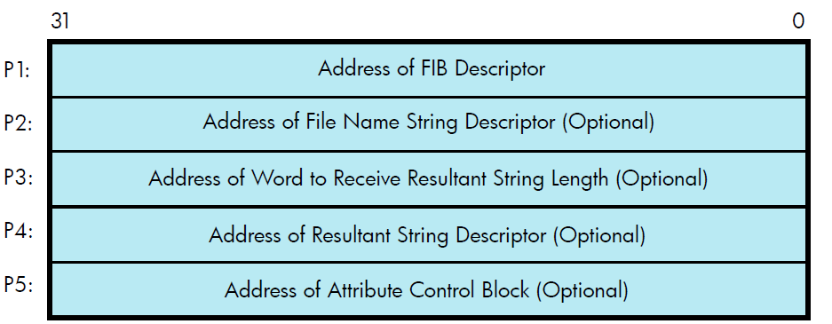
The fifth argument, P5, is an optional argument containing the address of the attribute control block. Section 1.3.5, ''Read/Write Attributes'' describes the attribute control block in detail.
All areas of memory specified by the descriptors must be capable of being read or written to.
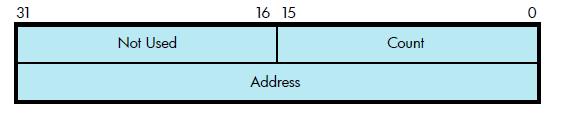
Figure 1.2, ''ACP Device/Function Argument Descriptor Format'' shows the format for the descriptors. The count field is the length in bytes of the item described.
Note
Starting with OpenVMS Version 8.4, volumes and files up to 2 TB in size are supported. This has an implication for the virtual and logical block numbers (VBN and LBN) and block counts referenced in structures such as the File Information Block (FIB) and in the I/O arguments in the call interfaces.
In the previous versions of OpenVMS, these fields are interpreted as SIGNED 32-bit integers. Bit 31, the 'signbit', is necessarily zero. Starting with OpenVMS Version 8.4, these fields are interpreted as UNSIGNED 32-bit integers. Bit 31 can now contain 1-bit, to accommodate block numbers and counts up to 4 million (4,294,967,296); 4 million blocks = 2 Terabytes (TB).
Applications and programs that continue to interpret these fields as SIGNED, apparently receive negative values for volume or file sizes between 1 TB and 2 TB. Ensure that the applications and programs are upgraded to avoid these errors.
The following are some of the fields that are now interpreted as UNSIGNED 32–bit integers:
FIB$L_EXVBN
FIB$L_MOV_SVBN
FIB$L_MOV_VBNCNT
FIB$L_LOC_ADDR
FAT$L_HIBLK
FAT$L_EFBLK
SBK$L_STLBN
SBK$L_FILESIZE
1.2. File Information Block (FIB)
The file information block (FIB) contains much of the information that is exchanged between the user process and the ACP. The FIB must be writable.
The FIB is passed by a descriptor (see Figure 1.2, ''ACP Device/Function Argument Descriptor Format''). A short FIB can be used in ACP calls that do not need arguments near the end of the FIB. The ACP treats the omitted portion of the FIB as if it were 0. Figure 1.3, ''Typical Short FIB'' shows the format of a typical short FIB that would be used to open an existing file.
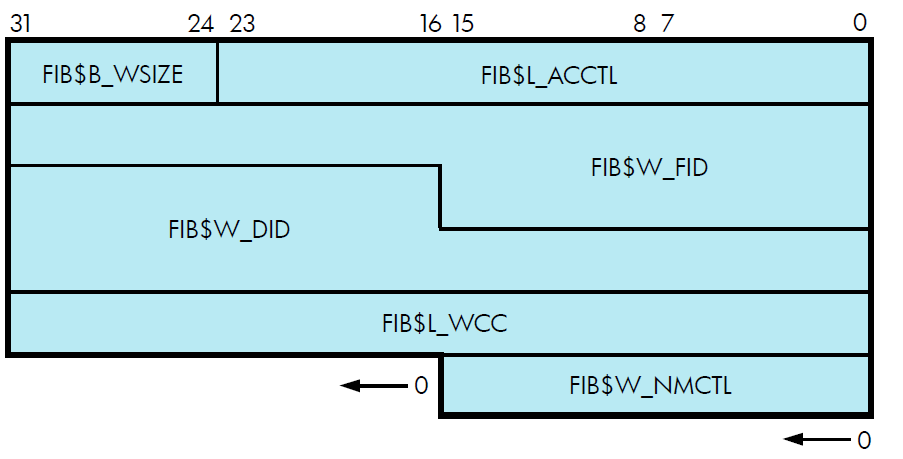
Table 1.1, ''Contents of the FIB'' gives a brief description of the FIB fields. More detailed descriptions are provided in Section 1.3, ''ACP Subfunctions'' and Section 1.6, ''Major Functions''.
| Field | Meaning | |
|---|---|---|
| FIB$L_ACCTL |
Contains flag bits that control the access to the file. Section 1.3.1.1, ''Input Parameters'', Section 1.3.2.1, ''Input Parameters'', Section 1.6.1.1, ''Input Parameters'', and Section 1.6.4.1, ''Input Parameters'' and Section 1.6.5, ''Delete File'' describe the FIB$L_ACCTL field flag bits. | |
| FIB$L_ACL_STATUS |
Status of the requested ACL attribute operation, if any. The ACL attributes are included in Table 1.7, ''ACP-QIO Attributes''. If no ACL attributes are given, SS$_NORMAL is returned here. | |
| FIB$L_ACLCTX |
Maintains position context when processing ACL attributes from the attribute (P5) list. | |
| FIB$B_ALALIGN | Contains the interpretation mode of the allocation (FIB$W_ALLOC) field. | |
| FIB$W_ALLOC |
Contains the desired physical location of the blocks being allocated. Interpretation of the field is controlled by the FIB$B_ALALIGN field. The following subfields are defined: | |
| Subfield | Meaning | |
| FIB$W_LOC_FID |
Three-word related file ID for RFI placement. | |
| FIB$W_LOC_NUM | Related file number. | |
| FIB$W_LOC_SEQ | Related file sequence number. | |
| FIB$B_LOC_RVN |
Related file relative volume number (RVN) or placement RVN. | |
| FIB$B_LOC_NMX | Related file number extension. | |
| FIB$L_LOC_ADDR | Placement logical block number (LBN), cylinder, or virtual block number (VBN). | |
| FIB$B_ALOPTS |
Contains option bits that control the placement of allocated blocks. Section 1.3.3.1, ''Input Parameters'' describes the FIB$B_ALOPTS field flag bits. | |
| FIB$L_ALT_ACCESS | A 32-bit mask that represents an access mask to check against file protection; for example, opens a file for read access and checks whether it can be deleted. The mask has the same configuration as the standard protection mask. | |
| FIB$W_CNTRLFUNC | In an IO$_ACPCONTROL function, this field contains the code that specifies which ACP control function is to be performed (see Section 1.6.8, ''ACP Control''). This field overlays FIB$W_EXCTL. | |
| FIB$L_CNTRLVAL |
Contains a control function value used in an IO$_ACPCONTROL function (see Section 1.6.8, ''ACP Control''). The interpretation of the value depends on the control function specified in FIB$W_CNTRLFUNC. This field overlays FIB$L_EXSZ. | |
| FIB$W_DID |
Contains the file identifier of the directory file. For Files-11 On-Disk Structure Level 1 and Level 2, the following subfields are defined: | |
| Subfield | Meaning | |
| FIB$W_DID_NUM | File number. | |
| FIB$W_DID_SEQ | File sequence number. | |
| FIB$W_DID_RVN | Relative volume number (only for magnetic tape devices). | |
| FIB$B_DID_RVN | Relative volume number (only for disk devices). | |
| FIB$B_DID_NMX | File number extension (only for disk devices). | |
| FIB$W_EXCTL | Contains flag bits that specify extend control for disk devices. Section 1.3.3.1, ''Input Parameters'' and Section 1.3.4.1, ''Input Parameters'' describe the FIB$W_EXCTL field flag bits. | |
| FIB$L_EXSZ | Specifies the number of blocks to be allocated in an extend operation on a disk file. | |
| FIB$L_EXVBN | Specifies the starting disk file virtual block number at which a file is to be truncated. | |
| FIB$W_FID |
Specifies the file identification. You supply the file identifier when it is known; the ACP returns the file identifier when it becomes known; for example, as a result of a create or directory lookup. A 0 file identifier can be specified when an operation is performed on a file that is already open on a particular channel. The ACP returns the file identifier of the open file. For Files-11 On-Disk Structure Level 1 and Level 2, the following subfields are defined: | |
| Subfields | Meaning | |
| FIB$W_FID_NUM | File number. | |
| FIB$W_FID_SEQ | File sequence number. | |
| FIB$W_FID_RVN | Relative volume number (only for magnetic tape devices). | |
| FIB$B_FID_RVN | Relative volume number (only for disk devices). | |
| FIB$B_FID_NMX | File number extension (only for disk devices). | |
| FIB$W_FID_DIRNUM | Directory number of the file identifier. This is the path table record number of the directory that describes the file. | |
| FIB$L_FID_RECNUM | Record number of the first directory record for the file within the current directory. | |
| FIB$B_NAME_FORMAT_IN | Contains the format of the input file specification. Section 1.3.1.1, ''Input Parameters'' describes the FIB$B_NAME_FORMAT_IN field flagbits. | |
| FIB$B_NAME_FORMAT_OUT |
Contains the format of the output file specification. Section 1.3.1.1, ''Input Parameters'' describes the FIB$B_NAME_FORMAT_OUT field flag bits. | |
| FIB$W_NMCTL |
Contains flag bits that control the processing of a name string in a directory operation. Section 1.3.1.1, ''Input Parameters'' and Section 1.6.1.1, ''Input Parameters'' describe the FIB$W_NMCTL field flag bits. | |
| FIB$L_STATUS | Access status. Applies to all major functions. The following bits are supported: | |
| Subfields | Meaning | |
| FIB$V_ALT_REQ | Set to indicate whether the alternate access bit is required for the current operation. If not set, the alternate access bit is optional. | |
| FIB$V_ALT_GRANTED |
If FIB$V_ALT_REQ = 0, the FIB bit returned from the file system is set if the alternate access check succeeded. Programmers can control the security information being propagated as well as the source of this information by setting the following bits (which apply only to the IO$_CREATE and IO$_MODIFY functions). | |
| FIB$V_DIRACL | Propagate the ACL from the parent directory to the file, assuming the file is a directory file. | |
|
FIB$V_ | Set to indicate that propagation may not occur from a previous version of the file. | |
| FIB$V_ALIAS_ENTRY | Set on any file system operation where the directory backlink in the file header is different (and nonzero) from the directory id specified in the FIB. | |
| FIB$V_NOCOPYACL | Set to indicate that the ACL should not be propagated from the parent directory (or a previous version of the file) to the file. | |
|
FIB$V_ | Set to indicate that the owner UIC should not be propagated from the parent directory (or a previous version of the file) to the file. | |
| FIB$V_NOCOPYPROT | Set to indicate that the UIC-based protection should not be propagated from the parent directory (or a previous version of the file) to the file. | |
| FIB$V_PROPAGATE | Propagate attributes from the parent directory (or previous version of the file). If you set the FIB$V_NOCOPYACL, FIB$V_NOCOPYOWNER, or FIB$V_NOCOPYPROT bits, you must also set FIB$V_PROPAGATE or a SS$_BADPARAM error results. | |
| FIB$W_VERLIMIT | Contains the version limit of the directory entry. | |
| FIB$L_WCC | Maintains position context when processing wildcard directory operations. | |
| FIB$B_WSIZE | Controls the size of the file window used to map a disk file. If a window size of 255 is specified, the file is completely mapped by using segmented windows. | |
1.3. ACP Subfunctions
The operations that the ACP performs can be organized into two categories: major ACP functions and subfunctions. Each ACP operation performs one major function. That function is specified by an I/O function code, such as IO$_ACCESS, IO$_CREATE, or IO$_MODIFY. While executing the major function, one or more subfunctions can be performed. A subfunction is an operation such as looking up, accessing, or extending a file. Most subfunctions can be executed by more than one of the major functions. Sections 1.3.1 through 1.3.5 describe the following subfunctions in detail:
Directory Lookup
Access
Extend
Truncate
Read/Write Attributes
Section 1.6, ''Major Functions'', which contains the descriptions of the major functions, lists the subfunctions available to each major function.
1.3.1. Directory Lookup
The directory lookup subfunction is used to search for a file in a disk directory or on a magnetic tape. This subfunction can be invoked using the major functions IO$_ACCESS, IO$_MODIFY, IO$_DELETE, and IO$_ACPCONTROL. A directory lookup occurs if the directory file ID field in the FIB (FIB$W_DID) is a nonzero number.
1.3.1.1. Input Parameters
Table 1.2, ''FIB Fields (Lookup Control)'' lists the FIB fields that control the processing of a lookup subfunction.
| Field | Subfields | Meaning |
|---|---|---|
| FIB$W_NMCTL | Name string control. The following name control bits are applicable to a lookup operation: | |
| FIB$V_ALLNAM | Set to match all name field values. | |
| FIB$V_ALLTYP | Set to match all field type values. | |
| FIB$V_ALLVER | Set to match all version field values. | |
|
FIB$V_CASE_ | When set, performs case-sensitive lookup; when clear, performs case-blind lookup. | |
| FIB$V_FINDFID | Set to search a directory for the file ID in FIB$W_FID. | |
| FIB$V_NAMES_8BIT | Caller can accept (8-bit) ODS-2 or ISO Latin-1 formats. | |
| FIB$V_NAMES_16BIT | Caller can accept (16-bit) Unicode (UCS-2) formats. | |
| FIB$V_WILD | Set if name string contains wildcards. Setting this bit causes wildcard context to be returned in FIB$L_WCC. | |
| FIB$W_FID | File identification. The file ID of the file found is returned in this field. | |
| FIB$W_DID | Contains the file identifier of the directory file. This field must be a nonzero number. | |
| FIB$L_WCC | Maintains position context when processing wildcard directory operations. | |
| FIB$L_ACCTL |
The following access control flag is applicable to a lookup subfunction: | |
| FIB$V_REWIND | Set to rewind magnetic tape before lookup. If not set, a magnetic tape is searched from its current position. | |
| FIB$B_NAME_FORMAT_IN | Contains the format of the input file specification. The following formats are valid: | |
| FIB$C_ODS2 | ODS-2 Format (default) | |
| FIB$C_ISO_LATIN | ISO Latin-1 Format | |
| FIB$C_UCS2 | Unicode (UCS-2) Format | |
|
FIB$B_NAME_FORMAT_ | Contains the format of the output file specification. The following formats are valid: | |
| FIB$C_ODS2 | ODS-2 Format (default) | |
| FIB$C_ISO_LATIN | ISO Latin-1 Format | |
| FIB$C_UCS2 | Unicode (UCS-2) Format |
QIO arguments P2 through P5 (see Figure 1.1, ''ACP Device- or Function-DependentArguments'') are passed as values. The second argument, P2, specifies the address of the descriptor for the file name string to be searched for in the directory.
name.type;version name.type.version
The name and type can be any combination of alphanumeric characters, and the dollar sign ($), asterisk (*), and percent (%) characters. The version must consist of numeric characters optionally preceded by a minus sign (-) (only for disk devices) or a single asterisk. The total number of alphanumeric and percent characters in the name field and in the type field must not exceed 39. Any number of additional asterisks can be present.
If any of the bits FIB$V_ALLNAM, FIB$V_ALLTYP, and FIB$V_ALLVER are set, then the contents of the corresponding field in the name string are ignored and the contents are assumed to be an asterisk.
Note that the file name string cannot contain a directory string. The directory is specified by the FIB$W_DID field (see Table 1.1, ''Contents of the FIB''). Only RMS can process directory strings.
Argument P3 is the address of a word to receive the resultant file name string length. Argument P4 is the address of a descriptor for a buffer to receive the resultant file name string. The resultant string is not padded. The P3 and P4 arguments are optional.
The name and type can be any combination of alphanumeric characters, and the dollar sign ($), asterisk (*), and percent (%) characters. The version must consist of numeric characters optionally preceded by a minus sign (-) (only for disk devices) or a single asterisk. The total number of alphanumeric and percent characters in the name field and in the type field must not exceed 39. Any number of additional asterisks can be present.
If any of the bits FIB$V_ALLNAM, FIB$V_ALLTYP, and FIB$V_ALLVER are set, then the contents of the corresponding field in the name string are ignored and the contents are assumed to be an asterisk.
Note that the file name string cannot contain a directory string. The directory is specified by the FIB$W_DID field (see Table 1.2, ''FIB Fields (Lookup Control)''). Only RMS can process directory strings.
Argument P3 is the address of a word to receive the resultant file name string length. Argument P4 is the address of a descriptor for a buffer to receive the resultant file name string. The resultant string is not padded. The P3 and P4 arguments are optional.
1.3.1.2. Operation
The system searches either the directory file specified by FIB$W_DID or the magnetic tape for the file name specified in the P2 file name parameter. The actual file name found and its length are returned in the P3 and P4 length and result string buffers. The file ID of the file found is returned in FIB$W_FID and can be used in subsequent operations as the major function is processed.
Zero and negative version numbers have special significance in a disk lookup operation. Specifying 0 as a version number causes the latest version of the file to be found. Specifying -1 locates the second most recent version, -2 the third most recent, and so forth. Specifying a version of -0 locates the lowest numbered version of the file. For magnetic tape lookups, a version number of 0 locates the first occurrence of the file encountered; negative version numbers are not allowed.
Wildcard lookups are performed by specifying the appropriate wildcard characters in the name string and setting FIB$V_WILD. (The name control bits FIB$V_ALLNAM, FIB$V_ALLTYP, and FIB$V_ALLVER can also be used in searching for wildcard entries, but they are intended primarily for compatibility mode use.) On the first lookup, FIB$L_WCC should contain zero entries. On each lookup, the ACP returns a nonzero value in FIB$L_WCC, which must be passed back on the next lookup call. In addition, you must pass the resultant name string returned by the previous lookup using the P4 result string buffer, and its length in the P3 result length word. This string is used together with FIB$L_WCC to continue the wildcard search at the correct position in the directory.
To perform a lookup by file ID, set the name control bit FIB$V_FINDFID. When this bit is set, the system searches the directory for an entry containing the file ID specified in FIB$W_FID, and the name of the entry found is returned in the P3 and P4 result parameters. Note that if a directory contains multiple entries with the same file ID, only the first entry can be located with this technique.
Lookups by file ID should be done only when the file name is not available, because lookups by this method are often significantly slower than lookups by file name.
Because not all programs can handle all of the available name formats, the FIB$W_NMCTL flags govern the name formats, and are returned as follows:
FIB$V_ NAMES_8BIT clear
FIB$V_ NAMES_16BIT clear
Only ODS-2 format names are returned. Note that this includes specifications that were originally in ISO Latin-1 format or Unicode (UCS-2) format but converted to ODS-2 format before being stored on the volume. All specifications are converted to uppercase before being returned.
FIB$V_ NAMES_8BIT set
FIB$V_ NAMES_16BIT clear
Only those file specifications stored in ODS-2 and ISO Latin-1 formats are returned. The value in the FIB$B_NAME_FORMAT_OUT field indicates the format of the particular name being returned. ODS-2 format file specifications are not converted to uppercase before being returned.
FIB$V_ NAMES_8BIT clear
FIB$V_ NAMES_16BIT set
All file specifications are returned in Unicode (UCS-2) format.
FIB$V_ NAMES_8BIT set
FIB$V_ NAMES_16BIT set
File specifications are returned in the format stored on the volume. This is the simplest format compatible with the file name syntax and the characters it contains. For example, a specification originally in Unicode format that only contains characters that are part of the ISO Latin-1 character set are returned in ISO Latin-1 format.
1.3.1.3. Directory Entry Protection
A directory entry is protected with the same protection code as the file itself. For example, if a directory file is protected against delete access, then the file name has the same protection. Consequently, a nonprivileged user (that is, a user who is not the volume owner, or a user who does not have SYSPRV) cannot rename a file because renaming a file is essentially the same as deleting the file name. This protection is applied regardless of the protection on the directory file.
Nonprivileged users can neither write directly into a .DIR;1 directory file nor turn off the directory bit in a directory file header.
1.3.2. Access
The access subfunction is used to open a file so that virtual read or write operations can be performed. This subfunction can be invoked using the major functions IO$_CREATE and IO$_ACCESS (see Section 1.6.1, ''Create File'' and Section 1.6.2, ''Access File''). An access subfunction is performed if the IO$M_ACCESS modifier is specified in the I/O function code.
1.3.2.1. Input Parameters
Table 1.3, ''FIB Fields (Access Control)''lists the FIB fields that control the processing of an access subfunction.
| Field | Subfields | Meaning |
|---|---|---|
| FIB$L_ACCTL | Specifies field values that control access to the file. The following access control bits are applicable to the access subfunction: | |
| FIB$V_WRITE | Set for write access; clear for read-only access. | |
| FIB$V_NOREAD |
Set to deny read access to others. (You must have write privilege to the file to use this option.) | |
| FIB$V_NOWRITE | Set to deny write access to others. | |
| FIB$V_NOTRUNC |
Set to prevent the file from being truncated; clear to allow truncation. | |
| FIB$V_CONTROL | Set for control access. If this bit is set, you cannot access the file if you do not have control access. | |
|
FIB$V_NO_READ_ | Set to deny read access to the file. | |
| FIB$V_DLOCK | Set to enable deaccess lock (close check). Used only for disk devices. | |
| FIB$V_UPDATE | Set to position at the start of a magnetic tape file when opening a file for write; clear to position at end-of-file. | |
| FIB$V_READCK | Set to enable read checking of the file. Virtual reads to the file are performed using a data check operation. | |
| FIB$V_WRITECK | Set to enable write checking of the file. Virtual writes to the file are performed using a data check operation. | |
| FIB$V_EXECUTE | Set to access the file in execute mode. The protection check is made against the EXECUTE bit instead of the READ bit. Valid only for requests issued from SUPERVISOR, EXEC, or KERNEL mode. | |
|
FIB$V_NOLOCK |
Set to override exclusive access to the file, allowing you to access the file when another user has the file open with FIB$V_NOREAD specified. You must have SYSPRV privilege to use this option. FIB$V_NOREAD and FIB$V_NOWRITE must be clear for this option to work. You must have either SYSPRV privilege or control access to use this option. In VSI OpenVMS x86-64 V9.2 and later,
FIB$V_NOLOCK is only allowed on
a read-only access. This means that the
FIB$V_WRITE flag must be clear
(along with the FIB$V_NOREAD and
FIB$V_NOWRITE flags).
Attempting to access a file with both
FIB$V_NOLOCK set and
FIB$V_WRITE set will result in
a | |
| FIB$V_NORECORD | Set to inhibit recording of the file's modification and expiration dates. If not set, the file's expiration date can be modified, depending on the file retention parameters of the volume. | |
| FIB$V_SEQONLY | Set to inform the file system that the file is to be processed sequentially only. | |
| FIB$B_WSIZE | Controls the size of the file window used to map a disk file. The ACP uses the volume default if FIB$B_WSIZE is 0. A value of 1 to 127 indicates the number of retrieval pointers to be allocated to the window. A value of -1 indicates that the window should be as large as necessary to map the entire file. Note that the window is charged to the user's BYTELIM quota. | |
| FIB$W_FID | Specifies the file identification of the file to be accessed. |
1.3.2.2. Operation
The file is opened according to the access control specified (see Table 1.3, ''FIB Fields (Access Control)'').
1.3.3. Extend
The extend subfunction is used to allocate space to a disk file. This subfunction can be invoked using the major I/O functions IO$_CREATE and IO$_MODIFY (see Section 1.6.1, ''Create File'' and Section 1.6.4, ''Modify File''). The extend subfunction is performed if the bit FIB$V_EXTEND is set in the extend control word FIB$W_EXCTL.
1.3.3.1. Input Parameters
Table 1.4, ''FIB Fields (Extend Control)'' lists the FIB fields that control the processing of an extend subfunction.
| Field | Subfields | Meaning |
|---|---|---|
| FIB$W_EXCTL | Extend control flags. The following flags are applicable to the extend subfunction: | |
| FIB$V_EXTEND | Set to enable extension. | |
| FIB$V_NOHDREXT | Set to inhibit generation of extension file headers. | |
| FIB$V_ALCON |
Allocates the maximum amount of contiguous space. If both FIB$V_ALCON and FIB$V_ALCONB are set, a single contiguous area, whose size is the largest available but not greater than the size requested, is allocated. | |
| FIB$V_FILCON | Marks the file as contiguous. This bit can only be set if the file does not have space already allocated to it. | |
| FIB$V_ALDEF | Allocates the extend size (FIB$L_EXSZ) or the system default, whichever is greater. | |
| FIB$L_EXSZ |
Specifies the number of blocks to allocate to the file. The number of blocks actually allocated for this operation is returned in this longword. More blocks than requested can be allocated to meet cluster boundaries. | |
| FIB$L_EXVBN | Returns the starting virtual block number of the blocks allocated. FIB$L_EXVBN must initially contain 0 blocks. | |
| FIB$B_ALOPTS | Contains option bits that control the placement of allocated blocks. The following bits are defined: | |
| FIB$V_EXACT | Set to require exact placement; clear to specify approximate placement. If this bit is set and the specified blocks are not available, the extend operation fails. | |
| FIB$V_ONCYL | Set to locate allocated space within a cylinder. This option functions correctly only when FIB$V_ALCON or FIB$V_ALCONB is specified. | |
| FIB$B_ALALIGN | Contains the interpretation mode of the allocation (FIB$W_ALLOC) field. One of the following values can be specified: | |
| (zero) | No placement data. The remainder of the allocation field is ignored. | |
| FIB$C_CYL | Location is specified as a byte relative volume number (RVN) in FIB$B_LOC_RVN and a cylinder number in FIB$L_LOC_ADDR. | |
| FIB$C_LBN | Location is specified as a byte RVN in FIB$B_LOC_RVN, followed by a longword logical block number (LBN) in FIB$L_LOC_ADDR. | |
| FIB$C_VBN | Location is specified as a longword virtual block number (VBN) of the file being extended in FIB$L_LOC_ADDR. A 0 VBN or one that fails to map indicates the end of the file. | |
| FIB$C_RFI | Location is specified as a three-word file ID in FIB$W_LOC_FID, followed by a longword VBN of that file in FIB$L_LOC_ADDR. A 0 file ID indicates the file being extended. A 0 VBN or one that fails to map indicates the end of that file. | |
| FIB$W_ALLOC | Contains the desired physical location of the blocks being allocated. Interpretation of the field is controlled by the FIB$B_ALALIGN field. The following subfields are defined: | |
| FIB$W_LOC_FID | Three-word related file ID for RFI placement. | |
| FIB$W_LOC_NUM | Related file number. | |
| FIB$W_LOC_SEQ | Related file sequence number. | |
| FIB$B_LOC_RVN | Related file RVN or placement RVN. | |
| FIB$B_LOC_NMX | Related file number extension. | |
| FIB$L_LOC_ADDR | Placement LBN, cylinder, or VBN. |
1.3.3.2. Operation
The specified number of blocks are allocated and appended to the file. The virtual block number assigned to the first block allocated is returned in FIB$L_EXVBN. The actual number of blocks allocated is returned in FIB$L_EXSZ.
The actual number of blocks allocated is also returned in the second longword of the user's I/O status block. If a contiguous allocation (FIB$V_ALCON) fails, the size of the largest contiguous space available on the disk is returned in the second longword of the user's I/O status block.
1.3.4. Truncate
The truncate subfunction is used to remove space from a disk file. This subfunction can be invoked by the major I/O functions IO$_DEACCESS and IO$_MODIFY (see Section 1.6.3, ''Deaccess File'' and Section 1.6.4, ''Modify File''). The truncate subfunction is performed if the bit FIB$V_TRUNC is set in the extend control word FIB$W_EXCTL.
1.3.4.1. Input Parameters
Table 1.5, ''FIB Fields (Truncate Control)'' lists the FIB fields that control the processing of a truncate subfunction.
| Field | Subfields | Meaning |
|---|---|---|
| FIB$W_EXCTL | Extend control flags. The following flags are applicable to the truncate subfunction: | |
| FIB$V_TRUNC | Must be set to enable truncation. | |
| FIB$V_MARKBAD | Set to append the truncated blocks to the bad block file, instead of returning them to the free storage pool. Only one cluster can be deallocated. This is most easily accomplished by specifying the last VBN of the file in FIB$L_EXVBN. SYSPRV privilege or ownership of the volume is required to deallocate blocks to the bad block file. | |
| FIB$L_EXSZ | Returns the actual number of blocks deallocated. FIB$L_EXSZ must initially contain a value of 0. | |
| FIB$L_EXVBN | Specifies the first virtual block number to be removed from the file. The actual starting virtual block number of the truncate operation is returned in this field. |
1.3.4.2. Operation
Blocks are deallocated from the file, starting with the virtual block specified in FIB$L_EXVBN and continuing through the end of the file. The actual number of blocks deallocated is returned in FIB$L_EXSZ. The virtual block number of the first block actually deallocated is returned in FIB$L_EXVBN. Because of cluster round-up, this value might be greater than the value specified. If FIB$V_MARKBAD is specified, the truncation VBN is rounded down instead of up, and the value returned in FIB$L_EXVBN might be less than that specified.
The number of blocks by which FIB$L_EXVBN was rounded up is returned in the second longword of the I/O status block.
The truncate subfunction normally requires exclusive access to the file at run time. This means, for example, that a file cannot be truncated while multiple writers have access to it.
An exception occurs when a truncate subfunction is requested for a write-accessed file that allows other readers. Although the truncate subfunction returns success status in this instance, the actual file truncation (the return of the truncated blocks to free storage) is deferred until the last reader deaccesses the file. If a new writer accesses the file after the truncate subfunction is requested, but before the last deaccess, the deferred truncation is ignored.
Once the truncate operation has started, the file is locked from other writers for the duration of the truncate operation. Attempts to access the file for shared write access during this time results in an SS$_ACCONFLICT error.
1.3.5. Read/Write Attributes
The read and write attributes subfunctions are used for operations such as reading and writing file protection and creating and revising dates. A read or write attributes operation is invoked by specifying an attribute list with the QIO parameter P5. A read attributes operation can be invoked by the major I/O function IO$_ACCESS (see Section 1.6.2, ''Access File''); a write attributes operation can be invoked by the major I/O functions IO$_CREATE, IO$_DEACCESS, and IO$_MODIFY (see Section 1.6.1, ''Create File'', Section 1.6.3, ''Deaccess File'', and Section 1.6.4, ''Modify File'').
1.3.5.1. Input Parameters
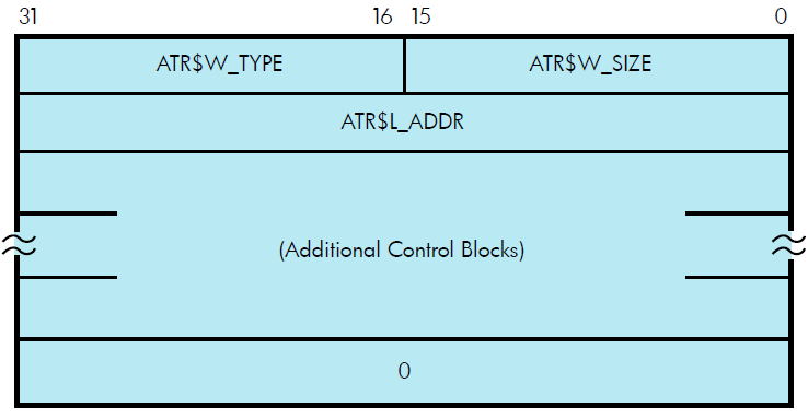
The read or write attributes subfunction is controlled by the attribute list specified by P5. The list consists of a variable number of two longword control blocks, terminated by a 0 longword, as shown in Figure 1.4, ''Attribute Control Block Format''.The maximum number of attribute control blocks in one list is 30. Table 1.6, ''Attribute Control Block Fields'' describes the attribute control block fields.
| Field | Meaning |
|---|---|
| ATR$W_SIZE | Specifies the number of bytes of the attribute to be written, or the size of the buffer into which the attribute is to be read. Legal values for writing attributes are from 0 to the maximum size of the particular attribute (see Table 1.7, ''ACP-QIO Attributes''), and legal values for the reading attributes are from 0 to the maximum unsigned 16-bit integer. |
| ATR$W_TYPE | Identifies the individual attribute to be read or written. |
| ATR$L_ADDR | Contains the buffer address of the memory space to or from which the attribute is to be transferred. The attribute buffer must be writable. |
Table 1.7, ''ACP-QIO Attributes'' lists the valid attributes for ACP-QIO functions. The maximum size (in bytes) is determined by the required attribute configuration. For example, the Radix-50 file name (ATR$S_FILNAM) uses only 6 bytes, but it is always accompanied by the file type and file version, so a total of 10 bytes is required. Each attribute has two names: one for the code (for example, ATR$C_UCHAR) and one for the size (for example, ATR$S_UCHAR).
| Attribute Name? | Maximum Size (bytes) | Meaning |
|---|---|---|
| ATR$C_ACCDATE? | 8 | Corresponds to POSIX st_atime and reflects the last time a file was accessed. |
| ATR$C_ACCESS_MODE | 1 | Access mode for following attribute descriptors. |
| ATR$C_ACLEVEL? ? ? ? | 1 | File access level. |
| ATR$C_ACLLENGTH? ? | 4 | Returns the size, in bytes, of the object's ACL. |
| ATR$C_ADDACLENT? ? ? | 255 | Adds an ACE to the beginning of the ACL when the ACE context value is 0; to the end of the ACL when the ACE context value is -1; or at a location pointed to by a prior ATR$C_FNDACETYP or ATR$C_FNDACLENT. |
| ATR$C_ALCONTROL | 14 | Compatibility mode allocation data. |
| ATR$C_ASCDATES? ? | 35 | Revision count (2 binary bytes), revision date, creation date, and expiration date, in ASCII. Format: DDMMMYY (revision date), HHMMSS (time), DDMMMYY (creation date), HHMMSS (time), DDMMMYY (expiration date). (The format contains no embedded spaces or commas.) |
| ATR$C_ASCNAME |
252 (ODS-5) 86 (ODS-2) |
File name, type, and version, in ASCII, including punctuation. Format: name.type;version. Magnetic tape: contains 17-character file identifier (ANSI a); no version number. Overrides all other file name and file type specifications if supplied on input operations. If specified on an access operation and you want only a value to be returned, specify (in ATR$W_SIZE) a buffer of greater than 17 bytes. See Section 1.3.5.2, ''Attribute Descriptions'' for additional information. |
| ATR$C_ATTDATE? | 8 | Corresponds to POSIX st_ctime and reflects the last time a file attribute was modified. |
| ATR$C_BACKLINK? | 6 | File back link pointer. |
| ATR$C_BAKDATE? ? ? ? | 8 | 64-bit backup date and time. |
| ATR$C_BLOCKSIZE | 2 | Magnetic tape block size. |
| ATR$C_BUFFER_OFFSET? | 2 | Offset length for ANSI magnetic tape header label buffer. |
| ATR$C_CREDATE | 8 | 64-bit creation date and time. |
| ATR$C_DELACLENT? ? ? | 255 | Deletes an access control entry pointed to by the buffer address or, if the buffer address is 0, the ACE pointed to by a prior ATR$C_FNDACETYP or ATR$C_FNDACLENT. |
| ATR$C_DELETE_ALL? ? ? | 255 | Delete the entire ACL, including protected entries. |
| ATR$C_DELETEACL? ? ? | 255 | Deletes the entire ACL with the exception of protected ACEs. |
| ATR$C_DIRSEQ? | 2 | Directory update sequence count. |
| ATR$C_ENDLBLAST | 4 | End of magnetic tape label processing; provides AST control block. |
| ATR$C_EXPDAT? | 7 | Expiration date in ASCII. Format: DDMMMYY. |
| ATR$C_EXPDATE? | 8 | 64-bit expiration date and time. |
| ATR$C_FILE_SPEC? |
4098 (ODS-5) 512 (ODS-2) | Convert FID to file specification. See Section 1.3.5.2, ''Attribute Descriptions'' for additional information. |
| ATR$C_FILNAM | 10 | 6-byte Radix-50 file name plus ATR$C_FILTYP and ATR$C_FILVER. See Section 1.3.5.2, ''Attribute Descriptions'' for additional information. |
| ATR$C_FILTYP | 4 | 2-byte Radix-50 file type plus ATR$C_FILVER. See Section 1.3.5.2, ''Attribute Descriptions'' for additional information. |
| ATR$C_FILVER | 2 | 2-byte binary version number. See Section 1.3.5.2, ''Attribute Descriptions'' for additional information. |
| ATR$C_FNDACLENT? ? | 255 | Locates an ACE pointed to by its buffer address. |
| ATR$C_FNDACETYP? ? | 255 | Locates an ACE of the type pointed to by its buffer address. |
| ATR$C_FPRO? ? | 2 | File protection. |
| ATR$C_GRANT_ACE? ? | 255 | Return an ACE that grants or denies access to the object. |
| ATR$C_HDR1_ACC | 1 | ANSI magnetic tape header label accessibility character. |
| ATR$C_HEADER | 512 | Complete file header. This attribute is read only. |
| ATR$C_HIGHWATER? | 4 | High-water mark (user read-only). |
| ATR$C_JOURNAL? | 1 | Journal control flags. |
| ATR$C_LINKCOUNT | 2 | Count of hardlinks. |
| 255 | ACE used to gain access (if any). This attribute can only be retrieved on the initial file access or create operation. | |
| ATR$C_MODACLENT? ? ? | 255 | Replaces the ACE pointed to by a prior ATR$C_FNDACETYP or ATR$C_FNDACLENT with the ACE pointed to by its buffer address. |
| ATR$C_MODDATE? | 8 | Corresponds to POSIX st_mtime and reflects the last time data was modified. |
| ATR$C_NEXT_ACE? ? | 4 | Advance to the next ACE in the ACL. |
| ATR$C_PRIVS_USED? | 4 | Privileges used to gain access. This attribute can only be retrieved on the initial file access or create operation. |
| ATR$C_READACE? ? | 255 | Reads the ACE pointed to by ATR$C_FNDACETYP or ATR$C_FNDACLENT into the buffer. |
| ATR$C_READACL? ? | 512 | Reads the entire ACL or as much as will fit in the supplied buffer. Only complete ACEs are transferred. |
| ATR$C_RECATTR? | 32 | Record attribute area. Section 1.4, ''ACP-QIO Record Attributes Area'' describes the record attribute area in detail. |
| ATR$C_RESERVED? | 380 | Modifies the reserve area. |
| ATR$C_REVDATE? ? | 8 | 64-bit revision date and time. |
| ATR$C_RPRO? | 2 | 2-byte record protection. |
| ATR$C_SEMASK? | 8 | File security mask and limit. |
| ATR$C_STATBLK | 32 | Statistics block. This attribute is read only. Section 1.5, ''ACP-QIO Attributes Statistics Block'' describes the statistics block in detail. |
| ATR$C_UCHAR? ? | 4 | 4-byte file characteristics. (The file characteristics bits are listed following this table.) |
| ATR$C_USERLABEL | 80 | User file label. This attribute is not supported for disk devices. |
| ATR$C_UIC? | 4 | 4-byte file owner UIC. |
| ATR$C_UIC_RO | 4 | 4-byte file owner UIC. This attribute is read only. |
Table 1.8, ''File Characteristics Bits'' lists the bits contained in the file characteristics longword, which is read with the ATR$C_UCHAR attribute.
| Bits | Meaning |
|---|---|
| FCH$M_NOBACKUP | Do not back up file. |
| FCH$M_READCHECK | Verify all read operations. |
| FCH$M_WRITCHECK | Verify all write operations. |
| FCH$M_CONTIGB | Keep file as contiguous as possible. |
| FCH$M_LOCKED | File is deaccess-locked. |
| FCH$M_CONTIG | File is contiguous. |
| FCH$M_BADACL | File's ACL is corrupt. |
| FCH$M_SPOOL | File is an intermediate spool file. |
| FCH$M_DIRECTORY | File is a directory. |
| FCH$M_BADBLOCK | File contains bad blocks. |
| FCH$M_MARKDEL | File is marked for deletion. |
| FCH$M_ERASE | Erase file contents before deletion. |
| FCH$M_ASSOCIATED? | File has an associated file. |
| FCH$M_EXISTENCE? | Suppress existence of file. |
| FCH$M_NOMOVE | Disable move file operations on this file. |
| FCH$M_NOSHELVABLE | File is not shelvable. |
| FCH$M_SHELVED | File is shelved. |
1.3.5.2. Attribute Descriptions
ATR$C_ASCNAME
ATR$C_FILE_SPEC
ATR$C_FILNAM
ATR$C_FILTYP
ATR$C_FILVER
ATR$C_ASCNAME
The ATR$C_ASCNAME attribute allows the file specification stored in a file's primary file header to be read and written.
Reading the ATR$C_ASCNAME Attribute
ForODS-5 volumes, the file specification is returned in the supplied buffer, and the name format is returned in the FIB$B_ASCNAME_FORMAT cell.
The format in which the name is returned is controlled by the settings of the FIB$V_NAMES_8BIT and FIB$V_NAMES_16BIT flags in the same way as the output file specification parameter. A pseudo name can be returned in place of the actual file specification if the format is not one of those the calling program can accept.
Unlike the output file specification parameter, the length of a file specification contained in the ASCNAME attribute is not passed back explicitly. To determine the length of the file specification, the calling program must search the attribute buffer for the first occurrence of the padding character. If neither the FIB$V_NAMES_8BIT nor the FIB$V_NAMES_16BIT flag is set, the buffer is padded with space (note that only ODS-2 format names are returned in this case). If one or more of the flags are set, the attribute buffer is padded with zeros.
Note
The file system does not enforce a minimum length on the attribute buffer. If the file specification is longer than the attribute buffer, the value returned is truncated without signaling an error or warning.
In contrast, the file system does enforce a maximum size for the attribute buffer. Supplying a larger buffer returns a BADPARAM error.
Writing the ATR$C_ASCNAME Attribute
The ASCNAME attribute can only be written for files on ODS-2 or ODS-5 volumes provided that the FIB$V_NAMES_8BIT and FIB$V_NAMES_16BIT flags are clear.
The ability to write this attribute is only intended to provide compatibility with existing applications that do so. New and modified programs should not write this attribute. Changing its value can prevent a file from being permanently deleted.
In those cases where it is legal to write the attribute, the contents of the attribute buffer (up to 252 bytes) are copied to the file name field in the file header. For ODS-5 headers, the format is set to ODS-2, and the file name length is set to the offset of the first space character. This can be 252 bytes or the length of the supplied buffer, whichever is the least.
ATR$C_FILE_SPEC
DDnn:[DIR1.DIR2_DIRn]name.type;1
The file name returned is that from the file header, which may be different from that in the directory. The specification may be incomplete if any errors are encountered while reading the file headers of any of the directories in the path.
For files on ODS-5 volumes, the path may contain file names that are in any of the three name formats. This creates a number of problems; for instance, the presence of periods in a directory name could return an ambiguous path specification. To avoid this and other problems, the file system makes use of services provided by RMS to translate the file specification and the components of the path to their escaped form.
If the escaped form of the path is longer than can be accommodated by the buffer for the attribute, one or more directories in the path may be replaced by the DID of the rightmost of those replaced. This process is identical to that performed by RMS.
However, if the file specification, even after DID abbreviation, is longer than can be accommodated by the buffer, the file name is truncated. The file specification string returned to the user buffer has a 2-byte count prefix. The count contains the number of bytes for the untruncated file specification. If the count is greater than the size of the user buffer (minus the two bytes that contain the count), the user can conclude that the returned file specification has been truncated.
ATR$C_FILNAM, ATR$C_FILTYP, and ATR$C_FILVER
The first two of these attributes allow the file name and file type to be read and written using Radix-50 encoding. This encoding scheme enables 3 characters to be packed into a 16-bit word. Only 38 characters in the ODS-2 format set are valid for Radix-50 names, with the exceptions being dash (-) and underscore (_).
File name: 15 characters (10 bytes)
File type: 6 characters (4 bytes)
As a result of the additional character and length restrictions, only a subset of legal ODS-2 file names is can be expressed in the Radix-50 encoding.
The file system only attempts to read or write the three attributes if the format of the existing file name in the file header is ODS-2. If this is not the case, a NORAD50 error will be returned. If the existing file name is in ODS-2 format, but is incompatible with the Radix-50 encoding or the length limits on Radix-50 file names, a BADFILENAME error will be returned.
The ATR$C_FILVER attribute allows the file version number in the file header to be read or written as a 2-byte integer. As the process requires the existing file name to be converted into a Radix-50 file name, the previous restriction also applies to this attribute.
1.4. ACP-QIO Record Attributes Area
Figure 1.5, ''ACP-QIO Record Attributes Area'' shows the format of the record attributes area.
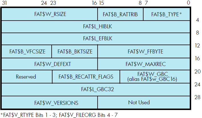
Table 1.9, ''ACP Record Attributes Values'' lists the record attributes values and their meanings.
| Field Value | Meaning | |
|---|---|---|
| FAT$B_TYPE | Record type. Contains FAT$V_RTYPE and FAT$V_FILEORG. | |
| FAT$V_RTYPE | Record type. The following bit values are defined: | |
| FAT$C_FIXED | Fixed-length record | |
| FAT$C_VARIABLE | Variable-length record | |
| FAT$C_VFC | Variable-length record with fixed control | |
| FAT$C_UNDEFINED | Undefined record format (stream binary) | |
| FAT$C_STREAM | RMS stream format | |
| FAT$C_STREAMLF | Stream terminated by LF | |
| FAT$C_STREAMCR | Stream terminated by CR | |
| FAT$V_RTYPE | File organization. The following bit values are defined: | |
| FAT$C_DIRECT | Direct file organization? | |
| FAT$C_INDEXED | Indexed file organization | |
| FAT$C_RELATIVE | Relative file organization | |
| FAT$C_SEQUENTIAL | Sequential file organization | |
| FAT$B_RATTRIB | Record attributes. The following bit values are defined: | |
| FAT$M_FORTRANCC | Fortran carriage control | |
| FAT$M_IMPLIEDCC | Implied carriage control | |
| FAT$M_PRINTCC | Print file carriage control | |
| FAT$M_NOSPAN | No spanned records | |
| FAT$M_MSBRCW? | Record count word (RCW) is MSB formatted | |
| FAT$W_RSIZE | Record size in bytes. | |
| FAT$L_HIBLK? | Highest allocated VBN. The ACP maintains this field when the file is extended or truncated. Attempts to modify this field in a write attributes operation are ignored. | |
| FAT$W_HIBLKH | High-order 16 bits | |
| FAT$W_HIBLKL | Low-order 16 bits | |
| FAT$L_EFBLK? ? | End of file VBN | |
| FAT$W_EFBLKH | High-order 16 bits | |
| FAT$W_EFBLKL | Low-order 16 bits | |
| FAT$W_FFBYTE | First free byte in FAT$L_EFBLK. | |
| FAT$B_BKTSIZE | Bucket size, in blocks. | |
| FAT$B_VFCSIZE | Size in bytes of fixed-length control for VFC records. | |
| FAT$W_MAXREC | Maximum record size, in bytes. | |
| FAT$W_DEFEXT | Default extend quantity. | |
| FAT$W_GBC | Global buffer count. | |
| FAT$W_VERSIONS | Default version limit; valid only if the file is a directory. | |
| FAT$L_GBC32 | Enhanced longword global buffer count. | |
|
FAT$B_RECATTR_ | Record attributes flags. The following bit values are defined: | |
| FAT$M_GBC_PERCENT | Interpret value in FAT$L_GBC32 as a percent instead of count. | |
| FAT$M_GBC_DEFAULT | RMS should set default for global buffer count and ignore any values in FAT$W_GBC or FAT$L_GBC32. | |
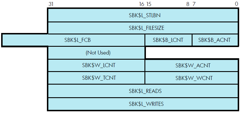
1.5. ACP-QIO Attributes Statistics Block
Figure 1.6, ''ACP-QIO Attributes Statistics Block'' shows the format of the attributes statistics block. Table 1.10, ''Contents of the Statistics Block'' lists the contents of this block.
| Field | Subfields | Meaning |
|---|---|---|
| SBK$L_STLBN | Contains the starting LBN of the file if the file is contiguous. If the file is not contiguous, this field contains a value of 0. The LBN appears as an inverted longword (the high- and low-order 16 bits are transposed for PDP-11 compatibility). The following subfields are defined: | |
| SBK$W_STLBNH | Starting LBN (high-order 16 bits) | |
| SBK$W_STLBNL | Starting LBN (low-order 16 bits) | |
| SBK$L_FILESIZE | Contains the size of the file in blocks. The file size appears as an inverted longword (the high- and low-order 16 bits are transposed for PDP-11 compatibility). The following subfields are defined: | |
| SBK$W_FILESIZH | File size (high-order 16 bits) | |
| SBK$W_FILESIZL | File size (low-order 16 bits) | |
| SBK$B_ACNT? | Access count (low byte). Field is for PDP-11 compatibility. | |
| SBK$B_LCNT? | Lock count (low byte). Field is for PDP-11 compatibility. | |
| SBK$L_FCB | System pool address of the file's file control block. | |
| SBK$W_ACNT? | Access count (number of channels with file open currently). | |
| SBK$W_LCNT? | Lock count (the number of access operations that have locked the file against writers). | |
| SBK$W_WCN? | Writer count (the number of channels that currently have the file open for write). | |
| SBK$W_TCNT? | Truncate lock count (the number of access operations that have locked the file against truncation). | |
| SBK$L_READS | Number of read operations executed for the file on this channel. | |
| SBK$L_WRITES | Number of write operations executed for the file on this channel. |
1.6. Major Functions
The following sections describe the operation of the major ACP functions. Each section describes the required and optional parameters for a particular function, as well as the sequence in which the function is performed. For clarity, when a major function invokes a subfunction, the input parameters used by the subfunction are omitted.
1.6.1. Create File
Create file is a virtual I/O function that creates a directory entry or a file on a disk device, or a file on a magnetic tape device.
IO$_CREATE
IO$M_CREATE—Creates a file.
IO$M_ACCESS—Opens the file on your channel.
IO$M_DELETE—Marks the file for deletion (applicable only to disk devices).
1.6.1.1. Input Parameters
P1—The address of the file information block (FIB) descriptor.
P2—The address of the file name string descriptor (optional).
P3—The address of the word that is to receive the length of the resultant file namestring (optional).
P4—The address of a descriptor for a buffer that is to receive the resultant file namestring (optional).
P5—The address of a list of attribute descriptors (optional).
Table 1.11, ''IO$_CREATE and the FIB'' lists fields in the FIB that are applicable to the IO$_CREATE operation.
| Field | Subfields | Meaning |
|---|---|---|
| FIB$L_ACCTL | Specifies field values that control access to the file. The following bits are applicable to the IO$_CREATE function: | |
| FIB$V_REWIND | Set to rewind magnetic tape before creating the file. Any data currently on the tape is overwritten. | |
| FIB$V_CURPOS | Set to create magnetic tape file at the current tape position. (Note: a magnetic tape file is created at the end of the volume set if neither FIB$V_REWIND nor FIB$V_CURPOS is set.) If the tape is not positioned at the end of a file, FIB$V_CURPOS creates a file at the next file position. Any data currently on the tape past the current file position is overwritten. | |
| FIB$V_WRITETHRU | Specifies that the file header is to be written back to the disk. If not specified and the file is opened, writing of the file header can be deferred to some later time. | |
| FIB$W_CNTRLFUNC | Specifies the following value, which allows you to control actions subsequent to EOT detection on a magnetic tape file. | |
| FIB$W_FID | Contains the file ID of the file created or entered. | |
| FIB$W_DID | Contains the file identifier of the directory file. | |
| FIB$W_NMCTL | Controls the processing of the file name in a directory operation. The following bits are applicable to the IO$_CREATE function: | |
| FIB$V_NEWVER | Set to create a file of the same name with the next higher version number. Only for disk devices. | |
| FIB$V_SUPERSEDE | Set to supersede an existing file of the same name, type, and version. Only for disk devices. | |
| FIB$V_LOWVER | Seton return if a lower numbered version of the file exists. Only for disk devices. | |
| FIB$V_HIGHVER | Seton return if a higher numbered version of the file exists. Only for disk devices. | |
| FIB$W_VERLIMIT | Specifies the version limit for the directory entry created. Used only for disk devices and only when the first version of a new file is created. If 0, the directory default is used. If a directory operation was performed, FIB$W_VERLIMIT always contains the actual version limit of the file. | |
| FIB$L_ACL_STATUS | Status of the requested ACL attribute operation, if any. The ACL attributes are included in Table 1.7, ''ACP-QIO Attributes''. If no ACL attributes are given, SS$_NORMAL is returned here. | |
| FIB$L_STATUS | Access status. Programmers can control the security information being propagated as well as the source of this information by setting the following bits. |
1.6.1.2. Disk ACP Operation
If the modifier IO$M_CREATE is specified, a file is created. The file ID of the file created is returned in FIB$W_FID. If the modifier IO$M_DELETE is specified, the file is marked for deletion.
If a non-zero directory ID is specified in FIB$W_DID, a directory entry is created. The file name specified by parameter P2 is entered in the directory, together with the file ID in FIB$W_FID. (Table 1.2, ''FIB Fields (Lookup Control)'' describes the format for the file name string.) Wildcards are not permitted. Negative version numbers are treated as equivalent to a 0 version number. If a result string buffer and length are specified by P3 and P4, the actual file name entered, and its length, are returned.
If the version number in the specified file name is 0 or negative, the directory entry created gets a version number one greater than the highest previously existing version of that file (or version 1 if the file did not previously exist).
If the version number in the specified file name is a nonzero number and FIB$V_NEWVER is set, the directory entry created gets a version number one greater than the highest previously existing version of that file, or the specified version number, whichever is greater.
If the version number in the specified file name is a nonzero number and the directory already contains a file of the same name, type, and version, the previously existing file is set aside for deletion if FIB$V_SUPERSEDE is specified. If FIB$V_SUPERSEDE is not specified, the create operation fails with a SS$_DUPFILNAM status.
If, after creating the new directory entry, the number of versions of the file exceeds the version limit, the lowest numbered version is set aside for deletion.
If the file did not previously exist, the new directory entry is given a version limit as follows: the version limit is taken from FIB$W_VERLIMIT if it is a nonzero number; if it is 0, the version limit is taken from the default version limit of the directory file; if the default version limit of the directory file is 0, the version limit is set to 32,767 (the highest possible number).
The file name string entered in the directory is returned using the P3 and P4 result string parameters, if present. The file name string is also written into the header. If no directory operation is requested (FIB$W_DID is 0), the file name string specified by P2, if any, is written into the file header.
If an attribute list is specified by P5, a write attributes subfunction is performed (see Section 1.3.5, ''Read/Write Attributes'').
If the modifier IO$M_ACCESS is specified, the file is opened (see Section 1.3.2, ''Access'').
If the extend enable bit FIB$V_EXTEND is specified in the FIB, an extend subfunction is performed (see Section 1.3.3, ''Extend'').
Finally, if a file was set aside for deletion (IO$M_DELETE is specified), that file is deleted. If the file is deleted because the FIB$V_SUPERSEDE bit was set, the alternate success status SS$_SUPERSEDE is returned in the I/O status block. If the file is deleted because the version limit was exceeded, the alternate success status SS$_FILEPURGED is returned.
If an error occurs in the operation of an IO$_CREATE function, all actions performed to that point are reversed (the file is neither created nor changed), and the error status is returned to the user in the I/O status block.
1.6.1.3. Directory Entry Creation
Creating a new version of a file eliminates default access to the previously highest version of the file. For example, creating RESUME.TXT;4 masks RESUME.TXT;3 so the DCL command TYPE RESUME.TXT yields the contents of version 4, not version 3. To protect the contents of the earlier version of a file, the creator of a file must have write access to the previous version of a file of the same name.
1.6.1.4. Magnetic Tape ACP Operation
No operation is performed unless the IO$M_CREATE modifier is specified. The magnetic tape is positioned as specified by FIB$V_REWIND and FIB$V_CURPOS, and the file is created. The name specified by the P2 parameter is written into the file header label.
If P5 specifies an attribute list, a write attributes subfunction is performed (see Section 1.3.5, ''Read/Write Attributes'').
If the modifier IO$M_ACCESS is specified, the file is opened (see Section 1.3.2, ''Access'').
1.6.2. Access File
This virtual I/O function searches a directory on a disk device or a magnetic tape for a specified file and accesses that file if found.
The following is the function code:
IO$_ACCESS
The following are the function modifiers:
IO$M_CREATE—Creates a file.
IO$M_ACCESS—Opens the file on your channel.
1.6.2.1. Input Parameters
P1—The address of the file information block (FIB) descriptor.
P2—The address of the file name string descriptor (optional).
P3—The address of the word that is to receive the length of the resultant file namestring (optional).
P4—The address of a descriptor for a buffer that is to receive the resultant file namestring (optional).
P5—The address of a list of attribute descriptors (optional).
Table 1.12, ''IO$_ACCESS and the File Information Block'' lists FIB fields that are applicable to the IO$_ACCESS operation.
| Field | Subfields | Meaning |
|---|---|---|
| FIB$W_CNTRLFUNC | Specifies the value that allows the user to control actions subsequent to EOT detection on a magnetic tape file. | |
| FIB$W_VERLIMIT | Receives the version limit for the file. Applicable only if FIB$W_DID is a nonzero number (if a directory lookup is done). Used only for disk devices. | |
| FIB$L_ACL_STATUS | Status of the requested ACL attribute operation, if any. The ACL attributes are included in Table 1.7, ''ACP-QIO Attributes''.If no ACL attributes are given, SS$_NORMAL is returned here. (For Files-11 C/D, this field is always set to SS$_NORMAL.) | |
| FIB$L_STATUS | Alternate access status. The following bits are supported: | |
| FIB$V_ALT_REQ | Set to indicate whether the alternate access bit is required for the current operation. If not set, the alternate access bit is optional. | |
| FIB$V_ALT_GRANTED | If FIB$V_ALT_REQ = 0 and the alternate access check succeeded, the FIB bit returned from the file system is set. | |
| FIB$L_ALT_ACCESS | A 32-bit mask that represents an access mask to check against file protection; for example, to open a file for read and to check whether it can be deleted. The mask has the same configuration as the standard protection mask. |
1.6.2.2. Operation
If a nonzero directory file ID is specified in FIB$W_DID, a lookup subfunction is performed (see Section 1.3.1, ''Directory Lookup''.) The version limit of the file found is returned in FIB$W_VERLIMIT.
If the directory search fails with a “file not found” condition and the IO$M_CREATE function modifier is specified, the function is reexecuted as a CREATE. In that case, the argument interpretations for IO$_CREATE, rather than those for IO$_ACCESS, apply.
If IO$M_ACCESS is specified, an access subfunction is performed to open the file (see Section 1.3.2, ''Access'').
If P5 specifies an attribute list, a read attributes subfunction is performed (see Section 1.3.5, ''Read/Write Attributes'').
1.6.3. Deaccess File
De access file is a virtual I/O function that deaccesses a file and, if specified, writes final attributes in the file header.
IO$_DEACCESS
IO$_DEACCESS takes no function modifiers.
1.6.3.1. Input Parameters
The following are the device- or function-dependent arguments for IO$_DEACCESS:
P1—The address of the file information block (FIB) descriptor.
P5—The address of a list of attribute descriptors (optional).
The following FIB fields are applicable to the IO$_DEACCESS function:
| Field | Meaning |
|---|---|
| FIB$W_FID | File ID of the file being deaccessed. This field can contain a value of 0. If it does not, it must match the file identifier of the accessed file. |
| FIB$L_ACL_STATUS | Status of the requested ACL attribute operation, if any. The ACL attributes are included in Table 1.7, ''ACP-QIO Attributes''. If no ACL attributes are given, SS$_NORMAL is returned here. (For Files-11 C/D, this field is always set to SS$_NORMAL.) |
1.6.3.2. Operation
For disk files, if P5 specifies an attribute control list and the file was accessed for a write operation, a write attributes subfunction is performed (see Section 1.3.5, ''Read/Write Attributes''). If the file was opened for write, no attributes were specified, and FIB$V_DLOCK was set when the file was accessed, the deaccess lock bit is set in the file header, inhibiting further access to that file.
For disk files, if the truncate enable bit FIB$V_TRUNC is specified in the FIB, a truncate subfunction is performed (see Section 1.3.4, ''Truncate'').
Finally, the file is closed. Trailer labels are written for a magnetic tape file that was opened for write.
1.6.4. Modify File
Modify file is a virtual I/O function that modifies the file attributes or allocation of a disk file. The IO$_MODIFY function is not applicable to magnetic tape; that is, the function returns success, but no action is performed.
The following is the function code:
IO$_MODIFY
The following is the function modifier:
IO$M_MOVEFILE
1.6.4.1. Input Parameters
The following are the device- or function-dependent arguments for IO$_MODIFY:
P1—The address of the file information block (FIB) descriptor.
P2—The address of the file name string descriptor (optional). If specified, the directory is searched for the name.
P3—The address of the word that is to receive the length of the resultant file name string (optional).
P4—The address of a descriptor for a buffer that is to receive the resultant file name string (optional).
P5—The address of a list of attribute descriptors (optional).
The following FIB fields are applicable to the IO$_MODIFY function:
| Field | Subfields | Meaning |
|---|---|---|
| FIB$L_ACCTL | Specifies field values that control access to the file. The following bit is applicable to the IO$_MODIFY function: | |
| FIB$V_WRITETHRU | Specifies that the file header is to be written back to the disk. If not specified and the file is currently open, writing of the file header can be deferred to some later time. | |
| FIB$W_VERLIMIT | If a nonzero number, specifies the version limit for the file. | |
| FIB$L_ACL_STATUS | Status of the requested ACL attribute operation. The ACL attributes are listed in Table 1.7, ''ACP-QIO Attributes''. If no ACL attributes are given, SS$_NORMAL is returned here. |
1.6.4.2. Operation
If a nonzero directory ID is specified in FIB$W_DID, a lookup subfunction is executed (see Section 1.3.1, ''Directory Lookup''). If a nonzero version limit is specified in FIB$W_VERLIMIT and the directory entry found is the latest version of that file, the version limit is set to the value specified.
If P5 specifies an attribute list, a write attributes subfunction is performed (see Section 1.3.5, ''Read/Write Attributes'').
The file can be either extended or truncated. If FIB$V_EXTEND is specified in the FIB, an extend subfunction is performed (see Section 1.3.3, ''Extend''). If FIB$V_TRUNC is specified in the FIB, a truncate subfunction is performed (see Section 1.3.4, ''Truncate''). Extend and truncate operations cannot be performed at the same time.
1.6.5. Delete File
Delete file is a virtual I/O function that removes a directory entry or file header from a disk volume.
The following is the function code:
IO$_DELETE
The following is the function modifier:
IO$M_DELETE—Deletes the file (or marks it for deletion).
The following are the device- or function-dependent arguments for IO$_DELETE:
P1—The address of the file information block (FIB) descriptor.
P2—The address of the file name string descriptor (optional).
P3—The address of the word that is to receive the length of the resultant file name string (optional).
P4—The address of a descriptor for a buffer that is to receive the resultant file name string (optional).
The following FIB fields are applicable to the IO$_DELETE function:
| Field | Subfields | Meaning |
|---|---|---|
| FIB$L_ACCTL | Specifies field values that control access to the file. The following bits are applicable to the IO$_DELETE function: | |
| FIB$V_NOLOCK (Alpha only) | Allows the caller to mark a file for delete that is currently open for write access. When the file is closed, it is automatically deleted. The file cannot be accessed by new callers after it has been marked for delete. | |
| FIB$V_WRITETHRU | Specifies that the file header is to be written back to the disk. If not specified and the file is currently open, writing of the file header can be deferred to some later time. | |
| FIB$W_DID | Contains the file identifier of the directory file. This field must be a nonzero number. | |
| FIB$W_FID | Specifies the file identification to be deleted. |
1.6.5.1. Operation
If a nonzero directory ID is specified in FIB$W_DID, a lookup subfunction is performed (see Section 1.3.1, ''Directory Lookup''). The file name located is removed from the directory.
If the function modifier IO$M_DELETE is specified, the file is marked for deletion. If the file is not currently open, it is deleted immediately. If the file is open, it is deleted when the last accessor closes it.
1.6.6. Movefile Subfunction
The movefile subfunction permits you to move the contents of a file, or part of the contents of a file, to a new disk location. This subfunction can, for example, form the basis of a disk defragmentation application.
You can disable movefile operations on specific user files by specifying the /NOMOVE qualifier on the SET FILE command. Use the DIRECTORY/FULL and the DUMP/HEADER commands to find out if movefile operations are disabled on a file.
1.6.6.1. Calling the Movefile Subfunction
A program can invoke a movefile subfunction by issuing a QIO request using the function code IO$_MODIFY and the function modifier IO$M_MOVEFILE. This section describes the various input parameters that control the processing of movefile operations together with an operational description.
1.6.6.1.1. Input Parameters
Table 1.13, ''FIB Fields (Movefile)'' lists the FIB fields that control the processing of a movefile subfunction.
| Field | Subfields | Meaning |
|---|---|---|
| FIB$L_ACCTL | Movefile control flag. The following flags are applicable: | |
| FIB$V_NOVERIFY | Inhibits comparison of the moved blocks. If this flag is clear, the movefile operation verifies that the operation was carried out correctly by comparing the moved blocks to the original blocks. | |
|
FIB$V_CHANGE_ |
Enables the movefile operation to move blocks from one volume to another within a volume set. The movefile operation clears this flag if the specified file is a directory. | |
| FIB$W_FID | Specifies the file identification of the file to be moved. | |
| FIB$W_EXCTL | Movefile control flags. The following flag applies to the movefile operation. All other FIB$W_EXCTL flags must be clear. | |
| FIB$V_ALCON |
Specifies that the movefile operation must allocate contiguous disk space to the moved blocks. If the necessary contiguous space is not available, the movefile operation fails. The movefile operation sets this flag if the file was previously marked as contiguous. | |
| FIB$V_ALCONB |
Specifies that the movefile operation should attempt to allocate contiguous disk space to the moved blocks. That is, if the movefile operation cannot allocate contiguous space to all the moved blocks, it allocates contiguous space to as many of the blocks as possible. The movefile operation sets this flag if the file was previously marked as contiguous best try. | |
| FIB$V_FILCON |
Specifies that the entire file must be made contiguous. Do not set this flag without also setting the FIB$V_ALCON flag. If the FIB$V_FILCON flag is set, and either the FIB$V_ALCON flag is clear or the file would not be made contiguous by moving the specified virtual blocks, the movefile operation fails. The movefile operation sets this flag if the file was previously marked as contiguous. | |
| FIB$V_NOPLACE |
Specifies that placement information is not recorded in the file header. If this flag is clear and you specify exact placement for the moved blocks, placement information for those blocks will be recorded in the file header. If this flag is set, the placement information is not recorded. You specify exact placement through the FIB$V_EXACT, FIB$C_LBN, and FIB$L_LOC_ADDR fields. | |
| FIB$B_ALOPTS | Flags that control the placement of the allocated blocks. Currently, only the FIB$V_EXACT flag applies to the movefile operation. All other FIB$B_ALOPTS flags must be clear. The following flag is applicable: | |
| FIB$V_EXACT | Set to require exact placement. If this flag is set and the specified blocks are not available, the movefile operation fails. | |
| FIB$B_ALALIGN | Contains the interpretation mode of the allocation field (FIB$W_ALLOC). You can specify a field value of 0 or you can specify the symbolic value FIB$C_LBN. If you specify 0, the allocation field is ignored. | |
| FIB$W_ALLOC | Contains the desired location of the blocks being allocated. Interpretation of the field is controlled by the FIB$B_ALALIGN field. The following subfields are defined: | |
| FIB$B_LOC_RVN | Specifies the relative volume number (RVN) of the volume to which the blocks are moved. Do not specify a value for this field unless you have set the FIB$V_CHANGE_VOL flag. | |
| FIB$L_LOC_ADDR | If the FIB$C_LBN and FIB$V_EXACT flags are set, specifies the starting logical address to which the blocks are moved. | |
| FIB$L_MOV_SVBN |
Specifies the virtual block number (VBN) of the first block to be moved. The starting VBN must correspond to the first block of a disk cluster. The value must be greater than 0 and it must not exceed the number of virtual blocks allocated to the file. If you specify an invalid value, the movefile operation fails. | |
|
FIB$L_MOV_ |
Specifies the number of consecutive virtual blocks to be moved. This value must be a multiple of the disk cluster size, and it must not exceed the difference between the greatest VBN allocated to the file and the FIB$L_MOV_SVBN value. If you specify a value of 0, the movefile operation moves all the virtual blocks between the FIB$L_MOV_SVBN value and the greatest VBN. If you specify an invalid value, the movefile operation fails. |
1.6.6.1.1.1. Operation
A program can perform a movefile operation on a file if the following conditions are met:
The program has write and control access to the file.
The file is closed.
Movefile operations are not disabled on the file.
Movefile operations are automatically disabled on critical system files. You can disable movefile operations on specific user files by specifying the /NOMOVE qualifier with the SET FILE command.
The operation is not interrupted.
If the movefile operation is interrupted by any other operation, such as a read or write operation, the movefile operation aborts and the file remains in its original position.
The movefile operation moves a specified number of consecutive virtual blocks to new logical blocks on disk, beginning with the virtual block specified in the FIB$L_SVBN field.
The number of blocks moved is specified in the FIB$L_VBNCNT field. To move an entire file, specify FIB$L_VBNCNT as 0 and FIB$L_SVBN as 1.
To specify a starting logical block for the moved blocks, specify the logical block address in the FIB$L_LOC_ADDR subfield and set the FIB$C_LBN and the FIB$V_EXACT flags.
To move the blocks to another volume, or move blocks that span more than one volume, set the FIB$V_CHANGE_VOL flag of the FIB$L_ACCTL field. Use the FIB$B_LOC_RVN subfield of the FIB$W_ALLOC field to specify the volume to which the blocks are moved. If you do not specify a volume, the blocks are moved to the volume containing the first virtual block. Note that you cannot move blocks of a directory file to another volume.
If the file was previously marked as contiguous, the movefile operation sets the FIB$V_ALCON, FIB$V_ALCONB, and FIB$V_FILCON flags. This ensures that a contiguous file is not fragmented by a movefile operation.
For virtual blocks beyond the file's highwater mark, the movefile operation allocates new logical blocks but does not copy the contents. The position of the file's highwater mark remains unchanged.
1.6.7. Mount
On Alpha and IA-64 server systems, mount is a virtual I/O function that informs the ACP when a disk or magnetic tape volume is mounted. MOUNT privilege is required. IO$_MOUNT takes no arguments or function modifiers. This function is part of the volume mounting operation only, and it is not meant for general use. Most of the actual processing is performed by the MOUNT command or the Mount Volume ($MOUNT) system service.
1.6.8. ACP Control
ACP Control is a virtual I/O function that performs ancillary control functions, depending on the arguments specified.
The following is the function code:
IO$_ACPCONTROL
The following is the function modifier:
IO$M_DMOUNT—Dismounts a volume.
1.6.8.1. Input Parameters
The following are the device- or function-dependent arguments for IO$_ACPCONTROL:
P1—The address of the file information block (FIB) descriptor.
P2—The address of the file name string descriptor (optional).
P3—The address of the word that is to receive the length of the resultant file name string (optional).
P4—The address of a descriptor for a buffer that is to receive the resultant file name string (optional).
Table 1.14, ''IO$_ACPCONTROL and the FIB'' lists FIB fields that control the processing of the IO$_ACPCONTROL function.
| Field | Subfields | Meaning |
|---|---|---|
| FIB$W_CNTRLFUNC | Specifies the control function to be performed. This field overlays FIB$W_EXCTL. | |
| FIB$L_CNTRLVAL? | Specifies additional function-dependent data. This field overlays FIB$L_EXSZ. | |
| FIB$L_ACL_STATUS | Status of the requested ACL attribute operation, if any. The ACL attributes are included in Table 1.7, ''ACP-QIO Attributes''. If no ACL attributes are given, SS$_NORMAL is returned here. For Files-11 C/D, this field is always set to SS$_NORMAL. | |
| FIB$L_STATUS? | Alternate access status. The following bits are supported: | |
| FIB$V_ALT_REQ | Set to indicate whether the alternate access bit is required for the current operation. If not set, the alternate access bit is optional. | |
| FIB$V_ALT_GRANTED | If FIB$V_ALT_REQ = 0 and the alternate access check succeeded, the FIB bit returned from the file system is set. | |
| FIB$L_ALT_ACCESS? | A 32-bit mask that represents an access mask to check against file protection; for example, to open a file for read and to check whether it can be deleted or not. The mask has the same configuration as the standard protection mask. |
1.6.8.2. Magnetic Tape Control Functions
Table 1.15, ''Magnetic Tape Operations and the FIB'' lists the FIB field applicable to magnetic tape operations.
| Field | Subfields | Meaning |
|---|---|---|
| FIB$W_CNTRLFUNC | Several ACP control functions are used for magnetic tape positioning. These functions are specified by supplying a FIB with P1 containing the FIB descriptor address. Modifiers and parameters P2, P3, and P4 are not allowed. These functions clear serious exceptions in magnetic tape drivers. The following control functions can be specified to control magnetic tape positioning: | |
| FIB$C_REWINDFIL | Rewind to beginning-of-file. | |
| FIB$C_REWINDVOL | Rewind to beginning-of-volume set. | |
| FIB$C_POSEND | Position to end-of-volume set. | |
| FIB$C_NEXTVOL | Force next volume. | |
| FIB$C_SPACE | Space n blocks forward or backward. The FIB$L_CNTRLVAL field specifies the number of magnetic tape blocks to space forward if positive or to space backward if negative. | |
| FIB$C_CLSEREXCP | If set, clears the serious exception in the magnetic tape driver (see FIB$C_USEREOT in Section 1.6.1, ''Create File'' and Section 1.6.2, ''Access File''). If writing, allows you to write data blocks beyond the EOT marker, which can result in the magnetic tape not conforming to the ANSI standard for magnetic tapes (see ANSI Standard X3.27-1978). If reading, allows you to handle the move to the next volume or to stop reading the tape. Do not attempt to read past EOV. |
1.6.8.3. Miscellaneous Disk Control Functions
Several ACP control functions are available for disk volume control. The following function does not use parameters P2, P3, and P4:
| IO$M_DMOUNT | Specifying the dismount modifier on the IO$_ACPCNTRLfunction executes a dismount QIO. No parameters in the FIB are used; the FIB can be omitted. This function does not perform a dismount by itself, but is used to synchronize the ACP with the DISMOUNT command and the Dismount Volume ($DISMOUNT) system service. |
The FIB$W_CNTRLFUNC field of the FIB specifies the following miscellaneous control functions (with no modifier on the IO$_ACPCONTROL function code). These functions use no other parameters.
| FIB$C_REMAP | Remap a file. The file window for the file open on the user's channel is remapped so that it maps the entire file. |
| FIB$C_LOCK_VOL |
Allocation lock the volume. Operations that change the file structure, such as file creation, deletion, extension, and deaccess, are not permitted. If such requests are queued to the file system for an allocation-locked volume, they are not processed until the FIB$C_UNLK_VOL function is issued to unlock the volume. To issue the FIB$C_LOCK_VOL function, you must have either a system UIC or SYSPRV privilege, or be the owner of the volume. |
| FIB$C_UNLK_VOL | Unlock the volume. Cancels FIB$C_LOCK_VOL. To issue this function, you must have either a system UIC or SYSPRV privilege, or be the owner of the volume. |
1.6.8.4. Disk Quotas
Disk quota enforcement is enabled by a quota file on the volume, or relative volume 1 if the file is on a volume set. The quota file appears in the volume's master file directory (MFD) under the name QUOTA.SYS;1. This section describes the control functions that operate on the quota file.
Table 1.16, ''Disk Quota Functions (Enable/Disable)'' lists the enable and disable quota control functions.
| Value | Meaning |
|---|---|
| FIB$C_ENA_QUOTA |
Enable the disk quota file. If a nonzero directory file ID is specified in FIB$W_DID, a lookup subfunction is performed to locate the quota file (see Section 1.3.1, ''Directory Lookup''). To issue this function, you must have either a system UIC or SYSPRV privilege, or be the owner of the volume. The quota file specified by FIB$W_FID, if present, is accessed by the ACP, and quota enforcement is turned on. By convention, the quota file is named [0,0]QUOTA.SYS;1. Therefore, FIB$W_DID should contain the value 4,4,0 and the name string specified with P2 should be “QUOTA.SYS;1”. |
| FIB$C_DSA_QUOTA | Disable the disk quota file. The quota file is deaccessed and quota enforcement is turned off. To issue this function, you must have either a system UIC or SYSPRV privilege, or be the owner of the volume. |
Table 1.17, ''Disk Quota Functions (Individual Entries)'' lists the quota control functions that operate on individual entries in the quota file. Each operation transfers quota file data to and from the ACP using a quota data block. This block has the same format as a record in the quota file. Figure 1.7, ''Quota File Transfer Block'' shows the format of this block.
| Value | Meaning | |
|---|---|---|
| FIB$C_ADD_QUOTA | Add an entry to the disk quota file, using the UIC and quota specified in the P2 argument block. FIB$C_ADD_QUOTA requires write access to the quota file. | |
| FIB$C_EXA_QUOTA | Examine a disk quota file entry. The entry whose UIC is specified in the P2 argument block is returned in the P4 argument block, and its length is returned in the P3 argument word. Using two flags in FIB$L_CNTRLVAL, it is possible to search through the quota file using wildcards. The two flags are: | |
| FIB$V_ALL_MEM | Match all UIC members | |
| FIB$V_ALL_GRP | Match all UIC groups | |
|
The ACP maintains position context in FIB$L_WCC. On the first examine call, you specify 0 in FIB$L_WCC; the ACP returns a nonzero value so that each succeeding examine call returns the next matching entry. Read access to the quota file is required to examine all nonuser entries. | ||
| FIB$C_MOD_QUOTA | Modify a disk quota file entry. The quota file entry specified by the UIC in the P2 argument block is modified according to the values in the block, as controlled by the following three flags in FIB$L_CNTRLVAL: | |
| FIB$V_MOD_PERM | Change the permanent quota | |
| FIB$V_MOD_OVER | Change the overdraft quota | |
| FIB$V_MOD_USE | Change the usage data | |
|
The usage data can be changed only if the volume is locked by FIB$C_LOCK_VOL (see Section 1.6.8.3, ''Miscellaneous Disk Control Functions''). FIB$C_MOD_QUOTA requires write access to the quota file. The P3 and P4 arguments return the modified quota entry to you. By using the flags FIB$V_ALL_MEM and FIB$V_ALL_GRP, you can search through the quota file using wildcards just as you would with the FIB$C_EXA_QUOTA function. | ||
| FIB$C_REM_QUOTA |
Remove a disk quota file entry whose UIC is specified in the P2 argument block. FIB$C_REM_QUOTA requires write access to the quota file. The P3 and P4 arguments return the removed quota file entry to you. By using the flags FIB$V_ALL_MEM and FIB$V_ALL_GRP, you can search through the quota file using wildcards just as you would with the FIB$C_EXAQUOTA function. | |
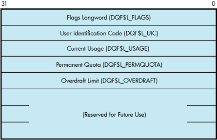
IO$_ACPCONTROL functions that transfer quota file data between the caller and the ACP use the following device- or function-dependent arguments:
P2—The address of a descriptor for the quota data block being sent to the ACP.
P3—The address of a word that returns the data length.
P4—The address of a descriptor for a buffer to receive the quota data block returned from the ACP.
1.7. I/O Status Block
Figure 1.8, ''IOSB Contents — ACP-QIO Functions'' shows the I/O status block (IOSB) for ACP-QIO functions. Appendix A, "I/O Function Codes" lists the status returns for these functions. (The OpenVMS system messages documentation provides explanations and suggested user actions for these returns.)
The file ACP returns a completion status in the first longword of the IOSB. In an extend operation, the second longword is used to return the number of blocks allocated to the file. If a contiguous extend operation (FIB$V_ALCON) fails, the second longword is used to return the size of the file after truncation.
Values returned in the IOSB are most useful during operations in compatibility mode. When executing programs in the native mode, use the values returned in FIB locations.
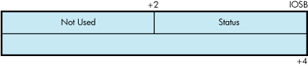
If an extend operation (including CREATE) was performed, IOSB+4 contains the number of blocks allocated, or the largest available contiguous space if a contiguous extend operation failed. If a truncate operation was performed, IOSB+4 contains the number of blocks added to the file size to reach the next cluster boundary.
Chapter 2. Disk Drivers
This chapter describes the use of disk drivers that support the disk devices listed in the Software Product Description for the OpenVMS Operating System (SPD 82.35.xx). The chapter also includes descriptions of many of the supported disks and controllers; however, not all supported devices are described here. For the definitive list of supported devices, see Software Product Description for the OpenVMS Operating System
All disk drivers support Files-11 On-Disk Structure Level 1 and Level 2 file structures. Access to these file structures is through the DCL commands INITIALIZE and MOUNT, followed by the RMS calls described in the VSI OpenVMS Record Management Utilities Reference Manual. Files in RT-11 format can be read or written with the file exchange facility EXCHANGE.
2.1. Driver Features
Disk drivers provide the following features:
Multiple controllers of the same type (except RB730), for example, more than one MBA or RK611 can be used on the system
Multiple disk drives per controller (the exact number depends on the controller)
Different types of disk drives on a single controller
Static dual porting (MBA drives only)
Overlapped seeks (except RL02, RX01, RX02, and TU58)
Data checks on a per-request, per-file, or per-volume basis (except RX01 and RX02)
Full recovery from power failure for online disk drives with volumes mounted
Extensive error recovery algorithms, such as error code correction and offset (except RB02, RL02, RX01, RX02, and TU58); for DSA disks, these algorithms are implemented in the controller
Dynamic, as well as static, bad block handling
Logging of device errors in a file that can be displayed by field service personnel or customer personnel
Online diagnostic support for drive level diagnostics
Multiple-block, noncontiguous, virtual I/O operations at the driver level
Logical-to-physical sector translation (RX01 and RX02 only)
The following sections describe these features in greater detail.
2.1.1. Data Check
A data check is made after successful completion of a read or write operation and, except for the TU58, compares the data in memory with the data on disk to make sure they match.
Disk drivers support data checks at the following levels:
Per request—You can specify the data check function modifier (IO$M_DATACHECK) on a read logical block, write logical block, read virtual block, write virtual block, read physical block, or write physical block operation. IO$M_DATACHECK is not supported for the RX01 and RX01 drivers.
Per volume—You can specify the characteristics “data check all reads” and “data check all writes” when the volume is mounted. The VSI OpenVMS DCL Dictionary describes volume mounting and dismounting. The VSI OpenVMS System Services Reference Manual describes the Mount Volume ($MOUNT) and Dismount Volume ($DISMOUNT) system services.
Per file—You can specify the file access attributes “data check on read” and “data check on write.” File access attributes are specified when the file is accessed. Chapter 1, "ACP-QIO Interface" of this manual and the VSI OpenVMS Record Management Services Reference Manual describe file access.
Offset recovery is performed during a data check, but error code correction (ECC) is not performed (see Section 2.1.3, ''Error Recovery''). For example, if a read operation is performed and an ECC correction is applied, the data check would fail even though the data in memory is correct. In this case, the driver returns a status code indicating that the operation was completed successfully, but the data check could not be performed because of an ECC correction.
Data checks on read operations are extremely rare, and you can either accept the data as is, treat the ECC correction as an error, or accept the data but immediately move it to another area on the disk volume.
A data check operation directed to a TU58 does not compare the data in memory with the data on tape. Instead, either a read check or a write check operation is performed (see Section 2.3.1, ''Read'' and Section 2.3.2, ''Write'').
2.1.2. Effects of a Failure During an I/O Write Operation
The operating system ensures that when an I/O write operation returns a successful completion status, the data is available on the disk or tape media. Applications that must guarantee the successful completion of a write operation can verify that the data is on the media by specifying the data check function modifier IO$M_DATACHECK. Note that the IO$M_DATACHECK data check function, which compares the data in memory with the data on disk, affects performance because the function incurs the overhead of an additional read operation to the media.
If a system failure occurs while a multiple-block write operation is in progress, the operating system does not guarantee the successful completion of the write operation. (OpenVMS does guarantee single-block write operations to DSA drives.) When a failure interrupts a write operation, the data may be left in any one of the following conditions:
The new data is written completely to the disk blocks on the media, but a completion status was not returned before the failure.
The new data is partially written to the media so that some of the disk blocks involved in the I/O contain the data from the write operation in progress, and the remainder of the blocks contain the data that was present before the write operation.
The new data was never written to the disk blocks on the media.
To guarantee that a write operation either finishes successfully or (in the event of failure) is redone or rolled back as if it were never started, use additional techniques to ensure data correctness and recovery. For example, using database journaling and recovery techniques allows applications to recover automatically from failures such as the following:
Permanent loss of the path between a CPU data buffer containing the data being written and the disk being written to during a multiple-block I/O operation. Communication path loss can occur due to node or controller failure or a failure of node-to-node communications.
Failure of a CPU (such as a system failure, system halt, power failure, or system shutdown) during a multiple-block write operation.
Mistaken deletion of a file.
Corruption of file system pointers.
File corruption due to a software error or incomplete bucket write operation to an indexed file.
Cancellation of an in-progress multiple-block write operation.
2.1.3. Error Recovery
Error recovery in the operating system is aimed at performing all possible operations to complete an I/O operation successfully. Error recovery operations fall into the following categories:
Handling special conditions such as power failure and interrupt timeout.
Retrying nonfatal controller and drive errors. For DSA and SCSI disks, this function is implemented by the controller.
Applying error correction information (not applicable for RB02, RL02, RX01, RX02, and TU58 drives). For DSA and SCSI disks, error correction is implemented by the controller.
Offsetting read heads to try to obtain a stronger recorded signal (not applicable for RB02, RL02, RB80, RM80, RX01, RX02, and TU58 drives). For DSA and SCSI disks, this function is implemented by the controller.
The error recovery algorithm uses a combination of these four types of error recovery operations to complete an I/O operation:
Power failure recovery consists of waiting for mounted drives to spin up and come on line, followed by reexecution of the I/O operation that was in progress at the time of the power failure.
Device timeout is treated as a nonfatal error. The operation that was in progress when the timeout occurred is reexecuted up to eight times before a timeout error is returned.
Nonfatal controller/drive errors are executed up to eight times before a fatal error is returned.
All normal error recovery procedures (nonspecial conditions) can be inhibited by specifying the inhibit retry function modifier (IO$M_INHRETRY). If any error occurs and this modifier is specified, the virtual, logical, or physical I/O operation is immediately terminated, and a failure status is returned. This modifier has no effect on power recovery and timeout recovery.
2.1.4. SCSI Disk Class Driver
Although SCSI disks do not conform to DSA, they do support the following error recovery features:
Static and dynamic bad block replacement (BBR)
Error correction code (ECC)
Reexecution of read or write operations within the SCSI drive
Reexecution of read or write operations by the SCSI disk class driver
All SCSI disks supplied by HPE implement the REASSIGN BLOCKS command, which relocates data for a specific logical block to a different physical location on the disk. The SCSI disk class driver reassigns the block in the following instances: (1) when the retry threshold is exceeded during an attempt to read or write a block of data on the disk or (2) when an irrecoverable error occurs during a write operation.
Unlike DSA, there is no forced error flag in SCSI. Blocks that produce irrecoverable errors during read operations are not reassigned in order to prevent undetected loss of user data. Instead, the SCSI disk class driver returns the SS$_PARITY status whenever a read operation results in an irrecoverable error.
2.1.5. Audio Extensions to the SCSI Disk Class Driver
The operating system provides audio functionality through the SCSI disk class driver. The SCSI disk class driver provides an interface by which the audio commands can be issued to SCSI devices. These commands can be issued through the QIO function call. This functionality is available for devices, such as CD-ROMs that have audio capability.
The IO$_AUDIO function code allows the SCSI disk class driver to process the SCSI audio commands. An Audio Control Block (AUCB) must be defined for a specific SCSI audio command. This AUCB provides the SCSI disk class driver with command-specific arguments and control information. An application program must use the IO$_AUDIO function code and provide the AUCB for the SCSI driver to process the audio commands.
For more information, see Section 2.3.11.1, ''$QIO Interface to Audio Functionality of the SCSI Disk Class Driver''.
2.2. Disk Driver Device Information
You can obtain information on all disk device characteristics by using the Get Device/Volume Information ($GETDVI) system service (see the VSI OpenVMS System Services Reference Manual).
$GETDVI returns disk characteristics when you specify the item codes DVI$_DEVCHAR and DVI$_DEVCHAR2.
See the Help files for disk device characteristics.
2.3. Disk Function Codes
Disk drivers can perform logical, virtual, and physical I/O functions. Foreign-mounted devices do not require privilege to perform logical and virtual I/O requests.
Logical and physical I/O functions allow access to volume storage and require only that the issuing process have access to the volume; however, DSA disks and the Shadow disk class driver (DUDRIVER) do not accept physical QIO data transfers or seek operations.
Note
The results of logical and physical I/O operations are unpredictable if an ancillary control process (ACP) or extended QIO processing (XQP) is present.
Virtual I/O functions require an ACP for Files-11 On-Disk Structure Level 1 files or an XQP for Files-11 On-Disk Structure Level 2 files. Virtual I/O functions must be executed in a prescribed order. First, you create and access a file, then you write information to that file, and lastly you deaccess the file. Subsequently, when you access the file, you read the information and then deaccess the file. Delete the file when the information is no longer useful.
The volume to which a logical or virtual function is directed must be mounted for the function actually to be executed. If it is not mounted, either a “device not mounted” or “invalid volume” status is returned in the I/O status block.
Table 2.1, ''Disk I/O Functions'' lists the logical, virtual, and physical disk I/O functions and their function codes. Chapter 1, "ACP-QIO Interface" describes the QIO level interface to the disk device ACP.
| Function Code | Arguments | Type? | Function Modifiers | Function |
|---|---|---|---|---|
| IO$_ACCESS | P1, [P2],[P3], [P4], [P5] | V |
| Search a directory for a specified file and access the file if found. |
| IO$_ACPCONTROL | P1,[P2],[P3], [P4],[P5] | V | IO$M_DMOUNT | Perform miscellaneous control functions. |
| IO$_AVAILABLE | P | Clear volume valid; make DSA units available. | ||
| IO$_CREATE | P1,[P2],[P3], [P4],[P5] | V |
| Create a directory entry or a file. |
| IO$_DEACCESS | P1,[P2],[P3], [P4],[P5] | V | Deaccess a file and, if specified, write final attributes in the file header. | |
| IO$_DELETE | P1,[P2],[P3],[ P4],[P5] | V | IO$M_DELETE | Remove a directory entry or file header, or both. |
| IO$_FORMAT | P1 | P | Set density (RX02 only). | |
| IO$_MODIFY | P1,[P2],[P3], [P4],[P5] | V | Modify the file attributes or allocation, or both. | |
| IO$_PACKACK | P | Update UCB fields if RX02; initialize volume valid on other devices. Bring DSA units on line. | ||
| IO$_READLBL? | P1,P2,P3 | L |
| Read logical block. |
| IO$_READPBLK? | P1,P2,P3 | P | Read physical block.? | |
| IO$_READVBLK? | P1,P2,P3 | V |
| Read virtual block. |
| IO$_SEARCH | P1 | P | Search for specified block or sector (only for TU58). | |
| IO$_SEEK | P1 | P | Seek to specified cylinder.? | |
| IO$_SENSECHAR | P | Sense the device-dependent characteristics and return them in the I/O status block. | ||
| IO$_SENSEMODE | L | Sense the device-dependent characteristics and return them in the I/O status block. | ||
| IO$_SETPRFPATH | P1 | P | IO$M_FORCEPTH | Specifies a preferred path for DSA disks. |
| IO$_UNLOAD | P | Clear volume valid; make DSA units available and spin down the volume. | ||
| IO$_WRITECHECK? | P1,P2,P3 | P | Verify data written to disk by a previous write QIO.? | |
| IO$_WRITELBLK? | P1,P2,P3 | L |
| Write logical block. |
| IO$_WRITEPBLK? | P1,P2,P3 | P | Write physical block.? | |
| IO$_WRITEVBLK? | P1,P2,P3 | V |
| Write virtual block. |
The function-dependent arguments for IO$_CREATE, IO$_ACCESS, IO$_DEACCESS, IO$_MODIFY, and IO$_DELETE are as follows:
P1—The address of the file information block (FIB) descriptor.
P2—The address of the file name string descriptor (optional). If specified, the name is entered in the directory specified by the FIB.
P3—The address of the word that is to receive the length of the resulting file name string (optional).
P4—The address of a descriptor for a buffer that is to receive the resulting file name string (optional).
P5—The address of a list of attribute descriptors (optional). If specified, the indicated attributes are read (IO$_ACCESS) or written (IO$_CREATE, IO$_DEACCESS, and IO$_MODIFY).
The function-dependent arguments for IO$_READVBLK, IO$_READLBLK, IO$_WRITEVBLK, and IO$_WRITELBLK are as follows:
P1—The starting virtual address of the buffer that is to receive the data from a read operation; or, in the case of a write operation, the virtual address of the buffer that is to be written on the disk. On OpenVMS Alpha, P1 can be a 64-bit address.
P2—The number of bytes that are to be read from the disk, or written from memory to the disk. An even number must be specified if the controller is an RK611, RL11, RX211, or UDA50.
P3—The starting virtual/logical disk address of the data to be transferred in a read operation; or, in a write operation, the disk address of the area that is to receive the data.
In a virtual read or write operation, the address is expressed as a block number within the file, that is, block 1 of the file is virtual block 1. (Virtual block numbers are converted to logical block numbers using mapping windows that are set up by the file system ACP process.)
In a logical read or write operation, the address is expressed as a block number relative to the start of the disk. For example, the first sector on the disk contains block 0 (or at least the beginning of block 0).
The function-dependent arguments for IO$_WRITEVBLK, IO$_WRITELBLK, and IO$_WRITEPBLK functions that include the IO$M_ERASE function modifier are as follows:
- P1—The starting virtual address of the buffer that contains a 4-byte, user-specified erase pattern. If the P1 address is 0, a longword of 0 is used for the erase pattern. If the P1 address is nonzero, the contents of the 4 bytes starting at that address is used as the erase pattern. User can specify a P1 address of 0 to lower system overhead. On OpenVMS Alpha, P1 can be a 64-bit address.
Note
DSA disk controllers provide controlled, assisted erasing for the IO$M_ERASE modifier (with virtual and logical write functions) only when the erase pattern is all zeros. If a nonzero erase pattern is used, there is a significant performance degradation with these disks. DSA disks do not accept physical QIO transfers.
P2—The number of bytes of erase pattern to write to the disk. The number specified is rounded up to the next highest block boundary (512 bytes).
P3—The starting virtual, logical, or physical disk address of the data to be erased.
The function-dependent arguments for IO$_WRITECHECK, IO$_READPBLK, and IO$_WRITEPBLK are as follows:
P1—The starting virtual address of the buffer that is to receive the data in a read operation; or, in a write operation, the starting virtual address of the buffer that is to be written on the disk. Passed by reference. On OpenVMS Alpha and OpenVMS IA-64 server, P1 can be a 64-bit address.
P2—The number of bytes that are to be read from the disk, or written from memory to the disk. Passed by value. An even number must be specified if the controller is an RK611, RL11, or UDA50.
- P3—The starting physical disk address of the data to be read in a read operation; or, in a write operation, the starting physical address of the disk area that is to receive the data. Passed by value. The address is expressed as sector, track, and cylinder in the format shown in Figure 2.1, ''Starting Physical Address''. (On the RX01 and RX02, the high word specifies the track number rather than the cylinder number.) Check the UCB of a currently mounted device to determine the maximum physical address value for that type of device.
Note
On the RB80 and RM80, do not address cylinders 560 and 561. These two cylinders are used for diagnostic testing only.
The function-dependent argument for IO$_SEARCH is as follows:
P1—The physical disk address where the tape is positioned. The address is expressed as sector, track, and cylinder in the format shown in Figure 2.1, ''Starting Physical Address''.
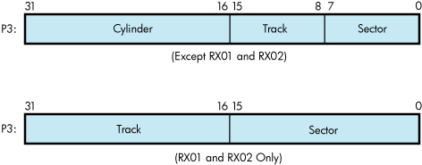
The function-dependent argument for IO$_SEEK is as follows:
P1—The physical cylinder number where the disk heads are positioned. The address is expressed in the format shown in Figure 2.2, ''Physical Cylinder Number Format''.

The function-dependent argument for IO$_FORMAT is as follows:
P1—The density at which an RX02 diskette is reformatted (see Section 2.3.4, ''Set Density'').
2.3.1. Read
The read function reads data into a specified buffer from disk starting at a specified disk address.
The operating system provides the following read function codes:
IO$_READVBLK—Read virtual block
IO$_READLBLK—Read logical block
IO$_READPBLK—Read physical block
If a read virtual block function is directed to a volume that is mounted foreign, that function is converted to read logical block. If a read virtual block function is directed to a volume that is mounted structured, the volume is handled in the same way as for a file-structured device.
Three function-dependent arguments are used with these codes: P1, P2, and P3. These arguments are described in Section 2.3, ''Disk Function Codes''.
The data check function modifier (IO$M_DATACHECK) can be used with all read functions. If this modifier is specified, a data check operation is performed after the read operation completes. A data check operation is also performed if the volume that has been read, or the volume on which the file resides (virtual read) has the characteristic “data check all reads.” Furthermore, a data check is performed after a virtual read if the file has the attribute “data check on read.” The RX01 and RX02 drivers do not support the data check function.
If IO$M_DATACHECK is specified with a read function code to a TU58, or if the volume read has the characteristic “data check all reads,” a read check operation is performed. This alters certain TU58 hardware parameters when the tape is read. (The read threshold in the data recovery circuit is increased; if the tape has any weak spots, errors are detected.)
The data check function modifier to a disk or tape can return five error codes in the I/O status block:
| SS$_CTRLERR | SS$_DRVERR | SS$_MEDOFL |
| SS$_NONEXDRV | SS$_NORMAL |
If no errors are detected, the disk or tape data is considered reliable.
The inhibit retry function modifier (IO$M_INHRETRY) can be used with all read functions. If this modifier is specified, all error recovery attempts are inhibited. IO$M_INHRETRY takes precedence over IO$M_DATACHECK. If both are specified and an error occurs, there is no attempt at error recovery and no data check operation is performed. If an error does not occur, the data check operation is performed.
2.3.2. Write
The write function writes data from a specified buffer to disk starting at a specified disk address.
The operating system provides the following write function codes:
IO$_WRITEVBLK—Write virtual block
IO$_WRITELBLK—Write logical block
IO$_WRITEPBLK—Write physical block
If a write virtual block function is directed to a volume that is mounted foreign, the function is converted to write logical block. If a write virtual block function is directed to a volume that is mounted structured, the volume is handled in the same way as for a file-structured device.
Three function-dependent arguments are used with these codes: P1, P2, and P3. These arguments are described in Section 2.3, ''Disk Function Codes''.
The data check function modifier (IO$M_DATACHECK) can be used with all write operations. If this modifier is specified, a data check operation is performed after the write operation completes. A data check operation is also performed if the volume written, or the volume on which the file resides (virtual write), has the characteristic “data check all writes.” Furthermore, a data check is performed after a virtual write if the file has the attribute “data check on write.” The RX01 and RX02 drivers do not support the data check function.
If IO$M_DATACHECK is specified with a write function code to a TU58, or if the volume written has the characteristic “data check all writes,” a write check operation is performed. The write check verifies data written on the tape. First, the specified data is written on the tape. Then the tape is reversed and the TU58 controller reads the data internally to perform a checksum verification. If the checksum verification is unsuccessful after eight attempts, the write check operation is aborted and an error status is returned.
The inhibit retry function modifier (IO$M_INHRETRY) can be used with all write functions. If that modifier is specified, all error recovery attempts are inhibited. IO$M_INHRETRY takes precedence over IO$M_DATACHECK. If both IO$M_INHRETRY and IO$M_DATACHECK are specified and an error occurs, there is no attempt at error recovery, and no data check operation is performed. If an error does not occur, the data check operation is performed. IO$M_INHRETRY has no effect on DSA disks.
The write deleted data function modifier (IO$M_DELDATA) can be used with the write physical block (IO$_WRITEPBLK) function to the RX02. If this modifier is specified, a deleted data address mark instead of the standard data address mark is written preceding the data. Otherwise, the operation of the IO$_WRITEPBLK function is the same; write data is transferred to the disk. When a successful read operation is performed on this data, the status code SS$_RDDELDATA is returned in the I/O status block rather than the usual SS$_NORMAL status code.
The IO$M_ERASE function modifier can be used with all write function codes to erase a user-selected part of a disk. This modifier propagates an erase pattern through the specified range. Section 2.3, ''Disk Function Codes'' describes the write function arguments to be used with IO$M_ERASE.
2.3.3. Sense Mode
Sense mode operations obtain current disk device-dependent characteristics that are returned to the caller in the second longword of the I/O status block (see Figure 2.6, ''IOSB Contents for the Sense Mode Function''). The operating system provides the following function codes:
IO$_SENSEMODE—Sense characteristics
IO$_SENSECHAR—Sense characteristics
IO$_SENSEMODE is a logical function. IO$_SENSECHAR is a physical I/O function and requires the access privilege necessary to perform physical I/O. No device- or function-dependent arguments are used with either function.
2.3.4. Set Density
The set density function assigns a new density to an entire RX02 diskette. The diskette is also reformatted: new data address marks are written (single or double density) and all data fields are zeroed. Set density is a physical I/O function and requires the access privilege necessary to perform physical I/O. The following function code is provided:
IO$_FORMAT
IO$_FORMAT takes the following function-dependent argument:
P1—The density at which the diskette is reformatted:
0 = single density (default)
1 = single density
2 = double density
The set density operation should not be interrupted before it is completed (about 15 seconds). If the operation is interrupted, the resulting diskette might contain illegal data address marks in both densities. The diskette must then be completely reformatted and the function reissued.
2.3.5. Search
The search function positions a TU58 magnetic tape to the block specified. Search is a physical I/O function and requires the access privilege necessary to perform physical I/O. The operating system provides a single function code:
IO$_SEARCH
This function code takes the following function-dependent argument:
P1—Specifies the block where the read/write head is positioned. The low byte contains the sector number in the range 0 to 127; the high byte contains the track number in the range 0 to 3.
IO$_SEARCH can save time between read and write operations. For example, nearly 30 seconds are required to completely rewind a tape. If the last read or write operation is near the end of the tape and the next operation is near the beginning of the tape, the search operation can begin after the last operation completes, and the tape rewinds while the process is otherwise occupied. (The search QIO is not completed until the search is completed. Consequently, if a $QIOW system service request is issued, the process is held up until the search is completed.)
2.3.6. Pack Acknowledge
The pack acknowledge function sets the volume valid bit for all disk devices. Pack acknowledge is a physical I/O function and requires the access privilege to perform physical I/O. If directed to an RX02 disk, pack acknowledge also determines the diskette density and updates the device-dependent information returned by $GETDVI item codes DVI$_CYLINDERS, DVI$_TRACKS, DVI$_SECTORS, DVI$_DEVTYPE, DVI$_CLASS, and DVI$_MAXBLOCK. If directed to a DSA disk, pack acknowledge also sends the online packet to the controller. The following function code is provided:
IO$_PACKACK
This function code takes no function-dependent arguments.
IO$_PACKACK must be the first function issued when a volume (pack, cartridge, or diskette) is placed in a disk drive. IO$_PACKACK is issued automatically when the DCL commands INITIALIZE or MOUNT are issued.
For DSA disks, the IO$_PACKACK function locks the drive's port selector on the port that initiated the pack acknowledge function.
In addition, the IO$_PACKACK function updates device-dependent information about DSA disks returned by $GETDVI.
2.3.7. Unload
The unload function clears the volume valid bit for all disk drives, makes DSA disks available, and issues an unload command to the drive (spins down the volume). The unload function reverses the function performed by pack acknowledge (see Section 2.3.6, ''Pack Acknowledge''). The following function code is provided:
IO$_UNLOAD
This function takes no function-dependent arguments.
2.3.8. Available
The available function clears the volume valid bit for all disk drives; that is, it reverses the function performed by pack acknowledge (see Section 2.3.6, ''Pack Acknowledge''). No unload function is issued to the drive; therefore, those drives capable of spinning down do not spin down. The following function code is provided:
IO$_AVAILABLE
This function takes no function-dependent arguments.
2.3.9. Seek
The seek function directs the read/write heads to move to the cylinder specified in the P1 argument (see Section 2.3, ''Disk Function Codes'' and Figure 2.2, ''Physical Cylinder Number Format'').
2.3.10. Write Check
The write check function verifies that data was written to disk correctly. The data to be checked is addressed using physical disk addressing (sector, track, and cylinder) (see Figure 2.1, ''Starting Physical Address''). If the request is directed to a DSA disk, you must specify a logical block number, even though IO$_WRITECHECK is a physical I/O function. The following function code is provided:
IO$_WRITECHECK
A write QIO must be used to write data to disk before you enter this command. IO$_WRITECHECK then reads the same block of data and compares it with the data in the specified buffer. Three function-dependent arguments are used with this code: P1, P2, and P3. These arguments are described in Section 2.3, ''Disk Function Codes''.
IO$_WRITECHECK is similar to the IO$M_DATACHECK function modifier for write QIOs, except that IO$_WRITECHECK does not write the data to disk; it is specified after data is written by a separate write QIO. Nonprivileged processes can use the IO$M_DATACHECK modifier with IO$_WRITEVBLK (which does not require access privilege) to determine whether data is written correctly. The RX01 and RX02 drivers do not support the write check function.
The write check function and the data check function modifier to a TU58 can return six error codes in the I/O status block: SS$_NORMAL, SS$_CTRLERR, SS$_DRVERR, SS$_MEDOFL, SS$_NONEXDRV, and SS$_WRTLCK.
2.3.11. Audio Extensions
The OpenVMS operating system provides audio functionality through the SCSI disk class driver. The SCSI disk class driver provides an interface by which the audio commands can be issued to SCSI devices. The audio commands can be issued through the QIO function call. This functionality is available for devices, such as CD-ROMs which have audio capability.
The function code IO$_AUDIO allows the SCSI disk class driver to process the SCSI audio commands. An Audio Control Block (AUCB) must be defined for a specific SCSI audio command. The AUCB provides the SCSI disk class driver with command-specific arguments and control information. An application program must use the IO$_AUDIO function code and provide the AUCB in order for the SCSI driver to process the audio commands.
For more information, see
This section describes the SCSI disk class driver audio commands and the $QIO interface by which the operating system provides audio functionality to the SCSI disk.
Table 2.2, ''SCSI Disk Class Driver Audio Commands'' lists the SCSI audio commands supported by the SCSI disk class driver.
| Command | Audio Function Code? | Description |
|---|---|---|
| Play Audio MSF | AUDIO_PLAY_AUDIO_MSF (5) | Requests the CD-ROM to begin an audio playback operation. The two required command arguments specify absolute starting and ending addresses of the playback in terms of minutes, seconds, and frame (MSF). |
| Play Audio Track |
AUDIO_PLAY_AUDIO_ | Requests the CD-ROM to begin an audio playback operation. The two required command arguments specify the starting and ending tracks of the playback in terms of track number and index. |
| Play Audio | AUDIO_PLAY_AUDIO (4) | Requests the CD-ROM to begin an audio playback operation. The two required command arguments specify the starting logical block address (LBA) and the transfer count, in blocks, of the playback. |
| Pause | AUDIO_PAUSE (0) | Requests the CD-ROM to suspend any active audio operations. In response, the CD-ROM enters the hold-track state, muting the audio output after playing the current block. |
| Resume | AUDIO_RESUME (1) | Requests the CD-ROM to resume any active audio operations. In response, the CD-ROM exits the hold-track state and resumes playback at the block following the last block played. |
| Get Status | AUDIO_GET_STATUS (9) | Requests from the CD-ROM the status of the currently active playback operation, as well as the state of the current block. The Get Status command corresponds to the SCSI II Read Sub-channel command (READ SUBQ). |
| Set Volume | AUDIO_SET_VOLUME (11) | Requests the CD-ROM to adjust the output channel selection and volume settings for ports 0 through 3. The Set Volume command corresponds to the SCSI II Mode Select command for the CD-ROM Audio Control Parameters page. |
| Get Volume | AUDIO_GET_VOLUME (12) | Requests from the CD-ROM the output channel selection and volume settings for ports 0 through 3. The Get Volume command corresponds to the SCSI II Mode Sense command for the CD-ROM Audio Control Parameters page. |
| Prevent Removal |
AUDIO_PREVENT_ | Prevents the removal of the CD caddy from the CD-ROM drive. |
| Allow Removal | AUDIO_ALLOW_REMOVAL (3) | Allows the removal of the CD caddy from the CD-ROM drive. |
| Get TOC | AUDIO_GET_TOC (10) | Requests from the CD-ROM a list of each track on the disk, including information about the audio or data contents of each track. Applications that require a detailed knowledge of the organization of a CD-ROM can use this function to obtain that information. The Get TOC command corresponds to the SCSI II Read TOC command. |
2.3.11.1. $QIO Interface to Audio Functionality of the SCSI Disk Class Driver
To employ the audio functions of the RRD42 CD-ROM reader, the application program issues a call to the $QIO system service using the following format:
status=SYS$QIO ([efn] ,[chan] ,func [,iosb] [,astadr] [,astprm] [,p1] [,p2]
                [,p3] [,p4] [,p5] [,p6])
Arguments
[efn]
[chan]
[iosb]
[astadr]
[astprm]
These arguments apply to the $QIO system service completion, not to device interrupt actions. For an explanation of these arguments, see the description of the $QIO system service in the VSI OpenVMS System Services Reference Manual.
func
The IO$_AUDIO function code allows the SCSI disk class driver to process SCSI audio commands.
p1
Address of an audio control block (AUCB). The $QIO system service passes a SCSI audio command and command-specific control information to the SCSI disk class driver in the AUCB structure (see Section 2.3.11.2, ''Defining an Audio Control Block (AUCB)'').
p2
Size of the AUCB.
2.3.11.2. Defining an Audio Control Block (AUCB)
An application program that issues a call to the $QIO system service that specifies the IO$_AUDIO function code in the func argument must supply the address of an AUCB structure in the p1 argument and its size in the p2 argument.
An AUCB defines a specific SCSI audio command and provides the SCSI disk class driver with command-specific arguments and control information. Table 2.3, ''Contents of AUCB'' defines the fields that appear in an AUCB; these fields are shown in Figure 2.3, ''Audio Control Block (AUCB)''. See SYS$EXAMPLES:CDROM_AUDIO.C for a code example that shows how an AUCB is defined in the C programming language.
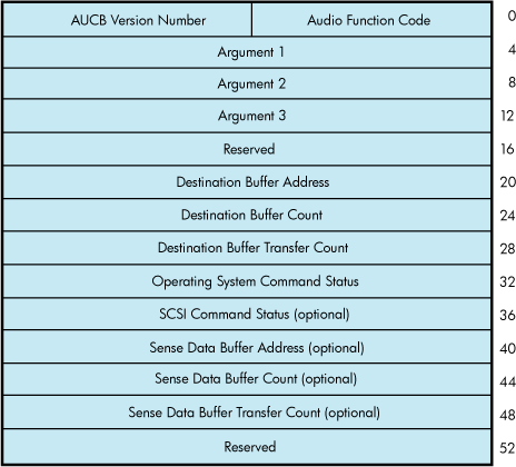
| Field | Use | |
|---|---|---|
| Audio Function Code | Numeric or symbolic code representing the audio function desired by the application program. (See Table 2.2, ''SCSI Disk Class Driver Audio Commands''.) The application program must provide a valid audio function code for each operation. | |
| AUCB Version Number | Version of the AUCB and SCSI disk class driver audio interface. For the current version of the interface the value of this field should be 1. This field must never contain a zero. | |
| Argument 1 | This field is audio command-specific and contains the first argument of the function as follows: | |
| Audio Function Code? | Field Contents | |
| AUDIO_PLAY_AUDIO_MSF (5) | Starting Frames|(Sec shifted left 8 bits)|(Min shifted left 16 bits) | |
|
AUDIO_PLAY_AUDIO_ | Starting (Track shifted left 8 bits) |Index | |
| AUDIO_PLAY_AUDIO (4) | Starting logical block address. | |
| AUDIO_GET_STATUS (9) | 0 if LBA format, 1 if MSF format. See the SCSI II specification for information about these formats. | |
| AUDIO_SET_VOLUME (11) | Longword representing the values to be used to determine the new output channel selection and volume settings for CD-ROM ports 0 through 3. Figure 2.4, ''Output Channel Selection and Volume Settings for CD-ROM Ports as Used by the SET_VOLUME Function'' shows the format of this longword. Note that many CD-ROM drives do not support ports 2 and 3. | |
| AUDIO_GET_VOLUME (12) | Longword to receive the current values determining output channel selection and volume settings for CD-ROM ports 0 through 3. Figure 2.4, ''Output Channel Selection and Volume Settings for CD-ROM Ports as Used by the SET_VOLUME Function'' shows the format of this longword. Note that many CD-ROM drives do not support ports 2 and 3. | |
| AUDIO_GET_TOC (10) | 0 if LBA format, 1 if MSF format. See the SCSI II specification for information about these formats. | |
| Argument 2 | This field is audio command-specific and contains the second argument of the function as follows: | |
| Audio Function Code? | Field Contents | |
| AUDIO_PLAY_AUDIO_MSF (5) | Starting frames|(sec shifted left 8 bits)|(min shifted left 16 bits) | |
|
AUDIO_PLAY_AUDIO_ | Ending (track shifted left 8 bits)|index | |
| AUDIO_PLAY_AUDIO (4) | Transfer count in number of contiguous blocks to be played | |
| AUDIO_GET_TOC (10) | Starting track | |
| Reserved | Must be zero. | |
| Destination Buffer Address | Address of the application program's buffer from which the status from a GET_STATUS or GET_TOC function is returned. | |
| Destination Buffer Count | Size, in bytes, of the destination buffer specified in the Destination Buffer Address field. For the GET_STATUS function, this field must contain the value 48 to receive complete status information. For the GET_TOC function, this field must contain the value 804 to receive full status. The SCSI disk class driver truncates the status data, if the destination buffer size is smaller than the size of the data. | |
| Destination Buffer Transfer Count |
The SCSI disk class driver returns to this field the actual number of bytes transferred to the buffer specified in the Destination Buffer Address field. Before accessing data returned by the GET_TOC or GET_STATUS commands, an application program must check the contents of this field to determine precisely how many bytes were returned by the CD-ROM. The application program initializes this field to zero. | |
| Operating System Command Status |
Completion status of the SCSI audio function. This value is also returned in the I/O status block of specified in the iosb argument to the $QIO system service call. See Table 2.4, ''Status Codes Returned to the IOSB and AUCB by the SCSI Disk Class Driver'' for a description of these status codes. The application program initializes this field to zero. | |
| SCSI Command Status (optional) |
SCSI status of the current operation. The SCSI disk class driver returns the SCSI status byte for the SCSI audio command described by this AUCB in the low byte of the low-order word of this field. It returns the sense key in the low byte of the high-order word. See the SCSI specification for information regarding SCSI status and SCSI sense keys. The application program initializes this field to zero. | |
| Sense Data Buffer Address (optional) | Address of buffer to which the SCSI disk class driver returns sense data when errors occur during audio function execution. When this field is specified, in the event of a check condition on an Audio command, the SCSI disk class driver automatically issues a Request Sense command to retrieve the Sense Key/Sense Data from the target. The target returns this data to the buffer specified in this field before the failing $QIO audio function completes. | |
| Sense Data Buffer Count (optional) | Size, in bytes, of the buffer specified in the Sense Data Buffer Address field. During request sense processing, the target device truncates the sense data to fit in this buffer. | |
| Sense Data Buffer Transfer Count (optional) |
Actual number of bytes of sense data returned to the application in the buffer specified in the Sense Data Buffer Address field. The application program initializes this field to zero. | |
| Reserved | Must be zero. | |
The output channel selection and volume settings for CD-ROM ports as used by the SET_VOLUME function appear as shown in Figure 2.4, ''Output Channel Selection and Volume Settings for CD-ROM Ports as Used by the SET_VOLUME Function''.
2.3.11.3. Error Handling in Applications Using SCSI Audio Functions
As indicated in Table 2.3, ''Contents of AUCB'', the AUCB provides for three levels of error status reporting:
Condition values, returned in the Operating System Command Status field of the AUCB, as well as in the I/O status block of specified in the iosb argument to the $QIO system service call. (See Table 2.4, ''Status Codes Returned to the IOSB and AUCB by the SCSI Disk Class Driver'' for a description of these status codes.)
If this status is SS$_NORMAL, the function has completed without error. If the status is not SS$_NORMAL, the application program should check the SCSI Command Status field and the Sense Data buffer to fully determine the cause of the failure.
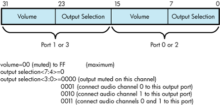
SCSI command status, returned in the SCSI Command Status field of the AUCB. The SCSI disk class driver returns to this field SCSI status as well as the sense key in the event of a check condition SCSI status. The sense key can be used to determine the first level of error reporting supported by SCSI. See the SCSI specification for further information.
Sense data, returned in the buffer specified in the Sense Data Buffer Address field of the AUCB. Sense data bytes are assigned as defined in the SCSI II specification. Sophisticated programmers can use the data in this to obtain detailed information about the error-causing condition.
If the CD-ROM device is currently software-enabled (that is, the volume has been mounted) and a unit attention is detected, then mount verification is initiated by the driver. However, if the CD-ROM is not software-enabled, the event returns to the application issuing the Audio $QIO function.
| Code | Meaning |
|---|---|
| SS$_NORMAL | AUCB command completed successfully. |
| SS$_ABORT | Returned by the SCSI disk port driver. In general, you should retry commands that fail with this status. |
| SS$_BADPARM | The driver detected an illegal value or missing value in the AUCB. |
| SS$_CTRLERR | CD-ROM failed some part of its initialization sequence. When this status is returned, it is unlikely that the CD-ROM is usable. |
| SS$_DEVOFFLINE | Device returned a not-ready sense key or failed the TEST UNIT READY/START sequence. |
| SS$_DRVERR | CD-ROM failed to execute the command, either because the drive has failed or an illegal command was issued. Such a command could be a command that requested the drive to issue an audio command to a data track or attempted to perform a play operation on nonexistent tracks. |
| SS$_ILLIOFUNC | Illegal I/O function was specified in the func argument of the $QIO request. |
| SS$_IVADDR | Specified block number is larger than UCB$L_MAXBLOCK. |
| SS$_MEDOFL | Last command failed because the drive detected the removal and replacement of the CD carrier, or the unsuccessful completion of a Request Sense command after a check condition error. In general, you should not retry commands that fail with this status. |
| SS$_NOPRIV | Caller does not have sufficient privileges to execute this function. If the CD-ROM has not been mounted before an IO$_READVBLK function is issued, this status may be returned. |
| SS$_OPINCOMPL | Number of bytes requested is less than the number of bytes returned. |
| SS$_PARITY | Nonrecoverable media error (does not apply to audio functions). |
| SS$_RECOVERR | Recovered media error (does not apply to audio functions). |
| SS$_VOLINV | CD-ROM has not been mounted. |
| SS$_WRITLCK | Write operations not permitted on read-only devices. |
2.3.11.4. Using CD-ROM to Store Both Data and Audio Information
To make effective use of mixed data and audio CDs, an application program requires detailed knowledge of the particular CD being played. The application program must know which tracks include data and which tracks include audio so it can use commands appropriate to the different track types. Issuing an audio command on a data track results in the command failing with a status of SS$_DRVERR.
By default, the SCSI disk class driver transfers all requests issued to a CD-ROM in blocks of 512 bytes. This byte amount is referred to as the default block size. Before attempting to issue READ operations to the CD-ROM, you must ensure that the CD-ROM has been mounted as foreign or as a Files-11 volume. The application program can then determine, by issuing a GET_TOC function, which tracks (and, therefore, which logical blocks) contain data and which contain audio information.
2.3.11.5. Programming Audio Applications
The following list contains information useful in avoiding problems when writing code using the SCSI audio interfaces:
If you do not know the type of file system on the CD-ROM, you should mount the CD-ROM as foreign and issue a $QIO request with the logical block I/O read function (IO$_READLBLK) to read individual data blocks. The default block size for all CD-ROMs is 512 bytes.
When using the GET_TOC command to obtain CD-ROM address information in LBA format, be advised that the byte ordering of the returned data is in big-endian form. SYS$EXAMPLES:CDROM_AUDIO.C contains an example of how to perform this exchange.
Before attempting to issue a $QIO request with the virtual block I/O read function (IO$_READVBLK) to the CD-ROM, ensure that the CD-ROM has been mounted. Typically, you have to foreign mount non-Files-11 disks. If an IO$_READVBLK $QIO request is issued to an unmounted CD, the request fails with a status of SS$_NOPRIV.
2.4. I/O Status Block
Figure 2.5, ''IOSB Contents'' shows the I/O status block (IOSB) for all disk device QIO functions except sense mode. Figure 2.6, ''IOSB Contents for the Sense Mode Function'' shows the I/O status block for the sense mode function. Figure 2.6, ''IOSB Contents for the Sense Mode Function'' lists the status messages for all functions and devices. (The OpenVMS system messages documentation provides explanations and suggested user actions for these messages.)
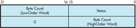
The byte count is a 32-bit integer that gives the actual number of bytes transferred to or from the process buffer.
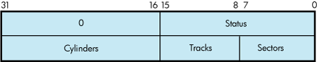
The second longword of the I/O status block for the sense mode function returns information about the cylinder, track, and sector configurations for the particular device.
2.5. Disk Driver Programming Example
A sample MACRO 32 disk driver program, DISK_DRIVER.MAR, is shown in Example 2.1, ''DISK_DRIVER.MAR Disk Driver Programming Example''. This sample program provides an example of optimizing access time to a disk file. The program creates a file using Record Management Services (RMS), stores information concerning the file, and closes the file. The program then accesses the file and reads and writes to the file using the Queue I/O ($QIO) system service.
; ********************************************************************
;

        .TITLE  Disk Driver Programming Example
        .IDENT  /01/


;
; Define necessary symbols.
;

        $FIBDEF                 ;Define file information block Offsets
        $IODEF                  ;Define I/O function codes
        $RMSDEF                 ;Define RMS-32 Return Status Values
;
; Local storage
;
; Define number of records to be processed.
;

NUM_RECS=100                    ;One hundred records

;
; Allocate storage for necessary data structures.
;
; Allocate File Access Block.
;
;       A file access block is required by RMS-32 to open and close a
;       file.
;
FAB_BLOCK:                              ;
        $FAB    ALQ = 100,-             ;Initial file size is to be
                -                       ;100 blocks
                FAC = PUT,-             ;File Access Type is output
                FNA = FILE_NAME,-       ;File name string address
                FNS = FILE_SIZE,-       ;File name string size
                FOP = CTG,-             ;File is to be contiguous
                MRS = 512,-             ;Maximum record size is 512
                -                       ;bytes
                NAM = NAM_BLOCK,-       ;File name block address
                ORG = SEQ,-             ;File organization is to be
                -                       ;sequential
                REM = FIX               ;Record format is fixed length
;
; Allocate file information block.
;
;       A file information block is required as an argument in the
;       Queue I/O system service call that accesses a file.
;
FIB_BLOCK:                              ;
        .BLKB   FIB$K_LENGTH            ;


;
; Allocate file information block descriptor.
;

FIB_DESCR:                              ;
        .LONG   FIB$K_LENGTH            ;Length of the file
                                        ;information block
        .LONG   FIB_BLOCK               ;Address of the file
                                        ;information block
;
; Allocate File Name Block
;
;       A file name block is required by RMS-32 to return information
;       concerning a file (for example, the resultant file name string
;       after logical name translation and defaults have been applied).
;

NAM_BLOCK:                              ;
        $NAM                            ;

;
; Allocate Record Access Block
;
;       A record access block is required by RMS-32 for record
;       operations on a file.
;
RAB_BLOCK:
        $RAB    FAB = FAB_BLOCK,-       ;File access block address
                RAC = SEQ,-             ;Record access is to be
                -                       ;sequential
                RBF = RECORD_BUFFER,-   ;Record buffer address
                RSZ = 512               ;Record buffer size
;
; Allocate direct address buffer
;

BLOCK_BUFFER:
        .BLKB   1024                    ;Direct access buffer is 1024
                                        ;bytes

;
; Allocate space to store channel number returned by the $ASSIGN
; Channel system service.
;
DEVICE_CHANNEL:                         ;
        .BLKW   1                       ;

;
; Allocate device name string and descriptor.
;


DEVICE_DESCR:                           ;
        .LONG   20$-10$                 ;Length of device name string
        .LONG   10$                     ;Address of device name string
10$:    .ASCII  /SYS$DISK/              ;Device on which created file
                                        ;will reside
20$:                                    ;Reference label to calculate
                                        ;length
;
; Allocate file name string and define string length symbol.
;

FILE_NAME:                              ;
        .ASCII  /SYS$DISK:MYDATAFIL.DAT/        ;File name string

FILE_SIZE=.-FILE_NAME                   ;File name string length

;
; Allocate I/O status quadword storage.
;

IO_STATUS:                              ;
        .BLKQ   1                       ;
;
; Allocate output record buffer.
;

RECORD_BUFFER:                          ;
        .BLKB   512                     ;Record buffer is 512 bytes
;
; ********************************************************************
;
;                       Start Program
;
; ********************************************************************


;
; The purpose of the program is to create a file called MYDATAFIL.DAT
; using RMS-32; store information concerning the file; write 100
; records, each containing its record number in every byte;
; close the file; and then access, read, and write the file directly,
; using the Queue I/O system service.  If any errors are detected, the
; program returns to its caller with the final error status in
; register R0.

        .ENTRY  DISK_EXAMPLE,^M,R3,R4,R5,R6>  ;Program starting
                                                 ;address

;
; First create the file and open it, using RMS-32.
;
PART_1:                                 ;First part of example
        $CREATE FAB = FAB_BLOCK         ;Create and open file
        BLBC    R0,20$                  ;If low bit = 0, creation
                                        ;failure

;
; Second, connect the record access block to the created file.
;

        $CONNECT RAB = RAB_BLOCK        ;Connect the record access
                                        ;block
        BLBC    R0,30$                  ;If low bit = 0, creation
                                        ;failure
;
; Now write 100 records, each containing its record number.
;


        MOVZBL  #NUM_RECS,R6            ;Set record write loop count

;
; Fill each byte of the record to be written with its record number.
;

10$:    SUBB3   R6,#NUM_RECS+1,R5       ;Calculate record number

        MOVC5   #0,(R6),R5,#512,RECORD_BUFFER  ;Fill record buffer

;
; Now use RMS-32 to write the record into the newly created file.
;


        $PUT    RAB = RAB_BLOCK         ;Put record in file
        BLBC    R0,30$                  ;If low bit = 0, put failure
        SOBGTR  R6,10$                  ;Any more records to write?
;
; The file creation part of the example is almost complete.  All that
; remains to be done is to store the file information returned by
; RMS-32 and close the file.
;

        MOVW    NAM_BLOCK+NAM$W_FID,FIB_BLOCK+FIB$W_FID  ;Save file
                                        ;identification
        MOVW    NAM_BLOCK+NAM$W_FID+2,FIB_BLOCK+FIB$W_FID+2  ;Save
                                        ;sequence number
        MOVW    NAM_BLOCK+NAM$W_FID+4,FIB_BLOCK+FIB$W_FID+4  ;Save
                                        ;relative volume
        $CLOSE  FAB = FAB_BLOCK         ;Close file
        BLBS    R0,PART_2               ;If low bit set, successful
                                        ;close
20$     RET                             ;Return with RMS error status
;
; Record stream connection or put record failure.
;
; Close file and return status.
;
30$:    PUSHL   R0                      ;Save error status
        $CLOSE  FAB = FAB_BLOCK         ;Close file
        POPL    R0                      ;Retrieve error status
        RET                             ;Return with RMS error status
;
; The second part of the example illustrates accessing the previously
; created file directly using the Queue I/O system service, randomly
; reading and writing various parts of the file, and then deaccessing
; the file.
;
; First, assign a channel to the appropriate device and access the
; file.
PART_2:                                 ;
        $ASSIGN_S DEVNAM = DEVICE_DESCR,-  ;Assign a channel to file
                CHAN = DEVICE_CHANNEL   ;device
        BLBC    R0,20$                  ;If low bit = 0, assign
                                        ;failure
        MOVL    #FIB$M_NOWRITE!FIB$M_WRITE,- ;Set for read/write
                FIB_BLOCK+FIB$L_ACCTL   ;access
        $QIOW_S CHAN = DEVICE_CHANNEL,- ;Access file on device channel
                FUNC = #IO$_ACCESS!IO$M_ACCESS,- ;I/O function is
                -                       ;access file
                IOSB = IO_STATUS,-      ;Address of I/O status
                -                       ;quadword
                P1 = FIB_DESCR          ;Address of information block
                                        ;descriptor
        BLBC    R0,10$                  ;If low bit = 0, access
                                        ;failure
        MOVZWL  IO_STATUS,R0            ;Get final I/O completion
                                        ;status

        BLBS    R0,30$                  ;If low bit set, successful
                                        ;I/O function
10$:    PUSHL   R0                      ;Save error status
        $DASSGN_S CHAN = DEVICE_CHANNEL ;Deassign file device channel
        POPL    R0                      ;Retrieve error status
20$:    RET                             ;Return with I/O error status
;
; The file is now ready to be read and written randomly.  Since the
; records are fixed length and exactly one block long, the record
; number corresponds to the virtual block number of the record in the
; file. Thus a particular record can be read or written simply by
; specifying its record number in the file.
;
; The following code reads two records at a time and checks to see
; that they contain their respective record numbers in every byte.
; The records are then written back into the file in reverse order.
; This results in record 1 having the old contents of record 2 and
; record 2 having the old contents of record 1, and so forth. After
; the example has been run, it is suggested that the file dump
; utility be used to verify the change in data positioning.
;


30$     MOVZBL  #1,R6                   ;Set starting record (block)
                                        ;number
;
; Read next two records into block buffer.
;

40$:    $QIO_S  CHAN = DEVICE_CHANNEL,- ;Read next two records from
                -                       ;file channel
                FUNC = #IO$_READVBLK,-  ;I/O function is read virtual
                -                       ;block
                IOSB = IO_STATUS,-      ;Address of I/O status
                -                       ;quadword
                P1 = BLOCK_BUFFER,-     ;Address of I/O buffer
                P2 = #1024,-            ;Size of I/O buffer
                P3 = R6                 ;Starting virtual block of
                                        ;transfer
        BSBB    50$                     ;Check I/O completion status
;
; Check each record to make sure it contains the correct data.
;

        SKPC    R6,#512,BLOCK_BUFFER    ;Skip over equal record
                                        ;numbers in data

        BNEQ    60$                     ;If not equal, data match
                                        ;failure
        ADDL3   #1,R6,R5                ;Calculate even record number

        SKPC    R5,#512,BLOCK_BUFFER+512 ;Skip over equal record
                                        ;numbers in data
        BNEQ    60$                     ;If not equal, data match
                                        ;failure
;
; Record data matches.
;
; Write records in reverse order in file.
;

        $QIOW_S CHAN = DEVICE_CHANNEL,- ;Write even-numbered record in
                -                       ;odd slot
                FUNC = #IO$_WRITEVBLK,- ;I/O function is write virtual
                -                       ;block
                IOSB = IO_STATUS,-      ;Address of I/O status
                -                       ;quadword
                P1 = BLOCK_BUFFER+512,- ;Address of even record buffer
                P2 = #512,-             ;Length of even record buffer
                P3 = R6                 ;Record number of odd record
        BSBB    50$                     ;Check I/O completion status
        ADDL3   #1,R6,R5                ;Calculate even record number
        $QIOW_S CHAN = DEVICE_CHANNEL,- ;Write odd numbered record in
                -                       ;even slot
                FUNC = #IO$_WRITEVBLK,- ;I/O function is write virtual
                -                       ;block
                IOSB = IO_STATUS,-      ;Address of I/O status
                -                       ;quadword
                P1 = BLOCK_BUFFER,-     ;Address of odd record buffer
                P2 = #512,-             ;Length of odd record buffer
                P3 = R5                 ;Record number of even record
        BSBB    50$                     ;Check I/O completion status
        ACBB    #NUM_RECS-1,#2,R6,40$   ;Any more records to be read?

        BRB     70$                     ;


;
; Check I/O completion status.
;

50$:    BLBC    R0,70$                  ;If low bit = 0, service
                                        ;failure
        MOVZWL  IO_STATUS,R0            ;Get final I/O completion
                                        ;status
        BLBC    R0,70$                  ;If low bit = 0, I/O function
        RSB                             ;failure
;
; Record number mismatch in data.
;

60$:    MNEGL   #4,R0                   ;Set dummy error status value

;
; All records have been read, verified, and odd/even pairs inverted
;
70$:    PUSHL   R0                      ;Save final status
        $QIOW_S CHAN = DEVICE_CHANNEL,- ;Deaccess file
                FUNC = #IO$_DEACCESS    ;I/O function is deaccess file
        $DASSGN_S CHAN = DEVICE_CHANNEL ;Deassign file device channel
        POPL    R0                      ;Retrieve final status
        RET                             ;

        .END    DISK_EXAMPLE
Chapter 3. Magnetic Tape Drivers
This chapter describes the use of magnetic tape drivers, drives, and controllers.
3.1. Magnetic Tape Controllers and Drives
The following sections describe magnetic tape controllers and drives; however, note that not all supported devices are described here. See the Software Product Description for the OpenVMS Operating System (SPD 82.35.xx) for the definitive list of supported devices.
3.2. Magnetic Tape Driver Device Information
You can obtain information on all magnetic tape device characteristics by using the Get Device/Volume Information ($GETDVI) system service. (See the VSI OpenVMS System Services Reference Manual.)
See the Help files for more information on the $GETDVI system service.
$GETDVI returns magnetic tape characteristics when you specify the item codes DVI$_DEVCHAR, DVI$_DEVCHAR2, DVI$_DEVDEPEND, and DVI$_DEVDEPEND2. Tables Table 3.1, ''Magnetic Tape Device-Independent Characteristics'', Table 3.2, ''Device-Dependent Information for Tape Devices'', and Table 3.3, ''Device-Dependent Information for Tape Devices'' list these characteristics. The $DEVDEF macro defines the device-independent characteristics, the $MTDEF macro defines the device-dependent characteristics, and the $MT2DEF macro defines the extended device characteristics. The extended device characteristics apply only to the TU81-Plus tape drive.
| Characteristic? | Meaning |
|---|---|
| Dynamic Bits (Conditionally Set) | |
| DEV$M_AVL | Device is on line and available. |
| DEV$M_FOR | Volume is foreign. |
| DEV$M_MNT | Volume is mounted. |
| DEV$M_RCK | Perform data check on all read operations. |
| DEV$M_WCK | Perform data check on all write operations. |
| Static Bits (Always Set) | |
| DEV$M_FOD | Device is file-oriented. |
| DEV$M_IDV | Device is capable of input. |
| DEV$M_ODV | Device is capable of output. |
| DEV$M_SQD | Device is capable of sequential access. |
| DEV$M_WBC? | Device is capable of write-back caching. |
| Characteristic? | Meaning | |
|---|---|---|
| MT$M_LOST | If set, the current tape position is unknown. | |
| MT$M_HWL | If set, the selected drive is hardware write-locked. | |
| MT$M_EOT | If set, an end-of-tape (EOT) condition was encountered by the last operation to move the tape in the forward direction. | |
| MT$M_EOF | If set, a tape mark was encountered by the last operation to move the tape. | |
| MT$M_BOT | If set, a beginning-of-tape (BOT) marker was encountered by the last operation to move the tape in the reverse direction. | |
| MT$M_PARITY | If set, all data transfers are performed with even parity. If clear (normal case), all data transfers are performed with odd parity. Only nonreturn-to-zero-inverted recording at 800 bits/inch can have even parity. | |
|
MT$V_DENSITY MT$S_DENSITY | Specifies the density at which all data transfer operations are performed. Possible density values are as follows: | |
| MT$K_GCR_6250 | Group-coded recording, 6250 bits/inch | |
| MT$K_PE_1600 | Phase-encoded recording, 1600 bits/inch | |
| MT$K_NRZI_800 | Nonreturn-to-zero-inverted recording, 800 bits/inch | |
| MT$K_BLK_833 | Cartridge block mode recording? | |
| Specifies the format in which all data transfers are performed. A possible format value is as follows: | |
| MT$K_NORMAL11 | Normal PDP-11 format. Data bytes are recorded sequentially on tape with each byte occupying exactly one frame. | |
| MT$_FASTSKIP_USED | If set, the most recent IO$_SKIPFILE function was performed using the optimized SCSI space-by-file-marks algorithm. (See Section 3.3.4, ''Skip File'' for more information about the IO$M_ALLOWFAST modifier to the IO$_SKIPFILE function.) | |
| Characteristic? | Meaning |
|---|---|
| MT2$V_WBC_ENABLE | If set, write-back caching is enabled for this unit. |
| MT2$V_RDC_DISABLE | If set, read caching is disabled for this unit. |
DVI$_DEVTYPE and DVI$_DEVCLASS return the device type and class names, which are defined by the $DCDEF macro. DVI$_DEVBUFSIZ returns the buffer size. The buffer size is the default to be used for tape transfers (normally 2048 bytes). The device class for magnetic tapes is $DCTAPE, and the device type is determined by the magnetic tape model. For example, the device type for the TA78 is DT$_TA78; for the TA81 it is DT$_TA81.
This function code takes no function-dependent arguments.
3.3. Magnetic Tape Function Codes
The magnetic tape driver can perform logical, virtual, and physical I/O functions. Foreign-mounted devices do not require privileges to perform logical and virtual I/O requests.
Logical and physical I/O functions to magnetic tape devices allow sequential access to volume storage and require only that the requesting process have direct access to the device. The results of logical and physical I/O operations are unpredictable if an ACP is present.
Virtual I/O functions require intervention by an ACP and must be executed in a prescribed order. The normal order is to create and access a file, write information to that file, and deaccess the file. Subsequently, when you access the file, you read the information and then deaccess the file. You can write over the file when the information it contains is no longer useful and the file has expired.
Any number of bytes (from a minimum of 14 to a maximum of 65,535) can be read from or written into a single block by a single request. The number of bytes itself has no effect on the applicable quotas (direct I/O, buffered I/O, and AST). Reading or writing any number of bytes subtracts the same amount from a quota.
The volume to which a logical or virtual function is directed must be mounted for the function actually to be executed. If it is not, either a “device not mounted” or “invalid volume” status is returned in the I/O status block.
Table 3.4, ''Magnetic Tape I/O Functions'' lists the logical, virtual, and physical magnetic tape I/O functions and their function codes. These functions are described in more detail in the following paragraphs. Chapter 1, "ACP-QIO Interface" describes the QIO level interface to the magnetic tape device ACP. Chapter 10, "Optional Features for Improving I/O Performance" describes features to improve performance for larger file transfers.
| Function Code | Arguments | Type? | Function Modifiers | Function |
|---|---|---|---|---|
| IO$_ACCESS | P1,[P2],[P3], [P4],[P5] | V |
| Search a tape for a specified file and access the file if found and IO$M_ACCESS is set. If the file is not found and IO$M_CREATE is set, create a file at end-of-tape (EOT) marker. |
| IO$_ACPCONTROL | P1,[P2],[P3], [P4], [P5] | V | IO$M_DMOUNT | Perform miscellaneous control functions.? |
| IO$_AVAILABLE | P | Clear volume valid bit. | ||
| IO$_CREATE | P1,[P2][,[P3], [P4],[P5] | V |
| Create a file. |
| IO$_DEACCESS | P1,[P2],[P3], [P4],[P5] | V | Deaccess a file and, if the file has been written, write out trailer records. | |
| IO$_DSE? | P | IO$M_NOWAIT | Erase a prescribed section of the tape. | |
| IO$_FLUSH | L | Flush the controller cache to tape. | ||
| IO$_MODIFY | P1,[P2],[P3], [P4],[P5] | V | Write user labels. | |
| IO$_PACKACK | P | Initialize volume valid bit. | ||
| IO$_READLBLK ? | P1,P2 | L | Read logical block. | |
| IO$_READPBLK | P1,P2 | P | Read physical block. | |
| IO$_READVBLK | P1,P2 | V | Read virtual block. | |
| IO$_REWIND | L |
| Reposition tape to the beginning-of-tape (BOT) marker. | |
| IO$_REWINDOFF | L |
| Rewind and unload the tape on the selected drive. | |
| IO$_SENSECHAR | [P1],[P2]? | P | IO$M_INHRETRY | Sense the tape characteristics and return them in the I/O status block. |
| IO$_SENSEMODE | [P1],[P2]? | L | IO$M_INHRETRY | Sense the tape characteristics and return them in the I/O status block. |
| IO$_SETCHAR | P1,[P2]? | P | Set tape characteristics for subsequent operations. | |
| IO$_SETMODE | P1,[P2]? | L | Set tape characteristics for subsequent operations. | |
| IO$_SKIPFILE | P1 | L |
| Skip past a specified number of tape marks in either a forward or reverse direction. |
| IO$_SKIPRECORD | P1 | L |
| Skip past a specified number of blocks in either a forward or reverse direction. |
| IO$_UNLOAD | L |
| Rewind and unload the tape on the selected drive. | |
| IO$_WRITELBLK | P1,P2 | L | Write logical block. | |
| IO$_WRITEOF | L |
| Write an extended interrecord gap followed by a tape mark. | |
| IO$_WRITEPBLK | P1,P2 | P | Write physical block. | |
| IO$_WRITEVBLK | P1,P2 | V | Write virtual block. |
The function-dependent arguments for IO$_CREATE, IO$_ACCESS, IO$_DEACCESS, IO$_MODIFY, IO$_ACPCONTROL are as follows:
P1—The address of the file information block (FIB) descriptor.
P2—Optional. The address of the file name string descriptor. If specified with IO$_ACCESS, the name identifies the file being sought. If specified with IO$_CREATE, the name is the name of the created file.
P3—Optional. The address of the word that is to receive the length of the resultant file name string.
P4—Optional. The address of a descriptor for a buffer that is to receive the resultant file name string.
P5—Optional. The address of a list of attribute descriptors. If specified with IO$_ACCESS, the attributes of the file are returned to the user. If specified with IO$_CREATE, P5 is the address of the attribute descriptor list for the new file. All file attributes for IO$_MODIFY are ignored.
See Chapter 1, "ACP-QIO Interface" for more information on these functions.
The function-dependent arguments for IO$_READVBLK, IO$_READLBLK, IO$_READPBLK, IO$_WRITEVBLK, IO$_WRITELBLK, and IO$_WRITEPBLK are as follows:
P1—The starting virtual address of the buffer that is to receive the data in the case of a read operation; or, in the case of a write operation, the virtual address of the buffer that is to be written on the tape. On OpenVMS Alpha, P1 can be a 64-bit address.
P2—The length of the buffer specified by P1.
The function-dependent argument for IO$_SKIPFILE and IO$_SKIPRECORD is:
P1—The number of tape marks to skip over in the case of a skip file operation; or, in the case of a skip record operation, the number of blocks to skip over. If a positive number is specified, the tape moves forward; if a negative number is specified, the tape moves in reverse. (The maximum number of tape marks or records that P1 can specify is 32,767.)
Example 3.1, ''Defining the P1 Parameter in a IO$_SKIPRECORD QIO'' shows the correct method of defining the P1 parameter in an IO$_SKIPRECORD QIO.
  .
  .
  .
TAPE_CHAN:
        .WORD    0
IOSB:   .WORD    0
        .WORD    0
        .LONG    0
DEVICE: .ASCID   /$127$MUA0:/
RECORD: .LONG    2000
;
        .PSECT   CODE,EXE,NOWRT
;
        .ENTRY   MT_IO,^M


;
        $ASSIGN_S    CHAN=TAPE_CHAN,-
                 DEVNAM=DEVICE
        BLBC     R0,EXIT_ERROR
;
        $QIOW_S  CHAN=TAPE_CHAN,-
                 FUNC=#IO$_SKIPRECORD,-
                 IOSB=IOSB,-
                 P1=RECORD
        BLBC     R0,EXIT_ERROR
        $EXIT_S  R0
  .
  .
  .
EXIT_ERROR:
        $EXIT_S  R0
        .END     MT_IO
3.3.1. Read
The read function reads data into a specified buffer in the forward or reverse direction starting at the next block position.
The operating system provides the following read function codes:
IO$_READVBLK—Read virtual block
IO$_READLBLK—Read logical block
IO$_READPBLK—Read physical block
If a read virtual block function is directed to a volume that is mounted foreign, it is converted to a read logical block function. If a read virtual block function is directed to a volume that is mounted structured, the volume is handled the same way as a file-structured device.
Two function-dependent arguments are used with these codes: P1 and P2. These arguments are described in Section 3.3, ''Magnetic Tape Function Codes''.
If the read function code includes the reverse function modifier (IO$M_REVERSE), the drive reads the tape in the reverse direction instead of the forward direction. IO$M_REVERSE cannot be specified for the TUK50 and TQK50 devices.
The data check function modifier (IO$M_DATACHECK) can be used with all read functions. If this modifier is specified, a data check operation is performed after the read operation completes. (The drive performs a space reverse or space forward between the read and data check operations.) A data check operation is also performed if the volume that was read, or the volume on which the file resides (virtual read), has the characteristic “data check all reads.” Furthermore, a data check is performed after a virtual read if the file has the attribute “data check on read.” The TS04 and TU80 tape drives do not support the data check function.
For read physical block and read logical block functions, the drive returns the status SS$_NORMAL (not end-of-tape status) if either of the following conditions occurs and no other error condition exists:
The tape is positioned past the end-of-tape (EOT) position at the start of the read (forward or reverse) operation.
The tape enters the EOT region as a result of the read (forward) operation.
The transferred byte count reflects the actual number of bytes read.
If the drive reads a tape mark during a logical or physical read operation in either the forward or reverse direction, any of the following conditions can return an end-of-file (EOF) status:
The tape is positioned past the EOT position at the start of the read operation.
The tape enters the EOT region as a result of the read operation.
The drive reads a tape mark as a result of a read operation but the tape does not enter the EOT region.
An EOF status is also returned if the drive attempts a read operation in the reverse direction when the tape is positioned at the beginning-of-tape (BOT) marker. All conditions that cause an EOF status result in a transferred byte count of zero.
If the drive attempts to read a block that is larger than the specified memory buffer during a logical or physical read operation, a data overrun status is returned. The buffer receives only the first part of the block. On a read in the reverse direction (on drives other than the TK50 and TZ30) the buffer receives only the latter part of the block. The transferred byte count is equal to the actual size of the block. Read reverse starts at the top of the buffer. Therefore, the start of the block is at P1 plus P2 minus the length read. The TUK50 and TZ30 cannot actually perform read reverse operations; they must be simulated by the driver. Therefore, the data returned are those that would have been returned had the block been read in the forward direction.
It is not possible to read a block that is less than 14 bytes in length. Records that contain less than 14 bytes are termed “noise blocks” and are completely ignored by the driver.
3.3.2. Write
The write function writes data from a specified buffer to tape in the forward direction starting at the next block position.
The operating system provides the following write function codes:
IO$_WRITEVBLK—Write virtual block
IO$_WRITELBLK—Write logical block
IO$_WRITEPBLK—Write physical block
If a write virtual block function is directed to a volume that is mounted foreign, the function is converted to a write logical block. If a write virtual block function is directed to a volume that is mounted structured, the volume is handled the same way as a file-structured device.
Two function-dependent arguments are used with these codes: P1 and P2. These arguments are described in Section 3.3, ''Magnetic Tape Function Codes''“Magnetic Tape Function Codes”.
The IO$M_ERASE function modifier can be used with the IO$_WRITELBLK and IO$_WRITEPBLK function codes to erase a user-selected part of a tape. This modifier propagates an erase pattern of all zeros from the current tape position to 10 feet past the EOT position and then rewinds to the BOT marker.
The data check function modifier (IO$M_DATACHECK) can be used with all write functions. If this modifier is specified, a data check operation is performed after the write operation completes. (The drive performs a space reverse between the write and the data check operations.) The driver forces a data check operation when an error occurs during a write operation. This ensures that the data can be reread. A data check operation is also performed if the volume written, or the volume on which the file resides (virtual write), has the characteristic “data check all writes.” Furthermore, a data check is performed after a virtual write if the file has the attribute “data check on write.” The TS04 and TU80 tape drives do not support the data check function.
If the IO$M_NOWAIT function modifier is specified, write-back caching is enabled on a per-command basis. IO$M_NOWAIT is applicable only to TU81-Plus drives.
If the drive performs a write physical block or a write logical block operation, an EOT status is returned if either of the following conditions occurs and no other error condition exists:
The tape is positioned past the EOT position at the start of the write operation.
The tape enters the EOT region as a result of the write operation.
The transferred byte count reflects the size of the block written. It is not possible to write a block less than 14 bytes in length. An attempt to do so results in the return of a bad parameter status for the QIO request.
3.3.3. Rewind
The rewind function repositions the tape to the beginning-of-tape (BOT) marker.
If the IO$M_NOWAIT function modifier is specified, the I/O operation is completed when the rewind is initiated. Otherwise, I/O completion does not occur until the tape is positioned at the BOT marker.
If the IO$M_RETENSION function modifier is specified and the device supports the retention operation, the rewind function positions the tape to the physical-end-of-tape (EOT) marker and rewinds the tape to the BOT marker. If the tape does not support the IO$M_RETENSION modifier, a SS$_ILLIOFUNC error is returned.
IO$_REWIND has no function-dependent arguments.
3.3.4. Skip File
The skip file function (IO$_SKIPFILE) skips past a specified number of tape marks in either a forward or reverse direction. A function-dependent argument (P1) is provided to specify the number of tape marks to be skipped, as shown in Figure 3.1, ''IO$_SKIPFILE Argument''. If a positive file count is specified, the tape moves forward; if a negative file count is specified, the tape moves in reverse. (The actual number of files skipped is returned as an unsigned number in the I/O status block.)

Only tape marks (when the tape moves in either direction) and the BOT marker (when the tape moves in reverse) are counted during a skip file operation. The BOT marker terminates a skip file function in the reverse direction. The end-of-tape (EOT) marker does not terminate a skip file function in either the forward or reverse direction. A negative skip file function leaves the tape positioned just before a tape mark (at the end of a file) unless the BOT marker is encountered, whereas a positive skip file function leaves the tape positioned just past the tape mark.
A skip file function in the forward direction can also be terminated if two consecutive tape marks are encountered. Section 3.3.5.1, ''Logical End-of-Volume (EOV) Detection'' describes this feature.
The IO$M_ALLOWFAST modifier can be used with the IO$_SKIPFILE function to provide better performance on SCSI tape drives that support the SCSI space-by-file-marks command and the SCSI read position command.
When the IO$M_ALLOWFAST modifier is specified, a tape operation skips over consecutive tape marks that are not immediately before the end-of-data position on the medium. However, if two consecutive tape marks are detected immediately before the end-of-data position on the tape, the tape is positioned between these two tape marks and the SS$_ENDOFVOLUME status is returned.
The IO$M_ALLOWFAST modifier allows a SCSI tape subsystem to use the optimized IO$_SKIPFILE if it is capable. If a specific tape device does not adequately support the optimized IO$_SKIPFILE that uses the SCSI space-by-file-marks command, the tape subsystem uses the standard space-by-records algorithm.
3.3.5. Skip Record
The skip record function skips past a specified number of physical tape blocks in either a forward or reverse direction. A device- or function-dependent argument (P1) specifies the number of blocks to skip, as shown in Figure 3.2, ''IO$_SKIPRECORD Argument''. If a positive block count is specified, the tape moves forward; if a negative block count is specified, the tape moves in reverse. The actual number of blocks skipped is returned as an unsigned number in the I/O status block. If a tape mark is detected, the count is the number of blocks skipped, plus 1 (forward tape motion) or minus 1 (reverse tape motion).

A skip record operation is terminated by the end-of-file (EOF) marker when the tape moves in either direction, by the BOT marker when the tape moves in reverse, and by the EOT marker when the tape moves forward.
A skip record function in the forward direction can also be terminated if the tape was originally positioned between two tape marks. Section 3.3.5.1, ''Logical End-of-Volume (EOV) Detection'' describes this feature.
3.3.5.1. Logical End-of-Volume (EOV) Detection
A skip file or skip record operation that uses the standard space-by-records algorithm is terminated when two consecutive tape marks are encountered when the tape moves in the forward direction. After the operation terminates, the tape remains positioned between the two tape marks that were detected. The I/O status block (IOSB) returns the status SS$_ENDOFVOLUME and the actual number of files (or records) skipped during the operation prior to the detection of the second tape mark. The skip count is returned in the high-order word of the first longword of the IOSB.
An optimized skip file that uses the IO$M_ALLOWFAST modifier is terminated when the end-of-data position is encountered. If two consecutive tape marks immediately precede the end-of-data position on the tape, the tape is positioned between these two tape marks. The SS$_ENDOFVOLUME status and the skip count are returned in the IOSB.
Subsequent skip record (or skip file) requests terminate immediately when the tape is positioned between the two tape marks, producing no net tape movement and returning the SS$_ENDOFVOLUME status with a skip count of zero.
To move the tape beyond the second tape mark, you must employ another I/O function. For example, the IO$_READLBLK function, if issued after receipt of the SS$_ENDOFVOLUME status return, terminates with an SS$_ENDOFFILE status and with the tape positioned just past the second tape mark. From this new position, other skip functions could be issued to produce forward tape motion (assuming there is additional data on the tape).
If three consecutive tape marks are encountered during a skip file function, you must issue two IO$_READLBLK functions, the first to get the SS$_ENDOFFILE return and the second to position the tape past the third tape mark.
3.3.6. Write End-of-File
The write end-of-file (EOF) function writes an extended interrecord gap (of approximately 3 inches for nonreturn-to-zero-inverted (NRZI) recording and 1.5 inches for phase-encoded (PE) recording) followed by a tape mark. No device- or function-dependent arguments are used with IO$_WRITEOF.
An end-of-tape (EOT) status is returned in the I/O status block if either of the following conditions is present and no other error conditions occur:
A write EOF function is executed while the tape is positioned past the EOT marker.
A write EOF function causes the tape position to enter the EOT region.
3.3.7. Rewind Offline
The rewind offline function rewinds and unloads the tape on the selected drive.
The I/O operation is completed as soon as the tape movement is initiated. The actual finish of the mechanical rewind or unload operation may occur long after the I/O operation completes.
If the IO$M_RETENSION function modifier is specified and the device supports the retention operation, the rewind offline function positions the tape to the physical end-of-tape (EOT) marker and rewinds the tape to the beginning-of-tape (BOT) marker. If the tape does not support the IO$M_RETENSION modifier, a SS$_ILLIOFUNC error is returned.
No device- or function-dependent arguments are used with IO$_REWINDOFF.
3.3.8. Unload
The unload function rewinds and unloads the tape on the selected drive. The unload function is functionally the same as the rewind offline function. If the IO$M_NOWAIT function modifier is specified, the I/O operation is completed as soon as the rewind operation is initiated. No device- or function-dependent arguments are used with IO$_UNLOAD.
3.3.9. Sense Tape Mode
The sense tape mode function senses the current device-dependent and extended device characteristics (see Tables Table 3.2, ''Device-Dependent Information for Tape Devices'' and Table 3.3, ''Device-Dependent Information for Tape Devices'').
The operating system provides the following function codes:
IO$_SENSEMODE—Sense mode
IO$_SENSECHAR—Sense characteristics
Sense mode requires logical I/O privilege. Sense characteristics requires physical I/O privilege. For TMSCP and SCSI drives, the sense mode function returns magnetic tape information in a user-supplied buffer, which is specified by the following function-dependent arguments:
P1—Optional. Address of a user-supplied buffer.
P2—Optional. Length of a user-supplied buffer.
If P1 is not zero, the sense mode buffer returns the tape characteristics. (If P2=8, the second longword of the buffer contains the device-dependent characteristics. If P2=12, the second longword contains the device-dependent characteristics and the third longword contains the tape densities that the drive supports and the extended tape characteristics.) The extended characteristics are identical to the information returned by DVI$_DEVDEPEND2 (see Table 3.3, ''Device-Dependent Information for Tape Devices''). Figure 3.3, ''Sense Mode P1 Buffer'' shows the contents of the P1 buffer.
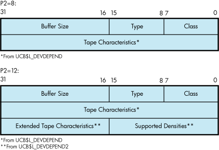
3.3.10. Set Mode
Set mode operations affect the operation and characteristics of the associated magnetic tape device. The operating system defines two types of set mode functions: set mode and set characteristics.
Set mode requires logical I/O privilege. Set characteristics requires physical I/O privilege. The following function codes are provided:
IO$_SETMODE—Set mode
IO$_SETCHAR—Set characteristics
These functions take the following device- or function-dependent arguments (other arguments are ignored):
P1—The address of a characteristics buffer.
P2—Optional. The length of the characteristics buffer. The default is 8 bytes. If a length of 12 bytes is specified, the third longword (which is for TMSCP and SCSI drives only) specifies the extended tape characteristics.
Figure 3.4, ''Set Mode Characteristics Buffer for IO$_SETMODE'' shows the P1 characteristics buffer for IO$_SETMODE. Figure 3.5, ''Set Mode Characteristics Buffer for IO$_SETCHAR'' shows the same buffer for IO$_SETCHAR.
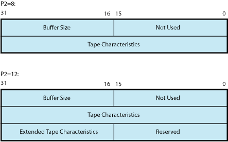
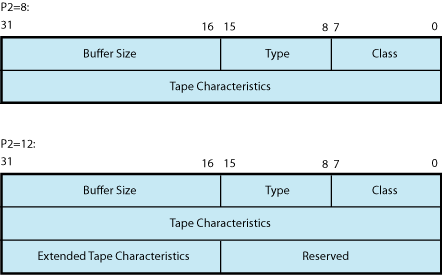
The first longword of the P1 buffer for the set characteristics function contains information on device class and type, and the buffer size. The device class for tapes is DC$_TAPE.
The $DCDEF macro defines the device type and class names. The buffer size is the default to be used for tape transfers (this default is normally 2048 bytes).
The second longword of the P1 buffer for both the set mode and set characteristics functions contains the tape characteristics. Table 3.5, ''Set Mode and Set Characteristics Magnetic Tape Characteristics'' lists the tape characteristics and their meanings. The $MTDEF macro defines the symbols listed. If P2=12, the third longword contains the extended tape characteristics for TMSCP and SCSI drives, which are listed in Table 3.6, ''Extended Device Characteristics for Tape Devices''. The extended tape characteristics are defined by the $MT2DEF macro and are identical to the information returned by DVI$_DEVDEPEND2.
| Characteristic? | Meaning | |
|---|---|---|
| MT$M_PARITY | If set, all data transfers are performed with even parity. If clear (normal case), all data transfers are performed with odd parity. Even parity can be selected only for nonreturn-to-zero-inverted recording at 800 bits/inch. Even parity cannot be selected for phase-encoded recording (tape density is MT$K_PE_1600) or group-coded recording (tape density is MT$K_GCR_6250) and is ignored. | |
| Specifies the density at which all data transfers are performed. Tape density can be set only when the selected drive's tape position is at the BOT marker. Possible density values are as follows: | |
| MT$K_DEFAULT | Default system density. | |
| MT$K_GCR_6250 | Group-coded recording, 6250 bits/inch. | |
| MT$K_PE_1600 | Phase-encoded recording, 1600 bits/inch. | |
| MT$K_NRZI_800 | Nonreturn-to-zero-inverted recording, 800 bits/inch. | |
| MT$K_BLK_833 | Cartridge block mode recording.? | |
| Specifies the format in which all data transfers are performed. Possible format values are as follows: | |
| MT$K_DEFAULT | Default system format. | |
| MT$K_NORMAL11 | Normal PDP-11 format. Data bytes are recorded sequentially on tape with each byte occupying exactly one frame. | |
| Characteristic? | Meaning |
|---|---|
| MT2$V_WBC_ENABLE | Enable write-back caching on a per-unit basis. |
| MT2$V_RDC_DISABLE | Disable read caching on a per-unit basis. |
Application programs that change specific magnetic tape characteristics should perform the following steps, as shown in Section 3.5, ''Magnetic Tape Drive Programming Examples''“Magnetic Tape Drive Programming Examples”:
Use the IO$_SENSEMODE function to read the current characteristics.
Modify the characteristics.
Use the set mode function to write back the results.
Failure to follow this sequence results in clearing any previously set characteristic.
3.3.11. Multiple Tape Density Support
As of Version 7.2, OpenVMS Alpha permits the selection of any density and any compression supported by a tape drive. You can write to tapes using any density and any compression algorithm supported by the tape drive. Exchanging tapes among tape drives with different default settings for density or compression is much easier with this enhancement.
Note
After the media has been initialized to a specific density, it retains that density until the media is initialized to a different density. For example, if an HPE media has been initialized with TK86 density, the DCL command MOUNT/DENSITY=TK85 will have no effect because the media is initialized at TK86 density. Likewise, BACKUP/DENSITY=TK85 will have no effect if the media is initialized at TK86 density. However, BACKUP/DENS=TK85/INITIALIZE initializes the media to TK85 density.
These enhancements allow IO$_SETMODE and IO$_SENSEMODE to function with most density values and a wider variety of drives. The system management utilities BACKUP and MOUNT take advantage of this added functionality. For more information about multiple tape density support with these utilities, see the VSI OpenVMS System Manager's Manual. For more information about enhancements in INITIALIZE, see the VSI OpenVMS DCL Dictionary.
3.3.12. Data Security Erase
The data security erase function erases all data from the current position of the volume to 10 feet beyond the EOT reflective strip, and then rewinds the tape to the BOT marker. It is a physical I/O function and requires the access privilege necessary to perform physical I/O functions. The following function code is provided:
IO$_DSE
If the function is issued when a tape is positioned at the BOT marker, all data on the tape is erased.
IO$_DSE takes no device- or function-dependent arguments.
3.3.13. Modify
Specifying the ATR$C_USERLABEL or ATR$C_ENDLBLAST attributes with IO$_MODIFY results in a bad attribute error. If any other attributes are specified, the IO$_MODIFY function is treated as a no-operation; that is, the function returns success, but no action is performed.
3.3.14. Pack Acknowledge
The pack acknowledge function sets the volume valid bit for all magnetic tape devices. It is a physical I/O function and requires the access privilege to perform physical I/O. The following function code is provided:
IO$_PACKACK
IO$_PACKACK must be the first function issued when a volume is placed in a magnetic tape drive. IO$_PACKACK is issued automatically when the DCL commands INITIALIZE or MOUNT are issued.
3.3.15. Available
The available function clears the volume valid bit for all magnetic tape drives, that is, it reverses the function performed by the pack acknowledge function (see the Section 3.3.14, ''Pack Acknowledge''). A rewind of the tape is performed (applicable to all tape drives). No unload function is issued to the drive. The following function code is provided:
IO$_AVAILABLE
This function takes no function-dependent arguments.
3.3.16. Flush
The flush function is used to ensure that all previously issued cached commands have fully completed. Normally, hosts use this function to establish or maintain synchronization with write-back cached commands issued to the specified tape unit. The I/O request does not complete until all cached data is written successfully to the media in the exact order that the user specified.
IO$_FLUSH
This function code takes no function-dependent arguments.
3.4. I/O Status Block
The I/O status block (IOSB) for QIO functions on magnetic tape devices is shown in Figure 3.6, ''IOSB Contents''. Appendix A, "I/O Function Codes" lists the status returns for these functions. (The OpenVMS system messages documentation provides explanations and suggested user actions for these returns.) Table 3.2, ''Device-Dependent Information for Tape Devices'' (in Section 3.2, ''Magnetic Tape Driver Device Information'') lists the device-dependent data returned in the second longword. The IO$_SENSEMODE function can be used to return that data.
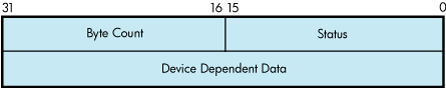
The byte count is the actual number of bytes transferred to or from the process buffer or the number of files or blocks skipped. (If an IO$_SKIPRECORD function is terminated by the detection of a tape mark, the count returned in the IOSB is an unsigned number reflecting the number of blocks skipped, plus 1.
3.5. Magnetic Tape Drive Programming Examples
This section presents magnetic tape driver programming examples.
Example 3.2, ''Device Characteristic Program Example'' shows the recommended sequence for changing a device characteristic. It retrieves the current characteristics using an IO$_SENSEMODE request, sets the new characteristics bits, and then uses IO$_SETMODE to set the new characteristics.
Example 3.3, ''Set Mode and Sense Mode Program Example'' shows ways of specifying sense mode and set mode, both with and without a user buffer specified, and with user buffers of different lengths.
In addition, Example 3.4, ''MAGNETIC_TAPE.MAR Device Characteristic Program Example'' shows how data is written to and read from magnetic tape through the magnetic tape ACP.
$QIOW_S -                                     ; Get current characteristics.
        FUNC      = #IO$_SENSEMODE,-          ; - Sense mode
        CHAN      = CHANNEL,-                 ; - Channel
        IOSB      = IO_STATUS,-               ; - IOSB
        P1        = BUFFER,-                  ; - User buffer supplied
        P2        = #12                       ; - Buffer length = 12
        .
        .
        .
(Check for errors)
        .
        .
        .
(Set desired characteristics bits)
        .
        .
        .

$QIOW_S -                                     ; Set new characteristics.
        FUNC      = #IO$_SETMODE,-            ; - Set Mode
        CHAN      = CHANNEL,-                 ; - Channel
        IOSB      = IO_STATUS,-               ; - IOSB
        P1        = BUFFER,-                  ; - User buffer address
        P2        = #12                       ; - Buffer length = 12
        .
        .
        .
(Check for errors)
        .
        .
        .
        .PSECT        IMPURE, NOEXE, NOSHR

        $IODEF


DEVICE_NAME:                                  ; Name of device
        .ASCID        /MUA0/                  ;

CHANNEL:                                      ; Channel to device
        .WORD        0                        ;

BUFFER: .BLKL        3                        ; Set/Sense characteristics
                                              ;  buffer

IO_STATUS:                                    ; Final I/O status
        .QUAD        0                        ;


        .PSECT        CODE, RD, NOWRT, EXE

        .ENTRY        MAIN,^M


$ASSIGN_S -                                   ; Assign a channel to device
          DEVNAM      = DEVICE_NAME,-         ;
          CHAN        = CHANNEL               ;

BSBW    ERR_CHECK2                            ; Check for errors

$QIOW_S -                                     ; Get current characteristics
          FUNC        = #IO$_SENSEMODE,-      ; No user buffer supplied
          CHAN        = CHANNEL,-             ;
          IOSB        = IO_STATUS             ;

BSBW      ERR_CHECK                           ; Check for errors


$QIOW_S -                                     ; Get current characteristics
         FUNC        = #IO$_SENSEMODE,-       ; User buffer supplied, length
         CHAN        = CHANNEL,-              ;  defaulted
         IOSB        = IO_STATUS,-            ;
         P1          = BUFFER                 ;

BSBW     ERR_CHECK                            ; Check for errors

$QIOW_S -                                     ; Get current characteristics
         FUNC        = #IO$_SENSEMODE,-       ; User buffer supplied, length
         CHAN        = CHANNEL,-              ;  = 8
         IOSB        = IO_STATUS,-            ;
          P1          = BUFFER,-              ;
          P2          = #8                    ;

BSBW    ERR_CHECK                             ; Check for errors


$QIOW_S -                                     ; Get extended characteristics
        FUNC        = #IO$_SENSEMODE,-        ; User buffer supplied, length
        CHAN        = CHANNEL,-               ;  = 12
        IOSB        = IO_STATUS,-             ;
        P1        = BUFFER,-                  ;
        P2        = #12                       ;

BSBW    ERR_CHECK                             ; Check for errors

$QIOW_S


         FUNC        = #IO$_SETMODE,-        ; Length defaulted
         CHAN        = CHANNEL,-             ;
         IOSB        = IO_STATUS,-           ;
         P1          = BUFFER                ;

BSBW    ERR_CHECK                            ; Check for errors


$QIOW_S -                                    ; Set new characteristics
         FUNC        = #IO$_SETMODE,-        ; Length = 8
         CHAN        = CHANNEL,-             ;
         IOSB        = IO_STATUS,-           ;
         P1          = BUFFER,-              ;
         P2          = #8                    ;

BSBW    ERR_CHECK                            ; Check for errors


$QIOW_S -                                    ; Set extended characteristics
        FUNC        = #IO$_SETMODE,-         ; Length = 12
        CHAN        = CHANNEL,-              ;
        IOSB        = IO_STATUS,-            ;
        P1        = BUFFER,-                 ;
        P2        = #12                      ;

BSBW    ERR_CHECK                            ; Check for errors


RET


        .ENABLE LSB

ERR_CHECK:
        BLBS    IO_STATUS,ERR_CHECK2          ; Continue if good IOSB
        MOVZWL  IO_STATUS,-(SP)               ; Otherwise, set up for stop
        BRB     10$                           ; Branch to common code

ERR_CHECK2:
        BLBS    R0,20$                        ; Continue if good status
        PUSHL   R0                            ; Otherwise, set up for stop
10$:    CALLS        #1,G^LIB$STOP            ; Stop execution

20$:    RSB

        .DISABLE LSB


.END MAIN; *********************************************************************
;
.TITLE MAGTAPE PROGRAMMING EXAMPLE
.IDENT /01/
;
; Define necessary symbols.
;
$FIBDEF ;Define file information block
;symbols
$IODEF ;Define I/O function codes
;
; Allocate storage for the necessary data structures.
;
;
; Allocate magtape device name string and descriptor.
;
TAPENAME: ;
.LONG 20$-10$ ;Length of name string
.LONG 10$ ;Address of name string
10$: .ASCII /TAPE/ ;Name string
20$: ;Reference label
;
; Allocate space to store assigned channel number.
;
TAPECHAN: ;
.BLKW 1 ;Tape channel number
;
; Allocate space for the I/O status quadword.
;
IOSTATUS: ;
.BLKQ 1 ;I/O status quadword
;
; Allocate storage for the input/output buffer.
;
BUFFER: ;
.REPT 256 ;Initialize buffer to
.ASCII /A/ ;contain 'A'
.ENDR ;
;
; Now define the file information block (FIB), which the ACP uses
; in accessing and deaccessing the file. Both the user and the ACP
; supply the information required in the FIB to perform these
; functions.
;
FIB_DESCR: ;Start of FIB
.LONG ENDFIB-FIB ;Length of FIB
.LONG FIB ;Address of FIB
FIB: .LONG FIB$M_WRITE!FIB$M_NOWRITE ;Read/write access allowed
.WORD 0,0,0 ;File ID
.WORD 0,0,0 ;Directory ID
.LONG 0 ;Context
.WORD 0 ;Name flags
.WORD 0 ;Extend control
ENDFIB: ;Reference label
;
; Now define the file name string and descriptor.
;
NAME_DESCR: ;
.LONG END_NAME-NAME ;File name descriptor
.LONG NAME ;Address of name string
NAME: .ASCII "MYDATA.DAT;1" ;File name string
END_NAME: ;Reference label
;
; *********************************************************************
;
; Start Program
;
; *********************************************************************
;
; The program first assigns a channel to the magnetic tape unit and
; then performs an access function to create and access a file called
; MYDATA.DAT. Next, the program writes 26 blocks of data (the letters
; of the alphabet) to the tape. The first block contains all A's, the
; next, all B's, and so forth. The program starts by writing a block of
; 256 bytes, that is, the block of A's. Each subsequent block is reduced
; in size by two bytes so that by the time the block of Z's is written,
; the size is only 206 bytes. The magtape ACP does not allow the reading
; of a file that has been written until one of three events occurs:
; 1. The file is deaccessed.
; 2. The file is rewound.
; 3. The file is backspaced.
; In this example the file is backspaced zero blocks and then read in
; reverse (incrementing the block size every block); the data is
; checked against the data that is supposed to be there. If no data
; errors are detected, the file is deaccessed and the program exits.
;
.ENTRY MAGTAPE_EXAMPLE,^M,R4,R5,R6,R7,R8>
;
; First, assign a channel to the tape unit.
;
$ASSIGN_S TAPENAME,TAPECHAN ;Assign tape unit
CMPW #SS$_NORMAL,R0 ;Success?
BSBW ERRCHECK ;Find out
;
; Now create and access the file MYDATA.DAT.
;
$QIOW_S CHAN=TAPECHAN,- ;Channel is magtape
FUNC=#IO$_CREATE!IO$M_ACCESS!IO$M_CREATE,-;Function
- ;is create
IOSB=IOSTATUS,- ;Address of I/O status
- ;word
P1=FIB_DESCR,- ;FIB descriptor
P2=#NAME_DESCR ;Name descriptor
CMPW #SS$_NORMAL,R0 ;Success?
BSBW ERRCHECK ;Find out
;
; LOOP1 consists of writing the alphabet to the tape (see previous
; description).
;
MOVL #26,R5 ;Set up loop count
MOVL #256,R3 ;Set up initial byte count
;in R3
LOOP1: ;Start of loop
$QIOW_S CHAN=TAPECHAN,- ;Perform QIOW to tape channel
FUNC=#IO$_WRITEVBLK,- ;Function is write virtual
- ;block
P1=BUFFER,- ;Buffer address
P2=R3 ;Byte count
CMPW #SS$_NORMAL,R0 ;Success?
BSBW ERRCHECK ;Find out
;
; Now decrement the byte count in preparation for the next write
; operation and set up a loop count for updating the character
; written; LOOP2 performs the update.
SUBL2 #2,R3 ;Decrement byte count for
;next write
MOVL R3,R8 ;Copy byte count to R8 for
;LOOP2 count
MOVAL BUFFER,R7 ;Get buffer address in R7
LOOP2: INCB (R7)+ ;Increment character
SOBGTR R8,LOOP2 ;Until finished
SOBGTR R5,LOOP1 ;Repeat LOOP1 until alphabet
;complete
;
; The alphabet is now complete. Fall through LOOP1 and update the
; byte count so that it reflects the actual size of the last block
; written to tape.
;
ADDL2 #2,R3 ;Update byte count
;
; The tape is now read, but first the program must perform one of
; the three functions described previously before the ACP allows
; read access. The program performs an ACP control function,
; specifying skip zero blocks. This is a special case of skip reverse
; and causes the ACP to allow read access.
;
CLRL FIB+FIB$L_CNTRLVAL ;Set up to space zero blocks
MOVW #FIB$C_SPACE,FIB+FIB$W_CNTRLFUNC ;Set up for space
;function
$QIOW_S CHAN=TAPECHAN,- ;Perform QIOW to tape channel
FUNC=#IO$_ACPCONTROL,- ;Perform an ACP control
- ;function
P1=FIB_DESCR ;Define the FIB
CMPW #SS$_NORMAL,R0 ;Success?
BSBW ERRCHECK ;Find out
;
; Read the file in reverse.
;
MOVL #26,R5 ;Set up loop count
MOVB #^A/Z/,R6 ;Get first character in R6
LOOP3: ;
MOVAL BUFFER,R7 ;And buffer address to R7
$QIOW_S CHAN=TAPECHAN,- ;Channel is magtape
FUNC=#IO$_READVBLK!IO$M_REVERSE,- ;Function is read
- ;reverse
IOSB=IOSTATUS,- ;Define I/O status quadword
P1=BUFFER,- ;And buffer address
P2=R3 ;R3 bytes
CMPW #SS$_NORMAL,R0 ;Success?
BSBW ERRCHECK ;Find out
;
; Check the data read to verify that it matches the data written.
;
MOVL R3,R4 ;Copy R3 to R4 for loop count
CHECKDATA: ;
CMPB (R7)+,R6 ;Check each character
BNEQ MISMATCH ;If error, print message
SOBGTR R4,CHECKDATA ;Continue until finished
DECB R6 ;Go through alphabet in reverse
ADDL2 #2,R3 ;Update byte count by 2 for
;next block
SOBGTR R5,LOOP3 ;Read next block
;
; Now deaccess the file.
;
$QIOW_S CHAN=TAPECHAN,- ;Channel is magtape
FUNC=#IO$_DEACCESS,- ;Deaccess function
P1=FIB_DESCR,- ;File information block (required)
IOSB=IOSTATUS ;I/O status
;
; Deassign the channel and exit.
;
EXIT: $DASSGN_S CHAN=TAPECHAN ;Deassign channel
RET ;Exit
;
; If an error had been detected, a program would normally
; generate an error message here. But for this example the
; program simply exits.
;
MISMATCH: ;
BRB EXIT ;Exit
ERRCHECK: ;
BNEQ EXIT ;If not success, exit
RSB ;Otherwise, return
.END MAGTAPE_EXAMPLEChapter 4. Mailbox Driver
The operating system supports a virtual device, called a mailbox, that is used for communication between processes. Mailboxes provide a controlled, synchronized method for processes to exchange data. Although mailboxes transfer information much like other I/O devices, they are not hardware devices. Rather, mailboxes are a software-implemented way to perform read and write operations between processes.
For additional information about using mailboxes, see VSI OpenVMS Programming Concepts Manual and the VSI OpenVMS System Services Reference Manual.
4.1. Mailbox Operations
This section describes the following mailbox operations:
Creating mailboxes
Deleting mailboxes
Protecting mailboxes
4.1.1. Creating Mailboxes
To create a mailbox and assign a channel and logical name to it, a process uses the Create Mailbox and Assign Channel ($CREMBX) system service. A logical name can optionally be associated with the mailbox. If a logical name is specified for the mailbox, the system enters the logical name in a logical name table and gives it an equivalence name of MBAn, where n is a unique unit number.
$CREMBX also establishes the characteristics of the mailbox. These characteristics include a protection mask, a permanence indicator, maximum message size, buffer quota, and direction in which I/O can be performed (read, write, or read/write). A mailbox is created as either temporary or permanent; both types require privilege to create. Applications and restrictions on how to use temporary and permanent mailboxes are described in the following sections. (See the VSI OpenVMS System Services Reference Manual for additional information on creating mailboxes.)
Other processes can assign additional channels to a mailbox using either the $CREMBX or the Assign I/O Channel ($ASSIGN) system service. The mailbox is identified by its logical name both when it is created and when it is assigned channels by cooperating processes. Channels assigned to the mailbox can specify the direction that I/O can be performed on the channel.
Figure 4.1, ''Multiple Mailbox Channels'' shows the use of $CREMBX and $ASSIGN.
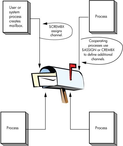
If sufficient dynamic memory for the mailbox data structure is not available when a mailbox is created, a resource wait occurs if resource wait mode is enabled.
When a mailbox is created, a certain amount of space is specified for buffering messages that have been written to the mailbox but have not yet been read. The bufquo argument to the $CREMBX system service specifies this amount or quota. If that argument is omitted, its value defaults to the system parameter DEFMBXBUFQUO.
A message written to a mailbox, in the absence of an outstanding read request, is queued to the mailbox, and the size of the message (the QIO P2 argument) is subtracted from the available buffering space. After the message is read, it is added back to the available buffering space.
If a process attempts to write to a mailbox that is full or has insufficient buffering space and if the process has resource wait enabled (which is the default case), the process is placed in miscellaneous resource wait mode until sufficient space is available in the mailbox. If resource wait is not enabled, the I/O completes with the status return SS$_MBFULL in the I/O status block (IOSB).
Channels can be assigned to mailboxes as bidirectional (read/write), read only, or write only. This allows for greater synchronization between users of the mailbox. To specify a unidirectional channel to the mailbox, specify the flags argument for the $CREMBX or $ASSIGN system services.
The flags argument is a longword bit mask that enables you to specify that the channel assigned to the mailbox is a read-only or write-only channel. If the flags argument is not specified, the default channel behavior is read/write. A channel assigned to the mailbox as read only is considered a reader. A channel assigned to the mailbox as write only is considered a writer. A channel assigned to the mailbox as read/write is considered both a reader and a writer.
For the $ASSIGN system service, the $AGNDEF macro defines a symbolic name for each flag bit. These flags are as follows:
AGN$M_READONLY— When this flag is specified, $ASSIGN assigns a read-only channel to the mailbox device. An attempt to issue a $QIO WRITE operation on the mailbox channel causes an illegal I/O operation error.
AGN$M_WRITEONLY— When this flag is specified, $ASSIGN assigns a write-only channel to the mailbox device. An attempt to issue a $QIO READ operation on the mailbox channel causes an illegal I/O operation error.
For the $CREMBX system service, the $CMBDEF macro defines a symbolic name for each flag bit. These flags are as follows:
CMB$M_READONLY— When this flag is specified, $CREMBX assigns a read-only channel to the mailbox device. An attempt to issue a $QIO WRITE operation on the mailbox channel causes an illegal I/O operation error.
CMB$M_WRITEONLY— When this flag is specified, $CREMBX assigns a write-only channel to the mailbox device. An attempt to issue a $QIO READ operation on the mailbox channel causes an illegal I/O operation error.
See the VSI OpenVMS System Services Reference Manual for a syntax description of the $CREMBX and $ASSIGN system services.
The programming examples at the end of this section (Section 4.5, ''Mailbox Driver Programming Examples'') show mailbox creation, interprocess communication, and synchronization.
4.1.2. Deleting Mailboxes
As each process finishes using a mailbox, it deassigns the channel using the Deassign I/O Channel ($DASSGN) system service. Temporary mailboxes or permanent mailboxes that have been marked for deletion are actually deleted when no more channels are assigned to them.
If a mailbox channel is deassigned, any incomplete I/O requests on the mailbox channel for the process deassigning the channel are removed.
Permanent mailboxes that have not been marked for deletion must be explicitly deleted using the Delete Mailbox ($DELMBX) system service. An explicit deletion can occur at any time. As is true for temporary mailboxes, the mailbox is deleted when no processes have channels assigned to it.
When a temporary mailbox is deleted, its message buffer quota is returned to the process that created it. (No quota charge is made for permanent mailboxes.)
4.1.3. Mailbox Protection
Mailboxes (both temporary and permanent) are protected by a code, or mask, that is similar to the code used in protecting volumes. As with volumes, four types of users (defined by UIC) can gain access to a mailbox: SYSTEM, OWNER, GROUP, and WORLD; however, only three types of access—logical I/O, read, and write—are meaningful to users of a mailbox. Therefore, when creating a mailbox, you can specify logical I/O, read, and write access to the mailbox separately for each type of user. Logical I/O access is required for any mailbox operation. The set protection function modifier provides additional control of mailbox access (see Section 4.3.6, ''Set Protection'').
For additional information on temporary mailboxes and mailbox protection, see the description of the $CREMBX system service in the VSI OpenVMS System Services Reference Manual.
4.1.4. Mailbox Message Format
There is no standardized format for mailbox messages and none is imposed on users.
4.2. Mailbox Driver Device Information
You can obtain information on mailbox characteristics by using the Get Device/Volume Information ($GETDVI) system service. (See the VSI OpenVMS System Services Reference Manual.)
$GETDVI returns mailbox characteristics when you specify the item code DVI$_DEVCHAR. Table 4.1, ''Mailbox Characteristics'' lists these characteristics, which are defined by the $DEVDEF macro.
| Characteristic? | Meaning |
|---|---|
| Dynamic Bits (Conditionally Set) | |
| DEV$M_SHR | Device is shareable. |
| DEV$M_AVL | Device is available. |
| Static Bits (Always Set) | |
| DEV$M_REC | Device is record-oriented. |
| DEV$M_IDV | Device is capable of input. |
| DEV$M_ODV | Device is capable of output. |
| DEV$M_MBX | Device is a mailbox. |
DVI$_DEVCLASS and DVI$_DEVTYPE return the device class and device type names, which are defined by the $DCDEF macro. The device class for mailboxes is DC$_MAILBOX. The device type is DT$_MBX (or DT$_SHRMBX if the mailbox is a shared memory mailbox). DVI$_DEVBUFSIZ returns the buffer size, which is the maximum message size in bytes.
DVI$_DEVDEPEND returns a longword field in which the two low-order bytes contain the number of messages in the mailbox. (The two high-order bytes are not used and should be ignored.) This information can also be obtained through the Get Mailbox Information function (see Section 4.3.7, ''Get Mailbox Information'').
DVI$_UNIT returns the mailbox unit number. Using mailbox to hold a termination message for a subprocess or a detached process requires that the parent process obtain this number to pass to the mbxunt argument of the $CREPRC system service.
4.3. Mailbox Function Codes
The mailbox I/O functions are:
read
write
write end-of-file
set attention AST
wait for writer/reader
set protection
get mailbox information
No buffered I/O byte count quota checking is performed on mailbox I/O messages. Instead, the byte count or buffer quota of the mailbox is checked for sufficient space to buffer the message being sent. The buffered I/O quota and AST quota are also checked.
4.3.1. Read
Read mailbox functions are used to obtain messages written to the mailbox. The operating system provides the following mailbox function codes:
IO$_READVBLK—Read virtual block
IO$_READLBLK—Read logical block
IO$_READPBLK—Read physical block
IO$_READVBLK, IO$_READLBLK, and IO$_READPBLK all perform the same operation. To issue a read request, a process can specify any of the read function codes.
The following device- or function-dependent arguments are used with these codes:
P1—The starting virtual address of the buffer that is to receive the message. If P2 specifies a zero-length buffer, P1 is ignored. On OpenVMS Alpha and IA-64 server, P1 can be a 64-bit address.
P2—The size of the buffer in bytes (limited by the maximum message size for the mailbox). A zero-length buffer may be specified. If a message longer than the buffer is read, the alternate success status SS$_BUFFEROVF is returned in the I/O status block. In such cases, the message is truncated to fit the buffer. The driver does not provide a means for recovering the deleted portion of the message.
The following function modifiers can be specified with a read request:
IO$M_WRITERCHECK—Completes the I/O operation with SS$_NOWRITER status if the mailbox is empty and no write channels are assigned to the mailbox. If no writer is assigned to the mailbox when the $QIO is issued and no data is in the mailbox, the $QIO completes immediately. If no data is in the mailbox but a writer is assigned, the $QIO operation completes when either a message is written or all writers deassign their channels to the mailbox. IO$M_WRITERCHECK is ignored if the channel on which it is issued is read/write because a writer is always assigned.
IO$M_NOW—Completes the I/O operation immediately with no wait for a write request from another process.
IO$M_STREAM—Ignores QIO record boundaries. The read operation transfers message data to the user's buffer until either P2 bytes are transferred, all message data currently in the mailbox is transferred, or an end-of-file message is encountered. If a WRITEOF message is within the records required to be read in order to fulfill the request for P2 bytes, the read request terminates successfully with the bytes it was able to read before finding the WRITEOF message and the end-of-file message becomes the first message in the mailbox. The next read request processes the end-of-file message. If the read request is a READ STREAM, then the request must be for greater than 0 bytes. $QIO READ STREAM can return fewer than P2 bytes with a return value of SS$_NORMAL if the mailbox is emptied by the $QIO READ STREAM request or a WRITEOF message is encountered.
Figure 4.2, ''$QIO READ STREAM Operation'' shows $QIO READ STREAM operations.
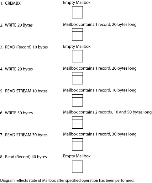
A READ IO$M_STREAM (without IO$M_NOW specified) on an empty mailbox waits until some data has been written to the mailbox. It terminates with:
0 bytes read if the next data written is an end-of-file message.
Fewer than P2 bytes read if the next data written is less than P2 bytes but greater than 0 bytes. (READ IO$M_STREAM ignores writes of 0 bytes.)
P2 bytes read if the next data written is greater than or equal to P2 bytes.
If a $QIO READ STREAM is fulfilled by multiple $QIO WRITE requests, the sender PID returned in the IOSB of the $QIO READ STREAM reflects the first write request. A $QIO READ STREAM is charged BUFQUO for the request. This BUFQUO is released when the read request is met. A $QIO READ STREAM request that would cause BUFQUO to be exceeded for the mailbox when the mailbox has no writes pending returns an SS$_EXQUOTA error.
A $QIO READ STREAM issued to a mailbox that would cause BUFQUO to be exceeded because BUFQUO is occupied by write requests still executes. This happens because by allowing the mailbox to temporarily exceed BUFQUO, BUFQUO is freed. Similarly, a $QIO WRITE that is issued to a mailbox that would cause BUFQUO to be exceeded, because the BUFQUO is occupied by read stream requests, still executes.
Reads of 0 bytes are handled differently depending on which functional modifiers are specified. If IO$M_STREAM is specified, then the $QIO returns SS$_NORMAL with 0 bytes read. The contents of the mailbox remain exactly as they were before the $QIO was issued. A $QIO READ STREAM of 0 bytes does not remove a 0 byte record, nor does it remove an end-of-file marker. If IO$M_STREAM is not specified, then $QIO returns one of the following:
SS$_NORMAL (if 0 bytes were written with the corresponding $QIO WRITE performed)
SS$_BUFFEROVF (if the corresponding $QIO WRITE wrote more than 0 bytes with 0 bytes read)
SS$_ENDOFFILE (if a WRITEOF function was performed as the corresponding $QIO write function)
For a 0-byte nonstream read, a record is actually removed from the mailbox to meet the $QIO READ request. Note that the use of the word “immediately” does not imply that synchronization of the $QIO request should not be performed.
Figure 4.3, ''Read Mailbox'' shows the read mailbox functions. In this figure, Process A reads a mailbox message written by Process B. As the figure indicates, a mailbox read request requires a corresponding mailbox write request (except in the case of an error). The requests can be made in any sequence; the read request can either precede or follow the write request.
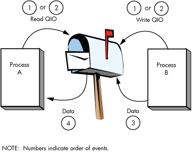
If Process A issues a read request before Process B issues a write request, one of two events can occur. If Process A did not specify the function modifier IO$M_NOW, Process A's request is queued before Process B issues the write request. When Process B's write request occurs, the data is transferred from Process B, through the system buffers, to Process A to complete the I/O operation.
However, if Process A did specify the IO$M_NOW function modifier, the read operation is completed immediately. That is, no data is transferred from Process B to Process A, and Process A's request is not queued. In this case, the I/O status returned to Process A is SS$_ENDOFFILE.
If Process B sends a message (with no function modifier; see Section 4.3.2, ''Write'') before Process A issues a read request (with or without a function modifier), Process A finds a message in the mailbox. The data is transferred and the I/O operation is completed immediately, regardless of whether IO$M_NOW is specified on the read request.
4.3.2. Write
Write mailbox functions are used to transfer data from a process to a mailbox. The operating system provides the following mailbox function codes:
IO$_WRITEVBLK—Write virtual block
IO$_WRITELBLK—Write logical block
IO$_WRITEPBLK—Write physical block
IO$_WRITEVBLK, IO$_WRITELBLK, and IO$_WRITEPBLK all perform the same operation. To issue a write request, a process can specify any of the write function codes.
These function codes take the following device- or function-dependent arguments:
P1—The starting virtual address of the buffer that contains the message being written. If P2 specifies a zero-length buffer, P1 is ignored. On OpenVMS Alpha and IA-64 servers, P1 can be a 64-bit address.
P2—The size of the buffer in bytes (limited by the maximum message size for the mailbox). A zero-length buffer produces a zero-length message to be read by the mailbox reader.
The following function modifiers can be specified with a write request:
IO$M_READERCHECK—Completes the I/O operation immediately, with SS$_NOREADER status, if no read channels are assigned to the mailbox. If a $QIO WRITE with IO$M_READERCHECK is issued and is outstanding and all read channels assigned to the mailbox are then deassigned, the $QIO completes with SS$_NOREADER status. IO$M_READERCHECK is ignored if the channel on which it is issued is bidirectional read/write, because there is always a reader assigned. If SS$_NOREADER is returned for a write request, the $QIO WRITE operation does not place any data in the mailbox. If SS$_NOREADER is returned for a write end-of-file message request, the $QIO WRITE operation does not place the end-of-file marker in the mailbox.
IO$M_NOW—Completes the I/O operation immediately without waiting for another process to read the mailbox message. $QIO WRITE, without IO$M_NOW specified, does not complete until the data is read. $QIO WRITE NOW completes when the data is in the mailbox. If both IO$M_READERCHECK and IO$M_NOW are specified and no read channel is assigned to the mailbox, a status of SS$_NOREADER is returned and the data is not placed in the mailbox. If a read channel is assigned, the IO$M_READERCHECK modifier is ignored.
IO$M_NORSWAIT—If the mailbox is full, the I/O operation fails with a status return of SS$_MBFULL rather than placing the process in resource wait mode. Note that IO$M_NORSWAIT does not disable resource waits that may occur elsewhere in the $QIO operation. For example, IO$M_NORSWAIT does not affect any resource waiting that occurs when I/O processing routines try to allocate an I/O request packet while passing the I/O request to the mailbox driver.
A $QIO WRITE of 0 bytes causes a 0-byte long message to be placed in the mailbox. When this data is read by a $QIO READ without IO$M_STREAM specified, the $QIO READ returns an SS$_NORMAL status and 0 bytes. When this data is read by a $QIO READ STREAM in an attempt to read P2 bytes (P2 being greater than 0), the data is ignored. However, a $QIO READ STREAM of 0 bytes has no effect on the mailbox. A $QIO WRITE READERCHECK of 0 bytes, when no read channel is assigned to the mailbox, returns an SS$_NOREADER error and the 0-byte record is not placed in the mailbox. A message that is 0 bytes long is charged 1 byte of mailbox BUFQUO.
Figure 4.4, ''Write Mailbox'' shows the write mailbox function. In this figure, Process A writes a message to be read by Process B. As in the read request example, a mailbox write request requires a corresponding mailbox read request (unless an error occurs) and the requests can be made in any sequence.
If Process A issues a write request before Process B issues a read request, one of two events can occur. If Process A did not specify the function modifier IO$M_NOW, Process A's write request is queued before Process B issues a read request. When this request occurs, the data is transferred from Process A to Process B to complete the I/O operation.
However, if Process A did specify the IO$M_NOW function modifier, the write operation is completed immediately. The data is available to Process B and is transferred when Process B issues a read request.
If Process B issues a read request (with no function modifier) before Process A issues a write request (with or without the function modifier), Process A finds a request in the mailbox. The data is transferred and the I/O operation is completed immediately.
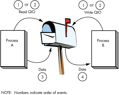
4.3.3. Write End-of-File Message
Write end-of-file message functions are used to insert a special message in the mailbox. The process that reads the end-of-file message is returned the status code SS$_ENDOFFILE in the I/O status block. The message count of the Get Mailbox Information function reflects this end-of-file message; however, the mailbox byte count of this function does not include end-of-file markers. An end-of-file message is charged 1 byte of mailbox BUFQUO.
This function takes no arguments. The operating system provides the following function code:
IO$_WRITEOF—Write end-of-file message
The following function modifiers can be specified with a write end-of-file request:
IO$M_READERCHECK—Completes the I/O operation immediately, with SS$_NOREADER status, if no read channels are assigned to the mailbox. If a $QIO WRITEOF with IO$M_READERCHECK is issued and is outstanding and all read channels assigned to the mailbox are then deassigned, the $QIO completes with SS$_NOREADER status. IO$M_READERCHECK is ignored if the channel on which it is issued is bidirectional read/write, because there is always a reader assigned. If SS$_NOREADER is returned for a write end-of-file message request, the $QIO WRITEOF operation does not place the end-of-file marker in the mailbox.
IO$M_NOW—Completes the I/O operation immediately without waiting for another process to read the mailbox message. If both IO$M_READERCHECK and IO$M_NOW are specified, and no read channel is assigned to the mailbox, a status of SS$_NOREADER is returned and the end-of-file message is not placed in the mailbox.
IO$M_NORSWAIT—If the mailbox is full, the I/O operation fails with a status return of SS$_MBFULL instead of placing the process in resource wait mode. Note that IO$M_NORSWAIT does not disable resource waits that may occur elsewhere in the $QIO operation. For example, IO$M_NORSWAIT does not affect any resource waiting that occurs when I/O processing routines try to allocate an I/O request packet while passing the I/O request to the mailbox driver.
4.3.4. Set Attention AST
Set attention AST functions specify that an asynchronous system trap (AST) be delivered to the requesting process in the following cases:
When a cooperating process places a read request for which no write request is pending in a designated mailbox. This is called an unsolicited read request.
When a cooperating process places a write request for which no read request is pending in a designated mailbox. This is called an unsolicited write request.
When room becomes available in the mailbox.
If a message exists in the mailbox when a request to enable a write attention AST is issued, the AST routine is activated immediately. If no message exists, the AST is delivered when a write request message arrives; therefore, the requesting process need not repeatedly check the mailbox status. You must have both logical I/O and read access to the mailbox prior to performing a set attention AST function.
The operating system provides the following function codes:
IO$_SETMODE!IO$M_READATTN—Read attention AST
IO$_SETMODE!IO$M_WRTATTN—Write attention AST
IO$_SETMODE!IO$M_MB_ROOM_NOTIFY—Room in the mailbox attention AST
These function codes take the following device- or function-dependent arguments:
P1—AST address (request notification is disabled if the address is 0)
P2—AST parameter returned in the argument list when the AST service routine is called
P3—Access mode to deliver AST; maximized with requester's mode
These functions are enabled only once; they must be explicitly reenabled after the AST has been delivered if you desire repeat notification. All types of enable functions, and more than one of each type, can be set at the same time. The number of enable functions is limited only by the AST quota for the process.
Figure 4.5, ''Write Attention AST (Read Unsolicited Data)'' shows the write attention AST function. In this figure, an AST is set to notify Process A when Process B sends an unsolicited message.
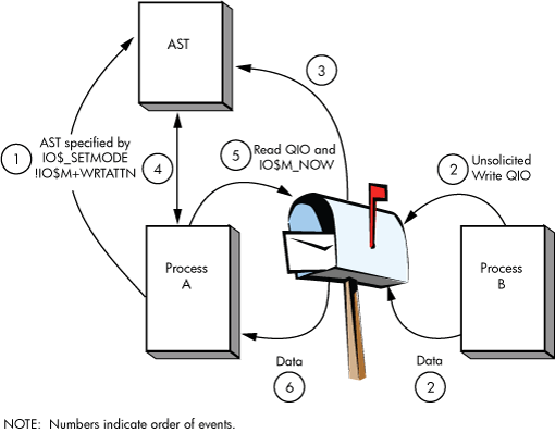
Process A uses the IO$_SETMODE!IO$M_WRTATTN function to request an AST. When Process B sends a message to the mailbox, the AST is delivered to Process A. Process A responds to the AST by issuing a read request to the mailbox. The data is then transferred to complete the I/O operation.
If several requesting processes have set ASTs for unsolicited messages at the same mailbox, all ASTs are delivered when the first unsolicited message is placed in the mailbox; however, only the first process to respond to the AST with a read request receives the data. Therefore, when the next process to respond to an AST issues a read request to the mailbox, it might find the mailbox empty. If this request does not include the function modifier IO$M_NOW, it is queued before the next message arrives in the mailbox.
Figure 4.6, ''Read Attention AST'' shows the read attention AST function. In this figure, an AST is set to notify Process A when Process B issues a read request for which no message is available.
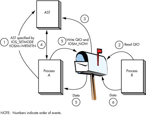
Process A uses the IO$_SETMODE!IO$M_READATTN function to specify an AST. When Process B issues a read request to the mailbox, the AST is delivered to Process A. Process A responds to the AST by sending a message to the mailbox. The data is then transferred to complete the I/O operation.
If several requesting processes set ASTs for read requests for the same mailbox, all ASTs are delivered when the first read request is placed in the mailbox. Only the first process to respond with a write request is able to transfer data to Process B.
4.3.5. Wait for Writer/Reader
The wait for writer/reader mailbox driver function waits until a channel is assigned to the mailbox with the requested access direction. This function returns immediately if a channel is already assigned to the mailbox with the proper access direction. This function always returns immediately if issued on a bidirectional mailbox channel. Any channel assigned bidirectionally to the mailbox satisfies both types of wait requests.
The wait function requires the same synchronization techniques as all other $QIO functions. $QIO Wait should not be issued without any synchronization of its completion. If no synchronization is performed, the program behaves as if no $QIO Wait function had been issued (except for the small delay caused by issuing the $QIO Wait).
The following function codes and modifiers are provided:
IO$_SETMODE!IO$M_READERWAIT—Waits for a read channel to be assigned to the mailbox.
IO$_SETMODE!IO$M_WRITERWAIT—Waits for a write channel to be assigned to the mailbox.
These function codes require no function-dependent arguments.
These functions are enabled only once. Once the $QIO operation completes, these functions must be explicitly reenabled.
4.3.6. Set Protection
The set protection functions allow the user to set volume protection on a mailbox (see Section 4.1.3, ''Mailbox Protection''). The requester must either be the owner of the mailbox or have BYPASS privilege. The OpenVMS operating system provides the following function code:
IO$_SETMODE!IO$M_SETPROT—Set protection
This function code takes the following device- or function-dependent argument:
P2—A volume protection mask
The protection mask specified by P2 is a 16-bit mask with 4 bits for each class of owner: SYSTEM, OWNER, GROUP, and WORLD, as shown in Figure 4.7, ''Protection Mask''.
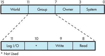
Only logical I/O, read, and write functions have meaning for mailboxes. A clear (0) bit implies that access is allowed. If P2 is 0 or unspecified, the mask is set to allow all read, write, and logical operations.
The I/O status block for the set protection function (see Figure 4.10, ''IOSB Contents— Set Protection Function'' ) returns SS$_NORMAL in the first word if the request was successful. If the request was not successful, the $QIO system service returns SS$_NOPRIV and both longwords of the I/O status block are returned as zeros.
4.3.7. Get Mailbox Information
The get mailbox information function allows the user to find out the number of unread messages and bytes in the mailbox. The following function code is provided:
IO$_SENSEMODE—Get mailbox contents information
The following function codes and modifiers are provided:
IO$_SENSEMODE!IO$M_READERCHECK—If a $QIO SENSEMODE with IO$M_READERCHECK is issued and no read channels are assigned to the mailbox, then the SS$_NOREADER condition value is returned in the IOSB.
IO$_SENSEMODE!IO$M_WRITERCHECK—If a $QIO SENSEMODE with IO$M_WRITERCHECK is issued and no write channels are assigned to the mailbox, then the SS$_NOWRITER condition value is returned in the IOSB.
These function codes require no function-dependent arguments.
The I/O status block for the get information function (see Figure 4.11, ''IOSB Contents — Get Mailbox Information Function'').
4.4. I/O Status Block
The I/O status blocks (IOSB) for mailbox read, write, set protection, and get mailbox information QIO functions are shown in Figures Figure 4.8, ''IOSB Contents — Read Function'', Figure 4.9, ''IOSB Contents— Write Function'', Figure 4.10, ''IOSB Contents— Set Protection Function'', and Figure 4.11, ''IOSB Contents — Get Mailbox Information Function''.
Appendix A, "I/O Function Codes" lists the I/O status returns for these functions. In addition to the IOSB return values, the following statuses can be returned in R0 by the call to the system service:
SS$_ACCVIO
SS$_EXQUOTA
SS$_ILLIOFUNC
SS$_INSFMEM
SS$_MBFULL
SS$_MBTOOSML
SS$_NOPRIV
SS$_NORMAL
(The OpenVMS system messages documentation provides explanations and suggested user actions for both types of returns.)
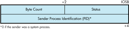
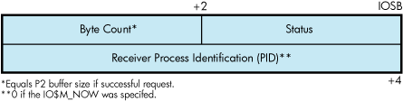
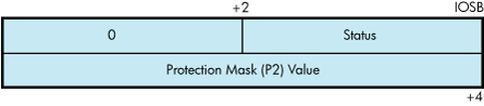
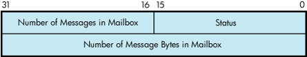
4.5. Mailbox Driver Programming Examples
This section contains the following programming examples:
Example 4.1, ''Mailbox Driver Program Example 1'' shows a MACRO32 program that creates a mailbox and puts mail into it.
Example 4.2, ''Mailbox Driver Program Example 2'' assigns a read-only channel to the mailbox.
Example 4.3, ''Mailbox Driver Program Example 3'' assigns a write-only channel to the mailbox.
Example 4.1, ''Mailbox Driver Program Example 1'' creates a mailbox and puts mail into it; no matching read is pending on the mailbox. First, the program shows that if the function modifier IO$M_NOW is not used when mail is deposited, the write function waits until a read operation is performed. In this case, IO$M_NOW is specified and the program continues after the mail is left in the mailbox.
Next, the mailbox is read. If there is no mail in the mailbox, the program waits because IO$M_NOW is not specified. IO$M_NOW should be specified if there is any doubt about the availability of data in the mailbox, and it is important for the program not to wait.
It is up to the user to coordinate the data that goes into and out of mailboxes. In this example, the process reads its own message. Normally, two mailboxes are used for interprocess communication: one for sending data from process A to process B, and one for sending data from process B to process A. If a program is arranged in this manner, there is no possibility of a process reading its own message.
Note
The table for temporary mailbox names can be redefined to be a group table. This allows the processes in other jobs with same group number to use the same logical name to access the mailbox. For example, LNM$TEMPORARY_MAILBOX can be redefined to any shareable table that the process has write access to. In this case, it could be redefined to LNM$GROUP if the process has GRPNAM privlege or if the group table allows the process to write to it. See the description of the $CREMBX service in the VSI OpenVMS System Services Reference Manual for more information.
Example 4.2, ''Mailbox Driver Program Example 2'' andExample 4.3, ''Mailbox Driver Program Example 3'' work together from two separate processes and show the unidirectional mailbox synchronization features. With the default definition of LNM$TEMPORARY_MAILBOX, the logical name for the mailbox is created in the job logical name table. The processes running both example programs should be in the same job.
Example 4.2, ''Mailbox Driver Program Example 2'' performs the following functions:
Assigns a read-only channel to the mailbox.
Waits for another program to assign a writable channel to the mailbox.
Reads, using the IO$M_WRITERCHECK function modifier, what has been written to the mailbox. Each record is echoed to SYS$OUTPUT.
When SS$_NOWRITER is returned from the read operation, goes back to Step 2 and waits for another writer.
Example 4.3, ''Mailbox Driver Program Example 3'' is a writer to the mailbox. It performs the following functions:
Assigns a write-only channel to the mailbox.
Waits for a reader.
Gathers user input until the user enters Ctrl/Z, then writes that input to the mailbox.
; *********************************************************************
;

        .TITLE  MAILBOX DRIVER PROGRAM EXAMPLE
        .IDENT  /01/

;
; Define necessary symbols.
;

        $IODEF                          ;Define I/O function codes

;
; Allocate storage for necessary data structures.
;

;
; Allocate output device name string and descriptor.
;

DEVICE_DESCR:                           ;
        .LONG   20$-10$                 ;Length of name string
        .LONG   10$                     ;Address of name string
10$:    .ASCII  /SYS$OUTPUT/            ;Name string of output device
20$:                                    ;Reference label

;
; Allocate space to store assigned channel number.
;

DEVICE_CHANNEL:                         ;
        .BLKW   1                       ;Channel number

;
; Allocate mailbox name string and descriptor.
;

MAILBOX_NAME:                           ;
        .LONG   ENDBOX-NAMEBOX          ;Length of name string
        .LONG   NAMEBOX                 ;Address of name string
NAMEBOX: .ASCII /146_MAIN_ST/           ;Name string
ENDBOX:                                 ;Reference label

;
; Allocate space to store assigned channel number.
;

MAILBOX_CHANNEL:                        ;
        .BLKW   1                       ;Channel number

;
; Allocate space to store the outgoing and incoming messages.
;

IN_BOX_BUFFER:                          ;
        .BLKB   40                      ;Allocate 40 bytes for
                                        ;received message
        IN_LENGTH=.-IN_BOX_BUFFER       ;Define input buffer length

OUT_BOX_BUFFER:                         ;
        .ASCII  /SHEEP ARE VERY DIM/    ;Message to send
        OUT_LENGTH=.-OUT_BOX_BUFFER     ;Define length of message to
                                        ;send

;
; Finally, allocate space for the I/O status quadword.
;

STATUS:                                 ;
        .QUAD   1                       ;I/O status quadword

;
; *********************************************************************
;
;                      Start Program
;
; *********************************************************************
;

;
; The program first creates a mailbox and assigns a channel to the
; process output device.  Then a message is placed in the mailbox and
; a message is received from the mailbox (the same message).  Finally,
; the program prints the contents of the mailbox on the process output
; device.
;

START:  .WORD   0                       ;Entry mask
        $CREMBX_S CHAN=MAILBOX_CHANNEL,- ;Channel is the mailbox
                PROMSK=#^X0000,-        ;No protection
                BUFQUO=#^X0060,-        ;Buffer quota is hex 60
                LOGNAM=MAILBOX_NAME,-   ;Logical name descriptor
                MAXMSG=#^X0060          ;Maximum message is hex 60
        CMPW    #SS$_NORMAL,R0          ;Successful mailbox creation?
        BSBW    ERROR_CHECK             ;Find out
        $ASSIGN_S -                     ;Assign channel
                DEVNAM=DEVICE_DESCR,-   ;Device descriptor
                CHAN=DEVICE_CHANNEL     ;Channel
        CMPW    #SS$_NORMAL,R0          ;Successful channel assign?
        BSBW    ERROR_CHECK             ;Find out

;
; The program now writes to the mailbox using a write request that
; includes the function modifier IO$M_NOW so that it need not wait for
; a read request to the mailbox before continuing to the next step in
; the program.
;

        $QIOW_S FUNC=#IO$_WRITEVBLK!IO$M_NOW,- ;Write message NOW
                CHAN=MAILBOX_CHANNEL,-         ;to the mailbox channel
                P1=OUT_BOX_BUFFER,-            ;Write buffer
                P2=#OUT_LENGTH                 ;Buffer length
        CMPW    #SS$_NORMAL,R0                 ;Successful write request?
        BSBW    ERROR_CHECK                    ;Find out

;
; Read the mailbox.
;

        $QIOW_S FUNC=#IO$_READVBLK,-    ;Read the message
                CHAN=MAILBOX_CHANNEL,-  ;in the mailbox channel
                IOSB=STATUS,-           ;Define status block to
                -                       ;receive message length
                P1=IN_BOX_BUFFER,-      ;Read buffer
                P2=#IN_LENGTH           ;Buffer length
        CMPW    #SS$_NORMAL,R0          ;Successful read request?
        BSBW    ERROR_CHECK             ;Find out

;
; The program now determines how much mail is in the mailbox (this
; information is in STATUS+2) and then prints the mailbox message on
; the process output device.
;

        MOVZWL  STATUS+2,R2             ;Byte count into R2
        $QIOW_S FUNC=#IO$_WRITEVBLK,-   ;Write function to the
                CHAN=DEVICE_CHANNEL,-   ;output device channel
                P1=IN_BOX_BUFFER,-      ;Address of buffer to write
                P2=R2,-                 ;How much to write
                P4=#32                  ;Carriage control

;
; Finally, deassign the channel and exit.
;

EXIT:   $DASSGN_S CHAN=DEVICE_CHANNEL   ;Deassign channel
        RET                             ;Return

;
; This is the error-checking part of the program.  Normally, some kind
; of error recovery would be attempted at this point if an error was
; detected.  However, this example program simply exits.
;

ERROR_CHECK:                            ;
        BNEQ    EXIT                    ;System service failure, exit
        RSB                             ;Otherwise, return

        .END    START
Example 4.2, ''Mailbox Driver Program Example 2'' assigns a read-only channel to the mailbox.
/*
 * MAILBOX_READER.C
 * C program to demonstrate features of the Mailbox driver.
 * This program is a Mailbox READER. It assigns a READ_ONLY channel to the
 * mailbox. Its partner program is a Mailbox WRITER.
 * Compile with Compaq C on VAX or Alpha systems:
 * $ CC MAILBOX_READER
 * $ LINK MAILBOX_READER
 * /
#include <stdio.h>             /* Standard C I/O */
#include <descrip.h>           /* Descriptor structure definitions */
#include <lib$routines.h>      /* LIB$ RTL function definitions */
#include <starlet.h>           /* System service definitions */
#include <ssdef.h>             /* System Service status code definitions */
#include <cmbdef.h>            /* CREMBX definitions */
#include <efndef.h>            /* Event Flag definitions */
#include <iodef.h>             /* I/O definitions */

#define $ARRAY_DESCRIPTOR(name,size,array_name) \
    static char array_name[ size ]; \
    struct dsc$descriptor_s name = \
       { size, DSC$K_DTYPE_T, DSC$K_CLASS_S, array_name }
int main(void)
{
/*
 * Message limits are intentionally small to facilitate demonstration of
 * error conditions.
 */
#define max_msg_len 64            /* Maximum output string size     */
#define mailbox_maxmsg 64         /* Maximum mailbox message size  */
#define mailbox_bufquo 128        /* Total buffer space in mailbox */
$DESCRIPTOR(mailbox_name_desc,"MAILBOX_EXAMPLE");
$DESCRIPTOR(EOF_string_desc,
    "End of file read ... waiting for another WRITER");
$ARRAY_DESCRIPTOR(read_buffer_desc,max_msg_len,read_buffer);

#pragma member_alignment save
#pragma nomember_alignment LONGWORD
    struct io_status_block { /* I/O status block */
    unsigned short int condition;
    unsigned short int count;
    unsigned int dev;
    } iosb;
#pragma member_alignment restore

int status, mailbox_channel;

/*
 * Create a temporary mailbox with a READONLY channel. Its logical name
 * will be entered into the LNM$TEMPORARY_MAILBOX logical name table.
 */

    status = sys$crembx(0,&mailbox_channel,mailbox_maxmsg,mailbox_bufquo,
        0,0,&mailbox_name_desc,CMB$M_READONLY);
    if (status != SS$_NORMAL)
       (void) lib$signal(status);

/*
 * Mark the mailbox for deletion.  This step is not necessary for a temporary
 * mailbox, but is included as an illustration.
 */
    (void) sys$delmbx(mailbox_channel);
/*
 * Loop forever, first waiting until a WRITE channel is assigned to the mailbox
 * and then reading data from it until the WRITER deassigns.
 */
    while (TRUE)
    {
       /* First, check to see if there is a WRITER assigned to the mailbox */
        status = sys$qiow(
            EFN$C_ENF,
            mailbox_channel,
            IO$_SENSEMODE|IO$M_WRITERCHECK,            &iosb,
            0,0,
            0,0,0,0,0,0);

        /* If there was no WRITER, then wait for one.*/
        if ((unsigned int) iosb.condition == SS$_NOWRITER)
        status = sys$qiow(
            EFN$C_ENF,
            mailbox_channel,
            IO$_SETMODE|IO$M_WRITERWAIT,
            &iosb,
            0,0,
            0,0,0,0,0,0);

        /*
         * While the status is good, READ from the mailbox, and echo the
         * data to SYS$OUTPUT.
         */
        while (status == SS$_NORMAL)
        {
            status = sys$qiow(
                EFN$C_ENF,
                mailbox_channel,
                IO$_READVBLK|IO$M_WRITERCHECK,
                &iosb,
                0,0,
                read_buffer_desc.dsc$a_pointer,max_msg_len,
                0,0,0,0);
            if (status != SS$_NORMAL)
               (void) lib$signal(status);
            status = iosb.condition;

            if (status == SS$_NORMAL)
            {
                read_buffer_desc.dsc$w_length = iosb.count;
                (void) lib$put_output(&read_buffer_desc);
            }
            else if (status == SS$_ENDOFFILE)
            {
                (void) lib$put_output(&EOF_string_desc);
            }
        }
    }
}
Example 4.3, ''Mailbox Driver Program Example 3'' assigns a write-only channel to the mailbox.
/*
 * MAILBOX_WRITER.C
 * C program to demonstrate features of the Mailbox driver.
 * This program is a Mailbox WRITER. It assigns a WRITE_ONLY channel to the
 * mailbox. It's partner program is a Mailbox READER.
 * Compile with Compaq C on VAX or Alpha systems:
 * $ CC MAILBOX_WRITER
 * $ LINK MAILBOX_WRITER
 */

#include <stdio.h>             /* Standard C I/O */
#include <descrip.h>           /* Descriptor structure definitions */
#include <lib$routines.h>      /* LIB$ RTL function definitions */
#include <rmsdef.h>            /* RMS status code definitions */
#include <starlet.h>           /* System service definitions */
#include <ssdef.h>             /* System Service status code definitions */
#include <cmbdef.h>            /* CREMBX definitions */
#include <efndef.h>            /* Event Flag definitions */
#include <iodef.h>             /* I/O definitions */

#define $ARRAY_DESCRIPTOR(name,size,array_name) \
    static char array_name[ size ]; \
    struct dsc$descriptor_s name = \
       { size, DSC$K_DTYPE_T, DSC$K_CLASS_S, array_name }

void enable_room_ast(int mailbox_channel, int efn);
void more_room_ast(int efn);

volatile int ast_enabled = FALSE;
int main(void)
{
/*
 * Message limits are intentionally small to facilitate demonstration of
 * error conditions.
 */
#define max_msg_len 128           /* Maximum input string size     */
#define mailbox_maxmsg 64         /* Maximum mailbox message size  */
#define mailbox_bufquo 128        /* Total buffer space in mailbox */
$DESCRIPTOR(mailbox_name_desc,"MAILBOX_EXAMPLE");
$DESCRIPTOR(prompt_string_desc,
    "DATA TO SEND TO MAILBOX (<CTRL Z> to terminate) >>>");
$ARRAY_DESCRIPTOR(write_buffer_desc,max_msg_len,write_buffer);

#pragma member_alignment save
#pragma nomember_alignment LONGWORD
struct io_status_block {                /* I/O status block */
    unsigned short int condition;
    unsigned short int count;
    unsigned int dev;
    } iosb;
#pragma member_alignment restore

int status, mailbox_channel, wait_efn;

/*
 * Create a temporary mailbox with a WRITEONLY channel. Its logical name
 * will be entered into the LNM$TEMPORARY_MAILBOX logical name table.
 */

   status = sys$crembx(0,&mailbox_channel,mailbox_maxmsg,mailbox_bufquo,
       0,0,&mailbox_name_desc,CMB$M_WRITEONLY);
if (status != SS$_NORMAL)       (void) lib$signal(status);

/*
 * Mark the mailbox for deletion.  This step is not necessary for a temporary
 * mailbox, but is included as an illustration.
 */
    (void) sys$delmbx(mailbox_channel);

/*
 * Reserve an event flag to use with "room in mailbox" AST notifications.
 */
    status = lib$get_ef(&wait_efn);
    if (status != SS$_NORMAL)
        (void) lib$signal(status);

/*
 * Loop forever, first waiting until a READ channel is assigned to the mailbox
 * and then write data until there is no more data to write.
 */
    while (TRUE)
    {
        /*
         * Wait for a READER to assign a channel. If a READER is already
         * assigned, this will return immediately.
         */
        status = sys$qiow(
            EFN$C_ENF,
            mailbox_channel,
            IO$_SETMODE|IO$M_READERWAIT,
            &iosb,
            0,0,
            0,0,0,0,0,0);
        while (status)
        {
            write_buffer_desc.dsc$w_length = max_msg_len;
            status = lib$get_input(
                &write_buffer_desc,
                &prompt_string_desc,
                &write_buffer_desc.dsc$w_length);

            /* If at end of file (user typed <CTRL Z>) then write EOF to
             * the mailbox, deassign the channel, and exit.
             * The writer should not deassign the channel while the write EOF
             * operation is pending, since the write would be cancelled and
             * the reader would never receive the EOF.  Omitting IO$M_NOW in
             * this QIOW insures that it will not complete until the reader
             * has actually read the EOF from the mailbox.
             */
            if (status == RMS$_EOF)
            {                (void) sys$qiow(
                    EFN$C_ENF,
                    mailbox_channel,
                    IO$_WRITEOF|IO$M_READERCHECK,
                    &iosb,
                    0,0,0,0,
                    0,0,0,0);
                (void) sys$dassgn(mailbox_channel);
                (void) sys$exit(SS$_NORMAL);
            }

            /* Write the message into the mailbox.  If there isn't enough
             * room, try again until it fits.
             * Note that if the NORSWAIT function modifier had been eliminated
             * below, then the ROOM_NOTIFY and the retry loop could have been
             * removed. ROOM_NOTIFY was used in this example simply to show
             * its use. It would be more appropriately used when the program
             * has other things it can be working on, as opposed to the
             * example below in which the program is not doing anything except
             * WAITING for room in the mailbox.
             */
            do
            {
                status = sys$qiow(
                    EFN$C_ENF,
                    mailbox_channel,
                    IO$_WRITEVBLK|IO$M_READERCHECK|IO$M_NOW|IO$M_NORSWAIT,
                    &iosb,
                    0,0,
                    write_buffer_desc.dsc$a_pointer,
                    write_buffer_desc.dsc$w_length,
                    0,0,0,0);
                if (status == SS$_NORMAL)
                {
                    /* If there is no longer a reader, just exit. */
                    if ((unsigned int) iosb.condition == SS$_NOREADER)
                    {
                        (void) sys$dassgn(mailbox_channel);
                        (void) sys$exit(iosb.condition);
                    }
                }
                else if (status == SS$_MBFULL)
                {
                    if (ast_enabled)
                        /*
                         * Wait here until the AST routine sets the event
                         * flag.  A read might have already occurred, in which
                         * case the wait will return immediately.
                         */
                        (void) sys$waitfr(wait_efn);
                    else
                        /*
                         * The mailbox was full a moment ago at the time of
                         * write, but a read might have already occurred and
                         * the mailbox might be empty now.  It is possible
                         * that no more reads will complete (and deliver
                         * the AST) before the next write.  So enable the AST
                         * and try the write one more time before waiting for
                         * the event flag.
                         */
                        enable_room_ast(mailbox_channel, wait_efn);
                }                else  /* An unexpected error condition */
                    (void) lib$signal(status);
            }
            while (status != SS$_NORMAL);
        }
    }
}
void enable_room_ast(int mailbox_channel, int efn)
/*
 * This routine requests AST delivery when there is room in the mailbox.
 * AST delivery may be triggered by a read or a cancelled I/O.
 */
{
    int status;

    ast_enabled = TRUE;
    status = sys$clref(efn);

    /*
     * This QIOW returns immediately, whether there is room in the mailbox
     * or not.  Even if there is room in the mailbox now, the AST is
     * NOT delivered immediately, but only later when a read or cancel
     * I/O occurs on the mailbox.
     */
    status = sys$qiow(
        EFN$C_ENF,
        mailbox_channel,
        IO$_SETMODE|IO$M_MB_ROOM_NOTIFY,
        0,0,0,
        more_room_ast,efn,0,0,0,0);
}
void more_room_ast(int efn)
/*
 * This AST routine is called when there is room to write more data into
 * the mailbox.
 */
{
    ast_enabled = FALSE;
    (void) sys$setef(efn);
}
Chapter 5. Terminal Driver
This chapter describes the use of the terminal driver (TTDRIVER) and the LAT port driver (LTDRIVER). The terminal driver supports the asynchronous, serial line multiplexers. The terminal driver also supports the console terminal. The LAT port driver accommodates I/O requests from application programs; for example to make connections to remote devices, such as a printer, on a server (see Section 5.3.4, ''LAT Port Driver QIO Interface'').
5.1. Terminal Driver Features
The terminal driver provides the following features:
Input processing
Command-line editing and command recall
Control characters and special keys
Input character validation (read verify)
American National Standard Institute (ANSI) escape sequence detection
Type-ahead feature
Specifiable or default input terminators
Special operating modes, such as NOECHO and PASTHRU
Output processing
Efficiency
Limited full-duplex operation
Formatted or unformatted output
Dialup support
Modem control
Hangup on logout
Preservation of process across hangups
Miscellaneous
Terminal/mailbox interaction
Autobaud detection
Out-of-band control character handling
Note
Not all terminal controllers support all terminal driver capabilities.
5.1.1. Input Processing
The terminal driver defines many terminal characteristics and read function modifiers, which provide a wide range of options to an application program. These options allow multiple levels of control over the terminal driver's input process, ranging from the default of command-line editing that provides a highly flexible user interface, to the PASTHRU mode, which inhibits input process interpretation of data.
5.1.1.1. Command-Line Editing and Command Recall
The terminal driver input process defines a bounded set of line editing functions. You can access these functions with control keys on all keyboards, and with some special keys on certain keyboards as well. You can move the cursor in single-character increments (left arrow or Ctrl/D, right arrow or Ctrl/F) or in multicharacter increments, to the beginning of the line (Ctrl/H) or end of the line (Ctrl/E). The terminal driver supports both insert character and overstrike character modes. The insert or overstrike mode is the terminal's default characteristic? at the beginning of a read operation, but you can change it with the toggle insert/overstrike key (Ctrl/A). You can delete characters in word increments (Ctrl/J or line feed) and beginning-of-the-line increments (Ctrl/U).
When you use the terminal driver's editing functions, the following restrictions result:
You cannot move the cursor to a previous line after a line wrap.
You cannot insert a character if the insertion would force a line wrap or if a tab follows the current cursor position.
You cannot delete a word at the beginning of a line after a line wrap.
You cannot assign the line editing function to other keys.
Command recall, initiated by Ctrl/B or the up arrow, returns the last line entered to the command-line buffer. At this point, you edit or reenter the line by pressing the Return key. DCL extends command recall up to the last 254 commands by using the TRM$M_TM_NORECALL modifier to disable the terminal driver's recall mechanism.
Any control key that is not defined by line editing is ignored. For application programs that require control key input but do not perform QIO functions with special read modifiers, the SET TERMINAL/NOLINE_EDIT DCL command disables command-line editing.
5.1.1.2. Control Characters and Special Keys
A control character is a character that controls action at the terminal rather than passing data to a process. An ASCII control character has a code between 0 and 31, and 127 (hexadecimal 0 through 1F, and 7F); that is, all normal control characters plus DELETE. (Table C-1 lists the numeric values for all control characters.) You enter some control characters at the terminal by simultaneously pressing the Ctrl key and a character key, such as Ctrl/x. Table 5.1, ''Terminal Control Characters'' lists the terminal control characters. You can change control character echo strings (Ctrl/C, Ctrl/Y, Ctrl/O, and Ctrl/Z) on a systemwide basis (see the VSI OpenVMS System Management Utilities Reference Manual). You enter special keys, such as Return, Line Feed, and Escape, by pressing a single key. Several of the control characters do not function as described if the DCL command SET TERMINAL/LINE_EDIT is not specified. See the VSI OpenVMS DCL Dictionary for information on line editing function keys and the SET TERMINAL command.
| Control Character | Meaning |
|---|---|
| Cancel (Ctrl/C) |
Gains the attention of the enabling process if the user program has enabled a Ctrl/C AST. If a Ctrl/C AST is not enabled, Ctrl/C is converted to Ctrl/Y (see Section 5.3.3.2, ''Enable Ctrl/C AST and Enable Ctrl/Y AST Function Modifiers''). The terminal performs a carriage-return/line-feed combination (carriage return followed by a line feed), echoes CANCEL, and performs another carriage-return/line-feed combination. If the terminal has the ReGIS characteristic or if Ctrl/Y is pressed, the cancel ReGIS escape sequence is sent. Additional consequences of Ctrl/C are as follows:
The F6 key maps to Ctrl/C on the following terminal types: LK201, LK46W, LK461, LK463, and other compatible LK-series keyboards. Note that Ctrl/C is generally translated to Ctrl/Y for processing within DCL, unless you have a Ctrl/C handler. Use LIB$ENABLE_CTRL and LIB$DISABLE_CTRL to get Ctrl/C and Ctrl/Y handled within your application. Example 5.4, ''LIB$XXABLE_CTRL.C Terminal Driver Programming Example'' shows a programming example that demonstrates Ctrl/Y and Ctrl/C handling under OpenVMS. |
| Delete Character (DELETE) |
Removes the last character entered from the input stream. DELETE (decimal 127 or hexadecimal 7F) is ignored if there are currently no input characters. Hardcopy terminals echo the deleted character enclosed in backslashes. For example, if the character z is deleted, \z\is echoed (the second backslash is echoed after the next non-DELETE character is entered). Terminals that have the TT$M_SCOPE characteristic echo DELETE by removing the character. |
| Delete line (Ctrl/U) | Purges current input data. When Ctrl/U is entered before the end of a read operation, the current input line is deleted. (In the case of a line wrap, Ctrl/U deletes only a line at a time.) If line editing is enabled (SET TERMINAL/LINE_EDIT is specified), the data from the beginning of the line to the current cursor position is deleted. |
| Delete word (Ctrl/J or F13) (Line feed) | Deletes the word before the cursor. Word terminators are all control characters, space, comma, dash, period, and ! ' # $ & ' ( ) + @ [ \ ] ^ {| ~ / : ; = ? (see Appendix C, "DEC Multinational Character Set and Terminal Escape Sequences/Modes"). |
| Discard output (Ctrl/O) |
Discards output. Action is immediate. All output is discarded until the next read operation, the next write operation with a IO$M_CANCTRLO modifier, or the receipt of the next Ctrl/O. The terminal echoes OUTPUT OFF. The current write operation (if any) and write operations performed while Ctrl/O is in effect are completed with a status return of SS$_CONTROLO. A second Ctrl/O, which reenables output, echoes OUTPUT ON. Ctrl/C, Ctrl/Y, and Ctrl/T cancel Ctrl/O. |
| End of line (Ctrl/E) | Moves the cursor to the end of the line. |
| Exit (Ctrl/Z or F10) | Echoes EXIT when Ctrl/Z is entered as a read terminator. By convention, Ctrl/Z constitutes end-of-file. |
| Interrupt (Ctrl/Y) |
Ctrl/Y is a special interrupt or attention character that is used to invoke the command interpreter for a logged-in process. Ctrl/Y can be enabled with an IO$M_CTRLYAST function modifier to a IO$_SETCHAR or IO$_SETMODE function code. The command interpreter's Ctrl/Y AST handler always takes precedence over a user program's Ctrl/Y AST handler Entering Ctrl/Y results in an AST to an enabled process to signify that the user entered Ctrl/Y from the terminal. The terminal performs a carriage-return/line-feed combination, echoes INTERRUPT, and performs another carriage-return/line-feed combination if the AST and echo are enabled. Ctrl/Y is ignored (and not echoed) if the process is not enabled for the AST. Additional consequences of Ctrl/Y are as follows:
|
| Move cursor left (Ctrl/D) | Moves the cursor one position to the left. |
| Move cursor right (Ctrl/F) | Moves the cursor one position to the right. |
| Move cursor to beginning of line (Ctrl/H or F12) (Backspace) | Moves the cursor to the beginning of the line. |
| Purge type-ahead (Ctrl/X) | Purges the type-ahead buffer and performs a Ctrl/U operation. Action is immediate. If a read operation is in progress, the operation is equivalent to Ctrl/U. |
| Recall (Ctrl/B or up arrow) | Recalls the last command entered. DCL extends recall to several commands. |
| Redisplay input (Ctrl/R) | Redisplays current input. When Ctrl/R is entered during a read operation, a carriage-return/line-feed combination is echoed on the terminal, and the current contents of the input buffer are displayed. If the current operation is a read with prompt (IO$_READPROMPT) operation, the current prompt string is also displayed. Ctrl/R has no effect if the characteristic TT$M_NOECHO is set. |
| Restart output (Ctrl/Q) |
Controls data flow; used by terminals and the driver. Restarts data flow to and from a terminal if previously stopped by Ctrl/S. The action occurs immediately with no echo. Ctrl/Q is also used to solicit read operations. Ctrl/Q is meaningless if the line does not have the characteristic TT$M_TTSYNC, the characteristic TT$M_READSYNC, or is not currently stopped by Ctrl/S. |
| RET (Return) | If used during a read (input) operation, RET echoes a carriage-return/line-feed combination. All carriage returns are filled on terminals with TT$M_CRFILL specified. |
| Stop output (Ctrl/S) | Controls data flow; used by both terminals and the terminal driver. Ctrl/S stops all data flow; the action occurs immediately with no echo. Ctrl/S is also used to stop read operations. Ctrl/S is meaningful only if the terminal has either the TT$M_TTSYNC characteristic or the TT$M_READSYNC characteristic. |
| TAB (Ctrl/I) | Tabs horizontally. Advances to the next tab stop on terminals with the characteristic TT$M_MECHTAB, but the terminal driver assumes tab stops on MODULO 8 (multiples of 8) cursor positions. On terminals without this characteristic, enough spaces are output to move the cursor to the next MODULO 8 position. |
| Status (Ctrl/T) | Displays the current time. Ctrl/T also displays the current node and user name, the name of the image that is running, and information about system resources that have been used during the current terminal session. |
| Toggle insert/overstrike (Ctrl/A or F14) | Changes current edit mode from insert to overstrike, or from overstrike to insert. The default mode (as set with SET TERMINAL/LINE_EDIT) is reset at the beginning of each line. |
5.1.1.3. Read Verify
The read verify instructions provided by the terminal driver allow validation of data as each character is entered. Invalid characters are not echoed and terminate the operation. The terminal driver does not support full function field processing. Large data entry applications should use one of the DECforms, FMS, or TDMS layered products, which support the entire data entry environment.
5.1.1.4. Escape and Control Sequences
Escape and control sequences provide additional terminal control not furnished by the control characters and special keys (see Section 5.1.1.2, ''Control Characters and Special Keys''). Escape sequences are strings of two or more characters, beginning with the escape character (decimal 27 or hexadecimal 1B), which indicate that control information follows. Many terminals send and respond to such escape sequences to request special character sets or to indicate the position of a cursor.
The set mode characteristic TT$M_ESCAPE (see Table 5.4, ''Terminal Characteristics'') is used to specify that terminal lines can generate valid escape sequences. Also, the read function modifier IO$M_ESCAPE allows any read operation to terminate on an escape sequence regardless of whether TT$M_ESCAPE is set. If either TT$M_ESCAPE or IO$M_ESCAPE is set, the terminal driver verifies the syntax of the escape sequences. The sequence is always considered a read function terminator and is returned in the read buffer; a read buffer can contain other characters that are not part of an escape sequence, but a complete escape sequence always terminates a read operation. The return information in the read buffer and the I/O status block includes the position and size of the terminating escape sequence in the data record (see Section 5.3.1.4, ''Read Verify Function'').
Any escape sequence received from a terminal is checked for correct syntax. If the syntax is not correct, SS$_BADESCAPE is returned as the status of the I/O. If the escape sequence does not fit in the user buffer, SS$_PARTESCAPE is returned. If SS$_PARTESCAPE is returned, the application program must issue enough single-character read requests, without timeout, to read the remaining characters in the escape sequence, while parsing the syntax of the rest of the escape sequence. Use of the TRM$_ESCTRMOVR item code prevents SS$_PARTESCAPE errors. No syntax integrity is guaranteed across read operations. Escape sequences are never echoed. Valid escape sequences take any of the following forms (hexadecimal notation):
ESC <int>...<int><fin>(7-bit environment)

CSI <int>...<int><fin>(8-bit environment)
The keywords in the escape sequences indicate the following:
| ESC | The ESC key, a byte (character) of 1B. This character introduces the escape sequence in a 7-bit environment. |
| CSI | The control sequence introducer, a byte (character) of 9B. This character introduces the escape sequence in a 8-bit environment. |
| <int> | An “intermediate character” in the range of 20 to 2F. This range includes the space character and 15 punctuation marks. An escape sequence can contain any number of intermediate characters, or none. |
| <fin> | A “final character” in the range of 30 to 7E. This range includes uppercase and lowercase letters, numbers, and 13 punctuation marks. |
Three additional escape sequence forms are as follows:
ESC <;> <20-2F>...<30-7E>
ESC <20-2F>...<30-7E>
ESC <O><20-2F>...<40-7E>
Control sequences, as defined by the ANSI standard, are escape sequences that include control parameters. Control sequences have the following format:
ESC [ <par>...<par><int>...<int><fin>(7-bit environment)

CSI  <par>...<par><int>...<int><fin>(8-bit environment)
The keywords in the control sequences indicate the following:
| ESC | The ESC key, a byte (character) of 1B. |
| [ | A control sequence, a byte (character) of 5B. |
| CSI | The control sequence introducer, a byte (character) of 9B. |
| <par> | A parameter specifier in the range of 30 to 3F. |
| <int> | An “intermediate character” in the range of 20 to 2F. |
| <fin> | A “final character” in the range of 40 to 7E. |
For example, the position cursor control sequence is ESC [ Pl ; Pc H where Pl is the desired line position and Pc is the desired column position.
The user guides for the various terminals list valid escape and control sequences. For example, the VT100 User Guide lists the escape and control sequences for VT100 terminals.
Section 5.1.1.2, ''Control Characters and Special Keys'' describes control character functions during escape sequences.
Table C.2, ''Sequences and Modes'' lists the valid ANSI and DIGITAL private escape sequences for terminals that have the TT2$M_ANSICRT, TT2$M_DECCRT, TT2$M_DECCRT2, TT2$M_AVO, TT2$M_EDIT, and TT2$M_BLOCK characteristics (see Table 5.5, ''Extended Terminal Characteristics''). Table C.2, ''Sequences and Modes'' also lists assumed and selectable ANSI modes and selectable DIGITAL private modes. Only the names of the escape sequences and modes are listed (for more information, see the specific user guide for the various terminals). Unless otherwise noted, the operation of escape sequences and modes is identical to the particular terminals that implement these features.
5.1.1.5. Type-Ahead Feature
Input (data received) from a terminal is always independent of concurrent output (data sent) to a terminal. This feature is called type-ahead. Type-ahead is allowed on all terminals, unless explicitly disabled by the set mode characteristic, inhibit type-ahead (TT$M_NOTYPEAHD; see Table 5.4, ''Terminal Characteristics'' and Section 5.3.3, ''Set Mode'').
Data entered at the terminal is retained in the type-ahead buffer until the user program issues an I/O request for a read operation. At that time, the data is transferred to the program buffer and echoed at the terminal where it was typed.
Deferring the echo until the read operation is active allows the user process to specify function code modifiers that modify the read operation. These modifiers can include, for example, noecho (IO$M_NOECHO) and convert lowercase characters to uppercase (IO$M_CVTLOW) (see Table 5.6, ''Read QIO Function Modifiers for the Terminal Driver'').
If a read operation is already in progress when the data is typed at the terminal, the data transfer and echo are immediate.
The action of the driver when the type-ahead buffer fills depends on the set mode characteristic TT$M_HOSTSYNC (see Table 5.4, ''Terminal Characteristics'' and Section 5.3.3, ''Set Mode''). If TT$M_HOSTSYNC is not set, Ctrl/G (bell) is returned to inform you that the type-ahead buffer is full. The buffer must then be emptied, at which time a status of SS$_DATAOVERUN is returned. If TT$M_HOSTSYNC is set, the driver stops input by sending a Ctrl/S and the terminal responds by sending no more characters. These warning operations begin eight characters before the type-ahead buffer fills unless the TT2$M_ALTYPEAHD characteristic is set. In that case, the system generation parameter TTY_ALTALARM is used. The driver sends a Ctrl/Q to restart transmission when the type-ahead buffer empties completely, and the user has posted another READ QIO.
The type-ahead buffer length is variable, with possible values in the range of 0 through 32,767. The length can be set on a systemwide basis through use of the system generation parameter TTY_TYPAHDSZ. Terminal lines that do a large amount of bulk input should use the characteristic TT2$M_ALTYPEAHD, which allows the use of a larger type-ahead buffer specified by the system generation parameters TTY_ALTYPAHD and TTY_ALTALARM. (TTY_ALTYPAHD specifies the total size of the alternate type-ahead buffer; TTY_ALTALARM specifies the threshold at which a Ctrl/S is sent.)
Certain input-intensive applications, such as block mode input terminals, can take advantage of an optimization in the driver. If a terminal has the characteristic TT2$M_PASTHRU and the read function IO$M_NOECHO is specified, data is placed directly into the read buffer and thereby eliminates the overhead for moving the data from the type-ahead buffer.
5.1.1.6. Line Terminators
A line terminator is the control sequence that you type at the terminal to indicate the end of an input line. Optionally, the application can specify a particular line terminator or class of terminators for read operations.
Terminators are specified by an argument to the QIO request for a read operation. By default, they can be any ASCII control character except FF, VT, LF, TAB, or BS (see Appendix C, "DEC Multinational Character Set and Terminal Escape Sequences/Modes"). If line editing is enabled, the only terminators are CR, Ctrl/Z, or an escape sequence. Control keys that do not have an editing function are nonfunctioning keys. If included in the request, the argument is a user-selected group of characters (see Section 5.3.1.2, ''Read Function Terminators'').
All characters are 7-bit ASCII characters unless data is input on an 8-bit terminal (see Section 5.3.1, ''Read''). The characteristic TT$M_EIGHTBIT determines whether a terminal uses the 7-bit or 8-bit character set; see Table 5.4, ''Terminal Characteristics''. All input characters (except some special keys; see Section 5.1.1.2, ''Control Characters and Special Keys'') are tested against the selected terminators. The input is terminated when a match occurs or your input buffer fills.
The terminal driver notifies the job controller to initiate login when it detects a carriage-return terminator on a line with no current process (provided the line is not a secure server or the type-ahead feature has not been disabled). A bell character is sent when the notification occurs. A notification character other than the bell character may be specified by setting the system generation parameter TTY_AUTOCHAR.
5.1.1.7. Special Operating Modes
The terminal driver supports many special operating modes for terminal lines. (Table 5.4, ''Terminal Characteristics'' and Table 5.5, ''Extended Terminal Characteristics'' list these modes.) All special modes are enabled or disabled by the set mode and set characteristics functions (see Section 5.3.3, ''Set Mode'').
5.1.2. Output Processing
Output handling is designed to be very efficient in the terminal driver. For example, on multiplexers that support both silo and direct memory access (DMA) output, the driver considers record size to decide dynamically which mode will result in the least overhead. The block size specified by the system generation parameter TTY_DMASIZE is the minimum size block that can be used in a DMA operation.
5.1.2.1. Duplex Modes
The terminal driver can execute in either half- or full-duplex mode. These modes describe the terminal driver software, specifically the ordering algorithms used to service read and write requests, not the terminal communication lines.
In half-duplex mode, all read and write requests are inserted onto one queue. The terminal driver removes requests from the head of this queue and executes them one at a time; all requests are executed sequentially in the order in which they were issued.
In full-duplex mode, read requests (and all other requests except write requests) are inserted onto one queue and write requests onto another. The existence of two queues allows the driver to recognize the presence of two requests, such as a read request and a write request at the same time. However, the driver does not execute the read request and the write request simultaneously. When it is ready to service a request, the driver decides which request—the read request or the write request—to process next.
The following terms describe the state of a read request:
A read request is active when the terminal driver removes that request from the head of the I/O queue.
A read request is started when the terminal driver moves the first character into the read buffer.
In the terminal driver, write requests usually have priority. A write request can interrupt an active, but not started, read request.
The terminal driver does not start a read request until all outstanding writes are completed. This means that a read request could be removed from the head of the read queue while write requests are outstanding, but the first character is not moved into the read buffer until all outstanding writes are completed.
Once a read request is started, all write requests are queued until the read completes. However, during a read operation many write requests can be executed before the first input character is entered at the terminal. Terminal lines that have the TT$M_NOECHO characteristic, or read functions that include the IO$M_NOECHO function modifier, do not inhibit write operations in full-duplex mode.
If a write function specifies the IO$M_BREAKTHRU modifier, the write operation is not blocked, even by an active read operation. IO$M_BREAKTHRU does not change the order in which write operations are queued.
When all I/O requests are entered using the Queue I/O Request and Wait ($QIOW) system service, there can be only one current I/O request at a time. In this case, the order in which requests are serviced is the same for both half- and full-duplex modes.
The type-ahead buffer always buffers input data for which there is no current read request, in both half- and full-duplex modes.
5.1.2.2. Formatting of Output
By default, output data is subject to formatting by the terminal driver. This formatting includes actions such as wrapping, tab expansion, uppercase, and fallback conversions. Applications that do not require formatting of data can write with the IO$M_NOFORMAT modifier and thereby reduce overhead. IO$M_NOFORMAT overrides all formatting except fallback translation. Setting the PASTHRU mode (TT2$M_PASTHRU) is equivalent to writing with the noformat modifier.
Fallback conversions occur regardless of formatting mode.
5.1.2.3. SET HOST Facility and Output Buffering
The SET HOST facility emulates the terminal driver in the way it writes data to the terminal by stopping the display as soon as the abort character is entered. However, the SET HOST facility behaves differently from the terminal driver in that it buffers output data from the program that is executing. Occasionally, this causes a perception problem for the user when the program is aborted with a Ctrl/C, Ctrl/Y, or an out-of-band abort character. The user expects the program to terminate and the display to stop immediately.
CTDRIVER and RTPAD
When used between two systems, the SET HOST facility consists of two components: RTPAD on the local node and CTDRIVER on the remote node. Both components buffer output data to enhance performance when using wide area networks. CTDRIVER performs the initial buffering, queues the buffers for network transfer, and returns a successful write status. The user should note that the local terminal display reflects the output of the executing program after the data has been buffered and transferred over the network—not as the output buffers are filled on the remote node.
The delay between execution of an application and the display of its output can lead to several anomalies in the effects of Ctrl/C, Ctrl/Y, and out-of-band abort characters.
Output Line Not in Sequence Following an Abort Character
After you enter an abort character (Ctrl/C, Ctrl/Y, or an out-of-band abort character) that causes the input or output to be aborted, it is possible to receive an additional line of output. This occurs when the application program calls $QIO (either directly or indirectly through RMS or language support routines) to output data to a buffer at the same time the abort character is entered.
When CTDRIVER receives the abort character (Ctrl/C, Ctrl/Y, or an out-of-band abort character) from the network, it flushes the current output buffers and aborts any pending read operations. However, if the application program calls $QIO with a write operation when the abort character is entered, the $QIO write data is still buffered and then displayed. The data may not be the next output in sequence from the user's point of view, since all the previous output buffers in CTDRIVER were flushed and the data in them was not displayed.
When using the terminal driver, the effect of an abort character on the display screen is different. The terminal driver does not buffer output from the application during program execution. If the application program has just called $QIO with a write operation when the abort character is entered, then the $QIO write data is displayed. Because all write operations are sequential and do not complete until the output is actually displayed, the additional line displayed is in sequence. There is no break in the data. Normally, the user does not notice that there is an additional line.
Extra Input Prompt Following an Abort Character
For connections between systems, the CTERM protocol allows CTDRIVER to synchronize with RTPAD before displaying any more data on the terminal.
Processing Abort Characters
The abort character AST is delivered after the message describing the aborted read operation has been received. Therefore, the read status should be set very shortly after the abort character AST is delivered to the application. Note, however, these are still two asynchronous events, and the application must still synchronize with the completing read operation.
Captive Command Procedures and Ctrl/Y
CTDRIVER and RTPAD emulate the terminal driver in that the current read operation and all pending write operations abort when Ctrl/Y is entered. However, the pending write operations also include all the buffered output that occurred and that would have been output before the Ctrl/Y was entered but due to the buffering was not.
The effect of the buffering can be confusing if a Ctrl/Y is entered when a captive command procedure is executing. During execution of captive command procedures, DCL has a Ctrl/Y pending. When this AST is delivered, DCL only reenables it; no other action is performed. In that case, if the program being executed only performs output, it appears that the program was aborted by the Ctrl/Y. Actually, the program completed execution before the Ctrl/Y was entered, and the Ctrl/Y merely discarded all the buffered output.
5.1.3. Dialup Support
The operating system supports modem control (for example, Bell 103A, Bell 113, or equivalent) for all supported multiplexers in autoanswer, full-duplex mode. The terminal driver does not support half-duplex operations on modems such as the Bell 202. Also not supported are modems that use circuit 108/1 (connect data set to line signal) in place of the data terminal ready (DTR) signal. Most U.S. and European modems use the data terminal ready signal, which is the signal supported by the operating system.
5.1.3.1. Modem Signal Control
Dialup lines with the characteristic TT$M_MODEM are monitored periodically to detect a change in the modem carrier signals data set ready (DSR), calling indicator (RING), or request to send (RTS). The system generation parameter TTY_SCANDELTA establishes the dialup monitoring for multiplexers that do not support modem signal transition interrupts, such as the DZ series of controllers.
If a line's carrier signal is lost, the driver waits 2 seconds for the carrier signal to return. If bit 0 of the system generation parameter TTY_DIALTYPE is set to 1, the driver does not wait. Bit 0 is 0 by default for countries with Bell System standards, but that bit should be set to 1 for countries with International Telegraph and Telephone Consultative Committee (CCITT) standards. If the carrier signal is not detected during this time, the line is hung up. The hangup action can signal the owner of the line, through a mailbox message, that the line is no longer in use. (No dial-in message is sent; the unsolicited character message is sufficient when the first available data is received.) The line is not available for a minimum of 2 seconds after the hangup sequence begins. The hangup sequence is not reversible. If the line hangs up, all enabled Ctrl/Y and out-of-band ASTs are delivered; the Ctrl/Y AST P2 argument is overwritten with SS$_HANGUP. The I/O operation in progress is canceled, and the status value SS$_HANGUP is returned in the I/O status block. DCL is responsible for process deletion after Ctrl/Y is delivered. If the process is suspended, DCL cannot run, and therefore deletion cannot occur, until the process is resumed.
Note
Some systems provide built-in serial lines using 6-pin modular jacks. These lines do not provide the minimum required modem signals. Although the hardware may allow a dial-out connection to be established, hangup cannot be detected and process deletion does not occur on these lines.
For terminals with the TT$M_MODEM characteristic, TT$M_REMOTE reflects the state of the carrier signal. TT$M_REMOTE is set when the carrier signal changes from off to on, and cleared when the carrier signal is lost.
A line that does not have TT$M_MODEM set does not respond to modem signals or set the DTR signal. Modem signals can be set and sensed manually through use of the IO$M_MAINT function modifier (see Section 5.3.3.3, ''Set Modem Function Modifier'').
The terminal driver default modem protocol meets the requirements of the United States and of European countries. This protocol is capable of working in automatic answer mode and can also perform manually dialed outgoing calls. The protocol supports the requirements of most known international telephone networks. Enhanced modem features are used on multiplexers that support them; processor polling is not necessary. The protocol also functions in a subset mode for the multiplexers that do not support full modem signals.
Table 5.2, ''Control and Data Signals'' lists the control and data signals used in a full modem control mode configuration (in a two-way simultaneous, symmetrical transmit mode). Figure 5.1, ''Modem Control: Two-Way Simultaneous Operation'' is a flowchart that shows a typical signal sequence for a terminal operation in this mode. The flowchart shows the states that the modem transition code goes through to detect different types of transitions in modem state. These transitions allow the driver to detect loss of lines that have been idle for several minutes. Modem states do not affect the ability of the system to transmit characters.
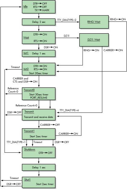
Set mode function modifiers are provided to allow a process to activate or deactivate modem control signals (see Section 5.3.3.3, ''Set Modem Function Modifier'').
Bit 1 of the system generation parameter TTY_DIALTYPE enables alternate modem protocol on a system-wide basis. If bit 1 is 0 (the default), the RING signal is not used. If bit 1 is 1, the modem protocol delays setting the DTR signal until the RING signal is detected.
Remote terminal connections have a timeout feature for the security of dialup lines. If no channel is assigned to the port within 30 seconds, or a port with an assigned channel is not allocated, the DTR signal is dropped. Such action prevents an unused terminal from tying up a line. However, there are configurations (such as a printer connected to a remote line) in which the line should not be dropped even though it is not being used interactively. To bypass the 30-second timeout, set the system generation parameter TTY_DIALTYPE to 4. (Note that if TTY_DIALTYPE is equal to 4, all dialup lines skips the timeout waiting for a channel to be assigned.)
| Signal | Source | Meaning |
|---|---|---|
| Transmitted data (TxD) | Computer | The data originated by the computer and transmitted through the modem to one or more remote terminals. |
| Received data (RxD) | Modem | The data generated by the modem in response to telephone line signals received from a remote terminal and transferred to the computer. |
| Request to send (RTS) | Computer | If present (ON condition), RTS directs the modem to assume the transmit mode. If not present (OFF condition), RTS directs the modem to assume the nontransmit mode after all transmit data has been transmitted. |
| Clear to send (CTS) | Modem | Indicates whether the modem is ready (ON condition) or not ready (OFF condition) to transmit data on the telephone line. |
| Data set ready (DSR) | Modem | If present (ON condition), DSR indicates that the modem is ready to transmit and receive; that is, the modem is connected to the line and is ready to exchange further control signals with the computer to initiate the exchange of data. |
| If DSR is not present (OFF condition), the modem is not ready to transmit and receive. If DSR is detected, the operating system initiates a 30-second timer. This ensures that the phone line is disconnected if CARRIER is not detected. | ||
| Data channel received line signal detector (CARRIER) | Modem | If present (ON condition), CARRIER indicates that the received data channel line signal is within appropriate limits, as specified by the modem. If not present (OFF condition), the received signal is not within appropriate limits. |
| Data terminal ready (DTR) | Computer | If present (ON condition), DTR indicates that the computer is ready to operate, prepares the modem to connect to the telephone line, and maintains the connection after it has been made by other means. DTR can be present whenever the computer is ready to transmit or receive data. If DTR is not present (OFF condition), the modem disconnects the modem from the line. |
| Calling indicator (RING) | Modem | Indicates whether a calling signal is being received by the modem. Bit 1 of the system generation parameter TTY_DIALTYPE must be set (=1). If RING is detected, the operating system initiates a 30-second timer. This ensures that the phone line is disconnected if CARRIER is not detected. |
5.1.3.2. Hangup on Logging Out
By default, logging out on a line with modem signals will not break the connection. If TT2$M_HANGUP is set, modem signals are dropped when the process logs out. If TT2$M_MODHANGUP is set, no privilege is required to change the state of TT2$M_HANGUP. By setting TT2M_HANGUP, system managers can prevent nonprivileged users who are not logged in from tying up a dial-in line.
5.1.3.3. Preservation of a Process Across Hangups
Virtual terminal support provides disconnect table terminals that allow a connection to a physical terminal line to be broken without losing the job.
On Alpha and IA-64 server systems, the following SYSMAN command allows terminals to be discountable terminals:
SYSMAN> IO CONNECT VTA0/NOADAPTER/DRIVER=SYS$TTDRIVERAfter this command is entered, a terminal with the TT2$M_DISCONNECT characteristic logs in as VTAn:, rather than with the physical terminal name. When a terminal is set up in this manner, no input or output operations are allowed to the physical device; I/O is automatically redirected to the appropriate virtual terminal.
Following are four ways in which a terminal can become disconnected:
Modem signals between the host and the terminal are lost.
A user presses the BREAK key on a terminal that has the TT2$M_SECURE characteristic.
A user enters the DCL command DISCONNECT.
A user enters the DCL command CONNECT/CONTINUE.
After validated as a user, you can connect to a disconnected process in either of the following ways:
Allow the login process to make the connection.
Enter the DCL command CONNECT.
5.1.4. Terminal/Mailbox Interaction
Mailboxes are virtual I/O devices used to communicate between processes. The terminal I/O driver can use a mailbox to communicate with a user process. Chapter 4, "Mailbox Driver" describes the mailbox driver.
A user program can use the Assign I/O Channel ($ASSIGN) system service to associate a mailbox with one or more terminals. The terminal driver sends messages to this mailbox when terminal-related events that require the attention of the user image occur.
Mailboxes used in this way carry status messages, not terminal data, from the driver to the user program. For example, when data is received from a terminal for which no read request is outstanding (unsolicited data), a message is sent to the associated mailbox to indicate data availability. On receiving this message, the user program reads the channel assigned to the terminal to obtain the data. Messages are sent to mailboxes under the following conditions:
Unsolicited data in the type-ahead buffer. The use of the associated mailbox can be enabled and disabled as a subfunction of the read and write requests (see Section 5.3.1, ''Read'' and Section 5.3.2, ''Write''). (Initially, mailbox messages are enabled on all terminals. This is the default state.) Therefore, the user process can enter into a dialogue with the terminal after an unsolicited data message arrives. Then, after the dialogue is over, the user process can reenable the unsolicited data message function on the last I/O exchange. Only one message is sent between read operations.
Terminal hangup. When a remote line loses the carrier signal, it hangs up; a message is sent to the mailbox. When hangup occurs on lines that have the characteristic TT$M_REMOTE set, the line returns to local mode.
Broadcast messages. If the characteristic TT2$M_BRDCSTMBX is set, broadcasts sent to a terminal are placed in the mailbox (this is independent of the state of TT$M_NOBRDCST).
Messages placed in the mailbox have the following content and format (see Figure 5.2, ''Terminal Mailbox Message Format''):
Message type. The codes MSG$_TRMUNSOLIC (unsolicited data), MSG$_TRMHANGUP (hangup), and MSG$_TRMBRDCST (terminal broadcast) identify the type of message. Message types are identified by the $MSGDEF macro.
Device unit number to identify the terminal that sent the message.
Counted string to specify the device name.
Controller name.
Message (for broadcasts).
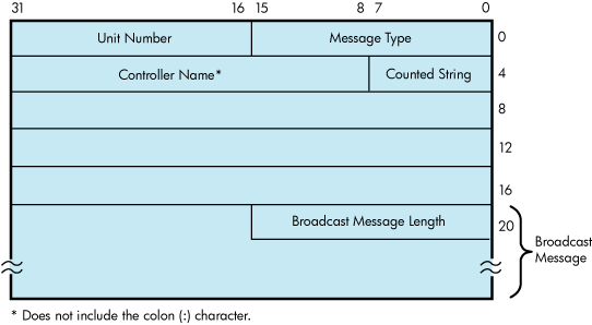
Interaction with a mailbox associated with a terminal occurs through standard QIO functions and ASTs. Therefore, the process need not have outstanding read requests to an interactive terminal to respond to the arrival of unsolicited data. The process need only respond when the mailbox signals the availability of unsolicited data. Chapter 4, "Mailbox Driver" contains an example of mailbox programming.
The ratio of terminals to mailboxes is not always one to one. One user process can have many terminals associated with a single mailbox.
5.1.5. Autobaud Detection
If you specify the /AUTOBAUD qualifier with the SET TERMINAL command, automatic baud rate detection is enabled, allowing the terminal baud rate to be set when you log in. The baud rate is set at login by pressing the Return key two or more times separated by an interval of at least one second. (Pressing a key other than Return might detect the wrong baud rate; if this occurs, wait for the login procedure to time out before continuing.) The supported baud rates are 110, 150, 300, 600, 1200, 1800, 2400, 3600, 4800, 9600, and 19,200. Most Alpha systems can autobaud up to 57600. Parity is allowed on these lines.
The autobaud function works with either even parity or no parity, but not with odd parity. If a line is set to even parity and has 7 bits of data, the line automatically switches to no parity if a terminal not generating parity attempts to log in.
The SET TERMINAL qualifier /EIGHT_BIT specifies that the terminal uses 8-bit ASCII code. /NOEIGHT_BIT, which is the default, specifies 7-bit ASCII code. (If parity is specified, the parity bit is separate from the data bits.) The optimal settings for automatic baud rate detection on HPE terminals are /NOEIGHT_BIT/PARITY=EVEN or /EIGHT_BIT/NOPARITY, although automatic baud rate detection also works with other combinations, such as /NOEIGHT_BIT/NOPARITY.
Table 5.5, ''Extended Terminal Characteristics'' describes the terminal characteristic TT2$M_AUTOBAUD, which allows the baud rate to be set automatically at login.
It is not usually recommended to specify the /FRAME qualifier with the SET TERMINAL command. The terminal driver selects the frame size (the number of data bits that the device can transmit) based on how the /PARITY and /EIGHT_BIT qualifiers are set. It might be necessary to change these values if the terminal is not made by HPE.
5.1.6. Out-of-Band Control Character Handling
All control characters (0 through 1F hexadecimal) can be enabled as out-of-band characters. Typing one of these characters immediately delivers an AST to the requesting process. DCL uses this mechanism to sense whether Ctrl/T has been entered. Out-of-band character options allow using the IO$M_INCLUDE function modifier to include the character in the data stream and the IO$M_TT_ABORT function modifier to abort the current input or output operation.
5.2. Terminal Driver Device Information
You can obtain information on terminal characteristics by using the Get Device/Volume Information ($GETDVI) system service. (See the VSI OpenVMS System Services Reference Manual.) The sense mode function provides an alternative means to obtain terminal characteristics; see Section 5.3.4.10, ''Sense Mode and Sense Characteristics''.
$GETDVI returns terminal characteristics when you specify the item codes DVI$_DEVCHAR, DVI$_DEVDEPEND, and DVI$_DEVDEPEND2. Table 5.3, ''Terminal Device-Independent Characteristics'', Table 5.4, ''Terminal Characteristics'', and Table 5.5, ''Extended Terminal Characteristics'' list these characteristics. Terminal characteristics are normally set during system generation to any one of, or a combination of, the values listed in Table 5.4, ''Terminal Characteristics''. DVI$_DEVDEPEND returns a longword field in which the three low-order bytes contain the device-dependent characteristics and the high-order byte contains the page length. Page length can have a value in the range of 0 through 255. The $DEVDEF macro defines the device-independent characteristics, the $TTDEF macro defines the device-dependent characteristics, and the $TT2DEF macro defines the extended device-dependent characteristics.
DVI$_DEVCLASS and DVI$_DEVTYPE return the device class and device type names, which are defined by the $DCDEF and $TTDEF macros, respectively. The device class for terminals is DC$_TERM. The terminal model determines the device type. For example, the device type for the VT240 is TT$_VT200_SERIES. DVI$_DEVBUFSIZ returns the page width, which can be a value in the range of 1 through 511. The driver does not accept a value of 0.
| Characteristic | Meaning |
|---|---|
| DEV$M_AVL | Terminal is on line and available. |
| DEV$M_CCL | Carriage control is enabled. |
| DEV$M_DET | Terminal is detached. |
| DEV$M_IDV | Terminal is capable of input. |
| DEV$M_ODV | Terminal is capable of output. |
| DEV$M_OPR | Terminal is enabled as an operator console. |
| DEV$M_REC | Device is record-oriented. |
| DEV$M_RTT | Terminal has remote terminal UCB extension. |
| DEV$M_SPL | Device is spooled. |
| DEV$M_TRM | Device is a terminal. |
| DEV$M_NET | Terminal line is allocated for DECnet use. |
| Value? | Meaning |
|---|---|
| TT$M_CRFILL | Terminal requires fill after the Return key is pressed (the fill type can be specified by the set mode function P4 argument). |
| TT$M_EIGHTBIT | Terminal uses the 8-bit ASCII character set (see Appendix C, "DEC Multinational Character Set and Terminal Escape Sequences/Modes"). Terminals without this characteristic use the 7-bit ASCII code. In this case, the eighth bit is masked out on received characters and is ignored on output characters. The eighth bit is meaningful only if TT$M_EIGHTBIT is set. |
| TT$M_ESCAPE | Terminal generates escape sequences (see Section 5.1.1.4, ''Escape and Control Sequences''). Escape sequences are validated for syntax. |
| TT$M_HALFDUP | Terminal is in half-duplex mode (see Section 5.1.2.1, ''Duplex Modes''). All read and write requests are executed sequentially. |
| TT$M_HOSTSYNC | The host system is synchronized to the terminal. Ctrl/Q and Ctrl/S are used to control data flow and thus keep the type-ahead buffer from filling. TT$M_HOSTSYNC should always be set on LAT terminals. |
| TT$M_LFFILL | Terminal requires fill after the line-feed character is processed. (The fill can be specified by the set mode P4 argument.) |
| TT$M_LOWER | Terminal has the lowercase character set. Unless the terminal is in the PASTHRU mode or IO$M_NOFORMAT is specified, all input and echoed lowercase characters (hexadecimal 61 to 7A) are converted to uppercase if TT$M_LOWER is not set. (The character ALTMODE (decimal 125 and 126, or hexadecimal 7D and 7E) converts to ESCAPE on terminals that do not have the lowercase characteristic TT$M_LOWER set.) |
| TT$M_MBXDSABL | Mailboxes associated with the terminal do not receive notification of unsolicited input or hangup (see Section 5.1.3, ''Dialup Support''). This bit can be set by the IO$M_DSABLMBX function modifier for read requests and cleared by the IO$M_ENABLMBX function modifier for write requests. |
| TT$M_MECHFORM | Terminal has mechanical form feed. The terminal driverpasses form feeds directly to the terminal instead of expanding to line feeds. |
| TT$M_MECHTAB | Terminal has mechanical tabs and is capable of tab expansion. To accomplish correct line wrapping, the terminal driver assumes there are eight spaces between tab stops. |
| TT$M_MODEM |
Terminal line is connected to a modem. If TT$M_MODEM is set, the terminal driver automatically handles modem control. If TT$M_MODEM is not set, all modem signals are ignored. If TT$M_MODEM is set and then cleared, a hangup is declared on the terminal line if that line is in the remote state (TT$M_REMOTE is set). If DTR and RTS are set with IO$_SETMODE!IO$M_SET_MODEM!IO$M_MAINT on a nonmodem port, DTR and RTS goes off and then back on when the port is set for modem. TT$M_MODEM is not supported for LAT devices. |
| TT$M_NOBRDCST | Terminal does not receive any broadcast messages. |
| TT$M_NOECHO | Input characters are not echoed on this terminal line (see Section 5.1.1.5, ''Type-Ahead Feature''). |
| TT$M_NOTYPEAHD | Data must be solicited by a read operation. Data is lost if received in the absence of an outstanding read request (if it is unsolicited data). Disables type-ahead feature (see Section 5.1.1.5, ''Type-Ahead Feature''). If this characteristic is set, login attempts on this line are disabled. See Section 5.1.3.1, ''Modem Signal Control'' for information on modem signal control. |
| TT$M_READSYNC | Read synchronization is enabled. The host explicitly solicits all read operations by entering a Ctrl/Q and terminates the operation by entering a Ctrl/S. TT$M_READSYNC is not applicable to LAT terminals. |
| TT$M_REMOTE | Dialup characteristic is enabled. The terminal returns to local mode when a hangup occurs on the terminal line (see Section Section 5.1.3, ''Dialup Support''). This characteristic cannot be changed; it is only informational. |
| TT$M_SCOPE | Terminal is a video screen display (CRT terminal), for example, the VT100 or VT240 terminals. |
| TT$M_TTSYNC | The terminal is synchronized to the host system. Output to the terminal is controlled by terminal-generated Ctrl/Q or Ctrl/S. TT$M_TTSYNC is not applicable to LAT terminals unless TT$M_PASTHRU is set and TT$M_TTSYNC is disabled, in which case the LAT session is placed in PASSALL mode. |
| TT$M_WRAP | A carriage-return/line-feed combination should be inserted if the cursor moves beyond the right margin. If TT$M_WRAP is not set, no carriage-return/line-feed combination is sent. The operating system does not support hardware-provided wrapping functions. |
| Value? | Meaning |
|---|---|
| TT2$M_ALTYPEAHD | Alternate type-ahead buffer size is enabled. Use the alternate type-ahead buffer size specified during system generation (see Section 5.1.1.5, ''Type-Ahead Feature''). If a type-ahead buffer already exists for a terminal line, there is no effect when this characteristic is set for that line. TT2$M_ALTYPEAHD should be set prior to using the terminal, such as in the startup command procedure. You can only set TT2$M_ALTYPEAHD; this characteristic cannot be cleared until the system is rebooted. |
| TT2$M_ANSICRT | ANSI CRT terminal is enabled. This characteristic is set by the SET TERMINAL command. TT2$M_ANSICRT is a subset of the ANSI standard with no DIGITAL private escape sequences (see Appendix C, "DEC Multinational Character Set and Terminal Escape Sequences/Modes"). It is also a subset of the VT100 family terminals (because TT2$M_ANSICRT is a subset of TT2$M_DECCRT) and the VT100. Terminals with this characteristic must provide a display of at least 24 lines, each with 80 columns. |
| TT2$M_APP_KEYPAD | Notifies application programs of state to set the keypad to when exiting. |
| TT2$M_AUTOBAUD | Automatic baud rate detection is enabled. This characteristic allows the baud rate to be set automatically when you log in. (The baud rate is set when one or more carriage returns are entered during the login procedure.) Terminals are set to a permanent speed of 9600 baud. If TT2$M_AUTOBAUD is specified, the permanent speed must not be changed while this characteristic is in use on a given terminal line. See Section 5.1.5, ''Autobaud Detection'' for additional information on automatic baud rate detection. |
| TT2$M_AVO | Advanced video is enabled. This characteristic provides the terminal with blink, bold, and flashing fields as well as a full screen of 132 character lines. TT2$M_AVO is set by the SET TERMINAL command. Appendix C, "DEC Multinational Character Set and Terminal Escape Sequences/Modes" lists the valid escape sequences for terminals with the TT2$M_AVO characteristic. |
| TT2$M_BLOCK | Block mode is enabled. This characteristic is set by the SET TERMINAL command. TT2$M_BLOCK defines additional ANSI-defined and DIGITAL private escape sequences (see Appendix C, "DEC Multinational Character Set and Terminal Escape Sequences/Modes"). Terminals with this characteristic are capable of local editing and block mode transmission (XON/XOFF flow control must be honored), and have protected fields. If the terminal is used for large amounts of block input, TT2$M_ALTYPEAHD should also be specified. |
| TT2$M_BRDCSTMBX | Mailbox broadcasts messages. Broadcast messages are sent to an associated mailbox, if one exists. |
| TT2$M_COMMSYNC |
Enables devices such as asynchronous printers to be connected to terminal ports. Flow control is handled by EIA modem signals instead of XON/XOFF. Setting TT2$M_COMMSYNC activates the DTR and RTS signals; data is sent once the DSR and CTS signals are also present. If either of these signals is not present, printing stops. When both signals are present again, printing resumes. Do not set TT2$M_COMMSYNC on a line connected to a modem that is intended for interactive use. TT2$M_COMMSYNC disables the modem terminal characteristic that disconnects a user process from the terminal line in case of a modem phone line failure. With TT2$M_COMMSYNC set, the next call on the terminal line could be attached to the previous user's process. TT2$M_COMMSYNC should also not be used in combination with XON/XOFF, TT$M_TTSYNC, or TT$M_HOSTSYNC. TT2$M_COMMSYNC and TT$M_MODEM are mutually exclusive. |
| TT2$M_DECCRT | DIGITAL CRT terminal. This characteristic is set by the SET TERMINAL command for all terminals that are upward-compatible with VT100 family terminals. TT2$M_DECCRT is a superset of TT2$M_ANSICRT. Additional ANSI-defined as well as most DIGITAL private escape sequences are allowed for terminals with this characteristic (see Appendix C, "DEC Multinational Character Set and Terminal Escape Sequences/Modes"); maintenance modes, VT52 mode, and the use of the LED displays are not defined by TT2$M_DECCRT. Not all VT100 family terminals implement these features. The presence of the advanced video feature cannot be assumed because it is a VT100 option. This restricts the use of graphics attributes. However, the TT2$M_AVO characteristic can be used to determine whether additional graphic attributes are available. |
| TT2$M_DECCRT2 | DIGITAL CRT terminal. This characteristic is set by the SET TERMINAL command for all terminals that are upward-compatible with VT200 family terminals. TT2$M_DECCRT2 is a superset of TT2$M_DECCRT. |
| TT2$M_DECCRT3 | DIGITAL CRT terminal. This characteristic is set by the SET TERMINAL command for all terminals that are upward-compatible with VT300 family terminals. TT2$M_DECCRT3 is a superset of TT2$M_DECCRT2. |
| TT2$M_DECCRT4 | DIGITAL CRT terminal. This characteristic is set by the SET TERMINAL command for all terminals that are upward-compatible with VT400 family terminals. TT2$M_DECCRT4 is a superset of TT2$M_DECCRT3. |
| TT2$M_DIALUP | Terminal is a dialup line. Used by LOGINOUT for the disable dialup control. |
| TT2$M_DISCONNECT | Allows terminal disconnect when a hangup occurs (that is, when modem signals are lost, when the DCL commands DISCONNECT or CONNECT/CONTINUE are entered, or when the BREAK key is pressed on a terminal that has the TT2$M_SECURE characteristic). These terminals are created as VTAn:. (See the description for the DCL command CONNECT/DISCONNECT in the VSI OpenVMS DCL Dictionary.) |
| TT2$M_DMA | Direct memory access (DMA) mode. This characteristic enables the use of DMA mode for asynchronous DMA multiplexers. It is ignored by non-DMA controllers. |
| TT2$M_DRCS | Terminal supports loadable character fonts. This characteristic is set with the DCL command SET TERMINAL/SOFT_CHARACTERS. |
| TT2$M_EDIT | Terminal edit. This characteristic is set by the SET TERMINAL command for all terminals that support ANSI-defined advanced editing functions. These functions include the ability to insert or delete a line and the ability to insert or delete characters in an existing line. Terminals with this characteristic are a superset of TT2$M_DECCRT. Appendix C, "DEC Multinational Character Set and Terminal Escape Sequences/Modes" lists the valid escape sequences for terminals with the TT2$M_EDIT characteristic. |
| TT2$M_EDITING | Line editing is allowed. |
| TT2$M_FALLBACK? | Output is transformed from the 8-bit multinational character set to a 7-bit ASCII character set on terminals that do not support the 8-bit character set (see Appendix C, "DEC Multinational Character Set and Terminal Escape Sequences/Modes"). |
| TT2$M_HANGUP | Terminal hangup. Terminal lines connected through modems are hung up when a process logs out or is deleted. The state of this characteristic cannot be changed unless TT2$M_MODHANGUP is enabled or the process has either LOG_IO or PHY_IO privilege. |
| TT2$M_INSERT | Sets default mode for insert or overstrike at the beginning of each read operation. |
| TT2$M_LOCALECHO | Local echo. This characteristic is used with TT$M_NOECHO. If both characteristics are set, only terminators and special control characters are echoed. Use of this mode is restricted to command-line read operations. Application programs that use the IO$M_NOECHO function modifier will not necessarily work if TT2$M_LOCALECHO is set. Local echo is also not compatible with line editing (TT2$M_EDITING). |
| TT2$M_MODHANGUP | Modify hangup. If specified, TT2$M_HANGUP can be modified without privilege. Otherwise, logical or physical I/O privilege is required. |
| TT2$M_PASTHRU | Terminal is in PASTHRU mode; all input and output data is in 7- or 8-bit binary format (no data interpretation occurs). Data is terminated when the buffer is full or when the data that is read matches the specified terminator. If the characteristic TT$M_TTSYNC is set, Ctrl/S and Ctrl/Q interpretation does occur. |
| TT2$M_PRINTER | DIGITAL CRT terminal with a local printer port. |
| TT2$M_REGIS | ReGIS graphics. The terminal supports the ReGIS graphics instruction set. |
| TT2$M_SIXEL | SIXEL graphics. The terminal supports the SIXEL graphics instruction set. |
| TT2$M_SECURE | For use with nonmodem, nonautobaud lines. This characteristic guarantees that no process is connected to the terminal after the BREAK key is pressed. If TT2$M_SECURE is not set, BREAK is a null key. |
| TT2$M_SETSPEED | Set speed. If specified, either LOG_IO or PHY_IO privilege is required to change terminal speed. TT2$M_SETSPEED is not supported for LAT devices. |
| TT2$M_SYSPWD | System password. This characteristic specifies that the login procedure should require the system password before the user name prompt is displayed. |
| TT2$M_XON | XON/XOFF control. If a set mode function is performed on a terminal in the Ctrl/S state, and if TT2$M_XON is set, output is resumed. Users must note that the driver attempts to resume stopped (XOFF) output on the line. However, restarting the output may not be successful in all cases. The XON/XOFF feature does not work on all terminals, for example, the VT220. |
5.2.1. Terminal Characteristics Categories
The set mode and set characteristics functions (see Section 5.3.3, ''Set Mode'') and the DCL command SET TERMINAL are used to change terminal characteristics. The VSI OpenVMS DCL Dictionary describes the SET TERMINAL command.
To customize terminal behavior and usage, the operating system divides terminal characteristics into the following categories:
Format effectors—The following characteristics allow you to specify terminal-dependent formatting requirements:
TT$M_CRFILL TT$M_EIGHTBIT TT$M_LFFILL TT$M_LOWER TT2$M_LOCALECHO TT$M_MECHFORM TT$M_MECHTAB TT$M_NOECHO TT$M_SCOPE TT$M_WRAP Generic terminal capabilities—The following characteristics specify generic terminal features available to applications programs:
TT2$M_ANSICRT TT2$M_AVO TT2$M_BLOCK TT2$M_DECCRT TT2$M_DECCRT2 TT2$M_DECCRT3 TT2$M_DECCRT4 TT2$M_DRCS TT2$M_EDIT TT2$M_PRINTER TT2$M_REGIS TT2$M_SIXEL Their use allows execution of these programs without knowledge of the actual terminal type. For example, a program should check for TT2$M_DECCRT rather than for VT100 or VT101.
Protocol—The following characteristics control protocols used by the terminal:
TT$M_ESCAPE TT$M_HALFDUP TT$M_HOSTSYNC TT2$M_PASTHRU TT$M_TTSYNC System management—The following characteristics, normally set only at system startup, allow the system manager to regulate terminal usage:
TT2$M_ALTYPEAHD TT2$M_AUTOBAUD TT2$M_DIALUP TT2$M_DISCONNECT TT2$M_DMA TT2$M_HANGUP TT$M_MODEM TT$M_NOTYPEAHD TT2$M_MODHANGUP TT2$M_SECURE TT2$M_SETSPEED TT2$M_SYSPWD TT2$M_COMMSYNC User preference—The following characteristics allow you to customize the terminal operating mode:
TT2$M_APP_KEYPAD TT2$M_FALLBACK TT2$M_EDITING TT2$M_INSERT TT$M_NOBRDCST Miscellaneous—The following characteristics provide greater program control of terminal operations:
TT2$M_BRDCSTMBX TT$M_MBXDSABL TT2$M_XON
5.3. Terminal Function Codes
The basic terminal I/O functions are read, write, set mode, set characteristics, sense mode, and sense characteristics. All I/O functions can take function modifiers.
5.3.1. Read
When a read function code is issued, the user-specified buffer is filled with characters from the associated terminal. The operating system provides the following read function codes:
IO$_READVBLK—Read virtual block
IO$_READLBLK—Read logical block
IO$_READPROMPT—Read with prompt
Read operations are terminated if either of the following two conditions occurs:
The user buffer is full.
The received character is included in a specified terminator mask (see Section 5.3.1.2, ''Read Function Terminators'').
The following device- or function-dependent arguments are used with the read function codes. The codes can take all six arguments (P1 through P6) on QIO requests. The descriptions for these arguments differ when itemlist read operations are performed (see Section 5.3.1.3, ''Itemlist Read Operations'').
P1—The starting virtual address of the buffer that is to receive the data read.
P2—The size of the buffer that is to receive the data read in bytes. (The system generation parameter, MAXBUF, and the terminal driver limit the maximum size of the buffer. The terminal driver only functions with buffer sizes less than 32718 bytes.)
P3—Read with timeout, timeout count (see Table 5.6, ''Read QIO Function Modifiers for the Terminal Driver'', IO$M_TIMED).
P4—The read terminator descriptor block address (see Section 5.3.1.2, ''Read Function Terminators'').
P5—The starting virtual address of the prompt buffer that is to be written to the terminal; for read with prompt operations using the IO$_READPROMPT function code. (This argument is specified as a value rather than an address as in the P1 argument.)
P6—The size of the prompt buffer that is to be written to the terminal; for read with prompt operations using the IO$_READPROMPT function code.
In a read with prompt operation, the P5 and P6 arguments specify the address and size of a prompt string buffer containing data to be written to the terminal before the input data is read. In a read with prompt operation, both read and write operations are performed on the specified terminal. The prompt string buffer is formatted like any other write buffer. If cursor position specifiers are supplied, they are not interpreted by the driver but passed to the terminal.
During a read with prompt operation, pressing Ctrl/O (which is turned off at the start of any read operation) stops the prompt string. If you press either Ctrl/U or Ctrl/X, the entire prompt string is written out again, and the current input is ignored. If you press Ctrl/R, the current prompt string and input are written to the terminal.
Depending on the terminal type and your input, the prompt string can be very simple or quite complex—from single command prompts to screen fills followed by input data. It is recommended that prompt strings contain only one leading line feed.
In PASTHRU mode, data received from the associated terminal is placed in the user buffer as binary information without interpretation. (Prompts are not refreshed after a broadcast in PASTHRU mode.)
5.3.1.1. Function Modifier Codes for Read QIO Functions
| Code | Consequence |
|---|---|
| IO$M_CVTLOW | Lowercase alphabetic characters (hexadecimal 61 to 7A) are converted to uppercase when transferred to the user buffer or echoed. This characteristic is used only for IO$_READLBLK, IO$_READVBLK, and IO$_READPROMPT. |
| IO$M_DSABLMBX | The mailbox is disabled for unsolicited data. |
| IO$M_ESCAPE | A valid ANSI escape sequence is recognized as a valid delimiter for the read operation. The TT$M_ESCAPE characteristic is overridden by this modifier for the current read operation. |
| IO$M_EXTEND | This characteristic provides additional functionality for read operations (see Section 5.3.1.3, ''Itemlist Read Operations''). Do not specify IO$M_EXTEND with other function modifiers. |
| IO$M_NOECHO | Characters are not echoed as they are entered at the keyboard. The terminal line can also be set to a “no echo” mode by the set mode characteristic TT$M_NOECHO, which inhibits all read operation echoing. Setting IO$M_NOECHO also disables line editing. |
| IO$M_NOFILTR | The terminal does not interpret Ctrl/U, Ctrl/R, or DEL. They are passed to the user. IO$M_NOFILTR explicitly disables line editing. |
| IO$M_PURGE | The type-ahead buffer is purged before the read operation begins. |
| IO$M_TIMED |
The P3 argument specifies the maximum time (seconds) that can elapse between characters received from the terminal (the timeout value for the operation), only if IO$M_TIMED is specified as a modifier on the read function code. Note that if you are using a timeout in an item list of a $QIO read to a terminal driver, the timeout on an extend read must go into the item list. Because driver timing operates on a 1-second timer, a 2-second timeout must be specified to guarantee a 1-second wait. The timer starts when the prompt echo is started. If the read time exceeds the time specified in P3, a timeout error (SS$_TIMEOUT) is returned in the read IOSB. All input characters received before the read operation timed out are returned in the user's buffer. A read with timeout operation, in which the timeout value is 0, empties the type-ahead buffer into the user buffer until the proper termination condition is reached (buffer full, termination character detected, or type-ahead buffer empty). The read operation then returns the count of characters read and, if a terminator is read, SS$_NORMAL; SS$_TIMEOUT is returned if no terminator is read. In either case the offset to terminator in the IOSB always indicates the number of characters read. If a write request is active and there is no prompt string, the read request generally times out with zero bytes of data being returned. If a read operation is interrupted by either a broadcast write or a synchronous write request, the timer operation is restarted. |
| IO$M_TRMNOECHO | The termination character (if any) is not echoed. There is no formal terminator if the buffer is filled before the terminator is typed. |
5.3.1.2. Read Function Terminators
The P4 argument to a read QIO function either specifies the terminator set for the read function or points to the location containing the terminator set. If P4 is 0, all ASCII characters with a code in the range 0 through 31 (hexadecimal 0 through 1F), except LF, VT, FF, TAB, and BS, are terminators (see Appendix C, "DEC Multinational Character Set and Terminal Escape Sequences/Modes"). This is the RMS standard terminator set. The delete character (hexadecimal 7F) and 8-bit controls in the range 128 through 159, and 255 (hexadecimal 80 through 9F, and FF) are also terminators. If line editing is enabled, only Return, Ctrl/Z, or an escape sequence terminates a read operation.
If P4 does not equal 0, it contains the address of a quadword that either specifies a terminator character bit mask or points to a location containing that mask. (Note that if P4 references an address in a MACRO program, a number sign (#) must precede the address; for example, P4=#TMASK.) The quadword has a short form and a long form, as shown in Figure 5.3, ''Short and Long Forms of Terminator Mask Quadwords''. In the short form, the correspondence is between the bit number and the binary value of the character; the character is a terminator if the bit is set. For example, if bit 0 is set, NULL is a terminator; if bit 9 is set, TAB is a terminator. If a character is not specified, it is not a terminator. Since ASCII control characters are in the range 0 through 31, the short form can be used in most cases.
The long form allows use of a more comprehensive set of terminator characters. Any mask equal to or greater than 1 byte is acceptable. For example, a mask size of 16 bytes allows all 7-bit ASCII characters to be used as terminators; a mask size of 32 bytes allows all 8-bit characters to be used as terminators for 8-bit terminals.
If the terminator mask is all zeros, there are no specified terminators. The read operation ends when the specified number of bytes (characters) have been transferred to the input buffer.
Certain control keys will not act as terminators unless IO$M_NOFILTR is specified or the line has the TT2$M_PASTHRU characteristic (see Section 5.1.1.2, ''Control Characters and Special Keys'').
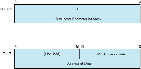
5.3.1.3. Itemlist Read Operations
Itemlist read operations provide expanded software features to read QIO requests. The operating system provides the following combination of function code and modifier:
IO$_READVBLK!IO$M_EXTEND—Itemlist read virtual block
No other function modifiers can be specified in an itemlist read request.
Note
Itemlist read features supported by the terminal driver are not supported by all DECnet terminal emulators.
The itemlist read function code and modifier combination takes the following device- or function-dependent arguments:
P1—The starting virtual address of the buffer that is to receive the data read.
P2—The size of the buffer that is to receive the data read in bytes. If required, the P2 size includes additional space for an overflow buffer to hold an escape sequence terminator (see item code TRM$_ESCTRMOVR in Table 5.7, ''Item Codes for Terminal Driver Itemlist Read Operations'').
Note
The IO$_READxBLK and IO$_WRITExBLK are limited by the system parameter MAXBUF as well as the terminal driver. The terminal driver only functions with buffer sizes less than 32718 bytes.
P3—The access mode at which the itemlist is to be probed (optional).
P5—The address of the itemlist buffer.
P6—The length in bytes of the itemlist buffer.
P4 is not meaningful for itemlist read operations. P5 points to a series of item descriptors. Figure 5.4, ''Itemlist Read Descriptor'' shows the format for these descriptors. You cannot repeat the same item code in the same item list.
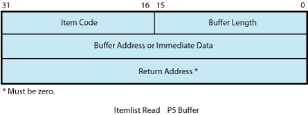
Table 5.7, ''Item Codes for Terminal Driver Itemlist Read Operations'' lists the item codes that can be specified in the first longword of the item descriptors.
| Item Code | Meaning | |
|---|---|---|
| TRM$_ALTECHSTR |
Alternate echo string. The buffer length word contains the length of the string. The data address word contains the address of the string. The alternate echo string is written to the terminal after the first character is entered. This item code for character validating read mode (TRM$K_EM_RDVERIFY) editing only. | |
| TRM$_EDITMODE | Extended editing modes. The immediate data longword specifies extended editing mode values. The buffer length word must be zero. The following editing modes are supported: | |
| TRM$K_EM_DEFAULT | Normal read mode. This is the default if TRM_EDITMODE is not present in the itemlist. | |
| TRM$K_EM_RDVERIFY | Character Validating read mode. See Section 5.3.1.4, ''Read Verify Function''. | |
| TRM$_ESCTRMOVR |
Escape terminator overflow size. Specifies the number of bytes that may be used to hold an escape sequence terminator. This number should be included in P2, the buffer size argument, in addition to the space required for the data to be read. Note that this overflow area is for the terminator only; it is not available for user data. TRM$_ESCTRMOVR is useful in preventing partial escape errors, which return SS$_PARTESCAPE. This overflow buffer ensures that all the characters in an escape sequence terminator fits in the user buffer, thus eliminating the need for additional single-character read operations. | |
| TRM$_FILLCHR |
A 2-byte value that indicates the fill and clear character for TRM$K_EM_RDVERIFY. The first byte of the immediate data longword specifies the clear character; the second byte specifies the fill character. This item code is for character validating read mode (TRM$K_EM_RDVERIFY) editing only. | |
| TRM$_INIOFFSET | Indicates the character in the initial string where echoing starts. The immediate data longword specifies the character. | |
| TRM$_INISTRNG | Specifies a string to preload into the read buffer (P1). The buffer length word contains the length of the string. The data longword contains the address of the string. TRM$_INISTRNG must be specified if the edit mode is TRM$K_EM_RDVERIFY, and must be the same length as specified by TRM$_PICSTRNG. | |
| TRM$_MODIFIERS | Read modifiers. The immediate data longword contains a 32-bit value that specifies modifiers to read operations. The read operations are defined in $TRMDEF. The buffer length word must be zero. The following bits are defined: | |
| TRM$M_TM_ARROWS | The terminal interprets the left and right arrow keys (TRM$K_EM_RDVERIFY mode only). The arrow keys are not put in the buffer and do not terminate the read. TRM$_ESCTRMOVR must be greater than or equal to 5. | |
| TRM$M_TM_AUTO_TAB | This bit creates an autotab mode field (TRM$K_EM_RDVERIFY mode only). | |
| TRM$M_TM_CVTLOW | Lowercase alphabetic characters (hexadecimal 61 to 7A) are converted to uppercase when transferred to the user buffer or echoed. | |
| TRM$M_TM_DSABLMBX | The mailbox is disabled for unsolicited data and for receiving hangup messages. | |
| TRM$M_TM_ESCAPE | A valid ANSI escape sequence is recognized as a valid delimiter for the read operation. | |
| TRM$M_TM_NOCLEAR | Fill characters are not replaced with clear characters after a nonfill character occurs (TRM$K_EM_RDVERIFY mode only). | |
| TRM$M_TM_NOECHO | Characters are not displayed as they are entered at the keyboard. | |
| TRM$M_TM_NOEDIT | This bit inhibits advanced editing for this read operation. | |
| TRM$M_TM_NOFILTR | The terminal does not interpret DEL, Ctrl/U, or Ctrl/R, but passes them to you. This characteristic explicitly disables line editing. | |
| TRM$M_TM_NORECALL | This bit inhibits command recall (Ctrl/B) by the terminal driver. | |
| TRM$M_TM_OTHERWAY | This bit sets left-justify fields to insert mode and right-justify fields to overstrike mode (TRM$K_EM_RDVERIFY mode only). TRM$M_TM_TOGGLE must equal 1. | |
| TRM$M_TM_PURGE | The type-ahead buffer is purged before the read operation begins. | |
| TRM$M_TM_R_JUST | This bit creates a right-justified field (TRM$K_EM_RDVERIFY mode only). | |
| TRM$M_TM_TERM_ARROW | The read operation is terminated when the left arrow key is pressed at the left margin or when the right arrow key is pressed at the right margin (TRM$K_EM_RDVERIFY mode only). TRM$M_TM_ARROWS must be enabled. | |
| TRM$M_TM_TERM_DEL | The read operation is terminated when the DELETE key is pressed at the left margin (TRM$K_EM_RDVERIFY mode only). | |
| TRM$M_TM_TOGGLE | Enables Ctrl/A to function as a toggle key between insert mode and overstrike mode (TRM$K_EM_RDVERIFY mode only). Left-justify insert mode shifts characters to the right; right-justify insert mode shifts characters to the left. Shifted characters are not checked for validity in their new positions. | |
| TRM$M_TM_TIMED | TRM$_TIMEOUT specifies the maximum time (seconds) that can elapse between characters received from the terminal; that is, the timeout value for the operation. TRM$M_TM_TIMED is assumed set if TRM$_TIMEOUT is included in the itemlist. See the description of IO$M_TIMED in Table 5.6, ''Read QIO Function Modifiers for the Terminal Driver''. | |
| TRM$M_TM_TRMNOECHO |
The termination character (if any) is not displayed. There is no formal terminator if the buffer is filled before the terminator is typed. All other bits must be zero. | |
| TRM$_PICSTRNG |
Character validation string. The buffer length word contains the length of the string, which must be the same as the length specified by TRM$_INISTRNG. The data address word contains the address of the string. TRM$_PICSTRNG must be specified if the edit mode is TRM$K_EM_RDVERIFY. Note that this item code is for character validating read mode (TRM$K_EM_RDVERIFY) editing only. The format of the character validation string is 1 byte per input character. Each byte is a bit mask. The following values are provided: | |
| Value | Meaning | |
| TRM$M_CV_UPPER | Uppercase alphabetic | |
| TRM$M_CV_LOWER | Lowercase alphabetic | |
| TRM$M_CV_NUMERIC | Numeric (0-9) | |
| TRM$M_CV_NUMPUNC | Numeric punctuation (+ - .) | |
| TRM$M_CV_PRINTABLE | Printable ASCII character | |
| TRM$M_CV_ANY | Any character | |
| If no values are set, the corresponding character specified by TRM$_INISTRNG is used. Appendix C, "DEC Multinational Character Set and Terminal Escape Sequences/Modes" lists the multinational character set. | ||
| TRM$_PROMPT | Specifies a prompt string. The buffer length word contains the length of the prompt. The data address word contains the address of the prompt string. See Section 5.3.1, ''Read'' for information on how carriage control specifiers in a prompt string are handled. | |
| TRM$_TERM | The buffer length word determines the format of the nondefault terminator mask. If the buffer length word is zero, then the data longword is used as a short form mask. If the buffer length word is nonzero, then a mask n bytes long is available at the specified address. | |
| TRM$_TIMEOUT | Read timeout. See the description of IO$M_TIMED in Table 5.6, ''Read QIO Function Modifiers for the Terminal Driver''. | |
5.3.1.4. Read Verify Function
When using the read verify function, the terminal driver performs input validation based on character attributes. (Read verification bypasses the optionally specified termination mask (TRM$_TERM).) Validation is performed one character at a time as data is entered. Invalid characters are not echoed, and cause the read operation to complete. It is then up to the application program to handle the error appropriately.
The initial string describes the initial contents of the input field. This string may consist of data and marker characters. The clear character is displayed on the screen for each occurrence of the fill character in the initial string buffer.
The picture string is a string of bytes where each byte corresponds to one character of the field being entered. Each byte specifies a mask of legal character types for that character position. If the byte is left as zero, then that position is a marker character, and the character from the initial string is echoed for that position.
For left-justified fields, the prompt data is output to the terminal, followed by an optional number (TRM$_INIOFFSET) of initial string characters. Leading marker characters are always output following the prompt, leaving the cursor at the leftmost data position. As each character is entered, it is validated and then echoed, advancing the cursor position. Additional marker characters are skipped as they are encountered. If an input character fails the validation, the read operation is completed with the invalid character as the terminator.
For right-justified fields, the prompt is output and is followed by the initial string. (In general, TRM$_INIOFFSET is set to the length of TRM$_INISTRNG for right-justified fields.) The cursor position remains one position to the right of the initial string. For proper operation, right-justified fields cannot have mixed picture definitions. After each character is input, the entire prompt and input fields are output. Therefore, the prompt should include a cursor positioning escape sequence.
The definition of full field is different for left- and right-justified read operations. For left-justified fields, full field is detected when the character corresponding to the last nonmarker position in the picture string has been entered. For right-justified fields, full field is detected when a character other than the fill character is shifted into the leftmost, nonmarker position in the field.
If the modifier TRM$M_TM_AUTO_TAB is set in TRM$_MODIFIERS, then detection of a full field terminates the read operation. In the event of autotab termination, the terminator character in the IOSB is null. If the autotab option is not selected, then termination occurs when one more character is typed to a full field. Applications can detect this condition when the terminating character index is one character beyond the end of the field. The extra character is reported as the terminator. In a left-justified field, the IOSB index to the terminator is zero-based; in a right-justified field, this index is one-based.
If a read verify function is interrupted by an asynchronous write operation, the read verify is completed with status SS$_OPINCOMPL.
No line editing functions other than the delete character function are supported for read verify.
5.3.2. Write
Write operations display the contents of a user-specified buffer on the associated terminal. The operating system provides the following write I/O functions, which are listed with their function codes:
IO$_WRITEVBLK—Write virtual block
IO$_WRITELBLK—Write logical block
IO$_WRITEPBLK—Write physical block
The write function codes can take the following device- or function-dependent arguments:
P1—The starting virtual address of the buffer that is to be written to the terminal.
P2—The number of bytes that are to be written to the terminal. (The system generation parameter, MAXBUF, and the terminal driver limit the maximum size of the buffer. The terminal driver only functions with buffer sizes less than 32718 bytes.)
P4—Carriage control specifier except for write physical block operations. (Write function carriage control is described in Section 5.3.2.2, ''Write Function Carriage Control''.)
P3, P5, and P6 are not meaningful for terminal write operations.
In write virtual block and write logical block operations, the buffer (P1 and P2) is formatted for the selected terminal and includes the carriage control information specified by P4.
Unless TT$M_MECHFORM is specified, multiple line feeds are generated for form feeds. The number of line feeds generated depends on the current page position and the length of the page. By producing a carriage return after the last line feed, a form feed also moves the cursor to the left margin. Multiple spaces are generated for tabs if the characteristics of the selected terminal do not include TT$M_MECHTAB (this does not apply to write physical block operations). Tab stops occur every eight characters or positions.
CTDRIVER and Buffered Output
CTDRIVER, a component of the SET HOST facility, buffers output from remote terminals in order to package multiple output requests into a single network transfer. As a result, control is returned early to the user with a status of SS$_NORMAL when the output buffer has been filled and successfully queued.
Note that this output might not be displayed if the user enters an abort character or a Ctrl/O.
5.3.2.1. Function Modifier Codes for Write QIO Functions
Five function modifiers can be specified with IO$_WRITEVBLK, IO$_WRITELBLK, and IO$_WRITEPBLK. Table 5.8, ''Write QIO Function Modifiers for the Terminal Driver'' lists these function modifiers. All write function modifiers are supported for LAT devices.
| Code | Consequence |
|---|---|
| IO$M_BREAKTHRU | Allows breakthrough read regardless of the current active state. |
| IO$M_CANCTRLO | Turns off Ctrl/O (if it is in effect) before the write operation. Otherwise, the data cannot be displayed. |
| IO$M_ENABLMBX | Enables use of the mailbox associated with the terminal for notification that unsolicited data is available. |
| IO$M_NOFORMAT | Allows you to specify write functions without interpretation or format; in effect, the terminal line is in a temporary PASTHRU mode. |
| IO$M_REFRESH | If a read operation is interrupted by a write operation (by either a write breakthrough? or any other type of write), the terminal displays the current read data when the read function is restarted. |
5.3.2.2. Write Function Carriage Control
The P4 argument is a longword that specifies carriage control. Carriage control determines the next printing position on the terminal. P4 is ignored in a write physical block operation. Figure 5.5, ''P4 Carriage Control Specifier''shows the P4 longword format.

Only bytes 0, 2, and 3 in the longword are used. Byte 1 is ignored. If the low-order byte (byte 0) is not 0, the contents of the longword are interpreted as a FORTRAN carriage control specifier. Table 5.9, ''FORTRAN Write Function Carriage Control'' lists the possible byte 0 values (in hexadecimal) and their meanings.
| Byte 0 Value (hexadecimal) | ASCII Character | Meaning |
|---|---|---|
| 20 | (space) | Single-space carriage control (sequence: carriage-return/line-feed combination, print buffer contents, return?). |
| 30 | 0 | Double-space carriage control (sequence: carriage-return/line-feed combination, carriage-return/line-feed combination, print buffer contents, return?). |
| 31 | 1 | Page eject carriage control (sequence: form feed, print buffer contents, return). |
| 2B | + | Overprint carriage control; allows double printing for emphasis or special effects (sequence: print buffer contents, return). |
| 24 | $ | Prompt carriage control (sequence: carriage-return/line-feed combination, print buffer contents). |
| All other values | Same as ASCII space character: single-space carriage control. |
If the low-order byte (byte 0) is 0, bytes 2 and 3 of the P4 longword are interpreted as the prefix and postfix carriage control specifiers. The prefix (byte 2) specifies the carriage control before the buffer contents are printed. The postfix (byte 3) specifies the carriage control after the buffer contents are printed. The sequence is as follows:
Prefix carriage control
Print
Postfix carriage control
The prefix and postfix bytes, although interpreted separately, use the same encoding scheme. Table 5.10, ''Write Function Carriage Control (P4 byte 0 = 0)'' shows this encoding scheme in hexadecimal.
With several exceptions, Figure 5.6, ''Write Function Carriage Control (Prefix and Postfix Coding)'' shows the prefix and postfix hexadecimal coding that produces the carriage control functions listed in Table 5.9, ''FORTRAN Write Function Carriage Control''. Prefix and postfix coding provides an alternative way to achieve these controls.
In the first example in Figure 5.6, ''Write Function Carriage Control (Prefix and Postfix Coding)'', the prefix/postfix hexadecimal coding for a single-space carriage control (carriage-return/line-feed combination, print buffer contents, return) is obtained by placing the value 1 in the second (prefix) byte and the sum of the bit 7 value (80) and the return value (D) in the third postfix byte.
 80  (bit 7 = 1)
+ D  (return)
—-
 8D  (postfix = return)
| Prefix/Postfix Bytes (Hexadecimal) | ||||
|---|---|---|---|---|
| Bit 7 | Bits 0—6 | Meaning | ||
| 0 | 0 | No carriage control is specified (NULL). | ||
| 0 | 1—7F | Bits 0 through 6 are a count of carriage-return/line-feed combinations. | ||
| Bit 7 | Bit 6 | Bit 5 | Bits 0—4 | Meaning |
| 1 | 0 | 0 | 0—1F | Output the single ASCII control character specified by the configuration of bits 0 through 4 (7-bit character set). |
| 1 | 1 | 0 | 0—1F | Output the single ASCII control character specified by the configuration of bits 0 through 4, which are translated as ASCII characters 128 through 159 (8-bit character set; see Appendix C, "DEC Multinational Character Set and Terminal Escape Sequences/Modes"). |
| 1 | 1 | 1 | 0—1F | Reserved. |
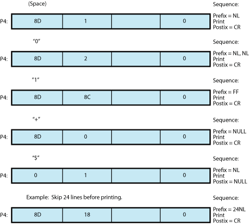
5.3.3. Set Mode
Set mode operations affect the operation and characteristics of the associated terminal line. The operating system provides two types of set mode functions: set mode and set characteristics.
The set mode function affects the mode and temporary characteristics of the associated terminal line. Set mode is a logical I/O function and requires no privilege. (If you do not have LOG_IO or PHY_IO privilege, the terminal driver does not accept a set mode request to a terminal that does not have the extended terminal characteristic TT2$M_SETSPEED, even if no request for a change of speed is made. Privilege is not required if TT2$M_SETSPEED is set but no attempt to change the speed is made.) The following function code is provided:
IO$_SETMODE
The set characteristics function affects the permanent characteristics of the associated terminal line. Set characteristics is a physical I/O function and requires the privilege necessary to perform physical I/O. The following function code is provided:
IO$_SETCHAR
The set mode and set characteristics functions take the following device- or function-dependent arguments if no function modifiers are specified:
P1—Address of characteristics buffer
P2—Length of characteristics buffer (default length is 8 bytes, maximum is 16 bytes)
P3—Speed specifier (bits 0 through 7 = transmit; 8 through 15 = receive)
P4—Fill specifier (bits 0 through 7 = CR fill count; bits 8 through 15 = LF fill count)
P5—Parity flags
The P1 argument points to a variable-length block, as shown in Figure 5.7, ''Set Mode and Set Characteristics Buffers''. With the exception of terminal characteristics, the contents of the block are the same for both the set mode and set characteristics functions.
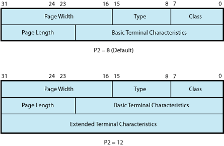
In the buffer, the device class is DC$_TERM, which is defined by the $DCDEF macro. The terminal type is defined by the $TTDEF macro; for example, TT$_LA36. The page width is a value in the range of 1 through 511. The page length is a value in the range of 0 through 255. Table 5.4, ''Terminal Characteristics'' lists the values for terminal characteristics. Table 5.5, ''Extended Terminal Characteristics'' lists the extended terminal characteristics. Characteristics values are defined by the $TTDEF, $TT2DEF, and $TT3DEF macros.
Note
Make sure that the selected device is a terminal before performing any set mode function, particularly when using SYS$INPUT or SYS$OUTPUT.
The P3 argument defines the device speed, such as TT$C_BAUD_300. The low eight bits specify the transmit speed, and the high eight bits specify the receive speed. If no receive speed is specified, the indicated transmit speed is used for both transmitting and receiving. If neither the transmit nor the receive speed is specified (P3 = 0), the baud rate is not changed. The terminal driver ignores the receive speed bits for interfaces that do not support split-speed operation. Though speeds up to 115.2 K baud can be specified, not all controllers support all speed combinations. See the associated hardware documentation to determine which speeds are supported by your controller.
P4 contains fill counts for the carriage-return and line-feed characters. Bits 0 through 7 specify the number of fill characters used after a carriage return. Bits 8 through 15 specify the number of fill characters used after a line feed.
P4 is applicable only if TT$M_CRFILL or TT$M_LFFILL is specified as a terminal characteristic for the current QIO request; see
The P3 argument defines the device speed, such as TT$C_BAUD_300. The low eight bits specify the transmit speed, and the high eight bits specify the receive speed. If no receive speed is specified, the indicated transmit speed is used for both transmitting and receiving. If neither the transmit nor the receive speed is specified (P3 = 0), the baud rate is not changed. The terminal driver ignores the receive speed bits for interfaces that do not support split-speed operation. Though speeds up to 115.2 K baud can be specified, not all controllers support all speed combinations. See the associated hardware documentation to determine which speeds are supported by your controller.
P4 contains fill counts for the carriage-return and line-feed characters. Bits 0 through 7 specify the number of fill characters used after a carriage return. Bits 8 through 15 specify the number of fill characters used after a line feed.
P4 is applicable only if TT$M_CRFILL or TT$M_LFFILL is specified as a terminal characteristic for the current QIO request; see Table 5.4, ''Terminal Characteristics''.
Several parity flags can be specified in the P5 argument:
TT$M_ALTRPAR—Alter parity. If set, check the state of TT$M_PARITY and TT$M_ODD and, if indicated, change the parity. Otherwise, ignore these bits.
TT$M_PARITY—Enable parity on terminal line if set, disable if clear.
TT$M_ODD—Parity is odd if set.
TT$M_ALTDISPAR—Alter dismiss parity errors. If set, check the state of TT$M_DISPARERR.
TT$M_DISPARERR—Dismiss parity errors. If this mode is set, a character with a parity error is passed to the reader. An error message is not reported.
.
Several parity flags can be specified in the P5 argument:
TT$M_ALTRPAR—Alter parity. If set, check the state of TT$M_PARITY and TT$M_ODD and, if indicated, change the parity. Otherwise, ignore these bits.
TT$M_PARITY—Enable parity on terminal line if set, disable if clear.
TT$M_ODD—Parity is odd if set.
TT$M_ALTDISPAR—Alter dismiss parity errors. If set, check the state of TT$M_DISPARERR.
TT$M_DISPARERR—Dismiss parity errors. If this mode is set, a character with a parity error is passed to the reader. An error message is not reported.
Note
If parity is enabled, the DZ11 generates a parity check bit to detect parity mismatch. Unless TT$M_DISPARERR is enabled, parity errors that occur during an I/O read operation are fatal to the operation. Parity errors that occur on input characters (that is, keys pressed on the keyboard) when no I/O operation is in progress might result in a character loss.
TT$M_BREAK—Generate a break if set. The break is in effect until this bit is turned off. TT$M_BREAK is supported by the LTDRIVER for terminal servers that support the break capability, such as the DECserver 200 and DECserver 500. However, in the case of LAT terminals, the terminal server controls the duration of the break.
TT$M_ALTFRAME—If set, the four low-order bits of P5 become the frame size. Note that the frame size is for data bits only and is exclusive of parity. TT$M_ALTFRAME is supported for frame sizes of 7 and 8 for LAT devices.
To take the existing parity settings, modify them, and use them in the set mode or set characteristic function, move the byte starting at the second nibble of the buffer that is going to be used in the P5 argument. For example, the following instructions change the parity from even to odd:
insv    iosb+6, #4, #8, flags
bisl    #tt$m_altrpar!tt$m_odd!tt$m_parity, flags
The following instruction then resets the parity to its original state:
bicl #tt$m_odd!tt$m_parity, flags
See Section 5.1.5, ''Autobaud Detection'' for information about the SET TERMINAL/FRAME command.
Application programs that change terminal characteristics should perform the following steps:
Use the IO$_SENSEMODE function to read the current characteristics.
Modify the characteristics.
Use the set mode function to write back the results.
If the characteristic is intended to be reset when the image exits, the application must perform this operation.
Failure to follow this sequence results in clearing any previously set characteristic.
Two stop bits are used only for data rates less than or equal to 150 baud; higher data rates default to one stop bit.
The set mode and set characteristics functions can take the enable Ctrl/C AST, enable Ctrl/Y AST, enable out-of-band AST, hangup, set modem, broadcast, and loopback function modifiers that are described in the following sections.
Note
If an attempt is made to turn on TT2$V_FALLBACK for a disconnected virtual terminal (_VTAx:) or if the Terminal Fallback facility has not been activated, the status code SS$_BADPARAM is returned. For more information on TFF, see the OpenVMS Terminal Fallback Utility Manual (available on the Documentation CD-ROM).
5.3.3.1. Hangup Function Modifier
The hangup function disconnects a terminal that is on a dialup line. (Dialup lines are described in Section 5.3.3, ''Set Mode''.) The following combinations of function code and modifier are provided:
IO$_SETMODE!IO$M_HANGUP
IO$_SETCHAR!IO$M_HANGUP
The hangup function modifier takes no arguments. SS$_NORMAL is returned in the I/O status block.
Note
For remote terminals, the hangup function breaks the network connection to the local system, ending the remote terminal session.
5.3.3.2. Enable Ctrl/C AST and Enable Ctrl/Y AST Function Modifiers
Both set mode functions can take the enable Ctrl/C AST and enable Ctrl/Y AST function modifiers. These function modifiers request the terminal driver to queue an AST for the requesting process when you press Ctrl/C or Ctrl/Y. The following combinations of function code and modifier are provided:
IO$_SETMODE!IO$M_CTRLCAST—Enable Ctrl/C AST
IO$_SETMODE!IO$M_CTRLYAST—Enable Ctrl/Y AST
These function code modifier pairs take the following device- or function-dependent arguments:
P1—Address of the AST service or 0 if the corresponding AST is disabled
P2—AST parameter
P3—Access mode to deliver AST (maximized with caller's access mode)
If the respective enabling is in effect, pressing Ctrl/C or Ctrl/Y gains the attention of the enabling process (see Table 5.1, ''Terminal Control Characters'').
Enable Ctrl/C and Ctrl/Y AST are one-time enabling function modifiers. After the AST occurs, it must be explicitly reenabled by one of the two function code combinations before an AST can occur again. This function code is also used to disable the AST. The function is subject to AST quotas.
You can have more than one Ctrl/C or Ctrl/Y enabled; pressing Ctrl/C, for example, results in the delivery of all Ctrl/C ASTs. ASTs are queued and delivered to the user process on a first-in/first-out basis for each access mode. However, ASTs are processed in the reverse order of the Ctrl/C AST or Ctrl/Y AST requests that have been issued to the terminal driver (on a last-in/first-out basis).
If no enable Ctrl/C AST is present, the holder of an enable Ctrl/Y AST receives an AST when Ctrl/C is pressed; carriage-return/line-feed combination, Ctrl/Y, and Return are echoed.
Figure 5.9, ''Relationship of Out-of-Band Function with Control Characters'' shows the relationship of Ctrl/C and Ctrl/Y with the out-of-band function. If Ctrl/C or Ctrl/Y is an enabled out-of-band character, any out-of-band ASTs specified for this character are delivered. If IO$M_INCLUDE function modifier is included in the out-of-band AST request for this character, an enabled Ctrl/C or Ctrl/Y AST is also delivered.
Enable Ctrl/C AST requests are flushed by the Cancel I/O on the Channel ($CANCEL) system service. Enable Ctrl/Y AST requests are flushed by the Deassign I/O Channel ($DASSGN) system service.
Ctrl/Y is normally used to gain the attention of the command interpreter and to input special commands such as DEBUG, STOP, and CONTINUE. Programs that are run from a command interpreter should not enable Ctrl/Y. Because ASTs are delivered on a first-in/first-out basis, the command interpreter's AST routine gets control first, and might not allow the program's AST to be delivered at all. Programs that require the use of Ctrl/Y should use the LIB$DISABLE_CTRL RTL routine to disable DCL recognition of Ctrl/Y.
See Example 5.4, ''LIB$XXABLE_CTRL.C Terminal Driver Programming Example'' for a programming example that demonstrates Ctrl/Y and Ctrl/C handling under OpenVMS.
Section 5.1.1.2, ''Control Characters and Special Keys'' describes other effects of Ctrl/C and Ctrl/Y.
5.3.3.3. Set Modem Function Modifier
The set modem function modifier is used in maintenance operations to allow a process to activate and deactivate modem control signals. Both set mode and set characteristics functions can take the set modem function modifier. The following combinations of function code and modifier are provided:
IO$_SETMODE!IO$M_SET_MODEM!IO$M_MAINT
IO$_SETCHAR!IO$M_SET_MODEM!IO$M_MAINT
Note
For LAT devices, the set modem field for maintenance operations of the IO$M_SET_MODEM!IO$M_MAINT function modifier is unsupported and may return unpredictable results.
These function code modifier pairs take the following device- or function-dependent argument:
P1—The address of a quadword block that specifies which modem control signals to activate or deactivate
Figure 5.8, ''Set Mode P1 Block'' shows the format of this block.
The modem on and modem off fields, in combination or separately, can specify one or more of the following values:
TT$M_DS_RTS—Request to send (RTS)
TT$M_DS_DTR—Data terminal ready (DTR)
Figure 5.8. Set Mode P1 Block 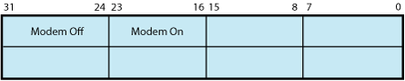
TT$M_DS_SECTX—Transmitted backward channel data (Sec Txd)
The $TTDEF macro defines the values for these values. These values can only be specified if the terminal characteristic TT$M_MODEM is not set. Otherwise, an error (SS$_ABORT) occurs.
Note
The set modem function is not supported for remote terminals. The status SS$_DEVREQERR is returned in the I/O status block. Because the DMF32 does not provide the secondary transmitted data signal (Sec Txd), the driver sets the secondary request to send the signal. Users should connect a jumper cable between pins 14 and 19 on the DMF32.
5.3.3.4. Loopback Function Modifier
The loopback function modifier is used in maintenance operations to place the terminal line in a hardware loopback mode. Data transmitted to a line in this mode is returned as receive data. If the controller does not support loopback mode or the terminal line has the TT$M_MODEM characteristic set, an error status (SS$_ABORT) is returned. Both set mode functions can take the loopback function modifier.
Note
The loopback function is not supported for remote terminals. The status SS$_DEVREQERR is returned in the I/O status block.
The following combinations of function code and modifier are provided:
IO$_SETMODE!IO$M_LOOP!IO$M_MAINT
IO$_SETCHAR!IO$M_LOOP!IO$M_MAINT
Data transmitted in the loopback mode should only be written in records less than or equal to the size of the type-ahead buffer (see Section 5.1.1.5, ''Type-Ahead Feature''). Programs that use the loopback function modifier should incorporate a 1-second delay to allow the controller to enable the loopback mode after the request is posted. Write requests should also include the IO$M_NOFORMAT function modifier to prevent terminal driver from formatting input or output data.
The operating system provides another function modifier to reset a terminal line previously placed in loopback mode. The following combinations of function code and modifier are provided:
IO$_SETMODE!IO$M_UNLOOP!IO$M_MAINT
IO$_SETCHAR!IO$M_UNLOOP!IO$M_MAINT
Programs that use the unloop function modifier should incorporate a 1-second delay to allow the controller to reset the loopback mode after the request is posted.
Note
IO$M_LOOP and IO$M_UNLOOP are not supported for LAT devices.
5.3.3.5. Enable Out-of-Band AST Function Modifier
The enable out-of-band AST function modifier requests that the terminal driver queue an AST for the requesting process when you enter any one of 32 control characters. The following combinations of function code and modifier are provided:
IO$_SETMODE!IO$M_OUTBAND—Enable out-of-band AST
IO$_SETCHAR!IO$M_OUTBAND—Enable out-of-band AST
These function code modifier pairs take the following device- or function-dependent arguments:
P1—Address of the AST service or 0 if the AST entered on this channel is to be canceled. (The AST parameter is the out-of-band character.)
P2—Address of a character mask with the same format as the short form terminator mask (see Section 5.3.1.2, ''Read Function Terminators'').
P3—Access mode to deliver AST (maximized with the caller's access mode).
The IO$_SETMODE!IO$M_OUTBAND function can optionally take the following function modifiers:
IO$M_INCLUDE—Include the character typed in the data stream.
IO$M_TT_ABORT—Allow current read and write operations to be aborted. (The IOSB for aborted operations returns the status SS$_CONTROLC.)
If an out-of-band AST is in effect, pressing any control character specified in the P2 mask gains the attention of the enabling process. Figure 5.9, ''Relationship of Out-of-Band Function with Control Characters'' shows the relationship of the out-of-band function with some of the control characters.
You can have only one out-of-band AST enabled per channel.
Out-of-band ASTs are repeating ASTs; they continue to be delivered until specifically disabled. Out-of-band AST enables are flushed by the Cancel I/O on Channel ($CANCEL) system service.
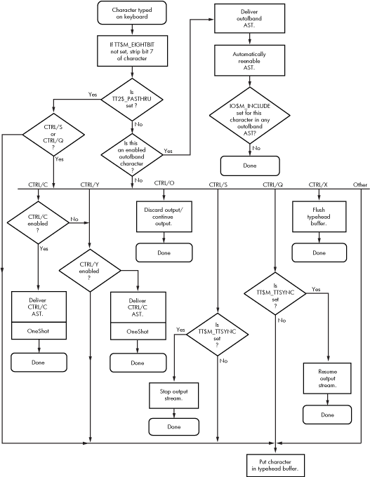
5.3.3.6. Broadcast Function Modifier
The broadcast function modifier allows you to turn on or turn off selected broadcast requester identifiers (IDs). The following combination of function code and modifier is provided:
IO$_SETMODE!IO$M_BRDCST
This function code modifier pair takes the following device- or function-dependent arguments:
P1—A buffer that contains the bits that specify the requester IDs to be broadcast
P2—The length of the P1 buffer (default is 8 bytes)
The first longword of P1 is reserved for use by HPE facilities, as shown in Table 5.11, ''Broadcast Requester IDs''. The symbols are defined in the system macro library ($BRKDEF). The second longword is for customer use to specify selected bits. If any bit is set in the P1 buffer, that particular requester ID is turned off for broadcast.
| Bit | Meaning |
|---|---|
| BRK$C_DCL | Disables broadcasts by Ctrl/T |
| BRK$C_GENERAL | Disables broadcasts by the DCL command REPLY and the SYS$BRDCST system service |
| BRK$C_MAIL | Disables broadcasts by the Mail utility |
| BRK$C_PHONE | Disables broadcasts by the Phone utility |
| BRC$C_QUEUE | Disables broadcasts about batch and print queues |
| BRK$C_SHUTDOWN | Disables broadcasts about system shutdown |
| BRK$C_URGENT | Disables broadcasts labeled URGENT by the REPLY command |
| BRK$C_USERn | Disables broadcasts by images associated with the specified value; n can be any decimal integer between 1 and 16 |
5.3.4. LAT Port Driver QIO Interface
The LAT port driver (LTDRIVER) accommodates I/O requests from application programs for connections to remote devices on one or more terminal servers; for connections to remote services; and for configuring LTDRIVER and retrieving configuration information about LTDRIVER. A remote device, such as a printer, can be shared in a LAT configuration. Before an application program can access a remote device, the system manager must create logical devices and map them to physical devices connected to terminal servers. Creating and mapping these logical devices can be done either with the LAT Control Program (LATCP) utility or with a $QIO request from a program that has OPER privilege. Once mapped, application programs can establish and terminate connections to these remote devices.
This section describes the capabilities of the QIO interface to the LAT port driver (LTDRIVER). The QIO interface allows application programs to access and modify information contained in the LTDRIVER data structures and to initiate events and obtain status information. You must use these QIO functions to establish a connection to a remote device or service from an application program.
The LTDRIVER responds to TEST SERVICE commands issued at terminal servers that support the TEST SERVICE command, such as the DECserver 200 and DECserver 500 servers.
LAT devices can use all read and write function modifiers listed for the terminal driver function codes except those modifiers that apply to modems (see Section 5.3.1, ''Read'' and Section 5.3.2, ''Write'').
The operating system does not support the following set mode or set characteristics function code modifiers for LAT devices:
IO$M_LOOP
IO$M_UNLOOP
TT$M_ALTRPAR
TT$M_ALTFRAME
TT$M_MODEM
TT$M_READSYNC
TT2$M_SETSPEED
With LAT devices, the terminal server, rather than the host, handles flow control to the physical device. A separate flow control mechanism exists between the server and the host.
5.3.4.1. LAT Port Types
QIO functions can be used to create the following LAT port types:
Application Port. This type of port can be used to connect to a remote device (typically a printer) on a terminal server or to a dedicated port on another LAT service node. This is the default port type. See Section 5.3.4.5, ''Programming Application Ports'' for a description of programming an application port.
Dedicated Port. This type of port specifies that the logical port on your node is dedicated to an application service. When users on a terminal server (or on another node that supports outgoing connections) request a connection to this service name, they are connected to a dedicated port. See Section 5.3.4.6, ''Programming Application Services and Dedicated Ports'' for a description of programming a dedicated port and application service.
Forward Port. This type of port is used for outgoing LAT connections (to remote services) and is created by assigning a channel to the LAT template device _LTA0: with the $ASSIGN system service.
QIO functions can also be used to configure and read information about these ports; for more information:
See Section 5.3.4.3, ''Creating and Configuring LAT Entities'' for a description of configuring a LAT port
See Section 5.3.4.4, ''Obtaining Information About LAT Entities'' for a description of reading configuration information about a LAT port
See Section 5.3.4.7, ''Programming Forward Ports'' for a description of programming a forward port in order to make a connection to a LAT service
5.3.4.2. LAT Port Driver Functions
The operating system provides the following combinations of function code and modifier:
IO$_TTY_PORT!IO$M_LT_CONNECT. Requests that the LAT port driver make a connection to a remote device on a server (or dedicated port on another LAT service node) or to a remote service, depending on whether the port is an application port or a forward port respectively. For dedicated ports, this QIO completes when an incoming connection to the port is established. See Section 5.3.4.5, ''Programming Application Ports'' for a description of programming an application port, Section 5.3.4.6, ''Programming Application Services and Dedicated Ports'' for a description of programming a dedicated port, and Section 5.3.4.7, ''Programming Forward Ports'' for a description of programming a forward port.
IO$_TTY_PORT!IO$M_LT_DISCON. Depending on the port type, requests that the LAT port driver terminate the LAT connection to the remote device, service, or local application service. IO$M_FLUSH_DATA can be specified in the P2 argument to IO$M_LT_DISCON. The flush flag indicates that any data not delivered to the remote device is to be flushed when the disconnect is issued.
IO$_TTY_PORT!IO$M_LT_SETMODE. Requests that the LAT port driver create or configure a LAT entity. See Section 5.3.4.3, ''Creating and Configuring LAT Entities'' for more information.
IO$_TTY_PORT!IO$M_LT_SENSEMODE. Requests that the LAT port driver return configuration information about a LAT entity. See Section 5.3.4.4, ''Obtaining Information About LAT Entities'' for more information.
5.3.4.3. Creating and Configuring LAT Entities
The LAT SETMODE $QIO function (IO$_TTY_PORT!IO$M_LT_SETMODE) is used to create, delete, and modify LAT nodes, services, ports, and links.
Creation, deletion, or modification of any entity requires the OPER privilege.
The LAT SETMODE $QIO function accepts four arguments: P1, P2, P3, and P4. P1 is the address of an item list; P2 is the length of this item list.
P3 specifies the type of entity to which the SETMODE operation applies. The entity type can be one of five types:
Node (LAT$C_ENT_NODE). Only the local node name may be specified, with the exception of a SETMODE itemlist containing no item codes other than LAT$_ITM_COUNTERS.
Service (LAT$C_ENT_SERVICE). Only local service names may be specified, with the exception of a SETMODE itemlist containing no item codes other than LAT$_ITM_COUNTERS.
Link (LAT$C_ENT_LINK). The data link associated with the LAN.
Port (LAT$C_ENT_PORT).
Queue Entry (LAT$C_ENT_QUEUE_ENTRY). Indicates queue entry entities. When this entity is used, the only valid SETMODE operation is delete.
The value for the entity type occupies the low-order 16 bits (bits 0--15) of the P3 parameter. For all four entity types, bits 16--19 are used as a status field to indicate the expected current status of the entity. These bits are used to decide whether the entity needs to be created before its characteristics are set. The possible values for this field are:
LAT$C_ENTS_OLD—The entity must already exist. An SS$_NOSUCHDEV error is returned if the entity does not exist.
LAT$C_ENTS_NEW—The entity must be created. An SS$_DUPLNAM error is returned if the entity already exists.
LAT$C_ENTS_UNK—If the entity does not exist, it is created. If it does exist, its characteristics are modified.
LAT$C_ENTS_DEL—If the entity exists, delete it. Otherwise, an SS$_NOSUCHDEV error is returned and the item list is not used.
P4 may contain the address of an entity name string descriptor. If this parameter is omitted (contains a 0 or the address of a descriptor that points to an empty buffer), a default may be used in some cases. The defaults for each entity type are as follows:
LAT$C_ENT_NODE—The local node.
LAT$C_ENT_SERVICE—No default; you must specify the service name.
LAT$C_ENT_LINK—The string LAT$LINK.
LAT$C_ENT_PORT—The device name associated with the currently assigned channel (the CHAN parameter of the $QIO function).
SETMODE can return the following status codes:
SS$_NOPRIV—No privilege to complete the desired operation.
SS$_ACCVIO—Part of the argument list or itemlist is not addressable.
SS$_BADPARAM—One of the parameters in the itemlist is in error. If this value is returned, the second longword of the IOSB contains the item code of the parameter in error.
SETMODE Item Codes
Each item in the itemlist consists of a one-word (16-bit) item code, followed by a value associated with the item.
Item codes in which the bit named LAT$V_STRING is zero take a longword value. The associated value is contained in the longword immediately following the item code in the itemlist. Item codes in which this bit is 1 take a counted string for their value. The byte immediately following the item code contains a byte count, which describes the length of the string that immediately follows it.
If you set bit LAT$V_CLEAR in the item code to 1, the current value associated with the item code is cleared or set to its default value. In this case, the actual value specified in the itemlist is ignored, although the byte count field skips to the next item in the itemlist.
Figure 5.10, ''Example SETMODE Itemlist'' shows an example of a SETMODE itemlist.
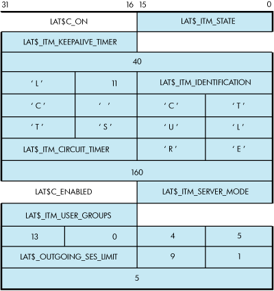
This SETMODE itemlist is the P1 parameter for a $QIO SETMODE function on the local node. P4 is omitted, and P3 is #LAT$C_ENT_NODE!$C_ENTS_OLD@16>. P2 is the length of the itemlist (52). A $QIO SETMODE function for this itemlist would perform the following operations:
Set the state of the node to on.
Set the LAT keepalive timer to 40 seconds.
Set the node identification to LTC CLUSTER.
Set the LAT circuit timer to 160 milliseconds.
Enable LAT outbound connections.
Turn on user groups 2, 8, 10, 11, 12, 16, and 19. LAT$_ITM_USER_GROUPS is represented by a bit field.
Set the outgoing session limit to five sessions.
For each entity type, only a subset of item codes may be set. Table 5.12, ''LAT$C_ENT_NODE Item Codes'' lists the item codes that may be set for the LAT$C_ENT_NODE entity type.
| Item Code | Meaning | |
|---|---|---|
| LAT$_ITM_STATE | Operating state of the LAT protocol. The following values are allowed: | |
| LAT$C_OFF | Turns off LAT protocol processing. No new connections allowed in either direction. Existing connections are terminated immediately. This is the default. | |
| LAT$C_SHUT | Disallows new LAT connections in either direction. Existing connections are allowed to remain active. | |
| LAT$C_ON | Turns on LAT protocol processing. | |
| LAT$_ITM_CIRCUIT_TIMER | Circuit timer value in milliseconds. Valid values are 10 to 1000 milliseconds. The default is 80 milliseconds. | |
| LAT$_ITM_CPU_RATING | CPU rating. Valid values are 0 to 100. If this value is 0, then the CPU rating value is not used in the rating calculation. See the VSI OpenVMS System Management Utilities Reference Manual for a complete description of this feature. | |
| LAT$_ITM_DEVICE_SEED | Overrides the default lower boundary for new LTA devices. Valid values are 0 to 9999; the default is 0. See the VSI OpenVMS System Management Utilities Reference Manual for more information on this feature. | |
| LAT$_ITM_KEEPALIVE_TIMER | Keepalive timer value in seconds. Valid values are 10 to 255 seconds. The default is 20 seconds. | |
| LAT$_ITM_MULTICAST_TIMER | Multicast timer value in seconds. Valid values are 10 to 180 seconds. The default is 60 seconds. | |
| LAT$_ITM_NODE_LIMIT | Maximum number of nodes in LAT database. The default is 0, where the maximum is determined by system resources. | |
| LAT$_ITM_RETRANSMIT_LIMIT | LAT retransmit limit. Valid values are 4 to 120 retransmissions. The default is 8 retransmissions. | |
| LAT$_ITM_SERVER_MODE | Controls whether the node allows the use of the MASTER side of the LAT protocol for outbound connections. Valid values are: | |
| LAT$C_DISABLED | Server mode disabled (this is the default). | |
| LAT$C_ENABLED | Server mode enabled. | |
| LAT$_ITM_SERVICE_RESPONDER | Indicates whether the node is to respond to service inquiries originating from a remote system. These inquiries are not necessarily directed at services being offered by the node. See the VSI OpenVMS System Management Utilities Reference Manual for a complete description of this feature. Valid values are: | |
| LAT$C_DISABLED | Service responder disabled (this is the default). | |
| LAT$C_ENABLED | Service responder enabled. | |
| LAT$_ITM_OUTGOING_SES_LIMIT | Maximum number of outgoing LAT sessions. A value of 0, which is the default, indicates that the limit is determined by system resources. | |
| LAT$_ITM_INCOMING_SES_LIMIT | Maximum number of interactive LAT sessions. A value of 0, which is the default, indicates that the limit is determined by system resources. | |
| LAT$_ITM_CONNECTIONS | Controls whether inbound connections can be accepted. Valid values are: | |
| LAT$C_DISABLED | Inbound connections disabled. | |
| LAT$C_ENABLED | Inbound connections enabled (this is the default). | |
| LAT$_ITM_NODE_NAME | Causes the LAT node name to be set to the given name. This item code may be specified only if the entity status field of the P3 parameter is LAT$C_ENTS_NEW; otherwise, a LAT$_ENTNOTFOU error results. | |
| LAT$_ITM_IDENTIFICATION | Node identification string. The default is the translation of SYS$ANNOUNCE. | |
| LAT$_ITM_SERVICE_GROUPS |
Specifies a default service group code bit mask. This mask is then used when creating new local services. The default is group code 0 enabled and all others disabled when the LAT software is initialized. Note that the use of the LAT$V_CLEAR bit is an exception for this parameter code. If you clear bit LAT$V_CLEAR, group codes corresponding to the group code mask, as specified in the itemlist, are set. Alternatively, if you set LAT$V_CLEAR, group codes corresponding to the group code mask, as specified in the itemlist, are cleared. | |
| LAT$_ITM_USER_GROUPS |
LAT group codes to be used when attempting outbound connections using the MASTER side of the LAT protocol. The default is all group codes disabled when the LAT software is initialized. Note that the use of the LAT$V_CLEAR bit is an exception for this parameter code. If you clear bit LAT$V_CLEAR, group codes corresponding to the group code mask, as specified in the itemlist, are set. Alternatively, if you set LAT$V_CLEAR, group codes corresponding to the group code mask, as specified in the itemlist, are cleared. | |
| LAT$_ITM_COUNTERS | Node counters block. Allows for zeroing of all node counters. This item code may be specified only if the entity status field of the P3 parameter is LAT$C_ENTS_OLD and the LAT$V_CLEAR bit is set. Violating either of these two rules results in a returned status of SS$_BADPARAM. | |
| LAT$_ITM_MAXIMUM_UNITS | Maximum unit number. Sets the highest value for a LTA unit number. Must be between 1 and 9999; defaults to 9999. | |
| LAT$_ITM_HI_CIRCUITS? | Indicates the highest number the resource attained since the host was initialized for LAT connections to node. | |
| LAT$_ITM_CUR_CIRCUITS? | Indicates current count of active connections to node. | |
| LAT$_ITM_MAX_CIRCUITS? | Indicates maximum allowed virtual circuits to node. | |
| LAT$_ITM_HI_SESSIONS? | Indicates highest number the resource attained since the host was initialized for LAT sessions. | |
| LAT$_ITM_CUR_SESSIONS? | Indicates current number of active sessions. | |
| LAT$_ITM_MAX_SESSIONS? | Indicates maximum possible sessions. | |
| LAT$_ITM_HI_OUT_QUEUE? | Indicates highest number the resource attained since the host was initialized of outgoing queued connect requests. | |
| LAT$_ITM_CUR_OUT_QUEUE? | Indicates current count of outgoing queued connect requests. | |
| LAT$_ITM_MAX_OUT_QUEUE? | Indicates maximum number of simultaneous outgoing queued connect requests. | |
| LAT$_TIM_HI_IN_QUEUE? | Indicates highest number the resource attained since the host was initialized of incoming queued requests. | |
| LAT$_ITM_CUR_IN_QUEUE? | Indicates current number of entries in the incoming connect queue. | |
| LAT$_ITM_CUR_IN_QUEUE? | Indicates maximum number of entries allowed on the incoming connect queue. | |
| LAT$_ITM_HI_SAMS_QUEUED? | Indicates highest number the resource attained since the host was initialized of outstanding, unprocessed service announcement messages by LATACP. | |
| LAT$_ITM_CUR_SAMS_QUEUED? | Indicates current number of outstanding, unprocessed service announcement messages on LATACP's queue. | |
| LAT$_ITM_MAX_SAMS_QUEUED? | Indicates maximum number of outstanding, unprocessed service announcement messages allowed on LATACP's queue. If this limit is ever reached, subsequent service announcement messages are not delivered or processed by LATACP. | |
| LAT$_ITM_HI_SOL_QUEUED? | Indicates highest number the resource attained since the host was initialized of outstanding, unprocessed solicit information messages by LATACP. | |
| LAT$_ITM_CUR_SOL_QUEUED | Indicates current number of outstanding, unprocessed solicit information messages on LATACP's queue. | |
| LAT$_ITM_MAX_SOL_QUEUED? | Indicates maximum number of outstanding, unprocessed solicit information messages allowed on LATACP's queue. If this limit is ever reached, subsequent solicit information messages are not delivered or processed by LATACP. | |
| LAT$_ITM_HI_AVAIL_SVCS? | Indicates highest number the resource attained since the host was initialized by the number of available services in LATACP database. | |
| LAT$_ITM_CUR_AVAIL_SVCS? | Indicates count of currently available LAT services in LATACP database. | |
| LAT$_ITM_MAX_AVAIL_SVCS? | Indicates maximum number of available services possible in LATACP database. | |
| LAT$_ITM_HI_REACH_NODES? | Indicates highest number the resource attained since the host was initialized of reachable nodes in LATACP database. | |
| LAT$_ITM_CUR_REACH_NODES? | Indicates current number of reachable nodes in LATACP database. | |
| LAT$_ITM_MAX_REACH_NODES? | Indicates maximum number of nodes allowed in LATACP database. | |
| LAT$_ITM_HI_LCL_SVCS | Indicates highest number the resource attained since the host was initialized of locally offered services. | |
| LAT$_ITM_CUR_LCL_SVCS?] | Indicates current count of locally offered service. | |
| LAT$_ITM_MAX_LCL_SVCS?] | Indicates maximum number of locally offered services. | |
| LAT$_ITM_DISCARDED_NODES? | Indicates number of discarded service announcement messages. | |
| LAT$_ITM_SERVICE_CLASSES? | Indicates returned service class bit mask for supported service classes on node. It is returned for both local and remote nodes. If service class 1 is enabled, then bit 1 is set in this mask. When bit setting equals 1, this indicates the corresponding service class for that bit is enabled. That is, when bit 3 equal 1, then service class 3 is enabled. | |
| LAT$_ITM_LARGE_BUFFERS | Indicates in Boolean logic whether or not the LAT software is using large packet support by default. | |
| LAT$_ITM_ANNOUNCEMENTS | Indicates in Boolean logic whether or not the LAT software is transmitting LAT service advertisement messages. | |
Table 5.13, ''LAT$C_ENT_SERVICE Item Codes'' lists the item codes that may be set for the LAT$C_ENT_SERVICE entity type.
| Item Code | Meaning | |
|---|---|---|
| LAT$_ITM_RATING | Static LAT service rating. The default is the dynamic rating calculation. Static ratings can be between 0 and 255. | |
| LAT$_IETEM_IDENTIFICATION | Service identification string. The default is the translation of SYS$ANNOUNCE. | |
| LAT$_ITM_SERVICE_TYPE | Defines the type of service. Valid values are: | |
| LAT$C_ST_GENERAL | Creates a general timesharing service. | |
|
LAT$C_ST_ | Creates a special application service that must then be associated with ports dedicated to accepting connections to this service (dedicated ports). | |
| LAT$C_ST_LIMITED? | Indicates that the service is limited. | |
| LAT$_ITM_COUNTERS | Service counters block. Allows for zeroing of all service counters. This item code may be specified only if the entity status field is LAT$C_ENTS_OLD and the LAT$V_CLEAR bit is set. Violating either of these two rules results in a returned status of SS$_BADPARAM. | |
| LAT$_ITM_PASSWORD? | Indicates that if a value of LAT$C_ENABLED is indicated, then the service is password protected. Indicates that if a value of LAT$C_DISABLED is indicated, then the service is not password protected. | |
| LAT$_ITM_LIM_PORT_BLOCK? | Indicates a subblock contained in an itemlist, which has a list of limited ports associated with the named service. This subblock may be repeated several times; that is, once for each limited LAT device associated with the specified service. | |
Table 5.14, ''LAT$C_ENT_LINK Item Codes'' lists the item codes that may be set for the LAT$C_ENT_LINK entity type.
| Item Code | Meaning | |
|---|---|---|
| LAT$_ITM_STATE | Operating state of the LAT protocol. Valid values are: | |
| LAT$C_OFF | Turns off LAT protocol processing. No new connections allowed in either direction. Existing connections are terminated immediately. | |
| LAT$C_SHUT | Disallows new LAT connections in either direction. Existing connections are allowed to remain active. | |
| LAT$C_ON | Turns on LAT protocol processing. This is the default. | |
| LAT$_ITM_DEVICE_NAME | The name of the local area network (LAN) device to be used for this link. The default is hardware-dependent. | |
| LAT$_ITM_DECNET_ADDRESS | Specifies whether to use the DECnet address when starting the LAT protocol on the LAN controller associated with this link. Valid values are: | |
| LAT$C_DISABLED | DECnet address use disabled. | |
| LAT$C_ENABLED | DECnet address use enabled (this is the default). | |
| LAT$_ITM_COUNTERS | Link counters block. Allows for zeroing of all link counters. This item code may be specified only if the entity status field is LAT$C_ENTS_OLD and the LAT$V_CLEAR bit is set. Violating either of these two rules results in a returned status of SS$_BADPARAM. | |
Table 5.15, ''LAT$C_ENT_PORT Item Codes'' lists the item codes that may be set for the LAT$C_ENT_PORT entity type.
| Item Code | Meaning | |
|---|---|---|
| LAT$_ITM_PORT_TYPE | Type of port. Valid values are: | |
|
LAT$C_PT_ | Application port for solicited connections. | |
|
LAT$C_PT_ | Dedicated port associated with a local application service. | |
|
LAT$C_PT_ | Indicates that the port type is limited. | |
| LAT$_ITM_QUEUED | Controls whether the solicited connection requests queued or nonqueued access. Valid values are: | |
| LAT$C_DISABLED | Queued access disabled. | |
| LAT$C_ENABLED | Queued access enabled (this is the default). | |
| LAT$_ITM_SERVICE_CLASS | Controls the class driver that the LAT driver communicates with when a connection is established. This item code can be used only with an entity status of LAT$C_ENTS_NEW. Therefore, the service class must be specified when the device is created. An attempt to change the service class of an existing device returns SS$_BADPARAM. Valid values are: | |
|
LAT$C_SERVCLASS_ | Service class 1, TTDRIVER (this is the default). | |
|
LAT$C_SERVCLASS_ | Service class 3, X Protocol. | |
|
LAT$C_SERVCLASS_ | Service class 4, X fonts. | |
| LAT$_ITM_DISPLAY_NUMBER | For X devices, this is the binary value of the display number, which may need to be transmitted in some LAT messages. Values range from 0--255, with a default of 0. This item code has meaning only when used with service classes 3 and 4 (LAT$C_SERVCLASS_XTRANSPORT AND LAT$C_SERVCLASS_FONT). | |
| LAT$_ITM_TARGET_NODE_NAME | Target node name for connection. This parameter must be specified for application ports and may optionally be specified for forward ports. | |
|
LAT$_ITM_TARGET_SERVICE_ | Target service name for connection. This parameter must be specified for forward ports and may optionally be specified for application ports. For dedicated ports, this parameter specifies the local application service to which the port should be associated. | |
| LAT$_ITM_TARGET_PORT_NAME | Target port name for connection. This parameter may optionally be specified for application ports or forward ports; it is ignored for all other kinds of ports. | |
| LAT$_ITM_SERVICE_PASSWORD | Password string for remote service on forward ports. This parameter must be specified to access services that are protected with a password. This parameter is ignored if it is specified for a service that is not protected with a password. | |
| LAT$_ITM_DIALUP? | Indicates if an LAT device tells a remote node that the connection is coming from a dialing source. Possible values are LAT$C_ENABLED or LAT$C_DISABLED. | |
| LAT$_ITM_AUTOPROMPT? | Indicates if a connect request has autoprompt enabled. Possible values are LAT$C_ENABLED or LAT$C_DISABLED. | |
5.3.4.4. Obtaining Information About LAT Entities
The LAT SENSEMODE $QIO function (IO$_TTY_PORT!IO$M_LT_SENSEMODE) is used to obtain information about LAT nodes, services, ports, and links.
The LAT SENSEMODE $QIO function accepts four arguments: P1, P2, P3, and P4. P1 is the address of a buffer into which information about the desired entity is returned. The information is returned in the form of an item list. Unlike system services such as $GETDVI or $GETJPI, you do not select which items of information are returned. P2 is the length of the buffer specified in P1, in bytes. The number of bytes of information returned in the P1 buffer is returned in IOSB+2.
P3 specifies the type of entity to which the SENSEMODE operation applies. The entity type can be one of five types:
Node (LAT$C_ENT_NODE). Node, including the local node.
Service (LAT$C_ENT_SERVICE). Service, including local services.
Link (LAT$C_ENT_LINK). Data link associated with the LAN.
Port (LAT$C_ENT_PORT).
Queue Entry (LAT$C_ENT_QUEUE_ENTRY). Indicates queue entry entities.
The value for the entity type occupies the low-order 16 bits (bits 0--15) of the P3 parameter. Bits 16--23 are used as a flag field. Two bits are currently defined within this field: LAT$V_SENSE_NEXT and LAT$V_SENSE_FULL. If the LAT$V_SENSE_NEXT bit is 0, information about the current entity described by the P3 and P4 parameters is returned to the user; if this bit is 1, information about the next entity that logically follows the one described by P4 is returned. If LAT$V_SENSE_FULL is 0, only those item codes marked SUMMARY in the following tables are returned; if this bit is 1, all item codes that describe the entity specified by the P3 and P4 parameters are returned.
P4 may contain the address of an entity name string descriptor. If this parameter is omitted (contains a zero or the address of a descriptor that points to an empty string) and the LAT$V_SENSE_NEXT bit is set, information about the first entity that matches the entity type supplied by P3 is returned.
If P4 is omitted and the LAT$V_SENSE_NEXT bit is 0, a default entity name may be used in some cases. The defaults for each entity type are as follows:
LAT$C_ENT_NODE—The local node.
LAT$C_ENT_SERVICE—No default; you must specify the service name.
LAT$C_ENT_LINK—The string LAT$LINK.
LAT$C_ENT_PORT—The device name associated with the currently assigned channel (the CHAN parameter of the $QIO function.)
SENSEMODE can return the following failure return codes:
SS$_NOPRIV—No privilege to complete the desired operation
SS$_ACCVIO—Part of the argument list or item list is not addressable
5.3.4.4.1. SENSEMODE Item Codes
Each item in the itemlist starts with a one-word (16-bit) item code that describes the type of information contained in the item. The item code is followed by a value associated with the item.
Item codes in which the bit named LAT$V_STRING is 0 take a longword value. The associated value is contained in the longword immediately following the item code in the itemlist. Item codes in which this bit is 1 take a counted string for their value. The byte immediately following the item code contains a byte count, which describes the length of the string that immediately follows it.
Table 5.16, ''LAT$C_ENT_NODE Item Codes'' lists the item codes that are returned for the LAT$C_ENT_NODE entity type. Item codes noted as LOCAL are returned only if the information being returned is for the local node. Item codes noted as REMOTE are returned only if the information being returned is for a remote node. Item codes noted as BOTH are returned for both types of nodes.
| Item Code | Meaning | |
|---|---|---|
| LAT$_ITM_NODE_NAME (BOTH, SUMMARY) | LAT node name for the node. | |
| LAT$_ITM_IDENTIFICATION (BOTH, SUMMARY) | Node identification string. | |
| LAT$_ITM_NODE_TYPE (BOTH, SUMMARY) | Type of node. Possible values are: | |
| LAT$C_NT_LOCAL | Node is local node. | |
| LAT$C_NT_REMOTE | Node is remote node. | |
| LAT$_ITM_STATE (LOCAL, SUMMARY) | Operating state of the LAT protocol. Possible values are: | |
| LAT$C_ON | New connections are allowed and the LAT protocol is running. | |
| LAT$C_OFF |
New connections are not allowed. The LAT protocol is not running. No new connections are allowed. Currently active connections are still maintained. The LAT protocol remains running only until the last active session is disconnected, at which time the node is placed in the OFF state. | |
| LAT$_ITM_NODE_STATUS (REMOTE, SUMMARY) | Current status of remote node. This item code is present only if a LAT virtual circuit does not currently exist between the local node and this remote node. Possible values are: | |
| LAT$C_REACHABLE | Remote node is reachable. | |
|
LAT$C_ | Remote node is unreachable. | |
| LAT$C_UNKNOWN | Remote node status is unknown. | |
|
LAT$_ITM_CONNECTED_ | Number of LAT sessions from the local node to this remote node. This item code replaces the LAT$_ITM_NODE_STATUS item code for remote nodes to which a LAT virtual circuit currently exists. | |
| LAT$_ITM_SERVICE_GROUPS (BOTH) | A bit mask of LAT group codes that are serviced by the node. | |
|
LAT$_ITM_PROTOCOL_ | LAT protocol version string. | |
|
LAT$_ITM_DATALINK_ | LAN address used by the node. | |
| LAT$_ITM_NODE_LIMIT | Maximum number of nodes in LAT database. The default is 0, where the maximum is determined by system resources. | |
|
LAT$_ITM_RETRANSMIT_ | LAT retransmit limit. Possible values are 4 to 120 retransmissions. The default is 8 retransmissions. | |
| LAT$_ITM_MAXIMUM_UNITS (LOCAL) | Maximum LTA unit number. | |
| LAT$_ITM_SERVER_MODE (LOCAL) | Controls whether the node allows the use of the MASTER side of the LAT protocol for outbound connections. Possible values are: | |
| LAT$C_DISABLED | Server mode disabled (this is the default). | |
| LAT$C_ENABLED | Server mode enabled. | |
|
LAT$_ITM_SERVICE_ | Indicates whether the node is to respond to service inquiries originating from a remote system. These inquiries are not necessarily directed at services being offered by the node. See the VSI OpenVMS System Management Utilities Reference Manual for more information on this feature. Possible values are: | |
| LAT$C_DISABLED | Service responder disabled (this is the default). | |
| LAT$C_ENABLED | Service responder enabled. | |
|
LAT$_ITM_OUTGOING_SES_ | Maximum number of outgoing LAT sessions. A value of 0, which is the default, indicates that the limit is determined by system resources. | |
|
LAT$_ITM_INCOMING_SES_ | Maximum number of interactive LAT sessions. A value of 0, which is the default, indicates that the limit is determined by system resources. | |
| LAT$_ITM_USER_GROUPS (LOCAL) | Bit mask of LAT group codes to be used when attempting outbound connections using the MASTER side of the LAT protocol. | |
| LAT$_ITM_CIRCUIT_TIMER (BOTH) | Circuit timer value in milliseconds. Possible values are 10 to 1000 milliseconds. The default is 80 milliseconds. | |
| LAT$_ITM_CPU_RATING (LOCAL) | CPU rating. | |
| LAT$_ITM_KEEPALIVE_TIMER (LOCAL) | Keepalive timer value in seconds. Possible values are 10 to 255 seconds. The default is 20 seconds. | |
| LAT$_ITM_MULTICAST_TIMER (BOTH) | Multicast timer value in seconds. Possible values are 10 to 180 seconds. The default is 20 seconds. | |
| LAT$_ITM_CONNECTIONS (BOTH) | Indicates whether inbound connections (interactive sessions) can be accepted. Possible values are: | |
| LAT$C_DISABLED | Inbound connections disabled. | |
| LAT$C_ENABLED | Inbound connections enabled (this is the default). | |
| LAT$C_ITM_LARGE_BUFFERS | Indicates in Boolean logic whether the LAT software is using large packet support by default. | |
|
LAT$C_ITM_ | Indicates in Boolean logic whether the LAT software is transmitting LAT service advertisement messages. | |
Node service information is presented as a list of node service subblocks, with each subblock containing information about one particular service offered by the node. The subblock item code LAT$_ITM_NODE_SVC_BLOCK has the LAT$V_STRING bit set to 1, and the string length byte actually contains the length of the entire subblock. Each subblock itself is an itemlist and consists of the item codes listed in Table 5.17, ''Node Service Subblock Item Codes''.
| Item Code | Meaning | |
|---|---|---|
| LAT$_ITM_SERVICE_NAME (BOTH) | Name of a LAT service offered by the node. | |
| LAT$_ITM_SERVICE_STATUS (BOTH) | Status of the service. Possible values are: | |
| LAT$C_AVAILABLE | Service available. | |
| LAT$C_UNAVAILABLE | Service unavailable. | |
| LAT$_ITM_SERVICE_TYPE (LOCAL) | Type of service. Possible values are: | |
| LAT$C_ST_GENERAL | Creates a general timesharing service. | |
| LAT$C_ST_APPLICATION | Creates a special application service that must then be associated with ports dedicated to accepting connections to this service (dedicated ports). | |
| LAT$_ITM_RATING (BOTH) | LAT service rating associated with the service. | |
| LAT$_ITM_RATING_TYPE (LOCAL) | Type of LAT rating calculation being done by this node. Possible values are: | |
| LAT$C_STATIC | Static rating calculation | |
| LAT$C_DYNAMIC | Dynamic rating calculation | |
| LAT$_ITM_IDENTIFICATION (BOTH) | Identification string associated with the service. | |
On Alpha and IA-64 server systems, port counters information is presented as a counters subblock. The subblock item code LAT$_ITM_COUNTERS has the LAT$V_STRING bit set to 1, and the string length byte actually contains the length of the entire subblock. The subblock itself is an itemlist and consists of the item codes listed in Table 5.18, ''Node Counters Item Codes''.
| Item Codes | Meaning |
|---|---|
| LAT$_ITM_CTPRT_LCL | Indicates number of local accesses to port. |
| LAT$_ITM_CTPRT_SLCA | Indicates number of solicitations accepted. |
| LAT$_ITM_CTPRT_SLCR | Indicates number of solicitations rejected. |
| LAT$_ITM_CTPRT_ISOLA | Indicates number of incoming solicitations accepted. |
| LAT$_ITM_CTPRT_ISOLR | Indicates number of incoming solicitations rejected. |
| LAT$_ITM_CTPRT_FRAMERR | Indicates number of framing errors for named port. Returned in port counter subblock. |
| LAT$_ITM_CTPRT_PARERR | Indicates number of parity errors for named port. Returned in port counter subblock. |
| LAT$_ITM_CTPRT_OVERRUN | Indicates number of data overruns for named port. Returned in port counter subblock. |
|
LAT$_ITM_PASSWORD_ | Indicates password failures. |
Node counters information is presented as a counters subblock. The subblock item code LAT$_ITM_COUNTERS has the LAT$V_STRING bit set to 1, and the string length byte actually contains the length of the entire subblock. The subblock itself is an itemlist and consists of the item codes listed in Table 5.19, ''Node Counters Item Codes''.
| Item Codes | Meaning |
|---|---|
| LAT$_ITM_CTNOD_SSZ (BOTH) | Seconds since zeroed |
| LAT$_ITM_CTNOD_MSGR (BOTH) | Messages received |
| LAT$_ITM_CTNOD_MSGT (BOTH) | Messages transmitted |
| LAT$_ITM_CTNOD_SLTR (BOTH) | Slots received |
| LAT$_ITM_CTNOD_SLTT (BOTH) | Slots transmitted |
| LAT$_ITM_CTNOD_BYTR (BOTH) | Bytes received |
| LAT$_ITM_CTNOD_MNA (BOTH) | Multiple node addresses |
| LAT$_ITM_CTNOD_DUP (BOTH) | Duplicates received |
| LAT$_ITM_CTNOD_MRT (BOTH) | Messages retransmitted |
| LAT$_ITM_CTNOD_ILM (BOTH) | Illegal messages received |
| LAT$_ITM_CTNOD_ILS (BOTH) | Illegal slots received |
| LAT$_ITM_CTNOD_SLCA (BOTH) | Solicitations accepted |
| LAT$_ITM_CTNOD_SLCR (BOTH) | Solicitations rejected |
| LAT$_ITM_CTNOD_TER (LOCAL) | Transmit errors |
| LAT$_ITM_CTNOD_RES (LOCAL) | Resource errors |
| LAT$_ITM_CTNOD_NTB (LOCAL) | No transmit buffer |
| LAT$_ITM_CTNOD_TMO (LOCAL) | Virtual circuit timeout |
| LAT$_ITM_CTNOD_DOB (LOCAL) | Discarded output bytes |
| LAT$_ITM_CTNOD_LSTER (LOCAL) | Last transmit error |
| LAT$_ITM_CTNOD_MCBXMT (LOCAL) | Number of multicast bytes transmitted |
| LAT$_ITM_CTNOD_MCBRCV (LOCAL) | Number of multicast bytes received |
| LAT$_ITM_CTNOD_MCMXMT (LOCAL) | Number of multicast messages transmitted |
| LAT$_ITM_CTNOD_MCMRCV (LOCAL) | Number of multicast messages received |
| LAT$_ITM_CTNOD_SOLFAIL (LOCAL) | Number of solicitation failures |
| LAT$_ITM_CTNOD_ATLOS (LOCAL) | Number of times attention slot data was lost |
| LAT$_ITM_CTNOD_DATLOS (LOCAL) | Number of times user data was lost |
| LAT$_ITM_CTNOD_NOREJ (LOCAL) | Number of times a reject slot could not be sent |
| LAT$_ITM_CTNOD_LOSCT (LOCAL) | Number of times remote node counters were lost |
| LAT$_ITM_CTNOD_LOSSAM (LOCAL) | Number of service announcement messages lost |
| LAT$_ITM_CTNOD_NOSAM (LOCAL) | Number of times a service announcement message could not be sent |
| LAT$_ITM_CTNOD_NOSTS (LOCAL) | Number of times node status was lost |
| LAT$_ITM_CTNOD_NOXMT (LOCAL) | Number of times no link was available for a transmit |
| LAT$_ITM_CTNOD_CTLERR (LOCAL) | Number of controller errors |
| LAT$_ITM_CTNOD_CERRCOD (LOCAL) | Lost controller error |
| LAT$_ITM_CTNOD_ISOLA (LOCAL) | Number of incoming solicitations accepted |
| LAT$_ITM_CTNOD_ISOLR (LOCAL) | Number of incoming solicitations rejected |
| LAT$_ITM_CTNOD_PROTO (LOCAL) | Protocol error count |
| LAT$_ITM_CTNOD_XSTR (REMOTE)? | Indicates that the node attempted to start up too many LAT sessions for a specific virtual circuit |
Several protocol errors are also included in a separate subblock. The protocol errors item code is LAT$_ITM_PROTOCOL_ERRORS and has LAT$V_STRING set (the size of the subblock is contained in the first byte following the item code). The item codes and the events they represent are listed in Table 5.20, ''Protocol Error Item Codes''.
| Item Codes | Meaning |
|---|---|
| LAT$_ITM_CTPRO_IVM (LOCAL) | Invalid message type received. |
| LAT$_ITM_CTPRO_ISM (LOCAL) | Invalid start message received. |
| LAT$_ITM_CTPRO_IVS (LOCAL) | Invalid sequence number received. |
| LAT$_ITM_CTPRO_NIZ (LOCAL) | Zero-node index received. |
| LAT$_ITM_CTPRO_ICI (LOCAL) | Node circuit index out of range. |
| LAT$_ITM_CTPRO_CSI (LOCAL) | Node circuit sequence invalid. |
| LAT$_ITM_CTPRO_NLV (LOCAL) | Node circuit index no longer valid. |
| LAT$_ITM_CTPRO_HALT (LOCAL) | Circuit was forced to halt. |
| LAT$_ITM_CTPRO_MIZ (LOCAL) | Invalid master slot index. |
| LAT$_ITM_CTPRO_SIZ (LOCAL) | Invalid slave slot index. |
| LAT$_ITM_CTPRO_CRED (LOCAL) | Invalid credit field. |
| LAT$_ITM_CTPRO_RCSM (LOCAL) | Repeat creation of slot by master. |
| LAT$_ITM_CTPRO_RDSM (LOCAL) | Repeat disconnection of slot by master. |
| LAT$_ITM_CTPRO_INVCLASS (LOCAL) | Indicates the number of times a LAT message was received with an invalid service class specified in that message (local node only). |
| LAT$_ITM_CTPRO_EXCSTART (LOCAL)? | Indicates that a remote node attempted to start up too many LAT sessions. When a virtual circuit is started between two LAT nodes, the maximum number of sessions on that virtual circuit is negotiated. If the master node attempts to create more sessions than the maximum number of sessions on a virtual circuit, then the operating system rejects the excess connections and increments this counter. |
Table 5.21, ''LAT$C_ENT_SERVICE Item Codes'' lists the item codes that are returned for the LAT$C_ENT_SERVICE entity type. As in Table 5.16, ''LAT$C_ENT_NODE Item Codes'', item codes noted as LOCAL are returned only if the information being returned is for a locally offered service. Item codes noted as REMOTE are returned only if the information being returned is for a service offered by a remote node. Item codes noted as BOTH are returned for both types of services.
| Item Code | Meaning | |
|---|---|---|
| LAT$_ITM_SERVICE_NAME (BOTH, SUMMARY) | Service name. | |
| LAT$_ITM_SERVICE_STATUS (BOTH, SUMMARY) | Status of the specified service. Possible values are: | |
| LAT$C_AVAILABLE | Service available. | |
| LAT$C_UNAVAILABLE | Service unavailable. | |
| LAT$_ITM_SERVICE_TYPE (LOCAL,SUMMARY) | Type of service. Possible values are: | |
| LAT$C_ST_GENERAL | General timesharing service. | |
| LAT$C_ST_APPLICATION | Special application service associated with ports dedicated to accepting connections to this service. | |
| LAT$_ITM_IDENTIFICATION (BOTH, SUMMARY) | Service identification string, as advertised by the highest rated node that currently offers the service. | |
Service node information is presented as a list of service node subblocks, with each subblock containing information about one particular node that offers the service. The subblock item code LAT$_ITM_SVC_NODE_BLOCK has the LAT$V_STRING bit set to 1, and the string length byte actually contains the length of the entire subblock. Each subblock itself is an itemlist and consists of the item codes listed in Table 5.22, '' Service Node Subblock Item Codes''.
| Item Code | Meaning | |
|---|---|---|
| LAT$C_ITM_NODE_NAME (BOTH) | Name of a LAT node that offers the selected service. | |
| LAT$_ITM_STATE (LOCAL) | Current state of the LAT protocol on the local node. Possible values are: | |
| LAT$C_ON | New connections are allowed, and the LAT protocol is running. | |
| LAT$C_OFF | New connections are not allowed, and any current connections are abnormally terminated. The LAT protocol is not running. | |
| LAT$C_SHUT | No new connections are allowed. Currently active connections are still maintained. The LAT protocol remains running only until the last active sessions is disconnected, at which time the node is placed in the OFF state. | |
| LAT$_ITM_NODE_STATUS (REMOTE) | Current status of the remote node. This item code is present only if a LAT virtual circuit does not currently exist to the remote node. Possible values are: | |
| LAT$C_REACHABLE | Remote node is reachable. | |
|
LAT$C_ | Remote node is unreachable. | |
| LAT$C_UNKNOWN | Remote node status is unknown. | |
|
LAT$_ITM_CONNECTED_ | Number of LAT sessions from the local node to this remote node. This item code replaces the LAT$_ITM_NODE_STATUS item code for remote nodes to which a LAT virtual circuit currently exists. | |
| LAT$_ITM_RATING (BOTH) | LAT service rating associated with the service. | |
| LAT$_ITM_RATING_TYPE (LOCAL) | Type of LAT rating calculation being done by this node. Possible values are LAT$C_STATIC and LAT$C_DYNAMIC. | |
| LAT$_ITM_IDENTIFICATION (BOTH) | Identification string associated with the service. | |
Service counters information is presented as a counters subblock. The subblock item code LAT$_ITM_COUNTERS has the LAT$V_STRING bit set, and the string length byte actually contains the length of the entire subblock. Each subblock itself is an itemlist and consists of the item codes listed in Table 5.23, ''Service Counters Subblock Item Codes''.
| Item Codes | Meaning | |
|---|---|---|
| LAT$_ITM_CTSRV_SSZ (BOTH) | Seconds since zeroed. | |
| LAT$_ITM_CTSRV_MCNA (BOTH) |
Outgoing connections attempted (the number of times the local node has attempted to connect to the service offered on a remote node). | |
| LAT$_ITM_CTSRV_MCNC (BOTH) |
Outgoing connections completed (the number of times the local node successfully connected to the service offered on a remote node). | |
| LAT$_ITM_CTSRV_SCNA (BOTH) | Incoming connections accepted (the number of times the local node has accepted a connection request from a remote node to the locally offered service). | |
| LAT$_ITM_CTSRV_SCNR (BOTH) | Incoming connections rejected (the number of times the local node rejected a connection request from a remote node to the locally offered service). | |
| LAT$_ITM_DED_PORT_BLOCK (LOCAL) | If the selected service is an application service offered by the local node, a list of one or more port subblocks is included in the itemlist. These subblocks describe the dedicated port or ports associated with this application service, with each subblock describing one particular port. The subblock item code LAT$_ITM_DED_PORT_BLOCK has the LAT$V_STRING bit set, and the string length byte actually contains the length of the entire subblock. Each subblock itself is an itemlist and currently consists only of the following item code: | |
| LAT$_ITM_PORT_NAME (LOCAL) | Name of the dedicated port. | |
|
LAT$_ITM_PASSWORD_ | Indicates password failures. | |
Table 5.24, ''LAT$C_ENT_LINK Item Codes'' lists the item codes that are returned for the LAT$C_ENT_LINK entity type.
| Item Codes | Meaning | |
|---|---|---|
| LAT$_ITM_LINK_NAME (SUMMARY) | Link name (such as LAT$LINK). | |
| LAT$_ITM_STATE (SUMMARY) | State of the link. Possible values are: | |
| LAT$C_ON | New connections are allowed, and the LAT protocol is running. | |
| LAT$C_OFF | New connections are not allowed, and any current connections are abnormally terminated. The LAT protocol is not running. | |
| LAT$C_SHUT | No new connections are allowed. Currently active connections are still maintained. The LAT protocol remains running only until the last active session is disconnected, at which time the node is placed in the OFF state. | |
| LAT$_ITM_DEVICE_NAME (SUMMARY) | The name of the LAN device used for the link. | |
|
LAT$_ITM_DATALINK_ | The LAN device's current physical address for the link. | |
|
LAT$_ITM_DECNET_ | Indicates whether the link attempts to use the default DECnet LAN address when starting the data link controller (enabling the LAT protocol). Possible values are: | |
| LAT$C_DISABLED | DECnet LAN address use disabled. | |
| LAT$C_ENABLED | DECnet LAN address use enabled (this is the default. | |
Link counters information is presented as a counters subblock. The subblock item code LAT$_ITM_COUNTERS has the LAT$V_STRING bit set, and the string length byte actually contains the length of the entire subblock. Because the link counters are independent of the protocol type, they include not only LAT messages and events, but also all other protocol messages and events (that is, DECnet) associated with the same LAN device. The counters are actually maintained by the LAN device driver and are identified within the subblock by the nonprotocol-specific item codes listed in Table 5.25, ''Link Counters Item Codes''.
| Item Codes | Meaning |
|---|---|
| NMA$C_CTLIN_ZER | Seconds since zeroed |
| NMA$C_CTLIN_DBR | Messages received |
| NMA$C_CTLIN_DBS | Messages transmitted |
| NMA$C_CTLIN_MBL | Multicast messages received |
| NMA$C_CTLIN_MBS | Multicast messages transmitted |
| NMA$C_CTLIN_BRC | Bytes received |
| NMA$C_CTLIN_BSN | Bytes transmitted |
| NMA$C_CTLIN_MBY | Multicast bytes received |
| NMA$C_CTLIN_MSN | Multicast bytes transmitted |
| NMA$C_CTLIN_RFL | Receive errors |
| NMA$C_CTLIN_SFL | Transmit errors |
| NMA$C_CTLIN_OVR | Data overrun |
| NMA$C_CTLIN_UBU | User buffer unavailable |
| NMA$C_CTLIN_SBU | System buffer unavailable |
| NMA$C_CTLIN_LBE | Local buffer errors |
| NMA$C_CTLIN_BS1 | Messages sent, single collisions |
| NMA$C_CTLIN_BSM | Messages sent, multiple collisions |
| NMA$C_CTLIN_BID | Messages sent, initially deferred |
| NMA$C_CTLIN_CDC | Transmit collision detection check failure |
Table 5.26, ''Additional Link Counters Item Codes'' lists additional link counter item codes of the LINK entity.
| Item Codes | Meaning |
|---|---|
| LAT$_ITM_CTLAT_RMSG | Count of LAT messages received through link |
| LAT$_ITM_CTLAT_RBYT | Count of bytes for LAT received through link |
| LAT$_ITM_CTLAT_XMSG | Count of LAT messages transmitted through link |
| LAT$_ITM_CTLAT_XBYT | Count of bytes for LAT transmitted through link |
| LAT$_ITM_CTLAT_MUL_RMSG | Count of LAT multicast messages received through link |
| LAT$_ITM_CTLAT_MUL_RBYT | Count of multicast bytes for LAT received through link |
| LAT$_ITM_CTLAT_MUL_XMSG | Count of LAT multicast messages transmitted through link |
| LAT$_ITM_CTLAT_MUL_XBYT | Count of multicast bytes for LAT transmitted through link |
|
LAT$_ITM_LAT_DEV_ | This block contains the LAT-specific counters for the specified link. Counters returned in this block are the ones defined above (with CTLAT in their name). These counters are LAT-specific for the link (device). They do not include counts from other protocols using the same adapter. |
The counter item codes listed in Table 5.26, ''Additional Link Counters Item Codes'' are used by LATCP in the display generated by the command:
$SHOW LINK /COUNTERThe display looks similar to the following:
Link Name: LAT$LINK
Device Name: _XQA1:
Seconds Since Zeroed: 65535
Messages Received: 7080630 Messages Sent: 2135394
LAT Messages Received: 1484817 LAT Messages Sent: 2086167
Multicast Msgs Received: 5578139 Multicast Msgs Sent: 10775
LAT Multicast Msgs Received: 5093417 LAT Multicast Msgs Sent: 9142
Bytes Received: 678189475 Bytes Sent: 1312778402
LAT Bytes Received: 107809441 LAT Bytes Sent: 1278118808
Multicast Bytes Received: 602984574 Multicast Bytes Sent: 1696264
LAT Multicast Bytes Received: 565264261 LAT Multicast Bytes Sent: 1448342
System Buffer Unavailable: 1638401 User Buffer Unavailable: 1
Unrecognized Destination: 65537 Data Overrun: 1
Receive Errors: 7 Transmit Errors: 1
Receive Errors (bitmask = 001) - Transmit Errors (bitmask = 001) -
Block Check Error: Yes Excessive Collisions: Yes
Framing Error: No Carrier Check Failure: No
Frame Too Long: No Short Circuit: No
Frame Status Error: No Open Circuit: No
Frame Length Error: No Frame Too Long: No
Remote Failure To Defer: No
Transmit Underrun: No
Transmit Failure: No
CSMACD Specific Counters
————————
Transmit CDC Failure: 1
Messages Transmitted -
Single Collision: 5208
Multiple Collisions: 4732
Initially Deferred: 0Table 5.27, ''LAT$C_ENT_PORT Item Codes'' lists the item codes that are returned for the LAT$C_ENT_PORT entity type.
| Item Code | Meaning | |
|---|---|---|
| LAT$_ITM_PORT_NAME_SUMMARY | Name of the port (such as _LTA15:). | |
| LAT$_ITM_PORT_TYPE_SUMMARY | Type of port. | |
| Possible values are: | ||
| LAT$_PT_FORWARD | Forward port used for outgoing LAT connections or for management functions. | |
| LAT$_PT_INTERACTIVE | Interactive port created as the result of an incoming LAT connection request. | |
| LAT$_PT_APPLICATION | Application port for solicited connections. | |
| LAT$_PT_DEDICATED | Dedicated port associated with a local service. | |
| LAT$_ITM_QUEUED | Controls whether the solicited connection requests queued or nonqueued access. | |
| Possible values are: | ||
| LAT$C_DISABLED | Queued access disabled. | |
| LAT$C_ENABLED | Queued access enabled (this is the default). | |
| LAT$_ITM_SERVICE_CLASS | Indicates the class driver with which the device is communicating. This item code can be used only with an entity status of LAT$C_ENTS_NEW. Therefore, the service class must be specified when the device is created. An attempt to change the service class of an existing device returns SS$_BADPARAM. | |
| Possible values are: | ||
|
LAT$C_SERVCLASS_ | Service class 1, TTDRIVER (this is the default). | |
|
LAT$C_SERVCLASS_ | Service class 2, TEST SERVICE. | |
|
LAT$C_SERVCLASS_ | Service class 3, X Protocol. | |
|
LAT$C_SERVCLASS_ | Service class 4, X fonts. | |
| LAT$_ITM_DISPLAY_NUMBER | Display number value for the device. This field has meaning for services classes 3 and 4 (X) only. It returns a value of 0 for all other service classes. | |
| LAT$_ITM_DISCONNECT_REASON | Reason (if any) for the last disconnect on the port. If it is not a 0--19 LAT rejection code, it is a LAT message code. The 0--19 LAT rejection code meanings are listed in Table 5.31, ''LAT Rejection Codes''. | |
| LAT$C_PT_STATE_DISCONNECTING? | Name of service to which this port is connected. For forward and application ports, this is the name of the remote service to which the port is connected (if any). For interactive and dedicated ports, this is the name of the local service that accepted the remote-initiated connection. | |
| LAT$_ITM_CONNECTED_NODE_NAME? | Name of remote node to which this port is connected. | |
| LAT$_ITM_CONNECTED_PORT_NAME? | Name of remote port to which this port is connected. | |
| LAT$_ITM_CONNECTED_LINK_NAME? | Name of the link on which the LAT connection exists. | |
| LAT$_ITM_TARGET_SERVICE_NAME? | Target service name for connection of forward or application ports. For dedicated ports, this item code specifies the local service with which the port is associated. | |
| LAT$_ITM_TARGET_NODE_NAME? | Target node name for connection of forward or application ports. | |
| LAT$_ITM_TARGET_PORT_NAME? | Target port name for connection of forward or application ports. | |
| LAT$_ITM_NODE_QUEUE_POSITION? | Indicates current node queue position for connect request. Returned during SENSEMODE of port entity. | |
| LAT$_ITM_SERVICE_QUEUE_POSITION? | Indicates current service queue position for connect request. Returned during SENSEMODE of port entity. | |
| LAT$_ITM_PORT_STATE | Current port state. | |
| Possible values are: | ||
|
LAT$C_PT_STATE_ | Port is inactive. | |
|
LAT$C_PT_STATE_ | Port connection in progress but not complete. | |
|
LAT$C_PT_STATE_ | Port has active LAT connection. | |
|
LAT$C_PT_STATE_ | Port LAT connection in process of terminating. | |
On Alpha and IA-64 server systems, the item codes for queue entries are listed in Table 5.28, ''LAT SENSEMODE Queue Entries''.
| Item Code | Meaning |
|---|---|
| LAT$_ITM_QUEUED_ENTRY_ID (SUMMARY) | Indicates by string the queue entry ID name. |
|
LAT$_ITM_NODE_QUEUE_ | Indicates the current position of entry in node wide queue. |
|
LAT$_ITM_SERVICE_QUEUE_ | Indicates the current position of entry in service wide queue. |
| LAT$_ITM_NODE_NAME (SUMMARY) | Indicates where the remote node name queue entry came from. |
| LAT$_ITM_SERVICE_NAME (SUMMARY) | Indicates the target service name to which the queue entry is queued (if specified). |
| LAT$_ITM_PORT_NAME (SUMMARY) | Indicates the target port name to which the entry is queued (if specified). |
| LAT$_ITM_LINK_NAME | Returns the link name on which the queued request is active. |
|
LAT$_ITM_DATALINK_ | Returns the remote node that issued the request’s data link address. |
5.3.4.5. Programming Application Ports
An application port is used to connect to a remote device (typically a printer) on a terminal server or to a dedicated port on another LAT service node. The LAT port driver can only connect to a remote device if the device is currently not in use. Table 5.29, ''IO$M_LT_CONNECT Request Status'' lists the conditions that can occur when an application program issues an IO$M_LT_CONNECT request for a connection to a remote device. After a request is queued on the terminal server (or dedicated port on another LAT service node), the QIO request is not completed until the connection is established, rejected, or times out.
| Event | IOSB Status | Explanation |
|---|---|---|
| Connection established | SS$_NORMAL | The connection is successful, and the port is ready for use. |
| Connection timeout | SS$_TIMEOUT | The connection did not complete because communication was never established with the remote end. IOSB+2 contains LAT$_CONTIMEOUT. |
| Connection rejected | SS$_ABORT. IOSB+2 contains LAT rejection code or LAT facility message code. | The connection cannot be made. The LAT port driver updates the I/O status block. The LAT rejection codes (0--19) are listed in Table 5.31, ''LAT Rejection Codes''. |
| Connection request | SS$_ILLIOFUNC | The QIO request is not to an application, dedicated, or forward port. The LAT port driver rejects the request immediately. |
| Connection already established on port | SS$_DEVACTIVE | The QIO request is for a port already in use. The LAT port driver rejects the request immediately. |
| Incorrectly configured LAT port | SS$_DEVREQERR | The LAT port is incorrectly configured. This may mean that the port type was neither forward nor application nor dedicated, because a forward port had no service name mapped or because an application port had no node name mapped. |
| Insufficient resources | SS$_INS FMEM | The QIO request failed because the LAT port driver could not get system memory to complete the connection. |
Before the application port can be used, it must be mapped to a remote node name, and either the port name or the service name of the remote terminal server port. (These names must be defined locally on the terminal server.) The application port is mapped with the IO$M_LT_SETMODE modifier, specifying the following items in the P1 itemlist parameter:
LAT$_ITM_TARGET_NODE_NAME—The node name. The node name is the name of the terminal server where the application device is located.
LAT$_ITM_TARGET_PORT_NAME—The port name.
LAT$_ITM_TARGET_SERVICE_NAME—The service name.
The queued status of the connection can also be mapped to the port by specifying the LAT$_ITM_QUEUED item in the P1 itemlist parameter. Valid values for this item are:
LAT$C_ENABLED—Port has queued status. This is the default.
LAT$C_DISABLED—The port does not have queued status.
5.3.4.6. Programming Application Services and Dedicated Ports
Rather than the normal time sharing service offered by the operating system, application programs can make use of LAT application services that allow terminal server users (or users on systems with outgoing connections) to connect to a specialized application. To do this, the system manager must create LAT ports that are dedicated to a particular application service. (Alternatively, this LAT port creation can be done from a program using the QIOs discussed in previous sections, providing OPER privilege.) When the remote user makes the connection to the application service, the connection is directly to the application program that controls a LAT port (LTA device) associated with the service. In this case the prompt, Username:, is not received. Follow these steps to create an application service:
Define the dedicated ports in LAT$SYSTARTUP.COM and execute the command procedure in SYSTARTUP_VMS.COM. (For additional information, see the VSI OpenVMS System Management Utilities Reference Manual and the VSI OpenVMS System Manager's Manual.)
Run the application program. Within the application program, allocate dedicated ports with the same name as those defined in LAT$SYSTARTUP.COM. Use the Assign I/O Channel ($ASSIGN) system service to assign service channels to the ports.
Post a read request to the dedicated ports. When the terminal user connects to the service and presses the Return key, the application program can perform I/O to the dedicated port.
To break the connection, use the Deassign I/O Channel ($DASSGN) system service to deassign the channel and the Deallocate Device ($DALLOC) system service to deallocate the device. The application program must reallocate the port and reassign the channel in preparation for the next connection.
An example of the application service concept is a program that provides the time of day. For this example, the system manager includes the following lines in LAT$SYSTARTUP.COM (or enters them manually in the LATCP program):
CREATE SERVICE TIME/ID="At the tone, the time will be"/APPLICATION
CREATE PORT LTA99:/DEDICATED
SET PORT LTA99:/SERVICE=TIME
An application program then assigns a channel to device LTA99. When a terminal server user types CONNECT TIME, the user is connected to this application program, and the program prints out the time of day. The program then deassigns the channel, which disconnects the server user.
A system manager may associate more than one LAT port with the same service. In that case, the application program that offers the service should assign channels to all of the LTA devices created for that service.
5.3.4.7. Programming Forward Ports
An outbound LAT connection to a remote service node can be made using a forward port. The LAT port driver can connect to a remote service node only if outgoing connections are enabled on the local node. Outgoing connections can be enabled with LATCP or with a LAT SETMODE QIO to the local node. In addition, user group codes on the local node must match the service group codes of the service to which they are being connected. LATCP can list the services to which the local node can connect. (For additional information, see the VSI OpenVMS System Management Utilities Reference Manual.) Before the forward port can be used to make an outbound LAT connection, it must be mapped to a service and optionally, a node and port. The forward port is mapped with the IO$M_LT_SETMODE modifier, specifying the following items in the P1 item list parameter:
LAT$_ITM_TARGET_SERVICE_NAME—The service name. The service name is the name of the service to which to connect.
LAT$_ITM_TARGET_NODE_NAME—The node name. The node name is the name of a specific service node offering the service.
LAT$_ITM_TARGET_PORT_NAME—The port name. The port name is the name of a specific port on the target node. The LAT$_ITM_TARGET_NODE_NAME item must be supplied when supplying this item.
LAT$_ITM_SERVICE_PASSWORD—The password. The password is required for access to a password-protected service.
A LAT SETMODE QIO on a forward port does not require OPER privilege if the port name is not specified in the P4 parameter. In other words, the LAT SETMODE QIO must be to the port corresponding to the CHAN parameter (the forward port attained by assigning a channel to _LTA0:). Note that SS$_NOPRIV is returned if you attempt to change the port type by specifying the LAT$_ITM_PORT_TYPE item code in the P1 itemlist parameter. If the P4 parameter is specified, the LAT port driver also returns SS$_NOPRIV.
Table 5.29, ''IO$M_LT_CONNECT Request Status'' lists the conditions that can occur when an application program issues an IO$M_LT_CONNECT request for a connection to a remote service node. The QIO request is completed when a session is established with the service node. Once the connection completes, data can be read and written to the port with the QIO read and write functions.
5.3.4.8. Queue Change Notification
On Alpha and IA-64 server systems, the IO$M_LT_QUE_CHG_NOTIF function modifier for $QIO allows a process to enable an attention asynchronous system trap (AST), which is used with the LAT $QIO connect request. The IO$M_LT_QUE_CHG_NOTIF function is available only for APPLICATION and FORWARD LAT devices.
If a $QIO connect request has been issued to a remote node and that request has been queued, this attention AST is set each time the queue position changes. This AST can be used as long as the $QIO connect request is queued. Like a Ctrl/Y AST, it is set only once; it must be reenabled after each completion.
If the LAT $QIO connect succeeds or if a LAT connection exists for the intended service, the AST completes with the SS$_DEVACTIVE status code.
If the LAT device does not have the queued characteristic, issuing the IO$M_LT_QUE_CHG_NOTIF function results in the return of SS$_DEVREQERR status code.
The implementation of IO$M_LT_QUE_CHG_NOTIF is shown in the following C example:
status - sys$qiow  (
                0,                 /* efn                */
                ltchannel,         /* channel            */
                IO$_TTY_PORT|IO$M_LT_QUE_CHG_NOTIF,
                                   /* function           */
                q_iosb,            /* iosb               */
                0,                 /* astadr             */
                0,                 /* astprm             */
                queue_pos_change,  /* P1 = ast routine   */
                0, 0, 0, 0, 0);    /* P2 through P6 not used */
When a queue position change occurs, the AST routine is called with a 32-bit value. If this value is 0, then the LAT connect $QIO is about to complete, if it has not already. If the value is not 0, the lower word of 16 bits indicates the service queue position, and the upper word of 16 bits indicates the node queue position.
5.3.4.9. Hangup Notification
To allow notification by the terminal driver of abnormal termination during I/O operations, enable a Ctrl/Y AST on the channel. This ensures that the terminal driver notifies application programs of an abnormal connection termination. Note that the operating system does not return an AST parameter to the Ctrl/Y AST routine.
When an application with a pending read or write request has an abnormal LAT connection completion, the terminal driver returns a SS$_HANGUP status in the first word of the IOSB. The reason for the abnormal LAT connection completion can be attained with a LAT SENSEMODE QIO request to the port. Search the resulting P1 itemlist for the value corresponding to the LAT$_ITM_DISCONNECT_REASON item code. The value is either a LAT reject code or a LAT facility message. The LAT$V_SENSE_FULL bit must be set in the P3 parameter in order to receive this information.
If IOSB indicates an abnormal completion (SS$_ABORT, see Table 5.29, ''IO$M_LT_CONNECT Request Status'') on a IO$M_LT_CONNECT modifier QIO, the LAT port driver returns the reason for the abnormal completion in IOSB+2. The reason can also be attained with the LAT SENSEMODE QIO function.
5.3.4.10. Sense Mode and Sense Characteristics
The sense mode and sense characteristics functions sense the characteristics of the terminal and return them to the caller in the I/O status block. The following function codes are provided:
IO$_SENSEMODE
IO$_SENSECHAR
IO$_SENSEMODE returns the temporary characteristics of the terminal (the characteristics associated with the current process), and IO$_SENSECHAR returns the permanent characteristics of the terminal. IO$_SENSEMODE is a logical I/O function and requires no privilege. IO$_SENSECHAR is a physical I/O function and requires the privilege necessary to perform physical I/O.
These function codes take the following device- or function-dependent arguments:
P1—Address of a characteristics buffer
P2—Length of characteristics buffer (default length is 8 bytes)
For remote terminals, specify a P2 value of 8 or 12 only.
The P1 argument points to a variable-length block, as shown in Figure 5.11, ''Sense Mode Characteristics Buffer''.
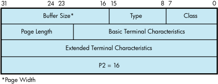
In the buffer, the device class is DC$_TERM, which is defined by the $DCDEF macro. The terminal type is defined by the $TTDEF macro, such as TT$_LA36. The maximum entry for the buffer size (page width) is 255. Table 5.4, ''Terminal Characteristics'' lists the values for terminal characteristics. Table 5.5, ''Extended Terminal Characteristics'' lists the extended terminal characteristics. Characteristics values are defined by the $TTDEF macro.
The sense mode and sense characteristics functions can take the type-ahead count, read modem, and broadcast function modifiers described in the following sections.
5.3.4.10.1. Type-ahead Count Function Modifier
The type-ahead count function modifier returns the count of characters presently in the type-ahead buffer and a copy of the first character in the buffer. In this case, the P1 argument points to a characteristics buffer returned by IO$M_TYPEAHDCNT. Figure 5.12, ''Sense Mode Characteristics Buffer (type-ahead)'' shows the format of this buffer.
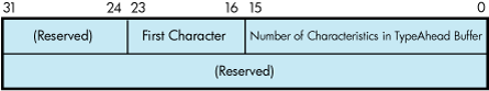
5.3.4.10.2. Read Modem Function Modifier
The read modem function modifier allows access to controller-dependent information. The following combinations of function code and modifier are provided:
IO$_SENSEMODE!IO$M_RD_MODEM
IO$_SENSECHAR!IO$M_RD_MODEM
These function code modifier pairs take the following device- or function-dependent argument:
P1—The address of a quadword block
Figure 5.13, ''Sense Mode P1 Block'' shows the format of this block.
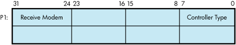
The receive modem field returns the value of the current input modem signals. Any or all of the following signals can be returned:
TT$M_DS_DSR—Data set ready (DSR)
TT$M_DS_RING—Calling indicator (RING)
TT$M_DS_CARRIER—Data channel received line signal detector (CARRIER)
TT$M_DS_CTS—Ready for sending (CTS)
TT$M_DS_SECREC—Received backward channel data (Sec RxD)
The $TTDEF macro defines the symbols for the receive modem field.
The controller type field returns the type of terminal controller in use by the currently active terminal line. The $DCDEF macro defines the symbols for the following types of controllers:
DT$_DZ11—DZ11 and DZV11
DT$_DZ32—DZ32
DT$_DMF32—DMF32
DT$_DMB32—DMB32
DT$_DMZ32—DMZ32
DT$_DHV—DHV11
DT$_DHU—DHU11
DT$_LAT—LAT server
Note
For LAT devices, the receive modem field of the IO$M_RD_MODEM function modifier does not return any valid modem signal data.
The IO$M_RD_MODEM function modifier is not supported for remote terminals. The status SS$_DEVREQERR is returned in the I/O status block.
5.3.4.10.3. Broadcast Function Modifier
The broadcast function modifier returns those bits that have been set by the set mode function modifier IO$M_BRDCST (see Table 5.11, ''Broadcast Requester IDs'' in Section 5.3.3.6, ''Broadcast Function Modifier''). The following combination of function code and modifier is provided:
IO$_SENSEMODE!IO$M_BRDCST
This function code modifier pair takes the following device- or function-dependent arguments:
P1—A buffer that contains the bits that specify the requester IDs to be broadcast. (If the bit is set in the first longword, that particular command is turned off for broadcast.)
P2—The length of the P1 buffer.
5.4. I/O Status Block
The I/O status block (IOSB) formats for the read, write, set mode, set characteristics, sense mode, sense characteristics, and LAT port driver I/O functions are shown in Figures Figure 5.14, ''IOSB Contents—Read Function'', Figure 5.16, ''IOSB Contents—Write Function'', Figure 5.17, ''IOSB Contents—Set Mode, Set Characteristics, Sense Mode, and Sense Characteristics Functions'', and Figure 5.18, ''IOSB Contents—LAT Port Driver Function''. Figure 5.15, ''IOSB Contents—Itemlist Read Function'' shows the IOSB format for the itemlist read function. Appendix A, "I/O Function Codes" lists the status returns for these functions. (The OpenVMS system messages documentation explanations and suggested user actions for these returns.)
In Figure 5.14, ''IOSB Contents—Read Function'', the offset to terminator at IOSB+2 is the count of characters before the terminator character (see Section 5.3.1.2, ''Read Function Terminators''). The terminator character is in the buffer at the offset specified in IOSB+2. When the buffer is full, the offset at IOSB+2 is equal to the requested buffer size. At the same time, IOSB+4 is equal to 0. In the case of multiple character escape sequences that act as terminators, the terminator at IOSB+4 is the first character (ESC) of the escape sequence. IOSB+6 contains the size of the terminator string, usually 1. However, in an escape sequence, IOSB+6 contains the size of the validated escape sequence (see Section 5.1.1.4, ''Escape and Control Sequences''). The sum of IOSB+2 and IOSB+6 is the number of characters in the buffer.
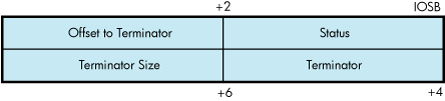
In Figure 5.15, ''IOSB Contents—Itemlist Read Function'' the terminator position word contains a number, the character of which is determined by the mode of operation. For itemlist read operations that do not specify TRM$K_EM_RDVERIFY, this word contains the number of characters from the end of the buffer to the cursor location at the time the terminator character was received. If TRM$K_EM_RDVERIFY is specified, the terminator position word contains the offset into the buffer from the nonverified character.
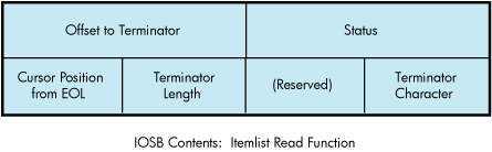
The byte at IOSB+5 passes the status information, listed in Table 5.30, ''Byte IOSB+5 Status Information'', on TRM$K_EM_RDVERIFY operations in which TRM$M_TM_ARROWS or TRM$M_TM_TOGGLE is set in TRM$_MODIFIERS.
| Bit | Interpretation |
|---|---|
| 7 (sign bit) | 0 to indicate rest of bits valid. This applies to insert/overstrike and arrow key read verify functionality only. |
| 6-2 | Always 0 if bit 7 is equal to 0. Not used; reserved for future use. |
| 1 TRM$V_ST_OTHERWAY | Set to indicate that read is terminated in left-justify insert mode or right-justify overstrike mode. |
| 0 TRM$V_ST_FIELD_FULL | Read terminated on an autotab field full condition. IOSB+7 contains an index to the cursor. |
In Figure 5.16, ''IOSB Contents—Write Function'', the remote terminal driver does not return the number of lines output or the cursor position.

In Figure 5.17, ''IOSB Contents—Set Mode, Set Characteristics, Sense Mode, and Sense Characteristics Functions'', the TT driver attempts to return the correct data in IOSB after a SETMODE or SETCHAR. To be sure the returned data is correct, the user should follow the SETMODE or SETCHAR with a SENSEMODE or SENSECHAR.
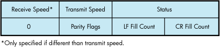
When an application program makes an I/O request for a connection to a remote device on a terminal server, the LAT port driver places status information about the request into the first word of the I/O status block, as shown in Figure 5.18, ''IOSB Contents—LAT Port Driver Function''. Table 5.29, ''IO$M_LT_CONNECT Request Status'' lists the possible status returns.
If the server rejects the request, the LAT port driver returns a numeric LAT rejection code in the second word of the I/O status block. Table 5.31, ''LAT Rejection Codes'' lists the LAT rejection codes.
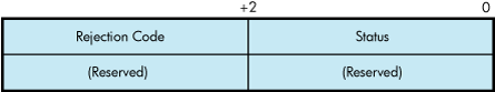
| Value | Reason |
|---|---|
| 0 | Reason is unknown. |
| 1 | User requested disconnect. |
| 2 | System shutdown in progress. |
| 3 | Invalid slot received. |
| 4 | Invalid service class received. |
| 5 | Insufficient resources to satisfy request. |
| 6 | Service in use. |
| 7 | No such service. |
| 8 | Service is disabled. |
| 9 | Service is not offered on the requested port. |
| 10 | Port name is unknown. |
| 11 | Invalid password. |
| 12 | Entry is not in queue. |
| 13 | Immediate access rejected (server queue full). |
| 14 | Access denied (group code mismatch). |
| 15 | Corrupted solicit request. |
| 16 | COMMAND_TYPE code is illegal/not supported. |
| 17 | Start slot cannot be sent. |
| 18 | Queue entry deleted by local node. |
| 19 | Inconsistent or illegal request parameters. |
5.5. Terminal Driver Programming Examples
The C program LAT.C shown in Example 5.1, ''LAT.C Terminal Driver Programming Example'' initiates and maintains an outbound LAT session from the local node. It demonstrates the following LAT $QIO functions:
Cloning the LAT template device (LTA0:)
IO$M_LT_SETMODE
IO$M_LT_CONNECT (on forward port)
IO$M_LT_SENSEMODE
#module LAT_FORWARD_CONNECT "X1.0-001"/* **++ ** ** MODULE DESCRIPTION: ** ** In initiating and maintaining an outbound LAT session from the local ** node, this program demonstrates the following LAT $QIO functions: ** ** o Cloning the LAT template device (LTA0:) ** o IO$M_LT_SETMODE ** o IO$M_LT_CONNECT (on forward port) ** o IO$M_LT_SENSEMODE ** **-- */ /* ** ** INCLUDE FILES ** */ #include /* VMS Descriptor Definitions */ #include /* I/O Function Codes Definitions */ #include /* LAT Definitions */ #include /* System Service Return Status */ /* Code Definitions */ #include /* Terminal Characteristics */ #include /* Terminal Extended */ /* Characteristics */ /* ** ** MACRO DEFINITIONS ** */ /* ** Service name which the session will be to. */ #define SERVICE_NAME "LAT_SERVICE" #define SERVICE_NAME_LENGTH 11 /* ** For the sake of clarity, the sizes of the buffers used for reading from ** and writing to the LTA and TT devices are set to the values below. In ** order to gain maximum throughput from this program, the following system ** parameters can be set: ** ** o TTY_ALTYPAHD - 1500 ** o TTY_TYPAHDSZ - 80 ** ** To get the best performance from this program without touching these ** system parameters on your system, modify the program to set the size of ** the buffers to the following: ** ** o LTA_BUFFER_SIZE = MIN(TTY_ALTYPAHD, 1500) ** o TT_BUFFER_SIZE = MIN(TTY_TYPAHDSZ, 132) */ #define LTA_MAXBUF 1500 #define TT_MAXBUF 80 /* ** Size of the LAT SENSEmode itemlist. */ #define MAX_SENSE_ITEMLIST_SIZE 1500 /* ** Character user can press to terminate the LAT connection (CTRL+\). */ #define CONNECTION_TERMINATOR 0x1C /* ** ** FUNCTION PROTOTYPES ** */ unsigned long SetDeviceChars(void); void ConnectAST(void); void LTAreadChannelAST(void); void TTreadChannelAST(void); void LTAhangupHandler(void); void EndSession(void); void ExitHandler(void); /* ** ** GLOBAL DATA ** */ char *LTAbuffer, /* LTA device I/O buffer */ *TTbuffer, /* TT device I/O buffer */ /* ** Text for LAT reject codes. Note that some LAT ** implementations will return a 0 reject code to ** indicate a normal disconnect. */ *LATrejectTable[] = { "Unknown", "User requested disconnect", "System shutdown in progress", "Invalid slot received", "Invalid service class received", "Insufficient resources at server", "Port or service in use", "No such service", "Service is disabled", "Service is not offeredon the requested port", "Port name is unknown", "Invalid service password", "Remote entry is not in queue", "Immediate access rejected", "Access denied", "Corrupted request", "Requested function is not supported", "Session cannot be started", "Queue entry deleted by server", "Illegal request parameters" }; unsigned short LTAchannel, /* LTA device I/O channel */ TTchannel, /* TT device I/O channel */ LTA_QIOiosb[4], /* IOSB for LTA device functions */ TT_QIOiosb[4]; /* IOSB for TT device functions */ unsigned long ReadTerminatorMask[2] = { 0, 0 }, /* $QIO read terminator mask */ SavedTTdeviceChar[3], /* Saved TT device characteristics */ DeviceCharBuffSize = sizeof(SavedTTdeviceChar); /* Size of device characteristics buffer*/ ExitConditionValue, /* Exit condition value of program */ LATrejectTableSize =/* Number of elements in LAT reject tbl */ sizeof(LATrejectTable) / sizeof(LATrejectTable[0]); /* ** Itemlist for setting LAT port with the target service name. */ struct { unsigned short item_code; char item_byte_count; char item_value[ SERVICE_NAME_LENGTH ]; } PortSetmodeItemlist = { LAT$_ITM_TARGET_SERVICE_NAME, SERVICE_NAME_LENGTH, SERVICE_NAME }; /* ** Exit handler block. */ struct { unsigned long flink; void (*exit_handler)(); unsigned long arg_count; unsigned long *exit_status; } ExitHandlerBlock = { 0, ExitHandler, 1, &ExitConditionValue }; /* ** Devices which channels are assigned to. */ $DESCRIPTOR(LTAtemplateDSC, "LTA0:"); $DESCRIPTOR(TTchannelDSC, "SYS$COMMAND"); main() { /* ** Local Variables: */ unsigned long status, portSetmodeItemlistSize = sizeof(PortSetmodeItemlist); /* ** BEGIN: ** ** Declare an exit handler. */ if (!( (status = sys$dclexh(&ExitHandlerBlock) ) & 1) ) lib$signal(status); /* ** Assign a channel to LTA0: to get a forward LAT port and assign a ** channel to the terminal. */ if (!( (status = sys$assign(<AtemplateDSC, <Achannel, 0, 0) ) & 1) ) lib$signal(status); if (!( (status = sys$assign(&TTchannelDSC, &TTchannel, 0, 0) ) & 1) ) lib$signal(status); /* ** Allocate memory for the channel data buffers. */ LTAbuffer = malloc(LTA_MAXBUF); TTbuffer = malloc(TT_MAXBUF); /* ** Set device characteristics for the two channels. */ if (!( (status = SetDeviceChars() ) & 1) ) lib$signal(status); /* ** Do SETmode $QIO to set the port entity with the target service name ** specified in the item list. */ if (!( (status = sys$qiow( 0, LTAchannel, IO$_TTY_PORT|IO$M_LT_SETMODE, <A_QIOiosb, 0, 0, &PortSetmodeItemlist, portSetmodeItemlistSize, LAT$C_ENT_PORT|(LAT$C_ENTS_OLD << 0x10), 0, 0, 0) ) & 1) ) lib$signal(status); if (!(LTA_QIOiosb[0] & 1) ) lib$signal(LTA_QIOiosb[0]); /* ** Enable a CTRL+Y AST on the LAT channel. */ if (!( (status = sys$qiow( 0, LTAchannel, IO$_SETMODE|IO$M_CTRLYAST, <A_QIOiosb, 0, 0, LTAhangupHandler, 0, 0, 0, 0, 0) ) & 1) ) lib$signal(status); if (!(LTA_QIOiosb[0] & 1) ) lib$signal(LTA_QIOiosb[0]); /* ** Post the first read (with AST) on the LTA device to ensure that the ** first burst of data from the target service is not lost. It is very ** important that the first read is queued before doing the connect ** $QIO to ensure no data lossage. */ if (!( (status = sys$qio( 0, LTAchannel, IO$_READVBLK|IO$M_NOECHO, <A_QIOiosb, LTAreadChannelAST, 0, LTAbuffer, 1, 0, &ReadTerminatorMask, 0, 0) ) & 1) ) lib$signal(status); /* ** Do the LAT connect $QIO and hibernate until program exit. The ** ConnectAST will execute when the connection completes and post the ** initial read on the TT channel. */ if (!( (status = sys$qio( 0, LTAchannel, IO$_TTY_PORT|IO$M_LT_CONNECT, <A_QIOiosb, ConnectAST, 0, 0, 0, 0, 0, 0, 0) ) & 1) ) lib$signal(status); sys$hiber(); } /* END - main() */ /* **++ ** ** FUNCTIONAL DESCRIPTION: ** ** This routine sets device characteristics of the LTA and TT devices. ** The HOSTSYNC, NOBRDCST, EIGHTBIT and PASTHRU characteristics are set ** on the LTA device. The ESCAPE and TTSYNC characteristics are cleared. ** ** The TTSYNC, HOSTSYNC, EIGHTBIT, and PASTHRU characteristics are set ** on the TT device. The ESCAPE characteristic is cleared. The TT ** characterisitcs are also saved for restoration at program exit. ** **-- */ unsigned long SetDeviceChars(void) { /* ** Local Variables: */ unsigned long status, deviceChar[3]; /* ** BEGIN: ** ** Mask and set the characteristics of the LTA device. Sense the ** current characteristics, and mask in and set the new ones. */ if (!( (status = sys$qiow( 0, LTAchannel, IO$_SENSEMODE, <A_QIOiosb, 0, 0, &deviceChar, DeviceCharBuffSize, 0, 0, 0, 0) ) & 1) ) lib$signal(status); if (!(LTA_QIOiosb[0] & 1) ) lib$signal(LTA_QIOiosb[0]); deviceChar[1] = (deviceChar[1] | (TT$M_HOSTSYNC | TT$M_NOBRDCST | TT$M_EIGHTBIT) ) & ~TT$M_ESCAPE & ~TT$M_TTSYNC; deviceChar[2] |= TT2$M_PASTHRU; if (!( (status = sys$qiow( 0, LTAchannel, IO$_SETMODE, &TT_QIOiosb, 0, 0, &deviceChar DeviceCharBuffSize, 0, 0, 0, 0) ) & 1) ) lib$signal(status); if (!(LTA_QIOiosb[0] & 1) ) lib$signal(LTA_QIOiosb[0]); /* ** Repeat the procedure for TT device characteristics. However, save ** the current characteristics for restoration at program exit. */ if (!( (status = sys$qiow( 0, TTchannel, IO$_SENSEMODE, $TT_QIOiosb, 0, 0, &SavedTTdeviceChar DeviceCharBuffSize, 0, 0, 0, 0) ) & 1) ) lib$signal(status); if (!(TT_QIOiosb[0] & 1) ) lib$signal(TT_QIOiosb[0]); deviceChar[0] = SavedTTdeviceChar[0]; deviceChar[1] = (SavedTTdeviceChar[1] | (TT$M_TTSYNC | TT$M_HOSTSYNC | TT$M_EIGHTBIT) ) & ~TT$M_ESCAPE; deviceChar[2] = SavedTTdeviceChar[2] | TT2$M_PASTHRU; if (!( (status = sys$qiow( 0, TTchannel, IO$_SETMODE, &TT_QIOiosb, 0, 0, &deviceChar DeviceCharBuffSize, 0, 0, 0, 0) ) & 1) ) lib$signal(status); if (!(TT_QIOiosb[0] & 1) ) lib$signal(TT_QIOiosb[0]); return(status); } /* END - SetDeviceChars */ /* **++ ** ** FUNCTIONAL DESCRIPTION: ** ** This routine is an AST which executes when the connect $QIO completes. ** First the IOSB is checked. If the connection timed out or was aborted, ** simply end the session. Any other abnormal status causes the program ** to exit. ** ** Otherwise the connection completed successfully and a read on the TT ** channel is posted. ** **-- */ void ConnectAST() { /* ** Local Variables: */ unsigned long status; /* ** BEGIN: ** ** If the status in the IOSB indicates that the connection timed out ** or aborted, call the session end routine. Any other abnormal ** status causes program exit. */ if ( (LTA_QIOiosb[0] == SS$_TIMEOUT) || (LTA_QIOiosb[0] == SS$_ABORT) ) EndSession(); if (!(LTA_QIOiosb[0] & 1) ) sys$exit(LTA_QIOiosb[0]); /* ** The connection completed successfully! Post a read (with AST) on ** the TT device and return. */ if (!( (status = sys$qio( 0, TTchannel, IO$_READVBLK|IO$M_NOECHO, &TT_QIOiosb, TTreadChannelAST, 0, TTbuffer, 1, 0, &ReadTerminatorMask 0, 0) ) & 1) ) lib$signal(status); return; } /* END - ConnectAST */ /* **++ ** ** FUNCTIONAL DESCRIPTION: ** ** This routine is an AST which executes when the first character read on ** the LTA channel completes. It does a "flush" read of the channel to ** drain any data out of the ALTYPAHD buffer and writes the data to the ** TT channel. It then posts another read on the channel. ** **-- */ void LTAreadChannelAST(void) { /* ** Local Variables: */ unsigned long status; /* ** BEGIN: ** ** If the status in the IOSB indicates channel hangup, simply end the ** session. Signal any other abnormal status. */ if (LTA_QIOiosb[0] == SS$_HANGUP) EndSession(); if (!(LTA_QIOiosb[0] & 1) ) lib$signal(LTA_QIOiosb[0]); /* ** Do a "flush" read of the LTA device. This is done by doing a timed ** read with a 0 timeout. There may or may not be any data to drain. ** This method is more efficient than using single character reads. */ if (!( (status = sys$qiow( 0, LTAchannel, IO$_READVBLK|IO$M_TIMED|IO$M_NOECHO, <A_QIOiosb, 0, 0, LTAbuffer+1, LTA_MAXBUF-1, 0, &ReadTerminatorMask, 0, 0) ) & 1) ) lib$signal(status); if (!(LTA_QIOiosb[0] & 1) && (LTA_QIOiosb[0] != SS$_TIMEOUT) ) lib$signal(LTA_QIOiosb[0]); /* ** The second word of the IOSB contains the number of characters ** read. Write the characters plus 1 for the initial read to the ** TT device. */ if (!( (status = sys$qiow( 0, TTchannel, IO$_WRITEVBLK, &TT_QIOiosb, 0, 0, LTAbuffer, LTA_QIOiosb[1]+1, 0, 0, 0, 0) ) & 1) ) lib$signal(status); if (!(TT_QIOiosb[0] & 1) ) lib$signal(TT_QIOiosb[0]); /* ** Post another read on the LTA device. */ if (!( (status = sys$qio( 0, LTAchannel, IO$_READVBLK|IO$M_NOECHO, <A_QIOiosb, LTAreadChannelAST, 0, LTAbuffer, 1, 0, &ReadTerminatorMask, 0, 0) ) & 1) ) lib$signal(status); return; } /* END - LTAreadChannelAST */ /* **++ ** ** FUNCTIONAL DESCRIPTION: ** ** This routine is an AST which executes when the first character read on ** the TT channel completes. It does a "flush" read of the channel to ** drain any data out of the TYPAHD buffer and writes the data to the ** LTA channel. It then posts another read on the channel. ** **-- */ void TTreadChannelAST(void) { /* ** Local Variables: */ unsigned long status; /* ** BEGIN: ** ** If the user pressed the connection terminator character, do a LAT ** disconnect $QIO and exit. */ if (*TTbuffer == CONNECTION_TERMINATOR) { if (!( (status = sys$qiow( 0, LTAchannel, IO$_TTY_PORT|IO$M_LT_DISCON, <A_QIOiosb, 0, 0, 0, 0, 0, 0, 0, 0) ) & 1) ) lib$signal(status); if (!(LTA_QIOiosb[0] & 1) ) lib$signal(LTA_QIOiosb[0]); return; } /* ** Do a "flush" read of the TT device. This is done by doing a timed ** read with a 0 timeout. There may or may not be any data to drain. */ if (!( (status = sys$qiow( 0, TTchannel, IO$_READVBLK|IO$M_TIMED|IO$M_NOECHO, &TT_QIOiosb, 0, 0, TTbuffer+1, TT_MAXBUF-1, 0, &ReadTerminatorMask, 0, 0) ) & 1) ) lib$signal(status); if (!(TT_QIOiosb[0] & 1) && (TT_QIOiosb[0] != SS$_TIMEOUT) ) lib$signal(TT_QIOiosb[0]); /* ** The second word of the IOSB contains the number of characters ** read. Write the characters plus 1 for the initial read to the ** TT device. */ if (!( (status = sys$qiow( 0, LTAchannel, IO$_WRITEVBLK, <A_QIOiosb, 0, 0, TTbuffer, TT_QIOiosb[1]+1, 0, 0, 0, 0) ) & 1) ) lib$signal(status); /* ** If the status in the IOSB indicates channel hangup, simply end ** the session. Signal any other abnormal status. */ if (LTA_QIOiosb[0] == SS$_HANGUP) EndSession(); if (!(LTA_QIOiosb[0] & 1) ) lib$signal(LTA_QIOiosb[0]); /* ** Post another read on the LTA device. */ if (!( (status = sys$qio( 0, TTchannel, IO$_READVBLK|IO$M_NOECHO, &TT_QIOiosb, TTreadChannelAST, 0, TTbuffer, 1, 0, &ReadTerminatorMask, 0, 0) ) & 1) ) lib$signal(status); return; } /* END - TTreadChannelAST */ /* **++ ** ** FUNCTIONAL DESCRIPTION: ** ** This routine is the CTRL+Y AST for the LTA channel. It executes when ** a hangup on the LTA channel is recognized (connection timed out or ** aborted). It will call the session end routine if it hasn't already ** been called by ConnectAST. ** ** NOTE: CTRL+Y ASTs for application ports will NOT execute when the ** connection is disconnected. ** **-- */ void LTAhangupHandler(void) { /* ** BEGIN: ** ** Call the session end routine and return. */ EndSession(); return; } /* END - LTAhanghupHandler */ /* **++ ** ** FUNCTIONAL DESCRIPTION: ** ** This routine is executed at session end. It will do a $QIO SENSEmode ** and search the resulting itemlist to find the reason for the LAT ** disconnect. The reason for the disconnect is displayed on the ** terminal and the image exits. ** **-- */ void EndSession(void) { /* ** Local Variables: */ struct ITEM_ENTRY *itemlistEntry; unsigned long status; char *senseItemlist = malloc(MAX_SENSE_ITEMLIST_SIZE), *itemlistEntryPointer; /* ** BEGIN: ** ** Do the SENSEmode on the port. */ if (!( (status = sys$qiow( 0, LTAchannel, IO$_TTY_PORT|IO$M_LT_SENSEMODE, <A_QIOiosb, 0, 0, senseItemlist, MAX_SENSE_ITEMLIST_SIZE, LAT$C_ENT_PORT|(LAT$M_SENSE_FULL << 0x10), 0, 0, 0) ) & 1) ) lib$signal(status); if (!(LTA_QIOiosb[0] & 1) ) lib$signal(LTA_QIOiosb[0]); /* ** Set up two pointers used to traverse the itemlist. */ itemlistEntry = (struct ITEM_ENTRY *) senseItemlist; itemlistEntryPointer = senseItemlist; /* ** Search the itemlist for the LAT$_ITM_DISCONNECT_REASON code to find ** out why the connection terminated. */ while (itemlistEntry->LAT$R_ITM_CODE.LAT$W_ITEMCODE != LAT$_ITM_DISCONNECT_REASON) { /* ** If the current itemcode being checked has a string value, ** advance the pointer to the next itemcode by skipping ** BCNT bytes plus 3 bytes for the BCNT byte itself and the ** 2 byte itemcode. */ if (itemlistEntry-> LAT$R_ITM_CODE.LAT$R_ITM_BITS.LAT$V_STRING) itemlistEntryPointer += itemlistEntry->LAT$R_ITEM_VALUE. LAT$R_ITEM_COUNTED_STRING.LAT$B_ITEM_BCNT + 3; /* ** If the current itemcode being checked has a scalar value, ** advance the pointer to the next itemcode by skipping 6 ** bytes for the itemcode and the 4 byte scalar. */ else itemlistEntryPointer += 6; itemlistEntry = (struct ITEM_ENTRY *) itemlistEntryPointer; } /* ** If the disconnect reason is a LAT reject code, print out the ** text corresponding to the code and set the exit condition value ** to SS$_NORMAL. */ if (itemlistEntry->LAT$R_ITEM_VALUE.LAT$L_ITEM_SCALAR_VALUE <= LATrejectTableSize) { printf("\nSession disconnected. Reason: %s\n\n\n", LATrejectTable[ itemlistEntry->LAT$R_ITEM_VALUE. LAT$L_ITEM_SCALAR_VALUE ]); ExitConditionValue = SS$_NORMAL; } /* ** The scalar value is a LAT facility message code. Set the exit ** condition value to be the scalar. Upon image exit, the ** corresponding LAT facility message will be displayed. */ else ExitConditionValue = itemlistEntry->LAT$R_ITEM_VALUE.LAT$L_ITEM_SCALAR_VALUE; sys$exit(ExitConditionValue); } /* END - EndSession */ /* **++ ** ** FUNCTIONAL DESCRIPTION: ** ** This is the program exit handler which is executed upon image exit. ** It will cancel all pending I/O on the two channels and restore the ** TT channel characteristics. ** **-- */ void ExitHandler(void) { /* ** Local Variables: */ unsigned long status; /* ** BEGIN: ** ** Cancel I/O on the channels, reset terminal characteristics and ** return. */ if (!( (status = sys$cancel(LTAchannel) ) & 1) ) lib$signal(status); if (!( (status = sys$cancel(TTchannel) ) & 1) ) lib$signal(status); if (!( (status = sys$qiow( 0, TTchannel, IO$_SETMODE, &TT_QIOiosb, 0, 0, &SavedTTDeviceChar, DeviceCharBuffSize, 0, 0, 0, 0) ) & 1) ) lib$signal(status); if (!(TT_QIOiosb[0] & 1) ) lib$signal(TT_QIOiosb[0]); return; } /* END - ExitHandler */
The MACRO 32 program FULL_DUPLEX_TERMINAL.MAR (Example 5.2, ''FULL_DUPLEX_TERMINAL.MAR Terminal Driver Programming Example'') shows several I/O operations using the full-duplex capabilities of the terminal. This program shows some important concepts about terminal driver programming: assigning an I/O channel, performing full-duplex I/O operations, enabling Ctrl/C AST requests, and itemlist read operations. The program is designed to run with a terminal set to full-duplex mode.
The initialization code queues a read request to the terminal and enables Ctrl/C AST requests. The main loop then prints out a random message every three seconds. When you enter a message on the terminal, the read AST routine prints an acknowledgment message and queues another read request. If you press Ctrl/C, the associated AST routine cancels the I/O operation on the assigned channel and exits to the command interpreter.
        .TITLE  FULL_DUPLEX TERMINAL PROGRAMMING EXAMPLE
        .IDENT  /05/

; ********************************************************************
;
;                         TERMINAL PROGRAM
;
; ********************************************************************

        .SBTTL  DECLARATIONS
        .DISABLE        GLOBAL

;
; Declare the external symbols and MACRO libraries.
;

        .EXTERNAL       LIB$GET_EF
        .LIBRARY        'SYS$LIBRARY:LIB.MLB'
        .LIBRARY        'SYS$LIBRARY:STARLET.MLB'
;
; Define symbols
;

        $IODEF                  ; Define I/O function codes
        $QIODEF                 ; Define QIO definition codes
        $SSDEF                  ; Define the system service status codes
        $TRMDEF                 ; Define itemlist read codes
        $TTDEF                  ; Terminal characteristic definitions


;
; Define macros
;
        .SHOW
        .MACRO  ITEM    LEN=0,CODE,VALUE
        .WORD   LEN
        .WORD   TRM$_'CODE'
        .LONG   VALUE
        .LONG   0
        .ENDM   ITEM
        .NOSHOW

;
; Declare exit handler control block
;
EXIT_HANDLER_BLOCK:
        .LONG   0               ; System uses this for pointer
        .LONG   EXIT_HANDLER    ; Address of exit handler
        .LONG   1               ; Argument count for handler
        .LONG   STATUS          ; Destination of status code
STATUS: .BLKL   1               ; Status code from $EXIT

;
; Allocate terminal descriptor and channel number storage
;

TT_DESC:
        .ASCID  /SYS$INPUT/     ; Logical name of terminal
TT_CHAN:
        .BLKW   1               ; TT channel number storage

;
; Define acknowledgment message.  This is done right above input buffer
; so that we can concatenate the two together when the acknowledgment
; message is issued.
;

ACK_MSG:
        .ASCII  <CR> /Following input acknowledged: /
ACK_MSGLEN=.-ACK_MSG            ; Calculate length of message

;
; Allocate input buffer
;

IN_BUFLEN = 20                  ; Set length of buffer
IN_BUF:
        .BLKB   IN_BUFLEN       ; Allocate character buffer
IN_IOSB:
        .BLKQ   1               ; Input I/O status block
;
; Define out-of-band ast character mask
;
CNTRLA_MASK:
        .LONG   0
        .LONG   ^B0010          ; Control A mask


;
; Define old terminal characteristics buffer
;
OLDCHAR_BUF_LEN = 12
OLDCHAR_BUF:
        .BLKB   OLDCHAR_BUF_LEN

;
; Define new terminal characteristics buffer
;
NEWCHAR_BUF_LEN = 12
NEWCHAR_BUF:
        .BLKB   NEWCHAR_BUF_LEN

;
; Define carriage control symbols
;

        CR=^X0D                 ; Carriage return
        LF=^X0A                 ; Line feed

;
; Define output messages
;
; Output messages are accessed by indexing into a table of
; longwords with each message described by a message address and
; message length
;

ARRAY:                          ; Table of message addresses and
                                ; lengths
        .LONG   10$             ; First message address
        .LONG   15$             ; First message length
        .LONG   20$
        .LONG   25$
        .LONG   30$
        .LONG   35$
        .LONG   40$
        .LONG   45$
;
; Define messages
;

10$:    .ASCII            <CR>/RED ALERT! RED ALERT!/
15$=.-10$
;
20$:    .ASCII            <CR>/ALL SYSTEMS GO/
25$=.-20$
;
30$:    .ASCII            <CR>/WARNING..INTRUDER ALARM/
35$=.-30$
;
40$:    .ASCII            <CR>/** SYSTEM OVERLOAD **/
45$=.-40$
;
; Static QIO packet for message output using QIO$_G form
;


WRITE_QIO:
        $QIO    EFN=SYNC_EFN, - ; QIO packet
                FUNC=IO$_WRITEVBLK!IO$M_BREAKTHRU!IO$M_REFRESH, -
                IOSB=SYNC_IOSB

;
; Declare the required I/O status blocks.
;
SYNC_IOSB::     .BLKQ   1       ; I/O status block for synchronous terminal processing.

;
; Declare the required event flags.
;
ASYNC_EFN::     .BLKL   1       ; Event flag for asynchronous terminal processing.
SYNC_EFN        ==      WRITE_QIO + 4   ; Event flag for sync terminal processing.
TIMER_EFN::     .BLKL   1       ; Event flag for timer processing.

;
; Timer storage
;

WAITIME:
        .LONG   -10*1000*1000*3,-1     ; 3 second delta time
TIME:
        .BLKQ   1               ; Current storage time used for
                                ; random number

        .PAGE
        .SBTTL  START - MAIN ROUTINE
        .ENABLE LOCAL_BLOCK
;++
;
; Functional description:
;
; ********************************************************************
;
;                      Start program
;
; ********************************************************************
;
;       The following code performs initialization functions.
;       It is assumed that the terminal is already in
;       FULL-DUPLEX mode.
;
;       NOTE: When doing QIO_S calls, parameters P1 and P3-P6 should be
;             passed by value, while P2 should be passed by reference.
;
; Input parameters:
;       None
;
; Output parameters:
;       None
;
;--
        .ENTRY  START   ^M < >


;               Get the required event flags.

        PUSHAL  ASYNC_EFN
        CALLS   # 1, G^ LIB$GET_EF      ; Get EFN for async terminal operations.
        BLBC    R0, 10$                 ; Error - branch.
        PUSHAL  SYNC_EFN
        CALLS   # 1, G^ LIB$GET_EF      ; Get EFN for sync terminal operations.
        BLBC    R0, 10$                 ; Error - branch.
        PUSHAL  TIMER_EFN
        CALLS   # 1, G^ LIB$GET_EF      ; Get EFN for timer operations.
        BLBC    R0, 10$                 ; Error - branch.


;               Initialize the terminal characteristics.

        $ASSIGN_S       DEVNAM=TT_DESC,-; Assign terminal channel using
                        CHAN=TT_CHAN    ; logical name and channel number
        BLBC    R0, 10$                 ; Error - branch.
        BSBW    CHANGE_CHARACTERISTICS  ; Change the characteristics of
                                        ; terminal
        BSBW    ENABLE_CTRLCAST         ; Allow Ctrl/C traps
        BSBW    ENABLE_OUTBANDAST       ; Enable Ctrl/A out-of-band AST
        BSBW    ENABLE_READ             ; Queue read
        MOVZWL  TT_CHAN, WRITE_QIO+8    ; Insert channel into
        BRB     LOOP                    ; static QIO packet

10$:
        BRW     ERROR

;
; This loop outputs a message based on a random number and then
; delays for 3 seconds
;

LOOP:
        $GETTIM_S      TIMADR=TIME      ; Get random time
        BLBC    R0, 10$                 ; Error - branch.
        EXTZV   #6, #2, TIME, R0        ; Load random bits into switch
        MOVQ    ARRAY[R0], -            ; Load message address
                WRITE_QIO+QIO$_P1       ; and size into QIO
                                        ; packet

;
; Issue QIO write using packet defined in data area
;

        $QIOW_G WRITE_QIO
        BLBC    R0, 10$                 ; QIO error - branch.
        MOVZWL  SYNC_IOSB, R0           ; Get the terminal driver status.
        BLBC    R0, 10$                 ; Terminal driver error - branch.


;
; Delay for 3 seconds before issuing next message
;

        $SETIMR_S       EFN=TIMER_EFN,- ; Timer service
                        DAYTIM=WAITIME  ; will set event flag
                                        ; in 3 seconds
        BLBC    R0, 10$                 ; Error - branch.
        $WAITFR_S       EFN=TIMER_EFN   ; Wait for event flag
        BLBS    R0, LOOP                ; No error if set
        BRB     10$                     ; Error - branch.

        .DISABLE        LOCAL_BLOCK

        .PAGE
        .SBTTL  CHANGE_CHARACTERISTICS - CHANGE CHARACTERISTICS OF TERMINAL
;++
;
; Functional description:
;
;       Routine to change the characteristics of the terminal.
;
; Input parameters:
;       None
;
; Output parameters:
;       R0 - status from $QIO call.
;       R1 - R5 destroyed
;
;--
;


CHANGE_CHARACTERISTICS:
        $QIOW_S EFN=SYNC_EFN, -         ; Get current terminal characteristics
                CHAN=TT_CHAN, -
                FUNC=#IO$_SENSEMODE, -
                IOSB=SYNC_IOSB, -
                P1=OLDCHAR_BUF, -
                P2=#OLDCHAR_BUF_LEN
        BLBC    R0, 10$                 ; Error if clear
        MOVZWL  SYNC_IOSB, R0           ; Get the terminal driver status.
        BLBC    R0, 10$                 ; Error - branch

        $DCLEXH_S EXIT_HANDLER_BLOCK    ; Declare exit handler to reset
                                        ; characteristics
        BLBC    R0, 10$                 ; Error - branch.
        MOVC3   #OLDCHAR_BUF_LEN, -     ; Move old characteristics into
                OLDCHAR_BUF, -          ; new characteristics buffer
                NEWCHAR_BUF
        BISL2   #TT$M_NOBRDCST, -       ; Set nobroadcast bit
                NEWCHAR_BUF+4           ; ...
        $QIOW_S EFN=SYNC_EFN, -         ; Set current terminal characteristics
                CHAN=TT_CHAN, -
                FUNC=#IO$_SETMODE, -
                IOSB=SYNC_IOSB, -
                P1=NEWCHAR_BUF, -
                P2=#NEWCHAR_BUF_LEN
        BLBC    R0, 10$                 ; QIO error - branch.
        MOVZWL  SYNC_IOSB, R0           ; Get the terminal driver status.
        BLBC    R0, 10$                 ; Terminal driver error - branch.
        RSB
10$:
        BRW     ERROR

        .PAGE
        .SBTTL  ENABLE_CTRLCAST - ENABLE Ctrl/C AST
;++
;
; Functional description:
;
;       Routine to allow Ctrl/C recognition.
;
; Input parameters:
;       None
;
; Output parameters:
;       None
;
;--
;

ENABLE_CTRLCAST:
        $QIOW_S EFN=SYNC_EFN, -
                CHAN=TT_CHAN, -
                FUNC=#IO$_SETMODE!IO$M_CTRLCAST, -
                IOSB=SYNC_IOSB, -
                P1=CTRLCAST, -          ; AST routine address
                P3=#3                   ; User mode
        BLBC    R0, 10$                 ; Error - branch.
        MOVZWL  SYNC_IOSB, R0           ; Get the terminal driver status.
        BLBC    R0, 10$                 ; Terminal driver error - branch.
        RSB


10$:
        BRW     ERROR

        .PAGE
        .SBTTL  ENABLE_OUTBANDAST - ENABLE Ctrl/A AST
;++
;
; Functional description:
;
;       Routine to allow CNTRL/A recognition.
;
; Input parameters:
;       None
;
; Output parameters:
;       None
;

ENABLE_OUTBANDAST:
        $QIOW_S EFN=SYNC_EFN, -
                CHAN=TT_CHAN, -
                FUNC=#IO$_SETMODE!IO$M_OUTBAND, -
                IOSB=SYNC_IOSB, -
                P1=CTRLAAST, -          ; AST routine address
                P2=#CNTRLA_MASK, -      ; Character mask
                P3=#3                   ; User mode
        BLBC    R0, 10$                 ; QIO error - branch.
        MOVZWL  SYNC_IOSB, R0           ; Get the terminal driver status.
        BLBC    R0, 10$                 ; Terminal driver error - branch.
        RSB

10$:
        BRW     ERROR

        .PAGE
        .SBTTL  ENABLE_READ - QUEUE A READ TO THE TERMINAL.
;++
;
; Functional description:
;
;       Routine to queue a read operation to the terminal.
;
; Input parameters:
;       None
;
; Output parameters:
;       None
;
; Define item list for itemlist read
;
ITEM_LST:
        ITEM    0, MODIFIERS, -                 ; Convert lowercase to
                TRM$M_TM_CVTLOW!TRM$M_TM_NOEDIT ; upper and inhibit line
        ITEM    6, TERM,MASK_ADDR               ; editing
                                                ; Set up terminator mask


ITEM_LEN        =       . - ITEM_LST
MASK_ADDR:
        .LONG   1@^XD                   ; Terminator mask is
                                         ; <CR>
.WORD   1@4                     ; and "$"ENABLE_READ:
        $QIO_S  EFN=ASYNC_EFN, -        ; Must not be QIOW form or read will block
                CHAN=TT_CHAN, -         ; process
                FUNC=#IO$_READVBLK!IO$M_EXTEND, -
                IOSB=IN_IOSB, -
                ASTADR=READAST, -       ; AST routine to execute
                P1=IN_BUF, -            ; on
                P2=#IN_BUFLEN, -
                P5=#ITEM_LST, -         ; Itemlist read address
                P6=#ITEM_LEN            ; Itemlist read size
        BLBC    R0, 10$                 ; QIO error - branch.

; The queued read operation will not affect write operations due
; to the fact that breakthru has been set for the write operations.

        RSB

10$:
        BRW     ERROR

        .PAGE
        .SBTTL  READAST - AST ROUTINE FOR READ COMPLETION
        .ENABLE LOCAL_BLOCK
;++
;
; Functional description:
;
;       AST routine to execute on read completion.
;
; Input parameters:
;       None
;
; Output parameters:
;       None
;
;--
;

10$:
        MOVZWL  IN_IOSB, R0             ; Get the terminal driver status
20$:
        BRW     ERROR                   ; Exit with error status.


        .ENTRY  READAST         ^M < R2, R3, R4, R5 >   ; Procedure entry mask

        BLBC    IN_IOSB, 10$            ; Terminal driver error - branch
        MOVZWL  IN_IOSB+2, R0           ; Get number of characters read into R0
        ADDL2   #ACK_MSGLEN, R0         ; Add size of fixed acknowledge message
        $QIO_S  EFN=ASYNC_EFN, -        ; Issue acknowledge message
                CHAN=TT_CHAN, -         ; Note, ACK must be asynchronous (QIO)
                FUNC=#IO$_WRITEVBLK, -  ; and the terminal driver write status
                P1=ACK_MSG, -           ; is ignored (no IOSB and AST routine).
                P2=R0                   ; Specify IOSB and AST routine if output
                                        ; must be displayed on the terminal.
        BLBC    R0, 20$                 ; QIO error - branch


;
; Process read message
;
;        .
;        .
;        .
;(user-provided code to decode command inserted here)
;        .
;        .
;        .

        BSBW     ENABLE_READ            ; Queue next read
        RET                             ; Return to mainline loop

        .DISABLE        LOCAL_BLOCK

        .PAGE
        .SBTTL  CTRLAAST - AST ROUTINE FOR Ctrl/A
        .SBTTL  CTRLCAST - AST ROUTINE FOR Ctrl/C
        .SBTTL  ERROR - EXIT ROUTINE
;++
;
; Functional description:
;
;       AST routine to execute when Ctrl/C or Ctrl/A is entered.
;
; Input parameters:
;       None
;
; Output parameters:
;       None
;

CTRLCAST::
CTRLAAST::
        .WORD   ^M < >                  ; Procedure entry mask
        MOVL    #SS$_NORMAL, R0         ; Put success in R0

ERROR::
        $EXIT_S R0                      ; Exit
        RSB

        .PAGE
        .SBTTL  EXIT_HANDLER - EXIT HANDLER ROUTINE
;++
;
; Functional description:
;
;       Exit handler routine to execute when image exits.  It cancels
;       any outstanding I/O on this channel and resets the terminal
;       characteristics to their original state.
;
; Input parameters:
;       None
;
; Output parameters:
;       None
;
;--
;


        .ENTRY  EXIT_HANDLER    ^M< >
        $CANCEL_S       CHAN=TT_CHAN    ; Flush any I/O on queue
        $QIOW_S EFN=SYNC_EFN, -         ; Reset terminal characteristics
                CHAN=TT_CHAN, -
                FUNC=#IO$_SETMODE, -
                IOSB=SYNC_IOSB, -
                P1=OLDCHAR_BUF, -
                P2=#OLDCHAR_BUF_LEN
        BLBC    R0, 10$                 ; QIO error - branch.
        MOVZWL  SYNC_IOSB, R0           ; Get the terminal driver status.

10$:
        RET

        .END     START
The MACRO 32 program READ_VERIFY.MAR (Example 5.3, ''READ_VERIFY.MAR Terminal Driver Programming Example'') shows the read verify function. The program shows a typical build of itemlists (both the right and left fields), channel assignment, a right- and left-justified read verify operation, and then the read QIO operation.
        .TITLE READ_VERIFY - Read Verify Coding Example
        .IDENT  'V05-000'

        .SBTTL  DECLARATIONS
        .DISABLE        GLOBAL

;
; Declare the external system routines and MACRO libraries.
;
        .EXTERNAL       LIB$GET_EF
        .EXTERNAL       SCR$ERASE_PAGE

        .LIBRARY        'SYS$LIBRARY:LIB.MLB'
        .LIBRARY        'SYS$LIBRARY:STARLET.MLB'
;
; Include files:
;
        $IODEF
        $TRMDEF
;
; Macros:
;
.MACRO ITEM LEN=0,CODE,VALUE
        .WORD   LEN
        .WORD   TRM$_'CODE'
        .LONG   VALUE
        .LONG   0
.ENDM ITEM

;
; Equated symbols:
;
INBUF_LEN = 20
ESC = ^X1B


;
; Own storage:
;
; Build item lists for the read verify QIO
;

;
; Right-justified field
;
R_ITEM_LIST:
        ITEM    CODE    = MODIFIERS, -
                VALUE   = TRM$M_TM_R_JUST       ; Right justify

        ITEM    CODE    = EDITMODE, -
                VALUE   = TRM$K_EM_RDVERIFY     ; Enable read verify

        ITEM    CODE    = PROMPT, -
                VALUE   = R_PROMPT_ADDR, -
                LEN     = R_PROMPT_LEN          ; Set up prompt

        ITEM    CODE    = INISTRNG, -
                VALUE   = R_INISTR_ADDR, -
                LEN     = R_INISTR_LEN          ; Set up initial string

        ITEM    CODE    = INIOFFSET, -
                VALUE   = R_INISTR_LEN

        ITEM    CODE    = PICSTRNG, -
                VALUE   = R_PICSTR_ADDR, -
                LEN     = R_PICSTR_LEN          ; Set up picture string

        ITEM    CODE    = FILLCHR, -
                VALUE   = <^A/* />            ; clear = *, fill = space

R_ITEM_LIST_LEN = .-R_ITEM_LIST

R_PROMPT_ADDR:
        .ASCII  /[12;12H$/
R_PROMPT_LEN = .-R_PROMPT_ADDR

R_INISTR_ADDR:
        .ASCII  /   ,   /
R_INISTR_LEN = .-R_INISTR_ADDR

MASK = TRM$M_CV_NUMERIC!TRM$M_CV_NUMPUNC

R_PICSTR_ADDR:
        .BYTE   MASK
        .BYTE   MASK
        .BYTE   MASK
        .BYTE   0               ; Marker character
        .BYTE   MASK
        .BYTE   MASK
        .BYTE   MASK
R_PICSTR_LEN = .-R_PICSTR_ADDR
;
; Left-justified field
;
L_ITEM_LIST:
        ITEM    CODE    = MODIFIERS, -
                VALUE   = TRM$M_TM_CVTLOW!TRM$M_TM_AUTO_TAB
                                                ; Upcase input and
                                                ; complete on field full

        ITEM    CODE    = EDITMODE, -
                VALUE   = TRM$K_EM_RDVERIFY     ; Enable read verify

        ITEM    CODE    = PROMPT, -
                VALUE   = L_PROMPT_ADDR, -
                LEN     = L_PROMPT_LEN          ; Set up prompt

        ITEM    CODE    = INISTRNG, -
                VALUE   = L_INISTR_ADDR, -
                LEN     = L_INISTR_LEN          ; Set up initial string

        ITEM    CODE    = INIOFFSET, -
                VALUE   = 0

        ITEM    CODE    = PICSTRNG, -
                VALUE   = L_PICSTR_ADDR, -
                LEN     = L_PICSTR_LEN          ; Set up picture string

        ITEM    CODE    = FILLCHR, -
                VALUE   = <^A/* />              ; clear = *, fill = space

L_ITEM_LIST_LEN = .-L_ITEM_LIST

L_PROMPT_ADDR:
        .ASCII  /[13;12H Enter Date: /
L_PROMPT_LEN = .-L_PROMPT_ADDR

L_INISTR_ADDR:
        .ASCII  /  -   -  /
L_INISTR_LEN = .-L_INISTR_ADDR

MASK1 = TRM$M_CV_NUMERIC
MASK2 = TRM$M_CV_UPPER!TRM$M_CV_LOWER


L_PICSTR_ADDR:
        .BYTE   MASK1
        .BYTE   MASK1
        .BYTE   0               ; Marker character
        .BYTE   MASK2
        .BYTE   MASK2
        .BYTE   MASK2
        .BYTE   0               ; marker character
        .BYTE   MASK1
        .BYTE   MASK1
L_PICSTR_LEN = .-L_PICSTR_ADDR

IN_IOSB:        .BLKL   2
TT_CHAN:        .BLKW   1
INBUF:          .BLKB   INBUF_LEN
SYSINPUT:       .ASCID  /SYS$INPUT/
SYNC_EFN:       .BLKL   1

        .PAGE

        .ENTRY  READ_VERIFY     ^M < >

;
; Get the required event flags.
;

        PUSHAL  SYNC_EFN
        CALLS   # 1, G^ LIB$GET_EF
        BLBC    R0, ERROR                       ; Error - branch
;
; Assign the channel to SYS$INPUT
;

        $ASSIGN_S -
                CHAN = TT_CHAN -
                DEVNAM = SYSINPUT               ; SYS$INPUT
        BLBC    R0, ERROR                       ; Branch on error

;
; Clear the screen
;

        CLRQ    -(SP)
        CALLS   #2, G^ SCR$ERASE_PAGE
        BLBC    R0, ERROR

;
; Do the right-justified read operation
;

        PUSHL   #R_ITEM_LIST_LEN
        PUSHAB  R_ITEM_LIST
        CALLS   #2, DO_READ
        BLBC    R0, ERROR


;
; Do the left-justified read operation
;

        PUSHL   #L_ITEM_LIST_LEN
        PUSHAB  L_ITEM_LIST
        CALLS   #2, DO_READ
        BLBC    R0, ERROR

ERROR:
        RET

        .PAGE
;++
;
; DO_READ - do the actual QIO
;
; Inputs:
;
;       4(AP)   the address of the itemlist
;       8(AP)   the length of the itemlist
;
;--

        .ENTRY  DO_READ, ^M


        $QIOW_S EFN=SYNC_EFN, -
                CHAN = TT_CHAN, -
                FUNC = #$_READVBLK!IO$M_EXTEND>, -
                IOSB = IN_IOSB, -
                p1 = inbuf, -
                p2 = #inbuf_len, -
                p5 = 4(AP), -
                P6 = 8(AP)
        BLBC    R0, 10$                 ; QIO error - branch
        MOVZWL  IN_IOSB, R0             ; Get the terminal driver status.
        BLBC    R0, 10$                 ; Terminal driver error - branch

;  Handle the input...

10$:
        RET
.END READ_VERIFY//Demonstrates CTRL-Y and CTRL-C handling under OpenVMS, //as well as //some basic dynamic string descriptor operations and a few other //string-related operations. ////To build and use: //$ CC/DECC LIB$XXABLE_CTRL //$ LINK LIB$XXABLE_CTRL //$ RUN LIB$XXABLE_CTRL #include <descrip.h> #include <iodef.h> #include <libclidef.h> #include <lib$routines.h> #include <ssdef.h> #include <starlet.h> #include <stdio.h> #include <stsdef.h> void CtrlYHandler() { int RetStat; $DESCRIPTOR( Y, "<CTRL/Y> was detected" ); RetStat = lib$put_output( &Y ); if (!$VMS_STATUS_SUCCESS( RetStat ) ) return; RetStat = lib$enable_ctrl( &LIB$M_CLI_CTRLY ); if (!$VMS_STATUS_SUCCESS( RetStat ) ) return; return; } void CtrlCHandler() { int RetStat; $DESCRIPTOR( Y, "<CTRL/C> was detected" ); RetStat = lib$put_output( &Y ); if (!$VMS_STATUS_SUCCESS( RetStat ) ) return; RetStat = lib$enable_ctrl( &LIB$M_CLI_CTRLY ); if (!$VMS_STATUS_SUCCESS( RetStat ) ) return; return; } main() { int RetStat; unsigned short int IOChan; unsigned short int GotLen; struct dsc$descriptor GotDsc = { 0, DSC$K_DTYPE_T, DSC$K_CLASS_D, NULL }; $DESCRIPTOR( Prompt, "Enter CTRL/Y, CTRL/C, or any characters and RETURN:" ); $DESCRIPTOR( Exiting, "Exiting" ); $DESCRIPTOR( TTDsc, "TT:"); RetStat = lib$disable_ctrl( &LIB$M_CLI_CTRLY ); if (!$VMS_STATUS_SUCCESS( RetStat ) ) return RetStat; RetStat = sys$assign( &TTDsc, &IOChan, 0, 0 ); if (!$VMS_STATUS_SUCCESS( RetStat ) ) return RetStat; RetStat = sys$qiow( 0, IOChan, IO$_SETMODE|IO$M_CTRLYAST, 0, 0, 0, CtrlYHandler, 0, 0, 0, 0, 0 ); if (!$VMS_STATUS_SUCCESS( RetStat ) ) return RetStat; RetStat = sys$qiow( 0, IOChan, IO$_SETMODE|IO$M_CTRLCAST, 0, 0, 0, CtrlCHandler, 0, 0, 0, 0, 0 ); if (!$VMS_STATUS_SUCCESS( RetStat ) ) return RetStat; RetStat = lib$get_input( &GotDsc, &Prompt, &GotLen ); if (!$VMS_STATUS_SUCCESS( RetStat ) ) return RetStat; RetStat = sys$dassgn( IOChan ); if (!$VMS_STATUS_SUCCESS( RetStat ) ) return RetStat; RetStat = lib$enable_ctrl( &LIB$M_CLI_CTRLY ); if (!$VMS_STATUS_SUCCESS( RetStat ) ) return RetStat; RetStat = lib$put_output( &Exiting ); if (!$VMS_STATUS_SUCCESS( RetStat ) ) return RetStat; RetStat = lib$sfree1_dd( &GotDsc ); if (!$VMS_STATUS_SUCCESS( RetStat ) ) return RetStat; return SS$_NORMAL; }
Chapter 6. Pseudoterminal Driver
This chapter describes the use of the pseudoterminal driver (FTDRIVER) and the pseudoterminal software.
A pseudoterminal is a software device that appears as a real terminal to an application communicating with it, but does not require the existence of a physical terminal. A pseudoterminal consists of two components: the pseudoterminal device and a control program. The control program acts like a keyboard; that is, anything written to the control program appears on the pseudoterminal device as if the keystrokes had been typed in at a physical terminal. The control program also acts like a viewport to the pseudoterminal device; that is, the control program reads anything that is written by the system to the pseudoterminal device.
A pseudoterminal allows an application to be set up on the control side of the link to communicate with another application that is on the pseudoterminal side. This arrangement allows development of applications that either simulate users or monitor the communication between a real user (at a physical terminal) and an application. As with other devices, the work of the pseudoterminal is performed by a device driver and is tightly coupled to the operating system.
The pseudoterminal driver software includes a set of control connection routines. Applications can use these routines to perform pseudoterminal operations and functions. Appendix D, "Control Connection Routines" provides the calling conventions for these routines.
6.1. Pseudoterminal Operations
This section contains information on the following pseudoterminal operations:
Creating a pseudoterminal
Canceling a request
Deleting a pseudoterminal
6.1.1. Creating a Pseudoterminal
To create a pseudoterminal, use the PTD$CREATE routine described in Appendix D, "Control Connection Routines". When a pseudoterminal is created, it inherits the current system terminal default attributes unless you specify an alternate set of characteristics. In either case, you cannot use PTD$CREATE to alter the following startup attributes:
TT$M_CRFILL is cleared. To change this attribute, issue the SET MODE $QIO function.
TT$M_LFFILL is cleared. To change this attribute, issue the SET MODE $QIO function.
TT$M_MODEM is cleared. This attribute cannot be changed.
TT$M_REMOTE is cleared. This attribute cannot be changed.
TT$M_HOSTSYNC is set. To change this attribute, issue the SET MODE $QIO function.
TT$M_TTSYNC is set. To change this attribute, issue the SET MODE $QIO function.
TT2$M_DMA is cleared. To change this attribute, issue the SET MODE $QIO function. Changing it does not alter the behavior of TTDRIVER or the pseudoterminal.
TT2$M_AUTOBAUD is cleared. To change this attribute, issue the SET MODE $QIO function. Changing it does not alter the behavior of TTDRIVER or the pseudoterminal.
TT2$M_FALLBACK is cleared. To change this attribute, issue the SET MODE $QIO function.
TT2$M_HANGUP is cleared. To change this attribute, issue the SET MODE $QIO function.
TT2$M_DCL_MAILBX is cleared. This attribute cannot be changed.
When you create a pseudoterminal, you can specify a repeating asynchronous system trap (AST) to be delivered when the terminal connection is freed. This AST can be supplied only when the pseudoterminal is created, and it cannot be deleted. A terminal is freed when a process logs out or deassigns the last channel to the device. The AST allows the control program to determine whether or not a user of a pseudoterminal is using it. At this point, the control program can reuse or delete the pseudoterminal by deassigning the control channel.
6.1.2. Canceling a Request
To cancel a queued control connection request, the control program uses the PTD$CANCEL routine. This routine enables the pseudoterminal driver to differentiate between control requests and terminal requests that are being canceled. This routine cannot be used to flush event notification ASTs.
6.1.3. Deleting a Pseudoterminal
To delete the pseudoterminal, the control program uses the PTD$DELETE routine. When a pseudoterminal is deleted, any process that is using the pseudoterminal (except the control process) is disconnected. If you have the TT2$M_DISCONNECT bit set in the default terminal characteristics parameter (TTY_DEFCHAR2) and virtual terminals have been enabled (see Section 5.1.2.3, ''SET HOST Facility and Output Buffering''), you get a virtual terminal upon logging in to a pseudoterminal. In this case, the process is not logged out, but the virtual terminal is disconnected from the pseudoterminal.
The PTD$DELETE request causes any pending I/O for the control program to be aborted. It deletes any queued event notification ASTs and returns the I/O buffers to the application. It also causes the pseudoterminal unit control block (UCB) to be deleted once the reference count returns to zero.
Note
If an application exits without calling PTD$DELETE, the pseudoterminal is still deleted.
6.2. Pseudoterminal Driver Features
The terminal portion of a pseudoterminal is similar to a regular terminal. The pseudoterminal driver provides the following features:
Type-ahead buffer
Specifiable or default line terminators
Special operating modes, such as NOECHO and PASTHRU
Escape sequence detection
Terminal/mailbox interaction
Terminal control characters, such as Ctrl/S and Ctrl/Q for starting and stopping output, Ctrl/O for discarding output, and all other special characters that are handled by the standard terminal driver
Limited full-duplex operation (simultaneously active read and write requests)
For more information on these features, see Section 5.1, ''Terminal Driver Features''.
6.3. Pseudoterminal Driver Device Information
The pseudoterminal inherits its device characteristics from the system default parameters, with the following exceptions:
The device inherits initial device characteristics from the SYSGEN-supplied default values. You can modify the device characteristics during device creation by supplying new characteristics.
The HOSTSYNC terminal characteristic is always set.
The device is set to NOMODEM and cannot be set to MODEM.
The device is set not to time output character transmission. Hardware controllers time output character transmission to determine whether the controller is broken.
You can obtain information on pseudoterminal characteristics by using the Get Device/Volume Information ($GETDVI) system service, as described in Section 5.2, ''Terminal Driver Device Information'' and the VSI OpenVMS System Services Reference Manual.
Applications should assign a channel other than the control channel to read data from, write data to, read, or alter the pseudoterminal characteristics. An attempt to perform such I/O with the control channel, or any other attempt to queue an illegal or unsafe I/O request, results in an SS$_CHANINTLK error.
6.4. I/O Buffers
When you create a pseudoterminal, you must provide at least one page to be used as an I/O buffer.
On Alpha and IA-64 server systems, you can allocate one page and divide it into I/O buffers as needed.
No read or write request should reference more than one I/O buffer at a time. The I/O buffers must be page aligned; therefore, you should create these pages with the $EXPREG system service or the LIB$GET_VM_PAGE routine. The pages are owned by the driver until you delete the pseudoterminal. The application is responsible for managing the pages and cannot use buffers that are owned by another pseudoterminal. The application must decide whether to delete the buffers when they are freed by the driver or to reuse them.
The I/O buffers must be valid pages in virtual address space. Creating or deleting an I/O buffer does not alter the contents of the pages.
The low-order word of the status information longword contains the status of the request. The high-order word of the status information longword contains the actual number of bytes that are read or written.
Assume that an I/O buffer starting at 200 hexadecimal is available for use. If you want to read 20 bytes from the pseudoterminal, the readbuf address would be 200, and the readbuf_len would be 20. An application can use the rest of this buffer for other purposes, including reading or writing to the pseudoterminal. Figure 6.1, ''Buffer Layout'' shows how the buffer would look.
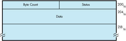
6.5. Pseudoterminal Functions
This section discusses the following pseudoterminal functions:
Reading data
Writing data
Using write with echo
Flow control
Event notification
6.5.1. Reading Data
To read data from the pseudoterminal, the control program uses the PTD$READ routine. When a PTD$READ routine is called, the operating system queues a read operation. The read operation completes when the pseudoterminal has characters to output. The read request queries TTDRIVER whether there is data found to be returned. If so, the resulting string of characters is returned. If a read request is issued and no data is available, the read request is queued and then completed at a later time. In this case, the routine always returns at least one character. The read request may complete even when there are no characters available to output. In this rare case when TTDRIVER indicates that there is no more data to be output and there is really no data, the read operation completes with zero bytes of data.
An application that issues an asynchronous pseudoterminal read can use the $SYNCH system service to find out when the read completed. The efn argument for the $SYNCH service must be the same as the efn specified in the original PTD$READ call, and the iosb for the $SYNCH service must match the readbuf of the PTD$READ call.
6.5.2. Writing Data
To write data to the pseudoterminal, the control program uses the PTD$WRITE routine. The write request allows you to specify a buffer to receive any output that the write request generates; you do not need to issue a separate read request to read this data. When you use an echo buffer, the control application can significantly reduce the number of I/O requests required.
An application can issue only one write request at a time. Once the write request completes, the application must check the write buffer status longword to see whether all the data supplied was written. If not, the application must issue additional write requests until all the data has been accepted.
6.5.3. Using Write with Echo
If a read request is pending when a write-with-echo request is issued, the echo data is placed in the echo buffer. If more data is echoed than can fit in the echo buffer, the remaining data is placed in the pending read requests buffer. If no pending read exists, the data is held by the driver until another request that can take the data is issued. Both the read and the write with echo must use completion ASTs to allow the driver to report request completions to the application in the correct order.
If an application is not using the write-with-echo capability, the application should avoid using completion ASTs if possible. Unnecessary use of completion ASTs significantly increases the number of instructions needed to complete a read or write operation.
When using write with echo, both the wrtbuf and echobuf arguments contain I/O status information. An application must check both of these status longwords if the PTD$WRITE completes successfully. If a write operation wrote no characters, characters might still be in the echo buffer. If no data was echoed, the status in the echobuf is SS$_NORMAL with zero bytes transferred.
6.5.4. Flow Control
By default, the driver attempts to notify the control program of data overrun or loss. The pseudoterminal sends an XOFF AST when the type-ahead buffer is getting full. Once the pseudoterminal delivers an XOFF AST, the pseudoterminal also returns a status of SS$_DATAOVERUN with the actual number of characters input. This prevents a single request from flooding the type-ahead buffer. If a control program makes repeated attempts to insert data after receiving the SS$_DATAOVERUN message, it can flood the terminal type-ahead buffer. When the type-ahead buffer has filled, the pseudoterminal returns the status of SS$_DATALOST.
If the control program is writing to the terminal or terminal driver, it should let the terminal and terminal driver handle flow control. To do this, the application should enable all three input flow control notification ASTs. The control program should write a DC1 to the terminal if an XON AST is delivered. It should write a DC3 to a terminal if an XOFF AST is delivered, and write a BELL character to the terminal if the BELL AST is delivered. These signals allow the terminal to decide what to do with the flow control data. The application should ignore the SS$_DATAOVERUN and SS$_DATALOST return status and continue writing data to the pseudoterminal.
6.5.5. Event Notification
This section describes how the pseudoterminal driver provides notification of important driver events.
6.5.5.1. Input Flow Control
The driver provides three ways to indicate when the class driver wants to stop input and one way to signal when it is safe to resume output:
The driver returns a status of SS$_DATAOVERUN and the number of characters input for the control program write.
The control program can enable a BELL attention AST to be delivered when the class driver calls the PTD$SET_TERMINAL_NOTIFICATION routine. This AST is delivered if the pseudoterminal does not have the HOSTSYNC attribute set. If only a BELL or only an XOFF AST event is enabled and an XOFF or a BELL AST needs to be delivered, the AST that is available is delivered.
The control program can enable an XOFF attention AST to be delivered when the class driver calls the PTD$SET_TERMINAL_NOTIFICATION routine. This AST is delivered if the pseudoterminal has the HOSTSYNC attribute set.
The control program can enable an XON attention AST to be delivered when the class driver calls the PTD$SET_TERMINAL_NOTIFICATION routine. This AST is delivered only if the pseudoterminal has the HOSTSYNC attribute set.
6.5.5.2. Output Stop
The Output Stop AST tells the control program that the terminal driver is stopping output. This keeps the control program from having to determine whether an XOFF written to the control side is being treated by the terminal driver as flow control or data.
6.5.5.3. Output Resume
The Output Resume AST tells the control program that the terminal driver wants to resume output. This AST can be delivered at any time, even if output is active or has previously been stopped. The control program should always restart output processing when it receives this AST.
6.5.5.4. Characteristics Changed
The Characteristics Changed AST tells the control program that the terminal driver has called the pseudoterminal CHANGE CHARACTERISTICS routine. This routine is called whenever the terminal driver has changed the device characteristics. The control program should then read the pseudoterminal characteristics to determine what has changed.
6.5.5.5. Output Abort
The Output Abort AST tells the control program that the terminal driver has called the pseudoterminal ABORT OUTPUT routine. This routine is called when the terminal driver wants to flush any outstanding output data. The control program should flush any internally buffered data when this AST is received.
6.5.5.6. Terminal Driver Read Events
Three special event types notify the control program when a terminal read request starts and finishes. By default, the pseudoterminal does not deliver the read notification ASTs associated with these events. The PTD$SET_EVENT_NOTIFICATION routine must be used explicitly to enable or disable their delivery.
Start Read—Tells the control program that the terminal driver is starting a read request. Some applications require this in order to know when to start inputting a logged session script. The special event types are:
Middle Read—Tells the control program that the terminal driver has finished writing the prompt string if one was supplied.
End Read—Tells the control program that the terminal driver has finished a read request.
Once an event notification AST is enabled, it continues to be delivered until it is canceled, or until the device is deleted. This characteristic allows the control program to enable the AST once, which greatly reduces the risk of missing multiple rapid occurrences of an event. If the driver cannot get sufficient resources to deliver the notification AST, that report is lost. Only one AST per event is allowed, and attempts to specify multiple ASTs result in use of the last one specified.
To enable or disable event notification, the control program uses the PTD$SET_EVENT_NOTIFICATION routine, which is described in Appendix D, "Control Connection Routines".
6.6. Pseudoterminal Driver Programming Example
Example 6.1, ''Sample Pseudocode for Pseudoterminal Driver Program'' shows how to use the pseudoterminal. (The example is also included in the SYS$EXAMPLES directory.) This section begins with a brief overview of the example. The example itself briefly discusses each module; the pseudocode for that module follows its discussion.
The scenario chosen for this example is a simple terminal session logging utility that uses most of the pseudoterminal capabilities. This example also shows how to use the write-with-echo capability, which provides a significant gain in performance.
6.6.1. Design Overview
The design approach writes the log record in a main loop that hibernates when it has no work to do. The loop uses ASTs to read keystrokes from the terminal, write to the pseudoterminal, and write data to the terminal. When a block of characters is written to the terminal, that block is placed into a queue of blocks to be written to the log file, and a wake request is issued. Logging is stopped if you log out of the subprocess, if you enter the stop logging character Ctrl\, or if a severe error occurs during data processing. When any of these events occur, all outstanding log records are written before the program exits.
One major design consideration is how flow control should be handled — either by attempting to enforce flow control, or by letting the terminal and terminal driver handle it. In this example, the terminal and terminal driver handle flow control; the driver sends XON, XOFF, or BELL characters to the terminal as necessary.
One of the six I/O buffers is permanently reserved as the terminal read buffer. This buffer is passed directly to the terminal read $QIO. This eliminates having to move data that is read from the terminal into the read buffer. The other five buffers are placed in a queue and are allocated and deallocated as needed. This pool of buffers reserves the first two longwords to be used as queue headers and traditional IOSBs. The third longword and the I/O status longwords are used by the pseudoterminal driver.
/*
** Main Routine
**
** Function: Intitializes the environment and then hibernates, waiting
** to be awakened.  When awakened, the program checks to see whether it
** is exiting, or whether more log data is available.  If more data is
** available, the data is appended to the current log record and checked
** to see whether a log record should be written.  A log record is written
** either when maxbuf characters are in the log buffer,
** or when it finds a <CR>character pair.  The algorithm
** allows an unlimited number of <NULL> fill characters to occur
** between the <CR>and the <LF>. If the program is
** exiting, it closes the log file,  deletes the pseudoterminal, resets the
** terminal, and exits.
*/
Initialize environments (This includes creating pseudoterminal, the log file
                         and starting up the subprocess.)

If (Initialization OK) Then
   Do
      while (I/O buffer to log)
         Data size = number of bytes in I/O buff
         For all data in I/O buffer
            If (cr_seen) Then
               If (current char == <LF>) Then
                  write current log buffer
                  reset cr_seen
                  point to start of log buffer
               Else if (current char != <NULL>) Then
                  insert <CR>and current char into log buffer
                  move log buffer ptr over 2 characters
                  reset cr_seen
               Endif
            Else if (current character != <CR>) Then
               insert character into log buffer
               move log buffer ptr over 1 character
            Else
               set cr_seen
            Endif

            If (log buffer ptr >= IOC$GW_MAX-48) Then
               write log buffer
               reset log buffer pointer
               reset cr_seen
            Endif
         Endloop
         Free I/O buffer call free_io_buffers
      Endwhile
      If (not exiting) Then
         Wait for more to do call SYS$HIBER
      Endif
   Until ( (exiting) and (no I/O buffers to log) )

   close log file
   If ( (close failed) and (exit reason is SS$_NORMAL) ) Then
      set exit to status to failure reason
   Endif
   If (subprocess still running) Then
      call SYS$FORCEX to run down the subprocess
   Endif
   call PTD$CANCEL to flush all pending pseudoterminal read requests
   call SYS$CANCEL to flush all terminal requests
   call PTD$DELETE to delete the pseudoterminal
   If ( (delete failed) and (exit reason is SS$_NORMAL) ) Then
      set exit to status to failure reason
   Endif
   reset terminal to startup condition using SYS$QIOW
   If ( (terminal reset failed) and (exit reason is SS$_NORMAL) ) Then
      exit to status to failure reason
   Endif
Endif
call LIB$SIGNAL and report exit reason
Exit

/*
**
** Initialization Code
**
** Function: This routine sets the terminal characteristics, creates the
** pseudoterminal, starts up the subprocess, and opens the log file.  If
** any of these steps fail, the program undoes any steps already done and
** returns to the  main routine.
**
*/

read the maximum buffer size from IOC$GW_MAXBUF
Assign a channel to SYS$INPUT
If (assign ok) Then
   Read the terminal characteristics from the terminal
   If (read of terminal characteristics ok) Then
      Open log file with maximum record size of IOC$GW_MAXBUF
      If (open ok) Then
         Create the pseudoterminal with characteristics of terminal
         If (create ok) then
            Place 4 of the buffers on the queue of free I/O buffers
            Copy terminal characteristics and modify them to NOECHO and PASTHRU
            Set the terminal characteristics use modified value
            If (set ok) Then
               Get device name of pseudoterminal use SYS$GETDVI
               If (get ok) Then
                  Create subprocess
                  If (create ok) Then
                     Enable XON, XOFF, BELL, SET_LINE event notification ASTs
                     If (AST setup OK) Then
                        Call PTD$READ to start reading from the pseudoterminal
                                      ASTADR = ft_read_ast
                                      ASTPRM = buffer address
                                      READBUF = I/O buffer + 8
                                      READBUF_LEN = 500
                        If (read ok) Then
                           Call SYS$QIO and read a single character from the
                                        keyboard ASTADR = kbd_read_ast
                           If (read failed) Then
                              Call PTD$CANCEL to flush queued pseudoterminal read
                              Call PTD$DELETE to delete pseudoterminal
                              Reset terminal to original state
                              Close log file and delete it
                           Endif
                        Else
                           Call PTD$DELETE to delete pseudoterminal
                           Reset terminal to original state
                           Close log file and delete it
                        Endif
                     Else
                        Call PTD$DELETE to delete pseudoterminal
                        Reset terminal to original state
                        Close log file and delete it
                     Endif
                  Else
                     Call PTD$DELETE to delete pseudoterminal
                     Reset terminal to original state
                     Close log file and delete it
                  Endif
               Else
                  Call PTD$DELETE to delete pseudoterminal
                  Reset terminal to original state
                  Close log file and delete it
               Endif
            Else
               Call PTD$DELETE to delete pseudoterminal
               Close log file and delete it
            Endif
         Else
            Close log file and delete it
         Endif
      Endif
   Endif
Endif

/*
** kbd_read_ast
**
** Function: This routine is called every time data is read from the terminal.
** If the program is exiting, then the routine exits without restarting the
** read.   The character read is checked to see if the terminate processing
** character Ctrl\ was entered.  If the terminate processing character was
** entered, the exiting state is set and a SYS$WAKE is issued to start the
** main routine.  Now an attempt is made to obtain an I/O buffer in which
** to store echoed output.  If an I/O buffer is unavailable, a simple
** PTD$WRITE is issued; a PTD$WRITE with echo is issued if a buffer is
** available.  If the write completes successfully, another read is issued
** to the keyboard.
**
*/

If (not exiting) Then
   If (read ok) Then
      Search input data for Ctrl\
      Allocate a read buffer call allocate_io_buffer
      If (got a buffer) Then
         Call PTD$WRITE to write characters to pseudoterminal
                        ASTADR = ft_echo_ast
                        ASTPRM = allocated I/O buffer
                        WRTBUF = read I/O buffer
                        WRTBUF_LEN = number of characters read
                        ECHOBUF = allocated I/O buffer
                        ECHOBUF_LEN = 500
      Else
         Call PTD$WRITE to write characters to pseudoterminal
                        WRTBUF = read I/O buffer
                        WRTBUF_LEN = number of characters read
      Endif
      If (write setup ok)
         If ( (write status is ok) or (write status is SS$_DATALOST) )
            Issue another single character read to terminal with
                     ASTADR = kbd_read_ast, with data going to read I/O buffer
            If (read setup failed) Then
               Set exit flag
               Set exiting reason to SS$_NORMAL
            Endif
         Else
            Set exit flag
            Set exiting reason to SS$_NORMAL
         Endif
      Else
         Set exit flag
         Set exiting reason to SS$_NORMAL
      Endif
   Else
      Set exit flag
      Set exiting reason to read failure status
   Endif
   If (exiting) Then
      Wake the mainline call SYS$WAKE
   Endif
Endif

/*
** terminal_output_ast
**
** Function: This routine is called every time an I/O buffer is written
** to the terminal.  If the terminal write request completes successfully,
** it inserts the I/O buffer into the queue of I/O buffers to be logged.
** If the I/O buffer is the only entry on the queue, it issues a SYS$WAKE
** to start the main routine. To prevent spurious wake requests,
** SYS$WAKE is not issued if multiple entries are already on
** the queue.  If a terminal write error occurs, the routine sets the
** exit flag and wakes the main routine.
**
*/
If (terminal write completed ok) Then
   insert I/O buffer onto logging queue
   If (this is only entry on queue) Then
      wake the mainline call SYS$WAKE
   Endif
Else
   set exit flag
   set exiting reason to terminal write error reason
   wake the mainline call SYS$WAKE
Endif

/*
**
** ft_read_ast
**
** Function: This routine is called when a pseudoterminal read request
** completes.  It writes the buffer to the terminal and attempts to start
** another read from the pseudoterminal.  If the program is not exiting,
** this routine writes the buffer to the terminal and does not start another
** pseudoterminal read.
**
*/
If (not exiting)
   If (Pseudoterminal read ok) Then
      write buffer to the terminal ASTADR = terminal_output_ast
      If (write setup ok) Then
         Allocate another read buffer call allocate_io_buffer
         If (got a buffer) Then
            Call PTD$READ to restart reads from the pseudoterminal.
                      ASTADR = ft_read_ast
                      ASTPRM = buffer address
                      READBUF = I/O buffer + 8
                      READBUF_LEN = 500
            If (read setup failed) Then
               Set exit flag
               Set exiting reason to read failure reason
               Wake the mainline call SYS$WAKE
            Endif
         Else
            Set read stopped flag
         Endif
      Else
         Set exit flag
         Set exiting reason to terminal write failure reason
         Wake the mainline call SYS$WAKE
      Endif
   Else
      Set exit flag
      Set exiting reason to terminal read failure reason
      Wake the mainline call SYS$WAKE
   Endif
Endif

/*
**
** ft_echo_ast
**
** Function: This routine is called if a write to the pseudoterminal used
** an ECHO buffer.  If any data was echoed, the output is written to the
** terminal.  If no data was echoed, the I/O buffer is freed so it can be
** used later. If the program is exiting, this routine exits.
**
*/
If (not exiting) Then
   If (ECHO buffer has data) Then
      Write the buffer to the terminal with ASTADR = terminal_output_ast
      If (error setting up write) Then
         Set exit flag
         Set exiting reason to write failure reason
         Wake mainline call SYS$WAKE
      Endif
   Else
      Free I/O buffer call free_io_buffers
   Endif
Endif

/*
** free_io_buffers
**
** Function: This routine places a free I/O buffer on the queue of available
** I/O buffers. It also restarts any stopped read operations from the
** pseudoterminals.  This routine disables AST delivery while it is running
** in order to synchronize reading and resetting the read stopped flag.
**
*/
If (not exiting) Then
   Disable AST deliver using SYS$SETAST
   If (Pseudoterminal reads not stopped) Then
      Insert I/O buffer on the interlocked queue of free I/O buffers
   Else
      Call PTD$READ to restart reads from the pseudoterminal.
                   ASTADR = ft_read_ast
                   ASTPRM = buffer address
                   READBUF = I/O buffer + 8
                   READBUF_LEN = 500
      If (no error starting read) Then
         Clear read stopped flag
      Else
         Set exit flag
         Set exit reason to read setup reason
      Endif
  Endif
  Enable AST delivery using SYS$SETAST
Endif

/*
**
** allocate_io_buffer
**
** Function: This routine obtains a free I/O buffer from the queue of
** available I/O buffers.  If the program is exiting, this routine
** returns an SS$_FORCEDEXIT error.
**
*/
If (not exiting) Then
   remove a I/O buffer from the interlocked queue of I/O buffers
   If (queue empty) Then
      exit with reason LIB$_QUEWASEMP
else
   exit with reason SS$_FORCEDEXIT
Endif

/*
** subprocess_exit
**
** Function: This routine is called when the subprocess has completed
** and exited.  This routine checks whether the program is already exiting.
** If not, then the routine indicates that the program is exiting and wakes
** up the main program.
**
*/
If (not exiting) Then
   indicate subprocess no longer running
   set exit status to SS$_NORMAL
   indicate exiting
   call SYS$WAKE to start up main loop
Endif

/*
** xon_ast
**
** Function: This routine is called for the pseudoterminal driver to signal
** that it is ready to accept keyboard input. The routine attempts to send
** an XON character to the terminal by sending XON DC1 using SYS$QIO.
** If the attempt fails, it is not retried.
**
*/
If (not exiting) Then
   call SYS$QIO to send a <DC1> character to the terminal
Endif

/*
** bell_ast
**
** Function: This routine is called when the pseudoterminal driver wants
** to warn the user to stop sending keyboard data.  The routine attempts
** to ring the terminal bell by sending the BELL character to the terminal
** using SYS$QIO.  If the attempt fails, it is not retried.
**
*/
If (not exiting) Then
   call SYS$QIO to send a <BELL> character to the terminal
Endif

/*
** xoff_ast
**
** Function: This routine is called when the pseudoterminal driver wants to
** signal that it will stop accepting  keyboard input. The routine attempts
** to send an XOFF character to the terminal by sending XOFF DC3 to the
** terminal using SYS$QIO.  If the attempt fails, it is not retried.
**
*/
If (not exiting) Then
   call SYS$QIO to send a <DC3> character to the terminal
Endif

/*
** set_line_ast
**
** Function: This routine is called when the pseudoterminal device
** characteristics  change.  The routine reads the current pseudoterminal
** characteristics, changes the characteristics to set PASTHRU and NOECHO,
** and applies the characteristics to the input terminal.  If the attempt
** to alter the terminal characteristics fails, it is not retried.
**
*/
If (not exiting) Then
   call SYS$QIOW to read the pseudoterminals characteristics
   If (not error) Then
      Set the alter the just read characteristics to have PASTHRU and NOECHO
      attributes
      call SYS$QIO to set the terminal characteristics.
   Endif
Endif
Chapter 7. Shadow-Set Virtual Unit Driver
This chapter provides an overview of HPE Volume Shadowing for OpenVMS and describes the use of the shadow-set virtual unit driver (SHDRIVER).
7.1. Introduction
HPE Volume Shadowing for OpenVMS ensures that data is available for applications and end users by duplicating data on multiple disks. Because the same data is recorded on multiple disk volumes, if one disk fails, the remaining disk or disks can continue to service I/O requests. This ability to shadow disk volumes is sometimes referred to as disk mirroring.
Volume shadowing supports the clusterwide shadowing of a variety of storage systems. Volume shadowing also supports shadowing of all mass storage control protocol (MSCP) served disks. For more information about Volume Shadowing supported devices, see the Volume Shadowing for OpenVMS Software Product Description.
You can mount multiple compatible disk volumes, including the system disk, to form a shadow set. Each disk in the shadow set is known as a shadow set member. Volume Shadowing for OpenVMS logically binds the shadow set devices together and represents them as a single virtual device called a virtual unit. This means that multiple members of the shadow set, represented by the virtual unit, appear to applications and users as a single, highly available disk.
Volume Shadowing features include:
Controller independence. Shadow set members can be located on any node in an OpenVMS Cluster that has Volume Shadowing enabled.
Clusterwide, homogeneous shadow-set maintenance functions.
Ability to survive controller, disk, and media failures transparently.
Shadowing functions that do not affect application I/O.
Applications and users read and write data to and from a shadow set using the same commands and program language syntax and semantics that are used for nonshadowed I/O operations. Volume shadowed sets are managed and monitored using the same commands and utilities that are used for nonshadowed disks. The only difference is that access is through the virtual unit, not to individual devices.
SHDRIVER, the driver that controls the virtual unit functions, is described in Section 7.3, ''Driver Functions''.
For more detailed information on HPE Volume Shadowing for OpenVMS, see the Volume Shadowing for OpenVMS manual.
7.2. Configurations
HPE Volume Shadowing for OpenVMS does not depend on specific hardware in order to operate. All shadowing functions can be performed on Alpha and IA-64 server systems running the OpenVMS operating system. Shadow set members must have the same physical geometry (that is, the same number of identical logical blocks (LBNs)) and members can be located anywhere in an OpenVMS Cluster.
7.2.1. Supported Hardware
Volume shadowing requires a minimum of one Alpha or IA-64 server computer and disk drives.
See the most recent Volume Shadowing for OpenVMS Software Product Descriptions (SPD 27.29.xx) for additional information about hardware requirements.
7.2.2. Compatible Disk Drives and Volumes
Volume shadowing requires compatibility among the physical units (disk drives and volumes) that form a shadow set. For example:
Units must be Files-11 On-Disk Structure Level 2 (ODS-2 or ODS-5) data disks.
Units and controllers must conform to DSA and OpenVMS MSCP, or must be SCSI FC compliant.
Units should not have hardware write protection enabled. Hardware write protection stops the volume shadowing software from maintaining identical volumes. However, the shadow set virtual unit may be mounted software write-locked with the /NOWRITE qualifier to MOUNT.
7.3. Driver Functions
This section describes the major virtual unit functions supported by SHDRIVER. In addition to the virtual unit functions described in this section, SHDRIVER supports all OpenVMS disk functions. SHDRIVER receives QIO operations from application programs and is a client of the disk class drivers DUDRIVER. Applications access the shadow set as they would access a standard OpenVMS disk.
Table 7.1, ''Functions of the Shadow Set Virtual Unit Driver'' summarizes the major SHDRIVER functions.
Note
The MOUNTSHAD, ADDSHADMBR, COPYSHAD, SETCHAR, and REMSHADMBR functions are reserved for the internal use. Use of these functions by customer or third-party provided software may cause unpredictable results including system crashes and data corruption.
| Function | Description |
|---|---|
| MOUNTSHAD | Creates a virtual unit |
| ADDSHADMBR | Evaluates a physical member and adds members |
| COPYSHAD | Triggers and controls copy operations |
| REMSHADMBR | Removes a physical member |
| AVAILABLE | Virtual unit dissolution |
| SENSECHAR | Verifies shadow set status |
| READ | Directs I/O to a physical member |
| WRITE | Propagates a write operation to all physical members |
| SETCHAR | Sets characteristics of the shadow set |
7.3.1. Read and Write Functions
With minor changes, the read and write functions for SHDRIVER operate the same as for the disk class driver (see Section 2.3.1, ''Read'' and Section 2.3.2, ''Write'').
During an SHDRIVER read operation, the host directs the read to the member volume, which will likely return the data the fastest. See the Volume Shadowing for OpenVMSmanual for more information about controlling this behavior.
During a write operation, SHDRIVER directs the write to each member volume. The write operations for each member volume usually proceed in parallel; the virtual unit write operation terminates when all writes have completed. The write function for SHDRIVER takes the IO$M_VUEX_FC function modifier; this modifier should not be used by application programs.
The read and write SHDRIVER functions, as well as all user functions, are issued by user programs. All other SHDRIVER functions are invoked by MOUNT and DISMOUNT commands, or the $MOUNT and $DISMOUNT system services.
Remember that volume shadowing provides data availability by protecting against hardware problems or communication path problems that might cause a disk volume to be a single point of failure. If a write request is made to a shadow set, but the system fails before a completion status is returned from all of the shadow set members, it is possible that:
All members might contain the new data.
All members might contain the old data.
Some members might contain new data and others might contain old data.
When the system recovers, volume shadowing performs a merge operation to ensure that the corresponding blocks on each shadow set member contain the same data (right or wrong); therefore, the goal here is not one of data correctness but of data availability. Volume shadowing is designed to make the data on all disks identical, then, if necessary, incorrect data can be reconciled either by the user reentering the data or by an application automatically employing database or journaling techniques.
For example, when used with volume shadowing, OpenVMS RMS journaling allows you to develop applications that can automatically recover from failures such as:
Permanent loss of the path between a CPU data buffer containing the data being written and the disk being written to during a multiple block I/O operation. Communication path loss can occur due to node failure or a failure of node-to-node communications.
Failure of a CPU (such as a system crash, halt, power failure, or system shutdown) during a multiple block write I/O operation.
Mistaken deletion of a file.
Corruption of file system pointers.
OpenVMS RMS file corruption due to a software error or incomplete bucket write operation to an indexed file.
Cancellation of an in-progress multiple block write operation.
For more information about shadowing merge operations, see the Volume Shadowing for OpenVMS manual.
7.4. Error Processing
Shadow set recovery and repair are handled by volume processing, which replaces mount verification for shadow sets. Membership failure decisions are made by the host system. Device errors that result in inaccessibility of physical member units first utilize the class driver's connection walking algorithm. If that fails, a local decision is made on the shadow set membership. The rules are:
If some, but not all, members of the set are accessible, then the local node sequentially adjusts the membership and notifies the other hosts.
If no members are accessible, no modifications to the set membership are made.
There are two types of volume processing: active and passive. Active volume processing handles error processing on a local node. Triggered by a failed I/O operation, active volume processing also controls mount verification functions, member removal, and failover. Passive volume processing is triggered by lock messages or by a cluster event. Passive volume processing revalidates shadow set membership, ensures that the shadow set reflects changes made outside the shadow set, and handles the following functions:
Member additions from other nodes
Member removals from other nodes
A new node mounting the shadow set
A node dismounting the shadow set
A system crash on a node that has the shadow set mounted
For more information, see the Volume Shadowing for OpenVMS manual.
Chapter 8. Using the OpenVMS Generic SCSI Class Driver
This chapter describes the use of the OpenVMS Generic Small Computer System Interface (SCSI) class driver.
8.1. Overview of SCSI
The American National Standard for information systems — Small Computer System Interface-2 (SCSI-2) specification defines mechanical, electrical, and functional requirements for connecting small computers to a wide variety of intelligent devices, such as rigid disks, flexible disks, magnetic tape devices, printers, optical disks, and scanners. It specifies standard electrical bus signals, timing, and protocol, as well as a standard packet interface for sending commands to devices on the SCSI bus.
Certain OpenVMS systems employ the SCSI bus as an I/O bus. For these systems, you can use a SCSI-compliant disk and tape drives. The operating system also allows devices including disk drives, tape drives, and scanners, produced by different suppliers, to be connected to the SCSI bus of such a system.
SCSI has been widely adopted by manufacturers for a variety of peripheral devices; however, because the ANSI SCSI standard is broad in scope, not all devices that implement its specifications can fully interrelate on the bus. HPE fully supports SCSI-compliant equipment sold or supplied by HPE. Proper operation of products not sold or supplied by HPE cannot be assured.
For more information, see the following documents:
American National Standard for Information Systems — Small Computer System Interface-2 (SCSI-2) specification (X3T9.2/86-109)
Copies of this document can be purchased from: Global Engineering Documents, 2805 McGaw, Irvine, California 92714, United States; or (800) 854-7179 or (714) 261-1455. See document X3.131-198X.
American National Standard for Information Systems — Small Computer System Interface specification (X3.131-1986)
Copies of this document can be obtained from: American National Standards Institute, Inc., 1430 Broadway, New York, New York, 10018. This document is now known as the SCSI-1 standard.
Consider two additional documents to help third-party vendors prepare SCSI peripherals and peripheral software for use with DIGITAL workstations.
The Small Computer System Interface: An Overview (EK-SCSISOV-001) provides a general description of the DIGITAL SCSI third-party support program.
The Small Computer System Interface: A Developer's Guide (EK-SCSIS-SP-001) presents the details of implementation of SCSI within DIGITAL operating systems.
8.2. OpenVMS SCSI Class/Port Architecture
The operating system employs a class/port driver architecture to communicate with devices on the SCSI bus. The class/port design allows the responsibilities for communication between the operating system and the device to be cleanly divided between two separate driver modules (see Figure 8.1, ''OpenVMS SCSI Class/Port Interface'').
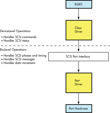
The SCSI port driver transmits and receives SCSI commands and data. It knows the details of transmitting data from the local processor's SCSI port hardware across the SCSI bus. Although it understands SCSI bus phases, protocol, and timing, it has no knowledge of which SCSI commands the device supports, what status messages it returns, or the format of the packets in which this information is delivered. Strictly speaking, the port driver is a communications path. When directed by a SCSI class driver, the port driver forwards commands and data from the class driver onto the SCSI bus to the device. On any given OpenVMS system, a single SCSI port driver handles bus-level communications for all SCSI class drivers that may exist on the system.
The SCSI class driver acts as an interface between the user and the SCSI port, translating an I/O function as specified in a user's $QIO request to a SCSI command targeted to a device on the SCSI bus. Although the class driver knows about SCSI command descriptor buffers, status codes, and data, it has no knowledge of underlying bus protocols or hardware, command transmission, bus phases, timing, or messages. A single class driver can run on any given OpenVMS system, in conjunction with the SCSI port driver that supports that system. The operating system supplies a standard SCSI disk class driver and a standard SCSI tape class driver to support its disk and tape SCSI devices.
8.3. Overview of the OpenVMS Generic SCSI Class Driver
The OpenVMS generic SCSI class driver provides a mechanism by which an application program can control a SCSI device that cannot be controlled by the standard OpenVMS disk and tape class drivers. By means of a Queue I/O Request ($QIO) system service call, a program can pass to the generic SCSI class driver a pre-formatted SCSI command descriptor block. The generic SCSI class driver, in conjunction with the standard OpenVMS SCSI port driver, delivers this SCSI command to the device, manages any transfer of data from the device to a user buffer, and returns SCSI status to the application.
In effect, an application using the generic SCSI class driver implements details of device control usually managed within device driver code. The programmer of such an application must understand which SCSI commands the device supports and which SCSI status values the device returns. The programmer must also be aware of the device's timeout requirements, data transfer capabilities, and command retry behavior.
The application program sets up the characteristics of the connection the generic SCSI class driver uses when delivering commands to, exchanging data with, and receiving status from the device. The program associates each I/O operation the device can perform with a specific SCSI command. When it receives a request for a particular operation, the application program creates the specific command descriptor block that, when passed to the device, causes it to perform that operation.
The application initiates all transactions to the SCSI device by means of a $QIO call to the generic SCSI class driver, supplying the address and length of the SCSI command descriptor block, plus the parameters of any data transfer operation, in the call. When the transaction completes and the application program regains control, it interprets the returned status value, processes any returned data, and services any failure. To avoid conflicts with other applications accessing the same device, an application may need to explicitly allocate the device.
Because the generic SCSI class driver has no knowledge of specific device errors, it neither logs device errors nor implements error recovery. An application using the driver must manage device-specific errors itself. To service an error returned on a single transaction, the application must issue additional $QIO requests and initiate further transactions to the device. If more precise or more efficient error recovery is required for a device, the developer should consider writing a third-party SCSI class driver, as described in the OpenVMS VAX Device Support Manual. A third-party SCSI class driver can log errors associated with device activity by using the method described in the OpenVMS VAX Device Support Manual.
A third-party class driver is the only means of supporting devices that themselves generate transactions on the SCSI bus, such as notification of a device selection event to the host processor. See the description of asynchronous event notification (AEN) in the OpenVMS VAX Device Support Manual.
Figure 8.2, ''Generic SCSI Class Driver Flow'' shows the flow of a $QIO request through the generic SCSI class driver and the port driver.
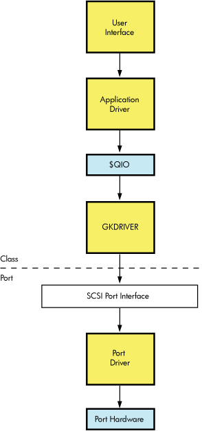
When direct access to a target device on the SCSI bus is required, the generic SCSI class driver is loaded for that device, as described in Section 8.6, ''Configuring a Device Using the Generic Class Driver''“Configuring a Device Using the Generic Class Driver”. An application program using the generic class driver performs the following tasks to issue a command to the target device:
Calls the Assign I/O Channel ($ASSIGN) system service to assign a channel to the generic SCSI class driver, and to allocate the device for the application's exclusive use.
Formats a SCSI command descriptor block.
Formats any data to be transferred to the device.
Calls the Queue I/O Request ($QIO) system service to request the generic SCSI class driver to send the SCSI command descriptor block to the port driver.
Upon completion of the I/O request, interprets the SCSI status byte and any data returned from the target device.
These operations are described in following sections.
Note
Because incorrect or malicious use of the generic SCSI class driver can result in SCSI bus hangs and lead to SCSI bus resets, DIAGNOSE and PHY_IO or LOG_IO privileges are required to access the driver. An application program can be designed in such a way as to filter user I/O requests, which allows nonprivileged users access to some device functions.
8.4. Accessing the OpenVMS Generic SCSI Class Driver
Interactive commands and procedure calls can use the OpenVMS generic SCSI class driver to access devices on the SCSI bus. However, it is unlikely that a user application would access a device on the SCSI bus by directly using the $QIO interface of the generic SCSI class driver. First of all, any user process directly using the $QIO interface would require DIAGNOSE and PHY_IO or LOG_IO privileges. Under normal circumstances, it would be a system security risk to grant DIAGNOSE and PHY_IO or LOG_IO privileges to many system users. Secondly, it would be cumbersome for end users of the device to identify, format, and issue SCSI commands to the device. Rather, it would be more efficient to develop an interface that hides these details.
A utility program, installed with the DIAGNOSE and PHY_IO or LOG_IO privileges, can provide nonprivileged users with a command-line interface to a SCSI device. The utility translates interactive commands provided by the user into the appropriate set of SCSI commands and sends them to the device using the $QIO interface provided by the generic SCSI class driver. The utility checks user commands to ensure that only valid SCSI commands are sent to the device. For information about installing images with privileges, see the VSI OpenVMS System Manager's Manual and the VSI OpenVMS System Management Utilities Reference Manual.
A privileged shareable image can provide system applications with a procedure interface to a SCSI device. The image contains a set of procedures that translate operations specified by the caller into the appropriate set of SCSI commands. The SCSI commands are sent to the device through the $QIO interface of the generic SCSI class driver. The privileged shareable image checks its caller's parameters to ensure that only valid SCSI commands are sent to the device. For information about creating shareable images, see the VSI OpenVMS Programming Concepts Manual.
8.5. SCSI Port Features Under Application Control
The standard OpenVMS SCSI port driver provides mechanisms by which the generic SCSI class driver can control the nature of data transfers and command transmission across the SCSI bus. An application uses the $QIO interface to tailor these mechanisms to the specific device it supports. Among the features under application program control are the following:
Data transfer mode
Disconnection and reselection
Command retry
Command time-outs
The following sections discuss these features.
8.5.1. Setting the Data Transfer Mode
The SCSI bus defines two data transfer modes, asynchronous and synchronous. In asynchronous mode, for each REQ from a target there is an ACK from the host prior to the next REQ from the target. Synchronous mode allows higher data transfer rates by allowing a pipelined data transfer mechanism where, for short bursts (defined by the REQ-ACK offset), the target can pipeline data to an initiator without waiting for the initiator to respond.
Whether or not a port or a target device allows synchronous data transfers, it is harmless for the program to set up the connection to use such transfers. If synchronous mode is not supported, the port driver automatically uses asynchronous mode.
For example, to use synchronous mode in a transfer, a programmer using the generic SCSI class driver must ensure that both the SCSI port and the SCSI device involved in the transfer support synchronous mode. The SCSI port of the VAXstation 3520/3540 system allows both synchronous and asynchronous transfers, whereas that of OpenVMS 3100 systems supports only asynchronous transfers.
To set up a connection to use synchronous data transfer mode, a program using the generic SCSI class driver sets the syn bit in the flags field of the generic SCSI descriptor, the address of which is passed to the driver in the p1 argument to the $QIO request.
8.5.2. Enabling Disconnection and Reselection
The ANSI SCSI specification defines a disconnection facility that allows a target device to yield ownership of the SCSI bus while seeking or performing other time-consuming operations. When a target disconnects from the SCSI bus, it sends a sequence of messages to the initiator that cause it to save the state of the I/O transfer in progress. Once this is done, the target releases the SCSI bus. When the target is ready to complete the operation, it reselects the initiator and sends to it another sequence of messages. This sequence uniquely identifies the target and allows the initiator to restore the context of the suspended I/O operation.
Whether disconnection should be enabled or disabled on a given connection depends on the nature and capabilities of the device involved in the transfer, as well as on the configuration of the system. In configurations where there is a slow device present on the SCSI bus, enabling disconnection on connections that transfer data to the device can increase bus throughput. By contrast, systems where most of the I/O activity is directed towards a single device for long intervals can benefit from disabling disconnection. By disabling disconnection when there is no contention on the SCSI bus, port drivers can increase throughput and decrease the processor overhead for each I/O request.
By default, the OpenVMS class/port interface disables the disconnect facility on a connection. To enable disconnection, an application program using the generic SCSI class driver sets the dis bit of the flags field of the generic SCSI descriptor, the address of which is passed to the driver in the p1 argument to the $QIO call.
8.5.3. Disabling Command Retry
The SCSI port driver implements a command retry mechanism, which is enabled on a given connection by default.
When the command retry mechanism is enabled, the port driver retries up to three times any I/O operation that fails during the COMMAND, Message, Data, or STATUS phases. For instance, if the port driver detects a parity error during the Data phase, it aborts the I/O operation, logs an error, and retries the I/O operation. It repeats this sequence twice more, if necessary. If the I/O operation completes successfully during a retry attempt, the port driver returns success status to the class driver. However, if all retry attempts fail, the port driver returns failure status to the class driver.
An application may need to disable the command retry mechanism under certain circumstances. For example, repeated execution of a command on a sequential device may produce different results than are intended by a single command request. A tape drive could perform a partial write and then repeat the write without resetting the tape position.
An application program using the generic SCSI class driver can disable the command retry mechanism by setting the dpr bit of the flags field of the generic SCSI descriptor, the address of which is passed to the driver in the p1 argument to the $QIO request.
8.5.4. Setting Command Timeouts
The SCSI port driver implements several timeout mechanisms, some governed by the ANSI SCSI specification and others required by OpenVMS. The time-outs required by OpenVMS include the following:
| Timeout | Description |
|---|---|
| Phase change timeout |
Maximum number of seconds for a target to change the SCSI bus phase or complete a data transfer. (This value is also known as the DMA timeout.) Upon sending the last command byte, the port driver waits this many seconds for the target to change the bus phase lines and assert REQ (indicating a new phase). Or, if the target enters the DATA IN or DATA OUT phase, the transfer must be completed within this interval. |
| Disconnect timeout | Maximum number of seconds, from the time the initiator receives the DISCONNECT message, for a target to reselect the initiator so that it can proceed with the disconnected I/O transfer |
An application program using the generic SCSI class driver is responsible for maintaining both of these timeout values. It has the following options:
Accepting a connection's default value. The default value for both timeouts is 20 seconds.
Altering the connection's default value. To modify the default values, the class driver specifies nonzero values for the phase change timeout and disconnect timeout fields of the generic SCSI descriptor, the address of which is passed to the driver in the p1 argument to the $QIO system service call.
8.6. Configuring a Device Using the Generic Class Driver
If a third-party-supplied SCSI device requires that the generic class driver be loaded, it must be configured by an explicit SYSGEN CONNECT command, as follows:
$ RUN SYS$SYSTEM:SYSGEN
SYSGEN> CONNECT GKpd0u /NOADAPTER
On Alpha systems, GK is the device mnemonic for the generic SCSI class driver (GKDRIVER); p represents the SCSI port ID (for instance, the controller ID Aor B ); d represents the SCSI device ID (a digit from 0 to 7); 0 signifies the digit zero; and u represents the SCSI logical unit number (a digit from 0 to 7).
Multiple devices residing on any SCSI bus in the system can share GKDRIVER as a class driver, as long as a CONNECT command is issued for each target device that requires the driver.
Because just one connection can exist through the SCSI port driver to each target, the generic class driver cannot be used for a target if a different SCSI class driver is already connected to that target. For example, if the SCSI disk class driver has a connection to device ID 2 on the SCSI bus identified by SCSI port ID B (DKB200), the generic class driver cannot be used to communicate with this disk. An attempt to connect GKDRIVER for this target results in GKB200 being placed off line.
8.7. Assigning a Channel to GKDRIVER
An application program assigns a channel to the generic SCSI class driver using the standard call to the $ASSIGN system service, as described in the VSI OpenVMS System Services Reference Manual. The application program specifies a device name and a word to receive the channel number.
8.8. Issuing a $QIO Request to the Generic Class Driver
The format of the Queue I/O Request ($QIO) system service that initiates a request to the SCSI generic class driver is as follows. This explanation concentrates on the special elements of a $QIO request to the SCSI generic class driver. For a detailed description of the $QIO system service, see the VSI OpenVMS System Services Reference Manual.
High-Level Language Format
SYS$QIO ([efn] ,chan ,func ,iosb ,[astadr] ,[astprm] ,p1 ,p2 [,p3] [,p4]
                [,p5] [,p6])
Arguments
| chan | I/O channel assigned to the device to which the request is directed. The chan argument is a word value containing the number of the channel, as returned by the Assign I/O Channel ($ASSIGN) system service. |
| func | Longword value containing the IO$_DIAGNOSE function code. Only the IO$_DIAGNOSE function code is implemented in the generic SCSI class driver. |
| iosb |
The iosb argument is required in a request to the generic SCSI class driver; it has the following format: 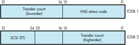
The status code provides the final status indicating the success or failure of the SCSI command. The SCSI status byte contains the status value returned from the target device, as defined in the ANSI SCSI specification. The transfer count field specifies the actual number of bytes transferred during the SCSI bus DATA IN or DATA OUT phase |
| [efn], [astadr], [astprm] | These arguments apply to $QIO system service completion. For an explanation of these arguments, see the VSI OpenVMS System Services Reference Manual. |
| p1 |
Address of a generic SCSI descriptor of the following format: 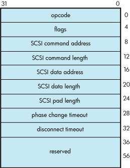
|
| p2 | Length of the generic SCSI descriptor. |
Descriptor Fields
| opcode | Currently, the only supported opcode is 1, indicating a pass-through function. Other opcode values are reserved for future expansion. | |
| flags |
Bit map having the following format: 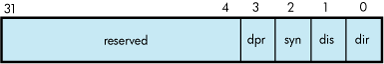
Bits in the flags bit map are defined as follows: | |
| Field | Definition | |
| dir |
Direction of transfer. If this bit is set, the target is expected at some time to enter the DATA IN phase to send data to the host. To facilitate this, the port driver maps the specified data buffer for write access. If this bit is clear, the target is expected at some time to enter the DATA OUT phase to receive data from the host. To facilitate this, the port driver maps the specified data buffer for read access. The generic SCSI class driver ignores the dir flag if either the SCSI data address or SCSI data length field of the generic SCSI descriptor is zero. | |
| dis |
Enable disconnection. If this bit is set, the target device is allowed to disconnect during the execution of the command. If this bit is clear, the target cannot disconnect during the execution of the command. Note that targets that hold on to the bus for long periods of time without disconnecting can adversely affect system performance. See Section 8.5.2, ''Enabling Disconnection and Reselection'' for additional information. | |
| syn |
Enable synchronous mode. If this bit is set, the port driver uses synchronous mode for data transfers, if both the host and target allow this mode of operation. If this bit is clear, or synchronous mode is not supported by either the host or target, the port driver uses asynchronous mode for data transfers. See Section 8.5.1, ''Setting the Data Transfer Mode'' for additional information. | |
| dpr |
Disable port retry. If this bit is clear, the port driver retries, up to three times, any command that fails with a timeout, bus parity, or invalid phase transition error. If this bit is set, the port driver does not retry commands for which it detects failure. See Section 8.5.3, ''Disabling Command Retry'' for additional information. | |
| SCSI command address | Address of a buffer containing a SCSI command. | |
| SCSI command length | Length of the SCSI command. The maximum length of the SCSI command is 128 bytes. | |
| SCSI data address |
Address of a data buffer associated with the SCSI command. If the dir bit is set in the flags field, data is written into this buffer during the execution of the command. Otherwise, data is read from this buffer and sent to the target device. If the SCSI command requires no data to be transferred, then the SCSI data address field should be clear. | |
| SCSI data length |
Length, in bytes, of the data buffer pointed to by the SCSI data addressfield. The maximum data buffer size is 65,535 bytes. If the SCSI command requires no data to be transferred, then this field should be clear. | |
| SCSI pad length |
This field is used to accommodate SCSI device classes that require that the transfer length be specified in terms of a larger data unit than the count of bytes expressed in the SCSI data length field. If the total amount of data requested in the SCSI command does not match that specified in the SCSI data length field, this field must account for the difference. For example, suppose an application program is using the generic class driver to read the first 2 bytes of a disk block. The length field in the SCSI READ command contains 1 (indicating one logical block, or 512 bytes), while the SCSI data length field contains a 2. The SCSI pad length field must contain the difference, 510 bytes. For most transfers, this field should contain 0. Failure to initialize the SCSI pad length field properly causes port driver timeouts and SCSI bus resets. | |
| phase change timeout |
Maximum number of seconds for a target to change the SCSI bus phase or complete a data transfer. A value of 0 causes the SCSI port driver's default phase change timeout value of 4 seconds to be used. See Section 8.5.4, ''Setting Command Timeouts'' for additional information. | |
| disconnect timeout |
Maximum number of seconds for a target to reselect the initiator to proceed with a disconnected I/O transfer. A value of 0 causes the SCSI port driver's default disconnect timeout value of 4 seconds to be used. See Section 8.5.4, ''Setting Command Timeouts'' for additional information. | |
8.9. Generic SCSI Class Driver Device Information
A call to the Get Device/Volume Information ($GETDVI) system service returns the following information for any device serviced by the generic SCSI class driver. (See the description of the $GETDVI system service in the VSI OpenVMS System Services Reference Manual.)
$GETDVI returns the following device characteristics when you specify the item code DVI$_DEVCHAR:
| DEV$M_AVL | Available device |
| DEV$M_IDV | Input device |
| DEV$M_ODV | Output device |
| DEV$M_SHR | Shareable device |
| DEV$M_RND | Random-access device |
DVI$DEVCLASS returns the device class, which is DC$_MISC; DVI$DEVTYPE returns the device type, which is DT$_GENERIC_SCSI.
8.10. Call a Generic SCSI Class Driver
Example 8.1, ''Generic SCSI Class Driver Call Example'' is an application that uses the generic SCSI class driver to send a SCSI INQUIRY command to a device.
/*
**
* © 2017 Hewlett-Packard Development Company, L.P.
*
* Confidential computer software. Valid license from HPE and/or its
* subsidiaries required for possession, use, or copying.
*
* Consistent with FAR 12.211 and 12.212, Commercial Computer Software,
* Computer Software Documentation, and Technical Data for Commercial Items
* are licensed to the U.S. Government under vendor's standard commercial
* license.
*
* Neither HPE nor any of its subsidiaries shall be liable for technical or
* editorial errors or omissions contained herein. The information in this
* document is provided "as is" without warranty of any kind and is subject
* to change without notice. The warranties for HPE products are set forth
* in the express limited warranty statements accompanying such products.
* Nothing herein should be construed as constituting an additional
* warranty.
*
*/

#ifdef VAX
#module gktest "V01-03"
#else
#pragma module gktest "V01-03"
#endif

/*
**++
**  FACILITY:  SYS$EXAMPLES
**
**  MODULE DESCRIPTION:
**
**  GKTEST -- Generic SCSI device inquiry example.  This program
**  uses the SCSI generic class driver to send an inquiry command
**  to a device on the SCSI bus and send the resulting status to
**  stdout.  PHY_IO and DIAGNOSE privileges are needed to run this
**  program.
**


**  AUTHORS:
**
**      Hewlett-Packard
**
**  CREATION DATE:  28-Aug-2017  (adapted from previous OpenVMS version)
**
**  DESIGN ISSUES:
**
**  To be appropriately upwardly-compatible, it would be better
**  that this module use a SCSI descriptor structure definition
**  from an appropriate header file (something like scsidef.h).
**  At the time of most recent modification, no such file was
**  available for OpenVMS.
**
**
**  MODIFICATION HISTORY:
**
**  X-1 DCP001                  28-Aug-2017
**  Use structure members that are more "type-sensitive".
**
**  X-2 DCP002                  11-Sep-2017
**  Modifications to platform-specific macro names.
**  X-3                     05-Oct-2017
**  Modify status checking to return proper error code from
**  $qio.
**--
*/


/*
**
**  INCLUDE FILES
**
*/

#include <stdio.h>
#include <ctype.h>
#include <iodef.h>
#include <descrip.h>
#include <starlet.h>

/*
**  "De-comment" (and if necessary modify) the following if the
**  appropriate header file becomes available:
#include <scsidef.h>
*/


/*
**
**  MACRO DEFINITIONS
**
*/


#define GK_EFN 0            /*  Event flag number */

#define INQUIRY_OPCODE 0x12     /*  Operation code for SCSI inquiry */
#define INQUIRY_DATA_LENGTH 0x24    /*  Length of inquiry buffer */


/*
** SCSI definitions:
**
** Ideally, these definitions should come from a header file provided
** with the system.  At the time that this example was written and at
** the time of last update, no such file was available. For now, we
** define right here fields we need from the SCSI descriptor for this
** example; this should be replaced with the appropriate #include,
** should such a header file become available.  The reader should note
** that some of the field names and types in that header file may
** differ slightly from what's shown here; when and if the header file
** becomes available, code which does depend on the names should use
** the appropriate header file names.  Code which depends on getting
** the types right may need to re-cast these members when referencing
** them.
*/

/* Generic SCSI command descriptor */

struct SCSI$DESC {
    unsigned int    SCSI$L_OPCODE;       /* SCSI Operation Code */
    unsigned int    SCSI$L_FLAGS;        /* SCSI Flags Bit Map */
    char    * SCSI$A_CMD_ADDR;       /* ->SCSI command buffer */
    unsigned int    SCSI$L_CMD_LEN;      /* SCSI command length, bytes */
    char    * SCSI$A_DATA_ADDR;      /* ->SCSI data buffer */
    unsigned int    SCSI$L_DATA_LEN;     /* SCSI data length, bytes */
    unsigned int    SCSI$L_PAD_LEN;      /* SCSI pad length, bytes */
    unsigned int    SCSI$L_PH_CH_TMOUT;  /* SCSI phase change timeout, sec */
    unsigned int    SCSI$L_DISCON_TMOUT; /* SCSI disconnect timeout, sec */
    unsigned int    SCSI$L_RES_1;        /* Reserved */
    unsigned int    SCSI$L_RES_2;        /* Reserved */
    unsigned int    SCSI$L_RES_3;        /* Reserved */
    unsigned int    SCSI$L_RES_4;        /* Reserved */
    unsigned int    SCSI$L_RES_5;        /* Reserved */
    unsigned int    SCSI$L_RES_6;        /* Reserved */
    } ;

/* SCSI Input/Output Status Block */

#ifdef __ALPHA
#pragma member_alignment save
#pragma nomember_alignment
#endif

struct SCSI$IOSB {
    unsigned short int  SCSI$W_VMS_STAT;        /* VMS status code */
    unsigned long int   SCSI$L_IOSB_TFR_CNT; /* Actual #bytes transferred */
    char    SCSI$B_IOSB_FILL_1;
    unsigned char   SCSI$B_IOSB_STS;        /* SCSI device status */
    };

#ifdef __ALPHA
#pragma member_alignment restore
#endif


/* SCSI status codes and flag field constants */

#define SCSI$K_GOOD_STATUS      0
#define SCSI$K_READ     0X1 /* direction of transfer=read */
#define SCSI$V_FL_ENAB_DIS  1   /* enable disconnects */
#define SCSI$K_FL_ENAB_DIS  0X2 /* enable disconnects */

/* end of SCSI definitions */

/* data declarations */

char scsi_status,
     inquiry_command[6] = {INQUIRY_OPCODE, 0, 0, 0,
                 INQUIRY_DATA_LENGTH, 0},
     inquiry_data[INQUIRY_DATA_LENGTH],
     gk_device[] = {"GKA0"};


main ()

{

    unsigned short int gk_chan,
               transfer_length;
    int i,
    status;


/* Set up the descriptor with the SCSI information to be sent to the target */

    struct SCSI$DESC gk_desc = { 1,  /* Pass-through - the only code defined */
                 SCSI$K_READ|SCSI$K_FL_ENAB_DIS, /* flags   */
                 &inquiry_command[0],   /* command addr */
                 6,         /* command length*/
                 &inquiry_data[0],  /* data addr */
                 INQUIRY_DATA_LENGTH,   /* data length */
                 0,         /* pad length */
                 180,           /* phase timeout */
                 60,            /* disconnect timeout */
                 0, 0, 0, 0, 0, 0 };    /* reserved */

    struct SCSI$IOSB gk_iosb ;

    $DESCRIPTOR (gk_device_desc, gk_device);

/*  Assign the device channel */
    status = sys$assign ( &gk_device_desc,  &gk_chan,  0,  0);
    if (!(status & 1))
    {
        printf ("Unable to assign channel to %s", &gk_device[0]);
    sys$exit (status);
    }

/* Issue the QIO to send the inquiry command and receive the inquiry data */

    status = sys$qiow ( GK_EFN,  gk_chan,  IO$_DIAGNOSE,  &gk_iosb,  0,  0,
                      &gk_desc,  15*4,  0,  0,  0,  0);


/* Check the various returned status values */
    if (!(status & 1))  sys$exit (status);


/* Was VMS Status OK from QIO? */

    if (!(gk_iosb.SCSI$W_VMS_STAT & 1))
        sys$exit (gk_iosb.SCSI$W_VMS_STAT);

/* Yes, was SCSI Status OK from QIO? */

    if (gk_iosb.SCSI$B_IOSB_STS != SCSI$K_GOOD_STATUS)
    {
        printf ("Bad SCSI status returned: %02.2x\n", gk_iosb.SCSI$B_IOSB_STS);
    sys$exit (1);
    }

/* The command succeeded. Display the SCSI data returned from the target */

    transfer_length = gk_iosb.SCSI$L_IOSB_TFR_CNT;
    printf ("SCSI inquiry data returned %lu bytes of data: ", transfer_length);
    for (i=0;  i<transfer_length;  i++)
    {
        if (isprint (inquiry_data[i]))
            printf ("%c", inquiry_data[i]);
        else
            printf (".");
    }
    printf ("\n");
}
Chapter 9. Local Area Network (LAN) Device Drivers
This chapter describes the use of LAN drivers that support the LAN devices listed in the Software Product Description for the OpenVMS Operating System (SPD 82.35.xx). Most of the LAN devices are described here, but see the Software Product Description for the OpenVMS Operating System for the definitive list of supported devices.
The LAN drivers support two user interfaces or APIs, QIO and VCI (VMS Communications Interface). This chapter describes the QIO interface to the LAN drivers, primarily. But most of the QIO functionality applies to the VCI interface as well. And the description of the other features and characteristics of the LAN devices and LAN drivers applies equally to either interface.
The LAN drivers are composed of a set of LAN common routines that implement the user interfaces plus a LAN port driver for each different type of LAN device. The LAN drivers comprise the Data Link layer as defined by the OSI Model defined in Section 9.1, ''Local Area Network (LAN) Terminology''.
9.1. Local Area Network (LAN) Terminology
The following is a list of terms relevant to local area networks:
Ethernet — A network communications technology using coaxial or twisted-pair cable, originally developed by Intel, Xerox, and Digital. It has a data transmission rate of 10 megabits/second. It is characterized by the use of the CSMA/CD network access method. It is described by the IEEE 802.3 standard. Ethernet is also used as an adjective to describe Ethernet characteristics, such as an Ethernet address, or an Ethernet application.
Fast Ethernet — Ethernet operating at 100 megabits/second over twisted-pair cable or multimode fiber. Fast Ethernet devices support 10 and 100 megabits/second operation over twisted-pair media or 100 megabits/second over multimode fiber.
Gigabit Ethernet — Ethernet operating at 1000 megabits/second over twisted-pair cable or multimode fiber. Gigabit Ethernet devices support 10, 100, and 1000 megabits/second operation over twisted-pair media or 1000 megabits/second over multimode fiber.
FDDI — Fiber Distributed Data Interface, a token-passing network communications technology characterized by use of a dual ring configuration to improve availability upon failure of a node or connection. It has a data transmission rate of 100 megabits/second. It operates over multimode fiber or twisted-pair cable. It is described by the American National Standards Institute (ANSI) standard X3T9.5.
Token Ring — A token-passing network communications technology characterized by a star topology in most implementations. It has a data transmission rate of 4 or 16 megabits/second. It operates over twisted-pair cable. It is described by the IEEE 802.5 standard.
ATM — Asynchronous Transfer Mode, a cell-based network communications technology, where network data is divided into 48-byte chunks and transferred across the network with a 5-byte header that contains addressing and control information. The ATM Forum describes the communications protocol, and specifies how it is to be used to interoperate with Ethernet networks, in the LAN Emulation (LANE) standard. To interoperate with Ethernet, the ATM device hardware transparently breaks transmit packets into 48-byte chunks and adds a 5-byte header and transmits the cells onto the ATM network. On receive, it transparently re-assembles the 48-byte chunks to construct each receive packet.
IEEE — Institute of Electrical and Electronics Engineers, an organization that, among other activities, develops and maintains standards for the computer and electronics industries, including the 802 standards that define local area networking.
ANSI — American National Standards Institute, an organization that develops and maintains standards for the computer and communications industries
802.3 — The IEEE standard for Ethernet network technology, including 802.3u for Fast Ethernet, and 802.3z for Gigabit Ethernet.
802.5 — The IEEE standard for Token Ring network technology.
CSMA/CD — Carrier Sense Multiple Access with Collision Detection, the network access protocol used on half-duplex Ethernet networks to resolve contention between nodes competing for access to the network medium.
NIC — Network Interface Card. Other terms that may be used interchangeably include Adapter, Controller, Device, Card, Port. LAN On Motherboard (LOM) is a variant where the NIC hardware is included on a system board. A multiport adapter consists of multiple adapters on one card, so, for example, a quad Ethernet NIC may be referred to as a 4-port card. A combo adapter consists of multiple adapters, some Ethernet and some storage, SCSI or Fibre Channel.
Bus — Data and control paths that connect the functional units of a computer. In relation to LAN devices, it refers to the hardware interface between the CPU and the I/O devices. Each LAN device connects to a particular type of bus, such as PCI, PCI-X, PCI-Express, EISA, ISA, XMI, TurboChannel, each of which typically has multiple slots to accommodate several I/O devices.
Duplex — A characteristic of a 2-way communication channel that indicates whether the channel can allow transmission in both directions at the same time (full-duplex) or not (half-duplex).
Flow Control — A technique where the flow of data along a communications channel is adjusted to ensure that the receiving side can handle incoming data without loss. Many network applications implement flow control techniques in software. Here, this term refers to the implementation of flow control in hardware independent of the network application or protocol, as specified by the IEEE 802.3x standard. The receiver side hardware sends special packets, called pause frames, that asks the transmitting side to stop transmitting for a certain amount of time. When the receiver has caught up, it sends a pause frame with a zero time to re-enable the transmitter.
Packet — A unit of data transmission on the network, also called frame. It consists of a header, body of data, and a Cyclic Redundancy Check (CRC). The frame may be encapsulated by additional data needed for the particular network technology. Note that LAN Emulation over ATM imposes packet concepts over the underlying cell-based network technology.
Jumbo Frames — Oversize Ethernet packets, where the range of sizes on Ethernet is from 64-1518 bytes, jumbo frames are packets ranging in size from 1519 to 9216 bytes depending on the hardware and software implementation.
Link Up/Down — Network connection state, for Ethernet devices. Most Ethernet devices that connect to twisted-pair cables have the ability to detect if an active link connection exists. When both ends of the network connection can detect a valid connection, the link is considered to be 'up' and the Ethernet device is capable of using the network channel to transmit and receive packets. When the Ethernet device cannot detect a valid connection, the link is considered 'down' and the device will not transmit or receive over the network communications path.
Ring Available/Unavailable — Network connection state, for FDDI, Token Ring, or ATM devices.
Open Systems Interconnect (OSI) Model — Defines the following seven layers in a networking framework:
(7) Application Layer
(6) Presentation Layer
(5) Session Layer
(4) Transport Layer
(3) Network Layer
(2) Data Link Layer
(1) Physical Layer
Port — One end of a communications channel, or the channel itself. When correlated to the OSI Model, port may refer to a communications channel at various layers. At the physical layer, a port is a LAN device, so a quad Ethernet device is said to be a 4-port card. At the data link layer, the LAN drivers allow multiple applications to run on one LAN device. Each application will have opened a port to the LAN driver. At the application layer, an application may allow multiple ports to be opened to it, with the application itself doing the multiplexing of the ports through itself to the underlying network. An example of this would be a network application written to send and receive data over a TCP/IP port.
In this chapter, applications open a port to the LAN driver to communicate over a particular LAN device. In OpenVMS terms, opening a port is done by assigning a channel.
User — Refers to the application that has opened a port to the LAN driver. A LAN device may be described as having a number of different users. Each user would have opened a port to the LAN device. Examples of users are LAT, TCP/IP, DECnet, Clusters (NISCA).
In this chapter, the terms application and user may be used interchangeably.
9.2. Supported LAN Devices
Table 9.1, ''Supported OpenVMS IA-64 server Systems LAN Devices, Part 1'' and Table 9.2, ''Supported OpenVMS IA-64 server Systems LAN Devices, Part 2'' show the LAN devices supported by the OpenVMS IA-64 server operating system. Table 9.2, ''Supported OpenVMS IA-64 server Systems LAN Devices, Part 2'' lists additional information for the devices listed in Table 9.1, ''Supported OpenVMS IA-64 server Systems LAN Devices, Part 1''. Most of the LAN devices are described here, but see the Software Product Description for the OpenVMS Operating System (SPD 82.35.xx) for the definitive list of supported devices.
| Medium | Medium Type | I/O Bus | Device Name |
OpenVMS Name |
DECnet Name | OpenVMS Device Type |
|---|---|---|---|---|---|---|
| Ethernet | 100BaseTX | PCI | A5230A | EW | EWA | DT$_EW_DE500 |
| Ethernet | 4x100BaseTX | PCI | A5506B | EW | EWA | DT$_EW_DE500 |
| Ethernet | 100BaseTX | PCI | 82559 (LOM) | EW | EWA | DT$_EI_82559 |
| Ethernet | 1000BaseSX | PCI-X | A6847A | EW | EWA | DT$_EW_BCM5701 |
| Ethernet | 1000BaseTX | PCI-X | A6825A | EW | EWA | DT$_EW_BCM5701 |
| Ethernet | 2x1000BaseSX | PCI-X | A7011A | EI | EIA | DT$_EI_82540 |
| Ethernet | 2x1000BaseTX | PCI-X | A7012A | EI | EIA | DT$_EI_82540 |
| Ethernet | 1000BaseTX | PCI-X | Intel 82546 (LOM) | EI | EIA | DT$_EI_82540 |
| Ethernet | 1000BaseSX | PCI-X | AB352A | EW | EWA | DT$_EW_BCM5703 |
| Ethernet | 1000BaseSX | PCI-X | A9782A | EW | EWA | DT$_EW_BCM5703 |
| Ethernet | 1000BaseTX | PCI-X | A9784A | EW | EWA | DT$_EW_BCM5703 |
| Ethernet | 1000BaseTX | PCI-X | AB290A | EW | EWA | DT$_EW_BCM5703 |
| Ethernet | 2x1000BaseTX | PCI-X | AB465A | EW | EWA | DT$_EW_BCM5704 |
| Ethernet | 1000BaseTX | PCI | BCM5701 (LOM) | EW | EWA | DT$_EW_BCM5701 |
| Ethernet | 1000BaseT | PCI-e | AD337A | EI | EIA | DT$_EI_82540 |
| Ethernet | 1000BaseSX | PCI-e | AD338A | EI | EIA | DT$_EI_82540 |
| Ethernet | 1000BaseT | PCI-e | AD339A | EI | EIA | DT$_EI_82540 |
| Ethernet | 2-p 1Gb Mezz | PCI-e | NC360M | EI | EIA | DT$_EI_82540 |
| Ethernet | 4-p GbE Mezz | PCI-e | NC364M | EI | EIA | DT$_EI_82540 |
| Device | OpenVMS Device Type |
OpenVMS Version | Driver Name |
|---|---|---|---|
| A5230A | DT$_EW_DE500 | V8.2 | SYS$EWDRIVER_DE500BA.EXE |
| A5506B | DT$_EW_DE500 | V8.2 | SYS$EWDRIVER_DE500BA.EXE |
| 82559 (LOM) | DT$_EI_82559 | V8.2 | SYS$EIDRIVER.EXE |
| A6847A | DT$_EW_BCM5701 | V8.2 | SYS$EW5700.EXE |
| A6825A | DT$_EW_BCM5701 | V8.2 | SYS$EW5700.EXE |
| A7011A | DT$_EI_82540 | V8.2 | SYS$EI1000.EXE |
| A7012A | DT$_EI_82540 | V8.2 | SYS$EI1000.EXE |
| Intel 82546 (LOM) | DT$_EI_82540 | V8.2 | SYS$EI1000.EXE |
| AB352A | DT$_EI_82540 | V8.2 | SYS$EI1000.EXE |
| A9782A | DT$_EW_BCM5703 | V8.2 | SYS$EW5700.EXE |
| A9784A | DT$_EW_BCM5703 | V8.2 | SYS$EW5700.EXE |
| AB290A | DT$_EW_BCM5703 | V8.2 | SYS$EW5700.EXE |
| AB465A | DT$_EW_BCM5703 | V8.2 | SYS$EW5700.EXE |
| BCM5701 (LOM) | DT$_EW_BCM5701 | V8.2 | SYS$EW5700.EXE |
| BCM5703 (LOM) | DT$_EW_BCM5703 | V8.2 | SYS$EW5700.EXE |
| BCM5704 (LOM) | DT$_EW_BCM5704 | V8.2 | SYS$EW5700.EXE |
| AB545A | DT$_EI_82540 | V8.2 | SYS$EI1000.EXE |
| AD193A | DT$_EI_82540 | V8.3 | SYS$EI1000.EXE |
| AD194A | DT$_EI_82540 | V8.3 | SYS$EI1000.EXE |
| AD331A | DT$_EI_82540 | V8.3 | SYS$EI1000.EXE |
| AD332A | DT$_EI_82540 | V8.3 | SYS$EI1000.EXE |
| AD337A | DT$_EI_82540 | V8.3–1H1 | SYS$EI1000.EXE |
| AD338A | DT$_EI_82540 | V8.3 | SYS$EI1000.EXE |
| AD339A | DT$_EI_82540 | V8.3 | SYS$EI1000.EXE |
| NC360M | DT$_EI_82540 | V8.3 | SYS$EI1000.EXE |
| NC364M | DT$_EI_82540 | V8.3 | SYS$EI1000.EXE |
Note
A5230A is a DE500-BA equivalent made by Adaptec.
A5506B is a DE504-BA equivalent made by IntraServer.
A9782A and A9784A are combo Qlogic FibreChannel plus Gigabit Ethernet devices.
AB465A is a combo dual Qlogic FibreChannel plus dual Gigabit Ethernet device.
AD193A and AD194A are combo Qlogic FibreChannel plus Gigabit Ethernet devices.
BCM5701 (LOM) is embedded in the rx2600 and rx8620 systems.
BCM5703 (LOM) is embedded in the rx8640 systems.
BCM5704 (LOM) is embedded in the rx2660 and BL860c systems.
Intel 82546 (LOM) is embedded in the rx1620 and rx2620 systems.
100BaseTX devices can do 10BaseT as well.
1000BaseTX devices can do 10BaseT and 100BaseTX as well.
1000BaseSX is 1000 Mb/s multimode fiber.
9.3. Supported Industry Standards
Ethernet drivers support the following features and standards:
Ethernet and IEEE 802.3 packet format
Physical layer identified as 10Base5 (ThickWire), 10Base2 (ThinWire), and 10BaseT (twisted-pair)
Fast Ethernet physical layer identified as type 100BaseTX
Gigabit Ethernet physical layer identified as 1000BaseT for unshielded twisted-pair (UTP), 1000BaseSX for multimode fiber-optic cables
Gigabit and 10 Gigabit Ethernet implementation of jumbo frames, a de facto industry standard using a maximum frame size larger than the standard Ethernet maximum of 1518 bytes, generally up to 9018 bytes
FDDI drivers support the following features and standards:
FDDI packet format
Transmission and reception of frame control (FC) priority
ANSI X3.139-1987 FDDI Media Access Control (MAC)
ANSI X3.148-1988 FDDI Physical Layer Protocol (PHY)
ANSI X3.166-1990 FDDI Physical Layer Medium Dependent (PMD)
Token Ring drivers support the following features and standards:
IEEE 802.5 packet format
Transmission and reception of priority bits in the access control (AC) field and the frame control (FC) field
Transmission of source routing header information
Reception of route information (RI)
ATM drivers over ELAN support the following features and standards:
Ethernet and IEEE 802.3 packet format
UNI Version 3.0 or 3.1 signaling protocol
LAN emulation (LANE) Version 1.0
Maximum frame sizes of 1516, 4544, and 9234 bytes
All LAN drivers support the following features:
802.2 packet format
IEEE 802.2 Class I service including the unnumbered information (UI), exchange identification (XID) commands and responses, and TEST commands and responses
IEEE 802.2 Class II service may be specified where the functions are provided by the user application
Six-byte destination and source address fields
9.4. LAN I/O Architecture
The OpenVMS LAN software employs a class/port driver architecture to allow LAN applications to communicate with other nodes over the LAN device and the network.
The class driver is implemented by a collection of execlets known as the LAN common routines. The LAN common routines implement two APIs, QIO and VCI. LAN applications interface to the LAN device port drivers using these APIs in a common manner across each type of LAN (Ethernet, FDDI, Token Ring, ATM, and Shared Memory). An execlet for each LAN medium minimizes the differences between them so applications can operate transparently over different types of LANs. LAN over ATM emulates Ethernet and uses the Ethernet LAN common routines. ATM needs a significant amount of additional support code to provide LAN emulation (LANE) and Classical IP (CLIP) support. This support code is located in an ATM execlet. LAN over Shared Memory also emulates Ethernet and uses the Ethernet LAN common routines. No additional support code is needed for Shared Memory.
The port drivers operate the LAN hardware, and there is one port driver for each type of LAN device. Many of the port drivers operate multiple variations of similar hardware. One port driver for ATM emulates Ethernet and another emulates IP (called Classical IP). The port driver for Shared Memory emulates Ethernet. Unlike the port drivers that directly control LAN hardware, the emulated port drivers are pseudo drivers that implement a pseudo hardware interface in software.
When correlated to the OSI Model, the LAN implementation occupies the bottom two layers, the LAN common routines and LAN port drivers constitute the Data Link Layer, and the LAN device hardware the Physical Layer and parts of the Data Link Layer. The LAN drivers are often called the data link drivers.
9.4.1. LAN Data Structures
The OpenVMS I/O subsystem describes devices in terms of a Unit Control Block (UCB). There is a UCB for each device, which may be an actual physical device or a pseudo or virtual device. LAN devices include physical devices, NICs located in PCI buses, for example; and virtual devices, a shared memory emulated Ethernet device, an ATM emulated LAN device, a LAN Failover device, or a VLAN device. The LAN drivers define an extension to the standard VMS UCB that includes additional fields needed to provide LAN context.
When a LAN application wants to use a LAN device, it assigns a channel (opens a port) to the UCB associated with the LAN device. When this occurs, the VMS I/O subsystem makes a copy of the device UCB and associates the channel with this cloned UCB. Then the application can activate the channel by specifying the desired characteristics of the channel, such as protocol type and what multicast addresses to enable. The unit 0 UCB is called the template UCB. Each non-zero UCB represents a channel to the device and contains application-specific channel characteristics.
Each LAN driver also maintains another structure, the LAN Station Block (LSB), which contains LAN common information as well as device-specific data. For each LAN device there is one LSB and a corresponding unit 0 UCB. The LSB contains device-specific data the would be inappropriate to include in the UCB structures such as device rings and device counters.
In summary, the UCBs contain application-specific data. The LSBs contain device and driver-specific data. There is one LSB and one template UCB per LAN device that are created and initialized during device discovery. Whenever an application opens a channel to a particular LAN device, the template UCB is cloned to a newly created cloned UCB which represents the channel. There is one cloned UCB for each channel. When the channel is deassigned, the cloned UCB ceases to exist along with any context associated with the channel.
Additional data structures are defined to allow applications to send and receive I/O requests to the LAN drivers, as described in the following QIO and VCI sections.
9.4.2. Hardware Configuration
When the system boots, system support code probes the I/O buses looking for I/O devices. On Alpha and IA-64 server systems, device configuration is done by comparing device IDs found during bus probing with entries in the file SYS$SYSTEM:SYS$CONFIG.DAT. This file includes the set of supported LAN devices on Alpha and IA-64 server systems, as well as entries for other I/O devices supported such as SCSI, FibreChannel, USB, ATA and others.
9.4.3. Software Modules
OpenVMS LAN software consists of LAN common routines, LAN port drivers, LAN Control Programs, and LAN diagnostic software listed in Table 9.3, ''LAN Software Module''.
| Location | Module | Architecture | Function |
|---|---|---|---|
|
SYS$LOADABLE_ | SYS$LAN.EXE | Alpha, IA-64 servers | LAN common routines, common across all media types |
|
SYS$LOADABLE_ | SYS$LAN_CSMACD.EXE | Alpha, IA-64 servers | LAN common routines, Ethernet-specific support |
|
SYS$LOADABLE_ | SYS$LAN_FDDI.EXE | Alpha | LAN common routines, FDDI-specific support |
|
SYS$LOADABLE_ | SYS$LAN_TR.EXE | Alpha | LAN common routines, Token ring-specific support |
|
SYS$LOADABLE_ | SYS$LAN_ATM.EXE | Alpha | LAN common routines, ATM-specific support |
|
SYS$LOADABLE_ | NET$CSMACD.EXE | Alpha, IA-64 servers | DECnet-Plus network management support routines for Ethernet |
|
SYS$LOADABLE_ | NET$FDDI.EXE | Alpha | DECnet-Plus network management support routines for FDDI |
| SYS$SYSTEM | SYS$CONFIG.DAT | Alpha, IA-64 servers | Device ID entries for file-based device configuration |
| SYS$SYSTEM | LANCP.EXE | Alpha, IA-64 servers | LAN Control Program |
| SYS$SYSTEM | LANACP.EXE | Alpha, IA-64 servers | LAN Auxiliary Control Program, including MOP server |
| SYS$LIBRARY | SDA$SHARE.EXE | Alpha, IA-64 servers | System Dump Analyzer or System Analyzer |
| SYS$LIBRARY | LAN$SDA.EXE | Alpha, IA-64 servers | SDA extension for LAN drivers |
|
SYS$LOADABLE_ | LAN port drivers | Alpha, IA-64 servers | LAN port drivers |
The NET$ modules are only loaded when DECnet-Plus is configured on the system. SYS$CONFIG.DAT includes LAN devices as well as any other I/O devices. LAN support represents only a small portion of the SDA.EXE and SDA$SHARE.EXE images.
On Alpha and IA-64 servers, these routines are separate execlets.
9.4.4. Application APIs
The LAN common routines provide two APIs to allow applications to interface to the LAN drivers and ultimately to send and receive data over the network. The APIs allow an application to initialize a port (assign a channel), send a packet over the port, receive a packet from the port, and do other management functions such as set port characteristics, obtain port characteristics and counters, and to shut down the port (deassign the channel).
The APIs are:
QIO — An unprivileged interface to the LAN drivers, designed for user mode code.
VCI — A privileged interface to the LAN drivers that runs in kernel mode at IPL 8, designed to be very efficient.
9.4.4.1. QIO API
The QIO API is implemented in the LAN common routines to interface between an application and the LAN port driver in user mode. The QIO subsystem passes I/O requests from the application to the LAN driver. The LAN driver performs the requested I/O and returns status and data to the application.
An application calls SYS$QIO with a function code, function modifiers, and addresses of buffers that provide any information needed, such as a buffer containing transmit data, transmit header data, a buffer to contain receive data and receive header data, and buffers for setmode and sensemode functions. This information is passed to the LAN driver via the P1-P6 QIO parameters.
The LAN common routines translate the I/O function in the QIO request to a transmit, receive, sensemode, setmode, or diagnose operation and passes the request on to the LAN port driver.
The LAN port driver does the transmit request, retrieves the receive packet, collects sensemode data, sets characteristics, or does the diagnose function, and passes the results back through the LAN common routines, back through the QIO subsystem, and back to the application.
QIO operations do buffered I/O. This, in addition to considerable validation of the QIO request, makes for a robust user mode interface, but less efficient from a performance standpoint than the VCI interface.
9.4.4.1.1. QIO Program Operation
The following sequence shows a typical application sequence, to start a port, do transmits and receives, then shut down a port:
Use the Assign I/O Channel ($ASSIGN) system service to assign I/O channels to one or more of the LAN device names and devices specified in Title not available through Table 9.3, ''LAN Software Module''. $ASSIGN creates a new unit control block (UCB), to which the channel for the port is assigned.
Start the port with the set mode function and startup function modifier (see Section 9.7.3.1, ''Set Controller Mode''. You must supply the required P2 buffer parameters listed in Table 9.33, ''P2 Attributes'').
Perform read, write, and sense mode operations as needed.
Shut down the port with the set mode function and shutdown function modifier (see Section 9.7.4, ''Shutdown Controller'').
Use the Deassign I/O Channel ($DASSGN) system service to deassign the I/O channel.
The sample programs described in Section 9.8.2, ''Local Area Network Programming Examples'' illustrate a QIO implementation.
9.4.4.2. VCI API
The VCI API is implemented in the LAN common routines to interface between the application and the LAN port driver in kernel mode at IPL 8. The VCI application calls VCI routines in kernel mode at IPL 8. The VCI routines are part of the LAN common routines. There are routines to initiate a port management request (to start, stop, and change a port) and to initiate a transmit request. The VCI application provides routines that the LAN common routines calls for transmit, receive, and port management completion.
An applications calls a VCI initiation routine with an I/O request that contains the transmit buffer or pointers to the transmit data, or the port management buffer data.
The LAN common routines process the transmit or port management request and passes the request on to the LAN port driver.
The LAN port driver does the transmit request, or sets characteristics, and passes the results back through the LAN common routines, and back to the VCI application by calling the application's completion routine. When a receive packet arrives, the LAN common routines passes the receive buffer to the VCI application by calling the application's receive completion routine. When the application has completed processing the receive data, it returns the receive buffer to the LAN common routines by calling a return receive buffer routine.
VCI operations do direct I/O, avoiding buffer copies in most cases. VCI applications are considered trusted applications, so must abide by the VCI specification to gain that trust and to ensure system integrity is maintained operating in kernel mode with privileges.
9.4.5. LAN Addressing
Each LAN device is identified by a hardware address that is intended to uniquely identify the LAN device and local system as a node on the network. The hardware address is a 48-bit address known as a MAC address or Ethernet address.
Ethernet addresses are represented by the Ethernet standard as six pairs of hexadecimal digits (six bytes), separated by hyphens (for example, AA-01-23-45-67-FF). The bytes are displayed from left to right in the order in which they are transmitted; bits within each byte are transmitted from right to left. In this example, byte AA is transmitted first; byte FF is transmitted last. (See the description of NMA$C_PCLI_PHA in Table 9.33, ''P2 Attributes'', Section 9.7.3.1, ''Set Controller Mode'', for the internal representation of addresses.)
For Token Ring networks, the address is often given in bit-reversed form, called canonical format, separated by colons. For example, AA-01-23-45-67-FF in canonical format is 55:80:C4:A2:E6:FF.
Upon application, IEEE assigns a block of addresses to a producer of LAN nodes. Thus, every manufacturer has a unique set of addresses to use. Normally, one address out of the assigned block of physical addresses is permanently associated with each device (usually in read-only memory). This address is known as the hardware address or MAC address of the device. Each individual device has a unique hardware address.
9.4.5.1. Ethernet Address Classifications
An Ethernet address can be a physical address of a single node or a multicast address, depending on the value of the low-order bit of the first byte of the address (this bit is transmitted first). Following are the two types of node addresses:
Physical address—The unique address of a single node on a LAN. The least significant bit of the first byte of a physical address is 0. (For example, in physical address AA-00-03-00-FC-00, byte AA in binary is 1010 1010, and the value of the low-order bit is 0.) This is also called an individual address or unicast address.
Multicast address—A multi-destination address of one or more nodes on a given LAN. The least significant bit of the first byte of a multicast address is 1. (For example, in the multicast address 0B-22-22-22-22-22, byte 0B in binary is 0000 1011, and the value of the low-order bit is 1. This is the first bit of the address as transmitted over the wire.)
9.4.5.2. Selecting an Ethernet Physical Address
The OpenVMS interface to the LAN controllers allows you to set a physical address of the controller. The selection of the physical address of a LAN controller is different for Ethernet and FDDI.
For Ethernet, all users of the controller must agree on this address. The first user of the controller chooses the physical address; any additional users of the controller must specify either the same physical address, no physical address, or change the address (if allowed). When all channels to the controller are shut down, the next user to start a channel chooses the physical address. The controller's physical address is always chosen on the first successful startup when there are no active ports. If the address is not chosen at this time, the controller's hardware address is used as the physical address.
For Ethernet, the Can Change Address parameter allows the physical address to be changed even though there are active users. If all current users of the controller have set the NMA$C_PCLI_CCA parameter to NMA$C_STATE_ON, then the physical address can be changed.
For FDDI, each port using a controller may specify its own unique physical address. Any combination of sharing of physical addresses is also allowed across the ports of an FDDI controller. For example, ports A, B, and C may use one unique physical address and ports D and E may use another unique address.
9.4.5.3. Ethernet Physical and Multicast Address Values
The following shows the multicast addresses assigned for use in cross-company communications:
| Value | Meaning |
|---|---|
| FF-FF-FF-FF-FF-FF | Broadcast |
| CF-00-00-00-00-00 | Loopback assistance |
The following lists the commonly used multicast addresses.
| Value | Meaning |
|---|---|
| AB-00-00-01-00-00 | Dump/load assistance |
| AB-00-00-02-00-00 | Remote console |
| AB-00-00-03-00-00 | Level 1 and Level 2 routers |
| AB-00-00-04-00-00 | All end nodes |
| 09-00-2B-02-00-00 | Level 2 routers |
| AB-00-00-05-00-00 through AB-00-03-FF-FF-FF | Reserved for future use |
| AB-00-03-00-00-00 | LAT |
| AB-00-04-00-00-00 through AB-00-04-00-FF-FF | For use by OpenVMS customers for their own applications |
| AB-00-04-01-00-00 through AB-00-04-01-FF-FF | Local area VMScluster |
| AB-00-04-02-00-00 through AB-00-04-FF-FF-FF | Reserved for future use |
| 09-00-2B-01-00-00 | Bridge management |
| 09-00-2B-01-00-01 | Bridge hello multicast |
9.4.5.4. Token Ring Functional Address Mapping
Except for the global broadcast address (FF-FF-FF-FF-FF-FF), Token Ring hardware does not support the 802 standard group LAN address mechanism. Instead, it uses functional addresses. Functional addresses are locally administered group addresses (multicast addresses). The first two bytes of the address are always 03-00 (canonical format), and the remaining four bytes contain a bit mask that specifies which of the 32 possible combination masks is being described.
Because most OpenVMS LAN applications use standard multicast addresses, a mechanism has been designed to map functional addresses to globally and locally administered multicast addresses. This allows applications to use the same multicast addresses that are used in the other LAN media.
Table 9.4, ''Address Mappings of Token Ring Drivers'' shows the default mapping used by the OpenVMS Alpha Token Ring drivers:
| Multicast Address | Functional Address | Bit-Reversed | Description |
|---|---|---|---|
| 09-00-2B-00-00-04 | 03-00-00-00-02-00 | C0:00:00:00:40:00 | ISO 9542 All End-system Network Entities |
| 09-00-2B-00-00-05 | 03-00-00-00-01-00 | C0:00:00:00:80:00 | ISO 9542 All Intermediate System Network Entities |
| CF-00-00-00-00-00 | 03-00-00-08-00-00 | C0:00:00:10:00:00 | Loopback Assistance |
| AB-00-00-01-00-00 | 03-00-02-00-00-00 | C0:00:40:00:00:00 | MOP Dump/Load |
| AB-00-00-02-00-00 | 03-00-04-00-00-00 | C0:00:20:00:00:00 | MOP Remote Console |
| AB-00-00-03-00-00 | 03-00-08-00-00-00 | C0:00:10:00:00:00 | DNA L1 Routers |
| 09-00-2B-02-00-00 | 03-00-08-00-00-00 | C0:00:10:00:00:00 | DNA L2 Routers |
| 09-00-2B-02-01-0A | 03-00-08-00-00-00 | C0:00:10:00:00:00 | DECnet Phase IV — TRN — All Phase IV — TRN Routers |
| AB-00-00-04-00-00 | 03-00-10-00-00-00 | C0:00:08:00:00:00 | DNA End nodes |
| 09-00-2B-02-01-0B | 03-00-10-00-00-00 | C0:00:08:00:00:00 | Phase IV Prime Unknown |
| 09-00-2B-00-00-07 | 03-00-20-00-00-00 | C0:00:04:00:00:00 | PCSA NETBIOS Emulation |
| 09-00-2B-00-00-0F | 03-00-40-00-00-00 | C0:00:02:00:00:00 | Local Area Transport (LAT) |
| 09-00-2B-02-01-04 | 03-00-80-00-00-00 | C0:00:01:00:00:00 | LAT Directory Service Solicit (to slave) |
| 09-00-2B-02-01-07 | 03-00-00-02-00-00 | C0:00:00:40:00:00 | LAT Directory Service Solicit — X Service Class |
| 09-00-2B-04-00-00 | 03-00-00-04-00-00 | C0:00:00:20:00:00 | LAST |
| 09-00-2B-02-01-00 | 03-00-00-00-08-00 | C0:00:00:00:10:00 | DNA Naming Service Advertisement |
| 09-00-2B-02-01-01 | 03-00-00-00-10-00 | C0:00:00:00:08:00 | DNA Naming Service Solicitation |
| 09-00-2B-02-01-02 | 03-00-00-00-20-00 | C0:00:00:00:04:00 | DNA Time Service |
| 03-00-00-00-00-01 | 03-00-00-00-00-01 | C0:00:00:00:00:80 | NETBUI Emulation |
If an application needs to change or add mappings, QIOs exist for performing such operations. If the system or network manager has a requirement regarding mapping of the functional addresses, the LAN control program (LANCP) utility may be used to manage the mapping. The following example maps the multicast address AB-01-01-01-02-03 to functional address 03-00-00-01-00-00 on Token Ring device ICA0:
$MCR LANCP

LANCP>SET DEVICE/MAP= -

_LANCP> (MULTICAST=AB-01-01-01-02-03,-

_LANCP> FUNCTIONAL=00-01-00-00) ICA0:
Note that it is possible for more than one multicast address to map to the same functional address. In all cases, the use of the functional address is associated with an individual application's protocol.
9.4.6. LAN Frame Formats
Several different LAN physical layer protocols are supported by OpenVMS with some differences in frame formats. The following sections describe the similarities and differences in these frame formats. Despite differences, the QIO interface to the LAN drivers is designed to allow applications to run over the different media with few changes to the application.
The frame formats available in the LAN media are shown in Figure 9.1, ''LAN Frame Formats''.
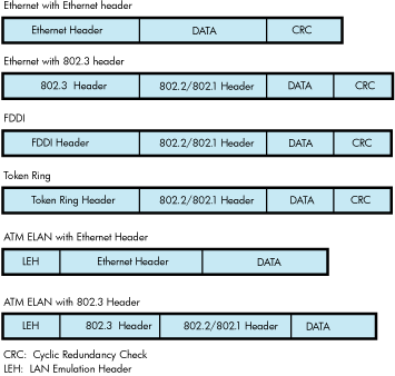
Note that Ethernet provides two frame formats and the FDDI provides one frame format. The 802.1 header is an optional extension to the 802.2 header.
9.4.6.1. Ethernet Frames
There are two headers for Ethernet frames:
Ethernet header
IEEE 802.3 header
Figure 9.2, ''Ethernet Frame with Ethernet Header'' illustrates an Ethernet frame with an Ethernet header.
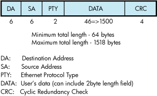
The Ethernet header consists of the DA, SA, and PTY fields. Ethernet frames must be at least 64 bytes in length, which means that the minimum data length is 46 bytes. Applications select Ethernet format by specifying NMA$C_LINFM_ETH (the default) as the value for NMA$C_PCLI_FMT in their P2 characteristics buffer. If the amount of actual data to be transmitted is less than 46 bytes, the Ethernet drivers transmit extra bytes of zero after the application data.
Figure 9.3, ''Ethernet Frame with IEEE 802.3 Header'' illustrates a Ethernet frame with an IEEE 802.3 header.
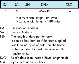
The IEEE 802.3 format is similar to the Ethernet format, except the PTY field is replaced by the LEN field.
9.4.6.2. FDDI Frames
Figure 9.4, ''FDDI Frame Format'' illustrates the format of FDDI frames.
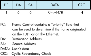
9.4.6.3. Token Ring Frames
Figure 9.5, ''Token Ring Frame Format'' illustrates the format of Token Ring frames.
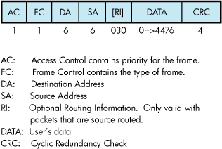
9.4.6.4. ATM ELAN Frames
Figure 9.6, '' LAN Emulation Data Frame Format with IEEE 802.3/Ethernet Header'' illustrates the format of LAN emulation data frame format for the IEEE 802.3 and Ethernet Header.
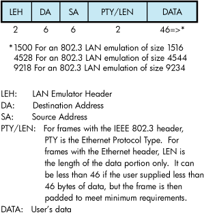
9.4.6.5. Ethernet (Ethernet Version 2, DIX) Frame Format
The Ethernet format specifies a two-byte protocol type field followed by an optional length field. The length field is included in transmit packets and expected in receive packets with the PAD parameter is enabled. The following sections describe these features.
9.4.6.5.1. Ethernet Protocol Types
Every Ethernet frame has a 2-byte protocol type field. This field is used to determine the port to which a packet belongs. When an application starts a port, it specifies the protocol type to be used on that port. Packets sent over that port always have the protocol type inserted in the packet header by the LAN driver, and packets received for that protocol type are delivered to the application that owns the port. Valid protocol types are in the range 05-DD through FF-FF.
The following lists the cross-company protocol types:
| Value | Meaning |
|---|---|
| 08-00 | IP protocol |
| 08-06 | Address resolution protocol (ARP) |
| 86-DD | IP protocol Version 6 (IPV6) |
| 90-00 | Ethernet Loopback protocol |
The following list some commonly used protocol types.
| Value | Meaning |
|---|---|
| 60-01 | DNA Dump/load (MOP) |
| 60-02 | DNA Remote Console (MOP) |
| 60-03 | DNA Routing |
| 60-04 | Local Area Transport (LAT) |
| 60-05 | Diagnostics |
| 60-06 | Customer use |
| 60-07 | System Communication Architecture (SCA) |
| 80-38 | Bridge |
| 80-3C | DNA Naming Service |
| 80-3D | CSMA/CD Encryption |
| 80-3E | DNA Time Service |
| 80-3F | LAN Traffic Monitor |
| 80-40 | NETBIOS Emulator (PCSG) |
| 80-41 | Local Area System Transport (LAST) |
9.4.6.6. 802 (IEEE 802.x LLC) Frame Format
The IEEE 802 packet formats accepted for a port depend on the service enabled on that port. All 802 packet formats have an 802.2 header. The service on the port determines the valid values for the 802.2 fields.
When a port is started, the NMA$C_PCLI_SRV parameter in the P2 buffer selects the service on that port. A value of NMA$C_LINSR_CLI specifies Class I service and a value of NMA$C_LINSR_USR specifies er-supplied service (the default).
9.4.6.6.1. 802 Service Access Point (SAP) Types
Every IEEE 802 frame has a 1-byte Service Access Point (SAP) field. This field identifies where the packet came from, the source port on the sending node. And it identifies the destination port for the packet on the receiving node. When an application starts a port, it specifies the SAP value that identifies the port. Packets sent over that port always have SAP value inserted into the SSAP field in the packet header by the LAN driver, and packets received for the SAP value in the DSAP field are delivered to the application that owns the port. Also, when transmitting a packet, the application specifies the destination SAP value, in addition to the destination address. And when receiving a packet, the application is given the source SAP value as well as the source address.
The following lists some commonly used SAP values.
| Value | Meaning |
|---|---|
| FE | DECnet-V Link State Routing |
| F0 | Pathworks |
9.4.6.6.2. Class I Service Packet Format
For Class I service, only three packet formats are transmitted and received: UI, XID, and TEST. Figure 9.7, ''Class I Service 802.2 Header'' shows the 802.2 header format for Class I service.
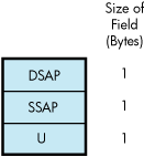
The control field for an 802 packet is always an unnumbered control field. The unnumbered control field, which is always 1 byte in length, is passed by the P4 argument of the write QIO and can be one of the following binary values:
UI command (00000011)
This is the unnumbered information command. It is the method used to transmit data from one user to another and is the most widely used control field value.
The UI command can be specified by using NMA$C_CTLVL_UI.
XID command (101p1111)
This is the exchange identification command. It is used to convey information about the port. The “p” bit is the poll bit and can be either 0 or 1. This command can be specified by using NMA$C_CTLVL_XID for a “0” poll bit or NMA$C_CTLVL_XID_P for a “1” poll bit.
XID response (101f1111)
The XID response is a response to an XID command. The “f” bit is the final bit and matches the poll bit from the XID command.
TEST command (111p0011)
The TEST command is used to test a connection. The “p” bit is the poll bit and can be either 0 or 1. This command can be specified by using NMA$C_CTLVL_TEST for a “0” poll bit or NMA$C_CTLVL_TEST_P for a “1” poll bit.
TEST response (111f0011)
The TEST response is a response to a TEST command. The “f” bit is the final bit and matches the poll bit from the TEST command.
An 802 format port with Class I service is allowed to transmit UI, XID, and TEST commands. An 802 format port with Class I service is allowed to receive UI commands and XID and TEST responses.
For more information on these control field values and response messages, see the IEEE 802.2 Standard.
9.4.6.6.3. User-Supplied Service Packet Format
The user provides the control field values, which are documented in the IEEE 802.2 Standard. The user-supplied packet format is the generic packet format as specified in the IEEE 802.2 Standard. Class I packets (see Section 9.4.6.6.2, ''Class I Service Packet Format'') are a subset of this generic packet format; therefore, if the control field value of the user-supplied packet is UI, XID, or TEST, the packet is the same as a Class I packet. Note that Class II packets, as defined in the IEEE 802.2 Standard, include the UI, XID, and TEST command/response formats.
9.4.6.6.4. Service Access Point (SAP) Use and Restrictions
The IEEE 802.2 Standard places restrictions on both user SAPs and source SAPs (SSAPs). All SAPs are 8 bits long. Figure 9.8, ''DSAP and SSAP Format'' shows the format of destination SAPs (DSAPs) and SSAPs.
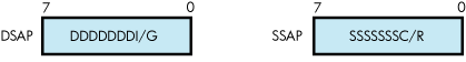
Definition of the least significant bit depends on whether the SAP is a source SAP (SSAP) or a destination SAP (DSAP). For a DSAP field, the least significant bit distinguishes group SAPs (bit 0 = 1) from individual SAPs (bit 0 = 0). For an SSAP field, the least significant bit distinguishes commands (bit 0 = 0) from responses (bit 0 = 1). Because these two bits are located at the same bit position within the SAP field, a group SAP cannot be used as an SSAP. If this were allowed, a group SAP would be interpreted as an individual SAP with the command/response bit set to 1, thus implying a response. The IEEE 802.2 Standard reserves for its own definition all SAP addresses with the second least significant bit set to 1. You should use these SAP values for their intended purposes, as defined in the IEEE 802.2 Standard.
Up to four group SAPs can be enabled on each 802 port. The group SAPs enabled on a controller do not have to be unique for each port; for example, two 802 format ports can have the same group SAP enabled. This allows a single packet coming into the controller to be duplicated and passed to each port on the controller that has the group SAP enabled—assuming the packet has a DSAP value that is a group SAP. If the received packet has an individual SAP for a DSAP, the packet goes to, at most, one port.
9.4.6.7. 802 Extended (IEEE 802.x LLC/SNAP) Frame Format
The 802E format uses the 802.2 and 802.1 headers, as shown in Figure 9.9, ''802 Extended Header''.
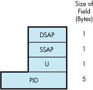
For an 802E packet format, the DSAP and SSAP fields are always set to the SNAP SAP (AA hex). The SNAP SAP value is a special SAP value reserved for 802 extended format packets. The SNAP SAP value distinguishes an 802 packet from an 802 extended packet. The only valid control field value for 802 extended packets is UI (unnumbered information).
9.4.6.7.1. 802E PID Types
Every SNAP frame has a 5-byte protocol ID (PID) field. This field is used to determine the port to which a packet belongs. When an application starts a port, the it specifies the PID to be used on that port. Packets sent over that port always have the PID inserted in the packet header by the LAN driver, and packets received for that PID are delivered to the application that owns the port.
The following lists the cross-company PID values.
| Value | Meaning |
|---|---|
| 08-00-2B-90-00 | Loopback protocol |
The following lists some commonly used PID values.
| Value | Meaning |
|---|---|
| 08-00-2B-60-02 | Loopback protocol |
| 08-00-2B-60-01 | DNA Dump/load (MOP) |
| 08-00-2B-60-02 | DNA Remote Console (MOP) |
| 08-00-2B-80-3C | DNA Naming Service |
| 08-00-2B-80-3E | DNA Time Service |
| 08-00-2B-80-48 | Availability Manager (AMDS) |
9.4.7. Packet Padding
This section describes the PAD parameter NMA$C_PCLI_PAD, which is used only in the Ethernet packet format.
All Ethernet frames must be at least 64 bytes in length. This includes the Ethernet header, the user data, and the CRC. If the user data, CRC, and Ethernet header together are less than 64 bytes, zero padding bytes are inserted between the user data and the CRC to make a 64-byte packet. This packet padding cannot be turned off.
The PAD parameter directs the LAN drivers to place a data-size field in the packet between the standard header and the user data. If padding is on (NMA$C_STATE_ON is specified), a 2-byte length field is inserted after the Protocol Type field and before the user data.
If the PAD parameter is off (NMA$C_STATE_OFF is specified), Ethernet packets have the following characteristics:
Packets transmitted are padded with null bytes as needed (CSMA/CD only).
Packets transmitted do not include the size field.
The length of user data in the packets received is always between 46 and 1500 bytes (9000 bytes for jumbo frames) for CSMA/CD, and 0 to 4470 for FDDI. For example, if a 10-byte packet is transmitted, it is received as 46 bytes because the driver cannot determine the amount of user data in the packet—only the amount of user data plus padded null bytes.
If the PAD parameter is on (NMA$C_STATE_ON is specified), Ethernet packets have the following characteristics:
Packets transmitted are padded with null bytes as needed (CSMA/CD only).
Packets transmitted include the size field.
The length of user data in the packets received is always between 0 and 1498 bytes (8998 bytes for jumbo frames) for CSMA/CD, and 0 to 4468 bytes for FDDI. The driver uses the size field to determine the amount of user data in the packet. The size field is not included in the data returned to the user.
9.4.8. Protocol Type and PID Sharing
Protocol types and PIDs are usually nonshareable; however, an application may benefit from a shared protocol implementation. The protocol access parameter (NMA$C_PCLI_ACC) allows a protocol type or PID to be opened in either of two shareable modes: shared-default (NMA$C_ACC_SHR) and shared-with-destination (NMA$C_ACC_LIM).The LAN drivers also provide the nonshareable exclusive mode (NMA$C_ACC_EXC). (See Table 9.33, ''P2 Attributes''.) The rules and requirements for using each mode are as follows:
The exclusive mode is the default if no access mode is supplied as a P2 buffer parameter. This mode of operation does not allow the protocol to be shared by other users. Any attempt to start up another protocol of the same type results in an error status of SS$_BADPARAM.
The shared-with-destination mode is a protocol type or PID/destination address pairing that allows multiple users to share a protocol type or PID and to communicate with a different node.
For a given shared protocol type or PID, there can be many “shared-with-destination” users; each user communicates with a different destination address. Any attempt to start a port with a destination address that is in use results in an error status of SS$_BADPARAM.
When a “shared-with-destination” user passes the set mode P2 buffer, the buffer must contain a destination address in the NMA$C_PCLI_DES parameter. This destination address is used as the destination address in all messages transmitted, and the user receives messages only from this address.
The shared-default mode is the default user of a shared protocol type or PID. There can be only one such user for each shared protocol type or PID. A “shared-default” user does not have to exist if a protocol type or PID is shared, but there can be no more than one such user per shared protocol type or PID.
The “shared-default” user receives all messages for the shared protocol type or PID, but not for any of the “shared-with-destination” users. The “shared-default” user also receives all messages matching both the shared protocol type or PID and any multicast address enabled by the “shared-default” user.
The “shared-default” user can only transmit to multicast addresses and physical addresses that are not enabled by any of the “shared-with-destination” users sharing the same protocol type or PID.
If there is no “shared-default” user of a protocol type or PID, incoming messages from nodes not among the “shared-with-destination” users for that protocol type or PID are ignored.
9.5. LAN Devices
This section describes each LAN device, giving a list of device variants and device characteristics. Some port drivers for these devices provide additional counters and device-specific functions that are useful for troubleshooting purposes. This additional data is described in a text file on the system, SYS$HELP:LAN_COUNTERS_AND_FUNCTIONS.TXT.
9.5.1. Driver-Specific Internal Counters
Driver-specific internal counters consist of data maintained by a particular LAN driver that is not common across all LAN drivers or is not suitable for inclusion in LAN statistics and error counters.
The LANCP command SHOW DEVICE/INTERNAL_COUNTERS displays the internal counters maintained by a port driver. Some counters are special debug counters. These are not displayed unless the additional qualifier /DEBUG is specified. Counters that are zero are not displayed unless the additional qualifier /ZERO is specified.
The LAN$SDA SDA extension also displays the complete set of internal counters with the command LAN INTERNAL/DEVICE=devname.
Some Alpha and IA-64 servers LAN drivers do not provide a LANCP or LAN$SDA mechanism for reading these counters. For these drivers, use SDA to display the internal counters using the command SHOW LAN/INTERNAL/DEVICE=devname.
The definition of these counters may change from one driver version to the next. Some counters fields describe device or driver information that is useful for debug of the driver but is not particularly interesting otherwise. This includes such fields as device register contents. The definition of these counters fields may be omitted from the SYS$HELP text file.
9.5.2. Device-Specific Functions
The device-specific functions provide additional functionality that is useful for troubleshooting and validation of the port driver. These functions may change from one driver version to the next. And some functions may be incorporated into LANCP as a standard device command. These functions are supported on Alpha and IA-64 server systems only.
9.5.3. Ethernet LAN Devices
In general terms, Ethernet includes Fast Ethernet, Gigabit Ethernet, and 10 Gigabit Ethernet devices. The following media types are used:
10Base2 (thinwire or BNC) — Ethernet running over thin shielded coaxial cable, half-duplex only.
10Base5 (thickwire or AUI) — Ethernet running over thick shielded coaxial cable, half-duplex only.
10BaseT — Ethernet running over Category 5 unshielded twisted-pair cabling (UTP). It uses two of the four pairs of wires to provide full-duplex communication.
100BaseTX — Fast Ethernet running over Category 5 unshielded twisted-pair cabling (UTP). It uses two of the four pairs of wires to provide full-duplex communication.
100BaseFX — Fast Ethernet running over multimode optical fiber cable. It uses two strands of fiber to provide full-duplex communication.
1000BaseT — Gigabit Ethernet running over Category 5 unshielded twisted-pair cabling (UTP). It uses two of the four pairs of wires to provide full-duplex communication.
1000BaseSX — Gigabit Ethernet running over multimode optical fiber cable. It uses two strands of fiber to provide full-duplex communication.
10GBaseSR — 10 Gigabit Ethernet running over multimode optical fiber cable. It uses two strands of fiber to provide full-duplex communication.
9.5.3.1. DEMNA Ethernet Device
The DEMNA is an XMI bus Ethernet device that is supported on Alpha systems that have an XMI bus. There are several variants of the DEBNA, the DEBNK, DEBNT, and DEBNI. Each device is implemented using a LANCE chip. Firmware on the device operates the LANCE chip.
| Device | Bus | Characteristics |
|---|---|---|
| DEMNA | XMI | 10Base5 (thickwire) Ethernet only |
| DEBNI | BI | 10Base5 (thickwire), Ethernet only |
| DEBNT | BI | 10Base5 (thickwire), Ethernet + TK50 combo adapter |
| DEBNK | BI | 10Base5 (thickwire), Ethernet + TK50 combo adapter |
| DEBNA | BI | 10Base5 (thickwire), Ethernet + TK50 combo adapter |
9.5.3.2. SGEC/TGEC Ethernet Devices
The Third Generation Ethernet Controller (TGEC) is embedded in the Alpha-based Digital 4000 system.
| Device | Bus | Characteristics |
|---|---|---|
| TGEC | Alpha | 10Base2 (thinwire) |
9.5.3.3. LANCE Ethernet Devices
The LANCE is a widely used Ethernet chip used in Alpha systems. It is used in embedded (LOM) configurations in Alpha systems, and in QBUS and TURBOchannel-based NICs in Alpha systems.
| Device | Bus | Characteristics |
|---|---|---|
| LANCE | Alpha | LOM, 10Base2 (thinwire) |
| PMAD | Alpha | TURBOchannel NIC, 10Base5 (thickwire) |
| DELTA | Alpha | Dual TURBOchannel, 10Base5 (thickwire) |
| DE422 | Alpha | EISA, 10BaseT (UTP), 10Base2 (thinwire) |
| DE200 | Alpha | ISA, 10Base2 (thinwire), 10Base5 (thickwire) |
| DE201 | Alpha | ISA, 10BaseT (UTP) |
| DE202 | Alpha | ISA, 10Base2 (thinwire), 10BaseT (UTP) |
9.5.3.3.1. LANCE Hardware Configuration
For implementations that include both the 10Base2 and 10Base5 ports, a switch next to the physical connectors determines the port selection.
The DE422 includes a jumper block on the NIC that selects 10BaseT or 10Base2.
The DE20x NICs are configured by a 12-pin DIP switch on the NIC. See the DE20x User Guide for details.
9.5.3.4. LEMAC Ethernet Devices
The DE203 and variants are based on the LEMAC chip. These NICs are used on ISA-based Alpha workstations, primarily the AlphaStation 200 and 400 system.
| Device | Characteristics |
|---|---|
| DE203 | 10Base2 (thinwire) |
| DE204 | 10BaseT (UTP) |
| DE205 | 10Base2 (thinwire), 10Base5 (thickwire), 10BaseT (UTP) |
9.5.3.4.1. ISA LEMAC Hardware Configuration
The DE203 NIC and variants are configured by the console of AlphaStations 200 and 400 systems using the 'isacfg' console utility. First, an ISA slot number is chosen, then the IRQ, IO base address, and DMA channel address. Then the slot is configured with the selected characteristics. When the system is reset or power-cycled, the console configures the device as specified.
For complete information on using 'isacfg' from your console prompt, see the hardware documentation associated with your system for more information.
The ISA slot number is any one of three available slots that is not already in use. The physical location of the NIC in the ISA bus is of no consequence as any free slot can be assigned to the NIC.
To initialize the 'isacfg' data at the console prompt:
>>> isacfg -init
To add a DE205 in slot 1, using IRQ 15:
>>> add_de205>>>isacfg -slot 1 -dev 0 -mod -irq 15
To display the ISA configuration data for slot 1:
>>>isacfg -slot 1
=============================================================
handle: DE200-LE
etyp: 1
slot: 1
dev: 0
enadev: 1
totdev: 1
iobase0: 300    iobase1: 8000000000000000
iobase2: 8000000000000000   iobase3: 8000000000000000
iobase4: 8000000000000000   iobase5: 8000000000000000
membase0: d0000   memlen0: 10000
membase1: 8000000000000000   memlen1: 8000000000000000
membase2: 8000000000000000   memlen2: 8000000000000000
rombase: 8000000000000000   romlen:   8000000000000000
dma0: 80000000          irq0: f
dma1: 80000000          irq1: 80000000
dma2: 80000000          irq2: 80000000
dma3: 80000000          irq3: 80000000    =============================================================
>>> show config

    ISA
    Slot    Device  Name            Type         Enabled  BaseAddr  IRQ     DMA
    0
            0       MOUSE           Embedded        Yes     60      12
            1       KBD             Embedded        Yes     60      1
            2       COM1            Embedded        Yes     3f8     4
            3       COM2            Embedded        Yes     2f8     3
            4       LPT1            Embedded        Yes     3bc     7
            5       FLOPPY          Embedded        Yes     3f0     6       2
    1       0       DE200-LE        Singleport      Yes     300     15
    2       0       DW11            Singleport      Yes     a20     10      7
    3       0       DW11            Singleport      Yes     1a20    5       6
9.5.3.5. 3C589 Ethernet Device
The 3COM 3C589 PCMCIA NIC is used on the Tadpole AlphaBook notebook system. There are two variants:
| Device | Characteristics |
|---|---|
| 3C589B | 10Base2 (thinwire), 10BaseT (UTP) |
| 3C589D | 10Base2 (thinwire), 10BaseT (UTP) |
9.5.3.6. Tulip Ethernet and Fast Ethernet Devices
Tulip refers to an Ethernet chip designed by Digital Equipment Corporation. It also refers to later Fast Ethernet versions of the chip that maintain a similar programming interface, so can be controlled by the same driver with few changes.
| Device | Bus | Characteristics |
|---|---|---|
| DE425 | EISA | 10Base2 (thinwire), 10Base5 (thickwire), 10BaseT (UTP) |
| DE434 | PCI | 10BaseT (UTP) |
| DE435 | PCI | 10Base2 (thinwire), 10Base5 (thickwire), 10BaseT (UTP) |
| DE436 | PCI | Quad DE435 |
| DE450 | PCI | 10Base2 (thinwire), 10Base5 (thickwire), 10BaseT (UTP) |
| DE500-XA | PCI | 10BaseT (UTP), 100BaseTX (UTP), auto-negotiation not supported |
| DE500-AA | PCI | 10BaseT (UTP), 100BaseTX (UTP), auto-negotiation supported |
| DE500-BA | PCI | 10BaseT (UTP), 100BaseTX (UTP), auto-negotiation supported |
| DE500-FA | PCI | 100BaseFX (multimode fiber), auto-negotiation not supported |
| DE504-BA | PCI | Quad DE500-BA |
| P2SE | PCI | Combo SCSI + DE434 |
| P2SE+ | PCI | Combo SCSI + DE500-XA |
| 21142 | PCI | LOM, Digital Personal Workstation, all modes depending on MAU options, auto-negotiation supported |
| 21143 | PCI | LOM, Alpha Professional Workstation XP900/XP1000, all modes depending on MAU options, auto-negotiation supported |
| A5230A | PCI | DE500-BA equivalent |
| A5506B | PCI | DE504-BA equivalent |
9.5.3.6.1. Tulip Hardware Configuration
The DE425 and DE435 contain a hardware jumper block that selects twisted-pair or AUI as noted on the printed circuit board. AUI includes 10Base2 (thinwire) or 10Base5 (thickwire) and this selection is made by setting a console environment variable, by a driver autosense algorithm, or by a LANCP command to set the media type, speed, and duplex mode.
On Alpha systems prior to OpenVMS Version 7.1, the Tulip driver autosenses the media connection if needed.
On Alpha systems starting with OpenVMS Version 7.1, the Tulip driver uses the setting of a console environment variable to select the media connection, speed, duplex mode, and auto-negotiation setting. The console environment variable is called EWx0_MODE where x is the controller letter (for example, A, B, C, ...). The console environment variable is set with the command:
SET EWx0_MODE media_selection
The media_selection is defined by Table 9.11, ''Tulip Hardware Media Selection''.
| Media selection | What is selected |
|---|---|
| Twisted-pair | 10BaseT (UTP) half-duplex |
| Full duplex, twisted-pair | 10BaseT (UTP) full-duplex |
| AUI | 10Base5 (thickwire) |
| BNC | 10Base2 (thinwire) |
| Fast | 100BaseTX (UTP) half-duplex |
| FastFD (full duplex) | 100BaseTX (UTP) full-duplex |
| Autonegotiate | Auto-negotiate speed and duplex (UTP) |
During driver initialization, a message is sent to the operator's console to indicate the console selection.
If a console environment variable has been set with an unsupported media type for the actual device, then the driver selects a default media type.
An Alpha system console may assign a controller letter to an adapter differently from OpenVMS, because OpenVMS EW devices include Tulip, DEGPA, and Broadcom 5700, but the console only recognizes Tulip devices as EW devices. In this case, you can compare the MAC address listed for the device at the console SHOW CONFIG and the LANCP SHOW CONFIG commands.
On IA-64 server systems, there is no console environment variable equivalent, so the default setting is auto-negotiation.
On Alpha and IA-64 server systems, you can override the console environment variable setting or default setting of auto-negotiation by defining the speed, duplex mode, and auto-negotiation settings in the LANCP permanent device database.
9.5.3.7. Intel 82559 Fast Ethernet Devices
82559 refers to a Fast Ethernet chip designed by Intel Corporation, either the 82558 or the 82559 chip. These chips are implemented in PCI bus NICs or a embedded PCI bus on the system board. Both chips support auto-negotiation. Table 9.12, ''Intel 82559 Fast Ethernet Characteristics'' lists the Intel 82559 Fast Ethernet characteristics.
| Device | Characteristics |
|---|---|
| DE600-AA | 10BaseT (UTP), 100BaseTX (UTP) |
| DE602-AA | Dual DE600-AA |
| DE602-BA | Dual DE600-AA |
| DE602-BB | Dual DE600-AA |
| DE602-TA | Dual DE600-AA daughter card for the DE602 |
| DE602-FA | Dual 100BaseFX (multimode fiber) daughter card for the DE602 |
| Trifecta | Combo SCSI + DE600 |
| 82559ER | LOM, 10BaseT (UTP), 100BaseTX (UTP) |
| 82559 | LOM, 10BaseT (UTP), 100BaseTX (UTP) |
9.5.3.7.1. 82559 Hardware Configuration
On Alpha systems, the 82559 driver uses the setting of a console environment variable to select the media connection, speed, and duplex mode. The console environment variable is called EIx0_MODE where x is the controller letter (e.g., A, B, C, ...). The console environment variable is set with the command:
SET EWx0_MODE media_selection
The media_selection is defined by Table 9.13, ''Hardware Media Selection''.
| Media selection | What is selected |
|---|---|
| Twisted-pair | 10BaseT (UTP) half-duplex |
| Full-duplex, twisted-pair | 10BaseT (UTP) full-duplex |
| Fast | 100BaseTX (UTP) half-duplex |
| FastFD (full-duplex) | 100BaseTX (UTP) full-duplex |
| Autonegotiate | Auto-negotiate speed and duplex (UTP) |
During driver initialization, a message is sent to the operator's console to indicate the console selection.
If a console environment variable has been set to an unsupported speed and duplex for the actual device, then the driver selects auto-negotiation.
On IA-64 server systems, there is no console environment variable equivalent, so the default setting is auto-negotiation.
On Alpha and IA-64 server systems, you can override the console environment variable setting or default setting of auto-negotiation by defining the speed, duplex mode, and auto-negotiation settings in the LANCP permanent device database.
9.5.3.8. DEGPA Gigabit Ethernet Devices
The DEGPA series of Gigabit Ethernet NICs uses the Tigon2 chip, designed by Alteon Networks..
Table 9.14, ''DEGPA Devices'' lists and describes the devices and drivers of the DEGPA.
| Device | Characteristics |
|---|---|
| DEGPA-SA | 1000BaseSX (multimode fiber) |
| DEGPA-TA | 10BaseT (UTP), 100BaseTX (UTP), 1000BaseT (UTP) |
9.5.3.8.1. DEGPA Hardware Configuration
The DEGPA NICs are supported only on Alpha systems. The DEGPA is not a bootable device and has no console support, therefore has no console environment variable mode setting for configuration, and the default setting is auto-negotiation.
You can override the default setting of auto-negotiation by defining the speed, duplex mode, and auto-negotiation settings in the LANCP permanent device database.
9.5.3.9. Broadcom 5700 Gigabit Ethernet Devices
The Broadcom 5700 refers to a family of Gigabit Ethernet chips designed by Broadcom Corporation. The 5700 NICs described here use three almost identical variants, the 5701, 5703, and 5704 chips.
| Device | Bus | Characteristics |
|---|---|---|
| DEGXA-SA | PCI | 1000BaseSX (multimode fiber) |
| DEGXA-TA | PCI | 10BaseT (UTP), 100BaseTX (UTP), 1000BaseT (UTP) |
| DEGXA-SB | PCI-X | 1000BaseSX (multimode fiber) |
| DEGXA-TB | PCI-X | 10BaseT (UTP), 100BaseTX (UTP), 1000BaseT (UTP) |
| BCM5703 (LOM) | PCI | 10BaseT (UTP), 100BaseTX (UTP), 1000BaseT (UTP) |
| A6847A | PCI | 1000BaseSX (multimode fiber) |
| A6825A | PCI | 10BaseT (UTP), 100BaseTX (UTP), 1000BaseT (UTP) |
| AB352A | PCI-X | 10BaseT (UTP), 100BaseTX (UTP), 1000BaseT (UTP) |
| A9782A | PCI-X | 1000BaseSX (multimode fiber) |
| A9784A | PCI-X | 10BaseT (UTP), 100BaseTX (UTP), 1000BaseT (UTP) |
| AB465A | PCI-X | 10BaseT (UTP), 100BaseTX (UTP), 1000BaseT (UTP) |
| BCM5701 (LOM) | PCI | 10BaseT (UTP), 100BaseTX (UTP), 1000BaseT (UTP) |
| BCM704 (LOM) | PCI | 2x10BaseT (UTP), 10BaseT (UTP), 100BaseTX (UTP), 1000BaseT (UTP) |
| BCM5709 (LOM) | PCI | 2x10BaseT (UTP), 10BaseT (UTP), 100BaseTX (UTP), 1000BaseT (UTP) |
9.5.3.9.1. 5700 Hardware Configuration
On Alpha systems, the 5700 driver uses the setting of a console environment variable to select the speed and duplex mode. The console environment variable is called EGx0_MODE where x is the controller letter (e.g., A, B, C, ...). The console environment variable is set with the command:
SET EGx0_MODE media_selection
The media_selection is defined by Table 9.16, ''5700 Hardware Media Selection''.
| Media selection | What is selected |
|---|---|
| auto | Auto-negotiate speed and duplex (UTP) |
| 10mbps | 10BaseT (UTP) half-duplex |
| 10mbps_full_duplex | 10BaseT (UTP) full-duplex |
| 100mbps | 100BaseTX (UTP) half-duplex |
| 100mbps_full_duplex | 100BaseTX (UTP) full-duplex |
| 1000mbps | 1000BaseT (UTP) half-duplex |
| 1000mbps_full_duplex | 1000BaseT (UTP) full-duplex |
During driver initialization, a message is sent to the operator's console to indicate the console selection.
If a console environment variable has been set with an unsupported media type for the actual device, then the driver selects a default media type.
An Alpha system console may assign a controller letter to an adapter differently from OpenVMS, since OpenVMS EW devices include Tulip, DEGPA, Broadcom 5700, but the console only recognizes 5700 devices as EW devices. In this case you can compare the MAC address listed for the device at the console SHOW CONFIGURATION and LANCP SHOW CONFIGURATION commands.
On IA-64 server systems, there is no console environment variable equivalent, so the default setting is auto-negotiation.
On Alpha and IA-64 server systems, you can override the console environment variable setting or default setting of auto-negotiation by defining the speed, duplex mode, and auto-negotiation settings in the LANCP permanent device database.
9.5.3.10. Intel 82540 Gigabit Ethernet Devices
The Intel 82540 refers to a family of Gigabit Ethernet chips designed by Intel Corporation. The variants used on these NICs include the 82540, 82546, and 82571 chips.
| Device | Bus | Characteristics |
|---|---|---|
| A7011A | PCI-X | Dual 1000BaseSX (multimode fiber) |
| A7012A | PCI-X | Dual 10BaseT (UTP), 100BaseTX (UTP), 1000BaseT (UTP) |
| Intel 82546 (LOM) | PCI-X | Dual 10BaseT (UTP), 100BaseTX (UTP), 1000BaseT (UTP) |
| AB352A | PCI-X | Dual 10BaseT (UTP), 100BaseTX (UTP), 1000BaseT (UTP) |
9.5.3.10.1. 82540 Hardware Configuration
The 82540 devices are supported only on IA-64 server systems. The default setting is auto-negotiation.
You can override the default setting of auto-negotiation by defining the speed, duplex mode, and auto-negotiation settings in the LANCP permanent device database.
9.5.3.11. Neterion XFRAME 10–Gigabit Ethernet Devices
XFRAME refers to a family of 10–Gigabit Ethernet adapters from Neterion. The variants used include the AB287A and AD385A.
9.5.3.12. Shared Memory Ethernet Device
The Shared Memory device is an emulated Ethernet device that uses Galaxy Shared Memory on Alpha systems. Each Galaxy partion is considered a network node. The driver uses shared memory to send packet data from one node to another. Applications see the Shared Memory device as just another Ethernet device.
9.5.4. FDDI LAN Devices
FDDI devices support the following media
Multimode optical fiber, using two strands of fiber to provide full-duplex communication.
Category 5 unshielded twisted-pair cabling (UTP), using two of the four pairs of wires to provide full duplex communication.
9.5.4.1. DEMFA FDDI Device
The DEMFA is an XMI bus FDDI device that is supported on Alpha systems that have an XMI bus. The DEMFA is a firmware based FDDI controller that uses an Motorola 68000 microprocessor to implement a host interface and the necessary FDDI support functionality.
| Device | Bus | Characteristics |
|---|---|---|
| DEMFA | XMI | Multimode fiber, 100 megabits/second |
9.5.4.2. DEFZA FDDI Device
The DEFZA is a TurboChannel FDDI device supported on Alpha TURBOchannel-based systems.
| Device | Bus | Characteristics |
|---|---|---|
| DEFZA | TurboChannel | Multimode fiber, 100 megabits/second |
9.5.4.3. PDQ FDDI Devices
The PDQ chip forms the basis of a family of FDDI devices. These are shown in Table 9.20, ''PDQ FDDI Characteristics''.
| Device | Bus | Characteristic |
|---|---|---|
| DEFQA-SA | QBUS | Multimode fiber, single attached station (SAS), 100 megabits/second |
| DEFQA-DA | QBUS | Multimode fiber, dual attached station (DAS), 100 megabits/second |
| DEFQA-SF | QBUS | UTP, single attached station (SAS), 100 megabits/second |
| DEFQA-DF | QBUS | UTP, dual attached station (DAS), 100 megabits/second |
| DEFTA-AA | TurboChannel | Multimode fiber, single attached station (SAS), 100 megabits/second |
| DEFTA-DA | TurboChannel | Multimode fiber, dual attached station (DAS), 100 megabits/second |
| DEFTA-UA | TurboChannel | UTP, single attached station (SAS), 100 megabits/second |
| DEFTA-MA | TurboChannel | UTP, dual attached station (DAS), 100 megabits/second |
| DEFAA-AA | FutureBus+ | Multimode fiber, single attached station (SAS), 100 megabits/second |
| DEFAA-DA | FutureBus+ | Multimode fiber, dual attached station (DAS), 100 megabits/second |
| DEFEA-AA | EISA | Multimode fiber, single attached station (SAS), 100 megabits/second |
| DEFEA-DA | EISA | Multimode fiber, dual attached station (DAS), 100 megabits/second |
| DEFEA-UA | EISA | UTP, single attached station (SAS), 100 megabits/second |
| DEFEA-MA | EISA | UTP, dual attached station (DAS), 100 megabits/second |
| DEFPA-AA | PCI | Multimode fiber, single attached station (SAS), 100 megabits/second |
| DEFPA-DA | PCI | Multimode fiber, dual attached station (DAS), 100 megabits/second |
| DEFPA-UA | PCI | UTP, single attached station (SAS), 100 megabits/second |
| DEFPA-MA | PCI | UTP, dual attached station (DAS), 100 megabits/second |
9.5.5. Token Ring LAN Devices
Token Ring devices support the following media types:
STP — Shielded twisted-pair cabling, type 1 STP, using 2 pairs of wires in crossover form. The cables have DB-9 connectors on them.
UTP — Unshielded twisted-pair cabling, type 3 UTP, using 2 pairs of wires in crossover form to provide full-duplex communications.
9.5.5.1. TMS380 Token Ring Devices
The Texas Instruments TMS380 chip forms the basis of a family of Token Ring devices. These are shown in Table 9.21, ''TMS380 Token Ring Characteristics''.
| Device | Bus | Characteristics |
|---|---|---|
| DETRA | TurboChannel | 4/16 megabits/second, STP or UTP |
| DW300 | EISA | 4/16 megabits/second, STP or UTP |
| DW110 | ISA | 4/16 megabits/second, STP or UTP, aka P1392+ |
| TC4048 | PCI | 4/16 megabits/second, STP or UTP, made by Thomas Conrad Corporation |
| M8154 | PCI | 4/16 megabits/second, STP or UTP, made by Racore Computer Products, Inc. |
9.5.5.1.1. ISA TMS380 Hardware Configuration
The DW110 is a bus mastering DMA device on the ISA bus. In addition to setting up the ISA I/O parameters, you may configure ring speed (4 or 16 megabits/second) and media (UTP or STP). By using LANCP you can also configure ring speed and media during system startup. Example 9.1, ''Using the 'isacfg' at Console Prompt with the DW110'' shows how to configure the OpenVMS software to use the DW110 device.
The method for configuring an ISA TMS380 device is to type 'isacfg' at the console prompt (>>>). For complete information on using 'isacfg' from your console prompt, see the hardware documentation associated with your system for more information.
The following example illustrates a configuration of:
Slot 4
IRQ 10
DMA channel 7
Base %x4e20
Shielded twisted pair (STP)
Ring speed of 16
>>> isacfg -slot 4 -etyp 1 -ena 1 -irq0 %xa -dmachan0 7
           -iobase0 %x4e20 -handle "DW11,STP,16" -mk
The -mk command makes an isacfg entry for an ISA device at slot 4. It is a Single port type of device (-etyp 1). The -handle parameter tells the operating system that this is a DW110 device, that STP media is to be used, and the ring speed is 16.
9.5.6. ATM LAN Devices
Asynchronous transfer mode (ATM) is a cell-oriented switching technology that uses fixed-length packets to carry different types of data.
The ATM communicates by first establishing endpoints between two computers with a virtual circuit (VC) through one or more ATM switches. ATM then provides a physical path for data flow between the endpoints by either a permanent virtual circuit (PVC), or a switched virtual circuit (SVC).
OpenVMS provides LAN Emulation Client (LEC) support over ATM. The LAN Emulation Client software supports IEEE/802.3 Emulated LANs, and UNI 3.0 or UNI 3.1 and the following maximum frame size (in bytes): 1516, 4544, and 9234.
The Emulated LAN driver provides the means for communicating over the LAN ATM. The device type for the Emulated LAN device is DT$_EL_ELAN.
The device name for the Emulated LAN is:
ELcu
where c is the controller and u is the unit number (for example, ELA0).
ATM devices support the following media types:
Multimode optical fiber, using two strands of fiber to provide full-duplex communication.
Category 5 unshielded twisted-pair cabling (UTP), using two of the four pairs of wires to provide full-duplex communication.
9.5.6.1. OTTO ATM Devices
OTTO refers to a family of ATM adapters developed by Digital Equipment Corporation. The TurboChannel adapter is named OTTO. The PCI DGLPB adapter is named OPPO. OTTO and OPPO are programmable logic designs where the driver loads firmware onto the adapters to program the FPGA devices. The DGLPA is a single chip ATM adapter that is a considerably different implementation but lumped into this same category.
| Device | Bus | Characteristics |
|---|---|---|
| DGLTA | TurboChannel | 155 megabits/second (OC3), multimode fiber |
| DGLPB | PCI | 155 megabits/second (OC3), multimode fiber |
| DGLPA-UA | PCI | 155 megabits/second (OC3), UTP |
| DGLPA-FA | PCI | 155 megabits/second (OC3), multimode fiber |
The OTTO drivers support ATM LAN Emulation according to the ATM LANE standards, and Classical IP over ATM according to RFC 1577.
9.5.6.2. FORE ATM Devices
The DAPBA and DAPCA are ATM adapters made by Fore Networks, Inc., now part of Marconi Corporation, Plc.
The FORE drivers support ATM LAN Emulation according to the ATM LANE standards.
| Device | Characteristics |
|---|---|
| DAPBA-UA | 155 megabits/second (OC3), UTP |
| DAPBA-FA | 155 megabits/second (OC3), multimode fiber |
| DAPCA-FA | 622 megabits/second (OC12), multimode fiber |
For each DAPBA, increase the SYSGEN parameter NPAGEVIR by 3000000. For each DAPCA, increase NPAGEVIR by 6000000. To do this, add the ADD_NPAGEVIR parameter to MODPARAMS.DAT and then run AUTOGEN. For example, add the following command to MODPARAMS.DAT on a system with two DAPBAs and one DAPCA:
ADD_NPAGEVIR = 12000000
The following restrictions apply to the DAPBA and DAPCA adapters.
The adapter cannot be located on a PCI bus that is located behind a PCI-to-PCI bridge. Systems that have this configuration are the following:
HPE Personal AlphaWorkstation 600 (MIATA GL)
AlphaStation 1000A (Noritake)
HPE Professional Workstation XP1000 (MONET)
AlphaServer 2000 and 2100 (SABLE)
Classical IP is not supported.
9.5.6.3. Permanent Virtual Circuits (PVC)
Permanent Virtual Circuits are set up and torn down by prior arrangement. They are established manually by a user before the sending of any data between endpoints on a network. Some PVCs are defined directly on the switch; others are predefined for use in managing switched virtual circuits (SVCs).
9.5.6.4. Switched Virtual Circuits (SVC)
Switched virtual circuits require no operator interaction to create and manage connections between endpoints. Software sets up and tears down connections dynamically as they are needed through the request of an endpoint.
9.5.6.5. LAN Emulation over an ATM Network
LAN emulation over an ATM network network allows existing applications to run essentially unchanged while also allowing the applications to run on computers directly connected to the ATM network. The LAN emulation hides the underlying ATM network at the media access control (MAC) layer, which provides device driver interfaces.
Table 9.24, ''Components of LAN Emulation over an ATM Network'' shows the four components that make up a LAN emulation over an ATM network. Of the four components, OpenVMS supports only the LAN emulation client (LEC). The remaining components are provided by the ATM switch.
| Component | Function |
|---|---|
| LAN emulation client (LEC) | Provides a software driver that runs on a network client and enables LAN clients to connect to an ATM network. |
| LAN emulation server (LES) | Maintains a mapping between LAN and ATM addresses by resolving LAN media access control (MAC) addresses with ATM addresses. |
| Broadcast and Unknown Server (BUS) | Maintains connections with every LAN emulation client (LEC) in the network. For broadcast messages, the BUS sends messages to every attached LEC. The LECs then forward the message to their respectively attached LANs. For multicast messages, the BUS sends messages to only those LECs that have devices in the multicast group. For a LEC that wants to send a regular message whose destination MAC address is unknown, the BUS can be used to determine this address. |
| LAN emulation configuration server (LECS) | Provides a service for LAN emulation clients by helping to determine which emulated LAN each of the LEC's registered users should join, since each client can specify which emulated LAN to join. |
The LEC exists on all ATM-attached computers that participate in the LAN emulation configuration. LEC provides the ATM MAC-layer connectionless function that is transparent to the LAN-type applications. The LEC, LES, and BUS can exist on one ATM-attached computer or on separate computers. The server functions usually reside inside an ATM switch, but can be implemented on client systems.
9.5.6.6. LAN Emulation Topology
Figure 9.10, ''Emulated LAN Topology'' shows the topology of a typical emulated LAN over ATM.
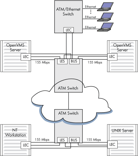
9.5.6.7. Classical IP Over an ATM Network
Classical IP (CLIP) implements a data-link level device that has the same semantics as an Ethernet interface (802.3). This interface is used by a TCP/IP protocol to transmit 802.3 (IEEE Ethernet) frames over an ATM network. The model that OpenVMS follows for exchanging IP datagrams over ATM is based on RFC 1577 (Classical IP over ATM).
For information on using LANCP commands to manage Classical IP, see the VSI OpenVMS System Management Utilities Reference Manual.
9.5.6.8. Specifying the User to Network Interface (UNI)
The ATM software is set to autosense the UNI version by default. Setting bit 3 of the system parameter, LAN_FLAGS, to 1 enables UNI 3.0 over all ATM adapters. Setting bit 4 of the system parameter, LAN_FLAGS, to 1 enables UNI 3.1 over all ATM adapters.
9.5.6.9. Enabling SONET/SDH
The ATM drivers have the capability of operating with either synchronous optical network (SONET) or Synchronous Digital Hierarchy (SDH) framing. Setting bit 0 of the system parameter, LAN_FLAGS, to 1 enables SDH framing. Setting bit 0 of the system parameter, LAN_FLAGS, to 0 enables SONET framing (default). For this to take affect, the system parameter must be specified correctly before the ATM adapter driver is loaded.
9.5.6.10. Booting
OpenVMS Alpha does not support ATM adapters as boot devices.
9.5.6.11. Configuring an Emulated LAN (ELAN)
The LANCP utility sets up an Emulated LAN (ELAN). If the ELAN is defined in the permanent database, these settings take effect at boot time. To define the commands in the permanent database for specific adapters, you invoke the DEFINE DEVICE commands. Once these commands define the adapters in the permanent database, the ELAN can be started during system startup.
You can also invoke the LANCP SET commands to start up an ELAN after the system is booted.
The following example shows the DEFINE DEVICE commands that define the adapter in the permanent database:
$ mcr lancp
LANCP> define device ela0/elan=create
LANCP> define device ela0/elan=(parent=hwa0,type=csmacd,size=1516)
LANCP> define device ela0/elan=(descr="An ATM ELAN")
LANCP> define device ela0/elan=enable=startup
LANCP> list dev ela0/param

Device Characteristics, Permanent Database, for ELA0:
                  Value  Characteristic
                  ——  —————
                   HWA0  Parent ATM device
          "An ATM ELAN"  Emulated LAN description
                   1516  Emulated LAN packet size
                CSMA/CD  Emulated LAN type
                    Yes  Emulated LAN enabled for startup
LANCP> exit
$
The following example shows the SET DEVICE commands required for setting up an ELAN with the desired parameters. Note that some of the commands generate a console message.
$ mcr lancp
LANCP> set dev ela0/elan=create

%%%%%%%%%%%  OPCOM  26-MAR-2017 16:57:12.89  %%%%%%%%%%%
Message from user SYSTEM on ALPHA1
LANACP LAN Services
Found LAN device ELA0, hardware address 00-00-00-00-00-00

LANCP> set dev ela0/elan=(parent=hwa0,type=csmacd,size=1516)
LANCP> set dev ela0/elan=(descr="An ATM ELAN")
LANCP> set dev ela0/elan=enable=startup

%ELDRIVER, LAN Emulation event at 26-MAR-1996 16:57:28.78
%ELDRIVER, LAN Emulation startup: Emulated LAN 1 on device ELA0

LANCP> sho dev ela/char

   Device Characteristics ELA0:
                  Value  Characteristic
                  ——  —————
                 Normal  Controller mode
               External  Internal loopback mode
                CSMA/CD  Communication medium
                     16  Minimum receive buffers
                     32  Maximum receive buffers
                     No  Full duplex enable
                     No  Full duplex operational
            Unspecified  Line media
                     10  Line speed (megabits/second)
                CSMA/CD  Communication medium
                 "HWA0"  Parent ATM Device
          "An ATM ELAN"  Emulated LAN Description
   3999990000000008002B  LAN Emulation Server ATM Address
   A57E80AA000302FF1300
                Enabled  Emulated LAN State
LANCP> exit
$
For information about using LANCP and system manager commands with qualifiers for LAN emulation over ATM networks, see the VSI OpenVMS System Management Utilities Reference Manual and VSI OpenVMS System Manager's Manual.
9.6. LAN Device Information
You can obtain information on controller characteristics by using the Get Device/Volume Information ($GETDVI) system service. (See the VSI OpenVMS System Services Reference Manual.)
$GETDVI returns controller characteristics when you specify the item code DVI$_DEVCHAR. Table 9.25, ''Ethernet Controller Device Characteristics'' lists these characteristics, which are defined by the $DEVDEF macro and in the file SYS$LIBRARY:DEVDEF.H.
| Characteristic | Meaning |
|---|---|
| Static Bits (Always Set) | |
| DEV$M_AVL | Device is available. |
| DEV$M_IDV | Input device. |
| DEV$M_NET | Network device. |
| DEV$M_ODV | Output device. |
DVI$_DEVTYPE and DVI$_DEVCLASS return the device type and device class names, which are defined by the $DCDEF macro and in the file SYS$LIBRARY:DCDEF.H. The device class name for the LAN Ethernet controllers listed in Section 9.2, ''Supported LAN Devices'' is always DC$_SCOM.
DVI$_DEVBUFSIZ returns the maximum message size. The maximum send or receive message size depends on the packet format and whether padding (NMA$C_PCLI_PAD) is enabled (see Section 9.7.1, ''Read'' and Section 9.7.2, ''Write'' ). DVI$_DEVDEPEND returns the unit and line status bits and the error summary bits in a longword field as shown in Figure 9.11, ''DVI$_DEVDEPEND Returns''.
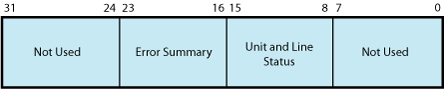
Table 9.26, ''Ethernet Controller Unit and Line Status'' lists the status values and their meanings. These values are defined by the $XMDEF macro. XM$M_STS_ACTIVE is set when the port is started. XM$M_STS_BUFFAIL and XM$M_STS_TIMO are dynamically set and cleared by the LAN driver.
| Status | Meaning |
|---|---|
| XM$M_STS_ACTIVE | Port is active. |
| XM$M_STS_BUFFAIL | Attempt to allocate a system receive buffer failed. |
| XM$M_STS_TIMO | Timeout occurred. |
The error summary bits are set when an error occurs. They are read-only bits. If an error is fatal, the Ethernet port is shut down. Table 9.27, ''Error Summary Bits'' lists the error summary bit values and their meanings.
| Error Summary Bit | Meaning |
|---|---|
| XM$M_ERR_FATAL | Hardware or software error occurred on the controller. |
9.7. LAN Function Codes
The LAN drivers can perform logical, virtual, and physical I/O operations. The basic functions are read, write, set mode, set characteristics, sense mode, and sense characteristics. Table 9.28, ''LAN I/O Functions'' lists these functions and their codes. The following sections describe these functions in greater detail.
| Function Code | Arguments | Type? | Function Modifiers | Function |
|---|---|---|---|---|
| IO$_READLBLK? | P1,P2,[P5] | L | IO$M_NOW | Read logical block. |
| IO$_READVBLK? | P1,P2,[P5] | V | IO$M_NOW | Read virtual block. |
| IO$_READPBLK? | P1,P2,[P5] | P | IO$M_NOW | Read physical block. |
| IO$_WRITELBLK? | P1,P2,[P4],P5 | L | IO$M_RESPONSE | Write logical block. |
| IO$_WRITEVBLK? | P1,P2,[P4],P5 | V | IO$M_RESPONSE | Write virtual block. |
| IO$_WRITEPBLK? | P1,P2,[P4],P5 | P | IO$M_RESPONSE | Write physical block. |
| IO$_SETMODE | P1,[P2],P3? | L |
| Set controller characteristics and controller state for subsequent operations. |
| IO$_SETCHAR | P1,[P2],P3? | P |
| Set controller characteristics and controller state for subsequent operations. |
| IO$_SENSEMODE | [P1],[P2] | L |
| Sense controller characteristics and return them in specified buffers. |
| IO$_SENSECHAR | [P1],[P2] | P |
| Sense controller characteristics and return them in specified buffer. |
Note that the LAN device drivers do not differentiate among logical, virtual, and physical I/O functions; all are treated identically.
9.7.1. Read
Read functions directly transfer data from a packet received from another port on the Ethernet into the virtual memory address space of the user process. The operating system provides the following function codes:
IO$_READLBLK—Read logical block
IO$_READVBLK—Read virtual block
IO$_READPBLK—Read physical block
Received messages are buffered in system memory and then copied to the user's buffer when a read operation is performed.
The read functions take the following device- or function-dependent arguments:
P1—The starting virtual address of the buffer that is to receive data. On OpenVMS Alpha and IA-64 server systems, P1 can be a 64-bit address.
P2—The size of the receive buffer in bytes.
P5—The address of a buffer where the LAN driver returns packet header information. This is an optional argument. The information returned depends on the packet format enabled with the set mode QIO. The size of the buffer must be 14 bytes for an Ethernet format packet, 16 bytes for an IEEE 802 format packet, and 20 bytes for an 802 extended format packet. Note that the information returned is not the entire packet header but the header information less any length or size fields. The IOSB, if specified, is where the packet length information is returned. For FDDI, if received access control (RAC) is on, then 1 byte must be added to these sizes.
For Token Ring, this buffer must be at least 54 bytes in length due to a possible variable length source routing header.
If NMA$C_PCLI_PRM (see Table 9.33, ''P2 Attributes'') is enabled, the P5 buffer must be at least 20 bytes for Ethernet and 21 bytes for FDDI. Figure 9.12, ''Read Function P5 Buffer'' shows the format of the three buffers. On OpenVMS Alpha and IA-64 server systems, P5 can be a 64-bit address.
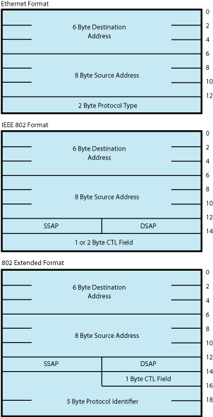
The P1 and P2 arguments must always be specified; the P5 argument is optional. However, if P5 is not specified, you will not be able to determine the source of the received message .
If the size of the user data in a receive message is larger than the value of the NMA$C_PCLI_BUS parameter, the message is not given to the user, even if there is sufficient space in the user's receive buffer.
If the size of the user data in a receive message is larger than the size specified in P2 (and less than or equal to the value of the NMA$C_PCLI_BUS parameter), the P1 buffer is filled and SS$_DATAOVERUN is returned in the I/O status block.
Table 9.29, ''Maximum User Data Sizes for Ethernet, FDDI, and Token Ring'' lists the maximum user data sizes that can be received for Ethernet, FDDI, and Token Ring protocols.
| Packet Format | Ethernet | FDDI | Token Ring |
|---|---|---|---|
| Ethernet format without padding | 1500 | 4470 | 4418 |
| Ethernet format with padding | 1498 | 4468 | 4416 |
| 802 format with 1-byte CTL field | 1497 | 4475 | 4423 |
| 802 format with 2-byte CTL field | 1496 | 4474 | 4422 |
| 802E format | 1492 | 4470 | 4418 |
Table 9.30, ''Maximum User Data Sizes for LAN Emulation over ATM'' lists the maximum user data sizes that can be received for LAN emulation over ATM protocol.
| Packet Format | ATM ELAN size: | 1516 | 4544 | 9234 |
|---|---|---|---|---|
| Ethernet format without padding | 1500 | 4528 | 9218 | |
| Ethernet format with padding | 1498 | 4526 | 9216 | |
| 802 format with 1-byte CTL field | 1497 | 4525 | 9215 | |
| 802 format with 2-byte CTL field | 1496 | 4524 | 9214 | |
| 802E format | 1492 | 4520 | 9210 |
For 802 format packets, the P5 buffer always contains the DSAP and SSAP in the bytes at offset 12 and 13. The next one or two bytes (offsets 14 and 15) following the SSAP contain the control field value. For Class I service, the control field value is always 1 byte in length and is always placed in the byte at offset 14 of this buffer. For user-supplied service, you have to determine the length of the control field value according to the IEEE 802.2 Standard.
For Token Ring, if received access control (RAC) is on, the first byte of the P5 buffer contains the frame control (FC) field.
For FDDI, if RAC is on, the first byte of the P5 buffer contains the FC field.
The read functions can take the following function modifier:
IO$M_NOW—Complete the read operation immediately with a received message (if no message is currently available, return a status of SS$_ENDOFFILE in the I/O status block).
9.7.2. Write
Write functions provide for the direct transfer of data from the virtual memory address space of the user process to the communications medium. The operating system provides the following function codes:
IO$_WRITELBLK—Write logical block
IO$_WRITEVBLK—Write virtual block
IO$_WRITEPBLK—Write physical block
Transmitted messages are copied from the buffer of the requesting process to a system buffer for transmission.
The write function takes the following device- or function-dependent arguments:
P1—The starting virtual address of the buffer containing the data to be transmitted. On OpenVMS Alpha and IA-64 server systems, P1 can be a 64-bit address.
P2—The size of the buffer in bytes.
P4—The address of a quadword that points to a buffer that contains the DSAP and CTL field values (optional). (See Section 9.4.6.6.4, ''Service Access Point (SAP) Use and Restrictions''.) The first longword is the buffer length; the second longword is the address of the buffer. This argument is used only for ports with the 802 packet format. The format of the buffer is:
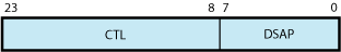
On OpenVMS Alpha and IA-64 server systems, P4 can be a 64-bit address.
P5—The address of a 6-byte buffer that contains the destination address. For FDDI, if XFC is specified as zero on startup, the first byte of the P5 buffer contains the low-order 3 bits of the FC field to be transmitted. On OpenVMS Alpha and IA-64 server systems, P5 can be a 64-bit address.
If the device is in promiscuous mode (NMA$C_PCLI_PRM; see Table 9.33, ''P2 Attributes''), you must pass a larger buffer with additional information positioned after the destination address. For Ethernet packet format, the buffer must be 8 bytes with the 2-byte protocol type following the destination address. For 802 packet format, the buffer must be 7 bytes with the 1-byte source SAP following the destination address. For 802 extended packet format, the buffer must be 11 bytes with the 5-byte protocol identifier following the destination address. The Source SAP cannot be a group SAP or the SNAP SAP. Figure 9.13, ''Write Function P5 Buffer'' shows the format of the P5 buffer. For FDDI with XFC specified as zero on startup, 1 byte must be added to these sizes for the FC field.
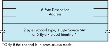
Table 9.31, ''Maximum Message Sizes for Ethernet, FDDI, and Token Ring'' lists the maximum user data sizes that can be specified by P2 and received for Ethernet, FDDI, and Token Ring protocols.
| Packet Format | Ethernet | FDDI | Token Ring |
|---|---|---|---|
| Ethernet format without padding | 1500 | 4470 | 4418 |
| Ethernet format with padding | 1498 | 4468 | 4416 |
| 802 format with 1-byte CTL field | 1497 | 4475 | 4423 |
| 802 format with 2-byte CTL field | 1496 | 4474 | 4422 |
| 802E format | 1492 | 4470 | 4418 |
Table 9.32, ''Maximum Message Sizes for LAN Emulation over ATM'' lists the maximum user data sizes that can be specified by P2 and received for LAN emulation over ATM protocol.
| Packet Format | ATM ELAN size: | 1516 | 4544 | 9234 |
|---|---|---|---|---|
| Ethernet format without padding | 1500 | 4528 | 9218 | |
| Ethernet format with padding | 1498 | 4526 | 9216 | |
| 802 format with 1-byte CTL field | 1497 | 4525 | 9215 | |
| 802 format with 2-byte CTL field | 1496 | 4524 | 9214 | |
| 802E format | 1492 | 4520 | 9210 |
If P2 specifies a message size larger than that allowed, the driver returns the status SS$_IVBUFLEN in the I/O status block.
If the P4 buffer is specified, it must be at least 3 bytes long. The first byte is always the DSAP; the next two bytes are used to determine the CTL field value. The DSAP value cannot be the SNAP SAP.
The CTL field value is either a 1-byte or 2-byte value. If the two least significant bits of the low-order byte of the CTL field contain the bit values 11, just the low-order byte of the CTL field is used as the CTL field value. Otherwise, both bytes of the CTL field are used as the CTL field value.
If the driver uses only the low-order byte of the CTL field, you still must pass at least a 3-byte buffer. In this case, the driver uses the low-order byte of the CTL field and ignores the high-order byte.
If Class I service is enabled, only 1-byte CTL field values can be passed. If user-supplied service is enabled, then both 1- and 2-byte CTL field values are valid. If Class I service is enabled, the CTL field value must be one of the three command values: UI, XID, or TEST.
Regarding 802 ports, you can receive packets for the SAP enabled with the IO$_SETMODE or IO$_SETCHAR QIOs and can transmit packets destined for a different SAP. This is similar to an Ethernet port receiving packets for one protocol type and transmitting packets with a different protocol type (which is not possible with the current Ethernet $QIO interface). It is expected that most 802 format applications wants to process only receive packets from a source SAP that matches the SAP enabled on their port. To do this, the read function (see Section 9.7.1, ''Read'') has been enhanced to return the source SAP to you. To verify that the source SAP of an incoming packet matches the SAP enabled on the port, you need only match the source SAP returned by the read function with the SAP enabled on the port.
The write function can take the following function modifier:
IO$M_RESPONSE—Transmit a response packet (sets the low-order bit in the SSAP field). This allows users with user-supplied service enabled to respond to certain 802 format command packets. IO$M_RESPONSE can be specified only when you have the 802 packet format enabled. The 802 packet format ports, with Class I service enabled, result in an error if you attempt to transmit a response message with a CTL field value of unnumbered information (UI).
9.7.3. Set Mode and Set Characteristics
The operating system provides the following two function codes:
IO$_SETMODE
IO$_SETCHAR
Other than the privilege check, these two function codes are treated the same by the LAN drivers. This section refers to the IO$_SETMODE function code only, even though applications can use either function code.
The set mode function code is used to perform many different functions. These different functions are distinguished by the modifiers set with the function code. The LAN drivers support the following set mode requests:
IO$_SETMODE!IO$M_CTRL — Set or modify port attributes
IO$_SETMODE!IO$M_CTRL!IO$M_STARTUP — Set port attributes and start port
IO$_SETMODE!IO$M_SET_MAC — Set medium attributes
IO$_SETMODE!IO$M_CTRL!IO$M_SHUTDOWN — Shut down port
IO$_SETMODE!IO$M_ATTNAST — Enable attention AST
IO$M_SETMODE!IO$M_UPDATE_MAP — Update functional address mapping table (Token Ring only)
IO$M_SETMODE!IO$M_ROUTE — Update source routing cache table (Token Ring only)
The following sections describe these functions in detail.
9.7.3.1. Set Controller Mode
Once a port is created using the $ASSIGN system service, you can set the port attributes and start the port using the requests listed in the previous section. Note that in most cases only IO$_SETMODE!IO$M_CTRL!IO$M_STARTUP is issued because it sets the port attributes and starts the port with one request. IO$_SETMODE!IO$M_CTRL is most often used to modify port attributes after the port has been started.
If the function modifier IO$M_STARTUP is specified, the LAN port is started. If IO$M_STARTUP is not specified, the specified characteristics are modified.
This function takes the following device- or function-dependent argument:
P2—The address of a quadword descriptor for an extended characteristics buffer. The first longword of the descriptor is the buffer length; the second longword is the address of the buffer. The P2 argument is optional.
The P2 buffer consists of a series of 6-byte or counted string entries. The first word of each entry contains the parameter identifier (ID) of an attribute, followed by either a longword that contains one of the (binary) values that can be associated with the parameter ID or a counted string. Counted strings consist of a word that contains the size of the character string followed by the character string. Figure 9.14, ''P2 Extended Characteristics Buffer'' shows the format for this buffer.
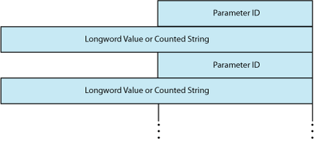
Table 9.33, ''P2 Attributes'' is an alphabetic listing of the parameter IDs and values that can be specified in the P2 buffer. These parameter IDs are applicable to all LAN controllers, except where otherwise noted. The $NMADEF macro defines these values. The $NMADEF macro is included in the macro library SYS$LIBRARY:LIB.MLB. (Table 9.33, ''P2 Attributes'' lists the parameters that can be used with each of the packet formats, and indicates which are required, which are optional, and which generate the SS$_BADPARAM error.)
If the status SS$_BADPARAM is returned in the first word of the I/O status block, the second longword contains the parameter ID of the parameter in error.
| Parameter ID | Meaning |
|---|---|
| NMA$C_PCLI_ACC |
Protocol access mode. This optional parameter determines the access mode for the protocol type. NMA$C_PCLI_ACC is valid only for ports using Ethernet packet format. NMA$C_PCLI_ACC is valid for ports using 802E packet format. One of the following values can be specified:
Section 9.4.8, ''Protocol Type and PID Sharing'' provides a description of protocol type sharing. Section 9.4.8, ''Protocol Type and PID Sharing'' provides a description of protocol type PID sharing. NMA$C_PCLI_ACC is passed as a longword value. |
| NMA$C_PCLI_BFN |
Number of receive buffers to preallocate (default = 1). NMA$C_PCLI_BFN can have a maximum value of 255. This optional parameter is specified on a per-port basis. NMA$C_PCLI_BFN is passed as a longword value. NMA$C_PCLI_BFN represents the number of receive messages the LAN driver holds for a port when the port has no read QIOs posted to the driver. |
| NMA$C_PCLI_BUS |
Any message received for this port that is larger than this parameter value is discarded. Maximum allowable port receive data size, that is, message length (default = 512 bytes). NMA$C_PCLI_BUS can have a maximum value of 9234. This optional parameter is specified on a per-port basis. It is passed as a longword value. |
| NMA$C_PCLI_CCA |
Can change address. This optional parameter enables applications to start before DECnet starts. DECnet may attempt to set the physical address of the controller when it starts. Ethernet devices support only one physical address, and so all applications that are using the same device must also use the same physical address. If applications that do not use the DECnet address start before DECnet, DECnet is not able to start on that controller unless the other applications that have already started have all specified NMA$C_PCLI_CCA to be ON. This parameter is not applicable to FDDI because FDDI devices can run with more than one physical address; however, no error is returned if this parameter is supplied for FDDI devices. The application receives no indication whatsoever that the physical address has changed. This parameter is passed as a longword. One of the following values can be specified:
|
| NMA$C_PCLI_CON[1] |
Controller mode. This optional parameter determines whether transmit packets are to be looped back at the controller. One of the following values can be specified: NMA$C_LINCN_NOR — Normal mode (default) NMA$C_LINCN_LOO — Loopback mode The only messages looped back are those acceptable to the controller as receive messages, that is, those messages that possess at least one of the following characteristics:
NMA$C_PCLI_CON affects all ports on a single controller. It is passed as a longword value. For the DELUA, DEBNA, DEBNI, DEQTA, PMAD, DEMNA, and DESVA, the following list shows the maximum amount of user data that can be looped: Ethernet format without padding — 18 bytes Ethernet format with padding — 16 bytes 802 format with 1-byte CTL field — 15 bytes 802 format with 2-byte CTL field — 14 bytes 802 extended format—10 bytes When the DEUNA is in loopback mode, the driver always enables echo mode (NMA$C_PCLI_EKO is in the ON state). Not all devices support loopback mode. If normal mode is not specified, the request is completed with SS$_BADPARAM status. |
| NMA$C_PCLI_CRC? |
Cyclic redundancy check (CRC) generation state for transmitted messages (optional). One of the following values can be specified: NMA$C_STATE_ON — Controller generates a CRC (default).NMA$C_STATE_OFF — Controller does not generate a CRC.NMA$C_PCLI_CRC affects all ports on a single controller. There is no effect on checking a receive message’s CRC (it is always checked). NMA$C_PCLI_CRC is passed as a longword value. If NMA$C_PCLI_CRC is turned off, all users of the controller must supply the 4-byte CRC value for all messages transmitted. The CRC is passed at the end of the P1 transmit buffer; the additional 4 bytes are included in the size of the P1 buffer. The CRC value is not checked for correctness. For the DEQNA, DELQA, and Token Ring devices, the NMA$C_PCLI_CRC parameter cannot be turned off. For the DEQNA, DELQA, and Token Ring devices, the NMA$C_PCLI_CRC parameter cannot be turned off. Not all devices support user-supplied CRC. If a controller-generated CRC is specified, the request is completed with SS$_BADPARAM status. |
| NMA$C_PCLI_DES |
Shared protocol destination address. Passed as a counted string that consists of a modifier word (NMA$C_LINMC_SET or NMA$C_LINMC_CLR) followed by a 6-byte (48-bit) physical destination address. The size of the counted string must always be 8. NMA$C_PCLI_DES only has meaning when protocol access (NMA$C_PCLI_ACC) is defined as shared-with-destination mode (NMA$C_ ACC_LIM). The destination address specified must be a physical address—not a multicast address—and it must be unique among all ports sharing the same protocol. NMA$C_PCLI_DES is required when the access mode is defined as ‘‘shared-with-destination.’’ NMA$C_PCLI_DES should not be specified on a port where the 802 or 802E packet format is selected (NMA$C_PCLIFMT is set to NMA$C_LIFM_802 or NMA$C_LIFM_802E). For 802 packet format, the concept of shared protocol type is handled by using group SAPs. NMA$C_PCLI_DES should not be specified on a port where the 802 packet format is selected (NMA$C_PCLIFMT is set to NMA$C_LIFM_802). For 802 packet format, the concept of shared protocol type is handled by using group SAPs. Section 9.4.8, ''Protocol Type and PID Sharing'' provides a description of protocol type sharing. Section 9.4.8, ''Protocol Type and PID Sharing'' provides a description of protocol type PID sharing. |
| NMA$C_PCLI_EKO? |
Echo mode. Applicable only to the DEUNA device driver. If echo mode is on, transmitted messages are returned to the sender. This optional parameter controls the condition of the half-duplex bit in the DEUNA mode register. One of the following values can be specified: NMA$C_STATE_OFF — Does not echo transmit messages (default) NMA$C_STATE_ON — Echoes transmit messages If NMA$C_STATE_ON is specified, the only transmitted messages echoed are those acceptable to the DEUNA as receive messages, that is, those messages that have at least one of the following characteristics:
If the DEUNA is placed in loopback mode (NMA$C_LINCN_LOO is specified in the NMA$C_PCLI_CON parameter), the driver enables echo mode. NMA$C_PCLI_EKO affects all ports on a single controller. It is passed as a longword value. |
| NMA$C_PCLI_FMT |
Packet format. This optional parameter specifies the packet format as either Ethernet, IEEE 802, or 802 extended. This characteristic is passed as a longword value and affects single ports on a single controller. One of the following values can be specified: NMA$C_LINFM_ETH — Ethernet packet format (default) NMA$C_LINFM_802 — 802 packet format NMA$C_LINFM_802E — 802 extended packet format NMA$C_PCLI_PTY, NMA$C_PCLI_ACC, and NMA$C_PCLI_DES should only be specified on those ports where the Ethernet packet format (NMA$C_LINFM_ ETH) is selected. NMA$C_PCLI_SRV, NMA$C_PCLI_SAP, and NMA$C_PCLI_GSP should only be specified on those ports where the 802 packet format (NMA$C_LINFM_802) is selected. NMA$C_PCLI_PID should only be specified on those ports where the 802 extended packet format (NMA$C_LINFM_802E) is selected. |
| NMA$C_PCLI_GSP |
Group SAP. This is an optional parameter if the 802 packet format is selected (NMA$C_PCLIFMT is set to NMA$C_LINFM_802). If the Ethernet or 802 extended packet format is selected, NMA$C_PCLI_GSP cannot be specified. Group SAPs can be shared among multiple ports on the same controller. If the 802 packet format is selected, NMA$C_PCLI_GSP defines up to four 802 group SAPs that are to be enabled for matching incoming packets to complete read operations on this port. By default, no group SAPs are enabled. NMA$C_PCLI_GSP is passed as a longword value and is read as four 8-bit unsigned integers. Each integer must be either a group SAP or zero. To enable a single group SAP on a port, you need only specify the group SAP value to be enabled in one of the four integers and place a value of zero in the three remaining integers. To disable group SAPs on the port, you need only place a value of zero in all four integers and issue the QIO. If this characteristic is correctly specified, any group SAPs that were previously enabled on the port are now replaced by the SAPs specified by the current request. |
| NMA$C_PCLI_ILP? |
Internal loopback mode. This optional parameter places the device in internal loopback mode (not for the DEUNA, DEQNA, or DELQA devices). One of the following values can be specified: NMA$C_STATE_OFF — Not in internal loopback mode (default) NMA$C_STATE_ON — Internal loopback mode If NMA$C_STATE_ON is specified, the NMA$C_PCLI_CON parameter must be in loopback (NMA$C_LINCN_LOO) mode. When the controller is in loopback mode (generally for testing), it can loop packets in external loopback or internal loopback. This parameter places the controller in one of these loopback modes. NMA$C_PCLI_ILP is passed as a longword value and affects all ports on the controller. Not all devices support loopback mode. If NMA$C_STATE_OFF is not specified, the request is completed with SS$_BADPARAM status. |
| NMA$C_PCLI_MCA |
Multicast address (optional). Passed as a counted string that consists of a modifier word followed by a list of 6-byte (48-bit) multicast addresses. The value specified in the modifier word determines whether the addresses are set or cleared. If NMA$C_LINMC_CAL is specified, all multicast addresses in the list are ignored. The following mode values can be specified in the low byte of the modifier word: NMA$C_LINMC_CLR — Clear the multicast addresses. NMA$C_LINMC_CAL — Clear all multicast addresses. NMA$C_LINMC_SET — Set the multicast addresses. The driver filters all multicast addresses on a per-port basis; therefore, only messages received with the port's physical address or the multicast addresses enabled on the port are used to complete the user's read operations. Note that each LAN controller supports a limited number of multicast addresses. If this limit is exceeded, the LAN driver enables the “accept all multicast” feature on the controller and all multicast packets on the LAN must be filtered by the LAN driver. This may cause a minor performance loss. NMA$C_PCLI_MCA is specified on a per-port basis. |
| NMA$C_PCLI_MLT |
Multicast address state. This optional parameter instructs the controller hardware whether to accept all multicast addresses for this port. One of the following values can be specified: NMA$C_STATE_ON — Accept all multicast addresses. NMA$C_STATE_OFF — Do not accept all multicast addresses (default). NMA$C_PCLI_MLT allows you to receive all multicast address packets that also match the port's protocol type, SAP, or protocol identifier. Generally, you enable only your individual set of multicast addresses using the NMA$C_PCLI_MCA parameter, and leave the NMA$C_PCLI_MLT parameter in the off state. There could be a minor performance loss when the NMA$C_PCLI_MLT parameter is in the ON state because the LAN driver may have to process all multicast addresses on the medium; the number of multicast addresses on the line determines the amount of processing required. The NMA$C_PCLI_MLT parameter is passed as a longword value. |
| NMA$C_PCLI_PAD |
Use message size field on transmit and receive messages (optional). One of the following values can be specified: NMA$C_STATE_ON — Insert message size field (default) NMA$C_STATE_OFF — No size field NMA$C_PCLI_PAD affects only the protocol type that issued the set mode request. It is passed as a longword value. On Ethernet, if padding is enabled on Ethernet format packets, the driver adds a 2-byte count field to the transmitted data. This field allows short packets (packets fewer than 46 bytes long) to be received with the proper length returned by the driver. The minimum Ethernet packet contains 46 bytes of user data. When fewer than 46 bytes are sent, the packet is padded and the receiver always receives 46 bytes of data. When padding is enabled, the maximum message size for transmit or receive operations is 1498 bytes (8998 bytes for jumbo packets) and the minimum is zero bytes. See Section 9.4.6.5.1, ''Ethernet Protocol Types'' for additional information. NMA$C_PCLI_PAD should be specified only on a port where the Ethernet packet format is selected (NMA$C_PCLI_FMT is set to NMA$C_LINFM_ETH). For FDDI, the same 2-byte count field is added; however, because FDDI packets can be as short as 22 bytes, FDDI transmit requests are never padded. |
| NMA$C_PCLI_PHA? |
Physical address (optional). It is passed as a counted string that consists of a modifier word followed by the 48-bit physical address. If the request is to clear the physical address or to set the physical address to the default address, the physical address (if present) is not read. One of the following mode values can be specified in the low byte of the modifier word: NMA$C_LINMC_SET — Set the string value. NMA$C_LINMC_CLR — Clear the physical address. NMA$C_LINMC_SDF — Set the physical address to the default address. For CSMA/CD, the default address is constructed by appending the low-order word of the system parameter SCSSYSTEMID to the constant DECnet header (AA-00-04-00). If SCSSYSTEMID is zero, and NMA$C_LINMC_SDF is specified, the hardware address is used as the default. If not specified for Ethernet, the default is the current address set by a previous set mode function on this controller, or the hardware address if no address was defined by a previous set mode function. If not specified for FDDI, the default is the hardware address. The physical address must be passed as a 6-byte (48-bit) quantity. The first byte is the least significant byte. A return value of -1 on a sense mode request implies that a physical address is not defined. The NMA$C_PCLI_PHA parameter affects all ports on a single controller. If the address specified is already being used on the extended LAN, SS$_IVADDR is returned. |
| NMA$C_PCLI_PID |
Protocol identifier. This parameter is required for, and valid only on, ports that use 802 extended format packets. NMA$C_PCLI_PID is passed as a counted 5-byte string, which is the unique protocol identifier required for each 802 extended format user. All protocol identifiers specified on a controller must be unique except when the PID is being shared. NMA$C_PCLI_PID may only be specified on a port when the 802 extended packet format is selected; that is, NMA$C_PCLIFMT is set to NMA$C_LIFM_802E. |
| NMA$C_PCLI_PRM |
Promiscuous (optional). One of the following values can be specified:
The NMA$C_PCLI_PRM parameter is passed as a longword value. Only one port on each controller can be active with promiscuous mode enabled. Enabling promiscuous mode requires PHY_IO privilege. The NMA$C_PCLI_PRM parameter is passed as a longword value. Do not use the promiscuous mode for normal usage. Some Token Ring devices do not support real promiscuous access to the ring. See Section 9.8.1, ''Promiscuous Mode'' for additional information. |
| NMA$C_PCLI_PTY |
Protocol type. This value is read as a 16-bit unsigned integer and must be unique on the controller except when the protocol type is being shared. For Ethernet format ports, this is a required parameter. Valid protocol types are in the range 05-DD through FF. NMA$C_PCLI_PTY may only be specified on a port where the Ethernet packet format is selected (NMA$C_PCLI_FMT is set to NMA$C_LINFM_ETH). NMA$C_PCLI_PTY is passed as a longword value; however, only the low-order word is used. |
| NMA$C_PCLI_RAC |
Receive access control (Token Ring only). This optional parameter specifies whether the application receives a copy of the access control (AC) field for each Token Ring frame received. It is passed as a longword value. It must be passed with one of the following values:
The AC is returned in the P5 buffer. The P5 buffer size for Token Ring should always be a minimum of 54 bytes. This is due to the variable size of the Token Ring header. |
| NMA$C_PCLI_RES |
Restart. This optional parameter allows the user to enable the automatic port restart feature of the LAN drivers. One of the following values can be specified:
The LAN drivers shut down all users of a controller if there is a fatal error on the controller or if the LAN driver determines that the controller has stopped functioning. All outstanding I/O operations on the LAN driver are completed with either an SS$_ABORT or SS$_TIMEOUT status. All ports that have the NMA$C_PCLI_RES parameter enabled (set to NMA$C_LINRES_ENA) have the port automatically restarted by the LAN driver approximately one second after it has been shut down due to a fatal error. If the user issues read or write QIOs to the port during the time the port is shut down, the driver completes the QIOs with an SS$_OPINCOMPL status. All ports that have the automatic restart feature disabled must be restarted by the application program when the port is shut down by the LAN driver. The application program should wait approximately 2 seconds to allow the LAN driver to stabilize. Once the LAN driver shuts down a port, it attempts a maximum of 30 consecutive automatic restarts. If there are 30 consecutive failures to restart the port, the port remains shut down. Note that it is unusual to have fatal errors on a LAN controller or to have a LAN driver detect that a LAN controller has stopped functioning. Having the ability to automatically restart a user's port makes the program easier to design because the program does not have to take into account the possibility of the LAN driver shutting down the port. |
| NMA$C_PCLL_RFC |
Receive frame control (FDDI only). This optional parameter specifies whether the application receives a copy of the Frame Control (FC) field for each FDDI frame received. It is passed as a longword value. However, only the low-order byte is used. It must be passed with one of the following values:
For $QIO Read operations, the FC is passed to the application in the P5 buffer. The following are the sizes required for the P5 buffer for various packet formats and settings of NMA$C_PCLI_RFC:
|
| NMA$C_PCLI_SAP |
802 format SAP. This parameter is required if the 802 packet format is selected (NMA$C_PCLI_FMT is set to NMA$C_LINFM_802)> NMA$C_PCLI_SAP defines an 802 SAP and is read as an 8-bit unsigned integer. The least significant bit of the SAP must be 0 and the SAP cannot be the null SAP (all 8 bits equal 0) or the SNAP SAP. NMA$C_PCLI_SAP is passed as a longword value. However, only the low-order byte is used. The SAP specified by NMA$C_PCLI_SAP is the SAP used to match incoming packets to complete read requests. It is used as the source SAP (SSAP) in all transmissions (write QIOs). Because it is illegal to transmit using a group SAP as the source SAP, the SAP specified by this NMA$C_PCLI_SAP cannot be a group SAP. NMA$C_PCLI_GSP describes how to set up group SAPs on a port. All individual SAPs specified on a controller must be unique on that controller; therefore, the SAP specified using the NMA$C_PCLI_SAP parameter is checked for uniqueness on the controller. |
| NMA$C_PCLI_SRMODE |
Sets the source routing (SR) mode for the $QIO user (Token Ring only). This optional parameter allows the application to perform the source routing discovery. It must be passed with one of the following values:
The $QIOs exist to further manipulate the source routing cache. Use the NMA$C_SR_TRANSPARENT mode for applications. |
| NMA$C_PCLI_SRV |
Port service. This optional parameter specifies the service supplied by the driver for the port. It can only be specified if the 802 packet format is selected (NMA$C_PCLI_FMT is set to NMA$C_LINFM_802). This characteristic is passed as a longword value. One of the following values can be specified:
|
| NMAC$C_PCLI_XAC | Transmit access control (Token Ring only). This is an optional parameter that enables applications to control the setting of the priority bits in the access control (AC) for frames being transmitted in a $QIO write operations. When set to a wanted value, all subsequent transmits use this AC value. |
| NMA$C_PCLI_XFC |
Transmit frame control (FDDI) only). NMA$C_PCLI_XFC is an optional parameter that enables applications to control the setting of the priority bits in the FC for frames being transmitted in a $QIO write operation. NMA$C_PCLI_XFC is passed as a longword parameter that has many valid settings. If specified with a value of 0, the application supplies an FC value on each $QIO write operation. The FC value to be used in this case is supplied in the P5 buffer for the $QIO write operation. If the parameter is specified with a value other than 0, that value is inserted into the FC field of every transmit by the FDDI drivers. NO FC is present in the P5 buffer for the $QIO write in this case. If this parameter is not specified, the default setting (0) of the priority bits is used. Regardless of how the FC is supplied, the value specified must be valid. The allowable values for FC are between 50 hexadecimal and 57 hexadecimal. If NMA$C_PCLI_XFC is specified with a nonzero value outside the valid range, the application receives a SS$_BADPARAM error. The priority bits are the three low-order bits. |
9.7.3.2. Set Mode Parameters for Packet Formats
Table 9.34, ''Set Mode Parameters for Packet Formats'' summarizes the use of the set mode parameters for the Ethernet, 802, and 802 extended (802E) packet formats.
| Parameter ID | Ethernet | IEEE 802 | 802E |
|---|---|---|---|
| FMT | Default | Required | Required |
| PTY | Required | Error | Error |
| SAP | Error | Required | Error |
| PID | Error | Error | Required |
| ACC | Optional | Error | Error |
| DES | Optional | Error | Error |
| PAD | Optional | Error | Error |
| SRV | Error | Optional | Error |
| GSP | Error | Optional | Error |
| BFN, BUS, CCA, CON, CRC, EKO, ILP, MCA, MLT, PHA, PRM, RAC, RES, RFC, SRMODE, XAC, XFC | Optional | OPT | OPT |
9.7.3.3. Set Mode Parameter Validation
When starting a LAN port, the LAN driver checks that the mode of the new port is compatible with the mode of the LAN ports already started. There are two sets of compatibility checks: one for ports running in shared mode and one for all ports.
The following parameters must match for all ports on the same controller:
NMA$C_PCLI_CON
NMA$C_PCLI_CRC
NMA$C_PCLI_EKO
NMA$C_PCLI_ILP
NMA$C_PCLI_PHA (need only match for Ethernet controllers)
Once a port is started, only the following parameters can be changed:
NMA$C_PCLI_GSP
NMA$C_PCLI_MCA
9.7.4. Shutdown Controller
The shutdown controller function shuts down the LAN port. On completion of a shutdown request all outstanding I/O requests are completed. This port cannot be used again until another startup request has been issued (see Section 9.7.3.1, ''Set Controller Mode'').
The following function code is used to shut down a port:
IO$_SETMODE!IO$M_CTRL!IO$M_SHUTDOWN—Shut down port
The shutdown controller function takes no device- or function-dependent arguments.
9.7.5. Enable Attention AST
This function requests that an attention AST be delivered to the requesting process when a status change occurs on the assigned port. An AST is queued when a message is available and there is no waiting read request. The enable attention AST function is legal at any time, regardless of the condition of the unit status bits.
The following function code and modifier is used to enable an attention AST:
IO$_SETMODE!IO$M_ATTNAST—Enable attention AST
This function takes the following device- or function-dependent arguments:
P1—The address of an AST service routine or 0 for disable
P2—Ignored
P3—Access mode to deliver AST
The enable attention AST function enables an attention AST to be delivered to the requesting process once only. After the AST occurs, it must be explicitly reenabled by the function before the AST can occur again. The function is subject to AST quotas.
The AST service routine is called with an argument list. The first argument is the current value of the second longword of the I/O status block (see Section 9.7.13, ''I/O Status Block'').
9.7.6. IO$M_SET_MAC Functional Modifier to IO$M_SETMODE
The IO$M_SET_MAC qualifier, when used with IO$_SETMODE, is used to set medium specific parameters. The Token Ring parameters require PHY_IO privilege to be set. Table 9.35, ''Parameters of IO$M_SET_MAC for Ethernet'' shows the parameters that may be set for Ethernet. Table 9.36, ''Parameters of IO$M_SET_MAC for FDDI'' shows the parameters that may be set for FDDI. Table 9.37, ''Parameters of IO$M_SET_MAC for Token Ring'' shows the parameters that may be set for Token Ring, and Table 9.38, ''Parameters of IO$M_SET_MAC for ATM'' shows the parameters that may be set for ATM.
| Parameter ID | Meaning |
|---|---|
| MA$C_PCLI_FDE | Enables or disables full duplex operation. The values for this parameter are NMA$C_STATE_ON or NMA$C_STATE_OFF. |
| NMA$C_PCLI_LINEMEDIA |
Sets the connection media type for the Ethernet adapter. Valid values for this parameter are:
|
| NMA$C_PCLI_LINESPEED |
Sets the speed of the Ethernet adapter. Valid values for this parameter are:
|
| Parameter ID | Meaning |
|---|---|
| NMA$C_PCLI_TREQ | Requested value for token rotation timer, ANSI MAC T_req parameter. Units are in 80 nanoseconds, the default is 8000, minimum is 4000, and maximum is 167772. |
| NMA$C_PCLI_TVX | Maximum time between arrivals of a valid frame or unrestricted token, ANSI MAC TVX parameter. Units are in 80 nanoseconds, the default is 2621, minimum is 2500, and maximum is 5222. |
| NMA$C_PCLI_REST_TTO | Restricted token timeout which limits how long a single restricted mode dialog may last before being terminated. Units are in milliseconds, the default is 1000, minimum is 0, and maximum is 10000. |
| NMA$C_PCLI_RPE | Ring purge enable. If 1 (TRUE), this link participates in the Ring Purger election and, if elected, perform the Ring Purger function. |
| NMA$C_PCLI_NIF_TARG | Neighbor information frame target. |
|
NMA$C_PCLI_SIF_CONF_ | Station information frame configuration target. A 6-byte string specifying the LAN address of the target. Used only by DECnet/OSI. |
| NMA$C_PCLI_SIF_OP_TARG | Station information frame operation target. A 6-byte string specifying the LAN address of the target. Used only by DECnet/OSI. |
| NMA$C_PCLI_ECHO_TARG | Echo test target. A 6-byte string specifying the LAN address of the target. Used only by DECnet/OSI. |
| NMA$C_PCLI_ECHO_DAT | Data pattern to use for the echo test. Used only by DECnet/OSI. |
| NMA$C_PCLI_ECHO_LEN | Length of the echo packet. Used only by DECnet/OSI. |
| Parameter ID | Meaning |
|---|---|
| NMA$C_PCLI_RNG_SPD |
Sets the speed of the ring. This longword may be either:
The default is NMA$C_LINRNG_SIXTN. |
| NMA$C_PCLI_LINEMEDIA |
Sets the connection media type for the Token Ring adapter. Valid values for this longword parameter are:
The default is NMA$C_MEDIA_STP. |
| NMA$C_PCLI_ETR | Controls the Early Token release feature of the Token Ring hardware. This feature can greatly improve throughput, and is only valid on 16 Mb/s rings. The values for this longword parameter are NMA$C_STATE_ON or NMA$C_STATE_OFF. The default is NMA$C_STATE_ON. |
|
NMA$C_PCLI_ | Specifies whether the controller participates in the monitor contention process when another adapter detects the need for contention and initiates the process. The values for this longword parameter are NMA$C_STATE_ON or NMA$C_STATE_OFF. The default is NMA$C_STATE_OFF. |
| NMA$C_PCLI_CACHE_ENT | The number of source routing (SR) entries to make available for caching. The default is 200, minimum is 20, and maximum is 2000. Each cache entry consumes 64 bytes. |
| NMA$C_PCLI_ROUTEDIS | The source routing discovery timer. This is the amount of seconds to wait after the transmission of ring explorer packets before declaring the route of a path to be unknown. The default is 2 seconds, minimum is 1, and maximum is 255. |
| NMA$C_PCLI_A_TIM | The source routing aging timer. After traffic is neither received from nor sent to a given node for this number of seconds, the entry is marked stale. After the entry is marked stale, rediscovery is required to communicate with the node. The default is 60 seconds, minimum is 1, and maximum is 65535. |
| NMA$C_PCLI_SRC_ROU | Enables and disables source routing. The values for this longword parameter are NMA$C_LINSRC_ENA or NMA$C_LINSRC_DIS. The default is NMA$C_LINSRC_ENA. |
| NMA$C_PCLI_AUTH_PR | Specifies the highest priority that a user may transmit a frame. The priority is set within the NMA$C_PCLI_XAC parameter. The default for this parameter is 3, minimum is 0, and maximum is 6. |
| Parameter ID | Meaning |
|---|---|
| NMA$C_PCLI_MED | Medium. This longword parameter defaults to and may only be set to NMA$C_LINMD_CSMACD. |
| NMA$C_PCLI_BUS | Buffer size. This longword parameter specifies the requested maximum packet size of the emulated LAN. The value may be either 1516, 4544, or 9234. |
| NMA$C_PCLI_ELAN_PAR | Parent device name. This is a 3- or 4-character string parameter that specifies the name of the ATM device to associate with this emulated LAN. |
| NMA$C_PCLI_NET | ELAN name. This is a string of up to 64 characters that specifies the name of the emulated LAN to join. |
| NMA$C_PCLI_ELAN_DESC | ELAN description. This is a string of up to 64 characters long that provides additional description of the emulated LAN for status displays. |
| NMA$C_PCLI_LES_HWA | LES ATM address. This is specified as a 40-character string as the hexadecimal representation of a 20-byte ATM address. |
|
NMA$C_PCLI_ELAN_STATE_ | ELAN change state request value. This longword parameter directs the driver to either start or shutdown the emulated LAN. Start is specified by a value of 2. Shutdown is specified by a value of 4. |
| NMA$C_PCLI_EVENT_REQ | Event mask request. If set to 1, this longword parameter directs the driver to set the event reporting mask to the value given by the event parameter. |
| NMA$C_PCLI_EVENT | Event mask value. This is a longword bit mask that controls the event reporting done by the driver. A bit set in the mask enables the reporting of corresponding event(s). |
9.7.7. IO$M_UPDATE_MAP Functional Modifier to IO$_SETMODE
Using Token Ring only, the IO$M_UPDATE_MAP qualifier, when used with IO$_SETMODE, manipulates the adapter's functional address mapping table. Figure 9.15, ''Format of IO$M_UPDATE_MAP Setmode P2 Buffer'' shows the format of the P2 buffer for this operation. This QIO requires PHY_IO privilege.
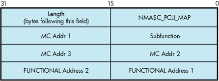
The subfunction is one of the following:
NMA$C_MAP_CHANGE — This function adds or changes a mapping in the functional address table. If the specified multicast entry does not exist, an entry is created with the specified functional address mask. If the specified multicast entry does exist, the corresponding functional address mask is changed to the specified mask. All users who currently have the multicast enabled when the functional mask is changed will automatically update the functional address table as part of this operation.
Possible errors returned include the following:
SS$_DEVICEFULL — This error indicates that there is insufficient space in the mapping table to complete the request. The multicast to functional address mapping table has 200 entries.
NMA$C_MAP_DELETE — This function deletes the specified MC address in the table. For this function, the functional address mask is not required to pass the P2 buffer. If the functional address mask is passed, its contents are ignored.
Possible errors returned include the following:
SS$_BADPARAM — This error indicates that the specified multicast address cannot be found in the table.
The following example maps multicast address AB-01-01-01-02-03 to the functional address 03-00-00-01-00-00 for device ICA0:
LANCP>SET DEVICE/MAP= -_LANCP>(MULTICAST=AB-01-01-01-02-03, -_LANCP>FUNCTIONAL=00-01-00-00) ICA0:
The following example deletes the mapping of the multicast address of AB-01-01-01-02-03 for the device ICA0:
LANCP>SET DEVICE/NOMAP=(MULTICAST=AB-01-01-01-02-03) ICA0:
9.7.8. IO$M_ROUTE Functional Modifier to IO$_SETMODE
For Token Ring only, the IO$M_ROUTE qualifier, when used with IO$_SETMODE, manipulates the source routing cache table. This command is successful only when source routing is enabled. Source routing is enabled with the set mac qualified set mode QIO. Figure 9.16, ''Format of the IO$M_ROUTE P2 Buffer'' shows the format of the P2 buffer. This QIO requires the PHY_IO privilege.
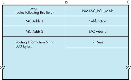
The subfunction is one of the following:
NMA$C_SR_ADD — This function adds or changes a source routing cache entry. It enters the LAN address into the table with the enclosed routing information. The routing information string format is documented in Section 9.4.6.3, ''Token Ring Frames''. If RI_size is passed as 0, the entry is created (or modified) to be in the EXPLORING state (this is useful for users who are doing their own source routing). If the RC 'Lth' field is 0, the LAN address is entered in the table as being in the local state.
Possible errors returned include:
SS$_INSFMEM — The source routing cache is full.
SS$_BADPARAM — An invalid RI string was passed or invalid sizes were passed.
SS$_IVMODE — Source routing is not enabled.
NMA$C_SR_DELETE — This function deletes a source routing cache entry. The RI_size and the routing information string are not required for this QIO. If one or both of the fields are passed for this operation, they are ignored. The result of this command is to put the entry into the deleted state. When the entry goes into the deleted state, it is deleted within 10 minutes.
Possible errors returned include the following:
SS$_BADPARAM — The requested entry could not be found.
9.7.9. Sense Mode and Sense Characteristics
The sense mode function returns the port attributes in the specified buffer. These attributes include the device characteristics described in Section 9.6, ''LAN Device Information''“LAN Device Information” and, with the exceptions noted below, the attributes listed in Table 9.33, ''P2 Attributes''.
The following combinations of function code and modifier are provided:
IO$_SENSEMODE!IO$M_CTRL—Read characteristics
IO$_SENSECHAR!IO$M_CTRL—Read characteristics
IO$_SENSEMODE!IO$M_SENSE_MAC—Medium specific characteristics
IO$_SENSEMODE!IO$M_SHOW_MAP—Returns current functional address to multicast address mapping (Token Ring only)
IO$_SENSEMODE!IO$M_SHOW_ROUTE—Returns current source routing cache table (Token Ring only)
These functions take the following device- or function-dependent arguments:
P1—The address of a two-longword buffer where the device characteristics are stored. (Figure 9.17, ''Sense Mode P1 Characteristics Buffer'' shows the format for, and Section 9.6, ''LAN Device Information'' describes the contents of, the P1 buffer.) The P1 argument is optional.
P2—The address of a quadword descriptor where the attributes buffer is stored. The first longword of the descriptor is the buffer length; the second longword is the address of the buffer. The P2 argument is optional.
The P2 buffer is not read by the LAN driver. The driver stores the port's attributes in the buffer, which contains multiple entries. The format of each entry depends on whether a longword or a counted string is returned, as shown in Figure 9.18, ''Sense Mode Attribute Buffer''. Each parameter ID contains a string indicator bit (bit 12) that describes whether the data item is a string or a longword.
Except for the following differences, P2 returns the same attributes as those listed in Table 9.31, ''Maximum Message Sizes for Ethernet, FDDI, and Token Ring'':
All parameters that are valid for the enabled packet format are returned (see Table 9.32, ''Maximum Message Sizes for LAN Emulation over ATM'').
The sense-mode P2 buffer does not return the modifier word for the NMA$C_PCLI_PHA, NMA$C_PCLI_MCA, and NMA$C_PCLI_DES parameter IDs.
The NMA$C_PCLI_DES parameter is only returned on Ethernet ports whose access mode is set to “shared with destination.”
In addition to the parameter IDs listed in Table 9.31, ''Maximum Message Sizes for Ethernet, FDDI, and Token Ring'', the sense-mode P2 buffer contains the following parameter IDs?:
| Parameter ID | Meaning |
|---|---|
| NMA$C_PCLI_FCA | List of the currently enabled functional addresses (Token Ring only). Each 32-bit entry corresponds respectively with the items returned under NMA$C_PCLI_MCA. |
| NMA$C_PCLI_HWA | Hardware address. Describes the value for the hardware address. The hardware address is the default physical address when no physical address has been specified and there are no active users on the controller. NMA$C_PCLI_HWA is returned in the same format as NMA$C_PCLI_PHA. |
| NMA$C_PCLI_MBS | Maximum packet length. NMA$C_PCLI_MBS is a longword, read-only parameter. The value returned reflects the largest data packet that the application can receive for its packet format and type of LAN, measured in bytes. The values for Ethernet, FDDI, and Token Ring are: |
| Packet Format | Ethernet | FDDI | Token Ring |
|---|---|---|---|
| Ethernet format without padding | 1500 | 4470 | 4418 |
| Ethernet format with padding | 1498 | 4468 | 4416 |
| 802 format with 1-byte CTL field | 1497 | 4475 | 4423 |
| 802E format | 1492 | 4470 | 4418 |
The values for LAN emulation over ATM are:
| Packet Format | ATM ELAN size: | 1516 | 4544 | 9234 |
| Ethernet format without padding | 1500 | 4528 | 9218 | |
| Ethernet format with padding | 1498 | 4526 | 9216 | |
| 802 format with 1-byte CTL field | 1497 | 4525 | 9215 | |
| 802E format | 1492 | 4520 | 9210 |
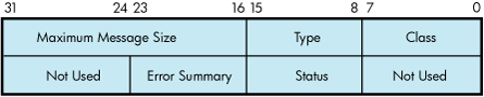
It is suggested that a size of 250 bytes be used for the P2 buffer. This allows space for additional parameters that may be returned in future releases of OpenVMS.
All attributes that fit into the buffer specified by P2 are returned; however, if all the attributes cannot be stored in the buffer, the I/O status block returns the status SS$_BUFFEROVF. The second word of the I/O status block contains the number of bytes used in the P2 buffer (see Section 9.7.13, ''I/O Status Block'').
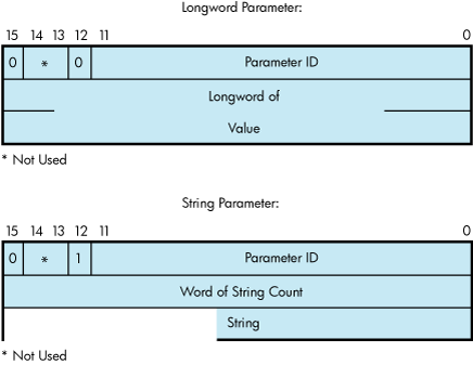
9.7.10. IO$M_SENSE_MAC Functional Modifier to IO$_SENSEMODE
The IO$M_SENSE_MAC qualifier, when used with IO$_SENSEMODE, returns the parameters specified in Section 9.7.6, ''IO$M_SET_MAC Functional Modifier to IO$M_SETMODE''. In addition to the set mac parameters, Table 9.39, ''Parameters of IO$M_SENSE_MAC'' shows the returns of the following parameters:
| Parameter ID | Meaning |
|---|---|
| NMA$C_PCLI_T_NEG | The negotiated value of the token rotation timer (ANSI MAC parameter T_neg) (FDDI only). |
| NMA$C_PCLI_DAT | The duplicate address test flag (FDDI only). If set, this indicates that there is another station on the ring with the same hardware LAN address. |
| NMA$C_PCLI_UNA | Upstream neighbor's address (FDDI and Token Ring). This is a string parameter specifying the 6-byte LAN address of the upstream neighbor. Not all devices may support this feature. |
| NMA$C_PCLI_OLD_UNA | The old (previous) upstream neighbor address (FDDI only). Neighbor addresses change as nodes insert and deinsert into the ring. |
| NMA$C_PCLI_UN_DAT | The upstream neighbor's duplicate address test flag (FDDI only). |
| NMA$C_PCLI_DNA | The downstream neighbor's LAN address (FDDI only). |
| NMA$C_PCLI_OLD_DNA | The old (previous) downstream neighbor's LAN address (FDDI only). |
| NMA$C_PCLI_RPS |
The current ring purger state (FDDI only). This longword parameter is one of the following values:
|
| NMA$C_PCLI_RER |
The latest ring error reason (FDDI only). This longword parameter is one of the following values:
|
| NMA$C_PCLI_NBR_PHY |
Neighbor's PHY type (FDDI only). This longword parameter is one of the following values:
|
| NMA$C_PCLI_RJR |
Ring reject reason (FDDI only). This longword parameter is one of the following values:
|
| NMA$C_PCLI_LEE | Link error estimate (FDDI only). The longword value is a negative exponent of 10 representing the Link error rate. For example, the value of X represents the error rate of 10^X. |
| NMA$C_PCLI_RNG_NUM | The longword value contains the ring number that the controller is running on (Token Ring only). It is only valid for a controller that is started, and also only valid for rings that have a ring parameter server that is configured for providing this information. |
9.7.11. IO$M_SHOW_MAP Functional Modifier to IO$_SENSEMODE
For Token Ring only, the IO$M_SHOW_MAP qualifier, when used with IO$_SENSEMODE, returns the current setting of the mapping table. The P2 buffer is filled with the current multicast to functional address mapping information. The entries are 16 bytes long and are in the format shown in Figure 9.19, ''Format of IO$M_SHOW_MAP P2 Buffer''. This QIO requires PHY_IO privilege.
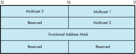
The multicast address and functional address mask are returned in canonical format (that is, not bit-reversed). The following errors may occur:
SS$_BUFFEROVF — The passed buffer is not large enough to hold all the data required for the operation.
SS$_BADPARAM — Not able to get read access to buffer or zero length buffer passed.
9.7.12. IO$M_SHOW_ROUTE Functional Modifier to IO$_SENSEMODE
For Token Ring only, the IO$M_SHOW_ROUTE qualifier, when used with IO$_SENSEMODE, returns the current value of the source routing cache table. Each entry is 64 bytes long. Figure 9.20, ''Format of IO$M_SHOW_ROUTE P2 Buffer'' shows the format of the returned P2 buffer.
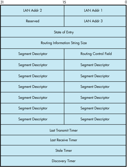
Table 9.40, ''State of the Entry'' shows possible states of the entry.
| Value | Name | Description |
|---|---|---|
| 0 | LOCAL | Address is reachable on the attached ring. |
| 1 | STALE | Entry is stale (inactive). |
| 2 | UNKNOWN | Route to the address is unknown. |
| 3 | DELETED | Entry is marked for deletion. |
| 4 | KNOWN | Route is known and the route is stored in the routing information string. |
| 5 | EXPLORING | Route to the address is currently being explored. |
The LAN address is returned in canonical format (that is, not bit-reversed). The timers are recorded as seconds before expiration. The transmit and receive timers are initialized from the NMA$C_PCLI_A_TIM parameter, the discovery timer is initialized from the NMA$C_PCLI_ROUTEDIS parameter, and the stale timer is initialized to 10 minutes (600 seconds). The following errors may occur:
SS$_BUFFEROVF — The passed buffer is not large enough to hold all the data required for the operation.
SS$_BADPARAM — Not able to get read access to buffer or zero length buffer passed.
9.7.13. I/O Status Block
The I/O status block (IOSB) for all LAN driver functions is shown in Figure 9.21, ''IOSB Contents''. Appendix A, "I/O Function Codes" lists the completion status returned for these functions. (The OpenVMS system messages documentation provides explanations and suggested user actions for these status codes.)
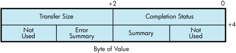
The first longword of the IOSB returns, in addition to the completion status, either the size (in bytes) of the data transfer or the size (in bytes) of the attribute buffer (P2) returned by a sense mode function. The second longword returns the unit and line status bits listed in Table 9.26, ''Ethernet Controller Unit and Line Status'' and the error summary bits listed in Table 9.27, ''Error Summary Bits''.
9.8. Application Programming Notes
This section contains information to assist you in writing application programs that use the LAN device drivers. Section 9.8.1, ''Promiscuous Mode'' discusses the additional rules required for application programs that you intend to run in promiscuous mode. Section 9.8.2, ''Local Area Network Programming Examples'' describe the Ethernet and 802 sample programs.
9.8.1. Promiscuous Mode
The LAN drivers allow only one port per controller to enable promiscuous mode (NMA$C_PCLI_PRM specified as NMA$C_STATE_ON). A port running in promiscuous mode usually places an additional load on the CPU because the LAN device is configured to deliver all received packets to the LAN driver regardless of destination address or multicast filtering. The LAN driver then has deliver the packets to the promiscuous port as well as a copy to the intended recipient.
| I/O Function | Rule |
|---|---|
|
It is not necessary to specify a unique identifier (a protocol type, SAP, or protocol identifier parameter ID) in the P2 buffer. The port cannot be running in shared mode. |
|
IO$_WRITE |
The user can only transmit packets in the packet format previously specified with a set mode QIO when the user was started. The unique identifier for the packet format must be included in the P5 buffer following the destination address (see Section 9.7.2, ''Write''). |
|
IO$_READ |
The LAN driver completes the promiscuous user's read requests with Ethernet, 802, and 802 extended packets. Because any packet format can be used to complete a read request, the P5 parameter (if specified) must be at least 20 bytes in length (21 bytes for FDDI with RFC turned on). All Ethernet format packets are processed as if they have no size field specified after the protocol type. Therefore, Ethernet packets are always returned with 46 to 1500 bytes of data. If the Ethernet packet contains a size field, it is returned as part of the user data in the first word of the P1 buffer. The promiscuous user should use the information returned in the P5 buffer to determine the packet format. If the application program first filled the P5 buffer with zeros, the program can determine the format of the packet received by scanning the P5 buffer after the read request is completed. |
9.8.2. Local Area Network Programming Examples
The MACRO program LANETH.MAR (Example 9.2, ''LANETH.MAR Local Area Network Programming Example'' shows the typical use of QIO functions in driver operations such as establishing the protocol type, starting the port, and transmitting and receiving data. The program sends a LOOPBACK packet and waits for the packet to be returned.
The C program LAN802E.C (Example 9.3, ''LAN802.C Local Area Network Programming Example'') shows how to initialize an 802E port and how to send and receive packets on that port. This program sends a LOOPBACK packet and waits for the packet to be returned.
.TITLE   LAN SAMPLE TEST PROGRAM
.IDENT   /X03/
.PSECT   RWDATA,WRT,NOEXE,PAGE

; This LAN test program sends a MOP loopback message to the Loopback Assistant
; Multicast address and waits for a response. The program uses the LAN device
; EWA0. To use a different device, change the device name in the program or
; define the desired lan device as EWA0.
;
* To build on VAX, Alpha, I64:
;   $ MACRO/OBJECT=LANETH/LIST=LANETH SYS$LIBRARY:ARCH_DEFS.MAR+SYS$DISK:[]LANETH
;   $ LINK LANETH
;
; To run:
;       $ RUN LANETH

        .LIBRARY "SYS$LIBRARY:LIB.MLB"

        $IODEF            ; Define I/O functions and modifiers
        $NMADEF           ; Define Network Management parameters

; Setmode parameter buffer and descriptor. Since the loopback protocol does
; not include a length word following the protocol type, we have to explicitly
; turn off padding since the default is on.
SETPARM:

.WORD    NMA$C_PCLIFMT     ; Packet format
.LONG    NMA$C_LIFM_ETH    ; Ethernet
.WORD    NMA$C_PCLI_PTY    ; Protocol type
.LONG    ^X0090            ; Loopback
.WORD    NMA$C_PCLI_PAD    ; Padding
.LONG    NMA$C_STATE_OFF   ; Off
SETPARMLEN = .-SETPARM

SETPARMDSC:
      .LONG     SETPARMLEN
      .ADDRESS  SETPARM

; Sensemode parameter buffer and descriptor. This is used to get our physical
; address to put into the loopback message.

SENSEBUF:
      .BLKB     512
SENSELEN=.-SENSEBUF

SENSEDSC:
      .LONG     SENSELEN
      .ADDRESS  SENSEBUF

; P2 transmit data buffer.

XMTBUF: .WORD   00   ; Skip count
        .WORD   02   ; Forward request
FORW:   .BLKB   6    ; Forward address
        .WORD   01   ; Reply request
        .WORD   00
XMTBUFLEN = .-XMTBUF ; Size of transmit buffer

; P5 transmit destination address, the Loopback Assistant Multicast Address.
XMTP5:  .BYTE   ^XCF,0,0,0,0,0

; P2 receive data buffer.

RCVBUF:  .BLKB  512
RCVBUFLEN = .-RCVBUF ; Size of receive buffer

; P5 receive header buffer.
RCVP5:

RCVDA:  .BLKB   6
RCVSA:  .BLKB   6
RCVPTY: .BLKB   2

; Messages used to display status of this program.

GMSG:  .ASCID  "Successful test"
LMSG:  .ASCID  "No response"
EMSG:  .ASCID  "Error occurred while running test"
DMSG:  .ASCID  "LAN device not found"

; Miscellaneous data.

IOSB:    .BLKQ    1                ; I/O status block
DEVCHAN: .BLKL    1                ; Returned port number
LANDSC:  .ASCID   'EWA0'           ; Device to use for test

;*************************************************************************
;
; Start of code
;
;*************************************************************************

         .PSECT  CODE,EXE,NOWRT,PAGE
         .ENTRY  START,^M<>

; Assign a port to the LAN device.

       $ASSIGN_S DEVNAM=LANDSC,CHAN=DEVCHAN
       BLBS    R0,10$               ; Branch if succeeded
       MOVAL   DMSG,R9              ; Get address of error message
       BRW     EXIT                 ; Print message and exit

; Set up the port's characteristics.

10$:   MOVAL   EMSG,R9              ; Assume error message address
       $QIOW_S FUNC=#<IO$_SETMODE!IO$M_CTRL!IO$M_STARTUP>,-
               CHAN=DEVCHAN,IOSB=IOSB,-
               P2=#SETPARMDSC
       BLBC    R0,20$               ; Branch if failed
       MOVZWL  IOSB,R0              ; Get status from IOSB
       BLBS    R0,30$               ; Branch if succeeded
20$:   BRW     EXIT                 ; Print message and exit

; Issue the SENSEMODE QIO to get our physical address for the loopback
; message.

30$:   $QIOW_S FUNC=#<IO$_SENSEMODE!IO$M_CTRL>,-
               CHAN=DEVCHAN,IOSB=IOSB,-
               P2=#SENSEDSC
       BLBC    R0,20$               ; Branch if failed
       MOVZWL  IOSB,R0              ; Get status from IOSB
       BLBC    R0,20$               ; Branch if failed

; Locate the PHA parameter in the SENSEMODE buffer and copy it into the
; LOOPBACK transmit message. The PHA parameter is a string parameter.

       MOVAB   SENSEBUF,R0          ; Start at beginning of buffer
40$:   BBS     #^XC,(R0),50$        ; Branch if a string parameter
       ADDL    #6,R0                ; Skip over longword parameter
       BRB     40$                  ; Check next parameter

50$:   BICW3   #^XF000,(R0)+,R1     ; Get type field less flag bits
       CMPW    R1,#NMA$C_PCLI_PHA   ; Is this the PHA parameter?
       BEQL    60$                  ; Branch if so
       ADDW    (R0)+,R0             ; Skip over string parameter
       BRW     40$                  ; Check next parameter
.IF NOT_DEFINED VAX
       .DISABLE FLAGGING
.ENDC
60$:   MOVL     2(R0),FORW          ; Copy our address to the loopback
       MOVW     6(R0),FORW+4        ; packet we are about to transmit
.IF NOT_DEFINED VAX
       .ENABLE FLAGGING
.ENDC

; Transmit the loopback message.

       $QIOW_S FUNC=#IO$_WRITEVBLK,CHAN=DEVCHAN,IOSB=IOSB,-
               P1=XMTBUF,P2=#XMTBUFLEN,P5=#XMTP5
       BLBC    R0,70$               ; Branch if failed
       MOVZWL  IOSB,R0              ; Get status from IOSB
       BLBS    R0,80$               ; Branch if succeeded
70$:   BRW     EXIT                 ; Print message and exit

; Look for a response. We use the NOW function modifier on the READ so that
; we don't hang here waiting forever if there is no response. If there is no
; response in 1000 receive attempts, we declare no response status.

80$:   MOVL    #1000,R2             ; Check 1000 times
90$:   $QIOW_S FUNC=#IO$_READVBLK!IO$M_NOW,CHAN=DEVCHAN,IOSB=IOSB,-
               P1=RCVBUF,P2=#RCVBUFLEN,P5=#RCVP5
       BLBC    R0,EXIT              ; Branch if failed
       MOVZWL  IOSB,R0              ; Get status from IOSB
       BLBS    R0,100$              ; Branch if succeeded
       CMPL    R0,#SS$_ENDOFFILE    ; Was there just no message available?
       BNEQ    EXIT                 ; Branch if failed
       SOBGTR  R2,90$               ; Try again

; No response in 1000 attempts.

       MOVAL   LMSG,R9              ; Get address of lost message
       BRW     EXIT                 ; Print message and exit

; Received a message.

100$:  MOVAL   GMSG,R9              ; Get address of success message

; The test is done. Call LIB$PUT_OUTPUT to display the test status.

EXIT:  PUSHL   R9                   ; P1 = Address of message to print
       CALLS   #1,G^LIB$PUT_OUTPUT  ; Print the message
       $EXIT_S                      ; Exit

       .END   START
/*************************************************************
* LAN Sample Test Program
*
* This LAN test program sends a MOP loopback message to the Loopback Assistant
* Multicast address and waits for a response.  The program uses the LAN device
* EWA0.  To use a different device, change the device name in the program or
* define the desired lan device as EWA0.
*
* To build on VAX:
* $ CC LAN802E
* $ LINK LAN802E,SYS$INPUT:/OPT
* SYS$SHARE:VAXCRTL.EXE/SHARE
*
* Note:  NMADEF.H must be supplied containing definitions for:
*
* #define NMA$C_PCLIFMT 2770
* #define NMA$C_PCLI_PID 2774
* #define NMA$C_PCLI_PHA 2820
* #define NMA$C_LIFM_802E 0
*
* To build on Alpha, I64:
* $ CC LAN802E+SYS$LIBRARY:SYS$LIB_C.TLB/LIB
* $ LINK LAN802E
*
* To run:
* $ RUN LAN802E
*************************************************************/

#include <ctype>         /* Character type classification macros/routines */
#include <descrip>       /* For VMS descriptor manipulation */
#include <iodef>         /* I/O function code definitions */
#include "nmadef.h"   /* LAN parameter definitions */
#include <ssdef>      /* System service return status code definitions */
#include <starlet>    /* System library routine prototypes */
#include <stdio>      /* ANSI C Standard Input/Output */
#include <stdlib>     /* General utilities */
#include <string>     /* String handling */
#include <stsdef>     /* VMS status code definitions */

#define $SUCCESS(status) (((status) & STS$M_SUCCESS) == SS$_NORMAL)
#define $FAIL(status) (((status) & STS$M_SUCCESS) != SS$_NORMAL)
#pragma nomember_alignment struct parm_802e
{
short pcli_fmt;       /* Format - 802E */ int fmt_value;
short pcli_pid;       /* Protocol ID - 08-00-2B-90-00 */ short pid_length;
char pid_value[5];
} setparm_802e = {NMA$C_PCLIFMT, NMA$C_LIFM_802E,
NMA$C_PCLI_PID, 5, 8,0,0x2B,0x90,0};

struct setparmdsc
{
int parm_len;
void *parm_buffer;
};

struct setparmdsc setparmdsc_loop = { sizeof(setparm_802e),&setparm_802e};

struct p5_param                 /* P5 Receive header buffer */
{
unsigned char da[6]; unsigned char sa[6]; char misc[20];
};

struct iosb                     /* IOSB structure */
{
short w_err;                    /* Completion status */
short w_xfer_size;              /* Transfer size */
short w_addl;                   /* Additional status */
short w_misc;                   /* Miscellaneous */
};

struct ascid                    /* Device descriptor for assign */
{
short w_len; short w_info; char *a_string;
} devdsc = {4,0,"EWA0"};

struct iosb qio_iosb; /* IOSB structure */
struct p5_param rcv_param;      /* Receive header structure */
struct p5_param xmt_param = {   /* Transmit header structure */
0xCF,0,0,0,0,0};
char rcv_buffer[512];           /* Receive buffer */

char xmt_buffer[20] = {         /* Transmit buffer */
0,0,                            /* Skip count */
2,0,                            /* Forward request */
0,0,0,0,0,0,                    /* Forward address */
1,0,                            /* Reply request */
0,0};

char sense_buffer[512];         /* Sensemode buffer */

struct setparmdsc sensedsc_loop =
 {sizeof(sense_buffer),&sense_buffer};

/*
* MAIN
*/

main(int argc, char *argv[])
{
int i, j;                       /* Scratch */
int chan;                       /* Channel assigned */
int status;                     /* Return status */

/*
* Start a channel.
*/

status =
 sys$assign(&devdsc,&chan
,0,0); if
 ($FAIL(status))
 exit(status);
status =
 sys$qiow(0,chan,IO$_SETMODE|IO$M_CTRL|IO$M_STARTUP,&qio_iosb,0,0,
0,&setparmdsc_loop,0,0,0,0); if ($SUCCESS(status)) status =
 qio_iosb.w_err;
if ($FAIL(status)) {
    printf("IOSB addl status = %04X
 %04X\n",qio_iosb.w_addl,qio_iosb.w_misc);
 exit(status);
}

/*
* Issue the SENSEMODE QIO to get our physical address for the
loopback message.
*/

status =
sys$qiow(0,chan,IO$_SENSEMODE|IO$M_CTRL,&qio_iosb,0,0,0,
&sensedsc_loop,0,0,0,0); if ($SUCCESS(status)) status =
qio_iosb.w_err;
if ($FAIL(status)) {
    printf("IOSB addl status = %04X
%04X\n",qio_iosb.w_addl,qio_iosb.w_misc);
exit(status);
}

/*
* Locate the PHA parameter in the SENSEMODE buffer and copy it
into the
* LOOPBACK transmit message.  The PHA parameter is a string
parameter.
*/

j = 0;
while (j < sizeof(sense_buffer)) {
i = (sense_buffer[j] +
(sense_buffer[j+1] << 8)); if
(0x1000 & i) {
if ((i & 0xFFF) == NMA$C_PCLI_PHA) {
memcpy(&xmt_buffer[4],&sense_buffer[j+4],6); break;
}
j += (sense_buffer[j+2] + (sense_buffer[j+3] << 8)) + 4;
} else
j += 6;                         /* Skip over longword parameter */
}

/*
* Transmit the loopback message.
*/

status =sys$qiow(0,chan,IO$_WRITEVBLK,&qio_iosb,0,0,&xmt_buffer[0],
        sizeof(xmt_buffer),0,0,&xmt_param,0);
if ($SUCCESS(status)) status
= qio_iosb.w_err; if
($FAIL(status)) {
printf("IOSB addl status = %04X
        %04X (on transmit)\n",
        qio_iosb.w_addl,qio_iosb.w_mis
        c);
exit(status);
}

/*
* Look for a response. We use the NOW function modifier on the READ so that
* we don't hang here waiting forever if there is no response. If there is no
* response in 1000 receive attempts, we declare no response status.
*/

for (i=0;i<1000;i++) {
status =sys$qio(0,chan,IO$_READVBLK|IO$M_NOW,&qio_iosb,0,0,&rcv_buffer[0],
         sizeof(rcv_buffer),0,0,&rcv_param,0);
if ($SUCCESS(status)) status
= qio_iosb.w_err; if
($SUCCESS(status)) break;
}
if
($SUCCESS(status)
)
printf("Successful test\n");
else
printf("No response\n");
}
Chapter 10. Optional Features for Improving I/O Performance
Two features of OpenVMS Alpha and IA-64 servers provide dramatically improved I/O performance: Fast I/O and Fast Path. These features are designed to promote OpenVMS as a leading platform for database systems. Performance improvement results from reducing the CPU cost per I/O request and improving symmetric multiprocessing (SMP) scaling of I/O operations. The CPU cost per I/O is reduced by optimizing code for high-volume I/O and by using better SMP CPU memory cache. SMP scaling of I/O is increased by reducing the number of spinlocks taken per I/O and by substituting finer-granularity spinlocks for global spinlocks.
The improvements follow a natural division that already exists between the device-independent and device-dependent layers in the OpenVMS I/O subsystem. The device-independent overhead is addressed by Fast I/O, which is a set of lean system services that can substitute for certain
$QIO operations. Using these services requires some coding changes in existing applications, but the changes are usually modest and well contained. The device-dependent overhead is addressed by Fast Path, which is an optional performance feature that creates a “fast path” to the device. It requires no application changes.
Fast I/O and Fast Path can be used independently; however, together they can provide a 45 percent reduction in CPU cost per I/O on uniprocessor systems and a 52 percent reduction on multiprocessor systems.
10.1. Fast I/O
Fast I/O is a set of three system services that were developed as a $QIO alternative built for speed. These services are not a $QIO replacement; $QIO is unchanged, and $QIO interoperation with these services is fully supported. Rather, the services substitute for a subset of $QIO operations, namely, only the high-volume read/write I/O requests.
The Fast I/O services support 64-bit addresses for data transfers to and from disk and tape devices.
10.1.1. Fast I/O Benefits
The performance benefits of Fast I/O result from streamlining high-volume I/O requests. The Fast I/O system service interfaces are optimized to avoid the overhead of general-purpose services. For example, I/O request packets (IRPs) are now permanently allocated and used repeatedly for I/O rather than allocated and deallocated anew for each I/O.
The greatest benefits stem from having user data buffers and user I/O status structures permanently locked down and mapped using system space. This allows Fast I/O to do the following:
For direct I/O, avoid per-I/O buffer lockdown or unlocking.
For buffered I/O, avoid allocation and deallocation of a separate system buffer, because the user buffer is always addressable.
Complete Fast I/O operations at IPL 8, thereby avoiding the interrupt chaining usually required by the more general-purpose $QIO system service. For each I/O, this eliminates the IPL 4 IOPOST interrupt and a kernel AST.
In total, Fast I/O services eliminate four spinlock acquisitions per I/O (two for the MMG spinlock and two for the SCHED spinlock). The reduction in CPU cost per I/O is 20 percent for uniprocessor systems and 10 percent for multiprocessor systems.
10.1.2. Using Buffer Objects
The lockdown of user-process data structures is accomplished by buffer objects. A “buffer object” is process memory whose physical pages have been locked in memory and double-mapped into system space. After creating a buffer object, the process remains fully pageable and swappable and the process retains normal virtual memory access to its pages in the buffer object.
If the buffer object contains process data structures to be passed to an OpenVMS system service, the OpenVMS system can use the buffer object to avoid any probing, lockdown, and unlocking overhead associated with these process data structures. Additionally, double-mapping into system space allows the OpenVMS system direct access to the process memory from system context.
To date, only the $QIO system service and the Fast I/O services have been changed to accept buffer objects. For example, a buffer object allows a programmer to eliminate I/O memory management overhead. On each I/O, each page of a user data buffer is probed and then locked down on I/O initiation and unlocked on I/O completion. Instead of incurring this overhead for each I/O, it can be done once at buffer object creation time. Subsequent I/O operations involving the buffer object can completely avoid this memory management overhead.
Two system services can be used to create and delete buffer objects, respectively, and can be called from any access mode. To create a buffer object, the $CREATE_BUFOBJ system service is called. This service expects as inputs an existing process memory range and returns a buffer handle for the buffer object. The buffer handle is an opaque identifier used to identify the buffer object on future I/O requests. The $DELETE_BUFOBJ system service is used to delete the buffer object and accepts as input the buffer handle. Although image rundown deletes all existing buffer objects, it is good form for the application to clean up properly.
A 64-bit equivalent version of the $CREATE_BUFOBJ system service ($CREATE_BUFOBJ_64) can be used to create buffer objects from the new 64-bit P2 or S2 regions. The $DELETE_BUFOBJ system service can be used to delete 32-bit or 64-bit buffer objects.
Buffer objects require system management. Because buffer objects tie up physical memory, extensive use of buffer objects requires system management planning. All the bytes of memory in the buffer object are deducted from a systemwide system parameter called MAXBOBMEM (maximum buffer object memory). System managers must set this parameter correctly for the application loads that run on their systems.
The MAXBOBMEM parameter defaults to 100 Alpha pages, but for applications with large buffer pools it will likely be set much larger. To prevent user-mode code from tying up excessive physical memory, user-mode callers of $CREATE_BUFOBJ must have a new system identifier, VMS$BUFFER_OBJECT_USER, assigned. This new identifier is automatically created in an OpenVMS Version 7.0 upgrade if the file SYS$SYSTEM:RIGHTSLIST.DAT is present. The system manager can assign this identifier with the DCL command SET ACL command to a protected subsystem or application that creates buffer objects from user mode. It may also be appropriate to grant the identifier to a particular user with the Authorize utility command GRANT/IDENTIFIER (for example, to a programmer who is working on a development system).
There is currently a restriction on the type of process memory that can be used for buffer objects. Global section memory cannot be made into a buffer object.
10.1.3. Differences Between Fast I/O Services and $QIO
The precise definition of high-volume I/O operations optimized by Fast I/O services is important. I/O that does not comply with this definition either is not possible with the Fast I/O services or is not optimized. The characteristics of the high-volume I/O optimized by Fast I/O services can be seen by contrasting the operation of Fast I/O system services to the $QIO system service as follows:
The $QIO system service I/O status block (IOSB) is replaced by an I/O status area (IOSA) that is larger and quadword aligned. The transfer byte count returned in IOSA is 64 bits, and the field is aligned on a quadword boundary. Unlike the IOSB, which is optional, the IOSA is required.
User data buffers must be aligned to a 512-byte boundary.
All user process structures passed to the Fast I/O system services must reside in buffer objects. This includes the user data buffer and the IOSA.
Only transfers that are multiples of 512 bytes are supported.
Only the following function codes are supported: IO$_READVBLK, IO$_READLBLK, IO$_WRITEVBLK, and IO$_WRITELBLK.
Only I/O to disk and tape devices is optimized for performance.
No event flags are used with Fast I/O services. If application code must use an event flag in relation to a specific I/O, then the Event No Flag EFN (EFN$C_ENF) can be used. This event flag is a no-overhead EFN that can be used in situations when an EFN is required by a system service interface but has no meaning to an application.
For example, Fast I/O services do not use EFNs, so the application cannot specify a valid EFN associated with the I/O to the $SYNCH system service with which to synchronize I/O completion. To resolve this issue, the application can call the $SYNCH system service passing as arguments: EFN$C_ENF and the address of the appropriate IOSA. Specifying EFN$C_ENF signifies to $SYNCH that no EFN is involved in the synchronization of the I/O. Once the IOSA has been written with a status and byte count, return from the $SYNCH call occurs. The IOSA is now the central point of synchronization for a given Fast I/O (and is the only way to determine whether the asynchronous I/O is complete).
To minimize arguments passing overhead to these services, the $QIO parameters P3 through P6 are replaced by a single argument that is passed directly by the Fast I/O system services to device drivers. For disk-like devices, this argument is the media address (VBN or LBN) of the transfer. For drivers with complex parameters, this argument is the address of a descriptor or of a buffer specific to the device and function.
Segmented transfers are supported by Fast I/O but are not fully optimized. There are two major causes of segmented transfers. The first is disk fragmenting. While this can be an issue, it is assumed that sites seeking maximum performance have eliminated the overhead of segmenting I/O due to fragmentation.
A second cause of segmenting is issuing an I/O that exceeds the port's maximum limit for a single transfer. Transfers beyond the port maximum limit are segmented into several smaller transfers. Some ports limit transfers to 64KB. If the application limits its transfers to less than 64KB, this type of segmentation should not be a concern.
10.1.4. Using Fast I/O Services
The three Fast I/O system services are:
$IO_SETUP—-Sets up an I/O
$IO_PERFORM[W]—-Performs an I/O request
$IO_CLEANUP—Cleans up an I/O request
10.1.4.1. Using Fandles
A key concept behind the operation of the Fast I/O services is the file handle or fandle. A fandle is an opaque token that represents a “setup” I/O. A fandle is needed for each I/O outstanding from a process.
All possible setup, probing, and validation of arguments is performed off the mainline code path during application startup with calls to the $IO_SETUP system service. The I/O function, the AST address, the buffer object for the data buffer, and the IOSA buffer object are specified on input to $IO_SETUP service, and a fandle representing this setup is returned to the application.
To perform an I/O, the $IO_PERFORM system service is called, specifying the fandle, the channel, the data buffer address, the IOSA address, the length of the transfer, and the media address (VBN or LBN) of the transfer.
If the asynchronous version of this system service, $IO_PERFORM, is used to issue the I/O, then the application can wait for I/O completion using a $SYNCH specifying EFN$C_ENF and the appropriate IOSA. The synchronous form of the system service, $IO_PERFORMW, is used to issue an I/O and wait for it to complete. Optimum performance comes when the application uses AST completion; that is, the application does not issue an explicit wait for I/O completion.
To clean up a fandle, the fandle can be passed to the $IO_CLEANUP system service.
10.1.4.2. Modifying Existing Applications
Modifying an application to use the Fast I/O services requires a few source-code changes. For example:
A programmer adds code to create buffer objects for the IOSAs and data buffers.
The programmer changes the application to use the Fast I/O services. Not all $QIOs need to be converted. Only high-volume read/write I/O requests should be changed.
A simple example is a “database writer” program, which writes modified pages back to the database. Suppose the writer can handle up to 16 simultaneous writes. At application startup, the programmer would add code to create 16 fandles by 16 $IO_SETUP system service calls.
In the main processing loop within the database writer program, the programmer replaces the $QIO calls with $IO_PERFORM calls. Each $IO_PERFORM call uses one of the 16 available fandles. While the I/O is in progress, the selected fandle is unavailable for use with other I/O requests. The database writer is probably using AST completion and recycling fandle, data buffer, and IOSA once the completion AST arrives.
If the database writer routine cannot return until all dirty buffers are written (that is, it must wait for all I/O completions), then $IO_PERFORMW can be used. Alternatively $IO_PERFORM calls can be followed by $SYNCH system service calls passing the EFN$C_ENF argument to await I/O completions.
The database writer runs faster and scale better because I/O requests now use less CPU time.
When the application exits, an $IO_CLEANUP system service call is done for each fandle returned by a prior $IO_SETUP system service call. Then the buffer objects are deleted. Image rundown performs fandle and buffer object cleanup on behalf of the application, but it is good form for the application to clean up properly.
10.1.4.3. I/O Status Area (IOSA)
The central point of synchronization for a given Fast I/O is its IOSA. The IOSA replaces the $QIO system service's IOSB argument. Larger than the IOSB argument, the byte count field in the IOSA is 64 bits and quadword aligned. Unlike the $QIO system service, Fast I/O services require the caller to supply an IOSA and require the IOSA to be part of a buffer object.
The IOSA context field can be used in place of the $QIO system service ASTPRM argument. The
$QIO ASTPRM argument is typically used to pass a pointer back to the application on the completion AST to locate the user context needed for resuming a stalled user-thread; however, for the $IO_PERFORM system service, the ASTPRM on the completion AST is always the IOSA. Because there is no user-settable ASTPRM, an application can store a pointer to the user-thread context for this I/O in the IOSA context field and retrieve the pointer from the IOSA in the completion AST. )
10.1.4.4. $IO_SETUP
The $IO_SETUP system service performs the setup of an I/O and returns a unique identifier for this setup I/O, called a fandle, to be used on future I/Os. The $IO_SETUP arguments used to create a given fandle remain fixed throughout the life of the fandle. This has implications for the number of fandles needed in an application. For example, a single fandle can be used only for reads or only for writes. If an application module has up to 16 simultaneous reads or writes pending, then potentially 32 fandles are needed to avoid any $IO_SETUP calls during mainline processing.
The $IO_SETUP system service supports an expedite flag, which is available to boost the priority of an I/O among the other I/O requests that have been handed off to the controller. Unrestrained use of this argument is useless, because if all I/O is expedited, nothing is expedited. Note that this flag requires the use of ALTPRI and PHY_IO privilege.
10.1.4.5. $IO_PERFORM[W]
The $IO_PERFORM[W] system service accepts a fandle and five other variable I/O parameters for the high-performance I/O operation. The fandle remains in use to the application until the
$IO_PERFORMW returns or if $IO_PERFORM is used until a completion AST arrives.
The CHAN argument to the fandle contains the data channel returned to the application by a previous file operation. This argument allows the application the flexibility of using the same fandle for different open files on successive I/Os; however, if the fandle is used repeatedly for the same file or channel, then an internal optimization with $IO_PERFORM is taken.
Note that $IO_PERFORM was designed to have no more than six arguments to take advantage of the VSI OpenVMS Calling Standard, which specifies that calls with up to six arguments can be passed entirely in registers.
10.1.4.6. $IO_CLEANUP
A fandle can be cleaned up by passing the fandle to the $IO_CLEANUP system service.
10.1.4.7. Fast I/O FDT Routine (ACP_STD$FASTIO_BLOCK)
Because $IO_PERFORM supports only four function codes, this system service does not use the generalized function decision table (FDT) dispatching that is contained in the $QIO system service. Instead, $IO_PERFORM uses a single vector in the driver dispatch table called DDT$PS_FAST_FDT for the four supported functions. The DDT$PS_FAST_FDT field is a FDT routine vector that indicates whether the device driver called by $IO_PERFORM is set up to handle Fast I/O operations. A nonzero value for this field indicates that the device driver supports Fast I/O operations and that the I/O can be fully optimized.
If the DDT$PS_FAST_FDT field is zero, then the driver is not set up to handle Fast I/O operations. The $IO_PERFORM system service tolerates such device drivers, but the I/O is only slightly optimized in this circumstance.
The OpenVMS disk and tape drivers that ship as part of OpenVMS Version 7.0 have added the following line to their driver dispatch table (DDTAB) macro:
FAST_FDT=ACP_STD$FASTIO_BLOCK,- ; Fast-IO FDT routineThis line initializes the DDT$PS_FAST_FDT field to the address of the standard Fast I/O FDT routine, ACP_STD$FASTIO_BLOCK.
If you have a disk or tape device driver that can handle Fast I/O operations, you can add this DDTAB macro line to your driver. If you cannot use the standard Fast I/O FDT routine, ACP_STD$FASTIO_BLOCK, you can develop your own based on the model presented in this routine.
10.1.5. Additional Information
See the VSI OpenVMS System Services Reference Manual for additional information about the following Fast I/O system services:
$CREATE_BUFOBJ
$DELETE_BUFOBJ
$CREATE_BUFOBJ_64
$IO_SETUP
$IO_PERFORM
$IO_CLEANUP
To see a sample program that demonstrates the use of buffer objects and the Fast I/O system services, see the IO_PERFORM.C program in the SYS$EXAMPLES directory.
10.2. Fast Path (Alpha and IA-64 servers Only)
Fast Path is an optional feature designed to improve I/O performance. Three factors serve to throttle performance for OpenVMS on SMP systems.
Time spent by a CPU waiting for memory to be faulted into its cache.
Contention for the SCS/IOLOCK8 spinlock.
Contention for the primary CPU on which all I/O completion is processed.
Fast Path addresses these factors as follows:
Select a secondary CPU for a given device or port and cause all I/O for that device to originate and complete on that CPU. This offloads the primary CPU and reduces cache faults.
Replace dependence upon SCS/IOLOCK8 spinlock by providing a port-specific spinlock whenever possible.
For the most common I/O requests, preallocate resources and provide an optimized path through the mainline code.
Using Fast Path features does not require source-code changes. It does require major changes to device drivers, so it has been implemented only for the newer high-performance devices. These currently service many CI, Fibre Channel, parallel SCSI, and LAN devices.
|
Version |
Supported Ports |
|
7.3-2 |
SMART Array 53xx, many LAN devices |
|
7.3-1 |
KZPEA |
|
7.3 |
CIXCD, CIPCA, KGPSA, KZPBA |
|
7.1 |
CIXCD, CIPCA |
|
7.0 |
CIXCD |
Prior to OpenVMS Alpha Version 7.3-1, all hardware interrupts took place on the primary CPU. Interrupts from Fast Path enabled devices would have to be redirected from the primary CPU to a ''preferred'' CPU. However, this redirection still involved the primary CPU, and also incurred interprocessor overhead.
Starting with OpenVMS Alpha Version 7.3-1, hardware interrupts that are targeted for a ''preferred'' CPU go directly to the ''preferred'' CPU, thereby eliminating any I/O processing in the primary CPU. This major Fast Path enhancement is known as distributed interrupts.
Note
This feature is available on Fibre Channel, CI, and some SCSI ports on AlphaServer DS20, ES40/45, and GS series systems.
For more information about Fibre Channel, SCSI, and CI configurations, see Guidelines for OpenVMS Cluster Configurations.
10.2.1. Using Fast Path Features
10.2.1.1. Preferred CPU Selection
All Fast Path ports are assignable to CPUs. You can set a system parameter specifying the set of CPUs that are allowed to serve as preferred CPUs. This set is called the set of allowable CPUs. At any point in time, the set of CPUs that currently can have ports assigned to them, called the set of usable CPUs, is the intersection of the set of allowable CPUs, and the current set of running CPUs.
Each Fast Path Port is initially assigned to a CPU by the FASTPATH_SERVER process that runs at port initialization time. This process executes an automatic assignment algorithm that spreads Fast Path ports evenly among the usable CPUs. The FASTPATH_SERVER process also runs whenever a secondary CPU is started, and whenever the set of system parameters specifying the allowable CPUs is changed.
If the primary CPU is in the set of allowable CPUs, the initial distribution is biased against the primary CPU in that a port will only be assigned to the primary after ports have been assigned to each of the other usable CPUs.
To identify a device or port's current preferred CPU, you can use either $GETDVI or the SHOW DEVICE/FULL command. To identify the Fast Path ports currently assigned to a CPU, you use the SHOW CPU /FULL command.
You can directly assign a Fast Path port to a CPU, or request the system to automatically select the port's preferred CPU from a specific set of CPUs. To do this, you either issue a $QIO or use the SET DEVICE/PREFERRED_CPU command. This also sets the port's User Preferred CPU to be the selected CPU.
You can clear the port's User Preferred CPU by issuing either a $QIO, or by using the SET DEVICE/NOPREFERRED CPU DCL command.
You can redistribute the system assignable Fast Path ports across a subset of the set of usable CPUs by calling the $IO_FASTPATH system service.
10.2.1.2. Optimizing Application Performance
Processes running on a port's preferred CPU have an inherent advantage when issuing I/O to a port in that the overhead to assign the I/O to the preferred CPU can be avoided. An application process can use the $PROCESS_AFFINITY system service to assign itself to the preferred CPU of the device to which the majority of its I/O is sent.
With proper attention to assignment, a process's execution need never leave the preferred CPU. This presents a scalable process and I/O scheme for maximizing multiprocessor system operation. Like most RISC systems, Alpha system performance is highly dependent on the performance of CPU memory caches. Process assignment and preferred CPU assignment are two keys to minimizing the memory stalls in the application and in the operating system, thereby maximizing multiprocessor system throughput.
10.2.2. Managing Fast Path
This section describes how to manage Fast Path.
10.2.2.1. Fast Path System Parameters
There are three FAST_PATH system parameters:
FAST_PATH
FAST_PATH_PORTS
IO_PREFER_CPUS
|
FAST_PATH |
FAST_PATH is a static system parameter that enables (1) or disables (0) the Fast Path performance features for all Fast Path-capable ports. Fast Path is enabled by default. | ||
|
FAST_PATH_PORTS |
FAST_PATH_PORTS is a static parameter that deactivates Fast Path for specific drivers. FAST_PATH_PORTS is a 32-bit mask, with a bit assigned for each Fast Path port driver. The bit values are described as follows:
The bit position and associated drivers are described as follows: | ||
| Bit Position | Value When Set | Description | |
| 0 | 1 | Controls Fast Path for PKQDRIVER (for the Qlogic parallel SCSI HBA) | |
| 1 | 2 |
Controls Fast Path for FGEDRIVER (for Emulex LP7000, LP8000, LP9002, LP9802, LP10000 Fibre Channel) | |
| 2 | 4 |
Controls Fast Path for PKADRIVER (for Adaptec AIC-78xx Ultra3 SCSI) | |
| 3 | 8 | Controls Fast Path for LAN drivers | |
| 4 | 16 | Controls Fast Path for PKRDRIVER (for SMART Array 5300) | |
| 5 | 32 |
Controls Fast Path for PKMDRIVER, including support for the LSI Logic LSI53C1030 SCSI port driver and the LSI Logic Parallel driver on VMware ESXi | |
| 6 | 64 |
Controls Fast Path for PGQDRIVER (for ISP2422, ISP2432, ISP2532, ISP2660, ISP2662, ISP2722, ISP2812) | |
| 7 | 128 | Controls Fast Path for PZADRIVER (for iSCSI) | |
| 8 | 256 | Controls Fast Path for VSPDRIVER (for VirtIO‑SCSI on KVM) | |
| 9 | 512 | Controls Fast Path for PKPDRIVER when using the PVSCSI driver on VMware ESXi | |
|
The remaining bits are reserved for possible future adapter types. The default setting for FAST_PATH_PORTS is 0; therefore, all supported ports are enabled. Note:
| |||
| IO_PREFER_CPUS |
IO_PREFER_CPUS is a dynamic system parameter that controls the set of CPUs available for use as Fast Path preferred CPUs. IO_PREFER_CPUS is a CPU bit mask specifying the CPUs that are allowed to serve as preferred CPUs and thus can be assigned a Fast Path port. CPUs whose bit is set in the IO_PREFER_CPUS bit mask are enabled for Fast Path port assignment. IO_PREFER_CPUS defaults to -1, which specifies that all CPUs are allowed to be assigned Fast Path ports. You may want to disable the primary CPU from serving as a preferred CPU by clearing its bit in IO_PREFER_CPUS. This reserves the primary for use by non-Fast Path IO operations. Changing the value of IO_PREFER_CPUS causes the FASTPATH_SERVER process to execute the automatic assignment algorithm that spreads Fast Path ports evenly among the new set of usable CPUs. | ||
10.2.2.2. Identifying and Setting a Port's Preferred CPU
Following are the commands used to identify and set a preferred CPU for a port.
|
DCL SHOW DEVICE/FULL or $GETDVIDVI$_PREFERRED_CPU |
To identify the preferred CPU for any Fast Path-capable device when Fast Path is enabled, use the DCL command SHOW DEVICE/FULL to display — whether or not the device supports Fast Path — the current preferred CPU ID and, if set, the User Preferred CPU ID for a port or disk device. Alternatively, the $GETDVI system service or the DCL F$GETDVI lexical function returns the preferred CPU for a given device or file. The $GETDVI system service item code is DVI$_PREFERRED_CPU, and the F$GETDVI item code string argument is PREFERRED_CPU. The return argument is a 32-bit CPU bit mask with a bit set indicating the preferred CPU. A return argument containing a bit mask of zero indicates that no preferred CPU exists, either because Fast Path is disabled or the device is not a Fast Path-capable device. The return argument serves as a CPU bit mask input argument to the $PROCESS_AFFINITY system service. The argument can be used to assign an application process to the optimal preferred CPU. For an application seeking optimal Fast Path benefits, you can code each application process to identify and run on the preferred CPU where the majority of the process' I/O activity occurs. A high-availability feature of OpenVMS Cluster Systems is that dual-pathed devices automatically fail over to a secondary path, if the primary path becomes inoperable. Because a Fast Path device could fail over to another path or port, and thereby, to another preferred CPU, an application should occasionally reissue the $GETDVI in a timer thread to check that process assignment is optimal. |
|
DCL SHOW CPU /FULL |
You can use this DCL command to identify whether a CPU is enabled for use as a preferred CPU, and the current set of ports assigned to that CPU. |
|
DCL SET DEVICE/PREFERRED_CPU and /NOPREFERRED_CPU |
These commands allow you to specify a CPU or a set of candidate CPUs from which the operating system chooses the CPU to assign to the Fast Path port. The chosen CPU is called the preferred CPU for this Fast Path port. The Fast Path port's interrupt I/O completion processing and I/O initiation processing is performed on this preferred CPU. In addition to selecting the preferred CPU, the User Preferred CPU is set for this port. Setting the User Preferred CPU prevents the port from being reassigned to another CPU unless the User Preferred CPU is being stopped. The qualifier can be negated. When the /NOPREFERRED_CPUS qualifier is specified, the User Preferred CPU is cleared for the port, but it still remains a Fast Path port, and the current preferred CPU is not changed. If both /PREFERRED_CPUS and /NOPREFERRED_CPUS are specified on the same command line, /NOPREFERRED_CPUS is ignored. |
|
You can change the assignment of a Fast Path port to a CPU by issuing a $QIO IO$_SETPRFPATH (Set Preferred Path) to the port device, for example, PNA0. The IO$M_PREFERRED_CPU modifier must be set, and the $QIO argument P1 must be set to either 0 or the address of a 32-bit CPU bit mask with a bit set indicating the new preferred CPU. On return from the I/O, the port and its associated devices are all assigned to a new preferred CPU. Note that explicitly setting the preferred CPU overrides any default assignment of Fast Path ports to CPUs. This interface allows you the flexibility to load balance I/O activity over multiple CPUs in an SMP system. This is important because I/O activity can change over the course of a day or week. The $QIO passes in either a set containing one or more candidate CPUs, or 0 as a wildcard value indicating the set of usable CPUs. If the candidate set contains only one CPU, you are explicitly designating the new preferred CPU. If the candidate set contains multiple CPUs, you are requesting use of the automatic preferred CPU assignment algorithm to select a suitable CPU from the candidate set. Including the IO$M_SYS_ASSIGNABLE modifier inhibits setting the selected CPU as the device's User Preferred CPU. The $QIO or the SET DEVICE/PREFERRED_CPU command makes a best effort to assign the port to a CPU. However, it is possible for this request to return failure for the following reasons:
If the $QIO or SET DEVICE/PREFERRED_CPU returns failure, you should consider retrying either immediately or after a short delay. It is possible that a large number of ports were being reassigned, and the request failed due to resource contention. |
|
$IO_FASTPATH |
The $IO_FASTPATH system service performs operations on the set of Fast Path devices and CPUs enabled for Fast Path use. The $IO_FASTPATHW system service completes synchronously. That is, it returns after the operation is complete. The FP$K_BALANCE_PORTS function code specifies that the system service is to distribute the set of system assignable Fast Path ports across the intersection of a caller-supplied set of candidate CPUs. |
10.2.3. Fast Path Restrictions
Fast Path restrictions include the following:
Only high-volume I/Os are optimized.
Fast Path streamlines the operation of high-volume I/O. I/O that does not meet the definition of high-volume is not optimized.
A high-volume Fast Path I/O is a read or write operation to a Fast Path device without special I/O modifiers issued at a time when necessary resources have been pre-allocated and there are no circumstances restricting I/O operations.
Send-credits resource must be managed for DSA controllers.
Applications seeking maximum performance must ensure the availability of sufficient I/O resources.
The only I/O resource that a Fast Path user needs to be concerned about is send credits. Send credits are extended by DSA controllers to host systems and represent the maximum number of I/Os that can be outstanding at any given point in time. If an application sends an unlimited number of simultaneous I/Os to a controller, it is likely that some I/O will back up waiting for send credits.
You can tell whether the send-credit limit is being exceeded by using the DCL command SHOW CLUSTER/CONTINUOUS, followed by an ADD CONNECTIONS, CR_WAIT
command. Rapidly increasing credit-wait counts for the disk-class driver connections (a LOC_PROC_NAME name of VMS$DISK_CL_DRVR) is a sign that an application may be incurring send-credit waits.
To ensure sufficient send credits, some controllers, like the HSC and HSJ, allow the number of send credits to vary; however, not all controllers have this flexibility, and different controllers have different send-credit limits. The best workaround is to know your application access patterns and look for send-credit waits.
If the number of send credits is being exhausted on one node, then add another controller to spread the load over multiple controllers. An alternative is to rework the application to load balance controller activity throughout the cluster, spreading a given controller's disk load over multiple nodes and allowing an application to exceed the send credits allotted to one node.
10.2.4. Special Considerations for Fast Path on Multi-RAD Systems
On systems supporting multiple resource affinity domains (RADs), the best performance for Fast Path ports is usually obtained by setting the Fast Path preferred CPU assignment to a CPU within the same RAD as the port.
The FASTPATH_SERVER restricts its distribution of ports accordingly whenever possible. If a port should be within a RAD without available Fast Path CPUs, the system sets the preferred CPU to the primary CPU.
Because you can override this assignment by the methods described in this chapter, care should be taken that reassignment does not sacrifice the performance improvements provided by localizing activity to a single RAD.
Appendix A. I/O Function Codes
This appendix lists the function codes and function modifiers defined in the $IODEF macro. The arguments for these functions are also listed.
A.1. ACP-QIO Interface Driver
This section lists the function codes and function modifiers for the ACP-QIO interface driver.
|
Functions |
Arguments |
Modifiers |
|---|---|---|
|
P1 — FIB descriptor address | |
|
IO$_DEACCESS |
P2 — file name string address | |
|
P3 — result string length address | |
|
IO$_ACPCONTROL |
| |
|
IO$_MOUNT |
None |
None |
| QIO Status Returns | ||
| SS$_ACCONFLICT | SS$_ACPVAFUL | SS$_BADATTRIB |
| SS$_BADCHKSUM | SS$_BADFILEHDR | SS$_BADFILENAME |
| SS$_BADFILEVER | SS$_BADIRECTORY | SS$_BADPARAM |
| SS$_BADQFILE | SS$_BLOCKCNTERR | SS$_CREATED |
| SS$_DEVICEFULL | SS$_DIRFULL | SS$_DIRNOTEMPTY |
| SS$_DUPDSKQUOTA | SS$_DUPFILENAME | SS$_ENDOFFILE |
| SS$_EXBYTLM | SS$_EXDISKQUOTA | SS$_FCPREADERR |
| SS$_FCPREWNDERR | SS$_FCPSPACERR | SS$_FCPWRITERR |
| SS$_FILELOCKED | SS$_FILENUMCHK | SS$_FILEPURGED |
| SS$_FILESEQCHK | SS$_FILESTRUCT | SS$_FILNOTEXP |
| SS$_HEADERFULL | SS$_IBCERROR | SS$_IDXFILEFULL |
| SS$_ILLCNTRFUNC | SS$_NODISKQUOTA | SS$_NOMOREFILES |
| SS$_NOPRIV | SS$_NOQFILE | SS$_NOSUCHFILE |
| SS$_NOTAPEOP | SS$_NOTLABELMT | SS$_NOTPRINTED? |
| SS$_NOTVOLSET | SS$_OVRDSKQUOTA | SS$_QFACTIVE |
| SS$_QFNOTACT | SS$_SERIOUSEXCP | SS$_SUPERSEDE |
| SS$_TAPEPOSLOST | SS$_TOOMANYVER | SS$_WRITLCK |
| SS$_WRONGACP | ||
A.2. Disk Drivers
|
Functions |
Arguments |
Modifiers |
|---|---|---|
|
IO$_READVBLK |
P1 — buffer address |
IO$M_INHSEEK? |
|
IO$_READLBLK |
|
IO$M_DATACHECK? |
|
IO$_READPBLK |
IO$M_DELDATA? | |
|
IO$_WRITEVBLK |
| |
|
IO$_WRITELBLK | ||
|
IO$_WRITEPBLK | ||
|
IO$_WRITECHECK |
|
None |
|
IO$_SENSECHAR |
None |
None |
|
IO$_SENSEMODE | ||
|
IO$_PACKACK | ||
|
IO$_AVAILABLE | ||
|
IO$_UNLOAD | ||
|
IO$_SEARCH |
P1 — read/write head position |
None |
|
IO$_SEEK |
P1 — seek to specified cylinder |
None |
|
IO$_FORMAT? |
P1 — RX02 density |
None |
|
IO$_SETPRFPATH |
P1 — node or HSx name |
IO$_FORCEPATH |
|
P1 — FIB descriptor address |
|
|
IO$_DEACCESS |
P2 — file name string address | |
|
IO$_MODIFY |
P3 — result string length address | |
|
IO$_DELETE |
P4 — result string descriptor address | |
|
IO$_ACPCONTROL |
P5 — attribute list address | |
|
QIO Status Returns | ||
|
SS$_ABORT |
SS$_CANCEL |
SS$_CTRLERR |
|
SS$_DATACHECK |
SS$_DATAOVERUN |
SS$_DRVERR |
|
SS$_FORCEDERR |
SS$_FORMAT |
SS$_ILLIOFUNC |
|
SS$_IVADDR |
SS$_IVBUFLEN |
SS$_MEDOFL |
|
SS$_NONEXDRV |
SS$_NORMAL |
SS$_OPINCOMPL |
|
SS$_PARITY |
SS$_RCT |
SS$_RDDELDATA |
|
SS$_TIMEOUT |
SS$_UNSAFE |
SS$_VOLINV |
|
SS$_WASECC |
SS$_WRITLCK | |
A.3. Magnetic Tape Drivers
|
Functions |
Arguments |
Modifiers |
|---|---|---|
|
IO$_READVBLK |
P1— buffer address |
IO$M_DATACHECK? |
|
IO$_READLBLK |
P2 — byte count |
IO$M_INHRETRY |
|
IO$_READPBLK |
IO$M_REVERSE? | |
|
IO$_WRITEVBLK |
P1 — buffer address |
IO$M_DATACHECK? |
|
IO$_WRITELBLK |
P2 — byte count |
|
|
IO$_WRITEPBLK | ||
|
| |
|
| |
|
IO$_SKIPFILE |
P1 — skip n tape marks | |
|
IO$_SKIPRECORD |
P1 — skip n blocks |
|
|
None |
|
|
IO$_WRITEOF |
None | |
|
IO$M_INHRETRY | |
|
IO$_DSE? |
None |
None |
| ||
|
QIO Status Returns | ||
|
SS$_ABORT |
SS$_CANCEL |
SS$_CTRLERR |
|
SS$_DATACHECK |
SS$_DATAOVERUN |
SS$_DEVOFFLINE |
|
SS$_DRVERR |
SS$_ENDOFFILE |
SS$_ENDOFTAPE |
|
SS$_ENDOFVOLUME |
SS$_FORMAT |
SS$_ILLIOFUNC |
|
SS$_MEDOFL |
SS$_NONEXDRV |
SS$_NORMAL |
|
SS$_OPINCOMPL |
SS$_PARITY |
SS$_SERIOUSEXCP |
|
SS$_TIMEOUT |
SS$_UNSAFE |
SS$_VOLINV |
|
SS$_WRITLCK | ||
A.4. Mailbox Driver
|
Functions |
Arguments |
Modifiers | |
|---|---|---|---|
|
| ||
|
IO$_WRITEOF |
None |
| |
|
P1 — AST address |
None | |
|
P2 — AST parameter | ||
|
P3 — access mode | ||
|
None |
None | |
| |||
|
P2 — volume protection mask |
None | |
|
None |
None | |
| |||
|
QIO Status Returns in R0 | |||
|
SS$_ACCVIO |
SS$_EXQUOTA |
SS$_ILLIOFUNC |
SS$INFMEM |
|
SS$MBFULL |
SS$_MBTOOSML |
SS$_NOPRIV |
SS$_NORMAL |
|
IOSB Status Returns | |||
|
SS$_ABORT |
SS$_BUFFEROVF |
SS$_CANCEL |
SS$_ENDOFFILE |
|
SS$_NOREADER |
SS$_NORMAL |
SS$_NOWRITER | |
A.5. Terminal Driver
This section lists the function codes and function modifiers for the terminal driver.
|
Functions |
Arguments |
Modifiers |
|---|---|---|
|
|
|
|
IO$_READVBLK |
|
IO$M_EXTEND? |
|
|
|
|
| |
|
None |
IO$M_HANGUP |
|
IO$_SETMODE |
|
IO$M_BRDCST |
|
|
|
|
|
|
|
P1 — address of control signals |
|
|
None | |
|
IO$_TTY_PORT |
IO$M_LT_CONNECT | |
|
IO$_TTY_PORT |
|
|
|
IO$_TTY_PORT |
|
IO$M_LT_RATING |
|
IO$_TTY_PORT |
|
IO$M_LT_SENSEMODE |
|
IO$_TTY_PORT |
|
IO$M_LT_SETMODE |
|
|
IO$M_TYPEAHDCNT |
|
P1 — address of input modem signal block |
IO$M_RD_MODEM |
|
IO$_SENSEMODE |
|
IO$M_BRDCST |
|
QIO Status Returns | ||
|
SS$_ABORT |
SS$_BADESCAPE |
SS$_BADPARAM |
|
SS$_CANCEL |
SS$_CHANINTLK |
SS$_CONTROLC |
|
SS$_CONTROLO |
SS$_CONTROLY |
SS$_DATAOVERUN |
|
SS$_INCOMPAT |
SS$_NORMAL |
SS$_PARITY |
|
SS$_PARTESCAPE |
SS$_TIMEOUT | |
A.6. Local Area Network Device Drivers
|
Functions |
Arguments |
Modifiers |
|---|---|---|
| ||
|
P2 — extended characteristics buffer (optional)? |
|
|
|
IO$M_ATTNAST |
|
|
IO$M_CTRL |
| QIO Status Returns | ||
| SS$_ABORT | SS$_ACCVIO | SS$_BADPARAM |
| SS$_BUFFEROVF | SS$_COMMHARD | SS$_CTRLERR |
| SS$_DATACHECK | SS$_DATAOVERUN | SS$_DEVACTIVE |
| SS$_DEVALLOC | SS$_DEVINACT | SS$_DEVOFFLINE |
| SS$_DEVREQERR | SS$_DISCONNECT | SS$_DUPUNIT |
| SS$_ENDOFFILE | SS$_EXQUOTA | SS$_INFMEM |
| SS$_INFMAPREG | SS$_IVBUFLEN | SS$_MEDOFL |
|
SS$_NOPRIV |
SS$_NORMAL |
SS$_OPINCOMPL |
|
SS$_TIMEOUT |
SS$_TOOMUCHDATA | |
A.7. Fast I/O Function Codes and Modifiers
|
Functions |
Arguments |
|---|---|
|
IO$_READVBLK |
bufobj - user's buffer |
|
IO$_READLBLK |
iosobj — I/O Status Area (IOSA) |
|
IO$_WRITEVBLK |
astadr — Completion AST routine |
|
IO$_WRITELBLK |
flags — longword mask |
|
return_fandle — fandle address |
A.8. Fast Path Function Code and Modifiers
|
Function |
Argument |
Modifiers |
|---|---|---|
|
IO$_SETPRFPATH |
|
|
Appendix B. IO$_DIAGNOSE Function for SCSI Class Drivers
As of OpenVMS Version 7.0, the $QIO IO$_DIAGNOSE function has been enhanced to support 64-bit addressing for the following SCSI class drivers: GKDRIVER, DKDRIVER, and MKDRIVER. This means that the virtual addresses specified within the S2DGB may now be 64-bit virtual addresses if the user application requests it.
The $QIO IO$_DIAGNOSE arguments are still as follows:
|
Argument |
Use |
|---|---|
|
P1 |
S2DGB base address |
|
P2 |
S2DGB length |
|
P3 |
Reserved, should be 0 |
|
P4 |
Reserved, should be 0 |
|
P5 |
Reserved, should be 0 |
|
P6 |
Reserved, should be 0 |
The SCSI Diagnose Buffer (S2DGB) defined in STARLET now allows two formats, one for 32-bit addressing and one for 64-bit addressing. The 32-bit format is identical to the one supported on OpenVMS Alpha Version 6.2.
Figure B.1, ''OpenVMS SCSI-2 Diagnose Buffer (S2DGB) 32-Bit Layout'' shows the 32-bit S2DGB format. Figure B.2, ''OpenVMS SCSI-2 Diagnose Buffer (S2DGB) 64-Bit Layout'' shows the 64-bit S2DGB format.
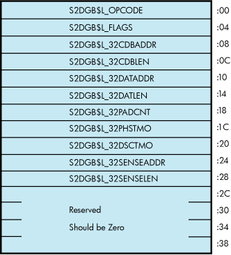
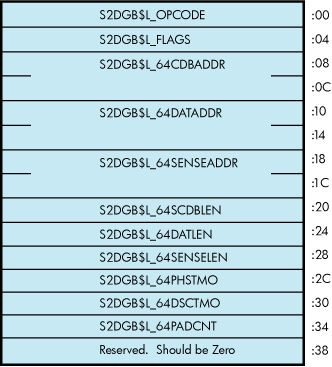
A user application must specify which one of the two S2DGB formats is to be used by passing a format value in S2DGB$L_OPCODE. Specifically, S2DGB$L_OPCODE must be assigned a value of either OP_XCDB32 (= 1) to request 32-bit format, or OP_XCDB64 (= 2) to request 64-bit format. Once the value of OP_XCDB64 has been specified, the user application is obligated to use the 64-bit S2DGB format and, in particular, to use the 64-bit names for S2DGB fields as described below. Likewise, an opcode value of OP_XCDB32 obligates the user application to use the 32-bit names for the fields.
The correct length of the structure is defined by the constant S2DGB$K_XCDB32_LENGTH (value:60-decimal), as well as by the constant S2DGB$K_XCDB64_LENGTH (value: 60-decimal).
The fields in the S2DGB are in the sections that follow. Whenever a field has two different names for the 32-bit and 64-bit cases, the 32-bit name is given first, and the 64-bit name is given after it in parentheses. Also, except for fields that contain addresses, all fields are unsigned longwords.
S2DGB$L_OPCODE
This field should contain either S2DGB$K_OP_XCDB32 or S2DGB$K_OP_XCDB64, depending on whether the user application intends to supply 32-bit virtual addresses or 64-bit virtual addresses, respectively, in the other fields of the S2DGB.
S2DGB$L_FLAGS
This field should contain the bit fields shown in the following table. Note that these bit definitions start at bit 0 and omit no bits. This is required for compatibility with the IO$_DIAGNOSE interface available in OpenVMS Alpha Version 6.1 and earlier.
|
BitField |
Description |
|---|---|
|
S2DGB$V_READ |
This bit should be 1 if the operation being performed is a read. If the operation is a write, this bit should be 0. |
|
S2DGB$V_DISCPRIV |
This bit should contain the DiscPriv bit value to be used in the IDENTIFY message sent with this operation. If S2DGB$V_TAGGED_REQ is 1, then this bit is ignored. Note that S2DGB$V_DISCPRIV may be ignored by some ports unconditionally. |
|
S2DGB$V_SYNCHRONOUS |
This bit is ignored because its value is beyond the control of the user in SCSI-2 drivers. |
|
S2DGB$V_OBSOLETE1 |
This bit is ignored. In previous releases, it represented the disabling of command retries, which is now beyond the control of the user in SCSI-2 drivers. |
|
S2DGB$V_TAGGED_REQ |
When this bit is 1, the operation is processed as using tagged command queuing and S2DGB$V_TAG should define the tag value to be used. When this bit is 0, the operation is processed without benefit of tagged command queuing. Note that although some ports do not support tagged command
queuing, setting this bit to 1 will inhibit changing the values of
S2DGB$L_32PADCNT
(S2DGB$L_64PADCNT),
S2DGB$L_32DSCTMO
(S2DGB$L_64DSCTMO), and
S2DGB$L_32PHSTMO
(S2DGB$L_64PHSTMO), and causes
S2DGB$V_DISCPRIV to be ignored. Note
also that some ports simulate untagged operations using
appropriately tagged operations. If
S2DGB$V_TAGGED_REQ is 1, then this
3-bit field should contain one of the following coded constant values:
Note that automatic contingent allegiance processing is not accessible through the IO$_DIAGNOSE function. Also, even though this is a 3-bit field, only 2 bits are currently being utilized. That is, the 3 constants above represent values, not bit positions. |
|
S2DGB$V_AUTOSENSE |
When this bit is 1, S2DGB$L_32SENSEADDR andS2DGB$L_32SENSELEN CONDITION or COMMAND TERMINATED status is returned, REQUEST SENSE data is returned in the buffer defined by S2DGB$L_32SENSEADDR and S2DGB$L_32SENSELEN. When S2DGB$V_AUTOSENSE is 0, the buffer described by S2DGB$L_32SENSEADDR and S2DGB$L_32SENSELEN is ignored. In such cases, the class driver saves the autosense data in pool and returns it to the next IO$_DIAGNOSE, if and only if that IO$_DIAGNOSE has a REQUEST SENSE CDB. All other bits in S2DGB$L_FLAGS should be 0. |
S2DGB$L_32CDBADDR (S2DGB$PQ_64CDBADDR)
This field should contain the 32-bit (or 64-bit) virtual address of the SCSI command data block (CDB) to be sent to the target by this IO$_DIAGNOSE operation.
Note that S2DGB$L_32CDBADDR is a pointer to a longword, while S2DGB$PQ_64CDBADDR is a pointer to a quadword.
S2DGB$L_32CDBLEN (S2DGB$L_64CDBLEN)
This field should contain the number of bytes in the SCSI command data block (CDB) to be sent to the target by this IO$_DIAGNOSE operation. (Legal values: 2 to 248; however, some ports may restrict CDBs to smaller lengths. Recommended values: 2 to 16.)
S2DGB$L_32DATADDR (S2DGB$PQ_64DATADDR)
This field should contain the 32-bit (or 64-bit) virtual address of the DATAIN or DATAOUT buffer to be used with this SCSI operation. If the CDB being sent to the target does not use a DATAIN or DATAOUT buffer, then this field should be 0.
Note that S2DGB$L_32DATADDR is a pointer to a longword, while S2DGB$PQ_64DATADDR is a pointer to a quadword.
S2DGB$L_32DATLEN (S2DGB$L_64DATLEN)
This field should contain the number of bytes in the DATAIN or DATAOUT buffer associated with this operation. If the CDB being sent to the target does not use a DATAIN or DATAOUT buffer, then this field should be 0. (Legal values: 0 to UCB$L_MAXBCNT. Recommended values: 0 to 65,536. All ports are required to support at least 65,536 byte data transfers.)
S2DGB$L_32PADCNT (S2DGB$L_64PADCNT)
This field should contain the number of padding DATAIN or DATAOUT bytes required by this operation. If S2DGB$V_TAGGED_REQ is 1, then the PAD count value is not its default value. (Legal values: 0 to the maximum number of bytes in a disk block on this system minus one.
Current legal values: 0 to 511.)
S2DGB$L_32PHSTMO (S2DGB$L_64PHSTMO)
This field should contain the number of seconds that the port driver should wait for a phase transition to occur or for delivery of an expected interrupt. If S2DGB$V_ TAGGED_REQ is 1 or this field contains a 0 or 1, then the current phase transition timeout setting will not be changed. (Legal values: 0 to 65,535 (about 18 hours).)
S2DGB$L_32DSCTMO (S2DGB$L_64DSCTMO)
This field should contain the number of seconds that the port driver should wait for a disconnected transaction to reconnect. If S2DGB$V_TAGGED_REQ is 1 or this field contains a 0 or 1, then the current disconnect timeout setting will not be changed. (Legal values: 0 to 65,535 (about 18 hours).)
S2DGB$L_32SENSEADDR (S2DGB$PQ_64SENSEADDR)
IfS2DGB$V_AUTOSENSE is 1, then this field should contain the 32-bit (or 64-bit) virtual address of the sense buffer to be used by this SCSI operation. If S2DGB$V_AUTOSENSE is 0, this field is ignored.
Note that S2DGB$L_32SENSEADDR is a pointer to a longword, while S2DGB$PQ_64SENSEADDR is a pointer to a quadword.
S2DGB$L_32SENSELEN (S2DGB$L_64SENSELEN)
If S2DGB$V_AUTOSENSE is 1, then this field should contain the number of bytes in the sense buffer associated with this operation. (Legal values: 0 to 255. Note that a value of 0 instructs the class driver to discard any sense data received. Recommended value: 18. Some ports may restrict the number of sense bytes to 18.) If S2DGB$V_AUTOSENSE is 0, this field is ignored.
#include                                         /* Define S2DGB*/
#include _pointers.h>                            /* Define VOID_PQ */
 S2DGB diag_desc;
/* Set up some default S2DGB descriptor values */

diag_desc.s2dgb$l_opcode = OP_XCDB64             /* Use 64-bits*/
diag_desc.s2dgb$l_flags = (S2DGB$M_READ |        /* Flags*/
S2DGB$M_TAGGED_REQ | S2DGB$M_AUTOSENSE);
diag_desc.s2dgb$v_tag = S2DGB$K_SIMPLE;          /* SIMPLE que tag */
diag_desc.s2dgb$pq_64cdbaddr = (VOID_PQ)(&cdb[0]);   /* Command addr*/
diag_desc.s2dgb$l_64cdblen = 6;                  /* Command length */
diag_desc.s2dgb$pq_64dataddr = (VOID_PQ)(&buf[0]);   /* Data addr*/
diag_desc.s2dgb$l_64datlen = 20;                 /* Data length*/
diag_desc.s2dgb$l_64padcnt = 0;                  /* Pad length*/
diag_desc.s2dgb$l_64phstmo = 20;                 /* Phase timeout */
diag_desc.s2dgb$l_64dsctmo = 10;                 /* Disc timeout*/
diag_desc.s2dgb$pq_64senseaddr = (VOID_PQ)(&asn[0]); /* Autosense addr*/
diag_desc.s2dgb$l_64senselen = 255;              /* Sense length*/
diag_desc.s2dgb$l_reserved_1 = 0;                /* Reserved*/
.
.

.

status = sys$qiow(0, target_chan, IO$_DIAGNOSE, &iosb, 0, 0,
&diag_desc, S2DGB$K_XCDB64_LENGTH, 0, 0, 0, 0);
If all arguments are valid, the class driver invokes the necessary port functions to send the CDB, transfer the data, and return, save or discard sense data as defined by the input S2DGB. Up on completion, the return IOSB has the following format:
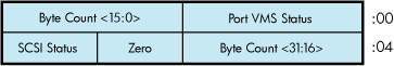
The DKDRIVER, GKDRIVER, and MKDRIVER class drivers, which implement other QIO functions, might intermix other tagged requests with IO$_DIAGNOSE requests. The order in which requests are sent generally matches the order in which requests are presented to the driver. An exception to this ordering occurs when the driver receives REQUEST SENSE for which autosense data previously has been recovered and stored. In this case, the IO$_DIAGNOSE completes immediately and no command is sent to the target.
The DKDRIVER, GKDRIVER, and MKDRIVER class drivers permit only one IO$_DIAGNOSE operation to be active (in the start I/O routine) at a given time, except as described in the next paragraph. However, applications must single thread IO$_DIAGNOSE requests to properly detect the presence of sense data and send the required REQUEST SENSE command. For example, if three reads are issued with no waiting and the first read gets a CHECK CONDITION, the sense data is discarded by the target when the second read arrives.
The DKDRIVER, GKDRIVER, and MKDRIVER drivers permit more than one IO$_DIAGNOSE operation to be active (in the start I/O routine) only when all active operations have the S2DGB$V_AUTOSENSE flag equal to 1. Upon encountering the first IO$_DIAGNOSE with S2DGB$V_AUTOSENSE equal to 0, the class driver applies the restrictions described in the previous paragraph.
Appendix C. DEC Multinational Character Set and Terminal Escape Sequences/Modes
This appendix includes tables for the DEC Multinational character set and for terminal escape sequences and modes.
C.1. DEC Multinational Character Set
Table C.1, ''DEC Multinational Character Set'' lists the DEC Multinational character set. The DEC Multinational character set is an 8-bit character set with 256 characters. The first 128 characters in the set correspond to the ASCII character set.
| Hex Code | Octal Code | Decimal Code | Char or Abbrev. | Description |
|---|---|---|---|---|
| ASCII Control Characters | ||||
| 00 | 000 | 000 | NUL | null character |
| 01 | 001 | 001 | SOH | start of heading (Ctrl/A) |
| 02 | 002 | 002 | STX | start of text (Ctrl/B) |
| 03 | 003 | 003 | ETX | end of text (Ctrl/C) |
| 04 | 004 | 004 | EOT | end of transmission (Ctrl/D) |
| 05 | 005 | 005 | ENQ | enquiry (Ctrl/E) |
| 06 | 006 | 006 | ACK | acknowledge (Ctrl/F) |
| 07 | 007 | 007 | BEL | bell (Ctrl/G) |
| 08 | 010 | 008 | BS | backspace (Ctrl/H) |
| 09 | 011 | 009 | HT | horizontal tabulation (Ctrl/I) |
| 0A | 012 | 010 | LF | line feed (Ctrl/J) |
| 0B | 013 | 011 | VT | vertical tabulation (Ctrl/K) |
| 0C | 014 | 012 | FF | form feed (Ctrl/L) |
| 0D | 015 | 013 | CR | carriage return (Ctrl/M) |
| 0E | 016 | 014 | SO | shift out (Ctrl/N) |
| 0F | 017 | 015 | SI | shift in (Ctrl/O) |
| 10 | 020 | 016 | DLE | data link escape (Ctrl/P) |
| 11 | 021 | 017 | DC1 | device control 1 (Ctrl/Q) |
| 12 | 022 | 018 | DC2 | device control 2 (Ctrl/R) |
| 13 | 023 | 019 | DC3 | device control 3 (Ctrl/S) |
| 14 | 024 | 020 | DC4 | device control 4 (Ctrl/T) |
| 15 | 025 | 021 | NAK | negative acknowledge (Ctrl/U) |
| 16 | 026 | 022 | SYN | synchronous idle (Ctrl/V) |
| 17 | 027 | 023 | ETB | end of transmission block (Ctrl/W) |
| 18 | 030 | 024 | CAN | cancel (Ctrl/X) |
| 19 | 031 | 025 | EM | end of medium (Ctrl/Y) |
| 1A | 032 | 026 | SUB | substitute (Ctrl/Z) |
| 1B | 033 | 027 | ESC | escape |
| 1C | 034 | 028 | FS | file separator |
| 1D | 035 | 029 | GS | group separator |
| 1E | 036 | 030 | RS | record separator |
| 1F | 037 | 031 | US | unit separator |
| ASCII Special and Numeric Characters | ||||
| 20 | 040 | 032 | SP | space |
| 21 | 041 | 033 | ! | exclamation point |
| 22 | 042 | 034 | ' | quotation marks (double quote) |
| 23 | 043 | 035 | # | number sign |
| 24 | 044 | 036 | $ | dollar sign |
| 25 | 045 | 037 | % | percent sign |
| 26 | 046 | 038 | & | ampersand |
| 27 | 047 | 039 | ' | apostrophe (single quote) |
| 28 | 050 | 040 | ( | opening parenthesis |
| 29 | 051 | 041 | ) | closing parenthesis |
| 2A | 052 | 042 | * | asterisk |
| 2B | 053 | 043 | + | plus |
| 2C | 054 | 044 | , | comma |
| 2D | 055 | 045 | — | hyphen or minus |
| 2E | 056 | 046 | . | period or decimal point |
| 2F | 057 | 047 | / | slash |
| 30 | 060 | 048 | 0 | zero |
| 31 | 061 | 049 | 1 | one |
| 32 | 062 | 050 | 2 | two |
| 33 | 063 | 051 | 3 | three |
| 34 | 064 | 052 | 4 | four |
| 35 | 065 | 053 | 5 | five |
| 36 | 066 | 054 | 6 | six |
| 37 | 067 | 055 | 7 | seven |
| 38 | 070 | 056 | 8 | eight |
| 39 | 071 | 057 | 9 | nine |
| 3A | 072 | 058 | : | colon |
| 3B | 073 | 059 | ; | semicolon |
| 3C | 074 | 060 | < | less than |
| 3D | 075 | 061 | = | equals |
| 3E | 076 | 062 | > | greater than |
| 3F | 077 | 063 | ? | question mark |
| ASCII Alphabetic Characters | ||||
| 40 | 100 | 064 | @ | commercial at sign |
| 41 | 101 | 065 | A | uppercase A |
| 42 | 102 | 066 | B | uppercase B |
| 43 | 103 | 067 | C | uppercase C |
| 44 | 104 | 068 | D | uppercase D |
| 45 | 105 | 069 | E | uppercase E |
| 46 | 106 | 070 | F | uppercase F |
| 47 | 107 | 071 | G | uppercase G |
| 48 | 110 | 072 | H | uppercase H |
| 49 | 111 | 073 | I | uppercase I |
| 4A | 112 | 074 | J | uppercase J |
| 4B | 113 | 075 | K | uppercase K |
| 4C | 114 | 076 | L | uppercase L |
| 4D | 115 | 077 | M | uppercase M |
| 4E | 116 | 078 | N | uppercase N |
| 4F | 117 | 079 | O | uppercase O |
| 50 | 120 | 080 | P | uppercase P |
| 51 | 121 | 081 | Q | uppercase Q |
| 52 | 122 | 082 | R | uppercase R |
| 53 | 123 | 083 | S | uppercase S |
| 54 | 124 | 084 | T | uppercase T |
| 55 | 125 | 085 | U | uppercase U |
| 56 | 126 | 086 | V | uppercase V |
| 57 | 127 | 087 | W | uppercase W |
| 58 | 130 | 088 | X | uppercase X |
| 59 | 131 | 089 | Y | uppercase Y |
| 5A | 132 | 090 | Z | uppercase Z |
| 5B | 133 | 091 | [ | left bracket |
| 5C | 134 | 092 | \ | backslash |
| 5D | 135 | 093 | ] | right bracket |
| 5E | 136 | 094 | ^ | circumflex |
| 5F | 137 | 095 | _ | underscore |
| 60 | 140 | 096 | ` | grave accent |
| 61 | 141 | 097 | a | lowercase a |
| 62 | 142 | 098 | b | lowercase b |
| 63 | 143 | 099 | c | lowercase c |
| 64 | 144 | 100 | d | lowercase d |
| 65 | 145 | 101 | e | lowercase e |
| 66 | 146 | 102 | f | lowercase f |
| 67 | 147 | 103 | g | lowercase g |
| 68 | 150 | 104 | h | lowercase h |
| 69 | 151 | 105 | i | lowercase i |
| 6A | 152 | 106 | j | lowercase j |
| 6B | 153 | 107 | k | lowercase k |
| 6C | 154 | 108 | l | lowercase l |
| 6D | 155 | 109 | m | lowercase m |
| 6E | 156 | 110 | n | lowercase n |
| 6F | 157 | 111 | o | lowercase o |
| 70 | 160 | 112 | p | lowercase p |
| 71 | 161 | 113 | q | lowercase q |
| 72 | 162 | 114 | r | lowercase r |
| 73 | 163 | 115 | s | lowercase s |
| 74 | 164 | 116 | t | lowercase t |
| 75 | 165 | 117 | u | lowercase u |
| 76 | 166 | 118 | v | lowercase v |
| 77 | 167 | 119 | w | lowercase w |
| 78 | 170 | 120 | x | lowercase x |
| 79 | 171 | 121 | y | lowercase y |
| 7A | 172 | 122 | z | lowercase z |
| 7B | 173 | 123 | { | left brace |
| 7C | 174 | 124 | | | vertical line |
| 7D | 175 | 125 | } | right brace (ALTMODE) |
| 7E | 176 | 126 | ~ | tilde (ALTMODE) |
| 7F | 177 | 127 | DEL | rubout (DELETE) |
| 80 | 200 | 128 | — | [reserved] |
| 81 | 201 | 129 | — | [reserved] |
| 82 | 202 | 130 | — | [reserved] |
| 83 | 203 | 131 | — | [reserved] |
| 84 | 204 | 132 | IND | index |
| 85 | 205 | 133 | NEL | next line |
| 86 | 206 | 134 | SSA | start of selected area |
| 87 | 207 | 135 | ESA | end of started area |
| 88 | 210 | 136 | HTS | horizontal tab set |
| 89 | 211 | 137 | HTJ | horizontal tab set with justification |
| 8A | 212 | 138 | VTS | vertical tab set |
| 8B | 213 | 139 | PLD | partial line down |
| 8C | 214 | 140 | PLU | partial line up |
| 8D | 215 | 141 | RI | reverse index |
| 8E | 216 | 142 | SS2 | single shift 2 |
| 8F | 217 | 143 | SS3 | single shift 3 |
| 90 | 220 | 144 | DCS | device control string |
| 91 | 221 | 145 | PU1 | private use 1 |
| 92 | 222 | 146 | PU2 | private use 2 |
| 93 | 223 | 147 | STS | set transmit state |
| 94 | 224 | 148 | CCH | cancel character |
| 95 | 225 | 149 | MW | message waiting |
| 96 | 226 | 150 | SPA | start of protected area |
| 97 | 227 | 151 | EPA | end of protected area |
| 98 | 230 | 152 | — | [reserved] |
| 99 | 231 | 153 | — | [reserved] |
| 9A | 232 | 154 | — | [reserved] |
| 9B | 233 | 155 | CSI | control sequence introducer |
| 9C | 234 | 156 | ST | string terminator |
| 9D | 235 | 157 | OSC | operating system command |
| 9E | 236 | 158 | PM | privacy message |
| 9F | 237 | 159 | APC | application |
| A0 | 240 | 160 | — | [reserved] |
| A1 | 241 | 161 | ¡ | inverted exclamation point |
| A2 | 242 | 162 | ¢ | cent sign |
| A3 | 243 | 163 | £ | pound sign |
| A4 | 244 | 164 | — | [reserved] |
| A5 | 245 | 165 | ¥ | yen sign |
| A6 | 246 | 166 | — | [reserved] |
| A7 | 247 | 167 | § | section sign |
| A8 | 250 | 168 | ¤ | general currency sign |
| A9 | 251 | 169 | © | copyright sign |
| AA | 252 | 170 | ª | feminine ordinal indicator |
| AB | 253 | 171 | << | angle quotation mark left |
| AC | 254 | 172 | — | [reserved] |
| AD | 255 | 173 | — | [reserved] |
| AE | 256 | 174 | — | [reserved] |
| AF | 257 | 175 | — | [reserved] |
| B0 | 260 | 176 | ° | degree sign |
| B1 | 261 | 177 | ± | plus/minus sign |
| B2 | 262 | 178 | ² | superscript 2 |
| B3 | 263 | 179 | ³ | superscript 3 |
| B4 | 264 | 180 | — | [reserved] |
| B5 | 265 | 181 | µ | micro sign |
| B6 | 266 | 182 | ¶ | paragraph sign, pilcrow |
| B7 | 267 | 183 | placeholder | middle dot |
| B8 | 270 | 184 | — | [reserved] |
| B9 | 271 | 185 | ¹ | superscript 1 |
| BA | 272 | 186 | º | masculine ordinal indicator |
| BB | 273 | 187 | >> | angle quotation mark right |
| BC | 274 | 188 | 1/4 | fraction one-quarter |
| BD | 275 | 189 | 1/2 | fraction one-half |
| BE | 276 | 190 | — | [reserved] |
| BF | 277 | 191 | ¿ | inverted question mark |
| C0 | 300 | 192 | À | uppercase A with grave accent |
| C1 | 301 | 193 | Á | uppercase A with acute accent |
| C2 | 302 | 194 | Â | uppercase A with circumflex |
| C3 | 303 | 195 | Ã | uppercase A with tilde |
| C4 | 304 | 196 | Ä | uppercase A with umlaut (diaeresis) |
| C5 | 305 | 197 | Å | uppercase A with ring |
| C6 | 306 | 198 | AE | uppercase AE diphthong |
| C7 | 307 | 199 | Ç | uppercase C with cedilla |
| C8 | 310 | 200 | È | uppercase E with grave accent |
| C9 | 311 | 201 | É | uppercase E with acute accent |
| CA | 312 | 202 | Ê | uppercase E with circumflex |
| CB | 313 | 203 | Ë | uppercase E with umlaut (diaeresis) |
| CC | 314 | 204 | Ì | uppercase I with grave accent |
| CD | 315 | 205 | Í | uppercase I with acute accent |
| CE | 316 | 206 | Î | uppercase I with circumflex |
| CF | 317 | 207 | Ï | uppercase I with umlaut (diaeresis) |
| D0 | 320 | 208 | — | [reserved] |
| D1 | 321 | 209 | Ñ | uppercase N with tilde |
| D2 | 322 | 210 | Ò | uppercase O with grave accent |
| D3 | 323 | 211 | Ó | uppercase O with acute accent |
| D4 | 324 | 212 | Ô | uppercase O with circumflex |
| D5 | 325 | 213 | Õ | uppercase O with tilde |
| D6 | 326 | 214 | Ö | uppercase O with umlaut (diaeresis) |
| D7 | 327 | 215 | OE | uppercase OE ligature |
| D8 | 330 | 216 | Ø | uppercase O with slash |
| D9 | 331 | 217 | Ù | uppercase U with grave accent |
| DA | 332 | 218 | Ú | uppercase U with acute accent |
| DB | 333 | 219 | Û | uppercase U with circumflex |
| DC | 334 | 220 | Ü | uppercase U with umlaut (diaeresis) |
| DD | 335 | 221 | Ÿ | uppercase Y with umlaut (diaeresis) |
| DE | 336 | 222 | — | [reserved] |
| DF | 337 | 223 | B | German lowercase sharp s |
| E0 | 340 | 224 | à | lowercase a with grave accent |
| E1 | 341 | 225 | á | lowercase a with acute accent |
| E2 | 342 | 226 | â | lowercase a with circumflex |
| E3 | 343 | 227 | ã | lowercase a with tilde |
| E4 | 344 | 228 | ä | lowercase a with umlaut (diaeresis) |
| E5 | 345 | 229 | å | lowercase a with ring |
| E6 | 346 | 230 | æ | lowercase ae diphthong |
| E7 | 347 | 231 | ç | lowercase c with cedilla |
| E8 | 350 | 232 | è | lowercase e with grave accent |
| E9 | 351 | 233 | é | lowercase e with acute accent |
| EA | 352 | 234 | ê | lowercase e with circumflex |
| EB | 353 | 235 | ë | lowercase e with umlaut (diaeresis) |
| EC | 354 | 236 | ì | lowercase i with grave accent |
| ED | 355 | 237 | í | lowercase i with acute accent |
| EE | 356 | 238 | î | lowercase i with circumflex |
| EF | 357 | 239 | ï | lowercase i with umlaut (diaeresis) |
| F0 | 360 | 240 | — | [reserved] |
| F1 | 361 | 241 | ñ | lowercase n with tilde |
| F2 | 362 | 242 | ò | lowercase o with grave accent |
| F3 | 363 | 243 | ó | lowercase o with acute accent |
| F4 | 364 | 244 | ô | lowercase o with circumflex |
| F5 | 365 | 245 | õ | lowercase o with tilde |
| F6 | 366 | 246 | ö | lowercase o with umlaut (diaeresis) |
| F7 | 367 | 247 | oe | lowercase oe ligature |
| F8 | 370 | 248 | ø | lowercase o with slash |
| F9 | 371 | 249 | ù | lowercase u with grave accent |
| FA | 372 | 250 | ú | lowercase u with acute accent |
| FB | 373 | 251 | û | lowercase u with circumflex |
| FC | 374 | 252 | ü | lowercase u with umlaut (diaeresis) |
| FD | 375 | 253 | ÿ | lowercase y with umlaut (diaeresis) |
| FE | 376 | 254 | — | [reserved] |
| FF | 377 | 255 | — | [reserved] |
C.2. Terminal Sequences and Modes
Table C.2, ''Sequences and Modes'' lists the valid ANSI and DIGITAL private escape sequences for terminals that have the TT2$M_ANSICRT, TT2$M_DECCRT, TT2$M_AVO, TT2$M_EDIT, and TT2$M_BLOCK characteristics (see Section 5.1.1.4, ''Escape and Control Sequences'').
Table C.2, ''Sequences and Modes'' also lists assumed and selectable ANSI modes and selectable DIGITAL private modes. Only the names of the escape sequences and modes are listed (for more information, see the specific VT100-, VT200-, or VT300- family user's guide). Unless otherwise noted, the operation of escape sequences and modes is identical to the particular VT100-, VT200-, or VT300- family terminals that implement these features.
| Name | Valid Parameters' | ANSICRT' | DECCRT | AVO' | EDIT | BLOCK |
|---|---|---|---|---|---|---|
| ANSI-Defined Escape Sequences | ||||||
| CPR | All | x | x | |||
| CUB | All | x | x | |||
| CUD | All | x | x | |||
| CUF | All | x | x | |||
| CUP | All | x | x | |||
| CUU | All | x | x | |||
| DSR | 0,3,5,6 | x | x | |||
| ED | 0,1,2 | x | x | |||
| EL | 0,1,2 | x | x | |||
| HVP | All | x | x | |||
| IND | x | x | ||||
| NEL | x | x | ||||
| RI | x | x | ||||
| RIS | x | x | ||||
| SCS | UK,ASCII,0 | x | ||||
| SCS | UK,ASCII | x | x | |||
| SGR | 0,4,7 | x | x | |||
| SGR | 0,1,4,5,7 | x | ||||
| DA | Terminal-specific | x | ||||
| HTS | x | |||||
| RM | Class-specific | x | ||||
| SM | Class-specific | x | ||||
| TBC | 0,3 | x | ||||
| DCH | All | x | x | |||
| DL | All | x | x | |||
| IL | All | x | x | |||
| DIGITAL Private Escape Sequences | ||||||
| DECDHDL | 2,3 | x | ||||
| DECDWL |
6 | x | ||||
| DECKPAM |
| x | ||||
| DECKPNM |
| x | ||||
| DECRC |
8 | x | ||||
| DECSC |
7 | x | ||||
| DECSTBM |
All | x | ||||
| DECSWL |
5 | x | ||||
| DECPRO | 0,1,4,5,7,254 | x | ||||
| DECTTC | 0,1 | x | ||||
| DECXMIT | 5 | x | ||||
| ANSI Selectable Modes (Set with ANSI SM/RM) | ||||||
| IRM | 4 | x | x | |||
| GATM | 1 | x | x | |||
| ERM | 6 | x | ||||
| TTM | 16 | x | ||||
| DIGITAL Private Selectable Modes (Set with ANSI SM/RM) | ||||||
| DECCKM | 1 | x | ||||
| DECANM | 2 | x | ||||
| DECCOLM | 3 | x | ||||
| DECSCLM | 4 | x | ||||
| DECSCNM | 5 | x | ||||
| DECOM | 6 | x | ||||
| DECAWM | 7 | x | ||||
| DECARM | 8 | x | ||||
| DECEDM | 10 | x | ||||
| DECEKEM | 16 | x | ||||
| DECLTM | 11 | x | ||||
| DECSCFDM | 13 | x | ||||
| DECTEM | 14 | x | ||||
| ANSI Assumed Modes | ||||||
| CRM | Reset | Reset | ||||
| EBM | Reset | Reset | ||||
| ERM | Set | Set | 2 | |||
| FEAM | Reset | Reset | ||||
| FETM | Reset | Reset | ||||
| GATM | N/A | N/A | 2 | |||
| HEM | N/A | N/A | ||||
| IRM | Reset | Reset | 2 | 2 | ||
| KAM | Reset | Reset | ||||
| MATH | N/A | N/A | ||||
| PUM | Reset | Reset | ||||
| SATM | N/A | N/A | ||||
| SRTM | Reset | Reset | ||||
| TSM | Reset | Reset | ||||
| TTM | N/A | N/A | 2 | |||
| VEM | N/A | N/A | ||||
Appendix D. Control Connection Routines
This appendix lists and describes the calling conventions for the pseudoterminal driver control connection routines. The routines appear in this section in alphabetical order.
Table D.1, ''Control Connection Routines'' lists the control connection routines and their functions:
|
Routine Name |
Description |
|---|---|
|
PTD$CANCEL |
Cancels a queued control connection read request |
|
PTD$CREATE |
Creates a pseudoterminal |
|
PTD$DELETE |
Deletes a pseudoterminal |
|
PTD$READ |
Reads data from the pseudoterminal |
|
PTD$READW |
Reads data from the pseudoterminal and waits for read to complete |
|
PTD$SET_EVENT_NOTIFICATION |
Enables or disables terminal event notification ASTs |
|
PTD$WRITE |
Writes data to the pseudoterminal |
PTD$CANCEL
PTD$CANCEL — Cancel Queued Request. Cancels a queued control connection read request.
Format
PTD$CANCEL chan
Returns
| OpenVMS usage: | cond_value |
| type: | longword (unsigned) |
| access: | write only |
| mechanism: | by value |
Arguments
| OpenVMS usage: | channel |
| type: | word (unsigned) |
| access: | read only |
| mechanism: | by value |
Number of the I/O channel assigned to the pseudoterminal. This channel is only intended to be sued for PTD$XXX operations.
Return Values
|
SS$_NORMAL |
Normal successful completion. |
|
SS$_DEVOFFLINE |
Device is off line and request cannot proceed. |
|
SS$_IVCHAN |
Illegal channel. |
|
SS$_NOPRIV |
Insufficient privilege to perform request. |
PTD$CREATE
PTD$CREATE — Create a Pseudoterminal. Creates a new pseudoterminal with a unique
device name.
Format
PTD$CREATE chan [,acmode] [,charbuff] [,bufflen] [,astadr] [,astprm]
                        [,ast_acmode], inadr
Returns
| OpenVMS usage: | cond_value |
| type: | longword (unsigned) |
| access: | write only |
| mechanism: | by value |
Arguments
| OpenVMS usage: | channel |
| type: | word (unsigned) |
| access: | write only |
| mechanism: | by value |
Number of the channel that is assigned to the new pseudoterminal. This argument is the address of a word into which PTD$CREATE writes the channel number. This channel is only intended to be used for PTD$XXX operations.
| OpenVMS usage: | access_mode |
| type: | longword (unsigned) |
| access: | read only |
| mechanism: | by value |
Access mode to be associated with the channel. The most privileged access mode is the access mode of the caller. I/O operations on the channel can be performed only from equal and more privileged access modes.
| OpenVMS usage: | device_characteristics |
| type: | longword (unsigned) |
| access: | read only |
| mechanism: | by reference |
Address of buffer containing the device characteristics. This information is used to set up the pseudoterminal's initial characteristics. This buffer can be 12, 16, or 20 bytes long.
Figure D.1, ''Device Characteristics Buffer'' shows the format of this buffer:

| OpenVMS usage: | word_unsigned |
| type: | word (unsigned) |
| access: | read only |
| mechanism: | by value |
Length of the characteristics buffer (either 12, 16, or 20 bytes). This
argument is required if you supply the charbuff
argument.
| OpenVMS usage: | ast_procedure |
| type: | procedure value |
| access: | call without stack unwinding |
| mechanism: | by reference |
AST service routine to be executed when the terminal connection deassigns the last channel to the pseudoterminal. This argument is the procedure value of this routine. This is a repeating AST and is active until the control connection deletes the pseudoterminal.
| OpenVMS usage: | user_arg |
| type: | longword (unsigned) |
| access: | read only |
| mechanism: | by value |
AST parameter to be passed to the AST service routine specified by
astadr.
| OpenVMS usage: | access_mode |
| type: | longword (unsigned) |
| access: | read only |
| mechanism: | by value |
Access mode for which the AST is to be declared. The most privileged access mode is the access mode of the caller. The resulting mode is the access mode at which the AST is declared.
| OpenVMS usage: | address_range |
| type: | longword (unsigned) |
| access: | read only |
| mechanism: | by reference |
Address of a two-longword array containing the starting and ending virtual
addresses in the virtual address space of the process (either P0 or P1 regions)
to be used as I/O buffers. The array contains, in order, the starting and ending
virtual addresses. The addresses supplied to inadr must
express an integral number of CPU-specific pages. The lower address must be on
a
CPU-specific page boundary, and the higher address must be one less than a CPU-specific page boundary. Together these addresses form a range from lowest to highest bytes. The pages must already exist and must be fully contained in either P0 or P1 space. All pages in the range must:
Have identical page protection
Be writable in the mode of the caller
Be owned by the same access mode
Be owned in a mode equal to or less privileged than the caller
Be of the same page type (process or global)
Description
PTD$CREATE creates a new pseudoterminal with a unique
device name. This device name is in the form FTA n:,
where n is the unit number.
When a pseudoterminal is created, it inherits the current system terminal default attributes unless you specify an alternate set of characteristics.
Return Values
|
SS$_NORMAL |
Normal successful completion. |
|
SS$_ACCVIO |
Unable to read one of the arguments. |
|
SS$_BADPARAM |
Bad Parameter Value. |
|
SS$_EXBYTLM |
Insufficient BYTLM to create device or map buffers. |
|
SS$_EXQUOTA |
Insufficient quota to create device. |
|
SS$_EXASTLM |
Insufficient AST quota for notification AST. |
|
SS$_INFMEM |
Insufficient memory to create device. |
|
SS$_INSFWSL |
Insufficient working set limit to map buffers. |
|
SS$_IVSECFLG |
Invalid process or global section flags. |
|
SS$_NOPRIV |
No privilege for attempted operation. |
|
SS$_PAGPNWNVIO |
Page owner violation. |
|
SS$_VA_IN_USE |
Virtual address already in use. |
PTD$DELETE
PTD$DELETE — Delete a Pseudoterminal. Forces the pseudoterminal to be deleted and
frees the channel.
Format
PTD$DELETE chan
Returns
| OpenVMS usage: | longword (unsigned) |
| type: | write |
| access: | by value |
Argument
| OpenVMS usage: | channel |
| type: | word (unsigned) |
| access: | read only |
| mechanism: | by value |
Number of the I/O channel assigned to the pseudoterminal. This channel is only intended to be used for PTD$XXX operations.
Description
PTD$DELETE forces the pseudoterminal to be deleted and frees the channel assigned to the pseudoterminal. When a pseudoterminal is deleted, any process using the pseudoterminal (except the control program) is disconnected. A PTD$DELETE request causes any pending I/O for the control program to be aborted. It deletes any queued event notification ASTs and returns the I/O buffers back to the application. It also causes the pseudoterminal unit control block (UCB) to be deleted once the reference count returns to zero.
Return Values
|
SS$_NORMAL |
Normal successful completion. |
|
SS$_DEVOFFLINE |
Device is off line and request cannot proceed. |
|
SS$_IVCHAN |
Illegal channel. |
|
SS$_NOPRIV |
Insufficient privilege to perform request. |
PTD$READ
PTD$READ — Read Data from Pseudoterminal. Reads data from the pseudoterminal. The
PTD$READ routine completes asynchronously; that is,
it returns to the caller without waiting for the data to be read. For
synchronous completion, use the PTD$READW routine. The
PTD$READW routine is identical to the
PTD$READ routine in every way, except that
PTD$READW returns to the caller after the data is
read.
Format
PTD$READ [efn], chan [.astadr] [,astprm] readbuf,
                    readbuf_len
Returns
| OpenVMS usage: | longword (unsigned) |
| type: | write only |
| access: | by value |
Arguments
| OpenVMS usage: | ef_number |
| type: | longword (unsigned) |
| access: | read only |
| mechanism: | by value |
Number of the event flag to be set when PTD$READ returns the requested information. If you do not specify this argument, event flag 0 is used. When PTD$READ begins execution, it clears this flag.
| OpenVMS usage: | channel |
| type: | word (unsigned) |
| access: | read only |
| mechanism: | by value |
Number of the I/O channel assigned to the new pseudoterminal. This channel is only intended to be used for PTD$XXX operations.
| OpenVMS usage: | ast_procedure |
| type: | procedure value |
| access: | call without stack unwinding |
| mechanism: | by reference |
AST service routine to be executed when PTD$READ
completes. If you specify astadr, the AST routine executes at
the same access mode as the caller of the PTD$READ
routine.
| OpenVMS usage: | user_arg |
| type: | longword (unsigned) |
| access: | read only |
| mechanism: | by value |
AST parameter to be passed to the AST service routine specified by the
astadr argument.
| OpenVMS usage: | char_string |
| type: | character coded text string |
| access: | write only |
| mechanism: | by reference |
Address of the read I/O status longword. The first character position in an
I/O buffer to receive all output is this address plus 4. The
readbuf argument must be in the range specified in the
inadr argument of the PTD$CREATE
routine; otherwise, an SS$_ACCVIO status is
returned.
| OpenVMS usage: | word_unsigned |
| type: | word (unsigned) |
| access: | read only |
| mechanism: | by value |
Number of characters that can be read from the pseudoterminal and stored in
the buffer specified by readbuf.
Description
The PTD$READ routine reads data from the
pseudoterminal. The read request completes with a minimum of one character and a
maximum of the number of characters specified by the
readbuf_len argument.
When a PTD$READ routine is called, the operating system queues a read operation. The read operation completes when the pseudoterminal has characters to output. The read request queries TTDRIVER whether there is data found to be returned. If so, the resulting string of characters is returned. If a read request is issued and no data is available, the read request is queued and then completed at a later time. In this case, the routine always returns at least one character. The read request may complete even when there are no characters available to output. In this rare case when TTDRIVER indicates that there is no more data to be output and there is really no data, the read operation completes with zero bytes of data.
Return Values
|
SS$_NORMAL |
Normal successful completion. |
|
SS$_ACCVIO |
Unable to read an argument, or invalid read buffer address. |
|
SS$_DEVOFFLINE |
Device is off line and request cannot proceed. |
|
SS$_EXASTLM |
Insufficient AST quota for notification AST. |
|
SS$_ILLEFC |
Illegal event flag cluster. |
|
SS$_INFMEM |
Insufficient memory. |
|
SS$_IVBUFLEN |
Buffer size supplied is illegal. |
|
SS$_IVCHAN |
Illegal channel. |
|
SS$_NOPRIV |
Insufficient privilege to perform request. |
|
SS$_UNASEFC |
Unassociated event flag cluster. |
PTD$READW
PTD$READW — Read Data from Pseudoterminal and Wait. Reads data from the
pseudoterminal. The PTD$READW routine completes
synchronously; that is, it returns to the caller after the data has been read.
For asynchronous completion, use the PTD$READ routine.
The PTD$READ routine is identical to the
PTD$READW routine in every way except that
PTD$READ returns to the caller without waiting for
the data to be read.
D.5.1 Format
PTD$READW [efn], chan [.astadr] [,astprm] readbuf,
                    readbuf_len
PTD$SET_EVENT_NOTIFICATION
PTD$SET_EVENT_NOTIFICATION — Enable or Disable Terminal Event Notification ASTs. Enables or disables
a number of repeating terminal event notification ASTs.
Format
PTD$SET_EVENT_NOTIFICATION chan, astadr [,astprm] [,acmode],
                    type
Returns
| OpenVMS usage: | longword (unsigned) |
| type: | write only |
| access: | by value |
Arguments
| OpenVMS usage: | channel |
| type: | word (unsigned) |
| access: | read only |
| mechanism: | by value |
Number of the I/O channel assigned to the pseudoterminal. This channel is only intended to be used for PTD$XXX operations.
| OpenVMS usage: | ast_procedure |
| type: | procedure value |
| access: | call without stack unwinding |
| mechanism: | by reference |
Address of the notification AST service routine, or zero if the AST is to be canceled.
| OpenVMS usage: | user_arg |
| type: | longword (unsigned) |
| access: | read only |
| mechanism: | by value |
AST parameter to be passed to the AST service routine specified by the
astadr argument.
| OpenVMS usage: | access_mode |
| type: | longword (unsigned) |
| access: | read only |
| mechanism: | by value |
Access mode for which the AST is to be declared. The most privileged access mode is the access mode of the caller. The resulting mode is the access mode at which the AST is declared.
| OpenVMS usage: | type_longword |
| type: | longword (unsigned) |
| access: | read only |
| mechanism: | by value |
Value that indicates which notification AST to enable. The $PTDDEF macro defines the symbolic names listed in Table D.2, ''Symbolic Names Defined by $PTDDEF Macro''.
|
Symbolic Name |
Description |
|---|---|
|
PTD$C_SEND_XON |
Deliver notification AST when the pseudoterminal is ready to accept input. This AST is not delivered if the pseudoterminal is set to NO HOSTSYNC. |
|
PTD$C_SEND_BELL |
Deliver notification AST when the pseudoterminal wants to stop input and signal it with a bell character. |
|
PTD$C_SEND_XOFF |
Deliver notification AST when the pseudoterminal wants to stop input and signal it with a DC3 character. |
|
PTD$C_STOP_OUTPUT |
Deliver notification AST when the pseudoterminal is stopping output. |
|
PTD$C_RESUME_OUTPUT |
Deliver notification AST when the pseudoterminal is resuming output. |
|
PTD$C_CHAR_CHANGED |
Deliver notification AST when the pseudoterminal has changed some device characteristic. |
|
PTD$C_ABORT_OUTPUT |
Deliver notification AST when the pseudoterminal wants to abort output. |
|
PTD$C_START_READ |
Deliver notification AST when the pseudoterminal is starting an application's read request. This AST is delivered only if read event notification has been enabled. |
|
PTD$C_MIDDLE_READ |
Deliver notification AST when the pseudoterminal has finished sending an application's read request prompt string. This AST is delivered only if read event notification has been enabled. |
|
PTD$C_END_READ |
Deliver notification AST when the pseudoterminal has finished an application's read request. This AST is delivered only if read event notification has been enabled. |
|
PTD$C_ENABLE_READ |
Enable terminal read event AST delivery. If this code is
used, you cannot supply the |
|
PTD$C_DISABLE_READ |
Disable terminal read event AST delivery. If this code is
used, you cannot supply the |
Description
PTD$SET_EVENT_NOTIFICATION enables or disables the repeating terminal event notification ASTs listed in Table D.2, ''Symbolic Names Defined by $PTDDEF Macro''. After an event notification AST is enabled, it remains in effect until it is disabled or until the device is deleted.
Return Values
|
SS$_NORMAL |
Normal successful completion. |
|
SS$_ACCVIO |
Unable to read an argument, or invalid I/O buffer address. |
|
SS$_BADPARAM |
An |
|
SS$_DEVOFFLINE |
Device is off line and request cannot proceed. |
|
SS$_EXASTLM |
Insufficient AST quota for notification AST. |
|
SS$_INFMEM |
Insufficient memory. |
|
SS$_IVCHAN |
Illegal channel. |
|
SS$_NOPRIV |
Insufficient privilege to perform request. |
PTD$WRITE
PTD$WRITE — Write Data to Pseudoterminal. Inputs data to the pseudoterminal and
reads any immediately echoed characters.
Format
PTD$WRITE chan [.astadr] [,astprm] wrtbuf, wrtbuf_len [,echobuf]
                        [,echobuf_len]
Returns
| OpenVMS usage: | longword (unsigned) |
| type: | write only |
| access: | by value |
Arguments
| OpenVMS usage: | channel |
| type: | word (unsigned) |
| access: | read only |
| mechanism: | by value |
Number of the I/O channel assigned to the new pseudoterminal. This channel is only intended to be used for PTD$XXX operations.
| OpenVMS usage: | ast_procedure |
| type: | procedure value |
| access: | call without stack unwinding |
| mechanism: | by reference |
AST service routine to be executed when PTD$READ
completes. If you specify astadr, the AST routine executes at
the same access mode as the caller of the PTD$WRITE
routine.
| OpenVMS usage: | user_arg |
| type: | longword (unsigned) |
| access: | read only |
| mechanism: | by value |
AST parameter to be passed to the AST service routine specified by the
astadr argument.
| OpenVMS usage: | char_string |
| type: | character coded text string |
| access: | write only |
| mechanism: | by reference |
Address of the read I/O status longword. The first character position in an
I/O buffer to receive all output is this address plus 4. The
wrtbuf argument must be in the range specified in the
inadr argument of the PTD$CREATE
routine; otherwise, an SS$_ACCVIO status is
returned.
| OpenVMS usage: | word_unsigned |
| type: | word (unsigned) |
| access: | read only |
| mechanism: | by value |
Number of characters to be written to the pseudoterminal. These characters appear as input to the terminal side of the pseudoterminal.
| OpenVMS usage: | char_string |
| type: | character coded text string |
| access: | write only |
| mechanism: | by reference |
Address of the echo I/O status longword. The first character position in an
I/O buffer to receive all output is this address plus 4. The
echobuf must be in the range specified by the
inadr argument of the PTD$CREATE
routine; otherwise an SS$_ACCVIO status is
returned.
| OpenVMS usage: | word_unsigned |
| type: | word (unsigned) |
| access: | read only |
| mechanism: | by value |
Number of characters that can be read from the pseudoterminal. If an echo
buffer is specified, up to echobuf_len characters can be
stored in it.
Description
PTD$WRITE inputs data to the pseudoterminal and reads any immediately echoed characters. PTD$WRITE allows you to specify a buffer to receive any output generated by the write; you do not need to issue a separate read request to read this data.
Return Values
|
SS$_NORMAL |
Normal successful completion. |
|
SS$_ACCVIO |
Unable to read an argument, or invalid read buffer address. |
|
SS$_DATALOST |
The terminal driver type-ahead buffer is full and character written was lost. |
|
SS$_DATEAOVERUN |
The terminal type-ahead buffer is getting full; attempts to send more data might result in loss of characters. |
|
SS$_DEVOFFLINE |
Device is off line and request cannot proceed. |
|
SS$_EXASTLM |
Insufficient AST quota for notification AST. |
|
SS$_INFMEM |
Insufficient memory. |
|
SS$_IVBUFLEN |
Buffer size supplied is illegal. |
|
SS$_IVCHAN |
Illegal channel. |
|
SS$_NOPRIV |
Insufficient privilege to perform request. |
Appendix E. DDT Intercept Establisher Routines and Device Configuration Notification Routines
The DDT intercept establisher routines and device configuration notification routines are designed for use in applications for OpenVMS x86-64, OpenVMS IA-64, and OpenVMS Alpha that are developed by third-party application providers.
The DDT intercept establisher routines are used for establishing driver dispatch table (DDT) intercepts of OpenVMS device drivers. They can be used by any privileged kernel-mode application that alters the DDT. These routines allow intercepting calls into the driver by way of DDT entry points so that multiple intercepts work correctly.
The device configuration notification routines provide notification of device configuration by way of a callback. These routines enhance the functionality of the DDT intercept establisher routines but are not limited to use with them.
Using the DDT intercept establisher routines and device configuration notification routines in third-party kernel-mode applications, such as disk caching products and SCSI disk-shadowing applications, enable these applications to run in an OpenVMS SCSI or Fibre Channel multipath configuration. Any third-party applications that rely on altering the DDT of the OpenVMS Alpha SCSI disk-class driver (SYS$DKDRIVER.EXE), the SCSI tape-class driver (SYS$MKDRIVER), or the SCSI generic-class driver (SYS$GKDRIVER) require using these routines to ensure correct functioning.
E.1. DDT Intercept Establisher Routines
The DDT intercept establisher routines provide a mechanism to intercept calls through a driver dispatch table (DDT). Third-party applications that modifies the DDT directly can be revised to use the appropriate DDT intercept establisher routines, so that they function properly in an OpenVMS SCSI or Fibre Channel configuration. These routines establish intercepts on a per-UCB basis.
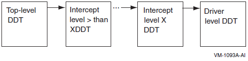
IOC_STD$ESTABLISH_DDT_CANCEL
IOC_STD$ESTABLISH_DDT_ALTSTART
IOC_STD$ESTABLISH_DDT_START
IOC_STD$ESTABLISH_DDT_MNTVER
If there are multiple declarations of DDT intercepts, they are called in descending order, from the highest level DDT (DDT$K_ITCLVL_TOP) to the lowest-level DDT (DDT$K_ITCLVL_DRVR).
Although the standard driver cancel, altstart,
start, and mntver routines do not return a
status, the intermediate routines must return either
SS$_SUPERSEDE or SS$_CHAINW
status. Any other return value results in a bugcheck. As the return value suggests, the
SS$_SUPERSEDE return value from the intermediate routine
supersedes the lower-level call to the DDT intercept routines. The
SS$_CHAINW return value from the intermediate routine
causes the next lower-level DDT intercept routines to be called.
The intercept DDTs are placed in the DDT chain according to their level. The top-level DDT is always the dispatcher DDT, and the bottom-level DDT is always the driver-level DDT. Other DDTs are placed in descending order between the top-level DDT and the driver-level DDT.
Intercept Levels
DDT$K_ITCLVL_TOP 32767
DDT$K_ITCLVL_HSM 24576
DDT$K_ITCLVL_MPDEV 4096
DDT$K_ITCLVL_DRVR 0
The valid intercept levels are from 4097 to 32766, except for 24576, which is reserved for the HSM interval. You can define as many intercepts as needed in that range.
Restrictions
Third-party intercepts are allowed only in the primary path UCB.
Multipath currently does not support intercepts in the secondary path UCB.
The flag parameter is required. It is a placeholder for future development, and the value must be zero.
IOC_STD$ESTABLISH_DDT_START
IOC_STD$ESTABLISH_DDT_START — Establishes the intercept of the DDT$PS_START_2 routine.
Calling Convention
int ioc_std$establish_ddt_start (UCB *ucb, int (*start_itc_routine)(IRP
    *irp, UCB *ucb), int level,int flag)
Input
| ucb |
Pointer to a UCB whose DDT$PS_START_2 is to be intercepted. |
| start_itc_routine |
The intercepting
start routine. This
routine is called before the driver’s
start routine. The calling convention
of the start routine is the same as the
standard DDT$PS_START_2 routine,
except that this routine must return one of the following
status values:
Any other return value results in a bugcheck. |
| level |
Level of DDT to be intercepted. Currently, multipath does not support an intercept level below MPDEV intercept. |
| flag | Placeholder for future development; must be zero. |
Return Value
SS$_NORMAL DDT intercept added successfully.
This routine may also return various other error status values, including any status returned on a failure to allocate pool.
Synchronization Environment
Caller must be in kernel mode, IPL at or below UCB fork IPL.
Almost all use of the DDT within OpenVMS requires holding the UCB fork lock. This is why this routine acquires and conditionally releases the UCB fork lock to change the DDT.
IOC_STD$ESTABLISH_DDT_ALTSTART
IOC_STD$ESTABLISH_DDT_ALTSTART — Establishes the intercept of the DDT$PS_ALTSTART_2 routine.
Calling Convention
int ioc_std$establish_ddt_altstart (UCB *ucb, int (*altstart_itc_routine)
    (IRP *irp, UCB *ucb), int level,int flag)
Input
| ucb |
Pointer to a UCB whose DDT$PS_ALTSTART_2 is to be intercepted. |
| altstart_itc_routine |
The intercepting
altstart routine. This
routine is called before the driver’s
altstart routine. The calling
convention of the altstart routine is the
same as the standard
DDT$PS_ALTSTART_2 routine,
except that this routine must return one of the following
status values:
Any other return value results in a bugcheck. |
| level |
Level of DDT to be intercepted. Currently, multipath does not support an intercept level below MPDEV intercept. |
| flag |
Placeholder for future development; must be zero. |
Return Value
SS$_NORMAL DDT intercept added successfully.
This routine may also return various other error status values, including any status returned on a failure to allocate nonpaged pool.
Synchronization Environment
Caller must be in kernel mode, IPL at or below UCB fork IPL.
Almost all use of the DDT within OpenVMS requires holding the UCB fork lock. This is why this routine acquires and conditionally releases the UCB fork lock to change the DDT.
IOC_STD$ESTABLISH_DDT_CANCEL
IOC_STD$ESTABLISH_DDT_CANCEL — Establishes the intercept of the DDT$PS_CANCEL_2 routine.
Calling Convention
int ioc_std$establish_ddt_cancel (UCB *ucb, int (*cancel_itc_routine)
    (int chan, IRP *irp,PCB *pcb,UCB *ucb, int reason), int level,int flag)
Input
| ucb |
Pointer to a UCB whose DDT$PS_CANCEL_2 is to be intercepted. |
| cancel_itc_routine |
The intercepting
cancel routine. This
routine is called before the driver’s
cancel routine. The calling
convention of the cancel routine is the
same as the standard
DDT$PS_CANCEL_2 routine, except
that this routine must return one of the following status values:
Any other return value results in a bugcheck. |
| level |
Level of DDT to be intercepted. Currently, multipath does not support an intercept level below MPDEV intercept. |
| flag |
Placeholder for future development; must be zero. |
Return Value
SS$_NORMAL DDT intercept added successfully.
This routine may also return various other error status values, including any status returned on a failure to allocate nonpaged pool.
Synchronization Environment
Caller must be in kernel mode, IPL at or below UCB fork IPL.
Almost all use of the DDT within OpenVMS requires holding the UCB fork lock. This is why this routine acquires and conditionally releases the UCB fork lock to change the DDT.
IOC_STD$ESTABLISH_DDT_MNTVER
IOC_STD$ESTABLISH_DDT_MNTVER — Establishes the intercept of the DDT$PS_MNTVER_2 routine.
Calling Convention
int ioc_std$establish_ddt_mntver (UCB *ucb, int(*mntver_itc_routine)
    (IRP *irp, UCB *ucb), int level,int flag)
Input
| ucb |
Pointer to a UCB whose DDT$PS_MNTVER_2 is to be intercepted. |
| mntver_itc_routine |
The intercepting
mntver routine. This
routine is called before the driver’s
mntver routine. The calling
convention of the mntver routine is the
same as the standard
DDT$PS_MNTVER_2 routine, except
that this routine must return one of the following status values:
Any other return value results in a bugcheck. |
| level |
Level of DDT to be intercepted. Currently, multipath does not support an intercept level below MPDEV intercept. |
| flag |
Placeholder for future development; must be zero. |
Return Value
SS$_NORMAL DDT intercept added successfully.
This routine may also return various other error status values, including any status returned on a failure to allocate pool.
Synchronization Environment
Caller must be in kernel mode, IPL at or below UCB fork IPL.
Almost all use of the DDT within OpenVMS requires holding the UCB fork lock. This is why this routine acquires and conditionally releases the UCB fork lock to change the DDT.
E.2. Device Configuration Notification Routines
The device configuration notification routines provide notification of device configuration by way of a callback. These routines enhance the functionality of the DDT intercept establisher routines but are not limited to use with them.
IOC_STD$DEVCONFIG_REGISTER — A kernel mode “registration” routine that privileged code can call
IOC_STD$DEVCONFIG_DEREGISTER — A complementary routine to revoke the registration
The registration routine specifies a device class and a callback routine address. Subsequently, when any new device of that class is configured, the specified callback routine is called before the device becomes visible to other threads of execution.
The callback routine can call any of the DDT intercept establisher routines for that device and thus guarantees that the driver intercept is in place before any I/O could possibly be issued to the driver.
IOC_STD$DEVCONFIG_REGISTER
IOC_STD$DEVCONFIG_REGISTER — Delivers a notification via a callback when a new device of a specified device class is configured on this system. The callback notification occurs when a device is first configured on a system. Notification is not provided when an additional path or a new MSCP server is added for an existing device. The notification mechanism remains in effect until it is revoked by a call to the IOC_STD$DEVCONFIG_DEREGISTER routine.
Calling Convention
int ioc_std$devconfig_register( int flags, int devclass, void
    (*devconfigured)(UCB*ucb, int64 user_param), int64 user_param,
     int64 *ret_handle );
Input
| flags |
Reserved to OpenVMS; must be zero. All other values result in a SS$_BADPARAM error. |
| devclass |
The device class value, DC$_xxx from devdef.h in STARLET, for which notification is desired. Any value greater than 0 and less than 256 is supported. All other values result in a SS$_BADPARAM error. |
| devconfigured |
Address of the caller’s desired callback routine, which must be in S0/S1 space. When a new device is configured, this routine is called after the device UCB has been linked into the I/O database and sufficiently initialized so that the I/O database mutex is about to be released. This is after the appropriate driver’s structure initialization routine has been called but before the driver’s unit initialization is called. The IPL is at the UCB fork IPL, and the UCB fork lock is held. |
| user_param |
Arbitrary 64-bit integer parameter that is passed to the callback routine. Can be used by the callback routine as a context parameter. The same combination of devclass value, devconfigured value, and user_param value cannot be registered twice. |
Output
| ret_handle |
64-bit “handle” that can be used with the IOC_STD$DEVCONFIG_DEREGISTER routine to revoke this notification request. The caller should treat the ret_handle value as an “opaque” quantity. A ret_handle value of zero is returned if the routine fails. |
Return Values
SS$_NORMAL Notification was successfully delivered.
SS$_BADPARAM The flags or devclass parameter values are invalid.
SS$_IVADDR The callback routine address is not in S0/S1 space.
SS$_CBKEXISTS Callback already exists for this combination of devclass, devconfigured, and user_param values. Multiple registration request for exactly the same notification routine, device class, and parameter are not allowed.
Other return values: Other error return values are possible, including any error return from an attempt to allocate nonpaged pool.
Synchronization Environment
This routine must be called from kernel mode, process context, IPL 2 or lower. It returns at the entry IPL. This routine declares an SPLIPLHIGH fatal bugcheck if the entry IPL is greater than 2.
Access to the list of registered device configuration callbacks is protected by the I/O database mutex. Therefore, this routine acquires the I/O database mutex for write access and may put the calling process into a resource wait state. This routine releases the I/O database mutex and restore the entry IPL before returning to the caller.
IOC_STD$DEVCONFIG_DEREGISTER
IOC_STD$DEVCONFIG_DEREGISTER — Revokes a device configuration notification callback that was previously enabled by a call to IOC_STD$DEVCONFIG_REGISTER.
Calling Convention
int ioc_std$devconfig_deregister( int64 ret_handle );Input
| ret_handle |
64-bit “handle” that was returned by a prior call to IOC_STD$DEVCONFIG_DEREGISTER. |
Return Values
SS$_NORMAL Successfully revoked notification.
SS$_NOSUCHCBK Did not find a registered device configuration callback with the specified handle, or the handle value is invalid.
Synchronization Environment
This routine must be called from kernel mode, process context, IPL 2 or lower. It returns at the entry IPL. This routine will declare a SPLIPLHIGH fatal bugcheck if the entry IPL is greater than 2.
Access to the list of registered device configuration callbacks is protected by the I/O database mutex. Therefore, this routine acquires the I/O database mutex for write access and may put the calling process into a resource wait state. This routine releases the I/O database mutex before returning to the caller.
Device Configuration Callback Routine
Functional Description
The device configuration callback routine is a caller-specified routine. It is established as a device configuration callback routine by a call to the IOC_STD_$DEVCONFIG_REGISTER routine.
The device configuration callback routine is called after a new device UCB has
been linked into the I/O database and sufficiently initialized such that the
I/O database mutex is about to be released. This is after the appropriate
driver’s structure initialization routine has been called but before the
driver’s unit init routine is called.
The device configuration routine must be accessible in system context. Therefore, the address of the device configuration routine must be in S0/S1 space. This is enforced by the IOC_STD$DEVCONFIG_REGISTER routine.
The callback is not invoked when an additional path or a new MSCP server is added for an existing device, even though an additional UCB could be created for the new path.
Calling Convention
void (*devconfigured)(UCB *ucb, int64 user_param );
Input
| ucb |
Address of the UCB that was just linked into the I/O database. |
| user_param |
64-bit value that was specified on the call to IOC_STD$DEVCONFIG_REGISTER that established this callback routine. |
Return Values
None.
Synchronization Environment
The device configuration callback routine is called in kernel mode at UCB fork IPL, with the UCB fork lock held. The I/O database mutex is held for write access.
Note that the environment of the device configuration callback routine is not appropriate for calls to IOC_STD$DEVCONFIG_REGISTER and IOC_STD$DEVCONFIG_DEREGISTER.
Appendix F. Programming USB Generic Drivers
This appendix describes the USB generic driver, SYS$UGDRIVER.EXE, which allows users to support USB devices such as scanners and smart card readers without having to write a USB device driver. This is analogous to GKDRIVER for SCSI, which enables programmers to interface to SCSI devices without having to write a full OpenVMS device driver.
The device name of the SYS$UGDRIVER driver is UGAx:. The generic driver allows users to support USB devices that are not part of the USB Human Interface Device (HID). This document describes various capabilities of the generic driver and provides a simple example of how to use it.
F.1. USB Device Structure
A USB device usually comprises one or more interfaces, with each interface having one or more configurations. Each interface contains one or more communications paths called pipes. Each pipe behaves like a virtual circuit in a network.
By default, the control pipe is opened to identify a device and to match a driver for the device. The control pipe is a bidirectional pipe: You send commands out over the pipe and, optionally, receive data back.
Three other types of pipes are the interrupt, bulk, and isochronous pipes. The interrupt pipe is used to report an insertion and removal of a card. Bulk input and bulk output pipes are used to move data on and off the card.
As part of configuring a device, the driver opens all the necessary pipes and sets the desired configuration.
Note
OpenVMS currently does not support isochronous pipes.
F.2. Driver Model
This section describes a simple fictional device and lists the steps an application takes to use the generic USB driver to control the device. This fictional device is a smart-card reader that does not conform to the smart-card device class. This reader has one interface that uses the vendor-specific class “sub class” and protocol types of 0xff. It has a bulk-in pipe, a bulk-out pipe, an interrupt pipe, and the required control pipe.
Assume that the steps necessary for the USB configuration to load a driver are complete. (How device configuration works and how to obtain the information necessary for configuration are discussed later.) With these assumptions, plug the device into the system.
F.2.1. Driver Actions
At this point, the generic driver has opened all the pipes for the chosen interface and is waiting for an application to assign a channel to it. The first channel assigned must be associated with the control pipe before it can be used for anything else.
The application now associates a channel to the interrupt pipe, the bulk-in pipe, and the bulk-out pipe.
The application next determines the type of pipe it has and other data about the device that it needs by using the IO$_SETCHAR and IO$_SENSECHAR functions.
The application then issues a “read” to the interrupt to determine if a card is present in the reader. If a card is present, the application uses the control pipe and the bulk in and bulk out pipes to exchange data with the smart card.
F.3. Supported $QIO Functions
This section describes the $QIO function codes that the generic driver supports.
F.3.1. IO$_READxBLK
The driver treats read virtual, logical, and physical in the same way. Note that normal $QIO processing rules for logical and physical block I/O still apply and are enforced by the $QIO dispatching code. When a read is queued to a pipe, the driver checks to see if there is an outstanding I/O for that pipe. If one is found, the request is placed in the I/O queue of the pipe. If no I/O is outstanding, the driver starts the I/O queue for that pipe.
The driver treats parameters from the $QIO P1-P6 as follows:
| P1 | Address of buffer in which to store results |
| P2 | Size of buffer in bytes |
| P3 | Flag USB$_SHORT_XFER_OK allows fewer bytes than requested to complete the I/O |
| P4 | Pipe handle |
Status return codes are the usual OpenVMS ones for I/O devices. Because USB device status codes are a longword in length, after first checking the status word of the I/O status block, the application must check the second longword of the I/O status block. The second longword contains the USB status code for the request. The status word in the IOSB can indicate success but have a USB error in the second longword, shown as follows:
| Xfer size bytes | OpenVMS Status |
| USB Status | |
F.3.2. IO$_WRITExBLK
The driver treats virtual, logical, and physical writes in the same way. Note that normal $QIO processing rules for logical and physical block I/O still apply and are enforced by the $QIO dispatching code.
When a write is queued to a pipe, the driver checks to see if there is an outstanding I/O for that pipe. If one is found, the request is placed in the I/O queue of the pipe. If no I/O is outstanding, the driver starts an I/O queue for that pipe.
The driver treats parameters from the $QIO P1-P6 as follows:
| P1 | Address of buffer from which to read date |
| P2 | Size of buffer in bytes |
| P3 | Flag USB$_SHORT_XFER_OK allows fewer bytes than requested to complete the I/O |
| P4 | Pipe handle |
Status return codes are the usual OpenVMS ones for I/O devices. Because USB device status codes are a longword in length, after first checking the status word of the I/O status block, the application must check the second longword of the I/O status block. The second longword contains the USB status code for the request. (The status word in the IOSB can indicate success but have a USB error in the second longword.)
F.3.3. IO$_SET MODE/CHAR
F.3.3.1. Enable Unplug notification AST
This item allows an application to associate an AST that is delivered if a device is unplugged. You can use any channel to enable this AST. Use the control channel for this AST. To cancel the AST, do not supply an AST routine address and parameter.
The driver treats parameters from the $QIO P1-P6 as follows:
| P1 | AST routine address |
| P2 | AST parameter |
| P3 | UG$_ENABLE_AST |
| P4 | Access mode |
F.3.3.2. Associate channel
Use this command to associate an OpenVMS channel to a pipe and to break the association of a channel to a pipe.
The driver treats parameters from the $QIO P1-P6 as follows:
| P1 | Unused |
| P2 | Unused |
| P3 | UG$_ASSOCIATE associates a channel to a pipe; UG$_DISASSOCIATE breaks an association |
| P4 | Pipe handle |
F.3.3.3. Set pipe state
Use this command to set the state of a pipe. The driver treats parameters from the $QIO P1-P6 as follows:
| P1 | Unused |
| P2 | Pipestate values are UG$_PIPE_STATE_ACTIVE, UG$_PIPE_STATE_STALED, and UG$_PIPE_STATE_IDLE. |
| P3 | UG$_SET_PIPE_STATE |
| P4 | Pipe handle |
F.3.3.4. Send a control request
Use this command to send a device request to the device control pipe. For more details about device requests, see section 9.3 USB 1.1 or 2.0 specifications at http://www.usb.org/developers/docs/.
The driver treats parameters from the $QIO P1-P6 as follows:
| P1 | Address of setup data; see the following table. |
| P2 | Must be 8. |
| P3 | UG$_DEVICE_REQUEST. |
| P4 | Pipe handle. |
| P5 | Address of buffer to receive data if there is a data phase. |
| P6 | Flag USB$_SHORT_XFER_OK allows fewer bytes than requested to complete the I/O. |
The following table shows the P1 buffer:
| Offset | Field | Size | Description |
|---|---|---|---|
| 0 | bmRequestType | 1 |
Characteristics of the request: B7: 0–Host to device 1–Device to host B6..5 Type 0–Standard 1–Class 2–Vendor 3–Reserved B4..0 Recipient 0–Device 1–Interface 2–Endpoint 3–Other 4...31–Reserved |
| 1 | bRequest | 1 | See the USB Specification. |
| 2 | wValue | 2 | Word sized field varies according to the request. |
| 4 | wIndex | 2 | Word sized field varies according to the request. |
| 6 | wlength | 2 | Number of bytes to transfer if there is a data phase. |
F.3.4. IO$_SENSEMODE/CHAR
F.3.4.1. Get number of pipes
Use this command to obtain the number of pipes. Make this the first operation that an application performs using the driver. Use the channel for the control connection for this operation.
The driver treats parameters from the $QIO P1-P6 as follows:
| P1 | Address of longword to store the number of pipes |
| P2 | Size of buffer in bytes must be 4. |
| P3 | UG$_GET_PIPE_COUNT |
F.3.4.2. Get pipe handles
Use this command to obtain all the pipe handles. The buffer must have one quadword for each pipe of the device.
The driver treats parameters from the $QIO P1-P6 as follows:
| P1 | Address of buffer to hold pipe handles |
| P2 | Size of buffer in bytes |
| P3 | UG$_GET_PIPE_HANDLES |
F.3.4.3. Get pipe direction
Use this command to obtain the direction of a pipe associated with its handle. The driver treats parameters from the $QIO P1-P6 as follows:
| P1 | Address of buffer to store pipe direction. Legal returns are USB$_XFER_OUT, USB$XFER_IN, and USB$XFER_SETUP. |
| P2 | Must be 4. |
| P3 | UG$_GET_PIPE_TYPE |
| P4 | Pipe handle |
F.3.4.4. Get pipe type
Use this command to obtain the type of pipe associated with its handle. The driver treats parameters from the $QIO P1-P6 as follows:
| P1 |
Address of buffer to store pipe type. Types are UG$_PIPE_TYPE_CONTROL, UG$_PIPE_TYPE_BULK, UG$_PIPE_TYPE_INTERRUPT, UG$_PIPE_TYPE_ISOCHRONOUS (The last type is currently not supported.) |
| P2 | Must be 4. |
| P3 | UG$_GET_PIPE_TYPE |
| P4 | Pipe handle |
F.3.4.5. Get pipe state
Use this command to obtain the state of the pipe.
The driver treats parameters from the $QIO P1-P6 as follows:
| P1 | Address of buffer to hold the pipe state. Values of the pipe state are UG$_PIPE_STATE_ACTIVE, UG$_PIPE_STATE_STALLED, UG$_PIPE_STATE_IDLE. |
| P2 | Must be 4. |
| P3 | UG$_GET_PIPE_STATE |
| P4 | Pipe handle |
F.3.4.6. Get pipe size
Use this command to obtain the size of the largest transfer on the pipe. (This is really the largest size that is sent on the bus in one transfer.) Actual requests can be larger. The driver takes care of splitting the transfer up into appropriately sized bus transfers.
The driver treats parameters from the $QIO P1-P6 as follows:
| P1 | Address of buffer to hold pipe size |
| P2 | Must be 4. |
| P3 | UG$_GET_PIPE_SIZE |
| P4 | Pipe handle |
F.3.4.7. Get pipe descriptor
Use this routine is used to obtain the device descriptor from the device. The driver treats parameters from the $QIO P1-P6 as follows:
| P1 | Address of buffer to receive the device descriptor. The format of the buffer is shown in Table F.1, ''Format of the Device Descriptor''. |
| P2 | Size of buffer in bytes. |
| P3 | UG$_GET_PIPE_SIZE |
| P4 | UG$_GET_DEVICE_DESCRIPTOR |
|
unsigned char |
ug$b_blength |
Descriptor length in bytes |
|
unsXigned char |
ug$b_bdescriptortype |
Descriptor type constant 0X01 |
|
unsigned shortint |
ug$w_bcdusb |
BCD-encoded specification release number |
|
unsigned char |
ug$b_bdeviceclass |
Device class code |
|
unsigned char |
ug$b_bdevicesubclass |
Device sub class code |
|
unsigned char |
ug$b_bdeviceprotocol |
Device protocol |
|
unsigned char |
ug$b_bmaxpacket |
Maximum packet size for control pipe; 8, 16, 32, 64 are valid. |
|
unsigned shortint |
ug$w_idvendor |
Vendor ID |
|
unsigned shortint |
ug$w_idproduct |
Product ID |
|
unsigned shortint |
ug$w_bcddevice |
BCD encoded device release number. |
|
unsigned char |
ug$b_imanufacturer |
Index of string descriptor that describes the manufacturer. |
|
unsigned char |
ug$b_iproduct |
Index of string descriptor that describes the product. |
|
unsigned char |
ug$b_iserailnumber |
Index of string descriptor of device serial number. |
|
unsigned char |
ug$b_bnumconfigurations |
Number of possible device configurations. |
F.3.4.8. Get pipe descriptor
Use this routine is used to obtain the device descriptor from the device. The driver treats parameters from the $QIO P1-P6 as follows:
| P1 | Address of buffer to receive the device descriptor. The format of the buffer is shown in Table F.1, ''Format of the Device Descriptor''. |
| P2 | Size of buffer in bytes. |
| P3 | UG$_GET_PIPE_SIZE |
| P4 | UG$_GET_DEVICE_DESCRIPTOR |
|
unsigned char |
ug$b_blength |
Descriptor length in bytes |
|
unsXigned char |
ug$b_bdescriptortype |
Descriptor type constant 0X01 |
|
unsigned shortint |
ug$w_bcdusb |
BCD-encoded specification release number |
|
unsigned char |
ug$b_bdeviceclass |
Device class code |
|
unsigned char |
ug$b_bdevicesubclass |
Device sub class code |
|
unsigned char |
ug$b_bdeviceprotocol |
Device protocol |
|
unsigned char |
ug$b_bmaxpacket |
Maximum packet size for control pipe; 8, 16, 32, 64 are valid. |
|
unsigned shortint |
ug$w_idvendor |
Vendor ID |
|
unsigned shortint |
ug$w_idproduct |
Product ID |
|
unsigned shortint |
ug$w_bcddevice |
BCD encoded device release number. |
|
unsigned char |
ug$b_imanufacturer |
Index of string descriptor that describes the manufacturer. |
|
unsigned char |
ug$b_iproduct |
Index of string descriptor that describes the product. |
|
unsigned char |
ug$b_iserailnumber |
Index of string descriptor of device serial number. |
|
unsigned char |
ug$b_bnumconfigurations |
Number of possible device configurations. |
F.3.4.9. Get interface descriptor
Use this command to obtain the interface descriptor from the device. The driver treats parameters from the $QIO P1-P6 as follows:
| P1 | Address of buffer to receive the interface descriptor. The format of the buffer is shown in Table F.3, ''Format of the Interface Descriptor''. |
| P2 | Size of buffer in bytes. |
| P3 | UUG$_GET_INTERFACE_DESCRIPTOR |
|
unsigned char |
ug$b_blength |
Descriptor length in bytes |
|
unsigned char |
ug$b_bdescriptortype |
Descriptor type constant 0X04 |
|
unsigned char |
ug$b_binterfacenumber |
Zero-based count of this interface |
|
unsigned char |
ug$b_balternatesetting |
Used to select alternate setting for the interface |
|
unsigned char |
ug$b_bnumendpoints |
Number of endpoints for the interface |
|
unsigned char |
ug$b_binterfaceclass |
Interface class code |
|
unsigned char |
ug$b_binterfacesubclass |
Interface subclass code |
|
unsigned char |
ug$b_binterfaceprotocol |
Interface protocol |
F.3.5. Cancel I/O
When you issue a cancel on a channel, the driver checks the I/O queue of the channel, flushes any queued requests, and returns them with a status of SS$_CANCEL. Any pending I/O to the pipe is aborted using the USB abort pipe code. In that situation, the status in the I/O status block is SS$_ABORT, and the second longword has the status that is returned from the aborted I/O.
If you deassign a channel, the association between the channel number and the pipe is broken. Deassigning the channel does not close the pipe. The pipes are closed only when the device is unplugged. Therefore, you can reuse a device without unplugging it from the system and plugging it back in.
F.3.6. Error Handling
You can encounter any number of errors while developing code to support a device. One common error that you is USB$_STALL, the common way USB devices indicate that the command they just received is invalid. Unfortunately, it is also possible to receive this in normal operation if the device is simply too busy to acknowledge the request.
F.3.7. Example
An example program is in
SYS$COMMON:[SYSHLP.EXAMPLES.USB],:ug_example.c. This program is
a simple example of how to use the UG driver to control a USB device. In this
case, it loops two PL2303 USB to RS232 controllers and exchanges data. Note that
this example does not exercise all the capabilities of the UG driver, nor does
it work on all PL2303-based controllers. Some PL230- based controllers require
additional setup, which is not shown in this example.
To compile the example, copy the programs ug_example.c and
ugdef.h from
sys$common:[syshlp.examples.usb] to a local directory where you
have write access, then compile and link them; no special switches are needed.
To run the program, you must add both PL2303 devices into the system. To do
this, follow the steps in Section F.3.8, ''USB Device Configuration''.
The example program follows steps that are the usual ones for any device you want to control:
Assign a channel to the device or devices.
Find out how many pipes the device has
Verify that you are communicating with the correct device. The program does this by reading the device descriptor and checking it against what it expects to find.
Associate an OpenVMS channel to a pipe and obtain the pipe type and direction.
Perform any required device-specific setup.
Exchange data with the device.
F.3.8. USB Device Configuration
USB device configuration is as simple as adding some text lines to SYS$USER_CONFIG.DAT; it is also simple to do wrong.
You perform USB configuration with the same files that you use to configure device controllers for OpenVMS: SYS$CONFIG.DAT and SYS$USER_CONFIG.DAT. Both files are located in the SYS$SYSTEM: directory. As you might expect, user-written drivers add their configuration records to SYS$USER_CONFIG.DAT; OpenVMS does not modify the contents – even across O/S upgrades.
The contents of the files are evaluated: SYS$USER_CONFIG.DAT is evaluated first, and SYS$CONFIG.DAT second, allowing a user-written configuration record to supersede a system-supplied record.
USB is different from normal OpenVMS device configuration in several respects:
The devices are not classic bus-based controllers, but, rather, devices connected to a peripheral bus.
You can attach and remove devices at will, even at runtime, which requires USB drivers to be loaded on the fly as well as made offline on the fly.
Simple vendor/device identification matching, which is performed for other buses, is not sufficient to determine which driver to load for a USB device.
USB device drivers are part of a larger “stack” of drivers; the controller port driver, the HUB driver, or the HID driver are involved in aspects of configuration and operation of the device. A USB device driver is a pseudo-driver in the sense that it does not directly talk to the device, but passes messages to other drivers that can talk to the USB bus and send messages to and receive messages from USB devices.
The USB protocol was developed to allow device-to-driver matching to be done on multiple levels, depending on the type of device and the needs of the driver.
Device discovery is asynchronous on the USB bus, and it is not feasible to poll the bus to find devices. Instead, devices are configured in response to an event from a HUB device indicating that it has a new device to report. HUBs are both external devices that provide additional slots, and a Root HUB is built onto the controller to which the initial USB connections are attached.
You can attach and remove devices at will, even at runtime, which requires USB drivers to be loaded on the fly as well as made offline on the fly.
The UGDRIVER is the basis of a “generic” driver. It is the functional equivalent of the SCSI GKDRIVER for USB devices; it implements simple logic that takes care of USB housekeeping and allows a user to read and write raw data packets to the USB device.
Section F.3.8.1, ''The Basics of Configuration'', describes how to (configure UGDRIVER to a specific device or a specific class of devices), and how to make sure that UGDRIVER does not interfere with the configuration of other devices and their drivers.
F.3.8.1. The Basics of Configuration
USB devices include the device itself and one or more Interfaces. Most devices present a single interface. An interface can be serviced by a single driver, or by multiple drivers. A single driver can also service multiple interfaces. Though this procedure seems complex, for the typical USB device, there is only one interface.
When a new device is discovered by a HUB, the HUB driver collects information about the device and sends a message to the USB Configuration Manager (UCM), which is a background process that hibernates, waiting to service configuration events. UCM is the code that knows how to perform device-to-driver matching and how to load device drivers. UCM also maintains an on-disk database of device-to-driver mappings that it previously performed and made permanent (persistent). This database allows a device always to obtain the same OpenVMS device name each time it is plugged in.
F.3.8.2. Plugging In A New Device
The HUB driver collects information about the device and its interfaces, and then requests UCM to attempt to configure and load a device driver for it. The HUB driver does this in the following methods:
First it tries to configure the device as a “DEVICE,” the simplest type of configuration; it ignores the interface information. Devices can be identified by vendor_id, product_id, revision, device_class, device_subclass, anddevice_protocol.
If a driver is not successfully configured, then the HUB driver asks UCM to try to configure the device as an “INTERFACE”—for each interface the device presents (which is usually only one). Interfaces are identified by vendor_id, product_id, revision, interface_class, interface_subclass, and interface_protocol. The vendor and product ID codes and revision value are inherited from the device.
Note
This discussion excludes Human Interface Devices. These devices involve human interaction—such as a mouse, keyboard, joystick, simulator, tablet, or game pad—and are handled by a special HID driver. HID devices are identified by a two-byte value of Usage Page and Usage Type; these values are combined into a 16-bit value “TAG,” and device- driver matching is performed by searching for a matching TAG value. The UG driver can be used to talk to a HID device, but it cannot be loaded using the HID Usage Page/Type values. A second generic HID driver is needed for that purpose.
F.3.8.3. The Generic List
UCM now has the device information it needs to match to a device driver. To do this, it examines the Generic list. It has created this list by reading the SYS$USER_CONFIG.DAT file and the SYS$CONFIG.DAT file, searching for records that contain a private section with a USB_CONFIG_TYPE record.
The records in the file are simple; each record starts with a DEVICE keyword and ends with an END_DEVICE keyword. USB records are pseudo-devices in the sense that they provide no ADAPTER type and do not have a conventional device ID. Instead, using the BEGIN_PRIVATE and END_PRIVATE construct, they provide USB-specific information. Within this private data area, each line starts with a USB keyword.
The following table lists the USB keywords:
| Keyword | Description |
|---|---|
| USB_CONFIG_TYPE | Tells UCM how the driver is to be configured – as a DEVICE, INTERFACE or TAG method. |
| USB_CLASS_DRIVER | Used for specialized drivers that are class drivers for other USB drivers such as the HID driver. You do not need to use it. The values are SINGLE_INSTANCE and MULTIPLE_INSTANCE. |
| VENDOR_ID | Vendor ID |
| PRODUCT_ID | Product ID |
| RELEASE_NUMBER | Revision number |
| DEVICE_CLASS | The device class code |
| DEVICE_SUB_CLASS | Device subclass |
| DEVICE_PROTOCOL | Device protocol |
| BEGIN_INTERFACE | Starts an interface definition. (There can be multiple interface definitions.) |
| INTERFACE_CLASS | Interface class |
| INTERFACE_SUB_CLASS | Interface subclass |
| INTERFACE_PROTOCOL | Interface protocol |
| END_INTERFACE | Ends an interface definition. |
| HID_USAGE_DATA | The Usage Page/Type TAG for HID devices |
| USAGE_TAG | An alternate TAG type used by HID-like drivers for performing TAG lookups; for example, the EDGEPORT Serial Multiplexer uses this. |
| USB_LOGGING | Used to enable some extra logging (not available to normal drivers – used by CLASS drivers) |
In addition, the standard DEVICE and DRIVER keywords must be included outside the BEGIN_PRIVATE and END_PRIVATE section, telling UCM the device name and driver name to use for the device.
UCM parses this data into a data structure and creates an in-memory Generic list of all the USB devices that are in the files. The queue is in the same order as the devices appear in the file, and the SYS$USER_CONFIG.DAT records come before the SYS$CONFIG.DAT records.
The data in this list is used to match against the configuration request that the HUB driver makes. The matching process can be considered complex.
F.3.8.4. Device Configuration
In device configuration, the hub driver asks UCM to configure the device by device, not by interface or tag.
Note
In general, drivers do not use device configuration; rather, they use interface configuration. The most common use of device configuration is to load special device classes such as hub devices. For a general driver, the only practical use of device configuration is to force the loading of a specific device driver, regardless of any other configuration records that might otherwise match.
The match logic for a device that has not been connected to the system before is not a simple comparison of all the fields in search of a match. The reason is that a driver (and its configuration record) can match a variety of devices; this is a generic driver. Alternatively, you might have a vendor-specific driver.
The driver class code can be 0-255, and 255 can have special meanings: If the device code is zero, the device present has no device class, no subclass, and no protocol; all of these fields are 0. If the class is 255 (0xFF), the protocol is vendor-specific and must match the vendor ID.
A set of tests determines whether a generic record matches the configuration request. The tests are not all equal: A“priority” is assigned to each test. All the generic records are scanned. A record that matches is compared against the previous match; if the new match has a greater priority, it is used. If no records have matched, a zero is used. This matching means the following:
Higher priority matches win over lower ones.
Duplicate matches of the same priority ignore subsequent matches.
In this manner, records are created so that drivers are selected from more specific to less specific. The following tests are in order of priority—from best match to worst match. When only a field is included, both the configuration request and the generic list entry field must match. When a generic field must be 0 (because omitting the field in the device record in the file sets it to zero), the request field is ignored.
Match 1:
Vendor ID
Product ID
Release Number
Device Class
Device Subclass
Device Protocol
Match 2:
Vendor ID
Product ID
Release Number
Device Class
Device Subclass
Generic Device Protocol must be 0
Match 3:
Vendor ID
Product ID
Release Number
Generic Device Protocol must be 0
Match 4:
Vendor ID
Product ID
Generic Record Release Number must be 0
Generic Device Protocol must be 0
Match 5:
Generic Vendor ID must be 0
Generic Product ID must be 0
Generic Release Number must be 0
Device Class (not 255)
Device Subclass
Device Protocol
Match 6:
Generic Vendor ID must be 0
Generic Product ID must be 0
Generic Release Number must be 0
Device Class (not 255)
Device Subclass
The matching tests show that an entry that is fully qualified always matches before a more generic one.
Note that there is no explicit testing for a Device Class of 0 because the standard requires that devices with a class field of 0 have the subclass and protocol set to 0. The preceding tests handle classes of 0 correctly.
All tests in which the device class cannot be 255 require that the generic record contain no vendor ID (and, by implication, no product ID and no Release Number). This allows the hub record, for example, which has no vendor or product IDs, to match against all devices with a class code of 9. However, a user record that provides only the vendor and product IDs claims a device with a class code of 9 over the generic hub record.
The tests might be tuned to provide a finer granularity, but, in general, the current tests provide all the control a user might need for configuring a device.
F.3.8.5. Interface Configuration
An interface configuration means that the hub driver asks UCM to configure the device by interface—not by device or tag. The match logic for a device interface that has not been connected to the system before is not simply a comparison of all the fields looking for a match, because you can have an interface driver (and a configuration record for it) that can match a variety of devices; this is a generic driver. However, you might have a vendor-specific driver.
The interface class code can be 0 through 255. The value 255 has a unique meaning: If the class is 255 (0xFF), the interface is vendor-specific and must match the vendor ID.
A set of tests determines if a generic record matches the configuration request. The tests are not all equal – a “priority” is assigned to each test, and all the generic records are scanned. A record that matches is compared against the previous match (or against zero if no matches are found). If the new match has a greater priority, it is used. This matching means the following:
Higher priority matches win over lower ones.
Duplicate matches of the same priority ignore subsequent matches.
In this manner of matching, records can be created so that drivers are selected from more specific to less specific. The following tests are in order of priority—from best match to worst match.
When only one field is given, both the configuration request and the generic list entry field must match. When a generic field must be 0 (because omitting the field in the device record in the file sets it to 0), the request field is ignored.
Match 1:
Vendor ID
Product ID
Interface Class
Interface Subclass
Interface Protocol
Match 2:
Vendor ID
Product ID
Interface Class
Interface Subclass
Generic Interface Protocol must be 0
Match 3:
Vendor ID
Interface Class must be 255
Interface Subclass
Interface Protocol
Match 4:
Vendor ID
Interface Class must be 255
Interface Subclass
Generic Interface Protocol must be 0
Match 5:
Generic Vendor ID must be 0
Generic Product ID must not be 255
Interface Subclass
Interface Protocol
Match 6:
Generic Vendor ID must be 0
Interface Class must not be 255
Interface Subclass
Just as in device matching, the order is from strongest match to weakest match, from more specific to less specific, from vendor-specific to generic.
As an example, you might find an inexpensive tablet on the Internet and want to write a driver for it. First, you must configure the device to obtain its device information, so you must plug it in. Using the UCM command SHOW EVENT, you can look at events on the USB bus.
UCM> show event/since=today
Date        Time        Type         Priority Component
--------------------------------------------------------------------------------
15-MAY-2017 13:23:14.54 DRIVER       NORMAL   HUBDRIVER
Message: Configured device UCM0 using driver SYS$HUBDRIVER:

15-MAY-2017 13:23:16.83 DRIVER       NORMAL  HUBDRIVER
Message: Configured device UCM0 using driver SYS$HUBDRIVER:

15-MAY-2017 13:25:05.27 DRIVER       NORMAL  HUBDRIVER
Message: Configured device HID0 using driver SYS$MOUDRIVER:

UCM>
This example shows the events from today. The first two are HUB devices; the last event, however, is your device. To obtain more information, ask for INFORMATIONAL events:
UCM> sho event/since=today/priority=informational
Date        Time        Type         Priority Component
--------------------------------------------------------------------------------
15-MAY-2017 13:23:14.52 DRIVER       INFORMATIONAL HUBDRIVER
Message: Find a driver for DeviceClass/DeviceSubClass = 0x9/0x0

15-MAY-2017 13:23:14.52 DRIVER       INFORMATIONAL HUBDRIVER
Message: Find a driver for DeviceClass/DeviceSubClass = 0x9/0x0

15-MAY-2017 13:23:14.54 UNKNOWN      INFORMATIONAL UCM DEVICE UCM0
Message: VENDOR_ID = 4113
PRODUCT_ID = 0
RELEASE_NUMBER = 0
BUS_NUMBER = 0
PATH = 0.0.0.0.0.0
DEVICE_CLASS = 9
DEVICE_SUB_CLASS = 0
DEVICE_PROTOCOL = 0
NUMBER_OF_INTERFACES = 1
NUMBER_OF_CONFIGURATIONS = 1
CONFIGURATION_NUMBER = 0.

15-MAY-2017 13:23:14.54 UCM          INFORMATIONAL SYS$HUBDRIVER.EXE
Message: Loaded single instance class driver for UCM0.

15-MAY-2017 13:23:14.77 DRIVER       INFORMATIONAL HUBDRIVER
Message: Find a driver for DeviceClass/DeviceSubClass = 0x9/0x0

15-MAY-2017 13:23:16.83 UNKNOWN      INFORMATIONAL UCM DEVICE UCM0
Message: VENDOR_ID = 1033
PRODUCT_ID = 89
RELEASE_NUMBER = 256
BUS_NUMBER = 1
PATH = 1.0.0.0.0.0
DEVICE_CLASS = 9
DEVICE_SUB_CLASS = 0
DEVICE_PROTOCOL = 0
NUMBER_OF_INTERFACES = 1
NUMBER_OF_CONFIGURATIONS = 1
CONFIGURATION_NUMBER = 0.

15-MAY-2017 13:23:16.83 UCM          INFORMATIONAL SYS$HUBDRIVER.EXE
Message: Loaded single instance class driver for UCM0.

15-MAY-2017 13:25:04.94 DRIVER       INFORMATIONAL HUBDRIVER
Message: Find a driver for DeviceClass/DeviceSubClass = 0x0/0x0

15-MAY-2017 13:25:04.94 DRIVER       INFORMATIONAL HUBDRIVER
Message: Find a driver for InterfaceClass/InterfaceSubClass/Protocol = 0

x3/0x0/0x0

15-MAY-2017 13:25:04.99 UNKNOWN      INFORMATIONAL UCM DEVICE HID0
Message: VENDOR_ID = 2250
PRODUCT_ID = 16
RELEASE_NUMBER = 261
BUS_NUMBER = 1
PATH = 1.2.0.0.0.0
DEVICE_CLASS = 0
DEVICE_SUB_CLASS = 0
DEVICE_PROTOCOL = 0
NUMBER_OF_INTERFACES = 1
CONFIGURATION_VALUE = 1
INTERFACE_NUMBER = 0
INTERFACE_PROTOCOL = 0
INTERFACE_CLASS = 3
INTERFACE_SUB_CLASS = 0
NUMBER_OF_CONFIGURATIONS = 1
MANUFACTURER_STRING = AIPTEK International Inc. PRODUCT_STRING = USB Tablet Series Version 1.05 CONFIGURATION_NUMBER = 0
CURRENT_INTERFACE = 0.

15-MAY-2017 13:25:04.99 UCM         INFORMATIONAL SYS$HIDDRIVER.EXE
Message: Loaded single instance class driver for HID0.

15-MAY-2017 13:25:05.00 DRIVER      INFORMATIONAL HIDDRIVER
Message: Find a driver for usage page 0001 usage type 0002

15-MAY-2017 13:25:05.27 UNKNOWN     INFORMATIONAL UCM DEVICE MOU
Message: BUS_NUMBER = 1
PATH = 1.2.0.0.0.0.HID_USAGE_DATA = 65538.

UCM>
This display provides more information. The last section shows the device, which uses an Interface Class of 3, the class that causes the Human Interface Driver (HID) to claim it.
To configure your driver (UGDRIVER), assume that you want to handle only this device (because the generic Interface driver for this class is HID) and currently no way exists to provide user-written HID drivers.
Edit SYS$USER_CONFIG.DAT to add the following record:
device = "CyberTablet 12000"
name   = UG
driver = sys$ugdriver
begin_private
usb_config_type = interface
vendor_id = 2250
product_id = 16
begin_interface
interface_class = 3
interface_sub_class = 0
interface_protocol = 0
end_interface
end_private
end_device
This new record indicates that if a device has the vendor code of 2250, and product ID of 16, and Interface Class of 3, and Protocol and Subclass of 0, load the UGDRIVER and call the device UG.
All numbers came from the event information. You must include a vendor and product code because you do not want other devices, such as a generic mouse or some other vendor’s tablet, to use your driver.
You then must reload the database for UCM by using the RELOAD or RESTART command. The difference between the two commands is that a RESTART (besides reading in new configuration data) also removes any in-memory structures that might have been built by earlier device events.
In this case, you create a MOU0 (USB MOUSE) device; MOU0, by default, is never saved as a permanent device (see the description of permanent devices). To reduce the amount of information in the event file, you must reset it, then you unplug the device and plug it back in as shown in the following example:
$ UCM
Universal Serial Bus Configuration Manager, Version V1.0 UCM> restart
Restart UCM Server? [N]: y
Waiting for UCM Server image to exit....
Waiting for UCM Server image to restart....
%USB-S-SRVRRESTART, Identification of new UCM Server is 0000021E
UCM> set log/new
UCM> show event
Date        Time        Type                  Priority Component
--------------------------------------------------------------------------------
15-MAY-2017 13:47:13.58 DECONFIGURED NORMAL   HUBDRIVER
Message: Deconfiguring device on bus 1 at port 2 bus tier 2 usb address 3

15-MAY-2017 13:47:14.76 UCM          NORMAL   SYS$UGDRIVER.EXE
Message: Tentative device UGA0 proposed... auto-loading driver.

15-MAY-2017 13:47:14.78 UCM          NORMAL   UGA
Message: Auto-perm converting tentative device UGA0 into permanent device.

15-MAY-2017 13:47:14.88 DRIVER       NORMAL   HUBDRIVER
Message: Configured device UGA0 using driver SYS$UGDRIVER:

UCM>
The messages indicate that the device was loaded.
If you display INFORMATIONAL data, you see the following additional information:
UCM> show event/priority=all
Date        Time        Type                  Priority Component
--------------------------------------------------------------------------------
15-MAY-2017 13:47:13.58 DECONFIGURED NORMAL   HUBDRIVER
Message: Deconfiguring device on bus 1 at port 2 bus tier 2 usb address 3

15-MAY-2017 13:47:14.71 DRIVER       INFORMATIONAL HUBDRIVER
Message: Find a driver for DeviceClass/DeviceSubClass = 0x0/0x0

15-MAY-2017 13:47:14.71 DRIVER       INFORMATIONAL HUBDRIVER
Message: Find a driver for InterfaceClass/InterfaceSubClass/Protocol = 0x3/0x0/0x0

15-MAY-2017 13:47:14.76 UNKNOWN      INFORMATIONAL UCM DEVICE UGA
Message: VENDOR_ID = 2250
         PRODUCT_ID = 16
         RELEASE_NUMBER = 261
         BUS_NUMBER = 1
         PATH = 1.2.0.0.0.0
         DEVICE_CLASS = 0
         DEVICE_SUB_CLASS = 0
         DEVICE_PROTOCOL = 0
         NUMBER_OF_INTERFACES = 1
         CONFIGURATION_VALUE = 1
         INTERFACE_NUMBER = 0
         INTERFACE_PROTOCOL = 0
         INTERFACE_CLASS = 3
         INTERFACE_SUB_CLASS = 0
         NUMBER_OF_CONFIGURATIONS = 1
         MANUFACTURER_STRING = AIPTEK International Inc.
         PRODUCT_STRING = USB Tablet Series Version 1.05
         CONFIGURATION_NUMBER = 0
         CURRENT_INTERFACE = 0.

15-MAY-2017 13:47:14.76 UCM          NORMAL    SYS$UGDRIVER.EXE
Message: Tentative device UGA0 proposed... auto-loading driver.

15-MAY-2017 13:47:14.78 UCM          NORMAL    UGA
Message: Auto-perm converting tentative device UGA0 into permanent device.

15-MAY-2017 13:47:14.88 DRIVER       NORMAL    HUBDRIVER
Message: Configured device UGA0 using driver SYS$UGDRIVER:

UCM>
The most significant part of the device configuration is that it does not interfere with other devices with the same interface class; for example, the joystick also uses class 3, subclass 0, and protocol 0. However, if you plug in a joystick, it correctly uses the HID driver, which uses the generic match for Interface Class 3 to load the joystick driver (AGDRIVER), as shown in the following example:
UCM> show event/priority=all
Date        Time        Type         Priority Component
--------------------------------------------------------------------------------
15-MAY-2017 13:47:13.58 DECONFIGURED NORMAL        HUBDRIVER
Message: Deconfiguring device on bus 1 at port 2 bus tier 2 usb address 3

15-MAY-2017 13:47:14.71 DRIVER       INFORMATIONAL HUBDRIVER
Message: Find a driver for DeviceClass/DeviceSubClass = 0x0/0x0

15-MAY-2017 13:47:14.71 DRIVER       INFORMATIONAL HUBDRIVER
Message: Find a driver for InterfaceClass/InterfaceSubClass/Protocol = 0x3/0x0/0x0

15-MAY-2017 13:47:14.76 UNKNOWN      INFORMATIONAL UCM DEVICE UGA
Message: VENDOR_ID = 2250
         PRODUCT_ID = 16
         RELEASE_NUMBER = 261
         BUS_NUMBER = 1
         PATH = 1.2.0.0.0.0
         DEVICE_CLASS = 0
         DEVICE_SUB_CLASS = 0
         DEVICE_PROTOCOL = 0
         NUMBER_OF_INTERFACES = 1
         CONFIGURATION_VALUE = 1
         INTERFACE_NUMBER = 0
         INTERFACE_PROTOCOL = 0
         INTERFACE_CLASS = 3
         INTERFACE_SUB_CLASS = 0
         NUMBER_OF_CONFIGURATIONS = 1
         MANUFACTURER_STRING = AIPTEK International Inc.
         PRODUCT_STRING = USB Tablet Series Version 1.05
         CONFIGURATION_NUMBER = 0
         CURRENT_INTERFACE = 0.

15-MAY-2017 13:47:14.76 UCM          NORMAL       SYS$UGDRIVER.EXE
Message: Tentative device UGA0 proposed... auto-loading driver.

15-MAY-2017 13:47:14.78 UCM          NORMAL       UGA
Message: Auto-perm converting tentative device UGA0 into permanent device.

15-MAY-2017 13:47:14.88 DRIVER       NORMAL       HUBDRIVER
Message: Configured device UGA0 using driver SYS$UGDRIVER:

15-MAY-2017 14:16:46.55 DECONFIGURED NORMAL       HUBDRIVER
Message: Deconfiguring device on bus 1 at port 2 bus tier 2 usb address 3

15-MAY-2017 14:16:49.46 DRIVER       INFORMATIONAL HUBDRIVER
Message: Find a driver for DeviceClass/DeviceSubClass = 0x0/0x0

15-MAY-2017 14:16:49.46 DRIVER       INFORMATIONAL HUBDRIVER
Message: Find a driver for InterfaceClass/InterfaceSubClass/Protocol = 0x3/0x0/0x0

15-MAY-2017 14:16:49.49 UNKNOWN      INFORMATIONAL UCM DEVICE HID0
Message: VENDOR_ID = 1699
         PRODUCT_ID = 13630
         RELEASE_NUMBER = 256
         BUS_NUMBER = 1
         PATH = 1.2.0.0.0.0
         DEVICE_CLASS = 0
         DEVICE_SUB_CLASS = 0
         DEVICE_PROTOCOL = 0
         NUMBER_OF_INTERFACES = 1
         CONFIGURATION_VALUE = 1
         INTERFACE_NUMBER = 0
         INTERFACE_PROTOCOL = 0
         INTERFACE_CLASS = 3
         INTERFACE_SUB_CLASS = 0
         NUMBER_OF_CONFIGURATIONS = 1
         MANUFACTURER_STRING = Saitek
         PRODUCT_STRING = Cyborg evo Wireless
         CONFIGURATION_NUMBER = 0
         CURRENT_INTERFACE = 0.

15-MAY-2017 14:16:49.49 UCM          INFORMATIONAL SYS$HIDDRIVER.EXE
Message: Loaded single instance class driver for HID0.

15-MAY-2017 14:16:49.50 DRIVER       INFORMATIONAL HIDDRIVER
Message: Find a driver for usage page 0001 usage type 0005

15-MAY-2017 14:16:49.63 UNKNOWN      INFORMATIONAL UCM DEVICE AGA
Message: BUS_NUMBER = 1
PATH = 1.2.0.0.0.0.HID_USAGE_DATA = 65541.

15-MAY-2017 14:16:49.63 UCM          NORMAL        SYS$AGDRIVER.EXE
Message: Tentative device AGA0 proposed... auto-loading driver.

15-MAY-2017 14:16:49.65 UCM          NORMAL        AGA
Message: Auto-perm converting tentative device AGA0 into permanent device.

15-MAY-2017 14:16:49.78 DRIVER       NORMAL        HUBDRIVER
Message: Configured device HID0 using driver SYS$AGDRIVERR:

UCM>
The following section describes the message reporting that the device is tentative and is converted into a permanent device.
F.3.9. Permanent Devices and Tentative Devices
USB devices have OpenVMS device names assigned to them when they are configured; however, if you plug in multiple devices of the same type, in a different order or in different places, they all might have different names. Worse still, the USB bus discovery is asynchronous, and between each boot, the order of device discovery might be different.
It is not advisable for two printers, for example, to change names randomly when the system is booted.
The UCM tries to ensure that names are persistent (permanent) across boots and across hot-plugs. UCM uses two strategies to do this:
Serial Number—If a device has a serial number, the vendor/product code part must be unique.
Path—The USB bus is a hierarchical topology. Each device can be described by the level (HUB level) and port within the HUB. A path is a six- digit value similar to 1.2.0.0.0.0.
When a device is configured, UCM looks in a database of PERMANENT devices to determine if this device has been seen before. If it has not, the device is configured (as described previously), and the complete information about the device is stored in the permanent database, including the OpenVMS name that was used for it.
In general, the matching of devices in the permanent database is not a heuristic; it is, rather, an exact match.
The exception to this is TEMPLATE devices. Currently, only two—the Mouse and Keyboard—exist. These devices have preallocated entries in the permanent database. A flag tells UCM that if a Mouse or Keyboard is plugged in always to create MOU0 and KBD0, no matter where they are plugged in. Mice and keyboards do not have serial numbers, and it would not be user-friendly to create MOU1 instead of MOU0 simply because someone plugged the connectors into a different USB slot. However, this dates from when making devices permanent and configuring and loading the OpenVMS device was a manual process.
F.3.9.1. Controlling Device Permanence and Loading
You can use the UCM commands SET AUTO and SHOW AUTO to restrict the automatic recognition of new devices. This can be useful when debugging your USB device or debugging its configuration. For example:
$ UCM SET AUTO/ENABLE=(LOAD)/DISABLE=(PERM)
This command allows the device to be loaded but does not save it in the permanent (on disk) database.
$ UCM SET AUTO/DISABLE
This command disables automatic loading of the device. Instead, the device is made “Tentative” – that is, UCM knows that the device is there and what driver to load but requires the UCM command ADD DEVICE to cause it to be made permanent. In addition, the device must then be hot-swapped (unplugged and plugged back in again).
The default is SET AUTO/ENABLE, which enables auto-load and auto-perm. The SHOW AUTO command displays the current settings.
In addition, you can set EXCLUDE and INCLUDE lists. For more information, see the UCM section of the VSI OpenVMS System Management Utilities Reference Manual.
Attributes with an ATR$C_ prefix have two names: one with the ATR$C prefix for the code and one with an ATR$S_ prefix for the size, which is not included in the list.
Not supported by all ACPs. Maintained on ODS-5 volumes when access dates are enabled using the DCL INITIALIZE or SET VOLUME commands. Not maintained on ODS-2 volumes.
Protected (can be written to only by system or owner).
Locked (cannot be written to while the file is locked).
For Files-11 C/D; returns 0.
Not supported for Files-11 On Disk Structure Level 1 or magnetic tapes.
The status from this attribute operation is returned in FIB$L_ACL_STATUS.
Exclusive access required. This operation does not complete successfully if other readers or writers are allowed.
Not supported on writer operations to MTAACP; defaults are returned on read operations.
Can be written only by the system, owner, or someone holding READALL privilege.
The actual length available can decrease if the file is extended in a noncontiguous manner or if an ACL is applied to the file.
Files-11 C/D only.
Defined but not implemented.
Variable-length record format (FAT$C_VARIABLE) only.
Inverted format field. The high- and low-order 16 bits are transposed for compatibility with PDP-11 software.
When the end-of-file position corresponds to a block boundary; by convention, FAT$L_EFBLK contains the end-of-file VBN plus 1 and FAT$W_FFBYTE contains 0.
Accesses from processes on the local node in a cluster are counted.
Not supported or valid for Files-11 C/D.
V = virtual; L = logical; P = physical.
On OpenVMS Alpha, P1 supports a 64-bit address.
Not for RX01 and RX02 disks.
Not for TU58, TX01, RX02, RB02 and RL02 drives.
Not for DSA and SCSI disks.
RX02 only.
Symbolic values for the function codes of SCSI audio commands are defined in SYS$EXAMPLES:CDVERIFY.C. Numeric values appear within parentheses in this table column.
For any function code not listed in this table, this field contains a zero.
Defined by the $DEVDEF macro.
This bit is located in DVI$_DEVCHAR2.
Defined by the $MTDEF macro.
Only for the TK50 and TZ30 tape drives.
Defined by the $MT2DEF macro. Only for the TU81-Plus. Initial device status will show both of these bits cleared; write-back caching will be disabled, read caching will be enabled.
V = virtual; L = logical; P = physical.
Only for TMSCP and SCSI drives, and TZK50, and TZ30 tape devices.
On OpenVMS Alpha and IA-64 systems, P1 supports a 64-bit address.
Not for TS04 and TU80 tape devices.
Not for TUK50 and TQK50 tape devices.
The P1 and P2 arguments for IO$_SENSEMODE and IO$_SENSECHAR and the P2 argument for IO$_SETMODE and IO$_SETCHAR are for TMSCP and SCSI drives only.
Only for RV20, TA90, and TU81-Plus drives.
Takes no arguments; valid only for TMSCP and SCSI drives, and TZK50 and TZ30 tape devices.
Only for TE16, TU45, and TU77 tape devices.
Defined by the $MTDEF macro.
Only for the TK50 and TZ30.
Defined by the $MT2DEF macro. Only for TU81-Plus drives.
Defined by the $DEVDEF macro.
VSI suggests that new users specify overstrike mode.
Defined by the $TTDEF macro. The prefix can be TT$M_ or TT$V_. TT$M_ is a bit mask whose bit corresponds to the specific field; TT$V_ is a bit number.
Defined by the $TT2DEF macro. The prefix can be TT2$M_ or TT2$V_. TT2$M_ is a bit mask in which the bit set corresponds to the specific field; TT2$V_ is a bit number.
If an attempt is made to turn on TT2$V_FALLBACK for a disconnected virtual terminal (_VTAx:) or if the Terminal Fallback Facility (TFF) has not been activated, the status code SS$_BADPARAM is returned. For more information on TFF, see the OpenVMS Terminal Fallback Utility Manual (available on the Documentation CD-ROM).
Any interruption caused by the execution of the $BRDCST or the $BRKTHRU system service broadcasting messages to terminals is referred to as a “write breakthrough.”
A carriage-return/line-feed combination is a carriage return followed by a line feed.
Alpha and IA-64 servers specific
Alpha and IA-64 servers specific
Alpha and IA-64 servers specific
Alpha and IA-64 servers specific
Alpha and IA-64 servers specific
Returned only when the LTA port has an active LAT connection.
Shows information about how the port is set up. May be returned even if there is no current LAT connection.
Alpha and IA-64 servers specific
V= virtual, L=logical, P=physical (There is no functional difference in these operations.)
On OpenVMS Alpha and IA-64 servers , P1 and P5 support 64-bit addresses.
On OpenVMS Alpha, P1, P4, and P5 support 64-bit address.
The P1 and P3 arguments are only for attention AST QIOs.
If the LAN controller is active and you do not specify this parameter, the parameter defaults to current setting. If the LAN controller is not active, this parameter defaults to the default value indicated.
Alpha specific.
Only for IO$_CREATE and IO$_ACCESS
Only for IO$_CREATE and IO$_DELETE
Only for IO$_ACPCONTROL
The second longword of the IOSB contains a job controller status code.
Only for IO$_READPBLK and IO$_WRITEPBLK (not for TU58, RX01, RX02, RB02, or RL02)
Not for RX01 and RX02
Only for IO$_RWRITEPBLK on RX02
Only for write functions
Not for DSA disks
Not for TS04 and TU80
Not for TK50
Only for TE16, TU45, and TU77
Only for TU81-Plus drives
IO$M_REASE takes no arguments; only for IO$_WRITEBLK and IO$_WRITEPBLK on TMSCP drives.
Only for TMSCP drives
Only for IO$_CREATE and IO$_ACCESS
Only for IO$_ACPCONTROL
Only for local SCSI drives
Only for TU78, TU81, TA81, and TA78
Only for write functions
Only for read functions
VAX specific
Only for IO$_READPROMPT
Only for itemlist read function. Do not specify with other modifiers.
Only for IO$_WRITEBLK and IO$_WRITEVBLK
Only with IO$M_OUTBAND
Only with IO$M_MAINT
Item list: IO$V_LT_MAP_NODENAM, IO$V_LT_MAP_PORNAM, IO$V_LT_MAP_SRVNAM, IO$V_LT_MAP_LNKNAM, and IO$V_LT_MAP_NETADR.
See text for complete contents
Only for read functions
Only for write functions
Use only with IO$M_CTRL alone or with IO$_STARTUP; that is, the set controller mode