VSI OpenVMS Linker Utility Manual
- Operating System and Version:
- VSI OpenVMS IA-64 Version 8.4-1H1 or higher
VSI OpenVMS Alpha Version 8.4-2L1 or higher
VSI OpenVMS x86-64 Version 9.2-2 or higher
Preface
1. About VSI
VMS Software, Inc. (VSI) is an independent software company licensed by Hewlett Packard Enterprise to develop and support the OpenVMS operating system.
2. Intended Audience
Programmers at all levels of experience can use this manual effectively.
3. Document Structure
This book is organized as follows:
Chapter 1, "Introduction" introduces the OpenVMS Linker utility and how to use the LINK command and its qualifiers and parameters.
Chapter 2, "Understanding Symbol Resolution (x86-64 and I64)" describes how the linker resolves symbolic references among input files on x86-64 and IA-64 systems.
Chapter 3, "Understanding Image File Creation (x86-64 and I64)" describes how the linker creates image files on x86-64 and IA-64 systems.
Chapter 4, "Creating Shareable Images (x86-64 and I64)" describes how to create shareable images and use them in link operations on x86-64 and IA-64 systems.
Chapter 5, "Interpreting an Image Map File (x86-64 and I64)" describes how to interpret linker image maps on x86-64 and IA-64 systems.
Chapter 6, "Understanding Symbol Resolution (Alpha and VAX)" describes how the linker resolves symbolic references among input files on Alpha and VAX systems.
Chapter 7, "Understanding Image File Creation (Alpha and VAX)" describes how the linker creates image files on Alpha and VAX systems.
Chapter 8, "Creating Shareable Images (Alpha and VAX)" describes how to create shareable images and use them in link operations on Alpha and VAX systems.
Chapter 9, "Interpreting an Image Map File (Alpha and VAX)" describes how to interpret linker image maps on Alpha and VAX systems.
Chapter 10, "LINK Command Reference" provides reference information that describes the LINK command and its qualifiers and options.
The Glossary contains a list of important terms to refer to hardware and/or software entities, for the OpenVMS Linker running on a variety of OpenVMS operating systems and computers.
4. Related Documents
The following manuals contain related information.
VAX Architecture Handbook, Digital Equipment Corporation, 1987
Alpha Architecture Handbook, Digital Equipment Corporation, 1996
Intel® Itanium® Architecture Software Developer’s Manual, Intel Corporation, 2010
Intel® 64 and IA-32 Architectures Software Developer Manuals, Intel Corporation, 2019
For information about run-time conventions, see the VSI OpenVMS Calling Standard.
For information on including the debugger in the linking operation and about debugging in general, see the VSI OpenVMS Debugger Manual.
5. VSI Encourages Your Comments
You may send comments or suggestions regarding this manual or any VSI document by sending electronic mail to the following Internet address: <docinfo@vmssoftware.com>. Users who have VSI OpenVMS support contracts through VSI can contact <support@vmssoftware.com> for help with this product.
6. OpenVMS Documentation
The full VSI OpenVMS documentation set can be found on the VMS Software Documentation webpage at https://docs.vmssoftware.com.
7. Typographical Conventions
| Convention | Meaning |
|---|---|
| Ctrl/x | A sequence such as Ctrl/x indicates that you must hold down the key labeled Ctrl while you press another key or a pointing device button. |
| PF1 x | A sequence such as PF1
x indicates that you must first press
and release the key labeled PF1 and then press and release
another key (x) or a pointing device
button. |
... |
A horizontal ellipsis in examples indicates one of the
following possibilities:
|
. . . | A vertical ellipsis indicates the omission of items from a code example or command format; the items are omitted because they are not important to the topic being discussed. |
| ( ) | In command format descriptions, parentheses indicate that you must enclose choices in parentheses if you specify more than one. |
| [ ] | In command format descriptions, brackets indicate optional choices. You can choose one or more items or no items. Do not type the brackets on the command line. However, you must include the brackets in the syntax for directory specifications and for a substring specification in an assignment statement. |
| | | In command format descriptions, vertical bars separate choices within brackets or braces. Within brackets, the choices are optional; within braces, at least one choice is required. Do not type the vertical bars on the command line. |
| { } | In command format descriptions, braces indicate required choices; you must choose at least one of the items listed. Do not type the braces on the command line. |
| bold type | Bold type represents the name of an argument, an attribute, or a reason. Bold type also represents the introduction of a new term. |
| italic type | Italic type indicates important information, complete titles of manuals, or variables. Variables include information that varies in system output (Internal error number), in command lines (/PRODUCER=name), and in command parameters in text (where dd represents the predefined code for the device type). |
| UPPERCASE TYPE | Uppercase type indicates a command, the name of a routine, the name of a file, or the abbreviation for a system privilege. |
Example |
This typeface indicates code examples, command examples, and interactive screen displays. In text, this type also identifies website addresses, UNIX command and pathnames, PC-based commands and folders, and certain elements of the C programming language. |
- | A hyphen at the end of a command format description, command line, or code line indicates that the command or statement continues on the following line. |
| numbers | All numbers in text are assumed to be decimal unless otherwise noted. Nondecimal radices—binary, octal, or hexadecimal—are explicitly indicated. |
Chapter 1. Introduction
Definition of the linker and its main functions
How to invoke the linker
How to specify input files in a link operation
How to specify which output files the linker produces
In addition, this chapter provides an overview of how you can control a link operation by using qualifiers and options.
1.1. Overview
This section provides a list of key terms used in this manual and an overview of the OpenVMS Linker.
1.1.1. Terminology Used in this Manual
system — The computer hardware, the server; distinguish from the operating system (for example, OpenVMS Alpha).
platform — The system architecture; includes all systems running (for example, Intel® Itanium® processors).
OpenVMS system — An operating system that runs on multiple platforms including x86-64, I64, Alpha, and VAX.
OpenVMS x86-64 system (or x86-64 system) — A server running the OpenVMS x86-64 operating environment.
OpenVMS IA-64 system (or IA-64 system) — An HPE Integrity server running the OpenVMS IA-64 operating environment.
OpenVMS Alpha system (or Alpha system) — An HPE Alpha system running the OpenVMS Alpha operating system.
OpenVMS VAX system (or a VAX system) — An HPE VAX system running the OpenVMS VAX operating system.
Executable and Linkable Format (ELF) — The object and image format described in the System V Application Binary Interface. See the Glossary for a complete definition of this term and additional terms.
x86-64 linking — The process of using the OpenVMS Linker utility to create an OpenVMS x86-64 image.
I64 image — An OpenVMS IA-64 image that includes binary data and Itanium instructions.
Alpha object file — An OpenVMS Alpha object that includes binary data and Alpha instructions.
1.1.2. Linker Overview
The primary purpose of the linker is to create images. An image is a file containing binary code and data that can be executed on an OpenVMS system.
On OpenVMS x86-64 and OpenVMS IA-64 systems, the linker creates only native images—x86-64 images on x86-64 systems, I64 images on IA-64 systems.
On OpenVMS Alpha and OpenVMS VAX systems, the linker creates native images by default.
On both OpenVMS Alpha and OpenVMS VAX systems, the linker supports /ALPHA and /VAX qualifiers that allow you to instruct the linker to accept Alpha or VAX object files on each respective system (see information about these linker qualifiers in Chapter 10, "LINK Command Reference"). As a result, the linker can create VAX images on an Alpha system, and vice versa.
Image Types
The primary type of image the linker creates is an executable image. An executable image can be activated at the DCL command line by issuing the RUN command. At run-time, the image activator, which is part of the operating system, opens the image file and reads activation information from the image to set up process page tables and pass control to the location (transfer address) where image execution is to begin.
The linker can also create a shareable image. A shareable image is a collection of procedures and data that can be called by executable images or by other shareable images. A shareable image is similar to an executable image. The linker separates shareable from nonshareable code and data. Shareable code and data can be shared via global sections that are set up by the Install utility or by the image activator.
To use the procedures or data of a shareable image, the shareable image has to be included in a link operation for another image, either explicitly in a linker option or implicitly from a default shareable image library. At run-time, when the image activator processes an executable image, it activates all the shareable images to which the executable image was linked.
The OpenVMS Alpha and OpenVMS VAX linkers can also create a system image, which can be run as a standalone system. System images generally do not contain image activation information and are not activated by the image activator. Images without activation information are not defined in the OpenVMS x86-64 and I64 object languages. As a result, the OpenVMS x86-64 and OpenVMS IA-64 linkers do not create this special type of image.
Input Files
The linker creates images by processing the input files you specify. The primary type of input file that can be specified in a link operation is an object file. Object files that contain one or more object modules are produced by language processors, such as compilers or assemblers.
On x86-64 and I64 platforms, the object module (and the resulting image) is in the Executable and Linkable Format (ELF).
On Alpha platforms, the object module is in the Alpha Object Language format.
On VAX platforms, the object module is in the VAX Object Language format.
Note
This manual frequently refers to parts of the format of the object language. As such, different terminology is occasionally used when referring to the same item on different platforms.
For example, on OpenVMS Alpha and VAX systems, the linker collects program sections (generally called psects) into image sections. Comparatively, on OpenVMS x86-64 and IA-64 systems the linker collects sections into segments. Although the names appear similar, there are considerable differences between the structure and content of an image section on OpenVMS Alpha and VAX compared with a segment on OpenVMS x86-64 and I64.
OpenVMS IA-64 compilers also take advantage of a short data section when constructing code with offsets from the global pointer (GP) register, neither of which are present on OpenVMS Alpha and VAX. See also .the section called “Different Image Layout on x86-64 and Itanium”
When the manual refers to a specific part of the object language, distinctions are made as to whether the reference pertains to the object language used by OpenVMS x86-64, I64, Alpha, or VAX.
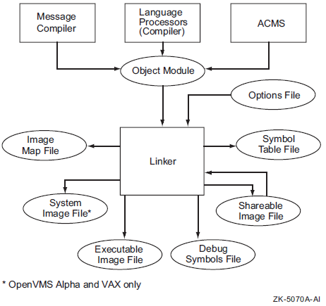
The linker also accepts other input files such as shareable images, and on VAX platforms, symbol table files, which are both products of previous link operations. Section 1.2, ''Specifying Input to the Linker'' provides more information about all the types of input files accepted by the linker. Section 1.3, ''Specifying Linker Output Files'' provides more information about the output files created by the linker.
Figure 1.1, ''Position of the Linker in Program Development'' illustrates the relationship of the linker to the language processor in the program development process.
Different Image Layout on x86-64 and Itanium
When porting an application from Itanium to x86-64, be aware that the image layout may change in an incompatible way – although the compile and link commands/options did not change. This is an architectural difference.
On Itanium, the compiler may generate short data, which is accessed in an efficient way. See Section 3.2.1.5, ''Short Data Sections (I64 Only)'' for more information on short data.
On x86-64, there is no short data. All data defined in an object module will go where the module goes (except the defining PSECT which is moved with an explicit COLLECT option). That is, on x86-64, for partially protected shareable images, all data defined by an object module which is collected into a protected linker cluster will be protected. User-mode code in the shareable image cannot write to it.
1.1.3. Linker Functions
Symbol resolution. Source modules can use symbols to represent the location of a routine entry point, the location of a data item, or a constant value. A source module may reference symbols that are defined externally to the module. When a language processor, such as a compiler or assembler, processes the source module, it cannot find the value of a symbol defined externally to the module. A language processor flags these externally defined symbols as unresolved symbolic references and leaves it to the linker to find their definitions among the other input files you specify. When the linker finds the definition of a symbol, it substitutes the value of the symbol (its definition) for the reference to the symbol. Chapter 2, "Understanding Symbol Resolution (x86-64 and I64)" (x86-64 and I64) and Chapter 6, "Understanding Symbol Resolution (Alpha and VAX)" (Alpha and VAX) provide more information about symbol resolution.
Virtual memory allocation. After resolving symbolic references among the input files, the linker allocates virtual memory for the image, based on the memory requirements specified by the input files. Chapter 3, "Understanding Image File Creation (x86-64 and I64)" (x86-64 and I64) and Chapter 7, "Understanding Image File Creation (Alpha and VAX)" (Alpha and VAX) provide more information about memory allocation.
Image initialization. After the linker resolves references and obtains the memory requirements of the image, it initializes the image by filling it with the compiled binary data and code. The linker also inserts the actual value of resolved symbols at each instance where the symbol is referenced.
For certain global symbols, the linker does not write their value into the image. For example, when taken from shareable images, the value of a symbol that represents an address cannot be determined until run-time; that is, when the image activator loads the image into memory. The linker lists these symbols in the fix-up information, to which the image activator provides the actual address at run-time.
When the image activator loads a shareable image in memory and relocates all the symbols in the shareable image, it must ensure that the other images that reference these symbols in the shareable image have their correct addresses. Chapter 3, "Understanding Image File Creation (x86-64 and I64)" (x86-64 and I64) and Chapter 7, "Understanding Image File Creation (Alpha and VAX)" (Alpha and VAX) provide more information about image initialization.
Image optimization. For OpenVMS Alpha images, the linker can perform certain optimizations to improve the run-time performance of the image it is creating. These optimizations include replacing JSR instruction sequences with the more efficient Branch to Subroutine (BSR) instruction sequence wherever the language processors specify. For OpenVMS IA-64 images, the linker can optimize data references to the short data segment. For more information, see Chapter 3, "Understanding Image File Creation (x86-64 and I64)" (I64) and Chapter 7, "Understanding Image File Creation (Alpha and VAX)" (Alpha and VAX).
1.1.4. Using the Linker
You start the linker interactively by entering the LINK command together with the appropriate input file names at the DCL prompt. You can also start the linker by including the LINK command in a command procedure. For more information about starting the linker, see Chapter 10, "LINK Command Reference".
#include <stdio.h>
main() {
   printf( "Hello World!\n" );
}$ CC HELLO
During compilation, the compiler translates the statements in the source file into
machine instructions and groups portions of the program into program sections
according to their memory use and other characteristics. In addition, the compiler
lists all the global symbols defined in the module and referenced by the module in
the symbol table. In Alpha and VAX object modules, this table is also called a
global symbol directory (GSD). In Example 1.1, ''Hello World! Program (HELLO.C)'', the printf routine is referenced by the module but is not
defined in it. The printf routine is defined in the VSI C
Run-Time Library (DECC$SHR).
$ LINK HELLO
By default, the linker processes DECC$SHR because it resides in the default system shareable image library [IMAGELIB.OLB]. Because of this, you do not need to specify this as input unless you are changing the behavior of the default library scans (for example, linking with /NOSYSLIB). See Section 2.2.3.3, ''Processing Default Libraries'' (x86-64 and I64) and Section 6.2.3.3, ''Processing Default Libraries'' (Alpha and VAX) for more information about how the linker processes default system libraries.
The linker processes the input files you specify in two passes. In its first pass through the input files, the linker resolves symbolic references between the modules. Because the linker processes different types of input files in different ways, the order in which you specify input files can affect symbol resolution. Chapter 2, "Understanding Symbol Resolution (x86-64 and I64)" (x86-64 and I64) and Chapter 6, "Understanding Symbol Resolution (Alpha and VAX)" (Alpha and VAX) provide more information about this topic.
After performing symbol resolution and determining all the input modules necessary to create the image, the linker ascertains the memory requirements of the image based on the memory requirements of the input files. The compilers have specified the memory requirements of the object modules as program section attributes.
On Alpha and VAX systems, the linker gathers together program sections with similar attributes into image sections. At activation time, the image activator reads the memory requirements of the image that the linker has stored in the image file by processing the list of image section descriptors (ISDs) and begins to set up the image for execution. Chapter 7, "Understanding Image File Creation (Alpha and VAX)" provides more information about Alpha and VAX image creation.
On x86-64 and IA-64 systems, the linker gathers ELF sections with similar attributes into ELF segments. At run-time, the image activator reads the memory requirements of the image that the linker has stored in the image file by processing the segments. Chapter 3, "Understanding Image File Creation (x86-64 and I64)" provides more information about creation of x86-64 and I64 images.
$ RUN HELLO
Hello World!
Note that a LINK command required to create a real application, unlike the Hello World! example, can involve specifying hundreds of input files of various types.
As with most other DCL commands, the LINK command supports numerous qualifiers with which you can control various aspects of a link operation. The linker also supports linker options, which you can use to further control a link operation. Linker options can be specified in an options file, which is then specified as an input file in a link operation. Section 1.2.5, ''Options Files as Linker Input Files'' describes the benefits of using options files and describes how to create them. Chapter 10, "LINK Command Reference" provides descriptions of the qualifiers and options supported by the linker. Section 1.4, ''Controlling a Link Operation'' contains a summary table of these qualifiers and options.
1.2. Specifying Input to the Linker
|
File |
Default File Type |
Description |
|---|---|---|
|
Object file |
.OBJ |
Created by a language processor. May be specified on the LINK command line or in a linker options file. This is the default input file accepted by the linker. |
|
Shareable image |
.EXE |
Produced by a previous link operation. Must be specified in a linker options file; you cannot specify a shareable image as an input file on the command line. Identify the input file as a shareable image by appending the /SHAREABLE qualifier to the file specification. |
|
Library file |
.OLB |
Produced by the Librarian utility. May contain object modules or shareable images. May be specified on the LINK command line, in a linker options file, or as a default user library processed by the linker. Identify the input file as a library file by appending the /LIBRARY qualifier to the library file specification. You can also include specific modules from a library in a link operation by appending the /INCLUDE qualifier to the library file specification. |
|
Symbol table file |
.STB |
Produced by a previous link operation or a language processor. May be specified on the LINK command line or in an options file. Because a symbol table file is processed as an object module, it requires no identifying qualifier. Note that symbol table files produced by the linker during x86-64, I64, and Alpha links cannot be specified as input files in a link operation. They are intended to be used only as an aid to debugging with the System Dump Analyzer utility (see Section 1.2.4, ''Symbol Table Files as Linker Input Files (VAX Only)'' for more information). |
|
Options file |
.OPT |
Text file containing link option specifications or link input file specifications. May be specified only on the command line; you cannot specify an options file inside another options file. Identify the input file as an options file by appending the /OPTIONS qualifier to the end of the file specification. |
Note
OpenVMS VAX images can run as translated images on OpenVMS Alpha and IA-64 systems. Similarly, OpenVMS Alpha images can run as translated images on IA-64 systems. Translated images can interoperate with native OpenVMS images.
For information about migrating applications from VAX to Alpha, see Migrating an Application from OpenVMS VAX to OpenVMS Alpha Manual.
For information about migrating applications from Alpha to I64, see Porting Applications from VSI OpenVMS Alpha to VSI OpenVMS Industry Standard 64 for Integrity Servers.
1.2.1. Object Modules as Linker Input Files
When a language processor translates a source language program, it produces an output file that contains one or more object modules. This output file, called an object file, has the default file type of .OBJ and is the primary form of linker input. At least one object file must be specified in any link operation. An object file may be specified in the command line or in an options file.
$ LINK HELLO
The linker processes the entire contents of an object file, that is, every object module in the file. It cannot selectively process object modules within an object file. The linker can process object modules selectively in an object module library (.OLB) file only.
You cannot examine an object module by using a text editor. The only way to examine an object file is by using the ANALYZE/OBJECT utility. This utility produces a report that lists the records that make up the object module. This report is primarily useful to compiler writers. For information about using the ANALYZE command, see the VSI OpenVMS DCL Dictionary: A–M.
1.2.2. Shareable Images as Linker Input Files
Note
Another method for referencing a shareable image is to dynamically activate the image by calling LIB$FIND_IMAGE_SYMBOL and passing one of its symbols. For more information, see the VSI OpenVMS RTL Library (LIB$) Manual.
A shareable image file consists of activation information, image binaries (code and data), and a symbol table. This symbol table contains definitions of universal symbols exported by the shareable image. A universal symbol is to a shareable image what a global symbol is to a module. That is, where a global symbol can be used to satisfy references external to an object module, a universal symbol can be used to satisfy references external to the shareable image.
Reducing total link processing time. Because the linker needs only to read the activation information and to process the symbol table in a shareable image, it takes less time for the linker to process a shareable image. The linker does not have to resolve symbolic references within the shareable image, sort program sections into the image, or initialize the image contents as it does when processing object modules.
Avoiding relinking entire applications. You can create a shareable image that can be modified, recompiled, and relinked without causing the images that were linked against previous versions of the shareable image to be relinked. This is called upward compatibility. For more information about this topic, see Chapter 4, "Creating Shareable Images (x86-64 and I64)" (x86-64 and I64) and Chapter 8, "Creating Shareable Images (Alpha and VAX)" (Alpha and VAX).
Conserving disk space. Because many different executable images can be linked against the same shareable image, it is necessary to keep only a single copy of the shareable image on the disk. (Images that are linked with shareable images do not actually contain a copy of the shareable image).
Conserving physical memory. Because the system can map the shareable pages of an installed shareable image into the address space of many processes, each process does not need to have its own copy of these pages. Note that, to achieve this benefit, the shareable image must be installed using the Install utility, specifying the /SHARED qualifier.
Reduction of paging I/O. Because a page in an installed shareable image may be mapped into the working set of several processes, it is more likely to be in physical memory, reducing paging I/O. Note that, to achieve this benefit, the shareable image must be installed using the Install utility, specifying the /SHARED qualifier.
Implementing memory-resident databases. Because installed shareable images are memory resident, they simplify the implementation of applications, such as data acquisition and control systems, where response times are so critical that control variables and data readings must remain in main memory.
1.2.2.1. Including a Shareable Image in a Link Operation
MY_SHARE/SHAREABLE
$ LINK MY_MAIN_PROGRAM,MY_OPTIONS_FILE/OPTIONS
By default, if you do not specify the device and directory in the file specification, the linker looks for shareable images in your default device and directory.
You link against shareable images in a shareable image library by specifying the library on the LINK command line or in a linker options file, identifying the file as a library by appending the /LIBRARY qualifier to the library file specification. You can include specific shareable images from the library in the link operation by appending the /INCLUDE qualifier to the library file specification, specifying which shareable images you want to include as parameters. For more information about specifying library files in a link operation, see Section 1.2.3, ''Library Files as Linker Input Files''. By default, the linker looks for user library files in the current default directory.
Note that images that link against shareable images do not contain the shareable image but only a reference to it. When the executable image is activated, the image activator activates all the shareable images to which it has been linked. By default, each image maps its own copy of the shareable image's pages.
1.2.2.2. Installing a Shareable Image
$ INSTALL ADD/SHARED WORK:[PROGRAMS]MY_SHARE.EXE
The system creates a set of global sections for the portions of the shareable image that can be shared. The system can map these portions as global sections into the address space of multiple processes. For portions of the image that are not shareable, each process gets a private copy at image activation time. For help in creating an image on x86-64 and IA-64 systems, see Chapter 3, "Understanding Image File Creation (x86-64 and I64)". For similar information on Alpha and VAX systems, see Chapter 7, "Understanding Image File Creation (Alpha and VAX)".
If you do not install the shareable image specifying the /SHARED qualifier, each process receives a private copy of the image. For information about installing images, see the VSI OpenVMS System Manager's Manual, Volume 1: Essentials.
1.2.3. Library Files as Linker Input Files
A library file is a file produced by the Librarian utility (default file type is .OLB). The linker accepts object module libraries and shareable image libraries as input files.
1.2.3.1. Creating a Library File
$ LIBRARY/CREATE/INSERT MY_LIB MY_PROG
A library file contains a library header and a name table. A library name table lists all of the global symbols in all of the modules and shareable images inserted in the library and associates the name of the symbol with the name of the module or shareable image in which it is defined.
Object module libraries contain copies of the object module. Shareable image libraries contain only the names of the shareable images. However, both object and shareable image libraries contain a name table, each entry associated with a definition in an object module or shareable image. Note that this is not the full symbol table of a module or a shareable image.
$ LIBRARIAN/LIST/NAMES MYMATH_LIB
Directory of ELF OBJECT library WORK:[PROGS]MYMATH_LIB.OLB;1 on 8-MAR-2019 09:59:06
Creation date:  8-MAR-2019 09:58:53       Creator:  Librarian I01-42
Revision date:  8-MAR-2019 09:58:53       Library format:   6.0
Number of modules:      1                 Max. key length:  1024
Other entries:          4                 Preallocated index blocks:    213
Recoverable deleted blocks:        0      Total index blocks used:        2
Max. Number history records:      20      Library history records:        0
Module MYMATHROUTS
MYADD
MYDIV
MYMUL
MYSUB
For more information about creating and using libraries, see the VSI OpenVMS Command Definition, Librarian, and Message Utilities Manual.
1.2.3.2. Including a Library File in a Link Operation
Using the /LIBRARY qualifier. You can specify a library file on the LINK command line or in an options file, identifying the input file as a library by appending the /LIBRARY qualifier.
When the linker processes a library file, it searches the library's name table for the definitions of symbols referenced in the other input files it has processed previously in the link operation. Note that the order in which the linker processes a library file can affect symbol resolution. For more information, see Chapter 2, "Understanding Symbol Resolution (x86-64 and I64)" (x86-64 and I64) and Chapter 6, "Understanding Symbol Resolution (Alpha and VAX)" (Alpha and VAX).
When the linker finds the symbol name of a definition in the library's name table, it includes the associated library element in the link operation and processes it as it would any other object module or shareable image. For object module libraries, the linker extracts the object module from the library. For shareable image libraries, the linker takes the image name from the library and attempts to translate it in order to find the image. If that fails, the linker looks for the shareable image in the device and directory in which the library resides. If the linker cannot find the shareable image at this location, it looks in the directory pointed to by the logical name X86$LIBRARY for x86-64 links, IA64$LIBRARY for I64 links, ALPHA$LIBRARY for Alpha links, and SYS$LIBRARY for VAX links.
Using the /INCLUDE qualifier. You can include specific modules from a library into a link operation by appending the /INCLUDE qualifier to the library file specification. You specify the modules you want included in the link operation as arguments to the qualifier.
Note, however, that the linker does not process the name table of a library file specified using the /INCLUDE qualifier. The linker includes from the library the modules specified as arguments to the /INCLUDE qualifier into the link operation and processes them as it would any other object module or shareable image.
If you append both the /LIBRARY qualifier and the /INCLUDE qualifier to a library file specification, the linker processes the library's name table and also includes the specified modules in the link operation.
Defining the library as a default user library. You can include a library in a link operation by defining it as a default user library. To define a default user library, assign the name of the library as the value of one of the linker's LNK$LIBRARY logical names. The linker processes libraries pointed to by these logicals after processing all the other input files specified in the link operation. See Section 2.2.3.3, ''Processing Default Libraries'' (x86-64 and I64) and Section 6.2.3.3, ''Processing Default Libraries'' (Alpha and VAX) for more information about default library processing.
1.2.4. Symbol Table Files as Linker Input Files (VAX Only)
A symbol table file is the product of a previous link operation or a language processor. A symbol table file is similar to an object module but it contains only a symbol table.
For VAX linking, you can specify a symbol table file as input in a link operation as you would any other object module, as in the following example:
$ LINK MY_MAIN_PROGRAM, MY_SYMBOL_TABLE
Note
On 64-bit systems, you cannot specify a symbol table as input in a link operation.
The linker processes the symbol table file during symbol resolution. If the symbol table file is the by-product of a link operation in which an executable image or system image was created, the symbol table contains the names and values of every global symbol in the image. If the symbol table file is associated with a shareable image, it contains by default the names and values of the symbols in the image declared as universal.
For a symbol table file to be useful in link operations, the values associated with the symbols in the symbol table file must be constants. The value of symbols that represent addresses, such as a procedure entry point, can vary each time the image is activated (unless the image is based).
Note also that a symbol table file associated with a shareable image should not be specified as an input file in a link operation in place of the shareable image. The shareable image itself must be specified as input because the linker requires more information than can be found in a symbol table file, such as the memory requirements of the shareable image (contained in the image header).
Symbol table files created by the linker on 64-bit systems can be used as an aid to debugging with the System Dump Analyzer utility (SDA).
1.2.5. Options Files as Linker Input Files
An options file is a standard text file you must use to specify linker options and shareable images specified as input files. You cannot specify linker options or shareable images on the LINK command line. Linker options, similar to linker qualifiers, allow you to control various aspects of the linker operation. Chapter 10, "LINK Command Reference" includes descriptions of the options supported by the linker.
Specifying frequently used input file specifications
Entering LINK commands that might exceed the buffer capacity of the command language interpreter
Separate input file specifications with a comma (,).
Do not enter any linker qualifiers except those required to identify input files or modules, such as the /SELECTIVE_SEARCH, /LIBRARY (optionally followed by /INCLUDE) or /SHAREABLE (optionally followed by /SELECTIVE_SEARCH) qualifier.
Do not specify an options file within an options file.
Enter at most one option per line.
Continue a line by entering the continuation character (the hyphen (-)) at the end of the line.
Enter comments after an exclamation point (!).
You may abbreviate the name of a link option to as few letters as needed to make the abbreviation unique.
MOD1.OBJ,MOD7.OBJ,LIB3.OLB/LIBRARY,-
LIB4/LIBRARY/INCLUDE=(MODX,MODY,MODZ),-
MOD12.OBJ/SELECTIVE_SEARCH
STACK=75
SYMBOL=JOBCODE,5
$ LINK PROGA,PROGB,PROJECT3/OPTIONS
If you precede the link operation with the SET VERIFY command, DCL displays the contents of the options file as the file is processed.
$ !  LINK command
$ LINK  MAIN,SUB1,SYS$INPUT/OPTIONS
MYPROC/SHAREABLE
SYS$LIBRARY:APPLPCKGE/SHAREABLE
STACK=75
$
$ LINK MAIN,SUB1,SUB2,SYS$INPUT:/OPTIONS
MYPROC/SHAREABLE
SYS$LIBRARY:APPLPCKGE/SHAREABLE
STACK=75
Ctrl/Z
$ @LINKPROC
1.3. Specifying Linker Output Files
On all platforms, a symbol table file and a map file
On 64-bit systems, a debug symbol file
|
File |
Default File Type |
Description |
|---|---|---|
|
Executable image |
.EXE |
A program that can be run at the command line. This image is the default output file created by the linker. Specify the /EXECUTABLE qualifier to create an executable image. |
|
Shareable image |
.EXE |
A collection of procedures and data that usually can be referenced after being included in a link operation in which another image is created. Specify the /SHAREABLE qualifier to create a shareable image. |
|
System image? |
.EXE |
A program that is meant to be run as a standalone system. Specify the /SYSTEM qualifier to create a system image. |
|
Symbol table file |
.STB |
An object module containing the global symbol table from an executable or system image, or the universal symbol table from a shareable image. Specify the /SYMBOL_TABLE qualifier to create a symbol table file. |
|
Map file |
.MAP |
A text file created by the linker that provides information about the layout of the image and statistics about the link operation. Specify the /MAP qualifier to create a map file. |
|
Debug symbol file? |
.DSF |
A file containing debug information for use by the OpenVMS Debugger or System Code Debugger. Specify the /DSF qualifier to create a debug symbol file. See VSI OpenVMS Debugger Manual and Writing OpenVMS Alpha Device Drivers in C for guidelines on using the system code debugger. |
You cannot examine an image file using a text editor. To examine an image file, check for errors in image format, and obtain other information about the image, you must use the ANALYZE/IMAGE utility. See the VSI OpenVMS DCL Dictionary: A–M for information about using this utility.
1.3.1. Creating an Executable Image
An executable image is a file that can be executed by the RUN command.
On x86-64 and IA-64 systems, an executable image conforms to the ELF specification. Typically, this image consists of header tables, note sections containing the image identification information, a dynamic segment containing the image activation information and shareable image dependencies, and program segments containing the image binaries that define the memory requirements of the image.
On Alpha and VAX systems, an executable image is usually made up of an image header which contains image identification information and the image section descriptors (ISDs) that define the memory requirements and shareable image dependencies of the image binaries.
An executable image can reference one or more shareable images.
$ LINK HELLO
By default, the linker uses the name of the first input file specified as the name of the image file, giving the file the .EXE file type. However, you can alter this default naming convention. For more information, see the LINK command description in Chapter 10, "LINK Command Reference".
1.3.2. Creating a Shareable Image
A shareable image is similar in structure and content to an executable image, though it differs in the way that shareable program sections are sorted. To make use of a shareable image, include it in a link operation in which another image is created.
In x86-64 and I64 images, the symbol table is an ELF section that contains the symbol information.
In Alpha and VAX images, the symbol table resembles an appended object module that only contains the symbol information.
Note that the following LINK command includes an options file using SYS$INPUT. To make symbols in the shareable image available for other images to link against, you must declare them as universal symbols in a linker options file. The mechanism used to declare universal symbols for I64 and Alpha linking differs from VAX linking. For information and examples about creating and using shareable images, see Chapter 4, "Creating Shareable Images (x86-64 and I64)" (x86-64 and I64) and Chapter 8, "Creating Shareable Images (Alpha and VAX)" (Alpha and VAX).
$ LINK/SHAREABLE MY_SHARE, SYS$INPUT/OPTIONS
SYMBOL_VECTOR=(-
MY_ROUTINE=PROCEDURE,-
MY_COUNTER=DATA)
$
1.3.3. Creating a System Image (Alpha and VAX)
A system image is an image that does not run under the control of the operating system. It is intended for standalone operation only.
On x86-64 and IA-64 systems, system images have no special format; they are simply OpenVMS images that conform to the ELF specification. These system images might have constraints that you may have to address (for example, limits to the number of program segments).
By default, Alpha and VAX system images do not contain an image header, as do executable and shareable images. You can create a system image with a header by specifying the /HEADER qualifier. System images do not contain global symbol tables.
$ LINK/SYSTEM MY_SYSTEM_IMAGE
1.3.4. Creating a Symbol Table File
A symbol table file is like an object module that contains all the global symbol definitions in the image. You can create a symbol table for any type of image: executable, shareable, or system. For executable images and system images, the symbol table contains a listing of the global symbols in the image. For shareable images, the symbol table lists the universal symbols in the image.
On 64-bit systems, the symbol table files created by the linker cannot be used as input files in subsequent link operations.
For VAX linking, symbol table files can be specified as input files in link operations. For more information, see Section 1.2.4, ''Symbol Table Files as Linker Input Files (VAX Only)''.
On all platforms, symbol table files are intended to be used with SDA as an aid to debugging.
$ LINK/SYMBOL_TABLE MY_EXECUTABLE_IMAGE
By default, the linker uses the name of the first input file specified as the name of the symbol table file, giving the file the .STB file type. However, you can alter this default naming convention. For more information, see the description of the /SYMBOL_TABLE qualifier in Chapter 10, "LINK Command Reference".
1.3.5. Creating a Map File
A listing of the object modules included in the link operation
A listing of the image segments (on x86-64 and IA-64 systems) or image sections (on Alpha and VAX systems) created by the linker for the image
A listing of all the program sections created by the linker
A listing of all the global and universal symbols resolved by the linker for the image
A compilation of summary statistics about the link operation
To create an image map file, specify the /MAP qualifier on the LINK command line. In batch mode, the linker creates a map file by default. When you invoke the linker interactively (at the DCL command prompt), you must request a map explicitly. By default, the linker uses the name of the first input file specified as the name of the map file, giving the file the .MAP file type. However, you can alter this default naming convention. For more information, see the LINK command description in Chapter 10, "LINK Command Reference".
$ LINK/MAP HELLO
You can determine the information contained in the image map by specifying additional qualifiers that are related to the /MAP qualifier. For example, by specifying the /BRIEF qualifier with the /MAP qualifier, you can generate a map file that contains only a subset of the total information that can be returned. For information about creating a map file and the contents of a map file, see Chapter 5, "Interpreting an Image Map File (x86-64 and I64)" (x86-64 and I64) and Chapter 9, "Interpreting an Image Map File (Alpha and VAX)" (Alpha and VAX).
1.3.6. Creating a Debug Symbol File (64-Bit Systems)
$ LINK/DSF MY_PROJ.OBJ
By default, the linker uses the name of the first input file specified as the name of the DSF file, giving the file the .DSF file type. However, you can alter this default naming convention. For more information, see the description of the /DSF qualifier in Chapter 10, "LINK Command Reference".
1.4. Controlling a Link Operation
The linker allows you to control various aspects of the link operation by specifying qualifiers and options. The following sections summarize the qualifiers and options supported by the linker. The remaining chapters of this manual describe how to use these qualifiers and options, and Chapter 10, "LINK Command Reference" provides reference information about each linker qualifier and option.
1.4.1. Linker Qualifiers
Identify input files. For example, you must identify library files by appending the /LIBRARY qualifier to the file specification. Section 1.2, ''Specifying Input to the Linker'' describes these qualifiers.
Specify output files. For example, you must specify the /SHAREABLE qualifier to direct the linker to create a shareable image. Section 1.3, ''Specifying Linker Output Files'' describes these qualifiers.
Control symbol resolution. For example, if you specify the /NOSYSLIB qualifier, the linker will not process the default system object library or the default system image library. Chapter 2, "Understanding Symbol Resolution (x86-64 and I64)" (x86-64 and I64) and Chapter 6, "Understanding Symbol Resolution (Alpha and VAX)" (Alpha and VAX) contain more information about this topic.
Control image file creation. For example, if you specify the /CONTIGUOUS qualifier, the linker attempts to allocate contiguous disk blocks for the image file. Chapter 3, "Understanding Image File Creation (x86-64 and I64)" (x86-64 and I64) and Chapter 7, "Understanding Image File Creation (Alpha and VAX)" (Alpha and VAX) contain more information about this topic.
|
Qualifier |
Supported Platform |
Description |
|---|---|---|
|
/ALPHA |
Alpha, VAX |
Directs the linker to build an OpenVMS Alpha image. Section 1.5, ''Linking for Different Architectures (Alpha and VAX)'' describes this qualifier in more detail. |
|
/BASE_ADDRESS |
x86-64, I64 |
Directs the linker to suggest a starting address for an executable image, when used in the boot process. This starting address is ignored by the image activator. |
|
/BPAGE |
All |
Specifies the page size the linker should use when creating image sections or segments. |
|
/BRIEF |
All |
Directs the linker to create a brief image map. Must be specified with the /MAP qualifier. |
|
/CONTIGUOUS |
All |
Directs the linker to attempt to store the output image in contiguous disk blocks. |
|
/CROSS_REFERENCE |
All |
Directs the linker to replace the Symbols By Name section of the image map with the Symbol Cross-Reference section. Must be specified with the /MAP qualifier. |
|
/DEBUG |
All |
Directs the linker to include debug information in the image and to give control to the OpenVMS Debugger when the image is run. |
|
/DEMAND_ZERO |
64-bit platforms |
Controls how the linker creates demand-zero image sections or segments. |
|
/DNI |
x86-64, I64 |
Controls the processing of demangling information. |
|
/DSF |
64-bit platforms |
Directs the linker to create a file called a debug symbol file (DSF) for use by OpenVMS debuggers. |
|
/EXECUTABLE |
All |
Directs the linker to create an executable image. |
|
/FP_MODE |
x86-64, I64 |
Directs the linker to set the program's initial floating-point mode in case it was not supplied by the main module. |
|
/FULL |
All |
Directs the linker to create a full image map. Used only with the /MAP qualifier. |
|
/GST |
64-bit platforms |
Directs the linker to include symbols that have been declared universal in the global symbol table (GST) of a shareable image. Use /NOGST to create an image with an empty GST. As such, /NOGST allows you to ship a shareable image that cannot be linked against. This qualifier is not supported for VAX linking. |
|
/HEADER |
All |
Directs the linker to include an image header in a system image. Used only with the /SYSTEM qualifier. Accepted on x86-64 and I64, but not processed. |
|
/INCLUDE |
All |
Identifies the input file to which it is appended as a library file and directs the linker to include specific modules from the library in the link operation. |
|
/INFORMATIONALS |
All |
Directs the linker to output informational messages produced by a link operation. /NOINFORMATIONALS directs the linker to suppress informational messages. |
|
/LIBRARY |
All |
Identifies the input file to which it is appended as a library file. |
|
/MAP |
All |
Directs the linker to create an image map. |
|
/NATIVE_ONLY |
Alpha, I64 |
Directs the linker to create an image that cannot operate with a translated OpenVMS image. |
|
/OPTIONS |
All |
Identifies an input file as a linker options file. |
|
/P0IMAGE |
All |
Directs the linker to mark the specified executable image as one that can run only in P0 address space. |
|
/PROTECT |
All |
Directs the linker to protect the shareable image from user-mode and supervisor-mode write access. Used with the /SHAREABLE qualifier when the linker creates a shareable image. |
|
/REPLACE |
Alpha |
Directs the linker to perform certain optimizations that improve the performance of the resulting image. |
|
/SECTION_BINDING |
Alpha |
Directs the linker to check whether the image to be created contains dependencies on the layout of image sections that could interfere with the performance enhancement if installed resident. |
|
/SEGMENT_ATTRIBUTE |
x86-64, I64 |
Directs the linker to set attributes for image segments. |
|
/SELECTIVE_SEARCH |
All |
Directs the linker to include only those global symbols that are defined in the module or image and referenced by previously processed modules. |
|
/SHAREABLE |
All |
Directs the linker to create a shareable image. Can also be used to identify an input file as a shareable image. |
|
/SYMBOL_TABLE |
All |
Directs the linker to create a symbol table file. |
|
/SYSEXE |
64-bit platforms |
Directs the linker to process the OpenVMS executive file SYS$BASE_IMAGE.EXE (located in the directory pointed to by the logical name X86$LOADABLE_IMAGES on x86-64 systems, IA64$LOADABLE_IMAGES on IA-64 systems, or ALPHA$LOADABLE_IMAGES on Alpha systems) to resolve references to symbols in a link operation. |
|
/SYSLIB |
All |
Directs the linker to search the default system image library and the default system object library to resolve undefined symbolic references. |
|
/SYSSHR |
All |
Directs the linker to search the default system shareable image library to resolve undefined symbolic references. |
|
/SYSTEM |
Alpha,VAX |
Directs the linker to create a system image. |
|
/THREADS_ENABLE |
All |
Directs the linker to enable features of the thread environment, in which the generated image is activated. |
|
/TRACEBACK |
All |
Directs the linker to include traceback information in the image. |
|
/USERLIBRARY |
All |
Directs the linker to search default user libraries to resolve undefined symbolic references. /USERLIBRARY accepts a keyword (ALL, GROUP, PROCESS, SYSTEM, or NONE) to further specify which logical name tables to search for the definitions of default user libraries. |
|
/VAX |
Alpha, VAX |
Directs the linker to build an OpenVMS VAX image. Section 1.5, ''Linking for Different Architectures (Alpha and VAX)'' describes this qualifier in more detail. |
1.4.2. Link Options
Specify image identification information. Using options such as NAME=, ID=, and GSMATCH=, you can supply values to identify the image.
Declare universal symbols in shareable images. Using the UNIVERSAL= option on VAX systems and the SYMBOL_VECTOR= option on 64-bit systems, you can make symbols in shareable images accessible to external modules.
Group input files together. Using the CLUSTER= option or the COLLECT= option, you can specify which input files (or program sections in those input files) the linker should group together. This can affect the order of module processing and, therefore, symbol resolution.
Note that linker options must be specified in a linker options file. (See Section 1.2.5, ''Options Files as Linker Input Files'' for information about creating linker options files and specifying them in link operations).
|
Option |
Supported Platform |
Description |
|---|---|---|
|
BASE= |
VAX |
Sets the base virtual address for the image. |
|
CASE_SENSITIVE= |
All |
Determines whether the linker preserves the mixture of uppercase and lowercase characters used in arguments to linker options. |
|
CLUSTER= |
All |
Directs the linker to create a cluster and to assign the cluster the specified name, and insert the input files specified in the cluster. Note that the base-address option value, which specifies the virtual address for the cluster, is valid on VAX, valid on Alpha for executable images only, and not accepted on x86-64 and I64. See Chapter 10, "LINK Command Reference" for information about CLUSTER= option and other option values. |
|
COLLECT= |
All |
Moves the specified program sections into the specified cluster. |
|
DZRO_MIN= |
Alpha, VAX |
Sets the minimum number of uninitialized,contiguous pages that must be found in an image section before the linker can extract the pages from the image section and create a demand-zero image section. |
|
GSMATCH= |
All |
Sets match control parameters for a shareable image. |
|
IDENTIFICATION= |
All |
Sets the image ID field. |
|
IOSEGMENT= |
All |
Specifies the size of the image I/O segment. |
|
ISD_MAX= |
Alpha, VAX |
Specifies the maximum number of image sections. |
|
NAME= |
All |
Sets the image name field. |
|
PROTECT= |
All |
Directs the linker to protect one or more clusters from user-mode or supervisor-mode write access. Can be used only with shareable images. |
|
PSECT_ATTR= |
All |
Assigns values and attributes to program sections. |
|
RMS_RELATED_CONTEXT= |
All |
Determines RMS related-name context processing, also known as file specification "stickiness". |
|
STACK= |
All |
Sets the initial size of the user-mode stack. |
|
SYMBOL= |
All |
Defines a global symbol and assigns it a value. |
|
SYMBOL_TABLE= |
64-bit platforms |
Specifies whether a symbol table file, produced in a link operation in which a shareable image is created, should contain all the global symbols as well as the universal symbols in the shareable image. By default, the linker includes only universal symbols. |
|
SYMBOL_VECTOR= |
64-bit platforms |
Exports symbols in a shareable image, making them accessible to external images. |
|
UNIVERSAL= |
VAX |
Declares the specified global symbol as a universal symbol, making it accessible to external images. |
1.5. Linking for Different Architectures (Alpha and VAX)
Note
You cannot create OpenVMS x86-64 or I64 images on Alpha and VAX platforms, nor create images for Alpha or VAX on x86-64 and IA-64 systems.
| Logical Name | Description |
|---|---|
|
ALPHA$LIBRARY |
The linker uses this logical name when creating an OpenVMS Alpha image to locate the target system's shareable images and system libraries. |
|
VAX$LIBRARY |
The linker uses this logical name when creating an OpenVMS VAX image on an OpenVMS Alpha computer to locate the target system's shareable images and system libraries. |
|
SYS$LIBRARY |
The linker uses this logical name when creating an OpenVMS VAX image on an OpenVMS VAX computer to locate the target system's shareable images and system libraries. |
|
ALPHA$LOADABLE_IMAGES |
The linker uses this logical when creating an OpenVMS Alpha image to locate the target system's base image SYS$BASE_IMAGE.EXE when the /SYSEXE qualifier is in the link command line. |
When you specify /ALPHA, the linker creates an OpenVMS Alpha image using the OpenVMS Alpha libraries and OpenVMS Alpha images from the target system disk that the logicals ALPHA$LIBRARY and ALPHA$LOADABLE_IMAGES point to. When you link on an OpenVMS Alpha system, these logical names initially point to the current system's libraries and images. The qualifier /ALPHA is the default on OpenVMS Alpha systems.
When you specify /VAX on an OpenVMS Alpha system, the linker creates an OpenVMS VAX image using the OpenVMS VAX libraries and OpenVMS VAX images from the target system disk that the logical VAX$LIBRARY points to. On an OpenVMS VAX system, you create VAX images by using the OpenVMS VAX libraries and OpenVMS VAX images that the logical SYS$LIBRARY points to. The qualifier /VAX is the default on OpenVMS VAX systems.
Chapter 2. Understanding Symbol Resolution (x86-64 and I64)
This chapter describes how the linker performs symbol resolution on OpenVMS x86-64 and OpenVMS IA-64 systems.
For information on performing symbol resolution on OpenVMS Alpha and OpenVMS VAX systems, see Chapter 6, "Understanding Symbol Resolution (Alpha and VAX)".
As one of its primary tasks, the linker must resolve symbolic references between modules. This chapter describes how you can control the process to ensure that the linker resolves symbolic references as you intend.
2.1. Overview
Programs are typically made up of many interdependent modules. For example, one module may define a symbol to represent a program location or data element that is referenced by many other modules. The linker is responsible for finding the correct definition of each symbol referenced in all the modules included in the link operation. This process of matching symbolic references with their definitions is called symbol resolution.
2.1.1. Types of Symbols
Symbols can be categorized by their scope, that is, the range of modules over which they are intended to be visible. Some symbols, called local symbols, are meant to be visible only within a single module. Because the definition and the references to these symbols must be confined to a single module, language processors such as compilers can resolve these references.
Other symbols, called global symbols, are meant to be visible to external modules. A module can reference a global symbol that is defined in another module. Because the value of the symbol is not available to the compiler processing the source file, it cannot resolve the symbolic reference. Instead, a compiler creates an ELF symbol table (SYMTAB) in an object module that includes all of the global symbol references and global symbol definitions it contains. These symbols are part of the global symbol directory (GSD).
On x86-64 and IA-64 systems, the GSD has a conceptual meaning. It no longer indicates an area within an object module, in which all named entities are listed. For ELF objects, the named entities for data and code are listed in the ELF symbol table; the name identities for sections are listed in the section header table. To use the traditional name GSD on x86-64 and IA-64 systems, the GSD can be seen as a subset of the ELF symbol table, plus a subset of the section header table.
In most programming languages, you can explicitly specify whether a symbol is global or local by setting or omitting particular attributes in the symbol definition or reference. For example, in C all functions are global symbols by default but the functions with the static attribute are local symbols.
In shareable images, symbols that are intended to be visible to external modules are called universal symbols. A universal symbol in a shareable image is the equivalent of a global symbol in an object module. Note, however, that only those global symbols that have been declared as universal are listed in the ELF symbol table (SYMTAB) of the shareable image and are available to external modules to link against. These symbols are part of the global symbol table (GST).
Similar to the GSD, the GST has a conceptual meaning on x86-64 and IA-64 systems; that is, it no longer indicates an area within an image file, in which all named entities are listed. For ELF images, the named entities for data and code are listed in the ELF symbol table and the named entities for sections are listed in the section header table. To use the traditional name GST on x86-64 and IA-64 systems, the GST can be seen as a subset of the ELF symbol table, plus a subset of the section header table.
You must explicitly declare universal symbols as part of the link operation in which the shareable image is created. For more information about declaring universal symbols, see Chapter 4, "Creating Shareable Images (x86-64 and I64)".
2.1.1.1. Understanding Strong and Weak Symbols
As on Alpha and VAX systems, the linkers on x86-64 and IA-64 systems support global symbols that can be strong or weak. Weak symbols can be one of two types: VMS-style weak and UNIX-style weak.
The VMS-style weak symbol is identical to the weak symbol on Alpha and VAX. Using VMS-style weak symbols reflects a programming concept where the developer marks a symbol as weak depending on available language support. For information about how the linker processes VMS-style weak symbols, see Section 2.5, ''Processing Weak and Strong Global Symbols''.
UNIX-style weak symbols are unique to x86-64 and IA-64 systems and primarily used by the C++ compiler. Using UNIX-style weak symbols reflects an implementation concept, where the compiler marks symbols as weak, depending on language constructs. For information about how the linker processes UNIX-style weak symbols, see Section 2.6, ''Processing VSI C++ Compiler-Generated UNIX-Style Weak and Group Symbols''.
2.1.1.2. Group Symbols
Global symbols can be gathered in a group which is seen by the linker as a single entity. All symbols in a group are included or excluded in the link process. The group is identified by its group name, which is also called a group signature. A group also defines a set of sections, which contain definitions or references of the group symbols. As with UNIX-style weak symbols, groups are an implementation concept, primarily used by the VSI C++ compiler. For more information about working with group symbols, see Section 2.6, ''Processing VSI C++ Compiler-Generated UNIX-Style Weak and Group Symbols''.
2.1.1.3. The C Extern Common Model
In some VSI programming languages, certain types of global symbols, such as external variables in the C common extern model and COMMON data in FORTRAN, are not listed in the symbol table as global symbol references or definitions. Because these data types implement virtual memory that is shared, the languages implement them as sections that are overlaid. Rather than appearing as global symbol definitions or references, these variable names emerge as section names. (Compilers use sections to define the memory requirements of an object module). Although this may look like symbol resolution to the user, the linker does not process symbols. For information about how the linker processes sections, see Chapter 3, "Understanding Image File Creation (x86-64 and I64)".
#pragma extern_model common_block
struct { int first; int second; } numbers;
INTEGER*4 first, second COMMON /numbers/ first, second
2.1.1.4. Tentative Definitions in C
Note
Do not confuse the term "ELF common" with "Fortran common"; these are different concepts.
Creates a section named after the symbol to define memory for the tentative definitions.
Assigns the first module with a tentative definition as the defining module.
The section created by the linker contains the overlay attribute. Any other section with the same name and the same attributes can overlay onto this section.
/* module A */ #pragma extern_model relaxed_refdef int my_data;
/* module B */ #pragma extern_model relaxed_refdef int my_data;
Note
The linker does not include section names in its symbol resolution processing. The name spaces for symbols and sections are separate. The overlaying of sections with a created section for a tentative definition with the same name does not produce an exception.
2.1.1.5. Considerations for C Language Extensions
On x86-64 and IA-64 systems, the VSI C language extensions
globalref and globaldef allow you to
create external variables that appear as symbol references and definitions in
the symbol table. For more information, see the VSI C User Manual.
In addition, VSI C supports command line qualifiers and source code pragma statements (as shown in the previous examples) that allow you to control the extern model. For more information, see the VSI C User Manual.
2.1.2. Linker Symbol Resolution Processing
During its first pass through the input files specified in the link operation, the linker attempts to find the definition for every symbol referenced in the input files. By default, the linker processes all the global symbols defined and referenced in the symbol table of each object module (GSD) and all the universal symbols defined in the global symbol table (GST) of each shareable image and any symbol defined by linker options. The definition of the symbol provides the value of the symbol. The linker substitutes this value for each instance where the symbol is referenced in the image being created. This value might not be the actual value of the virtual address at run-time, because the values might be relocated by the image activator.
The value of a symbol depends on what the symbol represents. A symbol can represent a routine entry point or a data location within an image. For these symbols, the value of the symbol is an address. A symbol can also represent a data constant (for example, the linker option SYMBOL=X,10). In this case, the value of the symbol is its actual value.
For symbols that represent addresses in object modules, the value is expressed initially as an offset into a section. (This is the manner in which language processors express addresses). Later in its processing, the linker determines the symbol's preliminary value after combining all module contributions into segments, which yields the proposed memory layout. For information about how the linker determines the virtual memory layout of an image, see Chapter 3, "Understanding Image File Creation (x86-64 and I64)".
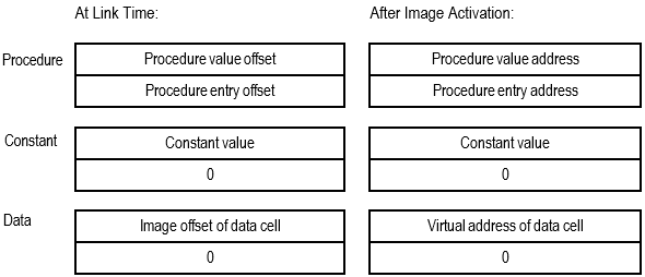
For x86-64 and I64 images, at link time, the value of a symbol in a shareable image (as listed in the GST of the image) is the index of the symbol's entry in the symbol vector of the image.
An x86-64 symbol vector entry is a pair of quadwords. The contents of the two quadwords depend on whether the symbol represents a procedure entry point, data location, or absolute constant. For procedure entries, the first quadword is the procedure's canonical address (that is, its procedure value); and the second quadword is the procedure's actual entry address. For data locations and constant values, the first quadword contains the address, offset, or constant value, and the second quadword contains zero. Figure 2.1, ''Symbol Vector Contents on x86-64'' shows the contents of the x86-64 symbol vector at link time and at image activation time.
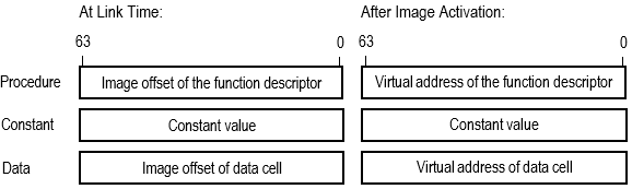
An I64 symbol vector entry is a quadword that contains the value of the symbol. The contents of the quadword depends on whether the symbol represents a procedure entry point, data location, or a constant. At link time, a symbol vector entry for a procedure entry point or a data location is expressed as an offset into the image. At image activation time, when the image is loaded into memory and the base address of the image is known, the image activator converts the image offset into a virtual address. Figure 2.2, ''Symbol Vector Contents on IA-64'' shows the contents of the I64 symbol vector at link time and at image activation time.
Note that the linker does not allow programs to make procedure calls to symbols that represent data locations.
Note
For x86-64 and I64 images, you can not specify an address at which you want an image mapped into virtual memory. The image activator decides where to place the image.
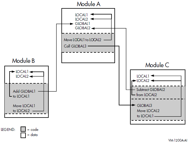
Figure 2.3, ''Symbol Resolution'' illustrates the interdependencies created by symbolic references among the modules that make up an application. In the figure, arrows point from a symbol reference to a symbol definition. (The statements do not reflect a specific programming language).
$ LINK MY_MAIN ! The module MY_MATH is omitted %ILINK-W-NUDFSYMS, 1 undefined symbol:%ILINK-I-UDFSYM, MYSUB
%ILINK-W-USEUNDEF, undefined symbol MYSUB referenced section: $CODE$ offset: %X0000000000000110 slot: 2 module: MY_MAIN file: WORK:[PROGRAMS]MY_MAIN.OBJ;1
| The linker issues an informational message for each symbol for which it cannot find a definition. |
| The linker issues a warning message for each instance where an undefined symbol is referenced in the image. |
$ RUN MY_MAIN
%SYSTEM-F-CALLUNDEFSYM, Call using undefined function symbol
%TRACE-F-TRACEBACK, symbolic stack dump follows
image     module    routine     line      rel PC           abs PC
MY_MAIN                            0 00000000000101B2 00000000000101B2
MY_MAIN  MY_MAIN  main          1594 0000000000000120 0000000000010120
MY_MAIN  MY_MAIN  __main        1586 00000000000000C0 00000000000100C0
                                   0 FFFFFFFF80B7FB30 FFFFFFFF80B7FB30
DCL                                0 000000000006BD60 000000007AE25D60
%TRACE-I-END, end of TRACE stack dump
2.2. Input File Processing for Symbol Resolution
The linker can include object modules, shareable images, and libraries in its symbol resolution processing. Options files do not play an important role in symbol resolution (the SYMBOL= option can define a symbol and its value).
By default, the linker includes all the symbol definitions from the object module or shareable image. However, if you append the /SELECTIVE_SEARCH qualifier to the object module or shareable image file specification, then the linker includes in its processing only those symbols that define symbols referenced in a previously processed input file. For more information about selectively processing input files, see Section 2.2.4, ''Processing Input Files Selectively''.
|
Input File |
How Processed |
|---|---|
|
Object file (.OBJ) |
By default, the linker processes all the symbol definitions and references listed in the global symbol table of the module. If you append the /SELECTIVE_SEARCH qualifier to the input file specification, the linker includes only those symbol definitions from the global symbol table that resolve symbolic references found in previously processed input files. |
|
Shareable image file (.EXE) |
By default, the linker processes all symbol definitions listed in the global symbol table of the image. However, the linker lists only those symbol definitions in the map file that are referenced by other modules in order to reduce map file clutter. If you append the /SELECTIVE_SEARCH qualifier to the input file specification, the linker includes in its processing only those symbol definitions from the global symbol table that resolve symbolic references found in previously processed input files. |
|
Library files (.OLB) |
Specifying /LIBRARY, the linker searches the name table of the library for symbols that are undefined in previously-processed input files. (Usually, a library file's name table lists all the symbols available in all of the modules it contains). If the linker finds the definition of a symbol referenced by a previously-processed input file, it includes in the link operation, the library module containing the definition of the symbol. Once the object module or shareable image is included in the link operation, the linker processes it as any other object module or shareable image. If you append only the /INCLUDE qualifier to a library file specification, the linker does not search the library's name table to find undefined symbolic references. Instead, the linker includes the specified object module or shareable image specified as a parameter to the /INCLUDE qualifier. You cannot process a library file selectively. However, if the Librarian utility's /SELECTIVE_SEARCH qualifier was specified when the object module or shareable image was inserted into the library, the linker processes the module selectively when it extracts it from the library. VSI does not recommend to use libraries with selectively added object modules. |
2.2.1. Processing Object Modules
mysub.#include <stdio.h>
int mysub( int value_1, int value_2 );
main()
{
int num1, num2, result;
num1 = 5;
num2 = 6;
result = 0;
result = mysub( num1, num2 );
printf( "Result is: %d\n", result );
}mysub, which Example 2.1, ''Source File Containing a Symbolic Reference: MY_MAIN.C'' references, is defined in the
program in Example 2.2, ''Source File Containing a Symbol Definition: MY_MATH.C''.int myadd( int value_1, int value_2 )
{
int result;
result = value_1 + value_2;
return result;
}
int mysub ( int value_1, int value_2 )
{
int result;
result = value_1 - value_2;
return result;
}
int mymul( int value_1, int value_2 )
{
int result;
result = value_1 * value_2;
return result;
}
int mydiv( int value_1, int value_2 )
{
int result;
result = value_1 / value_2;
return result;
}mysub. Because object modules cannot be examined using a text
editor, the following representation of the GSD is taken from the output of the
ANALYZE/OBJECT utility of the OpenVMS object module MY_MAIN.OBJ.$ CC MY_MAIN.C $ ANALYZE/OBJECT/SECTION=SYMTAB MY_MAIN.OBJ . . . Description Hex <bitmask> Decimal Interpretation ----------- --------------- ------- -------------- Symbol 16. (00000010) "MYSUB"Symbol 'Other' Field: 80 Symbol Visibility 00 STV_DEFAULT . . . Bound to section: 0000 0. (SHDR$K_SHN_UNDEF)
Symbol Value 0000000000000000 0.
Size associated with sym: 0000000000000000
| In Example 2.2, ''Source File Containing a Symbol Definition: MY_MATH.C'', |
| The Symbol Type for |
| The Symbol Binding for |
| References, or undefined symbols, are bound to a special section number which marks an undefined, missing, irrelevant or otherwise meaningless section (zero or SHDR$K_SHN_UNDEF). Definitions are bound to a section with a number greater than zero. |
| For references, the Symbol Value and the Size are not always known, and therefore are displayed as a zero. |
The GSD created by the language processor for the object module MY_MATH.OBJ contains the
definition of the symbol
mysub, as well as the other symbols defined in the module.
The definition of the symbol includes the value of the symbol.
$ CC MY_MATH.C
$ ANALYZE/OBJECT/SECTION=SYMTAB MY_MATH.OBJ
   .
   .
   .
Description                  Hex <bitmask>  Decimal Interpretation
-----------                  -------------  ------- --------------
Symbol 12. (0000000C)        "MYSUB"
 Name Index in Sec. 8.:            00000027      39.
 Symbol Info Field:                      12
   Symbol Type:                          02          STT_FUNC
   Symbol Binding:                       01          STB_GLOBAL
 Symbol 'Other' Field:                   80
   Symbol Visibility                     00          STV_DEFAULT
     .
     .
     .
 Bound to section:                     0003       3. "$CODE$"
 Symbol Value              0000000000000020      32.
 Size associated with sym: 0000000000000020
| Since |
| The Symbol Value (32) is the byte offset of the code entry point into the section $CODE$. |
| The Size associated with the symbol is the amount of code in the routine (32 bytes). |
$ LINK MY_MAIN, MY_MATH
When the linker processes these object modules, it reads the contents of the GSDs, obtaining the value of the symbol from the symbol definition.
If the linker has created a function descriptor (called a procedure descriptor on Alpha) the value is the address of the function descriptor. This is listed in the Symbol Cross Reference portion of the map with the suffix -R or in the Symbols By Value portion of the map with the prefix R-.
If the symbol is a function, and the linker has not created a function descriptor, the value of a symbol is the location within the image of the entry point of the function. This information is listed in the Symbol Cross Reference portion of the map with the suffix -RC or in the Symbols By Value portion of the map with the prefix RC-. R is the label that means relocatable, and C is the label that means code address.
The function descriptor created by the linker is a pair of quadwords that contain the Global Pointer (GP) for the image and the pointer to the entry point of the function. Note that on IA-64, the linker creates the function descriptors rather than the compiler. The linker also chooses the value for the GP, which is an address that the code segment uses to access the short data segment. It accesses different parts of the short data segment by using different offsets to the value the linker has chosen for the GP.
For x86-64 images, a function symbol's value is always a code address. There is no GP and no short data segment.
If the symbol is data, it can be either relocatable or not relocatable. The linker uses the R prefix or suffix in the map to indicate relocation.
2.2.2. Processing Shareable Images
When the linker processes a shareable image, it processes all the universal symbol definitions in the GST of the image. Because the linker creates the GST of a shareable image in the same format as an object module's symbol table, the processing of shareable images for symbol resolution is similar to the processing of object modules. The linker sets an attribute that flags the symbol as protected, which also indicates a universal symbol when the linker creates an image. Note that the linker includes only those universal symbols in the map file that resolve references, thus eliminating extraneous symbols in the linker map.
$ LINK/MAP/FULL MY_MAIN, SYS$INPUT/OPT
MY_MATH.EXE/SHAREABLE
Ctrl/Z
The GST created by the linker for the shareable image MY_MATH.EXE contains the
universal definition of the symbol
MYSUB, as well as the other symbols defined in the
module.
Because images cannot be examined using a text editor, the following representations of the GST are taken from the output of the ANALYZE/IMAGE utility:
$ CC MY_MATH.C
$ LINK/MAP/FULL/CROSS/SHAREABLE MY_MATH.OBJ,SYS$INPUT/OPT
SYMBOL_VECTOR=(MYADD=PROCEDURE,-
               MYSUB=PROCEDURE,-
               MYMUL=PROCEDURE,-
               MYDIV=PROCEDURE)
Ctrl/Z
$ ANALYZE/IMAGE/SECTION=SYMTAB MY_MATH.EXE
Ctrl/Z
   .
   .
   .
  Symbol 3. (00000003)        "MYSUB"
    Name Index in Sec. 2.:            0000000D      13.
    Symbol Info Field:                      12
      Symbol Type:                          02          STT_FUNC
      Symbol Binding:                       01          STB_GLOBAL
    Symbol 'Other' Field:                   93
      Symbol Visibility                     03          STV_PROTECTED
      Function Type                         10          VMS_SFT_SYMV_IDX
       .
       .
       .
    Bound to section:                     0008       8. "$LINKER RELOCATABLE_SYMBOL"
    Symbol Value              0000000000000001       1.
    Size associated with sym: 0000000000000000
For x86-64 and I64 images, STV_PROTECTED indicates a universal definition. The
"Symbol Type", STT_FUNC, indicates that this symbol represents a function (or
procedure). The Function Type, VMS_SFT_SYMV_IDX, indicates that the symbol value (in
this case 1) is the index into the symbol vector of the pointer to the function
descriptor for MYSUB.
The analysis also lists all the indexes in the symbol vector. The following Index, which matches the previous value for the symbol, is 1.
MYSUB, and the second value is the code address of the entry
point for
MYSUB.SYMBOL VECTOR 4. Elements
------------- -----------
Index Value Size Symbol or Section Name
----- ----- ---- ----------------------
0. 0000000000002070 PROCEDURE "MYADD"
0000000080000000
1. 0000000000002080 PROCEDURE "MYSUB"
0000000080000020
2. 0000000000002090 PROCEDURE "MYMUL"
0000000080000040
3. 00000000000020A0 PROCEDURE "MYDIV"
0000000080000060
.
.
.For I64 images, the entry in the symbol vector with the index value of 1, contains
the value 30080, which is the address of a function descriptor for
MYSUB. The function descriptor is a quadword pair. The first
quadword is the address of the entry point for MYSUB (10020). The
address 10020 is in a segment that has the execute flag set (that is, a code
segment). The second quadword contains the global pointer chosen by the linker for
the image (230000).
SYMBOL VECTOR                         4. Elements
-------------                         -----------
Index   Value                       Entry/GP or Size  Symbol or Section Name
-----   -----                       ----------------  ----------------------
    0.  0000000000030068 PROCEDURE  0000000000010000  "MYADD"
                                    0000000000230000
    1.  0000000000030080 PROCEDURE  0000000000010020  "MYSUB"
                                    0000000000230000
    2.  0000000000030098 PROCEDURE  0000000000010040  "MYMUL"
                                    0000000000230000
    3.  00000000000300B0 PROCEDURE  0000000000010090  "MYDIV"
                                    0000000000230000
            .
            .
            .
2.2.2.1. Implicit Processing of Shareable Images
For VAX linking, when you specify a shareable image in a link operation, the linker not only resolves symbols from the shareable image you specify but it also resolves symbols from all shareable images that the shareable image has been linked against (that is, the shareable image's dependency list).
$ LINK/MAP/FULL/CROSS MY_MAIN,SYS$INPUT/OPT
MY_MATH.EXE/SHAREABLE
Ctrl/Z
$ ANALYZE/IMAGE MY_MAIN
   .
   .
   .
Image Activation Information, in segment 4.
     Global Pointer:                             0000000000240000
     Whole program FP-mode:                      IEEE DENORM_RESULTS
     Link flags
         Call SYS$IMGSTA
         Image has main transfer
         Traceback records in image file
     Shareable Image List
         MY_MATH
             (EQUAL, 9412., 468313704).
         DECC$SHR
             (LESS/EQUAL, 1., 1).
Note
If your VAX application's build procedure depends on implicit processing of shareable images, you may need to add these shareable images to your x86-64 or I64 linker options file.
2.2.3. Processing Library Files
Libraries specified as input files in link operations contain either object modules or shareable images. The way in which the linker processes library files depends on how you specify the library in the link operation. Sections 2.2.3.1, 2.2.3.2, and 2.2.3.3 describe these differences. Note, however, that once an object module or shareable image is included from the library into the link operation, the linker processes the file as it would any other object module or shareable image.
$ LIBRARY/CREATE/INSERT MYMATH_LIB MY_MATH
$ LIBRARY/LIST/NAMES MYMATH_LIB
Directory of ELF OBJECT library WORK:[PROGRAMS]MYMATH_LIB.OLB;1 on 8-MAR-2019 17:49:14
Creation date:   8-MAR-2019 17:48:57      Creator:  Librarian I01-42
Revision date:   8-MAR-2019 17:48:57      Library format:   6.0
Number of modules:      1                 Max. key length:  1024
Other entries:          4                 Preallocated index blocks:    213
Recoverable deleted blocks:        0      Total index blocks used:        2
Max. Number history records:      20      Library history records:        0
 Module MY_MATH
MYADD
MYDIV
MYMUL
MYSUB
$ LINK/MAP/FULL/CROSS MY_MATH, MYMATH_LIB/LIBRARY
The map file produced by the link operation verifies that the object module MY_MATH.OBJ was included in the link operation.
2.2.3.1. Identifying Library Files Using the /LIBRARY Qualifier
When the linker processes a library file identified by the /LIBRARY qualifier, the linker processes the library's name table and looks for the definitions of symbols referenced in previously processed input files.
Note that in order to resolve a reference to a symbol defined in a library, the linker must first process the module that references the symbol before it processes the library file. As such, while the order of object modules and shareable images is not usually important in a link operation, how you order library files can be important. For more information about controlling the order in which the linker processes input files, see Section 2.3, ''Ensuring Correct Symbol Resolution''.
Once the object module or shareable image is included from the library into the link operation, the linker processes all the symbol definitions in a shareable image, and symbol definitions and references in an object module. If you want the linker to selectively process object modules or shareable images that are included in the link operation from a library, you must append the Librarian utility's /SELECTIVE_SEARCH qualifier to the file specification of the object module or shareable image when you insert it into the library. Processing libraries with selectively added object modules can result in multiple inclusion of the same object module, which is usually not wanted. VSI does not recommend using libraries with selectively added object modules. Appending the linker's /SELECTIVE_SEARCH qualifier to a library file specification in a link operation is illegal. For more information about processing input files selectively, see Section 2.2.4, ''Processing Input Files Selectively''.
Processing Object Module Libraries
Extracts from the library the object module that contains the definition and includes it in the link operation
Processes the GSD of the object module extracted from the library, adding an entry to the linker's list of symbol definitions for every symbol defined in the object module, and adding entries to the linker's undefined symbol list for all the symbols referenced by the module (see Section 2.2.1, ''Processing Object Modules'')
Continues to process the undefined symbol list until there are no definitions in the library for any outstanding references
When the linker finishes processing the library, it will have extracted all the modules that resolve references generated by modules that were previously extracted from the library.
Processing Shareable Image Libraries
When the linker finds a symbol in the name table of a shareable image library, it notes which shareable image contains the symbol and then looks for the shareable image to include it in the link operation. By default, the linker looks for the shareable image in the same device and directory as the library file
If the linker cannot find the shareable image in the device and directory of the library file, the linker looks for the shareable image in the directory pointed to by the logical name X86$LIBRARY for x86-64 links and IA64$LIBRARY for I64 links.
Once the linker locates the shareable image, it processes the shareable image as it does any other shareable image (see Section 2.2.2, ''Processing Shareable Images'').
2.2.3.2. Including Specific Modules from a Library Using the /INCLUDE Qualifier
If the library file is specified with the /INCLUDE qualifier, the linker does not process the library's name table. Instead, the linker includes in the link operation modules from the library specified with the /INCLUDE qualifier and processes these modules as it would any other object module or shareable image.
If you append both the /LIBRARY qualifier and the /INCLUDE qualifier to a library file specification, the linker processes the library's name table to search for modules that contain needed definitions. When the linker finds an object module or shareable image in the library that contains a needed definition, it processes it as described in Section 2.2.3.1, ''Identifying Library Files Using the /LIBRARY Qualifier''. In addition, the linker includes the modules specified with the /INCLUDE qualifier in the link operation and processes them as it would any other object module or shareable image.
2.2.3.3. Processing Default Libraries
Default user library files. You specify a default user library by associating the library with one of the linker's default logical names from the range LNK$LIBRARY, LNK$LIBRARY_1, … LNK$LIBRARY_999. If the /NOUSERLIBRARY qualifier is specified, the linker skips processing default user libraries. For more information about defining a default user library, see the description of the /USERLIBRARY qualifier in Chapter 10, "LINK Command Reference".
If the default user library contains shareable images, the linker looks for the shareable image as described in Section 2.2.3.1, ''Identifying Library Files Using the /LIBRARY Qualifier''.
Default system shareable image library file. The linker processes the default system shareable image library IMAGELIB.OLB by default unless you specify the /NOSYSSHR or the /NOSYSLIB qualifier.
Note that when the linker needs to include a shareable image from IMAGELIB.OLB in a link operation, it always looks for the shareable images in X86$LIBRARY on x86-64 and IA64$LIBRARYon IA-64. The linker does not look for the shareable image in the device and directory of IMAGELIB.OLB as it does for other shareable image libraries.
Default system object module library file. The linker processes the default system object library STARLET.OLB by default unless you specify the /NOSYSLIB qualifier.
When the x86-64 or I64 linkers process STARLET.OLB by default, it also processes the shareable image (SYS$PUBLIC_VECTORS.EXE). This shareable image is needed to resolve references to system services.
When STARLET is not processed by default (for example, when the /NOSYSLIB qualifier is specified), the linker does not process SYS$PUBLIC_VECTORS.EXE automatically, even if you explicitly specify STARLET.OLB in an options file.
If you specify SYS$PUBLIC_VECTORS.EXE explicitly in an options file when it is already being processed by default, the linker displays the following warning:%ILINK-W-MULCLUOPT, cluster SYS$PUBLIC_VECTORS multiply defined in options file [filename]
2.2.4. Processing Input Files Selectively
By default, the linker processes all the symbol definitions and references in an object module or a shareable image specified as input in a link operation. However, if you append the /SELECTIVE_SEARCH qualifier to an input file specification, the linker processes from the input file only those symbol definitions that resolve references in previously processed input files.
Note
Processing files selectively does not affect the size of the resultant image; the entire object module is included in the image even if only a subset of the symbols it defines is referenced. (Shareable images do not contribute to the size of an image).
For example, in the link operation in Section 2.2.2, ''Processing Shareable Images'', the linker
processes the shareable image MY_MATH.EXE before it processes the object module
MY_MAIN.OBJ because of the way in which the linker clusters input files. (For
information about how the linker clusters input files, see Section 2.3.1, ''Understanding Cluster Creation''). When it processes the shareable image, the
linker includes on its list of symbol definitions all the symbols defined in the
shareable image. When it processes the object module MY_MAIN.OBJ and encounters the
reference to the symbol mysub, the linker has the definition to
resolve the reference.
mysub, the linker cannot resolve the reference to the symbol.
For information about how to correct this link operation, see Section 2.3.1, ''Understanding Cluster Creation''.$ LINK MY_MAIN, SYS$INPUT/OPT MY_MATH.EXE/SHAREABLE/SELECTIVE_SEARCH Ctrl/Z %ILINK-W-NUDFSYMS, 1 undefined symbol: %ILINK-I-UDFSYM, MYSUB %ILINK-W-USEUNDEF, undefined symbol MYSUB referenced section: $CODE$ offset: %X0000000000000110 slot: 2 module: MY_MAIN file: WORK:[PROGRAMS]MY_MAIN.OBJ;1
To process object modules or shareable images in a library selectively, you must specify the /SELECTIVE_SEARCH qualifier when you insert the module in the library. For more information about using the Librarian utility, see the VSI OpenVMS Command Definition, Librarian, and Message Utilities Manual.
2.3. Ensuring Correct Symbol Resolution
For many link operations, the order in which the input files are specified in the LINK command is not important. However, in complex link operations that specify multiple library files or process input files selectively, correct symbol resolution may become problematic.
To ensure that the linker resolves all the symbolic references as you intend, you may need to know order in which the linker processes the input files. To control the order in which the linker processes input files, you must understand how the linker parses the command line. The following sections describe these processes.
2.3.1. Understanding Cluster Creation
As it parses the command line, the linker groups the input files you specify into clusters and places these clusters on a cluster list. A cluster is an internal linker construct that determines segment creation. The position of an input file in a cluster and the position of that cluster on the linker's cluster list determine the order in which the linker processes the input files you specify.
The linker always creates at least one cluster, called the default cluster. The linker may create additional clusters, called named clusters, depending on the types of input files you specify and the linker options you specify. If it creates additional clusters, the linker places them on the cluster list ahead of the default cluster, in the order in which it encounters them in the options file. The default cluster appears at the end of the cluster list. (Within the default cluster, input files appear in the same order in which they are specified on the LINK command line).
Clusters for shareable images, specified in shareable image libraries, appear after the default cluster on the cluster list because they are created later in linker processing, when the linker knows which shareable images in the library are needed for the link operation.
|
Input File |
Cluster Processing |
|---|---|
|
Object file (.OBJ) |
Placed in the default cluster unless explicitly placed in a named cluster using the CLUSTER= option. |
|
Shareable image file (.EXE) |
Always placed in a named cluster. |
|
Library files (.OLB) |
Placed in the default cluster unless explicitly placed in a named cluster using the CLUSTER= option. If the library contains shareable images and the linker includes a shareable image from the library in the link operation, the linker creates a new cluster for the shareable image. The linker puts input files included in a link operation from a library using the /INCLUDE qualifier in the same cluster as the library. The linker puts modules extracted from any default user library that is an object library and from STARLET.OLB in the default cluster. However, the linker puts shareable images referenced from IMAGELIB.OLB into new clusters at the end of the cluster list (after the default cluster). |
|
Options file (.OPT) |
Not placed in a cluster. |
$ DEFINE LNK$LIBRARY  SYS$DISK:[]MY_DEFAULT_LIB.OLB
$ LINK  MY_MAIN.OBJ, MY_LIB.OLB/LIBRARY, SYS$INPUT/OPT
CLUSTER=MY_CLUS,,,MY_PROG.OBJ
MY_SHARE.EXE/SHAREABLE
MY_SHARE_LIB.OLB/LIBRARY
Ctrl/Z
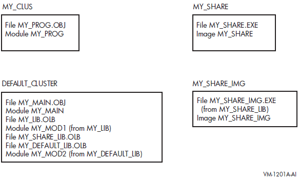
The linker processes input files in cluster order, processing each input file starting with the first file in the first cluster, then processing the second file, and so on, until it has processed all files in the first cluster. The linker continues processing the input files in the second, and subsequent, clusters in the same manner. Processing concludes when the linker has processed all files in all clusters.
2.3.2. Controlling Cluster Creation
CLUSTER= option
COLLECT= option
2.3.2.1. Using the CLUSTER= Option to Control Clustering
The CLUSTER= option causes the linker to create a named cluster and to place, in the cluster, the object modules specified in the option. (The linker puts shareable images in their own clusters).
$ LINK/EXECUTABLE=MY_MAIN SYS$INPUT/OPT
CLUSTER=MYMAIN_CLUS,,,MY_MAIN
MY_MATH/SHAREABLE/SELECTIVE_SEARCH
Ctrl/Z
The Object and Image Synopsis section of the image map file verifies that the linker processed the object module MY_MAIN before it processed the shareable image MY_MATH, as in the following map file excerpt:
                      +---------------------------+
                      ! Object and Image Synopsis !
                      +---------------------------+
  Module/Image  File           Ident             Attributes      Bytes
  ------------  ----           -----          –--------------    -----
  MY_MAIN                       V1.0               Lkg    Dnrm     504
                WORK:[PROGRAMS]MY_MAIN.OBJ;1
  MY_MATH                       V1.0           Sel Lkg               0
                WORK:[PROGRAMS]MY_MATH.EXE;1
    .
    .
    .
2.3.2.2. Using the COLLECT= Option to Control Clustering
You can also create a named cluster by specifying the COLLECT= option. The COLLECT= option directs the linker to put specific sections in a named cluster. The linker creates the cluster if it does not already exist. Note that the COLLECT= option manipulates sections, not input files.
$ LINK/EXECUTABLE=MY_MAIN SYS$INPUT/OPT
CLUSTER=MYMAIN_CLUS,,,MY_MAIN
COLLECT=MYCODE_CLUS,$CODE$
MY_MATH/SHAREABLE/SELECTIVE_SEARCH
Ctrl/Z
In this example, a cluster MYCODE_CLUS is created after MYMAIN_CLUS and the section $CODE$ is collected into the cluster MYCODE_CLUS.
2.4. Resolving Symbols Defined in the OpenVMS Executive
For x86-64 and I64 linking, you link against the OpenVMS executive by specifying the /SYSEXE qualifier. When this qualifier is specified, the linker selectively processes the system shareable image, SYS$BASE_IMAGE.EXE, located in the directory pointed to by the logical name X86$LOADABLE_IMAGES for x86-64 links and IA64$LOADABLE_IMAGES for I64 links. The linker does not process SYS$BASE_IMAGE.EXE by default. Note that, because the linker is processing a shareable image, references to symbols in the OpenVMS executive are fixed up at image activation.
When the /SYSEXE qualifier is specified, the linker processes the file selectively. To disable selective processing, specify the /SYSEXE=NOSELECTIVE qualifier and keyword. For more information about using the /SYSEXE qualifier, see the description of the qualifier in Chapter 10, "LINK Command Reference".
Relation to Default Library Processing
When you specify the /SYSEXE qualifier, the linker processes the SYS$BASE_IMAGE.EXE file after processing the system shareable image library, IMAGELIB.OLB, and before processing the system object library, STARLET.OLB. (Note that the linker also processes the system service shareable image, SYS$PUBLIC_VECTORS.EXE, when it processes STARLET.OLB by default).
The /SYSSHR and /SYSLIB qualifiers, which control processing of the default system libraries, do not affect SYS$BASE_IMAGE.EXE processing. When the /NOSYSSHR qualifier is specified with the /SYSEXE qualifier, the linker does not process IMAGELIB.OLB, but still processes SYS$BASE_IMAGE.EXE and then STARLET.OLB and SYS$PUBLIC_VECTORS.EXE. When /NOSYSLIB is specified, the linker does not process IMAGELIB.OLB, STARLET.OLB, or SYS$PUBLIC_VECTORS, but still processes SYS$BASE_IMAGE.EXE.
To process SYS$BASE_IMAGE.EXE before the shareable images in IMAGELIB.OLB, specify SYS$BASE_IMAGE.EXE in a linker options file as you would any other shareable image. If you specify SYS$BASE_IMAGE.EXE in your options file, do not use the /SYSEXE qualifier.
Figure 2.5, ''Linker Processing of Default Libraries and SYS$BASE_IMAGE.EXE'' illustrates how the /SYSEXE qualifier, in combination with the /SYSSHR and /SYSLIB qualifiers, can affect linker processing. (The default syntax illustrated in the figure is rarely specified).
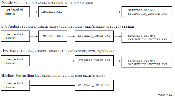
2.5. Processing Weak and Strong Global Symbols
This section describes how the linker processes weak and strong global symbols.
2.5.1. Overview of Weak and Strong Global Symbol Processing
The linker records each symbol definition and each symbol reference in its internal global symbol table. For each symbol, the linker notes whether the symbol is strong, VMS-style weak, or UNIX-style weak.
The linker processes strong symbol definitions differently than it does UNIX-style weak symbol definitions (see Section 2.5.2, ''Strong and Weak Definitions''). In general, a symbol can have only one strong or one VMS-style weak definition but it can have multiple UNIX-style weak definitions. When linking against libraries, note that there is also a difference between VMS-style weak and UNIX-style weak symbol definitions.
The linker processes weak references differently than it does strong references, although it handles both types of weak references in the same manner. Strong references must be resolved, whereas VMS-style and UNIX-style weak can be resolved optionally. If any weak symbol is not resolved, then the linker puts the value zero in place of the reference. In this case, the linker does not display a warning message.
By default, all global symbols generated by most x86-64 and I64 language processors are strong. That is, object modules usually contain strong symbol definitions and strong symbol references. You can decide to make some symbols VMS-weak definitions and references. To do so, you must use a language feature and explicitly mark the code or data as VMS-style weak. (For example, you would explicitly mark the code or data as VMS-style weak with the intention of performing a link operation on partially complete development code). See Section 2.5.1.2, ''VMS-Style Weak Symbols'' for more information about creating and using VMS-style weak symbols.
For some language constructs, the VSI C++ compiler generates UNIX-style weak symbols. That is, some object modules may contain strong and weak symbol definitions and references. The compiler produces redundant code or data in multiple object modules and the linker resolves to the first symbol encountered in the link operation.
2.5.1.1. Strong Symbols
For strong global symbols, there can be only one definition. If the linker finds more than one definition in different input modules, any secondary definition is reported as a multiple definition.
By default, when adding an object module to a library, a strong symbol definition from the object module is included in the library symbol table. As a result, the symbol can be found when the linker searches a library to resolve a symbol reference.
2.5.1.2. VMS-Style Weak Symbols
VMS-style weak global symbols can have only one definition. If the linker finds more than one definition in different input modules, any secondary definition is reported as multiply defined.
When adding an object module to a library, a VMS-style weak global symbol is not included in the library symbol table. As a result, if the module containing the weak symbol definition is in a library but is not selected for inclusion (by means of the /INCLUDE qualifier or to resolve a strong reference), the linker is unable to resolve the reference.
2.5.1.3. UNIX-Style Weak Symbols
UNIX-style weak global symbols can have multiple definitions. When a strong definition is absent, the linker selects the first occurrence of the UNIX-style weak definition and views subsequent ones as references.
When adding an object module to a library, a UNIX weak symbol is included in the library symbol table. (The x86-64 and I64 Librarians are compatible with UNIX-style weak symbols). If multiple modules define the same UNIX-style weak symbol, the librarian maintains an ordered list of symbols in its symbol table. With this information, the linker can find a UNIX-style weak symbol when searching a library for an unresolved symbol. Note that the earliest module added in the library defining the symbol is selected for inclusion.
If the object module containing any type of weak symbol definition is explicitly specified, either as an input object file or for extraction from a library (by means of the /INCLUDE qualifier or to resolve a strong reference), the VMS-style weak or UNIX-style weak symbol definitions are available for symbol resolution.
2.5.2. Strong and Weak Definitions
|
Current Symbol Definition |
New Symbol Definition Encountered |
Action |
|---|---|---|
|
|
|
Assign new definition |
|
UNIX-style weak |
UNIX-style weak |
Ignore new definition |
|
UNIX-style weak |
VMS-style weak |
Assign VMS-style weak definition |
|
UNIX-style weak |
Strong |
Assign Strong definition |
|
VMS-style weak |
UNIX-style weak |
Ignore new definition |
|
VMS-style weak |
VMS-style weak |
Report multiple defined symbols |
|
VMS-style weak |
Strong |
Report multiple defined symbols |
|
Strong |
UNIX-style weak |
Ignore new definition |
|
Strong |
VMS-style weak |
Report multiple defined symbols |
|
Strong |
Strong |
Report multiple defined symbols |
An exception to the rules presented in Table 2.3, ''Symbol Definition Handling'' is for the special
symbol, ELF$TFRADR, which defines the image entry point. Typically, each compiler
defines one symbol for each module that contains code. If the module contains a
main entry, then a strong symbol is defined. Conversely, if
there is no main entry, a VMS-style weak symbol is defined (which
behaves differently than a strong symbol).
Note
This case is different than processing UNIX-style weak symbols, where ignored symbols are converted to references.
2.5.3. Resolving Strong and Weak Symbols
This section describes how the x86-64 and I64 linkers process strong and weak references to resolve symbols. In general, a strong reference can be resolved by a strong symbol definition or any type of weak symbol definition.
For a strong reference, the linker searches all input files (explicit and implicit) for a definition of the symbol. If the linker cannot locate the definition needed to resolve the strong reference, it reports the undefined symbol and assigns the symbol a value, which usually results in a run-time error for accessing the data or calling the routine.
The linker will not search library modules that have been specified with the /LIBRARY qualifier or default libraries (user-defined or system) solely to resolve a weak reference. If, however, the linker resolves a strong reference to another symbol in such a module, it will also use that module to resolve any weak references.
If the linker cannot locate the definition needed to resolve a weak reference, it assigns the symbol a value, which usually results in a run-time error, but does not report an undefined symbol. If, however, the linker reports any unresolved strong references, it will also report any unresolved weak references.
By default, most global definitions in x86-64 and I64 languages are strongly defined.
2.5.4. Creating and Using VMS-style Weak Symbols
In the dialects of MACRO, BLISS, and Pascal supported on x86-64 and IA-64 systems, you can define a global symbol as either strong or VMS-style weak, and you can make either a strong or a VMS-style weak reference into a global symbol.
In these languages, all definitions and references are strong by default. To make a VMS-style weak definition or a VMS-style weak reference, you must use the .WEAK assembler directive (in MACRO), the WEAK attribute (in BLISS), or the WEAK_GLOBAL or WEAK_EXTERNAL attribute (in Pascal).
One purpose for making a weak reference is need to write and test incomplete programs. Resolving all symbolic references is crucial to a successful link operation. Therefore, a problem arises when the definition of a referenced global symbol does not yet exist. (This would be the case, for example, if the global symbol definition is an entry point to a module that is not yet written). The solution to this condition is to make the reference to the symbol VMS-style weak, which informs the linker that the resolution of this particular global symbol is not crucial to the link operation.
2.6. Processing VSI C++ Compiler-Generated UNIX-Style Weak and Group Symbols
UNIX-style weak symbols and groups are used by the VSI C++ compiler to implement template instantiation. Templates, commonly used in the VSI C++ standard library,provide a programming model that allows you to write and use data type-independent code. When this code is part of a source module, it is used with a data type, that is, the template is instantiated.
To instantiate the template, the compiler defines UNIX-style weak symbols for variables and functions used in the template and generates a group. All these symbols, along with code and data, are placed in the group and marked as group symbols. When the same template with the same data type is instantiated in several source modules, a group with the same name containing the same code and data appears in each object module.
The linker handles group symbols in a special way to generate an image which contains only one occurrence of this group of sections. The linker ensures that all references to the groups are resolved to the designated instance of the group.
Currently, UNIX-style weak symbols and group symbols are only used by the VSI C++ compiler, which usually limits the usage of UNIX-style weak binding to group symbols. However, UNIX-style weak symbols and group symbols can be seen as independent, and the linker handles them as such. UNIX-style weak symbols can be defined in shareable images and – similar to shareable image groups – always take precedence over UNIX-style weak symbol definitions found in object modules.
2.6.1. Processing Group Symbols
When linking modules, the first occurrence of a group makes its symbols known to the linker. The linker regards any additional occurrence of the group with the same name as redundant and therefore, ignores it.
Because the concept of groups (as described in the ELF specification) is limited to object modules, the use of shareable images requires a different approach: the VMS extension to ELF allows groups for shareable images. A shareable image group always takes precedence over groups found in object modules. For global symbols and identical groups, this means that all group symbols from an already processed group of an object module are replaced by the ones from the shareable image. The linker's intention is to always use the code and data from the shareable image.
2.6.2. VSI C++ Examples
The following VSI C++ examples demonstrate how symbols are resolved when you link with compiler-generated UNIX-style weak and group symbols.
The examples apply a user-written function template called
myswap. Note that you can also use class templates, which are
implemented in a similar manner. If you are an experienced C++ programmer, you will
also recognize that there is a "swap" function in the VSI C++ standard library,
which you should use instead of writing your own function.
In the examples, the compiler combines code sections (and other required data)into a group, giving it a unique group name derived from the template instantiation.
The linker includes the first occurrence of this group in the image. All UNIX-style weak definitions obtained from that group are now defined by the module providing this group. All subsequent groups with the same name do not contribute code or data; that is, the linker ignores all subsequent sections. The UNIX-style weak definitions from these ignored sections become references, which are resolved by the definition from the designated instance (that is, first-encountered instance) of the group. In this manner, code (and data) from templates are included only once for the image.
// file: my_asc.cxx template <typename T>
$ CXX/OPTIMIZE=NOINLINE/STANDARD=STRICT_ANSI MY_MAIN
In the examples, the compiler combines code sections (and other required data) into a group, giving it a unique group name derived from the template instantiation.
| To keep the examples simple, the template definitions are included in the sources, usually templates are defined in include files. |
| C++ mangles symbol names to guarantee unique names for overloaded functions. Therefore, in the linker map or in the output from ANALYZE/OBJECT utility, the string MYSWAP may be part of a longer symbol name and may not be easily identified. Further, the compiler creates more names using the string MYSWAP:the unique group name, code section names, and so on. |
| The functions "ascending" and "descending" sort a pair of numbers. If necessary the contents are swapped. Swapping is implemented as a function template, which is automatically instantiated with the call inside of the functions "ascending"and "descending". |
| In the main function, "myswap" is used to demonstrate a strong reference to a UNIX-style weak definition. (As previously mentioned, this is not common practice. Usually, templates are defined in include files and included in all sources). Note that there is only a reference to the function and that there is no definition. That is, the compiler does not create a group. When compiling the main module, a reference to "myswap <int>" is automatically generated for the call to myswap inside the main function. This strong reference will be resolved by the first UNIX-style weak definition from either MY_ASC.OBJ or MY_DESC.OBJ which define "myswap <int>". |
| To see the effects of this example, the compiler should not inline code. Because inlining is an optimization, this feature is demonstrated only by omitting optimization. |
| When both source modules are compiled, both object modules contain the definition of the "myswap <int>" function. The compiler groups the code (and other required data) sections into a group with a unique group name derived from the template instantiation. The compiler generates UNIX-style weak symbols and adds them to the group. |
| For linking, the CXXLINK command is used in the examples. This command invokes the C++ linker driver, which in turn calls the OpenVMS linker to perform the actual link operation. |
2.6.3. Compiler-Generated Symbols and Shareable Images
To create a VMS shareable image, you must define the interface in a symbol vector at link time with a SYMBOL_VECTOR option. VSI C++ generated objects contain mangled symbols and may contain compiler-generated data, which belongs to a public interface. In the SYMBOL_VECTOR option, the interface is describe with the names from the object modules. Because they contain mangled names, such a relationship may not be obvious from the source code and the symbols as seen in an object module.
If you do not export all parts of an interface, code that is intended to update one data cell may be duplicated in the executable and the shareable image along with the data cell. That is, data can become inconsistent at run-time, producing a severe error condition. This error condition can not be detected at link time nor at image activation time. Conversely, if you export all symbols from an object module, you may export the same symbol which is already public from other shareable images.
A conflict arises when an application is linked with two shareable images that export the same symbol name. In this case, the linker flags the multiple definitions with a MULDEF warning that should not be ignored. This type of error most often results when using templates defined in the C++ standard library but instantiated by the user with common data types. Therefore, VSI recommends that you only create a shareable image when you know exactly what belongs to the public interface. In all other cases, use object libraries and let applications link against these libraries.
The VSI C++ run-time library contains pre-instantiated templates. The public interfaces for these are known and therefore, the VSI C++ run-time library ships as a shareable image. The universal symbols from the VSI C++ run-time library and the group symbols take precedence over user instantiated templates with the same data types. As with other shareable images, this design is upwardly compatible and does not require you to recompile or relink to make use of the improved VSI C++ run-time library.
2.7. Understanding and Fixing DIFTYPE and RELODIFTYPE Linker Conditions (I64 Only)
On OpenVMS IA-64 systems, if a module defines a variable as data (OBJECT), it must be referenced as data by all other modules. If a module defines a variable as a procedure (FUNC), it must be referenced as a procedure by all other modules.
%ILINK-I-DIFTYPE, symbol symbol-name of type OBJECT cannot be referenced as type FUNC
%ILINK-I-DIFTYPE, symbol symbol-name of type FUNC cannot be referenced as type OBJECT
Type checking is performed by the linker on OpenVMS IA-64 because the linker must create function descriptors. The equivalent procedure descriptor was created by the compiler on OpenVMS Alpha, so this informational message is new for the linker on OpenVMS IA-64.
%ILINK-W-RELODIFTYPE, relocation requests the linker to build a function descriptor for a non-function type of symbol
TYPE1.C
#include <stdio>
int status ;   // Defines status as data.
extern int sub();
main ()
{
    printf ("Hello World\n");
    sub();
}

TYPE2.C
extern int status (int x) ;  // Refers to status as a procedure.
sub ()
{
    int x;
    x = (int)status;
    return status (x);
}$ CC/EXTERN_MODEL=STRICT_REFDEF TYPE1
$ CC/EXTERN_MODEL=STRICT_REFDEF TYPE2
$ LINK TYPE1,TYPE2
%ILINK-I-DIFTYPE, symbol STATUS of type OBJECT cannot be referenced as
type FUNC
module: TYPE2
file: NODE1$:[SMITH]TYPE2.OBJ;6
%ILINK-W-RELODIFTYPE, relocation requests the linker to build a
function descriptor for a non-function type of symbol
symbol: STATUS
relocation section: .rela$CODE$ (section header entry: 18)
relocation type: RELA$K_R_IA_64_LTOFF_FPTR22
relocation entry: 0
module: TYPE2
file: NODE1$:[SMITH]TYPE2.OBJ;6TYPE1.C
#include <stdio>
int status (int x); // Defines status as a procedure.
extern int sub();
main ()
{
printf ("Hello World\n");
sub();
}
nt status (int x) {
return 1;
}
$ CC/EXTERN_MODEL=STRICT_REFDEF TYPE1
$ CC/EXTERN_MODEL=STRICT_REFDEF TYPE2
$ LINK TYPE1,TYPE2Chapter 3. Understanding Image File Creation (x86-64 and I64)
This chapter describes how the linker creates an image on OpenVMS x86-64 and OpenVMS IA-64 systems. The linker creates images from the input files you specify in a link operation. You can control image file creation by using linker qualifiers and options.
3.1. Overview
After the linker has resolved all symbolic references between the input files specified in the LINK command (described in Chapter 2, "Understanding Symbol Resolution (x86-64 and I64)"), the linker knows all the object modules and shareable images that are required to create the image. For example, the linker has extracted from libraries specified in the LINK command those modules that contain the definitions of symbols required to resolve symbolic references in other modules. The linker must now combine all these modules into an image.
Determine the memory requirements of the image
The memory requirements of an image are the sum of the memory requirements of each object module included in the link operation, together with the memory the linker created to support code and data. The language processors that create the object modules specify the memory requirements of an object module as section definitions. A section represents an area of memory that has a name, a length, and other characteristics, called attributes, which describe the intended or permitted usage of that portion of memory. Section 3.2, ''Creating Sections'' describes sections.
The linker processes the section definitions in each object module, combining sections with similar attributes into a segment, which on x86-64 and IA-64 systems is analogous to an image section on Alpha and VAX systems (see Chapter 7, "Understanding Image File Creation (Alpha and VAX)"). Each segment specifies the size and attributes of a portion of the virtual memory of an image. The image activator uses the segment attributes to determine the characteristics of the physical memory pages into which it loads the image, such as protection.
Figure 3.1, ''Communication of Image Memory Requirements on x86-64/I64'' illustrates how memory requirements are communicated from the language processor to the linker and from the linker to the image activator. Section 3.3, ''Creating Segments'' provides more information about this process.
Figure 3.1. Communication of Image Memory Requirements on x86-64/I64 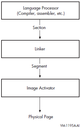
Note that shareable images included in link operations have already been processed by the linker. These images are separate images with their own memory requirements, as specified by their own segments. The image activator activates these shareable images at run-time.
Initialize the image
When segments are first created, they are empty. In this step of linker processing, the linker copies the code and data sections from the object modules into the image's segments. Section 3.4, ''Initializing an Image on x86-64 and IA-64 systems'' provides more information about this process.
In the process of initializing the image, the linker may encounter sections that have the type SHT_NOBITS. This section type indicates that the section occupies no space in the file — a demand-zero section. The linker combines these sections together into demand-zero segments. The linker also trims the zeros off the end of segments when the qualifier /DEMAND_ZERO=PER_PAGE is used. Note that this is not the default. The operating system initializes demand-zero segments at run-time, when a reference to a segment requires the operating system to move the pages into memory. Section 3.4.4, ''Keeping the Size of Image Files Manageable'' describes how the linker creates demand-zero segments.
After creating segments and filling them with binary code and data, the linker writes the image to an image file. Section 3.4.2, ''Writing the Binary Contents of Segments'' describes this process.
3.2. Creating Sections
Language processors create sections and define their attributes. The number of sections created by a language processor and the attributes of these sections are depend on language semantics. For example, some programming languages implement global variables as separate sections with a particular set of attributes. Programmers working in high-level languages typically have little direct control over the sections created by the language processor. Medium- and low-level languages provide programmers with more control over section creation. For more information about the section creation features of a particular programming language, see the language processor documentation.
The x86-64 and I64 linkers also create sections that are combined with the compiler sections to create segments (see Section 3.2.1, ''Sections Created by The Linker'').
Section Attributes
The language processors define the attributes of the sections they create and communicate these attributes to the linker in the section header table.
Access
Using section attributes, compilers can prohibit some types of access, such as write access. Using other section attributes, compilers can allow access to the section by more than one process.
Positioning
By specifying certain section attributes, compilers can specify to the linker how it should position the section in memory.
Section attributes are Boolean values, that is, they are either on or off. Table 3.2, ''Section Attributes on x86-64/I64'' lists all section attributes with the keyword you can use to set or clear the attribute, using the PSECT_ATTR=option. For more information about using the PSECT_ATTR= option, see Section 3.3.7, ''Controlling Segment Creation''.
For example, to specify that a section should have write access, specify the writability attribute as WRT. To turn off an attribute, specify the negative keyword. Some attributes have separate keywords that express the negation of the attribute. For example, to turn off the global attribute (GBL), you must specify the local attribute (LCL). Note that the alignment of a section is not strictly considered an attribute of the section. However, because you can set it using the PSECT_ATTR= option, it is included in the table.
To be compatible with Alpha and VAX linkers, the x86-64 and I64 linkers retain the user interfaces as much as possible. This information includes the traditional OpenVMS section attribute names (WRT, EXE, and so on) that are used in the PSECT_ATTR= option. However, on x86-64 and IA-64 systems, the underlying object conforms to the ELF standard. When processing the object module, the linker maps the ELF terms to the OpenVMS terms. For compatibility, only OpenVMS terms are written to the map file. In contrast, other tools, such as the ANALYZE/OBJECT utility, do not use OpenVMS terms; they simply format the contents of the object file and therefore display the ELF terms.
Note
On x86-64 systems, when the linker encounters writable code sections, with PSECT attributes set to WRT and EXE, it prints the following informational message:
%ILINK-I-MULPSC, conflicting attributes for section <PSECT name>
        conflicting attribute(s): EXE,WRT
        module: <module name>
        file: <obj-or-olb-filename>
When the linker finds unwind data in a module, but no section with the PSECT attribute set to EXE, it prints the following informational message:
%ILINK-I-BADUNWSTRCT, one or more unwind related sections are
missing or corrupted
        section: .eh_frame, there is no non-empty EXE section
        module: <module name>
        file: <obj-or-olb-filename>
These messages are seen mainly with MACRO-32 and BLISS source modules. All code sections must be non-writable. You must have code in sections with the PSECT attribute set to EXE.
| Attribute | Keyword | Description | ||
|---|---|---|---|---|
|
Alignment |
— |
Specifies the alignment of the section as an integer that represents the power of 2 required to generate the desired alignment. For certain alignments, the linker supports keywords to express the alignment. The following table lists all the alignments supported by the linker with their keywords: | ||
| Power of 2 | Keyword | Meaning | ||
|
0 |
BYTE |
Alignment on byte boundaries. | ||
|
1 |
WORD |
Alignment on word boundaries. | ||
|
2 |
LONG |
Alignment on longword boundaries. | ||
|
3 |
QUAD |
Alignment on quadword (8-byte) boundaries. | ||
|
4 |
OCTA |
Alignment on octaword (16-byte) boundaries. | ||
|
5 |
HEXA |
Alignment on hexadecimal word (32-byte) boundaries. | ||
|
6 |
— |
Alignment on 64-byte boundaries. | ||
|
7 |
— |
Alignment on 128-byte boundaries. | ||
|
8 |
— |
Alignment on 256-byte boundaries. | ||
|
9 |
— |
Alignment on 512-byte boundaries. | ||
|
13 |
— |
Alignment on 8 KB boundaries. | ||
|
14 |
— |
Alignment on 16 KB boundaries. | ||
|
15 |
— |
Alignment on 32 KB boundaries. | ||
|
16 |
— |
Alignment on 64 KB boundaries. | ||
|
— |
PAGE |
Alignment on the default target page size, which is 8 KB for x86-64 and 64 KB for I64 linking. You can override this default by specifying the /BPAGE qualifier. | ||
|
Position Independence |
PIC/NOPIC |
This keyword is ignored by the x86-64 and I64 linkers. | ||
|
Overlaid/Concatenated |
OVR/CON |
When set to OVR, specifies that the linker will overlay this section with other sections with the same name and attribute settings. Sections that are overlaid are assigned the same base address. When set to CON, the linker concatenates the sections. | ||
|
Relocatable/Absolute |
REL/ABS |
When set to REL, specifies that the linker can place the section anywhere in virtual memory. Absolute sections are used by compilers primarily to define constants, but in the ELF object language they are not put into an actual section. Setting the section to ABS on x86-64 and I64 is not meaningful, and the ABS keyword is ignored by the x86-64 and I64 linkers. | ||
|
Global/Local |
GBL/LCL |
When set to GBL, specifies that the linker should gather contributions to the section from all clusters and place them in the same segment. When set to LCL, the linker gathers sections into the same segment only if they are in the same cluster. The memory for a global section is allocated in the cluster that contains the first contributing module. | ||
|
Shareability |
SHR/NOSHR |
Specifies that the section can be shared between several processes. Only used to sort sections in shareable images. | ||
|
Executability |
EXE/NOEXE |
Specifies that the section contains executable code. | ||
|
Writability |
WRT/NOWRT |
Specifies that the contents of a section can be modified at run-time. | ||
|
Protected Vectors |
VEC/NOVEC |
Specifies that the section contains privileged change-mode vectors or message vectors. In shareable images, segments with the VEC attribute are automatically protected. | ||
|
Solitary |
SOLITARY |
Specifies that the linker should place this section in its own segment. Useful for programs that map data into specific locations in their virtual memory space. Note that compilers do not set this attribute. You can set this attribute using the PSECT_ATTR=option. | ||
|
Unmodified |
NOMOD/MOD |
When set, specifies that the section has not been initialized (NOMOD). The x86-64 and I64 linkers use this attribute to create demand zero segments (see Section 3.4.4, ''Keeping the Size of Image Files Manageable''). Only compilers can set this attribute (in ELF objects, the section type SHT_NOBITS). You can clear this attribute only by specifying the MOD keyword in the PSECT_ATTR= option. | ||
|
Readability |
RD |
This keyword is ignored by the x86-64 and I64 linkers. | ||
|
User/Library |
USR/LIB |
This keyword is ignored by the x86-64 and I64 linkers. | ||
|
Short Data? |
SHORT |
When set this indicates that a data section should be put in one of the short sections. Compilers can set this attribute, in which case the user can not alter it. | ||
|
Allocate section in P2 space |
ALLOC_64BIT/ |
When set this indicates that the section should be allocated in P2 space instead of P0 space. The program may run but not execute correctly when initialized data is put in P2 space. Code and demand zero data do work properly. | ||
#include <stdio.h>
extern int global_data;
extern int myadd( int, int );
extern int mysub( int, int );
main()
{
  int num1, num2, res1, res2;
  num1 = 5;
  num2 = 6;
  res1 = myadd( num1, num2 );
  res2 = mysub( num1, num2 );
  printf( "res1 = %d, res2 = %d, globaldata = %d\n", res1, res2, global_data );
}#include <stdio.h>
int add_data = -1;
int myadd( int value_1, int value_2 )
{
printf( "In MYADD.C\n" );
add_data = value_1 + value_2;
return add_data;
}#include <stdio.h>
int global_data = 5;
int sub_data = -1;
int mysub( int value_1, int value_2 )
{
printf( "In MYSUB.C\n" );
sub_data = value_1 - value_2;
return sub_data;
}$ anal/object/section=all/out=mytest.anl mytest.obj
.
.
.
SECTION SUMMARY
Number Type Name Flags
0. NULL ----------------------
1. PROGBITS .text -AE-------------------
2. PROGBITS .data WA--------------------
3. NOBITS .bss WA--------------------
4. NOTE .note ----------------------
5. PROGBITS .debug_info ----------------------
6. RELA .rela.debug_info ----------------------
7. PROGBITS .debug_abbrev ----------------------
8. PROGBITS .debug_aranges ----------------------
9. PROGBITS .debug_macinfo ----------------------
10. PROGBITS .debug_line ----------------------
11. RELA .rela.debug_line ----------------------
12. PROGBITS .debug_loc ----------------------
13. PROGBITS .debug_pubnames ----------------------
14. RELA .rela.debug_pubnames ----------------------
15. PROGBITS .debug_pubtypes ----------------------
16. RELA .rela.debug_pubtypes ----------------------
17. PROGBITS .debug_str ---S------------------
18. PROGBITS .debug_ranges ----------------------
19. PROGBITS $CODE$ -AE--------------Shr--
20. RELA .rela$CODE$ ----------------------
21. PROGBITS .rodata -A--------------------
22. PROGBITS .note.GNU-stack ----------------------
23. PROGBITS .eh_frame -A--------------------
24. RELA .rela.eh_frame ----------------------
25. STRTAB .shstrtab ----------------------
26. SYMTAB .symtab ----------------------
27. STRTAB .strtab ----------------------
Key for Flags: W (Write), A (Alloc), E (Execute), S (Strings), I (Info link), L (Link order), O (OS-specific processing), G (Group), Lrg (Large), Sho (Short), Nrc (No recovery code), Gbl (Global), Ovr (Overlaid), Shr (Shared), Vec (Vector), 64b (Allocate 64bit address), Pro (Protected)
.
.
.
SECTION HEADER ENTRY 19. (0013)
"$CODE$"
Description Hex (<bitmask>) Interpretation Field Name
----------- --------------- -------------- ----------
Name Offset in .shstrtab: 000000FA "$CODE$" shdr$l_sh_name
Section Type: 00000001 SHDR$K_SHT_PROGBITS shdr$l_sh_type
Section Flags: 0000000000400006 shdr$q_sh_flags
Data occupies memory: <0000000000000002> SHDR$M_SHF_ALLOC shdr$v_shf_alloc
Machine instructions: <0000000000000004> SHDR$M_SHF_EXECINSTR shdr$v_shf_execinstr
Shareable section: <0000000000400000> SHDR$M_SHF_VMS_SHARED_ shdr$v_shf_vms_shared_
Section Load Address: 0000000000000000 Not Used (Object File) shdr$pq_sh_addr
Offset to Section Data: 00000000000001B0 shdr$q_sh_offset
Size of Section Data: 0000000000000163 shdr$q_sh_size
Section Link Field: 00000000 shdr$l_sh_link
Section Info Field: 00000000 shdr$l_sh_info
Alignment Constraint: 0000000000000010 shdr$q_sh_addralign
Entry Size (if table): 0000000000000000 shdr$q_sh_entsize
.
.
.
SECTION HEADER ENTRY 23. (0017)
".eh_frame"
Description Hex (<bitmask>) Interpretation Field Name
----------- --------------- -------------- ----------
Name Offset in .shstrtab: 000000B8 ".eh_frame" shdr$l_sh_name
Section Type: 00000001 SHDR$K_SHT_PROGBITS shdr$l_sh_type
Section Flags: 0000000000000002 shdr$q_sh_flags
Data occupies memory: <0000000000000002> SHDR$M_SHF_ALLOC shdr$v_shf_alloc
Section Load Address: 0000000000000000 Not Used (Object File) shdr$pq_sh_addr
Offset to Section Data: 0000000000000340 shdr$q_sh_offset
Size of Section Data: 0000000000000058 shdr$q_sh_size
Section Link Field: 00000000 shdr$l_sh_link
Section Info Field: 00000000 shdr$l_sh_info
Alignment Constraint: 0000000000000008 shdr$q_sh_addralign
Entry Size (if table): 0000000000000000 shdr$q_sh_entsize$ anal/object/section=all/out=mytest.anl mytest.obj
.
.
.
SECTION SUMMARY
Number Type Name Flags
0. NULL -------------------------
1. STRTAB .shstrtab -------------------------
2. NOTE .note -------------------------
3. PROGBITS $CODE$ -AE-----------------Shr--
4. PROGBITS $LITERAL$ -A------------------Shr--
5. NOBITS $LINK$ -A-----------------------
6. PROGBITS .IA_64.unwind_info -A-----------------------
7. IA_64_UNWIND .IA_64.unwind -A---L-------------------
8. STRTAB .strtab -------------------------
9. SYMTAB .symtab -------------------------
10. VMS_TRACE .debug_line -------------------------
11. RELA .rela.debug_line -------------------------
12. VMS_TRACE .trace_abbrev -------------------------
13. VMS_TRACE .trace_info -------------------------
14. RELA .rela.trace_info -------------------------
15. VMS_TRACE .trace_aranges -------------------------
16. RELA .rela.trace_aranges -------------------------
17. RELA .rela.IA_64.unwind_info -------------------------
18. RELA .rela.IA_64.unwind -------------------------
19. RELA .rela$CODE$ -------------------------
Key for Flags: W (Write), A (Alloc), E (Execute), S (Strings), I (Info link), L (Link order),
O (OS-specific processing), G (Group), Sho (Short), Nrc (No recovery code),
Gbl (Global), Ovr (Overlaid), Shr (Shared), Vec (Vector),
64b (Allocate 64bit address), Pro (Protected)
.
.
.
SECTION HEADER ENTRY 3. (0003)
"$CODE$"
Description Hex (<bitmask>) Interpretation Field Name
----------- --------------- -------------- ----------
Name Offset in .shstrtab: 00000011 "$CODE$" shdr$l_sh_name
Section Type: 00000001 SHDR$K_SHT_PROGBITS shdr$l_sh_type
Section Flags: 0000000400000006 shdr$q_sh_flags
Data occupies memory: <0000000000000002> SHDR$M_SHF_ALLOC shdr$v_shf_alloc
Machine instructions: <0000000000000004> SHDR$M_SHF_EXECINSTR shdr$v_shf_execinstr
Shareable section: <0000000400000000> SHDR$M_SHF_VMS_SHARED shdr$v_shf_vms_shared
Section Load Address: 0000000000000000 Not Used (Object File) shdr$pq_sh_addr
Offset to Section Data: 0000000000000170 shdr$q_sh_offset
Size of Section Data: 00000000000001C0 shdr$q_sh_size
Section Link Field: 00000000 shdr$l_sh_link
Section Info Field: 00000000 shdr$l_sh_info
Alignment Constraint: 0000000000000010 shdr$q_sh_addralign
Entry Size (if table): 0000000000000000 shdr$q_sh_entsize
.
.
.
SECTION HEADER ENTRY 7. (0007)
".IA_64.unwind"
Description Hex (<bitmask>) Interpretation Field Name
----------- --------------- -------------- ----------
Name Offset in .shstrtab: 0000003C ".IA_64.unwind" shdr$l_sh_name
Section Type: 70000001 SHDR$K_SHT_IA_64_UNWIND shdr$l_sh_type
Section Flags: 0000000000000082 shdr$q_sh_flags
Data occupies memory: <0000000000000002> SHDR$M_SHF_ALLOC shdr$v_shf_alloc
Preserve section order: <0000000000000080> SHDR$M_SHF_LINK_ORDER shdr$v_shf_link_order
Section Load Address: 0000000000000000 Not Used (Object File) shdr$pq_sh_addr
Offset to Section Data: 0000000000000090 shdr$q_sh_offset
Size of Section Data: 0000000000000030 shdr$q_sh_size
Section Link Field: 00000003 shdr$l_sh_link
Section Info Field: 00000006 shdr$l_sh_info
Alignment Constraint: 0000000000000008 shdr$q_sh_addralign
Entry Size (if table): 0000000000000000 shdr$q_sh_entsize Note
You can also determine the sections in an object module after a link operation by looking at the Program Section Synopsis of an image map file, as illustrated in Example 3.8, ''Section Information in a Map File''.
The items in the following list correspond to the numbered items in Example 3.4, ''Sections Generated by an Analysis of Example 3.1, ''Sample Program MYTEST.C'' on x86-64'' and Example 3.5, ''Sections Generated by an Analysis of Example 3.1, ''Sample Program MYTEST.C'' on IA-64'':
| The unwind table section is the only section with the Link Order attribute set. The Link Order attribute signifies that the I64 linker must preserve section ordering (see Section 3.2.1.7, ''Sections that Contain Unwind Data (I64 Only)''). |
| The Name Offset indicates the name of the section. |
| Section flags indicate which section attributes are set. The attributes
are listed by their ELF name. Note that the keywords are only listed when
the bit in |
| The Size of Section Data indicates the number of bytes required for the section. |
| Alignment Constraint specifies the address boundary at which the linker must place a module's contribution to the section. The number shown here, 10 (hexadecimal), is a byte alignment and not an OpenVMS style (power of 2) of specifying the section attributes. |
Figure 3.2, ''Sections Created for Examples 3.1, 3.2, and 3.3'' illustrates some of the sections created by the VSI C Compiler for the modules in Examples 3.1, 3.2, and 3.3 on x86-64 and IA-64 systems. The shaded areas represent the settings of the section attributes the linker considers when sorting the sections into image segments in an executable image. See Section 3.3.4, ''Processing Significant Section Attributes'' for more information about how the linker creates segments in an image.
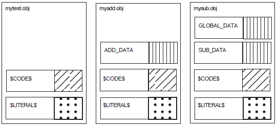
3.2.1. Sections Created by The Linker
Unlike the VAX and Alpha linkers, the x86-64 and I64 linkers create new sections as well as contributions to existing sections for loadable segments.
When the linker assigns a name for a section, the name can be a reserved name containing an embedded space (for example, $LINKER UNWIND$). The linker uses the embedded space in a reserved name to prevent you from changing the section attributes. The PSECT_ATTR option reads the embedded space and compresses it out of the name. As such, the name is not read by the linker as you intended and the attributes are preserved.
3.2.1.1. Sections for Relaxed Symbol Definitions
In VSI C, relaxed symbol definitions that can act like a reference or a
definition (when no other definition is found) have no section assigned to them.
If there is no hard definition (that is, a symbol with a
compiler-supplied section), the linker allocates a section for the symbol. The
section has the same name as the symbol, and is contributed by the linker
(labeled with <Linker> in the map).
3.2.1.2. Sections Embedded in Code Segments (x86-64 only)
On x86-64, from the point of view of a compiler or assembly-language programmer, all calls are local, which means the call target is always in the same linker cluster. If a call resolves to a procedure in a different cluster or image, the linker creates a code that forwards that call to the target. These are linker-created code fragments in the caller’s code segment. They do an indirect jump through a Global Offset Table entry that contains a pointer to the target procedure.
The label <Linker> is used to mark the linker contribution
in the map at the end of the code section (normally named $CODE$).
3.2.1.3. Procedure Linkage Table (PLT) Import Stubs (x86-64 only)
On x86-64, a procedure value (function pointer) is a pointer to code. All procedure values must be representable in 32 bits, which means that the code they point to must reside in P0, P1, or S0/S1. If the procedure itself is in P2 or S2, the linker creates a 32-bit-addressable trampoline for it. The trampoline code simply jumps to the procedure itself. This trampoline becomes the procedure value for that procedure.
3.2.1.4. Sections Embedded in Code Segments (I64 Only)
The I64 linker contributes sections to code segments that contain calls to code outside the image, outside the code segment but to another segment within the image, or to code that can't be reached with a normal branch instruction inside the segment (called a trampoline).
The instructions can be helpful when using the debugger to step into subroutines. The instructions are grouped in 128-bit bundles, with a series of dashes marking the end of a bundle.
<Linker> is used to label the linker contribution in
the map, usually at the end of the code section (normally named
$CODE$).
Calls Out of the Image
addl r15=<offset>,r1;;
ld8 r16=[r15],8
nop.i
-----
ld8 r1=[r15]
mov b6=r16
br.few b6;;
-----
| This is an Indirect Branch (B4). For more information, see the Intel IA-64 Architecture Software Developer's Manual |
In the first instruction, R15 contains the address of the Function Descriptor (FD), which the linker obtained by adding an offset to the Global Pointer register (GP, implemented as R1). R16 is loaded with a pointer to the code address. R1 then receives the new Global Pointer. The branch instruction completes the call sequence.
Calls Out of the Segment to Another Segment in the Same Image
addl r15=<offset>,r1;;
ld8 r16=[r15]
nop.i
-----
nop.m
mov b6=r16
br.few b6;;
-----
| This is an Indirect Branch (B4). For more information, see the Intel IA-64 Architecture Software Developer's Manual |
In the first instruction, R15 contains the address of the Function Descriptor (FD), which the linker obtained by adding an offset to the Global Pointer (GP, implemented as R1) register. R16 is loaded with a pointer to the code address. Because the instructions branch to another segment in the same image and because there is one GP per image, the linker can skip copying the GP from the FD.
Calls That Cannot be Reached with Normal Branch Instruction (Trampolines)
nop.m 0x0 movl r15=<offset between the next instruction and the target>
| See the Intel IA-64 Architecture Software Developers Manual. |
| The |
| This is an Indirect Branch (B4). For more information, see the Intel IA-64 Architecture Software Developer's Manual. |
3.2.1.5. Short Data Sections (I64 Only)
In order to make position-independent code that does not require any relocations, Itanium platforms allow code to make a reference to pointers and other short data using offsets from an address in a register. This special register is called the Global Pointer (GP) register. The language processors place such data into sections named short data sections. It is the task of the linker to collect these sections into a segment or segments and to determine the GP value. The GP value is determined so that the beginning of the first (or only) short data segment is the negative-most offset from the GP within range. For the Intel Itanium architecture, the negative-most offset is 2 MB. Therefore, the GP value is the virtual address of the beginning of the first (or only) short data segment plus 2 MB. If the address range for your short data segment or segments is less than 2 MB, the GP value may not even point to a virtual address mapped by your image. The compilers usually place data in the short data sections that are relatively short (like quadwords or smaller) and not long (like an array).
There are two kinds of short data sections — read-only and read-write. The I64
linker is a major contributor to the read-only short data section. In this
section, the linker puts addresses of data and function descriptors (termed
procedure descriptors on Alpha) that can be reached by code with a short offset
from the Global Pointer register. This section is named
$LINKER
SDATA$. In the map, <Linker>
is used to label the linker contributions to this section.
Function descriptors placed in the read-only short data section have varying lengths depending on their type. The types are official and local. Official function descriptors are always three quadwords long. Local function descriptors can be two quadwords or four quadwords long, depending on whether the qualifier /NONATIVE_ONLY is present. If the image is supposed to interoperate with translated images, the /NONATIVE_ONLY qualifier must be used, and local function descriptors will be four quadwords long.
Official function descriptors represent functions that are defined by an image. One example of functions defined by an image are those functions which can be exported from a shareable image by the symbol vector and called by other images. Official function descriptors always contain the address of the first instruction of the function in the first quadword. The GP value under which the function executes is in the second quadword. The third quadword contains a zero, or if the /NONATIVE_ONLY qualifier is used it contains the function's signature or a pointer to the function's signature. A signature describes the parameters and return status of the function. If the third quadword is zero then the function descriptor has no signature, and a translated image is not allowed to call the function.
An official function descriptor has the following format at run-time:
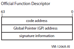
A local function descriptor represents a function outside of the image. Local function descriptors made for images that do not interoperate with translated images contain at run-time the address of the first instruction of the function in the first quadword. The GP value under which the function executes is in the second quadword. The linker generates a fix-up for the function descriptor because it has no knowledge of those addresses. The fix-up is applied by the image activator which has already activated the image with those addresses in it.
A local function descriptor has the following format at run-time:
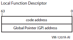
Entry (code) address of the routine that mediates calls between native and translated code
Address of this function descriptor
Signature information for the call
Pointer to the official function descriptor for the entry point in the translated image (or some other unique identification that can be interpreted by the support facility the mediates calls between native and translated code)
The linker assumes the image activator will find a native image, and issues a fix-up to the image activator to fill in the first two (of four) quadwords with the code address and GP. The third quadword is filled in with signature information, like an official function descriptor. The fourth quadword is filled in with a zero. If the image activator determines that the function referenced by this function descriptor in a native image, it applies the fix-up and ignores the last two quadwords.
3.2.1.6. Section for the Symbol Vector
The x86-64 and I64 linkers place the symbol vector in a section with the name $LINKER SYMBOL_VECTOR$. The I64 linker places this section in the short data segment by default.
In the map, <Linker Option> is used to label this
linker contribution.
For I64 linking, you can use the qualifier /SEGMENT=(SYMBOL_VECTOR=NOSHORT) to move $LINKER SYMBOL_VECTOR$ to a data segment which is read-only. The I64 linker creates a read-only data segment if one does not already exist.
For the layout of a symbol vector, see Figure 2.1, ''Symbol Vector Contents on x86-64'' (x86-64) and Figure 2.2, ''Symbol Vector Contents on IA-64'' (I64).
3.2.1.7. Sections that Contain Unwind Data (I64 Only)
When an exception is signaled by hardware or software, the condition handling facility looks for a condition handler. If a condition handler is found, the handler may choose to call SYS$UNWIND to unwind the stack. SYS$UNWIND has, at its disposal, an unwind table. The unwind table contains a pointer into a variable-sized information block that contains the unwind descriptor list and a language-specific area. The unwind table and the unwind information block are created by the compilers. The linker has to place the contributions to the unwind tables in the same order as the contributions to the code segment for unwinding to work.
The I64 linker renames the compiler-named sections that contain unwind tables (usually named .IA_64.unwind) and unwind information blocks (usually named .IA_64_unwinfo). It can tell which sections contain unwind tables because those sections have the type SHT_IA_64_UNWIND. It also has the link order (SHF_LINK_ORDER) attribute set. The link order attribute means that the contributions to the unwind table must be in the same order as contributions pointed to by the SH_LINK field (a code section).
The new, reserved name of the section that contains the unwind tables is $LINKER UNWIND$.$LINKER UNWINFO$ is the new, reserved name of the section that contains unwind information. These names appear in the linker map; the actual names of these sections are gone by the time the map is written. The linker uses reserved names for these sections;this means that you are not allowed to change the section attributes with a PSECT_ATTR= clause or collect them with the COLLECT= option to other clusters. This is because the placement and ordering of these sections are driven by the placement and ordering of the code sections to which they refer. By altering the placement or ordering of the code sections through the use of linker options or input file ordering, the sections containing unwind tables and unwind information blocks will likewise have the placement or ordering of their contributions altered.
$LINKER UNWIND$ and $LINKER UNWINFO$ have identical significant attributes and therefore end up in the same unwind segment. This is denoted in the Image Segment Synopsis section of the map by the [UNWIND] tag. The unwind segment is connected to the corresponding code segment by entries in the dynamic segment (which the image activator uses for activating an image).
If you have a complex link with an options file that contains a number of CLUSTER= or COLLECT= options, you may have more unwind segments than you really need. The I64 linker constructs one unwind segment per cluster with one or more code segments. To reduce the number of unwind segments, you should reduce the number of clusters containing code. This is done by collecting code sections onto a smaller number of clusters or onto a single cluster.
3.2.1.8. Fixed-offset segments (x86-64 only)
On x86-64, all segments within a shared library must have the same positions relative to each other that they were given by the linker. The image activator is free to load segments in a shareable image independently of each other. To allow segments to be loaded independently, VMS compilers generate code that uses indirect addressing. This way, the only segments whose relative positions have to be maintained are the code segment, the unwind segment, and the Global Offset Table segment. The linker flags those segments. A segment which requires the linker-given position to the preceeding segment is flagged as "Fixed Offset" (Fof). In an image with code segments in multiple clusters, each cluster will have its own unwind segment and Global Offset Table so that their relationship can be maintained. The image activator and the install utility maintain the relative positions of these segments.
3.3. Creating Segments
On x86-64 and IA-64 systems, the linker creates segments, which are analogous to image sections on Alpha and VAX systems. Segments define the memory requirements and page protection characteristics of an image.
To create segments, the linker processes the sections in the object modules specified in the link operation. The number and type of segments the linker creates depend on the input files and what is specified in the link operation. For more information on creating segments, see Section 3.3.1, ''Processing Clusters to Create Segments'', which describes how the clustering of input files affects segment creation, and Section 3.3.2, ''Combining Sections into Image Segments'', which describes the effects of section attributes on segment creation.
3.3.1. Processing Clusters to Create Segments
To create segments, the linker processes the section definitions in the input files you specify in the LINK command. The linker processes these input files on a cluster-by-cluster basis (as described in Section 2.3.1, ''Understanding Cluster Creation'').
Each cluster spawns segments into which sections are placed. However, the linker crosses cluster boundaries when processing sections with the global (GBL) attribute. (In ELF, GBL corresponds to SHF_VMS_GLOBAL). When the linker encounters a section with the global attribute, it searches all the previously processed clusters for a section with the same name and attributes and, if it finds one, places the new definition of the global section in the same cluster as the first definition of the program section.
The linker processes input files in the order by which they appear in the clusters. Note that on x86-64 and IA-64 systems, there are no based clusters, that is, the x86-64 and I64 linkers do not allow you to enter a base address with the CLUSTER= option. In addition, the linkers only have to process clusters once.
For more information about creating clusters, see the descriptions of the CLUSTER= and the COLLECT= option in Chapter 10, "LINK Command Reference".
$ LINK/MAP/FULL/CROSS MYTEST, MYADD, SYS$INPUT/OPT
CLUSTER=MYSUB_CLUS,,,MYSUB
Ctrl/ZMYSUB_CLUS
DEFAULT_CLUSTER
DECC$SHR
The linker always processes the default cluster after any user-specified cluster (MYSUB_CLUS). DECC$SHR was automatically picked up from IMAGELIB.OLB by the x86-64 and I64 linkers after the preceding clusters were processed and there were still unresolved symbols.
3.3.2. Combining Sections into Image Segments
The linker creates segments by grouping together sections with similar attributes. Within a segment, the linker organizes sections alphabetically by name. If more than one object module contributes to the same section, the linker lays out their contributions in the order it processes them.
Figure 3.5, ''Combining Sections into Image Segments — Part 1'' shows how the linker groups the sections in the object modules from the sample link into segments, based on the setting of their significant attributes. In the figure, the settings of these significant attributes are represented by shading. (The figure considers attributes that are significant when creating executable images, and does not consider the SHR attribute as significant as it does with shareable images. Section 3.3.4, ''Processing Significant Section Attributes'' provides more information about which program section attributes are significant).
Note that in Figure 3.5, ''Combining Sections into Image Segments — Part 1'', the relaxed definition from MYTEST.OBJ for GLOBAL_DATA appears in the MYSUB_CLUS cluster, even though the object module MYTEST.OBJ is in the default cluster. In general, the linker puts all contributions to a global section in the cluster in which it is first defined. In the relaxed case, the linker chooses the memory from the hard definition that occurs in MYSUB.OBJ.
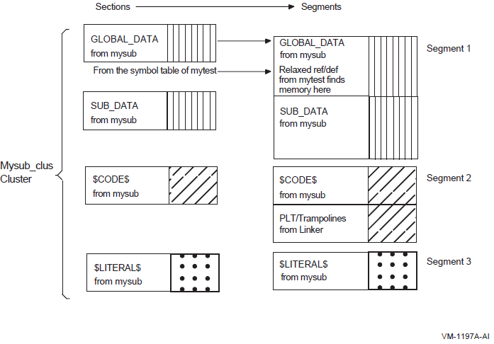
Figure 3.6, ''Combining Sections into Image Segments — Part 2'' continues the representation in Figure 3.5, ''Combining Sections into Image Segments — Part 1''.
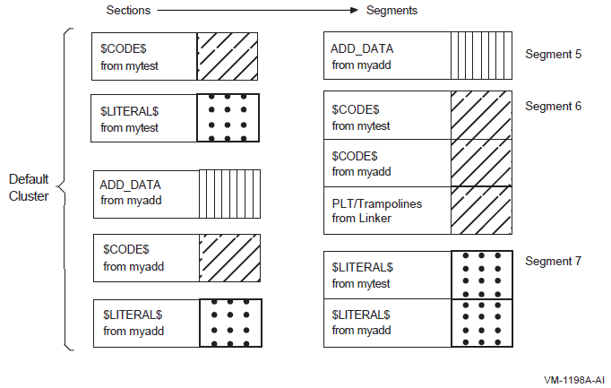
3.3.3. Traditional OpenVMS Image Attribute Terms and ELF Terms
|
Traditional OpenVMS Image Attribute (prefix [E]ISD$M_) |
Display Name in Linker Map |
ELF Image Attribute (prefix PHDR$M_) |
|---|---|---|
|
GBL |
— |
—? |
|
CRF |
WRITE,SHARED |
PF_VMS_SHARED,PF_W |
|
Demand zero |
DEMAND ZERO |
Zero segment file size? |
|
EXE |
EXECUTABLE |
PF_X |
|
WRT |
READ WRITE |
PF_W |
|
MATCHCTL |
— |
—? |
|
LASTCLU |
— |
—? |
|
FIXUPVEC |
— |
—? |
|
RESIDENT |
RESIDENT |
PF_VMS_RESIDENT? |
|
VECTOR |
VECTOR |
PF_VMS_VECTOR |
|
PROTECT |
PROTECT |
PF_VMS_PROTECT |
Note
All sections, and therefore all segments, are position independent. Therefore, there is no PIC segment type on x86-64 and I64.
3.3.4. Processing Significant Section Attributes
Writability (WRT/NOWRT)
Executability (EXE/NOEXE)
Protected vector (VEC/NOVEC)
Unmodified (NOMOD/MOD)
Short (SHORT/NOSHORT)
Allocation in P2 (ALLOC_64BIT/NOALLOC_64BIT)
Writability (WRT/NOWRT)
Executability (EXE/NOEXE)
Shareability (SHR/NOSHR)
Protected vector (VEC/NOVEC)
Unmodified (NOMOD/MOD)
Short (SHORT/NOSHORT)
Allocation in P2 (ALLOC_64BIT/NOALLOC_64BIT)
Tables 3.4 and 3.5 list all the possible combinations of the significant section attributes for executable images and shareable images. Note that the order in which the combinations appear in the table (each row) is the same order in which the linker processes them.
For example, the linker first processes all sections with the WRT, NOEXE, NOVEC, MOD, and NOSHORT attributes, creating a segment of sections with these attributes. The linker then processes all sections with the WRT, NOEXE, NOVEC, NOMOD, and NOSHORT attributes, creating another segment for those sections. The linker continues this processing until all the combinations of significant attributes have been processed and all the sections in the cluster have been placed in a segment.
The tables include only sections that are relocatable (with the REL attribute). Absolute sections (with the ABS attribute), by definition, can have no allocation (they contain only constants) and cannot contribute to a segment.
To simplify the tables, they do not include the ALLOC_64BIT attribute. ALLOC_64BIT only determines if the section should be allocated in P2 space. The default is NOALLOC_64BIT. This attribute does not influence the segment attributes of the created segment. But obviously, two sections, whose attribute only differ in ALLOC_64BIT, end up in different segments. On IA-64, the ALLOC_64BIT attribute can be set for all sections except the ones with the SHORT attribute.
The linker creates additional segments that cannot be controlled by the user (see Section 3.4.3, ''Other Image Segments'').
The tables assume that the images are linked using the /DEMAND_ZERO qualifier, which is the default. (When this qualifier is specified, the linker groups sections that do not contain any data into demand-zero segments, allocating memory for the segment but not writing zeros to disk). If the image is linked with the /NODEMAND_ZERO qualifier, then the linker allocates space for the segment in the image file. Note that the /NODEMAND_ZERO qualifier does not affect how the linker sorts sections; it proceeds exactly as specified by the table. However, when the image is written, the linker allocates disk space for the segment and fills the space with zeros.
|
Significant Section Attribute Settings |
Segment Attributes Set (prefix PHDR$V_) | ||||
|---|---|---|---|---|---|
|
NOEXE |
WRT |
NOVEC |
MOD |
NOSHORT |
PF_R,PF_W |
|
NOEXE |
WRT |
NOVEC |
NOMOD |
NOSHORT |
PF_R,PF_W,Demand zero? |
|
NOEXE |
WRT |
VEC |
MOD |
NOSHORT |
PF_R,PF_W,PF_VMS_VECTOR, |
|
EXE |
NOWRT |
NOVEC |
MOD |
NOSHORT |
PF_R,PF_X |
|
EXE |
WRT |
NOVEC |
MOD |
NOSHORT |
PF_R,PF_W,PF_X |
|
EXE |
NOWRT |
VEC |
MOD |
NOSHORT |
PF_R,PF_X,PF_VMS_VECTOR, |
|
EXE |
WRT |
VEC |
MOD |
NOSHORT |
PF_R,PF_W,PF_X,PF_VMS_VECTOR, |
|
EXE |
NOWRT |
*? |
NOMOD |
NOSHORT |
PF_R,PF_X |
|
EXE |
WRT |
* |
NOMOD |
NOSHORT |
PF_R,PF_W,PF_X |
|
NOEXE |
NOWRT |
NOVEC |
MOD |
NOSHORT |
PF_R |
|
NOEXE |
NOWRT |
NOVEC |
NOMOD |
NOSHORT |
PF_R,Demand zero? |
|
NOEXE |
NOWRT |
VEC |
MOD |
NOSHORT |
PF_R,PF_VMS_VECTOR, |
|
* |
WRT |
* |
* |
SHORT |
PF_R,PF_W,PF_VMS_SHORT |
|
* |
NOWRT |
* |
* |
SHORT |
PF_R,PF_VMS_SHORT |
|
Significant Section Attribute Settings |
Segment Attributes Set (prefix PHDR$V_) | |||||
|---|---|---|---|---|---|---|
|
NOSHR |
NOEXE |
WRT |
NOVEC |
MOD |
NOSHORT |
PF_R,PF_W |
|
NOSHR |
NOEXE |
WRT |
NOVEC |
NOMOD |
NOSHORT |
PF_R,PF_W,Demand zero? |
|
SHR |
NOEXE |
WRT |
NOVEC |
MOD |
NOSHORT |
PF_R,PF_W,PF_VMS_SHARED |
|
SHR |
NOEXE |
WRT |
NOVEC |
NOMOD |
NOSHORT |
PF_R,PF_W,PF_VMS_SHARED |
|
NOSHR |
NOEXE |
WRT |
VEC |
MOD |
NOSHORT |
PF_R,PF_W,PF_VMS_VECTOR, |
|
SHR |
NOEXE |
WRT |
VEC |
MOD |
NOSHORT |
PF_R,PF_W,PF_VMS_VECTOR, |
|
NOSHR |
EXE |
NOWRT |
NOVEC |
MOD |
NOSHORT |
PF_R,PF_X |
|
NOSHR |
EXE |
WRT |
NOVEC |
MOD |
NOSHORT |
PF_R,PF_W,PF_X |
|
SHR |
EXE |
NOWRT |
NOVEC |
MOD |
NOSHORT |
PF_R,PF_X,PF_VMS_SHARED |
|
SHR |
EXE |
WRT |
NOVEC |
MOD |
NOSHORT |
PF_R,PF_W,PF_X, |
|
NOSHR |
EXE |
NOWRT |
VEC |
MOD |
NOSHORT |
PF_R,PF_X,PF_VMS_VECTOR, |
|
NOSHR |
EXE |
WRT |
VEC |
MOD |
NOSHORT |
PF_R,PF_W,PF_X, |
|
SHR |
EXE |
NOWRT |
VEC |
MOD |
NOSHORT |
PF_R,PF_X,PF_VMS_VECTOR, |
|
SHR |
EXE |
WRT |
VEC |
MOD |
NOSHORT |
PF_R,PF_W,PF_X, |
|
*? |
EXE |
NOWRT |
* |
NOMOD |
NOSHORT |
PF_R,PF_X |
|
* |
EXE |
WRT |
* |
NOMOD |
NOSHORT |
PF_R,PF_W,PF_X |
|
NOSHR |
NOEXE |
NOWRT |
NOVEC |
MOD |
NOSHORT |
PF_R |
|
NOSHR |
NOEXE |
NOWRT |
NOVEC |
NOMOD |
NOSHORT |
PF_R,Demand zero? |
|
SHR |
NOEXE |
NOWRT |
NOVEC |
MOD |
NOSHORT |
PF_R,PF_VMS_SHARED |
|
SHR |
NOEXE |
NOWRT |
NOVEC |
NOMOD |
NOSHORT |
PF_R,PF_VMS_SHARED |
|
NOSHR |
NOEXE |
NOWRT |
VEC |
MOD |
NOSHORT |
PF_R,PF_VMS_VECTOR, |
|
SHR |
NOEXE |
NOWRT |
VEC |
MOD |
NOSHORT |
PF_R,PF_VMS_VECTOR, |
|
* |
* |
WRT |
* |
* |
SHORT |
PF_R,PF_W,PF_VMS_SHORT |
|
* |
* |
NOWRT |
* |
* |
SHORT |
PF_R,PF_VMS_SHORT |
|
User Section |
Writability |
Executability |
Short Data |
|---|---|---|---|
|
GLOBAL_DATA |
WRT |
NOEXE |
NOSHORT |
|
SUB_DATA |
WRT |
NOEXE |
NOSHORT |
|
$CODE$ |
NOWRT |
EXE |
NOSHORT |
|
$LITERAL$ |
NOWRT |
NOEXE |
NOSHORT |
The GLOBAL_DATA and SUB_DATA sections have identical attributes, including the WRT attribute.
The $CODE$ and $LITERAL$ sections have the NOWRT attribute and differ in the EXE attribute.
The linker collects all these sections in segments in the named cluster MYSUB_CLUS, as requested with the CLUSTER= option in Example 3.6, ''Linking Examples 3.1, 3.2, and 3.3''.
                                   +------------------------+
                                   ! Image Segment Synopsis !
                                   +------------------------+
Seg#  Cluster            Type       Base Addr     Protection  Attributes
----  -------            ----       ---------     ----------  ----------
   0  MYSUB_CLUS         LOAD       00010000      READ WRITE
   1                     LOAD       00020000      READ ONLY   EXECUTABLE
   2                     LOAD       00030000      READ ONLY
   3                     LOAD       00040000      READ ONLY   [UNWIND]
   4  DEFAULT_CLUSTER    LOAD       00050000      READ WRITE
   5                     LOAD       00060000      READ ONLY   EXECUTABLE
   6                     LOAD       00070000      READ ONLY
   7                     LOAD       00080000      READ ONLY   [UNWIND]
   8                     LOAD       00090000      READ ONLY   SHORT
   9                     DYNAMIC  Q-00000000
                                    80000000      READ ONLY
| Linker created segments which can not be controlled by the user (see Section 3.4.3, ''Other Image Segments''). |
| UNWIND is not a segment attribute and is therefore printed in brackets. Marking the unwind segment here, helps to differentiate this segment from segments into which other sections are collected. |
For more information about the image segment synopsis section of a map file, see Chapter 5, "Interpreting an Image Map File (x86-64 and I64)".
                               +--------------------------+
                               ! Program Section Synopsis !
                               +--------------------------+
Psect Name Module/Image   Base     End       Length            Attributes
---------- ------------   ----     ---       ------            ----------
GLOBAL_DATA             00010000 00010003 00000004 (   4.) NOEXE,  WRT
           MYSUB        00010000 00010003 00000004 (   4.) Initializing Contribution
SUB_DATA                00010010 00010013 00000004 (   4.) NOEXE,  WRT
           MYSUB        00010010 00010013 00000004 (   4.) Initializing Contribution
$CODE$                  00020000 0002008F 00000090 ( 144.)   EXE,NOWRT
           MYSUB        00020000 0002006F 00000070 ( 112.)
           <Linker>     00020070 0002008F 00000020 (  32.)
$LITERAL$               00030000 0003000C 0000000D (  13.) NOEXE,NOWRT
           MYSUB        00030000 0003000C 0000000D (  13.)
$LINKER UNWIND$         00040000 00040017 00000018 (  24.) NOEXE,NOWRT
           MYSUB        00040000 00040017 00000018 (  24.)
$LINKER UNWINFO$        00040018 0004002F 00000018 (  24.) NOEXE,NOWRT
           MYSUB        00040018 0004002F 00000018 (  24.)
ADD_DATA                00050000 00050003 00000004 (   4.) NOEXE,  WRT
           MYADD        00050000 00050003 00000004 (   4.) Initializing Contribution
$CODE$                  00060000 000602CF 000002D0 ( 720.)   EXE,NOWRT
           MYTEST       00060000 000601BF 000001C0 ( 448.)
           MYADD        000601C0 0006022F 00000070 ( 112.)
           <Linker>     00060230 000602CF 000000A0 ( 160.)
$LITERAL$               00070000 0007003C 0000003D (  61.) NOEXE,NOWRT
           MYTEST       00070000 00070027 00000028 (  40.)
           MYADD        00070030 0007003C 0000000D (  13.)
$LINKER UNWIND$         00080000 00080047 00000048 (  72.) NOEXE,NOWRT
           MYTEST       00080000 0008002F 00000030 (  48.)
           MYADD        00080030 00080047 00000018 (  24.)
$LINKER UNWINFO$        00080048 000800A7 00000060 (  96.) NOEXE,NOWRT
           MYTEST       00080048 0008008F 00000048 (  72.)
           MYADD        00080090 000800A7 00000018 (  24.)
$LINKER SDATA$          00090000 000900B7 000000B8 ( 184.) NOEXE,NOWRT,SHORT
           <Linker>     00090000 000900B7 000000B8 ( 184.)
| To fit on a page, the attribute column of the Program Section Synopsis is reduced to show only the attributes listed in Table 3.6, ''Significant Attributes of User Sections from Module MYSUB''. |
For more information about the Program Synopsis Section of a map file, see Section 5.2.4, ''Program Section Synopsis Section''.
3.3.5. Allocating Memory for Segments
When it creates a segment, the linker allocates enough memory for the image segment to accommodate all the sections it contains. Each section definition includes its size.
The linker aligns segments on CPU-specific page boundaries. Within a segment, the linker assigns to each section a virtual address relative to the base address of the segment.
Concatenated Sections
If the sections have the concatenated (CON) attribute set, the linker positions the sections one after the other within a segment, inserting padding bytes between the sections if necessary to achieve the alignment requirement of a particular contribution to a section. The linker retains the alignment specified for each section contribution but uses the largest alignment of a contributing module as the alignment of the whole section.
With a PSECT_ATTR= option you can align the section within the segment. However, aligning the section does not influence the alignment of the individual contributions to the section. The linker follows the compiler's alignment specification when it aligns each individual contribution. If you specify a smaller alignment for a section than any compiler-assigned alignment from all contributions, the linker issues a warning.
Overlaid Program Sections
If the sections have the overlaid (OVR) attribute set, the linker uses the same start address for the sections so that they occupy the same virtual memory (that is, the sections overlay each other). For overlaid sections, the linker allocates enough space to accommodate the largest of all the section contributions. Note that the linker does not generate a warning message if the contributions specify different size allocations.
Any module can initialize the contents of an overlaid program section. However, the x86-64 and I64 linkers only allow compatible initializations for the same section data. See Section 3.4.1, ''Handling of Initialized Overlaid Sections'' for an explanation of a compatible initialization.
Assigning Virtual Addresses
The linker allocates virtual memory to all the segments beginning at a page size boundary.
The x86-64 linker places code segments in the P2 region by default and uses the default page size of 2000 hexadecimal. The /SEGMENT=CODE=P0 option can be specified to place code segments in the P0 region. Non-code segments (without the ALLOC_64BIT attribute specified) are placed in the P0 region by default.
The I64 linker places segments in the P0 region by default and uses the default page size of 10000 hexadecimal. The /SEGMENT=CODE=P2 option can be specified to place segments in the P2 region.
For x86-64 and I64 linking, you can specify the page size value using the /BPAGE qualifier. For information about the /BPAGE qualifier, see Chapter 10, "LINK Command Reference".
On x86-64 systems, the first P0 segment is placed at 2000 hexadecimal. On IA-64 systems, the first P0 segment is placed at 10000 hexadecimal, leaving the first page unused as a guard page. The first P2 segment (for example, containing sections with the ALLOC_64BIT attribute) is placed at 80000000 hexadecimal. However, all segment base addresses are only suggestions for the OpenVMS image activator. The image activator can determine a different base address for each segment (within the address region) to map the segment. This is always the case for shareable images. This is also the case for all images being installed as resident images, where the INSTALL utility determines the addresses. Unlike the Alpha and VAX platforms, executable images can also have their segment base addresses determined by the image activator or the INSTALL utility.
An image not activated by the OpenVMS image activator might need a specific base address for the first segment. For such an image, you can specify this address with the /BASE_ADDRESS qualifier. (For information about the /BASE_ADDRESS qualifier, see Chapter 10, "LINK Command Reference").
Because the linker processes clusters in the order in which they appear in the cluster list, the virtual address space of the final image will generally contain contiguous segments of consecutive clusters on the basis of their order in the cluster list.
Relocating each section in the segment. The linker adds the starting virtual address of the segment to the relative offset of the section from the base of the segment.
Relocating each global symbol in the section. The linker adds the newly calculated section virtual address to the relative offset of the global symbols from the base of the section.
3.3.6. Segment Attributes
When creating segments, the linker assigns attributes to the segment based on the attributes of the sections it contains. The segment attributes describe certain characteristics of the portion of memory they represent, for example, the protection characteristics. For example, a segment that contains sections with the writability attribute also has the writability attribute set. Tables 3.4 and 3.5 include the segment attributes associated with a segment that contains sections with a particular set of attributes. Table 3.7, ''Segment Attributes'' lists all the segment attributes. Segment attributes, like section attributes, are Boolean values that are either on or off.
Attribute | Symbol (prefix PHDR$V_) | Function |
|---|---|---|
Executability | PF_X | The mapping of the EXE attribute from the section. |
Write | PF_W | The mapping of the WRT attribute from the section. |
Readability | PF_R | All segments have this attribute set. |
Modified if Relocated | PF_VMS_NOWRIT_RELOC | The attribute is set by the linker if the segment contents is changed when relocated. The image activator sets the protection to NOWRT after the relocation. |
Initial Code | PF_VMS_INITALCODE | This attribute is reserved to OpenVMS. |
Resident | PF_VMS_RESIDENT | This attribute is reserved to OpenVMS. |
Vectored | PF_VMS_VECTOR | The mapping of the VEC attribute from the section. |
Protected | PF_VMS_PROTECT | Protect indicates that a section is protected. The linker sets the PF_VMS_PROTECT attribute whenever PF_VMS_VECTOR is set. PROTECT is also set if the /PROTECT qualifier is used, or if the cluster that the segment is spawned from came after a PROTECT=YES option (and before a PROTECT=NO option). |
Modified by Fix-Ups | PF_VMS_NOWRIT_FIXUP | The attribute is set by the linker if the segment contents is changed for fix-ups. The image activator sets the protection to NOWRT after the fix-ups are applied. |
Short Data? | PF_VMS_SHORT | The mapping of the SHORT attribute from the section. |
Shared | PF_VMS_SHARED | The SHR mapping of the SHR attribute from the sections. |
SEGMENT HEADER ENTRY 0. Offset Description Hex (<bitmask>) Interpretation ------ ----------- --------------- -------------- 00000000 Segment Type: 00000001 PHDR$K_PT_LOAD 00000004 Segment Flags: 0000000600000030 Alignment Constraint: 0000000000000010 SEGMENT HEADER ENTRY 1. (0001) 56. (0038) bytes Offset Description Hex (<bitmask>) Interpretation ------ ----------- --------------- -------------- 00000000 Segment Type: 00000001 PHDR$K_PT_LOAD 00000004 Segment Flags: 00000005
| The settings of segment attributes. Table 3.7, ''Segment Attributes'' lists these attributes. |
| The offset in the image file in bytes, at which the segment begins. |
| The virtual base address assigned to the segment by the linker. Note that at run-time the image activator may decide to map this segment at a different address. |
| The number of page lets that should be mapped in when the initial page fault occurs. You can set this value by using the CLUSTER= option. |
| The size of the segment in the image file, expressed in bytes. Note that demand zero segments have a file size of zero but a nonzero memory size. |
| The size of the segment in the memory, expressed in bytes. For the shown segments, both sizes are identical so they are not demand zero segments. |
3.3.7. Controlling Segment Creation
By modifying the attributes of sections
By using the SOLITARY attribute
By using the /SEGMENT_ATTRIBUTES qualifier
By putting object modules into named clusters
By collecting sections
3.3.7.1. Modifying Section Attributes
The linker combines sections in the same cluster into the same segment if they have the same settings for the significant section attributes. To force the linker to put the sections into different segments, change the attributes of one of the sections by using the PSECT_ATTR= option.
$ LINK/MAP/FULL MYTEST,MYADD,SYS$INPUT/OPT
CLUSTER=MYSUB_CLUS,,,MYSUB
PSECT_ATTR=GLOBAL_DATA,NOWRT
Ctrl/Z +--------------------------+
! Program Section Synopsis !
+--------------------------+
Psect Name Module/Image Base End Length Attributes
---------- ------------ ---- --- ------ ----------
SUB_DATA 00010000 00010003 00000004 ( 4.) NOEXE, WRT,NOVEC, MOD
MYSUB 00010000 00010003 00000004 ( 4.) Initializing Contribution
$CODE$ 00020000 0002008F 00000090 ( 144.) EXE,NOWRT,NOVEC, MOD
MYSUB 00020000 0002006F 00000070 ( 112.)
<Linker> 00020070 0002008F 00000020 ( 32.)
$LITERAL$ 00030000 0003000C 0000000D ( 13.) NOEXE,NOWRT,NOVEC, MOD
MYSUB 00030000 0003000C 0000000D ( 13.)
GLOBAL_DATA 00030010 00030013 00000004 ( 4.) NOEXE,NOWRT,NOVEC, MOD
MYSUB 00030010 00030013 00000004 ( 4.) Initializing Contribution
$LINKER UNWIND$ 00040000 00040017 00000018 ( 24.) NOEXE,NOWRT,NOVEC, MOD
MYSUB 00040000 00040017 00000018 ( 24.)
.
.
.Note that there is no change in the number and attributes of the segments. However, the GLOBAL_DATA section moved into an existing read-only segment. (It also moved in the address space.) The GLOBAL_DATA section is now in the same segment as the read-only $LITERAL$ section, which it follows, based on alphabetical order (for a comparison, see Example 3.8, ''Section Information in a Map File'').
3.3.7.2. Alternate Way to Modify Section Attributes
With the /SEGMENT_ATTRIBUTE qualifier, you can change some attributes for a class of sections. The keywords SHORT_DATA, CODE, and SYMBOL_VECTOR define obvious classes of sections: all sections with the SHORT, all sections with the EXE attribute, and the symbol vector section. The attribute to change depends on the class.
For short data sections, you can set WRT. For executable sections, you can set or clear the ALLOC_64BIT attribute. For the I64 symbol vector, you can set or clear the SHORT attribute. For the x86-64 symbol vector, setting or clearing the SHORT attribute is ignored. To be compatible with other DCL command qualifiers, for the first two classes, more descriptive names are used: WRITE for WRT, P0 for NOALLOC_64BIT, P2 for ALLOC_64BIT. For information about the /SEGMENT_ATTRIBUTE qualifier, see Chapter 10, "LINK Command Reference".
With /SEGMENT_ATTRIBUTE, the section attributes are changed before the sections are collected into segments. As a result, the effect is the same as using the PSECT_ATTR= for each member of the class. However, /SEGMENT_ATTRIBUTE can do more because even the linker-generated sections are members of the classes (for example, $LINKER SDATA$ and $LINKER SYMBOL_VECTOR$).
on IA-64, to move all code into P2 space, you can use the /SEGMENT_ATTRIBUTE=CODE=P2 command qualifier. On x86, to move all code into P0 space, you can use the /SEGMENT_ATTRIBUTE=CODE=P0 command qualifier. Please note, that if you use clusters in the same link command (with linker options) and if EXE sections are put on specific clusters, setting ALLOC_64BIT does not change the per cluster segment creation. You then will see more than one executable segment with base addresses in P2 space.
For I64 linking, the /SEGMENT_ATTRIBUTE=SHORT_DATA=WRITE command qualifier allows you to combine the read-only and the read-write short data segments into a single segment, reclaiming up to 65,535 bytes of unused, read-only space (default value for /BPAGE). When setting SHORT_DATA to WRITE, your program may accidentally write to formerly read-only data. Therefore, this qualifier is recommended only if your short data segment has reached the limit of 4 MB.
on IA-64, the linker stores the shareable image's symbol vector into the read-only short data segment by default. That is, the linker created section $LINKERSYMBOL_VECTOR$ has the SHORT attribute. By specifying /SEGMENT_ATTRIBUTE=SYMBOL_VECTOR=NOSHORT, the linker clears the SHORT attribute of the section and, therefore, collects the symbol vector into a read-only data segment of the default cluster. If the shareable image has no read-only data segment, one is created. This frees up the symbol vector entries from the short data. This qualifier is recommended only if your short data segment has reached the limit of 4 MB.
3.3.7.3. Manipulating Cluster Creation
In general, the linker creates segments on a per-cluster basis; that is, only sections within a particular cluster can contribute to segment creation. (The linker can collect sections with the global attribute from all clusters into a single segment. However, there is one exception: sections with the I64 SHORT attribute can not be collected.) To ensure that a section appears in a particular segment, put the section in a specific cluster.
Note
.text.$ LINK/MAP/FULL MYTEST, MYADD, SYS$INPUT/OPT CLUSTER=MYSUB_CLUS,,,MYSUB COLLECT=MYSUB_CLUS,$CODE$ Ctrl/Z
3.3.7.4. Isolating a Section into a Segment
You can specify that the linker places a particular section into its own segment. This can be useful for programs that map data into predefined locations within an image.
$ LINK/MAP/FULL MYTEST,MYADD,SYS$INPUT/OPT
CLUSTER=MYSUB_CLUS,,,MYSUB
PSECT_ATTR=GLOBAL_DATA,SOLITARY
Ctrl/Z
When mapping data into an existing location in the virtual memory of
your program using the Create and Map Global Section ($CRMPSC) system service or
the Map Global Section ($MGBLSC) system service, you must specify an address
range (in the inadr argument) that is aligned on a
CPU-specific page boundary. Because the linker aligns segments on CPU-specific
page boundaries and the section in which the global section is to be mapped is
the only section in the segment, you ensure that the start address of the
location is page aligned. In addition, because x86-64 and IA-64 systems must map at least an
entire page of memory at a time, using the SOLITARY attribute allows you to
ensure that no other data is in the segment. By default, the linker creates the
next segment on the next page boundary so that no data can be
overwritten.
Note that SHORT sections can not be isolated. That is, an attempt to set the SOLITARY attribute to a SHORT section is ignored by the I64 linker and a warning is issued.
3.4. Initializing an Image on x86-64 and IA-64 systems
After allocating memory for the image, the linker initializes the image by writing the binary contents into the segment buffers, that is, by copying section data from the object modules. In addition, the linker inserts the addresses of symbols within the image wherever they are referenced.
3.4.1. Handling of Initialized Overlaid Sections
On x86-64 and IA-64 systems, the ELF object language does not implement the feature of the Alpha and VAX object language which allows the initialization of portions of the sections. When an initializations made, the entire section is initialized. Subsequent initializations of this section can be performed only if they are compatible. A subsequent initialization is compatible if the number of initializers are less or equal to the existing ones and all the values match or if there are more initializers than the existing ones but all the existing values match.
%ILINK-E-INVOVRINI, incompatible multiple initializations for
 overlaid section
        section:  <section name>
        module:   <module name for first overlaid section>
        file:  <file name for first overlaid section>
        module:  <module name for second overlaid section>
        file:  <file name for second overlaid section>
In this message, the linker lists the first module, which contributes an initialization, and the first module with an incompatible initialization. Note that this is not a full list of all incompatible initializations; it is simply the first one that the linker encounters.
In the Program Section Synopsis of the linker map, each module with an initialization is flagged as Initializing Contribution. Use this information to identify and resolve all the incompatible initializations.
$ cre one.c
#pragma extern_model common_block
int common_data[]={0,1,2,3};
int main (void) {return 1;}
Ctrl/Z
$ cc one
$ cre two.c
#pragma extern_model common_block
int common_data[]={0,1};
Ctrl/Z
$ cc two
$ cre three.c
#pragma extern_model common_block
int common_data[]={0,1,2,3,4,5,6,7};
Ctrl/Z
$ cc  three
$ link/map one,two,three
$ +--------------------------+
! Program Section Synopsis !
+--------------------------+
Psect Name Module/Image Base End Length Attributes
---------- ------------ ---- --- ------ ------------
COMMON_DATA 00010000 0001001F 00000020 ( 32.) OVR,NOEXE, WRT,NOVEC, MOD
ONE 00010000 0001000F 00000010 ( 16.) Initializing Contribution
TWO 00010000 00010007 00000008 ( 8.) Initializing Contribution
THREE 00010000 0001001F 00000020 ( 32.) Initializing Contribution$ cre four.c
#pragma extern_model common_block
int common_data[]={0,1,0,0};
Ctrl/Z
$ cc /extern=common four
$ link one,two,three,four
%ILINK-E-INVOVRINI, incompatible multiple initializations for
overlaid section
section: COMMON_DATA
module: ONE
file: DISK$USER:[JOE]ONE.OBJ;1
module: FOUR
file: DISK$USER:[JOE]FOUR.OBJ;1Note that the sources use a #pragma to force the extern common model. For OpenVMS, the default extern model is the relaxed reference/definition (ref/def) model. In that model, only one explicit initialization is allowed. That is, even identical initializations result in a linker MULDEF message.
3.4.2. Writing the Binary Contents of Segments
An object module contains sections with compiler-initialized data. The linker copies the data into the corresponding segment buffer. For overlaid sections, subsequent data overwrites already existing data. With the compatibility check for overlaid sections, (as explained in Section 3.4.1, ''Handling of Initialized Overlaid Sections'') the linker ensures, that existing data is only overwritten with identical values.
If the compilers initialized data with binary zeros, the buffer contains zeros as well. To save some disk space, the linker can check a segment buffer contents for trailing zeros. This time-consuming operation is not performed by default. You can request it with the PER_PAGE keyword for the /DEMAND_ZERO qualifier. Similar to a demand-zero section, the trailing zeros are not written to the image file. The amount of trailing demand-zero bytes for such a segment is expressed as the difference between the memory size (including these zeros) and the file size (excluding them). For information about the PER_PAGE keyword and the /DEMAND_ZERO qualifier, see Chapter 10, "LINK Command Reference".
An object module can contain information to express link time calculations for addresses, offsets or values. For example, an offset between two global variables defined in two different object modules can be calculated by the linker and can be used to initialize another global variable. The link time expressions in the object modules are implemented in object relocations. The linker processes them similar to the other object relocations. The calculation is done in a linker internal accumulator and the results written into the corresponding buffer of the segment.
When this processing is complete, the linker has written the binary contents of all code and data sections into segment buffers in its own address space.
3.4.3. Other Image Segments
|
Section 3.4.3.1, ''Global Offset Table Segments (x86-64 Only)'' Section 3.4.3.2, ''Unwind Segments (I64 Only)'' Section 3.4.3.3, ''Short Data Segment (I64 Only)'' |
3.4.3.1. Global Offset Table Segments (x86-64 Only)
The x86-64 linker creates Global Offset Table (GOT) segments when required by code. They contain addresses of procedures and data. The code uses these addresses to access data and call procedures.
Each code segment in an x86-64 image usually has an associated GOT segment adjacent to it in memory. There are no linker options or qualifiers to control placement of a GOT.
3.4.3.2. Unwind Segments (I64 Only)
Creation of the unwind segments can not be controlled with linker options or qualifiers. You can indirectly influence where they appear by moving code sections. For each cluster with a code segment there is an unwind segment. That is, to move all unwind information into one segment you can collect all code sections on one cluster. Both, the sections and the segments, are listed in the corresponding sections of the linker map.
3.4.3.3. Short Data Segment (I64 Only)
The I64 linker usually creates two short data segments. One of them is read-only and the other is read-write. They must be placed by the image activator at addresses that are the same relative distance apart as the linker originally put them in the image. In other words, they must be relocated together as if they were one segment. Note that the qualifier /SEGMENT_ATTRIBUTE=SHORT=WRITE can be used to combine the two short data segments into one read-write segment.
3.4.3.4. Signature Segment (I64 Only)
In case the generated image needs to interoperate with translated images, the I64 linker may create another segment to save procedure signature information. Such a segment is only necessary if the signature can not be stored with the function descriptor (because the signature is greater than 8 bytes, a quadword). Signatures describe the calling interface for translated images and are described in Section 3.2.1.5, ''Short Data Sections (I64 Only)''.
3.4.3.5. Dynamic Segment
The x86-64 and I64 linkers create a segment with image activator information, referred to as the dynamic segment. This segment contains the necessary information about the shareable images on which the image depends, including the required match control and pointers to the fix-ups. It contains linker flags, for example, if the image was linked with /DEBUG and (by default) should run under the control of the OpenVMS debugger. For shareable images, the dynamic segment contains a pointer to the symbol vector. For all images, it includes fix-up and image relocation information.
Note
Changing linker flags might result in unexpected image behavior.
|
Flag? |
Description |
Set by Linker Qualifier or Option |
|---|---|---|
|
CALL_DEBUG |
SYS$IMGSTA checks this flag to determine whether it calls the debugger. |
See Table 3.9, ''Flag Settings Determined by /TRACEBACK, /DEBUG, and /DSF'' |
|
DBG_IN_DSF |
Debug information is present in the DSF file. |
See Table 3.9, ''Flag Settings Determined by /TRACEBACK, /DEBUG, and /DSF'' |
|
DBG_IN_IMG |
Debug information is present in the image file. |
See Table 3.9, ''Flag Settings Determined by /TRACEBACK, /DEBUG, and /DSF'' |
|
EXE_INIT |
Image has a pointer to EXE$INITIALIZE. |
Reserved to OpenVMS |
|
IMGSTA |
Image execution is to begin by calling SYS$IMGSTA. The image activator includes SYS$IMGSTA as the first address in the (traditional VMS style) transfer vector. |
See Table 3.9, ''Flag Settings Determined by /TRACEBACK, /DEBUG, and /DSF'' |
|
INITIALIZE |
Image has a pointer to LIB$INITIALIZE. |
If at least one of the input object modules has a reference to LIB$INITIALIZE. See LIB$INITIALIZE Handling (x86-64 only) for additional information. |
|
MAIN |
Image has a main transfer address. |
In at least one of the input object modules a procedure was flagged as a main entry point by the corresponding language processor. |
|
MKTHREADS |
Enable multiple kernel thread use. |
/THREADS_ENABLE=MULTIPLE_ |
|
NOP0BUFS |
No P0 buffers for RMS image I/O. |
IOSEGMENT=,NOP0BUFS |
|
P0IMAGE |
Image is loaded only to P0 space. |
/P0IMAGE |
|
SIGNATURES |
TIE Signatures are present. |
/NONATIVE_ONLY |
|
TBK_IN_DSF |
Traceback records are present in the DSF file. |
See Table 3.9, ''Flag Settings Determined by /TRACEBACK, /DEBUG, and /DSF'' |
|
TBK_IN_IMG |
Traceback records are present in the image file. |
See Table 3.9, ''Flag Settings Determined by /TRACEBACK, /DEBUG, and /DSF'' |
|
UPCALLS |
User thread up calls are enabled. |
/THREADS_ENABLE=UPCALLS |
LIB$INITIALIZE Handling (x86-64 only)
Programs that use the LIB$INITIALIZE startup mechanism must declare a LIB$INITIALIZE PSECT and include the LIB$INITIALIZE module from STARLET.OLB when linking. Traditionally, besides the PSECT, source programs simply declared an external reference to that module, and the linker resolved the reference from STARLET.OLB. However, the LLVM backend used by the compilers removes that external reference from the object file since there were no additional source references to the routine.
On x86-64 systems, the linker was changed to automatically include the required module if it encounters a LIB$INITIALIZE PSECT. This change does not affect any source module where external references to the LIB$INITIALIZE module were declared. This change also does not affect any existing link commands that explicitly include the LIB$INITIALIZE module from STARLET.OLB.
|
Qualifier |
IMGSTA? |
CALL_ |
TBK_IN |
DBG_IN |
TBK_IN |
DBG_IN |
|---|---|---|---|---|---|---|
|
/NoTrace /NoDebug /NoDSF |
0 |
0 |
0 |
0 |
0 |
0 |
|
/Trace /NoDebug /NoDSF |
1 |
0 |
1 |
0 |
0 |
0 |
|
/NoTrace /Debug /NoDSF |
1 |
1 |
1 |
1 |
0 |
0 |
|
/Trace /Debug /NoDSF |
1 |
1 |
1 |
1 |
0 |
0 |
|
/NoTrace /NoDebug /DSF |
0 |
0 |
0 |
0 |
1 |
1 |
|
/Trace /NoDebug /DSF |
1 |
0 |
1 |
0 |
1 |
1 |
|
/NoTrace /Debug /DSF |
1 |
1 |
1 |
0 |
1 |
1 |
|
/Trace /Debug /DSF |
1 |
1 |
1 |
0 |
1 |
1 |
Notes
On x86-64 and IA-64 systems, the value of SYS$IMGSTA is not included in the image's transfer array; only a flag that indicates it is to be called. The image activator already knows the value of SYS$IMGSTA.
Linker flags do not appear in a DSF file. DSF files are not activated by the image activator (they have no dynamic segment and, therefore, no linker flags field).
When /DSF is specified along with /TRACEBACK or /DEBUG, the VMS_LF_TBK_IN_IMG (traceback in image) flag is set. This is a difference in behavior from Alpha, where traceback records are not included in the image when /TRACEBACK/DSF or /DEBUG/DSF is specified. Note that debugger records do not get copied to an image whenever /DEBUG/DSF is specified. Here, /DEBUG causes only the VMS_LF_IMGSTA bit to be set in the image.
The dynamic segment contains additional data taken from the linker qualifier keywords or values, or option arguments. Other than these, you can not influence the creation or contents of the dynamic segment.
Note that the linker, by default, assigns a P2 base address for the dynamic segment. The image activator needs the dynamic segment at image activation time, the segment is not used at run-time. The image activator maps the dynamic segment at the proposed P2 address and processes its contents. The image activator maps the dynamic segments of the shareable images as well, also into P2 space. When all of the information of all these dynamic segments is processed, the image activator may unmap all of these segments.
Fixing Up Addresses, Relocating Images
While the linker assigns addresses to the segments of executable and shareable images in memory, their actual final address is determined by the image activator. Because the linker does not know the actual address that an image will be loaded, it cannot initialize external symbol references nor even symbol references internal to the image itself. In both cases, the image requires a virtual address to make the reference.
In the first case, the image needs to refer to external symbols which are usually resolved from shareable images that will be loaded in the future when the image is activated. For such symbols, the linker creates fix-ups that the image activator uses to resolve these external symbolic references.
In the second case, internal symbolic references, the linker creates image relocations that the image activator must use to relocate the image. These relocations are used if the image activator uses a load address different from the one proposed for it, which is the case for all shareable images.
The linker combines the fix-ups and image relocations with the activation in formation in the dynamic segment.
The linker generates fix-ups for symbol references to a shareable image. These references are to global data (by value or by reference) or to global procedures, which the shareable image offers. Depending on the type, the linker generates fix-ups for currently undetermined values or address data in an image segment. The image activator processes these fix-ups. At activation-time, the values and addresses of global data and procedures from the shareable image are known. Then, the image activator fills in the data in the segment to contain the values from the shareable image.
This collaboration of the linker and the image activator makes images independent of the implementation of a public interface, which is manifested in the shareable image and its symbol vector.
The linker generates image relocations for address data of resolved symbol references within the generated image. The address value has to change if the linker-proposed load address changes at image activation time. If the image activator determines a different load address, it uses the linker provided relocations to adjust the address data.
This combined effort of the linker and the image activator preserves the position independence of the images.
3.4.4. Keeping the Size of Image Files Manageable
On OpenVMS, uninitialized static data is initialized with bytes of zeros. Language processors usually do not provide explicit bytes of zeros for uninitialized static data within the object file. Instead, they create conceptual sections filled with bytes of zeros. In ELF, these are sections with a section type specified as SHT_NOBITS (equivalent to the traditional NOMOD section attribute). These sections occupy virtual memory when the image is activated but do not occupy any space in the object file. As these sections are collected together, they will generate demand-zero segments in the image file that will occupy virtual memory at image activation time but do not occupy space in the image file (just as the NOBITS sections do in object files).
When a reference is made to data in a demand-zero segment at run-time, the operating system will map an in-memory page of zeros rather than having to access the image file on disk to load a page of zeros (a much slower process). Along with that benefit, demand-zero segments keep the image file size smaller.
If one or more contributions to a section do not have the NOMOD attribute set,the section is considered a non-demand-zero section and will be collected into anon-demand-zero segment.
On OpenVMS x86-64 and IA-64 systems, the linker can create demand-zero segments for both executable and shareable images. However, sections with the SHR and the NOMOD attributes set are not sorted into demand-zero segments in shareable images.
At run-time, uninitialized static data is identical to zero-initialized data. However, x86-64 and I64 language processors supply actual sections with bytes of zeros for static data explicitly initialized to zero in your source code. Such sections are not collected into demand-zero segments. However, the linker can search these non-demand-zero segment buffers for whole pages of trailing zero data and create demand-zero pages from them. Because this process, called trailing demand-zero compression, can be time-consuming, it is not done by default. To have this processing done, you must specify the PER_PAGE keyword in the /DEMAND_ZERO qualifier.
Trailing demand-zero compression reduces the size of the image file and usually enhances the performance of the program. As with demand-zero segments, a run-time reference made to data in a demand-zero page will cause the operating system to map an in-memory page of zeros rather than having to go out to disk for a block of zeros.
3.4.4.1. Controlling Demand-Zero Image Segment Creation
On x86-64 and IA-64 systems, you can force the linker to allocate disk blocks for demand-zero segments by specifying the /NODEMAND_ZERO qualifier. The linker initializes the segment data with zeros and writes the segment data into the image file. Note that the linker still sorts the sections with the NOMOD attribute into separate segments.
To control which sections are placed in demand-zero segments, you must reset the NOMOD attribute of the section by using the PSECT_ATTR=option. The NOMOD attribute cannot be set by the programmer in source code or with linker options, but it can be cleared with PSECT_ATTR=psect-name, MOD.
If you set the EXE or VEC attributes for a section for which the compiler has set the NOMOD attribute, the linker issues a warning and sets the section attributes back to NOEXE and NOVEC. The linker creates a read-only demand-zero segment for a segment with the NOWRT attribute. See Chapter 10, "LINK Command Reference" for more information.
To request trailing zero compression, you have to use the PER_PAGE keyword for the /DEMAND_ZERO qualifier.
The DZRO_MIN= and the ISD_MAX= options are not supported on x86-64 and IA-64 systems. The linker ignores these options and produces informational messages. For further explanation of these options, see Chapter 10, "LINK Command Reference".
3.4.5. Creating ELF Sections in the Image File
Debugger and traceback sections are processed only if you requested in the LINK command that the debug information be included using the /DEBUG qualifier and that the traceback information not be excluded using the /NOTRACE qualifier. Otherwise, this information is ignored. These sections contain their information in the Debugging With Attribute Record Format, or DWARF. DWARF information is kept in several sections, identified by a few section types and distinguished by name. You are not able to control these sections with the PSECT_ATTR= or the COLLECT= option clauses. Also, the linker does not collect these sections into segments.
The DWARF sections are combined according to their section type and are usually written into the image file. You can request that the debug information go into a separate file called a debug symbol file (DSF) by using the /DSF qualifier. For information about the /DSF qualifier, see Chapter 10, "LINK Command Reference".
The linker saves some image information in the .note ELF section, referred
to as the note section. It saves the link time and the linker ID,as well as the
image name and the global symbol table name (GSTNAM). This section contains a copy
of some of the original link-time value settings for additional fields that can be
modified by the SET IMAGE command. Further, it contains a
modification time stamp field, updated when the SET IMAGE command
changes field values. Finally, it contains a modification timestamp the PATCH
utility uses when it changes any data in the image file.
When you request a shareable image. (If you want to ship a shareable image that cannot be linked against, use /NOGST to exclude the global symbol from the shareable image file).
When you request a debug version of the image.
|
Qualifier |
Global Symbols in Image |
Global Symbols in DSF File |
|---|---|---|
|
/NoTrace /NoDebug /NoDSF |
0 |
0 |
|
/Trace /NoDebug /NoDSF |
0 |
0 |
|
/NoTrace /Debug /NoDSF |
1 |
0 |
|
/Trace /Debug /NoDSF |
1 |
0 |
|
/NoTrace /NoDebug /DSF |
0 |
1 |
|
/Trace /NoDebug /DSF |
0 |
1 |
|
/NoTrace /Debug /DSF |
0 |
1 |
|
/Trace /Debug /DSF |
0 |
1 |
The linker creates the required ELF sections, to implement the symbol table. It creates a section named .symtab to contain the values and symbol attributes together with a pointer to a string section, .strtab, which contains the symbol names.
3.4.6. Writing the Main Output Files
Temporary ELF header, temporary segment header table
All segments to the image file.
The traceback sections to the image or debug symbol file, unless /NOTRACEBACK specified in the LINK command.
The debug sections to the image or debug symbol file, in case /DEBUG was specified in the LINK command.
The remaining sections of the map to the map file, if requested in the LINK command. (These sections include all requested sections except the Object Module Synopsis, which it already wrote, and the Link Run Statistics, which it cannot write until the linking operation finishes).
The global symbol table to the image file, and also to another separate file, if requested in the LINK command.
The supporting ELF sections to the image file.
The ELF section header table to the image file.
The updated ELF header and segment header table.
The link statistics to the map file, if requested in the LINK command.
Chapter 4. Creating Shareable Images (x86-64 and I64)
This chapter describes how to create shareable images on OpenVMS x86-64 and OpenVMS IA-64 systems and how to declare universal symbols in shareable images.
4.1. Overview of Creating Shareable Images on x86-64 and IA-64 systems
To create a shareable image, specify the /SHAREABLE qualifier on the LINK command line. You can specify as input files in the link operation any of the types of input files accepted by the linker, as described in Chapter 1, "Introduction".
Note, however, to enable other modules to reference symbols in the shareable image, you must declare them as universal symbols. You must declare universal symbols at link time using linker options. The linker lists all universal symbols in the global symbol table (GST) of the shareable image. For x86-64 and I64 images the GST is implemented as a set of symbols in the ELF symbol table (SYMTAB) in the shareable image. The linker processes the GST of a shareable image specified as an input file in a link operation during symbol resolution. For more information about symbol resolution, see Chapter 2, "Understanding Symbol Resolution (x86-64 and I64)".
For x86-64 and I64 linking, you declare universal symbols by listing the symbols in a SYMBOL_VECTOR= option statement in a linker options file. You do not need to create a transfer vector to create an upwardly compatible shareable image, as you do with OpenVMS VAX shareable images. The symbol vector can provide upward compatibility. For more information about this topic, see Section 4.2, ''Declaring Universal Symbols in x86-64 and I64 Shareable Images''.
|
Qualifier |
Description |
|---|---|
|
/GST |
Directs the linker to include universal symbols in the global symbol table (GST) of the shareable image, which is the default. When you specify the /NOGST qualifier, the linker creates an empty GST for the image. See Section 4.2.4, ''Creating Run-Time Kits'' for more information about using this qualifier to create run-time kits. |
|
/PROTECT |
Directs the linker to protect the shareable image from write access by user or supervisor mode. |
|
/SHAREABLE |
Directs the linker to create a shareable image, when specified in the link command line. When appended to a file specification in a linker options file, this qualifier identifies the input file as a shareable image. |
| Option | Description |
|---|---|
|
GSMATCH= |
Sets the major and minor identification numbers in the shareable image and specifies the algorithm when comparing identification numbers. |
|
PROTECT=? |
When specified with the YES keyword in a linker options file, this option directs the linker to protect the clusters created by subsequent options specified in the options file. You turn off protection by specifying the PROTECT=NO option in the options file. |
|
SYMBOL_TABLE=? |
When specified with the GLOBALS keyword, this option directs the linker to include in a symbol table file all the global symbols defined in the shareable image, in addition to the universal symbols. By default, the linker includes only universal symbols in a symbol table file associated with a shareable image (SYMBOL_TABLE=UNIVERSALS). |
|
SYMBOL_VECTOR= |
Specifies symbols in the shareable image that you want declared as universal. |
4.2. Declaring Universal Symbols in x86-64 and I64 Shareable Images
#include <stdio.h>
#pragma extern_model save
#pragma extern_model common_block
extern int my_data;
#pragma extern_model restore
extern int my_symbol;
extern int mysub( int, int );
main()
{
  int num1, num2, result;
  num1 = 7;
  num2 = 4;
  result = mysub( num1, num2 );
  printf("Result= %d\n", result);
  printf("Data implemented as overlaid psect= %d\n", my_data);
  printf("Global reference data is= %d\n", my_symbol);
}#pragma extern_model save
#pragma extern_model common_block
int my_data = 5;
#pragma extern_model restore
int my_symbol = 10;
int add_data = -1;
int sub_data = -1;
int mul_data = -1;
int div_data = -1;
int myadd( int value_1, int value_2 )
{
add_data = value_1 + value_2;
return add_data;
}
int mysub( int value_1, int value_2 )
{
sub_data = value_1 - value_2;
return sub_data;}
int mymul( int value_1, int value_2 )
{
mul_data = value_1 * value_2;
return mul_data;
}
int mydiv( int value_1, int value_2 )
{
div_data = value_1 / value_2;
return div_data;
}You must use the
extern common model to make the VSI C for x86-64 or I64 compiler implement the symbol
my_data as an overlaid section. The default
model on VSI C is relaxed/refdef. For more information on the extern models and how they
are enabled with pragmas or command qualifiers, see the VSI C User Manual.
For x86-64 and I64 linking, you declare universal symbols by listing them in a SYMBOL_VECTOR= option. For each symbol listed in the SYMBOL_VECTOR= option, the linker creates an entry in the shareable image's symbol vector and creates an entry for the symbol in the shareable image's GST. When the shareable image is included in a subsequent link operation, the linker processes the symbols listed in its GST.
To enable images that linked against a shareable image to run with various versions of the shareable image, you must specify the identification numbers of the image. By default, the linker assigns a unique identification number to each version of a shareable image. At run-time, if the ID of the shareable image as it is listed in the executable image does not match the ID of the shareable image the image activator finds to activate, the activation will abort. For information about using the GSMATCH= option to specify ID numbers, see the description of the GSMATCH= option in Chapter 10, "LINK Command Reference".
$ LINK/SHAREABLE MY_MATH, SYS$INPUT/OPT
GSMATCH=LEQUAL,1,1000
SYMBOL_VECTOR=(MYADD=PROCEDURE,-
               MYSUB=PROCEDURE,-
               MYMUL=PROCEDURE,-
               MYDIV=PROCEDURE,-
               MY_SYMBOL=DATA,-
               MY_DATA=PSECT)
Ctrl/Z
You must identify the type of symbol vector entry you want to create by specifying a keyword. The linker allows you to create symbol vector entries for procedures, data (relocatable or constant), and for global data implemented as an overlaid section.
A symbol vector entry is two quadwords (on x86-64 systems) or one quadword (on IA-64 systems) that contain information about the symbol that can be used in subsequent fix-up of images that are linked against the shareable image. The contents of the entry depend on what the symbol represents. If the symbol represents a procedure (=PROCEDURE), the symbol vector entry contains the procedure value, that is the function address. If the symbol represents a data item (=DATA), the symbol vector entry contains the address of the data location. If the symbol represents a data constant (=DATA), the symbol vector entry contains the actual value of the constant. If the symbol represents a section (=PSECT), the symbol vector entry contains the address of the location of the section.
The linker fills in the symbol vector with values and addresses. The address calculations are based on the assumption that the shareable image will be mapped at the default base address. This is done despite the fact that the linker cannot know where the image will be in memory at run-time. The linker also adds relocation information so that the image activator can adjust the address values based on the actual base address of the shareable image at activation time. This way, at run-time the symbol vector contains the actual code or data addresses.
When you create the shareable image (by linking it specifying the /SHAREABLE
qualifier), the value of a universal symbol listed in the GST is the zero-based index of
the symbol in the symbol vector (expressed as index z in Figure 4.1, ''Accessing Universal Symbols Specified Using the SYMBOL_VECTOR=Option on
x86-64''
(x86-64) and Figure 4.2, ''Accessing Universal Symbols Specified Using the SYMBOL_VECTOR=Option on IA-64'' (I64)).
When you include this shareable image in a subsequent link operation, the linker leaves references to the procedure, data or section empty. The linker create fix-ups in the executable image that reference symbols from the shareable image. The fix-up includes the symbol’s index in the symbol vector of the shareable image.
$ LINK MY_MAIN, SYS$INPUT/OPTMY_MATH/SHAREABLE
Ctrl/Z
On x86-64 systems, when an executable image calls a function in a shareable image,
the call goes through one or two linker-generated code stubs. In MY_MAIN.EXE, the call
to mysub is redirected by the linker to a PLT stub. The PLT stub
consists of a single instruction, an indirect jump through a GOT entry. Using the symbol
vector in MY_MATH.EXE, the image activator fixes up the GOT entry in MY_MAIN.EXE so it
contains the procedure value for mysub. Since, in this example, the
code for mysub is located in P2, the procedure value points to
another linker-generated stub. This stub does an indirect jump to
mysub itself.
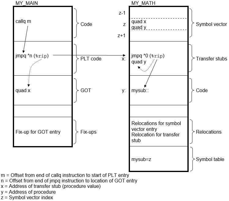
on IA-64 systems, at run-time, when the image activator maps the shareable image into memory, it calculates the actual locations of the routines and relocatable data within the image and stores these values in its symbol vector. The image activator then fixes up the references to these symbols in the executable image. For a symbol representing constant data, the constant from the symbol vector is copied into the executable image. For a symbol representing relocatable data, the address of the data from the symbol vector is copied into the executable image. For a symbol representing a procedure the contents of the FD pointed to by the address in the symbol vector, the code address and the global pointer, is copied into the executable image. When the executable image makes a call to the procedure, shown as the branch (br.few) instruction sequence in Figure 4.2, ''Accessing Universal Symbols Specified Using the SYMBOL_VECTOR=Option on IA-64'', control is transferred directly to the location of the procedure within the shareable image.
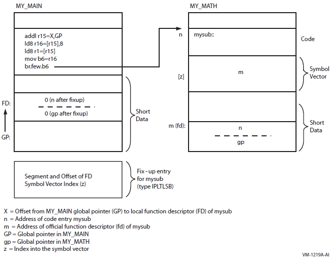
Note that the images are being activated by the image activator with all relocations
applied, pointing out a single fix-up. That is, m and
n are the virtual addresses after the image relocations are
applied and gp is the relocated global pointer value.
Note also that, unlike VAX linking, global symbols implemented as overlaid sections
are not universal by default. Instead, you control which of these symbols is a universal
symbol by including it in the SYMBOL_VECTOR=option, specifying the PSECT keyword. The
example declares the section my_data as a universal symbol.
4.2.1. Symbol Definitions Point to Shareable Image Sections
On x86-64 and IA-64 systems, the linker cannot overlay sections that are referenced by symbol definitions with shareable image sections of the same name.
For example, the VSI C compiler generates symbol definitions when the relaxed ref/def extern model is used (the default).
For hard symbol definitions, the compiler creates an overlaid section defining the memory requirements for that symbol. For tentative symbol definitions, there is no virtual memory allocated by the compiler. At link time, if there is no virtual memory for a symbol found, the linker creates an overlaid section defining the memory.
If an overlaid section was created for a symbol definition, such a section cannot be overlaid with shareable image sections that are created when you link a shareable image and use the PSECT keyword in your SYMBOL_VECTOR option. For more information on the extern models, see VSI C User Manual.
%LINK-E-SHRSYMFND, shareable image psect <name> was pointed
to by a symbol definition
%LINK-E-NOIMGFIL, image file not created
The link continues, but no image is created. To work around this restriction, change the symbol vector keyword to DATA, or recompile your C program with the qualifier /EXTERN=COMMON.
For more information, see the VSI C User Manual.
If the section specified in a SYMBOL_VECTOR= option does not exist, the linker issues a warning, places zeros in the symbol vector entry and does not create an entry for the section in the image's GST.
Note
Although this is correct linker behavior, using identical names in this manner can create confusion. As such, VSI discourages the use of this feature.
4.2.2. Creating Upwardly Compatible Shareable Images
The SYMBOL_VECTOR= option allows you to create upwardly compatible shareable images. You can create a shareable image that can be modified, recompiled, and relinked without causing the images that were linked against previous versions of the image to be relinked.
To ensure upward compatibility when using a SYMBOL_VECTOR= option, you must preserve the order and placement of the entries in the symbol vector with each relinking. Do not delete existing entries and only add new entries at the end of the list. If you use multiple SYMBOL_VECTOR= option statements in a single options file to declare the universal symbols, you must also maintain the order of the SYMBOL_VECTOR= option statements in the options file. If you specify SYMBOL_VECTOR= options in separate options files, make sure the linker always processes the options files in the same order. (The linker creates only one symbol vector for an image).
Major changes or incompatible changes, different orders of existing symbol vector entries, or deletion of entries most likely will result in a mismatch of the major ID number.
Minor changes or compatible changes, or addition of new entries should result in a match of the major ID number but in a mismatch of the minor ID number.
By using the major and minor IDs in this manner, along with the LEQUAL keyword, you can create upwardly compatible shareable images. For example, a main image linked against minor ID 2 of a shareable image is not allowed to run against the shareable image with a minor ID less than 2, if the shareable image was linked with the keyword LEQUAL. For more information, see the description of the GSMATCH= option in Chapter 10, "LINK Command Reference".
4.2.3. Deleting Universal Symbols Without Disturbing Upward Compatibility
mysub is deleted using the PRIVATE_PROCEDURE
keyword:$ LINK/SHAREABLE MY_MATH, SYS$INPUT/OPT
GSMATCH=LEQUAL,1,1000
SYMBOL_VECTOR=(MYADD=PROCEDURE,-
MYSUB=PRIVATE_PROCEDURE,-
MYMUL=PROCEDURE,-
MYDIV=PROCEDURE,-
MY_SYMBOL=DATA,-
MY_DATA=PSECT)
Ctrl/zWhen you specify the PRIVATE_PROCEDURE or PRIVATE_DATA keyword in the SYMBOL_VECTOR= option, the linker creates symbol vector entries for the symbols but does not create an entry for the symbol in the GST of the image. The symbol still exists in the symbol vector and none of the other symbol vector entries have been disturbed. Images that were linked with previous versions of the shareable image that reference the symbol still work, but the symbol is not available for new images to link against.
Using the PRIVATE_PROCEDURE keyword, you can replace an entry for an obsolete procedure with a private entry for a procedure that returns a message that explains the status of the procedure.
4.2.4. Creating Run-Time Kits
If you use shareable images in your application, you may want to ship a run-time kit with versions of these shareable images that cannot be used in link operations.
To do this, you must first link your application, declaring the universal symbols in the shareable images using the SYMBOL_VECTOR= option so that references to these symbols can be resolved. After the application is linked, you must then relink the shareable images so that they have fully populated symbol vectors but empty global symbol tables (GSTs). The fully populated symbol vectors allow your application to continue to use the shareable images at run-time. The empty GSTs prevent other images from linking against your application.
To create this type of shareable image for a run-time kit (without having to disturb the SYMBOL_VECTOR= option statements in your application's options files), relink the shareable image after development is completed, specifying the /NOGST qualifier on the LINK command line. When you specify the /NOGST qualifier, the linker builds a complete symbol vector, containing the symbols you declared universal in the SYMBOL_VECTOR= option, but does not create entries for the symbols that you declared universal in the GST of the shareable image. For more information about the /GST qualifier, see Chapter 10, "LINK Command Reference".
4.2.5. Specifying an Alias Name for a Universal Symbol
mysub is declared as a universal symbol under the name
sub_alias.$ LINK/SHAREABLE MY_MATH, SYS$INPUT/OPT
GSMATCH=LEQUAL,1,1000
SYMBOL_VECTOR=(MYADD=PROCEDURE,-
SUB_ALIAS/MYSUB=PROCEDURE,-
MYMUL=PROCEDURE,-
MYDIV=PROCEDURE,-
MY_SYMBOL=DATA,-
MY_DATA=PSECT)
Ctrl/ZYou can specify universal alias names for symbols that represent procedures or data; you cannot declare a universal alias name for a symbol implemented as an overlaid section. In link operations in which the shareable image is included, the calling modules must refer to the universal symbol by its universal alias name to enable the linker to resolve the symbolic reference.
$ LINK/SHAREABLE MY_MATH, SYS$INPUT/OPT
CASE_SENSITIVE=YES
SYMBOL_VECTOR=(MYADD=PROCEDURE,-
               myadd/MYADD=PROCEDURE,-
               MYSUB=PROCEDURE,-
               mysub/MYSUB=PROCEDURE,-
               MYMUL=PROCEDURE,-
               mymul/MYMUL=PROCEDURE,-
               MYDIV=PROCEDURE,-
               mydiv/MYDIV=PROCEDURE,-
               MY_SYMBOL=DATA,-
               my_symbol/MY_SYMBOL=DATA,-
               MY_DATA=PSECT)CASE_SENSITIVE=NO
Ctrl/Z
In a privileged shareable image, calls from within the image that use the alias name result in a fix-up and subsequent vectoring through the privileged library vector (PLV), which results in a mode change. Calls from within the shareable image that use the internal name are done in the caller's mode. (Calls from external images always result in a fix-up). For more information about creating a PLV, see the VSI OpenVMS Programming Concepts Manual, Volume I.
4.3. Improving the Performance of Installed Shareable Images
On x86-64 and IA-64 systems, you can improve the performance of an installed shareable image by installing it as a resident image (by using the /RESIDENT qualifier of the Install utility). INSTALL loads the executable and read-only segments of resident images into physical memory, with virtual addresses in system space. Data or code of such images is directly accessed from memory. That is, at run-time image pages do not need to be read from the image file. See the documentation on the Install utility for more information about installing images as resident images.
4.4. Linking User-Written System Services
User-written system services allow user-mode programs to call routines that can perform functions that require privileges. These services are implemented in shareable images. Because of the privileged code, these images are also referred to as privileged shareable images. For security reasons, the privileged code and associated data must be protected from manipulations. Therefore, such images are also called protected shareable images.
Protect the privileged shareable image from user-mode or supervisor-mode write access — Create a protected shareable image by specifying the /PROTECT qualifier. If you need to protect only certain segments in a privileged shareable image, use the PROTECT= option. For more information about this option, see Chapter 10, "LINK Command Reference".
Create a Privileged Library Vector (PLV) and put it in a protected section — Create a PLV for a privileged shareable image. The image activator uses the information in the PLV to set up the change of mode code. You can create a protected shareable image by specifying the /PROTECT qualifier. For information about creating a PLV, see the VSI OpenVMS Programming Concepts Manual, Volume I.
Note
On x86-64 and IA-64 systems, it is recommended to protect the entire image, rather than parts of the image (that is, individual image segments). Partial protection requires that you verify that all data to be protected is in the protected segment. Compilers for x86-64 and I64 put data in different types of sections. By doing so, it becomes difficult to control protection setting.
For example, compilers for I64 put some data into short data sections. The linker then must collect these sections into short data segments, which cannot be collected into user-defined clusters (the only clusters that you can protect with the linker option). That is, for partially protected images, you need control over that location that the compiler puts all your data. The compiler of your choice might not offer a reliable method to do so, therefore, it is recommended to protect the entire image.
Chapter 5. Interpreting an Image Map File (x86-64 and I64)
This chapter describes how to interpret information in an image map created by the linker on OpenVMS x86-64 and OpenVMS IA-64 systems. It describes the combinations of linker qualifiers used to produce a map.
For information about interpreting an image map file on OpenVMS Alpha and OpenVMS VAX systems, see Chapter 9, "Interpreting an Image Map File (Alpha and VAX)".
5.1. Overview of x86-64/I64 Linker Map
At your request, the linker can generate information that describes the contents of the image and the linking process. This information, called an image map, can be helpful when determining programming and link-time errors, studying the layout of the image in virtual memory, and keeping track of global symbols.
The names of all modules included in the link operation, both explicitly in the LINK command and implicitly from libraries
The names, sizes, and other information about the segments that comprise the image
The names, sizes, and locations of sections within an image
The names and values of all the global symbols referenced in the image, including the name of the module in which the symbol is defined and the names of the modules in which the symbol is referenced
Statistical summary information about the image and the link operation itself
|
Qualifier |
Description |
|---|---|
|
/MAP |
Directs the linker to create a map file. This is the default for batch jobs. /NOMAP is the default for interactive link operations. |
|
/BRIEF |
When used in combination with the /MAP qualifier, directs the linker to create a map file that contains only a subset of the default map sections. |
|
/FULL |
When used in combination with the /MAP qualifier, directs the
linker to create a map file that contains extensive information
of the image in the map file. To tailor the full information to
your needs, you can use keywords to add or suppress specific
information. The default value for /FULL is SECTION_DETAILS.
|
|
/CROSS_ |
When used in combination with the /MAP qualifier, directs the linker to replace the Symbols By Name section with a Symbol Cross-Reference section, in which all the symbols in each module are listed with the modules in which they are called. You cannot request this type of listing in a brief map file. |
5.2. Components of an x86-64/I64 Image Map File
|
Section Name |
Description |
Default Map |
Full Map |
Brief Map |
|---|---|---|---|---|
|
Object and Image Synopsis? |
Lists all the object modules included in the image and the shareable images referenced in the order they are processed by the linker. |
Yes |
Yes |
Yes |
|
Cluster Synopsis |
Lists all the clusters created by the linker |
— |
Yes |
— |
|
Image Segment Synopsis |
Lists the image segments that were created |
— |
Yes |
— |
|
COMDAT Group Synopsis |
Lists the processed groups ordered by group name |
— |
Keyword
GROUP_ |
— |
|
Program Section Synopsis? |
Lists the sections and their attributes. |
Yes |
Yes |
— |
|
Symbol Cross Reference? |
Lists each symbol name, its value, the name of the module that defined it, and the names of the modules that refer to it. |
Yes /CROSS |
Yes /CROSS |
— |
|
Symbols By Value |
Lists all the symbols with their values in hexadecimal representation. |
— |
Yes |
— |
|
Cross Reference Footnotes |
If the cross reference or the symbol value lists contain shortened name, this section is automatically created and the full names are listed. |
Yes |
Yes |
— |
|
Mangled/Demangled Symbols |
Lists all the mangled symbols with their demangled (source code) names. |
— |
Keyword
DEMANGLED_ |
— |
|
Image Synopsis |
Presents statistics and other information about the output image. |
Yes |
Yes |
Yes |
|
Link Run Statistics |
Presents statistics about the link run that created the image. Quota usage keeps track of quotas being used by the linker and may suggest which quota should be increased to improve performance. |
Yes |
Yes |
Yes |
5.2.1. Object and Image Synopsis Section
The first section that appears in a map file is the Object and Image Synopsis, which lists the name of each object or shareable image included in the link operation in the order in which they were processed. This section of the map file also includes other information about each module, arranged in columns. Example 5.1, ''Object and Image Synopsis'' shows the Object and Image Synopsis map.
                                           +---------------------------+
                                           ! Object and Image Synopsis !
                                           +---------------------------+

Module/Image     File        Ident       Attributes      Bytes  Creation Date     Creator
------------     ----        -----    ----------------   -----  -------------     -------
GETJPI                       V1.0         Lkg     Dnrm    280   8-MAR-2019 15:50  VSI C X7.4-151
                 DISK$USER:[JOE]GETJPI.OBJ;1
DECC$SHR                     V8.3-00      Lkg               0  28-FEB-2019 10:57  Linker I02-68
                 SYS$COMMON:[SYSLIB]DECC$SHR.EXE;1
SYS$PUBLIC_VECTORS           X-3          Sel Lkg           0  28-FEB-2019 10:56  Linker I02-68
                 SYS$COMMON:[SYSLIB]SYS$PUBLIC_VECTORS.EXE;1


                 Key for Attributes
                +------------------------------------------+
                ! Sel  - Module was selectively searched   !
                ! Lkg  - Contains call linkage information !
                ! Dnrm - Denormal IEEE FP model            !
                +------------------------------------------+
| Module/Image. The name of each object module or shareable image included in the link operation. The modules/images are listed in the order in which the linker processed them. (Note that the order of processing can be different from the order in which the files were specified in the command line. For more information about how the linker processes input files, see Chapter 2, "Understanding Symbol Resolution (x86-64 and I64)"). If the linker encounters an error during its processing of an object module or shareable image, an error message appears on the line directly following the line containing the name of that module or image. This column corresponds to the Module Name column on the Alpha linker map. |
| File. Full file specification of the input file, including device and directory. The specification is printed on a separate line. It starts at the File column and continues across the other columns. If the specification is longer than 111 characters, it is shortened by dropping the device portion of the file specification or both the device and directory portions of the file specification. |
| Attributes. The attributes displays four subcolumns of module attributes. An explanation of the abbreviations used appears in the Key for Attributes legend that appears at the end of the Object and Image Synopsis section: The first of the four subcolumns indicates whether the symbol search of the module was selective. If the symbol search was selective, the abbreviation Sel appears. If the symbol search of the module was not selective, this subcolumn is left blank. The second subcolumn indicates whether the module has call linkage information. If the module has call linkage information, Lkg appears. If the module does not have call linkage information, this subcolumn is left blank. The third subcolumn indicates whether the module was compiled with the Reduced Floating Point model. If it was, the abbreviation RFP appears. If the module was not compiled with the Reduced Floating Point model, this subcolumn is left blank. This designation is suppressed for shareable images. The fourth subcolumn indicates the whole program Floating Point mode for the module. Several abbreviations can appear in this column. For example Dnrm, the denormal IEEE FP model. The following example lists all of the possible abbreviations for this subcolumn in the Keys for Attributes legend. The Bytes, Creation Date and Creator columns are omitted from this example; refer to the preceding map example for the entire Object and Image Synopsis.
Module/Image      File           Ident               Attributes
------------      ----           -----            ----------------
NONE                              V1.0                 Lkg
                  DISK1:[JOE]NONE.OBJ;1
NOFLOAT_CASE                                           Lkg RFP
                  DISK1:[JOE]NOFLOAT.OBJ;1
DNORM_CASE                                             Lkg     Dnrm
                  DISK1:[JOE]DENORM_W.OBJ;1
FAST_CASE                                              Lkg     Fast
                  DISK1:[JOE]FAST_W.OBJ;1
NEPCT_CASE                                             Lkg     Inex
                  DISK1:[JOE]INEXACT_W.OBJ;1
SPCL_CASE                                              Lkg     Spcl
                  DISK1:[JOE]SPECIAL_W.OBJ;1
UNDER_CASE                                             Lkg     Undr
                  DISK1:[JOE]UNDERFLOW_W.OBJ;1
DG_FL_CASE                                             Lkg     VXfl
                  DISK1:[JOE]VAXFLOAT_W.OBJ;1
DECC$SHR                          V8.2-00              Lkg
                  RESD$:[SYSLIB]DECC$SHR.EXE;1
SYS$PUBLIC_VECTORS                X-2              Sel Lkg
                  RESD$:[SYSLIB]SYS$PUBLIC_VECTORS.EXE;1


                 Key for Attributes
                +------------------------------------------+
                ! Sel  - Module was selectively searched   !
                ! Lkg  - Contains call linkage information !
                ! RFP  - Conforms to the reduced FP model  !
                ! VXfl - VAX Float FP model                !
                ! Dnrm - Denormal IEEE FP model            !
                ! Fast - Fast IEEE FP model                !
                ! Inex - Inexact IEEE FP model             !
                ! Undr - Underflow-to-zero IEEE FP model   !
                ! Spcl - Special FP model                  !
+------------------------------------------+ |
| Bytes. The number of bytes the object module contributes to the image. Because shareable images do not contribute to the image the value 0 (zero) appears in this column. |
| Creation Date. The date and time the module or image was created. |
| Creator. Identification of the language processor or other utility that created the module or image. |
5.2.2. Cluster Synopsis Section
                                                +------------------+
                                                ! Cluster Synopsis !
                                                +------------------+

Cluster                         Match       Majorid   Minorid
-------                         -----       -------  ----------
MYCLU
DEFAULT_CLUSTER
DECC$SHR                        LESS/EQUAL        1           1
SYS$PUBLIC_VECTORS              EQUAL          9525   361572293
| Cluster Synopsis. On x86-64 and IA-64 systems, there are separate map sections titled Cluster Synopsis and Image Segment Synopsis. The Cluster Synopsis section on x86-64 and I64 does not contain segment information. |
| Cluster. The Cluster column shows the names of the clusters created for and used by the linker, and the order in which they were processed. STARLET.OLB is an exception. It is on the default cluster but its processing is postponed after processing IMAGELIB.OLB. See Chapter 2, "Understanding Symbol Resolution (x86-64 and I64)" for more information on processing default libraries. |
| Match, Majorid, and Minorid. The Match, Majorid, and Minorid columns show the GSMATCH criteria along with the major and minor version numbers, if this information is available. For more information, see the GSMATCH= option in Chapter 10, "LINK Command Reference". |
5.2.3. Image Segment Synopsis Section
The Image Segment Synopsis section of the linker map file (Example 5.3, ''Image Segment Synopsis'') lists the image segments created by the linker. The image segments appear in the order in which the linker created them. The order of the segments depends on the order of the clusters as shown in the linker's image cluster synopsis (see Section 5.2.2, ''Cluster Synopsis Section''). On x86-64 and IA-64 systems, segments of the shareable images which are included in the link operation are not listed in the Image Segment Synopsis.
+------------------------+
! Image Segment Synopsis !
+------------------------+


 Seg# Cluster Type Pglts Base Addr Disk VBN PFC Protection Attributes
---- ------- ---- ----- --------- -------- --- ---------- ----------
0 MYCLU LOAD 1 00010000 2 0 READ WRITE
1 LOAD 1 00020000 0 0 READ WRITE DEMAND ZERO
2 LOAD 1 00030000 3 0 READ ONLY EXECUTABLE,SHARED
3 LOAD 1 00040000 4 0 READ ONLY SHARED
4 LOAD 1 00050000 5 0 READ ONLY [UNWIND]
5 DEFAULT_CLUSTER LOAD 1 00060000 6 0 READ ONLY SHORT
Seg# Cluster Type Pglts Base Addr Disk VBN PFC Protection Attributes
---- ------- ---- ----- --------- -------- --- ---------- ----------
0 MYCLU LOAD 1 00010000 2 0 READ WRITE
1 LOAD 1 00020000 0 0 READ WRITE DEMAND ZERO
2 LOAD 1 00030000 3 0 READ ONLY EXECUTABLE,SHARED
3 LOAD 1 00040000 4 0 READ ONLY SHARED
4 LOAD 1 00050000 5 0 READ ONLY [UNWIND]
5 DEFAULT_CLUSTER LOAD 1 00060000 6 0 READ ONLY SHORT 6 DYNAMIC 2 Q-00000000
80000000 7 0 READ ONLY
Key for special characters above
+----------------------+
! Q - Quad Value !
+----------------------+
6 DYNAMIC 2 Q-00000000
80000000 7 0 READ ONLY
Key for special characters above
+----------------------+
! Q - Quad Value !
+----------------------+
| The Image Segment Synopsis section shows each segment as it was created. | ||||||||||||||||||||
| Seg#. The image's segment number, indicating segments in the order the linker created them and used in image relocations and image fix-ups that are applied to a segment by the image activator. Using the ANALYZE/IMAGE/SEGMENT=DYNAMIC command, you can format the
dynamic segment, which includes the image relocations and fix-ups. The
following extract of the ANALYZE shows how the segment numbers are used
for image
relocations: Segment Offset Modified: 0000000000000050 imr$q_rela_offset Image Relocation Type: 00000081 imr$l_type Segment Being Modified: 00000003 imr$l_rela_seg Image Relocation Addend: 0000000000000000 imr$q_addend Symbol Segment Offset: 0000000000000000 imr$q_sym_offset Symbol Segment Number: 00000000 imr$l_sym_seg Virtual Address Affected: 0000000000040050 | ||||||||||||||||||||
| Cluster. The name of each cluster the linker created, listed in the order in which the linker created them. For better readability, the cluster name is only shown for the first segment in the cluster. | ||||||||||||||||||||
| Type. The type of the segment, indicating if a segment will be in memory at run-time (LOAD), or if the segment is used to activate the image (DYNAMIC). | ||||||||||||||||||||
| Pagelets. The length of each segment, expressed in pagelets (512-byte quantities). | ||||||||||||||||||||
| Base Address. The base address assigned to the segment. Note that all segments are relocatable, the image activator may relocate the base address. | ||||||||||||||||||||
| Disk VBN (virtual block number). The virtual block number of the image file on disk where the segment begins. The number 0 indicates that the segment is not in the image file. This is the case for demand-zero segments. | ||||||||||||||||||||
| Page fault cluster (PFC). The number of pagelets read into memory by the operating system when the initial page fault occurs for that segment. The number 0 indicates that the system parameter PFCDEFAULT determines this value, rather than the linker. | ||||||||||||||||||||
| Protection. The protection attributes of the segment:
| ||||||||||||||||||||
| Attributes. A keyword phrase that characterizes the settings of certain attributes of the image segment, such as the attributes that affect paging. The following table lists the keywords used by the linker to indicate these characteristics of an image segment:
The linker may use more than one keyword to describe a segment. For example, to describe a segment that contains code, the linker uses the READ ONLY and EXECUTABLE keywords. | ||||||||||||||||||||
| (I64 specific) If the module was compiled with /TIE and the image is linked /NONATIVE_ONLY and if the image contains nonstandard signatures, a separate segment appears immediately after the short data segment that contains them. |
5.2.4. Program Section Synopsis Section
                                            +--------------------------+
                                            ! Program Section Synopsis !
                                            +--------------------------+

Psect Name    Module/Image    Base    End         Length     Align               Attributes
----------      ------------      ----     ---           ------       -----                 ----------
ITMLET                          00010000 0001000F 00000010 (    16.) OCTA  4 OVR,REL,GBL,NOSHR,NOEXE, WRT,NOVEC, MOD
                GETJPI          00010000 0001000F 00000010 (    16.) OCTA  4 Initializing Contribution
FILLEN                          00020000 00020003 00000004 (     4.) OCTA  4 OVR,REL,GBL,NOSHR,NOEXE, WRT,NOVEC,NOMOD
                <Linker>      00020000 00020003 00000004 (     4.) OCTA  4
FILLM                           00020010 00020013 00000004 (     4.) OCTA  4 OVR,REL,GBL,NOSHR,NOEXE, WRT,NOVEC,NOMOD
                <Linker>        00020010 00020013 00000004 (     4.) OCTA  4
IOSB                            00020020 00020023 00000004 (     4.) OCTA  4 OVR,REL,GBL,NOSHR,NOEXE, WRT,NOVEC,NOMOD
                <Linker>        00020020 00020023 00000004 (     4.) OCTA  4
STATUS                          00020030 00020033 00000004 (     4.) OCTA  4 OVR,REL,GBL,NOSHR,NOEXE, WRT,NOVEC,NOMOD
                <Linker>        00020030 00020033 00000004 (     4.) OCTA  4
$CODE$                          00030000 0003015F 00000160 (   352.) OCTA  4 CON,REL,LCL, SHR, EXE,NOWRT,NOVEC, MOD
                GETJPI          00030000 0003015F 00000160 (   352.) OCTA  4
$LINKER C$0                     00030160 0003019F 00000040 (    64.) OCTA  4 CON,REL,LCL, SHR, EXE,NOWRT,NOVEC, MOD
                <Linker>      00030160 0003019F 00000040 (    64.) OCTA  4
$LITERAL$                       00040000 00040012 00000013 (    19.) OCTA  4 CON,REL,LCL,  SHR,NOEXE,NOWRT,NOVEC, MOD
                GETJPI          00040000 00040012 00000013 (    19.) OCTA  4
$LINKER UNWIND$                 00050000 0005002F 00000030 (    48.) QUAD  3 CON,REL,LCL,NOSHR,NOEXE,NOWRT,NOVEC, MOD
                GETJPI          00050000 0005002F 00000030 (    48.) QUAD  3
$LINKER UNWINFO$                00050030 0005005F 00000030 (    48.) QUAD  3 CON,REL,LCL,NOSHR,NOEXE,NOWRT,NOVEC, MOD
                GETJPI          00050030 0005005F 00000030 (    48.) QUAD  3
$LINKER SYMBOL_VECTOR$          00060000 00060007 00000008 (     8.) OCTA  4 CON,REL,GBL,NOSHR,NOEXE,NOWRT,NOVEC, MOD,SHORT
                <Linker Option> 00060000 00060007 00000008 (     8.) OCTA  4
$LINKER SDATA$                  00060008 000600AF 000000A8 (   168.) OCTA  4 CON,REL,GBL,NOSHR,NOEXE,NOWRT,NOVEC, MOD,SHORT
                <Linker>        00060008 000600AF 000000A8 (   168.) OCTA  4
There are two types of line entries: first type is a section entry (Psect Name); the second type are individual module contributions to that section (Module/Image).
| Psect Name. The name of each section in the image in ascending order of its base virtual address. |
| Module/Image. The names of the modules that contribute to the section whose name appears on the line directly above in the Psect Name column. If a shareable image appears in this column, the section is overlaid onto the section in the shareable image. |
| Base. The starting virtual address of the section or of a module that contributes to a section. If the section is overlaid onto a section in a shareable image, the virtual address is taken from the shareable image. |
| End. The ending virtual address of the section or of a module that contributes to a section. If the section is overlaid onto a section in a shareable image, the virtual address is taken from the shareable image. |
| Length. For the section entry line, the total length of the section in bytes; for the individual module contribution lines, the length of the individual contribution in bytes. |
| Align. The type of alignment used for the entire section or for an individual section contribution. The alignment is expressed in two ways. In the first column, the alignment is expressed using a predefined keyword, such as OCTA. In the second column, the alignment is expressed as an integer that is the power of 2 that creates the alignment. For example, octaword alignment would be expressed as the keyword OCTA and as the integer 4 (because 24 = 16). For more information on the effects of alignment with the PSECT= option see Chapter 10, "LINK Command Reference". If the linker does not support a keyword to express an alignment, it puts the text "2 **" in the column in which the keyword usually appears. When read with the integer in the second column, it expresses these alignments, such as 25 = 32. |
| Attributes. The attributes associated with the section. For a complete list of all the possible attributes, see Chapter 3, "Understanding Image File Creation (x86-64 and I64)". |
| The linker indicates which modules made initializations (if there were any) to sections which have the attributes OVR, REL and GBL with the designation Initializing Contribution. If you get multiple initialization errors, the linker will have two or more sections marked with the designation Initializing Contribution, in order to help you debug an instance that has many contributors. |
| The linker contributes storage for common or relaxed ref/def symbols.
It is marked with |
| The linker makes a contribution to the code section containing
trampolines (instructions with larger branches within the same code
segment) or code to branch to another segment (either inside or outside
the image). It is marked with |
Note
If a routine is extracted from the default system library to resolve a symbolic reference, the Program Section Synopsis section in a full map contains information about the program sections comprising that routine. The Program Section Synopsis section in a default map does not.
5.2.5. Symbol Cross-Reference Section
                                             +------------------------+
                                             ! Symbol Cross Reference !
                                             +------------------------+

Symbol          Value              Defined By                Referenced By ...
------          -----              ----------                -----------------
DECC$TXPRINTF   00000496-X       DECC$SHR                  GETJPI
ELF$TFRADR      00060050-R      WK-GETJPI
FILLEN          00020000-R         GETJPI                    GETJPI
FILLM           00020010-R         GETJPI                    GETJPI
GETJPI (U)      00000000           <Linker Option>
INTERNAL_GETJPI 00060098-R         GETJPI
IOSB            00020020-R         GETJPI                    GETJPI
ITMLST          00010000-R         GETJPI
STATUS          00020030-R         GETJPI                    GETJPI
SYS$GETJPIW     0000009A-X         SYS$PUBLIC_VECTORS        GETJPI
| Symbol. The name of the global symbol. |
| Value. The value of the global symbol, expressed in hexadecimal. The linker appends characters to the end of the symbol value to describe other characteristics of the symbol. For an explanation of these symbols, see Section 5.2.6, ''Symbols By Value Section''. |
| Defined By. The name of the module in which the symbol is defined. For example, the symbol ITMLST is defined in the module named GETJPI. |
| Referenced By... . The name or names of all the modules that contain at least one reference to the symbol. |
| On x86-64 and IA-64 systems, the designation of an external symbol is always X (external). The linker can not know whether or not an external symbol is relocatable or not. As a result, the designation R (relocatable) can not be attached. |
5.2.6. Symbols By Value Section
The Symbols By Value section lists all the global symbols in the image in ascending order by value. The linker formats the information into columns. Example 5.6, ''Symbols by Value'' shows the Symbols By Value map section.
                                                +------------------+
                                                ! Symbols By Value !
                                                +------------------+

Value           Symbols...
-----           ----------
00000000        GETJPI (U)
0000009A      X-SYS$GETJPIW
00000496      X-DECC$TXPRINTF
00010000      R-ITMLST
00020000      R-FILLEN
00020010      R-FILLM
00020020      R-IOSB
00020030      R-STATUS
00060050      R-ELF$TFRADR
00060098      R-INTERNAL_GETJPI

              Key for special characters above
                +----------------------+
                !   *  - Undefined     !
                !  (U) - Universal     !
                !   R  - Relocatable   !
                !   X  - External      !
                !   C  - Code Address  !
                !  WK  - Weak          !
                ! UxWk - Unix-Weak     !
                +----------------------+
| Value. The value of each global symbol, expressed in hexadecimal, in ascending numerical order. |
| Symbols... . The names of the global symbols. If more than one symbol has the same value, the linker lists them on more than one line. The characters prefixed to the symbol names indicate other characteristics of the symbol, such as its scope. |
| Keys for Special Characters. The keys for special characters used in
the Symbols column are defined as follows:
|
5.2.7. Image Synopsis Section
                                                 +----------------+
                                                 ! Image Synopsis !
                                                 +----------------+

Virtual memory allocated:              00010000 0006FFFF 00060000 (393216. bytes, 768. pages)
64-Bit Virtual memory allocated:       00000000 00000000 00000000
                                         80000000 80010000 00010000 (65536. bytes, 128. pages)
Stack size:                                           0. pages
Image header virtual block limits:             1.        1. (    1. block)
Image binary virtual block limits:             2.        8. (    7. blocks)
Image name and identification:           GETJPI V1.0
Number of files:                                5.
Number of modules:                              3.
Number of program sections:                     8.
Number of global symbols:                    3364.
Number of cross references:                    17.
Number of image segments:                       7.
Transfer address from module:                GETJPI
User transfer FD address:               00000000 00060050
User transfer code address:             00000000 00030000
Initial FP mode:                        00000000 09800000 (IEEE DENORM_RESULTS)
Number of code references to shareable images:        2.
Image type:                    SHAREABLE. Global Section Match=EQUAL, Ident, Major=9533, Minor=3817251083
Reduced Floating Point model (RFP):  Image does not use RFP model
Map format:                          FULL WITH CROSS REFERENCE in file DISK$USER:[JOE]GETJPI.MAP;1
Estimated map length:                443. blocks
| Virtual memory allocated. This line contains the following
information:
The numbers in parentheses at the end of the line indicate the total size of the image, expressed in bytes and in pagelets. Both these values are expressed in decimal. |
| 64-Bit Virtual memory allocated. The next two lines contain information on the image portions in P2 space. The virtual addresses are printed by column,in two rows, with the high order digits in the first row. The values are as in the preceding line: the starting-address, the ending-address, the size. Sections with the attribute ALLOC_64BIT are collected into P2 space (For more information on collecting sections and assigning virtual addresses see Chapter 3, "Understanding Image File Creation (x86-64 and I64)"). The linker usually places the image activator information (dynamic segment) into the 64-bit space. Therefore, for all x86-64 and I64 images, 64-bit virtual memory is usually allocated. |
| Stack size. |
| Image header virtual block limits. For x86-64 and I64 images, the header blocks contain the ELF header and the segment header table. This is usually one disk block. |
| Image binary virtual block limits. For x86-64 and I64 images, the binary blocks contain the image binaries (the segments) and other sections, depending on the type of image. There can be traceback and debug information as well as symbol tables. Also, the section header table describing such sections is counted here. |
| (I64 specific) User transfer FD address. The virtual address of the function descriptor (FD) for the main entry. This is an address in the short data segment. |
| User transfer code address. The virtual address of the first code instruction in the main entry. This is an address in an executable segment. |
5.2.8. Link Run Statistics Section
The Link Run Statistics section contains miscellaneous statistical information about the link operation, such as performance indicators. Example 5.8, ''Link Run Statistics'' shows the formatting of this section.
                                              +---------------------+
                                              ! Link Run Statistics !
                                              +---------------------+

Performance Indicators                            Page Faults   CPU Time        Elapsed Time
----------------------                            -----------   --------        ------------
    Command processing:                                    52   00:00:00.01     00:00:00.00
    Pass 1:                                               187   00:00:00.01     00:00:00.01
    Allocation/Relocation:                                 10   00:00:00.01     00:00:00.02
    Pass 2:                                               537   00:00:00.00     00:00:00.00
    Write program segments:                                15   00:00:00.01     00:00:00.05
    Symbol table output:                                    3   00:00:00.00     00:00:00.06
    Map data after object module synopsis:                  6   00:00:00.00     00:00:00.01
Total run values:                                         810   00:00:00.04     00:00:00.17

Quota usage                                      ByteCount  FileCount  PgFlCount
------------                                       ---------  ---------  ---------
    Available:                                        255616        128     700000
    Command processing:                                  384          3       7040
    Pass 1:                                              384          3       9504
    Allocation/Relocation:                               576          4       9504
    Pass 2:                                              384          3      17824
    Write program segments:                              576          4      17952
    Symbol table output:                                 384          3      17952
    Map data after object module synopsis:               384          3      17952

Using a working set limited to 18784 pages and 11105 pages of data storage (excluding image)

Number of modules extracted explicitly             = 0
    with 0 extracted to resolve undefined symbols

1 library searches were for symbols not in the library searched

A total of 1 global symbol table entries was written

LINK/MAP/FULL/CROSS/SHARE GETJPI/OPT
<DISK$USER:[JOE]GETJPI.OPT;1>
cluster=myclu,,,getjpi.obj
symbol_vector=(getjpi/internal_getjpi=procedure)
| Quota usage. For x86-64 and I64, includes Quota usage information in
the Link Run Statistics section. This information can help you to keep
track of the quotas that are being used by the linker. If quota issues
occur, the linker is usually able to work around them. However, the
linker outputs a special message to the Quota Usage section indicating
what quota should be increased to improve performance. For
example: Performance of this link operation could be improved by increasing quotas Quota related to status return: %SYSTEM-SECTBLFUL, process or global section table is full 2688 extra file I/O operations performed due to current process quota(s) 36 performed on object files; 2652 performed on library files |
| Library searches were for symbols not in the library searched. When
resolving undefined symbols, libraries are searched for definitions (see
Chapter 2, "Understanding Symbol Resolution (x86-64 and I64)" for more information on symbol
resolution). The printed number shows how often undefined symbols are
not found in a library. For example, assume that module MAIN references
the symbols MY_ADD and MY_SUB, which are defined by modules in
ADDLIB.OLB and SUBLIB.OLB. Using the link
command: $ LINK MAIN, MAINLIB/LIB, ADDLIB/LIB, SUBLIB/LIBif the MY_ADD and MY_SUB symbols are not found in MAINLIB, MY_SUB is not found in ADDLIB. This results in "3 library searches for symbols not in the library searched". |
| The number of global symbols written into a shareable image corresponds to the procedure and data entries in the symbol vector option. In this example, there is only a single entry in the symbol vector option. |
5.3. Shortened Names with Footnotes in the Cross-Reference
Some sections of the linker map have tables with a fixed amount of space for their columns. The Symbol Cross-Reference and the Symbols By Value map sections are examples. If names exceed the given column size, the linker prints a shortened name. On x86-64 and I64, for the cross reference and the symbol value list the linker attaches a footnote, referring to the full name. If there are footnotes attached to any name, the linker automatically adds a Cross-Reference Footnotes section. The footnote section contains the footnote index and the full name, wrapped to several lines, if necessary.
The following example demonstrates how to read the footnotes. The long names were constructed for demonstration purpose only. In Example 5.9, ''Shortened Symbol and Module Names'', the qualifiers /MAP/CROSS/FULL were specified to get both the cross-reference and the symbol value list.
                                             +------------------------+
                                             ! Symbol Cross Reference !
                                             +------------------------+

Symbol                    Value              Defined By                            Referenced By ...
------                    -----              ----------                            -----------------
a_very_very_very_very_very_very_very_very_very_very_very_very_very_very_very_long_variable_name...[1]
                          00010000-R         A_VERY_LONG_MODULE_NAME_JUST_F...[2]

                                                +------------------+
                                                ! Symbols By Value !
                                                +------------------+

Value           Symbols...
-----           ----------
00010000      R-a_very_very_very_very_very_very_very_very_very_very_very_very_very_very_very_very_lon...[1]
| In the symbol cross reference, the symbol name does not fit on one line. The name is shortened, which is shown with the trailing ellipses. And index of the footnote is in the rightmost column. |
| In the symbol cross reference, the module name exceeds the size for the column Defined By. Again, ellipses show that the names is shortened and an index of the footnote is attached. |
| The same symbol shows in the Symbols By Value section. Even less space is provided to fit the symbol into the Symbols... column. The name, therefore, is shortened with ellipses and a footnote index is attached. Because this is the same symbol as in the Cross-Reference Section (although more shortened), the same index points to the same full name, and the entry in the footnote section. |
                                           +---------------------------+
                                           ! Cross Reference Footnotes !
                                           +---------------------------+

Index  Full Symbol Name
-----  ----------------
    1  a_very_very_very_very_very_very_very_very_very_very_very_very_very
       _very_very_long_variable_name
       _used_only_for_demonstration_purpose
    2  A_VERY_LONG_MODULE_NAME_JUST_FOR_DEMO
| In this example, the full name does not fit into the footnote column. The full symbol name will be wrapped to multiple lines, as necessary. |
5.4. Translation Table for Mangled Names
Some compilers mangle symbol names to implement language features (for example,overloading) or to use shortened, unique names. Ada and C++ compilers, for example, do so. The linker receives only mangled names from the compilers for resolving symbols and for exporting universal symbols. There is no general rule to derive a mangled name from a source codename or vice versa. If you need to know the source code name for a given mangled name, you need the demangler support from that programming language processor.
                                           +---------------------------+
                                           ! Mangled/Demangled Symbols !
                                           +---------------------------+

Symbol = Source Code Name
-------------------------
CX3$ZN4RW22RWRDNRYXCHNGI2LM6VES
  = "int __rw::__rw_ordinary_exchange<int, int>(int&, int const&)"
CX3$_Z10DESCENDINGRIS_2OLL9N5
  = "descending(int&, int&)"
CX3$_Z6MYSWAPIIEVRT_S1_1658A7V
  = "void myswap<int>(int&, int&)"
CX3$_Z9ASCENDINGRIS_162K6TK
  = "ascending(int&, int&)"
CXXL$ZN4RW10RWGARDC1ERNS1UGN3D2
  = "__rw::__rw_guard::$complete$__rw_guard(__rw::__rw_mutex_base&)"
CXXL$ZN4RW10RWGARDC2EPNS05KBR8A
  = "__rw::__rw_guard::$subobject$__rw_guard(__rw::__rw_mutex_base*)"
CXXL$ZN4RW10RWGARDC9EPNS20LCU4S
  = "__rw::__rw_guard::__rw_guard(__rw::__rw_mutex_base*)"
CXXL$ZN4RW10RWGARDC9ERNS2NGDC8S
  = "__rw::__rw_guard::__rw_guard(__rw::__rw_mutex_base&)"
CXXL$ZN4RW17RWSTTCMTXB8C19J9SHI
  = "__rw::__rw_static_mutex<bool>::_C_mutex"
CXXL$ZN4RW17RWSTTCMTXJ8C1AJH16C
  = "__rw::__rw_static_mutex<unsigned int>::_C_mutex"
CXXL$ZN4RW20RWTMCXCHNGII0DCUDA8
  = "int __rw::__rw_atomic_exchange<int, int>(int&, int const&, __rw::__rw_mutex_base&)"
CXXL$ZNKST15BSCSTRAMBFCS03029KV
  = "std::basic_streambuf<char, std::char_traits<char> >::_C_write_avail() const"
CXXL$ZNKST5CTYPEICE5WDNC2S864U0
  = "std::ctype<char>::widen(char) const"
| The translation table is sorted by the mangled names. Sorting the names by the source code name is not helpful. For example, the C++ source code function names contain the return type, which would determine the sort order rather than the function names. Note that the mangled names might contain a dollar sign ($) character. This does not necessarily indicate an OpenVMS reserved name. |
| The table only contains global symbol definitions from the object modules included in the link. However, there might be more names than expected; the compiler may generate some names (for example, when implementing C++ templates). In the map extract, "descending(int&, int&)", "void myswap <int>(int&, int&)"and "ascending(int&, int&)" are the user-defined template functions from the example Example 2.3, ''UNIX-Style Weak and Group Symbols''. Other names are C++ generated names. |
Chapter 6. Understanding Symbol Resolution (Alpha and VAX)
This chapter describes how the linker performs symbol resolution on OpenVMS Alpha and OpenVMS VAX systems.
For information on performing symbol resolution on OpenVMS x86-64 and OpenVMS IA-64 systems, see Chapter 2, "Understanding Symbol Resolution (x86-64 and I64)".
As one of its primary tasks, the linker must resolve symbolic references between modules. This chapter describes how you can control the process to ensure that the linker resolves symbolic references as you intend.
6.1. Overview
Programs are typically made up of many interdependent modules. For example, one module may define a symbol to represent a program location or data element that is referenced by many other modules. The linker is responsible for finding the correct definition of each symbol referenced in all the modules included in the link operation. This process of matching symbolic references with their definitions is called symbol resolution.
6.1.1. Types of Symbols
Symbols can be categorized by their scope, that is, the range of modules over which they are intended to be visible. Some symbols, called local symbols, are meant to be visible only within a single module. Because the definition and the references to these symbols must be confined to a single module, language processors such as compilers can resolve these references.
Other symbols, called global symbols, are meant to be visible to external modules. A module can reference a global symbol that is defined in another module. Because the value of the symbol is not available to the compiler processing the source file, it cannot resolve the symbolic reference. Instead, a compiler creates a global symbol directory (GSD) in an object module that lists all of the global symbol references and global symbol definitions it contains.
In shareable images, symbols that are intended to be visible to external modules are called universal symbols. A universal symbol in a shareable image is the equivalent of a global symbol in an object module. Note, however, that only those global symbols that have been declared as universal are listed in the global symbol table (GST) of the shareable image and are available to external modules to link against.
Language processors determine whether a symbol is local or global. For example, in VAX FORTRAN, statement numbers are local symbols and module entry points are global symbols. In other languages, you can explicitly specify whether a symbol is local or global by including or excluding particular attributes in the symbol definition. Note also that some languages allow you to specify symbols as weak or strong (see Section 6.5, ''Defining Weak and Strong Global Symbols'' for more information).
Note
In some VSI programming languages, certain types of global symbols, such as external variables in C and COMMON data in FORTRAN, are not listed in the GSD as global symbol references or definitions. Because these data types implement virtual memory that is shared, the languages implement them as program sections that are overlaid. These symbols appear as program section definitions in the GSD, not as a symbol definition or reference. (Compilers use program sections to define the memory requirements of an object module). The linker does not include program section definitions in its symbol resolution processing. For information about how the linker processes program sections, see Chapter 7, "Understanding Image File Creation (Alpha and VAX)".
On VAX systems, the VAX C language extensions globalref and globaldef allow you to create external variables that appear as symbol references and definitions in the GSD. For more information, see the VAX C documentation.
On Alpha systems, the VSI C compiler supports the globalref and globaldef language extensions. In addition, VSI C supports command line qualifiers and source code pragma statements that allow you to control whether it implements external variables as program sections or as global symbol references and definitions. For more information, see the VSI C documentation.
6.1.2. Linker Symbol Resolution Processing
During its first pass through the input files specified in the link operation,the linker attempts to find the definition for every symbol referenced in the input files. By default, the linker processes all the global symbols defined and referenced in the GSD of each object module and all the universal symbols defined and referenced in the GST of each shareable image. The definition of the symbol provides the value of the symbol. The linker substitutes this value for each instance where the symbol is referenced in the image.
The value of a symbol depends on what the symbol represents. A symbol can represent a routine entry point or a data location within an image. For these symbols, the value of the symbol is an address. A symbol can also represent a data constant (for example, X = 10). In this case, the value of the symbol is its actual value (in the example, the value of X is 10).
For symbols that represent addresses in object modules, the value is expressed initially as an offset into a program section. This is how language processors express addresses. Later in its processing, when the linker combines the program sections contributed by all the object modules into the image sections that define the virtual memory layout of the image, it determines the actual value of the address. For information about how the linker determines the virtual memory layout of an image, see Chapter 7, "Understanding Image File Creation (Alpha and VAX)".
For symbols that represent addresses in a shareable image, the value of the symbol at link time is architecture specific.
For Alpha images, at link time, the value of a symbol in a shareable image (as listed in the GST of the image) is the offset of the symbol's entry in the symbol vector of the image. A symbol vector entry is a pair of quadwords that contain information about the symbol. The contents of these quadwords depend on whether the symbol represents a procedure entry point, data location, or a constant. Figure 6.1, ''Symbol Vector Contents'' illustrates the contents of a symbol vector entry for each of these three types of symbols. Note that, at link time, a symbol vector entry for a procedure entry point or a data location is expressed as an offset into the image. At image activation time, when the image is loaded into memory and the base address of the image is known, the image activator converts the image offset into a virtual address. Figure 6.1, ''Symbol Vector Contents'' shows the contents of the symbol vector at link time and at image activation time.
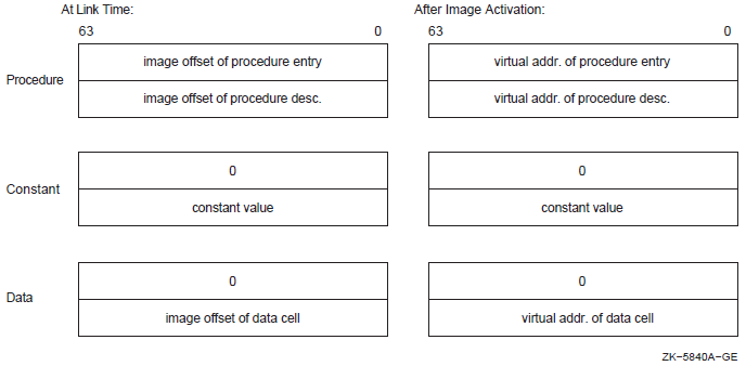
Note that the linker does not allow programs to make procedure calls to symbols that represent data locations.
For VAX images, at link time, the value of a symbol in a shareable image (as listed in the GST of the image) is the offset into the image of the routine or data location, if the symbol was declared universal using the UNIVERSAL=option. If the symbol was declared universal using a transfer vector, the value of the symbol is the offset into the image of the transfer vector entry. If the symbol represents a constant, the GST contains the actual value of the constant.
The actual value of an address symbol in a shareable image is determined at run-time by the image activator when it loads the shareable image into memory. The image activator relocates all the address references within a shareable image when it loads the image into memory. Once it has determined the absolute values of these addresses, the image activator fixes up references to these addresses in the image that linked against the shareable image. Previously, the linker created fix-ups that flag to the image activator where it must insert the actual addresses to complete the linkage of a symbolic reference to its definition in an image. The linker listed these fix-ups in the fix-up section it creates for the image. For more information about shareable images, see Chapter 8, "Creating Shareable Images (Alpha and VAX)".
For VAX images, you can specify the address at which you want a shareable image loaded into memory by using the BASE= option. When you specify this option, the linker can calculate the absolute addresses of symbols within the shareable image because the base address of the shareable image is known. By specifying a base address, you eliminate the need for the image activator to perform fix-ups and relocations.
Note, however, that basing a shareable image can potentially destroy upward compatibility between the shareable image and other images that were linked against it.
Figure 6.2, ''Symbol Resolution'' illustrates the interdependencies created by symbolic references among the modules that make up an application. In the figure, arrows point from a symbol reference to a symbol definition. (The statements do not reflect a specific programming language.)
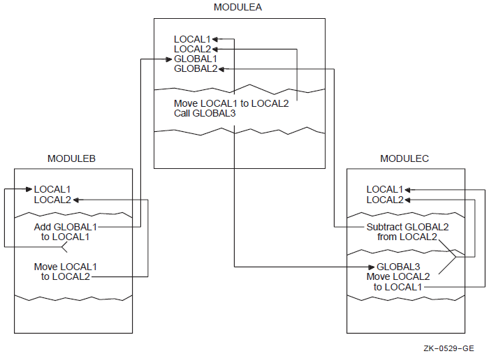
$ link my_main ! The module MY_MATH is omitted %LINK-W-NUDFSYMS, 1 undefined symbols:
| The linker issues an informational message for each symbol for which it cannot find a definition. |
| The linker issues a warning message for each instance where an undefined symbol is referenced in the image. |
$ run my_main
%SYSTEM-F-ACCVIO, access violation, reason mask=00, virtual address=00000000,
PC=00001018, PSL=03C00000
%TRACE-F-TRACEBACK, symbolic stack dump follows
module name     routine name                 line   rel PC    abs PC
MY_MAIN         main                          15   00000018  00001018
6.2. Input File Processing for Symbol Resolution
The linker can include object modules, shareable images, and libraries in its symbol resolution processing. For VAX images, the linker can also include a symbol table file in its symbol resolution processing. (Options files, in which linker options and input files are specified, are not included in symbol resolution).
By default, when the linker processes an object module or shareable image, it includes all the symbol definitions from the object module or shareable image in its processing. However, if you append the /SELECTIVE_SEARCH qualifier to the object module or shareable image file specification, the linker includes in its processing only those symbols from the object module or shareable image that define symbols referenced in a previously processed input file. For more information about selectively processing input files, see Section 6.2.4, ''Processing Input Files Selectively''.
|
Input File |
How Processed |
|---|---|
|
Object file (.OBJ) |
By default, the linker processes all the symbol definitions and references listed in the GSD of the module. If you append the /SELECTIVE_SEARCH qualifier to the input file specification, the linker includes in its processing only those symbol definitions from the GSD that resolve symbolic references found in previously processed input files. |
|
Shareable image file (.EXE) |
By default, the linker processes all symbol definitions and references listed in the GST of the image. Note, however, to avoid cluttering the map file of the resultant image, the linker lists only those symbol definitions in the map file that are referenced by other modules. If you append the /SELECTIVE_SEARCH qualifier to the input file specification,the linker includes in its processing only those symbol definitions from the GST that resolve symbolic references found in previously processed input files. |
|
Symbol table file (.STB)? |
By default, the linker processes all the symbol definitions and references in the GSD of the module. If you append the /SELECTIVE_SEARCH qualifier to the input file specification, the linker includes in its processing only those symbol definitions from the module that resolve symbolic references found in previously processed input files. |
|
Library files (.OLB) |
The linker searches the name table of the library for symbols that are undefined in previously processed input files. (A library file's name table lists all the symbols available in all of the modules it contains). If the linker finds the definition of a symbol referenced by a previously processed input file, it includes in the link operation the module in the library that contains the definition of the symbol. Once the object module or shareable image is included in the link operation, the linker processes it as any other object module or shareable image. If you append the /INCLUDE qualifier to a library file specification, the linker does not search the library's name table to find undefined symbolic references. Instead, the linker simply includes the specified object module or shareable image specified as a parameter to the /INCLUDE qualifier. You cannot process a library file selectively. However, if the Librarian utility's /SELECTIVE_SEARCH qualifier was specified when the object module or shareable image was inserted into the library, the linker will process the module selectively when it extracts it from the library. |
6.2.1. Processing Object Modules
The way the linker processes object modules to resolve symbolic references illustrates how the linker processes most other input files. (Symbol table files are object modules. The GST of a shareable image, which the linker processes in symbol resolution, is also created as an object module appended to the shareable image).
mysub.#include <stdio.h>
int mysub();
main()
{
int num1, num2, result;
num1 = 5;
num2 = 6;
result = 0;
result = mysub( num1, num2 );
printf("Result is: %d\n", result);
}mysub, which Example 6.1, ''Module Containing a Symbolic Reference: my_main.c'' references, is defined in the
program in Example 6.2, ''Module Containing a Symbol Definition: my_math.c''.int myadd(int value_1,int value_2) {
int result;
result = value_1 + value_2;
return( result);
}
int mysub(int value_1,int value_2)
int result;
result = value_1 - value_2;
return( result);
}
int mymul(int value_1,int value_2)
int result;
result = value_1 * value_2;
return( result);
}
int mydiv(int value_1,int value_2)
int result;
result = value_1 / value_2;
return( result);
}mysub. Because
object modules cannot be examined using a text editor, the following representation
of the GSD is taken from the output of the ANALYZE/OBJECT utility. The example is
from the analysis of an OpenVMS Alpha object module. Differences between the format
of the symbol reference between VAX object files and Alpha object files are
highlighted in the list following the example.4. GLOBAL SYMBOL DIRECTORY (EOBJ$C_GSD)
| For VAX object files, the symbol for the global symbol directory is OBJ$C_GSD. |
| For VAX object files, the symbol for a global symbol specification is GSD$C_SYM. |
| For VAX object files, this field is not included. |
| For VAX object files, this field is not included. For Alpha object files, the value of this field is always zero for symbolic references. |
The GSD created by the language processor for the object module MY_MATH.OBJ contains the
definition of the symbol mysub, as well
as the other symbols defined in the module. The definition of the symbol includes
the value of the symbol.
4. GLOBAL SYMBOL DIRECTORY (EOBJ$C_GSD), 46 bytes . . . 9) Global Symbol Specification (EGSD$C_SYM) data type: DSC$K_DTYPE_Z (0) symbol flags: (0) EGSY$V_WEAK 0 (1) EGSY$V_DEF 1 (2) EGSY$V_UNI 0 (3) EGSY$V_REL 1 (4) EGSY$V_COMM 0 (5) EGSY$V_VECEP 0 (6) EGSY$V_NORM 1
| The value of the EGSY$V_NORM flag is 1 if the symbol represents a procedure. The value is set to zero if the symbol represents data. |
| The index of the program section that contains the procedure
descriptor for |
| The location of the procedure descriptor expressed as the offset from the starting address of the program section that contains the procedure descriptor. |
| Index of program section that contains the code entry point. |
| The location of the code entry point, expressed as the offset from the starting address of the program section that contains the entry point. |
4.  GLOBAL SYMBOL DIRECTORY (OBJ$C_GSD), 46 bytes
        .
        .
        .
        2)  Entry Point Symbol and Mask Definition (GSD$C_EPM)
                data type: DSC$K_DTYPE_Z (0)
                symbol flags:
                        (0)  GSY$V_WEAK       0
                        (1)  GSY$V_DEF        1
                        (2)  GSY$V_UNI        0
                        (3)  GSY$V_REL        1
                        (4)  GSY$V_COMM       0
                psect: 0
                value: 0 (%X'0000000C')
                entry mask: <>
                symbol: "MYSUB"
                  .
                  .
                  .
The value of the symbol is expressed as an offset into a program section.
$ LINK MY_MAIN, MY_MATH
When the linker processes these object modules, it reads the contents of the GSDs, obtaining the value of the symbol from the symbol definition.
Note that, for Alpha images, in the map file associated with the image, the value of the
symbol mysub is the location within the image of the procedure
descriptor for the routine. The procedure descriptor contains the address of the
routine within the image.
For VAX images, the value of the symbol mysub is represented in the map
file as the location of the entry point mask.
6.2.2. Processing Shareable Images
When the linker processes a shareable image specified as input in a link operation, it processes all the symbol definitions and references in the GST of the image. The GST contains all the universal symbols defined in the shareable image. Because the linker creates the GST of a shareable image in the format of an object module, the processing of shareable images for symbol resolution is similar to the processing of object modules. Note that the linker includes in the map file only those symbols that resolve references to avoid cluttering the listing with extraneous symbols.
$ LINK/MAP/FULL   MY_MAIN, SYS$INPUT/OPT
MY_MATH/SHAREABLE
The GST created by the linker for the shareable image MY_MATH.EXE contains the
definition of the symbol mysub, as well
as the other symbols defined in the module.
Because images cannot be examined using a text editor, the following representations of the GST are taken from the output of the ANALYZE/IMAGE utility.
mysub in the shareable image
MY_MATH.EXE appears in the GST of the image as a Universal Symbol Specification
record, as illustrated in the following
example:SHAREABLE IMAGE - GLOBAL SYMBOL TABLE
.
.
.
4. GLOBAL SYMBOL DIRECTORY (EOBJ$C_EGSD), 200 bytes
.
.
.
3) Universal Symbol Specification (EGSD$C_SYMG)
data type: DSC$K_DTYPE_Z (0)
symbol flags:
(0) EGSY$V_WEAK 0
(1) EGSY$V_DEF 1
(2) EGSY$V_UNI 1
(3) EGSY$V_REL 1
(4) EGSY$V_COMM 0
(5) EGSY$V_VECEP 0
(6) EGSY$V_NORM 1
psect: 0
value: 16 (%X'00000010')
symbol vector entry (procedure)
%X'00000000 00010008'
%X'00000000 00000040'
symbol: "MYSUB"
.
.
.Note that the value of the symbol, as it appears in the Universal Symbol Specification, is the location of the symbol's entry in the image's symbol vector, expressed as an offset from the base of the symbol vector. The symbol vector entry contains the address of mysub's entry point and the address of its procedure descriptor. These locations are expressed as offsets from the base of the image. The entry for a symbol in the GST of an image is a duplicate of the symbol's entry in the symbol vector.
mysub in the shareable image
MY_MATH.EXE appears in the GST of the image as an Entry Point Symbol and Mask
Definition record, as illustrated in the following
example:SHAREABLE IMAGE - GLOBAL SYMBOL TABLE
.
.
.
2) Entry Point Symbol and Mask Definition (GSD$C_EPM)
data type: DSC$K_DTYPE_Z (0)
symbol flags:
(0) GSY$V_WEAK 0
(1) GSY$V_DEF 1
(2) GSY$V_UNI 1
(3) GSY$V_REL 1
(4) GSY$V_COMM 0
psect: 0
value: 8 (%X'00000008')
entry mask: <>
symbol: "MYSUB"
.
.
.Note that the flag GSY$V_UNI is set for universal symbols to distinguish them from global symbols in object modules that use the same record format.
Implicit Processing of Shareable Images
For VAX linking, when you specify a shareable image in a link operation, the linker not only processes the shareable image you specify, but also all the shareable images that the shareable image has been linked against. (A shareable image contains a global image section descriptor [GISD] for each shareable image to which it has been linked).
For Alpha linking, the linker does not process the shareable images that the shareable image you specify has been linked against. (Shareable images on Alpha systems still contain GISDs for each shareable image that they have been linked against, however). If your application's build procedure depends on implicit processing of shareable images, you may need to add these shareable images to your linker options file.
6.2.3. Processing Library Files
Libraries specified as input files in link operations contain either object modules or shareable images. The way in which the linker processes library files depends on how you specify the library in the link operation. Sections 6.2.3.1, 6.2.3.2, and 6.2.3.3 describe these differences. Note, however, that once an object module or shareable image is included from the library into the link operation, the linker processes the file as it would any other object module or shareable image.
$ LIBRARY/CREATE/INSERT MYMATH_LIB MY_MATH
$ LIBRARY/LIST/NAMES MYMATH_LIB
Directory of OBJECT library WORK:[PROGS]MYMATH_LIB.OLB;1 on 3-NOV-2000 11:11:33
Creation date:  3-NOV-2000 11:08:04     Creator:  VAX-11 Librarian V04-00
Revision date:  3-NOV-2000 11:08:04     Library format:   3.0
Number of modules:      1               Max. key length:  31
Other entries:          5               Preallocated index blocks:     49
Recoverable deleted blocks:      0      Total index blocks used:        2
Max. Number history records:     20     Library history records:        0
Module MY_MATH
MYADD                            MYDIV
MYMUL                            MYSUB
$ LINK/MAP/FULL MY_MATH, MYMATH_LIB/LIBRARY
The map file produced by the link operation verifies that the object module MY_MATH.OBJ was included in the link operation.
6.2.3.1. Identifying Library Files Using the /LIBRARY Qualifier
When the linker processes a library file identified by the /LIBRARY qualifier, the linker processes the library's name table, looking for the definitions of symbols referenced in previously processed input files.
Note that, to resolve a reference to a symbol defined in a library, the linker must process the module that references the symbol before processing the library file. Thus, while the ordering of object modules and shareable images is not usually important in a link operation, the ordering of library files can be important. For more information about controlling the order in which the linker processes input files, see Section 6.3, ''Ensuring Correct Symbol Resolution''.
Once the object module or shareable image is included from the library into the link operation, the linker processes all the symbol definitions and references in the module. If you want the linker to selectively process object modules or shareable images that are included in the link operation from a library, you must append the Librarian utility's /SELECTIVE_SEARCH qualifier to the file specification of the object module or shareable image when you insert it into the library. Appending the linker's /SELECTIVE_SEARCH qualifier to a library file specification in a link operation is illegal. For more information about processing input files selectively, see Section 6.2.4, ''Processing Input Files Selectively''.
Processing Object Module Libraries
When the linker finds a symbol in the name table of an object module library,it extracts from the library the object module that contains the definition and includes it in the link operation. The linker then processes the GSD of the object module extracted from the library, adding an entry to the linker's list of symbol definitions for every symbol defined in the object module, and adding entries to the linker's undefined symbol list for all the symbols referenced by the module (as described in Section 6.2.1, ''Processing Object Modules''). The linker continues to process the undefined symbol list until there are no definitions in the library for any outstanding references. When the linker finishes processing the library, it has extracted all the modules that resolve references generated by modules previously extracted from the library.
Processing Shareable Image Libraries
When the linker finds a symbol in the name table of a shareable image library,it notes which shareable image contains the symbol and then looks for the shareable image to include it in the link operation. By default, the linker looks for the shareable image in the same device and directory as the library file.
For VAX linking, if the linker cannot find the shareable image in the device and directory of the library file, the linker looks for the shareable image in the directory pointed to by the logical name SYS$LIBRARY.
For Alpha linking, if the linker cannot find the shareable image in the device and directory of the library file, the linker looks for the shareable image in the directory pointed to by the logical name ALPHA$LIBRARY.
Once it locates the shareable image, the linker processes the shareable image as it does any other shareable image (as described in Section 6.2.2, ''Processing Shareable Images'').
6.2.3.2. Including Specific Modules from a Library Using the /INCLUDE Qualifier
If the library file is specified with the /INCLUDE qualifier, the linker does not process the library's name table. Instead, the linker includes in the link operation the modules from the library specified in the /INCLUDE qualifier and processes them as it would any other object module or shareable image.
If you append both the /LIBRARY qualifier and the /INCLUDE qualifier to a library file specification, the linker processes the library's name table to search for modules that contain needed definitions. When the linker finds an object module or shareable image in the library that contains a needed definition, it processes it as described in Section 6.2.3.1, ''Identifying Library Files Using the /LIBRARY Qualifier''. In addition, the linker also includes the modules specified with the /INCLUDE qualifier in the link operation and processes them as it would any other object module or shareable image.
6.2.3.3. Processing Default Libraries
Default user library files. You specify a default user library by associating the library with one of the linker's default logical names from the range LNK$LIBRARY, LNK$LIBRARY_1, … LNK$LIBRARY_999. If the /NOUSERLIBRARY qualifier is specified, the linker skips processing default user libraries. For more information about defining a default user library, see the description of the /USERLIBRARY qualifier in Chapter 10, "LINK Command Reference".
If the default user library contains shareable images, the linker looks for the shareable image as described in Section 6.2.3.1, ''Identifying Library Files Using the /LIBRARY Qualifier''.
Default system shareable image library file. The linker processes the default system shareable image library IMAGELIB.OLB by default unless you specify the /NOSYSSHR or the /NOSYSLIB qualifier.
Note that when the linker needs to include a shareable image from IMAGELIB.OLB in a link operation, it always looks for the shareable images in SYS$LIBRARY for VAX linking or ALPHA$LIBRARY for Alpha linking. The linker does not look for the shareable image in the device and directory of IMAGELIB.OLB as it does for other shareable image libraries.
Default system object module library file. The linker processes the default system object library STARLET.OLB by default unless you specify the /NOSYSLIB qualifier.
For Alpha linking, when the linker processes STARLET.OLB by default, it also processes the shareable image (SYS$PUBLIC_VECTORS.EXE). This shareable image is needed to resolve references to system services. (For VAX linking,references to system services are resolved by linking against the file SYS$P1_VECTOR, which resides in STARLET.OLB).
When STARLET is not processed by default (for example, when the /NOSYSLIB qualifier is specified), the linker does not process SYS$PUBLIC_VECTORS.EXE automatically, even if you explicitly specify STARLET.OLB in an options file.
If you specify SYS$PUBLIC_VECTORS.EXE explicitly in an options file when it is already being processed by default, the linker displays the following warning:%LINK-W-MULCLUOPT, cluster SYS$PUBLIC_VECTORS multiply defined in options file [filename]
6.2.3.4. Open Systems Library Support
If you are developing portable applications using the Network Application Support (NAS) products, a second image library, similar to IMAGELIB, is used. The second image library contains components that conform to NAS conventions rather than to OpenVMS conventions. By default, the linker will not search this library because it may contain symbols that do not conform to the OpenVMS global symbol naming rules.
User libraries, if defined with LNK$LIBRARY_nnn
OPEN_LIB, if LNK$OPEN_LIB logical is defined
IMAGELIB, unless /NOSYSSHR is specified
STARLET, unless /NOSYSLIB is specified
6.2.4. Processing Input Files Selectively
By default, the linker processes all the symbol definitions and references in an object module or a shareable image specified as input in a link operation. However, if you append the /SELECTIVE_SEARCH qualifier to an input file specification, the linker processes from the input file only those symbol definitions that resolve references in previously processed input files.
Note
Processing files selectively does not affect the size of the resultant image; the entire object module is included in the image even if only a subset of the symbols it defines is referenced. (Shareable images do not contribute to the size of an image).
For example, in the link operation in Section 6.2.2, ''Processing Shareable Images'', the linker processes
the shareable image MY_MATH.EXE before it processes the object module MY_MAIN.OBJ
because of the way in which the linker clusters input files. (For information about
how the linker clusters input files, see Section 6.3.2.1, ''Using the CLUSTER= Option to Control Clustering''). When it
processes the shareable image, the linker includes on its list of symbol definitions
all the symbols defined in the shareable image. When it processes the object module
MY_MAIN.OBJ and encounters the reference to the symbol mysub, the
linker has the definition to resolve the reference.
mysub, the linker cannot resolve the reference to the symbol.
For information about how to correct this link operation, see Section 6.3.2.1, ''Using the CLUSTER= Option to Control Clustering''.$ LINK MY_MAIN, SYS$INPUT/OPT MY_MATH/SHAREABLE/SELECTIVE_SEARCH Ctrl/Z %LINK-W-NUDFSYMS, 1 undefined symbol: %LINK-I-UDFSYM, MYSUB %LINK-W-USEUNDEF, undefined symbol MYADD referenced in psect $CODE offset %X00000011 in module MY_MAIN file WORK:[PROGRAMS]MY_MAIN.OBJ;6
$ LIBRARY/CREATE/INSERT MYMATH_LIB MY_MATH/SELECTIVE_SEARCH
6.3. Ensuring Correct Symbol Resolution
For many link operations, the order in which the input files are specified in the LINK command is not important. However, in complex link operations that specify many library files or process input files selectively, to ensure that the linker resolves all the symbolic references among the input files as you intend, you may need to be aware of the order in which the linker processes the input files. To control the order in which the linker processes input files, you must understand how the linker parses the command line.
6.3.1. Understanding Cluster Creation
As it parses the command line, the linker groups the input files you specify into clusters and places these clusters on a cluster list. A cluster is an internal linker construct that determines image section creation. The position of an input file in a cluster and the position of that cluster on the linker's cluster list determine the order in which the linker processes the input files you specify.
The linker always creates at least one cluster, called the default cluster. The linker may create additional clusters, called named clusters, depending on the types of input files you specify and the linker options you specify. If it creates additional clusters, the linker places them on the cluster list ahead of the default cluster, in the order in which it encounters them in the options file. The default cluster appears at the end of the cluster list. (Within the default cluster, input files appear in the same order in which they are specified on the LINK command line).
Clusters for shareable images specified in shareable image libraries appear after the default cluster on the cluster list because they are created later in linker processing, when the linker knows which shareable images in the library are needed for the link operation.
|
Input File |
Cluster Processing |
|---|---|
|
Object file (.OBJ) |
Placed in the default cluster unless explicitly placed in a named cluster using the CLUSTER= option. |
|
Shareable image file (.EXE) |
Always placed in a named cluster. |
|
Symbol table file (.STB)? |
Placed in the default cluster unless explicitly placed in a named cluster using the CLUSTER= option. |
|
Library files (.OLB) |
Placed in the default cluster unless explicitly placed in a named cluster using the CLUSTER= option. If the library contains shareable images and the linker includes a shareable image from the library in the link operation, the linker creates a new cluster for the shareable image. The linker puts input files included in a link operation from a library using the /INCLUDE qualifier in the same cluster as the library. The linker puts modules extracted from any default user library that is an object library and from STARLET.OLB in the default cluster. However, because they are shareable images, the linker puts modules extracted from IMAGELIB.OLB into new clusters at the end of the cluster list (after the default cluster). |
|
Options file (.OPT) |
Not placed in a cluster. |
$ DEFINE LNK$LIBRARY  SYS$DISK:[]MY_DEFAULT_LIB.OLB
$ LINK  MY_MAIN.OBJ, MY_LIB.OLB/LIBRARY, SYS$INPUT/OPT
CLUSTER=MY_CLUS,,,MY_PROG.OBJ
MY_SHARE.EXE/SHAREABLE
MY_SHARE_LIB.OLB/LIBRARY
MY_TAB.STB
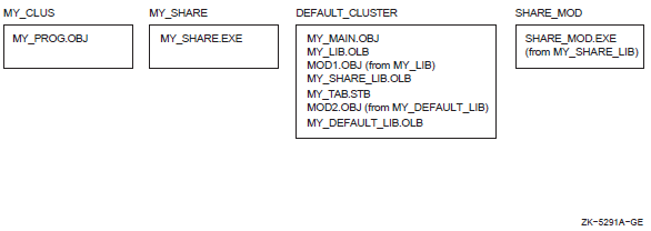
The linker processes input files in cluster order: processing each input file starting with the first file in the first cluster, then the second, and so on, until it has processed all files in the first cluster. Then it does the same for the second cluster, and the next, and so on, until it has processed all files in all clusters.
6.3.2. Controlling Cluster Creation
CLUSTER= option
COLLECT= option
6.3.2.1. Using the CLUSTER= Option to Control Clustering
The CLUSTER= option causes the linker to create a named cluster and to place in the cluster the object modules specified in the option. (The linker puts shareable images in their own clusters by default).
$ link/executable=my_main sys$input/opt
CLUSTER=mymain_clus,,,my_main
my_math/shareable/selective_search
Ctrl/Z
The Object Module Synopsis section of the image map file verifies that the linker processed the object module MY_MAIN before it processed the shareable image MY_MATH, as in the following map file excerpt:
                               +------------------------+
                               ! Object Module Synopsis !
                               +------------------------+
Module Name     Ident              Bytes      File
-----------     -----              -----      -----
MY_MAIN         V1.0                  105 MY_MAIN.OBJ;1
MY_MATH         V1.0                   12 MY_MATH.EXE;1
   .
   .
   .
6.3.2.2. Using the COLLECT= Option to Control Clustering
You can also create a named cluster by specifying the COLLECT= option. The COLLECT= option directs the linker to put specific program sections in a named cluster. The linker creates the cluster if it does not already exist. Note that the COLLECT= option manipulates program sections, not input files.
The linker sets the global (GBL) attribute of the program sections specified in a COLLECT= option to enable a global search for the definition of that program section.
6.4. Resolving Symbols Defined in the OpenVMS Executive
For VAX linking, you link against the OpenVMS executive by specifying the system symbol table (SYS$LIBRARY:SYS.STB) in the link operation. Because a symbol table file is an object module, the linker processes the symbol table file as it would any other object module.
For Alpha linking, you link against the OpenVMS executive by specifying the /SYSEXE qualifier. When this qualifier is specified, the linker selectively processes the system shareable image, SYS$BASE_IMAGE.EXE, located in the directory pointed to by the logical name ALPHA$LOADABLE_IMAGES. The linker does not process SYS$BASE_IMAGE.EXE by default.
Note that, because the linker is processing a shareable image, references to symbols in the OpenVMS executive are fixed up at image activation, not fully resolved at link time as they are for VAX linking. Also note that the linker looks for SYS$BASE_IMAGE.EXE in the directory pointed to by the logical name ALPHA$LOADABLE_IMAGES, not in the directory pointed to by the logical name SYS$LIBRARY as for VAX linking.
When the /SYSEXE qualifier is specified, the linker processes the file selectively. To disable selective processing, specify the /SYSEXE=NOSELECTIVE qualifier. For more information about using the /SYSEXE qualifier, see the description of the qualifier in Chapter 10, "LINK Command Reference".
Relation to Default Library Processing
When you specify the /SYSEXE qualifier, the linker processes the SYS$BASE_IMAGE.EXE file after processing the system shareable image library, IMAGELIB.OLB, and before processing the system object library, STARLET.OLB. (Note that the linker also processes the system service shareable image, SYS$PUBLIC_VECTORS.EXE, when it processes STARLET.OLB by default).
The /SYSSHR and /SYSLIB qualifiers, which control processing of the default system libraries, do not affect SYS$BASE_IMAGE.EXE processing. When the /NOSYSSHR qualifier is specified with the /SYSEXE qualifier, the linker does not process IMAGELIB.OLB, but still processes SYS$BASE_IMAGE.EXE and then STARLET.OLB and SYS$PUBLIC_VECTORS.EXE. When /NOSYSLIB is specified, the linker does not process IMAGELIB.OLB, STARLET.OLB, or SYS$PUBLIC_VECTORS, but still processes SYS$BASE_IMAGE.EXE.
To process SYS$BASE_IMAGE.EXE before the shareable images in IMAGELIB.OLB, specify SYS$BASE_IMAGE.EXE in a linker options file as you would any other shareable image. If you specify SYS$BASE_IMAGE.EXE in your options file, do not use the /SYSEXE qualifier.
Figure 6.4, ''Linker Processing of Default Libraries and SYS$BASE_IMAGE.EXE'' illustrates how the /SYSEXE qualifier, in combination with the /SYSSHR and /SYSLIB qualifiers, can affect linker processing. (The default syntax illustrated in the figure is rarely specified).
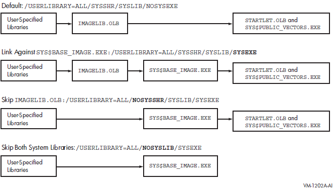
6.5. Defining Weak and Strong Global Symbols
In the dialects of MACRO, BLISS, and Pascal supported on both VAX and Alpha systems, you can define a global symbol as either strong or weak, and you can make either a strong or a weak reference to a global symbol.
In these languages, all definitions and references are strong by default. To make a weak definition or a weak reference, you must use the .WEAK assembler directive (in MACRO), the WEAK attribute (in BLISS), or the WEAK_GLOBAL or WEAK_EXTERNAL attribute (in Pascal).
The linker records each symbol definition and each symbol reference in its global symbol table, noting for each whether it is strong or weak. The linker processes weak references differently from strong references and weakly defined symbols differently from strongly defined symbols.
A strong reference can be made to a weakly defined symbol or to a strongly defined symbol.
For a strong reference, the linker checks all explicitly specified input modules and libraries and all default libraries for a definition of the symbol. In addition, if the linker cannot locate the definition needed to resolve the strong reference, it reports the undefined symbol and assigns the symbol a value, which usually results in a run-time error for accessing the data or calling the routine.
The linker will not search library modules that have been specified with the /LIBRARY qualifier or default libraries (user-defined or system) solely to resolve a weak reference. If, however, the linker resolves a strong reference to another symbol in such a module, it will also use that module to resolve any weak references.
If the linker cannot locate the definition needed to resolve a weak reference, it assigns the symbol a value of 0, but does not report an error (as it does if the reference is strong). If, however, the linker reports any unresolved strong references, it will also report any unresolved weak references.
One purpose of making a weak reference arises from the need to write and test incomplete programs. The resolution of all symbolic references is crucial to a successful linking operation. Therefore, a problem arises when the definition of a referenced global symbol does not yet exist (as would be the case, for example, if the global symbol definition is an entry point to a module that is not yet written). The solution is to make the reference to the symbol weak, which informs the linker that the resolution of this particular global symbol is not crucial to the link operation.
By default, all global symbols in all VAX and Alpha languages have a strong definition.
A strongly defined symbol in a library module is included in the library symbol table; a weakly defined symbol in a library module is not. As a result,if the module containing the weak symbol definition is in a library but has not been specified for inclusion by means of the /INCLUDE qualifier, the linker will not be able to resolve references (strong or weak) to the symbol. If, however, the linker has selected that library module for inclusion (in order to resolve a strong reference), it will be able to resolve references (strong or weak) to the weakly defined symbol.
If the module containing the weak symbol definition is explicitly specified either as an input object file or for extraction from a library (by means of the /INCLUDE qualifier), the weak symbol definition is as available for symbol resolution as a strong symbol definition.
Chapter 7. Understanding Image File Creation (Alpha and VAX)
This chapter describes how the linker creates an image on OpenVMS Alpha and OpenVMS VAX systems. The linker creates images from the input files you specify in a link operation. You can control image file creation by using linker qualifiers and options.
7.1. Overview of Creating Images on Alpha/VAX Systems
After the linker has resolved all symbolic references between the input files specified in the LINK command (described in Chapter 6, "Understanding Symbol Resolution (Alpha and VAX)"), the linker knows all the object modules and shareable images that are required to create the image. For example, the linker has extracted from libraries specified in the LINK command those modules that contain the definitions of symbols required to resolve symbolic references in other modules. The linker must now combine all these modules into an image.
Determine the memory requirements of the image. The memory requirements of an image are the sum of the memory requirements of each object module included in the link operation. The language processors that create the object modules specify the memory requirements of an object module as program section definitions. A program section represents an area of memory that has a name, a length, and other characteristics, called attributes, which describe the intended or permitted usage of that portion of memory. Section 7.2, ''Creating Program Sections (Alpha/VAX)'' describes program sections.
The linker processes the program section definitions in each object module,combining program sections with similar attributes into an image section. Each image section specifies the size and attributes of a portion of the virtual memory of an image. The image activator uses the image section attributes to determine the characteristics of the physical memory pages into which it loads the image, such as protection.
Figure 7.1, ''Communication of Image Memory Requirements on Alpha/VAX'' illustrates how memory requirements are communicated from the language processor to the linker and from the linker to the image activator. Section 7.3, ''Creating Image Sections'' provides more information about this process.
Figure 7.1. Communication of Image Memory Requirements on Alpha/VAX 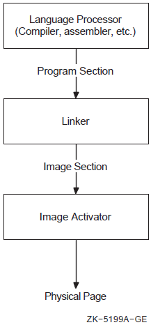
Note that shareable images included in link operations have already been processed by the linker. These images are separate images with their own memory requirements, as specified by their own image sections. The linker does, however, create special global image section descriptors (GISDs) for each shareable image to which an image has been linked. The image activator activates these shareable images at run-time.
Initialize the image. When image sections are first created, they are empty. In this step of linker processing, the linker fills the image sections with the machine code and data, as specified by the Text Information and Relocation (TIR) commands in the object module. Section 7.4, ''Initializing an Image on Alpha/VAX Systems'' provides more information about this process.
For Alpha linking, the linker also attempts to optimize the performance of an image by replacing Jump to Subroutine (JSR) instruction sequences with the more efficient Branch to Subroutine (BSR) instruction sequences.
After creating image sections and filling them with binary code and data, the linker writes the image to an image file. Section 7.4.1, ''Writing the Binary Contents of Image Sections'' describes this process. To keep the size of image files manageable, the linker does not allocate space in the image file for image sections that have not been initialized with any data unless this function has been disabled (that is, the linker does not write pages of zeros to the image file). The linker can create demand-zero image sections, which the operating system initializes at run-time when a reference to the image section requires the operating system to move the pages into memory. Section 7.4.3, ''Keeping the Size of Image Files Manageable'' describes how the linker creates demand-zero image sections.
7.2. Creating Program Sections (Alpha/VAX)
Language processors create program sections and define their attributes. The number of program sections created by a language processor and the attributes of these program sections are dependent upon language semantics. For example, some programming languages implement global variables as separate program sections with a particular set of attributes. Programmers working in high-level languages typically have little direct control over the program sections created by the language processor. Medium- and low-level languages provide programmers with more control over program section creation. For more information about the program section creation features of a particular programming language, please refer to the appropriate OpenVMS programming language documentation.
In general, the linker does not create program sections. However, for Alpha linking, the linker creates a special program section for a shareable image, named $SYMVECT, which contains the symbol vector of the shareable image.
Program Section Attributes
The language processors define the attributes of the program sections they create and communicate these attributes to the linker in program section definition records in the global symbol directory (GSD) in an object module. (The GSD also contains global symbol definitions and references, as described in Chapter 6, "Understanding Symbol Resolution (Alpha and VAX)").
Access. Using program section attributes, compilers can prohibit some types of access, such as write access. Using other program section attributes, compilers can allow access to the program section by more than one process.
Positioning. By specifying certain program section attributes, compilers can specify to the linker how it should position the program section in memory.
Program section attributes are Boolean values, that is, they are either on or off. Table 7.1, ''Program Section Attributes (Alpha/VAX)'' lists all program section attributes with the keyword you can use to set or clear the attribute, using the PSECT_ATTR=option. For more information about using the PSECT_ATTR= option, see Section 7.3.6, ''Controlling Image Section Creation''.
| Attribute | Keyword | Description | ||
|---|---|---|---|---|
|
Alignment |
— |
Specifies the alignment of the program section as an integer that represents the power of 2 required to generate the desired alignment. For certain alignments, the linker supports keywords to express the alignment. The following table lists all the alignments supported by the linker with their keywords: | ||
| Power of 2 | Keyword | Meaning | ||
| 0 | BYTE | Alignment on byte boundaries. | ||
| 1 | WORD | Alignment on word boundaries. | ||
| 2 | LONG | Alignment on longword boundaries. | ||
| 3 | QUAD | Alignment on quadword boundaries. | ||
| 4 | OCTA | Alignment on octaword boundaries. | ||
| 9 | — | Alignment on 512-byte boundaries. | ||
| 13 | — | Alignment on 8 KB boundaries. | ||
| 14 | — | Alignment on 16 KB boundaries. | ||
| 15 | — | Alignment on 32 KB boundaries. | ||
| 16 | — | Alignment on 64 KB boundaries. | ||
| — | PAGE | Alignment on the default target page size, which is 64 KB for Alpha linking and 512 bytes for VAX linking. You can override this default by specifying the /BPAGE qualifier. | ||
|
Position Independence |
PIC/NOPIC |
Specifies that the program section can run anywhere in virtual address space. Applicable in shareable images only. Note that this attribute is not meaningful for Alpha images, but it is still used to sort program sections. | ||
|
Overlaid/Concatenated |
OVR/CON |
When set to OVR, specifies that the linker may combine (overlay) this program section with other program sections with the same name and attribute settings. Program sections that are overlaid are assigned the same base address. When set to CON, the linker concatenates the program sections. | ||
|
Relocatable/Absolute |
REL/ABS |
When set to REL, specifies that the linker can place the program section anywhere in virtual memory, according to the memory allocation strategy for the type of image being produced. When set to ABS, this attribute specifies that the program section is an absolute program section that contains no binary data or code and appears to be based at virtual address 0. Absolute program sections are used by compilers primarily to define constants. | ||
|
Global/Local |
GBL/LCL |
When set to GBL, specifies that the linker should gather contributions to the program section from all clusters and place them in the same image section. When set to LCL, the linker gathers program sections into the same image section only if they are in the same cluster. The memory for a global program section is allocated in the cluster that contains the first contributing module. | ||
|
Shareability |
SHR/NOSHR |
Specifies that the program section can be shared between several processes. Only used to sort program sections in shareable images. | ||
|
Executability |
EXE/NOEXE |
Specifies that the program section contains executable code. If an image transfer address is defined in a nonexecutable program section, the linker issues a diagnostic message. | ||
|
?For Alpha linking, the EXE attribute is propagated to the image section descriptor where it is used by the Install utility when it is installing the image as a resident image. For information about resident images, see the description of the /SECTION_BINDING qualifier in Chapter 10, "LINK Command Reference". | ||||
|
Writability |
WRT/NOWRT |
Specifies that the contents of a program section can be modified at run-time. | ||
|
Protected Vectors |
VEC/NOVEC |
Specifies that the program section contains privileged change-mode vectors or message vectors. In shareable images, image sections with the VEC attribute are automatically protected. | ||
|
Solitary |
SOLITARY |
Specifies that the linker should place this program section in its own image section. Useful for programs that map data into specific locations in their virtual memory space. Note that compilers do not set this attribute. You can set this attribute using the PSECT_ATTR=option. | ||
|
Unmodified? |
NOMOD/MOD |
When set, specifies that the program section has not been initialized (NOMOD). On Alpha systems, the linker uses this attribute to create demand zero sections; see Section 7.4.3, ''Keeping the Size of Image Files Manageable''. Only compilers can set this attribute. You can clear this attribute only by specifying the MOD keyword in the PSECT_ATTR= option. | ||
|
COM? |
— |
Used by the VSI C compiler to implement the relaxed symbol reference/definition model for external variables. See the C documentation for more information. This attribute cannot be modified using the PSECT_ATTR= option. | ||
|
Readability |
RD |
Reserved to OpenVMS. | ||
|
User/Library |
USR/LIB |
Reserved to OpenVMS. To ensure future compatibility, this attribute should be clear. | ||
extern int global_data;
int myadd();
int mysub();
main()
{
   int num1, num2, res1, res2;
   static int my_data;
   num1 = 5;
   num2 = 6;
   res1 = myadd( num1, num2 );
   res2 = mysub( num1, num2 );
   printf("res1 = %d, res2 =%d, globaldata=%d\n",
                   res1,res2,global_data);
}#include <stdio.h>
myadd(value_1,value_2)
int value_1;
int value_2;
{
int result;
static int add_data;
printf("In MYADD.C\n");
result = value_1 + value_2;
return( result );
}int global_data = 5;
mysub(value_1,value_2)
int value_1;
int value_2;
{
int result;
static int sub_data;
result = value_1 - value_2;
return( result );
}To see what program sections the VAX C compiler creates for these programs, use the ANALYZE/OBJECT utility to examine the global symbol directory (GSD) in each object module. (Note that the names the language processors assign to program sections are architecture specific).
4. GLOBAL SYMBOL DIRECTORY (OBJ$C_GSD), 138 bytes . . . 6) Program Section Definition (GSD$C_PSC)
Note that you can also determine the program sections in an object module after a link operation by looking at the Program Section Synopsis section of an image map file, as illustrated in Example 7.7, ''Program Section Information in a Map File (VAX Example)''.
| Alignment specifies the address boundary at which the linker places a module's contribution to the program section. |
| Attribute flags indicate which program section attributes are set. The attributes are listed by their full symbolic name, that is, each abbreviation is preceded by the character string "GPS$V_". Note that, for attributes that are turned off by specifying different keywords, only the keyword that sets the attribute is listed. For example, you can see whether the program section is overlaid by checking attribute flag number 2. If the value is 1, the program section is overlaid; if the value is 0, the program section must be concatenated. Table 7.1, ''Program Section Attributes (Alpha/VAX)'' lists all the program section attributes. Note that the solitary attribute is not included in the GSD of an object module because that attribute is not set by language processors. For Alpha linking, the program section display includes several additional attribute flags. The COM attribute is reserved to OpenVMS. The NOMOD attribute indicates that the program section does not contain initialized data. The linker gathers program sections with this attribute into demand-zero image sections. Section 7.4.3, ''Keeping the Size of Image Files Manageable'' describes how the linker creates demand-zero image sections. |
| Allocation indicates the number of bytes required for the program section. |
| Symbol indicates the name of the program section. |
Figure 7.2, ''Program Sections Created for Examples 7.1, 7.2, and 7.3'' illustrates the program sections created by the VAX C compiler for the programs in Examples 7.1, 7.2, and 7.3. (The shaded areas represent the settings of the program section attributes the linker considers when sorting the program sections into image sections in an executable image. See Section 7.3.3, ''Processing Significant Program Section Attributes (Alpha/VAX)'' for more information about how the linker creates image sections).
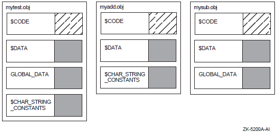
7.3. Creating Image Sections
To create the image sections that define the memory requirements and page protection characteristics of an image, the linker processes the program section definitions in the object modules specified in the link operation. The number and type of image sections the linker creates depend on the number of clusters the linker creates when processing the LINK command and on the attributes of the program sections in the object modules in each cluster. Section 7.3.1, ''Processing Clusters to Create Image Sections'' describes how the clustering of input files affects image section creation. Section 7.3.2, ''Combining Program Sections into Image Sections'' describes the effects of program section attributes on image section creation.
7.3.1. Processing Clusters to Create Image Sections
To create image sections, the linker processes the program section definitions in the input files you specify in the LINK command. The linker processes these input files on a cluster-by-cluster basis (as described in Section 6.3.1, ''Understanding Cluster Creation'').
In general, only program sections in a particular cluster can contribute to a particular image section. However, the linker crosses cluster boundaries when processing program sections with the global (GBL) attribute. When the linker encounters a program section with the global attribute, it searches all the previously processed clusters for a program section with the same name and attributes and, if it finds one, places the new definition of the global program section in the same cluster as the first definition of the program section.
The linker processes input files in the order in which they appear in the clusters, making two passes through the cluster list.
On its first pass, the linker processes based clusters. Based clusters specify the location within memory at which the linker must position them. A based cluster can be a cluster that contains a based shareable image or a cluster, created by the CLUSTER= option, in which a base address was specified.
For VAX linking, you can also use the BASE= option to specify the base address of the default cluster.
For more information about creating based clusters, see the descriptions of the CLUSTER= and BASE= options in Chapter 10, "LINK Command Reference".
After processing based clusters, the linker then processes non based clusters. The linker ignores non based (position-independent) shareable image clusters because they are allocated virtual memory at run-time.
$ LINK/MAP/FULL MYTEST, MYADD, SYS$INPUT/OPT
CLUSTER=MYSUB_CLUS,,,MYSUB
SYS$LIBRARY:VAXCRTL/SHARE
Ctrl/Z
MYSUB.OBJ. The linker also
creates a cluster for the C Run-Time Library shareable image
VAXCRTL.EXE. The linker puts the object modules MYTEST.OBJ and
MYADD.OBJ in the default cluster. These clusters appear on the
linker's cluster list in the following order:MYSUB_CLUS
VAXCRTL
DEFAULT_CLUSTER
The linker always processes the default cluster last. (For Alpha linking, you do not need to explicitly include the C Run-Time Library shareable image in the link operation because it resides in the default system shareable image library IMAGELIB.OLB, which the linker processes by default).
7.3.2. Combining Program Sections into Image Sections
The linker creates image sections by grouping together program sections with similar attributes. Within an image section, the linker organizes program sections alphabetically by name. If more than one object module contributes to the same program section, the linker lays out their contributions in the order it processes them.
Figure 7.3, ''Combining Program Sections into Image Sections'' shows how the linker groups the program sections in the object modules from the sample link into image sections, based on the setting of their significant attributes. In the figure, the settings of these significant attributes are represented by shading. (The figure considers attributes that are significant when creating executable images, not shareable images. Section 7.3.3, ''Processing Significant Program Section Attributes (Alpha/VAX)'' provides more information about which program section attributes are significant).
Note, in the figure, that the overlaid contributions from MYSUB.OBJ and
MYTEST.OBJ to the program section, GLOBAL_DATA, both appear in the
MYSUB_CLUS cluster, even though the object module MYTEST.OBJ is in the default cluster. The
linker puts all contributions to a global program section in the cluster in which it is
first defined.
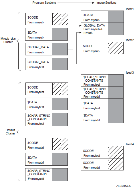
7.3.3. Processing Significant Program Section Attributes (Alpha/VAX)
Writability (WRT/NOWRT)
Executability (EXE/NOEXE)
Protected vector (VEC/NOVEC)
Unmodified (NOMOD/MOD) (Alpha linking only)
Writability (WRT/NOWRT)
Executability (EXE/NOEXE)
Shareability (SHR/NOSHR)
Position independence (PIC/NOPIC)
Protected vector (VEC/NOVEC)
Unmodified (NOMOD/MOD) (Alpha linking only)
The linker creates only one large image section for system images, so combining program sections by attributes is not applicable.
Tables 7.2 and 7.3 list all the possible combinations of program section attributes for executable images and shareable images. Note that the order in which the combinations appear in the table (each row) is the same order in which the linker processes them. For example,the linker first processes all program sections with the NOWRT, NOEXE, and NOVEC attributes, creating an image section of program sections with these attributes. The linker then processes all program sections with the WRT, NOEXE, and NOVEC attributes, creating an image section for these program sections. The linker continues this processing until all the combinations of significant attributes have been processed and all the program sections in the cluster have been placed in an image section.
The tables include only program sections that are relocatable (with the REL attribute). Absolute program sections (with the ABS attribute), by definition, can have no allocation (they contain only constants) and cannot contribute to an image section.
For OpenVMS Alpha images, the tables assume that the images are linked using the /DEMAND_ZERO qualifier, which is the default. (When this qualifier is specified, the linker groups program sections that do not contain any data into demand-zero image sections, allocating memory for the image section but not writing zeros to disk). If the image is linked with the /NODEMAND_ZERO qualifier, the linker allocates space for the image section in the image file. Note that the /NODEMAND_ZERO qualifier does not affect how the linker sorts program sections; it proceeds exactly as specified by the table. However, when the image is written, the linker allocates disk space for the image section and fills the space with zeros.
|
Significant Psect Attribute Settings? |
Type of Isect |
Isect Attributes Set? | |||
|---|---|---|---|---|---|
|
NOWRT |
NOEXE |
NOVEC |
?MOD |
NORMAL |
— |
|
WRT |
NOEXE |
NOVEC |
?MOD |
" |
WRT, CRF |
|
NOWRT |
EXE |
NOVEC |
?MOD |
" |
?EXE |
|
WRT |
EXE |
NOVEC |
?MOD |
" |
WRT, CRF, ?EXE |
|
NOWRT |
NOEXE |
VEC |
?MOD |
" |
VECTOR, PROTECT |
|
WRT |
NOEXE |
VEC |
?MOD |
" |
WRT, VECTOR, PROTECT, CRF |
|
NOWRT |
EXE |
VEC |
?MOD |
" |
VECTOR, PROTECT, ?EXE |
|
WRT |
EXE |
VEC |
?MOD |
" |
WRT, VECTOR, PROTECT, ?EXE |
|
?NOWRT |
?NOEXE |
?NOVEC |
?NOMOD |
" |
DZRO |
|
?WRT |
?NOEXE |
?NOVEC |
?NOMOD |
" |
WRT, DZRO? |
|
Significant Psect Attribute Settings? |
Type of Isect |
Isect Attributes Set? | |||||
|---|---|---|---|---|---|---|---|
|
NOWRT |
NOEXE |
SHR |
NOPIC |
NOVEC |
?MOD |
SHRFXD |
— |
|
WRT |
NOEXE |
SHR |
NOPIC |
NOVEC |
?MOD |
" |
WRT |
|
NOWRT |
EXE |
SHR |
NOPIC |
NOVEC |
?MOD |
" |
?EXE |
|
WRT |
EXE |
SHR |
NOPIC |
NOVEC |
?MOD |
" |
WRT, ?EXE |
|
NOWRT |
NOEXE |
NOSHR |
NOPIC |
NOVEC |
?MOD |
PRVFXD |
— |
|
WRT |
NOEXE |
NOSHR |
NOPIC |
NOVEC |
?MOD |
" |
WRT, CRF |
|
NOWRT |
EXE |
NOSHR |
NOPIC |
NOVEC |
?MOD |
" |
?EXE |
|
WRT |
EXE |
NOSHR |
NOPIC |
NOVEC |
?MOD |
" |
WRT, CRF, ?EXE |
|
NOWRT |
NOEXE |
SHR |
PIC |
NOVEC |
?MOD |
SHRPIC |
PIC |
|
WRT |
NOEXE |
SHR |
PIC |
NOVEC |
?MOD |
" |
WRT, PIC |
|
NOWRT |
EXE |
SHR |
PIC |
NOVEC |
?MOD |
" |
PIC, ?EXE |
|
WRT |
EXE |
SHR |
PIC |
NOVEC |
?MOD |
" |
WRT, PIC, ?EXE |
|
NOWRT |
NOEXE |
NOSHR |
PIC |
NOVEC |
?MOD |
PRVPIC |
PIC |
|
WRT |
NOEXE |
NOSHR |
PIC |
NOVEC |
?MOD |
" |
WRT, CRF, PIC |
|
NOWRT |
EXE |
NOSHR |
PIC |
NOVEC |
?MOD |
" |
PIC, ?EXE |
|
WRT |
EXE |
NOSHR |
PIC |
NOVEC |
?MOD |
" |
WRT, CRF, PIC, ?EXE |
|
NOWRT |
NOEXE |
SHR |
NOPIC |
VEC |
?MOD |
SHRFXD |
VECTOR, PROTECT |
|
WRT |
NOEXE |
SHR |
NOPIC |
VEC |
?MOD |
" |
WRT, VECTOR, PROTECT |
|
NOWRT |
EXE |
SHR |
NOPIC |
VEC |
?MOD |
" |
VECTOR, PROTECT, ?EXE |
|
WRT |
EXE |
SHR |
NOPIC |
VEC |
?MOD |
" |
WRT, VECTOR, PROTECT, ?EXE |
|
NOWRT |
NOEXE |
NOSHR |
NOPIC |
VEC |
?MOD |
PRVFXD |
VECTOR, PROTECT |
|
WRT |
NOEXE |
NOSHR |
NOPIC |
VEC |
?MOD |
" |
WRT, CRF |
|
NOWRT |
EXE |
NOSHR |
NOPIC |
VEC |
?MOD |
" |
VECTOR, PROTECT, ?EXE |
|
WRT |
EXE |
NOSHR |
NOPIC |
VEC |
?MOD |
" |
WRT, CRF, VECTOR, PROTECT, ?EXE |
|
NOWRT |
NOEXE |
SHR |
PIC |
VEC |
?MOD |
SHRPIC |
PIC, VECTOR, PROTECT |
|
WRT |
NOEXE |
SHR |
PIC |
VEC |
?MOD |
" |
WRT, PIC, VECTOR, PROTECT |
|
NOWRT |
EXE |
SHR |
PIC |
VEC |
?MOD |
" |
PIC, VECTOR, PROTECT, ?EXE |
|
WRT |
EXE |
SHR |
PIC |
VEC |
?MOD |
" |
WRT, PIC, VECTOR, PROTECT, ?EXE |
|
NOWRT |
NOEXE |
NOSHR |
PIC |
VEC |
?MOD |
PRVPIC |
PIC, VECTOR, PROTECT |
|
WRT |
NOEXE |
NOSHR |
PIC |
VEC |
?MOD |
" |
WRT, CRF, PIC, VECTOR, PROTECT |
|
NOWRT |
EXE |
NOSHR |
PIC |
VEC |
?MOD |
" |
PIC, VECTOR, PROTECT, ?EXE |
|
WRT |
EXE |
NOSHR |
PIC |
VEC |
?MOD |
" |
WRT, CRF, PIC, VECTOR, PROTECT, ?EXE |
|
?NOWRT |
?NOEXE |
?SHR |
?NOPIC |
?NOVEC |
?NOMOD |
SHRFXD |
— |
|
?WRT |
?NOEXE |
?SHR |
?NOPIC |
?NOVEC |
?NOMOD |
" |
WRT |
|
?NOWRT |
?NOEXE |
?NOSHR |
?NOPIC |
?NOVEC |
?NOMOD |
PRVFXD |
DZRO |
|
?WRT |
?NOEXE |
?NOSHR |
?NOPIC |
?NOVEC |
?NOMOD |
" |
WRT, DZRO? |
|
?NOWRT |
?NOEXE |
?NOSHR |
?PIC |
?NOVEC |
?NOMOD |
PRVPIC |
DZRO |
|
?WRT |
?NOEXE |
?NOSHR |
?PIC |
?NOVEC |
?NOMOD |
" |
WRT, DZRO?, PIC |
|
?NOWRT |
?NOEXE |
?SHR |
?PIC |
?NOVEC |
?NOMOD |
SHRPIC |
PIC |
|
?WRT |
?NOEXE |
?SHR |
?PIC |
?NOVEC |
?NOMOD |
" |
WRT, PIC |
|
Writability |
Executability |
Protected Vector | |
|---|---|---|---|
|
$CODE |
NOWRT |
EXE |
NOVEC |
|
DATA |
WRT |
NOEXE |
NOVEC |
|
$CHAR_STRING_CONSTANTS |
WRT |
NOEXE |
NOVEC |
The linker puts both the DATA and $CHAR_STRING_CONSTANTS program sections in the same image section because they both have the same settings of significant attributes. Within the image section, the linker organizes the program sections alphabetically, so the $CHAR_STRING_CONSTANTS program section appears before the DATA program section. The linker creates a separate image section for the $CODE program section.
                                             +------------------------+
                                             ! Image Section Synopsis !
                                             +------------------------+
   Cluster      Type Pages   Base Addr  Disk VBN PFC Protection and Paging
   -------      ---- -----   ---------  -------- --- ---------------------
MYSUB_CLUS         0     1    00000200        2   0  READ WRITE   COPY ON REF
                   0     1    00000400        3   0  READ ONLY
VAXCRTL            3     4    00000000-R      0   0  READ ONLY
                   3     1    00000800-R      0   0  READ ONLY
                   4     1    00000A00-R      0   0  READ WRITE   COPY ON REF
                   3    17    00000C00-R      0   0  READ ONLY
                   3   142    00002E00-R      0   0  READ ONLY
                   4    21    00014A00-R      0   0  READ WRITE   COPY ON REF
                   4     1  P-00017400-R      0   0  READ WRITE   COPY ON REF
                   2     3    00017600-R      0   0  READ WRITE   FIXUP VECTORS
LIBRTL             3   193    00000000-R      0   0  READ ONLY
                   4     8    00018200-R      0   0  READ WRITE   DEMAND ZERO
MTHRTL             3   335    00000000-R      0   0  READ ONLY
                   2     1    00029E00-R      0   0  READ WRITE   FIXUP VECTORS
DEFAULT_CLUSTER    0     1    00000600        4   0  READ WRITE   COPY ON REF
                   0     1    00000800        5   0  READ ONLY
                   0     1    00000A00        6   0  READ WRITE   FIXUP VECTORS
                 253    20    7FFFD800        0   0  READ WRITE   DEMAND ZERO
For more information about the image section synopsis section of a map file, see Section 9.2.3, ''Image Section Synopsis Section (Alpha/VAX)''.
                                        +--------------------------+
                                        ! Program Section Synopsis !
                                        +--------------------------+
Psect Name Module Name   Base     End      Length        Align      Attributes
---------- -----------   ----     ---      ------        -----      ----------
$DATA                  00000200 00000203 00000004 (  4.) LONG 2 PIC,USR,CON ...
           MYSUB       00000200 00000203 00000004 (  4.) LONG 2
GLOBAL_DATA            00000204 00000207 00000004 (  4.) LONG 2 PIC,USR,OVR ...
           MYSUB       00000204 00000207 00000004 (  4.) LONG 2
           MYTEST      00000204 00000207 00000004 (  4.) LONG 2
$CODE                  00000400 0000040B 0000000C ( 12.) LONG 2 PIC,USR,CON ...
           MYSUB       00000400 0000040B 0000000C ( 12.) LONG 2
$CHAR_STRING_CONSTANTS 00000600 0000062D 0000002E ( 46.) LONG 2 PIC,USR,CON ...
           MYTEST      00000600 00000623 00000024 ( 36.) LONG 2
           MYADD       00000624 0000062D 0000000A ( 10.) LONG 2
$DATA                  00000630 00000637 00000008 (  8.) LONG 2 PIC,USR,CON ...
           MYTEST      00000630 00000633 00000004 (  4.) LONG 2
           MYADD       00000634 00000637 00000004 (  4.) LONG 2
$CODE                  00000800 00000858 00000059 ( 89.) LONG 2 PIC,USR,CON ...
           MYTEST      00000800 0000083E 0000003F ( 63.) LONG 2
           MYADD       00000840 00000858 00000019 ( 25.) LONG 2
   .
   .
   .
For more information about the program synopsis section of a map file, see Section 9.2.4, ''Program Section Synopsis Section (Alpha/VAX)''.
7.3.4. Allocating Memory for Image Sections
When it creates an image section, the linker allocates enough memory for the image section to accommodate all the program sections it contains. Each program section definition includes its size.
The linker aligns image sections on CPU-specific page boundaries. Within an image section, the linker assigns to each program section a virtual address relative to the base address of the image section.
Concatenated Program Sections
If the program sections have the concatenated (CON) attribute set, the linker positions the program sections one after the other within an image section, inserting padding bytes between the program sections if necessary to achieve the alignment requirement of a particular contribution to a program section. The linker retains the alignment specified for each program section contribution but uses the largest alignment of a contributing module as the alignment of the whole program section.
Overlaid Program Sections
If the program sections have the overlaid (OVR) attribute set, the linker uses the same start address for the program sections so that they occupy the same virtual memory (that is, the program sections overlay each other). For overlaid program sections, the linker allocates enough space to accommodate the largest of all the program section contributions. Note that the linker does not generate a warning message if the contributions specify different size allocations.
Any module can initialize the contents of an overlaid program section. However, the final contents of the program section are determined by the last contributing module. Therefore, the order in which you specify the input modules is important.
Assigning Virtual Addresses
The linker keeps track of free (available) virtual addresses by maintaining a free virtual memory list. For each cluster, the linker determines the number of pages required, searches the list beginning at the lowest virtual address for a contiguous number of pages large enough to contain the cluster, allocates those addresses to the cluster, then removes those addresses from the list.
The linker allocates virtual memory to the first cluster beginning at a page size boundary for executable images in the P0 region of the user's virtual address space, unless the cluster is based, in which case it allocates virtual memory beginning at the specified address. For VAX linking,the default is 512 (200 hexadecimal). However, you can specify the page size using the /BPAGE qualifier. For information about the /BPAGE qualifier, see Chapter 10, "LINK Command Reference".
On its first pass through the cluster list, the linker allocates virtual addresses to any based user clusters or based shareable image clusters on the cluster list, removing the allocated addresses from the free virtual memory list as it proceeds. On its second pass, it repeats this procedure for non based user clusters. (Remember that non based shareable image clusters will have memory allocated for them at run-time).
Because the linker processes clusters in the order of their appearance on the cluster list, the virtual address space of the final image will generally contain contiguous image sections of consecutive clusters on the basis of their order in the cluster list. The presence of based clusters, however,may prevent such an outcome, and for this reason they are not recommended.
Relocating each image section. The linker adds the starting virtual address of the cluster to the relative offset of the image section from the cluster base and places the result in the appropriate field of the image section descriptor (ISD).
Relocating each program section in the image section. The linker adds the newly calculated starting virtual address of the image section to the relative offset of the program section from the base of the image section.
Relocating each global symbol in the program section. The linker adds the newly calculated program section virtual address to the relative offset of the global symbols from the base of the program section.
7.3.5. Image Section Attributes
When it creates image sections, the linker assigns attributes to the image section based on the attributes of the program sections it contains. The image section attributes describe certain characteristics of the portion of memory they represent, for example, the protection characteristics. For example, an image section that contains program sections with the writability attribute also has the writability attribute set. Tables 7.2 and 7.3 include the image section attributes associated with an image section that contains program sections with a particular set of attributes. Table 7.5, ''Image Section Attributes'' lists all the image section attributes. Image section attributes, like program section attributes, are Boolean values that are either on or off.
| Attribute | Symbol | Function |
|---|---|---|
Global | [E]ISD$M_GBL | GBL is set when the ISD came from a shareable image. On both VAX and Alpha systems, the first ISD of a shareable image is included in the base image for use by the image activator. For VAX linking, if the shareable image is based, all of its ISDs are included in the image being linked. |
Copy On Reference | [E]ISD$M_CRF | CRF is set whenever the psect attributes are WRT and not SHR. CRF is also set by the linker whenever it creates fix-ups to the section (which require the image activator to write to it). |
Demand Zero | [E]ISD$M_DZRO | Demand zero is set for VAX linking for executable images if:
Demand zero is set for Alpha executable and Alpha shareable images if the user has not
specified /NODEMAND_ZERO and
if:
DZRO is always set for stack ISDs on both Alpha images and VAX images. |
Executability | [E]ISD$M_EXE | The EXE attribute is inherited from the program section. |
Write | [E]ISD$M_WRT | The WRT attribute is inherited from the program section. WRT is also set by the linker if fix-ups are made to the section. When this is done, the linker also generates a change protection fix-up so that the image activator can change the protection back to NOWRT after the fix-up is applied. |
Match Control | ISD$M_MATCHCTL | This is used only for VAX images. It is not an attribute. MATCHCTL is a 3-bit field inside the flags field. It contains the match control bits. For Alpha images, this information is contained in a completely separate field. |
Last Cluster | [E]ISD$M_LASTCLU | LASTCLU is set only for sections in executable images. LASTCLU indicates that an image section was generated off of the last cluster (which was not a shareable image cluster) in the cluster list. If FIXUPVEC is set, LASTCLU is clear. |
Initial Code | [E]ISD$M_INITALCODE | This attribute is reserved to OpenVMS. |
Based | [E]ISD$M_BASED | BASED indicates that the section is based. This is set when BASE= is specified in the options file. This attribute may also be set if based shareable images are encountered during linking. This attribute is present but not used for Alpha linking. |
Fix-Up Vectors | [E]ISD$M_FIXUPVEC | FIXUPVEC marks the section that contains the image activator fix-ups. This section is created by the linker. The attribute cannot be set by the user. |
Resident | [E]ISD$M_RESIDENT | This attribute is reserved to OpenVMS. |
Vectored | [E]ISD$M_VECTOR | VECTOR indicates a vectored section,either a message section or a privileged library vector. |
Protected | [E]ISD$M_PROTECT | Protect indicates that a section is protected. The linker sets the PROTECT attribute whenever VECTOR is set. PROTECT is also set if the /PROTECT qualifier is used, or if the cluster that the section is spawned from came after a PROTECT=YES option (and before a PROTECT=NO option). |
The linker uses type designations instead of image section attributes to propagate the SHR and PIC program section attributes. The linker assigns the type designation [E]ISD$K_NORMAL for image sections in executable images. Image sections in shareable images can be any of the following types:
Image Section Type | Attribute Settings |
|---|---|
Share fixed ([E]ISD$K_SHRFXD) | SHR, NOPIC |
Private fixed ([E]ISD$K_PRVFXD) | NOSHR, NOPIC |
Share position-independent ([E]ISD$K_SHRPIC) | SHR, PIC |
Private position-independent ([E]ISD$K_PRVPIC) | NOSHR, PIC |
Image Section Descriptors (ISD) 1)
| The size of the image section descriptor. |
| The size of the image section, expressed in pages. For Alpha images, the value is expressed in bytes. |
| The start address assigned to the image section by the linker. Note that this address is an offset from the beginning of the image, which is assumed to start at virtual address zero. (The linker always inserts an empty page at the beginning of every executable image). Note also that the linker does not assign a start address for image sections representing shareable images because this information cannot be determined until run-time, when the shareable image is loaded into memory by the image activator. |
| The number of pagelets that should be mapped in when the initial page fault occurs. You can set this value by using the CLUSTER= option. |
| The settings of image section attributes. Table 7.5, ''Image Section Attributes'' lists these attributes. |
| The type of image section, based on the combination of image section attributes. |
| The virtual block in the image file at which the image section begins. |
| Image sections that represent shareable images include the global section identification number, which specifies the identification number of the shareable image. |
| Image sections that represent shareable images also include a match control field that identifies the match control algorithm the image activator should apply to the global image section identification number when it activates the shareable image this ISD describes. |
| Image sections that represent shareable images include the global section name field, which is the name of the shareable image. The "_001"" is appended to the name by the linker to indicate which ISD in the image this represents. |
7.3.6. Controlling Image Section Creation
By modifying the attributes of program sections
By putting object modules into named clusters
By using the SOLITARY attribute
7.3.6.1. Modifying Program Section Attributes
The linker combines program sections in the same cluster into the same image section if they have the same settings for the significant program section attributes. To force the linker to put the program sections into different image sections, change the attributes of one of the program sections by using the PSECT_ATTR= option.
$ LINK/MAP/FULL MYTEST,MYADD,SYS$INPUT/OPT
CLUSTER=MYSUB_CLUS,,,MYSUB
PSECT_ATTR=$CHAR_STRING_CONSTANTS,NOWRT
SYS$LIBRARY:VAXCRTL/SHARE
Ctrl/Z
   Cluster    Type Pages Base Addr Disk VBN PFC Protection and Paging ...
   -------    ---- ----- --------- -------- --- ---------------------
                .
                .
                .
DEFAULT_CLUSTER 0    1    00000600      4    0  READ ONLY
                0    1    00000800      0    0  READ WRITE   DEMAND ZERO
                0    1    00000A00      5    0  READ ONLY
                0    1    00000C00      6    0  READ WRITE   FIXUP VECTORS
              253   20    7FFFD800      0    0  READ WRITE   DEMAND ZERO
                .
                .
                .
Note that the default cluster contains one additional image section, a read-only image section beginning at virtual address 0x00000600, than the default cluster in the original link, illustrated in Section 7.3.1, ''Processing Clusters to Create Image Sections''.
7.3.6.2. Manipulating Cluster Creation
In general, the linker creates image sections on a per-cluster basis; that is,only program sections within a particular cluster can contribute to image section creation. (The linker can collect program sections with the global attribute from all clusters into a single image section). To ensure that a program section appears in a particular image section, put the program section in a specific cluster.
$ LINK/MAP/FULL MYTEST, MYADD, SYS$INPUT/OPT
CLUSTER=MYSUB_CLUS,,,MYSUB
COLLECT=MYSUB_CLUS,$CODE
SYS$LIBRARY:VAXCRTL/SHARE
Ctrl/Z
7.3.6.3. Isolating a Program Section into an Image Section
You can specify that the linker place a particular program section into its own image section. This can be useful for programs that map data into predefined locations within an image.
$ LINK/MAP/FULL MYTEST,MYADD,SYS$INPUT/OPT
CLUSTER=MYSUB_CLUS,,,MYSUB
PSECT_ATTR=GLOBAL_DATA,SOLITARY
Ctrl/Z
For Alpha linking, when mapping data into an existing
location in the virtual memory of your program using the Create and
Map Global Section ($CRMPSC) system service or the Map Global Section
($MGBLSC) system service,you must specify an address range (in the
inadr argument) that is aligned on a
CPU-specific page boundary. Because the linker aligns image sections
on CPU-specific page boundaries and the program section in which the
section is to be mapped is the only program section in the image
section, you ensure that the start address of the location is page
aligned. In addition,because Alpha systems must map at least an entire
page of memory at a time, using the SOLITARY attribute allows you to
ensure that no other data in the image section is inadvertently
overwritten by the mapping. By default, the linker creates the next
image section on the next page boundary so that no data can be
overwritten.
7.4. Initializing an Image on Alpha/VAX Systems
After allocating memory for the image, the linker initializes the image by writing the binary contents of the image sections by processing text information and relocation (TIR) records in the object modules. These records direct the linker in the initialization of the image section by telling it what to store in the image section buffers. In addition, the linker inserts the addresses of symbols within the image wherever they are referenced.
7.4.1. Writing the Binary Contents of Image Sections
A TIR record contains object language commands, such as stack and store commands. Stack commands direct the linker to put information on its stack,and store commands direct the linker to write the information from its stack to the buffer for that image section.
During this image section initialization, the linker keeps track of the program section being initialized and the image section to which it has been allocated. The first attempt to initialize part of an image section by storing nonzero data causes the linker to allocate a buffer in its own program region to contain the binary contents of the generated image section. This allocation is achieved by the Expand Region ($EXPREG) system service, and it requires that the linker have available a virtually contiguous region of its own memory at least as large as the image section being initialized.
A buffer is not allocated for an image section until the linker executes a store command (with nonzero data) within that image section.
Debugger information (DBG) records and traceback information (TBT) records are processed only if the debugger was requested and traceback information was not excluded by the /NOTRACE qualifier in the LINK command. Otherwise, these records are ignored. The records contain stack and store object language commands (TIR records), but they are stored in the debugger symbol table (DST) instead of in an image section. (The linker expands its memory region to accommodate the DST, unless the /NOTRACEBACK qualifier was specified in the LINK command).
When the linker processes end-of-module (EOM) records, it checks that its internal stack has been collapsed to its initial state. When this processing is complete, the linker has written the binary contents of all image sections to image section buffers in its own address space.
All image sections to the image file.
The debugger symbol table to the image file, unless /NOTRACEBACK was specified in the LINK command.
The remaining sections of the map to the map file, if requested in the LINK command. (These sections include all requested sections except the Object Module Synopsis, which it already wrote, and the Link Run Statistics, which it cannot write until the linking operation finishes).
The global symbol table to the image file, and also to another separate file, if requested in the LINK command.
The image header to the image file.
The link statistics to the map file, if requested in the LINK command.
7.4.2. Fixing Up Addresses
Executable images and based images are loaded into memory at a known location in P0 space. The linker cannot know where in memory a shareable image will be located when it is loaded into memory at run-time by the image activator. Thus, the linker cannot initialize references to symbols within the shareable image from external modules or to internal symbolic references within the shareable image itself. For shareable images, the linker creates fix-ups that the image activator must resolve when it activates the images at run-time.
The fix-up image section adjusts the values stored by any .ADDRESS directives that are encountered during the creation of the non based shareable image. This action, together with subsequent adjustment of these values by the image activator,preserves the position independence of the shareable image.
On Alpha systems, an error message informs you at link time that the linker is placing global symbols from shareable images in byte- or word-sized fields. The OpenVMS Alpha image header format does not allow byte or word fix-ups.
Following is an example of the kind of error message the system displays:%LINK-E-NOFIXSYM, unable to perform WORD fixup for symbol TPU$_OPTIONS in psect $PLIT$ in module TEST_MODULE file USER:[ACCOUNT]TEST.OLB;1
To work around the Alpha image header format restriction, move the symbolic value into a selected location at run-time rather than at link time. For example, in MACRO, rather than performing .WORD TPU$_OPTIONS, use the following instruction:MOVW #TPU$_OPTIONS,
destFor VAX linking, the fix-up image section processes all general-address-mode code references to targets in position-independent shareable images. In this way, it creates the linkage between these code references and their targets, whose locations are not known until run-time.
7.4.3. Keeping the Size of Image Files Manageable
Because neither language processors nor the linker initialize data areas in a program with zeros, leaving this task to the operating system instead, some image sections might contain uninitialized pages. To keep the size of the image file as small as possible, the linker does not write pages of zeros to disk for these uninitialized pages unless you explicitly disable this function. The linker can search image sections that contain initialized data for groups of contiguous, uninitialized pages and creates demand-zero image sections out of these pages (called demand-zero compression). Demand-zero image sections reduce the size of the image file and enhance the performance of the program. At run-time, when a reference is made that initializes the section, the operating system initializes the allocated page of physical memory with zeros (hence the name "demand-zero").
The Alpha compilers identify to the linker program sections that have not been initialized by setting the NOMOD attribute of the program section. The linker groups these uninitialized program sections into a demand-zero image section.
If two modules contribute to the same program section and one contribution has the NOMOD attribute set and the other does not, the linker performs a logical AND of the NOMOD bits so that the two contributions end up in the same (non-demand-zero) image section.
Note that the linker creates demand-zero image sections only for OpenVMS VAX executable images. On OpenVMS Alpha systems,the linker can create demand-zero image sections for both executable and shareable images. Program sections with the SHR and the NOMOD attributes set are not sorted into demand-zero image sections in shareable images.
7.4.3.1. Controlling Demand-Zero Image Section Creation
When performing demand-zero compression, by default the linker searches the pages of existing image sections looking for the default minimum of contiguous, uninitialized pages. You can specify a different minimum by using the DZRO_MIN= option. For more information about the effect of this option on image size and performance, see the description of the DZRO_MIN= option in Chapter 10, "LINK Command Reference".
You can control demand-zero compression by specifying the maximum number of image sections that the linker can create using the ISD_MAX= option.
Chapter 8. Creating Shareable Images (Alpha and VAX)
This chapter describes how to create shareable images on OpenVMS Alpha and OpenVMS VAX systems and how to declare universal symbols in shareable images.
For information on how to create shareable images on OpenVMS x86-64 and OpenVMS IA-64 systems, see Chapter 4, "Creating Shareable Images (x86-64 and I64)".
8.1. Overview of Creating Shareable Images on Alpha/VAX Systems
To create a shareable image, specify the /SHAREABLE qualifier on the LINK command line. You can specify as input files in the link operation any of the types of input files accepted by the linker, as described in Chapter 1, "Introduction".
Note, however, to enable other modules to reference symbols in the shareable image, you must declare them as universal symbols. High- and mid-level languages do not provide semantics to declare universal symbols. You must declare universal symbols at link time using linker options. The linker lists all universal symbols in the global symbol table (GST) of the shareable image. The linker processes the GST of a shareable image specified as an input file in a link operation during symbol resolution. For more information about symbol resolution, see Chapter 6, "Understanding Symbol Resolution (Alpha and VAX)".
For Alpha linking, you declare universal symbols by listing the symbols in a SYMBOL_VECTOR= option statement in a linker options file. You do not need to create a transfer vector to create an upwardly compatible shareable image. The symbol vector can provide upward compatibility. For more information about this topic, see Section 8.3, ''Declaring Universal Symbols in Alpha Shareable Images ''.
For VAX linking, you declare universal symbols by listing the symbols in a UNIVERSAL= option statement in a linker options file. You can create shareable images that can be modified, recompiled, and relinked without causing the images that were linked against previous versions of the shareable image to be relinked. To provide this upward compatibility, you must create a transfer vector that contains an entry for each universal symbol in the image. For more information about these topics, see Section 8.2, ''Declaring Universal Symbols in VAX Shareable Images''.
|
Qualifier |
Description |
|---|---|
|
/GST? |
For Alpha images, directs the linker to include universal symbols in the global symbol table (GST) of the shareable image, which is the default. When you specify the /NOGST qualifier, the linker creates an empty GST for the image. See Section 8.3.4, ''Creating Run-Time Kits (Alpha Only)'' for more information about using this qualifier to create run-time kits. Not supported for VAX images. |
|
/PROTECT |
Directs the linker to protect the shareable image from write access by user or supervisor mode. |
|
/SHAREABLE |
Directs the linker to create a shareable image, when specified in the link command line. When appended to a file specification in a linker options file, this qualifier identifies the input file as a shareable image. |
|
Option |
Description |
|---|---|
|
GSMATCH= |
Sets the major and minor identification numbers in the header of the shareable image and specifies the algorithm the linker uses when comparing identification numbers. |
|
PROTECT= |
When specified with the YES keyword in a linker options file, this option directs the linker to protect the clusters created by subsequent options specified in the options file. You turn off protection by specifying the PROTECT=NO option in the options file. |
|
SYMBOL_TABLE=? |
For Alpha linking, when specified with the GLOBALS keyword, this option directs the linker to include in a symbol table file all the global symbols defined in the shareable image, in addition to the universal symbols. By default, the linker includes only universal symbols in a symbol table file associated with a shareable image (SYMBOL_TABLE=UNIVERSALS). Not supported for VAX linking. |
|
SYMBOL_VECTOR=? |
For Alpha linking, specifies symbols in the shareable image that you want declared as universal. Not supported for VAX linking. |
|
UNIVERSAL=? |
For VAX linking, specifies symbols in the shareable image that you want declared as universal. Not supported for Alpha linking. |
8.2. Declaring Universal Symbols in VAX Shareable Images
For VAX linking, you declare universal symbols by specifying the UNIVERSAL=option in an options file. List the symbol or symbols you want to be universal as an argument to the option. The symbols listed in a UNIVERSAL= option can represent procedures, relocatable data, or constants. For each symbol declared as universal, the linker creates an entry in the global symbol table (GST) of the image. At link time, when the linker performs symbol resolution, it processes the symbols listed in the GSTs of the shareable images included in the link operation.
#include <stdio.h>
extern int my_data;
globalref int my_symbol;
int mysub();
main()
{
int num1, num2, result;
num1 = 5;
num2 = 6;
result = mysub( num1, num2 );
printf("Result= %d\n", result);
printf("Data implemented as overlaid psect= %d\n", my_data);
printf("Global reference data is= %d\n", my_symbol);
}int my_data = 5;
globaldef int my_symbol = 10;
myadd(value_1, value_2)
int value_1;
int value_2;
{
int result;
result = value_1 + value_2;
return( result );
}
mysub(value_1,value_2)
int value_1;
int value_2;
{
int result;
result = value_1 - value_2;
return( result );
}
mydiv( value_1, value_2 )
int value_1;
int value_2;
{
int result;
result = value_1 / value_2;
return( result );
}
mymul( value_1, value_2 )
int value_1;
int value_2;
{
int result;
result = value_1 * value_2;
return( result );
}$ LINK/SHAREABLE MY_MATH, SYS$INPUT/OPT
PSECT_ATTR=my_data,NOSHR
UNIVERSAL=myadd
UNIVERSAL=mysub
UNIVERSAL=mymul
UNIVERSAL=mydiv
UNIVERSAL=my_symbol
Ctrl/ZNote that the symbol my_data in Example 8.2, ''Shareable Image: my_math.c'' does not have
to be declared universal because of the way in which VAX C implements it. Several
programming languages, including VAX C and Fortran for OpenVMS VAX, implement certain
external variables as program sections with the overlaid (OVR), global (GBL), and
relocatable (REL) attributes. When the linker processes these object modules, it
overlays the program sections so that the various object
modules that reference the variable access the same virtual memory. Symbols implemented
in this way are declared universal (appear in the GST of the image) by default.
In the sample link operation, the SHR attribute of the program section that implements the
data symbol my_data is reset to NOSHR. If you do not reset the
shareable attribute for program sections that are writable,you must install the
shareable image to run the program. (The shareable attribute [SHR] determines whether
multiple processes have shared access to the memory).
$ LINK MY_MAIN, SYS$INPUT/OPT
MY_MATH/SHAREABLE
PSECT_ATTR=my_data,NOSHR
Ctrl/Z
8.2.1. Creating Upwardly Compatible Shareable Images (VAX Only)
For VAX linking, you can create a shareable image that can be modified, recompiled, and relinked without causing the images that were linked against previous versions of the image to be relinked. To provide this upward compatibility, you must ensure that the values of relocatable universal symbols within the image remain constant with each relinking.
Universal Symbols that Represent Procedures
To fix the locations of universal symbols that represent procedures in shareable image, create a transfer vector for the shareable image. In a transfer vector, you create small routines in VAX MACRO that define an entry point in the image and then transfer control to another location in memory. You declare the entry points defined in the transfer vector as the universal symbols and have each routine transfer control to the actual location of the procedures within the shareable image. As long as you ensure that the location of the transfer vector remains the same with each relinking, images that linked with previous versions of the shareable image will access the procedures at the locations they expect.
Figure 8.1, ''Comparison of UNIVERSAL= Option and Transfer Vectors'' illustrates the flow of control at run-time between a main image and a shareable image in which the actual routines are declared as universal symbols (as shown in Section 8.2, ''Declaring Universal Symbols in VAX Shareable Images'') and between a main image and a shareable image in which the transfer vector entry points are declared as universal symbols (as shown in Section 8.2.1.1, ''Creating a Transfer Vector (VAX Only)'').
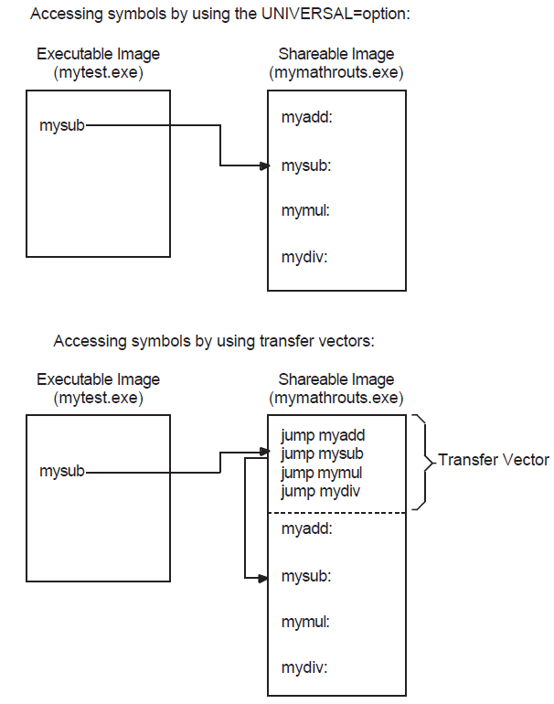
Universal Symbols that Represent Data
To provide upwardly compatible symbols that represent data locations, you must also fix these locations within memory. You can accomplish this by allocating the data symbols at the end of the transfer vector file. In this way, when you fix the location of the transfer vector within an image, the data locations also remain the same.
8.2.1.1. Creating a Transfer Vector (VAX Only)
| The .TRANSFER directive causes the symbol, named
|
| The .MASK directive causes the assembler to allocate 2 bytes of
memory, find the register save mask accompanying the entry point
( |
| The JMP instruction transfers control to the address specified as its argument. In the example, this address is two bytes past the routine entry point FOO (the first two bytes of the routine are the register save mask). It is recommended to use a jump instruction (for example, JMP L^) in the transfer vector. Transferring control with a BSBW or JSB instruction results in saving the address of the next instruction from the transfer vector on the stack. In addition, the displacement used by the BSBW instruction must be expressible in 16 bits, which may not be sufficient to reach the target routine. Also, to avoid making the image position dependent, do not use an absolute mode instruction. |
Note that the preceding convention assumes that the routine is called using the procedure call format, the default for most high-level language compilers. If a routine is called as a subroutine, using the JSB instruction, you do not need to include the .MASK directive. When creating a transfer vector for a subroutine call, VSI recommends adding bytes of padding to the transfer vectors. This padding makes a subroutine transfer vector the same size as a transfer vector for a procedure call. If you need to replace a subroutine transfer vector with a procedure call transfer vector, you can make the replacement without disturbing the addresses of all the succeeding transfer vectors.
.TRANSFER FOO ;Begin transfer vector to FOO
JMP L^FOO ;Jump to routine
.BLKB 2 ;Pad vector to 8 bytes
Preserve the order and placement of entries in a transfer vector. Once you establish the order in which entries appear in a transfer vector, do not change it. Images that were linked against the shareable image depend on the location of the symbol in the transfer vector.
You can reserve space within a transfer vector for future growth by specifying dummy transfer vector entries at various positions in a transfer vector.
Add new entries to the end of a transfer vector. When including universal data in a transfer vector file, use padding to leave adequate room for future growth between the end of the transfer vector and the beginning of the list of universal data declarations.
.transfer myadd
.mask myadd
jmp l^myadd+2
.transfer mysub
.mask mysub
jmp l^mysub+2
.transfer mymul
.mask mymul
jmp l^mymul+2
.transfer mydiv
.mask mydiv
jmp l^mydiv+2
.end
$ MACRO MY_MATH_TRANS_VEC.MAR
8.2.1.2. Fixing the Location of the Transfer Vector in Your Image (VAX Only)
For VAX linking, you include a transfer vector in a link operation as you would any other object module. However, to ensure upward compatibility,you must make sure that the transfer vector always appears in the same location in the image. The best way to accomplish this is to make the transfer vector always appear at the beginning of the image by forcing the linker to process it first. If you put the transfer vector file in a named cluster, using the CLUSTER=option, and specify it as the first option in an options file that can generate a cluster, the transfer vector will appear at the beginning of the file. For more information about controlling cluster creation, see Section 6.3, ''Ensuring Correct Symbol Resolution''.
$ LINK/SHAREABLE MY_MATH, SYS$INPUT/OPT
| To enable images that linked against a shareable image to run with various versions of the shareable image, you must specify the identification numbers of the image. By default, the linker assigns a unique identification number to each version of a shareable image. At run-time, if the ID of the shareable image as it is listed in the executable image does not match the ID of the shareable image the image activator finds to activate, the activation will abort. For information about using the GSMATCH= option to specify ID numbers, see the description of the GSMATCH= option Chapter 10, "LINK Command Reference". |
| This CLUSTER= option causes the linker to create the named cluster TRANS_VEC_CLUS and to put the transfer vector file in this cluster. |
8.2.2. Creating Based Shareable Images (VAX Linking Only)
For VAX linking, you can create a based shareable image by specifying the BASE= option in a linker options file. In a based image, you specify the starting address at which you want the linker to begin allocating memory for the image. For more information about the BASE= option, see Chapter 10, "LINK Command Reference".
VSI does not recommend using based shareable images.
Based shareable Alpha images are not supported.
8.3. Declaring Universal Symbols in Alpha Shareable Images
For Alpha linking, you declare universal symbols by listing them in a SYMBOL_VECTOR= option. For each symbol listed in the SYMBOL_VECTOR= option,the linker creates an entry in the shareable image's symbol vector and creates an entry for the symbol in the shareable image's global symbol table (GST). When the shareable image is included in a subsequent link operation, the linker processes the symbols listed in its GST.
$ LINK/SHAREABLE MY_MATH, SYS$INPUT/OPT
GSMATCH=lequal,1,1000
SYMBOL_VECTOR=(myadd=PROCEDURE,-
mysub=PROCEDURE,-
mymul=PROCEDURE,-
mydiv=PROCEDURE,-
my_symbol=DATA,-
my_data=PSECT)
Ctrl/Z
You must identify the type of symbol vector entry you want to create by specifying a keyword. The linker allows you to create symbol vector entries for procedures, data (relocatable or constant), and for global data implemented as an overlaid program section.
A symbol vector entry is a pair of quadwords that contains information about the symbol. The contents of these quadwords depends on what the symbol represents. If the symbol represents a procedure, the symbol vector entry contains the address of the procedure entry point and the address of the procedure descriptor. If the symbol represents a data location, the symbol vector entry contains the address of the data location. If the symbol represents a data constant, the symbol vector entry contains the actual value of the constant.
When you create the shareable image (by linking it specifying the /SHARE qualifier),
the value of a universal symbol listed in the GST is the offset of its entry into the
symbol vector (expressed as the offset z in Figure 8.2, ''Accessing Universal Symbols Specified Using the SYMBOL_VECTOR=Option'').
When you include this shareable image in a subsequent link operation, the linker puts this value in the linkage pair in the linkage section of the executable image that references the symbol. A linkage pair is a data structure defined by the VSI OpenVMS Calling Standard.
At run-time, when the image activator loads the shareable image into memory, it calculates the actual locations of the routines and relocatable data within the image and stores these values in the symbol vector. The image activator then fixes up the references to these symbols in the executable image that references symbols in the shareable image, moving the values from the symbol vector in the shareable image into the linkage section in the executable image. When the executable image makes the call to the procedure, shown as the Jump-to-Subroutine (JSR) instruction sequence in Figure 8.2, ''Accessing Universal Symbols Specified Using the SYMBOL_VECTOR=Option'', control is transferred directly to the location of the procedure within the shareable image.
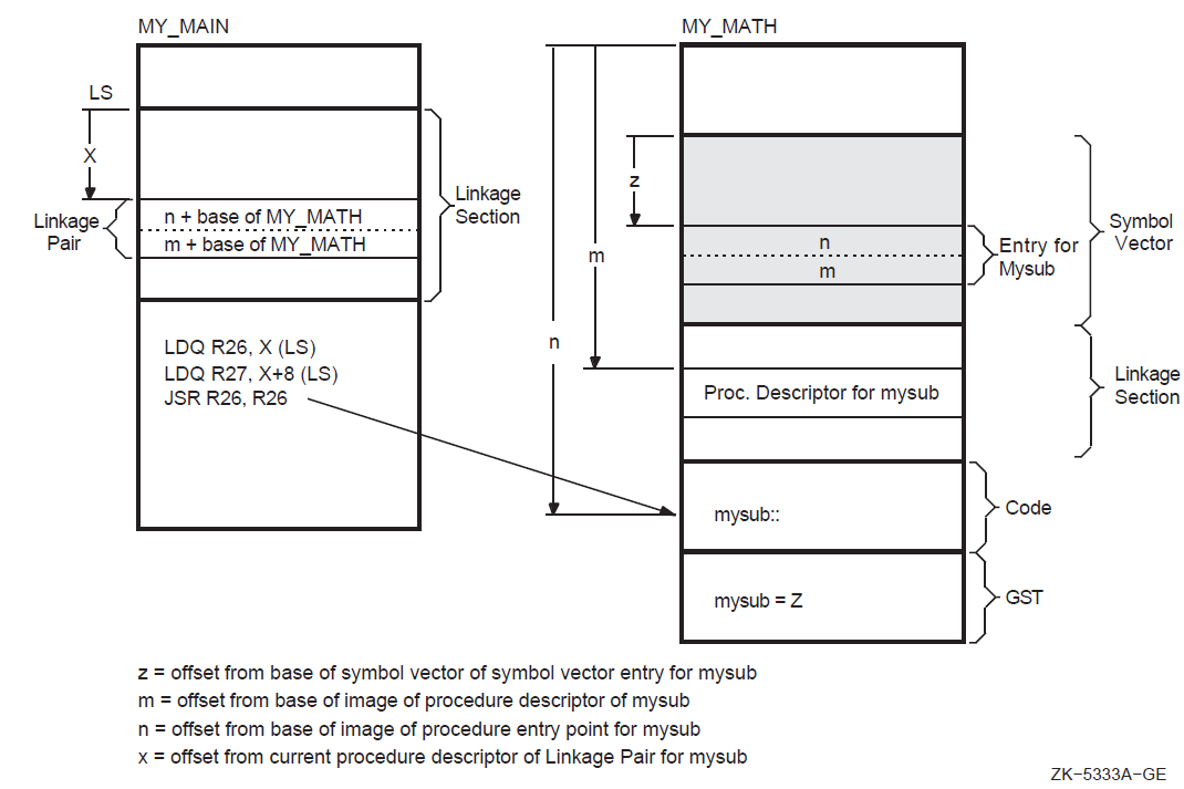 |
Note that, unlike VAX linking, global symbols implemented as overlaid program sections
are not universal by default. Instead, you control which of these symbols is a universal
symbol by including it in the SYMBOL_VECTOR=option, specifying the PSECT keyword. The
example declares the program section my_data as a universal symbol.
You must specify the qualifier /EXTERN_MODEL=COMMON on the compile command line to make the VSI C for OpenVMS Alpha compiler implement the symbol as an overlaid program section. If you do not specify the COMMON keyword, the default keyword is RELAXED_REFDEF.
8.3.1. Symbol Definitions Point to Shareable Image Psects (Alpha Only)
On Alpha systems, the linker cannot overlay program sections that are referenced by symbol definitions with shareable image program sections of the same name. The C compiler generates symbol definition records that contain the index of an overlaid program section when the relaxed ref-def extern model is used (the default).
Shareable image program sections are created when you link a shareable image and use the PSECT keyword in your SYMBOL_VECTOR option.
%LINK-E-SHRSYMFND, shareable image psect <name> was pointed to
by a symbol definition
%LINK-E-NOIMGFIL, image file not created
The link continues, but no image is created. To work around this restriction, change the symbol vector keyword to DATA, or recompile your C program with the qualifier /EXTERN=COMMON.
For more information, see the VSI C for OpenVMS Alpha documentation.
The name of a symbol implemented as an overlaid program section can duplicate the name of a symbol representing a procedure or data location. If the program section specified in a SYMBOL_VECTOR= option does not exist, the linker issues a warning, places zeros in the symbol vector entry, and does not create an entry for the program section in the image's GST.
8.3.2. Creating Upwardly Compatible Shareable Images (Alpha Only)
The SYMBOL_VECTOR= option allows you to create upwardly compatible shareable images without requiring you to create transfer vectors as for VAX images.
However, as with transfer vectors, to ensure upward compatibility when using a SYMBOL_VECTOR= option, you must preserve the order and placement of the entries in the symbol vector with each relinking. Do not delete existing entries. Add new entries only at the end of the list. If you use multiple SYMBOL_VECTOR= option statements in a single options file to declare the universal symbols, you must also maintain the order of the SYMBOL_VECTOR= option statements in the options file. If you specify SYMBOL_VECTOR= options in separate options files, make sure the linker always processes the options files in the same order. (The linker creates only one symbol vector for an image).
Note, however, that there is no need to anchor the symbol vector at a particular location in memory, as you would anchor a transfer vector for a VAX link. The value at link time of a universal symbol in an Alpha shareable image is its location in the symbol vector, expressed as an offset from the base of the symbol vector, and the location of the symbol vector is stored in the image header. (For VAX linking, the value of a universal symbol at link time is the location of the symbol in the image, expressed as an offset from the base of the image). Thus, the relative position of the symbol vector within the image does not affect upward compatibility.
8.3.3. Deleting Universal Symbols Without Disturbing Upward Compatibility (Alpha Only)
mysub is deleted using the PRIVATE_PROCEDURE
keyword:$ LINK/SHAREABLE MY_MATH, SYS$INPUT/OPT
GSMATCH=lequal,1,1000
SYMBOL_VECTOR=(myadd=PROCEDURE,-
mysub=PRIVATE_PROCEDURE,-
mymul=PROCEDURE,-
mydiv=PROCEDURE,-
my_symbol=DATA,-
my_data=PSECT)
Ctrl/ZWhen you specify the PRIVATE_PROCEDURE or PRIVATE_DATA keyword in the SYMBOL_VECTOR= option, the linker creates symbol vector entries for the symbols but does not create an entry for the symbol in the GST of the image. The symbol still exists in the symbol vector and none of the other symbol vector entries have been disturbed. Images that were linked with previous versions of the shareable image that reference the symbol will still work, but the symbol will not be available for new images to link against.
Using the PRIVATE_PROCEDURE keyword, you can replace an entry for an obsolete procedure with a private entry for a procedure that returns a message that explains the status of the procedure.
8.3.4. Creating Run-Time Kits (Alpha Only)
If you use shareable images in your application, you may want to ship a run-time kit with versions of these shareable images that cannot be used in link operations.
To do this, you must first link your application, declaring the universal symbols in the shareable images using the SYMBOL_VECTOR= option so that references to these symbols can be resolved. After the application is linked,you must then relink the shareable images so that they have fully populated symbol vectors but empty global symbol tables (GSTs). The fully populated symbol vectors allow your application to continue to use the shareable image sat run-time. The empty GSTs prevent other images from linking against your application.
To create this type of shareable image for a run-time kit (without having to disturb the SYMBOL_VECTOR= option statements in your application's options files), relink the shareable image after development is completed, specifying the /NOGST qualifier on the LINK command line. When you specify the /NOGST qualifier, the linker builds a complete symbol vector, containing the symbols you declared universal in the SYMBOL_VECTOR= option, but does not create entries for the symbols that you declared universal in the GST of the shareable image. For more information about the /GST qualifier, see Chapter 10, "LINK Command Reference".
8.3.5. Specifying an Alias Name for a Universal Symbol (Alpha Only)
LINK/SHAREABLE MY_SHARE/SYS$INPUT/OPT
SYMBOL_VECTOR=(myadd=procedure,-
               sub_alias/mysub=procedure,-
               mymul=procedure,-
               mydiv=procedure,-
               my_symbol=DATA,-
               my_data=PSECT)
Ctrl/Z
You can specify universal alias names for symbols that represent procedures or data; you cannot declare a universal alias name for a symbol implemented as an overlaid program section. In link operations in which the shareable image is included, the calling modules must refer to the universal symbol by its universal alias name to enable the linker to resolve the symbolic reference.
In a privileged shareable image, calls from within the image that use the alias name result in a fix-up and subsequent vectoring through the privileged library vector (PLV), which results in a mode change. Calls from within the shareable image that use the internal name are done in the caller's mode. (Calls from external images always result in a fix-up). For more information about creating a PLV, see the VSI OpenVMS Programming Concepts Manual, Volume I.
8.3.6. Improving the Performance of Installed Shareable Images (Alpha Only)
For Alpha linking, you can improve the performance of an installed shareable image by installing it as a resident image (by using the /RESIDENT qualifier of the Install utility). INSTALL moves the executable, read-only pages of resident images into system space where they reside on huge pages. Executing your image in huge pages improves performance.
Chapter 9. Interpreting an Image Map File (Alpha and VAX)
This chapter describes how to interpret the information returned in an image map on OpenVMS Alpha and OpenVMS VAX systems and describes the combinations of linker qualifiers used to obtain a map.
For information about interpreting an image map file on OpenVMS x86-64 and OpenVMS IA-64 systems, see Chapter 5, "Interpreting an Image Map File (x86-64 and I64)".
9.1. Overview of Alpha/VAX Linker Map
At your request, the linker can generate information that describes the contents of the image and the linking process itself. This information, called an image map, can be helpful when locating link-time errors, studying the layout of the image in virtual memory, and keeping track of global symbols.
The names of all modules included in the link operation, both explicitly in the LINK command and implicitly from libraries
The names, sizes, and other information about the image sections that comprise the image
The names, sizes, and locations of program sections within an image
The names and values of all the global symbols referenced in the image,including the name of the module in which the symbol is defined and the names of the modules in which the symbol is referenced
Statistical summary information about the image and the link operation itself
|
/MAP |
Directs the linker to create a map file. This is the default for batch jobs. /NOMAP is the default for interactive link operations. |
|
/BRIEF |
When used in combination with the /MAP qualifier, directs the linker to create a map file that contains only a subset of all the possible information. |
|
/FULL |
When used in combination with the /MAP qualifier, directs the linker to create a map file that contains all the possible information. |
|
/CROSS_REFERENCE |
When used in combination with the /MAP qualifier, directs the linker to replace the Symbols By Name section with a Symbol Cross-Reference section, in which all the symbols in each module are listed with the modules in which they are called. You cannot request this type of listing in a brief map file. |
9.2. Components of an Image Map File (Alpha/VAX)
|
Section Name |
Description |
Default Map |
Full Map |
Brief Map |
|---|---|---|---|---|
|
Object Module Synopsis? |
Lists all the object modules in the image. |
Yes |
Yes |
Yes |
|
Module Relocatable Reference Synopsis? |
Specifies the number of .ADDRESS directives in each module. |
— |
Yes |
— |
|
Image Section Synopsis |
Lists all the image sections and clusters created by the linker. |
— |
Yes |
— |
|
Program Section Synopsis? |
Lists the program sections and their attributes. |
Yes |
Yes |
— |
|
Symbols By Name? |
Lists global symbol names and values. |
Yes |
Yes |
— |
|
Symbol Cross-Reference? |
Lists each symbol name, its value, the name of the module that defined it, and the names of the modules that refer to it. Replaces the Symbols By Name section when the /CROSS_REFERENCE qualifier is specified. |
Yes |
Yes |
— |
|
Symbols By Value |
Lists all the symbols with their values (in hexadecimal representation). |
— |
Yes |
— |
|
Image Synopsis |
Presents statistics and other information about the output image. |
Yes |
Yes |
Yes |
|
Link Run Statistics |
Presents statistics about the link run that created the image. |
Yes |
Yes |
Yes |
The following sections describe each of the image map sections in detail. The examples of the map sections are taken from the map file created in a link operation of the executable image in Chapter 8, "Creating Shareable Images (Alpha and VAX)".
9.2.1. Object Module Synopsis (Alpha/VAX)
                                        +------------------------+
                                        ! Object Module Synopsis !
                                        +------------------------+

Module Name   Ident    Bytes  File                            Creation Date    Creator
-----------     -----     -----    -----                             -------------     -------
MY_MATH         V1.0      0        WORK:[PROGS]MY_MATH.EXE;11        3-NOV-2000 12:27  Linker T10-37
MY_MAIN         V1.0      553      WORK:[PROGS]MY_MAIN.OBJ;15        3-NOV-2000 12:27  C X1.1-048E
DECC$SHR        V1.0      0        [SYSLIB]DECC$SHR.EXE;2            9-JUL-2000 07:49  Linker T10-03
SYS$PUBLIC_VECTORS
                X-26      0        [SYSLIB]SYS$PUBLIC_VECTORS.EXE;2  9-JUL-2000 07:34  Linker T10-03
| Module Name. The name of each object module included in the link operation. The modules are listed in the order in which the linker processed them. If the linker encounters an error during its processing of an object module, an error message appears on the line directly following the line containing the name of that object module. |
| Ident. The text string in the IDENT field in an object module or in the image header of a shareable image. |
| Bytes. The number of bytes the object module contributes to the image. Because shareable images are activated at run-time, the linker cannot calculate the size of their contributions to the image. Thus, the value 0 (zero) is associated with shareable images. |
| File. Full file specification of the input file, including device and directory. If the specification is longer than 35 characters, it is shortened by dropping the device portion of the file specification or both the device and directory portions of the file specification. |
| Creation Date. The date and time the file was created. |
| Creator. Identification of the language processor or other utility that created the file. |
The order in which the modules are listed in this section reflects the order in which the linker processes the input files specified in the link operation. Note that the order of processing can be different from the order in which the files were specified in the command line. For more information about how the linker processes input files, see Chapter 6, "Understanding Symbol Resolution (Alpha and VAX)".
9.2.2. Module Relocatable Reference Synopsis (VAX Only)
                     +---------------------------------------+
                     ! Module Relocatable Reference Synopsis !
                     +---------------------------------------+

Module Name      Number  Module Name       Number   Module Name           Number
-----------        ------   -----------       ------   -----------           ------

MAIN1                       1
| Module Name. The name of each object module included in the link operation. The modules are listed in the order in which the linker processed them. |
| Number. The number of .ADDRESS references found. |
Note that you can reduce linker and image activator processing time by removing .ADDRESS directives from input files.
9.2.3. Image Section Synopsis Section (Alpha/VAX)
The Image Section Synopsis section of the linker map file lists the image sections created by the linker. The image sections appear in the order in which the linker created them, which is the same order as the clusters in the linker's cluster list. (For more information about clusters, see Chapter 6, "Understanding Symbol Resolution (Alpha and VAX)"). The section includes other information about these image sections, formatted in columns, as in the following example:
                                                      ++++++++++++++++++++++++++
                                                      ! Image Section Synopsis !
                                                      ++++++++++++++++++++++++++

  Cluster      Type    Pglts   Base Addr   Disk VBN   PFC    Protection and Paging    Global Sec. Name      Match     Majorid   Minorid
  -------      ----    -----   ---------   --------   ---    ---------------------    ----------------      -----     -------   -------

MY_MATH            2     1      00000000R      0         0   READ WRITE   COPY ON REF    MY_MATH_001        EQUAL      113      5598831
                   2     1      00010000R      0         0   READ WRITE   COPY ON REF    MY_MATH_002        EQUAL      113      5598831
                   3     1      00020000R      0         0   READ ONLY                   MY_MATH_003        EQUAL      113      5598831
                   4     1      00030000R      0         0   READ WRITE   COPY ON REF    MY_MATH_004        EQUAL      113      5598831
                   2     1      00040000R      0         0   READ WRITE   FIXUP VECTORS  MY_MATH_005        EQUAL      113      5598831

DEFAULT_CLUSTER    0     1      00010000       3         0   READ WRITE   NONSHAREABLE   ADDRESS DATA
                   0     1      00020000       4         0   READ ONLY
                   0     1      00030000       5         0   READ WRITE   FIXUP VECTORS
                 253    20      7FFF0000       0         0   READ WRITE   DEMAND ZERO

DECC$SHR           2   132     00000000-R      0         0   READ WRITE   COPY ON REF    DECC$SHR_001       LESS/EQUAL   1      0
                   2     3     00020000-R      0         0   READ WRITE   COPY ON REF    DECC$SHR_002       LESS/EQUAL   1      0
                   3    11     00030000-R      0         0   READ ONLY                   DECC$SHR_003       LESS/EQUAL   1      0
                   3   965     00040000-R      0         0   READ ONLY                   DECC$SHR_004       LESS/EQUAL   1      0
                   4     7     000C0000-R      0         0   READ WRITE   COPY ON REF    DECC$SHR_005       LESS/EQUAL   1      0
                   4    71     000D0000-R      0         0   READ WRITE   COPY ON REF    DECC$SHR_006       LESS/EQUAL   1      0
                   4     1   P-000E0000-R      0         0   READ WRITE   COPY ON REF    DECC$SHR_007       LESS/EQUAL   1      0
                   2     9     000F0000-R      0         0   READ WRITE   FIXUP VECTORS  DECC$SHR_008       LESS/EQUAL   1      0

SYS$PUBLIC_VECTORS
                   2    15     00000000-R      0         0   READ ONLY                   SYS$PUBLIC_VECTO   EQUAL      113     14651409
                   1    24     00004000-R      0         0   READ WRITE   COPY ON REF    SYS$PUBLIC_VECTO   EQUAL      113     14651409
                   2     1     00008000-R      0         0   READ WRITE   FIXUP VECTORS  SYS$PUBLIC_VECTO   EQUAL      113     14651409

          Key for special characters above:
                      +++++++++++++++++++++
                      ! R   Relocatable   !
                      ! P   Protected     !
                      +++++++++++++++++++++
| The name of each cluster the linker created, listed in the order in which the linker created them. | ||||||||||||||||
| The type of image section, expressed as one of the following codes:
For more information about the types of image sections the linker creates, see Section 7.3.5, ''Image Section Attributes''. | ||||||||||||||||
| The length of each image section, expressed in pages or pagelets. | ||||||||||||||||
| The base address assigned to the image section. Note that if the cluster is relocatable, the image activator relocates the base address. In this case, the base address entry for each image section in the cluster MY_MATH has the letter "R" appended to it, indicating that the base address entry is an offset to be added to the cluster base address assigned by the image activator. For Alpha linking, when images are installed as resident images, the Install utility moves image sections containing code into system space. This invalidates the base addresses listed for these image sections in this section of the map file. Note, however, that the relative positions of the program sections within the image section, listed in the Program Section Synopsis section of the map file, remain valid when the image section is moved into system space. | ||||||||||||||||
| The virtual block number of the image file on disk where the image section begins. The number 0 indicates that the image section is not in the image file. | ||||||||||||||||
| Page fault cluster, the number of pagelets read into memory by the operating system when the initial page fault occurs for that image section. The number 0 indicates that the system parameter PFCDEFAULT determines this value, rather than the linker. | ||||||||||||||||
| A keyword phrase that characterizes the settings of certain attributes of the image section, such as the attributes that affect protection and paging. The following table lists the keywords used by the linker to indicate these characteristics of an image section:
The linker may use more than one keyword to describe an image section. For example, to describe an image section that contains code, the linker uses the READ ONLY and EXECUTABLE keywords. Note that a program section that you may have protected from write access (by setting the NOWRT program section attribute) may appear in the map file as writable (with the READ WRITE keyword). If this program section also has the NON-SHAREABLE ADDRESS DATA keyword (as the first image section in DEFAULT_CLUSTER illustrates), the linker has enabled write access to the program section to allow the image activator to fix up address references in the image section at run-time. The image activator resets the program section attributes to READ ONLY after it is finished. | ||||||||||||||||
| Global Section Name, the name assigned by the linker to each image section comprising a shareable image. The linker creates the names by appending the characters "_00x" after the file name, where "x" is an integer, starting with 1, and incremented for each image section in a shareable image. | ||||||||||||||||
| The algorithm the image activator uses when comparing identification numbers in a shareable image, expressed by the keyword LESS/EQUAL, EQUAL, or ALWAYS. For more information about this topic, see the description of the GSMATCH= option in Chapter 10, "LINK Command Reference". | ||||||||||||||||
| An identification number assigned to the image. The linker assigns the number to the image if it is not specified as part of the link operation in the GSMATCH= option. | ||||||||||||||||
| An identification number assigned to the image. The linker assigns the number to the image if it is not specified as part of the link operation in the GSMATCH= option. |
9.2.4. Program Section Synopsis Section (Alpha/VAX)
The Program Section Synopsis section lists the program sections that comprise the image, with information about the size of the program section, its starting- and ending-addresses, and its attributes. The Module Name column in this section lists the modules that contribute to each program section. The following example illustrates this format:
Psect Name
| The name of each program section in the image in ascending order of its base virtual address. |
| The names of the modules that contribute to the program section whose name appears on the line directly above in the Psect Name column. If a shareable image appears in this column, the linker processed the program section as a shareable image reference. |
| The starting virtual address of the program section or of a module that contributes to a program section. |
| The ending virtual address of the program section or of a module that contributes to a program section. |
| The total length of the program section or of a module that contributes to a program section. |
| The type of alignment used for the entire program section or for an individual program section contribution. The alignment is expressed in two ways. In the first column, the alignment is expressed using a predefined keyword, such as OCTA. In the second column, the alignment is expressed as an integer that is the power of 2 that creates the alignment. For example, octaword alignment would be expressed as the keyword OCTA and as the integer 4 (because 24 = 16). If the linker does not support a keyword to express an alignment, it puts the text "2 **" in the column in which the keyword usually appears. When read with the integer in the second column, it expresses these alignments, such as 2 ** 5. |
| The attributes associated with the program section. For a list of all the possible attributes, see Chapter 7, "Understanding Image File Creation (Alpha and VAX)". For Alpha linking, the linker includes the MOD attribute in the list of program section attributes (as illustrated in the example). To make room in the display for this attribute, the linker leaves out the Readability (RD/NORD) and User Library (USR/LIB) attributes, which are reserved for future use. For VAX linking, the list of attributes includes the Readability (RD/NORD) and User Library (USR/LIB) attributes. The Modified (MOD/NOMOD) attribute, which is not supported for VAX images, is not included. |
Note that, if a routine is extracted from the default system library to resolve a symbolic reference, the Program Section Synopsis section in a full map contains information about the program sections comprising that routine. The Program Section Synopsis section in a default map does not.
9.2.5. Symbols By Name Section (Alpha/VAX)
                                             +-----------------+
                                             ! Symbols By Name !
                                             +-----------------+

Symbol       Value   Symbol      Value         Symbol       Value       Symbol   Value
------         -----    ------      -----         ------       -----       ------   -----
DECC$EXIT       00001FD0-RX
DECC$GPRINTF    00001710-RX
DECC$MAIN       000007D0-RX
MAIN            00010000-R
MYSUB           00000010-RX
MY_SYMBOL       00000050-RX
SYS$IMGSTA      00000340-RX
__MAIN          00010078-R
| Symbol. The names of the image's global symbols in alphabetical order. |
| Value. The value of the symbol, expressed in hexadecimal. The linker appends characters to the end of the symbol value to describe other characteristics of the symbol. For an explanation of these symbols, see Section 9.2.7, ''Symbols By Value Section (Alpha/VAX)''. |
Note that this section is replaced by the Symbol Cross-Reference section when you specify the /CROSS_REFERENCE qualifier in the LINK command. The Symbols by Value section, described in Section 9.2.7, ''Symbols By Value Section (Alpha/VAX)'', lists the same symbols by value.
9.2.6. Symbol Cross-Reference Section (Alpha/VAX)
                                        +------------------------+
                                        ! Symbol Cross Reference !
                                        +------------------------+

Symbol        Value         Defined By      Referenced By ...
------          -----           ----------        -----------------
DECC$EXIT    00001FD0-RX       DECC$SHR                 MY_MAIN
DECC$GPRINTF 00001710-RX       DECC$SHR                 MY_MAIN
DECC$MAIN    000007D0-RX       DECC$SHR                 MY_MAIN
MAIN         00010000-R        MY_MAIN
MYSUB        00000010-RX       MY_MATH                  MY_MAIN
MY_SYMBOL    00000050-RX       MY_MATH                  MY_MAIN
SYS$IMGSTA   00000340-RX       SYS$PUBLIC_VECTORS
__MAIN       00010078-R        MY_MAIN
| Symbol. The name of the global symbol. |
| Value. The value of the global symbol, expressed in hexadecimal. The linker appends characters to the end of the symbol value to describe other characteristics of the symbol. For an explanation of these symbols, see Section 9.2.7, ''Symbols By Value Section (Alpha/VAX)''. |
| Defined By. The name of the module in which the symbol is defined. For
example, the symbol |
| Referenced By.... The name or names of all the modules that contain at least one reference to the symbol. |
9.2.7. Symbols By Value Section (Alpha/VAX)
The Symbols By Value section lists all the global symbols in the image
                                           +------------------+
                                           ! Symbols By Value !
                                           +------------------+

Value                  Symbols...
-----                   ----------
00000010     RX-MYSUB
00000050     RX-MY_SYMBOL
00000340     RX-SYS$IMGSTA
000007D0     RX-DECC$MAIN
00001710     RX-DECC$GPRINTF
00001FD0     RX-DECC$EXIT
00010000      R-MAIN
00010078      R-__MAIN
| Value. The value of each global symbol, expressed in hexadecimal, in ascending numerical order. | ||||||||||||||||
| Symbols... The names of the global symbols. If more than one symbol
has the same value, the linker lists them on more than one line. The
characters prefixed to the symbol names indicate other characteristics
of the symbol, such as its scope. Table 9.3, ''Symbol Characterization Codes (Alpha/VAX)'' lists
these codes.
|
9.2.8. Image Synopsis Section (Alpha/VAX)
                                              +----------------+
                                              ! Image Synopsis !
                                              +----------------+

Virtual memory allocated:          00010000 0003FFFF 00030000 (196608. bytes, 384. pages)
Stack size:                                       20. pages
Image header virtual block limits:                 1.        2. (    2. blocks)
Image binary virtual block limits:                 3.        5. (    3. blocks)
Image name and identification:              MY_MAIN V1.0
Number of files:                                   7.
Number of modules:                                 4.
Number of program sections:                       11.
Number of global symbols:                        944.
Number of cross references:                       13.
Number of image sections:                         20.
User transfer address:                      00010078
Debugger transfer address:                  00000340
Number of code references to shareable images:     6.
Image type:                                 EXECUTABLE.
Map format:                                 FULL WITH CROSS REFERENCE in file WORK:[PROGS]MY_MAIN.MAP;15
Estimated map length:                       148. blocks
| Virtual memory allocated. This line contains the following
information:
|
The numbers in parentheses at the end of the line indicate the total size of the image, expressed in bytes and in pagelets. Both these values are expressed in decimal.
9.2.9. Link Run Statistics Section (Alpha/VAX)
                                          +---------------------+
                                          ! Link Run Statistics !
                                          +---------------------+

Performance Indicators                        Page Faults   CPU Time        Elapsed Time
----------------------                        -----------   --------        ------------
    Command processing:                                93   00:00:00.18     00:00:00.81
    Pass 1:                                           345   00:00:00.55     00:00:12.04
    Allocation/Relocation:                              9   00:00:00.04     00:00:00.30
    Pass 2:                                            29   00:00:00.14     00:00:00.62
    Map data after object module synopsis:              3   00:00:00.05     00:00:00.31
    Symbol table output:                                0   00:00:00.00     00:00:00.10
Total run values:                                     479   00:00:00.96     00:00:14.18

Using a working set limited to 2048 pages and 946 pages of data storage (excluding image)

Total number object records read (both passes):   167
    of which 0 were in libraries and 0 were DEBUG data records containing 0 bytes

Number of modules extracted explicitly             = 0
    with 0 extracted to resolve undefined symbols

5 library searches were for symbols not in the library searched

A total of 0 global symbol table records was written

LINK/MAP/FULL/CROSS MY_MAIN,SYS$INPUT/OPT
my_math/share
Chapter 10. LINK Command Reference
10.1. LINK Command
LINK
LINK — Invokes the OpenVMS Linker utility to link one or more input files into a program image and defines the execution characteristics of the image.
Format
LINK file-spec [,...] | Qualifiers |
Supported Platform | Defaults |
|---|---|---|
| /ALPHA | Alpha, VAX | Platform dependent, see reference description. |
| /BASE_ADDRESS[=address] | x86-64, I64 | /NOBASE_ADDRESS |
| /BPAGE[=page-size-indicator] | All | Platform dependent, see reference description. |
| /BRIEF | All | None. |
| /CONTIGUOUS | All | /NOCONTIGUOUS |
| /CBT | x86-64, I64 | /CBT |
| /CROSS_REFERENCE | All | None. |
| /DEBUG[=file-spec] | All | /NODEBUG |
| /DEMAND_ZERO[=PER_PAGE] | 64-bit platforms | /DEMAND_ZERO |
| /DNI (Display Name Information) | x86-64, I64 | /DNI |
| /DSF[=file-spec] (Debug Symbol File) | 64-bit platforms | /NODSF |
| /EXECUTABLE[=file-spec] | All | /EXECUTABLE |
| /FP_MODE=keyword | x86-64, I64 | /NOFP_MODE |
| /FULL[=(keyword[,...])] | All | None. |
| /GST (Global Symbol Table) | 64-bit platforms | /GST |
| /HEADER | Alpha, VAX | /NOHEADER? |
| /INCLUDE=(module-name[,...]) | All | None. |
| /INFORMATIONALS | All | /INFORMATIONALS |
| /LIBRARY | All | None. |
| /MAP[=file-spec] | All | /NOMAP (in interactive mode) |
| /NATIVE_ONLY | I64, Alpha | /NATIVE_ONLY |
| /OPTIONS | All | None. |
| /P0IMAGE | All | /NOP0IMAGE |
| /PROTECT | All | /NOPROTECT |
| /REPLACE | Alpha | /REPLACE? |
| /SECTION_BINDING[=(CODE,DATA)] | Alpha | /NOSECTION_BINDING? |
| /SEGMENT_ATTRIBUTE=(segm-attribute,[...]) | x86-64, I64 | None. |
| /SELECTIVE_SEARCH | All | None. |
| /SHAREABLE[=file-spec] | All | /NOSHAREABLE |
| /SYMBOL_TABLE[=file-spec] | All | /NOSYMBOL_TABLE |
| /SYSEXE | 64-bit platforms | /NOSYSEXE |
| /SYSLIB | All | /SYSLIB |
| /SYSSHR | All | /SYSSHR |
| /SYSTEM[=base-address] | Alpha, VAX | /NOSYSTEM |
| /THREADS_ENABLE | All | /NOTHREADS_ENABLE |
| /TRACE[=keyword]? | All | /TRACE=SYMBOLS? |
| /USERLIBRARY[=(table[,...])] | All | /USERLIBRARY=ALL |
| /VAX | Alpha, VAX | Platform dependent, see reference description. |
Parameters
file-spec [,...] Specifies one or more input files (wildcard characters are not allowed). Input files may be object modules, shareable images, libraries to be searched for external references or from which specific modules are to be included, or options files to be read by the linker. Separate multiple input file specifications with commas (,) or plus signs (+). In either case, the linker creates a single image file.
If you omit the file type in an input file specification, the linker supplies default file types, based on the nature of the input file. For object modules, the default file type is .OBJ. For more information about specifying input files, see Chapter 1, "Introduction".
10.2. Qualifier Descriptions
This section describes the LINK command qualifiers.
/ALPHA (Alpha and VAX)
/ALPHA (Alpha and VAX) — Directs the linker to produce an OpenVMS Alpha image. On OpenVMS Alpha or VAX systems, when neither /ALPHA nor /VAX is specified, the default action is to create an OpenVMS VAX image on an OpenVMS VAX system and to create an OpenVMS Alpha image on an OpenVMS Alpha system.
Format
/ALPHA Description
This qualifier is used to instruct the linker to accept OpenVMS Alpha object files and library files to produce an OpenVMS Alpha image.
You must inform the linker where OpenVMS Alpha system libraries and shareable images are located with the logical names ALPHA$LOADABLE_IMAGES and ALPHA$LIBRARY. On an OpenVMS Alpha system, these logicals are already defined to point to the correct directories on the current system disk. On OpenVMS VAX, you must define these logical names so that they translate to the location of an OpenVMS Alpha system disk residing on the system where the Alpha linking is to occur.
For more information on cross-architecture linking, see Section 1.5, ''Linking for Different Architectures (Alpha and VAX)''.
Example
$ DEFINE ALPHA$LIBRARY DKB100:[VMS$COMMON.SYSLIB]
$ DEFINE ALPHA$LOADABLE_IMAGES DKB100:[VMS$COMMON.SYS$LDR]
$ LINK/ALPHA ALPHA.OBJ
This example, which is performed on an OpenVMS VAX system, shows the definition of logical names to point to the appropriate a reason an OpenVMS Alpha system disk mounted on device DKB100. The qualifier /ALPHA tells the linker to expect the object file, ALPHA.OBJ, to be an OpenVMS Alpha object file and to link it using the OpenVMS Alpha libraries and images on DKB100, if necessary.
/BASE_ADDRESS (x86-64 and I64)
/BASE_ADDRESS (x86-64 and I64) — Assigns a virtual address for executable images that are not activated by the OpenVMS image activator, such as images used in the boot process.
Format
/BASE_ADDRESS=address /NOBASE_ADDRESS (default) Qualifier Values
address The location at which you want the first segment of the executable image located. You can express this location as decimal (%D), octal (%O), or hexadecimal (%X) numbers. The default is hexadecimal.
Description
The /BASE_ADDRESS qualifier assigns a virtual address for executable images that are not activated by the OpenVMS image activator, such as images used in the boot process. The base address is the starting address that you want the linker to assign to an executable image. The OpenVMS image activator is free to ignore any linker-assigned starting address. This qualifier is used primarily by system developers.
The /BASE_ADDRESS qualifier does not replace the BASE= option or the base-address specifier in the CLUSTER= option, which is illegal on OpenVMS x86-64 and IA-64 systems.
For all images (executable and shareable), the starting address is determined by the image activator. Any linker assigned address value can be changed when activating the image.
/BPAGE
/BPAGE — Specifies the page size the linker should use when it creates the segments (on x86-64 and IA-64 systems) or image sections (on Alpha and VAX systems) that make up an image.
Format
/BPAGE[=page-size-indicator] Qualifier Values
page-size-indicator An integer that specifies a page size as the power of 2 required to create a page that size. For example, to get an 8 KB page size, specify the value 13 because 213 equals 8 K. The following table lists the page sizes supported by the linker with the defaults:
|
Value |
Page Size |
Defaults |
|---|---|---|
|
9 |
512 bytes |
Default value for VAX links when the /BPAGE qualifier is not specified. |
|
13 |
8 KB |
Default value on x86-64 systems when /BPAGE is not specified. Default value on x86-64 and VAX systems when the /BPAGE qualifier is specified without a value. |
|
14 |
16 KB |
— |
|
15 |
32 KB |
— |
|
16 |
64 KB |
Default value on IA-64 and Alpha when /BPAGE is not specified or when the /BPAGE qualifier is specified without a value. |
Description
The images the linker creates are made up of segments (on x86-64 and IA-64 systems) or image sections (on Alpha and VAX systems) that the linker allocates on page boundaries. When you specify a larger page size, the origin of segments or image sections increases to the next multiple of that size.
An image linked to a page size that is larger than the page size of the CPU generally runs correctly, but it might consume more virtual address space.
On 64-bit systems, by default the linker creates segments or image sections on 64 KB boundaries, thus allowing the images to run properly on any 64-bit system, regardless of the hardware page size.
On VAX systems, linking a shareable image to a larger page size can cause the value of transfer vector offsets to change if they were not allocated in page 0 of the image. Do not link against a shareable image that was created with a different page size. (You cannot determine the page size used in the creation of a VAX image from the image).
Example
$ LINK/BPAGE=16 MY_PROG.OBJ
Including the value 16 with the /BPAGE qualifier causes the linker to create segments (on x86-64 and IA-64 systems) or image sections (on Alpha and VAX systems) on 64 KB page boundaries.
/BRIEF
/BRIEF — Directs the linker to produce a brief image map. For more information, see also the /MAP and /FULL qualifiers.
Format
/MAP/BRIEF Qualifier Values
None.
Description
Object and Image Synopsis
Image Segment Synopsis
Link Run Statistics
Object Module Synopsis
Image Section Synopsis
Link Run Statistics
In contrast, on x86-64 and IA-64 systems, the default image map contains the Object and Image Synopsis, Image Synopsis, Link Run Statistics, Program Section Synopsis, and Symbols By Name sections. On Alpha and VAX systems, the default image map contains the Object Module Synopsis, Image Synopsis, Link Run Statistics, Program Section Synopsis, and Symbols By Name sections. For more information about image maps, see Chapter 5, "Interpreting an Image Map File (x86-64 and I64)" (x86-64 and I64) and Chapter 9, "Interpreting an Image Map File (Alpha and VAX)" (Alpha and VAX).
The /BRIEF qualifier must be specified with the /MAP qualifier and is incompatible with the /FULL qualifier and the /CROSS_REFERENCE qualifier.
Example
$ LINK/MAP/BRIEF MY_PROG
In this example, the linker creates a brief image map with the filename MY_PROG.MAP.
/CONTIGUOUS
/CONTIGUOUS — Directs the linker to place the entire image in consecutive disk blocks. If sufficient contiguous space is not available on the output disk, the linker reports an error and terminates the link operation.
Format
/CONTIGUOUS /NOCONTIGUOUS (default) Description
You can use the /CONTIGUOUS qualifier to speed up the activation time of any type of image because images usually activate more slowly if their image disk blocks are not contiguous. Note, however, that in most cases performance benefits do not warrant the use of the /CONTIGUOUS qualifier.
You can also use the /CONTIGUOUS qualifier when linking bootstrap programs for certain system images that require contiguity.
Even when you do not specify the /CONTIGUOUS qualifier, the file system tries to use contiguous disk blocks for images, if sufficient contiguous space is available.
Example
$ LINK/CONTIGUOUS MY_PROG
This example directs the linker to place the entire image named MY_PROG.EXE in consecutive disk blocks.
/CBT
/CBT — Directs the linker to create a contiguous best try (CBT) image file.
Format
/CBT /NOCBT Description
Directs the linker to create a contiguous best try (CBT) image file. This helps to reduce the number of I/Os when activating the image. However in a cluster environment and for heavily fragmented disks, this creates noticeable overhead and slows down creating the image file as well as other I/Os to that disk.
/NOCBT directs the linker not to attempt a CBT image file. This usually improves performance during development. It is recommended to build the final image file with /CBT or to make a CBT copy.
Examples
$ LINK/CBT
$ LINK/NOCBT
/CROSS_REFERENCE
/CROSS_REFERENCE — Directs the linker to replace the Symbols By Name section in a full or default image map with the Symbol Cross-Reference section.
Format
/MAP/CROSS_REFERENCE Description
Its value
The name of the first module in which it is defined
The name of each module in which it is referenced
The number of symbols listed in the cross-reference section depends on whether the linker generates a full map or a default map. In a full map, this section includes global symbols from all modules in the image, including those extracted from all libraries. In a default map, this section does not include global symbols from modules extracted from the default system libraries IMAGELIB.OLB and STARLET.OLB. For more information about image map files, see Chapter 5, "Interpreting an Image Map File (x86-64 and I64)" (x86-64 and I64) and Chapter 9, "Interpreting an Image Map File (Alpha and VAX)" (Alpha and VAX).
The /CROSS_REFERENCE qualifier is incompatible with the /BRIEF qualifier.
Example
$ LINK/MAP/CROSS_REFERENCE MY_PROG
This example produces an image map file named MY_PROG.MAP that includes a Symbol Cross-Reference section.
/DEBUG
/DEBUG — Directs the linker to generate debug and traceback information and to give the debugger control when the image is run.
Format
/DEBUG[=file-spec] /NODEBUG (default) Qualifier Values
file-spec (x86-64, Alpha, and
                                VAX)
Identifies a user-written debugger module.
If you specify the /DEBUG qualifier without entering a file specification, the OpenVMS Debugger gains control at run-time. Requesting the OpenVMS Debugger does not affect the location of code within the image because the debugger is mapped into the process address space at run-time, not at link time. See the VSI OpenVMS Debugger Manual for additional information.
on IA-64 systems, a file specification is not allowed.
On x86-64, Alpha, and VAX systems, if you specify the /DEBUG qualifier with a file specification, the user-written debugger module that the file specification identifies gains control at run-time. The linker assumes a default file type of .OBJ. Requesting a user-written debugger module does affect the location of code within the image.
Description
The /DEBUG qualifier automatically includes the /TRACE qualifier. If you specify the /DEBUG qualifier and the /NOTRACE qualifier, the linker overrides your specification and includes traceback information.
To debug a shareable image, you must compile and link it with the /DEBUG qualifier and then include it in a link operation that creates a debuggable image (that link operation must also use the /DEBUG qualifier).
For x86-64 and IA-64 systems, Table 3.10, ''Location of Global Symbols Determined by /TRACEBACK, /DEBUG, and /DSF'' indicates where global symbol definitions are written during a link operation that uses the debug related qualifiers as /DEBUG, /DSF, or /TRACE. Table 3.9, ''Flag Settings Determined by /TRACEBACK, /DEBUG, and /DSF'' shows how these qualifiers determine the link flags in the generated image.
|
RUN |
RUN/DEBUG |
RUN/NODEBUG |
Traceback Info |
Debug Info | |
|---|---|---|---|---|---|
|
Start main |
Same as RUN |
Same as RUN |
None |
None |
|
Enable traceback handler; start main |
Set initial breakpoint; start debugger |
Same as RUN |
Automatic: in image |
None |
|
The linker converts /NoTrace to /Trace: see next row | ||||
|
Set initial breakpoint; start debugger |
Same as RUN |
Enable traceback handler; start main |
Automatic: in image |
Automatic: in image |
|
Start main |
Same as RUN |
Same as RUN |
Not used |
Not used |
|
Enable traceback handler; start main |
Set initial breakpoint; start debugger |
Same as RUN |
Automatic: in image? |
Manual: in DSF |
|
The linker converts /NoTrace to /Trace: see next row | ||||
|
Set initial breakpoint; start debugger |
Same as RUN |
Enable traceback handler; start main |
Automatic: in image? |
Manual: in DSF |
The VAX linker does not generate a DSF file. For VAX, a reduced table with /NoDSF lines applies.
Start main — Execution starts at the main entry of the image
None — No traceback or debug information is generated by the linker
Enable traceback handler — In case of an error, a traceback with source line information is printed. if there is no handler, in case of an error, a register dump is printed.
Set initial breakpoint — Depending on the programming language, the initial breakpoint may be at main or before main
Start debugger — The debugger controls the execution of the image
Not used — There is traceback or debug information in the image or DSF file, however it is not used.
Automatic — Automatically found by the debugger.
Manual — Automatically found by the debugger if the DSF is in the same directory as the image. Manually points to a different directory of the DSF file with the logical DBG$IMAGE_DSF_PATH.
Example
$ LINK/DEBUG MY_PROG
This example produces an executable image named MY_PROG.EXE. Upon image activation, control will be passed to the debugger.
/DEMAND_ZERO (64-Bit Systems)
/DEMAND_ZERO (64-Bit Systems) — Enables demand-zero segment (on x86-64 and IA-64 systems) or image section (on Alpha systems) production for both executable and shareable images.
Format
/DEMAND_ZERO (default) /DEMAND_ZERO[=PER_PAGE] /NODEMAND_ZERO Qualifier Values
PER_PAGE On x86-64 and IA-64 systems, directs the linker to compress trailing zeros for each segment (that is, demand-zero compression of zeros on trailing pages).
On Alpha systems, enables the linker to perform demand-zero compression on Alpha images on a per-page basis. If this keyword is not used, the linker performs demand-zero compression on an image-section basis only.
Description
On x86-64 and IA-64 system, compilers identify uninitialized sections by setting the NOBITS section type, which is interpreted by the linker as the NOMOD program section attribute.
On Alpha systems, compilers identify to the linker which program sections have not been initialized by setting the NOMOD program section attribute.
The linker collects these uninitialized program sections into demand-zero segments (on x86-64 and IA-64 systems) or image sections (on Alpha systems). For more information about demand-zero segment or image section production, see Section 3.4.4, ''Keeping the Size of Image Files Manageable'' (x86-64 and I64) and Section 7.4.3, ''Keeping the Size of Image Files Manageable'' (Alpha).
If you specify the /NODEMAND_ZERO qualifier, the linker still gathers uninitialized program sections into demand-zero segments or image sections but writes them to disk. Thus, the virtual memory layout of an image is the same when the /DEMAND_ZERO qualifier is specified and when the /NODEMAND_ZERO qualifier is specified.
If you specify the /NODEMAND_ZERO qualifier, the linker turns the demand-zero segments or image sections containing the NOMOD sections into regular segments or image sections. The Alpha linker sets the copy-on-reference (CRF) attribute if the write (WRT) attribute is set.
PSECT_ATTRIBUTE=psect-name,MODNote that only language processors can set the NOMOD attribute of a section.
Examples
$ LINK/NODEMAND_ZERO
In this example, the linker does not perform demand-zero compression.
$ LINK/DEMAND_ZERO
In this example, the linker by default performs demand-zero compression on a per-segment basis (on x86-64 and IA-64 systems) or per-image-section basis (on Alpha systems).
$ LINK/DEMAND_ZERO=PER_PAGE
In this example, on x86-64 and IA-64 systems, the linker performs demand-zero compression on both a per-segment and per-trailing-pages basis. On Alpha systems, the linker performs demand-zero compression on both a per-image-section and per-page basis.
/DNI (x86-64 and I64)
/DNI (x86-64 and I64) — Controls the processing of the demangling information. Specify /DNI (the default) to allow the linker to attempt symbol name demangling and move the necessary demangling information into the shareable image being created.
Format
/DNI (default) /NODNI Description
The /DNI qualifier controls the processing of the demangling information.
The object modules generated by the VSI C, VSI C++, GNAT Pro Ada, and possibly other compilers can have symbol names in the symbol table that have been altered; a process is commonly referred to as "mangling". These names are the symbol names visible to the linker, which the linker uses for symbol resolution.
The reason for mangling can be an overload feature in the programming language or simply the need to uniquely shorten names. When you link such modules and get an undefined-symbol message,the linker displays only the symbol name from the object module's symbol table (that is, the mangled name). This processing makes it difficult to match the undefined, mangled symbol with the unmangled, source code name. The linker displays the source code name; that is, the linker can "demangle" the undefined symbol name. Further, if there is demangling information for universal symbols (that is, those to be exported from a shareable image), the linker can include that information in the generated shareable images so that when you link against the shareable image at a later time, the linker can demangle the name when it issues an error message.
The symbol resolution process remains unchanged. The linker still uses the mangled symbol names for symbol definitions and to resolve symbol references. The symbol vector option remains the same as well; it still requires the names found in the symbol tables (the mangled names).
You do not want the demangled names to be displayed in error messages.
You do not want the demangling information to be moved into the shareable image.
/DSF (64-Bit Systems)
/DSF (64-Bit Systems) — Directs the linker to create a file called a debug symbol file (DSF) for use by the OpenVMS Debugger or the OpenVMS System-Code Debugger.
Format
/DSF[=file-spec] /NODSF (default) Qualifier Values
file-spec Specifies the character string you want the linker to use as the name of the debug symbol file. If you do not include a file type in the character string, the linker appends the .DSF file type to the file name.
If you specify the /DSF qualifier without the file specification, the linker creates a debug symbol file with the file name of the first input file and the default file type .DSF. If you append the /DSF qualifier to one of the input file specifications, the linker creates a debug symbol file with the file name of the file to which the qualifier is appended and with the default file type .DSF.
The OpenVMS Debugger (whether you use it in System-Code Debugger mode or user mode) requires that the name of the DSF file be the same as the name of the image file,except that the file extension is .DSF. If you use the /EXECUTABLE or /SHAREABLE qualifier and a file name with the LINK command, you must also include the same file name with the /DSF qualifier. (You must also use the .DSF file type).
Description
The /DSF qualifier directs the linker to create a separate file to contain the debug information used by the OpenVMS Debugger. The /DSF qualifier can be used with the /NOTRACE qualifier to suppress the call of SYS$IMGSTA at activation time. For x86-64 and I64 linking, the /DSF qualifier determines link flags and if traceback information is written into the image file (see Table 3.9, ''Flag Settings Determined by /TRACEBACK, /DEBUG, and /DSF''). For Alpha linking, the /DSF qualifier has no effect on the contents of the image, including the image header. For more information on the effects of using /DSF combined with /DEBUG and /TRACE, see /DEBUG.
To use the information in the DSF file when you run the image and in case the DSF file is not in the same directory as the image file, you must define the logical name DBG$IMAGE_DSF_PATH to point to disk and directory where the DSF file resides. For more information, see the VSI OpenVMS Debugger Manual.
Example
$ LINK/DSF/NOTRACE MY_PROG.OBJ
In this example, the linker creates the files MY_PROG.DSF and MY_PROG.EXE.
/EXECUTABLE
/EXECUTABLE — Directs the linker to create an executable image, as opposed to a shareable image or a system image.
Format
/EXECUTABLE[=file-spec] (default) /NOEXECUTABLE Qualifier Values
file-spec Specifies the character string you want the linker to use as the name of the image file produced by the link operation. If you do not specify a file type in the character string, the linker assigns the .EXE file type by default.
If you do not specify a file name with the /EXECUTABLE qualifier, the linker creates an executable image with the file name of the first input file. If you append the /EXECUTABLE qualifier to an input file specification, the linker creates an executable image with the file name of the file to which the qualifier is appended.
Description
The /NOEXECUTABLE qualifier directs the linker to perform the linking operation but to not create an image file. Use the /NOEXECUTABLE qualifier to have the linker process the input files you specify without creating an image file to check for errors in your LINK command syntax or other link-time errors. You can also use the linker to produce a map file or symbol table file only by specifying the /NOEXECUTABLE qualifier with the /MAP qualifier or the /SYMBOL_TABLE qualifier.
The linker assumes the /EXECUTABLE qualifier as the default unless you specify the /NOEXECUTABLE qualifier, the /SHAREABLE qualifier, or the /SYSTEM qualifier. Note, however, that on Alpha and VAX, when used with the /SYSTEM qualifier, you can use the /EXECUTABLE qualifier to specify the name of a system image.
Examples
$ LINK/NOEXECUTABLE MY_PROG
This example directs the linker to link the object module in the file MY_PROG.OBJ without creating an image file.
$ LINK/EXECUTABLE MY_PROG
This example directs the linker to produce an executable image named MY_PROG.EXE. (The command line $ LINK MY_PROG will yield the same result because the /EXECUTABLE qualifier is the default).
$ LINK/EXECUTABLE=MY_IMAGE MY_PROG
This example directs the linker to produce an executable image with the name MY_IMAGE.EXE instead of the name MY_PROG.EXE.
/FP_MODE (x86-64 and I64)
/FP_MODE (x86-64 and I64) — Determines the program's initial floating-point mode when one is not provided by the module that provides the main transfer address.
Format
/FP_MODE=keyword /NOFP_MODE (default) Qualifier Values
keyword |
Keyword |
Description |
|---|---|
|
D_FLOAT, G_FLOAT |
Sets VAX floating-point modes. |
|
IEEE_FLOAT[=ieee_behavior] |
Sets the IEEE floating-point mode to the default or a
specific behavior. The OpenVMS x86-64 and I64 linkers
accept the following IEEE behavior keywords:
|
|
LITERAL=fp_ctrl_mask |
Sets the floating-point mode to a literal control mask. You can express this mask as a decimal (%D), octal (%O), or hexadecimal (%X) value (for example, %X09800000, which is equivalent to the default, IEEE_FLOAT=DENORM_RESULTS). |
Description
The OpenVMS x86-64 and I64 linkers determine the program's initial floating-point mode using the floating point mode provided by the module that provides the main transfer address. Use the /FP_MODE qualifier to set an initial floating point mode only if the module that provides the main transfer address does not provide an initial floating-point mode. The /FP_MODE qualifier does not override an initial floating point mode provided by the main transfer module.
For more information about the initial floating-point mode, see the VSI OpenVMS Calling Standard.
/FULL
/FULL — Directs the linker to create a full image map file. For more information, see also the /MAP, /CROSS_REFERENCE, and /BRIEF qualifiers.
Format
/MAP/FULL[=(keyword[,...])] Qualifier Values
keyword (x86-64, I64) |
Keyword |
Description |
|---|---|
|
ALL |
For the OpenVMS x86-64 and I64 linkers, the ALL keyword is equivalent to specifying the DEMANGLED_SYMBOLS, GROUP_SECTIONS and SECTION_DETAILS keywords. |
|
DEMANGLED_SYMBOLS |
For the OpenVMS x86-64 and I64 linkers, when display name information is available and processed (DNI), directs the linkers to add a translation table to the map file. The table contains both mangled and demangled names for global symbols. |
|
GROUP_SECTIONS |
Directs the OpenVMS x86-64 and I64 linkers to list all processed groups. |
|
[NO]SECTION_DETAILS |
Directs whether or not the OpenVMS x86-64 and I64 linkers suppress zero length contributions in the Program Section Synopsis. |
Description
Object and Image Synopsis
Cluster Synopsis
Image Segment Synopsis
Program Section Synopsis
Symbols By Name (and the Symbol Cross-Reference section if the /CROSS_REFERENCE qualifier is specified)
Symbols By Value
Image Synopsis
Link Run Statistics
Object Module Synopsis
Module Relocatable Reference Synopsis (VAX only)
Image Section Synopsis
Program Section Synopsis
Symbols By Name (and the Symbol Cross-Reference section if the /CROSS_REFERENCE qualifier is specified)
Symbols By Value
Image Synopsis
Link Run Statistics
By default, a full linker map lists all the module contributions in the Program Section Synopsis on all systems.
The full map also contains information about modules included from the default system libraries STARLET.OLB and IMAGELIB.OLB in the Object Module Synopsis, Program Section Synopsis, and Symbols By Name sections. For more information about image map files, see Chapter 5, "Interpreting an Image Map File (x86-64 and I64)" (x86-64 and I64) and Chapter 9, "Interpreting an Image Map File (Alpha and VAX)" (Alpha and VAX).
The /FULL qualifier is valid only if you also specify the /MAP qualifier in the LINK command. The /FULL qualifier is compatible with the /CROSS_REFERENCE qualifier, but it is not compatible with the /BRIEF qualifier.
On x86-64 and IA-64 systems, you can request a map section containing a translation table for the global symbol definitions. This table correlates the mangled symbol names with their demangled equivalents. By default, the linker does not generate this section in the map file. To request this section, specify the keyword DEMANGLED_SYMBOLS to the /FULL qualifier. As with other keywords for the /FULL qualifier, specify the /MAP qualifier. You should not specify the /NODNI qualifier. The translation table in the map can be helpful to verify the symbol vector entries.
Example
$ LINK/MAP/FULL MY_PROG
This example directs the linker to produce a full image map named MY_PROG.MAP.
/GST (64-Bit Systems)
/GST (64-Bit Systems) — Directs the linker to include in the global symbol table (GST) of a shareable image those symbols that have been declared as universal symbols in a symbol vector.
Format
/GST (default) /NOGST Description
By default, the linker lists in the GST of a shareable image the global symbols in the image that have been declared universal. By listing these symbols in the GST, the linker allows them to be referenced in link operations where the shareable image is specified as an input file.
To create a shareable image that can be activated by the images that linked against it, but that cannot be used to resolve symbolic references in a link operation, you can specify the /NOGST qualifier. When this qualifier is specified, the linker creates the image with an empty GST. (The linker still creates a GST). By using the /NOGST qualifier, you can create a run-time version of a shareable image without having to remove the symbol vector from the link operation.
The images that were linked against the shareable image can still access symbols within the image because the /NOGST qualifier does not affect the symbol vector in the image.
This qualifier is valid only when used with the /SHAREABLE qualifier to create a shareable image.
Example
$ LINK/NOGST/SHAREABLE MY_SHARE,UNIVERSALS/OPTIONS
This example creates the shareable image MY_PROG.EXE without listing entries for universal symbols in its global symbol table. The image contains an empty global symbol table.
/HEADER (Alpha and VAX)
/HEADER (Alpha and VAX) — On Alpha and VAX systems, when specified with the /SYSTEM qualifier, directs the linker to include an image header in a system image.
Format
/HEADER /NOHEADER (default) Description
On Alpha and VAX systems, the linker always creates executable images and shareable images with headers;a required component of those image files. The linker creates system images without a header by default. To create a system image with a header, you must specify the /HEADER qualifier along with the /SYSTEM qualifier on the command line.
The linker ignores the /HEADER qualifier if it is specified for any other type of image (executable or shareable).
Example
$ LINK/SYSTEM/HEADER MY_SYS
This example directs the linker to produce a system image named MY_SYS.EXE with an image header. For more information about when to specify the /HEADER qualifier with the /SYSTEM qualifier, see the description of the /SYSTEM qualifier.
/INCLUDE
/INCLUDE — Identifies the input file specification to which it is appended as a library file and directs the linker to include in the link operation the module or modules specified as the value of the qualifier.
Format
library-name/INCLUDE=(module-name[,...]) Qualifier Values
library-name Specifies the name of the library from which you want a module or modules extracted. The file name must specify a library file. The linker assumes the default file type of .OLB.
module-name Specifies the module or modules that you want to extract from the library. To specify more than one module, enclose the list in parentheses and separate the module names with commas.
Description
Note that the /INCLUDE qualifier does not cause the linker to process the library for the definitions of unresolved symbolic references. If you want the linker to search the library for definitions of unresolved symbols, you must also specify the /LIBRARY qualifier before the /INCLUDE qualifier.
Examples
$ LINK MY_PROG,MY_LIB/INCLUDE=(MOD1,MOD2,MOD5)
This example directs the linker to include modules MOD1, MOD2, and MOD5 from the library MY_LIB.OLB in the link operation with MY_PROG.
$ LINK MY_PROG,MY_LIB/LIBRARY/INCLUDE=(MOD1,MOD2,MOD5)
This example directs the linker to extract modules MOD1, MOD2, and MOD5 from the library MY_LIB.OLB and then to search that library for symbol definitions that are unresolved in all four modules.
/INFORMATIONALS
/INFORMATIONALS — Directs the linker to output informational messages produced by a link operation.
Format
/INFORMATIONALS (default) /NOINFORMATIONALS Description
The linker outputs informational messages by default. To suppress informational messages, specify the /NOINFORMATIONALS qualifier.
Example
$ LINK/NOINFORMATIONALS MY_PROG
When the /NOINFORMATIONALS qualifier is specified, informational messages are suppressed.
/LIBRARY
/LIBRARY — Identifies the input file specification to which it is appended as a library file and directs the linker to process the library's name table as part of its symbol resolution processing. When the linker finds in the library the definition of a symbol referenced in a previously processed input file, the linker includes from the library the module in which the symbol is defined.
Format
library-name/LIBRARY Qualifier Values
library-name Specifies the name of the library to be included in the link operation. You must specify a library file. The linker assumes the default file type of .OLB.
Description
The order in which a library file is specified in the command string (or in an options file) is important because the linker uses the library file to resolve undefined symbols in previously processed (not subsequently processed) modules only. For more information about how the linker processes input files to resolve symbolic references, see Chapter 2, "Understanding Symbol Resolution (x86-64 and I64)" (x86-64 and I64) and Chapter 6, "Understanding Symbol Resolution (Alpha and VAX)" (Alpha and VAX).
Note that shareable image libraries do not contain a copy of an image. They contain the image's name, the image's identification information and a table including the image's universal symbols. The identification information is provided by the GSMATCH= option,when the shareable image is linked. (See the GSMATCH= option for more information).
It is possible that a shareable image is relinked but a library is not updated. To handle this case, the linker looks for compatibility. On Alpha and VAX systems, the linker makes the same verification that the image activator does; that is, it uses the GSMATCH criteria to verify compatibility.
On VAX systems, the linker also compares against the date and time,signaling LINK-I-DATMISMCH, if they are different.
On Alpha systems, the initial behavior of the linker was the same as the VAX linker. The check was seen as too sensitive and the default behavior was changed to use only the GSMATCH criteria. If you prefer, you can obtain the former VAX behavior by setting the logical name LINK$SHR_DATE_CHECK.
Examples
$ LINK MY_PROG,MY_LIB/LIBRARY,PROG2,PROG3
In this example, the linker uses the library MY_LIB.OLB to resolve undefined symbols in MY_PROG, but not in PROG2 or PROG3.
$ LINK MY_PROG,PROG2,PROG3,MY_LIB/LIBRARY
In this example, the linker can resolve undefined symbols in MY_PROG, PROG2, and PROG3 from the library MY_LIB.OLB.
/MAP
/MAP — Directs the linker to create an image map file. For more information, see also the /BRIEF, /CROSS_REFERENCE, and /FULL qualifiers.
Format
/MAP[=file-spec]/NOBRIEF/NOCROSS_REFERENCE/NOFULL (default
                        in batch mode)
/NOMAP (default in interactive mode) Qualifier Values
file-spec If you enter a file specification with the /MAP qualifier, the linker creates an image map file with that file name. If you do not enter a file type after the file name, the linker assumes a file type of .MAP.
If you do not enter a file specification with the /MAP qualifier, the linker creates an image map file with the file name of the first input file specified on the command line and the file type .MAP. (If there are no input files specified on the command line, the linker names the map file .MAP).
If you append the /MAP qualifier to one of the input file specifications, the linker creates an image map file with the file name of the file to which the qualifier is appended,using the .MAP file type.
Description
Object and Image Synopsis
Program Section Synopsis
Symbols By Name
Image Synopsis
Link Run Statistics
Object Module Synopsis
Program Section Synopsis
Symbols By Name
Link Run Statistics
See Chapter 5, "Interpreting an Image Map File (x86-64 and I64)" (x86-64 and I64) and Chapter 9, "Interpreting an Image Map File (Alpha and VAX)" (Alpha and VAX) for more information about image map files.
Examples
$ LINK/MAP MY_PROG
This example directs the linker to produce an image map with the default name of MY_PROG.MAP.
$ LINK/MAP=MY_MAP MY_PROG
This example directs the linker to produce an image map with the name of MY_MAP.MAP instead of the default name of MY_PROG.MAP.
$ LINK MY_PROG,MY_SUB/MAP
This example directs the linker to produce an image map with the default name of MY_SUB.MAP.
$ LINK MY_PROG,SYS$INPUT/OPTIONS/MAP
MY_SHARE/SHAREABLE
Ctrl/Z
This example directs the linker to produce an image map with the default name of .MAP, because SYS$INPUT is a device specification without a file name.
/NATIVE_ONLY (I64 and Alpha)
/NATIVE_ONLY (I64 and Alpha) — on IA-64 and Alpha systems, prevents the linker from generating procedure signature information.
Format
/NATIVE_ONLY (default) /NONATIVE_ONLY Description
on IA-64 and Alpha systems, prevents the linker from generating procedure signature information. Procedure signatures are required to allow the native code being linked to interoperate with images translated from either VAX or Alpha binary code. To build an executable or shareable image that calls or can be called by translated code, link it using /NONATIVE_ONLY. Code that is to interoperate with translated images must also be compiled using the /TIE qualifier. (See the associated compiler documentation for details).
Since OpenVMS x86-64 does not support translated imaged, this option is ignored on x86-64 systems.
Example
$ LINK/NATIVE_ONLY MY_PROG
In this example, the linker creates an image, named MY_PROG.EXE, that cannot interoperate with translated OpenVMS images.
$ LINK/NONATIVE_ONLY MY_PROG
In this example, the linker creates an image, named MY_PROG.EXE, that can interoperate with translated OpenVMS images.
/OPTIONS
/OPTIONS — Identifies the input file specification to which it is appended as a linker options file.
Format
options-file-name/OPTIONS Qualifier Values
options-file-name The file specification of a linker options file. The linker assumes the file type .OPT by default.
Description
A linker options file can contain linker option specifications and input file specifications. For information about creating an options file, see Chapter 1, "Introduction".
Examples
$ LINK MY_PROG,MY_OPTIONS/OPTIONS
This example directs the linker to use an options file named MY_OPTIONS.OPT to produce an executable image named MY_PROG.EXE.
$ LINK MY_PROG,SYS$INPUT/OPTIONSMY_SHARE/SHAREABLE
Ctrl/Z
This example illustrates how to create an options file interactively by specifying SYS$INPUT as the file specification. After entering the options, press Ctrl/Z to end the options file.
/P0IMAGE
/P0IMAGE — Directs the linker to place an executable image entirely in P0 address space. When the /P0IMAGE qualifier is specified, the user stack and OpenVMS RMS buffers, which usually reside in P1 space, are placed in P0 space by the image activator.
Format
/P0IMAGE /NOP0IMAGE (default) Description
For Alpha and VAX, note that the address of the stack shown in the map of an image linked with the /P0IMAGE qualifier does not reflect the true address of the stack at run-time because, when /P0IMAGE is specified, the virtual address space for the stack is dynamically allocated at the end of P0 space at run-time.
/P0IMAGE is used to create executable images that modify P1 address space.
Example
$ LINK/P0IMAGE MY_PROG
This example directs the linker to set up an executable image named MY_PROG.EXE to be run entirely in the P0 address space.
/PROTECT
/PROTECT — Directs the linker to protect an entire shareable image from user-mode write access and supervisor-mode write access. Can be specified only with the /SHAREABLE qualifier.
Format
/PROTECT /NOPROTECT (default) Description
The /PROTECT qualifier protects an entire shareable image from user-mode write access and supervisor-mode write access. To protect only specific segments (on x86-64 and IA-64 systems) or image sections (on Alpha systems) within a shareable image, but not the entire shareable image, use the PROTECT= option. For more information about using the PROTECT= option, see its description later in this section.
The /PROTECT qualifier is commonly used to protect shareable images that are used to implement user-written system services (called privileged shareable images) from user-mode access.
On x86-64 and IA-64 systems, it is recommended to protect the whole image with the /PROTECT qualifier (see Section 4.4, ''Linking User-Written System Services'').
The /PROTECT qualifier is incompatible with the /EXECUTABLE qualifier and the /SYSTEM qualifier.
Example
$ LINK/SHAREABLE/PROTECT MY_SHARE
This example directs the linker to produce a privileged shareable image named MY_SHARE.EXE.
/REPLACE (Alpha Only)
/REPLACE (Alpha Only) — For Alpha linking, specifies that the linker should perform certain optimizations to improve the performance of the resultant image, when instructed by the compiler. This qualifier is ignored by the OpenVMS x86-64 and I64 linkers.
Format
/REPLACE (default) /NOREPLACE Description
For Alpha linking, it is more efficient to execute a procedure call as a branch,using the BSR (Branch to Subroutine) instruction sequence, than it is to execute the call as a jump, using the JSR (Jump to Subroutine) instruction sequence. In a BSR instruction, the destination can be expressed as an offset, requiring fewer memory fetches than a JSR instruction sequence.
Compilers cannot always take advantage of the efficiency of the BSR instruction because the information needed to calculate the offset is not available until link time, when the linker lays out the image sections that make up the image. To achieve this performance enhancement, compilers flag uses of the JSR instruction sequence and the linker examines each use and attempts to replace it with the BSR instruction sequence wherever possible.
In addition to code replacement, the linker can also specify hints to improve the performance of the JSR instructions that remain in the image. A hint is used to index the instruction cache and can improve performance. Hints are generated for JSR instructions within the image and for JSR instructions to shareable images.
/SECTION_BINDING (Alpha Only)
/SECTION_BINDING (Alpha Only) — For Alpha linking, directs the linker to create an image that can be installed as a resident image and to flag coding practices in the image that would prevent this. This qualifier is ignored by the OpenVMS x86-64 and I64 linkers. The x86-64 and I64 linkers always produce images that can be installed as resident images.
Format
/[NO]SECTION_BINDING[=(CODE,DATA)] /NOSECTION_BINDING (default) Qualifier Values
CODE Prevents the linker from replacing the Jump to Subroutine (JSR) instruction sequence with the more efficient Branch to Subroutine (BSR) instruction sequence when the target of the branch crosses an image section boundary.
DATA Directs the linker to check for address calculations that create dependencies on the layout of data image sections. The linker reports such occurrences.
When the /SECTION_BINDING qualifier is specified without either the CODE or DATA keyword, the linker performs both types of checking by default.
Description
For Alpha linking, you can improve the performance of an installed image by installing it as a resident image (by using the /RESIDENT qualifier of the Install utility). The Install utility moves portions of resident images into system space where they reside on a large single page with granularity hints set (called a granularity hint region or GHR), thus improving performance.
For an image to be installed as a resident image, it must not contain any dependencies on the layout of image sections, such as branch instructions that cross image section boundaries. The offsets calculated by the linker for such branches depend on the layout of the image sections. The relative position of the code image sections changes when they are moved to system space and the accuracy of the offsets calculated by the linker is destroyed. (These dependencies are created by the linker when it replaces the JSR instruction sequence with the BSR instruction sequence. For more information, see the description of the /REPLACE qualifier).
When the /SECTION_BINDING qualifier is specified, the linker does not replace JSR instructions when the destination crosses an image section boundary. The linker still replaces the JSR instruction sequence for calls that stay within the boundaries of an image section.
In addition to eliminating image section layout dependencies in code image sections, the linker can also check the data image sections in an image to see if they contain coding practices that produce dependencies on image section layout.
OWN
   FOO: INITIAL ( FOO - BAR)
%LINK-W-BINDFAIL, failed to bind reference at %X00030000 between sections
        at locations %X00030000 and %X00010000
        in module X file WORK:[TEST]X.OBJ;6
The warning message produced by the linker indicates the two addresses being operated on and the virtual address where it was trying to write the result. To find the source code that is creating the dependency, examine the map file to determine what entities reside at these addresses and then search the source code for places where they are used in calculations. In this example, module X contained a data cell, FOO, initialized with the difference between FOO's address and BAR's (as in the previous code example). In the image map, FOO resides at%X00030000 and BAR at %X00010000. Because these addresses appear in different image sections, the calculation introduces a dependency on the layout of image sections. To fix this dependency, rewrite the source code to remove the calculation or move the two data cells into the same image section by using the COLLECT= option or the PSECT_ATTRIBUTE= option.
%LINK-W-BINDISABLE, section binding of data has been disabled
%LINK-W-BINDFAIL, failed to bind reference at %X0000865D between sections
        at locations %X00008000 and %X00000000
        in module MKDRIVER file X56Y_RESD$:[DRIVER.OBJ]DRIVER.OLB;1
%LINK-W-BINDFAIL, failed to bind reference at %X00008665 between sections
        at locations %X00008000 and %X00000000
        in module MKDRIVER file X56Y_RESD$:[DRIVER.OBJ]DRIVER.OLB;1
%LINK-W-BINDFAIL, failed to bind reference at %X0000866D between sections
        at locations %X00008000 and %X00000000
        in module MKDRIVER file X56Y_RESD$:[DRIVER.OBJ]DRIVER.OLB;1
Example
$ LINK/SHAREABLE/SECTION_BINDING MY_PROG
In this example, the linker creates the image MY_PROG.EXE and processes it so that it can be installed as a resident image.
/SEGMENT_ATTRIBUTE (x86-64 and I64)
/SEGMENT_ATTRIBUTE (x86-64 and I64) — Instructs the OpenVMS x86-64 and I64 linkers to set certain attributes for segments.
Format
/SEGMENT_ATTRIBUTE=(segm-attribute[,...]) Qualifier Values
segm-attribute - CODE=address_region
- DYNAMIC=address_region
- SHORT_DATA=WRITE (I64 only)
- SYMBOL_VECTOR=[NO]SHORT (I64 only)
where an address_region can be specified with keywords P0 and P2.
Description
By default, the linker assigns code segments to P2 space on x86-64 systems and P0 space on IA-64 systems. With the CODE=P0 or CODE=P2 keywords, you can override the default spaces for placing code segments. When the image activator activates an image, code segments will be placed in the space specified by the CODE=address_region keyword.
By default, the linker puts the dynamic segment, which contains information for the image activator, into P2 space. For images not activated by the OpenVMS image activator, DYNAMIC=P0 forces the linker to put the dynamic segment into P0 space. This qualifier is primarily used by system developers.
on IA-64 systems, the SHORT_DATA=WRITE keyword allows you to combine the read-only and the read-write short data segments into a single segment, reclaiming up to 65,535 bytes of unused, read-only space (when /BPAGE=16, the default value).When setting SHORT_DATA to WRITE, your program may accidentally write to formerly read-only data. Therefore, this qualifier is recommended only if your short data segment has reached the limit of 4 MB.
on IA-64 systems, by default for shareable images, the linker stores the symbol vector into the read-only short data segment. By specifying SYMBOL_VECTOR=NOSHORT, the linker collects the symbol vector into a read-only data segment of the default cluster. If the shareable image has none, such a segment is created. This frees up the short data of the symbol vector entries. This qualifier is recommended only if your short data segment has reached the limit of 4 MB.
/SELECTIVE_SEARCH
/SELECTIVE_SEARCH — When this qualifier is appended to an input file specification, the linker processes only those symbols in the input file that have been referenced by previously processed input files.
Format
input-file-name/SELECTIVE_SEARCH Qualifier Values
input-file-name The input file you want included in the link operation. The /SELECTIVE_SEARCH qualifier works with object modules and shareable images only. This qualifier is illegal with library files. (To process the modules in a library selectively, you specify the /SELECTIVE_SEARCH qualifier when inserting the files into the library. For more information, see the VSI OpenVMS Command Definition, Librarian, and Message Utilities Manual).
Description
If you do not specify the /SELECTIVE_SEARCH qualifier with an input file, the linker includes all the input file's global symbols in the linker's internal global symbol table for symbol resolution by default.
Note that the /SELECTIVE_SEARCH qualifier does not affect the size of the resultant image. The entire object module is included in the image, even if only a subset of the symbols in its global symbol table are needed to resolve symbolic references. Specifying the /SELECTIVE_SEARCH qualifier can improve the performance of a link operation and conserve the linker's use of virtual memory.
Examples
$ LINK/MAP MY_MAIN,MY_PROG/SELECTIVE_SEARCH
In this example, the linker processes the object module MY_PROG.OBJ selectively. You can verify this processing by checking the list of symbols in the image map file created in this link. The only symbols from the file MY_PROG.OBJ that will appear in the map file are those symbols that were referenced by MY_MAIN.OBJ.
$ LINK/MAP=MY_MAIN/EXECUTABLE=MY_MAIN SYS$INPUT/OPTIONS
CLUSTER=MY_MAIN_CLUS,,,MY_MAIN
MY_SHARE/SHAREABLE/SELECTIVE_SEARCH
Ctrl/Z
In this example, the linker processes the shareable image MY_SHARE.EXE selectively. Note that, to ensure that the linker processes references to symbols in the shareable image before it processes the shareable image selectively, the input file MY_MAIN.OBJ is placed in a named cluster(MY_MAIN_CLUS), using the CLUSTER= option. If the object modules had been specified on the LINK command line, the linker would have put it in the default cluster. The linker processes named clusters before it processes the default cluster.
$ LIBRARIAN/INSERT/SELECTIVE_SEARCH MY_LIB MY_PROG
$ LINK MY_PROG,MY_LIB/LIBRARY
In this example, the object module MY_PROG.OBJ is inserted into the library MY_LIB.OLB selectively. When the library is specified in a link operation, the linker processes the object module selectively. This link operation is equivalent to the link operation in Example 1.
/SHAREABLE
/SHAREABLE — When specified anywhere on the LINK command line, the /SHAREABLE qualifier directs the linker to create a shareable image. When the /SHAREABLE qualifier is appended to a file specification in a linker options file, it identifies the input file as a shareable image.
Format
/SHAREABLE[=file-spec] /NOSHAREABLE (default) shareable-image-file-name/SHAREABLE Qualifier Values
file-spec When the /SHAREABLE qualifier is used to create a shareable image, this parameter specifies the name you want the linker to assign to the shareable image being created. If you do not include a file specification, the linker assigns the shareable image the name of the file to which the /SHAREABLE qualifier is appended in the LINK command line. If the /SHAREABLE qualifier is not appended to an input file specification, the linker assigns to the shareable image the name of the first input file specified on the command line using the extension .EXE.
If you designate a file name but omit the file type, the linker assigns the shareable image the file type .EXE.
shareable-image-file-name Specifies the name of a shareable image. Note that you can use the /SHAREABLE qualifier to identify a shareable image only in a linker options file. It is illegal to include a shareable image in a link operation by specifying it on the LINK command line.
Description
The linker creates executable images by default; you must specify the /SHAREABLE qualifier to create a shareable image. The /SHAREABLE qualifier is incompatible with the /SYSTEM qualifier.
For more information about creating and using shareable images, see Chapter 4, "Creating Shareable Images (x86-64 and I64)" (x86-64 and I64) and Chapter 8, "Creating Shareable Images (Alpha and VAX)" (Alpha and VAX).
Examples
$ LINK/SHAREABLE MY_SHARE,UNIVERSALS/OPTIONS
This example directs the linker to produce a shareable image named MY_SHARE.EXE. The options file UNIVERSALS.OPT contains declarations of the universal symbols in the shareable image.
$ LINK/SHAREABLE=MY_APP MY_SHARE,UNIVERSALS/OPTIONS
This example directs the linker to produce a shareable image named MY_APP.EXE using the object module MY_SHARE.OBJ as input.
$ TYPE MY_OPTIONS.OPTMY_SHARE/SHAREABLE
$ LINK MY_PROG,MY_OPTIONS.OPT/OPTIONS
In this example, a shareable image is included in a link operation. The shareable image is specified in the options file MY_OPTIONS.OPT, which is specified as an input file on the LINK command line.
$ LINK MY_PROG,SYS$INPUT/OPTIONS
MY_SHARE/SHAREABLE
Ctrl/Z
This example shows how the shareable image MY_SHARE.EXE is used, together with the object file MY_PROG.OBJ, to create an executable image named MY_PROG.EXE.
Note how you can specify options interactively at the command line by identifying the logical name SYS$INPUT as an options file. The linker interprets the lines following the LINK command as the contents of an options file, until you terminate the options by entering the Ctrl/Z key sequence.
/SYMBOL_TABLE
/SYMBOL_TABLE — Directs the linker to create a symbol table file.
Format
/SYMBOL_TABLE[=file-spec] /NOSYMBOL_TABLE (default) Qualifier Values
file-spec Specifies the character string you want the linker to use as the name of the symbol table file. If you do not include a file type in the character string,the linker appends the .STB file type to the file name.
If you specify the /SYMBOL_TABLE qualifier without the file specification, the linker creates a symbol table file with the file name of the first input file and the default file type .STB. If you append the /SYMBOL_TABLE qualifier to one of the input file specifications, the linker creates a symbol table file with the file name of the file to which the qualifier is appended, with the default file type .STB.
Description
A symbol table file contains a copy of the image's global symbol table, excluding definitions from shareable images, in object module format.
On 64-bit systems, you cannot specify symbol table files as input files in a link operation. Symbol table files of images are intended only as an aid in debugging crash dumps using the OpenVMS System Dump Analyzer utility (SDA). For more information, see Section 1.2.4, ''Symbol Table Files as Linker Input Files (VAX Only)''.
On 64-bit systems, note that you can direct the linker to include global symbols in a symbol table file associated with a shareable image by specifying the SYMBOL_TABLE=GLOBALS option. When you specify this option, the linker includes global symbols as well as universal symbols in a symbol table file by default.
On VAX systems, a global symbol table produced by a link that creates a shareable image contains only universal symbols. A global symbol table produced by a link that creates an executable image contains all the global symbols in the image.
On VAX systems, you can specify symbol table files as input files in link operations if they were produced in an operation in which an executable or system image was created. Symbol table files produced in a link operation in which a shareable image was created do not always contain enough information to be used as input files in link operations. For more information, see Section 1.2.4, ''Symbol Table Files as Linker Input Files (VAX Only)''.
Examples
$ LINK/SYMBOL_TABLE/NOEXECUTABLE MY_PROG
In this example, the linker produces a symbol table file named MY_PROG.STB without producing an executable image.
$ LINK/SYMBOL_TABLE=MY_PROG_SYMB_TAB MY_PROG
In this example, the linker produces a symbol table file named MY_PROG_SYMB_TAB.STB. An executable image file named MY_PROG.EXE is also produced.
$ LINK/SHAREABLE/SYMBOL_TABLE MY_SHARE,SYS$INPUT/OPTIONS
GSMATCH=LEQUAL,1,1000
SYMBOL_VECTOR=(MYPROC=PROCEDURE, -
       MYDATA=DATA, -
       MYPROC2=PROCEDURE)SYMBOL_TABLE=GLOBALS
Ctrl/Z
In this example, the linker creates a symbol table file on 64-bit systems, named MY_SHARE.STB, that contains both global symbols and universal symbols because the linker option SYMBOL_TABLE=GLOBALS is specified in the options file.
/SYSEXE (64-Bit Systems)
/SYSEXE (64-Bit Systems) — Directs the linker to process the system shareable image, SYS$BASE_IMAGE.EXE, in a link operation. The linker looks for SYS$BASE_IMAGE.EXE in the directory pointed to by the logical name X86$LOADABLE_IMAGES on x86-64 systems, IA64$LOADABLE_IMAGES on IA-64 systems, and ALPHA$LOADABLE_IMAGES on Alpha systems.
Format
/SYSEXE[=[NO]SELECTIVE] /NOSYSEXE (default) Qualifier Values
SELECTIVE (default) When the /SYSEXE qualifier is specified with no keyword, the linker processes the SYS$BASE_IMAGE.EXE file selectively.
When you specify /SYSEXE with the SELECTIVE keyword, the linker processes the SYS$BASE_IMAGE.EXE file selectively, including only those symbols from the global symbol table of the SYS$BASE_IMAGE.EXE file that were referenced by input files previously processed in the link operation.
NOSELECTIVE When you specify the NOSELECTIVE keyword, the linker includes all the symbols from the SYS$BASE_IMAGE.EXE global symbol table in the link operation.
Description
When you specify the /SYSEXE qualifier, the linker processes the SYS$BASE_IMAGE.EXE file selectively after processing the system shareable image library, IMAGELIB.OLB, and before processing the system object library, STARLET.OLB, and the system service shareable image, SYS$PUBLIC_VECTORS.EXE, which is associated with STARLET.OLB. (By default, the linker processes IMAGELIB.OLB, STARLET.OLB, and SYS$PUBLIC_VECTORS.EXE, in that order, to resolve symbols that remain undefined after all the files specified in the LINK command have been processed and after any user-specified libraries have been processed). Note that the linker qualifiers that determine whether the linker processes the default system libraries, /SYSSHR and /SYSLIB, do not affect SYS$BASE_IMAGE.EXE processing.
If you want the linker to process SYS$BASE_IMAGE.EXE before processing IMAGELIB.OLB, specify SYS$BASE_IMAGE.EXE in an options file, as you would any other shareable image. If you specify SYS$BASE_IMAGE.EXE in your options file, do not specify the /SYSEXE qualifier in the LINK command.
For more information about linking against the OpenVMS executive, see Section 2.4, ''Resolving Symbols Defined in the OpenVMS Executive'' (x86-64 and I64) and Section 6.4, ''Resolving Symbols Defined in the OpenVMS Executive'' (Alpha).
Example
$ LINK/SHAREABLE/SYSEXE MY_SHARE, SYS$INPUT/OPTIONS
SYMBOL_VECTOR=(MY_PROC=PROCEDURE)
Ctrl/Z
In this example, the linker processes the OpenVMS system executive file, SYS$BASE_IMAGE.EXE, to create a shareable image named MY_SHARE.EXE.
/SYSLIB
/SYSLIB — Directs the linker to process the default system shareable image library, IMAGELIB.OLB, and the default system object module library, STARLET.OLB, to resolve symbolic references that remain undefined after all specified input files and any default user libraries have been processed.
Format
/SYSLIB (default) /NOSYSLIB Description
The linker first searches IMAGELIB.OLB, the default system shareable image library, then STARLET.OLB, the default system object library.
On 64-bit systems, the linker also searches the shareable image SYS$PUBLIC_VECTORS.EXE to resolve references to system services. (For more information about processing SYS$PUBLIC_VECTORS.EXE, see the description of the /SYSEXE qualifier). The linker looks for these default libraries in the directory pointed to by the logical name X86$LIBRARY for x86-64 links, IA64$LIBRARY for I64 links, and ALPHA$LIBRARY for Alpha links.
For VAX linking, the linker looks for these default libraries in the directory that the logical name SYS$LIBRARY points to.
If you specify the /NOSYSLIB qualifier and the /SYSSHR qualifier, the /SYSSHR qualifier is ignored.
If you want the linker to search IMAGELIB.OLB but not STARLET.OLB, specify the /NOSYSLIB qualifier (to inhibit the default search of both default system libraries), and then specify IMAGELIB.OLB in the LINK command line or in an options file.
Example
$ LINK/NOSYSLIB MY_PROG
In this example, the linker creates the executable image MY_PROG.EXE without referencing the default system libraries IMAGELIB.OLB or STARLET.OLB.
/SYSSHR
/SYSSHR — Directs the linker to process the default system shareable image library (IMAGELIB.OLB) to resolve symbolic references that remain undefined after all specified input files and any default user libraries have been processed.
Format
/SYSSHR (default) /NOSYSSHR Description
The linker searches IMAGELIB.OLB, the default system shareable image library,and resolves symbolic references that remain undefined after all specified input files and any default user libraries have been processed.
If you want the linker to skip processing the default shareable image library, IMAGELIB.OLB, but still process the default system object library, STARLET.OLB, specify the /NOSYSSHR qualifier.
See the description of the /SYSLIB qualifier for information about controlling how the linker processes the default system libraries.
Example
$ LINK/NOSYSSHR MY_PROG
In this example, the linker processes the default system object library (STARLET.OLB), but does not process the default system shareable image library (IMAGELIB.OLB), to resolve symbolic references while producing an executable image named MY_PROG.EXE.
/SYSTEM (Alpha and VAX)
/SYSTEM (Alpha and VAX) — On Alpha and VAX systems, directs the linker to create a system image and optionally allows you to specify the address at which the image should be loaded into memory. A system image cannot be activated with the RUN command; it must be bootstrapped or otherwise loaded into memory.
Format
/SYSTEM[=base-address] /NOSYSTEM (default) Qualifier Values
base-address Specifies the address at which the image is to be loaded in virtual memory. You can specify a base address in hexadecimal (%X), octal (%O), or decimal (%D) format. The default base address is %X80000000.
Note that if you specify the /HEADER qualifier, the linker adjusts the base address to the next highest page boundary if it is not already a page boundary. The next highest page boundary is the smallest number that is greater than the value specified in the base-address parameter and that is divisible by the default page size (which is architecture specific) or the page size specified using the /BPAGE qualifier.
Description
System images are intended for special purposes, such as standalone operating system diagnostics. When the linker creates a system image, it orders the program sections in alphanumeric order and ignores all program section attributes.
The linker creates the system image with the file name of the first input file and the file type .EXE. If you want a different output file specification,specify that file specification with the /EXECUTABLE qualifier.
If you specify the /SYSTEM qualifier, you cannot specify the /SHAREABLE qualifier or the /DEBUG qualifier.
Example
$ LINK/SYSTEM MY_SYS
This example directs the linker to produce a system image named MY_SYS.EXE based at address %X80000000.
/THREADS_ENABLE
/THREADS_ENABLE — Kernel threads allow a multithreaded application to have a thread executing on every CPU in a multiprocessor system. The /THREADS_ENABLE qualifier allows you to turn kernel threads on and off on a per-image basis.
Format
/THREADS_ENABLE[=(MULTIPLE_KERNEL_THREADS,UPCALLS)] /NOTHREADS_ENABLE (default) Qualifier Values
MULTIPLE_KERNEL_THREADS Whether the image is allowed to enter a multiple kernel threads environment
Whether the image can receive upcalls from the OpenVMS scheduler
On 64-bit systems, this keyword sets the MULTIPLE_KERNEL_THREADS bit in the dynamic segment (on x86-64 and IA-64 systems) or the image header (on Alpha systems) of the image being built. This bit indicates to the image activator that the image can be run in a multiple kernel threads environment.
If you specify this keyword for OpenVMS VAX links, it is ignored.
UPCALLS This qualifier sets the UPCALLS bit in the OpenVMS dynamic segment (on x86-64 and IA-64 systems) and image header (on Alpha and VAX systems) of the image being built. This bit indicates to the image activator that the process can receive upcalls from the OpenVMS scheduler.
When the /THREADS_ENABLE qualifier is specified without either the MULTIPLE_KERNEL_THREADS or UPCALLS keyword, the linker sets both bits by default.
Description
The principal benefit of threading is to allow you to launch multiple paths of execution within a process. With threading, you can have some threads running while others are waiting for an external event to occur, such as I/O. The multi-threading kernel of OpenVMS can place threads on separate central processing units for concurrent execution; this enables a process to run faster.
Caution
The OpenVMS linker does no analysis whatsoever to determine if the image can be safely placed in a multiple kernel threads environment. The linker only sets the bits.
On x86-64 systems, when linking applications that use the POSIX Threads Library (PTHREAD$RTL), you can set up the application in such a way that it can receive upcalls from VMS and/or that VMS should map user threads to multiple kernel threads. This behavior can be enabled with the /THREADS_ENABLE qualifier.
However, if that qualifier is not specified, the linker automatically enables upcalls and displays an informational message to make the user aware of that. The user can overwrite the default behavior by expliclitly specifying /NOTHREADS_ENABLE.
For more information on kernel threads, see the Guide to POSIX Threads Library.
Examples
$ LINK /NOTHREADS_ENABLE
This command, which is the default, keeps the MULTIPLE_KERNEL_THREADS and UPCALLS bits clear in the image being built.
$ LINK/THREADS_ENABLE
For this command, the result on 64-bit systems is different from the result on VAX systems:On 64-bit systems, this command sets the UPCALLS and MULTIPLE_KERNEL_THREADS bits in the image being built.
On VAX systems, the command sets only the UPCALLS bit in the image being built.
$ LINK/THREADS_ENABLE=UPCALLS
This command sets the UPCALLS bit in the images being built on all systems.
$ LINK/THREADS_ENABLE=MULTIPLE_KERNEL_THREADS
For this command, the result on 64-bit systems is different from the result on VAX systems:On 64-bit systems, the command sets the MULTIPLE_KERNEL_THREADS bit in the image being built.
On VAX systems, the qualifier and keyword are ignored.
$ LINK/THREADS_ENABLE=(MULTIPLE_KERNEL_THREADS,UPCALLS)
For this command, the result on 64-bit systems is different from the result on VAX systems:On 64-bit systems, the command sets the UPCALLS and MULTIPLE_KERNEL_THREADS bits in the image being built.
On VAX systems, the command sets only the UPCALLS bit in an image being built.
/TRACE
/TRACE — Directs the linker to include traceback information in the image file. If you specify the /DEBUG qualifier, the linker includes traceback information by default, overriding the /NOTRACE qualifier if it is specified.
Format
/TRACE[=keyword] (default) /NOTRACE Qualifier Values
SYMBOLS
Directs the linker to include sufficient information for the TRACE facility to print module names, line numbers and symbolized routine names.
LINE_NUMBERS
Directs the linker to include minimum information for the TRACE facility to print module names and line numbers. Image files created with this keyword can be significant smaller than others.
Description
Traceback is a facility that displays information from the call stack when a program error occurs. The output shows which modules were called before the error occurred.
For more information on the effects of using /TRACE combined with /DEBUG and /DSF, see /DEBUG.
Example
$ LINK/NOTRACE MY_PROG
In this example, the linker does not include traceback information in the executable image named MY_PROG.EXE.
/USERLIBRARY
/USERLIBRARY — Directs the linker to process one or more default user libraries to resolve symbolic references that remain undefined after all specified input files have been processed.
Format
/USERLIBRARY[=(table[,...])] /NOUSERLIBRARY /USERLIBRARY=ALL (default) Qualifier Values
table Specifies the logical name tables that the linker searches for default user libraries. The following keywords are the only acceptable parameter values:
|
Keyword |
Description |
|---|---|
|
ALL |
Directs the linker to search the process, group, and system logical name tables for default user library definitions. This is the default. |
|
GROUP |
Directs the linker to search the group logical name table for default user library definitions. |
|
NONE |
Directs the linker not to search any logical name table; the /USERLIBRARY=NONE qualifier is equivalent to the /NOUSERLIBRARY qualifier. |
|
PROCESS |
Directs the linker to search the process logical name table for default user library definitions. |
|
SYSTEM |
Directs the linker to search the system logical name table for default user library definitions. |
Description
A default user library may be an object module library or a shareable image library.
To define a default user library, you must use the DCL command DEFINE or ASSIGN to equate the logical name LNK$LIBRARY to the file specification of the library, because the linker looks for this logical name to determine if a default user library exists.
Further, to control access to the library, you can define LNK$LIBRARY in the process, group, or system logical name tables by using the /PROCESS qualifier, the /GROUP qualifier, and the /SYSTEM qualifier, respectively, in the DEFINE command.
$ DEFINE LNK$LIBRARY DB2:[MARK]MY_LIB
$ DEFINE/GROUP LNK$LIBRARY DB2:[PROJECT]GROUP_LIB
$ DEFINE/SYSTEM LNK$LIBRARY SYS$LIBRARY:ANY_LIB
Note that the GRPNAM and SYSNAM privileges are required to use the /GROUP qualifier and the /SYSTEM qualifier, respectively.
If you are defining more than one library in a single logical name table, use the logical names LNK$LIBRARY for the first library, LNK$LIBRARY_1 for the second library, LNK$LIBRARY_2 for the third, and so on, up to the last possible logical name of LNK$LIBRARY_999. However, you must specify these logical names in numeric order without skipping any, because when the linker does not find the next sequential logical name, it stops searching in that logical name table.
If you specify the /USERLIBRARY=PROCESS qualifier or the /USERLIBRARY qualifier, the linker searches the process logical name table for the name LNK$LIBRARY. If this entry exists, the linker translates the logical name and searches the specified library for unresolved strong references. If you exclude PROCESS from the table list in the /USERLIBRARY qualifier or if no entry exists for LNK$LIBRARY, the linker proceeds to step 4 (searching the group logical name table).
If any unresolved strong references remain, the linker searches the process logical name table for the name LNK$LIBRARY_1 and follows the logic of step 1. If no entry exists for LNK$LIBRARY_1, the linker proceeds to step 4 (searching the group logical name table).
If any unresolved strong references remain, the linker follows the logic of step 1 for LNK$LIBRARY_2, LNK$LIBRARY_3, and so on, until it finds no match in the process logical name table, at which point it proceeds to step 4.
If you specify the /USERLIBRARY=GROUP qualifier or the /USERLIBRARY qualifier, the linker follows the logic in steps 1 through 3 using the group logical name table. If you exclude GROUP from the table list in the /USERLIBRARY qualifier or when any logical name translation fails, the linker proceeds to step 5.
If you specify the /USERLIBRARY=SYSTEM qualifier or the /USERLIBRARY qualifier, the linker follows the logic in steps 1 through 3 using the system logical name table. If you exclude SYSTEM from the table list in the/USERLIBRARY qualifier or when any logical name translation fails, the search of default user libraries is complete. By default, the linker proceeds to search the default system libraries if any unresolved references remain.
Search lists are not recognized in LNK$LIBRARY* logical names. Instead, use LNK$LIBRARY_nnn with a single library specification.
Example
$ LINK/USERLIBRARY=(GROUP) MY_PROG
In this example, the linker searches only the group logical name table to translate the logical names LNK$LIBRARY, LNK$LIBRARY_1, LNK$LIBRARY_2, and so on.
/VAX (Alpha and VAX)
/VAX (Alpha and VAX) — Directs the linker to produce an OpenVMS VAX image. The default action, when neither /ALPHA nor /VAX is specified, is to create an OpenVMS VAX image on an OpenVMS VAX system and to create an OpenVMS Alpha image on an OpenVMS Alpha system.
Format
/VAX Description
This qualifier is used to instruct the linker to accept OpenVMS VAX object, image and library files to produce an OpenVMS VAX image.
You must inform the linker where OpenVMS VAX system libraries and shareable images are located. On an OpenVMS VAX system, you use the logical name SYS$LIBRARY to do this. On an OpenVMS Alpha system, you use the logical name VAX$LIBRARY to do this. Therefore, if the link is to occur on an OpenVMS Alpha system, you must define the logical VAX$LIBRARY so that it translates to the location of an OpenVMS VAX system disk residing on the system where the VAX linking is to occur.
For more information on cross-architecture linking, see Section 1.5, ''Linking for Different Architectures (Alpha and VAX)''.
Example
$ DEFINE VAX$LIBRARY DKB200:[VMS$COMMON.SYSLIB]
$ LINK/VAX VAX.OBJ
This example, performed on an OpenVMS Alpha system, shows the definition of the logical name VAX$LIBRARY to point to an OpenVMS VAX system disk mounted on device DKB200 in the appropriate area. The qualifier tells the linker to expect the object file, VAX.OBJ, to be an OpenVMS VAX object file and to link it using the OpenVMS VAX libraries and images on DKB200, if necessary.
10.3. Option Descriptions
This section describes the linker options that you can specify in a linker options file. For information about creating and using linker options files, see Chapter 1, "Introduction".
You can express numeric parameters in decimal (%D), hexadecimal (%X), or octal (%O) radix by prefixing the number with the corresponding radix operator. If no radix operator is specified, the linker assumes decimal radix.
The default and maximum numeric values in this manual are expressed in decimal numbers, as are the values in any linker messages relating to these options.
| Options |
Supported Platform | Defaults |
|---|---|---|
| BASE=address | VAX | See reference description. |
| CASE_SENSITIVE=YES/NO | All | NO |
| CLUSTER=cluster-name | All | None. |
| COLLECT=cluster-name | All | None. |
| DZRO_MIN=number-of-pages | Alpha, VAX | Platform specific, see reference description. |
| GSMATCH=keyword,major-id,minor-id | All | See reference description. |
| IDENTIFICATION=id-name | All | See reference description. |
| IOSEGMENT=number-of-pagelets[,[NO]P0BUFS] | All | 0,NOP0BUFS |
| ISD_MAX=number-of-image-sections | Alpha, VAX | Approximately 96 |
| NAME=image-name | All | Name of the image |
| PROTECT=YES/NO | All | NO |
| PSECT_ATTRIBUTE=psect-name,attribute-keyword[,...] | All | None. |
| RMS_RELATED_CONTEXT=YES/NO | All | YES |
| STACK=number-of-pagelets | All | 20 |
| SYMBOL=symbol-name,symbol-value | None. | |
| SYMBOL_TABLE=GLOBALS/UNIVERSALS | 64-bit platforms | UNIVERSALS |
| SYMBOL_VECTOR=([alias/]name= entry-type[,...]) | 64-bit platforms | None. |
| UNIVERSAL=symbol-name[,...] | VAX | None. |
BASE= (VAX Only)
BASE= (VAX Only) — For VAX linking, specifies the base address (starting address) that you want the linker to assign to the image.
Format
BASE=address Option Values
address The address at which you want the image based. You can express the number in decimal (%D), octal (%O), or hexadecimal (%X) notation. If the address specified is not divisible by 512, the linker automatically adjusts it upward to the next multiple of 512, that is, to the next highest page boundary. Do not attempt to base an image linked with a larger page size (specified using the /BPAGE qualifier).
The linker bases shareable images at address 0, by default, and bases system images at address %X80000000, by default.
Description
The BASE= option is illegal in a link operation that produces a system image. To specify a base address for a system image, use the /SYSTEM qualifier.
The BASE= option is not supported on 64-bit systems. On x86-64 and IA-64 systems, you cannot create any based image. On Alpha systems, however, you can create a based executable image but you cannot create a based shareable image.
On Alpha systems, you can set the base address for an executable image by specifying the base address argument to the CLUSTER= cluster-name,base-addressoption. On x86-64 and IA-64 systems, the base address argument must be omitted in a CLUSTER= option.
In general, the use of based images is not recommended. The image activator, a component of the OpenVMS operating system,cannot relocate a based image in the virtual address space, which can result in conflicts in the address space: when two or more based images overlap. It can also result in fragmentation of the used virtual address space.
If the additional clusters are based (that is, if the CLUSTER=option specifies a base address or if the shareable image is a based shareable image), the linker must check that memory requirements for each based cluster do not conflict. Memory requirements conflict when more than one cluster requires the same section of address space. If they do conflict, the linker issues an error message and aborts the linking operation. If they do not conflict, the linker allocates each cluster the memory space it requests.
If the additional clusters are not based, there will be no conflicting memory requirements. However, the linker will place each additional cluster at an address higher than that of the default cluster (because the base address of the default cluster must be the base address of the entire image). Consequently, the location of clusters (relative to each other) in the image will differ from what you would expect based on the position of each cluster in the cluster list. (Remember that the additional clusters precede the default cluster on the cluster list and that the linker typically allocates memory for clusters beginning at the first cluster on the cluster list, then the second, and so on). For more information about the linker's clustering algorithm, see Chapter 6, "Understanding Symbol Resolution (Alpha and VAX)". For more information about the linker’s memory allocation algorithm, see Chapter 7, "Understanding Image File Creation (Alpha and VAX)".
CASE_SENSITIVE=
CASE_SENSITIVE= — Directs the linker to preserve the mixture of uppercase and lowercase characters used in character string arguments to linker options.
Format
CASE_SENSITIVE=YES/NO CASE_SENSITIVE=NO (default) Option Values
YES Enables case sensitivity. You can use any mixture of uppercase and lowercase characters when specifying the keyword YES.
NO Disables case sensitivity. Note that you must use only uppercase characters when specifying the keyword NO because case sensitivity is enabled and the linker does not accept mixed case in keywords.
Description
Once case sensitivity has been enabled, the linker preserves the case of all succeeding character string arguments to linker options until you explicitly disable it. When the CASE_SENSITIVE= option is disabled (which is the default), the linker changes all the characters in a character string to uppercase before processing the string.
Note that the CASE_SENSITIVE= option only affects how the linker processes arguments to linker options. When it searches object files and shareable image files for symbols that need to be resolved, the linker preserves the case used in the symbol names (created by the language compilers). Also, the names of the linker options (all the characters preceding the equal sign, as in the NAME= option) are unaffected by the case-sensitivity option. The linker changes all the characters in option names to uppercase characters before processing the option, even if case sensitivity has been enabled.
Carefully delimit the section of a linker options file in which you use case sensitivity to avoid unintentional side effects. For example, if you include options in the case sensitive region that accept keyword arguments, such as YES, NO, EXE, and SHR, make sure the keywords are specified using uppercase characters. Because these keywords appear after the equal sign, they are affected by case sensitivity. Similarly, character string arguments used to name a program section, cluster, or image are also affected by case sensitivity.
Symbol names issued by compilers are upper-cased by default. But you can use compiler switches to preserve mixed-case source code names. Be aware that this may result in mixed-case module or program section names as well. For example, if you have a library include statement and the module names in the library are mixed-case, then set CASE_SENSITIVE=YES to operate on mixed-case names in the options file.
        case=Yes
        My_Lib/library/include=(Add_Func, Sub_Func)
        symbol_vector=(Add_Func=PROCEDURE,PAGE_COUNT=DATA)
case=NO CASE=YES
MY_LIB/LIBRARY/INCLUDE=(Add_Func,Sub_Func)
SYMBOL_VECTOR=(Add_Func=PROCEDURE,PAGE_COUNT=DATA)
CASE=NONote
It is recommended to switch to case sensitivity only when needed.
Example
$ LINK/SHAREABLE/MAP/FULL TEST,SYS$INPUT/OPTIONS
CASE_SENSITIVE=YES
NAME=ImageName
SYMBOL=OneSymbol,1
CASE_SENSITIVE=NO
SYMBOL_VECTOR=(myroutine=PROCEDURE)
Ctrl/Z
In the example, the CASE_SENSITIVE= option with the value YES enables case sensitivity in the linker options file. Because case sensitivity has been enabled, the linker preserves the mix of uppercase and lowercase characters used in character string arguments to all succeeding linker options. In the example, this includes the character string Image Name passed to the NAME=option and the character string One Symbol passed to the SYMBOL= option.
ImageName
OneSymbol
MYROUTINE
CLUSTER=
CLUSTER= — Directs the linker to create a cluster. (The linker groups input files into clusters before processing their contents).
Format
CLUSTER=cluster-name[,base-address[,pfc[,file-spec[,...]]]] Option Values
cluster-name The name you want assigned to the cluster.
base-address The base virtual address for the cluster. If you omit the base-address value, you must still enter the comma.
On x86-64 and IA-64 systems, the base address must be omitted.
On Alpha systems, it is illegal to specify a base address for a cluster when creating a shareable image.
pfc (page fault cluster) The number of pagelets read into memory by the operating system when the initial page fault occurs for a page in the cluster. If you do not specify the pfc parameter, the operating system uses the default value established by the system parameter PFCDEFAULT. If you omit the page fault cluster value, you must still enter the comma.
file-spec The file you want the linker to place in the cluster. Note that you should not specify in the LINK command itself any file that you specify with the CLUSTER= option (unless you want to include two copies of the file in the final image).
Description
To control the order in which the linker processes input files
To cause specified modules to be placed close together in virtual memory
If you do not specify the CLUSTER= option, the linker always creates at least one cluster, called the default cluster. For more information about how the linker creates clusters, see Chapter 2, "Understanding Symbol Resolution (x86-64 and I64)" (x86-64 and I64) and Chapter 6, "Understanding Symbol Resolution (Alpha and VAX)" (Alpha and VAX).
You can also create a cluster by specifying the COLLECT= option
Example
$ LINK MY_PROG,SYS$INPUT/OPTIONS CLUSTER=MY_CLUSTER,,,PROG2,PROG3In this example, the linker creates a cluster, named MY_CLUSTER, that contains the input files named PROG2.OBJ and PROG3.OBJ.
COLLECT=
COLLECT= — Directs the linker to place the specified program section (or program sections) into the specified cluster.
Format
COLLECT=cluster-name
                        [/ATTRIBUTES=(RESIDENT,INITIALIZATION_CODE)],psect-name[,...]
Option Values
cluster-name Name of the cluster.
psect-name Name of the program sections (psects) you want placed in the cluster.
Qualifier
/ATTRIBUTES On 64-bit systems, directs the linker to mark the cluster 'cluster-name' with the indicated qualifier keyword value. Attributes set by this qualifier are only evaluated by the loader. This qualifier is used to build OpenVMS drivers. See Writing OpenVMS Alpha Device Drivers in C for guidelines for using this qualifier.
Qualifier Values
RESIDENT—Marks the cluster 'cluster-name' as RESIDENT so that the segment (on x86-64 and IA-64 systems) or image section (on Alpha systems) created from that cluster has the RESIDENT flag set. This will cause the loader to map the segment or image section into non-paged memory.INITIALIZATION_CODE—Marks the cluster 'cluster-name' as INITIALIZATION_CODE so that the segment (on x86-64 and IA-64 systems) or image section (on Alpha systems) created from that cluster has the INITALCOD flagset. The initialization code will be executed by the loader. This keyword is specifically intended for use with program sections from modules SYS$DOINIT and SYS$DRIVER_INIT in STARLET.OLB.
Description
If the specified cluster does not already exist, the linker creates the cluster when it processes the COLLECT= option.
The linker sets the global (GBL) attribute for all the program sections specified, if they do not already have this attribute set. Program sections exported from a shareable image referenced in the options file with the /SHAREABLE qualifier cannot be specified in the COLLECT= option.
Example
LINK MY_PROG,SYS$INPUT/OPTIONS
COLLECT=MY_CLUSTER,PSECT2,PSECT3
Ctrl/Z
In the example, the linker creates the cluster named MY_CLUSTER, if it does not already exist, and puts the program sections named PSECT2 and PSECT3 in the cluster.
DZRO_MIN= (Alpha and VAX)
DZRO_MIN= (Alpha and VAX) — On Alpha and VAX systems, specifies the minimum number of contiguous, uninitialized pages that the linker must find in an image section before it can extract the pages from the image section and place them in a newly created demand-zero image section. By creating demand-zero image sections (image sections that do not contain initialized data), the linker can reduce the size of images.
Format
DZRO_MIN=number-of-pages Option Values
number-of-pages Specifies the minimum number of contiguous pages.
For VAX linking, the linker, by default, uses a minimum of 5 pages. Each VAX page equals 512 bytes.
For Alpha linking, the linker, by default, uses a minimum of 1 page. The size of an Alpha page is CPU-specific. The initial set of Alpha systems uses an 8 KB page. The page size used is that of the current link operation. (See the /BPAGE qualifier).
The number of pages must be equal to or greater than the value specified in the parameter.
Description
A demand-zero image section contains uninitialized, writable pages, which do not occupy physical space in the image file on disk, but which, when accessed during program execution, are allocated memory and initialized with binary zeros by the operating system. For more information about demand-zero compression on Alpha and VAX, see Chapter 7, "Understanding Image File Creation (Alpha and VAX)".
When specifying a value for this option, be aware that a low value (less than the default value) increases the likelihood that the linker will encounter the required number of contiguous, uninitialized pages and thus may increase the number of demand-zero image sections the linker creates for the image (depending on the contents of the object modules). While this can reduce the size of the image file on disk, it can also decrease the image's paging performance during execution. Conversely, a value higher than the default value decreases the likelihood that the linker will encounter the required number of contiguous, uninitialized pages; decreases the number of demand-zero image sections the linker creates; and may increase the size of the image file on disk but provide better paging performance during execution.
The linker stops creating demand-zero image sections when the total number of image sections in the image reaches the value specified by the ISD_MAX= option or the default value. For more information, see the description of the ISD_MAX= option.
The DZRO_MIN= option is illegal in a link operation that produces a system image.
Example
$ LINK MY_PROG,SYS$INPUT/OPTIONS
DZRO_MIN=15
Ctrl/Z
In this example, the value of the DZRO_MIN= is set to 15.
GSMATCH=
GSMATCH= — Sets match control parameters for a shareable image and specifies the match algorithm. This option allows you to control whether executable images that link with a shareable image must be relinked each time the shareable image is updated and relinked.
Format
GSMATCH=keyword,major-id,minor-id GSMATCH=EQUAL,link-time-derived-major-id,link-time-derived-minor-id
(default) Option Values
keyword Identifies the match algorithm used by the image activator. Specify one of the following keywords:
|
Keyword |
Meaning |
|---|---|
|
EQUAL |
Directs the image activator to allow the image to map
to the referenced shareable image when one condition is
met:
|
|
LEQUAL |
Directs the image activator to allow the image to map
to the referenced shareable image when two conditions
are met:
|
|
ALWAYS |
Directs the image activator to unconditionally allow
the image to map to the referenced shareable image:
|
major-id Specifies the major identification number.
minor-id Specifies the minor identification number.
When a shareable image is created without specifying a GSMATCH= option, the linker by default creates one. It sets the EQUAL match control and uses portions of the image creation time, as a binary value, for the major and minor IDs. In general this is sufficient to set a unique value for the IDs each time the shareable image is linked. On x86-64 and IA-64 systems, the linker uses bits 40 through 54 of the binary time value for the major ID and bits 8 through 39 for the minor ID. On Alpha and VAX systems, the linker uses bits 32 through 46 of the binary time value for the major ID and bits 16 through 31 for the minor ID.
Description
The GSMATCH= option causes a major identification parameter (major-id), a minor identification parameter (minor-id), and a match control keyword to be stored in the shareable image file. The control keyword together with the IDs is called the GSMATCH information.
When an image is linked with a shareable image, together with the reference to the shareable image its GSMATCH information is saved in the image file.
When the image is run, the image activator encounters the reference to the shareable image. At this time, the image activator compares the GSMATCH information as saved in the image with the GSMATCH information retrieved from the actual shareable image. The implementation details on different systems are slightly different, the mechanism and its effects are the same.
On x86-64 and IA-64 systems, the GSMATCH= option causes a major identification parameter (major-id), a minor identification parameter (minor-id), and a match control keyword to be stored in the dynamic segment of the shareable image. It is the DT_VMS_IDENT field which holds this information.
When an executable image is linked with a shareable image, the dynamic segment of the executable image contains the name of the shareable image. This information is saved in the field DT_NEEDED. The name is accompanied by the GSMATCH information of the shareable image, taken at link time. This information is saved in the field DT_VMS_NEEDED_IDENT.
When the executable image is run and the image activator begins processing the dynamic segment of the executable image, the image activator encounters the name of the shareable image. At that time, the image activator looks up the shareable image file based on this name, either as a logical name, pointing to a file, or as a file name in the directory SYS$LIBRARY. If an image file was found, the image activator continues to process the GSMATCH information.
On Alpha and VAX systems, the GSMATCH= option causes a major identification parameter (major-id), a minor identification parameter (minor-id), and a match control keyword to be stored in the image header of the shareable image.
When an executable image is linked with a shareable image, the image header of the executable image contains an image section descriptor (ISD) for the shareable image (as well as an ISD for each image section in the image). The ISD for the shareable image contains a major ID, minor ID, and match control keyword, which the linker copies from the shareable image at link time.
When the executable image is run and the image activator begins processing the ISDs in the image header of the executable image, the image activator encounters the ISD for the shareable image. As such, the image activator looks up the shareable image file based on its name, either as a logical name, pointing to a file, or as a file name in the directory SYS$LIBRARY. If an image file was found, the image activator compares the image section name in the ISD to the image section name in the image header of the current shareable image file. If the image section names do not match, the image activator does not allow the executable image to map to the shareable image, regardless of the GSMATCH parameters. If the image section names match, the image activator continues to process the GSMATCH information.
To process the GSMATCH information, the image activator compares the major ID parameters. If they do not match, the image activator does not allow the executable image to map to the shareable image unless GSMATCH=ALWAYS has been specified.
If the major ID parameters match, the image activator compares the minor ID parameters. If the relation between the minor ID parameters does not satisfy the relation specified by the match control keyword, the image activator does not allow the executable image to map to the shareable image. Then the image activator issues an error message stating that the executable image must be relinked.
The match control keyword must be the same in both the shareable and executable image files. If it is different, then the more restrictive match is used. For example, if a shareable image is linked with ALWAYS,and an executable image contains EQUAL (from an earlier version of the shareable image), then the test at activation time will be EQUAL.
Thus, to create an upwardly compatible shareable image, increment only the value of the minor ID and leave unchanged the value of the major ID. If the match control keyword is LEQUAL, the executable image that links against it will run. (If the major ID is changed, executable images can never map to the shareable image unless ALWAYS is specified). By using this convention, you can ensure that executable images that linked with an older version of the shareable image can map to the newer version.
On Alpha and VAX systems, the linker uses the same GSMATCH mechanism to check the compatibility of the information in a shareable image library and the shareable image file. For more information, see the description of the /LIBRARY qualifier in /LIBRARY.
The image activator verifies the index (on x86-64 and IA-64 systems) or offset (on Alpha systems) of a referenced symbol in a shareable image; the index or offset is then confirmed if it is within the symbol vector.
This additional step makes it possible to avoid relinking of some images. To illustrate the feature, consider a shareable image with an exported routine MY_ADD, created with a SYMBOL_VECTOR=(MY_ADD=PROCEDURE) option. Consider also an updated version of the shareable image with an improved MY_ADD routine but also with an additional routine MY_SUB. That is, a shareable image created with a SYMBOL_VECTOR=(MY_ADD=PROCEDURE,MY_SUB=PROCEDURE) option.
The usual way to make such a change upward compatible is by changing the minor ID in the GSMATCH= option. (This method is also the required way on VAX). Now consider linking your application, which only calls MY_ADD, with the new shareable image and shipping it to a customer site, where only the old shareable image is available. This image will not be activated with the old shareable image because of the GSMATCH mechanism. It does not matter that the new symbol is not referenced and that the application - if activated - would correctly work. To resolve this GSMATCH conflict, the application image needs to be relinked with the old shareable image at the customer site or the updated shareable image needs to be shipped with the application.
On 64-bit systems, this condition can be avoided. By using an unchanged minor ID in the GSMATCH= option, the updated shareable image is downward compatible. Again, the application image only uses the old interface (MY_ADD, in this example). Such images, although linked against the new shareable image, can be activated with the old shareable image. Any application image using the additional interface (MY_SUB, in this example) will not be activated with the old shareable image; the check fails, the index or offset of the new symbol is not within the symbol vector of the old shareable image. The image activation aborts with the secondary message -LOADER-E-BADSVINDX (on x86-64 and IA-64 systems) or with the error message %IMGACT-F-SYMVECMIS (on Alpha systems).
In such a situation, where you only add interfaces at the end of the symbol vector, you can safely leave the minor ID of the updated shareable image the same and rely on the check of the image activator.
Examples
$ LINK/SHAREABLE MY_SHARE,SYS$INPUT/OPTIONS
GSMATCH=LEQUAL,1,1000
Ctrl/Z
In this example, the GSMATCH= option sets the major and minor identification numbers for this shareable image.
$ LINK/SHAREABLE MY_SHARE,SYS$INPUT/OPTIONS
GSMATCH=LEQUAL,1,1001
Ctrl/Z
In this example, the shareable image created in the previous example is relinked and the minor identification number is incremented. Note that executable images that link with the new version cannot map to the old version, whereas executable images that link with the old version can map to the new version.
$ LINK/SHAREABLE MY_SHARE,SYS$INPUT/OPTIONS
GSMATCH=ALWAYS,0,0
Ctrl/Z
By specifying the keyword ALWAYS, an executable image can run with any version of the shareable image (newer or older).
IDENTIFICATION=
IDENTIFICATION= — Sets the image-id field in the image file. The image identification usually holds a version number of the image, but can be used for any text to identify the generated image.
Format
IDENTIFICATION=id-name Option Values
id-name The maximum length of the identification character string is 15 characters. If the string contains characters other than uppercase and lowercase A through Z, the numerals 0 through 9, the dollar sign,and the underscore, enclose it in quotation marks.
Description
On x86-64 and IA-64 systems, the identification string is saved in the NOTE section. On Alpha and VAX systems, the text is saved in the image header.
When the IDENTIFICATION= option is not specified, the linker always creates and saves a default identification. Because object modules have identification strings as well,the linker tries to use them for the image. If that fails, the linker uses the file type, explicitly or implicitly specified for the image file. In such a case you may see the identification ".EXE".
For the default image ID, the linker takes the first non-empty identification string from an object module,when processing the input files. Thereafter, the default image ID is only changed, if the linker encounters an object module that provides the transfer address. (A transfer address is the main entry point for the image). The providing module is seen as the main contributor and therefore should determine the default image ID.
Because shareable images normally do not have a main entry point, the default image ID usually remains as the ID of the first object module processed.
On Alpha and VAX systems, when linking system image with /SYSTEM and /NOHEADER, the IDENTIFICATION= option is accepted but is not saved in the image file.
Example
$ LINK /EXECUTABLE=IA64_LINKER LINKER/OPTIONS,SYS$INPUT/OPTIONS
IDENTIFICATION="I02-31"
Ctrl/Z
In this example, it is shown how a version number of the I64 linker is specified with the IDENTIFICATION= option. With the Analyze utility, the image can be identified as the second major release of the I64 linker with version 31.
IOSEGMENT=
IOSEGMENT= — Specifies the amount of space to be allocated for the image I/O segment, which holds the buffers and OpenVMS RMS control information for all files used by the image.
Format
IOSEGMENT=number-of-pagelets[,[NO]P0BUFS] IOSEGMENT=0,NOP0BUFS (default) Option Values
number-of-pagelets Specifies the number of pagelets (512-byte units) to be allocated for the image I/O segment. By default, the operating system uses the value set by the IMGIOCNT system parameter to determine the size of the image I/O space.
[NO]P0BUFS By default, the operating system allocates the I/O segment in the P1 region of the process space and, if additional space is needed, at the end of the P0 region. If you specify NOP0BUFS, you deny OpenVMS RMS additional pages in the P0 region.
Description
Specifying the value of number-of-pagelets to be greater than the value of IMGIOCNT ensures the contiguity of P1 address space, providing that OpenVMS RMS does not require more pages than the value specified. If OpenVMS RMS requires more pagelets than the value specified, the pagelets in the P0 region would be used (by default).
Note that if you specify NOP0BUFS and if OpenVMS RMS requires more pagelets than have been allocated for it, OpenVMS RMS issues an error message.
Example
$ LINK MY_PROG,SYS$INPUT/OPTIONS
IOSEGMENT=100,P0BUFS
Ctrl/Z
ISD_MAX= (Alpha and VAX)
ISD_MAX= (Alpha and VAX) — On Alpha and VAX systems, specifies the maximum number of image sections allowed in the image.
Format
ISD_MAX=number-of-image-sections ISD_MAX=96 (default, approximate value) Option Values
number-of-image-sections The maximum number of image sections that may be created. You can specify the value in hexadecimal (%X), decimal (%D), or octal (%O) radix. The default is decimal radix.
Description
This option is used to control the linker's creation of demand-zero image sections by imposing an upward limit on the number of total image sections. Thus, if the linker is creating demand-zero image sections, and if the total number of image sections reaches the ISD_MAX= value, demand-zero image section creation ceases at that point. For more information about how the linker creates demand-zero image sections, see Section 7.4.3, ''Keeping the Size of Image Files Manageable''.
The ISD_MAX= option may be specified only in a link operation that produces an executable image. The ISD_MAX= option is illegal in a link operation that produces either a shareable or a system image.
The default value for ISD_MAX= is approximately 96. Note that any value you specify is also an approximation. The linker determines an exact ISD_MAX=value based on characteristics of the image, including the different combinations of section attributes. The exact value, however, will be equal to or slightly greater than what you specify; it will never be less.
Example
$ LINK MY_PROG,SYS$INPUT/OPTIONS
ISD_MAX=126
Ctrl/Z
NAME=
NAME= — Sets the image-name field in the image file. The image name is used on Alpha and VAX systems to resolve self-references in the shareable image list.
Format
NAME=image-name Format
image-name A character string up to 39 characters in length. If the name contains characters other than uppercase and lowercase A through Z, the numerals 0 through 9, the dollar sign, and the underscore, enclose it in quotation marks.
Description
If the NAME= option is not specified, the string specified with /SHAREABLE or /EXECUTABLE is used for the image-name field. If no string was specified to /SHAREABLE or /EXECUTABLE, the name of the first module processed is used.
The NAME= option does not affect the name of the image file.
The image-name field is not used by the linker or librarian.
For Alpha and VAX linking, if a shareable image references its own exported symbol (on Alpha systems, created with a SYMBOL_VECTOR clause that contains an ALIAS keyword), the linker always uses the string from the NAME= option to name the image in the shareable image list. When using a different name than the image file, the to be generated shareable image will not show in its own shareable image list. The image-name field will not change when the image file is renamed. This way the image activator can always resolve a self-reference.
On x86-64 and IA-64 systems, self-references is expressed differently. There is no entry in the shareable image list for the current image. Self-references are referred to with a special index value into the shareable image list (-1 in the DT_VMS_FIXUP_NEEDED field) that results in a set of DT_NEEDED entries. However, the NAME= option is supported for compatibility reasons.
File name — Images are given an image file specification (for example, FOO.EXE) that can be changed with the DCL command RENAME.
Image name — The image name as specified with the NAME= option and stored in the image file. This name can be different than the image file specification name. However, if you do not use the NAME= option, the name defaults to the image file specification name. The Analyze utility displays this name as the "Image name". Once written to the image file, you cannot change this name.
Global Symbol Table Name — An additional name for the image is associated with the global symbol table (GST) and stored in the image, for example, in x86-64 and I64 images it is in a note of type NT_VMS_GSTNAM. The linker sets this name to be the same as the image file specification name. This name is used by the Librarian when you insert an image into an image library. It is displayed by the Analyze utility as the Global Symbol Table Name. Once written to the image file, you cannot change this name.
Example
$ LINK MY_PROG,SYS$INPUT/OPTIONS
NAME=MY_IMAGE
Ctrl/Z
PROTECT=
PROTECT= — Specifies that the segments (on x86-64 and IA-64 systems) or image sections (on Alpha and VAX systems) in one or more clusters in a shareable image should be protected from user-mode or supervisor-mode write access.
Format
PROTECT=YES/NO PROTECT=NO (default) Option Values
YES Enables protection for all the clusters defined in subsequent lines in the options file by the CLUSTER= option or the COLLECT= option, up to a line containing another PROTECT= option.
NO Disables protection for all clusters specified on subsequent lines of a linker options file by the CLUSTER=option or the COLLECT= option, up to the line containing another PROTECT=YES option. Protection is disabled by default.
Description
This option is used to protect segments or image sections that contain privileged code or data in shareable images that implement user-written system services (called privileged shareable images). For more information about creating user-written system services, see the VSI OpenVMS Programming Concepts Manual, Volume I.
Note that the protection applies to the segments and image sections the linker creates from the cluster, not the cluster itself. A cluster is an internal construct the linker uses to organize how it processes input files. The linker communicates the actual memory requirements of an image, including its protection, to the image activator as segment or image section specifications.
If the entire shareable image needs to be protected,specify the /PROTECT qualifier.
On x86-64 and IA-64 systems, it is recommended to protect the whole image with the /PROTECT qualifier; see Section 4.4, ''Linking User-Written System Services'').
Example
$ LINK/SHAREABLE=MY_SHARE SYS$INPUT/OPTIONS
PROTECT=YES
CLUSTER=A,,,MOD1,MOD2
SYMBOL_VECTOR=(ENTRY=PROCEDURE)
PROTECT=NO
CLUSTER=B,,,MOD3
COLLECT=A,PSECTX,PSECTY,PSECTZ
Ctrl/Z
In this example, the segments or image sections, created from the modules MOD1 and MOD2 in cluster A are protected; the segments or image sections, created from the module MOD3 in cluster B are not protected; the segments or image sections into which the program sections PSECTX, PSECTY, and PSECTZ are collected in cluster A are protected. Note that other linker options, such as the SYMBOL_VECTOR= option in the example, are not affected. Please note, the symbol vector, which is a NOWRT program section by default, is not protected with this scheme. Its program section is collected onto the default cluster.
PSECT_ATTRIBUTE=
PSECT_ATTRIBUTE= — Specifies the attributes of a program section.
Format
PSECT_ATTRIBUTE=psect-name,attribute-keyword[,...] Option Values
Specifies the name of the program section whose attributes you want to set. The name may be a character string up to 31 characters in length.
attribute-keyword One or more attributes, identified by a keyword or a number, separated by commas. For a complete description of the program section attributes see Section 3.2, ''Creating Sections'' (x86-64 and I64) and Section 7.2, ''Creating Program Sections (Alpha/VAX)'' (Alpha and VAX).
- Alignment — Specify the alignment of the program section as an integer that represents the power of 2 required to generate the desired alignment or specify a keyword, if available.
Power of 2
Keyword
Meaning
0
BYTE
Alignment on byte boundaries.
1
WORD
Alignment on word boundaries.
2
LONG
Alignment on longword boundaries.
3
QUAD
Alignment on quadword (8-byte) boundaries.
4
OCTA
Alignment on octaword (16-byte) boundaries.
5?
HEXA
Alignment on hexadecimal word (32-byte) boundaries.
6?
—
Alignment on 64-byte boundaries.
7?
—
Alignment on 128-byte boundaries.
8
—
Alignment on 256-byte boundaries.
9
—
Alignment on 512-byte boundaries.
13
—
Alignment on 8 KB boundaries.
14
—
Alignment on 16 KB boundaries.
15
—
Alignment on 32 KB boundaries.
16
—
Alignment on 64 KB boundaries.
—
PAGE
Alignment on the default target page size, see the /BPAGE qualifier
ALLOC_64BIT/NOALLOC_64BIT (x86-64 and I64) — Allocate section in P2 space
EXE/NOEXE — Executability
GBL/LCL — Global/Local
MOD (64-bit systems) — Unmodified
OVR/CON — Overlaid/Concatenated
PIC/NOPIC (Alpha and VAX) — Position Independence
REL/ABS — Relocatable/Absolute
SHORT (I64 only) — Short Data
SHR/NOSHR — Shareability
SOLITARY — Solitary
VEC/NOVEC — Protected Vectors
WRT/NOWRT — Writability
Description
Attributes not specified in a PSECT_ATTRIBUTE= option remain unchanged.
If you specify a program section alignment that is greater than the target page size, the linker issues a warning and adjusts the alignment to be equal to the target page size.
By default, the linker aligns program sections, at a minimum, on the boundary specified by the compiler.
The PSECT_ATTRIBUTE= option aligns the program section on the specified boundary which should be equal to or greater than that which the compiler specified. The linker does not align each individual contribution to the section;rather, it aligns the total program section. The linker follows the compiler's alignment specification when it aligns each individual contribution.
Do not specify a smaller program section alignment with the PSECT_ATTRIBUTE=option than the alignment that the compiler gave to the program section.
$ LINK HI,SYS$INPUT/OPTIONS
PSECT_ATTRIBUTE=$LITERAL$,BYTE
Ctrl/Z
%ILINK-W-CONFALGN, PSECT option alignment (1) less than compiler
assigned (16);
alignment ignored
        section: $LITERAL$
        module: HI
        file: DISK$USER:[JOE]HI.OBJ;3
Please note, the alignment number in the linker message indicates a multiple-of-bytes alignment, where 1 is a byte alignment and 16 is an octaword alignment.
On Alpha and VAX systems, the linker inappropriately aligns the program section on the boundary that you specified ("byte", in the preceding code example), and places all the contributions to that program section (from other modules you might have linked with "HI", in the example) on boundaries that were not specified by the compiler. The linker does not issue an error message.
Example
$ LINK MY_PROG,SYS$INPUT/OPTIONS
PSECT_ATTRIBUTE=MY_CONST,NOWRT
Ctrl/Z
In this example, the linker protects the program section MY_CONST from write access and leaves all other attributes of MY_CINST unchanged.
RMS_RELATED_CONTEXT=
RMS_RELATED_CONTEXT= — Enables or disables RMS related name context processing. This is also known as file specification "stickiness." The default is to have RMS related name context processing enabled. This default applies at the start of each options file regardless of the setting in a previous options file. The related name context itself (the collection of data structures RMS maintains to supply the most recently specified fields) does not carry over from one linker options file to the next. That is,previously specified fields in the previous options file are not used to fill in absent fields for file specifications in the current options file.
Format
RMS_RELATED_CONTEXT=YES/NO RMS_RELATED_CONTEXT=YES (default) Option Values
YES Enables RMS related name context processing. If an option RMS_RELATED_CONTEXT=NO is in effect, its saved related name context is restored. If RMS related name context processing is already enabled, this option has no effect.
RMS related name context processing is enabled by default. Therefore command line file specifications are processed with RMS related name context. Also, RMS related name context processing is enabled at the start of each options file. The related name context is limited to a single options file. That is, the saved related name context is cleared at the start of each options file.
NO Disables RMS related name context processing. If an option RMS_RELATED_CONTEXT=YES is in effect, the current name context is saved for a possible future RMS_RELATED_CONTEXT=YES option. If RMS related name context processing is already disabled, specifying RMS_RELATED_CONTEXT=NO has no effect.
Description
When RMS related name processing is enabled (by default and at the beginning of each options file), file specifications that do not have all fields of the file specification present will have the missing fields replaced with the corresponding fields most recently specified in earlier file specifications. When disabled, fields in the file specification that are absent are not replaced with corresponding fields of previous file specifications.
When the RMS related name context processing is switched from enabled to disabled, the current related name context is saved. Vice versa, if the RMS related name context processing is switched from disabled to enabled, the saved related name context is restored.
Specify SYS$INPUT/OPTIONS in the LINK command and press Return. (The linker waits for you to enter option clauses for the link operation from the terminal).
- Enter the option clauses and include the following information:
On the first line, specify: RMS_RELATED_CONTEXT=NO.
With the RMS_RELATED_CONTEXT= option set to NO, any missing file listed in this options file generates an immediate "file not found" message.
On subsequent lines, specify the files to be linked, using full file specifications in the form
disk:[dir]filename.extfor every file. Full file specifications are required because when you specify RMS_RELATED_CONTEXT=NO, file name "stickiness" is disabled.
Press Ctrl/Z.
Example
$ LINK DSK:[TEST]A.OBJ, B.OBJ
In this example the RMS related name context processing is enabled by default. The specified input file B.OBJ gets the name context DSK:[TEST] from the previous input file DSK:[TEST]A.OBJ.
$ LINK/EXECUTABLE=A.EXE SYS$INPUT/OPTIONS
           RMS_RELATED_CONTEXT=NO
           DSK:[TEST]A.OBJ, DSK:[TEST]B.OBJ
  Ctrl/Z
In this example the RMS related name context processing is disabled. The full file specifications for both object modules are required. The link operation is the same as in the previous example.
      $  DEFINE DSKD$ WORK4:[TEST.LINKER.OBJ.]
      $  DEFINE RESD$ ROOT$, ROOT2$, ROOT3$,
                  ROOT4$, ROOT5$, DISK_READ$:[SYS.]
      $  DEFINE ROOT$ WORK4:[TEST.PUBLIC.TEST]
      $  DEFINE ROOT2$ WORK4:[TEST.LINKER.]
      $  DEFINE ROOT3$ WORK4:[TEST.UTIL32.]
      $  DEFINE ROOT4$ WORK4:[TEST.PUBLIC.]
      $  DEFINE ROOT5$ WORK4:[TEST.PUBLIC.TMP]
      $  LINK/MAP/FULL/CROSS_REFERENCE/EXECUTABLE=ALPHA.EXE RESD$:[TMPOBJ]A.OBJ,-
           _$  RESD$:[SRC]B.OBJ,C,DSKD$:[OBJ]D.OBJ,E,RESD$:[TMPSRC]F.OBJ,-
           _$  RESD$:[TEST]G.OBJ,RESD$:[SRC.OBJ]H,RESD$:[COM]DOES_NOT_EXIST.OBJ
           Ctrl/T
           NODE6::_FTA183: 15:49:46 LINK CPU=00:02:30.04 PF=5154 IO=254510 MEM=134
           Ctrl/T
           NODE6::_FTA183: 15:49:46 LINK CPU=00:02:30.05 PF=5154 IO=254513 MEM=134
           Ctrl/T
           NODE6::_FTA183: 15:50:02 LINK CPU=00:02:38.27 PF=5154 IO=268246 MEM=134
           Ctrl/T
           NODE6::_FTA183: 15:50:02 LINK CPU=00:02:38.28 PF=5154 IO=268253 MEM=134
           Ctrl/T
           NODE6::_FTA183: 15:50:14 LINK CPU=00:02:44.70 PF=5154 IO=278883 MEM=134
In this example, the linker appears to loop. The file DOES_NOT_EXIST.OBJ, as included in the argument list, does not exist. An RMS_RELATED_CONTEXT= option is not specified (and, therefore, defaults to YES). With multiple logical names and a search list for the logical RESD$, determining that this file is missing takes very long.
| These commands define logical names and equivalents. |
| Each time you press Ctrl/T, the CPU and IO values increase, but the
MEM and PF values do not, indicating that
LIB$FIND_FILE has been called with RMS
related name context.
$  DEFINE DSKD$ WORK4:[TEST.LINKER.OBJ.]
$  DEFINE RESD$ ROOT$, ROOT2$, ROOT3$, ROOT4$, ROOT5$, DISK_READ$:[SYS.]
$  DEFINE ROOT$ WORK4:[TEST.PUBLIC.TEST.]
$  DEFINE ROOT2$ WORK4:[TEST.LINKER.]
$  DEFINE ROOT3$ WORK4:[TEST.UTIL32.]
$  DEFINE ROOT4$ WORK4:[TEST.PUBLIC.]
$  DEFINE ROOT5$ WORK4:[TEST.PUBLIC.TMP.]
$  LINK/MAP/FULL/CROSS_REFERENCE/EXECUTABLE=ALPHA.EXE SYS$INPUT/OPTIONS
    RMS_RELATED_CONTEXT=NO
        RESD$:[TMPOBJ]A.OBJ,RESD$:[SRC]B.OBJ,RESD$:[SRC]C,DSKD$:[OBJ]D.OBJ
        DSKD$:[OBJ]E,RESD$:[TMPSRC]F.OBJ,RESD$:[TEST]G.OBJ
        RESD$:[SRC.OBJ]H,RESD$:[COM]DOES_NOT_EXIST.OBJ
Ctrl/Z

%LINK-F-OPENIN, error opening DISK_RESD$:[SYS.][COM]DOES_NOT_EXIST.OBJ; as input
     -RMS-E-FNF, file not found
$
In this example, using an options file with RMS_RELATED_CONTEXT set to NO, causes the link operation to finish immediately because it determines quickly the missing file. |
STACK=
STACK= — Specifies the size of the user-mode stack.
Format
STACK=number-of-pagelets STACK=20 (default) Format
number-of-pagelets Specifies the size of the stack in pagelets (512-byte units).
Description
If you do not specify the STACK= option, the linker allocates 20 pagelets (512-byte units) for the user-mode stack. Note that the stack is usually located at the lower end of the used P1 space and that additional space for the user-mode stack is automatically allocated — growing into unused, lower P1 space, if needed, during program execution. The STACK= option is primarily used to set the stack size for images that are linked with the /P0IMAGE qualifier, where the stack growth is limited by the mapped images. Depending on the layout of the images, the stack can grow into a writable data segment (on x86-64 and IA-64 systems) or image section (on Alpha and VAX systems) and corrupt the data. The STACK= option may be specified only in a link operation that produces an executable image. Shareable images share the stack with the executable image.
SYMBOL=
SYMBOL= — Directs the linker to define an absolute global symbol with the specified name and assign it the specified value. You can use this option to specify a link-time constant.
Format
SYMBOL=symbol-name,symbol-value Option Values
symbol-name A character string up to 31 characters in length.
symbol-value The value you want to assign to the symbol. An absolute global symbol has a fixed numeric value and is therefore not relocatable. Thus, the value must be a number.
On x86-64 and IA-64 systems, the numeric value is a 64-bit value.
Description
If the symbol is defined as relocatable in an input object module,the linker ignores this definition, uses the definition specified by the SYMBOL= option, and issues a warning message.
If the symbol is defined as absolute in an input object module,the linker ignores this definition and uses the definition specified by the SYMBOL= option; however, it does not issue a warning message.
Note
The SYMBOL= option cannot be used to define a symbol used in the SYMBOL_VECTOR= option or the UNIVERSAL= option.
Example
$ LINK MY_PROG,SYS$INPUT/OPTIONS
SYMBOL=ITERATIONS,15
Ctrl/Z
In this example, the program MY_PROG contains a loop, which is performed ITERATIONS times. In this link operation, for the image MY_PROG, the value of ITERATIONS, even if defined in an object module, is set to 15.
SYMBOL_TABLE= (64-Bit Systems)
SYMBOL_TABLE= (64-Bit Systems) — Specifies whether the linker should include global symbols in a symbol table file produced in a link operation in which a shareable image is created. By default, the linker includes only universal symbols in a symbol table file associated with a shareable image.
Format
SYMBOL_TABLE=GLOBALS/UNIVERSALS SYMBOL_TABLE=UNIVERSALS (default) Option Values
GLOBALS Specifies that the linker should include global symbols and universal symbols in the symbol table file associated with the shareable image.
UNIVERSALS Specifies that the linker should include only universal symbols in the symbol table file associated with the shareable image.
Description
This option may be specified only in the creation of a shareable image. Note that the symbol table file affected by this option cannot be used as input in a subsequent link operation but is intended to be used with the OpenVMS System Dump Analyzer utility (SDA) as an aid to debugging.
Example
$ LINK/SHAREABLE/SYMBOL_TABLE  MY_SHARE,SYS$INPUT/OPTIONS
GSMATCH=LEQUAL,1,1000
SYMBOL_VECTOR=(PROC1=PROCEDURE,-
               PROC2=PROCEDURE,-
               PROC4=PROCEDURE)
SYMBOL_TABLE=GLOBALS
Ctrl/Z
In the example, the symbols PROC1, PROC2, and PROC4 are declared as universal symbols. Normally, these symbols would be the only symbols to appear in a symbol table file associated with this shareable image. (The symbol table file duplicates the global symbol table of the shareable image). However, because the SYMBOL_TABLE=GLOBALS option is specified, the linker also puts all the global symbols in the shareable image into the symbol table file. You must specify the /SYMBOL_TABLE qualifier to obtain a symbol table file.
SYMBOL_VECTOR= (64-Bit Systems)
SYMBOL_VECTOR= (64-Bit Systems) — Declares universal symbols in shareable images.
Format
SYMBOL_VECTOR=([alias/]name=entry-type[,...]) Option Values
alias Optionally specifies an alias name for the symbol you want to declare universal. When specified, the alias name appears in the global symbol table (GST) of the image and values associated with the name specified in the symbol-name parameter appear in the symbol vector of the image.
Note that you can specify alias names only for symbol vector entries declared using the DATA or PROCEDURE keywords. For more information about symbol vector entry types, see the following table.
name Specifies the name of the symbol or the name of a program section in the shareable image that you want to declare universal.
entry-type Specifies the type of the symbol vector entry. The following table lists the types of symbol vector entries supported by the linker along with the keyword you use to specify them:
|
Keyword |
Function |
|---|---|
|
DATA? |
Creates a symbol vector entry for data (relocatable or constant). The linker creates an entry for the symbol in the GST of the shareable image. |
|
PROCEDURE? |
Creates a symbol vector entry for a procedure and creates an entry for the symbol in the GST of the shareable image. |
|
PRIVATE_DATA |
Creates a symbol vector entry for data; however, the linker does not create an entry for the data in the GST of the shareable image. Thus, the symbol is not available for other modules to link against. |
|
PRIVATE_PROCEDURE |
Creates a symbol vector entry for a procedure;however, the linker does not create an entry for the procedure in the GST of the shareable image. Thus, the symbol is not available for other modules to link against. |
|
PSECT |
Creates a symbol vector entry for a program section and creates an entry for the program section in the GST of the shareable image.? |
|
SPARE |
Use this keyword to create a placeholder. SPARE allows you to preserve the order of the symbol vector entries when you need to create an upwardly compatible shareable image. The SPARE keyword is used alone; it is not preceded by a symbol name and equal sign. |
Description
The linker creates an entry in the GST of a shareable image for each name listed in the SYMBOL_VECTOR= option, unless the symbol is declared private, the /NOGST qualifier is specified, or the symbol is the internal name for an alias. Symbols and program sections that appear in the GST of a shareable image are available for external modules to link against. For more information about creating and using shareable images, see Chapter 4, "Creating Shareable Images (x86-64 and I64)" (x86-64 and I64) and Chapter 8, "Creating Shareable Images (Alpha and VAX)" (Alpha).
Example
$ LINK/SHAREABLE MY_SHARE,SYS$INPUT/OPTIONS
GSMATCH=LEQUAL,1,1000
SYMBOL_VECTOR=(MY_ADD=PROCEDURE,-
               MY_SUB=PROCEDURE,-
               SPARE,-
               SPARE,-
               MY_DATA=DATA,-
               MY_DATA_PSECT=PSECT)
Ctrl/Z
This example creates a symbol vector with entries for procedures, data, and a program section.
$ LINK/SHAREABLE MY_SHARE,SYS$INPUT/OPTIONS
GSMATCH=LEQUAL,1,1001
SYMBOL_VECTOR=(MY_ADD=PRIVATE_PROCEDURE,-
               DEPRECATED_SUB=PRIVATE_PROCEDURE,-
               MY_ADD/UPDATED_ADD=PROCEDURE,-
               MY_SUB/UPDATED_SUB=PROCEDURE,-
               MY_DATA=DATA,-
               MY_DATA_PSECT=PSECT)
Ctrl/Z
This example creates a symbol vector to be upward compatible with the shareable image from the last example. Images linked against the old shareable image continue to work. For calling MY_ADD and MY_SUB, they use the first and second entry. The old MY_ADD is still available, but no longer public. The old MY_SUB is replaced by DEPRECATED_SUB. Newly linked images will always use the third and fourth entry for MY_ADD and MY_SUB, the updated public interfaces. For MY_DATA and MY_DATA_PSECT, all images use entries 5 and 6 to reference the unchanged data interfaces.
$ LINK/SHAREABLE MY_SHARE,SYS$INPUT/OPTIONS
GSMATCH=LEQUAL,1,200
CASE_SENSITIVE=YES
SYMBOL_VECTOR=(       my_mul=PROCEDURE,-
               MY_MUL/my_mul=PROCEDURE,-
                      my_div=PROCEDURE,-
               MY_DIV/my_div=PROCEDURE,-
                       my_data=DATA,-
               MY_DATA/my_data=DATA)
CASE_SENSITIVE=NO
Ctrl/Z
This example creates a symbol vector or a shareable image with all the symbols in the GST as lowercase and uppercase names. This is useful if applications built in the traditional way (compilers uppercase global names) and built as in the Open Source environment (global names as-is) link against that shareable image.
UNIVERSAL= (VAX Only)
UNIVERSAL= (VAX Only) — For VAX linking, declares a symbol in a shareable image as universal, causing the linker to include it in the global symbol table of a shareable image.
Format
UNIVERSAL=symbol-name[,...] Description
This option may be specified only in the creation of a shareable image.
For more information about declaring universal symbols, refer to Chapter 8, "Creating Shareable Images (Alpha and VAX)".
Option Values
symbol-name The name of the symbol or symbols you want to declare universal.
Example
$ LINK/SHAREABLE MY_SHARE,SYS$INPUT/OPTIONS
UNIVERSAL=MY_SYMBOL
Ctrl/Z
In this example, the linker includes the universal symbol MY_SYMBOL in the global symbol table of the shareable image MY_SHARE.EXE.
Glossary
This glossary defines key terms for the OpenVMS Linker. The OpenVMS Linker is part of the OpenVMS operating system which is available on x86-64, Integrity, Alpha, and VAX hardware platforms. Certain terminology commonly used by the linker on OpenVMS Alpha and OpenVMS VAX systems might be different on OpenVMS x86-64 and OpenVMS IA-64 systems.
- based cluster
An Alpha and VAX term. A cluster located at a base address using the CLUSTER= option.
- brief map
Information produced by the linker when the /BRIEF qualifier is specified with the /MAP qualifier. A brief map contains only a subset of the default map.
See Also image map.
- default map
Information produced by the linker when the /MAP qualifier is specified without the /BRIEF and /FULL qualifiers.
See Also image map.
- demangler
A compiler tool that translates mangled names back to their source-name equivalents. Recent compilers are able to include demangling information when they generate their object modules.
See Also mangled names.
- ELF
- Executable and Linkable Format (ELF)
The object and image format as described in System V Application Binary Interface. The ELF format is extensible; that is, it can contain hardware and software extensions.
For IA-64 systems, a hardware extension is used as described in the Intel Itanium Processor-specific Application Binary Interface.
For x86-64 systems, a hardware extension is used as described in the System V Application Binary Interface, AMD64 Architecture Processor Supplement.
In the OpenVMS x86-64 and I64 extensions, ELF is the object and image file format for object and image binaries. Compilers, assemblers, and other language processors whose output is used by the OpenVMS Linker utility must produce object files that conform to the OpenVMS extensions of the ELF specification.
- executable image
The primary type of image created from a link operation. This image can be executed from the DCL command line.
See Also shareable image.
- fix-up
Executable and shareable images can have references to shareable images. At link time, when symbols are resolved, the address values are not known. They become visible when the image activator maps the shareable image. At that time, the image activator "fixes up" the references with the address values.
- full map
Information produced by the linker when the /FULL qualifier is specified with the /MAP qualifier. To tailor the full information, you can use keywords to add or suppress specific information.
See Also image map.
- function descriptor
An I64 term. As defined in the VSI OpenVMS Calling Standard, a function descriptor is the pairing of a code address and a global pointer. With this information, a call to the function (or procedure) can be made, and the called function can access its data by way of the global pointer.
- hard definition
A symbol with compiler-supplied storage that is not in an overlaid section.
- header table
An ELF term. The ELF format describes portions of the object and image modules, as well as their attributes, using section and segment headers. These headers are contained in two arrays of headers called the Section Header Table (for section headers) and the Program Header Table (for program segment headers). Only one header, the main ELF header, is not listed in either of these tables. It is located at the beginning of the module.
See Also Executable and Linkable Format (ELF).
- image file
A file containing binary code and data of a program for an OpenVMS system; essentially, an image of what is in memory when the program is started. Also called an image.
- image header
An Alpha and VAX term. The part of an executable or shareable image that describes the contents of the image file (the image sections). It is located at the beginning of the file.
- image initialization
The part of the link operation where the linker, after it resolves references and obtains memory requirements, initializes the image by filling it with the compiled binary code and data.
- image map
Information generated by the linker that describes the contents of the image and the linking process. The image map helps you determine programming and link-time errors, study the layout of the image in virtual memory, and keep track of global symbols. You control the information generated by the map by accepting the default map, or by specifying either a brief or full map.
See Also default map, brief map, full map.
- image optimization
An I64 and Alpha term. Actions the linker takes to improve run-time performance of an image it creates. For example, for OpenVMS IA-64 images, the linker can optimize data references to the short data segment.
- image relocations
Address suggested by the linker that image activator uses to relocate the image.
See Also relocations.
- linkage pair
An Alpha term. A compiler-generated small data structure to implement a call. A linkage pair consists of the required information to make a call: the code address and the procedure descriptor address of a procedure. The linkage pair is defined in the VSI OpenVMS Calling Standard.
- local function descriptor
An I64 term. As defined in the VSI OpenVMS Calling Standard, a function descriptor is the pairing of a code address and a global pointer. With this information, a call to the function (or procedure) can be made and the called function can access its data by way of the global pointer. The calling standard requires a local function descriptor for each call to another image. Local function descriptors are set up by the linker. Although for each call a different local function descriptor can be used, the linker sets up and re-uses one local function descriptor per target function. The linker creates a fix-up for each local function descriptor.
See Also fix-up, official function descriptor.
- mangled names
The process where some compilers create abbreviated symbol names to implement language features or to use shortened, unique names. For example, C++ compilers mangle symbol names to guarantee unique names for overloaded functions.
See Also demangler.
- object file
A file produced from a source language by a language processor (compiler, assembler, etc.) that contains one or more object modules that serves as input to the linker.
See Also image file.
- official function descriptor
An I64 term. As defined in the VSI OpenVMS Calling Standard, a function descriptor is the pairing of a code address and a global pointer. With this information, a call to the function (or procedure)can be made and the called function can access its data via the global pointer. The linker sets up an official function descriptor to implement calls to the function (or procedure). As such,an official function descriptor is an entry point. An entry is unique: there can be only one official function descriptor per function (or procedure).
See Also local function descriptor.
- OpenVMS system
A system running the VSI OpenVMS operating system. These include OpenVMS x86-64, I64, Alpha, and VAX operating systems.
See Also system.
- OpenVMS Alpha system
An HPE Alpha system running the OpenVMS Alpha operating system. Also referred to as Alpha system or Alpha.
- OpenVMS IA-64 system
An HPE Integrity server running the OpenVMS IA-64 operating system. Also referred to as IA-64 system or I64.
- OpenVMS VAX system
An HPE VAX system running the OpenVMS VAX operating system. Also referred to as VAX system or VAX.
- OpenVMS x86-64 system
A server running the OpenVMS x86-64 operating environment. Also referred to as x86-64 system or x86-64.
- OpenVMS 64-bit system
An OpenVMS Alpha, OpenVMS IA-64, or OpenVMS x86-64.
- platform
A generic term referring to all systems of a specific processor architecture. For example, Intel Itanium.
See Also system.
- privileged shareable image
A shareable image containing privileged code. For example, user-written system services allow user-mode programs to call routines that can perform functions that require privileges. These services are implemented in shareable images. Because of the presence of privileged code, they are referred to as privileged shareable images.
See Also protected shareable image.
- program section
An area of memory that has a name, a length, and other attributes describing the intended or permitted usage of that portion of memory. Program sections are part of an object module. At link time, the user can set or change some of the attributes so the linker combines them in a manner that the user controls.
- program segment
An x86-64 and I64 term. A chunk of the image binary, usually data or code. In general, everything that needs to be available to activate and run the image.
See Also image header.
- protected shareable image
A shareable image created with the /PROTECT qualifier. Privileged shareable images must be protected from user-mode and supervisor-mode write access.
See Also privileged shareable image.
- psect
See program section.
- relaxed definition
See tentative definition.
- relocations
The linker combines object binaries (code and data) from different object modules. The language processors do not know where their modules will be located in virtual address space. Therefore, the language processors generate information packets for the linker, called relocations, so that code execution and data references will work from any linker-chosen memory location. The linker applies these relocations to data. Because the image activator can place an image at any memory location, the linker produces relocations, called "image relocations", to assist the image activator. Code is always position independent, that is, it requires no relocations.
- shareable image
A collection of data and program services that is a product of a link operation and is not directly executed from the DCL command line. To make use of a shareable image, it must first be included as input in a link operation that produces an executable image.
See Also executable image.
- symbol resolution
The process of resolving references to symbols whose definitions are external to the module.
- system
The computer hardware; the server. Distinguish from the operating system (for example, OpenVMS Alpha).
See Also platform.
- system image
An Alpha and VAX term. A product of a link operation producing an image that can be run as a standalone program, without operating system support. Therefore, these images typically do not contain image activation information. On OpenVMS x86-64 and IA-64 systems, images always contain image activation information. As a result, the x86-64 and I64 linkers do not create system images.
See Also executable image.
- tentative definition
A symbol definition without compiler supplied storage or storage in overlaid sections. There can be tentative definitions for a symbol in several modules. If no hard definition for the symbol is encountered, one of the tentative definitions for that symbol is selected by the linker to be the defining instance.
See Also hard definition.
Alpha and VAX specific
64-bit specific
All ELF sections are relative (REL). There is only a conceptual absolute section: the reserved section number SHDR$K_SHN_ABS. Absolute symbols are defined by that mechanism.
x86-64 specific
I64 specific
This is an ELF section type (prefixed with SHDR$K_), mapped to an OpenVMS section attribute.
SHT_NOBITS/NOMOD is only set by compilers; it reflects uninitialized data.
I64 specific
Not an attribute, implemented in the dynamic segment
Zero PHDR$Q_P_FILESZ and nonzero PHDR$Q_P_MEMSZ
Not used on x86-64 and I64
Reserved to OpenVMS
Demand zero is no attribute, it is expressed as a file size of zero for a segment with nonzero memory size. If the /NODEMAND_ZERO qualifier is specified, the file size is equal to the memory size of the segment.
An asterisk (*) means any section attribute.
Demand zero is no attribute, it is expressed as a file size of zero for a segment with nonzero memory size. If the /NODEMAND_ZERO qualifier is specified, the file size is equal to the memory size of the segment.
An asterisk (*) means any section attribute.
I64 specific
These dynamic segment flags are prefixed with DYNSEG$SC_VMS_LF_ as a main entry point by the corresponding language processor.
These dynamic segment flags are prefixed with DYNSEG$SC_VMS_LF_.
It is recommended to protect the whole image with the /PROTECT qualifier, see Section 4.4, ''Linking User-Written System Services''.
The only purpose of a symbol table file is to make symbols and their values known to the System Dump Analyzer (SDA). The option is intended for system developers who use SDA to look at a running system, a process, or crash dump.
In a full map file, these sections include information about modules that were included in the link operation from libraries but were not explicitly specified on the LINK command line.
x86-64 specific
I64 specific
VAX specific
VAX specific
Alpha specific
For Alpha images, these attributes are prefixed with EGPS$V_. For VAX images, these attributes are prefixed with GPS$V_.
For Alpha images, these attributes are prefixed with EISD$V_. For VAX images, these attributes are prefixed with ISD$V_.
Alpha specific
For Alpha images, these attributes are prefixed with EGPS$V_. For VAX images, these attributes are prefixed with GPS$V_.
If the /NODEMAND_ZERO qualifier is specified, the copy-on-reference (CRF) attribute is set instead of the DZRO attribute.
For Alpha images, these attributes are prefixed with EISD$V_. For VAX images, these attributes are prefixed with ISD$V_.
Alpha specific
If the /NODEMAND_ZERO qualifier is specified, the copy-on-reference (CRF) attribute is set instead of the DZRO attribute.
Alpha specific
VAX specific
In a full map file, these sections include information about modules that were included in the link operation from libraries but were not explicitly specified on the LINK command line.
VAX specific
Alpha specific
On x86-64 and IA-64 systems, the qualifier is accepted by the linker but has no effect.
Keywords are only supported on x86-64 systems.
x86-64 and I64 specific. On Alpha systems, the traceback info is in the DSF file; for a RUN, the traceback handler is enabled but it cannot print the line information, because it is not in the image.
x86-64 and I64 specific
You can specify an alias name for this type of symbol vector entry.
Although not a symbol, the name of an exported program section is part of the GST, which implements the public interface of the shareable image.