VAX MACRO and Instruction Set Reference Manual
- Operating System and Version:
- OpenVMS VAX Version 7.3
Preface
1. About VSI
VMS Software, Inc. (VSI) is an independent software company licensed by Hewlett Packard Enterprise to develop and support the OpenVMS operating system.
2. Intended Audience
This manual is intended for all programmers writing VAX MACRO programs. You should be familiar with assembly language programming, the VAX instruction set, and the OpenVMS operating system before reading this manual.
3. Document Structure
This manual is divided into two parts, each of which is subdivided into several chapters.
Chapter 1, "Introduction" introduces the features of the VAX MACRO language.
Chapter 2, "VAX MACRO Source Statement Format" describes the format used in VAX MACRO source statements.
- Chapter 3, "Components of MACRO Source Statements" describes the following components of VAX MACRO source statements:
Character set
Numbers
Symbols
Local labels
Terms and expressions
Unary and binary operators
Direct assignment statements
Current location counter
Chapter 4, "Macro Arguments and String Operators" describes the arguments and string operators used with macros.
Chapter 5, "VAX MACRO Addressing Modes" summarizes and gives examples of using the VAX MACRO addressing modes.
Chapter 6, "VAX MACRO Assembler Directives" describes the VAX MACRO general assembler directives and the directives used in defining and expanding macros.
Chapter 7, "Terminology and Conventions" summarizes the terminology and conventions used in the descriptions in Part II,''VAX Data Types and Instruction Set''.
- Chapter 8, "Basic Architecture" describes the basic VAX architecture,including the following:
Address space
Data types
Processor status longword
Permanent exception enables
Instruction and addressing mode formats
Chapter 9, "VAX Instruction Set" describes the native-mode instruction set. The instructions are divided into groups according to their function and are listed alphabetically within each group.
Chapter 10, "VAX Vector Architecture" describes the extension to the VAX architecture for integrated vector processing.
Appendix A, "ASCII Character Set" lists the ASCII character set used in VAX MACRO programs.
Appendix B, "Hexadecimal/Decimal Conversion" gives rules for hexadecimal/decimal conversion.
Appendix C, "VAX MACRO Assembler Directives and Language Summary" summarizes the general assembler and macro directives (in alphabetical order), special characters, unary operators, binary operators, macro string operators, and addressing modes.
Appendix D, "Permanent Symbol Table Defined for Use with VAX MACRO" lists the permanent symbols(instruction set) defined for use with VAX MACRO.
Appendix E, "Exceptions That May Occur During Instruction Execution" describes the exceptions (traps and faults) that may occur during instruction execution.
4. Related Documents
VAX Architecture Reference Manual
VSI OpenVMS DCL Dictionary
- The descriptions of the VMS Linker and Symbolic Debugger in:
VSI OpenVMS Linker Utility Manual
VSI OpenVMS Debugger Manual
VSI OpenVMS Programming Concepts Manual
5. VSI Encourages Your Comments
You may send comments or suggestions regarding this manual or any VSI document by sending electronic mail to the following Internet address: <docinfo@vmssoftware.com>. Users who have VSI OpenVMS support contracts through VSI can contact <support@vmssoftware.com> for help with this product.
6. OpenVMS Documentation
The full VSI OpenVMS documentation set can be found on the VMS Software Documentation webpage at https://docs.vmssoftware.com.
7. Typographical Conventions
The following conventions are used in this manual:
| Convention | Meaning |
|---|---|
| Ctrl/x | A sequence such as Ctrl/x indicates that you must hold down the key labeled Ctrl while you press another key or a pointing device button. |
| PF1 x | A sequence such as PF1 x
indicates that you must first press and release the key labeled PF1
and then press and release another key
(x) or a pointing device button. |
... |
A horizontal ellipsis in examples indicates one of the
following possibilities:
|
. . . | A vertical ellipsis indicates the omission of items from a code example or command format; the items are omitted because they are not important to the topic being discussed. |
| ( ) | In command format descriptions, parentheses indicate that you must enclose choices in parentheses if you specify more than one. |
| [ ] | In command format descriptions, brackets indicate optional choices. You can choose one or more items or no items. Do not type the brackets on the command line. However, you must include the brackets in the syntax for OpenVMS directory specifications and for a substring specification in an assignment statement. |
| | | In command format descriptions, vertical bars separate choices within brackets or braces. Within brackets, the choices are optional; within braces, at least one choice is required. Do not type the vertical bars on the command line. |
| { } | In command format descriptions, braces indicate required choices; you must choose at least one of the items listed. Do not type the braces on the command line. |
| bold type | Bold type represents the name of an argument, an attribute, or a reason. Bold type also represents the introduction of a new term. |
| italic type | Italic type indicates important information, complete titles of manuals, or variables. Variables include information that varies in system output (Internal error number), in command lines (/PRODUCER=name), and in command parameters in text (where dd represents the predefined code for the device type). |
| UPPERCASE TYPE | Uppercase text indicates a command, the name of a routine, the name of a file, or the abbreviation for a system privilege. |
Monospace text |
Monospace type indicates code examples and interactive screen displays. In the C programming language, monospace type in text identifies the following elements: keywords, the names of independently compiled external functions and files, syntax summaries, and references to variables or identifiers introduced in an example. |
- | A hyphen at the end of a command format description, command line, or code line indicates that the command or statement continues on the following line. |
| numbers | All numbers in text are assumed to be decimal unless otherwise noted. Nondecimal radixes—binary, octal, or hexadecimal—are explicitly indicated. |
Part I. VAX MACRO Language
Part I provides an overview of the features of the VAX MACRO language. It includes an introduction to the structure and components of VAX MACRO source statements. Part I also contains a detailed discussion of the VAX MACRO addressing modes, general assembler directives, and macro directives.
Chapter 1. Introduction
VAX MACRO is an assembly language for programming VAX computers using the OpenVMS operating system. Source programs written in VAX MACRO are translated into object (or binary) code by the VAX MACRO assembler, which produces an object module and, optionally, a listing file. The features of the language are introduced in this chapter.
VAX native-mode instructions
Direct assignment statements
Assembler directives
Instructions manipulate data. They perform such functions as addition, data conversion, and transfer of control. Instructions are usually followed in the source statement by operands, which can be any kind of data needed for the operation of the instruction. The VAX instruction set is summarized in Appendix D, "Permanent Symbol Table Defined for Use with VAX MACRO" of this volume and is described in detail in Chapter 9, "VAX Instruction Set". Direct assignment statements equate symbols to values. Assembler directives guide the assembly process and provide tools for using the instructions. There are two classes of assembler directives:general assembler directives and macro directives.
Store data or reserve memory for data storage
Control the alignment of parts of the program in memory
Specify the methods of accessing the sections of memory in which the program will be stored
Specify the entry point of the program or a part of the program
Specify the way in which symbols will be referenced
Specify that a part of the program is to be assembled only under certain conditions
Control the format and content of the listing file
Display informational messages
Control the assembler options that are used to interpret the source program
Define new opcodes
Repeat identical or similar sequences of source statements throughout a program without rewriting those sequences
Use string operators to manipulate and test the contents of source statements
Use of macros and repeat blocks helps minimize programmer errors and speeds the debugging process.
Chapter 2. VAX MACRO Source Statement Format
A source program consists of a sequence of source statements that the assembler interprets and processes, one at a time, generating object code or performing a specific assembly-time process. A source statement can occupy one source line or can extend onto several source lines. Each source line can be up to 132 characters long; however, to ensure that the source line fits (with its binary expansion) on one line in the listing file, no line should exceed 80 characters.
Label field — symbolically defines a location in a program.
Operator field — specifies the action to be performed by the statement; can be an instruction, an assembler directive, or a macro call.
Operand field — contains the instruction operands, the assembler directive arguments, or the macro arguments.
Comment field — contains a comment that explains the meaning of the statement; does not affect program execution.
The label field and the comment field are optional. The label field ends with a colon (:) and the comment field begins with a semicolon (;). The operand field must conform to the format of the instruction, directive, or macro specified in the operator field.
|
Field |
Begins in Column |
Tab Characters to Reach Column |
|---|---|---|
|
Label |
1 |
0 |
|
Operator |
9 |
1 |
|
Operand |
17 |
2 |
|
Comment |
41 |
5 |
       .TITLE  ROUT1
       .ENTRY  START,^M<>   ; Beginning of routine
       CLRL    R0           ; Clear register
LABT:  SUBL3   #10,4(AP),R2 ; Subtract 10
LAB2: BRB CONT ; Branch to another routineLAB1: MOVAL W^BOO$AL_VECTOR,- ; Save boot driver
RPB$L_IOVEC(R7)LAB1: MOVAL W^BOO$AL_VECTOR,RPB$L_IOVEC(R7) ; Save boot driver
A statement can be continued at any point. Do not continue permanent and user-defined symbol names on two lines. If a symbol name is continued and the first character on the second line is a tab or a blank, the symbol name is terminated at that character. Section 3.3, ''Symbols'' describes symbols in detail.
Note that when a statement occurs in a macro definition (see Chapter 4, "Macro Arguments and String Operators" and Chapter 6, "VAX MACRO Assembler Directives"), the statement cannot contain more than 1000 characters.
Blank lines are legal, but they have no significance in the source program except that they terminate a continued line.
The following sections describe each of the statement fields in detail.
2.1. Label Field
A label is a user-defined symbol that identifies a location in the program. The symbol is assigned a value equal to the location counter where the label occurs. The user-defined symbol name can be up to 31 characters long and can contain any alphanumeric character and the underscore (_), dollar sign ($), and period (.) characters. See Section 3.3.2, ''User-Defined Symbols and Macro Names'' for a description of the rules for forming user-defined symbol names in more detail.
If a statement contains a label, the label must be in the first field on the line.
A label is terminated by a colon (:) or a double colon (::). A single colon indicates that the label is defined only for the current module (an internal symbol). A double colon indicates that the label is globally defined; that is, the label can be referenced by other object modules.
Once a label is defined, it cannot be redefined during the source program. If a label is defined more than once, VAX MACRO displays an error message when the label is defined and again when it is referenced.
If a label extends past column 7, place it on a line by itself so that the following operator field can start in column 9 of the next line.
EXP:    .BLKL   50      ; Table stores expected values
DATA::  .BLKW   25      ; Data table accessed by store
                        ;   routine in another module
EVAL:   CLRL    R0      ; Routine evaluates expressions
ERROR_IN_ARG:           ; The arg-list contains an error
        INCL    R0      ;   increment error count
TEST::  MOVO    EXP,R1  ; This tests routine
                        ;   referenced externally
TEST1:  BRW     EXIT    ; Go to exit routine
The label field is also used for the symbol in a direct assignment statement (see Section 3.8, ''Direct Assignment Statements'').
2.2. Operator Field
The operator field specifies the action to be performed by the statement. This field can contain an instruction, an assembler directive, or a macro call.
When the operator is an instruction, VAX MACRO generates the binary code for that instruction in the object module. The binary codes are listed in Appendix D, "Permanent Symbol Table Defined for Use with VAX MACRO"; the instruction set is described in Chapter 9, "VAX Instruction Set". When the operator is a directive, VAXMACRO performs certain control actions or processing operations during source program assembly. The assembler directives are described in Chapter 6, "VAX MACRO Assembler Directives". When the operator is a macro call, VAXMACRO expands the macro. Macro calls are described in Chapter 4, "Macro Arguments and String Operators" and in Chapter 6, "VAX MACRO Assembler Directives" (.MACRO directive).
Use either a space or a tab character to terminate the operator field;however, the tab is the recommended termination character.
2.3. Operand Field
The operand field can contain operands for instructions or arguments for either assembler directives or macro calls.
Operands for instructions identify the memory locations or the registers that are used by the machine operation. These operands specify the addressing mode for the instruction, as described in Chapter 5, "VAX MACRO Addressing Modes". The operand field for a specific instruction must contain the number of operands required by that instruction. See Chapter 9, "VAX Instruction Set" for descriptions of the instructions and their operands.
Arguments for a directive must meet the format requirements of that directive. Chapter 6, "VAX MACRO Assembler Directives" describes the directives and the format of their arguments.
Operands for a macro must meet the requirements specified in the macro definition. See the description of the .MACRO directive in Chapter 6, "VAX MACRO Assembler Directives".
If two or more operands are specified, they must be separated by commas (,). VAX MACRO also allows a space or tab to be used as a separator for arguments to any directive that does not accept expressions (see Section 3.5, ''Terms and Expressions'' for a discussion of expressions). However, a comma is required to separate operands for instructions and for directives that accept expressions as arguments.
The semicolon that starts the comment field terminates the operand field. If aline does not have a comment field, the operand field is terminated by the end of the line.
2.4. Comment Field
The comment field contains text that explains the function of the statement. Every line of code should have a comment. Comments do not affect assembly processing or program execution. You can cause user-written messages to be displayed during assembly by the .ERROR, .PRINT, and .WARN directives (see descriptions in Chapter 6, "VAX MACRO Assembler Directives").
The comment field must be preceded by a semicolon; it is terminated by the end of the line. The comment field can contain any printable ASCII character (see Appendix A, "ASCII Character Set").
To continue a lengthy comment to the next line, write the comment on the next line and precede it with another semicolon. If a comment does not fit on one line, it can be continued on the next, but the continuation must be preceded by another semicolon. A comment can appear on a line by itself.
Write the text of a comment to convey the meaning rather than the action of the statement. The instruction MOVAL BUF_PTR_1,R7, for example, should have a comment such as "Get pointer to first buffer," not "Move address of BUF_PTR_1 to R7."
MOVAL   STRING_DES_1,R0 ; Get address of string
                        ;   descriptor
MOVZWL  (R0),R1         ; Get length of string
MOVL    4(R0),R0        ; Get address of string
Chapter 3. Components of MACRO Source Statements
Character set
Numbers
Symbols
Local labels
Terms and expressions
Unary and binary operators
Direct assignment statements
Current location counter
3.1. Character Set
The letters of the alphabet, A to Z, uppercase and lowercase. Note that the assembler considers lowercase letters equivalent to uppercase letters except when they appear in ASCII strings.
The digits 0 to 9.
The special characters listed in Table 3.1, ''Special Characters Used in VAX MACRO Statements''.
|
Character |
Character Name |
Function |
|---|---|---|
|
_ |
Underscore |
Character in symbol names |
|
$ |
Dollar sign |
Character in symbol names |
|
. |
Period |
Character in symbol names, current location counter, and decimal point |
|
: |
Colon |
Label terminator |
|
= |
Equal sign |
Direct assignment operator and macro keyword argument terminator |
|
Tab |
Field terminator | |
|
Space |
Field terminator | |
|
# |
Number sign |
Immediate addressing mode indicator |
|
@ |
At sign |
Deferred addressing mode indicator and arithmetic shift operator |
|
, |
Comma |
Field, operand, and item separator |
|
; |
Semicolon |
Comment field indicator |
|
+ |
Plus sign |
Autoincrement addressing mode indicator, unary plus operator, and arithmetic addition operator |
|
- |
Minus sign or hyphen |
Autodecrement addressing mode indicator, unary minus operator, arithmetic subtraction operator, and line continuation indicator |
|
* |
Asterisk |
Arithmetic multiplication operator |
|
/ |
Slash |
Arithmetic division operator |
|
& |
Ampersand |
Logical AND operator |
|
! |
Exclamation point |
Logical inclusive OR operator point |
|
\ |
Backslash |
Logical exclusive OR and numeric conversion indicator in macro arguments |
|
^ |
Circumflex |
Unary operators and macro argument delimiter |
|
[ ] |
Square brackets |
Index addressing mode and repeat count indicators |
|
( ) |
Parentheses |
Register deferred addressing mode indicators |
|
<> |
Angle brackets |
Argument or expression grouping delimiters |
|
? |
Question mark |
Created local label indicator in macro arguments |
|
' |
Apostrophe |
Macro argument concatenation indicator |
|
% |
Percent sign |
Macro string operators |
|
Character |
Character Name |
Usage |
|---|---|---|
|
Space or tab |
Separator between statement fields. Spaces within expressions are ignored. |
|
, |
Comma |
Separator between symbolic arguments within the operand field. Multiple expressions in the operand field must be separated by commas. |
3.2. Numbers
Numbers can be integers, floating-point numbers, or packed decimal strings.
3.2.1. Integers
Integers can be used in any expression including expressions in operands and in direct assignment statements (Section 3.5, ''Terms and Expressions'' describes expressions).
Format
snn
s nn VAX MACRO interprets all integers in the source program as decimal unless the number is preceded by a radix control operator (see Section 3.6.1, ''Radix Control Operators'').
Integers must be in the range of -2,147,483,648 to +2,147,483,647 for signed data or in the range of 0 to 4,294,967,295 for unsigned data.
Negative numbers must be preceded by a minus sign; VAX MACRO translates such numbers into two's complement form. In positive numbers, the plus sign is optional.
3.2.2. Floating-Point Numbers
A floating-point number can be used in the .F_FLOATING(.FLOAT), .D_FLOATING (.DOUBLE), .G_FLOATING, and .H_FLOATING directives (described in Chapter 6, "VAX MACRO Assembler Directives") or as an operand in a floating-point instruction. A floating-point number cannot be used in an expression or with a unary or binary operator except the unary plus, unary minus, and unary floating-point operator, ^F (F_FLOATING). Section 3.6, ''Unary Operators'' and Section 3.7, ''Binary Operators'' describe unary and binary operators.
A floating-point number can be specified with or without an exponent.
Formats
snn
snn.nn
snn.
snnEsnn
snn.nnEsnn
snn.Esnn
s nn The decimal point can appear anywhere to the right of the first digit. Note that a floating-point number cannot start with a decimal point because VAXMACRO will treat the number as a user-defined symbol (see Section 3.3.2, ''User-Defined Symbols and Macro Names'').
Floating-point numbers can be single-precision (32-bit), double-precision(64-bit), or extended-precision (128-bit) quantities. The degree of precision is 7 digits for single-precision numbers, 16 digits for double-precision numbers, and 33 digits for extended-precision numbers.
The magnitude of a nonzero floating-point number cannot be smaller than approximately 0.29E-38 or greater than approximately 1.7E38.
Single-precision floating-point numbers can be rounded (by default) or truncated. The .ENABLE and .DISABLE directives (described in Chapter 6, "VAX MACRO Assembler Directives") control whether single-precision floating-point numbers are rounded or truncated. Double-precision and extended-precision floating-point numbers are always rounded.
Sections 8.3.6 through 8.3.9 describe the internal format of floating-point numbers.
3.2.3. Packed Decimal Strings
A packed decimal string can be used only in the .PACKED directive (described in Chapter 6, "VAX MACRO Assembler Directives").
Format
snn
s nn A packed decimal string cannot have a decimal point or an exponent.
Section 8.3.14, ''Packed Decimal String'' describes the internal format of packed decimal strings.
3.3. Symbols
Three types of symbols can be used in VAX MACRO source programs: permanent symbols, user-defined symbols, and macro names.
3.3.1. Permanent Symbols
Permanent symbols consist of instruction mnemonics (see Appendix D, "Permanent Symbol Table Defined for Use with VAX MACRO"), VAX MACRO directives (see Chapter 6, "VAX MACRO Assembler Directives"), and register names. You need not define instruction mnemonics and directives before you use them in the operator field of a VAX MACRO source statement. Also, you need not define register names before using them in the addressing modes (see Chapter 5, "VAX MACRO Addressing Modes").
|
Register Name |
Processor Register |
|---|---|
|
R0 |
General register 0 |
|
R1 |
General register 1 |
|
R2 |
General register 2 |
|
. |
. |
|
R11 |
General register 11 |
|
R12 or AP |
General register 12 or argument pointer. If you use R12 as an argument pointer, the name AP is recommended; if you use R12 as a general register, the name R12 is recommended. |
|
FP |
Frame pointer |
|
SP |
Stack pointer |
|
PC |
Program counter |
Note that the symbols IV and DV are also permanent symbols and cannot be redefined. These symbols are used in the register mask to set the integer overflow trap (IV) and the decimal string overflow trap (DV). See Section 3.6.2.2, ''Register Mask Operator'' for an explanation of their uses.
3.3.2. User-Defined Symbols and Macro Names
You can use symbols that you define as labels or you can equate them to a specific value by a direct assignment statement (see Section 3.8, ''Direct Assignment Statements''). These symbols can also be used in any expression (see Section 3.5, ''Terms and Expressions'').
User-defined symbols can be composed of alphanumeric characters,underscores (_), dollar signs ($), and periods (.). Any other character terminates the symbol.
The first character of a symbol must not be a number.
The symbol must be no more than 31 characters long and must be unique.
The dollar sign ($) is reserved for names defined by VSI. This convention ensures that a user-defined name (which does not have a dollar sign) will not conflict with a VSI-defined name (which does have a dollar sign).
Do not use the period (.) in any global symbol name (see Section 3.3.3, ''Determining Symbol Values'') because languages, such as FORTRAN, do not allow periods in symbol names.
Macro names follow the same rules and conventions as user-defined symbols. (See the description of the .MACRO directive in Chapter 6, "VAX MACRO Assembler Directives" for more information on macro names.) User-defined symbols and macro names do not conflict; that is, the same name can be used for a user-defined symbol and a macro. To avoid confusion, give the symbols and macros that you define different names.
3.3.3. Determining Symbol Values
The value of a symbol depends on its use in the program. VAX MACRO uses a different method to determine the values of symbols in the operator field than it uses to determine the values of symbols in the operand field.
A symbol in the operator field can be either a permanent symbol or a macro name. VAX MACRO searches for a symbol definition in the following order:
Previously defined macro names
User-defined opcode (see the .OPDEF description in Chapter 6, "VAX MACRO Assembler Directives")
Permanent symbols (instructions and directives)
Macro libraries
This search order allows permanent symbols to be redefined as macro names. If a symbol in the operator field is not defined as a macro or a permanent symbol, the assembler displays an error message.
A symbol in the operand field must be either a user-defined symbol or a register name.
User-defined symbols can be either local (internal) symbols or global(external) symbols. Whether symbols are local or global depends on their use in the source program.
A local symbol can be referenced only in the module in which it is defined. If local symbols with the same names are defined in different modules, the symbols are completely independent. The definition of a global symbol,however, can be referenced from any module in the program.
Use the double colon (::) in defining a label (see Section 2.1, ''Label Field'').
Use the double equal sign (==) in a direct assignment statement (see Section 3.8, ''Direct Assignment Statements'').
Use the .GLOBAL, .ENTRY, or .WEAK directive (see Chapter 6, "VAX MACRO Assembler Directives").
When your code references a symbol within the module in which it is defined,VAX MACRO considers the reference internal. When your code references a symbol within a module in which it is not defined, VAX MACRO considers the reference external (that is, the symbol is defined externally in another module). You can use the .DISABLE directive to make references to symbols not defined in the current module illegal. In this case, you must use the .EXTERNAL directive to specify that the reference is an external reference. See Chapter 6, "VAX MACRO Assembler Directives" for descriptions of the .DISABLE and .EXTERNAL directives.
3.4. Local Labels
Use local labels to identify addresses within a block of source code.
Format
nn$
nn Local labels cannot be referenced outside the block of source code in which they appear.
Local labels can be reused in another block of source code.
Local labels do not appear in the symbol tables and thus cannot be accessed by the VAX Symbolic Debugger.
Local labels cannot be used in the .END directive (see Chapter 6, "VAX MACRO Assembler Directives").
By convention, local labels are positioned like statement labels:left-justified in the source text. Although local labels can appear in the program in any order, by convention, the local labels in any block of source code should be in numeric order.
Local labels are useful as branch addresses when you use the address only within the block. You can use local labels to distinguish between addresses that are referenced only in a small block of code and addresses that are referenced elsewhere in the module. A disadvantage of local labels is that their numeric names cannot provide any indication of their purpose. Consequently, you should not use local labels to label sequences of statements that are logically unrelated; user-defined symbols should be used instead.
VSI recommends that users create local labels only in the range of 1$ to 29999$ because the assembler automatically creates local labels in the range of 30000$ to 65535$ for use in macros (see Section 4.7, ''Created Local Labels'').
A user-defined label
A .PSECT directive (see Chapter 6, "VAX MACRO Assembler Directives")
The .ENABLE and .DISABLE directives (see Chapter 6, "VAX MACRO Assembler Directives"), which can extend a local label block beyond user-defined labels and .PSECT directives
A second .ENABLE LOCAL_BLOCK directive
A .DISABLE LOCAL_BLOCK directive followed by a user-defined label or a .PSECT directive
Although local label blocks can extend from one program section to another,VSI recommends that local labels in one program section not be referenced from another program section. User-defined symbols should be used instead.
Local labels can be preserved for future reference with the context of the program section in which they are defined; see the descriptions of the .SAVE_PSECT [LOCAL_BLOCK] directive and the .RESTORE_PSECT directive in Chapter 6, "VAX MACRO Assembler Directives".
RPSUB:  MOVL    AMOUNT,R0       ; Start local label block
10$:    SUBL2   DELTA,R0        ; Define local label 10$
        BGTR    10$             ; Conditional branch to local label
        ADDL2   DELTA,R0        ; Executed when R0 not > 0
COMP:   MOVL    MAX,R1          ; End previous local label
        CLRL    R2              ;   block and start new one
10$:    CMPL    R0,R1           ; Define new local label 10$
        BGTR    20$             ; Conditional branch to local label
        SUBL    INCR,R0         ; Executed when R0 not > R1
        INCL    R2              ; . . .
        BRB     10$             ; Unconditional branch to local label
20$:    MOVL    R2,COUNT        ; Define local label
        BRW     TEST            ; Unconditional branch to user-defined label

        .ENABLE LOCAL_BLOCK     ; Start local label block that
ENTR1:  POPR    #^M<R0,R1,R2>   ;   will not be terminated
        ADDL3   R0,R1,R3        ;   by a user-defined label
        BRB     10$             ; Branch to local label that appears
                                ;   after a user-defined label
ENTR2:  SUBL2    R2,R3          ; Does not start a new local label block
10$:    SUBL2   R2,R3           ; Define local label
        BGTR    20$             ; Conditional branch to local label
        INCL    R0              ; Executed when R2 not > R3
        BRB     NEXT            ; Unconditional branch to user-defined label
20$:    DECL    R0              ; Define local label
        .DISABLE LOCAL_BLOCK    ; Directive followed by user-defined
NEXT:   CLRL    R4              ;   label terminates local label block
3.5. Terms and Expressions
A number
A symbol
The current location counter (see Section 3.9, ''Current Location Counter'')
A textual operator followed by text (see Section 3.6.2, ''Textual Operators'')
Any of the previously noted items preceded by a unary operator (see Section 3.6, ''Unary Operators'')
VAX MACRO evaluates terms as longword (4-byte) values. If you use an undefined symbol as a term, the linker determines the value of the term. The current location counter (.) has the value of the location counter at the start of the current operand.
Expressions are combinations of terms joined by binary operators (see Section 3.7, ''Binary Operators'') and evaluated as longword (4-byte) values. VAX MACRO evaluates expressions from left to right with no operator precedence rules. However, angle brackets ( <>) can be used to change the order of evaluation. Any part of an expression that is enclosed in angle brackets is first evaluated to a single value, which is then used in evaluating the complete expression. For example, the expressions A*B+C and A*<B+C> are different. In the first case, A and B are multiplied and then C added to the product. In the second case, B and C are added and the sum is multiplied by A. Angle brackets can also be used to apply a unary operator to an entire expression, such as -<A+B>.
.WORD <DATA1'$^XFF@8+-
      89>
You must use /LIST/SHOW=EXPANSION to show the continuation line.
VAX MACRO considers unary operators part of a term and thus, performs the action indicated by a unary operator before it performs the action indicated by any binary operator.
An expression is relocatable if its value is fixed relative to the start of the program section in which it appears. The current location counter is relocatable in a relocatable program section.
An expression is absolute if its value is an assembly-time constant. An expression whose terms are all numbers is absolute. An expression that consists of a relocatable term minus another relocatable term from the same program section is absolute, since such an expression reduces to an assembly-time constant.
An expression is external if it contains one or more symbols that are not defined in the current module.
.ALIGN alignment directives
.BLK x storage allocation directives
.IF and .IIF conditional assembly block directives
.REPEAT repeat block directives
.OPDEF opcode definition directives
.ENTRY entry point directives
.BYTE, .LONG, .WORD, .SIGNED_BYTE, and .SIGNED_WORD directive repetition factors
Direct assignment statements (see Section 3.8, ''Direct Assignment Statements'')
See Chapter 6, "VAX MACRO Assembler Directives" for descriptions of the directives listed in the preceding list.
Expressions used in these directives and in direct assignment statements can contain only symbols that have been previously defined in the current module. They cannot contain either external symbols or symbols defined later in the current module. In addition, the expressions in these directives must be absolute. Expressions in direct assignment statements can be relocatable.
A = 2*100                 ; 2*100 is an absolute expression
        .BLKB   A+50      ; A+50 is an absolute expression and
                          ;   contains no undefined symbols
LAB:    .BLKW   A         ; LAB is relocatable
HALF = LAB+<A/2>          ; LAB+<A/2> is a relocatable
                          ;   expression and contains no
                          ;   undefined symbols
LAB2:   .BLKB   LAB2-LAB  ; LAB2-LAB is an absolute expression
                          ;   and contains no undefined symbols
                          ;   but contains the symbol LAB3
                          ;   that is defined later in this module
LAB3:   .WORD   TST+LAB+2 ; TST+LAB+2 is an external expression
                          ;   because TST is an external symbol
3.6. Unary Operators
|
Unary Operator |
Operator Name |
Example |
Operation |
|---|---|---|---|
|
+ |
Plus sign |
+A |
Results in the positive value of A |
|
- |
Minus sign |
-A |
Results in the negative (two's complement) value of A |
|
^B |
Binary |
^B11000111 |
Specifies that 11000111 is a binary number |
|
^D |
Decimal |
^D127 |
Specifies that 127 is a decimal number |
|
^O |
Octal |
^O34 |
Specifies that 34 is an octal number |
|
^X |
Hexadecimal |
^XFCF9 |
Specifies that FCF9 is a hexadecimal number |
|
^A |
ASCII |
^A/ABC/ |
Produces an ASCII string; the characters between the matching delimiters are converted to ASCII representation |
|
^M |
Register mask |
#^M<R3,R4,R5> |
Specifies the registers R3, R4, and R5 in the register mask |
|
^F |
Floating-point |
^F3.0 |
Specifies that 3.0 is a floating-point number |
|
^C |
Complement |
^C24 |
Produces the one's complement value of 24 (decimal) |
-+-A
-<+<-A>>
3.6.1. Radix Control Operators
VAX MACRO accepts terms or expressions in four different radixes: binary,decimal, octal, and hexadecimal. The default radix is decimal. Expressions modified by radix control operators must be enclosed in angle brackets.
Formats
^Bnn
^Dnn
^Onn
^Xnn
nn |
Format |
Radix Name |
Legal Characters |
|---|---|---|
|
^Bnn |
Binary |
0 and 1 |
|
^Dnn |
Decimal |
0 to 9 |
|
^Onn |
Octal |
0 to 7 |
|
^Xnn |
Hexadecimal |
0 to 9 and A to F |
Radix control operators can be included in the source program anywhere a numeric value is legal. A radix control operator affects only the term or expression immediately following it, causing that term or expression to be evaluated in the specified radix.
.WORD   ^B00001101              ; Binary radix
.WORD   ^D123                   ; Decimal radix (default)
.WORD   ^O47                    ; Octal radix
.WORD   <A+^O13>                ; 13 is in octal radix
.LONG   ^X<F1C3+FFFFF-20>       ; All numbers in expression
                                ;   are in hexadecimal radix
The circumflex (^) cannot be separated from the B, D, O, or X that follows it,but the entire radix control operator can be separated by spaces and tabs from the term or expression that is to be evaluated in that radix.
.LONG ^O<10000 + 100 + ^D16>
3.6.2. Textual Operators
The textual operators are the ASCII operator (^A) and the register mask operator (^M).
3.6.2.1. ASCII Operator
The ASCII operator converts a string of printable characters to their 8-bit ASCII values and stores them 1 character to a byte. The string of characters must be enclosed in a pair of matching delimiters.
The delimiters can be any printable character except the space, tab, or semicolon. Use nonalphanumeric characters to avoid confusion.
Format
^Astring
string The delimited ASCII string must not be larger than the data type of the operand. For example, if the ^A operator occurs in an operand in a Move Word(MOVW) instruction (the data type is a word), the delimited string cannot be more than 2 characters.
.QUAD   ^A%1234/678%    ; Generates 8 bytes of ASCII data
MOVL    #^A/ABCD/,R0    ; Moves characters ABCD
                        ;   into R0 right justified with
                        ;   "A" in low-order byte and "D"
                        ;   in high-order byte
CMPW    #^A/XY/,R0      ; Compares X and Y as ASCII
                        ;   characters with contents of low
                        ;   order 2 bytes of R0
MOVL    #^A/AB/,R0      ; Moves ASCII characters AB into
                        ;   R0; "A" in low-order byte; "B" in
                        ;   next; and zero the 2 high-order bytes
3.6.2.2. Register Mask Operator
The register mask operator converts a register name or a list of register names enclosed in angle brackets into a 1- or 2-byte register mask. The register mask is used by the Push Registers (PUSHR) and Pop Registers (POPR) instructions and the .ENTRY and .MASK directives (see Chapter 6, "VAX MACRO Assembler Directives").
Formats
^Mreg-name
^M<reg-name-list>
reg-name reg-name-list |
Register Name |
Arithmetic Trap Enable |
Bits |
|---|---|---|
|
R0 to R11 |
0 to 11 | |
|
R12 or AP |
12 | |
|
FP |
13 | |
|
SP |
IV |
14 |
|
DV |
15 |
When the POPR or PUSHR instruction uses the register mask operator, R0 to R11, R12 or AP, FP, and SP can be specified. You cannot specify the PC register name and the IV and DV arithmetic trap-enable specifiers.
When the .ENTRY or .MASK directive uses the register mask operator, you can specify R2 to R11 and the IV and DV arithmetic trap-enable specifiers. However, you cannot specify R0, R1, FP, SP, and PC. IV sets the integer overflow trap, and DV sets the decimal string overflow trap.
The arithmetic trap-enable specifiers are described in Chapter 8, "Basic Architecture".
For example:
.ENTRY RT1,^M<R3,R4,R5,R6,IV>   ; Save registers R3, R4,
                                ;   R5, and R6 and set the
                                ;   integer overflow trap

PUSHR  #^M<R0,R1,R2,R3>         ; Save registers R0, R1,
                                ;   R2, and R3

POPR   #^M<R0,R1,R2,R3>         ; Restore registers R0, R1,
                                ;   R2, and R3
3.6.3. Numeric Control Operators
The numeric control operators are the floating-point operator (^F)and the complement operator (^C). The use of the numeric control operators is explained in Section 3.6.3.1, ''Floating-Point Operator'' and Section 3.6.3.2, ''Complement Operator''.
3.6.3.1. Floating-Point Operator
The floating-point operator accepts a floating-point number and converts it to its internal representation (a 4-byte value). This value can be used in any expression. VAX MACRO does not perform floating-point expression evaluation.
Format
^Fliteral
literal The floating-point operator is useful because it allows a floating-point number in an instruction that accepts integers.
MOVL      #^F3.7,R0      ; NOTE: the recommended instruction
                         ;   to move this floating-point
MOVF      #3.7,R0        ;   number is the MOVF instruction
3.6.3.2. Complement Operator
The complement operator produces the one's complement of the specified value.
Format
^Cterm
term VAX MACRO evaluates the term or expression as a 4-byte value before complementing it.
.LONG      ^C^XFF      ; Produces FFFFFF00 (hex)
.LONG      ^C25        ; Produces complement of
                       ;   25 (dec) which is
                       ;   FFFFFFE6 (hex)
3.7. Binary Operators
|
Binary Operator |
Operator Name |
Example |
Operation |
|---|---|---|---|
|
+ |
Plus sign |
A+B |
Addition |
|
- |
Minus sign |
A-B |
Subtraction |
|
* |
Asterisk |
A*B |
Multiplication |
|
/ |
Slash |
A/B |
Division |
|
@ |
At sign |
A@B |
Arithmetic shift |
|
& |
Ampersand |
A &B |
Logical AND |
|
! |
Exclamation point |
A!B |
Logical inclusive OR |
|
\ |
Backslash |
A \B |
Logical exclusive OR |
.LONG      1+2*3      ; Equals 9
.LONG      1+<2*3>    ; Equals 7
Note that a 4-byte result is returned from all binary operations. If you use a 1-byte or 2-byte operand, the result is the low-order bytes of the 4-byte result. VAX MACRO displays an error message if the truncation causes a loss of significance.
The following sections describe the arithmetic shift, logical AND, logical inclusive OR, and logical exclusive OR operators.
3.7.1. Arithmetic Shift Operator
You use the arithmetic shift operator (@) to perform left and right arithmetic shifts of arithmetic quantities. The first argument is shifted left or right by the number of bit positions that you specify in the second argument. If the second argument is positive, the first argument is shifted left; if the second argument is negative, the first argument is shifted right. When the first argument is shifted left, the low-order bits are set to zero. When the first argument is shifted right, the high-order bits are set to the value of the original high-order bit (the sign bit).
        .LONG   ^B101@4              ; Yields 1010000 (binary)
        .LONG   1@2                  ; Yields 100 (binary)
A = 4
        .LONG   1@A                  ; Yields 10000 (binary)
        .LONG   ^X1234@-A            ; Yields 123(hex)
        MOVL    #<^B1100000@-5>,R0   ; Yields 11 (binary)
3.7.2. Logical AND Operator
The logical AND operator (&) takes the logical AND of two operands.
A = ^B1010
B = ^B1100
.LONG A&B ; Yields 1000 (binary)3.8. Direct Assignment Statements
A direct assignment statement equates a symbol to a specific value. Unlike a symbol that you use as a label, you can redefine a symbol defined with a direct assignment statement as many times as you want.
Formats
symbol=expression
symbol==expression
symbol expression The format with a single equal sign (=) defines a local symbol and the format with a double equal sign (==) defines a global symbol. See Section 3.3.3, ''Determining Symbol Values'' for more information about local and global symbols.
An equal sign (=) or double equal sign (==) must separate the symbol from the expression which defines its value. Spaces preceding or following the direct assignment operators have no significance in the resulting value.
Only one symbol can be defined in a single direct assignment statement.
A direct assignment statement can be followed only by a comment field.
By VSI convention, the symbol in a direct assignment statement is placed in the label field.
A == 1                  ; The symbol 'A' is globally
                        ;   equated to the value 1

B = A@5                 ; The symbol 'B' is equated
                        ;   to 1@5 or 20(hex)

C = 127*10              ; The symbol 'C' is equated
                        ;   to 1270(dec)

D = ^X100/^X10          ; The symbol 'D' is equated
                        ;   to 10(hex)
3.9. Current Location Counter
The symbol for the current location counter, the period (.), always has the value of the address of the current byte. VAX MACRO sets the current location counter to zero at the beginning of the assembly and at the beginning of each new program section.
Every VAX MACRO source statement that allocates memory in the object module increments the value of the current location counter by the number of bytes allocated. For example, the directive .LONG 0 increments the current location counter by 4. However, with the exception of the special form described below,a direct assignment statement does not increase the current location counter because no memory is allocated.
The current location counter can be explicitly set by a special form of the direct assignment statement. The location counter can be either incremented or decremented. This method of setting the location counter is often useful when defining data structures. Data storage areas should not be reserved by explicitly setting the location counter; use the .BLKx directives(see Chapter 6, "VAX MACRO Assembler Directives").
Format
.=expression
expression In a relocatable program section, the expression must be relocatable; that is,the expression must be relative to an address in the current program section. It may be relative to the current location counter.
. = .+40 ; Moves location counter forward
When a program section that you defined in the current module is continued, the current location counter is set to the last value of the current location counter in that program section.
When you use the current location counter in the operand field of an instruction, the current location counter has the value of the address of that operand; it does not have the value of the address of the beginning of the instruction. For this reason, you would not normally use the current location counter as a part of the operand specifier.
Chapter 4. Macro Arguments and String Operators
By using macros, you can use a single line to insert a sequence of source lines into a program.
A macro definition contains the source lines of the macro. The macro definition can optionally have formal arguments. These formal arguments can be used throughout the sequence of source lines. Later, the formal arguments are replaced by the actual arguments in the macro call.
The macro call consists of the macro name optionally followed by actual arguments. The assembler replaces the line containing the macro call with the source lines in the macro definition. It replaces any occurrences of formal arguments in the macro definition with the actual arguments specified in the macro call. This process is called the macro expansion.
The macro directives (described in Chapter 6, "VAX MACRO Assembler Directives") provide facilities for performing eight categories of functions. Table 6.2, ''Summary of Macro Directives'' lists these categories and the directives that fall under them.
By default, macro expansions are not printed in the assembly listing. They are printed only when the .SHOW directive (see description in Chapter 6, "VAX MACRO Assembler Directives") or the /SHOW qualifier (described in the VSI OpenVMS DCL Dictionary) specifies the EXPANSIONS argument. In the examples in this chapter, the macro expansions are listed as they would appear if .SHOW EXPANSIONS was specified in the source file or /SHOW=EXPANSIONS was specified in the MACRO command string.
The remainder of this chapter describes macro arguments, created local labels,and the macro string operators.
4.1. Arguments in Macros
Macros have two types of arguments: actual and formal. Actual arguments are the strings given in the macro call after the name of the macro. Formal arguments are specified by name in the macro definition; that is, after the macro name in the .MACRO directive. Actual arguments in macro calls and formal arguments in macro definitions can be separated by commas (,) ,tabs, or spaces.
The number of actual arguments in the macro call can be less than or equal to the number of formal arguments in the macro definition. If the number of actual arguments is greater than the number of formal arguments, the assembler displays an error message.
Formal and actual arguments normally maintain a strict positional relationship. That is, the first actual argument in a macro call replaces all occurrences of the first formal argument in the macro definition. This strict positional relationship can be overridden by the use of keyword arguments (see Section 4.3, ''Keyword Arguments'').
.MACRO  STORE  ARG1,ARG2,ARG3
.LONG   ARG1                     ; ARG1 is first argument
.WORD   ARG3                     ; ARG3 is third argument
.BYTE   ARG2                     ; ARG2 is second argument
.ENDM   STORE
STORE   3,2,1                    ; Macro call
.LONG   3                        ; 3 is first argument
.WORD   1                        ; 1 is third argument
.BYTE   2                        ; 2 is second argument

STORE   X,X-Y,Z                  ; Macro call
#.LONG   X                       ; X is first argument
#.WORD   Z                       ; Z is third argument
#.BYTE   X-Y                     ; X-Y is second argument
4.2. Default Values
Default values are values that are defined in the macro definition. They are used when no value for a formal argument is specified in the macro call.
formal-argument-name = default-value
.MACRO  STORE   ARG1=12,ARG2=0,ARG3=1000
.LONG   ARG1
.WORD   ARG3
.BYTE   ARG2
.ENDM   STORE
STORE                   ; No arguments supplied
.LONG   12
.WORD   1000
.BYTE   0

STORE   ,5,X            ; Last two arguments supplied
.LONG   12
.WORD   X
.BYTE   5

STORE   1               ; First argument supplied
.LONG   1
.WORD   1000
.BYTE   0
4.3. Keyword Arguments
Keyword arguments allow a macro call to specify the arguments in any order. The macro call must specify the same formal argument names that appear in the macro definition. Keyword arguments are useful when a macro definition has more formal arguments than need to be specified in the call.
In any one macro call, the arguments should be either all positional arguments or all keyword arguments. When positional and keyword arguments are combined in a macro, only the positional arguments correspond by position to the formal arguments; the keyword arguments are not used. If a formal argument corresponds to both a positional argument and a keyword argument, the argument that appears last in the macro call overrides any other argument definition for the same argument.
.MACRO  STORE   ARG1,ARG2,ARG3
.LONG   ARG1
.WORD   ARG3
.BYTE   ARG2
.ENDM   STORE
STORE   ARG3=27+5/4,ARG2=5,ARG1=SYMBL
.LONG   SYMBL
.WORD   27+5/4
.BYTE   5
Because the keywords are specified in the macro call, the arguments in the macro call need not be given in the order they were listed in the macro definition.
4.4. String Arguments
If an actual argument is a string containing characters that the assembler interprets as separators (such as a tab, space, or comma), the string must been closed by delimiters. String delimiters are usually paired angle brackets (<>).
The assembler also interprets any character after an initial circumflex (^) as a delimiter. To pass an angle bracket as part of a string,you can use the circumflex form of the delimiter.
<HAVE THE SUPPLIES RUN OUT?>
<LAST NAME, FIRST NAME>
<LAB:    CLRL    R4>^%ARGUMENT IS
<LAST,FIRST> FOR CALL%^?EXPRESSION IS
<5+3>*
<4+2>?
In the last two examples, the initial circumflex indicates that the percent sign (%) and question mark (?) are the delimiters. Note that only the left-hand delimiter is preceded by a circumflex.
The assembler interprets a string argument enclosed by delimiters as one actual argument and associates it with one formal argument. If a string argument that contains separator characters is not enclosed by delimiters, the assembler interprets it as successive actual arguments and associates it with successive formal arguments.
.MACRO  REPEAT STRNG
.ASCII  /STRNG/
.ASCII  /STRNG/
.ENDM   REPEAT
REPEAT  <A B C D E>
.ASCII  /A B C D E/
.ASCII  /A B C D E/

REPEAT  A B C D E
%MACRO-E-TOOMNYARGS, Too many arguments in macro call
Note that the assembler interpreted the second macro call as having five actual arguments instead of one actual argument with spaces.
When a macro is called, the assembler removes any delimiters around a string before associating it with the formal arguments.
If a string contains a semicolon (;), the string must be enclosed by delimiters, or the semicolon will mark the start of the comment field.
Strings enclosed by delimiters cannot be continued on a new line.
To pass a number containing a radix or unary operator (for example, ^XF19), the entire argument must be enclosed by delimiters, or the assembler will interpret the radix operator as a delimiter.
<^XF19>
<^B01100011>
<^F1.5>
Macros can be nested; that is, a macro definition can contain a call to another macro. If, within a macro definition, another macro is called and is passed a string argument, you must delimit the argument so that the entire string is passed to the second macro as one argument.
        .MACRO   CNTRPT LAB1,LAB2,STR_ARG
LAB1:   .BYTE    LAB2-LAB1-1            ; Length of 2*string
        REPEAT   <STR_ARG>              ; Call REPEAT macro
LAB2:
        .ENDM    CNTRPT
Note that the argument in the call to REPEAT is enclosed in angle brackets even though it does not contain any separator characters. The argument is thus delimited because it is a formal argument in the definition of the macro CNTRPT and will be replaced with an actual argument that may contain separator characters.
        CNTRPT  ST,FIN,<LEARN YOUR ABC'S>
ST:     .BYTE   FIN-ST-1                ; Length of 2*string
        REPEAT  <LEARN YOUR ABC'S>      ; Call REPEAT macro
        .ASCII  /LEARN YOUR ABC'S/
        .ASCII  /LEARN YOUR ABC'S/
FIN:
An alternative method to pass string arguments in nested macros is to enclose the macro argument in nested delimiters. Do not use delimiters around the macro calls in the macro definitions. Each time you use the delimited argument in a macro call, the assembler removes the outermost pair of delimiters before associating it with the formal argument. This method is not recommended because it requires that you know how deeply a macro is nested.
       .MACRO  CNTRPT2 LAB1,LAB2,STR_ARG
LAB1:  .BYTE   LAB2-LAB1-1             ; Length of 2*string
       REPEAT  STR_ARG                 ; Call REPEAT macro
LAB2:
       .ENDM   CNTRPT2
Note that the argument in the call to REPEAT is not enclosed in angle brackets.
       CNTRPT2 BEG,TERM,<<MIND YOUR P'S AND Q'S>>
BEG:   .BYTE   TERM-BEG-1              ; Length of 2*string
       REPEAT  <MIND YOUR P'S AND Q'S> ; Call REPEAT macro
       .ASCII  /MIND YOUR P'S AND Q'S/
       .ASCII  /MIND YOUR P'S AND Q'S/
TERM:
Note that even though the call to REPEAT in the macro definition is not enclosed in delimiters, the call in the expansion is enclosed because the call to CNTRPT2 contains nested delimiters around the string argument.
4.5. Argument Concatenation
The argument concatenation operator, the apostrophe ('), concatenates a macro argument with some constant text. Apostrophes can either precede or follow a formal argument name in the macro source.
If an apostrophe precedes the argument name, the text before the apostrophe is concatenated with the actual argument when the macro is expanded. For example, if ARG1 is a formal argument associated with the actual argument TEST, ABCDE ’ARG1 is expanded to ABCDETEST.
If an apostrophe follows the formal argument name, the actual argument is concatenated with the text that follows the apostrophe when the macro is expanded. For example, if ARG2 is a formal argument associated with the actual argument MOV, ARG2 ’L is expanded to MOVL.
Note that the apostrophe itself does not appear in the macro expansion.
To concatenate two arguments, separate the two formal arguments with two successive apostrophes. Two apostrophes are needed because each concatenation operation discards an apostrophe from the expansion.
        .MACRO CONCAT   INST,SIZE,NUM
TEST'NUM':
        INST''SIZE      R0,R'NUM
TEST'NUM'X:
        .ENDM   CONCAT
Note that two successive apostrophes are used when concatenating the two formal arguments INST and SIZE.
        CONCAT  MOV,L,5
TEST5:
        MOVL    R0,R5
TEST5X:
4.6. Passing Numeric Values of Symbols
When a symbol is specified as an actual argument, the name of the symbol, not the numeric value of the symbol, is passed to the macro. The value of the symbol can be passed by inserting a backslash (\) before the symbol in the macro call. The assembler passes the characters representing the decimal value of the symbol to the macro. For example, if the symbol COUNT has a value of 2 and the actual argument specified is \COUNT, the assembler passes the string "2" to the macro; it does not pass the name of the symbol, "COUNT".
Passing numeric values of symbols is especially useful with the apostrophe (') concatenation operator for creating new symbols.
.MACRO  TESTDEF,TESTNO,ENTRYMASK=^?^M<>?
.ENTRY  TEST'TESTNO,ENTRYMASK     ; Uses arg concatenation
.ENDM   TESTDEF
COUNT = 2
        TESTDEF \COUNT
        .ENTRY  TEST2,^M<>         ; Uses arg concatenation
COUNT = COUNT + 1
        TESTDEF \COUNT,^?^M<R3,R4>?
        .ENTRY  TEST3,^M<R3,R4>    ; Uses arg concatenation
4.7. Created Local Labels
Local labels are often very useful in macros. Although you can create a macro definition that specifies local labels within it, these local labels might be duplicated elsewhere in the local label block possibly causing errors. However, the assembler can create local labels in the macro expansion that will not conflict with other local labels. These labels are called created local labels.
Created local labels range from 30000$ to 65535$. Each time the assembler creates a new local label, it increments the numeric part of the label name by 1. Consequently, no user-defined local labels should be in the range of 30000$ to 65535$.
A created local label is specified by a question mark (?) in front of the formal argument name. When the macro is expanded, the assembler creates a new local label if the corresponding actual argument is blank. If the corresponding actual argument is specified, the assembler substitutes the actual argument for the formal argument. Created local symbols can be used only in the first 31 formal arguments specified in the .MACRO directive.
Created local labels can be associated only with positional actual arguments;created local labels cannot be associated with keyword actual arguments.
        .MACRO  POSITIVE        ARG1,?L1
        TSTL    ARG1
        BGEQ    L1
        MNEGL   ARG1,ARG1
L1: .ENDM POSITIVE POSITIVE R0
TSTL R0
BGEQ 30000$
MNEGL R0,R0
30000$:
POSITIVE COUNT
TSTL COUNT
BGEQ 30001$
MNEGL COUNT,COUNT
30001$:
POSITIVE VALUE,10$
TSTL VALUE
BGEQ 10$
MNEGL VALUE,VALUE
10$:4.8. Macro String Operators
%LENGTH
%LOCATE
%EXTRACT
These operators perform string manipulations on macro arguments and ASCII strings. They can be used only in macros and repeat blocks. The following sections describe these operators and give their formats and examples of their use.
4.8.1. %LENGTH Operator
Format
%LENGTH(string)
string Description
The %LENGTH operator returns the length of a string. For example, the value of
%LENGTH(<ABCDE>) is 5.
Examples
        .MACRO  CHK_SIZE     ARG1            ; Macro checks if ARG1
        .IF GREATER_EQUAL    %LENGTH(ARG1)-3 ;   is between 3 and
        .IF LESS_THAN        6-%LENGTH(ARG1) ;   6 characters long
        .ERROR  ; Argument ARG1 is greater than 6 characters
        .ENDC                                ; If more than 6
        .IF_FALSE                            ; If less than 3
        .ERROR  ; Argument ARG1 is less than 3 characters
        .ENDC                                ; Otherwise do nothing
        .ENDM   CHK_SIZE
The macro calls and expansions of the macro defined previously are as follows:
        CHK_SIZE        A                    ; Macro checks if A
        .IF GREATER_EQUAL   1-3              ;   is between 3 and
        .IF LESS_THAN       6-1              ;   6 characters long.
                                             ;   Should be too short.
        .ERROR  ; Argument A is greater than 6 characters
        .ENDC                                ; If more than 6
        .IF_FALSE                            ; If less than 3
%MACRO-E-GENERR, Generated ERROR: Argument A is less than 3 characters

        .ENDC                                ; Otherwise do nothing
CHK_SIZE ABC ; Macro checks if ABC .IF GREATER_EQUAL 3-3 ; is between 3 and .IF LESS_THAN 6-3 ; 6 characters long. ; Should be ok. .ERROR ; Argument ABC is greater than 6 characters .ENDC ; If more than 6 .IF_FALSE ; If less than 3 .ERROR ; Argument ABC is less than 3 characters .ENDC ; Otherwise do nothing
4.8.2. %LOCATE Operator
Format
%LOCATE(string1,string2 [,symbol])
string1 string2 symbol Description
The %LOCATE operator locates a substring within a string. If %LOCATE finds a match
of the substring, it returns the character position of the first character of the
match in the string. For example, the value of
%LOCATE(<D>,<ABCDEF>) is 3. Note that the first
character position of a string is zero. If %LOCATE does not find a match, it returns
a value equal to the length of the string. For example, the value of
%LOCATE(<Z>,<ABCDEF>) is 6.
The %LOCATE operator returns a numeric value that can be used in any expression.
Examples
        .MACRO  BIT_NAME ARG1   ; Checks if ARG1 is in list
         .IF EQUAL  %LOCATE(ARG1,<DELDFWDLTDMOESC>)-15
                                ; If it is not, print error
         .ERROR  ; ARG1 is an invalid bit name
         .ENDC                  ; If it is, do nothing
         .ENDM  BIT_NAME
The macro calls and expansions of the macro defined previously are as follows:
        BIT_NAME  ESC           ; Is ESC in list
        .IF EQUAL  12-15        ; If it is not, print error
        .ERROR  ; ESC is an invalid bit name
        .ENDC                   ; If it is, do nothing

        BIT_NAME  FOO           ; Not in list
        .IF EQUAL  15-15
                                ; If it is not, print error
%MACRO-E-GENERR, Generated ERROR:  FOO is an invalid bit name

        .ENDC                   ; If it is, do nothing
Note
If the optional symbol is specified, the search begins at the character
position of string2 specified by the symbol. For example, the value of
%LOCATE(<ACE>,<SPACE_HOLDER>,5) is 12 because
there is no match after the fifth character position.
4.8.3. %EXTRACT Operator
Format
%EXTRACT(symbol1,symbol2,string)
symbol1 symbol2 string Description
The %EXTRACT operator extracts a substring from a string. It returns the substring
that begins at the specified position and is of the specified length. For example,
the value of %EXTRACT(2,3,<ABCDEF>) is CDE. Note that the
first character in a string is in position zero.
Examples
        .MACRO  RESERVE ARG1
XX = %LOCATE(<=>,ARG1)
        .IF EQUAL   XX-%LENGTH(ARG1)
        .WARN   ; Incorrect format for macro call - ARG1
        .MEXIT
        .ENDC

%EXTRACT(0,XX,ARG1)::
XX = XX+1
        .BLKB   %EXTRACT(XX,3,ARG1)
        .ENDM   RESERVE
The macro calls and expansions of the macro defined previously are as follows:
        RESERVE FOOBAR
XX = 6
        .IF EQUAL  XX-6
%MACRO-W-GENWRN, Generated WARNING:  Incorrect format for macro call - FOOBAR

        .MEXIT
RESERVE LOCATION=12 XX = 8 .IF EQUAL XX-11 .WARN ; Incorrect format for macro call - LOCATION=12 .MEXIT .ENDC LOCATION:: XX = XX+1 .BLKB 12
Note
If the starting position specified is equal to or greater than the length of the string, or if the length specified is zero, %EXTRACT returns a null string (a string of zero characters).
Chapter 5. VAX MACRO Addressing Modes
This section summarizes the VAX addressing modes and contains examples of VAXMACRO statements that use these addressing modes. Table 5.1, ''Addressing Modes'' summarizes the addressing modes. (Chapter 8, "Basic Architecture" describes the addressing mode formats in detail.)
General register
Program counter (PC)
Index
Branch
Although index mode is a general register mode, it is considered separate because it can be used only in combination with another type of mode.
5.1. General Register Modes
The general register modes use registers R0 to R12, AP (the same as R12), FP, and SP.
Register
Register deferred
Autoincrement
Autoincrement deferred
Autodecrement
Displacement
Displacement deferred
Literal
|
Type |
Addressing Mode |
Format |
Hex Value |
Description |
Can Be Indexed? |
|---|---|---|---|---|---|
|
Key:
| |||||
|
General register |
Register |
Rn |
5 |
Register contains the operand. |
No |
|
Register deferred |
(Rn) |
6 |
Register contains the address of the operand. |
Yes | |
|
Autoincrement |
(Rn)+ |
8 |
Register contains the address of the operand; the processor increments the register contents by the size of the operand data type. |
Yes | |
|
Autoincrement deferred |
@(Rn)+ |
9 |
Register contains the address of the operand address; the processor increments the register contents by 4. |
Yes | |
|
Autodecrement |
-(Rn) |
7 |
The processor decrements the register contents by the size of the operand data type;the register then contains the address of the operand. |
Yes | |
|
Displacement |
|
|
The sum of the contents of the register and the displacement is the address of the operand; B^, W^, and L^ respectively indicate byte, word,and longword displacement. |
Yes | |
|
Displacement deferred |
|
|
The sum of the contents of the register and the displacement is the address of the operand address; B^, W^, and L^ respectively indicate, byte, word, and longword displacement. |
Yes | |
|
Literal |
|
|
The literal specified is the operand; the literal is stored as a short literal. |
No | |
|
Program counter |
Relative |
|
|
The address specified is the address of the operand; the address is stored as a displacement from the PC; B^, W^, and L^ respectively indicate byte,word, and longword displacement. |
Yes |
|
Relative deferred |
|
|
The address specified is the address of the operand address; the address specified is stored as a displacement from the PC; B^, W^, and L^ indicate byte, word, and longword displacement respectively. |
Yes | |
|
Absolute |
@#address |
9 |
The address specified is the address of the operand; the address specified is stored as an absolute virtual address, not as a displacement. |
Yes | |
|
Immediate |
|
|
The literal specified is the operand; the literal is stored as a byte, word, longword, or quadword. |
No | |
|
General |
G^address |
— |
The address specified is the address of the operand; if the address is defined as relocatable, the linker stores the address as a displacement from the PC; if the address is defined as an absolute virtual address, the linker stores the address as an absolute value. |
Yes | |
|
Index |
Index |
base-mode[Rx] |
4 |
The base-mode specifies the base address and the register specifies the index; the sum of the base address and the product of the contents of Rx and the size of the operand data type is the address of the operand; base mode can be any addressing mode except register, immediate, literal, index, or branch. |
No |
|
Branch |
Branch |
address |
— |
The address specified is the operand;this address is stored as a displacement from the PC; branch mode can only be used with the branch instructions. |
No |
5.1.1. Register Mode
For quadword, D_floating, G_floating, or variable-bit field operands, the operand is the contents of register n concatenated with the contents of register n+1.
For octaword and H_floating operands, the operand is the contents of register n concatenated with the contents of registers n+1, n+2, and n+3.
In each of these cases, the least significant bytes of the operand are in register n and the most significant bytes are in the highest register used,either n+1 or n+3.
The results of the operation are unpredictable if you use the PC in register mode or if you use a large data type that extends the operand into the PC.
Formats
Rn
AP
FP
SP
n Example
CLRB    R0      ; Clear lowest byte of R0
CLRQ    R1      ; Clear R1 and R2
TSTW    R10     ; Test lower word of R10
INCL    R4      ; Add 1 to R4
5.1.2. Register Deferred Mode
In register deferred mode, the register contains the address of the operand. Register deferred mode can be used with index mode (see Section 5.3, ''Index Mode'').
Formats
(Rn)
(AP)
(FP)
(SP)
Parameters
n Example
        MOVAL   LDATA,R3      ; Move address of LDATA to R3
        CMPL    (R3),R0       ; Compare value at LDATA to R0
        BEQL    10$           ; If they are the same, ignore
        CLRL    (R3)          ; Clear longword at LDATA
10$:    MOVL    (SP),R1       ; Copy top item of stack into R1
        MOVZBL  (AP),R4       ; Get number of arguments in call
5.1.3. Autoincrement Mode
In autoincrement mode, the register contains the address of the operand. After evaluating the operand address contained in the register, the process or increments that address by the size of the operand data type. The process or increments the contents of the register by 1, 2, 4, 8, or 16 for a byte, word, longword, quadword, or octaword operand, respectively.
Autoincrement mode can be used with index mode (see Section 5.3, ''Index Mode''), but the index register cannot be the same as the register specified in autoincrement mode.
Formats
(Rn)+
(AP)+
(FP)+
(SP)+
Parameters
n Example
MOVAL   TABLE,R1              ; Get address of TABLE.
CLRQ    (R1)+                 ; Clear first and second longwords
CLRL    (R1)+                 ;   and third longword in TABLE;
                              ;   leave R1 pointing to TABLE+12.

MOVAB   BYTARR,R2             ; Get address of BYTARR.
INCB    (R2)+                 ; Increment first byte of BYTARR
INCB    (R2)+                 ;   and second.

XORL3   (R3)+,(R4)+,(R5)+     ; Exclusive-OR the 2 longwords
                              ;   whose addresses are stored in
                              ;   R3 and R4 and store result in
                              ;   address contained in R5; then
                              ;   add 4 to R3, R4, and R5.
5.1.4. Autoincrement Deferred Mode
In autoincrement deferred mode, the register contains an address that is the address of the operand address (a pointer to the operand). After evaluating the operand address, the processor increments the contents of the register by 4 (the size in bytes of an address).
Autoincrement deferred mode can be used with index mode (see Section 5.3, ''Index Mode''), but the index register cannot be the same as the register specified in autoincrement deferred mode.
Formats
@(Rn)+
@(AP)+
@(FP)+
@(SP)+
Parameters
n Example
MOVAL   PNTLIS,R2       ; Get address of pointer list.

CLRQ    @(R2)+          ; Clear quadword pointed to by
                        ;   first absolute address in PNTLIS;
                        ;   then add 4 to R2.

CLRB    @(R2)+          ; Clear byte pointed to by second
                        ;   absolute address in PNTLIS
                        ;   then add 4 to R2.

MOVL    R10,@(R0)+      ; Move R10 to location whose address
                        ;   is pointed to by R0; then add 4
                        ;   to R0.
5.1.5. Autodecrement Mode
In autodecrement mode, the processor decrements the contents of the register by the size of the operand data type; the register contains the address of the operand. The processor decrements the register by 1, 2, 4, 8, or 16 for byte,word, longword, quadword, or octaword operands, respectively.
Autodecrement mode can be used with index mode (see Section 5.3, ''Index Mode''), but the index register cannot be the same as the register specified in autodecrement mode.
Formats
-(Rn)
-(AP)
-(FP)
-(SP)
Parameters
n Example
CLRO    -(R1)           ; Subtract 8 from R1 and zero
                        ;   the octaword whose address
                        ;   is in R1.

MOVZBL  R3,-(SP)        ; Push the zero-extended low byte
                        ;   of R3 onto the stack as a
                        ;   longword.

CMPB    R1,-(R0)        ; Subtract 1 from R0 and compare
                        ;   low byte of R1 with byte whose
                        ;   address is now in R0.
5.1.6. Displacement Mode
In displacement mode, the contents of the register plus the displacement(sign-extended to a longword) produce the address of the operand.
Displacement mode can be used with index mode (see Section 5.3, ''Index Mode''). If used in displacement mode, the index register can be the same as the base register.
Formats
dis(Rn)
dis(AP)
dis(FP)
dis(SP)
Parameters
n dis |
Displacement Length Specifier |
Meaning |
|---|---|
|
B^ |
Displacement requires 1 byte. |
|
W^ |
Displacement requires one word (2 bytes). |
|
L^ |
Displacement requires one longword (4 bytes). |
If no displacement length specifier precedes the expression, and the value of the expression is known, the assembler chooses the smallest number of bytes(1, 2, or 4) needed to store the displacement. If no length specifier precedes the expression, and the value of the expression is unknown, the assembler reserves one word (2 bytes) for the displacement. Note that if the displacement is either relocatable or defined later in the source program, the assembler considers it unknown. If the actual displacement does not fit in the memory reserved, the linker displays an error message.
Example
MOVAB   KEYWORDS,R3             ; Get address of KEYWORDS.

MOVB    B^IO(R3),R4             ; Get byte whose address is IO
                                ;   plus address of KEYWORDS;
                                ;   the displacement is stored
                                ;   as a byte.

MOVB    B^ACCOUNT(R3),R5        ; Get byte whose address is
                                ;   ACCOUNT plus address of
                                ;   KEYWORDS; the displacement
                                ;   is stored as a byte.

CLRW    L^STA(R1)               ; Clear word whose address
                                ;   is STA plus contents of R1;
                                ;   the displacement is stored
                                ;   as a longword.

MOVL    R0,-2(R2)               ; Move R0 to address that is -2
                                ;   plus the contents of R2; the
                                ;   displacement is stored as a
                                ;   byte.

TSTB    EXTRN(R3)               ; Test the byte whose address
                                ;   is EXTRN plus the address
                                ;   of KEYWORDS; the displace-
                                ;   ment is stored as a word,
                                ;   since EXTRN is undefined.

MOVAB   2(R5),R0                ; Move <contents of R5> + 2
                                ;   to R0.
Note
If the value of the displacement is zero, and no displacement length is specified, the assembler uses register deferred mode rather than displacement mode.
5.1.7. Displacement Deferred Mode
In displacement deferred mode, the contents of the register plus the displacement (sign-extended to a longword) produce the address of the operand address (a pointer to the operand).
Displacement deferred mode can be used with index mode (see Section 5.3, ''Index Mode''). If used in displacement deferred mode, the index register can be the same as the base register.
Formats
@dis(Rn)
@dis(AP)
@dis(FP)
@dis(SP)
Parameters
n dis |
Displacement Length Specifier |
Meaning |
|---|---|
|
B^ |
Displacement requires 1 byte. |
|
W^ |
Displacement requires one word (2 bytes). |
|
L^ |
Displacement requires one longword (4 bytes). |
If no displacement length specifier precedes the expression, and the value of the expression is known, the assembler chooses the smallest number of bytes(1, 2, or 4) needed to store the displacement. If no length specifier precedes the expression, and the value of the expression is unknown, the assembler reserves one word (2 bytes) for the displacement. Note that if the displacement is either relocatable or defined later in the source program, the assembler considers it unknown. If the actual displacement does not fit in the memory the assembler has reserved, the linker displays an error message.
Example
MOVAL   ARRPOINT,R6             ; Get address of array of pointers.
CLRL    @16(R6)                 ; Clear longword pointed to by
                                ;   longword whose address is
                                ;   <16 + address of ARRPOINT>; the
                                ;   displacement is stored as a byte.

MOVL    @B^OFFS(R6),@RSOFF(R6)  ; Move the longword pointed to
                                ;   by longword whose address is
                                ;   <OFFS + address of ARRPOINT>
                                ;   to the address pointed to by
                                ;   longword whose address is
                                ;   <RSOFFS + address of ARRPOINT>;
                                ;   the first displacement is
                                ;   stored as a byte; the second
                                ;   displacement is stored as a word.

CLRW    @84(R2)                 ; Clear word pointed to by
                                ;   <longword at 84 + contents of R2>;
                                ;   the assembler uses byte
                                ;   displacement automatically.
5.1.8. Literal Mode
In literal mode, the value of the literal is stored in the addressing mode byte.
Formats
#literal
S^#literal
Parameters
literal |
Exponent |
0 |
1 |
2 |
3 |
4 |
5 |
6 |
7 |
|---|---|---|---|---|---|---|---|---|
|
0 |
0.5 |
0.5625 |
0.625 |
0.6875 |
0.75 |
0.8125 |
0.875 |
0.9375 |
|
1 |
1.0 |
1.125 |
1.25 |
1.37 |
1.5 |
1.625 |
1.75 |
1.875 |
|
2 |
2.0 |
2.25 |
2.5 |
2.75 |
3.0 |
3.25 |
3.5 |
3.75 |
|
3 |
4.0 |
4.5 |
5.0 |
5.5 |
6.0 |
6.5 |
7.0 |
7.5 |
|
4 |
8.0 |
9.0 |
10.0 |
11.0 |
12.0 |
13.0 |
14.0 |
15.0 |
|
5 |
16.0 |
18.0 |
20.0 |
22.0 |
24.0 |
26.0 |
28.0 |
30.0 |
|
6 |
32.0 |
36.0 |
40.0 |
44.0 |
48.0 |
52.0 |
56.0 |
60.0 |
|
7 |
64.0 |
72.0 |
80.0 |
88.0 |
96.0 |
104.0 |
112.0 |
120.0 |
|
Exponent |
0 |
1 |
2 |
3 |
4 |
5 |
6 |
7 |
|---|---|---|---|---|---|---|---|---|
|
0 |
1/2 |
9/16 |
5/8 |
11/16 |
3/4 |
13/16 |
7/8 |
15/16 |
|
1 |
1 |
1-1/8 |
1-1/4 |
1-3/8 |
1-1/2 |
1-5/8 |
1-3/4 |
1-7/8 |
|
2 |
2 |
2-1/4 |
2-1/2 |
2-3/4 |
3 |
3-1/4 |
3-1/2 |
3-3/4 |
|
3 |
4 |
4-1/2 |
5 |
5-1/2 |
6 |
6-1/2 |
7 |
7-1/2 |
|
4 |
8 |
9 |
10 |
11 |
12 |
13 |
14 |
15 |
|
5 |
16 |
18 |
20 |
22 |
24 |
26 |
28 |
30 |
|
6 |
32 |
36 |
40 |
44 |
48 |
52 |
56 |
60 |
|
7 |
64 |
72 |
80 |
88 |
96 |
104 |
112 |
120 |
Example
MOVL    #1,R0           ; R0 is set to 1; the 1 is stored
                        ;   in the instruction as a short
                        ;   literal.

MOVB    S^#CR,R1        ; The low byte of R1 is set
                        ;   to the value CR.
                        ;   CR is stored in the instruction
                        ;   as a short literal.
                        ;   If CR is not in range 0-63,
                        ;   the linker produces a
                        ;   truncation error.

MOVF    #0.625,R6       ; R6 is set to the floating-point
                        ;   value 0.625; it is stored
                        ;   in the floating-point short
                        ;   literal form.
Notes
- When you use the #literal format, the assembler chooses whether to use literal mode or immediate mode (see Section 5.2.4, ''Immediate Mode''). The assembler uses immediate mode if any of the following conditions is satisfied:
The value of the literal does not fit in the short literal form.
The literal is a relocatable or external expression (see Section 3.5, ''Terms and Expressions'').
The literal is an expression that contains undefined symbols.
The difference between immediate mode and literal mode is the amount of storage that it takes to store the literal in the instruction.
The S^#literal format forces the assembler to use literal mode.
5.2. Program Counter Modes
Relative
Relative deferred
Absolute
Immediate
General
In Section 8.8, ''Summary of General Mode Addressing'', Table 8.6, ''Program Counter Addressing'' is a summary of PC addressing.
5.2.1. Relative Mode
In relative mode, the address specified is the address of the operand. The assembler stores the address as a displacement from the PC.
Relative mode can be used with index mode (see Section 5.3, ''Index Mode'').
Format
address
Parameters
address |
Displacement Length Specifier |
Meaning |
|---|---|
|
B^ |
Displacement requires 1 byte. |
|
W^ |
Displacement requires one word (2 bytes). |
|
L^ |
Displacement requires one longword (4 bytes). |
If no displacement length specifier precedes the address expression, and the value of the expression is known, the assembler chooses the smallest number of bytes (1, 2, or 4) needed to store the displacement. If no length specifier precedes the address expression, and the value of the expression is unknown,the assembler uses the default displacement length (see the description of .DEFAULT in Chapter 6, "VAX MACRO Assembler Directives"). If the address expression is either defined later in the program or defined in another program section, the assembler considers the value unknown.
Example
MOVL    LABEL,R1        ; Get longword at LABEL; the
                        ;   assembler uses default
                        ;   displacement unless LABEL was
                        ;   previously defined in this
                        ;   section

CMPL    W^<DATA+4>,R10  ; Compare R10 with longword at
                        ;   address DATA+4; CMPL
                        ;   uses a word displacement
5.2.2. Relative Deferred Mode
In relative deferred mode, the address specified is the address of the operand address (a pointer to the operand). The assembler stores the address specified as a displacement from the PC.
Relative deferred mode can be used with index mode (see Section 5.3, ''Index Mode'').
Format
@address
Parameters
address |
Displacement Length Specifier |
Meaning |
|---|---|
|
B^ |
Displacement requires 1 byte. |
|
W^ |
Displacement requires one word (2 bytes). |
|
L^ |
Displacement requires one longword (4 bytes). |
If no displacement length specifier precedes the address expression, and the value of the expression is known, the assembler chooses the smallest number of bytes (1, 2, or 4) needed to store the displacement. If no length specifier precedes the address expression, and the value of the expression is unknown,the assembler uses the default displacement length (see the description of .DEFAULT in Chapter 6, "VAX MACRO Assembler Directives"). If the address expression is either defined later in the program or defined in another program section, the assembler considers the value unknown.
Example
CLRL    @W^PNTR         ; Clear longword pointed to by
                        ;   longword at PNTR; the assembler
                        ;   uses a word displacement

INCB    @L^COUNTS+4     ; Increment byte pointed to by
                        ;   longword at COUNTS+4; assembler
                        ;   uses a longword displacement
5.2.3. Absolute Mode
In absolute mode, the address specified is the address of the operand. The address is stored as an absolute virtual address (compare relative mode, where the address is stored as a displacement from the PC).
Absolute mode can be used with index mode (see Section 5.3, ''Index Mode'').
Format
@#address
Parameters
address Example
CLRL    @#^X1100        ; Clear the contents of location 1100(hex)

CLRB    @#ACCOUNT       ; Clear the contents of location
                        ;   ACCOUNT; the address is stored
                        ;   absolutely, not as a displacement

CALLS   #3,@#SYS$FAO    ; Call the procedure SYS$FAO with
                        ;   three arguments on the stack
5.2.4. Immediate Mode
In immediate mode, the literal specified is the operand.
Formats
#literal
I^#literal
Parameters
literal Example
MOVL        #1000,R0        ; R0 is set to 1000; the operand 1000
                            ;   is stored in a longword

MOVB        #BAR,R1         ; The low byte of R1 is set
                            ;   to the value of BAR

MOVF        #0.1,R6         ; R6 is set to the floating-point
                            ;   value 0.1; it is stored
                            ;   as a 4-byte floating-point
                            ;   value (it cannot be
                            ;   represented as a short literal)

ADDL2        I^#5,R0        ; The 5 is stored in a longword
                            ;   because the I^ forces the
                            ;   assembler to use immediate mode

MOVG        #0.2,R6         ; The value 0.2 is converted
                            ;   to its G_FLOATING representation

MOVG        #PI,R6          ; The value contained in PI is
                            ;   moved to R6; no conversion is
                            ;   performed
Notes
- When you use the #literal format, the assembler chooses whether to use literal mode (Section 5.1.8, ''Literal Mode'') or immediate mode. If the literal is an integer from 0 to 63 or a floating-point constant that fits in the short literal form, the assembler uses literal mode. If the literal is an expression, the assembler uses literal mode if all the following conditions are met:
The expression is absolute.
The expression contains no undefined symbols.
The value of the expression fits in the short literal form.
In all other cases, the assembler uses immediate mode.
The difference between immediate mode and literal mode is the amount of storage required to store the literal in the instruction. The assembler stores an immediate mode literal in a byte, word, or longword depending on the operand data type.
The I^#literal format forces the assembler to use immediate mode.
- You can specify floating-point numbers two ways: as a numeric value or as a symbol name. The assembler handles these values in different ways, as follows:Once the assembler obtains the value, it tries to convert the internal representation of the value to a short floating literal. If conversion fails,the assembler uses immediate mode; if conversion succeeds, the assembler uses short floating literal mode.
Numeric values are converted to the appropriate internal floating-point representation.
Symbols are not converted. The assembler assumes that the values have already been converted to internal floating-point representation.
5.2.5. General Mode
In general mode, the address you specify is the address of the operand. The linker converts the addressing mode to either relative or absolute mode. If the address is relocatable, the linker converts general mode to relative mode. If the address is absolute, the linker converts general mode to absolute mode. You should use general mode to write position-independent code when you do not know whether the address is relocatable or absolute. A general addressing mode operand requires 5 bytes of storage.
You can use general mode with index mode (see Section 5.3, ''Index Mode'').
Format
G^address
Parameters
address Example
CLRL    G^LABEL_1           ; Clears the longword at LABEL_1
                            ;   If LABEL_1 is defined as
                            ;   absolute then general mode is
                            ;   converted to absolute
                            ;   mode; if it is defined as
                            ;   relocatable, then general mode is
                            ;   converted to relative mode

CALLS   #5,G^SYS$SERVICE    ; Calls procedure SYS$SERVICE
                            ;   with 5 arguments on stack
5.3. Index Mode
Index mode is a general register mode that can be used only in combination with another mode (the base mode). The base mode can be any addressing mode except register, immediate, literal, index, or branch. The assembler first evaluates the base mode to get the base address. To get the operand address,the assembler multiplies the contents of the index register by the number of bytes of the operand data type, then adds the result to the base address.
Register deferred index
Autoincrement index
Autoincrement deferred index
Autodecrement index
Displacement index
Displacement deferred index
Relative index
Relative deferred index
Absolute index
General index
The process of first evaluating the base mode and then adding the index register is the same for each of these modes.
Formats
base-mode[Rx]
base-mode[AP]
base-mode[FP]
base-mode[SP]
Parameters
base-mode x Table 5.4, ''Index Mode Addressing'' lists the formats of index mode addressing.
Example
;
; Register deferred index mode
;
OFFS=20                         ; Define OFFS
        MOVAB   BLIST,R9        ; Get address of BLIST
        MOVL    #OFFS,R1        ; Set up index register
        CLRB    (R9)[R1]        ; Clear byte whose address
                                ;   is the address of BLIST
                                ;   plus 20*1

        CLRQ    (R9)[R1]        ; Clear quadword whose
                                ;   address is the address
                                ;   of BLIST plus 20*8

        CLRO    (R9)[R1]        ; Clear octaword whose
                                ;   address is the address
                                ;   of BLIST plus 20*16
;
; Autoincrement index mode
;
        CLRW    (R9)+[R1]       ; Clear word whose address
                                ;   is address of BLIST plus
                                ;   20*2; R9 now contains
                                ;   address of BLIST+2
;
; Autoincrement deferred index mode
;
        MOVAL   POINT,R8        ; Get address of POINT
        MOVL    #30,R2          ; Set up index register
        CLRW    @(R8)+[R2]      ; Clear word whose address
                                ;   is 30*2 plus the address
                                ;   stored in POINT; R8 now
                                ;   contains 4 plus address of
                                ;   POINT
;
; Displacement deferred index mode
;
        MOVAL   ADDARR,R9       ; Get address of address array
        MOVL    #100,R1         ; Set up index register
        TSTF    @40(R9)[R1]     ; Test floating-point value
                                ;   whose address is 100*4 plus
                                ;   the address stored at
                                ;   (ADDARR+40)
Notes
If the base mode alters the contents of its register (autoincrement, autoincrement deferred, and autodecrement), the index mode cannot specify the same register.
The index register is added to the address after the base mode is completely evaluated. For example, in autoincrement deferred index mode, the base register contains the address of the operand address. The index register (times the length of the operand data type) is added to the operand address rather than to the address stored in the base register.
5.4. Branch Mode
In branch mode, the address is stored as an implied displacement from the PC. This mode can be used only in branch instructions. The displacement for conditional branch instructions and the BRB instruction is stored in a byte. The displacement for the BRW instruction is stored in a word (2 bytes). A byte displacement allows a range of 127 bytes forward and 128 bytes backward. A word displacement allows a range of 32,767 bytes forward and 32,768 bytes backward. The displacement is relative to the updated PC, the byte past the byte or word where the displacement is stored. See Chapter 9, "VAX Instruction Set" for more information on the branch instructions.
Format
address
Parameters
address Example
ADDL3   (R1)+,R0,TOTAL          ; Total values and set condition
                                ;   codes
BLEQ    LABEL1                  ; Branch to LABEL1 if result is
                                ;   less than or equal to 0
BRW     LABEL                   ; Branch unconditionally to LABEL
Chapter 6. VAX MACRO Assembler Directives
The general assembler directives provide facilities for performing 11 types of functions. Table 6.1, ''Summary of General Assembler Directives'' lists these types of functions and their directives.
The macro directives provide facilities for performing eight categories of functions. Table 6.2, ''Summary of Macro Directives'' lists these categories and their associated directives. Chapter 4, "Macro Arguments and String Operators" describes macro arguments and string operators.
|
Category |
Directives? |
|---|---|
|
Listing control directives |
|
|
Message display directives |
|
|
Assembler option directives |
|
|
Data storage directives |
|
|
Location control directives |
|
|
Program sectioning directives |
|
|
Symbol control directives |
|
|
Routine entry point definition directives |
|
|
Conditional and subconditional assembly block directives |
|
|
Cross-reference directives |
|
|
Instruction generation directives |
|
|
Linker option record directive |
.LINK |
|
Category |
Directives? |
|---|---|
|
Macro definition directives |
|
|
Macro library directives |
|
|
Macro deletion directive |
.MDELETE |
|
Macro exit directive |
.MEXIT |
|
Argument attribute directives |
|
|
Indefinite repeat block directives |
|
|
Repeat block directives |
.REPEAT (.REPT) |
|
End range directive |
.ENDR |
.ADDRESS
.ADDRESS — Address storage directive
Format
.ADDRESS address-list Parameter
address-list Description
.ADDRESS stores successive longwords containing addresses in the object module. VSI recommends that you use .ADDRESS rather than .LONG for storing address data to provide additional information to the linker. In shareable images, addresses that you specify with .ADDRESS produce position-independent code.
Example
TABLE: .ADDRESS LAB_4, LAB_3, ROUTTERM ; Reference table
.ALIGN
.ALIGN — Location counter alignment directive
Format
.ALIGN integer[,expression] .ALIGN keyword[,expression] Parameters
integer keyword |
Keyword |
Size (in Bytes) |
|---|---|
|
BYTE |
2^0 = 1 |
|
WORD |
2^1 = 2 |
|
LONG |
2^2 = 4 |
|
QUAD |
2^3 = 8 |
|
PAGE |
2^9 = 512 |
expression Description
.ALIGN aligns the location counter to the boundary specified by either an integer or a keyword.
Notes
The alignment that you specify in .ALIGN cannot exceed the alignment of the program section in which the alignment is attempted (see the description of .PSECT). For example, if you are using the default program section alignment (BYTE) and you specify .ALIGN with a word or larger alignment, the assembler displays an error message. fills the bytes skipped by the location counter (if any) with the value of that expression. Otherwise, the assembler fills the bytes with zeros.
- Although most instructions can use byte alignment of data, execution speed is improved by the following alignments:
Data Length
Alignment
Word
Word
Longword
Longword
Quadword
Quadword
Example
.ALIGN  BYTE,0      ; Byte alignment--fill with null
.ALIGN  WORD        ; Word alignment
.ALIGN  3,^A/ /     ; Quad alignment--fill with blanks
.ALIGN  PAGE        ; Page alignment
.ASCIx
.ASCIx — ASCII character storage directives
Description
|
Directive |
Function |
|---|---|
|
ASCIC |
Counted ASCII string storage |
|
ASCID |
String-descriptor ASCII string storage |
|
ASCII |
ASCII string storage |
|
ASCIZ |
Zero-terminated ASCII string storage |
Each directive is followed by a string of characters enclosed in a pair of matching delimiters. The delimiters can be any printable character except the space or tab character, equal sign (=), semicolon (;), or left angle bracket (<). The character that you use as the delimiter cannot appear in the string itself. Although you can use alphanumeric characters as delimiters, use nonalphanumeric characters to avoid confusion.
Any character except the null, carriage-return, and form-feed characters can appear within the string. The assembler does not convert lowercase alphabetic characters to uppercase.
ASCII character storage directives convert the characters to their 8-bit ASCII value (see Appendix A, "ASCII Character Set") and store them one character to a byte.
Any character, including the null, carriage-return, and form-feed characters,can be represented by an expression enclosed in angle brackets (<>) outside of the delimiters. You must define the ASCII values of null, carriage-return, and form-feed with a direct assignment statement. The ASCII character storage directives store the 8-bit binary value specified by the expression.
CR=13
LF=10

       .ASCII    /ABC DEFG/
       .ASCIZ    @Any character can be a delimiter@
       .ASCIC    ? lowercase is not converted to UPPER?
       .ASCII    ? this is a test!?<CR><KEY>(LF\TEXT)!Isn't it?!
       .ASCII    \ Angle Brackets <are part <of> this> string \
       .ASCII    / This string is continued / -
                 \ on the next line \
       .ASCII    <CR><KEY>(LF\TEXT)! this string includes an expression! -
                 <128+CR>? whose value is a 13 plus 128?
.ASCIC
.ASCIC — Counted ASCII string storage directive
Format
.ASCIC string Parameter
string A delimited ASCII string.
Description
.ASCIC performs the same function as .ASCII, except that .ASCIC inserts a count byte before the string data. The count byte contains the length of the string in bytes. The length given includes any bytes of nonprintable characters outside the delimited string but excludes the count byte.
.ASCIC is useful in copying text because the count indicates the length of the text to be copied.
Example
CR=13                                 ; Direct assignment statement
                                      ;   defines CR
       .ASCIC       #HELLO#<CR>       ; This counted ASCII string
                                      ;   is equivalent to the
       .BYTE        6                 ;   count followed by
       .ASCII       #HELLO#<CR>       ;   the ASCII string
.ASCID
.ASCID — String-descriptor ASCII string storage directive
Format
.ASCID string Parameter
string Description
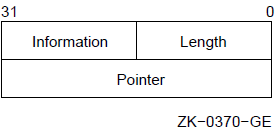
Parameters
length information pointer String descriptors are used in calling procedures (see the VSI OpenVMS RTL String Manipulation (STR$) Manual).
Example
DESCR1:  .ASCID  /ARGUMENT FOR CALL/       ; String descriptor
DESCR2:  .ASCID  /SECOND ARGUMENT/         ; Another string
                                           ;   descriptor
           .
           .
           .
         PUSHAL  DESCR1                    ; Put address of descriptors
         PUSHAL  DESCR2                    ;   on the stack
         CALLS   #2,STRNG_PROC             ; Call procedure
.ASCII
.ASCII — ASCII string storage directive
Format
.ASCII string Parameter
string Description
.ASCII stores the ASCII value of each character in the ASCII string or the value of each byte expression in the next available byte.
Example
CR=13                                   ; Assignment statements
LF=10                                   ;   define CR and LF

       .ASCII   "DATE: 17-NOV-1988"     ; Delimiter is "
       .ASCII   /EOF/<CR><LF>           ; Delimiter is /
.ASCIZ
.ASCIZ — Zero-terminated ASCII string storage directive
Format
.ASCIZ string Parameter
string Description
.ASCIZ performs the same function as .ASCII, except that .ASCIZ appends a null byte as the final character of the string. When a list or text string is created with an .ASCIZ directive, you need only perform a search for the null character in the last byte to determine the end of the string.
Example
 FF=12                                  ; Define FF

        .ASCIZ  /ABCDEF/                ; 6 characters in string,
                                        ;   7 bytes of data
.ASCIZ /A/<FF>/B/ ; 3 characters in strings.BLKx
.BLKx — Block storage allocation directives
Format
.BLKA expression .BLKB expression .BLKD expression .BLKF expression .BLKG expression .BLKH expression .BLKL expression .BLKO expression .BLKQ expression .BLKW expression Parameter
expression Description
|
Directive |
Function |
|---|---|
|
.BLKA |
Reserves storage for addresses (longwords). |
|
.BLKB |
Reserves storage for byte data. |
|
.BLKD |
Reserves storage for double-precision floating-point data(quadwords). |
|
.BLKF |
Reserves storage for single-precision floating-point data(longwords). |
|
.BLKG |
Reserves storage for G_floating data (quadwords). |
|
.BLKH |
Reserves storage for H_floating data (octawords). |
|
.BLKL |
Reserves storage for longword data. |
|
.BLKO |
Reserves storage for octaword data. |
|
.BLKQ |
Reserves storage for quadword data. |
|
.BLKW |
Reserves storage for word data. |
Each directive reserves storage for a different data type. The value of the expression determines the number of data items for which VAX MACRO reserves storage. For example, .BLKL 4 reserves storage for 4 longwords of data and .BLKB 2 reserves storage for 2 bytes of data.
|
Directive |
Number of Bytes Allocated |
|---|---|
|
.BLKB |
Value of expression |
|
.BLKW |
2 * Value of expression |
|
.BLKA |
4 * Value of expression |
|
.BLKF |
4 * Value of expression |
|
.BLKL |
4 * Value of expression |
|
.BLKD |
8 * Value of expression |
|
.BLKG |
8 * Value of expression |
|
.BLKQ |
8 * Value of expression |
|
.BLKH |
16 * Value of expression |
|
.BLKO |
16 * Value of expression |
Example
.BLKB   15            ; Space for 15 bytes
.BLKO   3             ; Space for 3 octawords (48 bytes)
.BLKL   1             ; Space for 1 longword (4 bytes)
.BLKF   <3*4>         ; Space for 12 single-precision
                      ;   floating-point values (48 bytes)
.BYTE
.BYTE — Byte storage directive
Format
.BYTE expression-list Parameter
expression-list expression1[expression2]
expression1 [expression2] Description
.BYTE generates successive bytes of binary data in the object module.
Notes
The assembler displays an error message if the high-order 3 bytes of the longword expression have a value other than 0 or ^XFFFFFF.
- At link time, a relocatable expression can result in a value that exceeds 1 byte in length. In this case, the linker issues a truncation diagnostic message for the object module in question. For example:
A:      .BYTE   A       ; Relocatable value 'A' will
                        ;   cause linker truncation
                        ;   diagnostic if the statement
                        ;   has a virtual address of 256
                        ;   or above
The .SIGNED_BYTE directive is the same as .BYTE except that the assembler displays a diagnostic message if a value in the range 128 to 255 is specified. See the description of .SIGNED_BYTE for more information.
Example
.BYTE   <1024-1000>*2           ; Stores a value of 48
.BYTE   ^XA,FIF,10,65-<21*3>    ; Stores 4 bytes of data
.BYTE   0                       ; Stores 1 byte of data
.BYTE   X,X+3[5*4],Z            ; Stores 22 bytes of data
.CROSS
.CROSS, .NOCROSS — Cross-reference directives
Format
.CROSS [symbol-list] .NOCROSS [symbol-list] Parameter
symbol-list Description
When you specify the /CROSS_REFERENCE qualifier in the MACRO command, VAXMACRO produces a cross-reference listing. The .CROSS and .NOCROSS directives control which symbols are included in the cross-reference listing. The .CROSS and .NOCROSS directives have an effect only if /CROSS_REFERENCE was specified in the MACRO command (see the VSI OpenVMS DCL Dictionary).
By default, the cross-reference listing includes the definition and all the references to every symbol in the module.
You can disable the cross-reference listing for all symbols or for a specified list of symbols by using .NOCROSS. Using .NOCROSS without a symbol list disables the cross-reference listing of all symbols. Any symbol definition or reference that appears in the code after .NOCROSS used without a symbol list and before the next .CROSS used without a symbol list is excluded from the cross-reference listing. You reenable the cross-reference listing by using .CROSS without a symbol list.
.NOCROSS with a symbol list disables the cross-reference listing for the listed symbols only. .CROSS with a symbol list enables or reenables the cross-reference listing of the listed symbols.
Notes
The .CROSS directive without a symbol list will not reenable the cross-reference listing of a symbol specified in .NOCROSS with a symbol list.
If the cross-reference listing of all symbols is disabled, .CROSS with a symbol list will have no effect until the cross-reference listing is reenabled by .CROSS without a symbol list.
Examples
        .NOCROSS                ; Stop cross-reference
LAB1:   MOVL      LOC1, LOC2    ; Copy data
        .CROSS                  ; Reenable cross-reference
In this example, the definition of LAB1 and the references to LOC1 and LOC2are not included in the cross-reference listing.
        .NOCROSS  LOC1         ; Do not cross-reference LOC1
LAB2:   MOVL      LOC1,LOC2    ; Copy data
        .CROSS    LOC1         ; Reenable cross-reference
                               ;   of LOC1
In this example, the definition of LAB2 and the reference to LOC2 are included in the cross-reference, but the reference to LOC1 is not included in the cross-reference.
.DEBUG
.DEBUG — Debug symbol attribute directive
Format
.DEBUG symbol-list Parameter
symbol-list Description
.DEBUG specifies that the symbols in the list are made known to the VAX Symbolic Debugger. During an interactive debugging session, you can use these symbols to refer to memory locations or to examine the values assigned to the symbols.
Note
The assembler adds the symbols in the symbol list to the symbol table in the object module. You need not specify global symbols in the .DEBUG directive because global symbols are automatically put in the object module's symbol table. (See the description of .ENABLE for a discussion of how to make information about local symbols available to the debugger.)
Example
.DEBUG  INPUT,OUTPUT,-    ; Make these symbols known
        LAB_30,LAB_40     ;   to the debugger
.DEFAULT
.DEFAULT — Default control directive
Format
.DEFAULT DISPLACEMENT, keyword Parameter
keyword Description
.DEFAULT determines the default displacement length for the relative and relative deferred addressing modes (see Section 5.2.1, ''Relative Mode'' and Section 5.2.2, ''Relative Deferred Mode'').
Notes
The .DEFAULT directive has no effect on the default displacement for displacement and displacement deferred addressing modes (see Section 5.1.6, ''Displacement Mode'' and Section 5.1.7, ''Displacement Deferred Mode'').
If there is no .DEFAULT in a source module, the default displacement length for the relative and relative deferred addressing modes is a longword.
Example
.DEFAULT  DISPLACEMENT,WORD   ; WORD is default
MOVL      LABEL,R1            ; Assembler uses word
                              ;   displacement unless
                              ;   label has been defined
.DEFAULT  DISPLACEMENT,LONG   ; LONG is default
INCB    @COUNTS+4             ; Assembler uses longword
                              ;   displacement unless
                              ;   COUNTS has been defined
.D_FLOATING
.D_FLOATING, .DOUBLE — Floating-point storage directive
Format
.D_FLOATING literal-list .DOUBLE literal-list Parameter
literal-list Description
.D_FLOATING evaluates the specified floating-point constants and stores the results in the object module. .D_FLOATING generates 64-bit, double-precision,floating-point data (1 bit of sign, 8 bits of exponent, and 55 bits of fraction). See the description of .F_FLOATING for information on storing single-precision floating-point numbers and the descriptions of .G_FLOATING and .H_FLOATING for descriptions of other floating-point numbers.
Notes
Double-precision floating-point numbers are always rounded. They are not affected by .ENABLE TRUNCATION.
The floating-point constants in the literal list must not be preceded by the floating-point operator (^F).
Example
.D_FLOATING  1000,1.0E3,1.0000000E-9    ; Constant
.DOUBLE      3.1415928, 1.107153423828  ; List
.D_FLOATING  5, 10, 15, 0, 0.5
.DISABLE
.DISABLE — Function control directive
Format
.DISABLE argument-list Parameter
argument-list Description
.DISABLE disables the specified assembler functions. See the description of .ENABLE for more information.
Note
The alternate form of .DISABLE is .DSABL.
.ENABLE
.ENABLE — Function control directive
Format
.ENABLE argument-list Parameter
argument-list If you specify multiple arguments, separate them with commas (,),spaces, or tabs.
| Long Form | Short Form | Default Condition | Function |
|---|---|---|---|
|
ABSOLUTE |
AMA |
Disabled |
When ABSOLUTE is enabled, all the PC relative addressing modes are assembled as absolute addressing modes. |
|
DEBUG |
DBG |
Disabled |
When DEBUG is enabled, all local symbols are included in the object module's symbol table for use by the debugger. |
|
GLOBAL |
GBL |
Enabled |
When GLOBAL is enabled, all undefined symbols are considered external symbols. When GLOBAL is disabled, any undefined symbol that is not listed in an .EXTERNAL directive causes an assembly error. |
|
LOCAL_BLOCK |
LSB |
Disabled |
When LOCAL_BLOCK is enabled, the current local label block is ended and a new one is started. When LOCAL_BLOCK is disabled, the current local label block is ended. See Section 3.4, ''Local Labels'' for a complete description of local label blocks. |
|
SUPPRESSION |
SUP |
Disabled |
When SUPPRESSION is enabled, all symbols that are defined but not referred to are not listed in the symbol table. When SUPPRESSION is disabled, all symbols that are defined are listed in the symbol table. |
|
TRACEBACK |
TBK |
Enabled |
When TRACEBACK is enabled, the program section names and lengths, module names, and routine names are included in the object module for use by the debugger. When TRACEBACK is disabled, VAX MACRO excludes this information and, in addition, does not make any local symbol information available to the debugger. |
|
TRUNCATION |
FPT |
Disabled |
When TRUNCATION is enabled,single-precision, floating-point numbers are truncated. When TRUNCATION is disabled, single-precision floating-point numbers are rounded. D_floating, G_floating, and H_floating numbers are not affected by .ENABLE TRUNCATION;they are always rounded. |
|
VECTOR |
Disabled |
When VECTOR is enabled, the assembler accepts and correctly handles vector code. If vector assembly is not enabled, vector code produces assembly errors. |
Description
Creating local label blocks
Making all local symbols available to the debugger and enabling the traceback feature
Specifying that undefined symbol references are external references
Truncating or rounding single-precision floating-point numbers
Suppressing the listing of symbols that are defined but not referenced
Specifying that all the PC references are absolute, not relative
Note
The alternate form of .ENABLE is .ENABL.
Example
.ENABLE ABSOLUTE, GLOBAL       ; Assemble relative address mode
                               ;   as absolute address mode, and consider
                               ;   undefined references as global

.DISABLE TRUNCATION,TRACEBACK  ; Round floating-point numbers, and
                               ;   omit debugging information from
                               ;   the object module
.END
.END — Assembly termination directive
Format
.END [symbol] Parameter
symbol Description
.END terminates the source program. No additional text should occur beyond this point in the current source file or in any additional source files specified in the command line for this assembly. If any additional text does occur, the assembler ignores it. The additional text does not appear in either the listing file or the object file.
Notes
The transfer address must be in a program section that has the EXE attribute (see the description of .PSECT).
When an executable image consisting of several object modules is linked,only one object module should be terminated by an .END directive that specifies a transfer address. All other object modules should be terminated by .END directives that do not specify a transfer address. If an executable image contains either no transfer address or more than one transfer address, the linker displays an error message.
If the source program contains an unterminated conditional code block when the .END directive is specified, the assembler displays an error message.
Example
.ENTRY  START,0                 ; Entry mask
  .
  .                             ; Main program
  .
.END    START                   ; Transfer address
.ENDC
.ENDC — End conditional directive
Format
.ENDC Description
.ENDC terminates the conditional range started by the .IF directive. See the description of .IF for more information and examples.
.ENDM
.ENDM — End definition directive
Format
.ENDM [macro-name] Parameter
macro-name Description
.ENDM terminates the macro definition. See the description of .MACRO for an example of the use of .ENDM.
Note
If .ENDM is encountered outside a macro definition, the assembler displays an error message.
.ENDR
.ENDR — End range directive
Format
.ENDR Description
.ENDR indicates the end of a repeat range. It must be the final statement of every indefinite repeat block directive (.IRP and .IRPC) and every repeat block directive (.REPEAT). See the description of these directives for examples of the use of .ENDR.
.ENTRY
.ENTRY — Entry directive
Format
.ENTRY symbol,expression Parameters
symbol expression Description
.ENTRY defines a symbolic name for an entry point and stores a register save mask (2 bytes) at that location. The symbol is defined as a global symbol with a value equal to the value of the location counter at the .ENTRY directive. You can use the entry point as the transfer address of the program. Use the register save mask to determine which registers are saved before the procedure is called. These saved registers are automatically restored when the procedure returns control to the calling program. See the description of the procedure call instructions in Chapter 9, "VAX Instruction Set".
Notes
The register mask operator (^M) is convenient to use for setting the bits in the register save mask (see Section 3.6.2.2, ''Register Mask Operator'').
An assembly error occurs if the expression has bits 0, 1, 12, or 13 set. These bits correspond to the registers R0, R1, AP, and FP and are reserved for the CALL interface.
- VSI recommends that you use .ENTRY to define all callable entry points including the transfer address of the program. Although the following construct also defines an entry point, VSI discourages its use:
symbol:: .WORD expression
Although your program can call a procedure starting with this construct, the entry mask is not checked for any illegal registers, and the symbol cannot be used in a .MASK directive.
- You should use .ENTRY only for procedures that are called by the CALLS or CALLG instruction. A routine that is entered by the BSB or JSB instruction should not use .ENTRY because these instructions do not expect a register save mask. Begin these routines using the following format:
symbol:: first instruction
The first instruction of the routine immediately follows the symbol.
Example
.ENTRY  CALC,^M<R2,R3,R7>      ; Procedure starts here.
                               ; Registers R2, R3, and R7
                               ;   are preserved by CALL
                               ;   and RET instructions
.ERROR
.ERROR — Error directive
Format
.ERROR [expression] ;comment Parameters
expression ;comment Description
.ERROR causes the assembler to display an error message on the terminal or batch log file and in the listing file (if there is one).
Notes
.ERROR, .WARN, and .PRINT are message display directives. Use them to display information indicating that a macro call contains an error or an illegal set of conditions.
When the assembly is finished, the assembler displays the total number of errors, warnings, information messages, and the sequence numbers of the lines causing the errors or warnings.
If .ERROR is included in a macro library, end the comment with a semicolon (;). Otherwise, the librarian will strip the comment from the directive and it will not be displayed when the macro is called.
The line containing the .ERROR directive is not included in the listing file.
If the expression has a value of zero, it is not displayed in the error message.
Example
.IF DEFINED     LONG_MESS
.IF GREATER     1000-WORK_AREA
.ERROR 25                        ; Need larger WORK_AREA;
.ENDC
.ENDC
In this example, if the symbol LONG_MESS is defined and if the symbol WORK_AREA has a value of 1000 or less, the following error message is displayed:
%MACRO-E-GENERR, Generated ERROR: 25 Need larger WORK_AREA
.EVEN
.EVEN — Even location counter alignment directive
Format
.EVEN Description
.EVEN ensures that the current value of the location counter is even by adding 1 if the current value is odd. If the current value is already even, no action is taken.
.EXTERNAL
.EXTERNAL — External symbol attribute directive
Format
.EXTERNAL symbol-list Parameter
symbol-list Description
.EXTERNAL indicates that the specified symbols are external; that is, the symbols are defined in another object module and cannot be defined until link time (see Section 3.3.3, ''Determining Symbol Values'' for a discussion of external references).
Notes
If the GLOBAL argument is enabled (see Table 6.3, ''.ENABLE and .DISABLE Symbolic Arguments''), all unresolved references will be marked as global and external. If GLOBAL is enabled, you need not specify .EXTERNAL. If GLOBAL is disabled, you must explicitly specify .EXTERNAL to declare any symbols that are defined externally but are referred to in the current module.
If GLOBAL is disabled and the assembler finds symbols that are neither defined in the current module nor listed in a .EXTERNAL directive, the assembler displays an error message.
Note that if your program does not reference, in a relocatable program section, symbols that are declared in the absolute program section (ABS), the unreferenced symbols are filtered out by the assembler and will not be included in the object file. This filtering out will occur even if the symbols are declared global or external.
If you want to be sure that a symbol will be included even if it is not referenced, declare it in a relocatable program section. If you want to make sure that a symbol you define in an absolute program section is included,reference it in a relocatable program section.
The alternate form of .EXTERNAL is .EXTRN.
Example
.EXTERNAL      SIN,TAN,COS     ; These symbols are defined in
.EXTERNAL      SINH,COSH,TANH  ;   externally assembled modules
.F_FLOATING
.F_FLOATING, .FLOAT — Floating-point storage directive
Format
.F_FLOATING literal-list .FLOAT literal-list Parameter
literal-list Description
.F_FLOATING evaluates the specified floating-point constants and stores the results in the object module. .F_FLOATING generates 32-bit, single-precision,floating-point data (1 bit of sign, 8 bits of exponent, and 23 bits of fractional significance). See the description of .D_FLOATING for information on storing double-precision floating-point numbers and the descriptions of .G_FLOATING and .H_FLOATING for descriptions of other floating-point numbers.
Notes
See the description of .ENABLE for information on specifying floating-point rounding or truncation.
The floating-point constants in the literal list must not be preceded by the floating-point unary operator (^F).
Example
.F_FLOATING  134.5782,74218.34E20     ; Constant list
.F_FLOATING  134.2,0.1342E3,1342E-1   ; These all generate 134.2
.F_FLOATING  -0.75,1E38,-1.0E-37      ; Constant list
.FLOAT       0,25,50
.G_FLOATING
.G_FLOATING — G_floating-point storage directive
Format
.G_FLOATING literal-list Parameters
literal-list Description
.G_FLOATING evaluates the specified floating-point constants and stores the results in the object module. .G_FLOATING generates 64-bit data (1 bit of sign, 11 bits of exponent, and 52 bits of fraction).
Notes
G_floating-point numbers are always rounded. They are not affected by the .ENABLE TRUNCATION directive.
The floating-point constants in the literal list must not be preceded by the floating-point operator (^F).
Example
.G_FLOATING 1000, 1.0E3, 1.0000000E-9 ; Constant list
.GLOBAL
.GLOBAL — Global symbol attribute directive
Format
.GLOBAL symbol-list Parameter
symbol-list Description
.GLOBAL indicates that specified symbol names are either globally defined in the current module or externally defined in another module (see Section 3.3.3, ''Determining Symbol Values'').
Notes
.GLOBAL is provided for MACRO-11 compatibility only. VSI recommends that global definitions be specified by a double colon (::) or double equal sign (==) (see Section 2.1, ''Label Field'' and Section 3.8, ''Direct Assignment Statements'') and that external references be specified by .EXTERNAL when necessary.
The alternate form of .GLOBAL is .GLOBL.
Example
.GLOBAL LAB_40,LAB_30           ; Make these symbol names
                                ;   globally known
.GLOBAL UKN_13                  ;   to all linked modules
.H_FLOATING
.H_FLOATING — H_floating-point storage directive
Format
.H_FLOATING literal-list Parameter
literal-list Description
.H_FLOATING evaluates the specified floating-point constants and stores the results in the object module. .H_FLOATING generates 128-bit data (1 bit of sign, 15 bits of exponent, and 112 bits of fraction).
Notes
H_floating-point numbers are always rounded. They are not affected by the .ENABLE TRUNCATION directive.
The floating-point constants in the literal list must not be preceded by the floating-point operator (^F).
Example
.H_FLOATING 36912, 15.0E18, 1.0000000E-9 ; Constant list
.IDENT
.IDENT — Identification directive
Format
.IDENT string Parameter
string Description
.IDENT provides a means of identifying the object module. This identification is in addition to the name assigned to the object module with .TITLE. A character string can be specified in .IDENT to label the object module. This string is printed in the header of the listing file and also appears in the object module.
Notes
If a source module contains more than one .IDENT, the last directive given establishes the character string that forms part of the object module identification.
If the delimiting characters do not match, or if you use an illegal delimiting character, the assembler displays an error message.
Example
.IDENT /3-47/ ; Version and edit numbers
The character string "3-47" is included in the object module.
.IF
.IF — Conditional assembly block directives
Format
.IF condition argument(s) ⁝
range ⁝
.ENDC Parameters
condition argument(s) range |
Condition Test |
Complement Condition Test |
Argument Type |
Number of Args |
Condition that Assembles Block | ||
|---|---|---|---|---|---|---|
|
Long Form |
Short Form |
Long Form |
Short Form | |||
|
EQUAL |
EQ |
NOT_EQUAL |
NE |
Expression |
1 |
Expression is equal to 0/not equal to 0. |
|
GREATER |
GT |
LESS_EQUAL |
LE |
Expression |
1 |
Expression is greater than 0/less than or equal to 0. |
|
LESS_THAN |
LT |
GREATER_EQUAL |
GE |
Expression |
1 |
Expression is less than 0/greater than or equal to 0. |
|
DEFINED |
DF |
NOT_DEFINED |
NDF |
Symbolic |
1 |
Symbol is defined /not defined. |
|
BLANK? |
B |
NOT_BLANK? |
NB |
Macro |
1 |
Argument is blank/ nonblank. |
|
IDENTICAL? |
IDN |
DIFFERENT? |
DIF |
Macro |
2 |
Arguments are identical/different. |
Description
A conditional assembly block is a series of source statements that is assembled only if a certain condition is met. .IF starts the conditional block and .ENDC ends the conditional block; each .IF must have a corresponding .ENDC. The .IF directive contains a condition test and one or two arguments. The condition test specified is applied to the arguments. If the test is met,all VAX MACRO statements between .IF and .ENDC are assembled. If the test is not met, the statements are not assembled. An exception to this rule occurs when you use subconditional directives (see the description of the .IF_xdirective).
Conditional blocks can be nested; that is, a conditional block can be inside another conditional block. In this case, the statements in the inner conditional block are assembled only if the condition is met for both the outer and inner block.
Notes
If .ENDC occurs outside a conditional assembly block, the assembler displays an error message.
VAX MACRO permits a nesting depth of 31 conditional assembly levels. If a statement attempts to exceed this nesting level depth, the assembler displays an error message.
Lowercase string arguments are converted to uppercase before being compared, unless the string is surrounded by delimiters. For information on string arguments and delimiters, see Chapter 4, "Macro Arguments and String Operators".
The assembler displays an error message if .IF specifies any of the following: a condition test other than those in Table 6.4, ''Condition Tests for Conditional Assembly Directives'',an illegal argument, or a null argument specified in an .IF directive.
The .SHOW and .NOSHOW directives control whether condition blocks that are not assembled are included in the listing file.
Examples
An example of a conditional assembly directive is:

   .IF EQUAL  ALPHA+1        ; Assemble block if ALPHA+1=0. Do
     .                       ;   not assemble if ALPHA+1 not=0
     .
     .
   .ENDC
Nested conditional directives take the form: .IF condition,argument(s) .IF condition,argument(s) . . . .ENDC .ENDCThe following conditional directives can govern whether assembly is to occur: .IF DEFINED SYM1 .IF DEFINED SYM2 . . . .ENDC .ENDCIn this example, if the outermost condition is not satisfied, no deeper level of evaluation of nested conditional statements within the program occurs. Therefore, both SYM1 and SYM2 must be defined for the code to be assembled.
.IF_x
.IF_x — Subconditional assembly block directives
Format
.IF_FALSE .IF_TRUE .IF_TRUE_FALSE Description
|
Directive |
Function |
|---|---|
|
.IF_FALSE |
If the condition of the assembly block tests false, the program includes the source code following the .IF_FALSE directive and continuing up to the next subconditional directive or to the end of the conditional assembly block. |
|
.IF_TRUE |
If the condition of the assembly block tests true, the program includes the source code following the .IF_TRUE directive and continuing up to the next subconditional directive or to the end of the conditional assembly block. |
|
.IF_TRUE_FALSE |
Regardless of whether the condition of the assembly block tests true or false, the source code following the .IF TRUE_FALSE directive (and continuing up to the next subconditional directive or to the end of the assembly block) is always included. |
The implied argument of a subconditional directive is the condition test specified when the conditional assembly block was entered. A conditional or subconditional directive in a nested conditional assembly block is not evaluated if the preceding (or outer) condition in the block is not satisfied (see Examples 3 and 4).
A conditional block with a subconditional directive is different from a nested conditional block. If the condition in the .IF is not met, the inner conditional blocks are not assembled, but a subconditional directive can cause a block to be assembled.
Notes
If a subconditional directive appears outside a conditional assembly block, the assembler displays an error message.
The alternate forms of .IF_FALSE, .IF_TRUE, and .IF_TRUE_FALSE are .IFF,.IFT, and .IFTF.
Examples
Assume that symbol SYM is defined:

   .IF DEFINED   SYM               ; Tests TRUE since SYM is defined.
     .                             ;   Assembles the following code.
     .
     .
   .IF_FALSE                       ; Tests FALSE since previous
     .                             ;   .IF was TRUE.  Does not
     .                             ;   assemble the following code.
     .
   .IF_TRUE                        ; Tests TRUE since SYM is defined.
     .                             ;   Assembles the following code.
     .
     .
   .IF_TRUE_FALSE                  ; Assembles the following code
     .                             ;   unconditionally.
     .
     .
   .IF_TRUE                        ; Tests TRUE since SYM is defined.
     .                             ;   Assembles remainder of
     .                             ;   conditional assembly block.
     .
   .ENDC
Assume that symbol X is defined and that symbol Y is not defined: .IF DEFINED X ; Tests TRUE since X is defined. .IF DEFINED Y ; Tests FALSE since Y is not defined. .IF_FALSE ; Tests TRUE since Y is not defined. . ; Assembles the following code. . . .IF_TRUE ; Tests FALSE since Y is not defined. . ; Does not assemble the following . ; code. . .ENDC .ENDCAssume that symbol A is defined and that symbol B is not defined: .IF DEFINED A ; Tests TRUE since A is defined. . ; Assembles the following code. . . .IF_FALSE ; Tests FALSE since A is defined. . ; Does not assemble the following . ; code. . .IF NOT_DEFINED B ; Nested conditional directive . ; is not evaluated. . . .ENDC .ENDCAssume that symbol X is not defined but symbol Y is defined: .IF DEFINED X ; Tests FALSE since X is not defined. . ; Does not assemble the following . ; code. . .IF DEFINED Y ; Nested conditional directive . ; is not evaluated. . . .IF_FALSE ; Nested subconditional . ; directive is not evaluated. . . .IF_TRUE ; Nested subconditional . ; directive is not evaluated. . . .ENDC .ENDC
.IIF
.IIF — Immediate conditional assembly block directive
Format
.IIF condition [,]argument(s), statement Parameters
condition argument(s) statement Description
.IIF provides a means of writing a one-line conditional assembly block. The condition to be tested and the conditional assembly block are expressed completely within the line containing the .IIF directive. No terminating .ENDC statement is required.
Note
The assembler displays an error message if .IIF specifies a condition test other than those listed in Table 6.4, ''Condition Tests for Conditional Assembly Directives'', an illegal argument,or a null argument.
Example
.IIF DEFINED EXAM, BEQL ALPHA
This directive generates the following code if the symbol EXAM is defined within the source program:
BEQL ALPHA
.IRP
.IRP — Indefinite repeat argument directive
Format
.IRP symbol, <argument list> ⁝
range ⁝
.ENDR Parameters
symbol <argument list> range Description
.IRP replaces a formal argument with successive actual arguments specified in an argument list. This replacement process occurs during the expansion of the indefinite repeat block range. The .ENDR directive specifies the end of the range.
.IRP is analogous to a macro definition with only one formal argument. At each expansion of the repeat block, this formal argument is replaced with successive elements from the argument list. The directive and its range are coded in line within the source program. This type of macro definition and its range do not require calling the macro by name, as do other macros described in this section.
.IRP can appear either inside or outside another macro definition, indefinite repeat block, or repeat block (see the description of .REPEAT). The rules for specifying .IRP arguments are the same as those for specifying macro arguments.
Example
.MACRO  CALL_SUB        SUBR,A1,A2,A3,A4,A5,A6,A7,A8,A9,A10
.NARG   COUNT
.IRP    ARG,<A10,A9,A8,A7,A6,A5,A4,A3,A2,A1>
.IIF    NOT_BLANK ,     ARG,    PUSHL ARG
.ENDR
CALLS   #<COUNT-1>,SUBR         ; Note SUBR is counted
.ENDM   CALL_SUB
The macro call and expansion of the macro defined previously is as follows:
CALL_SUB        TEST,INRES,INTES,UNLIS,OUTCON,#205
.NARG   COUNT
.IRP    ARG,<,,,,,#205,OUTCON,UNLIS,INTES,INRES>
.IIF    NOT_BLANK ,     ARG,      PUSHL ARG
.ENDR
.IIF    NOT_BLANK ,     ,         PUSHL
.IIF    NOT_BLANK ,     ,         PUSHL
.IIF    NOT_BLANK ,     ,         PUSHL
.IIF    NOT_BLANK ,     ,         PUSHL
.IIF    NOT_BLANK ,     ,         PUSHL
.IIF    NOT_BLANK ,     #205,     PUSHL #205
.IIF    NOT_BLANK ,     OUTCON,   PUSHL OUTCON
.IIF    NOT_BLANK ,     UNLIS,    PUSHL UNLIS
.IIF    NOT_BLANK ,     INTES,    PUSHL INTES
.IIF    NOT_BLANK ,     INRES,    PUSHL INRES
CALLS   #<COUNT-1>,TEST         ; Note TEST is counted
This example uses the .NARG directive to count the arguments and the .IIFNOT_BLANK directive (see descriptions of .IF and .IIF in this section) to determine whether the actual argument is blank. If the argument is blank, no binary code is generated.
.IRPC
.IRPC — Indefinite repeat character directive
Format
.IRPC symbol,<string> ⁝
range ⁝
.ENDR Parameters
symbol <string> range Description
.IRPC is similar to .IRP except that .IRPC permits single-character substitution rather than argument substitution. On each iteration of the indefinite repeat range, the formal argument is replaced with each successive character in the specified string. The .ENDR directive specifies the end of the range.
.IRPC is analogous to a macro definition with only one formal argument. At each expansion of the repeat block, this formal argument is replaced with successive characters from the actual argument string. The directive and its range are coded in line within the source program and do not require calling the macro by name.
.IRPC can appear either inside or outside another macro definition, indefinite repeat block, or repeat block (see description of .REPEAT).
Example
      .MACRO  HASH_SYM        SYMBOL
      .NCHR   HV,<SYMBOL>
      .IRPC   CHR,<SYMBOL>
HV = HV+^A?CHR?
      .ENDR
      .ENDM   HASH_SYM
The macro call and expansion of the macro defined previously is as follows:
      HASH_SYM        <MOVC5>
      .NCHR   HV,<MOVC5>
      .IRPC   CHR,<MOVC5>
HV = HV+^A?CHR?
      .ENDR
HV = HV+^A?M?
HV = HV+^A?O?
HV = HV+^A?V?
HV = HV+^A?C?
HV = HV+^A?5?
This example uses the .NCHR directive to count the number of characters in an actual argument.
.LIBRARY
.LIBRARY — Macro library directive
Format
.LIBRARY macro-library-name Parameter
macro-library-name Description
.LIBRARY adds a name to the macro library list that is searched whenever a .MCALL or an undefined opcode is encountered. The libraries are searched in the reverse order in which they were specified to the assembler.
If you omit any information from the macro-library-name argument, default values are assumed. The device defaults to your current default disk; the directory defaults to your current default directory; the file type defaults to MLB.
VSI recommends that libraries be specified in the MACRO command line with the /LIBRARY qualifier rather than with the .LIBRARY directive. The .LIBRARY directive makes moving files cumbersome.
Example
.LIBRARY   /DISK:[TEST]USERM/     ; DISK:[TEST]USERM.MLB
.LIBRARY   ?DISK:SYSDEF.MLB?      ; DISK:SYSDEF.MLB
.LIBRARY   \CURRENT.MLB\          ; Uses default disk and directory
.LINK
.LINK — Linker option record directive
Format
.LINK "file-spec" [/qualifier[=(module-name[,...])],...] Parameters
file-spec[,...] The input files can be object modules to be linked, or shareable images to be included in the output image. Input files can also be libraries containing external references or specific modules for inclusion in the output image. The linker will search the libraries for the external references. If you specify multiple input files, separate the file specifications with commas (,).
If you do not specify a file type in an input file specification, the linker supplies default file types, based on the nature of the file. All object modules are assumed to have file types of OBJ.
Note that the input file specifications must be correct at linktime. Make your references explicit, so that if the object module created by VAX MACRO is linked in a directory other than the one in which it was created,the linker will still be able to find the files referenced in the .LINK directive.
No wildcard characters are allowed in the file specification.
File Qualifiers
/INCLUDE=(module-name[,...]) At least one module name must be specified. If you specify more than one module name, separate the names with commas (,) and enclose the list in parentheses.
No wildcard characters are allowed in the module name specifications. Module names may not be longer than 31 characters, the maximum length of a VAX MACRO symbol.
/LIBRARY If the associated input file specification does not include a file type, the linker assumes the default file type of OLB. You can use both /INCLUDE and/LIBRARY to qualify a file specification. If you specify both /INCLUDE and/LIBRARY, the library is subsequently searched for unresolved references. In this case, the explicit inclusion of modules occurs first; then the linker searches the library for unresolved references.
/SELECTIVE_SEARCH /SHAREABLE |
Abbreviation |
Qualifier |
|---|---|
|
/I |
/INCLUDE |
|
/L |
/LIBRARY |
|
/SE |
/SELECTIVE_SEARCH |
|
/SH |
/SHAREABLE |
Description
The .LINK directive allows you to include linker option records in an object module produced by VAX MACRO. The qualifiers for the .LINK directive perform functions similar to the functions performed by the same qualifiers for the DCL command LINK.
You should use the .LINK directive for references that are not linker defaults, but that you always want to include in a particular image. Using the .LINK directive enables you to avoid having to explicitly name these references in the DCL command LINK.
For detailed information on the qualifiers to the DCL command LINK, see the VSI OpenVMS DCL Dictionary. For a complete discussion of the operation of the linker itself, see the VSI OpenVMS Linker Utility Manual.
Examples
.LINK "SYS$LIBRARY:MYLIB" /INCLUDE=(MOD1, MOD2, MOD6)
This statement, when included in the file MYPROG.MAR, causes the assembler to request that MYPROG.OBJ be linked with modules MOD1, MOD2, and MOD6 in the library SYS$LIBRARY:MYLIB.OLB (where SYS$LIBRARY is a logical name for the disk and directory in which MYLIB.OLB is listed). The library is not searched for other unresolved references. The statement is equivalent to linking the file with the DCL command:
$ LINK MYPROG, SYS$LIBRARY:MYLIB /INCLUDE=(MOD1, MOD2, MOD6)
.LINK \SYS$LIBRARY:MYOBJ\                  ; Link with object module
                                           ;  SYS$LIBRARY:MYOBJ.OBJ

.LINK 'SYS$LIBRARY:YOURLIB' /LIBRARY       ; Search object library
                                           ;  SYS$LIBRARY:YOURLIB.OLB
                                           ;  for unresolved references

.LINK *SYS$LIBRARY:MYSTB.STB* /SELECTIVE_SEARCH
                                           ; Search symbol table
                                           ;  SYS$LIBRARY:MYSTB.STB
                                           ;  for unresolved references

.LINK "SYS$LIBRARY:MYSHR.EXE" /SHAREABLE   ; Link with shareable image
                                           ;  SYS$LIBRARY:MYSHR.EXE
To increase efficiency and performance, include several related input files in a single .LINK directive. The following example shows how the five options illustrated previously can be included in one statement:
.LINK   'SYS$LIBRARY:MYOBJ',-
        'SYS$LIBRARY:YOURLIB' /LIBRARY,-
        'SYS$LIBRARY:MYLIB' /INCLUDE=(MOD1, MOD2, MOD6),-
        'SYS$LIBRARY:MYSTB.STB' /SELECTIVE_SEARCH,-
        'SYS$LIBRARY:MYSHR.EXE' /SHAREABLE
.LIST
.LIST — Listing directive
Format
.LIST [argument-list] Parameter
argument-list Description
.LIST is equivalent to .SHOW. See the description of .SHOW for more information.
.LONG
.LONG — Longword storage directive
Format
.LONG expression-list Parameter
expression-list expression1[expression2]
expression1 [expression2] Description
.LONG generates successive longwords (4 bytes) of data in the object module.
Example
LAB_3:  .LONG   LAB_3,^X7FFFFFFF,^A'ABCD' ; 3 longwords of data
        .LONG   ^XF@4                     ; 1 longword of data
        .LONG   0[22]                     ; 22 longwords of data
Note
Each expression in the list must have a value that can be represented in 32bits.
.MACRO
.MACRO — Macro definition directive
Format
.MACRO macro-name [formal-argument-list] ⁝
range ⁝
.ENDM [macro name] Parameters
macro-name .MACRO macro-name [formal-argument-list] formal-argument-list range Description
.MACRO begins the definition of a macro. It gives the macro name and a list of formal arguments (see Chapter 4, "Macro Arguments and String Operators"). If the name specified is the same as the name of a previously defined macro, the previous definition is deleted and replaced with the new one. The .MACRO directive is followed by the source text to be included in the macro expansion. The .ENDM directive specifies the end of the range.
Macro names do not conflict with user-defined symbols. Both a macro and a user-defined symbol can have the same name.
When the assembler encounters a .MACRO directive, it adds the macro name to its macro name table and stores the source text of the macro (up to the matching .ENDM directive). No other processing occurs until the macro is expanded.
The symbols in the formal argument list are associated with the macro name and are limited to the scope of the definition of that macro. For this reason,the symbols that appear in the formal argument list can also appear elsewhere in the program.
Notes
If a macro has the same name as a VAX opcode, the macro is used instead of the instruction. This feature allows you to temporarily redefine an opcode.
If a macro has the same name as a VAX opcode and is in a macro library,you must use the .MCALL directive to define the macro. Otherwise, because the symbol is already defined (as the opcode), the assembler will not search the macro libraries.
You can redefine a macro with new source text during assembly by specifying a second .MACRO directive with the same name. Including a second .MACRO directive within the original macro definition causes the first macro call to redefine the macro. This feature is useful when a macro performs initialization or defines symbols, when an operation is performed only once. The macro redefinition can eliminate unneeded source text in a macro or it can delete the entire macro. The .MDELETE directive provides another way to delete macros.
Example
        .MACRO  USERDEF
        .PSECT  DEFIES,ABS
MYSYM=  5
HIVAL=  ^XFFF123
LOWVAL= 0
        .PSECT  RWDATA,NOEXE,LONG
TABLE:  .BLKL   100
LIST:   .BLKB   10
        .MACRO  USERDEF                  ; Redefine it to null
        .ENDM   USERDEF
        .ENDM   USERDEF
The macro calls and expansions of the macro defined previously are as follows:
        USERDEF                          ; Should expand data
        .PSECT  DEFIES,ABS
MYSYM=  5
HIVAL=  ^XFFF123
LOWVAL= 0
        .PSECT  RWDATA,NOEXE,LONG
TABLE:  .BLKL   100
LIST:   .BLKB   10
        .MACRO  USERDEF                  ; Redefine it to null
        .ENDM   USERDEF

        USERDEF                          ; Should expand nothing
In this example, when the macro is called the first time, it defines some symbols and data storage areas and then redefines itself. When the macro is called a second time, the macro expansion contains no source text.
.MASK
.MASK — Mask directive
Format
.MASK symbol[,expression] Parameters
symbol expression Description
.MASK reserves a word for a register save mask for a transfer vector. See the description of .TRANSFER for more information and for an example of .MASK.
Notes
If .MASK does not contain an expression, the assembler directs the linker to copy the register save mask specified in .ENTRY to the word reserved by .MASK.
If .MASK contains an expression, the assembler directs the linker to combine this expression with the register save mask specified in .ENTRY and store the result in the word reserved by .MASK. The linker performs an inclusive OR operation to combine the mask in the entry point and the value of the expression. Consequently, a register specified in either .ENTRY or .MASK will be included in the combined mask. See the description of .ENTRY for more information on entry masks.
.MCALL
.MCALL — Macro call directive
Format
.MCALL macro-name-list Parameter
macro-name-list Description
.MCALL specifies the names of the system and user-defined macros that are required to assemble the source program but are not defined in the source file.
If any named macro is not found upon completion of the search (that is, if the macro is not defined in any of the macro libraries), the assembler displays an error message.
Note
.MCALL is provided for compatibility with MACRO-11; with one exception,VSI recommends that you not use it. When VAX MACRO finds an unknown symbol in the opcode field, it automatically searches all macro libraries. If it finds the symbol in a library, it uses the macro definition and expands the macro reference. If VAX MACRO does not find the symbol in the library, it displays an error message.
You must use .MCALL when a macro has the same name as an opcode (see description of .MACRO).
Example
.MCALL  INSQUE         ; Substitute macro in
                       ;   library for INSQUE
                       ;   instruction
.MDELETE
.MDELETE — Macro deletion directive
Format
.MDELETE macro-name-list Parameter
macro-name-list Description
.MDELETE deletes the definitions of specified macros. The number of macros actually deleted is printed in the assembly listing on the same line as the .MDELETE directive.
.MDELETE completely deletes the macro, freeing memory as necessary. Macro redefinition with .MACRO merely redefines the macro.
Example
.MDELETE USERDEF,$SSDEF,ALTR
.MEXIT
.MEXIT — Macro exit directive
Format
.MEXIT Description
.MEXIT terminates a macro expansion before the end of the macro. Termination is the same as if .ENDM were encountered. You can use the directive within repeat blocks. .MEXIT is useful in conditional expansion of macros because it bypasses the complexities of nested conditional directives and alternate assembly paths.
Notes
When .MEXIT occurs in a repeat block, the assembler terminates the current repetition of the range and suppresses further expansion of the repeat range.
When macros or repeat blocks are nested, .MEXIT exits to the next higher level of expansion.
If .MEXIT occurs outside a macro definition or a repeat block, the assembler displays an error message.
Example
.MACRO   P0L0    N,A,B
   .
   .
   .
.IF EQ  N                    ; Start conditional assembly block
   .
   .
   .
.MEXIT                       ; Terminate macro expansion
.ENDC                        ; End conditional assembly block
   .
   .
   .
.ENDM   P0L0                 ; Normal end of macro
In this example, if the actual argument for the formal argument N equals zero, the conditional block is assembled, and the macro expansion is terminated by .MEXIT.
.NARG
.NARG — Number of arguments directive
Format
.NARG symbol Parameter
symbol Description
.NARG determines the number of arguments in the current macro call.
.NARG counts all the positional arguments specified in the macro call,including null arguments (specified by adjacent commas (,)). The value assigned to the specified symbol does not include either any keyword arguments or any formal arguments that have default values.
Note
If .NARG appears outside a macro, the assembler displays an error message.
Example
.MACRO  CNT_ARG A1,A2,A3,A4,A5,A6,A7,A8,A9=DEF9,A10=DEF10
.NARG   COUNTER         ; COUNTER is set to no. of ARGS
.WORD   COUNTER         ; Store value of COUNTER
.ENDM   CNT_ARG
The macro calls and expansions of the macro defined previously are as follows:
CNT_ARG TEST,FIND,ANS   ; COUNTER will = 3
.NARG   COUNTER         ; COUNTER is set to no. of ARGS
.WORD   COUNTER         ; Store value of COUNTER

CNT_ARG                 ; COUNTER will = 0
.NARG   COUNTER         ; COUNTER is set to no. of ARGS
.WORD   COUNTER         ; Store value of COUNTER

CNT_ARG TEST,A2=SYMB2,A3=SY3      ; COUNTER will = 1
.NARG   COUNTER         ; COUNTER is set to no. of ARGS
.WORD   COUNTER         ; Store value of COUNTER
                        ; Keyword arguments are not counted

CNT_ARG ,SYMBL,,        ; COUNTER will = 3
.NARG   COUNTER         ; COUNTER is set to no. of ARGS
.WORD   COUNTER         ; Store value of COUNTER
                        ; Null arguments are counted
.NCHR
.NCHR — Number of characters directive
Format
.NCHR .NCHR symbol,<string> Parameters
symbol <string> Description
.NCHR determines the number of characters in a specified character string. It can appear anywhere in a VAX MACRO program and is useful in calculating the length of macro arguments.
Example
.MACRO   CHAR    MESS                    ; Define MACRO
.NCHR    CHRCNT,<MESS>                   ; Assign value to CHRCNT
.WORD    CHRCNT                          ; Store value
.ASCII   /MESS/                          ; Store characters
.ENDM    CHAR                            ; Finish
The macro calls and expansions of the macro defined previously are as follows:
CHAR     <HELLO>                        ; CHRCNT will = 5
.NCHR    CHRCNT,<HELLO>                 ; Assign value to CHRCNT
.WORD    CHRCNT                          ; Store value
.ASCII   /HELLO/                         ; Store characters

CHAR     <14, 75.39  4>                 ; CHRCNT will = 12(dec)
.NCHR    CHRCNT,<14, 75.39  4>          ; Assign value to CHRCNT
.WORD    CHRCNT                          ; Store value
.ASCII   /14, 75.39  4/                  ; Store characters
.NLIST
.NLIST — Listing directive
Format
.NLIST [argument-list] Parameter
argument-list Description
.NLIST is equivalent to .NOSHOW. See the description of .SHOW for more information.
.NOCROSS
.NOCROSS — Cross-reference directive
Format
.NOCROSS [symbol-list] Parameter
symbol-list Description
VAX MACRO produces a cross-reference listing when the /CROSS_REFERENCE qualifier is specified in the MACRO command. The .CROSS and .NOCROSS directives control which symbols are included in the cross-reference listing. The description of .NOCROSS is included with the description of .CROSS.
.NOSHOW
.NOSHOW — Listing directive
Format
.NOSHOW [argument-list] Parameter
argument-list One or more of the symbolic arguments listed in Table 6.8, ''.SHOW and .NOSHOW Symbolic Arguments'' in the description of .SHOW. Use either the long form or the short form of the arguments. If you specify multiple arguments, separate them with commas (,), spaces, or tabs.
Description
.NOSHOW specifies listing control options. See the description of .SHOW for more information.
.NTYPE
.NTYPE — Operand type directive
Format
.NTYPE symbol,operand Parameters
symbol operand Description
.NTYPE determines the addressing mode of the specified operand.
The value of the symbol is set to the specified addressing mode. In most cases, an 8-bit (1-byte) value is returned. Bits 0 to 3 specify the register associated with the mode, and bits 4 to 7 specify the addressing mode. To provide concise addressing information, the mode bits 4 to 7 are not exactly the same as the numeric value of the addressing mode described in Table C.6, ''Addressing Modes''. Literal mode is indicated by a zero in bits 4 to 7, instead of the values 0 to 3. Mode 1 indicates an immediate mode operand, mode 2 indicates an absolute mode operand, and mode 3 indicates a general mode operand.
For indexed addressing mode, a 16-bit (2-byte) value is returned. The high-order byte contains the addressing mode of the base operand specifier and the low-order byte contains the addressing mode of the primary operand (the index register).
See Chapter 5, "VAX MACRO Addressing Modes" of this volume for more information on addressing modes.
Example
; The following macro is used to push an address on the stack. It
; checks the operand type (by using .NTYPE) to determine if the
; operand is an address and, if not, the macro simply pushes the
; argument on the stack and generates a warning message.
;
        .MACRO  PUSHADR #ADDR
        .NTYPE  A,ADDR                  ; Assign operand type to 'A'
A = A@-4&^XF                            ; Isolate addressing mode
        .IF IDENTICAL 0,<ADDR>          ; Is argument exactly 0?
        PUSHL   #0                      ; Stack zero
        .MEXIT                          ; Exit from macro
        .ENDC
ERR = 0                                 ; ERR tells if mode is address
                                        ; ERR = 0 if address, 1 if not
        .IIF LESS_EQUAL A-1,   ERR=1    ; Is mode not literal or
                                        ;   immediate?
        .IIF EQUAL A-5,   ERR=1         ; Is mode not register?
        .IF EQUAL  ERR                  ; Is mode address?
        PUSHAL  ADDR                    ; Yes, stack address
        .IFF                            ; No
        PUSHL   ADDR                    ; Then stack operand & warn
        .WARN   ; ADDR is not an address;
        .ENDC
        .ENDM   PUSHADR
The macro calls and expansions of the macro defined previously are as follows:
        PUSHADR (R0)                    ; Valid argument
        PUSHAL  (R0)                    ; Yes, stack address

        PUSHADR (R1)[R4]                ; Valid argument
        PUSHAL  (R1)[R4]                ; Yes, stack address

        PUSHADR 0                       ; Is zero
        PUSHL   #0                      ; Stack zero

        PUSHADR #1                      ; Not an address
        PUSHL   #1                      ; Then stack operand & warn
%MACRO-W-GENWRN, Generated WARNING: #1 is not an address

        PUSHADR R0                      ; Not an address
        PUSHL   R0                      ; Then stack operand & warn
%MACRO-W-GENWRN, Generated WARNING: R0 is not an address
Note that to save space, this example is listed as it would appear if .SHOWBINARY, not .SHOW EXPANSIONS, were specified in the source program.
.OCTA
.OCTA — Octaword storage directive
Format
.OCTA literal .OCTA symbol Parameters
literal symbol Description
.OCTA generates 128 bits (16 bytes) of binary data.
Note
.OCTA is like .QUAD and unlike other data storage directives (.BYTE, .WORD, and .LONG), in that it does not evaluate expressions and that it accepts only one value. It does not accept a list.
Example
.OCTA  ^A"FEDCBA987654321"       ; Each ASCII character
                                 ;   is stored in a byte
.OCTA  0                         ; OCTA 0
.OCTA  ^X01234ABCD5678F9         ; OCTA hex value specified
.OCTA  VINTERVAL                 ; VINTERVAL has 32-bit value,
                                 ;   sign-extended
.ODD
.ODD — Odd location counter alignment directive
Format
.ODD Description
.ODD ensures that the current value of the location counter is odd by adding 1 if the current value is even. If the current value is already odd, no action is taken.
.OPDEF
.OPDEF — Opcode definition directive
Format
.OPDEF opcode value,operand-descriptor-list Parameters
opcode value |
If 0 < expression < 251 |
Expression is a 1-byte opcode. |
|
If expression > 255 |
Expression bits 7:0 are the first byte of the opcode and expression bits 15:8 are the second byte of the opcode. |
operand-descriptor-list |
Access Type | Data Type | ||||||||
|---|---|---|---|---|---|---|---|---|---|
|
Byte Word | Word | Long word |
Floating Point |
Double Floating Point |
G_ Floating Point |
H_ Floating Point |
Quad word |
Octa word | |
|
Address |
AB | AW | AL |
AF |
AD |
AG |
AH |
AQ |
AO |
|
Read-only |
RB | RW | RL |
RF |
RD |
RG |
RH |
RQ |
RO |
|
Modify |
MB | MW | ML |
MF |
MD |
MG |
MH |
MQ |
MO |
|
Write-only |
WB | WW | WL |
WF |
WD |
WG |
WH |
WQ |
WO |
|
Field |
VB | VW | VL |
VF |
VD |
VG |
VH |
VQ |
VO |
|
Branch |
BB | BW | — |
— |
— |
— |
— |
— |
— |
Description
.OPDEF defines an opcode, which is inserted into a user-defined opcode table. The assembler searches this table before it searches the permanent symbol table. This directive can redefine an existing opcode name or create a new one.
Notes
You can also use a macro to redefine an opcode (see the description of .MACRO in this section). Note that the macro name table is searched before the user-defined opcode table.
.OPDEF is useful in creating "custom" instructions that execute user-written microcode. This directive is supplied to allow you to execute your microcode in a MACRO program.
The operand descriptors are specified in a format similar to the operand specifier notation described in Chapter 8, "Basic Architecture". The first character specifies the operand access type, and the second character specifies the operand data type.
Example
.OPDEF  MOVL3   ^XA9FF,RL,ML,WL         ; Defines an instruction
                                        ;   MOVL3, which uses
                                        ;   the reserved opcode FF
.OPDEF  DIVF2   ^X46,RF,MF              ; Redefines the DIVF2 and
.OPDEF  MOVC5   ^X2C,RW,AB,AB,RW,AB     ;   MOVC5 instructions

.OPDEF  CALL    ^X10,BB                 ; Equivalent to a BSBB
.PACKED
.PACKED — Packed decimal string storage directive
Format
.PACKED decimal-string[,symbol] Parameters
decimal-string symbol Description
.PACKED generates packed decimal data, two digits per byte. Packed decimal data is useful in calculations requiring exact accuracy. Packed decimal data is operated on by the decimal string instructions. See Section 8.3.14, ''Packed Decimal String'' for more information on the format of packed decimal data.
Example
.PACKED -12,PACK_SIZE         ; PACK_SIZE gets value of 2
.PACKED +500
.PACKED 0
.PACKED -0,SUM_SIZE           ; SUM_SIZE gets value of 1
.PAGE
.PAGE — Page ejection directive
Format
.PAGE Description
.PAGE forces a new page in the listing. The directive itself is not printed in the listing.
VAX MACRO ignores .PAGE in a macro definition. The paging operation is performed only during macro expansion.
.PRINT — Assembly message directive
Format
.PRINT [expression] ;comment Parameters
expression ;comment Description
.PRINT causes the assembler to display an informational message. The message consists of the value of the expression and the comment specified in the .PRINT directive. The message is displayed on the terminal for interactive jobs and in the log file for batch jobs. The message produced by .PRINT is not considered an error or warning message.
Notes
.PRINT, .ERROR, and .WARN are called the message display directives. You can use these to display information indicating that a macro call contains an error or an illegal set of conditions.
If .PRINT is included in a macro library, end the comment with an additional semicolon. If you omit the semicolon, the comment will be stripped from the directive and will not be displayed when the macro is called.
If the expression has a value of zero, it is not displayed with the message.
Example
.PRINT 2 ; The sine routine has been changed
.PSECT
.PSECT — Program sectioning directive
Format
.PSECT [program-section-name[,argument-list]] Parameters
program-section-name argument-list |
Keyword |
Size (in Bytes) |
|---|---|
|
BYTE |
2^0 = 1 |
|
WORD |
2^1 = 2 |
|
LONG |
2^2 = 4 |
|
QUAD |
2^3 = 8 |
|
PAGE |
2^9 = 512 |
BYTE is the default.
|
Attribute |
Function |
|---|---|
|
ABS |
Absolute—The linker assigns the program section an absolute address. The contents of the program section can be only symbol definitions(usually definitions of symbolic offsets to data structures that are used by the routines being assembled). No data allocations can be made. An absolute program section contributes no binary code to the image, so its byte allocation request to the linker is zero. The size of the data structure being defined is the size of the absolute program section printed in the "program section synopsis" at the end of the listing. Compare this attribute with its opposite, REL. |
|
CON |
Concatenate—Program sections with the same name and attributes (including CON) are merged into one program section. Their contents are merged in the order in which the linker acquires them. The allocated virtual address space is the sum of the individual requested allocations. |
|
EXE |
Executable—The program section contains instructions. This attribute provides the capability of separating instructions from read-only and read/write data. The linker uses this attribute in gathering program sections and in verifying that the transfer address is in an executable program section. |
|
GBL |
Global—Program sections that have the same name and attributes, including GBL and OVR, will have the same relocatable address in memory even when the program sections are in different clusters (see the VSI OpenVMS Linker Utility Manual for more information on clusters). This attribute is specified for FORTRAN COMMON block program sections (see the VAX FORTRAN User's Guide). Compare this attribute with its opposite, LCL. |
|
LCL |
Local—The program section is restricted to its cluster. Compare this attribute with its opposite, GBL. |
|
LIB |
Library Segment—Reserved for future use. |
|
NOEXE |
Not Executable—The program section contains data only; it does not contain instructions. |
|
NOPIC |
Non-Position-Independent Content—The program section is assigned to a fixed location in virtual memory (when it is in a shareable image). |
|
NORD |
Nonreadable—Reserved for future use. |
|
NOSHR |
No Share—The program section is reserved for private use at execution time by the initiating process. |
|
NOWRT |
Nonwritable—The contents of the program section cannot be altered (written into) at execution time. |
|
OVR |
Overlay—Program sections with the same name and attributes,including OVR, have the same relocatable base address in memory. The allocated virtual address space is the requested allocation of the largest overlaying program section. Compare this attribute with its opposite, CON. |
|
PIC |
Position-Independent Content—The program section can be relocated; that is, it can be assigned to any memory area (when it is in a shareable image). |
|
RD |
Readable—Reserved for future use. |
|
REL |
Relocatable—The linker assigns the program section are locatable base address. The contents of the program section can be code or data. Compare this attribute with its opposite, ABS. |
|
SHR |
Share—The program section can be shared at execution time by multiple processes. This attribute is assigned to a program section that can be linked into a shareable image. |
|
USR |
User Segment—Reserved for future use. |
|
VEC |
Vector-Containing—The program section contains a change mode vector indicating a privileged shareable image. You must use the SHR attribute with VEC. |
|
WRT |
Write—The contents of the program section can be altered(written into) at execution time. |
|
Default Attribute |
Opposite Attribute |
|---|---|
|
CON |
OVR |
|
EXE |
NOEXE |
|
LCL |
GBL |
|
NOPIC |
PIC |
|
NOSHR |
SHR |
|
RD |
NORD |
|
REL |
ABS |
|
WRT |
NOWRT |
|
NOVEC |
VEC |
Description
Develop modular programs.
Separate instructions from data.
Allow different modules to access the same data.
Protect read-only data and instructions from being modified.
Identify sections of the object module to the debugger.
Control the order in which program sections are stored in virtual memory.
The assembler automatically defines two program sections: the absolute program section and the unnamed (or blank) program section. Any symbol definitions that appear before any instruction, data, or .PSECT directive are placed in the absolute program section. Any instructions or data that appear before the first named program section is defined are placed in the unnamed program section. Any .PSECT directive that does not include a program section name specifies the unnamed program section.
A maximum of 254 user-defined, named program sections can be defined.
When the assembler encounters a .PSECT directive that specifies a new program section name, it creates a new program section and stores the name,attributes, and alignment of the program section. The assembler includes all data and instructions that follow the .PSECT directive in that program section until it encounters another .PSECT directive. The assembler starts all program sections at a location counter of 0, which is relocatable.
If the assembler encounters a .PSECT directive that specifies the name of a previously defined program section, it stores the new data or instructions after the last entry in the previously defined program section. The location counter is set to the value of the location counter at the end of the previously defined program section. You need not list the attributes when continuing a program section but any attributes that are listed must be the same as those previously in effect for the program section. A continuation of a program section cannot contain attributes conflicting with those specified in the original .PSECT directive.
The attributes listed in the .PSECT directive only describe the contents of the program section. The assembler does not check to ensure that the contents of the program section actually include the attributes listed. However, the assembler and the linker do check that all program sections with the same name have exactly the same attributes. The assembler and linker display an error message if the program section attributes are not consistent.
Program section names are independent of local symbol, global symbol, and macro names. You can use the same symbolic name for a program section and fora local symbol, global symbol, or macro name.
Notes
The .ALIGN directive cannot specify an alignment greater than that of the current program section; consequently, .PSECT should specify the largest alignment needed in the program section. For efficiency of execution, an alignment of longword or larger is recommended for all program sections that have longword data.
- The attributes of the default absolute and the default unnamed program sections are listed in the following table. Note that the program section names include the periods (.) and enclosed spaces.
Program Section Name
Attributes and Alignment
. ABS .
NOPIC, USR, CON, ABS, LCL, NOSHR, NOEXE, NORD, NOWRT, NOVEC, BYTE
. BLANK .
NOPIC, USR, CON, REL, LCL, NOSHR, EXE, RD, WRT, NOVEC, BYTE
Example
.PSECT  CODE,NOWRT,EXE,LONG     ; Program section to contain
                                ;   executable code
.PSECT  RWDATA,WRT,NOEXE,QUAD
                                ; Program section to contain
                                ;   modifiable data
.QUAD
.QUAD — Quadword storage directive
Format
.QUAD literal .QUAD symbol Parameters
literal symbol Description
.QUAD generates 64 bits (8 bytes) of binary data.
Note
.QUAD is like .OCTA and different from other data storage directives (.BYTE,.WORD, and .LONG) in that it does not evaluate expressions and that it accepts only one value. It does not accept a list.
Example
.QUAD   ^A'..ASK?..'           ; Each ASCII character is stored
                               ;   in a byte
.QUAD   0                      ; QUAD 0
.QUAD   ^X0123456789ABCDEF     ; QUAD hex value specified
.QUAD   ^B1111000111001101     ; QUAD binary value specified
.QUAD   LABEL                  ; LABEL has a 32-bit,
                               ;   zero-extended value.
.REFn
.REFn — Operand generation directives
Format
.REF1 operand .REF2 operand .REF4 operand .REF8 operand .REF16 operand Parameter
operand Description
|
Directive |
Function |
|---|---|
|
.REF1 |
Generates a byte operand |
|
.REF2 |
Generates a word operand |
|
.REF4 |
Generates a longword operand |
|
.REF8 |
Generates a quadword operand |
|
.REF16 |
Generates an octaword operand |
The .REFn directives are provided for compatibility with VAX MACRO Version 1.0. Because the .OPDEF directive provides greater functionality and is easier to use than .REFn, you should use .OPDEF instead of .REFn.
Example
.MACRO  MOVL3 A,B,C
.BYTE   ^XFF,^XA9
.REF4   A                    ; This operand has longword context
.REF4   B                    ; This operand has longword context
.REF4   C                    ; This operand has longword context
.ENDM   MOVL3

MOVL3   R0,@LAB-1,(R7)+[R10]
This example uses .REF4 to create a new instruction, MOVL3, which uses the reserved opcode FF. See the example in .OPDEF for a preferred method to create a new instruction.
.REPEAT
.REPEAT — Repeat block directive
Format
.REPEAT expression range .ENDR Parameters
expression range Description
.REPEAT repeats a block of code a specified number of times, in line with other source code. The .ENDR directive specifies the end of the range.
Note
The alternate form of .REPEAT is .REPT.
Example
        .MACRO  COPIES  STRING,NUM
        .REPEAT NUM
        .ASCII  /STRING/
        .ENDR
        .BYTE   0
        .ENDM   COPIES
The macro calls and expansions of the macro defined previously are as follows:
        COPIES  <ABCDEF>,5
        .REPEAT 5
        .ASCII  /ABCDEF/
        .ENDR
        .ASCII  /ABCDEF/
        .ASCII  /ABCDEF/
        .ASCII  /ABCDEF/
        .ASCII  /ABCDEF/
        .ASCII  /ABCDEF/
        .BYTE   0

 VARB = 3
        COPIES  <HOW MANY TIMES>,VARB
        .REPEAT 3
        .ASCII  /HOW MANY TIMES/
        .ENDR
        .ASCII  /HOW MANY TIMES/
        .ASCII  /HOW MANY TIMES/
        .ASCII  /HOW MANY TIMES/
        .BYTE   0
.RESTORE_PSECT
.RESTORE_PSECT — Restore previous program section context directive
Format
.RESTORE_PSECT Description
.RESTORE_PSECT retrieves the program section from the top of the program section context stack, an internal stack in the assembler. If the stack is empty when .RESTORE_PSECT is issued, the assembler displays an error message. When .RESTORE_PSECT retrieves a program section, it restores the current location counter to the value it had when the program section was saved. The local label block is also restored if it was saved when the program section was saved. See the description of .SAVE_PSECT for more information.
Note
The alternate form of .RESTORE_PSECT is .RESTORE.
Example
        .MACRO  INITD                  ; Initialize symbols
                                       ;   and data areas
        .SAVE_PSECT                    ; Save the current PSECT
        .PSECT  SYMBOLS,ABS            ; Define new PSECT
HELP_LEV=2                             ; Define symbol
MAXNUM=100                             ; Define symbol
RATE1=16                               ; Define symbol
RATE2=4                                ; Define symbol
        .PSECT  DATA,NOEXE,LONG        ; Define another PSECT
TABL:   .BLKL   100                    ; 100 longwords in TABL
TEMP:   .BLKB   16                     ; More storage
        .RESTORE_PSECT                 ; Restore the PSECT
                                       ;   in effect when
                                       ;   MACRO is invoked
        .ENDM
.SAVE_PSECT
.SAVE_PSECT — Save current program section context directive
Format
.SAVE_PSECT [LOCAL_BLOCK] Parameter
LOCAL_BLOCK Description
.SAVE_PSECT stores the current program section context on the top of the program section context stack, an internal assembler stack. It leaves the current program section context in effect. The program section context stack can hold 31 entries. Each entry includes the value of the current location counter and the maximum value assigned to the location counter in the current program section. If the stack is full when .SAVE_PSECT is encountered, an error occurs.
.SAVE_PSECT and .RESTORE_PSECT are especially useful in macros that define program sections. See the description of .RESTORE_PSECT for another example using .SAVE_PSECT.
Note
The alternate form of .SAVE_PSECT is .SAVE.
Example
The macro definition is as follows:

        .MACRO  ERR_MESSAGE,TEXT         ; Set up lists of messages
                                         ;   and pointers
                                         ;
        .IIF    NOT_DEFINED      MESSAGE_INDEX, MESSAGE_INDEX=0
        .SAVE_PSECT -
                LOCAL_BLOCK              ; Keep local labels
        .PSECT  MESSAGE_TEXT             ; List of error messages
MESSAGE::
        .ASCIC  /TEXT/
        .PSECT  MESSAGE_POINTERS         ; Addresses of error
        .ADDRESS -                       ;   messages
                MESSAGE                  ; Store one pointer
        .RESTORE_PSECT                   ; Get back local labels
        PUSHL   #MESSAGE_INDEX           ;
        CALLS   #1,PRINT_MESS            ; Print message
MESSAGE_INDEX=MESSAGE_INDEX+1
        .ENDM   ERR_MESSAGE
Macro call: RESETS: CLRL R4 BLBC R0,30$ ERR_MESSAGE <STRING TOO SHORT> ; Add "STRING TOO SHORT" ; to list of error 30$: RSB ; messagesBy using .SAVE_PSECT LOCAL_BLOCK, the local label 30$ is defined in the same local label block as the reference to 30$. If a local label is not defined in the block in which it is referenced, the assembler produces the following error message:
%MACRO-E-UNDEFSYM, Undefined Symbol
.SHOW, .NOSHOW
.SHOW , NOSHOW — Listing directives
Format
.SHOW [argument-list] .NOSHOW [argument-list] Parameter
argument-list |
Long Form |
Short Form |
Default |
Function |
|---|---|---|---|
|
BINARY |
MEB |
NOSHOW |
Lists macro and repeat blockexpansions that generate binary code. BINARY is a subset of EXPANSIONS. |
|
CALLS |
MC |
SHOW |
Lists macro calls and repeat block specifiers. |
|
CONDITIONALS |
CND |
SHOW |
Lists unsatisfied conditional code associated with the conditional assembly directives. |
|
DEFINITIONS |
MD |
SHOW |
Lists macro and repeat range definitions that appear in an input source file. |
|
EXPANSIONS |
ME |
NOSHOW |
Lists macro and repeat range expansions. |
Description
.SHOW and .NOSHOW specify listing control options in the source text of a program. You can use .SHOW and .NOSHOW with or without an argument list.
When you use them with an argument list, .SHOW includes and .NOSHOW excludes the lines specified in Table 6.8, ''.SHOW and .NOSHOW Symbolic Arguments''. .SHOW and .NOSHOW control the listing of the source lines that are in conditional assembly blocks (see the description of .IF), macros, and repeat blocks.
When you use them without arguments, these directives alter the listing level count. The listing level count is initialized to 0. Each time .SHOW appears in a program, the listing level count is incremented; each time .NOSHOW appears in a program, the listing level count is decremented.
When the listing level count is negative, the listing is suppressed (unless the line contains an error). Conversely, when the listing level count is positive, the listing is generated. When the count is 0, the line is either listed or suppressed, depending on the value of the listing control symbolic arguments.
Notes
The listing level count allows macros to be listed selectively; a macro definition can specify .NOSHOW at the beginning to decrement the listing count and can specify .SHOW at the end to restore the listing count to its original value.
The alternate forms of .SHOW and .NOSHOW are .LIST and .NLIST.
Example
        .MACRO  XX
          .
          .
          .
        .SHOW                   ; List next line
X=.
        .NOSHOW                 ; Do not list remainder
          .                     ;   of macro expansion
          .
          .
        .ENDM

        .NOSHOW EXPANSIONS      ; Do not list macro
                                ;   expansions
        XX
X=.
.SIGNED_BYTE
.SIGNED_BYTE — Signed byte data directive
Format
.SIGNED_BYTE expression-list Parameters
expression-list expression1[expression2]
expression1 [expression2] Description
.SIGNED_BYTE is equivalent to .BYTE, except that VAX MACRO indicates that the data is signed in the object module. The linker uses this information to test for overflow conditions.
Note
Specifying .SIGNED_BYTE allows the linker to detect overflow conditions when the value of the expression is in the range of 128 to 255. Values in this range can be stored as unsigned data but cannot be stored as signed data in a byte.
Example
.SIGNED_BYTE   LABEL1-LABEL2   ;  Data must fit
.SIGNED_BYTE   ALPHA[20]       ;    in byte
.SIGNED_WORD
.SIGNED_WORD — Signed word storage directive
Format
.SIGNED_WORD expression-list Parameter
expression-list expression1[expression2]
expression1 [expression2] Description
.SIGNED_WORD is equivalent to .WORD except that the assembler indicates that the data is signed in the object module. The linker uses this information to test for overflow conditions. .SIGNED_WORD is useful after the case instruction to ensure that the displacement fits in a word.
Note
Specifying .SIGNED_WORD allows the linker to detect overflow conditions when the value of the expression is in the range of 32,768 to 65,535. Values in this range can be stored as unsigned data but cannot be stored as signed data in a word.
Example
        .MACRO  CASE,SRC,DISPLIST,TYPE=W,LIMIT=#0,NMODE=S^#,?BASE,?MAX
                                        ; MACRO to use CASE instruction,
                                        ;   SRC is selector, DISPLIST
                                        ;   is list of displacements, TYPE
                                        ;   is B (byte) W (word) L (long),
                                        ;   LIMIT is base value of
                                        ;    selector
        CASE'TYPE       SRC,LIMIT,NMODE'<<MAX-BASE>/2>-1
                                        ; Case instruction
BASE:                                   ; Local label specifying base
        .IRP   EP,<DISPLIST>            ;   to set up offset list
        .SIGNED_WORD   EP-BASE          ; Offset list
        .ENDR                           ;
MAX:                                    ; Local label used to count
        .ENDM   CASE                    ;   args

        CASE    IVAR   <ERR_PROC,SORT,REV_SORT>         ; If IVAR=0, error
        CASEW   IVAR,#0,S^#<<30001$-30000$>/2>-1

30000$:                                 ; Local label specifying base
        .SIGNED_WORD    ERR_PROC-30000$ ; Offset list
        .SIGNED_WORD    SORT-30000$     ; Offset list
        .SIGNED_WORD    REV_SORT-30000$ ; Offset list
30001$:                                 ; Local label used to count args
                                        ; =1, forward sort;  =2, backward
                                        ;   sort

        CASE    TEST    <TEST1,TEST2,TEST3>,L,#1
        CASEL   TEST,#1,S^#<<30003$-30002$>/2>-1
30002$:                                 ; Local label specifying base
        .SIGNED_WORD    TEST1-30002$    ; Offset list
        .SIGNED_WORD    TEST2-30002$    ; Offset list
        .SIGNED_WORD    TEST3-30002$    ; Offset list
30003$:                                 ; Local label used to count args
                                        ; Value of TEST can be 1, 2, or 3
In this example, the CASE macro uses .SIGNED_WORD to create a CASEB, CASEW, or CASEL instruction.
.SUBTITLE
.SUBTITLE — Subtitle directive
Format
.SUBTITLE comment-string Parameter
comment-string Description
Note
The alternate form of .SUBTITLE is .SBTTL.
Examples
.SUBTITLE CONDITIONAL ASSEMBLY
This directive causes the assembler to print the following text as the subtitle of the assembly listing:CONDITIONAL ASSEMBLY
It also causes the text to be printed out in the listing's table of contents, along with the source page number and the line sequence number of the source statement where .SUBTITLE was specified. The table of contents would have the following format:
TABLE OF CONTENTS
(1) 5000 ASSEMBLER DIRECTIVES
(2) 300 MACRO DEFINITIONS
(2) 2300 DATA TABLES AND INITIALIZATION
(3) 4800 MAIN ROUTINES
(4) 2800 CALCULATIONS
(4) 5000 I/O ROUTINES
(5) 1300 CONDITIONAL ASSEMBLY
.TITLE
.TITLE — Title directive
Format
.TITLE module-name comment-string Parameters
module-name comment-string Description
.TITLE assigns a name to the object module. This name is the first 31 or fewer nonblank characters following the directive.
Notes
The module name specified with .TITLE bears no relationship to the file specification of the object module, as specified in the VAX MACRO command line. The object module name appears in the linker load map and is also the module name that the debugger and librarian recognize.
If .TITLE is not specified, VAX MACRO assigns the default name .MAIN to the object module. If more than one .TITLE directive is specified in the source program, the last .TITLE directive encountered establishes the name for the entire object module.
When evaluating the module name, VAX MACRO ignores all spaces, tabs, or both, up to the first nonspace/nontab character after .TITLE.
Example
.TITLE EVAL Evaluates Expressions
.TRANSFER
.TRANSFER — Transfer directive
Format
.TRANSFER symbol Parameter
symbol Description
.TRANSFER redefines a global symbol for use in a shareable image. The linker redefines the symbol as the value of the location counter at the .TRANSFER directive after a shareable image is linked.
To make program maintenance easier, programs should not need to be relinked when the shareable images to which they are linked change. To avoid relinking entire programs when their linked shareable images change, keep the entry points in the changed shareable image at their original addresses. To do this, create an object module that contains a transfer vector for each entry point. Do not change the order of the transfer vectors. Link this object module at the beginning of the shareable image. The addresses of the entry points remain fixed even if the source code for a routine is changed. After each .TRANSFER directive, create a register save mask (for procedures only) and a branch to the first instruction of the routine.
The .TRANSFER directive does not cause any memory to be allocated and does not generate any binary code. It merely generates instructions to the linker to redefine the symbol when a shareable image is being created.
Use .TRANSFER with procedures entered by the CALLS or CALLG instruction. In this case, use .TRANSFER with the .ENTRY and .MASK directives. The branch to the actual routine must be a branch to the entry point plus 2 to bypass the 2-byte register save mask.
Figure 6.1, ''Using Transfer Vectors'' illustrates the use of transfer vectors.
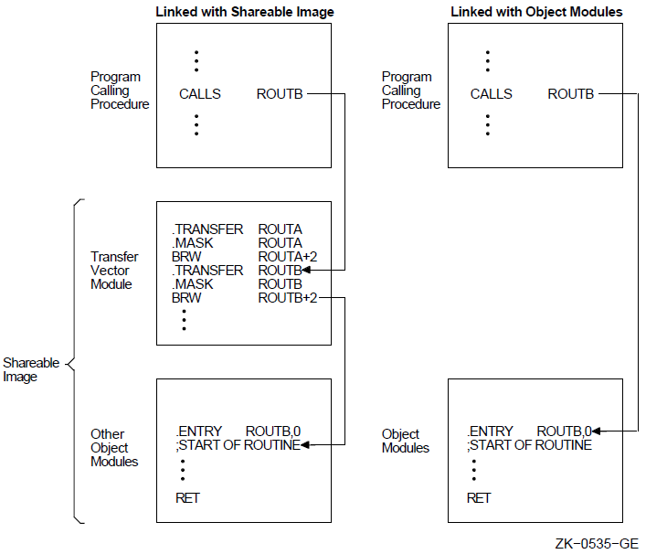
Example
.TRANSFER ROUTINE_A
.MASK     ROUTINE_A,^M<R4,R5>   ; Copy entry mask
                                ;   and add registers
                                ;   R4 and R5
BRW       ROUTINE_A+2           ; Branch to routine
                                ;   (past entry mask)
  .
  .
  .
.ENTRY    ROUTINE_A,^M<R2,R3>   ; ENTRY point, save
                                ;   registers R2 and R3
  .
  .
  .
RET
In this example, .MASK copies the entry mask of a routine to the new entry address specified by .TRANSFER. If the routine is placed in a shareable image and then called, registers R2, R3, R4, and R5 will be saved.
.WARN
.WARN — Warning directive
Format
.WARN [expression] ;comment Parameters
expression ;comment Description
.WARN causes the assembler to display a warning message on the terminal or in the batch log file, and in the listing file (if there is one).
Notes
.WARN, .ERROR, and .PRINT are called the message display directives. Use them to display information indicating that a macro call contains an error or an illegal set of conditions.
When the assembly is finished, the assembler displays on the terminal or in the batch log file, the total number of errors, warnings, and information messages, and the page numbers and line numbers of the lines causing the errors or warnings.
If .WARN is included in a macro library, end the comment with an additional semicolon. If you omit the semicolon, the comment will be stripped from the directive and will not be displayed when the macro is called.
The line containing the .WARN directive is not included in the listing file.
If the expression has a value of zero, it is not displayed in the warning message.
Example
 .IF DEFINED   FULL
 .IF DEFINED   DOUBLE_PREC
 .WARN         ; This combination not tested
 .ENDC
 .ENDC
If the symbols FULL and DOUBLE_PREC are both defined, the following warning message is displayed:
%MACRO-W-GENWRN, Generated WARNING: This combination not tested
.WEAK
.WEAK — Weak symbol attribute directive
Format
.WEAK symbol-list Parameter
symbol-list Description
.WEAK specifies symbols that are either defined externally in another module or defined globally in the current module. .WEAK suppresses any object library search for the symbol.
When .WEAK specifies a symbol that is not defined in the current module, the symbol is externally defined. If the linker finds the symbol's definition in another module, it uses that definition. If the linker does not find an external definition, the symbol has a value of zero and the linker does not report an error. The linker does not search a library for the symbol, but if a module brought in from a library for another reason contains the symbol definition, the linker uses it.
When .WEAK specifies a symbol that is defined in the current module, the symbol is considered to be globally defined. However, if this module is inserted in an object library, this symbol is not inserted in the library's symbol table. Consequently, searching the library at link time to resolve this symbol does not cause the module to be included.
Example
.WEAK IOCAR,LAB_3
.WORD
.WORD — Word storage directive
Format
.WORD expression-list Parameters
expression-list expression1[expression2]
expression1 [expression2] Description
.WORD generates successive words (2 bytes) of data in the object module.
Notes
The expression is first evaluated as a longword, then truncated to a word. The value of the expression should be in the range of -32,768 to +32,767 for signed data or 0 to 65,535 for unsigned data. The assembler displays an error if the high-order 2 bytes of the longword expression have a value other than zero or ^XFFFF.
The .SIGNED_WORD directive is the same as .WORD except that the assembler displays a diagnostic message if a value is in the range from 32,768 to 65,535.
Example
.WORD ^X3F,FIVE[3],32
Part II. VAX Data Types and Instruction Set
Part II describes the VAX data types, addressing mode formats, instruction formats, and the instructions themselves.
Chapter 7. Terminology and Conventions
The following sections describe terminology and conventions used in Part II of this volume.
7.1. Numbering
FF (hex)
7.2. UNPREDICTABLE and UNDEFINED
Results specified as UNPREDICTABLE may vary from moment to moment,implementation to implementation, and instruction to instruction within implementations. Software can never depend on results specified as UNPREDICTABLE. Operations specified as UNDEFINED may vary from moment to moment, implementation to implementation, and instruction to instruction within implementations. The operation might vary from causing no effect to stopping system operation. UNDEFINED operations must not cause the processor to hang—to reach an unhalted state from which there is no transition to a normal state in which the machine executes instructions. Note the distinction between result and operation. Nonprivileged software cannot invoke UNDEFINED operations. When the operation of the VAX scalar processor becomes UNDEFINED, so does the operation of its associated processor. The converse is not true;when the operation of the vector processor becomes UNDEFINED, the operation of the scalar processor need not become UNDEFINED.
7.3. Ranges and Extents
Ranges are specified in English and are inclusive (for example, a range of integers 0 to 4 includes the integers 0, 1, 2, 3, and 4). Extents are specified by a pair of numbers separated by a colon and are inclusive (that is, bits 7:3 specifies an extent of bits including bits 7, 6, 5, 4, and 3).
7.4. MBZ
Fields specified as MBZ (must be zero) must never be filled by software with a nonzero value. If the processor encounters a nonzero value in a field specified as MBZ, a reserved operand fault or abort occurs if that field is accessible to nonprivileged software. MBZ fields that are accessible only to privileged software (kernel mode) cannot be checked for nonzero value by some or all VAX implementations. Nonzero values in MBZ fields accessible only to privileged software may produce UNDEFINED operation.
7.6. SBZ
Fields specified as SBZ (should be zero) should be filled by software with a zero value. Non-zero values in SBZ fields produce UNPREDICTABLE results and may produce extraneous instruction-issue delays.
7.7. Reserved
Unassigned values of fields are reserved for future use. In many cases, some values are indicated as reserved to CSS and customers. Only these values should be used for nonstandard applications. The values indicated as reserved to OpenVMS and all MBZ (must be zero) fields are to be used only to extend future standard architecture.
7.8. Figure Drawing Conventions
Figures that depict registers or memory follow the convention that increasing addresses extend from right to left and from top to bottom.
Chapter 8. Basic Architecture
Address space
Data types
Processor status longword (PSL)
Permanent exception enables
Instruction and addressing mode formats
8.1. Basic Architecture
The VAX architecture represents a significant extension of the PDP-11 family architecture. It shares byte addressing with the PDP-11 family, similar I/O and interrupt structures, and identical data formats. Although the instruction set is not strictly compatible with the PDP-11 system, it is related and can be mastered easily by a PDP-11 programmer. Likewise, the similarity allows straightforward manual conversion of existing PDP-11 programs to the VAX system. Existing user-mode PDP-11 programs that do not need the extended features of a VAX system can run unchanged in the PDP-11 compatibility mode provided in the VAX architecture.
As compared to the PDP-11 architecture, VAX architecture offers a greatly extended virtual address space, additional instructions and data types, and new addressing modes. VAX architecture also provides a sophisticated memory management and protection mechanism, and hardware-assisted process sharing and synchronization.
VAX architecture has maximal compatibility with the PDP-11 architecture consistent with a significant extension of the virtual address space and a significant functional enhancement.
High bit efficiency is achieved by a wide range of data types and new addressing modes.
The systematic, elegant instruction set with orthogonality of operators, data types, and addressing modes can be exploited easily, particularly by high-level language processors.
The VAX system is extensible. The instruction set is designed so that new data types and operators can be included efficiently in a manner consistent with the currently defined operators and data types.
A vector part, which includes the instructions,registers, and execution model for vector processing.
A scalar part, which includes the remainder of the architecture.
Where confusion may be possible, this manual uses the term scalar to describe objects belonging to the scalar part of the architecture — as in scalar instructions and scalar processor. Similarly, the term vector is used to describe parts belonging to the vector part of the architecture — as in vector registers, and vector instructions. With the exception of Chapter 10, "VAX Vector Architecture", instructions, exceptions, registers, and other objects described in the rest of the this manual refer to the scalar part of the architecture unless otherwise stated.
8.2. VAX Addressing
The basic addressable unit in VAX MACRO is the 8-bit byte. Virtual addresses are 32 bits long. Therefore, the virtual address space is 232 (approximately 4.3 billion) bytes. Virtual addresses as seen by the program are translated into physical memory addresses by the memory management mechanism.
8.3. Data Types
The following sections describe the VAX data types.
8.3.1. Byte
A byte is 8 contiguous bits starting on an addressable byte boundary. The bits are numbered from right to left 0 to 7.
A byte is specified by its address A. When interpreted arithmetically, a byte is a two's complement integer with bits of increasing significance ranging from bit 0 to bit 6, with bit 7 the sign bit. The value of the integer is int he range -128 to +127. For the purposes of addition, subtraction, and comparison, VAX instructions also provide direct support for the interpretation of a byte as an unsigned integer with bits of increasing significance ranging from bit 0 to bit 7. The value of the unsigned integer is in the range 0 to 255.
8.3.2. Word
A word is 2 contiguous bytes starting on an arbitrary byte boundary. The 16 bits are numbered from right to left 0 to 15.
A word is specified by its address, A, which is the address of the byte containing bit 0. When interpreted arithmetically, a word is a two's complement integer with bits of increasing significance ranging from bit 0 to bit 14, with bit 15 the sign bit. The value of the integer is in the range -32,768 to +32,767. For the purposes of addition, subtraction, and comparison, VAX instructions also provide direct support for the interpretation of a word as an unsigned integer with bits of increasing significance ranging from bit 0 to bit 15. The value of the unsigned integer is in the range 0 to 65,535.
8.3.3. Longword
A longword is 4 contiguous bytes starting on an arbitrary byte boundary. The 32 bits are numbered from right to left 0 to 31.
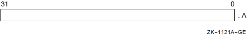
A longword is specified by its address, A, which is the address of the byte containing bit 0. When interpreted arithmetically, a longword is a two's complement integer with bits of increasing significance ranging from bit 0 to bit 30, with bit 31 the sign bit. The value of the integer is in the range -2,147,483,648 to +2,147,483,647. For the purposes of addition, subtraction,and comparison, VAX instructions also provide direct support for the interpretation of a longword as an unsigned integer with bits of increasing significance ranging from bit 0 to bit 31. The value of the unsigned integer is in the range 0 to 4,294,967,295.
8.3.4. Quadword
A quadword is 8 contiguous bytes starting on an arbitrary byte boundary. The 64 bits are numbered from right to left 0 to 63.
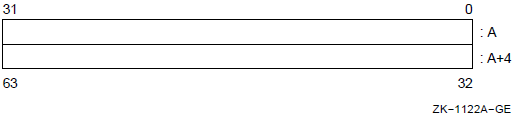
A quadword is specified by its address, A, which is the address of the byte containing bit 0. When interpreted arithmetically, a quadword is a two's complement integer with bits of increasing significance ranging from bit 0 to bit 62, with bit 63 the sign bit. The value of the integer is in the range -2**63 to +2**63-1. The quadword data type is not fully supported by VAX instructions.
8.3.5. Octaword
An octaword is 16 contiguous bytes starting on an arbitrary byte boundary. The 128 bits are numbered from right to left 0 to 127.
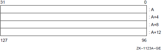
An octaword is specified by its address, A, which is the address of the byte containing bit 0. When interpreted arithmetically, an octaword is a two's complement integer with bits of increasing significance ranging from bit 0 to bit 126, with bit 127 the sign bit. The value of the integer is in the range -2**127 to +2**127-1. The octaword data type is not fully supported by VAX instructions.
8.3.6. F_floating
An F_floating datum is 4 contiguous bytes starting on an arbitrary byte boundary. The 32 bits are labeled from right to left 0 to 31.
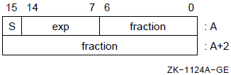
An F_floating datum is specified by its address, A, which is the address of the byte containing bit 0. The form of an F_floating datum is sign magnitude with bit 15 as the sign bit, bits 14:7 as an excess 128 binary exponent, and bits 6:0 and 31:16 as a normalized 24-bit fraction with the redundant most-significant fraction bit not represented. Within the fraction, bits of increasing significance range from bits 16 to 31 and 0 to 6. The 8-bit exponent field encodes the values 0 to 255. An exponent value of zero,together with a sign bit of zero, is taken to indicate that the F_floating datum has a value of zero. Exponent values of 1 to 255 indicate true binary exponents of -127 to +127. An exponent value of zero, together with a sign bit of 1, is taken as reserved. Floating-point instructions processing are served operand take a reserved operand fault (see Appendix E, "Exceptions That May Occur During Instruction Execution"). The value of an F_floating datum is in the approximate range .29*10**-38 to 1.7*10**38. The precision of an F_floating datum is approximately one part in 2**23; that is, typically 7 decimal digits.
8.3.7. D_floating
A D_floating datum is 8 contiguous bytes starting on an arbitrary byte boundary. The bits are labeled from right to left 0 to 63.
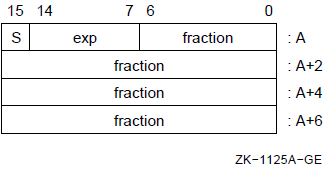
A D_floating datum is specified by its address, A, which is the address of the byte containing bit 0. The form of a D_floating datum is identical to an F_floating datum except for additional 32 low-significance fraction bits. Within the fraction, bits of increasing significance range from bits 48 to 63,32 to 47, 16 to 31, and 0 to 6. The exponent conventions and the approximate range of values are the same for D_floating as they are for F_floating. The precision of a D_floating datum is approximately one part in 2**55, typically, 16 decimal digits.
8.3.8. G_floating
A G_floating datum is 8 contiguous bytes starting on an arbitrary byte boundary. The bits are labeled from right to left 0 to 63.
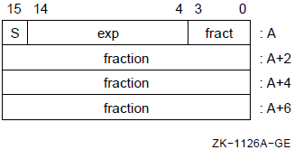
A G_floating datum is specified by its address, A, which is the address of the byte containing bit 0. The form of a G_floating datum is sign magnitude, with bit 15 as the sign bit, bits 14:4 as an excess 1024 binary exponent, and bits 3:0 and 63:16 as a normalized 53-bit fraction with the redundant most-significant fraction bit not represented. Within the fraction, bits of increasing significance range from bits 48 to 63, 32 to 47, 16 to 31, and 0 to 3. The 11-bit exponent field encodes the values 0 to 2047. An exponent value of zero, together with a sign bit of zero, is taken to indicate that the G_floating datum has a value of zero. Exponent values of 1 to 2047 indicate true binary exponents of -1023 to +1023. An exponent value of zero, together with a sign bit of 1, is taken as reserved. Floating-point instructions processing a reserved operand take a reserved operand fault (see Appendix E, "Exceptions That May Occur During Instruction Execution"). The value of a G_floating datum is in the approximate range .56*10**-308 to .9*10**308. The precision of a G_floating datum is approximately one part in 2**52; that is, typically 15 decimal digits.
8.3.9. H_floating
An H_floating datum is 16 contiguous bytes starting on an arbitrary byte boundary. The 128 bits are labeled from right to left 0 to 127.
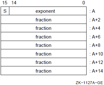
An H_floating datum is specified by its address, A, which is the address of the byte containing bit 0. The form of an H_floating datum is sign magnitude with bit 15 as the sign bit, bits 14:0 as an excess 16,384 binary exponent,and bits 127:16 as a normalized 113-bit fraction with the redundant most-significant fraction bit not represented. Within the fraction, bits of increasing significance range from bits 112 to 127, 96 to 111, 80 to 95, 64 to 79, 48 to 63, 32 to 47, and 16 to 31. The 15-bit exponent field encodes the values 0 to 32,767. An exponent value of zero, together with a sign bit of 0,is taken to indicate that the H_floating datum has a value of zero. Exponent values of 1 to 32,767 indicate true binary exponents of -16,383 to +16,383. An exponent value of zero, together with a sign bit of 1, is taken as reserved. Floating-point instructions processing a reserved operand take are served operand fault (see Appendix E, "Exceptions That May Occur During Instruction Execution"). The value of an H_floating datum is in the approximate range .84*10**-4932 to .59*10**4932. The precision of an H_floating datum is approximately one part in 2**112, typically, 33 decimal digits.
8.3.10. Variable-Length Bit Field
Address A of a byte
Bit position P, which is the starting location of the field with respect to bit 0 of the byte at A
Size S of the field
The specification of a bit field is indicated by the following figure, where the field is the shaded area.
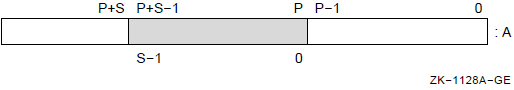
For bit strings in memory, the position is in the range -2**31 to 2**31-1 and is conveniently viewed as a signed 29-bit byte offset and a 3-bit,bit-within-byte field.
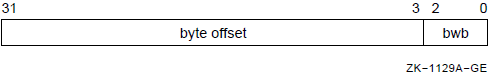
The sign-extended, 29-bit byte offset is added to the address A; the resulting address specifies the byte in which the field begins. The 3-bit,bit-within-byte field encodes the starting position (0 to 7) of the field within that byte. The VAX field instructions provide direct support for the interpretation of a field as a signed or unsigned integer. When interpreted as a signed integer, it is two's complement with bits of increasing significance ranging from bits 0 to S-2; bit S-1 is the sign bit. When interpreted as an unsigned integer, bits of increasing significance range from bits 0 to S-1. Afield of size zero has a value identically equal to zero.
A variable-length bit field may be contained in 1 to 5 bytes. From a memory management point of view, only the minimum number of aligned longwords necessary to contain the field may be actually referenced.
For bit fields in registers, the position is in the range 0 to 31. The position operand specifies the starting position (0 to 31) of the field in the register. A variable-length bit field may be contained in two registers if the sum of position and size exceeds 32.
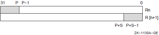
For further details on the specification of variable-length bit fields, seethe descriptions of the variable-length bit field instructions in Section 9.4, ''Variable-Length Bit Field Instructions''.
8.3.11. Character String
A character string is a contiguous sequence of bytes in memory. A character string is specified by two attributes: the address A of the first byte of the string, and the length L of the string in bytes. Thus, the format of a character string is represented as follows:
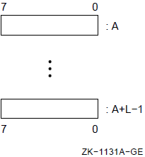
The address of a string specifies the first character of a string. Thus "XYZ" is represented as follows:

The length L of a string is in the range 0 to 65,535.
8.3.12. Trailing Numeric String
A trailing numeric string is a contiguous sequence of bytes in memory. The string is specified by two attributes: the address A of the first byte(most-significant digit) of the string, and the length L of the string in bytes.
All bytes of a trailing numeric string, except the least-significant digit byte, must contain an ASCII decimal digit character (0 to 9).
|
Digit |
Decimal |
Hex |
ASCII Character |
|---|---|---|---|
|
0 |
48 |
30 |
0 |
|
1 |
49 |
31 |
1 |
|
2 |
50 |
32 |
2 |
|
3 |
51 |
33 |
3 |
|
4 |
52 |
34 |
4 |
|
5 |
53 |
35 |
5 |
|
6 |
54 |
36 |
6 |
|
7 |
55 |
37 |
7 |
|
8 |
56 |
38 |
8 |
|
9 |
57 |
39 |
9 |
Unsigned numeric encoding, in which there is no sign and the east-significant digit contains an ASCII decimal digit character
Zoned numeric encoding
Overpunched numeric encoding
|
Digit |
Decimal |
Hex |
ASCII Character |
|---|---|---|---|
|
0 |
48 |
30 |
0 |
|
1 |
49 |
31 |
1 |
|
2 |
50 |
32 |
2 |
|
3 |
51 |
33 |
3 |
|
4 |
52 |
34 |
4 |
|
5 |
53 |
35 |
5 |
|
6 |
54 |
36 |
6 |
|
7 |
55 |
37 |
7 |
|
8 |
56 |
38 |
8 |
|
9 |
57 |
39 |
9 |
|
-0 |
112 |
70 |
p |
|
-1 |
113 |
71 |
q |
|
-2 |
114 |
72 |
r |
|
-3 |
115 |
73 |
s |
|
-4 |
116 |
74 |
t |
|
-5 |
117 |
75 |
u |
|
-6 |
118 |
76 |
v |
|
-7 |
119 |
77 |
w |
|
-8 |
120 |
78 |
x |
|
-9 |
121 |
79 |
y |
|
Digit |
Decimal |
Hex |
ASCII Character | |
|---|---|---|---|---|
|
Norm |
Alt. | |||
|
0 |
123 |
7B |
{ |
0[? |
|
1 |
65 |
41 |
A |
1 |
|
2 |
66 |
42 |
B |
2 |
|
3 |
67 |
43 |
C |
3 |
|
4 |
68 |
44 |
D |
4 |
|
5 |
69 |
45 |
E |
5 |
|
6 |
70 |
46 |
F |
6 |
|
7 |
71 |
47 |
G |
7 |
|
8 |
72 |
48 |
H |
8 |
|
9 |
73 |
49 |
I |
9 |
|
-0 |
125 |
7D |
} |
]:! |
|
-1 |
74 |
4A |
J | |
|
-2 |
75 |
4B |
K | |
|
-3 |
76 |
4C |
L | |
|
-4 |
77 |
4D |
M | |
|
-5 |
78 |
4E |
N | |
|
-6 |
79 |
4F |
O | |
|
-7 |
80 |
50 |
P | |
|
-8 |
81 |
51 |
Q | |
|
-9 |
82 |
52 |
R | |
The length L of a trailing numeric string must be in the range 0 to 31 (0 to 31 digits). The value of a zero-length string is zero.
The address A of the string specifies the byte of the string containing the most-significant digit. Digits of decreasing significance are assigned to increasing addresses. Thus "123" is represented as follows:
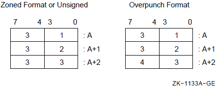
The trailing numeric string with a value of "-123" is represented as follows:
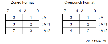
8.3.13. Leading Separate Numeric String
A leading separate numeric string is a contiguous sequence of bytes in memory. A leading separate numeric string is specified by two attributes: the address A of the first byte (containing the sign character), and a length L, which is the length of the string in digits and not the length of the string in bytes. The number of bytes in a leading separate numeric string is L+1.
|
Sign |
Decimal |
Hex |
ASCII character |
|---|---|---|---|
|
+ |
43 |
2B |
+ |
|
+ |
32 |
20 |
{blank} |
|
- |
45 |
2D |
- |
|
Digit |
Decimal |
Hex |
ASCII character |
|---|---|---|---|
|
0 |
48 |
30 |
0 |
|
1 |
49 |
31 |
1 |
|
2 |
50 |
32 |
2 |
|
3 |
51 |
33 |
3 |
|
4 |
52 |
34 |
4 |
|
5 |
53 |
35 |
5 |
|
6 |
54 |
36 |
6 |
|
7 |
55 |
37 |
7 |
|
8 |
56 |
38 |
8 |
|
9 |
57 |
39 |
9 |
The length L of a leading separate numeric string must be in the range 0 to 31 (0 to 31 digits). The value of a zero-length string is zero.
The address A of the string specifies the byte of the string containing the sign. Digits of decreasing significance are assigned to bytes of increasing addresses. Thus "+123" is represented as follows:
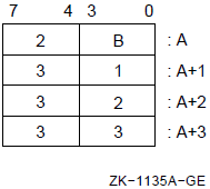
The leading separate numeric string with a value of "-123" is represented as follows:
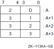
8.3.14. Packed Decimal String
|
Digit or Sign |
Decimal |
Hexadecimal |
|---|---|---|
|
0 |
0 |
0 |
|
1 |
1 |
1 |
|
2 |
2 |
2 |
|
3 |
3 |
3 |
|
4 |
4 |
4 |
|
5 |
5 |
5 |
|
6 |
6 |
6 |
|
7 |
7 |
7 |
|
8 |
8 |
8 |
|
9 |
9 |
9 |
|
+ |
10,12,14, or 15 |
A,C,E, or F |
|
- |
11 or 13 |
B or D |
The preferred sign representation is 12 for "+" and 13 for "-".The length L is the number of digits in the packed decimal string (not counting the sign); L must be in the range 0 to 31. When the number of digits is odd, the digits and the sign fit into a string of bytes whose length is defined by the following equation: L/2 (integer part only) + 1. When the number of digits is even, it is required that an extra "0" digit appear in the high nibble (bits 7:4) of the first byte of the string. Again, the length in bytes of the string is L/2 + 1.
The address A of the string specifies the byte of the string containing the most-significant digit in its high nibble. Digits of decreasing significance are assigned to increasing byte addresses and from high nibble to low nibble within a byte. Thus, "+123" has a length of 3 and is represented as follows:
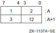
The packed decimal number "-12" has a length of 2 and is represented as follows:
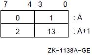
8.4. Processor Status Longword (PSL)
The processor status longword (PSL) consists of a set of processor state variables associated with each process. Bits 31:16 of the PSL have privileged status. For information on this part of the PSL, refer to the VAX Architecture Reference Manual. Bits 15:0 of the PSL are referred to separately as the processor status word (PSW).
The format of the PSL is as follows:
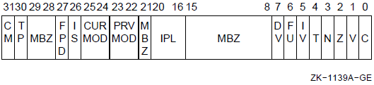
The condition codes, which give information on the results produced by previous VAX scalar instructions.
The exception enable codes, which control the processor action on certain VAX scalar exception conditions (see Appendix E, "Exceptions That May Occur During Instruction Execution").
The condition codes are UNPREDICTABLE when they are affected by UNPREDICTABLE results. The VAX procedure call instructions conditionally set the IV and DV enable bits, clear the FU enable bit, and leave the Tenable bit unchanged at procedure entry.
The PSL is saved automatically on the stack when an exception or interrupt occurs and is saved in the process control block on a process context switch. The PSL can also be read by the MOVPSL instruction.
The vector processor does not use PSL(IV) and PSL(FU) to enable integer overflow and floating underflow exception checking for vector instructions. Also, vector instruction exceptions do not affect the values of the PSL condition codes bits.
8.4.1. C Bit
The C (carry) condition code bit, when set, indicates that the last instruction that affected C had a carry out of the most-significant bit of the result, or a borrow into the most-significant bit. When C is clear, no carry or borrow occurred.
8.4.2. V Bit
The V (overflow) condition code bit, when set, indicates that the last instruction that affected V produced a result whose magnitude was too large to be properly represented in the operand that received the result, or that there was a conversion error. When V is clear, no overflow or conversion error occurred.
8.4.3. Z Bit
The Z (zero) condition code, when set, indicates that the last instruction that affected Z produced a result that was zero. When Z is clear, the result was nonzero.
8.4.4. N Bit
The N (negative) condition code bit, when set, indicates that the last instruction that affected N produced a negative result. When N is clear, the result was positive (or zero).
8.4.5. T Bit
The T (trace) bit, when set at the beginning of an instruction, causes the TP bit in the Processor Status Longword to be set. When TP is set at the end of an instruction, a trace fault is taken before the execution of the next instruction. See Appendix E, "Exceptions That May Occur During Instruction Execution" for additional information on the TP bit and the trace fault.
8.4.6. IV Bit
The IV (integer overflow) bit, when set, forces an integer overflow trap after execution of an instruction that produced an integer result that overflowed or had a conversion error. When IV is clear, no integer overflow trap occurs. (However, the condition code V bit is still set.)
8.4.7. FU Bit
The FU (floating underflow) bit, when set, forces a floating underflow fault if the result of a floating-point instruction is too small in magnitude to be represented in the result operand. When FU is clear, no underflow fault occurs.
8.4.8. DV Bit
The DV (decimal overflow) bit, when set, forces a decimal overflow trap after execution of an instruction that produced an overflowed decimal (numeric string, or packed decimal) result or had a conversion error. When DV is clear,no trap occurs. (However, the condition code V bit is still set.)
8.5. Permanent Exception Enables
The processor action on certain exception conditions is not controlled by bits in the PSW. Traps or faults always result from these exception conditions.
8.6. Instruction and Addressing Mode Formats
The following sections describe the formats for instruction opcodes and for the operand specifiers used with the various addressing modes.
8.6.1. Opcode Formats
An instruction is specified by the byte address A of its opcode.
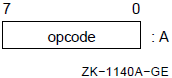
The opcode may extend over 2 bytes; the length depends on the contents of the byte at address A. If, and only if, the value of the byte is FC (hex) to FF (hex), the opcode is 2 bytes long.
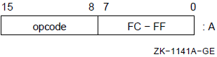
8.6.2. Operand Specifiers
Each instruction takes a specific sequence of operand specifier types. An operand specifier type conceptually has two attributes: the access type and the data type.
Read—The specified operand is read only.
Write—The specified operand is written only.
Modify—The specified operand is read, potentially modified, and written. This operation is not performed under a memory interlock.
Address—The address of the specified operand in the form of a longword is the actual instruction operand. The specified operand is not accessed directly, although the instruction may subsequently use the address to access that operand.
Variable bit field base address—This access type is a special variant of the address access type. Variable bit field base address type is the same as address access type except for register mode. In register mode, the field is contained in register n, designated by the operand specifier (or register n+1 concatenated with register n).
Branch—No operand is accessed. The operand specifier itself is a branch displacement.
Access types 1 to 5 are general mode addressing. Type 6 is branch mode addressing.
Byte
Word
Longword and F_floating (equivalent for addressing mode considerations)
Quadword, D_floating, and G_floating (equivalent for addressing mode considerations)
Octaword and H_floating (equivalent for addressing mode considerations)
Address—the operand size to be used in the address calculation in autoincrement, autodecrement, and index modes
Branch—the size of the branch displacement
8.7. General Addressing Mode Formats
The following sections describe the operand specifier formats for the general addressing modes. For descriptions and examples of the use of the general addressing modes, see Chapter 5, "VAX MACRO Addressing Modes".
In Section 8.8, ''Summary of General Mode Addressing'', Table 8.5, ''General Register Addressing'' is a summary of general register addressing and Table 8.6, ''Program Counter Addressing'' is a summary of program counter addressing.
Notation for Describing Addressing Modes
|
+ |
Addition |
|
- |
Subtraction |
|
* |
Multiplication |
|
<- |
Is replaced by |
|
= |
Is defined as |
|
’ |
Concatenation |
|
Rn or R[n] |
The contents of register n |
|
PC or SP |
The contents of register 15 or 14, respectively |
|
(x ) |
The contents of a location in memory whose address is x |
|
{ } |
Arithmetic parentheses that indicate precedence |
|
SEXT(x) |
x is sign extended to size of operand needed |
|
ZEXT(x) |
x is zero extended to size of operand needed |
|
OA |
Operand address |
|
! |
Comment delimiter |
Note
In the formal descriptions of the addressing modes, the symbol for a register (for example, Rn or PC) always means the contents of the register (for example, the contents of register n or the contents of register 15). However,in text, when there is no ambiguity, the symbol for a register is often used as the name of a register (for example, Rn may be used for the name of register n, and PC may be used for the name of register 15).
Each general mode addressing description includes the definition of the operand address and the specified operand. For operand specifiers of address access type, the operand address is the actual instruction operand. For other access types, the specified operand is the instruction operand. The branch mode addressing description includes the definition of the branch address.
8.7.1. Register Mode
The operand specifier format is as follows:
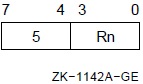
No specifier extension follows.
operand = Rn                       ! If 1 register
          or
          R[n+1]’Rn                ! If two registers
          or
          R[n+3]’R[n+2]’R[n+1]’Rn  ! If four registers
The assembler notation for register mode is Rn.
8.7.2. Register Deferred Mode
The operand specifier format is as follows:
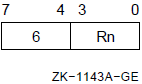
No specifier extension follows.
OA = Rn
operand = (OA)
The assembler notation for register deferred mode is (Rn).
8.7.3. Autoincrement Mode
The operand specifier format is as follows:
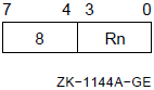
No specifier extension follows. If Rn denotes the PC, immediate data follows,and the mode is termed immediate mode.
OA = Rn
Rn <- Rn + size
operand = (OA)
The assembler notation for autoincrement mode is (Rn)+. For immediate mode,the notation is I^#constant, where constant is the immediate data that follows.
8.7.4. Autoincrement Deferred Mode
The operand specifier format is as follows:
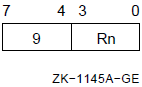
No specifier extension follows. If Rn denotes the PC, a longword address follows and the mode is termed absolute mode.
OA = (Rn)
Rn <- Rn + 4
operand = (OA)
The assembler notation for autoincrement deferred mode is @(Rn)+. For absolute mode, the notation is @#address, where address is the longword that follows.
8.7.5. Autodecrement Mode
The operand specifier format is as follows:
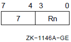
No specifier extension follows.
Rn <- Rn - size
OA = Rn
operand = (OA)
The assembler notation for autodecrement mode is -(Rn).
8.7.6. Displacement Mode
There are three operand specifier formats.
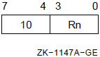
The specifier extension is a signed byte displacement that follows the operand specifier. This is the byte displacement mode.
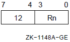
The specifier extension is a signed word displacement that follows the operand specifier. This is the word displacement mode.
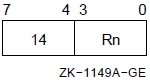
The specifier extension is a longword displacement that follows the operand specifier. This is the longword displacement mode.
In displacement mode addressing, the displacement (after it is sign extended to 32 bits, if it is byte or word displacement) is added to the contents of register n, and the result is the operand address.
OA = Rn + SEXT(displ)        !If byte or word displacement
     or
     Rn + displ              ! If longword displacement
     or
     operand = (OA)
If Rn denotes PC, the updated contents of the PC are used. The address in the PC (the updated contents) is the address of the first byte beyond the specifier extension.
The assembler notation for byte, word, and long displacement mode is B^D(Rn), W^D(Rn), and L^D(Rn), respectively, where D = displacement.
8.7.7. Displacement Deferred Mode
There are three operand specifier formats.
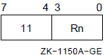
The specifier extension is a signed byte displacement that follows the operand specifier. This is the byte displacement deferred mode.
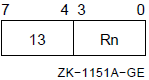
The specifier extension is a signed word displacement that follows the operand specifier. This is the word displacement deferred mode.
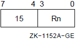
The specifier extension is a longword displacement that follows the operand specifier. This is the longword displacement deferred mode.
OA = (Rn + SEXT(displ))      ! If byte or word displacement
      or
     (Rn + displ)            ! If longword displacement
operand = (OA)
If Rn denotes PC, the updated contents of the PC are used. The address in the PC (the updated contents) is the address of the first byte beyond the specifier extension.
The assembler notation for byte, word, and longword displacement deferred mode is @B^D(Rn), @W^D(Rn), and @L^D(Rn), respectively, where D = displacement.
8.7.8. Literal Mode
The operand specifier format is as follows:
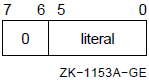
No specifier extension follows.
operand = ZEXT(literal)
Thus, for these data types, you may use literal mode for values in the range 0to 63.
For operands of data type F_floating, G_floating, D_floating, and H_floating, the 6-bit literal field is composed of two, 3-bit fields. These fields are illustrated in the following diagram,where exp is exponent and fra is fraction:
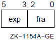
You use the exponent and fraction fields to form an F_floating or D_floating operand as follows:
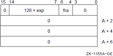
Note that bits 63:32 are not present in an F_floating operand.
You use the exponent and fraction fields to form a G_floating operand as follows:
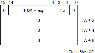
You use the exponent and fraction fields to form an H_floating operand as follows:
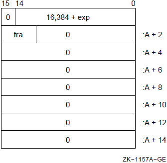
|
Exponent |
0 |
1 |
2 |
3 |
4 |
5 |
6 |
7 |
|---|---|---|---|---|---|---|---|---|
|
0 |
0.5 |
0.5625 |
0.625 |
0.6875 |
0.75 |
0.8125 |
0.875 |
0.9375 |
|
1 |
1.0 |
1.125 |
1.25 |
1.37 |
1.5 |
1.625 |
1.75 |
1.875 |
|
2 |
2.0 |
2.25 |
2.5 |
2.75 |
3.0 |
3.25 |
3.5 |
3.75 |
|
3 |
4.0 |
4.5 |
5.0 |
5.5 |
6.0 |
6.5 |
7.0 |
7.5 |
|
4 |
8.0 |
9.0 |
10.0 |
11.0 |
12.0 |
13.0 |
14.0 |
15.0 |
|
5 |
16.0 |
18.0 |
20.0 |
22.0 |
24.0 |
26.0 |
28.0 |
30.0 |
|
6 |
32.0 |
36.0 |
40.0 |
44.0 |
48.0 |
52.0 |
56.0 |
60.0 |
|
7 |
64.0 |
72.0 |
80.0 |
88.0 |
96.0 |
104.0 |
112.0 |
120.0 |
|
Exponent |
0 |
1 |
2 |
3 |
4 |
5 |
6 |
7 |
|---|---|---|---|---|---|---|---|---|
|
0 |
1/2 |
9/16 |
5/8 |
11/16 |
3/4 |
13/16 |
7/8 |
15/16 |
|
1 |
1 |
1-1/8 |
1-1/4 |
1-3/8 |
1-1/2 |
1-5/8 |
1-3/4 |
1-7/8 |
|
2 |
2 |
2-1/4 |
2-1/2 |
2-3/4 |
3 |
3-1/4 |
3-1/2 |
3-3/4 |
|
3 |
4 |
4-1/2 |
5 |
5-1/2 |
6 |
6-1/2 |
7 |
7-1/2 |
|
4 |
8 |
9 |
10 |
11 |
12 |
13 |
14 |
15 |
|
5 |
16 |
18 |
20 |
22 |
24 |
26 |
28 |
30 |
|
6 |
32 |
36 |
40 |
44 |
48 |
52 |
56 |
60 |
|
7 |
64 |
72 |
80 |
88 |
96 |
104 |
112 |
120 |
The assembler notation for literal mode is S^#literal.
8.7.9. Index Mode
The operand specifier format is as follows:
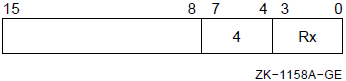
Bits 15:8 contain a second operand specifier (termed the base operand specifier) for any of the addressing modes except register, literal, or index. The specification of register, literal, or index addressing mode results in an illegal addressing mode fault (see Appendix E, "Exceptions That May Occur During Instruction Execution"). If the base operand specifier requires it, a specifier extension immediately follows. The base operand specifier is subject to the same restrictions as would apply if it were used alone. If the use of some particular specifier is illegal (that is, causes a fault or UNPREDICTABLE behavior) under some circumstances, then that specifier is similarly illegal as a base operand specifier in index mode under the same circumstances.
OA = BOA + {size * (Rx)}
operand = (OA)
If the base operand specifier is for autoincrement or autodecrement mode, the increment or decrement size is the size in bytes of the primary operand.
Certain restrictions are placed on the index register x. You cannot use the PCas an index register. If you use it, a reserved addressing mode fault occurs(see Appendix E, "Exceptions That May Occur During Instruction Execution"). If the base operand specifier is for an addressing mode that results in register modification (that is, autoincrement mode, autodecrement mode, or autoincrement deferred mode), the same register cannot be the index register. If it is, the primary operand address is UNPREDICTABLE.
Register deferred indexed— (Rn)[Rx]
Autoincrement indexed— (Rn)+[Rx]
or
Immediate indexed— I^#constant[Rx](Immediate indexed is recognized by the assembler, but is not generally useful. Note that the operand address is independent of the value of the constant.)
Autoincrement deferred indexed— @(Rn)+[Rx]
or
Absolute indexed— @#address[Rx]
Autodecrement indexed— -(Rn)[Rx]
Byte, word, or longword displacement indexed— B^D(Rn)[Rx],W^D(Rn)[Rx], or L^D(Rn)[Rx]
Byte, word, or longword displacement deferred indexed—@B^D(Rn)[Rx],@W^D(Rn)[Rx], or @L^D(Rn)[Rx]
8.8. Summary of General Mode Addressing
This section provides summaries of general register and program counter(PC) addressing.
Table 8.5, ''General Register Addressing'' is a summary of general register addressing and Table 8.6, ''Program Counter Addressing'' is a summary of PC addressing.
8.8.1. General Register Addressing
The general register addressing format is as follows:
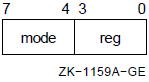
| Hex | Dec | Name | Assembler | r m w a v | PC | SP | AP FP | Can Be Indexed? |
|---|---|---|---|---|---|---|---|---|
|
Key:
| ||||||||
|
0–3 |
0–3 |
Literal |
S^#literal |
y f f f f |
— |
— |
— |
f |
|
4 |
4 |
Indexed |
i[Rx] |
y y y y y |
f |
y |
y |
f |
|
5 |
5 |
Register |
Rn |
y y y f y |
u |
uq |
uo |
f |
|
6 |
6 |
Register deferred |
(Rn) |
y y y y y |
u |
y |
y |
y |
|
7 |
7 |
Autodecrement |
-(Rn) |
y y y y y |
u |
y |
y |
ux |
|
8 |
8 |
Autoincrement |
(Rn)+ |
y y y y y |
p |
y |
y |
ux |
|
9 |
9 |
Autoincrement deferred |
@(Rn)+ |
y y y y y |
p |
y |
y |
ux |
|
A |
10 |
Byte displacement |
B^D(Rn) |
y y y y y |
p |
y |
y |
y |
|
B |
11 |
Byte displacement deferred |
@B^D(Rn) |
y y y y y |
p |
y |
y |
y |
|
C |
12 |
Word displacement |
W^D(Rn) |
y y y y y |
p |
y |
y |
y |
|
D |
13 |
Word displacement deferred |
@W^D(Rn) |
y y y y y |
p |
y |
y |
y |
|
E |
14 |
Longword displacement |
L^D(Rn) |
y y y y y |
p |
y |
y |
y |
|
F |
15 |
Longword displacement deferred |
@L^D(Rn) |
y y y y y |
p |
y |
y |
y |
8.8.2. Program Counter Addressing
The program counter addressing format is as follows:
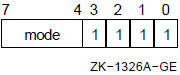
| Hex | Dec | Name | Assembler | r m w a v | Can Be Indexed? |
|---|---|---|---|---|---|
Key:
| |||||
8 | 8 | Immediate | I^#constant | y u u y y | u |
9 | 9 | Absolute | @#address | y y y y y | y |
A | 10 | Byte relative | B^address | y y y y y | y |
B | 11 | Byte relative deferred | @B^address | y y y y y | y |
C | 12 | Word relative | W^address | y y y y y | y |
D | 13 | Word relative deferred | @W^address | y y y y y | y |
E | 14 | Longword relative | L^address | y y y y y | y |
F | 15 | Longword relative deferred | @L^address | y y y y y | y |
8.9. Branch Mode Addressing Formats
There are two operand specifier formats.
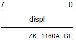
The operand specifier is a signed byte displacement.
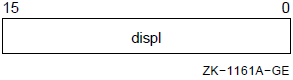
The operand specifier is a signed word displacement.
A = PC + SEXT(displ)
The assembler notation for byte and word branch displacement addressing is A, where A is the branch address. Note that you must use the branch address, and not the displacement.
Chapter 9. VAX Instruction Set
The following sections describe the native-mode instruction set. The instructions are divided into groups according to their function and are listed alphabetically within each group.
9.1. Introduction to the VAX Instruction Set
This section describes the instructions generally used by all software across all implementations of the VAX architecture.
You can find a more complete description of the instruction set in the VAX Architecture Reference Manual. The VAX Architecture Reference Manual also contains information on instructions that are generally used by privileged software and are specific to specialized portions of the VAX architecture, such as memory management, interrupts and exceptions, process dispatching, and processor registers.
A list of instructions and opcode assignments appears in Appendix D, "Permanent Symbol Table Defined for Use with VAX MACRO".
9.2. Instruction Descriptions
Integer arithmetic and logical
Address
Variable-length bit field
Control
Procedure call
Miscellaneous
Queue
Floating point
Character string
Cyclic redundancy check (CRC)
Decimal string
Edit
The group name.
The format of each instruction in the group, including the name and type of each instruction operand specifier and the order in which it appears in memory. Operand specifiers from left to right appear in increasing memory addresses.
The operation of the instruction. The operation is given as a sequence of pseudo code statements in an ALGOL-like syntax. Each VAX processor may implement the instruction in different or more efficient ways, but each processor gives results consistent with the pseudo code, English descriptions, and notes.
The effect on condition codes.
Exceptions specific to the instruction. Exceptions that are generally possible for all instructions (for example, illegal or reserved addressing mode, T-bit, and memory management violations) are not listed.
The opcodes, mnemonics, and names of each instruction in the group. The opcodes are given in hexadecimal.
A description, in English, of the instruction.
Optional notes on the instruction and programming examples.
Operand Specifier Notation
name . access-type data-type
name access-type |
a |
Calculate the effective address of the specified operand.
Address is returned in a longword that is the actual instruction
operand. Context of address calculation is given by
|
|
b |
No operand reference. Operand specifier is a branch
displacement. Size of branch displacement is given by
|
|
m |
Operand is read, potentially modified, and written. Note that this is not an indivisible memory operation. Also note that if the operand is not actually modified, it may not be written back. However, modify type operands are always checked for both read and write accessibility. |
|
r |
Operand is read only. |
|
v |
Calculate the effective address of the specified operand. If
the effective address is in memory, the address is returned in a
longword that is the actual instruction operand. Context of
address calculation is given by
|
|
w |
Operand is written only. |
data-type |
b |
Byte |
|
d |
D_floating |
|
f |
F_floating |
|
g |
G_floating |
|
h |
H_floating |
|
l |
Longword |
|
o |
Octaword |
|
q |
Quadword |
|
w |
Word |
|
x |
First data type specified by instruction |
|
y |
Second data type specified by instruction |
Operation Description Notation
|
+ |
Addition |
|
- |
Subtraction, unary minus |
|
* |
Multiplication |
|
/ |
Division (quotient only) |
|
** |
Exponentiation |
|
' |
Concatenation |
|
<- |
Is replaced by |
|
= |
Is defined as |
|
Rn or R[n] |
Contents of register Rn |
|
PC, SP, FP, or AP |
The contents of register R15, R14, R13, or R12, respectively |
|
PSW |
The contents of the processor status word |
|
PSL |
The contents of the processor status longword |
|
(x) |
Contents of memory location whose address is x |
|
(x)+ |
Contents of memory location whose address is x; x incremented by the size of operand referenced at x |
|
-(x) |
x decremented by size of operand to be referenced at x;contents of memory location whose address is x |
|
|
A modifier that delimits an extent from bit position x to bit position y inclusive |
|
|
A modifier that enumerates bits x1, x2, ..., xn |
|
{ } |
Arithmetic parentheses used to indicate precedence |
|
AND |
Logical AND |
|
OR |
Logical OR |
|
XOR |
Logical XOR |
|
NOT |
Logical (one's) complement |
|
LSS |
Less than signed |
|
LSSU |
Less than unsigned |
|
LEQ |
Less than or equal signed |
|
LEQU |
Less than or equal unsigned |
|
EQL |
Equal signed |
|
EQLU |
Equal unsigned |
|
NEQ |
Not equal signed |
|
NEQU |
Not equal unsigned |
|
GEQ |
Greater than or equal signed |
|
GEQU |
Greater than or equal unsigned |
|
GTR |
Greater than signed |
|
GTRU |
Greater than unsigned |
|
SEXT(x) |
x is sign extended to size of operand needed |
|
ZEXT(x) |
x is zero extended to size of operand needed |
|
REM(x,y) |
Remainder of x divided by y, such that x/y and REM(x,y) have the same sign |
|
MINU(x,y) |
Minimum unsigned of x and y |
|
MAXU(x,y) |
Maximum unsigned of x and y |
Other than alterations caused by (x)+, or -(x), and the advancement of the program counter (PC), only operands or portions of operands appearing on the left side of assignment statements are affected.
No operator precedence is assumed, except that replacement (<-) has the lowest precedence. Precedence is indicated explicitly by { }.
All arithmetic, logical, and relational operators are defined in the context of their operands. For example, "+" applied to floating operands means a floating add, while "+" applied to byte operands is an integer byte add. Similarly, "LSS" is a floating comparison when applied to floating operands, while "LSS" is an integer byte comparison when applied to byte operands.
Instruction operands are evaluated according to the operand specifier conventions (see Chapter 8, "Basic Architecture"). The order in which operands appear in the instruction description has no effect on the order of evaluation.
Condition codes generally indicate the effect of an operation on the value of actual stored results, not on "true" results (which might be generated internally to greater precision). For example, two positive integers can be added together and the sum stored as a negative value because of overflow. The condition codes indicate a negative value even though the "true" result is clearly positive.
9.2.1. Integer Arithmetic and Logical Instructions
|
Description and Opcode |
Number of Instructions | |
|---|---|---|
|
1. |
Add Aligned Word ADAWI add.rw, sum.mw |
1 |
|
2. |
Add 2 Operand ADD{B,W,L}2 add.rx, sum.mx |
3 |
|
3. |
Add 3 Operand ADD{B,W,L}3 add1.rx, add2.rx, sum.wx |
3 |
|
4. |
Add with Carry ADWC add.rl, sum.ml |
1 |
|
5. |
Arithmetic Shift ASH{L,Q} cnt.rb, src.rx, dst.wx |
2 |
|
6. |
Bit Clear 2 Operand BIC{B,W,L}2 mask.rx, dst.mx |
3 |
|
7. |
Bit Clear 3 Operand BIC{B,W,L}3 mask.rx, src.rx, dst.wx |
3 |
|
8. |
Bit Set 2 Operand BIS{B,W,L}2 mask.rx, dst.mx |
3 |
|
9. |
Bit Set 3 Operand BIS{B,W,L}3 mask.rx, src.rx, dst.wx |
3 |
|
10. |
Bit Test BIT{B,W,L} mask.rx, src.rx |
3 |
|
11. |
Clear CLR{B,W,L,Q,O} dst.wx |
5 |
|
12. |
Compare CMP{B,W,L} src1.rx, src2.rx |
3 |
|
13. |
Convert CVT{B,W,L}{B,W,L} src.rx, dst.wy All pairs except BB,WW,LL |
6 |
|
14. |
Decrement DEC{B,W,L} dif.mx |
3 |
|
15. |
Divide 2 Operand DIV{B,W,L}2 divr.rx, quo.mx |
3 |
|
16. |
Divide 3 Operand DIV{B,W,L}3 divr.rx, divd.rx, quo.wx |
3 |
|
17. |
Extended Divide EDIV divr.rl, divd.rq, quo.wl, rem.wl |
1 |
|
18. |
Extended Multiply EMUL mulr.rl, muld.rl, add.rl, prod.wq |
1 |
|
19. |
Increment INC{B,W,L} sum.mx |
3 |
|
20. |
Move Complemented MCOM{B,W,L} src.rx, dst.wx |
3 |
|
21. |
Move Negated MNEG{B,W,L} src.rx, dst.wx |
3 |
|
22. |
Move OV{B,W,L,Q} src.rx, dst.wx |
4 |
|
23. |
Move Zero-Extended MOVZ{BW,BL,WL} src.rx, dst.wy |
3 |
|
24. |
Multiply 2 Operand MUL{B,W,L}2 mulr.rx, prod.mx |
3 |
|
25. |
Multiply 3 Operand MUL{B,W,L}3 mulr.rx, muld.rx,prod.wx |
3 |
|
26. |
Push Long PUSHL src.rl, {-(SP).wl} |
1 |
|
27. |
Rotate Long ROTL cnt.rb, src.rl, dst.wl |
1 |
|
28. |
Subtract with Carry SBWC sub.rl, dif.ml |
1 |
|
29. |
Subtract 2 Operand SUB{B,W,L}2 sub.rx, dif.mx |
3 |
|
30. |
Subtract 3 Operand SUB{B,W,L}3 sub.rx, min.rx, dif.wx |
3 |
|
31. |
Test TST{B,W,L} src.rx |
3 |
|
32. |
Exclusive OR 2 Operand XOR{B,W,L}2 mask.rx, dst.mx |
3 |
|
33. |
Exclusive OR 3 Operand XOR{B,W,L}3 mask.rx, src.rx,dst.wx |
3 |
ADAWI
ADAWI — Add Aligned Word Interlocked
Format
opcode add.rw, sum.mw Condition Codes
N <— sum LSS 0;
Z <— sum EQL 0;
V <— {integer overflow};
C <— {carry from most-significant bit};
Exceptions
- reserved operand fault
- integer overflow
Opcodes
|
58 |
ADAWI |
Add Aligned Word Interlocked |
Description
The addend operand is added to the sum operand, and the sum operand is replaced by the result. If the sum operand is contained in memory, then the operation is interlocked against interlocked operations to the same address from other processors. The destination must be aligned on a word boundary; that is, bit 0 of the address of the sum operand must be zero. If it is not, a reserved operand fault is taken.
Notes
Integer overflow occurs if the input operands to the add have the same sign, and the result has the opposite sign. On overflow, the sum operand is replaced by the low-order bits of the true result.
If the addend and the sum operands overlap, the result and the condition codes are UNPREDICTABLE.
ADD
ADD — Add
Format
2operand: opcode add.rx, sum.mx 3operand: opcode add1.rx, add2.rx, sum.wx Condition Codes
N <— sum LSS 0;
Z <— sum EQL 0;
V <— {integer overflow};
C <— {carry from most-significant bit};
Exceptions
- integer overflow
Opcodes
|
80 |
ADDB2 |
Add Byte 2 Operand |
|
81 |
ADDB3 |
Add Byte 3 Operand |
|
A0 |
ADDW2 |
Add Word 2 Operand |
|
A1 |
ADDW3 |
Add Word 3 Operand |
|
C0 |
ADDL2 |
Add Long 2 Operand |
|
C1 |
ADDL3 |
Add Long 3 Operand |
Description
In 2 operand format, the addend operand is added to the sum operand and the sum operand is replaced by the result. In 3 operand format, the addend 1 operand is added to the addend 2 operand and the sum operand is replaced by the result.
Note
Integer overflow occurs if the input operands to the add have the same sign and the result has the opposite sign. On overflow, the sum operand is replaced by the low-order bits of the true result.
ADWC
ADWC — Add with Carry
Format
opcode add.rl, sum.ml Condition Codes
N <— sum LSS 0;
Z <— sum EQL 0;
V <— {integer overflow};
C <— {carry from most-significant bit};
Exceptions
- integer overflow
Opcodes
|
D8 |
ADWC |
Add with Carry |
Description
The contents of the condition code C-bit and the addend operand are added to the sum operand and the sum operand is replaced by the result.
Notes
On overflow, the sum operand is replaced by the low-order bits of the true result.
The two additions in the operation are performed simultaneously.
ASH
ASH — Arithmetic Shift
Format
opcode cnt.rb, src.rx, dst.wx Condition Codes
N <— dst LSS 0;
Z <— dst EQL 0;
V <— {integer overflow};
C <— 0;
Exceptions
- integer overflow
Opcodes
|
78 |
ASHL |
Arithmetic Shift Long |
|
79 |
ASHQ |
Arithmetic Shift Quad |
Description
The source operand is arithmetically shifted by the number of bits specified by the count operand and the destination operand is replaced by the result. The source operand is unaffected. A positive count operand shifts to the left, bringing zeros into the least significant bit. A negative count operand shifts to the right, bringing in copies of the most significant (sign) bit into the most significant bit. A zero count operand replaces the destination operand with the unshifted source operand.
Notes
Integer overflow occurs on a left shift if any bit shifted into the sign bit position differs from the sign bit of the source operand.
If
cntGTR 32 (ASHL) orcntGTR 64 (ASHQ), the destination operand is replaced by zero.If
cntLEQ -31 (ASHL) orcntLEQ -63 (ASHQ), all the bits of the destination operand are copies of the sign bit of the source operand.
BIC
BIC — Bit Clear
Format
2operand: opcode mask.rx, dst.mx 3operand: opcode mask.rx, src.rx, dst.wx Condition Codes
N <— dst LSS 0;
Z <— dst EQL 0;
V <— 0;
C <— C;
Exceptions
- None.
Opcodes
|
8A |
BICB2 |
Bit Clear Byte |
|
8B |
BICB3 |
Bit Clear Byte |
|
AA |
BICW2 |
Bit Clear Word |
|
AB |
BICW3 |
Bit Clear Word |
|
CA |
BICL2 |
Bit Clear Long |
|
CB |
BICL3 |
Bit Clear Long |
Description
In 2 operand format, the result of the logical AND on the destination operand and the one's complement of the mask operand replaces the destination operand. In 3 operand format, the result of the logical AND on the source operand and the one's complement of the mask operand replaces the destination operand.
BIS
BIS — Bit Set
Format
2operand: opcode mask.rx, dst.mx 3operand: opcode mask.rx, src.rx, dst.wx Condition Codes
N <— dst LSS 0;
Z <— dst EQL 0;
V <— 0;
C <— C;
Exceptions
- None.
Opcodes
|
88 |
BISB2 |
Bit Set Byte 2 Operand |
|
89 |
BISB3 |
Bit Set Byte 3 Operand |
|
A8 |
BISW2 |
Bit Set Word 2 Operand |
|
A9 |
BISW3 |
Bit Set Word 3 Operand |
|
C8 |
BISL2 |
Bit Set Long 2 Operand |
|
C9 |
BISL3 |
Bit Set Long 3 Operand |
Description
In 2 operand format, the result of the logical OR on the mask operand and the destination operand replaces the destination operand. In 3 operand format, the result of the logical OR on the mask operand and the source operand replaces the destination operand.
BIT
BIT — Bit Test
Format
opcode mask.rx, src.rx Condition Codes
N <— tmp LSS 0;
Z <— tmp EQL 0;
V <— 0;
C <— C;
Exceptions
- None.
Opcodes
|
93 |
BITB |
Bit Test Byte |
|
B3 |
BITW |
Bit Test Word |
|
D3 |
BITL |
Bit Test Long |
Description
The logical AND is performed on the mask operand and the source operand. Both operands are unaffected. The only action is to modify condition codes.
CLR
CLR — Clear
Format
opcode dst.wx Condition Codes
N <— 0;
Z <— 1;
V <— 0;
C <— C;
Exceptions
- None.
Opcodes
|
94 |
CLRB |
Clear Byte |
|
B4 |
CLRW |
Clear Word |
|
D4 |
CLRL |
Clear Long |
|
7C |
CLRQ |
Clear Quad |
|
7CFD |
CLRO |
Clear Octa |
Description
The destination operand is replaced by zero.
Note
CLR x
dst is equivalent to MOV x S^#0,
dst, but is 1 byte shorter.
CMP
CMP — Compare
Format
opcode src1.rx, src2.rx Condition Codes
N <— src1 LSS src2;
Z <— src1 EQL src2;
V <— 0;
C <— src1 LSSU src2;
Exceptions
- None.
Opcodes
|
91 |
CMPB |
Compare Byte |
|
B1 |
CMPW |
Compare Word |
|
D1 |
CMPL |
Compare Long |
Description
The source 1 operand is compared with the source 2 operand. The only action is to modify the condition codes.
CVT
CVT — Convert
Format
opcode src.rx, dst.wy Condition Codes
N <— dst LSS 0;
Z <— dst EQL 0;
V <— {integer overflow};
C <— 0;
Exceptions
- integer overflow
Opcodes
|
99 |
CVTBW |
Convert Byte to Word |
|
98 |
CVTBL |
Convert Byte to Long |
|
33 |
CVTWB |
Convert Word to Byte |
|
32 |
CVTWL |
Convert Word to Long |
|
F6 |
CVTLB |
Convert Long to Byte |
|
F7 |
CVTLW |
Convert Long to Word |
Description
The source operand is converted to the data type of the destination operand and the destination operand is replaced by the result. Conversion of a shorter data type to a longer one is done by sign extension; conversion of longer data type to a shorter one is done by truncation of the higher-numbered (most significant) bits.
Note
Integer overflow occurs if any truncated bits of the source operand are not equal to the sign bit of the destination operand.
DEC
DEC — Decrement
Format
opcode dif.mx Condition Codes
N <— dif LSS 0;
Z <— dif EQL 0;
V <— {integer overflow};
C <— {borrow into most significant bit};
Exceptions
- integer overflow
Opcodes
|
97 |
DECB |
Decrement Byte |
|
B7 |
DECW |
Decrement Word |
|
D7 |
DECL |
Decrement Long |
Description
One is subtracted from the difference operand, and the difference operand is replaced by the result.
Notes
Integer overflow occurs if the largest negative integer is decremented. On overflow, the difference operand is replaced by the largest positive integer.
DECx
difis equivalent to SUBx S^#1,dif, but is 1 byte shorter.
DIV
DIV — Divide
Format
2operand: opcode divr.rx, quo.mx 3operand: opcode divr.rx, divd.rx, quo.wx Condition Codes
N <— quo LSS 0;
Z <— quo EQL 0;
V <— {integer overflow} OR {divr EQL 0};
C <— 0;
Exceptions
- integer overflow
- divide by zero
Opcodes
|
86 |
DIVB2 |
Divide Byte 2 Operand |
|
87 |
DIVB3 |
Divide Byte 3 Operand |
|
A6 |
DIVW2 |
Divide Word 2 Operand |
|
A7 |
DIVW3 |
Divide Word 3 Operand |
|
C6 |
DIVL2 |
Divide Long 2 Operand |
|
C7 |
DIVL3 |
Divide Long 3 Operand |
Description
In 2 operand format, the quotient operand is divided by the divisor operand,and the quotient operand is replaced by the result. In 3 operand format, the dividend operand is divided by the divisor operand, and the quotient operand is replaced by the result.
Notes
Division is performed so that the remainder has the same sign as the dividend; that is, the result is truncated toward zero. (Note that a remainder of zero is not saved.)
Integer overflow occurs only if the largest negative integer is divided by-1. On overflow, operands are affected as in note 3 following.
If the divisor operand is zero, then in 2 operand format the quotient operand is not affected; in 3 operand format the quotient operand is replaced by the dividend operand.
EDIV
EDIV — Extended Divide
Format
opcode divr.rl, divd.rq, quo.wl, rem.wl Condition Codes
N <— quo LSS 0;
Z <— quo EQL 0;
V <— {integer overflow} OR {divr EQL 0};
C <— 0;
Exceptions
- integer overflow
- divide by zero
Opcodes
|
7B |
EDIV |
Extended Divide |
Description
The dividend operand is divided by the divisor operand, the quotient operand is replaced by the quotient, and the remainder operand is replaced by the remainder.
Notes
The division is performed such that the remainder operand (unless it is zero) has the same sign as the dividend operand.
On overflow, the operands are affected as in note 3, following.
If the divisor operand is zero, then the quotient operand is replaced by bits 31:0 of the dividend operand, and the remainder operand is replaced by zero.
EMUL
EMUL — Extended Multiply
Format
opcode mulr.rl, muld.rl, add.rl, prod.wq Condition Codes
N <— prod LSS 0;
Z <— prod EQL 0;
V <— 0;
C <— 0;
Exceptions
- None.
Opcodes
|
7A |
EMUL |
Extended Multiply |
Description
The multiplicand operand is multiplied by the multiplier operand, giving a double-length result. The addend operand is sign extended to double length and added to the result. The product operand is replaced by the final result.
INC
INC — Increment
Format
opcode sum.mx Condition Codes
N <— sum LSS 0;
Z <— sum EQL 0;
V <— {integer overflow};
C <— {carry from most significant bit};
Exceptions
- integer overflow
Opcodes
|
96 |
INCB |
Increment Byte |
|
B6 |
INCW |
Increment Word |
|
D6 |
INCL |
Increment Long |
Description
One is added to the sum operand and the sum operand is replaced by the result.
Notes
Arithmetic overflow occurs if the largest positive integer is incremented. On overflow, the sum operand is replaced by the largest negative integer.
INC x
sumis equivalent to ADD x S^#1,sum, but is 1 byte shorter.
MCOM
MCOM — Move Complemented
Format
opcode src.rx, dst.wx Condition Codes
N <— dst LSS 0;
Z <— dst EQL 0;
V <— 0;
C <— C;
Exceptions
- None.
Opcodes
|
92 |
MCOMB |
Move Complemented Byte |
|
B2 |
MCOMW |
Move Complemented Word |
|
D2 |
MCOML |
Move Complemented Long |
Description
The destination operand is replaced by the one's complement of the source operand.
MNEG
MNEG — Move Negated
Format
opcode src.rx, dst.wx Condition Codes
N <— dst LSS 0;
Z <— dst EQL 0;
V <— {integer overflow};
C <— dst NEQ 0;
Exceptions
- integer overflow
Opcodes
|
8E |
MNEGB |
Move Negated Byte |
|
AE |
MNEGW |
Move Negated Word |
|
CE |
MNEGL |
Move Negated Long |
Description
The destination operand is replaced by the negative of the source operand.
Note
Integer overflow occurs if the source operand is the largest negative integer(which has no positive counterpart). On overflow, the destination operand is replaced by the source operand.
MOV
MOV — Move
Format
opcode src.rx, dst.wx Condition Codes
N <— dst LSS 0;
Z <— dst EQL 0;
V <— 0;
C <— C;
Exceptions
- None.
Opcodes
|
90 |
MOVB |
Move Byte |
|
B0 |
MOVW |
Move Word |
|
D0 |
MOVL |
Move Long |
|
7D |
MOVQ |
Move Quad |
|
7DFD |
MOVO |
Move Octa |
Description
The destination operand is replaced by the source operand.
MOVZ
MOVZ — Move Zero-Extended
Format
opcode src.rx, dst.wy Condition Codes
N <— 0;
Z <— dst EQL 0;
V <— 0;
C <— C;
Exceptions
- None.
Opcodes
|
9B |
MOVZBW |
Move Zero-Extended Byte to Word |
|
9A |
MOVZBL |
Move Zero-Extended Byte to Long |
|
3C |
MOVZWL |
Move Zero-Extended Word to Long |
Description
For MOVZBW, bits 7:0 of the destination operand are replaced by the source operand; bits 15:8 are replaced by zero. For MOVZBL, bits 7:0 of the destination operand are replaced by the source operand; bits 31:8 are replaced by zero. For MOVZWL, bits 15:0 of the destination operand are replaced by the source operand; bits 31:16 are replaced by zero.
MUL
MUL — Multiply
Format
2operand: opcode mulr.rx, prod.mx 3operand: opcode mulr.rx, muld.rx, prod.wx Condition Codes
N <— prod LSS 0;
Z <— prod EQL 0;
V <— {integer overflow};
C <— 0;
Exceptions
- integer overflow
Opcodes
|
84 |
MULB2 |
Multiply Byte 2 Operand |
|
85 |
MULB3 |
Multiply Byte 3 Operand |
|
A4 |
MULW2 |
Multiply Word 2 Operand |
|
A5 |
MULW3 |
Multiply Word 3 Operand |
|
C4 |
MULL2 |
Multiply Long 2 Operand |
|
C5 |
MULL3 |
Multiply Long 3 Operand |
Description
In 2 operand format, the product operand is multiplied by the multiplier operand, and the product operand is replaced by the low half of the double-length result. In 3 operand format, the multiplicand operand is multiplied by the multiplier operand, and the product operand is replaced by the low half of the double-length result.
Note
Integer overflow occurs if the high half of the double-length result is not equal to the sign extension of the low half of the double-length result.
PUSHL
PUSHL — Push Long
Format
opcode src.rl Condition Codes
N <— src LSS 0;
Z <— src EQL 0;
V <— 0;
C <— C;
Exceptions
- None.
Opcodes
|
DD |
PUSHL |
Push Long |
Description
The longword source operand is pushed on the stack.
Notes
PUSHL is equivalent to MOVL
src, -(SP), but is 1 byte shorter.- POPL is not a VAX instruction. However, the assembler recognizes the inclusion of
POPL destination
in a program, for which it generates the code forMOVL (SP)+,destination
ROTL
ROTL — Rotate Long
Format
opcode cnt.rb, src.rl, dst.wl Condition Codes
N <— dst LSS 0;
Z <— dst EQL 0;
V <— 0;
C <— C;
Exceptions
- None.
Opcodes
|
9C |
ROTL |
Rotate Long |
Description
The source operand is rotated logically by the number of bits specified by the count operand, and the destination operand is replaced by the result. The source operand is unaffected. A positive count operand rotates to the left. A negative count operand rotates to the right. A zero count operand replaces the destination operand with the source operand.
SBWC
SBWC — Subtract with Carry
Format
opcode sub.rl, dif.ml Condition Codes
N <— dif LSS 0;
Z <— dif EQL 0;
V <— {integer overflow};
C <— {borrow into most significant bit};
Exceptions
- integer overflow
Opcodes
|
D9 |
SBWC |
Subtract with carry |
Description
Notes
On overflow, the difference operand is replaced by the low-order bits of the true result.
The two subtractions in the operation are performed simultaneously.
SUB
SUB — Subtract
Format
2operand: opcode sub.rx, dif.mx 3operand: opcode sub.rx, min.rx, dif.wx Condition Codes
N <— dif LSS 0;
Z <— dif EQL 0;
V <— {integer overflow};
C <— {borrow into most significant bit};
Exceptions
- integer overflow
Opcodes
|
82 |
SUBB2 |
Subtract Byte 2 Operand |
|
83 |
SUBB3 |
Subtract Byte 3 Operand |
|
A2 |
SUBW2 |
Subtract Word 2 Operand |
|
A3 |
SUBW3 |
Subtract Word 3 Operand |
|
C2 |
SUBL2 |
Subtract Long 2 Operand |
|
C3 |
SUBL3 |
Subtract Long 3 Operand |
Description
In 2 operand format, the subtrahend operand is subtracted from the difference operand, and the difference operand is replaced by the result. In 3 operand format, the subtrahend operand is subtracted from the minuend operand, and the difference operand is replaced by the result.
Note
Integer overflow occurs if the input operands to the subtract are of different signs and the sign of the result is the sign of the subtrahend. On overflow,the difference operand is replaced by the low-order bits of the true result.
TST
TST — Test
Format
opcode src.rx Condition Codes
N <— src LSS 0;
Z <— src EQL 0;
V <— 0;
C <— 0;
Exceptions
- None.
Opcodes
|
95 |
TSTB |
Test Byte |
|
B5 |
TSTW |
Test Word |
|
D5 |
TSTL |
Test Long |
Description
The condition codes are modified according to the value of the source operand.
Note
The operand src is equivalent to
CMPx
src, S^#0, but is 1 byte shorter.
XOR
XOR — Exclusive OR
Format
2operand: opcode mask.rx, dst.mx 3operand: opcode mask.rx, src.rx, dst.wx Condition Codes
N <— dst LSS 0;
Z <— dst EQL 0;
V <— 0;
C <— C;
Exceptions
- None.
Opcodes
|
8C |
XORB2 |
Exclusive OR Byte 2 Operand |
|
8D |
XORB3 |
Exclusive OR Byte 3 Operand |
|
AC |
XORW2 |
Exclusive OR Word 2 Operand |
|
AD |
XORW3 |
Exclusive OR Word 3 Operand |
|
CC |
XORL2 |
Exclusive OR Long 2 Operand |
|
CD |
XORL3 |
Exclusive OR Long 3 Operand |
Description
In 2 operand format, the result of the logical XOR on the mask operand and the destination operand replaces the destination operand. In 3 operand format, the result of the logical XOR on the mask operand and the source operand replaces the destination operand.
9.3. Address Instructions
Description and Opcode | Number of Instructions | |
|---|---|---|
1. | Move Address MOVA{B,W,L=F,Q=D=G,O=H} src.ax, dst.wl | 5 |
2. | Push Address PUSHA{B,W,L=F,Q=D=G,O=H} src.ax, {-(SP).wl} | 5 |
MOVA
MOVA — Move Address
Format
opcode src.ax, dst.wl Condition Codes
N <— dst LSS 0;
Z <— dst EQL 0;
V <— 0;
C <— C;
Exceptions
- None.
Opcodes
|
9E |
MOVAB |
Move Address Byte |
|
3E |
MOVAW |
Move Address Word |
|
DE |
MOVAL |
Move Address Long |
|
MOVAF |
Move Address F_floating | |
|
7E |
MOVAQ |
Move Address Quad |
|
MOVAD |
Move Address D_floating | |
|
MOVAG |
Move Address G_floating | |
|
7EFD |
MOVAH |
Move Address H_floating |
|
MOVAO |
Move Address Octa |
Description
The destination operand is replaced by the source operand. The context in which the source operand is evaluated is given by the data type of the instruction. The operand whose address replaces the destination operand is not referenced.
Note
The access type of the source operand is address, which causes the address of the specified operand to be moved.
PUSHA
PUSHA — Push Address
Format
opcode src.ax Condition Codes
N <— src LSS 0;
Z <— src EQL 0;
V <— 0;
C <— C;
Exceptions
- None.
Opcodes
|
9F |
PUSHAB |
Push Address Byte |
|
3F |
PUSHAW |
Push Address Word |
|
DF |
PUSHAL |
Push Address Long, |
|
PUSHAF |
Push Address F_floating | |
|
7F |
PUSHAQ |
Push Address Quad, |
|
PUSHAD |
Push Address D_floating, | |
|
PUSHAG |
Push Address G_floating | |
|
7FFD |
PUSHAH |
Push Address H_floating |
|
PUSHAO |
Push Address Octa |
Description
The source operand is pushed on the stack. The context in which the source operand is evaluated is given by the data type of the instruction. The operand whose address is pushed is not referenced.
Notes
PUSHAx
srcis equivalent to MOVAxsrc, -(SP), but is one byte shorter.The source operand is of address access type, which causes the address of the specified operand to be pushed.
9.4. Variable-Length Bit Field Instructions
A longword position operand.
A byte field size operand in the range 0 to 32; if out of this range, are served operand fault occurs.
A base address. Use the position operand to locate the bit field relative to this base address. The address is obtained from an operand of address access type. However, unlike other instances of operand specifiers of address access type, register mode can be designated in the operand specifier. In this case, the field is contained in the register n designated by the operand specifier (or register n+1 concatenated with register n). (See Chapter 8, "Basic Architecture".) If the field is contained in a register and the size operand is not zero, the position operand must have a value in the range 0 to 31, or a reserved operand fault occurs.
Zero bytes are referenced if the field size is zero.
|
Description and Opcode |
Number of Instructions | |
|---|---|---|
|
1. |
Compare Field CMPV pos.rl, size.rb, base.vb, {field.rv}, src.rl |
1 |
|
2. |
Compare Zero-Extended Field CMPZV pos.rl, size.rb,base.vb, {field.rv}, src.rl |
1 |
|
3. |
Extract Field EXTV pos.rl, size.rb, base.vb, {field.rv}, dst.wl |
1 |
|
4. |
Extract Zero-Extended Field EXTZV pos.rl, size.rb,base.vb, {field.rv}, dst.wl |
1 |
|
5. |
Find First FF{S,C} startpos.rl, size.rb, base.vb, {field.rv}, findpos.wl |
2 |
|
6. |
Insert Field INSV src.rl, pos.rl, size.rb, base.vb, {field.wv} |
1 |
|
Description and Opcode |
Number of Instructions | |
|---|---|---|
|
1. |
Branch on Bit BB{S,C} pos.rl, base.vb, displ.bb, {field.rv} |
2 |
|
2. |
Branch on Bit (and modify without interlock) BB{S,C}{S,C} pos.rl, base.vb, displ.bb, {field.mv} |
4 |
|
3. |
Branch on Bit (and modify) Interlocked BB{SS,CC}I pos.rl, base.vb, displ.bb, {field.mv} |
2 |
CMP
CMP — Compare Field
Format
opcode pos.rl, size.rb, base.vb, src.rl Condition Codes
N <— tmp LSS src;
Z <— tmp EQL src;
V <— 0;
C <— tmp LSSU src;
Exceptions
- reserved operand
Opcodes
|
EC |
CMPV |
Compare Field |
|
ED |
CMPZV |
Compare Zero-Extended Field |
Description
The field specified by the position, size, and base operands is compared with the source operand. For CMPV, the source operand is compared with the sign-extended field. For CMPZV, the source operand is compared with the zero-extended field. The only action is to affect the condition codes.
Notes
- A reserved operand fault occurs if:
sizeGTRU 32posGTRU 31,sizeNEQ 0, and the field is contained in the registers
On a reserved operand fault, the condition codes are UNPREDICTABLE.
EXT
EXT — Extract Field
Format
opcode pos.rl, size.rb, base.vb, dst.wl Condition Codes
N <— dst LSS 0;
Z <— dst EQL 0;
V <— 0;
C <— C;
Exceptions
- reserved operand
Opcodes
|
EE |
EXTV |
Extract Field |
|
EF |
EXTZV |
Extract Zero-Extended Field |
Description
For EXTV, the destination operand is replaced by the sign-extended field specified by the position, size, and base operands. For EXTZV, the destination operand is replaced by the zero-extended field specified by the position, size, and base operands. If the size operand is zero, the only action is to replace the destination operand with zero and to modify the condition codes.
Notes
- A reserved operand fault occurs if:
sizeGTRU 32posGTRU 31,sizeNEQ 0, and the field is contained in the registers
On a reserved operand fault, the destination operand is unaffected, and the condition codes are UNPREDICTABLE.
FF
FF — Find First
Format
opcode startpos.rl, size.rb, base.vb, findpos.wl Condition Codes
N <— 0;
Z <— {bit not found};
V <— 0;
C <— 0;
Exceptions
- reserved operand
Opcodes
|
EB |
FFC |
Find First Clear |
|
EA |
FFS |
Find First Set |
Description
A field specified by the start position, size, and base operands is extracted. Starting at bit 0 and extending to the highest bit in the field, the field is tested for a bit in the state indicated by the instruction. If a bit in the indicated state is found, the find position operand is replaced by the position of the bit, and the Z condition code bit is cleared. If no bit in the indicated state is found, the find position operand is replaced by the position (relative to the base) of a bit one position to the left of the specified field, and the Z condition code bit is set. If the size operand is zero, the find position operand is replaced by the start position operand, and the Z condition code bit is set.
Notes
- A reserved operand fault occurs if:
sizeGTRU 32startposGTRU 31,sizeNEQ 0, and the field is contained in the registers
On a reserved operand fault, the find position operand is unaffected, and the condition codes are UNPREDICTABLE.
INSV
INSV — Insert Field
Format
opcode src.rl, pos.rl, size.rb, base.vb Condition Codes
N <— N;
Z <— Z;
V <— V;
C <— C;
Exceptions
- reserved operand
Opcodes
|
F0 |
INSV |
Insert Field |
Description
The field specified by the position, size, and base operands is replaced by bits size – 1:0 of the source operand. If the size operand is zero, the instruction has no effect.
Notes
When executing INSV, a processor may read in the entire aligned longword or longwords that contains the field, replace the field portion of the aligned longword with the source operand, and write back the entire aligned longword. Because of this, data written to the nonfield portion of the aligned longword in memory by another processor or I/O device during the execution of INSV may be written over when the INSV is completed.
- A reserved operand fault occurs if:
sizeGTRU 32posGTRU 31,sizeNEQ 0, and the field is contained in the registers
On a reserved operand fault, the field is unaffected, and the condition codes are UNPREDICTABLE.
9.5. Control Instructions
In most implementations of the VAX architecture, improved execution speed will result if the target of a control instruction is on an aligned longword boundary.
|
Description and Opcode |
Number of Instructions | ||
|---|---|---|---|
|
1. |
Add Compare and Branch ACB{B,W,L,F,D,G,H} limit.rx, add.rx, index.mx, displ.bw Compare is LE on positive add, GE on negative add. |
7 | |
|
2. |
Add One and Branch Less Than or Equal AOBLEQ limit.rl, index.ml, displ.bb |
1 | |
|
3. |
Add One and Branch Less Than AOBLSS limit.rl, index.ml, displ.bb |
1 | |
|
4. |
Conditional Branch |
12 | |
| Condition | Name | ||
|
LSS |
Less Than | ||
|
LEQ |
Less Than or Equal | ||
|
EQL, EQLU | 2-4 | ||
|
NEQ, NEQU |
Not Equal, Not Equal Unsigned | ||
|
GEQ |
Greater Than or Equal | ||
|
GTR |
Greater Than | ||
|
LSSU, CS |
Less Than Unsigned, Carry Set | ||
|
LEQU |
Less Than or Equal Unsigned | ||
|
GEQU, CC |
Greater Than or Equal Unsigned, Carry Clear | ||
|
GTRU |
Greater Than Unsigned | ||
|
VS |
Overflow Set | ||
|
VC |
Overflow Clear | ||
|
5. |
Branch on Bit BB{S,C} pos.rl, base.vb, displ.bb, {field.rv} |
2 | |
|
6. |
Branch on Bit (and modify without interlock ) BB{S,C}{S,C} pos.rl, base.vb, displ.bb, {field.mv} |
4 | |
|
7. |
Branch on Bit (and modify) Interlocked BB{SS,CC}I pos.rl, base.vb, displ.bb, {field.mv} |
2 | |
|
8. |
Branch on Low Bit BLB{S,C} src.rl, displ.bb |
2 | |
|
9. |
Branch with {Byte, Word} Displacement BR{B,W} displ.bx |
2 | |
|
10. |
Branch to Subroutine with {Byte, Word} Displacement BSB{B,W} displ.bx, {-(SP).wl} |
2 | |
|
11. |
Case CASE{B,W,L} selector.rx, base.rx, limit.rx, displ.bw-list |
3 | |
|
12. |
Jump JMP dst.ab |
1 | |
|
13. |
Jump to Subroutine JSB dst.ab, {-(SP).wl} |
1 | |
|
14. |
Return from Subroutine RSB {(SP)+.rl} |
1 | |
|
15. |
Subtract One and Branch Greater Than or Equal SOBGEQ index.ml, displ.bb |
1 | |
|
16. |
Subtract One and Branch Greater Than SOBGTR index.ml, displ.bb |
1 | |
ACB
ACB — Add Compare and Branch
Format
opcode limit.rx, add.rx, index.mx, displ.bw Condition Codes
N <— index LSS 0;
Z <— index EQL 0;
V <— {integer overflow};
C <— C;
Exceptions
- integer overflow
- floating overflow
- floating underflow
- reserved operand
Opcodes
|
9D |
ACBB |
Add Compare and Branch Byte |
|
3D |
ACBW |
Add Compare and Branch Word |
|
F1 |
ACBL |
Add Compare and Branch Long |
|
4F |
ACBF |
Add Compare and Branch F_floating |
|
4FFD |
ACBG |
Add Compare and Branch G_floating |
|
6F |
ACBD |
Add Compare and Branch D_floating |
|
6FFD |
ACBH |
Add Compare and Branch H_floating |
Description
The addend operand is added to the index operand and the index operand is replaced by the result. The index operand is compared with the limit operand. If the addend operand is positive (or zero) and the comparison is less than or equal to zero, or if the addend is negative and the comparison is greater than or equal to zero, the sign-extended branch displacement is added to the program counter (PC), and the PC is replaced by the result.
Notes
ACB efficiently implements the general FOR or DO loops in high-level languages, since the sense of the comparison between
indexandlimitis dependent on the sign of the addend.On integer overflow, the index operand is replaced by the low-order bits of the true result. Comparison and branch determination proceed normally on the updated index operand.
On floating underflow, if FU is clear, the index operand is replaced by zero, and comparison and branch determination proceed normally. A fault occurs if FU is set, and the index operand is unaffected.
On floating overflow, the instruction takes a floating overflow fault, and the index operand is unaffected.
On a reserved operand fault, the index operand is unaffected, and condition codes are UNPREDICTABLE.
Except for the circumstance described in note 5, the C-bit is unaffected.
AOBLEQ
AOBLEQ — Add One and Branch Less Than or Equal
Format
opcode limit.rl, index.ml, displ.bb Condition Codes
N <— index LSS 0;
Z <— index EQL 0;
V <— {integer overflow};
C <— C;
Exceptions
- integer overflow
Opcodes
|
F3 |
AOBLEQ |
Add One and Branch Less Than or Equal |
Description
One is added to the index operand, and the index operand is replaced by the result. The index operand is compared with the limit operand. If the comparison is less than or equal to zero, the sign-extended branch displacement is added to the program counter (PC), and the PC is replaced by the result.
Notes
Integer overflow occurs if the index operand before addition is the largest positive integer. On overflow, the index operand is replaced by the largest negative integer, and the branch is taken.
The C-bit is unaffected.
AOBLSS
AOBLSS — Add One and Branch Less Than
Format
opcode limit.rl, index.ml, displ.bb Condition Codes
N <— index LSS 0;
Z <— index EQL 0;
V <— {integer overflow};
C <— C;
Exceptions
- integer overflow
Opcodes
|
F2 |
AOBLSS |
Add One and Branch Less Than |
Description
One is added to the index operand and the index operand is replaced by the result. The index operand is compared with the limit operand. If the comparison result is less than zero, the sign-extended branch displacement is added to the program counter (PC), and the PC is replaced by the result.
Notes
Integer overflow occurs if the index operand before addition is the largest positive integer. On overflow, the index operand is replaced by the largest negative integer, and thus (unless the limit operand is the largest negative integer), the branch is taken.
The C-bit is unaffected.
B
B — Branch on (condition)
Format
opcode displ.bb Condition Codes
N <— N;
Z <— Z;
V <— V;
C <— C;
Exceptions
- None.
Opcodes
|
14 |
{N OR Z} EQL 0 |
BGTR |
Branch on Greater Than (signed) |
|
15 |
{N OR Z} EQL 1 |
BLEQ |
Branch on Less Than or Equal (signed) |
|
12 |
Z EQL 0 |
|
|
|
13 |
Z EQL 1 |
|
|
|
18 |
N EQL 0 |
BGEQ |
Branch on Greater Than or Equal (signed) |
|
19 |
N EQL 1 |
BLSS |
Branch on Less Than (signed) |
|
1A |
{C OR Z} EQL 0 |
BGTRU |
Branch on Greater Than Unsigned |
|
1B |
{C OR Z} EQL 1 |
BLEQU |
Branch Less Than or Equal Unsigned |
|
1C |
V EQL 0 |
BVC |
Branch on Overflow Clear |
|
1D |
V EQL 1 |
BVS |
Branch on Overflow Set |
|
1E |
C EQL 0 |
|
|
|
1F |
C EQL 1 |
|
|
Description
The condition codes are tested. If the condition indicated by the instruction is met, the sign-extended branch displacement is added to the program counter(PC), and the PC is replaced by the result.
Notes
- Overflow and Carry Group
BVS
V EQL 1
BVC
V EQL 0
BCS
C EQL 1
BCC
C EQL 0
Typically, you would use these instructions to check for overflow (when overflow traps are not enabled), for multiprecision arithmetic, and for other special purposes.
- Unsigned Group
BLSSU
C EQL 1
BLEQU
{C OR Z} EQL 1
BEQLU
Z EQL 1
BNEQU
Z EQL 0
BGEQU
C EQL 0
BGTRU
{C OR Z} EQL 0
These instructions typically follow integer and field instructions where the operands are treated as unsigned integers, address instructions, and character string instructions.
- Signed Group
BLSS
N EQL 1
BLEQ
{N OR Z} EQL 1
BEQL
Z EQL 1
BNEQ
Z EQL 0
BGEQ
N EQL 0
BGTR
{N OR Z} EQL 0
These instructions typically follow floating-point instructions, decimal string instructions, and integer and field instructions where the operands are being treated as signed integers.
BB
BB — Branch on Bit
Format
opcode pos.rl, base.vb, displ.bb Condition Codes
N <— N;
Z <— Z;
V <— V;
C <— C;
Exceptions
- reserved operand
Opcodes
|
E0 |
BBS |
Branch on Bit Set |
|
E1 |
BBC |
Branch on Bit Clear |
Description
The single bit field specified by the position and base operands is tested. If it is in the test state indicated by the instruction, the sign-extended branch displacement is added to the program counter (PC), and the PC is replaced by the result.
Notes
A reserved operand fault occurs if
posGTRU 31 and the bit specified is contained in a register.On a reserved operand fault, the condition codes are UNPREDICTABLE.
BB
BB — Branch on Bit (and modify without interlock)
Format
opcode pos.rl, base.vb, displ.bb Condition Codes
N <— N;
Z <— Z;
V <— V;
C <— C;
Exceptions
- reserved operand
Opcodes
|
E2 |
BBSS |
Branch on Bit Set and Set |
|
E3 |
BBCS |
Branch on Bit Clear and Set |
|
E4 |
BBSC |
Branch on Bit Set and Clear |
|
E5 |
BBCC |
Branch on Bit Clear and Clear |
Description
The single bit field specified by the position and base operands is tested. If it is in the test state indicated by the instruction, the sign-extended branch displacement is added to the program counter (PC), and the PC is replaced by the result. Regardless of whether the branch is taken or not, the tested bit is put in the new state as indicated by the instruction.
Notes
A reserved operand fault occurs if
posGTRU 31 and the bit is contained in a register.On a reserved operand fault, the field is unaffected, and the condition codes are UNPREDICTABLE.
The modification of the bit is not an interlocked operation. See BBSSI and BBCCI for interlocking instructions.
BB
BB — Branch on Bit Interlocked
Format
opcode pos.rl, base.vb, displ.bb Condition Codes
N <— N;
Z <— Z;
V <— V;
C <— C;
Exceptions
- reserved operand
Opcodes
|
E6 |
BBSSI |
Branch on Bit Set and Set Interlocked |
|
E7 |
BBCCI |
Branch on Bit Clear and Clear Interlocked |
Description
The single bit field specified by the position and base operands is tested. If it is in the test state indicated by the instruction, the sign-extended branch displacement is added to the program counter (PC), and the PC is replaced by the result. Regardless of whether the branch is taken, the tested bit is put in the new state as indicated by the instruction. If the bit is contained in memory, the reading of the state of the bit and the setting of the bit to the new state is an interlocked operation. No other processor or I/O device can do an interlocked access on this bit during the interlocked operation.
Notes
A reserved operand fault occurs if
posGTRU 31 and the specified bit is contained in a register.On a reserved operand fault, the field is unaffected, and the condition codes are UNPREDICTABLE.
Except for memory interlocking, BBSSI is equivalent to BBSS, and BBCCI is equivalent to BBCC.
- This instruction is designed to modify interlocks with other processors or devices. For example, to implement "busy waiting":
1$: BBSSI bit,base,1$
BLB
BLB — Branch on Low Bit
Format
opcode src.rl, displ.bb Condition Codes
N <— N;
Z <— Z;
V <— V;
C <— C;
Exceptions
- None.
Opcodes
|
E8 |
BLBS |
Branch on Low Bit Set |
|
E9 |
BLBC |
Branch on Low Bit Clear |
Description
The low bit (bit 0) of the source operand is tested. If it is equal to the test state indicated by the instruction, the sign-extended branch displacement is added to the program counter (PC), and the PC is replaced by the result.
BR
BR — Branch
Format
opcode displ.bx Condition Codes
N <— N;
Z <— Z;
V <— V;
C <— C;
Exceptions
- None.
Opcodes
|
11 |
BRB |
Branch with Byte Displacement |
|
31 |
BRW |
Branch with Word Displacement |
Description
The sign-extended branch displacement is added to the program counter (PC), and the PC is replaced by the result.
BSB
BSB — Branch to Subroutine
Format
opcode displ.bx Condition Codes
N <— N;
Z <— Z;
V <— V;
C <— C;
Exceptions
- None.
Opcodes
|
10 |
BSBB |
Branch to Subroutine with Byte Displacement |
|
30 |
BSBW |
Branch to Subroutine with Word Displacement |
Description
The program counter (PC) is pushed on the stack as a longword. The sign-extended branch displacement is added to the PC, and the PC is replaced by the result.
CASE
CASE — Case
Format
opcode selector.rx, base.rx, limit.rx, displ[0].bw, …, displ[limit].bw Condition Codes
N <— tmp LSS limit;
Z <— tmp EQL limit;
V <— 0;
C <— tmp LSSU limit;
Exceptions
- None.
Opcodes
|
8F |
CASEB |
Case Byte |
|
AF |
CASEW |
Case Word |
|
CF |
CASEL |
Case Long |
Description
The base operand is subtracted from the selector operand, and the result replaces a temporary operand. The temporary operand is compared with the limit operand; if it is less than or equal unsigned, a branch displacement selected by the temporary value is added to the program counter (PC), and the PC is replaced by the result. Otherwise, twice the sum of the limit operand and 1 is added to the PC, and the PC is replaced by the result. This operation causes the PC to be moved past the array of branch displacements. Regardless of the branch taken, the condition codes are modified as a result of the comparison of the temporary operand with the limit operand.
Notes
After operand evaluation, the PC points at
displ[0], not to the next instruction. The branch displacements are relative to the address ofdispl[0].The selector and base operands can both be considered as either signed or unsigned integers.
        .PSECT    CODE, PIC, SHR, WRT, EXE, LONG
TABIND: .WORD 4
        .ENTRY    START,^M<>
        CLRW      R4
        CLRW      R5
        MOVW      #0,R4
        MOVW      #7,R5
        CASEB     TABIND,R4,R5
TAB:    .WORD     1$-TAB
        .WORD     2$-TAB
        .WORD     3$-TAB
        .WORD     4$-TAB
        .WORD     5$-TAB
        .WORD     6$-TAB
        .WORD     7$-TAB
        BRB       9$
1$:     .ASCII    /AT 1/
2$:     .ASCII    /AT 2/
3$:     .ASCII    /AT 3/
4$:     .ASCII    /AT 4/
5$:     .ASCII    /AT 5/
6$:     .ASCII    /AT 6/
7$:     .ASCII    /AT 7/
8$:     .ASCII    /AT 8/
9$:     $EXIT_S
        .END START
The objective of the CASE instruction is to transfer control to one of many possible locations depending on the value of "selector," or TABIND, as shown in the example. These locations are labeled in the example from 1$: to 8$:.
In the example, the table contains eight branch displacements. In all cases,the limit operand (here shown as R5, which contains a 7) is one less than the number of displacements (8) in the table. The base operand (here shown as R4,which contains a zero) is the lowest permissible value for TABIND.
The CASE instruction subtracts base (contents of R4, a zero) from the value of TABIND to produce a zero-origin index into the table. The limit (contents of R5, a 7) is compared with this index to ensure that the table limit is not exceeded.
After operand evaluation, the program counter (PC) points to TAB:. The locations to which branching occurs are represented in the table as displacements. The displacement in the table selected by TABIND is added to the PC to form a destination address. The destination selected in the example is at location 5$:. In practical usage, this location would contain a branch to a specific routine.
JMP
JMP — Jump
Format
opcode dst.ab Condition Codes
N <— N;
Z <— Z;
V <— V;
C <— C;
Exceptions
- None.
Opcodes
|
17 |
JMP |
Jump |
Description
The program counter (PC) is replaced by the destination operand.
JSB
JSB — Jump to Subroutine
Format
opcode dst.ab Condition Codes
N <— N;
Z <— Z;
V <— V;
C <— C;
Exceptions
- None.
Opcodes
|
16 |
JSB |
Jump to Subroutine |
Description
The program counter (PC) is pushed onto the stack as a longword. The PC is replaced by the destination operand.
Note
JSB @(SP)+
RSB
RSB — Return from Subroutine
Format
opcode Condition Codes
N <— N;
Z <— Z;
V <— V;
C <— C;
Exceptions
- None.
Opcodes
|
05 |
RSB |
Return from Subroutine |
Description
The program counter (PC) is replaced by a longword popped from the stack.
Notes
Use RSB to return from subroutines called by the BSBB, BSBW, and JSB instructions.
RSB is equivalent to JMP @(SP)+, but is 1 byte shorter.
SOBGEQ
SOBGEQ — Subtract One and Branch Greater Than or Equal
Format
opcode index.ml, displ.bb Condition Codes
N <— index LSS 0;
Z <— index EQL 0;
V <— {integer overflow};
C <— C;
Exceptions
- integer overflow
Opcodes
|
F4 |
SOBGEQ |
Subtract One and Branch Greater Than or Equal |
Description
One is subtracted from the index operand, and the index operand is replaced by the result. If the index operand is greater than or equal to zero, the sign-extended branch displacement is added to the program counter (PC), and the PC is replaced by the result.
Notes
Integer overflow occurs if the index operand before subtraction is the largest negative integer. On overflow, the index operand is replaced by the largest positive integer; therefore, the branch is taken.
The C-bit is unaffected.
SOBGTR
SOBGTR — Subtract One and Branch Greater Than
Format
opcode index.ml, displ.bb Condition Codes
N <— index LSS 0;
Z <— index EQL 0;
V <— {integer overflow};
C <— C;
Exceptions
- integer overflow
Opcodes
|
F5 |
SOBGTR |
Subtract One and Branch Greater Than |
Description
One is subtracted from the index operand, and the index operand is replaced by the result. If the index operand is greater than zero, the sign-extended branch displacement is added to the program counter (PC), and the PC is replaced by the result.
Notes
Integer overflow occurs if the index operand before subtraction is the largest negative integer. On overflow, the index operand is replaced by the largest positive integer, and thus, the branch is taken.
The C-bit is unaffected.
9.6. Procedure Call Instructions
CALLG and CALLS call the procedure. The RETURN instruction returns from the procedure. Refer to the VSI OpenVMS Programming Concepts Manual for the procedure calling standard.
The CALLG instruction calls a procedure with the argument list in an arbitrary location.
The CALLS instruction calls a procedure with the argument list on the stack. Upon return after a CALLS instruction, this list is automatically removed from the stack. Both call instructions specify the address of the entry point of the procedure being called. The entry point is assumed to consist of a word called the entry mask followed by the procedure's instructions. The procedure terminates by executing a RET instruction.
The entry mask specifies the register use and overflow enables of the subprocedure.
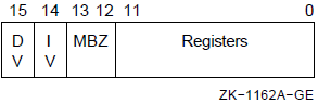
At the occurrence of one of the call instructions, the stack is aligned to along word boundary, and the trap enables in the processor status longword (PSW) are set to a known state to ensure consistent behavior of the called procedure. Integer overflow enable and decimal overflow enable are affected according to bits 14 and 15 of the entry mask, respectively. Floating underflow enable is cleared. Registers R11 to R0, specified by bits 11 to 0,respectively, are saved on the stack and are restored by the RET instruction. In addition, the program counter (PC), stack pointer (SP), frame pointer (FP),and argument pointer (AP) are always preserved by the CALL instructions and restored by the RET instruction.
All external procedure calls generated by standard HPE language processors and all intermodule calls to major VAX software subsystems comply with the procedure calling software standard (see the VAX Procedure Calling and Condition Handling Standard in the VSI OpenVMS Programming Concepts Manual). The procedure calling standard requires that all registers in the range R2 to R11 used in the procedure must appear in the mask. R0 and R1 are not preserved by any called procedure that complies with the procedure calling standard.
To preserve the state, the CALL instructions form a structure on the stack termed a call frame or stack frame. The call frame contains the saved registers, the saved PSW, the register save mask, and several control bits. The frame also includes a longword that the CALL instructions clear. The system uses this longword to implement the OpenVMS condition handling facility (see the VAX Procedure Calling and Condition Handling Standard in the OpenVMS Programming Interfaces: Calling a System Routine). At the end of execution of the CALL instruction,the frame pointer (FP) contains the address of the stack frame. The RET instruction uses the contents of FP to find the stack frame and the restore state. The condition handling facility assumes that FP always points to the stack frame.
The stack frame has the following format:
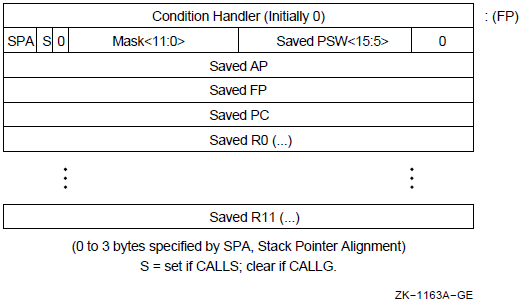
Note that the saved condition codes and the saved trace enable (PSW<T>)
are cleared.
The contents of the frame PSW <3:0> at the time RET is executed will become the
condition codes resulting from the execution of the procedure. Similarly, the content of
the frame PSW <4> at the time the RET is executed will become the
PSW<T> bit.
|
Description and Opcode |
Number of Instructions | |
|---|---|---|
|
1. |
Call Procedure with General Argument List CALLG arglist.ab, dst.ab, {-(SP).w*} |
1 |
|
2. |
Call Procedure with Stack Argument List CALLS numarg.rl, dst.ab, {-(SP).w*} |
1 |
|
3. |
Return from Procedure RET {(SP)+.r*} |
1 |
CALLG
CALLG — Call Procedure with General Argument List
Format
opcode arglist.ab, dst.ab Condition Codes
N <— 0;
Z <— 0;
V <— 0;
C <— 0;
Exceptions
- reserved operand
Opcodes
|
FA |
CALLG |
Call Procedure with General Argument List |
Description
The stack pointer (SP) is saved in a temporary register. Bits 1:0 are replaced
by zero, so that the stack is longword aligned. The procedure entry mask is
scanned from bit 11 to bit 0, and the contents of registers whose numbers
correspond to set bits in the mask are pushed on the stack as longwords. The
program counter (PC), frame pointer (FP), and argument pointer(AP) are pushed on
the stack as longwords. The condition codes are cleared. A longword containing
the saved low 2 bits of the SP in bits 31:30, a zero in bits 29 and 28, the low
12 bits of the procedure entry mask in bits 27:16, and the processor status word
(PSW) in bits 15:0 with T cleared are pushed on the stack. A longword zero is
pushed on the stack. The FP is replaced by the SP. The AP is replaced by the
arglist operand. The trap enables in the PSW are set
to a known state. Integer overflow and decimal overflow are affected according
to bits 14 and 15 of the entry mask, respectively; floating underflow is
cleared. The T-bit is unaffected. The PC is replaced by the sum of destination
operand plus 2, which transfers control to the called procedure at the byte
beyond the entry mask.
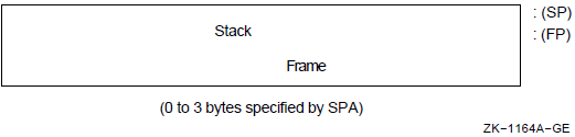
Notes
If bits 13:12 of the entry mask are not zero, a reserved operand fault occurs.
On a reserved operand fault, condition codes are UNPREDICTABLE.
- The procedure calling standard and the condition handling facility require the following register saving conventions:
R0 and R1 are always available for function return values and are never saved in the entry mask.
All registers R2 to R11 that are modified in the called procedure must be preserved in the mask.
Refer to the VAX Procedure Calling and Condition Handling Standard in the VSI OpenVMS Programming Concepts Manual.
CALLS
CALLS — Call Procedure with Stack Argument List
Format
opcode numarg.rl, dst.ab Condition Codes
N <— 0;
Z <— 0;
V <— 0;
C <— 0;
Exceptions
- reserved operand
Opcodes
|
FB |
CALLS |
Call Procedure with Stack Argument List |
Description
The numarg operand is pushed on the stack as a longword
(byte 0 contains the number of arguments; VSI uses the high-order 24 bits). The
stack pointer (SP) is saved in a temporary register, and then bits 1:0 of the SP
are replaced by zero so that the stack is longword aligned. The procedure entry
mask is scanned from bit 11 to bit 0, and the contents of registers whose
numbers correspond to set bits in the mask are pushed on the stack. The program
counter (PC), frame pointer (FP), and argument pointer (AP) are pushed on the
stack as longwords. The condition codes are cleared. A longword containing the
saved low 2 bits of the SP in bits 31:30, a 1 in bit 29, a zero in bit 28, the
low 12 bits of the procedure entry mask in bits 27:16, and the processor status
word (PSW) in bits 15:0 with T cleared is pushed on the stack. A longword zero
is pushed on the stack. The FP is replaced by the SP. The AP is set to the value
of the stack pointer after the numarg operand was pushed
on the stack. The trap enables in the PSW are set to a known state. Integer
overflow and decimal overflow are affected according to bits 14 and 15 of the
entry mask, respectively. Floating underflow is cleared. The T-Bit is
unaffected.
The PC is replaced by the sum of destination operand plus 2, which transfers control to the called procedure at the byte beyond the entry mask. The appearance of the stack after CALLS is executed is:
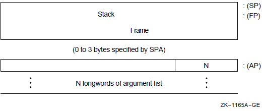
Notes
If bits 13:12 of the entry mask are not zero, a reserved operand fault occurs.
On a reserved operand fault, the condition codes are UNPREDICTABLE.
Normal use is to push the
arglistonto the stack in reverse order prior to the CALLS. On return, thearglistis removed from the stack automatically.- The procedure calling standard and the condition handling facility require the following register saving conventions:
R0 and R1 are always available for function return values and are never saved in the entry mask.
All registers R2 to R11 that are modified in the called procedure must be preserved in the entry mask. Refer to the VAX Procedure Calling and Condition Handling Standard in the VSI OpenVMS Programming Concepts Manual.
RET
RET — Return from Procedure
Format
opcode Condition Codes
N <— tmp1<3>;
Z <— tmp1<2>;
V <— tmp1<1>;
C <— tmp1<0>;
Exceptions
- reserved operand
Opcodes
|
04 |
RET |
Return from Procedure |
Description
The stack pointer (SP) is replaced by the frame pointer (FP) plus 4. A longword containing stack alignment bits in bits 31:30, a CALLS/CALLG flag in bit 29, the low 12 bits of the procedure entry mask in bits 27:16, and a saved processor status word (PSW) in bits 15:0 is popped from the stack and saved in a temporary. The program counter (PC), frame pointer (FP), and argument pointer (AP) are replaced by longwords popped from the stack. A register restore mask is formed from bits 27:16 of the temporary. Scanning from bit 0 to bit 11 of the restore mask, the contents of registers whose numbers are indicated by set bits in the mask are replaced by longwords popped from the stack. The SP is incremented by 31:30 of the temporary. The PSW is replaced by bits 15:0 of the temporary. If bit 29 in the temporary is 1 (indicating that the procedure was called by CALLS), a longword containing the number of arguments is popped from the stack. Four times the unsigned value of the low byte of this longword is added to the SP, and the SP is replaced by the result.
Notes
A reserved operand fault occurs if
tmp1<15:8> NEQ 0.On a reserved operand fault, the condition codes are UNPREDICTABLE.
The value of
tmp1<28> is ignored.The procedure calling standard and condition handling facility assume that procedures which return a function value or a status code do so in R0, or R0 and R1. Refer to the VAX Procedure Calling and Condition Handling Standard in the VSI OpenVMS Programming Concepts Manual.
9.7. Miscellaneous Instructions
|
Description and Opcode |
Number of Instructions | |
|---|---|---|
|
1. |
Bit Clear PSW BICPSW mask.rw |
1 |
|
2. |
Bit Set PSW BISPSW mask.rw |
1 |
|
3. |
Breakpoint Fault BPT {-(KSP).w*} |
1 |
|
4. |
Halt HALT {-(KSP).w*} |
1 |
|
5. |
Index INDEX subscript.rl, low.rl, high.rl, size.rl, indexin.rl, indexout.wl |
1 |
|
6. |
Move from PSL MOVPSL dst.wl |
1 |
|
7. |
No Operation NOP |
1 |
|
8. |
Pop Registers POPR mask.rw, {(SP)+.r*} |
1 |
|
9. |
Push Registers PUSHR mask.rw, {-(SP).w*} |
1 |
|
10. |
Extended Function Call XFC {unspecified operands} |
1 |
BICPSW
BICPSW — Bit Clear PSW
Format
opcode mask.rw Condition Codes
N <— N AND {NOT mask<3>};
Z <— Z AND {NOT mask<2>};
V <— V AND {NOT mask<1>};
C <— C AND {NOT mask<0>};Exceptions
- reserved operand
Opcodes
|
B9 |
BICPSW |
Bit Clear PSW |
Description
The result of the logical AND on processor status word (PSW) and the one's complement of the mask operand replaces PSW.
Note
A reserved operand fault occurs if mask <15:8> is
not zero. On a reserved operand fault, the PSW is not affected.
BISPSW
BISPSW — Bit Set PSW
Format
opcode mask.rw Condition Codes
N <— N OR mask<3>; Z <— Z OR mask<2>; V <— V OR mask<1>; C <— C OR mask<0>;
Exceptions
- reserved operand
Opcodes
|
B8 |
BISPSW |
Bit Set PSW |
Description
The result of the logical OR on processor status word (PSW) and the mask operand replaces PSW.
Note
A reserved operand fault occurs if mask <15:8> is
not zero. On a reserved operand fault, the PSW is not affected.
BPT
BPT — Breakpoint Fault
Format
opcode Condition Codes
N <— 0; ! Condition codes cleared after BPT fault Z <— 0; V <— 0; C <— 0;
Exceptions
- None.
Opcodes
|
03 |
BPT |
Breakpoint Fault |
Description
To understand the operation of this instruction, refer to Appendix E, "Exceptions That May Occur During Instruction Execution". This instruction, together with the T-bit, is used to implement debugging facilities.
HALT
HALT — Halt
Format
opcode Condition Codes
N <— 0; ! If privileged instruction fault, Z <— 0; ! condition codes are cleared after V <— 0; ! the fault. PSL saved on stack C <— 0; ! contains condition codes prior to HALT. N <— N; ! If processor halt Z <— Z; V <— V; C <— C;
Exceptions
- privileged instruction
Opcodes
|
00 |
HALT |
Halt |
Description
If the process is running in kernel mode, the processor is halted. Otherwise, a privileged instruction fault occurs. For information about privileged instruction faults, refer to Appendix E, "Exceptions That May Occur During Instruction Execution".
Note
This opcode is zero to trap many branches to data.
INDEX
INDEX — Compute Index
Format
opcode subscript.rl, low.rl, high.rl, size.rl, indexin.rl, indexout.wl Condition Codes
N <— indexout LSS 0; Z <— indexout EQL 0; V <— 0; C <— 0;
Exceptions
- subscript range
Opcodes
|
0A |
INDEX |
index |
Description
The indexin operand is added to the
subscript operand and the sum multiplied by the
size operand. The indexout
operand is replaced by the result. If the subscript
operand is less than the low operand or greater than the
high operand, a subscript range trap is taken.
Notes
No arithmetic exception other than subscript range can result from this instruction. Therefore, no indication is given if overflow occurs in either the add or the multiply steps. If overflow occurs on the add step, the sum is the low-order 32 bits of the true result. If overflow occurs on the multiply step, the
indexoutoperand is replaced by the low-order 32 bits of the true product of the sum and thesubscriptoperand. In the normal use of this instruction, overflow cannot occur without a subscript range trap occurring.The index instruction is useful in index calculations for arrays of the fixed-length data types (integer and floating) and for index calculations for arrays of bit fields, character strings, and decimal strings. The
indexinoperand permits cascading INDEX instructions for multidimensional arrays. For one-dimensional bit field arrays, it also permits introduction of the constant portion of an index calculation that is not readily absorbed by address arithmetic. The following notes show some of the uses of INDEX.- The following example shows a sequence of COBOL statements and the VAX MACRO code their compilation might generate:
COBOL: 01 A-ARRAY. 02 A PIC X(10) OCCURS 15 TIMES. 01 B PIC X(10). MOVE A(I) TO B.MACRO: INDEX I, #1, #15, #10, #0, R0 MOVC3 #10, A-10[R0], B.
- The following example shows a sequence of PL/I statements and the VAX MACRO code their compilation might generate:
PL/I: DCL A(-3:10) BIT (5); A(I) = 1;
MACRO: INDEX I, #-3, #10, #5, #3, R0 INSV #1, R0, #5, A ; Assumes A is byte aligned
- The following example shows a sequence of FORTRAN statements and the VAXMACRO code their compilation might generate:
FORTRAN: INTEGER*4 A(L1:U1, L2:U2), I, J A(I,J) = 1
MACRO: INDEX J, #L2, #U2, #M1, #0, R0; M1=U1-L1+1 INDEX I, #L1, #U1, #1, R0, R0; MOVL #1, A-a[R0]; a = {{L2*M1} + L1} *4
MOVPSL
MOVPSL — Move from PSL
Format
opcode dst.wl Condition Codes
N <— N; Z <— Z; V <— V; C <— C;
Exceptions
- None.
Opcodes
|
DC |
MOVPSL |
Move from PSL |
Description
The destination operand is replaced by processor status longword (PSL).
NOP
NOP — No Operation
Format
opcode Condition Codes
N <— N; Z <— Z; V <— V; C <— C;
Exceptions
- None.
Opcodes
|
01 |
NOP |
No Operation |
Description
No operation is performed. Because the time delay caused by a NOP instruction is dependent on processor type, VSI recommends that you do not use NOP as a means of delaying program execution. When you must have a program wait for a specified period, you should use a macro, such as the TIMEDWAIT macro, or code sequence that is not dependent on the processor's internal speed.
POPR
POPR — Pop Registers
Format
opcode mask.rw Condition Codes
N <— N; Z <— Z; V <— V; C <— C;
Exceptions
- None.
Opcodes
|
BA |
POPR |
Pop Registers |
Description
The contents of registers whose numbers correspond to set bits in the mask
operand are replaced by longwords popped from the stack. R[n] is replaced if
mask<n> is set. The mask is
scanned from bit 0 to bit 14. Bit 15 is ignored.
PUSHR
PUSHR — Push Registers
Format
opcode mask.rw Condition Codes
N <— N; Z <— Z; V <— V; C <— C;
Exceptions
- None.
Opcodes
|
BB |
PUSHR |
Push Registers |
Description
The contents of registers whose numbers correspond to set bits in the mask
operand are pushed on the stack as longwords. R[n] is pushed if
mask<n> is set. The mask is
scanned from bit 14 to bit 0. Bit 15 is ignored.
Note
The order of pushing is specified so that the contents of higher-numbered registers are stored at higher memory addresses. An example of a result of this would be a double-floating datum stored in adjacent registers being stored by PUSHR in memory in the correct order.
XFC
XFC — Extended Function Call
Format
opcode Condition Codes
N <— 0; Z <— 0; V <— 0; C <— 0;
Exceptions
- None.
Opcodes
|
FC |
XFC |
Extended Function Call |
Description
To understand the operation of this instruction, refer to Appendix E, "Exceptions That May Occur During Instruction Execution" and the VAX Architecture Reference Manual. This instruction provides for customer-defined extensions to the instruction set.
9.8. Queue Instructions
A queue is a circular, doubly linked list. A queue entry is specified by its address. Each queue entry is linked to the next by a pair of longwords. The first longword is the forward link; it specifies the location of the succeeding entry. The second longword is the backward link; it specifies the location of the preceding entry. Because a queue contains redundant links, it is possible to create ill-formed queues. The VAX instructions produce UNPREDICTABLE results when used on ill-formed queues.
A queue is classified by the type of link that it uses. The VAX supports two distinct types of links: absolute and self-relative.
9.8.1. Absolute Queues
Absolute queues use absolute addresses as links. Queue entries are linked by a pair of longwords. The first (lowest-addressed) longword is the forward link;it is the address of the succeeding queue entry. The second (highest-addressed) longword is the backward link; it is the address of the preceding queue entry.
A queue is specified by a queue header, which is identical to a pair of queue linkage longwords. The forward link of the header is the address of the entry called the head of the queue. The backward link of the header is the address of the entry termed the tail of the queue. The forward link of the tail points to the header.
Two general operations can be performed on queues: insertion of entries and removal of entries. Generally, entries can be inserted or removed only at the head or tail of a queue. (Under certain restrictions they can be inserted or removed elsewhere; this is discussed later.)
The following text contains examples of queue operations. An empty queue is specified by its header at address H.
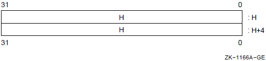
If an entry at address B is inserted into an empty queue (at either the head or the tail), the queue appears as follows:
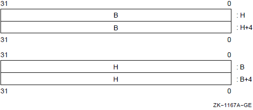
If an entry at address A is inserted at the head of the queue,the queue appears as follows:
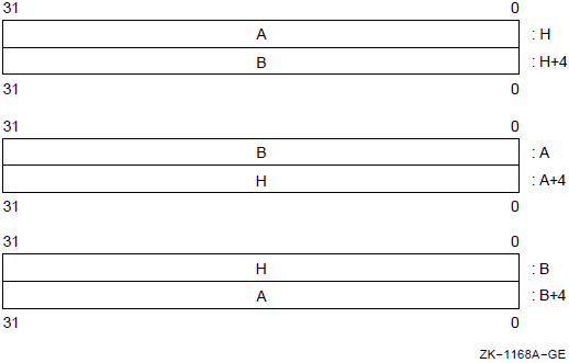
Finally, if an entry at address C is inserted at the tail, the queue appears as follows:
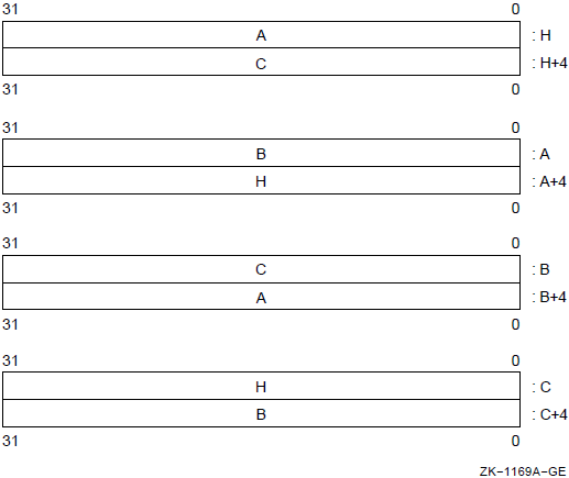
Following the preceding steps in reverse order gives the effect of removal at the tail and removal at the head.
If more than one process can perform operations on a queue simultaneously,insertions and removals should only be done at the head or tail of the queue. If only one process (or one process at a time) can perform operations on a queue, insertions and removals can be made at other than the head or tail of the queue. In the preceding example with the queue containing entries A, B,and C, the entry at address B can be removed, giving the following:
The reason for this restriction is that operations at the head or tail are always valid because the queue header is always present. Operations elsewhere in the queue depend on specific entries being present and may become invalid if another process is simultaneously performing operations on the queue.
Two instructions are provided for manipulating absolute queues: INSQUE and REMQUE. INSQUE inserts an entry specified by an entry operand into the queue following the entry specified by the predecessor operand. REMQUE removes the entry specified by the entry operand. Queue entries can be on arbitrary byte boundaries. Both INSQUE and REMQUE are implemented as noninterruptible instructions.
9.8.2. Self-Relative Queues
Self-relative queues use displacements from queue entries as links. Queue entries are linked by a pair of longwords. The first (lowest addressed)longword is the forward link; it is the displacement of the succeeding queue entry from the present entry. The second (highest-addressed) longword is the backward link; it is the displacement of the preceding queue entry from the present entry.
A queue is specified by a queue header, which also consists of two longword links. The forward link of the header is the address of the entry called the head of the queue. The backward link of the header is the address of the entry called the tail of the queue. The forward link of the tail points to the header.
The following text contains examples of queue operations. An empty queue is specified by its header at address H. Because the queue is empty, the self-relative links must be zero, as shown.
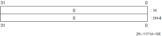
If an entry at address B is inserted into an empty queue (at either the head or tail), the queue appears as follows:
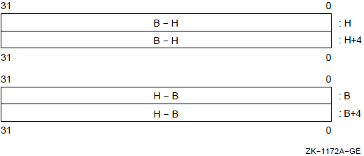
If an entry at address A is inserted at the head of the queue, the queue appears as follows:
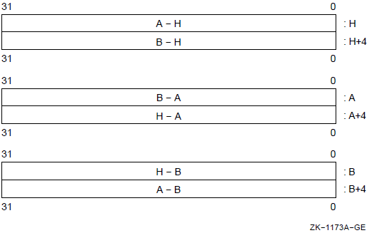
Finally, if an entry at address C is inserted at the tail, the queue appears as follows:
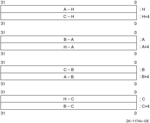
Following the previous steps in reverse order gives the effect of removal at the tail and at the head.
INSQHI—Insert entry into queue at head, interlocked.
INSQTI—Insert entry into queue at tail, interlocked.
REMQHI—Remove entry from queue at head, interlocked.
REMQTI—Remove entry from queue at tail, interlocked.
These operations are interlocked to allow cooperating processes in a multiprocessor system to access a shared list without additional synchronization. Queue entries must be quadword aligned. A hardware-supported interlocked memory access mechanism is used to read the queue header. Bit 0 of the queue header is used as a secondary interlock; it is set when the queue is being accessed.
If an interlocked queue instruction encounters the secondary interlock set,then, if no exception conditions exist, it terminates after setting the condition codes to indicate failure to gain access to the queue. If the secondary interlock bit is not set, then the interlocked queue instruction sets the secondary interlock bit during instruction execution and clears the secondary interlock bit at instruction completion. In this way, other interlocked queue instructions are prevented from operating on the same queue.
If an interlocked queue instruction encounters both the secondary interlock set and an exception condition resulting from instruction execution, then it is UNPREDICTABLE whether the exception occurs or the instruction terminates after setting the condition codes.
9.8.3. Instruction Descriptions
|
Description and Opcode |
Number of Instructions | |
|---|---|---|
|
1. |
Insert Entry into Queue at Head, Interlocked INSQHI entry.ab, header.aq |
1 |
|
2. |
Insert Entry into Queue at Tail, Interlocked INSQTI entry.ab, header.aq |
1 |
|
3. |
Insert Entry in Queue INSQUE entry.ab, pred.ab |
1 |
|
4. |
Remove Entry from Queue at Head, Interlocked REMQHI header.aq, addr.wl |
1 |
|
5. |
Remove Entry from Queue at Tail, Interlocked REMQTI header.aq, addr.wl |
1 |
|
6. |
Remove Entry from Queue REMQUE entry.ab, addr.wl |
1 |
INSQHI
INSQHI — Insert Entry into Queue at Head, Interlocked
Format
opcode entry.ab, header.aq Condition Codes
if {insertion succeeded} then
begin
N <— 0;
Z <— (entry) EQL (entry+4); ! First entry in queue
V <— 0;
C <— 0;
end;
else
begin
N <— 0;
Z <— 0;
V <— 0;
C <— 1; ! Secondary interlock failed
end;Exceptions
- reserved operand
Opcodes
|
5C |
INSQHI |
Insert Entry into Queue at Head, Interlocked |
Description
The entry specified by the entry operand is inserted into the queue following the header. If the entry inserted was the first one in the queue, the condition code Z-bit is set; otherwise it is cleared. The insertion is a noninterruptible operation. The insertion is interlocked to prevent concurrent interlocked insertions or removals at the head or tail of the same queue by another process even in a multiprocessor environment. Before performing any part of the operation, the processor validates that the entire operation can be completed. This method ensures that if a memory management exception occurs (see Appendix E, "Exceptions That May Occur During Instruction Execution"), the queue is left in a consistent state. If the instruction fails to acquire the secondary interlock, then, if no exception conditions exist, the instruction sets condition codes and terminates.
Notes
Because the insertion is noninterruptible, processes running in kernel mode can share queues with interrupt service routines.
The INSQHI, INSQTI, REMQHI, and REMQTI instructions are implemented such that cooperating software processes in a multiprocessor may access a shared list without additional synchronization.
- To set a software interlock realized with a queue, you can use the following:
INSERT: INSQHI ... ; Was queue empty? BEQL 1$ ; Yes BCS INSERT ; Try inserting again CALL WAIT(...) ; No, wait 1$: During access validation, any access that cannot be completed results in a memory management exception even though the queue insertion is not started.
A reserved operand fault occurs if
entryorheaderis an address that is not quadword aligned (that is, <2:0> NEQU 0) or ifheader<2:1> is not zero. A reserved operand fault also occurs ifheaderequalsentry. In this case, the queue is not altered.If an interlocked queue instruction encounters both the secondary interlock set and an exception condition resulting from instruction execution, then it is UNPREDICTABLE whether the exception occurs or the instruction terminates after setting the condition codes.
INSQTI
INSQTI — Insert Entry into Queue at Tail, Interlocked
Format
opcode entry.ab, header.aq Condition Codes
if {insertion succeeded} then
begin
N <— 0;
Z <— (entry) EQL (entry+4); ! First entry in queue
V <— 0;
C <— 0;
end;
else
begin
N <— 0;
Z <— 0;
V <— 0;
C <— 1; ! Secondary interlock failed
end;Exceptions
- reserved operand
Opcodes
|
5D |
INSQTI |
Insert Entry into Queue at Tail, Interlocked |
Description
The entry specified by the entry operand is inserted into the queue preceding the header. If the entry inserted was the first one in the queue, the condition code Z-bit is set; otherwise, it is cleared. The insertion is a noninterruptible operation. The insertion is interlocked to prevent concurrent interlocked insertions or removals at the head or tail of the same queue by another process even in a multiprocessor environment. Before performing any part of the operation, the processor validates that the entire operation can be completed. This method ensures that if a memory management exception occurs (see Appendix E, "Exceptions That May Occur During Instruction Execution"), queue is left in a consistent state. If the instruction fails to acquire the secondary interlock, then, if no exception conditions exist, the instruction sets condition codes and terminates.
Notes
Because the insertion is noninterruptible, processes running in kernel mode can share queues with interrupt service routines.
The INSQHI, INSQTI, REMQHI, and REMQTI instructions are implemented such that cooperating software processes in a multiprocessor may access a shared list without additional synchronization.
- To set a software interlock realized with a queue, you can use the following:
INSERT: INSQHI ... ; Was queue empty? BEQL 1$ ; Yes BCS INSERT ; Try inserting again CALL WAIT(...) ; No, wait 1$: During access validation, any access that cannot be completed results in a memory management exception even though the queue insertion is not started.
A reserved operand fault occurs if
entry,header, or (header+4) is an address that is not quadword aligned (that is, <2:0> NEQU 0) or ifheader<2:1> is not zero. A reserved operand fault also occurs ifheaderequalsentry. In this case, the queue is not altered.If the instruction encounters both the secondary interlock set and an exception condition resulting from instruction execution, then it is UNPREDICTABLE whether the exception occurs or the instruction terminates after setting the condition codes.
INSQUE
INSQUE — Insert Entry in Queue
Format
opcode entry.ab, pred.ab Condition Codes
N <— (entry) LSS (entry+4); Z <— (entry) EQL (entry+4); ! First entry in queue V <— 0; C <— (entry) LSSU (entry+4);
Exceptions
- None.
Opcodes
|
0E |
INSQUE |
Insert Entry in Queue |
Description
The entry specified by the entry operand is inserted into the queue following the entry specified by the predecessor operand. If the entry inserted was the first one in the queue, the condition code Z-bit is set; otherwise it is cleared. The insertion is a noninterruptible operation. Before performing any part of the operation, the processor validates that the entire operation can be completed. This method ensures that if a memory management exception occurs (see Appendix E, "Exceptions That May Occur During Instruction Execution"), the queue is left in a consistent state.
Notes
- The following three types of insertion can be performed by appropriate choice of the predecessor operand:
- Insert at head:
INSQUE entry, h ; h is queue head
- Insert at tail:
INSQUE entry,@h+4 ; h is queue head (Note "@" in this case only)
- Insert after arbitrary predecessor:
INSQUE entry,p ; p is predecessor
Because the insertion is noninterruptible, processes running in kernel mode can share queues with interrupt service routines.
The INSQUE and REMQUE instructions are implemented such that cooperating software processes in a single processor may access a shared list without additional synchronization, if the insertions and removals are only at the head or tail of the queue.
- To set a software interlock realized with a queue, you can use the following:
INSQUE ... ; Was queue empty? BEQL 1$ ; Yes CALL WAIT(...) ; No, wait 1$: During access validation, any access that cannot be completed results in a memory management exception, even though the queue insertion is not started.
REMQHI
REMQHI — Remove Entry from Queue at Head, Interlocked
Format
opcode header.aq, addr.wl Condition Codes
if {removal succeeded} then
begin
N <— 0;
Z <— (header) EQL 0; ! Queue empty after removal
V <— {queue empty before this instruction};
C <— 0;
end;
else
begin
N <— 0;
Z <— 0;
V <— 1; ! Did not remove anything
C <— 1; ! Secondary interlock failed
end;Exceptions
- reserved operand
Opcodes
|
5E |
REMQHI |
Remove Entry from Queue at Head, Interlocked |
Description
If the secondary interlock is clear, the queue entry following the header is removed from the queue and the address operand is replaced by the address of the entry removed. If the queue was empty prior to this instruction, or if the secondary interlock failed, the condition code V-bit is set; otherwise it is cleared.
If the interlock succeeded and the queue is empty at the end of this instruction, the condition code Z-bit is set; otherwise, it is cleared. The removal is interlocked to prevent concurrent interlocked insertions or removals at the head or tail of the same queue by another process even in a multiprocessor environment. The removal is a noninterruptible operation. Before performing any part of the operation, the processor validates that the entire operation can be completed. This ensures that if a memory management exception occurs (see Appendix E, "Exceptions That May Occur During Instruction Execution"), the queue is left in a consistent state. If the instruction fails to acquire the secondary interlock, then, if no exception conditions exist, the instruction sets condition codes and terminates.
Notes
Because the removal is noninterruptible, processes running in kernel mode can share queues with interrupt service routines.
The INSQHI, INSQTI, REMQHI, and REMQTI instructions are implemented so that cooperating software processes in a multiprocessor may access a shared list without additional synchronization.
- To release a software interlock realized with a queue, you can use the following:
1$: REMQHI ... ; Removed last? BEQL 2$ ; Yes BCS 1$ ; Try removing again CALL ACTIVATE(...) ; Activate other waiters 2$: - To remove entries until the queue is empty, you can use the following:
1$: REMQHI ... ; Anything removed? BVS 2$ ; No . process removed entry . BR 1$ ; . 2$ BCS 1$ ; Try removing again queue empty During access validation, any access that cannot be completed results in a memory management exception, even though the queue removal is not started.
A reserved operand fault occurs if
headeror (header+ (header)) is an address that is not quadword aligned (that is, <2:0> NEQU 0) or if (header) <2:1> is not zero. A reserved operand fault also occurs if the header address operand equals the address of theaddroperand. In this case, the queue is not altered.If the instruction encounters both the secondary interlock set and an exception condition resulting from instruction execution, then it is UNPREDICTABLE whether the exception occurs or the instruction terminates after setting the condition codes.
REMQTI
REMQTI — Remove Entry from Queue at Tail, Interlocked
Format
opcode header.aq, addr.wl Condition Codes
if {removal succeeded} then
begin
N <— 0;
Z <— (header + 4) EQL 0; ! Queue empty after removal
V <— {queue empty before this instruction};
C <— 0;
end;
else
begin
N <— 0;
Z <— 0;
V <— 1; ! Did not remove anything
C <— 1; ! Secondary interlock failed
end;Exceptions
- reserved operand
Opcodes
|
5F |
REMQTI |
Remove Entry from Queue at Tail, Interlocked |
Description
If the secondary interlock is clear, the queue entry preceding the header is removed from the queue and the address operand is replaced by the address of the entry removed. If the queue was empty prior to this instruction, or if the secondary interlock failed, the condition code V-bit is set; otherwise it is cleared.
If the interlock succeeded and the queue is empty at the end of this instruction, the condition code Z-bit is set; otherwise it is cleared. The removal is interlocked to prevent concurrent interlocked insertions or removals at the head or tail of the same queue by another process, even in a multiprocessor environment. The removal is a noninterruptible operation. Before performing any part of the operation, the processor validates that the entire operation can be completed. This ensures that if a memory management exception occurs (see Appendix E, "Exceptions That May Occur During Instruction Execution"), the queue is left in a consistent state. If the instruction fails to acquire the secondary interlock, then, if no exception conditions exist, the instruction sets condition codes and terminates.
Notes
Because the removal is noninterruptible, processes running in kernel mode can share queues with interrupt service routines.
The INSQHI, INSQTI, REMQHI, and REMQTI instructions are implemented to allow cooperating software processes in a multiprocessor system to access as hared list without additional synchronization.
- To release a software interlock realized with a queue, you can use the following:
1$: REMQTI ... ; Removed last? BEQL 2$ ; Yes BCS 1$ ; Try removing again CALL ACTIVATE(...) ; Activate other waiters 2$: - To remove entries until the queue is empty, you can use the following:
1$: REMQTI ... ; Anything removed? BVS 2$ ; No . process removed entry . BR 1$ ; . 2$: BCS 1$ ; Try removing again queue empty During access validation, any access that cannot be completed results ina memory management exception, even though the queue removal is not started.
A reserved operand fault occurs if
header, (header+ 4), or (header+ (header+ 4)+4) is an address that is not quadword aligned (that is, <2:0> NEQU 0), or if (header) <2:1> is not zero. A reserved operand fault also occurs if the header address operand equals the address of theaddroperand. In this case, the queue is not altered.If the instruction encounters both the secondary interlock set and an exception condition resulting from instruction execution, then it is UNPREDICTABLE whether the exception occurs or the instruction terminates after setting the condition codes.
REMQUE
REMQUE — Remove Entry from Queue
Format
opcode entry.ab,addr.wl Condition Codes
N <— (entry) LSS (entry+4); Z <— (entry) EQL (entry+4); ! Queue empty V <— (entry) EQL (entry+4); ! No entry to remove C <— (entry) LSSU (entry+4);
Exceptions
- None.
Opcodes
|
0F |
REMQUE |
Remove Entry from Queue |
Description
The queue entry specified by the entry operand is removed from the queue. The address operand is replaced by the address of the entry removed. If there was no entry in the queue to be removed, the condition code V-bit is set;otherwise it is cleared. If the queue is empty at the end of this instruction, the condition code Z-bit is set; otherwise it is cleared. The removal is a noninterruptible operation. Before performing any part of the operation, the processor validates that the entire operation can be completed. This ensures that if a memory management exception occurs (see Appendix E, "Exceptions That May Occur During Instruction Execution"), the queue is left in a consistent state.
Notes
- The following three types of removal can be performed by suitable choice of entry operand:
- Remove at head:
REMQUE @h,addr ; h is queue header
- Remove at tail:
REMQUE @h+4,addr ; h is queue header
- Remove arbitrary entry:
REMQUE entry,addr
Because the removal is noninterruptible, processes running in kernel mode can share queues with interrupt service routines.
The INSQUE and REMQUE instructions are implemented so that cooperating software processes in a single processor may access a shared list without additional synchronization, if the insertions and removals are only at the head or tail of the queue.
- To release a software interlock realized with a queue, you can use the following:
REMQUE ... ; Queue empty? BEQL 1$ ; Yes CALL ACTIVATE(...) ; Activate other waiters 1$: - To remove entries until the queue is empty, you can use the following:
1$: REMQUE ... ; Anything removed? BVS EMPTY ; No . . . BR 1$ During access validation, any access that cannot be completed results in a memory management exception, even though the queue removal is not started.
9.9. Floating-Point Instructions
F_floating, standard on all VAX processors
D_floating, standard on all VAX processors
G_floating, optional on the VAX-11/780 and the VAX-11/750, and standard on the VAX-11/730
H_floating, optional on the VAX-11/780 and the VAX-11/750, and standard on the VAX-11/730
To be consistent with the floating-point instruction set, which faults on reserved operands (see Chapter 8, "Basic Architecture"), software-implemented floating-point functions (for example, the absolute function) should verify that no input operands are reserved. An easy way to do this is a floating move or test of the input operands.
To make high-speed, floating-point operations easier, restrictions are placed on the addressing mode combinations usable within a single floating-point instruction. These combinations involve the logically inconsistent simultaneous use of a value as both a floating-point operand and an address.
If, within the same instruction, you use the contents of register Rn as both apart of a floating-point input operand (an .rf, .rd, .rg, .rh, .mf, .md, .mg, or .mh operand) and as an address in an addressing mode that modifies Rn (autoincrement, autodecrement, or autoincrement deferred), the value of the floating-point operand is UNPREDICTABLE.
9.9.1. Introduction
Mathematically, a floating-point number may be defined as having the following form:
(+ or −) (2 * *K) *f
K is an integer and f is a nonnegative
fraction. For a nonvanishing number, K and
f are uniquely determined by imposing the following
condition:1/2 LEQ f LSS 1.
The fractional factor, f, of the number is then said to be
binary normalized. For the number 0,
f must be assigned the value zero, and the value of
K is indeterminate.
Nonzero floating-point numbers:
The most significant bit of the floating-point data is the sign bit: 0 for positive and 1 for negative.
The fractional factor
fis assumed normalized, so that its most significant bit must be 1. This 1 is the "hidden" bit: it is not stored in the data word, but the hardware restores it before carrying out arithmetic operations. The F_floating and D_floating data types use 23 and 55 bits, respectively, forf, which, with the hidden bit, imply effective significance of 24 bits and 56 bits for arithmetic operations. The extended-range (G_floating and H_floating) data types use 52 and 112 bits,respectively, forf, which, with the hidden bit, imply effective significance of 53 and 113 bits for arithmetic operations.In the F_floating and D_floating data types, 8 bits are reserved for the storage of the exponent
Kin excess 128 notation. Thus, exponents from -128 to +127 could be represented, in biased form, by 0 to 255. For reasons given later, a biased exponent of zero (the true exponent of -128) is reserved for floating-point zero. Thus, for F_floating and D_floating data types, exponents are restricted to the range -127 to +127 inclusive or, in excess 128 notation, 1 to 255.In the G_floating data type, 11 bits are reserved for the storage of the exponent in excess 1024 notation. In the H_floating data type, 15 bits are reserved for the storage of the exponent in excess 16,384 notation. A biased exponent of zero is reserved for floating-point zero. Thus, exponents are restricted to -1023 to +1023 inclusive (in excess notation, 1 to 2047), and-16,383 to +16,383 inclusive (in excess notation, 1 to 32,767) for G_floating and H_floating data types, respectively.
Floating-point 0:
Because of the hidden bit, the fractional factor is not available to distinguish between zero and nonzero numbers whose fractional factor is exactly 1/2. Therefore, the VAX reserves a sign-exponent field of zero for this purpose. Any positive floating-point number with a biased exponent of zero is treated as if it were an exact zero by the floating-point instruction set. In particular, a floating-point operand whose bits are all zeros is treated as zero, and this is the format generated by all floating-point instructions for which the result is zero.
The reserved operands:
A reserved operand is defined to be any bit pattern with a sign bit of 1 and a biased exponent of zero. On the VAX, all floating-point instructions generate a fault if a reserved operand is encountered. A reserved operand is never generated as a result of a floating-point instruction. Scalar floating-point instructions never generate a reserved operand. However, vector floating-point instructions can generate reserved operands.
9.9.2. Overview of the Instruction Set
The VAX has the standard arithmetic operations ADD, SUB, MUL, and DIV implemented for all four floating-point data types. The results of these operations are always rounded, as described in Section 9.9.3, ''Accuracy''. In addition, VAX has two composite operations, EMOD and POLY, also implemented for all four floating-point data types. EMOD generates a product of two operands and then separates the product into its integer and fractional terms. POLY evaluates a polynomial, given the degree, the argument, and a pointer to a table of coefficients. Details on the operation of EMOD and POLY are given in their respective descriptions. All of these instructions are subject to the rounding errors associated with floating-point operations, as well as to exponent overflow and underflow. Accuracy is discussed in Section 9.9.3, ''Accuracy''. Exceptions are discussed in Appendix E, "Exceptions That May Occur During Instruction Execution".
The VAX architecture also has a complete set of instructions for conversion from integer arithmetic types (byte, word, longword) to all floating types (F_floating, D_floating, G_floating, H_floating), and vice versa. The VAX architecture also has a set of instructions for conversion between all of the floating types except between D_floating and G_floating. Many of these instructions are exact, in the sense defined in Section 9.9.3, ''Accuracy''. However, a few may generate rounding error, floating overflow, or floating underflow, or induce integer overflow. Details are given in the description of the CVT instructions.
The following move-type instructions are always exact: MOV, NEG, CLR, CMP, and TST. The ACB (Add Compare and Branch) instruction is subject to rounding errors, overflow, and underflow.
All of the floating-point instructions on the VAX architecture fault if they encounter a reserved operand. Floating-point instructions also fault on the occurrence of floating overflow or divide by zero, and the condition codes are UNPREDICTABLE. The FU bit in the processor status word (PSW) is available to enable or disable an exception on underflow. If the FU bit is clear, no exception occurs on underflow and zero is returned as the result. If the FU bit is set, a fault occurs on underflow. Further details on the actions taken if any of these exceptions occurs are included in the descriptions of the instructions and discussed in Appendix E, "Exceptions That May Occur During Instruction Execution".
9.9.3. Accuracy
This section discusses general comments on the accuracy of the VAX floating-point instruction set. The descriptions of the individual instructions may include additional details on their accuracy.
An instruction is defined to be exact if its result, extended on the right by an infinite sequence of zeros, is identical to that of an infinite precision calculation involving the same operands. The prior accuracy of the operands is ignored. For all arithmetic operations except DIV, a zero operand implies that the instruction is exact. The instruction is exact for DIV if the 0 operand is the dividend. If the 0 operand is the divisor, division is undefined and the instruction faults.
For nonzero floating-point operands, the fractional factor is binary normalized with 24 or 56 bits for single-precision (F_floating) or double-precision (D_floating), respectively; and 53 or 113 bits for extended-range double-precision (G_floating), and extended-range quadruple-precision (H_floating), respectively. The ADD, SUB, MUL, and DIV instructions require an overflow bit (on the left) and two guard bits (on the right) to guarantee the return of a rounded result identical to the corresponding infinite precision operation rounded to the specified word length. With these two guard bits, a rounded result has an error bound of 1/2LSB (least significant bit).
If the rounding bit is 1, the rounded result is the chopped result incremented by an LSB (least significant bit).
If the rounding bit is zero, the rounded and chopped results are identical.
- If a stored result is exact:
rounded value = chopped value = true value
- If a stored result is not exact:
Its magnitude is always less than that of the true result for chopping.
Its magnitude is always less than that of the true result for rounding if the rounding bit is zero.
Its magnitude is greater than that of the true result for rounding if the rounding bit is 1.
9.9.4. Instruction Descriptions
|
Description and Opcode |
Number of Instructions | |
|---|---|---|
|
1. |
Add 2 Operand ADD{F,D,G,H}2 add.rx, sum.mx |
4 |
|
2. |
Add 3 Operand ADD{F,D,G,H}3 add1.rx, add2.rx, sum.wx |
4 |
|
3. |
Clear CLR{L=F,Q=D=G,O=H} dst.wx |
3 |
|
4. |
Compare CMP{F,D,G,H} src1.rx, src2.rx |
4 |
|
5. |
Convert CVT{F,D,G,H}{B,W,L,F,D,G,H} src.rx, dst.wy CVT{B,W,L}{F,D,G,H} src.rx, dst.wy All pairs except FF, DD, GG, HH, DG, and GD |
34 |
|
6. |
Convert Rounded CVTR{F,D,G,H}L src.rx, dst.wl |
4 |
|
7. |
Divide 2 Operand DIV{F,D,G,H}2 divr.rx, quo.mx |
4 |
|
8. |
Divide 3 Operand DIV{F,D,G,H}3 divr.rx, divd.rx, quo.wx |
4 |
|
9. |
Extended Modulus EMOD{F,D} mulr.rx, mulrx.rb, muld.rx, int.wl, fract.wx EMOD{G,H} mulr.rx, mulrx.rw, muld.rx, int.wl, fract.wx |
4 |
|
10. |
Move Negated MNEG{F,D,G,H} src.rx, dst.wx |
4 |
|
11. |
Move MOV{F,D,G,H} src.rx, dst.wx |
4 |
|
12. |
Multiply 2 Operand MUL{F,D,G,H}2 mulr.rx, prod.mx |
4 |
|
13. |
Multiply 3 Operand MUL{F,D,G,H}3 mulr.rx, muld.rx, prod.wx |
4 |
|
14. |
Polynomial Evaluation F_floating POLYF arg.rf, degree.rw, tbladdr.ab, {R0-3.wl} |
1 |
|
15. |
Polynomial Evaluation D_floating POLYD arg.rd, degree.rw, tbladdr.ab, {R0-5.wl} |
1 |
|
16. |
Polynomial Evaluation G_floating POLYG arg.rg, degree.rw, tbladdr.ab, {R0-5.wl} |
1 |
|
17. |
Polynomial Evaluation H_floating POLYH arg.rh, degree.rw, tbladdr.ab, {R0-5.wl,-16(SP):-1(SP).wb} |
1 |
|
18. |
Subtract 2 Operand SUB{F,D,G,H}2 sub.rx, dif.mx |
4 |
|
19. |
Subtract 3 Operand SUB{F,D,G,H}3 sub.rx, min.rx, dif.wx |
4 |
|
20. |
Test TST{F,D,G,H} src.rx |
4 |
|
Description and Opcode |
Number of Instructions | |
|---|---|---|
|
1. |
Add Compare and Branch ACB{F,D,G,H} limit.rx, add.rx, index.mx, displ.bw Compare is LE on positive add, GE on negative add. |
4 |
ADD
ADD — Add
Format
2operand: opcode add.rx, sum.mx 3operand: opcode add1.rx, add2.rx, sum.wx Condition Codes
N <— sum LSS 0; Z <— sum EQL 0; V <— 0; C <— 0;
Exceptions
- floating overflow
- floating underflow
- reserved operand
Opcodes
|
40 |
ADDF2 |
Add F_floating 2 Operand |
|
41 |
ADDF3 |
Add F_floating 3 Operand |
|
60 |
ADDD2 |
Add D_floating 2 Operand |
|
61 |
ADDD3 |
Add D_floating 3 Operand |
|
40FD |
ADDG2 |
Add G_floating 2 Operand |
|
41FD |
ADDG3 |
Add G_floating 3 Operand |
|
60FD |
ADDH2 |
Add H_floating 2 Operand |
|
61FD |
ADDH3 |
Add H_floating 3 Operand |
Description
In 2 operand format, the addend operand is added to the sum operand, and the sum operand is replaced by the rounded result. In 3 operand format, the addend 1 operand is added to the addend 2 operand, and the sum operand is replaced by the rounded result.
Notes
On a reserved operand fault, the sum operand is unaffected, and the condition codes are UNPREDICTABLE.
On floating underflow, if FU is set, a fault occurs. Zero is stored as the result of floating underflow only if FU is clear. On a floating underflow fault, the sum operand is unaffected. If FU is clear, the sum operand is replaced by zero, and no exception occurs.
On floating overflow, the instruction faults, the sum operand is unaffected, and the condition codes are UNPREDICTABLE.
CLR
CLR — Clear
Format
opcode dst.wx Condition Codes
N <— 0; Z <— 1; V <— 0; C <— C;
Exceptions
- None.
Opcodes
|
D4 |
CLRF |
Clear F_floating |
|
7C |
CLRD |
Clear D_floating, |
|
CLRG |
Clear G_floating | |
|
7CFD |
CLRH |
Clear H_floating |
Description
The destination operand is replaced by zero.
Note
CLR x
dst is equivalent to MOV x S^#0,
dst, but is 1 byte shorter.
CMP
CMP — Compare
Format
opcode src1.rx, src2.rx Condition Codes
N <— src1 LSS src2; Z <— src1 EQL src2; V <— 0; C <— 0;
Exceptions
- reserved operand
Opcodes
|
51 |
CMPF |
Compare F_floating |
|
71 |
CMPD |
Compare D_floating |
|
51FD |
CMPG |
Compare G_floating |
|
71FD |
CMPH |
Compare H_floating |
Description
The source 1 operand is compared with the source 2 operand. The only action is to affect the condition codes.
CVT
CVT — Convert
Format
opcode src.rx, dst.wy Condition Codes
N <— dst LSS 0;
Z <— dst EQL 0;
V <— {integer overflow};
C <— 0;Exceptions
- integer overflow
- floating overflow
- floating underflow
- reserved operand
Opcodes
|
4C |
CVTBF |
Convert Byte to F_floating |
|
6C |
CVTBD |
Convert Byte to D_floating |
|
4CFD |
CVTBG |
Convert Byte to G_floating |
|
6CFD |
CVTBH |
Convert Byte to H_floating |
|
4D |
CVTWF |
Convert Word to F_floating |
|
6D |
CVTWD |
Convert Word to D_floating |
|
4DFD |
CVTWG |
Convert Word to G_floating |
|
6DFD |
CVTWH |
Convert Word to H_floating |
|
4E |
CVTLF |
Convert Long to F_floating |
|
6E |
CVTLD |
Convert Long to D_floating |
|
4EFD |
CVTLG |
Convert Long to G_floating |
|
6EFD |
CVTLH |
Convert Long to H_floating |
|
48 |
CVTFB |
Convert F_floating to Byte |
|
68 |
CVTDB |
Convert D_floating to Byte |
|
48FD |
CVTGB |
Convert G_floating to Byte |
|
68FD |
CVTHB |
Convert H_floating to Byte |
|
49 |
CVTFW |
Convert F_floating to Word |
|
69 |
CVTDW |
Convert D_floating to Word |
|
49FD |
CVTGW |
Convert G_floating to Word |
|
69FD |
CVTHW |
Convert H_floating to Word |
|
4A |
CVTFL |
Convert F_floating to Long |
|
4B |
CVTRFL |
Convert Rounded F_floating to Long |
|
6A |
CVTDL |
Convert D_floating to Long |
|
6B |
CVTRDL |
Convert Rounded D_floating to Long |
|
4AFD |
CVTGL |
Convert G_floating to Long |
|
4BFD |
CVTRGL |
Convert Rounded G_floating to Long |
|
6AFD |
CVTHL |
Convert H_floating to Long |
|
6BFD |
CVTRHL |
Convert Rounded H_floating to Long |
|
56 |
CVTFD |
Convert F_floating to D_floating |
|
99FD |
CVTFG |
Convert F_floating to G_floating |
|
98FD |
CVTFH |
Convert F_floating to H_floating |
|
76 |
CVTDF |
Convert D_floating to F_floating |
|
32FD |
CVTDH |
Convert D_floating to H_floating |
|
33FD |
CVTGF |
Convert G_floating to F_floating |
|
56FD |
CVTGH |
Convert G_floating to H_floating |
|
F6FD |
CVTHF |
Convert H_floating to F_floating |
|
F7FD |
CVTHD |
Convert H_floating to D_floating |
|
76FD |
CVTHG |
Convert H_floating to G_floating |
Description
|
Form |
Instructions |
|---|---|
|
Exact |
CVTBF, CVTBD, CVTBG, CVTBH, CVTWF, CVTWD, CVTWG, CVTWH,CVTLD, CVTLG, CVTLH, CVTFD, CVTFG, CVTFH, CVTDH, CVTGH |
|
Truncated |
CVTFB, CVTDB, CVTGB, CVTHB, CVTFW, CVTDW, CVTGW, CVTHW, CVTFL, CVTDL, CVTGL, CVTHL |
|
Rounded |
CVTLF, CVTRFL, CVTRDL, CVTRGL, CVTRHL, CVTDF, CVTGF,CVTHF, CVTHD, CVTHG |
Notes
Only CVTDF, CVTGF, CVTHF, CVTHD, and CVTHG can result in a floating overflow fault; the destination operand is unaffected, and the condition codes are UNPREDICTABLE.
Only converts with a floating-point source operand can result in are served operand fault. On a reserved operand fault, the destination operand is unaffected, and the condition codes are UNPREDICTABLE.
Only converts with an integer destination operand can result in integer overflow. On integer overflow, the destination operand is replaced by the low-order bits of the true result.
Only CVTGF, CVTHF, CVTHD, and CVTHG can result in floating underflow. If FU is set, a fault occurs. On a floating underflow fault, the destination operand is unaffected. If FU is clear, the destination operand is replaced by zero, and no exception occurs.
DIV
DIV — Divide
Format
2operand: opcode divr.rx, quo.mx 3operand: opcode divr.rx, divd.rx, quo.wx Condition Codes
N <— quo LSS 0; Z <— quo EQL 0; V <— 0; C <— 0;
Exceptions
- floating overflow
- floating underflow
- divide by zero
- reserved operand
Opcodes
|
46 |
DIVF2 |
Divide F_floating 2 Operand |
|
47 |
DIVF3 |
Divide F_floating 3 Operand |
|
66 |
DIVD2 |
Divide D_floating 2 Operand |
|
67 |
DIVD3 |
Divide D_floating 3 Operand |
|
46FD |
DIVG2 |
Divide G_floating 2 Operand |
|
47FD |
DIVG3 |
Divide G_floating 3 Operand |
|
66FD |
DIVH2 |
Divide H_floating 2 Operand |
|
67FD |
DIVH3 |
Divide H_floating 3 Operand |
Description
In 2 operand format, the quotient operand is divided by the divisor operand and the quotient operand is replaced by the rounded result. In 3 operand format, the dividend operand is divided by the divisor operand, and the quotient operand is replaced by the rounded result.
Notes
On a reserved operand fault, the quotient operand is unaffected, and the condition codes are UNPREDICTABLE.
On floating underflow, if FU is set, a fault occurs. On a floating underflow fault, the quotient operand is unaffected. If FU is clear, the quotient operand is replaced by zero, and no exception occurs.
On floating overflow, the instruction faults, the quotient operand is unaffected, and the condition codes are UNPREDICTABLE.
On divide by zero, the quotient operand and condition codes are affected,as in note 3.
EMOD
EMOD — Extended Multiply and Integerize
Format
EMODF and EMODD: opcode mulr.rx, mulrx.rb, muld.rx, int.wl, fract.wx EMODG and EMODH: opcode mulr.rx, mulrx.rw, muld.rx, int.wl, fract.wx Condition Codes
N <— fract LSS 0;
Z <— fract EQL 0;
V <— {integer overflow};
C <— 0;Exceptions
- integer overflow
- floating underflow
- reserved operand
Opcodes
|
54 |
EMODF |
Extended Multiply and Integerize F_floating |
|
74 |
EMODD |
Extended Multiply and Integerize D_floating |
|
54FD |
EMODG |
Extended Multiply and Integerize G_floating |
|
74FD |
EMODH |
Extended Multiply and Integerize H_floating |
Description
The multiplier extension operand is concatenated with the multiplier operand to gain 8 (EMODD and EMODF), 11 (EMODG), or 15 (EMODH) additional low-order fraction bits. The low-order 5 or 1 bits of the 16-bit multiplier extension operand are ignored by the EMODG and EMODH instructions, respectively. The multiplicand operand is multiplied by the extended multiplier operand. The multiplication result is equivalent to the exact product truncated (before normalization) to a fraction field of 32 bits in F_floating, 64 bits in D_floating and G_floating, and 128 bits in H_floating. The result is regarded as the sum of an integer and fraction of the same sign. The integer operand is replaced by the integer part of the result, and the fraction operand is replaced by the rounded fractional part of the result.
Notes
On a reserved operand fault, the integer operand, and the fraction operand are unaffected. The condition codes are UNPREDICTABLE.
On floating underflow, if FU is set, a fault occurs. On a floating underflow fault, the integer and fraction parts are unaffected. If FU is clear, the integer and fraction parts are replaced by zero, and no exception occurs.
On integer overflow, the integer operand is replaced by the low-order bits of the true result.
Floating overflow is indicated by integer overflow; however, integer overflow is possible in the absence of floating overflow.
The signs of the integer and fraction are the same unless integer overflow results.
Because the fraction part is rounded after separation of the integer part,it is possible that the value of the fraction operand is 1.
MNEG
MNEG — Move Negated
Format
opcode src.rx, dst.wx Condition Codes
N <— dst LSS 0; Z <— dst EQL 0; V <— 0; C <— 0;
Exceptions
- reserved operand
Opcodes
|
52 |
MNEGF |
Move Negated F_floating |
|
72 |
MNEGD |
Move Negated D_floating |
|
52FD |
MNEGG |
Move Negated G_floating |
|
72FD |
MNEGH |
Move Negated H_floating |
Description
The destination operand is replaced by the negative of the source operand.
MOV
MOV — Move
Format
opcode src.rx, dst.wx Condition Codes
N <— dst LSS 0; Z <— dst EQL 0; V <— 0; C <— C;
Exceptions
- reserved operand
Opcodes
|
50 |
MOVF |
Move F_floating |
|
70 |
MOVD |
Move D_floating |
|
50FD |
MOVG |
Move G_floating |
|
70FD |
MOVH |
Move H_floating |
Description
The destination operand is replaced by the source operand.
Note
On a reserved operand fault, the destination operand is unaffected, and the condition codes are UNPREDICTABLE.
MUL
MUL — Multiply
Format
2operand: opcode mulr.rx, prod.mx 3operand: opcode mulr.rx, muld.rx, prod.wx Condition Codes
N <— prod LSS 0; Z <— prod EQL 0; V <— 0; C <— 0;
Exceptions
- floating overflow
- floating underflow
- reserved operand
Opcodes
|
44 |
MULF2 |
Multiply F_floating 2 Operand |
|
45 |
MULF3 |
Multiply F_floating 3 Operand |
|
64 |
MULD2 |
Multiply D_floating 2 Operand |
|
65 |
MULD3 |
Multiply D_floating 3 Operand |
|
44FD |
MULG2 |
Multiply G_floating 2 Operand |
|
45FD |
MULG3 |
Multiply G_floating 3 Operand |
|
64FD |
MULH2 |
Multiply H_floating 2 Operand |
|
65FD |
MULH3 |
Multiply H_floating 3 Operand |
Description
In 2 operand format, the product operand is multiplied by the multiplier operand, and the product operand is replaced by the rounded result. In 3 operand format, the multiplicand operand is multiplied by the multiplier operand, and the product operand is replaced by the rounded result.
Notes
On a reserved operand fault, the product operand is unaffected, and the condition codes are UNPREDICTABLE.
On floating underflow, if FU is set, a fault occurs. On a floating underflow fault, the product operand is unaffected. If FU is clear, the product operand is replaced by zero, and no exception occurs.
On floating overflow, the instruction faults, the product operand is unaffected, and the condition codes are UNPREDICTABLE.
POLY
POLY — Polynomial Evaluation
Format
opcode arg.rx, degree.rw, tbladdr.ab Condition Codes
N <— R0 LSS 0; Z <— R0 EQL 0; V <— 0; C <— 0;
Exceptions
- floating overflow
- floating underflow
- reserved operand
Opcodes
|
55 |
POLYF |
Polynomial Evaluation F_floating |
|
75 |
POLYD |
Polynomial Evaluation D_floating |
|
55FD |
POLYG |
Polynomial Evaluation G_floating |
|
75FD |
POLYH |
Polynomial Evaluation H_floating |
Description
if d = degree and x = arg result = C[0]+x**0 + x*(C[1] + x*(C[2] + ... x*C[d]))
The unsigned word degree operand specifies the highest-numbered
coefficient to participate in the evaluation. POLYH requires four longwords
on the stack to store arg in case the instruction is
interrupted.
Notes
After execution:
- POLYF:
- R0 = result
- R1 = 0
- R2 = 0
- R3 = table address + degree*4 + 4
- POLYD and POLYG:
- R0 = high-order part of result
- R1 = low-order part of result
- R2 = 0
- R3 = table address + degree*8 + 8
- R4 = 0
- R5 = 0
- POLYH:
- R0 = highest-order part of result
- R1 = second-highest-order part of result
- R2 = second-lowest-order part of result
- R3 = lowest-order part of result
- R4 = 0
- R5 = table address + degree*16 + 16
- On a floating fault:
If PSL
<FPD>= 0, the instruction faults, and all relevant side effects are restored to their original state.- If PSL
<FPD>= 1, the instruction is suspended, and the state is saved in the general registers as follows:POLYF: R0 = tmp3 ! Partial result after iteration ! prior to the one causing the ! overflow/underflow R1 = arg R2<7:0> = tmp1 ! Number of iterations remaining R2<31:8> = implementation specific R3 = tmp2 ! Points to table entry causing ! exception POLYD and POLYG: R1'R0 = tmp3 ! Partial result after iteration ! prior to the one causing the ! overflow/underflow R2<7:0> = tmp1 ! Number of iterations remaining R2<31:8> = implementation specific R3 = tmp2 ! Points to table entry causing ! exception R5'R4 = arg POLYH: R3'R2'R1'R0 = tmp3 ! Partial result after iteration ! prior to the one causing the ! overflow/underflow R4<7:0> = tmp1 ! Number of iterations remaining R4<31:8> = implementation specific R5 = tmp2 ! Points to table entry causing ! exceptionargis saved on the stack in use during the faulting instruction.Implementation-specific information is saved to allow the instruction to continue after possible scaling of the coefficients and partial result by the fault handler.
If the unsigned word degree operand is zero and the argument is not are served operand, the result is C[0].
If the unsigned word degree operand is greater than 31, a reserved operand fault occurs.
- On a reserved operand fault:
If PSL
<FPD>= 0, the reserved operand is either the degree operand (greater than 31), or the argument operand, or some coefficient.If PSL
<FPD>= 1, the reserved operand is a coefficient, and R3 (except for POLYH) or R5 (for POLYH) is pointing at the value that caused the exception.The state of the saved condition codes and the other registers is UNPREDICTABLE. If the reserved operand is changed and the contents of the condition codes and all registers are preserved, the fault can be continued.
On floating underflow after the rounding operation at any iteration of the computation loop, a fault occurs if FU is set. If FU is clear, the temporary result (
tmp3) is replaced by zero and the operation continues. In this case, the final result may be nonzero if underflow occurred before the last iteration.On floating overflow after the rounding operation at any iteration of the computation loop, the instruction terminates with a fault.
If the argument is zero and one of the coefficients in the table is the reserved operand, whether a reserved operand fault occurs is UNPREDICTABLE.
For POLYH, some implementations may not save
argon the stack until after an interrupt or fault occurs. However,argwill always be on the stack if an interrupt or floating fault occurs after FPD is set. If the four longwords on the stack overlap any of the source operands, the results are UNPREDICTABLE.
Example
; To compute P(x) = C0 + C1*x + C2*x**2
; where C0 = 1.0, C1 = .5, and C2 = .25
POLYF X,#2,PTABLE
.
.
.
PTABLE: .FLOAT 0.25 ; C2
.FLOAT 0.5 ; C1
.FLOAT 1.0 ; C0SUB
SUB — Subtract
Format
2operand: opcode sub.rx, dif.mx 3operand: opcode sub.rx, min.rx, dif.wx Condition Codes
N <— dif LSS 0; Z <— dif EQL 0; V <— 0; C <— 0;
Exceptions
- floating overflow
- floating underflow
- reserved operand
Opcodes
|
42 |
SUBF2 |
Subtract F_floating 2 Operand |
|
43 |
SUBF3 |
Subtract F_floating 3 Operand |
|
62 |
SUBD2 |
Subtract D_floating 2 Operand |
|
63 |
SUBD3 |
Subtract D_floating 3 Operand |
|
42FD |
SUBG2 |
Subtract G_floating 2 Operand |
|
43FD |
SUBG3 |
Subtract G_floating 3 Operand |
|
62FD |
SUBH2 |
Subtract H_floating 2 Operand |
|
63FD |
SUBH3 |
Subtract H_floating 3 Operand |
Description
In 2 operand format, the subtrahend operand is subtracted from the difference operand, and the difference is replaced by the rounded result. In 3 operand format, the subtrahend operand is subtracted from the minuend operand, and the difference operand is replaced by the rounded result.
Notes
On a reserved operand fault, the difference operand is unaffected, and the condition codes are UNPREDICTABLE.
On floating underflow, if FU is set, a fault occurs. Zero is stored as the result of floating underflow only if FU is clear. On a floating underflow fault, the difference operand is unaffected. If FU is clear, the difference operand is replaced by zero, and no exception occurs.
On floating overflow, the instruction faults, the difference operand is unaffected, and the condition codes are UNPREDICTABLE.
TST
TST — Test
Format
opcode src.rx Condition Codes
N <— src LSS 0; Z <— src EQL 0; V <— 0; C <— 0;
Exceptions
- reserved operand
Opcodes
|
53 |
TSTF |
Test F_floating |
|
73 |
TSTD |
Test D_floating |
|
53FD |
TSTG |
Test G_floating |
|
73FD |
TSTH |
Test H_floating |
Description
The condition codes are affected according to the value of the source operand.
Notes
TSTx
srcis equivalent to CMPxsrc, #0, but is 5 (F_floating) or 9 (D_floating or G_floating) or 17 (H_floating) bytes shorter.On a reserved operand fault, the condition codes are UNPREDICTABLE.
9.10. Character String Instructions
An unsigned word operand that specifies the length of the character string in bytes.
The address of the lowest-addressed byte of the character string. This is specified by a byte operand of address access type.
Each of the character string instructions uses general registers R0 to R1, R0 to R3, or R0 to R5 to contain a control block that maintains updated addresses and state during the execution of the instruction. At completion, these registers are available to software to use as string specification operands for a subsequent instruction on a contiguous character string. During the execution of the instructions, pending interrupt conditions are tested. If any conditions are found, the control block is updated, a first-part-done bit is set in the processor status longword (PSL), and the instruction is interrupted (refer to Appendix E, "Exceptions That May Occur During Instruction Execution"). After the interruption, the instruction resumes transparently. The format of the control block is as follows:
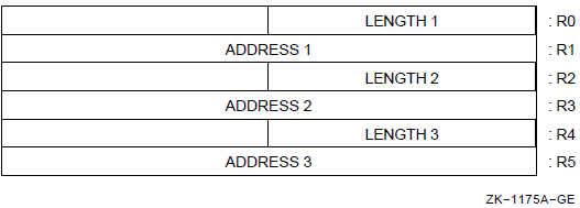
The fields LENGTH 1, LENGTH 2 (if required), and LENGTH 3 (if required)contain the number of bytes remaining to be processed in the first, second,and third string operands, respectively. The fields ADDRESS 1, ADDRESS 2 (if required), and ADDRESS 3 (if required) contain the address of the next byte to be processed in the first, second, and third string operands, respectively.
Memory access faults do not occur when a zero-length string is specified because no memory reference occurs.
|
Description and Opcode |
Number of Instructions | |
|---|---|---|
|
1. |
Compare Characters 3 Operand CMPC3 len.rw, src1addr.ab, src2addr.ab, {R0-3.wl} |
1 |
|
2. |
Compare Characters 5 Operand CMPC5 src1len.rw, src1addr.ab, fill.rb, src2len.rw, src2addr.ab, {R0-3.wl} |
1 |
|
3. |
Locate Character LOCC char.rb, len.rw, addr.ab, {R0-1.wl} |
1 |
|
4. |
Match Characters MATCHC len1.rw, addr1.ab, len2.rw, addr2.ab, {R0-3.wl} |
1 |
|
5. |
Move Character 3 Operand MOVC3 len.rw, srcaddr.ab, dstaddr.ab, {R0-5.wl} |
1 |
|
6. |
Move Character 5 Operand MOVC5 srclen.rw, srcaddr.ab, fill.rb, dstlen.rw, dstaddr.ab, {R0-5.wl} |
1 |
|
7. |
Move Translated Characters MOVTC srclen.rw, srcaddr.ab, fill.rb, tbladdr.ab, dstlen.rw, dstaddr.ab, {R0-5.wl} |
1 |
|
8. |
Move Translated Until Character MOVTUC srclen.rw, srcaddr.ab, esc.rb, tbladdr.ab, dstlen.rw, dstaddr.ab, {R0-5.wl} |
1 |
|
9. |
Scan Characters SCANC len.rw, addr.ab, tbladdr.ab, mask.rb, {R0-3.wl} |
1 |
|
10. |
Skip Character SKPC char.rb, len.rw, addr.ab, {R0-1.wl} |
1 |
|
11. |
Span Characters SPANC len.rw, addr.ab, tbladdr.ab, mask.rb, {R0-3.wl} |
1 |
CMPC
CMPC — Compare Characters
Format
3operand: opcode len.rw, src1addr.ab, src2addr.ab 5operand: opcode src1len.rw, src1addr.ab,
fill.rb, src2len.rw, src2addr.ab Condition Codes
N <— {first byte} LSS {second byte};
Z <— {first byte} EQL {second byte};
V <— 0;
C <— {first byte} LSSU {second byte};Exceptions
- None.
Opcodes
|
29 |
CMPC3 |
Compare Characters 3 Operand |
|
2D |
CMPC5 |
Compare Characters 5 Operand |
Description
In 3 operand format, the bytes of string1 specified by the length and address1 operands are compared with the bytes of string2 specified by the length and address2 operands. Comparison proceeds until inequality is detected or all the bytes of the strings have been examined. Condition codes are affected by the result of the last byte comparison. In 5 operand format, the bytes of the string1 operand specified by the length1 and address1 operands are compared with the bytes of the string2 operand specified by the length2 and address2 operands. If one string is longer than the other, the shorter string is conceptually extended to the length of the longer by appending (at higher addresses) bytes equal to the fill operand. Comparison proceeds until inequality is detected or all the bytes of the strings have been examined. Condition codes are affected by the result of the last byte comparison. For either CMPC3 or CMPC5, two zero-length strings compare equal (that is, Z is set and N, V, and C are cleared).
Notes
- After execution of CMPC3:
R0 =
Number of bytes remaining in string1 (including byte that terminated comparison); R0 is zero only if strings are equal
R1 =
Address of the byte in string1 that terminated comparison; if strings are equal, address of 1 byte beyond string1
R2 =
R0
R3 =
Address of the byte in string2 that terminated comparison; if strings are equal, address of 1 byte beyond string2
- After execution of CMPC5:
R0 =
Number of bytes remaining in string1 (including byte that terminated comparison); R0 is zero only if string1 and string2 are of equal length and equal or string1 was exhausted before comparison terminated
R1 =
Address of the byte in string1 that terminated comparison; if comparison did not terminate before string1 exhausted, address of 1 byte beyond string1
R2 =
Number of bytes remaining in string2 (including byte that terminated comparison); R2 is zero only if string2 and string1 are of equal length or string2 was exhausted before comparison terminated
R3 =
Address of the byte in string2 that terminated comparison; if comparison did not terminate before string2 was exhausted, address of 1 byte beyond string2
If both strings have zero length, condition code Z is set and N, V, and Care cleared just as in the case of two equal strings.
LOCC
LOCC — Locate Character
Format
opcode char.rb, len.rw, addr.ab Condition Codes
N <— 0; Z <— R0 EQL 0; V <— 0; C <— 0;
Exceptions
- None.
Opcodes
|
3A |
LOCC |
Locate Character |
Description
The character operand is compared with the bytes of the string specified by the length and address operands. Comparison continues until equality is detected or all bytes of the string have been compared. If equality is detected, the condition code Z-bit is cleared; otherwise, the Z-bit is set.
Notes
- After execution:
R0 =
Number of bytes remaining in the string (including locate done) if byte located; otherwise, zero
R1 =
Address of the byte located if byte located; otherwise,address of 1 byte beyond the string
If the string has zero length, condition code Z is set just as though each byte of the entire string were unequal to character.
MATCHC
MATCHC — Match Characters
Format
opcode objlen.rw, objaddr.ab, srclen.rw, srcaddr.ab Condition Codes
N <— 0; Z <— R0 EQL 0; !match found V <— 0; C <— 0;
Exceptions
- None.
Opcodes
|
39 |
MATCHC |
Match Characters |
Description
The source string specified by the source length and source address operands is searched for a substring that matches the object string specified by the object length and object address operands. If the substring is found, the condition code Z-bit is set; otherwise, it is cleared.
Notes
- After execution:
R0 =
If a match occurred, zero; otherwise, the number of bytes in the object string
R1 =
If a match occurred, the address of 1 byte beyond the object string; that is,
objaddr+objlen; otherwise,the address of the object stringR2 =
If a match occurred, the number of bytes remaining in the source string; otherwise, zero
R3 =
If a match occurred, the address of 1 byte beyond the last byte matched; otherwise, the address of 1 byte beyond the source string; that is,
srcaddr+srclenFor zero-length source and object strings, R3 and R1 contain the source and object addresses, respectively.
If both strings have zero length, or if the object string has zero length,condition code Z is set, and registers R0 to R3 are left just as though the substring were found.
If the source string has zero length and the object string has nonzero length, condition code Z is cleared, and registers R0 to R3 are left just as though the substring were not found.
MOVC
MOVC — Move Character
Format
3operand: opcode len.rw, srcaddr.ab, dstaddr.ab 5operand: opcode srclen.rw, srcaddr.ab, fill.rb, dstlen.rw, dstaddr.ab Condition Codes
N <— 0; !MOVC3 Z <— 1; V <— 0; C <— 0; N <— srclen LSS dstlen; !MOVC5 Z <— srclen EQL dstlen; V <— 0; C <— srclen LSSU dstlen;
Exceptions
- None.
Opcodes
|
28 |
MOVC3 |
Move Character 3 Operand |
|
2C |
MOVC5 |
Move Character 5 Operand |
Description
In 3 operand format, the destination string specified by the length and destination address operands is replaced by the source string specified by the length and source address operands. In 5 operand format, the destination string specified by the destination length and destination address operands is replaced by the source string specified by the source length and source address operands. If the destination string is longer than the source string,the highest-addressed bytes of the destination are replaced by the fill operand. If the destination string is shorter than the source string, the highest-addressed bytes of the source string are not moved. The operation of the instruction is such that overlap of the source and destination strings does not affect the result.
Notes
- After execution of MOVC3:
R0 =
0
R1 =
Address of 1 byte beyond the source string
R2 =
0
R3 =
Address of 1 byte beyond the destination string
R4 =
0
R5 =
0
- After execution of MOVC5:
R0 =
Number of unmoved bytes remaining in source string. R0 is nonzero only if source string is longer than destination string
R1 =
Address of 1 byte beyond last byte in source that was moved
R2 =
0
R3 =
Address of 1 byte beyond the destination string
R4 =
0
R5 =
0
MOVC3 is the preferred way to copy one block of memory to another.
MOVC5 with a zero source length operand is the preferred way to fill a block of memory with the fill character.
MOVTC
MOVTC — Move Translated Characters
Format
opcode srclen.rw, srcaddr.ab, fill.rb, tbladdr.ab, dstlen.rw, dstaddr.ab Condition Codes
N <— srclen LSS dstlen; Z <— srclen EQL dstlen; V <— 0; C <— srclen LSSU dstlen;
Exceptions
- None.
Opcodes
|
2E |
MOVTC |
Move Translated Characters |
Description
The source string specified by the source length and source address operands is translated. It replaces the destination string specified by the destination length and destination address operands. Translation is accomplished by using each byte of the source string as an index into a 256-byte table whose first entry (entry number 0) address is specified by the table address operand. The byte selected replaces the byte of the destination string. If the destination string is longer than the source string, the highest-addressed bytes of the destination string are replaced by the fill operand. If the destination string is shorter than the source string, the highest-addressed bytes of the source string are not translated and moved. The operation of the instruction is such that overlap of the source and destination strings does not affect the result.
If the destination string overlaps the translation table, the destination string is UNPREDICTABLE.
Notes
- After execution:
R0 =
Number of untranslated bytes remaining in source string; R0 is nonzero only if source string is longer than destination string
R1 =
Address of 1 byte beyond the last byte in source string that was translated
R2 =
0
R3 =
Address of the translation table
R4 =
0
R5 =
Address of 1 byte beyond the destination string
MOVTUC
MOVTUC — Move Translated Until Character
Format
opcode srclen.rw, srcaddr.ab, esc.rb, tbladdr.ab, dstlen.rw, dstaddr.ab Condition Codes
N <— srclen LSS dstlen;
Z <— srclen EQL dstlen;
V <— {terminated by escape};
C <— srclen LSSU dstlen;Exceptions
- None.
Opcodes
|
2F |
MOVTUC |
Move Translated Until Character |
Description
The source string specified by the source length and source address operands is translated. It replaces the destination string specified by the destination length and destination address operands. Translation is accomplished by using each byte of the source string as an index into a 256-byte table whose first entry address (entry number 0) is specified by the table address operand. The byte selected replaces the byte of the destination string. Translation continues until a translated byte is equal to the escape byte, or until the source string or destination string is exhausted. If translation is terminated because of escape, the condition code V-bit is set;otherwise, it is cleared.
If the destination string overlaps the table, the destination string and registers R0 to R5 are UNPREDICTABLE. If the source and destination strings overlap and their addresses are not identical, the destination string and registers R0 to R5 are UNPREDICTABLE. If the source and destination string addresses are identical, the translation is performed correctly.
Notes
- After execution:
R0 =
Number of bytes remaining in source string (including the byte that caused the escape); R0 is zero only if the entire source string was translated and moved without escape
R1 =
Address of the byte that resulted in destination string exhaustion or escape; or if no exhaustion or escape, address of 1 byte beyond the source string
R2 =
0
R3 =
Address of the table
R4 =
Number of bytes remaining in the destination string
R5 =
Address of the byte in the destination string that would have received the translated byte that caused the escape or would have received a translated byte if the source string were not exhausted; or if no exhaustion or escape, the address of 1 byte beyond the destination string
SCANC
SCANC — Scan Characters
Format
opcode len.rw, addr.ab, tbladdr.ab, mask.rb Condition Codes
N <— 0; Z <— R0 EQL 0; V <— 0; C <— 0;
Exceptions
- None.
Opcodes
|
2A |
SCANC |
Scan Characters |
Description
The assembler successively uses the bytes of the string specified by the length and address operands to index into a 256-byte table whose first entry(entry number 0) address is specified by the table address operand. The logical AND is performed on the byte selected from the table and the mask operand. The operation continues until the result of the AND is nonzero, or until all the bytes of the string have been exhausted. If a nonzero AND result is detected, the condition code Z-bit is cleared; otherwise, the Z-bit is set.
Notes
- After execution:
R0 =
Number of bytes remaining in the string (including the byte that produced the nonzero AND result); R0 is zero only if there was no nonzero AND result
R1 =
Address of the byte that produced the nonzero AND result; if no nonzero result, address of 1 byte beyond the string
R2 =
0
R3 =
Address of the table
If the string has zero length, condition code Z is set just as though the entire string were scanned.
SKPC
SKPC — Skip Character
Format
opcode char.rb, len.rw, addr.ab Condition Codes
N <— 0; Z <— R0 EQL 0; V <— 0; C <— 0;
Exceptions
- None.
Opcodes
|
3B |
SKPC |
Skip Character |
Description
The character operand is compared with the bytes of the string specified by the length and address operands. Comparison continues until inequality is detected or all bytes of the string have been compared. If inequality is detected, the condition code Z-bit is cleared; otherwise, the Z-bit is set.
Notes
- After execution:
R0 =
Number of bytes remaining in the string (including the unequal one) if unequal byte located; otherwise, zero
R1 =
Address of the byte located if byte located; otherwise,address of 1 byte beyond the string
If the string has zero length, condition code Z is set just as though each byte of the entire string were equal to the character.
SPANC
SPANC — Span Characters
Format
opcode len.rw, addr.ab, tbladdr.ab, mask.rb Condition Codes
N <— 0; Z <— R0 EQL 0; V <— 0; C <— 0;
Exceptions
- None.
Opcodes
|
2B |
SPANC |
Span Characters |
Description
The assembler successively uses the bytes of the string specified by the length and address operands to index into a 256-byte table whose first entry(entry number 0) address is specified by the table address operand. The logical AND is performed on the byte selected from the table and the mask operand. The operation continues until the result of the AND is zero, or until all the bytes of the string have been exhausted. If a zero AND result is detected, the condition code Z-bit is cleared; otherwise, the Z-bit is set.
Notes
- After execution:
R0 =
Number of bytes remaining in the string (including the byte that produced the zero AND result); R0 is zero only if there was no zero AND result
R1 =
Address of the byte that produced a zero AND result; if no nonzero result, address of 1 byte beyond the string
R2 =
0
R3 =
Address of the table
If the string has zero length, the condition code Z-bit is set just as though the entire string were spanned.
9.11. Cyclic Redundancy Check Instruction
This instruction implements the calculation of a cyclic redundancy check (CRC)string for any CRC polynomial up to 32 bits. Cyclic redundancy checking is an error detection method involving a division of the data stream by a CRC polynomial. The data stream is represented as a standard VAX string in memory. Error detection is accomplished by computing the CRC at the source and again at the destination, comparing the CRC computed at each end. The choice of the polynomial minimizes the number of undetected block errors of specific lengths. The choice of a CRC polynomial is not given here.
The operands of the CRC instruction are a string descriptor, a 16-longword table, and an initial CRC. The string descriptor is a standard VAX operand pair of the length of the string in bytes (up to 65,535) and the starting address of the string. The contents of the table are a function of the CRC polynomial to be used. It can be calculated from the polynomial by the algorithm in the notes. Several common CRC polynomials are also included in the notes. The system uses the initial CRC to start the polynomial correctly. Typically, the CRC has the value zero or -1. If the data stream is represented by a sequence of noncontiguous strings, the value would vary from 0 to -1.
The CRC instruction scans the string and includes each byte of the data stream in the CRC being calculated. The instruction includes the byte of the data stream by performing a logical exclusive OR (XOR) with it and the rightmost 8 bits of the CRC. Then the instruction shifts the CRC right 1 bit and inserts a zero on the left. The instruction uses the rightmost bit of the CRC (lost by the shift) to control the logical XOR operation of the CRC polynomial with the resultant CRC. If the bit is a 1, the instruction performs a logical XOR with the polynomial and the CRC. The instruction again shifts the CRC to the right and performs a conditional logical XOR on the polynomial with the result, fora total of eight times. The actual algorithm used can shift by 1, 2, or 4 bits at a time using the appropriate entries in a specially constructed table. The instruction produces a 32-bit CRC. For shorter polynomials, the result must be extracted from the 32-bit field. The data stream must be either a multiple of 8 bits in length or right-adjusted in the string with leading zero bits.
CRC
CRC — Calculate Cyclic Redundancy Check
Format
opcode tbl.ab, inicrc.rl, strlen.rw, stream.ab Condition Codes
N <— R0 LSS 0; Z <— R0 EQL 0; V <— 0; C <— 0;
Exceptions
- None.
Opcodes
|
0B |
CRC |
Calculate Cyclic Redundancy Check |
Description
The CRC of the data stream described by the string descriptor is calculated.
The initial CRC is given by inicrc; it is normally zero
or -1,unless the CRC is calculated in several steps. The result is left in R0.
If the polynomial is less than order 32, the result must be extracted from the
low-order bits of R0. The CRC polynomial is expressed by the contents of the
16-longword table. See the notes for the calculation of the table.
Notes
- After execution:
R0 =
Result of CRC
R1 =
0
R2 =
0
R3 =
Address 1 byte beyond the end of the source string
If the data stream is not a multiple of 8 bits, it must be right-adjusted with leading zero fill.
If the CRC polynomial is less than order 32, the result must be extracted from the low-order bits of R0.
- Use the following algorithm to calculate the CRC table given a polynomial expressed:
polyn<n> <- {coefficient of x**{order -1-n}}The following routine is system library routine LIB$CRC_TABLE (poly.r1, table.ab). The table is the location of the 64-byte (16-longword) table into which the result will be written.SUBROUTINE LIB$CRC_TABLE (POLY, TABLE) INTEGER*4 POLY, TABLE(0:15), TMP, X DO 190 INDEX = 0, 15 TMP = INDEX DO 150 I = 1, 4 X = TMP .AND. 1 TMP = ISHFT(TMP,-1) !logical shift right one bit IF (X .EQ. 1) TMP = TMP .XOR. POLY 150 CONTINUE TABLE(INDEX) = TMP 190 CONTINUE RETURN END - The following are descriptions of some commonly used CRC polynomials:
CRC-16 (used in DDCMP and Bisync) polynomial: x^16 + x^15 + x^2 + 1 poly: 120001 (octal) initialize: 0 result: R0<15:0> CCITT (used in ADCCP, HDLC, SDLC) polynomial: x^16 + x^12 + x^5 + 1 poly: 102010 (octal) initialize: -1<15:0> result: one's complement of R0<15:0> AUTODIN-II polynomial: x^32+x^26+x^23+x^22+x^16+x^12 +x^11+x^10+x^8+x^7+x^5+x^4+x^2+x+1 poly: EDB88320 (hex) initialize: -1<31:0> result: one's complement of R0<31:0> - The CRC instruction produces an UNPREDICTABLE result unless the table is well-formed, like the one produced in note 3. Note that for any well-formed table,
entry[0] is always zero andentry[8] is always the polynomial expressed as in note 3. The operation can be implemented using shifts of 1, 2, or 4 bits at a time, as follows:Shift (s)
Steps per Byte (limit)
Table Index
Table Index Multiplier (i)
Use Table Entries
1
8
tmp3 <0>
8
[0]=0,[8]
2
4
tmp3 <1:0>
4
[0]=0,[4],[8],[12]
4
2
tmp3 <3:0>
1
all
If the stream has zero length, R0 receives the initial CRC.
9.12. Decimal String Instructions
Decimal string instructions operate on packed decimal strings.
Packed decimal string
Trailing numeric string (overpunched and zoned)
Leading separate numeric string
Where the phrase "decimal string" is used, it means any of the three data types. Conversion instructions are provided between the data types. Where necessary, a specific data type is identified.
For all decimal strings, the length is the number of digits in the string. The number of bytes in the string is a function of the length and the type of decimal string referenced (see Chapter 8, "Basic Architecture").
The address of the lowest-addressed byte of the string. This byte contains the most significant digit for trailing numeric and packed decimal strings, as well as a sign for leading separate numeric strings. The address is specified by a byte operand of address access type.
Each of the decimal string instructions uses general registers R0 to R3 or R0 to R5 to hold a control block that maintains updated addresses and state during the execution of the instruction. At completion, the registers containing addresses are available to the software for use as string specification operands for a subsequent instruction on the same decimal strings.
During the execution of the instructions, pending interrupt conditions are tested; if any is found, the control block is updated. The first part done is set in the processor status longword (PSL), and the instruction is interrupted (refer to Appendix E, "Exceptions That May Occur During Instruction Execution"). After the interruption, the instruction resumes transparently. The format of the control block at completion is as follows:
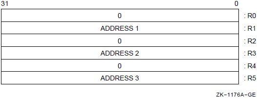
The fields ADDRESS 1, ADDRESS 2, and ADDRESS 3 (if required) contain the address of the byte containing the most significant digit of the first, second, and third (if required) string operands, respectively.
The decimal string instructions treat decimal strings as integers with the decimal point assumed immediately beyond the least significant digit of the string. If a string in which a result is to be stored is longer than the result, its most significant digits are filled with zeros.
9.12.1. Decimal Overflow
Decimal overflow occurs if the destination string is too short to contain all of the digits (excluding leading zeros) of the result. On overflow, the destination string is replaced by the correctly signed least significant digits of the true result (even if the stored result is -0). Note that neither the high nibble of an even-length packed decimal string nor the sign byte of a leading separate numeric string is used to store result digits.
9.12.2. Zero Numbers
A zero result has a positive sign for all operations that complete without decimal overflow, except for CVTPT, which does not change a -0 to a +0. However, when digits are lost because of overflow, a zero result receives the sign (positive or negative) of the correct result.
A decimal string with value -0 is treated as identical to a decimal string with value +0. Thus, for example, +0 compares as equal to -0. When condition codes are affected on a -0 result, they are affected as if the result were+0; that is, N is cleared and Z is set.
9.12.3. Reserved Operand Exception
A reserved operand abort occurs if the length of a decimal string operand is outside the range 0 to 31, or if an invalid sign or digit is encountered in CVTSP or CVTTP. The program counter (PC) points to the opcode of the instruction causing the exception.
9.12.4. UNPREDICTABLE Results
The result of any operation is UNPREDICTABLE if any source decimal string operand contains invalid data. Except for CVTSP and CVTTP, the decimal string instructions do not verify the validity of source operand data.
If the destination operands overlap any source operands, the result of an operation will be UNPREDICTABLE. The destination strings, registers used by the instruction, and condition codes will be UNPREDICTABLE when a reserved operand abort occurs.
9.12.5. Packed Decimal Operations
Packed decimal strings generated by the decimal string instructions always have the preferred sign representation: 12 for "+" and 13 for "-". An even-length packed decimal string is always generated with a "0" digit in the high nibble of the first byte of the string.
A digit occurs in the sign position
A sign occurs in a digit position
A nonzero nibble occurs in the high-order nibble of the lowest-addressed byte in an even length string
9.12.6. Zero-Length Decimal Strings
The length of a packed decimal string can be zero. In this case, the value is zero (plus or minus) and 1 byte of storage is occupied. This byte must contain a "0" digit in the high nibble and the sign in the low nibble.
The length of a trailing numeric string can be zero. In this case, no storage is occupied by the string. If a destination operand is a zero-length trailing numeric string, the sign of the operation is lost. Memory access faults do not occur when a zero-length trailing numeric operand is specified because no memory reference occurs. The value of a zero-length trailing numeric string is identically zero.
The length of a leading separate numeric string can be zero. In this case, 1 byte of storage is occupied by the sign. Memory is accessed when a zero-length operand is specified, and a reserved operand abort will occur if an invalid sign is detected. The value of a zero-length leading separate numeric string is zero.
9.12.7. Instruction Descriptions
|
Description and Opcode |
Number of Instructions | |
|---|---|---|
|
1. |
Add Packed 4 Operand ADDP4 addlen.rw, addaddr.ab, sumlen.rw, sumaddr.ab, {R0-3.wl} |
1 |
|
2. |
Add Packed 6 Operand ADDP6 add1len.rw, add1addr.ab, add2len.rw, add2addr.ab, sumlen.rw, sumaddr.ab, {R0-5.wl} |
1 |
|
3. |
Arithmetic Shift and Round Packed ASHP cnt.rb, srclen.rw, srcaddr.ab, round.rb, dstlen.rw, dstaddr.ab, {R0-3.wl} |
1 |
|
4. |
Compare Packed 3 Operand CMPP3 len.rw, src1addr.ab, src2addr.ab, {R0-3.wl} |
1 |
|
5. |
Compare Packed 4 Operand CMPP4 src1len.rw, src1addr.ab, src2len.rw, src2addr.ab, {R0-3.wl} |
1 |
|
6. |
Convert Long to Packed CVTLP src.rl, dstlen.rw, dstaddr.ab, {R0-3.wl} |
1 |
|
7. |
Convert Packed to Long CVTPL srclen.rw, srcaddr.ab, {R0-3.wl}, dst.wl |
1 |
|
8. |
Convert Packed to Leading Separate CVTPS srclen.rw, srcaddr.ab, dstlen.rw, dstaddr.ab, {R0-3.wl} |
1 |
|
9. |
Convert Packed to Trailing CVTPT srclen.rw, srcaddr.ab, tbladdr.ab, dstlen.rw, dstaddr.ab, {R0-3.wl} |
1 |
|
10. |
Convert Leading Separate to Packed CVTSP srclen.rw, srcaddr.ab, dstlen.rw, dstaddr.ab, {R0-3.wl} |
1 |
|
11. |
Convert Trailing to Packed CVTTP srclen.rw, srcaddr.ab, tbladdr.ab, dstlen.rw, dstaddr.ab, {R0-3.wl} |
1 |
|
12. |
Divide Packed DIVP divrlen.rw, divraddr.ab, divdlen.rw, divdaddr.ab, quolen.rw, quoaddr.ab, {R0-5.wl, -16(SP):-1(SP).wb} |
1 |
|
13. |
Move Packed MOVP len.rw, srcaddr.ab, dstaddr.ab, {R0-3.wl} |
1 |
|
14. |
Multiply Packed MULP mulrlen.rw, mulraddr.ab, muldlen.rw, muldaddr.ab, prodlen.rw, prodaddr.ab, {R0-5.wl} |
1 |
|
15. |
Subtract Packed 4 Operand SUBP4 sublen.rw, subaddr.ab, diflen.rw, difaddr.ab, {R0-3.wl} |
1 |
|
16. |
Subtract Packed 6 Operand SUBP6 sublen.rw, subaddr.ab, minlen.rw, minaddr.ab, diflen.rw, difaddr.ab, {R0-5.wl} |
1 |
ADDP
ADDP — Add Packed
Format
opcode addlen.rw, addaddr.ab, sumlen.rw, sumaddr.ab opcode add1len.rw, add1addr.ab, add2len.rw, add2addr.ab, sumlen.rw, sumaddr.ab Condition Codes
N <— {sum string} LSS 0;
Z <— {sum string} EQL 0;
V <— {decimal overflow};
C <— 0;Exceptions
- reserved operand
- decimal overflow
Opcodes
|
20 |
ADDP4 |
Add Packed 4 Operand |
|
21 |
ADDP6 |
Add Packed 6 Operand |
Description
In 4 operand format, the addend string specified by the addend length and addend address operands is added to the sum string specified by the sum length and sum address operands, and the sum string is replaced by the result.
In 6 operand format, the addend1 string specified by the addend1 length and addend1 address operands is added to the addend2 string specified by the addend2 length and addend2 address operands. The sum string specified by the sum length and sum address operands is replaced by the result.
Notes
- After execution of ADDP4:
R0 =
0
R1 =
Address of the byte containing the most significant digit of the addend string
R2 =
0
R3 =
Address of the byte containing the most significant digit of the sum string
- After execution of ADDP6:
R0 =
0
R1 =
Address of the byte containing the most significant digit of the addend1 string
R2 =
0
R3 =
Address of the byte containing the most significant digit of the addend2 string
R4 =
0
R5 =
Address of the byte containing the most significant digit of the sum string
The sum string, R0 to R3 (or R0 to R5 for ADDP6) and the condition codes are UNPREDICTABLE if: the sum string overlaps the addend, addend1, or addend2 strings; the addend, addend1, addend2, or sum (4 operand only) strings contain an invalid nibble; or a reserved operand abort occurs.
ASHP
ASHP — Arithmetic Shift and Round Packed
Format
opcode cnt.rb, srclen.rw, srcaddr.ab, round.rb, dstlen.rw, dstaddr.ab Condition Codes
N <— {dst string} LSS 0;
Z <— {dst string} EQL 0;
V <— {decimal overflow};
C <— 0;Exceptions
- reserved operand
- decimal overflow
Opcodes
|
F8 |
ASHP |
Arithmetic Shift and Round Packed |
Description
The source string specified by the source length and source address operands is scaled by a power of 10 specified by the count operand. The destination string specified by the destination length and destination address operands is replaced by the result.
Notes
- After execution:
R0 =
0
R1 =
Address of the byte containing the most significant digit of the source string
R2 =
0
R3 =
Address of the byte containing the most significant digit of the destination string
The destination string, R0 to R3, and the condition codes are UNPREDICTABLE if the destination string overlaps the source string, the source string contains an invalid nibble, or a reserved operand abort occurs.
When the count operand is negative, the result is rounded by decimally adding bits 3:0 of the round operand to the most significant low-order digit discarded and propagating the carry, if any, to higher-order digits. Both the source operand and the round operand are considered to be quantities of the same sign for the purpose of this addition.
If bits 7:4 of the round operand are nonzero, or if bits 3:0 of the round operand contain an invalid packed decimal digit, the result is UNPREDICTABLE.
When the count operand is zero or positive, the round operand has no effect on the result except as specified in note 4.
The round operand is normally 5. Truncation can be accomplished by using a zero round operand.
CMPP
CMPP — Compare Packed
Format
3operand: opcode len.rw, src1addr.ab, src2addr.ab 4operand: opcode src1len.rw, src1addr.ab, src2len.rw, src2addr.ab Condition Codes
N <— {src1 string} LSS {src2 string};
Z <— {src1 string} EQL {src2 string};
V <— 0;
C <— 0;Exceptions
- reserved operand
Opcodes
|
35 |
CMPP3 |
Compare Packed 3 Operand |
|
37 |
CMPP4 |
Compare Packed 4 Operand |
Description
In 3 operand format, the source 1 string specified by the length and source 1 address operands is compared to the source 2 string specified by the length and source 2 address operands. The only action is to affect the condition codes.
In 4 operand format, the source 1 string specified by the source 1 length and source 1 address operands is compared to the source 2 string specified by the source 2 length and source 2 address operands. The only action is to affect the condition codes.
Notes
- After execution of CMPP3 or CMPP4:
R0 =
0
R1 =
Address of the byte containing the most significant digit of string1
R2 =
0
R3 =
Address of the byte containing the most significant digit of string2
R0 to R3 and the condition codes are UNPREDICTABLE if the source strings overlap, if either string contains an invalid nibble, or if a reserved operand abort occurs.
CVTLP
CVTLP — Convert Long to Packed
Format
opcode src.rl, dstlen.rw, dstaddr.ab Condition Codes
N <— {dst string} LSS 0;
Z <— {dst string} EQL 0;
V <— {decimal overflow};
C <— 0;Exceptions
- reserved operand
- decimal overflow
Opcodes
|
F9 |
CVTLP |
Convert Long to Packed |
Description
Notes
- After execution:
R0 =
0
R1 =
0
R2 =
0
R3 =
Address of the byte containing the most significant digit of the destination string
The destination string, R0 to R3, and the condition codes are UNPREDICTABLE on a reserved operand abort.
Overlapping operands produce correct results.
CVTPL
CVTPL — Convert Packed to Long
Format
opcode srclen.rw, srcaddr.ab, dst.wl Condition Codes
N <— dst LSS 0;
Z <— dst EQL 0;
V <— {integer overflow};
C <— 0;Exceptions
- reserved operand
- integer overflow
Opcodes
|
36 |
CVTPL |
Convert Packed to Long |
Description
Notes
- After execution:
R0 =
0
R1 =
Address of the byte containing the most significant digit of the source string
R2 =
0
R3 =
0
The destination operand, R0 to R3, and the condition codes are UNPREDICTABLE on a reserved operand abort, or if the string contains an invalid nibble.
The destination operand is stored after the registers are updated as specified in note 1. You may use R0 to R3 as the destination operand.
If the source string has a value outside the range -2,147,483,648 to +2,147,483,647, integer overflow occurs and the destination operand is replaced by the low-order 32 bits of the correctly signed infinite precision conversion. On overflow, the sign of the destination may be different from the sign of the source.
Overlapping operands produce correct results.
CVTPS
CVTPS — Convert Packed to Leading Separate Numeric
Format
opcode srclen.rw, srcaddr.ab, dstlen.rw, dstaddr.ab Condition Codes
N <— {src string} LSS 0;
Z <— {src string} EQL 0;
V <— {decimal overflow};
C <— 0;Exceptions
- reserved operand
- decimal overflow
Opcodes
|
08 |
CVTPS |
Convert Packed to Leading Separate Numeric |
Description
The source packed decimal string specified by the source length and source address operands is converted to a leading separate numeric string. The destination string specified by the destination length and destination address operands is replaced by the result.
Notes
- After execution:
R0 =
0
R1 =
Address of the byte containing the most significant digit of the source string
R2 =
0
R3 =
Address of the sign byte of the destination string
The destination string, R0 to R3, and the condition codes are UNPREDICTABLE if the destination string overlaps the source string, the source string contains an invalid nibble, or a reserved operand abort occurs.
This instruction produces an ASCII "+" or "-" in the sign byte of the destination string.
If decimal overflow occurs, the value stored in the destination might be different from the value indicated by the condition codes (Z and N bits).
If the conversion produces a -0 without overflow, the destination leading separate numeric string is changed to a +0 representation.
CVTPT
CVTPT — Convert Packed to Trailing Numeric
Format
opcode srclen.rw, srcaddr.ab, tbladdr.ab, dstlen.rw, dstaddr.ab Condition Codes
N <— {src string} LSS 0;
Z <— {src string} EQL 0;
V <— {decimal overflow};
C <— 0;Exceptions
- reserved operand
- decimal overflow
Opcodes
|
24 |
CVTPT |
Convert Packed to Trailing Numeric |
Description
The source packed decimal string specified by the source length and source address operands is converted to a trailing numeric string. The destination string specified by the destination length and destination address operands is replaced by the result. The condition code N and Z bits are affected by the value of the source packed decimal string.
Notes
- After execution:
R0 =
0
R1 =
Address of the byte containing the most significant digit of the source string
R2 =
0
R3 =
Address of the most significant digit of the destination string
The destination string, R0 to R3, and the condition codes are UNPREDICTABLE if the destination string overlaps the source string or the table; if the source string or the table contains an invalid nibble; or if are served operand abort occurs.
The condition codes are computed on the value of the source string even if overflow results. In particular, condition code N is set only if the source is nonzero and contains a minus sign (-).
By appropriate specification of the table, you can convert any form of trailing numeric string. See Chapter 8, "Basic Architecture" for the preferred form of trailing overpunch, zoned and unsigned data. In addition, the table can be set up for absolute value, negative absolute value, or negated conversions. The translation table may be referenced even if the length of the destination string is zero.
Decimal overflow occurs if the destination string is too short to contain the converted result of a nonzero packed decimal source string (not including leading zeros). Conversion of a source string with zero value never results in overflow; conversion of a nonzero source string to a zero-length destination string results in overflow.
If decimal overflow occurs, the value stored in the destination may be different from the value indicated by the condition codes (Z and N bits).
CVTSP
CVTSP — Convert Leading Separate Numeric to Packed
Format
opcode srclen.rw, srcaddr.ab, dstlen.rw, dstaddr.ab Condition Codes
N <— {dst string} LSS 0;
Z <— {dst string} EQL 0;
V <— {decimal overflow};
C <— 0;Exceptions
- reserved operand
- decimal overflow
Opcodes
|
09 |
CVTSP |
Convert Leading Separate Numeric to Packed |
Description
Notes
- A reserved operand abort occurs if:
The length of the source leading separate numeric string is outside the range 0 to 31
The length of the destination packed decimal string is outside the range 0 to 31
The source string contains an invalid byte. An invalid byte is any character other than an ASCII "0" to "9" in a digit byte or an ASCII "+", "
<space>", or "-" in the sign byte
- After execution:
R0 =
0
R1 =
Address of the sign byte of the source string
R2 =
0
R3 =
Address of the byte containing the most significant digit of the destination string
The destination string, R0 to R3, and the condition codes are UNPREDICTABLE if the destination string overlaps the source string, or if are served operand abort occurs.
srclenis the length of the passed string minus the sign byte.
CVTTP
CVTTP — Convert Trailing Numeric to Packed
Format
opcode srclen.rw, srcaddr.ab, tbladdr.ab, dstlen.rw, dstaddr.ab Condition Codes
N <— {dst string}LSS 0;
Z <— {dst string} EQL 0;
V <— {decimal overflow};
C <— 0;Exceptions
- reserved operand
- decimal overflow
Opcodes
|
26 |
CVTTP |
Convert Trailing Numeric to Packed |
Description
The source trailing numeric string specified by the source length and source address operands is converted to a packed decimal string, and the destination packed decimal string specified by the destination address and destination length operands is replaced by the result.
Notes
- A reserved operand abort occurs if:
The length of the source trailing numeric string is outside the range 0 to 31
The length of the destination packed decimal string is outside the range 0 to 31
The source string contains an invalid byte. An invalid byte is any value other than ASCII "0" to "9" in any high-order byte (that is, any byte except the least significant byte)
The translation of the least significant digit produces an invalid packed decimal digit or sign nibble
- After execution:
R0 =
0
R1 =
Address of the most significant digit of the source string
R2 =
0
R3 =
Address of the byte containing the most significant digit of the destination string
The destination string, R0 to R3, and the condition codes are UNPREDICTABLE if the destination string overlaps the source string or the table, or if a reserved operand abort occurs.
If the convert instruction produces a -0 without overflow, the destination packed decimal string is changed to a +0 representation, condition code N is cleared, and Z is set.
If the length of the source string is zero, the destination packed decimal string is set equal to zero, and the translation table is not referenced.
By appropriate specification of the table, you can convert any form of trailing numeric string. See Chapter 8, "Basic Architecture" for the preferred form of trailing overpunch, zoned and unsigned data. In addition, the table can be set up for absolute value, negative absolute value, or negated conversions.
If the table translation produces a sign nibble containing any valid sign,the preferred sign representation is stored in the destination packed decimal string.
DIVP
DIVP — Divide Packed
Format
opcode divrlen.rw, divraddr.ab, divdlen.rw, divdaddr.ab, quolen.rw, quoaddr.ab Condition Codes
N <— {quo string} LSS 0;
Z <— {quo string} EQL 0;
V <— {decimal overflow};
C <— 0;Exceptions
- reserved operand
- decimal overflow
- divide by zero
Opcodes
|
27 |
DIVP |
Divide Packed |
Description
Notes
This instruction allocates a 16-byte workspace on the stack. After execution, the stack pointer (SP) is restored to its original contents, and the contents of {(SP)-16}:{(SP)-1} are UNPREDICTABLE.
- The division is performed, resulting in the following conditions:
The absolute value of the remainder (which is lost) is less than the absolute value of the divisor
The product of the absolute value of the quotient times the absolute value of the divisor is less than or equal to the absolute value of the dividend
The sign of the quotient is determined by the rules of algebra from the signs of the dividend and the divisor; if the value of the quotient is zero,the sign is always positive
- After execution:
R0 =
0
R1 =
Address of the byte containing the most significant digit of the divisor string
R2 =
0
R3 =
Address of the byte containing the most significant digit of the dividend string
R4 =
0
R5 =
Address of the byte containing the most significant digit of the quotient string
The quotient string, R0 to R5, and the condition codes are UNPREDICTABLE if: the quotient string overlaps the divisor or dividend strings; the divisor or dividend string contains an invalid nibble; the divisor is zero; or are served operand abort occurs.
MOVP
MOVP — Move Packed
Format
opcode len.rw, srcaddr.ab, dstaddr.ab Condition Codes
N <— {dst string} LSS 0;
Z <— {dst string} EQL 0;
V <— 0;
C <— C;Exceptions
- reserved operand
Opcodes
|
34 |
MOVP |
Move Packed |
Description
Notes
- After execution:
R0 =
0
R1 =
Address of the byte containing the most significant digit of the source string
R2 =
0
R3 =
Address of the byte containing the most significant digit of the destination string
The destination string, R0 to R3, and the condition codes are UNPREDICTABLE if: the destination string overlaps the source string; the source string contains an invalid nibble; or a reserved operand abort occurs.
If the source is -0, the result is +0, N is cleared, and Z is set.
MULP
MULP — Multiply Packed
Format
opcode mulrlen.rw, mulraddr.ab, muldlen.rw, muldaddr.ab, prodlen.rw, prodaddr.ab Condition Codes
N <— {prod string} LSS 0;
Z <— {prod string} EQL 0;
V <— {decimal overflow};
C <— 0;Exceptions
- reserved operand
- decimal overflow
Opcodes
|
25 |
MULP |
Multiply Packed |
Description
Notes
- After execution:
R0 =
0
R1 =
Address of the byte containing the most significant digit of the multiplier string
R2 =
0
R3 =
Address of the byte containing the most significant digit of the multiplicand string
R4 =
0
R5 =
Address of the byte containing the most significant digit of the product string
The product string, R0 to R5, and the condition codes are UNPREDICTABLE if: the product string overlaps the multiplier or multiplicand strings; the multiplier or multiplicand strings contain an invalid nibble; or a reserved operand abort occurs.
SUBP
SUBP — Subtract Packed
Format
4operand: opcode sublen.rw, subaddr.ab, diflen.rw, difaddr.ab 6operand: opcode sublen.rw,
subaddr.ab, minlen.rw, minaddr.ab, diflen.rw, difaddr.ab Condition Codes
N <— {dif string} LSS 0;
Z <— {dif string} EQL 0;
V <— {decimal overflow};
C <— 0;Exceptions
- reserved operand
- decimal overflow
Opcodes
|
22 |
SUBP4 |
Subtract Packed 4 Operand |
|
23 |
SUBP6 |
Subtract Packed 6 Operand |
Description
In 4 operand format, the subtrahend string specified by the subtrahend length and subtrahend address operands is subtracted from the difference string specified by the difference length and difference address operands, and the difference string is replaced by the result.
Notes
- After execution of SUBP4:
R0 =
0
R1 =
Address of the byte containing the most significant digit of the subtrahend string
R2 =
0
R3 =
Address of the byte containing the most significant digit of the difference string
- After execution of SUBP6:
R0 =
0
R1 =
Address of the byte containing the most significant digit of the subtrahend string
R2 =
0
R3 =
Address of the byte containing the most significant digit of the minuend string
R4 =
0
R5 =
Address of the byte containing the most significant digit of the difference string
The difference string, R0 to R3 (R0 to R5 for SUBP6), and the condition codes are UNPREDICTABLE if: the difference string overlaps the subtrahend or minuend strings; the subtrahend, minuend, or difference (4 operand only)strings contain an invalid nibble; or a reserved operand abort occurs.
9.13. The EDITPC Instruction and Its Pattern Operators
The EDITPC instruction implements the common editing functions that occur when handling fixed-format output. The operation consists of converting an input packed decimal number to an output character string and generating characters for the output. When converting digits, options include filling in leading zeros, protecting leading zeros, insertion of floating sign, insertion of floating currency symbol, insertion of special sign representations, and blanking an entire field when it is zero. An example of this operation is a MOVE to a numeric edited (PICTURE) item in COBOL or PL/I. Many other applications are possible.
A packed decimal string descriptor (as input). This is a standard VAX operand pair consisting of the length of the decimal string in digits (up to 31) and the starting address of the string.
A pattern specification, consisting of the starting address of a pattern operation editing sequence. VAX MACRO interprets a pattern specification in the same way as it interprets normal instructions.
The starting address of the output string. The output string is described by its starting address only, because the pattern defines the length unambiguously.
The EDITPC instruction manipulates two character registers and the four condition codes:
The fill register (R2 <7:0>) contains the fill character. This is normally an ASCII blank but could be changed to an asterisk (*), for instance, for check protection.
The sign register (R2 <15:8>) contains the sign character. Initially this register contains either an ASCII blank or a minus sign (-), depending upon the sign of the input. You can change the contents of this register to allow other sign representations such as plus/minus or plus/blank. You can also manipulate it to output special notations such as CR or DB. To implement a floating currency sign, you can change the sign register to the currency sign.
|
N |
The sign of the input |
|
Z |
The presence of a zero source |
|
V |
An overflow condition |
|
C |
The presence of significant digits |
Condition code N is determined at the start of the instruction and remains unchanged (except for correcting a -0 input). The processor computes and updates the other condition codes as the instruction proceeds.
When the EDITPC instruction completes processing, registers R0 to R5 contain the values they would normally have after a decimal instruction.
EDITPC
EDITPC — Edit Packed to Character String
Format
opcode srclen.rw, srcaddr.ab, pattern.ab, dstaddr.ab Condition Codes
N <— {src string} LSS 0; !N <- 0 if src is -0
Z <— {src string} EQL 0;
V <— {decimal overflow}; !nonzero digits lost
C <— {significance};Exceptions
- reserved operand
- decimal overflow
Opcodes
|
38 |
EDITPC |
Edit Packed to Character String |
Description
The destination string specified by the pattern and destination address operands is replaced by the edited version of the source string specified by the source length and source address operands. The editing is performed according to the pattern string, starting at the address of the pattern operand and extending until a pattern end pattern operator (EO$END) is encountered.
The pattern string consists of 1-byte pattern operators. Some pattern operators take no operands. Some take a repeat count that is contained in the rightmost nibble of the pattern operator itself. The rest take a 1-byte operand that immediately follows the pattern operator. This operand is either an unsigned integer length or a byte character.
Table 9.1, ''Summary of EDITPC Pattern Operators'' lists the pattern operators that can be used with the EDITPC instruction to form a pattern. Subsequent pages define each pattern operator in a format similar to that of the normal instruction descriptions. In each case, if there is an operand, it is either a repeat count (r) from 1 to 15, an unsigned byte length (len), or a character byte (ch). The encoding of the pattern operators is represented graphically in Table 9.2, ''EDITPC Pattern Operator Encoding''.
Notes
A reserved operand abort occurs if
srclenGTRU 31.- The destination string is UNPREDICTABLE if any of the following is true:
The source string contains an invalid nibble.
The EO$ADJUST_INPUT operand is outside the range 1 to 31.
The source and destination strings overlap.
The pattern and destination strings overlap.
- After execution, the following general registers have contents as specified:
R0 =
Length of source string
R1 =
Address of the byte containing the most significant digit of the source string
R2 =
0
R3 =
Address of the byte containing the EO$END pattern operator
R4 =
0
R5 =
Address of 1 byte beyond the last byte of the destination string
If the destination string is UNPREDICTABLE, R0 to R5 and the condition codes are UNPREDICTABLE.
If V is set at the end and DV is enabled, a numeric overflow trap occurs unless the conditions in note 9 are satisfied.
The destination length is specified exactly by the pattern operators in the pattern string. If the pattern is incorrectly formed or if it is modified during the execution of the instruction, the length of the destination string is UNPREDICTABLE.
If the source is -0, the result may be -0 unless a fixup pattern operator is included (EO$BLANK_ZERO or EO$REPLACE_SIGN).
The contents of the destination string and the memory preceding it are UNPREDICTABLE if the length covered by EO$BLANK_ZERO or EO$REPLACE_SIGN is zero, or if it is outside the destination string.
If more input digits are requested by the pattern than are specified, are served operand abort is taken with R0 = -1 and R3 = location of the pattern operator that requested the extra digit. The condition codes and other registers are as specified in note 11. This abort cannot be continued.
If fewer input digits are requested by the pattern than are specified, are served operand abort is taken with R3 = location of EO$END pattern operator. The condition codes and other registers are as specified in note 11. This abort cannot be continued.
On an unimplemented or reserved pattern operator, a reserved operand fault is taken with R3 = location of the faulting pattern operator. The condition codes and other registers are as specified in note 11. This fault can be continued as long as the defined register state is manipulated according tot he pattern operator description and the state specified as "implementation dependent" is preserved.
- On a reserved operand exception, as specified in notes 8 to 10, FPD is set and the condition codes and registers are as follows:
N =
{
srchas minus sign}Z =
All source digits zero so far
V =
Nonzero digits lost
C =
Significance
R0 <31:16> =
-(count of source zeros to supply)
R0 <15:0> =
Remaining
srclenR1 =
Current source location
R2 <31:16> =
Implementation dependent
R2 <15:8> =
Current contents of sign register
R2 <7:0> =
Current contents of fill register
R3 =
Location of edit pattern operator causing exception
R4 =
Implementation dependent
R5 =
Location of next destination byte
|
Name |
Operand |
Summary |
|---|---|---|
|
Key:
| ||
|
Insert operators | ||
|
EO$INSERT |
ch |
Insert character, fill if insignificant |
|
EO$STORE_SIGN |
— |
Insert sign |
|
EO$FILL |
r |
Insert fill |
|
Move operators | ||
|
EO$MOVE |
r |
Move digits, fill if insignificant |
|
EO$FLOAT |
r |
Move digits, floating sign |
|
EO$END_FLOAT |
— |
End floating sign |
|
Fixup operators | ||
|
EO$BLANK_ZERO |
len |
Fill backward when 0 |
|
EO$REPLACE_SIGN |
len |
Replace with fill if -0 |
|
Load operators | ||
|
EO$LOAD_FILL |
ch |
Load fill character |
|
EO$LOAD_SIGN |
ch |
Load sign character |
|
EO$LOAD_PLUS |
ch |
Load sign character if positive |
|
EO$LOAD_MINUS |
ch |
Load sign character if negative |
|
Control operators | ||
|
EO$SET_SIGNIF |
— |
Set significance flag |
|
EO$CLEAR_SIGNIF |
— |
Clear significance flag |
|
EO$ADJUST_INPUT |
len |
Adjust source length |
|
EO$END |
— |
End edit |
|
Hex |
Symbol |
Notes |
|---|---|---|
|
00 |
EO$END |
— |
|
01 |
EO$END_FLOAT |
— |
|
02 |
EO$CLEAR_SIGNIF |
— |
|
03 |
EO$SET_SIGNIF |
— |
|
04 |
EO$STORE_SIGN |
— |
|
05 …1F |
— |
Reserved to OpenVMS |
|
20 …3F |
— |
Reserved for all time |
|
40 |
EO$LOAD_FILL |
Character is in next byte |
|
41 |
EO$LOAD_SIGN |
Character is in next byte |
|
42 |
EO$LOAD_PLUS |
Character is in next byte |
|
43 |
EO$LOAD_MINUS |
Character is in next byte |
|
44 |
EO$INSERT |
Character is in next byte |
|
45 |
EO$BLANK_ZERO |
Unsigned length is in next byte |
|
46 |
EO$REPLACE_SIGN |
Unsigned length is in next byte |
|
47 |
EO$ADJUST_INPUT |
Unsigned length is in next byte |
|
48 …5F |
— |
Reserved to OpenVMS |
|
60 …7F |
— |
Reserved to CSS and customers |
|
80,90,A0 |
— |
Reserved to OpenVMS |
|
81 …8F |
EO$FILL |
— |
|
91 …9F |
EO$MOVE |
Repeat count is <3:0> |
|
A1 …AF |
EO$FLOAT |
— |
|
B0 …FE |
— |
Reserved to OpenVMS |
|
FF |
— |
Reserved for all time |
EO$ADJUST_INPUT
EO$ADJUST_INPUT — Adjust Input Length
Format
opcode pattern len Pattern Operators
|
47 |
EO$ADJUST_INPUT |
Adjust Input Length |
Description
The EO$ADJUST_INPUT pattern operator is followed by an unsigned byte integer length in the range 1 to 31. If the source string has more digits than this length, the excess leading digits are read and discarded. If any discarded digits are nonzero, the overflow is set, significance is set, and zero is cleared. If the source string has fewer digits than this length, a counter is set of the number of leading zeros to supply. This counter is stored as a negative number in R0 <31:16>.
Note
If the length is not in the range 1 to 31, the destination string, condition codes, and R0 to R5 are UNPREDICTABLE.
EO$BLANK_ZERO
EO$BLANK_ZERO — Blank Backwards when Zero
Format
opcode pattern len Pattern Operators
|
45 |
EO$BLANK_ZERO |
Blank Backwards when Zero |
Description
Notes
The length must be nonzero and within the destination string already produced. If it is not, the contents of the destination string and the memory preceding it are UNPREDICTABLE.
Use this pattern operator to blank out any characters stored in the destination under a forced significance such as a sign or the digits following the radix point.
EO$END
EO$END — End Edit
Format
opcode pattern Pattern Operators
|
00 |
EO$END |
End Edit |
Description
Notes
If there are still input digits, a reserved operand abort is taken.
If the source value is -0, the N condition code is cleared.
EO$END_FLOAT
EO$END_FLOAT — End Floating Sign
Format
opcode pattern Pattern Operators
|
01 |
EO$END_FLOAT |
End Floating Sign |
Description
The EO$END_FLOAT pattern operator terminates a floating sign operation. If the floating sign has not yet been placed in the destination (if significance is not set), the contents of the sign register are stored in the destination, and significance is set.
Note
Use this pattern operator after a sequence of one or more EO$FLOAT pattern operators that start with significance clear. The EO$FLOAT sequence can include intermixed EO$INSERTs and EO$FILLs.
EO$FILL
EO$FILL — Store Fill
Format
opcode pattern r Pattern Operators
|
8x |
EO$FILL |
Store Fill |
Description
The rightmost nibble of the pattern operator is the repeat count. The EO$FILL pattern operator places the contents of the fill register into the destination the number of times specified by the repeat count.
Note
Use this pattern operator for fill (blank) insertion.
EO$FLOAT
EO$FLOAT — Float Sign
Format
opcode pattern r Pattern Operators
|
Ax |
EO$FLOAT |
Float Sign |
Description
The EO$FLOAT pattern operator moves digits, floating the sign across insignificant digits. The rightmost nibble of the pattern operator is the repeat count. For the number of times specified in the repeat count, the following algorithm is executed:
Notes
If r is greater than the number of digits remaining in the source string,a reserved operand abort is taken.
Use this pattern operator to move digits with a floating arithmetic sign. The sign must already be set up as for EO$STORE_SIGN. A sequence of one or more EO$FLOATs can include intermixed EO$INSERTs and EO$FILLs. Significance must be clear before the first pattern operator of the sequence. The sequence must be terminated by one EO$END_FLOAT.
- Use this pattern operator to move digits with a floating currency sign. The sign must already be set up with an EO$LOAD_SIGN. A sequence of one or more EO$FLOATs can include intermixed EO$INSERTs and EO$FILLs. Significance must be clear before the first pattern operator of the sequence. The sequence must be terminated by one
EO$END_FLOAT.
EO$INSERT
EO$INSERT — Insert Character
Format
opcode pattern ch Pattern Operators
|
44 |
EO$INSERT |
Insert Character |
Description
The EO$INSERT pattern operator is followed by a character. If significance is set, the character is placed into the destination. If significance is not set,the contents of the fill register are placed into the destination.
Note
Use this pattern operator for inserts that can be made blank (for example, comma (,)) and fixed inserts (for example, slash (/)).Fixed inserts require that significance be set (by EO$SET_SIGNIF or EO$END_FLOAT).
EO$LOAD_
EO$LOAD_ — Load Register
Format
opcode pattern ch Pattern Operators
|
40 |
EO$LOAD_FILL |
Load Fill Register |
|
41 |
EO$LOAD_SIGN |
Load Sign Register |
|
42 |
EO$LOAD_PLUS |
Load Sign Register If Plus |
|
43 |
EO$LOAD_MINUS |
Load Sign Register If Minus |
Description
Notes
Use EO$LOAD_FILL to set up check protection (* instead of space).
Use EO$LOAD_SIGN to set up a floating currency sign.
Use EO$LOAD_PLUS to set up a nonblank plus sign.
Use EO$LOAD_MINUS to set up a nonminus minus sign (such as CR, DB, or the PL/I +).
EO$MOVE
EO$MOVE — Move Digits
Format
opcode pattern r Pattern Operators
|
9x |
EO$MOVE |
Move Digits |
Description
The EO$MOVE pattern operator moves digits, filling for insignificant digits. The rightmost nibble of the pattern operator is the repeat count. For the number of times specified in the repeat count, the following algorithm is executed:
Notes
If r is greater than the number of digits remaining in the source string, a reserved operand abort is taken.
Use this pattern operator to move digits without a floating sign. If leading-zero suppression is desired, significance must be clear. If leading zeros should be explicit, significance must be set. A string of EO$MOVEs intermixed with EO$INSERTs and EO$FILLs will handle suppression correctly.
If check protection (*) is desired, EO$LOAD_FILL must precede the EO$MOVE.
EO$REPLACE_SIGN
EO$REPLACE_SIGN — Replace Sign when Zero
Format
opcode pattern len Pattern Operators
|
46 |
EO$REPLACE_SIGN |
Replace Sign when Zero |
Description
len bytes before the current position.
Notes
The length must be nonzero and within the destination string already produced. If it is not, the contents of the destination string and the memory preceding it are UNPREDICTABLE.
You can use this pattern operator to correct a stored sign (EO$END_FLOAT or EO$STORE_SIGN) if a minus was stored and the source value turned out to be zero.
EO$_SIGNIF
EO$_SIGNIF — Significance
Format
opcode pattern Pattern Operators
|
02 |
EO$CLEAR_SIGNIF |
Clear Significance |
|
03 |
EO$SET_SIGNIF |
Set Significance |
Description
Notes
Use EO$CLEAR_SIGNIF to initialize leading-zero suppression (EO$MOVE) or floating sign (EO$FLOAT) following a fixed insert (EO$INSERT with significance set).
Use EO$SET_SIGNIF to avoid leading-zero suppression (before EO$MOVE) or to force a fixed insert (before EO$INSERT).
EO$STORE_SIGN
EO$STORE_SIGN — Store Sign
Format
opcode pattern Pattern Operators
|
04 |
EO$STORE_SIGN |
Store Sign |
Description
The EO$STORE_SIGN pattern operator places contents of the sign register into the destination.
Note
Use this pattern operator for any nonfloating arithmetic sign. Precede it with either a EO$LOAD_PLUS or EO$LOAD_MINUS, or both, if the default sign convention is not desired.
9.14. Other VAX Instructions
|
Description and Opcode |
Number of Instructions | |
|---|---|---|
|
1. |
Probe {Read, Write} Accessibility PROBE{R,W} mode.rb, len.rw, base.ab |
2 |
|
2. |
Change Mode CHM{K,E,S,U} param.rw, {-(ySP).w*}
Where y=MINU(x,
PSL |
4 |
|
3. |
Return from Exception or Interrupt REI {(SP)+.r*} |
1 |
|
4. |
Load Process Context LDPCTX {PCB.r*, -(KSP).w*} |
1 |
|
5. |
Save Process Context SVPCTX {(SP)+.r*, PCB.w*} |
1 |
|
6. |
Move to Process Register MTPR src.rl, procreg.rl |
1 |
|
7. |
Move from Processor Register MFPR procreg.rl, dst.wl |
1 |
|
8. |
Bugcheck with {word, longword} message identifier BUG{W,L} message.bx |
2 |
PROBEx
PROBE x — Probe Accessibility
Format
opcode mode.rb, len.rw, base.ab Condition Codes
N <— 0;
Z <— if {both accessible} then 0 else 1;
V <— 0;
C <— C;Exceptions
- translation not valid
Opcodes
|
0C |
PROBER |
Probe Read Accessibility |
|
0D |
PROBEW |
Probe Write Accessibility |
Description
The PROBE instruction checks the read or write accessibility of the first and last byte specified by the base address and the zero-extended length. Note that the bytes in between are not checked. System software must check all pages if they will be accessed between the two end bytes.
The protection is checked against the larger (and therefore less privileged)of the modes specified in bits <1:0> of the mode operand and the previous mode field of the processor status longword (PSL). Note that probing with a mode operand of zero is equivalent to probing the mode specified in the previous-mode field of the PSL.
Example
MOVL 4(AP),R0 ; Copy the address of first arg so
; that it cannot be changed
PROBER #0,#4,(R0) ; Verify that the longword pointed to
; by the first arg could be read by
; the previous access mode
; Note that the arg list itself must
; already have been probed
BEQL violation ; Branch if either byte gives an
; access violation
MOVQ 8(AP),R0 ; Copy length and address of buffer
; arg so that they cannot change
PROBER #0,R0,(R1) ; Verify that the buffer described by
; the 2nd and 3rd args could be
; written by the previous access
; mode
; Note that the arg list must already
; have been probed and that the 2nd
; arg must be known to be less than
; 512
BEQL violation ; Branch if either byte gives an
; access violationNotes
If the valid bit of the examined page table entry is set, it is UNPREDICTABLE whether the modify bit of the examined page table entry is set by a PROBER. If the valid bit is clear, the modify bit is not changed.
Except for note 1, above, the valid bit of the page table entry, PTE <31>, mapping the probed address is ignored.
A length violation gives a status of "not-accessible."
On the probe of a process virtual address, if the valid bit of the system page table entry is zero, a Translation Not Valid Fault occurs. This allows for the demand paging of the process page tables.
On the probe of a process virtual address, if the protection field of the system page table entry indicates No Access, a status of "not-accessible" is given. Thus, a single No Access page table entry in the system map is equivalent to 128 No Access page table entries in the process map.
CHM
CHM — Change Mode
Format
opcode code.rw Condition Codes
N <— 0; Z <— 0; V <— 0; C <— 0;
Exceptions
- halt
Opcodes
|
BC |
CHMK |
Change Mode to Kernel |
|
BD |
CHME |
Change Mode to Executive |
|
BE |
CHMS |
Change Mode to Supervisor |
|
BF |
CHMU |
Change Mode to User |
Description
Change mode instructions allow processes to change their access mode in a controlled manner. The instruction increases privilege only (decreases the access mode).
A change in mode also results in a change of stack pointers; the old pointer is saved, and the new pointer is loaded. The processor status longword (PSL),program counter (PC), and code passed by the instruction are pushed onto the stack of the new mode. The saved PC addresses the instruction following the CHMx instruction. The code is sign extended. After execution, the appearance of the new stack is as follows:
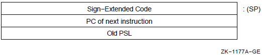
Notes
As usual for faults, any Access Violation or Translation Not Valid fault saves the PC and the PSL, and leaves the stack pointer (SP) as it was at the beginning of the instruction except for any pushes onto the kernel stack. Note that addresses just off the top of the target stack may have been written.
The noninterrupt stack pointers may be fetched and stored either in privileged registers or in their allocated slots in the process control block(PCB). Only LDPCTX and SVPCTX always fetch and store in the PCB. MFPR and MTPR always fetch and store the pointers whether in registers or the PCB.
By software convention, negative codes are reserved to CSS and customers.
Example
CHMK #7 ; Request the kernel mode service
; specified by code 7
CHME #4 ; Request the executive mode service
; specified by code 4
CHMS #-2 ; Request the supervisor mode service
; specified by customer code -2REI
REI — Return from Exception or Interrupt
Format
opcode Condition Codes
N <— saved PSL<3>; Z <— saved PSL<2>; V <— saved PSL<1>; C <— saved PSL<0>;
Exceptions
- reserved operand
Opcodes
|
02 |
REI |
Return from Exception or Interrupt |
Description
A longword is popped from the current stack and held in a temporary program counter (PC). A second longword is popped from the current stack and held in a temporary processor status longword (PSL).
The popped PSL is checked for internal consistency. If the processor is running virtual machine (VM) mode, the popped PSL is compared with the Virtual-Machine Processor Status Longword (VMPSL) to determine that the transition from current VMPSL to popped PSL is allowed, and a VM-emulation trap is taken. If the processor is running a real machine, the popped PSL is compared with the current PSL to determine that the transition from current PSL to popped PSL is allowed.
If the processor is not in kernel mode and is attempting to return to a PSL with the VMPSL VM bit set, a reserved operand fault occurs. The current stack pointer (SP) is saved, and a new SP is selected according to the new PSL CUR_MOD and IS fields. The level of the highest privilege asynchronous system trap (AST) is checked against the current mode to see whether a pending AST can be delivered. Execution resumes with the instruction being executed at the time of the exception or interrupt.
Notes
The exception or interrupt service routine is responsible for restoring any registers saved and for removing any parameters from the stack.
As usual for faults, any Access Violation or Translation Not Valid conditions on the stack pops restore the stack pointer and fault.
The noninterrupt stack pointers may be fetched and stored either in privileged registers or in their allocated slots in the process control block(PCB). Only LDPCTX and SVPCTX always fetch and store in the PCB. MFPR and MTPR always fetch and store the pointers, whether in registers or in the PCB.
LDPCTX
LDPCTX — Load Process Context
Format
opcode Condition Codes
N <— N; Z <— Z; V <— V; C <— C;
Exceptions
- reserved operand
- privileged instruction
Opcodes
|
06 |
LDPCTX |
Load Process Context |
Description
If the processor is in virtual machine (VM) mode, and the virtual machine is in kernel mode, then a VM-emulation trap is taken. Otherwise, if the processor is not in kernel mode, a privileged-instruction fault is taken. If neither exception is taken, the processor loads the process state in the process control block (PCB) specified by the privileged process control block base register (PCBB).
The general registers, process-space memory management registers, and the address space number register (if implemented) are loaded from the PCB into the scalar processor. Execution is switched to the kernel stack. The program counter (PC) and processor status longword (PSL) are moved from the PCB to the stack,suitable for use by a subsequent REI instruction.
Notes
Some processors keep a copy of each of the per-process stack pointers (SPs) in internal registers. In those processors, LDPCTX loads the internal registers from the PCB. Processors that do not keep a copy of all four per-process stack pointers in internal registers keep only the current access mode register in an internal register and switch this with the PCB contents whenever the current access mode field changes.
The preferred implementation of UNDEFINED operation is reserved operand abort.
LDPCTX does not invalidate the per-process translation buffer (TB) state in the vector processor TB. To invalidate the TB state on the vector processor use the invalidate all (TBIA), invalidate single (TBIS), or vector invalidate all (VTBIA) internal processor registers.
LDPCTX does not load the vector processor memory management registers, if such copies reside there.
To guarantee correct operation, an LDPCTX instruction must be followed by an REI instruction.
SVPCTX
SVPCTX — Save Process Context
Format
opcode Condition Codes
N <— N; Z <— Z; V <— V; C <— C;
Exceptions
- privileged instruction
Opcodes
|
07 |
SVPCTX |
Save Process Context |
Description
Notes
The map, ASTLVL, and PME contents of the process control block (PCB) are not saved because they are rarely changed. Thus, not writing them saves overhead.
Some processors keep a copy of each of the per-process stack pointers in internal registers. In those processors, SVPCTX stores the internal registers in the PCB. Processors that do not keep a copy of all four per-process stack pointers in internal registers keep only the current access mode register in an internal register and switch this access mode register with the PCB contents whenever the current access mode field changes.
Between the SVPCTX instruction that saves the state for one process and the LDPCTX that loads the state of another, the ISPs may not be referenced by MFPR or MTPR instructions. This implies that interrupt service routines invoked at a priority higher than the lowest one used for context switching must not reference the process stack pointers (SPs).
MTPR
MTPR — Move to Processor Register
Format
opcode src.rl, procreg.rl Condition Codes
N <— UNPREDICTABLE Z <— UNPREDICTABLE V <— UNPREDICTABLE C <— UNPREDICTABLE
Exceptions
- reserved operand fault
- reserved instruction fault
Opcodes
|
DA |
MTPR |
Move to Processor Register |
Description
src into all copies of the processor
register specified by procreg that are implemented on the
vector and scalar processors. The procreg operand is a
longword that contains the processor register number. Execution may have
register-specific side effects. Notes
If the processor internal register does not exist, a reserved operand fault occurs.
A reserved instruction fault occurs if instruction execution is attempted in other than kernel mode.
A reserved operand fault occurs on a move to a read-only register.
After an MTPR instruction, the condition codes are UNPREDICTABLE,unless noted otherwise under the description of the specific processor register.
MFPR
MFPR — Move from Processor Register
Format
opcode procreg.rl, dst.wl Condition Codes
N <— UNPREDICTABLE Z <— UNPREDICTABLE V <— UNPREDICTABLE C <— UNPREDICTABLE
Exceptions
- reserved operand fault
- reserved instruction fault
Opcodes
|
DB |
MFPR |
Move from Processor Register |
Description
procreg. The procreg operand
is a longword that contains the processor register number. Execution may have
register-specific side effects. Notes
If the processor internal register does not exist, a reserved operand fault occurs.
A reserved instruction fault occurs if instruction execution is attempted in other than kernel mode.
A reserved operand fault occurs on a move from a write-only register.
After an MFPR instruction, the condition codes are UNPREDICTABLE, unless noted otherwise under the description of the specific processor register.
BUG
BUG — Bugcheck
Format
opcode message.bx Condition Codes
N <— N; Z <— Z; V <— V; C <— C;
Exceptions
- reserved instruction
Opcodes
|
FEFF |
BUGW |
Bugcheck with word message identifier |
|
FDFF |
BUGL |
Bugcheck with longword message identifier |
Description
The hardware treats these opcodes as reserved to OpenVMS and as faults. The OpenVMS operating system treats them as requests to report software detected errors. The inline message identifier is zero extended to a longword (BUGW)and interpreted as a condition value (see the VAX Procedure Calling and Condition Handling Standard in the OpenVMS Programming Interfaces: Calling a System Routine). If the process is privileged to report bugs, a log entry is made. If the process is not privileged, a reserved instruction is signaled.
Example
BUGW ; Bugcheck with word message .WORD 4 ; identifier 4 BUGL ; Bugcheck with longword .LONG 5 ; message identifier 5
Chapter 10. VAX Vector Architecture
This chapter describes an extension to the VAX architecture for integrated vector processing. Some VAX vector architecture departs from the traditional VAX scalar architecture, especially in the areas of UNPREDICTABLE results, vector processor exceptions, and instruction/memory synchronization.
10.1. Introduction to VAX Vector Architecture
Implementation of the VAX vector architecture is optional. VAX processors that do implement the vector architecture do so as specified in this chapter. Operating system software may emulate the vector architecture on processors that omit this feature.
On VAX processors that omit the vector architecture, vector instructions result in a reserved-instruction fault.
The vector architecture features include additional instructions, vector registers, and vector control registers.
All descriptions and examples of vector instructions in this chapter use the assembler notation form of instructions, as described in Section 10.5, ''Execution Model''. The number and order of operands for the assembler notation differ from that defined in the instruction stream format. See Section 10.3, ''Vector Instruction Formats'' and Section 10.5, ''Execution Model'' for additional information.
10.2. VAX Vector Architecture Registers
This section identifies and describes the vector, vector control, and internal processor registers used in processing vector architecture operations.
10.2.1. Vector Registers
There are 16 vector registers, V0 to V15. Each vector register contains 64 elements numbered 0 to 63. Each element is 64 bits wide. Figure 10.1, ''Vector Register'' depicts a vector register.
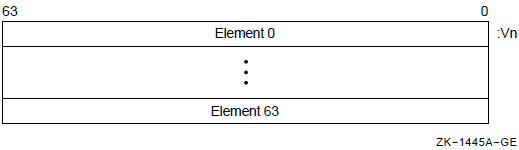
A vector instruction that performs a register-to-register operation is defined as a vector operate instruction. A vector operate instruction that reads or writes F_floating data, or integer data for shifts or integer arithmetic operations, reads bits <31:0> of each source element and writes bits <31:0> of each destination element. Bits <63:32> of the destination are UNPREDICTABLE for F_floating, integer arithmetic, and shift instructions.
Vector logical instructions read bits <31:0> of each source element and write the result into bits <31:0> of each destination element; bits <63:32> of the destination element receive bits <63:32> of the corresponding element of the Vb source operand.
For vector instructions that read longword data from memory into a vector register (VLDL and VGATHL), bits <63:32> of the destination elements are UNPREDICTABLE.
If the same vector register is used as both source and destination in a Gather Memory Data into Vector Register (VGATH) instruction, the result of the VGATH instruction is UNPREDICTABLE.
For the IOTA vector instruction, bits <63:32> of the destination elements are UNPREDICTABLE.
10.2.2. Vector Control Registers
The 7-bit Vector Length Register (VLR), shown in Figure 10.2, ''Vector Length Register (VLR)'', limits the highest vector element to be processed by a vector instruction. VLR is loaded prior to executing the vector instruction using a Move to Vector Processor (MTVP) instruction. The value in VLR may range from 0 to 64. If the vector length is zero, no vector elements are processed. If a vector instruction is executed with a vector length greater than 64, the results are UNPREDICTABLE. Elements beyond the vector length in the destination vector register are not modified.
The Vector Mask Register (VMR), shown in Figure 10.3, ''Vector Mask Register (VMR)'', has 64 bits, each corresponding to an element of a vector register. Bit <0> corresponds to vector element 0. See Section 10.3.1, ''Masked Operations'' for information on masked operations.
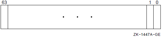
The 7-bit Vector Count Register (VCR), shown in Figure 10.4, ''Vector Count Register (VCR)'', receives the length of the offset vector generated by the IOTA instruction.
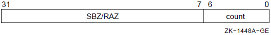
These registers are read and written by Move from/to Vector Processor (MFVP/MTVP) instructions.
10.2.3. Internal Processor Registers
Vector Processor Status Register (VPSR)
Vector Arithmetic Exception Register (VAER)
Vector Memory Activity Check (VMAC)
Vector Translation Buffer Invalidate All (VTBIA)
Vector State Address Register (VSAR)
The VPSR is shown in Figure 10.5, ''Vector Processor Status Register (VPSR)'', and is described in Table 10.1, ''Description of the Vector Processor Status Register (VPSR)''.
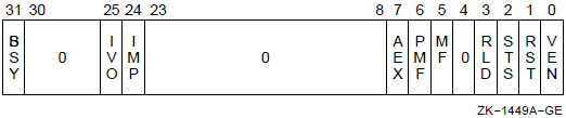
| Extent | Type | Description |
|---|---|---|
|
<0> |
R/W |
Vector Processor Enabled (VEN ). The vector processor is enabled by writing a one to this bit. Writing a zero disables the vector processor. If VPSR <VEN> is cleared by software while VPSR <BSY> is set, then once the new state of VPSR becomes synchronized with subsequent vector instructions, no more instructions are sent and the vector processor completes execution of all pending instructions in its instruction queue. See Section 10.6.3, ''Vector Processor Disabled'', Vector Processor Disabled, for more details. |
|
<1> |
W |
Vector Processor State Reset (RST). Writing a one to this bit clears VPSR and VAER. If VPSR <RST> is set by software while VPSR <BSY> is set, the operation of the vector processor is UNDEFINED. This bit is read as zero (RAZ). |
|
<2> |
W |
Vector State Store (STS). Writing a one to this bit initiates storing of implementation-specific vector state information to memory using the address in VSAR for the asynchronous method of handling memory management exceptions. If the synchronous method is implemented, write operations to VPSR <STS> are ignored. This bit is RAZ. |
|
<3> |
W |
Vector State Reload (RLD). Writing a one to this bit initiates reloading of implementation-specific vector state information from memory using the address in VSAR for the asynchronous method of handling memory management exceptions. If the synchronous method is implemented, write operations to VPSR <RLD> are ignored. This bit is RAZ. |
|
<4> |
R |
0 |
|
<5> |
R/W1C |
Memory Fault (MF). This bit is set by the vector processor when there is a memory reference to be retried due to an asynchronous memory management exception. Writing a one to VPSR <MF> clears it. Writing a zero to VPSR <MF> has no effect. If the synchronous method of handling memory management exceptions is implemented, this bit is always zero. |
|
<6> |
R/W1C |
Pending Memory Fault (PMF). This bit is set by the vector processor when an asynchronous memory management exception is pending. Writing a one to VPSR <PMF> clears it. Writing a zero to VPSR <PMF> has no effect. If the synchronous method of handling memory management exceptions is implemented, this bit is always zero. |
|
<7> |
R/W1C |
Vector Arithmetic Exception (AEX). This bit is set by the vector processor when disabling itself due to an arithmetic exception. Information regarding the nature of the exception can be found in VAER. Writing a one to VPSR <AEX> clears VPSR <AEX>and VAER. Writing a zero to VPSR <AEX> has no effect. |
|
<23:8> |
R |
0 |
|
<24> |
R/W1C |
Implementation-Specific Hardware Error (IMP). This bit is set by the vector processor when disabling itself due to an implementation-specific hardware error. Writing a one to VPSR <IMP> clears it. Writing a zero to VPSR <IMP> has no effect. An implementation may choose not to implement VPSR <IMP>. In this case, writing VPSR <IMP> with either value must have no effect and must not generate any error. Also, its value when read must be zero. |
|
<25> |
R/W1C |
Illegal Vector Opcode (IVO). This bit is set by the vector processor when disabling itself due to receiving an illegal vector opcode. Writing a one to VPSR <IVO> clears it. Writing a zero to VPSR <IVO> has no effect. An implementation may choose not to implement VPSR <IVO>. In this case, writing VPSR <IVO> with either value must have no effect and must not generate any error. Also, its value when read must be zero. |
|
<30:26> |
R |
0 |
|
<31> |
R |
Vector Processor Busy (BSY). When this bit is set, the vector processor is executing vector instructions. When it is clear,the vector processor is idle, or the vector processor has suspended instruction execution due to an asynchronous memory management exception or hardware error. Writing to VPSR <BSY> has no effect. |
| RLD | STS | RST | VEN | Meaning |
|---|---|---|---|---|
|
0 |
0 |
0 |
0 |
Disable vector processor |
|
0 |
0 |
0 |
1 |
Enable vector processor |
|
0 |
0 |
1 |
0 |
Reset state and disable vector processor |
|
0 |
0 |
1 |
1 |
Reset state and enable vector processor |
|
0 |
1 |
0 |
0 |
Store state (must disable vector processor) |
|
1 |
0 |
0 |
0 |
Reload state and disable vector processor |
|
1 |
0 |
0 |
1 |
Reload state and then enable vector processor |
|
VEN |
BSY |
Meaning |
|---|---|---|
|
0 |
0 |
The vector processor is not executing any instructions now,and either has no pending instructions or will not execute pending instructions. No more instructions should be sent. |
|
0 |
1 |
The vector processor is executing at least one pending instruction. No more instructions should be sent. |
|
1 |
0 |
The vector processor is not executing any instructions now,and either has no pending instructions or will not execute pending instructions. New instructions can be sent to the vector processor. |
|
1 |
1 |
The vector processor is executing at least one instruction now. New instructions can be sent. |
Note that because the vector and scalar processors can execute asynchronously,a VPSR state transition may not be seen immediately by the scalar processor. After performing an MTPR to VPSR, software must then issue an MFPR from VPSR to ensure that the new state of VPSR (and VAER if cleared by VPSR<RST>) will affect the execution of subsequently issued vector instructions. The MFPR in this case will not complete until the new state of the vector processor becomes visible to the scalar processor. If software does not issue the MFPR, then it is UNPREDICTABLE whether this synchronization between the new state of VPSR (and VAER) and subsequently issued vector instructions occurs.
The VAER, shown in Figure 10.6, ''Vector Arithmetic Exception Register (VAER)'', is a read-only register used to record information regarding vector arithmetic exceptions. Table 10.4, ''VAER Exception Condition Summary Word Encoding'' shows the encoding for the exception condition types. The destination register mask field of VAER records which vector registers have received default results due to arithmetic exceptions. VAER <16+n> corresponds to vector register Vn, where n is between 0 and 15. For more information, refer to Section 10.6.2, ''Vector Arithmetic Exceptions''.
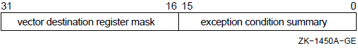
|
Bit |
Exception Condition |
|---|---|
|
<0> |
Floating underflow |
|
<1> |
Floating divide by zero |
|
<2> |
Floating reserved operand |
|
<3> |
Floating overflow |
|
<4> |
0 |
|
<5> |
Integer overflow |
|
<15:6> |
0 |
The Vector Memory Activity Check (VMAC) register, shown in Figure 10.7, ''Vector Memory Activity Check (VMAC) Register'', is used to guarantee the completion of all prior vector memory accesses. For more information on this function of VMAC, refer to Section 10.7.2.2, ''Memory Activity Completion Synchronization (VMAC)''. An MFPR from VMAC also ensures that all hardware errors encountered by previous vector memory instructions are reported before the MFPR completes. For more information on this function of VMAC, refer to Section 10.9, ''Hardware Errors'', Hardware Errors. The value returned by MFPR from VMAC is UNPREDICTABLE.
The Vector Translation Buffer Invalidate All (VTBIA) register, shown in Figure 10.8, ''Vector Translation Buffer Invalidate All (VTBIA) Register'', is a write-only register that may be omitted in some implementations. If the vector processor contains its own translation buffer, moving zero into VTBIA using the MTPR instruction invalidates the entire vector translation buffer. For more information, refer to Section 10.8, ''Memory Management''.
The Vector State Address Register (VSAR), shown in Figure 10.9, ''Vector State Address Register (VSAR)'', is a read/write register that contains a quadword-aligned virtual address of memory assigned by software for storing implementation-specific vector hardware state when the asynchronous method of handling memory management exceptions is implemented. The length of this memory area is implementation specific. Software must guarantee that accessing the memory pointed to by the address does not result in a memory management exception. If the synchronous method of handling memory management exceptions is implemented, this register is omitted. For more information, refer to Section 10.6.1, ''Vector Memory Management Exception Handling''
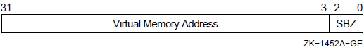
With the exception of VPSR (and VAER), an MTPR to any other writable vector internal processor register (IPR) ensures that the new state of the IPR affects the execution of all subsequently issued vector instructions. Vector instructions issued before an MTPR to any writable vector IPR are unaffected by the new state of the IPR (and any implicitly changed vector IPR) except in one case: when the MTPR sets VPSR <RST> while VPSR <BSY> is set. (See Table 10.1, ''Description of the Vector Processor Status Register (VPSR)'' for more details.)
If an implementation supports an optional vector processor, but the vector processor is not installed, MTPR to VPSR has no effect.
If an implementation supports an optional vector processor, but either the vector processor is not installed, or the scalar/vector processor pair uses a common translation buffer (TB), MTPR to VTBIA has no effect.
In each of these cases, MTPR is implemented as a no-op.
If an implementation supports an optional vector processor, but the vector processor is not installed, MFPR from VPSR returns zero.
If an implementation supports an optional vector processor, but the vector processor is not installed, MFPR from VMAC has no effect.
10.3. Vector Instruction Formats
Vector instructions use 2-byte opcodes and normal VAX operand specifiers. For more information on VAX operand specifiers, refer to the VAX Architecture Reference Manual. The vector registers to be used by a vector instruction are specified by the vector control word operand. The MFVP, MTVP, and Synchronize Vector Memory Access (VSYNC) instructions do not use a vector control word operand. The general format of the vector control word operand is shown in Figure 10.10, ''Vector Control Word Operand (cntrl)''. Table 10.6, ''Description of the Vector Control Word Operand'' describes the fields of the vector control word operand (cntrl). The actual format of the vector control word operand is instruction dependent. (Refer to the instruction descriptions later in this chapter for more detail.) The vector control word operand is passed by the VAX scalar processor to the vector processor.
| Extent | Description |
|---|---|
|
<3:0> |
Vc. This field selects the vector register to be used as the Vc operand. For the Vector Floating Compare (VCMP) instruction,it specifies the compare function. |
|
<7:4> |
Vb. This field selects the vector register to be used as the Vb operand. |
|
<11:8> |
Va. This field selects the vector register to be used as the Va operand. For the Vector Convert (VVCVT) instruction, it specifies the convert function. |
|
<12> |
0 |
|
<13> |
Modify Intent (MI). Used only in Load Memory Data into Vector Register (VLD) and VGATH instructions. instructions to indicate that a majority of the memory locations being loaded by the VLD or VGATH will later be stored into by VST/VSCAT instructions. This bit is optional to implement. See Section 10.3.3, ''Modify Intent Bit'', Modify Intent bit, for more details. |
|
<13> |
Exception Enable (EXC). Used only in vector integer and floating-point instructions to enable integer overflow and floating underflow, respectively. |
|
<14> |
Match True/False (MTF). When masked operations have been enabled (cntrl <MOE> EQL 1), only elements for which the corresponding VMR bit matches cntrl <MTF> are operated on. See previous description. Cntrl <MTF> is also used by the VMERGE and IOTA instructions. |
|
<15> |
Masked Operation Enable (MOE). This bit enables operations under the control of the Vector Mask Register (VMR) for vector instructions. When set, masked operations are enabled, and only elements for which the corresponding VMR bit matches cntrl <MTF> are operated on. If cntrl <MOE> is clear, all elements are operated upon. In either case, the Vector Length Register (VLR) limits the highest element operated upon. |
Enabling of masked operations
Enabling of floating underflow for floating-point instructions and integer overflow for integer operations
Which vector registers to use as sources, destinations, or both
Which type of operation to perform (for the convert and compare instructions)
10.3.1. Masked Operations
Masked operations are enabled by the use of cntrl <15:14> of the vector control word operand. Cntrl <15> is the Masked Operation Enable (MOE) bit, and cntrl <14> is the Match True/False (MTF) bit. When cntrl <MOE> is set, masked operations are enabled. Only elements for which the corresponding Vector Mask Register (VMR) bit matches cntrl <MTF> are operated upon. If cntrl <MOE> is clear,all elements are operated upon. In either case, the Vector Length Register(VLR) limits the highest element operated upon.
Cntrl <MOE> should be zero for VMERGE and IOTA instructions;otherwise the results are UNPREDICTABLE. Both the Vector Mask Register (VMR) and the Match True/False bit (cntrl <MTF>) are always used by these instructions. VMERGE and IOTA operate upon vector register elements up to the value specified in VLR.
10.3.2. Exception Enable Bit
The vector processor does not use the IV and FU bits in the processor status longword (PSL) to enable integer overflow and floating underflow exception conditions. These exception conditions are enabled or disabled on a per instruction basis for vector integer and floating-point instructions by bit <13> in the vector control word operand (cntrl <EXC>). When cntrl <EXC> is set, floating underflow is enabled for vector floating-point instructions, and integer overflow is enabled for vector integer instructions. When cntrl <EXC> is clear, floating underflow and integer overflow are disabled. Note that for VLD/VGATH instructions bit <13> is used and labeled differently.
10.3.3. Modify Intent Bit
The Modify Intent (MI) bit is used by the software to indicate to the vector processor that a majority of the memory locations being loaded by VLD/VGATH instructions will later be stored into, and so become modified, by VST/VSCAT instructions. When informed of software's intent to modify, some vector processor implementations can optimize the vector loads and stores performed on these locations.
The MI bit resides in bit <13> of the vector control word operand (cntrl <MI>) and is used only in VLD and VGATH instructions. A vector processor implementation is not required to implement cntrl <MI>.
By setting cntrl <MI> to zero, software indicates that less than a majority of the locations loaded by the VLD/VGATH instructions will later be stored into by VST/VSCAT instructions.
By setting cntrl <MI> to 1, software indicates that a majority of the locations loaded by the VLD/VGATH instructions will later be stored into by VST/VSCAT instructions.
Vector processors that do not implement cntrl <MI> ignore the setting of this bit in the control word for VLD and VGATH.
The results of VLD/VGATH and VST/VSCAT are unaffected by the setting of cntrl <MI>. This includes memory management, where access-checking is done with read intent for VLD/VGATH even if cntrl <MI> is set. However, incorrectly setting cntrl <MI> can prevent the optimization of these instructions.
10.3.4. Register Specifier Fields
The Va (cntrl <11:8>), Vb (cntrl <7:4>), and Vc (cntrl <3:0>) fields of the vector control word operand are generally used to select vector registers. Some vector instructions use these fields to encode other instruction-specific information as shown later in this section.
10.3.5. Vector Control Word Formats
Depending on the instruction, the vector control word can specify up to two vector registers as sources, and one vector register as a destination. Other information may be encoded in the vector control word, as shown in Figure 10.11, ''Vector Control Word Format''a to Figure 10.11, ''Vector Control Word Format''n. Bits that are shown as "0 " should be zero (SBZ). Execution of vector instructions with illegal, inconsistent, or unspecified control word fields produces UNPREDICTABLE results.
Figure 10.11, ''Vector Control Word Format''a depicts the vector control word for VLDL and VLDQ.
Figure 10.11, ''Vector Control Word Format''b depicts the vector control word for VSTL and VSTQ.
Figure 10.11, ''Vector Control Word Format''c depicts the vector control word for VGATHL and VGATHQ.
Figure 10.11, ''Vector Control Word Format''d depicts the vector control word for VSCATL and VSCATQ.
Figure 10.11, ''Vector Control Word Format''e depicts the vector control word for VVADDL/F/D/G, VVSUBL/F/D/G, VVMULL/F/D/G, and VVDIVF/D/G.
Figure 10.11, ''Vector Control Word Format''f depicts the vector control word for VVSLLL,VVSRLL, VVBISL, VVXORL, and VVBICL. Cntrl <EXC> should always be zero for these instructions, otherwise the results are UNPREDICTABLE.
Figure 10.11, ''Vector Control Word Format''g depicts the vector control word for VVCMPL/F/D/G. The Vc field (cntrl <3:0>) is used to specify the compare function.
Figure 10.11, ''Vector Control Word Format''h depicts the vector control word for VVCVT. The Va field (cntrl <11:8>) is used to specify the convert function.
Figure 10.11, ''Vector Control Word Format''i depicts the vector control word for VVMERGE.
Figure 10.11, ''Vector Control Word Format''j depicts the vector control word for VSADDL/F/D/G, VSSUBL/F/D/G, VSMULL/F/D/G, and VSDIVF/D/G.
Figure 10.11, ''Vector Control Word Format''k depicts the vector control word for VSSLLL,VSSRLL, VSBISL, VSXORL, and VSBICL. Cntrl <EXC> should be zero for these instructions; otherwise, the results are UNPREDICTABLE.
Figure 10.11, ''Vector Control Word Format''l depicts the vector control word for VSCMPL/F/D/G. The Vc field (cntrl <3:0>) is used to specify the compare function.
Figure 10.11, ''Vector Control Word Format''m depicts the vector control word for VSMERGE.
Figure 10.11, ''Vector Control Word Format''n depicts the vector control word for IOTA.
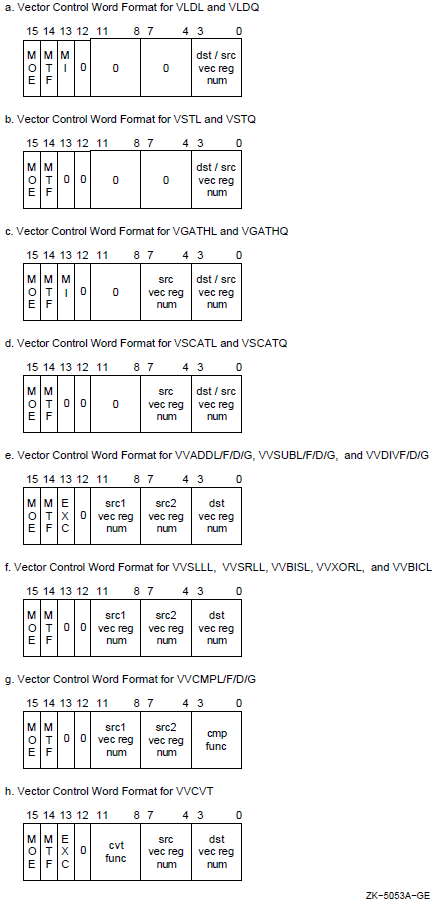
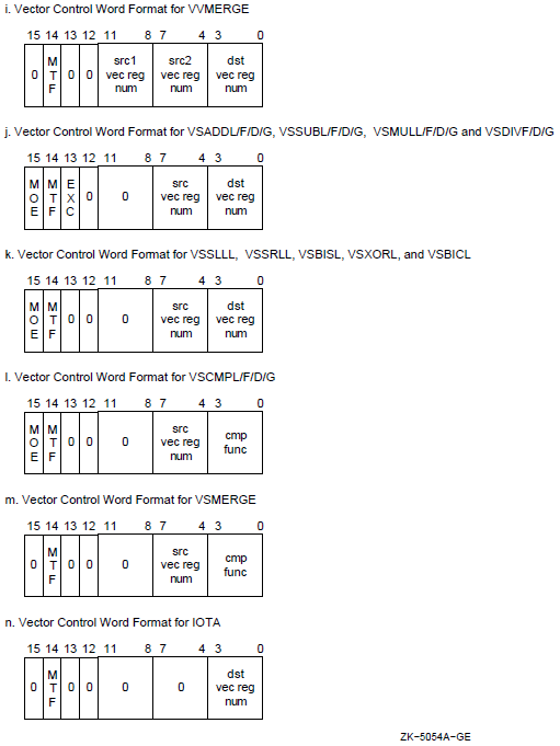
10.3.6. Restrictions on Operand Specifier Usage
Certain restrictions are placed on the addressing mode combinations usable within a single vector instruction. These combinations involve the logically inconsistent simultaneous use of a value as both a source operand (that is, a.rw, .rl, or .rq operand) and an address. Specifically, if within the same instruction the contents of register Rn is used as both a part of a source operand and as an address in an addressing mode that modifies Rn (that is, autodecrement, autoincrement, or autoincrement deferred), the value of the scalar source operand is UNPREDICTABLE.
Use of short literal mode for the scalar source operand of a vector floating-point instruction causes UNPREDICTABLE results.
If a Store Vector Register Data into Memory (VST) or Scatter Memory Data into Vector Register (VSCAT) instruction overwrites anything needed for calculation of the memory addresses to be written, the result of the VST or VSCAT is UNPREDICTABLE.
If the same vector register is used as both source and destination in a Gather Memory Data into Vector Register (VGATH) instruction, the result of the VGATH is UNPREDICTABLE.
When the addressing mode of the BASE operand used in a VLD, VST, VGATH, or VSCAT instruction is immediate, the results of the instruction are UNPREDICTABLE.
10.3.7. VAX Condition Codes
The vector instructions do not affect the condition codes in the processor status longword (PSL) of the associated scalar processor.
10.3.8. Illegal Vector Opcodes
An illegal vector opcode is defined as a vector opcode to which no vector processor function is currently assigned. Opcodes that are not identified in Appendix D, "Permanent Symbol Table Defined for Use with VAX MACRO" as vector opcodes are neither decoded nor executed by the vector processor.
Reserved-instruction fault. This is the recommended implementation.
Illegal vector opcode. The vector processor disables itself and sets VPSR <IVO>. The remainder of the vector processor state is left unmodified.
The way in which a particular illegal vector opcode is reported is implementation specific.
10.4. Assembler Notation
The qualifier U enables floating underflow. The qualifier V enables integer overflow. Both of these qualifiers set cntrl <EXC>. The default is no vector processor exception conditions are enabled.
The qualifier 0 denotes masked operation on elements for which the Vector Mask Register (VMR) bit is 0. The qualifier 1 denotes masked operation on elements for which the VMR bit is 1. Both qualifiers set cntrl <MOE>. The default is no masked operations.
For the VMERGE and IOTA instructions only, the qualifier 0 denotes cntrl <MTF> is 0. The qualifier 1 denotes cntrl <MTF> is1. Cntrl <MTF> is 1 by default. Cntrl <MOE> is not set in this case.
For the VLD and VGATH instructions only, the qualifier M indicates modify intent (cntrl <MI> is 1). The default is no modify intent (cntrl <MI> is 0).
VVADDF/1 V0, V1, V2 ;Operates on elements with mask bit set
VVMULD/0 V0, V1, V2 ;Operates on elements with mask bit clear
VVADDL/V V0, V1, V2 ;Enables exception conditions
(integer overflow here)
VVSUBG/U0 V0, V1, V2 ;Enables floating underflow and
;Operates on elements with mask bit clearVLDL/M base,#4,V1 ;Indicates Modify Intent
10.5. Execution Model
A typical processor consists of a VAX scalar processor and its associated vector processor, which contains vector registers and vector function units. The scalar and vector processors may execute asynchronously. The VAX scalar processor decodes both scalar and vector instructions following the operand specifier evaluation rules stated in the VAX Architecture Reference Manual, but executes only the scalar instructions. The scalar processor passes the information required to execute a vector instruction to the vector processor. This information may include the vector opcode, scalar source operands, and vector control words. The vector processor performs the required operation,such as loading data from memory, storing data to memory, or manipulating data already loaded into its vector registers.
If the scalar processor views the vector processor as enabled (the scalar processor sees VPSR <VEN> as set), the decoded vector instruction is sent to the vector processor. The vector processor queues instructions sent by the scalar processor until they can be executed.
If the scalar processor views the vector processor as disabled (the scalar processor sees VPSR <VEN> as clear), attempting to send the decoded vector instruction to the vector processor results in a vector processor disabled fault.
DO WHILE (the scalar processor has a decoded vector instruction for
the vector processor)
IF (the vector processor is viewed as disabled -- the scalar processor
sees VPSR<VEN> as clear) THEN
enter the vector processor disabled fault handler.
ELSE
IF (asynchronous memory management handling is implemented
AND VPSR<PMF> is set) THEN
enter the memory management exception handler.
{The vector processor clears VPSR<PMF>.}
ELSE
BEGIN
{If asynchronous memory management handling is
implemented and VPSR<MF> is set, the vector processor
clears VPSR<MF>, and retries the faulting memory
reference before any new vector instructions in the
queue are executed.}
IF (the vector processor instruction queue is not full) THEN
BEGIN
Send the decoded instruction to the vector processor
for execution.
IF (the decoded instruction is a vector memory access
instruction AND synchronous memory management
handling is implemented) THEN
ensure instruction completion without the occurrence
of memory management exceptions.
END
END
ENDIf asynchronous memory management handling is implemented, and VPSR <MF> is set when the scalar processor sends the vector processor an instruction, the vector processor clears VPSR <MF>, and retries the faulting memory reference before any new vector instructions in the queue are executed.
The VAX scalar processor need not wait for the vector processor to complete its operation before processing other instructions. Thus, the scalar processor could be processing other VAX instructions while the vector processor is performing vector operations. However, if the scalar processor issues an MFVP instruction to the vector processor, the scalar processor must wait for the MFVP result to be written before processing other instructions.
Because the scalar and vector processors may execute asynchronously, it is possible to context switch the scalar processor before the vector processor is idle. Software is responsible for ensuring that scalar and vector memory management remains synchronized, and that all exceptions get reported in the context of the process where they occurred. This is achieved by making sure all vector memory accesses complete, and then disabling the vector processor before any scalar context switch.
The vector processor may have its own translation buffer (TB) and cache and may have separate paths to memory, or it may share these resources with the scalar processor.
10.5.1. Access Mode Restrictions
In general, processes are expected to use the vector processor in only one mode. However, multimode use of the vector processor by a process is allowed. Software decides whether to allow vector processor exceptions from vector instructions executed in a previous access mode to be reported in the current mode. The preferred method is to report all vector processor exceptions in the access mode where they occurred. This is achieved by requiring a process that uses the vector processor to execute a SYNC instruction before changing to an access mode where additional vector instructions are executed.
For correct access checking of vector memory references, the vector processor must know the access mode in effect when a vector memory access instruction is issued by the scalar processor.
10.5.2. Scalar Context Switching
Disable the vector processor so that no new vector instructions will be accepted. Writing zero to the VPSR using the MTPR instruction clears VPSR <VEN> and disables the vector processor without affecting VPSR <31:1>. (See Section 10.6.3, ''Vector Processor Disabled'' for more details.)
Ensure that no more vector memory read or write operations can occur. Reading the VMAC internal processor register (IPR) using the MFPR instruction does the required scalar/vector memory synchronization without any exceptions being reported. Reading VMAC also ensures that all unreported hardware errors encountered by previous vector memory instructions are reported before the MFPR completes. For more information on this function of VMAC, refer to Section 10.9, ''Hardware Errors''.
Set a software scalar-context-switch flag and perform a normal scalar processor context switch, for example SVPCTX, and so on, leaving the vector processor state as is.
The vector processor cannot be executing non-memory-access instructions from the previous process while a normal scalar context switch to a new process is being performed – which may be desirable to an operating system.
All unreported hardware errors encountered by previous non-memory-access instructions will be reported by the time the vector processor clears VPSR <BSY> and thus known to software before scalar-context switching continues (refer to Section 10.9, ''Hardware Errors'' for more details).
The MFPR from VPSR used to read VPSR <BSY> also ensures that the scalar processor views the vector processor as disabled.
If software does not wait for VPSR <BSY> to be clear, it is possible that while a normal scalar context switch to a new process is being performed,the vector processor may still be executing non-memory-access instructions from the previous process.
The required steps for Vector Context Switching are discussed in Section 10.6.4, ''Handling Disabled Faults and Vector Context Switching''.
10.5.3. Overlapped Instruction Execution
To improve performance, the vector processor may overlap the execution of multiple instructions – that is, execute them concurrently. Further, when no data dependencies are present, the vector processor may complete instructions out of order relative to the order in which they were issued. A vector processor implementation can perform overlapped instruction execution by having separate function units for such operations as addition,multiplication, and memory access. Both data-dependent and data-independent instructions can be overlapped; the former by a technique known as chaining,which is described in the next section. In many instances, overlapping allows an operation from one instruction to be performed in any order with respect to an operation of another instruction.
When vector arithmetic exceptions occur during overlapped instruction execution, exception handling software may not see the same instruction state and exception information that would be returned from strictly sequential execution. Most notably, the VAER could indicate the exception conditions and destination registers of a number of vector instructions that were executing concurrently and encountered exceptions. Exception reporting during chained execution is discussed further in Section 10.5.3.1, ''Vector Chaining''.
To ensure correct program results and exception reporting, the architecture does place requirements on the ordering among the operations of one vector instruction and those of another. The primary goal of these requirements is to ensure that the results obtained from both the overlapped and strictly sequential execution of data-dependent instructions are identical. A secondary goal is to establish places within the instruction stream where software is guaranteed to receive the reporting of exceptions from a chain of data-dependent instructions.
In many cases, these requirements ensure the obvious: for example, an output vector register element of one arithmetic instruction must be computed before it can be used as an input element to a subsequent instruction. But, a number of the things ensured are not obvious: for example, a Memory Instruction Synchronization (MSYNC) instruction must report exceptions encountered in generating a value of Vector Mask Register (VMR) that is used in a previously issued masked store instruction.
To precisely define the requirements on the ordering among operations, Section 10.5.5, ''Dependencies Among Vector Results'' discusses the "dependence " amongt heir results (the vector register elements and control register bits produced by the operations).
10.5.3.1. Vector Chaining
The architecture allows vector chaining, where the results of one vector instruction are forwarded (chained) to another before the input vector of the first instruction has been completely processed. In this way, the execution of data-dependent vector instructions may be overlapped. Thus, chaining is an implementation-dependent feature that is used to improve performance.
With some restrictions stated below, the vector processor may chain a number of instructions. Usually, each instruction is performed by a separate function unit. The number and types of instructions allowed within a chained sequence (often referred to as a "chain") are implementation dependent. Typically, implementations will attempt to chain sequences of two or three instructions such as: operate-operate, operate-store, load-operate,operate-operate-store, and load-operate-store. Load-operate-operate-store may also be possible.
VVADDF V0, V1, V2 VVMULF V2, V3, V4
The destination of the VVADDF is a source of the succeeding VVMULF. The VVMULF begins executing when the first sum element of the VVADDF is available.
A number of instructions within a chained sequence can encounter exceptions. For each instruction that encounters an exception, the vector processor records the exception condition type and destination register number in the Vector Arithmetic Exception Register (VAER). When the last instruction within the chain completes, the VAER will show the exception condition type and destination register number of all instructions that encountered exceptions within the chain. Furthermore, when the vector processor disabled fault is finally generated for the exceptions, the VAER may also indicate exception state for instructions issued after the last instruction within the chain. This effect is possible due to the asynchronous exception-reporting nature of the vector processor.
Furthermore, for each instruction that encounters an exception within a chain,the default result, as defined in Section 10.6.2, ''Vector Arithmetic Exceptions'', is forwarded as the source operand to the next instruction. This has the effect that default results and exceptions can propagate down through a chain. Note that the default result of one instruction may be overwritten by another instruction before the exception is taken.
VVADDG V1, V2, V3 ;gets Floating Overflow VVGEQG V3, V4 ;gets Floating Reserved Operand VVMULG V4, V5, V3 ;overwrites V3
For the previous example, assume that an exception is taken after the completion of the VVMULG. The VAER will indicate: Floating Overflow and Floating Reserved Operand exception condition types; and V3 as a destination register. However, no default result will be found in the appropriate element of V3 because it has been overwritten by the VVMULG.
VLDL A, #4, V0 VVADDF V0, V1, V1
In synchronous memory management mode, the VVADDF cannot be chained into the VLDL until the VLDL is ensured to complete without a memory management exception. This occurs because the scalar processor is not even allowed to issue the VVADDF to the vector processor until the memory management checks for the VLDL have been completed. In asynchronous memory management mode, the VVADDF may be chained into the VLDL prior to the completion of memory management exception checking. This is possible because a memory management exception in asynchronous memory management mode provides sufficient state to restart both the VLDL and the VVADDF when the memory management exception is corrected.
The architecture allows a vector operate instruction to be chained into a store instruction. If the vector operate instruction encounters an arithmetic exception, the exception condition type and destination register number are recorded in the Vector Arithmetic Exception Register (VAER). The default result generated by that instruction (in some cases an encoded reserved operand) may be written to memory by the store instruction before the exception is reported.
10.5.3.2. Register Conflict
VVADDF V1, V2, V3 VVMULF V4, V5, V1
In the example, the VVADDF and VVMULF cannot both begin execution simultaneously because the elements of V1 generated by the VVMULF would overwrite the original elements of V1 required as input by the VVADDF. However, a vector processor implementation can still overlap the execution of these two instructions in a number of ways. One way would be by not starting the VVMULF until the first element of V1 has been read by the VVADDF. In this manner, as the VVADDF reads the next elements from V1 and V2, the VVMULF writes its product into the previous element of V1. This process continues until all the elements have been processed by both instructions. The VVADDF will finish execution while the VVMULF still has at least one product to store.
In the case of the Vector Mask Register (VMR), the vector processor ensures that register conflict does not occur. This is often accomplished by making a copy of the VMR value under which a pending vector instruction is to execute,and using this copy when execution begins. This allows the vector processor to begin executing an instruction that writes VMR before it completes prior instructions that read VMR.
10.5.4. Memory Instructions
This section describes VAX vector architecture memory instructions.
10.5.5. Dependencies Among Vector Results
To achieve correct results and exception reporting during overlapped execution, the vector processor must maintain certain dependencies among the register elements and control register bits produced by various vector instructions. Because of the vector processor's asynchronous exception reporting nature and out-of-order completion of instructions, these dependencies differ from those ensured by the VAX scalar processor. In addition, these dependencies are at the level of vector register elements and vector control register bits; rather than at the level of vector registers and vector control registers.
Among other things, these dependencies determine the exception reporting nature of the MFVP instruction. The value of the vector control register (VCR, VLR,VMR <31:0>, VMR <63:32>) delivered by an MFVP depends upon the value of certain vector register elements and vector control register bits. Unreported exceptions that occur in the production of these elements and control register bits are reported by the vector processor prior to the completion of the MFVP from the vector control register.
The dependencies are expressed formally for the various classes of vector instructions by the tables of pseudo-code in this section. These are the only dependencies that software should rely upon the vector processor to ensure.
Note
VVSUBF V5, V6, V7 VVADDF V1, V2, V7 VVMULF V7, V7, V3 VVDIVF V1, V4, V7
Implicit in statements of the form: "result DEPENDS on B" is the requirement that the result depends only on the value of "B" generated by the most immediate previously issued instruction relative to the result's own generating instruction. For instance, in the following example, the V3 produced by the VVMULF has the dependence: "V3[i] DEPENDS on V7[i]".This means that the value of V3[i] produced by the VVMULF depends only on the value of V7[i] produced by the VVADDF.
|
Instructions |
Dependence |
|---|---|
|
VVADDx, VSADDx, VVSUBx, VSSUBx, VVMULx, VSMULx, VVDIVx, VSDIVx,VVCVTxy, VVBICL, VSBICL, VVBISL, VSBISL, VVXORL, VSXORL, VVSLLL, VSSLLL,VVSRLL, VSSRLL |
for i = 0 to VLR-1
begin
Vc[i] DEPENDS on VLR;
if {MOE EQL 1} then Vc[i] DEPENDS on VMR<i>;
if ( {MOE EQL 1} AND {VMR<i> EQL MTF} ) OR {MOE EQL 0} then
begin
Vc[i] DEPENDS on Vb[i];
if {Vector-Vector Operation} AND NOT {VVCVTxy} then
Vc[i] DEPENDS on Va[i];
end;
end;
|
|
Instructions |
Dependence |
|---|---|
|
VLDx, VGATHx |
for i = 0 to VLR-1
begin
Vc[i] DEPENDS on VLR;
if {MOE EQL 1} then Vc[i] DEPENDS on VMR<i>;
if ( {MOE EQL 1} AND {VMR<i> EQL MTF} ) OR {MOE EQL 0} then
if VGATH then
begin
Vc[i] DEPENDS on Vb[i];
k = BASE + Vb[i];
end
else
k = BASE + i * STRIDE;
Vc[i] DEPENDS on LOAD_COMPLETED(k);
end;
|
|
Instructions |
Dependence |
|---|---|
|
VSTx, VSCATx |
j = 0;
for i = 0 to VLR-1
begin
if ( {MOE EQL 1} AND {VMR<i> EQL MTF} ) OR {MOE EQL 0} then
begin
if {MOE EQL 1} then ELEMENT_STORED[j] depends on VMR<i>;
ELEMENT_STORED[j] DEPENDS on Vc[i];
ELEMENT_STORED[j] DEPENDS on VLR;
if VSCAT then
begin
ELEMENT_STORED[j] DEPENDS on Vb[i];
k = BASE + Vb[i];
end
else
k = BASE + i * STRIDE;
STORE_COMPLETED(k) DEPENDS on ELEMENT_STORED[j];
j = j+1;
end;
end;
|
|
Instructions |
Dependence |
|---|---|
|
VVCMPx, VSCMPx |
for i = 0 to VLR-1
begin
VMR<i> DEPENDS on VLR;
if {MOE EQL 1} then VMR<i> DEPENDS on VMR<i>
if ( {MOE EQL 1} AND {VMR<i> EQL MTF} ) OR {MOE EQL 0} then
begin
VMR<i> DEPENDS on Vb[i];
if VVCMP then VMR<i> DEPENDS on Va[i];
end;
end;
|
|
Instructions |
Dependence |
|---|---|
|
VVMERGE, VSMERGE |
for i = 0 to VLR-1
begin
Vc[i] DEPENDS on VLR;
Vc[i] DEPENDS on VMR<i>;
if {VMR<i> EQL MTF} then
begin
if VVMERGE then Vc[i] DEPENDS on Va[i];
end
else
Vc[i] DEPENDS on Vb[i];
end;
|
|
Instruction |
Dependence |
|---|---|
|
IOTA |
j = 0;
for i = 0 to VLR-1
begin
Vc[j] DEPENDS on VLR;
if {VMR<i> EQL MTF} then
begin
Vc[j] DEPENDS on VMR<0..i>;
j = j+1;
end;
end;
VCR DEPENDS on VMR<0..VLR-1>;
|
|
Instructions |
Dependence |
|---|---|
|
MSYNC |
DEPENDS on the following:
|
|
SYNC |
DEPENDS on the vector register elements and vector control register bits produced and stored by all previous vector instructions |
|
MFVMRLO |
DEPENDS on VMR <0..31> |
|
MFVMRHI |
DEPENDS on VMR <32..63> |
|
MFVCR |
DEPENDS on VCR |
|
MFVLR |
DEPENDS on VLR |
|
Item |
Dependence |
|---|---|
|
VSYNC |
Depends on nothing, but for each memory location, x forces all subsequent LOAD_COMPLETED(x) and STORE_COMPLETED(x) to DEPEND on all previous LOAD_COMPLETED(x) and STORE_COMPLETED(x). |
|
MTVP |
DEPENDS on nothing. |
|
Value of a memory location |
The value of a memory location DEPENDS on nothing and is not DEPENDED on by any vector instruction. |
|
Transitive dependence |
if {a DEPENDS on b} AND {b DEPENDS on c}
then a DEPENDS on c
|
10.6. Vector Processor Exceptions
- Vector memory management
- Access control violation
- Vector access control violation
- Vector alignment
- Vector I/O space reference
Translation not valid
Modify
- Vector Arithmetic
Floating underflow
Floating divide by zero
Floating reserved operand
Floating overflow
Integer overflow
Floating underflow and integer overflow can be disabled on a per-instruction basis by clearing cntrl <EXC>.
Vector processor arithmetic exceptions cause the vector processor to disable itself (see Section 10.6.3, ''Vector Processor Disabled'', Vector Processor Disabled). The vector processor does not disable itself for vector processor memory management exceptions.
10.6.1. Vector Memory Management Exception Handling
Vector processor memory management exceptions are taken through the system control block (SCB) vector for their scalar counterparts. Figure 10.12, ''Memory Management Fault Stack Frame (as Sent by the Vector Processor)'' illustrates the memory management fault stack frame that contains the memory management fault parameter.
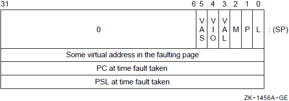
The length (L) bit, the Page Table Entry (PTE) reference (P) bit, and the modify or write intent (M) bit are defined in the VAX Architecture Reference Manual. Vector processor memory management exceptions set these bits in the same way as required for scalar memory management exceptions.
The vector alignment exception (VAL) bit must be set when an access control violation has occurred due to a vector element not being properly aligned in memory.
The vector I/O space reference (VIO) bit is set by some implementations to indicate that an access control violation has occurred due to a vector instruction reference to I/O space.
The vector asynchronous memory management exception(VAS) bit must be set to indicate that a vector processor memory management exception has occurred when the following asynchronous memory management scheme is implemented.
If more than one kind of memory management exception could occur on a reference to a single page, then access control violation takes precedence over both translation not valid and modify. If more than one kind of access control violation could occur, the precedence of vector access control violation, vector alignment exception, and vector I/O space reference is UNPREDICTABLE.
Synchronous memory management handling and restart from the beginning.
Asynchronous memory management handling and store/reload implementation-specific state using VSAR.
With the synchronous method, no new instructions are processed by the vector or the scalar processor until the vector memory access instruction is guaranteed to complete without incurring memory management exceptions. In such an implementation, the vector memory access instruction is backed up when a memory management exception occurs and a normal VAX memory management (access control violation, translation not valid, modify) fault taken with the program counter (PC) pointing to the faulting vector memory access instruction. If the synchronous method is implemented, VSAR is omitted. After fixing the vector processor memory management exception, software may REI back to the faulting vector instruction. Alternately, software may context switch to another process. For further details, see Section 10.6.4, ''Handling Disabled Faults and Vector Context Switching''.
With the asynchronous method, vector memory management exceptions set VPSR <PMF> and VPSR <MF>. The vector processor does not inform the scalar processor of the exception condition; the scalar processor continues processing instructions. All pending vector instructions that have started execution are allowed to complete if their source data is valid. The scalar processor is notified of an exception condition or conditions when it sends the next vector instruction to the vector processor and a normal VAX memory management fault is taken. The saved PC points to this instruction, which is not the vector memory access instruction that incurred the memory management exception. At this point, the vector processor clears VPSR <PMF>. After fixing the vector processor memory management exception, software may allow the current scalar/vector process to continue. Before vector processor instruction execution resumes using state that already exists in the vector processor, the vector processor clears VPSR <MF> and the faulting memory reference is retried. Alternately, software may context switch to another process. For further details, see Section 10.6.4, ''Handling Disabled Faults and Vector Context Switching''.
When a vector processor memory management exception is encountered by a VLD or VGATH instruction, the contents of the destination vector register elements are UNPREDICTABLE. When a vector processor memory management exception is encountered by a VSTL or VSCAT instruction, it is UNPREDICTABLE whether the vector processor writes any result location for which an exception did not occur. In either case, if the fault condition can be eliminated by software and the instruction restarted, then the vector processor will ensure that all destination register elements or result locations are written.
10.6.2. Vector Arithmetic Exceptions
The low-order 32 bits of the true result for integer overflow.
Zero for floating underflow if exceptions are disabled.
An encoded reserved operand for floating divide by zero, floating overflow, reserved operand, and enabled floating underflow.
For vector convert instructions that convert floating-point data to integer data, where the source element is a reserved operand, the value written to the destination element is UNPREDICTABLE.
The exception condition type and destination register number are always recorded in the Vector Arithmetic Exception Register (VAER) when a vector arithmetic exception occurs. Refer to Section 10.2.3, ''Internal Processor Registers'', Internal Processor Registers, for more information.
10.6.3. Vector Processor Disabled
As a result of error conditions or software control, the vector processor signals the scalar processor not to issue any more vector instructions. The vector processor is disabled when this signal is generated and its state is reflected in VPSR <VEN>.Because the scalar and vector processors can execute asynchronously, the scalar processor may not receive this signal immediately. As a result, the scalar processor may continue to view the vector processor as enabled and send it vector instructions. Once the scalar processor receives this signal, it will view the vector processor as disabled and will not send it any more vector instructions (including MFVP/MTVP). While the vector processor is disabled, and in the absence of hardware errors, it will complete all pending instructions in its instruction queue including those sent by the scalar processor after the vector processor became disabled.
Vector arithmetic exception (flagged by VPSR <AEX>)
Hardware error (flagged by VPSR <IMP> in some implementations)
On some implementations, receipt of an illegal vector opcode (flagged by VPSR <IVO>)
In these cases, the vector processor clears VPSR <VEN> and flags the error condition by setting the appropriate bit in VPSR. (See Table 10.1, ''Description of the Vector Processor Status Register (VPSR)''.)
Software disables the vector processor by writing a zero into VPSR <VEN> using an MTPR instruction. Once the vector processor is disabled, only software can enable it. The software does this by writing a one to VPSR <VEN> using an MTPR. Recall that after performing an MTPR to VPSR, software must then issue an MFPR from VPSR to ensure that the new state of VPSR will affect the execution of subsequently issued vector instructions. The MFPR will not complete in this case until the new state of the vector processor becomes visible to the scalar processor.
When the vector processor disables itself due to a hardware error, it I implementation dependent whether the vector processor completes any pending vector instruction. However, in this case, the vector processor ensures when it is reenabled that all incompleted instructions have been flushed from the instruction queue.
If the scalar processor attempts to issue a vector instruction after it views the vector processor as disabled, then a vector processor disabled fault occurs. The vector processor disabled fault uses SCB offset 68 (hex). The exception handling software (running on the scalar processor) can then read the vector internal processor registers (IPRs) with MFPR instructions to determine what exception conditions are recorded in the vector processor and if the vector processor is still busy processing other unfinished instructions.
Once the scalar processor views the vector processor as disabled, the only operations that can be issued to the vector processor are MTPR and MFPR to and from the vector IPRs.
10.6.4. Handling Disabled Faults and Vector Context Switching
The following flow outlines the required steps for handling a vector processor disabled fault.
If the new process executing on the scalar processor has a vector instruction to execute, saving and restoring the state of the vector processor – that is,vector context switching – is done as part of handling a subsequent vector processor disabled fault.
Obtain the vector processor status by reading the VPSR using the MFPR instruction.
- Perform the following checks to see if any of these conditions caused the vector processor to be disabled. If any of these conditions exist, a decision to not continue this flow may occur.
If VPSR <IVO> is set, then write one to clear VPSR <IVO> using the MTPR instruction, and report an illegal vector opcode error.
If VPSR <IMP> is set, then write one to clear VPSR <IMP> using the MTPR instruction, and report an implementation-specific error.
If VPSR <AEX> is set, then write one to clear VPSR <AEX> using the MTPR instruction, and enter the vector arithmetic exception handler with information in VAER.
- If the software scalar-context-switch flag is set, indicating that a scalar context switch has been done, then perform the following:
Make sure the vector processor has access to correct P0LR, P0BR, P1LR, and P1BR values.
If any vector translation buffer needs to be invalidated, then write zero into the VTBIA IPR using the MTPR instruction. Vector translation buffer flushing is required if the process was swapped out and the mapping change has not yet been made known to the vector translation buffer.
Clear the software scalar-context-switch flag.
Enable the vector processor by writing one to VPSR <VEN> using the MTPR instruction. Ensure the new state of the vector processor becomes visible to the scalar processor by reading VPSR with the MFPR instruction.
REI to retry the vector instruction at the time of the vector processor disabled fault. If there is an asynchronous memory management exception pending, it is taken when that vector instruction is reissued to the vector processor.
- Check if there is a current vector process. If there is one, then perform the following procedure:
Wait for VPSR <BSY> to be clear using the MFPR instruction.
- Perform the following check to see if this condition caused the vector processor to be disabled. If this condition exists, a decision to not continue this flow may occur.
If VPSR <IMP> is set, then report an implementation-specific error.
If VPSR <IVO> is set, then set a software IVO flag for this process. The illegal vector opcode error is handled when this process next tries to execute in the vector processor.
If VPSR <AEX> is set, then set a software AEX flag for this process, and save vector arithmetic exception state from VAER using the MFPR instruction. Any vector arithmetic exception conditions are handled when this process next tries to execute in the vector processor.
- At this point there cannot be a synchronous memory management exception pending. But, if asynchronous memory management handling is implemented, there may be an asynchronous memory management exception pending. Because scalar/vector memory synchronization was required before scalar context switching, all such pending exceptions are known at this time. So, if VPSR <PMF> is set, then perform the following procedure:
Set a software a synch-memory-exception-pending flag for this process.
Store implementation-specific vector state in memory starting at the address in VSAR by writing one to VPSR <STS> using the MTPR instruction.
Reset the vector processor state to clear VAER and VPSR, and enable the vector processor. Writing a one to both VPSR <RST> and VPSR <VEN> using the same MTPR instruction accomplishes this. Ensure the new state of the vector processor becomes visible to the scalar processor by reading VPSR with the MFPR instruction.
Store the current vector (V0–V15) and vector control (VLR, VMR, and VCR)register values using VST and MFVP instructions.
Read the VMAC IPR using the MFPR instruction. This ensures scalar/vector memory synchronization and that all hardware errors encountered by previous vector memory instructions have been reported.
Make the current scalar process also the current vector process.
Clear the software scalar-context-switch flag.
Make sure the vector processor has access to correct P0LR, P0BR, P1LR, and P1BR values, and invalidate any vector translation buffer by writing zero to the VTBIA IPR using the MTPR instruction.
Load the saved vector (V0–V15) and vector control (VLR, VMR, and VCR) register values using VLD and MTVP instructions.
- If the software IMP, IVO, or AEX flags for this process are set, perform the following procedure:
Disable the vector processor by writing zero to VPSR <VEN>using the MTPR instruction. Ensure the new state of the vector processor becomes visible to the scalar processor by reading VPSR with the MFPR instruction.
If set, clear the software IMP flag for this process and finish handling the implementation-specific error. A decision to not continue this flow may occur.
If set, clear the software IVO flag for this process and report an illegal vector opcode error occurred. A decision to not continue this flow may occur.
If set, clear the software AEX flag for this process and enter the vector arithmetic exception handler with saved VAER state. A decision to not continue this flow may occur.
- If the software a sync-memory-exception-pending flag for this process is set, perform the following procedure:
Clear the software a sync-memory-exception-pending flag for this process.
Send the vector processor the memory address that points to implementation-specific vector state for this process by writing VSAR using the MTPR instruction.
Reload the implementation-specific vector state for this process and leave the vector processor enabled by writing one to both VPSR <RLD> and VPSR <VEN> using the same MTPR instruction. From this state, the vector processor determines if VPSR <PMF>, VPSR <MF>, or both need to be set, and does it. Ensure the new state of the vector processor becomes visible to the scalar processor by reading VPSR with the MFPR instruction.
REI to retry the vector instruction at the time of the vector processor disabled fault. If there is an asynchronous memory management exception pending, it is taken when that vector instruction is reissued to the vector processor.
10.6.5. MFVP Exception Reporting Examples
This section gives examples of Move from Vector Processor (MFVP) exception reporting that are ensured by the vector processor. The rules used to determine the correct result for each example are found in: the tables of dependencies found in Section 10.5.5, ''Dependencies Among Vector Results'', the description of MSYNC in Section 10.7.2, ''Scalar/Vector Memory Synchronization'', and the description of MFVP in Section 10.15, ''Miscellaneous Instructions''.
Examples of Exceptions That Cause MSYNC to Fault
VVMULF V1, V1, V2 VVADDF V3, V2, V3 MTVLR #1 VSTL V2, A, #4 VVCVTFD V2, V3 MSYNC R0
The MSYNC faults if exceptions occur in the production of V2[0] by the VVMULF or in the storage of V2[0] by the VSTL. MSYNC need not fault if exceptions occur in the production of: V2[1..VLR-1] by the VVMULF, V3[0..VLR-1] by the VVADDF, or V3[0..VLR-1] by the VVCVTFD.
VVADDF V1, V1, V0 VLDL A, #4, V0 MSYNC R0
The MSYNC faults if exceptions occur in the loading of V0[0..VLR-1] from memory. MSYNC need not fault if exceptions occur in the production of V0[0..VLR-1] by the VVADDF.
VVADDF V1, V1, V2 VLDL A, #4, V1 MSYNC R0
The MSYNC faults if exceptions occur in the loading of V1[0..VLR-1] from memory. MSYNC need not fault if exceptions occur in the production of V2[0..VLR-1] by the VVADDF.
VVMULF V1, V1, V2 VVGTRF V2, V3 VSTL/1 V0, A, #4 MSYNC R0
The MSYNC faults if exceptions occur: in the production of V2[0..VLR-1] by the VVMULF, in the production of VMR <0..VLR-1> by the VVGTRF, or in the storage by the VSTL/1 of elements of V0 for which the corresponding VMR bit is one.
Examples of Exceptions the Processor Reports Prior to MFVP Completion
VLDL A, #4, V1 VVMULF V1, V1, V2 MTVLR #1 VVGTRF V2, V3 MFVMRHI R1 MFVMRLO R2
Unreported exceptions that occur: in the loading of V1[0] from memory by the VLDL, in the production of V2[0] by the VVMULF, and VMR <0> by the VVGTRF are reported by the vector processor prior to the completion of the MFVMRLO. The vector processor need not at that time report any exceptions that occur in the loading of V1[1..63] from memory by the VLDL or in the production of V2[1..63] by the VVMULF. Note that the vector processor need not report any exceptions before completing MFVMRHI.
VVGTRF V0, V1 MTVMRLO #patt MFVMRLO R1
For any value of "i" in the range of 0 to 31 inclusive: the value of VMR <i> delivered by MFVMRLO only depends on the value placed into VMR <i> by the MTVMRLO. As a result, the vector processor need not report exceptions that occur in the production of VMR by the VVGTRF prior to completing the MFVMRLO.
VVMULF/1 V1, V1, V2 MTVMRLO #patt MFVMRLO R1
For any value of "i" in the range of 0 to 31 inclusive: the value of VMR <i> delivered by MFVMRLO only depends on the value placed into VMR <i> by the MTVMRLO. As a result, the vector processor need not report exceptions that occur in the production of V2[0..VLR-1] by the VVMULF/1 prior to completing the MFVMRLO.
#4 MTVLR #64 VVMULF V0, V0, V2 VVGTRF V0, V2 MTVLR #32 IOTA #str, V4 MFVCR R1
Prior to the completion of the MFVCR, the vector processor must report any exceptions that occurred in the production of V2[0..31] by the VVMULF and VMR <0..31> by the VVGTRF. Note that VCR produced by an IOTA depends only on VMR <0..VLR-1>. Recall that no exceptions can occur in the production of V4[0..VCR-1] by IOTA.
MTVLR #64 VLDL A, #4, V2 VVGTRF V0, V1 VSGTRF/1 #3.0, V2 MFVMRLO R1
For any value of "i" in the range of 0 to 31 inclusive: prior to the completion of the MFVMRLO, the vector processor must report any exceptions that occurred: in the loading of V2[i] from memory for which V0[i]is greater than V1[i], in the production of VMR <0..31> by the VVGTRF, and in the production of VMR <0..31> by the VSGTRF/1.
VVMULF V1, V1, V1 VSTL V1, base, #str MTVMRLO base MFVMRLO R1
In this example, the value of VMR <31:0> delivered by MFVMRLO only depends on the value placed into VMR <31:0> by the MTVMRLO –whether this value is V1[0] or the previous value of the location is UNPREDICTABLE. As a result, the vector processor need not report exceptions that occur in the production of V1 by the VVMULF or in the storage of V1 by the VSTL.
10.7. Synchronization
Exception reporting between the vector and scalar processors
Memory accesses between the scalar and vector processors
Memory accesses between multiple load/store units of the vector processor
Software must determine when to use these synchronization instructions to ensure correct results.
The following sections describe the synchronization instructions.
10.7.1. Scalar/Vector Instruction Synchronization (SYNC)
A mechanism for scalar/vector instruction synchronization between the scalar and vector processors is provided by SYNC, which is implemented by the MFVP instruction. SYNC allows software to ensure that the exceptions of previously issued vector instructions are reported before the scalar processor proceeds with the next instruction. SYNC detects both arithmetic exceptions and asynchronous memory management exceptions and reports these exceptions by taking the appropriate VAX instruction fault. Once it issues the SYNC, the scalar processor executes no further instructions until the SYNC completes or faults.
A pending or currently executing vector instruction encounters an exception – in which case the SYNC faults
The vector processor determines that all pending and currently executing vector instructions (including memory instructions in asynchronous memory management mode) will execute to completion without encountering vector exceptions. In that case the SYNC completes.
When SYNC completes, a longword value (which is UNPREDICTABLE) is returned to the scalar processor. The scalar processor writes the longword value to the scalar destination of the MFVP and then proceeds to execute the next instruction. If the scalar destination is in memory, it is UNPREDICTABLE whether the new value of the destination becomes visible to the vector processor until scalar/vector memory synchronization is performed.
When SYNC faults, it is not completed by the vector processor and the scalar processor does not write a longword value to the scalar destination of the MFVP. Also, depending on the exception condition encountered, the SYNC itself takes either a vector processor disabled fault or memory management fault. If both faults are encountered while the vector processor is performing SYNC,then the SYNC itself takes a vector processor disabled fault. Note that it is UNPREDICTABLE whether the vector processor is idle when the fault is generated. After the appropriate fault has been serviced, the SYNC may be returned to through an REI.
SYNC only affects the scalar/vector processor pair that executed it. It has no effect on other processors in a multiprocessor system.
10.7.2. Scalar/Vector Memory Synchronization
Scalar/vector memory synchronization allows software to ensure that the memory activity of the scalar/vector processor pair has ceased and the resultant memory write operations have been made visible to each processor in the pair before the pair's scalar processor proceeds with the next instruction. Two ways are provided to ensure scalar/vector memory synchronization: using MSYNC, which is implemented by the MFVP instruction, and using the MFPR instruction to read the VMAC (Vector Memory Activity Check) internal processor register (IPR). Section 10.7.2.1, ''Memory Instruction Synchronization (MSYNC)'' discusses MSYNC in detail. Section 10.7.2.2, ''Memory Activity Completion Synchronization (VMAC)'' discusses VMAC in detail.
Scalar/vector memory synchronization does not mean that previously issued vector memory instructions have completed; it only means that the vector and scalar processors are no longer performing memory operations. While both VMAC and MSYNC provide scalar/vector memory synchronization, MSYNC performs significantly more than just that function. In addition, VMAC and MSYNC differ in their exception behavior.
Note that scalar/vector memory synchronization only affects the scalar/vector processor pair that executed it. It has no effect on other processors in a multiprocessor system. Scalar/vector memory synchronization does not ensure that the write operations made by one scalar/vector pair are visible to any other scalar or vector processor. Software can make data visible and shared between a scalar/vector pair and other scalar and vector processors by using the mechanisms described in the VAX Architecture Reference Manual. Software must first make a memory write operation by the vector processor visible to its associated scalar processor through scalar/vector memory synchronization before making the write operation visible to other processors. With outperforming this scalar/vector memory synchronization, it is UNPREDICTABLE whether the vector memory write will be made visible to other processors even by the mechanisms described in the VAX Architecture Reference Manual.
Lastly, waiting for VPSR <BSY> to be clear does not guarantee that a vector write operation is visible to the scalar processor.
10.7.2.1. Memory Instruction Synchronization (MSYNC)
While MSYNC performs scalar/vector memory synchronization, it does more than that. MSYNC allows software to ensure that all previously issued memory instructions of the scalar/vector processor pair are complete and their results made visible before the scalar processor proceeds with the next instruction.
MSYNC is implemented through the nonprivileged MFVP instruction. Arithmetic and asynchronous memory management exceptions encountered by previous vector instructions can cause MSYNC to fault.
Once it issues MSYNC, the scalar processor executes no further instructions until MSYNC completes or faults.
All previously issued scalar and vector memory instructions have completed.
All resultant memory write operations (scalar write operations and vector store operations) have been made visible to both the scalar and vector processor.
No exception that should cause MSYNC to fault has occurred. (See the next paragraph.)
MSYNC faults when any unreported exception has occurred in the production or storage of any result (vector register element or vector control register bit) that MSYNC depends upon. Such results include all elements loaded or stored by a previously issued vector memory instruction as well as any element or control register bit that these elements depend upon.
It is UNPREDICTABLE whether MSYNC faults due to exceptions that occur in the production and storage of results (vector register elements and vector control register bits) that MSYNC does not depend upon. Software should not rely on such exceptions being reported by MSYNC for program correctness.
When MSYNC completes, a longword value (which is UNPREDICTABLE) is returned to the scalar processor, which writes it to the scalar destination of the MFVP. The scalar processor then proceeds to execute the next instruction. If the scalar destination is in memory, it is UNPREDICTABLE whether the new value of the destination becomes visible to the vector processor until another scalar/vector memory synchronization instruction is performed.
When MSYNC faults, it is not ensured that all previously issued scalar and vector memory instructions have finished. In this case, the scalar processor writes no longword value to the scalar destination of the MFVP. Depending on the exception encountered by the vector processor, the MSYNC takes a vector processor disabled fault or memory management fault. Note that it is UNPREDICTABLE whether the vector processor is idle when the fault is generated. After the fault has been serviced, the MSYNC may be returned to through an REI.
Section 10.5.5, ''Dependencies Among Vector Results'' gives the necessary rules and examples to determine what vector control register elements and vector control register bits MSYNC depends upon.
10.7.2.2. Memory Activity Completion Synchronization (VMAC)
Privileged software needs a way to ensure scalar/vector memory synchronization that will not result in any exceptions being reported. Reading the VMAC internal processor register (IPR) with the privileged MFPR instruction is provided for these situations. It is especially useful for context switching.
All vector and scalar memory activities have ceased.
All resultant memory write operations have been made visible to both the scalar and vector processor.
A longword value (which is UNPREDICTABLE) is returned to the scalar processor.
After writing the longword value to the scalar destination of the MFPR, the scalar processor then proceeds to execute the next instruction. If the scalar destination is in memory, it is UNPREDICTABLE whether the new value of the destination becomes visible to the vector processor until another scalar/vector memory synchronization operation is performed.
As stated in Section 10.7.2, ''Scalar/Vector Memory Synchronization'', Scalar/Vector Memory Synchronization, the ceasing of vector and scalar memory activities does not mean that previously issued vector memory instructions have completed. For example, consider a vector memory instruction that has suspended execution due to an asynchronous memory management exception or hardware error. Once it becomes suspended, the instruction will write no further elements and its memory activity will cease. As a result, a subsequently issued VMAC will complete as soon as those write operations that were made by the memory instruction before it was suspended are visible to both the scalar and vector processor. But, after the completion of the VMAC, the memory instruction is not completed and remains suspended.
Vector arithmetic and memory management exceptions of previous vector instructions never fault an MFPR-from-VMAC and never suspend its execution.
10.7.3. Other Synchronization Between the Scalar and Vector Processors
In the absence of pending vector arithmetic exceptions, reading a vector control register using the MFVP instruction waits for all previous write operations to that register to complete. In addition, the scalar processor must wait for the MFVP result to be written before processing other instructions. An MFVP instruction that reads a vector control register must fault if there is any unreported exception that has occurred in the production of the value of the control register.
Writing to VTBIA or VSAR with MTPR causes the new state of the changed vector IPR to affect the execution of all subsequently issued vector instructions.
Reading from VPSR with MFPR after writing to VPSR with MTPR causes the new state of VPSR (and VAER if cleared by VPSR <RST>) to affect the execution of subsequently issued vector instructions.
10.7.4. Memory Synchronization Within the Vector Processor (VSYNC)
The vector processor may concurrently execute a number of vector memory instructions through the use of multiple load/store paths to memory. When it is necessary to synchronize the accesses of multiple vector memory instructions the MSYNC instruction can be used; however, there are cases for which this instruction does more than is needed. If it is known that only synchronization between the memory accesses of vector instructions is required, the VSYNC instruction is more efficient.
VSYNC orders the conflicting memory accesses of vector-memory instructions issued after VSYNC with those of vector-memory instructions issued before VSYNC. Specifically, VSYNC forces the access of a memory location by any subsequent vector-memory instruction to wait for (depend upon) the completion of all prior conflicting accesses of that location by previous vector-memory instructions.
VSYNC does not have any synchronizing effect between scalar and vector memory access instructions. VSYNC also has no synchronizing effect between vector load instructions because multiple load accesses cannot conflict. It also does not ensure that previous vector memory management exceptions are reported to the scalar processor.
10.7.5. Required Use of Memory Synchronization Instructions
Table 10.15, ''Possible Pairs of Read and Write Operations When Scalar/Vector Memory Synchronization (M) or VSYNC (V) Is Required Between Instructions That Reference the Same Memory Location '' shows for all possible pairs of vector or scalar read and write operations to a common memory location, whether one of the scalar/vector memory synchronization instructions or the VSYNC instruction must be issued after the first reference and before the second. Since the MSYNC instruction also includes the VSYNC function, it can always be used instead of VSYNC.
VLDL A, #4, V0
.
other scalar/vector instructions
that do not access A
.
MSYNC Dst
MOVL R0, AIn most cases, MSYNC is the preferred method for ensuring scalar/vector memory synchronization. However, there are special cases, usually encountered by an operating system, when VMAC is more appropriate.
After a vector instruction that stores to memory and before a peripheral(I/O) data transfer of the stored location is initiated by an application program. This ensures that the value stored will be transferred to the output device. The application must ensure that this requirement is met by using MSYNC. Using VMAC in this case is not sufficient because unlike MSYNC, VMAC does not ensure that all previous vector memory instructions have successfully completed.
After a vector instruction that stores to memory and before the associated scalar processor can execute a HALT instruction. This ensures that a read operation or modify operation by another processor will access the updated memory value. VMAC is the preferred method for this case.
Before the vector processor state is saved as a result of power failure. A read or modify operation of the same memory must read the updated value(provided that the duration of the power failure does not exceed the maximum nonvolatile period of the main memory). Also, software is responsible for saving any pending vector processor exception status. VMAC is the preferred method for this case.
Before a context switch. Software is responsible for ensuring that the vector processor has completed all its memory accesses before performing a context switch. Software is also responsible for saving any pending vector processor exception status. VMAC is the preferred method for this case.
10.7.5.1. When VSYNC Is Not Required
- Each of the store's accesses to the location does not conflict with any access to the location by previously issued vector store instructions. Conflict is avoided in this case because one of the following events occurred:
The location is not shared.
All accesses to the location by previous store instructions were forced to complete by the issue of an MSYNC or VMAC.
- Each of the store's accesses to the location does not conflict with any access to the location by previously issued vector load (VLD/VGATH)instructions. Conflict is avoided in this case because one of the following events occurred:
The location is not shared.
All accesses to the location by previous load instructions were forced to complete by the issue of an MSYNC or VMAC.
Each of the store's accesses to the location depends on the completion (as seen by the vector processor) of all accesses to the location by previous LOAD instructions. (The examples immediately following demonstrate this concept.)
In all other cases of conflicting vector memory accesses, VSYNC is necessary to ensure correct results.
Examples Where VSYNC Is Not Required
VLDL A, #4, V0 VSTL V0, A, #4
VLDL A, #4, V0 VSSUBL R0, V0, V1 VSTL V1, A, #4
VLDL/0 A, #4 ,V0 VSMULL/0 #3, V0, V0 VLDL/1 A, #4 ,V1 VVMULL/1 V1, V1, V1 VVMERGE/1 V1, V0, V2 VSTL V2, A, #4
VLDL A, #4 ,V0 VSGTRF #0, V0 VLDL/1 B, #4, V1 VLDL/0 C, #4, V2 VVMERGE/0 V2, V1, V3 VSTL V3, A, #4
Examples Where VSYNC Is Required
VLDL/1 A,#4,V0 VSLSSL #0,V1 VSYNC VSTL/1 V1,A,#4
If the VSYNC is not included, V0 could contain incorrect data at the end of the sequence since the vector processor is allowed to begin the VSTL before the VLDL is finished. This occurs because there is no dependence between the VMR value used by the VLDL and the VSTL.
VLDL A, #4, V0 VVMERGE/0 V0, V1, V1 VSYNC VSTL V1, A, #4
Unless the programmer can ensure that the VMR mask being used by the VVMERGE will force the access of each location by the VSTL to depend on the access to that location by the VLDL, a VSYNC is required. Note that in general, when masked operations provide a conditional path of dependence between conflicting memory accesses, a VSYNC is usually necessary to ensure correct results.
VSTL V1, A, #4 MTVLR #32 VSYNC VLDL A+128, #4, V2
In this example, the VSTL writes locations A to A+255 and the VLDL reads locations A+128 to A+255. Without the VSYNC, the vector processor is allowed to start reading locations A+128 to A+255 for the VLDL before the vector processor completes (or even starts) writing locations A+128 to A+255 for the VSTL. Consequently, V2[0:31] will not contain V1[32:63], which is the intended result. Note that the rules on when VSYNC is not required (found in Section 10.7.5.1, ''When VSYNC Is Not Required'') only apply to waiving the use of VSYNC prior to V ST/VSCAT instructions.
VGATHL A, V2, V0 ; let at least two elements ; of V2 be equal VVMULL V9, V0, V1 VSYNC VSCATL V1, A, V2The VSYNC is needed in this example because the VSCATL may store elements of V1 into a common location before the VGATHL has finished loading that location into all the appropriate elements of V0. As a result, elements of V0 fetched from the same location may be unequal. Suppose in the example that V2[0] =V2[63] = 0 and that the original value of location A before the sequence starts is X. Then it is possible without the VSYNC that V0[63] = X*V9[0] and that (A)= V1[63] = V9[63]*V9[0]*X after the sequence completes.
VLDL A, #0, V0 VVMULL V9, V0, V1 VSYNC VSTL V1, A, #0
The VSYNC is needed in this example because the VSTL may store elements of V1into A before the VLDL has finished loading all elements of V0 from A. As a result, the elements of V0 may be unequal and so produce incorrect results.
10.8. Memory Management
The vector processor may include its own translation buffer and maintain its own copies of SBR, SLR, SPTEP, P0BR, P0LR, P1BR, and P1LR as a group, or may use the scalar processor's memory management unit. Hardware implementations must ensure that MTPR to these registers update the copy retained by the vector processor. Changes to P0BR, P0LR, P1BR, and P1LR due to a LDPCTX do not update the copies in the vector processor. Before software enables the vector processor again, explicit MTPRs to P0BR, P0LR, P1BR, and P1LR are required to guarantee correct operation.
An MTPR to TBIS must also invalidate the corresponding TB entry in the vector processor, and an MTPR to TBIA must also invalidate the entire TB in the vector processor. However, the vector TB is not invalidated by a LDPCTX instruction. Software can use an MTPR to the Vector TB Invalidate All (VTBIA)register to invalidate only the vector TB. An MTPR to VTBIA results in no operation on a processor that uses a common TB for the scalar and vector processors.
Updates to memory management registers and invalidates of translation buffer entries in the vector processor take place even when the vector processor is disabled (VPSR <VEN> is clear). However, the vector processor may load translation buffer entries only when the vector processor is executing a vector memory access instruction.
The vector processor implements the modify-fault option if its scalar processor implements the virtual-machine option.
Vector memory access instructions must not be used to read or write page tables. If a vector instruction is used to read or write page tables, the results are UNPREDICTABLE.
Vector instructions are not allowed to reference I/O space. If a vector instruction references I/O space, the results are UNPREDICTABLE.
Issuing vector instructions with memory management disabled causes the operation of the vector processor to be UNDEFINED. Disabling memory management when the vector processor is busy (VPSR <BSY> is set)also causes the operation of the vector processor to be UNDEFINED.
10.9. Hardware Errors
A vector processor implementation may experience error conditions (such as chip malfunctions, parity errors, or bus errors) that prevent it from executing and completing instructions and from which it cannot recover through its own means. Such errors are termed hardware errors and may occur at anytime, even when the vector processor is already disabled. Vector processor hardware errors do not normally halt the scalar processor.
At some point after the error condition occurs, the vector processor reports the error to the scalar processor. The reporting may be accomplished through a machine check; or by disabling the vector processor, setting VPSR <IMP>, and generating a vector processor disabled fault when the next vector instruction is issued. After the error is reported, the appropriate software handler will be invoked to diagnose the vector processor and to determine the severity of the hardware error and whether the vector processor can be restarted.
During execution, software may wish to force the reporting of hardware errors encountered by previous vector instructions before issuing further ones. This can be accomplished by reading the VMAC internal processor register (IPR) and by waiting for VPSR <BSY> to become clear.
If the errors are reported by machine check, then the exception is taken either upon the VMAC itself, or upon the instruction immediately following the VMAC.
If the errors are reported through VPSR <IMP>, the vector processor sets VPSR <IMP> and disables itself by the time the scalar processor completes VMAC. Subsequently, a vector processor disabled fault will occur when the next vector instruction is issued. A read of VPSR immediately after the VMAC completes will find the vector processor disabled and VPSR <IMP> set.
If the errors are reported by machine check, then the exception is taken either upon the first instruction during which the new state of VPSR <BSY> becomes visible to the scalar processor or upon the instruction immediately thereafter.
If the errors are reported through VPSR <IMP>, the vector processor sets VPSR <IMP> and disables itself by the time it clears VPSR <BSY>. Subsequently, a vector processor disabled fault will occur when the next vector instruction is issued. The first MFPR instruction that reads VPSR <BSY> as clear will also read VPSR <VEN>as clear and VPSR <IMP> as set.
VMAC does not ensure that hardware errors encountered by pending non-memory-access instructions will be reported. Waiting for VPSR <BSY> to become clear does not ensure that vector-processor hardware errors encountered by vector memory instructions are reported.
Software can force the reporting of hardware errors encountered during the execution of previous vector instructions (both memory and non-memory) by waiting for VPSR <BSY> to become clear and then by issuing an MFPR from VMAC. This technique can be used during scalar context switching to cause hardware errors resulting from the execution of vector instructions for the current process to be reported before that process is context-switched.
10.10. Vector Memory Access Instructions
There are alignment, stride, address specifier context, and access mode considerations for the vector memory access instructions.
10.10.1. Alignment Considerations
Vector memory access instructions require their vector operands to be naturally aligned in memory. Longwords must be aligned on longword boundaries. Quadwords must be aligned on quadword boundaries. If any vector element is not naturally aligned in memory, an access control violation occurs. For further details, see Section 10.6.1, ''Vector Memory Management Exception Handling'', Vector Memory Management Exception Handling.
The scalar operands need not be naturally aligned in memory.
10.10.2. Stride Considerations
A vector's stride is defined as the number of memory locations (bytes) between the starting address of consecutive vector elements. A contiguous vector that has longword elements has a stride of four; a contiguous vector that has quadword elements has a stride of eight.
10.10.3. Context of Address Specifiers
The base address specifier used by the vector memory access instructions is of byte context, regardless of the data type. Arrays are addressed as bye strings. Index values in array specifiers are multiplied by one, and the amount of autoincrement or autodecrement, when either of these modes is used,is one.
10.10.4. Access Mode
A vector memory access instruction is executed using the access mode in effect when the instruction is issued by the scalar processor.
VLD
VLD — Load Memory Data into Vector Register
Format
VLDL [/M[0 | 1]] base, stride, Vc VLDQ [/M[0 |1]] base, stride, Vc Architecture
Format
opcode cntrl.rw, base.ab, stride.rl
Opcodes
|
34FD |
VLDL |
Load Longword Vector from Memory to Vector Register |
|
36FD |
VLDQ |
Load Quadword Vector from Memory to Vector Register |
Vector Control Word
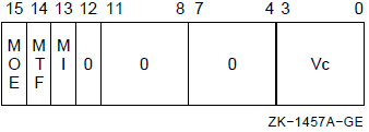
Exceptions
- access control violation
- translation not valid
- vector alignment
Description
The source operand vector is fetched from memory and is written to vector destination register Vc. The length of the vector is specified by VLR. The virtual address of the source vector is computed using the base address and the stride. The address of element i (0 LEQU i LEQU (VLR-1)) is computed as{base+{i*stride}}. The stride can be positive, negative, or zero.
In VLDL, bits <31:0> of each destination vector element receive the memory data and bits <63:32> are UNPREDICTABLE.
If any vector element operated upon is not naturally aligned in memory, a vector alignment exception occurs.
The results of VLD are unaffected by the setting of cntrl <MI>. For more details about the use of cntrl <MI>, see Section 10.3.3, ''Modify Intent Bit''.
If the addressing mode of the BASE operand is immediate, the results of the instruction are UNPREDICTABLE.
An implementation may load the elements of the vector in any order, and more than once. When a vector processor memory management exception occurs, the contents of the destination vector elements are UNPREDICTABLE.
VGATH
VGATH — Gather Memory Data into Vector Register
Format
VGATHL [/M[0 | 1]] base, Vb, Vc VGATHQ [/M[0 | 1]] base, Vb, Vc Architecture
Format
opcode cntrl.rw, base.ab
Opcodes
|
35FD |
VGATHL |
Gather Longword Vector from Memory to Vector Register |
|
37FD |
VGATHQ |
Gather Quadword Vector from Memory to Vector Register |
vector_control_word

Exceptions
- access control violation
- translation not valid
- vector alignment
Description
The source operand vector is fetched from memory and is written to vector destination register Vc. The length of the vector is specified by VLR. The virtual address of the vector is computed using the base address and the 32-bit offsets in vector register Vb. The address of element i (0 LEQU i LEQU(VLR-1)) is computed as {base+Vb[i]}. The 32-bit offset can be positive,negative, or zero.
In VGATHL, bits <31:0> of each destination vector element receive the memory data and bits <63:32> are UNPREDICTABLE.
If any vector element operated upon is not naturally aligned in memory, a vector alignment exception occurs.
The results of VGATH are unaffected by the setting of cntrl <MI>.For more details about the use of cntrl <MI>, see Section 10.3.3, ''Modify Intent Bit''.
If the addressing mode of the BASE operand is immediate, the results of the instruction are UNPREDICTABLE.
An implementation may load the elements of the vector in any order, and more than once. When a vector processor memory management exception occurs, the contents of the destination vector elements are UNPREDICTABLE.
If the same vector register is used as both source and destination, the result of the VGATH is UNPREDICTABLE.
VST
VST — Store Vector Register Data into Memory
Format
VSTL [/0 |1] Vc, base, stride []VSTQ [/0 |1] Vc, base, stride []Architecture
Format
opcode cntrl.rw, base.ab, stride.rl
Opcodes
|
9CFD |
VSTL |
Store Longword Vector from Vector Register to Memory |
|
9EFD |
VSTQ |
Store Quadword Vector from Vector Register to Memory |
vector_control_word
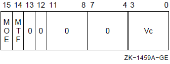
Exceptions
- access control violation
- translation not valid
- vector alignment
- modify
Description
The source operand in vector register Vc is written to memory. The length of the vector is specified by the Vector Length Register (VLR). The virtual address of the destination vector is computed using the base address and the stride. The address of element i (0 LEQU i LEQU (VLR-1)) is computed as {base+{i*stride}}. The stride can be positive, negative, or zero.
If any vector element operated upon is not naturally aligned in memory, a vector alignment exception occurs.
For a nonzero stride value, an implementation may store the vector elements in parallel; therefore the order in which these elements are stored is UNPREDICTABLE. Furthermore, if the nonzero stride causes result locations in memory to overlap, then the values stored in the overlapping result locations are also UNPREDICTABLE.
For a stride value of zero, the highest numbered register element destined for the single memory location becomes the final value of that location.
When a vector processor memory management exception occurs, it is UNPREDICTABLE whether the vector processor writes any result location for which an exception did not occur. If the fault condition can be eliminated by software and the instruction restarted, then the vector processor will ensure that all destination locations are written.
If the destination vector overlaps the vector instruction control word, base, or stride operand, the result of the instruction is UNPREDICTABLE.
If the addressing mode of the BASE operand is immediate, the results of the instruction are UNPREDICTABLE.
VSCAT
VSCAT — Scatter Vector Register Data into Memory
Format
VSCATL [/0 |1] Vc, base, Vb VSCATQ [/0 |1] Vc, base, Vb Architecture
Format
opcode cntrl.rw, base.ab
Opcodes
|
9DFD |
VSCATL |
Scatter Longword Vector from Vector Register to Memory |
|
9FFD |
VSCATQ |
Scatter Quadword Vector from Vector Register to Memory |
vector_control_word
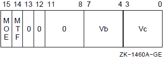
Exceptions
- access control violation
- translation not valid
- vector alignment
- modify
Description
The source vector operand Vc is written to memory. The length of the vector is specified by the Vector Length Register (VLR) register. The virtual address of the destination vector is computed using the base address operand and the 32-bit offsets in vector register Vb. The address of element i (0 LEQU i LEQU(VLR-1)) is computed as {base+Vb[i]}. The 32-bit offset can be positive,negative, or zero.
If any vector element operated upon is not naturally aligned in memory, a vector alignment exception occurs.
An implementation may store the vector elements in parallel; therefore, the order in which elements are stored to different memory locations is UNPREDICTABLE. In the case where multiple elements are destined for the same memory location, the highest numbered element among them becomes the final value of that location.
When a vector processor memory management exception occurs, it is UNPREDICTABLE whether the vector processor writes any result location for which an exception did not occur. If the fault condition can be eliminated by software and the instruction restarted, then the vector processor will ensure that all destination locations are written.
If the destination vector overlaps the vector instruction control word or base operand, the result of the instruction is UNPREDICTABLE.
If the addressing mode of the BASE operand is immediate, the results of the instruction are UNPREDICTABLE.
10.11. Vector Integer Instructions
This section describes VAX vector architecture integer instructions.
VADDL
VADDL — Vector Integer Add
Format
vector + vector: VVADDL [/0 | 1] Va, Vb, Vc scalar + vector: VSADDL [/0 | 1] scalar, Vb, Vc Architecture
Format
vector + vector: opcode cntrl.rw
scalar + vector: opcode cntrl.rw, addend.rl
Opcodes
|
80FD |
VVADDL |
Vector Vector Add Longword |
|
81FD |
VSADDL |
Vector Scalar Add Longword |
vector_control_word
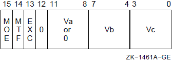
Exceptions
- integer overflow
Description
The scalar addend or Va operand is added, element-wise, to vector register Vb and the 32-bit sum is written to vector register Vc. Only bits <31:0> of each vector element participate in the operation. Bits <63:32> of the elements of vector register Vc are UNPREDICTABLE. The length of the vector is specified by the Vector Length Register (VLR).
If integer overflow is detected and cntrl <EXC> is set, the exception type and destination register number are recorded in the Vector Arithmetic Exception Register (VAER) and the vector operation is allowed to complete. On integer overflow, the low-order 32 bits of the true result are stored in the destination element.
VCMPL
VCMPL — Vector Integer Compare
Format
vector–vector: {VVGTRL | VVEQLL |VVLSSL |VVLEQL|VVNEQL|VVGEQL} [/0|1] Va, Vb scalar–vector: {VSGTRL|VSEQLL|VSLSSL|VSLEQL|VSNEQL|VSGEQL} [/0|1] src, Vb Architecture
Format
vector–vector: opcode cntrl.rw
scalar–vector: opcode cntrl.rw, src.rl
Opcodes
|
C0FD |
VVCMPL |
Vector Vector Compare Longword |
|
C1FD |
VSCMPL |
Vector Scalar Compare Longword |
vector_control_word
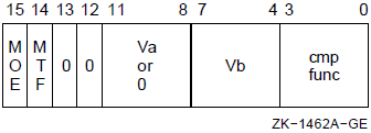
Description
The scalar or Va operand is compared, element-wise, with vector register Vb. The length of the vector is specified by the Vector Length Register (VLR). For each element comparison, if the specified relationship is true, the Vector Mask Register bit (VMR <i>) corresponding to the vector element is set to one; otherwise, it is cleared. If cntrl <MOE> is set, VMR bits corresponding to elements that do not match cntrl <MTF> are left unchanged. VMR bits beyond the vector length are left unchanged. Only bits <31:0> of each vector element participate in the operation.
VMULL
VMULL — Vector Integer Multiply
Format
vector * vector: VVMULL [/V[0|1]] Va, Vb, Vc scalar * vector: VSMULL [/V[0|1]] scalar, Vb, Vc Architecture
Format
vector * vector: opcode cntrl.rw
scalar * vector: opcode cntrl.rw, mulr.rl
Opcodes
|
A0FD |
VVMULL |
Vector Vector Multiply Longword |
|
A1FD |
VSMULL |
Vector Scalar Multiply Longword |
vector_control_word
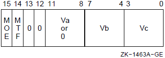
Exceptions
- integer overflow
Description
The scalar multiplier or vector operand Va is multiplied, element wise, by vector operand Vb and the least significant 32 bits of the signed 64-bit product are written to vector register Vc. Only bits <31:0> of each vector element participate in the operation. Bits <63:32> of the elements of vector register Vc are UNPREDICTABLE. The length of the vector is specified by the Vector Length Register (VLR).
If integer overflow is detected and cntrl <EXC> is set, the exception condition type and destination register number are recorded in the Vector Arithmetic Exception Register (VAER) and the vector operation is allowed to complete. On integer overflow, the low-order 32 bits of the true result are stored in the destination element.
VSUBL
VSUBL — Vector Integer Subtract
Format
vector–vector: VVSUBL [/V[0 | 1]] Va, Vb, Vc scalar–vector: VSSUBL [/V[0 | 1]] scalar, Vb, Vc Architecture
Format
vector–vector: opcode cntrl.rw
scalar–vector: opcode cntrl.rw, min.rl
Opcodes
|
88FD |
VVSUBL |
Vector Vector Subtract Longword |
|
89FD |
VSSUBL |
Vector Scalar Subtract Longword |
vector_control_word
Exceptions
- integer overflow
Description
The vector operand Vb is subtracted, element-wise, from the scalar minuend or vector operand Va. The 32-bit difference is written to vector register Vc. Only bits <31:0> of each vector element participate in the operation. Bits <63:32> of the elements of vector register Vc are UNPREDICTABLE. The length of the vector is specified by the Vector Length Register (VLR).
If integer overflow is detected and cntrl <EXC> is set, the exception condition type and destination register number are recorded in the Vector Arithmetic Exception Register (VAER) and the vector operation is allowed to complete. On integer overflow, the low-order 32 bits of the true result are stored in the destination element.
10.12. Vector Logical and Shift Instructions
This section describes VAX vector architecture logical and shift instructions.
VBIC, VBIS, and VXOR
VBIC, VBIS, and VXOR — Vector Logical Functions
Format
vector op vector: {VVBISL|VVXORL|VVBICL} [/V[0|1]] Va, Vb, Vc vector op scalar: {VSBISL|VSXORL|VSBICL} [/V[0|1]] scalar, Vb, Vc Architecture
Format
vector op vector: opcode cntrl.rw
vector op scalar: opcode cntrl.rw, src.rl
Opcodes
|
C8FD |
VVBISL |
Vector Vector Bit Set Longword |
|
E8FD |
VVXORL |
Vector Vector Exclusive-OR Longword |
|
CCFD |
VVBICL |
Vector Vector Bit Clear Longword |
|
C9FD |
VSBISL |
Vector Scalar Bit Set Longword |
|
E9FD |
VSXORL |
Vector Scalar Exclusive-OR Longword |
|
CDFD |
VSBICL |
Vector Scalar Bit Clear Longword |
vector_control_word
Exceptions
- None.
Description
The scalar src or vector operand Va is combined, element wise, using the specified Boolean function, with vector register Vb and the result is written to vector register Vc. Only bits <31:0> of each vector element participate in the operation. Bits <63:32> of the elements of Vb are written into bits <63:32> of the corresponding elements of Vc. The length of the vector is specified by the Vector Length Register (VLR).
VSL
VSL — Vector Shift Logical
Format
vector shift count: {VVSRLL|VVSLLL [/V[0|1]] Va, Vb, Vc scalar shift count: {VSSRLL|VSSLLL [/V[0|1]] cnt, Vb, Vc Architecture
Format
vector shift count: opcode cntrl.rw
scalar shift count: opcode cntrl.rw, cnt.rl
Opcodes
|
E0FD |
VVSRLL |
Vector Vector Shift Right Logical Longword |
|
E4FD |
VVSLLL |
Vector Vector Shift Left Logical Longword |
|
E1FD |
VSSRLL |
Vector Scalar Shift Right Logical Longword |
|
E5FD |
VSSLLL |
Vector Scalar Shift Left Logical Longword |
vector_control_word
Exceptions
- None.
Description
Each element in vector register Vb is shifted logically left or right 0 to 31 bits as specified by a scalar count operand or vector register Va. The shifted results are written to vector register Vc. Zero bits are propagated into the vacated bit positions. Only bits <4:0> of the count operand and bits <31:0> of each Vb element participate in the operation. Bits <63:32> of the elements of vector register Vc are UNPREDICTABLE. The length of the vector is specified by the Vector Length Register (VLR).
10.13. Vector Floating-Point Instructions
The VAX vector architecture provides instructions for operating on F_floating, D_floating, and G_floating operand formats. The floating-point arithmetic instructions are add, subtract, compare, multiply, and divide. Data conversion instructions are provided to convert operands between D_floating, G_floating, F_floating, and longword integer.
Rounding is performed using standard VAX rounding rules. The accuracy of the vector floating-point instructions matches that of the scalar floating-point instructions. Refer to the section on floating-point instructions in the VAX Architecture Reference Manual for more information.
10.13.1. Vector Floating-Point Exception Conditions
All vector floating-point exception conditions occur asynchronously with respect to the scalar processor. These exception conditions do not interrupt the scalar processor. If the exception condition is enabled, then the exception condition type and destination register number are recorded in the Vector Arithmetic Exception Register (VAER), and a reserved operand in the format of the instruction's data type is written into the destination register element. Encoded in this reserved operand is the exception condition type. After recording the exception and writing the appropriate result into the destination register element, the instruction encountering the exception continues executing to completion.
If a vector convert floating to integer instruction encounters a source element that is a reserved operand, an UNPREDICTABLE result rather than operand is written into the destination register element.
Figure 10.13, ''Encoding of the Reserved Operand'' shows the encoding of the reserved operand that is written for vector floating-point exceptions. Consistent with the definition of a reserved operand, the sign bit (bit <15>) is one and the exponent (bits <14:7> for F_floating and D_floating, and bits <14:4> for G_floating) is zero. When the reserved operand is written in F_floating or D_floating format, bits <6:4> are also zero. The exception condition type (ETYPE) is encoded in bits <3:0>, as shown in Table 10.16, ''Encoding of the Exception Condition Type (ETYPE)''. If a reserved operand is divided by zero, both ETYPE bits may be set. The state of all other bits in the result(denoted by shading) is UNPREDICTABLE.
If the floating underflow exception condition is suppressed by cntrl <EXC>, a zero result is written to the destination register element and no further action is taken. Floating overflow, floating divide by zero, and floating reserved operand are always enabled.
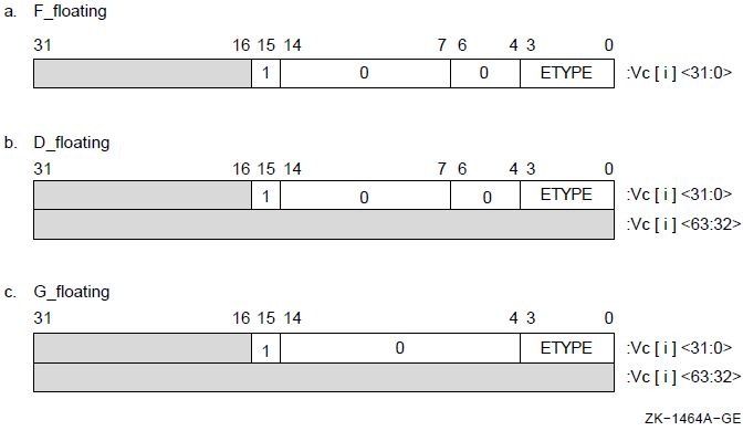 |
|
Bit |
Exception Condition Type |
|---|---|
|
<0> |
Floating underflow |
|
<1> |
Floating divide by zero |
|
<2> |
Floating reserved operand |
|
<3> |
Floating overflow |
10.13.2. Floating-Point Instructions
This section describes VAX vector architecture floating-point instructions.
VADD
VADD — Vector Floating Add
Format
vector + vector: {VVADDF|VVADDD|VVADDG} [/U[0|1]] Va, Vb, Vc scalar + vector: {VSADDF|VSADDD|VSADDG [/U[0|1]] scalar, Vb, Vc Architecture
Format
vector + vector:
opcode cntrl.rw
scalar + vector (F_floating):
opcode cntrl.rw, addend.rl
scalar + vector (D_ and G_floating):
opcode cntrl.rw, addend.rq
Opcodes
|
84FD |
VVADDF |
Vector Vector Add F_Floating |
|
85FD |
VSADDF |
Vector Scalar Add F_Floating |
|
86FD |
VVADDD |
Vector Vector Add D_Floating |
|
87FD |
VSADDD |
Vector Scalar Add D_Floating |
|
82FD |
VVADDG |
Vector Vector Add G_Floating |
|
83FD |
VSADDG |
Vector Scalar Add G_Floating |
vector_control_word
Exceptions
- floating overflow
- floating reserved operand
- floating underflow
Description
The source addend or vector operand Va is added, element-wise, to vector register Vb and the sum is written to vector register Vc. The length of the vector is specified by the Vector Length Register (VLR).
In Vx ADDF, only bits <31:0> of each vector element participate in the operation. Bits <63:32> of the destination vector elements are UNPREDICTABLE.
If a floating underflow occurs when cntrl <EXC> is set or if a floating overflow or floating reserved operand occurs, an encoded reserved operand is stored as the result and the exception condition type and destination register number are recorded in the Vector Arithmetic Exception Register (VAER). The vector operation is then allowed to complete. If cntrl <EXC> is clear, zero is written to the destination element when an exponent underflow occurs and no other action is taken.
VCMP
VCMP — Vector Floating Compare
Format
vector–vector: {VVGTRF|VVGTRD|VVGTRG|VVEQLF|VVEQLD|VVEQLG|VVLSSF|VVLSSD|VVLSSG|VVLEQF|VVLEQD|VVLEQG|VVNEQF|VVNEQD|VVNEQG|VVGEQF|VVGEQD|VVGEQG}
[/U[0|1]] Va, Vb scalar–vector: {VSGTRF|VSGTRD|VSGTRG|VSEQLF|VSEQLD|VSEQLG|VSLSSF|VSLSSD|VSLSSG|VSLEQF|VSLEQD|VSLEQG|VSNEQF|VSNEQD|VSNEQG|VSGEQF|VSGEQD|VSGEQG}
[/U[0|1]] src, Vb Architecture
Format
vector–vector:
opcode cntrl.rw
scalar–vector (F_floating):
opcode cntrl.rw, src.rl
scalar–vector (D_ and G_floating):
opcode cntrl.rw, src.rq
Opcodes
|
C4FD |
VVCMPF |
Vector Vector Compare F_floating |
|
C5FD |
VSCMPF |
Vector Scalar Compare F_floating |
|
C6FD |
VVCMPD |
Vector Vector Compare D_floating |
|
C7FD |
VSCMPD |
Vector Scalar Compare D_floating |
|
C2FD |
VVCMPG |
Vector Vector Compare G_floating |
|
C3FD |
VSCMPG |
Vector Scalar Compare G_floating |
vector_control_word
Note
Cntrl <3> should be zero; if it is set, the results of the instruction are UNPREDICTABLE.
Exceptions
- floating reserved operand
Description
The scalar or vector operand Va is compared, element-wise, with vector register Vb. The length of the vector is specified by the Vector Length Register (VLR).For each element comparison, if the specified relationship is true, the Vector Mask Register bit (VMR <i>) corresponding to the vector element is set to one, otherwise it is cleared. If cntrl <MOE> is set, VMR bits corresponding to elements that do not match cntrl <MTF> are left unchanged. VMR bits beyond the vector length are left unchanged. If an element being compared is a reserved operand, VMR <i> is UNPREDICTABLE. In VxCMPF, only bits <31:0> of each vector element participate in the operation.
If a floating reserved operand exception occurs, the exception condition type is recorded in the Vector Arithmetic Exception Register (VAER) and the vector operation is allowed to complete.
Note that for this instruction, no bits are set in the VAER destination register mask when an exception occurs.
VVCVT
VVCVT — Vector Convert
Format
{VVCVTLF|VVCVTLD|VVCVTLG|VVCVTFL|VVCVTRFL|VVCVTFD|VVCVTFG|VVCVTDL|VVCVTDF|VVCVTRDL|VVCVTGL|VVCVTGF|VVCVTRGL}
[/U[0|1]] Vb, Vc Architecture
Format
opcode cntrl.rw
Opcodes
|
ECFD |
VVCVT |
Vector Convert |
vector_control_word
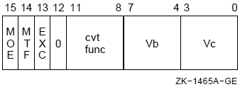
|
cntrl <11:8> |
Meaning |
|---|---|
|
1 1 1 1 |
CVTRGL (Convert Rounded G_Floating to Longword) |
|
1 1 1 0 |
Reserved? |
|
1 1 0 1 |
CVTGF (Convert Rounded G_Floating to F_Floating) |
|
1 1 0 0 |
CVTGL (Convert Truncated G_Floating to Longword) |
|
1 0 1 1 |
Reserved? |
|
1 0 1 0 |
CVTRD (Convert Rounded D_Floating to Longword) |
|
1 0 0 1 |
CVTDF (Convert Rounded D_Floating to F_Floating) |
|
1 0 0 0 |
CVTDL (Convert Truncated D_Floating to Longword) |
|
0 1 1 1 |
CVTFG (Convert F_Floating to G_Floating (exact)) |
|
0 1 1 0 |
CVTFD (Convert F_Floating to D_Floating (exact)) |
|
0 1 0 1 |
CVTRF (Convert Rounded F_Floating to Longword) |
|
0 1 0 0 |
CVTFL (Convert Truncated F_Floating to Longword) |
|
0 0 1 1 |
CVTLG (Convert Longword to G_Floating (exact)) |
|
0 0 1 0 |
CVTLD (Convert Longword to D_Floating (exact)) |
|
0 0 0 1 |
CVTLF (Convert Rounded Longword to F_Floating) |
|
0 0 0 0 |
Reserved? |
Exceptions
- floating overflow
- floating reserved operand
- floating underflow
- integer overflow
Description
The vector elements in vector register Vb are converted and results are written to vector register Vc. Cntrl <11:8> specifies the conversion to be performed. The length of the vector is specified by the Vector Length Register (VLR). Bits <63:32> of Vc are UNPREDICTABLE for instructions that convert from D_floating or G_floating to F_floating or longword. When CVTRGL, CVTRDL, and CVTRFL round, the rounding is done in sign magnitude, before conversion to two's complement.
If an integer overflow occurs when cntrl <EXC> is set, the low-order 32 bits of the true result are written to the destination element as the result, and the exception condition type and destination register number are recorded in the Vector Arithmetic Exception Register (VAER). The vector operation is then allowed to complete. If integer overflow occurs when cntrl <EXC> is clear, the low-order 32 bits of the true result are written to the destination element, and no other action is taken.
For vector convert floating to integer, where the source element is a reserved operand, the value written to the destination element is UNPREDICTABLE. In addition, the exception type and destination register number are recorded in the VAER. The vector operation is then allowed to complete.
For vector convert floating to floating instructions, if floating underflow occurs when cntrl <EXC> is clear, zero is written to the destination element, and no other action is taken. The vector operation is then allowed to complete.
For vector convert floating to floating instructions, if floating underflow occurs with cntrl <EXC> set or if a floating overflow or reserved operand occurs, an encoded reserved operand is written to the destination element, and the exception condition type and destination register number are recorded in the VAER. The vector operation is then allowed to complete.
VDIV
VDIV — Vector Floating Divide
Format
vector/vector: {VVDIVF|VVDIVD|VVDIVG} [/U[0|1]] Va, Vb, Vc scalar/vector: {VSDIVF|VSDIVD|VSDIVG} [/U[0|1]] scalar, Vb, Vc Architecture
Format
vector/vector:
opcode cntrl.rw
scalar/vector (F_floating):
opcode cntrl.rw, divd.rl
scalar/vector (D_ and G_floating):
opcode cntrl.rw, divd.rq
Opcodes
|
ACFD |
VVDIVF |
Vector Vector Divide F_floating |
|
ADFD |
VSDIVF |
Vector Scalar Divide F_floating |
|
AEFD |
VVDIVD |
Vector Vector Divide D_floating |
|
AFFD |
VSDIVD |
Vector Scalar Divide D_floating |
|
AAFD |
VVDIVG |
Vector Vector Divide G_floating |
|
ABFD |
VSDIVG |
Vector Scalar Divide G_floating |
vector_control_word
Exceptions
- floating divide by zero
- floating overflow
- floating reserved operand
- floating underflow
Description
The scalar dividend or vector register Va is divided, element-wise, by the divisor in vector register Vb and the quotient is written to vector register Vc. The length of the vector is specified by the Vector Length Register (VLR).
In VxDIVF, only bits <31:0> of each vector element participate in the operation; bits <63:32> of the destination vector elements are UNPREDICTABLE.
If a floating underflow occurs when cntrl <EXC> is set or if a floating overflow, divide by zero, or reserved operand occurs, an encoded reserved operand is stored as the result and the exception condition type and destination register number are recorded in the Vector Arithmetic Exception Register (VAER). The vector operation is then allowed to complete. If cntrl <EXC> is clear, zero is written to the destination element when an exponent underflow occurs and no other action is taken.
VMUL
VMUL — Vector Floating Multiply
Format
vector * vector: VVMULF|VVMULD|VVMULG} [/U[0|1]] Va, Vb, Vc scalar * vector: {VSMULF|VSMULD|VSMULG} [/U[0|1]] scalar, Vb, Vc Architecture
Format
vector * vector:
opcode cntrl.rw
scalar * vector (F_floating):
opcode cntrl.rw, mulr.rl
scalar * vector (D_ and G_floating):
opcode cntrl.rw, mulr.rq
Opcodes
|
A4FD |
VVMULF |
Vector Vector Multiply F_floating |
|
A5FD |
VSMULF |
Vector Scalar Multiply F_floating |
|
A6FD |
VVMULD |
Vector Vector Multiply F_floating |
|
A7FD |
VSMULD |
Vector Scalar Multiply D_floating |
|
A2FD |
VVMULG |
Vector Vector Multiply G_floating |
|
A3FD |
VSMULG |
Vector Scalar Multiply G_floating |
vector_control_word
Exceptions
- floating overflow
- floating reserved operand
- floating underflow
Description
The multiplicand in vector register Vb is multiplied, element-wise,by the scalar multiplier or vector operand Va and the product is written to vector register Vc. The length of the vector is specified by the Vector Length Register (VLR).
In VxMULF, only bits <31:0> of each vector element participate in the operation. Bits <63:32> of the destination vector elements are UNPREDICTABLE.
If a floating underflow occurs when cntrl <EXC> is set or if a floating overflow or reserved operand occurs, an encoded reserved operand is stored as the result and the exception condition type and destination register number are recorded in the Vector Arithmetic Exception Register (VAER). The vector operation is then allowed to complete. If cntrl <EXC> is clear, zero is written to the destination element when an exponent underflow occurs and no other action is taken.
VSUB
VSUB — Vector Floating Subtract
Format
vector–vector: {VVSUBF|VVSUBD|VVSUBG} [/U[0|1]] Va, Vb, Vc scalar–vector: {VSSUBF|VSSUBD|VSSUBG} [/U[0|1]] scalar, Vb, Vc Architecture
Format
vector–vector:
opcode cntrl.rw
scalar–vector (F_floating):
opcode cntrl.rw, min.rl
scalar–vector (D_ and G_floating):
opcode cntrl.rw, min.rq
Opcodes
|
8CFD |
VVSUBF |
Vector Vector Subtract F_floating |
|
8DFD |
VSSUBF |
Vector Scalar Subtract F_floating |
|
8EFD |
VVSUBD |
Vector Vector Subtract D_floating |
|
8FFD |
VSSUBD |
Vector Scalar Subtract D_floating |
|
8AFD |
VVSUBG |
Vector Vector Subtract G_floating |
|
8BFD |
VSSUBG |
Vector Scalar Subtract G_floating |
vector_control_word
Exceptions
- floating overflow
- floating reserved operand
- floating underflow
Description
Vector register Vb is subtracted, element-wise, from the scalar minuend or vector register Va and the difference is written to vector register Vc. The length of the vector is specified by the Vector Length Register (VLR).
In VxSUBF, only bits <31:0> of each vector element participate in the operation; bits <63:32> of the destination vector elements are UNPREDICTABLE.
If a floating underflow occurs when cntrl <EXC> is set or if a floating overflow or reserved operand occurs, an encoded reserved operand is stored as the result and the exception condition type and destination register number are recorded in the Vector Arithmetic Exception Register (VAER). The vector operation is then allowed to complete. If cntrl <EXC> is clear, zero is written to the destination element when an exponent underflow occurs and no other action is taken.
10.14. Vector Edit Instructions
This section describes VAX vector architecture edit instructions.
VMERGE
VMERGE — Vector Merge
Format
vector vector merge: VVMERGE [/0|1] Va, Vb, Vc vector scalar merge: VSMERGE|VSMERGEF|VSMERGED|VSMERGEG} [/0|1] src, Vb, Vc Architecture
Format
vector-vector: opcode cntrl.rw
vector-scalar: opcode cntrl.rw,src.rq
Opcodes
|
EEFD |
VVMERGE |
Vector Vector Merge |
|
EFFD |
VSMERGE |
Vector Scalar Merge |
vector_control_word

Exceptions
- None.
Description
The scalar src or vector operand Va is merged, element-wise, with vector register Vb and the resulting vector is written to vector register Vc. Thel ength of the vector operation is specified by the Vector Length Register(VLR).
For each vector element, i, if the corresponding Vector Mask Register bit(VMR <i>) matches cntrl <MTF>, src or Va[i] is written to the destination vector element Vc[i]. If VMR <i> does not match cntrl <MTF>, Vb[i] is written to the destination vector element.
IOTA
IOTA — Generate Compressed Iota Vector
Format
IOTA [/0 |1] stride, Vc []Architecture
Format
opcode cntrl.rw, stride.rl
Opcodes
|
EDFD |
IOTA |
Generate Compressed Iota Vector |
vector_control_word
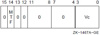
Exceptions
- None.
Description
IOTA constructs a vector of offsets for use by the vector gather/scatter instructions VGATH and VSCAT.
0*stride, 1*stride, 2*stride, 3*stride, ..., {VLR-1}*stride
The iota vector is then compressed using the contents of the Vector Mask Register (VMR). Elements of the iota vector for which the corresponding Vector Mask Register bit matches cntrl <MTF> are written in contiguous elements of the destination vector register Vc. Only bits <31:0> of each iota and destination vector element participate in the operation. Bits <63:32> of the destination vector elements are UNPREDICTABLE.
Note
tmp <- tmp + stride Value of tmp before above step: FFFFFF00 Value of Stride: FFFFFF00 Value of tmp + stride: 1 FFFFFE00 Since the overflow is ignored, the new value of tmp is FFFFFE00.
10.15. Miscellaneous Instructions
This section describes VAX vector architecture miscellaneous instructions.
MFVP
MFVP — Move from Vector Processor
Format
{MFVCR|MFVLR|MFVMRLO|MFVMRHI|SYNCH|MSYNCH} dst Architecture
Format
opcode regnum.rw, dst.wl
Opcodes
|
31FD |
MFVP |
Move from Vector Processor |
vector_control_word
None.
Exceptions
- None.
MFVP instructions that specify reserved values of the regnum operand produce UNPREDICTABLE results.
Description
This instruction can be used to read the Vector Count, Length, and Mask Registers, and to synchronize a scalar processor with its associated vector processor.
When the scalar processor issues an MFVP instruction to the vector processor,the scalar processor waits for the MFVP result to be written before processing other instructions.
MFVP from VCR or VLR does not read that register until all previous write operations to the register are completed. MFVP from VMR <31:0> or VMR <63:32> does not read that longword of VMR until all previous write operations to the same longword of VMR are completed; however, this is not true for previous write operations to the other longword.
SYNC allows software to ensure that the unreported exceptions of all previously issued vector instructions (including vector memory instructions in asynchronous memory management mode) are detected and reported to the scalar processor before the scalar processor proceeds with further instructions. For more details about SYNC and its exception reporting nature refer to Section 10.7.1, ''Scalar/Vector Instruction Synchronization (SYNC)''.
MSYNC allows software to ensure that all previously issued memory instructions of the scalar/vector processor pair are complete before the scalar processor proceeds with further instructions. For more details about MSYNC and its exception reporting nature, refer to Section 10.7.2, ''Scalar/Vector Memory Synchronization'', Memory Instruction Synchronization.
The value of the vector control register (VCR, VLR, VMR <31:0>,VMR <63:32>) delivered by an MFVP depends upon the value of certain vector register elements and vector control register bits. Unreported exceptions that occur in the production of these elements and control register bits are reported by the vector processor prior to the completion of the MFVP from the vector control register.
In addition, there are vector register elements and vector control register bits that the value of a vector control register delivered by an MFVP does not depend upon. It is UNPREDICTABLE whether unreported exceptions that occur in the production of these elements and control register bits are reported by the vector processor prior to the completion of the MFVP from the vector control register. Software must not rely upon the reporting of these exceptions prior to the completion of the MFVP for the correctness of program results.
Section 10.5.5, ''Dependencies Among Vector Results'' gives the necessary rules to determine what vector control register elements and vector control register bits the value of a vector control register delivered by an MFVP depends upon. Examples of MFVP exception reporting using these rules are found in Section 10.6.5, ''MFVP Exception Reporting Examples''.
The operation of the MFVP does not complete.
No longword result is written to the scalar destination of the MFVP by the scalar processor.
The MFVP itself (rather than the next vector instruction) takes either a vector processor disabled fault or a memory management fault.
After the appropriate fault has been serviced, the MFVP may be returned to through an REI. If both exception conditions are encountered by an MFVP, then the MFVP itself takes a vector processor disabled fault. In this case, after the vector processor disabled fault has been serviced, returning to the MFVP instruction will cause the asynchronous memory management exception to be reported.
MTVP
MTVP — Move to Vector Processor
Format
{MTVCR|MTVLR|MTVMRLO|MTVMRHI} src Architecture
Format
opcode regnum.rw, src.rl
Opcodes
|
A9FD |
MTVP |
Move to Vector Processor |
vector_control_word
None.
Exceptions
- None.
Move to Vector Processor instructions that specify reserved values of the regnum operand produce UNPREDICTABLE results.
Description
This instruction can be used to write the Vector Count, Length,and Mask Registers.
The new value of VCR, VLR, or VMR does not affect any prior instructions. The new value remains in effect for all subsequent vector instructions executed until a new value is loaded.
VSYNC
VSYNC — Synchronize Vector Memory Access
Format
VSYNCH Architecture
Format
opcode regnum.rw
Opcodes
|
A8FD |
VSYNC |
Synchronize Vector Memory Access |
vector_control_word
None.
Exceptions
- None.
Synchronize Vector Memory Access instructions that specify reserved values of the regnum operand produce UNPREDICTABLE results.
Description
The VSYNC instruction can be used to synchronize memory access within the vector processor. The instruction allows software to order the conflicting memory accesses of vector-memory instructions issued after VSYNC with those of vector-memory instructions issued before VSYNC. Specifically, VSYNC forces the access of a memory location by any subsequent vector-memory instruction to wait for (depend upon) the completion of all prior conflicting accesses of that location by previous vector-memory instructions. See Section 10.7.1, ''Scalar/Vector Instruction Synchronization (SYNC)'' for more details.
See Section 10.7.5, ''Required Use of Memory Synchronization Instructions'' for the conditions when VSYNC is not required before a vector store instruction.
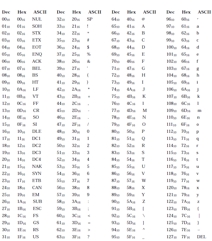
Appendix B. Hexadecimal/Decimal Conversion
The following table lists the decimal value for each possible hexadecimal value in each byte of a longword. The following sections contain instructions to use the table to convert hexadecimal numbers to decimal and decimal numbers to hexadecimal.
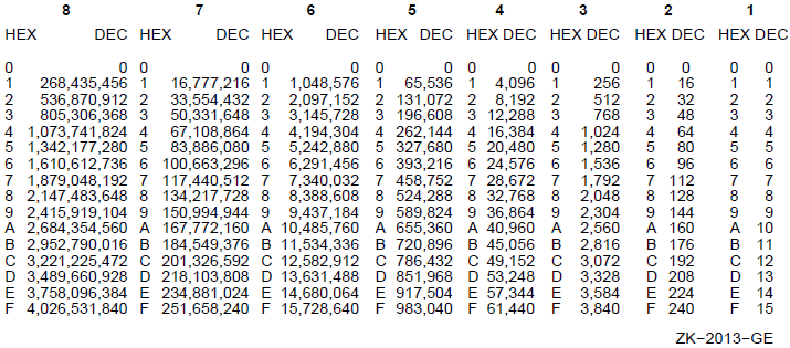 |
B.1. Hexadecimal to Decimal
For each integer position of the hexadecimal value, locate the corresponding column integer and record its decimal equivalent in the conversion table. Add the decimal equivalent to obtain the decimal value.
D0500AD0 (hex) = ?(dec)
D0000000 = 3,489,660,928
500000 = 5,242,880
A00 = 2,560
D0 = 208
D0500AD0 = 3,494,906,576B.2. Decimal to Hexadecimal
In the conversion table, locate the largest decimal value that does not exceed the decimal number to be converted.
Record the hexadecimal equivalent, followed by the number of zeros that corresponds to the integer column minus 1.
Subtract the table decimal value from the decimal number to be converted.
Repeat steps 1 to 3 until the subtraction balance equals zero. Add the hexadecimal equivalents to obtain the hexadecimal value.
22,466 (dec) = ?(hex)
20,480 = 5000 22,466
1,792 = 700 -20,480
192 = C0
2 = 2 1,986
- 1,792
22,466 = 57C2
194
- 192
2
- 2
0B.3. Powers of 2 and 16
Powers of 2 Powers of 16
2**n n 16**n n
256 8 1 0
512 9 16 1
1024 10 256 2
2048 11 4096 3
4096 12 65536 4
8192 13 1048576 5
16384 14 16777216 6
32768 15 268435456 7
65536 16 4294967296 8
131072 17 68719476736 9
262144 18 1099511627776 10
524288 19 17592186044416 11
1048576 20 281474976710656 12
2097152 21 4503599627370496 13
4194304 22 72057594037927936 14
8388608 23 1152921504606846976 15
16777216 24 Appendix C. VAX MACRO Assembler Directives and Language Summary
This appendix summarizes the general assembler and macro directives (in alphabetical order), special characters, unary operators, binary operators,and addressing modes.
C.1. Assembler Directives
|
Format |
Operation |
|---|---|
|
.ADDRESS address-list |
Stores successive longwords of address data |
|
.ALIGN keyword[,expression] |
Aligns the location counter to the boundary specified by the keyword |
|
.ALIGN integer[,expression] |
Aligns location counter to the boundary specified by (2^integer) |
|
.ASCIC string |
Stores the ASCII string (enclosed in delimiters), preceded by a count byte |
|
.ASCID string |
Stores the ASCII string (enclosed in delimiters), preceded by a string descriptor |
|
.ASCII string |
Stores the ASCII string (enclosed in delimiters) |
|
.ASCIZ string |
Stores the ASCII string (enclosed in delimiters) followed by a 0 byte |
|
.BLKA expression |
Reserves longwords of address data |
|
.BLKB expression |
Reserves bytes for data |
|
.BLKD expression |
Reserves quadwords for double-precision floating-point data |
|
.BLKF expression |
Reserves longwords for single-precision floating-point data |
|
.BLKG expression |
Reserves quadwords for floating-point data |
|
.BLKH expression |
Reserves octawords for extended-precision floating-point data |
|
.BLKL expression |
Reserves longwords for data |
|
.BLKO expression |
Reserves octawords for data |
|
.BLKQ expression |
Reserves quadwords for data |
|
.BLKW expression |
Reserves words for data |
|
.BYTE expression-list |
Generates successive bytes of data;each byte contains the value of the specified expression |
|
.CROSS |
Enables cross-referencing of all symbols |
|
.CROSS symbol-list |
Cross-references specified symbols |
|
.DEBUG symbol-list |
Makes symbol names known to the debugger |
|
.DEFAULT DISPLACEMENT, keyword |
Specifies the default displacement length for the relative addressing modes |
|
.D_FLOATING literal-list |
Generates 8-byte double-precision floating-point data |
|
.DISABLE argument-list |
Disables functions specified in argument-list |
|
.DOUBLE literal-list |
Equivalent to .D_FLOATING |
|
.DSABL argument-list |
Equivalent to .DISABLE |
|
.ENABL argument-list |
Equivalent to .ENABLE |
|
.ENABLE argument-list |
Enables functions specified in argument-list |
|
.END [symbol] |
Indicates logical end of source program;optional symbol specifies transfer address |
|
.ENDC |
Indicates end of conditional assembly block |
|
.ENDM [macro-name] |
Indicates end of macro definition |
|
.ENDR |
Indicates end of repeat block |
|
.ENTRY symbol [,expression] |
Procedure entry directive |
|
.ERROR [expression] ;comment |
Displays specified error message |
|
.EVEN |
Ensures that the current location counter has an even value (adds 1 if it is odd) |
|
.EXTERNAL symbol-list |
Indicates specified symbols are externally defined |
|
.EXTRN symbol-list |
Equivalent to .EXTERNAL |
|
.F_FLOATING literal-list |
Generates 4-byte single-precision floating-point data |
|
.FLOAT literal-list |
Equivalent to .F_FLOATING |
|
.G_FLOATING literal-list |
Generates 8-byte G_floating-point data |
|
.GLOBAL symbol-list |
Indicates specified symbols are global symbols |
|
.GLOBL |
Equivalent to .GLOBAL |
|
.H_FLOATING literal-list |
Generates 16-byte extended-precision H_floating-point data |
|
.IDENT string |
Provides means of labeling object module with additional data |
|
.IF condition [,] argument (s) |
Begins a conditional assembly block of source code, which is included in the assembly only if the stated condition is met with respect to the arguments specified |
|
.IFF |
Equivalent to .IF_FALSE |
|
.IF_FALSE |
Appears only within a conditional assembly block; begins block of code to be assembled if the original condition tests false |
|
.IFT |
Equivalent to .IF_TRUE |
|
.IFTF |
Equivalent to .IF_TRUE_FALSE |
|
.IF_TRUE |
Appears only within a conditional assembly block;begins block of code to be assembled if the original condition tests true |
|
.IF_TRUE_FALSE |
Appears only within a conditional assembly block; begins block of code to be assembled unconditionally |
|
.IIF condition argument(s), statement |
Acts as a 1-line conditional assembly block where the condition is tested for the argument specified; the statement is assembled only if the condition tests true |
|
.IRP symbol, <argument list> |
Replaces a formal argument with successive actual arguments specified in an argument list |
|
.IRPC symbol, <BIT_STRING> |
Replaces a formal argument with successive single characters specified in string |
|
.LIBRARY macro-library-name |
Specifies a macro library |
|
.LINK "file-spec" [/qualifier[=(module-name[,...])],...] |
Includes linker option records in object module |
|
.LIST [argument-list] |
Equivalent to .SHOW |
|
.LONG expression-list |
Generates successive longwords of data; each longword contains the value of the specified expression |
|
.MACRO macro-name [formal-argument-list] |
Begins a macro definition |
|
.MASK symbol [,expression] |
Reserves a word for and copies a register save mask |
|
.MCALL macro-name-list |
Specifies the system or user-defined macros, or both, in libraries that are required to assemble the source program |
|
.MDELETE macro-name-list |
Deletes from memory the macro definitions of the macros in the list |
|
.MEXIT |
Exits from the expansion of a macro before the end of the macro is encountered |
|
.NARG symbol |
Determines the number of arguments in the current macro call |
|
.NCHR symbol, <BIT_STRING> |
Determines the number of characters in a specified character string |
|
.NLIST [argument-list] |
Equivalent to .NOSHOW |
|
.NOCROSS |
Disables cross-referencing of all symbols |
|
.NOCROSS symbol-list |
Disables cross-referencing of specified symbols |
|
.NOSHOW |
Decrements listing level count |
|
.NOSHOW argument-list |
Controls listing of macros and conditional assembly blocks |
|
.NTYPE symbol,operand |
Can appear only within a macro definition; equates the symbol to the addressing mode of the specified operand |
|
.OCTA literal |
Stores 16 bytes of data |
|
.OCTA symbol |
Stores 16 bytes of data |
|
.ODD |
Ensures that the current location counter has an odd value (adds 1 if it is even) |
|
.OPDEF opcode value, operand-descriptor-list |
Defines an opcode and its operand list |
|
.PACKED decimal-string [,symbol] |
Generates packed decimal data, 2 digits per byte |
|
.PAGE |
Causes the assembly listing to skip to the top of the next page and to increment the page count |
|
.PRINT [expression] ;comment |
Displays the specified message |
|
.PSECT |
Begins or resumes the blank program section |
|
.PSECT section-name argument list |
Begins or resumes a user-defined program section |
|
.QUAD literal |
Stores 8 bytes of data |
|
.QUAD symbol |
Stores 8 bytes of data |
|
.REF1 operand |
Generates byte operand |
|
.REF2 operand |
Generates word operand |
|
.REF4 operand |
Generates longword operand |
|
.REF8 operand |
Generates quadword operand |
|
.REF16 operand |
Generates octaword operand |
|
.REPEAT expression |
Begins a repeat block; the section of code up to the next .ENDR directive is repeated the number of times specified by the expression |
|
.REPT |
Equivalent to .REPEAT |
|
.RESTORE |
Equivalent to .RESTORE_PSECT |
|
.RESTORE_PSECT |
Restores program section context from the program section context stack |
|
.SAVE [LOCAL_BLOCK] |
Equivalent to .SAVE_PSECT |
|
.SAVE_PSECT [LOCAL_BLOCK] |
Saves current program section context on the program section context stack |
|
.SBTTL comment-string |
Equivalent to .SUBTITLE |
|
.SHOW |
Increments listing level count |
|
.SHOW argument-list |
Controls listing of macros and conditional assembly blocks |
|
.SIGNED_BYTE expression-list |
Stores successive bytes of signed data |
|
.SIGNED_WORD expression-list |
Stores successive words of signed data |
|
.SUBTITLE comment-string |
Causes the specified string to be printed as part of the assembly listing page header; the string component of each .SUBTITLE is collected into a table of contents at the beginning of the assembly listing |
|
.TITLE module-name comment-string |
Assigns the first 15 characters in the string as an object module name and causes the string to appear on each page of the assembly listing |
|
.TRANSFER symbol |
Directs the linker to redefine the value of the global symbol for use in a shareable image |
|
.WARN [expression] ;comment |
Displays specified warning message |
|
.WEAK symbol-list |
Indicates that each of the listed symbols has the weak attribute |
|
.WORD expression-list |
Generates successive words of data;each word contains the value of the corresponding specified expression |
C.2. Special Characters
| Character | Character Name | Functions |
|---|---|---|
|
_ |
Underscore |
Character in symbol names |
|
$ |
Dollar sign |
Character in symbol names |
|
. |
Period |
Character in symbol names, current location counter, and decimal point |
|
: |
Colon |
Label terminator |
|
= |
Equal sign |
Direct assignment operator and macro keyword argument terminator |
|
|
Tab |
Field terminator |
|
|
Space |
Field terminator |
|
# |
Number sign |
Immediate addressing mode indicator |
|
@ |
At sign |
Deferred addressing mode indicator and arithmetic shift operator |
|
, |
Comma |
Field, operand, and item separator |
|
; |
Semicolon |
Comment field indicator |
|
+ |
Plus sign |
Autoincrement addressing mode indicator,unary plus operator, and arithmetic addition operator |
|
- |
Minus sign |
Autodecrement addressing mode indicator, unary minus operator, arithmetic subtraction operator, and line continuation indicator |
|
* |
Asterisk |
Arithmetic multiplication operator |
|
/ |
Slash |
Arithmetic division operator |
|
& |
Ampersand |
Logical AND operator |
|
! |
Exclamation point |
Logical inclusive OR operator |
|
\ |
Backslash |
Logical exclusive OR and numeric conversion indicator in macro arguments |
|
^ |
Circumflex |
Unary operator indicator and macro argument delimiter |
|
[ ] |
Square brackets |
Index addressing mode and repeat count indicators |
|
( ) |
Parentheses |
Register deferred addressing mode indicators |
|
<> |
Angle brackets |
Argument or expression grouping delimiters |
|
? |
Question mark |
Created label indicator in macro arguments |
|
' |
Apostrophe |
Macro argument concatenation indicator |
|
% |
Percent sign |
Macro string operators |
C.3. Operators
This section lists the VAX MACRO unary, binary, and macro string operators.
C.3.1. Unary Operators
| Unary Operator | Operator Name | Example | Effect |
|---|---|---|---|
|
+ |
Plus sign |
+A |
Results in the positive value of A (default) |
|
- |
Minus sign |
-A |
Results in the negative (two's complement) value of A |
|
^B |
Binary |
^B11000111 |
Specifies that 11000111 is a binary number |
|
^D |
Decimal |
^D127 |
Specifies that 127 is a decimal number |
|
^O |
Octal |
^034 |
Specifies that 34 is an octal number |
|
^X |
Hexadecimal |
^XFCF9 |
Specifies that FCF9 is a hexadecimal number |
|
^A |
ASCII |
^A/ABC/ |
Produces an ASCII string; the characters between the matching delimiters are converted to ASCII representation |
|
^M |
Register mask |
^M |
Specifies the registers R3, R4, and R5 in the register mask |
|
^F |
Floating point |
^F3.0 |
Specifies that 3.0 is a floating-point number |
|
^C |
Complement |
^C24 |
Produces the one's complement value of 24(decimal) |
C.3.2. Binary Operators
| Binary Operator | Operator Name | Example | Operation |
|---|---|---|---|
|
+ |
Plus sign |
A+B |
Addition |
|
- |
Minus sign |
A-B |
Subtraction |
|
* |
Asterisk |
A *B |
Multiplication |
|
/ |
Slash |
A/B |
Division |
|
@ |
At sign |
A@B |
Arithmetic Shift |
|
& |
Ampersand |
A &B |
Logical AND |
|
! |
Exclamation point |
A!B |
Logical inclusive OR |
|
\ |
Backslash |
A\B |
Logical exclusive OR |
C.3.3. Macro String Operators
|
Format |
Function |
|---|---|
|
%LENGTH(string) |
Returns the length of the string |
|
%LOCATE(string1,string2[,symbol]) |
Locates the substring string1 within string2 starting the search at the character position specified by symbol |
|
%EXTRACT(symbol1,symbol2,string) |
Extracts a substring from string that begins at character position specified by symbol1 and has a length specified by symbol2 |
C.4. Addressing Modes
Table C.6, ''Addressing Modes'' summarizes the VAX MACRO addressing modes.
|
Type |
Addressing Mode |
Format |
Hex Value |
Description |
Can Be Indexed? |
|---|---|---|---|---|---|
|
Key:
| |||||
|
General register |
Register |
Rn |
5 |
Register contains the operand. |
No |
|
Register deferred |
(Rn) |
6 |
Register contains the address of the operand. |
Yes | |
|
Autoincrement |
(Rn)+ |
8 |
Register contains the address of the operand; the processor increments the register contents by the size of the operand data type. |
Yes | |
|
Autoincrement deferred |
@(Rn)+ |
9 |
Register contains the address of the operand address; the processor increments the register contents by 4. |
Yes | |
|
Autodecrement |
-(Rn) |
7 |
The processor decrements the register contents by the size of the operand data type;the register then contains the address of the operand. |
Yes | |
|
Displacement |
|
|
The sum of the contents of the register and the displacement is the address of the operand; B^, W^, and L^ respectively indicate byte, word,and longword displacement. |
Yes | |
|
Displacement deferred |
|
|
The sum of the contents of the register and the displacement is the address of the operand address; B^, W^, and L^ respectively indicate, byte, word, and longword displacement. |
Yes | |
|
Literal |
|
|
The literal specified is the operand; the literal is stored as a short literal. |
No | |
|
Program counter |
Relative |
|
|
The address specified is the address of the operand; the address is stored as a displacement from the PC; B^, W^, and L^ respectively indicate byte,word, and longword displacement. |
Yes |
|
Relative deferred |
|
|
The address specified is the address of the operand address; the address specified is stored as a displacement from the PC; B^, W^, and L^ indicate byte, word, and longword displacement respectively. |
Yes | |
|
Absolute |
@#address |
9 |
The address specified is the address of the operand; the address specified is stored as an absolute virtual address, not as a displacement. |
Yes | |
|
Immediate |
|
|
The literal specified is the operand; the literal is stored as a byte, word, longword, or quadword. |
No | |
|
General |
G^address |
— |
The address specified is the address of the operand; if the address is defined as relocatable, the linker stores the address as a displacement from the PC; if the address is defined as an absolute virtual address, the linker stores the address as an absolute value. |
Yes | |
|
Index |
Index |
base-mode[Rx] |
4 |
The base-mode specifies the base address and the register specifies the index; the sum of the base address and the product of the contents of Rx and the size of the operand data type is the address of the operand; base mode can be any addressing mode except register, immediate, literal, index, or branch. |
No |
|
Branch |
Branch |
address |
— |
The address specified is the operand;this address is stored as a displacement from the PC; branch mode can only be used with the branch instructions. |
No |
Appendix D. Permanent Symbol Table Defined for Use with VAX MACRO
The permanent symbol table (PST) contains the symbols that VAX MACRO automatically recognizes. These symbols consist of both opcodes and assembler directives. Tables D.1, D.2, and D.3 present the opcodes (instruction set) in alphabetical and numerical order. Section C.1, ''Assembler Directives'' (in Appendix C, "VAX MACRO Assembler Directives and Language Summary") presents the assembler directives.
| Hex Value | Mnemonic | Functional Name |
|---|---|---|
|
9D |
ACBB |
Add compare and branch byte |
|
6F |
ACBD |
Add compare and branch D_floating |
|
4F |
ACBF |
Add compare and branch F_floating |
|
4FFD |
ACBG |
Add compare and branch G_floating |
|
6FFD |
ACBH |
Add compare and branch H_floating |
|
F1 |
ACBL |
Add compare and branch longword |
|
3D |
ACBW |
Add compare and branch word |
|
58 |
ADAWI |
Add aligned word interlocked |
|
80 |
ADDB2 |
Add byte 2 operand |
|
81 |
ADDB3 |
Add byte 3 operand |
|
60 |
ADDD2 |
Add D_floating 2 operand |
|
61 |
ADDD3 |
Add D_floating 3 operand |
|
40 |
ADDF2 |
Add F_floating 2 operand |
|
41 |
ADDF3 |
Add F_floating 3 operand |
|
40FD |
ADDG2 |
Add G_floating 2 operand |
|
41FD |
ADDG3 |
Add G_floating 3 operand |
|
60FD |
ADDH2 |
Add H_floating 2 operand |
|
61FD |
ADDH3 |
Add H_floating 3 operand |
|
C0 |
ADDL2 |
Add longword 2 operand |
|
C1 |
ADDL3 |
Add longword 3 operand |
|
20 |
ADDP4 |
Add packed 4 operand |
|
21 |
ADDP6 |
Add packed 6 operand |
|
A0 |
ADDW2 |
Add word 2 operand |
|
A1 |
ADDW3 |
Add word 3 operand |
|
D8 |
ADWC |
Add with carry |
|
F3 |
AOBLEQ |
Add one and branch on less or equal |
|
F2 |
AOBLSS |
Add one and branch on less |
|
78 |
ASHL |
Arithmetic shift longword |
|
F8 |
ASHP |
Arithmetic shift and round packed |
|
79 |
ASHQ |
Arithmetic shift quadword |
|
E1 |
BBC |
Branch on bit clear |
|
E5 |
BBCC |
Branch on bit clear and clear |
|
E7 |
BBCCI |
Branch on bit clear and clear interlocked |
|
E3 |
BBCS |
Branch on bit clear and set |
|
E0 |
BBS |
Branch on bit set |
|
E4 |
BBSC |
Branch on bit set and clear |
|
E2 |
BBSS |
Branch on bit set and set |
|
E6 |
BBSSI |
Branch on bit set and set interlocked |
|
1E |
BCC |
Branch on carry clear |
|
1F |
BCS |
Branch on carry set |
|
13 |
BEQL |
Branch on equal |
|
13 |
BEQLU |
Branch on equal unsigned |
|
18 |
BGEQ |
Branch on greater or equal |
|
1E |
BGEQU |
Branch on greater or equal unsigned |
|
14 |
BGTR |
Branch on greater |
|
1A |
BGTRU |
Branch on greater unsigned |
|
8A |
BICB2 |
Bit clear byte 2 operand |
|
8B |
BICB3 |
Bit clear byte 3 operand |
|
CA |
BICL2 |
Bit clear longword 2 operand |
|
CB |
BICL3 |
Bit clear longword 3 operand |
|
B9 |
BICPSW |
Bit clear program status word |
|
AA |
BICW2 |
Bit clear word 2 operand |
|
AB |
BICW3 |
Bit clear word 3 operand |
|
88 |
BISB2 |
Bit set byte 2 operand |
|
89 |
BISB3 |
Bit set byte 3 operand |
|
C8 |
BISL2 |
Bit set longword 2 operand |
|
C9 |
BISL3 |
Bit set longword 3 operand |
|
B8 |
BISPSW |
Bit set program status word |
|
A8 |
BISW2 |
Bit set word 2 operand |
|
A9 |
BISW3 |
Bit set word 3 operand |
|
93 |
BITB |
Bit test byte |
|
D3 |
BITL |
Bit test longword |
|
B3 |
BITW |
Bit test word |
|
E9 |
BLBC |
Branch on low bit clear |
|
E8 |
BLBS |
Branch on low bit set |
|
15 |
BLEQ |
Branch on less or equal |
|
1B |
BLEQU |
Branch on less or equal unsigned |
|
19 |
BLSS |
Branch on less |
|
1F |
BLSSU |
Branch on less unsigned |
|
12 |
BNEQ |
Branch on not equal |
|
12 |
BNEQU |
Branch on not equal unsigned |
|
03 |
BPT |
Break point trap |
|
11 |
BRB |
Branch with byte displacement |
|
31 |
BRW |
Branch with word displacement |
|
10 |
BSBB |
Branch to subroutine with byte displacement |
|
30 |
BSBW |
Branch to subroutine with word displacement |
|
1C |
BVC |
Branch on overflow clear |
|
1D |
BVS |
Branch on overflow set |
|
FA |
CALLG |
Call with general argument list |
|
FB |
CALLS |
Call with stack |
|
8F |
CASEB |
Case byte |
|
CF |
CASEL |
Case longword |
|
AF |
CASEW |
Case word |
|
BD |
CHME |
Change mode to executive |
|
BC |
CHMK |
Change mode to kernel |
|
BE |
CHMS |
Change mode to supervisor |
|
BF |
CHMU |
Change mode to user |
|
94 |
CLRB |
Clear byte |
|
7C |
CLRD |
Clear D_floating |
|
DF |
CLRF |
Clear F_floating |
|
7C |
CLRG |
Clear G_floating |
|
7CFD |
CLRH |
Clear H_floating |
|
D4 |
CLRL |
Clear longword |
|
7CFD |
CLRO |
Clear octaword |
|
7C |
CLRQ |
Clear quadword |
|
B4 |
CLRW |
Clear word |
|
91 |
CMPB |
Compare byte |
|
29 |
CMPC3 |
Compare character 3 operand |
|
2D |
CMPC5 |
Compare character 5 operand |
|
71 |
CMPD |
Compare D_floating |
|
51 |
CMPF |
Compare F_floating |
|
51FD |
CMPG |
Compare G_floating |
|
71FD |
CMPH |
Compare H_floating |
|
D1 |
CMPL |
Compare longword |
|
35 |
CMPP3 |
Compare packed 3 operand |
|
37 |
CMPP4 |
Compare packed 4 operand |
|
EC |
CMPV |
Compare field |
|
B1 |
CMPW |
Compare word |
|
ED |
CMPZV |
Compare zero-extended field |
|
0B |
CRC |
Calculate cyclic redundancy check |
|
6C |
CVTBD |
Convert byte to D_floating |
|
4C |
CVTBF |
Convert byte to F_floating |
|
4CFD |
CVTBG |
Convert byte to G_floating |
|
6CFD |
CVTBH |
Convert byte to H_floating |
|
98 |
CVTBL |
Convert byte to longword |
|
99 |
CVTBW |
Convert byte to word |
|
68 |
CVTDB |
Convert D_floating to byte |
|
76 |
CVTDF |
Convert D_floating to F_floating |
|
32FD |
CVTDH |
Convert D_floating to H_floating |
|
6A |
CVTDL |
Convert D_floating to longword |
|
69 |
CVTDW |
Convert D_floating to word |
|
48 |
CVTFB |
Convert F_floating to byte |
|
56 |
CVTFD |
Convert F_floating to D_floating |
|
99FD |
CVTFG |
Convert F_floating to G_floating |
|
98FD |
CVTFH |
Convert F_floating to H_floating |
|
4A |
CVTFL |
Convert F_floating to longword |
|
49 |
CVTFW |
Convert F_floating to word |
|
48FD |
CVTGB |
Convert G_floating to byte |
|
33FD |
CVTGF |
Convert G_floating to F_floating |
|
56FD |
CVTGH |
Convert G_floating to H_floating |
|
4AFD |
CVTGL |
Convert G_floating to longword |
|
49FD |
CVTGW |
Convert G_floating to word |
|
68FD |
CVTHB |
Convert H_floating to byte |
|
F7FD |
CVTHD |
Convert H_floating to D_floating |
|
F6FD |
CVTHF |
Convert H_floating to F_floating |
|
76FD |
CVTHG |
Convert H_floating to G_floating |
|
6AFD |
CVTHL |
Convert H_floating to longword |
|
69FD |
CVTHW |
Convert H_floating to word |
|
F6 |
CVTLB |
Convert longword to byte |
|
6E |
CVTLD |
Convert longword to D_floating |
|
4E |
CVTLF |
Convert longword to F_floating |
|
4EFD |
CVTLG |
Convert longword to G_floating |
|
6EFD |
CVTLH |
Convert longword to H_floating |
|
F9 |
CVTLP |
Convert longword to packed |
|
F7 |
CVTLW |
Convert longword to word |
|
36 |
CVTPL |
Convert packed to longword |
|
08 |
CVTPS |
Convert packed to leading separate |
|
24 |
CVTPT |
Convert packed to trailing |
|
6B |
CVTRDL |
Convert rounded D_floating to longword |
|
4B |
CVTRFL |
Convert rounded F_floating to longword |
|
4BFD |
CVTRGL |
Convert rounded G_floating to longword |
|
6BFD |
CVTRHL |
Convert rounded H_floating to longword |
|
09 |
CVTSP |
Convert leading separate to packed |
|
26 |
CVTTP |
Convert trailing to packed |
|
33 |
CVTWB |
Convert word to byte |
|
6D |
CVTWD |
Convert word to D_floating |
|
4D |
CVTWF |
Convert word to F_floating |
|
4DFD |
CVTWG |
Convert word to G_floating |
|
6DFD |
CVTWH |
Convert word to H_floating |
|
32 |
CVTWL |
Convert word to longword |
|
97 |
DECB |
Decrement byte |
|
D7 |
DECL |
Decrement longword |
|
B7 |
DECW |
Decrement word |
|
86 |
DIVB2 |
Divide byte 2 operand |
|
87 |
DIVB3 |
Divide byte 3 operand |
|
66 |
DIVD2 |
Divide D_floating 2 operand |
|
67 |
DIVD3 |
Divide D_floating 3 operand |
|
46 |
DIVF2 |
Divide F_floating 2 operand |
|
47 |
DIVF3 |
Divide F_floating 3 operand |
|
46FD |
DIVG2 |
Divide G_floating 2 operand |
|
47FD |
DIVG3 |
Divide G_floating 3 operand |
|
66FD |
DIVH2 |
Divide H_floating 2 operand |
|
67FD |
DIVH3 |
Divide H_floating 3 operand |
|
C6 |
DIVL2 |
Divide longword 2 operand |
|
C7 |
DIVL3 |
Divide longword 3 operand |
|
27 |
DIVP |
Divide packed |
|
A6 |
DIVW2 |
Divide word 2 operand |
|
A7 |
DIVW3 |
Divide word 3 operand |
|
38 |
EDITPC |
Edit packed to character |
|
7B |
EDIV |
Extended divide |
|
74 |
EMODD |
Extended modulus D_floating |
|
54 |
EMODF |
Extended modulus F_floating |
|
54FD |
EMODG |
Extended modulus G_floating |
|
74FD |
EMODH |
Extended modulus H_floating |
|
7A |
EMUL |
Extended multiply |
|
EE |
EXTV |
Extract field |
|
EF |
EXTZV |
Extract zero-extended field |
|
EB |
FFC |
Find first clear bit |
|
EA |
FFS |
Find first set bit |
|
00 |
HALT |
Halt |
|
96 |
INCB |
Increment byte |
|
D6 |
INCL |
Increment longword |
|
B6 |
INCW |
Increment word |
|
0A |
INDEX |
Index calculation |
|
5C |
INSQHI |
Insert into queue at head, interlocked |
|
5D |
INSQTI |
Insert into queue at tail, interlocked |
|
0E |
INSQUE |
Insert into queue |
|
F0 |
INSV |
Insert field |
|
EDFD |
IOTA |
Generate compressed iota vector |
|
17 |
JMP |
Jump |
|
16 |
JSB |
Jump to subroutine |
|
06 |
LDPCTX |
Load program context |
|
3A |
LOCC |
Locate character |
|
39 |
MATCHC |
Match characters |
|
92 |
MCOMB |
Move complemented byte |
|
D2 |
MCOML |
Move complemented longword |
|
B2 |
MCOMW |
Move complemented word |
|
DB |
MFPR |
Move from processor register |
|
31FD |
MFVP |
Move from vector processor |
|
8E |
MNEGB |
Move negated byte |
|
72 |
MNEGD |
Move negated D_floating |
|
52 |
MNEGF |
Move negated F_floating |
|
52FD |
MNEGG |
Move negated G_floating |
|
72FD |
MNEGH |
Move negated H_floating |
|
CE |
MNEGL |
Move negated longword |
|
AE |
MNEGW |
Move negated word |
|
9E |
MOVAB |
Move address of byte |
|
7E |
MOVAD |
Move address of D_floating |
|
DE |
MOVAF |
Move address of F_floating |
|
7E |
MOVAG |
Move address of G_floating |
|
7EFD |
MOVAH |
Move address of H_floating |
|
DE |
MOVAL |
Move address of longword |
|
7EFD |
MOVAO |
Move address of octaword |
|
7E |
MOVAQ |
Move address of quadword |
|
3E |
MOVAW |
Move address of word |
|
90 |
MOVB |
Move byte |
|
28 |
MOVC3 |
Move character 3 operand |
|
2C |
MOVC5 |
Move character 5 operand |
|
70 |
MOVD |
Move D_floating |
|
50 |
MOVF |
Move F_floating |
|
50FD |
MOVG |
Move G_floating |
|
70FD |
MOVH |
Move H_floating |
|
D0 |
MOVL |
Move longword |
|
7DFD |
MOVO |
Move data |
|
34 |
MOVP |
Move packed |
|
DC |
MOVPSL |
Move program status longword |
|
7D |
MOVQ |
Move quadword |
|
2E |
MOVTC |
Move translated characters |
|
2F |
MOVTUC |
Move translated until character |
|
B0 |
MOVW |
Move word |
|
0A |
MOVZBL |
Move zero-extended byte to longword |
|
9B |
MOVZBW |
Move zero-extended byte to word |
|
3C |
MOVZWL |
Move zero-extended word to longword |
|
DA |
MTPR |
Move to processor register |
|
A9FD |
MTVP |
Move to vector processor |
|
84 |
MULB2 |
Multiply byte 2 operand |
|
85 |
MULB3 |
Multiply byte 3 operand |
|
64 |
MULD2 |
Multiply D_floating 2 operand |
|
65 |
MULD3 |
Multiply D_floating 3 operand |
|
44 |
MULF2 |
Multiply F_floating 2 operand |
|
45 |
MULF3 |
Multiply F_floating 3 operand |
|
44FD |
MULG2 |
Multiply G_floating 2 operand |
|
45FD |
MULG3 |
Multiply G_floating 3 operand |
|
64FD |
MULH2 |
Multiply H_floating 2 operand |
|
65FD |
MULH3 |
Multiply H_floating 3 operand |
|
C4 |
MULL2 |
Multiply longword 2 operand |
|
C5 |
MULL3 |
Multiply longword 3 operand |
|
25 |
MULP |
Multiply packed |
|
A4 |
MULW2 |
Multiply word 2 operand |
|
A5 |
MULW3 |
Multiply word 3 operand |
|
01 |
NOP |
No operation |
|
75 |
POLYD |
Evaluate polynomial D_floating |
|
55 |
POLYF |
Evaluate polynomial F_floating |
|
55FD |
POLYG |
Evaluate polynomial G_floating |
|
75FD |
POLYH |
Evaluate polynomial H_floating |
|
BA |
POPR |
Pop registers |
|
0C |
PROBER |
Probe read access |
|
0D |
PROBEW |
Probe write access |
|
9F |
PUSHAB |
Push address of byte |
|
7F |
PUSHAD |
Push address of D_floating |
|
DF |
PUSHAF |
Push address of F_floating |
|
7F |
PUSHAG |
Push address of G_floating |
|
7FFD |
PUSHAH |
Push address of H_floating |
|
DF |
PUSHAL |
Push address of longword |
|
7FFD |
PUSHAO |
Push address of octaword |
|
7F |
PUSHAQ |
Push address of quadword |
|
3F |
PUSHAW |
Push address of word |
|
DD |
PUSHL |
Push longword |
|
BB |
PUSHR |
Push registers |
|
02 |
REI |
Return from exception or interrupt |
|
5E |
REMQHI |
Remove from queue at head, interlocked |
|
5F |
REMQTI |
Remove from queue at tail, interlocked |
|
0F |
REMQUE |
Remove from queue |
|
04 |
RET |
Return from called procedure |
|
9C |
ROTL |
Rotate longword |
|
05 |
RSB |
Return from subroutine |
|
D9 |
SBWC |
Subtract with carry |
|
2A |
SCANC |
Scan for character |
|
3B |
SKPC |
Skip character |
|
F4 |
SOBGEQ |
Subtract one and branch on greater or equal |
|
F5 |
SOBGTR |
Subtract one and branch on greater |
|
2B |
SPANC |
Span characters |
|
82 |
SUBB2 |
Subtract byte 2 operand |
|
83 |
SUBB3 |
Subtract byte 3 operand |
|
62 |
SUBD2 |
Subtract D_floating 2 operand |
|
63 |
SUBD3 |
Subtract D_floating 3 operand |
|
42 |
SUBF2 |
Subtract F_floating 2 operand |
|
43 |
SUBF3 |
Subtract F_floating 3 operand |
|
42FD |
SUBG2 |
Subtract G_floating 2 operand |
|
43FD |
SUBG3 |
Subtract G_floating 3 operand |
|
62FD |
SUBH2 |
Subtract H_floating 2 operand |
|
63FD |
SUBH3 |
Subtract H_floating 3 operand |
|
C2 |
SUBL2 |
Subtract longword 2 operand |
|
C3 |
SUBL3 |
Subtract longword 3 operand |
|
22 |
SUBP4 |
Subtract packed 4 operand |
|
23 |
SUBP6 |
Subtract packed 6 operand |
|
A2 |
SUBW2 |
Subtract word 2 operand |
|
A3 |
SUBW3 |
Subtract word 3 operand |
|
07 |
SVPCTX |
Save process context |
|
95 |
TSTB |
Test byte |
|
73 |
TSTD |
Test D_floating |
|
53 |
TSTF |
Test F_floating |
|
53FD |
TSTG |
Test G_floating |
|
73FD |
TSTH |
Test H_floating |
|
D5 |
TSTL |
Test longword |
|
B5 |
TSTW |
Test word |
|
35FD |
VGATHL |
Gather longword vector from memory to vector register |
|
37FD |
VGATHQ |
Gather quadword vector from memory to vector register |
|
34FD |
VLDL |
Load longword vector from memory to vector register |
|
36FD |
VLDQ |
Load quadword vector from memory to vector register |
|
87FD |
VSADDD |
Vector scalar add D_floating |
|
85FD |
VSADDF |
Vector scalar add F_floating |
|
83FD |
VSADDG |
Vector scalar add G_floating |
|
81FD |
VSADDL |
Vector scalar add longword |
|
CDFD |
VSBICL |
Vector scalar bit clear longword |
|
C9FD |
VSBISL |
Vector scalar bit set longword |
|
9DFD |
VSCATL |
Scatter longword vector from vector register to memory |
|
9FFD |
VSCATQ |
Scatter quadword vector from vector register to memory |
|
C7FD |
VSCMPD |
Vector scalar compare D_floating |
|
C5FD |
VSCMPF |
Vector scalar compare F_floating |
|
C3FD |
VSCMPG |
Vector scalar compare G_floating |
|
C1FD |
VSCMPL |
Vector scalar compare longword |
|
AFFD |
VSDIVD |
Vector scalar divide D_floating |
|
ADFD |
VSDIVF |
Vector scalar divide F_floating |
|
ABFD |
VSDIVG |
Vector scalar divide G_floating |
|
EFFD |
VSMERGE |
Vector scalar merge |
|
A7FD |
VSMULD |
Vector scalar multiply D_floating |
|
A5FD |
VSMULF |
Vector scalar multiply F_floating |
|
A3FD |
VSMULG |
Vector scalar multiply G_floating |
|
A1FD |
VSMULL |
Vector scalar multiply longword |
|
E5FD |
VSSLLL |
Vector scalar shift left logical longword |
|
E1FD |
VSSRLL |
Vector scalar shift right logical longword |
|
8FFD |
VSSUBD |
Vector scalar subtract D_floating |
|
8DFD |
VSSUBF |
Vector scalar subtract F_floating |
|
8BFD |
VSSUBG |
Vector scalar subtract G_floating |
|
89FD |
VSSUBL |
Vector scalar subtract longword |
|
9CFD |
VSTL |
Store longword vector from vector register to memory |
|
9EFD |
VSTQ |
Store quadword vector from vector register to memory |
|
E9FD |
VSXORL |
Vector scalar exclusive-OR longword |
|
A8FD |
VSYNC |
Synchronize vector memory access |
|
86FD |
VVADDD |
Vector vector add D_floating |
|
84FD |
VVADDF |
Vector vector add F_floating |
|
82FD |
VVADDG |
Vector vector add G_floating |
|
80FD |
VVADDL |
Vector vector add longword |
|
CCFD |
VVBICL |
Vector vector bit clear longword |
|
C8FD |
VVBISL |
Vector vector bit set longword |
|
C6FD |
VVCMPD |
Vector vector compare D_floating |
|
C4FD |
VVCMPF |
Vector vector compare F_floating |
|
C2FD |
VVCMPG |
Vector vector compare G_floating |
|
C0FD |
VVCMPL |
Vector vector compare longword |
|
ECFD |
VVCVT |
Vector convert |
|
AEFD |
VVDIVD |
Vector vector divide D_floating |
|
ACFD |
VVDIVF |
Vector vector divide F_floating |
|
AAFD |
VVDIVG |
Vector vector divide G_floating |
|
EEFD |
VVMERGE |
Vector vector merge |
|
A6FD |
VVMULD |
Vector vector multiply F_floating |
|
A4FD |
VVMULF |
Vector vector multiply F_floating |
|
A2FD |
VVMULG |
Vector vector multiply G_floating |
|
A0FD |
VVMULL |
Vector vector multiply longword |
|
E4FD |
VVSLLL |
Vector vector shift left logical longword |
|
E0FD |
VVSRLL |
Vector vector shift right logical longword |
|
8EFD |
VVSUBD |
Vector vector subtract D_floating |
|
8CFD |
VVSUBF |
Vector vector subtract F_floating |
|
8AFD |
VVSUBG |
Vector vector subtract G_floating |
|
88FD |
VVSUBL |
Vector vector subtract longword |
|
E8FD |
VVXORL |
Vector vector exclusive-OR longword |
|
FC |
XFC |
Extended function call |
|
8C |
XORB2 |
Exclusive-OR byte 2 operand |
|
8D |
XORB3 |
Exclusive-OR byte 3 operand |
|
CC |
XORL2 |
Exclusive-OR longword 2 operand |
|
CD |
XORL3 |
Exclusive-OR longword 3 operand |
|
AC |
XORW2 |
Exclusive-OR word 2 operand |
|
AD |
XORW3 |
Exclusive-OR word 3 operand |
| Hex Value | Mnemonic | Hex Value | Mnemonic |
|---|---|---|---|
|
00 |
HALT |
30 |
BSBW |
|
01 |
NOP |
31 |
BRW |
|
02 |
REI |
32 |
CVTWL |
|
03 |
BPT |
33 |
CVTWB |
|
04 |
RET |
34 |
MOVP |
|
05 |
RSB |
35 |
CMPP3 |
|
06 |
LDPCTX |
36 |
CVTPL |
|
07 |
SVPCTX |
37 |
CMPP4 |
|
08 |
CVTPS |
38 |
EDITPC |
|
09 |
CVTSP |
39 |
MATCHC |
|
0A |
INDEX |
3A |
LOCC |
|
0B |
CRC |
3B |
SKPC |
|
0C |
PROBER |
3C |
MOVZWL |
|
0D |
PROBEW |
3D |
ACBW |
|
0E |
INSQUE |
3E |
MOVAW |
|
0F |
REMQUE |
3F |
PUSHAW |
|
10 |
BSBB |
40 |
ADDF2 |
|
11 |
BRB |
41 |
ADDF3 |
|
12 |
BNEQ, BNEQU |
42 |
SUBF2 |
|
13 |
BEQL, BEQLU |
43 |
SUBF3 |
|
14 |
BGTR |
44 |
MULF2 |
|
15 |
BLEQ |
45 |
MULF3 |
|
16 |
JSB |
46 |
DIVF2 |
|
17 |
JMP |
47 |
DIVF3 |
|
18 |
BGEQ |
48 |
CVTFB |
|
19 |
BLSS |
49 |
CVTFW |
|
1A |
BGTRU |
4A |
CVTFL |
|
1B |
BLEQU |
4B |
CVTRFL |
|
1C |
BVC |
4C |
CVTBF |
|
1D |
BVS |
4D |
CVTWF |
|
1E |
BGEQU, BCC |
4E |
CVTLF |
|
1F |
BLSSU, BCS |
4F |
ACBF |
|
20 |
ADDP4 |
50 |
MOVF |
|
21 |
ADDP6 |
51 |
CMPF |
|
22 |
SUBP4 |
52 |
MNEGF |
|
23 |
SUBP6 |
53 |
TSTF |
|
24 |
CVTPT |
54 |
EMODF |
|
25 |
MULP |
55 |
POLYF |
|
26 |
CVTTP |
56 |
CVTFD |
|
27 |
DIVP |
57 |
Reserved to OpenVMS |
|
28 |
MOVC3 |
58 |
ADAWI |
|
29 |
CMPC3 |
59 |
Reserved to OpenVMS |
|
2A |
SCANC |
5A |
Reserved to OpenVMS |
|
2B |
SPANC |
5B |
Reserved to OpenVMS |
|
2C |
MOVC5 |
5C |
INSQHI |
|
2D |
CMPC5 |
5D |
INSQTI |
|
2E |
MOVTC |
5E |
REMQHI |
|
2F |
MOVTUC |
5F |
REMQTI |
|
60 |
ADDD2 |
90 |
MOVB |
|
61 |
ADDD3 |
91 |
CMPB |
|
62 |
SUBD2 |
92 |
MCOMB |
|
63 |
SUBD3 |
93 |
BITB |
|
64 |
MULD2 |
94 |
CLRB |
|
65 |
MULD3 |
95 |
TSTB |
|
66 |
DIVD2 |
96 |
INCB |
|
67 |
DIVD3 |
97 |
DECB |
|
68 |
CVTDB |
98 |
CVTBL |
|
69 |
CVTDW |
99 |
CVTBW |
|
6A |
CVTDL |
9A |
MOVZBL |
|
6B |
CVTRDL |
9B |
MOVZBW |
|
6C |
CVTBD |
9C |
ROTL |
|
6D |
CVTWD |
9D |
ACBB |
|
6E |
CVTLD |
9E |
MOVAB |
|
6F |
ACBD |
9F |
PUSHAB |
|
70 |
MOVD |
A0 |
ADDW2 |
|
71 |
CMPD |
A1 |
ADDW3 |
|
72 |
MNEGD |
A2 |
SUBW2 |
|
73 |
TSTD |
A3 |
SUBW3 |
|
74 |
EMODD |
A4 |
MULW2 |
|
75 |
POLYD |
A5 |
MULW3 |
|
76 |
CVTDF |
A6 |
DIVW2 |
|
77 |
Reserved to OpenVMS |
A7 |
DIVW3 |
|
78 |
ASHL |
A8 |
BISW2 |
|
79 |
ASHQ |
A9 |
BISW3 |
|
7A |
EMUL |
AA |
BICW2 |
|
7B |
EDIV |
AB |
BICW3 |
|
7C |
CLRQ, CLRD, CLRG |
AC |
XORW2 |
|
7D |
MOVQ |
AD |
XORW3 |
|
7E |
MOVAQ, MOVAD, MOVAG |
AE |
MNEGW |
|
7F |
PUSHAQ, PUSHAD, PUSHAG |
AF |
CASEW |
|
80 |
ADDB2 |
B0 |
MOVW |
|
81 |
ADDB3 |
B1 |
CMPW |
|
82 |
SUBB2 |
B2 |
MCOMW |
|
83 |
SUBB3 |
B3 |
BITW |
|
84 |
MULB2 |
B4 |
CLRW |
|
85 |
MULB3 |
B5 |
TSTW |
|
86 |
DIVB2 |
B6 |
INCW |
|
87 |
DIVB3 |
B7 |
DECW |
|
88 |
BISB2 |
B8 |
BISPSW |
|
89 |
BISB3 |
B9 |
BICPSW |
|
8A |
BICB2 |
BA |
POPR |
|
8B |
BICB3 |
BB |
PUSHR |
|
8C |
XORB2 |
BC |
CHMK |
|
8D |
XORB3 |
BD |
CHME |
|
8E |
MNEGB |
BE |
CHMS |
|
8F |
CASEB |
BF |
CHMU |
|
C0 |
ADDL2 |
E0 |
BBS |
|
C1 |
ADDL3 |
E1 |
BBC |
|
C2 |
SUBL2 |
E2 |
BBSS |
|
C3 |
SUBL3 |
E3 |
BBCS |
|
C4 |
MULL2 |
E4 |
BBSC |
|
C5 |
MULL3 |
E5 |
BBCC |
|
C6 |
DIVL2 |
E6 |
BBSSI |
|
C7 |
DIVL3 |
E7 |
BBCCI |
|
C8 |
BISL2 |
E8 |
BLBS |
|
C9 |
BISL3 |
E9 |
BLBC |
|
CA |
BICL2 |
EA |
FFS |
|
CB |
BICL3 |
EB |
FFC |
|
CC |
XORL2 |
EC |
CMPV |
|
CD |
XORL3 |
ED |
CMPZV |
|
CE |
MNEGL |
EE |
EXTV |
|
CF |
CASEL |
EF |
EXTZV |
|
D0 |
MOVL |
F0 |
INSV |
|
D1 |
CMPL |
F1 |
ACBL |
|
D2 |
MCOML |
F2 |
AOBLSS |
|
D3 |
BITL |
F3 |
AOBLEQ |
|
D4 |
CLRL, CLRF |
F4 |
SOBGEQ |
|
D5 |
TSTL |
F5 |
SOBGTR |
|
D6 |
INCL |
F6 |
CVTLB |
|
D7 |
DECL |
F7 |
CVTLW |
|
D8 |
ADWC |
F8 |
ASHP |
|
D9 |
SBWC |
F9 |
CVTLP |
|
DA |
MTPR |
FA |
CALLG |
|
DB |
MFPR |
FB |
CALLS |
|
DC |
MOVPSL |
FC |
XFC |
|
DD |
PUSHL |
FD |
ESCD to OpenVMS |
|
DE |
MOVAL, MOVA |
FE |
ESCE to OpenVMS |
|
DF |
PUSHAL, PUSHAF |
FF |
ESCF to OpenVMS |
| Hex Value | Mnemonic | Hex Value |
Mnemonic |
|---|---|---|---|
|
00FD |
Reserved to OpenVMS |
30FD |
Reserved to OpenVMS |
|
01FD |
Reserved to OpenVMS |
31FD |
MFVP |
|
02FD |
Reserved to OpenVMS |
32FD |
CVTDH |
|
03FD |
Reserved to OpenVMS |
33FD |
CVTGF |
|
04FD |
Reserved to OpenVMS |
34FD |
VLDL |
|
05FD |
Reserved to OpenVMS |
35FD |
VGATHL |
|
06FD |
Reserved to OpenVMS |
36FD |
VLDQ |
|
07FD |
Reserved to OpenVMS |
37FD |
VGATHQ |
|
08FD |
Reserved to OpenVMS |
38FD |
Reserved to OpenVMS |
|
09FD |
Reserved to OpenVMS |
39FD |
Reserved to OpenVMS |
|
0AFD |
Reserved to OpenVMS |
3AFD |
Reserved to OpenVMS |
|
0BFD |
Reserved to OpenVMS |
3BFD |
Reserved to OpenVMS |
|
0CFD |
Reserved to OpenVMS |
3CFD |
Reserved to OpenVMS |
|
0DFD |
Reserved to OpenVMS |
3DFD |
Reserved to OpenVMS |
|
0EFD |
Reserved to OpenVMS |
3EFD |
Reserved to OpenVMS |
|
0FFD |
Reserved to OpenVMS |
3FFD |
Reserved to OpenVMS |
|
10FD |
Reserved to OpenVMS |
40FD |
ADDG2 |
|
11FD |
Reserved to OpenVMS |
41FD |
ADDG3 |
|
12FD |
Reserved to OpenVMS |
42FD |
SUBG2 |
|
13FD |
Reserved to OpenVMS |
43FD |
SUBG3 |
|
14FD |
Reserved to OpenVMS |
44FD |
MULG2 |
|
15FD |
Reserved to OpenVMS |
45FD |
MULG3 |
|
16FD |
Reserved to OpenVMS |
46FD |
DIVG2 |
|
17FD |
Reserved to OpenVMS |
47FD |
DIVG3 |
|
18FD |
Reserved to OpenVMS |
48FD |
CVTGB |
|
19FD |
Reserved to OpenVMS |
49FD |
CVTGW |
|
1AFD |
Reserved to OpenVMS |
4AFD |
CVTGL |
|
1BFD |
Reserved to OpenVMS |
4BFD |
CVTRGL |
|
1CFD |
Reserved to OpenVMS |
4CFD |
CVTBG |
|
1DFD |
Reserved to OpenVMS |
4DFD |
CVTWG |
|
1EFD |
Reserved to OpenVMS |
4EFD |
CVTLG |
|
1FFD |
Reserved to OpenVMS |
4FFD |
ACBG |
|
20FD |
Reserved to OpenVMS |
50FD |
MOVG |
|
21FD |
Reserved to OpenVMS |
51FD |
CMPG |
|
22FD |
Reserved to OpenVMS |
52FD |
MNEGG |
|
23FD |
Reserved to OpenVMS |
53FD |
TSTG |
|
24FD |
Reserved to OpenVMS |
54FD |
EMODG |
|
25FD |
Reserved to OpenVMS |
55FD |
POLYG |
|
26FD |
Reserved to OpenVMS |
56FD |
CVTGH |
|
27FD |
Reserved to OpenVMS |
57FD |
Reserved to OpenVMS |
|
28FD |
Reserved to OpenVMS |
58FD |
Reserved to OpenVMS |
|
29FD |
Reserved to OpenVMS |
59FD |
Reserved to OpenVMS |
|
2AFD |
Reserved to OpenVMS |
5AFD |
Reserved to OpenVMS |
|
2BFD |
Reserved to OpenVMS |
5BFD |
Reserved to OpenVMS |
|
2CFD |
Reserved to OpenVMS |
5CFD |
Reserved to OpenVMS |
|
2DFD |
Reserved to OpenVMS |
5DFD |
Reserved to OpenVMS |
|
2EFD |
Reserved to OpenVMS |
5EFD |
Reserved to OpenVMS |
|
2FFD |
Reserved to OpenVMS |
5FFD |
Reserved to OpenVMS |
|
60FD |
ADDH2 |
90FD |
Reserved to OpenVMS |
|
61FD |
ADDH3 |
91FD |
Reserved to OpenVMS |
|
62FD |
SUBH2 |
92FD |
Reserved to OpenVMS |
|
63FD |
SUBH3 |
93FD |
Reserved to OpenVMS |
|
64FD |
MULH2 |
94FD |
Reserved to OpenVMS |
|
65FD |
MULH3 |
95FD |
Reserved to OpenVMS |
|
66FD |
DIVH2 |
96FD |
Reserved to OpenVMS |
|
67FD |
DIVH3 |
97FD |
Reserved to OpenVMS |
|
68FD |
CVTHB |
98FD |
CVTFH |
|
69FD |
CVTHW |
99FD |
CVTFG |
|
6AFD |
CVTHL |
9AFD |
Reserved to OpenVMS |
|
6BFD |
CVTRHL |
9BFD |
Reserved to OpenVMS |
|
6CFD |
CVTBH |
9CFD |
VSTL |
|
6DFD |
CVTWH |
9DFD |
VSCATL |
|
6EFD |
CVTLH |
9EFD |
VSTQ |
|
6FFD |
ACBH |
9FFD |
VSCATQ |
|
70FD |
MOVH |
A0FD |
VVMULL |
|
71FD |
CMPH |
A1FD |
VSMULL |
|
72FD |
MNEGH |
A2FD |
VVMULG |
|
73FD |
TSTH |
A3FD |
VSMULG |
|
74FD |
EMODH |
A4FD |
VVMULF |
|
75FD |
POLYH |
A5FD |
VSMULF |
|
76FD |
CVTHG |
A6FD |
VVMULD |
|
77FD |
Reserved to OpenVMS |
A7FD |
VSMULD |
|
78FD |
Reserved to OpenVMS |
A8FD |
VSYNC |
|
79FD |
Reserved to OpenVMS |
A9FD |
MTVP |
|
7AFD |
Reserved to OpenVMS |
AAFD |
VVDIVG |
|
7BFD |
Reserved to OpenVMS |
ABFD |
VSDIVG |
|
7CFD |
CLRH, CLRO |
ACFD |
VVDIVF |
|
7DFD |
MOVO |
ADFD |
VSDIVF |
|
7EFD |
MOVAH, MOVAO |
AEFD |
VVDIVD |
|
7FFD |
PUSHAH, PUSHAO |
AFFD |
VSDIVD |
|
80FD |
VVADDL |
B0FD |
Reserved to OpenVMS |
|
81FD |
VSADDL |
B1FD |
Reserved to OpenVMS |
|
82FD |
VVADDG |
B2FD |
Reserved to OpenVMS |
|
83FD |
VSADDG |
B3FD |
Reserved to OpenVMS |
|
84FD |
VVADDF |
B4FD |
Reserved to OpenVMS |
|
85FD |
VSADDF |
B5FD |
Reserved to OpenVMS |
|
86FD |
VVADDD |
B6FD |
Reserved to OpenVMS |
|
87FD |
VSADDD |
B7FD |
Reserved to OpenVMS |
|
88FD |
VVSUBL |
B8FD |
Reserved to OpenVMS |
|
89FD |
VSSUBL |
B9FD |
Reserved to OpenVMS |
|
8AFD |
VVSUBG |
BAFD |
Reserved to OpenVMS |
|
8BFD |
VSSUBG |
BBFD |
Reserved to OpenVMS |
|
8CFD |
VVSUBF |
BCFD |
Reserved to OpenVMS |
|
8DFD |
VSSUBF |
BDFD |
Reserved to OpenVMS |
|
8EFD |
VVSUBD |
BEFD |
Reserved to OpenVMS |
|
8FFD |
VSSUBD |
BFFD |
Reserved to OpenVMS |
|
C0FD |
VVCMPL |
E0FD |
VVSRLL |
|
C1FD |
VSCMPL |
E1FD |
VSSRLL |
|
C2FD |
VVCMPG |
E2FD |
Illegal Vector Opcode |
|
C3FD |
VSCMPG |
E3FD |
Illegal Vector Opcode |
|
C4FD |
VVCMPF |
E4FD |
VVSLLL |
|
C5FD |
VSCMPF |
E5FD |
VSSLLL |
|
C6FD |
VVCMPD |
E6FD |
Illegal Vector Opcode |
|
C7FD |
VSCMPD |
E7FD |
Illegal Vector Opcode |
|
C8FD |
VVBISL |
E8FD |
VVXORL |
|
C9FD |
VSBISL |
E9FD |
VSXORL |
|
CAFD |
Illegal Vector Opcode |
EAFD |
Illegal Vector Opcode |
|
CBFD |
Illegal Vector Opcode |
EBFD |
Illegal Vector Opcode |
|
CCFD |
VVBICL |
ECFD |
VVCVT |
|
CDFD |
VSBICL |
EDFD |
IOTA |
|
CEFD |
Illegal Vector Opcode |
EEFD |
VVMERGE |
|
CFFD |
Illegal Vector Opcode |
EFFD |
VSMERGE |
|
D0FD |
Reserved to OpenVMS |
F0FD |
Reserved to OpenVMS |
|
D1FD |
Reserved to OpenVMS |
F1FD |
Reserved to OpenVMS |
|
D2FD |
Reserved to OpenVMS |
F2FD |
Reserved to OpenVMS |
|
D3FD |
Reserved to OpenVMS |
F3FD |
Reserved to OpenVMS |
|
D4FD |
Reserved to OpenVMS |
F4FD |
Reserved to OpenVMS |
|
D5FD |
Reserved to OpenVMS |
F5FD |
Reserved to OpenVMS |
|
D6FD |
Reserved to OpenVMS |
F6FD |
CVTHF |
|
D7FD |
Reserved to OpenVMS |
F7FD |
CVTHD |
|
D8FD |
Reserved to OpenVMS |
F8FD |
Reserved to OpenVMS |
|
D9FD |
Reserved to OpenVMS |
F9FD |
Reserved to OpenVMS |
|
DAFD |
Reserved to OpenVMS |
FAFD |
Reserved to OpenVMS |
|
DBFD |
Reserved to OpenVMS |
FBFD |
Reserved to OpenVMS |
|
DCFD |
Reserved to OpenVMS |
FCFD |
Reserved to OpenVMS |
|
DDFD |
Reserved to OpenVMS |
FCFE |
Reserved to OpenVMS |
|
DEFD |
Reserved to OpenVMS |
FCFF |
Reserved to OpenVMS |
|
DFFD |
Reserved to OpenVMS |
FDFF |
BUGL |
|
|
|
FEFF |
BUGW |
|
|
|
FFFF |
Reserved for all time |
Appendix E. Exceptions That May Occur During Instruction Execution
Arithmetic traps and faults
Memory management exceptions
Exceptions detected during operand reference
Tracing
Serious system failures
E.1. Arithmetic Traps and Faults
|
Exception Type |
Mnemonic |
Decimal Value |
Hexadecimal Value |
|---|---|---|---|
|
Traps | |||
|
integer overflow |
SS$_INTOVF |
1 |
1 |
|
integer divide-by-zero |
SS$_INTDIV |
2 |
2 |
|
floating overflow |
SS$_FLTOVF |
3 |
3 |
|
floating or decimal divide-by-zero |
SS$_FLTDIV |
4 |
4 |
|
floating underflow |
SS$_FLTUND |
5 |
5 |
|
decimal overflow |
SS$_DECOVF |
6 |
6 |
|
subscript range |
SS$_SUBRNG |
7 |
7 |
|
Faults | |||
|
floating underflow |
SS$_FLTOVF_F |
8 |
8 |
|
floating divide-by-zero |
SS$_FLTDIV_F |
9 |
9 |
|
floating underflow |
SS$_FLTUND_F |
10 |
A |
E.1.1. Integer Overflow Trap
An integer overflow trap is an exception indicating that the last instruction executed had an integer overflow, which set the processor status longword (PSL) V bit, and that the integer overflow was enabled (the IV bit in the PSL was set). The stored result is the low-order part of the correct result. The N and Z bits in the PSL are set according to the stored result. The type code pushed onto the stack is 1 (SS$_INTOVF).
E.1.2. Integer Divide-by-Zero Trap
An integer divide-by-zero trap is an exception indicating that the last instruction executed had an integer zero divisor. The stored result is equal to the dividend, and condition code V bit in the PSL is set. The type code pushed onto the stack is 2 (SS$_INTDIV).
E.1.3. Floating Overflow Trap
A floating overflow trap is an exception indicating that the last instruction executed resulted in an exponent greater than the largest representable exponent for the data type after normalization and rounding. The stored result contains a one in the sign field and zeros in the exponent and fraction fields. This is a reserved operand. It causes a reserved operand fault if used in a subsequent floating-point instruction. The N and V condition code bits in the PSL are set, and the Z and C bits in the PSL are cleared. The type code pushed onto the stack is 3 (SS$_FLTOVF).
E.1.4. Divide-by-Zero Trap
A floating divide-by-zero trap is an exception indicating that the last instruction executed had a floating zero divisor. The stored result is the reserved operand described previously for the floating overflow trap. The condition codes are set as they are for the floating overflow trap.
A decimal string divide-by-zero trap is an exception indicating that the last instruction executed had a decimal-string zero divisor. The destination, R0 to R5, and condition codes are UNPREDICTABLE. The zero divisor can be either +0 or -0.
The type code pushed onto the stack for both types of divide-by-zero is 4 (SS$_FLTDIV).
E.1.5. Floating Underflow Trap
A floating underflow trap is an exception indicating that the last instruction executed resulted in an exponent less than the smallest representable exponent for the data type after normalization and rounding, and that floating underflow was enabled (FU set). The stored result is zero. The N, V, and C condition codes bits in the PSL are cleared, and the Z bit in the PSL is set,except for the polynomial evaluation instruction POLYx. In POLYx, the trap occurs on completion of the instruction, which may be many operations after the underflow. The condition codes are set on the final result in POLYx. The type code pushed onto the stack is 5 (SS$_FLTUND).
E.1.6. Decimal String Overflow Trap
A decimal string overflow trap is an exception indicating that the last instruction executed had a decimal-string result too large for the destination string provided, and that decimal overflow was enabled (the DV bit in the PSL was set). The V condition code bit in the PSL is always set. The type code pushed onto the stack is 6 (SS$_DECOVF).
E.1.7. Subscript-Range Trap
A subscript range trap is an exception indicating that the last instruction was an INDEX instruction with a subscript operand that failed the range check. The value of the subscript operand is lower than the low operand or greater than the high operand. The result is stored in index out, and the condition codes are set as if the subscript were within range. The type code pushed onto the stack is 7 (SS$_SUBRNG).
E.1.8. Floating Overflow Fault
A floating overflow fault is an exception indicating that the last instruction executed resulted in an exponent greater than the largest representable exponent for the data type after normalization and rounding. The destination was unaffected, and the saved condition codes are UNPREDICTABLE. The saved program counter (PC) points to the instruction causing the fault. The POLYx instruction is suspended with the first-part-done bit (FPD) set. The type code pushed onto the stack is 8 (SS$_FLTOVF_F).
E.1.9. Divide-by-Zero Floating Fault
A floating divide-by-zero fault is an exception indicating that the last instruction executed had a floating zero divisor. The quotient operand was unaffected and the saved condition codes are UNPREDICTABLE. The saved PC points to the instruction causing the fault. The type code pushed onto the stack is 9 (SS$_FLTDIV_F).
E.1.10. Floating Underflow Fault
A floating underflow fault is an exception indicating that the last instruction executed resulted in an exponent less than the smallest representable exponent for the data type after normalization and rounding, and that floating underflow was enabled (the FU bit was set). The destination operand is unaffected. The saved condition codes are UNPREDICTABLE. The saved PC points to the instruction causing the fault. The POLYx instruction is suspended with FPD set. The type code pushed onto the stack is 10 (SS$_FLTUND_F).
E.2. Memory Management Exceptions
A memory management exception can be either an access control violation fault or a translation not valid fault.
E.2.1. Access Control Violation Fault
An access control violation fault is an exception indicating that the process attempted a reference not allowed at the current access mode.
E.2.2. Translation Not Valid Fault
A translation not valid fault is an exception indicating that the process attempted a reference to a page for which the valid bit in the page table had not been set.
Note that if a process attempts to reference a page for which the page table entry specifies both translation not valid fault and access control violation, an access control violation fault occurs.
E.3. Exceptions Detected During Operand Reference
Two exceptions are possible during operand reference: the reserved addressing mode fault and the reserved operand exception.
E.3.1. Reserved Addressing Mode Fault
A reserved addressing mode fault is an exception indicating that an operand specifier attempted to use an addressing mode that is disallowed. No parameters are pushed.
E.3.2. Reserved Operand Exception
A reserved operand exception is an exception indicating that an accessed operand has a format reserved for future use. No parameters are pushed onto the stack. This exception always backs up the saved PC to point to the opcode. The exception service routine may determine the type of operand by examining the opcode using the saved PC.
Note that only the changes made by instruction fetch and the changes made because of operand specifier evaluation may be restored. Therefore, some instructions are not restartable. These exceptions are labeled as aborts rather than as faults. The saved PC is always restored properly unless the instruction attempted to modify it in a manner that results in UNPREDICTABLE results.
Bit field too wide
Invalid combination of bits in PSL restored by the return from interrupt(REI) instruction (fault)
Invalid combination of bits in PSW mask longword during a return from procedure (RET) instruction (fault)
Invalid combination of bits in the bit set PSW (BISPSW) or bit clear PSW(BICPSW) instructions (fault)
Invalid call procedure with stack argument list (CALLS) or call procedure with general argument list (CALLG) instructions entry mask (fault)
Invalid register number in the move from processor register (MFPR) instruction or move to processor register (MTPR) instruction (fault)
Invalid PCB contents in the load processor context (LDPCTX) instruction for some implementations (abort)
Unaligned operand in the add aligned word interlocked (ADAWI) instruction(fault)
Invalid register contents in the move to processor register (MTPR) instruction for some implementations (fault)
Invalid operand addresses in insert and remove queue interlocked (INSQHI,INSQTI, REMQHI, or REMQTI) instructions (fault)
A floating-point number that has the sign bit set and the exponent zero in the polynomial evaluation (POLY) instruction table (fault)
POLY degree too large (fault)
Decimal string too long (abort)
Invalid digit in convert trailing numeric to packed (CVTTP) or convert separate numeric to packed (CVTSP) instructions (abort)
Reserved pattern operator in the edit packed to character string (EDITPC) instruction (fault)
Incorrect source string length at completion of EDITPC (abort)
E.4. Exceptions Occurring as the Consequence of an Instruction
Reserved or privileged instruction fault
Opcode reserved to customers fault
Instruction emulation exceptions
Compatibility mode exception
Change mode trap
Breakpoint fault
Each is described in the following subsections.
E.4.1. Reserved or Privileged Instruction Fault
A reserved or privileged instruction fault occurs when the processor encounters an opcode that is not specifically defined or requires higher privileges than the current mode. No parameters are pushed onto the stack. Opcode FFFF (hex) will always fault.
E.4.2. Operand Reserved to Customers Fault
An opcode reserved to customers fault is an exception that occurs when an opcode reserved to customers is executed. The operation is identical to the reserved or privileged instruction fault, except that the event is caused by a different set of opcodes and faults through a different vector. All opcodes reserved to customers start with FC (hex), which is the XFC instruction. If the special instruction must generate a unique exception, one of the reserved-to-customer vectors should be used. An example might be an unrecognized second byte of the instruction.
The XFC fault is intended primarily for use with writable control store to implement installation-dependent instructions. The method used to enable and disable the handling of an XFC fault in user-written microcode is implementation dependent. Some implementations may transfer control to microcode without checking bits <1:0> of the exception vector.
E.4.3. Instruction Emulation Exceptions
When a subset processor executes a string instruction that is omitted from its instruction set, an emulation exception results. An emulation exception can occur through either of two system control block (SCB) vectors, depending on whether or not the first-part-done (FPD) bit in the program status longword was set at the beginning of the instruction. If the FPD bit is clear, a subset emulation trap occurs through the SCB vector at offset CB (hex), and a subset emulation trap frame is pushed onto the current stack. If the FPD bit is set, a suspended emulation fault occurs through the SCB vector at offset CC (hex), and the PC and the PSL are pushed onto the current stack.
E.4.4. Compatibility Mode Exception
A compatibility mode exception is an exception that occurs when the processor is in compatibility mode. A longword of information containing a code that indicates the exception type is pushed onto the stack. Figure E.1, ''Compatibility Mode Exception Stack Frame''shows the stack frame, which is the same as that for arithmetic exceptions.
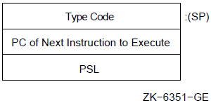
| Exception Type | Decimal Value |
|---|---|
|
Faults | |
|
reserved opcode |
0 |
|
BPT instruction |
1 |
|
IOT instruction |
2 |
|
EMT instruction |
3 |
|
TRAP instruction |
4 |
|
illegal instruction |
5 |
|
Aborts | |
|
odd address |
6 |
All other exceptions in compatibility mode, including the access control violation fault, the translation not valid fault, and the machine check abort, occur by means of the regular native-mode vector.
E.4.5. Change Mode Trap
A change mode trap is an exception occurring when one of the change mode instructions (CHMK, CHME, CHMS, or CHMU) is executed. The instruction operand is pushed onto the exception stack.
E.4.6. Breakpoint Fault
A breakpoint fault is an exception that occurs when the breakpoint instruction (BPT) is executed. The BPT instruction pushes the current PSL onto the stack.
Restores the original contents of the location containing the BPT instruction.
Sets the T bit in the PSL saved by the BPT fault. The PSL is on the stack.
Resumes operation of the main instruction stream.
Reinserts the BPT instruction.
Restores the T bit to its original state (usually zero).
Resumes operation of the main instruction stream.
Note that if both tracing and breakpointing are in progress (if the PSL T bit was set at the time of the BPT), both the BPT restoration and a normal trace exception should be processed on the trace exception by the trace handler.
E.5. Trace Fault
Program tracing is used for many purposes. Debugging programs and evaluating program performance are the most common uses of program tracing.
A trace fault is an exception that occurs between instructions when trace is enabled. One trace fault occurs before the execution of each traced instruction. The address in the PC saved when a trace fault occurs is the address of the instruction after the trace fault that would normally be executed. The trace exception for an instruction takes precedence over all other exceptions. The detection of reserved instruction faults occurs after the trace fault. If a trace fault and a memory management fault (or an odd address abort during a compatibility mode instruction fetch) occur simultaneously, exceptions are taken in UNPREDICTABLE order.
To ensure that exactly one trace occurs per instruction despite other traps and faults, the PSL contains the trace enable (T) and trace pending (TP) bits.
The PSL TP bit generates a fault before any other processing at the start of the next instruction.
At the beginning of an instruction, if the trace pending (TP) bit is set,it is cleared and a trace fault is taken.
The value of the trace enable (T) bit is loaded into the trace pending (TP) bit.
The detection of interrupts and other exceptions can occur during instruction execution. In this case, TP is cleared before the exception or interrupt is initiated. The system saves the entire PSL including the T bit and TP bit on interrupt or exception initiation and restores the PSL at the end with an REI. This makes interrupts and benign exceptions totally transparent to the executing program.
The following are conditions and results that might occur during instruction execution or before the next instruction:If the instruction faults or an interrupt is serviced, the PSL TP bit is cleared before the PSL is saved on the stack. The saved PC (the next lower word on the stack after the saved PSL) is set to the start of the faulting or interrupted instruction. Instruction execution is resumed at step 1.
If the instruction aborts or takes an arithmetic trap, the PSL TP bit is not changed before the PSL is saved on the stack.
If an interrupt is serviced after instruction completion and arithmetic traps but before the presence of tracing is checked at the start of the next instruction, the PSL TP bit is not changed before the PSL is saved on the stack.
E.5.1. Trace Operation When Entering a Change Mode Instruction
The routine entered by a change mode (CHMx) instruction is not traced because change mode clears T and TP in the new PSL that is used for whichever new mode is entered. However, if the T bit was set in the old PSW (the one to be saved)at the beginning of the change mode instruction, the system sets both the T and the TP bit in the saved PSL. Trace faults resume with the instruction that follows other returns from interrupt (REI) in the routine entered by the CHMx instruction. An instruction following an REI faults if T was set when the REI was executed, or if the TP bit in the saved PSL is set. In both cases, TP is set after the REI.
E.5.2. Trace Operation Upon Return From Interrupt
Note that a trace fault that occurs for an instruction following an REI instruction that had set the TP will be taken with the new PSL restored by the REI instruction. Thus, special care must be taken if exception or interrupt routines are traced.
E.5.3. Trace Operation After a BISPSW Instruction
If the T bit is set by a BISPSW instruction, trace faults begin with the second instruction after the BISPSW.
E.5.4. Trace Operation After a CALLS or CALLG Instruction
The CALLS and CALLG instructions save a clear T bit, although the T bit in the PSL is unchanged. This is done so that a debugger or trace program proceeding from a BPT fault does not get a spurious trace from the RET that matches the CALL.
E.6. Serious System Failures
Kernel stack not valid abort
Interrupt stack not valid halt
Machine check exception
These system failures are described in the following sections.
E.6.1. Kernel Stack Not Valid Abort
The kernel stack not valid abort is an exception indicating that the kernel stack was not valid while the processor was pushing information onto it during the initiation of an exception or interrupt. This is usually an indication of a stack overflow or other operating system error. During this process, the attempted exception is transformed into an abort that uses the interrupt stack. Only the PSL and PC of the original exception are pushed onto the interrupt stack. The interrupt priority level (IPL) is raised to 1F (hex). If the exception vector bits <1:0> are not both 1, the operation of the processor is UNDEFINED.
Software can abort the process without aborting the system. However, because of the lost information, the process cannot be continued. If the kernel stack is not valid during the normal execution of an instruction (including CHMx or REI), the normal memory management fault is initiated.
E.6.2. Interrupt Stack Not Valid Halt
An interrupt stack not valid halt results when the interrupt stack was not valid or a memory error occurred while the processor was pushing information onto the interrupt stack during the initiation of an exception or interrupt. No further interrupt requests are acknowledged on the processor. The processor leaves the PC, the PSL, and the reason for the halt in registers so that they are available to a debugger, to the normal bootstrap routine, or to an optional watchdog bootstrap routine. A watchdog bootstrap routine can cause the processor to leave the halted state.
E.6.3. Machine Check Exception
A machine check exception indicates that the processor detected an internal error. As is usual for exceptions, a machine check is taken regardless of current interrupt priority level (IPL). The machine check exception vector (bits 0 to 1) must specify 1 or the operation of the processor is UNDEFINED. The exception is taken on the interrupt stack, and IPL is raised to 1F (hex).
The processor pushes a machine check stack frame onto the interrupt stack,consisting of a count longword, an implementation-dependent number of error report longwords, a PC and a PSL. The count longword reports the number of bytes of error report pushed. For example, if 4 longwords of error report are pushed, the count longword will contain 16 (decimal).
Software can decide, on the basis of the information presented, whether to abort the current process if the machine check came from the process. The machine check includes any uncorrected bus and memory errors and any other processor-detected errors. Some processor errors cannot ensure the state of the machine at all. For such errors, the state is preserved as well as possible, given the circumstances.
Rn—Any general register R0 to R12 or the AP, FP, or SP register.
Rx—Any general register R0 to R12 or the AP, FP, or SP register. Rx cannot be the same register as Rn in the autoincrement index, autoincrement deferred index, and decrement index addressing modes.
dis—An expression specifying a displacement.
The alternate form, if any, is given in parentheses.
The alternate form, if any, is given in parentheses.
The BLANK, NOT_BLANK, IDENTICAL, and DIFFERENT conditions are only useful in macro definitions.
Scalar/vector memory synchronization is never required between two accesses by the VAX scalar processor to a memory location.
Scalar/vector memory synchronization or VSYNC is never required between two read accesses to a memory location.
Scalar/vector memory synchronization or VSYNC is never required between two read accesses to a memory location.
Scalar/vector memory synchronization or VSYNC is never required between two read accesses to a
memory location.
The scalar read is synchronous and will have completed before a vector memory operation is issued.
See Section 10.7.5.1, ''When VSYNC Is Not Required'' for the conditions when VSYNC is not required between a vector memory read/write pair.
Although a scalar write operation is a synchronous instruction,scalar/vector memory synchronization is required to ensure that the written data is visible to the vector processor before the vector memory reference is executed.
Vector integer compare instructions that specify reserved values of cntrl <2:0> produce UNPREDICTABLE results.
Vector integer compare instructions that specify reserved values of cntrl <2:0> produce UNPREDICTABLE results.
Vector convert instructions that specify reserved values of cntrl <11:8> produce UNPREDICTABLE results.