Volume Shadowing Guide
- Operating System and Version:
- VSI OpenVMS IA-64 Version 8.4-1H1 or higher
VSI OpenVMS Alpha Version 8.4-2L1 or higher
VSI OpenVMS x86-64 Version 9.2-2 or higher
Preface
This manual explains how to use VSI Volume Shadowing for OpenVMS to replicate data transparently on multiple disks and to provide high data availability.
1. About VSI
VMS Software, Inc. (VSI) is an independent software company licensed by Hewlett Packard Enterprise to develop and support the OpenVMS operating system.
2. Intended Audience
This book is intended for system managers and system users who want to:
Understand how Volume Shadowing for OpenVMS works
Configure shadowed data storage subsystems to maximize data availability
Set up and manage shadow sets
Enhance shadow set performance
Although you do not need any previous volume shadowing experience to use the volume shadowing software or this documentation, you do need a familiarity with the OpenVMS operating system, the OpenVMS Mount utility or OpenVMS system services, and setting system parameters.
3. Document Structure
| Chapter | Contents |
|---|---|
| Chapter 1, "Introduction to Volume Shadowing for OpenVMS" | Introduces Volume Shadowing for OpenVMS and describes how it provides high data availability. |
| Chapter 2, "Configuring Your System for High Data Availability" | Illustrates various shadow set configurations. |
| Chapter 3, "Preparing to Use Volume Shadowing" | Describes how to set up a volume shadowing environment, including information about setting shadowing system parameters, booting a system that uses a system disk in a shadow set, and booting satellite nodes from a shadowed system disk. |
| Chapter 4, "Creating and Managing Shadow Sets Using DCL Commands" | Describes how to use DCL commands to create, mount, dismount,
and dissolve shadow sets. The chapter also describes how to use
the SHOW DEVICESSHOW DEVICES
command, the System Dump Analyzer, and the F$GETDVI lexical
function to obtain information about shadow sets on a running
system. |
| Chapter 5, "Creating and Managing Shadow Sets with System Services" | Describes how to use the OpenVMS system services in a user-written program to create and manage shadow sets. The chapter also describes how to use the $GETDVI system service to obtain information about shadow sets. |
| Chapter 6, "Ensuring Shadow Set Consistency" | Describes how the copy and merge operations maintain data consistency and availability during changes in shadow set membership. |
| Chapter 7, "Using Minicopy for Backing Up Data" | Describes how the minicopy operation can be used, in a carefully controlled environment, to reduce the time required for a member to be returned to a shadow set. Typically, the member is removed for backing up data. |
| Chapter 8, "Host-Based Minimerge (HBMM)" | Describes how to use host-based minimerge (HBMM) to shorten the time of a merge operation. |
| Chapter 9, "Performing System Management Tasks on Shadowed Systems" | Describes how to perform system management tasks on shadow sets, including performing backup and upgrade operations, performing shadowing operations in OpenVMS Cluster systems, and handling crash dumps on the shadow set. |
| Chapter 10, "Performance Information for Volume Shadowing" | Includes helpful information and guidelines for achieving better performance from shadow sets. |
| Appendix A, "Messages" | Lists messages related to volume shadowing that are returned by the Mount utility and the VOLPROC, shadow server, and OPCOM facilities. |
4. Related Documents
The following documents contain information related to this manual:
VSI OpenVMS License Management Utility Guide
VSI OpenVMS Cluster Systems Manual
Guidelines for OpenVMS Cluster Configurations
VSI OpenVMS DCL Dictionary: A–M
VSI OpenVMS DCL Dictionary: N–Z
VSI OpenVMS System Manager's Manual, Volume 1: Essentials
VSI OpenVMS System Manager's Manual, Volume 2: Tuning, Monitoring, and Complex Systems
VSI OpenVMS System Management Utilities Reference Manual, Volume I: A–L
VSI OpenVMS System Management Utilities Reference Manual, Volume II: M–Z
VSI OpenVMS System Analysis Tools Manual
VSI OpenVMS System Services Reference Manual: A–GETUAI
VSI OpenVMS System Services Reference Manual: GETUTC–Z
5. VSI Encourages Your Comments
You may send comments or suggestions regarding this manual or any VSI document by sending electronic mail to the following Internet address: <docinfo@vmssoftware.com>. Users who have VSI OpenVMS support contracts through VSI can contact <support@vmssoftware.com> for help with this product.
6. OpenVMS Documentation
The full VSI OpenVMS documentation set can be found on the VMS Software Documentation webpage at https://docs.vmssoftware.com.
7. Typographical Conventions
| Convention | Meaning |
|---|---|
|
Ctrl/ x |
A sequence such as Ctrl/ x indicates that you must hold down the key labeled Ctrl while you press another key or a pointing device button. |
|
PF1 x |
A sequence such as PF1 x indicates that you must first press and release the key labeled PF1 and then press and release another key or a pointing device button. |
|
Return |
In examples, a key name enclosed in a box indicates that you press a key on the keyboard. (In text, a key name is not enclosed in a box.) |
... |
A horizontal ellipsis in examples indicates one of the
following possibilities:
|
. . . |
A vertical ellipsis indicates the omission of items from a code example or command format; the items are omitted because they are not important to the topic being discussed. |
|
( ) |
In command format descriptions, parentheses indicate that you must enclose the options in parentheses if you choose more than one. |
|
[ ] |
In command format descriptions, brackets indicate optional choices. You can choose one or more items or no items. Do not type the brackets on the command line. However, you must include the brackets in the syntax for OpenVMS directory specifications and for a substring specification in an assignment statement. |
|
[ |] |
In command format descriptions, vertical bars separate choices within brackets or braces. Within brackets, the choices are options; within braces, at least one choice is required. Do not type the vertical bars on the command line. |
|
{ } |
In command format descriptions, braces indicate required choices; you must choose at least one of the items listed. Do not type the braces on the command line. |
|
bold text |
This typeface represents the introduction of a new term. It also represents the name of an argument, an attribute, or a reason. |
|
italic text |
Italic text indicates important information, complete titles of manuals, or variables. Variables include information that varies in system output (Internal error number), in command lines (/PRODUCER= name), and in command parameters in text (where dd represents the predefined code for the device type). |
|
UPPERCASE TEXT |
Uppercase text indicates a command, the name of a routine, the name of a file, or the abbreviation for a system privilege. |
|
|
Monospace type indicates code examples and interactive screen displays. In the C programming language, monospace type in text identifies the following elements: keywords, the names of independently compiled external functions and files, syntax summaries, and references to variables or identifiers introduced in an example. |
| Bold monospace type indicates DCL commands and qualifiers that can be entered at the command prompt. |
|
- |
A hyphen at the end of a command format description, command line, or code line indicates that the command or statement continues on the following line. |
|
numbers |
All numbers in text are assumed to be decimal unless otherwise noted. Nondecimal radixes—binary, octal, or hexadecimal—are explicitly indicated. |
Chapter 1. Introduction to Volume Shadowing for OpenVMS
This chapter introduces VSI Volume Shadowing for OpenVMS and describes how volume shadowing, sometimes referred to as disk mirroring, achieves high data availability.
1.1. Overview
VSI Volume Shadowing for OpenVMS ensures that data is available to your applications and end users by duplicating data on multiple disks. Because the same data is recorded on multiple disk volumes, if one disk fails, the remaining disk or disks can continue to service I/O requests. VSI Volume Shadowing for OpenVMS is available on VSI OpenVMS Integrity servers, OpenVMS Alpha, and OpenVMS x86 systems. All volume shadowing features are available on OpenVMS Integrity servers, OpenVMS Alpha, and OpenVMS x86 systems.
An implementation of RAID 1 (redundant arrays of independent disks) technology, Volume Shadowing for OpenVMS prevents a disk device failure from interrupting system and application operations. By duplicating data on multiple disks, volume shadowing transparently prevents your storage subsystems from becoming a single point of failure because of media deterioration or communication path failure, or through controller or device failure.
Any entity that is designated as a disk class device to OpenVMS is a device that can be used in a shadow set.
You can mount up to six compatible disk volumes, including the system disk, to form a shadow set.
VSI OpenVMS allows users to mount a maximum of six disk volumes. Each disk in the shadow set is a shadow set member. Volume Shadowing for OpenVMS logically binds the shadow set disks together and represents them as a single virtual device called a virtual unit, as shown in Figure 1.1, ''Virtual Unit''. This means that the multiple members of the shadow set, represented by the virtual unit, appear to applications and users as a single, highly available disk.
Note that the term disk and device are used interchangeably throughout this manual to refer to a disk volume. A disk volume is a disk that was prepared for use by placing a new file structure on it.
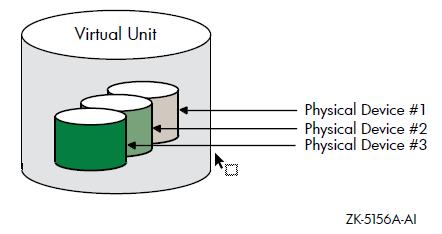
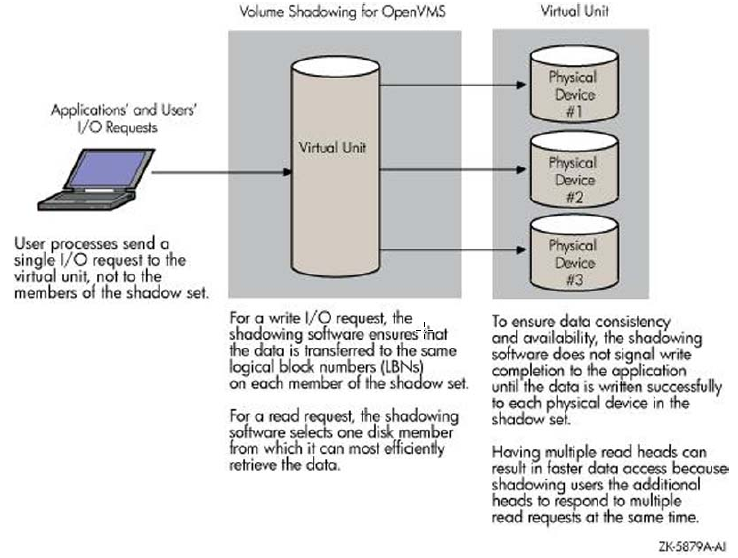
Figure 1.2, ''Elements of a Shadow Set'' shows how Volume Shadowing for OpenVMS propagates data through the virtual unit to three individual shadow set members.
Note
Remember that volume shadowing protects against hardware problems that cause a disk volume to be a single point of failure for both applications and systems that use the disk. Volume shadowing does not provide for recovery from software-related incidents, such as the accidental deletion of files or errant software corrupting the contents of a disk file. Do not use volume shadowing as a substitute for regular backup or journaling.
Applications and users read and write data to and from a shadow set using the same commands and program language syntax and semantics that are used for non-shadowed I/O operations. System managers manage and monitor shadow sets using the same commands and utilities they use for non-shadowed disks. The only difference is that access is through the virtual unit, not to individual disk.
1.2. Volume Shadowing Tasks and Operations
The primary volume shadowing operations used to create shadow sets and to maintain consistent data on each member are mount, copy, minicopy, merge, and minimerge. When these operations are in progress, the system continues to process read and write requests, thus providing continuous availability.
All volume shadowing operations, except for merges and minimerges, are under the control of the system manager. Merges and minimerges are started automatically by the volume shadowing software if a hardware or software failure occurs that could affect the consistency of the data on the shadow set members. However, you can control the order of these merges by assigning different priorities to the shadow sets, as described in Section 4.9, ''Prioritizing Merge and Copy Operations''. You can also change the default delays that affect merges and copies with the SHADOW_PSM_DLY and SHADOW_REC_DLY system parameters that are described in Table 3.1, ''Volume Shadowing Parameters''.
System managers turn on volume shadowing with the SHADOWING system parameter. They can control the number of concurrent merge or copy operations on a given node by the SHADOW_MAX_COPY system parameter. These volume shadowing system parameters, and all other system parameters used with volume shadowing, are described in Section 3.3, ''Volume Shadowing Parameters'' and in Section 3.4, ''Bitmap System Parameters''.
Volume Shadowing for OpenVMS is never invoked directly. Instead, you invoke the DCL commands
MOUNT and DISMOUNT. The MOUNT command
works with the volume shadowing software to create shadow sets. The DISMOUNT
command works with the volume shadowing software to remove shadow set members and to dissolve
entire shadow sets.
Host-based minimerge (HBMM) enables minimerge operations on Fibre Channel and SCSI disk devices.
OpenVMS also provides a programming interface for creating and managing shadow sets with the $MOUNT, $DISMOU, and $GETDVI system services. This programming interface is described in Chapter 5, "Creating and Managing Shadow Sets with System Services".
|
Task |
Operation |
Software Used |
|---|---|---|
|
Create a shadow set. |
Copy |
|
|
Remove a member from a shadow set. |
Dismount a disk |
|
|
Dissolve a shadow set. |
Dismount the shadow set (specify its virtual unit name) |
|
|
Ensure that the data is identical on all shadow set members in the event of a hardware failure. |
Merge or minimerge |
Shadowing software does this automatically when it detects a hardware or software failure. If an HSJ or HSC controller is present in the configuration, a minimerge might be done. |
|
Return a dismounted shadow set member to the shadow set. |
Copy or minicopy |
|
1.3. Hardware Environment
Hardware Environment Volume Shadowing for OpenVMS does not depend on specific hardware in order to operate. All shadowing functions can be performed on OpenVMS Integrity server systems, OpenVMS Alpha, and on OpenVMS x86 systems.
One CPU
One mass storage controller
- One of the following kinds of disk drives:
Serial Advanced Technology Attachment (SATA)
Small Computer Systems Interface (SCSI)
Fibre Channel
The following sections generically describe hardware support. See the most recent Volume Shadowing for OpenVMS Software Product Description DO-VIBHAA-031 for more information.
1.3.1. Memory Requirements
24 KB per node is required on Integrity server systems, OpenVMS Alpha systems, and OpenVMS x86 systems. These requirements are in effect even if you do not use Volume Shadowing for OpenVMS, unless you change the default setting.
If this memory is not available, the node will not boot.
4.5 KB per shadow set per node is required.
This amount of memory is required before a bitmap can be created. If this memory is not available, the mount fails (that is, the shadow set is not mounted on the node). TheMOUNTcommand that fails will issue the following message:%MOUNT-F-INSFMEM, insufficient dynamic memory
For every GB of storage of a shadow set member, 2.0 KB per node is required for the bitmaps for each shadow set mounted on a node. (Each shadow set can have up to six bitmaps. And, with HBMM support, a shadow set can have a maximum of 12 bitmaps.)
When calculating memory requirements, note that a two-member shadow set with 50 GB per member counts as 50 GB, not 100 GB.
For example, for a shadow set with 200 GB of storage per member, 400 KB of memory is required for its bitmaps for every node in the cluster. If this memory is not available on the node where the bitmap request occurs, the bitmap is not created.
If the master bitmap is created but sufficient memory is not available on another node on which the shadow set is subsequently mounted, a local bitmap is not created. If the WBM_OPCOM_LVL system parameter is set to 1 (the default) or 2, the following OPCOM message is displayed:Unable to allocate local bitmap - running in degraded mode.
Writes from nodes without local bitmaps are registered with the node on which the shadow set is first mounted.
24 KB per node (regardless of whether you use volume shadowing)
45 KB (10 shadow sets × 4.5 KB per unit mounted on the system)
1050 KB (50 × 2.1 KB (per GB of disk size) × 10 shadow sets
1119 KB total memory required
1.4. Supported Configurations
Volume Shadowing for OpenVMS provides data availability across the full range of configurations — from single nodes to large OpenVMS Cluster systems — so you can provide data availability where you require it most.
For the OpenVMS Operating System: SPD DO-VIBHAA-005 for Integrity V8.4-1H1; SPD DO-DVASPQ-001 for Alpha V8.4-2L1
For OpenVMS Cluster Software: SPD DO-VIBHAA-032
If an individual disk volume is already mounted as a member of an active shadow set, the disk volume cannot be mounted as a standalone disk on another node.
1.4.1. Maximum Number of Shadow Sets
You can mount a maximum of 500 disks in shadow sets on a standalone system or in an OpenVMS Cluster system. A limit of 10,000 single-member shadow sets is allowed on a standalone system or in an OpenVMS cluster. Dismounted shadow sets, unused shadow sets, and shadow sets with no write bitmaps allocated to them are included in this total. These limits are independent of controller and disk type. The shadow sets can be mounted as public or private volumes.
The SHADOW_MAX_UNIT system parameter is responsible for the maximum number of shadow sets that can exist on a node. For more information about SHADOW_MAX_UNIT, see Section 3.3.1, ''Guidelines for Using Volume Shadowing Parameters''.
1.4.2. Support for Six-Member Shadow Sets
VSI OpenVMS supports six-member shadow sets as compared to the previous three-member shadow sets. This is useful for multisite disaster-tolerant configurations. In a three-member shadow set, a three-site disaster tolerant configuration has only one shadow member per site. In this scenario, when two sites fail, the member left out in the surviving site becomes a single point of failure. With six-member shadow set support, you can have two members of a shadow set in each of the three sites providing high availability.
For example:
$ SHOW DEV DSA5678:
Device                Device          Error    Volume     Free   Trans  Mnt
 Name                 Status          Count    Label     Blocks  Count  Cnt
DSA5678:              Mounted             0  SIXMEMBER   682944      1    1
$6$DKB0:    (WSC236)  ShadowSetMember     0  (member of DSA5678:)
$6$DKB100:  (WSC236)  ShadowSetMember     0  (member of DSA5678:)
$6$DKB200:  (WSC236)  ShadowSetMember     0  (member of DSA5678:)
$6$DKB300:  (WSC236)  ShadowSetMember     0  (member of DSA5678:)
$6$DKB400:  (WSC236)  ShadowSetMember     0  (member of DSA5678:)
$6$DKB500:  (WSC236)  ShadowSetMember     0  (member of DSA5678:)
1.4.3. Shadowing System Disks
You can shadow system disks as well as data disks. Thus, a system disk need not be a single point of failure for any system that boots from that disk. System disk shadowing becomes especially important for OpenVMS Cluster systems that use a common system disk from which multiple computers boot. Volume shadowing makes use of the OpenVMS distributed lock manager, and the quorum disk must be accessed before locking is enabled. Note that you cannot shadow quorum disks.
Integrity server, Alpha, and x86 systems can share data on shadowed data disks, but separate system disks are required — one for each architecture.
1.4.4. EFI Shell Precautions on Shadowed System Disks
On each Integrity server and x86 system disk, there can exist up to two File Allocation Table (FAT)s partitions that contain OpenVMS boot loaders, Extensible Firmware Interface (EFI) applications, and hardware diagnostics. The OpenVMS bootstrap partition and, when present, the diagnostics partition are respectively mapped to the following container files on the OpenVMS system disk:
SYS$LOADABLE_IMAGES:SYS$EFI.SYS
SYS$MAINTENANCE:SYS$DIAGNOSTICS.SYS
The contents of the FAT partitions appear as fsn: devices
at the console EFI Shell> prompt. The fsn:
devices can be directly modified by the user command input at EFI Shell> prompt
and by the EFI console or EFI diagnostic applications. Neither OpenVMS nor any EFI console
environments that might share the system disk are notified of partition modifications; OpenVMS
and console environments are unaware of console modifications. You must ensure the proper
coordination and proper synchronization of the changes with OpenVMS and with any other EFI
consoles that might be in use.
You must take precautions when modifying the console in configurations using either or both of the following:
OpenVMS host-based volume shadowing for the OpenVMS Integrity server and x86 system disk;
Shared system disks and parallel EFI console access across Integrity server and x86 environments sharing a common system disk.
You must preemptively reduce the OpenVMS system disk environments to a single-member
host-based volume shadow set or to a non-shadowed system disk, and you must externally
coordinate access to avoid parallel EFI shell sessions whenever making shell-level modifications
to the fsn: devices, such as:
Installing or operating diagnostics within the diagnostics partition.
Allowing diagnostics in the partition (or running from removable media) to modify the boot or the diagnostic partition on an OpenVMS Integrity server and x86 system disk.
Modifying directly or indirectly the boot or the diagnostics partition within these environments from the EFI
Shell>prompt.
If you do not take these precautions, any modifications made within the fsn: device associated with the boot partition or the device associated with the diagnostic partition can be overwritten and lost immediately or after the next OpenVMS host-based volume shadowing full-merge operation.
For example, when the system disk is shadowed and changes are made by the EFI console shell to the contents of these container files on one of the physical members, the volume shadowing software is unaware that a write is done to a physical device. If the system disk is a multiple-member shadow set, you must make the same changes to all of the other physical devices that are the current shadow set members. If this is not done, when a full merge operation is next performed on that system disk, the contents of these files might regress. The merge operation might occur many days or weeks after any EFI changes are made.
Furthermore, if a full merge is active on the shadowed system disk, you must not make changes to either file using the console EFI shell.
To suspend a full merge operation that is in progress or to determine the membership of a shadow set, see Chapter 8, "Host-Based Minimerge (HBMM)".
The precautions are applicable only for the Integrity server and x86 system disks that are configured for host-based volume shadowing, or are configured and shared across multiple OpenVMS Integrity server and OpenVMS x86 systems.
1.4.5. Using Minicopy in a Mixed-Version OpenVMS Cluster System
To use the minicopy feature in a mixed-version OpenVMS Cluster system, every node in the cluster must use a version of OpenVMS that supports this feature.
1.4.6. Shadow Sets, Bound Volume Sets, and Stripe Sets
Shadow sets also can be constituents of a bound volume set or a stripe set. A bound volume
set consists of one or more disk volumes that have been bound into a volume set by specifying
the /BIND qualifier with the MOUNT command. Section 1.5, ''Shadowing Disks Across an OpenVMS Cluster System'' describes shadowing across OpenVMS Cluster systems. Chapter 10, "Performance Information for Volume Shadowing" contains more information about striping and how it relates to
volume shadowing.
1.5. Shadowing Disks Across an OpenVMS Cluster System
The host-based implementation of volume shadowing allows disks that are connected to multiple physical controllers to be shadowed in an OpenVMS Cluster system. There is no requirement that all members of a shadow set be connected to the same controller. Controller independence allows you to manage shadow sets regardless of their controller connection or their location in the OpenVMS Cluster system and helps provide improved data availability and flexible configurations.
For clusterwide shadowing, members can be located anywhere in an OpenVMS Cluster system and served by MSCP servers across any supported OpenVMS Cluster interconnect, including the Ethernet, Digital Storage Systems Interconnect (DSSI), and Fiber Distributed Data Interface (FDDI). For example, OpenVMS Cluster systems using IPCI and wide area network services can be hundreds of miles apart, which further increases the availability and disaster tolerance of a system.
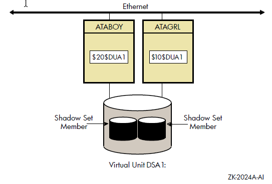
Figure 1.3, ''Shadow Sets Accessed Through the MSCP Server'' shows how shadow-set members are on line to local adapters located on different nodes. In the figure, a disk volume is local to each of the nodes ATABOY and ATAGRL. The MSCP server provides access to the shadow set members over the Ethernet. Even though the disk volumes are local to different nodes, the disks are members of the same shadow set. A member that is local to one node can be accessed by the remote node via the MSCP server.
The shadowing software maintains shadow sets in a distributed fashion on each node that mounts the shadow set in the OpenVMS Cluster system. In an OpenVMS Cluster environment, each node creates and maintains shadow sets independently. The shadowing software on each node maps each shadow set, represented by its virtual unit name, to its respective physical units. Shadow sets are not served to other nodes. When a shadow set must be accessed by multiple nodes, each node creates an identical shadow set. The shadowing software maintains clusterwide membership coherence for shadow sets mounted on multiple nodes. For shadow sets that are mounted on an OpenVMS Cluster system, mounting or dismounting a shadow set on one node in the cluster does not affect applications or user functions executing on other nodes in the system. For example, you can dismount the shadow set from one node in an OpenVMS Cluster system and leave the shadow set operational on the remaining nodes on which it is mounted.
1.6. Installation
Volume Shadowing for OpenVMS is a System Integrated Product (SIP) that you install at the same time that you install the operating system. On OpenVMS Integrity server systems, the license for Volume Shadowing is included in the Enterprise Operating Environment and in the Mission Critical Operating Environment. It is not included in the Foundation Operating Environment but can be purchased separately. On OpenVMS Alpha, Volume Shadowing for OpenVMS requires its own license that is separate from the OpenVMS base operating system license. To use the volume shadowing software, it must be licensed either as part of an OpenVMS Integrity server operating environment or by a separate license, as described. All nodes booting from shadowed system disks must have shadowing licensed and enabled. See the instructions included in your current OpenVMS upgrade and installation manual.
See Section 3.2, ''Licensing Volume Shadowing for OpenVMS'' for more information about licensing Volume Shadowing for OpenVMS.
Chapter 2. Configuring Your System for High Data Availability
System availability is a critical requirement in most computing environments. A dependable environment enables users to interact with their system when they want and in the way they want.
2.1. Levels of High Data Availability Using Volume Shadowing
A key component of overall system availability is availability or accessibility of data. Volume Shadowing for OpenVMS provides high levels of data availability by allowing shadow sets to be configured on a single-node system or on an OpenVMS Cluster system, so that continued access to data is possible despite failures in the disk media, disk drive, or disk controller. For shadow sets whose members are local to different OpenVMS Cluster nodes, if one node serving a shadow set member shuts down, the data is still accessible through an alternate node.
You can create a virtual unit, the system representation of a shadow set, that consists of only one disk volume. However, you must mount two or more disk volumes in order to “shadow,” that is, to maintain multiple copies of the same data. This configuration protects against either failure of a single disk drive or deterioration of a single volume. For example, if one member fails out of a shadow set, the remaining member can be used as a source device whose data can be accessed by applications at the same time the data is being copied to a newly mounted target device. Once the data is copied, both devices contain identical information and the target device becomes a source member of the shadow set. (Disks of different sizes can be combined into a shadow set, as described in Section 7.5, ''Write Bitmaps and Dissimilar Device Shadowing Caution''.)
Using two controllers provides a further guarantee of data availability in the event of a single-controller failure. When setting up a system with volume shadowing, you should connect each disk drive to a different controller I/O channel whenever possible. Separate connections help protect against either failure of a single controller or of the communication path used to access it.
Using an OpenVMS Cluster system (as opposed to a single-node environment) and multiple controllers provides the greatest data availability. Disks that are connected to different local controllers and disks that are MSCP-served by other OpenVMS systems can be combined into a single shadow set, provided the disks are compatible and no more than three are combined.
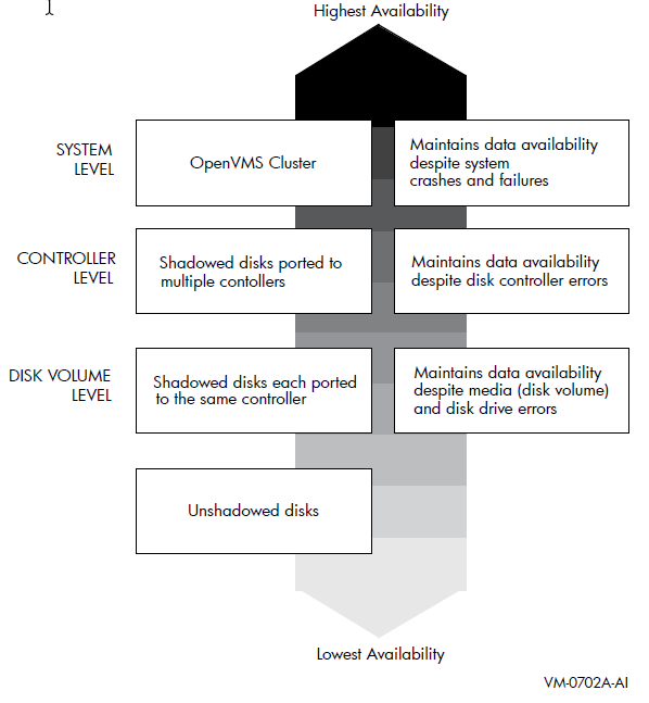
Figure 2.1, ''Levels of Availability '' provides a qualitative, high-level classification of how you can achieve increasing levels of physical data availability in different types of configurations.
Section 2.2, ''Repair and Recovery from Failures'' describes how you can configure your shadowed system to achieve high data availability despite physical failures.
2.2. Repair and Recovery from Failures
Controller errors
Device errors
Data errors
Connectivity failures
The handling of shadow set recovery and repair depends on the type of failure that occurred and the hardware configuration. In general, devices that are inaccessible tend to fail over to other controllers whenever possible. Otherwise, they are removed from the shadow set. Errors that occur as a result of media defects can often be repaired automatically by the volume shadowing software.
|
Type |
Description |
|---|---|
|
Controller error |
Results from a failure in the controller. If the failure is recoverable, processing continues and data availability is not affected. If the failure is nonrecoverable, shadow set members connected to the controller are removed from the shadow set, and processing continues with the remaining members. In configurations where disks are dual-pathed between two controllers, and one controller fails, the shadow set members fail over to the remaining controller and processing continues. |
|
Device error |
Signifies that the mechanics or electronics in the device failed. If the failure is recoverable, processing continues. If the failure is nonrecoverable, the node that detects the error removes the device from the shadow set. |
|
Data errors |
Results when a device detects corrupt data. Data errors usually result from media
defects that do not cause the device to be removed from a shadow set. Depending on the
severity of the data error (or the degree of media deterioration), the controller:
When data cannot be corrected by the controller, volume shadowing replaces the lost data by retrieving it from another shadow set member and writing the data to a different LBN of the member with the incorrect data. This repair operation is synchronized within the cluster and with the application I/O stream. |
|
Connectivity failures |
When a connectivity failure occurs, the first node to detect the failure must decide
how to recover from the failure in a manner least likely to affect the availability or
consistency of the data. As each node discovers the recoverable device failure, it
determines its course of action as follows:
|
2.3. Shadow Set Configurations
To illustrate the various levels of data availability obtainable through Volume Shadowing for OpenVMS, this section provides a representative sample of hardware configurations. Figures 2.2 through 2.4 show possible system configurations for shadow sets. The hardware used to describe the sample systems, while intended to be representative, is hypothetical; they must used only for general observations about availability and not as a suggestion for any specific configurations or products.
In all the following examples, the shadow set members use the
$allocation-class$ddcu: naming convention. The virtual unit uses the DSA
n: format, where n represents a number between 0 and 9999.
These naming conventions are described in more detail in Section 4.2, ''Creating a Shadow Set''.
Figure 2.2, ''OpenVMS Cluster System With Two FC Switches, Two Dual Controllers and Two Shadow Sets'' shows an OpenVMS Cluster system consisting of two systems connected to the same two shadow sets. Each system has two host-based adapters (HBAs) connecting it to the same two Fibre Channel (FC) switches. In turn, the FC switches are connected to two dual controllers, which are connected to two shadow sets.
Each shadow set member is connected by two paths, one to each of the dual controllers of one storage system. Each shadow set member can fail over between controllers independently of each other. Each system can access both shadow sets by direct connections.
This configuration provides coverage against:
Media errors
Failure on one system
Failure of one HBA per system
Failure of one or more controllers
Failure of one disk per shadow set
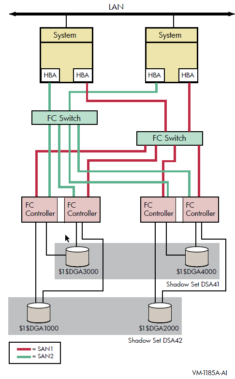
Figure 2.3, ''OpenVMS Cluster System With Four Systems, Four FC Switches, Four Dual Controllers, and Two Shadow Sets'' shows an OpenVMS Cluster system consisting of four systems. Each system in the cluster is identical to each system shown in Figure 2.2, ''OpenVMS Cluster System With Two FC Switches, Two Dual Controllers and Two Shadow Sets''. In addition to the protection offered by Figure 2.2, ''OpenVMS Cluster System With Two FC Switches, Two Dual Controllers and Two Shadow Sets'', this OpenVMS Cluster configuration provides greater protection from:
Component failure because there are twice as many components
Failure of one or two devices in shadow set DSA42 because it is a three-member set
This type of configuration provides continued access to data in spite of the failure of any one or more of these systems or switches.
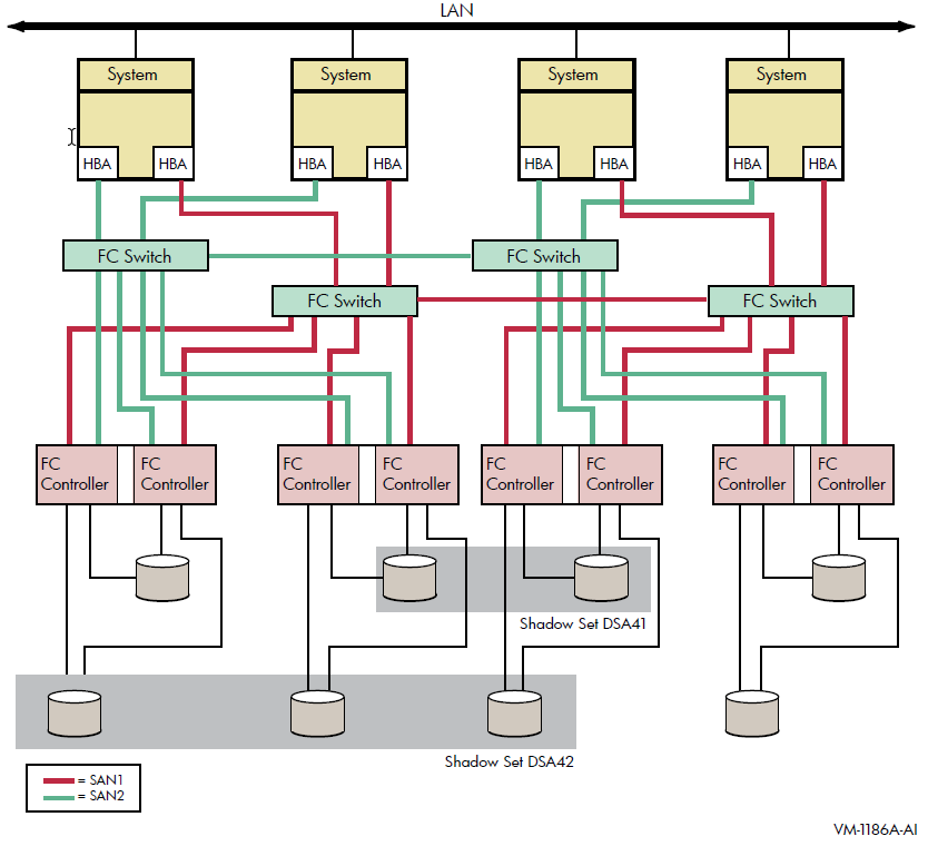
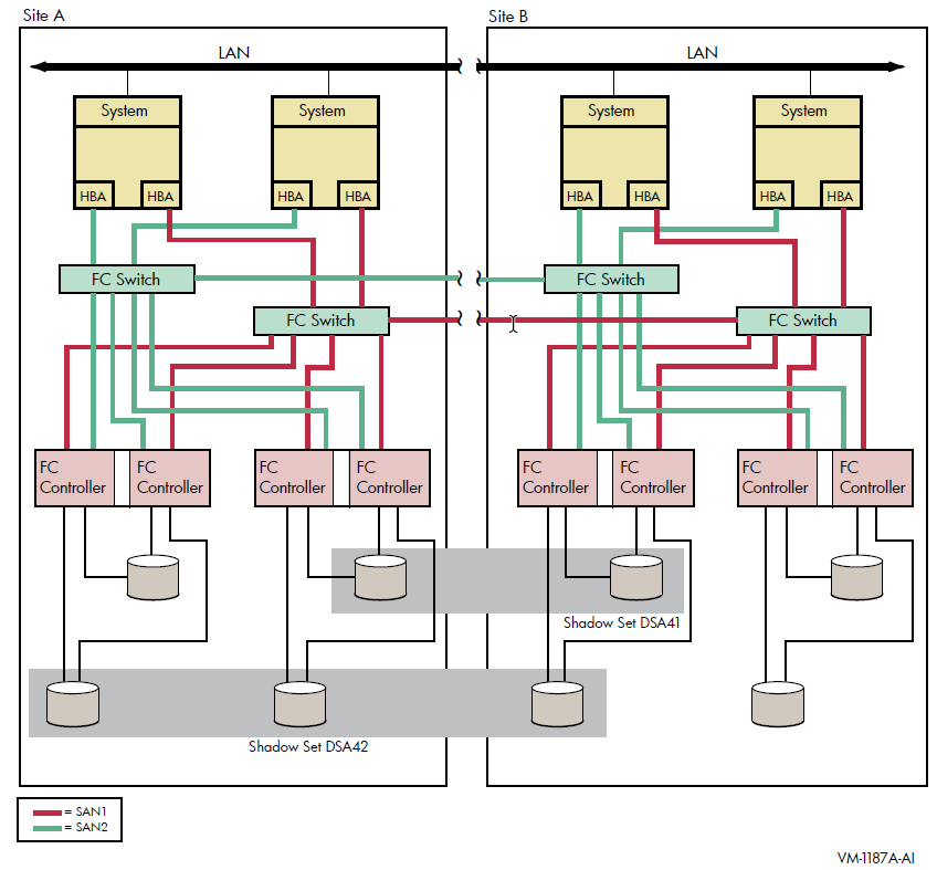
Figure 2.4, ''Multiple-Site OpenVMS Cluster System With Four Systems, Four FC Switches, Four Controllers, and Two Shadow Sets'' shows an OpenVMS Cluster system identical to Figure 2.3, ''OpenVMS Cluster System With Four Systems, Four FC Switches, Four Dual Controllers, and Two Shadow Sets'' except that the four systems are not in a single location. Instead, two systems are at one site and two at a second site. This figure illustrates how you can shadow data disks over long distances. Members of each shadow set are configured between two distinct and widely separated locations — a multiple-site OpenVMS Cluster system. The OpenVMS systems and shadowed disks in both locations function together as a single OpenVMS Cluster system and shadow set configuration. If a failure occurs at either site, the critical data is still available at the remaining site.
Chapter 3. Preparing to Use Volume Shadowing
This chapter describes the configuration tasks that are required before you can use volume shadowing on your system, including setting system parameters and installing licenses (unless volume shadowing is licensed with your OpenVMS Integrity server operating environment). This chapter also documents booting from a system disk and booting satellite nodes.
3.1. Configuration Tasks
Select which of your disk drives you want to shadow. Prepare the selected volumes for mounting by physically placing the volumes in the drives (for removable media disks). Ensure the disks are not write locked.
Consider whether or not you want to initialize the volumes you have chosen to shadow. Do not initialize volumes that contain useful data.
If you are creating a new shadow set, you can initialize one volume at a time, or multiple volumes with one command, which can streamline the creation of a shadow set (see Section 4.3, ''Using INITIALIZE/SHADOW/ERASE to Form a Shadow Set''). When you initialize one volume at a time, you can give it a volume label to be used for the shadow set. When you later mount additional volumes into the shadow set, each volume is initialized and is given the same volume label automatically.
Install the Volume Shadowing for OpenVMS licenses unless you are running OpenVMS Integrity servers and purchased either the Enterprise Operating Environment or the Mission Critical Operating Environment. These operating environments include the Volume Shadowing for OpenVMS license. See Section 3.2, ''Licensing Volume Shadowing for OpenVMS'' for more information.
Set the SHADOWING parameter to enable volume shadowing on each node that will use volume shadowing. See Section 3.3, ''Volume Shadowing Parameters'' for more information.
Setting the SHADOWING parameter requires that you reboot the system.
Set the ALLOCLASS parameter to a nonzero value. This parameter enables the use of allocation classes in device names. You must include a nonzero allocation class in the device name of shadowed disks. For more information, see Section 4.2, ''Creating a Shadow Set''.
- Dismount the disk drives you selected for the shadow set and remount them (along with the additional shadow set disk drives) as shadow set members. Note that:
You do not need to change the device volume labels and logical names.
If you use mount command files, ensure that the commands mount the physical devices using the appropriate naming syntax for virtual units (DSA n:).
For more information on the MOUNT command, see Chapter 4, "Creating and Managing Shadow Sets Using DCL Commands".
System disks can be shadowed. All nodes booting from that system disk must have shadowing licensed and enabled.
3.2. Licensing Volume Shadowing for OpenVMS
To use the volume shadowing product on OpenVMS Alpha, you must purchase a license for it, even though the volume shadowing software is part of the OpenVMS operating system. On OpenVMS Integrity server systems, the volume shadowing license is included in enterprise, mission critical, and high availability operating environments.
For OpenVMS Integrity server computers, a volume shadowing license is included in the collection of OpenVMS products known as the High Availability Operating Environment (HAOE). It is not included in the Base Operating Environment for OpenVMS license.
After licensing the OpenVMS operating system by registering an OpenVMS Product Authorization Key (PAK), OpenVMS Alpha system managers and managers of OpenVMS Integrity server systems with the FOE or BOE must also license Volume Shadowing for OpenVMS with a separate volume shadowing PAK. The PAK provides information that defines the Volume Shadowing for OpenVMS license contract you have with VSI. Obtain a PAK from your VSI sales representative.
When you enter information from the PAK into the online LICENSE database, the OpenVMS License Management Facility (LMF) authorizes the use of volume shadowing.
You must register and activate a license for Volume Shadowing for OpenVMS on each node that mounts a shadow set, including satellites in an OpenVMS Cluster system. If you do not register and activate licenses on nodes that use volume shadowing, subsequent shadow set mount operations do not succeed and displays error messages similar to the ones shown in Example 3.1, ''Nodes Not Registered to Use Volume Shadowing''.
%LICENSE-E-NOAUTH, DEC VOLSHAD use is not authorized on this node
-LICENSE-F-NOLICENSE, no license is active for this software product
-LICENSE-I-SYSMGR, please see your system manager
After you register the volume shadowing PAK, you must set the shadowing parameters on each node where you want to enable shadowing.
For more information about volume shadowing licensing, see the VSI Volume Shadowing for OpenVMS Software Product Description (DO-VIBHAA-031). For more information about the License Management Facility, see the OpenVMS Operating System Software Product Description (DO-VIBHAA-005 for Integrity V8.4-1H1; and DO-DVASPQ-001 for Alpha V8.4-2L1). You can also consult the VSI OpenVMS License Management Utility Guide.
3.3. Volume Shadowing Parameters
Table 3.1, ''Volume Shadowing Parameters'' lists the system parameters that are required to specify the use of Volume Shadowing for OpenVMS and the system parameters you can use to tailor the shadowing software on your system.
The term dynamic in Table 3.1, ''Volume Shadowing Parameters'' means that the active value can be changed on a running system. For more information about setting system parameters, see the VSI OpenVMS System Manager's Manual, Volume 1: Essentials.
Table 3.4, ''Write Bitmap System Parameters'' describes four bitmap system parameters. These system parameters support the host-based minicopy operation, described in Chapter 7, "Using Minicopy for Backing Up Data", and the host-based minimerge (HBMM) operation, described in Chapter 8, "Host-Based Minimerge (HBMM)".
|
Parameter |
Function |
Range |
Default |
Dynamic |
|---|---|---|---|---|
|
ALLOCLASS |
Specifies the device allocation class for the system. When using Volume Shadowing for OpenVMS, a nonzero value is required. |
0–255 |
0 |
No |
|
SHADOWING |
A value of 2 enables volume shadowing. See Table 3.2, ''SHADOWING Parameter Settings '' for a description of parameter values. |
0, 2? |
0 |
No |
|
SHADOW_MAX_COPY |
Limits the number of concurrent merge or copy operations on a given node. |
0–200 |
4 |
Yes |
|
SHADOW_MBR_TMO |
Controls the amount of time the system tries to fail over physical members of a shadow set. |
1–65,535 seconds |
120 |
Yes |
|
SHADOW_MAX_UNIT |
Specifies the maximum number of shadow sets that can exist on a node. Dismounted shadow sets, unused shadow sets, and shadow sets with no write bitmaps allocated to them are included in this total. |
10–10,000 |
500 on Alpha |
No |
|
SHADOW_SYS_DISK |
Allows system disk to be a shadow set |
0–1 |
0 |
0–1 |
|
SHADOW_SYS_DISK |
Allows system disk to be a shadow set and, optionally, enables a minimerge to occur. If a minimerge is enabled, the system must also be configured for writing to a nonshadowed, nonsystem disk of your choice. |
0, 1, 4097 ? |
0 |
Yes |
|
SHADOW_SYS_TMO |
Controls the amount of time members of a system disk shadow set have to return to the set. |
1–65,535 seconds |
120 |
Yes |
|
SHADOW_SYS_UNIT |
Contains the virtual unit number of the system disk. |
0–9999 |
0 |
No |
|
SHADOW_SYS_WAIT |
This parameter applies only to shadow sets that are currently mounted in the cluster. Controls the amount of time a booting system will wait for all members of a mounted system disk shadow set to become available. |
1–65,535 seconds |
480 |
Yes |
3.3.1. Guidelines for Using Volume Shadowing Parameters
This section provides guidelines for using volume shadowing parameters.
ALLOCLASS
The ALLOCLASS parameter is used to specify an allocation class that forms part of a device name. The purpose of allocation classes is to provide unique and unchanging device names. When using Volume Shadowing for OpenVMS on a single system or on an OpenVMS Cluster system, a nonzero allocation class value is required for each physical device in the shadow set. For more information about using allocation classes, see the VSI OpenVMS Cluster Systems Manual.
SHADOWING
The SHADOWING parameter enables or disables volume shadowing on your system, as shown in Table 3.2, ''SHADOWING Parameter Settings ''.
|
Setting |
Effect |
|---|---|
|
0 |
Shadowing is not enabled. This is the default value. |
|
2 |
Enables host-based shadowing. This setting provides shadowing of all disks that are located on a standalone system or on an OpenVMS Cluster system. Set SHADOWING to 2 on every node that will mount a shadow set, including satellite nodes. |
SHADOW_HBMM_RTC
SHADOW_HBMM_RTC is used to specify, in seconds, how frequently each shadow set on
this system has its modified block count compared with its reset threshold. If the
modified block count exceeds the reset threshold, the bitmap for that shadow set is
zeroed. This comparison is performed for all shadow sets mounted on the system that
have HBMM bitmaps. The reset threshold is specified by the RESET_THRESHOLD keyword
in the /POLICY qualifier of the SET SHADOW
command. When the comparison is made, the modified block count might exceed the
reset threshold by a small increment or by a much larger amount. The difference
depends on the write activity to the volume and the setting of this
parameter.
The default setting of SHADOW_HBMM_RTC is 150 seconds.
You can view the reset threshold setting and the modified block count, since the
last reset, in the SHOW SHADOW command display. For guidelines on
setting the reset threshold values and a sample SHOW SHADOW
display, see Section 8.5.2, ''Considerations for Setting a Bitmap RESET_THRESHOLD Value''. For a SHOW
SHADOW display that includes a modified block count greater than the
reset threshold value, refer to the VSI OpenVMS DCL Dictionary: N–Z.
SHADOW_MAX_COPY
The SHADOW_MAX_COPY parameter controls how many parallel copy and merge operations are allowed on a given node. (Copy and merge operations are described in Chapter 6, "Ensuring Shadow Set Consistency".) This parameter provides a way to limit the number of copy and merge operations in progress at any time.
The value of SHADOW_MAX_COPY can range from 0 to 200. The default value is specific to the OpenVMS version. You can determine the default value by looking at the parameter setting. When the value of the SHADOW_MAX_COPY parameter is 4, and you mount five multivolume shadow sets that all need a copy operation, only four copy operations can proceed. The fifth copy operation must wait until one of the first four copies completes.
CPU power
Disk controller bandwidth
Interconnect controller bandwidth
Other work loads on the system
For example, the default value of 4 may be too high for a small node. (In particular, satellite nodes should have SHADOW_MAX_COPY set to a value of 0.) Too low a value for SHADOW_MAX_COPY unnecessarily restricts the number of operations your system can effectively handle and extends the amount of time it takes to merge all of the shadow sets.
SHADOW_MAX_COPY is a dynamic parameter. Changes to the parameter affect only future copy and merge operations; current operations (pending or already in progress) are not affected.
SHADOW_MAX_UNIT
The SHADOW_MAX_UNIT specifies the number of shadow sets that can exist on a node and determines the memory reserved for the bitmap for each shadow set. (See Section 1.3.1, ''Memory Requirements''.) The important thing to note about this value is that any shadow set that has been created, regardless of whether it is in use, is included in this total. Because this is not a dynamic system parameter, you must be very careful when determining the value to use. If you have to change this parameter, you must reboot the system.
The default value for OpenVMS Alpha systems is 500.
Caution
Any MOUNT command that attempts to create more shadow sets
than the maximum specified for the node fails.
Note that this parameter does not affect the naming of shadow sets. For example, with the default value of 100, a device name such as DSA999 is still valid.
SHADOW_MBR_TMO
The SHADOW_MBR_TMO parameter controls the amount of time the system tries to fail over physical members of a shadow set before removing them from the set. SHADOW_MBR_TMO is a dynamic parameter that you can change on a running system.
Note
The value of SHADOW_MBR_TMO should not exceed the value of the parameter MVTIMEOUT.
If you specify zero, a default delay is used. The default delay is specific to the version of OpenVMS running on your system. For shadow sets in an OpenVMS Cluster configuration, the value of SHADOW_MBR_TMO must be set to the same value on each node.
Determining the correct value for SHADOW_MBR_TMO is a trade-off between rapid recovery and high availability. If rapid recovery is required, set SHADOW_MBR_TMO to a low value. This ensures that failing shadow set members are removed from the shadow set quickly and that user access to the shadow set continues. However, removal of shadow set members reduces data availability and, after the failed member is repaired, a full copy operation is required when it is mounted back into the shadow set.
If high availability is paramount, set SHADOW_MBR_TMO to a high value. This allows the shadowing software additional time to regain access to failed members. However, user access to the shadow set is stalled during the recovery process. If recovery is successful, access to the shadow set continues without the need for a full copy operation, and data availability is not degraded. Setting SHADOW_MBR_TMO to a high value may be appropriate when shadow set members are configured across LANs that require lengthy bridge recovery time.
Shadowing uses a timer to adhere to the number of seconds specified by the SHADOW_MBR_TMO parameter. For directly connected SCSI devices that have been powered down or do not answer to polling, the elapsed time before a device is removed from a shadow set can take several minutes.
| System Parameter | Recommended Setting |
|---|---|
| MSCP_CMD_TMO |
60 as a minimum. The value of 60 is appropriate for most configurations. Some configurations may require a higher setting. |
| SHADOW_MBR_TMO | At least 3 x MSCP_CMD_TMO |
| SHADOW_SYS_TMO | At least 3 x MSCP_CMD_TMO |
| MVTIMEOUT | At least 4 x SHADOW_MBR_TMO |
Note
The recommended setting for MVTIMEOUT, as shown in Table 3.3, ''System Parameter Settings for Multipath Shadow Sets''.
To modify SHADOW_MBR_TMO for an existing shadow set member, see the SET
SHADOW/RECOVERY_OPTIONS=DELAY_PER_SERVED_MEMBER=n
command, which is described in Section 4.8, ''Managing Copy and Merge Operations''.
SHADOW_PSM_DLY
SHADOW_PSM_DLY allows the system manager to adjust the delay that Shadowing adds automatically when a copy or merge operation is needed on a shadow set that is mounted on many systems.
The Shadowing facility attempts to perform the operation on a system that has a local connection to all the shadow set members. Shadowing implements the copy or merge operation by adding a time delay based on the number of shadow set members that are MSCP-served to the system. No delay is added for local members. Therefore, a system with all locally accessible shadow set members usually performs the copy or merge before a system on which one or more members is served and is therefore delayed.
When a shadow set is mounted on a system, the value of SHADOW_PSM_DLY is used as
the default shadow set member recovery delay for that shadow set. To modify
SHADOW_PSM_DLY for an existing shadow set, see the SET
SHADOW/RECOVERY_OPTIONS=DELAY_PER_SERVED_MEMBER=n
command, which is described in Section 4.8, ''Managing Copy and Merge Operations''.
SHADOW_PSM_DLY is a static parameter; its range is 0 to 65535 seconds. The default value is 30 seconds for each MSCP served shadow set member.
SHADOW_REC_DLY
SHADOW_REC_DLY governs the system behavior after a system failure or after a shadow set is aborted. The value of the SHADOW_REC_DLY parameter is added to the value of the RECNXINTERVAL parameter to determine how long a system waits before it attempts to manage a merge or copy operation on any shadow sets that it has mounted.
SHADOW_REC_DLY can be used to predict the systems that can perform recovery operations in an OpenVMS Cluster. This is done by setting lower values of SHADOW_REC_DLY on systems that are preferred to handle recovery operations and higher values of SHADOW_REC_DLY on the remaining systems.
SHADOW_REC_DLY is a dynamic parameter; its range is 0 to 65535 seconds. The default value is 20 seconds.
For more information about controlling which systems perform the merge or copy operations, see Section 4.9.5, ''Controlling Which Systems Manage Merge and Copy Operations''.
SHADOW_SYS_DISK
A SHADOW_SYS_DISK parameter value of 1 enables shadowing of the system disk. A value of 0 disables shadowing of the system disk. A value of 4097 enables a minimerge. The default value is 0.
If you enable a minimerge of the system disk, you must also configure your system to write a dump to a non-shadowed, non-system disk of your choice. This is known as dump off system disk (DOSD). For more information on DOSD, see the VSI OpenVMS System Manager's Manual, Volume 2: Tuning, Monitoring, and Complex Systems.
In addition, you must specify a system-disk, shadow-set virtual unit number with the SHADOW_SYS_UNIT system parameter, unless the desired system disk virtual unit number is DSA0.
SHADOW_SYS_TMO
You can use the SHADOW_SYS_TMO parameter in two ways: during the booting process and during normal operations. SHADOW_SYS_TMO is a dynamic parameter that you can change on a running system.
During the booting process, you can use this parameter on the first node in the cluster to boot and to create a specific shadow set. If the proposed shadow set is not currently mounted in the cluster, use this parameter to extend the time a booting system waits for all former members of the system disk shadow set to become available.
The second use of this parameter comes into effect once the system successfully mounts the shadow set and begins normal operations. Just as the SHADOW_MBR_TMO parameter controls the time the operating system waits for failing members of an application disk shadow set to rejoin the shadow set, the SHADOW_SYS_TMO parameter controls how long the operating system waits for failing members of a system disk shadow set. All nodes using a particular system disk shadow set must have their SHADOW_SYS_TMO parameter equal to the same value, after normal operations begin. Therefore, after booting, this parameter applies only to members of the system disk shadow set.
The default value is OpenVMS version specific. You can set a range of up to 65,535 seconds if you want the system to wait longer than the default for all members to join the shadow set.
SHADOW_SYS_UNIT
The SHADOW_SYS_UNIT parameter, which must be used when the SHADOW_SYS_DISK parameter is set to 1, contains the virtual unit number of the system disk.
The SHADOW_SYS_UNIT parameter is an integer value that contains the virtual unit number of the system disk. The default value is 0. The maximum value allowed is 9999. This parameter is effective only when the SHADOW_SYS_DISK parameter has a value of 1. This parameter must be set to the same value on all nodes that boot off a particular system disk shadow set. SHADOW_SYS_UNIT is not a dynamic parameter.
SHADOW_SYS_WAIT
Use the SHADOW_SYS_WAIT parameter to extend the time a booting system waits for all current members of a mounted system disk shadow set to become available to this node. SHADOW_SYS_WAIT is a dynamic parameter that you can change on a running system (for debugging purposes only). The shadow set must already be mounted by at least one other cluster node for this parameter to take effect. The default value is 256 seconds. Change this parameter to a higher value if you want the system to wait more than the 256-second default for all members to join the shadow set. This parameter has a range of 1 through 65,535 seconds.
3.4. Bitmap System Parameters
The four system parameters for managing minicopy bitmap messages apply equally to managing HBMM bitmap messages. Three parameters are used to manage update traffic between a master bitmap and its corresponding local bitmaps in an OpenVMS Cluster system. The fourth parameter controls whether bitmap system messages are sent to the operator console and, if they are to be sent, the volume of messages. System parameters are dynamic; they can be changed on a running system. Table 3.4, ''Write Bitmap System Parameters'' lists the bitmap system parameters.
The bitmap system parameters check if the messages are buffered and then packaged in a single System Communications Services (SCS) message to update the master bitmap or whether each message is sent immediately. The system parameters are used to set the upper and lower thresholds of message traffic and a time interval during which the traffic is measured.
The writes issued by each remote node are, by default, sent one at a time in individual SCS messages to the node with the master bitmap. This is known as single-message mode.
|
Parameter |
Meaning |
Unit |
Min |
Max? |
Default |
|---|---|---|---|---|---|
|
WBM_MSG_INT |
In single-message mode, the time interval msec between assessment of the most suitable bitmap message mode. In buffered-message mode, the maximum time (in milliseconds) that a message waits before it is sent. |
msec |
10 1 |
-1 100 |
10 7 |
|
WBM_MSG_UPPER |
The upper threshold for the number of messages sent during the test interval (calculated in 100 millisecond windows) that initiates buffered-message mode. |
msgs/interval |
0 |
-1 |
80 |
|
WBM_MSG_LOWER |
The lower threshold for the number of messages sent during the test interval (calculated in 100 millisecond windows) that initiates single-message mode. |
msgs/interval |
0 |
-1 |
20 |
|
WBM_OPCOM_LVL |
Controls whether bitmap messages are provided to the operator console: 0 means messages are turned off; 1 means messages are provided when bitmaps are started, deleted, and renamed, and when the SCS message mode (buffered or single) changes; 2 means that all messages for a setting of 1 are provided along with detailed messages for debugging purposes. |
n/a |
0 |
2 |
1 |
3.4.1. Setting System Parameters
n.SYSEXE]MODPARAMS.DAT file or the appropriate AUTOGEN
include file. After editing the file, execute SYS$UPDATE:AUTOGEN as described in the
VSI OpenVMS System Manager's Manual, Volume 2: Tuning, Monitoring, and Complex Systems. If you have an OpenVMS Cluster system, ensure that the system
parameters are updated on each node. Example 3.2, ''MODPARAMS.DAT File'' illustrates a
MODPARAMS.DAT file that includes assignment statements to set shadowing
parameters. .
.
.
! Volume Shadowing Parameters:
SHADOWING=2 ! Enables phase II shadowing
SHADOW_SYS_DISK=1 ! Enables system disk shadowing
SHADOW_SYS_UNIT=7 ! Specifies 7 as the virtual unit number
of the system disk
SHADOW_MAX_COPY=4 ! Specifies that 4 parallel copies can occur at one time
SHADOW_MBR_TMO=120 ! Allows 120 seconds for physical members to fail over
! before removal from the shadow set
.
.
.See the VSI OpenVMS System Manager's Manual, Volume 2: Tuning, Monitoring, and Complex Systems for complete information about invoking AUTOGEN and specifying the appropriate command qualifiers to perform the desired AUTOGEN operations.
3.4.2. Displaying System Parameters
It is sometimes useful to use the SYSGEN command SHOW to
display the values of system parameters.
SHOW command, or you can use the SHOW/ALL
command to display information about all system parameters. (Enter HELP
SHOW at the SYSGEN> prompt for more information about the
SHOW command.) The following example illustrates how you can
check the current default, minimum, and maximum values for the SHADOWING
parameter.$ MCR SYSGEN SYSGEN> SHOW SHADOWING Parameter Name Current Default Minimum Maximum Unit Dynamic -------------- ------- ------- ------- ------- ---- ------- SHADOWING 2 0 0 2 Coded-value SYSGEN>
3.5. Dynamic Volume Expansion
The basis of dynamic volume expansion is the one-time allocation of extra bitmap space
to the maximum size ever used on this volume. The current limit is 1 TB. The one-time
allocation of extra bitmap space can be performed either at disk initialization time
with the INITIALIZE/LIMIT command or on a mounted volume with the
SET VOLUME/LIMIT command. By allocating extra bitmap space, you
can later expand the logical volume size while the device is mounted by using
SET VOLUME
volume-name/SIZE=x command. (The
logical volume size is the amount of disk space allocated to the file system.) For
example, you might prepare a disk for 1 TB of storage (by allocating 1 TB of bitmap
space) but use only 18 GB today. Next year, you might increase it to 36 GB, and so on,
until you reach the maximum of 1 TB. By allocating the maximum size for storage on the
disk, you can later increase the size of the volume without stopping the application or
dismounting a disk. To use the SET VOLUME/LIMIT command to allocate
extra bitmap space, the disk must be mounted privately. However, once allocated, the
volume can be expanded while the disk is mounted as shareable
(MOUNT/SHARE).
You can allocate additional bitmap space regardless of whether the physical volume has room for expansion.
Note
In volume expansion, you must disable and re-enable HBMM so that write bitmaps are recreated, which encompasses the new volume size. Failing to do this might result in longer than expected merge times because the expansion area is subject to a complete merge.
The following command allocates extra bitmap size on a new volume:
$ INITIALIZE/LIMIT $1$DGAnnn: ! Allocates 1 TB bitmap
The following command allocates extra bitmap size on a mounted volume:
$ SET VOLUME/LIMIT $1$DGAnnn
The default /LIMIT size for both commands is 1 TB, which is also
the maximum size currently supported on OpenVMS. In special circumstances, you may want
to specify less.
When you use the /LIMIT qualifier with the
INITIALIZE or SET VOLUME command, you increase
the BITMAP.SYS file by a few hundred blocks, which gives you much greater flexibility in
the future.
When additional physical storage is made available (either by adding a larger device to the shadow set and removing the smaller member, or by increasing the size on the storage subsystem), you can then enter the following command to increase the volume size:
$ SET VOLUME $1$DGAn/SIZE=x
In this command syntax, x represents the number of blocks.
Note
If the volume of a shadow set is expanded to be larger than the physical size of a member, the smaller member can no longer be added back to the shadow set.
3.5.1. Using the /SIZE Qualifier With the INITIALIZE Command
You can use the INITIALIZE/SIZE command to create a file system
that is smaller than the current physical size of the volume. If you have a 36-GB
disk and you anticipate adding an 18-GB disk in the future, then you can initialize
the disk with the following command:
$ INIT/SIZE=36000000 $1$DGAnlabel
In this example, 18GB disk = 36,000,000 blocks of 512 bytes each approximately.
3.5.2. When to Increase the Expansion Limit on Each Volume
If you are adding a new volume to your system, increase the expansion limit on the
volume when you initialize the disk with INITIALIZE/LIMIT. To
increase the expansion limit on volumes already in use, plan to increase the
expansion limit during the next convenient maintenance period using the command
SET VOLUME/LIMIT.
If INITIALIZE/LIMIT is used, the default cluster size of the
/CLUSTER_SIZE qualifier is 8. This value controls how much
space the bitmap occupies. You can later expand the volume (using the SET
VOLUME volume-name/SIZE=x
command) while the device is still mounted if your storage requirements grow
unexpectedly.
3.6. Booting from a System Disk Shadow Set
When multiple nodes boot from a common system disk shadow set, ensure that all nodes specify a physical disk that is a source member of the system disk shadow set.
If the boot device was not formerly a member of a shadow set, the system creates a new shadow set containing only the boot device. You can manually mount additional disks into the shadow set after the system boot procedure completes.
If the boot device is already a valid member of an existing shadow set (for instance, if it is already an up-to-date member of a shadow set mounted by another node in the cluster), the shadowing software automatically locates all the members of the set.
When booting the first node in a cluster, information stored in the SCB of the physical boot device is used to locate other members of the shadow set and to create the complete system disk shadow set.
The shadowing software detects boot attempts from a physical disk that is inconsistent with currently active shadow set members. In this case, the boot attempt detects the existence of the other shadow set members and determines (using the information in the SCB) that the boot device is not a valid member of the shadow set. When this occurs, the boot attempt fails with a SHADBOOTFAIL bugcheck message on the system console, and a dump file is written to the boot device.
The system bugchecks because it can boot only from a currently valid member of the system disk shadow set. If the boot device fails out of or is otherwise removed from the system disk shadow set, you must either mount the boot device back into the shadow set (and wait for the copy operation to complete) or modify the boot command file to boot from a current shadow set member.
Caution
A system is operating normally with a multiple member system disk shadow set.
The original boot device is removed from the shadow set but remains as a functioning disk.
The system continues with the remaining members.
The system is shut down or it fails.
The system is rebooted using the original boot device (which is now out of date).
The boot process determines that the boot device is not consistent with the other shadow set members and, therefore, does not add them into the shadow set. This behavior preserves the up-to-date data on the other members.
A
MOUNTcommand in the startup procedure adds the other shadow set members to the system disk shadow set.A copy operation from the boot device to the other shadow set members is initiated, thereby overwriting them.
virtual-unit: does not contain the member named to VMB.
System may not reboot.After the boot device has been repaired, manually add it back into the system disk shadow set.
3.7. Booting Satellite Nodes from a Served, System Disk Shadow Set
The OpenVMS operating system uses the Maintenance Operations Procedure (MOP) protocol to boot satellite nodes. MOP protocol support is provided by either the LANACP process controlled by the LANCP utility or by DECnet software controlled by the NCP or NCL utilities. You must specify the name of the satellite's system disk using LANCP, NCP, or NCL commands (depending on which you are using to boot satellites). If the system disk is shadowed, the commands must specify the name of the virtual unit or the virtual unit logical name rather than the name of any physical unit.
The MOP server accesses the system disk shadow set (using the virtual unit defined) to perform downline load operations to the satellite. These operations include downline loading the physical boot device name to the satellite. When downline loading is complete, the satellite is able to connect to an MSCP server and access the physical boot device directly. The satellite's shadowing parameters are then used in the same way as a non-satellite node.
You can use the SYS$MANAGER:CLUSTER_CONFIG_LAN.COM procedure or the SYS$MANAGER:CLUSTER_CONFIG.COM procedure to set MOP server, MSCP server, and satellite parameters automatically. When configuring satellite nodes with the cluster configuration command procedure, you can specify a shadowed system disk virtual unit as the satellite's system disk. The cluster configuration command procedure then automatically sets the satellite's system parameters SHADOW_SYS_DISK and SHADOW_SYS_UNIT for you. The values of these parameters are transferred automatically to the system parameter file ALPHAVMSSYS.PAR for Alpha satellites. (See the VSI OpenVMS Cluster Systems Manual for more information about using this command procedure.)
$ MCR LANCP LANCP> LIST DEVICE/MOPDLL Device Listing, permanent database: --- MOP Downline Load Service Characteristics --- Device State Access Mode Client Data Size ------ ----- ----------- ------ --------- ESA0 Disabled NoExlusive NoKnownClientsOnly 246 bytes FCA0 Disabled NoExlusive NoKnownClientsOnly 246 bytes LANCP> EXIT
For DECnet–Plus commands, see the DECnet–Plus documentation.
$ MCR NCP NCP> SHOW NODE HIWAY1 CHAR Node Volatile Characteristics as of 12-MAR-2000 14:53:59 Remote node = 19.891 (HIWAY1) Hardware address = 03-03-03-03-03-BC Tertiary loader = SYS$SYSTEM:TERTIARY_VMB.EXE Load Assist Agent = SYS$SHARE:NISCS_LAA.EXE Load Assist Parameter = DSA1: NCP> EXIT
You may need to adjust the settings of the SHADOW_MBR_TMO and SHADOW_MAX_COPY parameters on satellite nodes. These parameters are not automatically set by the cluster configuration command procedure. See Section 3.3, ''Volume Shadowing Parameters'' for more information.
The cluster configuration command procedure automatically enables shadowing on satellite nodes when you want to shadow the system disk. If you do not want to shadow the system disk but need to enable shadowing, you must do so manually after the cluster configuration command procedure completes. Set shadowing parameters in the satellite node's MODPARAMS.DAT file and execute AUTOGEN as described in Section 3.3, ''Volume Shadowing Parameters'' and in Section 3.4.1, ''Setting System Parameters''.
Figure 3.1, ''Booting Satellite Nodes'' shows two satellite nodes with shadowed system disk volumes located in an OpenVMS Cluster system configuration. In this configuration, the devices $254$DUA1 and $254$DUA2 make up a two-member shadow set. The satellites HIWAY1 and BYWAY2 access shadow set members across the Ethernet via the MSCP servers in the two boot nodes.
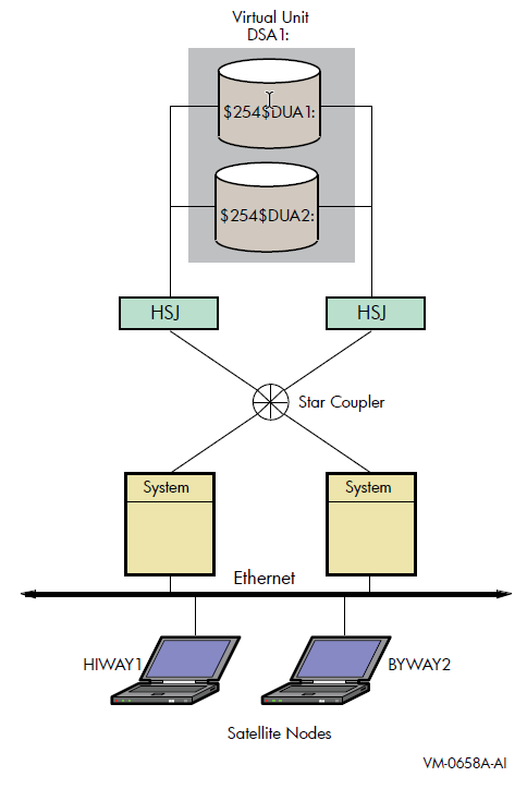
When a satellite node in Figure 3.1, ''Booting Satellite Nodes'' is booted, the boot node (MOP server) downline loads initial bootstrap code from the virtual unit DSA1. The boot node points the satellite to use either $254$DUA1 or $254$DUA2 as a boot device for the remainder of the boot process. Note that the boot node must have the virtual unit mounted. The satellite then forms the system disk shadow set locally according to the shadow set membership information stored in the SCB on the boot device.
SHOW DEVICES command displays how the shadow set appears
after the satellite node HIWAY1 is booted. In this example, the physical disk devices
are accessed through the MSCP server node BTNODE.$ SHOW DEVICES DSA1 Device Device Error Volume Free Trans Mnt Name Status Count Label Blocks Count Cnt DSA1: Mounted 0 MYVOLUME 181779 194 37 $254$DUA1: (BTNODE) ShadowSetMember 0 (member of DSA1:) $254$DUA2: (BTNODE) ShadowSetMember 0 (member of DSA1:) $
Chapter 4. Creating and Managing Shadow Sets Using DCL Commands
This chapter describes how to create, mount, dismount, and dissolve shadow sets using
interactive DCL commands. It also describes how to use the DCL command SET
SHADOW to manage merge and copy operations and to specify management
attributes for shadow set members located at different sites in a multiple-site OpenVMS
Cluster system. In addition, it describes how to use the DCL command SHOW
DEVICE and the lexical function F$GETDVI to access
current information about the state of shadow sets.
Volume Shadowing for OpenVMS improves data availability by ensuring that corresponding logical block numbers (LBNs) on multiple disk volumes contain the same information. Upon receiving a command to mount or dismount disks in a shadow set, the volume shadowing software may need to reconcile data differences and ensure that corresponding LBNs contain the same information.
An understanding of the copy and merge operations used for data reconciliation is essential to the discussions in this chapter. Therefore, you may find it helpful to refer to Chapter 6, "Ensuring Shadow Set Consistency" to understand how Volume Shadowing for OpenVMS ensures data availability and consistency during changes in shadow set membership.
4.1. Allocating Devices
MOUNT command, you can optionally allocate the device before
issuing the MOUNT command. Use the DCL command
ALLOCATE to provide your process with exclusive access to a
physical device until you either deallocate the device or terminate your process.
Optionally, you can associate a logical name with the device. The format for the
ALLOCATE command is as
follows:ALLOCATE device-name[:] logical-name[:]
4.2. Creating a Shadow Set
MOUNT command with the
/SHADOW qualifier to mount at least one physical disk into a
shadow set and assign a virtual unit name to the set, as shown in Example 4.1, ''Creating a Shadow Set''.$ MOUNT DSA23:/SHADOW
=$4$DUA9:
volume-label
logical-name
| Use the DSAn: format to name the shadow set virtual unit, where n
represents a unique number from 0 through 9999. If you do not include a
number after the DSA prefix, Each virtual unit number must be unique across the system, regardless of
whether or not the unit is mounted for public (mounted with the
|
| The |
| Use a non-zero allocation class for each physical device in the shadow
set. Use the allocation class naming format
$allocation-class$ddcu, where:
Note that you cannot use more than 3 letters for the ddc portion of the name. See VSI OpenVMS Cluster Systems Manual for more information about allocation classes. |
| Specify a 1- to 12-character volume label for the virtual unit. |
| Optionally, specify a 1- to 255-alphanumeric-character logical name string for the shadow set. |
In addition, you can specify /SYSTEM, /GROUP, or
/CLUSTER to make the shadow set available to all users of a
system, all members of a group, or all nodes in a cluster on which shadowing is
enabled.
To create a three-member shadow set, you can add two members in a single
MOUNT command to an existing one-member shadow set. This method
optimizes the I/O operation because both members are copied at
the same time. (See the example in Section 4.4.4, ''Creating a Shadow Set With /SYSTEM and With /CLUSTER''.)
You can also streamline the process of creating a shadow set by initialized multiple
devices in one command, using INITIALIZE/SHADOW/ERASE, as described
in Section 4.3, ''Using INITIALIZE/SHADOW/ERASE to Form a Shadow
Set''.
Upon receiving a command to create a shadow set, the volume shadowing software may
perform a copy or a merge operation to reconcile data differences. If you are not sure
which disks might be targets of copy operations, you can specify the
/CONFIRM or /NOCOPY qualifiers as a precaution
against overwriting important data when you mount a disk. These and other
MOUNT command qualifiers are discussed in Section 4.4, ''MOUNT Command Qualifiers for Shadowing''.
4.3. Using INITIALIZE/SHADOW/ERASE to Form a Shadow Set
You can use the DCL command INITIALIZE with the
/SHADOW and /ERASE command qualifiers to
initialize multiple members of a future shadow set. Initializing multiple members in
this way eliminates the requirement of a full copy when you later create a shadow
set.
INITIALIZE command with the /SHADOW and
/ERASE qualifiers performs the following operations:Formats up to six devices with one command, so that any three can be subsequently mounted together as members of a new host-based shadow set.
Writes a label on each volume.
Deletes all information from the devices except for the system files and leaves each device with identical file structure information.
All former contents of the disks are lost. You can then mount up to three of the devices that you have initialized in this way as members of a new host-based shadow set.
4.3.1. Benefits and Side Effects of Using /ERASE
VSI strongly recommends that you use the /ERASE qualifier. By
using the /ERASE qualifier, a subsequent merge operation will be
substantially reduced.
If you omit the /ERASE qualifier, then the portions of the
volume that do not contain file system data structures contain indeterminate data.
This data can differ from one shadow set member to another. Make sure to take this
into account when using utilities that compare all of the LBNs between shadow set
members.
The next time a full merge operation occurs, the presence of this indeterminate
data causes the merge to take much longer than it takes without the use of the
INITIALIZE/SHADOW/ERASE command. When this full merge
completes, the LBNs contain identical data, and the storage control block (SCB) no
longer indicates that the /ERASE qualifier was omitted from the
INITIALIZE/SHADOW command.
Note, however, that a side effect of using /ERASE is that the
ERASE volume attribute is set. In effect, each file on the volume is erased when it
is deleted. Another side effect is that an INITIALIZE/ERASE
operation is always slower than an INITIALIZE/NOERASE operation.
The disks are erased sequentially, which effectively doubles or triples the time it
takes for the command to complete. If the disks are large, consider performing
multiple, simultaneous INITIALIZE/ERASE commands (with the
/SHADOW qualifier) to erase the disks. After all the commands
have completed, then perform an INITIALIZE/SHADOW command with
the /ERASE qualifier.
You can remove the ERASE volume attribute by issuing the SET
VOLUME/NOERASE_ON_DELETE command.
For more information about these DCL commands and qualifiers, see the VSI OpenVMS DCL Dictionary: N–Z.
4.3.2. Requirements for Using INITIALIZE/SHADOW
Shadow set members can differ in size, that is, they can have different nonzero
values for Total Blocks. If devices of different sizes are specified in the
INITIALIZE command, and /SIZE or
/LIMIT or both are omitted, the default values for these
qualifiers take effect. The default value for /SIZE (for the
logical volume size for the device) is the smallest member’s MAXBLOCK value. The
default value for /LIMIT (for future expansion) is the largest
member’s MAXBLOCK value, which is used to compute the expansion limit.
You can view the Total Blocks value by entering the SHOW
DEVICE/FULL command. If a device has never been mounted or initialized
on this system, the SHOW DEVICE/FULL command for the device does
not display a value for Total Blocks. To correct this condition, either mount and
then dismount the device, or initialize the device. The Total Blocks value is then
displayed by SHOW DEVICE/FULL.
The use of INITIALIZE/SHADOW requires the VOLPRO
privilege.
Note that the INITIALIZE/SHADOW command must not be used to
initialize a disk to be added to an existing shadow set, since there is no benefit
to be gained.
INITIALIZE/SHADOW=(device_name1, device_name2, device_name3) label
4.3.3. INITIALIZE/SHADOW Examples
$ INITIALIZE /ERASE /SHADOW=($4$DKA1300, $4$DKA1301) NONVOLATILE $ MOUN/SYS DSA42 /SHAD=( $4$DKA1300 , $4$DKA1301 ) NONVOLATILE %MOUNT-I-MOUNTED, NONVOLATILE MOUNTED ON _DSA42: %MOUNT-I-SHDWMEMSUCC, _$4$DKA1300: (WILD3) IS NOW A VALID MEMBER OF THE SHADOW SET %MOUNT-I-SHDWMEMSUCC, _$4$DKA1301: (WILD4) IS NOW A VALID MEMBER OF THE SHADOW SET $ SHO DEV DSA42: DEVICE DEVICE ERROR VOLUME FREE TRANS MNT NAME STATUS COUNT LABEL BLOCKS COUNT CNT DSA42: MOUNTED 0 NONVOLATILE 5799600 1 1 $4$DKA1300: (WILD3) SHADOWSETMEMBER 0 (MEMBER OF DSA42:) $4$DKA1301: (WILD4) SHADOWSETMEMBER 0 (MEMBER OF DSA42:)
$ INITIALIZE /ERASE /SHADOW= $4$DKA1300 NONVOLATILE $ INITIALIZE /ERASE /SHADOW= $4$DKA1301 NONVOLATILE $ MOUN/SYS DSA42 /SHAD=( $4$DKA1300 , $4$DKA1301 ) NONVOLATILE %MOUNT-I-MOUNTED, NONVOLATILE MOUNTED ON _DSA42: %MOUNT-I-SHDWMEMSUCC, _$4$DKA1300: (WILD3) IS NOW A VALID MEMBER OF THE SHADOW SET %MOUNT-I-SHDWMEMSUCC, _$4$DKA1301: (WILD4) IS NOW A VALID MEMBER OF THE SHADOW SET $ SHO DEV DSA42: DEVICE DEVICE ERROR VOLUME FREE TRANS MNT NAME STATUS COUNT LABEL BLOCKS COUNT CNT DSA42: MOUNTED 0 NONVOLATILE 5799600 1 1 $4$DKA1300: (WILD3) ShadowSetMember 0 (member of DSA42:) $4$DKA1301: (WILD4) ShadowCopying 0 (copy trgt DSA42: 0% copied)
4.4. MOUNT Command Qualifiers for Shadowing
This section briefly describes the MOUNT command qualifiers that
are useful for shadow set management. See also the VSI OpenVMS System Management Utilities Reference Manual, Volume II: M–Z for complete
information about these and other DCL commands.
You must use the /SHADOW qualifier when you create a new shadow set
or when you add a member to an existing shadow set. You can also use the optional
qualifiers described in Table 4.1, ''MOUNT Command Qualifiers (Shadowing Specific)'' and in Table 4.2, ''Additional MOUNT Command Qualifiers (Not Shadowing Specific)''. These qualifiers require the VOLPRO and OPER
privileges, or your user identification code (UIC) must match the owner UIC of the
volume being mounted. To mount a shadow set throughout the system, you must also have
the SYSNAM privilege. In addition, the
MOUNT/POLICY=[NO]MINICOPY[=OPTIONAL] command requires the LOG_IO
privilege.
Detailed examples and descriptions of how to use these qualifiers are included in
Section 4.5, ''Adding Shadow Set Members''. In addition to the shadowing-specific qualifiers
described in Table 4.1, ''MOUNT Command Qualifiers (Shadowing Specific)'', the /NOASSIST,
/SYSTEM, /GROUP, and
/CLUSTER qualifiers are also frequently used when mounting shadow
sets, as described in Table 4.2, ''Additional MOUNT Command Qualifiers (Not Shadowing Specific)'' and in Section 4.4.2, ''Additional MOUNT Command Qualifiers Used for Shadowing''.
4.4.1. MOUNT Command Qualifiers Specific to Shadowing
MOUNT command qualifiers described in Table 4.1, ''MOUNT Command Qualifiers (Shadowing Specific)'' are specific to shadowing.|
Qualifier |
Function |
|---|---|
|
|
Controls whether the Mount utility issues a request to
confirm a copy operation when mounting a shadow set. The
default is |
|
|
Enables or disables copy operations on physical devices
named when mounting or adding to a shadow set. The default
is |
|
|
Automatically mounts and reinstates a shadow set to the
way it was before the shadow set was dissolved. The default
is |
|
|
Directs the Mount utility to proceed with shadowing, even
though the device or controller does not support forced
error handling. Using unsupported SCSI disks can cause
members to be removed from a shadow set if certain error
conditions arise that cannot be corrected, because some SCSI
disks do not implement |
|
|
Mounts a former shadow set member and zeroes the disk's shadow set generation number so that the disk is no longer marked as having been a member of the shadow set. |
|
Controls the setup and use of the shadowing minicopy function. This qualifier requires LOG_IO privilege. The meaning of [NO]MINICOPY[=OPTIONAL] depends on the
status of the shadow set. If the shadow set is not mounted,
either on a standalone system or on any cluster member, and
MINICOPY=OPTIONAL is specified, the shadow set is mounted
and a write bitmap is created. (A write bitmap enables a
shadowing minicopy operation.)
The OPTIONAL keyword allows the mount to continue, even if the system was unable to start the write bitmap. A bitmap could fail to start properly because of an improperly dismounted shadow set, a shadow set that requires a merge operation, or various resource problems. If the OPTIONAL keyword is omitted and the system is unable to start the write bitmap, the shadow set will not be mounted. If you specify
If NOMINICOPY is specified, the shadow set will be mounted but a write bitmap will not be created. If a former member of the shadow set is returned to the
shadow set, which has minicopy enabled, then a minicopy is
started instead of a full copy. This is the default behavior
and will occur even if you omit
If a minicopy cannot be started and the keyword OPTIONAL was omitted, the mount will fail. If NOMINICOPY is specified, then a minicopy will not be performed, even if one is possible. |
|
|
Controls whether every physical device specified with the
|
|
|
Requires that any member to be added to the shadow set have a volume label of SCRATCH_DISK. This helps ensure that the wrong disk is not added to a
shadow set by mistake. If you plan to use VERIFY_LABEL, then
before using this qualifier you must either initialize the
disk to be added to the set with the label SCRATCH_DISK, or
specify a label for the disk with the command The default behavior is NOVERIFY_LABEL, which means that the volume label of the copy targets will not be checked. This is the same behavior that occurred before the introduction of this qualifier. The volume label of the copy targets will not be checked. |
|
Directs the Mount utility to bind the specified physical devices into a shadow set represented by the virtual unit named in the command. |
Caution
Do not use the /OVERRIDE=IDENTIFICATION or
/NOMOUNT_VERIFICATION qualifiers when mounting shadow
sets. Using either of these qualifiers can result in loss of data.
If you mount a shadow set with the
/OVERRIDE=IDENTIFICATION qualifier, individual shadow
set members start with different volume labels, which can cause a volume to
lose data.
If you specify the /NOMOUNT_VERIFICATION qualifier, the
shadow set becomes unusable at the first state change of the shadow
set.
4.4.2. Additional MOUNT Command Qualifiers Used for Shadowing
MOUNT command qualifiers described in this section are not
specific to shadowing but can be very useful when creating shadow sets. These
additional qualifiers are described in Table 4.2, ''Additional MOUNT Command Qualifiers (Not Shadowing Specific)'' and in
the examples that follow.|
Qualifier |
Function |
|---|---|
/NOASSIST |
Successfully mounts a shadow set if at least one of the
devices included in the |
/SYSTEM |
Makes the volume available to all users on the system. Use
this qualifier when you add a disk to an existing shadow
set. If the |
/GROUP |
Makes the volume available to all users with the same
group number in their UICs as the user entering the
|
/CLUSTER |
Creates the virtual unit automatically on every node in
the cluster on which shadowing is enabled. Use this
qualifier if the shadow set is to be accessed across the
cluster. You must have the SYSNAM privilege to use this
qualifier. Using |
4.4.3. Creating a Shadow Set With /NOASSIST
You may occasionally find it useful to specify the /NOASSIST
qualifier on the MOUNT command. For example, you can use the
MOUNT/NOASSIST command in startup files to avoid failure of a
MOUNT command when a device you specify in the command is not
available. The /NOASSIST qualifier can be used in startup files
because operator intervention is impossible during startup.
MOUNT/NOASSIST command can successfully mount the shadow
set as long as at least one of the devices included in the MOUNT
command is available for mounting. Example 4.2, ''Using the /NOASSIST Qualifier'' shows an example of
the /NOASSIST qualifier and the resulting messages when one of
the members included in the command is not available for mounting.$ MOUNT/SYS DSA65:/SHADOW=($4$DIA6,$4$DIA5) GALEXY/NOASSIST %MOUNT-I-MOUNTED, GALEXY mounted on _DSA65: %MOUNT-I-SHDWMEMSUCC, _$4$DIA6: (READY) is now a valid member of the shadowset %MOUNT-I-SHDWMEMFAIL, $4$DIA5 failed as a member of the shadow set -SYSTEM-F-VOLINV, volume is not software enabled
Even though device $4$DIA5 is not available for mounting, the
MOUNT command continues to create the shadow set with $4$DIA6
as its only member. If the command did not include the /NOASSIST
qualifier, the MOUNT command would not mount the shadow
set.
4.4.4. Creating a Shadow Set With /SYSTEM and With /CLUSTER
When you create a shadow set, you must specify either the
/SYSTEM qualifier or the /CLUSTER
qualifier, or both (see Table 4.2, ''Additional MOUNT Command Qualifiers (Not Shadowing Specific)'') to provide access for
all users on a single system or on a cluster.
In Example 4.3, ''Using the /CLUSTER Qualifier'', if the shadow set (identified by its virtual unit
name DSA2) is not currently mounted, the first command creates a shadow
set with one shadow set member; the second command adds two more members to the
same shadow set. An automatic copy operation causes any
data on the second and third volumes to be overwritten as the shadow set members are
added.
MOUNT command, you have to specify only
/SYSTEM when you add the $6$DIA5 and $6$DIA6 devices to the
shadow set. Do not use /CLUSTER. These disks are added with the
same status that the shadow set currently has, which in this case is clusterwide
access.$ MOUNT DSA2: /CLUSTER /SHADOW=$6$DIA4: PEAKSISLAND DISK$PEAKSISLAND $ MOUNT DSA2: /SYSTEM/SHADOW=($6$DIA5:,$6$DIA6:) PEAKSISLAND DISK$PEAKSISLAND
4.5. Adding Shadow Set Members
Once a shadow set is created, you can add and remove individual members by mounting or dismounting physical disk devices. The shadowing software allows you to add and remove shadow set members at any time, transparently to user processes or applications running on the system.
4.5.1. Adding a Disk to an Existing Shadow Set
$ MOUNT/CONFIRM/SYSTEM DSA23: /SHADOW=($4$DUA9,$4$DUA3) volume-label
The command specifies both the currently active shadow set member ($4$DUA9) and the new member ($4$DUA3). Although it is not necessary to include them when mounting additional physical devices, you can specify current shadow set members without affecting their membership state.
Note that when you add volumes to an existing shadow set mounted across an OpenVMS Cluster system, the shadowing software automatically adds the new members on each OpenVMS Cluster node.
4.5.2. Creating a Two-Member Shadow Set and Adding a Third Member
$ MOUNT/SYSTEM DSA4: /SHADOW = ($3$DIA7:, $3$DIA8:)
FORMERSELF
%MOUNT-I-MOUNTED, FORMERSELF mounted on DSA4:
%MOUNT-I-SHDWMEMSUCC, _$3$DIA7: (DISK300) is now a valid member of
the shadow set
%MOUNT-I-SHDWMEMSUCC, _$3$DIA8: (DISK301) is now a valid member of
the shadow set
$ MOUNT/SYSTEM DSA4: /SHADOW = $3$DIA6: FORMERSELF
%MOUNT-I-SHDWMEMCOPY, _$3$DIA6: (DISK302) added to the shadow set
with a copy operationIn this example, the first command creates a shadow set whose virtual unit name is DSA4. The member disks are $3$DIA7 and $3$DIA8. The second command mounts the disk $3$DIA6 and adds it to shadow set DSA4. The shadow set now includes three members: $3$DIA6, $3$DIA7, and $3$DIA8. In this example, when you add $3$DIA6 after the shadow set already exists, the added volume becomes the target of a copy operation.
4.5.3. Checking Status of Potential Shadow Set Members With /CONFIRM
/CONFIRM qualifier or the /NOCOPY
qualifier. When you specify the /CONFIRM qualifier, as shown in
Example 4.5, ''Using the /CONFIRM Qualifier'', the MOUNT command displays
the targets of copy operations and prompts for permission before the operations are
performed. This precaution can prevent the erasure of important data. For more
information about copy operations, see Chapter 6, "Ensuring Shadow Set Consistency".$ MOUNT/CONFIRM DSA23: /SHADOW=($1$DUA4:,$1$DUA6:) SHADOWVOL
| This command instructs |
| Because a copy operation is necessary, the virtual unit name and the volume label are displayed. |
| The display also includes the physical device name, the volume label, and the volume owner of the potential shadow set member that requires the copy operation. |
| A response of No causes |
4.5.4. Checking Status of Potential Shadow Set Members With /NOCOPY
When you specify more than one disk, the shadowing software automatically
determines the correct copy operation to perform in order to make shadow set members
consistent with each other (see Section 6.2, ''Copy Operations'' for details). The
Mount utility interprets information recorded on each member to determine whether a
member requires a copy operation, a merge operation, or no copy operation. If you
are not sure which disks might be targets of copy operations, you can specify the
/CONFIRM qualifier or the /NOCOPY
qualifier as a precaution against overwriting important data when you mount a disk.
With the /NOCOPY qualifier, you disable the copy
operation.
/NOCOPY
qualifier to check the status of potential shadow set members before any data is
erased.$ MOUNT/NOCOPY DSA2: /SHADOW=($1$DUA4:,$1$DUA6:,$1$DUA7:) - _$ SHADOWVOL DISK$SHADOWVOL
| This command instructs |
|
|
| If the device does not contain valuable data, you can reenter the
|
| The shadow set is successfully mounted. The $1$DUA7 device is currently the target of a copy operation; it attains full shadow set membership when the copy operation completes. |
4.6. Mounting a Shadow Set on Other Nodes in the Cluster
/SHADOW qualifier is not required when you mount the same shadow
set on other nodes in the cluster. For example, if DSA42 is already mounted in the
cluster when a new node is brought into the cluster, you can use the following command
to mount DSA42 on the new
node:$ MOUNT/SYS DSA42: volume-label logical-name
Upon receiving this command, the volume shadowing software creates the virtual unit on the new node with the same members that currently exist on other nodes in the cluster.
4.6.1. Reconstructing a Shadow Set With /INCLUDE
$ MOUNT /SYSTEM DSA4/SHAD=($4$DIA1,$4$DIA2,$4$DIA3) NEWDISK
| This is the original |
| After all copy operations have completed, the
|
| The |
| Because the shadow set was properly dismounted, the shadow set members
are in a consistent state. The |
4.6.2. Mounting a Former Shadow Set Member as a Non-shadowed Disk
Occasionally, you have to mount a physical shadow set member as a nonshadowed disk. By default, when a shadow set member is mounted outside a shadow set, the Mount utility automatically write-locks the disk. This provides a safeguard against accidental modification, thereby allowing the disk to be remounted into a shadow set at a later time.
To override this default behavior, include the
/OVERRIDE=SHADOW_MEMBERSHIP qualifier on the
MOUNT command as shown in the following example:
$ MOUNT/OVERRIDE=SHADOW_MEMBERSHIP $4$DUA20: WORKDISK
This command ignores shadow set membership status and mounts a former shadow set member on $4$DUA20 as a nonshadowed disk with write access.
4.7. Managing Shadow Sets With SET SHADOW
Many of the SET SHADOW qualifiers, described in Table 4.3, ''SET SHADOW Command Qualifiers'', can be applied to individual shadow set members or to the
entire shadow set.
By using these qualifiers, system managers can override the default volume shadowing actions that can occur when the systems at one site of a multiple-site OpenVMS Cluster configuration fail or when a merge operation is required. Designed primarily for use in a configuration that uses Fibre Channel for a storage interconnect, either locally or site-to-site, these command qualifiers can be used in other configurations as well.
Similarly, the DCL command DISMOUNT was enhanced
by the addition of the qualifier
/FORCE_REMOVAL ddcu:. This
qualifier was added to give system
managers greater control of shadow set members located at different sites. For more
information about this qualifier, see Section 4.10.1, ''Removing Members from Shadow Sets''.
4.7.1. How to Use the Multiple-Site SET SHADOW and DISMOUNT Command Qualifiers
Earlier versions of OpenVMS that do not support MSCP failover to a served path.
Versions of OpenVMS Alpha that support MSCP failover to a served path but serve only a subset of their disks.
If you have chosen to serve only a subset of the disks in your configuration, you must use this configuration method for site recovery for the disks that are not served. One reason to serve only a subset of your disks is that failover of the served disks, from a Fibre Channel interconnect to the LAN interconnects and the inter-site link, can put a very heavy load on these interconnects, which can seriously degrade performance.
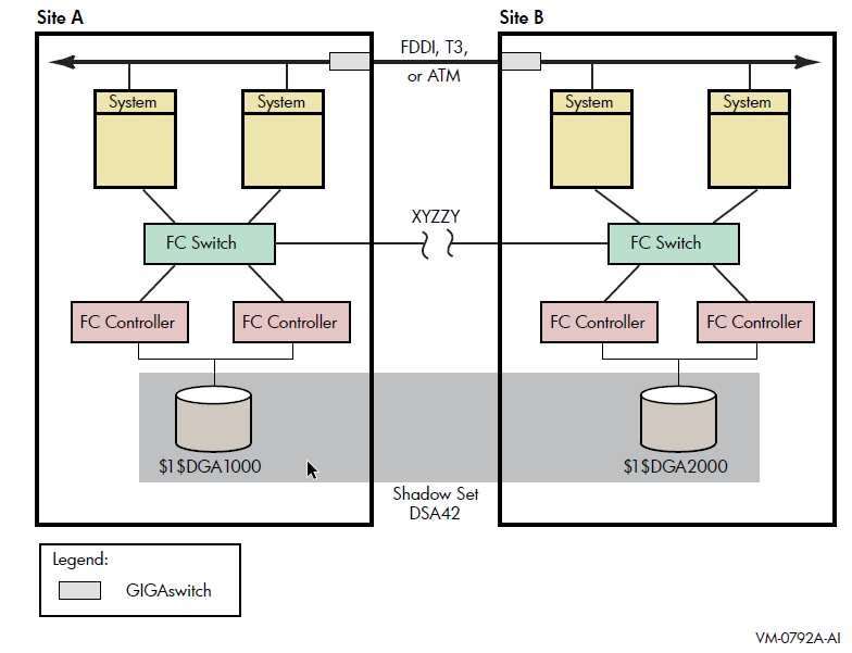
- Every device that is a member of a multiple-site shadow set must have its MEMBER_TIMEOUT setting raised to a high value, using the following command:
$ SET SHADOW /MEMBER_TIMEOUT=x ddcu:This command overrides the SHADOW_MBR_TMO value, is normally used for a shadow set member. A value for x of 259200 would be a 72-hour wait time.
Every shadow set that spans multiple sites must have its mount verification timeout setting raised to a very high value, higher than the MEMBER_TIMEOUT settings for each member of the shadow set.
Use the following command to increase the mount verification timeout setting for the shadow set:$ SET DEVICE /MVTIMEOUT=y DSAn
The y value of this command must always be greater than the x value of the
SET DEVICE /MEMBER_TIMEOUT=x ddcu:command.The
SET DEVICE /MVTIMEOUT=ycommand overrides the MVTIMEOUT value, which is normally used for the shadow set. A value for y of 262800 would be a 73-hour wait.Every shadow set and every shadow set member must have a site qualifier. As already noted, a site qualifier ensures that the read cost is correctly set. The other critical factor is three-member shadow sets. When they are being used, the site qualifier will ensure that the master member of the shadow set is properly maintained.
Figure 4.1, ''Multiple-Site OpenVMS Cluster System With FC and LAN Interconnects'' shows a shadow set DSA42, whose members are devices $1$DGA1000 and $1$DGA2000. Systems at Site A or Site B have direct access to all devices at both sites via Fibre Channel connections. XYZZY is a theoretical point between the two sites. If the Fibre Channel connection were to break at this point, each site could access different "local" members of DSA42 without error.
For the purpose of this example, Site A will be the sole site chosen to retain access to the shadow set.
- On Site A, issue the following command:
$ DISMOUNT /FORCE_REMOVAL= $1$DGA2000:
Once the command has completed, the shadow set is available for use only at site A.
- On Site B, issue the following command:
$ SET DEVICE /ABORT_VIRTUAL_UNIT DSA42:
Once the command has completed, the shadow set status will be
MntVerifyTimeout. - Next, issue the following command to free up the shadow set:
$ DISMOUNT/ABORT DSA42:
These steps must be taken for all affected multiple-site shadow sets.
4.8. Managing Copy and Merge Operations
Copies and merges performed by the volume shadowing software are regulated
automatically by the locking software and by the setting of SHADOW_MAX_COPIES. The
SET SHADOW
command
provides better control over the order of copies and merges and allows you to specify
the systems on which the copy operations must take place.
All SET SHADOW qualifiers pertain to shadow sets (DSAn:), and some
can also be applied to individual shadow set members (ddcu:), as described in Table 4.3, ''SET SHADOW Command Qualifiers''. For most qualifiers that take a shadow set as a parameter,
the /ALL qualifier can be used in place of the shadow set name to
indicate that the requested action applies to all shadow sets on the system.
The qualifiers remain in effect until the device (shadow set or shadow set member) is
dismounted. If the device is remounted (in the case of a shadow set member, returned to
the shadow set from which it was dismounted), the qualifier must be specified again. The
SET SHADOW command requires the SYSPRV privilege.
Note
The qualifiers /DELETE, /DISABLE,
/ENABLE, /NAME, and
/POLICY are used only to manage host-based minimerge (HBMM)
operations and do not apply to other operations. If you specify any other (non-HBMM)
qualifiers in a command that includes HBMM qualifiers, the command fails. For more
information about HBMM, see Chapter 8, "Host-Based Minimerge (HBMM)".
The following example shows how to specify qualifiers for a shadow set:
$ SET SHADOW DSAn:/qualifier/qualifier
| Qualifier | Function |
|---|---|
|
Aborts mount verification on the specified shadow set or on all
shadow sets in mount verification on the system. Use this qualifier
when you know that the unit cannot be recovered. When you use this
qualifier, the shadow set must be in mount verification. The shadow
set aborts mount verification immediately on the system from which
the command is issued. If the shadow set is not in mount
verification, this command returns the error
After this command completes, the shadow set must still be dismounted. Use the following command to dismount the shadow set: $ DISMOUNT/ABORT/OVERRIDE=CHECKS DSAn |
/ALL |
Causes the command to operate on all shadow sets that are mounted on the system from which the command is issued.
|
|
|
Specifies whether a query is made before each merge operation to
confirm that the operation must be performed on the designated
shadow set. This qualifier can be used only in conjunction with the
You can enter word responses in uppercase or lowercase letters,
and words can be abbreviated to one or more letters. If you enter an
illegal response, DCL redisplays the prompt. For examples, see the
|
|
Specifies which source member of a shadow set to use as the source
for read data during full copy operations when a third member is
added to a shadow set that contains two full members. This qualifier
affects only those copy operations that do not use disk copy data
(DCD) commands. The source specified by this qualifier persists
until the shadow set is dismounted. Some storage controllers, such
as the HSG80, have a read-ahead cache, which significantly improves
a device’s read performance. Copy operations normally alternate
reads between the two source members, which effectively nullifies
the benefits of the read-ahead cache. This qualifier lets you force
all reads from a single, specified source member for the duration of
a copy operation. In addition to improving copy performance,
|
|
Used only in conjunction with $ SET SHADOW /DELETE DSA1 /POLICY=HBMM In contrast, the following command removes COMPANY_POLICY from the cluster: $ SET SHADOW /DELETE /NAME=COMPANY_POLICY /POLICY=HBMM You cannot delete the NODEFAULT policy, nor can you specify
|
/DEMAND_MERGE |
Initiates a merge operation on the specified shadow set. This
qualifier is useful if the shadow set was created with the
You cannot specify An OPCOM message is displayed for each shadow set indicating that a demand merge has been invoked and recording the process ID (PID) of the process that executed the command. For example: %%%%%%%%%%% OPCOM 9-MAR-2004 10:35:23.24 %%%%%%%%%%% Message from user SYSTEM on NODE1 Demand Merge requested for _DSA721:, PID: 2760009A |
|
Disables host-based minimerge (HBMM) on the specified shadow set or clusterwide on all shadow sets. HBMM is the only supported value for |
/DISABLE=SPLIT_READ_LBNS | Disables the split behavior of LBNs and as a result the reads are alternated between the source shadow set members having the same read_cost and device queue length. |
/ENABLE=HBMM |
Enables host-based minimerge (HBMM) on the specified shadow set or across the entire cluster if an applicable HBMM policy exists. HBMM is the only supported value for |
/ENABLE=SPLIT_READ_LBNS | Logically divides the shadow set members having the same read cost into equal groups of LBNs. When a virtual unit performs a read, it does so by reading from the corresponding LBN group. This results in the maximum usage of the controller read-ahead cache. |
|
|
Forces the system to evaluate whether it must act on most shadow copy and merge operations currently being managed on the system. It cancels most operations and then, based on the value of system parameter SHADOW_MAX_COPY and the copy/merge priority of each shadow set, it evaluates the order in which the pending copies and merges should be restarted. RESOURCES is the only supported value for
EVALUATE does not apply to MSCP-based minimerge operations.
MSCP-based minimerge operations are not subject to cancellation and
restart by This command is intended to be used after changing the value of
the dynamic system parameter SHADOW_MAX_COPY or after issuing a
|
|
|
Expels the specified shadow set member from the shadow set. The
specified device must be a member of a shadow set that is mounted on
the system where the command is issued. You cannot specify
If connectivity to a device has been lost and the shadow set is in mount verification, this qualifier causes the member to be expelled from the shadow set immediately. If the shadow set is not currently in mount verification, no
immediate action is taken. If connectivity to a device has been lost
but the shadow set is not in mount verification, this qualifier lets
you flag the member to be expelled from the shadow set as soon the
shadow set enters mount verification. If no action has been taken on
the specified member and you wish to clear the flag, use
If the shadow set is dismounted before the member is expelled, the FORCE_REMOVAL request expires. |
/LOG | Instructs the volume shadowing software to display a brief message
confirming that the SET SHADOW command completed. If
/OUTPUT is also specified, this information is
written to the output file. |
|
|
Specifies the timeout value to be used for a shadow set member. The specified device must be a member of a shadow set that is mounted on the system where the command is issued. The value supplied by this qualifier overrides the system parameter SHADOW_MBR_TMO for this specific device. Each member of a shadow set can be assigned a different MEMBER_TIMEOUT value. The valid range for n is 1 to 16777215 seconds. The timeout value set by |
|
|
Specifies the mount verification timeout value to be used for all shadow sets on the cluster or for the shadow set, specified by its virtual unit name (DSAn:). The specified shadow set must be mounted on the system where the command is issued. The value supplied by this qualifier overrides the value specified by the system parameter MVTIMEOUT for this specific shadow set. NoteYou cannot change the value of MVTIMEOUT for a system disk. Any attempt to do so results in an error. The valid range for n is 1 to 16777215 seconds. The timeout value set by |
/NAME=policy-name |
Used with Policy names are case insensitive and must consist of 1 to 64 characters. Only letters, numbers, the dollar sign ($), and the underscore (_) are allowed. If you create a default policy, you must assign it the name DEFAULT. For details about creating and using policy names, see Chapter 8, "Host-Based Minimerge (HBMM)". |
/OUTPUT=file-name | Outputs any messages to the specified file. |
|
Creates or deletes a policy for host-based minimerge (HBMM). HBMM is the only supported value for the
When When Deleting bitmaps with the When defining a policy, you use five keywords (MASTER_LIST, COUNT, RESET_THRESHOLD, MULTIUSE, and DISMOUNT) to control the placement and management of HBMM bitmaps. An HBMM policy specification consists of a list of these keywords enclosed within parentheses. Only the MASTER_LIST keyword is required. If the COUNT and RESET_THRESHOLD keywords are omitted, default values are applied. The MULTIUSE and DISMOUNT keywords specify the number of bitmaps to be converted to multiuse bitmaps during the automatic and manual removal of members respectively. If MULTIUSE is omitted, the automatic minicopy on volume processing is not enabled. As a result, none of the HBMM bitmaps are converted to multiuse bitmaps. If DISMOUNT is omitted, a maximum of six HBMM bitmaps can be used as multiuse bitmaps.
|
/PRIORITY=n
DSAn: |
Overrides the current default priority setting. Priorities range
from 0 (lowest) to 10000 (highest). The default priority is 5000. A
shadow set with a priority of 0 is never considered for a merge or a
copy on the system. When a recovery operation (that is, either a
merge or a copy) is needed on multiple shadow sets, the shadow sets
are recovered in priority order from highest to lowest. The priority
setting is system specific; any change in priority made on a single
system does not propagate to the entire cluster and does not persist
across a system reboot. Once this qualifier has been applied to a
shadow set that is mounted, the setting persists across any
subsequent For more information about using this qualifier, see Section 4.9, ''Prioritizing Merge and Copy Operations''. |
|
Enables you to modify the default “cost” assigned to each shadow set member (ddcu:). By modifying the assignments, you can bias the reads in favor of one member of a two-member shadow set, or, in the case of three-member shadow sets, in favor of one or two members of the set over the remaining members. The device specified must be a member of a shadow set that is mounted on the node where the command is issued. The valid range for the specified cost (n) is 1 to 65,535 units.
You cannot specify The shadowing driver assigns default READ_COST values to shadow set members when each member is initially mounted. The default value depends on the device type and its configuration relative to the system mounting it. The following list of device types is ordered by the default READ_COST assignments, from the lowest cost to the highest cost:
The value supplied by the Different systems in the cluster can assign different costs to each shadow set member. When you specify a shadow set (DSAn) instead of a shadow set member, the read cost setting for all shadow set members reverts to the default read cost settings established automatically by the shadowing software. The specified shadow set must be mounted on the system where the command is issued. You an specify any value for the cost; the value is ignored, and the setting reverts to the default settings. After you have applied this qualifier to a member, the setting remains in effect as long as the member is part of the shadow set. If the member is removed from the shadow set and later returned, this qualifier must be specified again. If the Reads requested for a shadow set from a system at site 1 are performed from a shadow set member that is also at site 1. Reads requested for the same shadow set from site 2 can read from the member located at site 2. NoteDECram can shadow a DECram disk to a physical disk. However, be aware that in the current implementation of Volume Shadowing for OpenVMS, if the physical disk goes away, you are writing to a volatile disk. |
/RESET_COUNTERS |
Resets the shadowing-specific counters that are maintained for each shadow set. Counters that are reset to zero (0) are:
You can display the current settings of the counters using the
|
|
Allows the system manager to adjust the rating assigned to a
system based on a delay assessed for each MSCP served shadow set
member on that system. The value specified by this qualifier
overrides the value established by the SHADOW_PSM_RDLY system
parameter. The default delay for each MSCP served member is 30
seconds and the valid range for the specified delay is 0 through
65,535 seconds. When a copy or merge operation is needed on a shadow
set that is mounted on multiple systems, OpenVMS Volume Shadowing
attempts to perform this work on a system that has a local
connection to all of the shadow set members. Systems are rated with
a penalty (delay time) assessed for each shadow set member that is
MSCP served to the system. No delay is added for local members, so a
system with all locally accessible shadow set members is likely to
perform the work before a system where one or more members is
served. If |
/SITE = n {ddcu:|
DSAn:} |
Indicates to the shadowing driver the site location of the specified shadow set (DSAn:) or shadow set member (ddcu:). The SHADOW_SITE_ID system parameter defines the default site location of the shadow set. You can override the default location of the shadow set with this qualifier. The valid range for the site location, represented by n, is 1 through 255. If After you apply this qualifier, the setting remains in effect
until you change it using a This qualifier can improve read performance because the member
that is physically local to the system is the preferred disk from
which to read, provided that you specify the
|
/STALL=WRITES[=nnn] |
Pauses the write operations for nnn seconds. The default time is SHADOW_MBR_TMO. If a value is not specified for nnn, the lock on write operations is released after SHADOW_MBR_TMO seconds. For example: SET SHADOW DSA42 /STALL=WRITES In this example, the writes are stalled to the shadow set for a period of SHADOW_MBR_TMO seconds. SET SHADOW DSA42 /STALL=WRITES=60 In this example, the writes are stalled to the shadow set for a period of 60 seconds. |
/NOSTALL=WRITES[=nnn] |
Releases the lock on write operations after the specified period (nnn seconds). After the specified period is over, writes are allowed to the shadow set members. See the following example: SET SHADOW DSA42 /STALL=WRITES=60 SET SHADOW DSA42 /NOSTALL=WRITES=30 In this example, initially the write operations are locked for a
period of 60 seconds. On providing the |
4.8.1. Using /DEMAND_MERGE to Start a Merge Operation
The /DEMAND_MERGE qualifier was created to force a merge
operation on shadow sets that were created with the
INITIALIZE/SHADOW command without specifying the
/ERASE qualifier. The /DEMAND_MERGE
qualifier ensures that all blocks not in use by active files are the same. The
system manager can enter this command at a convenient time. If the
/ERASE qualifier was not used when the shadow set was created
with /INITIALIZE/SHADOW, and the SET
SHADOW/DEMAND_MERGE command has not been executed, then the higher
overhead of a full merge operation on this shadow set is encountered after a system
failure.
System managers can also use the SET SHADOW/DEMAND_ MERGE
command if the ANALYZE/DISK/SHADOW command found differences
between the members of the shadow set (see Section 4.11.4, ''Using ANALYZE/DISK/SHADOW to Examine a Shadow Set'').
4.8.2. SHOW SHADOW Management Functions
The SHOW SHADOW command reports on the status of the specified
shadow set and indicates whether a merge or copy operation is required, depending on
the qualifier that you specify. If a merge or copy operation is required, this
command reports whether it is pending or in progress. The qualifiers are described
in this section. To use this command, specify the shadow set’s virtual unit name,
followed by the qualifiers you want to use, as shown in the following
example:
$ SHOW SHADOW DSAnnnn:/qualifier/qualifier/
/ACTIVE
This qualifier returns one of three possible states:
Merge or copy is not required
Copy is in progress on node nnnnx at LBN xxxx
Merge is in progress on node nnnnx
/COPY
This qualifier returns one of three possible states:
Copy is not required
Copy is pending
Copy is in progress on node nnnnx at LBN xxxx
/MERGE
This qualifier returns one of three possible states:
Merge is not required
Merge is pending
Merge is in progress on node nnnnx at LBN xxxx
/OUTPUT=file-name
This qualifier outputs any messages to the specified file.
Example 4.8, ''SHOW SHADOW Sample Output'' shows sample output from the SHOW
SHADOW command:
$SHOW SHADOW DSA716: _DSA716: TST716 Virtual Unit SCB Status: 0001 - normal Local Virtual Unit Status: 00000010 - Local Read Total Devices 2 VU_UCB 810419C0 Source Members 2 SCB LBN 000009C8 Act Copy Target 0 Generation 00A15F90 Act Merge Target 0 Number EDA9D786 Last Read Index 0 VU Site Value 5 Master Mbr Index 0 VU Timeout Value 3600 Copy Hotblocks 0 Copy Collisions 0 SCP Merge Repair Cnt 0 APP Merge Repair Cnt 0 Device $252$DUA716 Master Member Index 0 Status 000000A0 src,valid Ext. Member Status 00 Read Cost 42 Site 5 Member Timeout 120 UCB 8116FF80 Device $252$DUA1010 Index 1 Status 000000A0 src,valid Ext. Member Status 00 Read Cost 500 Site 3 Member Timeout 120 UCB 811DD500
4.9. Prioritizing Merge and Copy Operations
The SET SHADOW command provides control to system administrators
for managing merge and copy operations with the qualifiers
/PRIORITY=n and
/EVALUATE=RESOURCES, and a system parameter SHADOW_REC_DLY. Using
these parameters, system managers can:
Prioritize shadow sets for merge and copy operations on a per-system basis.
Control which system performs a merge or copy operation of a particular shadow set.
Modify the SHADOW_MAX_COPY system parameter, which take effect immediately.
4.9.1. Default Management of Merge and Copy Operations
If a system fails or if it aborts a shadow set, most commonly through mount verification, it is termed as a significant event. When one of these significant events occurs, all systems in the cluster are notified automatically. This notification causes all shadow server processes to stop any full merge or full copy operations and release all the resources performing these operations. Thus, every system can reallocate its resources to newer, higher-priority work.
After a predetermined delay, each system with a non-zero SHADOW_MAX_COPY setting begins to process the shadow sets that are in a transient state, according to their priority. The predetermined delay is governed by the new system parameter SHADOW_REC_DLY. (For more information about SHADOW_REC_DLY, see Table 3.1, ''Volume Shadowing Parameters'' and Section 4.9.5, ''Controlling Which Systems Manage Merge and Copy Operations''.) Every system allocates the available SHADOW_MAX_COPY resources based on a shadow set's priority.
A shadow set is in a steady state when it is known that all members contain identical data. If a shadow set has one or more of the following operations pending, or one operation active, it is said to be in a transient state:
Minimerge
Minicopy
Full copy
Full merge
While a combination of these transient states is valid, only one operation at a time can be performed. For example, consider that HBMM is not enabled. After a device is added to a shadow set, it is marked as being in a full copy transient state. If the system on which this shadow set is mounted fails, the shadow set is further marked as being in a full merge state. In this example, the full copy operation is performed before the full merge is started.
Note
The priority assigned to a shadow set does not affect the hierarchy of transient state operations.
4.9.2. Hierarchy of Transient State Operations
Shadow set operations for a specific shadow set are performed in the following order:
Minimerge
Copy (either minicopy or full copy)
Full merge
4.9.3. Assigning Priorities to Shadow Sets
When first mounted on a system, every shadow set is assigned a default priority of
5000. You can assign a unique priority to every mounted shadow set on a per-system
basis using the SET SHADOW/PRIORITY=n
DSAn command. Every shadow set can have a
unique priority per system, or shadow sets can be assigned the same priority. Shadow
sets with the same priority are managed in a consistent way for each release.
However, the order in which shadow sets with the same priority are managed may
change from release to release because of changes to the algorithm. Therefore, if
the order is important, assign them different priorities.
The valid range for priority values is 0 through 10,000. The higher the assigned
value, the higher the priority. To ensure that high-priority volumes are merged (or
copied) before less important volumes, use SET
SHADOW/PRIORITY=n DSAn
command to override the default priority assignment on a system.
A priority level of 0 has a unique meaning. It means that the shadow set is not considered for merge or copy operations on this system.
Note
After the notification of a significant event and the allocation of a system's resources, it is not possible to directly affect any of the current merge or copy operations on the system by assigning a different priority level to one or more shadow sets. If you have to re-prioritize one or more shadow sets, you must use another technique, as described in Section 4.9.8, ''Managing Transient States in Progress''.
4.9.4. Displaying Shadow Set Priority Values
You can display the priority of a shadow set on a specific system by issuing the following command:
$ SHOW SHADOW/BY_PRIORITY DSAn:
This command displays the current priority and status of the specified shadow set. If any copy or merge operations are in progress, the node on which the operation is progressing is displayed, along with its progress. For example:
$ SHOW SHADOW DSA1104/BY_PRIORITY Device Mbr Active Name Cnt Priority Virtual Unit State on Node _DSA1104: 2 5000 Merge Active (29%) MAX
You can use the SHOW SHADOW/BY_PRIORITY command to display the
priority level and the status for all of the shadow sets that exist on the system.
The status indicates whether the shadow set is currently undergoing a copy or merge
operation or whether one is required. If either or both operations are underway, the
systems on which they occur are identified in the display, as shown in the following
example:
$ SHOW SHADOW/BY_PRIORITY Device Mbr Active Name Cnt Priority Virtual Unit State on Node _DSA106: 2 10000 Steady State _DSA108: 3 8000 Steady State _DSA110: 3 8000 Steady State _DSA112: 3 8000 Steady State _DSA114: 1 7000 Steady State _DSA116: 1 7000 Steady State _DSA150: 2 7000 Steady State _DSA152: 7000 Not Mounted on this node _DSA154: 3 6000 Steady State _DSA156: 1 6000 Steady State _DSA159: 2 5000 Steady State _DSA74: 3 5000 Merge Active (47%) CASSID _DSA304: 2+1 5000 Merge Active (30%), Copy Active (3%) MAX _DSA1104: 2 5000 Merge Active (29%) MAX _DSA300: 2+1 5000 Merge Active (59%), Copy Active (0%) MAX _DSA0: 1+2 5000 Copy Active (83%) CASSID _DSA3: 2 3000 Steady State _DSA100: 2 3000 Steady State _DSA102: 1 3000 Steady State _DSA104: 3 3000 Steady State Total of 19 Operational shadow sets; 0 in Mount Verification; 1 not mounted $
In this example, the 20 shadow sets on this system are displayed in their priority order. In the event of a failure of another system in the cluster that has these shadow sets mounted, the shadow sets are merged in this order on the system.
The Mbr Cnt field shows the number of source members in each shadow
set. If members are being added via a copy operation, this is indicated by
+1 or +2. Therefore, 2+1 indicates two
source members and one member being added. The notation 1+2 indicates
one source member and two members being copied into the set.
The summary line provides the total number of shadow sets that were found to be in
the various conditions. Operational shadow sets are shadow sets that
are mounted with one or more members and may or may not have copy or merge
operations occurring. These shadow sets are available to applications for reads and
writes. Mount Verification indicates the number of shadow sets that are
in some mount verification state. Shadow sets that have exceeded their mount
verification timeout times are also included in this total.
For additional examples, see the SHOW SHADOW examples in the
VSI OpenVMS DCL Dictionary: N–Z.
4.9.5. Controlling Which Systems Manage Merge and Copy Operations
When a system fails or aborts a shadow set, this significant event causes every shadow set to be reassessed by all other systems with that shadow set mounted. All active minimerge, full merge, or copy operations cease at this time, returning their resources to those systems. (However, if a system is performing a minicopy operation, that operation continues to completion.)
These systems wait a predetermined amount of time, measured in seconds, before each attempts to manage any shadow set in a transient state. This pause is called a significant-event recovery delay. It is the total of the values specified for two system parameters, SHADOW_REC_DLY and RECNXINTERVAL. (The default value for each is 20 seconds.)
If the value of the significant-event recovery delay is the same on all systems, it is not possible to predict which systems manage which shadow set. However, by making the value of the significant-event recovery delay different on all systems, you can predict when a specific system begins to manage transient-state operations.
4.9.6. Managing Merge Operations
A merge transient state is an event that cannot be predicted. The management of merge activity, on a specific system for multiple shadow sets, can be predicted if the priority level settings for the shadow sets differ.
The following example illustrates how the priority level is used to select shadow sets when only merge operations are involved. In this example:
There are four shadow sets
The SHADOW_MAX_COPY parameter on this system is equal to 1. (The value of 1 means that only one merge or copy operation can occur at the same time.)
Two shadow sets are assigned a priority level and two have the default priority level of 5000.
The four shadow sets DSA1, DSA20, DSA22, and DSA42 are mounted on two systems.
DSA20 and DSA42 are minimerge enabled.
$ SET SHADOW/PRIORITY=7000 DSA1: $ SET SHADOW/PRIORITY=3000 DSA42: ! DSA20: and DSA22: are at the default priority level of 5000
When one of the systems in this example fails, all shadow sets are put into a merge-required state. After the significant-event recovery delay time elapses, this system evaluates the shadow sets, and the operations are performed in the following order:
A minimerge operation starts first on DSA20, even though its priority of 5000 is lower than DSA1's priority of 7000. A minimerge operation always takes precedence over other operations. DSA20 and DSA42 are both minimerge enabled, but DSA20's higher priority causes its minimerge operation to start first.
A minimerge operation starts on DSA42. Its priority of 3000 is the lowest of all the shadow sets, but a minimerge operation takes precedence over other operations.
Because there are no other minimerge capable units, DSA1, with a priority level of 7000, is selected to start a merge operation, and it runs to completion.
A merge operation starts on DSA22, the one remaining shadow set whose priority is the default value of 5000, and runs to completion.
4.9.7. Managing Copy Operations
A copy transient state can be predicted by the user because it is the result of direct user action. Therefore, a full copy operation caused by adding a device to a shadow set is not considered a significant event in the cluster. The copy operation is managed by the first system that has an available resource.
In the following example, assume that there are four shadow sets, and the SHADOW_MAX COPY parameter on this system is equal to 1. Note that the for shadow sets that are not assigned a specific level, a default priority level is assigned.
For the following example, assume that:
DSA1, DSA20, DSA22, and DSA42 are mounted on multiple systems.
Only DSA42 is minimerge enabled.
DSA22 is already in a full copy state being managed on this system.
DSA1 has a priority level of 7000.
DSA42 has a priority level of 3000.
DSA20 has a priority level of 3000.
DSA22 has a default priority level of 5000.
The user adds a device to DSA1. This is not a significant event, and this system does not interrupt the full copy operation of the DSA22 in favor of performing the DSA1 full copy operation.
To expand on this example, assume that a system fails (a significant event) before the copy operations have completed. All shadow sets are put into a merge required state. Specifically, DSA1, DSA20, and DSA22 are put into a full merge state, and DSA42 is put into a minimerge state.
After the significant event recovery delay expires, this system begins to evaluate all the shadow sets in a transient state. The operations take place in the following order:
A minimerge operation starts on DSA42 and continues until completion. This operation takes priority over other operations, regardless of its priority level.
A copy operation starts on DSA1. The full merge operation is not started because a copy operation takes precedence over a full merge operation.
A merge operation is started and completed on DSA1.
A copy operation is started and completed on DSA22.
A merge operation is started and completed on DSA22.
A merge operation is started and completed on DSA20.
Thus, in this example, the priority level is used to direct the priority of merge and copy operations on this system.
4.9.8. Managing Transient States in Progress
SHADOW_MAX_COPY is a dynamic system parameter that governs the use of system resources by shadowing. Shadowing can be directed to immediately respond to changes in this parameter setting using the following DCL command:
$ SET SHADOW/EVALUATE=RESOURCES
This command stops all the current merge and copy operations on the system on which it is issued. It then restarts the work using the new value of SHADOW_MAX_COPY.
This command is also useful in other circumstances. For example, if a shadow set
has a priority level 0 or another low value, the SET SHADOW
/PRIORITY=n command can be used to increase
the value. Then, using the /EVALUATE=RESOURCES qualifier, the
priority of shadow sets in a transient state is reevaluated.
The /PRIORITY and /EVALUATE=RESOURCES
qualifiers can be used on the same command line.
When a significant event occurs, all of the SHADOW_MAX_COPY resources are applied.
If the value of SHADOW_MAX_COPY is modified using the SYSGEN SET
and WRITE ACTIVE commands, and then a SET
SHADOW/EVALUATE=RESOURCES is issued, the new value of SHADOW_MAX_COPY
has a direct and immediate effect.
To determine which system is controlling a transient operation, enter the following command:
$ SHOW SHADOW/ACTIVE DSAn:
To determine the priority values assigned to each shadow set, enter the following command:
$ SHOW SHADOW/BY_PRIORITY DSAn:
4.10. Removing Members and Dissolving Shadow Sets
You can remove shadow set members and dissolve shadow sets with the DCL command
DISMOUNT. You must have GRPNAM and SYSNAM user privileges to
dismount group and system volumes. You must also have the LOG_IO user privilege to use
the /POLICY=[NO]MINICOPY [=OPTIONAL] qualifier.
The DISMOUNT command has the following format:
DISMOUNT {device-name[:] virtual-unit-name}The action taken differs depending on whether you specify an individual shadow set
member or the shadow set (by its virtual unit name) on the DISMOUNT
command:
If you specify the device name of a shadow set member, only that member is dismounted, and the remaining shadow set members continue servicing I/O requests.
If you specify a shadow set virtual unit, all shadow set members are dismounted and the shadow set is dissolved.
To dismount a shadow set that is mounted across an OpenVMS Cluster system, include the
/CLUSTER qualifier with the DISMOUNT command.
If you dismount a shadow set without including the /CLUSTER
qualifier, only the node from which you issued the command dismounts the shadow set. The
shadow set remains operational on the other OpenVMS Cluster nodes that have the shadow
set mounted.
If the disks on your system are neither SCSI nor Fibre Channel disks, you can use the
/NOUNLOAD qualifier on the DISMOUNT command to
prevent the disk volume or volumes from spinning down. The devices remain in a ready
state. If you specify the /UNLOAD qualifier when dismounting a
virtual unit, the disk volumes are physically spun down after the shadow set is
dissolved. See the VSI OpenVMS DCL Dictionary: A–M for more information about using the
DISMOUNT command and its qualifiers.
4.10.1. Removing Members from Shadow Sets
To remove an individual member from a shadow set, specify the name of the physical
device with the DISMOUNT command. For example:
$DISMOUNT $5$DUA7:
When you dismount an individual shadow set member, all outstanding I/O operations are completed and the member is removed from the set.
The /FORCE_REMOVAL ddcu: qualifier is
available. If connectivity to a device has been lost and the shadow set is in mount
verification, /FORCE_REMOVAL ddcu: can be
used to immediately expel a named shadow set member (ddcu: ) from the shadow set. If
you omit this qualifier, the device is not dismounted until mount verification
completes. Note that this qualifier cannot be used in conjunction with the
/POLICY=[NO]MINICOPY [=OPTIONAL] qualifier.
The device specified must be a member of a shadow set that is mounted on the node where the command is issued.
The /FORCE_REMOVAL qualifier gives system managers greater
control of shadow sets whose members are located at different sites in an OpenVMS
Cluster configuration. SET SHADOW command qualifiers are also
available for specifying management attributes for shadow set members located at the
same or different sites, as described in Section 4.7, ''Managing Shadow Sets With SET SHADOW
'' and in
Section 4.8, ''Managing Copy and Merge Operations''.
Note
You cannot dismount a device if it is the only source member in a shadow set.
All shadow sets must have at least one valid source member. If you try to
dismount the only source member device, the DISMOUNT command
fails and returns the message:
%DISM-F-SRCMEM, Only source member of shadow set cannot be dismounted
The only way to dismount the last source member of a shadow set is to dissolve
the shadow set by specifying the virtual unit name on the
DISMOUNT command.
4.10.2. Dissolving Shadow Sets
The way you dissolve a shadow set depends on whether it is mounted on a single
system or on two or more systems in an OpenVMS Cluster system. In both cases, you
use the DISMOUNT command. If the shadow set is mounted on a
single system, you can dissolve the shadow set by specifying its virtual unit name
with the DISMOUNT command. If the shadow set is mounted in a
cluster, you must include the /CLUSTER qualifier to dissolve the
DSA36 shadow set across the cluster. For example:
$ DISMOUNT /CLUSTER DSA36:
Dismounting the shadow set can be done only after all files are closed, thereby ensuring that the dismounted disks are fully consistent from a file system perspective. The dismount operation marks the shadow set members as being properly dismounted so that a rebuild is not required the next time the disks are mounted. However, if a merge operation was either pending or in progress, then the dismount operation marks the shadow set members as being improperly dismounted and requires a merge operation.
Note
If you dismount a virtual unit while a copy operation is in progress for the shadow set, the copy operation aborts and the shadow set is dissolved. You receive OPCOM messages similar to those in the following example:
$DISMOUNT DSA9999: %%%%%%%%%%% OPCOM 24-MAR-1990 20:29:57.52 %%%%%%%%%%% $7$DUA6: (WRKDSK) has been removed from shadow set. %%%%%%%%%%% OPCOM 24-MAR-1990 20:29:57.68 %%%%%%%%%%% $7$DUA56: (PLADSK) has been removed from shadow set. %%%%%%%%%%% OPCOM 24-MAR-1990 20:29:57.88 %%%%%%%%%%% Message from user SYSTEM on SYSTMX
4.10.3. Dismounting Shadow Sets in Site-Specific Shutdown Procedures
Site-specific shutdown command procedures can be created for each system in your
cluster, as described in the OpenVMS System Manager’s Manual. The default
SHUTDOWN.COM procedure that ships with the operating system performs a
DISMOUNT/ABORT/OVERRIDE=CHECKS operation on all mounted
volumes. If files are left open on any mounted shadow sets, a merge operation is
required for these shadow sets when the system is rebooted.
To prevent such unnecessary merge operations, VSI recommends that you modify each
site-specific SYSHUTDWN.COM command procedure to dismount the shadow sets without
using the DISMOUNT/ABORT/OVERRIDE=CHECKS qualifiers. If open
files are found, they should be closed.
4.10.4. Dismounting and Remounting With One Less Member for Backup
As discussed in Section 4.10.2, ''Dissolving Shadow Sets'', the virtual unit can be dismounted on the system or across an OpenVMS Cluster system. To ensure that the virtual unit has been dismounted correctly, the following steps are recommended:
Issue the
MOUNT/NOWRITEcommand, followed by theSHOW DEVICEcommand, for example:$ MOUNT/NOWRITE DSA42: /SHADOW=($4$DUA3,$4$DUA4,$4$DUA5) volume-label $ SHOW DEVICE DSA42:
Observe that the virtual unit is in a steady state; that is, all members are consistent and no copy or merge operation is in progress. If a copy or merge operation is in progress, you must wait for the operation to complete.
When the virtual unit is in a steady state, remove a member from the shadow set with the
DISMOUNTcommand, as shown in the following example:$ DISMOUNT $4$DUA5
Dismount the virtual unit and then remount it with one less member, as shown by the following command:
$ DISMOUNT DSA42: $ MOUNT/SYS DSA42: /SHADOW=($4$DUA3,$4$DUA4) volume-label
The shadow set member that was removed can now be used for a backup operation of the virtual unit.
Note
If your application must run continuously (that is, you cannot dismount the virtual unit without disrupting your business), you can still remove a shadow set member that you plan to return later to the shadow set. Your application and recovery procedures must be designed to ensure data consistency, as described in Section 7.11, ''Guidelines for Using a Shadow Set Member for Backup''.
4.11. Displaying Information About Shadow Sets
You can use the DCL command SHOW DEVICE or the
F$GETDVI lexical function to get information about a shadow
set virtual unit and the physical volumes that make up the members. You can also use the
System Dump Analyzer (SDA) to get more information about shadow sets.
The following sections describe how to use these tools to examine volume shadowing virtual units and shadow set members. See also the VSI OpenVMS DCL Dictionary: N–Z for a full description of how to use the SHOW DEVICE command and the F$GETDVI lexical function. See the VSI OpenVMS System Analysis Tools Manual for more information about how to use SDA.
You can use any of the SHOW DEVICE qualifiers when you examine
shadow sets (by specifying a shadow set's virtual unit name) or shadow set
members.
Note
Because shadow sets are created and maintained individually on each node in the
OpenVMS Cluster, the SHOW DEVICE display does not list shadow
sets that have been created on only remote nodes.
4.11.1. Listing Shadow Sets
Use SHOW DEVICE in the following format to display information
about shadow sets:
SHOW DEVICE [virtual-unit-name[:]]
The variable virtual-unit-name replaces device-name as the SHOW
DEVICE command parameter for shadow sets. Use the virtual unit naming
format DSAn:.
As with any SHOW DEVICE command, the colon is optional. Note
also that you can specify a complete virtual unit name (or a portion of a virtual
unit name) just as you can with device names. If you omit the virtual unit number,
SHOW DEVICE lists all the shadow set virtual units that
represent shadow set member disks of the type specified. If you truncate a device
name (for example, if you specify D), SHOW DEVICE lists all the
devices and all the virtual units that begin with the letters you entered (in this
case, D).
When you specify the virtual unit number, SHOW DEVICE displays
the names of the shadow set members it represents. If you use the
/FULL qualifier, SHOW DEVICE displays full
information about the shadow set and all the associated shadow set members.
Because individual shadow set members that are mounted for systemwide or
clusterwide access are not allocated or mounted in the traditional sense, a
SHOW DEVICE command with the /ALLOCATED or
/MOUNTED qualifiers displays only virtual units.
4.11.2. Listing Shadow Set Members
Use the same format for the SHOW DEVICE command with shadow set
members as you use with other physical devices. The command lists all shadow set
members of the device name you specify.
Because shadow set members are not mounted in a traditional sense and they all
have the same device characteristics, SHOW DEVICE displays most
of the relevant data with the associated virtual unit. Listings of shadow set
members include information about current membership status.
If a shadow set is undergoing a copy or a merge operation, the display resulting
from the SHOW DEVICE command includes the percentage of the disk
that has been copied or merged. The SHOW DEVICE information is
available on all nodes that have the shadow set mounted.
The SHOW DEVICE display indicates the exact percentage of the
disk that has been copied. The node that is managing the copy operation knows
precisely how far the copy or merge operation has progressed, and periodically
notifies the other nodes in the OpenVMS Cluster of the progress. Thus, the other
nodes in the cluster know approximately the percentage copied. When you enter the
SHOW DEVICE command from a node other than the one where the
copy or merge operation is taking place, the number indicating the percentage copied
in the SHOW DEVICE output lags (by a small percentage) the actual
percentage copied.
Note that if a copy and a merge operation are occurring at the same time in the same shadow set, the number indicating the percentage merged remains static until the copy completes. Then the merge operation proceeds to completion.
4.11.3. SHOW DEVICE Examples for Shadow Set Information
The following examples of output from the SHOW DEVICE command
illustrate the types of shadow set information you can obtain, such as shadow set
membership and the status of each shadow set member during copy and merge
operations. For examples of output for write bitmaps used with the minicopy
operation, see Section 7.9, ''Managing Bitmaps With DCL Commands''.
Examples
$ SHOW DEVICE D Device Device Error Volume Free Trans Mnt Name Status Count Label Blocks Count Cnt DSA0: Mounted 0 SHADOWDISK 8694 151 1 DSA9999: Mounted 0 APPARITION 292971 1 1 $4$DUA0: (SYSTMX) Online 0 $4$DUA8: (HSJ001) ShadowSetMember 0 (member of DSA0:) $4$DUA10: (SYSTMX) ShadowSetMember 0 (member of DSA9999:) $4$DUA11: (SYSTMX) ShadowSetMember 0 (member of DSA9999:) $4$DUA12: (SYSTMX) ShadowSetMember 0 (member of DSA9999:) $4$DUA89: (HSJ002) ShadowSetMember 0 (member of DSA0:)
By truncating the device name, you cause the SHOW DEVICE
command to list all the devices and all the virtual units on the local node that
begin with the letters you entered (in this case, D). This example shows that two
virtual units, DSA0 and DSA9999, are active. Both shadow
sets are in a steady state. The device status ShadowSetMember indicates
that the shadow set is in a steady state—the shadow set members are consistent with
each other.
$ SHOW DEVICE DSA8 Device Device Error Volume Free Trans Mnt Name Status Count Label Blocks Count Cnt DSA8: Mounted 0 APPARITION 890937 1 1 $11$DUA8: (SYSTMX) ShadowSetMember 0 (member of DSA8:) $11$DUA89: (SYSTMY) ShadowSetMember 0 (member of DSA8:)
This example shows the membership and status of the shadow set represented by the
DSA8 virtual unit. The SHOW DEVICE display
provides information not only about the virtual unit DSA8, but also
about the physical devices $11$DUA8 and $11$DUA89 that are
members of the shadow set. The device status ShadowSetMember indicates
that the shadow set is in a steady state—the shadow set members are consistent with
each other. The shadow set members are being served by OpenVMS Cluster nodes
SYSTMX and SYSTMY.
$ SHOW DEVICE DSA Device Device Error Volume Free Trans Mnt Name Status Count Label Blocks Count Cnt DSA7: Mounted 0 PHANTOM 27060 35 7 DSA8: Mounted 0 APPARITION 890937 4 6
You might specify DSA on the SHOW DEVICE command to request
information about all the shadow sets on the local node. Entering a generic virtual
unit name, such as DSA, as a parameter produces a display of all virtual units
representing shadow sets mounted on the local system. This example shows that two
shadow sets are mounted on the local node, represented by the virtual units
DSA7 and DSA8.
$ SHOW DEVICE $11$DUA8: Device Device Error Volume Free Trans Mnt Name Status Count Label Blocks Count Cnt DSA8: Mounted 0 APPARITION 890937 1 1 $11$DUA8: (HSJ001) ShadowSetMember 0 (member of DSA8:) $11$DUA89: (HSJ002) ShadowSetMember 0 (member of DSA8:)
Although the SHOW DEVICE command specifies the name of a single
device, the resulting display includes information about the membership and status
of the shadow set represented by the DSA8 virtual unit to which the
$11$DUA8 device belongs. The device status
ShadowSetMember indicates that the shadow set is in a steady
state—the shadow set members are consistent with each other. The shadow set
members are accessed through the node named HSJ001.
$ SHOW DEVICE $11$DUA8: Device Device Error Volume Free Trans Mnt Name Status Count Label Blocks Count Cnt DSA8: Mounted 0 APPARITION 890937 1 1 $11$DUA8: (HSJ001) ShadowSetMember 0 (member of DSA8:) $11$DUA89: (HSJ002) ShadowCopying 0 (copy trgt DSA8: 48% copied)
The output from this SHOW DEVICE command shows a shadow set
that is in a transient state. The device status ShadowCopying indicates
that the physical device $11$DUA89 is the target of a copy operation,
and 48% of the disk has been copied. The device $11$DUA8
is the source member for the copy operation.
$ SHOW DEVICE DSA8 Device Device Error Volume Free Trans Mnt Name Status Count Label Blocks Count Cnt DSA8: Mounted 0 APPARITION 890937 1 12 $11$DUA8: (HSJ001) ShadowCopying 0 (copy trgt DSA8: 5% copied) $11$DUA89: (HSJ002) ShadowMergeMbr 0 (merging DSA8: 0% merged)
This example shows how the SHOW DEVICE command displays a
shadow set during a copy operation after a node in an OpenVMS Cluster system fails.
In this example, the shadow set members are located on different nodes in the
cluster, and one node on which the shadow set is mounted fails. At the time of the
failure, the shadow set was in a transient state, with the $11$DUA8
device undergoing a copy operation. The SHOW DEVICE command shows
the state of the shadow set during the copy operation, before the merge operation
occurs.
At the same time the $11$DUA89 shadow set member is acting as the
source member for the copy operation, $11$DUA89 also accepts and
performs I/O requests from applications running on the
OpenVMS Cluster system. Once the copy operation completes, a merge operation
automatically starts. See Chapter 6 for more information about merge
operations.
The next example shows how the SHOW DEVICE command display
looks during the merge operation.
$ SHOW DEVICE DSA8 Device Device Error Volume Free Trans Mnt Name Status Count Label Blocks Count Cnt DSA8: Mounted 0 APPARITION 890937 1 1 $11$DUA8: (HSJ001) ShadowMergeMbr 0 (merging DSA8: 78% merged) $11$DUA89: (HSJ002) ShadowMergeMbr 0 (merging DSA8: 78% merged)
The SHOW DEVICE command produces a display similar to this
example when a shadow set is in a transient state because of a merge operation. The
merge operation is 78% complete.
$ SHOW DEV D Device Device Error Volume Free Trans Mnt Name Status Count Label Blocks Count Cnt DSA456: (FUSS) Mounted 0 AUDITINGDISK 123189 225 17 $11$DIA1: (LISBEN) Online 0 $11$DJA16: (GALEXI) Online 0 $11$DJA128:(GALEXI) Mounted wrtlck 0 CORPORATEVOL 164367 1 18 $11$DJA134:(GALEXI) Mounted 0 WORKVOLUME 250344 1 16 $11$DUA1: (FUSS) Mounted 0 MAR24DISKVOL 676890 1 18 $11$DUA2: (FUSS) ShadowSetMember 0 (member of DSA456:) $11$DUA7: (BLISS) Online 0 (remote shadow member) $11$DUA11: (LISBEN) Mounted 0 RMSFILES 621183 1 18 $11$DUA13: (BLISS) Mounted 0 RESIDENTVOL 525375 1 18
This example shows how the SHOW DEVICE command displays remote
shadow set members. In this display, the device $11$DUA7, whose
description is remote shadow member, is a member of a shadow set that
is not mounted on this system.
$ SHOW DEVICE/FULL DSA80 Disk DSA80:, device type MSCP served SCSI disk, is online, mounted, file- oriented device, shareable, available to cluster, error logging is enabled. Error count 0 Operations completed 138 Owner process "" Owner UIC [SHADOW] Owner process ID 00000000 Dev Prot S:RWED,O:RWED,G:RWED,W:RWED Reference count 1 Default buffer size 512 Total blocks 891072 Sectors per track 51 Total cylinders 1248 Tracks per cylinder 14 Volume label "SHADTEST1" Relative volume number 0 Cluster size 3 Transaction count 1 Free blocks 890937 Maximum files allowed 111384 Extend quantity 5 Mount count 4 Mount status System Cache name "_DSA2010:XQPCACHE" Extent cache size 64 Maximum blocks in extent cache 89093 File ID cache size 64 Blocks currently in extent cache 0 Quota cache size 0 Maximum buffers in FCP cache 216 Volume status: subject to mount verification, file high-water marking,write- through caching enabled. Volume is also mounted on BLASTA, CNASTA, SHASTA. Disk $255$DUA56:, device type MSCP served SCSI disk, is online, member of shadow set DSA80:, error logging is enabled. Error count 0 Shadow member operation count 301 Host name "SHASTA" Host type, avail yes Allocation class 255 Volume status: volume is a merge member of the shadow set. Disk $255$DUA58:, device type MSCP served SCSI disk, is online, member of shadow set DSA80:, error logging is enabled. Error count 0 Shadow member operation count 107 Host name "SHASTA" Host type, avail yes Allocation class 255 Volume status: volume is a merge member of the shadow set.
This example shows how the SHOW DEVICE/FULL command displays
detailed information about the shadow set and its members. Notice that both members,
$255$DUA56 and $255$DUA58, are merge members. Section 4.11.5, ''Displaying Shadow Set Information With SDA'' shows what this shadow set looks like when it
is examined using the System Dump Analyzer.
4.11.4. Using ANALYZE/DISK/SHADOW to Examine a Shadow Set
The /SHADOW qualifier for the ANALYZE/DISK utility can be used
to compare either a specified range of blocks in a shadow set or the entire contents
of a shadow set. The ANALYZE/DISK/SHADOW command is useful if the
INITIALIZE/SHADOW command was used without the
/ERASE qualifier to initialize a shadow set. Another use of
ANALYZE/DISK/SHADOW is to exercise the
I/O subsystem.
In the unlikely event a discrepancy is found, the shadowset's clusterwide write
lock is taken on the shadow set, and the blocks are reread. If a discrepancy is
still present, the file name is displayed and the data block containing the
discrepancy is dumped to the screen or to a file if /OUTPUT was
specified. If no discrepancy is found on the second read, then the error is
considered transient (a write was in flight to that disk block). Although the
transient error is logged in the summary, verification that all members contained
the same information is considered a success.
Differences outside the file system are expected if
INITIALIZE/SHADOW was used without the
/ERASE qualifier to initialize a shadow set. This is not disk
corruption. The blocks that are reported as different have not been written to, but
they may contain stale data. The blocks reported as inconsistent may even be
allocated to a file, because there may be unwritten space between the file’s
end-of-data location and the end of the allocated space.
To eliminate such inconsistencies, perform a full merge. To initiate a full merge,
execute the DCL command SET SHADOW/DEMAND_MERGE DSAxxx. If the
devices are served by controllers that support controller-based minimerge (for
example, HSJ50s), this command should be issued while the shadow set is mounted on
only one node within the cluster. Otherwise, a minimerge occurs, and the discrepancy
may not be resolved. When you are adding members to a single member shadow set, a
full copy operation also ensures that the disk is consistent both within and outside
of the file system. If errors are reported on an
ANALYZE/DISK/SHADOW command after a full merge has been
executed, they should be investigated.
Differences are also expected in the following system files:
SWAPFILE*.*
PAGEFILE*.*
SYSDUMP.DMP
SYS$ERRLOG.DMP
Table 4.4, ''ANALYZE/DISK/SHADOW Command Qualifiers'' describes the qualifiers for the
ANALYZE/DISK/SHADOW command.
| Command | Description |
|---|---|
|
Compare only the range specified. The options are:
You can specify START/END/COUNT and either ALL or FILE_SYSTEM.
For example, if you specify If you specify |
/BRIEF | Displays only the logical block number (LBN) if a difference is found. Without this qualifier, if differences exist for an LBN, the hexadecimal data of that block is displayed for each member. |
/[NO]IGNORE | Ignore "special" files, which are likely to have some blocks with different data. These differences are not unusual and can be ignored. These special files are SWAPFILE*.*, PAGEFILE*.*, SYSDUMP.DMP, and SYS$ERRLOG. |
/OUTPUT=file-name | Outputs the information to the specified file. |
/STATISTICS | Display only the header and footer. The best use of this is with
/OUTPUT. |
Example 4.9, ''ANALYZE/DISK/SHADOW Sample Output'' shows the use of the
ANALYZE/DISK/SHADOW command with the
/BRIEF and /BLOCK qualifiers.
$ ANALYZE/DISK/SHADOW/BRIEF/BLOCK=COUNT=1000 DSA716:
Starting to check _DSA716: at 14-MAY-2003 13:42:52.43
Members of shadow set _DSA716: are _$252$MDA0: _$252$DUA716:
and the number of blocks to be compared is 1000.
Checking LBN #0 (approx 0%)
Checking LBN #127 (approx 12%)
Checking LBN #254 (approx 25%)
Checking LBN #381 (approx 38%)
Checking LBN #508 (approx 50%)
Checking LBN #635 (approx 63%)
Checking LBN #762 (approx 76%)
Checking LBN #889 (approx 88%)
Run statistics for _DSA716: are as follows:
Finish Time = 14-MAY-2003 13:42:52.73
ELAPSED TIME = 0 00:00:00.29
CPU TIME = 0:00:00.02
BUFFERED I/O COUNT = 10
DIRECT I/O COUNT = 16
Failed LBNs = 0
Transient LBN compare errors = 04.11.4.1. ANALYZE/DISK/SHADOW Command Behavior With a Connectivity Problem
If a member of the shadow set experiences connectivity problems for any reason
after you have issued the ANALYZE/DISK/SHADOW command, an
error is displayed, and the DCL prompt is displayed. To correct the connectivity
problem and run the utility again on the same shadow set, you might need to
create a temporary file on the virtual unit before reissuing the
ANALYZE/DISK/SHADOW command.
4.11.4.2. ANALYZE/DISK/SHADOW Command Behavior with Dissimilar Device Shadow Sets
An ANALYZE/DISK/SHADOW command may also report explainable
discrepancies if a full merge has not occurred since the shadow set was
logically expanded after a new member was added. The following example
illustrates this problem:
Shadow set DSA1: consists of two members, $1$DGA20: (18 GB) and $1DGA21 (36 GB).
A second 36 GB member, $1$DGA22:, is added to the shadow set with a full copy operation.
After the copy completes, $1$DGA20: is removed from the shadow set.
At this point, if the SET VOLUME/SIZE DSA1: command is
executed, the shadow set virtual unit DSA1: increases to 36 GB. Then,
ANALYZE/DISK/SHADOW reports discrepancies because only
the first 18 GB of the shadow set contents were copied to $1$DGA22:. The
discrepancies reported by ANALYZE/DISK/SHADOW are harmless
because the space in question has not yet been written to by
applications.
4.11.5. Displaying Shadow Set Information With SDA
The System Dump Analyzer (SDA) is a utility provided with the OpenVMS operating system. Although the main function of SDA is for crash dump analysis, it is also a useful tool for examining a running system, including the shadow sets. You can also use SDA to determine whether or not a third-party SCSI device supports the shadowing data repair (disk bad block errors) capability.An example is included in Section 4.11.5.1, ''Using SDA to Obtain Information About Third-Party SCSI Devices''.
The SDA command SHOW DEVICE displays information from the
system data structures that describe the devices in the system configuration. To
examine a shadow set, first enter ANALYZE/SYSTEM at the DCL
prompt to invoke the System Dump Analyzer. Then, at the SDA> prompt, enter the
SHOW DEVICE command followed by the virtual unit name.
The following example shows how to obtain information about the shadow set
represented by the virtual unit DSA80. Compare the SDA output in the following
example with the DCL SHOW DEVICE output shown in the last example
in Section 4.11.3, ''SHOW DEVICE Examples for Shadow Set Information''.
$ ANALYZE/SYSTEM
VMS System analyzer
SDA> SHOW DEVICE DSA80
I/O data structures
-------------------
DSA80 HSJ00 UCB address: 810B7F50
Device status: 00021810 online,valid,unload,lcl_valid
Characteristics: 1C4D4008 dir,fod,shr,avl,mnt,elg,idv,odv,rnd
00082021 clu,mscp,loc,vrt
Owner UIC [004000,000015] Operation count 138 ORB address 810B8080
PID 00000000 Error count 0 DDB address 813F49F0
Alloc. lock ID 009C2595 Reference count 1 DDT address 810BEBB8
Alloc. class 0 Online count 1 VCB address 810BE3F0
Class/Type 01/15 BOFF 0000 CRB address 8129EB10
Def. buf. size 512 Byte count 0200 PDT address 810121A0
DEVDEPEND 04E00E33 SVAPTE 81FDE55C CDDB address 813F4360
DEVDEPND2 00000000 DEVSTS 0004 SHAD address 8111D460
FLCK index 34 RWAITCNT 0000 I/O wait queue empty
DLCK address 00000000
Shadow Device status: 0004 nocnvrt
----- Shadow Descriptor Block (SHAD) 8111D460 -----
Virtual Unit status: 0041 normal,merging
Members 2 Act user IRPs 0 VU UCB 810B7F50
Devices 2 SCB LBN 0006CC63 Write log addr 00000000
Fcpy Targets 0 Generation Num 28D47C20 Master FL empty
Mcpy Targets 2 00935BC7 Restart FL empty
Last Read Index 1 Virtual Unit Id 00000000
Master Index 0 12610050
----- SHAD Device summary for Virtual Unit DSA80 -----
Device $255$DUA56
Index 0 Device Status A6 merge,cip,src,valid
UCB 810510D0 VCB 81400A00 Unit Id. 12A10038 000000FF
Merge LBN 0004B94D
Device $255$DUA58
Index 1 Device Status A6 merge,cip,src,valid
UCB 81051260 VCB 81439800 Unit Id. 12A1003A 000000FF
Merge LBN 0004B94D
SDA> exitThe SDA utility's SHOW DEVICE command first displays device
characteristics of the DSA80 virtual unit and the addresses of data
structures. SDA then displays the DSA80 virtual unit status and the
status of the individual shadow set members. Notice how the device status for each
member reflects that the unit is in a merge state. For example,
$255$DUA56 is shown with the following device status:
Device $255$DUA56 Index 0 Device Status A6 merge (1), cip (2), src (3), valid (4) UCB 810510D0 VCB 81400A00 Unit Id. 12A10038 000000FF Merge LBN 0004B94D
This information translates to the following:
merge—$255$DUA56is marked for a merge operation.cip— Copy in progress. In this example, a merge operation is in progress.src—$255$DUA56is considered a source member for the read operations.valid— The SCB information on$255$DUA56is considered valid.
Notice also how both devices $255$DUA56 and $255$DUA58
show that, at the time the SDA took this “snapshot” of the shadow set, the merge
operation is merging at LBN 0004B94D.
The following example shows an SDA display of the same shadow set when
$255$DUA56 is a merge member and $255$DUA58 is the
recipient of a copy operation. A shadow set can be in this merge/copy state when a
node that has the shadow set mounted crashes while a member in the shadow set is
undergoing a copy operation. Volume shadowing automatically marks the member
undergoing the copy operation so that it receives a merge operation after the copy
operation completes. This ensures consistency across the shadow set.
The example first shows output for one shadow set member, using the DCL command
SHOW DEVICE $255$DUA58; then the example shows the output for
the entire shadow set, using the SDA command SHOW DEVICE DSA80.
(SDA is invoked by the ANALYZE/SYSTEM command.)
$ SHOW DEVICE $255$DUA58
Device Device Error Volume Free Trans Mnt
Name Status Count Label Blocks Count Cnt
DSA80: Mounted 0 SHADTEST1 890937 1 3
$255$DUA56: (SHASTA) ShadowMergeMbr 0 (merging DSA80: 0% merged)
$255$DUA58: (SHASTA) ShadowCopying 0 (copy trgt DSA80: 9% copied )
$ ANALYZE/SYSTEM
VMS System analyzer
SDA> SHOW DEVICE DSA80
I/O data structures
-------------------
DSA80 RA81 UCB address: 810B7F50
Device status: 00021810 online,valid,unload,lcl_valid
Characteristics: 1C4D4008 dir,fod,shr,avl,mnt,elg,idv,odv,rnd
00082021 clu,mscp,loc,vrt
Owner UIC [004000,000015] Operation count 130 ORB address 810B8080
PID 00000000 Error count 0 DDB address 813F49F0
Alloc. lock ID 009C2595 Reference count 1 DDT address 810BEBB8
Alloc. class 0 Online count 1 VCB address 810BE3F0
Class/Type 01/15 BOFF 0000 CRB address 8129EB10
Def. buf. size 512 Byte count 0000 PDT address 810121A0
DEVDEPEND 04E00E33 SVAPTE 00000000 CDDB address 813F4360
DEVDEPND2 00000000 DEVSTS 0004 SHAD address 8111D460
FLCK index 34 RWAITCNT 0000 I/O wait queue empty
DLCK address 00000000
Shadow Device status: 0004 nocnvrt
----- Shadow Descriptor Block (SHAD) 8111D460 -----
Virtual Unit status: 0061 normal,copying,merging
Members 1 Act user IRPs 0 VU UCB 810B7F50
Devices 2 SCB LBN 0006CC63 Master FL empty
Fcpy Targets 1 Generation Num 7B7BE060 Restart FL empty
Mcpy Targets 0 00935BC4
Last Read Index 0 Virtual Unit Id 00000000
Master Index 0 12610050
----- SHAD Device summary for Virtual Unit DSA80 -----
Device $255$DUA56
Index 0 Device Status A2 merge,src,valid
UCB 810510D0 VCB 81400A00 Unit Id. 12A10038 000000FF
Merge LBN FFFFFFFF
Device $255$DUA58
Index 1 Device Status 87 fcpy,merge,cip,valid
UCB 81051260 VCB 81439800 Unit Id. 12A1003A 000000FF
Copy LBN 00033671In this example, in the SHAD Device summary for Virtual Unit DSA80 display, the
device status (fcpy) for $255$DUA58 shows that it is the
target of a full copy operation. The source of the operation is
$255$DUA56; notice that the Merge LBN line for
$255$DUA56 shows a series of Fs (FFFFFFFF). This
notation indicates that a merge operation must be done after the copy operation
completes. The Copy LBN line for the target disk
$255$DUA58 shows that the copy operation is currently copying at
LBN 00033671.
4.11.5.1. Using SDA to Obtain Information About Third-Party SCSI Devices
When you mount a SCSI disk, the SCSI disk class driver, DKDRIVER, checks the device-specific parameters to see whether the disk supports READL/WRITEL commands.
If a SCSI disk does not support READL and WRITEL commands, DKDRIVER sets a
NOFE (no forced error) bit to indicate that the disk cannot support the
shadowing data repair (disk bad block errors) capability. You can use the SDA
command SHOW DEVICE to check for the NOFE flag in the
Characteristics field of the SDA display.
For SCSI devices that support READL and WRITEL operations, SDA displays a Characteristics field that does not contain the NOFE flag, similar to the following example:
SDA> SHOW DEVICE DKA200:
I/O data structures
-------------------
COLOR$DKA200 Generic_DK UCB address: 806EEAF0
Device status: 00021810 online,valid,unload,lcl_valid
Characteristics: 1C4D4008 dir,fod,shr,avl,mnt,elg,idv,odv,rnd
01010281 clu,srv,nnm,scsiThe Characteristics field does not show a NOFE bit set; therefore, device DKA200 can support shadowing data repair.
4.11.6. Obtaining Shadow Set Information With F$GETDVI
The F$GETDVI lexical function provides another method for obtaining information about devices mounted in shadow sets. Using F$GETDVI, you can obtain general device and volume information and specific information about the shadow set status of the device or volume. For example, you can determine the following types of information:
Whether a device is a shadow set virtual unit or a shadow set member
Whether a copy operation is in progress on a device
What type of copy operation is in progress on a device
The name of the virtual unit that represents the shadow set of which the particular device is a member
The entire membership of a shadow set, including the virtual unit and all of the members
You can use the F$GETDVI lexical function interactively at the DCL command level or in a DCL command procedure. You can also use the $GETDVI system service with volume shadowing (see Section 5.6, ''Using $GETDVI to Obtain Information About Shadow Sets'').
The format for the F$GETDVI lexical function is as follows:
F$GETDVI (device-name,item)You supply two arguments to the F$GETDVI lexical function: a physical device name and the name of an item that specifies the type of information you want to obtain.
Note
If you use the file-system-related item codes with the $GETDVI system service to obtain meaningful system information (such as FREEBLOCK information) for a shadow set, you should specify the virtual unit name with the $GETDVI service. If you specify the device name of one of the shadow set members, the $GETDVI service returns a value of 0.
Table 4.5, ''F$GETDVI Item Codes for Volume Shadowing'' lists the items specific to volume shadowing that you can supply as arguments to the F$GETDVI lexical function. It shows the type of information returned by each item and the data types of the return values. (The VSI OpenVMS DCL Dictionary: A–M lists all the item codes that you can supply as an argument to F$GETDVI.)
| Item | ReturnType | Information Returned |
|---|---|---|
| SHDW_CATCHUP_COPYING | String | Returns TRUE or FALSE to indicate whether the device is a member that is the target of a copy operation. |
| SHDW_MASTER | String | Returns TRUE or FALSE to indicate whether the device is a virtual unit. |
| SHDW_MASTER_NAME | String | Returns the name of the virtual unit that represents the shadow set of which the specified device is a member. F$GETDVI returns a null string if the specified device is not a member or is, itself, a virtual unit. |
| SHDW_MEMBER | String | Returns TRUE or FALSE to indicate whether the device is a shadow set member. |
| SHDW_MERGE_COPYING | String | Returns TRUE or FALSE to indicate whether the device is a member that is a merge member of the shadow set. |
| SHDW_NEXT_MBR_NAME | String | Returns the device name of the next member in the shadow set. If you specify a virtual unit, F$GETDVI returns the device name of a member of the shadow set. If you specify the name of a shadow set member with the device name and item arguments, F$GETDVI returns the name of the "next" member or a null string if there are no more members. To determine all the members of a shadow set, first specify the virtual unit to F$GETDVI; on subsequent calls, specify the member name returned by the previous F$GETDVI call until it has finished, when it returns a null member name. |
Example
To check a device for possible shadow set membership, you could include the following DCL command in a command procedure:
$ IF F$GETDVI("WRKD$:","SHDW_MEMBER") THEN GOTO SHADOW_MEMBER
If WRKD$ (a logical name for a disk) is a shadow set member, then
F$GETDVI returns the string TRUE and directs the
procedure to the volume labeled SHADOW_MEMBER.
See the VSI OpenVMS DCL Dictionary: A–M for additional information about the F$GETDVI lexical function.
Chapter 5. Creating and Managing Shadow Sets with System Services
This chapter describes how to create, mount, dismount, and dissolve shadow sets using the $MOUNT and $DISMOU system services. It also describes how to use the $GETDVI system service to access current information about the state of shadow sets. For complete information about these OpenVMS system services, see the VSI OpenVMS System Services Reference Manual: A–GETUAI.
5.1. Using $MOUNT to Create and Mount Shadow Sets
You can create and mount shadow sets using the $MOUNT system service in a user-written program. Program calls to $MOUNT that create, mount, or add devices to shadow sets use the same syntax. To direct the system to perform any mount operation, you construct a $MOUNT item list. The item list specifies the virtual unit that represents the shadow set and the members (physical devices) that the shadow set contains.
SYS$MOUNT itmlst
DSA23: .ASCID /DSA23:/
MEMBER001: .ASCID /$4$DUA9:/
MEMBER002: .ASCID /$4$DUA5:/
VOLUME_LABEL: .ASCID /MYVOLUME/
VOLUME_LOGNM: .ASCID /DISK$MYVOLUME/
.MACRO .ITEM, SIZE, CODE, BUFFER, RETURN=0
.WORD SIZE, CODE
.ADDRESS BUFFER, RETURN
.ENDM .ITEM
ITMLST: .ITEM 6, MNT$_SHANAM, DSA23
.ITEM 8, MNT$_SHAMEM, MEMBER001
.ITEM 8, MNT$_SHAMEM, MEMBER002
.ITEM 8, MNT$_VOLNAM, VOLUME_LABEL
.ITEM 13, MNT$_LOGNAM, VOLUME_LOGNM
.LONG 0
.ITEM 8, MNT$_SHAMEM, MEMBER001
.ITEM 8, MNT$_SHAMEM, MEMBER002
.LONG 0
| Notice that the virtual unit item descriptor occurs first. This item
descriptor specifies |
| The virtual unit item descriptor is followed by two member-unit item
descriptors. Because Volume Shadowing for OpenVMS automatically determines
the type of operation (copy or merge) necessary before disks can join a
shadow set, all of the devices are mounted with |
| The member item descriptors are followed by an item descriptor that
specifies |
| The last item descriptor specifies |
DSA23: .ASCID /DSA23:/
MEMBER003: .ASCID /$4$DUA10:/
VOLUME_LABEL: .ASCID /MYVOLUME/
VOLUME_LOGNM: .ASCID /DISK$MYVOLUME/
.MACRO .ITEM, SIZE, CODE, BUFFER, RETURN=0
.WORD SIZE, CODE
.ADDRESS BUFFER, RETURN
.ENDM .ITEM
ITMLST: .ITEM 6, MNT$_SHANAM, DSA23
.ITEM 9, MNT$_SHAMEM, MEMBER003
.ITEM 8, MNT$_VOLNAM, VOLUME_LABEL
.ITEM 13, MNT$_LOGNAM, VOLUME_LOGNM
.LONG 0Section 5.2, ''$MOUNT Shadow Set Item Codes'' briefly describes the $MOUNT shadow set item codes and discusses how to construct a valid $MOUNT item list. For a complete description of the $MOUNT service and all its item codes, refer to the VSI OpenVMS System Services Reference Manual: GETUTC–Z.
5.2. $MOUNT Shadow Set Item Codes
This section briefly describes the SYS$MOUNT item codes that are useful for shadow set management. Refer to the VSI OpenVMS System Services Reference Manual: GETUTC–Z for complete information about SYS$MOUNT, item codes, and other system services.
MNT$_FLAGS Item Code
Specifies a longword bit vector in which each bit specifies an option for the mount operation. The buffer must contain a longword, which is the bit vector.
MNT$M_INCLUDE automatically reconstructs a shadow set to the state it was in before the shadow set was dissolved (because of dismounting or system failure). Use this option when mounting a complete shadow set.
MNT$M_NOCOPY disables automatic copy operations on all physical devices being mounted or added to a shadow set. This option prevents accidental loss of data that could occur if an unintended device is added to the shadow set.
MNT$M_MINICOPY_REQUIRED means that $MOUNT fails if minicopy has not been enabled on the disk.
MNT$M_MINICOPY_OPTIONAL means that $MOUNT continues even if minicopy has not been enabled on the disk.
MNT$M_OVR_SHAMEM allows you to mount former shadow set members outside of the shadow set. If you do not specify this option, $MOUNT automatically mounts the volume write-locked to prevent accidental deletion of data. To specify this option, you must either own the volume or have the VOLPRO privilege.
When you use this option, the shadow set generation number is erased from the volume. If you then remount the volume in the former shadow set, $MOUNT considers it an unrelated volume and marks it for a copy operation.
MNT$M_REQUIRE_MEMBERS controls whether every physical device specified with the
/SHADOWqualifier must be accessible when theMOUNTcommand is issued in order for the $MOUNT system service to take effect.MNT$M_VERIFY_LABELS requires that any member to be added to the shadow set have a volume label of SCRATCH_DISK. This helps ensure that the wrong disk is not added to a shadow set. If you plan to use VERIFY_LABELS, you must assign the disk a label first. You can do this either by initializing the disk to be added to the set with the label SCRATCH_DISK or by specifying a label for the disk with the
SET VOLUME/LABELcommand. The default is NOVERIFY_LABEL, which means that the volume label of the copy targets is not checked. This default behavior is the same that occurred prior to the introduction of this option.
MNT$_SHANAM Item Code
Specifies the name of the virtual unit to be mounted. The buffer is a 1- to
64-character string containing the virtual unit name in the format DSA
n:. This string can also be a logical name; if it is a logical
name, it must translate to a virtual unit name. An item list must include at least one
MNT$_SHANAM item descriptor.
If you are mounting a volume set containing more than one shadow set, you must include one MNT$_SHANAM item descriptor for each virtual unit included in the volume set.
MNT$_SHAMEM Item Code
Specifies the name of a physical device to be mounted into a shadow set. The shadowing software adds the device to the shadow set represented by the virtual unit specified in the MNT$_SHANAM item descriptor. The MNT$_SHAMEM descriptor is a 1- to 64-character string containing the device name. The string can be a physical device name or a logical name; if it is a logical name, it must translate to a physical device name.
An item list must contain at least one item descriptor specifying a member; this item descriptor must appear after the MNT$_SHANAM item descriptor.
Points to Remember When Constructing a $MOUNT Item List
Every item list that mounts a shadow set must contain at least one item descriptor that specifies the virtual unit and at least one item descriptor that specifies a member.
The item descriptor that specifies the virtual unit must come before the item descriptors that specify the members contained in the shadow set. Then, you can specify any number of members that are to be represented by that virtual unit by using the MNT$_SHAMEM item code.
When mounting a volume set, your item list must contain an item descriptor for each virtual unit. The virtual unit item descriptor must be followed by item descriptors specifying the members to be represented by that virtual unit.
When you mount a shadow set, the system determines whether a device requires a copy or merge operation before it can join the shadow set. Therefore, you can use the MNT$_SHAMEM item code to specify any member, regardless of the operation the device requires.
5.3. Using $MOUNT to Mount Volume Sets
When mounting volume sets, always list the volume with the largest storage capacity
first. You should name the largest volume first because the volume set and directory
information goes on the first volume listed in a MOUNT command line.
A small-capacity disk may not have adequate storage for the volume and directory
information.
DSA23: .ASCID /DSA23:/
DSA51: .ASCID /DSA51:/
MEMBER009: .ASCID /$4$DUA9:/
MEMBER005: .ASCID /$4$DUA5:/
MEMBER010: .ASCID /$4$DUA10:/
MEMBER012: .ASCID /$4$DUA12:/
MEMBER003: .ASCID /$4$DUA3:/
MEMBER034: .ASCID /$4$DUA34:/
VOLUME_WORK1: .ASCID /WORK1/
VOLUME_WORK2: .ASCID /WORK2/
VOLUME_LOGNM: .ASCID /WRKD$/
.MACRO .ITEM, SIZE, CODE, BUFFER, RETURN=0
.WORD SIZE, CODE
.ADDRESS BUFFER, RETURN
.ENDM .ITEM
ITMLST: .ITEM 6, MNT$_SHANAM, DSA23
.ITEM 8, MNT$_SHAMEM, MEMBER009
.ITEM 8, MNT$_SHAMEM, MEMBER005
.ITEM 9, MNT$_SHAMEM, MEMBER010
.ITEM 5, MNT$_VOLNAM, VOLUME_WORK1
.ITEM 6, MNT$_SHANAM, DSA51
.ITEM 9, MNT$_SHAMEM, MEMBER012
.ITEM 8, MNT$_SHAMEM, MEMBER003
.ITEM 9, MNT$_SHAMEM, MEMBER034
.ITEM 5, MNT$_VOLNAM, VOLUME_WORK2
.ITEM 5, MNT$_LOGNAM, VOLUME_LOGNM  .LONG 0
| Notice that the virtual unit item descriptor for the first volume in the
volume set occurs first. This item descriptor specifies |
| The virtual unit item descriptor is followed by item descriptors for each
of the devices or members that are to be represented by the first virtual
unit: |
| The member item descriptors are followed by an item descriptor that
specifies the volume label for the first shadow set in the volume set as
|
| Following the descriptors for the first shadow set in the volume set are
similar item descriptors for the second shadow set in the volume set. These
item descriptors specify the second virtual unit as |
| The last item descriptor specifies the logical name for the entire volume
set as |
5.4. Using $DISMOU to Dismount Shadow Sets
Remove a member from a shadow set;
Remove a member from a shadow set for a minicopy operation (as described in Section 7.11, ''Guidelines for Using a Shadow Set Member for Backup'');
Dismount a shadow set across a cluster from a single node;
Dismount and dissolve a shadow set.
SYS$DISMOU devnam, flags
The action that $DISMOU takes depends in part on whether you specify a shadow set
virtual unit or a shadow set member in the devnam
argument.
For a complete description of the $DISMOU service and its arguments, see the VSI OpenVMS System Services Reference Manual: A–GETUAI.
5.4.1. Removing Members from Shadow Sets
If you want to remove a single member from a shadow set, you must make a call to
$DISMOU. In the devnam argument, you should specify the name
of the shadow set member you want to remove. The specified member is spun down
unless you specify the DMT$M_NOUNLOAD option in the flags
argument.
$DMTDEF FLAGS: .LONG DMT$M_NOUNLOAD MEMBER001: .ASCID /$2$DUA9:/ . . . $DISMOU_S - devnam = MEMBER001, - flags = FLAGS . . . .END
5.4.2. Dismounting and Dissolving Shadow Sets
If you want to dismount a shadow set on a single node, you must make a call to
$DISMOU. In the devnam argument, you should specify the name
of the virtual unit that represents the shadow set you want to dismount. If you want
to dismount the shadow set clusterwide, specify the DMT$M_CLUSTER option in the
flags argument of the call.
When you dismount a shadow set on a single node in an OpenVMS Cluster system, and other nodes in the OpenVMS Cluster still have the shadow set mounted, none of the shadow set members contained in the shadow set are spun down, even if you have not specified the DMT$M_NOUNLOAD flag. After this call completes, the shadow set is unavailable on the node from which the call was made. The shadow set is still available to other nodes in the cluster that have the shadow set mounted.
If the node on which the shadow set is being dismounted is the only node that has the shadow set mounted, the shadow set dissolves. The shadow set member devices are spun down unless you specify the DMT$M_NOUNLOAD flag.
$DMTDEF FLAGS: .LONG 0 DSA23: .ASCID /DSA23:/ . . . $DISMOU_S - devnam = DSA23, - flags = FLAGS . . . .END
Each of the former shadow set members can be mounted as a single disk for other purposes.
Each volume, however, continues to be marked as having been part of a shadow set. After you dissolve a shadow set, each volume retains the volume shadowing generation number that identifies it as being a former shadow set member (unless you remount the volume outside of the shadow set). Volumes marked as having been part of a shadow set are automatically software write-locked to prevent accidental deletion of data. You cannot mount these volumes for writing outside of a shadow set unless you use the MNT$M_OVR_SHAMEM option with the system service MNT$_FLAGS item code.
The virtual unit changes to an offline state.
$DMTDEF FLAGS: .LONG DMT$M_CLUSTER DSA23: .ASCID /DSA23:/ . . . $DISMOU_S - devnam = DSA23, - flags = FLAGS . . . .END
You must specify the DMT$M_CLUSTER option with the flags
argument if you want the shadow set dismounted from every node in the cluster. When
each node in the cluster has dismounted the shadow set (the number of hosts having
the shadow set mounted reaches zero), the volume shadowing software dissolves the
shadow set.
5.4.3. Setting $DISMOU Flags for Shadow Set Operations
flags argument and describes the shadow set operations
that use these options. For a full description of each of these flag options, see
the description of the $DISMOU service in the VSI OpenVMS System Services Reference Manual: A–GETUAI.|
Option |
Description |
|---|---|
|
DMT$M_MINICOPY_REQUIRED |
$DISMOU fails if minicopy has not been enabled on the disk. |
|
DMT$M_MINICOPY_OPTIONAL |
$DISMOU takes place, regardless of whether minicopy is enabled on the disk. |
|
DMT$M_FORCE |
If connectivity to a device has been lost and the shadow set is in mount verification, this flag causes a named shadow set member to be immediately expelled from the shadow set. |
|
DMT$M_UNLOAD |
Valid for all shadowing-related requests. |
|
DMT$M_CLUSTER |
Valid for all shadowing-related requests. |
|
DMT$M_ABORT |
Honored for virtual units, ignored for members. |
|
DMT$M_UNIT |
Ignored for virtual units and their members. |
5.5. Evaluating Condition Values Returned by $DISMOU and $MOUNT
This section discusses the condition values returned by the $DISMOU and $MOUNT system services that pertain to mounting and using shadow sets. For a complete list of the condition values returned by these services, see the VSI OpenVMS System Services Reference Manual: GETUTC–Z.
The virtual unit specified in one of your MNT$_SHANAM item descriptors contains a name other than DSA
n:.A MNT$_SHAMEM item descriptor appears in the item list before any MNT$_SHANAM item descriptor.
Your item list contains a MNT$_SHANAM item descriptor, but it is not followed by the item descriptor MNT$_SHAMEM.
A MNT$_DEVNAM item descriptor appears in the item list in the middle of a series of item descriptors that specify a single shadow set. You can construct a volume set that contains one or more nonshadowed disks, as well as one or more shadow sets. However, when you use the MNT$_DEVNAM item descriptor to specify the nonshadowed disk, it must not appear between the MNT$_SHANAM item descriptor that specifies a virtual unit and the item descriptors that specify the members of the shadow set that the virtual unit represents.
- The following list contains possible status messages that $MOUNT can return when mounting and using shadow sets:
SS$_VOLINV (label mismatched)
SS$_SHACHASTA (shadow state change occurred during a mount operation)
SS$_MEDOFL (physical unit not accessible)
SS$_INCSHAMEM (physical disk incompatible for shadow set)
See also Appendix A, "Messages" for shadowing-related status messages.
5.6. Using $GETDVI to Obtain Information About Shadow Sets
Whether a device is a shadow set virtual unit or a shadow set member
Whether a device is the target of a copy or merge operation
The name of the virtual unit that represents the shadow set of which the particular device is a member
The entire membership of a shadow set, including the virtual unit and all of the members
Whether or not a member has been removed from the shadow set
SYS$GETDVI [efn],[chan],[devnam],itmlst,[iosb],[astadr],[astprm],[nullarg]
Note
If you use the file-system-related item codes with the $GETDVI system service to obtain meaningful system information (such as FREEBLOCK information) for a shadow set, you should specify the virtual unit name with the $GETDVI service. If you specify the device name of one of the shadow set members, the $GETDVI service returns a value of 0.
5.6.1. $GETDVI Shadow Set Item Codes
|
Item Code |
Function |
|---|---|
|
DVI$_SHDW_CATCHUP_COPYING |
Returns a Boolean longword. The value 1 indicates that the device is the target of a copy operation. |
| DVI$_SHDW_COPIER_NODE | Returns the name of the node that is actively performing either the copy or the merge operation, as a string |
| DVI$_SHDW_DEVICE_COUNT | Returns the total number of devices in the virtual unit, including devices being added as copy targets, as a longword |
| DVI$_SHDW_GENERATION | Returns the current, internal revision number of the virtual unit, as a quadword. |
|
DVI$_SHDW_MASTER |
Returns a Boolean longword. The value 1 indicates that the device is a virtual unit. |
| DVI$_SHDW_MASTER_MBR | Returns the name of the master member unit that is used for merge and copy repair operations and for shadow set recovery operations, as a string. |
|
DVI$_SHDW_MASTER_NAME |
When the specified device is a shadow set member, $GETDVI returns the virtual unit name for the shadow set of which it is a member. Because shadow set device names can include up to 64 characters, the buffer length field of this item descriptor should specify 64 (bytes). If you specify a virtual unit or a device that is not a shadow set member, $GETDVI returns a null string. |
| DVI$_SHDW_MBR_COPY_DONE | Returns the percentage of the copy operation that is complete on the current member unit, as a longword. |
| DVI$_SHDW_MBR_COUNT | Returns the number of full source members in the virtual unit, as a longword. Devices added as copy targets are not full source members. |
| DVI$_SHDW_MBR_MERGE_DONE | Returns the percentage of the merge operation that has been completed on the member, as a longword. |
| DVI$_SHDW_MBR_READ_COST | Returns the current value set for the member unit, as a longword. This value can be modified to use a customer-specified value. |
|
DVI$_SHDW_MEMBER |
Returns a Boolean longword. The value 1 indicates that the device is a shadow set member. |
|
DVI$_SHDW_MERGE_COPYING |
Returns a Boolean longword. The value 1 indicates that the device is a merge member of the shadow set. |
| DVI$_SHDW_MINIMERGE_ENABLE | Returns a longword interpreted as a Boolean. A value of TRUE indicates that the virtual unit undergoes a minimerge, not a full merge, if a system in the cluster fails. |
|
DVI$_SHDW_NEXT_MBR_NAME |
Returns the device name of the next member in the shadow set. If you specify a virtual unit, $GETDVI returns the member device names in the shadow set. If you specify the name of a device that is neither a virtual unit nor a shadow set member, $GETDVI returns a null string. Because shadow set device names can include up to 64 characters, the buffer length field of this item descriptor should specify 64 (bytes). |
| DVI$_SHDW_READ_SOURCE | Returns the name of the member unit that is used for reads, at this point in time, as a longword. DVI$_SHDW_READ_SOURCE uses the unit that has the lowest value of the sum of its queue length and read cost for reads. This is a dynamic value. |
| DVI$_SHDW_SITE | Returns as a longword the site value for the specified value.
This value is set by the SET DEVICE or
SET SHADOW command. |
| DVI$_SHDW_TIMEOUT | Returns the customer-specified timeout value set for the device, as a long word. If you do not set a value by way of the SETSHOWSHADOW utility, the SYSGEN parameter SHADOW_MBR_TWO is used for member units and MVTIMEOUT is used for virtual units. |
5.6.2. Obtaining the Device Names of Shadow Set Members
To obtain the device names of all members of a shadow set, you must make a series of calls to $GETDVI. In your first call to $GETDVI, you can specify either the virtual unit that represents the shadow set or the device name of a member of the shadow set.
5.6.2.1. Virtual Unit Names
If your first call specifies the name of the virtual unit, the item list
should contain a DVI$_SHDW_NEXT_MBR_NAME item descriptor into which $GETDVI
returns the name of the lowest-numbered member of the shadow set. The
devnam argument of the next call to $GETDVI should
specify the device name returned in the previous call's DVI$_SHDW_NEXT_MBR_NAME
item descriptor. This second call's item list should contain a
DVI$_SHDW_NEXT_MBR_NAME item descriptor to receive the name of the
next-highest-numbered unit in the shadow set. You should repeat these calls to
$GETDVI until $GETDVI returns a null string, which means that there are no more
members in the shadow set.
5.6.2.2. Shadow Set Member Names
If your first call specifies the device name of a shadow set member, you must
determine the name of the virtual unit that represents the shadow set before you
can obtain the device names of all members contained in the shadow set.
Therefore, if your first call specifies a member, it should also specify an item
list that contains a DVI$_SHDW_MASTER_NAME item descriptor. $GETDVI returns to
this descriptor the name of the virtual unit that represents the shadow set. You
can now make the series of calls to $GETDVI described in Section 5.6.2.1, ''Virtual Unit Names''. The devnam argument
of each call specifies the name of the device returned in the previous call's
DVI$_SHDW_NEXT_MBR_NAME item descriptor. You repeat these calls until $GETDVI
returns a null string, indicating that there are no more members in the shadow
set.
Chapter 6. Ensuring Shadow Set Consistency
Volume shadowing performs four basic functions. The two most important, as with any disk I/O subsystem, are to satisfy read and write requests. The other two functions, copy and merge, are required for shadow set maintenance.
Copy and merge operations are the cornerstone of achieving data availability. Under certain circumstances, Volume Shadowing for OpenVMS must perform a copy or a merge operation to ensure that corresponding LBNs on all shadow set members contain the same information. Although volume shadowing automatically performs these operations, this chapter provides an overview of their operation.
Copy and merge operations occur at the same time that applications and user processes read and write to active shadow set members, thereby having a minimal effect on current application processing.
6.1. Shadow Set Consistency
Disk drives occasionally need corrective maintenance.
New disks are added to replace other disks.
System failures occur, requiring merge operations to take place within the shadow set.
Controllers fail, requiring maintenance.
System management functions, such as backup, are required.
For example, suppose an operator dismounts a member of a shadow set and then remounts the member back into the shadow set. During the member's absence, the remaining members of the shadow set may have experienced write operations. Thus, the information on the member being remounted into the shadow set differs from the information on the rest of the shadow set. Therefore, a copy (or minicopy) operation is required.
As another example, consider a situation where a shadow set is mounted by several systems in an OpenVMS Cluster configuration. If one of those systems fails, the data on the members of the shadow set may differ because of outstanding or incomplete write operations issued by the failed system. The shadowing software resolves this situation by performing a merge operation.
In any event, copy and merge operations allow volume shadowing to preserve the consistency of the data written to the shadow set. A shadow set is considered to be in a transient state when one or more of its members are undergoing a copy or a merge operation.
Maintaining consistent data on shadow set members by automatically detecting and replacing bad blocks on one shadow set member and rewriting those bad blocks with good data from another shadow set member.
Notifying all nodes when a member is added or removed from a shadow set, and ensuring the shadow set membership is consistent clusterwide.
Storage control blocks (SCBs)
Volume shadowing uses a storage control block (SCB) as a primary method for controlling shadow set membership. Each physical disk contains an SCB in which the shadowing software records the names of all the current members of the shadow set. Each time the composition of the shadow set changes, the SCB on all members is updated. This feature simplifies clusterwide membership coordination and is also used by the
MOUNTqualifier/INCLUDEto reconstruct a shadow set.Shadow set generation number
Volume shadowing uses a shadow set generation number as a primary method of determining shadow set member validity and status. A shadow set generation number is an incrementing value that is stored on every member of a shadow set. Each time a membership change occurs to the shadow set (members are mounted, dismounted, or fail), the generation number on the remaining members is incremented. Thus, if a shadow set's generation number is 100 and a member is dismounted from the set, the generation numbers on the remaining members are incremented to 101. The removed member's generation number remains at 100. When mounting shadow sets, the shadowing software uses the generation numbers, found in the SCB on the physical units, to determine the need for and direction of copy operations.
|
SCB Information |
Function |
|---|---|
|
Volume label |
Identifies a unique name for the volume. Every member of a shadow set must use the same volume label. |
|
BACKUP revision number |
A BACKUP/IMAGE restoration rearranges the location of data on a volume and sets a revision number to record this change. The Mount utility (MOUNT) checks the revision number of the proposed shadow set member against the numbers on current or other proposed shadow set members. If the revision number differs, the shadowing software determines whether a copy or merge operation is required to bring the data on the less current members up to date. |
|
Volume shadowing generation number |
When a member joins a shadow set, it is marked with a volume
shadowing generation number. You can zero the generation number
by using the |
|
Mount and dismount status |
The SCB mount status field is used as a flag that is set when
a volume is mounted and cleared when it is dismounted. There is
also a count of the number of nodes that have mounted the shadow
set write-enabled. The |
Upon receiving a command to mount a shadow set, the volume shadowing software immediately
determines whether a copy or a merge operation is required; if either is required, the
software automatically performs the operation to reconcile data differences. If you are
not sure which disks might be targets of copy operations, you can specify the
/CONFIRM or /NOCOPY qualifiers when you use
the MOUNT command. To disable performing any copy operations, use the
/NOCOPY qualifier. If you mount a shadow set interactively, use
the /CONFIRM qualifier to instruct MOUNT to
display the targets of copy operations and request permission before the operations are
performed.
When you dismount an individual shadow set member, you produce a situation similar to a hardware disk failure. Because files remain open on the virtual unit, the removed physical unit is marked as not being properly dismounted.
After one of the devices is removed from a shadow set, the remaining shadow set members have their generation number incremented, identifying them as being more current than the former shadow set member. This generation number aids in determining the correct copy operation if you remount the member into a shadow set.
6.2. Copy Operations
The purpose of a copy operation is to duplicate data on a source disk to a target disk. At the end of a copy operation, both disks contain identical information, and the target disk becomes a complete member of the shadow set. Read and write access to the shadow set continues while a disk or disks are undergoing a copy operation.
The DCL command MOUNT initiates a copy operation when a disk is
added to an existing shadow set. A copy operation is simple in nature: a source disk is
read and the data is written to the target disk. This is usually done in multiple block
increments referred to as LBN ranges. In an OpenVMS Cluster environment, all systems
that have the shadow set mounted know about the target disk and include it as part of
the shadow set. However, only one of the OpenVMS systems actually manages the copy
operation.
Handling user I/O requests while the copy operation is in progress
Dealing with writes to the area that is currently being copied without losing the new write data
Volume Shadowing for OpenVMS handles these situations differently, depending on the architecture that it is running on, via unassisted (Section 6.2.1, ''Unassisted Copy Operations'') and assisted copy (Section 6.2.2, ''Assisted Copy Operations (Alpha and x86 Only)'') operations.
OpenVMS introduced the host-based minicopy operation. Minicopy and its enabling technology, write bitmaps, are fully implemented on OpenVMS Integrity servers, OpenVMS Alpha, and OpenVMS x86 systems. For more information about the minicopy operation, see Chapter 7, "Using Minicopy for Backing Up Data".
Volume Shadowing for OpenVMS supports both assisted and unassisted shadow sets in the same cluster. Whenever you create a shadow set, add members to an existing shadow set, or boot a system, the shadowing software reevaluate's each device in the changed configuration to determine whether the device is capable of supporting the copy assist.
6.2.1. Unassisted Copy Operations
Unassisted copy operations are performed by an OpenVMS system. The actual transfer of data from the source member to the target is done through host node memory. Although unassisted copy operations are not CPU intensive, they are I/O intensive and consume a small amount of CPU bandwidth on the node that is managing the copy. An unassisted copy operation also consumes interconnect bandwidth.
On the system that manages the copy operation, user and copy I/Os compete evenly for the available I/O bandwidth. For other nodes in the cluster, user I/Os proceed normally and contend for resources in the controller with all the other nodes. Note that the copy operation may take longer as the user I/O load increases.
The volume shadowing software performs an unassisted copy operation when it is not possible to use the assisted copy feature (see Section 6.2.2, ''Assisted Copy Operations (Alpha and x86 Only)''). The most common cause of an unassisted copy operation is when the source and target disk or disks are not on line to the same controller subsystem. For unassisted copy operations, two disks can be active targets of an unassisted copy operation simultaneously, if the members are added to the shadow set on the same command line. Disks participating in an unassisted copy operation may be on line to any controller anywhere in a cluster.
During any copy operation, a logical barrier is created that moves across the disk, separating the copied and uncopied LBN areas. This barrier is known as a copy fence. The node that is managing the copy operation knows the precise location of the fence and periodically notifies the other nodes in the cluster of the fence location. Thus, if the node performing the copy operation shuts down, another node can continue the operation without restarting at the beginning. During a copy operation, the I/O requests are processed as follows:
Read I/O requests to either side of the copy fence are serviced only from a source shadow set member.
Write I/O requests before or at the fence are issued in parallel to all members of the shadow set.
Write I/O requests, after the fence, are completed first to source members, then to copy target members.
The time and amount of I/O required to complete an unassisted copy operation depends heavily on the similarities of the data on the source and target disks. It can take at least two and a half times longer to copy a member containing dissimilar data than it does to complete a copy operation on a member containing similar data.
6.2.2. Assisted Copy Operations (Alpha and x86 Only)
An assisted copy does not transfer data through the host node memory. The actual transfer of data is performed within the controller, by direct disk-to-disk data transfers, without having the data pass through host node memory. Thus, the assisted copy decreases the impact on the system, the I/O bandwidth consumption, and the time required for copy operations.
Shadow set members must be accessed from the same controller in order to take advantage of the assisted copy. The shadowing software controls the copy operation by using special MSCP copy commands, called disk copy data (DCD) commands, to instruct the controller to copy specific ranges of LBNs. For an assisted copy, only one disk can be an active target for a copy at a time.
For OpenVMS Cluster configurations, the node that is managing the copy operation issues an MSCP DCD command to the controller for each LBN range. The controller then performs the disk-to-disk copy, thus avoiding consumption of interconnect bandwidth.
The source and target disks are not accessed using the same controller.
In the case of dual-ported disks, you can use the $QIO SET PREFERRED PATH feature to force both disks to be accessed via the same controller. See the PREFER program in SYS$EXAMPLES and refer to the VSI OpenVMS I/O User's Reference Manual for more information about setting a preferred path.
The shadow set is mounted on a controller that does not support the copy assist.
The shadow set member is mounted on an HSC controller with the copy assist disabled. (HSC controllers are the only controllers on which you can disable copy assists.)
The number of assisted copies specified by the DCD connection limit, available only on HSC controllers, has been reached, at which point additional copies will be performed unassisted.
See Section 6.4, ''Controlling HSC Assisted Copy and Minimerge Operations'' for information about disabling and reenabling the assisted copy capability.
6.3. Merge Operations
A system failure results in the possibility of incomplete writes.
For example, if a write request is made to a shadow set but the system fails before a completion status is returned from all the shadow set members, it is possible that:All members might contain the new data.
All members might contain the old data.
Some members might contain new data and others might contain old data.
The exact timing of the failure during the original write request defines which of these three scenarios results. When the system recovers, Volume Shadowing for OpenVMS ensures that corresponding LBNs on each shadow set member contain the same data (old or new). It is the responsibility of the application to determine if the data is consistent from its point of view. The volume might contain the data from the last write request or it might not, depending on when the failure occurred. The application should be designed to function properly in both cases.
If a shadow set enters mount verification with outstanding write I/O in the driver’s internal queue, and the problem is not corrected before mount verification times out, the systems on which the timeout occurred require other systems that have the shadow set mounted to put the shadow set into a merge transient state.
The merge operation is managed by one of the OpenVMS systems that has the shadow set mounted. The members of a shadow set are physically compared to each other to ensure that they contain the same data. This is done by performing a block-by-block comparison of the entire volume. As the merge proceeds, any blocks that are different are made the same — either both old or new — by means of a copy operation. Because the shadowing software does not know which member contains newer data, any full member can be the source member of the merge operation.
A full merge operation can be a very lengthy procedure. During the operation, application I/O continues but at a slower rate.
A minimerge operation can be significantly faster. By using information about write operations that were logged in volatile controller storage, the minimerge is able to merge only those areas of the shadow set where write activity was known to have occurred. This avoids the need for the entire volume scan that is required by full merge operations, thus reducing consumption of system I/O resources.
The shadowing software always selects one member as a logical master for any merge operation, across the OpenVMS Cluster. Any difference in data is resolved by a propagation of the information from the merge master to all the other members.
The system responsible for doing the merge operation on a given shadow set, updates the merge fence for this shadow set after a range of LBNs is reconciled. This fence “proceeds” across the disk and separates the merged and unmerged portions of the shadow set.
Application read I/O requests to the merged side of the fence can be satisfied by any source member of the shadow set. Application read I/O requests to the unmerged side of the fence are also satisfied by any source member of the shadow set; however, any potential data differences discovered by doing a data compare operation are corrected on all members of the shadow set before returning the data to the user or application that requested it.
This method of dynamic correction of data inconsistencies during read requests allows a shadow set member to fail at any point during the merge operation without impacting data availability.
Volume Shadowing for OpenVMS supports both assisted and unassisted merge operations in the same cluster. Whenever you create a shadow set, add members to an existing shadow set, or boot a system, the shadowing software reevaluates each device in the changed configuration to determine whether it is capable of supporting the merge assist.
6.3.1. Unassisted Merge Operations
For systems running software earlier than OpenVMS Version 5.5–2, the merge operation is performed by the system and is known as an unassisted merge operation.
To ensure minimal impact on user I/O requests, volume shadowing implements a mechanism that causes the merge operation to give priority to user and application I/O requests.
The shadow server process performs merge operations as a background process, ensuring that when failures occur, they minimally impact user I/O. A side effect of this is that unassisted merge operations can often take an extended period of time to complete, depending on user I/O rates. Also, if another node fails before a merge completes, the current merge is abandoned and a new one is initiated from the beginning.
Note that data availability and integrity are fully preserved during merge operations regardless of their duration. All shadow set members contain equally valid data.
6.3.2. Assisted Merge Operations (Alpha and x86 Only)
The merge operation includes enhancements for shadow set members that are configured on controllers that implement assisted merge capabilities. The assisted merge operation is also referred to as a minimerge. The minimerge feature significantly reduces the amount of time needed to perform merge operations. Usually, the minimerge completes in a few minutes. For more information, see Chapter 8, "Host-Based Minimerge (HBMM)".
By using information about write operations that were logged in controller memory, the minimerge is able to merge only those areas of the shadow set where write activity was known to have been in progress. This avoids the need for the total read and compare scans required by unassisted merge operations, thus reducing consumption of system I/O resources.
Note
The shadowing software does not automatically enable a minimerge on a system disk because of the requirement to consolidate crash dump files on a non-system disk.
Dump off system disk (DOSD) is supported on OpenVMS. If DOSD is enabled, the system disk can be minimerged.
The minimerge operation is enabled on nodes running OpenVMS Version 5.5–2 or later. Volume shadowing automatically enables the minimerge if the controllers involved in accessing the physical members of the shadow set support it. Note that minimerge operations are possible even when shadow set members are connected to different controllers. This is because write log entries are maintained on a per controller basis for each shadow set member.
A shadow set member is mounted on a controller running a version of firmware that does not support minimerge.
A shadow set member is mounted on a controller that has performance assists disabled.
If any node in the cluster, with a shadow set mounted, is running a version of Volume Shadowing that has minimerge disabled.
The shadow set is mounted on a standalone system. (Minimerge operations are not enabled on standalone systems.)
The shadow set is mounted on only one node in the OpenVMS Cluster.
If an unassisted merge operation is already in progress when a node fails.
In this situation, the shadowing software cannot interrupt the unassisted merge operation with a minimerge.
When not enough write log entries are available in the controllers.
The number of write log entries available is determined by controller capacity. The shadowing software dynamically determines when there are enough entries to maintain write I/O information successfully. If the number of available write log entries is too low, shadowing temporarily disables logging for that shadow set, and it returns existing available entries on this and every node in the cluster. After some time has passed, shadowing attempts to reenable write logging on this shadow set.
A controller retains a write log entry for each write I/O request until that entry is deleted by shadowing, or the controller is restarted.
A multiple-unit controller shares its write log entries among multiple disks. This pool of write log entries is managed by the shadowing software. If a controller runs out of write log entries, shadowing disables minimerges and performs an unassisted merge operation, should a node leave the cluster without first dismounting the shadow set. Note that write log exhaustion does not typically occur with disks on which the write logs are not shared.
- When the controller write logs become inaccessible for one of the following reasons, a minimerge operation is not possible.
Controller failure causes write logs to be lost or deleted.
A device that is dual ported to multiple controllers fails over to its secondary controller. (If the secondary controller is capable of maintaining write logs, the minimerge operations are reestablished quickly.)
6.4. Controlling HSC Assisted Copy and Minimerge Operations
This section describes how to control assisted copy and minimerge operations on an HSC controller. It is not possible to control these operations on an HSJ controller.
Press Ctrl/C to get to the HSC prompt.
- When the HSC> prompt appears on the terminal screen, enter the following commands:
HSC> RUN SETSHO SETSHO> SET SERVER DISK/NOHOST_BASED_SHADOWING SETSHO-I Your settings require an IMMEDIATE reboot on exit. SETSHO> EXIT SETSHO-Q Rebooting HSC. Press RETURN to continue, CTRL/Y to abort:
INIPIO-I Booting...
To reenable the assists, follow the same procedure on your HSC controller, but use the
/HOST_BASED_SHADOWING qualifier on the SET SERVER
DISK command.
SHOW ALL to see whether the assists are enabled or
disabled. The following example shows a portion of the SHOW ALL
display that indicates the shadowing assists status:HSC> SHOW ALL
.
.
.
5-Jun-1997 16:42:51.40 Boot: 21-Feb-1997 13:07:19.47 Up: 2490:26
Version: V860 System ID: %X000011708247 Name: HSJNOT
Front Panel: Secure HSC Type: HSC90
.
.
.
Disk Server Options:
Disk Caching: Disabled
Host Based Shadowing Assists: Enabled
Variant Protocol: Enabled
Disk Drive Controller Timeout: 2 seconds
Maximum Sectors per Track: 74 sectors
Disk Copy Data connection limit: 4 Active: 0
.
.
.6.5. What Happens to a Shadow Set When a System Fails?
When a system, controller, or disk failure occurs, the shadowing software maintains data availability by performing the appropriate copy, merge, or minimerge operation. The following subsections describe the courses of action taken when failures occur. The course of action taken depends on the event and whether the shadow set is in a steady state or a transient state.
Transitions from Steady State
If you mount a new disk into a steady state shadow set, the shadowing software performs a copy operation to make the new disk a full shadow set source member.
If a failure occurs on a standalone system (the system crashes), on a steady state shadow set, the shadow set SCB reflects that the shadow set has been incorrectly dismounted. When the system is rebooted and the set is remounted, a copy operation is not necessary, but a merge operation is necessary and initiated.
- If a failure occurs in a cluster, the shadow set is merged by a remaining node that has the shadow set mounted:
If performance assists are enabled, and the controller-based write logs are available, the shadowing software performs a minimerge.
If performance assists are not enabled, the shadowing software performs a merge operation.
Once the transition completes, the disks contain identical information and the shadow set returns to a steady state.
Transitions During Copy and Assisted Operations
If you mount an additional disk into the shadow set that is already undergoing a copy operation, the shadowing software finishes the original copy operation before it begins another copy operation on the newly mounted disk.
When a shadow set on a standalone system is undergoing a copy operation and the system fails, the copy operation aborts and the shadow set is left with the original members. For a standalone system, there is no recourse except to reboot the system and reinitiate the shadow set copy operation with a
MOUNTcommand.When a shadow set is mounted on more than one node in the cluster and is undergoing a copy operation, if the node performing the copy operation dismounts the virtual unit, another node in the cluster that has that shadow set mounted continues the copy operation automatically.
If a shadow set is undergoing a an assisted copy operation when this occurs, the minicopy will not continue. Instead, a full copy will continue from the point where the minicopy stopped, and all the remaining blocks will be copied.
If a shadow set is mounted on more than one node in the cluster and is undergoing a copy operation, should the node performing the copy operation fail, another node in the cluster that has that shadow set mounted continues the copy operation automatically.
If minimerge is enabled and can be performed, the shadowing software interrupts the copy operation to perform a minimerge and then resumes the copy operation.
If the minimerge is not enabled, the shadowing software marks the set as needing a merge operation and finishes the copy operation before beginning the merge operation.
Transitions During Minimerge Operations
If a new member is mounted into a shadow set when a minimerge operation is in progress, the minimerge is completed before the copy operation is started.
- If another system failure occurs before a pending minimerge has completed, the action taken depends on whether or not the shadowing performance assists are enabled and if the controller-based write logs are available.
If performance assists are enabled and if the controller-based write logs are available for the last node failure, the shadowing software restarts the minimerge from the beginning and adds new LBNs to the write log file based on the entries taken from the nodes that failed.
If performance assists are disabled, the shadowing software reverts to a merge operation. The performance assists might be disabled if the controller runs out of write logs or if a failover occurs from a controller with write logs to one that does not.
Transitions During Merge Operations
If you add a new disk to a shadow set that is undergoing a merge operation, the shadowing software interrupts the merge operation to perform a copy operation. The merge operation resumes when the copy operation is completed.
If a node failure occurs when the shadow set is performing a merge operation, the shadowing software abandons the current merge operation and starts a new merge operation.
6.6. Examples of Copy and Merge Operations
Example 6.1, ''Copy Operation: Creating a New Shadow Set'' shows what happens when you create a shadow set by mounting two
disk volumes that have never been a part of a shadow set. Because neither disk volume
has been a part of a shadow set, the Mount utility (MOUNT) assumes that the first disk
named in the MOUNT command is the source member. When the Mount
utility checks the volume labels on the disks, it discovers that they are different from
each other, and the utility automatically performs a copy operation.
$ MOUNT DSA0: /SHADOW=($1$DUA8:,$1$DUA89:) SHADOWDISK
%MOUNT-I-MOUNTED, SHADOWDISK mounted on _DSA0:
%MOUNT-I-SHDWMEMSUCC, _$1$DUA8: (FUSS) is now a valid member
of the shadow set
%MOUNT-I-SHDWMEMCOPY, _$1$DUA89: (FUSS) added to the shadow
set with a copy operation
$ SHOW DEVICE DSA0:
Device Device Error Volume Free Trans Mnt
Name Status Count Label Blocks Count Cnt
DSA0: Mounted 0 SHADOWDISK 890937 1 1
$1$DUA8: (FUSS) ShadowSetMember 0 (member of DSA0:)
$1$DUA89: (FUSS) ShadowCopying 0 (copy trgt DSA0: 1% copied)The SHOW DEVICE display in Example 6.1, ''Copy Operation: Creating a New Shadow Set'' shows the shadow
set during the copy operation (transient state). Because the SCB information on
$1$DUA8 and $1$DUA89 indicates that these devices have
never been part of a shadow set, the shadowing software uses the first device named in
the command line ($1$DUA8) as the source of the copy operation. The device
status ShadowSetMember indicates that the $1$DUA8 device is a
source shadow set member, and ShadowCopying indicates that the physical
device $11$DUA89 is the target of a copy operation.
Suppose you want to add a new member to an existing shadow set, and the device you add is a previous member of this same shadow set. In this case, the volume label of the new member matches that of the current shadow set members, but the new member's MOUNT generation number is out of date compared with those of the current members. Thus, the MOUNT utility automatically performs a copy operation on that member.
MOUNT command and
MOUNT status messages returned when you add the $3$DIA12 device to the shadow set
represented by the DSA9999 virtual unit. Notice that you do not need to list the member
units currently in the shadow set on the MOUNT command line.$ MOUNT /SYSTEM DSA9999: /SHADOW=$3$DIA12: AXP_SYS_071
%MOUNT-I-MOUNTED, AXP_SYS_071 mounted on _DSA9999:
%MOUNT-I-SHDWMEMCOPY, _$3$DIA12: (SHAD03) added to the shadow
set with a copy operation
$ SHOW DEVICE DSA9999:
Device Device Error Volume Free Trans Mnt
Name Status Count Label Blocks Count Cnt
DSA9999: Mounted 0 AXP_SYS_071 70610 1 1
$3$DIA7: (BGFUSS) ShadowSetMember 0 (member of DSA9999:)
$3$DIA5: (SHAD03) ShadowSetMember 0 (member of DSA9999:)
$3$DIA12: (SHAD03) ShadowCopying 0 (copy trgt DSA9999: 0% copied)Example 6.3, ''No Copy Operation: Rebuilding a Shadow Set'' shows what happens when a three-member shadow set is dissolved on one node and then is immediately remounted on another node. When the Mount utility checks the volume information on each member, it finds that the volume information is consistent across the shadow set. Thus, a copy operation is not necessary when the shadow set is mounted.
SHOW DEVICE command, which shows that the shadow set is mounted and
in a steady state. Then the user dismounts the DSA10 shadow set and immediately remounts
it.$ SHOW DEVICE D
Device Device Error Volume Free Trans Mnt
Name Status Count Label Blocks Count Cnt
DSA10: Mounted 0 292971 1 1
$3$DUA10: (MYNODE) ShadowSetMember 0 (member of DSA10:)
$3$DUA11: (MYNODE) ShadowSetMember 0 (member of DSA10:)
$3$DUA12: (MYNODE) ShadowSetMember 0 (member of DSA10:)
$ DISMOUNT /NOUNLOAD DSA10:
%%%%%%%%%%% OPCOM 24-MAR-1997 20:26:41.40 %%%%%%%%%%%
$3$DUA10: (MYNODE) has been removed from shadow set.
%%%%%%%%%%% OPCOM 24-MAR-1997 20:26:41.69 %%%%%%%%%%%
$3$DUA11: (MYNODE) has been removed from shadow set.
%%%%%%%%%%% OPCOM 24-MAR-1997 20:26:41.69 %%%%%%%%%%%
$3$DUA12: (MYNODE) has been removed from shadow set.
%%%%%%%%%%% OPCOM 24-MAR-1997 20:26:41.69 %%%%%%%%%%%
$ MOUNT /SYSTEM DSA10: /SHADOW=($3$DUA10:, $3$DUA11:, $3$DUA12:) %MOUNT-I-MOUNTED, mounted on _DSA10:
%MOUNT-I-SHDWMEMSUCC, _$3$DUA10: (MYNODE) is now a valid member of
the shadow set
%MOUNT-I-SHDWMEMSUCC, _$3$DUA11: (MYNODE) is now a valid member of
the shadow set
%MOUNT-I-SHDWMEMSUCC, _$3$DUA12: (MYNODE) is now a valid member of
the shadow set
$Example 6.4, ''Merge Operation: Rebuilding a Shadow Set'' shows the output from the SHOW DEVICE command at
the time of the merge operation.
MOUNT command
again after the node reboots, the shadowing software automatically performs a merge
operation on the shadow set.$ SHOW DEVICE DSA42: Device Device Error Volume Free Trans Mnt Name Status Count Label Blocks Count Cnt DSA42: Mounted 0 ATHRUZ 565997 1 1 $4$DUA2: (MYNODE) ShadowMergeMbr 0 (merging DSA42: 0% merged) $4$DUA42: (YRNODE) ShadowMergeMbr 0 (merging DSA42: 0% merged)
Chapter 7. Using Minicopy for Backing Up Data
This chapter describes the minicopy feature of Volume Shadowing for OpenVMS. Minicopy and its enabling technology, bitmaps, are fully implemented on OpenVMS Integrity, OpenVMS Alpha, and OpenVMS x86 systems. In an OpenVMS Cluster system, only one system is required in order to use minicopy.
The primary purpose of minicopy is to reduce the time it takes to return a shadow set member to the shadow set. The shadow set member is typically removed for the purpose of backing up the data and is then returned to membership in the shadow set.
7.1. What Is Minicopy?
Minicopy operation is a streamlined copy operation. A bitmap tracks writes to a shadow set and is used to direct a minicopy operation when a shadow set member is returned to the shadow set. Instead of copying the entire contents of a device, only the changed blocks, identified by the bitmap, are copied. Minicopy ensures that the data on a shadow set member, when returned to the shadow set, is identical to the data in the shadow set.
Prior to the removal of a shadow set member, application writes are sent directly to the shadow set (also known as the virtual unit), as shown in Figure 7.1, ''Application Writes to a Shadow Set''.
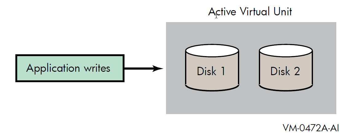
If you specify the minicopy qualifier (/POLICY=MINICOPY[=OPTIONAL]) when
you dismount a shadow set member, a bitmap is created. Subsequent writes to the shadow
set are recorded by the bitmap. Note that the bitmap records only the logical block
numbers (LBNs) of the associated writes, not the contents. The address is noted by
setting one or more bits in a bitmap; each bit corresponds to a range of 127 disk
blocks.
When data is written to any block in the range of 127 blocks, the bit in the bitmap that corresponds to that range is set. After the bit or bits are set, the data is written to the shadow set, as shown in Figure 7.2, ''Application Writes to a Write Bitmap''.
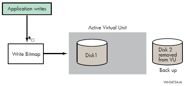
When the member is returned to the shadow set, the bitmap is used to direct the minicopy operation, as shown in Figure 7.3, ''Member Returned to the Shadow Set (Virtual Unit)''. While the minicopy operation is taking place, the application continues to read and write to the shadow set.
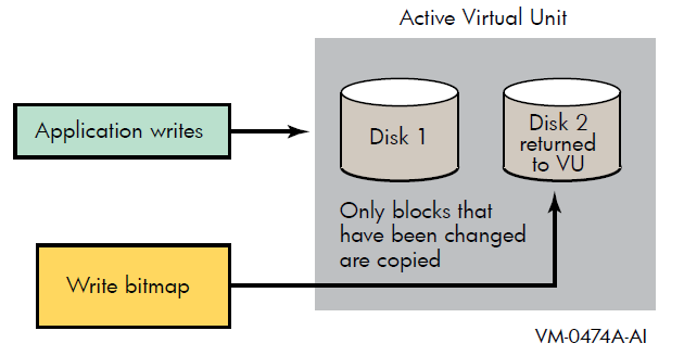
With the minicopy function, a full copy is no longer required when a member is returned to its shadow set, provided that the system managers follow the guidelines provided in Section 7.11, ''Guidelines for Using a Shadow Set Member for Backup''. Note that, in this chapter, copy and full copy mean the same thing.
Several DCL commands can be used to manage bitmaps. System parameters are provided for managing the bitmap updates in an OpenVMS Cluster system and for setting an upper limit on shadow sets per node.
7.2. Different Uses for Copy and Minicopy
Prior to the introduction of minicopy, the copy operation was used for two purposes: to add members to a virtual unit, and to restore a member to the shadow set from which it was removed. In order for a member to rejoin the shadow set, its data must be made to match the data on the shadow set.
The copy operation is the principal method for creating a multiple member shadow set.
(You can also use the DCL command INITIALIZE/SHADOW to create an
empty multi-member shadow set.) The minicopy operation is now the preferred method for
returning a member to a shadow set.
Typically, the reason for removing a shadow set member is to back up the data onto tape or disk.
Using the
SHOW DEVICEcommand, verify that the virtual unit is not marked for a merge operation.Stop the application I/O. The method for doing this is specific to the application and the computing environment.
Remove a shadow set member.
Reactivate the application.
Back up the data of the shadow set member to disk or tape. While the backup is progressing, the application is writing data to the remaining members of the shadow set.
Return the shadow set member to the shadow set when the backup is complete.
Note
For detailed information about the conditions under which this form of backup is supported, see Section 7.11, ''Guidelines for Using a Shadow Set Member for Backup''.
7.3. Why Use Minicopy?
The minicopy operation can be used at the discretion of the system manager and at a time chosen by the system manager.
Because minicopy can significantly reduce the time it takes to return a member to a shadow set, it gives system managers greater flexibility in scheduling the removal and return of a shadow set member, and it improves availability.
The time needed to perform a minicopy is proportional to the amount of change that occurred to a shadow set in the disk's absence. A shorter copy time gives sites more flexibility in managing backups.
|
Percentage of Bits Set |
Time for Full Copy (seconds) |
Time for Minicopy (seconds) |
Minicopy Time as Percentage of Full Copy Time |
|---|---|---|---|
|
100% |
4196.09 |
3540.21 |
84.4% |
|
90% |
3881.95 |
3175.92 |
81.8% |
|
80% |
3480.50 |
2830.47 |
81.3% |
|
75% |
3290.67 |
2614.87 |
79.5% |
|
70% |
3194.05 |
2414.03 |
75.6% |
|
60% |
2809.06 |
2196.60 |
78.2% |
|
50% |
2448.39 |
1759.67 |
71.9% |
|
40% |
2076.52 |
1443.44 |
69.5% |
|
30% |
1691.51 |
1039.90 |
61.5% |
|
25% |
1545.94 |
775.35 |
50.2% |
|
20% |
1401.21 |
682.67 |
48.7% |
|
15% |
1198.80 |
554.06 |
46.2% |
|
10% |
1044.33 |
345.78 |
33.1% |
|
5% |
905.88 |
196.32 |
21.7% |
|
2% |
712.77 |
82.79 |
11.6% |
|
1% |
695.83 |
44.90 |
6.5% |
|
Percentage of Bits Set |
DCD Copy Time (seconds) |
Minicopy Time (seconds) |
Minicopy Time as Percentage of DCD Copy Time |
|---|---|---|---|
|
100% |
1192.18 |
1181.61 |
99.1% |
|
90% |
1192.18 |
1097.03 |
92.0% |
|
80% |
1192.18 |
979.06 |
82.1% |
|
70% |
1192.18 |
862.66 |
72.4% |
|
60% |
1192.18 |
724.61 |
60.8% |
|
50% |
1192.18 |
627.24 |
52.6% |
|
40% |
1192.18 |
490.70 |
41.2% |
|
30% |
1192.18 |
384.45 |
32.3% |
|
20% |
1192.18 |
251.53 |
21.1% |
|
10% |
1192.18 |
128.11 |
10.7% |
|
5% |
1192.18 |
71.00 |
6.0% |
|
0% |
1192.18 |
8.32 |
0.7% |
7.4. Procedure for Using Minicopy
Start a write bitmap.
A write bitmap is started by specifying the new qualifier
/POLICY=MINICOPY[=OPTIONAL]to theDISMOUNTcommand when removing a member from a shadow set. You can also start a write bitmap with theMOUNTcommand when mounting a shadow set less one or two members, as described in Section 7.6.2, ''Creating a Bitmap With MOUNT''.Use the bitmap for a minicopy operation when you return the shadow set member to the shadow set.
If a write bitmap exists for the shadow set, a minicopy operation is invoked by default by the followingMOUNTcommand:$ MOUNT DSA42/SHAD=$4$DUA42 volume-labelTo guarantee that only a minicopy takes place, use the/POLICY=MINICOPYqualifier, as shown in the following example:$ MOUNT DSA42/SHAD=$4$DUA42 volume-label/POLICY=MINICOPYIf a write bitmap does not exist for a minicopy, the mount fails.
When a minicopy operation is completed, the write bitmap associated with the disk is deleted.
For a detailed description of how to use
/POLICY=MINICOPY[=OPTIONAL] with the MOUNT and
DISMOUNT commands, see Section 7.6, ''Creating Bitmaps''
and Section 7.7, ''Starting a Minicopy Operation''.
7.5. Write Bitmaps and Dissimilar Device Shadowing Caution
DDS allows you to construct shadow sets of disk devices that are of dissimilar sizes.
Write bitmaps track application writes made to a shadow set virtual unit so that a
member can be returned to that virtual unit without the overhead of a full copy. A write
bitmap is created when the user issues a DISMOUNT/POLICY=MINICOPY
command for a shadow set member or mounts a shadow set using the
MOUNT/POLICY=MINICOPY command. When this bitmap is created, its
size depends on the current size of the volume.
When a shadow set is mounted, the logical size of the shadow set virtual unit is set to the size of the smallest member unit. When a member of the shadow set is removed, the logical size of the virtual unit is recomputed based on the sizes of the remaining members of the set.
Consequently, the logical size of the virtual unit might increase.
When a write bitmap is created for a shadow set, its size is determined by the current size of the shadow set virtual unit. If the virtual unit’s size subsequently increases, the bitmap does not cover the entire virtual unit. If the bitmap is then used to bring back a shadow set member with a minicopy operation, the portion of the virtual unit that is not covered by the bitmap is copied with a full copy operation.
The following example illustrates this problem:
Shadow set DSA1: includes the following three members:
$1$DGA20: (18 GB)
$1$DGA21: (36 GB)
$1$DGA22: (36 GB)
$1$DGA22: is removed from the shadow set with a minicopy bitmap using the following command:
$ DISMOUNT/POLICY=MINICOPY $1$DGA22:
The write bitmap is sized for 18 GB, the current size of the shadow set virtual unit.
$1$DGA20: is removed from the shadow set. To allow the file system to utilize the entire 36 GB of the remaining member, use the following command:
$ SET VOLUME/SIZE DSA1
$1$DGA20 can no longer be used in this shadow set because it is smaller than the new volume size.
$1$DGA22: is returned to the shadow set using the following command:
$ MOUNT/SYSTEM DSA1:/SHADOW=$1$DGA22: label
The logical size of DSA1: remains at 36 GB; however, the bitmap covers only the first 18 GB.
The first 18 GB of $1$DGA22: are copied using the minicopy bitmap; the remaining 18 GB are copied using a full copy operation.
If the removal of a smaller shadow set member is planned, removing it before removing a larger member with a minicopy bitmap causes a larger bitmap to be created and avoids the performance impact of a short bitmap. (In the preceding example, you would remove $1$DGA20: before removing $1$DGA22:.)
7.6. Creating Bitmaps
The DCL commands DISMOUNT and MOUNT are used for
creating write bitmaps. The MOUNT command is used for starting a
minicopy operation using a write bitmap (see Section 7.7, ''Starting a Minicopy Operation'').
7.6.1. Creating a Bitmap With DISMOUNT
To create a bitmap, you must specify the
/POLICY=MINICOPY[=OPTIONAL] qualifier with the
DISMOUNT command. If you specify
/POLICY=MINICOPY=OPTIONAL, a bitmap is created if there is
sufficient memory. The disk is dismounted, regardless of whether a bitmap is
created.
POLICY=MINICOPY=OPTIONAL qualifier with the
DISMOUNT
command:$ DISMOUNT $4$DUA1 /POLICY=MINICOPY=OPTIONAL
This command removes $4$DUA1 from the shadow set and starts logging
writes to a bitmap, if possible.
If you specify /POLICY=MINICOPY only (that is, if you omit
=OPTIONAL) and there is not enough memory on the node to create a bitmap, the
dismount fails.
7.6.2. Creating a Bitmap With MOUNT
MOUNT command under the
following conditions:The shadow set that was previously mounted was correctly dismounted.
A multiple member shadow set must have been mounted before on the same node, on another node in the same cluster, or on another node outside the cluster.
The shadow set is not currently mounted on any other node in the cluster (if the node on which you are mounting the shadow set is in a cluster).
When you mount the shadow set, you mount it minus one member.
You specify the
/POLICY=MINICOPY[=OPTIONAL]qualifier to theMOUNTcommand.
The bitmap created with this command is used for a minicopy operation when you later mount one of the former members of the shadow set into the set.
If you specify the /POLICY=MINICOPY=OPTIONAL qualifier and the
shadow set is already mounted on another node in the cluster, the
MOUNT command succeeds but a bitmap is not created.
7.7. Starting a Minicopy Operation
If a bitmap exists for a shadow set member, a minicopy operation starts by default when you
specify the MOUNT command to return a shadow set member to the shadow set. This is
equivalent to using the /POLICY=MINICOPY=OPTIONAL qualifier to the
MOUNT command. If a bitmap is not available, a full copy
occurs.
/POLICY=MINICOPY=OPTIONAL qualifier with the
MOUNT command
follows:$ MOUNT DSA5/SHAD=$4$DUA0/POLICY=MINICOPY=OPTIONAL volume_labelIf the shadow set (DSA5) is already mounted and a bitmap exists for this shadow
set member ($4$DUA0), the command adds the device $4$DUA0 to
the shadow set with a minicopy operation. If a bitmap is not available, this command
adds $4$DUA0 with a full copy.
To ensure that a MOUNT command succeeds only if a minicopy can take place,
specify /POLICY=MINICOPY only (that is, omit =OPTIONAL). If a bitmap
is not available, the mount will fail.
7.8. Master and Local Bitmaps
In an OpenVMS Cluster system, a master bitmap is created on
the node that issues the DISMOUNT or MOUNT command
that creates the bitmap. When a master bitmap is created, a local
bitmap is automatically created on all other nodes in the cluster on
which the shadow set is mounted, provided the nodes have sufficient memory.
A master bitmap contains a record of all the writes to the shadow set from every node in the cluster that has the shadow set mounted. A local bitmap tracks all the writes that the local node issues to a shadow set.
Note that if a node with a local bitmap writes to the same logical block number (LBN) of a shadow set more than once, only the LBN of the first is sent to the master bitmap. The minicopy operation uses the LBN for the update, not the number of changes to the same LBN.
When there is not enough memory on a node to create a local bitmap, the node sends a message for each directly to the master bitmap. This degrades application write performance.
7.9. Managing Bitmaps With DCL Commands
The SHOW DEVICE, SHOW CLUSTER, and
DELETE commands have been extended for managing bitmaps.
7.9.1. Determining Bitmap Support and Activity
You can find out whether a write bitmap exists for a shadow set by using the DCL
command SHOW DEVICE/FULL device-name. If a
shadow set supports write bitmaps, device supports bitmaps is displayed
along with either bitmaps active or no bitmaps active. If
the device does not support write bitmaps, no message pertaining to write bitmaps is
displayed.
$ SHOW DEVICE/FULL DSA0
Disk DSA0:, device type RAM Disk, is online, mounted, file-oriented device,
shareable, available to cluster, error logging is enabled, device supports bitmaps (no bitmaps active).
Error count 0 Operations completed 47
Owner process "" Owner UIC [SYSTEM]
Owner process ID 00000000 Dev Prot S:RWPL,O:RWPL,G:R,W
Reference count 2 Default buffer size 512
Total blocks 1000 Sectors per track 64
Total cylinders 1 Tracks per cylinder 32
Volume label "TST0" Relative volume number 0
Cluster size 1 Transaction count 1
Free blocks 969 Maximum files allowed 250
Extend quantity 5 Mount count 1
Mount status System Cache name "_$252$DUA721:XQPCACHE"
Extent cache size 64 Maximum blocks in extent cache 96
File ID cache size 64 Blocks currently in extent cache 0
Quota cache size 0 Maximum buffers in FCP cache 404
Volume owner UIC [SYSTEM] Vol Prot S:RWCD,O:RWCD,G:RWCD,W:RWCD
Volume Status: ODS-2, subject to mount verification, file high-water marking, write-back caching enabled.
Disk $252$MDA0:, device type RAM Disk, is online, member of shadow set DSA0:.
Error count 0 Shadow member operation count 128
Allocation class 252
Disk $252$MDA1:, device type RAM Disk, is online, member of shadow set DSA0:.
Error count 0 Shadow member operation count 157
Allocation class 257.9.2. Displaying Bitmap IDs
You can find out the ID of each bitmap on a node with the DCL command
SHOW DEVICE/BITMAP device-name. The
/BITMAP qualifier cannot be combined with other SHOW
DEVICE qualifiers except /FULL. The SHOW
DEVICE/BITMAP display can be brief or full; brief is the
default.
If no bitmap is active, no bitmap ID is displayed. The phrase no bitmaps
active is displayed.
SHOW DEVICE/BITMAP
display:$ SHOW DEVICE/BITMAP DSA1 Device BitMap Size Percent of Name ID (Bytes) Full Copy DSA1: 00010001 652 11%
The following example shows a SHOW DEVICE/BITMAP/FULL
display:
$ SHOW DEVICE DSA12/BITMAP/FULL Device Bitmap Size Percent of Active Creation Master Cluster Local Delete Bitmap Name ID (bytes) Full Copy Date/Time Node Size Set Pending Name DSA12: 00010001 652 11% Yes 5-MAY-2000 13:30... 300F2 127 2% No SHAD$TEST
Note
The bitmap name, which is only displayed when you specify
SHOW/DEVICE/FULL, takes the form of SHAD$volume-name,
followed by many (about 30) unreadable characters. These unreadable characters
are used internally to represent the generation number of the bitmap, the time
it was created, and other details. The bitmap name is only used internally. The
bitmap ID is used by system managers.
7.9.3. Displaying Bitmap Status of Cluster Members
SHOW CLUSTER display
by issuing the ADD BITMAPS command, as shown in the following
example:$ SHOW CLUSTER/CONTINUOUS
Command > ADD BITMAPS
Command > ADD CSID
View of Cluster from system ID 57348 node: WPCM1 14-FEB-2000 13:38:53
SYSTEMS MEMBERS
NODE SOFTWARE CSID STATUS BITMAPS
CSGF1 VMS X6TF 300F2 MEMBER MINICOPY
HSD30Y HSD YA01 300E6
HS1CP2 HSD V31D 300F4
CSGF2 VMS X6TF 300D0 MEMBER MINICOPYIn this example, MINICOPY means that nodes CSGF1 and
CSGF2 are capable of supporting minicopy operations. If a cluster
node does not support minicopy, the term UNSUPPORTED replaces
MINICOPY in the display, and the minicopy function is disabled in
the cluster.
7.9.4. Deleting Bitmaps
After a minicopy operation is completed, the corresponding bitmap is automatically deleted.
There may be times when you would like to delete one or more bitmaps. Reasons for deleting bitmaps include recovering the memory consumed by a bitmap and stopping the recording of the bitmap.
DELETE with the
/BITMAP qualifier. You use the bitmap qualifier to specify
the ID of the bitmap you want to delete. For
example:$ DELETE/BITMAP/LOG 00010001 %DELETE-I-DELETED, 00010001 deleted
7.10. Performance Implications of Bitmaps
There are several aspects of bitmaps that affect performance; the message traffic that occurs between local and master bitmaps, the size requirements of each bitmap, asynchronous processing of SetBit messages, and reduced SetBit messages for sequential I\O.
The message traffic can be adjusted by changing the message mode. Single message mode is the default mode. Buffered message mode can improve the overall system performance, but the time to record the write of each process in the master bitmap usually takes longer. These modes are described in detail in Section 3.4, ''Bitmap System Parameters''.
Note
Additional memory is required to support bitmaps, as described in Section 1.3.1, ''Memory Requirements''. Depending on the memory usage of your system, it may require additional memory.
There can be multiple master bitmap nodes for a shadow set. In OpenVMS Version 8.3 and earlier, SetBit messages are sent to the multiple master bitmap nodes synchronously. Only when the response for the SetBit message is received from the first remote master bitmap node, is the message sent to the next master bitmap node. When this process completes for all the remote master bitmap nodes, the I/O resumes.
In OpenVMS Version 8.4, SetBit messages are sent to all multiple master bitmap nodes asynchronously. I/O resumes when the responses from all the master bitmap nodes are received, thus reducing I/O delay by the write bitmap code.
In earlier versions, if sequential writes are occurring to a disk, these writes often resulted in delivering Setbit messages that set sequential bits in the remote bitmap. In OpenVMS Version 8.4, the write bitmap code recognizes where a number of prior bits in the bitmap are set. In this case, additional bits are set so that if sequential writes should continue, fewer Setbit messages are required. Assuming that the sequential I/O continues, the number of Setbit messages are reduced by about a factor of 10, thus improving the I/O rate for sequential writes.
7.11. Guidelines for Using a Shadow Set Member for Backup
Volume Shadowing for OpenVMS can be used as an online backup mechanism. With proper application design and proper operating procedures, shadow set members removed from mounted shadow sets constitute a valid backup.
To obtain a copy of a file system or application database for backup purposes using Volume Shadowing for OpenVMS, the standard recommendation has been to determine that the virtual unit is not in a merge state, to dismount the virtual unit, then to remount the virtual unit minus one member.
However, VSI recognizes that this restriction is unacceptable when true 24/7 application availability is a requirement, and that it is unnecessary if appropriate data-consistency measures can be ensured through a combination of application software and system management practice.
7.11.1. Removing a Shadow Set Member for Backup
DISMOUNT can be used
to remove members from shadow sets for the purpose of backing up data, provided that
the following requirements are met:The shadow set must not be in a merge state. VSI also recommends that the shadow set not have a copy operation in progress.
Adequate redundancy must be maintained after member removal. VSI recommends that the active shadow set never be reduced to less than two members; alternatively, the shadow sets should employ controller mirroring or RAID 5.
Establish data consistency over the virtual units through system management procedures or application software, or both. This is a complex topic and is the subject of most of the rest of this chapter.
Ensure that the requirements regarding merge state and adequate redundancy are met.
Remove the members to be backed up from the virtual units.
Terminate the data consistency measures taken in step 1.
7.11.2. Data Consistency Requirements
Removal of a shadow set member results in what is called a crash-consistent copy. That is, the copy of the data on the removed member is of the same level of consistency as what would result if the system had failed at that instant. The ability to recover from a crash-consistent copy is ensured by a combination of application design, system and database design, and operational procedures. The procedures to ensure recoverability depend on application and system design and will be different for each site.
The conditions that might exist at the time of a system failure range from no data having been written, to writes that occurred but were not yet written to disk, to all data having been written. The following sections describe components and actions of the operating system that may be involved if a failure occurs and there are outstanding writes, that is, writes that occurred but were not written to disk. You must consider these issues when establishing procedures to ensure data consistency in your environment.
7.11.3. Application Activity
To achieve data consistency, application activity should be suspended and no operations should be in progress. Operations in progress can result in inconsistencies in the backed-up application data. While many interactive applications tend to become quiet if there is no user activity, the reliable suspension of application activity requires cooperation in the application itself. Journalling and transaction techniques can be used to address in-progress inconsistencies but must be used with extreme care. In addition to specific applications, miscellaneous interactive use of the system that might affect the data to be backed up must also be suspended.
7.11.4. RMS Considerations
Applications that use RMS file access must be aware of the following issues.
7.11.4.1. Caching and Deferred Writes
RMS can, at the application's option, defer disk writes to some time after it has reported completion of an update to the application. The data on disk will be updated in response to other demands on the RMS buffer cache and to references to the same or nearby data by cooperating processes in a shared file environment.
Writes to sequential files are always buffered in memory and are not written to disk until the buffer is full.
7.11.4.2. End of File
The end-of-file pointer of a sequential file is normally updated only when the file is closed.
7.11.4.3. Index Updates
The update of a single record in an indexed file may result in multiple index updates. Any of these updates can be cached at the application's option. Splitting a shadow set with an incomplete index update will result in inconsistencies between the indexes and data records. If deferred writes are disabled, RMS orders writes so that an incomplete index update may result in a missing update but never in a corrupt index. However, if deferred writes are enabled, the order in which index updates are written is unpredictable.
7.11.4.4. Run-Time Libraries
The I/O libraries of various languages use a variety of RMS buffering and deferred write options. Some languages allow application control over the RMS options.
7.11.4.5. $FLUSH
Applications can use the $FLUSH service to guarantee data consistency. The $FLUSH service guarantees that all updates completed by the application (including end of file for sequential files) have been recorded on the disk.
7.11.4.6. Journalling and Transactions
RMS provides optional roll-forward, roll-back, and recovery unit journals and supports transaction recovery using the OpenVMS transaction services. These features can be used to back out in-progress updates from a removed shadow set member. Using such techniques requires careful data and application design. It is critical that virtual units containing journals be backed up along with the base data files.
7.11.5. Mapped Files
OpenVMS allows access to files as backing store for virtual memory through the process and global section services. In this mode of access, the virtual address space of the process acts as a cache on the file data. OpenVMS provides the $UPDSEC service to force updates to the backing file.
7.11.6. Database Systems
ALTER TABLESPACE tablespace-name BEGIN BACKUP;ALTER TABLESPACE tablespace-name END BACKUP;It is critical to back up the database logs and control files as well as the database data files.
7.11.7. Base File System
The base OpenVMS file system caches free space. However, all file metadata operations (such as create and delete) are made with a "careful write-through" strategy so that the results are stable on disk before completion is reported to the application. Some free space may be lost, which can be recovered with an ordinary disk rebuild. If file operations are in progress at the instant the shadow member is dismounted, minor inconsistencies may result that can be repaired with ANALYZE/DISK. The careful write ordering ensures that any inconsistencies do not jeopardize file Integrity server before the disk is repaired.
7.11.8. $QIO File Access and VIOC
OpenVMS maintains a virtual I/O cache (VIOC) to cache file data. However, this cache is write through. OpenVMS Version 7.3 introduces extended file cache (XFC), which is also write through.
File writes using the $QIO service are completed to disk before completion is reported to the caller.
7.11.9. Multiple Shadow Sets
Multiple shadow sets present the biggest challenge to splitting shadow sets for backup. While the removal of a single shadow set member is instantaneous, there is no way to remove members of multiple shadow sets simultaneously. If the data that must be backed up consistently spans multiple shadow sets, application activity must be suspended while all shadow set members are being dismounted. Otherwise, the data is not crash consistent across the multiple volumes. Command procedures or other automated techniques are recommended to speed the dismount of related shadow sets. If multiple shadow sets contain portions of an Oracle database, putting the database into backup mode ensures recoverability of the database.
7.11.10. Host-Based RAID
The OpenVMS software RAID driver presents a special case for multiple shadow sets. A software RAID set may be constructed of multiple shadow sets, each consisting of multiple members. With the management functions of the software RAID driver, it is possible to dismount one member of each of the constituent shadow sets in an atomic operation. Management of shadow sets used under the RAID software must always be done using the RAID management commands to ensure consistency.
7.11.11. OpenVMS Cluster Operation
All management operations used to attain data consistency must be performed for all members of an OpenVMS Cluster system on which the affected applications are running.
7.11.12. Testing
Testing alone cannot guarantee the correctness of a backup procedure. However, testing is a critical component of designing any backup and recovery process.
7.11.13. Restoring Data
Too often, organizations concentrate on the backup process with little thought to how their data is restored. Remember that the ultimate goal of any backup strategy is to recover data in the event of a disaster. Restore and recovery procedures must be designed and tested as carefully as the backup procedures.
Chapter 8. Host-Based Minimerge (HBMM)
This chapter describes minimerge operations, the conditions that cause this operation, and the difference between a minimerge and a full merge operation. It also provides the various policies and qualifiers associated and the guidelines for using HBMM. This chapter includes the following topics/sections:
Overview of full merge and minimerge operations
Overview of host-based minimerge (HBMM)
HBMM policy specification syntax
Rules governing HBMM policies
Guidelines for establishing HBMM policies
Configuring and managing HBMM
Use of
/DEMAND_MERGEwhen HBMM is enabledVisible impact of transient state events
8.1. Overview of Full Merge and Minimerge Operations
The purpose of either a full merge or a minimerge recovery operation is to compare data on shadow set members to ensure that all of them contain identical data on every logical block. Each block is identified by its logical block number (LBN). During recovery operations, application I/O continues but at a slower rate. A full merge or minimerge operation is managed by one of the OpenVMS systems that has the shadow set mounted. Throughout this manual, minimerge operation and merge operation refer to a minimerge recovery operation and a merge recovery operation, respectively.
A full merge or minimerge operation is initiated by any of the following events:
A system failure that results in incomplete application writes.
A shadow set that enters mount verification and then times out or aborts mount verification, under certain conditions (as described in Section 8.1.2, ''Merge Resulting from Mount Verification Timeout'').
A system manager issues a
SET SHADOW/DEMAND_MERGEcommand.
8.1.1. Merge Resulting from a System Failure
When a system with a mounted shadow set fails, if a write request is made to a shadow set and the system fails before a completion status is returned to the application, the data might be inconsistent on the shadow set members:
All members might contain the new data.
All members might contain the old data.
Some members might contain new data and others might contain old data.
The exact timing of the failure during the original write request determines the outcome. Volume Shadowing for OpenVMS ensures that corresponding LBNs on each shadow set member contain the same data (old or new), when the application issues a read to the shadow set.
Note
Volume Shadowing for OpenVMS guarantees that data is the same on all members of the shadow set, but it cannot guarantee that a write request in progress when a system failed is recorded on the shadow set. The volume might contain the data from the last write request, depending on when the failure occurred. In this regard, the shadow set does not differ from a non-shadowed device. The application must be designed to function properly in either case.
8.1.2. Merge Resulting from Mount Verification Timeout
A shadow set that enters mount verification and either times out or aborts mount verification enters a merge state, if the following conditions are true:
There are outstanding write I/O requests in the shadow driver's internal queues on the system or systems on which it has timed out.
The shadow set is mounted on other systems in the cluster.
The system on which the mount verification timed out (or aborted mount verification) notifies the other systems on which the shadow set is mounted that a merge operation is needed, and then it disables the shadow set. (It does not dismount it.)
For example, if a shadow set is mounted on eight systems and mount verification times out on two of them, those two systems check their internal queues for write I/O. If any write I/O is found, the shadow set is merged.
8.1.3. Merge Resulting from use of SET SHADOW/DEMAND_MERGE
The SET SHADOW/DEMAND_MERGE command initiates a merge of a
specified shadow set or of all shadow sets. This qualifier is useful if the shadow
set is created with the INITIALIZE/SHADOW command without using
the /ERASE qualifier.
For more information about using the SET SHADOW/DEMAND_MERGE
command, see the VSI OpenVMS DCL Dictionary: N–Z.
8.1.4. Comparison of Merge and Minimerge Operations
In a full merge operation, the members of a shadow set are compared with each other to ensure that they contain the same data. This is done by performing a block-by-block comparison of the entire volume. This can be a very lengthy procedure.
A minimerge operation is significantly faster. By using information about write operations that are logged in volatile controller storage or in a write bitmap on an OpenVMS system, volume shadowing merges only those areas of the shadow set where the write activity occurred. This avoids the need for the entire volume scan that is required by full merge operations, thus reducing consumption of system I/O resources.
Minimerges existed as controller-based prior to the introduction of HBMM, and available only on the HSJ, HSC, and HSD controllers.
8.2. Overview of HBMM
HBMM depends on bitmaps and policies to provide the information required for minimerge operations. Depending on your computing environment, one HBMM policy, a DEFAULT policy that you specify, might be sufficient.
Before you can use HBMM for recovery of a shadow set, the following conditions must be in effect:
An HBMM policy exists.
An HBMM policy is assigned to a shadow set.
The shadow set is mounted on one or more systems that are specified in the HBMM policy.
When a policy is assigned to a shadow set and the shadow set is mounted on several systems, bitmaps specific to that shadow set are created.
The systems selected from the master list, as specified in the HBMM policy definition, can perform a minimerge operation because they possess the master bitmaps. All other systems on which the shadow set is mounted possess a local bitmap for each master bitmap.
8.2.1. Bitmaps: Master and Local
For a given bitmap, there is one master version on a system in the cluster and a local version on every other system on which the shadow set is mounted. A minimerge operation can occur only on a system with a master bitmap. Multiple master bitmaps for the same shadow set are equivalent but they do have different bitmap IDs.
The following example shows two master bitmaps for DSA12, one on
RAIN and one on SNOW, each with a unique bitmap
ID:
$ SHOW DEVICE/BITMAP DSA12
Device BitMap Size Percent Type of Master Active
Name ID (Bytes) Populated Bitmap Node
DSA12: 00040013 4132 0.01% Minimerge RAIN Yes
00010014 4132 0.01% Minimerge SNOW YesIf only one master bitmap exists for the shadow set and the system with the master bitmap fails or is shut down, the remaining local bitmap versions are automatically deleted. Local bitmaps cannot be used for recovery.
If multiple master bitmaps are created for the shadow set and at least one remains, that master bitmap can be used for recovery. VSI recommends the use of multiple master bitmaps, especially for multiple-site cluster systems. Multiple master bitmaps increase the likelihood of an HBMM operation rather than a full merge in the event of a system failure.
Bitmaps require additional memory. The calculation is based on the shadow set volume size. For every gigabyte of storage of a shadow set mounted on a system, 2 KB of bitmap memory is required on that system for each bitmap. For example, a shadow set with a volume size of 200 GB of storage and 2 bitmaps uses 800 KB of memory on every system on which it is mounted.
8.2.2. HBMM Policies
An HBMM policy specifies the following attributes for one or more shadow sets:
Names of systems that are eligible to host a master bitmap.
Number of systems that host a master bitmap (not to exceed six). If this number is omitted in OpenVMS Version 8.3 and earlier, the first available six systems from the number of systems specified are selected. Starting from OpenVMS Version 8.4, you can have up to 12 systems in a shadow set and the first available 12 systems are used if the number is omitted.
Threshold (in 512-byte blocks) at which the bitmaps are reset. If omitted, the threshold defaults to 1,000,000 blocks.
You can assign a name to a policy. However, the reserved names DEFAULT and NODEFAULT have specific properties that are described in Section 8.4, ''Rules Governing HBMM Policies''. You can also create a policy without a name and assign it to a specific shadow set. An advantage of a named policy is that it can be reused by specifying only its name.
Multiple policies can be created to customize the minimerge operations in a cluster.
You can use the SET SHADOW/POLICY command with HBMM-specific
qualifiers to define, assign, de-assign, and delete policies and to enable and
disable HBMM on a shadow set. SET SHADOW/POLICY is the only user
interface command for specifying HBMM policies. You cannot use the
MOUNT command to define a policy.
You can define a policy before the shadow set is mounted. Policies can be assigned to shadow sets in other ways as well, as described in Section 8.4, ''Rules Governing HBMM Policies''.
Three system parameters, namely, SHADOW_REC_DLY, SHADOW_PSM_DLY, and SHADOW_HBMM_RTC support HBMM. For more information about these system parameters, see the Section 3.3, ''Volume Shadowing Parameters''.
8.3. HBMM Policy Specification Syntax
An HBMM policy specification consists of a list of HBMM policy keywords enclosed within parentheses. The HBMM policy keywords are MASTER_LIST, COUNT, and RESET_THRESHOLD. Of the three keywords, only MASTER_LIST must be specified. If COUNT and RESET_THRESHOLD are omitted, the default values are supplied. For examples of policy specifications, see Section 8.6.1, ''How to Define an HBMM Policy'' and the VSI OpenVMS DCL Dictionary: N–Z.
The use of these keywords and the rules for specifying them are described in this section.
MASTER_LIST=system-list
The MASTER_LIST keyword is used to identify a set of systems as candidates for a master bitmap. The system-list value can be a single system name; a parenthesized, comma-separated list of system names; or the asterisk (*) wildcard character. For example:
MASTER_LIST=node1 MASTER_LIST=(node1,node2,node3) MASTER_LIST=*
When the system list consists of a single system name or the wildcard character, parentheses are optional.
An HBMM policy must include at least one MASTER_LIST. Multiple master lists are optional. If a policy has multiple master lists, the entire policy must be enclosed with parentheses, and each constituent master list must be separated by a comma, as shown in the following example:
(MASTER_LIST=(node1,node2), MASTER_LIST=(node3,node4))
There is no significance to the position of a system name in a master list.
COUNT=n
The COUNT keyword specifies the number of master bitmap systems to be chosen from the systems listed in a master system list. Therefore, the COUNT keyword must be associated with a specific master list by enclosing both with parentheses.
A COUNT value of n means that you want master bitmaps on any n systems in the associated master list. It does not necessarily mean that the first n systems in the list are chosen.
The COUNT keyword is optional. When omitted, the default value is the number of systems in the master list or the value of six, whichever is less. You cannot specify more than one COUNT keyword for any one master list.
The following two examples are valid policies:
(MASTER_LIST=(node1,node2,node3),COUNT=2) (MASTER_LIST=(node1,node2,node3),COUNT=2),(COUNT=2, MASTER_LIST=(system4,system5,system6))
The following example is not valid because the COUNT keyword is not grouped with a specific master list:
(MASTER_LIST=(node1,node2 ), MASTER_LIST=(node4,node5 ), COUNT=1) RESET_THRESHOLD=n
The RESET_THRESHOLD keyword specifies the number of blocks that can be set before the bitmap is eligible to be cleared. Each bit that is set in a master bitmap corresponds to a set of blocks that needs to be merged. Therefore, the merge time can be influenced by this value.
Bitmaps are cleared when the RESET_THRESHOLD is exceeded, although the reset is not guaranteed to occur immediately when the threshold is crossed. For additional information about choosing a value for this attribute, see Section 8.5.2, ''Considerations for Setting a Bitmap RESET_THRESHOLD Value'' and Section 3.3, ''Volume Shadowing Parameters''.
A single reset threshold value is associated with any given HBMM policy. Therefore, the RESET_THRESHOLD keyword cannot be specified more than once in a given policy specification. Because its scope is the entire policy, the RESET_THRESHOLD keyword cannot be specified inside a constituent master list when the policy uses multiple master lists.
When the RESET_THRESHOLD keyword is omitted, the value of 1,000,000 is used by default.
The following policy example includes an explicit reset threshold value:
(MASTER_LIST=*, COUNT=4, RESET_THRESHOLD=800000)
8.4. Rules Governing HBMM Policies
The following rules govern the creation and management of HBMM policies. The rules are based on the assumption that a shadow set is mounted on a system that supports HBMM.
Policies and Their Attributes
A policy can be assigned to a shadow set by specifying only its attributes. The number of policies that you can assign in this way is limited only by the number of shadow sets that are supported on a system.
A shadow set can have only one HBMM policy assigned to it at a time.
Policies are in effect clusterwide.
Policy names must conform to the following rules:
A policy name can range from 1 to 64 characters in length and is case-insensitive.
Only letters, numbers, the dollar sign ($), and the underscore (_) are allowed.
A policy name must be specified in full; abbreviations are not allowed.
A named policy can be assigned to a shadow set only by the
SET SHADOW/POLICY=HBMM=policy-namecommand.The limit on user-defined, named policies is 128.
DEFAULT and NODEFAULT Policies
The named policies DEFAULT and NODEFAULT have special properties, as summarized in the following sections:
DEFAULT
A DEFAULT policy is useful if the majority of the shadow sets in a cluster are expected to use an identical policy.
You can create a DEFAULT policy by defining a named policy with the reserved name DEFAULT. No predetermined DEFAULT policy is provided by VSI.
When a policy with the reserved name of DEFAULT is defined, this policy is assigned to a shadow set by any of the following operations:
Mount of a shadow set without an assigned policy
The DEFAULT policy, if defined, is applied to a shadow set in the absence of an assigned policy (including the NODEFAULT policy). For example, when shadow set DSA1 is mounted on an HBMM-capable system, an attempt is made to apply an HBMM policy, if one exists, that is specific to DSA1. (To verify whether a device-specific policy exists and to display specific policies, see Section 8.6.9, ''How to Display Policies''.)
If a policy is not defined specifically for DSA1, an attempt is made to apply the DEFAULT policy. If the DEFAULT policy exists, the attributes of that policy are applied to DSA1.
End of merge of a shadow set without an assigned policy
Use of
SET SHADOW/ENABLE=HBMMcommand
If a shadow set has a policy assignment and that policy assignment is deleted, it is then eligible for the DEFAULT policy, if one is established for your cluster.
NODEFAULT Policy
The NODEFAULT policy specifies that the shadow set to which it is applied does not use HBMM; no HBMM bitmaps are created anywhere in the cluster for this shadow set.
In a cluster where a DEFAULT policy has been defined, the NODEFAULT policy can be used to prevent specific shadow sets from receiving the default policy.
The NODEFAULT policy cannot be deleted or redefined.
Assignment and Activation of a Policy
A policy can be assigned to a shadow set before the shadow set is mounted on any system in the cluster.
If a policy has been assigned, it is activated by the first mount of a shadow set on a bitmap master system.
Assigning a policy implicitly enables HBMM on a mounted shadow set if it is mounted on a system that can create a master bitmap. Consider DSA1 that is mounted on system MAPLE.
When DSA1 is mounted, no HBMM policy is set for DSA1, nor is there a DEFAULT policy that can be applied. Later, the following command is used:
$ SET SHADOW DSA1:/POLICY=HBMM=(MASTER=(MAPLE), COUNT=1)
Because
DSA1is already mounted on systemMAPLE, HBMM is enabled as a result of the policy assignment (see Section 8.6.2, ''How to Assign an HBMM Policy to a Shadow Set'').Any attempt to enable HBMM using
SET SHADOW DSAn /ENABLE=HBMMreturns a failure if a shadow set is not mounted on a system that has a master bitmap, or if the policy has not been defined.As new systems join the cluster, they inherit the policies in existence in that cluster.
Changes to Policies
Named policies can be created, changed, and deleted at will. Changes made to a named policy are not inherited by any mounted shadow set assigned the previous version of that named policy.
The assignment of a policy to a mounted shadow set cannot be changed while HBMM is enabled for that shadow set. HBMM must first be disabled on that shadow set, and then a different policy can be assigned to it.
Any policy change is clusterwide.
Life of a Policy
All policies remain in effect in a cluster as long as at least one system remains active. However, if all systems are shut down, all policy definitions and assignments are deleted. The policies must be defined and assigned again when the systems form the cluster. Therefore, VSI recommends that you define your desired HBMM policies in your system startup procedures before you mount your shadow sets.
Policy assignments persist across the disabling of HBMM or the dismounting of the shadow set as long as at least one system in the cluster remains active.
8.5. Guidelines for Establishing HBMM Policies
Establishing HBMM policies is likely to be an ongoing process as configurations change and as you learn more about how HBMM works and how it affects various operations on your systems. This section describes a number of considerations to help you determine what policies are appropriate for your configuration.
The settings depend on your hardware and software configuration, the computing load, and your operational requirements. These guidelines can assist you when selecting the initial settings for your configuration. As you observe the results in your configuration, you can make further adjustments to suit your computing environment.
8.5.1. Selecting the Systems to Host Master Bitmaps
There are several factors you must consider when selecting the number of master bitmaps to specify in a policy and the systems that host the master bitmaps. The first issue is how many master bitmaps must be used in the configuration. For OpenVMS Version 8.3 and earlier, six is the maximum number of HBMM master bitmaps per shadow set. Starting from OpenVMS Version 8.4, 12 is the maximum per shadow set. The use of each additional master bitmap has a slight impact on write performance and also consumes memory on each system (as described in Section 8.2.1, ''Bitmaps: Master and Local'').
Using only one master bitmap creates a single point of failure; if the system hosting the master bitmap fails, then this shadow set undergoes a full merge. Therefore, the memory consumption must be weighed against the adverse effects of a full merge. Multiple master bitmaps provide the greatest defense against performing full merges.
Another issue when selecting a system to host the master bitmap is the I/O bandwidth of the various systems. Keep in mind that minimerges are always performed on a system that has a master bitmap. Therefore, low-bandwidth systems, such as satellite cluster members, are not good candidates.
The disaster tolerance of the configuration is also important in the decision process. Specifying systems to host master bitmaps at multiple sites help ensure that a minimerge is performed if connectivity to an entire site is lost. A two-site configuration must ensure that half the master bitmap systems are at each site, and a three-site configuration must ensure that one third of the master bitmaps are at each of the three sites.
8.5.2. Considerations for Setting a Bitmap RESET_THRESHOLD Value
When selecting a threshold reset value, you must balance the effects of bitmap resets on I/O performance with the time it takes to perform HBMM minimerges. The goal is to set the reset value as low as possible (thus decreasing merge times) while not affecting application I/O performance. Too low a value degrades I/O performance. Too high a value causes merges to take extra time.
HBMM bitmaps keep track of writes to a shadow set. The more bits that are set in the bitmap, the greater the amount of merging that is required in the event of a minimerge. HBMM clears the bitmap (after ensuring that all outstanding writes have completed so that the members are consistent) when certain conditions are met (see the description of SHADOW_HBMM_RTC in Section 3.3, ''Volume Shadowing Parameters''). A freshly cleared bitmap, with few bits set, performs a minimerge faster.
The bitmap reset, however, can affect I/O performance. Before a bitmap reset can occur, all write I/O to the shadow set must be paused and any write I/O that is in progress must be completed. Then the bitmap is cleared. This is performed on all systems on a per shadow set basis. Therefore, avoid a reset threshold setting that causes frequent resets.
You can view the number of resets performed by using the SHOW
SHADOW command. The HBMM Reset Count appears in the last section of
the display, as shown in the following example:
$ SHOW SHADOW DSA1031
_DSA1031: Volume Label: HBMM1031
Virtual Unit State: Steady State
Enhanced Shadowing Features in use:
Host-Based Minimerge (HBMM)
VU Timeout Value 3600 VU Site Value 0
Copy/Merge Priority 5000 Mini Merge Enabled
Served Path Delay 30
HBMM Policy
HBMM Reset Threshold: 1000000
HBMM Master lists:
Up to any 2 of the systems: LEMON, ORANGE
Any 1 of the systems: MELON, PEACH
HBMM bitmaps are active on LEMON, MELON, ORANGE
HBMM Reset Count 2 Last Reset 13-JUL-2004 10:13:53.90
Modified blocks since last bitmap reset: 11181
.
.
.
$Writes that need to set bits in the bitmap are slightly slower than writes to areas that are already marked as having been written. Therefore, if many of the writes to a particular shadow set are concentrated in certain “hot” files, the reset threshold must be made large enough so that the same bits are not constantly set and then cleared.
On the other hand, if the reset threshold is too large, then the advantages of HBMM are reduced. For example, if 50% of the bitmap is populated (that is, 50% of the shadow set has been written to since the last reset), the HBMM merge takes approximately 50% of the time of a full merge.
You can change the RESET_THRESHOLD value while a policy is in effect by specifying the same policy with a different RESET_THRESHOLD value. (The syntax for specifying a policy, including the RESET_THRESHOLD keyword, is described in Section 8.3, ''HBMM Policy Specification Syntax''.)
The following example shows how to:
Display status information about shadow set DSA3233
Create and assign an unnamed policy to DSA3233
Confirm that the policy is assigned to DSA3233
Change the RESET_THRESHOLD value of the assigned policy
Confirm that the change to RESET_THRESHOLD is in effect
$!
$! To display status information about DSA3233
$!
$ Show Shadow DSA3233
_DSA30: Volume Label: OSCAR
Virtual Unit State: Steady State
Enhanced Shadowing Features in use:
Host-Based Minimerge (HBMM)
Extended Memberships
VU Timeout Value 3600 VU Site Value 0
Copy/Merge Priority 3233 Mini Merge Enabled
Recovery Delay Per Served Member 30
Merge Delay Factor 200 Delay Threshold 200
Device $1$DGA32
Read Cost 2 Site 0
Member Timeout 120
Device $1$DGA33 Master Member
Read Cost 2 Site 0
Member Timeout 120
$!
$! To create a policy and assign it to DSA3233
$!
$ SET SHADOW/POLICY=HBMM=(master_list=(ATHRUZ,ATWOZ,A2ZIPF),count=2,-
reset_threshold=420000) DSA3233:
$!
$! To confirm that the policy was assigned to DSA3233
$!
$ Show Shadow DSA3233
_DSA3233: Volume Label: DSA3233
Virtual Unit State: Steady State
Enhanced Shadowing Features in use:
Host-Based Minimerge (HBMM)
VU Timeout Value 3600 VU Site Value 0
Copy/Merge Priority 3233 Mini Merge Enabled
Recovery Delay Per Served Member 30
Merge Delay Factor 200 Delay Threshold 200
HBMM Policy
HBMM Reset Threshold: 420000
HBMM Master lists:
Up to any 2 of the nodes: ATHRUZ,ATWOZ,A2ZIPF
HBMM bitmaps are active on ATHRUZ,ATWOZ
Modified blocks since bitmap creation: 0
Device $1$DGA32
Read Cost 2 Site 0
Member Timeout 120
Device $1$DGA33 Master Member
Read Cost 2 Site 0
Member Timeout 120
$!
$! To change the Reset Threshold value
$!
$ SET SHAD/POLICY=HBMM=(master_list=(ATHRUZ,ATWOZ,A2ZIPF),count=2, -
reset_threshold=840000) DSA3233:
$!
$! To confirm the change to the Reset Threshold value
$!
$ Show Shadow DSA3233
_DSA3233: Volume Label: DSA3233
Virtual Unit State: Steady State
Enhanced Shadowing Features in use:
Host-Based Minimerge (HBMM)
VU Timeout Value 3600 VU Site Value 0
Copy/Merge Priority 3233 Mini Merge Enabled
Recovery Delay Per Served Member 30
Merge Delay Factor 200 Delay Threshold 200
HBMM Policy
HBMM Reset Threshold: 840000
HBMM Master lists:
Up to any 2 of the nodes: ATHRUZ,ATWOZ,A2ZIPF
HBMM bitmaps are active on ATHRUZ,ATWOZ
Modified blocks since bitmap creation: 0
Device $1$DGA32
Read Cost 2 Site 0
Member Timeout 120
Device $1$DGA33 Master Memeber
Read Cost 2 Site 0
Member Timeout 1208.5.3. Using Multiple Policies
HBMM policies are defined to implement decisions regarding master bitmaps. Some sites might find that a single policy can effectively implement the decisions. Other sites might require greater granularity and therefore implement multiple policies.
Multiple policies are required when the cluster includes enough high-bandwidth systems that you want to ensure that the merge load is spread out. Note that minimerges occur only on systems that host a master bitmap. Therefore, if 12 systems with high bandwidth are set up to perform minimerge or merge operations (the system parameter SHADOW_MAX_COPY is greater than zero on all systems), you must ensure that the master bitmaps are spread out among these high-bandwidth systems.
Multiple HBMM policies are also useful when shadow sets need different bitmap reset thresholds. The list of master bitmap systems can be the same for each policy, but the threshold can differ.
8.6. Configuring and Managing HBMM
This section describes the major tasks for configuring and managing HBMM.
8.6.1. How to Define an HBMM Policy
The SET SHADOW/POLICY=HBMM command is used to define HBMM
policies. You can define multiple policies for your environment. The following
examples show how to define two policies, a DEFAULT policy and POLICY_1, a named
policy.
To define the policy named DEFAULT:
$ SET SHADOW/POLICY=HBMM=(MASTER_LIST=*)/NAME=DEFAULT
In this example, a DEFAULT policy is created for the cluster. The use of the asterisk wildcard (*) means that any system can host a master bitmap. The omission of the keyword COUNT=n means that up to six systems (the default value and the current maximum supported) can host a master bitmap. The DEFAULT policy is inherited at mount time by shadow sets that have not been assigned a named policy.
The following example defines a named policy (POLICY_1), specifies the systems that are eligible to host a master bitmap, limits to two the number of systems to host a master bitmap, and specifies a higher threshold (default is 1,000,000 blocks) to be reached before clearing the bitmap.
$ SET SHADOW /POLICY=HBMM=( - _$ (MASTER_LIST=(NODE1,NODE2,NODE3), COUNT=2), - _$ RESET_THRESHOLD=1250000) - _$ /NAME=POLICY_1
In OpenVMS Version 8.4, if you are using the DISMOUNT keyword, you can have up to 12 HBMM master bitmaps. For DISMOUNT keyword examples, see the Section 8.10.2, ''Examples of Multiuse and Dismount''.
For the complete DCL syntax of the SET SHADOW/POLICY=HBMM command, see the VSI OpenVMS DCL Dictionary: N–Z.
8.6.2. How to Assign an HBMM Policy to a Shadow Set
You can assign a policy, named or unnamed, to a shadow set. To assign an existing named policy, use the following command:
$ SET SHADOW DSAn:/POLICY=HBMM=policy-name
To assign an unnamed policy to a shadow set, use the same command, but in place of the policy name, specify the attributes of the policy you want to use. For example:
$ SET SHADOW DSA1:/POLICY=HBMM=(MASTER_LIST=(NODE1, NODE2, NODE3), COUNT=2)
In this example, the default bitmap reset value of 1,000,000 blocks takes effect because the RESET_THRESHOLD keyword is omitted.
8.6.3. How to Activate HBMM on a Shadow Set
HBMM is automatically activated on a shadow set under the following conditions:
An HBMM policy exists for a given shadow set, which is mounted on one or more systems defined in the master list.
An HBMM policy is created for a mounted shadow set and at least one system that has it mounted is defined in the master list.
You can also activate HBMM using the SET SHADOW/ENABLE=HBMM
command, provided a policy exists and the shadow set is mounted on a system defined
in the master list of the shadow set policy, and the count has not been
exceeded.
8.6.4. How to Disable HBMM on a Shadow Set
To disable HBMM on a shadow set, use the following command:
$ SET SHADOW DSAn:/DISABLE=HBMM
Reasons for disabling HBMM on a shadow set include:
Changing the policy assigned to it.
Deleting the policy assigned to it.
Mounting the shadow set on a system that does not support HBMM. You must disable HBMM first and then dismount it from all the HBMM-capable systems on which it is mounted before you can mount it on a system that does not support HBMM.
HBMM remains disabled until you either re-enable it or define a new policy for the shadow set.
8.6.5. How to Remove a Policy Assignment from a Shadow Set
Before removing a policy assignment from a shadow set, HBMM must be disabled, if active. You can remove a policy assignment from a shadow set by entering the following command:
$ SET SHADOW DSAn:/POLICY=HBMM/DELETE
This command removes any policy set for this shadow set, making the shadow set
eligible for the DEFAULT policy. If a DEFAULT policy exists, it is assigned the next
time the shadow set is eligible for a policy, for example, at the end of a merge or
when you issue the SET SHADOW/ENABLE=HBMM command.
8.6.6. How to Change a Policy Assignment of a Shadow Set
To change a policy assigned to a shadow set, you must first disable HBMM, as described in Section 8.6.4, ''How to Disable HBMM on a Shadow Set'', and then assign another policy to the shadow set. To apply a different policy, specify the policy name or specify the policy attributes (thereby creating an “unnamed” policy), as described in Section 8.6.2, ''How to Assign an HBMM Policy to a Shadow Set''. Specifying a new policy (or policy attributes) for a shadow set replaces the previous policy. The use of the command shown in Section 8.6.5, ''How to Remove a Policy Assignment from a Shadow Set'' is not required when you are changing the policy assignment.
8.6.7. How to Delete a Named Policy from the Cluster
You can delete a named policy with the /DELETE qualifier, as
shown in the following example:
$ SET SHADOW /POLICY=HBMM/NAME=policy-name/DELETE
This command deletes the specified policy, which takes effect across the cluster. It does not delete the policy from any shadow set to which it is already assigned.
Note
You cannot delete the NODEFAULT policy.
8.6.8. How to Apply a Changed DEFAULT Policy
The DEFAULT policy can be changed at any time. However, if a previous definition of the DEFAULT policy is assigned to a shadow set, a subsequent change to the definition of the DEFAULT policy is not retroactively applied to that shadow set. In this regard, the DEFAULT policy behaves just like any other named policy.
This section shows how to apply a changed DEFAULT policy.
Initially, the following DEFAULT policy is assigned to DSA20 when it is mounted, as shown by the following example:
$ SET SHADOW/POLICY=HBMM=(MASTER=(NODE1,NODE2,NODE3),COUNT=2)/NAME=DEFAULT $ MOUNT/SYSTEM DSA20:/SHADOW=($1$DGA20,$1$DGA21) VOL_20
Subsequently, the DEFAULT policy is redefined by the following command. This redefined policy allows any node in the cluster to be eligible for an HBMM master bitmap:
$ SET SHADOW/POLICY=HBMM=(MASTER=*,COUNT=2)/NAME=DEFAULT
You can apply the redefined DEFAULT policy to DSA20 using the following commands:
$ SET SHADOW DSA20:/DISABLE=HBMM $ SET SHADOW DSA20:/POLICY=HBMM/DELETE $ SET SHADOW DSA20:/ENABLE=HBMM
Note
You must explicitly delete the HBMM policy assigned to DSA20 in order for DSA20 to become eligible for the current DEFAULT policy. This step is required because, when HBMM is disabled on DSA20, the policy (MASTER=(NODE1,NODE2,NODE3),COUNT=2) remains assigned to DSA20.
An alternative way to apply the updated DEFAULT policy to DSA20 is to take advantage of the fact that the DEFAULT policy is a named policy. This method requires only two commands, as shown:
$ SET SHADOW DSA20:/DISABLE=HBMM $ SET SHADOW DSA20:/POLICY=HBMM=DEFAULT
8.6.9. How to Display Policies
You can display policies using the SHOW SHADOW command. You can
display:
The policy assigned to a specified shadow set
The definition of a named policy
All shadow sets in a cluster with policy assignments, together with the definition of each policy
All named policies and their definitions that exist on a cluster
Displaying the Policy of a Specific Shadow Set
To display the policy assigned to a specific shadow set, issue the following command:
$ SHOW SHADOW DSAn:/POLICY=HBMM
An example of the resulting output:
$ SHOW SHADOW DSA999:/POLICY=HBMM HBMM Policy for device _DSA999: HBMM Reset Threshold: 1000000 HBMM Master lists: Up to any 2 of the nodes: NODE1,NODE2,NODE3 Any 1 of the nodes: NODE4,NODE5 Up to any 2 of the nodes: NODE6,NODE7,NODE8
Displaying the Definition of a Named Policy
To display the definition of a named policy, issue the following command:
$ SHOW SHADOW/POLICY=HBMM/NAME=policy-name
The following display shows the definition of the PEAKS_ISLAND
policy:
$ SHOW SHADOW/POLICY=HBMM/NAME=PEAKS_ISLAND HBMM Policy PEAKS_ISLAND HBMM Reset Threshold: 750000 HBMM Master lists: Up to any 2 of the nodes: NODE1,NODE2,NODE3 Any 1 of the nodes: NODE4,NODE5 Up to any 2 of the nodes: NODE6,NODE7,NODE8
Displaying All Shadow Sets with Policy Assignments
To display all shadow sets in a cluster with policy assignments, along with the definition of each policy, use the following command:
$ SHOW SHADOW/POLICY=HBMM
The following display results from this command:
$ SHOW SHADOW/POLICY=HBMM HBMM Policy for device _DSA12: HBMM Reset Threshold: 1000000 HBMM Master lists: Up to any 2 of the nodes: NODE1,NODE2 HBMM bitmaps are active on NODE1,NODE2 Modified blocks since bitmap creation: 254 HBMM Policy for device _DSA30: HBMM Reset Threshold: 1000000 HBMM Master lists: Up to any 2 of the nodes: FLURRY,FREEZE,HOTTUB HBMM Policy for device _DSA99: HBMM Reset Threshold: 1000000 HBMM Master lists: Up to any 2 of the nodes: NODE1,NODE2,NODE3 Any 1 of the nodes: NODE4,NODE5 Up to any 2 of the nodes: NODE6,NODE7,NODE8 HBMM Policy for device _DSA999: HBMM Reset Threshold: 1000000 HBMM Master lists: Up to any 2 of the nodes: NODE1,NODE2,NODE3 Any 1 of the nodes: NODE4,NODE5 Up to any 2 of the nodes: NODE6,NODE7,NODE8
Displaying All Named Policies on a Cluster
To display the named policies that exist on a cluster, along with their definitions, issue the following command:
$ SHOW SHADOW/POLICY=HBMM/NAME
The named policies are displayed in the order in which they were created. The following display results from this command:
$ SHOW SHADOW/POLICY=HBMM/NAME HBMM Policy DEFAULT HBMM Reset Threshold: 1000000 HBMM Master lists: Up to any 6 nodes in the cluster HBMM Policy PEAKS_ISLAND HBMM Reset Threshold: 1000000 HBMM Master lists: Up to any 2 of the nodes: NODE1,NODE2,NODE3 Any 1 of the nodes: NODE4,NODE5 Up to any 2 of the nodes: NODE6,NODE7,NODE8 HBMM Policy POLICY_1 HBMM Reset Threshold: 1000000 HBMM Master lists: Up to any 2 of the nodes: NODE1,NODE2,NODE3 Any 1 of the nodes: NODE4,NODE5 HBMM Policy ICE_HOTELS HBMM Reset Threshold: 1000000 HBMM Master lists: Up to any 2 of the nodes: QUEBEC,ICELND,SWEDEN Any 1 of the nodes: ALASKA,GRNLND
8.6.10. How to Display the Merge Status of Shadow Sets
You can check the merge status of each shadow set member by issuing the
SHOW SHADOW/MERGE DSAn command. The
/MERGE qualifier returns one of the following
messages:
Merge is not required.
Merge is pending.
Merge is in progress on node file-name.
An example of the display produced by the SHOW SHADOW/MERGE
DSAn command:
$ SHOW SHADOW/MERGE Device Volume Device Name Label Status _DSA1010 MINIMERGE Merging (10%)
If a copy operation (instead of the merge operation) is currently active, the
display shows the percentage of the merge that has completed and the percentage of
the copy that has completed with the designation Copy Active, as
follows:
$ SHOW SHADOW/MERGE Device Volume Device Name Label Status _DSA1010 FOOBAR Merging (23%), Copy Active (77%) on CSGF1
8.6.11. How to Prevent Merge Operations on a System
You can prevent merge operations on a system in two ways:
Set SHADOW_MAX_COPY to zero.
Set the priority for merge and copy operations to zero for every shadow set mounted on the system using the
SET SHADOW/PRIORITY=0 DSAncommand for each shadow set.
8.6.12. Considerations for Multiple-Site OpenVMS Cluster Systems
Only systems that have an HBMM master bitmap for a particular shadow set are able to perform HBMM recovery on that shadow set. If a merge recovery is required on a shadow set and no systems in the cluster have an HBMM master bitmap for that shadow set, a full merge is performed.
Therefore, to minimize the need to perform a full merge, you must use policies that maintain at least one HBMM master bitmap at each site in a multiple-site OpenVMS Cluster system. The ability to specify multiple master lists in an HBMM policy is designed for this purpose. You must specify a separate MASTER_LIST for each site.
For example, consider a three-site OpenVMS Cluster system with 12 cluster members:
Site 1: Member systems NYN1, NYN2, NYN3, and NYN4
Site 2: Member systems CTN1, CTN2, CTN3, and CTN4
Site 3: Member systems NJN1, NJN2, NJN3, and NJN4
The following definition of a DEFAULT policy provides up to two HBMM master bitmaps at each site:
$ SET SHADOW/NAME=DEFAULT/POLICY=HBMM=( - _$ (MASTER_LIST=(NYN1,NYN2,NYN3,NYN4), COUNT=2), - _$ (MASTER_LIST=(CTN1,CTN2,CTN3,CTN4), COUNT=2), - _$ (MASTER_LIST=(NJN1,NJN2,NJN3,NJN4), COUNT=2) )
Specifically, this policy requests master bitmaps at any two of the systems in the first master list, any two of the systems in the second master list, and any two of the systems in the third master list.
Note that you cannot accomplish this type of distribution by listing the systems in a particular order within a single MASTER_LIST. This is because the order in which the systems are specified in a master list does not affect the order in which the systems are considered when HBMM master bitmaps are created. If an event occurs that requires the creation of an HBMM master bitmap, the bitmap is created in a random order by systems that have the shadow set mounted. In the following example, the likelihood of system NYN1 getting a master bitmap is the same for either POLICY_A or POLICY_B:
$ SET SHADOW/NAME=POLICY_A/POLICY=HBMM=( - _$ (MASTER_LIST=(NYN1,CTN1,NJN1,NYN2,CTN2,NJN2),COUNT=3) ) $ SET SHADOW/NAME=POLICY_B/POLICY=HBMM=( - _$ (MASTER_LIST=(NJN2,CTN2,NYN2,NJN1,CTN1,NYN1),COUNT=3) )
8.7. Use of /DEMAND_MERGE When HBMM Is Enabled
If a shadow set is HBMM-enabled and is actively using HBMM, then the SET
SHADOW/DEMAND_MERGE DSAn: command causes a minimerge
operation to occur. To force a full merge instead of a minimerge operation, you must
disable HBMM on the shadow set before issuing the SET SHADOW/DEMAND_MERGE
DSAn: command. For information about disabling
HBMM, see Section 8.6.4, ''How to Disable HBMM on a Shadow Set''.
The /DEMAND_MERGE qualifier of the SET SHADOW
command is used primarily to force a merge operation on shadow sets that are created
with the INITIALIZE/SHADOW command without specifying the
/ERASE qualifier. The /DEMAND_MERGE qualifier
ensures that all blocks on the shadow set are the same, including those blocks that are
not currently allocated to files. System managers can use this command at their
convenience during off-peak demands on their computing environment.
If the /ERASE qualifier is not used when the shadow set is created
with the INITIALIZE/SHADOW command, and the SET
SHADOW/DEMAND_MERGE DSAn: command is not executed,
then the overhead of a full merge operation on this shadow set is even higher than is
normally encountered after a system failure.
System managers can also use the SET SHADOW/DEMAND_MERGE
DSAn: command for the following reasons:
If the
ANALYZE/DISK/SHADOWcommand finds differences between the members of the shadow set.If they want to measure the impact that a minimerge or a full merge has on their I/O throughput.
8.8. Visible Impact of Transient State Events
Table 8.1, ''Visible Impact of Transient State Events'' summarizes the user-visible impact of transient state events from the viewpoint of a shadow set on one system on an OpenVMS Cluster system. For each type of transient state event, the effects on the shadow set, when a merge (full merge, HBMM, or controller minimerge) or copy (full or minicopy) operation is already underway, are listed. The terms Canceled, Restarted, Continued, and Suspended, have the same meaning in this table as in Volume Shadowing for OpenVMS messages:
Canceled — Operation is stopped so that it can be restarted or continued on any system that is eligible.
Restarted — Operation must start over again on the same system at LBN 0 when the operation is resumed.
Continued — Operation continues at the LBN where it left off when canceled or suspended.
Suspended — Operation is stopped such that the operation for that SS can be initiated, restarted, or continued only on the same system where the suspended operation is active.
The following are the characteristics of merge and copy operations:
If both a merge and a copy are pending on a shadow set, the merge is done before the copy if and only if the merge is a minimerge. This applies to controller-based minimerges, host-based minimerges, full copies, and minicopies.
If an event that specifies a delay occurs during the delay for some earlier event, no additional delay is incurred. The merges or copies required for the current event are considered when the earlier delay expires.
If an event that specifies no delay occurs during the delay for some earlier event, the merges or copies required for the “no-delay” event are not considered until the earlier delay expires.
| Event? | Shadow Set (SS) Focus | New work required | What happens prior to merge /copy on SS? | De- | |||
|---|---|---|---|---|---|---|---|
| Prior full merge or HBMM | Prior controller minimerge | Prior full copy | Prior minicopy | ||||
| Failure of other system that had at least one mounted SS in common with this system. | All SSs that were mounted on failed system. | Merge required. | Canceled and is restarted. | If on failed system, it restarts. Otherwise, minimerge continues with added work. | Canceled but is eventually continued. | Canceled but is eventually continued. Continued as full copy if minicopy master bitmap was on failed system. | Yes |
| All other SSs with prior merge or copy state. | No new work. | Canceled but is continued. | No change. | Canceled but is continued. | Canceled but is continued. | Yes | |
| Failure of a system that did not have any SS mounted in common with this system. | All other SSs with prior merge or copy state. | No new work. | No change. | No change. | No change. | No Change. | Yes. |
| SS aborted on another system, with writes in restart queue on the aborting system; SS is also mounted on this system. | Aborted SS. | Merge required. | Canceled and is restarted. | If on failed system, it restarts. Otherwise, minimerge continues with added work. | Canceled but is continued. | Canceled but is continued. | Yes. |
| All other SSs with prior merge or copy state. | No new work. | Canceled but is continued. | No change. | Canceled but is continued. | Canceled but is continued. | Yes | |
| Other system dismounts a SS that has a merge or copy in progress on its system; SS is also mounted on this system. | SS dismounted on other system. |
No new work. | Continued. | Restarted. | Continued. | Continued. | No |
| All other SSs with prior merge or copy state. | No change. | No change. | No change. | No change. | No change. | No | |
| A member is added to a SS that is mounted on this system. | Specified SS. | Copy required. | Canceled but is continued. | No change. | No change. | No change. | No |
| All other SSs with prior merge or copy state. | No new work. | No change. | No change. | No change. | No change. | No | |
| Mount a requires a merge or copy; SS is not mounted on any other system. | SS that Specified SS. | Copy and/or merge required. | Restarted as full merge. | Restarted as full merge. | Restarted. | Restarted as full copy. | No |
SET SHADOW /DEMAND_MERGE command
issued on any system for SS mounted on this system. | Specified SS does not use controller minimerge. | Merge required. | Restarted. | Not applicable. | Canceled but is continued. | Canceled but is continued. | No |
| Specified SS uses controller minimerge. | Full merge required. | Restarted. | Suspended and restarted as full merge. | Canceled but is continued. | Canceled but is continued. | No | |
| All other SSs with prior merge or copy state. | No change. | No change. | No change. | No change. | No change. | No | |
SET SHADOW /EVAL=RESOURCES command
issued on this system. | All SSs mounted on this system with prior merge or copy state. | No change. | Canceled but is continued. | No change. | Canceled but is continued. | Canceled but is continued. | Yes |
8.9. Automatic Minicopy on Volume Processing
Automatic Minicopy on volume processing means that an existing HBMM bitmap functions as a minicopy bitmap when connectivity to one or more shadow set members is lost and is not restored during the shadow member timeout period.
Before the introduction of this feature, it was a lengthy process to return expelled members to a shadow set after connectivity was restored. The expelled members are returned only by undergoing a full copy. The availability of a bitmap enables the use of a minicopy operation, which takes less time than a full copy operation.
When connectivity is lost, the shadow set is paused for volume processing, that is, writes and reads are temporarily suspended until connectivity is restored or the timeout period expires (established by the value of SHADOW_MBR_TMO), whichever comes first. If connectivity is not restored by the end of the timeout period, the member or members are expelled from the shadow set, read and write I/O to the remaining member or members resumes, and the bitmap keeps track of the writes. The bitmap, whose name has changed from HBMMx to rrsex, functions as a minicopy bitmap for the member or members that are expelled.
Note
While one or two members are expelled and after all members are restored to membership in the shadow set, the HBMM bitmap functionality remains in effect. The HBMM bitmap functionality is useful in the case of an expelled member only when the shadow set has three members and one member is expelled.
When connectivity is restored to one of the expelled shadow set members, you can mount it back into the shadow set. If the expelled member's metadata matches a bitmap that exists, it is used for a minicopy operation to restore that member to the shadow set. If a second shadow set member was removed at the same time, that member can also use that bitmap. After the members are restored to the shadow set, the name of the bitmap reverts to its HBMM bitmap name.
When one or more members are expelled from a shadow set, you must minimize the time for the following reasons:
During a period of reduced membership of the shadow set, data availability is at risk.
If a shadow set member is expelled, reads and writes to the remaining members continue.
The more writes that take place before the expelled member or members are returned, the longer it takes to restore the member or members to the shadow set. This is especially significant in a disaster tolerant (DT) configuration.
To enable automatic bitmap creation on volume processing, you must establish an HBMM policy for the shadow sets, and include the new MULTIUSE keyword in the policy.
8.10. Multiuse Property for Host-Based Minicopies
On OpenVMS Version 8.3 and later, you can implement HBMM write bitmaps to perform minicopies, under certain conditions. By specifying the MULTIUSE property, you can prevent full copies from occurring when a member is removed from a shadow set as a result of loss of connectivity (For example, a MEDOFFL occurs when a link to the remote site is lost). If MULITUSE cannot initiate a minicopy, it reverts back to a full copy to ensure that the data is safe.
To use minicopies using the MULTIUSE property:
Ensure that all VMS cluster members are running OpenVMS Version 8.3 or higher (for Alpha and IA-64) and OpenVMS Version 9.2 or higher (for x86-64) with the latest volume shadowing kits.
Enable HBMM; the Multiuse property uses HBMM write bitmaps.
Define an HBMM policy where you specify the Multiuse property:
$ SET SHADOW DSAnnn/POLICY=HBMM=((Master=(Node1, Node2), Count=2, Multiuse=1), - (Master=(Node3, Node4), Count=2, Multiuse=2) )In the syntax:
Node1andNode2are at Site ANode3andNode4are at Site BCountrefers to the number of master bitmaps that are created at the site. This number must be less than or equal to the number of nodes listed. The total number of master bitmaps is limited to six. This can be increased up to a maximum of 12 using the DISMOUNT=n keyword. For more information on the DISMOUNT keyword, see Table 4.3, ''SET SHADOW Command Qualifiers'' and also Section 8.10.2, ''Examples of Multiuse and Dismount''.Multiuserefers to the number of master bitmaps that can be converted to multiuse bitmaps, when a member is automatically removed from the shadow set. This number must be less than or equal to the COUNT for that site.
When a shadow set member is removed, of the two master HBMM bitmaps created for a shadow set that uses this policy, only one of the two HBMM master bitmaps at Site A is converted to multiuse bitmaps. At Site B, both the master bitmaps are eligible for use as multiuse bitmaps.
Until a member is removed from the set, output from the SHOW
DEVICE/BITMAP command shows the bitmap as a minimerge bitmap. It is not
marked as multiuse until a member is removed and the bitmap is actually
converted.
A multiuse bitmap can be used to perform an HBMM recovery (if a node fails and causes a merge) or a multiuse bitmap can be used to bring the former member back into the shadow set using a minicopy. A multiuse bitmap cannot use minicopy to bring a new member into the set. In addition, if the disk is removed due to a fatal drive error, then the bitmaps are not converted to multiuse and it is unlikely that the broken disk is returned.
8.10.1. Multiuse Property and DISMOUNT Keyword
The DISMOUNT keyword specifies the number of HBMM bitmaps to be converted to multiuse bitmaps during the manual removal of members.
If MULTIUSE is omitted, then automatic minicopy on volume processing is not enabled. As a result, no HBMM bitmap is converted to multiuse bitmap. If DISMOUNT is omitted, only a maximum of 6 HBMM bitmaps can be used as multiuse bitmaps.
For examples on the DISMOUNT keyword, see the Section 8.10.2, ''Examples of Multiuse and Dismount''.
8.10.2. Examples of Multiuse and Dismount
$ SET SHADOW DSA1/POLICY=HBMM=(MASTER=*,COUNT=12,MULTIUSE=12,DISMOUNT=1)
In this example, a policy is set in which all 12 bitmaps can be used as
multiuse bitmaps. When you execute the command
DISMOUNT/POLICY=MINICOPY, 1 minimerge bitmap is converted
to multiuse bitmap. You can use this multiuse bitmap with the
MINICOPY command to add the dismounted member back to the
shadow set. In other words, it specifies that all 12 bitmaps can be used during
the automatic and 1 bitmap during the manual removal of the shadow set
member.
$ SHOW SHADOW
_DSA1: Volume Label: DDD
Virtual Unit State: Steady State
Enhanced Shadowing Features in use:
Host-Based Minimerge (HBMM)
Automatic Minicopy (AMCVP)
Dismount uses Multiuse Bitmaps
VU Timeout Value 3600 VU Site Value 0
Copy/Merge Priority 5000 Mini Merge Enabled
Recovery Delay Per Served Member 30
Merge Delay Factor 200 Delay Threshold 200
HBMM Policy
HBMM Reset Threshold: 1000000
HBMM Master lists:
Up to any 12 nodes in the cluster - Multiuse: 12 Dismount: 1
HBMM bitmaps are active on NODEA,KRISNA,MEERAA
Modified blocks since bitmap creation: 0
Device $1$MDA50 Master Member
Read Cost 1 Site 0
Member Timeout 120
Device $1$MDA51
Read Cost 1 Site 0
Member Timeout 120
$ SHOW DEV/BIT
Device BitMap Size Percent Type of Master Active
Name ID (Bytes) Populated Bitmap Node
DSA1: 000A0001 12 0.01% Minimerge NODEA Yes
000A0002 12 0.01% Minimerge KRISNA Yes
00090003 12 0.01% Minimerge MEERAA Yes
$ SHOW DEV DSA1
Device Device Error Volume Free Trans Mnt
Name Status Count Label Blocks Count Cnt
DSA1: Mounted 0 DDD 10139 1 3
$1$MDA50: (NODEA) ShadowSetMember 0 (member of DSA1:)
$1$MDA51: (NODEA) ShadowSetMember 0 (member of DSA1:)
NODEA$dismount $1$MDA51:/poli=mini
$ SHOW DEV/BIT
Device BitMap Size Percent Type of Master Active
Name ID (Bytes) Populated Bitmap Node
DSA1: 000A0001 12 0.01% Multiuse NODEA Yes
000A0002 12 0.01% Minimerge KRISNA Yes
00090003 12 0.01% Minimerge MEERAA Yes
$$ SET SHADOW DSA10/POLICY=HBMM=((MASTER=(*),COUNT=12,MULTIUSE=12,DISMOUNT=12))
In this example, a policy is set in which all 12 bitmaps can be used as
multiuse bitmaps. When you execute the command
DISMOUNT/POLICY=MINICOPY, 12 minimerge bitmaps are
converted to multiuse bitmaps. You can use this multiuse bitmap with the
MINICOPY command to add the dismounted member back to the shadow set. In other
words, it specifies that 12 bitmaps can be used during the automatic or manual
removal of the shadow set member.
$SHOW DEVICE DSA10/BIT
Device BitMap Size Percent Type of Master Active
Name ID (Bytes) Populated Bitmap Node
DSA10: 00010085 6196 0.01% Minimerge LEXUS Yes
00010086 6196 0.01% Minimerge DARWIN Yes
00010087 6196 0.01% Minimerge NAPALM Yes
00010088 6196 0.01% Minimerge SPIFF Yes
00010089 6196 0.01% Minimerge CALVIN Yes
0001008A 6196 0.01% Minimerge LOPEZ Yes
0001008B 6196 0.01% Minimerge OBELIX Yes
0001008C 6196 0.01% Minimerge KRUSTY Yes
0001008D 6196 0.01% Minimerge GIMLI Yes
0001008E 6196 0.01% Minimerge HOMER Yes
0001008F 6196 0.01% Minimerge OOTY Yes
00010090 6196 0.01% Minimerge HOBBES Yes
$DISMOUNT $1$DGA4996: /POLICY=MINI
$SHOW DEVICE DSA10/bit
Device BitMap Size Percent Type of Master Active
Name ID (Bytes) Populated Bitmap Node
DSA10: 00010085 6196 0.01% Multiuse LEXUS Yes
00010086 6196 0.01% Multiuse DARWIN Yes
00010087 6196 0.01% Multiuse NAPALM Yes
00010088 6196 0.01% Multiuse SPIFF Yes
00010089 6196 0.01% Multiuse CALVIN Yes
0001008A 6196 0.01% Multiuse LOPEZ Yes
0001008B 6196 0.01% Multiuse OBELIX Yes
0001008C 6196 0.01% Multiuse KRUSTY Yes
0001008D 6196 0.01% Multiuse GIMLI Yes
0001008E 6196 0.01% Multiuse HOMER Yes
0001008F 6196 0.01% Multiuse OOTY Yes
00010090 6196 0.01% Multiuse HOBBES YesWhen the minicopy completes and the dismounted member is added back to the shadow set, the “multiuse” bitmap is converted to the “minimerge” bitmap.
$SHOW DEVICE DSA301/BIT
Device BitMap Size Percent Type of Master Active
Name ID (Bytes) Populated Bitmap Node
DSA301: 00010085 6196 0.01% Minimerge LEXUS Yes
00010086 6196 0.01% Minimerge DARWIN Yes
00010087 6196 0.01% Minimerge NAPALM Yes
00010088 6196 0.01% Minimerge SPIFF Yes
00010089 6196 0.01% Minimerge CALVIN Yes
0001008A 6196 0.01% Minimerge LOPEZ Yes
0001008B 6196 0.01% Minimerge OBELIX Yes
0001008C 6196 0.01% Minimerge KRUSTY Yes
0001008D 6196 0.01% Minimerge GIMLI Yes
0001008E 6196 0.01% Minimerge HOMER Yes
0001008F 6196 0.01% Minimerge OOTY Yes
00010090 6196 0.01% Minimerge HOBBES YesThe following example shows that using any further commands to create bitmaps fails because all the 12 bitmap slots are utilized.
$DISM $1$DGA4993: /POLICY=MINI %DISM-W-CANNOTDMT, $1$DGA4993: cannot be dismounted %SYSTEM-F-WBMERR, WBM error during dismount
Chapter 9. Performing System Management Tasks on Shadowed Systems
This chapter explains how to accomplish system maintenance tasks on a standalone system or an OpenVMS Cluster system that uses volume shadowing.
9.1. Upgrading the Operating System on a System Disk Shadow Set
It is important to upgrade the operating system at a time when your system can afford to have its shadowing support disabled. This is because you cannot upgrade to new versions of the OpenVMS operating system on a shadowed system disk. If you attempt to upgrade a system disk while it is an active member of a shadow set, the upgrade procedure will fail.
Procedure for Upgrading Your Operating System
This procedure is divided into four parts.
Preparing a shadowed system disk for the upgrade.
Performing the upgrade.
Enabling volume shadowing on the upgraded system.
Booting other nodes in an OpenVMS Cluster system from the upgraded disk.
Part 1: Preparing a Shadowed System Disk
On OpenVMS cluster systems, choose the node on which you want to perform the upgrade.
- Create a non-shadowed system disk to do the upgrade using either of these methods:
Prepare a copy of the current system disk to use as the target of the upgrade procedure. See Section 9.3.2, ''Using Copy Operations to Create a Backup''.
Use
BACKUPto create a compressed copy of the shadow set on a single scratch disk (a disk with no useful data). See the section called “Example 3” in Section 9.3.4, ''Using BACKUP/IMAGE on a Shadow Set'' for an example.
Enter the
MOUNT/OVERRIDE=SHADOW_MEMBERSHIPcommand on the upgrade disk to zero the shadowing-specific information on the storage control block (SCB) of the disk. Do not mount the disk for systemwide or clusterwide access; omit the/SYSTEMand/CLUSTERqualifiers on theMOUNTcommand line.- Use the DCL command
SET VOLUME/LABEL=volume-label device-spec[:]to change the label on the upgrade disk. (TheSET VOLUME/LABELcommand requires write access [W] to the index file on the volume. If you are not the volume owner, you must have either a system UIC or the SYSPRV privilege.) For OpenVMS cluster systems, ensure that the volume label is a unique name across the cluster.Note
If you have to change the volume label of a disk that is mounted across the cluster, be sure you change the label on all nodes in the OpenVMS cluster system. For example, you could propagate the volume label change to all nodes in the cluster with one SYSMAN utility command, after you define the environment as the cluster:SYSMAN> SET ENVIRONMENT/CLUSTER SYSMAN> DO SET VOLUME/LABEL=
new-labeldisk-device-name: Ensure that the boot command line or file boots from the upgrade disk. The manner in which you store the boot command information depends on the architecture/hypervisor you are running OpenVMS. For more information about boot commands, refer to the OpenVMS installation guide for the appropriate architecture.
If volume shadowing is enabled on the node, disable it according to the instructions in step 6. Otherwise, proceed to Performing the Upgrade.
- Prepare to perform the upgrade procedure by disabling system disk shadowing (if it is enabled) on the node to be upgraded.
Note
You cannot perform an upgrade on a shadowed system disk. If your system is set up to boot from a shadow set, you must disable shadowing the system disk before performing the upgrade. This requires changing SYSGEN parameter values interactively using the SYSGEN utility.
Invoke SYSGEN by entering the following command:$ RUN SYS$SYSTEM:SYSGEN
Enter the following command:SYSGEN> USE
whereupgrade-disk:[SYSn.SYSEXE]filenamefilenameis:ALPHAVMSSYS.PARon OpenVMS AlphaX86_64VMSSYS.PARon OpenVMS x86_64IA64VMSSYS.PARon OpenVMS IA-64
The
USEcommand defines the system parameter file from which data is to be retrieved. You should replace the variable upgrade-disk with the name of the disk to be upgraded. For the variable n in[SYSn.SYSEXE], use the system root directory you want to boot from (this is generally the same root you booted from before you started the upgrade procedure).Disable shadowing of the system disk by setting the SYSGEN parameter SHADOW_SYS_DISK to 0, as follows:SYSGEN> SET SHADOW_SYS_DISK 0
Enter the following command:SYSGEN> WRITE
upgrade-disk:[SYSn.SYSEXE]filenamewhere
filenameis:ALPHAVMSSYS.PARon OpenVMS AlphaX86_64VMSSYS.PARon OpenVMS x86_64IA64VMSSYS.PARon OpenVMS IA-64
Type EXIT or press Ctrl/Z to exit the SYSGEN utility and return to the DCL command level.
You must also change parameters in the MODPARAMS.DAT file before shutting down the system. Changing parameters before shutdown ensures that the new system parameter values take effect when AUTOGEN reads the MODPARAMS.DAT file and reboots the nodes. Edit upgrade-disk:[SYSn:SYSEXE]MODPARAMS.DAT and set SHADOWING and SHADOW_SYS_DISK to 0.
Even if you plan to use the upgraded system disk to upgrade the operating system on other OpenVMS Cluster nodes, you should complete the upgrade on one node before altering parameters for other nodes. Proceed to Part 2.
Part 2: Performing the Upgrade
Boot from and perform the upgrade on the single, nonshadowed disk. Follow the upgrade procedure described in the OpenVMS upgrade and installation manual.
If you are upgrading a system that already has the volume shadowing software installed and licensed, then skip to Part 3.
Otherwise, you must register the Volume Shadowing for OpenVMS Product Authorization Key (PAK) or keys. PAK registration is described in the release notes and cover letter supplied with your installation kit.
Part 3: Enabling Volume Shadowing on the Upgraded System
- Invoke the System Generation utility (SYSGEN) by entering the following command:
$ RUN SYS$SYSTEM:SYSGEN SYSGEN> USE CURRENT SYSGEN>
The
USE CURRENTcommand initializes the SYSGEN work area with the source information from the current system parameter file on disk. (To find out the current value of system parameters, use theSHOWcommand [for example,SHOW SHADOWING] to see the current system parameter values as well as the minimum, maximum, and default values of the parameters.)To enable shadowing, set the system parameter SHADOWING to 2. If the system disk is to be a shadow set, set the system parameter SHADOW_SYS_DISK to 1, and set the SHADOW_SYS_UNIT parameter to the unit number of the virtual unit, as follows (assume the system disk virtual unit is DSA54):SYSGEN> SET SHADOWING 2 SYSGEN> SET SHADOW_SYS_DISK 1 SYSGEN> SET SHADOW_SYS_UNIT 54 SYSGEN> WRITE CURRENT
Type EXIT or press Ctrl/Z to exit the SYSGEN utility and return to the DCL command level.
To ensure that volume shadowing is enabled each time AUTOGEN executes, edit the SYS$SYSTEM:MODPARAMS.DAT file to set the shadowing parameters. For OpenVMS Cluster systems, set system parameters in MODPARAMS.DAT on each node that uses volume shadowing. See Chapter 3, "Preparing to Use Volume Shadowing" for more information about editing the MODPARAMS.DAT file.
Shut down the system on which you performed the upgrade, and reboot.
Part 4: Booting Other Nodes in the OpenVMS Cluster from the Upgraded Disk
- If the upgraded disk is not yet a shadow set:
Disable shadowing (if it is enabled) for the system disk on the nodes to be upgraded.
Alter the boot files for those nodes so they boot from the upgraded disk.
Make sure the system parameters in the node-specific SYS$SYSTEM:MODPARAMS.DAT files are correct (as described in Section 3.4.1, ''Setting System Parameters''). When the OpenVMS upgrade procedure invokes AUTOGEN, it will use these parameter settings.
Boot the nodes from the upgraded disk.
- If the upgraded disk is already a shadow set member, additional steps are required:
For each node to be booted from the upgraded disk, edit ALPHAVMSSYS.PAR for Alpha systems, and MODPARAMS.DAT to enable system disk shadowing. Set SHADOWING to 2, SHADOW_SYS_DISK to 1, and SHADOW_SYS_UNIT to the number of the system disk's virtual unit name. Remember to modify the files on the upgraded disk, not on the system disk, prior to upgrade.
On Alpha computers, you can use the
SET BOOTDEF_DEVconsole command. For more information, see the hardware information or the upgrade and installation manual for your system.
Boot each node. With shadowing enabled in each node's ALPHAVMSSYS.PAR on the upgraded disk, the node will be able to boot from the shadowed (upgraded) system disk.
Mount additional shadow set members into the shadow set, if necessary. Do not use a command procedure to add members to a system disk shadow set. For more information, see Section 3.6, ''Booting from a System Disk Shadow Set''.
Back up your new system disk shadow set. If you usually use online BACKUP for this task, you can use one of the procedures described in Section 9.3, ''Performing Backup Operations on a Shadow Set''. If you usually use standalone BACKUP at this point, refer to Section 9.3.1, ''Restrictions on BACKUP Procedures''.
9.2. Modifying Data on Individual Shadow Set Members
Generally, users and applications access a shadow set through the virtual unit. Occasionally, you may want to change the data on an individual shadow set member and then pass the changed data to other shadow set members.
The following series of commands demonstrates how you can dissolve and recreate the shadow set to perform specialized processes on one shadow set member and transfer the change to the other shadow set members.
$ MOUNT DSA9:/SHADOW=($45$DUA2:,$45$DUA4:,$45$DUA8:) LURK1
$ DISMOUNT DSA9:
$ MOUNT/OVERRIDE=SHADOW_MEMBERSHIP $45$DUA2: LURK1
In this command, in order to have write access, you must use the
/OVERRIDE=SHADOW_MEMBERSHIP qualifier to zero the shadow set generation
number. At this point, the disk is mounted as a nonshadowed volume and can be modified as
required.
$45$DUA2 physical disk, as
follows:$ DISMOUNT/NOUNLOAD $45$DUA2 $ MOUNT DSA9:/SHADOW=$45$DUA2: LURK1
The second command recreates the shadow set with $45$DUA2 as the only
member.
Note that mounting $45$DUA2 with the
/OVERRIDE=SHADOW_MEMBERSHIP qualifier automatically zeroed the volume
shadowing generation number. If you were to specify all the former members
of the shadow set in the same command line, the MOUNT command would consider
$45$DUA2 an unrelated volume and would determine that it requires a copy operation.
This would overwrite the earlier modifications.
$45$DUA2, add the other two former shadow set
members to the new shadow set with a subsequent MOUNT
command:$ MOUNT DSA9:/SHADOW=($45$DUA4:,$45$DUA8:) LURK1
In this command, $45$DUA4 and $45$DUA8 are added to the shadow set
DSA9. This recreates the original shadow set, except that each shadow set member
now has the benefit of the changed data that was done to the single shadow set member.
9.3. Performing Backup Operations on a Shadow Set
You should think of a shadow set as a single, highly available disk. As such, backup techniques for nonshadowed disks apply to shadow set virtual units. However, to preserve the consistency and integrity of the shadow set, avoid removing a physical member of the shadow set without dismounting the virtual unit unless you have scrupulously followed the guidelines in Section 7.11, ''Guidelines for Using a Shadow Set Member for Backup''. If you leave some disk members of a shadow set active during the backup operation, data integrity is compromised because some disks in the shadow set may have files open. Refer to Section 4.10.4, ''Dismounting and Remounting With One Less Member for Backup'' for information about obtaining a member of a shadow set for the source of a backup operation.
To obtain a defragmented backup of a shadowed disk, begin by closing files and stopping application access to the disks. Dismount the virtual unit to dissolve the shadow set. Use the
/NOUNLOADqualifier to avoid spinning down the members of the shadow set. Remount the virtual unit as a private device, and use BACKUP/IMAGE (see Section 9.3.4, ''Using BACKUP/IMAGE on a Shadow Set'') with the virtual unit as the source of the backup operation. This is the recommended method of backing up shadow sets.To minimize the amount of time that data is unavailable to applications, consider remounting the shadow set with one less member (see Section 4.10.4, ''Dismounting and Remounting With One Less Member for Backup''). Then back up the dismounted member. This technique keeps the shadow set in service at the same time that you perform a backup operation. Once the backup is complete, remount the member into the shadow set. The shadowing software performs a copy, or minicopy, operation to make that member consistent with the other members of the shadow set.
If a spare disk of the type present in the shadow set is available, consider mounting the spare disk into the shadow set to minimize the time that the shadow set runs with reduced membership. Then, the member that served as the source of the backup can become a spare disk.
To ensure complete integrity of the backup of the system disk, you must shut down the systems that boot from it. For system disk shadow sets, you should also dismount the virtual unit by any other systems that have it mounted. Then remount the virtual unit as a private device on one of the systems that was not shut down, and use it as the source for a BACKUP/IMAGE operation (see Section 9.3.4, ''Using BACKUP/IMAGE on a Shadow Set'').
In addition, to provide system disk shadowing quickly as you perform a backup operation, remount the shadow set minus one member. Back up that member and either remount it into the shadow set or mount a spare disk. You can use the menu-driven BACKUP procedure on one of the systems that is down while the other systems are rebooted.
To do an incremental backup, use the virtual unit, not a single member of the shadow set. This is because incremental backups alter information in file headers. If you perform an incremental backup on a removed member of a shadow set, that member needs to be the target of a copy operation.
HSC BACKUP and RESTORE techniques are not recommended for saving and restoring the contents of a shadow set member. These HSC utilities are applicable to the disk geometry only, not to the OpenVMS file system. Although HSC BACKUP and RESTORE techniques save and restore the contents of an entire disk volume (including blocks that may not be in use by the file system on that volume), they do not save and restore specific files, groups of files, directories, or subdirectories. In addition, these utilities do not defragment a disk. Moreover, the utilities cannot restore the context of a shadow set virtual unit.
The following sections describe several approaches to shadow set backup operations.
9.3.1. Restrictions on BACKUP Procedures
On Alpha computers, you cannot use the standalone, menu-driven procedure included on the OpenVMS Alpha operating system distribution compact disc to perform BACKUP operations on shadow sets.
Do not boot standalone BACKUP from an alternative root on a shadowed system disk while other nodes are booting from the same shadowed system disk. If you do this, the boot attempt fails.
Standalone BACKUP does not mount virtual units. This makes access to virtual units impossible from standalone BACKUP.
Do not assume that standalone BACKUP prevents you from accessing a shadow set member unit. You must prevent standalone BACKUP from sending output to a disk mounted on any other OpenVMS Cluster member, either as a directly accessible disk or as the member of a shadow set.
9.3.2. Using Copy Operations to Create a Backup
$ MOUNT DSA0:/SHADOW=$1$DUA10: SHADOWFACTS
%MOUNT-I-MOUNTED, SHADOWFACTS mounted on _DSA0:
%MOUNT-I-SHDWMEMSUCC, _$1$DUA10: (DISK01) is now a
valid member of the shadow set$1$DUA11, to the shadow
set:$ MOUNT DSA0:/SHADOW=$1$DUA11: SHADOWFACTS
%MOUNT-I-SHDWMEMCOPY, _$1$DUA11: (DISK02) added to the shadow
set with a copy operationAt this point you must wait for the copy operation to complete before dismounting the shadow set. When the copy operation is complete, messages are sent to the system console and to any operators enabled to receive them.
$1$DUA10 and
$1$DUA11 with logically identical volumes:$ DISMOUNT DSA0:
At this point you can re-create the shadow set with one of the volumes and keep the other as a backup, or use it as a source for the backup operation.
9.3.3. Using the OpenVMS Backup Utility
Generally you can use the OpenVMS Backup utility (BACKUP) with shadow sets as you do with
regular volumes. (See the VSI OpenVMS System Manager's Manual, Volume 1: Essentials for a description of how to back up volumes.) You
can create BACKUP save sets or copies from shadow sets by using the shadow set virtual unit name
instead of a physical device name as the input specifier. However, you cannot always restore to
a shadow set by listing the virtual unit name as an output specifier. The main restriction to
any backup restoration is that you cannot mount the target volume with the
/FOREIGN qualifier. The proper procedure for a BACKUP/IMAGE restoration is
described in Section 9.3.4, ''Using BACKUP/IMAGE on a Shadow Set''.
BACKUP input-specifier output-specifier
$ BACKUP/RECORD DSA2:[*…]/SINCE=BACKUP MTA0:23DEC.BCK
This command saves all files on the shadow set DSA2 that have been created or
modified since the last backup and records the current time as their new backup date.
9.3.4. Using BACKUP/IMAGE on a Shadow Set
You must take special precautions when you restore a shadow set from a BACKUP/IMAGE save set. (See the VSI OpenVMS System Manager's Manual, Volume 1: Essentials and VSI OpenVMS System Management Utilities Reference Manual, Volume I: A–L for a description of BACKUP/IMAGE operations with physical volumes.) A BACKUP/IMAGE operation marks the target volume as more current than the other shadow set members. This designates it as the source of copy operations if you re-create the shadow set with it.
Although you can create BACKUP save sets or copies from shadow set virtual units, you
cannot mount your shadow set with the /FOREIGN qualifier to allow a
BACKUP/IMAGE restoration.
You should either restore to a physical disk and then re-create the shadow set with the restored disk as a shadow set member (Example 2) or, if the save operation was a copy to a compatible disk, re-create the shadow set with that disk as a member (Example 3). The target of the BACKUP/IMAGE operation becomes the source of copy operations if you re-create the shadow set with it.
Example 1
$ MOUNT DSA0:/SHADOW=($1$DUA10:, $1$DUA11:) GHOSTVOL
%MOUNT-I-MOUNTED, GHOSTVOL mounted on _DSA0:
%MOUNT-I-SHDWMEMSUCC, _$1$DUA10: (DISK01) is now a valid
member of the shadow set
%MOUNT-I-SHDWMEMSUCC, _$1$DUA11: (DISK02) is now a valid
member of the shadow setDSA0. Make sure all copy operations
are finished before you dismount the shadow set by using the following
command:$ DISMOUNT DSA0:
$ MOUNT/SYSTEM DSA0/SHADOW=$1$DUA10: GHOSTVOL
%MOUNT-I-MOUNTED, GHOSTVOL mounted on _DSA0:
%MOUNT-I-SHDWMEMSUCC, _$1$DUA10: (DISK01) is now a valid
member of the shadow set$1$DUA11. You can now
perform the backup to tape while the shadow set is on
line.$ MOUNT $1$DUA11: GHOSTVOL
%MOUNT-W-VOLSHDWMEM, mounting a shadow set member volume
volume write locked
%MOUNT-I-MOUNTED, GHOSTVOL mounted on _$1$DUA11:
$ MOUNT/FOREIGN MTA0:
%MOUNT-I-MOUNTED, …BACKUP
command.$ BACKUP/IMAGE $1$DUA11: MTA0:SAVESET.BCK
This command produces a BACKUP/IMAGE save set from $1$DUA11 while
the shadow set is on line with $1$DUA10.
Example 2
$ DISMOUNT DSA0: $ MOUNT/FOREIGN MTA0: %MOUNT-I-MOUNTED, … $ MOUNT/FOREIGN/OVERRIDE=SHADOW_MEMBERSHIP $1$DUA10: %MOUNT-I-MOUNTED, …
$ BACKUP/IMAGE MTA0:SAVESET.BCK $1$DUA10:
$1$DUA10 from the save
set.$ DISMOUNT/NOUNLOAD $1$DUA10:
Note
Do not attempt to add the restored volume to an existing shadow set without first dissolving the original shadow set. Mounting a restored volume into an existing shadow set will result in a copy operation erasing the restored disk.
$ MOUNT/SYSTEM DSA0/SHADOW=($1$DUA10:, $1$DUA11:) GHOSTVOL
%MOUNT-I-MOUNTED, GHOSTVOL mounted on _DSA0:
%MOUNT-I-SHDWMEMSUCC, _$1$DUA10: (DISK01) is now a valid member of
the shadow set
%MOUNT-I-SHDWMEMCOPY, _$1$DUA11: (DISK02) added to the shadow set
with a copy operationThis command mounts the shadow set with the restored shadow set member. The output of the
image backup operation has a newer generation number than other previous members of the shadow
set. Therefore, $1$DUA10 (the restored volume) is the source of a copy operation
when you form the shadow set.
Example 3
/FOREIGN qualifier, you must take special steps as shown with the following
commands:$ MOUNT DSA0:/SHADOW=($1$DUA10:,$1$DUA11:) MEANDMY
%MOUNT-I-MOUNTED, MEANDMY mounted on _DSA0:
%MOUNT-I-SHDWMEMSUCC, _$1$DUA10: (DISK03) is now a valid
member of the shadow set
%MOUNT-I-SHDWMEMSUCC, _$1$DUA11: (DISK04) is now a valid
member of the shadow set
$ MOUNT/FOREIGN $1$DUA20:
%MOUNT-I-MOUNTED, …DSA0. The second command mounts, on
$1$DUA20, the volume to be the output of the BACKUP/IMAGE
operation. The /FOREIGN qualifier is
required.$ BACKUP/IMAGE/IGNORE=INTERLOCK DSA0: $1$DUA20:
Note
If any writes occur between the start of the backup operation and the dismount of both
the volume containing the image backup copy and the shadow set, the backup image will not
contain all the data on the shadow set. You can prevent any writes from occurring during this
period by mounting the shadow set with the /NOWRITE qualifier prior to
mounting the volume that will serve as the backup volume.
$ DISMOUNT $1$DUA20: $ DISMOUNT DSA0:
$ MOUNT/SYSTEM DSA0/SHADOW=($1$DUA10:,$1$DUA11:,$1$DUA20:) MEANDMY
%MOUNT-I-MOUNTED, MEANDMY mounted on _DSA0:
%MOUNT-I-SHDWMEMSUCC, _$1$DUA20: (DISK05) is now a valid
member of the shadow set
%MOUNT-I-SHDWMEMCOPY, _$1$DUA10: (DISK03) added to the shadow
set with a copy operation
%MOUNT-I-SHDWMEMCOPY, _$1$DUA11: (DISK04) added to the shadow
set with a copy operationThis command rebuilds the shadow set with the image backup disk as one of the shadow set members. The other former shadow set members receive copy operations.
9.4. Crash Dumping to a Shadowed Disk
Note
The crash dump file is normally written to the original boot device, provided that it is available and on line. If that device has been removed from the shadow set, the dump file is written to the current master member of the shadow set, provided that it is available and on line.
Set the SHADOW_SYS_DISK system parameter to 4097.
Set the DUMPSTYLE system parameter to the appropriate setting for your system for a nonshadowed, nonsystem disk of your choice.
Configure a disk for dump off system disk (DOSD), as described in the VSI OpenVMS System Manager's Manual, Volume 2: Tuning, Monitoring, and Complex Systems.
If you accidentally enable a minimerge to a system disk that receives a crash dump and you have not set up DOSD, you may be able to recover if you know which disk contains the valid dump. Remove that member, remount it, and remove the dump from that member.
Once the system is rebooted, the shadowing software automatically begins a merge operation. This merge operation automatically propagates the dump file to all of the other members and also corrects any other inconsistencies caused by the system failure.
You can reboot the system from either the original boot device or the current master member device. At boot time, if the paths to all of the members of the shadow set are on the same type of adapter, the shadowing software correctly designates the current master and dump device on all of the booting nodes. At boot time, several OPCOM messages display information about the status of the dump device and the reboot condition of the system.
Caution
Do not add shadow set members to an existing system disk shadow set in any startup command procedure. Upon system reboot, all of the data, including the dump file, can be overwritten and therefore lost if volume shadowing automatically performs a copy operation. For more information, see Section 3.6, ''Booting from a System Disk Shadow Set''.
On some systems, you can stipulate that multiple devices be members of the same system disk shadow set. Please refer to the system-specific manual for further details.
If you use the System Dump Analyzer (SDA) to access the dump file on the virtual unit during
the merge operation, you can enter the SDA command ANALYZE/CRASH to examine
the dump while the shadow set is undergoing a merge operation. If SDA accesses portions of the
dump file that have not yet been merged, shadowing resolves inconsistent data across the shadow
set before the read is returned to SDA.
Note
Accessing the dump file with the SDA command COPY or the SDA command
ANALYZE/CRASH on a merging system disk significantly degrades
I/O performance on the volume. Accessing the dump file with the DCL
command COPY on a merging system disk will have the same effect.
Chapter 10. Performance Information for Volume Shadowing
Volume Shadowing for OpenVMS is designed primarily to be a data availability product and not a performance product. Recognizing that the topics of performance and data availability cannot be completely separated from each other, this chapter discusses the performance effects that can result on systems using Volume Shadowing for OpenVMS.
10.1. Factors That Affect Performance of a Shadow Set
I/O access path (local versus remote)
Size of I/O requests
Data access patterns (random or sequential)
Read-to-write ratio
Shadow set configuration
State of a shadow set (steady or transient)
Whether or not you use the shadowing copy and merge performance assists (see Section 10.3.2, ''Improving Performance for Merge and Copy Operations'')
Whether you use the minicopy operation (see Chapter 7, "Using Minicopy for Backing Up Data")
Whether you use HBMM (see Chapter 8, "Host-Based Minimerge (HBMM)")
Other work load on the system utilizing common resources (CPUs, disks, controllers, interconnects)
The following sections examine how the state of a shadow set and its configuration can affect resource utilization and performance. Some guidelines for controlling the use of system resources are also provided in Section 10.4, ''Guidelines for Managing Shadow Set Performance''. Because there is no significant difference in the performance of a nonshadowed disk and a one-member shadow set, all discussions that follow apply to multiple-member shadow sets.
10.2. Performance During Steady State
A shadow set is in a steady state when all of its members are consistent and no copy operation or merge operation is in progress. The performance of a shadow set in a steady state compares favorably with that of a nonshadowed disk due to the following factors:
Read and write I/O requests processed by a shadow set utilize a very small amount of extra CPU processing time as compared with a nonshadowed disk.
A shadow set can often process read requests more efficiently than a nonshadowed disk because it can use the additional devices to respond to multiple read requests simultaneously.
Write I/O requests are issued concurrently to all members of the shadow set. Because each member must be updated before the I/O request is considered complete, the overall completion time for a write operation is determined by the member unit with the longest access time from the node issuing the write request. Depending on how the shadow set is configured and the access paths to the individual member units, you might observe a slight increase in the time it takes to complete write I/O requests.
The steady state performance is generally better to a member that is locally connected because the access path is shorter and more direct than the access path to a served member. For example, you might notice degraded write performance on shadow sets that include some members that are accessed through an MSCP server across a network link, where each member is locally connected to a separate node.
Read I/O requests are issued to only one member unit. Volume Shadowing for OpenVMS attempts to access the member unit that can provide the best completion time. In terms of I/O throughput, a two-member shadow set can satisfy nearly twice as many read requests as a nonshadowed disk (and even more throughput is possible with a three-member shadow set). The shadow set can use the additional disk read heads to respond to multiple read requests at the same time. Thus, a steady-state shadow set can provide better performance when an application or user reads data from the disk. However, the performance gains occur mainly when the read requests queued to the shadow set come in batches such that there are as many read requests as there are member units.
However, even though the read performance of a shadow set in steady-state has the potential for better performance, the primary purpose of volume shadowing is to provide data availability. It is not appropriate to use volume shadowing as a means to increase the read I/O throughput of your applications (by explicitly increasing the I/O work load). This is because the same level of performance cannot be expected during situations when copy or merge operations must take place to add new members or preserve data consistency, or when members are removed from the shadow set. Section 10.3, ''Performance During Copy and Merge Operations'' discusses performance considerations when the shadow set is in a transient state.
10.3. Performance During Copy and Merge Operations
A shadow set is in a transient state when some or all of its members are undergoing a copy or merge operation. During merge operations, Volume Shadowing for OpenVMS ensures consistency by reading the data from one member and making sure it is the same as the data contained in the same LBNs on the other members of the shadow set. If the data is different, the shadowing software updates the LBN on all members before returning the I/O request. For copy operations, the shadowing software reads data from a source member and writes the data to the same LBN on target members.
Whilst performing a merge or copy operation, the shadowing software continues to process application and user I/O requests. The I/O processing necessitated by a copy operation can result in decreased performance as compared with the possible performance of the same shadow set under steady-state conditions. However, if your shadow set members are configured on controllers that support the shadowing assisted copy and assisted merge operations, you can significantly improve the speed with which a shadow set performs these operations. Volume Shadowing for OpenVMS supports both assisted and unassisted merge and copy operations.
Copy Operations:
A copy operation is started on a two- or three-member shadow set either when you mount the shadow set to create it or to add a new member to an existing shadow set. During a copy operation, members that are targets of the operation cannot provide data availability until the operation completes. Therefore, the shadowing software performs the copy operation as quickly as possible to make the shadow set fully available.
- During a copy operation, the shadowing software gives equal priority to user and application I/O requests and to I/O requests necessary to complete the copy operation. The performance of a shadow set during a copy operation is reduced because:
The shadowing software must follow special protocols for user read and write I/O requests during a copy operation.
Copy operation I/O requests are large in size and have the same priority as user and application I/O requests.
In addition, other system resources are utilized during a copy operation. Depending on the access path to the individual shadow set members, these resources could include the disk controller, interconnects, interconnect adapters, and systems.
Since you explicitly start copy operations when you mount a new shadow set or add members to an existing set, you can control when the shadowing software performs a copy operation. Therefore, you can minimize the effect on users and applications in the system by limiting the number of copy operations that occur at the same time. For example, when you create new sets or add new members, try to add the sets or members during periods of low system activity, and do not mount several sets at the same time.
You can further minimize the effect on users and applications in the system by using the minicopy operation. The minicopy operation can significantly reduce the time it takes to return a shadow set member to shadow set. By the use of write bitmap technology, the minicopy operation copies only the data that was changed while the member was dismounted. For more information, see Chapter 7, "Using Minicopy for Backing Up Data".
Merge Operations:
In contrast to copy operations, merge operations are not under the control of a user or program. The shadowing software automatically initiates a merge operation on a shadow set as a result of the failure of a node on which the shadow set is mounted.
As in the case of a copy operation, the volume shadowing software ensures that all I/O requests to the shadow set follow appropriate protocols to ensure data consistency. However, when a shadow set is undergoing a merge operation, full data availability exists in the sense that individual members of the set are valid data sources and are accessible by applications and users on the system. Therefore, it is not urgent for the shadowing software to finish the merge operation, especially when the system is being heavily used. Because of this major distinction from a copy operation, the shadowing software implicitly places a higher priority on user activity to the shadow set. Volume Shadowing for OpenVMS does this by detecting and evaluating system load, and then dynamically controlling or throttling the merge operation so that other I/O activity can proceed without interference.
Since the merge throttle slows merge operations when there is heavy application and user I/O activity on the system, merge operations can take longer than copy operations. The merge throttle allows application and user activity to continue unimpeded by the merge operation when heavy work loads are detected.
On the other hand, the read performance of a shadow set during a merge operation is reduced because the shadowing software must perform data integrity checks on all members for every read request. The volume shadowing software reads the data from the same LBN on all members of the shadow set, compares the data, and repairs any inconsistencies before returning the read data to the user.
10.3.1. Improving Performance of Unassisted Merge Operations
During an unassisted shadow set merge operation, read I/O performance available to applications is reduced by two factors:
The need to perform data consistency checks on all read I/Os
Contention for I/O bandwidth by the shadow set merge operation
The shadow set merge operation employs a throttling mechanism to limit the impact of merge I/O on applications. The merge process is throttled by introducing a delay between merge I/Os when system load is detected.
Depending on the requirements of your application load, it may be desirable to minimize the impact of the merge I/O on your applications and allow the merge to take longer to complete; conversely, it may be desirable to make the merge complete quickly and accept the impact on applications. The following two parameters, specified with logical names, allow you to make this tradeoff for all shadow sets on your system:
SHAD$MERGE_DELAY_THRESHOLD specifies the threshold I/O time at which the merge process becomes throttled. The threshold is expressed as a multiplier on the “ideal” I/O time measured by the system on the shadow set. The default value of 200 is equivalent to a multiplier of 1. This parameter can be set to values from 0 to 20000.
SHAD$MERGE_DELAY_FACTOR specifies the length of the I/O delay. The I/O delay time is computed by subtracting the threshold from the currently observed merge I/O time. The delay factor acts as a divisor to the delay time; the default value of 200 is equivalent to a divisor of 1. This parameter can be set to values from 2 to 100000.
The delay between merge I/O operations is computed as follows:
delay-time = (current I/O time - ideal I/O time * MERGE_DELAY_THRESHOLD/200) * 200/MERGE_DELAY_FACTOR
Increasing either parameter causes merge operations to run faster and place a heavier load on the system; conversely, decreasing them causes merge operations to run more slowly. Setting the parameters to 200 or lower slows merge operations much more gradually than in previous OpenVMS versions.
In addition to the previous two logical names which specify the parameters for all shadow sets on your system, you can specify parameters for specific shadow sets (designated by "_DSAnnnn" with logical names of the form:
SHAD$MERGE_DELAY_THRESHOLD_DSAnnnn
SHAD$MERGE_DELAY_FACTOR_DSAnnnn
You can use the same ranges of values for these parameters that you use for SHAD$MERGE_DELAY_THRESHOLD and SHAD$MERGE_DELAY_FACTOR.
The applicable logical names are sampled by the shadow copy server every 1000 I/Os, so that an in-progress copy or merge responds to a parameter change after a short delay.
10.3.2. Improving Performance for Merge and Copy Operations
There are two types of performance assists: the merge assist and the copy assist. The merge assist improves performance by using information that is maintained in controller-based write logs to merge only the data that is inconsistent across a shadow set. When a merge operation is assisted by the write logs, it is referred to as a minimerge. The copy assist reduces system resource usage and copy times by enabling a direct disk-to-disk transfer of data without going through host node memory.
Assisted merge operations are usually too short to be noticeable. Improved performance is also possible during the assisted copy operation because it consumes less CPU and interconnect resources. Although the primary purpose of the performance assists is to reduce the system resources required to perform a copy or merge operation, in some circumstances you may also observe improved read and write I/O performance.
Volume Shadowing for OpenVMS supports both assisted and unassisted shadow sets in the same OpenVMS Cluster configuration. Whenever you create a shadow set, add members to an existing shadow set, or boot a system, the shadowing software reevaluates each device in the changed configuration to determine whether it is capable of supporting either the copy assist or the minimerge. Enhanced performance is possible only as long as all shadow set members are configured on controllers that support performance assist capabilities. If any shadow set member is connected to a controller without these capabilities, the shadowing software disables the performance assist for the shadow set.
When the correct revision levels of software are installed, the copy assist and minimerge are enabled by default, and are fully managed by the shadowing software.
10.3.3. Effects on Performance
The copy assist and minimerge are designed to reduce the time needed to do copy and merge operations. In fact, you may notice significant time reductions on systems that have little or no user I/O occurring during the assisted copy or merge operation. Data availability is also improved because copy operations quickly make data consistent across the shadow set.
Minimerge Performance Improvements
The minimerge feature provides a significant reduction in the time needed to perform merge operations. By using controller-based write logs, it is possible to avoid the total volume scan required by earlier merge algorithms and to merge only those areas of the shadow set where write activity was known to be in progress at the time the node or nodes failed.
Unassisted merge operations often take several hours, depending on user I/O rates. Minimerge operations typically complete in a few minutes and are usually undetectable by users.
The exact time taken to complete a minimerge depends on the amount of outstanding write activity to the shadow set when the merge process is initiated, and on the number of shadow set members undergoing a minimerge simultaneously. Even under the heaviest write activity, a minimerge will complete within several minutes. Additionally, minimerge operations consume minimal compute and I/O bandwidth.
Copy Assist Performance Improvements
Copy times vary according to each configuration and generally take longer on systems supporting user I/O. Performance benefits are achieved when the source and target disks are on different HSJ internal buses.
10.4. Guidelines for Managing Shadow Set Performance
Sections 10.2 and 10.3 describe the performance impacts on a shadow set in steady state and while a copy or merge operation is in progress. In general, performance during steady state compares with that of a nonshadowed disk. Performance is affected when a copy or a merge operation is in progress to a shadow set. In the case of copy operations, you control when the operations are performed.
However, merge operations are not started because of user or program actions. They are started automatically when a system fails, or when a shadow set on a system with outstanding application write I/O enters mount verification and times out. In this case, the shadowing software reduces the utilization of system resources and the effects on user activity by throttling itself dynamically. Minimerge operations consume few resources and complete rapidly with little or no effect on user activity.
The actual resources that are utilized during a copy or merge operation depend on the access path to the member units of a shadow set, which in turn depends on the way the shadow set is configured. By far, the resources that are consumed most during both operations are the adapter and interconnect I/O bandwidths.
You can control resource utilization by setting the SHADOW_MAX_COPY system parameter to an appropriate value on a system based on the type of system and the adapters on the machine. SHADOW_MAX_COPY is a dynamic system parameter that controls the number of concurrent copy or merge threads that can be active on a single system. If the number of copy threads that start up on a particular system is more than the value of the SHADOW_MAX_COPY parameter on that system, only the number of threads specified by SHADOW_MAX_COPY will be allowed to proceed. The other copy threads are stalled until one of the active copy threads completes.
For example, assume that the SHADOW_MAX_COPY parameter is set to 3. If you mount four shadow sets that all need a copy operation, only three of the copy operations can proceed; the fourth copy operation must wait until one of the first three operations completes. Because copy operations use I/O bandwidth, this parameter provides a way to limit the number of concurrent copy operations and avoid saturating interconnects or adapters in the system. The value of SHADOW_MAX_COPY can range from 0 to 200. The default value is OpenVMS version specific.
Chapter 3, "Preparing to Use Volume Shadowing" explains how to set the SHADOW_MAX_COPY parameter. Keep in mind that, once you arrive at a good value for the parameter on a node, you should also reflect this change by editing the MODPARAMS.DAT file so that when invoking AUTOGEN, the changed value takes effect.
Create or add members to shadow sets when your system is lightly loaded.
The amount of data that a system can transfer during copy operations varies depending on the type of disks, interconnect, controller, the number of units in the shadow set, and the shadow set configuration on the system. For example, approximately 5% to 15% of the Ethernet or CI bandwidth might be consumed for each copy operation (for disks typically configured in CI or Ethernet environments).
When you create unassisted, three-member shadow sets consisting of one source member and two target devices, add both target devices at the same time in a single mount command rather than in two separate mount commands. Adding all members at once optimizes the copy operations by starting a single copy thread that reads from the source member once, and performs write I/O requests to the target members in parallel.
For satellite nodes in a mixed-interconnect or local area OpenVMS Cluster system, set the system parameter SHADOW_MAX_COPY to a value of 0 for nodes that do not have local disks as shadow set members.
Do not use the
MOUNT/CLUSTERcommand to mount every shadow set across the cluster unless all nodes must access the set. Instead, use theMOUNT/SYSTEMcommand to mount the shadow sets on only those nodes that need to access a particular set. This reduces the chances of a shadow set going into a merge state. Because a shadow set goes into a merge state only when a node that has the set mounted fails, you can reduce the chances of this happening by limiting the number of nodes that mount a shadow set, especially when there is no need for a node to access the shadow sets.Because a copy operation can occur only on nodes that have the shadow set mounted, create and mount shadow sets on the nodes that are local (have direct access) to the shadow set members. This allows the copy threads to run on these nodes, resulting in faster copy operations with fewer resources utilized.
If you have shadow sets configured across nodes that are accessed through the MSCP server, you might need to increase the value of the MSCP_BUFFER system parameter in order to avoid fragmentation of application I/O. Be aware that each shadow set copy or merge operation normally consumes 127 buffers.
Dual-pathed and dual-ported shadowed disks in a OpenVMS Cluster system can provide additional coverage against the failure of nodes that are directly connected to shadowed disks. This type of configuration provides higher data availability with reasonable performance characteristics.
Use the preferred path option to ensure dual-ported drives are accessed via the same controller so that the shadowing software will perform assisted copy operations.
Appendix A. Messages
This appendix lists volume shadowing status messages that are displayed on the console device.
For other system messages that are related to volume shadowing, use the Help Message
utility. For information about the HELP/MESSAGE command and qualifiers,
see DCL help (type HELP HELP/MESSAGE at the DCL prompt). Messages that
can occur before a system is fully functional are also included in
OpenVMS System Messages: Companion Guide for Help Message Users.
A.1. Mount Verification Messages
virtual-unit: is off line. Mount verification in progress.virtual-unit: has completed mount verification.virtual-unit: has aborted mount verification.
A.2. OPCOM Message
The following OPCOM message is returned in response to shadow set operations. This message results when the shadowing code detects that the boot device is no longer in the system disk shadow set. If the boot device is not added back into the system disk shadow set, the system may not reboot, and the dump may be lost if the system crashes.
virtual-unit: does not contain the member named to VMB.
System may not reboot.
The boot device is dismounted or failed out of the system disk shadow set.
Shadowing finds the boot device missing from the system disk shadow set membership during any dismount operations on the system disk.
Mount the boot device back into the shadow set as soon as possible.
If you cannot mount the boot device back into the shadow set, change the device name in VMB (primary bootstrap) so the system can reboot when necessary.
A.3. Shadow Server Messages
Shadow server operations can display the following status messages on the system console (OPA0:) and on terminals enabled to receive operator messages.
message-abbreviation. The following example includes the OPCOM banner
and the shadow server message to illustrate what the messages look like when they are
output to the
console:%%%%%%%%%%% OPCOM 24-MAR-1990 15:01:30.99 %%%%%%%%%%% (from node SYSTMX at 24-MAR-1990 15:01:31.36) Message from user SYSTEM on SYSTMX %SHADOW_SERVER-I-SSRVINICOMP, shadow server has completed initialization.
The following messages are returned by the shadow server in response to shadow set operations. Several of the messages refer to a copy thread number; this is a unique identifier denoting a copy or merge operation. The messages in this section are listed in alphabetical order by message abbreviation. For simplicity, the messages shown here do not include the SHADOW_SERVER-I- prefix.
SSRVCMPFCPY, completing copy operation on device _
virtual-unit: at LBN:
LBN-location, ID number:
copy-thread-number
Explanation: The copy operation has completed.
User Action: None.
SSRVCMPMRG, completing merge operation on device _
virtual-unit: at LBN:
LBN-location, ID number:
copy-thread-number
Explanation: The merge operation has completed.
User Action: None.
SSRVCOMPLYFAIL, still out of compliance for per-disk license units, new shadow members may be immediately removed
Explanation: The number of shadow set members on the node has exceeded the number of VOLSHAD-DISK license units for more than 60 minutes. Attempts to bring the node into compliance by removing unlicensed members from their shadow sets have failed. If any new members are mounted, they might be removed immediately.
User Action: Ensure that the number of VOLSHAD-DISK license units on each node is equal to the number of shadow set members mounted on that node. If necessary, dismount shadow set members until the number of mounted members equals the number of VOLSHAD-DISK license units loaded on the node. If you need more VOLSHAD-DISK license PAKs, contact a Digital support representative.
SSRVINICOMP, shadow server has completed initialization
Explanation: The shadow server has been initialized at boot time.
User Action: None.
SSRVINICPY, initiating copy operation on device _
virtual-unit: at LBN:
LBN-location,
I/O Size:
number-of-blocks blocks, ID number:
copy-thread-number
Explanation: A copy operation is beginning on the shadow set whose virtual unit number is listed in the message.
User Action: None.
SSRVINIMRG, initiating merge operation on device _
virtual-unit: at LBN
logical-block-number,
I/O Size:
number-of-blocks blocks, ID number:
copy-thread-number
Explanation: A merge operation is beginning on the shadow set. The merge can occur after a copy operation has completed.
User Action: None.
SSRVINIMMRG, initiating minimerge operation on device _
virtual-unit: at LBN
LBN-location, I/O size:
number-of-blocks blocks, ID number:
copy-thread-number
%SHADOW_SERVER-I-SSRVINIMMRG, initiating minimerge  operation on
device _DSA2: at LBN 0, I/O size: 105 blocks, ID number: 33555161
User Action: None.
SSRVINSUFPDL, insufficient per-disk license units loaded, shadow set member(s) will be removed in number minutes
Explanation: The number of shadow set members mounted exceeds the number of VOLSHAD-DISK license units loaded on the node. If this condition is not corrected before the number of minutes displayed in this message has elapsed, Volume Shadowing will remove unlicensed members from shadow sets in an attempt to make the node compliant with the number of loaded VOLSHAD-DISK license units.
User Action: Dismount shadow set members until the number of mounted members is equal to the number of VOLSHAD-DISK license units on the node.
SSRVNORMAL, successful completion of operation on device _
virtual-unit: at LBN
LBN-location, ID number:
copy-thread-number
Explanation: The copy or merge operation has completed.
User Action: None.
SSRVRESCPY, resuming copy operation on device _
virtual-unit: at LBN:
logical-block-number
I/O size:
number-of-blocks blocks, ID number:
copy-thread-number
%SHADOW_SERVER-I-SSRVRESFCPY, resuming Full-Copy copy sequence number
16777837 on device _DSA101:, at LBN 208314  I/O size: 71 blocks
User Action: None.
SSRVSPNDCPY, suspending operation on device _
virtual-unit: at LBN:
logical-block-number, ID number:
copy-thread-number
%SHADOW_SERVER-I-SSRVSPNDCPY, suspending operation on
device _DSA101:. at LBN: 208314, ID number: 16777837
User Action: None.
SSRVSPNDMMRG, suspending minimerge operation on device _
virtual-unit: at LBN:
logical-block-number ID number:
copy-thread-number
%SHADOW_SERVER-I-SSRVSPNDMMRG, suspending minimerge operation
on device _DSA101:. at LBN: 3907911, ID number: 16777837
User Action: None.
SSRVSPNDMRG, suspending merge operation on device _
virtual-unit: at LBN:
LBN-location, ID number:
copy-thread-number
Explanation: A merge operation has been suspended while the shadow set undergoes a copy operation.
User Action: None.
SSRVTRMSTS, reason for termination of operation on device: _
virtual-unit:, abort status
Explanation: This message always accompanies the SSRVTERM message to provide further information about the copy termination.
User Action: Possible actions vary depending on the reason for the error. You might need to check and repair hardware or restart the copy operation.
SSRVTERMCPY, terminating operation on device: _
virtual-unit:, ID number:
copy-thread-number
Explanation: The copy thread is aborting. See the accompanying SSRVTRMSTS message for more information.
User Action: None.
SSRVTERMMRG, terminating operation on device: _
virtual-unit:, ID number:
copy-thread-number
Explanation: The merge thread is aborting. See the accompanying SSRVTRMSTS message for more information.
User Action: None.
SSRVTERMMMRG, terminating operation on device: _
virtual-unit:, ID number:
copy-thread-number
Explanation: The minimerge thread is aborting. See the accompanying SSRVTRMSTS message for more information.
User Action: None.
A.4. VOLPROC Messages
Shadowing operations can display the following status messages on the system console (OPA0:) and on terminals enabled to receive disk operator messages.
Shadowing messages always include the prefix %SHADOW-I-VOLPROC and can sometimes be followed by "Volume Processing in Progress." The messages are displayed in the following format:
%SHADOW-I-VOLPROC, message-text
The
%SHADOWprefix indicates that the shadowing software is the facility that produced the error.Iis a one-letter code indicating the status or the severity of the error. The VOLPROC messages are always informational (I) errors.VOLPROC is an abbreviation for the volume-processing facility.
The variable
message-textis the description of the status message. For most volume-processing errors, the text includes the virtual unit number or member unit number of the disk or device causing the error.
%SHADOW-I-VOLPROC, DSA13: shadow set has changed state. Volume processing in progress.
The following messages are returned by the VOLPROC in response to shadow set operations. The messages in this section are listed in alphabetical order beginning with the first word after the shadow set member name or the virtual unit name. For simplicity, the messages do not include the %SHADOW-I-VOLPROC prefix.
shadow-set-member: contains the wrong
volume.
Explanation: The shadowing software discovered a volume label mismatch after failover.
User Action: Check the disk drives and unit numbers.
shadow-set-member: has aborted volume
processing.
Explanation: The shadow set is dissolved. A shadow set member was not restored to operational status before the MVTIMEOUT system parameter setting expires; thus, the mount operation aborts for the shadow set.
User Action: Check error logs and the shadow set membership; the disk or controller might need repair.
shadow-set-member: has been
write-locked.
Explanation: The data on the disk is protected against write I/O operations.
User Action: Remove the write lock on the volume.
shadow-set-member: has completed volume
processing.
Explanation: The shadow set state change is complete.
User Action: Check the shadow set membership; the disk or controller might need repair.
shadow-set-member: is offline.
Explanation: A shadow set member is off line. The shadowing software attempts to fail over.
User Action: None.
shadow-set-member: shadow copy has been
completed.
Explanation: A shadow copy operation has completed.
User Action: None.
shadow-set-member: shadow set has been
reduced.
Explanation: The specified shadow set member has been removed.
User Action: If the member failed out of the set (not dismounted), look for the cause of the failure and repair it.
virtual-unit: all shadow set copy
operations are completed.
Explanation: All pending shadow set copy operations have completed. The same logical block on any shadow set member contains the same data.
User Action: None.
virtual-unit: shadow copy has been
started.
Explanation: Indicates the start of a shadow copy operation.
User Action: None.
virtual-unit: shadow master has changed.
Dump file will be written if system crashes. Volume Processing
in progress.
Explanation: The shadowing software has determined a new master disk for the system disk shadow set. You can write a dump file for this system only if the master is the same disk as the one the system booted from. This is because the boot drivers are not connected with the shadow driver, and different boot drivers from the ones that interact with the booted system disk might be needed to interact with the new master disk. For example, a system disk could be served and also locally connected, causing the served path to use different drivers from the local path.
User Action: None.
virtual-unit: shadow master has changed.
Dump file will not be written if the system crashes. Volume
processing in progress.
Explanation: Indicates that the disk from which you booted is no longer in the shadow set. If a system failure occurs, a dump file cannot be written to the removed disk.
User Action: Return the disk to the shadow set.
virtual-unit: shadow set has changed state.
Volume processing in progress.
Explanation: The state of the shadow set is in transition. The membership of the shadow set is changing because of either the addition or removal of members from the shadow set, or failover to another device after a hardware error. Further messages provide details if a change occurs.
User Action: None.
All other values are reserved for use by VSI.
The maximum value of -1 corresponds to the maximum positive value that can be represented by a longword.
Each event is described from the perspective of one system in a cluster.
Delay represents a predetermined length of time that elapses before the operation begins. It is the total of the values specified for the SHADOW_REC_DLY and RECNXINTERVAL system parameters.