Reliable Transaction Router System Manager's Manual
- Software Version:
- VSI Reliable Transaction Router Version 5.1
- Operating System and Version:
- VSI OpenVMS IA-64 Version 8.4-1H1 or higher
VSI OpenVMS Alpha Version 8.4-2L1 or higher
Preface
This manual describes how to configure, manage and monitor the operation of Reliable Transaction Router (RTR) using the RTR Administrator, a web browser interface, and the RTR Command Line Interface (CLI).
1. About VSI
VMS Software, Inc. (VSI) is an independent software company licensed by Hewlett Packard Enterprise to develop and support the OpenVMS operating system.
2. Intended Audience
The VSI Reliable Transaction Router System Manager’s Manual is intended for persons who perform system management functions to configure, test, monitor, and maintain RTR applications.
Readers are assumed to be familiar with the operating systems on which RTR and its applications are running.
For a general overview of RTR and an introduction to RTR transaction processing and failure tolerant concepts, read the VSI Reliable Transaction Router Getting Started.
3. Structure of this Document
Chapter 1 introduces the RTR Administrator with its RTR Explorer and RTR Manager web browser interfaces, the RTR Command Line Interface (CLI) and the RTR help system; it also explains how to use local and remote commands, and command procedures.
Chapter 2 explains how to configure and start RTR.
Chapter 3 describes how to use RTR to manage partitions.
Chapter 4 provides information on managing transactions with RTR.
Chapter 5 describes RTR server shadowing and recovery.
Chapter 6 describes use of the standard Windows Administrative Tools Performance utility to capture and display certain RTR counters.
Chapter 7 identifies ways to diagnose and correct problems in RTR networks.
Chapter 8 describes how to use the RTR Monitor Utility to observe the performance and operation of RTR and applications that use RTR.
Chapter 9 describes all RTR commands. Commands are listed alphabetically.
Appendix A explains how to create your own monitor pictures for special monitoring needs.
Appendix B explains how to customize the appearance of RTR web browser HTML pages, and explains server security.
Appendix C describes how to use RTR with XA in an ORACLE environment.
Appendix D contains the list of messages that can be returned by RTR, by either the RTR browser interface, the RTR CLI, or by applications that run RTR.
Appendix E contains the list of all messages that RTR can write to the RTR log.
4. Related Documentation
|
Document |
Content |
|---|---|
|
For all users: | |
|
VSI Reliable Transaction Router Release Notes ? |
Describes new features, corrections, restrictions, and known problems for RTR. |
|
VSI Reliable Transaction Router Getting Started |
Provides an overview of RTR technology and solutions, and includes the glossary that defines all RTR terms. |
|
VSI Reliable Transaction Router Software Product Description |
Describes product features. |
|
For the system manager: | |
|
VSI Reliable Transaction Router Installation Guide |
Describes how to install RTR on all supported platforms. |
|
VSI Reliable Transaction Router System Manager’s Manual |
Describes how to configure, manage, and monitor RTR. |
|
For the application programmer: | |
|
VSI Reliable Transaction Router Application Design Guide |
Describes how to design application programs for use with RTR, with both C++ and C interfaces. |
|
JRTR Getting Started ? |
Provides an overview of the object-oriented JRTR Toolkit including installation, configuration and Java programming concepts, with links to additional online documentation. |
|
VSI Reliable Transaction Router C++ Foundation Classes |
Describes the object-oriented C++ interface that can be used to implement RTR object-oriented applications. |
|
VSI Reliable Transaction Router C Application Programmer’s Reference Manual |
Explains how to design and code RTR applications using the C programming language and the RTR C API. Contains full descriptions of the basic RTR API calls. |
5. OpenVMS Documentation
The full VSI OpenVMS documentation set can be found on the VMS Software Documentation webpage at https://docs.vmssoftware.com.
6. VSI Encourages Your Comments
You may send comments or suggestions regarding this manual or any VSI document by sending electronic mail to the following Internet address: <docinfo@vmssoftware.com>. Users who have VSI OpenVMS support contracts through VSI can contact <support@vmssoftware.com> for help with this product.
7. Conventions
|
Convention |
Meaning |
|---|---|
|
# |
A number sign (#) is the default superuser prompt. |
|
% |
A percent sign (%) is the default user prompt for many UNIX and Linux systems. |
|
$ |
A dollar sign ($) is the default user prompt for OpenVMS systems. |
|
Return |
In examples, a boxed symbol indicates that you must press the named key on the keyboard. |
|
Ctrl/C |
This symbol indicates that you must press the Ctrl key while you simultaneously press another key (in this case, C). |
|
|
In interactive examples, this typeface indicates input entered by the user. |
|
|
In text, this typeface indicates the exact name of a command, routine, partition, pathname, directory, or file. This typeface is also used in interactive examples and other screen displays. |
|
UPPERCASE lowercase |
The UNIX operating system differentiates between lowercase and uppercase characters. Examples, syntax descriptions, function definitions, and literal strings that appear in text must be typed exactly as shown. Commands typed to the RTR CLI are not case sensitive unless enclosed in quotation marks. |
|
|
In a prompt, square brackets indicate that the enclosed
item is the default response. For example, |
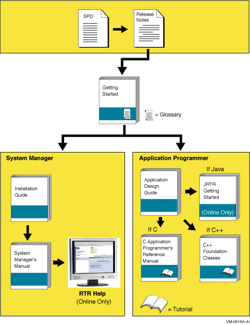
8. Reading Path
The reading path to follow when using the Reliable Transaction Router information set is shown in Figure 1, ''RTR Reading Path''.
Chapter 1. Introduction
For a general introduction to Reliable Transaction Router (RTR), read the VSI Reliable Transaction Router Getting Started manual. This is a prerequisite before using this manual for the system manager. Additional information about RTR is available in the other documents in the Reliable Transaction Router information set and from the RTR web browser and command line interfaces.
To use RTR, you must first install the RTR software and create and install your application. See the VSI Reliable Transaction Router Installation Guide for instructions on how to install RTR.
RTR applications can use the C API calls described in the VSI Reliable Transaction Router C Application Programmer’s Reference Manual and the C++ API classes described in the VSI Reliable Transaction Router C++ Foundation Classes manual.
1.1. Initial Setup
Before an RTR application can be used, RTR must be started on every node that is defined as part of your RTR configuration. You do this by issuing a START RTR command on each node. You can include the START RTR command in a startup command procedure, script or .bat file for each node, starting RTR whenever a node is booted. Note that RTR cannot start until after the network has started. For details on how to use startup procedures, see your operating system documentation. For information on installing RTR, see the VSI Reliable Transaction Router Installation Guide.
After RTR is started, you must create RTR's recovery journal files on specified disks. Use the RTR CREATE JOURNAL command to create journal files.
Note
While configuring RTR on HP-UX and Linux for Integrity servers (I64) in ACTIVE/STANDBY mode, a journal should be created in the shared disk (Cluster File System (CFS)/Global File System (GFS)), that is accessible from all the nodes configured in the cluster.
For RTR to work in ACTIVE/STANDBY mode, the following environmental variables must be set:
RTR_CLU_MEM_NODES: This variable enables RTR to recognize the backend nodes of the cluster participating in ACTIVE/STANDBY mode.
For example:
RTR_CLU_MEM_NODES="BE1, BE2"
RTR_CLU_LCK_DISK: This variable enables RTR to maintain the "cluster node locks" on a common shared disk in the cluster. All backend nodes in the cluster should use the same disk for maintaining "cluster node locks".
For example:
RTR_CLU_LCK_DISK= "/dev/vx/dsk/rtrdata/rtr_files"
- for HP-UX I64
You should also create a log file to log RTR messages with the RTR SET LOG command.
A separate facility must be defined for each application. An RTR facility is the user-defined name that provides the mapping between nodes and roles for a given application. Before starting application processes, use the RTR CREATE FACILITY command to define a facility. You may choose to include the CREATE FACILITY command in the command procedure used to start the application. For examples of configurations, see the VSI Reliable Transaction Router Getting Started manual.
1.2. Administering RTR and RTR Applications
RTR is started, configured, and maintained by using either the RTR Administrator web browser interface or the RTR Command Line Interface (CLI). Either interface is used to start, set up, and monitor the operation of RTR. An application written with the C++ API can also start RTR. For more information on system management from an application, see the VSI Reliable Transaction Router C++ Foundation Classes manual.
1.3. RTR Administrator
The RTR Administrator web browser interface has two parts, the RTR Manager and the RTR Explorer. Both are web-browser-based interfaces. Help is available in popups and through strategically placed help buttons.
- From the OpenVMS or Tru64 UNIX system prompt, start the HTTP server on the target computer system by using the following command:
% rtr start http_server
This command must be issued for each user of the management features.Operating System Prompt Symbol
The user prompt for the operating system is shown here as the percent (%) symbol. Your system may show a different prompt.
The system manager can issue the command on behalf of each user when the system starts up, or each user can issue the command by logging in to the target system or by issuing a remote command such as
rsh.On Windows, with RTR installed, the RTR command window will be displayed. If not, click Start then Programs then VSI then RTR then Reliable Transaction Router. The RTR command window will be displayed. Start the http server with the
start http_servercommand.The following qualifier to the
start http_servercommand starts the servers as read-only:/access=read_only
Read-only servers execute only the equivalent of the command-line-interface commands SHOW and MONITOR.
Note
Note that you should set your browser security to medium/low (See Appendix B).
- Start the RTR Administrator browser by opening the file
rtr_main.html. This file is located in one of the following operating system-dependent directories where RTR is installed:Server Operating System
File Location
Linux
/var/opt/rtr
OpenVMS
RTR$DIRECTORY
UNIX
/rtr
Windows
RTR installation directory
If RTR is not installed on the computer where the browser is running, use the URL
http://<hostname>:46000/rtr_main.htmlto display the RTR Manager screen from a system where the HTTP server has been started.On Windows, to start the RTR Administrator, click Start then Programs then VSI then RTR then Web Browser Interface. This brings up the RTR Administrator screen.
Figure 1.1. RTR Administrator Screen 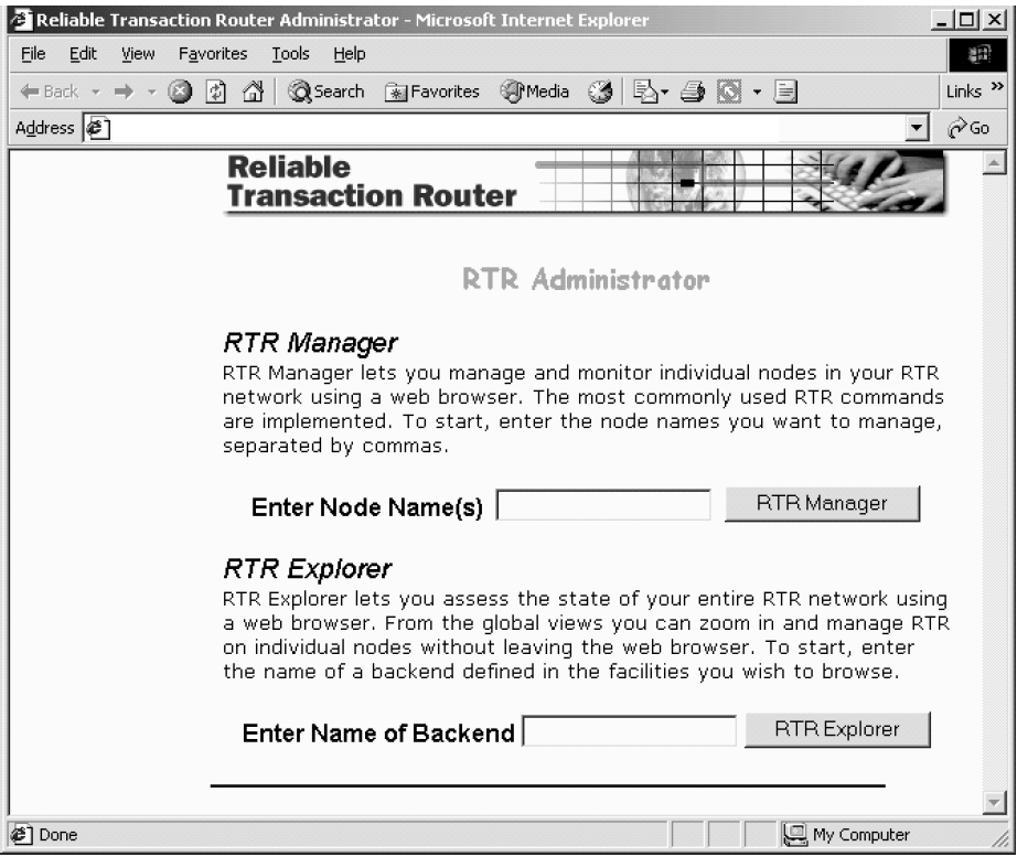
When the RTR Administrator screen appears (Figure 1.1, ''RTR Administrator Screen'') you can select whether to use the RTR Manager or RTR Explorer. The RTR Explorer graphically shows the configuration of each facility and provides alert mechanisms for viewing node, facility, and partition status. The RTR Manager provides extensive graphical monitoring mechanisms and provides a graphical menu of the most commonly used RTR commands.
To access the RTR Manager, enter the names of the nodes you wish to manage in the text box labeled ‘‘Enter Node Name(s),’’ and click the RTR Manager button. You can manage more than one node at a time by entering a comma-separated list of node names. RTR Manager can manage any node running an RTR HTTP server with RTR V4.0 or higher.
To access RTR Explorer, enter the name of the backend in the text box labeled ‘‘Enter Name of Backend,’’ and click the RTR Explorer button. Only a backend node will have the information needed to run the RTR Explorer for each facility in which it participates. Any backend running an RTR HTTP server with RTR V5.0 or higher installed can run RTR Explorer.
To access either RTR Manager or RTR Explorer on the local node, type nothing in either text box, and click the RTR Manager or RTR Explorer button, respectively. Your local node is the default.
A list of running HTTP servers will be shown on the next page. Choose the username corresponding to the HTTP server to which you wish to connect,as shown in Figure 1–2. If you have not started one, return to Step 1 and start one.
The following screen lets you select the RTR http server. Your selection is permanent for your browser session.
To change your selection, close your current browser window, reopen a new browser window and repeat Steps 1 through 5 with a new selection.
Figure 1.2. Select HTTP Server 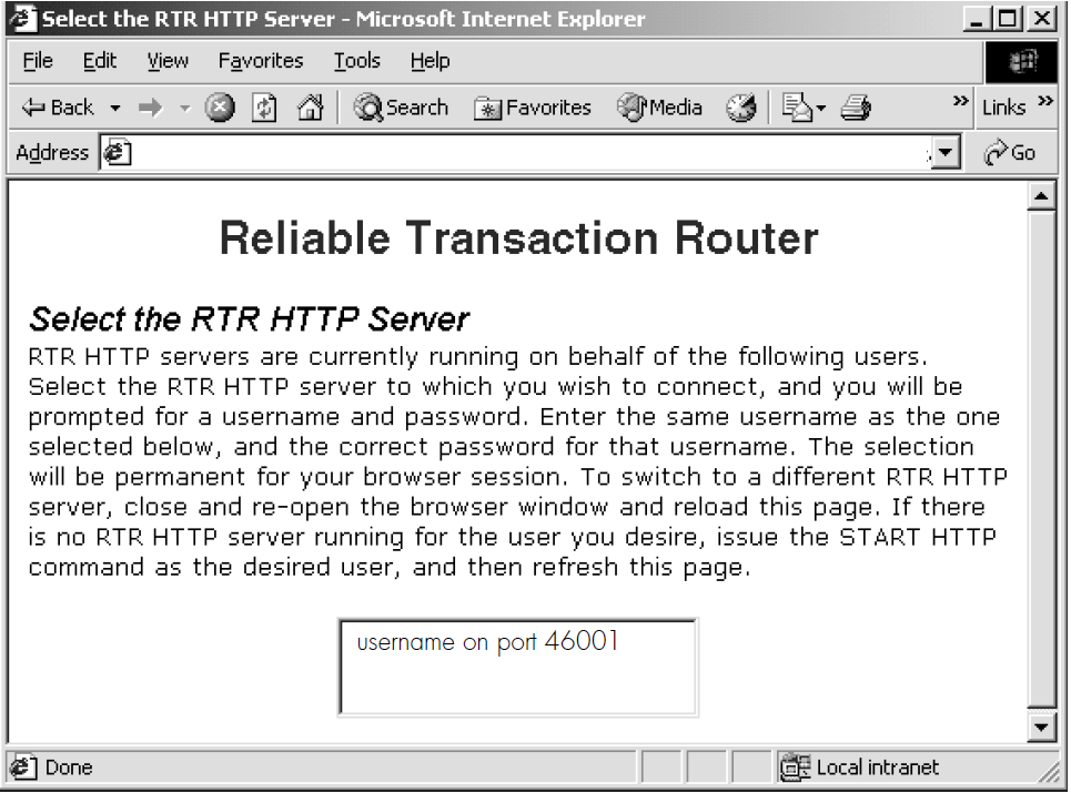
The RTR Security dialog box, Figure 1.3, ''RTR Security Dialog Box'', appears. Enter your username and password. Enter exactly the same username that was selected in Step 5. Do not prefix or suffix the username with a domain name, node name, or any other information. Enter exactly the same password you used to log into the system to start the HTTP server.
If incorrect credentials are given too many times, authentication is temporarily disabled as a security measure. You may either wait until authentication has been re-enabled, or stop and restart the RTR HTTP server.
Figure 1.3. RTR Security Dialog Box 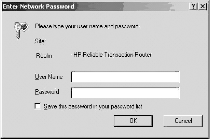
Either the RTR Manager screen, Figure 1–4, or the RTR Explorer screen, Figure 1–5, appears, depending on your selection.
Figure 1.4. RTR Manager Screen 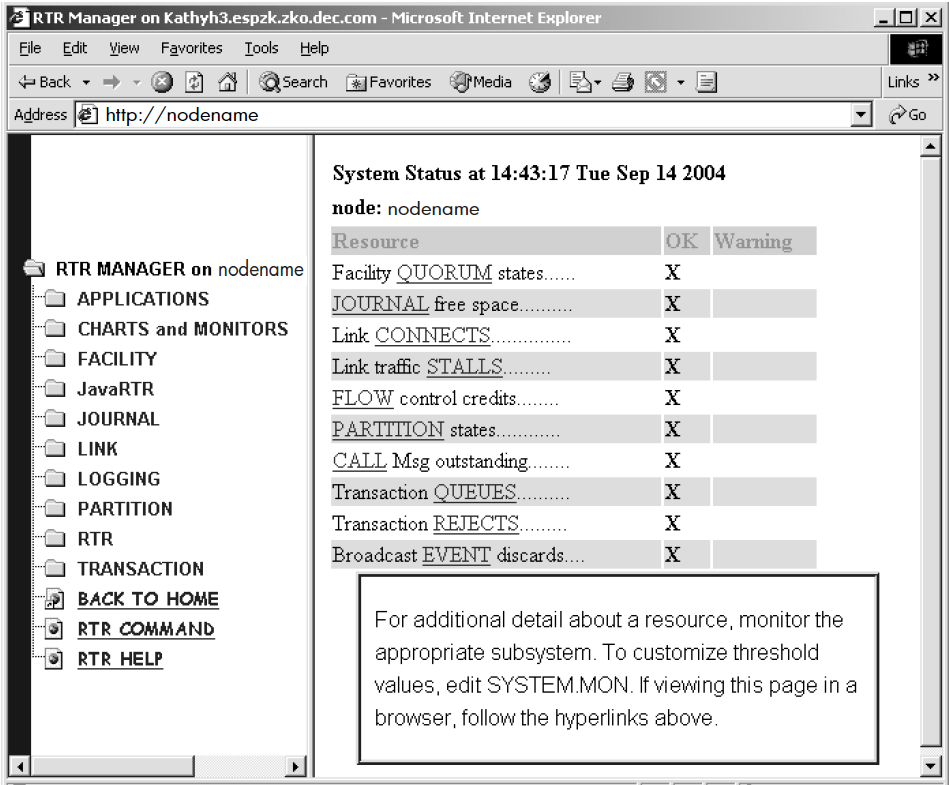
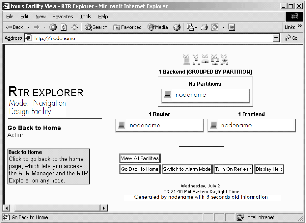
Figure 1.5. RTR Explorer 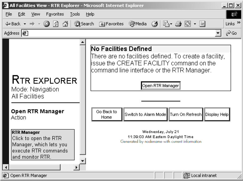
1.3.1. RTR Manager
The RTR Manager provides access to commands and displays with which you manage RTR, its facilities, nodes, logs, and partitions. The RTR Manager also provides enhanced graphical monitoring capabilities superior to the RTR CLI. Rows are color-coded, hyperlinks are available, and popups describe the content of monitor screens. Most RTR CLI commands are also available through the RTR Manager screen when you click on the RTR Command link.
In addition, the browser interface provides context-sensitive help for commands where user input is required, informational popups on certain headings such as "Resource," and details of a facility, partition, link, or transaction with links through browser popups. For example, to see details of a defined partition, click on the "show partition x details" popup seen when placing your mouse on a blue-underlined partition name.
Note
In the browser interface, node lists are built from the contents of the local
hosts file. You should add the names and addresses of current and potential
nodes in your configuration to the local hosts file. In some cases you must
enter the fully-qualified path name such as http://node.domain, to
reach the node you want to manage, in facility definitions, and when using a web
browser.
For information about server security and customizing the appearance of the RTR Administrator interface, see Appendix B, "Customizing the RTR Web Browser Interface".
1.3.2. RTR Explorer
The RTR Explorer interface enables the system administrator to monitor all nodes in the facilities defined for RTR, to navigate to all nodes in the RTR network, drill down to specific nodes, and receive automatic notification of warning, error, or fatal alarms. Nodes are self-monitoring; they detect faults in RTR nodes, roles, links, or partitions.
When everything is normal, RTR Explorer shows all nodes in graphical displays, and presents an alert when the state of a node or facility changes to an abnormal state. Three alarm levels are shown in color and an increasing number of flags: Warning (yellow, one flag), Error (orange, two flags) and Fatal (red, three flags).
Figure 1.6, ''RTR Explorer - Navigation Mode, All-Facility View'' shows an all-facility view with several alarm states. Buttons on the right pane let you Go Back to Home (the RTR Administrator screen), Switch to Alarm Mode, Turn On (or Off) Refresh, and Display Help.
The mouse pointer is over the ‘‘Go Back to Home’’ button, showing instructions in the bottom left information pane.
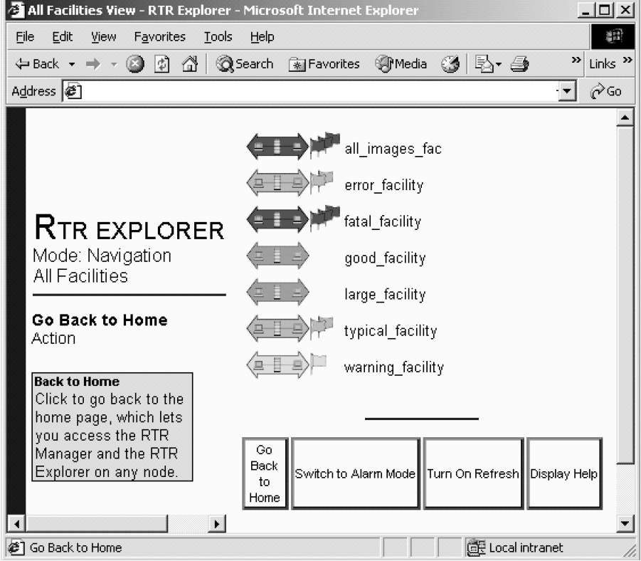
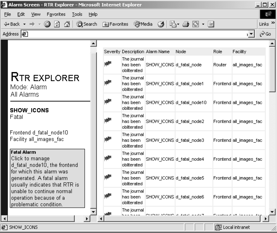
To find which node is sending an alarm and information about the alarm, click on the facility you want to examine. For example, the result when you click on the ‘‘all_images_fac’’ facility at the top of Figure 1.6, ''RTR Explorer - Navigation Mode, All-Facility View'' is shown in Figure 1.7, ''RTR Explorer - Alarm Screen''. This node-and-alarm view provides information about each node in the facility that has an alarm. For more information about RTR icons, see Section 1.3.2.1, ''RTR Explorer Icons''. For information about RTR Explorer Help (viewed from the Display Help button), see Section 1.3.2.2, ''RTR Explorer Help''.
1.3.2.1. RTR Explorer Icons
Explorer icons indicate states for nodes, facilities and partitions to assist you in finding and correcting the source of an alarm. Icons have a well-defined hierarchy from OK (green, no flags), through Warning (yellow, one flag) and Error (orange, two flags) to Fatal (red, three flags). The flags assist users who are color blind.
Several icon types assist your use of RTR:
Alarm icons (flags only, on the alarm screen)
Facility icons
Node icons
Node-group icons
Group-by icons
Partition-state icons (described in Chapter 3, "Partition Management").
When you place your mouse pointer over an icon or button, an information pane appears (lower left) describing the object under the mouse pointer. More detail on icons is available in the RTR Explorer interface.
Facility Icons
The icon status of a facility corresponds to the most serious status in the facility. To view the nodes in a specific facility and their individual status, click on the facility icon. The facility icons are shown in Figure 1.8, ''RTR Explorer Facility OK Icon'' to Figure 1.11, ''RTR Explorer Facility Fatal Icon''.


You obtain additional information to track down alarm origins using the node, node-group, and group-by-icons.
Node Icons
A node icon represents an individual node in an RTR facility; its status, shown by color and flags, represents the most serious alarm reported by that node. Node icons are shown in Figure 1.12, ''RTR Node OK Icon'' to Figure 1.15, ''RTR Node Fatal Icon''.


Node-Group Icons
In a large configuration where node icons cannot fit on one screen, nodes are grouped alphabetically, and a group icon shows the status of each group. Nodename alphabetization is case-insensitive; for example, Y.Z.COM comes after a.b.com. Node-group icons are shown in Figure 1.16, ''RTR Node-Group OK Icon'' to Figure 1.19, ''RTR Node-Group Fatal Icon''.


Group-By Icons
When examining a facility, you can group backends in several ways:
With no group
By cluster
By partition
By cluster, then partition
By partition, then cluster
Use these groupings to help you isolate the source of an alarm, as shown in Figure 1–20.
Group-by icons are shown in Figure 1–21 to Figure 1–25. Icons help remind you which grouping is shown, as follows:


Partition State Icons
Partition states show the current state of a given partition; they appear on the facility screen. They are described in Chapter 3, "Partition Management".
1.3.2.2. RTR Explorer Help
RTR Explorer provides advice and information through the Display Help mouse click, and includes background on the accuracy of current RTR Explorer data shown in RTR Explorer screens. If a screen contains the word INCOMPLETE, your displayed data may be incomplete. For additional information, see Table 1.1, ''Incomplete Indicator'' and Table 1.2, ''Updating Incomplete Data''.
| If you see: | It means that: |
|---|---|
| INCOMPLETE |
The backend gathering information could not gather all the information it needs to display the entire RTR network. The displayed information is accurate, but some frontend connection status may be missing. Some frontends may be erroneously marked as disconnected even though they are connected, because the backend may be unable to contact one or more routers to which the frontends are connected. |
The following explanations clarify the reasons why the data can be incomplete, and what can be done to fix the problems.
| If you see the message: | The reason is: | To correct the problem: |
|---|---|---|
| Disconnected Routers | The node that generates the page needs to contact all routers in each facility to gather the information. If any of the required links are disconnected, the information will be incomplete. | Ensure that all router links are connected and that the facility configuration is consistent across the nodes. If your router is disconnected and the situation cannot be changed, try viewing the RTR Explorer from another backend. If the other backend is connected to all routers, the information will be complete. |
| RTR Version does not include the RTR Explorer | The RTR Explorer is only supported by RTR versions 5.0 and higher. The node that generated the page must contact all routers in each facility to gather the information. However, if any of the routers are not running RTR version 5.0 or higher, the node cannot request the information from the router, and the information will be incomplete. | To correct this problem, upgrade RTR on the offending routers. |
| Non-responsive Routers | The node that generated the page must contact all routers in each facility to gather the information. If one or more routers fail to respond within a timeout, the node deems the router as non-responsive and no longer waits for a response. However, the information will also be incomplete. | The command SET NODE/ROUTER_ RESPONSE_TIMEOUT determines the timeout, where the default is 30 seconds. If you determine that the routers need more time to respond, increase the timeout to a value that gives all routers enough time to respond. |
| Improperly Formatted Data | Each router responds with data in a certain format. If the data is not formatted correctly, the node will be unable to parse it and extract the information, and the information will be incomplete. | This error most likely indicates that there is a problem on the network that is mangling the network packets. In that case, you must resolve the network issue to ensure complete data. If you are sure the network is operating correctly, you may need to contact the appropriate RTR support personnel for a resolution. |
| Internal Error | An internal error may be temporary, and so retrying your request may resolve the problem. | If the problem persists, contact the appropriate RTR support personnel for a resolution. |
1.4. Command Line Interface (CLI)
RTR at the operating system prompt.
You can enter commands on the same line as the RTR verb or you can enter several
commands at the RTR prompt. For example, this example shows a one-line command:
% rtr command%rtr(C)1994, 2003 Hewlett-Packard Development Company, L.P.RTR>start rtr%RTR-I-STACOMSRV,starting command server on NODEA in group "Testing"RTR>create journal%RTR-W-JOUALREXI,journal alredy created
The RTR CLI accepts commands that you type and can process procedures consisting of RTR commands.
Most RTR commands accept qualifiers, indicated by the forward slash
(/) character. For example, many RTR commands accept the /OUTPUT
qualifier; it directs the output from the command to a file.
The forward slash (/) character may also appear in the file names
of some operating systems; such file names must be enclosed in quotation marks to ensure
that RTR does not interpret the file name as a command qualifier.
RTR> call rtr_send_to_server "Message text"/channel=c
- On UNIX and Linux:
% rtr call rtr_send_to_server '"Message text"'/channel=c
- On OpenVMS:
$ rtr call rtr_send_to_server """Message text"""/channel=c
- On Windows:
C:\ rtr call rtr_send_to_server """Message text"""/channel=c
orC:\ rtr call rtr_send_to_server \"Message text\"/channel=c
For RTR on Windows
When executing commands from the RTR command line (CLI), if the process that opens a channel goes away, the PID associated with that channel also goes away due to the way Windows identifies the requester. This can cause invalid channel arguments, but is normal behavior in a test or experimental environment using the CLI.
1.4.1. Online Help for the RTR CLI
%rtr help
%rtr help show
%rtr help errors error-identification
where error-identification identifies the
returned error.
RTRALRSTA and a brief explanation. Further explanation can be
obtained by using the help errors rtralrsta command.
%rtrRTR>start rtr%RTR-F-RTRALRSTA, rtr already startedRTR>help errors rtralrstaErrorsRTRALRSTARTR already startedExplanation: RTR was already running when the "START RTR" commandwas executed. This error message is displayed by the RTR utility.RTR>
1.5. Command Procedures
RTR commands can be written in a command file, script, .cmd or .bat file and then executed as
a procedure using the RTR EXECUTE filespec or @filespec
commands.
%rtr execute createfacil
%rtr @createfacil
%rtrRTR>execute createfacil
RTR>@createfacil
Batch Procedure/Command File Restriction
The last line of a batch procedure or command file must explicitly end with <CRLF> added by pressing the Enter/Return key when creating the procedure. Without the explicit <CRLF>, RTR ignores the line. The workaround is to add a comment to the end of the file or to explicitly add <CRLF> to the end of the last line of the batch procedure.
1.6. Remote Commands
Most RTR commands can be issued either locally (the default) or on one or more remote nodes.
If you use the TCP/IP protocol to activate RTR's remote command capability, you must configure RSHELL for your users. You must start and configure daemons to accept remote commands and authorize users.
If you use DECnet, you must have proxy access which involves an authorization step on target systems and remote task objects must be enabled. Refer to your operating system documentation for more information.
RTR>command/node=node-list
RTR>start rtr/node=(nodeA,nodeB,nodeC)
RTR>command/cluster
Recognized Clusters
The /CLUSTER and /NOCLUSTER command qualifiers refer to recognized clusters. These qualifiers are used in operating systems such as OpenVMS that fully support clustering and that support the remote command capability. Using the /CLUSTER qualifier on systems that do not support clustering causes the relevant command to be executed on the local node only. For example, Windows systems and non-Tru64 UNIX systems do not support recognized clustering.
|
On this operating system: |
Complete this setup: |
|---|---|
|
HP-UX |
Install |
|
Linux |
Install |
|
OpenVMS |
If using DECnet, set up proxies; if using TCP/IP, also set up
an |
|
Windows |
Install |
To execute several commands remotely on several nodes but minimize typing, use the SET ENVIRONMENT command.
%RTRRTR>set environment/node=(nodeA, nodeC)RTR>stop rtr
For more details on the above commands, see the description of the SET ENVIRONMENT command in the reference section of this manual.
RTR command and http servers started during an interactive Windows session do not survive a user logout of that session. After user logout from an interactive Windows session, the machine is no longer accessible to the RTR web browser.
To avoid this, enable remote shell (rsh) access to the Windows system; the http server can then be started with a remote RTR command directed at the system of interest. Windows rsh functionality is available from third parties, and with the Microsoft NT V4.0 Server Resource kit.
Chapter 2. Starting and Setting Up RTR
This chapter describes how to configure and start an RTR environment. Recovery journals, router load balancing and callout servers are also discussed.
2.1. Introduction
START RTR and CREATE FACILITY
commands on each participating node. There are several ways to accomplish this:
Log in to each node in turn and issue the commands interactively.
Log in to one node and use the remote command capability to configure all the nodes from one session, where your system supports this capability. See Section 1.6, ''Remote Commands'' for more information.
Include the necessary commands in a startup script or command file on each node, so the commands are automatically executed when the nodes are booted.
Once RTR is started, you can use the RTR web interface or the RTR CLI to create facilities and partitions.
The first two methods are more suited to a development or test environment, while the last method is more suited to a production environment.
In the RTR configuration:
Start RTR
Create a journal
Create facilities
Create partitions
Use an application or the RTR CLI to send and receive transaction messages
For more information on startup scripts, see the chapter for the relevant operating system in the VSI Reliable Transaction Router Installation Guide.
The remaining sections contain examples of the commands used to start and configure RTR. Section 9.2, ''RTR Command Reference'' gives syntax details of the RTR commands.
2.2. Setting Up – An Example
The following example assumes that RTR has been started on the eight-node system shown in Figure 2.1, ''RTR Configuration''.
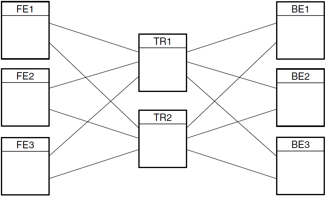
In Figure 2.1, ''RTR Configuration'', the application client processes run on the frontend nodes FE1, FE2 and FE3, and the server application processes run on the backend nodes BE1, BE2 and BE3. Nodes TR1 and TR2 are routers and have no application processes running on them. Figure 2.1, ''RTR Configuration'' shows all possible connections, but a frontend connects to only one router at a time.
2.2.1. Starting RTR and Creating a Facility
%rtr
RTR>start rtr
RTR>create facility funds_transfer/frontend=(FE1,FE2,FE3) -_RTR>/router=(TR1, TR2) -
_RTR>/backend=(BE1, BE2, BE3)
| Starts the RTR CLI. |
| Starts the RTRACP process. |
| This command issued on each node in the configuration creates a facility in which nodes FE1, FE2, and FE3 are frontends, nodes TR1 and TR2 are routers, and nodes BE1, BE2, and BE3 are backends. (The hyphen (-) at the end of command lines is a continuation character that retains the context for the command until it is ended with a carriage return.) |
The network must be started
RTR cannot start until after the network has started.
Frontends and backends need to know about the routers to which they are connected, but frontends don't need to
know about backends or other frontends, nor backends about frontends or other backends. In creating facilities,
RTR ignores superfluous node names so that you can use the same CREATE FACILITY command on every node
in an RTR configuration. This helps to simplify maintenance of startup command procedures.
For example, the same RTR CREATE FACILITY command shown in Example 2.2, ''Remote Setup from One Node''
can be issued on all nodes in the configuration. When issued on FE1, RTR ignores the list of backends because nodes
only need to know about the nodes in the neighboring layers of the configuration, thus FE1 does not need to know
about BE1.
SET ENVIRONMENT command is used to send commands to several RTR nodes.
%rtrRTR>set environment/node=(FE1, FE2, FE3, TR1, TR2, BE1, BR2, BR3)RTR>start rtrRTR>create facility funds_transfer/frontend=(FE1, FE2, FE3) -_RTR>/router=(TR1, TR2) -_RTR>/backend=(BE1, BE2, BE3)
This enters the commands on every node in the configuration. You must have an account with the necessary privileges on any node where the command is to execute.
Use the SHOW RTR command to find out if RTR has been started on a particular node.
SHOW FACILITY command to see which facilities have been created and use
the SHOW LINK command to see how they are configured. The full syntax of these commands
is given in Chapter 9, "RTR Commands". You can view the effect of these commands with the
RTR web browser.
Dynamic Addressing on Windows
CREATE FACILITY command by using the current
IP address that may need to be changed after a reboot. For example, the
following command could be executed on an OpenVMS system to include a
Windows frontend that uses dynamic addressing, where 1x.2x.xx.xxx represents
the IP address of the frontend:
RTR> CREATE FACILITY OSIRIS/backend=NODEA/router=NODEA/frontend=1x.2x.xx.xxx
%RTR-S-FACCREATE, facility OSIRIS created
RTR> SHOW FACILITY...
2.3. Creating a Recovery Journal
Every RTR backend must have a journal; an application with a callout server (which runs on the router) should have a journal on the router. The journal is used by the backend that must have physical access to the journal.
RTR writes data to journal files to be able to recover (that is, replay) partially executed transactions after a backend node failure. The journal file must be placed on a disk that is visible to nodes running RTR. If you locate your journal on a non-local disk, and the node accessing that disk goes down, RTR cannot access transactions in that journal until the failed node comes back up.
Size of the messages in a transaction
Number of messages in the transaction
Rate of generation of transactions
Maximum time a shadow site can be out of commission
Allow 140 bytes per inbound message (C++ API
SendApplicationMessageor C APIrtr_send_to_server()call).Allow 140 bytes per transaction (C++ API
AcceptTransactionor C APIrtr_accept_tx()call).Allow 512 bytes per journal file for internal header information.
Add an amount to accommodate your application message size.
Use of large transactions generally causes poor performance, not only for initial processing and recording in the database, but also during recovery. Large transactions fill up the RTR journal more quickly than small ones.
The /MAXIMUM_BLOCKS qualifier on the CREATE JOURNAL command controls how large
a journal may become. The /MAXIMUM_BLOCKS qualifier defines the maximum number of blocks which
the journal is allowed to occupy on any one disk. RTR does not check if this amount of space is actually
available, as the disk space specified by /MAXIMUM_BLOCKS is used only on demand by RTR when
insufficient space is available in the space allocated by the /BLOCKS qualifier.
The number of blocks specified by the /BLOCKS qualifier specifies the maximum size of the
journal that RTR attempts to use. The actual number of blocks used may vary, depending upon the load on
RTR.
The command MODIFY JOURNAL also accepts the /BLOCKS and /MAXIMUM_BLOCKS
qualifiers.
Journal file extension occurs on demand when RTR detects that a "write to journal" would otherwise fail due to lack of space. Journal file truncation takes place periodically when enough free blocks are detected.
MODIFY
                JOURNAL
command.RTR> show journal/files/full RTR journal:- Disk: /dev/rz3a Blocks: 2500 Allocated: 1253 Maximum: 3500 File: //rtrjnl/anders/BRONZE.J00 RTR>
See Section 5.3, ''RTR Journal System'', RTR Journal System, for information on how to calculate the size of the journal. Preferably, create your RTR journal on a disk in a recognized cluster.
To improve performance, the journal may be striped across several disks. Specify the location and size of
the journal using the CREATE JOURNAL command.
CREATE JOURNAL command on each node where an application server will run, that is,
on each backend node and on any router nodes where you intend to run router callout servers. It must be issued
after installing RTR and before creating any facilities. It may be issued again later to alter the size or
location of the journal to improve performance. Use the MODIFY JOURNAL command to adjust journal
sizes.
Caution for Journals
The CREATE JOURNAL/SUPERSEDE command deletes the contents
of any existing journal files. If transaction recovery is required, DO NOT ISSUE this command after
a failure.
To make a copy of a journal file, stop RTR and copy the file to a directory outside the rtrjnl
directory or RTR will issue a spurious journal file message (% RTR-F-SPUJOUFIL) when it sees a
journal file it did not create.
2.3.1. Maximum Journal Size
- Number of 512-bytes blocks per disk: 524288
(This is
max_segments_per_disk * disk_blocks_per_segment, or 16384 bytes times 32.) - Number of disks per journal: 16.
2.4. Fast Shadow Recovery Journaling
With fast shadow recovery, a node becomes primary active or secondary active as soon as it has copied all
the transactions from the remembering node. Whether it becomes primary or secondary depends on its priority
(established with the SET PARTITION/PRIORITY command). However, a large backlog of unprocessed
transactions could cause what looks like a dual-site outage if a node immediately becomes primary active,
because it must process the backlog before processing new transactions. Thus RTR ensures that a node processing
a fast-recovery backlog becomes secondary active until it has caught up with the primary.
Only when it has caught up will it change to primary active state. MONITOR QUEUES includes the
delay, in seconds, between when transactions arrive on a backend and when they are processed by a server
application.
2.5. Changing Membership of a Facility
Using TRIM FACILITY
TRIM FACILITY command to change RTR facility membership.
Note
The RTR facility defines the nodes used by an application and the roles (frontend, router, backend) they may assume. You do not need to change facility definitions in the event of node or link failures.
When using EXTEND FACILITY and TRIM FACILITY commands, make sure that the command
is issued on all nodes that are affected. That is, all backend nodes must be informed when router configurations
are changed and all router nodes must be informed when backend or frontend configurations are changed. For use of
anonymous clients, see the description in the CREATE FACILITY command.
In Figure 2.1, ''RTR Configuration'', assume that the FE3 node is being removed from the funds_transfer
facility. Since FE3 is a frontend for this facility, only the routers (TR1 and TR2) need be reconfigured.
%rtrRTR>set environment/node=FE3%RTR-S-COMARESEN, commands sent by default to node FE3RTR>delete facility funds_transfer%RTR-S-FACDELETE, facility funds_transfer deletedRTR>stop rtr/node=FE3%RTR-S-RTRSTOP, RTR stopped on node FE3RTR>set environment/node=(TR1,TR2)
%RTR-S-COMARESEN, commands sent by default to node TR1%RTR-S-COMARESEN, commands sent by default to node TR2RTR>trim facility funds_transfer/frontend=FE3
%RTR-S-FACTRIMMED, facility funds_transfer trimmed----TR1-------------------------------------------------------------%RTR-S-FACTRIMMED, facility funds_transfer trimmed----TR2-------------------------------------------------------------RTR>
| Subsequent commands are executed on node FE3. |
| The facility is deleted on node FE3. |
| RTR is stopped on node FE3, the node being excluded from the network. To
prevent transactions from being interrupted or aborted, application
processes should be stopped in an orderly manner before issuing the
|
| Subsequent commands are executed on nodes TR1 and TR2. |
| Node FE3 is removed from the facilities defined on nodes TR1 and TR2. |
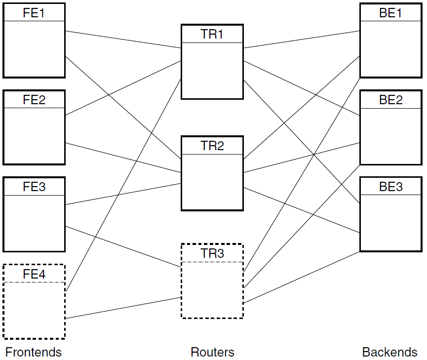
Using EXTEND FACILITY
In the example in Figure 2.1, ''RTR Configuration'', assume that a new router node TR3 and new frontend
FE4 are being added to the facility funds_transfer. The extended configuration is shown
in Figure 2.2, ''Extend Configuration''. This diagram shows the possible frontend to router connections.
The frontend connects to only one router at a time.
Roles in EXTEND FACILITY are Additive
EXTEND FACILITY commands are additive; roles are added, never removed. To remove a role,
use the TRIM FACILITY command.
EXTEND FACILITY command
used for this reconfiguration. % RTR RTR> sho fac
| Shows the initial configuration before extending the facility. |
| These are new nodes, so RTR must be started on them. |
| The |
| The |
| The |
2.6. Setting Up Callout Servers
Callout servers are checking or verification applications running on a router or backend; they receive a copy of every transaction passing through the node where the callout server is running.
Like any other server, callout servers can abort any transaction in which they participate. Callout servers are typically used to provide an additional security or checking service; transactions can be inspected by the callout server and aborted if they fail to meet user-defined criteria.
Callout servers require that a journal be created on the node where the server runs. For a backend callout server, there would already be a journal because backends require journals, but if the callout server is running on a router, a journal is required on the router node.
%rtrRTR>set environment/node= -_RTR>(FE1,FE2,FE3,TR1,TR2,BE1,BE2,BE3)RTR>start rtrRTR>create facility funds_transfer/frontend=(FE1,FE2,FE3) -_RTR>/router=(TR1,TR2) -_RTR>/backend=(BE1,BE2,BE3) -_RTR>/call_out=router
Note
Before changing a facility from one with callout servers to one without callout servers, verify that
all transactions in the facility are completely resolved by keyrange and callout server. (You can use
SHOW TRANSACTION/FULL to view the state of all transactions.) Otherwise, after changing your
facility, transactions may remain in the system as in recovery until either the facility is changed to
allow their recovery or the journal is recreated.
2.7. Router Considerations
To avoid problems with quorum resolution, design your configuration with an odd number of routers. This ensures that quorum can be achieved.
To improve failover, place your routers on separate nodes from your backends. This way, failure of one node does not take out both the router and the backend.
If your application requires frontend failover when a router fails, frontends must be on separate nodes from the routers, but frontends and routers must be in the same facility. For a frontend to fail over, there must be more than one router in the facility.
To identify a node used only for quorum resolution, define the node as a router or as a router and frontend. On this node, define all backends in the facility, but no other frontends.
With a widely dispersed set of nodes (such as nodes distributed across an entire country), use local routers to deal with local frontends. This can be more efficient than having many dispersed frontends connecting to a small number of distant routers. However, in some configurations such as those without long network links, it may be more effective to place routers near backends. For more information on configuration considerations, see the VSI Reliable Transaction Router Application Design Guide.
2.8. Router Load Balancing
Router load balancing, or intelligent reconnection of frontends to a router, enables a frontend to select a preferred router, the router that is least loaded. Load balancing is coordinated by backends.
You use the /BALANCE qualifier on the CREATE FACILITY and SET FACILITY commands to
control load balancing. (The RTR Version 2 implementation of load balancing treated all routers as equal which
might cause reconnection timeouts in geographically distant routers.)
When used with CREATE FACILITY, the /BALANCE qualifier enables load balancing for frontend-to-router
connections across the facility. Use SET FACILITY/NOBALANCE and /BALANCE to switch
load balancing off and on.
The default behavior (/NOBALANCE) connects a frontend to the preferred router. Preferred
routers are selected in the order specified in the /ROUTER=(tr1,tr2,tr3,...) qualifier used
with the CREATE FACILITY command. If the /ALL_ROLES qualifier is also used, the nodes specifed have
lower priority than the nodes specified by the /ROUTER qualifier. RTR automatic failback ensures that the frontend
will reconnect to the first router in the specified order when it becomes available. Manual balancing can be
attained by specifying different router orders across frontends.
When the /BALANCE qualifier is used, the list of routers specified in the router list is randomized, making the preferred router a random selection within the list. Randomness assures that there will be a balance of load in a configuration with a large number of frontends. RTR's process for automatic failback will maintain the load distribution on the routers. Failback is controlled so as not to overload configurations with a small number of routers.
RTR CREATE FACILITY test/FRONTEND=Z/ROUTER=(A,B,C)
The frontend attempts to select a router based on the priority list A, B, C, with A being the preferred router. If the /BALANCE qualifier is added to the end of this command, the preferred router is randomly selected from the three nodes. This random list exists for the duration of the facility. If a facility is stopped, a new random list is made when the facility is recreated, unless a router does not have quorum (sufficient access to backend systems). A router without quorum will no longer accept connections from frontend systems until it has again achieved quorum.
Frontends connect to a single router at a time, per facility
When several routers are configured on the frontend, the specified list in the
CREATE FACILITYcommand designates the preferred search order unless the /BALANCE qualifier is used.Balancing can be individually enabled or disabled on the frontend nodes.
Balancing is dynamic. The loss or addition of a router node causes the frontend nodes to redistribute their connections.
Use /BALANCE for frontends to specify router random selection. See
CREATE_FACILITYandSET_FACILITYfor more information on the /BALANCE qualifier.
CREATE FACILITY/BALANCEEnables load balancing on the node where it is issued
Significant only for frontend nodes to specify router random selection
Disabled, by default
SET FACILITY/[NO]BALANCEToggles the balance attribute on the node where it is issued
SHOW FACILITY/CONFIGURATIONShows, among other things, whether load balancing has been set
SHOW FACILITY/BALANCEShows the number of frontends connected and allowed, load coordinator status, number of quorate routers, total frontends, and current credit
Helps troubleshoot frontend connection problems
MONITOR FLOWShows available credits and data rates for role directions
MONITOR TRAFFICShows congestion on RTR links.
2.9. Concurrent Processes
Adding concurrent processes (concurrency) for server application processes usually increases performance. Concurrency permits multiple server channels to be connected to an instance of a partition.
Concurrency should be added during the testing phase, before an application goes into production to verify that performance does increase. For example, if multiple servers require a lock to the same part of the database, transaction throughput could decrease rather than increase with concurrent servers. For transaction throughput to increase in such a case, transactions must lock independent parts of the database.
Number of disks used for the RTR journal and the database
Disk I/O
Memory capacity
CPU speed
Number of CPUs
Network I/O
Network reliability, for example, insufficient capacity of hardware
Database access and contention
- Application performance
Multiple threads
Multiple channels
Multiple partitions
Refer to the VSI Reliable Transaction Router Application Design Guide for more information on application performance tuning.
2.10. RTR Privileges
rtroperandrtrinfoon UNIX platformsRTR$OPERATOR and RTR$INFO on OpenVMS platforms
RtrOperatorandRtrInfoon Windows platforms
In general, rtroper or RTR$OPERATOR is required to issue any command that affects the running
of the system, and rtrinfo or RTR$INFO is required for using monitor and display commands.
Setting RTR Privileges on UNIX Systems
On UNIX machines, RTR privileges are determined by the user ID and group membership. For RTR users and operators,
create the group rtroper and add RTR operators and users as appropriate.
The root user has all privileges needed to run RTR. Users in the group rtroper also have all
privileges with respect to RTR, but may not have sufficient privileges to access resources used by RTR, such as
shared memory or access to RTR files.
The rtrinfo group is used only to allow applications to call rtr_request_info(). For other
users, create the groups rtroper and rtrinfo. Users who do not fall into the above categories,
but are members of the rtrinfo group, can use only the RTR commands that display information
(SHOW, MONITOR, CALL RTR_REQUEST_INFO, etc.).
Depending on your UNIX system, see the addgroup, groupadd or mkgroup
commands or the System Administration documentation for details on how to add new groups to your system.
If the groups rtroper and rtrinfo are not defined, all users automatically belong to them.
This means that there is no system management required for systems that do not need privilege checking.
Setting RTR Privileges on OpenVMS Systems
Use the AUTHORIZE utility to create the Rights Identifiers RTR$OPERATOR and RTR$INFO if they do not already exist on your system, and assign them to users as appropriate. The RTR System Manager must have the RTR$OPERATOR identifier or the OPER privilege.
Setting RTR Privileges on Windows Systems
Administrator privileges are needed for RtrOperator rights by the RTR System Manager.
2.11. RTRACP Virtual Memory Sizing for all Systems
Basic memory requirements of an unconfigured RTR Application Control Process (RTRACP) on all supported operating systems is approximately 5.8 Mbytes. Additional memory may be required depending on the operating system environment being used by the RTRACP. While there is no penalty for allocating more virtual memory than is used, applications may fail if too little memory is allocated.
RTR contains a low memory check. If the RTRACP detects that it is critically low on free memory, it may reject new and uncommitted transactions to preserve its limited resources. Committed transactions will not be aborted. The RTRACP will also discard any broadcasts that arrive after it is low on memory. Versions of RTR prior to V4.2 would not detect that it was low on memory and RTR could crash as a result; now the crash is avoided.
The client and server receive an rtr_mt_rejected message if a transaction is aborted due to low
memory. If the frontend is low on memory, the associated status is FEREJECTLOWMEM; if the backend is low on memory,
the associated status is BEREJECTLOWMEM. A log entry, RTR_E_ACPLOWMEMORY, is written when the RTRACP is critically
low on memory. When the RTRACP regains access to sufficient memory, a log entry RTR-I-ACPSUFMEMORY is written.
|
For each |
Add an additional |
|---|---|
|
Link |
202 Kbytes |
|
Facility |
13 Kbytes plus 80 bytes for each link in the facility |
|
Client or server application process |
190 Kbytes for the first channel |
|
Additional application channel |
1350 bytes |
You must also prepare for the number of active transactions in the system. Unless the client applications are programmed to initiate multiple concurrent transactions (multi-threading), this number cannot exceed the total number of client channels in the system. This should be verified with the application provider.
- For each frontend:
Add 1 Kbyte per active transaction
Add 250 bytes per message per transaction
Add the size of all messages
Add the size of channel queues
- For each transaction router:
Allow 1 Kbyte for each active transaction
- For each back end:
Allow 1 Kbyte per active transaction
Allow 50 bytes for each message of a transaction
Add the size of all replies
Add the size of channel queues
128 bytes per reply plus
- the lesser of:
size of the replies plus 120 times the number of replies
10 Mbytes
Thus if you want to send a million replies, make provision for a virtual address space of 138 Mbytes.
The total of all the contributions listed will provide an estimate of the virtual memory requirements of the RTRACP. A generous additional safety factor should be applied to the total virtual memory sizing requirement.
Resource Sizing for OpenVMS
On OpenVMS, it is better to grant the RTRACP resource limits exceeding its real requirements than to risk loss of service in a production environment as a result of insufficient resource allocation. The total result should be divided by the virtual memory size in pages to obtain the final virtual memory requirement. Process memory and page file quotas should be set to accommodate at least this much memory.
Resource Sizing for UNIX and Windows
On other operating systems, just make sure your machine has the physical memory and the disk space for a swap file.
2.11.1. OpenVMS Virtual Memory Sizing
START RTR command.
START RTR accepts both links and application processes as qualifiers which can be used to specify
the expected number of links and application processes in the configuration. The values supplied are used to
calculate reasonable and safe minimum values for the following RTRACP process quotas:
ASTLM
BIOLM
DIOLM
FILLM
PGFLQUOTA
Both the /LINKS and /PROCESSES qualifiers have high default values.
The default value for /LINKS is 512. This value is high but is chosen to protect RTR routers against a failover where the number of frontends is large and the number of surviving routers is small. The maximum value for /LINKS is 1200.
The default value for /PROCESSES is 64. This value is large for frontend and router nodes but is sized for backends hosting applications. Backends with complex applications may have to set this value higher.
The maximum value for /PROCESSES is the OpenVMS allowed maximum. Warning messages are generated if the requested (or default) memory quotas conflict with the system-wide WSMAX parameter, or if the calculated or specified page file quota is greater than the remaining free page file space.
The default values for /LINKS and /PROCESSES require a large page file. RTR issues a warning if insufficient free space remains in the page file to accommodate RTR, so choose values appropriate for your configuration.
The /LINKS and /PROCESSES qualifiers do not take into account memory requirements for transactions. If an
application passes a large amount of data from client to server or vice-versa, this should be included in the
sizing calculations. For further information on the START RTR qualifiers, see the START RTR
command in the Command Reference section.
You may explicitly specify values for the VMS process quotas listed above, but it is an error to specify a value smaller than that calculated by RTR based on the values supplied with /LINKS and /PROCESSES.
Available space in the system page files
CHANNELCNT
MAXPROCESSCNT
WSMAX
Note
The OpenVMS AUTHORIZE utility does not play a role in the determination of RTRACP quotas. RTR uses AUTHORIZE quotas for the command line interface and communication server, COMSERV. Virtual memory sizing for the RTRACP is determined through the qualifiers of the START RTR command.
2.11.2. UNIX Virtual Memory Sizing
The RTRACP requires the operator to size the process limits for the RTRACP before starting RTR on all platforms. No direct control of the process quotas of the RTRACP is offered for UNIX based platforms. However, log file entries will result if hard limits are less than the preferred values for the RTRACP.
1024 open file descriptors
1048576 Kbytes for virtual memory address space
262144 Kbytes for a single file size
409600 Kbytes for heap data segment sizing
32768 Kbytes for core file size
8192 Kbytes for stack segment size
0 for CPU time
The START RTR qualifiers /LINK and /PROCESSES apply only to the OpenVMS platform. Process quotas on UNIX platforms must be determined through operating system handling of virtual memory sizing.
2.12. RTR Shared Memory Sizing
Each operating system where RTR runs has different requirements for shared memory, a system-wide resource. These requirements are as follows:
For Linux:
To start and operate, RTR allocates a shared memory segment of approximately 160,040 bytes. This portion of memory will be exclusively used for management operations such as establishing connections between a frontend and a router.
In addition to this memory, RTR also uses a shared memory segment of approximately 12,592 bytes for every process including the RTR COMSERV that has opened an RTR channel. This requirement is independent of the number of threads used in the application process.
Often, RTR needs to service multiple client/server applications on a given node. To minimize shared-memory related operations on each client/server application open-channel request, the RTRACP allocates shared memory in large chunks, in amounts that differ on different platforms. These large chunks are later used on demand. Please consult your operating system documentation for more information on various tunable shared memory-related parameters.
For Windows and OpenVMS:
RTR uses a different mechanism on Windows and OpenVMS platforms. For OpenVMS, RTR uses global sections and on Windows, memory-mapped I/O. However, the basic memory requirement of 12,592 bytes for every application process, and 160,040 bytes for management activities, remains the same. Each global section will be able to accommodate process counters belonging to ~32 RTR applications. Any increase in application counters, which happens from release to release, will reduce the number of applications that can be accommodated in a global section.
For more information on limits of memory-mapped I/O and global sections, see the Operating system documentation.
2.13. Environment Variables Used by RTR
RTR can use several environment variables for specific needs. How you set these depends on your operating system. Use them to do the following:
tune journal access
compress reply data
manage flow control
establish network transports, frontend notification, best response time, journalling parameters, default node affixes
restrict incoming connections to a specific network
ensure that partition instances resume in their prior mode when regaining a connection
customize break-in detection and evasion
revert to V3/V4 behavior
You set these environment variables on OpenVMS with ASSIGN or DEFINE. On UNIX the command differs according to the shell. For the c shell (csh), use SETENV; for the bourne shell (sh) or bourne again shell (bash), use SET followed by EXPORT. Other shells may use a different command. On Windows, set the environment variables through the Advanced Properties tab on My Computer. These variables are summarized in Section 2.13.7 and described more fully in the sections that follow.
2.13.1. Environmental Variables for HP-UX and Linux I64 Clusters
In HP-UX and Linux clusters, to configure RTR in ACTIVE/STANDBY mode the following environmental variables must be set:
RTR_CLU_MEM_NODES: This variable enables RTR to recognize the backend nodes of the cluster participating in the ACTIVE/STANDBY mode.
For example:RTR_CLU_MEM_NODES= "BE1, BE2"
RTR_CLU_LCK_DISK: This variable enables RTR to maintain "cluster node locks" on a common disk shared in the cluster. All backend nodes in the cluster must use the same disk for maintaining "cluster node locks".
For example:RTR_CLU_LCK_DISK="/dev/vx/dsk/rtrdata/rtr_files"
- for HP-UX I64
2.13.2. Tuning for Journal Access in a Cluster
RTR_JNL_RETAIN_SECS: To prevent premature journal release in an unstable network, a system requires that conditions enabling a node to resign hosting its journal persist for the length of time (in seconds) specified by this environment variable. If this variable is not specified, RTR assumes the default of 30 seconds. The effective value used by RTR is the greater of the value specified (or the default) and the greatest link-inactivity timeout for all RTR links that communicate with routers.
To display the value of this parameter, use the
SHOW RTR/COUNTER=jam_jnl_retain_secscommand.RTR_JNL_RELEASE_SECS: Systems requesting that a cluster colleague node give up its journal persist with the request for this number of seconds. After this time period, the request will be dropped and the journal access attempt is allowed to fail. The default value assumes by RTR is three times that in use for the journal retention timer RTR_JNL_RETAIN_SECS.
- RTR_JNL_RETAIN_MODE: Defines the level of support for the journal host resignation feature. This parameter can be used to resolve a journal access conflict when an RTR backend becomes isolated from the network and blocks access to its journal by other cluster members, defeating RTR standby takeover. Valid values are:
0: feature disabled
1: RTR resigns journal if appropriate, then stops.
2: (default) RTR does not stop after resigning the journal and can recover if the network isolation condition ends.
To display the value of this parameter, use the
SHOW RTR/counter=jam_jnl_retain_modecommand, which displays one of the following values:retain_jnl, resign_jnl_and_stop,orresign_jnl_and_wait.
RTR_JNL_PARTITION_FAILBACK: Define this to defeat the default behavior so that when an isolated node regains its connection to the network, partition instances resume in their prior mode, not in standby mode.
For more details on these environment variables, see Table 2.2, ''RTR Environment Variables''.
2.13.3. Compression of Event and Reply Data
Transaction data can be transmitted in a compressed format, to address the needs of users who wish to reduce
their network bandwidth requirements for the transfer of such data. User data passed to RTR using the
rtr_reply_to_client(), rtr_broadcast_event() and rtr_ext_broadcast_event() calls may
optionally be compressed before being passed to the RTRACP process for transmission to the RTR router. The event
or reply data are decompressed to their original state before being presented to the receiving applications.
Compression and decompression occur in the address space of client and server applications, so these processes will consume additional CPU resources when compression is in use. Compression is done using the zlib open source library.
To ensure interoperability, all participating systems must be running a version of RTR that supports compression. Failure to observe this restriction may cause compressed data to be incorrectly delivered to applications expecting uncompressed data.
You cannot use compression and the msgfmt argument of rtr_reply_to_client(), rtr_broadcast_event(),
or rtr_ext_broadcast_event() simultaneously.
Compression is controlled with the following environment variables defined on participating frontends and backends as follows:
- RTR_EVENT_COMPRESS_LEVEL
- RTR_EVENT_COMPRESS_THRESHOLD
- RTR_EVENT_COMPRESS_LEVEL
- RTR_EVENT_COMPRESS_THRESHOLD
- RTR_REPLY_COMPRESS_LEVEL
- RTR_REPLY_COMPRESS_THRESHOLD
The EVENT_COMPRESS variables control event-data compression. They are deployed on a frontend to control compression of outgoing client broadcasts, and on a backend to control compression of outgoing server broadcasts. The LEVEL variable controls compression amount or level; valid values are integers in the range 1-9. Higher levels cause better compression, at the cost of increased CPU usage. If unspecified, the zlib default compression level is used.
The REPLY_COMPRESS variables control outgoing server reply data compression, and are consequently deployed on the backends where the replies originate.
The THRESHOLD variable defines the size of the largest data packet not subject to compression; anything larger is compressed. A threshold value of 0, the default, disables compression. These variables are read once only, shortly after an application makes its first call to the RTR API. No setup is required on router nodes, or if no compression is wanted. Decompression is automatic, provided the interoperability criteria (see above) are met.
RTR> show process/counter=api_compress*
RTR> show process/counter=*compressed
RTR> show process/counter=*event*bytes*
RTR> show process/counter=*reply_to_client_bytes*
2.13.4. Flow Control Environment Variables
RTR flow control manages message flow between processes and nodes controlled by RTR. Flow control regulates the
sending rate of a process to achieve maximum message throughput and avoid resource exhaustion. RTR flow control is
designed to deal with short-term system overload; if flow control indicates frequent resource depletion, the topology
of the system should be evaluated. Use MONITOR TRAFFIC to check for congestion rates on RTR links
between nodes.
Within a facility, RTR monitors four role directions:
frontend to router (FE=>TR)
router to backend (TR=>BE)
backend to router (BE=>TR)
router to frontend (TR=>FE)
Messages travel from a sender to a recipient at a rate, controlled by RTR, that the recipient can handle. RTR achieves this by limiting the rate of the sender using credits. Each sending RTRACP asks its partner for credit or permission to send. When a recipient is prepared to receive data, it grants credits. Each time a sender sends data, its credit is reduced until it is exhausted. Exhausted credit must be replenished before more data can be sent. Availability of credits can be checked with the MONITOR FLOW display. If an application is sending many large messages, flow control may not close the application channel soon enough. This may cause the RTRACP to run out of memory.
For applications using large messages containing tens of thousands of bytes, the following environment variables are provided to adjust the flow control algorithm parameters: RTR_MAX_CHANNEL_WAITQ_LIMIT, RTR_MAX_CHANNEL_WAITQ_BYTES, and RTR_MAX_CHANNEL_FULL_COUNT. These variables are described in Table 2.2, ''RTR Environment Variables''.
When the WAITQ memory quota is exceeded, the RTRACP deletes all messages in the queue and returns a status of
RTR_STS_CACHEXHAU, along with a "channel has been closed" message (rtr_mt_closed) which indicates that
all messages were discarded in the application channel's queue.
2.13.5. Sizing for Channels and Sockets
Facilities do not require channels but networks links do. On OpenVMS, the number of channels is defined by the parameter CHANNELCNT that can be updated by changing MODPARAMS.DAT and running AUTOGEN. UNIX uses sockets, not channels.
|
To compute: |
For Parameter: |
Parameter value must be greater than: |
|---|---|---|
|
Channel count |
CHANNELCNT |
(30 + (number-of-processes * 2) + (number-of-links)) |
|
Maximum process count |
MAXPROCCNT |
(number-of-processes + 50) |
2.13.6. Optional TID Values
Note
For V2 API TIDs Only
To avoid possible non-unique TID values for with the V2 API, an environment variable has been added which supports optional settings for TID values.
RTR V2 TIDs are 2 longwords in length. In certain circumstances with multiple interface cards and no DECnet network, a V2 API may encounter a non-unique TID seen across nodes due to a non-unique value in the high-order 2 bytes of the 2nd longword. You can uniquely set the high-order 2 bytes of the 2nd longword with the RTR_TID_OPTION environment variable using one of two possible settings:
$ DEFINE/SYS RTR_TID_OPTION value   !where 0 < value < 65536
$ DEFINE/SYS RTR_TID_OPTION -1      !uses the SCSSYSTEMID
2.13.7. Environment Variable Descriptions
|
Environment Variable |
Description |
|---|---|
|
System Logicals and Directories: | |
|
SYS$NODE |
Set by DECnet if configured; used to detect presence of DECnet. |
|
RTR_DIRECTORY |
Define to run RTR as a Service on Windows NT. |
|
RTR$DUMP_DIRECTORY |
Directory for |
|
RTR_DUMP_DIRECTORY |
Synonym for RTR$DUMP_DIRECTORY. |
|
RTRHELP |
Specifies an alternate location for the RTR online help file ( |
|
Notification Variables: | |
|
RTR_FE_NOTIFICATION_MSG_COUNT |
Defines how many times a frontend will disconnect the current router and attempt to reconnect with the preferred routers. The default is 3; that is, after three attempts the frontend remains connected to the current router and no longer bounces between routers. Minimum: 3, maximum: 100. |
|
RTR_FE_NOTIFICATION_MSG_SECS |
Defines the interval within which a frontend can change routers three times, in seconds. The default is 600 seconds, or 10 minutes (10*60). With the default, if a frontend fails three times in 10 minutes, it will stop changing routers. The minimum is 60 seconds, and the maximum, 12*60*60. |
|
RTR_FE_NOTIFICATION_RESUME_SECS |
Defines the interval for a frontend to remain connected to the current router, after three failed attempts to use the preferred routers list. Once the interval is over, the frontend will again try to connect to the preferred routers in the list. The default is 4*60*60 (4 hours); the minimum is 2 hours, and the maximum, 12 hours. |
|
Best Response Time Variable: | |
|
RTR_GOAL_RESPONSE |
To ensure best throughput, RTR queues data that is to be sent from an application to the RTRACP and sends it in one operation. The send is initiated when RTR is about to wait for something to occur. In a threaded application that has made an RTR API call and is waiting for something outside RTR to occur, this could lengthen response time. To change RTR's performance goal from best throughput to best response time, define the application process environment variable RTR_GOAL_RESPONSE. Defining this variable can impact both throughput and application CPU usage. |
|
Journaling Variables: | |
|
RTR_JNL_PARTITION_FAILBACK |
Resets partition priorities from standby to a prior mode. |
|
RTR_JNL_RELEASE_SECS |
Releases the journal after a given period of time. |
|
RTR_JNL_RETAIN_MODE |
Defines the level of support for journal host resignation. |
|
RTR_JNL_RETAIN_SECS |
Prevents premature journal release. |
|
Default Node Affixes | |
|
RTR can accept a default nodename prefix or suffix from the environment. The prefix or suffix is applied to all node names referenced in facility creation, trim and extend operations, unless the nodename as entered already contains the period character '.' This functionality is controlled by the following environment variables: | |
|
RTR_DEFAULT_NODE_PREFIX |
Defines a default node prefix for facility configuration commands. Example:
$ define/system RTR_DEFAULT_NODE_PREFIX "LOCAL:.ZKO." |
|
RTR_DEFAULT_NODE_SUFFIX |
Defines a default node suffix for facility configuration commands. Examples: OpenVMS:
$ define/system RTR_DEFAULT_NODE_SUFFIX ".hp.com" UNIX:
export RTR_DEFAULT_NODE_SUFFIX=".hp.com" Windows:
set RTR_DEFAULT_NODE_SUFFIX=".hp.com" |
|
RTR_DEFAULT_NODE_ALL |
If defined, overrides the setting that exempts nodes whose names contain a period from default prefix and suffix processing. |
|
Local Node Euphemism | |
|
. |
When working with facilities, the nodename of '.' (a period or full stop) is an
acceptable substitute for the local nodename. For example, the command:
RTR> create facility f1/frontend=./router=elsewheremakes the computer executing the command a frontend in the facility named |
|
Flow Control Variables: | |
|
RTR_MAX_CHANNEL_FULL_COUNT |
Defines for each channel the maximum number of attempts the RTRACP allows for a message to be placed in a full queue. The default value is 2000. This number may be set to a maximum of RTR_MAX_CHANNEL_WAITQ_LIMIT/64000, where 64000 is the maximum number of bytes allowed in an application message. |
|
RTR_MAX_CHANNEL_WAITQ_BYTES |
Defines for each application channel the maximum queue size in bytes for a pending transaction or set of broadcasts. The default value is 100,000 bytes. You can set the RTR_MAX_CHANNEL_WAITQ_BYTES variable somewhat larger than the total amount of data that can possibly occur in one transaction or one set of broadcasts. This value might be a few million bytes for a typical large message application. This variable must be set to a value less then RTR_MAX_CHANNEL_WAITQ_LIMIT when RTR_MAX_CHANNEL_WAITQ_LIMIT is enabled (set greater than -1). |
|
Raising this limit affects all application channel queues held by the ACP. As ACP virtual memory usage will consequently increase, this must be considered when sizing ACP process quotas. For further details, see Section 2.11, ''RTRACP Virtual Memory Sizing for all Systems''. | |
|
RTR_MAX_CHANNEL_WAITQ_LIMIT |
Defines for each channel the maximum amount of RTRACP WAITQ memory (in bytes) allowed. The default value is -1, which means there is no limit. This value may set to several million bytes. Set the RTR_MAX_CHANNEL_WAITQ_LIMIT value to an amount of RTRACP WAITQ memory that you can afford for one channel, considerably less than your virtual memory and heap quotas. If the value is -1, both RTR_MAX_CHANNEL_WAITQ_BYTES and RTR_MAX_CHANNEL_FULL_COUNT apply. If the value is greater than -1, only RTR_MAX_CHANNEL_FULL_COUNT applies. |
|
Compression variables: | |
|
RTR_EVENT_COMPRESS_LEVEL |
Enables unconditional compression and decompression of event data in levels from 1 to 9 (9=highest level of compression). |
|
RTR_EVENT_COMPRESS_THRESHOLD |
Enables unconditional compression and decompression of reply data. |
|
RTR_REPLY_COMPRESS_LEVEL |
Enables unconditional compression and decompression of reply data in levels from 1 to 9 (9=highest level of compression). |
|
RTR_REPLY_COMPRESS_THRESHOLD |
Defines the size of the largest data packet not subject to compression; anything larger is compressed. A threshold of 0, the default, disables compression. |
|
Networking Variables: | |
|
RTR_PREF_PROT |
Default is RTR_DNA_FIRST for OpenVMS nodes with DECnet; RTR_TCP_FIRST for other platforms. Other possible values are RTR_DNA_ONLY and RTR_TCP_ONLY. |
|
RTR_DNA_PREFIX RTR_TCP_PREFIX RTR_TUNNEL_PREFIX |
These command interfaces allow link names to be prefixed to indicate special
treatment, e.g. |
|
Sun Variable: | |
|
RTR_STANDBY_WITHOUT_CLUSTER |
Modifies failover for Sun systems. |
|
Break-in Detection and Evasion Variables: | |
|
RTR_LGI_WINDOW |
Enable customization of break-in detection and evasion; for additional information, see Section B.2.3, ''Break-in Detection and Evasion''. |
|
RTR_LGI_BRK_LIM | |
|
RTR_LGI_HID_TIM | |
|
Optional TID Values: | |
|
RTR_TID_OPTION |
Set to a value (0 < value < 65536) or -1 to use SCSSYTEMID. |
|
Quorate-Router Voting-Timeout Variable: | |
|
RTR_CRM_TR_ABORT_TO_SECS |
Controls the amount of time a quorate router will allow a transaction to linger in the voting state without a connection to an active BE partition before aborting the transaction with the RTR status COMSTAUNO. Use when the default value is insufficient for complex cluster transitions. The minimum is 60 sec and the maximum settable value is INT_MAX. Choose a value greater than your cluster transition time if needed. |
|
Revert to V3/V4 Behavior: | |
|
RTR_IOS_CHANNEL_TYPE 0 |
Reverts to V3/V4 behavior for the V2 API. |
|
Define Remote Username: | |
|
RTR_RSH_REMOTE_USER |
When using the .rhosts file to control remote access, user names on the local and remote systems must match. If they do not, use this environment variable to define your user name on the remote system. |
2.14. Network Transports
RTR supports multiple network transports with a default behavior.
OpenVMS - first DECnet then TCP/IP
All other platforms - first TCP/IP, then DECnet if available
If a connection attempt fails on all available protocols, it is retried at a later time starting again with the first transport protocol.
If an established link fails, RTR automatically initiates a reconnection of the link, starting with the first transport protocol for the platform, regardless of the transport employed when the link failed.
For information on dual-rail and multihome environments, see Section 2.14.4, ''Dual-Rail Setup''.
2.14.1. Specifying the Link Transport Protocol
It is possible to override the protocol failover mechanism by specifying the transport protocol to be
employed for a link by naming links to include a transport selecting prefix. Prefixing names of nodes
with tcp. and dna. specifies TCP/IP or DECnet as the required transports respectively.
These prefixes cause the local node to employ only the specified transport protocol when attempting a connection
on the link to which the prefix has been applied. Using a protocol prefix on one node does not prevent a remote
node from connecting using some other transport.
RTR> create facility FAX1 /frontend=(dna.FE1,dna.FE2,dna.FE3 ....)
/router=(dna.DNET1,dna.DNET2)
/backend=(dna.SRV1,dna.SRV2)
RTR> create facility FINANCE
/frontend=(tcp.client1,tcp.client2,tcp.client7 ....)
/router=(tcp.routr1,tcp.routr2)
/backend=(tcp.srv1,tcp.srv2)
2.14.2. Using RTR with DHCP and Internet Tunnels
When using RTR with Dynamic Host Configuration Protocol (DHCP) or an internet tunnel, a node name may not be fully known; special naming techniques are provided for these conditions.
Anonymous Clients
RTR allows the use of wildcards when specifying the frontends from which a router is permitted to accept connections (that is, in the facility definition on the router). Valid wild card characters are "*", "%" and "?". The result of using a wild card character at facility configuration time is the creation of a template link. definition on the router). Valid wildcard characters are asterisk (*), percent sign (%), and question mark (?). Using a wildcard character at facility configuration time will result in the creation of a template link.
When operating RTR in conjunction with internet tunnels, a client system outside of the corporate firewall uses tunnel software to obtain a secure channel from the Internet to inside the corporate domain. The tunnel client is assigned an address by the tunnel server from a pool when the tunnel software starts up.
RTR> create facility . . ./frontend=*.pool.places.dec.com
This command enables all nodes connecting through the tunnel to connect as frontends. The anonymous client feature may also be used with frontends that are using DHCP for TCP/IP address assignment.
Using the Tunnel Prefix
RTR> create facility . . ./router=router.rtr.dec.com -
/frontend=tunnel.client.rtr.dec.com
RTR> create facility /router=router.rtr.dec.com -
/frontend=client.rtr.dec.com
Troubleshooting Tunnel and Wildcard Connections
To assist in diagnosing connect-acceptance problems, use the monitor picture ACCFAIL. This picture displays the recent history of those links from which the local node has refused to accept connections. It also displays the failed link name as provided by the network transport, and can assist in rapidly identifying any problems.
TCP Services File
RTR uses the TCP/IP port number 46000 for the network communication daemon rtr rtrd. Refer to
the VSI Reliable Transaction Router Installation Guide for how to reserve this port for UNIX systems.
TCP Port Usage
If usage of TCP is enabled, the RTR usage of TCP ports is as follows:
The RTR daemon (process rtrd) binds to port 46000 and listens for port number requests.
Each new RTR ACP and user command server instance allocates a port on which to listen for incoming connections. It does so by searching for a free port, commencing its search at port 46001. Once a free port is found, the process binds to the port and registers the port number in an internal database accessible to the daemon.
Note that restarting a process does not always enable the process to reclaim the same port number since the port may not be available for immediate reuse.
It is currently not possible to change these port number assignments.
2.14.3. Network Protocol Selection
set RTR_PREF_PROT=RTR_TCP_FIRST
set RTR_PREF_PROT=RTR_TCP_ONLY
set RTR_PREF_PROT=RTR_DNA_FIRST
set RTR_PREF_PROT=RTR_DNA_ONLY
These statements set the choice of network transport to TCP/IP with fallback to DECnet, TCP/IP only, DECnet with fallback to TCP/IP or DECnet only.
Network Protocol Selection on OpenVMS
RTR$STARTUP.COM:
$ DEFINE/SYSTEM RTR_PREF_PROT RTR_DNA_FIRST
If you are using TCP/IP, you must use the node name prefix dna. if you want DECnet transport
to be used.
If you are using DECnet as the default, you must use the node name prefix tcp. to connect to
other nodes using TCP/IP transport.
If the value of the logical RTR_PREF_PROT is changed, the new value takes effect only after RTR has been restarted.
VSI Reliable Transaction Router Version 5.1 for OpenVMS can use either TCP/IP Services for OpenVMS or TCPware Version 5.1 as the TCP/IP transport layer. For more details on modifying RTR$STARTUP.COM on OpenVMS, see the full OpenVMS installation instructions in the VSI Reliable Transaction Router Installation Guide.
Restricting Network Connections
Ordinarily RTR accepts network connections on any configured interface in the system. Connections may optionally
be limited to a specific interface by specifying the interface name with the environment variable RTR_BIND_HOST.
This variable is read by the ACP, daemon and command server processes. The name supplied must be resolvable to an
IP address (using gethostbyname( )). Note that only the first IP address obtained is used.
It is an error if the value of the bind host cannot be resolved, or translates to an interface that cannot be bound, and entries in the RTR log file will result. The affected process will continue to run, but will be unable to accept incoming network connections.
Warning
RTR currently does not check if the value of BIND_HOST would prevent connections from subsequently configured nodes.
2.14.4. Dual-Rail Setup
You may need to set up a dual-rail (multihome) environment to accommodate a firewall, segregate a network subnet or possibly to ease the load on an Ethernet line. In some situations, this can improve performance.
Physical network card setup
RTR facility setup
DNS (Domain Name System) support
Tunnel configurations
Physical Network Card Setup
Install two network cards in the dual-rail node. This can be your frontend or your router. The two configurations are shown in Figure 2.3, ''Dual-Rail Configuration with Network Cards on a Router'' and Figure 2.4, ''Dual-Rail Configuration with Network Cards on a Frontend''.
Assign each network card a unique IP address.
Use static IP addresses for the network cards - check your operating system installation documents for how to use the appropriate utility or application to perform this setup.
Create an RTR facility that spans all nodes. Specify the RTR Router (TR) on the node with the two network cards, and use an * wildcard when executing the Create Facility command on the router, (see the example in RTR Facility Setup).
For example, the configuration shown in Figure 2.3, ''Dual-Rail Configuration with Network Cards on a Router'' illustrates a firewall in a configuration with three RTR nodes and two network cards installed on the router.
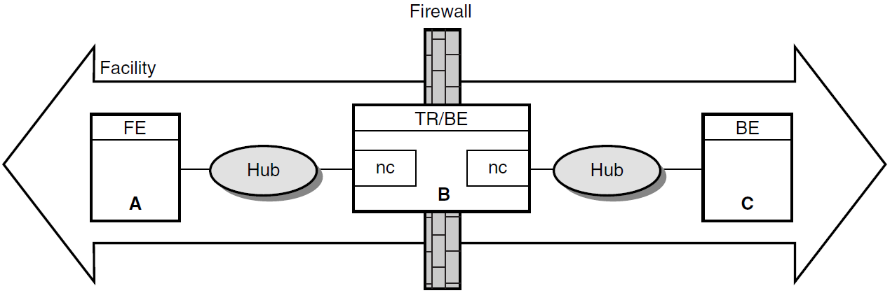
In Figure 2.3, ''Dual-Rail Configuration with Network Cards on a Router'', Node A is a frontend, Node B, with the two network cards (nc), is both a router and a backend, and Node C is a backend. The hubs are Ethernet hubs. Figure 2.4, ''Dual-Rail Configuration with Network Cards on a Frontend'' illustrates a frontend with two network cards.
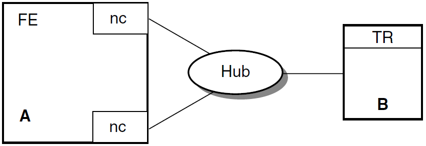
RTR Facility Setup
|
Use this Create Facility command: |
On: |
|---|---|
|
|
The frontend, node A. |
|
|
The router, node B. |
|
|
The backend, node C. |
Note
To ensure correct node recognition, include an explicit node name of a known frontend with a wildcard.
RTR resolves addresses to one name in the DNS Server when you use a wildcard for frontends from a router.
2.14.5. DNS Server Support
A host with more than one network interface is multihomed. In a multihomed configuration, care must
be taken to ensure that the gethostbyname function returns the list of all possible network
addresses for the host. Otherwise, RTR may reject connections when it cannot recognize the host. To return
the address list, use a correctly configured DNS. Using the /etc/hosts file on a UNIX server does not
return the list of addresses.
Networking support for machines with multiple network adapters allows multiple IP connection targets for any host. With this capability, any pair of machines connected by multiple network paths can fail over to an alternate path if the primary path becomes unusable.
RTR determines the set of IP addresses to be used for a remote host when the host name is looked up
using the gethostbyname() API. Depending on your platform and site policies, the IP address
information will be provided by UNIX hosts file entries, OpenVMS TCPIP hosts entries, or by one or more
BIND servers. Examples for a system named 'host1' with two interfaces follow:
UNIX hosts file:
1.2.3.4    host1_interfaceb
1.2.4.4    host1 host1_interfaceb
OpenVMS:
TCPIP> set host "host1_interfaceb"/address=1.2.3.4
TCPIP> set host "host1"/address=1.2.4.4/alias="host1_interfaceb"
Given the information above, RTR will attempt to connect to remote system 'host1' using address 1.2.4.4 first. Should this connection attempt fail, RTR will retry using address 1.2.3.4.
Connection attempts that invoked address failover can be monitored using the RTR monitor picture Netstat.
Note that connection attempts using IP to unreachable hosts usually terminate with a timeout condition, but are often intercepted by the RTR connection timeout whose default value is 60s. This is followed by a further quiescent period whose default value is 90s. You may wish to consider changing the values for these timers for a faster reconnection rate.
Linux INET Interface Support:
/etc/hosts file may contain an entry matching the hostname with IP
address 127.0.0.1. A sample default /etc/hosts file on
those platforms would look like the following:
– SAMPLE /etc/hosts file –
# Do not remove the following line, or various programs
# that require network functionality will fail.
127.0.0.1        hostname localhost.localdomain   localhost
----------------------------
Thus, the gethostbyname() function returns address 127.0.0.1 for any query
on hostname. RTR on Linux ensures smooth operation by enumerating all INET interfaces, adding
to its cache the IP address associated with each INET interface that is not a loopback interface and is UP
(as shown by the ifconfig command).
To view the interfaces on your system, issue the command ifconfig -a; this command reveals
which interfaces are loopback, and which are UP.
2.14.6. Tunnel Configurations
If a tunnel separates the frontends from the routers, configure the frontends on the routers with names corresponding to the pseudo-adapter addresses assigned by the tunnel. If these are unpredictable, you can use wildcards on the routers only.
If a tunnel separates the routers and the backends, configure each with respect to the other with the name prefix "tunnel."
2.15. Running RTR as a Service on Windows
To start RTR, click on the START button.
To stop RTR, click on the STOP button.
Note
Pressing START and STOP or the reverse in quick succession (within approximately 5 seconds, depending on the speed of your computer) may cause undesirable results because the Service executes quickly, making available the other action button. However, the requested RTR action may not have completed when the second action button is pressed. It is therefore possible that the STOP action may be blocked by an incomplete START action. Although the Service will claim to be stopped, RTR may in fact remain started. Pressing whichever action button is functioning should repair the problem.
By default, RTR will not restart automatically at system reboot. To change this, set the Control Panel/Services entry for RTR.
2.15.1. Customizing the RTR Windows Service
When starting RTR, the Service looks for the file UsrStart.RTR in the RTR home directory.
When it finds the file, the Service executes any RTR commands it may contain. RTR commands from
UsrStart.RTR execute after RTR has been started.
From the point of view of the Service, the RTR home directory is found in the system-level environment
variable RTR_DIRECTORY, or, if that is not defined, then the directory from which the Service
was executed.
For the RTR Service to use it, RTR_DIRECTORY must be defined in the system-level environment
variables list, not the user-level environment variables list. Also, the system must be rebooted after the
definition of RTR_DIRECTORY is either created or changed for it to be used.
RTR_DIRECTORY exists, it must identify the same RTR home directory
as the system-level copy, or if there is no system-level copy, the directory containing the currently
registered Service program. If it does not, behavior of RTR is undefined.
Caution
Changing the value of RTR_DIRECTORY, or reregistering the service from another
directory while RTR is running, is dangerous and should be avoided. Starting RTR from the Service,
then stopping it from DOS (or the reverse) should also be avoided.
If you put STOP RTR in the UsrStart.RTR file, it will stop RTR. The Service will not detect
that RTR has been stopped and will offer only the STOP action button. Pressing the STOP button will fix the
problem.
UsrStop.RTR
and, if the file exists, it executes any RTR commands in it. User commands from UsrStop.RTR are
executed before RTR has stopped.
Caution
If you put QUIT or EXIT in either UsrStart.RTR or UsrStop.RTR, RTR will
exit improperly. As a result, an RTR command server process incorrectly remains active, preventing the
Service from starting or stopping RTR, and preventing the RTR command server from exiting. Because the RTR
command server executes under the SYSTEM account, it cannot be stopped from Task Manager other than by the
SYSTEM account.
2.15.2. Files Created by the RTR Windows Service
SrvcIn.Txtis created to act as a command line input sourceSrvcOut.Txtacts as a container for console outputRTRStart.RTRcontains the startup commands.
When the Service stops RTR, it recreates SrvcIn.Txt and creates RTRStop.RTR
for stopdown commands. Creation of these files is unconditional; that is, they are created every time RTR is
started or stopped, whether or not they already exist. RTR will therefore ignore (and overwrite) any changes
made to one of these files.
2.16. Assignment of Processing States for Partitions
RTR assigns a primary or secondary processing state to a partition (or a key-range definition), consisting of one or more server application channels, which may or may not share a common process. On a given backend, all such server application channels belonging to a given partition will have the same processing state, but the processing state for the same partition will normally be different on different backends. The exception is the case of the standby processing state. Because a given partition can have multiple standby backends, several of these may be in a given state.
RTR determines the processing state of a given partition through the use of a globally managed sequence number for that partition. By default, the RTR router automatically assigns sequence numbers to partitions during startup. When a server starts up on a backend and declares a new partition for that backend, the partition initially has a sequence number of zero. When the partition on that backend makes an initial connection to the router, the router increases its sequence number count for that partition by one and assigns the new sequence number to the new backend partition. The active backend with the lowest backend partition sequence number gets the primary processing state in both shadow and standby configurations. That backend is also referred to as the primary backend, though the same backend could have a standby processing state for a different partition.
Under certain failover conditions, backend partitions may either retain their original sequence number or be assigned a new sequence number by the router. If a failure is caused by a network disruption, for example, a backend partition retains its sequence number when it reconnects with the router. However, if the backend node is rebooted or RTR is restarted on the backend node, a new sequence number is assigned by the router to any partitions that start up on that backend. Routers will only assign new sequence numbers to backend partitions that have a current sequence number of zero, or if the backend partition is joining an existing facility and has a sequence number that conflicts with that of another backend partition on another node.
Sequence number information is obtained from the SHOW PARTITION/FULL command. In the output
of this command, the sequence number is indicated by the "relative priority."
Example 2.6, ''SHOW PARTITION/FULL for Routers'' shows use of the SHOW PARTITION/FULL command from a router partition.
In this example, the backend partition called Bronze has a sequence number of 1, and the backend partition
called Gold has a sequence number of 2.
Router partitions on node SILVER in group "test" at Fri Nov 15 14:51:16 2002

Facility:                 Metals     State:                    ACTIVE
Low bound:                     0     High bound:           4294967295
Failover policy:                                      fail_to_standby
Backends:                                                 bronze,gold
 States:                                              pri_act,sec_act
 Relative priorities:                                             1,2
Primary main:             bronze     Shadow main:                gold
SHOW PARTITION/FULL
command for each backend node. Backend partitions on node BRONZE in group "test" at Mon Mar 22 14:52:32 1999 Partition name: p1 Configuration:- Facility: Metals State: pri_act Low bound: 0 High bound: 4294967295 Active servers: 0 Free servers: 1 Transaction presentation: active Last Rcvy BE: gold Active transaction count: 0 Transactions recovered: 0 Failover policy: fail_to_standby Key range ID: 16777217 Master router: silver Relative priority: 1 Recovery retry count: 0 Resource Manager: Features: Shadow,NoStandby,Concurrent Backend partitions on node GOLD in group "test" at Mon Mar 22 14:54:12 1999 Partition name: p1 Configuration:- Facility: Metals State: sec_act Low bound: 0 High bound: 4294967295 Active servers: 0 Free servers: 1 Transaction presentation: active Last Rcvy BE: bronze Active transaction count: 0 Transactions recovered: 0 Failover policy: fail_to_standby Key range ID: 16777216 Master router: silver Relative priority: 2 Recovery retry count: 0 Resource Manager: Features: Shadow,NoStandby,Concurrent
2.16.1. Sequence Numbers in a Shadow Configuration
Figure 2.5, ''Assignment of Sequence Numbers in a Shadow Configuration'' shows how sequence numbers are initially assigned in a simple partition with two backends named Bronze and Gold, and a router named Silver.
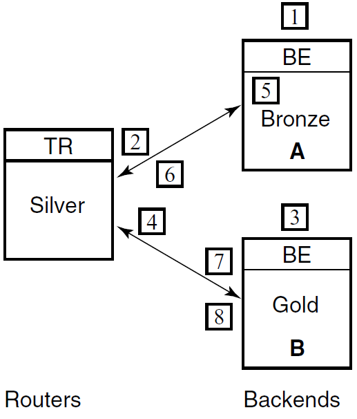
|
Step |
Action |
|---|---|
|
1 |
A partition (with shadowing enabled) is started on backend Bronze. |
|
2 |
The partition on Bronze obtains sequence number 1 from the router and becomes the primary. |
|
3 |
Another server on the same partition (with the same attributes) is started on backend Gold. |
|
4 |
The partition on backend Gold obtains sequence number 2 from the router and becomes the secondary. |
|
5 |
Backend Bronze crashes and reboots (the partition sequence number on Bronze is reset to 0). The partition on backend Gold goes into Remember mode. |
|
6 |
When the server starts, the partition on backend Bronze obtains sequence number 3 from the router and becomes the secondary; backend Gold now becomes the primary. |
|
7 |
The network connection from router Silver to backend Gold fails. The partition on backend Bronze becomes the primary. The partition on backend Gold loses quorum and is in a wait-for-quorum state. |
|
8 |
The network connection to backend Gold is reestablished. The partition on backend Gold retained its original sequence number of 2 and retains the primary role while the partition on backend Bronze reassumes the secondary role. |
SET PARTITION command. The /PRIORITY_LIST qualifier can be used to ensure that when
Bronze fails and then returns to participate in the facility, it becomes the active primary member. To
ensure this, the following command would be issued on both backend systems immediately after creating the
partition:
SET PARTITION test/PRIORITY_LIST=(bronze,gold)
Use the same priority list order on all partition members. If a different list is used, the router will determine the sequence number for conflicting members through the order in which those members joined the facility. For example, if the above command were issued only on Bronze, and Gold had the opposite priority list, the router would assign the lower sequence number to the backend that joined the facility first.
2.16.2. Setting Failover Policy
Use the SET PARTITION command with the /FAILOVER_POLICY qualifier to establish whether to
fail over to a shadow or a standby backend. For example, use the /FAILOVER_POLICY qualifier to select a new
active primary in configurations where shadowing is enabled. This qualifier takes precedence over the
/PRIORITY_LIST qualifier. Use the /PRIORITY_LIST qualifier to determine the failover order for specific
nodes. It is most useful in cluster configurations where it can specify the exact failover order for the
nodes within the cluster.
For example, in a standby facility on a cluster of four nodes, the /PRIORITY_LIST qualifier can specify the desired order of failover for those cluster members. Some machines within a cluster may be more powerful than other machines. This feature allows for the most efficient use of those machines.
2.17. Router Selection in Facilities
Within a given facility, routers and backends connect to one another, although nodes with a given role do not connect to nodes with the same role, that is, routers do not connect to other routers. Frontends connect to only one router at a given time. This selected router is called the current router for that frontend in a facility.
A backend connects to all routers defined within a facility. The connected router with the lowest network address is designated the master router. Internally, a node is identified through a structure called the Kernel Net ID. The Kernel Net ID is a concatenation of all network addresses a node is known as for all the protocols and interfaces that it supports. The master router designation is only relevant to a backend. It is where the backend goes to obtain and verify partition configuration and facility information.
Routers are made known to the frontend systems through the list specified in the /ROUTER=(list) qualifier to
the CREATE FACILITY command issued on the frontend or the router. This list specifically determines
the preferred router. If the first router specified is not available, the next one on the
list is chosen. When the facility is created on the frontend, the list of routers specified can be a subset of
the routers contained within the entire facility. Use this to prevent a frontend from selecting a router reserved
for other frontend systems. Failback of routers to the preferred router is supported. Thus if the preferred
router is not available, but later becomes available, the frontend automatically fails back and connects to its
preferred router.
You can also use the /BALANCE qualifier with the CREATE or SET FACILITY commands to
randomize router selection. For more information on use of the /BALANCE qualifier,
see Section 2.8, ''Router Load Balancing''.
2.18. Clustering Considerations for RTR Standby Servers
The standby server remains idle while the RTR active server performs its work, accepting transactions and updating the database. A failure of the active RTR server occurs when either the process itself crashes, when the RTRACP on the node crashes or when the node itself becomes unreachable due to an operating or hardware fault, such as a network interface failure. When the active server fails, the standby server takes over, recovers any in-progress transactions, updates the database, and communicates with clients until the active server returns.
There can be many concurrent instances of the active server, and failover occurs only when the last remaining server has also failed. There can be many instances of a standby server. Activation of the standby server is transparent to the user. Standby failover behavior depends on whether the standby and active nodes are members of the same cluster and whether the cluster is a recognized or unrecognized cluster.
The clustering systems that RTR supports as recognized clusters are OpenVMS clusters and Tru64 UNIX Clusters (TruClusters). RTR supports Windows clusters as unrecognized clusters with file sharing. RTR treats all other cluster systems (for example, Sun) as non-clustered. Figure 2.6, ''Sample OpenVMS Cluster Running RTR'' shows a sample configuration of a clustered system.
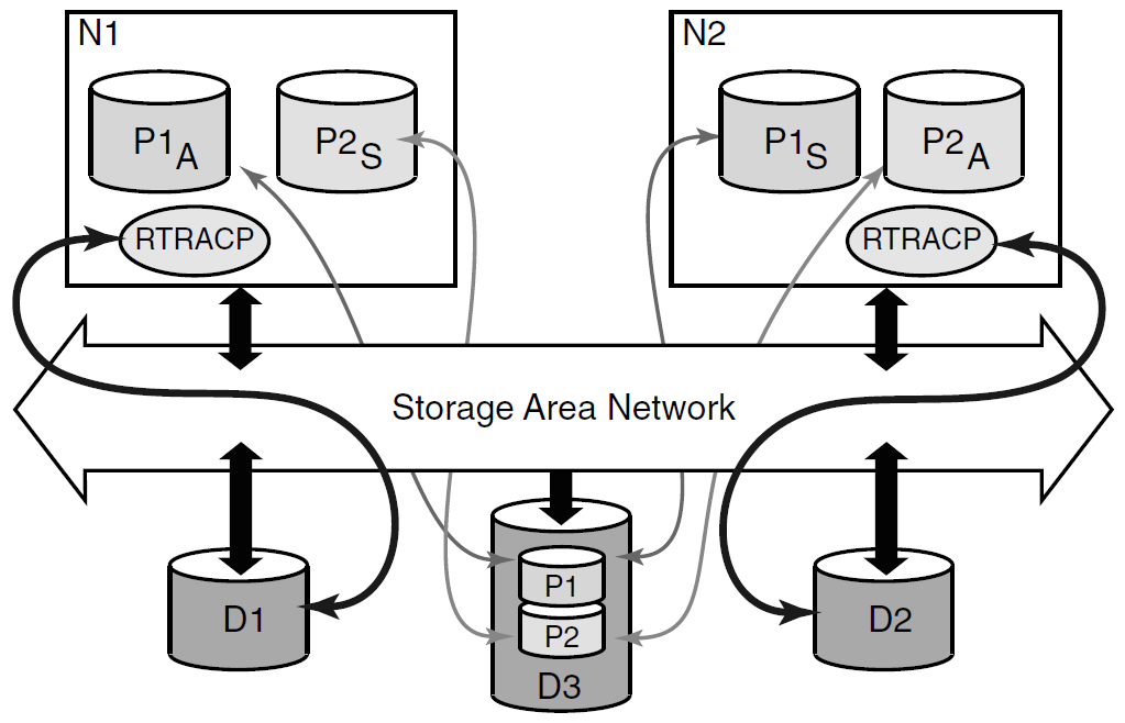
2.18.1. Recognized Clusters
OpenVMS and Tru64 UNIX clusters use mechanisms such as a lock manager to deal with file sharing and sustained availability. The cluster configuration includes dual-ported disks to provide access from multiple CPUs.
2.18.1.1. OpenVMS Clusters and Tru64 Truclusters
In Figure 2.6, ''Sample OpenVMS Cluster Running RTR'', N1 and N2 are nodes in an OpenVMS cluster. When the active process P1 A fails, the standby process P1 S takes over. Whenever standby takeover occurs as part of takeover activity, the standby server undergoes a recovery process in which it tries to recover any uncertain transactions that the active server was processing when the failure occurred.
If node N1 failed, then RTR on node N2 opens the failed node's RTR journal and recovers any uncertain transactions from it, thereby ensuring transaction consistency. If only the RTR server process failed, the failed node (N1) still has its journal open so RTR does not try to open the journal directly. Instead, it asks the remote RTR system N2 to recover any uncertain transactions. This behavior imposes certain requirements on the accessibility of the journal.
2.18.1.2. Journal Location
Since the node that takes over needs to open the journal of the failed node, this journal must be placed
on the cluster file system. If the journal is not on the cluster file system, the standby recovery process
will continue to scan the file systems for the journal and the partition will never come out of recovery.
As long as RTR is unable to access the required journal and the system operator does not enter an overriding
system management command, the partition state remains in lcl_rec_fail.
2.18.1.3. Journal Locking
On OpenVMS clusters and Tru64 TruClusters, RTR uses the distributed lock manager (DLM) to coordinate access to the journal file.
Normally each node locks and opens its own journal file. During recovery, some other node may receive the lock and open the journal. However, when the owning node is restored, RTR will request release of the journal. In this case, the remote node will release the lock on this journal, and the owner node can open its journal.
On OpenVMS and Tru64 Clusters, If the node loses cluster quorum, then RTR releases locks on this journal and lets another node take over.
RTR uses the distributed lock manager (DLM) to coordinate access to the journal file. Normally each node locks and opens its own journal file. During recovery, some other node may receive the lock and open the journal. However, when the owning node is restored, RTR will request release of the journal. In this case, the remote node will release the lock on this journal, and the owner node can open its journal. If the node loses cluster quorum, then RTR releases locks on this journal and lets another node take over.
2.18.1.4. Cluster Communications
When setting up networks and cluster communications in an OpenVMS or Tru64 cluster that are intended for RTR standby operations, avoid the situation where RTR loses quorum on the node while the OpenVMS or Tru64 cluster has quorum. This can happen if there is one interface for cluster traffic and a completely separate interface for network traffic (IP, DECnet). In this case, if the network interface breaks, then RTR will view the node as unreachable and therefore inquorate.
However, since cluster communication is still intact, the operating system does not lose cluster quorum. Since RTR has lost quorum, another node will try to take over, but since the operating system cluster has not lost quorum, the lock on the journal will not be released and recovery will not complete. The key point is to avoid situations where a backend node can lose network communication to its RTR routers yet remain a viable member of its cluster.
2.18.2. HP-UX and Linux Clusters
HP-UX and Linux clusters, unlike OpenVMS and Tru64 Clusters, are not shared - all clusters. HP-UX uses HP Serviceguard and Cluster File System (CFS) and Red Hat Linux uses the Cluster-suite and Global File System (GFS) for clustering.
For enabling RTR to recognize the backend nodes of the cluster participating in ACTIVE/STANDBY configuration, the following environmental variable should be set:
RTR_CLU_MEM_NODES= "BE1, BE2"
In a ACTIVE/STANDBY configuration, if one of the nodes in the cluster fails, then RTR on the other node opens the failed node’s RTR journal and recovers any uncertain transactions from it, thereby ensuring transaction consistency.
2.18.2.1. Journal Location
Since the node that takes over needs to open the journal of the failed node, this journal must be placed
on a common disk shared in the cluster. If the journal is not on shared disk in the cluster, the standby
recovery process will continue to scan the file systems for the journal and the partition will never come
out of recovery. As long as RTR is unable to access the required journal and the system operator does not
enter an overriding system management command, the partition state remains in lcl_rec_fail.
2.18.2.2. Journal Locking
RTR uses the file locking mechanism to coordinate access to the journal file. By default, the locks are maintained in the RTR home directory. If RTR is configured in ACTIVE/STANDBY mode, these locks must be maintained on a common shared disk in the cluster.
In order to maintain these locks on a common shared disk in the cluster, the following environmental
variable should be set:
RTR_CLU_LCK_DISK="/dev/vx/dsk/rtrdata/rtr_files" - for HP-UX I64
All backend nodes in the cluster must use the same disk for maintaining the "cluster node locks".
Normally each node locks and opens its own journal file. During recovery, some other node may receive the lock and open the journal. However, when the owning node is restored, RTR will request release of the journal. In this case, the remote node will release the lock on this journal, and the owner node can open its journal. If RTR loses quorum, then it releases the locks on this journal and lets another node take over.
2.18.3. Windows Clusters
Windows clusters, unlike OpenVMS and Tru64 Clusters, are not shared-all clusters. Windows clusters use the concept of host-based clustering, that is, one node physically mounts the shared disks and makes the shared disks available as a network share to all other nodes in the cluster. If the host node fails, then one of the other nodes will rehost the disks. This rehosting is handled by the Windows clustering software. Only two-node Windows cluster configurations are supported for RTR. In terms of Windows clusters, RTR is an application and the RTR journals are the database resource that fails over between the Windows cluster servers. (A good reference for Windows clustering information is Joseph M. Lamb's Windows 2000 Clustering and Load Balancing Handbook available from Prentice-Hall.)
2.18.3.1. Journal Location
The RTR journal for both Windows NT servers must be located on the same disk on the SCSI bus that is
shared between the two NT cluster servers. The RTR registry entry for the journal must be set to the
same value on both server nodes. Furthermore, the registry entry should specify the journal disk using
the path qualified by the cluster name. For example, if the cluster name is ALPHACLUSTER,
and the journal disk has the cluster share name DISK1, then the RTR journal registry entry
should be entered as \\ALPHACLUSTER\DISK1.
which can be modified using the Registry Editor. The registry key for the journal is found
under \HKEY_LOCAL_MACHINE\SOFTWARE\Hewlett-Packard Company\HP Reliable Transaction Router\Journal.
There is no default and the value must be in the given format. If the journal is not located on a shared disk in a Windows cluster configuration, then RTR behaves as a standalone RTR node and no use is made of cluster functionality.
2.18.3.2. Facility Role Definition
The computers (nodes) participating in RTR Facilities that are using the standby features must be configured with both a backend role and a router role.
2.18.3.3. RTR Home Directory
In a Windows cluster configuration, the RTR home directory must not be located on a shared SCSI disk. RTR creates lock files in the RTR home directory and the journal directory during normal operation. These are of the form N*.LCK or N*.BLK, and C*.LCK or C*.BLK. These files may be left in these directories after RTR has been stopped, but they will be reused once RTR is started again. There is no real need for a daemon to purge these files at system boot time.
2.18.3.4. Cluster Failover
The cluster failover group containing the disk share on which the RTR journal files are located must not have failback policy enabled. That is, if the failover group fails over to the secondary cluster node due to a primary server outage, the group must not fail back to the primary node once the primary node is available again. As long as RTR facilities have been defined in a cluster configuration, then the failover group with the journal device must not be manually failed over to the other cluster server by the cluster administrator. Failover should only occur at the discretion of the cluster failover manager software.
2.18.4. Unrecognized Clusters
Unrecognized or unsupported clusters have different behavior than recognized or supported clusters.
The default behavior in unrecognized cluster systems is to treat them as non-clustered. However, RTR standby failover will still work. RTR will fail over to the standby server process if the active server process fails. This standby takeover also performs recovery. If it is only the active server process that failed, then RTR can still recover any uncertain transactions through the remote RTR process. If, however, the node itself becomes unavailable (from, for example, an RTR crash, a node crash or a network crash) then the recovery process performs a journal scan to locate the journal of the failed node.
But unlike the case of a recognized cluster, RTR does not wait for the journal to become available. Instead, it changes to the active state and continues to process transactions. Any incomplete transactions in the failed node's journal will remain there; these transactions are not lost. They are eventually recovered when the failed node becomes active again, although their sequencing will be lost.
Chapter 3. Partition Management
3.1. Overview
This section describes the concepts and operations of RTR partitions.
3.1.1. What is a Partition?
Partitions are subdivisions of a routing key range of values. They are used with a partitioned data model and RTR data-content routing. Partitions exist for each distinct range of values in the routing key for which a server is available to process transactions. RTR provides for failure tolerance by allowing system operators to start separate instances of partitions in a distributed network and by automatically managing the state and flow of transactions to the partition instances.
Concurrency - permits multiple server channels to be connected to an instance of a partition.
Standbys - permits multiple instances of a partition to be distributed over the nodes of a cluster. A group of standby servers (a standby set) may have as many members as a cluster has nodes, or with some restrictions you may place a standby on any network node. At any one time, one member of the set is active while the others wait in standby mode to take over if the active member fails.
Shadows - provide site disaster protection by allowing replication of transaction processing at a remote site. A pair of partition instances (or standby sets) cooperate to provide this replication, with provision for automatic recovery of a shadow member restarting after a failure.
The system operator can issue commands to control certain partition characteristics, and to set preferences concerning partition behavior.
3.2. Partition Naming
A prerequisite for partition management is the ability to identify a partition in the system that is to be the subject of management commands. For this purpose, partitions have names, either by default, supplied by the programmer, or supplied by the system manager.
3.2.1. Name Format and Scope
A valid partition name can contain no more than 63 characters. It can combine alphanumeric characters (abc123), the underscore (_), and the dollar sign ($). Partition names must be unique within a facility name and should be referenced on the command line with the facility name when using partition commands. Partition names exist only on the backend where the partition resides. You will not see the partition names at the RTR routers.
3.2.2. Default Partition Names
Partitions can receive automatically generated default names, in the form RTR$DEFAULT_PARTITION, unless the name is supplied.
3.2.3. Programmer-Supplied Names
rtr_open_channel() call.
The pkeyseg argument specifies an additional item of type rtr_keyseg_t, assigning the following values:
ks_type = rtr_keyseg_partitionindicates that a partition name is being passed.ks_lo_boundshould point to the null-terminated string to use for the partition name.ks_hi_boundmust be NULL.
Using this model, the partition segments and key ranges served by the server are still specified by the server when the channel is opened.
3.2.4. System-Manager Supplied Partition Names
The system manager can supply partition names using the create partition system management command,
or by using rtr_open_channel() flag arguments. The system manager can set partition characteristics with
this command and applications can open channels to the partition by name.
See Section 3.4, ''Binding Server Channels to Named Partitions'' for an example of passing a partition name with rtr_open_channel().
3.3. Life Cycle of a Partition
This section describes the life cycle of partitions, including the ways they can be created and their persistence.
3.3.1. Implicit Partition Creation
Partitions are created implicitly when an application program calls rtr_open_channel() to create a server
channel, specifying the key segments and value ranges for the segments with the pkeyseg argument.
Other partition attributes are established with the flags argument. Prior to RTR V3.2, this was the only way
partitions could be created. Partitions created in this way are automatically deleted when the last server channel
to the partition is closed.
3.3.2. Explicit Partition Creation
Partitions can also be created by the system operator before server application program start up using system management commands. This gives the operator more control over partition characteristics. Partitions created in this way remain in the system until either explicitly deleted by the operator, or RTR is stopped.
3.3.3. Persistence of Partition Definitions
SET TRANSACTION command), where the partition name can be used to select
a subset of the transactions in the journal. RTR will not permit a change in the partition name or definition
as long as transactions remain in the journal that were processed under the current name or definition for
the partition. If transactions remain in the journal and you need to change the partition name or definition,
you can take one of the following actions:
Start appropriate servers to complete processing of the transactions.
Remove the transactions from the journal with the
SET TRANSACTIONcommand.Replace the RTR journal with the
CREATE JOURNAL/SUPERSEDEcommand. Note that this will destroy any transactions remaining in the journal and should be done with caution.
3.4. Binding Server Channels to Named Partitions
pkeyseg argument of rtr_open_channel() call. It is not
necessary to pass key segment descriptors, but if the application does, they must be
compatible with the existing partition definition. You may pass partition
characteristics through the flags argument, but these will be superseded by
those of the existing partition.
RTR> create partition/KEY1=(type. . .) par_one
    . . .
rtr_keyseg_t            partition_name;
partition_name.ks_type = rtr_keyseg_partition;
partition_name.ks_lo_bound = "par_one";
status - rtr_open_channel(..., RTR_F_OPE_SERVER,..., 1, &partition_name);
In summary, to fully decouple server applications from the definition of the partitions to be processed, write applications that open server channels where only the required partition name is passed. Leave the management of the partition characteristics to the system managers and operators.
3.5. Entering Partition Commands
A command line processed by the RTR command line interface, for example
RTR> SET PARTITIONProgrammed using
rtr_set_info()
Enter partition commands on the backend where the partition is located. Note that commands that affect a partition state only take effect once the first server joins a partition. Errors encountered at that time will appear as log file entries. Using partition commands to change the state of the system causes a log file entry.
3.5.1. Command Line Usage
RTR> CREATE PARTITIONRTR> SET PARTITIONRTR> DELETE PARTITION
The name of the facility in which the partition resides can be specified with the /FACILITY
command line qualifier, or as a colon-separated prefix to the partition name (for example, Facility1:Partition1).
Detailed descriptions of the command syntax are given in the Command Line Reference section of this manual,
and are summarized in the following discussions. Examples in the following sections use a partition name of
Partition1 in the facility name of Facility1.
3.5.2. Programmed Partition Management
rtr_set_info(). Usage of the arguments are as follows:
pchannelsupplies the address of artr_channel_tto receive the channel opened in the event of a successful call.Flags must be
RTR_NO_FLAGS.Verb must be the value
verb_set(from the enumerationrtr_verb_t).Object must be
rtr_partition_object.select_qualifiersshould identify the facility and partition, by name:rtr_qualifier_value_t select_qualifiers[ 3 ]; select_qualifiers[ 0 ].qv_qualifier = rtr_facility_name; select_qualifiers[ 0 ].qv_value = "your_facility_name_here"; select_qualifiers[ 1 ].qv_qualifier = rtr_partition_name; select_qualifiers[ 1 ].qv_value = "your_partition_name_here"; select_qualifiers[ 2 ].qv_qualifier = rtr_qualifiers_end; select_qualifiers[ 2 ].qv_value = NULL;
The
set_qualifierlist expresses the required change in partition behavior or characteristic.
The rtr_set_info() call completes asynchronously. If the function call is successful,
completion is signaled by the delivery of an RTR message of type rtr_mt_closed on the channel
whose identifier is returned through the pchannel argument. The programmer should retrieve this
message by using rtr_receive_message(). The data accompanying the message is of type
rtr_status_data_t. The completion status of the partition command can be accessed as the status
field of the message data.
3.6. Managing Partitions
A set of commands or program calls are used to manage partitions. Information on managing partitions is provided in this section.
3.6.1. Controlling Shadowing
Enabling site disaster protection for an application partition for the first time
A recovery aid following prolonged outage of a former shadow site.
Shadowing for a partition can be turned off only in the absence of an active secondary site.
The active member must be running in remember mode.
The command will fail if entered on either an active primary or secondary with a message to this effect.
If entered on a standby of either the primary or secondary, the command is accepted but fails in the RTR router. This failure is recorded with a log file entry at the router.
RTR> SET PARTITION/SHADOW Facility1:Partition1
For further information, see the SET PARTITION command in Chapter 9, "RTR Commands".
set_qualifier argument of
rtr_set_info() as follows:
rtr_qualifier_value_t    set_qualifiers[ 2 ];
rtr_partition_state_t    newState = rtr_partition_state_shadow;
set_qualifiers[ 0 ].qv_qualifier = rtr_partition_state;
set_qualifiers[ 0 ].qv_value = &newState;
set_qualifiers[ 1 ].qv_qualifier = rtr_qualifiers_end;
set_qualifiers[ 1 ].qv_value = NULL;
To disable shadowing, specify newState as rtr_partition_state_noshadow.
3.6.2. Controlling Transaction Presentation
Transaction presentation is the process of passing transactions to idle server channels for processing. While transaction presentation is active, new transactions are started on the first free server channel for the appropriate partition.
Use the /SUSPEND qualifier to the SET PARTITION command to halt the presentation
of new transactions to servers on the backend where the command is entered. The command completes when
the processing of all currently active transactions is complete.
The optional /TIMEOUT qualifier specifies, as a number of seconds, the time that the command
waits for completion. If the command times out, presentation of new transactions are suspended, but there still
exist transactions for which servers have yet to complete processing. The operator must decide either to reenter
the command and wait a further period of time, or resume the partition. Note that use of this command does not
affect any transaction timeout value specified by RTR clients, so such transactions may encounter a timeout
condition if the partition remains suspended.
The /RESUME qualifier restarts presentation of transactions to the server application channels.
RTR> SET PARTITION/SUSPEND/TIMEOUT=5 Facility1:Partition1
RTR>
RTR> SET PARTITION/RESUME Facility1:Partition1
For a more complete description, see the SET PARTITION command in Chapter 6.
set_qualifier argument of the rtr_set_info()
call as follows:
rtr_qualifier_value_t    set_qualifiers[ 3 ];
rtr_partition_state_t    newState = rtr_partition_state_suspend;
rtr_uns_32_t    ulTimeoutSecs = 30;
set_qualifiers[ 0 ].qv_qualifier = rtr_partition_state;
set_qualifiers[ 0 ].qv_value = &newState;
set_qualifiers[ 1 ].qv_qualifier = rtr_partition_cmd_timeout_secs;
set_qualifiers[ 1 ].qv_value = &ulTimeoutSecs;
set_qualifiers[ 2 ].qv_qualifier = rtr_qualifiers_end;
set_qualifiers[ 2 ].qv_value = NULL;
Note that the timeout is an optional element. To resume transaction presentation, specify newState as
rtr_partition_state_resume.
3.6.3. Controlling Recovery
The purpose of RTR automated recovery is to ensure the best possible consistency of application databases across a distributed computing environment. To achieve this, RTR relies in part on information stored in the journals of the participating backends. Should one or more of these systems be unavailable at recovery time, automated recovery may stall or fail awaiting availability of these systems and their journals. This enforces data consistency where transaction order is important, but can affect application availability.
For example, if a partition enters a wait state or fails, but has neither a local or remote journal, an operator can instruct RTR to skip the current step in the recovery process with the /IGNORE_RECOVERY qualifier. Since this command bypasses parts of the recovery cycle, use it with caution in cases where availability is valued over consistency in application databases. For a read-only database, transaction order will be unimportant.
The recovery cycle can also be manually restarted with the /RESTART_RECOVERY qualifier.
This may be useful if the operator previously aborted automated recovery. Since this command can result in
recovery of transactions from previously inaccessible journals, do not use this if your applications are
sensitive to the order in which transactions are processed by the servers.
RTR> SET PARTITION/IGNORE_RECOVERY Facility1:Partition1
RTR>
RTR> SET PARTITION/RESTART_RECOVERY Facility1:Partition1
A complete description of the SET PARTITION command qualifiers can be found in Chapter 6.
set_qualifier
argument of rtr_set_info() as follows:
rtr_qualifier_value_t    set_qualifiers[ 2 ];
rtr_partition_state_t    newState = rtr_partition_state_exitwait;
set_qualifiers[ 0 ].qv_qualifier = rtr_partition_state;
set_qualifiers[ 0 ].qv_value = &newState;
set_qualifiers[ 1 ].qv_qualifier = rtr_qualifiers_end;
set_qualifiers[ 1 ].qv_value = NULL;
To restart recovery, specify newState as rtr_partition_state_recover.
3.6.4. Controlling the Active Site
RTR> SET PARTITION/PRIORITY_LIST=(BE1, BE2, BE3) Facility1:Partition1
Suspend transaction presentation before entering or changing the priority list.
Chapter 9, "RTR Commands" provides more information on the SET PARTITION command.
set_qualifier
argument of the rtr_set_info() call as follows:
rtr_qualifier_value_t     set_qualifiers[ 2 ];
char    *szNodeList = "your,list,of,node,names,here"
set_qualifiers[ 0 ].qv_qualifier = rtr_partition_be_priority_list;
set_qualifiers[ 0 ].qv_value = &szNodeList;
set_qualifiers[ 1 ].qv_qualifier = rtr_qualifiers_end;
set_qualifiers[ 1 ].qv_value = NULL;
3.6.5. Controlling Failover
/FAILOVER_POLICY qualifier to the SET PARTITION command lets the system operator
select one of the following policies that RTR should pursue in selecting the new primary site in the event
of a failure:
/FAILOVER_POLICY=STAND_BYcauses RTR to choose a standby partition of the failed primary (if any) to become the new primary. If there is more than one standby, the operator may also use the priority list feature (described above) to control which standby is preferred. Depending on the size of the journal of the failed primary, there will be a holdup in the processing of transactions while the journal is recovered. This is the default behavior./FAILOVER_POLICY=SHADOWinstructs RTR to make the active secondary (if any) the new primary./FAILOVER_POLICY=COMPATIBLE_PRE_V32is a mode that will operate with configurations that contain RTR routers running versions of the software prior to V3.2. This mode will be automatically adopted if such routers exist in or join the configuration.This mode assigns the active role to the first instance of a partition to be declared. If the system hosting this partition becomes unreachable, then the active role is assigned to the next partition instance to be declared, until the first partition's host becomes reachable again when the original roles are restored.
The time required to effect a failover and the subsequent impact on client response times will influence choice of failover policy. The time for standby takeover of a failed node's journal depends on the size of that journal, though failover to a shadow site is affected quickly. However, if the secondary shadow site has accumulated a backlog of transactions, they must be processed before any new transactions can be started. The choice will be determined by the characteristics of your application and configuration.
/FAILOVER_POLICY qualifier
setting failover to a shadow
server:RTR> SET PARTITION/FAILOVER_POLICY=SHADOW Facility1:Partition1
RTR> SET PARTITION FacALPHA:AtoG/FAILOVER_POLICY=STAND_BY
You can view the policy that has been set with the SHOW PARTITION/FULL command.
For more information see the SET PARTITION command in Chapter 9, "RTR Commands".
set_qualifier
argument of the rtr_set_info() call as
follows:rtr_qualifier_value_t set_qualifiers[ 2 ]; rtr_partition_failover_policy_t newPolicy; set_qualifiers[ 0 ].qv_qualifier = rtr_partition_failover_policy; set_qualifiers[ 0 ].qv_value = &newPolicy; set_qualifiers[ 1 ].qv_qualifier = rtr_qualifiers_end; set_qualifiers[ 1 ].qv_value = NULL;
newPolicy are:
rtr_partition_fail_to_standbyrtr_partition_fail_to_shadowrtr_partition_pre32_compatible
3.6.6. Controlling Transaction Replay
After a failure, RTR replays transactions stored in its journal as appropriate. RTR has implemented the capability of controlling transaction replay in cases where a killer message happens during a transaction replay preventing recovery from continuing normally. A killer message causes server availability to be lost because of the presence of a message capable of causing repeated server application failure during recovery. This is typically the result of an improperly handled condition or application programming error within the server itself. Under such circumstances it may be desirable to sidestep a particular transaction, maintain server operation, and manually process the transaction at some later time.
The RTR solution is to establish, for a given partition with the SET PARTITION command,
the maximum number of retries for any given transaction presented during recovery.
Once this limit has been exceeded, the offending transaction is removed from the recovery process and is
written to the journal as an exception record. Subsequent processing of this transaction requires manual
intervention by someone qualified to evaluate and correct the situation in both the application and in RTR.
Once the application status is understood, the SET TRANSACTION command can be used to update the journal,
thus ensuring that the final state of any manually transacted exceptions are accurately reflected in future
recovery operations.
The recovery retry count is partition-specific, and applies to both local and shadow recovery operations. The default is no limit on the number of retries, which permits a killer message to bring down all available servers servicing a given partition.
The recovery retry count should be set before starting (or restarting) the application servers so that the limit is established prior to the start of recovery operations.
RTR> SET PARTITION/RECOVERY_RETRY_COUNT=3 Facility1:Partition1
See Chapter 9, "RTR Commands" for more information on the SET PARTITION command.
set_qualifier argument of rtr_set_info() as follows:
rtr_qualifier_value_t     set_qualifiers[ 2 ];
rtr_uns_32_t    newLimit    = . . .;
set_qualifiers[ 0 ].qv_qualifier = rtr_partition_rcvy_retry_count;
set_qualifiers[ 0 ].qv_value = &newLimit;
set_qualifiers[ 1 ].qv_qualifier = rtr_qualifiers_end;
set_qualifiers[ 1 ].qv_value = NULL;
The retry limit applies to all transactions that have reached the voting stage on a server.
If a server always dies before voting on a transaction, RTR aborts the transaction after
the third try ("three-strikes and you're out!"). For more information, see the description
of /RECOVERY_RETRY_COUNT for the SET PARTITION command.
3.6.7. Partition Persistence
Partitions in RTR are designed to be persistent, remaining until explicitly removed during normal RTR processing. However, under certain conditions, relics of partitions can remain in the RTR journal. RTR automatically performs some cleanup of such records, but depends on the creation of the relevant facility to initiate this process. For example, in a test environment, many facilities are created for temporary use, with no intention of retaining those facilities. Because the creation of each facility may cause the creation of associated records for a partition in the RTR journal, creating many ad hoc facilities can cause the RTR journal to become filled. In such a case, when trying to create a new partition (or opening a new server channel), the error message NOMOREPRT may appear.
To correct this problem, the journal must be purged of these ad hoc entries. To purge the RTR journal of such
unwanted transactions, use the DUMP JOURNAL command to verify the partition name and transaction ID
of the unwanted transactions, and use the SET TRANSACTION command with the partition name and transaction ID
to set the state to DONE. Recreate the facility with the CREATE FACILITY command.
3.7. Displaying Partition Information
SHOW PARTITION command, as seen in the following example. The
information of interest in the context of partition management relates to the backend
instance of the partition. See Chapter 9, "RTR Commands" for more information
on the SHOW PARTITION
command.RTR> show partition/backend Backend partitions on node BE1 at Wed Feb 24 15:07:50 1999 Partition name Facility State RTR$DEFAULT_PARTITION_16777217 RTR$DEFAULT_FACILITY active RTR$DEFAULT_PARTITION_16777218 RTR$DEFAULT_FACILITY active
Chapter 4. Transaction Management
4.1. Overview
This section describes the concepts of RTR's transaction management capability.
The RTR transaction is the center of an RTR application, and transaction state is the property that characterizes a transaction's current condition. Whenever a transaction progresses from one stage to another, the transaction state is updated to reflect a transaction transition. Transaction states are maintained in memory. Transaction states are also stored in the RTR Journal for recovery purposes.
Transaction Runtime State
Transaction Journal State
Transaction Server State
These three states are very closely related. The Transaction Runtime State, also known as Transaction State, describes how a transaction progresses from an RTR role (FE, TR, BE) point of view. For example, a transaction can enter a stage in which its transaction state from an RTR frontend viewpoint is different from its transaction state from the viewpoint of an RTR router.
|
Transaction Journal State (by Branch) |
Explanation of State |
|---|---|
|
SENDING |
Initial state of the transaction branch as the client sends a call to the server application. The RTR backend has received the transaction and RTR is waiting for votes. |
|
VOTED |
The servers have voted and the vote has been written to disk. |
|
COMMIT |
RTR has asked the servers to commit the transaction. |
|
ABORT |
RTR has asked the servers to roll back the transaction because of a "no" vote. |
|
DONE |
The servers have informed RTR that the transaction has been committed to the database. It is safe to FORGET the transaction. |
|
PRI_DONE |
The primary server has committed the transaction; the secondary may not have done so. This is the typical case of a REMEMBER transaction. |
|
EXCEPTION |
RTR asked the server to commit the transaction, but the server failed to commit it to the database. The transaction needs manual reconciliation. |
The Transaction Server State describes transaction state as seen by a specific server, serving that branch of the transaction. RTR uses this state to determine if a server is available to process a new transaction or if a server has voted on a particular transaction. As with the Transaction Journal State, the Transaction Server State is only relevant at the backend.
RTR provides a set of comprehensive management utilities to help users closely monitor the flow of a transaction and all three types of states associated with that transaction. These utilities help users understand how a transaction migrates from one stage to another and help diagnose problems.
Use the SHOW TRANSACTION command to examine a transaction's up-to-date status on frontend, router or
backend roles. With this command, users can see all three types of transaction states of a particular transaction and
also understand how the RTR journal and server applications perceive this transaction. When a transaction commits or aborts,
all status associated with this transaction is removed from memory and can no longer be monitored by the command.
The DUMP JOURNAL command can be used to trace and review the flow of a transaction. The RTR journal
saves all of the information about a transaction. This includes its transaction journal state and the transaction
messages (records) received from the RTR client and sent to the server. The information is kept until a transaction
is committed or aborted and all participants have been notified.
Use the SET TRANSACTION command to modify the current state of a transaction to a new state. This command can be used
to circumvent an unexpected situation. For example, in a situation with shadow servers, the system administrator might decide
not to replay (recover) all remembered transactions in an RTR journal after a failure. The SET TRANSACTION command
could set specified transactions in a PRI_DONE or REMEMBER state to a DONE state and avoid the delay of transactions
being remembered from a journal for fast recovery. The SET TRANSACTION command should only be used by
experienced RTR system administrators as the command introduces the risk of corrupting or losing transactions if used
incorrectly. It can be used on the backend only and the RTR log file must be turned on for this command.
Log file entries are made for all transaction state changes for debugging and auditing purposes.
4.2. Exception Transactions
The server can exit the process, causing RTR to recover the transaction to another concurrent server channel or to a standby server. If the problem with committing to the database persists, it is possible that the subsequent attempts at recovering the transaction will cause other server processes to exit. This can cause the entire pool of servers to go away, thus affecting the availability of the application. You can avoid this by limiting the number of recovery attempts that RTR does for a specific transaction, using the
SET PARTITION/RECOVERY_RETRY_COUNT=nncommand. This limits the number of times the same transaction is recovered to a server, which subsequently crashes. The transaction can no longer be aborted once it is committed and is placed in an EXCEPTION state.The server application could use the
rtr_set_info()function to directly change the state of a committed transaction to EXCEPTION. This avoids the need to crash in order to signal to RTR that something unexpected has happened to the transaction.
EXCEPTION transactions can be inspected with the DUMP JOURNAL command.
The final state of the transaction should say EXCEPTION.
4.2.1. Dealing with EXCEPTION Transactions
Fix the environmental issue that was causing the server to crash, and then recover the transaction from the journal. To do this, the transaction state should be changed to COMMIT using the
SET
                                TRANSACTION
command. When the server is restarted, RTR will recover this transaction.Manually apply the transaction to the database and remove the transaction from the RTR journal. To do this, the transaction state should be modified to DONE by using the
SET TRANSACTIONcommand. The transaction will be forgotten by RTR.
4.2.2. What EXCEPTION Transactions Mean to Data Integrity
EXCEPTION transactions keep the application available, although they cause some loss of data integrity. EXCEPTION transactions are considered committed by the initiator of the transaction, as well as by the other participants (such as the other shadow member). Therefore, subsequent transactions, which depend on the results of this transaction, could produce erroneous outcomes. In some applications, the erroneous outcomes do not matter, but in applications where the outcome does matter, the best approach is to allow the system administrator to manually intervene.
4.3. Transaction State Changes
SET TRANSACTION
command. Attempting to change transaction state to a state that is not allowed produces
an error
message:%RTR-E-INVSTATCHANGE, Invalid to change from current state to the specified stateTable 4.2, ''Valid Transaction State Transitions'' identifies the valid state changes.
|
New State | ||||
|---|---|---|---|---|
|
Current State |
COMMIT |
ABORT |
EXCEPTION |
DONE |
|
SENDING |
YES | |||
|
VOTED |
YES |
YES | ||
|
COMMIT |
YES |
YES | ||
|
EXCEPTION |
YES |
YES | ||
|
PRI_DONE |
YES | |||
All transaction states in Table 4.2, ''Valid Transaction State Transitions'' are RTR journal states.
Use the RTR commands SHOW TRANSACTION or DUMP JOURNAL (you
must stop the RTRACP to use this command) to determine the journal state for each
transaction branch.
State SENDING changed to state ABORT.
The server application, after receiving an
rtr_mt_preparemessage needs to access and lock the database record before callingrtr_accept_tx()for a particular transaction. If the record being accessed is locked for some reason, the application will experience a "hung" situation and cannot proceed. If the situation persists, the application will become unavailable. RTR detects such a deadlock, but intervention is probably required.Normally, this condition can be avoided by specifying a transaction timeout. However, if that is not the case, the system administrator can choose to abort the transaction with the
SET TRANSACTIONcommand. Internally, RTR will inform the router as well as all the other participating servers to abort this transaction in a consistent manner. Note that this may not be enough to correct the original condition with the database. The server application would still wait for the database to free up. Subsequent transactions could be sent to this server process, and be vulnerable. The real reason for the lockup should be investigated and corrected.State VOTED changed to state COMMIT.
A transaction branch could be in a VOTED state when a server application running on the backend may have been separated from the rest of participating servers after casting the VOTE for a multi-participant transaction. Another way this could happen is that at least one of the other participants in a distributed transaction has failed to cast its VOTE (by calling
rtr_accept_tx).As long as there is a router coordinating the transaction, RTR will not allow the state of the transaction to be modified from VOTED to COMMIT in order to prevent the possibility of data inconsistency. This can happen because RTR is still in the middle of determining the final state for the transaction. However, it is possible to modify the state to ABORT, as explained in the next section.
If the backend is not connected to a coordinating router, the other servers may have already committed the transaction but not "forgotten" it. As far as the application is concerned, this global transaction is committed and all changes have been committed to the underlying database on the different sites. However, the local transaction branch is still in VOTED state in the RTR journal. You can use the command to manually commit the local transaction branch. This results in the transaction being recovered to a server during the next recovery cycle.
As mentioned earlier, this command is only applicable if there is no coordinating router running (that is, the backend is separated from the rest of the RTR network). If this is not the case, RTR rejects the command with the error message RTR-E-SETTRANROUTER, indicating that a coordinating router is still available.Note
This operation could lead to data inconsistency, if used injudiciously, and should only be used after careful research.
State VOTED changed to state ABORT.
As previously explained, a transaction can be stalled in a VOTED state in one or more of the following situations.There is a distributed deadlock (only possible with multi-participant transactions and multiple simultaneously active transactions).
One participant has voted, but another participant has not voted (for example, waiting for the database record to become accessible).
The transaction is not currently active, and is a candidate for recovery. The transaction is probably a multi-participant transaction and the final journal state for the local branch is VOTED. The transaction outcome cannot be determined without consulting the journal from the other participants.
Whatever the cause, this transaction ties up the system resources and prevents other transactions from running. Should the system administrator decide to abort the transaction using the
SET TRANSACTIONcommand, RTR sends arequest-to-abortmessage to all the participants (transaction branches) to abort each transaction branch. After the abort, RTR presents artr_mt_rejectedmessage to each server with a status indicating that "TX was aborted by Set Transaction operation". If the coordinating router is available, a race condition is possible, in that the transaction coordinator might be trying to commit the transaction at the instant that the operator was attempting to abort the transaction. Under this scenario, RTR may not allow the abort to proceed, if the coordinating router has already decided to commit the transaction. An operator log message on the router will be written to warn the administrator of this situation.State COMMIT changed to state DONE.
An example of this state change is where a server crashed while performing an SQL commit immediately after receiving an
mt_acceptedmessage. The transaction is in COMMIT state as recorded in the RTR journal, but RTR considers this an uncertain transaction and will try to recover this transaction (unless limited by the partition's RECOVERY_RETRY_COUNT parameter). If a determination can be made that the transaction is truly committed in the underlying database, there is no reason to allow RTR to recover or replay this transaction to another server. To forget such transactions, the state should be changed from COMMIT to DONE. For single participant transactions, a journal state of VOTED really means COMMIT, because there is no reason for RTR not to commit a transaction that has one branch that is ready to commit.
After the SET TRANSACTION command is executed, use the DUMP
JOURNAL command to verify the result.
4.4. Command Line Examples
SET TRANSACTION
command:RTR> start rtr RTR> set log/file=settran RTR> set transaction/state=PRI_DONE/new_state=DONE/facility=Facility1/partition=Partition1 *
This example would set all transactions with the current state of PRI_DONE (remember) to DONE on the facility
Facility1 and the partition Partition1. The log file, settran, would record the transaction state changes.
The changes could be viewed with the SHOW TRANSACTION command or the DUMP JOURNAL command.
In a shadow recovery situation this would clear the journal of remember transactions and provide for a quick turnaround
of the shadow site.
The following example shows how RTR commands monitor and manipulate three different transaction states. Consider a scenario where a distributed transaction accesses two RTR partitions. The multiple-participant distributed transaction would have two transaction branches accessing different RTR partitions, say part1 and part2, respectively.
The client commits the transaction and calls rtr_accept_tx() which prompts RTR to start the two-phase commit
protocol. RTR sends a prepare message to the two participants. Upon receiving the prepare message (mt_prepare),
one of the server applications is ready to commit and casts its vote by calling rtr_accept_tx().
RTR writes a VOTE record in the RTR journal and sends the vote message back to the router. However, due to an unexpected
defect in the application software, the second server has not sent its VOTE message back to the RTR router.
Thus, the transaction is stalled in the second server.
To examine this situation, an RTR system administrator should first use the SHOW TRANSACTION/BACKEND command
on the backend node to analyze the transaction's status. As shown in the following example, the transaction runtime state
is RECEIVING, indicating the distributed transaction is not yet committed. The server states for the transaction branches
are VOTED and VREQ respectively, indicating that one of the transaction branches has been voted by the associated server
whereas the other transaction branch is still in the "Vote Request" state (VREQ). The journal states for the transaction
branches are VOTED and SENDING, indicating that one transaction branch has voted and its VOTED record was written in the RTR
journal. The other transaction branch's journal state is SENDING, indicating that transaction branch is still in the process
of processing a message from the client and it has not yet advanced to the VOTED state. The journal states for the transaction
branches that are recorded in the RTR journal are consistent with their server states.
SET TRANSACTION command to change a transaction's state. The DUMP
JOURNAL command is also useful to examine each transaction branch's journal
state.
Backend transactions on node nodea at Mon Mar 13 16:02:42 2000 Tid: 3ad01f10,0,0,0,0,3ad01f10,a08730b4 Facility: test Frontend: *tbs* FE-User: tu.7006 Frontend: nodea FE-User: tu.7006 State: RECEIVING Start time: Mon Mar 13 16:00:08 2000 Key-Range-Id: 16777216,16777217 Router: nodea Invocation: ORIGINAL,ORIGINAL Active-Key-Ranges: 2 Recovering-Key-Ranges: 0 Total-Tx-Enqs: 2 Server-Pid: 7006,7006 Server-State: VOTED,VREQ Journal-Node: nodea.com,nodea.com Journal-State: VOTED,SENDING First-Enq: 1,2 Nr-Enqs: 1,1 Nr-Replies: 0,0
RTR SET TRANSACTION command to
abort this transaction. Change either one of the transaction branch's journal state to
ABORT as shown in the following example:
RTR>set transaction/new=abort/state=voted/facility=test/partition=part1 %RTR-S-SETTRANDONE, 1 transaction(s) updated in partition part1 of facility test
RTR>set transaction/new=abort/state=sending/facility=test/partition=part2 %RTR-S-SETTRANDONE, 1 transaction(s) updated in partition part2 of facility test
See Chapter 9, "RTR Commands" for detailed information on these commands.
Chapter 5. Server Shadowing and Recovery
With RTR shadowing, your system can recover from a site disaster without the need for special coding within your application program.
A database is said to be shadowed when two copies of the same database are deployed on separate nodes at two different locations, typically two different sites. Each location maintains a copy of the database used by the server application, and RTR keeps the database copies synchronized. Shadow site configurations can contain two nodes at separate sites, two nodes in a cluster, or two clusters at separate sites. When setting up a shadow configuration for two nodes in a cluster, the syntax must explicitly state that the nodes are not to be standby nodes.
Concurrent servers handle similar transactions (that is, in the same key range but not the same transactions). Standby servers do not handle transactions at all (for the given key range) and shadow servers handle the same transactions.
5.1. Primary and Secondary Partition States
There is a concept of primary and secondary states for the shadow server pair, although in most cases this is transparent to the user when the processing is the same on both sites.
The assignment of primary and secondary states to partitions can be managed by the partition priority list or left to RTR. If left to RTR, initial role assignment is arbitrary, in that the first server of a shadow pair to start is put in the primary state and the second, in the secondary state. The adopted states may change, as servers come and go. RTR needs to determine which server is in the primary state before presenting a transaction to the server in the secondary state.
The state of a backend partition changes depending on the status of the partition on the backend. Some states are part of normal operation while some may indicate a problem to be resolved. Table 5–1 describes partition states you may see when running RTR. When using the RTR Explorer, each partition state has a unique icon. See the RTR Explorer interface to view these icons,some of which are animated.
| Name | Description |
|---|---|
| Active | The backend is actively accepting new transactions for this partition; one or more other backends may have other instances of this partition. |
| Catchup or Catching Up | The partition is recovering the last outstanding transactions from the shadow site for this partition before accepting new transactions. During catchup, RTR is doing shadow synchronization while the primary active partition temporarily pauses transaction processing so the shadow partition can ’catch up’ by processing the last outstanding transactions. Once the shadow partition has processed all transactions, it becomes either the primary or secondary backend and the remote shadow partition then resumes transaction processing. |
| Local Recovery |
The backend is recovering outstanding transactions found in the journals for this facility. The backend must complete local recovery before accepting new transactions. This partition state occurs when a channel is first opened for the partition by a server, or when the backend is part of a standby configuration when the backend assumes the active role. The RTRACP searches its local journal for all recoverable transactions, and plays those transactions to the server applications. If the backend is configured as a standby, it reads the journals from its standby peers. Once all recoverable transactions have been played to the applications, the backend begins to process new transactions. In general, the larger or more complex the journal, the longer it takes for a backend to complete local recovery. |
| Local Recovery Complete | The partition quickly enters and exits this temporary state during local recovery. The backend was recovering outstanding transactions in journals for this facility, but the partition could not recover all the transactions. For example, in a standby configuration, a backend that cannot access the journal on the remote backend would enter this state. Manual intervention may be required. |
| Local Recovery Incomplete | Local recovery has completed processing the journals of one or more backends in the facility, but the journals of some backends are yet to be processed. The partition quickly enters and exits this temporary state during local recovery. |
| No Servers | There are no server applications with channels to the partition, so the backend is not available to accept new transactions for this partition. The partition exits this state once a server opens a channel for the partition. |
| Primary Active | The backend is receiving new transactions for this partition and forwarding them to servers. It is the designated primary of a two-computer configuration providing shadowing for the partition. Once committed on the primary site, transactions become eligible for processing on the shadow secondary site. |
| Remember | Shadowing is in effect for this partition, but only one active partition instance is currently accessible. The backend thus records all new transactions for this partition in its journal. When a second active instance becomes available, it will receive the journaled transactions through shadow recovery. |
| Rundown | The backend is shutting down the partition. This state occurs when the last server with an open channel to the partition exits or closes the channel. |
| Secondary Active | The backend is receiving transactions committed on the primary active node for this partition. If the primary active node fails, the backend assumes the primary role and continues to process transactions without interruption. |
| Shadow Recovery | The partition is recovering outstanding transactions from the shadow site for this partition. During shadow operation, if one partition fails (for example, because of link disconnects or node failure), the partition on the shadow backend remembers all transactions from that point on. When the partition is restored, the backend copies and replays all remembered transactions from the shadow site, and is in shadow recovery state. To preserve transaction order, the backend does not accept new transactions for this partition until shadow recovery is complete. However, the primary backend continues to process transactions to maintain service continuity. |
| Shadow Recovery Complete | The partition quickly enters and exits this partition state during shadow recovery. |
| Shadow Recovery Failed | The partition could not recover its outstanding transactions from the shadow site. This might occur if a partition is in shadow recovery but the remote shadow site becomes inaccessible. Restoring access to the remote shadow site enables RTR to continue with shadow recovery. To maintain transaction order, the backend does not accept new transactions for this partition until shadow recovery completes. Manual intervention may be required. |
| Shadow Recovery Incomplete | The partition quickly enters and exits this partition state during shadow recovery. |
| Standby | This backend partition instance is a member of a redundant standby partition deployed over two or more computers. This instance is waiting to become the active member before accepting new transactions for the partition. Transactions are currently being processed on the active member of the set on another computer. If the active partition instance becomes unusable, RTR automatically promotes one of the standby instances to the active role. |
| Waiting for Quorum | The partition is waiting for backend quorum to be established for its facility. Failure to achieve quorum indicates either insufficient connectivity or an inconsistent facility definition across member systems. |
| Waiting for Router OK | The backend is waiting for a response from a router before accepting new transactions for this partition. The partition should stay in this state only temporarily. If the state persists, then check if there is a configuration or connectivity problem. |
5.2. Automatic Features
A shadow site has an identical copy of the customer's database.
Transactions are sent by RTR to both sites. RTR ensures that they are processed by the servers in the same order on each site (unless transactions are defined as independent), so that both copies of the customer database remain up to date.
A transaction is sent to the secondary site only after the primary has accepted it, or if the primary fails before being asked to vote.
RTR suppresses replies and broadcasts issued by the secondary shadow server.
5.2.1. Shadow Events in Partitions
RTR_EVTNUM_SRPRIMARY | Server is in primary mode |
RTR_EVTNUM_SRSTANDBY | Server is in standby mode |
RTR_EVTNUM_SRSECONDARY | Server is in secondary mode |
RTR_EVTNUM_SRSHADOWLOST | Server has lost its shadow partner |
RTR_EVTNUM_SRSHADOWGAIN | Server has gained its shadow partner |
RTR_EVTNUM_SRRECOVERCMPL | Server has completed recovery |
The shadow events are delivered with no special status and no data. They are delivered only to the servers whose state has changed.
On initial startup if servers for the key range are not already running on other nodes
If the server had previously been standby and the previous primary has failed
If the server had previously been shadow secondary and the previous primary has failed
A server receives RTR_EVTNUM_SRSTANDBY when it starts up and servers already exist for the same key range on another node in the same cluster.
A server receives RTR_EVTNUM_SRSECONDARY when it starts up and a shadow primary set of servers exist elsewhere.
A server receives RTR_EVTNUM_SRSHADOWLOST if it is running as primary and the secondary goes away.
A server receives RTR_EVTNUM_SRSHADOWGAIN if it is running as primary and a secondary node starts up.
A server receives RTR_EVTNUM_SRRECOVERCMPL when it has finished doing recovery operations and is ready to start processing new transactions.
5.3. RTR Journal System
RTR stores data about a transaction so that if the backend processing a transaction fails for any reason, another backend can transparently continue from where the previous server failed (if it is able to access the same database and journal) (assuming an environment where both backends can access the journal disk).
RTR also stores data about transactions when a shadow site is known to be missing. In this case, RTR stores all transaction data which can result in a database update. The RTR journal stores this data in the journal file accessible from the backend until the secondary shadow site is available again. RTR then transparently replays this data to the shadow site, after which the data is deleted from the journal.
Partition information
5.4. Shadow Site Failure and Journaling
If a shadow site fails, RTR allows transactions to continue to be processed on the remaining site. The transactions processed by the remaining server or servers are retained by the primary server in its journal; when the failed site restarts, these transactions are sent to this site as part of a shadow-recovery operation, thus bringing the failed site back up to date.
The overhead required when calculating journal size comes from internal journal data (block stamping) of approximately 3%. In addition, there is internal transaction data per (client to server) transactional message, and some further data per transaction (concerning voting and transaction completion).
Caution
If the journal disk becomes full, transactions are aborted until the shadow partner restarts and empties the journal of transactions to be replayed.
5.5. Performance
The performance of a shadow pair compares with a transaction that spans two nodes, with the addition of one extra protocol message which is required to ensure that the transactions are presented in the same order.
RTR does not have to wait for the secondary shadow server to complete its processing. It only needs to know that the primary has committed the transaction and that the journal file of the secondary shadow server contains the final vote status.
The two partners in a shadow pair should be connected with sufficient bandwidth to allow for the large amounts of data which may need to be transferred during a shadow catchup operation.
5.6. Shadows in Action
The first node on which a shadow backend for a particular key range starts is arbitrarily designated by RTR to be the primary site for that key range unless a priority list has been defined.
Initially each RTR backend searches its journals to find any recoverable transactions left over from a previous invocation of the backend. Once these have been processed (or RTR determines that no such transactions exist), the backend becomes active and available to handle new transactions sent by clients/frontends.
While no other backend node for this key range is available, the backend runs in REMEMBER mode. RTR saves transactions processed on this site in the RTR journal (together with the order in which they should be committed), so that when the other-site backend starts, they can be sent to this site.
When a backend starts on a second site, it begins processing the transactions saved in the primary site's journal. These are deleted from the journal as they are processed. When the second site backends have caught up, the second backend enters SECONDARY ACTIVE state and the original site backends enter PRIMARY ACTIVE state. In this mode, new transactions are sent to both sites in parallel. They are executed first on the primary site, and shortly afterward on the secondary site in the same order. The primary site commits transactions as soon as it knows that the secondary site has hardened (i.e. written to the journal) the order in which the transaction is to be committed.
If a failure occurs at this point, the remaining site executes a short cleanup operation. After completing the cleanup operation and determining that the other site is really down, it reverts to the REMEMBER state and continues processing new transactions autonomously, saving the transaction information in its journal for when the other site restarts.
The execution order is determined for transactions issued to concurrent servers on a particular node by recording the
order in which the individual servers issue calls. RTR knows that at the time a correctly written server application
calls (rtr_accept_tx(), it has already accessed (and therefore locked) any database records it uses, and
that it will release these records after RTR causes the (rtr_accept_tx() call to complete. Any conflicting
transaction would not be able to issue (rtr_accept_tx() concurrently. Therefore a correct serialization
order for issuing the transactions on the shadow site can be determined.
Transactions can also use the /INDEPENDENT or /READ_ONLY flag to tell RTR that their order is not important and transactions need not be recovered serially.
5.7. Server States
SHOW SERVER/FULL
command. For example, RTR> show server/full
Servers:
Process-id: 13340 Facility: RTR$DEFAULT_FACILITY
Channel: 131073 Flags: SRV
State: active Low Bound:
High Bound: 87 13 rcpnam: "RTR$DEFAULT_CHANNEL"
User Events: 0 RTR Events: 0
Partition-Id: 16777216
Process-id: 13340 Facility: RTR$DEFAULT_FACILITY
Channel: 196610 Flags: SRV
State: active Low Bound: 88 13
High Bound: 0f' rcpnam: "CHAN2"
User Events: 0 RTR Events: 0
Partition-Id: 16777217
| Server state |
Figure 5.1, ''Backend Server States'' shows the backend server states that can occur and
that appear in the State: field.
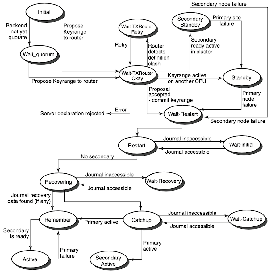
5.8. Client States
SHOW
CLIENT/FULL command. For example, RTR> show client/full
Clients:
Process-id: 13340 Facility: RTR$DEFAULT_FACILITY
Channel: 458755 Flags: CLI
State: declared rcpnam: "CHAN3"
User Events: 255 RTR Events: 0
| Client state |
Figure 5.2, ''Frontend Client States'' shows the client states that can occur and that
appear in the State: field.
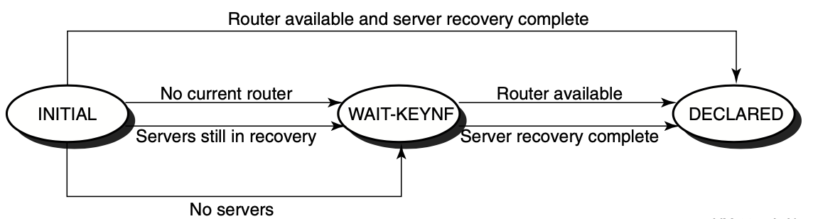
5.9. Partition States
The current state of a partition can be examined using the SHOW
PARTITION/FULL command on the routers and the backends. Using the
/ROUTER qualifier shows the states as seen from the routers, and using
the /BACKEND qualifier shows the states as seen from the backends.
RTR> show partition/router/full Facility: RTR$DEFAULT_FACILITY State: ACTIVE
| Router state |
| Backend state |
RTR> show partition/backend/full Partition name: RTR$DEFAULT_PARTITION_16777217 Facility: RTR$DEFAULT_FACILITY State: active
| Backend server state |
| Key range for partition |
| Server application channels that are available |
| Key range or partition identification |
Figure 5.3, ''Router Partition States'' shows the partition states that can occur and
that appear in the State: field.
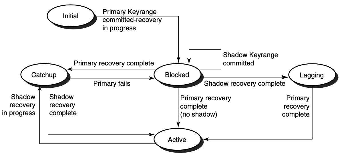
Chapter 6. Performance Management
RTR enables you to capture RTR counters and display them for monitoring with the standard Windows Administrative Tools Performance utility.
- Using a single Windows system to provide coverage of:
multiple RTR installations
all RTR platforms
prior RTR versions
Has very low impact on monitored systems
- Out-of-the-box RTR performance monitoring using the standard Windows performance tool, allowing:
performance logs and alerts
system operators to define and save multiple system views
performance charts, integrated with RTR Manager web pages
Allows viewing RTR performance information from any seat in your Windows network.
Provides an integration point for RTR performance data with other enterprise management products such as HP OpenView.
Figure 6.1, ''Performance Chart in RTR Performance Monitor'' illustrates use of this tool with RTR Manager.
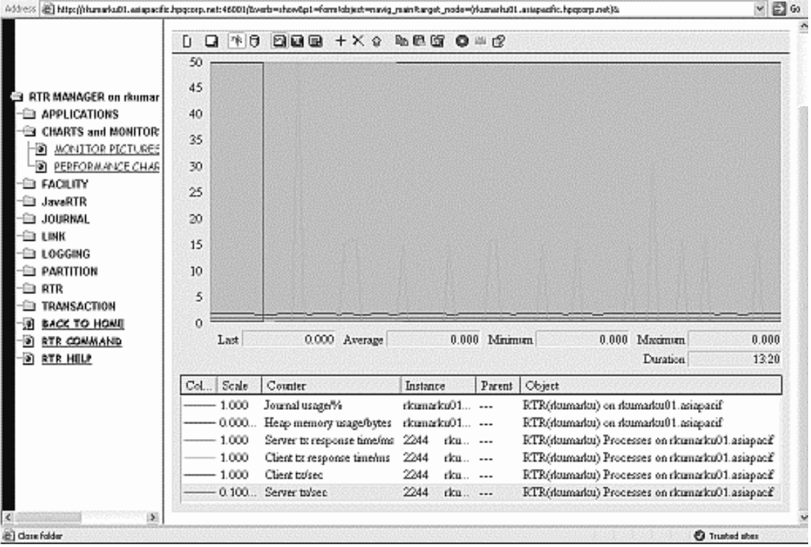
6.1. Performance Counter Hosting
Establish which machines are to be the counter hosts and which nodes are to be the target machines. RTR must have been installed on all these machines.
Start counter hosting by executing the
RTRCounterUpdatecommand on the counter host machine (a Windows system that meets the counter host requirements, see Section 6.2.1, ''Counter Host''). This command causes the counter host to gather data from the target machines.Gather the desired data, using specific performance counters that you determine are those to identify, review, and track performance.
View performance graphs using the Performance Monitor/Performance Chart selections from RTR Manager.
6.2. Terminology
The following terms define the components used for direct performance monitoring.
6.2.1. Counter Host
It must be a Microsoft Windows 2000 family (2000, XP) machine that has RTR installed.
It must be configured to collect performance information from one or more RTR target machines.
The Microsoft .NET Framework must be installed. The redistributable for this can be obtained as a free download from Microsoft.
rshaccess to the target machines is required to initiate network connections for RTR remote commands.Microsoft Internet Explorer must be installed.
RTR need only be installed; it can be on a Windows node defined with any RTR role. The counter host can also be on an HP machine running HP OpenView, which can handle Windows performance tools.
6.2.2. Target Machines
A target machine is any RTR node in your network which you wish to include
in your RTR performance counter coverage. Coverage is configured by including the name of the target machine
on the command line used to start the counter host. A target machine must accept RTR remote commands from any
counter host specifying the machine as a target. This requires TCP connectivity and permission for the user on
the counter host to operate RTR and use rsh for remote access on all target machines. Target machines
may be of any RTR platform type, that is, not just Windows.
6.3. Starting and Stopping Performance Counter Hosting
RtrCounterUpdate program
on the counter host machine at the Windows/DOS prompt. The command line for this program
is:
RtrCounterUpdate [-h] [-c counter-filename] [-i interval-ms] [node1 node2...]
-hdisplays a help message-c counter-filenamespecifies a counter-collection definition file (default: PerfCtr.ctr). This file is an ASCII file and must reside on the counter host. The default file is supplied with the RTR kit.-i interval-msspecifies the wait interval in ms (milliseconds) after each sampling (default: 500 ms).[node1...]is the target node list containing the nodenames of the target machines (default: the local node). There is no practical limit to the number of nodes you can specify.
RtrCounterUpdate -i 1000 OpenVMS_host Tru64_host Windows_host
As shown in the example, target machines of all platform types are supported, provided they meet the requirements listed previously.
RTR on <target_machine_name>
RTR Links on <target_machine_name>
RTR Facilities on <target_machine_name>
RTR Processes on <target_machine_name>
RTR Partitions on <target_machine_name>
Each performance object contains several performance counters that are useful metrics of RTR performance and configuration. Instances of each counter are provided for each corresponding RTR object found on the target systems.
The RtrCounterUpdate program exits if any user input from the terminal is entered.
6.4. Using Windows Performance Counters
Access the Windows system monitor as the Performance Chart page of the RTR Manager.
This page is in the monitoring collection. Note that this page is only available if viewing RTR manager web pages using Microsoft Internet Explorer on the Windows 2000 or Windows XP platform, and a current performance counter host exists for the computer being monitored. The default chart contains counters of general interest, but you can add other counters to suit your requirements using the Add Counters dialogue.
The Windows Performance tool can also be accessed through the Administrative Tools folder of the Windows control panel. Since this is a standard Windows application, please refer to Windows help for additional information on its use.
To add RTR performance counters to any tool configuration, use the Add Counters dialogue. Scroll down the performance object list box and select the desired RTR object and target node, then choose from the available counters and instances in the remainder of the dialogue. Use only the "Select counters from computer" option to connect to other counter hosts. You cannot connect directly to non-Windows targets.
Using this tool, you can define and save chart views of RTR performance counters, configure performance logs, and enable alerts triggered by RTR performance criteria.
6.5. Ensuring your Data Are Valid
counter host unknown
stale performance data
mismatched sampling and display rates
invalid instance names
6.5.1. Counter Host Unknown
To generate a web page allowing access to the performance counters for a system, the Windows system hosting the counters must contact the RTR HTTP web server machine with registration information. This registration is automatic, and occurs periodically. The message "no counter host for target ..." indicates that no such registration can be found on this web server for the indicated target machine.
The most likely reason for this condition is that no performance counter host has been configured to provide coverage for the target in question. For information on starting up counter hosting, see Section 6.3, ''Starting and Stopping Performance Counter Hosting''.
This message may also be observed if the RTR HTTP server has only recently been started and asked to display the performance chart page before receiving the necessary registration information. Since counter registration occurs automatically and periodically, just reload the page later.
6.5.2. Stale Performance Data
Performance counter hosts register their activity with covered target machines so that RTR management web pages may be generated to display the performance counter charting application. A warning appears if this registration data is more than 10 minutes old. Check that the performance counter host is functioning correctly.
6.5.3. Mismatched Sampling and Display Rates
The data in the Windows performance objects is periodically refreshed as new samples are taken from the target systems.
The rate at which this information is updated depends on both the value of interval_ms specified when
configuring the performance counter host, and the latency of the network connecting the host and target. Latency can be
minimized by placing hosts near the targets for which they provide coverage.
The default setting of the Windows performance tool charting function is to update the screen display every second. For performance counters that display as a rate of change per second, this will lead to erratic estimates of the rate in the displayed data, including false indications of zero rate, due to the mismatch in display and data update rates. VSI recommends that the display update rate be set to no less than 10 times the data sampling rate. For example, if the performance counters display per second, set the screen update interval at 10 seconds.
CPU usage on the counter host is inversely related to the value of interval_ms.
6.5.4. Invalid Instance Names
Where possible, the instance names of the Windows performance counters are the same as the underlying RTR objects being measured. However, not all names allowed by RTR are valid Windows counter instance names. Names containing the '$' character are modified by replacing that character with a hyphen for use in Windows.
6.6. Removing RTR Counters from the Registry
HKEY_LOCAL_MACHINE/SYSTEM/CurrentControlSet/Services
Chapter 7. Troubleshooting RTR Applications
This chapter contains information useful for analyzing performance aspects of RTR, especially in large configurations.
To manage remote nodes, you must have either proxy accounts or rsh access to
them. Use RTR remote commands to manage remote nodes.
You should also add and grant operator privileges to the accounts used to manage the RTR network.
7.1. RTR Monitor Pictures
RTR> MONITOR picture-name|
Type of Failure |
Monitor Pictures |
|---|---|
|
Most common problems |
SYSTEM |
|
Connection failures |
ACCFAIL, CONNECTS, FRONTEND, LINK, NETSTAT, STALLS |
|
Transaction sequence problems |
CALLS |
|
Channel problems |
CALLS, CHANNEL, PARTIT |
|
Quorum problems |
QUORUM, ROLEQUOR |
|
V2 interface API |
V2CALLS |
|
Journal problems |
JCALLS, JOURNAL |
|
API problems |
APP2ACP, ACP2APP, REJECTS, REJHIST, ROUTERS |
|
XA interface problems |
XA |
|
Application Problems |
APP2ACP, ACP2APP, CALLS, CHANNEL, PARTIT, REJECTS, REJHIST, ROUTERS |
Refer to Chapter 8, "RTR Monitoring" for descriptions of the monitor pictures, and
Chapter 9, "RTR Commands" for the full syntax of the MONITOR
command.
7.2. Troubleshooting a Looping RTRACP Process
When the RTRACP process goes into a loop, System Dump Analyzer (SDA) utility can be used to know the details about this process.
SDA is a utility that allows you to interpret the contents of this file, examine the status of each processor at the time of the system failure, and investigate the probable causes of the failure.
The following table provides details about some of the commonly used SDA commands:
| Commands | Description |
|---|---|
| SHOW PROCESS/IMAGES | Displays the address of the image control block, the start and end addresses of the image, the activation code, the protected and shareable flags, the image name, and the major and minor IDs of the image. The /IMAGES qualifier also displays the base, end, image offset, and section type for installed resident images in use by this process. |
| SHOW STACK | Displays the location and contents of the process stacks of the SDA current process and the system stack. |
| SHOW CALL_FRAME | Displays the locations and contents of the longwords representing a procedure call frame. |
| SHOW PROCESS/PHD | Lists the information included in the Process Header (PHD). |
| EXAMINE |
Displays either the contents of a location or range of locations in physical memory, or the contents of a register. Use location parameters to display specific locations or use qualifiers to display entire process and system regions of memory. Example:
|
| EVALUATE |
Computes and displays the value of the specified expression in both hexadecimal and decimal. Alternative evaluations of the expression are available with the use of the qualifiers defined for this command. Example:
|
For more information on the SDA utility, see the OpenVMS Alpha System Dump Analyzer Utility Manual.
7.3. Enabling RTR logging
Many problems can be better analyzed when RTR logging has been enabled.
$ RTR SET LOG /FILE=logfile.dat
You should monitor the size of the log file; archive and purge as necessary.
7.4. Starting a Facility
When a facility is started or restarted and servers are declared, RTR recovery features require that it searches journal files of backend nodes in the facility. This allows recovery of any incomplete transactions that were in-flight when the facility last existed. However, if some of the facility's recovery information exists on a backend that is not available at startup, RTR waits for access to the journal on that backend and thus appears to "hang".
Delete the facility and recreate it without the unavailable backend.
Begin the startup by creating a smaller facility and using the
EXTEND FACILITYandTRIM FACILITYcommands.Force a partition to abandon recovery with a SET PARTITION command.
7.5. Analyzing RTR Application Performance
This section provides guidance for System Managers who are analyzing an RTR application that is not functioning correctly.
Is there a system-level problem on the node concerned, such as a full disk?
- Has RTR been started? Is RTR running correctly?
$ RTR SHOW RTR RTR running on node MYNODE in SYSTEM mode
- Are the application programs running? RTR lists the processes using RTR with the following command:
$ RTR SHOW PROCESS
The user application processes should be in this list.
Has the application stopped?
Use MONITOR SYSTEM to check for problems. If it indicates a problem with a subsystem, you can get additional information by monitoring that subsystem.
Network partitioning can also be a problem; this can happen if half or fewer of the configured backends and routers are reachable. To recognize network partitioning, use the MONITOR QUORUM picture. If the number of retries keep increasing without a corresponding increase in the reason counters (CNF/RCH/QRT), you have a partitioned network.
To check the individual links, use the MONITOR CONNECTS picture. This picture displays the link protocol for connected links, and the reason for a failed connection on any links.
- Are the application programs running correctly? Use MONITOR CALLS to examine the state of the participating application processes.
Does the number of
rtr_open_channelcalls match the number ofrtr_mt_openedmessages? If they do not match, use the MONITOR CONNECTS picture to check individual links.Use MONITOR CONNECTS to make sure the connection to the router is OK.
Look in the RTR log file for error messages concerning any unconnected node.
- Look at any unconnected nodes found, and determine:
Is RTR running?
Has the RTR command CREATE FACILITY been issued?
Are there DECnet problems, e.g., executor maximum links too low? Are the router nodes reachable?
Is a server waiting for an
rtr_mt_acceptedorrtr_mt_rejectedmessage (in other words, has it voted, but not yet received confirmation of the outcome of the transaction)? This is most likely a problem with the application logic. Also check the database for a possible deadlock situation.Is a client channel declaration not completing? Client channels need to have connectivity via a router node to at least one server channel before they get an
mt_openedmessage. If the server is up and running, use MONITOR QUORUM and MONITOR CONNECTS to check connectivity.Has a client channel called
rtr_receive_messagewaiting for anrtr_mt_acceptedorrtr_reply_to_clientmessage and not received it within a reasonable time period? Check the application logic and the database for a deadlock.- Has a client channel called
rtr_receive_messageexpecting anrtr_mt_acceptedorrtr_mt_rejectedmessage that is not forthcoming? If yes, RTR is awaiting the necessary resources for message transmission to the backend servers. Reasons could be:Congestion of a network link, frontend to router or router to backend
Server application not correctly dequeuing messages
System-level problem on router or backend node
Use MONITOR TPS to check the transaction processing rate of each process on a system. A system's capacity is generally expressed as the throughput of the servers. If the rates are low or sporadic, contention may be the cause. For systems with throughput less than 10 tps, the MONITOR TPSLO display provides greater granularity in the associated bar graph.
Adding server instances can often decrease application throughput if transactions all access common data elements. Partitioning data so that server instances do not interfere with each other is one way to resolve database contention.
Use the command
SHOW PARTITION/FULLto display the backlog of transactions on a server pool (partition). If the number of free servers is continually zero, the arrival rate of transactions is greater than the processing capacity of the existing server pool.The MONITOR QUEUES picture also shows monitor backlogs. This display shows queuing by partition. If the service time and arrival rate of transactions are large, there are not enough servers to process the load. The remedy is to start additional server instances or decrease the processing time of each transaction. Also, many transactions or messages queued can be caused by contention which is limiting the efficiency of servers.
- Check the state of links with:
$ RTR SHOW FACILITY /LINK
Check if there are sufficient concurrent application server channels to handle the transaction load; messages may have to be queued for long periods before being processed.
Use MONITOR QUEUES to check the number of outstanding messages for each partition.
Check for congestion by examining the network links with the longest delays by using MONITOR TRAFFIC.
Use the command
MONITOR STALLSto determine if the network needs tuning.If there is no congestion, use MONITOR FLOW to discover if a link has credits for data traffic, or if the application requires more bandwidth than is available.
If the RTRACP dies when adding a facility (which has a backend role on the node), suspect journal file difficulties. Ensure that the journal file is not corrupted, or incompatible with the running RTR version. In the event of journal file corruption, please contact the support.
7.6. Server Crashes
Analyze the reasons why the server crashed before you restart the server. Failures that cascade could present a problem, but note that doing a restart will prevent failover.
7.7. Link-Connect Failures
|
Code |
Text |
Implications |
|---|---|---|
|
NOTRECOGNISED |
Node not recognized |
Remote node that received the connection request does not have the local node in its RTR configuration. |
|
REFUSED |
Connection refused |
Indicates one of the following conditions on the remote system: either RTR is not running, or a requested network protocol is not installed. |
|
FACNOTDEC |
Facility not declared |
The requested facility is not configured on the remote node. |
|
NODENOTCFG |
Node not configured |
The remote node has the local node in its configuration, though not as part of the requested facility. |
|
ROLESMISMATCH |
Roles mismatch |
The remote node has the local node configured in the requested facility, but in a role other than the one requested. |
You may have mistyped a name on either (or both) the local and remote nodes.
DNS at either the local or remote nodes (or both) may be giving incorrect address information for the names used.
The nodes are not in the same RTR group.
The nodes do not support a common network protocol.
There is a possible wildcarding error (on routers) in the facility definition.
Wildcarding or use of the "tunnel." prefix may be necessary due to a firewall.
7.8. Rejected Transactions
|
Code |
Text |
Implications |
|---|---|---|
|
NODSTFND |
No destination found |
Primary and all alternate servers for a partition cannot be reached by the client application. This situation can be caused by network problems or services which have not been started or have crashed. |
|
JNLFULL |
Journal full |
May occur when the RTR journal is full. Note that RTR reserves a percentage of the journal to ensure that in-progress transactions can be completed. The JNLFULL error is most likely to be seen with shadow servers running in remember mode, but can also be caused by many transactions being queued to an unresponsive server. |
|
DLKTXRES |
Deadlock detected transaction rescheduled |
May occur during the commit cycle for multi-participant transactions or in extreme failover situations when the order of transactions must be corrected. This reject reason indicates that two transactions were interfering with each other. RTR rejects one branch of the offending transactions to clear the deadlock. Since this transaction branch is subsequently rescheduled by RTR, this reject can be considered informational. |
|
TIMEOUT |
Time out |
Occurs if the |
7.9. Preparing to Submit a Problem Report
To provide sufficient information to Support when submitting a problem report for RTR, you can use the following procedures:
Create a snapshot
Generate a process dump
Access the RTR error log
These procedures are described in the next sections.
7.9.1. Using the Snapshot Procedure
Certain difficulties can be more easily investigated if a snapshot of the problem node is made. Make a snapshot if the application hangs, causes delays, or seems to be causing other problems.
Caution
Do not run snapshot on a production system if the system is running more than 49 processes or 14 partitions. The process of writing the snapshot file may occupy the RTRACP for several minutes, forcing other systems in the RTR configuration to isolate the node where snapshot is being run.
OpenVMS
$ @SYS$MANAGER:RTR$SNAPSHOT.COM
The output is a file named nodename_RTR_DIAGS.TMP.
Information in this file can help to determine the possible causes of a fault (OpenVMS, DECnet, RTR, environment, database, application, and so on.) The information includes numerous RTR monitor pictures, executable image versions, process states, and so on.
UNIX
> rtr_snapshot.sh
The information displayed on the screen includes many RTR monitor pictures, executable image versions, process states, and other information.
Windows
To take a snapshot on Windows, click on the Snapshot icon on the RTR menu. A
DOS-style window with the title ‘‘Snapshot’’ appears as the snapshot is taken. The
file rtr_snapshot.log is created in the directory where RTR runs, for
example, C:\Program Files\RTR . You can read this file with an editor such as
Notepad.
Note
If using Microsoft Windows Scripting Host, the minimum version is 5.6 for use with RTR. With an earlier version of the Scripting Host, RTR snapshot will run with reduced functionality.
To obtain the latest Scripting Host software, use the Microsoft download center at http://msdn.microsoft.com/downloads.
7.9.2. Generating a Process Dump
OpenVMS
Certain potential difficulties can be more easily investigated by RTR Support if a dump of the RTR ACP is available. It shows diagnostics generated if unhandled exceptions occur.
The file SYS$MANAGER:RTR$STARTUP.COM can be altered to include the definition of the logical name RTR$DUMP_DIRECTORY which specifies the device and directory where the dump is to be generated.
Since an RTR dump file typically uses about 5000 blocks, enough space should be available on the chosen disk. For a very large node installation, or a large number of links, the dump file may be up to 20,000 blocks.
SYS$SHARE:IMGDMP has been installed
RTR has been started from an account having CMKRNL privilege
The account used to start RTR has write access to the directory specified by RTR$DUMP_DIRECTORY
$ RTR RTR> SET MODE /UNSUPPORTED RTR> DEBUG ACP RTR> SET MODE /NOUNSUPPORTED $
Unsupported commands should be used with care.
UNIX Systems
UNIX core files are generated with no special configuration, but their name and location may vary depending on operating system settings and how RTR is started up.
Windows systems
(%WINDIR%\drwtsn32 -i)
The files created are %WINDIR%\DRWTSN32.LOG and %WINDIR%\USER.DMP.
These files should be included with any problem report submitted to RTR
Engineering in the event of an RTR crash, along with the RTR dump file
(RTR_<n>.DMP) and the RTR log file.
7.9.3. Accessing the RTR Error Log
To provide the RTR Error Log, run RTR with logging in use. This creates the RTR
Error Log, rtr_error*.log. This file resides in the RTR$DUMP_
DIRECTORY, as listed by operating system in the table below.
| For this Operating System: | The RTR Error Log is in: |
|---|---|
| HP-UX | /var/opt/rtr |
| OpenVMS | RTR$DUMP_DIRECTORY:rtr_error.log |
| Linux | /var/opt/rtr/rtr_error*.log |
| Windows | Program Files –> RTR rtr_error*.log |
Chapter 8. RTR Monitoring
This chapter describes the RTR monitor and provides examples of its use with the CLI interface. Displays with the browser interface contain the same information in a comparable format.
The RTR monitor lets you view the activities of RTR and your applications. Many different aspects of RTR's behavior can be viewed, allowing the activities and performance of RTR to be analyzed.
8.1. Introduction
The RTR monitor provides a means to continuously display the status of RTR and the applications using it.
It can be used to check the correct operation of an RTR network, showing information useful for tuning, capacity planning, and locating configuration and application errors.
The information displayed is composed of named data items which are continuously updated by RTR. These data items can be displayed in various formats and combined using simple arithmetic operators and constants.
The monitor is invoked with the MONITOR command. MONITOR displays a monitor picture that is periodically updated. See Section 9.2, ''RTR Command Reference'' for the full syntax of the MONITOR command.
A monitor picture contains elements that are either text (such as labels and titles) or
variables derived from data items. Monitor pictures can be defined either interactively
at the RTR> prompt or in a file called a monitor file.
You can use monitor files provided with RTR and you can create your own. See Appendix A, "Creating Customized RTR Monitor Pictures" for information about creating monitor files.
8.2. Standard Monitor Pictures
RTR>MONITOR picture-name
The files for standard monitor pictures are installed on your system when RTR is installed.
The location of these files is platform specific. The file names are the picture name
appended with .mon. Type the file name without .mon when
starting the display.
|
Picture name |
Description |
|---|---|
|
accfail |
Shows link transport name for links on which a connection attempt was declined, with a reason for failure. The most recent entry is highlighted. |
|
acp2app |
Displays counts of messages and number of bytes from RTRACP to the application, as viewed from a specific node. |
|
active |
Displays a list of RTR processes, and for each process the number of transactions they have started, the number of transactions they have completed and the number of transactions that are still active. |
|
app2acp |
Displays counts of messages and number of bytes from the application to RTRACP, as viewed from a specific node. |
|
appdelay |
Displays counts of flow-control induced traffic stalls by application process. |
|
broadcast |
Displays information about RTR user events by process, including number of user events enqueued, received, and discarded. |
|
calls |
Displays the total number of RTR API calls and their success
or failure for the processes on all the nodes being monitored.
All RTR messages are also shown by message type. (Pending
messages are those that an application has not received yet).
Use the |
|
channel |
Displays the roles of the channels declared by an application. This can be useful as a debugging tool in the early stages of application development. |
|
compress |
Displays compression configuration and operation information. |
|
connects |
Displays connection status summary, including the number of links up and down, and a list of links with state (up or down), architecture, network transport, and fail-reason, if any. |
|
ctccalls |
Displays the history of calls for a specific client transaction controller. |
|
downstream |
Displays counts of downstream flow-control induced traffic stalls. |
|
event |
Displays event routing data by facility. Information includes events in transit and destination information showing number of events enqueued, processed, and discarded. |
|
fastrecovery |
Displays the number of transactions recovered during optimized shadow recovery. |
|
flow |
Displays the flow control counters. |
|
flostalls |
Displays counts of flow-control induced traffic stalls. |
|
frontend |
Displays frontend status and counts by node and facility, including frontend state, current router, reject status, retry count, and quorum rejects. |
|
group |
Shows server and transaction concurrency by partition. |
|
ipc |
Shows counts of interprocess communication (IPC) activity in the RTR ACP and active RTR applications. |
|
ipcrate |
Displays rate information on IPC messages, byte counts, and I/O primitive usage. |
|
jcalls |
Displays counts of successful (success), failed (fail) and total journal calls for local and remote journals. |
|
jhuse |
Displays bar graphs of Maximum, Allocated, In Use and Peak usage for local and standby journals using the browser interface. Provides the same information as the juse monitor picture. |
|
jnlhtml |
Displays detail for local and standby journal usage with the browser interface. Data are the same as from the MONITOR JOURNAL CLI command. |
|
journal |
Displays detail for local and standby journal usage. Includes counts of the number of blocks in use, percent of journal used, number of blocks, top blocks, blocks available, transaction (tx) entries, transaction records, memory bytes, disk reads, blocks read, disk writes, blocks written, entries total, records total, records read, record bytes read, non-transaction entries and open journals. Also provides bar graphs that show usage of journal blocks as a percent of the total. |
|
juse |
Displays bar graphs of Maximum, Allocated, In Use and Peak usage for local and standby journals. |
|
link |
Displays a number of per-link data items. Use the
|
|
lrc |
Displays link checksum configuration and operation status. |
|
netbytes |
Displays a list of the links to other nodes. For each link, the total number of bytes received and sent on that link and the number of bytes received and sent per second are displayed. |
|
netstat |
Displays for each link the connection status in detail, with the link state (up or down), and architecture type of remote node (such as VAX, I386, Alpha, and so on). |
|
ortr |
Displays a list of server/client transaction controllers. |
|
partit |
Displays the status of server partitions. Shows the partition identifiers, key ranges and key segments, and the status of the servers (active, recovering and so on). |
|
queues |
Shows transaction queues on a partition basis. |
|
quorum |
Tracks (by facility) the configuration, reachability, and quorum status of one or more nodes. |
|
recovery |
Displays the status of server recovery procedures, such as waiting for quorum, catching up transactions, and so on. |
|
rejects |
Displays the last |
|
rejhist |
Displays the last 10 |
|
response |
Displays the elapsed time that a transaction has been active on the opened channels of a process. |
|
rolequor |
Displays a detailed picture of the various data items in the QUORUM picture, separated by roles. If a quorum problem is encountered, this picture may be useful for problem diagnosis. |
|
routers |
Displays information on a router node. It gives an indication of the utilization of the router in terms of transactions and broadcasts routed through this node. Useful to monitor performance or locate problems. |
|
routing |
Displays statistics of transaction and broadcast traffic by facility. |
|
rscbe |
Displays the most recent call's history for the RSC subsystem on a backend node. |
|
stalls |
Displays in real time any network links currently stalling in their outbound traffic, and provides a history of the stalls that the various links encountered during their lifetime. |
|
stccalls |
Displays a history of calls for a specified server transaction controller. |
|
summary |
Displays channel, transaction, and system environmental information. |
|
system |
Displays the state of critical resources within the RTR environment. If a resource has exceeded a predefined threshold, a warning indicator is displayed. |
|
tps |
Displays the rate of transaction commits performed by each process using RTR. |
|
tpslo |
Displays low end of the rate of transaction commits performed by each process using RTR. |
|
traffic |
Displays a list of the links to other nodes. Shown for each link are: byte rate, packet rate, message rate and congestion, in both directions. Average packets per second is also shown. |
|
trans |
Displays transactions for a frontend, router and backend. |
|
upstream |
Displays upstream flow-control-induced traffic stalls. |
|
v2calls |
Shows RTR Version 2 verb usage through the interoperability subsystem. The screen layout is identical to the RTR Version 2 Monitor Call's picture. |
|
xa |
Displays XA counter information including success and failure as well as call and read-only counters. |
The following sections describe the more commonly used standard monitor pictures in detail.
8.2.1. Monitor Accfail
========================================================================
U n a c c e p t a b l e L i n k s
Most recent links on which a connection attempt was declined
Node: NODE11 Wed Jan 7 1998 10:51:00
------------------------------------------------------------------------
Link Transport Name(s) Reason for failure
------------------------------------------------------------------------
nodef node is not configured for the facility
marke.zko.dec.com node not recognized
real1 facility name not matched
MARKE DEC:.ZKO.MARKE node not recognized
nodef node is not configured for the facility
marke.zko.dec.com node not recognized
real1 facility name not matched
nodez node role definitions do not match for
real1 facility name not matched
MARKE DEC:.ZKO.MARKE node not recognized
------------------------------------------------------------------------
List entries are reused in a cyclical fashion; the most
recent entry is highlighted.
========================================================================RTR_STS_NOTRECOGNISED - "node not recognized"
The local node has received a connection request over a link that is not configured in any facility on the local machine. If you expected the connection to succeed as the result of having a template link defined, check carefully the names displayed in the monitor picture. These are the names obtained from the network transport over which the link connection attempt was received, and it is with these that a match with a template (wildcard specification) link must succeed. Remember that the name match is performed in a case-sensitive manner. Names corresponding to TCP links may or may nor contain your domain name, depending on how the name is entered in either your local hosts file or name server. DECnet-Plus systems may yield both a pseudonym and a link name; both are checked for a match with a template.
RTR_STS_FACNOTDEC - "facility name not matched"
The connecting link is configured, but the facility that it requests does not exist on the local node.
RTR_STS_NODENOTCNFG - "node is not configured for the facility"
The connecting link is configured on the local node, but not as part of the requested facility.
RTR_STS_ROLESMISMATCH - "node role definitions do not match for this facility"
The connecting link is configured in the requested facility, but with a different role configuration on the local node.
RTR_STS_TRNOQUO - "router has no quorum in facility %s"
The router is unable to accept frontend connections since it is not quorate. This condition will clear up automatically as soon as the router gains connections to sufficient backends.
8.2.2. Monitor Acp2app
Displays counts of messages and number of bytes from RTRACP to the application, as
viewed from a specific node. Includes opened, closed, msg1, msg1_uncertain,
msgn, reply (reply to client), rettosend (return to sender),
accepted, prepared, rejected, user_event, rtr_event, prepare,
request_info, and set_info messages as appropriate. For
receive_message and user_wakeup, displays calls,
active, fail, and timeout counts. Refer to the VSI Reliable Transaction Router C Application Programmer’s Reference Manual for an explanation of the
message types.
/IDENTIFICATION=process-id.
RTR ACP to Application Messages, Node: NodeA PID: 1568 Process name: -ALL-
Image: -ALL- 14:15:46 Tue Dec 04 2001
Message Type Client Server Other Pend
# Bytes # Bytes # Bytes #
opened 4 760 3 38 0 0 8
closed 0 0 1 136 43492 295745 1
msg1 0 170 2
msg1_uncertain 0 0 0
msgn 0 253 3
reply 0 0 0 0 0
rettosend 0 0 0
prepared 0 0 0
accepted 0 0 0 0 0
rejected 0 0 0 68 1
user_event 0 0 0 0 0
rtr_event 0 0 0 0 0
prepare 0 0 0
Other
request_info 43347 5211764 0
set_info 0 0 0
Calls Active Fail Timeout
receive_message 88607 1 1759 1759
user_wakeup 0 08.2.3. Monitor Active
Displays a list of RTR processes, and for each process the number of transactions they have started, the number of transactions they have completed, and the number of transactions still active.
ACTIVE TRANSACTIONS BY PROCESS Fri Mar 12 1999 19:32:41
Starts Complete Active
Display totals: 5 5 0
Node ID Process name Image name
NodeA 11141 SMITH_1 DISK01:[SMITH]RTR 5 5 08.2.4. Monitor Alarm
Displays counts of RTR alarms. Shows the kilobytes sent, kilobytes received, number of alarms sent, and number of alarms received for internal alarm detection on the target node. Each node on the RTR network detects its own alarms, and then sends the alarms to their associated router. For backends, that means all routers. For routers, it means itself. For frontends, it means the router to which it is connected.
Thus each node may send alarms, and routers may receive alarms.
Alarm Detection Traffic at 11:28:46 Wed May 28 2003
node: rage
Facility KBytesSent KBytesRcvd AlarmsSent AlarmsRcvd
Facility1 5.57 5.57 42 42
Facility2 3.29 3.29 10 10
Facility3 5.64 5.64 43 43
Facility4 3.36 3.36 11 118.2.5. Monitor App2acp
Displays counts of messages and number of bytes from the application to RTRACP, as
viewed from a specific node. Includes open_channel, close_channel,
prepare_tx (prepare transaction), accept_tx (accept
transaction), reject_tx (reject transaction), broadcast_event,
start_tx, send_to_server, reply_to_client, request_info, and
set_info. Refer to the VSI Reliable Transaction Router C Application Programmer’s Reference Manual for an explanation of the message
types.
RTR Application to ACP Messages, Node: NodeA PID: 1568 Process name: -ALL-
Image: -ALL- 14:21:19 Tue Dec 04 2001
RTR Message Type Client Server Other
# Bytes # Bytes # Bytes
open_channel 11 8228 7 5376 0 0
close_channel 5 120 3 72 0 0
prepare_tx 0 0
accept_tx 0 0 0 0
reject_tx 0 0 0 0
broadcast_event 1 81 0 0
start_tx 2 0
send_to_server 5 548
reply_to_client 0 0
request_info 43768 16015270
set_info 0 08.2.6. Monitor Appdelay
FLOW CONTROL STALLS BY PROCESS Tue Dec 04 2001 15:38:37, NODE: rtrdoc
Txn traffic stalls Bdcst traffic stalls KBytes
PID Process Name reqs times secs max reqs times secs max sent
Total * 1 0 0 0 1 0 0 0 45528
1568 user rtr 1 0 0 0 1 0 0 0 455288.2.7. Monitor Broadcast
BROADCAST RECEPTION BY PROCESS 15:20:27 6-APR-1999 Node ID Process name Received Queued Lost Delivery Rate Total 2750 5 17 850.0 NODEA 20400249 SMITH RTR 0 0 0 NODEA 2040024D JONES RTR 2750 5 17 850.0 NODEA 2040024B BROWN RTR 0 0 0 NODEA 2040024C ALLEN RTR 0 0 0
8.2.8. Monitor Calls
process-id
qualifier to display the values for one specific process, otherwise the total values
for all processes are displayed.RTR API calls, Node: nodea , PID: 2162 , Process name: -ALL-
Image: -ALL- 16:38:05 Tue Dec 04 2001
CALLS Client server fail MESSAGES client server pend
open_channel 11 7 18 mt_opened 4 3 4
close_channel 5 3 0 mt_closed 0 1 0
start_tx 2 - 4 mt_msg1 - 0 2
send_to_server 5 - 2 mt_msg1_uncertain - 0 0
mt_msgn - 0 3
reply_to_client - 0 4 mt_reply 0 0 0
mt_rettosend 0 - 0
prepare_tx 0 - 0 mt_prepared 0 - 0
accept_tx 0 0 0 mt_accepted 0 0 0
reject_tx 0 0 0 mt_rejected 0 0 1
broadcast_event 0 0 0 mt_user_event 0 0 0
set_user_handle 0 0 0 mt_rtr_event 0 0 0
get_tid 0 0 0 mt_prepare - 0 0
other other
request_info 3 - 1 mt_request_info 2 - 0
set_info 0 - 0 mt_set_info 0 - 0
error_text 2 mt_closed 2
set_wakeup 0
calls active fail timeout
receive_message 9 1 2 2
user wakeup 0 08.2.9. Monitor Channel
Displays the channels opened by the CALL RTR_OPEN_CHANNEL command.
RTR CHANNELS BY TYPE PER PROCESS 16:41:13 Tue Dec 04 2001
Call-out
Node ID Process name Image name Client Server Router Backend
Nodea 2162 SMITH_1 DISK01:[SMI... 6 3 0 08.2.10. Monitor Compress
Displays compression configuration and operation information. Information displayed includes the following:
Compression settings and results for replies from server to client channels.
Compression settings and results for server and client generated broadcast events.
Name of computer sending the sample, and the application process ID and name.
Compression threshold setting in bytes (environment variable RTR_ REPLY_COMPRESS_THRESHOLD). Only larger replies are compressed. A value of 0 indicates that compression is not enabled.
The reply compression level in effect for the process (environment variable RTR_REPLY_COMPRESS_LEVEL). A value of -1 indicates the default compression level is selected.
Average compression effectiveness for server replies, ranging from 100 (perfect) to 0 (completely ineffective) or even less than 0. This column is only displayed if reply compression is enabled.
Compression threshold setting in bytes (environment variable RTR_ EVENT_COMPRESS_THRESHOLD). Only larger events are compressed. A value of 0 indicates that compression is not enabled.
The event compression level in effect for the process (environment variable RTR_EVENT_COMPRESS_LEVEL). A value of -1 indicates the default compression level is selected.
Average compression effectiveness for client generated events, ranging from 100 (perfect) to 0 (completely ineffective) or even less than 0. This column is only displayed if event compression is enabled.
Average compression effectiveness for server generated events, ranging from 100 (perfect) to 0 (completely ineffective) or even less than 0. This column is only displayed if event compression is enabled.
COMPRESSION OVERVIEW BY PROCESS 17:38:13 Wed Oct 15 2003 on -ALL-
+-Replies-----------+ +-Events------------------+
ClientServer
Node, Process ID & name Threshold Level Ratio Threshold Level Ratio Ratio
nodeaa 10712 10712 0 0 0 0
rtrm08 1940 usertest v3t_sr 1 -1 100.0 0 -1
rtrm08 2108 usertest v3t_sr 1 -1 100.0 0 -1
rtrm08 2072 usertest v3t_sr 1 -1 100.0 0 -1
rtrm08 2020 usertest v3t_sr 999 -1 100.0 0 -1
rtrm08 1856 usertest v3t_sr 0 -1 0 -1
rtrm08 2120 usertest v3t_sr 0 9 0 -1
rtrm08 2112 usertest v3t_sr 0 9 555 -1 100.0 100.0
rtrm08 156 usertest v3t_sr 0 9 555 3 100.0 100.0
rtrm08 2168 usertest rtr.ex 777 9 91.0 666 3 88.4 88.18.2.11. Monitor Connects
C o n n e c t i o n S t a t u s S u m m a r y
Node: nodea Tue Feb 16 1999 13:02:18
Executive summary---------------------------------------
Number of links up: 3
Number of links up (%): 100.0
Required links up: Yes
------------------------------------------------
-Detail-
Node -> Link State Arch T'port Fail-reason
--------------:-----:-----:------:--------------------------------
nodea->nodea up alpha -
nodea->nodeb up alpha TCP
nodea->nodec up i386 TCP8.2.12. Monitor Ctccalls
ORTR Call history monitor screen on node:walkin PID : -ALL- Image: -ALL- at 16:48:32 Mon Jul 16 2001_ Calls Channel # State Msg/Event Ch.Used Status
8.2.13. Monitor Downstream
FLOW CONTROL STALLS DOWNSTREAM BY NODE & FACILITY Mon Jul 16 2001 15:40:21, NODE
Txn traffic Bdcst traffic
be->tr tr->fe be->tr
Node & Facility reqs stall reqs stall reqs stall
rtrdoc Test8.2.14. Monitor Event
Displays event routing data by facility, with totals. Destination columns count the number of events received by the local node and facility delivered to application channels, based on their subscriptions. Transit columns count the number of events that are in transit from the router to remote nodes in the destination facility.
The count columns contain the following:
Destination In: Count of events for facility and node.
Destination Out: Count of events delivered to applications. This may be less than the Destination In count if all applications do not subscribe to all events.
Destination Lost: Count of events discarded by RTR because the application was too busy to receive them (events discarded to prevent channel queue overflow).
Transit In: Count of incoming events handled by the router. This count is zero if a node is not a router.
Transit Out: Count of forwarded events. Includes all events forwarded by the router and any events originating on the local node, including RTR events such as those generated by the router in response to link events.
Transit Lost: Count of transit events discarded by RTR because the RTR router was too busy to receive them (events discarded to prevent link transmission queue overflow).
EVENT ROUTING STATISTICS BY FACILITY Fri Sep 08 2000 15:21:47
Destination Transit
Node & Facility In Out Lost In Out Lost
Total 180 175 5 180 180 0
NODEA FACCMS 25 25 0 25 25 0
NODEA TESTFAC 155 150 5 155 155 08.2.15. Monitor Explorer
Displays counts of RTR Explorer events. Shows the kilobytes sent, kilobytes
received, number of alarms sent, and number of alarms received for backend data
gathering on the target node. When RTR Explorer information is requested on a
backend, either directly by using the GCS information class with API call
rtr_request_info( ), or indirectly by viewing the RTR Explorer via
a web browser, the backend must gather all configuration and status information from
all routers.
Thus the routers may send this information, and the backends may gather this information.
RTR Explorer Traffic at 11:34:53 Wed May 28 2003
node: rage
Facility KBytesSent KBytesRcvd AlarmsSent AlarmsRcvd
Facility1 4.47 4.47 20 20
Facility2 2.71 2.71 5 5
Facility3 4.54 4.54 21 21
Facility4 2.78 2.78 6 68.2.16. Monitor FastRecovery
RECOVERY INFORMATION at Tue Dec 04 2001 09:57:51, on NodeA
Last Currnt Restart CTR Total Shadow-Recovery
Server Rcvy Txns Txns Txns CTR Classic Copied
Partition State Backend Rcvd Rcvd Rcvd Rcvd Rcvd Rcvd
---------- ------- ------- ------ ------- ----- ----- - ------- ------
RTR$DEFAUL active NODEA 1 0 0 0 0 0 0 08.2.17. Monitor Flostalls
FLOW CONTROL INDUCED STALLS BY FACILITY Mon Jul 16 2001 15:41:03, NODE: rtrdoc
Request traffic Response traffic
fe->tr tr->be be->tr tr->fe
Node & Facility reqs stall reqs stall reqs stall reqs stall
rtrdoc Test8.2.18. Monitor Flow
FLOW CONTROL COUNTERS Tue Sep 19 2000 14:08:06, NODE: -ALL- , FAC: -ALL-
Credit Data Rate Requests Grants
Role Available Bytes/sec Waits Sent Pending Sent Pending
FE=>TR 15000 2065 307 966 0 966 0
TR=>BE 15000 2065 70 998 0 998 0
BE=>TR 0 0 0 0 0 0 0
TR=>FE 15000 0 0 2 2 0
Link Data Rate Waits Pending Reqs Sent Cache in use
NODEA =>NODEA 0 0 0 1 NODEA 0
NODEA =>NODEB 0 0 0 0 NODEB 51456
NODEB =>NODEB 2065 307 0 968
NODEB =>NODEA 2065 70 0 9998.2.19. Monitor Frontend
FRONTEND STATUS BY NODE AND FACILITY Tue Dec 04 2001 10:46:24, NODE:NODEA
Node Facility FE Reject Retry Quorum
State Router Status Count Rejects
NODEA RTR$DEFAULT_FACILITY cnctd to smith 2 0
NODEA funds_transfer cnctd to smith 2 0
NODEA payroll waiting no_qrum 395 08.2.20. Monitor Group
Concurrency Measures Tue Dec 04 2001 10:04:26, NODE: NODEA
-- averages --
txn -server- -- transactions -- srv txn txn
Partition state cnt cnt act vreq vote ack /csn act /sec /csn
RTR$DEFAULT active 2 3 1 0 0 0 0 1.0 0.0 0.0|
Field |
Meaning |
|---|---|
|
Partition |
Partition |
|
state |
Partition state. |
|
txn cnt |
Number of transactions executed for this partition. |
|
srv cnt |
Number of servers active for this partition. |
|
srv act |
Number of servers currently busy processing transactions for this sample. |
|
The following fields track the progress of a transaction through the states: vote requested, voted, acknowledged. | |
|
vreq |
Number of transactions waiting for the server to vote. |
|
vote |
Number of transactions that have been voted on by the server but not committed by RTR. |
|
ack |
Number of transactions that have been committed but have
not been acknowledged by the server. Acknowledgment occurs
on a subsequent |
|
/csn |
Number of transactions which have been grouped under the same "commit sequence number" (CSN). This grouping determines the ordering of transactions submitted to a secondary shadow server. |
|
txn/sec |
The average rate of transaction starts per second for this partition. |
|
txn/csn |
Average number of transactions which have been grouped
under the same commit sequence number (CSN) since this
partition became active. This average is computed as the
quotient of the |
8.2.21. Monitor Ipc
Node: NODE11 I P C S u m m a r y Fri Mar 5 1999 11:18:34 +-------------------------------------------------------------------------+ This screen displays usage information on IPC messages, byte counts and IO primitives. Display units are counts, kbytes and calls respectively. +-------------------------------------------------------------------------+ | - - - - - O u t g o i n g / s - - - - | - - I n c o m i n g / s - -| Process Messages ...kbytes send() ...kbytes Messages recv() ...kbytes rtracp 110334 49744 73437 49744 73434 220299 5616 3123B84F 0 0 0 0 0 0 0 31232395 73282 5569 73280 5569 109930 293144 49685
8.2.22. Monitor Ipcrate
Node: NODE11 I P C R a t e s Fri Mar 5 1999 11:18:53 +------------------------------------------------------------------------+ This screen displays rate information on IPC messages, byte counts and IO primitive usage. Display units are counts, kbytes and calls per second respectively. +------------------------------------------------------------------------+ | - - - - - O u t g o i n g / s - - - - | - - I n c o m i n g / s - -| Process Messages ...kbytes send() ...kbytes Messages recv() ...kbytes rtracp 44 19 29 19 29 86 2 3123B84F 0 0 0 0 0 0 0 31232395 28 2 28 2 41 110 18
8.2.23. Monitor Jcalls
JOURNAL CALLS ON NODE NODEA AT 11:25:44 Wed Jan 02 2002
Local Journal Remote Journal
Journal API Success Fail Total Success Fail Total
OPEN_JOURNAL 1 0 1 0 0 0
CLOSE_JOURNAL 0 0 0 0 0 0
READ_RECORD 4 0 4 0 0 0
READ_NEXT RECORD 2 3 4 0 0 0
GET_USAGE 4302 0 4303 0 0 0
WRITE_RECORD 5 0 5 0 0 0
FLUSH_TO_DISK 5 0 5 0 0 0
DELETE_RECORD 1 0 1 0 0 0
# BLOCKS # BLOCKS
EXTENDS 0 0 0 0
TRUNCATES 0 0 0 08.2.24. Monitor Journal
Displays information about journal usage, including total number of entries and
records written, number of records read, and how many bytes were involved. Bar
graphs showing current usage of journal blocks (as a percentage of the total) are
also provided. The bar graphs appear under the first line of the display
JNL_xxx_BLOCKS_IN_USE.
JOURNAL USAGE ON NODE NODEA AT 10:36:05 Tue Apr 6 1999 LOCAL JOURNAL STANDBY JOURNAL(S) JNL_LCL_BLOCKS_IN_USE 128 JNL_RMT_BLOCKS_IN_USE 0 [___ 13% ] [ 0% ] JNL_LCL_NR_BLOCKS 992 JNL_RMT_NR_BLOCKS 992 JNL_LCL_TOP_BLOCKS_USED 128 JNL_RMT_TOP_BLOCKS_USED 0 JNL_LCL_BLOCKS_AVAILABLE 864 JNL_RMT_BLOCKS_AVAILABLE 0 JNL_LCL_TX_ENTRIES 1 JNL_RMT_TX_ENTRIES 0 JNL_LCL_TX_RECORDS 2 JNL_RMT_TX_RECORDS 0 JNL_LCL_MEMORY_BYTES 530121 JNL_RMT_MEMORY_BYTES 4197 JNL_LCL_DISK_READS 31 JNL_RMT_DISK_READS 33 JNL_LCL_BLOCKS_READ 992 JNL_RMT_BLOCKS_READ 1056 JNL_LCL_DISK_WRITES 12 JNL_RMT_DISK_WRITES 0 JNL_LCL_BLOCKS_WRITTEN 14 JNL_RMT_BLOCKS_WRITTEN 0 JNL_LCL_ENTRIES_TOTAL 201 JNL_RMT_ENTRIES_TOTAL 5 JNL_LCL_RECORDS_TOTAL 398 JNL_RMT_RECORDS_TOTAL 9 JNL_LCL_RECORDS_READ 21 JNL_RMT_RECORDS_READ 0 JNL_LCL_REC_BYTES_READ 8006 JNL_RMT_REC_BYTES_READ 0 JNL_LCL_NONTX_ENTRIES 5 JNL_RMT_NONTX_ENTRIES 0 JNL_LCL_OPEN_JOURNALS 2
8.2.25. Monitor Juse
JOURNAL USAGE ON NODE NODEA AT 11:18:19 Wed Jan 02 2002 LOCAL JOURNAL BLOCKS STANDBY JOURNAL(S) BLOCKS Maximum 4992 Maximum 0 Allocated 1984 / 4992 Allocated 0 / 0 [ 40% ] [ 0% ] In use 928 / 4992 In use 0 / 0 [ 19% ] [ 0% ] Peak used 928 4992 Peak used 0 / 0 [ 19% ] [ 0% ] Number of open local journals: 1 Number of open remote journals: 0
8.2.26. Monitor Link
link-name
qualifier can be used to display the values for one specific link; otherwise the
total values for all links are displayed.LINK COUNTERS Tue Sep 19 2000 14:24:44, NODE: -ALL- , LINK: -ALL- -> -ALL- ncf_protocol 0 nio_writing 0 ncf_timeout 0 nio_reading 0 ncf_linkexit 0 nio_wrerror 0 ncf_disconnect 0 nio_rderror 0 ncf_thirdparty 0 nio_rdincmp 0 ncf_pathlost 0 nio_seqerr 0 ncf_responses_sent 3 nio_bufovf 0 ncf_queries_rcvd 11 nio_reads_active 3 ncf_responses_rcvd 2 nio_writes_active 0 ncf_queries_sent 10 nio_bytes_rcvd 44206961 ncf_ipt_msgs_rcvd 16 nio_bytes_sent 44206996 ncf_ipt_msgs_sent 16 nio_pckts_rcvd 412114 ncf_link_gain 4 nio_pckts_sent 412114 ncf_link_loss 0 nio_msgs_rcvd 189284 ncf_aborted 0 nio_tmo_sends 161307 ncf_rejected 1 nio_tot_stall_sec 0 ncf_accepted 1 nio_tot_stalls 0 ncf_confirmed 1 qrm_req_link_queue 0 ncf_initiated 2 qrm_rsp_link_queue 0
8.2.27. Monitor Lrc
Shows incoming message and checksum data for the given links.
Number of links which are up.
Number of links which are down.
Total number of links.
All required links are up.
Some required links are down.
Number of links with checksum enabled.
Number of messages received with a bad checksum.
Number of messages received from RTR V2 with an LRC.
Number of messages received with a checksum appended.
Number of messages received without a checksum.
Total number of messages received on the link.
Total of all shown links.
LINK CHECKSUM ERRORS Wed Oct 15 2003 18:03:57 DEPTH <- -ALL-
Links up 2 Links down 1 Total links 3 Required links down
enabled lrcerror lrcheader lrctrailer lrcundone received
Total 1 0 0 34 12155189 50839617
DEPTH <- depth 0 0 0 0 0 38684394
DEPTH <- length 1 0 0 34 12155189 12155223
DEPTH <- sarand 0 0 0 0 0 08.2.28. Monitor Management
This screen summarizes key areas managed by RTR showing, for example, the number of times RTR saved the day. All the counters describe the management by RTR as a whole, as opposed to per facility or per partition. The counters remain for the life of the RTRACP process. The table below describes the content of the Monitor Management rows.
| Field | Meaning |
|---|---|
| Restart Recoveries | This row enumerates the total number of transactions recovered during RTR start-up, including local and standby recoveries. RTR automatically recovers in-progress transactions during a restart and during a standby takeover. |
| Shadow Recoveries | This row enumerates the total number of transactions recovered from a backend’s shadow partner. RTR automatically recovers all transactions sent to a shadow partner after the disconnected node becomes available. |
| Replay Recoveries | This row enumerates the total number of messages automatically replayed because of an application server death. Whenever an application server dies, RTR automatically replays the message(s) that were being handled by the server to another concurrent server. |
| Three-Strikes Txns | This row enumerates the total number of transactions that were automatically aborted as a result of three server deaths for the same transaction. RTR prevents a single transaction from killing all application servers with this feature. |
| Transactions Processed | This row enumerates all transactions received by RTR. It reports the total number of transactions received by RTR on this node, regardless of the outcome of the transaction. RTR provides advanced transaction management. |
| Partition Activations | On the backend, this number enumerates how many times any partition went into an active state. An active state is one of active, primary active, secondary active, or remember. On the router, it enumerates the number of partition gains. RTR automatically manages transaction routing and failover with partitions. |
| Link Establishments | This row enumerates the total number of link establishments. Every time a link is connected or re-connected, it is considered a link establishment. RTR automatically manages network communication over TCP/IP or DECNET. |
RTR Management at 15:23:09 Tue Jul 8 2003
Node: NODEA
Backend Role Router Role
------------ ------------
Restart Recoveries...... 543 NA
Shadow Recoveries....... 19735 NA
Replay Recoveries....... 56 NA
Three-strikes Txns...... 4 NA
Transactions Processed.. 7385660 3958495
Partition Activations... 512 25
Link Establishments..... 57 50018.2.29. Monitor Netbytes
Max field represents the maximum rate since the link started.LINK TRAFFIC IN BYTES Fri Apr 16 1999 17:41:12, NODE: nodea
Bytes received Bytes sent
-------------------------- --------------------------
Count Rate Max Count Rate Max
Total 59201466 6776.0 - 1002579480 113857.0 -
nodea->nodea 3072248 336.0 336.0 3072248 336.0 336.0
nodea->nodeb 42569496 4974.0 4974.0 717457678 84438.0 84438.0
nodea->nodec 13559722 1466.0 1466.0 282049554 29083.0 29083.08.2.30. Monitor Netstat
C o n n e c t i o n S t a t u s D e t a i l
Node: NODEA Mon March 15 1999 09:50:28
Ini Cnf Acc Abo Rej Loss Gain Ctmo Rstr AFO() TFO() State Type FailCode
Node and Link 12 2 12 12 1 3 2074 2073 863 864
NODEA ->nodeb 0 0 0 0 0 0 1 0 0 0 0 up alpha
NODEA ->nodec 6 0 0 6 6 0 0 0 0 0 0 down ? 76490676
NODEA ->noded 6 0 0 6 6 0 0 0 0 0 0 down ? 76490676
NODEA ->nodee 2591 0 0 863 2590 0 1 2074 2073 863 864 cinit ? Remote node
unreachable
| Address failover |
| Transport failover |
8.2.31. Monitor Ortr
oRTR Transaction Controller List on node : rtrdoc
Image: -ALL- at 15:42:55
Server Controllers Client Controller
STC000 CTC000
STC001 CTC001
STC002 CTC002
STC003 CTC003
STC004 CTC0048.2.32. Monitor Partit
partition name if a partition name has been
specified using the SET PARTITION command. The number of servers and key segments
are shown for each partition. The least-significant byte of the partition's low and
high bound is also shown, and callout type (if any). Table 8.4, ''Monitor Partition States''
shows partition state meanings.PARTITION DEFINITIONS Tue Apr 6 1999 10:40:31, NODE: NODEA
Partition name # # Bounds Callout
State Svrs Segs lo hi type
RTR$DEFAULT_PARTITION_16777218 active 1 1 "A" "A" -
RTR$DEFAULT_PARTITION_16777221 active 1 1 "B" "B" -
RTR$DEFAULT_PARTITION_16777217 active 1 1 0 429496 -|
State |
Meaning |
|---|---|
|
wt_tr_ok |
Server is waiting for routers to accept it |
|
wt_quorum |
Server is waiting for backend to be quorate |
|
lcl_rec |
Local recovery |
|
lcl_rec_fail |
Primary server waiting for access to a restart journal |
|
lcl_rec_icpl |
Getting next journal to recover from |
|
lcl_rec_cpl |
Processed all journals for local recovery |
|
shd_rec |
Shadow recovery |
|
shd_rec_fail |
Shadow server waiting for access to a restart journal |
|
shd_rec_icpl |
Shadow getting next journal to recover from |
|
shd_rec_cpl |
Processed all journals for shadow recovery |
|
catchup |
Secondary is catching up with primary |
|
standby |
Server is declared as standby |
|
active |
Server is active |
|
pri_act |
Server is active as primary shadow |
|
sec_act |
Server is active as secondary shadow |
|
remember |
Primary is running without shadow secondary |
8.2.33. Monitor Queues
TRANSACTION QUEUES BY PARTITION Fri Sep 08 2000 12:42:53, NODE: NODEA
Partition name Processed Queued #
Txns Msgs Rplys Txn Msg Svrs Dly
RTR$DEFAULT_PARTITION_16842753 5792 5794 0 2 6 3 08.2.34. Monitor Quorum
QUORUM STATUS BY NODE AND FACILITY Tue Dec 04 2001 10:50:24, NODE: NODEA (Counts can be inaccurate for incorrectly configured facilities) States: bad configuration,not connected,minority,uncertain,quorate Node & Facility State CNF RCH QRT NODEA RTR$DEFAULT_FACILITY TR:quorate,BE:quorate 2 2 2 NODEA shadow TR:quorate,BE:minority(node12) 4 2 1 NODEA payroll TR:bad_config(NODEB) 1 0 0
8.2.35. Monitor Recovery
Shows the progress of transaction recovery. Last recovery backend is the last
backend accessed to recover transactions. If the server state is
lcl_rec_fail or shd_rec_fail, the Last Recovery
Backend is the backend that could not be accessed. Journal scans is the number of
journal files searched. Transactions recovered is the number of transactions found
for this partition.
RECOVERY INFORMATION at Tue Apr 6 1999 10:54:50, on NODEA
Last Restart-Recovery Shadow-Recovery
Server Recovery Journal Txns Journal Txns
Partition State Backend Scans Recovered Scans Recovered
------------ ------ ------- ------- --------- ------- ---------
RTR_PARTITA active NODEA 1 0 0 0
RTR_PARTITB active NODEA 1 0 0 0
RTR_PARTITC active NODEA 1 0 0 0|
State |
Meaning |
|---|---|
|
wt_tr_ok |
Server is waiting for routers to accept it |
|
wt_quorum |
Server is waiting for backend to be quorate |
|
lcl_rec |
Local recovery |
|
lcl_rec_fail |
Primary server waiting for access to a restart journal |
|
lcl_rec_icpl |
Getting next journal to recover from |
|
lcl_rec_cpl |
Processed all journals for local recovery |
|
shd_rec |
Shadow recovery |
|
shd_rec_fail |
Shadow server waiting for access to a restart journal |
|
shd_rec_icpl |
Shadow getting next journal to recover from |
|
shd_rec_cpl |
Processed all journals for shadow recovery |
|
catchup |
Secondary is catching up with primary |
|
standby |
Server is declared as standby |
|
active |
Server is active |
|
pri_act |
Server is active as primary shadow |
|
sec_act |
Server is active as secondary shadow |
|
remember |
Primary is running without shadow secondary |
8.2.36. Monitor Rejects
rtr_mt_rejected message received by each running
process. Table 8.6, ''Monitor Rejects Fields'' gives the meaning of each
column. Rejected Transaction Summary
NODE: NODEA PROCESS: 20413894 Fri Apr 9 1999 10:26:14
Time Pid Chan Reason Status Text
------------------- ------ ------ -------- -------------------
Fri Apr 9 10:18:43 20417266 client 0 No server available
Fri Apr 9 10:17:47 20417274 server 0 to handle Client
aborted tx|
Field |
Meaning |
|---|---|
|
Time |
Date and time when the |
|
Pid |
ID of the process that received the message |
|
Chan |
Type of channel (client or server) that received the message |
|
Reason |
Reason field returned in the
|
|
Status Text |
Text describing the reject reason |
8.2.37. Monitor Rejhist
rtr_mt_rejected messages received by the
selected process. Always invoke this picture with the /ID qualifier. The transaction
identifier associated with the rejected transaction can be displayed with the
SHOW PROCESS
<
id>/COUNTER=api_reject* command. Table 8.7, ''Monitor Rejhist Fields'' shows the meaning of Rejhist columns. Rejected Transaction History
NODE: NODEA PROCESS: 38009A8B Mon Mar 9 1999 10:26:14
Time Chan Reason Status Text
------------------- ------ ------- ----------------------------
Mon Mar 15 18:06:06 client 0 Client aborted tx
Mon Mar 15 18:06:41 server 0 Normal successful completion
Mon Mar 15 18:06:41 client 0 Server aborted tx
--------------------------------------------------------------------
number of reject messages: 3
number of accept messages: 0
rejected / total txns (%): 100%
This display should be invoked with the /ID qualifier.|
Field |
Meaning |
|---|---|
|
Time |
Date and time when the |
|
Chan |
Type of channel (client or server) that received the message |
|
Reason |
Reason field returned in the
|
|
Status Text |
Text describing the reject reason |
8.2.38. Monitor Response
rtr_start_tx or rtr_send_tx call and the receipt of
the final rtr_mt_accepted or rtr_mt_rejected message. A
call to rtr_reject_tx also marks the end of a transaction. On the
server, transaction duration is measured between receipt of an
rtr_mt_msg1 or rtr_mt_msg1_uncertain message and the
receipt of the final rtr_mt_rejected message or
rtr_reject_tx call. Accepted transaction end times are recorded
when the server issues an rtr_receive_message call to request a new
transaction for processing. TRANSACTION DURATION AT 10:24:51 Fri Apr 9 1999
Process ID, Image Name Client Response Time Server Response Time
seconds 0--1--2--3--4 seconds 0--1--2--3--4
20413894 SERVER.EXE;4 0.000 3.670
20417266 RTR.EXE;75 2.200 3.440
20417274 SERVER.EXE;4 0.000 1.1608.2.39. Monitor Rolequor
QUORUM COUNTS BY FACILITY Tue Dec 04 2001 14:32:48, NODE: NODEA
Facility name Router View of Backend View of
Backends Routers Backends Routers
CNF RCH QRT CNF RCH QRT CNF RCH QRT CNF RCH QRT
RTR$DEFAULT_FACILITY 1 1 1 1 1 1 1 1 1 1 1 1
funds_transfer 1 0 0 0 0 08.2.40. Monitor Routers
ROUTER TRANSACTION COUNTERS AT 14:33:29 Fri Sep 08 2000
Node: NODEA
Facility: -ALL-
Count Rate 10 20 30 40 50 60 70 80 90 100
Starts: 116641 25.7
Enqueues: 116641 25.7
Commits: 116641 25.6
Aborts: 0 0.08.2.41. Monitor Routing
ROUTING STATISTICS BY FACILITY Tue Dec 04 2001 14:34:20, NODE: NODEA
Facility name Transactions Broadcasts
Count Rate NoKR Count Rate NoDst
Total 118489 39.2 0 68444 994.0 1
RTR$DEFAULT_FACILITY 118489 39.2 0 68444 994.0 18.2.42. Monitor Rscbe
Most Recent RSC Dclsrv Calls History on Backend NODEA Thu Mar 4 1999,15:19:41
Partition name: RTR$DEFAULT Partition Start Time: THU MAR 4 15:18:22 1999
Image Name: RTR.EXE
T-delta RSC calls Router State Seq_nr
0 send_dcl_to_master nodez wait_for_response 0
1 recv_status_ok nodez rstart_rvy 1
1 send_dcl_to_master nodez rstart_rvy_incomp 1
1 recv_status_ok nodez rstart_rvy 1
1 send_dcl_to_master nodez rstart_rvy_incomp 1
1 recv_status_ok nodez active 1
1 send_dcl_to_other node10 active 1
1 recv_status_ok node10 active 18.2.43. Monitor Stalls
Node-to-node path of link analyzed
The outgoing network message count per link
The outgoing network message rate per link
The number of bytes sent per link
The number of link disconnects
Total accumulated network write-completion wait time, in seconds
Count of stalls between 1 and 3 seconds
Count of stalls between 3 and 10 seconds
Count of stalls between 10 and 30 seconds
Count of stalls longer than 30 seconds
Count of stalled network write completions
NETWORK STALLS AT Fri Sep 08 2000 15:35:03, ON NODE: TR1
Messages Bytes Link Stalls
Issued Rate Sent Drops Secs <3s <10s <30s >30s Totals
Total 5467 0.0 327148 2 33 23 1 0 0 24
TR1 -> TR1 29 0.0 3718 0 0 0 0 0 0 0
TR1 -> FE2 509 0.0 20707 0 4 4 0 0 0 4
TR1 -> BE1 303 0.0 13707 0 3 3 0 0 0 3
TR2 -> TR2 111 0.0 11682 0 0 0 0 0 0 0
TR2 -> BE1 504 0.0 22743 0 18 8 1 0 0 9
FE1 -> FE1 64 0.0 6645 0 0 0 0 0 0 0
FE1 -> FE2 373 0.0 18890 0 2 2 0 0 0 2
FE1 -> BE1 310 0.0 24487 0 0 0 0 0 0 0
FE2 -> FE2 231 0.0 18900 0 0 0 0 0 0 0
FE2 -> BE1 284 0.0 22503 1 1 1 0 0 0 1
FE2 -> TR1 536 0.0 28166 0 0 0 0 0 0 0
FE2 -> FE1 396 0.0 23643 0 0 0 0 0 0 0
BE1 -> BE1 355 0.0 28121 0 0 0 0 0 0 0
BE1 -> FE2 284 0.0 13014 1 0 0 0 0 0 0
BE1 -> TR2 515 0.0 27502 0 2 2 0 0 0 2
BE1 -> TR1 328 0.0 25698 0 1 1 0 0 0 1
BE1 -> FE1 335 0.0 17022 0 2 2 0 0 0 28.2.44. Monitor Stccalls
ORTR Call history monitor screen on node:rtrdoc PID : -ALL-
Image: -ALL- at 15:45:10 Mon Jul 16 2001
STC CurrentState : #Of Partitions : 0
PartitionName Channel #
Calls Channel #s State Msg/Event Ch. used Status8.2.45. Monitor Summary
- For server channels:
Processes (number of processes hosting server channels)
Active (number of primary active server channels)
Secondary active (number of secondary active server channels)
Standby (number of standby server channels)
Other (number of server channels in states not counted above)
All server channels (number of server channels in all states)
- For client channels:
Processes (number of processes hosting client channels)
Channels: number of client channels
For all processes: Total processes: number of RTR application processes (clients and servers). To see separation by process, use MONITOR CHANNEL.
For transaction counts: Active transactions (for each frontend, router, and backend role, displays counts of active transactions with node location and age (in days and clock time as dddd hh:mm::ss) of the oldest transaction)
For RTR uptime by system: Elapsed time in days and clock time(dddd hh:mm:ss) since RTR was started on the given system
Environment Summary at 16:00:36 Sat Mar 1 2003
on node -ALL-
--Server channels------- --Client channels-------
Processes : 2 Processes : 1
Active : 6 Channels : 2
Secondary active : 2
Standby : 4
Other : 1
All server channels : 13 Total processes : 2
Active transactions
Backend : 3 Oldest (on length ) 0000 00:04:06
Router : 3 Oldest (on depth ) 0000 00:04:05
Frontend : 3 Oldest (on depth ) 0000 00:04:05
RTR uptime by system
depth 0001 02:02:33
length 0001 02:01:568.2.46. Monitor System
System Status at 10:27:51 Fri Apr 9 1999
node: NODEA
Resource OK Warning
Facility QUORUM states...... x
JOURNAL free space.......... x
Link CONNECTS............... x
Link traffic STALLS......... x
FLOW control credits........ x
PARTITION states............ x
CALL Msg outstanding.......... x
Transaction QUEUES............ x
Transaction REJECTS........... x
Broadcast EVENT discards...... x
For additional detail about a resource,
monitor the appropriate subsystem. To
customize threshold values, edit
SYSTEM.MON. If viewing this page in a
browser, follow the hyperlinks above.|
For this Resource: |
A Warning Appears When: |
|---|---|
|
Quorum |
Any roles are inquorate |
|
Journal |
Journal free space is less than 30% of total |
|
Link Connects |
Any link is disconnected |
|
Stalls |
10 second stalls are greater than 1% of all messages sent |
|
Flow |
The wait is more than 1 second for 10% of the total credit requests |
|
Partition |
Any of the partitions are not in one of the following states: Standby, Active, Pri_act, or Sec_act |
|
Call Msg |
Any messages have been pending for more than 30 seconds |
|
Queues |
The transaction queue cannot be emptied within 10 seconds |
|
Rejects |
The number of rejects (non-user) is greater than 5% of the total transactions processed, or a reject (non-user) has occurred within the last 30 minutes |
|
Event discards |
The number of discards is greater than 5% of the total events sent |
To customize threshold values, edit the file SYSTEM.MON.
8.2.47. Monitor Tps
TRANSACTION COMMITS BY PROCESS 14:12:48 Wed Nov 3 1999 on nodeA
Commits Each # is 10tps
Node, Process ID & name Absolute Rate/s 50 100 150 200 250 300
nodeA -ALL- -CLIENTS- 2401 45.0 ####
nodeA -ALL- -SERVERS- 2401 45.0 ####
nodeA 22941 smith_1 2401 45.0 ####
nodeA 22933 jones_1 2401 45.0 ####8.2.48. Monitor Tpslo
TRANSACTION COMMITS BY PROCESS 14:12:48 Wed Nov 3 1999 on nodeA.zko.dec.com
Commits
Node ID Process Abs. Rate | 2 4 6 8 10
nodeA -ALL- -CLIENTS- 5 2.0 ##
nodeA -ALL- -SERVERS- 5 2.0 ##
nodeA 22941 smith_1 10 4.0 ####8.2.49. Monitor Traffic
LINK TRAFFIC Fri Sep 08 2000 14:38:08, NODE: -ALL-
Bytes/sec Packets/sec Messages/sec Congestion
Rcvd Sent Rcvd Sent Avrg Rcvd Sent Count Rate
Total 13465.5 13213.3 123.8 121.2 239.1 53.3 53.3 35 0.0
NODEA -> NODEA 0.0 0.0 0.0 0.0 0.0 0.0 0.0 0 0.0
NODEA -> NODEB 10718.0 2705.8 95.1 27.5 118.9 24.9 27.2 28 0.0
NODEB -> NODEB 41.7 41.7 1.2 1.2 1.4 1.2 1.2 0 0.0
NODEB -> NODEA 2705.8 10465.8 27.5 92.5 118.8 27.2 24.9 7 0.08.2.50. Monitor Trans
Monitoring transactions Wed Jan 09 2002 15:21:38, NODE: NODEA Transaction ID (frontend) Facility FE-User State 46d01f10,0,0,0,0,baa09daa,abf10001 RTR$DEFAULT_FACILITY RTRCSV_T.1 voting Transaction ID (router) Facility FE-User State 46d01f10,0,0,0,0,baa09daa,abf10001 RTR$DEFAULT_FACILITY RTRCSV_T.1 voting Transaction ID (backend) Facility FE-User State 46d01f10,0,0,0,0,baa09daa,abf10001 RTR$DEFAULT_FACILITY RTRCSV_T.1 receiving
8.2.51. Monitor Upstream
FLOW CONTROL UPSTREAM STALLS BY NODE & FACILITY Mon Jul 16 2001 15:42:25, Node:
Txn traffic Bdcst traffic
fe->tr tr->be tr->be
Node & Facility reqs stall reqs stall reqs stall Router used
rtrdoc Test rtrdoc_8.2.52. Monitor V2calls
RTR V2 system service calls, Node: NODEA , PID: 00000000, Process name: -ALL-
Image: -ALL- 13:09:18 5-MAR-1999
Accept Reject Success Failure Outstng Calls
dcl_tx_prc/server 3 0 4 0 0 4
dcl_tx_prc/req. 1
dcl_tx_prc/shut. 0
start_tx 1 0 1 0 0 1
start_tx /timeout 0
enq_tx 1 0 50395 0 0 50395
enq_tx /broadcast 25187
enq_tx /reply 25207
deq_tx 50381 0 50391 0 2 50393
deq_tx /reply 12
commit_tx 1 0 1 0 0 1
abort_tx 0 0 0 0 0 0
vote_tx /commit 25187 0 25189 0 0 25189
vote_tx /abort 0
vote_tx /forget 28.2.53. Monitor Wq_facility
Displays the state of the ACP channel wait queues by facility.
WAITQ STATISTICS BY FACILITY Mon Jul 26 2004 14:09:46 mpeso -ALL
Servers Clients
Current Maximum Timestamp Current Maximum Timestamp
451288 451288 26-Jul-2004 14:09 0 0
Servers Clients
Node Facility Current Maximum Current Maximum
mpeso f1 451288 451288 0 08.2.54. Monitor Wq_process
Displays the state of the ACP channel wait queues by process.
WAITQ STATISTICS BY PROCESS Mon Jul 26 2004 14:10:04 mpeso ID: -ALL
Servers Clients
Current Maximum Timestamp Current Maximum Timestamp
451288 451288 26-Jul-2004 14:09 0 0
Servers Clients
Node Proc. Id Process Name Current Maximum Current Maximum
mpeso 20409E6A GAISFORD_126 451288 451288 0 08.2.55. Monitor XA
RTR XA Calls Node: nodea.zko PID: -ALL- Process name: -ALL-
Image: -ALL- 11:42:06 Tue 6-Apr-1999
XA Verb Name Calls Success Readonly Failure
open 0 0 0 0
close 0 0 0 0
start 0 0 0 0
end 0 0 0 0
prepare 0 0 0 0
commit 0 0 0 0
rollback 0 0 0 0
recovery 0 0 0 0
Rate 0 2 4 6 8 10 12 14 16 18 20 Active
txn starts 0.0 0Chapter 9. RTR Commands
RTR commands can be invoked from the RTR web browser interface or with the RTR CLI. RTR C API calls can also be invoked from these interfaces to facilitate application testing. For example, client applications can be tested before the corresponding server applications have been written by manually entering the server's C API calls, and manual tests can be done between clients and servers.
RTR commands include those used in developing applications as well as commands that let you monitor and manage the operation of a production system. See Section 1.3, ''RTR Administrator'' for instructions on how to start using the RTR web browser and CLI interfaces, and see the VSI Reliable Transaction Router Getting Started manual for an example of a manual demonstration of sending data between a client and a server.
9.1. Introduction
The commands that invoke the RTR API calls are similar to the call names. For example, the call is invoked using CALL RTR_ACCEPT_TX at the CLI level.
Where possible, command qualifiers have been given the same names as the parameters to the API calls. See the VSI Reliable Transaction Router C Application Programmer’s Reference Manual for details about the parameters to API calls.
Most commands can be issued on remote nodes by using the /NODE=node-list
or /CLUSTER qualifiers, or by preceding them with the SET
ENVIRONMENT command to specify the nodes where the commands are to be
executed. Commands such as DEFINE KEY are intended for local execution
only.
Output from each command can be redirected to another device or file using the
/OUTPUT qualifier.
Note
In a mixed RTR Version 3 and Version 4 environment, you can execute commands
remotely with the /NODE qualifier.
9.2. RTR Command Reference
This section describes each command in the RTR command utility.
The command descriptions are presented in alphabetical order.
ADD FACILITY
ADD FACILITY — See CREATE FACILITY; ADD FACILITY is retained for compatibility reasons only.
CALL RTR_ACCEPT_TX
CALL RTR_ACCEPT_TX — The CALL RTR_ACCEPT_TX command causes a command
server to execute the rtr_accept_tx() routine and to display the returned
status.
Format
CALL RTR_ACCEPT_TX
| Command Qualifiers | Defaults |
|---|---|
| /CHANNEL_NAME=channel-name | /CHANNEL_NAME=RTR$DEFAULT_CHANNEL |
| /CLUSTER | /NOCLUSTER |
| /FORGET | /NOFORGET |
| /INDEPENDENT | /NOINDEPENDENT |
| /NODE[=node-list] | /NODE=default-node |
| /OUTPUT[=filespec] | /OUTPUT=stdout |
| /REASON[=reason] | /REASON=0 |
Description
The CALL RTR_ACCEPT_TX command causes a command server to call the
rtr_accept_tx() routine using values supplied on the command
line.
The numeric status returned from the call is then converted to its textual representation and displayed.
The rtr_accept_tx() routine itself is described in the VSI Reliable Transaction Router C Application Programmer’s Reference Manual.
rtr_accept_tx()
is: rtr_status_t rtr_accept_tx (
rtr_channel_t channel,
rtr_acc_flag_t flags,
rtr_reason_t reason
) ;|
C Parameter Name |
C Parameter Value |
Command Line Specification |
|---|---|---|
|
channel |
/CHANNEL_NAME=name | |
|
flags |
RTR_NO_FLAGS |
[none] [D] |
|
RTR_F_ACC_FORGET |
/FORGET | |
|
reason |
RTR_NO_REASON |
/NOREASON [D] |
|
reason_value |
/REASON=reason_value |
Issuing the CALL RTR_ACCEPT_TX command in preference to using the /ACCEPT qualifier with the CALL RTR_SEND_TO_SERVER or CALL RTR_REPLY_TO_CLIENT commands is only necessary when specifying an acceptance "reason" other than the default value of zero (using the /REASON qualifier).
Qualifiers
- /CHANNEL_NAME=channel_name
/CHANNEL_NAME=RTR$DEFAULT_CHANNEL Specifies the channel for which the operation is to be performed.
The command server uses a combination of the channel name and the window from which the call was issued to uniquely identify which channel to use.
channel_nameis not case sensitive.The default for
channel_nameis RTR$DEFAULT_CHANNEL.- /CLUSTER
/NOCLUSTER (D) Specifies that the command is executed on all the nodes in the cluster.
If neither /NODE nor /CLUSTER is specified, the command is executed on the nodes specified by the latest SET ENVIRONMENT command. If no SET ENVIRONMENT command has been entered, the command is executed only on the node where the command was issued.
Note
In environments that do not support remote command capability, the /CLUSTER qualifier causes the relevant command to be executed on the local node only.
- /EVENT_NUMBER=user-event-number
The user event number associated with this broadcast, in the range of RTR_EVTNUM_USERBASE to RTR_EVTNUM_USERMAX (i.e. 0 to 250).
- /FORMAT[=fmt-string]
/NOFORMAT (D) Specifies that a format string should be sent with this message.
If /FORMAT is specified without
fmt-string, RTR automatically generates a format string. The format string is generated using the parameters given for the qualifiers /SIGNED, /UNSIGNED, /STRING and /LENGTH. The following table shows permitted values for these qualifiers when using /FORMAT withoutfmt-string.Table 9.2. Generated Format Strings Data Type With /LENGTH= With /NOLENGTH STRING =n, "%nC" "%nC" wheren=strlen(string) SIGNED =1, "%SB" "%SL" SIGNED =2, "%SW" "%SL" SIGNED =4, "%SL" "%SL" UNSIGNED =1, "%UB" "%SL" UNSIGNED =2, "%UW" "%SL" UNSIGNED =4, "%UL" "%SL" Refer to the VSI Reliable Transaction Router C Application Programmer’s Reference Manual, section "Defining a Message Format Description" for information on constructing a fmt-string parameter.
- /LENGTH_OF_FIELD=field-length
Enter the size of the message field that you want to define. The default for string types is the length of the message entered, plus one (for the zero termination byte). The default for signed and unsigned types is four. This is a positional qualifier; it must immediately follow the message field that it refers to.
- /NODE[=node-list]
/NODE=default-node (D) Specifies that the command is executed on all nodes specified in node-list. If node-list is omitted, the command is executed only on the node where the command was issued.
- /OUTPUT[=filespec]
/OUTPUT=stdout (D) Specifies that the resulting information is written to the file filespec. If /OUTPUT or filespec is omitted, the standard or default output is used.
- /RECIPIENT_SPEC=rcpspc
Enter a string specifying the recipient name. The wildcard characters asterisk (*) and question mark (?) are permitted.
rcpspc is case sensitive, but defaults to the case-insensitive channel name if not explicitly defined.
- /TYPE_OF_DATA=STRING|SIGNED|UNSIGNED
/TYPE_OF_DATA=STRING (D) Enter the data type of the message field that you want to define. The default is the string type. This is a positional qualifier; it must immediately follow the message field that it refers to.
Examples
This command broadcasts user event number 23 to all default recipients. The message in quotes is sent with the broadcast.
RTR> CALL RTR_BROADCAST_EVENT /EVENT_NUMBER=23 "Dollar is up"
%RTR-S-OK, Normal successful completionThe following command broadcasts user event number 24 to all recipients whose /RECIPIENT_SPEC matches the DEALER? string (that is, DEALER1, DEALER2, DEALERx). Note that only the event is broadcast; there is no associated message.
RTR> CALL RTR_BROADCAST_EVENT /EVENT=24/RECIPIENT_SPEC=DEALER?
%RTR-S-OK, Normal successful completionThe following example shows a broadcast message containing two fields. The first field is of type unsigned, entered as a hexadecimal number; the second field is of type string.
RTR> CALL RTR_BROADCAST_EVENT /EVENT=24 0xFA9BC0 /TYPE_OF_
DATA=UNSIGNED/LENGTH=8,"This field of the message is a string"
%RTR-S-OK, Normal successful completionCALL RTR_CLOSE_CHANNEL
CALL RTR_CLOSE_CHANNEL — The CALL RTR_CLOSE_CHANNEL command causes a
command server to execute the rtr_close_channel() routine and to display
the returned status. This command is not available in the RTR web browser
interface.
Format
CALL RTR_CLOSE_CHANNEL
| Command Qualifiers | Defaults |
|---|---|
| /CHANNEL_NAME=channel-name | /CHANNEL_NAME=RTR$DEFAULT_CHANNEL |
| /CLUSTER | /NOCLUSTER |
| /IMMEDIATE | /IMMEDIATE=RTR_F_CLO_IMMEDIATE |
| /NODE[=node-list] | /NODE=default-node |
| /OUTPUT[=filespec] | /OUTPUT=stdout |
Description
The CALL RTR_CLOSE_CHANNEL command causes a command server to call the
rtr_close_channel() routine using values supplied on the
command line.
The numeric status returned from the call is then converted to its textual representation and displayed.
The rtr_close_channel() routine itself is described in the
VSI Reliable Transaction Router C Application Programmer’s Reference Manual.
rtr_close_channel()
is: rtr_status_t rtr_close_channel (
rtr_channel_t channel,
rtr_clo_flag_t flags
) ;|
C Parameter Name |
C Parameter Value |
Command Line Specification |
|---|---|---|
|
channel |
/CHANNEL_NAME=name | |
|
flags |
RTR_NO_FLAGS |
[none] [D] |
Qualifiers
- /CHANNEL_NAME=channel_name
/CHANNEL_NAME=RTR$DEFAULT_CHANNEL Specifies the channel for which the operation is to be performed.
The command server uses a combination of the channel name and the window from which the call was issued to uniquely identify which channel to use.
channel_nameis not case sensitive.The default channel name is RTR$DEFAULT_CHANNEL.
You may close all the channels belonging to a window using CLOSE CHANNEL/CHANNEL_NAME=*.
- /CLUSTER
/NOCLUSTER (D) Specifies that the command is executed on all the nodes in the cluster.
If neither /NODE nor /CLUSTER is specified, the command is executed on the nodes specified by the latest SET ENVIRONMENT command. If no SET ENVIRONMENT command has been entered, the command is executed only on the node where the command was issued.
Note
In environments that do not support remote command capability, the /CLUSTER qualifier causes the relevant command to be executed on the local node only.
- /IMMEDIATE
/IMMEDIATE=RTR_F_CLO_IMMEDIATE (D) Specifies the closing of a channel immediately without sending a transaction acknowledgement.
- /NODE[=node-list]
/NODE=default-node (D) Specifies that the command is executed on all nodes specified in node-list. If node-list is omitted, the command is executed only on the node where the command was issued.
- /OUTPUT[=filespec]
/OUTPUT=stdout (D) Specifies that the resulting information is written to the file filespec. If /OUTPUT or filespec is omitted, the standard or default output is used.
Examples
This command closes the RTR$DEFAULT_CHANNEL.
RTR> CALL RTR_CLOSE_CHANNEL %RTR-S-OK, Normal successful completion
This command closes the channel named CLIENT1.
RTR> CALL RTR_CLOSE_CHANNEL/CHANNEL_NAME=CLIENT1 %RTR-S-OK, Normal successful completion
CALL RTR_ERROR_TEXT
CALL RTR_ERROR_TEXT — The CALL RTR_ERROR_TEXT command causes a
command server to execute the rtr_error_text() routine and to display the
returned error text. This command is not available in the RTR web browser
interface.
Format
CALL RTR_ERROR_TEXT
| Command Qualifiers | Defaults |
|---|---|
| /OUTPUT[=filespec] | /OUTPUT=stdout |
| /STATUS=status-code | None |
Description
The CALL RTR_ERROR_TEXT command causes a command server to call the
rtr_error_text() routine using the value supplied on the
command line.
The rtr_error_text() routine itself is described in the
VSI Reliable Transaction Router C Application Programmer’s Reference Manual.
rtr_error_text()
is: char *rtr_error_text (
rtr_status_t sts
) ;|
C Parameter Name |
Parameter Value |
Command Line Specification |
|---|---|---|
|
sts |
42 |
42 (parameter) |
Qualifiers
- /OUTPUT[=filespec]
/OUTPUT=stdout (D) Specifies that the resulting information is written to the file filespec. If /OUTPUT or filespec is omitted, the standard or default output is used.
- /STATUS=status-code
No default Specifies the
stsparameter in thertr_request_info()call.
Example
This command shows the text associated with error number 4849722.
RTR> CALL RTR_ERROR_TEXT /STATUS=4849722 error text normal successful completion
CALL RTR_EXT_BROADCAST_EVENT
CALL RTR_EXT_BROADCAST_EVENT — The CALL RTR_EXT_BROADCAST_EVENT command causes
a command server to execute the rtr_ext_broadcast_event() routine and to
display the returned status. A timeout can be supplied to eliminate long waits that may
be seen with the similar call RTR_BROADCAST_EVENT. This command is not available in the
RTR web browser interface.
Format
CALL RTR_EXT_BROADCAST_EVENT [message-field1]
[,message-field2,...]
Parameters
[message-field1] [,message-field2...]
Specify the message to be sent (if any) as one or more comma-separated parameter values. You can use the /TYPE_OF_DATA and /LENGTH_OF_DATA positional qualifiers on each parameter value to specify the data type and length of each field.
| Command Qualifiers | Defaults |
|---|---|
| /CHANNEL_NAME=channel-name | /CHANNEL_NAME=RTR$DEFAULT_CHANNEL |
| /CLUSTER | /NOCLUSTER |
| /EVENT_NUMBER=evtnum | None |
| /FORMAT=fmt-string | /NOFORMAT |
| /LENGTH_OF_FIELD=msg length | Depends on data type. |
| /NODE[=node-list] | /NODE=default-node |
| /OUTPUT[=filespec] | /OUTPUT=stdout |
| /RECIPIENT_SPEC=rcpspc | /NORECIPIENT_SPEC |
| /TIMOUTMS=timeout | None |
| /TYPE_OF_DATA=data type | /TYPE_OF_DATA=STRING |
Description
The CALL RTR_EXT_BROADCAST_EVENT command causes a command server to call the
rtr_ext_broadcast_event() routine using values supplied on the command
line. In some circumstances, a broadcast event call can wait a long time if RTR runs out
of channel credits; it may seem that the application is hanging. To eliminate such a
wait, the user can specify a timeout value from which the function will return an
RTR_STS_TIMOUT status if RTR is unable to issue the broadcast message within the
specified broadcast period.
The numeric status returned from the call is converted to its textual representation and displayed.
The rtr_ext_broadcast_event() routine itself is described in the
VSI Reliable Transaction Router C Application Programmer’s Reference Manual.
rtr_ext_broadcast_event()
is: rtr_status_t rtr_ext_broadcast_event (
rtr_channel_t channel,
rtr_bro_flag_t flags,
rtr_msgbuf_t pmsg,
rtr_msglen_t msglen,
rtr_evtnum_t evtnum,
rtr_rcpspc_t rcpspc,
rtr_msgfmt_t msgfmt,
rtr_timoutms_t timoutms
) ;The table below shows the correspondence between values you supply on the command line and the C language parameter values produced and used for the call.
| C Parameter Name | C Parameter Value | Command Line Specification |
|---|---|---|
| channel | /CHANNEL_NAME=name | |
| flags | RTR_NO_FLAGS | [none] [D] |
| pmsg, msglen, msgfmt 1 | [message definition parameter list with positional qualifiers ] | |
| evtnum | 42 | /EVENT_NUMBER=42 |
| rcpspc | "workstat*" | /RECIPIENT_SPEC="workstat*" |
| timoutms | /TIMOUTMS=1000 (1 sec.) |
The command server uses message data specified as command line parameter values to
generate a record containing the message data (for the pmsg parameter), the
message length (for the msglen parameter), and a record type description
(for the msgfmt parameter).
Qualifiers
- /CHANNEL_NAME=channel-name
/CHANNEL_NAME=RTR$DEFAULT_CHANNEL Specifies the channel for which the operation is to be performed.
The command server uses a combination of the channel name and the window from which the call was issued to uniquely identify which channel to use.
channel_nameis not case sensitive.The default for
channel-nameis RTR$DEFAULT_CHANNEL.- /CLUSTER
/NOCLUSTER (D) Specifies that the command is executed on all the nodes in the cluster.
If neither /NODE nor /CLUSTER is specified, the command is executed on the nodes specified by the latest SET ENVIRONMENT command. If no SET ENVIRONMENT command has been entered, the command is executed only on the node where the command was issued.
Note
In environments that do not support remote command capability, the /CLUSTER qualifier causes the relevant command to be executed on the local node only.
- /EVENT_NUMBER=user-event-number
The user event number associated with this broadcast, in the range of RTR_EVTNUM_USERBASE to RTR_EVTNUM_USERMAX (i.e. 0 to 250).
- /FORMAT[=fmt-string]
/NOFORMAT (D) Specifies that a format string should be sent with this message.
If /FORMAT is specified without
fmt-string, RTR automatically generates a format string. The format string is generated using the parameters given for the qualifiers /SIGNED, /UNSIGNED, /STRING and /LENGTH. The following table shows permitted values for these qualifiers when using /FORMAT withoutfmt-string.Table 9.6. Generated Format Strings Data Type With /LENGTH= With /NOLENGTH STRING =n, "%nC" "%nC" wheren=strlen(string) SIGNED =1, "%SB" "%SL" SIGNED =2, "%SW" "%SL" SIGNED =4, "%SL" "%SL" UNSIGNED =1, "%UB" "%SL" UNSIGNED =2, "%UW" "%SL" UNSIGNED =4, "%UL" "%SL" Refer to the VSI Reliable Transaction Router C Application Programmer’s Reference Manual, section "Defining a Message Format Description" for information on constructing a
fmt-stringparameter.- /LENGTH_OF_FIELD=field-length
Enter the size of the message field that you want to define. The default for string types is the length of the message entered, plus one (for the zero termination byte). The default for signed and unsigned types is four. This is a positional qualifier; it must immediately follow the message field that it refers to.
- /NODE[=node-list]
/NODE=default-node (D) Specifies that the command is executed on all nodes specified in node-list. If node-list is omitted, the command is executed only on the node where the command was issued.
- /OUTPUT[=filespec]
/OUTPUT=stdout (D) Specifies that the resulting information is written to the file filespec. If /OUTPUT or filespec is omitted, the standard or default output is used.
- /RECIPIENT_SPEC=rcpspc
Enter a string specifying the recipient name. The wildcard characters asterisk (*) and question mark (?) are permitted.
rcpspcis case sensitive, but defaults to the case-insensitive channel name if not explicitly defined.- /TIMOUTMS=msec
Specifies a value in milliseconds for the timeout. RTR returns an error message if RTR is unable to issue the broadcast message within the specified timeout period.
- /TYPE_OF_DATA=STRING|SIGNED|UNSIGNED
/TYPE_OF_DATA=STRING (D) Enter the data type of the message field that you want to define. The default is the string type. This is a positional qualifier; it must immediately follow the message field that it refers to.
Example
The following command broadcasts user event number 40 to all recipients whose /RECIPIENT_SPEC matches the TRADER? string (where ? represents a wildcard), but times out after 1 second if traffic congestion prevents the broadcast.
RTR> CALL RTR_EXT_BROADCAST_EVENT /EVENT=40-
RTR_ /RECIPIENT_SPEC=TRADER?/TIMOUTMS=1000
%RTR-S-OK, Normal successful completionCALL RTR_GET_TID
CALL RTR_GET_TID — The CALL RTR_GET_TID command causes a command
server to execute the rtr_get_tid() routine and to display the
returned status. This command is not available in the RTR web browser
interface.
Format
CALL RTR_GET_TID
| Command Qualifiers | Defaults |
|---|---|
| /CHANNEL_NAME=channel-name | /CHANNEL_NAME=RTR$DEFAULT_CHANNEL |
| /CLUSTER | /NOCLUSTER |
| /NODE[=node-list] | /NODE=default-node |
| /OUTPUT[=filespec] | /OUTPUT=stdout |
Description
The CALL RTR_GET_TID command causes a command server to call to the
rtr_get_tid() routine using values supplied on the command
line.
The transaction ID returned from the call is converted to its textual representation and displayed.
The rtr_get_tid() routine itself is described in the VSI Reliable Transaction Router C Application Programmer’s Reference Manual.
rtr_get_tid()
is: rtr_status_t rtr_get_tid (
rtr_channel_t channel,
rtr_tid_flag_t flags,
void* ptid
) ;|
C Parameter Name |
Parameter Value |
Command Line Specification |
|---|---|---|
|
channel |
/CHANNEL_NAME=name | |
|
flags |
RTR_NO_FLAGS |
[none] [D] |
Qualifiers
- /CHANNEL_NAME=channel_name
/CHANNEL_NAME=RTR$DEFAULT_CHANNEL Specifies the channel for which the operation is to be performed.
The command server uses a combination of the channel name and the window from which the call was issued to uniquely identify which channel to use.
The default channel name is RTR$DEFAULT_CHANNEL.
- /CLUSTER
/NOCLUSTER (D) Specifies that the command is executed on all the nodes in the cluster.
If neither /NODE nor /CLUSTER is specified, the command is executed on the nodes specified by the latest SET ENVIRONMENT command. If no SET ENVIRONMENT command has been entered, the command is executed only on the node where the command was issued.
Note
In environments that do not support remote command capability, the /CLUSTER qualifier causes the relevant command to be executed on the local node only.
- /NODE[=node-list]
/NODE=default-node (D) Specifies that the command is executed on all nodes specified in node-list. If node-list is omitted, the command is executed only on the node where the command was issued.
- /OUTPUT[=filespec]
/OUTPUT=stdout (D) Specifies that the resulting information is written to the file filespec. If /OUTPUT or filespec is omitted, the standard or default output is used.
Examples
This command shows the transaction ID active on channel CLIENT1.
RTR> CALL RTR_GET_TID/CHANNEL=CLIENT1 %RTR-S-OK, normal successful completion tid: e100b810,0,0,0,0,3bc5,6eb02001
CALL RTR_GET_USER_CONTEXT
CALL RTR_GET_USER_CONTEXT — The CALL RTR_GET_USER_CONTEXT command causes a
command server to execute the rtr_get_user_context() routine and to display
the optional user-defined context associated with the specified RTR channel. This
command is not available in the RTR web browser interface.
Format
CALL RTR_GET_USER_CONTEXT
| Command Qualifiers | Defaults |
|---|---|
| /CHANNEL_NAME=channel-name | /CHANNEL_NAME=RTR$DEFAULT_CHANNEL |
| /NODE[=node-list] | /NODE=default-node |
| /OUTPUT[=filespec] | /OUTPUT=stdout |
Description
The CALL RTR_GET_USER_CONTEXT command causes a command server to call the
rtr_get_user_context() routine using values supplied on the command
line.
The rtr_get_user_context() routine itself is described in the VSI Reliable Transaction Router C Application Programmer’s Reference Manual.
The prototype of rtr_get_user_context() is:
rtr_usrctx_t rtr_get_user_context (
rtr_channel_t channel,
) ;The table below shows the correspondence between values you supply on the command line and the C language parameter values produced and used for the call.
| C Parameter Name | Parameter Value | Command Line Specification |
|---|---|---|
| channel | /CHANNEL_NAME=name |
Qualifiers
- /CHANNEL_NAME=channel_name
/CHANNEL_NAME=RTR$DEFAULT_CHANNEL Specifies the channel for which the operation is to be performed.
The command server uses a combination of the channel name and the window from which the call was issued to uniquely identify which channel to use.
The default channel name is RTR$DEFAULT_CHANNEL.
- /NODE[=node-list]
/NODE=default-node (D) Specifies that the command is executed on all nodes specified in node-list. If node-list is omitted, the command is executed only on the node where the command was issued.
- /OUTPUT[=filespec]
/OUTPUT=stdout (D) Specifies that the resulting information is written to the file filespec. If /OUTPUT or filespec is omitted, the standard or default output is used.
Examples
This command shows setting and then retrieving the user context on channel CLIENT1.
RTR> CALL RTR_SET_USER_CONTEXT/CHANNEL=CLIENT1/CONTEXT=567 %RTR-S-OK, normal successful completion RTR> CALL RTR_GET_USER_CONTEXT/CHANNEL=CLIENT1 User context for channel CLIENT1: 567
CALL RTR_OPEN_CHANNEL
CALL RTR_OPEN_CHANNEL — The CALL RTR_OPEN_CHANNEL command causes a
command server to execute the rtr_open_channel() routine and to display the
returned status. This command is not available in the RTR web browser
interface.
Format
CALL RTR_OPEN_CHANNEL
| Command Qualifiers | Defaults |
|---|---|
| /ACCEPT_EXPLICIT | /NOACCEPT_EXPLICIT |
| /ACCESS=access | /NOACCESS |
| /BE_CALL_OUT | /NOBE_CALL_OUT |
| /CHANNEL_NAME=channel-name | /CHANNEL_NAME=RTR$DEFAULT_CHANNEL |
| /CLIENT | /NOCLIENT |
| /CLUSTER | /NOCLUSTER |
| /[NO]CONCURRENT | /CONCURRENT |
| /EVENTS(=event-nr-list) | /NOEVENTS |
| /FACILITY_NAME[=facility-name] | /FACILITY_NAME=RTR$DEFAULT_FACILITY |
| /FOREIGN_TM[=tm_id] | /NOFOREIGN_TM |
| /HIGH_BOUND=high-bound | /HIGH_BOUND=max-value-for-key-type |
| /KEYn=keysegdesc | /See description |
| /LENGTH_OF_FIELD=key-field-length | /LENGTH_OF_FIELD=4 |
| /LOW_BOUND=low-bound | /LOW_BOUND=lowest value for key-type |
| /NODE[=node-list] | /NODE=default-node |
| /OFFSET_OF_KEY=offset | /OFFSET_OF_KEY=0 |
| /OUTPUT[=filespec] | /OUTPUT=stdout |
| /PARTITION_NAME=partition-name | None |
| /PREPARE_EXPLICIT | /NOPREPARE_EXPLICIT |
| /RECEIVE_REPLIES | /NORECEIVE_REPLIES |
| /RECIPIENT_NAME=rcpnam | /RECIPIENT_NAME=null |
| /SERVER | /NOSERVER |
| /SHADOW | /NOSHADOW |
| /[NO]STANDBY | /STANDBY |
| /TR_CALL_OUT | /NOTR_CALL_OUT |
| /TYPE_OF_FIELD=key-field-type | /TYPE_OF_FIELD=UNSIGNED |
Description
The CALL RTR_OPEN_CHANNEL command causes a command server to call the
rtr_open_channel() routine using values supplied on the command
line.
The numeric status returned from the call is then converted to its textual representation and displayed.
The rtr_open_channel() routine itself is described in the
VSI Reliable Transaction Router C Application Programmer’s Reference Manual.
rtr_open_channel()
is: rtr_status_t rtr_open_channel (
rtr_channel_t *pchannel,
rtr_ope_flag_t flags,
rtr_facnam_t facnam,
rtr_rcpnam_t rcpnam,
rtr_evtnum_t *pevtnum,
rtr_access_t access,
rtr_numseg_t numseg,
rtr_keyseg_t *pkeyseg
) ;|
C Parameter Name |
C Parameter Value |
Example |
|---|---|---|
|
channel |
/CHANNEL_NAME=name | |
|
flags |
RTR_NO_FLAGS |
none [D] |
|
RTR_F_OPE_CLIENT |
/CLIENT | |
|
RTR_F_OPE_SERVER |
/SERVER | |
|
RTR_F_OPE_BE_CALL_OUT |
/BE_CALL_OUT | |
|
RTR_F_OPE_NOCONCURRENT |
/NOCONCURRENT | |
|
RTR_F_OPE_EXPLICIT_PREPARE |
/PREPARE_EXPLICIT | |
|
RTR_F_OPE_EXPLICIT_ACCEPT |
/ACCEPT_EXPLICIT | |
|
RTR_F_OPE_EXPLICIT_START |
/EXPLICIT_START | |
|
RTR_F_OPE_FOREIGN_TM |
/FOREIGN=tm_id | |
|
RTR_F_OPE_RECEIVE_REPLIES |
/RECEIVE_REPLIES | |
|
RTR_F_OPE_SHADOW |
/SHADOW | |
|
RTR_F_OPE_NOSTANDBY |
/NOSTANDBY | |
|
RTR_F_OPE_TR_CALL_OUT |
/TR_CALL_OUT | |
|
facnam |
"CASHFACIL" |
/FACILITY_NAME=CASHFACIL |
|
rcpnam |
"CLI6CHAN" |
/RECIPIENT_NAME=CLI6CHAN |
|
pevtnum |
[All events. See /EVENTS] |
/EVENTS=(USER,RTR) |
|
access |
J67TF098 |
/ACCESS=J67TF098 |
|
numseg |
1 | |
|
pkeyseg | ||
|
###-> ks_type |
rtr_keyseg_string |
/TYPE_OF_FIELD=STRING |
|
###-> ks_length |
10 |
/LENGTH_OF_FIELD=10 |
|
###-> ks_offset |
2 |
/OFFSET_OF_KEY=2 |
|
###-> ks_lo_bound |
"AAAAAAAAAA" |
/LOW_BOUND="AAAAAAAAAA" |
|
###-> ks_hi_bound |
"NNNNNNNNNN" |
/HIGH_BOUND="NNNNNNNNNN" |
Qualifiers
- /ACCEPT_EXPLICIT
/NOACCEPT_EXPLICIT Specifies that the RTR_F_OPE_EXPLICIT_ACCEPT flag is set in the call to
rtr_open_channel(). This qualifier specifies that the server will accept transactions only by making an explicit call tortr_accept_tx.- /ACCESS=access
/NOACCESS (D) Specifies an access string (that is, a password). All application programs (clients and servers) must specify the same access string for a given facility.
- /BE_CALL_OUT
/NOBE_CALL_OUT (D) Valid for server channels only. Specifies that the RTR_F_OPE_BE_CALL_OUT flag is set in the
flagsparameter in the call tortr_open_channel(). The channel is opened as a backend callout server.- /CHANNEL_NAME=channel-name
/CHANNEL_NAME=RTR$DEFAULT_CHANNEL Specifies the name of the window's channel for use in subsequent operations on this channel.
channel_nameis not case sensitive. The default channel name is RTR$DEFAULT_CHANNEL.- /CLIENT
/NOCLIENT Specifies that the RTR_F_OPE_CLIENT flag is set on the call to
rtr_open_channel(). The channel is opened as a client.- /CLUSTER
/NOCLUSTER (D) Specifies that the command is executed on all the nodes in the cluster.
If neither /NODE nor /CLUSTER is specified, the command is executed on the nodes specified by the latest SET ENVIRONMENT command. If no SET ENVIRONMENT command has been entered, the command is executed only on the node where the command was issued.
Note
In environments that do not support remote command capability, the /CLUSTER qualifier causes the relevant command to be executed on the local node only.
- /CONCURRENT (D)
/NOCONCURRENT Specifying /NOCONCURRENT sets the RTR_F_OPE_NOCONCURRENT flag in the call to
rtr_open_channel(), and the server may not be concurrent with other servers. By default, a server may have other concurrent servers.- /EVENTS=event-nr-list
/NOEVENTS (D) The /EVENTS qualifier specifies that broadcast events are received on the channel. To subscribe to all user and RTR events, enter the qualifier with no arguments. Enter /EVENTS=RTR to receive the full range of RTR events only. Enter /EVENTS=USER to receive the full range of USER events only. Specify particular ranges of event numbers using arguments in the following format:
/EVENTS=(RTR,
n, TO,m, USER,p, TO,q)where
n,m,pandqare event numbers. The default is to listen to no events.- /EXPLICIT_START
NOEXPLICIT_START (D) Valid for client channels only. Using this flag requires that an explicit
rtr_start_tx()be called on this channel. The procedure is in effect until the channel is closed. The EXPLICIT_START flag insures thatrtr_send_to_server()does not generate new transactions should thertr_start_tx()time out.If the user calls
rtr_send_to_server()without first callingrtr_start_tx(), the error message RTR_STS_INVIMPCLSTRT is returned informing the caller that they must callrtr_start_tx()first on this channel.- /FACILITY_NAME=facility-name
/FACILITY=RTR$DEFAULT_FACILITY (D) Specifies the name of the facility for which the channel is declared. An application must specify the facility name when using the RTR CLI. The default facility name is RTR$DEFAULT_FACILITY.
- /FOREIGN_TM[=tm_id]
/NOFOREIGN_TM (D) Valid for client channels only. This indicates that the global coordinating Transaction Manager (TM) is a Foreign TM (denoted as FTM), and that all transactions on this channel will be coordinated by the FTM. If this qualifier is set, calls to
rtr_start_txon this channel must supply a value for thejointxidparameter, which is the TXID of the transaction.A TM identifier can also be passed in as parameter. It must be in the range of 0 to 65535. Default value is 0.
Operators or script programs using nested transactions should specify a TM identifier, particularly if more than one process opens RTR client channels using the same FTM on the one node, or if different types of FTMs are used on the same node. When a process that has open FTM client channels fails, the FTM must be able to find out from RTR what state the transactions are in that were active in that process. Thus the FTM must be able to identify itself to RTR so RTR can find out what transactions were active for that FTM channel. Generally, FTM client channels opened in the same process (and for the same FTM) can have a common TM identifier, but FTM client channels opened in separate processes should have different TM identifiers.
Calling CALL RTR_OPEN_CHANNEL with the FOREIGN_TM qualifier specified will cause a local journal scan to occur if a journal has not already been opened on that node.
- /HIGH_BOUND=high-bound
/HIGH_BOUND=max-val-for-key-type (D) Specifies the upper bound of the key range that the server handles. The interpretation of
high-bounddepends on the key type. If the key is of typestring, it is interpreted as text, otherwise it is interpreted as a numeric value. The default forhigh-boundis the largest possible value that can fit in the specified key type.If the key bound value length is less than the key length (given in /LENGTH_OF_FIELD), the key bound will automatically be null-padded to the required length.
- /KEYn=keysegdesc
Specifies a partition key segment. Up to eight key segments can be defined for a partition (KEY1, KEY2,... up to KEY8).
The syntax of theKEYnqualifier is:/KEYn= (type_of_key=[signed|unsigned|string], - length_of_key=nnnn, - offset_of_key=nnnn, - low_bound=low-bound-string, - high_bound=high_bound_string)type_of_key=Specifies the field type of the key. Thekey-typemust be eitherunsigned,signedorstring. The default isunsigned.length_of_key=nnnnSpecifies the length of the key field in enqueued messages in bytes. Use this qualifier only if the key field type isstring, since the key length is in other cases implied by the key type. The default value forkey-lengthis four bytes.offset_of_key=nnnnSpecifies the offset of the key within the messages in bytes. The default is zero, that is, the key is at the start of the messages. For discrete key segments such as 35 to 35 or 45 to 45 when the offset points to different parts of a message, RTR does a logical AND of all the segments of the key range and routes only if it finds a match.In case two or more keys are defined with same offset, RTR routes the message based on the following criteria:
Perform logical OR operation on all segments of the key range that have the same offsets.
Perform logical AND operation on remaining segments of the key range along with the results obtained from step1.
Note
While defining keys with same offset, the keys should be in a sequence (example: key1, key2 and key3 with same offset is a valid definition, but key1, key2 and key4 with same offset is not a valid definition).
low_bound=Specifies the lower bound of the key range that servers in the partition will service. The interpretation oflow-bounddepends on the key type; if the key is of typestringit is interpreted as text, otherwise it is interpreted as a numeric value. The default forlow-boundis the smallest possible value that can fit in the specified key type.If the key bound value length is less than the key length (given in
length_of_key), the key bound will automatically be null-padded to the required length.high_bound=Specifies the upper bound of the key range that servers in the partition will service. The interpretation ofhigh-bounddepends on the key type. If the key is of typestring, it is interpreted as text, otherwise it is interpreted as a numeric value. The default forhigh-boundis the largest possible value that can fit in the specified key type.If the key bound value length is less than the key length (given in
length_of_key), the key bound will automatically be null-padded to the required length.Note
The
/KEYn=keysegdescqualifier is an alternative to using the/xxx_OF_FIELDqualifier.- /LENGTH_OF_FIELD=key-field-length
/LENGTH_OF_FIELD=4 (D) Specifies the length of the key field in the enqueued messages in bytes. Use this qualifier only if the key field type is
string, since the key length is in all other cases implied by the key type. The default value forkey-lengthis four bytes.- /LOW_BOUND=low-bound
/LOW_BOUND=min-val-for-key-type (D) Specifies the lower bound of the key range that the server handles. The interpretation of
low-bounddepends on the key type. If the key is of typestring, it is interpreted as text, otherwise it is interpreted as a numeric value. The default forlow-boundis the smallest possible value that can fit in the specified key type.If the key bound value length is less than the key length (given in /LENGTH_OF_FIELD), the key bound will automatically be null-padded to the required length.
- /NODE[=node-list]
/NODE=default-node (D) Specifies that the command is executed on all nodes specified in node-list. If node-list is omitted, the command is executed only on the node where the command was issued.
- /OFFSET_OF_KEY=offset
/OFFSET_OF_KEY=0 (D) Specifies the offset of the key within the messages in bytes. The default is zero, that is, the key is at the start of the messages. The qualifier /KEYn must be used to specify more than one key segment definition.
- /OUTPUT[=filespec]
/OUTPUT=stdout (D) Specifies that the resulting information is written to the file filespec. If /OUTPUT or filespec is omitted, the standard or default output is used.
- /PARTITION_NAME=partition-name
Enables a system manager to specify a particular named partition.
- /PREPARE_EXPLICIT
/NOPREPARE_EXPLICIT Specifies that the flag RTR_F_OPE_EXPLICIT_PREPARE is set in the call to
rtr_open_channel(). This qualifier specifies that the server will receive prepare messages (messages of typertr_mt_prepare).- /RECEIVE_REPLIES
/NORECEIVE_REPLIES (D) Enables, for a backend callout server, server-to-client messages (replies) to be received. This can be useful in a shadow environment where shadowing servers are expected to reply consistently.
- /RECIPIENT_NAME=rcpnam
/RECIPIENT_NAME=null (D) Specifies an optional name for broadcast reception to be associated with the channel. Only broadcasts matching this name are delivered on the channel. To receive named events, the correct event number must also be specified.
RECIPIENT_NAME is case sensitive but defaults to the case-insensitive channel name if not explicitly defined. If /RECIPIENT_NAME is supplied without a qualifier value, its value defaults to the value of /CHANNEL_NAME. Not supplying the /RECIPIENT_NAME qualifier has the same effect as specifying a null string. Wildcard characters cannot be used for this qualifier. (However, senders of broadcasts can use wildcards when specifying /RECIPIENT_SPEC with the RTR_BROADCAST_EVENT call or command).
- /RECOVERY (D)
/NORECOVERY The CLI commands RTR_OPEN_CHANNEL accepts the above qualifier. Using /NORECOVERY applies the RTR_F_OPE_NO_RECOVERY flag to the
rtr_open_channel( )API call. The default value of the qualifier is/RECOVERY.- /SERVER
/NOSERVER (D) Specifies that the RTR_F_OPE_SERVER flag is set in the call to
rtr_open_channel(). Use this qualifier to declare the channel as a server.- /SHADOW
/NOSHADOW (D) Valid for server channels only. The /SHADOW qualifier specifies that the RTR_F_OPE_SHADOW flag is set in the call to
rtr_open_channel(). The server is part of a shadow pair.- /STANDBY (D)
/NOSTANDBY Valid for server channels only. The /NOSTANDBY qualifier specifies that the flag RTR_F_OPE_NOSTANDBY is set in the call to
rtr_open_channel(), and the server may not be (or have) standbys. By default, servers may have standbys.- /TR_CALL_OUT
/NOTR_CALL_OUT (D) Specifies that the RTR_F_OPE_TR_CALL_OUT flag is set in the call to
rtr_open_channel(), and the server is a router callout server. By default, a server is not a router callout server.- /TYPE_OF_FIELD=key-field-type
/TYPE_OF_FIELD=UNSIGNED (D) Specifies the field type of the key. The
key-typemust be one of UNSIGNED, SIGNED or STRING. The default is UNSIGNED.
Related Commands
CALL RTR_CLOSE_CHANNEL
Examples
This command opens a server channel called RTR$DEFAULT_CHANNEL that may not have concurrent servers, explicitly accepts transactions and listens for all RTR events.
RTR>CALL RTR_OPEN_CHANNEL/SERVER/NOCONCURRENT/ACCEPT_EXPLICIT/EVENTS=RTR%RTR-S-OK, Normal successful completionThis command opens a client channel called FIN1CHAN.
RTR>CALL RTR_OPEN_CHANNEL/CLIENT/CHANNEL=FIN1CHAN%RTR-S-OK, Normal successful completion
CALL RTR_RECEIVE_MESSAGE
CALL RTR_RECEIVE_MESSAGE — The CALL RTR_RECEIVE_MESSAGE command causes a
command server to execute the rtr_receive_message() routine and
to display the returned status. This command is not available in the RTR web browser
interface.
Format
CALL RTR_RECEIVE_MESSAGE
| Command Qualifiers | Defaults |
|---|---|
| /CHANNEL_NAME=channel-name | /CHANNEL_NAME=RTR$DEFAULT_CHANNEL |
| /CLUSTER | /NOCLUSTER |
| /NODE[=node-list] | /NODE=default-node |
| /OUTPUT[=filespec] | /OUTPUT=stdout |
| /TIMEOUT_MS=timoutms | /TIMEOUT_MS=0 |
| /TYPE=data-being-received | /TYPE=string |
Description
The CALL RTR_RECEIVE_MESSAGE command causes a command server to call the
rtr_receive_message() routine using values supplied on the
command line. The numeric status returned from the call is then converted to its textual
representation and displayed.
The rtr_receive_message() routine itself is described in the
VSI Reliable Transaction Router C Application Programmer’s Reference Manual.
rtr_receive_message()
is: rtr_status_t rtr_receive_message (
rtr_channel_t *pchannel,
rtr_rcv_flag_t flags,
rtr_channel_t *prcvchan,
rtr_msgbuf_t pmsg,
rtr_msglen_t maxlen,
rtr_timout_t timoutms,
rtr_msgsb_t *pmsgsb
) ;|
C Parameter Name |
C Parameter Value |
Command Line Specification |
|---|---|---|
|
pchannel |
[displayed] | |
|
flags |
RTR_NO_FLAGS |
[none] [D] |
|
prcvchan |
/CHANNEL=channel_name | |
|
pmsg |
[message displayed, if any] | |
|
maxlen |
RTR_MAX_MSGLEN |
[reasonable limit for display] |
|
timoutms |
/TIMEOUT_MS=timoutms | |
|
pmsgsb |
[relevant fields displayed] | |
|
type |
/TYPE=data-being-received |
msgsb) as follows:Message type (for example,
rtr_mt_opened,rtr_mt_msgn)Message length in bytes
Transaction ID, user handle, and event number are shown if they are relevant for the message type.
For message types that place a status code and reason code in the user buffer, the status code is converted to text and both are shown.
For all other message types, the contents of the user buffer are displayed in hexadecimal and ASCII text.
For certain events (FE, TR, BE GAIN/LOSS), the facility name and nodename of the node that sent the event are displayed.
Qualifiers
- /CHANNEL_NAME=channel_name
/CHANNEL_NAME=RTR$DEFAULT_CHANNEL Specifies one or more channels from which a message may be received. To specify two or more channels, enter a comma-separated list, such as /CHANNEL_NAME=(CHAN1,CHAN2,CHAN5). Channel names may include wildcard characters.
Note
When using
rtr_receive_messageRTR is careful to only collect messages for the channels it creates, and any V3, V4 or V5 API code active outside of the scope of the V2 API should be careful to do the same. In other words, do not use RTR_ANYCHAN in such cases.Note that
channel_nameis not case sensitive.Entering the qualifier without a value (that is, /CHANNEL) is equivalent to /CHANNEL=RTR$DEFAULT_CHANNEL. Omitting the qualifier altogether is equivalent to /CHANNEL=* (that is, receive a message on any defined channel).
The command server uses a combination of the
channel-nameand the window from which the call was issued to uniquely identify which channel to use.Note that this qualifier sets up the
prcvchanparameter on the call tortr_receive_message.- /CLUSTER
/NOCLUSTER (D) Specifies that the command is executed on all the nodes in the cluster.
If neither /NODE nor /CLUSTER is specified, the command is executed on the nodes specified by the latest SET ENVIRONMENT command. If no SET ENVIRONMENT command has been entered, the command is executed only on the node where the command was issued.
Note
In environments that do not support remote command capability, the /CLUSTER qualifier causes the relevant command to be executed on the local node only. See Section 1.6, ''Remote Commands'' for more information.
- /CLUSTER
/NOCLUSTER (D) Specifies that the command is executed on all the nodes in the cluster.
If neither /NODE nor /CLUSTER is specified, the command is executed on the nodes specified by the latest SET ENVIRONMENT command. If no SET ENVIRONMENT command has been entered, the command is executed only on the node where the command was issued.
Note
In environments that do not support remote command capability, the /CLUSTER qualifier causes the relevant command to be executed on the local node only.
- /NODE[=node-list]
/NODE=default-node (D) Specifies that the command is executed on all nodes specified in node-list. If node-list is omitted, the command is executed only on the node where the command was issued.
- /OUTPUT[=filespec]
/OUTPUT=stdout (D) Specifies that the resulting information is written to the file filespec. If /OUTPUT or filespec is omitted, the standard or default output is used.
- /TIMEOUT_MS=timoutms
/TIMEOUT_MS=0 (D) The
timoutmsargument defines a timeout for the receive, in milliseconds. If the /TIMEOUT_MS qualifier is not used, the timeout value is infinite (no timeout); if the /TIMEOUT_MS qualifier is used with no value (e.g., /TIMEOUT_MS), the timeout is immediate, equivalent of timeout of 0.Clock granularity is one second (1000 ms). The call completes after either:the specified timeout or when
a message is available on one of the specified channels
- /TYPE=data-being-received
/TYPE=signed, unsigned, string (D) The
typeargument specifies the type of data being received (string, unsigned, signed). If no value is given, it defaults to string type.
Example
The following example shows two CALL RTR_RECEIVE_MESSAGE commands on RTR$DEFAULT_CHANNEL.
RTR> CALL RTR_RECEIVE_MESSAGE /TIMEOUT_MS
%RTR-S-OK, normal successful completion
channel name: RTR$DEFAULT_CHANNEL
msgsb
msgtype: rtr_mt_rtr_event
msglen: 0
evtnum: 113 (RTR_EVTNUM_SRRECOVERCMPL)
RTR> CALL RTR_RECEIVE_MESSAGE /TIMEOUT_MS
%RTR-S-OK, normal successful completion
channel name: RTR$DEFAULT_CHANNEL
msgsb
msgtype: rtr_mt_msg1
msglen: 55
usrhdl: 0
tid: 1fe5c,495a4,0,0,1bf80,84,36
message
offset bytes text
000000 54 68 69 73 20 69 73 20 74 68 65 20 6D 65 73 73 This is the
000010 61 67 65 20 74 65 78 74 2E 20 53 6F 6D 65 20 64 message text.
000020 69 67 69 74 73 20 68 65 72 65 3A 20 31 32 33 34 Some digits
000030 35 36 37 38 39 30 00 here: 1234
567890.CALL RTR_REJECT_TX
CALL RTR_REJECT_TX — The CALL RTR_REJECT_TX command causes a command
server to execute the rtr_reject_tx() routine and to display
the returned status. This command is not available in the RTR web browser
interface.
Format
CALL RTR_REJECT_TX
| Command Qualifiers | Defaults |
|---|---|
| /CHANNEL_NAME=channel-name | /CHANNEL_NAME=RTR$DEFAULT_CHANNEL |
| /CLUSTER | /NOCLUSTER |
| /NODE[=node-list] | /NODE=default-node |
| /OUTPUT[=filespec] | /OUTPUT=stdout |
| /REASON[=reason] | /REASON=0 |
| /RETRY | /NORETRY |
Description
The CALL RTR_REJECT_TX command causes a command server to call the
rtr_reject_tx() routine using values supplied on the command
line.
The numeric status returned from the call is then converted to its textual representation and displayed.
The rtr_reject_tx() routine itself is described in the VSI Reliable Transaction Router C Application Programmer’s Reference Manual.
rtr_reject_tx()
is: rtr_status_t rtr_reject_tx (
rtr_channel_t channel,
rtr_rej_flag_t flags,
rtr_reason_t reason
) ;|
C Parameter Name |
C Parameter Value |
Command Line Specification |
|---|---|---|
|
channel |
/CHANNEL_NAME=name | |
|
flags |
RTR_NO_FLAGS |
[none] [D] |
|
RTR_F_REJ_RETRY |
/RETRY | |
|
reason |
RTR_NO_REASON |
/NOREASON [D] |
|
reason_value |
/REASON=reason_value |
Qualifiers
- /CHANNEL_NAME=channel_name
/CHANNEL_NAME=RTR$DEFAULT_CHANNEL Specifies the channel for which the operation is to be performed.
The command server uses a combination of the channel_name and the window from which the call was issued to uniquely identify which channel to use.
channel_nameis not case sensitive.The default channel name is RTR$DEFAULT_CHANNEL.
- /CLUSTER
/NOCLUSTER (D) Specifies that the command is executed on all the nodes in the cluster.
If neither /NODE nor /CLUSTER is specified, the command is executed on the nodes specified by the latest SET ENVIRONMENT command. If no SET ENVIRONMENT command has been entered, the command is executed only on the node where the command was issued.
Note
In environments that do not support remote command capability, the /CLUSTER qualifier causes the relevant command to be executed on the local node only.
- /NODE[=node-list]
/NODE=default-node (D) Specifies that the command is executed on all nodes specified in node-list. If node-list is omitted, the command is executed only on the node where the command was issued.
- /OUTPUT[=filespec]
/OUTPUT=stdout (D) Specifies that the resulting information is written to the file filespec. If /OUTPUT or filespec is omitted, the standard or default output is used.
- /REASON[=reason]
/REASON=0 Use /REASON to supply a value for the
reasonparameter in the call tortr_reject_tx().The default value for /REASON is 0, which causes the command server to use the value RTR_NO_REASON for the
reasonparameter in the call tortr_reject_tx().- /RETRY
/NORETRY (D) Use /RETRY to specify the
flagsparameter as RTR_F_REJ_RETRY in the callrtr_reject_tx().The default value for /RETRY is /NORETRY, which causes the command server to use the value RTR_NO_FLAGS for the
flagsparameter in the call tortr_reject_tx().
Related Commands
CALL RTR_OPEN_CHANNEL
CALL RTR_ACCEPT_TX
Example
Reject the current transaction with a reason of 42.
RTR>CALL RTR_REJECT_TX /REASON=42%RTR-S-OK, normal successful completion
CALL RTR_REPLY_TO_CLIENT
CALL RTR_REPLY_TO_CLIENT — The CALL RTR_REPLY_TO_CLIENT command causes a
command server to execute the rtr_reply_to_client() routine and
to display the returned status. Replies can be compressed with the compression
environment variables. See Section 2.13.3, ''Compression of Event and Reply Data'' for more details on how to use
these variables. This command is not available in the RTR web browser
interface.
Format
CALL RTR_REPLY_TO_CLIENT [message-field1]
[,message-field2,...]
Parameters
[message-field1] [,message-field2...]
Specify the message to be sent as one or more comma-separated parameter values. You can use the /TYPE_OF_DATA and /LENGTH_OF_DATA positional qualifiers on each parameter value to specify the data type and length of each field.
| Command Qualifiers | Defaults |
|---|---|
| /ACCEPT | /NOACCEPT |
| /CHANNEL_NAME=channel-name | /CHANNEL_NAME=RTR$DEFAULT_CHANNEL |
| /CLUSTER | /NOCLUSTER |
| /FORMAT[=fmt-string] | /NOFORMAT |
| /INDEPENDENT | /NOINDEPENDENT |
| /LENGTH_OF_FIELD=msg length | Depends on data type. |
| /NODE[=node-list] | /NODE=default-node |
| /OUTPUT[=filespec] | /OUTPUT=stdout |
| /TYPE_OF_DATA=data type | /TYPE_OF_DATA=STRING |
Description
The CALL RTR_REPLY_TO_CLIENT command causes a command server to call the
rtr_reply_to_client() routine using values supplied on the
command line.
The numeric status returned from the call is then converted to its textual representation and displayed.
The rtr_reply_to_client() routine itself is described in the
VSI Reliable Transaction Router C Application Programmer’s Reference Manual.
rtr_reply_to_client()
is: rtr_status_t rtr_reply_to_client (
rtr_channel_t channel,
rtr_rep_flag_t flags,
rtr_msgbuf_t pmsg,
rtr_msglen_t msglen,
rtr_msgfmt_t msgfmt
) ;|
C Parameter Name |
C Parameter Value |
Command Line Specification |
|---|---|---|
|
channel |
/CHANNEL_NAME=name | |
|
flags |
RTR_NO_FLAGS |
none [D] |
|
RTR_F_REP_ACCEPT |
/ACCEPT | |
|
pmsg, msglen, msgfmt ? |
[message definition parameter list with positional qualifiers.] |
The command server uses message data specified as command line parameter values to
generate a record containing the message data (for the pmsg
parameter), the message length (for the msglen parameter), and
a record type description (for the msgfmt parameter).
Qualifiers
- /ACCEPT
/NOACCEPT The /ACCEPT qualifier sets the flag RTR_F_REP_ACCEPT in the call to
reply_to_client(). It means the transaction is accepted by this server.- /CHANNEL_NAME=channel_name
/CHANNEL_NAME=RTR$DEFAULT_CHANNEL Specifies the channel for which the operation is to be performed.
The command server uses a combination of the channel name and the window from which the call was issued to uniquely identify which channel to use.
channel_nameis not case sensitive.The default channel name is RTR$DEFAULT_CHANNEL.
- /CLUSTER
/NOCLUSTER (D) Specifies that the command is executed on all the nodes in the cluster.
If neither /NODE nor /CLUSTER is specified, the command is executed on the nodes specified by the latest SET ENVIRONMENT command. If no SET ENVIRONMENT command has been entered, the command is executed only on the node where the command was issued.
Note
In environments that do not support remote command capability, the /CLUSTER qualifier causes the relevant command to be executed on the local node only.
- /FORMAT[=fmt-string]
/NOFORMAT (D) Specifies that a format string should be sent with this message.
If /FORMAT is specified without
fmt-string, RTR automatically generates a format string. The format string is generated using the parameters given for the qualifiers /SIGNED, /UNSIGNED, /STRING and /LENGTH. The following table shows permitted values for these qualifiers when using /FORMAT withoutfmt-string.Table 9.13. Generated Format Strings Data Type With /LENGTH= With /NOLENGTH STRING =n, "%nC" "%nC" wheren=strlen(string) SIGNED =1, "%SB" "%SL" SIGNED =2, "%SW" "%SL" SIGNED =4, "%SL" "%SL" UNSIGNED =1, "%UB" "%SL" UNSIGNED =2, "%UW" "%SL" UNSIGNED =4, "%UL" "%SL" Refer to the VSI Reliable Transaction Router C Application Programmer’s Reference Manual, section "Defining a Message Format Description" for information on constructing a fmt-string parameter.
- /INDEPENDENT
/NOINDEPENDENT Use the /INDEPENDENT qualifier to specify the flags parameter RTR_F_REP_INDEPENDENT in the call to
rtr_reply_to_client().- /LENGTH_OF_FIELD=field-length
Enter the size of the message field that you want to define. The default for string types is the length of the message entered, plus one (for the zero termination byte). The default for signed and unsigned types is four. This is a positional qualifier; it must immediately follow the message field that it refers to.
- /NODE[=node-list]
/NODE=default-node (D) Specifies that the command is executed on all nodes specified in node-list. If node-list is omitted, the command is executed only on the node where the command was issued.
- /OUTPUT[=filespec]
/OUTPUT=stdout (D) Specifies that the resulting information is written to the file filespec. If /OUTPUT or filespec is omitted, the standard or default output is used.
- /TYPE_OF_DATA=STRING|SIGNED|UNSIGNED
/TYPE_OF_DATA=STRING (D) Enter the data type of the message field that you want to define. The default is the string type. This is a positional qualifier; it must immediately follow the message field that it refers to.
Related Commands
CALL RTR_SEND_TO_SERVER
CALL RTR_RECEIVE_MESSAGE
Examples
The following example replies a message to the client.
RTR>CALL RTR_REPLY_TO_CLIENT "Getting that info for you"%RTR-S-OK, Normal successful completionThe following example shows a message of type unsigned and entered as a hexadecimal number.
RTR>CALL RTR_REPLY_TO_CLIENT "0xFA9BC0"/TYPE_OF_DATA=UNSIGNED%RTR-S-OK, Normal successful completion
CALL RTR_REQUEST_INFO
CALL RTR_REQUEST_INFO — The CALL RTR_REQUEST_INFO command causes a
command server to execute the rtr_request_info() routine and to
display the returned status. This command is not available in the RTR web browser
interface.
Format
CALL RTR_REQUEST_INFO
| Command Qualifiers | Defaults |
|---|---|
| /CHANNEL_NAME=channel-name | /CHANNEL_NAME=RTR$DEFAULT_CHANNEL |
| /CLUSTER | /NOCLUSTER |
| /GETITM=item-name | None |
| /INFCLA=infoclass | None |
| /NODE[=node-list] | /NODE=default-node |
| /OUTPUT[=filespec] | /OUTPUT=stdout |
| /SELITM=item-name | None |
| /SELVAL=item-value | None |
Description
The CALL RTR_REQUEST_INFO command causes a command server to call the
rtr_request_info() routine using values supplied on the command
line.
The rtr_request_info() routine itself is described in the
VSI Reliable Transaction Router C Application Programmer’s Reference Manual.
rtr_request_info()
is: rtr_status_t rtr_request_info (
rtr_channel_t *pchannel,
rtr_req_flag_t flags,
rtr_infoclass_t infcla
rtr_itemcode_t selitm
rtr_selval_t selval
rtr_itemcode_t getitms
) ;|
C Parameter Name |
Parameter Value |
Command Line Specification |
|---|---|---|
|
*pchannel |
/CHANNEL_NAME=name | |
|
flags |
RTR_NO_FLAGS |
[none] [D] |
|
infcla |
RTR_INFCLA_BACKEND_TX |
/INFCLA=BTX |
|
selitm |
fdb_f_name |
/SELITM=fdb_f_name |
|
selval |
CASHFACIL |
/SELVAL=CASHFACIL |
|
getitms |
fe_node_id |
/GETITMS=fe_node_id |
Qualifiers
- /CHANNEL_NAME=channel_name
/CHANNEL_NAME=RTR$DEFAULT_CHANNEL Specifies the channel for which the operation is to be performed.
The command server uses a combination of the channel name and the window from which the call was issued to uniquely identify which channel to use.
channel_nameis not case sensitive.The default channel name is RTR$DEFAULT_CHANNEL.
- /CLUSTER
/NOCLUSTER (D) Specifies that the command is executed on all the nodes in the cluster.
If neither /NODE nor /CLUSTER is specified, the command is executed on the nodes specified by the latest SET ENVIRONMENT command. If no SET ENVIRONMENT command has been entered, the command is executed only on the node where the command was issued.
Note
In environments that do not support remote command capability, the /CLUSTER qualifier causes the relevant command to be executed on the local node only.
- /GETITM=item-name[,item-name...]
No default Specifies the
getitmparameter in thertr_request_info()call.- /INFCLA=infoclass
No default - Specifies the
infcla
parameter in thertr_request_info()call. - /NODE[=node-list]
/NODE=default-node (D) Specifies that the command is executed on all nodes specified in node-list. If node-list is omitted, the command is executed only on the node where the command was issued.
- /OUTPUT[=filespec]
/OUTPUT=stdout (D) Specifies that the resulting information is written to the file filespec. If /OUTPUT or filespec is omitted, the standard or default output is used.
- /SELITM=item-name
No default Specifies the
selitmparameter in thertr_request_info()call.- /SELVAL=item-value
No default Specifies the
selvalparameter in thertr_request_info()call.
Examples
This command requests the backend transaction IDs for the facility CASHFAC.
RTR>CALL RTR_REQUEST_INFO/CHANNEL=INFOCHAN/INFCLA="btx"/SELITM=fac_id/SELVAL=CASHFAC/GETITMS=tb_txdx.tx_idThe information can then be viewed by repeatedly executing the following command until the channel is closed.
RTR>CALL RTR_RECEIVE_MESSAGE/CHANNEL=INFOCHAN/TIMEOUT
CALL RTR_SEND_TO_SERVER
CALL RTR_SEND_TO_SERVER — The CALL RTR_SEND_TO_SERVER command causes a
command server to execute the rtr_send_to_server() routine and to display
the returned status. This command is not available in the RTR web browser interface.
This command is not available in the RTR web browser interface.
Format
CALL RTR_SEND_TO_SERVER [message-field1]
[,message-field2,...]
Parameters
[message-field] [,message-field2,...]
Specify the message to be sent as one or more comma-separated parameter values. You can use the /TYPE_OF_DATA and /LENGTH_OF_DATA positional qualifiers on each parameter value to specify the data type and length of each field.
| Command Qualifiers | Defaults |
|---|---|
| /ACCEPT | /NOACCEPT |
| /CHANNEL_NAME=channel-name | /CHANNEL_NAME=RTR$DEFAULT_CHANNEL |
| /CLUSTER | /NOCLUSTER |
| /EXPENDABLE | /NOEXPENDABLE |
| /FORMAT[=fmt-string] | /NOFORMAT |
| /LENGTH_OF_FIELD=msg-length | Depends on data type. |
| /NODE[=node-list] | /NODE=default-node |
| /OUTPUT[=filespec] | /OUTPUT=stdout |
| /READONLY | /NOREADONLY |
| /RETURN_TO_SENDER | /NORETURN_TO_SENDER |
| /TYPE_OF_DATA=data type | /TYPE_OF_DATA=STRING |
Description
The CALL RTR_SEND_TO_SERVER command causes a command server to call the
rtr_send_to_server() routine using values supplied on the
command line.
The numeric status returned from the call is then converted to its textual representation and displayed.
The rtr_send_to_server() routine itself is described in the
VSI Reliable Transaction Router C Application Programmer’s Reference Manual.
rtr_send_to_server()
is: rtr_status_t rtr_send_to_server (
rtr_channel_t channel,
rtr_sen_flag_t flags,
rtr_msgbuf_t pmsg,
rtr_msglen_t msglen,
rtr_msgfmt_t msgfmt
) ;|
C Parameter Name |
C Parameter Value |
Command Line Specification |
|---|---|---|
|
channel |
/CHANNEL_NAME=name | |
|
flags |
RTR_NO_FLAGS |
none [D] |
|
RTR_F_SEN_EXPENDABLE |
/EXPENDABLE | |
|
RTR_F_SEN_READONLY |
/READONLY | |
|
RTR_F_SEN_RETURN_TO_SENDER |
/RETURN_TO_SENDER | |
|
pmsg, msglen, msgfmt ? |
[message definition parameter list with positional qualifiers ] |
The command server uses message data specified as command line parameter values to
generate a record containing the message data (for the pmsg
parameter), the message length (for the msglen parameter), and
a record type description (for the msgfmt parameter).
Qualifiers
- /ACCEPT
/NOACCEPT The /ACCEPT qualifier sets the flag RTR_F_REP_ACCEPT in the call to
send_to_server(). It means the transaction is accepted by this client.- /CHANNEL_NAME=channel_name
/CHANNEL_NAME=RTR$DEFAULT_CHANNEL Specifies the channel for which the operation is to be performed.
The command server uses a combination of the
channel_nameand the window from which the call was issued to uniquely identify which channel to use.channel_nameis not case sensitive.The default channel name is RTR$DEFAULT_CHANNEL.
- /CLUSTER
/NOCLUSTER (D) Specifies that the command is executed on all the nodes in the cluster.
If neither /NODE nor /CLUSTER is specified, the command is executed on the nodes specified by the latest SET ENVIRONMENT command. If no SET ENVIRONMENT command has been entered, the command is executed only on the node where the command was issued.
Note
In environments that do not support remote command capability, the /CLUSTER qualifier causes the relevant command to be executed on the local node only.
- /EXPENDABLE
/NOEXPENDABLE The /EXPENDABLE qualifier sets the flag RTR_F_SEN_EXPENDABLE in the call
rtr_send_to_server().- /FORMAT[=fmt-string]
/NOFORMAT (D) Specifies that a format string should be sent with this message.
If /FORMAT is specified without
fmt-string, RTR automatically generates a format string. The format string is generated using the parameters given for the qualifiers /SIGNED, /UNSIGNED, /STRING and /LENGTH. The following table shows permitted values for these qualifiers when using /FORMAT withoutfmt-string.Table 9.16. Generated Format Strings Data Type With /LENGTH= With /NOLENGTH STRING =n, "%nC" "%nC" wheren=strlen(string) SIGNED =1, "%SB" "%SL" SIGNED =2, "%SW" "%SL" SIGNED =4, "%SL" "%SL" UNSIGNED =1, "%UB" "%SL" UNSIGNED =2, "%UW" "%SL" UNSIGNED =4, "%UL" "%SL" Refer to the VSI Reliable Transaction Router C Application Programmer’s Reference Manual, section "Defining a Message Format Description" for information on constructing a fmt-string parameter.
- /LENGTH_OF_FIELD=field-length
Enter the size of the message field that you want to define. The default for string types is the length of the message entered, plus one (for the zero termination byte). The default for signed and unsigned types is four. This is a positional qualifier; it must immediately follow the message field that it refers to.
- /NODE[=node-list]
/NODE=default-node (D) Specifies that the command is executed on all nodes specified in node-list. If node-list is omitted, the command is executed only on the node where the command was issued.
- /OUTPUT[=filespec]
/OUTPUT=stdout (D) Specifies that the resulting information is written to the file filespec. If /OUTPUT or filespec is omitted, the standard or default output is used.
- /READONLY
/NOREADONLY The /READONLY qualifier sets the flag RTR_F_SEN_READONLY in the call
rtr_send_to_server(). No entry is made in the journal file.- /RETURN_TO_SENDER
/NORETURN_TO_SENDER The /RETURN_TO_SENDER qualifier sets the flag RTR_F_SEN_RETURN_TO_SENDER in the call
rtr_send_to_server().- /TYPE_OF_DATA=STRING|SIGNED|UNSIGNED
/TYPE_OF_DATA=STRING (D) Enter the data type of the message field that you want to define. The default is the string type. This is a positional qualifier; it must immediately follow the message field that it refers to.
Related Commands
CALL RTR_REPLY_TO_CLIENT
CALL RTR_RECEIVE_MESSAGE
Example
This command sends a message to a server. The message is type string (the default).
RTR>CALL RTR_SEND_TO_SERVER "Get that info for me, please"%RTR-S-OK, Normal successful completion
CALL RTR_SET_USER_CONTEXT
CALL RTR_SET_USER_CONTEXT — The CALL RTR_SET_USER_CONTEXT command causes a
command server to execute the rtr_set_user_context() routine and to display
the returned value.
Format
CALL RTR_SET_USER_CONTEXT
| Command Qualifiers | Defaults |
|---|---|
| /CHANNEL_NAME=channel-name | /CHANNEL_NAME=RTR$DEFAULT_CHANNEL |
| /CONTEXT=value | /CONTEXT=0 |
| /NODE[=node-list] | /NODE=default-node |
| /OUTPUT[=filespec] | /OUTPUT=stdout |
Description
The CALL RTR_SET_USER_CONTEXT command causes a
command server to call the rtr_set_user_context() routine using values
supplied on the command line.
The rtr_set_user_context() routine itself is described in the VSI Reliable Transaction Router C Application Programmer’s Reference Manual.
The prototype of rtr_set_user_context() is:
rtr_status_t rtr_set_user_context (
rtr_channel_t chan,
rtr_usrctx_t usrctx
) ;The table below shows the correspondence between values you supply on the command line and the C language parameter values produced and used for the call.
| C Parameter Name | Parameter Value | Command Line Specification |
|---|---|---|
| channel | /CHANNEL_NAME=name | |
| usrctx | 457 | /CONTEXT=457 |
Qualifiers
- /CHANNEL_NAME=channel_name
/CHANNEL_NAME=RTR$DEFAULT_CHANNEL Specifies the channel for which the operation is to be performed.
The command server uses a combination of the channel name and the window from which the call was issued to uniquely identify which channel to use.
channel_nameis not case sensitive.The default channel name is RTR$DEFAULT_CHANNEL.
- /CONTEXT=value
User context number associated with the current channel. Enter any numeric value.
- /NODE[=node-list]
/NODE=default-node (D) Specifies that the command is executed on all nodes specified in node-list. If node-list is omitted, the command is executed only on the node where the command was issued.
- /OUTPUT[=filespec]
/OUTPUT=stdout (D) Specifies that the resulting information is written to the file filespec. If /OUTPUT or filespec is omitted, the standard or default output is used.
Examples
The following command sets a user context of 567 for RTR$DEFAULT_CHANNEL.
RTR> CALL RTR_SET_USER_CONTEXT /CONTEXT=567
%RTR-S-OK, Normal successful completionCALL RTR_START_TX
CALL RTR_START_TX — The CALL RTR_START_TX command causes a command
server to execute the rtr_start_tx() routine and to display the returned
status. This command is not available in the RTR web browser interface.
Format
CALL RTR_START_TX
| Command Qualifiers | Defaults |
|---|---|
| /CHANNEL_NAME=channel-name | /CHANNEL_NAME=RTR$DEFAULT_CHANNEL |
| /CLUSTER | /NOCLUSTER |
| /JOIN_TXID=txid-number | /NOJOIN_TXID |
| /NODE[=node-list] | /NODE=default-node |
| /OUTPUT[=filespec] | /OUTPUT=stdout |
| /TIMEOUT_MS=timoutms | /TIMEOUT_MS=0 |
| /TXID_TYPE=txid-type | /TXID_TYPE=RTR |
Description
The CALL RTR_START_TX command causes a command server to call the
rtr_start_tx() routine using values supplied on the command
line.
The numeric status returned from the call is then converted to its textual representation and displayed.
The rtr_start_tx() routine itself is described in the VSI Reliable Transaction Router C Application Programmer’s Reference Manual.
rtr_start_tx()
is: rtr_status_t rtr_start_tx (
rtr_channel_t channel,
rtr_sta_flag_t flags,
rtr_timout_t timoutms,
rtr_channel_t joinchan
) ;|
C Parameter Name |
C Parameter Value |
Command Line Specification |
|---|---|---|
|
channel |
/CHANNEL_NAME=name | |
|
flags |
RTR_NO_FLAGS |
[none] [D] |
|
timoutms |
/TIMEOUT_MS=timoutms | |
|
joinchan |
/JOIN_CHANNEL=channel-name |
Qualifiers
- /CHANNEL_NAME=channel_name
/CHANNEL_NAME=RTR$DEFAULT_CHANNEL Specifies the channel for which the operation is to be performed.
The command server uses a combination of the channel name and the window from which the call was issued to uniquely identify which channel to use.
channel_nameis not case sensitive.The default channel name is RTR$DEFAULT_CHANNEL.
- /CLUSTER
/NOCLUSTER (D) Specifies that the command is executed on all the nodes in the cluster.
If neither /NODE nor /CLUSTER is specified, the command is executed on the nodes specified by the latest SET ENVIRONMENT command. If no SET ENVIRONMENT command has been entered, the command is executed only on the node where the command was issued.
Note
In environments that do not support remote command capability, the /CLUSTER qualifier causes the relevant command to be executed on the local node only.
- /JOIN_TXID=txid-number
/NOJOIN_TXID - The format of the txid-number depends on the TXID_TYPE:
TXID_TYPE Format of txid-number ----------------------------------------------------------- RTR 7 integers of 4 bytes each, separated by commas DDTM 4 integers of 4 bytes each, separated by commas XA Character-string up to 128 bytes of length
- /NODE[=node-list]
/NODE=default-node (D) Specifies that the command is executed on all nodes specified in node-list. If node-list is omitted, the command is executed only on the node where the command was issued.
- /OUTPUT[=filespec]
/OUTPUT=stdout (D) Specifies that the resulting information is written to the file filespec. If /OUTPUT or filespec is omitted, the standard or default output is used.
- /TIMEOUT_MS=timoutms
/TIMEOUT_MS=0 (D) The
timoutmsargument defines a timeout for the transaction, in milliseconds. If the /TIMEOUT_MS qualifier is not used, the timeout value is infinite (no timeout); if the /TIMEOUT_MS qualifier is used with no value (e.g., /TIME), the timeout is immediate (time out right away if there is no message to receive).The granularity of the underlying timer is 1 second. Fractional values of the
timoutmsargument are rounded up to the next whole second. A value of 0 causes an immediate timeout.- /TXID_TYPE=txid-type
/TXID_TYPE=RTR (D) Possible values for TXID_TYPE parameter are RTR, DDTM and XA.
Related Commands
CALL RTR_REJECT_TX
CALL RTR_ACCEPT_TX
Example
This command starts a new transaction with a timeout of 5000 milliseconds.
RTR>CALL RTR_START_TX /TIMEOUT_MS=5000%RTR-S-OK, Normal successful completion
CLEAR
CLEAR — The CLEAR command interactively removes one or more displayed items from a monitor picture.
Format
CLEAR /qualifier
| Command Qualifiers | Defaults |
|---|---|
| /ALL | /NOALL |
| /X[=column] | Column of previous item |
| /Y[=row] | Next free row |
Description
The CLEAR command enables you to interactively remove one or all of the displayed items from a monitor picture. The picture can then be redisplayed using the MONITOR/RESUME command. See Chapter 8, "RTR Monitoring", for a full discussion of monitor pictures.
Either /ALL, or /X and /Y must be given.
Qualifiers
- /ALL
/NOALL (D) Removes all items from the monitor picture. This is usually used when starting the interactive definition of a new picture.
- /X=column
/Y=row Specify that the item in position (
column,row) is to be removed from the monitor picture. This enables mistakes to be corrected when interactively modifying monitor pictures.It can also be used to remove unwanted items from predefined monitor pictures.
Related Commands
DISPLAY BAR
DISPLAY NUMERIC
DISPLAY TEXT
MONITOR
SHOW DISPLAY
Example
See Section A.1: Interactive Definition of a Monitor Picture, for an example of how to use the CLEAR command.
CREATE FACILITY
CREATE FACILITY — The CREATE FACILITY command creates an RTR facility and prepares it for transaction traffic.
Format
CREATE FACILITY [facility_name]
| Command Qualifiers | Defaults |
|---|---|
| /ALL_ROLES=node-list | /NOALL_ROLES |
| /BACKEND=backend-list | /NOBACKEND |
| /BALANCE | /NOBALANCE |
| /CALL_OUT=role-list | /NOCALL_OUT |
| /CLUSTER | /NOCLUSTER |
| /FRONTEND=frontend-list | /NOFRONTEND |
| /NODE[=node-list] | /NODE=default-node |
| /OUTPUT[=filespec] | /OUTPUT=stdout |
| /RESOURCE_MANAGER | None |
| =resource-list | |
| /ROUTER=router-list | /NOROUTER |
Description
The CREATE FACILITY command configures (defines on a node) an RTR facility and readies it for transaction traffic (that is, establishes links to the other participating nodes). Links may be established some time after the command executes.
Defining Roles
If the local node has the frontend or backend role, all router nodes must also be defined.
If the local node has the router role, all frontend and backend nodes must also be defined.
If a node has multiple roles, both of the above rules apply.
Using Anonymous Clients
RTR supports use of anonymous clients (clients set up using wildcarded node names), but to ensure correct node recognition, include the explicit node name of a known frontend with the wildcard when defining the configuration with a CREATE FACILITY or EXTEND FACILITY command. For example, with Node1 a router, and Node2 both frontend and backend, use the following command on the router:
CREATE FACILITY test /front=(Node2,*)/router=Node1/backend=Node2
This will ensure correct recognition of frontends by the router. The command to use on the frontend/backend would be:
CREATE FACILITY text /front=Node2 /router=Node1/backend=Node2
Parameters
facility_name
Specifies the name of the facility to be created.
Any application program which uses this facility must specify the same name when it
calls rtr_open_channel().
Facility names can contain up to 30 characters. Letters, numbers and underline characters are all valid, but the first character of a facility name must be a letter.
Foreign Characters Not Supported for RTR Identifiers
The supported character set for RTR identifiers such as facility and partition names is ASCII, with uppercase and lowercase letters being equivalent. Eight-bit characters are not supported because of interoperability requirements.
The default value for facility_name is
RTR$DEFAULT_FACILITY.
The /ROUTER qualifier, and at least one of /FRONTEND or /BACKEND must be specified.
Qualifiers
- /ALL_ROLES=node-list
/NOALL_ROLES (D) Specifies the names of the nodes that are to act as frontend, router and backend in this facility.
Note that the definition order of nodes may be significant. This applies to the order of router node definitions when frontend load balancing is not enabled. Nodes defined with the /ROUTER qualifier have the higher priority and are followed by nodes defined by the /ALL_ROLES qualifier. For example, in this definition:
$ RTR CREATE FACILITY /ALL_ROLES=mynode /ROUTER=(anode,bnode)
The router nodes are in definition order
anode,bnode,mynodefor all frontends exceptmynode. Any node that has both frontend and router roles selects its own router first.- /BACKEND=backend-list
/NOBACKEND (D) Specifies the names of the nodes that are to act as backends for this facility.
Backend-listis a list ofbackend-nodesseparated by commas. If there is more than onebackend-node,backend-listmust be enclosed in parentheses.Backend-nodeis either the name of a node or@filespec, wherefilespecspecifies a text file containing abackend-liston each line. Files containing nodelists can include comments. Text following a comment character is ignored. Valid comment characters are "!" and "#".- /BALANCE
/NOBALANCE (D) Specifies that load balancing is enabled for the frontend of the transaction router listed with /ROUTER. See Section 2.8: Router Load Balancing, for details on load balancing.
It has no significance on a backend node, and is ignored if specified.
The default behavior (/NOBALANCE) is for a frontend to connect to the preferred router. Preferred routers are selected in the order specified in the /ROUTER qualifier of the CREATE FACILITY command. This preference is subject to the router being available and quorate. Execute this qualifier on the frontend specifying the routers from which the frontend is to randomly select.
- /CALL_OUT[=role-list]
/NOCALL_OUT (D) Specifies which node roles are to have callout servers running on them.
Role-listis a list ofrolesseparated by commas. Ifrole-listcontains more than oneroleit must be enclosed in parentheses.Roleis one of the keywordsROUTERorBACKEND.The default for
role-listis(ROUTER,BACKEND).- /CLUSTER
/NOCLUSTER (D) Specifies that the command is executed on all the nodes in the cluster.
If neither /NODE nor /CLUSTER is specified, the command is executed on the nodes specified by the latest SET ENVIRONMENT command. If no SET ENVIRONMENT command has been entered, the command is executed only on the node where the command was issued.
Note
In environments that do not support remote command capability, the /CLUSTER qualifier causes the relevant command to be executed on the local node only.
- /FRONTEND=frontend-list
/NOFRONTEND (D) Specifies the names of the nodes that are to act as frontends for this facility.
Frontend-listis a list offrontend-nodesseparated by commas. If there is more than onefrontend-node,frontend-listmust be enclosed in parentheses.Frontend-nodeis either the name of a node or@filespec, wherefilespecspecifies a text file containing afrontend-liston each line. Files containing nodelists can include comments. Text following a comment character is ignored. Valid comment characters are "!" and "#".- /NODE[=node-list]
/NODE=default-node (D) Specifies that the command is executed on all nodes specified in node-list. If node-list is omitted, the command is executed only on the node where the command was issued.
- /OUTPUT[=filespec]
/OUTPUT=stdout (D) Specifies that the resulting information is written to the file filespec. If /OUTPUT or filespec is omitted, the standard or default output is used.
- /RESOURCE_MANAGER=resource-list
Specifies a list of defined resource managers that this facility may reference. Server applications using this facility and resource manager will receive any recovered transactions when the facility is created. See Appendix C, "RTR XA Support" for further information.
- /ROUTER=router-list
/NOROUTER (D) Specifies the names of the nodes that act as routers for this facility.
Router-listis a list ofrouter-nodesseparated by commas. If there is more than onerouter-node,router-listmust be enclosed in parentheses.If /NOBALANCE is specified with the CREATE FACILITY command, the order in which router nodes are specified with the /ROUTER qualifier defines the preferred routing order.
Router-nodeis either the name of a node or@filespec, wherefilespecspecifies a text file containing arouter-liston each line. Files containing nodelists can include comments. Text following a comment character is ignored. Valid comment characters are "!" and "#".
Related Commands
DELETE FACILITYEXTEND FACILITYSHOW FACILITYTRIM FACILITY
CREATE JOURNAL
CREATE JOURNAL — The CREATE JOURNAL command creates the RTR recovery journal.
Format
CREATE JOURNAL [disk-1] ... [,disk-n]
| Command Qualifiers | Defaults |
|---|---|
| /BLOCKS=nr-blocks | /BLOCKS=1000 |
| /CLUSTER | /NOCLUSTER |
| /MAXIMUM_BLOCKS=nr-blocks | /MAXIMUM_BLOCKS=1000 |
| /NODE[=node-list] | /NODE=default-node |
| /OUTPUT[=filespec] | /OUTPUT=stdout |
| /SUPERSEDE | /NOSUPERSEDE |
Description
The CREATE JOURNAL command creates RTR's recovery journal files on the specified disks. The target or minimum size of the files is specified using the /BLOCKS qualifier (512-byte blocks). The RTR journaling system extends the journal up to /MAXIMUM_BLOCKS as needed, or trims the journal to /BLOCKS to keep the journal file to this size. Specifying large block values can cause the command to take a long time to complete.
The /MAXIMUM_BLOCKS qualifier specifies the maximum size that the journal file can extend to; the RTR journaling system will not extend the journal file beyond this size. If the journal file grows to the maximum size specified, RTR processing stops because transactions cannot be safeguarded if they cannot be written to the journal file.
/BLOCKS and /MAXIMUM_BLOCKS are positional qualifiers, so the journal files need not have the same size on each disk.
The CREATE JOURNAL command checks that a journal does not already exist for the node. An error occurs if a journal does exist, unless the /SUPERSEDE qualifier is specified.
When the /SUPERSEDE qualifier is specified, any previously existing journal files are deleted. For this reason the CREATE JOURNAL/SUPERSEDE command should not be issued on a node being started up after a failure if the transactions interrupted by the failure need to be recovered. The CREATE JOURNAL command is often entered automatically from a startup command procedure.
RTR only uses journal files on nodes that are configured to run servers, that is, on backends and on routers with callout servers.
Parameter
disk-1, ... disk-n
Specifies a list of disk names where the new journal is to reside.
If no disks are specified, the issuer's current default disk is used.
|
Platform |
Journal Root |
Finding Disks |
Notes |
|---|---|---|---|
|
UNIX |
/rtrjnl |
Use |
Enter disk names as they appear in |
|
OpenVMS |
[RTRJNL] |
Use SHOW DEVICE. |
If the SYSTEM account has insufficient disk quota for journal file creation, you must have the EXQUOTA privilege for the command to complete successfully. |
|
Windows |
rtrjnl |
Use the Desktop. |
On shared SCSI disks in a Microsoft Cluster Server Environment, the cluster nodenames and disk names must be all uppercase, for example, //CLUSTERNODENAME/DISKNAME. |
Qualifiers
- /BLOCKS[=nr-blocks]
/BLOCKS=1000 (D) Specifies the target size of the journal file in 512-byte blocks. This qualifier can be applied locally to each disk or globally for all disks. The maximum number of blocks that can be specified is 524287 blocks on a single disk.
- /MAXIMUM_BLOCKS[=nr-blocks]
/MAXIMUM_BLOCKS=1000 (D) Specifies the maximum size that the journal file can use, up to 524287 blocks on each disk. This qualifier can be applied locally to each disk or globally for all disks.
- /CLUSTER
/NOCLUSTER (D) Specifies that the command is executed on all the nodes in the cluster.
If neither /NODE nor /CLUSTER is specified, the command is executed on the nodes specified by the latest SET ENVIRONMENT command. If no SET ENVIRONMENT command has been entered, the command is executed only on the node where the command was issued.
Note
In environments that do not support remote command capability, the /CLUSTER qualifier causes the relevant command to be executed on the local node only.
- /NODE[=node-list]
/NODE=default-node (D) Specifies that the command is executed on all nodes specified in node-list. If node-list is omitted, the command is executed only on the node where the command was issued.
- /OUTPUT[=filespec]
/OUTPUT=stdout (D) Specifies that the resulting information is written to the file filespec. If /OUTPUT or filespec is omitted, the standard or default output is used.
- /SUPERSEDE
/NOSUPERSEDE (D) Specifies how to handle the case where a journal already exists.
If /SUPERSEDE is specified, a journal is created whether or not a journal previously existed (unless the previously existing journal is currently in use). The previous contents of the journal, if any, are destroyed.
If /NOSUPERSEDE is specified (default), a journal is created only if no journal previously existed.
Related Commands
DELETE JOURNALMODIFY JOURNALSHOW JOURNAL
Examples
RTR>CREATE JOURNAL /SUPERSEDE DISK1$:/BLOCK=1000/MAXIMUM_BLOCK=10000, -_RTR>DISK2$:/BLOCK=2000/MAXIMUM_BLOCK=200000This command deletes any existing journal files and then creates new ones on DISK1$ and DISK2$. The target sizes of the journal files are 1000 and 2000 blocks, and the maximum sizes are 10,000 and 200,000 blocks respectively.
RTR>CREATE JOURNAL "/dev/rz3a", "/dev/rz2c" /BLOCK=1000 /MAXIMUM_BLOCK=2000This command creates journal files on
/dev/rz3aand/dev/rz2c. The target sizes of the journal files is 1000 blocks and the maximum size of the journal on/dev/rz2cis 2000 blocks.
CREATE PARTITION
CREATE PARTITION — The CREATE PARTITION command creates an RTR partition.
Format
CREATE PARTITION [partition_name]
| Command Qualifiers | Defaults |
|---|---|
| /CLUSTER | /NOCLUSTER |
| /CONCURRENT | /NOCONCURRENT |
| /FACILITY=facility-name | /FACILITY=RTR$DEFAULT_FACILITY |
| /KEYn=keysegdesc | See description |
| /NODE[=node-list] | /NODE=default-node |
| /OUTPUT[=filespec] | /OUTPUT=stdout |
| /RESOURCE_MANAGER=rmname | None |
| /SHADOW | /NOSHADOW |
| /STANDBY | /STANDBY |
Description
The CREATE PARTITION command defines an RTR partition. The partition characteristics that may be defined include key range or ranges and whether attached server processes can be shadows or standbys.
The command must be issued before any server application programs using the partition are started.
Parameters
partition_name
Specifies the name of the partition to be created. Partition names must be unique within a facility.
Any application program which uses this partition must specify the same name when it
calls rtr_open_channel().
Partition names can contain up to 63 characters. Letters, numbers and underline characters are all valid. The first character of a partition name can be a letter or a number.
If a partition name already exists in the facility, the command fails.
The default value for partition_name is RTR$DEFAULT_PARTITION.
Qualifiers
- /CLUSTER
/NOCLUSTER (D) Specifies that the command is executed on all the nodes in the cluster.
If neither /NODE nor /CLUSTER is specified, the command is executed on the nodes specified by the latest SET ENVIRONMENT command. If no SET ENVIRONMENT command has been entered, the command is executed only on the node where the command was issued.
Note
In environments that do not support remote command capability, the /CLUSTER qualifier causes the relevant command to be executed on the local node only.
- /CONCURRENT (D)
/NOCONCURRENT Specifies that concurrent servers are allowed for this partition.
- /FACILITY
Specifies the name of the facility in which the partition is being created.
- /KEYn=keysegdesc
Specifies a partition key segment. Up to 9 key segments may be defined for a partition (KEY1, KEY2,... up to KEY9). If more than 9 key segments are required, a named partition can be created using the
rtr_open_channel()call.The syntax of the KEYn qualifier is:/KEYn= (type_of_key=[signed|unsigned|string], - length_of_key=nnnn, - offset_of_key=nnnn, - low_bound=[string|nnnn] - high_bound=[string|nnnn]type_of_key=Specifies the field type of the key. Thekey-typemust be one ofunsigned,signedorstring. The default isunsigned.length_of_key=nnnnSpecifies the length of the key field in enqueued messages in bytes. For signed or unsigned ints, length may be either 1, 2, 4 or 8 bytes. The default value forkey-lengthis 4 bytes.offset_of_key=nnnnSpecifies the offset of the key within the messages in bytes. The default is zero, that is, the key is at the start of the messages.low_bound=Specifies the lower bound of the key range that servers in the partition will service. The interpretation oflow-bounddepends on the key type; if the key is of type string, it is interpreted as text, otherwise it is interpreted as a numeric value. The default forlow-boundis the smallest possible value that can fit in the specified key type.If the key bound value length is less than the key length (given in
length_of_key), the key bound will automatically be null-padded to the required length.high_bound=Specifies the upper bound of the key range that servers in the partition will service. The interpretation ofhigh-bounddepends on the key type. If the key is of type string, it is interpreted as text, otherwise it is interpreted as a numeric value. The default forhigh-boundis the largest possible value that can fit in the specified key type.If the key bound value length is less than the key length (given in
length_of_key), the key bound will automatically be null-padded to the required length.If the specified key range overlaps that of an existing partition in the facility, or if the key segment description conflicts with an existing definition, the command fails.
- /NODE[=node-list]
/NODE=default-node (D) Specifies that the command is executed on all nodes specified in node-list. If node-list is omitted, the command is executed only on the node where the command was issued.
- /OUTPUT[=filespec]
/OUTPUT=stdout (D) Specifies that the resulting information is written to the file filespec. If /OUTPUT or filespec is omitted, the standard or default output is used.
- /RESOURCE_MANAGER
Specifies that the partition will be managed by an underlying resource manager,
rmname, via the XA protocol.When you specify the XA-managed attribute for a partition at the command line, the attribute remains until the partition goes away. A partition can be managed by only one resource manager. When creating a new partition, do not use an existing resource manager name unless the partition previously using the resource manager name has been deleted.
- /SHADOW
/NOSHADOW (D) Specifies that shadow servers are allowed for this partition.
- /STANDBY (D)
/NOSTANDBY Specifies that standby servers are allowed for this partition.
Format
CREATE FACILITY
SET PARTITION
Examples
RTR> CREATE PARTITION myPartition/facility=myFacility/- _RTR> Key1=(length=1, type=signed,low=1,high=1)/NOSTANDBY %RTR-I-PRTCREATE, partition created
RTR> CREATE PARTITION ab/facility=ABC/NOSTANDBY/key1=(type=string,- _RTR> length=2,offset=0,low="AB",high="CD") %RTR-I-PRTCREATE, partition created
DEFINE /KEY
DEFINE /KEY — The DEFINE /KEY command assigns a string to a keyboard function key.
Format
DEFINE /KEY key-name "equivalence-string"
| Command Qualifiers | Defaults |
|---|---|
| /[NO]ECHO | /ECHO |
| /IF_STATE | /NOIF_STATE |
| /LOCK_STATE | /NOLOCK_STATE |
| /LOG | /NOLOG |
| /SET_STATE=state-name | /NOSET_STATE |
| /TERMINATE | /NOTERMINATE |
Description
This command lets you assign a string to a function key, possibly overriding any
predefined function that was bound to that key. When you then press the key, the RTR
Utility enters the currently associated string into your command line. The RTR DEFINE
/KEY command is similar to the OpenVMS DCL DEFINE /KEY command.
A key definition remains in effect until you redefine the key or exit from the RTR Utility. You can include key definitions in command procedures, for example in the RTR Utility initialization file.
The /IF_STATE qualifier lets you increase the number of key definitions available on your terminal. The same key can be assigned any number as long as each definition is associated with a different state.
By default, the current key state is the DEFAULT state. The current state
can be changed by pressing a key that causes a state change (that is, a key that was
defined with the DEFINE /KEY /STATE command).
Parameters
key-name
|
Key-name |
LK201 |
VT100-type |
|---|---|---|
|
PF1 |
PF1 |
PF1 |
|
PF2 |
PF2 |
PF2 |
|
PF3 |
PF3 |
PF3 |
|
PF4 |
PF4 |
PF4 |
|
KP0, KP1 ..KP9 |
Keypad 0 .. 9 |
Keypad 0 .. 9 |
|
PERIOD |
Keypad period (.) |
Keypad period (.) |
|
COMMA |
Keypad comma (,) |
Keypad comma (,) |
|
MINUS |
Keypad minus (-) |
Keypad minus (-) |
|
ENTER |
ENTER |
ENTER |
|
E1 |
Find | |
|
E2 |
Insert Here | |
|
E3 |
Remove | |
|
E4 |
Select | |
|
E5 |
Prev Screen | |
|
E6 |
Next Screen | |
|
HELP |
Help | |
|
DO |
Do | |
|
F6, F7, .. F20 |
F6, F7, .. F20 |
equivalence-string
Specifies the string to be processed when the specified key is pressed. Typically, this is all or part of an RTR command.
If the string contains spaces or non-alphanumeric characters, it must be enclosed in quotation marks.
Qualifiers
- /ECHO (D)
/NOECHO Controls whether the command line is displayed after the key has been pressed. Do not use /ECHO with /NOTERMINATE.
- /IF_STATE=state-name
/NOIF_STATE (D) Specifies the name of a state to which a key definition applies. /IF_STATE assigns the key definitions to the specified states. A state name can be any appropriate alphanumeric string. /NOIF_STATE (the default) assigns the key definition to the DEFAULT state.
- /LOCK_STATE
/NOLOCK_STATE (D) Controls how long the state set by /SET_STATE remains in effect after the specified key is pressed. /LOCK_STATE causes the state to remain in effect until it is changed explicitly by another function key being pressed that has the /SET_STATE attribute. /NOLOCK_STATE (the default) causes the state to remain in effect only until the next terminator character is typed, or until the next define function key is pressed.
- /LOG
/NOLOG (D) Controls whether a message is displayed indicating that the key definition has been successfully created.
- /SET_STATE=state-name
/NOSETSTATE (D) Controls whether pressing the key changes the current key state. /SET_STATE changes the current state to
state-namewhen you press the key. /NOSET_STATE (the default) causes the current state to remain in effect.- /TERMINATE
/NOTERMINATE (D) Controls whether the specified string is to be terminated (processed) when the key is pressed. /TERMINATE causes the string to be terminated when the key is pressed. /NOTERMINATE (the default) allows you to press other keys before terminating the string by pressing the RETURN key.
Related Commands
SHOW KEY
Examples
RTR>DEFINE /KEY PF3 "SHOW RTR" /TERMINATEDEFAULT PF3 key has been defined as "SHOW RTR"RTR>PF3RTR running on node BE1The DEFINE /KEY command defines the PF3 key on the keypad to perform a SHOW RTR command. DEFAULT refers to the default state.
RTR>DEFINE /KEY PF1 "HELP " /SET_STATE=GOLD /NOTERMINATE /ECHODEFAULT PF1 key has been defined as "HELP "RTR>DEFINE /KEY PF1 " CREATE" /TERMINATE /IF_STATE=GOLD /ECHOGOLD PF1 key has been defined as "CREATE"RTR>PF1RTR> HELPPF1RTR> HELP CREATEThe "CREATE FACILITY" command is used to ...The first DEFINE /KEY command defines the PF1 key to be the string HELP. The state is set to GOLD for the subsequent key. The /NOTERMINATE qualifier instructs the system to remain in command input mode when the key is pressed. The second DEFINE /KEY command defines the use of the PF1 key when the keypad is in the GOLD state. When the keypad is in the GOLD state, pressing PF1 will cause the current read to be terminated.
If you press PF1 twice, the system displays and processes the HELP CREATE command.
The word DEFAULT in the second line of the example refers to the fact that PF1 has been defined in the default state. Note the space before the word CREATE in the second DEFINE /KEY command. If the space is omitted, the system fails to recognize CREATE as the keyword for the HELP command.
DELETE CONNECTIONPOOL
DELETE CONNECTIONPOOL — The DELETE CONNECTIONPOOL command deletes an existing RTR connectionpool. Use of this command requires the RTR Java Toolkit.
Format
DELETE CONNECTIONPOOL connectionpool_name
| Command Qualifiers | Defaults |
|---|---|
| /NODE[=node-list] | /NODE=default-node |
Description
The DELETE CONNECTIONPOOL command deletes the specified connectionpool. The DELETE CONNECTIONPOOL command fails if the connectionpool does not exist, or if the connectionpool has been created but is currently in use. To delete a connectionpool instance, you must delete all datasources that reference it. There is no default value for connectionpool_ name.
See the related commands and the RTR Glossary in the VSI Reliable Transaction Router Getting Started for additional information on this and other Java-related commands.
Parameters
connectionpool_name
The name of the connectionpool to delete.
The parameter connectionpool_name is required.
Qualifiers
- /NODE[=node-list]
/NODE=default-node (D) Specifies that the command is executed on all nodes specified in node-list. If node-list is omitted, the command is executed only on the node where the command was issued.
Related Commands
CREATE CONNECTIONPOOL
CREATE DATASOURCE
CREATE SERVICEPROVIDER
MODIFY CONNECTIONPOOL
SHOW CONNECTIONPOOL
Examples
RTR> delete connect myconnection %RTR-S-CPDELETED, ConnectionPool myconnection deleted
DELETE DATASOURCE
DELETE DATASOURCE — The DELETE DATASOURCE command deletes an existing RTR datasource. Use of this command requires the RTR Java Toolkit.
Format
DELETE DATASOURCE datasource_name
| Command Qualifiers | Defaults |
|---|---|
| /NODE[=node-list] | /NODE=default-node |
Description
The DELETE DATASOURCE command deletes the specified datasource. The DELETE DATASOURCE command fails if the datasource does not exist. There is no default value for datasource_name.
See the related commands and the RTR Glossary in the VSI Reliable Transaction Router Getting Started for additional information on this and other Java-related commands.
Parameters
datasource_name
The name of the datasource to delete.
The parameter datasource_name is required.
Qualifiers
- /NODE[=node-list]
/NODE=default-node (D) Specifies that the command is executed on all nodes specified in node-list. If node-list is omitted, the command is executed only on the node where the command was issued.
Related Commands
CREATE CONNECTIONPOOL
CREATE DATASOURCE
CREATE SERVICEPROVIDER
MODIFY DATASOURCE
SHOW DATASOURCE
Examples
RTR> DELETE DATASOURCE mydatasource %RTR-S-DSDELETED, datasource mydatasource deleted
DELETE FACILITY
DELETE FACILITY — The DELETE FACILITY command deletes an RTR facility.
Format
DELETE FACILITY facility_name
| Command Qualifiers | Defaults |
|---|---|
| /CLUSTER | /NOCLUSTER |
| /NODE[=node-list] | /NODE=default-node |
| /OUTPUT[=filespec] | /OUTPUT=stdout |
Description
The DELETE FACILITY command removes the specified facility on the node where the command is issued. After issuing this command, applications are no longer able to use the facility. Any outstanding transactions using the facility are aborted.
Parameters
facility_name
The name of the facility to delete.
The parameter facility_name must be supplied.
Qualifiers
- /CLUSTER
/NOCLUSTER (D) Specifies that the command is executed on all the nodes in the cluster.
If neither /NODE nor /CLUSTER is specified, the command is executed on the nodes specified by the latest SET ENVIRONMENT command. If no SET ENVIRONMENT command has been entered, the command is executed only on the node where the command was issued.
Note
In environments that do not support remote command capability, the /CLUSTER qualifier causes the relevant command to be executed on the local node only.
- /NODE[=node-list]
/NODE=default-node (D) Specifies that the command is executed on all nodes specified in node-list. If node-list is omitted, the command is executed only on the node where the command was issued.
- /OUTPUT[=filespec]
/OUTPUT=stdout (D) Specifies that the resulting information is written to the file filespec. If /OUTPUT or filespec is omitted, the standard or default output is used.
Related Commands
CREATE FACILITY
SHOW FACILITY
Examples
See Chapter 2: "Starting and Setting Up RTR", for examples of how to use the DELETE FACILITY command.
DELETE JOURNAL
DELETE JOURNAL — The DELETE JOURNAL command deletes an RTR journal.
Format
DELETE JOURNAL
| Command Qualifiers | Defaults |
|---|---|
| /CLUSTER | /NOCLUSTER |
| /NODE[=node-list] | /NODE=default-node |
| /OUTPUT[=filespec] | /OUTPUT=stdout |
Description
The DELETE JOURNAL command deletes a previously created RTR journal on the node where the command is issued.
The DELETE JOURNAL command will fail if a journal does not exist, or if a journal has been created but is currently in use. The command causes the previous contents of the journal, if any, to be destroyed.
Qualifiers
- /CLUSTER
/NOCLUSTER (D) Specifies that the command is executed on all the nodes in the cluster.
If neither /NODE nor /CLUSTER is specified, the command is executed on the nodes specified by the latest SET ENVIRONMENT command. If no SET ENVIRONMENT command has been entered, the command is executed only on the node where the command was issued.
Note
In environments that do not support remote command capability, the /CLUSTER qualifier causes the relevant command to be executed on the local node only.
- /NODE[=node-list]
/NODE=default-node (D) Specifies that the command is executed on all nodes specified in node-list. If node-list is omitted, the command is executed only on the node where the command was issued.
- /OUTPUT[=filespec]
/OUTPUT=stdout (D) Specifies that the resulting information is written to the file filespec. If /OUTPUT or filespec is omitted, the standard or default output is used.
Related Commands
CREATE JOURNAL
MODIFY JOURNAL
SHOW JOURNAL
DELETE PARTITION
DELETE PARTITION — The DELETE PARTITION command deletes an RTR PARTITION.
Format
DELETE PARTITION partition_name
| Command Qualifiers | Defaults |
|---|---|
| /CLUSTER | /NOCLUSTER |
| /NODE[=node-list] | /NODE=default-node |
| /OUTPUT[=filespec] | /OUTPUT=stdout |
| /FACILITY=facility-name | None |
Description
The DELETE PARTITION command removes the specified partition on the node where the command is issued.
Parameters
PARTITION_name
The name of the partition to delete.
The parameter partition_name must be supplied. It may be specified as
partition_name or as facility_name:partition_name.
Qualifiers
- /CLUSTER
/NOCLUSTER (D) Specifies that the command is executed on all the nodes in the cluster.
If neither /NODE nor /CLUSTER is specified, the command is executed on the nodes specified by the latest SET ENVIRONMENT command. If no SET ENVIRONMENT command has been entered, the command is executed only on the node where the command was issued.
Note
In environments that do not support remote command capability, the /CLUSTER qualifier causes the relevant command to be executed on the local node only.
- /FACILITY
Specifies the name of the facility from which the partition is being deleted.
- /NODE[=node-list]
/NODE=default-node (D) Specifies that the command is executed on all nodes specified in node-list. If node-list is omitted, the command is executed only on the node where the command was issued.
- /OUTPUT[=filespec]
/OUTPUT=stdout (D) Specifies that the resulting information is written to the file filespec. If /OUTPUT or filespec is omitted, the standard or default output is used.
Related Commands
CREATE PARTITION
SHOW PARTITION
DELETE SERVICEPROVIDER
DELETE SERVICEPROVIDER — The DELETE SERVICEPROVIDER command deletes an existing RTR serviceprovider. Use of this command requires the RTR Java Toolkit.
Format
DELETE SERVICEPROVIDER serviceprovider_name
| Command Qualifiers | Defaults |
|---|---|
| /NODE[=node-list] | /NODE=default-node |
Description
The DELETE SERVICEPROVIDER command deletes the specified serviceprovider. The DELETE SERVICEPROVIDER command fails if the serviceprovider does not exist. There is no default value for serviceprovider_ name.
See the related commands and the RTR Glossary in the VSI Reliable Transaction Router Getting Started for additional information on this and other Java-related commands.
Parameters
serviceprovider_name
The name of the serviceprovider to delete.
The parameter serviceprovider_name is required.
Qualifiers
- /NODE[=node-list]
/NODE=default-node (D) Specifies that the command is executed on all nodes specified in node-list. If node-list is omitted, the command is executed only on the node where the command was issued.
Related Commands
CREATE SERVICEPROVIDER
MODIFY SERVICEPROVIDER
SHOW SERVICEPROVIDER
Examples
RTR> delete service myservice %RTR-S-SPDELETED, ServiceProvider myservice deleted Error message for delete serviceprovider. RTR> delete service myservice %RTR-E-SPINUSE, ServiceProvider myservice is currently in use
DISCONNECT LINK
DISCONNECT LINK — Disconnects the RTR link to the node identified by the link name. Removes the DECnet or TCP/IP connection. DISCONNECT LINK linkname [,linkname1,...]
Format
DELETE SERVICEPROVIDER serviceprovider_name
| Command Qualifiers | Defaults |
|---|---|
| /CLUSTER | /NOCLUSTER |
| /LOG | /LOG |
| /NODE[=node-list] | /NODE=default-node |
| /OUTPUT[=filespec] | /OUTPUT=stdout |
Description
Warning
The DISCONNECT LINK command is powerful. From the perspective of RTR, disconnecting a link using this command is like abruptly removing the TCP or DECnet connection. Use this command with caution. Be extra cautious when using wildcards in the command, for example "DISCONNECT LINK *", because such commands can remove multiple links simultaneously. Instead of using the wildcard, consider disconnecting each link one at a time, as that will minimize the disruption to the RTR network.
Keep in mind that disconnecting even a single link may cause undesirable behavior, including aborted transactions and quorum loss.
The DISCONNECT LINK command forces the temporary disconnection of a
logical link if it has already been established. The link is re-established
automatically after a certain time period.
To disconnect the link permanently, use the DISCONNECT LINK command after using the SET LINK command with the /DISABLE qualifier. For more information on the SET LINK command, see its description in this document. To re-establish a link that was permanently disconnected, use the SET LINK command with the /ENABLE qualifier.
Note
Linkname matching is case sensitive.
Linknames must be entered exactly as displayed by the SHOW LINK command; no aliases are allowed.
No error is generated if the specified link cannot be found, nor is exit status set to indicate an error.
Parameters
linkname
Specifies the name of a link (that is, the node at the other end of a link);
linkname may contain wild cards ("*" and "%"), in which case all
matching links are disconnected.
Qualifiers
- /CLUSTER
/NOCLUSTER (D) Specifies that the command is executed on all the nodes in the cluster.
If neither /NODE nor /CLUSTER is specified, the command is executed on the nodes specified by the latest SET ENVIRONMENT command. If no SET ENVIRONMENT command has been entered, the command is executed only on the node where the command was issued.
Note
In environments that do not support remote command capability, the /CLUSTER qualifier causes the relevant command to be executed on the local node only.
- /LOG (D)
/NOLOG Controls whether a message indicating that the link has been successfully disconnected is displayed.
- /NODE[=node-list]
/NODE=default-node (D) Specifies that the command is executed on all nodes specified in node-list. If node-list is omitted, the command is executed only on the node where the command was issued.
Related Commands
SET LINK
SHOW LINK
CREATE FACILITY
SHOW FACILITY/LINK
DISCONNECT SERVER
DISCONNECT SERVER — Disconnects the RTR command server (COMSERV) process.
Format
DISCONNECT SERVER [nodename]
Description
The DISCONNECT SERVER command disconnects the RTR command server. This can be
used to refresh the command server context.
Parameters
nodename
Specifies the name of a node.
Qualifiers
- /CLUSTER
/NOCLUSTER (D) Specifies that the command is executed on all the nodes in the cluster.
If neither /NODE nor /CLUSTER is specified, the command is executed on the nodes specified by the latest SET ENVIRONMENT command. If no SET ENVIRONMENT command has been entered, the command is executed only on the node where the command was issued.
Note
In environments that do not support remote command capability, the /CLUSTER qualifier causes the relevant command to be executed on the local node only.
- /DAEMON
Adding this qualifier will kill both command server and daemon process. To stop RTRACP process, use "stop rtr" command.
- /NODE[=node-list]
/NODE=default-node (D) Specifies that the command is executed on all nodes specified in node-list. If node-list is omitted, the command is executed only on the node where the command was issued.
- /OUTPUT[=filespec]
/OUTPUT=stdout (D) Specifies that the resulting information is written to the file filespec. If /OUTPUT or filespec is omitted, the standard or default output is used.
DISPLAY BAR
DISPLAY BAR — The DISPLAY BAR command displays a bar graph in a monitor picture. This command is not available in the RTR web browser interface.
Format
DISPLAY BAR expression
| Command Qualifiers | Defaults |
|---|---|
| /AVERAGE=(keyword,...) | None |
| /BELL[=Boolean-expression] | /NOBELL |
| /BLANK[=Boolean-expression] | /NOBLANK |
| /BLINK[=Boolean-expression] | /NOBLINK |
| /BOLD[=Boolean-expression] | /NOBOLD |
| /CHARACTER=char | /CHARACTER="a" |
| /COLSPAN=n | /COLSPAN=1 |
| /DAMPING=damping-factor | /NODAMPING |
| /DESCRIPTION="text-string" | None |
| /DISPLAY=NOHTML | /DISPLAY=TEXT |
| /DISPLAY=NOTEXT | /DISPLAY=HTML |
| /HEADER | /NOHEADER |
| /LABEL=text | /NOLABEL |
| /LENGTH=nr-chars | /LENGTH=50 |
| /MAXIMUM=max-value | /MAXIMUM=10 |
| /MINIMUM=min-value | /MINIMUM=0 |
| /PARAGRAPH | None |
| /RATE=interval | /NORATE |
| /REVERSE[=Boolean-expression] | /NOREVERSE |
| /ROWS=nr-rows | /ROWS=1 |
| /SELECT[=Boolean-expression] | /NOSELECT |
| /SEPARATE=(keyword,...) | None |
| /[NO]TABLE | None |
| /TOTALIZE=(keyword,...) | None |
| /UNDERLINE[=Boolean-expression] | /NOUNDERLINE |
| /VALUE=[value-type] | /VALUE=CURRENT |
| /X[=column] | Column of previous item |
| /Y[=row] | Next free row |
Description
The DISPLAY BAR command displays the expression as a bar graph in a
monitor picture. It can be used within a monitor file or issued at the RTR
prompt when interactively defining a monitor picture for use in a subsequent MONITOR
command.
Note that the introduction of the /SEPARATE, /TOTALIZE and /AVERAGE qualifiers has superseded the qualifiers /FACILITY, /LINK, /PARTITION, /NODE and /PROCESS. These superseded qualifiers are no longer described here, however they are still supported. Chapter 8, "RTR Monitoring" and Appendix A, "Creating Customized RTR Monitor Pictures" contain more information on monitor pictures and monitor files.
Parameters
expression
Specifies the quantity to be displayed. Expression can be either the name
of a single data item or an expression combining several items using simple arithmetic
operations and constants. In the latter case, expression must be in
quotes.
Qualifiers
- /AVERAGE=(keyword,...)
/NOAVERAGE Specifies that the items being monitored relating to
keywordare displayed as an average. This allows a number of items to be averaged in one qualifier.The
keywordcan be one of the following:Keyword Meaning NODE Node data items LINK Link data items FACILITY Facility data items PROCESS Process data items PARTITION Partition data items FE_TRANSACTION Frontend transaction data items TR_TRANSACTION Router transaction data items BE_TRANSACTION Backend transaction data items - /BELL[=Boolean-expression]
/NOBELL (D) Sends a bell character to the terminal if
Boolean-expressionevaluates to True (non-zero).- /BLINK[=Boolean-expression]
/NOBLINK (D) Specifies that the displayed value blinks if
Boolean-expressionevaluates to True (non-zero).- /BLANK[=Boolean-expression]
/NOBLANK (D) Specifies that the displayed value is replaced by blanks if
Boolean-expressionevaluates to True (non-zero).- /BOLD[=Boolean-expression]
/NOBOLD (D) Specifies that the item is displayed in high intensity if
Boolean-expressionevaluates to True (non-zero).- /CHARACTER[=char]
/NOCHARACTER
/CHARACTER="a" (D) Specifies the character used to draw bar charts. The line drawing character set is used to display them. By default, the character "a" is used, which corresponds to a rectangular block in the character set. If /NOCHARACTER is given, no characters are displayed and the bar is visible only if attributes have been specified. This can be used to draw a scale behind the bar chart.
- /COLSPAN=n
/COLSPAN=1 (D) Specifies the number of columns the item is to span in the HTML table where it is displayed. The default is one column.
- /DAMPING[=damping-factor]
/NODAMPING (D) Specifies that the value displayed is to fluctuate more slowly than the raw measured value. The default for
damping-factoris one. Damping is only relevant if/VALUE=CURRENT.- /DESCRIPTION="text-string"
Provides a descriptive text for the item being displayed. Column headers are often cryptic as little room is available. The browser will display the descriptive text in a popup window (currently, Internet Explorer only).
- /DISPLAY
Suppresses the entire output of the DISPLAY command in the HTML (DISPLAY=NOHTML) or TEXT (DISPLAY=NOTEXT) view. By default, items are displayed in both text and html views.
- /HEADER
/NOHEADER (D) Indicates the item is part of a table header. This qualifier should be attached to the first item of a new row.
- /LABEL=text
/NOLABEL (D) Specifies the text used to label the value being displayed. Symbols are substituted at display time.
- /LENGTH[=nr-chars]
/LENGTH=50 (D) Specifies the number of characters in a bar chart representing the maximum value. The default is 50.
- /MAXIMUM[=max-value]
/MAXIMUM=10 (D) Specifies the maximum value represented on a bar chart. The default is 10.
- /MINIMUM[=min-value]
/MINIMUM=0 (D) Specifies the minimum value represented on a bar chart. The default is zero.
- /PARAGRAPH
Causes a display item to be formatted as the first item of a new paragraph in the HTML output. This qualifier is effective only while in text mode, after the /NOTABLE qualifier has been used.
- /RATE[=interval]
/NORATE (D) Specifies that the rate of change of the expression is to be displayed rather than the absolute value. When /RATE is used, interval specifies the time interval in seconds used to calculate the rate of change. This has no effect on the sampling; it simply allows the rate to be displayed in another unit. For example, displaying the start transaction counter with /RATE=60 results in transactions per minute being displayed instead of per second.
- /REVERSE[=Boolean-expression]
/NOREVERSE (D) Specifies that the item is displayed with the foreground and background visual attributes swapped if
Boolean-expressionevaluates to True (non-zero).- /ROWS[=nr-rows]
/ROWS=1 (D) Specifies how many rows are used to display the item. This is only meaningful if
/SEPARATEis also specified. The default number of rows is one.- /SELECT[=Boolean-expression]
/NOSELECT (D) Displays the item if
Boolean-expressionevaluates to True (non-zero).- /SEPARATE=(keyword,...)
/NOSEPARATE Specifies that the items being monitored relating to keyword are separated from each other and displayed as a list. This allows a number of items to be separated in one qualifier.
The
keywordcan be one of the following:Keyword Meaning NODE Node data items LINK Link data items FACILITY Facility data items PROCESS Process data items PARTITION Partition data items FE_TRANSACTION Frontend transaction data items TR_TRANSACTION Router transaction data items BE_TRANSACTION Backend transaction data items - /TABLE
/NOTABLE Indicates the start of a new table in the monitor output. This qualifier should be attached to the first item of a new row. Specifying /NOTABLE causes any current table to be closed and a new text section to be started in the HTML output.
- /TOTALIZE=(keyword,...)
/NOTOTALIZE Specifies that the items being monitored relating to
keywordare added together and displayed as a total.The
keywordcan be one of the following:Keyword Meaning NODE Node data items LINK Link data items FACILITY Facility data items PROCESS Process data items PARTITION Partition data items FE_TRANSACTION Frontend transaction data items TR_TRANSACTION Router transaction data items BE_TRANSACTION Backend transaction data items - /UNDERLINE[=Boolean-expression]
/NOUNDERLINE (D) Specifies that the displayed value is underlined if
Boolean-expressionevaluates to True (non-zero).- /VALUE[=value-type]
/VALUE=CURRENT (D) Specifies how the value is processed before being displayed.
Value-typecan be one of the following keywords:The
keywordcan be one of the following:CURRENT (default) Displays the current value of expressionAVERAGE Displays the average value of expressionsince the MONITOR command was issuedMINIMUM Displays the minimum value of expressionsince the MONITOR command was issuedMAXIMUM Displays the maximum value of expressionsince the MONITOR command was issuedUse the MONITOR/RESUME command to reset average, maximum or minimum values.
- /X[=column]
/X=previous-column (D) Specifies the screen column where the item is displayed (the left-most column is 1). By default, items are displayed in the same column as defined by the previous DISPLAY command.
- /Y[=row]
/Y=next-free-row (D) Specifies the screen row where the item is displayed (top row is 1). By default, items are displayed on the next free row after the item defined by the previous DISPLAY command.
Related Commands
CLEAR
DISPLAY NUMERIC
DISPLAY SYMBOLIC
DISPLAY TEXT
MONITOR
SHOW DISPLAY
DISPLAY NUMERIC
DISPLAY NUMERIC — The DISPLAY NUMERIC command displays a number in a monitor picture. This command is not available in the RTR web browser interface.
Format
DISPLAY NUMERIC expression
| Command Qualifiers | Defaults |
|---|---|
| /AVERAGE=(keyword,...) | None |
| /BELL=Boolean-expression | /NOBELL |
| /BLANK=Boolean-expression | /NOBLANK |
| /BLINK=Boolean-expression | /NOBLINK |
| /BOLD=Boolean-expression | /NOBOLD |
| /COLSPAN=n | /COLSPAN=1 |
| /DAMPING=damping-factor | /NODAMPING |
| /DECIMALS=decimal-places | /DECIMALS=0 |
| /DESCRIPTION="text-string" | None |
| /DISPLAY=NOHTML | /DISPLAY=TEXT |
| /DISPLAY=NOTEXT | /DISPLAY=HTML |
| /HEADER | /NOHEADER |
| /LABEL=text | /NOLABEL |
| /PARAGRAPH | None |
| /RATE=interval | /NORATE |
| /REVERSE=[Boolean-expressoin] | /NOREVERSE |
| /ROWS=nr-rows | /ROWS=1 |
| /SELECT=Boolean-expression | /NOSELECT |
| /SEPARATE=(keyword,...) | None |
| /[NO]TABLE | None |
| /TOTALIZE=(keyword,...) | None |
| /UNDERLINE=[Boolean-expression] | /NOUNDERLINE |
| /VALUE=value-type | /VALUE=CURRENT |
| /WIDTH=field-width | /WIDTH=1 |
| /X[=column] | Column of previous item |
| /Y[=row] | Next free row |
Description
The DISPLAY NUMERIC command displays the specified expression as a number
in a monitor picture. It can be used within a monitor file or issued at the
RTR prompt when interactively defining a monitor picture for use in a
subsequent MONITOR command.
Note that the introduction of the /SEPARATE, /TOTALIZE and /AVERAGE qualifiers has superseded the qualifiers /FACILITY, /LINK, /PARTITION, /NODE and /PROCESS. These superseded qualifiers are no longer described here, however they are still supported.
Parameters
expression
Specifies the quantity to be displayed. Expression can be either the name
of a single data item or an expression combining several items using simple arithmetic
operations and constants. In the latter case, EXPRESSION must be in
quotes.
Note
A Boolean expression can contain a remembered expression. For more information on remembered expressions, see REMEMBER EXPRESSION.
Qualifiers
- /AVERAGE=(keyword,...)
/NOAVERAGE Specifies that the items being monitored relating to
keywordare displayed as an average. This allows a number of items to be averaged in one qualifier.The
keywordcan be one of the following:Keyword Meaning NODE Node data items LINK Link data items FACILITY Facility data items PROCESS Process data items PARTITION Partition data items FE_TRANSACTION Frontend transaction data items TR_TRANSACTION Router transaction data items BE_TRANSACTION Backend transaction data items - /BELL[=Boolean-expression]
/NOBELL (D) Sends a bell character to the terminal if
Boolean-expressionevaluates to True (non-zero).- /BLANK[=Boolean-expression]
/NOBLANK (D) Specifies that the displayed value is replaced by blanks if
Boolean-expressionevaluates to True (non-zero).- /BLINK[=Boolean-expression]
/NOBLINK (D) Specifies that the displayed value blinks if
Boolean-expressionevaluates to True (non-zero).- /BOLD[=Boolean-expression]
/NOBOLD (D) Specifies that the item is displayed in high intensity if
Boolean-expressionevaluates to True (non-zero).- /COLSPAN=n
/COLSPAN=1 (D) Specifies the number of columns the item is to span in the HTML table where it is displayed. The default is one column.
- /DAMPING[=damping-factor]
/NODAMPING (D) Specifies that the value displayed is to fluctuate more slowly than the raw measured value. The default for
damping-factoris one. Damping is only relevant if/VALUE=CURRENT.- /DECIMALS[=decimal-places]
/DECIMALS=0 (D) Specifies the number of digits to appear after the decimal point when displaying a numeric. The default for
decimal-placesis zero, that is, numbers are displayed as integers.- /DESCRIPTION="text-string"
Provides a descriptive text for the item being displayed. Column headers are often cryptic as little room is available. The browser will display the descriptive text in a popup window (currently, Internet Explorer only).
- /DISPLAY
Suppresses the entire output of the DISPLAY command in the HTML (DISPLAY=NOHTML) or TEXT (DISPLAY=NOTEXT) view. By default, items are displayed in both text and html views.
- /HEADER
/NOHEADER (D) Indicates the item is part of a table header. This qualifier should be attached to the first item of a new row.
- /LABEL=text
/NOLABEL (D) Specifies the text used to label the value being displayed. Symbols are substituted at display time.
- /PARAGRAPH
Causes a display item to be formatted as the first item of a new paragraph in the HTML output. This qualifier is effective only while in text mode, after the /NOTABLE qualifier has been used.
- /RATE[=interval]
/NORATE (D) Specifies that the rate of change of the expression is to be displayed rather than the absolute value. When /RATE is used, interval specifies the time interval in seconds used to calculate the rate of change. This has no effect on the sampling; it simply allows the rate to be displayed in another unit. For example, displaying the start transaction counter with /RATE=60 results in transactions per minute being displayed instead of per second.
- /REVERSE[=Boolean-expression]
/NOREVERSE (D) Specifies that the item is displayed with the foreground and background visual attributes swapped if
Boolean-expressionevaluates to True (non-zero).- /ROWS[=nr-rows]
/ROWS=1 (D) Specifies how many rows are used to display the item. This is only meaningful if
/SEPARATEis also specified. The default number of rows is one.- /SELECT[=Boolean-expression]
/NOSELECT (D) Displays the item if
Boolean-expressionevaluates to True (non-zero).- /SEPARATE=(keyword,...)
/NOSEPARATE Specifies that the items being monitored relating to keyword are separated from each other and displayed as a list. This allows a number of items to be separated in one qualifier.
The
keywordcan be one of the following:Keyword Meaning NODE Node data items LINK Link data items FACILITY Facility data items PROCESS Process data items PARTITION Partition data items FE_TRANSACTION Frontend transaction data items TR_TRANSACTION Router transaction data items BE_TRANSACTION Backend transaction data items - /TABLE
/NOTABLE Indicates the start of a new table in the monitor output. This qualifier should be attached to the first item of a new row. Specifying /NOTABLE causes any current table to be closed and a new text section to be started in the HTML output.
- /TOTALIZE=(keyword,...)
/NOTOTALIZE Specifies that the items being monitored relating to
keywordare added together and displayed as a total.The
keywordcan be one of the following:Keyword Meaning NODE Node data items LINK Link data items FACILITY Facility data items PROCESS Process data items PARTITION Partition data items FE_TRANSACTION Frontend transaction data items TR_TRANSACTION Router transaction data items BE_TRANSACTION Backend transaction data items - /UNDERLINE[=Boolean-expression]
/NOUNDERLINE (D) Specifies that the displayed value is underlined if
Boolean-expressionevaluates to True (non-zero).- /VALUE[=value-type]
/VALUE=CURRENT (D) Specifies how the value is processed before being displayed.
Value-typecan be one of the following keywords:The
keywordcan be one of the following:CURRENT (default) Displays the current value of expressionAVERAGE Displays the average value of expressionsince the MONITOR command was issuedMINIMUM Displays the minimum value of expressionsince the MONITOR command was issuedMAXIMUM Displays the maximum value of expressionsince the MONITOR command was issuedUse the MONITOR/RESUME command to reset average, maximum or minimum values.
- /WIDTH[=field-width]
/WIDTH=1 (D) Specifies the width (in number of characters) to display a numeric. If more characters than
widthare required, the number will be shifted to the right. No data will be lost, but columns of numbers will no longer line up. If/WIDTH=1(the default) is specified, numbers are displayed left justified.Numeric values that are too large to fit within the field width of a monitor picture when displayed on a terminal are rescaled and displayed with a suffix indicating the scale. The number of significant figures displayed depends on the available field width.
- /X[=column]
/X=previous-column (D) Specifies the screen column where the item is displayed (the left-most column is 1). By default, items are displayed in the same column as defined by the previous DISPLAY command.
- /Y[=row]
/Y=next-free-row (D) Specifies the screen row where the item is displayed (top row is 1). By default, items are displayed on the next free row after the item defined by the previous DISPLAY command.
Related Commands
CLEAR
DISPLAY BAR
DISPLAY SYMBOLIC
DISPLAY TEXT
MONITOR
SHOW DISPLAY
Examples
See Section A.1, ''Interactive Definition of a Monitor Picture'' for examples of how to use the DISPLAY NUMERIC command.
DISPLAY STRING
DISPLAY STRING — The DISPLAY STRING displays a string in a monitor picture. This command is not available in the RTR web browser interface.
Format
DISPLAY STRING expression
| Command Qualifiers | Defaults |
|---|---|
| /AVERAGE=(keyword,...) | None |
| /BELL=[Boolean-expression] | /NOBELL |
| /BLANK=[Boolean-expression] | /NOBLANK |
| /BLINK=[Boolean-expression] | /NOBLINK |
| /BOLD=[Boolean-expression] | /NOBOLD |
| /COLSPAN=n | /COLSPAN=1 |
| /DESCRIPTION="text-string" | None |
| /DISPLAY=NOHTML | /DISPLAY=TEXT |
| /DISPLAY=NOTEXT | /DISPLAY=HTML |
| /HEADER | /NOHEADER |
| /JUSTIFY=keyword | /JUSTIFY=LEFT |
| /LABEL=text | /NOLABEL |
| /PARAGRAPH | None |
| /REVERSE=[Boolean-expression] | /NOREVERSE |
| /ROWS=nr-rows | /ROWS=1 |
| /SELECT=[Boolean-expression] | /NOSELECT |
| /SEPARATE=(keyword,...) | None |
| /[NO]TABLE | None |
| /TOTALIZE=(keyword,...) | None |
| /UNDERLINE=[Boolean-expression] | /NOUNDERLINE |
| /WIDTH=field-width | /WIDTH=0 |
| /X[=column] | Column of previous item |
| /Y[=row] | Next free row |
Description
The DISPLAY STRING command displays the specified expression as an
alphanumeric in a monitor picture. It can be used within a monitor file or issued at the
RTR prompt when interactively defining a monitor picture for use in a
subsequent MONITOR command.
Note that the introduction of the /SEPARATE, /TOTALIZE and /AVERAGE qualifiers has superseded the qualifiers /FACILITY, /LINK, /PARTITION, /NODE and /PROCESS. These superseded qualifiers are no longer described here, however they are still supported.
Parameters
expression
The string you want to display; enclose it in quotation marks. Expression
can be the name of a single RTR data item.
Note
A Boolean expression can contain a remembered expression. For more information on remembered expressions, see REMEMBER EXPRESSION.
Qualifiers
- /AVERAGE=(keyword,...)
/NOAVERAGE Specifies that the items being monitored relating to
keywordare displayed as an average. This allows a number of items to be averaged in one qualifier.The
keywordcan be one of the following:Keyword Meaning NODE Node data items LINK Link data items FACILITY Facility data items PROCESS Process data items PARTITION Partition data items FE_TRANSACTION Frontend transaction data items TR_TRANSACTION Router transaction data items BE_TRANSACTION Backend transaction data items - /BELL[=Boolean-expression]
/NOBELL (D) Sends a bell character to the terminal if
Boolean-expressionevaluates to True (non-zero).- /BLANK[=Boolean-expression]
/NOBLANK (D) Specifies that the displayed value is replaced by blanks if
Boolean-expressionevaluates to True (non-zero).- /BLINK[=Boolean-expression]
/NOBLINK (D) Specifies that the displayed value blinks if
Boolean-expressionevaluates to True (non-zero).- /BOLD[=Boolean-expression]
/NOBOLD (D) Specifies that the item is displayed in high intensity if
Boolean-expressionevaluates to True (non-zero).- /COLSPAN=n
/COLSPAN=1 (D) Specifies the number of columns the item is to span in the HTML table where it is displayed. The default is one column.
- /DESCRIPTION="text-string"
Provides a descriptive text for the item being displayed. Column headers are often cryptic as little room is available. The browser will display the descriptive text in a popup window (currently, Internet Explorer only).
- /DISPLAY
Suppresses the entire output of the DISPLAY command in the HTML (DISPLAY=NOHTML) or TEXT (DISPLAY=NOTEXT) view. By default, items are displayed in both text and html views.
- /HEADER
/NOHEADER (D) Indicates the item is part of a table header. This qualifier should be attached to the first item of a new row.
- /JUSTIFY=keyword
/JUSTIFY=LEFT (D) Specifies whether justification is left, right or centered in the available width. (The
keywordmay be LEFT, RIGHT or CENTERED.) The /WIDTH qualifier must be greater than zero for /JUSTIFY to operate. If the available width is smaller than the string, truncation will occur.- /LABEL=text
/NOLABEL (D) Specifies the text used to label the value being displayed. Symbols are substituted at display time.
- /PARAGRAPH
Causes a display item to be formatted as the first item of a new paragraph in the HTML output. This qualifier is effective only while in text mode, after the /NOTABLE qualifier has been used.
- /REVERSE[=Boolean-expression]
/NOREVERSE (D) Specifies that the item is displayed with the foreground and background visual attributes swapped if
Boolean-expressionevaluates to True (non-zero).- /ROWS[=nr-rows]
/ROWS=1 (D) Specifies how many rows are used to display the item. This is only meaningful if
/SEPARATEis also specified. The default number of rows is one.- /SELECT[=Boolean-expression]
/NOSELECT (D) Displays the item if
Boolean-expressionevaluates to True (non-zero).- /SEPARATE=(keyword,...)
/NOSEPARATE Specifies that the items being monitored relating to keyword are separated from each other and displayed as a list. This allows a number of items to be separated in one qualifier.
The
keywordcan be one of the following:Keyword Meaning NODE Node data items LINK Link data items FACILITY Facility data items PROCESS Process data items PARTITION Partition data items FE_TRANSACTION Frontend transaction data items TR_TRANSACTION Router transaction data items BE_TRANSACTION Backend transaction data items - /TABLE
/NOTABLE Indicates the start of a new table in the monitor output. This qualifier should be attached to the first item of a new row. Specifying /NOTABLE causes any current table to be closed and a new text section to be started in the HTML output.
- /TOTALIZE=(keyword,...)
/NOTOTALIZE Specifies that the items being monitored relating to
keywordare added together and displayed as a total.The
keywordcan be one of the following:Keyword Meaning NODE Node data items LINK Link data items FACILITY Facility data items PROCESS Process data items PARTITION Partition data items FE_TRANSACTION Frontend transaction data items TR_TRANSACTION Router transaction data items BE_TRANSACTION Backend transaction data items - /UNDERLINE[=Boolean-expression]
/NOUNDERLINE (D) Specifies that the displayed value is underlined if
Boolean-expressionevaluates to True (non-zero).- /WIDTH[=field-width]
/WIDTH=0 (D) Specifies the width (in number of characters) to display the string. If
/WIDTH=0is specified (the default), the string is displayed as entered. If the width is greater than zero, the /JUSTIFY qualifier is activated.- /X[=column]
/X=previous-column (D) Specifies the screen column where the item is displayed (the left-most column is 1). By default, items are displayed in the same column as defined by the previous DISPLAY command.
- /Y[=row]
/Y=next-free-row (D) Specifies the screen row where the item is displayed (top row is 1). By default, items are displayed on the next free row after the item defined by the previous DISPLAY command.
Related Commands
CLEAR
DISPLAY BAR
DISPLAY SYMBOLIC
DISPLAY TEXT
MONITOR
SHOW DISPLAY
DISPLAY SYMBOLIC
DISPLAY SYMBOLIC — The DISPLAY SYMBOLIC command displays a text in a monitor picture depending on the result of an expression evaluation. This command is not available in the RTR web browser interface.
Format
DISPLAY SYMBOLIC expression "text-string"
[,"text-string"]...
| Command Qualifiers | Defaults |
|---|---|
| /BELL[=Boolean-expression] | /NOBELL |
| /BLANK[=Boolean-expression] | /NOBLANK |
| /BLINK[=Boolean-expression] | /NOBLINK |
| /BOLD[=Boolean-expression] | /NOBOLD |
| /COLSPAN=n | /COLSPAN=1 |
| /DESCRIPTION="text-string" | None |
| /DISPLAY=NOHTML | /DISPLAY=TEXT |
| /DISPLAY=NOTEXT | /DISPLAY=HTML |
| /HEADER | /NOHEADER |
| /PARAGRAPH | None |
| /REVERSE[=Boolean-expression] | /NOREVERSE |
| /[NO]TABLE | None |
| /UNDERLINE[=Boolean-expression] | /NOUNDERLINE |
| /X[=column] | Column of previous item |
| /Y[=row] | Next free row |
Description
The DISPLAY SYMBOLIC command displays one of the text strings depending on the value
of expression. The first string is output if the expression's value is zero
(0), the second string is output if the expression's value is 1, and so on. If the
expression has a value for which there is no corresponding entry in the list of texts,
the value itself is printed. Because there is a limit of 255 characters on the size of
one command to RTR, large numbers of long strings should be avoided.
The command can be used within a monitor file or issued at the RTR prompt
when interactively defining a monitor picture for use in a subsequent MONITOR
command.
Parameters
expression
The expression to be evaluated. Expression can either be the name of a
single data item, or an expression combining several data items using simple arithmetic
operations and constants. In the latter case, the data items must all be of the same
type and expression must be enclosed in quotation marks.
Note
A Boolean expression can contain a remembered expression. For more information on remembered expressions, see REMEMBER EXPRESSION.
Qualifiers
- /BELL[=Boolean-expression]
/NOBELL (D) Sends a bell character to the terminal if
Boolean-expressionevaluates to True (non-zero).- /BLANK[=Boolean-expression]
/NOBLANK (D) Specifies that the displayed value is replaced by blanks if
Boolean-expressionevaluates to True (non-zero).- /BLINK[=Boolean-expression]
/NOBLINK (D) Specifies that the displayed value blinks if
Boolean-expressionevaluates to True (non-zero).- /BOLD[=Boolean-expression]
/NOBOLD (D) Specifies that the item is displayed in high intensity if
Boolean-expressionevaluates to True (non-zero).- /COLSPAN=n
/COLSPAN=1 (D) Specifies the number of columns the item is to span in the HTML table where it is displayed. The default is one column.
- /DESCRIPTION="text-string"
Provides a descriptive text for the item being displayed. Column headers are often cryptic as little room is available. The browser will display the descriptive text in a popup window (currently, Internet Explorer only).
- /DISPLAY
Suppresses the entire output of the DISPLAY command in the HTML (DISPLAY=NOHTML) or TEXT (DISPLAY=NOTEXT) view. By default, items are displayed in both text and html views.
- /HEADER
/NOHEADER (D) Indicates the item is part of a table header. This qualifier should be attached to the first item of a new row.
- /PARAGRAPH
Causes a display item to be formatted as the first item of a new paragraph in the HTML output. This qualifier is effective only while in text mode, after the /NOTABLE qualifier has been used.
- /REVERSE[=Boolean-expression]
/NOREVERSE (D) Specifies that the item is displayed with the foreground and background visual attributes swapped if
Boolean-expressionevaluates to True (non-zero).- /TABLE
/NOTABLE Indicates the start of a new table in the monitor output. This qualifier should be attached to the first item of a new row. Specifying /NOTABLE causes any current table to be closed and a new text section to be started in the HTML output.
- /UNDERLINE[=Boolean-expression]
/NOUNDERLINE (D) Specifies that the displayed value is underlined if
Boolean-expressionevaluates to True (non-zero).- /X[=column]
/X=previous-column (D) Specifies the screen column where the item is displayed (the left-most column is 1). By default, items are displayed in the same column as defined by the previous DISPLAY command.
- /Y[=row]
/Y=next-free-row (D) Specifies the screen row where the item is displayed (top row is 1). By default, items are displayed on the next free row after the item defined by the previous DISPLAY command.
Related Commands
CLEAR
DISPLAY BAR
DISPLAY NUMERIC
DISPLAY TEXT
MONITOR
SHOW DISPLAY
Examples
See Section A.1, ''Interactive Definition of a Monitor Picture'' for examples of how to use the DISPLAY SYMBOLIC command.
DISPLAY TEXT
DISPLAY TEXT — The DISPLAY TEXT command displays text in a monitor picture. This command is not available in the RTR web browser interface.
Format
DISPLAY TEXT text
| Command Qualifiers | Defaults |
|---|---|
| /BELL[=Boolean-expression] | /NOBELL |
| /BLANK[=Boolean-expression] | /NOBLANK |
| /BLINK[=Boolean-expression] | /NOBLINK |
| /BOLD[=Boolean-expression] | /NOBOLD |
| /COLSPAN=n | /COLSPAN=1 |
| /DESCRIPTION="text-string" | None |
| /DISPLAY=NOHTML | /DISPLAY=TEXT |
| /DISPLAY=NOTEXT | /DISPLAY=HTML |
| /FACILITY | /NOFACILITY |
| /HEADER | /NOHEADER |
| /LINK | /NOLINK |
| /MONITOR-HYPERLINK | None |
| /NODE | /NODE |
| /PARAGRAPH | None |
| /PROCESS | /NOPROCESS |
| /REVERSE[=Boolean-expression] | /NOREVERSE |
| /SELECT[=Boolean-expression] | /NOSELECT |
| /[NO]TABLE | None |
| /UNDERLINE[=Boolean-expression] | /NOUNDERLINE |
| /X[=column] | Column of previous item |
| /Y[=row] | Next free row |
Description
The DISPLAY TEXT command displays the specified text in a monitor picture. It can be
used within a monitor file or issued at the RTR prompt when interactively
defining a monitor picture for use in a subsequent MONITOR command.
Parameters
text
Specifies the text to be displayed. This text may contain any of the substitution symbols. See Section A.2: Substitution Symbols.
Note
A Boolean expression can contain a remembered expression. For more information on remembered expressions, see REMEMBER EXPRESSION.
Qualifiers
- /BELL[=Boolean-expression]
/NOBELL (D) Sends a bell character to the terminal if
Boolean-expressionevaluates to True (non-zero).- /BLANK[=Boolean-expression]
/NOBLANK (D) Specifies that the displayed value is replaced by blanks if
Boolean-expressionevaluates to True (non-zero).- /BLINK[=Boolean-expression]
/NOBLINK (D) Specifies that the displayed value blinks if
Boolean-expressionevaluates to True (non-zero).- /BOLD[=Boolean-expression]
/NOBOLD (D) Specifies that the item is displayed in high intensity if
Boolean-expressionevaluates to True (non-zero).- /COLSPAN=n
/COLSPAN=1 (D) Specifies the number of columns the item is to span in the HTML table where it is displayed. The default is one column.
- /DESCRIPTION="text-string"
Provides a descriptive text for the item being displayed. Column headers are often cryptic as little room is available. The browser will display the descriptive text in a popup window (currently, Internet Explorer only).
- /DISPLAY
Suppresses the entire output of the DISPLAY command in the HTML (DISPLAY=NOHTML) or TEXT (DISPLAY=NOTEXT) view. By default, items are displayed in both text and html views.
- /FACILITY
/NOFACILITY (D) Specifies that the symbol substitution in the text is carried out as if a facility data item were being displayed. This means that the link name symbol ($LINK_NAME) and the process-related symbols ($PROCESS_ID, $PROCESS_NAME, $IMAGE_NAME, $FULL_IMAGE_NAME) are always replaced by the text "-ALL-".
The facility name symbol ($FACILITY_NAME) will be replaced by the text "-ALL-" unless
MONITOR/FACILITY=facility-nameis used; in this case $FACILITY_NAME is replaced byfacility-name.- /HEADER
/NOHEADER (D) Indicates the item is part of a table header. This qualifier should be attached to the first item of a new row.
- /LINK
/NOLINK (D) Specifies that symbol substitution in the text is carried out as if a link data item were being displayed. This means that the facility name symbol ($FACILITY_NAME) and the process related symbols ($PROCESS_ID, $PROCESS_NAME, $IMAGE_NAME, $FULL_IMAGE_NAME) are always replaced by the text "-ALL-". The link name symbol ($LINK_NAME) is replaced by the text "-ALL-" unless
MONITOR/LINK=node-nameis used, in which case $LINK_NAME is replaced bynode-name.- /MONITOR-HYPERLINK=[monitor-name]
Specifies a monitor picture name. The first occurrence of the string in the text item being displayed will act as a hyperlink to the monitor screen.
- /NODE
/NONODE Specifies that symbol substitution in the text is carried out as if a node data item were being displayed. This means that the facility name symbol ($FACILITY_NAME), the link name symbol ($LINK_NAME) and the process-related symbols ($PROCESS_ID, $PROCESS_NAME, $IMAGE_NAME, $FULL_IMAGE_NAME) are always replaced by the text "-ALL-".
- /PARAGRAPH
Causes a display item to be formatted as the first item of a new paragraph in the HTML output. This qualifier is effective only while in text mode, after the /NOTABLE qualifier has been used.
- /PROCESS
/NOPROCESS (D) Specifies that symbol substitution in the text is carried out as if a process data item were being displayed. This means that the facility name symbol ($FACILITY_NAME) and the link name symbol ($LINK_NAME) are always replaced by the text "-ALL-".
The process-related symbols ($PROCESS_ID, $PROCESS_NAME, $IMAGE_NAME, $FULL_IMAGE_NAME) are replaced by the text "-ALL-" unless
MONITOR/IDENTIFICATION=process-idis used. In this case they are replaced by the appropriate strings for the process specified byprocess-id.- /REVERSE[=Boolean-expression]
/NOREVERSE (D) Specifies that the item is displayed with the foreground and background visual attributes swapped if
Boolean-expressionevaluates to True (non-zero).- /SELECT[=Boolean-expression]
/NOSELECT (D) Displays the item if
Boolean-expressionevaluates to True (non-zero).- /TABLE
/NOTABLE Indicates the start of a new table in the monitor output. This qualifier should be attached to the first item of a new row. Specifying /NOTABLE causes any current table to be closed and a new text section to be started in the HTML output.
- /UNDERLINE[=Boolean-expression]
/NOUNDERLINE (D) Specifies that the displayed value is underlined if
Boolean-expressionevaluates to True (non-zero).- /X[=column]
/X=previous-column (D) Specifies the screen column where the item is displayed (the left-most column is 1). By default, items are displayed in the same column as defined by the previous DISPLAY command.
- /Y[=row]
/Y=next-free-row (D) Specifies the screen row where the item is displayed (top row is 1). By default, items are displayed on the next free row after the item defined by the previous DISPLAY command.
Related Commands
CLEAR
DISPLAY NUMERIC
DISPLAY BAR
DISPLAY SYMBOLIC
MONITOR
SHOW DISPLAY
Examples
See Section A.1: Interactive Definition of a Monitor Picture, for examples of how to use the DISPLAY TEXT command.
DO
DO — The DO command executes an operating system command. This command is not available in the RTR web browser interface.
Format
DO [operating-system-command]
| Command Qualifiers | Defaults |
|---|---|
| /CLUSTER | /NOCLUSTER |
| /NODE[=node-list] | /NODE=default-node |
| /OUTPUT[=filespec] | /OUTPUT=stdout |
Description
The DO command enables an operating system command to be executed from RTR. By using the /NODE and /CLUSTER qualifiers, the command can be executed on one or more remote nodes. (Note that the SPAWN command does not have this ability).
The DO command is only suitable for commands producing line-oriented output; use SPAWN to execute a local operating system command that produces screen-oriented output (for example, the OpenVMS MONITOR SYSTEM command, or screen mode editors).
Parameters
operating-system command
The operating system command that you want to execute.
Qualifiers
- /CLUSTER
/NOCLUSTER (D) Specifies that the command is executed on all the nodes in the cluster.
If neither /NODE nor /CLUSTER is specified, the command is executed on the nodes specified by the latest SET ENVIRONMENT command. If no SET ENVIRONMENT command has been entered, the command is executed only on the node where the command was issued.
Note
In environments that do not support remote command capability, the /CLUSTER qualifier causes the relevant command to be executed on the local node only.
- /NODE[=node-list]
/NODE=default-node (D) Specifies that the command is executed on all nodes specified in node-list. If node-list is omitted, the command is executed only on the node where the command was issued.
- /OUTPUT[=filespec]
/OUTPUT=stdout (D) Specifies that the resulting information is written to the file filespec. If /OUTPUT or filespec is omitted, the standard or default output is used.
Related Commands
SPAWN
Examples
RTR>DO/CLUSTER SHOW TIMEThis command shows the time on all nodes in a OpenVMS cluster.
RTR>DO/NODE=(TR2,TR1) SHOW LOGICAL MYLOGICALThis command examines the logical name MYLOGICAL on nodes TR2 and TR1.
RTR>SET ENVIRONMENT/NODE=(TR2,TR1)RTR>DO SHOW TIMERTR>DO SHOW LOGICAL MYLOGICALUse the SET ENVIRONMENT command if a series of DCL commands are to be issued on the same nodes.
RTR>DO/NODE=(TR2,TR1) "ps"This command displays the processes running on Tru64 UNIX nodes TR2 and TR1.
DUMP
                JOURNAL
DUMP JOURNAL — The DUMP JOURNAL command displays information from the current RTR journal.
Format
DUMP JOURNAL
| Command Qualifiers | Defaults |
|---|---|
| /BEFORE[=date] | Today |
| /COMMIT_SEQUENCE_NUMBER | all CSNs |
| =csn | |
| /FACILITY[=facility-name] | /FACILITY="*" |
| /FINAL_STATE=final-state | None |
| /FULL | /NOFULL |
| /LOCK | /NOLOCK |
| /MESSAGE_NUMBER=msg_nbr | All messages |
| /NODE[=node-list] | /NODE=default-node |
| /OUTPUT[=filespec] | /OUTPUT=stdout |
| /PARTITION=partition | None |
| /RAW_DATA=filename | None |
| /RECORD_CLASS=record-class-type | None |
| /SINCE[=date] | Today |
| /STATISTICS | None |
| /TID=tid | All TIDs |
| /USER=username | All users |
Description
The DUMP JOURNAL command dumps (that is, displays or sends to a file) the contents of an RTR journal file.
The command can display transaction messages that were written in text format, up to 256 bytes.
Qualifiers
- /BEFORE[=date]
Selects only those transactions whose timestamp is before the specified date. Default is the current date.
- /COMMIT_SEQUENCE_NUMBER=CSNs
The Commit Sequence Number (CSN) is used in the RTR mechanism controlling transaction sequencing across multiple servers. The CSNs for transactions are displayed by the DUMP JOURNAL command. When this qualifier is used, only those transactions that have the specified CSN number are selected.
- /FACILITY[=facility-name]
all facilities (D) Selects only those transactions belonging to the specified facility.
Facility-namemay contain wild cards ("*", "%" and "?"), in which case all matching facilities are displayed.Facility-namecan contain wildcards (*, % and ?), in which case all matching facilities are displayed. If /FACILITY is not specified, journal information for all facilities is displayed.- /FINAL_STATE=final_state
- Selects transactions whose final state matches that specified. Final state can be one of:
- VOTED
- COMMIT
- ABORT
- SEND
- EXCEPTION
- PREPARE
- PRI_DONE
- PRI_FORGET
- PRI_START
- PARTITION
- SEC_DONE
- DONE
- /FULL
/NOFULL (D) Specifies that the command dumps detailed information (in logged sequence) about each journal record including the record header and each individual state of the transaction. At the end, the command also dumps the final state of each transaction followed by statistics. If /FULL is not specified, only brief information is displayed.
- /LOCK
/NOLOCK (D) Lock the journal while dumping it. Locking the journal ensures that the data displayed is accurate and up-to-date; the contents of the journal cannot change while the DUMP JOURNAL command is executing.
Locking the journal may interfere with RTR during a standby recovery operation if a standby node tries to acquire the journal lock while the dump is in progress. If this occurs, the standby failover operation is delayed until the DUMP JOURNAL command completes and the standby node can acquire the lock.
- /MESSAGE_NUMBER=message_number
This qualifier is only valid when used in conjunction with the /TID and /RAW_DATA qualifiers. Message data is not output unless a raw data file has been specified.
Message_numbermay contain wild cards ("*", "%" and "?"), in which case all matching facilities are displayed. been specified.Message_numbercan contain wildcards (*, % and ?), in which case all matching facilities are displayed.For each selected transaction, message data for each specified message is collected and output to the file specified by the /RAW_DATA qualifier.
If no message is specified, the default is that all messages for each qualifying transaction are selected.
- /NODE[=node-list]
/NODE=default-node (D) Specifies that the command is executed on all nodes specified in node-list. If node-list is omitted, the command is executed only on the node where the command was issued.
- /OUTPUT[=filespec]
/OUTPUT=stdout (D) Specifies that the resulting information is written to the file filespec. If /OUTPUT or filespec is omitted, the standard or default output is used.
- /PARTITION=partition_name
Selects only those transactions contained in the specified partition.
- /RAW_DATA=filename
Writes the unedited content of each selected message for each selected transaction to the specified file. Message data contained in this file is application specific, and is not interpreted in any way by RTR. It is the responsibility of the application programmer to develop any necessary tools for viewing the contents of this file.
This qualifier is valid only when used in conjunction with the /MESSAGE_NUMBER qualifier.
For each message, the raw data file contains a message header, a variable-length string representing the transaction identifier, and finally the message data. The message header is defined in thertr.hinclude file, and is specified as follows:typedef struct rtr_raw_data_header_t { rtr_uns_32_t message_number; rtr_uns_32_t message_length; rtr_uns_32_t tid_length; rtr_uns_8_t reserved[256]; };Reading of the raw data file can be done as follows:Read the header (
sizeof rtr_raw_data_header_t).Read the transaction identifier (
tid_lengthbytes) followed by reading the message data (message_lengthbytes), which positions the file offset to the beginning of the next record, orRead the rest of the record by reading in
tid_length+message_lengthbytes, which again positions the file offset to the beginning of the next record, orSkip this message and position directly (
lseek) to the header of the next message at current offset +tid_length+message_lengthbytes.
- /RECORD_CLASS=record_class_type
Selects transactions which match the specified journal-record-class type.
record_class_typemay be one of the following:- VOTED
- COMMIT
- ABORT
- INFO
- SEND
- EXCEPTION
- PREPARE
- PRI_DONE
- PRI_FORGET
- PRI_START
- PARTITION
- SEC_DONE
- DONE
- /SINCE[=date]
Selects only those transactions whose timestamp is after the specified date. Default is the current date.
- /STATISTICS
Displays a brief summary of the journal contents, and the number of transactions that may be used for restart and shadow recovery.
- /TID=tid
All TIDs (D) - Specifies that the command displays only the information pertaining to this particular transaction ID (
tid).tidis the seven-field numeric identifier used by RTR to uniquely identify a transaction.DUMP JOURNAL /TID ="3bd01f10,0,0,0,0,1f4c,2d740001"
The quotes enclosing the
tidare required. Substituting an asterisk for any one or more of the seven numeric components is permitted as wildcard selection.If /TID is not specified, log information for all TIDs is displayed.
- /USER[=user-id]
/all users (D) Specifies that the command displays only the information transactions initiated by this particular
user-id.User-idmay contain wild cards ("*", "%" and "?"), in which case all matching user-ids will be displayed. Specifies that the command displays only the information transactions initiated by this particularuser-id.User-idmay contain wildcards (*, %, and ?), in which case all matching user IDs will be displayed. If /USER is not specified, log information for all users is displayed.
Related Commands
CREATE JOURNAL
DELETE JOURNAL
SHOW JOURNAL
MONITOR JOURNAL
Examples
RTR> DUMP JOURNAL
%RTR-W-JOUINUSE, journal is locked by another user
Final Tx States
===================================
TX #1
facility name = test_facility
txid = 3bd01f10,0,0,0,0,1f4c,2d740001
partition names = test_partition
tx start = Mon Oct 14 20:52:54 2002
fe user = user.28924
final tx state = rtr_tx_jnl_sending
number of enqs = 1
num of records = 3
commit_seq_nr = 1
Journal Record Statistics
===================================
total records processed = 3
send = 1
prepare = 0
prepared = 0
vote = 1
commit = 0
abort = 0
pri_done = 0
sec_done = 0
pri_forget = 0
sec_down = 0
pri_start = 0
dtx_info = 0
partition = 0
exception = 1
others = 0
restart recovery txns = 0
shadow recovery txns = 0RTR> DUMP JOURNAL/FULL
%RTR-W-JOUINUSE, journal is locked by another user
Record #1 Entry (1,507918)
Facility name = test
Record class = partition
Record version = 30210304
Partition name = p_test
Key range ID = 16777216 (0x1000000)
No. of Segments = 1
Low bound(s) = 0
High bound(s) = 4294967295
Segment Number Offset Length Type
1 0 4 unsigned longword
Record #2 Entry (2,508441)
Facility name = test
Txid = bb802010,0,0,0,0,bb802010,c0d90944
Tx start = Fri Jan 25 11:11:35 2002
FE user name = user1.30557
Partition name = p_test
Record class = send
Record version = 30210304
PJR address = (1,507918)
Record state:
kr_id = 16777216 first_kr_enq = 1
enq_nr = 1 buflen = 10
Message:
Offset Bytes Text
000000 6D 65 73 73 61 67 65 20 31 00 message 1.
Record #3 Entry (2,508441)
Facility name = test
Txid = bb802010,0,0,0,0,bb802010,c0d90944
Tx start = Fri Jan 25 11:11:35 2002
FE user name = user1.30557
Partition name = p_test
Record class = send
Record version = 30210304
PJR address = (1,507918)
Record state:
kr_id = 16777216 first_kr_enq = 1
enq_nr = 2 buflen = 10
Message:
Offset Bytes Text
000000 6D 65 73 73 61 67 65 20 32 00 message 2.
Final Tx States
===================================
TX #1
facility name = test
txid = bb802010,0,0,0,0,bb802010,c0d90944
partition names = p_test
tx start = Fri Jan 25 11:11:35 2002
fe user = user1.30557
final tx state = rtr_tx_jnl_sending
number of enqs = 2
num of records = 2
commit_seq_nr = 0
Journal Record Statistics
===================================
total records processed = 3
send = 2
prepare = 0
prepared = 0
vote = 0
commit = 0
abort = 0
pri_done = 0
sec_done = 0
pri_forget = 0
sec_down = 0
pri_start = 0
dtx_info = 0
partition = 1
exception = 0
others = 0
restart recovery txns = 0
shadow recovery txns = 0EXECUTE
EXECUTE — The EXECUTE command executes a file containing RTR commands.
Format
EXECUTE filespec
| Command Qualifiers | Defaults |
|---|---|
| /VERIFY | /NOVERIFY |
Description
The EXECUTE command reads a file containing RTR commands and executes them. This
command also has the form @filespec.
Parameters
filespec
Specifies the name of the file containing commands to be executed.
Qualifiers
- /VERIFY
/NOVERIFY (D) Specifies that the commands being executed and the resulting information is displayed on the terminal.
Examples
RTR>execute facility_startupThis command executes the file
facility_startup. This file might contain commands such as:start rtr create journal create facility funding/fontend=(node1,node2)/router=(node3)...
EXIT
EXIT — The EXIT command exits from the RTR prompt. This command is not available in the RTR web browser interface.
Format
EXIT
Description
The EXIT command exits from the RTR prompt and returns control to the operating system prompt. The command has no parameters or qualifiers. Same as QUIT.
EXPORT COUNTERS
EXPORT COUNTERS — The EXPORT COUNTERS command extracts RTR counter values and optionally captures them in a file for later analysis. This command is not available in the RTR web browser interface.
Format
EXPORT COUNTERS counter-file-spec
| Command Qualifiers | Defaults |
|---|---|
| /COUNT | /COUNT=1 |
| /INTERVAL | /INTERVAL=1 |
| /NODE[=node-list] | /NODE=default-node |
| /OUTPUT[=filespec] | /OUTPUT=stdout |
Description
The EXPORT COUNTERS command samples and displays the values of counters defined in the specified file.
Qualifiers
- /COUNT=n
/COUNT=1 (D) Defines the number of times to repeat the operation.
- /INTERVAL=n
/INTERVAL=1 (D) Defines the interval in seconds between repeats (if any).
- /NODE[=node-list]
/NODE=default-node (D) Specifies that the command is executed on all nodes specified in node-list. If node-list is omitted, the command is executed only on the node where the command was issued.
- /OUTPUT[=filespec]
/OUTPUT=stdout (D) Specifies that the resulting information is written to the file filespec. If /OUTPUT or filespec is omitted, the standard or default output is used.
Examples
RTR> EXPORT COUNTERS PerfCtrA.ctr/OUTPUT=CountersNodeA
This command tells RTR to write a file of counters called CountersNodeA using the performance counters defined in the file PerfCtrA.ctr.
EXTEND FACILITY
EXTEND FACILITY — The EXTEND FACILITY command adds new nodes or roles (or both) to an existing facility definition.
Format
EXTEND FACILITY [facility_name]
| Command Qualifiers | Defaults |
|---|---|
| /BACKEND=backend-list | /NOBACKEND |
| /BALANCE | /NOBALANCE |
| /CALL_OUT=role-list | /NOCALL_OUT |
| /CLUSTER | /NOCLUSTER |
| /FRONTEND=frontend-list | /NOFRONTEND |
| /NODE[=node-list] | /NODE=default-node |
| /OUTPUT[=filespec] | /OUTPUT=stdout |
| /ROUTER=router-list | /NOROUTER |
Description
Defining Nodes and Roles in Each Facility
For a new router node, define all its backend nodes.
For a new backend node, define all its router nodes.
For a new router node, define only those frontends to which it will connect.
For a new frontend node, define only those routers to which it will connect.
Multiple EXTEND FACILITY commands are additive; that is, a second EXTEND FACILITY command does not supersede a previous command or remove roles, it only adds them.
For use of anonymous clients (wildcards), see the CREATE FACILITY command.
When using this command, the facility being extended may temporarily lose quorum until the affected nodes agree upon the new facility definition. During this time, server applications will not be presented with any new transactions.
The RTR MONITOR QUORUM displays a monitor picture which allows the quorum negotiations
to be followed after a TRIM or EXTEND of a facility. Once quorum has been attained, the
participating nodes return to state qrt.
As with the CREATE FACILITY command, superfluous nodes or roles can be specified. That is, you may specify backend nodes on a node that has only a frontend role, and frontend nodes may be specified on a node that has only a backend role. This permits a single RTR management command to be issued on many nodes, and each node accepts only those parts of the command which are relevant to it.
facnam, the node
FE has the frontend role only. Node FETRBE, which has
frontend, router and backend roles, can be created as
follows: $ RTR
RTR> SET ENVIRONMENT /NODE=(FE,FETRBE)
RTR> CREATE FACILITY facnam /FRONTEND=(FE,FETRBE) -
/ROUTER=FETRBE -
/BACKEND=FETRBENFE can be added to this facility as
follows: $ RTR
RTR> SET ENVIRONMENT /NODE=(FETRBE,NFE)
RTR> EXTEND FACILITY facnam /FRONTEND=NFE -
/ROUTER=FETRBEParameters
facility_name
Specifies the name of the facility to be extended.
Any application program that uses this facility must specify the same name when it
calls the rtr_open_channel.
Facility names can contain up to 31 characters. Letters, numbers and underline characters are all valid, but the first character of a facility name must be a letter.
The default value for facility_name is
RTR$DEFAULT_FACILITY.
The /ROUTER qualifier, and at least one /FRONTEND or /BACKEND qualifier must be specified.
An EXTEND FACILITY command executed on a node where the facility is not defined is interpreted as a CREATE FACILITY command.
If a frontend role is added, the node where it is added must know about at least one router of the facility.
If a backend role is added, the node where it is added must know about all routers of the facility. If any router nodes are not known by a backend, problems can occur in achieving quorum.
If a router role is added, the node upon which it is added must know about all backends of the facility. If not all backend nodes are known by a router, problems will occur in achieving quorum. At least one frontend must be defined on a node that has the router role.
To have a consistent facility definition across all nodes in the facility (and thus avoid problems in attaining quorum), the command to add a router role must be executed on all relevant nodes, that is, the node gaining the router role and all backend nodes.
Qualifiers
- /ALL_ROLES=node-list
/NOALL_ROLES (D) Specifies the names of the nodes that are to act as frontend, router and backend in this facility.
Note that the definition order of nodes may be significant. This applies to the order of router node definitions when frontend load balancing is not enabled. Nodes defined with the /ROUTER qualifier have the higher priority and are followed by nodes defined by the /ALL_ROLES qualifier. For example, in this definition:
$ RTR CREATE FACILITY /ALL_ROLES=mynode /ROUTER=(anode,bnode)
The router nodes are in definition order
anode,bnode,mynodefor all frontends exceptmynode. Any node that has both frontend and router roles selects its own router first.- /BACKEND=backend-list
/NOBACKEND (D) Specifies the names of the added nodes that are to act as backends for this facility.
Backend-listis a list ofbackend-nodesseparated by commas. If there is more than onebackend-node,backend-listmust be enclosed in parentheses.Backend-nodeis either the name of a node or@filespec, wherefilespecspecifies a file containing abackend-liston each line.- /BALANCE
/NOBALANCE (D) Specifies that load balancing is enabled for frontend/router connections across the facility.
For load balancing to function correctly, /BALANCE must be defined on all routers, as well as on those frontends requiring load balancing.
It has no significance on a backend node, and will be ignored if specified.
The default behavior (/NOBALANCE) is for a frontend to connect to the preferred router. Preferred routers are defined by the order specified in the /ROUTER qualifier of the EXTEND FACILITY command. Note that this preference is subject to the router being available and quorate.
For more details on frontend load balancing, see Section 2.8: Router Load Balancing.
- /CALL_OUT[=role-list]
/NOCALL_OUT (D) Specifies which node types are to have callout servers running on them.
Role-listis a comma-separated list of roles. Ifrole-listcontains more than one role, it must be enclosed in parentheses.Roleis one of the keywordsROUTERorBACKEND.The default for
role-listis(ROUTER,BACKEND).- /CLUSTER
/NOCLUSTER (D) Specifies that the command is executed on all the nodes in the cluster.
If neither /NODE nor /CLUSTER is specified, the command is executed on the nodes specified by the latest SET ENVIRONMENT command. If no SET ENVIRONMENT command has been entered, the command is executed only on the node where the command was issued.
Note
In environments that do not support remote command capability, the /CLUSTER qualifier causes the relevant command to be executed on the local node only.
- /FRONTEND=frontend-list
/NOFRONTEND (D) Specifies the names of the added nodes that act as frontends in this facility.
Frontend-listis a list offrontend-nodesseparated by commas. If there is more than onefrontend-node,frontend-listmust be enclosed in parentheses.Frontend-nodeis either the name of a node or@filespec, wherefilespecspecifies a text file containing afrontend-liston each line.- /NODE[=node-list]
/NODE=default-node (D) Specifies that the command is executed on all nodes specified in node-list. If node-list is omitted, the command is executed only on the node where the command was issued.
- /OUTPUT[=filespec]
/OUTPUT=stdout (D) Specifies that the resulting information is written to the file filespec. If /OUTPUT or filespec is omitted, the standard or default output is used.
- /ROUTER=router-list
/NOROUTER (D) Specifies the names of the added nodes that act as routers for this facility.
Router-listis a list ofrouter-nodesseparated by commas. If there is more than onerouter-node,router-listmust be enclosed in parentheses.If /NOBALANCE is specified with the EXTEND FACILITY command, the order in which router nodes are specified with the /ROUTER qualifier defines the preferred routing order.
Router-nodeis either the name of a node or@filespec.filespecspecifies a text file containing arouter-liston each line.
Related Commands
CREATE FACILITY
DELETE FACILITY
SHOW FACILITY
TRIM FACILITY
Examples
See Chapter 2: "Starting and Setting Up RTR", for examples of how to use the EXTEND FACILITY command.
FLUSH NAME_CACHE
FLUSH NAME_CACHE — The FLUSH NAME_CACHE command flushes RTR's internal network name cache. This command is not available in the RTR web browser interface.
Format
FLUSH NAME_CACHE
| Command Qualifiers | Defaults |
|---|---|
| /CLUSTER | /NOCLUSTER |
| /NODE[=node-list] | /NODE=default-node |
Description
The FLUSH NAME_CACHE command removes information for all known nodes from RTR's internal network name cache.
Network links could become unstable if a Distributed Name Service (DNS) was configured improperly or the service was slow in responding. During extreme DNS latency, RTR could timeout the connections to nodes waiting for a DNS response. To avoid these problems, RTR has implemented an internal node-name-to-id cache; this reduces RTR's exposure to degraded name servers. The contents of the cache can then be deleted using the command FLUSH NAME_CACHE.
FLUSH NAME_CACHE can be used if the network has been reconfigured or
nodes have changed their addresses.
Qualifiers
- /CLUSTER
/NOCLUSTER (D) Specifies that the command is executed on all the nodes in the cluster.
If neither /NODE nor /CLUSTER is specified, the command is executed on the nodes specified by the latest SET ENVIRONMENT command. If no SET ENVIRONMENT command has been entered, the command is executed only on the node where the command was issued.
Note
In environments that do not support remote command capability, the /CLUSTER qualifier causes the relevant command to be executed on the local node only.
- /NODE[=node-list]
/NODE=default-node (D) Specifies that the command is executed on all nodes specified in node-list. If node-list is omitted, the command is executed only on the node where the command was issued.
- /OUTPUT[=filespec]
/OUTPUT=stdout (D) Specifies that the resulting information is written to the file filespec. If /OUTPUT or filespec is omitted, the standard or default output is used.
INITIALIZE JOURNAL
INITIALIZE JOURNAL — See CREATE JOURNAL; INITIALIZE is only retained for compatibility reasons.
LOG
LOG — The LOG command enters a message in a log file. This command is not available in the RTR web browser interface.
Format
LOG
| Command Qualifiers | Defaults |
|---|---|
| /CLUSTER | /NOCLUSTER |
| /NODE[=node-list] | /NODE=default-node |
| /OUTPUT[=filespec] | /OUTPUT=stdout |
Description
The LOG command lets you enter text that is written to the current log file. You can write log messages to the operator console or to a log file, but not both simultaneously.
To view which is the current log file, use the SHOW LOG command. To view the contents of the log file, use an editor such as Edt, Notepad, or vi, depending on your operating system. The log file is an ASCII text file. To establish which is the log file, use the SET LOG command. Log files must be periodically purged to avoid difficulties with full disks. If neither the /OPERATOR nor the /FILE qualifier is specified, logging is suppressed. Use the SET LOG command to specify a new file and close the old one.
Qualifiers
- /CLUSTER
/NOCLUSTER (D) Specifies that the command is executed on all the nodes in the cluster.
If neither /NODE nor /CLUSTER is specified, the command is executed on the nodes specified by the latest SET ENVIRONMENT command. If no SET ENVIRONMENT command has been entered, the command is executed only on the node where the command was issued.
Note
In environments that do not support remote command capability, the /CLUSTER qualifier causes the relevant command to be executed on the local node only.
- /NODE[=node-list]
/NODE=default-node (D) Specifies that the command is executed on all nodes specified in node-list. If node-list is omitted, the command is executed only on the node where the command was issued.
- /OUTPUT[=filespec]
/OUTPUT=stdout (D) Specifies that the resulting information is written to the file filespec. If /OUTPUT or filespec is omitted, the standard or default output is used.
Related Commands
SHOW LOG
SET LOG
Examples
RTR>LOG/OUTPUT=RTRLOG.LOG "Message check here"This command tells RTR to write a log message to the file RTRLOG.LOG.
RTR>LOG/CLUSTER "Check for this message to see if logging is working"This command tells RTR to write log messages to all members of a cluster.
RTR>LOG/NODE=hostname "Message check HERE"This command tells RTR to write a defined log message to the log file on the node
hostname.For an example of the contents of a log file, see the SET LOG command.
MODIFY CONNECTIONPOOL
MODIFY CONNECTIONPOOL — The MODIFY CONNECTIONPOOL command modifies an RTR connection pool that can be used with applications that employ JNDI, the Java Naming and Directory Interface. Use of this command requires the RTR Java Toolkit.
Format
MODIFY CONNECTIONPOOL connectionpool_name
| Command Qualifiers | Defaults |
|---|---|
|
/CLASSNAME=class_name | None |
|
/CON_CAPACITYINCREMENT=capacity-increment | None |
|
/CON_INITIALCAPACITY=initial-capacity | None |
|
/CON_MAXIMUMCAPACITY=maximum-capacity | None |
|
/DATABASENAME=database_name | None |
|
/DESCRIPTION=description | None |
|
/JNDI_NAME=jndi_name | None |
|
/NETWORKPROTOCOL=net-protocol | None |
|
/NODE[=node-list] | /NODE=default-node |
|
/PASSWORD=password | None |
|
/PORTNUMBER=port-number | None |
|
/PROPERTY=property_list | None |
|
/ROLENAME=role-name | None |
|
/SERVERNAME=server-name | None |
|
/SERVICEPROVIDER_NAME=serviceprovider_name | None |
|
/TEST | None |
|
/USER=user-name | None |
Description
The MODIFY CONNECTIONPOOL command modifies or changes an RTR connectionpool that is used with JNDI applications.
The command must be issued before any Java application using the specified connectionpool is started.
See the related commands and the RTR Glossary in the VSI Reliable Transaction Router Getting Started for additional information on this and other Java-related commands.
Parameters
connectionpool_name
Specifies the name of the connectionpool to be changed. A connectionpool_name must be unique within an RTR ACP process.
The command fails if the connectionpool_name does not exist in the RTR ACP process or if the connectionpool has been created and is currently in use.
To modify a connectionpool instance, you must delete all datasources that reference it.
There is no default value for connectionpool_name.
Qualifiers
- /CLASSNAME
Specifies the class-name that is used in setting up the connection.
- /CON_CAPACITYINCREMENT
Specifies the capacity increment of connectionpool as a standard property to set up the connectionpool object.
- /CON_INITIALCAPACITY
Specifies the initial capacity of connectionpool as a standard property to set up the connectionpool object.
- /CON_MAXIMUMCAPACITY
Specifies the maximum capacity of connectionpool as a standard property to set up the connectionpool object.
- /DATABASENAME
Specifies the database-name as a standard property in setting up the connectionpool object.
- /DESCRIPTION
Specifies the description as a standard property in setting up the connectionpool object.
- /JNDI_NAME
Specifies the jndi-name used to provide Java applications with JNDI services.
- /NETWORKPROTOCOL
Specifies the network protocol as a standard property in setting up the connectionpool object.
- /NODE[=node-list]
/NODE=default-node (D) Specifies that the command is executed on all nodes specified in node-list. If node-list is omitted, the command is executed only on the node where the command was issued.
- /PASSWORD
Specifies the password as a standard property in setting up the connectionpool object.
- /PORTNUMBER
Specifies the port number as a standard property in setting up the connectionpool object.
- /ROLENAME
Specifies the role-name as a standard property in setting up the connectionpool object.
- /PROPERTY
Specifies the standard/non-standard properties and their values in setting up the connectionpool. The format of the property list is as follows: (key1:value1, key2:value2, . . . <NULL>)
For information on JNDI properties, see CREATE SERVICEPROVIDER and the descriptions on the Java web site http://java.sun.com/products/jndi/tutorial/beyond/env/overview.html
RTR supports the following keys:
APPLET
AUTHORITATIVE
BATCHSIZE
LANGUAGE
REFERRAL
SECURITY_AUTHENTICATION
SECURITY_CREDENTIALS
SECURITY_PRINCIPAL
SECURITY_PROTOCOL
- /SERVERNAME
Specifies the server-name as a standard property in setting up the connectionpool object.
- /SERVICEPROVIDER_NAME
Specifies a defined serviceprovider that this connectionpool may reference.
- /TEST
Test the environment property.
- /USER
Specifies the user-name as a standard property in setting up the connectionpool object.
Related Commands
CREATE CONNECTIONPOOL
CREATE DATASOURCE
CREATE SERVICEPROVIDER
DELETE CONNECTIONPOOL
SHOW CONNECTIONPOOL
Examples
The following example shows use of the MODIFY CONNECTIONPOOL command to add a node to an existing connectionpool called myconnection.
RTR> MODIFY CONNECTIONPOOL myconnection/jndi=nodeA %RTR-S-CPMODIFIED, ConnectionPool myconnection, has been modified
MODIFY DATASOURCE
MODIFY DATASOURCE — The MODIFY DATASOURCE command modifies or changes an RTR datasource used with applications written using JNDI, the Java Naming and Directory Interface. Use of this command requires the RTR Java Toolkit.
Format
MODIFY DATASOURCE datasource_name
| Command Qualifiers | Defaults |
|---|---|
| /JNDI_NAME=jndi_name | None |
| /NODE[=node-list] | /NODE=default-node |
| /POOL_NAME=connectionpool_name | None |
| /SERVICEPROVIDER_NAME=serviceprovider_name | None |
Description
The MODIFY DATASOURCE command changes an RTR datasource used with a JNDI application.
The command must be issued before any Java application using the datasource is started.
See the related commands and the RTR Glossary in the VSI Reliable Transaction Router Getting Started for additional information on this and other Java-related commands.
Parameters
datasource_name
Specifies the name of the datasource to be changed. There is no default value for the datasource_name.
The command fails if the datasource_name does not exist in the RTR ACP process.
Qualifiers
- /JNDI_NAME
Specifies the name of the JNDI resource providing Java applications with multiple JNDI services.
- /NODE[=node-list]
/NODE=default-node (D) Specifies that the command is executed on all nodes specified in node-list. If node-list is omitted, the command is executed only on the node where the command was issued.
- /POOL_NAME
Specifies a defined connectionpool that this datasource may reference.
- /SERVICEPROVIDER_NAME
Specifies a defined serviceprovider that this datasource may reference.
Related Commands
CREATE CONNECTIONPOOL
CREATE DATASOURCE
CREATE SERVICEPROVIDER
DELETE CONNECTIONPOOL
SHOW CONNECTIONPOOL
Examples
The following example shows use of the MODIFY DATASOURCE command to modify a datasource called mydatasource.
RTR> modify data mydatasource /jndi=rtrDS1 %RTR-S-DSMODIFIED, datasource mydatasource has been modified
MODIFY JOURNAL
MODIFY JOURNAL — The MODIFY JOURNAL command specifies the desired and maximum allowed sizes of RTR's recovery journal.
Format
MODIFY JOURNAL [disk-1] ... [,disk-n]
| Command Qualifiers | Defaults |
|---|---|
| /CLUSTER | /NOCLUSTER |
| /BLOCKS[=nr-blocks] | /BLOCKS=1000 or current value |
| /MAXIMUM_BLOCKS[=nr-blocks] | /MAXIMUM_BLOCKS=1000 or current value |
| /NODE[=node-list] | /NODE=default-node |
| /OUTPUT[=filespec] | /OUTPUT=stdout |
Description
The MODIFY JOURNAL command specifies how the size of RTR recovery journal files on the specified disks can be modified. The target or minimum size is specified using the /BLOCKS qualifier. The maximum allowed size is specified using the /MAXIMUM_BLOCKS qualifier. /BLOCKS and /MAXIMUM_BLOCKS are positional qualifiers, so journal files need not be the same size on each disk.
RTR only uses journal files on nodes that are configured to run servers, that is, on backends and on routers with callout servers.
Note that the MODIFY JOURNAL command does not cause immediate journal file extension. Actual file size modifications take place on demand (by the RTRACP) within the limits defined by the MODIFY JOURNAL command.
The MODIFY JOURNAL command assumes that a journal already exists for the node. If a journal does not exist, an error message is output.
In contrast to the CREATE JOURNAL command, the MODIFY JOURNAL command is normally entered interactively, not automatically from a startup command procedure.
Parameters
disk-1 ... disk-n
Specifies a list of disk names where journal files are modified.
Refer to the CREATE JOURNAL command for information about disks used for journal files.
Qualifiers
- /BLOCKS[=nr-blocks]
/BLOCKS=1000 or current-value (D) Specifies the size of the journal file in blocks. This qualifier can be applied locally to each disk or globally for all disks. If the number of blocks has been specified in a CREATE JOURNAL command, the default is the current value.
- /CLUSTER
/NOCLUSTER (D) Specifies that the command is executed on all the nodes in the cluster.
If neither /NODE nor /CLUSTER is specified, the command is executed on the nodes specified by the latest SET ENVIRONMENT command. If no SET ENVIRONMENT command has been entered, the command is executed only on the node where the command was issued.
Note
In environments that do not support remote command capability, the /CLUSTER qualifier causes the relevant command to be executed on the local node only.
- /MAXIMUM_BLOCKS[=nr-blocks]
/MAXIMUM_BLOCKS=1000 or current-value (D) Specifies the maximum size that the journal file can use. This qualifier can be applied locally to each disk or globally for all disks. If the maximum number of blocks has been specified in a CREATE JOURNAL command, the default is the current value.
- /NODE[=node-list]
/NODE=default-node (D) Specifies that the command is executed on all nodes specified in node-list. If node-list is omitted, the command is executed only on the node where the command was issued.
- /OUTPUT[=filespec]
/OUTPUT=stdout (D) Specifies that the resulting information is written to the file filespec. If /OUTPUT or filespec is omitted, the standard or default output is used.
Related Commands
CREATE JOURNAL
INITIALIZE JOURNAL
SHOW JOURNAL
Example
RTR>MODIFY JOURNAL "/dev/rz3a" /BLOCK=2000 /MAXIMUM_BLOCKS=20000
This command specifies that the desired size of the journal file is 2000 blocks, and the maximum journal file size is 20,000 blocks.
OpenVMS example
RTR>MODIFY JOURNAL DISK1$:/BLOCKS=3000/MAXIMUM_BLOCKS=20000
This command specifies that the desired size of the journal file is 3000 blocks, and the maximum journal file size is 20,000 blocks.
MODIFY SERVICEPROVIDER
MODIFY SERVICEPROVIDER — The MODIFY SERVICEPROVIDER command modifies or changes an RTR serviceprovider used with applications written using JNDI, the Java Naming and Directory Interface. Use of this command requires the RTR Java Toolkit.
Format
MODIFY SERVICEPROVIDER serviceprovider_name
| Command Qualifiers | Defaults |
|---|---|
|
/DNS_URL=dns_url-name | None |
|
/INITIAL_CONTEXT_FACTORY= initial_context_factory-name | None |
|
/NODE[=node-list] | /NODE=default-node |
|
/OBJECT_FACTORIES=object_factories-name | None |
|
/PROPERTY=property_list | None |
|
/PROVIDER_URL=provider_url-name | None |
|
/TEST | None |
|
/URL_PKG_PREFIXES=url_pkg_prefixes-name | None |
Description
The MODIFY SERVICEPROVIDER command modifies or changes an RTR serviceprovider used with a JNDI application.
The command must be issued before any Java application using the changed serviceprovider is started.
See the related commands and the RTR Glossary in the VSI Reliable Transaction Router Getting Started for additional information on this and other Java-related commands.
Parameters
serviceprovider_name
Specifies the name of the serviceprovider to be changed.
The command fails if the serviceprovider_name does not exist in the RTR ACP process or if the serviceprovider has been created and is currently in use. To modify a serviceprovider instance, you must delete all connectionpools and datasources that reference it.
There is no default value for serviceprovider_name.
Qualifiers
- /DNS_URL
Specifies a constant containing the name of the environment property giving the DNS host and domain names to use for the JNDI URL context (for example, "dns://somehost/wiz.com").
- /INITIAL_CONTEXT_FACTORY
Specifies a constant containing the class name of the environment property that specifies the initial context factory.
- /NODE[=node-list]
/NODE=default-node (D) Specifies that the command is executed on all nodes specified in node-list. If node-list is omitted, the command is executed only on the node where the command was issued.
- /OBJECT_FACTORIES
Specifies a constant containing the name of the environment property that specifies the colon-separated list of object-factory class names.
- /PROPERTY
Specifies keys and values for the remaining environment property names. The format of the property list is (key1:value1,key2:value2, . . . <NULL>).
RTR supports the following keys:
APPLET
AUTHORITATIVE
BATCHSIZE
LANGUAGE
REFERRAL
SECURITY_AUTHENTICATION
SECURITY_CREDENTIALS
SECURITY_PRINCIPAL
SECURITY_PROTOCOL
For information on these JNDI environment properties, see the descriptions on the Java web site http://java.sun.com/products/jndi/tutorial/beyond/env/overview.html
- /PROVIDER_URL
Specifies a constant containing the name of the environment property that specifies a URL string for configuring the service provider specified by the INITIAL_CONTEXT_FACTORY property.
- /TEST
Test the environment property.
- /URL_PKG_PREFIXES
Specifies a constant containing the name of the environment property that specifies the colon-separated list of package prefixes to use when loading URL-context factories.
Related Commands
CREATE CONNECTIONPOOL
CREATE DATASOURCE
DELETE SERVICEPROVIDER
MODIFY CONNECTIONPOOL
MODIFY DATASOURCE
SHOW CONNECTIONPOOL
SHOW DATASOURCE
SHOW SERVICEPROVIDER
Example
The following example shows use of the MODIFY SERVICEPROVIDER command. command sets the provider URL used by the serviceprovider.
RTR> MODIFY SERVICEPROVIDER myservice /PROVIDER_URL="file:c:\\java_jndi" %RTR-S-SPMODIFIED, ServiceProvider myservice has been modified
MONITOR
MONITOR — The MONITOR command displays a monitor picture on the screen.
Format
MONITOR [monitor-filespec]
| Command Qualifiers | Defaults |
|---|---|
| /CLUSTER | /NOCLUSTER |
| /COUNT=nr-updates | /COUNT=infinite |
| /FACILITY=facility-name | /NOFACILITY |
| /IDENTIFICATION=process-id | /NOIDENTIFICATION |
| /INTERVAL=delay-seconds | /INTERVAL=2 |
| /LINK=link-name | /NOLINK |
| /NODE[=node-list] | /NODE=default-node |
| /OUTPUT[=filespec] | /OUTPUT=stdout |
| /PARTITION=partition-name | /NOPARTITION |
| /RESUME | /NORESUME |
| /VERIFY | /NOVERIFY |
Description
The MONITOR command allows certain RTR status variables to be continuously displayed on your terminal.
The individual items displayed in the monitor picture can be defined interactively using DISPLAY commands and then executed using a MONITOR/RESUME command.
You can also put the DISPLAY commands into a file (called a monitor file) and then
issue a MONITOR monitor-filespec command.
See Chapter 8, "RTR Monitoring" for a description of standard monitor pictures.
Parameters
monitor-filespec
Specifies a file containing DISPLAY commands. Monitor file names are of the form
monitor-filespec.mon
This file can specify either a user-defined display or one of the standard displays
supplied with RTR. If monitor-filespec contains only the file-name portion
of a file specification, the RTR utility first searches the platform-specific location
for a standard monitor file.
Qualifiers
- /CLUSTER
/NOCLUSTER (D) Specifies that the command is executed on all the nodes in the cluster.
If neither /NODE nor /CLUSTER is specified, the command is executed on the nodes specified by the latest SET ENVIRONMENT command. If no SET ENVIRONMENT command has been entered, the command is executed only on the node where the command was issued.
Note
In environments that do not support remote command capability, the /CLUSTER qualifier causes the relevant command to be executed on the local node only.
- /COUNT=nr-updates
/COUNT=infinite (D) Specifies how many times the RTR utility updates the screen before exiting or returning to the
RTR>prompt.The default is that RTR updates the screen until CTRL-Z, CTRL-Y or another RTR command is entered. Use the /COUNT qualifier when the /OUTPUT qualifier is being used to redirect output to a file. In this case,
nr-updatesspecifies how many screen images are written to the file.- /FACILITY=facility-name
/NOFACILITY (D) Specifies the name of the facility to be monitored. This is only meaningful if at least one facility counter is displayed.
- /IDENTIFICATION=process-id
/NOIDENTIFICATION (D) Specifies the process-id of the process to be monitored. This is only meaningful if at least one process counter is to be displayed.
- /INTERVAL[=delay-seconds]
/INTERVAL=2 (D) Specifies how frequently RTR updates the screen.
Delay-secondsis the number of seconds that RTR waits after completing one screen update before starting the next. Note that the interval between updates will always be slightly longer thanDelay-seconds, depending on the complexity of the display and the number of nodes being monitored.- /LINK=link-name
/NOLINK (D) Specifies the node name for the link to be monitored. This is only meaningful if at least one link counter is to be displayed.
- /NODE[=node-list]
/NODE=default-node (D) Specifies that the command is executed on all nodes specified in node-list. If node-list is omitted, the command is executed only on the node where the command was issued.
- /OUTPUT[=filespec]
/OUTPUT=stdout (D) Specifies that the resulting information is written to the file filespec. If /OUTPUT or filespec is omitted, the standard or default output is used.
- /PARTITION=partition-name
/NOPARTITION (D) Specifies the names of the partitions to be monitored. This is only meaningful if at least one partition counter is to be displayed.
- /RESUME
/NORESUME (D) Re-executes the last MONITOR command. The qualifiers /OUTPUT, /INTERVAL and /COUNT may be used with /RESUME. All other qualifiers are ignored. Use this qualifier to reset all the averages currently being displayed. It is also useful if monitoring is resumed after issuing one or more RTR commands.
- /VERIFY
/NOVERIFY (D) Specifies that the contents of
monitor-filespecare echoed onstdout. This is useful when developing monitor files to find the exact location of syntax errors.
Related Commands
CLEAR
DISPLAY BAR
DISPLAY NUMERIC
DISPLAY TEXT
SCROLL
|
Keystroke |
Meaning |
|---|---|
|
<CTRL>/W |
Refresh |
|
<CTRL>/P |
Print to file |
|
Q |
Quit |
|
q |
Quit |
Examples
RTR>MONITOR CALLS/NODE=(TR2,TR1)/INTERVAL=10RTR>SHOW PROCESSRTR>MONITOR/RESUME
| Display the CALLS picture, monitoring nodes TR2 and TR1 every 10 seconds. |
| The SHOW PROCESS command is entered, interrupting the display. |
| Redisplay the CALLS picture using the original parameters. |
RTR>MONITOR TRAFFIC/COUNT=10/OUTPUT=PICTURE.LIS
This command stores 10 images of the TRAFFIC picture in the file
PICTURE.LIS.
PRINT — Print the previously displayed monitor picture.
Format
PRINT
Description
The PRINT causes the last picture that was displayed using the
MONITOR command to be printed on the specified print queue.
Qualifiers
- /QUEUE[=queue-name]
/QUEUE=SYS$PRINT Specifies the name of the print queue. The default for
queue-nameis SYS$PRINT.
Related Commands
MONITOR
Examples
| Display the "TRAFFIC" picture. |
| Print the picture on SYS$PRINT. |
| Redisplay the picture. |
RTR>MONITOR TRAFFICRTR>RTR>MONITOR/RESUME
RTR> MONITOR TRAFFIC/COUNT=10/OUTPUT=PICTURE.LIS
This command stores 10 images of the TRAFFIC picture in the file
PICTURE.LIS.
QUIT
QUIT — The QUIT command quits from the RTR prompt. This command is not available in the RTR web browser interface.
Format
QUIT
Description
The QUIT command exits from the RTR prompt and returns control to the operating system prompt. The command has no parameters or qualifiers. Same as EXIT.
RECALL
RECALL — The RECALL command displays a previously entered command for subsequent command editing. This command is not available in the RTR web browser interface.
Format
RECALL [command-specifier]
| Command Qualifiers | Defaults |
|---|---|
| /ALL | /NOALL |
Description
When you enter commands to the RTR Utility, they are stored in a recall buffer for later use with the RECALL command. Commands can be recalled by either entering the first few characters of the command or the command's number. Use the RECALL/ALL command to list the last 50 commands.
When you recall a command, the RTR Utility displays the command but does not execute it. To execute the command as it appears, press RETURN. You can also use the command editing facility to make changes in the command line and then press RETURN to process the revised version of the command.
Parameters
command-specifier
Specifies either the command number or the first few characters of the command you want to recall.
If command-specifier is omitted, the most recently entered command is
recalled.
Qualifiers
- /ALL
/NOALL (D) Displays all the commands (and their numbers) available for recall.
Example
RTR>CREATE FACILITY QUOTES/FRONT=FE3/ROUTER=TR2RTR>SHOW FACILITY/LINKRTR>RECALL CREATERTR> CREATE FACILITY QUOTES/FRONT=FE3/ROUTER=TR2RTR>CREATE FACILITY ORDERS/FRONT=FE3/ROUTER=TR2
| Create facility QUOTES. |
| Check the links. |
| Recall the CREATE FACILITY command. |
| Change the facility name to ORDERS and resubmit the command. |
REGISTER RESOURCE_MANAGER (REGISTER RM)
REGISTER RESOURCE_MANAGER (REGISTER RM) — The REGISTER RESOURCE_MANAGER command registers an instance of a resource manager (RM) with RTR.
Format
REGISTER RESOURCE_MANAGER [resource_name]
REGISTER RM [resource_name]
| Command Qualifiers | Defaults |
|---|---|
| /OPEN_STRING=open_string | None |
| /CLOSE_STRING=close_string | None |
| /LIBRARY_PATH=library_path | None |
| /XASWITCH_NAME=switch_name | None |
Description
The REGISTER RESOURCE_MANAGER command registers multiple resource managers or instances of resource managers (up to 16) with the current transaction manager. A different resource manager (RM) instance name is needed for each referenced database. Use this command after the RTR ACP is started and before the RTR facilities associated with this resource manager are created. Each RM can be associated with only one facility, but one facility can be associated with multiple RMs.
Note
This command is available only on UNIX and Windows NT systems.
Parameters
resource_name
Specifies the name of the resource to be registered.
Any application program using this resource must specify the same name when it calls
rtr_open_channel().
Resource names can contain up to 30 characters. Letters, numbers and underline characters are all valid, but the first character of a resource name must be a letter.
The default value for resource_name is
RTR$DEFAULT_RESOURCE.
Qualifiers
- /OPEN_STRING=open_string
RTR uses the OPEN_STRING qualifier to open a connection to the underlying resource manager.
Open_stringis a null-terminated character string that may contain instance-specific information for the resource manager. The maximum length of the string is 256 bytes (including the null terminator). You must consult the resource manager system administrator to get the appropriate open string.If this qualifier is not specified, RTR uses a null open string to open the resource manager.
- /CLOSE_STRING=close_string
RTR uses the CLOSE_STRING qualifiers to close a connection to a resource manager.
Close_stringis a null-terminated character string with a maximum length of 256 bytes (including the null terminator). If the resource manager does not require a close string to close the connection to the resource manager, you do not need to use this qualifier. You must consult the resource manager's system administrator documentation to get the appropriate close string.- /LIBRARY_PATH=library_path
Specifies the path and name of the XA library provided by the resource manager. RTR uses the pathname to load the XA library and resolve symbols at runtime.
This qualifier is required.
- /XASWITCH_NAME=switch-name
Specifies an XA switch structure name that RTR uses to resolve symbols when it loads an XA library. Each resource manager is required to provide an XA switch and publish the switch structure name so that a transaction manager such as RTR can gain access to the RM's XA routines. You must consult the resource manager's system administrator documentation to get the proper switch name.
This qualifier is required.
Note
Resource manager-related information such as open string, close string and the switch name are very vendor specific. Each resource manager may have a different requirement for accessing the XA library. The resource manager vendor is required to publicize all the specific information and restrictions. You should read their documentation about XA libraries thoroughly before using it.
Related Commands
UNREGISTER RESOURCE_MANAGER
SHOW RESOURCE_MANAGER
Example
RTR> REGISTER RM rmi_1 -
_RTR> /open_string="Oracle_XA+Acc=P -
_RTR> /user/pw+SesTm=15+db=accounting" -
_RTR> /close_string="" /xaswitch_name=xaosw -
_RTR> /library_path="library_path"REMEMBER EXPRESSION
REMEMBER EXPRESSION — The REMEMBER EXPRESSION command adds rules to be evaluated when nodes are performing internal problem detection.
Format
REMEMBER EXPRESSION [expression_name]
| Command Qualifiers | Defaults |
|---|---|
| /ERROR=Boolean-expression | /ERROR=1 |
| /FATAL=Boolean-expression | /FATAL=1 |
| /MGERROR="text-string" | /MGERROR="Please provide an error message" |
| /MGFATAL="text-string" | /MGFATAL="Please provide a fatal message" |
| /MGWARN="text-string" | /MGWARN="Please provide a warning message" |
| /WARNING=Boolean-expression | /WARNING=1 |
Description
The REMEMBER EXPRESSION command remembers a rule that is evaluated when nodes perform internal problem detection. If a node is to evaluate the expression for each internal problem-detection cycle, place the REMEMBER EXPRESSION command in the monitor file system.mon. You can use the SET NODE/DETECTION_INTERVAL command to change the timing of the updates.
Remembered expressions may also be substituted in any Boolean formula in subsequent DISPLAY commands. To substitute a remembered formula, use the dollar sign ($) followed by expression_name, followed by the severity of the formula you wish to substitute.
Each node monitors itself based on the rules in SYSTEM.MON. RTR Explorer displays reflect new rules added or changed default rules.
To write your own rules, you can use any selitms and information
classes available in the C API rtr_request_info call. For example,
rtr:ncf_isolated uses the ‘‘rtr’’ info class and the ‘‘ncf_isolated’’
selitm.
Parameters
expression_name
Specifies the name of the expression to be remembered. There is no default. If the command is given without an expression, (that is, there are no rules for monitoring), a warning is issued to the user. The warning is also presented if SYSTEM.MON is missing or contains no rules by which the node can monitor itself.
Qualifiers
- /ERROR[=Boolean-expression]
If Boolean-expression yields true, then this rule is considered to be in an error state. Nodes will report an error when performing internal problem detection.
- /FATAL[=Boolean-expression]
If Boolean-expression yields true, then this rule is considered to be in a fatal state. Nodes will report a fatal problem when performing internal problem detection.
- /MGERROR[=text-string]
Specifies the error message that will be reported if Boolean-expression specified by the /ERROR qualifier yields true.
- /MGFATAL[=text-string]
Specifies the fatal message that will be reported if Boolean-expression specified by the /FATAL qualifier yields true.
- /MGWARN[=text-string]
Specifies the warning message that will be reported if Boolean-expression specified by the /WARNING qualifier yields true.
- /WARNING[=Boolean-expression]
If Boolean-expression yields true, then this rule is considered to be in a warning state. Nodes will report a warning when performing internal problem detection.
Related Commands
DISPLAY BAR
DISPLAY NUMERIC
DISPLAY STRING
DISPLAY SYMBOLIC
DISPLAY TEXT
MONITOR
CLEAR
Example
! Warn if we have a journal and free space is less than 30%
! Give an error if we have a journal and free space is less than 15%
! Give a fatal if we have a journal and journal free space is less than 1%
REMEMBER EXPRESSION JOURNAL -
/WARNING="((((jnl_lcl_nr_free_segments/jnl_lcl_nr_segments)*100)
< 30)&(jnl_lcl_open_journals <> 0))" -
/ERROR="((((jnl_lcl_nr_free_segments/jnl_lcl_nr_segments)*100)
< 15)&(jnl_lcl_open_journals <> 0))" -
/FATAL="((((jnl_lcl_nr_free_segments/jnl_lcl_nr_segments)*100)
< 1)&(jnl_lcl_open_journals <> 0))" -
/MGWARN="Either the journal is non-existent or the journal
is between 70-84 percent full" -
/MGERROR="The journal is between 85-99 percent full" -
/MGFATAL="The journal is 100 percent full"
.
.
.
DISPLAY TEXT "WARNING" /SELECT="$JOURNAL_WARNING"
DISPLAY TEXT "ERROR" /SELECT="$JOURNAL_ERROR"
DISPLAY TEXT "FATAL" /SELECT="$JOURNAL_FATAL"
These commands remember a rule for journal free space.
If these commands were present in system.mon, then
the expression "Journal" would be evaluated for
each internal problem detection cycle. In addition,
each of the display commands substitutes the /MGWARN,
/MGERROR, and /MGFATAL qualifier messages, respectively,
in the /SELECT qualifier.RTR
RTR — The RTR command invokes the RTR command line interface. This command is not available in the RTR web browser interface.
Format
RTR
Description
The RTR command causes the RTR command line interface to be invoked and presents the
RTR> prompt to accept commands.
Parameters
None.
Related Commands
START RTR
Example
%
| Displays the operating system prompt. |
| Invokes the RTR CLI. |
| Starts the RTRACP application control process. |
SCROLL
SCROLL — The SCROLL command scrolls a monitor picture. This command is not available in the RTR web browser interface.
Format
SCROLL direction [amount]
Description
The SCROLL command causes the last picture that was displayed using the MONITOR command to be scrolled in the direction specified and then redisplayed.
Parameters
direction
Specifies the direction in which the screen is to be scrolled. Can be one of
LEFT, RIGHT, UP, DOWN or
HOME.
HOME scrolls the picture so that its top-left corner coincides with the
top-left corner of the screen.
amount
Specifies the number of rows/columns by which the screen is scrolled.
Amount is ignored if direction is specified as
HOME.
Related Commands
MONITOR
Example
RTR>MONITOR TPS/INTERVAL=10)RTR>SCROLL UP 10RTR>SCROLL HOME
| Displays the |
| Scrolls the picture up 10 lines. Note that SCROLL automatically redisplays the current picture. |
| Restores the original picture position. |
SET
                ENVIRONMENT
SET ENVIRONMENT — The SET ENVIRONMENT command specifies the node
where RTR commands entered from the same RTR> prompt are executed. This
command is not available in the RTR web browser interface.
Format
SET ENVIRONMENT
| Command Qualifiers | Defaults |
|---|---|
| /CLUSTER | /NOCLUSTER |
| /NODE[=node-list] | /NODE=this_node |
Description
The SET ENVIRONMENT command causes RTR commands entered from the same
RTR> prompt to be executed on the specified nodes. Entering SET
ENVIRONMENT without any qualifiers causes RTR commands entered from the same
RTR> prompt to be executed on the local node only. This command must be
entered at the RTR> prompt. It cannot be executed from the operating system
prompt or command line.
Qualifiers
- /CLUSTER
Specifies that RTR commands entered from the same
RTR>prompt are executed on all nodes in the cluster.- /NODE[=node-list]
Specifies that subsequent RTR commands are executed on all nodes specified in
node-list. Thenode-listis a comma-separated list of nodenames in parentheses. Ifnode-listis omitted, or both the /NODE and /CLUSTER qualifiers are omitted, subsequent commands are executed on only the local or current node.
Related Commands
SHOW ENVIRONMENT
Example
See Section 1.6: Remote Commands, for examples of how to use the SET ENVIRONMENT command.
SET FACILITY
SET FACILITY — The SET FACILITY command sets various facility-related options.
Format
SET FACILITY facility-name
Description
The SET FACILITY command sets the router load balancing and quorum characteristics of a facility.
Qualifiers
- /BROADCAST_MINIMUM_RATE=Bps
/BROADCAST_MINIMUM_RATE=1000 /BROADCAST_MINIMUM_RATE=nnnn specifies the minimum rate (in bytes per second) to which flow control can reduce broadcast traffic on outgoing facility links from the node concerned.
For example, consider a facility has 100 frontends and 99 of them are able to receive data at a rate of 2KB per second, but one frontend has become congested and is not able to receive any. This can result in all the frontends slowing down to the rate that the slowest can accept.
Specifying /BROADCAST_MINIMUM_RATE=2000 on the router ensures that the 99 frontends receive their broadcasts, and that RTR attempts to send the broadcasts to the congested frontend. However, broadcasts for the congested frontend are discarded (if absolutely necessary) rather than slowing down all frontends to the rate that the slowest can accept.
Specifying /BROADCAST_MINIMUM_RATE without a value gives a default 1000 bytes per second; if you do not use the qualifier, the minimum is zero.
- /BALANCE
/NOBALANCE /BALANCE specifies whether router load balancing is to be performed.
The default behavior (/NOBALANCE) is for a frontend to connect to the preferred router. Preferred routers are selected in the order specified in the /ROUTER qualifier of the CREATE FACILITY command. This preference is subject to the router being available and quorate. See Section 2.8: Router Load Balancing, for more information on load balancing.
- /CLUSTER
/NOCLUSTER (D) Specifies that the command is executed on all the nodes in the cluster.
If neither /NODE nor /CLUSTER is specified, the command is executed on the nodes specified by the latest SET ENVIRONMENT command. If no SET ENVIRONMENT command has been entered, the command is executed only on the node where the command was issued.
Note
In environments that do not support remote command capability, the /CLUSTER qualifier causes the relevant command to be executed on the local node only.
- /NODE[=node-list]
/NODE=default-node (D) Specifies that the command is executed on all nodes specified in node-list. If node-list is omitted, the command is executed only on the node where the command was issued.
- /OUTPUT[=filespec]
/OUTPUT=stdout (D) Specifies that the resulting information is written to the file filespec. If /OUTPUT or filespec is omitted, the standard or default output is used.
- /QUORUM_THRESHOLD=n
/QUORUM_THRESHOLD=0 - /QUORUM_THRESHOLD=n sets the minimum number of node/role combinations that must be reachable to declare the configuration
quorate.Note
A node that combines both backend and router roles is counted twice in determining the threshold. A value of zero implies that the RTR determined threshold (half the number of node/role pairs configured plus one) is used. This is the default value; do not alter it unless you are sure that the unreachable nodes are really down. Before the rest of the nodes are started, this value should be reset to zero, the default setting.
The current value of
quorum_thresholdcan be displayed with the SHOW FACILITY /STATE command. - /REPLY_CHECKSUM
/NOREPLY_CHECKSUM (D) Specifies that the reply consistency check (or Response Matching) feature for replayed messages is enabled. It is a check for reply consistency during a replay of a reply to client message.
RTR can enable, disable and display this feature.Note
This command must be entered on a frontend.
Related Commands
SHOW FACILITY
Examples
RTR>SET FACILITY FINANCE/QUORUM_THRESHOLD=4quorum threshold set to 4 (from 0) for facility FINANCEThe SET FACILITY command tells RTR to set the quorum threshold to four for facility FINANCE. This command should be used on all the backend and router nodes in the facility.
RTR>SET FACILITY FINANCE/BALANCEThis command tells RTR to use router load balancing.
SET LINK
SET LINK — The SET LINK command sets various link related options.
Format
SET LINK link-name
| Command Qualifiers | Defaults |
|---|---|
| /AUTOISOLATE | /NOAUTOISOLATE |
| /ENABLE | /DISABLE |
| /CHECKSUM | /NOCHECKSUM |
| /CLUSTER | /NOCLUSTER |
| /INACTIVITY_TIMEOUT[=secs] | /INACTIVITY_TIMEOUT=node-default |
| /NODE[=node-list] | /NODE=default-node |
| /OUTPUT[=filespec] | /OUTPUT=stdout |
| /SUSPECT | /NOSUSPECT |
Description
The SET LINK command sets options for one or more links. The options are link enabled or disabled, link autoisolate, link checksum and link inactivity timeout.
The parameter link-name is the node from which connect attempts are to be
honored (or not). Note that disabling the link prevents incoming connections over an
established link. It only takes affect when new connect attempts are made. It does not
affect the ability to connect to a node whose link has been disabled. The
link-name can be wildcarded.
The current state of the link can be displayed with the SHOW LINK/STATUS command. When looking at connection problems, both ends of the link counters should be used with the SHOW LINK/COUNTER command.
Qualifiers
- /AUTOISOLATE
/NOAUTOISOLATE (D) Any RTR node may disconnect a remote node if it finds the remote node is unresponsive or congested. The normal behavior following such action is automatic network link reconnection and recovery.
Node autoisolation allows a node (the isolator) to disconnect a congested or unresponsive remote node (the isolatee) in such a way that when the congested node attempts to reconnect, it receives an instruction to close all its network links and cease connection attempts. A node in this state is termed
isolated.Some applications require that a node suspected of causing congestion (that is, not processing network data quickly enough) is isolated from the rest of the network, so as to cause minimum disruption. The node autoisolation feature meets this requirement.
Remote node autoisolation can be enabled (at the isolator) where it applies to all links using SET NODE/AUTOISOLATE, or for specific links only with the SET LINK/AUTOISOLATE command. An isolated node (isolatee) remains isolated until you perform both of the following actions:
Enable the link to the isolated node on all nodes that have isolated it, that is
set link [isolated-node]/enableExit the isolated state on the isolated node, that is
set node/noisolate
Autoisolation is disabled (at the isolator) using the /NOAUTOISOLATE qualifier.
- /CHECKSUM
/NOCHECKSUM (D) /CHECKSUMspecifies that checksum calculations for data packets over network links are performed. This qualifier is by default set to /NOCHECKSUM.This command is useful for diagnosing errors over network links. To see the checksum state, use the SHOW LINK/STATE command.
- /ENABLE
/DISABLE /ENABLEspecifies that connect attempts are honored from the node specified bylink-name.This command is used to enable a link in a disabled state. A link can be disabled either as a result of operator action, or automatically if it has been suspected of causing severe congestion. If a link is automatically disabled, an entry is made in the RTR error log.
/DISABLEspecifies that connect attempts are no longer honored from the nodelink-name. Note that disabling the link does not have any immediate effect on an established link. It only takes effect when new connection attempts are made.- /CLUSTER
/NOCLUSTER (D) Specifies that the command is executed on all the nodes in the cluster.
If neither /NODE nor /CLUSTER is specified, the command is executed on the nodes specified by the latest SET ENVIRONMENT command. If no SET ENVIRONMENT command has been entered, the command is executed only on the node where the command was issued.
Note
In environments that do not support remote command capability, the /CLUSTER qualifier causes the relevant command to be executed on the local node only.
- /INACTIVITY_TIMEOUT[=secs]
/INACTIVITY_TIMEOUT=node-default /INACTIVITY_TIMEOUT[=secs] specifies the maximum elapsed time in seconds before RTR discards a link that is neither receiving traffic nor responding to explicit link state queries. Link failover occurs between the adjustable environmental timer parameters
RTR_TIMEOUT_CONNECT, default of 60 seconds, andRTR_TIMEOUT_CONNECT_RELAX, default of 90 seconds, on a network link or remote node. When there is a failure, RTR detects it within the timer parameters stipulated and disconnects and retries the link according to the router preferences for a frontend. If a router fails to respond to the reconnect tries, there will be a time lapse ofRTR_TIMEOUT_CONNECTplusRTR_TIMEOUT_CONNECT_RELAXfor the link failover to occur.The new value for
secsbecomes effective only after a time of about one third of the current value of the link inactivity timeout.The minimum useful value for
secsis three. If a value is not specified, links inherit the current value of the node inactivity timeout. (See SET NODE/INACTIVITY_TIMEOUT.)You can check the current value of the link inactivity timeout with the command SHOW LINK
linkname/COUNTER=ndb_lw_inact.You should not specify a value of less than five times the time required for a round trip over the link. If you don't know this value, RTR can measure it for you. Make sure that there is no transactional traffic over the link, and monitor the link (with the MONITOR LINK command) between the two nodes whose round trip time you want to measure. After a few minutes, look at the link countersndb_lw_tripsandndb_lw_trips_msusing the SHOW LINK/COUNTER=ndb_lw_trips*ndb_lw_tripsandndb_lw_trips_msusing the SHOW LINK/COUNTER=ndb_lw_trips*command. Dividing the latter by the former yields the average round trip time in milliseconds.Note
The inactivity timeout is used for all RTR links, but the effect of a timeout and failover depends on what connections the link is supporting. In brief, a link between a router and a backend timing out causes a router or backend failover and quorum re-negotiations. A frontend will search for another router.
- /NODE[=node-list]
/NODE=default-node (D) Specifies that the command is executed on all nodes specified in node-list. If node-list is omitted, the command is executed only on the node where the command was issued.
- /OUTPUT[=filespec]
/OUTPUT=stdout (D) Specifies that the resulting information is written to the file filespec. If /OUTPUT or filespec is omitted, the standard or default output is used.
- /SUSPECT
/NOSUSPECT Obsolete. Available for compatibility reasons only; use /AUTOISOLATE instead.
Related Commands
SET NODE/AUTOISOLATE
SHOW LINK/STATUS
Examples
RTR>SET LINK JOEY/ENABLEThis command re-allows connections from node JOEY.
RTR>SET LINK JOEY/AUTOISOLATEThis command sets the auto-isolate attribute on the link to node JOEY.
SET LOG
SET LOG — The SET LOG command specifies where RTR writes its log messages.
Format
SET LOG/FILE= filespec.log
| Command Qualifiers | Defaults |
|---|---|
| /CLUSTER | /NOCLUSTER |
| /FILE=filespec-list | /NOFILE |
| /NODE[=node-list] | /NODE=default-node |
| /OPERATOR | /NOOPERATOR |
| /OUTPUT[=filespec] | /OUTPUT=stdout |
Description
The LOG command lets you enter text that is written to the current log file. Use the SET LOG command to specify the name of the file where logged messages are written, or log messages only to the operator console by using the /OPERATOR qualifier on the SET LOG command. On UNIX and Linux, SET LOG/OPERATOR places log entries into the system log where applications write their standard log entries. On Windows, you can view the RTR entries from Control Panel –> Administrative Tools –> Event Viewer –> Application Log, looking for RTR entries.
You use the SET LOG command to specify a new file and close the old one. Purge log files periodically to avoid problems with full disks.
Messages written to the log file are text including a LOGFILENT code, a timestamp, an RTRLOGENT code and the message. See the example at the end of this command description.
There is no restriction on how many files you name, but each is mutually exclusive. Once you specify a new file, the old one is closed. You cannot log messages to a file and also to the operator console.
Log files must be periodically purged to avoid difficulties with full disks. Do this by using SET LOG to specify a new file and deleting the old one.
Log Files Must Always Be Accessible
Log files must always be accessible even if a node fails.
- ADD command
- CREATE commands
- DELETE commands, but not DELETE KEY
- EXTEND command
- FLUSH command
- MODIFY command
- SET commands, but not SET ENVIRONMENT
- STOP commands
- TRIM command
- INITIALIZE command
- START commands
- REGISTER RM command
- UNREGISTER RM command
Qualifiers
- /CLUSTER
/NOCLUSTER (D) Specifies that the command is executed on all the nodes in the cluster.
If neither /NODE nor /CLUSTER is specified, the command is executed on the nodes specified by the latest SET ENVIRONMENT command. If no SET ENVIRONMENT command has been entered, the command is executed only on the node where the command was issued.
Note
In environments that do not support remote command capability, the /CLUSTER qualifier causes the relevant command to be executed on the local node only.
- /FILE=filespec-list
/NOFILE (D) Specifies the names of up to four files where the log messages are written.
- /NODE[=node-list]
/NODE=default-node (D) Specifies that the command is executed on all nodes specified in node-list. If node-list is omitted, the command is executed only on the node where the command was issued.
- /OPERATOR
/NOOPERATOR (D) Specifies that log messages are written only to the operator console.
- /OUTPUT[=filespec]
/OUTPUT=stdout (D) Specifies that the resulting information is written to the file filespec. If /OUTPUT or filespec is omitted, the standard or default output is used.
Related Commands
SHOW LOG
Examples
RTR> SET LOG/FILE=RTRLOG.LOG/OPERATOR
This command tells RTR to write log messages to the file RTRLOG.LOG and to the operator log.
RTR> SET LOG/NOFILE/NOOPERATOR
This command suppresses all RTR log messages.
RTR> SET LOG/FILE="/usr/users/rtruser/daily_logfile"
This command tells RTR to write log messages to the file /usr/users/rtruser/daily_logfile.log.
RTR> SET LOG/FILE=("logfile1.log","logfile2.log")This command tells RTR to write log messages to logfile1.log and logfile2.log.
RTR> SET LOG/OPERATOR
This command tells RTR to write log messages to the system log.
The following is an example of the contents of an RTR log file.
 ( c ) %RTR-I-LOGFILENT, Mon Sep 17 15:53:32 2001 A1 270
%RTR-I-EXERTRCOM, command: start RTR
 ( c ) %RTR-I-LOGFILENT, Mon Sep 17 15:56:30 2001 A1 270
%RTR-I-EXERTRCOM, command: start RTR
 (  a) %RTR-I-LOGFILENT, Mon Sep 17 15:59:24 2001 A1 259
%RTR-I-EXERTRCOM, command: creat fac TP/all_roles=A1
 (  a) %RTR-I-LOGFILENT, Mon Sep 17 15:59:25 2001 A1 259
%RTR-I-COMJOUSEA, commencing journal search of node A1 for
 transactions on facility TP needing recovery
 (  a) %RTR-I-LOGFILENT, Mon Sep 17 15:59:25 2001 A1 259
%RTR-I-JOUSEACOM, journal search of node A1 facility TP completed.
 0 recoverable transactions found
 (  a) %RTR-I-LOGFILENT, Mon Sep 17 15:59:25 2001 A1 259
%RTR-I-FACSTARTTR, facility TP started on node A1 as Router
 (  a) %RTR-I-LOGFILENT, Mon Sep 17 15:59:25 2001 A1 259
%RTR-I-FACSTARTBE, facility TP started on node A1 as Backend
 (  a) %RTR-I-LOGFILENT, Mon Sep 17 15:59:25 2001 A1 259
%RTR-W-RSPFAC, response from Node A1 about Facility TP
%NCF-I-I_STATUS_TEXT, Router has no quorum in facility %s
%NCF-I-I_STATUS_IS, -9371494 (10)
 (  a) %RTR-I-LOGFILENT, Mon Sep 17 15:59:25 2001 A1 259
%RTR-E-NOCURRTR, current router search failed for facility TP
 (  a) %RTR-I-LOGFILENT, Mon Sep 17 15:59:25 2001 A1 259
%RTR-I-BEINQUO, backend is quorate in facility TP
 (  a) %RTR-I-LOGFILENT, Mon Sep 17 15:59:25 2001 A1 259
%RTR-I-TRINQUO, router is quorate in facility TP
 (  a) %RTR-I-LOGFILENT, Mon Sep 17 15:59:25 2001 A1 259
%RTR-I-FACSTARTFE, facility TP started on node A1 as Frontend
 (  a) %RTR-I-LOGFILENT, Mon Sep 17 15:59:25 2001 A1 259
%RTR-S-CURRTR, node A1 now a router for facility TP
 ( c ) %RTR-I-LOGFILENT, Mon Sep 17 16:09:46 2001 A1 270
%RTR-I-EXERTRCOM, command: set log/file=TP0901.log
SET MODE
SET MODE — The SET MODE command specifies whether RTR runs in group or nogroup (system) mode.
Format
SET MODE
| Command Qualifiers | Defaults |
|---|---|
| /CLUSTER | /NOCLUSTER |
| /GROUP[=user-id] | /NOGROUP |
| /NODE[=node-list] | /NODE=default-node |
| /OUTPUT[=filespec] | /OUTPUT=stdout |
Description
The SET MODE command specifies whether RTR runs in group or nogroup mode. (Nogroup mode may also be called system mode).
Production systems use RTR in the default (nogroup) mode, whereby all users running in this mode use one common invocation of RTR.
Each developer typically has his or her own invocation of RTR to avoid having their use of RTR affect other developers or the production system. This mode is called group mode. Group mode allows development or testing of applications by several groups of people on the same physical system without interference.
Note
RTR does not execute any remote commands for a different group, and cannot set remote group different from the local group. To set a different mode for a remote user on a remote node, use SET MODE/GROUP first on the local node, then reissue SET MODE/GROUP as a remote command.
Qualifiers
- /CLUSTER
/NOCLUSTER (D) Specifies that the command is executed on all the nodes in the cluster.
If neither /NODE nor /CLUSTER is specified, the command is executed on the nodes specified by the latest SET ENVIRONMENT command. If no SET ENVIRONMENT command has been entered, the command is executed only on the node where the command was issued.
Note
In environments that do not support remote command capability, the /CLUSTER qualifier causes the relevant command to be executed on the local node only.
- /GROUP[=user-id]
/NOGROUP (D) /GROUP specifies that RTR be set to GROUP mode for the user who issues the command. The group name defaults to the first eight characters of your current user-id. A group name can contain only alphanumeric characters, and "-", hyphen, "$", dollar sign, or "_", underscore characters. (If the RTR group name is changed to a name containing an invalid character such as "\", backslash, RTR will not start in a later session.) You may also change to another group by entering a user or group ID. Note that group names are used for naming RTR journal files; do not use a group name containing the string SYSTEM or conflicts may occur.
RTR> set mode/group=develpr
/NOGROUPsets RTR into NOGROUP mode.Note
This qualifier is not available in the RTR web browser interface.
- /NODE[=node-list]
/NODE=default-node (D) Specifies that the command is executed on all nodes specified in node-list. If node-list is omitted, the command is executed only on the node where the command was issued.
- /OUTPUT[=filespec]
/OUTPUT=stdout (D) Specifies that the resulting information is written to the file filespec. If /OUTPUT or filespec is omitted, the standard or default output is used.
Related Commands
SHOW MODE
Examples
RTR> SET MODE/GROUP
This command tells RTR to enter GROUP mode.
RTR> SET MODE/NOGROUP
This command tells RTR to enter NOGROUP mode.
SET NODE
SET NODE — The SET NODE command sets various node-related options.
Format
SET node
| Command Qualifiers | Defaults |
|---|---|
| /AUTOISOLATE | /NOAUTOISOLATE |
| /CLUSTER | /NOCLUSTER |
| /INACTIVITY_TIMEOUT[=secs] | /INACTIVITY_TIMEOUT=60 |
| /ISOLATE | /NOISOLATE |
| /NODE[=node-list] | /NODE=default-node-list |
| /OUTPUT[=file-spec] | /OUTPUT=stdout |
| /RECOVERY=recovery-protocol | /RECOVERY=V40 |
Description
The SET NODE command sets the automatic isolation characteristics, the link timeout
default of a node, the rtr_request_info cache lifetime, and the recovery
protocol.
Qualifiers
- /AUTOISOLATE
/NOAUTOISOLATE (D) Any RTR node may disconnect a remote node if it finds the remote node is unresponsive or congested. The normal behavior following such action is automatic network link reconnection and recovery.
Node autoisolation allows a node (the isolator) to disconnect a congested or unresponsive remote node (the isolatee) in such a way that when the congested node attempts to reconnect, it receives an instruction to close all its network links and cease connection attempts. A node in this state is termed
isolated.Some applications require that a node suspected of causing congestion (that is, not processing network data quickly enough) is isolated from the rest of the network, so as to cause minimum disruption. The node autoisolation feature meets this requirement.
Remote node autoisolation can be enabled (at the isolator) where it applies to all links using SET NODE/AUTOISOLATE, or for specific links only with the SET LINK/AUTOISOLATE command. An isolated node (isolatee) remains isolated until you perform both of the following actions:
Enable the link to the isolated node on all nodes that have isolated it, that is
set link [isolated-node]/enableExit the isolated state on the isolated node, that is
set node/noisolate
Autoisolation is disabled (at the isolator) using the /NOAUTOISOLATE qualifier.
- /CLUSTER
/NOCLUSTER (D) Specifies that the command is executed on all the nodes in the cluster.
If neither /NODE nor /CLUSTER is specified, the command is executed on the nodes specified by the latest SET ENVIRONMENT command. If no SET ENVIRONMENT command has been entered, the command is executed only on the node where the command was issued.
Note
In environments that do not support remote command capability, the /CLUSTER qualifier causes the relevant command to be executed on the local node only.
- /INACTIVITY_TIMEOUT[=secs]
/INACTIVITY_TIMEOUT=60 /INACTIVITY_TIMEOUT[=secs]specifies the link inactivity timeout value for all current links, and also sets the default inactivity timeout value for new links. The default value is 60 seconds.See SET LINK/INACTIVITY_TIMEOUT for further information.
- /ISOLATE
/NOISOLATE (D) The /ISOLATE qualifier is obsolete and is available for compatibility reasons only. Use
/AUTOISOLATEinstead.Use /NOISOLATE to take a node out of the isolated state. (See the /AUTOISOLATE qualifier for further information).
- /NODE[=node-list]
/NODE=default-node (D) Specifies that the command is executed on all nodes specified in node-list. If node-list is omitted, the command is executed only on the node where the command was issued.
- /OUTPUT[=filespec]
/OUTPUT=stdout (D) Specifies that the resulting information is written to the file filespec. If /OUTPUT or filespec is omitted, the standard or default output is used.
- /RECOVERY=recovery-protocol
/RECOVERY=V40 (D) The /RECOVERY qualifier is used to set the recovery protocol to that used in RTR Version 3.2 and earlier and is used during rolling upgrades to RTR Version 4.0. If an RTR environment has many facilities with different mixes of backend and router roles on a node (making it difficult to satisfy the conditions for a rolling upgrade), use this command to set the recovery protocol to V3.2. Once the upgrade is completed, you can revert to using the V4.0 recovery protocol by omitting this command the next time RTR is started. The protocol will default to V4.0.
RTR must be started for this command to have any effect. The recovery protocol must be specified before any recovery is initiated by RTR, therefore this command must be entered before any facilities are defined.
You can display the recovery protocol that is in effect for RTR by using the RTR node counter:RTR>SHOW RTR/COUNTER=crm_be_recovery_protocol- /ROUTER_RESPONSE_TIMEOUT=[secs]
/ROUTER_RESPONSE_TIMEOUT=30 (D) Specifies the router responsiveness timeout for all
rtr_request_info( )API calls specifying the gcs information class. When the gcs information class is specified withrtr_request_info( ), the backend will contact all connected routers to obtain configuration and status data. Disconnected routers are not contacted. The backend waits until either all contacted routers have responded, or more than ROUTER_RESPONSE_TIMEOUT seconds have passed, whichever comes first, before making the data available to subsequentrtr_receive_message( )calls.Setting the ROUTER_RESPONSE_TIMEOUT value to 0 disables the timeout feature and causes the backend to wait until all routers have responded. If one or more routers do not respond, the backend will wait forever.
- /SWITCH_DELAY
/SWITCH_DELAY=1800 (D) /SWITCH_DELAY Specifies the delay, in seconds, before all partitions on the backend node switch from their normal priority to the lowest priority. This command only affects partitions on a backend node that are in a shadow configuration. Standby partitions are not affected.
After a backend loses sufficient link connectivity, the server partitions enter the ’wt_quorum’ state indicating that the backend does not have sufficient link connectivity to continue processing transactions. Normally, when sufficient link connectivity is regained, the partitions will revert to their original state after progressing through recovery. For a shadow partition, it will revert to primary active if it was primary active, or secondary active if it was secondary active.
Under normal operating conditions, this behavior is desirable. However, if links remain disconnected for a long time, the recovering backend may have a considerable backlog of transactions to process. If all partitions reverted to the primary active state, there would effectively be a dual site outage until those partitions had recovered the backlog of transactions.
Using the SWITCH_DELAY qualifier helps to resolve this issue. If a backend is in the ’wt_quorum’ state for longer than SWITCH_DELAY seconds, all shadow partitions will automatically take the lowest priority. The affected partitions will become secondary active after sufficient link connectivity is regained, even if they were originally primary active.
This priority switch overrides implicit and explicit partition priorities, including the priorities set by the SET PARTITION/PRIORITY_LIST command.
Set this value to 0 to disable priority switching. If the value is set to 0, then shadowed partitions will always revert to their original partition states after sufficient link connectivity is regained, regardless of the duration of the disconnect.
- /TR_OK_DELAY=[secs]
/TR_OK_DELAY=0 (D) The /TR_OK_DELAY timer limits the duration for a partition waiting in WAIT_ TR_OK state. The timer will be set when the partition goes to WT_TR_OK state. Upon the timer expiry, if the partition is still in the WT_TR_OK state, then all server channels will be closed with an appropriate error message. A value of ’0’ will disable the timer.
Related Commands
SHOW MODE
SET LINK
Example
RTR>SET NODE /NOISOLATE
This command tells RTR to set the executing node non-isolated.
SET PARTITION
SET PARTITION — The SET PARTITION command sets various partition-related options.
Format
SET PARTITION partition-name
| Command Qualifiers | Defaults |
|---|---|
| /FACILITY[=facility_name] | /FACILITY=RTR$DEFAULT_FACILITY |
| /FAILOVER_POLICY= | None |
| (SHADOW|STAND_BY) | |
| /IGNORE_RECOVERY | /NOIGNORE_RECOVERY |
| /PRIORITY_LIST= | None |
| (BE-node1,BE-node2,...) | |
| /RECOVERY_RETRY_COUNT=n | No limit |
| /RESTART_RECOVERY | None |
| /RESUME | None |
| /SHADOW | /NOSHADOW |
| /SUSPEND | None |
| /TIMEOUT=nn | None (nn in seconds) |
Description
The SET PARTITION command sets the characteristics of a named partition. Only backend partitions may be manipulated with this command; the command must be entered on the backend where the partition is located.
Use SET PARTITION any time after the partition has been created (either explicitly by CREATE PARTITION or implicitly by starting a server.) Note that the command only takes effect after the first server joins a partition. Any errors encountered at that time will appear as RTR log file entries. Using SET PARTITION to change the state of the system results in a log file entry.
See Chapter 3: "Partition Management" for a more detailed description of situations where the SET PARTITION command might be used and see Section 2.16: Assignment of Processing States for Partitions for information on how RTR establishes partition states.
Parameters
partition-name
The name of the partition being manipulated. This can be specified as
partition_name (if the partition name is unique on the node), or as
facility_name:partition_name.
Qualifiers
- /FACILITY=
facility_name(D) Determines the facility that the partition command will act on. This is required.
- /FAILOVER_POLICY=SHADOW
/FAILOVER_POLICY=STAND_BY (D) Determines the action to take when the primary partition fails. This qualifier lets the system manager decide which site to make active when the current primary site is lost. The administrator can select failover to a standby or to a remote shadow site.
The default action is to allow a standby of the primary to become the new primary. Optionally, RTR can be set to change state so that the secondary becomes primary, and a standby of the old primary (if any) becomes the new secondary.
If the /FAILOVER qualifier is used once on any backend, it affects all other partition instances with the same key range.
- /IGNORE_RECOVERY
/NOIGNORE_RECOVERY (D) Forces the partition to exit any current wait state it may be in.
If a partition should enter a wait state or fail because of the unavailability of either a local or remote journal, use this command to override the default RTR behavior. It instructs RTR to skip the current step in the recovery process. Since this command bypasses parts of the recovery cycle, use it with caution, and only when availability is more important than consistency in your application databases.
This qualifier applies only to the backend on which the command is entered.
- /PRIORITY_LIST=(BE-node1,BE-node2,...)
Sets a relative priority that is used by RTR when selecting a backend member to make active. Enter a list of the backends in your configuration in decreasing order of priority; the relative order of the list will be taken into consideration when RTR is determining on which node to make a partition active. This qualifier applies only to the backend on which the command is entered, and should be entered in the same form on all backends.
It is not an error to enter different versions of the priority list at different backends, but this is not recommended. You should suspend partitions before changing the priority list.
- /RECOVERY_RETRY_COUNT=n
If an application server dies while processing a transaction recovered from the journal, RTR will present the transaction to another (concurrent or standby) server. The RECOVERY_RETRY_COUNT indicates the maximum number of times the transaction is presented to a server for recovery before being written to the journal as an exception.
There are two types of recovery operations where transactions are recovered from the journal: local recovery and shadow recovery. Shadow recovery is the process of recovering the remembered transactions written to a primary shadow journal while the secondary shadow site is down.
The SET PARTITION /RECOVERY_RETRY_COUNT parameter does not have any effect on remembered transactions recovered during shadow recovery. That is, if there is a killer transaction remembered in the journal on a primary shadow node, on this node RTR does not count the number of times the transaction is recovered by a recovering secondary shadow node. The way to ensure that a remembered transaction will be exceptioned by RTR is by starting a sufficient number of concurrent servers on the recovering secondary shadow node.
For this reason, the number of concurrent secondary shadow servers started should be greater than the value set for the RECOVERY_RETRY_COUNT on a partition. This will ensure that a remembered (killer) transaction being recovered from a primary shadow journal will be exceptioned if the retry limit is exceeded.
Note that only those transactions that have reached voting stage on a server can be exceptioned. If a server always dies before voting on a transaction, the transaction will be aborted by RTR after the third try. This is a hard-coded limit (the so-called "three strikes and you're out" feature).
- /RESTART_RECOVERY
Restarts the recovery cycle. The recovery cycle can be manually restarted with /RESTART. This is useful if the operator previously aborted recovery through use of /IGNORE_RECOVERY. Since this command may result in recovery of transactions from previously inaccessible journals, it should not be used if your applications are sensitive to the order in which transactions are processed by the servers. This qualifier applies only to the backend on which the command is entered.
- /RESUME
Resume normal operations (that is, cancel a /SUSPEND command). If the partition is already in the desired state, the command has no effect. This qualifier applies only to the backend on which the command is entered.
- /SHADOW
/NOSHADOW (D) Turns shadowing on or off for the specified partition.
Shadowing for a partition can be turned off only in the absence of an active secondary site, that is, the active member must be running in remember mode. The command will fail if it is entered on either an active primary or secondary. Once shadowing is disabled, the secondary site servers will be unable to start up in shadow mode until shadowing is enabled again.
Shadowing for the partition can be turned on by entering the command at the current active member.
If the /SHADOW qualifier is used once on any backend, it affects all other partition instances with the same key range.
If shadowing is already in the desired mode, the command has no effect.Note
If theSET PARTITION/NOSHADOWcommand is used on a remembered partition, the operator must take action regarding the remembered transactions in the journal:Either leave them in place pending restoration of future shadow operation
or delete them with the
SET TRANSACTIONcommand.
- /SUSPEND
Stops presenting new transactions on the specified partition until a /RESUME is issued.
Use /SUSPEND to temporarily halt the presentation of new transactions to servers on the backend where the command is entered. The command completes when the processing of all currently active transactions is complete. This qualifier applies only to the backend on which the command is entered.
The optional /TIMEOUT qualifier may be used to limit the time in seconds that the command waits for completion. If the command times out, presentation of new transactions is suspended, but there still exist transactions for which servers have yet to complete processing. The operator must decide to either reenter the command and wait a longer period of time, or resume the partition. Using this command does not affect any transaction timeout value specified by RTR clients, so such transactions may encounter a timeout condition if the partition remains suspended.
If the command times out (cannot be completed within the specified timeout period), transaction presentation remains set to active.
- /TIMEOUT
See description for /SUSPEND.
Related Commands
CREATE PARTITION
SHOW PARTITION
SET TRANSACTION
SET TRANSACTION — The SET TRANSACTION command sets various transaction-related options.
Format
SET TRANSACTION [transaction-id]
| Command Qualifiers | Defaults |
|---|---|
| /BEFORE[=date] | Today |
| /FACILITY=facility_name | /FACILITY=RTR$DEFAULT_FACILITY |
| /NEW_STATE=new_state | None |
| /NODE[=node_list] | /NODE=default_node |
| /OUTPUT[=filespec] | /OUTPUT=stdout |
| /PARTITION=partition_name | None |
| /SINCE[=date] | Today |
| /STATE=current_state | None |
| /USER=username | All users |
Description
Caution
The SET TRANSACTION command could damage your journal and compromise database integrity if used incorrectly. Ensure that you fully understand the reason and impact for changing a transaction state before altering your RTR system.
This command is complementary to the DUMP JOURNAL and SHOW TRANSACTION commands in that it gives capability of reading and modifying the status of a transaction status in the RTR journal. For example, if a shadow recovery is known to be unnecessary, you may want to clean up the RTR journal to prevent the committed transactions in the journal from being replayed. Using the SET TRANSACTION command, the RTR administrator is able to delete that set of transactions from the journal.
In addition, the SET TRANSACTION command also helps users to better control the RTR runtime environment in difficult operational situations. For example, a transaction that is still in SENDING state on the backend may appear to be hung and cannot proceed. Using the SET TRANSACTION command, an RTR administrator can abort this transaction "on-the-fly" and free runtime resources.
While the SET TRANSACTION command enables RTR users to have full control of RTR transactions, it introduces the risk that a transaction could be lost or corrupted. The command must be used with discretion and only by experienced RTR system administrators.
After the SET TRANSACTION command completes, you may use the DUMP JOURNAL command to verify the results.
Refer to Chapter 4: "Transaction Management", for more information about transaction management and the SET TRANSACTION command.
Usage Notes
The command can only be executed on a backend node on which the journal is located and the RTR log file must be turned on to record the transaction changes. RTR needs to be started before using this command.
When you modify a transaction's state, you must specify the qualifier /PARTITION in addition to the required qualifiers /STATE and /NEW_STATE. Specifying this information ensures that RTR locates the specific transaction branch.
When a transaction's state is changed, the new state is written to the RTR journal synchronously. RTR will try to determine whether the change also affects other portions of the RTR environment. For example, in a runtime situation where RTR routers and RTR backend servers are active, the RTRACP will send the new status to application servers as well as RTR routers to make sure that the change takes effect on all nodes in the RTR facility or facilities.
However, in an off-line situation where an RTR facility has not been created, RTR will simply update the transaction state in place in the RTR journal. The RTR log file must be turned on before using the SET TRANSACTION command to record the state changes. See the SET LOG command.
There are eight legitimate situations where you can change a transaction's state. See Table 9.21, ''Valid Transaction State Changes''.
Parameters
transaction-id
Specifies a particular transaction or transactions whose transaction state you want to
change. The transaction_id format is the same as that displayed by the DUMP JOURNAL
and SHOW TRANSACTION commands.
If no transaction_id is specified then all transactions ("*") that If no
transaction_id is specified, all transactions (*) that satisfy the specifying
qualifiers are processed by the command.
Qualifiers
- /BEFORE[=date]
Selects only those transactions whose timestamp is before the specified date. Default is the current date.
- /FACILITY
/FACILITY=RTR$DEFAULT_FACILITY (D) Specifies the name of a facility for selecting transactions. The default facility, RTR$DEFAULT_FACILITY, is used if this qualifier is not specified.
- /NEW_STATE
Specifies the new transaction state that selected transactions will be changed to. This qualifier is required and new state value must be specified.
Value ofnew_statemay be one of the following:- ABORT
- COMMIT
- DONE
- EXCEPTION
- PRI_DONE
- DEFER
Note that one cannot always change a transaction's state from one legitimate transaction state to another. Some state changes are not valid. The following table shows state changes that are valid.Table 9.21. Valid Transaction State Changes NEW STATE
Current State
COMMIT
ABORT
EXCEPTION
DEFER
PRI_DONE
DONE
SENDING
YES
VOTED
YES
YES
COMMIT
YES
YES
EXCEPTION
YES
YES
PRI_DONE
YES
YES
DEFER
YES
- /NODE[=node-list]
/NODE=default-node (D) Specifies that the command is executed on all nodes specified in node-list. If node-list is omitted, the command is executed only on the node where the command was issued.
- /OUTPUT[=filespec]
/OUTPUT=stdout (D) Specifies that the resulting information is written to the file filespec. If /OUTPUT or filespec is omitted, the standard or default output is used.
- /PARTITION
/PARTITION=partition_name Specifies the name of a partition within which all transactions are running. A partition name must be supplied.
Use SHOW PARTITION to view the names of the currently active partitions.
- /SINCE[=date]
Selects only those transactions whose timestamp is after the specified date. Default is the current date.
- /STATE=current_state
- Selects a particular transaction or a set of transactions that are in the specified
current_statetransaction state. This qualifier is required and thecurrent_statevalue must be specified. Value ofcurrent_statemay be one of the following:- SENDING
- VOTED
- COMMIT
- EXCEPTION
- PRI_DONE
- DEFER
Use the SHOW TRANSACTION or DUMP JOURNAL commands to help you find the current state of a particular transaction. Once a transaction is in the
pri_donestate, that transaction has already been deleted from memory, so you must look in the journal (using the DUMP JOURNAL command) to see the details of that transaction. - /USER[=user-id]
/USER=all users (D) Allows you to select transactions that were initiated by a client process.
If /USER is not specified, transactions for all users are affected.
Related Commands
SHOW TRANSACTION
DUMP JOURNAL
Examples
RTR>SET TRANSACTION "50d01f10,0,0,0,0,2166,522b2001" -_RTR>/NEW=ABORT /STATE=SENDING /PART=DB_PARTAbort this specified transaction running in the DB_PART partition.
RTR>SET TRANSACTION /NEW=ABORT /STATE=VOTED /PART=DB_PARTAbort all transactions that are in VOTED transaction state and are running in DB_PART partition, in the RTR$DEFAULT-FACILITY facility.
For more examples, refer to Chapter 4: "Transaction Management".
SHOW CHANNEL
SHOW CHANNEL — The SHOW CHANNEL command shows the names and state of channels that have been opened using the CLI API.
Format
SHOW CHANNEL [channel-name]
Description
The SHOW CHANNEL command shows the channel type (client or server), the channel name and owner process-id for channels opened using the CLI API.
Parameters
channel-name
Specifies the name of the channel to be displayed. channel-name can
contain wildcards. If channel-name is omitted, all declared channels for
this window (terminal or virtual terminal) are displayed.
Qualifiers
- /ALL_WINDOWS
/NOALL_WINDOWS Specifies that channels opened in all windows (terminals or virtual terminals) are shown.
- /CLUSTER
/NOCLUSTER (D) Specifies that the command is executed on all the nodes in the cluster.
If neither /NODE nor /CLUSTER is specified, the command is executed on the nodes specified by the latest SET ENVIRONMENT command. If no SET ENVIRONMENT command has been entered, the command is executed only on the node where the command was issued.
Note
In environments that do not support remote command capability, the /CLUSTER qualifier causes the relevant command to be executed on the local node only.
- /NODE[=node-list]
/NODE=default-node (D) Specifies that the command is executed on all nodes specified in node-list. If node-list is omitted, the command is executed only on the node where the command was issued.
- /OUTPUT[=filespec]
/OUTPUT=stdout (D) Specifies that the resulting information is written to the file filespec. If /OUTPUT or filespec is omitted, the standard or default output is used.
Related Commands
CALL RTR_OPEN_CHANNEL
CALL RTR_CLOSE_CHANNEL
Example
RTR>SHOW CHANNEL/ALL_WINDOWSChannel type Channel name (Owner pid)server RTR$DEFAULT_CHANNEL (28879)client CLI_CHN (28879)client CLI_CHN2 (26225)
| Displays information about all declared channels. |
| The channel called |
| The channel called |
| The channel called |
SHOW CLIENT
SHOW CLIENT — The SHOW CLIENT command displays information about client channels.
Format
SHOW CLIENT
| Command Qualifiers | Defaults |
|---|---|
| /CLUSTER | /NOCLUSTER |
| /FACILITY[=facility_name] | /FACILITY="*" |
| /FULL | None |
| /IDENTIFICATION=process-id | /NOIDENTIFICATION |
| /NODE[=node-list] | /NODE=default-node |
| /OUTPUT[=filespec] | /OUTPUT=stdout |
Description
The SHOW CLIENT command displays information about client channels.
Information such as PID, key range, state, event mask and event name are displayed.
Qualifiers
- /CLUSTER
/NOCLUSTER (D) Specifies that the command is executed on all the nodes in the cluster.
If neither /NODE nor /CLUSTER is specified, the command is executed on the nodes specified by the latest SET ENVIRONMENT command. If no SET ENVIRONMENT command has been entered, the command is executed only on the node where the command was issued.
Note
In environments that do not support remote command capability, the /CLUSTER qualifier causes the relevant command to be executed on the local node only.
- /FACILITY
/FACILITY="*" (D) Specifies the facility name for which information should be displayed.
By default, information is displayed for all facilities.
- /FULL
none (D) Specifies a detailed listing of client information.
- /IDENTIFICATION=process-id
/NOIDENTIFICATION (D) Specifies the PID of the process for which information is displayed. The default (/NOIDENTIFICATION) displays information for all clients.
- /NODE[=node-list]
/NODE=default-node (D) Specifies that the command is executed on all nodes specified in node-list. If node-list is omitted, the command is executed only on the node where the command was issued.
- /OUTPUT[=filespec]
/OUTPUT=stdout (D) Specifies that the resulting information is written to the file filespec. If /OUTPUT or filespec is omitted, the standard or default output is used.
Examples
RTR>SHOW CLIENT/FULLProcess-id: 9234 Facility: TEST43Channel: 500 Flags: CLIState: declared rcpnam: "V3TEST"User Events: 255 RTR Events: 0
| Shows the client in detail. |
| Client's process ID and facility name. |
| Client's channel ID and the flags set when the channel was opened. |
| Channel state and recipient name for events. |
| User events and RTR events subscribed to. |
SHOW CONNECTIONPOOL
SHOW CONNECTIONPOOL — The SHOW CONNECTIONPOOL command displays information about connectionpool instances. Use of this command requires the RTR Java Toolkit.
Format
SHOW CONNECTIONPOOL [connectionpool_name]
| Command Qualifiers | Defaults |
|---|---|
| /NODE[=node-list] | /NODE=default-node |
| /OUTPUT[=filespec] | /OUTPUT=stdout |
Description
The SHOW CONNECTIONPOOL command displays information about connectionpool instances in the RTR ACP.
See the related commands and the RTR Glossary in the VSI Reliable Transaction Router Getting Started for additional information on this and other Java-related commands.
Parameters
connectionpool_name
Specifies the name of the connectionpool to be displayed. If connectionpool_name is omitted, all configured connectionpools are displayed.
Qualifiers
- /NODE[=node-list]
/NODE=default-node (D) Specifies that the command is executed on all nodes specified in node-list. If node-list is omitted, the command is executed only on the node where the command was issued.
- /OUTPUT[=filespec]
/OUTPUT=stdout (D) Specifies that the resulting information is written to the file filespec. If /OUTPUT or filespec is omitted, the standard or default output is used.
Related Commands
CREATE CONNECTIONPOOL
SHOW DATASOURCE
SHOW SERVICEPROVIDER
Examples
RTR> SHOW CONNECTIONPOOLServer Name : localhost
Database Name : RTRCS
User : username
| Shows information about all defined connectionpools. |
| Name of the ConnectionPool. |
| Full name of the XA driver class. |
| Name of the ConnectionPool known to the JNDI. |
| Name of the ServiceProvider. |
| Properties of the XA driver, if any. |
| Name of the server. |
| Name of the database. |
| Name of the user. |
SHOW DATASOURCE
SHOW DATASOURCE — The SHOW DATASOURCE command displays information about datasource instances. Use of this command requires the RTR Java Toolkit.
Format
SHOW DATASOURCE [datasource_name]
| Command Qualifiers | Defaults |
|---|---|
| /NODE[=node-list] | /NODE=default-node |
| /OUTPUT[=filespec] | /OUTPUT=stdout |
Description
The SHOW DATASOURCE command displays information about datasource instances in the RTR ACP.
See the related commands and the RTR Glossary in the VSI Reliable Transaction Router Getting Started for additional information on this and other Java-related commands.
Parameters
datasource_name
Specifies the name of the datasource to be displayed. If datasource_name is omitted, all configured connectionpools are displayed.
Qualifiers
- /NODE[=node-list]
/NODE=default-node (D) Specifies that the command is executed on all nodes specified in node-list. If node-list is omitted, the command is executed only on the node where the command was issued.
- /OUTPUT[=filespec]
/OUTPUT=stdout (D) Specifies that the resulting information is written to the file filespec. If /OUTPUT or filespec is omitted, the standard or default output is used.
Related Commands
CREATE CONNECTIONPOOL
SHOW DATASOURCE
SHOW SERVICEPROVIDER
Examples
RTR> SHOW DATASOURCE
| Shows information about all defined datasources. |
| Name of the Datasource. |
| Name of the JNDI. |
| Name of the ConnectionPool. |
| Name of the ServiceProvider. |
SHOW DISPLAY
SHOW DISPLAY — The SHOW DISPLAY command shows which items were displayed by the most recently issued MONITOR command or DISPLAY commands. This command is not available in the RTR web browser interface.
Format
SHOW DISPLAY
| Command Qualifiers | Defaults |
|---|---|
| /ALL | /ALL |
| /OUTPUT[=filespec] | /OUTPUT=stdout |
| /X[=column] | Column of previous item |
| /Y[=row] | Next free row |
Description
The SHOW DISPLAY command shows which items were displayed by the most recently issued
MONITOR command. These may have been read in from a display file using the MONITOR
filespec command, or entered interactively using DISPLAY
commands.
The item definitions are shown in DISPLAY command format. Use the command SHOW
DISPLAY/OUTPUT= filespec to create new monitor files.
Qualifiers
- /ALL (D)
/NOALL Specifies that all monitored items are shown.
- /OUTPUT[=filespec]
/OUTPUT=stdout (D) Specifies that the resulting information is written to the file filespec. If /OUTPUT or filespec is omitted, the standard or default output is used.
- /X=column /Y=row
Specifies that the single item in position (
column,row) is shown.
Related Commands
MONITOR
DISPLAY NUMERIC
DISPLAY BAR
DISPLAY TEXT
Example
RTR>MON CALLSRTR>SHOW DISPLAY/ALLDISPLAY TEXT "RTR api calls, Node: $node_name ,-PID: $process_id, Process name: -ALL-" -/X=1 /Y=1 -/BOLD="1"...DISPLAY NUMERIC "rtr_open_channel_succ" -/X=1 /Y=5 -/BLANK -/LABEL=" rtr_open_channel " -/WIDTH=9...
| Displays the CALLS monitor picture. |
| Shows all the items contained in the monitor picture. |
| Displays items in DISPLAY command format. See the relevant DISPLAY commands for a description of the various qualifiers. |
See Section A.1: Interactive Definition of a Monitor Picture, for an example of how to use the SHOW DISPLAY command.
SHOW ENVIRONMENT
SHOW ENVIRONMENT — The SHOW ENVIRONMENT command shows the default nodes used for remote command execution. This command is not available in the RTR web browser interface.
Format
SHOW ENVIRONMENT
Description
The SHOW ENVIRONMENT command shows which nodes are used by default for remote command execution.
Related Commands
SET ENVIRONMENT
Example
RTR>SET ENVIRONMENT/NODE=(FE2,FE3)RTR>SHOW ENVIRONMENT%RTR-S-COMARESEN, commands sent by default to node FE2%RTR-S-COMARESEN, commands sent by default to node FE3
| Sets the command environment so that subsequent commands will be executed on nodes FE2 and FE3. |
| Shows which nodes are selected. |
| Displays the RTR-S-COMARESEN message for each selected node. |
SHOW FACILITY
SHOW FACILITY — The SHOW FACILITY command shows the names, configuration, and status of one or more facilities.
Format
SHOW FACILITY [facility-name]
| Command Qualifiers | Defaults |
|---|---|
| /BALANCE | /NOBALANCE |
| /CLUSTER | /NOCLUSTER |
| /CONFIGURATION | /NOCONFIGURATION |
| /COUNTER[=counter-name] | /NOCOUNTER |
| /FULL | /NOFULL |
| /LINKS/BRIEF | /NOLINKS/NOBRIEF |
| /NODE[=node-list] | /NODE=default-node |
| /OUTPUT[=filespec] | /OUTPUT=stdout |
| /STATE | /NOSTATE |
Description
The SHOW FACILITY command shows the names, configuration and status of facilities on the node where the command is executed. If no qualifiers are used, only the facility name or names and the roles in the facility on the node are displayed.
Parameters
facility-name
Specifies the name of the facility you want to display. Facility-name may
contain wild cards ("*" and "%"), in which case Facility-name may contain
wildcards (* and %), in which case all matching facilities will be displayed. UNIX users
can also employ the ? single-character wildcard. If facility-name is
omitted, all configured facilities are displayed.
Qualifiers
- /BALANCE
/NOBALANCE (D) Specifies that the load balancing status of the facility is also displayed. See Section 2.8: Router Load Balancing for details of load balancing.
- /CLUSTER
/NOCLUSTER (D) Specifies that the command is executed on all the nodes in the cluster.
If neither /NODE nor /CLUSTER is specified, the command is executed on the nodes specified by the latest SET ENVIRONMENT command. If no SET ENVIRONMENT command has been entered, the command is executed only on the node where the command was issued.
Note
In environments that do not support remote command capability, the /CLUSTER qualifier causes the relevant command to be executed on the local node only.
- /CONFIGURATION
/NOCONFIGURATION (D) - Specifies that the facility configuration is to be displayed. The configuration information indicates the role of the node where the command is executed, and whether:
Router callout servers or backend callout servers have been configured
Load balancing has been configured
Quorum check is being handled on this node
Reply consistency check for replayed messages is enabled
- /COUNTER[=counter-name]
/NOCOUNTER (D) Specifies that the facility counters are displayed.
Counter-nameis the name of the counter. Ifcounter-nameis omitted, all counters are displayed.Counter-namemay contain wildcard characters.- /FULL
/NOFULL (D) Equivalent to specifying
/CONFIGURATION,/STATEand/LINK.- /LINKS
/NOLINKS (D) Lists all links to connected nodes in the facility (including the node where the command is executed).
If the /BRIEF qualifier is used, SHOW FACILITY/LINKS/BRIEF, the facility name is displayed, followed by one or more lines showing the name of each link followed by the link's roles and their status in parentheses.RTR> SHOW FACILITY/LINKS/BRIEF Facilities on node NODEA at Wed Nov 03 11:115:47 1999 BOVRIL (Backend coordinator, Router quorate, Frontend connected>
Backend nodes can be either connected, quorate, or coordinator. Router nodes can be either connected, quorate, or current (current is only seen from a frontend).
If the /BRIEF qualifier is not used, the following information is shown for each link:Whether the node on this link is active as frontend, router or backend roles.
- What kind link is active, that is:
frontend to router
router to frontend
router to backend
backend to router
Whether the router and backend roles are quorate
Whether the router role is the current router for the frontend
Whether the backend role is acting as a load balancing coordinator
- /NODE[=node-list]
/NODE=default-node (D) Specifies that the command is executed on all nodes specified in node-list. If node-list is omitted, the command is executed only on the node where the command was issued.
- /OUTPUT[=filespec]
/OUTPUT=stdout (D) Specifies that the resulting information is written to the file filespec. If /OUTPUT or filespec is omitted, the standard or default output is used.
- /STATE
/NOSTATE(D) Specifies that the state of the facility is displayed.
On nodes having a backend or router role, the quorum status is shown. Also, the current quorum threshold is shown (default quorum value is shown as zero), and the minimum broadcast rate (if it has been set).
On a frontend, this qualifier can be used to find out whether the node is currently connected to a router.
Related Commands
CREATE FACILITY
DELETE FACILITY
SHOW LINK
Example
RTR>SHOW FACILITY/FULL/NODE=BRONZEFacility: FUNDS_TRANSFERConfiguration:-Frontend: no Router: yes Backend: yesRouter call-out: no Backend call-out: noLoad balance: no Quorum-check off: noState:-FE -> TR: unused Router quorate: yes Backend quorate: yesQuorum threshold: 0 Min broadcast rate: 0Links:-Link to: bronzeFrontend: no Router: yes Backend: yesRouter -> Frontend:no Frontend -> Router: noBackend -> Router: yes Router -> Backend: yesRouter quorate: yes Backend quorate: yesRouter current: no Backend coordinator:yesLink to: airolaFrontend: yes Router: no Backend: noRouter -> Frontend:yes Frontend -> Router: noBackend -> Router: no Router -> Backend: noRouter quorate: no Backend quorate: noRouter current: no Backend coordinator: no
| Shows all facilities in detail. |
| Facility's name. |
| Facility's configured roles on this node. In this example, the node is a router and a backend; load balancing, router callouts and backend callouts are not enabled. |
| Facility's state. The router and backend roles are quorate. (Quorate means that this node's view of the availability of the other nodes in the configuration matches that of the other backends and routers. A facility that is not in the quorate state is effectively unusable.) The quorum threshold is at the default (zero) and no minimum broadcast rate has been set. |
| Facility's links. The first link shown (to node bronze i.e. itself) shows that it is a router, connected to the backend, and the router is quorate. The router is not current because there is no frontend on this connection. The link is also a backend, connected to the router, and this backend is quorate. This backend would also be the backend coordinator if load balancing was enabled. |
| Second link shown (to node airola) shows that it is a frontend, and is a frontend to router connection. |
RTR> SHOW FACILITY/BALANCE
Facilities:

Facility:       RTR$DEFAULT_FACILITY

Load:-

Frontends connected:          1    Frontends allowed:             1
Load coordinator:           yes    Quorate routers:               1
Total Frontends:              1    Current Credit:                1
FE -> TR:                     -
This display shows the load balancing status. This node is the current load coordinator.
SHOW JOURNAL
SHOW JOURNAL — The SHOW JOURNAL command displays information about current RTR journal files.
Format
SHOW JOURNAL
| Command Qualifiers | Defaults |
|---|---|
| /CLUSTER | /NOCLUSTER |
| /FILENAMES | /NOFILENAMES |
| /FULL | /NOFULL |
| /NODE[=node-list] | /NODE=default-node |
| /OUTPUT[=filespec] | /OUTPUT=stdout |
Description
The SHOW JOURNAL command shows the disks where the RTR journal files reside, and (optionally) the maximum and allocated number of blocks for each journal file and the journal file name.
Qualifiers
- /CLUSTER
/NOCLUSTER (D) Specifies that the command is executed on all the nodes in the cluster.
If neither /NODE nor /CLUSTER is specified, the command is executed on the nodes specified by the latest SET ENVIRONMENT command. If no SET ENVIRONMENT command has been entered, the command is executed only on the node where the command was issued.
Note
In environments that do not support remote command capability, the /CLUSTER qualifier causes the relevant command to be executed on the local node only.
- /FILENAMES
/NOFILENAMES (D) /FILE adds the journal file names to the display.
- /FULL
/NOFULL (D) /FULL adds to the display the maximum and allocated number of blocks for each journal file.
- /NODE[=node-list]
/NODE=default-node (D) Specifies that the command is executed on all nodes specified in node-list. If node-list is omitted, the command is executed only on the node where the command was issued.
- /OUTPUT[=filespec]
/OUTPUT=stdout (D) Specifies that the resulting information is written to the file filespec. If /OUTPUT or filespec is omitted, the standard or default output is used.
Related Commands
CREATE JOURNAL
DELETE JOURNAL
INITIALIZE JOURNAL
MONITOR JOURNAL
MONITOR RECOVERY
Example
RTR>SHOW JOURNAL/FULL/FILENAMESRTR journal:-Disk(1): /dev/rz3a Blocks: 1500 Allocated: 1502 Maximum: 3000File(1): /dev/rz3a /rtrjnl/SYSTEM/BRONZE.J01Disk(2): /dev/rz2c Blocks: 1500 Allocated: 1502 Maximum: 3000File(2): /dev/rz2c /usr/users/rtrjnl/SYSTEM/BRONZE.J11
| Shows the disks used for RTR's recovery journal and the file names |
| Shows two disks are currently in use |
| Shows device name |
| Shows file size in blocks |
| Shows allocated file size in blocks |
| Shows maximum file size in blocks |
| Filename |
SHOW KEY
SHOW KEY — The SHOW KEY command displays the key definitions created by the DEFINE /KEY command.
Format
SHOW KEY [key-name]
| Command Qualifiers | Defaults |
|---|---|
| /ALL | /NOALL |
| /FULL | /NOFULL |
| /OUTPUT[=filespec] | /OUTPUT=stdout |
| /IF_STATE | /NOIF_STATE |
Description
The SHOW KEY command shows the key definitions created by the DEFINE /KEY command.
Parameters
key-name
Specifies the name of the key whose definition you want displayed. See the description of the DEFINE /KEY command for a list of the valid key names.
Qualifiers
- /ALL
/NOALL (D) Requests that all key definitions in the current state be displayed. You can use the /IF_STATE qualifier to request key definitions in other states. Do not specify a key name with the /ALL qualifier. If no state is specified, all key definitions in the current state are displayed.
- /FULL
/NOFULL (D) Requests that all qualifiers associated with a definition are displayed. By default, only the state of the definition and the definition itself are displayed.
- /OUTPUT[=filespec]
/OUTPUT=stdout (D) Specifies that the resulting information is written to the file filespec. If /OUTPUT or filespec is omitted, the standard or default output is used.
- /IF_STATE=state-name
/NOIF_STATE (D) Specifies the name of a state for which the specified key definitions are displayed. State names can be any appropriate alphanumeric string. State names are created with the DEFINE /KEY command. If you omit the /IF_STATE qualifier or use /NOIF_STATE, key definitions in the current state are displayed.
Related Commands
DEFINE /KEY
Example
RTR>SHOW KEY/FULLDEFAULT PF1 defined as ""DEFAULT KP0 defined as "MONITOR/RESUME"DEFAULT KP2 defined as "SCROLL DOWN 1"DEFAULT KP4 defined as "SCROLL LEFT 1"DEFAULT KP5 defined as "SCROLL HOME"DEFAULT KP6 defined as "SCROLL RIGHT 1"DEFAULT KP8 defined as "SCROLL UP 1"GOLD KP2 defined as "SCROLL DOWN 10"GOLD KP4 defined as "SCROLL LEFT 10"GOLD KP6 defined as "SCROLL RIGHT 10"GOLD KP8 defined as "SCROLL UP 10"
SHOW LINK
SHOW LINK — The SHOW LINK command displays the configuration and status of the links to other nodes.
Format
SHOW LINK [node-name]
| Command Qualifiers | Defaults |
|---|---|
| /CLUSTER | /NOCLUSTER |
| /COUNTER[=counter-name] | /NOCOUNTER |
| /FACILITY | /NOFACILITY |
| /FULL | /NOFULL |
| /NODE[=node-list] | /NODE=default-node |
| /OUTPUT[=filespec] | /OUTPUT=stdout |
| /STATE | /NOSTATE |
Description
The SHOW LINK command shows the configuration and status of the links to RTR nodes. If no qualifiers are given, a brief display of the links is shown.
Parameters
node-name
Specifies the name of a node; the parameters for the link to this node are displayed.
Node-name may contain wild cards ("*" and "%"), in which case all
matching links will be displayed. If node-name is omitted
Node-name may contain wildcards (* and %), in which case all matching
links are displayed. If node-name is omitted, all known links are
displayed.
Qualifiers
- /CLUSTER
/NOCLUSTER (D) Specifies that the command is executed on all the nodes in the cluster.
If neither /NODE nor /CLUSTER is specified, the command is executed on the nodes specified by the latest SET ENVIRONMENT command. If no SET ENVIRONMENT command has been entered, the command is executed only on the node where the command was issued.
Note
In environments that do not support remote command capability, the /CLUSTER qualifier causes the relevant command to be executed on the local node only.
- /COUNTER[=counter-name]
/NOCOUNTER (D) Specifies that the link counters are also to be displayed.
Counter-nameis the name of the counter to be displayed. Ifcounter-nameis omitted then all counters will be displayed.Counter-namemay contain wild card characters.- /FACILITY
/NOFACILITY (D) Specifies that the names of facilities using the link are also displayed.
- /FULL
Equivalent to specifying /FACILITY/STATE.
- /NODE[=node-list]
/NODE=default-node (D) Specifies that the command is executed on all nodes specified in node-list. If node-list is omitted, the command is executed only on the node where the command was issued.
- /OUTPUT[=filespec]
/OUTPUT=stdout (D) Specifies that the resulting information is written to the file filespec. If /OUTPUT or filespec is omitted, the standard or default output is used.
- /STATE
/NOSTATE (D) Specifies that a detailed status of the specified link is displayed.
Related Commands
SET LINK
CREATE FACILITY
SHOW FACILITY/LINK
Example
RTR> SHOW LINK/FULL IRON
Links:

To Node:                       iron   Address:           iron.zuo.dec.com

Status:-

Outgoing message sequence nr:    22   Incoming message sequence nr:    22
Current receive buffer size:   2048   Current transmit buffer size:  2048
Current number of link users:     1   Write buffer timed out:          no
Write buffer full, may be sent:  no   Write buffer allocated:         yes
I/O error detected in write:     no   I/O error detected in read:      no
Pipe temporarily blocked:        no   Connection broken:               no
Write issued, not completed:     no   Read is pending:                yes
Node initiated the connection:  yes   Connection established:         yes
Connection in progress:          no   Node is configured:             yes
Link is in disabled state:       no   Link may be suspect:             no

Facilities:-

In facility:                 steve2
Frontend:            no  Router:              yes  Backend:            no
Router -> Frontend:  no  Frontend -> Router:  yes
Backend -> Router:   no  Router -> Backend:   no
                         Router quorate:       no  Backend quorate:    no
Router current: yes Backend coordinator:noName and network address of the partner node.
Link status.
Name of facility using this link and how the link is used in the facility.
SHOW LOG
SHOW LOG — The SHOW LOG command displays the names of the current log files.
Format
SHOW LOG
| Command Qualifiers | Defaults |
|---|---|
|
/CLUSTER |
/NOCLUSTER |
|
/NODE[=node-list] |
/NODE=default-node |
|
/OUTPUT[=filespec] |
/OUTPUT=stdout |
Description
The SHOW LOG command shows the names of the current RTR log files as defined with the SET LOG command.
Qualifiers
- /CLUSTER
/NOCLUSTER (D) Specifies that the command is executed on all the nodes in the cluster.
If neither /NODE nor /CLUSTER is specified, the command is executed on the nodes specified by the latest SET ENVIRONMENT command. If no SET ENVIRONMENT command has been entered, the command is executed only on the node where the command was issued.
Note
In environments that do not support remote command capability, the /CLUSTER qualifier causes the relevant command to be executed on the local node only.
- /NODE[=node-list]
/NODE=default-node (D) Specifies that the command is executed on all nodes specified in node-list. If node-list is omitted, the command is executed only on the node where the command was issued.
- /OUTPUT[=filespec]
/OUTPUT=stdout (D) Specifies that the resulting information is written to the file filespec. If /OUTPUT or filespec is omitted, the standard or default output is used.
Related Commands
SET LOG
Example
RTR>SHOW LOGMessages not being sent to operator consoleLog file[1]: /usr/users/someone/rtr_logfile.log
| Shows where RTR log messages are currently written |
| Shows log messages are currently not being sent to the operator log. |
| Shows log messages are currently being written to file
|
SHOW MODE
SHOW MODE — The SHOW MODE command displays the current RTR mode.
Format
SHOW MODE
| Command Qualifiers | Defaults |
|---|---|
| /CLUSTER | /NOCLUSTER |
| /NODE[=node-list] | /NODE=default-node |
| /OUTPUT[=filespec] | /OUTPUT=stdout |
Description
The SHOW MODE command shows the currently running user group for RTR. For nogroup (system) mode, a null group name is displayed. SET MODE command for further information about modes.
Qualifiers
- /CLUSTER
/NOCLUSTER (D) Specifies that the command is executed on all the nodes in the cluster.
If neither /NODE nor /CLUSTER is specified, the command is executed on the nodes specified by the latest SET ENVIRONMENT command. If no SET ENVIRONMENT command has been entered, the command is executed only on the node where the command was issued.
Note
In environments that do not support remote command capability, the /CLUSTER qualifier causes the relevant command to be executed on the local node only.
- /NODE[=node-list]
/NODE=default-node (D) Specifies that the command is executed on all nodes specified in node-list. If node-list is omitted, the command is executed only on the node where the command was issued.
- /OUTPUT[=filespec]
/OUTPUT=stdout (D) Specifies that the resulting information is written to the file filespec. If /OUTPUT or filespec is omitted, the standard or default output is used.
Related Commands
SET MODE
Examples
RTR>SHOW MODEGroup name is "develop"
SHOW NODE
SHOW NODE — The SHOW NODE command shows the node network
status, the autoisolation state, the node inactivity timer, the detection interval, and
the request_info cache lifetime.
Format
SHOW NODE
| Command Qualifiers | Defaults |
|---|---|
| /CLUSTER | /NOCLUSTER |
| /NODE[=node-list] | /NODE=default-node |
| /OUTPUT[=filespec] | /OUTPUT=stdout |
Description
The SHOW NODE shows the network status, the autoisolation state (enabled or
disabled), the node inactivity timer, the detection interval, and the request_info
cache lifetime.
Qualifiers
- /CLUSTER
/NOCLUSTER (D) Specifies that the command is executed on all the nodes in the cluster.
If neither /NODE nor /CLUSTER is specified, the command is executed on the nodes specified by the latest SET ENVIRONMENT command. If no SET ENVIRONMENT command has been entered, the command is executed only on the node where the command was issued.
Note
In environments that do not support remote command capability, the /CLUSTER qualifier causes the relevant command to be executed on the local node only.
- /NODE[=node-list]
/NODE=default-node (D) Specifies that the command is executed on all nodes specified in node-list. If node-list is omitted, the command is executed only on the node where the command was issued.
- /OUTPUT[=filespec]
/OUTPUT=stdout (D) Specifies that the resulting information is written to the file filespec. If /OUTPUT or filespec is omitted, the standard or default output is used.
Related Commands
SET NODE/ISOLATE
SET LINK
Example
RTR>SHOW NODENode properties:Network state: enabledAuto isolation: disabledInactivity timer/s: 60Detection interval/s: 20request_info cache lifetime/s: 20
| SHOW NODE command |
| Shows network status |
| Shows auto isolation state (enabled or disabled) |
| Shows inactivity timer value in seconds |
| Shows detection interval in seconds |
| Shows cache lifetime in seconds |
SHOW PARTITION
SHOW PARTITION — The SHOW PARTITION command displays server data partition information.
Format
SHOW PARTITION
| Command Qualifiers | Defaults |
|---|---|
| /BACKEND | /NOBACKEND |
| /BRIEF | /NOBRIEF |
| /CLUSTER | /NOCLUSTER |
| /FACILITY[=facility-name] | /FACILITY="*" |
| /FULL | /NOFULL |
| /NODE[=node-list] | /NODE=default-node |
| /OUTPUT[=filespec] | /OUTPUT=stdout |
| /ROUTER | /NOROUTER |
Description
The SHOW PARTITION command displays information about key range partitions, their states, and current transaction activity. This information is useful for diagnosing bottlenecks or partition difficulties in RTR. For more details, also see Section 2.16, ''Assignment of Processing States for Partitions''.
|
State |
Meaning |
|---|---|
|
wt_tr_ok |
Server is waiting for routers to accept it |
|
wt_quorum |
Server is waiting for backend to be quorate |
|
lcl_rec |
Local recovery |
|
lcl_rec_fail |
Primary server waiting for access to a restart journal |
|
lcl_rec_icpl |
Getting next journal to recover from |
|
lcl_rec_cpl |
Processed all journals for local recovery |
|
shd_rec |
Shadow recovery |
|
shd_rec_fail |
Shadow server waiting for access to a restart journal |
|
shd_rec_icpl |
Shadow getting next journal to recover from |
|
shd_rec_cpl |
Processed all journals for shadow recovery |
|
catchup |
Secondary is catching up with primary |
|
standby |
Server is declared as standby |
|
active |
Server is active |
|
pri_act |
Server is active as primary shadow |
|
sec_act |
Server is active as secondary shadow |
|
remember |
Primary is running without shadow secondary |
|
State |
Meaning |
|---|---|
|
BLOCKED |
Key range is recovering or awaiting journal access |
|
ACTIVE |
Primary server is ready to accept transactions |
|
CATCHUP |
Secondary server is catching up with primary |
|
TAKEOVR |
Standby take-over is in progress |
|
LAGGING |
Secondary is ready, primary is still recovering |
Qualifiers
- /BACKEND
/NOBACKEND (D) - Displays information about backend partitions; it shows the partition state and low and high bounds. /BACKEND with /FULL provides more detailed information for a partition, giving the current queue depth (transactions active) on a partition. This is useful for determining whether a server is processing transactions correctly.
Last Rcvy BE:shows from which node recovery information may be fetched.Txns Rcvrd:shows the number of transactions actually recovered.
The default is to output brief router and backend information.
- /CLUSTER
/NOCLUSTER (D) Specifies that the command is executed on all the nodes in the cluster.
If neither /NODE nor /CLUSTER is specified, the command is executed on the nodes specified by the latest SET ENVIRONMENT command. If no SET ENVIRONMENT command has been entered, the command is executed only on the node where the command was issued.
Note
In environments that do not support remote command capability, the /CLUSTER qualifier causes the relevant command to be executed on the local node only.
- /FACILITY
/FACILITY="*" (D) Specifies the facility name for which information should be displayed.
By default, information is displayed for all facilities.
- /FULL
/NOFULL (D) Gives a detailed listing of server partition information.
The following items are displayed:Key segment low and high bounds
Counts of the active and free servers bound to the partition
Counts of the active and recovered transactions for the partition
The state of transaction presentation - one of active, suspended or suspending
The current failover policy - one of
fail_to_standby,fail_to_shadoworpre_v32_compatibility
The SHOW PARTITION command displays callout server data as backend server data because a callout server uses server, not router, data structures. A callout server actually runs on the router identified for its facility.
- /NODE[=node-list]
/NODE=default-node (D) Specifies that the command is executed on all nodes specified in node-list. If node-list is omitted, the command is executed only on the node where the command was issued.
- /OUTPUT[=filespec]
/OUTPUT=stdout (D) Specifies that the resulting information is written to the file filespec. If /OUTPUT or filespec is omitted, the standard or default output is used.
- /ROUTER
/NOROUTER (D) Displays information about router partitions; it shows the partition state and partition low and high bounds. It can be used to quickly determine the current primary node for a given partition. Using /ROUTER with /FULL provides more detailed information, such as the main, shadow and standby servers for the partitions, as seen from the router.
Partition bounds are shown as ASCII characters if there is a translation, otherwise as hexadecimal digits. Only the least significant 4 bytes are shown.
Example
RTR> SHOW PARTITION/FULL Router partitions on node mspl01 in group "rtrlkg" at Tue Oct 15 13:40:53 2002 Backend partitions on node mspl01 in group "rtrlkg" at Tue Oct 15 13:40:53 2002 Partition name: Partition_A Configuration:- Facility: SHADOW_TEST State: pri_actPartition name: Partition_B Configuration:- Facility: SHADOW_TEST State: sec_act Low bound: "B" High bound: "B" Active servers: 0 Free servers: 1 Transaction presentation: active Last Rcvy BE: mswe01 Active transaction count: 0 Transactions recovered: 0 Failover policy: fail_to_standby Key range ID: 16777217 Master router: (nil) Relative priority: 2 Recovery Retry Count: 0 Resource Manager: Features: Shadow,NoStandby,Concurrent
| Partition state, see Section 2.16, ''Assignment of Processing States for Partitions''. |
| Number of servers available for processing. |
| State of transaction processing. |
| Node from which recovery information can be obtained. |
| Number of transactions currently active. |
| Nodename of master router, if any. |
| Priority established with the SET PARTITION command. |
| Number of retries for recovery in this partition. |
| Features currently set for the given partition. |
SHOW PROCESS
SHOW PROCESS — The SHOW PROCESS command displays information about processes that use RTR.
Format
SHOW PROCESS
| Command Qualifiers | Defaults |
|---|---|
| /CLUSTER | /NOCLUSTER |
| /COUNTER[=counter-name] | /NOCOUNTER |
| /FULL | /NOFULL |
| /IDENTIFICATION=process-id | /NOIDENTIFICATION |
| /NODE[=node-list] | /NODE=default-node |
| /OUTPUT[=filespec] | /OUTPUT=stdout |
Description
The SHOW PROCESS command displays information about the processes using RTR.
Qualifiers
- /CLUSTER
/NOCLUSTER (D) Specifies that the command is executed on all the nodes in the cluster.
If neither /NODE nor /CLUSTER is specified, the command is executed on the nodes specified by the latest SET ENVIRONMENT command. If no SET ENVIRONMENT command has been entered, the command is executed only on the node where the command was issued.
Note
In environments that do not support remote command capability, the /CLUSTER qualifier causes the relevant command to be executed on the local node only.
- /COUNTER[=counter-name]
/NOCOUNTER (D) Specifies that the process counters are also to be displayed.
counter-nameis the name of the counter to be displayed. Ifcounter-nameis omitted, all counters will be displayed.counter-namemay contain wild card characters.- /IDENTIFICATION=process-id
/NOIDENTIFICATION (D) Specifies the process about which information is required. The default (/NOIDENTIFICATION) displays all processes using RTR.
- /FULL
/NOFULL (D) Equivalent to specifying /COUNTER.
- /NODE[=node-list]
/NODE=default-node (D) Specifies that the command is executed on all nodes specified in node-list. If node-list is omitted, the command is executed only on the node where the command was issued.
- /OUTPUT[=filespec]
/OUTPUT=stdout (D) Specifies that the resulting information is written to the file filespec. If /OUTPUT or filespec is omitted, the standard or default output is used.
Example
RTR> SHOW PROCESS
Processes:

Process-id   Process Name
326
SHOW REQUESTER
SHOW REQUESTER — See SHOW CLIENT. The SHOW REQUESTER command has been replaced by SHOW CLIENT and is retained for compatibility reasons only.
SHOW RESOURCE_MANAGER (SHOW RM)
SHOW RESOURCE_MANAGER (SHOW RM) — The SHOW RESOURCE_MANAGER command displays resource manager (RM) instance information. This command is available only on UNIX and Windows NT systems.
Format
SHOW RESOURCE_MANAGER [resource_name]
SHOW RM [resource_name]
Description
Note
This command is available only on UNIX and Windows NT systems.
Refer to Appendix C: "RTR XA Support" for support information about XA.
Parameters
resource_name
Specifies the name of the resource manager instance you want to display.
resource_name may contain wild cards ("*" and "%"), in which case all
matching resources will be displayed. If resource_name is omitted all
configured resources are displayed. resource_name may contain wildcards (*
and %), in which case all matching resources are displayed. If
resource_name is omitted, all configured resources are
displayed.
Qualifiers
- /CLUSTER
/NOCLUSTER (D) Specifies that the command is executed on all the nodes in the cluster.
If neither /NODE nor /CLUSTER is specified, the command is executed on the nodes specified by the latest SET ENVIRONMENT command. If no SET ENVIRONMENT command has been entered, the command is executed only on the node where the command was issued.
Note
In environments that do not support remote command capability, the /CLUSTER qualifier causes the relevant command to be executed on the local node only.
- /FULL
/NOFULL (D) Displays additional information for facilities that reference a particular RM. If no
rmi_nameis included, displays information for all RMs.- /NODE[=node-list]
/NODE=default-node (D) Specifies that the command is executed on all nodes specified in node-list. If node-list is omitted, the command is executed only on the node where the command was issued.
- /OUTPUT[=filespec]
/OUTPUT=stdout (D) Specifies that the resulting information is written to the file filespec. If /OUTPUT or filespec is omitted, the standard or default output is used.
Related Commands
REGISTER RESOURCE_MANAGER
UNREGISTER RESOURCE_MANAGER
Example
RTR>SHOW RM rmi_0 /fullResource Manager:RMI Name : rm_0RMID : 0XA Switch : msqlsrvxalLibrary path : .xadll.dllThe facility associated with this RM: xatest
SHOW RTR
SHOW RTR — The SHOW RTR command displays the configuration and status of RTR.
Format
SHOW RTR
| Command Qualifiers | Defaults |
|---|---|
| /CLUSTER | /NOCLUSTER |
| /COUNTER[=counter-name] | /NOCOUNTER |
| /FULL | /NOFULL |
| /NODE[=node-list] | /NODE=default-node |
| /OUTPUT[=filespec] | /OUTPUT=stdout |
| /STATUS | /NOSTATUS |
| /VERSION | /NOVERSION |
Description
The SHOW RTR command displays the configuration and status of RTR.
Qualifiers
- /CLUSTER
/NOCLUSTER (D) Specifies that the command is executed on all the nodes in the cluster.
If neither /NODE nor /CLUSTER is specified, the command is executed on the nodes specified by the latest SET ENVIRONMENT command. If no SET ENVIRONMENT command has been entered, the command is executed only on the node where the command was issued.
Note
In environments that do not support remote command capability, the /CLUSTER qualifier causes the relevant command to be executed on the local node only.
- /COUNTER[=counter-name]
/NOCOUNTER (D) - Specifies that the per-node counters are also to be displayed.
Counter-nameis the name of the counter to be displayed. Ifcounter-nameis omitted, all counters will be displayed.Counter-namemay contain wild card characters. Counter names should be all lowercase.Recovery Protocol Version
The counter
crm_be_recovery_protocolcan take two values which refer to the version of the subsystem, not RTR as a whole. The values are described in Table 9.24, ''Recovery Version''.Table 9.24. Recovery Version Value
Meaning
3020 0000
V3.2 recovery
3021 0000
V4 recovery
- /FULL
/NOFULL (D) Equivalent to specifying /COUNTER/STATUS.
- /NODE[=node-list]
/NODE=default-node (D) Specifies that the command is executed on all nodes specified in node-list. If node-list is omitted, the command is executed only on the node where the command was issued.
- /OUTPUT[=filespec]
/OUTPUT=stdout (D) Specifies that the resulting information is written to the file filespec. If /OUTPUT or filespec is omitted, the standard or default output is used.
- /STATUS (D)
/NOSTATUS Displays the current status of RTR (started, stopped and so on).
- /VERSION
/NOVERSION (D) Displays the RTR version.
Related Commands
START RTR
STOP RTR
Example
RTR>SHOW RTRRTR running on node baby.home.dec.com in group: develpr
| Shows the state and configuration of RTR. |
| Shows RTR has been started in group mode for group
|
SHOW SEGMENT
SHOW SEGMENT — The SHOW SEGMENT command displays the type and size of routing key segments.
Format
SHOW SEGMENT
| Command Qualifiers | Defaults |
|---|---|
| /CLUSTER | /NOCLUSTER |
| /FACILITY[=facility-name] | /FACILITY="*" |
| /FULL | /NOFULL |
| /NODE[=node-list] | /NODE=default-node |
| /OUTPUT[=filespec] | /OUTPUT=stdout |
Description
The SHOW SEGMENT command displays the routing key segment definitions.
The routing key definition is common to all servers in a facility.
The routing key specifies the data within a message sent from clients used to route the message to a particular key range server.
The position, length and data type of each key segment is displayed.
Qualifiers
- /CLUSTER
/NOCLUSTER (D) Specifies that the command is executed on all the nodes in the cluster.
If neither /NODE nor /CLUSTER is specified, the command is executed on the nodes specified by the latest SET ENVIRONMENT command. If no SET ENVIRONMENT command has been entered, the command is executed only on the node where the command was issued.
Note
In environments that do not support remote command capability, the /CLUSTER qualifier causes the relevant command to be executed on the local node only.
- /FACILITY
/FACILITY="*" (D) Specifies the facility name for which information should be displayed.
By default, information is displayed for all facilities.
- /NODE[=node-list]
/NODE=default-node (D) Specifies that the command is executed on all nodes specified in node-list. If node-list is omitted, the command is executed only on the node where the command was issued.
- /OUTPUT[=filespec]
/OUTPUT=stdout (D) Specifies that the resulting information is written to the file filespec. If /OUTPUT or filespec is omitted, the standard or default output is used.
Example
RTR>SHOW SEGMENTFacility Data Type Length OffsetRTR$DEFAULT_FACILITY UNSIGNED 1 0TEST_FAC SIGNED 4 10
| Shows the routing key segments for all facilities. |
| Shows the facility name, the routing key data type, key length and offset for each facility. |
SHOW SERVER
SHOW SERVER — The SHOW SERVER command displays information about server channels.
Format
SHOW SERVER
| Command Qualifiers | Defaults |
|---|---|
| /CLUSTER | /NOCLUSTER |
| /FACILITY[=facility-name] | /FACILITY="*" |
| /FULL | /NOFULL |
| /IDENTIFICATION=process-id | /NOIDENTIFICATION |
| /NODE[=node-list] | /NODE=default-node |
| /OUTPUT[=filespec] | /OUTPUT=stdout |
Description
The SHOW SERVER command displays information about server channels.
Information such as PID, key range, state, event mask, event name and partition ID can be displayed.
|
State |
Meaning |
|---|---|
|
wt_tr_ok |
Server is waiting for routers to accept it |
|
wt_quorum |
Server is waiting for backend to be quorate |
|
lcl_rec |
Local recovery |
|
lcl_rec_fail |
Primary server waiting for access to a restart journal |
|
lcl_rec_icpl |
Getting next journal to recover from |
|
lcl_rec_cpl |
Processed all journals for local recovery |
|
shd_rec |
Shadow recovery |
|
shd_rec_fail |
Shadow server waiting for access to a restart journal |
|
shd_rec_icpl |
Shadow getting next journal to recover from |
|
shd_rec_cpl |
Processed all journals for shadow recovery |
|
catchup |
Secondary is catching up with primary |
|
standby |
Server is declared as standby |
|
active |
Server is active |
|
pri_act |
Server is active as primary shadow |
|
sec_act |
Server is active as secondary shadow |
|
remember |
Primary is running without shadow secondary |
|
FLAG |
Meaning |
|---|---|
|
BEC |
Backend callout |
|
EXA |
Explicit accept |
|
EXP |
Explicit prepare |
|
NCC |
No concurrent |
|
NSB |
No standby |
|
SHD |
Shadow |
|
SRV |
Server |
|
TRC |
Router callout |
Qualifiers
- /CLUSTER
/NOCLUSTER (D) Specifies that the command is executed on all the nodes in the cluster.
If neither /NODE nor /CLUSTER is specified, the command is executed on the nodes specified by the latest SET ENVIRONMENT command. If no SET ENVIRONMENT command has been entered, the command is executed only on the node where the command was issued.
Note
In environments that do not support remote command capability, the /CLUSTER qualifier causes the relevant command to be executed on the local node only.
- /IDENTIFICATION=process-id
/NOIDENTIFICATION (D) Specifies the PID of the process for which information should be displayed. The default (/NOIDENTIFICATION) displays information for all servers.
- /FACILITY
/FACILITY="*" (D) Specifies the facility name for which information should be displayed.
By default, information is displayed for all facilities.
- /FULL
/NOFULL (D) Specifies a detailed listing of server information.
- /NODE[=node-list]
/NODE=default-node (D) Specifies that the command is executed on all nodes specified in node-list. If node-list is omitted, the command is executed only on the node where the command was issued.
- /OUTPUT[=filespec]
/OUTPUT=stdout (D) Specifies that the resulting information is written to the file filespec. If /OUTPUT or filespec is omitted, the standard or default output is used.
Example
RTR> SHOW SERVER Servers: Process-id Facility Channel Flags State 20828 RTR$DEFAULT_FACILITY 589825 SRV active 20828 RTR$DEFAULT_FACILITY 655362 SRV active RTR> SHOW SERVER/FULL Servers on node NODEA in group "groupa" at Tue Jul 18 15:00:17 2000 Process-id: 27C3EEAE Configuration:- Facility: RTR$DEFAULT_FACILITY Channel: 803667970 Flags: SRV State: active Low Bound: 0 High Bound 4294967295 rcpnam: "RTR$DEFAULT_CHANNEL" User Events: 0 RTR Events: 0 Partition name: RTR$DEFAULT_PARTITION_167777217
SHOW SERVICEPROVIDER
SHOW SERVICEPROVIDER — The SHOW SERVICEPROVIDER command displays information about serviceprovider instances. Use of this command requires the RTR Java Toolkit.
Format
SHOW SERVICEPROVIDER [serviceprovider_name]
| Command Qualifiers | Defaults |
|---|---|
| /NODE[=node-list] | /NODE=default-node |
| /OUTPUT[=filespec] | /OUTPUT=stdout |
Description
The SHOW SERVICEPROVIDER command displays information about serviceprovider instances in the RTR ACP.
See the related commands and the RTR Glossary in the VSI Reliable Transaction Router Getting Started for additional information on this and other Java-related commands.
Parameters
serviceprovider_name
Specifies the name of the serviceprovider to be displayed. If serviceprovider_name is omitted, all configured serviceproviders are displayed.
Qualifiers
- /NODE[=node-list]
/NODE=default-node (D) Specifies that the command is executed on all nodes specified in node-list. If node-list is omitted, the command is executed only on the node where the command was issued.
- /OUTPUT[=filespec]
/OUTPUT=stdout (D) Specifies that the resulting information is written to the file filespec. If /OUTPUT or filespec is omitted, the standard or default output is used.
Related Commands
CREATE SERVICEPROVIDER
SHOW CONNECTIONPOOL
SHOW DATASOURCE
Example
The following example shows the result of using the SHOW SERVICEPROVIDER command.
RTR> SHOW SERVICEPROVIDER
| Shows information about all defined ServiceProviders. |
| Name of the ServiceProvider. |
| Reference to the initial context factory of the ServiceProvider. |
SHOW TRANSACTION
SHOW TRANSACTION — The SHOW TRANSACTION command displays information about currently active transactions.
Format
SHOW TRANSACTION [transaction-id]
| Command Qualifiers | Defaults |
|---|---|
| /BACKEND | /NOBACKEND |
| /BEFORE[=date] | today |
| /CLUSTER | /NOCLUSTER |
| /FACILITY[=facility-name] | /FACILITY="*" |
| /FRONTEND | /NOFRONTEND |
| /FULL=keyword | /NOFULL |
| /IDENTIFICATION=process-id | /NOIDENTIFICATION |
| /NODE[=node-list] | /NODE=default-node |
| /OUTPUT[=filespec] | /OUTPUT=stdout |
| /PARTITION=partition_name | None |
| /ROUTER | /NOROUTER |
| /SINCE[=date] | today |
| /STATE=current_state | None |
| /USER=username | All users |
Description
The SHOW TRANSACTION command displays transaction information, such as the transaction ID, facility, transaction state, frontend user, start time and router node.
Parameters
transaction-id
Specifies a particular transaction or transactions whose transaction state you want to
display. If no transaction_id is specified, all transactions (*) that
satisfy the specifying qualifiers are processed by the command.
Qualifiers
- /BACKEND
/NOBACKEND (D) Specifies that information should be listed for transactions in a backend node. If neither /BACKEND, /FRONTEND nor /ROUTER are specified, information for all of them is displayed. If either /FRONTEND or /ROUTER is specified, the default (/NOBACKEND) inhibits display of backend transaction information.
The Invocation field of SHOW TRANSACTION /BACKEND /FULL shows the following information:Table 9.27. Transaction Invocation Types Type
Meaning
ORIGINAL
Original transaction
REPLAY
Replayed transaction
RECOVERY
Shadow recovery transaction
WaitOnExcept
Transaction is pending manual intervention
- /BEFORE[=date]
Selects only those transactions whose timestamp is before the specified date. Default is the current date.
- /CLUSTER
/NOCLUSTER (D) Specifies that the command is executed on all the nodes in the cluster.
If neither /NODE nor /CLUSTER is specified, the command is executed on the nodes specified by the latest SET ENVIRONMENT command. If no SET ENVIRONMENT command has been entered, the command is executed only on the node where the command was issued.
Note
In environments that do not support remote command capability, the /CLUSTER qualifier causes the relevant command to be executed on the local node only.
- /FACILITY
/FACILITY="*" (D) Specifies the facility name for which information should be displayed.
By default, information is displayed for all facilities.
- /FRONTEND
/NOFRONTEND (D) Specifies that information should be listed for transactions in a frontend node. If neither /BACKEND, /FRONTEND nor /ROUTER are specified, information for all of them is displayed. If either /BACKEND or /ROUTER is specified, the default (/NOFRONTEND) inhibits display of frontend transaction information.
- /FULL=keyword
/NOFULL (D) Produces a detailed listing of transaction information.
keywordcan be either STANDARD or WIDE. STANDARD is the default value and provides the display seen in versions of RTR prior to Version 4.0. WIDE supports display field values of more than 36 character without truncation.- /IDENTIFICATION=process-id
/NOIDENTIFICATION (D) Specifies the PID of the process for which information is displayed. The default (/NOIDENTIFICATION) displays information for all processes.
- /NODE[=node-list]
/NODE=default-node (D) Specifies that the command is executed on all nodes specified in node-list. If node-list is omitted, the command is executed only on the node where the command was issued.
- /OUTPUT[=filespec]
/OUTPUT=stdout (D) Specifies that the resulting information is written to the file filespec. If /OUTPUT or filespec is omitted, the standard or default output is used.
- /PARTITION
/PARTITION=partition_name Specifies that information should be listed for the indicated partition. A partition name must be supplied.
Use SHOW PARTITION to view the names of the currently active partitions.
- /ROUTER
/NOROUTER (D) Specifies that information should be listed for transactions in a router node. If neither /BACKEND, /FRONTEND nor /ROUTER are specified, then information for all of them is displayed. If either /BACKEND or /FRONTEND is specified, the default (/NOROUTER) inhibits display of router transaction information.
The Key-Range-State field for SHOW TRANSACTION /ROUTER /FULL shows the following states:Table 9.28. Key-Range States State
Meaning
locl_rec
Local recovery in progress
shad_rec
Shadow recovery in progress
active
Active non-shadowed
sec_act
Secondary active
pri_act
Primary active
pri_lone
Primary running alone
sec_chup
Secondary is catching up
- /SINCE[=date]
Selects only those transactions whose timestamp is after the specified date. Default is the current date.
- /STATE=current_state
Displays a particular transaction or a set of transactions that are in the specified
current_statetransaction state. This qualifier is required and thecurrent_statevalue must be specified.Value ofcurrent_statemay be one of the following:- SENDING
- VOTED
- COMMIT
- EXCEPTION
- PRI_DONE
- /USER[=user-id]
/USER=all users (D) Allows you to display transactions that were initiated by a client process.
If /USER is not specified, transactions for all users are displayed.
Example
RTR>SHOW TRANSACTION/BACKEND/FULLBackend transactions on node NODEA in group "user" at Wed Nov 20 11:11:49 2002Tid: e100b810,0,0,0,0,a85,83290001Facility: RTR$DEFAULT_FACILITYFrontend: ***** FE-User: anders.7780State: RECEIVING Start-Time:Tue Feb 21 15:53:53 1995Router: bronze Invocation: ORIGINALActive-Key-Ranges: 1 Recovering-Key-Ranges: 0Total-Tx-Enqs: 1 Key-Range-Id: 16973824Tid: e100b810,0,0,0,0,a85,83290001Facility: DESIGNFrontend: *tbs* FE-User: user.7780State: RECEIVING Start-Time:Tue Nov 19 15:53:53 2002Key-Range_id: 16777219 Router: bronzeInvocation: ORIGINAL Active-Key-Ranges: 1Recovering-Key-Ranges: 0 Total-Tx-Enqs: 1Server-Pid: 20828 Server-State: RECEIVINGJournal-Node: NODEA Journal-State: SENDINGFirst-Enq: 1 Nr-Enqs: 1Nr-Replies: 0
SHOW VERSION
SHOW VERSION — The SHOW VERSION command displays the version of RTR running on the node where the command is issued.
Format
SHOW VERSION
Description
The SHOW VERSION command displays the version of RTR running on the node where the command is executed.
SPAWN
SPAWN — The SPAWN command allows you to execute operating system commands without leaving the RTR utility. This command is not available in the RTR web browser interface.
Format
SPAWN [operating-system-command]
| Command Qualifier | Defaults |
|---|---|
|
/INPUT=filespec |
/NOINPUT |
|
/OUTPUT=filespec |
/OUTPUT=stdout |
|
/WAIT |
/NOWAIT |
Description
The SPAWN command allows you to execute operating system commands without leaving the
RTR session. If you specify an operating system command as the parameter to SPAWN, the
command is executed in the context of a spawned subprocess. For example, the command
SPAWN mail invokes the mail utility; when you exit from mail, you return to
your RTR session.
If you do not specify a parameter, the SPAWN command enters the operating system command level in the spawned subprocess. You can then enter commands; you can return to your RTR session by exiting the subprocess.
Parameters
operating-system-command
Can be any operating system command.
Qualifiers
- /INPUT=filespec
/NOINPUT (D) Specifies an input file containing one or more shell commands to be executed by the spawned subprocess. If you specify a command and an input file (with the /INPUT qualifier), the command string is processed before the input file. Once processing of the input file is complete, the subprocess is terminated.
- /OUTPUT=filespec
/OUTPUT=stdout (D)
/NOUTPUT Requests that the output from the SPAWN operation is written to the
filespec.- /WAIT (D)
/NOWAIT Specifies that the ‘‘waited’’ form of the system service be used (default). Use the
/NOWAITqualifier if the unwaited form of the system service is required.
START HTTP_SERVER
START HTTP_SERVER — The START HTTP_SERVER starts the HTTP server on the computer system where you wish to use web-based management functions.
Format
START HTTP_SERVER
| Command Qualifiers | Defaults |
|---|---|
| /ACCESS=READ_ONLY | Write, edit |
| /[NO]USER_AUTHENTICATION | /USER-AUTHENTICATION |
Description
The START HTTP_SERVER command allows you to start the HTTP server on the target computer system. This command must be issued before you can access the web-based management functions. It must be issued for each user of the management features.
Qualifiers
- /ACCESS=READ_ONLY
The servers can be started in read-only mode. If this qualifier is not specified, the default access is WRITE, EDIT.
- /USER_AUTHENTICATION (D)
/NOUSER_AUTHENTICATION By default, the servers require HTTP clients to provide a user name and password which will be validated by the host computer operating system. Use /NOUSER_AUTHENTICATION to disable this feature and allow anonymous access.
START RTR
START RTR — The START RTR command starts the RTR Application Control Process (ACP) on one or more nodes. The RTR CLI (Command Line Interface) must be running to execute this command.
Format
START RTR
Qualifiers valid on all RTR systems:
| Command Qualifiers | Defaults |
|---|---|
| /CLUSTER | /NOCLUSTER |
| /NODE[=node-list] | /NODE=default-node |
| /OUTPUT[=filespec] | /OUTPUT=stdout |
| /PARTITION[partition-quantity] | /PARTITION=500 |
| /RESERVE_MEMORY_SIZE=m-size | /RESERVE_MEMORY_SIZE=10 |
Qualifiers valid only on OpenVMS systems.
| Command Qualifiers | Defaults |
|---|---|
| /ASTLM=AST-limit | Depends on /LINKS and /PROCESSES values |
| /BIOLM=io-buffered | Depends on /LINKS and /PROCESSES values |
| /BYTLM=buffer-limit | /BYTLM=1000000 |
| /CPULM=time-limit | /CPULM=default-time-limit |
| /DIOLM=io-direct | /Depends on /LINKS and /PROCESSES values |
| /ENQLM=enqueue-limit | /ENQLM=2000 |
| /FILLM=file-limit | Depends on /LINKS and /PROCESSES values |
| /JTQUOTA=job-table-quota | /JTQUOTA=5000 |
| /LINKS=max-links | /LINKS=512 |
| /PGFLQUOTA=pages quota | Depends on /LINKS and /PROCESSES values |
| /PRCLM=subprocess-limit | /PRCLM=10 |
| /PRIORITY=priority | /PRIORITY=6 |
| /PROCESSES=max-processes | /PROCESSES=64 |
| /TQELM=queue-limit | /TQELM=2000 |
| /WSDEFAULT=working-set | /WSDEFAULT=2000 |
| /WSEXTENT=extent | /WSEXTENT=20000 pages |
| /WSQUOTA=max-working-set | /WSQUOTA=10000 pages |
Description
The START RTR command starts the RTRACP on one or more nodes.
When RTR is started on a node, a detached process called the RTRACP is created. This process performs transaction and communication activities for all users of RTR running on that node in the same group.
The START RTR command must be issued before adding RTR facilities or starting application programs that use RTR.
When running on OpenVMS systems, the quota qualifiers affect the way the RTRACP is created. The default values will suffice for many applications. The values for quota qualifiers take effect independently of SYSGEN settings. This means that RTR can be started with different quotas without rebooting the system. The quota qualifiers are similar to those specified with the DCL RUN /DETACHED command.
If you use obsolete RTR Version 2 qualifiers with the START RTR command, a warning is
issued. Qualifiers affected are partitions, cache_pages, and
relations. Warnings are also generated if an OpenVMS qualifier is used
on a non-OpenVMS platform.
Qualifiers
- /ASTLM=AST-limit
/ASTLM=(max-links + max-processes) × 2 + 10 = default AST-limit (D) This qualifier is relevant only on OpenVMS systems.
Specifies the AST limit for the RTRACP.
The value for
AST-limitmust include five for RTRACP mailbox reads and timer scheduling and a minimum of two per DECnet logical link maintained by RTR.For example, in a 20-node configuration, a router node needs an ASTLM of at least 45 ( 10 + (20 × 2)).
In systems where a lot of traffic is expected, defining additional ASTLM quota will enable lookahead I/O to be booked to channels without RTRACP being held up in a resource wait.
The default value of
AST-limitis automatically calculated, based on the value of /LINKS and /PROCESSES.- /BIOLM=io-buffered
/BIOLM=(max-links + max-processes) × 2 + 10 = default io-buffered (D) This qualifier is relevant only on OpenVMS systems.
Specifies the maximum number of system-buffered I/O operations that the RTRACP can have outstanding at any one time.
The default value of
io-bufferedis automatically calculated, based on /LINKS and /PROCESSES values.- /BYTLM=buffer-limit
/BYTLM=1000000 (D) This qualifier is relevant only on OpenVMS systems.
Specifies the maximum amount of memory, in bytes, that the RTRACP can use for buffered I/O operations or temporary mailbox creation.
This should be sufficiently large to account for lookahead DECnet traffic.
The default for
buffer-limitis 1000000 bytes.- /CLUSTER
/NOCLUSTER (D) Specifies that the command is executed on all the nodes in the cluster.
If neither /NODE nor /CLUSTER is specified, the command is executed on the nodes specified by the latest SET ENVIRONMENT command. If no SET ENVIRONMENT command has been entered, the command is executed only on the node where the command was issued.
Note
In environments that do not support remote command capability, the /CLUSTER qualifier causes the relevant command to be executed on the local node only.
- /CPULM=time-limit
/CPULM=default-time-limit (D) This qualifier is relevant only on OpenVMS systems.
Specifies the maximum amount of CPU time (in delta time) allocated to the RTRACP. The unit of
time-limitis 10 milliseconds. When the time expires, the RTRACP is deleted.The default value is established at system-generation time.
A
time-limitvalue of 0 indicates that CPU time is not restricted.- /DIOLM=io-direct
/DIOLM=(max-links + max-processes) × 2 + 10 = default io-direct (D) This qualifier is relevant only on OpenVMS systems.
Specifies the maximum number of direct I/O operations that the RTRACP can have outstanding at any one time.
If you do not specify a direct I/O quota, the default value established at system generation time is used.
The default for
io-directis automatically calculated based on the values for /LINKS and /PROCESSES.- /ENQLM=enqueue-limit
/ENQLM=2000 (D) This qualifier is relevant only on OpenVMS systems.
Specifies the maximum number of locks that the RTRACP can have outstanding at any one time.
The default for
enqueue-limitis 2000.- /FILLM=file-limit
/FILLM=(max-links + max-processes) + 10 = default file-limit (D) This qualifier is relevant only on OpenVMS systems.
Specifies the maximum number of files that the RTRACP can have open at any one time.
The default value of
file-limitis automatically calculated, based on the values of /LINKS and /PROCESSES.- /JTQUOTA=job-table-quota
/JTQUOTA=5000 (D) This qualifier is relevant only on OpenVMS systems.
Allows you to specify a quota for the job-wide logical name table for the RTRACP.
The default for
job-table-quotais 1024.- /LINKS=max-links
/LINKS=512 (D) This qualifier is relevant only on OpenVMS systems.
Specifies the maximum number of nodes with which this node can communicate. The default for
max-linksis 512.- /NODE[=node-list]
/NODE=default-node (D) Specifies that the command is executed on all nodes specified in node-list. If node-list is omitted, the command is executed only on the node where the command was issued.
- /OUTPUT[=filespec]
/OUTPUT=stdout (D) Specifies that the resulting information is written to the file filespec. If /OUTPUT or filespec is omitted, the standard or default output is used.
- /PARTITIONS=partition-quantity
/PARTITIONS=500 (D) Specifies the maximum number of partitions allowed. The maximum allowable number is 65536. Partition quantity is dynamically allocated to the current maximum, which helps to minimize the use of memory for the user who needs very few partitions. If the /PARTITIONS qualifier is not used, the default (500) is used.
- /PGFLQUOTA=pages
/PGFLQUOTA=((max-links + max-processes) × 400) + 35000 + (reserve_memory_size × 2048) = default pages (D) This qualifier is relevant only on OpenVMS systems.
Specifies the maximum number of pages allocated in the paging file for the RTRACP. The paging file quota is the amount of secondary storage available during execution of the RTRACP image and limits available virtual memory. Note that a shortage of virtual memory can cause transactions to fail.
The default value of
pagesis automatically calculated, based on the values of /LINKS and /PROCESSES.- /PRCLM=subprocess-limit
/PRCLM=10 (D) This qualifier is relevant only on OpenVMS systems.
Specifies the maximum number of subprocesses that the RTRACP can create.
The default for
subprocess-limitis 10.- /PRIORITY=priority
/PRIORITY=6 (D) This qualifier is relevant only on OpenVMS systems.
Requires alter priority (ALTPRI) privilege to set the priority higher than your current process.
Specifies the base priority at which the RTRACP executes.
The priority value is a decimal number from 0 through 31, where 31 is the highest priority and 0 is the lowest. Normal priorities range from 0 through 15; real-time priorities range from 16 through 31.
Higher priorities result in faster response, but lower priorities may be more CPU efficient and give a higher overall throughput.
- /PROCESSES=max-processes
/PROCESSES=64 (D) This qualifier is relevant only on OpenVMS systems.
Specifies the maximum number of processes that can use RTR on this node. The default is 64.
- /RESERVE_MEMORY_SIZE=memory-size
/RESERVE_MEMORY_SIZE=10 (D) Specifies the amount of heap memory, in megabytes, reserved by the RTRACP at startup. This reserve memory is used when the RTRACP is critically low on heap memory, and serves as a buffer to keep the RTRACP from exiting immediately. A log entry, ACPLOWMEMORY, is written when the RTRACP is forced to use the reserve memory. Another log entry, ACPSUFMEMORY, is written after the RTRACP no longer needs to use the reserve memory.
When the reserve memory is in use, all new and uncommitted transactions are subject to automatic rejection.
The minimum value is 1MB, the maximum value is 500 MB, and the default value is 10MB.
- /TQELM=queue-limit
/TQELM=2000 (D) This qualifier is relevant only on OpenVMS systems.
Specifies the maximum number of timer queue entries that the RTRACP can have outstanding at any one time. This number includes timer requests and scheduled wakeup requests.
The default for
queue-limitis 2000.- /WSDEFAULT=working-set
/WSDEFAULT=2000 (D) This qualifier is relevant only on OpenVMS systems.
Specifies the default working set size for the image running in the RTRACP.
working-setcannot be greater than the working set quota (specified with the /WSQUOTA qualifier).The default for
working-setis 2000.- /WSEXTENT=extent
/WSEXTENT=20000 pages (D) This qualifier is relevant only on OpenVMS systems.
Specifies the maximum size in pages to which the image running in the RTRACP can increase its physical memory size.
The default for
extentis 20000 pages.- /WSQUOTA=max-working-set
/WSQUOTA=10000 pages (D) This qualifier is relevant only on OpenVMS systems.
Specifies the maximum size in pages to which the image being executed in the RTRACP process can increase its working set size.
The default for
max-working-setis 10000 pages.
Related Commands
SHOW RTR
STOP RTR
Examples
See Chapter 2: "Starting and Setting Up RTR", for examples of how to use the START RTR command.
STOP HTTP_SERVER
STOP HTTP_SERVER — The STOP HTTP_SERVER stops the HTTP server.
Format
STOP HTTP_SERVER
Description
The STOP HTTP_SERVER command stops the HTTP server. This command must be issued for each user of the web-based management features.
STOP RTR
STOP RTR — The STOP RTR command stops RTR on one or more nodes.
Format
STOP RTR
| Command Qualifiers | Defaults |
|---|---|
| /ABORT | /NOABORT |
| /CLUSTER | /NOCLUSTER |
| /NODE[=node-list] | /NODE=default-node |
| /OUTPUT[=filespec] | /OUTPUT=stdout |
Description
The STOP RTR command stops RTR in an orderly manner.
Alternatively, RTR can be stopped in an abrupt manner (/ABORT), and any applications using RTR are forced to exit.
Qualifiers
- /ABORT
Specifying /ABORT causes RTR to stop, regardless of the state of any RTR user applications. Applications using RTR are forced to exit.
Note
This qualifier supersedes the /NOCONFIRM of earlier versions of RTR.
- /CLUSTER
/NOCLUSTER (D) Specifies that the command is executed on all the nodes in the cluster.
If neither /NODE nor /CLUSTER is specified, the command is executed on the nodes specified by the latest SET ENVIRONMENT command. If no SET ENVIRONMENT command has been entered, the command is executed only on the node where the command was issued.
Note
In environments that do not support remote command capability, the /CLUSTER qualifier causes the relevant command to be executed on the local node only.
- /NODE[=node-list]
/NODE=default-node (D) Specifies that the command is executed on all nodes specified in node-list. If node-list is omitted, the command is executed only on the node where the command was issued.
- /OUTPUT[=filespec]
/OUTPUT=stdout (D) Specifies that the resulting information is written to the file filespec. If /OUTPUT or filespec is omitted, the standard or default output is used.
Related Comments
SHOW RTR
START RTR
Examples
See Chapter 2: "Starting and Setting Up RTR", for examples of how to use the STOP RTR command.
TRIM FACILITY
TRIM FACILITY — The TRIM FACILITY command removes nodes or roles (or both) from an existing facility definition.
Format
TRIM FACILITY [facility_name]
| Command Qualifiers | Defaults |
|---|---|
| /BACKEND=backend-list | /NOBACKEND |
| /CLUSTER | /NOCLUSTER |
| /FRONTEND=frontend-list | /NOFRONTEND |
| /NODE[=node-list] | /NODE=default-node |
| /OUTPUT[=filespec] | /OUTPUT=stdout |
| /ROUTER=router-list | /NOROUTER |
Description
The TRIM FACILITY command removes nodes or roles (or both) from an RTR facility definition. A node can be removed from a facility or a role can be removed from a node. For example, a node having both router and frontend roles can be trimmed to have only a router role. When a role is trimmed from a facility definition, quorum is recalculated. This may cause a backend to lose quorum briefly.
A TRIM FACILITY command causing the removal of all roles is equivalent to a DELETE FACILITY command.
A frontend role can be removed from a node with the router role as long as there is at least one other frontend defined.
A backend role can be removed from a node with the router role as long as at least one other backend is defined. A command to remove a backend role should be executed on all router nodes to avoid problems with inconsistent facility definitions.
If a router role is removed, the node from which it is removed will discard its knowledge of other backends and frontends in the facility. If the router role is again added to the node (using EXTEND FACILITY), this information must be specified again.
To have a consistent facility definition across the nodes of the facility (avoiding problems with attaining quorum), the command to remove a router role must be executed on all relevant nodes. This means executing the command on the node losing the router role, plus all backend and frontend nodes which know about this router.
As with CREATE or MODIFY FACILITY, superfluous nodes or roles can be specified. That is, you can specify backend nodes on a node which only has a frontend role, and frontend nodes can be specified on a node which only has a backend role. This permits a single RTR management command to be issued on many nodes, and each node only accepts those parts of the command which are relevant to it.
When using this command, the facility being extended may lose quorum until the affected nodes agree upon the new facility definition. During this time, server applications will not be presented with any new transactions.
RTR MONITOR QUORUM displays a monitor picture which allows the quorum negotiations to be observed. You can use this after using a TRIM FACILITY command; once quorum has again been attained, the participating nodes return to the quorate state.
facnam, the nodes
FE and NFE have only frontend roles, and node
FETRBE has frontend, router and backend roles. This facility could have
been created as
follows: % RTR
RTR> SET ENVIRONMENT /NODE=(FE,FETRBE,NFE)
RTR> CREATE FACILITY facnam /FRONTEND=(NFE,FE,FETRBE) -
/ROUTER=FETRBE -
/BACKEND=FETRBENFE can be removed from the facility as
follows: % RTR
RTR> SET ENVIRONMENT /NODE=(FETRBE,NFE)
RTR> TRIM FACILITY facnam /FRONTEND=NFEParameters
facility_name
Specifies the name of the facility to be trimmed.
The default value for facility_name is
RTR$DEFAULT_FACILITY.
Qualifiers
- /BACKEND=backend-list
/NOBACKEND (D) Specifies the names of the nodes where backend roles for this facility are removed.
backend-listis a list ofbackend-nodesseparated by commas. If there is more than onebackend-node,backend-listmust be enclosed in parentheses.backend-nodeis either the name of a node or@filespec, wherefilespecspecifies a text file containing abackend-liston each line.- /CLUSTER
/NOCLUSTER (D) Specifies that the command is executed on all the nodes in the cluster.
If neither /NODE nor /CLUSTER is specified, the command is executed on the nodes specified by the latest SET ENVIRONMENT command. If no SET ENVIRONMENT command has been entered, the command is executed only on the node where the command was issued.
Note
In environments that do not support remote command capability, the /CLUSTER qualifier causes the relevant command to be executed on the local node only.
- /FRONTEND=frontend-list
/NOFRONTEND (D) Specifies the names of nodes where the frontend role is removed for this facility.
frontend-listis a list offrontend-nodesseparated by commas. If there is more than onefrontend-node,frontend-listmust be enclosed in parentheses.frontend-nodeis either the name of a node or@filespec, wherefilespecspecifies a text file containing afrontend-liston each line.- /NODE[=node-list]
/NODE=default-node (D) Specifies that the command is executed on all nodes specified in node-list. If node-list is omitted, the command is executed only on the node where the command was issued.
- /OUTPUT[=filespec]
/OUTPUT=stdout (D) Specifies that the resulting information is written to the file filespec. If /OUTPUT or filespec is omitted, the standard or default output is used.
- /ROUTER=router-list
/NOROUTER (D) Specifies the names of the nodes where the router role is removed for this facility.
router-listis a list ofrouter-nodesseparated by commas. If there is more than onerouter-node,router-listmust be enclosed in parentheses.router-nodeis either the name of a node or@filespec, wherefilespecspecifies a text file containing arouter-liston each line.
Related Commands
SHOW FACILITY
DELETE FACILITY
CREATE FACILITY
EXTEND FACILITY
UNREGISTER RESOURCE_MANAGER (UNREGISTER RM)
UNREGISTER RESOURCE_MANAGER (UNREGISTER RM) — The UNREGISTER RESOURCE_MANAGER command unregisters an instance of a resource manager.
Format
UNREGISTER RESOURCE_MANAGER [resource_name]
UNREGISTER RM [resource_name]
| Command Qualifiers | Defaults |
| /CLUSTER | /NOCLUSTER |
| /NODE[=node-list] | /NODE=default-node |
| /OUTPUT[=filespec] | /OUTPUT=stdout |
Description
The UNREGISTER RESOURCE_MANAGER command unregisters an instance of a resource manager. The command succeeds only when its facility no longer exists. To unregister a resource manager instance, you must first delete all facilities that reference it. To see what facilities reference a specific resource manager, use the command SHOW RM/FULL. Refer to Appendix C: "RTR XA Support" for support information about XA.
Parameter
resource_name
Specifies the name of the resource to be unregistered.
Resource names can contain up to 32 characters. This argument is required.
Qualifiers
- /CLUSTER
/NOCLUSTER (D) Specifies that the command is executed on all the nodes in the cluster.
If neither /NODE nor /CLUSTER is specified, the command is executed on the nodes specified by the latest SET ENVIRONMENT command. If no SET ENVIRONMENT command has been entered, the command is executed only on the node where the command was issued.
Note
In environments that do not support remote command capability, the /CLUSTER qualifier causes the relevant command to be executed on the local node only.
- /NODE[=node-list]
/NODE=default-node (D) Specifies that the command is executed on all nodes specified in node-list. If node-list is omitted, the command is executed only on the node where the command was issued.
- /OUTPUT[=filespec]
/OUTPUT=stdout (D) Specifies that the resulting information is written to the file filespec. If /OUTPUT or filespec is omitted, the standard or default output is used.
Related Commands
REGISTER RESOURCE_MANAGER
SHOW RESOURCE_MANAGER
Example
UNREGISTER RM rmi_1
Appendix A. Creating Customized RTR Monitor Pictures
User-Modified Monitor Pictures
To ensure that your modified or new Monitor pictures are not overwritten when RTR upgrades are installed, always make your Monitor filenames unique. Do not reuse RTR Monitor picture names or copy Monitor files without renaming them.
The RTR monitor utility provides a means to continuously display the status of RTR and the applications using it. The information displayed is composed of named data items which are continuously updated by RTR. The data items can be displayed in various formats and combined using simple arithmetic operators and constants.
Note that in earlier versions of RTR, the data items were known as counters, and only contained numeric information. The name has been changed to indicate that string data can also be retrieved.
|
Information Class |
String |
|---|---|
|
Per node |
rtr |
|
Per facility |
fac |
|
Per link to a node |
lnk |
|
Per client process |
cli |
|
Per server process |
srv |
|
Per application process |
prc |
|
Per partition on a router |
rpt |
|
Per partition on a backend |
bpt |
|
Per key segment |
ksg |
|
Per transaction on a frontend |
ftx |
|
Per transaction on a router |
rtx |
|
Per transaction on a backend |
btx |
The monitor is invoked using the RTR MONITOR command. RTR monitor displays a monitor screen that is periodically updated. See Section 9.2, ''RTR Command Reference'' for the full syntax of the MONITOR command.
A monitor screen contains elements that are either text (such as labels and titles) or
variables derived from data items. Monitor screens can be defined either interactively at the
RTR> prompt, or defined in a file called a monitor file.
- CLEAR
- DISPLAY BAR
- DISPLAY NUMERIC
- DISPLAY STRING
- DISPLAY SYMBOLIC
- DISPLAY TEXT
- MONITOR
- SCROLL
- SHOW DISPLAY
These commands are described in the following sections.
A.1. Interactive Definition of a Monitor Picture
You can define your own monitor pictures using the CLEAR, DISPLAY, MONITOR, SCROLL, and SHOW
DISPLAY commands, including information from RTR data structures. You can obtain information from
RTR data structures by using RTR field names. The VSI Reliable Transaction Router C Application Programmer’s Reference Manual lists field names for RTR data structures in its description of the
rtr_request_info call().
$RTRRTR>CLEAR /ALLRTR>DISPLAY TEXT /X=25 /Y=1 "THE TEST PICTURE AT $TIME"RTR>DISPLAY NUMERIC some-RTR-data-field -_RTR>/X=1 /Y=3 /LABEL ="SOME DATA ITEM: "RTR>DISPLAY NUMERIC another-RTR-data-field -_RTR>/X=1 /Y=4 /LABEL ="OTHER DATA ITEM: "RTR>MONITORRTR>CLEAR /X=25 /Y=1RTR>DISPLAY TEXT /X=25 /Y=1 "THE NEW PICTURE AT $TIME"RTR>SHOW DISPLAY /OUTPUT=MYPICTURE.MON
| Any items from previously displayed pictures are cleared. |
| A title is displayed on the first line. The symbol |
| The data item called |
| The data item called |
| The monitor picture is displayed on the screen. Example A.2, ''Interactively Defined Monitor Picture'' shows what would appear on the screen at this point. |
| The title is removed from the picture definition. |
| A new title is added. This technique can also be used to make small alterations to standard monitor pictures. |
| The definition of the picture is saved in the text file
MYPICTURE.MON. The saved picture can be redisplayed by entering MONITOR
|
THE TEST PICTURE AT 11:49:24 SOME DATA ITEM: 0 OTHER DATA ITEM: 0
Caution
Because monitor file definitions depend on the internal structure and data items of RTR, they may need to be changed for future versions of RTR.
A.2. Substitution Symbols
|
Symbol |
Description |
|---|---|
|
$TIME |
Current time |
|
$DATE |
Current date |
|
$NODE_NAME |
Name of node where values were measured |
|
$LINK_NAME |
Name of link for which values were measured |
|
$FACILITY_NAME |
Name of facility for which value was measured |
|
$PROCESS_ID |
ID of process for which value was measured |
|
$PROCESS_NAME |
Name of process for which value was measured |
|
$IMAGE_NAME |
Image file name of process for which value was measured |
|
$FULL_IMAGE_NAME |
The full file specification of the image for the process for which values were measured |
The field width for these predefined symbols can be specified by appending a colon (:) and
then the required width. For example, $TIME displays the current system time in the
form 10:34:03, $TIME:5 displays the first five characters of the system time, in
this case, 10:34. If the field width specified is larger than the field, the data is left
justified and space filled to the required width.
A.3. Arithmetic Expressions and Operators
|
Characters |
Meaning |
|---|---|
|
|
Minus |
|
|
Plus |
|
|
Multiply |
|
|
Divide |
|
|
Logical AND |
|
|
Logical OR |
|
|
Less than or equal |
|
|
Greater than or equal |
|
|
Not equal |
|
|
Not equal |
|
|
Less than |
|
|
Greater than |
|
|
Equal |
RTR> DISPLAY NUMERIC some-RTR-data-field+2
| Two is added to the value of |
|
|
| Same as the one above, but displayed in bold if |
| The value of |
Note
To ensure that a data string is correctly parsed, use double quotes and parentheses that follow algebraic rules.
Aggregation of Data Items
|
MIN |
Select the data item instance with the lowest value |
|
MAX |
Select the data item instance with the highest value |
By default, data items are totaled unless the /AVERAGE=() qualifier is
specified.
! Warn if any messages have been pending for more than 30 seconds
DISPLAY TEXT /X=32 /Y=17 -
"X" -
/BOLD -
/SELECT="...
((rtr:rtr_current_time - _MIN(prc:rtr_mt_received_time)) <= 30)"
DISPLAY TEXT /X=40 /Y=17 -
"X" -
/BOLD /BLINK -
/SELECT="...
((rtr:rtr_current_time - _MIN(prc:rtr_mt_received_time)) > 30)"Appendix B. Customizing the RTR Web Browser Interface
This appendix explains how to customize the appearance of HTML pages generated by RTR. It also explains server security, including how client and user verification are performed.
B.1. Style Customization
rtrhead.html. RTR does not create this file as part of the installation procedure.
If rtrhead.html does not already exist, you must create it in one of the following
operating system-dependent directories:|
Server Operating System |
File Location |
|---|---|
|
OpenVMS |
RTR$DIRECTORY |
|
UNIX |
/rtr |
|
Windows |
RTR Installation Directory |
The content of this file appears in the HEAD section of any HTML pages generated by the server. To reduce server disk activity, the content of the file is cached. Updates to this file take approximately 60 seconds to take effect.
The visual appearance of the RTR HTML displays may be customized to meet local needs and
preferences by using the Cascading Style Sheet (CSS) language to provide an alternate definition
of the styles used by RTR. This allows for considerable flexibility, permitting a choice of a
wide range of formatting options, for example, fonts, colors, text properties and alignment,
background color, image, and texture. Style sheets can be created as text files in the CSS
language by any web-content editor, for example, MS Visual InterDev. Refer to the home page of
the World Wide Web Consortium (http://www.w3c.org/) for details on the CSS
language.
rtrhead.html. This file should contain one of the following:An embedded style sheet defining how to render for the styles used by RTR (embedded style sheets should be bounded with a style tag.)
A link to an external style sheet.
B.1.1. RTR Style Names
view source function of your browser when viewing an HTML page generated by
RTR.|
Style Name |
Usage |
|---|---|
|
div.RtrMoniText |
Text frames appearing in monitor pictures |
|
p.RtrMoniText |
Controls paragraphs appearing within text frames in monitor pictures |
|
tr.RtrRowOdd |
Odd rows of tabular output |
|
tr.RtrRowEven |
Even rows of tabular output |
|
td.RtrCellReverse |
Emulates reverse video effect for monitor picture |
|
td.RtrCellBold |
Emulates bold video effect for monitor pictures |
|
td.RtrCellUnder |
Emulates underline video effect for monitor picture |
|
tr.RtrShowNoBriefH1 |
Header text in tabular output |
|
tr.RtrShowNoBriefH2 |
Subhead text in tabular output |
|
td.RtrShowNoBriefLabelCell |
Table cell label text |
|
td.RtrShowNoBriefValueCell |
Table cell value text |
|
table.RtrMoniTable |
Tabular format for monitor pictures |
|
table.RtrShowTable |
Tabular format for other tables |
|
table.RtrHdrText |
Tabular format for monitor picture headers |
|
tr.RtrMonTableHdr |
Header rows for monitor tabular output |
|
tr.RtrShowTableHdr |
Header rows of other tabular output |
|
a.RtrPopupLink |
Links used to indicate available popup help text |
|
h3.RtrNodeName |
Style used by headers (table of contents, index, and node entries) when displaying results in a multi-node command environment |
|
hr.RtrNodeBreak |
Style of the horizontal rule used to separate sections of the display in a multi-node command environment |
B.1.2. Examples
view source option and then edit them. The following example changes the font
family to the browser default serif font, and displays a corporate logo at the
top-right corner of the
page:<style type="text/css">
body { font-family: serif;
background-image: url(http://your-server/logo.gif);
background-position: right top;
background-repeat: no-repeat; margin-top: +1in;}
div.RtrMoniText { line-height: 150%; border-style: ridge;
margin-left: 20; margin-right: 20 }
p.RtrMoniText { margin-left: 10; margin-right: 10 }
tr.RtrRowOdd{ background: rgb(204,204,255);}
td.RtrCellBlink{ color: red; font-weight: bold;}
td.RtrCellReverse{ color: white; background-color: gray;}
td.RtrCellBold{ font-weight: bold;}
td.RtrCellUnder{ text-decoration: underline;}
tr.RtrShowNoBriefH1{ background: "#FFCCFF"; }
tr.RtrShowNoBriefH2{ background: "#CCFFCC"; }
td.RtrShowNoBriefLabelCell{ text-align: right; }
td.RtrShowNoBriefValueCell{ text-align: bottom; color: "#49D6B6"; }
table.RtrMoniTable{ width="100%"; }
table.RtrShowTable{ width="100%"; }
table.RtrHdrText{ width="100%"; text-align: center; font-weight: bold;}
tr.RtrMonTableHdr{ background-color: silver;}
tr.RtrShowTableHdr{ background-color: silver; text-align: left; font-weight: bold;}
</style>rtrhead.html could contain a link to a style sheet stored elsewhere.
In this case the content of the file would look something like this:
<LINK rel="stylesheet" type="text/css" href="bigbankeuro.css">
B.2. Server Security
RTR performs both client and user verification.
B.2.1. User Authentication
Note
In order to perform user authentication on Windows 98 systems, you must first enable
User-level access control; follow the path Control Panel/Network/Access Control
and select User-level access control.
The HTTP server client will request user credentials, as shown in Figure 1.3, ''RTR Security Dialog Box''.
Enter a username and password for an account for which the RTR HTTP has been enabled.
Windows users may enter the username in the format domain-name user-name.
To reduce the overhead of accessing the host system user authorization facilities, the server caches user credentials for a period of 90 seconds. During this time it will not revalidate user credentials against the operating system. If you change your password, wait 90 seconds before submitting it to the RTR server.
In addition to validating the supplied credentials, the server ensures that all HTTP requests are received by a command server running under the validated username. Username/password validation errors are logged to the RTR log file.
B.2.2. User Credentials Caching
The RTR web server usually caches valid client credentials to avoid the overhead of validating each access with the operating system. Since only one set of credentials is cached, users who present different sets of credentials (for example, from different browser sessions using different Windows NT domains) will experience unexpected authorization failures. To turn off client credential caching, set the following environment variable: RTR_PASSWORD_CACHE_DISABLE. After a username/password combination has been entered, it is cached until you close your browser. To log in as a different user, close your browser and then reopen it.
B.2.3. Break-in Detection and Evasion
|
Description |
Environment Variable |
Default Value |
|---|---|---|
|
Counting window period |
RTR_LGI_WINDOW |
300 seconds |
|
Max. number of user authentications errors tolerated in window |
RTR_LGI_BRK_LIM |
5 |
|
Time during which server refuses connections from evaded client |
RTR_LGI_HID_TIM |
300 seconds |
Appendix C. RTR XA Support
This appendix explains how RTR can be used with an X/OPEN Distributed Transaction Processing (DTP) conformant Resource Manager.
C.1. Introduction
The X/OPEN Distributed Transaction Processing (DTP) architecture defines a standard interface that lets application programs share resources provided by resource managers. The XA interface uses the two-phase commit protocol to commit transactions, and is a system-level, bidirectional interface between the transaction manager (TM) and the resource manager (RM). In the RTR environment, RTR is the transaction manager and database software such as ORACLE8 is the resource manager.
Without XA, an RTR application must deal with replayed transactions after server
recovery delivered with rtr_mt_msg1_uncertain; the application has to check
if the transaction has been committed to the database. With XA, the application does not
need to be concerned with this problem.
Opening a resource manager
Starting a transaction
Rolling back a transaction
Preparing and committing a transaction
Closing a resource manager
With XA, RTR can connect directly to a resource manager such as ORACLE8.
C.2. Invoking RTR XA Support
Starting with RTR Version 4.0, you can invoke RTR XA support in an application without modifying the RTR API. This section shows how to use and invoke RTR XA support within an ORACLE environment.
C.2.1. Registering a Resource Manager
open_string and
xaswitch name.RTR> REGISTER RM db_name1_rm
/library_path="/opt/oracle8/lib/libclntsh.so"
/open_string="Oracle_XA+Acc=P/Scott/Tiger+db=db_name1"
/xaswitch=xaosw
RTR> REGISTER RM db_name2_rm
/library_path="/opt/oracle8/lib/libclntsh.so"
/open_string="Oracle_XA+Acc=P/Scott/Tiger+db=db_name2"
/xaswitch=xaoswNote
You can only register an RM on an RTR backend.
Threaded RTR
When using the threaded version of RTR with Oracle, Oracle 8.1.5 is required.
C.2.2. Associating a Resource Manager with a Facility
RTR> CREATE FACILITY facility_name/router=.../backend=... /resource_manager=(db_name1_rm,db_name2_rm)
C.2.3. Binding a Resource Manager with a Partition
You must bind the specific resource manager with an RTR partition when the partition is created. This allows RTR to manage transactions accessing this partition down to the underlying RM via the XA protocol. The XA-managed attribute for the partition remains until the partition goes away.
<RTR > CREATE PARTITION db_name1_part/resource_manager=db_name1_rm/... <RTR > CREATE PARTITION db_name2_part/resource_manager=db_name2_rm/...
Note
This feature is supported only in RTR Version 4.0 and later.
C.2.4. Opening an RTR Channel
Starting with RTR Version 4.0, when a server application opens a new channel it
does not have to specify the RTR_F_OPE_XA_MANAGED flag and RM name along with the
RM's attributes such as open_string in order to invoke RTR XA service.
The server application just has to specify the name of a partition that is
associated with a specific RM, provided that the user specifies an RM name when
creating the partition. All transactions processed through this channel will be
managed by the RTR XA service. For an example of opening an RTR channel with XA, see
the VSI Reliable Transaction Router C Application Programmer’s Reference Manual rtr_open_channel call.
C.3. MONITOR XA
This command monitors the internal status of XA interface activities. It displays counters containing information such as the number of XA calls, call status (success or failure), and the number of read-only transactions. It provides counts for the open, close, start, end, prepare, commit, rollback, and recovery commands.
Command Syntax: MONITOR XA
C.4. Microsoft DTC Support
RTR for Windows NT is interoperable with the Microsoft Distributed Transaction Controller (DTC). DTC is supported via the RTR XA software architecture. That is, with the XA protocol, RTR users can develop application programs to update MS SQL Server databases, MSMQ, or other Microsoft resource managers under the control of a true distributed transaction.
This is possible because RTR (as a distributed transaction manager) is able to directly communicate with MS DTC to manage a transaction or perform a recovery via the XA protocol. For each standard XA call received from RTR, MS DTC will translate it into a corresponding OLE transaction call that SQL Server or MSMQ can use to update databases.
Appendix D. RTR Utility Messages
This appendix describes the messages that can be returned by the RTR utility.
|
Code |
Meaning |
Description |
|---|---|---|
|
S |
Success |
The system has successfully performed your request. In some cases, the command processing continues after the message is issued. |
|
I |
Information |
The system has performed your request. The message provides information about the process. |
|
W |
Warning |
The command may have performed some, but not all, of your request. The message may suggest that you verify the command or the program output. |
|
E |
Error |
The output or program result is incorrect, but the system may attempt to continue execution. |
|
F |
Fatal (Severe) |
The system cannot continue to execute the request. |
D.1. Utility Error Messages
%RTR-F-ABKEYW, Ambiguous qualifier or keyword - supply more characters
Explanation: Too few characters were used to truncate a keyword or qualifier name to make the keyword or qualifier name unique.
%RTR-F-ABVERB, Ambiguous command verb - supply more characters
Explanation: Too few characters were used to truncate a command name to make the command name unique.
%RTR-E-ACCTOOBIG, ACCESS string is too long
Explanation: The string supplied with the /ACCESS qualifier on the OPEN CHANNEL command was too long.
%RTR-F-ACPINSRES, The RTRACP has insufficient resources
Explanation: The RTRACP was unable to perform an operation due to an unusual condition. This is most probably a resource issue, for example when the ACP cannot create an additional shared memory segment due to quota or system configuration limits. This may also occur on some platforms when an application connects to a newly restarted ACP before all applications have finished using the process counter shared memory segments belonging to a previous ACP.
The RTR log file usually contains more details.
%RTR-E-ACPNOTVIA, RTRACP is no longer a viable entity, restart RTR or application
Explanation: The RTRACP process has terminated unexpectedly. This status may also be reported by a process that has encountered an IPC error when communicating with the RTRACP. Check the RTR log file for additional information.
%RTR-I-ALRDYINSTATE, Partition is already in the desired state
Explanation: Returned following an attempt to change the state of shadowing for a partition when the partition was already in the desired state.
%RTR-E-AMBIGDISP, Ambiguous monitor file name, [A]
Explanation: The filename [A] could refer to more than one monitor file. Please supply more characters.
%RTR-F-AMBROUNAM, Ambiguous API routine name for CALL - supply more characters
Explanation: The parameter for the CALL command is the name (or part of a name) of an RTR API routine. This allows the user to type, for example, "rtr call accept" instead of "rtr call rtr_accept_tx". This message is issued if the user has specified part of an API routine name that matches more than one routine.
%RTR-F-BADDSKWRI, Unable to create/extend a journal file - disk write failed
Explanation: An attempt to create or extend a journal file on disk failed. Check that the disk(s) you are using for journals have sufficient free space and that you have not exceeded your quota.
%RTR-E-BADINTLEN, Integer keys of length [A] are not supported - use 1, 2, 4 or 8
Explanation: Keys of type integer are constrained in length to one of 1, 2, 4, 8.
%RTR-E-BADKEYLEN, Key-type string [A] of [A] ambiguous - use string, signed or unsigned
Explanation: The input string is too short to identify the required type unambiguously. Input more characters. Try string, signed, or unsigned.
%RTR-E-BADKEYTYPE, Key-type string [A] of [A] invalid - try string, signed or unsigned
Explanation: The input key type is unrecognised. Try one of string, signed, unsigned.
%RTR-E-BADKEYWORD, Segment [A] keyword [A] unrecognised - use type, length, offset, low_ or high_bound
Explanation: The indicated text is not a recognised keyword of the key segment syntax. Use type, length, offset, low_bound or high_bound.
%RTR-E-BADKEYWORDL, Segment [A] keyword string [A] ambiguous - use type, length, offset, low_ or high_bound
Explanation: Insufficient characters have been entered to allow unambiguous resolution of the keyword. Enter more text. Use type, length, offset, low_bound or high_bound.
%RTR-E-BADOP, Unable to complete operation @[A] line [A]
Explanation: Processing definition incomplete or undefined - report occurrence with supporting information on current command to RTR Engineering.
%RTR-F-BADOUTFIL, Cannot open file specified with /OUTPUT
Explanation: The file specified with the /OUTPUT qualifier cannot be opened.
%RTR-E-BADPRTSTATE, Disallowed attempt to make an illegal or undefined partition state transition
Explanation: Returned following an attempt to make an illegal or undefined partition state transition. The specified state transition is invalid.
%RTR-E-BADRTRINS, RTR is not correctly installed
Explanation: RTR is not correctly installed. Refer to the VSI Reliable Transaction Router Installation Guide for details of how to install RTR.
%RTR-W-BADTRVERSION, Function not supported in version of RTR on router node
Explanation: RTR is running in a mixed-version environment. A router running an older version of RTR does not recognize the operation requested of it by a newer version of RTR running on another node. Usually this indicates some inconsistency in the rolling upgrade procedure. Consult the VSI Reliable Transaction Router Release Notes and VSI Reliable Transaction Router Installation Guide for instructions on rolling upgrades.
%RTR-E-BENOTALL032, Not all backends are at the minimum required version of V3.2
Explanation: Cannot perform the requested action because not all routers are at a minimum version of V3.2.
%RTR-E-CANTSTOP, RTR could not be stopped
Explanation: RTR cannot be stopped under the present circumstances.
%RTR-E-CHAALROPE, Channel [A] is already open in this window
Explanation: An RTR channel of this name is already open in this window.
%RTR-F-CHANOTOPE, Channel not opened
Explanation: Channel was not opened. Check channels using the SHOW CHANNEL command.
%RTR-F-CHKDSKSP, Check for device full or inadequate disk quota
Explanation: Journal creation fails because there is not enough device space/disk quota. Increase device space/disk quota and create the journal.
%RTR-E-CHLDERR, RTR failed to create child process [A]
Explanation: RTR was not able to create a child process. Please check the log file for additional details and platform specific information.
%RTR-E-CHNALRDEC, Channel [A] is already declared
Explanation: The channel specified with the /CHANNEL qualifier on a CALL RTR_OPEN_CHANNEL command has already been declared.
%RTR-E-CHNOTACTIVE, Channel does not have active transaction running
Explanation: No transaction is currently active on this channel. This can occur only in the V2 command environment, and is retained for compatibility with previous versions of RTR.
%RTR-E-CLASSREQ, At least one data-class definition required
Explanation: At least one data-class definition is required in a call to rtr_request_info.
%RTR-E-CLOSEPEND, Send failed due to close pending on channel - call rtr_receive_message
Explanation: Sending of data to the RTRACP has been aborted due to the presence of an undelivered mt_closed message on the channel. The application may retrieve the reason for the channel closure by calling rtr_receive_message to receive the mt_closed message.
%RTR-I-CMDIGNORE, Command ignored for defined facility role
Explanation: Indicates that the command was ignored on the executing node since it has no significance for the role defined.
%RTR-I-CMDNOTWRK, [A]-command not implemented
Explanation: This command is not currently implemented.
%RTR-E-CMDRESDEV, Command reserved to RTR development
Explanation: An unsupported command was issued.
%RTR-E-CMDTOOLON, Command too long
Explanation: Command was longer than 256 characters.
%RTR-E-CNTCRJOU, Cannot create journal directory
Explanation: Cannot create journal directory. Check that RTR has sufficient permission, disk space and disk quota, and that the parent directory exists and is writable. There may be more details in the log.
%RTR-S-COMARESEN, Commands sent by default to node [A]
Explanation: Displays the default nodes for command execution after issuing a SET ENVIRONMENT or SHOW ENVIRONMENT command.
%RTR-E-COMNOTFOU, Command not found [A], use RECALL/ALL
Explanation: The command [A] requested with RECALL did not match any command in the recall buffer.
%RTR-E-COMNUMMUS, Command number must be between 1 and [A]
Explanation: The command number requested with RECALL was not in the allowed range (1 to [A]).
%RTR-F-CONFLICT, Illegal combination of command elements - check documentation, n [A]
Explanation: Two or more keywords, qualifiers or parameters that cannot be used in in combination were used in the same command line.
%RTR-S-CPCREATED, ConnectionPool [A] created
Explanation: Displays the name [A] of the ConnectionPool that was successfully created after issuing a CREATE CONNECTIONPOOL command.
%RTR-S-CPDELETED, ConnectionPool [A] deleted
Explanation: ConnectionPool has been successfully deleted after issuing a DELETE CONNECTIONPOOL command.
%RTR-E-CPINUSE, ConnectionPool [A], is currently in use
Explanation: The ConnectionPool name specified in a CREATE DATASOURCE or MODIFY DATASOURCE command is already associated with another DataSource.
%RTR-S-CPMODIFIED, ConnectionPool [A], has been modified
Explanation: Confirms that the MODIFY CONNECTIONPOOL command has successfully modified the required parameter of the RTR Connection Pool.
%RTR-E-CPNOTFOU, ConnectionPool [A], not found
Explanation: RTR ConnectionPool not found.
This status may be returned by the MODIFY CONNECTIONPOOL, DELETE CONNECTIONPOOL and SHOW CONNECTIONPOOL commands.
The can be caused by one of the following:
a) You have not issued an RTR CREATE CONNECTIONPOOL command.
b) The ConnectionPool has been deleted.
%RTR-E-CPPROPFMAT, The format of ConnectionPool [A]'s property is wrong - use key:val format
Explanation: The format of a ConnectionPool property is not proper. The defined format is "/property=(key1:val1, key2:val2,...)".
This status may be returned by the MODIFY CONNECTIONPOOL and CREATE CONNECTIONPOOL commands.
%RTR-S-CPTESTED, ConnectionPool [A] tested successfully
Explanation: The ConnectionPool has been successfully tested after issuing a CREATE CONNECTIONPOOL/TEST command.
%RTR-I-CPTESTFAIL, ConnectionPool [A] test failed
Explanation: The testing of ConnectionPool failed after issuing a CREATE CONNECTIONPOOL/TEST command.
%RTR-E-CTRHSTNOTSTART, Counter host not started
Explanation: The performance counter host could not be started. Check the RTR log file for additional information.
%RTR-S-CTRHSTSTART, Counter host started
Explanation: The performance counter host was successfully started.
%RTR-I-DEQDATA, Received data ([A] bytes) [B]
Explanation: Displays the dequeued data [B] and its length in bytes [A].
%RTR-F-DFSDISK, Disk is served by DFS
Explanation: An attempt was made to create a journal on a disk served by DFS. RTR does not support journals on DFS-supported disks.
%RTR-I-DISABMOD, [A] mode disabled
Explanation: Displays the name [A] of the mode that was disabled after issuing a SET MODE command.
%RTR-S-DISITMCLR, [A] monitor item(s) cleared
Explanation: Indicates how many monitor items [A] were successfully cleared after issuing a CLEAR command.
%RTR-E-DISKACCDEN, Disk access denied - privileges required to create a journal in the directory
Explanation: The journal directory exists, but the RTR process does not have sufficient access permission to create journal files in it.
%RTR-W-DISKALL, Disk is not available to RTR
Explanation: An attempt was made to create a journal on a disk which is allocated to a different process.
%RTR-W-DISKMNTVER, Disk is currently under mount verification
Explanation: An attempt was made to create a journal on a disk which is in mount verification. Try later.
%RTR-W-DISKMOUFOR, Disk is mounted foreign
Explanation: An attempt was made to create a journal on a disk which is mounted foreign. Please check disk for proper mount status.
%RTR-W-DISKNOTMOU, Disk is not mounted
Explanation: An attempt was made to create a journal on a disk which is not mounted. Please check disk for proper mount status.
%RTR-W-DISKSSM, Disk is a member of a shadow set
Explanation: An attempt was made to create a journal on a disk which is a member of a shadow set. RTR cannot locate journals on individual shadow set members.
%RTR-W-DISKSWL, Disk is software write locked
Explanation: An attempt was made to create a journal on a disk which is software write locked.
%RTR-I-DROPPEDBE, Implicitly dropped %u backend(s) from facility [B]
Explanation: This informational message states that [A] backends were implicitly dropped from facility [B].
The router role was trimmed from a node that also participates as a frontend or backend. The node is therefore no longer acting as a router, and will not remember links to backends. If the node is extended to participate in the router role once again, the lost backends will need to be added. For example, EXTEND FACILITY/ROUTER=this_node/BACKEND=(lost_backends).
%RTR-I-DROPPEDFE, Implicitly dropped %u frontend(s) from facility [B]
Explanation: This information message states that [A] frontends were implicitly dropped from facility [B].
The router role was trimmed from a node that also participates as a frontend or backend. The node is therefore no longer acting as a router, and will not remember links to frontends. If the node is extended to participate in the router role once again, the lost frontends will need to be added. For example, EXTEND FACILITY/ROUTER=this_node/FRONTEND=(lost_frontends).
%RTR-S-DSCREATED, Datasource [A] created
Explanation: Displays the name [A] of the DataSource that was successfully created after issuing a CREATE DATASOURCE command.
%RTR-S-DSDELETED, Datasource [A] deleted
Explanation: DataSource has been successfully deleted after issuing a DELETE DATASOURCE command.
%RTR-E-DSKNOTSET, Specified disk not part of the journal disk set
Explanation: A disk specified as part of a MODIFY JOURNAL command was not part of the original disk set specified in the CREATE JOURNAL command.
%RTR-S-DSMODIFIED, Datasource [A] has been modified
Explanation: Confirms that the RTR DataSource has successfully modified the required parameter after issuing a MODIFY DATASOURCE command.
%RTR-E-DSNOTFOU, DataSource [A] not found
Explanation: RTR DataSource not found.
This status may be returned by the MODIFY DATASOURCE, DELETE DATASOURCE and SHOW DATASOURCE commands.
This can be because:
a) You have not issued an RTR CREATE DATASOURCE command.
b) The DataSource has been deleted.
%RTR-E-DTXNOSUCHRM, There is no such RM registered
Explanation: There is no such Resource Manager (RM) registered.
%RTR-W-DTXREADONLY, The transaction branch was read-only and has been committed
Explanation: The Resource Manager (RM) will simply return a warning indicating the transaction branch was read-only and has been committed already.
%RTR-E-DTXRMBUSY, DTX RM is still in use by RTR
Explanation: The DTX Resource Manager (RM) is still referenced by at least one RTR facility or open channel.
%RTR-E-DTXRMEXISTS, The DTX RM has already been registered
Explanation: The Resource Manager (RM) has already been registered.
%RTR-E-DTXTOOMANYRMS, Too many RMs or instances of an RM have been registered
Explanation: The RTRACP has registered too many (> 16) Resource Manager (RM) instances.
%RTR-E-DTXXAERPROTO, RTR invoked an xa call in an improper context
Explanation: RTR called the XA routine in an improper context, for example, calling xa_commit call without calling xa_prepare.
%RTR-E-DUPCPNAME, Duplicate ConnectionPool name, [A]
Explanation: The ConnectionPool name specified in a CREATE CONNECTIONPOOL command already exists in the system.
%RTR-E-DUPDSNAME, Duplicate DataSource name, [A]
Explanation: The DataSource name specified in a CREATE DATASOURCE command already exists in the system.
%RTR-F-DUPJOUFIL, Duplicate RTR journal file found - remove duplicate or use CREATE JOURNAL /SUPERSEDE
Explanation: A duplicate RTR journal file has been found. This status may be returned by the CREATE FACILITY and SHOW JOURNAL commands.
The probable cause is a system management error. A user has copied a journal file or a disk containing a journal file. RTR can now see both the original and the copy and does not know which to use.
To correct this, do one of the following:
(a) Check the log for the relevant filenames, and delete or move the duplicate journal file, or
(b) Reissue the CREATE JOURNAL /SUPERSEDE command (in this case any recovery information in the old journal is lost).
%RTR-E-DUPLPARTNAME, Duplicate partition name
Explanation: Duplicate partition argument.
%RTR-E-DUPLRMNAME, Duplicate RM partition name
Explanation: Duplicate partition argument.
%RTR-E-DUPNODNAM, Duplicate node name, [A]
Explanation: The node name list specified with the /FRONTEND, /ROUTER or /BACKEND qualifiers on a CREATE FACILITY command contained the node name [A] more than once.
%RTR-E-DUPSPNAME, Duplicate ServiceProvider name, [A]
Explanation: The ServiceProvider name specified in a CREATE SERVICEPROVIDER command already exists on the system.
%RTR-E-EMPTYREQ, Request_info list is empty ...
Explanation: An empty list was supplied to rtr_request_info.
%RTR-I-ENABMOD, [A] mode enabled
Explanation: Displays the name [A] of the mode that was enabled after issuing a SET MODE command.
%RTR-E-ENODNANAM, DECnet definition required, but not found for node [A]
Explanation: A node name was specified in a context that required a successful lookup for the DECnet address, but none was available. This can occur when DECnet is explicitly specified through use of a node name prefix ("dna."), or when DECnet is the only enabled network transport. Check the network node name database on the local node, and the network name server (DNS).
%RTR-E-ENOIPNAM, IP definition required, but no host definition found for [A]
Explanation: A host name was specified in a context that required a successful lookup for the IP address, but none was available. This can occur when TCP is explicitly specified through use of a node name prefix ("tcp."), or when IP networking is the only enabled network transport. Check the host name database on the local node, and the network name server (DNS).
%RTR-F-ENOTRANSPORTS, No network transports available
Explanation: No network transport are available. Most likely cause is the manipulation of the transport protocols allowed to RTR.
%RTR-F-ERRACCDIR, Directory [A], cannot be accessed or opened
Explanation: A directory cannot be accessed or opened.
%RTR-E-ERRACCFIL, Error accessing file [A]
Explanation: Displays the name [A] of a file that the RTR utility was unable to access.
%RTR-E-ERRACCMBX, Error accessing mailbox
Explanation: An error occurred whilst accessing a mailbox. The subsequent message gives more details.
%RTR-E-ERRACCNOD, Error accessing node [A]
Explanation: An error occurred whilst accessing node [A]. If you were using the /NODE or /CLUSTER qualifier to issue a remote command please check that you are able to execute simple non-RTR remote shell or DECnet commands on the remote node. RTR remote commands will not work unless remote shell software is installed and proxy and rhost settings are correctly configured. Also check that both nodes have the same RTR_PREF_PROT value on platforms that can use both DECnet and TCP/IP.
%RTR-E-ERRACCTAB, Error accessing tables
Explanation: The configuration tables could not be accessed. The subsequent message gives more details.
%RTR-E-ERRCREMBX, Error creating mailbox
Explanation: An error occurred whilst creating a mailbox. The subsequent message gives more details.
%RTR-E-ERRDELMBX, Error deleting mailbox
Explanation: An error occurred whilst deleting a mailbox. The subsequent message gives more details.
%RTR-E-ERRGETNOD, Error obtaining information for node [A]
Explanation: An error occurred whilst trying to look up node [A] in the DECnet database. The subsequent message gives more details.
%RTR-E-ERRINIACS, Unable to initialize tables
Explanation: The configuration tables could not be initialized. The subsequent message gives more details.
%RTR-F-ERRJOUNAM, Error in journal file name - CREATE JOURNAL/SUPERSEDE and submit prob. report
Explanation: An RTR journal file has been found which has an incorrect name format. This may be an RTR error, so submit a problem report. This status may be returned by the CREATE FACILITY and SHOW JOURNAL commands.
Reissue the RTR CREATE JOURNAL command before restarting RTR. Use CREATE JOURNAL/SUPERSEDE.
%RTR-E-ERROPEFIL, Error opening file [A]
Explanation: Displays the name [A] of a file that the RTR utility was unable to open.
%RTR-F-ERROPEJOU, Error opening journal file
Explanation: An error occurred while opening a journal file.
%RTR-E-ERRSTAACP, Unable to start ACP
Explanation: The RTRACP process could not be started when a START RTR command was issued. The subsequent message gives more details.
%RTR-E-ERRSTARCH, Unable to start remote client handler
Explanation: The RTR remote client handler process could not be started when a START REMOTE_CLIENT_HANDLER command was issued. The subsequent message gives more details.
%RTR-E-EVTNAMILL, Unknown event name, [A]
Explanation: The /EVENT qualifier on the SYS$DCL_TX_PRC command specified an out-of-range event number.
%RTR-W-EXCHANNELCNT, SYSGEN parameter CHANNELCNT too small for the requested number of processes and links
Explanation: The value of the OpenVMS SYSGEN parameter CHANNELCNT is too small to allow RTR to handle the requested number of application processes and links. RTR will start, but fewer application processes can be handled than specified. Review the values of the /PROCESS and /LINK qualifiers to the START RTR command. CHANNELCNT should be greater than 30 plus the number of links plus twice the number of processes specified.
%RTR-W-EXCMAXSIZ, Create/Modify Journal failed - maximum journal size should not exceed [A] Blocks
Explanation: The user cannot create or modify an RTR Journal using the CREATE/MODIFY JOURNAL command with a Journal Size that exceeds the maximum size allowed by RTR.
%RTR-W-EXFREEPAGE, Requested page file quota exceeds free space in page files
Explanation: The page file quota specified on OpenVMS for the RTRACP process exceeds the current free space in the page file. RTR will start, but may have access to fewer resources than desired. Review the sizing qualifiers to the START RTR command (including the defaults) - you may need to increase the size of the system page file(s).
%RTR-W-EXMAXPROCESSCNT, SYSGEN parameter MAXPROCESSCNT too small for the requested number of processes
Explanation: The value of the OpenVMS SYSGEN parameter MAXPROCESSCNT is too small to allow RTR to handle the requested number of application processes. RTR will start, but fewer application processes can be handled than specified. Review the value of the /PROCESS qualifier to the START RTR command. MAXPROCESSCNT should be greater than 50 plus the number of processes specified.
%RTR-F-EXPNAMEUSED, NAME [A] has already been used
Explanation: The REMEMBER EXPRESSION /NAME [A] has already been used. This REMEMBER EXPRESSION command has been ignored.
%RTR-E-EXPNAMILL, Expression name [A] contains illegal character "[A]"
Explanation: The expression name [A] specified by the REMEMBER EXPRESSION command contains the specified illegal character. Legal characters are letters (A to Z), numbers (0 to 9), hyphen (-), and the underscore(_).
%RTR-W-EXPNAMNOTFOUND, EXPRESSION NAME [A] not declared - using default value "1" for SELECT clause
Explanation: The SELECT qualifier contains an expression name [A] that has not previously been declared.
%RTR-W-EXPNAMTRUNCATED, NAME truncated from [A] characters to [A] characters
Explanation: Data in a REMEMBER EXPRESSION /NAME qualifier is too long. The name has been truncated from [A] characters to [A] characters to fit in the appropriate space.
%RTR-E-EXPSYNILL, Expression has illegal syntax, [A] expected, n/[A]/
Explanation: The expression is invalid because token [A] was expected but the given token was found.
%RTR-E-EXPTOOCOM, Expression too complex, n[A]
Explanation: The expression [A] is too complex to evaluate. Please submit a Problem Report.
%RTR-W-EXWSMAX, Requested memory quotas exceed the system limit WSMAX
Explanation: The command qualifiers on the START RTR command specify a larger physical memory quota than is currently permitted by the operating system limits. RTR will start, but may have access to fewer resources than desired. Raise the system size limit.
%RTR-S-FACADDED, Facility [A] added
Explanation: Displays the name of the facility that was successfully created after issuing an CREATE FACILITY command.
%RTR-E-FACALREXI, Facility already exists, [A]
Explanation: The facility [A] specified with the CREATE FACILITY command already exists.
%RTR-S-FACCREATED, Facility [A] created
Explanation: Displays the name [A] of the facility that was successfully created after issuing a CREATE FACILITY command.
%RTR-S-FACDELETE, Facility [A] deleted
Explanation: Displays the name of the facility that has been deleted after issuing a DELETE FACILITY command.
%RTR-S-FACEXTENDED, Facility [A] extended
Explanation: Displays the name [A] of the facility that was successfully extended (or created) after issuing an EXTEND FACILITY command.
%RTR-E-FACNAMBLA, Facility name is blank
Explanation: An empty string was specified where a facility name was expected.
%RTR-E-FACNAMILL, Facility name [A] contains illegal character "[A]"
Explanation: The facility name [A] contains the identified illegal character. Legal characters are capital letters (A to Z), numbers (0 to 9), dollar ($) and underscore (_).
%RTR-E-FACNAMLON, Facility name [A] is longer than 30 characters
Explanation: The facility name [A] is too long. The maximum length of a facility name is RTR_MAX_FACNAM_LEN (currently 31). However, 31 character facility names are not supported in recent versions of RTR.
%RTR-E-FACNAMSTA, Facility name [A] does not start with a letter
Explanation: The facility name [A] does not start with a capital letter (A to Z).
%RTR-E-FACNOTDEL, Facility [A] cannot be deleted while it has active partitions
Explanation: The specified facility could not be deleted because it has at least one active partition. For a partition to be considered inactive it must either have no servers or be in standby state. Stop any servers running on partitions within the facility on the node where the facility is to be deleted.
%RTR-E-FACPRTREQ, Facility and partition name are required to set a transaction in pri_done state
Explanation: The transaction is in the pri_done state; to set it to another state, the user must supply both facility and partition names.
%RTR-I-FACROLEDEL, Node no longer configured for appropriate role
Explanation: This status can be returned as the reason status when a client channel is being shut down because the facility has been deleted or its configuration has been modified to exclude the appropriate role from the set of roles for this node.
%RTR-E-FACTABFUL, The FAC table is full
Explanation: This message is displayed when an CREATE FACILITY command is issued. It indicates that the maximum number of FACILITY to LINK relations has been reached.
%RTR-S-FACTRIMMED, Facility [A] trimmed
Explanation: Displays the name [A] of the facility that was successfully trimmed after issuing a TRIM FACILITY command.
%RTR-E-FDBTABFUL, The FDB table is full
Explanation: This message is displayed when an CREATE FACILITY command is issued. It indicates that the maximum number of facilities has already been reached.
%RTR-E-FENAMELONG, Frontend name string length greater than RTR_MAX_FE_NAM_LEN
Explanation: The supplied value for the frontend name string exceeded the permitted maximum of RTR_MAX_FE_NAM_LEN characters.
%RTR-E-FLDNFND, Field [A] not found
Explanation: Field not found in call to rtr_request_info.
%RTR-I-FORCEDEXI, Forcing RTR application exit, process [A], PID [A]
Explanation: Displays the name [A] and PID of the processes that were forced to exit due to the execution of a STOP RTR command.
%RTR-F-FUNCNOTSUP, Function not supported
Explanation: Function not supported.
%RTR-I-GRPMODCHG, Group changed from [A] to [A]
Explanation: RTR group changed from the first to the second named.
%RTR-E-GRPNAMILL, Group name [A] contains illegal character "[A]"
Explanation: The group name [A] contains the specified illegal character. Legal characters are letters (A to Z), numbers (0 to 9), dollar ($), hyphen (-), and underscore (_).
%RTR-I-HIGBNDHEX, High bound is [A] (hex)
Explanation: Displays the high bound of the server key range.
%RTR-E-HLBNCPTBL, Format of help library [A] is unknown
Explanation: The specified help library has an unknown format.
%RTR-I-HLPNOTFND, No help available (help file [A] not found)
Explanation: The help file specified by the RTRHELP environment variable cannot be found or cannot be opened.
%RTR-E-ILLDEVTYP, Device [A] is unsuitable for journals
Explanation: RTR can only create its journal files on directory structured devices. Reissue the CREATE JOURNAL command specifying a suitable disk. Setting the environment variable RTR_SCAN_ALL may help to overcome this if you are certain that the device is in fact suitable.
%RTR-E-ILLPARTCHAR, Legal characters are alphanumeric, dollar and underscore
Explanation: The partition name contains one or more illegal characters.
%RTR-E-ILLREMDEV, Device [A] contains a node specification
Explanation: RTR cannot create its journal files on remote systems. Reissue the CREATE JOURNAL command specifying a local disk.
%RTR-E-INICTXFAIL, The ServiceProvider [A], failed to register initial context in JVM
Explanation: The ServiceProvider name specified in CREATE SERVICEPROVIDER or MODIFY SERVICEPROVIDER failed to register its initial context in JVM, the Java Virtual Machine.
%RTR-E-INSUFPRIV, Insufficient privileges to run RTR
Explanation: More privileges required to run the RTR utility.
%RTR-F-INSVIRMEM, Insufficient virtual memory
Explanation: The application was unable to allocate additional virtual memory.
%RTR-F-INVCHANAM, Invalid chanam argument
Explanation: Invalid channel name (chanam) argument. The maximum length of a channel name is RTR_MAX_CHANAM_LEN (currently 31). Legal characters are alphanumeric, dollar and underscore.
%RTR-F-INVCHANNEL, Invalid channel argument
Explanation: Invalid channel specified.
%RTR-F-INVDEVNAM, Invalid device name length
Explanation: Invalid device name length.
%RTR-F-INVDSDEF, Msglen not consistent with len derived from msgfmt
Explanation: Invalid DSDEF format argument.
%RTR-F-INVEVTNUM, Invalid evtnum argument
Explanation: Invalid event number (evtnum) argument.
%RTR-F-INVEVTRAN, Invalid evtnum range
Explanation: Invalid event number range in the evtnum argument.
%RTR-E-INVFILNAM, Invalid file name, [A]
Explanation: The specified filename [A] is invalid.
%RTR-F-INVFL4CLI, Invalid flag for client channel
Explanation: Invalid flag for client channel.
%RTR-F-INVFL4SRV, Invalid flag for server channel
Explanation: Invalid flag for server channel.
%RTR-F-INVFLAGS, Invalid flags argument
Explanation: Invalid flags argument. An RTR API call was invoked with a combination of flags that had either insufficient, conflicting, or invalid flag bits set. If the RTR API call was made from the command line, then either supply additional qualifiers, or remove conflicting qualifiers.
%RTR-E-INVGETITMS, Invalid getitms argument
Explanation: The getitms argument given to rtr_request_info() was invalid.
%RTR-F-INVIMPLCTSTRT, Implicit start transaction disallowed by channel properties
Explanation: An implicit transaction start was attempted on a channel that disallows this operation. Any previous transaction on the channel has either completed or been rejected. Call rtr_start_tx() and send the data again.
%RTR-E-INVINFCLA, The given information class does not exist
Explanation: The information class passed to the API call rtr_request_info() does not exist.
%RTR-F-INVJOINTXID, Invalid join transaction argument
Explanation: If the RTR_F_OPE_FOREIGN_TM flag was specified in the call to rtr_open_channel, then the call to rtr_start_tx requires a join TX parameter. Also, the formatID field of the join TXID must be set to a valid value (not RTR_XID_FORMATID_NONE).
%RTR-F-INVKSLENGTH, Invalid ks_length argument
Explanation: Invalid key segment length (ks_length) argument. The length of a numeric key must be 1, 2, 4 or 8. The length may not be zero. The entire key must fit within the message.
%RTR-F-INVKSTYPE, Invalid ks_type argument
Explanation: Invalid key segment type (ks_type) argument.
%RTR-E-INVMONFILECMD, Command not allowed inside the monitor file, n[A]
Explanation: The specified monitor file contained an invalid command [A]. This may be caused by omitting the continuation character (-) on the end of a line that is to be continued.
%RTR-F-INVMSGFMT, Invalid format argument
Explanation: Invalid message format (msgfmt) argument.
Possible reasons include the use of an invalid character or expression in the format string, or a mismatch in the number of bytes specified by the format string and the message length argument. The maximum length of a format string is RTR_MAX_MSGFMT_LEN (currently 8192).
%RTR-F-INVMSGLEN, Invalid msglen argument
Explanation: Invalid message length (msglen) argument. The maximum size of an RTR message is RTR_MAX_MSGLEN (64000). Zero length messages are permitted.
%RTR-E-INVMSGSIZE, Signed and unsigned data must be 1, 2, 4 or 8 bytes
Explanation: The size of a numeric key segment must be 1, 2, 4, or 8 bytes.
%RTR-F-INVNUMSEG, Invalid numseg argument
Explanation: Invalid number of key segments (numseg) argument. The maximum number of segments in key is RTR_MAX_NUMSEG (currently 20).
%RTR-E-INVOBJCT, Specified object type invalid for managed object request
Explanation: An invalid management object type was the target of an rtr_set_info() command. Check your program and the VSI Reliable Transaction Router C Application Programmer’s Reference Manual for valid managed object types.
%RTR-F-INVOP4CLI, Invalid operation for client channel
Explanation: Invalid operation for client channel.
%RTR-F-INVOP4SRV, Invalid operation for server channel
Explanation: Invalid operation for server channel.
%RTR-F-INVPKEYSEG, Invalid pkeyseg argument
Explanation: Invalid key segment pointer (pkeyseg) argument.
%RTR-F-INVRCPNAM, Invalid rcpnam argument
Explanation: Invalid recipient name (rcpnam) argument. The maximum length of a broadcast recipient name is RTR_MAX_RCPNAM_LEN (currently 31). Some versions also tolerate 32 characters for compatibility with V2.
%RTR-F-INVREASON, Invalid reason argument
Explanation: Invalid reason argument.
%RTR-E-INVRMNAME, Invalid resource manager name
Explanation: Invalid resource manager name.
%RTR-E-INVSELITM, Invalid selitm argument
Explanation: An invalid character was found in the selitm argument given to rtr_request_info(), or selitm was of type OBJECT.
%RTR-E-INVSELLEN, Invalid sellen argument
Explanation: The sellen argument given to rtr_request_info() was invalid.
%RTR-E-INVSELVAL, Invalid selval argument
Explanation: The selval argument given to rtr_request_info() was invalid.
%RTR-E-INVSTATCHANGE, Invalid to change from current state to the specified state
Explanation: The SET TRANSACTION command cannot perform the required change.
%RTR-F-INVSVRCLIFLG, Either both /Client and /Server flags were supplied or they were missing
Explanation: Either /Client and /Server flags were both supplied or none were supplied. Please enter the desired flag for your command.
%RTR-F-INVWAKEUP, Invalid wakeup argument
Explanation: Invalid wakeup argument. The wakeup must be a void function with no arguments, or NULL.
%RTR-E-ITMALREXI, There is already something displayed at x = [A], y = [A]
Explanation: Invalid coordinates were specified on a DISPLAY command within a display file. There already is an item at point x,y.
%RTR-E-ITMLSTTOOBIG, Item-list got too big
Explanation: A MONITOR file is so complex that the item list is too big to pass to rtr_request_info.
%RTR-F-IVKEYW, Unrecognized keyword - check validity and spelling, n [A]
Explanation: A keyword specified in a command is not valid for the command. The rejected portion of the command is displayed between backslashes.
%RTR-F-IVQUAL, Unrecognized qualifier - check validity, spelling, and placement, n [A]
Explanation: An invalid qualifier is specified.
%RTR-F-IVVERB, Unrecognized command verb - check validity and spelling, n [A]
Explanation: The first word in the command is not a valid CLI command or a name equated with a command. The rejected portion of the command is displayed between backslashes.
%RTR-E-JNDIINUSE, JNDI [A], is currently in use
Explanation: The JNDI name specified in a CREATE DATASOURCE /CONNECTIONPOOL or MODIFY DATASOURCE /CONNECTIONPOOL command is already associated with another DataSource/ConnectionPool.
%RTR-E-JNDIREGFAIL, [A] [A] failed to register with JNDI in JVM
Explanation: Error occurs while registering with JNDI in JVM.
%RTR-E-JOUACCDEN, No access to journal for attempted operation: permission denied
Explanation: Could not access journal file due to insufficient privileges.
%RTR-W-JOUALREXI, Journal already created
Explanation: A previously existing journal was found.
This status, returned by the CREATE JOURNAL command, indicates that you have issued an RTR CREATE JOURNAL command without deleting the previous journal.
To create a journal, do one of the following:
use the /SUPERSEDE qualifier with the CREATE JOURNAL command or delete the old journal with the DELETE JOURNAL command.
%RTR-E-JOUCDROM, CD-ROM is unwritable, not suitable for a journal
Explanation: RTR cannot create a journal on a device that is a Compact Disc Read Only Memory and therefore mounted read-only and not designed to be writable.
%RTR-S-JOUDELETE, Journal has been deleted
Explanation: Journal has been successfully deleted after issuing a DELETE JOURNAL command.
%RTR-E-JOUDEVICEUNKNOWN, Cannot determine the device type, no journal has been created
Explanation: RTR cannot tell if the specified device is suitable for a journal. Setting the environment variable RTR_SCAN_ALL may help to overcome this if you are certain that the device is in fact suitable.
%RTR-E-JOUDISKFULL, Disk is full, cannot create journal
Explanation: The disk or file system is full, or the disk space quota is exceeded.
%RTR-F-JOUFILMIS, RTR journal file missing - Find missing file or use CREATE JOURNAL /SUPERSEDE
Explanation: One of the previously initialized RTR journal files for a backend could not be found. This status may be returned by the CREATE FACILITY and SHOW JOURNAL commands.
Probable causes are:
(1) One of the disks being used for journalling is unavailable, or
(2) A user has inadvertently deleted an RTR journal file.
Corrective action, either:
(a) Bring the missing disk back on line, or
(b) Reissue the RTR CREATE JOURNAL /SUPERSEDE command to create a new journal (in this case any recovery information in the old journal is lost).
%RTR-F-JOUFORCHA, Journal format has been changed - CREATE JOURNAL /SUPERSEDE
Explanation: The journal file(s) found have an out-of-date format. This status may be returned by the CREATE FACILITY and SHOW JOURNAL commands after a new version of RTR has been installed on a system.
Corrective action: Issue an RTR CREATE JOURNAL /SUPERSEDE command.
%RTR-W-JOUINUSE, Journal is locked by another user
Explanation: The journal is currently in use by another user.
This status may be returned by the CREATE JOURNAL, and DELETE JOURNAL commands.
Corrective action:
Wait for the other user to complete, then reissue the command.
%RTR-W-JOULOCKED, Journal locked - may interfere with standby recovery during dump
Explanation: The /LOCK qualifier locks the journal, making it unavailable to all RTR processes during the duration of dump execution. This may interfere with standby recovery if a standby node tries to open the journal.
%RTR-E-JOUNOTAVA, Error during recovery ([A]) from [A] journal
Explanation: The RTR transaction manager requested recovery from a remote journal, but the request could not be delivered to the node hosting the journal. In a non-clustered standby configuration, this indicates that local recovery after a server failure could not be completed. No user action is required, because the transaction manager will attempt to send the recovery query again, once it has detected that the remote journal has become available.
%RTR-F-JOUNOTFOU, Journal not found
Explanation: No RTR journal files can be found.
This status may be returned by the CREATE FACILITY, DELETE JOURNAL and SHOW JOURNAL commands.
This is due to one of the following:
a) You have not issued an RTR CREATE JOURNAL command.
b) All journal disks are offline.
c) The journal files have already been deleted.
%RTR-F-JOUNOTINI, Journal has not been created - CREATE JOURNAL
Explanation: No RTR journal files can be found.
This status may be returned by the CREATE FACILITY and SHOW JOURNAL commands.
This can be due to one of the following:
a) You have not issued an RTR CREATE JOURNAL command.
b) All journal disks are offline.
c) The journal files have been inadvertently deleted.
Either:
1) Bring the journal disk on line
2) Issue an RTR CREATE JOURNAL command.
%RTR-E-JOURAMDISK, RAM disk, unreliable for a journal
Explanation: There is no point in RTR creating a journal on a volatile memory device whose contents are not persistent and will disappear on power failure or reboot.
%RTR-E-JOUREADONLY, Read-only device, not suitable for a journal
Explanation: RTR cannot create a journal on a device that is either mounted read-only or is not designed to be writable.
%RTR-E-JOUREMOTDEVIC, Unreachable remote device, not suitable for journal
Explanation: Remote devices should only be used for journals if they are in fact disks in the same cluster mounted on a virtual host representing the cluster.
%RTR-S-JOURNALINI, Journal has been created on device [A]
Explanation: Confirms that the RTR journal has been successfully created on device [A] after issuing a CREATE JOURNAL command.
%RTR-S-JOURNALMOD, Journal has been modified on device [A]
Explanation: Confirms that the RTR journal has successfully modified the size requirements on device [A] after issuing a MODIFY JOURNAL command.
%RTR-E-JVMCLSFAIL, JVM failed to invoke [A] class
Explanation: The Java Virtual machine (JVM) failed to invoke the required class. Please check the CLASSPATH definition on your system.
%RTR-E-JVMFAIL, Unable to create a JVM in the RTRACP process
Explanation: Error occured while creating a Java Virtual Machine in the RTRACP process.
%RTR-E-JVMMTDFAIL, JVM failed to invoke [A] method
Explanation: JVM failed to invoke the required class method. Please check the CLASSPATH definition on your system.
%RTR-E-KEYTYPEVAL, Key type value for [A] missing - try one of string, signed, unsigned
Explanation: The type clause of the key qualifier requires a value - try one of string, signed, unsigned.
%RTR-F-KNLEXECFAIL, Knl_exec() delivered pid of 0 (starting [A]) on node [A][A]
Explanation: Indicates that knl_exec() failed, when trying to start a command server.
%RTR-E-KRINUSE, Key range already in use - respecify the key
Explanation: A call to rtr_open_channel() to create a partition specified a key range that is already in use. Respecify the key range.
%RTR-E-KRINUSEINJNL, Journalled transactions preclude change of partition name
Explanation: Transactions exist in the journal that were processed while this key range was assigned a different name. This equates to an attempt to change the partition name, which is not allowed. Recover or delete these transactions first.
%RTR-I-LFILREOPE, Log_file[[A]] [A] reopened
Explanation: The log file [A] has been reopened.
%RTR-E-LINKDISABLED, Link disabled - connection rejected
Explanation: The link to this node has been disabled at the remote partner. It can be enabled with the command SET LINK/ENABLE at the remote node.
%RTR-I-LIVEAPPL, Process [A], PID [A] still attached to RTR
Explanation: Displays the name [A] and PID of the processes that are still attached to RTR.
%RTR-I-LNKDSC, Link to node [A] disconnected
Explanation: This message is issued once per disconnected network link during execution of an RTR DISCONNECT LINK command.
%RTR-E-LOADLIBFAIL, Unable to dynamically load the shared library
Explanation: The RTRACP could not load the shared library dynamically.
%RTR-E-LOADSYMFAIL, Unable to find the symbol in the shared library
Explanation: The RTRACP could not locate the symbol name in the dynamically-loaded library.
%RTR-E-LOCKFAIL, Cannot obtain lock for resource [A]
Explanation: Failed to obtain lock. Enable logging to obtain for more information about the error.
%RTR-S-LOGFILSET, Logging to [A]
Explanation: Displays which log files will be used after issuing a SET LOG command with the /FILE, /OPERATOR or both qualifiers.
%RTR-S-LOGFILSUP, Logging suppressed
Explanation: Logging has been successfully suppressed by issuing a SET LOG command without a /FILE or /OPERATOR qualifier.
%RTR-E-LOGNOTACT, Logging not active
Explanation: Indicates that logging was not active when a SHOW LOG command was issued.
%RTR-F-MAXPARM, Too many parameters - reenter command with fewer parameters
Explanation: A command contained more than the maximum number of parameters allowed. This error can be caused by one of the following: (a) Leaving blanks on a command line where a special character (for example, a comma or plus sign) is required. (b) Using symbol names or logical names that, when substituted or translated, contain embedded blank characters. (c) Failing to place quotation marks around a character string that contains embedded blanks.
%RTR-E-MAXTOOSMA, Maximum number of blocks may not be less than /BLOCKS
Explanation: The number of blocks specified with the /MAX_BLOCKS qualifier in the CREATE JOURNAL or MODIFY JOURNAL command was lower than the number of blocks specified with the /BLOCKS qualifier.
%RTR-F-MISSINGREQFLG, A required flag is missing.
Explanation: One of the required flags (Server, Client, Create_Partition, or Delete_Partition) is missing. Please enter the desired flag for your command.
%RTR-E-MLTPRTTX, Partition name required for multiparticipant txn
Explanation: This is a multiparticipant transaction. The user must supply the name of the partition whose transaction state the user wants to change.
%RTR-E-MONCMPERR, Syntax error in command at line [A] in file [A]
Explanation: Error found compiling a MONITOR definition file.
%RTR-E-MONNOTACT, Monitor is not active, first use the "MONITOR" command
Explanation: A SCROLL or PRINT command was issued before any monitor picture had been displayed.
%RTR-E-MSGDATILL, Unable to convert string [A] to [A]
Explanation: The string [A] could not be converted to the given data type. The subsequent message gives the reason.
%RTR-E-MSGTOOBIG, The number of bytes in message exceeds the maximum of %u
Explanation: The message structure is too long. Specify shorter messages.
%RTR-W-NAMERR, Node name to address lookup error
Explanation: Error encountered while looking up a node address - details follow in subsequent message text.
%RTR-E-NDBTABFUL, The NDB table is full
Explanation: This message is displayed when an CREATE FACILITY command is issued. It indicates that the total number of different nodes specified with this and all previous CREATE FACILITY commands would exceed the limit specified with the /LINKS qualifier when RTR was started.
%RTR-E-NFW, Operation requires "SETPRV" privilege
Explanation: SETPRV privilege is required to execute a remote command.
%RTR-E-NOACTION, No object management action specified - check argument set_qualifiers
Explanation: No action was supplied along with an object management request. Check your program.
%RTR-I-NOAPPSRV, No application server channels currently declared
Explanation: Indicates that no application server channels are currently declared, and hence the requested information cannot be output.
%RTR-E-NOBACKEND, No backends specified
Explanation: No backends were specified on a CREATE FACILITY command and the node where the command was executed was specified as being a router.
%RTR-S-NOCHANGES, No changes made
Explanation: The modifications specified resulted in no changes being required.
%RTR-F-NOCHANOPEN, No channel is currently open
Explanation: No application channels are currently open so messages cannot be transmitted. Open a channel to send or receive messages.
%RTR-E-NODECNET, Network unavailable
Explanation: DECnet was shut down on the local node while the RTR utility was in use.
%RTR-F-NODEFDEV, No default device found for journal creation
Explanation: The CREATE JOURNAL command failed because RTR was unable to find a suitable default device for a journal.
%RTR-E-NODISOLATED, Node isolated - connection rejected
Explanation: Auto-isolation has isolated the node. Connection attempts from the isolated node are refused in this state. Connections can be enabled by issuing the following commands:
- on the isolating node(s): set link/enable isolated-node-name
- on the isolated node: set node/noisolate
This status supersedes the V2 condition LINKSHUT.
%RTR-E-NODNA, DECnet specified for [A], but transport protocol unavailable or disabled
Explanation: DECnet was specified as required through use of a node name prefix ("dna." or a substitute), but no corresponding entry in the node database can be found. Add an entry for the indicated node to your local node name database or to your name server.
%RTR-W-NODNANAM, DECnet is installed, but no node name definition found for [A]
Explanation: DECnet is active and enabled on the local node, but the address lookup for the indicated node failed. Since other network transports are available, you may continue, but protocol failover to DECnet will not be possible following this condition.
If the message refers to a host named local, this indicates an inability to determine the DECnet name of the local host. This can happen if DECnet has been stopped, for example as part of a system shutdown, or you may have a DECnet configuration problem. It will not be possible to start RTR while this condition persists.
%RTR-E-NODNOTFND, Node [A] not found in configuration - check spelling and case
Explanation: Unable to locate the referenced node in the current configuration. Might occur if the address of the node was changed since it joined the configuration and the name was not entered exactly as displayed in show link output.
%RTR-E-NODNOTKNO, Node not known, [A]
Explanation: The node [A] is unknown to DECnet.
%RTR-E-NODTXOPENSTRING, No RM open_string specified
Explanation: No "open_string" values were specified on a CREATE RM command while trying to register an underlying RM (XA Resource Manager) with the ACP.
%RTR-E-NODTXRMLIB, No dtx rm lib pathname specified
Explanation: No "xalib path" values were specified on a CREATE RM command while trying to register an underlying RM (XA Resource Manager) with the ACP.
%RTR-E-NOFACCOUNTERS, There are no facility-specific counters to display
Explanation: The /FACILITY qualifier was used with the MONITOR command, but there are no facility-specific counters to display.
%RTR-E-NOFACILIT, No facilities have been defined
Explanation: No facilities have yet been defined with the CREATE FACILITY command.
%RTR-E-NOFRONTEN, No frontends specified
Explanation: No frontends were specified on a CREATE FACILITY command and the node where the command was executed was specified as being a router.
%RTR-I-NOHLPENV, No help available (environment variable RTRHELP not found)
Explanation: The environment variable RTRHELP that defines where the RTR help files are is not defined.
%RTR-W-NOIPNAM, IP networking is installed, but no host definition found for [A]
Explanation: IP networking is active and enabled on the local node, but the address lookup for the indicated node failed. Since other network transports are available, you may continue, but protocol failover to TCP will not be possible following this condition.
%RTR-E-NOKEYBOUND, A key segment low or high bound value is missing for [A]
Explanation: A key segment low- or high-bound value string is required.
%RTR-E-NOKEYSEGS, You must specify at least one key segment - use /KEY1 - /KEY9
Explanation: Except for a callout partition, it is necessary to define the key range, so the absence of any key segment descriptors is an error.
%RTR-F-NOKEYW, Qualifier name is missing - append the name to the slash
Explanation: A slash character is on the command line but is not followed by a qualifier keyword name.
%RTR-E-NOLENVAL, A value is required for clause [A] of [A]
Explanation: The specified clause requires a value - specify a digit string.
%RTR-E-NOLICENSE, No license installed
Explanation: Appropriate license is not installed for the required operation.
%RTR-F-NOLIST, List of parameter values not allowed - check use of comma (,)
Explanation: The command does not accept a parameter list.
%RTR-E-NOLNKCOUNTERS, There are no link-specific counters to display
Explanation: The /LINK qualifier was used with the MONITOR command, but there are no link-specific counters to display.
%RTR-I-NOLOGSET, Logging not set
Explanation: RTR was started with logging disabled.
It is recommended to use RTR SET LOG to enable logging before starting RTR. Various important messages are only written to the log file and will be lost forever if logging is not enabled.
As with any log file, the RTR log will grow with time. Log files should be located on a disk or filesystem where they will not interfere with operation. Should the log file become too big you can set a new log file, and archive, compress or delete the old one.
%RTR-F-NOMOREPRT, No more partition slots available
Explanation: RTR is unable to create an additional partition since the limit on the number of partitions on this backend has been reached. Use the /Partitions qualifier to the 'start rtr' command to specify a higher limit. The default value for this limit is 500 partitions. The maximum permitted value is 65536.
%RTR-F-NONPRINTBLE, Command line contains a non-printable character
Explanation: Command line contains a non-printable character.
%RTR-E-NOOUTSTND, No outstanding operations on channel [A]
Explanation: A SYS$SYNCH command was issued but there were no outstanding operations on channel [A]
%RTR-F-NOPAREN, Value improperly delimited - supply parenthesis
Explanation: A value supplied as part of a parenthesized value list for a parameter, qualifier or keyword is missing a delimiting parenthesis.
%RTR-E-NOPARTCOUNTERS, There are no partition-specific counters to display
Explanation: The /PARTITION qualifier was used with the MONITOR command, but there are no partition-specific counters to display.
%RTR-E-NOPRCCOUNTERS, There are no process-specific counters to display
Explanation: The /ID qualifier was used with the MONITOR command, but there are no process-specific counters to display.
%RTR-E-NORMXASWITCH, No dtx rm xa_switch name specified
Explanation: No "xaswitch" values were specified on a CREATE RM command while trying to register an underlying RM (XA Resource Manager) with the ACP.
%RTR-E-NOROUTERS, No routers specified
Explanation: No routers were specified on a CREATE FACILITY command and the node where the command was executed was specified as being a frontend or a backend or both.
%RTR-E-NORTRPROC, No processes using RTR
Explanation: No processes are currently using RTR.
%RTR-E-NOSRVAVL, Service not yet available
Explanation: Client channel open could not be completed because there is either no router available, or no server channel has yet been opened.
%RTR-E-NOSUCHCHN, No channel matched [A]
Explanation: The requested channel [A] has not been declared.
%RTR-E-NOSUCHCOU, No counter matched [A]
Explanation: The requested counter [A] does not exist.
%RTR-E-NOSUCHDIS, No such monitor file, [A]
Explanation: The requested monitor file [A] does not exist.
%RTR-E-NOSUCHFAC, No facility matched [A]
Explanation: The requested facility [A] does not exist. See CREATE FACILITY.
%RTR-E-NOSUCHITM, Nothing displayed at x = [A], y = [A]
Explanation: Invalid coordinates were specified on a CLEAR DISPLAY or SHOW DISPLAY command. No item is displayed at point x, y.
%RTR-E-NOSUCHNOD, No such node, [A]
Explanation: The requested node [A] does not exist.
%RTR-E-NOSUCHPRC, No such process, process ID = [A] (0x[A])
Explanation: The process with PID = [A] does not exist or is not using RTR.
%RTR-E-NOSUCHPRCS, No such process, process ID = [A]
Explanation: The process with PID = [A] does not exist or is not using RTR. Like NOSUCHPRC, but used where the PID is only available as a string.
%RTR-E-NOSUCHPRT, No partition matched [A]
Explanation: The requested partition [A] does not exist.
%RTR-E-NOSUCHPRTN, No such partition in the system
Explanation: No such partition in the system. Also returned when when processing a SET PARTITION command through the rtr_set_info() API if the partition name has not been specified via the selitms argument.
%RTR-E-NOTCP, TCP specified for [A], but transport protocol unavailable or disabled
Explanation: TCP was specified as required through use of a hostname ("tcp." or a substitute), but no hostname entry can be found. Add an entry for the indicated node to your /etc/hosts file or to your name server.
%RTR-E-NOTHLIST, Nothing to LIST ...
Explanation: Nothing to list.
%RTR-E-NOTHTODIS, There is nothing to display
Explanation: No items had been defined with the DISPLAY command when a MONITOR or SCROLL command was issued.
%RTR-W-NOTNEG, Qualifier or keyword not negatable - remove "NO" or omit, n [A]
Explanation: The word NO preceded a qualifier or keyword, but the qualifier or keyword cannot be specified as a negative.
%RTR-E-NOTNESTEDTX, TX in progress is not nested
Explanation: A call to rtr_prepare_tx was called on a channel with an active TX that is not a nested TX. To start a nested TX, you must start the TX by calling rtr_start_tx with a valid jointxid parameter.
%RTR-E-NOTSAMTYP, All counters must have same type, [A]
Explanation: Counter [A] is not the same type as the other counters in the expression. All counters in an expression must be either "process counters," "facility counters," "link counters" or "node counters."
%RTR-I-NOTSTACOMSRV, Could not start command server on node [A][A]
Explanation: Indicates that a command server could not be started on the specified node [A].
%RTR-F-NOVALU, Value not allowed - remove value specification
Explanation: A value has been specified for a qualifier that does not take a value. Remove the value specification.
%RTR-W-NTREGENTREQ, Missing Windows Registry Entry: [A]
Explanation: Missing Windows Registry Entry.
%RTR-E-NUMCONILL, Numeric constant has illegal syntax, [A]
Explanation: The numeric constant [A] is invalid.
%RTR-W-OBSQUAL, Qualifier [A] is obsolete - value ignored
Explanation: An obsolete qualifier has been specified on a command line. The qualifier no longer has any effect, and the specified value will be ignored.
%RTR-E-OFFSETNOTREQD, OFFSET should not be used, if Partition is associated with JSTREAM
Explanation: The offset value of the Key of a partition is not required if the partition is associated with JSTREAM transaction.
%RTR-S-OK, Normal successful completion
Explanation: The command or action completed successfully. Nothing went wrong.
%RTR-E-ONLONENOD, Only one node allowed if process ID specified
Explanation: If a process ID is supplied on MONITOR command then only one node may be monitored.
%RTR-E-ONLYDISP, Only "DISPLAY" command allowed in this context , n[A]
Explanation: The specified display file contained a command [A] other than DISPLAY. This is sometimes caused by forgetting the continuation character (-) on the end of a line that is to be continued. Use MONITOR/VERIFY to find the incorrect command.
%RTR-W-OPENVMSQUAL, Qualifier [A] is not supported on this platform - value ignored
Explanation: A qualifier has been specified on a command line that is effective only on the OpenVMS operating system. The qualifier has no effect on the executing platform, and the specified value will be ignored.
%RTR-I-OPTSUPSED, The RTR V2.x option [A] is obsolete in V3.x
Explanation: The option is obsolete in this version of RTR.
%RTR-E-OWNNODMIS, Executing node [A] not specified as frontend, backend or router
Explanation: The node [A] where a CREATE FACILITY or EXTEND FACILITY command was executed was not specified as being a frontend, router or backend.
%RTR-F-PARMDEL, Invalid parameter delimiter - check use of special characters, n [A]
Explanation: A command contains an invalid character following the specification of a parameter, or an invalid character is present in a file specification.
%RTR-F-PARREQ, Missing parameter - supply required parameter, n [A]
Explanation: Missing parameter.
%RTR-E-PARTNAMELONG, Partition name too long
Explanation: Long partition name argument.
%RTR-E-PROCIDILL, Illegal process ID, [A]
Explanation: The specified process ID [A] has an invalid format. Process IDs are hexadecimal numbers with up to eight digits.
%RTR-S-PROPLISDEL, [A] property of ConnectionPool has been deleted
Explanation: The property list from ConnectionPool has been successfully deleted after issuing a DELETE CONNECTIONPOOL/PROPERTY_STRING command.
%RTR-I-PROPNOTFOU, The property [A] is not defined in the ConnectionPool
Explanation: The property is not defined in the ConnectionPool.
%RTR-E-PRTALREXI, Partition already exists
Explanation: An attempt was made to create a partition that already exists.
%RTR-E-PRTBADCMD, Partition command invalid or not implemented in this version of RTR
Explanation: The RTRACP received a request for an unknown partition command.
%RTR-E-PRTBADFPOL, Unrecognised partition failover policy code
Explanation: An invalid value was specified for the partition failover policy.
%RTR-E-PRTCMDACTV, Partition command is active - try again later
Explanation: An attempt was made to issue a partition command whilst a prior command instance is making a change to the system. Await prior command completion and try again.
%RTR-I-PRTCREATE, Partition created
Explanation: The partition was successfully created by the call to rtr_open_channel().
%RTR-E-PRTDEFNCONFLICT, Name and key information refer to different partitions
Explanation: A call to rtr_open_channel() specified both the partition name and key information, but these refer to different partitions.
%RTR-E-PRTDELCAN, Partition deleted - operation cancelled
Explanation: A pending operation was terminated because the partition was deleted before completion of the operation.
%RTR-E-PRTMODRMBR, Partition must be in remember on the active member
Explanation: Restriction: partition must be in remember mode on the active member before shadowing can be turned off.
%RTR-E-PRTMODSUSP, Partition not suspended - please suspend and retry the operation
Explanation: Completion status indicating a partition command was rejected as the partition was not in the prerequisite state. Suspend the partition first.
%RTR-E-PRTNACTIVE, Partition cannot be deleted so long as it has active servers or transactions
Explanation: Partition cannot be deleted so long as it has active servers or transactions.
%RTR-E-PRTNAMINUSE, Partition name already in use - use another name
Explanation: A call to rtr_open_channel() specified a partition name that is already in use in another partition of the facility. Use another name.
%RTR-E-PRTNAMINUSEINJNL, Journalled transactions preclude change of partition key range
Explanation: Transactions exist in the journal that were processed whilst this name was assigned to a different key range. Recover or delete these transactions first.
%RTR-E-PRTNAMNOTFND, The named partition does not exist
Explanation: A call to rtr_open_channel() specified a partition name that does not exist
%RTR-S-PRTNCREATED, Partition created
Explanation: The requested partition was successfully created.
%RTR-S-PRTNDELETED, Partition deleted
Explanation: The requested partition was successfully deleted.
%RTR-S-PRTNEWFPOLS, Failover policy set
Explanation: The partition failover policy was successfully changed.
%RTR-S-PRTNEWPOLWAIT, Failover policy stored - awaiting servers before taking effect
Explanation: The partition failover policy was successfully changed, but the change will only take effect once servers have been started.
%RTR-S-PRTNEWPRIO, Backend priority set
Explanation: The backend priority was successfully changed,
%RTR-S-PRTNEWPRIWAIT, Backend priority stored - awaiting servers before taking effect
Explanation: Status indicating successful change to the backend priority, but the change will only take effect once servers have been started.
%RTR-E-PRTNODNOTDEF, No definition found for a node in the list - see log file
Explanation: Status indicating absence of a definition for a node named in list of back ends for the partition.
%RTR-E-PRTNODNOTLST, Local node must be in the list of back end nodes
Explanation: Status indicating erroneous absence of the local node from the ordered list of back ends for the partition.
%RTR-E-PRTNOSRVRS, Partition has no servers - please start servers and retry
Explanation: Cannot perform the requested action until servers are attached to the partition. Start servers and retry.
%RTR-E-PRTNOTBACKEND, Partition commands must be entered on a backend node
Explanation: Restriction: partition commands must be entered on a BACKEND node.
%RTR-E-PRTNOTR, Partition command cancelled - no routers available
Explanation: The partition command cannot complete due to the lack of connected routers. Fix the connectivity problem and try again.
%RTR-E-PRTNOTSUSP, Unable to resume partition that is not suspended
Explanation: A partition resume command was attempted when the target partition was not suspended.
%RTR-E-PRTRECSTATE, Partition must be in remember or active (non-recovery) state
Explanation: An attempt was made to restart recovery whilst not in remember or active (for standby servers) mode.
%RTR-S-PRTRESUME, Partition resumed
Explanation: The partition resume command completed successfully. Transaction presentation is now enabled.
%RTR-S-PRTRSRTRCVY, Partition recovery initiated
Explanation: Completion status indicating that partition recovery was manually initiated by the operator.
%RTR-E-PRTRUNDOWN, Partition is in rundown prior to deletion - no action taken
Explanation: Cannot perform the requested action since the partition is being deleted.
%RTR-W-PRTSCOPE, Partition has no servers - scope of command is restricted to the executing node
Explanation: The partition has no servers, so the scope of command is restricted to the executing node.
%RTR-I-PRTSHDOFF, Partition [A]:[A] shadow state set to off by operator [A]
Explanation: The partition shadow state was changed in response to the user request.
%RTR-I-PRTSHDON, Partition [A]:[A] shadow state set to on by operator [A]
Explanation: The partition shadow state was changed in response to the user request.
%RTR-I-PRTSUSCAN, Suspend operation cancelled - partition resumed by operator
Explanation: A pending partition suspend operation has been cancelled as a result of the operator command to resume the partition.
%RTR-S-PRTSUSPENDED, Partition suspended - use resume to restart transaction presentation
Explanation: The partition suspend command completed successfully. Transaction presentation is now halted. Use resume to restart.
%RTR-E-PRTSUSTMO, Suspend operation timeout - transaction presentation is reset to active
Explanation: A time out condition was encountered while waiting for the partition to be suspended. The partition transaction presentation is reset to "active."
%RTR-E-PTRARDYSUSP, Partition already suspended
Explanation: A partition suspend command was attempted when the target partition was already suspended.
%RTR-E-PTRSUSPENDING, Partition already suspending - awaiting completion of current transactions
Explanation: A partition suspend command was attempted while the target partition was already suspending. Be more patient.
%RTR-E-RCHALRSTA, RTR remote client handler already started
Explanation: The remote client handler was already running when the START REMOTE_CLIENT_HANDLER command was executed.
%RTR-E-RCHNOTSTA, RTR remote client handler not started
Explanation: The remote client handler had not been started when a command was issued which requires it to be running.
%RTR-E-RCHWASSTO, RTR remote client handler has been stopped
Explanation: The remote client handler had been stopped when a command was issued which requires it to be running.
%RTR-S-REASONSTS, Reason status: [A]
Explanation: Displays the contents [A] of the RSNSTS field of the TXSB after calling a RTR V2 system service via the DCL interface.
%RTR-E-RESERVFILE, Reserved device name is used as file, [A]
Explanation: A file name begins with a reserved device name (CONx, LPTx, COMx, PRN, etc.). Because the device names are reserved for use in Windows environments, their use is not allowed in RTR.
%RTR-E-RMSTRINGLONG, Resource manager open or close string too long
Explanation: Resource manager open or close string too long.
%RTR-E-RTRALRSTA, RTR already started
Explanation: RTR was already running when the START RTR command was executed.
%RTR-S-RTRLOGENT, [A]
Explanation: The RTR LOG command was used to make an entry in the RTR LOG.
%RTR-I-RTRNOTRUN, RTR not running
Explanation: Message created specifically for the STOP RTR command if RTR is not currently running, so that the IVP does not report a fatal message.
%RTR-E-RTRNOTSTA, RTR not running
Explanation: RTR had not been started when a command was issued which requires RTR to be running.
%RTR-S-RTRRCHSTART, RTR remote client handler started
Explanation: Indicates that remote client handler has been successfully started after issuing a START REMOTE_CLIENT_HANDLER command.
%RTR-S-RTRRCHSTOP, RTR remote client handler stopped
Explanation: Indicates that the remote client handler has been successfully stopped after issuing a STOP REMOTE_CLIENT_HANDLER command.
%RTR-S-RTRSTART, RTR started on node [A][A]
Explanation: RTR has been successfully started after issuing a START RTR command.
%RTR-S-RTRSTOP, RTR stopped on node [A][A]
Explanation: RTR has been successfully stopped after issuing a STOP RTR command.
%RTR-E-RTRWASSTO, RTR has been stopped
Explanation: RTR had been stopped when a command was issued which requires RTR to be running.
%RTR-E-SECGRP, User authentication can only be disabled for system mode operation
Explanation: You cannot disable user authentication in the current operational mode.
%RTR-S-SETTRANDONE, [A] transaction(s) updated in partition [A] of facility [A]
Explanation: The requested set transaction command was successfully performed.
%RTR-W-SETTRANROUTER, Cannot process this command if coordinating router still available
Explanation: The SET TRANSACTION command cannot change because router is still available.
%RTR-S-SPCREATED, ServiceProvider [A] created
Explanation: Displays the name [A] of the ServiceProvider that was successfully created after issuing a CREATE SERVICEPROVIDER command.
%RTR-S-SPDELETED, ServiceProvider [A] deleted
Explanation: Confirms that the RTR ServiceProvider was deleted after issuing a DELETE SERVICEPROVIDER command.
%RTR-E-SPDELFILEFAIL, Unable to delete ServiceProvider's information
Explanation: The JVM cannot delete the ServiceProvider's information.
This status may be returned by a DELETE CONNECTIONPOOL/ DATASOURCE command.
%RTR-E-SPEMPTYLIS, ServiceProvider [A] is missing a value
Explanation: The ServiceProvider must have a value in its Key element.
%RTR-E-SPFILERDFAIL, Unable to read ServiceProvider's information
Explanation: The JVM cannot read the ServiceProvider's information.
This status may be returned by a MODIFY CONNECTIONPOOL /DATASOURCE or CREATE CONNECTIONPOOL /DATASOURCE command.
%RTR-E-SPFILEWRFAIL, Unable to write ServiceProvider's information
Explanation: The JVM cannot write the ServiceProvider's information.
This status may be returned by a MODIFY SERVICEPROVIDER or CREATE SERVICEPROVIDER command.
%RTR-E-SPINUSE, ServiceProvider [A] is currently in use
Explanation: The ServiceProvider name specified in a CREATE CONNECTIONPOOL or CREATE DATASOURCE command is already associated with another ConnectionPool or DataSource.
%RTR-S-SPMODIFIED, ServiceProvider [A] has been modified
Explanation: Confirms that the MODIFY SERVICEPROVIDER command has successfully modified the required parameter of the RTR ServiceProvider.
%RTR-E-SPNOTFOU, ServiceProvider [A] not found
Explanation: The RTR ServiceProvider was not found.
This status may be returned by a MODIFY SERVICEPROVIDER, DELETE SERVICEPROVIDER, and SHOW SERVICEPROVIDER command.
Either:
1) You have not issued an RTR CREATE SERVICEPROVIDER command or
2) The ServiceProvider has been deleted.
%RTR-E-SPPROPFMAT, The format of a ServiceProvider [A] property is invalid - use key:val format
Explanation: The format of a ServiceProvider property is not proper. The defined format is "/property=(key1:val1, key2:val2,...)".
This status may be returned by a MODIFY SERVICEPROVIDER or CREATE SERVICEPROVIDER command.
%RTR-E-SPPROPNOTFND, [A] is not a supported key
Explanation: The key entered is not supported in the current environment.
This status may be returned by a MODIFY SERVICEPROVIDER or CREATE SERVICEPROVIDER command.
%RTR-I-SPPROPNOTFOU, Property [A] is not defined in the ServiceProvider
Explanation: The property is not defined in the ServiceProvider.
%RTR-S-SPTESTED, ServiceProvider [A] tested successfully
Explanation: The ServiceProvider was successfully tested after issuing a CREATE SERVICEPROVIDER/TEST command.
%RTR-I-SPTESTFAIL, ServiceProvider [A] test failed
Explanation: The testing of the ServiceProvider failed after issuing a CREATE SERVICEPROVIDER/TEST command.
%RTR-F-SPUJOUFIL, Spurious RTR journal file found - remove extra file or use CREATE JOURNAL /SUPERSEDE and submit a Problem Report
Explanation: A spurious RTR journal file has been found which does not correspond to the other journal files on the system. This status may be returned by the CREATE FACILITY and SHOW JOURNAL commands.
Probable cause:
System management error. A user has copied a journal file, or a disk containing a journal file. RTR can now see extra journal files, or copies, that do not belong in the set.
Corrective action, either:
(a) Check the log for the relevant filenames, and delete or move the spurious journal file or files, or
(b) Reissue the CREATE JOURNAL /SUPERSEDE command (in this case any recovery information in the old journal is lost).
%RTR-I-STACOMSRV, Starting command server on node [A][A]
Explanation: An RTR command server process is being started on node [A]. The command server times out after not being used for a while, and is restarted automatically when needed.
%RTR-E-SUPCHAEND, Superfluous characters at end of expression, [A]
Explanation: The expression is invalid because the characters [A] at the end of the expression could not be interpreted.
%RTR-I-SYSSRVCOM, [A] completed on channel [A]
Explanation: Displays the name [A] of the operation that completed on a channel after issuing a SYS$SYNCH command.
%RTR-I-SYSSRVNOW, [A] posted with no wait on channel [A]
Explanation: Displays the name [A] of the operation that was issued with the /NOWAIT qualifier on the named channel.
%RTR-E-TEMPLATE_NOT_FE, Template link [A] valid for frontends only
Explanation: Template link names are valid for frontend roles only. It is an error to attempt to associate a template link name with the router or back end roles. A template link is link whose name contains one or more wild characters chosen from the set "*?%". '*' indicates a sequence of wild characters; '?' and '%' indicate an occurrence of a single wild character. characters chosen from the set "*?%". "*" indicates a sequence of wild characters; "?" and "%" indicate an occurrence of a single wild character.
%RTR-E-TIMOUT, Call to rtr_receive_message timed out
Explanation: rtr_receive_message was called, but "timoutms" milliseconds have elapsed and no message was received on the channel(s) specified. The timeout has expired and the transaction aborted.
%RTR-F-TIOSYS_FAILURE, General failure in TIO
Explanation: General failure in terminal I/O.
%RTR-F-TIO_BADROWCOL, The terminal is defined as : rows = [A] and cols = [A]
Explanation: Cannot use the terminal; rows or columns is set to 0. For UNIX platforms, please use "stty -a" to check rows and columns. Then use a command like "stty rows 50 cols 132" to set them correctly.
%RTR-E-TOOBIG, [A] may not be greater than [B]
Explanation: The value of qualifier [A] must be less than or equal to [B].
%RTR-F-TOOMANCHA, Too many channels already opened
Explanation: Too many channels already opened. Recent versions of RTR support 255 channels per RTR application process.
%RTR-E-TOOMANCHN, Too many channels
Explanation: Displayed when a SYS$DCL_TX_PRC command is issued and the channel table is full.
%RTR-F-TOOMANDIS, Too many disks specified in journal definition
Explanation: Too many disks were specified in journal definition. The RTR journal can be defined to use up to a maximum of sixteen disks.
User Action: Issue the CREATE JOURNAL command specifying a smaller number of disks.
%RTR-F-TOOMANREC, Too many records for one entry in the journal
Explanation: An attempt was made to write more than 65534 records to one entry (transaction) in the journal.
%RTR-E-TOOMANYOBJ, Max DECnet objects exceeded, raise and retry command
Explanation: The executor limit on the number of DECnet connect objects has been exceeded. Please use NCP to raise the maximum number of objects on this node.
%RTR-E-TOOMUCDAT, Too much data to be monitored
Explanation: An attempt was made to monitor too many processes. Please submit a Problem Report.
%RTR-E-TOOSMALL, [A] may not be less than [B]
Explanation: The value of qualifier [A] must be greater than or equal to [B].
%RTR-E-TRAALRSTA, Transaction already started, cannot be nested
Explanation: Transaction already started, cannot start another.
%RTR-I-TRMCENTRYNFND, No termcap-entry for terminal-type : [A]
Explanation: No such entry was found in the termcap file for the terminal type. For UNIX platforms, please check that the environment variables TERM and/or TERMCAP (if used) are correct. Also check that the TERMCAP file (if used) has a valid entry for your terminal type. (NOTE: These entries are case-sensitive.) The default terminal type is vt100.
%RTR-E-TRNOTALL032, Not all routers are at the minimum required version of V3.2
Explanation: Cannot perform the requested action since not all routers are at a minimum version of V3.2
%RTR-F-TRUNCATED, Buffer too short for msg
Explanation: Buffer too short for message, message truncated.
%RTR-I-TXINEXCEP, Transaction Aborted by Set Transaction to Exception
Explanation: This transaction is aborted by the server while set transaction command is used to change the state from commit to exception.
%RTR-F-TXNOTACT, No transaction currently active on this channel
Explanation: No transaction is currently active on this channel.
%RTR-E-TXNOTFOUND, Specified transaction not found
Explanation: RTR could not find the specified transaction(s).
%RTR-E-UICNOTGRP, UIC [A] cannot be used in GROUP mode
Explanation: A SET MODE/GROUP command was issued while running under system UIC (group one). System UICs cannot be used in group mode.
%RTR-E-UNEXPEND, Expression ended before [A] encountered
Explanation: The expression is invalid because it terminated where when token [A] was expected.
%RTR-E-UNKNOWQUAL, Invalid qualifier keyword value - check your program
Explanation: An unrecognised qualifier keyword value was supplied. Check your program, and refer to the VSI Reliable Transaction Router C Application Programmer’s Reference Manual for permissible values.
%RTR-F-UNRROUNAM, Unrecognised API routine name for CALL
Explanation: The parameter for the CALL command is the name (or part of a name) of an RTR API routine. This allows the user to type, for example, rtr call accept instead of rtr call rtr_accept_tx. This message is issued if the user has specified a part of an API routine name that does not match the name of an RTR API routine.
%RTR-F-VALREQ, Missing qualifier or keyword value - supply all required values
Explanation: A value must be specified for the keyword or qualifier.
%RTR-F-VALTOOBIG, 0x[A] is too big for [A] byte number
Explanation: A value has been specified that cannot be stored in the number of bytes specified. Specify a smaller value or a larger number of bytes.
%RTR-E-VERMISMAT, RTR version mismatch
Explanation: Utilities and/or shareable images being used are intended for a version of RTR different to that which is currently running on the system.
This message can however be ignored when it is displayed after issuing the first STOP RTR command after having just installed a new RTR release.
%RTR-I-WFPROCESS, Waiting for [A] to start up
Explanation: Displays the name [A] of the operation that completed on a channel after issuing a SYS$SYNCH command.
%RTR-E-WILNOTALL, Wild cards not allowed
Explanation: Wildcards ("%" and "*") are not allowed. Wildcards (% and *) are not allowed.
%RTR-E-WINONLY, The specified operation is applicable only to Windows NT family hosts
Explanation: Command applicable to Windows hosts only.
%RTR-E-WTTR, Not in contact with sufficient router nodes - please retry later
Explanation: Returned by a set partition command when either inquorate or no routers available to process the command. Try again later when none of the above conditions exist.
%RTR-E-WTTROKERR, Unable to change the partition state from WT_TR_OK - server channel closed automatically
Explanation: A partition instance created is not able to come out of WT_TR_OK state. Since further processing is not possible, the server channels associated with the affected partition have been automatically closed.
An application may optionally open one or more channels to create a new instance of the partition.
Appendix E. RTR Log Messages
E.1. Operator Log Messages
This appendix describes the various error messages that can be sent to the operator console or written to RTR's operator log file.
|
Code |
Meaning |
Description |
|---|---|---|
|
S |
Success |
The system has successfully performed your request. In some cases, the command processing continues after the message is issued. |
|
I |
Information |
The system has performed your request. The message provides information about the process. |
|
W |
Warning |
The command may have performed some, but not all, of your request. The message may suggest that you verify the command or the program output. |
|
E |
Error |
The output or program result is incorrect, but the system may attempt to continue execution. |
|
F |
Fatal (Severe) |
The system cannot continue to execute the request. |
%RTR-E-ABODEAREQ, Transaction aborted that was started by client that has since exited
Explanation: A transaction started by a client that has since exited has been aborted.
%RTR-E-ABODEASRV, Transaction aborted that was accepted by a server that has since exited
Explanation: A transaction sent to a server that has exited has been aborted.
%RTR-E-ACCERR, Rejecting connect attempt from unconfigured node [A]
Explanation: Node [A] that has not been configured as part of any RTR facility is trying to establish a connection. This could be a configuration problem or a problem with setup of DNS service.
%RTR-W-ACCTIMOUT, Connection accept timer expired - link is closed
Explanation: An accept timeout has been introduced. If a connection dialogue does not complete within a reasonable amount of time, then that connection/link is closed.
%RTR-F-ACPINSRES, The RTRACP has insufficient resources
Explanation: The RTRACP was unable to perform an operation due to an unusual condition. This is most probably a resource issue, for example when the ACP cannot create an additional shared memory segment due to quota or system configuration limits. This may also occur on some platforms when an application connects to a newly restarted ACP before all applications have finished using the process counter shared memory segments belonging to a previous ACP.
The RTR log file usually contains more details.
%RTR-E-ACPLOWMEMORY, Free memory available to the RTRACP has fallen to [A] MB (total [B] MB allocated). New and uncommitted transactions are subject to rejection
Explanation: The available memory for the RTRACP is low. Until it has access to sufficient memory, the RTRACP will be unable to allocate additional memory for new and uncommitted transactions. Any new and uncommitted transactions are subject to being rejected. Additionally, any broadcasts sent to this node will be dropped and not delivered to any applications.
[A] specifies how many megabytes the RTRACP may allocate before it completely runs out of memory. [B] specifies how many megabytes the RTRACP has currently allocated.
If possible, increase the quotas for the RTRACP process, increase available memory, or both. See START RTR/RESERVE_MEMORY_SIZE.
%RTR-I-ACPSUFMEMORY, Transactions and broadcasts being processed according to RTR's original policies
Explanation: The RTRACP has access to sufficient memory. Transactions and broadcasts are now being processed according to RTR's original policies. See START RTR/RESERVE_MEMORY_SIZE.
%RTR-E-ALRDCNCTD, Remote node already connected
Explanation: This can be a reason for rejecting a connect request. Submit a problem report.
%RTR-E-ALRINPRGS, Connection already in progress
Explanation: This can happen if both ACPs simultaneously try to connect to each other.
%RTR-E-BADENVVARIABLE, Environment variable [A] has bad value [A]
Explanation: An environment variable has been defined with an invalid value. Use a valid value.
%RTR-E-BADIDSIZ, Bad node ID size [A] detected at 0x[A]
Explanation: Errors have been detected when processing an internal node identifier. The presence of this message indicates a serious problem in the configuration of the network name/address databases, and RTR will likely be unable to operate correctly. Quorum and fault tolerance will be adversely affected. Check all network databases for consistency of node and host names and addresses.
%RTR-E-BADIDTYP, Empty node ID encountered at 0x[A]
Explanation: Errors were detected during processing of an internal node identifier. The presence of this message indicates a serious problem in the configuration of the network name/address databases, and RTR will likely be unable to operate correctly. Quorum and fault tolerance will be adversely affected. Check all network databases for consistency of node and host names and addresses.
%RTR-E-BADNETMSG, Bad message received from [A] - check network hardware - Indications %u %u %u %u %u %u %u
Explanation: RTR was unable to interpret the content of a network message received from a remote RTRACP process. Message corruption is the most likely culprit. If the condition persists, consider a network health check. The indication numbers at the end of the message are for the use of RTR support engineers.
%RTR-I-BEINQUO, Backend is quorate in facility [A]
Explanation: The backend role now has quorum in the facility [A]
%RTR-W-BENOQUO, Backend has no quorum in facility [A]
Explanation: The backend role has lost quorum for facility [A]
%RTR-E-BEREPLAYQDELETED, Replay queue for backend deleted
Explanation: A transaction in progress on a backend has had its (replay) queue of replies to the client deleted. Please submit a problem report.
%RTR-E-BMHDRVSN, Unrecognised broadcast from [A] for facility [A] - check network - Indications %u %u %u [A]
Explanation: A node has received an unrecognised broadcast event from the indicated node. If the sending and receiving nodes are running compatible versions of RTR, the cause of this might be message corruption. If the condition persists, consider performing a network health check.
%RTR-F-BRODISBLO, Broadcast message(s) discarded because of network blockage
Explanation: One or more broadcast messages was discarded because network throughput was too slow. Reduce broadcast rate or increase communications link capacity. See the VSI Reliable Transaction Router System Manager’s Manual for information on adjusting WAITQ size.
%RTR-F-BRODISCAC, Broadcast message(s) discarded because of memory cache congestion
Explanation: One or more broadcast messages were discarded because local memory was exhausted. Reduce the rate at which broadcasts are sent, or increase the efficiency of broadcast processing by the recipient applications.
If you are sending many large broadcast messages and encountering this error, please submit a problem report for information on how to adjust the relevant parameters.
%RTR-F-BRODISLIN, Broadcast message(s) discarded because of link unavailability
Explanation: One or more broadcast messages was discarded because there is no logical link to the destination node.
%RTR-F-BUGCHECK, RTR fatal internal error
Explanation: Signaled by a process when an RTR internal error occurs. Please submit a problem report.
%RTR-I-CLUENABLED, RTR cluster [A] is enabled using [A]
Explanation: Indicates that RTR is using specific cluster software.
%RTR-S-CNCTACCFR, Connection request from [A] accepted
Explanation: A connection request from the RTRACP running on node [A] has been accepted.
%RTR-S-CNCTCFRM, Connection confirmed by [A]
Explanation: A connection request has been confirmed by the RTRACP running on node [A].
%RTR-I-CNCTLOST, Connection to [A] lost
Explanation: A network connection with node [A] was lost.
%RTR-W-CNCTREJBY, Connection request rejected by [A]
Explanation: The RTRACP on node [A] rejected a connect request from this node.
%RTR-W-CNCTREJFR, Connection request from [A] rejected
Explanation: The RTRACP on node [A] made a connect request that was rejected.
%RTR-E-COMDEAREQ, Transaction committed that was started by client that has since exited
Explanation: A transaction that was started by a client that has since exited has been committed.
%RTR-E-COMDEASRV, Transaction committed that was accepted by a server that has since exited
Explanation: A transaction that was sent to a server that has exited has been committed.
%RTR-I-COMJOUSEA, Commencing journal search of node [A] for transactions on facility [A] needing recovery
Explanation: Journal search is starting. This message appears when the first facility that has transactions needing recovery is created with a backend role.
%RTR-E-COMSRVFAIL, Command server failed - diagnostics written to [A]
Explanation: An instance of the RTR command server process has failed. Submit a problem report with supporting information on the current commands.
%RTR-I-CONNALIAS, Link [A] connected as [A]
Explanation: Support for internet tunnels allows for the configuration of links from which connections appear to originate with an source address other than that by which the local node is registered locally. For example, a connection may appear to originate from an pseudo-adapter address assigned by the tunnel server. The CONNALIAS message registers the acceptance of such a connection, and lists the names of the local and connecting IP addresses.
%RTR-E-CREDREJ, HTTP client credentials rejected: originating node [A], username [A]
Explanation: The HTTP-enabled command server found that the credentials presented by an HTTP client could not be validated by the host operating system. This error is innocuous if it follows a password change by the respective user in the host environment, and will disappear as soon as the server refreshes its password cache. Otherwise, this entry may signal a security problem. Frequent occurrence of this error will cause the client node to be disabled for a period of time to evade a possible password-probing attack.
%RTR-S-CURRTR, Node [A] now a router for facility [A]
Explanation: A new current router [A] has been found for the named facility
%RTR-E-CURRTRLOSS, Current router lost for facility [A]
Explanation: The router handling facility [A] for this frontend node has failed or [A] has been deleted on the router. No user intervention is expected, and an attempt is made to reconnect to an alternate router, if one is available.
%RTR-I-DTXRECOV, Commencing DTX journal search for transactions needing recovery, log_id = %08X-%04X-%04X-%02X%02X-%02X%02X%02X%02X%02X%02X
Explanation: DTX journal search is starting. This message appears when RTR is started.
%RTR-I-DTXRECOVDONE, DTX journal search completed, [A] transactions found
Explanation: DTX journal search has completed. This message appears when RTR is started.
%RTR-E-DTXRECOVERFAIL, Obtaining a list of prepared transactions from an RM has failed
Explanation: A transaction manager (TM) calling xa_recover to obtain a list of prepared transaction branches failed while registering an XA resource manager (RM).
%RTR-I-DUMPOBJECT, [A]:, n[A]
Explanation: An object was dumped to the log.
%RTR-E-ENQDEAREQ, Server rtr_reply_to_client to a client that has since exited
Explanation: A call to rtr_reply_to_client was made for a client that has since exited.
%RTR-I-EVENTAST, Event AST for event number [A] on channel [A], data '%.*s'
Explanation: An event was received on a channel defined by the RTR CLI using the V2 interface ($dcl_tx_prc).
%RTR-E-EVNODE, HTTP client authorization error count exceeded for node [A] - taking evasive action for [A] seconds
Explanation: If client authentication errors from a particular node exceed the rate defined by the window and the error count, the server will take evasive action and refuse to accept subsequent connections from the client node concerned.
%RTR-W-EXCHANNELCNT, SYSGEN parameter CHANNELCNT too small for the requested number of processes and links
Explanation: The value of the OpenVMS SYSGEN parameter CHANNELCNT is too small to allow RTR to handle the requested number of application processes and links. RTR will start, but fewer application processes can be handled than specified. Review the values of the /PROCESS and /LINK qualifiers to the START RTR command. CHANNELCNT should be greater than 30 plus the number of links plus twice the number of processes specified.
%RTR-I-EXERTRCOM, Command: [A]
Explanation: A significant RTR command such as START RTR or CREATE FACILITY was issued.
%RTR-W-EXFREEPAGE, Requested page file quota exceeds free space in page files
Explanation: The page file quota specified on OpenVMS for the RTRACP process exceeds the current free space in the page file. RTR will start, but may have access to fewer resources than desired. Review the sizing qualifiers to the START RTR command (including the defaults) - you may need to increase the size of the system page file(s).
%RTR-W-EXMAXPROCESSCNT, SYSGEN parameter MAXPROCESSCNT too small for the requested number of processes
Explanation: The value of the OpenVMS SYSGEN parameter MAXPROCESSCNT is too small to allow RTR to handle the requested number of application processes. RTR will start, but fewer application processes can be handled than specified. Review the value of the /PROCESS qualifier to the START RTR command. MAXPROCESSCNT should be greater than 50 plus the number of processes specified.
%RTR-W-EXRCVYRETRIES, Too many recovery retries ([A]) for TX [A], facility [A], partition [A]
Explanation: The number of attempts to recover a TX exceeds the limit set on a partition with PARTITION/RECOVERY_RETRY_COUNT. This was detected on the node that opened the journal in which the TX is recorded.
%RTR-I-FACEXTNBE, Facility [A] extended with backend [A]
Explanation: The configuration of facility [A] has been extended to include the named node as a backend.
%RTR-I-FACEXTNFE, Facility [A] extended with frontend [A]
Explanation: The configuration of facility [A] has been extended to include the named node as a frontend.
%RTR-I-FACEXTNTR, Facility [A] extended with router [A]
Explanation: The configuration of facility [A] has been extended to include the named node as a router.
%RTR-I-FACLOSTBE, Facility [A] lost backend node [A]
Explanation: A connection with the named backend node was lost on facility [A]
%RTR-I-FACLOSTFE, Facility [A] lost Frontend node [A]
Explanation: This node is no longer a current router on facility [A] for the named frontend node
%RTR-I-FACLOSTTR, Facility [A] lost Router node [A]
Explanation: A connection was lost with the named router node on facility [A]
%RTR-E-FACNOTDEC, Facility name not matched
Explanation: A connection attempt was made to a remote node specifying a facility that does not (yet) exist on the remote node. Check that the facility name and the configuration match on all nodes concerned. If connecting to a V2 system, facility names must be specified in uppercase (all capital letters).
%RTR-E-FACNOTDEL, Facility [A] cannot be deleted while it has active partitions
Explanation: The specified facility could not be deleted because it has at least one active partition. For a partition to be considered inactive it must either have no servers or be in standby state. Stop any servers running on partitions within the facility on the node where the facility is to be deleted.
%RTR-I-FACROLEDEL, Node no longer configured for appropriate role
Explanation: This status can be returned as the reason status when a client channel is being shut down because the facility has been deleted or its configuration has been modified to exclude the appropriate role from the set of roles for this node.
%RTR-I-FACSTART, Facility [A] started on node [A]
Explanation: Facility [A] initialized on the named node
%RTR-I-FACSTARTBE, Facility [A] started on node [A] as backend
Explanation: A connection was established with the named backend node on facility [A]
%RTR-I-FACSTARTFE, Facility [A] started on node [A] as frontend
Explanation: This node is now a current router for the named frontend in facility [A]
%RTR-I-FACSTARTTR, Facility [A] started on node [A] as router
Explanation: A connection has been established with the named router node on facility [A]
%RTR-I-FACSTOP, Facility [A] stopped on node [A]
Explanation: Facility [A] on node [A] was stopped.
%RTR-I-FACSTOPPED, Facility [A] stopped on local node
Explanation: Facility [A] was stopped on the local node.
%RTR-I-FACTRMBE, Facility [A] modified: [A] no longer a backend
Explanation: The configuration of facility [A] has been modified to exclude the named node as a backend.
%RTR-I-FACTRMFE, Facility [A] modified: [A] no longer a frontend
Explanation: The configuration of facility [A] has been modified to exclude the named node as a frontend.
%RTR-I-FACTRMTR, Facility [A] modified: [A] no longer a router
Explanation: The configuration of facility [A] has been modified to exclude the named node as a router.
%RTR-I-HTTPSECOFF, The HTTP server component has been started with user authentication disabled
Explanation: The HTTP server was started with access control disabled.
%RTR-I-HTTPSTART, HTTP server started for user [A] [A]
Explanation: The HTTP server component was started.
%RTR-I-IGNREJACCEPTTX, Ignoring recovered aborted part-TX for committed TX
Explanation: A part-TX in the aborted state was recovered from the journal, but the TX is already in the committed state on the recovering node, so the aborted part-TX is ignored. This can only happen under unusual circumstances such as when the TX was rejected on one BE but the same TX was later accepted on another BE. (This might be caused by application inconsistency, or by an RTR condition such as a full journal.) RTR has ensured that the TX has been committed, but the operator should check the condition on the BE where the TX was aborted to determine why this happened (for example, there might be resource problems on the server).
%RTR-E-ILLIPCOP, IPC [A] completion with unexpected partner, process ID %08X
Explanation: RTR has detected IPC IO completion with a partner other than the expected IPC peer. This is likely due to illegal access to the mailboxes used by RTR for interprocess communication, and may be malicious in intent.
Investigate further the activities of the specified process with a view to terminating their illegal mailbox activity.
%RTR-E-ILLKRIDVAL, Illegal KRID value
Explanation: An attempt was made to free a krid already freed earlier, or the krid was invalid.
%RTR-I-IMAGEIS, Using image '[A]'
Explanation: Specifies an image name. Used to embellish the log file entry ILLIPCOP.
%RTR-F-INCOMPAT, Incompatible RTR versions
Explanation: Attempt to start an incompatible version of RTR on the same network with shared RTR facilities.
%RTR-E-INCONSRCVYTX, Inconsistent aborted part-TX ENQ1 %u JNL [A] FAC [A], committed TX ENQS %u CRP [A] FORGET [A]
Explanation: A partial, aborted trnasaction in an inconsistent state was encountered during recovery operations. It is not processed for recovery but deleted from the journal.
%RTR-F-INTERFERENCE, Group/system interference. Start RTR from another account
Explanation: Internal error. Submit a problem report.
%RTR-E-JNLENQMISSING, Enqueue %u (of transaction total %u) not found on partition [A] in recovery journal on [A]
Explanation: RTR has detected an inconsistency in the RTR journal during recovery. A transaction with some transaction data missing has been found in the journal. Save a copy of the journal and RTR log files and submit a problem report to RTR Engineering. The transaction could possibly be deleted using the RTR SET TRANSACTION command (after ensuring that the application has handled the transaction correctly), but RTR Engineering recommends that the journal be initialized using the RTR CREATE JOURNAL/SUPERSEDE command.
%RTR-I-JNLRSG, Journal host role resigned at the request of another member of the cluster
Explanation: Another member of the cluster has requested that the local node give up or resign hosting of its journal. The local node has determined that it is safe to accede to the request.
%RTR-I-JNLRSGDCL, Journal host role resignation declined
Explanation: Another member of the cluster has requested that the local node give up or resign hosting of its journal. The local node is currently unable to accede to this request because the shared resource is busy.
%RTR-W-JNLSCNTRMNAT, Journal scan terminated unexpectedly with error [A]
Explanation: Journal scan terminated unexpectedly. The reason for the unexpected scan termination is returned with this message.
%RTR-I-JOUEXCWRIT, Exception written to journal for transaction [A], previous state [A], reason status [A]
Explanation: An exception record has been written for the specified transaction. Manual intervention is required to see the transaction through to completion.
%RTR-W-JOUFILFUL, RTR journal file full - use MODIFY JOURNAL to increase size
Explanation: The RTR journal file is becoming full. Either reduce the number and size of concurrently active transactions or increase the size of the journal file using MODIFY JOURNAL /MAXIMUM_BLOCKS
%RTR-E-JOUFULDEL, Journal file full - transaction has been deleted
Explanation: The journal file is full and a message could not written; the message was deleted from the journal file.
%RTR-F-JOUHDRERR, RTR journal record header error: use CREATE JOURNAL /SUPERSEDE and submit problem report
Explanation: An inconsistency was found in a record header within the RTR journal.
Corrective action:
1) Reissue the RTR CREATE JOURNAL /SUPERSEDE command.
2) Restart RTR.
3) Submit a problem report.
%RTR-E-JOUNOTAVA, Error during recovery ([A]) from [A] journal
Explanation: The RTR transaction manager requested recovery from a remote journal, but the request could not be delivered to the node hosting the journal. In a non-clustered standby configuration, this indicates that local recovery after a server failure could not be completed. No user action is required, because the transaction manager will attempt to send the recovery query again, once it has detected that the remote journal has become available.
%RTR-I-JOUNOTFUL, Journal file no longer full - journal write succeeded
Explanation: After failing to write the previous journal entry and aborting a transaction due to a full journal file, the entry was successfully written. It may still be advisable to review the journal file's available blocks to determine if there is sufficient space for continued processing.
%RTR-F-JOUOVERFL, RTR journal file overflow - transaction recovery information lost
Explanation: The journal file is so full that some transaction recovery information was discarded. One or more of the currently active transactions may be incorrectly recovered if a system failure occurs in the near future.
%RTR-E-JOUREADINC, Error reading journal file. The journal file appears to be corrupt or incomplete: use CREATE JOURNAL /SUPERSEDE and submit a problem report
Explanation: The RTR journal file(s) found are unusable. Submit a problem report.
%RTR-I-JOUREDEL, Rewriting delete record to journal for completed TX [A]
Explanation: The delete record for the completed transaction is being rewritten to the journal.
%RTR-I-JOUSEACOM, Journal search of node [A] facility [A] completed. [A] recoverable transactions found
Explanation: Journal search has completed. This message appears when the first facility with a backend role is created. The number of transactions needing recovery is indicated by [A].
%RTR-F-JOUSEQERR, RTR journal record sequence error: use CREATE JOURNAL /SUPERSEDE and submit a problem report
Explanation: An inconsistency was found in the record sequence in the RTR journal.
Corrective action:
1) Reissue the RTR CREATE JOURNAL /SUPERSEDE command.
2) Restart RTR.
3) Submit a problem report.
%RTR-E-JOUTXUNRECOV, Found pre-V3.2 transactions in journal for [A], unrecoverable using V4 recovery mode
Explanation: Transaction records were found in the journal that were written by a version of RTR earlier than V3.2. These transactions are unrecoverable using V4 recovery mode. Restart RTR with recovery mode set to V32 using the command RTR SET NODE/RECOVERY=V32 to recover these transactions.
%RTR-I-JOUTXVERSION, Journalled transactions written by RTR version %u, current version %u, facility [A]
Explanation: Transaction records were found in the journal that were written by another version of RTR.
%RTR-E-LINKSHUT, No longer accepting connect requests from this node
Explanation: A connection between a router and a frontend or a router and a backend can fail if the link is in the closed state. A link can be closed if RTR suspects it is causing network congestion, or by the system manager.
%RTR-F-LNQOVERFLOW, LNQ table has overflowed
Explanation: There are insufficient static reservations of the per-link congestion-queue header blocks. Submit a problem report.
%RTR-E-LNXINETADDRFAIL, RTR could not query one or more INET interfaces. Reason: [A]
Explanation: There was an error obtaining the IP address from one or more interfaces on the Linux system. RTR's call to the ioctl() function failed. [A] gives a description of the error.
If RTR cannot obtain the IP addresses for the local node through other means, remote commands, quorum, and other components may not work correctly.
If your hosts file (usually "/etc/hosts") contains an entry matching the node to the localhost, removing the reference will cause RTR to work correctly despite this error.
For example, the line "127.0.0.1 node localhost.localdomain localhost" causes the system call gethostbyname() to return '127.0.0.1' for 'node'. Thus, since RTR is unable to obtain the IP addresses from the INET devices, it will use '127.0.0.1' for 'node', instead of its true IP address. View the man page for gethostbyname() for more information.
%RTR-E-LNXINETNOIP, Could not obtain an IP address from any INET interface on the Linux system.
Explanation: RTR could not find any IP addresses from the INET interfaces on the Linux system.
If RTR cannot obtain the IP addresses for the local node through other means, remote commands, quorum, and other components may not work correctly.
If your hosts file (usually "/etc/hosts") contains an entry matching the node to the localhost, removing the reference will cause RTR to work correctly despite this error.
For example, the line "127.0.0.1 node localhost.localdomain localhost" causes the system call gethostbyname() to return '127.0.0.1' for 'node'. Thus, since RTR is unable to obtain the IP addresses from the INET devices, it will use '127.0.0.1' for 'node', instead of its true IP address. View the man page for gethostbyname() for more information.
%RTR-E-LNXINETSOCKFAIL, RTR could not obtain IP addresses for any INET interfaces. Reason: [A]
Explanation: There was an error obtaining the IP addresses from all INET interfaces on the Linux system. RTR was unable to open an INET socket. [A] contains a description of the error.
If RTR cannot obtain the IP addresses for the local node through other means, remote commands, quorum, and other components may not work correctly.
If your hosts file (usually "/etc/hosts") contains an entry matching the node to the localhost, removing the reference will cause RTR to work correctly despite this error.
For example, the line "127.0.0.1 node localhost.localdomain localhost" causes the system call gethostbyname() to return '127.0.0.1' for 'node'. Thus, since RTR is unable to obtain the IP addresses from the INET devices, it will use '127.0.0.1' for 'node', instead of its true IP address. View the man page for gethostbyname() for more information.
%RTR-E-LOADLIBFAIL, Unable to dynamically load the shared library
Explanation: The RTRACP could not load the shared library dynamically.
%RTR-E-LOADSYMFAIL, Unable to find the symbol in the shared library
Explanation: The RTRACP could not locate the symbol name in the dynamically-loaded library.
%RTR-I-LOGFILENT, [A] [A] [A]
Explanation: Displays the time/date, node name and user name associated with the subsequent error message.
%RTR-E-LRCERROR, Found an LRC error in an incoming message
Explanation: The checksum, also known as the Linear Redundancy Check, was wrong in an incoming message.
%RTR-W-MESFLOCON, Message flow congestion on link to node [A] for facility [A]
Explanation: RTR internode communication has become congested. New messages are waiting for the congestion to clear.
%RTR-W-NEEDV33TR, [A] router in facility [A] incompatible, need V3.3 or later for [A] journal recovery, trying [A]
Explanation: To upgrade to V3.3 or later, RTR routers must first be upgraded. This is not always possible in environments that have mixed facility definitions on one node. During recovery from the journal, if RTR detects that the router is an incompatible version, it will try to find another router with the minimum supported version.
No action is required if recovery is successful. This warning is a reminder that there are routers running with incompatible versions of RTR that should be upgraded in the near future. If recovery fails, then the routers will need to be upgraded.
%RTR-F-NETSHUT, Network has been shut down or has become unusable ([A]) - automatic retry will follow
Explanation: DECnet or TCP/IP was stopped on a node running RTR. This can also occur if the network fails or otherwise becomes unusable.
%RTR-E-NOCURRTR, Current router search failed for facility [A]
Explanation: None of the routers specified for facility [A] are currently connectable. The search will continue after a short interval.
%RTR-W-NODENOTCNFG, Node is not configured for the facility
Explanation: A connection attempt to a remote node failed. The connecting link is not configured in the requested facility at the remote node.
%RTR-W-NODISOLAT, Isolating [A] - node suspected of causing congestion
Explanation: The remote node [A] has been diagnosed as causing network congestion; RTR will isolate the node from the rest of the network.
%RTR-W-NOFECREDIT, No credit for FE connect acceptance
Explanation: The router has no credit left to accept any more frontends at the moment. Other routers can be tried.
%RTR-F-NOMOREPRT, No more partition slots available
Explanation: RTR is unable to create an additional partition since the limit on the number of partitions on this backend has been reached. Use the /Partitions qualifier to the 'start rtr' command to specify a higher limit. The default value for this limit is 500 partitions. The maximum permitted value is 65536.
%RTR-E-NORULES, The system.mon file has no rules by which this node can monitor itself
Explanation: This node has no rules by which it can monitor itself. Please verify that the system.mon file exists and that it contains REMEMBER EXPRESSION commands by which this node can monitor itself.
%RTR-E-NOTCONFIGURED, RTR not configured on [A] to recognize this node
Explanation: None of the facilities defined on the local node [A] defined a valid role for the remote node to permit a connection.
%RTR-E-NOTRECOGNISED, Node not recognized
Explanation: Result of a connection attempt to a remote node where no facility references the connecting link at the remote node.
%RTR-W-NULLNSAPVETO, Vetoing null DECnet+/IP V4 NSAP
Explanation: This entry indicates that RTR has encountered a null IP NSAP when enumerating the available address towers for the local node. This occurs when using DECnet+ configured for DECnet over IP, at a time early in the system before DECnet has learnt the addresses of the available IP network interfaces.
Any null IP NSAPs so discovered are ignored. RTR will create appropriate NSAP entries from IP host name definitions for the local node (if defined, and if RTR IP networking is enabled for the node).
It is possible that the problem will be corrected with a future release of DECnet+ and/or TCPIP Services for OpenVMS.
The problem can be avoided by ensuring the local node has completed some outbound DECnet connections over IP prior to starting RTR, for example:
$ dir 'f$trnlnm( "TCPIP$INET_HOST")'.'f$trnlnm( "TCPIP$INET_DOMAIN")'::/total
%RTR-E-OBJNOTDECL, RTR network object could not be established - will try again later
Explanation: RTR could not establish a network object, most likely because the network was not available. A subsequent entry gives more detail on the error. RTR will retry the operation later, but the operator should investigate the state of the network.
%RTR-E-OBJUNKNOWN, RTRACP not running on node [A]
Explanation: A connection failed because RTR had not been started or had died on the remote node [A].
%RTR-E-ORPHANSHADTX, Transaction copied to secondary shadow journal, no longer found on primary
Explanation: Remembered transaction was partially copied from primary to secondary journal. Transaction can no longer be found in primary journal. Submit a problem report. The transaction can be exceptioned or removed from the secondary journal using the RTR SET TRANSACTION command.
%RTR-E-OVERFLOW, Table has overflowed, resize NCF
Explanation: There are insufficient static reservations for the NCF tables. Submit a problem report with an RTRACP dump.
%RTR-I-PATHLOST, Node [A] unreachable, retrying
Explanation: Node [A] cannot be reached at present. This generally means that RTR is trying to reestablish a connection.
%RTR-E-PROTOCOL, Incorrect protocol in optional data
Explanation: An internal error has occurred in messages between RTRACPs. This may be caused by network packet data loss or corruption, so consider a network health check. If the condition persists, submit a problem report.
%RTR-E-PRTBADCMD, Partition command invalid or not implemented in this version of RTR
Explanation: The RTRACP received a request for an unknown partition command.
%RTR-I-PRTBEGIN, Partition %u/[A]:[A] start up, server pid [A] image [A]
Explanation: The first server started on a backend partition. This message has been superseded by %RTR-I-PRTBESTRA
%RTR-I-PRTCMDFRMBE, Command received for partition [A]:[A] from backend node [A]
Explanation: The message indicates the source or origin of a command.
%RTR-I-PRTCREATED, Pid %8s created [A]/[A]:[A] [A]
Explanation: A partition was created on the backend.
%RTR-E-PRTDELCAN, Partition deleted - operation cancelled
Explanation: A pending operation was terminated because the partition was deleted before completion of the operation.
%RTR-I-PRTDELETED, Partition [A]:[A] deleted
Explanation: A backend partition was deleted.
%RTR-W-PRTEND, Pid %8s ended [A]/[A]:[A]
Explanation: The last server on a backend partition exited.
%RTR-I-PRTJNLSTA, Starting rundown journal scan for partition [A]:[A]
Explanation: The partition rundown journal scan started on a backend.
%RTR-W-PRTLCLRECEXIT, Partition [A]:[A] local recovery terminated by operator [A]
Explanation: The operator has requested a recovery wait override.
%RTR-I-PRTNEWFPOL, Failover policy for partition [A]:[A] set to [A] by operator [A]
Explanation: An operator request to change the failover policy of the indicated partition was accepted. This message can also appear when RTR automatically switches to pre-V3.2 compatibility mode.
%RTR-I-PRTNEWFPOLBE, Failover policy change for partition [A]:[A] received from router [A]: new policy [A]
Explanation: A backend received an operator request to change the failover policy of the indicated partition. This message also appears when RTR automatically switches to pre-V3.2 compatibility mode.
%RTR-I-PRTNEWFPOLTR, Failover policy change for partition [A]:[A] received from backend [A]: new policy [A]
Explanation: A router received an operator request to change the failover policy of the indicated partition. This message can also appear when RTR automatically switches to pre-V3.2 compatibility mode.
%RTR-I-PRTNEWPRI, Priority for partition [A]:[A] set to %u by operator [A]
Explanation: An operator request to change the backend priorities of the indicated partition has been accepted.
%RTR-I-PRTNEWPRITR, Priority change for partition [A]:[A] received from backend [A], new priority %u
Explanation: A router has received an operator request to change the priority of the indicated partition.
%RTR-S-PRTRESUMED, Partition [A]:[A] resumed by operator [A]
Explanation: A partition resume command completed successfully. Transaction presentation is now enabled.
%RTR-W-PRTRSTRCVY, Partition [A]:[A] recovery initiated by operator [A]
Explanation: The operator has manually initiated partition recovery.
%RTR-I-PRTSCANJNL, Partition %u scanning journal for node id [A]
Explanation: RTR is accessing the journal for node [A] that may contain relevant recovery information for the specified key range.
%RTR-E-PRTSETFAILTR, Router unable to process command
Explanation: A partition SET command failed at the router. An entry is written to the log file describing the problem. Message arguments are the facility name and the KR ID (key range identification). A second message is written detailing the nature of the problem.
%RTR-W-PRTSHDRECEXIT, Partition [A]:[A] shadow recovery terminated by operator [A]
Explanation: The operator has requested a recovery wait override.
%RTR-I-PRTSHDWOFF, Command SET PARTITION SHADOW STATE OFF received
Explanation: A request to set the partition shadow state to off has been received by the router.
%RTR-I-PRTSHDWON, Command SET PARTITION SHADOW STATE ON received
Explanation: A request to set the partition shadow state to on has been received by the router.
%RTR-I-PRTSTATRA, From %13s to %13s, [A]/[A]:[A]
Explanation: A backend partition changed state.
%RTR-I-PRTSUSPCAN, Suspend cancelled for partition [A]:[A], operator [A] - partition resumed by operator
Explanation: A pending partition suspend operation has been cancelled as a result of an operator command to resume the partition.
%RTR-S-PRTSUSPEND, Partition [A]:[A] suspended by operator [A]
Explanation: A partition has become suspended as the result of operator intervention.
%RTR-E-PRTSUSPTMO, Suspend timeout for partition [A]:[A], operator [A] after [A] seconds - partition still suspending
Explanation: A command to suspend a partition timed out. The partition will still be suspending - resume the partition to restart presentation of transactions.
%RTR-W-PRTWAITJNL, Partition %u waiting for access to journal for node [A]
Explanation: RTR cannot access one or more journals that may contain relevant recovery information for this key range. The journal referenced could be one of several unavailable journals. Either RTR should be started on the missing backend or the facility should be trimmed and the server restarted.
%RTR-F-QAROVERFLOW, No more QARs left
Explanation: This status is used to indicate an inadequacy in the static reservations for the internal query acceptor records. Make a note of all QRM counters using SHOW RTR /COUNTER=QRM* Send SPR with RTRACP dump. There are insifficient static reservations for the internal QARs (query acceptor records). Record all QRM counters using SHOW RTR /COUNTER=qrm* and submit a problem report with the corresponding RTRACP dump.
%RTR-F-QCROVERFLOW, QCR table has overflowed
Explanation: There are insufficient static reservations for the internal QCRs (query context record descriptors). Submit a problem report.
%RTR-F-QIROVERFLOW, No more QIRs left
Explanation: This status is used to indicate an inadequacy in the static reservations for the internal query initiation descriptors. Make a note of all QRM counters using SHOW RTR /COUNTER=QRM* There are insifficient static reservations for the internal QIRs (query initiation record descriptors). Record all QRM counters using SHOW RTR /COUNTER=qrm* and submit a problem report with the corresponding RTRACP dump.
%RTR-F-RAEOVERFLOW, No more RAEs
Explanation: This status is used to indicate an inadequacy in the static reservations for the internal response acceptor elements. Make a note of all QRM counters using SHOW RTR /COUNTER=QRM* Send SPR with the corresponding RTRACP dump. There are insufficient static reservations for the internal RAEs (response acceptor elements). Record all QRM counters using SHOW RTR /COUNTER=qrm* and submit a problem report with the corresponding RTRACP dump.
%RTR-F-RDEOVERFLOW, RDE table has overflowed
Explanation: This status is used to indicate an inadequacy in the static reservations for the internal response dispatch elements. Make a note of all QRM counters using SHOW RTR /COUNTER=QRM* Send SPR with the corresponding RTRACP dump. There are insufficient static reservations for the internal RDEs (response dispatch elements). Record all QRM counters using SHOW RTR /COUNTER=qrm* and submit a problem report with the corresponding RTRACP dump.
%RTR-E-REQDIED, Client exited, incomplete transaction aborted
Explanation: A client exited before completing a transaction.
%RTR-E-REQDIEDPREP, Client exited after calling rtr_prepare_tx, transaction unresolved
Explanation: A client exited after preparing a transaction.
%RTR-E-REQDIEDVOT, Client exited after issuing rtr_accept_tx, awaiting transaction result
Explanation: A client died after accepting a transaction, but before completion of the transaction.
%RTR-W-RESERVECORRUPT, Reserve memory size was corrupted. The value %u has been reset to %u.
Explanation: Reserve memory size in shared memory was corrupted. The value [A] was either too large or too small; it has been set to the specified default value.
See the /RESERVE_MEMORY_SIZE qualifier of the START RTR command for more information on reserve memory size.
To obtain a reserve memory size other than the default, restart RTR specifying the desired value with the /RESERVE_MEMORY_SIZE qualifier.
%RTR-W-ROLESMISMATCH, Node role definitions do not match for this facility
Explanation: The facility exists, but the definition of the role for the remote node is not the same as the one in the local node. The facilities on the two nodes concerned have been defined inconsistently.
%RTR-E-ROUTERUNAVAILTMO, FE discarded transaction due to router unavailability timeout
Explanation: Rarely a transaction can be aborted by an RTR frontend with this status. This can occur if an RTR client application has accepted the transaction but the link to the router is lost before the RTR frontend receives a response from the router. If no RTR router becomes available for more than eight minutes, the transaction is aborted by the frontend. This prevents the transaction being duplicated by RTR, because the router unanimously decides the outcome of accepted transactions that have lost their frontends after about 10 minutes. The client application should check whether the transaction has been completed, once the link to a router is re-established.
%RTR-W-ROUTERVSNLOW, Router [A] is incapable of providing data for the rtr_request_info() call for the 'gcs' info class
Explanation: This backend encountered a request, via the API call rtr_request_info(), for information in the global configuration and status (gcs) information class. To satisfy the request, the backend must gather data from all routers. However, router [A] is running an RTR version that is too old to understand the request. Consequently, the information returned from the request will be incomplete.
To ensure complete and accurate data, please upgrade all routers to a version that contains the RTR Explorer.
For more information on the global configuration and status information class, see the documentation on the rtr_request_info() API call.
%RTR-W-ROUTIMEOUT, A router failed to respond within the time limit of %u seconds
Explanation: An rtr_request_info() API call was executed on the backend using the GCS information class, and the backend requested the pertinent information from all routers. However, at least one router failed to respond within the time limit.
See the command SET NODE/ROUTER_RESPONSE_TIMEOUT for more information.
%RTR-I-RQEQUALS, Transaction client was [A]
Explanation: Displays the process name of the client [A] in messages relating to transactions.
%RTR-W-RSPFAC, Response from Node [A] about Facility [A]
Explanation: A negotiation with remote node [A] about the named facility has failed for the reason reported in the following line. The system manager may need to intervene.
%RTR-W-RSPNODE, Connection to node [A] failed : reason is
Explanation: A negotiation with remote node [A] has failed for the reason reported in the following line. The system manager may need to intervene.
%RTR-F-RTRACPFAIL, RTRACP failed - diagnostics written to [A]
Explanation: The RTRACP process has failed. Submit a problem report with supporting information on the current commands.
%RTR-E-RTRNEEDUPGRADE, Node [A] in facility [A] has a higher, incompatible RTR version. Please upgrade
Explanation: Node [A] in the named facility has a higher RTR version than this router. This router is unable to understand the message and so the gcs information class in rtr_request_info will be incomplete. Please upgrade RTR on this router.
%RTR-E-RTRSTS, [A]
Explanation: A call to an RTR core API call caused an unexpected condition. Such an entry in the log file may be generated by transaction manager calls to the RTR XA interface. Other uses may exist. Read the error text to determine what action may be taken to rectify the situation. Conditions that cannot be remedied should be submitted in a problem report through the usual support procedures.
%RTR-W-SETABORTIGNORED, SET TRAN asked router to abort a tx (id=[A]) in [A] state
Explanation: An RTR backend believed a transaction is in the JNL_VOTED state and asked the RTR router to abort this transaction. However, the RTR router could not abort this transaction because the transaction on the router side has already been committed or aborted. The RTR router could not process this SET TRAN ABORT request, but ignored it and logged this warning.
%RTR-W-SETABORTNFOUND, Router could not abort a tx ([A]) that does not exist
Explanation: An RTR backend used the SET TRANSACTION command to request that the RTR router abort a transaction that is in the JNL_VOTED state, but the RTR router could not find this transaction which may have been forgotten. The RTR router could not process this SET TRAN ABORT request, but ignored it and logged this warning.
%RTR-I-SETTRAN, Facility:[A] partition:[A] tx:[A] old:[A] new:[A] since:[A] before:[A] user:[A]
Explanation: A SET TRANSACTION command was issued.
%RTR-I-SETTRANEND, Status [A], [A] transactions updated in partition [A] of facility [A]
Explanation: A SET TRANSACTION command completed.
%RTR-E-SRVABOREC, Server aborted transaction recovery, check database consistency
Explanation: A server aborted a transaction that was being recovered after an earlier failure.
%RTR-E-SRVDIEDCOM, Server exited after being told to commit, check commit was completed
Explanation: A server exited after being told to commit a transaction.
%RTR-E-SRVDIEDREC, Server exited during transaction recovery, check database consistency
Explanation: A server exited while performing recovery of transactions lost on an earlier failure.
%RTR-E-SRVDIEDVOT, Server exited after voting on transaction, awaiting transaction result
Explanation: A server exited before completing a transaction.
%RTR-I-STATECHANGED, TX [A] journal state changed from [A] to [A]
Explanation: A transaction's key-range journal state (tkj) has changed.
%RTR-E-TCPREQUIRED, HTTP server requires TCP, but this is unavailable or disabled
Explanation: HTTP server requires TCP, so before starting the http server, it checks whether TCP is enabled. If TCP is not enabled, then RTR will not be accessible from a web browser.
%RTR-E-THREADREQD, Use of this feature requires the threaded RTR shareable (librtr_r)
Explanation: The caller attempted to access RTR with multiple threads using the unthreaded RTR sharable. This condition is raised by the RTR XA (RM) interface. To eliminate this error, use librtr_r, not librtr.
%RTR-I-TIMEEQUALS, Issued at [A]
Explanation: Displays the transaction start time [A] in messages relating to transactions.
%RTR-W-TOOMANYNETIDS, Too many net IDs for node [A] - check for and eliminate any unnecessary adapter/protocol combinations
Explanation: On a system configured to run multiple network protocols over multiple adapters, RTR can run out of space to store and communicate the resultant node IDs. RTR may be able to operate under this condition, but we recommend a review of the system configuration to eliminate any unnecessary adapter/protocol combinations.
%RTR-E-TOOMANYTRBE, The number of router or backend nodes in facility [A] is too large for this version of RTR
Explanation: The number of router or backend roles in a facility exceeds the capabilities of the current version of RTR. Contact RTR support for further information.
%RTR-I-TRINQUO, Router is quorate in facility [A]
Explanation: The router role now has quorum in the facility [A]
%RTR-W-TRNOQUO, Router has no quorum in facility [A]
Explanation: The router role has lost quorum for facility [A]
%RTR-I-TXIDEQUALS, Transaction ID [A]
Explanation: Displays the transaction identification [A] in messages relating to transactions.
%RTR-E-WRONGSERVER, Connection attempt to wrong command server: originating node [A], username [A]
Explanation: The HTTP-enabled command server found that the credentials presented by an HTTP client identified a username other than that under which the server is running. This could arise if the command server were restarted, which could invalidate some links in a current HTML display, or more seriously be an indication of system probing by unauthorized users. Frequent occurrence of this error will cause the client node to be disabled for a period of time.
Distributed on software kit.
In downloadable kit.
The actual values used for pmsg,
msglen and msgfmt are
based upon the message definition you specify as a
command line parameter.
The actual values used for pmsg,
msglen and msgfmt are
based upon the message definition you specify as a
command line parameter.