VSI OpenVMS x86-64 Boot Manager User Guide
- Operating System and Version:
- VSI OpenVMS x86-64 Version V9.2-1
Preface
VMS Software, Inc. (VSI) is an independent software company licensed by Hewlett Packard Enterprise to develop and support the VSI OpenVMS operating system.
1. About the Guide
Booting VSI OpenVMS x86-64 (type BOOT)
The boot process from pre-boot environment through transfer to SYSBOOT
Boot Manager operation and commands
Helpful troubleshooting tips
2. About VSI
VMS Software, Inc. (VSI) is an independent software company licensed by Hewlett Packard Enterprise to develop and support the OpenVMS operating system.
3. Intended Audience
This guide is intended for system managers of the VSI OpenVMS operating system.
4. Document Structure
Chapter 1 describes an overview of the Boot Manager software.
Chapter 2 describes the boot process in detail.
Chapter 3 describes the Boot Manager overview and tells about the boot modes, messages, and dictionary of commands.
Chapter 4 tells about the system preparation before installation and post-installation procedures.
Chapter 5 describes specific features of the device enumeration process.
Chapter 6 describes how to handle system crashes using the dump kernel.
Chapter 7 provides information about troubleshooting tools to help you with failures or errors that might occur while using the Boot Manager.
5. Related Documents
VSI OpenVMS x86-64 V9.2-1 Installation Guide describes how to install the VSI OpenVMS operating system.
VSI OpenVMS Delta/XDelta Debugger Manual describes the use of the Delta/XDelta debugger utility.
6. OpenVMS Documentation
The full VSI OpenVMS documentation set can be found on the VMS Software Documentation webpage at https://docs.vmssoftware.com.
7. VSI Encourages Your Comments
You may send comments or suggestions regarding this manual or any VSI document by sending electronic mail to the following Internet address: <docinfo@vmssoftware.com>. Users who have VSI OpenVMS support contracts through VSI can contact <support@vmssoftware.com> for help with this product.
8. Conventions
| Convention | Meaning |
|---|---|
|
Ctrl/x |
A sequence such as Ctrl/x indicates that you must hold down the key labeled Ctrl while you press another key or a pointing device button. |
|
PF1 x |
A sequence such as PF1 x indicates that you must first press and release the key labeled PF1 and then press and release another key or a pointing device button. |
... |
A horizontal ellipsis in examples indicates one of the
following possibilities:
|
. . . |
A vertical ellipsis indicates the omission of items from a code example or command format; the items are omitted because they are not important to the topic being discussed. |
|
( ) |
In command format descriptions, parentheses indicate that you must enclose the options in parentheses if you choose more than one. |
|
[ ] |
In command format descriptions, brackets indicate optional choices. You can choose one or more items or no items. Do not type the brackets on the command line. However, you must include the brackets in the syntax for VSI OpenVMS directory specifications and for a substring specification in an assignment statement. |
|
[ | ] |
In command format descriptions, vertical bars separate choices within brackets or braces. Within brackets, the choices are options; within braces, at least one choice is required. Do not type the vertical bars on the command line. |
|
{ } |
In command format descriptions, braces indicate required choices; you must choose at least one of the items listed. Do not type the braces on the command line. |
|
bold text |
This typeface represents the introduction of a new term. It also represents the name of an argument, an attribute, or a reason. |
|
italic text |
Italic text indicates important information, complete titles of manuals, or variables. Variables include information that varies in system output (Internal error number), in command lines (/PRODUCER= name), and in command parameters in text (where dd represents the predefined code for the device type). |
|
UPPERCASE TEXT |
Uppercase text indicates a command, the name of a routine, the name of a file, or the abbreviation for a system privilege. |
|
|
Monospace type indicates code examples and interactive screen displays. In the C programming language, monospace type in text identifies the following elements: keywords, the names of independently compiled external functions and files, syntax summaries, and references to variables or identifiers introduced in an example. |
- |
A hyphen at the end of a command format description, command line, or code line indicates that the command or statement continues on the following line. |
|
numbers |
All numbers in text are assumed to be decimal unless otherwise noted. Nondecimal radixes—binary, octal, or hexadecimal—are explicitly indicated. |
Chapter 1. Overview
The boot manager environment
Secure boot and trusted platform module feature
Supported installation methods
Note
Virtual machine (VM) configuration details are not covered herein. It is assumed that readers wishing to run VSI OpenVMS as a VM guest are familiar with the operation of their chosen host environment. Only where necessary for clarity will this guide touch on VM details.
1.1. The Boot Manager Environment
Two forms of a boot manager will exist on every VSI OpenVMS system. The platform firmware provides a form of a boot manager that is used to set up various parameters and boot options. This is often simply referred to as SETUP and typically consists of a series of menus providing access to system-specific chipset, configuration, and boot option parameters. In this document, this is referred to as either SETUP or the boot manager (of your platform firmware). This boot manager is aware of the platform features but not of the operating system that is being booted.
The second form of a boot manager is the VSI OpenVMS Boot Manager, which is a stand-alone, native UEFI (Unified Extensible Firmware Interface) application that knows very little about the underlying platform setup, but knows everything about booting VSI OpenVMS. In this document, this is referred to as the VSI OpenVMS Boot Manager or simply the Boot Manager.
The VSI OpenVMS Boot Manager identifies and enumerates devices, maps memory, builds critical data structures required to boot VSI OpenVMS, creates the standby dump kernel, loads the MemoryDisk and ultimately transfers control to the VSI OpenVMS SYSBOOT executable.
Note
A VM guest must support UEFI in order to run VSI OpenVMS. If you cannot get to the UEFI Shell> prompt, then you cannot run VSI OpenVMS.
UEFI (as opposed to BIOS) has existed since 2005, so the vast majority of today's systems support UEFI. However, not all systems expose the UEFI Shell application, and a very small number of systems provide UEFI services but not a UEFI Shell application (hence, they lack command input capability).
If you are unfamiliar with this issue, look at your platform firmware's SETUP screens and see if you can find any options for enabling UEFI. On some systems, you will need to first disable the “Secure Boot” feature before UEFI options will be presented. Most VM hosts provide an option for creating UEFI-enabled guests, although some may require installing optional packages to install UEFI. Consult the related product documentation if you are not sure.
If you determine your platform does not provide a UEFI shell, the OpenVMS Boot Manager can be launched from a platform firmware boot option, but it may operate with reduced functionality. Alternately, you may obtain a suitable UEFI Shell application from your hypervisor vendor..
1.2. Secure Boot and TPM
Secure Boot is a security feature used mostly by Microsoft operating systems. It essentially requires that each UEFI executable be signed by a process managed by Microsoft. Secure Boot must be disabled to run VSI OpenVMS as VSI OpenVMS manages its own security. Any system that does not allow Secure Boot to be disabled cannot run VSI OpenVMS.
Trusted Platform Module (TPM) is another security feature. TPM is based in hardware and is intended to detect certain types of platform intrusions. It may not be necessary to disable TPM to run VSI OpenVMS, but there is a possibility that this feature, when enabled, could result in interrupt misbehavior while running VSI OpenVMS.
1.3. Supported Installation Methods
Refer to the VSI OpenVMS x86-64 V9.2-1 Installation Guide for specific installation instructions.
VSI supports three methods for installing VSI OpenVMS V9.2-1. Each option begins by downloading the Installation Kit, which is a binary .ISO file, from the online VSI Service Platform.
Once you have obtained a copy of the Installation Kit, you can:
attach the kit file as a virtual DVD or an optical disk if using a VM;
create a physical DVD using a DVD burner applicaton;
post the file to your internal web server and network boot the Installation Kit.
Your choice of method depends on your own requirements and how many installations you intend to perform.
- Virtual DVD
Using a virtual DVD is a simple method if you have a small number of installations, as you can internally share the virtual DVD file location. As an ISO-formatted disc image, no further conversions are required; it will look and behave as a DVD.
VM users can directly attach the Installation Kit file (some VMs require using all lowercase for the .iso extension) to their VM as an optical drive (typically SATA).
- Physical DVD
If you prefer to use a physical DVD, the Installation Kit can be burned to a DVD. If you choose to burn a DVD, keep in mind that the file is already an ISO disc image, so it must be burned as-is to the DVD in order to retain the correct boot block and partition table structures. Do not attempt further conversions of the file. Many suitable DVD burner utilities are available; your desktop operating system might include one by default.
Note
Even though VSI OpenVMS has limited USB support, the Boot Manager is fully capable of accessing a USB-based DVD reader. On most VMs, you can define the USB DVD reader as a SATA optical disk. When loading an installation kit, the Boot Manager reads the entire DVD image into memory using UEFI BlockIO drivers, thus eliminating the need for VSI OpenVMS runtime drivers during installation.
- Web Server
The Installation Kit can be posted to your internal web server, allowing it to be accessed and installed by your VM guests.
To boot from a web server, users need to first download a small UEFI (console) utility named VMS_KITBOOT.EFI. The Kitboot utility is available from VSI or from an existing VSI OpenVMS installation. The utility can be copied to a USB stick or to the EFI partition of a local disk. When executed, the utility will prompt for the IP address of the web server and download the specified kit to the guest. Kitboot requires that your system be on a network with a DHCP server.
These methods will be described in greater detail in later sections of this document; the virtual DVD method is also covered in the Installation Guide.
Chapter 2. The Boot Process
Boot process in detail
MemoryDisk use
UEFI overview
2.1. Basic Boot
Start your VM guest.
VSI OpenVMS is booted from the UEFI Shell> prompt. If you have configured your system's Boot Options and Boot Order correctly, the UEFI Shell application should start automatically.
Note
Some VM hosts may require the installation of additional packages to obtain a UEFI Shell application. Oracle's VirtualBox provides a UEFI Shell when the system motherboard option is checked. KVM is based on the QEMU/OVMF (Open Virtual Machine Foundation) package, which provides the UEFI Shell.
Follow the steps below to boot from UEFI:
At the UEFI prompt... ...type this command Shell>VMS_BOOTMGRBOOTMGR>DEVICEThis command will return the list of VSI OpenVMS-bootable devices.
BOOTMGR>BOOT {device-name}This command will cause the specified disk to boot.
As shown above, from the UEFI Shell> prompt, launch the VSI OpenVMS
Boot Manager, select your boot source device, and issue the BOOT command specifying
your desired boot device name. If you have previously booted, then your prior boot
command will be used by default and you can omit the device name from your BOOT
command. Pay attention to your Default Boot Command as shown, to be sure you are
booting from the desired device. This is especially important after an installation
because you will be booting the target device for the first time, yet the previous
boot was from the installation media device or network location.
Boot flags control various aspects of booting. Boot flags and system roots can be managed by Boot Manager FLAGS and ROOT commands, specified as parameters of the BOOT command, or specified on the initial command line when you launch the Boot Manager.
BOOT {device} 0
                    807
. You could also issue the following fully qualified
command:Shell> vms_bootmgr {device} -fl 0 807UEFI commands can also be inserted (one per line) into the file STARTUP.NSH if you prefer to always boot the same device.
The Boot Manager AUTO BOOT command provides a brief countdown prior to taking an
automatic action. This countdown can be adjusted by the command AUTO
{seconds}, where seconds is a value between 1 and 30.
Note
The boot flags for VSI OpenVMS on x86-64 are significantly different from those on prior architectures. Refer to Section 3.3 for details, or simply issue the Boot Manager FLAGS command to see the flag definitions.
The VSI OpenVMS Boot Manager is independent from the VSI OpenVMS x86-64 Operating System version. Any version of Boot Manager should be able to load any instance of VSI OpenVMS x86-64 V9.2-1. The features offered by specific Boot Manager versions are certain to evolve, but all versions will support essential boot operation.
Shell> fs2:
fs2:> cd EFI\VMS
If you launch the Boot Manager without first selecting the UEFI file system device and directory, your platform firmware will scan a search path of fsx: file system devices and launch the first copy of VMS_BOOTMGR.EFI it locates. Often, platform firmware SETUP mode allows you to define or constrain this search path so that your desired boot operation is automatic. We will discuss several options for setting up automatic actions in later sections.
2.2. Boot Process Overview
VSI OpenVMS x86-64 V9.2 introduced a new boot process, which is also used in VSI OpenVMS x86-64 V9.2-1. This section contains a brief overview of the components involved in the new process. The next section describes the process in greater detail.
- Secure Boot
If this feature is present in your platform’s firmware, it must be disabled. VSI OpenVMS provides its own security features. Some commodity systems do not allow disabling Secure Boot. VSI OpenVMS cannot run on these systems.
- Platform Firmware
VSI OpenVMS requires UEFI-based console firmware as opposed to older Legacy BIOS-based consoles.
To clarify the difference between UEFI and BIOS: BIOS (Basic I/O System) is, in general, an older form of platform firmware based in system flash memory or ROM. BIOS provides the most essential methods for initializing, loading, and booting an operating system, but it is a very primitive environment with somewhat inconsistent implementations.
In 1998, Intel introduced EFI (Extensible Firmware Interface) which is a set of procedures designed to provide a consistent and feature-rich boot environment. In 2005, EFI was moved to an open-source project (Tianocore) and renamed to UEFI (Unified Extensible Firmware Interface). Practically all systems today provide UEFI. UEFI is also typically installed in flash memory and sometimes as a layer of firmware on top of traditional BIOS. The term “Legacy Boot” refers to booting with traditional BIOS or using a compatibility mode of UEFI which interfaces with BIOS. The VSI OpenVMS Boot Manager makes extensive use of UEFI’s more advanced features.
Note
VSI OpenVMS does not support Legacy BIOS.
- Firmware Shell Utility
Upon power-up, x86-64 systems must be set up to run the UEFI Shell application. The UEFI Shell can be set up to automatically launch the VSI OpenVMS Boot Manager utility; alternatively, the Boot Manager can be invoked manually from the Shell command line. Being able to reach the
Shell>prompt is a fundamental prerequisite for any system to boot VSI OpenVMS. Quite often, the Shell is hidden from users and requires changing some setup parameters. For example, disabling Secure Boot will often enable additional setup menu options for accessing the UEFI Shell. If necessary, a Shell application can be installed where one is not provided by default.- VSI OpenVMS Boot Manager
The VSI OpenVMS Boot Manager is bundled into the installation media and will be run from it during the initial installation. After installation, the Boot Manager can be run from any UEFI file system device, as it is not coupled to a specific VSI OpenVMS V9.2-1 instance or version. When performing an installation from a web server, the Boot Manager is downloaded separately, prior to downloading the full ISO image. After installation, the Boot Manager is typically, but not necessarily, run from the installed system disk.
The VSI OpenVMS Boot Manager should not be confused with a Platform Firmware Boot Manager (typically blue setup screens and menus). The VSI OpenVMS Boot Manager executes after a system or VM has booted and is ready to load VSI OpenVMS. The VSI OpenVMS Boot Manager provides commands for managing boot modes, messages, and devices. Potential boot devices are identified and enumerated using VSI OpenVMS device naming conventions. A
BOOT [device-name]command causes the Boot Manager to locate and load the operating system from the specified boot device.- Memory Disk
Unlike prior releases of VSI OpenVMS for Alpha, VAX, or Integrity systems, all of the files that comprise the core VSI OpenVMS kernel are pre-packaged into a Logical Disk (LD) container file, referred to as the MemoryDisk. Whether booting from a local drive or booting an installation kit over a network, the MemoryDisk is loaded into memory by the VSI OpenVMS Boot Manager using UEFI physical Block IO drivers. This greatly simplifies and speeds up the boot process while eliminating the need for VSI OpenVMS to provide Boot Drivers for every supported type of boot device.
During installation, the MemoryDisk will contain the full ISO image, regardless of whether it is downloaded from a web server or loaded from a virtual or physical DVD. After installation, on subsequent boots, the MemoryDisk contains only the minimal kernel files that are required to achieve the ability to switch to runtime drivers.
- Dump Kernel
During boot, after the Boot Manager loads the MemoryDisk into memory and initiates boot of the primary kernel, the MemoryDisk remains memory-resident. In the event of a primary kernel shutdown or crash, the same MemoryDisk is booted a second time into separate memory space, forming what is known as the dump kernel. The dump kernel is a limited-functionality VSI OpenVMS instance which processes a crash dump using runtime drivers and upon completion, initiates a system reset. Because the MemoryDisk is already resident in memory, the dump kernel boots nearly instantly and processes the crash data much faster than prior implementations that required primitive device drivers.
- Boot Blocks
Because the embedded MemoryDisk is a separately bootable entity from the system disk, VSI OpenVMS V9.2-1 supports additional “inner” boot blocks around the MemoryDisk itself. When booting a system disk, the “outer” boot blocks are used to locate these “inner” boot blocks. For the most part, this added complexity is transparent to the user. Related utilities such as BACKUP, PCSI, SYSGEN, etc. have been modified to maintain the integrity and security of the embedded MemoryDisk. The use of symlinks allows access to MemoryDisk-resident files from system components.
2.3. Boot Process in Greater Detail
The VSI OpenVMS x86-64 boot process is significantly different from the VAX, Alpha, or Itanium implementations. The VSI OpenVMS Boot Manager leverages many of the advanced capabilities of UEFI to provide a rich pre-boot environment.
The port of VSI OpenVMS to the x86-64 architecture has also provided an opportunity to modernize and improve the efficiency of the boot process.
The many individual files (~180) involved in OS startup are now consolidated into a single MemoryDisk image. Consolidation of these files into a single logical disk container file offers new options for network booting and greatly enhances boot performance and integrity.
Some of the major features of the Boot Manager and new boot process include:
A graphical user interface (GUI) that supports touchpad, touchscreen, and USB keyboard/mouse (on systems that report mouse events).
A rich command set for customers, support staff, and developers.
Functional decoupling of the Boot Manager from the operating system, which means it can boot the system from a different device.
Enumeration of bootable devices, which uses VSI OpenVMS device naming conventions.?
A single MemoryDisk image file to contain the bootable VSI OpenVMS kernel.
An ability to download the boot source from a web server.
A second kernel that can be initialized to handle shutdown and crash-dump processing.
Embedded security features to assure boot process integrity.
2.3.1. MemoryDisk
The most significant change in the boot process is the use of a new “MemoryDisk” boot method.
This small disk image is contained in the file SYS$COMMON:[SYS$LDR]SYS$MD.DSK. During boot, this device is represented as DMM0:; when connected as a logical disk at runtime, it is also represented as LDM1:
The minimum bootable VSI OpenVMS kernel occupies approximately one hundred and eighty files.
On prior architectures, during a network installation, the OS Loader (an EFI application) constructed a memory-resident, pseudo system disk containing a set of the essential directories found on a system disk. It then parsed a list of files, downloading and copying each file into its proper directory. The boot process ran from files in this memory-resident disk, eventually reaching a point where it could mount the real system disk and use runtime drivers for ongoing file access. The initial memory-resident disk was then dissolved.
This relatively slow and complex process resulted in an OS Loader that needed to understand VSI OpenVMS disk and file structures and was tied to the specific device and version of VSI OpenVMS being booted. It also required special primitive boot drivers for every supported boot device. Back when VSI OpenVMS ran on a limited set of systems from a single vendor, this was manageable, but for x86-64 we expect the OS to run on a much wider variety of systems.
The new MemoryDisk boot method eliminates most of this complexity and decouples the OS Loader (Boot Manager) from a specific device or instance of x86-64 VSI OpenVMS (V9.2-1). Instead of downloading a list of files and constructing a pseudo system disk image in memory at boot time, a single pre-packaged MemoryDisk container file (SYS$MD.DSK) is provided on distribution media (the Installation Kit) and on every bootable VSI OpenVMS system device.
The MemoryDisk contains all of the files that are required to boot the minimum VSI OpenVMS kernel. The Boot Manager loads the MemoryDisk into memory and transfers control to the secondary bootstrap program (SYSBOOT.EXE). It can do this using the physical BlockIO and FileIO drivers provided by UEFI, eliminating the need for VSI OpenVMS boot drivers and knowledge of VSI OpenVMS file systems. All of the files required by the dump kernel also reside in the MemoryDisk, allowing the dump kernel to directly boot from the pre-loaded MemoryDisk.
As the Boot Manager loads the MemoryDisk, it performs several security and integrity checks before transferring control to SYSBOOT.EXE. Errors in these checks are deemed fatal and result in clearing memory and performing a system reset. Future production releases of VSI OpenVMS will use “signed” kernel files, validated by SYSBOOT at load time.
An important concept to keep in mind is that the MemoryDisk is a container file that is structured as a bootable system disk, having its own (inner) boot blocks and GPT Partition Table, but containing only those files which are required by the early boot process; hence, a mini-kernel. When the system is running, the OS uses symlinks to direct file references to their actual location for any files that reside inside the MemoryDisk.
The contents of the MemoryDisk must be kept up to date. Any changes to these MemoryDisk-resident files through parameter file modifications, PCSI kit or patch installation, etc., require the operating system to execute a procedure to update the MemoryDisk container. This assures that the next boot will use the new images. This is handled by system utilities and is, for the most part, transparent to end users. The command procedure SYS$COMMON:[SYSUPD]SYS$MD.COM handles updating the MemoryDisk container.
Note
VSI documentation for System Managers will describe any maintenance of the MemoryDisk, including when and how to run SYS$MD.COM manually. It is uncommon that you would need to invoke SYS$MD.COM directly unless you are advised to do so by a utility or VSI Support Engineers. If you have customer-developed execlets to load, then you will need to use SYS$MD.COM to recreate the MemoryDisk with your new execlet included. Contact VSI for details.
Important
Do not rename or move SYS$MD.DSK (the MemoryDisk) or SYS$EFI.SYS (the UEFI partition) as this will invalidate the boot blocks and render the system unbootable.
The MemoryDisk is a Logical Disk (LD) container file named SYS$COMMON:[SYS$LDR]SYS$MD.DSK. Because this is an actual bootable disk image, it implements its own (inner) boot blocks consisting of a Protective Master Boot Record (PMBR), a GUID'ed? Partition Table (GPT) and multiple disk partition table entries (GPTE's).
The MemoryDisk image contains two ODS-5 structured partitions (signatures: X86VMS_SYSDISK_LOW and X86VMS_SYSDISK_HIGH) and one FAT-structured UEFI partition (signature: X86_EFI).
An installed system disk also has its own (outer) boot blocks consisting of GPT structures and three partitions, similar to the MemoryDisk. The outer boot blocks contain a pointer to the MemoryDisk. Therefore, we can boot a system disk, extracting the MemoryDisk from it, or we can directly boot a MemoryDisk. Direct boot of a MemoryDisk is primarily a development feature with some future uses.
During a normal boot from an installed system disk, the Boot Manager uses the outer boot blocks to locate and extract the MemoryDisk (SYS$MD.DSK) from the system disk. The MemoryDisk image is loaded into memory, represented as disk DMM0: and once the logical disk is connected (as LDA1:), it becomes the system device until the boot process reaches a point where it can mount the full, physical system disk. At that point, DMM0: is set offline but is retained in case the dump kernel needs to boot.
Note
It should never be necessary to run BACKUP on the (memory-resident) MemoryDisk as its own device (DMM0: or LDA1:). The MemoryDisk container file is backed up during a normal system backup operation.
Important
To avoid invalidating the MemoryDisk inner boot blocks, never dismount, disconnect, or remove DMM0: or LDM1:.
During a network installation, the entire Installation Kit image is downloaded into memory as DMM1: and (using the outer boot blocks) the embedded MemoryDisk DMM0: is extracted from the kit. In this one special case and only for the duration of the installation procedure, we have two memory-resident disk images: the Installation Kit (DMM1:) and the MemoryDisk contained within the Installation Kit (DMM0:). Both of these memory-resident disks are serviced by the new MemoryDisk driver: SYS$DMDRIVER.EXE
2.3.2. UEFI Partition
VSI OpenVMS is a three-partition system. Of the three disk partitions, the UEFI FAT-structured partition is the only partition that is recognized as a bootable partition by UEFI. Thus, during pre-boot execution, UEFI only sees this one partition and the files contained therein. This is where the VSI OpenVMS Boot Manager and any other UEFI executables reside. The other two ODS-5 structured partitions and the files they contain, remain invisible to UEFI.
Shell> MAP -BThe resulting display shows device paths for both file system devices (fsx:) and Block IO devices (blkx:). File system devices are those which contain a UEFI partition and UEFI executable files. Block IO devices are everything else. Each fsx: device path maps to its underlying blkx: device, but the blkx: devices are not directly accessible from the UEFI Shell.
A bootable VSI OpenVMS disk will have four device mappings associated with it; one file system (fsx:) device, where the Boot Manager resides, and three Block IO (blkx:) devices, representing the three partitions (one FAT and two ODS-5 partitions). Looking at these device paths, you will note that they contain, among other things, a PCI device path, a storage device type (SATA, Fibre, etc.) and a hard disk identifier (HD1, HD2, CD1, etc.). The bootable partition will always be shown as HD1. HD2 and HD3 are the ODS-5 partitions where the majority of VSI OpenVMS files reside.
If you want to launch a specific instance of the Boot Manager, then you will need to identify the UEFI fsx: device that is assigned to your desired boot disk (as you always had to do in Itanium systems). You can then switch to that fsx: device and to the \EFI\VMS folder where you will find and launch VMS_BOOTMGR.EFI. It is not always easy to sift through the UEFI device paths to locate your desired disk so it helps to familiarize yourself with device path nomenclature.
Shell> vms_bootmgr. In
this case, UEFI will launch the first instance of VMS_BOOTMGR.EFI it finds as it
scans the available fsx: device paths. Once running, the
Boot Manager will then allow you to identify and boot your system disk using
familiar VSI OpenVMS device names, for
example:BOOTMGR> BOOT DKA0
BOOTMGR> BOOT fs2
When a BOOT command has been issued, the Boot Manager locates an "extent map" contained in the boot blocks of the target disk. The extent map contains the information required to locate and load the MemoryDisk and the secondary bootstrap image SYSBOOT.EXE which resides in one of the ODS partitions.
The Boot Manager loads the MemoryDisk and SYSBOOT.EXE using UEFI Block IO protocol and the LBA (Logical Block Address aka LBN) and size specified in the extent map. Because UEFI contains Block IO protocols for every supported type of boot device, we no longer need VMS-specific boot drivers. During early boot, while running memory-resident, SYSBOOT.EXE loads and uses the new VSI OpenVMS MemoryDisk driver (SYS$DMDRIVER). Later, during SYSINIT, device-specific runtime drivers are loaded for access to the full physical system disk.
The UEFI partition is implemented as a Logical Disk (LD) container file named [SYSEXE]SYS$EFI.SYS. This is a full implementation of the UEFI partition; the folders and filesare visible from the UEFI Shell including \EFI\BOOT, \EFI\VMS, \EFI\UPDATE and \EFI\TOOLS.
In order to allow the MemoryDisk itself to be a bootable entity, the MemoryDisk container file [SYSEXE]SYS$MD.DSK contains a reduced-functionality UEFI partition implemented as another Logical Disk (LD) container file named: [SYSEXE]MEM$EFI.SYS. Although there are no UEFI utilities in this boot-only UEFI partition, its (inner) boot blocks contain just enough information to locate and load SYSBOOT.EXE when the MemoryDisk is directly booted (this is a development feature).
To be technically complete, the installation files and kit must adhere to ISO-9660 structure and boot method. Per ISO specification, yet another copy of the UEFI partition exists as the ISO boot file. Per UEFI specification, the ISO boot file must be a UEFI partition instead of an executable image. Therefore, when an ISO DVD is detected by UEFI firmware, UEFI treats the ISO boot file as a file system partition and if the partition contains a UEFI application named \EFI\BOOT\BOOTX64.EFI. UEFI firmware automatically launches the application. In our case, this is a copy of the VSI OpenVMS Boot Manager. The net result is that the Boot Manager executes automatically when the Installation Kit file is assigned to an optical device or an Installation Kit DVD is inserted into the DVD drive.
Because of the automatic launch feature of DVD/optical discs that contain
fsx:\EFI\BOOT\BOOTX64.EFI we strongly
urge you to disconnect these devices after installation to prevent unwanted
launching from the write-locked DVD device. After installation, you will want to
launch the Boot Manager from
fsx:\EFI\VMS\VMS_BOOTMGR on the installed
disc.
2.3.3. UEFI Folders
There are several folders in the UEFI partition:
- EFI\BOOT (Default Boot File)
This folder is used for automatic booting from a disk. The Boot Manager and related files are in this folder. There is also a file named BOOTX64.EFI, which is just a copy of VMS_BOOTMGR.EFI given a special name. When a UEFI Boot Option is defined that points to a specific disk, UEFI will look for a default boot file, EFI\BOOT\BOOTX64.EFI, and if found, will execute it.
- EFI\VMS
This folder contains the normal OS-specific boot files. In our case, it has all the same Boot Manager files in it, except it does not contain BOOTX64.EFI.
- EFI\TOOLS
This folder may contain optional UEFI applications deemed useful for maintenance.
- EFI\UPDATE
This folder may contain firmware updates for the system or adapters.
Note
Users should avoid adding additional files to the UEFI folders except where necessary to perform firmware and adapter updates. Copies of any such files should be kept elsewhere to avoid potential loss should the partition be updated.
2.3.4. UEFI Files
The following files may be found in the EFI\VMS and EFI\BOOT folders:
- VMS_BOOTMGR.EFI
This is the VSI OpenVMS Boot Manager executable.
- VMS_KITBOOT.EFI
This is the utility for downloading VSI OpenVMS from a web server. It is an optional file that is used only for downloading installation kits from a local web server. If this file is renamed or removed, the Boot Manager's button and command will be disabled.
- VMS_IMG.BMP
This is a background bitmap used by the Boot Manager when in graphical mode. This image can be customized per instructions in a later section. If this file is renamed or removed, the Boot Manager will fall back to a less graphical mode of operation.
- VMS_ENV.DAT
This is created by the Boot Manager and contains various application parameters in binary form. The contents can be viewed by the Boot Manager command
BOOTMGR> ENV. It is updated and saved whenever one of the parameters is changed and the user issues one of the commands: BOOT, EXIT, SHELL, or SAVE. If the file is deleted, a new copy will be created when the Boot Manager is next launched.- VMS_OPT.TXT
This is an optional file created by the user. It contains a simple list of fully qualified boot commands. If the file exists, the Boot Manager allows selection of boot commands by line number, i.e.,
BOOT
                                    #3
would execute the boot command from the third line. This is primarily intended for use by VSI Quality Assurance engineers.
Additional files may appear as ongoing development occurs.
2.3.5. Locating the MemoryDisk
When the Boot Manager is launched, it scans the system hardware to locate all bootable devices. A bootable device is one that contains a GPT (GUID'ed Partition Table) and minimally, a UEFI partition. If the GPT contains structures indicating the presence of VSI OpenVMS partitions, the volume details (labels, size, etc.) will be displayed as a bootable VSI OpenVMS device by the DEVICE command. Network devices that support the Intel UNDI (Universal Network Device Interface) protocol are also considered bootable.
When a BOOT command is issued, the Boot Manager attempts to locate the MemoryDisk inside the boot source device. It does this by scanning the boot block structures for a specific signature. If found, additional extent records in the boot block indicate the LBA (Logical Block Address) and size of the MemoryDisk. Up to twenty-four extent records can describe the full MemoryDisk image. Because all device access at this early stage uses physical block references, the Boot Manager can use the built-in BlockIO drivers provided by UEFI to load the MemoryDisk into system memory. This same method is used regardless of whether we are booting an installed system disk or an installation kit from an optical drive or over a network.
The MemoryDisk image, actually an LD (Logical Disk) container file, has its own set of boot blocks. We refer to these as the inner boot blocks. The MemoryDisk container file resides within the system disk image, which has its own set of boot blocks. We refer to these as the outer boot blocks.
When booting from a virtual or physical device, the boot source device's (outer) boot block contains the location (Logical Block Address) and size of the MemoryDisk and the relative location and size of SYSBOOT.EXE within the MemoryDisk. SYSBOOT.EXE is the initial VSI OpenVMS bootstrap program to be loaded and executed.
When booting the Installation Kit over a network, the VMS_KITBOOT.EFI utility downloads the entire Installation Kit image. It then launches the Boot Manager. The Boot Manager, using the outer boot blocks, locates, extracts, validates and loads the MemoryDisk from within the memory-resident Installation Kit image and then, using the inner boot blocks, locates, extracts, validates, loads, and executes SYSBOOT.EXE.
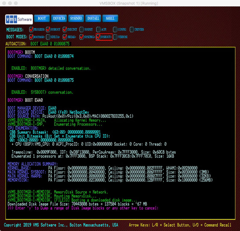
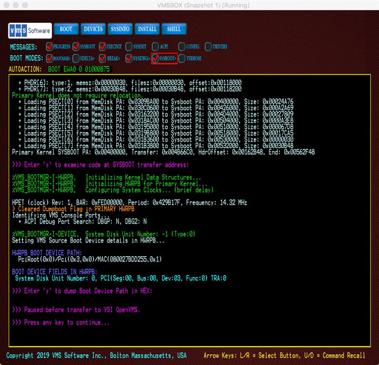
Before transferring control to SYSBOOT.EXE, the Boot Manager performs a variety of other tasks required to prepare the system for execution including allocation and initialization of boot-related data structures, such as the Hardware Restart Parameter Block (HWRPB), enumeration of devices and establishing the memory maps. It does this for both the primary kernel and the dump kernel.
If a Bugcheck occurs at any point after VSI OpenVMS is booted, the dump kernel is already resident in system memory (this includes the MemoryDisk and a separate copy of SYSBOOT.EXE). The crashing primary kernel passes control to the dump kernel, which will rapidly boot, perform its tasks, and reset the system. This independent dump kernel provides for faster crash dump and shutdown processing using runtime device drivers.
The operating system procedures that build and maintain the MemoryDisk must also maintain the inner boot blocks of the MemoryDisk and the outer boot blocks of the system disk's UEFI partition. If system files that reside within the MemoryDisk are updated, by installation of a patch kit for example, the involved utilities will invoke a command procedure (SYS$MD.COM) to create a new MemoryDisk image so that any changes will be preserved for the next system boot. The system files that reside within the MemoryDisk are not files that a user or system manager would typically need to modify unless you need to add customer-developed execlets to be loaded during boot.
Chapter 3. The Boot Manager
The Boot Manager overview
Boot modes, messages, and flags
Command dictionary
3.1. VSI OpenVMS Boot Manager
The VSI OpenVMS x86-64 Boot Manager loads the VSI OpenVMS operating system as a guest operating system on a VM host.
The Boot Manager is a UEFI (console firmware) application located on the boot
device, installation media or network distribution site. The actual on-disk file is
fsx:\EFI\VMS\VMS_BOOTMGR.EFI.
Those familiar with booting VSI OpenVMS on Itanium systems will recognize a similar console application named VMS_LOADER.EFI. Although the Boot Manager application is also an OS loader, it specifically serves the x86-64 architecture and has a considerably different functionality. The Itanium VMS_LOADER offered very few features. Additional EFI utilities were required to help users identify devices and manage the boot environment. The VSI OpenVMS x86-64 Boot Manager has many built-in features, eliminating the need for additional utilities.
It is important to note that platform firmware often provides its own form of a built-in boot manager, usually presented as a series of simple menus that manage platform setup features and let users define various boot options. Do not confuse these platform-specific setup programs with the VSI OpenVMS Boot Manager. If you are familiar with the Linux environment, you can consider the VSI OpenVMS Boot Manager to be analagous to the GRUB boot loader utility, but specifically tailored to the needs of VSI OpenVMS.
To boot VSI OpenVMS, the x86-64 system must be set up to launch the UEFI Shell
application. From the Shell> prompt, we (manually or automatically)
launch the VSI OpenVMS Boot Manager. Although the VSI OpenVMS Boot Manager can run
without the UEFI Shell, the Shell provides local UEFI file services. Without these
services, certain functions of the VSI OpenVMS Boot Manager will not be available.
Most notably, the enumeration of VSI OpenVMS device names (DKA100, etc.) is not
possible or precise, and the user may need to boot using UEFI file system device
names (fs1:, etc.).
3.2. Boot Manager Basics
This section describes the operation of the VSI OpenVMS Boot Manager. Most customers will seldom need more than the basic features of the Boot Manager. Normally functioning systems can be set up to automatically boot with no interaction with the Boot Manager at all. The more advanced features of the Boot Manager provide functions required to initially establish the desired boot environment, set it up for automatic booting and diagnose boot problems.
3.2.1. Automatic Launching
There are several ways to set up a system to automatically launch the VSI OpenVMS Boot Manager. Because the VMS Boot Manager is a standalone UEFI application, it can be launched from one disk and boot another. This can lead to confusion when several bootable disks are present, so the user needs to be careful about how this is set up.
Most UEFI implementations maintain a path-like list of all file system devices. UEFI can use this path to search for specific files among multiple disks. Such searches begin with fs0: and continue incrementally for the remaining fsx: devices.
Using a startup file
If a file STARTUP.NSH is found on any disk that is contained in UEFI’s path, it will be executed by the UEFI Shell, after a brief countdown. The STARTUP.NSH file is a simple, optional text file containing UEFI Shell commands. You can create this file using the
Shell>edit command or other method of placing the file in anfsx:\EFIfolder.The file should contain one Shell command per line. In its simplest form, a single line containing VMS_BOOTMGR will launch the VSI OpenVMS Boot Manager, but because no specific fsx: device was specified, UEFI will search its path for the first instance of VMS_BOOTMGR.EFI it finds.
Best practice is to always specify the root device, folder, and file on individual lines. For example:fs2: CD EFI\VMS VMS_BOOTMGR
By specifying the fsx: device first, you have identified the root device that UEFI will use. This is important because it helps to locate other files such as environment variable files.
Any combination of Shell commands can be placed in STARTUP.NSH. It is often used to configure low-level network and adapter details.
Typically, STARTUP.NSH is found in the
fsx:\EFIfolder. If multiple disks contain STARTUP.NSH files, UEFI will execute the first one it finds. This may or may not be what the user wants. You can place this file on fs0: (making it the first one found) or you can adjust the Boot Options and Boot Order in your platform firmware to point to the desired disk. Some systems allow STARTUP.NSH to be located on a network.Setting up Boot Options and Boot Order in the platform firmware
This is performed to point to the disk that you wish to automatically boot. Entering the Platform Boot Manager screens typically involves pressing a function key during system power-up or exiting from the
Shell>prompt. Your Boot Options are a list of bootable devices that can be edited. The Boot Order specifies the order in which the Boot Options are processed.Typical platform firmware implementations may provide some pre-defined Boot Options, one of which might be the “Internal UEFI Shell”. Often the Shell option says it is unsupported, meaning that it is not actually a boot device. You can still use this option if you want the UEFI Shell to be launched by default.
You can add new Boot Options and adjust the Boot Order as needed to place your desired default device at the top of the list. When adding a new Boot Option, if you specify only a boot device, UEFI will expect to find the default boot file at
fsx:\EFI\BOOT\BOOTX64.EFI. It is better to specify the full folder and file —fsx:\EFI\VMS\VMS_BOOTMGR— to avoid ambiguity. Failing to be precise means that if the default boot file is not found, the next Boot Option will be tried, which is likely to be a different disk.Precise Boot Options can be entered using the
Boot
                                    from a
                                file
function or careful construction of a new Boot Option entry. Unfortunately, the syntax and functions vary among platforms.Regardless of which method is used to select a disk and launch the VSI OpenVMS Boot Manager, you can complete the automatic boot by setting up the VSI OpenVMS Boot Manager’s auto-action feature. This is done using the following command and then booting the desired device.:BOOTMGR> AUTO BOOT
The next time the VSI OpenVMS Boot Manager is launched, it will perform a brief countdown, then automatically boot.You can adjust the boot countdown using the command:BOOTMGR> AUTO nwherenis a number of seconds from 1 to 30. Note that if you find yourself in a situation where you cannot prevent auto-boot, issue the command:BOOTMGR> EXIT
After that, proceed immediately to press the ESC key repeatedly to invoke the setup screen of the platform firmware.
3.2.2. Display and Input
Depending on the capabilities of the current system, the Boot Manager will operate in one of the four distinct modes..
The Boot Manager evaluates and selects the most capable mode in the following order:
GRAPHICAL_IO Mode
The system provides full graphical display features; it supports mouse, touchpad, or touchscreen input.. In this mode, the Boot Manager supports push buttons, check buttons, and a graphical background image.
GRAPHICAL Mode
The system provides full graphical display features but does not support mouse, touchpad, or touchscreen input. In this mode, the Boot Manager supports push buttons, check buttons and a graphical background image, but the keyboard arrow keys must be used to interact with these graphical controls.
RENDERED_TEXT Mode
The system supports simple graphical display features such as full screen colored text but without graphical controls or a background image. Input is limited to keyboard only. On systems that normally support the graphical modes, rendered text mode can be intentionally selected by deleting or renaming the background image file (
fsx:\EFI\VMS\VMS_IMG.BMP).SERIAL_TEXT Mode
The system does not support graphical display features. Input and output will be routed to a physical or virtual serial communications port.
When using the VSI OpenVMS Boot Manager, you can usually connect a remote terminal session to use in parallel with the graphical display. You will need a remote connection anyway for OPA0 interaction when the system boots.
The remote serial connection always uses the architectural COM 1 port (port
address 0x3F8). Currently, only COM 1 is supported. Remote terminal utilities
include the popular PuTTY program or similar terminal utilities. You can also
set up a console connection via network (tcp port 2023 etc.) or named_pipes
(i.e., \\.\pipe\<name> typically limited to
a common host system unless a proxy server is used).
Unfortunately, the number and variety of utilities and remote access methods, along with the unique behaviors of the various VM hosts, make console port setup exceedingly difficult to describe. You may need to do some reading and experimenting to arrive at what works best for you.
Some platform firmware and VM hosts do not support remote connections to the UEFI Shell. Others may support output-only (no keyboard input) until VSI OpenVMS is booted. In all cases, the VSI OpenVMS Boot Manager will suspend keyboard input after a BOOT command has been issued. This is because the UEFI keyboard drivers terminate once the boot has begun, and keyboard input will not resume until the VSI OpenVMS runtime drivers take over (just in time to support a conversational boot dialog).
Output can be routed to one or more serial ports even when operating in one of the graphical modes. This can be useful for logging console output to a terminal emulator. The Boot Manager itself, does not provide logging, although it has a screen capture feature.
When booted, VSI OpenVMS always assumes the use of COM 1 for OPA0 interaction, except in specific instances where hardware does not support legacy COM ports.
3.2.3. Custom Background Image
On systems that provide a graphical display, the Boot Manager will attempt to load an optional background image file that may be customized by the user. A default background image has been provided by VSI.
The background image file must adhere to certain guidelines pertaining to format, dimensions, color depth, location and name.
The file location and name must be
fsx:\EFI\VMS\VMS_IMG.BMP. If this file is
found and it meets the specified guidelines, it will be used by the Boot
Manager.
The background bitmap image must be non-compressed, BMP format with 24-bit color depth. Image dimensions must be a minimum of 1024 x 768 pixels and ideally, 1920 x 1080 pixels to support most common HD resolution monitors. If the image is smaller than the current display, it will be tiled as needed to fill the display. If the image is larger than the current display, it will be cropped. Image scaling and rotation are not supported.
A region in the upper left corner of the image, measuring 900 x 144 pixels, is reserved for overlaying the various buttons and the VSI Logo. The user cannot alter the placement or color of the graphical controls, so any custom image should provide adequate contrast in this region to assure that the controls remain visible. Selected controls are highlighted in red, so this too should be considered when selecting a custom image (avoid red). A VSI Copyright statement will be overlayed along the lower edge of the image. The text output area will be overlayed on top of the provided image.
If no suitable background image is found, the Boot Manager will fall back to the rendered text mode. In this mode the full display dimensions will be used for output. If this full size display mode is desirable, the user may rename or delete the bitmap image file. This effectively prevents the Boot Manager from entering graphical modes.
Note
For security reasons, the graphical subsystem's frame buffer memory is cleared prior to transferring control to the operating system.
3.2.4. Display within a Window
Some remote server management utilities and VM hosts will run the Boot Manager within a child window that is smaller than the physical monitor. Without having specific interfaces to these various utilities, the Boot Manager is unaware of the size of its containing window and will attempt to size its display according to the physical monitor size. This results in the need to scroll the window to see the complete Boot Manager display.
To improve usability when confined to a child window, do the following:
If you are using VirtualBox, the host provides a top menu item (when running) to scale the guest display. Unfortunately, not all hosts provide this feature.
- Alternatively, to display line numbers along the left side of the text output region, issue the following command:
BOOTMGR> LINES
Determine how many lines are visible without having to scroll.
- Issue the command again with the desired number of lines. For example:
BOOTMGR> LINES 34
This will cause the Boot Manager to recalculate its display height to fit the window. This can also be handy if you would like to shrink the Boot Manager to save screen space. Changes to the display size are preserved in response to a BOOT, EXIT or SAVE command. If you wish to restore the full display size, issue the LINES command specifying an excessively large number of lines and the Boot Manager will determine the maximum number of lines it can use with the current monitor.
Note that the Boot Manager does not currently support display width adjustment.
3.2.5. Page Mode and Scrolling
The Boot Manager supports a limited form of text scrolling. The PAGE UP/PAGE DN keys will redisplay prior pages of text output. The number of pages that can be recalled depends on the density of text on each page, but in typical use, six or more pages can usually be recalled, which is sufficient for most users. Page numbers at the bottom left corner will indicate which page is currently displayed.
Commands that produce more than a single page of output will automatically
pause as each full page has been displayed and the user may enter Q
to quit the current command output.
Although the Boot Manager is able to automatically control multiple-page output, the PAGE command can be issued to enter "Page Mode." This will cause the display to pause at the end of each page and wait for the user to press a key to continue. The display will be cleared as each subsequent page is displayed. Page Mode greatly improves the display performance when using remote server management utilities, particularly when the display is being sent to a Web Browser interface. You can disable Page Mode using the NOPAGE command.
3.2.6. Routing and Logging Boot Manager Output
Occasionally it is useful to capture boot process output for presentation or problem reporting. End-to-end logging of the boot process can be difficult to accomplish due to the many transitions that occur during the boot process. For example, the graphical or text mode Boot Manager runs within UEFI Boot context. It transitions into UEFI Runtime context as it transfers control to VSI OpenVMS.
In UEFI Runtime context and beyond, the Boot Manager has no access to UEFI file protocols, thus precluding UEFI file based logging. When VSI OpenVMS is able to initialize its Operator Terminal Driver it can commence logging to an VSI OpenVMS file. Seamless logging of output across these complex transitions is best accomplished by routing Boot Manager and Operator output to a terminal session where logging of session output is possible.
When booting VSI OpenVMS as a VM guest, the VM host will often provide a means of logging a session. You may also define a serial port for your Virtual Machine that can be directed to a TCPIP port and address. In this case, you can route the output to a terminal emulator to provide both scrolling and logging capability.
The Boot Manager COM x command, where 'x' is the x86
architecturally defined COM Port number (1 through 4), will cause Boot Manager
output to be echoed to the specified serial port. COM 0 disables
this function. You may route output to multiple ports by issuing additional COM
x commands.
COM 1 (0x3F8) will become the default port for OPA0 terminal
communications once VSI OpenVMS has booted, even if Boot Manager output was
disabled via COM 0 command.
Your selected COM port routing is preserved when you issue a BOOT, EXIT, or SAVE command.
3.2.7. Capturing and Projecting Graphical Display Output
BOOTMGR> prompt or at any PAGE break prompt, will
cause the Boot Manager to capture the current screen to a UEFI file.Note
Currently, only a single snapshot file is supported. Subsequent
captures will overwrite the prior capture unless you copy or rename the
previous file, which is saved as fsx:
snapshot.bmp. Be careful to avoid filling up the UEFI
partition with these large bitmap files.
Occasionally it is useful to project the display to a larger screen for demonstration or training purposes. This can be problematic due to the number of display resolution changes that occur between power-up BIOS, UEFI, Boot Manager and VSI OpenVMS. Experience has shown that most modern projectors will synchronize to the resolution used by UEFI. This is fine for projecting the initial power-up sequence. Once you launch the Boot Manager, the resolution will almost certainly increase and some projectors are not able to recognize the change. To accommodate this, we recommend that you avoid enabling output to your projector until you have launched the Boot Manager. This allows the projector to synchronize to the active resolution used by the Boot Manager.
3.2.8. Input Devices
Note
Many VM hosts fail to provide mouse movement notifications while executing in UEFI and Boot Manager context. Keyboard input, initially using UEFI protocols, will be disabled during transition between UEFI and the operating system. Once the operating system is running, it will establish terminal devices as needed. Because VSI OpenVMS V9.2-1 does not yet provide USB Keyboard drivers, your locally attached keyboard may not be usable once booted. Instead, user input is expected to occur through a terminal utility.
User input on x86-64 systems is typically provided by a locally attached keyboard. This may be a standard keyboard, a USB keyboard, a local or remote serial terminal or terminal emulator. Some systems require that the console keyboard be plugged into a specific port in order to recognize it as a boot keyboard. This is particularly true for USB keyboards on systems with firmware that doesn't yet support USB 3.x speeds. Refer to your specific system documentation.
Many x86-64 systems, particularly in the mid-range and low-end space, do not provide traditional (RS232/454) serial ports. Hardware design requirements, driven by certain retail/entertainment operating systems, forbid the use of these serial ports due to incompatibilities with plug-and-play strategies. The fear is that devices can be connected and configured, then removed or exchanged with other devices without notification to the operating system. For this reason, traditional serial ports have been replaced by USB ports as the de-facto standard for console input devices.
USB input devices have their own set of issues. USB operation requires an active System Timer interrupt and more system resources to be available than required by a simple RS232 serial port. Developers that need to work in the early boot stages should use traditional serial port input in order to avoid temporary loss of console input during boot.
As the system boots, the various input devices must transition to a runtime driver environment. During this transition, there may be a brief period of time (typically a second or two) when these devices become unavailable. For developers using the XDelta debugger, this problem is avoided by using a traditional serial port keyboard or special serial debug port device instead of the USB keyboard.
The Boot Manager and system firmware support a minimum subset of keyboard functionality as required to boot the system. Special function keys and languages other than English are not currently supported by the Boot Manager. Systems that provide a mouse, touch-pad or touch-screen input device should function as expected, but special features of these devices, such as gesture recognition or specialized buttons, are not supported in the boot environment. Some VM hosts, such as VirtualBox, do not report mouse movement at all in the UEFI environment.
The keyboard UP and DOWN Arrows operate a command recall buffer. The RIGHT and LEFT Arrow keys move input focus to the next or previous button in a circular chain of buttons. Whenever the Arrow keys highlight a button, the ESCAPE or ENTER keys will activate the highlighted button. If the user presses any key other than the Arrow keys, input focus is returned to the Boot Manager command line. The PgUp and PgDn keys redisplay pages. Pay attention to the page numbers in the lower left corner of the display. The number of pages that can be redisplayed depends on the density of text in each page, but typically up to six pages of output can be redisplayed.
3.2.9. Environment Variables
VSI OpenVMS has traditionally been dependent on UEFI Environment Variables to control certain aspects of the boot procedures. For x86 VSI OpenVMS, more emphasis is being given to running as a VM guest operating system. We have noted an inconsistency among the behavior of some VM hosts with regards to how they handle UEFI Environment Variables.
While most VM host applications support interfaces for managing Environment Variables, some fail to provide persistence of these values across power cycles. Worse yet, some VM hosts fail to provide the fundamental interfaces and also fail to report errors when these standard UEFI features are not available.
In order to address this problem, the Boot Manager maintains an internal
structure containing the required variables and attempts to store or retrieve
these variables from both Environment Variable (if present) and a UEFI binary
file, fsx:\EFI\VMS\VMS_ENV.DAT
Using a binary file to store environment variables works with the VM hosts that preserve such files across power cycles, although there remain some persistence issues. The VMS_ENV.DAT file should not be edited. Nothing in the file is critical and the file is deleted if it fails various validity checks.
3.3. Boot Modes, Boot Messages, and Boot Flags
There are many optional controls that affect the VSI OpenVMS boot procedures. Control of Boot Modes and Boot Messages can be accomplished using Boot Flags. However, most commonly used features also have Boot Manager commands or buttons that are easier to use than flags. This section describes these modes, messages and flags, and how they affect the boot procedures.
3.3.1. Boot Modes
- AUTO-ACTION
Most users will chose to set up their systems to boot with little or no interaction. Systems set up to auto-boot are assured the fastest recovery following a change in power state or fatal system event. The Boot Manager command [NO]AUTO enables or disables a brief countdown before executing the previous default boot command. Refer to Section 3.5 for further details.
- BOOTMGR INTERACTION
The Boot Manager can operate in an interactive mode that is designed to help diagnose boot problems. The Boot Manager command [NO]BOOTMGR enables or disables the interactive features that provide insight into the earliest UEFI phase of boot.
- XDELTA
Developers can use the XDelta instruction level debugger in one of two ways. To debug the early boot process, XDelta is linked into SYSBOOT. To debug later phases of operation, XDelta will be loaded by SYSBOOT as a loadable (execlet) image. The Boot Manager command [NO]XDELTA enables the XDelta debugger that is linked into SYSBOOT. This is most useful to developers working in the early phase of boot where the system is still using physical addressing.
- BREAK
When used along with the XDELTA or SYSDBG modes, the instruction level debugger will respond to the first breakpoint it encounters, typically a call to
ini$brk()in a code module.- SYSDBG
The Boot Manager command [NO]SYSDBG enables the loadable XDelta execlet debugger. This is most useful to developers working in later phases of boot where the system is using virtual addressing. It is also useful to device driver developers and for other system components.
- SYSBOOT INTERACTION
The Boot Manager command [NO]CONVERSATION enables or disables a pause in the boot process at the
SYSBOOT>prompt. This is also known as a Conversational Boot. A plethora of options are available at this prompt. Consult the appropriate documentation for greater details.- VERBOSE
This mode works in conjunction with the various message-related boot flags. When in VERBOSE mode, VSI OpenVMS System components may produce extended diagnostic information of interest to developers. This extended information is subject to change and does not follow any message formatting rules. Used with certain other flags, the amount of diagnostic data is substantial and may delay booting by many minutes. It is meant to be used by VSI Engineers and VSI Support personnel.
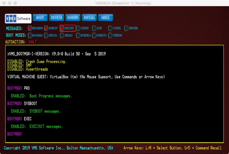
3.3.2. Boot Messages
Developers and Support Personnel may benefit from detailed messages during boot procedures. The source and verbosity of these messages are controlled by Boot Flags. However, most commonly used message controls have Boot Manager commands or buttons that are easier to use than hexadecimal flag values.
In an effort to manage the number of messages that VSI OpenVMS can produce during boot, VSI OpenVMS on x86-64 has defined a subset of Boot Flags to control messages from specific phases of the boot procedures. The Boot Manager provides commands and buttons to control each of these phase-specific messaging features.
The boot phases having their own boot message flags include: BOOTMGR, SYSBOOT, EXECINIT, SYSINIT, ACPI, HWCONFIG and DRIVER. Both graphical mode check buttons and commands are provided for each of these flags.
In addition to each phase-specific message flag, the command or button [NO]VERBOSE controls the extent of message detail.
%FACILITY-Severity-Mnemonic, Message String. For
example:%SYSBOOT-I-PARAM, Loaded Parameter FileThese messages are intended to provide basic progress indication and highlight interesting operations.
If the VERBOSE mode flag is SET, extended debug information will be provided. These messages are not held to format requirements and will take whatever form the developers felt would be useful for detailed troubleshooting.
3.3.3. Boot Flags
Boot Flags are a 32-bit mask of numeric constants that enable or disable specific boot related features. These features include Boot Modes, Boot Messages and a variety of less common features.
The definition of boot flags has changed for VSI OpenVMS x86-64. Many of the earlier flags no longer applied to the x86-64 architecture or served functions that were unrelated to booting.
For VSI OpenVMS on x86-64, we have reorganized the flags into three categories:
Message Controls
Boot Mode Controls
Debug and Diagnostic Controls
The Boot Manager presents graphical check-buttons for the most commonly used flags and commands to set and clear individual flags by name. Note however, that most VM hosts do not support mouse movement under UEFI, so if you wish to use the graphical buttons, you will need to press the arrow keys to select a button, then press ENTER to toggle the state of the button. As an alternative, you can use commands to control the flag states.
Each Boot Flag has a corresponding command to set or clear the flag. All such Boot Manager commands can be prefixed with NO to clear the flag. For example: PROGRESS sets the Progress Message flag and NOPROGRESS clears the flag. Most commands can be abbreviated to a minimum number of unique characters.
A FLAGS command is also available for managing the full set of available
flags. Entering the FLAGS command without an additional value will display and
interpret the current Boot Flag settings. In graphical modes, a chart of flag
bits will also be displayed. To set or clear Boot Flags the desired HEXIDECIMAL
value can be provided following the FLAGS command. For example, FLAGS
1070 would set Boot Flag bits 4, 5, 6 and 12, enabling general boot
PROGRESS messages and additional messages from SYSBOOT, EXEC_INIT and ACPI
facilities.
When setting new flag values, be aware that the value you enter will supersede flags that had been set previously. For this reason, you may want to use the FLAGS command first to see the current value, then adjust the value to enable or disable the flag bit/s you are interested in.
The Boot Manager saves your Boot Flags value in response to a BOOT, EXIT, or SAVE command. Flag values that were set during a BOOT command will also be preserved as the default boot command string to be used on subsequent boots.
3.4. Command Usage
The Boot Manager provides a set of commands that serve the needs of developers and system managers. The subset of these commands that support developers is subject to change and some of the commands will be disabled in production releases. This version of the Users Guide describes all of the commands that are active at the time of writing. Each command description will indicate its intended audience.
3.4.1. Command Syntax
Boot Manager commands use a very simple syntax.
A command verb is followed by an optional parameter separated by a space.
Command verbs can be abbreviated to the smallest number of characters required to assure uniqueness. Certain commands having significant effect must be entered in full as a means of verifying user intent.
Commands that set a flag or enable a feature, are typically cleared by prefixing the verb NO in front of the original command. For example, the PROGRESS command enables a flag to produce boot progress messages. The NOPROGRESS command clears the flag. In other words, the Boot Manager does not use SET, CLEAR, ENABLE, or DISABLE command precursors.
3.4.2. Command Recall and Logging
The Boot Manager provides a limited command recall buffer that can be accessed with the UP or DOWN arrow keys. The Boot Manager supports a limited form of scrolled output using the PG_UP and PG_DN keyboard keys.
It is unusual for the early boot process to produce large amounts of text prior to transfer to VSI OpenVMS, at which point the Operator terminal and logging are available. In cases where Boot Manager commands produce more lines of output than will fit on a single screen, the Boot Manager may pause the output as text exceeds each visible display page.
In cases where a permanent log of Boot Manager output is desired, output can be directed to a COM Port and Terminal Emulator. These features are described in their respective command descriptions.
3.4.3. Command Push Buttons
When operating in Graphical mode, common commands are represented by rows of push buttons. If a pointing device (mouse or touch-pad) is active, the push buttons can be activated as you would expect for a graphical application.
If no pointing device is active, the push buttons can be selected using the right arrow or left arrow keys. The selected button will be outlined in red. To activate the selected button, press ENTER or ESC keys. If you press any other keys, input focus will return to the command line.
3.5. Command Dictionary
This section describes the commands that are available from the
BOOTMGR> prompt.
The command descriptions show the full length command verbs. Most commands can be abbreviated to the shortest number of characters that would uniquely identify them. In certain instances, commands that result in particularly significant operations may not support an abbreviated form.
AUTOACTION
AUTOACTION — Determines what automatic action occurs when the Boot Manager is launched.
Syntax
AUTOACTION [arg]
Arguments
- HALT
Remain at the
BOOTMGR>command prompt- BOOT
Countdown before issuing the previous boot command.
- seconds
Sets a countdown delay between 1 and 30 seconds.
If the boot countdown is interrupted by pressing the ESC key, the
countdown stops and the BOOTMGR> prompt is displayed. Pressing
any other key during the countdown skips the remaining countdown and
proceeds to boot.
BOOT
BOOT — Initiates a system boot. Several optional arguments are available.
Syntax
BOOT [device] [root] [flags] Before you begin
If you have previously booted the system, a BOOT command with no additional arguments will attempt to boot the system using the prior boot command string, including device, root, and flags.
If you have not previously booted the system, a BOOT command with no additional arguments will attempt to boot the system from the device where the Boot Manager resides. In most cases, this will be your default system disk.
Optional Arguments
- BOOT [device]
- The first optional argument is an VSI OpenVMS Device name that you wish to boot from. Unlike prior versions of VSI OpenVMS, the Boot Manager can be run from one device and boot a different device. You no longer need to figure out which UEFI file system device (fsx:) equates to your boot device. The Boot Manager will do this for you. For example:
BOOTMGR> BOOT DKA100:
Note
Mapping of VSI OpenVMS to UEFI file system devices requires support of the UEFI Shell protocol. In some rare cases, this protocol is not available in platform firmware. In this case, you can use the UEFI file system device name (fs0:, etc.) in the BOOT command.
You must choose one of the bootable devices listed by the DEVICE command. The listed devices are those which have passed a series of tests to determine that they contain bootable VSI OpenVMS images. Specifying the trailing colon is optional. Note that the scope of devices that the Boot Manager sees during initialization is limited to those for which UEFI drivers are available. Complex storage systems do not always expose their devices to UEFI for booting. Most often, the listed devices will include the system boot device. Once VSI OpenVMS has booted, it gains additional capability for detecting devices and in some rare cases, the VSI OpenVMS device names may differ from the name that was used during boot.
- BOOT [device] [root]
- The second optional argument is a System Root to boot from. You can set the default System Root using the ROOT command, or you can specify it as the second argument in a fully qualified boot command. For example:
BOOTMGR> BOOT DKA0 0 10
This command boots DKA0 using Root 0 with boot flag (hex) 10; it sets bit 4, which is the PROGRESS message flag. - BOOT [device] [root] [flags]
The third optional argument is a hexadecimal value representing Boot Flags. Refer to the description of FLAGS and MESSAGE CHECK-BUTTONS for more details. Boot flags may also be passed into the Boot Manager when it is launched from the UEFI Shell prompt. If you specify flags at the UEFI Shell prompt, prefix the flags with
-flas you would on earlier versions of VSI OpenVMS. For example:Shell> vms_bootmgr DKA0 –fl 0,807
The above command boots device DKA0 using system root 0 and boot flags 0x807
You do not need the -fl prefix or comma when entering a BOOT command at the
BOOTMGR>prompt. The equivalent command line would beBOOTMGR> BOOT DKA0 0 807
Note
The VSI OpenVMS x86-64 Boot Flag definitions are different from prior versions of VSI OpenVMS. Refer to the FLAGS and MESSAGE CHECK-BUTTONS command description for details.
BOOT OPTIONS LIST
As an alternative to entering boot command arguments, you can also boot from a pre-defined list of boot options. These are not the same as UEFI Boot Option variables. UEFI Boot Option variables get you to the Boot Manager, not to an VSI OpenVMS boot device.
To use a predefined list of boot commands, you must first create the list
in the same folder where the VMS Boot Manager is launched from, typically
fsx:\EFI\VMS. The list is a simple text file that can be
created by the UEFI editor or copied to the system using FTP or other
mechanism to get the file into the EFI partition.
Refer to the OPTIONS command for details on creating the Options List.
If the Boot Manager finds the options list, the OPTIONS command with no arguments will enumerate and display the list.
To select a listed option, enter BOOT # followed by the
option number in the boot options list.
This feature is intended to simplify the task of booting many system configurations for test purposes, but it may be useful for other reasons too.
- AUTOACTION BOOT | HALT | seconds
If you have previously set AUTOACTION to BOOT, the Boot Manager will provide a countdown prior to launching the default boot command (prior successful boot command). Pressing the Escape key during this countdown period will abort the countdown and present the
BOOTMGR>command prompt. Pressing any other key during this countdown, skips the remaining count and commences with booting.Refer to the AUTOACTION command description for more details.
CLS and CLEAR
CLS and CLEAR — Each of these commands clears the current Graphical or Rendered-Text mode display.
Syntax
CLS
CLEAR
COMPORT
COMPORT — The COMPORT command used with no argument will display the currently active serial COM Port Numbers (0 through 4).
Syntax
COMPORT [arg]
Specifying COM 0 will disable all serial port output.
Specifying a value of 1 through 4 will enable COM 1 through COM 4 output
respectively. More than a single port can be enabled. These are the x86-64
architecturally defined serial ports.
If the Boot Manager detects a terminal connection, it will assign it to COM 1 (port address 0x3F8). Specifying a COM port causes the Boot Manager output to be directed to that serial port. If no COM command is issued, VSI OpenVMS will still support terminal connections. Only the Boot Manager output will be excluded from the serial port device.
CONVERSE
CONVERSE or CONVERSATION — Enables a pause in the boot process at the SYSBOOT>
prompt. This is also known as a Conversational Boot. A
plethora of options are available at this prompt. Consult the appropriate
documentation for greater details. NOCONVERSE disables conversational boot.
The [NO]SYSPROMPT command is a synonym for this command
function.
Syntax
CONVERSE
NOCONVERSE
DEMO
DEMO — Takes on various functions as needed. Typically this is used to demonstrate some feature of the Boot Manager for other developers to evaluate.
Syntax
DEMO
DEVCHECK (diagnostic feature)
DEVCHECK — executes a PCI/e Bus Scan and enables extended diagnostics regarding device discovery and assignment of VSI OpenVMS device names. This is a one-shot command which does not require a NODEVCHECK command.
Syntax
DEVCHECK
DEVELOPER (development feature)
DEVELOPER — The command is reserved for Boot Manager development use. Its function is subject to change.
Syntax
DEVELOPER
DEVICE
DEVICE — Presents a list of qualified VSI OpenVMS boot devices. The bootable devices are enumerated with VSI OpenVMS device names. The listed devices are those which have passed a series of tests to determine that they contain bootable VSI OpenVMS images.
Syntax
DEVICE [ BOOT | FS | NET | USB | PCI | CTRL | SER | APIC | CPU |
                            LIST]
List of tests
Does the device contain a GPT (GUIDed Partition Table)?
Does the device contain a properly configured set of three VSI OpenVMS partitions?
Is there a UEFI partition among this set?
Does the UEFI partition contain VMS_BOOTMGR.EFI?
Do the partitions satisfy security checks?
Note
The scope of devices that the Boot Manager sees during initialization is limited to those for which UEFI drivers are available. Complex storage systems do not always expose their devices to UEFI for booting. Most often, the listed devices will include the system boot device. Note however, that as VSI OpenVMS boots, it gains additional capability for detecting and enumerating devices and in some rare cases the VSI OpenVMS device names may differ from the name that was used during boot.
An optional argument can be provided to the DEVICE command to filter the type of devices shown.
Note
The DEVICE CPU option executes a Hardware Compatibility Test to verify that the system has the necessary features to run VSI OpenVMS. It then continues to decode the CPU ID instruction to list the full feature set of the processor chip.
Arguments
- BOOT [Default]
Shows bootable VSI OpenVMS devices which have VSI OpenVMS Device Names assigned.
- FS
Shows file system devices which have fsx: names, whether bootable or not.
- NET
Shows network devices. Those that support UNDI Protocol are considered bootable.
- USB
Shows USB devices. See also the USB command.
- PCI
Shows PCI devices. See also the PCI command.
The DEVICE PCI command displays the result of PCI and PCIe Bus Scans. Details of each device discovered is displayed. Where possible, vendor and device ID are decoded and a one-line description is displayed.
The vendor and device ID’s are used for searching an internal database of known vendors and devices. If a match is found, the database information is displayed. If the vendor or device is unrecognized, the Boot Manager will list it as a Curious Device and any embedded identification strings in the device’s configuration structures will be displayed.
Note
Identification or failure to identify any given device does not imply that an VSI OpenVMS device driver exists for the device or that the device is unsupported.
The Boot Manager’s database can be updated periodically to pick up the most recent definitions from a PCI Device Registration website. This is a semi-automated procedure that requires engineering support. Therefore, it is expected to be updated just prior to each shipping version of VSI OpenVMS.
Similar behavior applies to the DEVICE USB command.
- CTRL
Shows controller devices.
- SER
Shows serial port devices.
- APIC
Shows Advanced Programmable Interrupt Controllers.
- CPU
Decodes the CPU ID instruction and runs the Hardware Compatibility Test.
- LIST
Shows greater details of all configured devices.
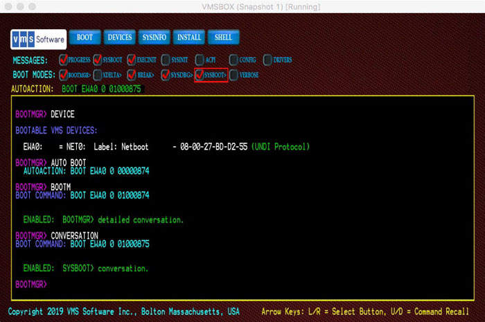
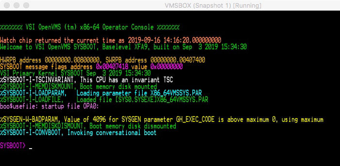
DUMPFLAGS
DUMPFLAGS — Similar to Boot Flags, this set of flags is passed to the dump kernel when it boots. This is to allow developers some further control over dump kernel boot behavior. Not all flags apply to dump kernel operation.
Syntax
DUMPFLAGS
ENV
ENV — Displays a list of currently defined VSI OpenVMS environment variables. If the optional argument is SAVE, the current set of values is saved to Non-volatile storage and will be restored the next time the Boot Manager is run. If the optional argument is DELETE, the environment variables will be deleted and their variables will take default values.
Syntax
ENV [SAVE | DELETE]
Environment variables which have changed are automatically saved whenever a BOOT, EXIT, or SHELL command is issued.
Important
UEFI Environment Variable storage is used whenever possible. However, some VMs fail to provide persistence of variables across power cycles. The Boot Manager attempts to store its set of environment variables in both the UEFI Non-Volatile storage and a file in the UEFI partition named: VMS_ENV.DAT. This file is in binary form with security features. If the user attempts to edit the file, it will be deleted by the Boot Manager and a new file will be created. Note too that this creates a requirement for the boot device to be writable. During installations, the environment variables will not be stored.
EXIT
EXIT — The EXIT command exits the Boot Manager and returns to the UEFI Shell prompt.
Syntax
EXIT
FLAGS and MESSAGE CHECK-BUTTONS
FLAGS — Displays the current set of Boot Flags. Boot Flags are manipulated through commands and, if in Graphical mode, buttons. The optional argument is a set of Boot Flags specified as hexadecimal value up to 32-bits wide.
Syntax
FLAGS [arg]
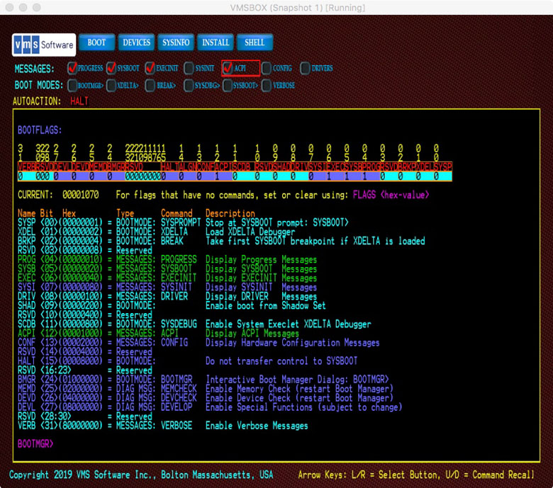
Boot Flags can also be specified on the UEFI command line when the Boot Manager is launched. For example:
Shell> vms_bootmgr DKA0 –fl 2,1The above command sets the SYSPROMT Boot Flag (bit<0>) and sets System Root to 2.
Note
x86-64 Boot Manager and VSI OpenVMS for x86-64 V9.2-1 use a different set of Boot Flags than prior versions of VSI OpenVMS. In order to have better control over messages, each major phase of the boot process has been assigned its own flag. All phases are also affected by the VERBOSE bit<31> flag which greatly extends the type of troubleshooting messages that are displayed during boot and runtime.
- Check Buttons
When operating in Graphical mode, common features are represented by rows of check buttons. If a pointing device (mouse or touch-pad) is active, the check buttons can be activated as you would expect for a graphical application.
If no pointing device is active, the check buttons can be selected using the right arrow or left arrow keys. The selected button will be outlined in red. To toggle the selected button, press ENTER or ESC keys. If you press any other keys, input focus will return to the command line.
Check buttons differ from push buttons because they visually represent two static states (set or clear). The state of the check buttons is preserved across boots. Each check button corresponds to a pair of commands to set and clear the represented state. These commands use the flag name as the command and the prefix “NO” to clear the flag. For example:
BOOTMGR> PROGRESS
The above command sets the PROGRESS check button and flag.
BOOTMGR> NOPROGRESS
This one clears the PROGRESS check button and flag.
Using text commands will toggle the visual state of the check buttons, and using a pointer to toggle the button state will alter the associated flag. The FLAGS command will display the current state of the various flags. Only the most commonly used flags have corresponding check buttons.
- Top row of check buttons
The top row of check buttons represents the common messaging flags using during VSI OpenVMS boot.
- PROGRESS
The PROGRESS flag, when set, causes the Boot Manager and VSI OpenVMS to display a number of progress messages during boot. These progress messages are carefully selected and formatted to provide a customer-facing indication of major boot phase transitions. The Boot Manager displays these messages in green.
The PROGRESS flag is Boot Flag bit<4> (Hex value 00000010).
- NOPROGRESS
Disables the PROGRESS flag and corresponding messages.
- SYSBOOT
The SYSBOOT flag, when set, causes the SYSBOOT component to display a number of detailed messages during boot. These messages are carefully selected and formatted to assist with troubleshooting problems during the early boot phase. The Boot Manager displays these messages in light blue. The SYSBOOT flag is Boot Flag bit<5> (Hex value 00000020).
SYSBOOT is the earliest boot phase where paging, memory management and system cells are initialized and early execlets are loaded from the Memory Disk.
- NOSYSBOOT
Disables the SYSBOOT flag and corresponding messages.
- EXECINIT
The EXECINIT flag, when set, causes the EXECINIT components to display a number of detailed messages during boot. These messages are carefully selected and formatted to assist with troubleshooting problems during the Executive Initialization boot phase. The Boot Manager displays these messages in light blue. The EXECINIT flag is Boot Flag bit<6> (Hex value 00000040).
EXECINIT is the boot phase where page tables are constructed, the remaining execlets are loaded from the system disk (no longer the Memory Disk), interrupts are enabled, subsystems are initialized, DCL becomes available, and symmetric multiprocessing (SMP) begins.
- NOEXECINIT
Disables the EXECINIT flag and corresponding messages.
- SYSINIT
The SYSINIT flag, when set, causes the SYSINIT process to display a number of detailed messages during boot. These messages are carefully selected and formatted to assist with troubleshooting problems during this phase. The Boot Manager displays these messages in light blue. The SYSINIT flag is Boot Flag bit<7> (Hex value 00000080).
The SYSINIT process is the final boot phase where system and user processes are initiated and the swapper runs.
- NOSYSINIT
Disables the SYSNIT flag and corresponding messages.
- ACPI
The ACPI flag, when set, causes the ACPI components to display a number of detailed messages during boot. These messages are carefully selected and formatted to assist with troubleshooting problems during this phase. The Boot Manager displays these messages in light blue. The ACPI flag is Boot Flag bit<12> (Hex value 00001000).
ACPI (Advanced Configuration and Power Interface) is the boot phase where system devices and their interrupt levels are initialized. Beware that the use of both ACPI and VERBOSE flags creates a huge amount of output.
- NOACPI
Disables the ACPI flag and corresponding messages.
- CONFIG
The CONFIG flag, when set, causes the IO Database components to display a number of detailed messages during boot. These messages are carefully selected and formatted to assist with troubleshooting problems during this phase. The Boot Manager displays these messages in light blue. The CONFIG flag is Boot Flag bit<13> (Hex value 00002000).
CONFIG is the boot phase where peripheral devices are enumerated and drivers are installed. Beware that the use of both CONFIG and VERBOSE flags creates a huge amount of output.
- NOCONFIG
Disables the CONFIG flag and corresponding messages.
- DRIVER
The DRIVER flag, when set, causes various device drivers to display a number of detailed messages during boot. These messages are carefully selected and formatted to assist with troubleshooting problems during this phase. The Boot Manager displays these messages in light blue. The DRIVER flag is Boot Flag bit<8> (Hex value 00000100).
The DRIVER flag invokes verbose output from all participating drivers; note that not all drivers support this flag.
- NODRIVER
Disables the DRIVER flag and corresponding messages.
GRAPHICS (development feature)
GRAPHICS — Enables diagnostics functions in the Graphical mode of operation. Details about the graphical framebuffer and display geometry are provided, then the current pointer coordinates and button-press events are displayed assuming their movement is reported by UEFI firmware. NOGRAPHICS disables the Graphical mode diagnostic messages.
Syntax
GRAPHICS
NOGRAPHICS
HALT
HALT — Causes the Boot Manager to halt just prior to transferring control to SYSBOOT. This allows the developer to work with Boot Manager behavior and to view various structures just prior to booting.
Syntax
HALT
HEADLESS
HEADLESS — Disables LINE and page numbering when operating a VM in Headless Mode. NOHEADLESS (Default) re-enables LINE and page numbering.
Syntax
HEADLESS
NOHEADLESS (Default)
HELP
HELP — Displays a list of commands and describes their functions.
Syntax
HELP ? INSTALL
INSTALL — The INSTALL command and its associated Push-Button is intended to initiate various installation and update procedures using the VMS_KITBOOT.EFI Utility. This feature is not yet officially supported.
Syntax
INSTALL
DUMP
DUMP — Enables the Dump Kernel to be loaded during boot. The Dump Kernel is a tiny kernel image that is invoked to write dump files in the event of a crash. It also participates in system shutdown operations. The Dump Kernel consumes only 256MB and should only be disabled in special situations. Disabling the loading of the Dump Kernel during boot ()
Syntax
DUMP
NODUMP (Disables the loading of the Dump Kernel during
boot. By disabling the Dump Kernel, system crash files will not be written
and shutdowns will require a manual system reset.)
KEYMAP
KEYMAP — provides the early developer with interpretation of Key Codes and Unicode characters as they are entered. The BOOTMGR boot flag must also be set to use this diagnostic function.
Syntax
KEYMAP
LINES
LINES — Displays line numbers along the left of the visible scroll region. NOLINES removes the display of line numbers.
Syntax
LINES [arg]
NOLINES
When running the Boot Manager from within another system’s window, such as when using a VM host window to launch VSI OpenVMS as a guest OS, the Boot Manager may not recognize the size of the parent window. In this case, several scroll region lines may fall beyond the visible window, requiring the user to scroll the parent window.
To solve this, the LINES command will display line numbers along the left of the visible scroll region. Simply look at the highest visible line number and use it as the optional argument for the same command. For example:
BOOTMGR> LINES 30The above command will resize the Boot Manager to display 30 lines. This is a persistent variable.
To return to the maximum number of lines, simply enter an overly-large number of lines and the Boot Manager will adjust to the maximum lines that can be displayed in the current monitor. For example:
BOOTMGR> LINES 100This will typically result in a line count of about 45 lines.
Note
The Boot Manager itself will only allow specifying the vertical size by number of lines. It does not support horizontal scaling. VirtualBox provides a menu item which allows the Boot Manager display to be freely scaled in its parent window in both horizontal and vertical dimensions. To make the display resizeable under VirtualBox, look in the very top VirtualBox menu bar and select: → . You can now scale the BootMgr dialog as needed by dragging the dialog from its frame corner
MDCHECK
MDCHECK — Executes MemoryDisk diagnostics. This is intended for development use, but support personnel may suggest this command when troubleshooting various disk structure issues.
Syntax
MDCHECK
MEMCHECK (diagnostic feature)
MEMCHECK — Enables extended diagnostics regarding memory allocation and assignment of memory to VSI OpenVMS during boot. Note that this command consumes additional memory and in some cases, may prevent successful boot. NOMEMCHECK disables the MEMCHECK diagnostics.
Syntax
MEMCHECK
NOMEMCHECK
MOUSESENSE
MOUSESENSE — Adjusts the sensitivity of mouse movement on systems which support mouse events in Graphical mode of operation. A value of 1 is the highest sensitivity and 16 is the lowest.
Syntax
MOUSESENSE
OPA0
OPA0 — Enables the continued display of OPA0 messages to the graphical monitor after the system is booted. Currently, the OpenVMS Boot Manager display is suspended once the system is booted. This is a result of losing use of UEFI keyboard boot services once the OS has taken control. Display output to the graphical monitor can continue, however character escape sequences and other graphics may not display correctly.
Syntax
OPA0
NOOPA0. Disabled OPA0 message display after the system
is booted. This is the normal default behavior.
OPTIONS
OPTIONS — As an alternative to entering boot command arguments, you can also boot from a pre-defined list of boot commands. These are not the same as UEFI Boot Option variables. UEFI Boot Option variables get you to the Boot Manager, not to an VSI OpenVMS boot device.
Syntax
OPTIONS [arg]
Usage
To use a predefined list of boot commands, you must first create the list. The list is a simple text file that can be created by the UEFI editor or copied to the system using FTP or other mechanism to get the file into the EFI partition.
The file must be named
VMS_OPT.TXT and must reside in the same folder as the OpenVMS Boot Manager
is launched from.
The file can contain any number of boot command lines (minus the keyword BOOT). Each command can be followed by a descriptive comment, prefixed by a semi-colon. For example:
DKA100: 0 1 ; Internal system disk, sysboot flag set, root 0
DKA100: 1 3 ; Internal system disk, xdelta and sysboot flags set, root 1
DGA0: ; Boot DGA0 with default flags and root
If the Boot Manager finds this file, the OPTIONS command will enumerate and display the list.
BOOTMGR> BOOT #3
The above command will boot DGA0, the third entry in the list.
This feature is intended to simplify the task of booting many system configurations for test purposes, but it may be useful for other reasons too.
PAGEMODE
PAGEMODE — Causes the Boot Manager to clear the screen after each page of output is displayed so as to avoid scrolling. NOPAGEMODE turns off the PAGEMODE display method and returns to normal line scrolling.
Syntax
PAGEMODE
NOPAGEMODE
When accessing the Boot Manager over certain networked interfaces, such as web-browser based management applications, text output may scroll slowly. Usage of this command in such cases can improve remote display performance.
As each page is displayed, the tag <PAGE> will occur at
the bottom of the scroll region. Press the ENTER key to display the next
page.
The Boot Manager will automatically use PAGE mode for command output that spans multiple screens, such as the HELP command.
RESET
RESET — Issues a system reset. This differs from an EXIT command in that the platform firmware will reinitialize the system and clear memory.
Syntax
RESET
ROOT
ROOT — Without any argument, displays the current default System Root being booted. The optional argument becomes the default System Root. This is a persistent variable.
Syntax
ROOT [arg]
SAVE
SAVE — Forces the save of current environment variable values.
Syntax
SAVE
SHELL
SHELL — The SHELL command exits the Boot Manager and returns to the UEFI Shell prompt.
Syntax
SHELL
SMBIOS
SMBIOS — Displays and interprets the various System Management BIOS tables. Interpretation is provided according to the official SMBIOS specification. Many vendor-specific tables exist. These are displayed in a raw data form.
Syntax
SMBIOS
SMP {num-APs} (development feature)
SMP — Enables multiple processor core enumeration. NOSMP limits the system to a single processor.
Syntax
SMP
NOSMP
SMP support is available and is enabled by default. To enable SMP, you must first select additional processors in your VM guest setup, then issue the SMP command in the Boot Manager prior to booting. Once you have issued the SMP command, it should remain enabled until you issue a NOSMP command. During boot, you should see a startup message from each secondary processor (also known as Auxiliary Processors or AP's).
Specifying a number after SMP will limit enumeration to that number of Application Processors (AP's). If no number is specified, the full set of AP's will be enumerated.
SYSINFO
SYSINFO — Displays the Boot Manager Build Number and Date and optionally, decodes the CPU ID fields, displays APICs, ACPI Tables and SMBIOS Tables.
Syntax
SYSINFO
THREADS (development feature)
THREADS — Enables processor hyper-thread enumeration. NOTHREADS disables thread enumeration. By default, threads are not enumerated. VSI OpenVMS does not by default use hyper-thread features due to certain architectural security issues, but in an environment where the security concerns are well understood, these additional Application Processors can be used.
Syntax
THREADS
NOTHREADS
TIME
TIME — The TIME command with no argument will display the current UEFI
Time. Specifying a number of seconds between 1 to 10 after the TIME command
will cause the Boot Manager to issue a delay of that many seconds to each of
the viable system clock candidates, displaying their respective counter
values. To set the UEFI time, use the time
hh:mm:ss command in Shell> prompt.
Syntax
TIME
Chapter 4. Pre-Installation, Installation, and Post-Installation
How to prepare the system before installation
Installation methods
Post-installation procedures
4.1. Installation Target Disk for Virtual Machines
On virtual machines, before performing an installation of VSI OpenVMS from a virtual or physical DVD or a web server, you will need to create an empty virtual disk to become your target system disk. VSI OpenVMS x86-64 V9.2-1 supports SATA, Fibre Channel (FC), and SCSI disks. Support for other disk types will be added in future releases of VSI OpenVMS x86-64. Your target system disk should be at least 4GB.
Virtual Disks are typically defined as a fixed-size (flat) or a variable size (sparse). Variable sized disks will dynamically expand as needed to accommodate files, with an optional size limit. This allows the device to occupy only the space required, but performance will suffer if the disk is frequently expanded. A fixed-size disk is slightly faster, but will immediately consume the maximum number of blocks that have been defined.
When you create a new disk, the VSI OpenVMS Boot Manager will see the disk as a Block IO device (blkx:) and it will not be given an VSI OpenVMS device name until after VSI OpenVMS installation. Only bootable devices are enumerated. However, once the Installation Kit is booted, the installation procedure will recognize the empty disk and list it as a potential Target disk for the installation.
4.2. Virtual DVD
Installing VSI OpenVMS from a Virtual DVD is the preferred method of installation. Refer to the VSI OpenVMS x86-64 V9.2-1 Installation Guide for details.
Whether or not your system has a physical DVD reader attached, you can use a DVD image file as though it were a physical DVD. VSI provides the Installation Kit as an ISO file, suitable for use as a virtual optical disc or for burning to physical DVD media.
One of the benefits of using ISO standard disc images is that the ISO format is recognized by the VM host and no further disk format conversion is required. Simply copy the file to your guest and attach it as an optical disc. Be sure to remove any semi-colon and version number when using host systems that do not recognized these file name elements. Also pay attention to case-sensitive host systems as you may need to use a lowercase file extension (.iso) for the file to be recognized.
4.3. Physical DVD
If your VM host has a physical DVD reader attached to your guest, you can use a DVD image file to burn a physical DVD for use in your reader. VSI has provided the Installation Kit as an ISO file, suitable for burning to physical DVD media.
Using a suitable DVD burner application, burn the file to a DVD. The file is already in ISO form and its structure is critical, so burn the file as-is without any further conversion. Many suitable burner applications exist; your desktop operating system might include one by default.
Even though VSI OpenVMS V9.2-1 has limited USB support, most VM hosts allow USB DVD readers to be defined as SATA drives on the guest storage setup. This is the recommended configuration.
Insert your new DVD in the reader that you intend to connect to your guest system. Some VM Hosts do not recognize a DVD reader until media is inserted.
Note
Most VM hosts will recognize and accept ISO-format DVDs, but in some cases the host OS (notably Windows hosts) will not recognize the DVD but will still allow it to be accessed by the guest. Some hosts also require the disc image file to have a lowercase .iso extension name.
HPE DL series systems may also have a physical DVD reader attached, but bear in mind that as of VSI OpenVMS V9.2-1, only SATA optical devices are supported. You should still be able to use the Virtual DVD method for installation.
4.4. Installing from a Web Server
VSI OpenVMS can be installed from a web server. This feature can be useful when you have many installations to do for systems (both VMs and bare-metal) which may not have DVD readers.
Note
Web server based installation is not the method VSI prefers, but it provides an attractive option for many customers who may already be familiar with the procedures.
4.4.1. Web Server Preparation
Your internal company web server can be used to serve installations. Because of the variety of available web servers, this document will focus on general setup steps only. It is assumed that the web server is accessible to your VM host and that your guest's network configuration is able to access this same network.
The first two files listed below can be found in the EFI partition of any
installed VSI OpenVMS V9.2-1 system disk at
fsx:\EFI\VMS\ or they can be copied from
an Installation Kit DVD.
Establish a
/netboot/directory on your web server.In binary mode, copy the following files from the VSI FTP server to your web server’s /netboot/ directory:
VMS_BOOTMGR.EFI - The Boot Manager
VMS_IMG.BMP - The Boot Manager background image (optional but nice to have)
{installation-kit}.ISO - The VSI OpenVMS Installation Kit
Note
If the host operating system does not recognize VSI OpenVMS file versions, you will need to rename the files to remove the semicolon and version numbers after copying them to your web server. Note also that some web servers are case-sensitive.
Once these files are posted to your web server, you must next prepare the target system/guest.
4.4.2. Virtual Machine Target System Preparation (VMS_KITBOOT)
Note
Web server based installation is not the VSI preferred installation method, but it provides an attractive option for many customers who may already be familiar with the procedures. The VMS_KITBOOT Utility is an optional feature. This utility is available for download from VSI or it can be copied from an installed system. The utility is loosely coupled to the Boot Manager's INSTALL button and command, primarily intended to support future update procedures. If such web server access is unwanted, instances of the file (VMS_KITBOOT.EFI) can be deleted from the EFI Partition of bootable VSI OpenVMS disks. If the file is deleted, the Boot Manager INSTALL button and command will simply be non-functional.
UEFI firmware provides HTTP/S protocols to support connection to web servers.
The legacy PXE (Pre-eXecution Environment) protocol is being phased out in favor
of more capable boot protocols. The most popular of these protocols is known as
iPXE. For more information about iPXE, refer to
http://www.ipxe.org
VSI provides a small UEFI-based web server boot utility based on iPXE
protocol; the utility is called VMS_KITBOOT.EFI. This file can be found in the
EFI partition of any installed VSI OpenVMS V9.2-1 system disk at
fsx:\EFI\VMS\ or it can be copied from
an Installation Kit DVD. VSI Support can also provide this image upon
request.
Note
VMS_KITBOOT requires that your target system/guest be located on a network segment which has a DHCP Server. If DHCP is not available, you cannot use this method. HPE DL systems can still use the WEBCLIENT method described earlier as it does not require DHCP.
VMS_KITBOOT.EFI automates most of the web server boot process. When launched from the UEFI Shell of your VM guest, the VMS_KITBOOT utility will identify your system hardware, configure a suitable network device, prompt for the IP address of your web server and handle the connection and download protocol for the Installation Kit. When VMS_KITBOOT has finished downloading the kit it will launch the VSI OpenVMS Boot Manager to boot the installation procedure.
Note
If these procedures, in addition to any firewall you might be using, present a security concern, you have the option of installing from a DVD image rather than a web server.
VMS_KITBOOT.EFI can be executed from any UEFI file system disk, for example fs0:. A simple way to do this is to copy the file onto a FAT-formatted USB stick assigned to your target system/guest. VM users can also use a pre-packaged Virtual Disk containing this file in common virtual disk formats.
- VMS_KITBOOT.VMDK
VirtualBox Virtual Disk containing the utility.
- VMS_KITBOOT.QCOW2
A KVM Virtual Disk containing the utility.
- VMS_KITBOOT.EFI
The utility by itself. Copy to a UEFI fsx: device or USB Stick.
Note
If you choose to use the .efi version, as opposed to a pre-packaged
virtual disk, you must create a USB stick containing VMS_KITBOOT.EFI on a
system that supports the FAT32 file system (such as a Windows PC) as this is
the file system expected by UEFI. Or if your guest already has access to
another EFI partition, you can put this file in that partition. If you
already have another disk with VSI OpenVMS installed on it, you can execute
VMS_KITBOOT directly from the UEFI Shell> prompt.
If you do not already have the file, FTP (in binary mode) the appropriate version of VMS_KITBOOT.xxx to your guest folder directory on the VM host. Each guest will require its own copy of VMS_KITBOOT, or you can share a hard drive containing the utility among multipleguests if they have a common host.
- When you start your guest and reach the UEFI Shell, launch VMS_KITBOOT using the following command:
Shell> vms_kitboot
VMS_KITBOOT will prompt you for the IPv4 (xx.xx.xx.xx) address of your web server and the full file path to the Installation Kit
/netboot/{kitfile}.iso. You can also use a named address (mywebserver.mycompany.com), but the use of numeric address will avoid a DNS lookup. The web server should respond by downloading the required installation images.For an initial web server based installation, one of the downloaded files is the full Installtion Kit (the .ISO file). This large file can take several minutes to download depending on the speed of your network. Once the file has been downloaded, the installation proceeds much faster than it would if each file were read individually.
Note
Installation and particularly installation over a network, requires sufficient physical memory to support UEFI firmware, the VMS_KITBOOT utility, the OpenVMS installation kit, the OpenVMS Boot Manager, and the installed operating system. Currently, 16GB is recommended and the minimum is 10GB.
If the download fails due to lack of memory, return to your guest setup and increase the amount of memory allocated to the guest. Once the installation completes, you can reduce the memory if you like.
When the download completes, the Boot Manager should appear and automatically initiate a boot of the Installation Kit. Note that the memory-resident Installation Kit image will appear as DMM1: to VSI OpenVMS during the installation.
Continue with the VSI OpenVMS Installation Menu.
4.5. Completing an Installation
4.5.1. Terminal Connection
The Boot Manager provides a bridge between the UEFI pre-boot environment and the early phase of system boot (SYSBOOT). Once control is transferred to SYSBOOT, the Boot Manager keyboard is no longer available for input (due to limited USB support in VSI OpenVMS V9.2-1) and the Boot Manager display shows only XDELTA and Operator terminal output. Normal interaction with VSI OpenVMS must occur through remote terminal session connection for both keyboard input and display output.
A variety of terminal utilities can be used with VSI OpenVMS. Telnet, SSH, Pipes and TCP are the most commonly used methods. It would be impractical to document every known terminal utility, so this document focuses on Telnet and assumes that the user can translate the methods to their chosen terminal utility.
As a general guideline, VSI OpenVMS assumes control over command processing, so you should ENABLE character command mode as opposed to line mode and DISABLE any functions that would modify the command line terminators (Carriage Returns and Line Feeds). Terminal utilities that attempt to negotiate connection details should be set up to avoid doing so. For example, Telnet may attempt auto-negotiation whereas a Raw connection won't. The result is that you may need to adjust your Telnet session to avoid duplicate line feeds, although a Raw session should work without similar concern.
In the serial port setup of your VM guest and in your terminal utility, define
your named pipe as \\.\pipe\pipe_name, where pipe_name
is simply a unique name you provide. Using named pipes requires that your
terminal utility reside on your VM host system. To use named pipes over a
different network node, you will need to use a Named Pipe Proxy server.
BOOTMGR> prompt appears, connect your terminal emulator
to your guest. If the Boot Manager doesn't automatically sense the connection,
issuing the following command will initiate command output to the serial
port:BOOTMGR> COM 1If you don't establish a connection, VSI OpenVMS will still respond to new terminal connections once booted. You will only miss the Boot Manager messages during boot.
The Boot Manager and UEFI use 115200 baud, 8 bit, 1 stop bit, no parity. It will auto-negotiage other baud rates.
Refer to the Chapter 7 section if you have problems establishing a terminal session.
VMSBOX gn$ telnet 10.10.XX.XX XXXX
Trying 10.10.XX.XX..
Will send carriage returns as telnet <CR><LF>.
Connected to 10.10.XX.XX.
Escape character is '^]'.


  ENABLED:  Console output to COM 1

BOOTMGR>
4.5.2. Booting the Installation
BOOTMGR> PROGRESSAdditional flags will produce more information during the various stages of the boot process.
BOOTMGR> BOOTFor an installation, it is not typically necessary to specify a boot device because the installation device will already be the default load device.
If you are performing a web server installation, the default device will always be the MemoryDisk DMM0:
BOOTMGR> DEVICEThis will list the available boot devices and device types. Note that individual disk partitions will have UEFI fsx: and blkx: device names. Pay attention to those which are listed as bootable VSI OpenVMS devices.
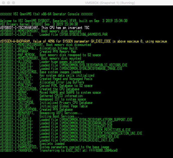
%SYSBOOT-I-PFNMAP,      Created PFN Memory Map
%SYSBOOT-I-MAP_MEMDSK,  Boot memory disk remapped to S2 space
%SYSBOOT-I-MEMDISKMOUNT, Boot memory disk mounted
%SYSBOOT-I-ALLOCPGS,    Loader huge pages allocated
%SYSBOOT-I-LOADFILE,    Loaded file [VMSSCOMMON.SYSLIBJSYSSPUBLIC_VECTORS.EXE
%SYSBOOT-I-LOADFILE,    Loaded file [VMSSCOMMON.SYSSLDR]SYSSBASE_IMAGE.EXE
%SYSBOOT-I-LOADSYSIMGS, Base system images loaded
%SYSBOOT-I-INITDATA,    Key system data cells initialized
%SYSBOOT-I-POOLINIT,    Created Paged and Nonpaged Pools
%SYSBOOT-I-ALLOCERL,    Allocated Error Log Buffers
%SYSBOOT-I-PXMLCOPY,    Copied PXML Database to S2 space
%SYSBOOT-I-CREATECPUDB, Created the CPU Database
96SYSBOOT-I-REMAP,      Moved HWRPB and SWRPB to system space
%SYSBOOT-I-CPUID,       Gathered CPUID information
%SYSBOOT-I-REMAPIDT,    Remapped IDT to system space
%SYSBOOT-I-INITCPUDB,   Initialized Primary CPU Database
%SYSBOOT-I-INITGPT,     Initialized Global Page Table
%SYSBOOT-I-CREATEPFNDB, Created PFN Database
%SYSBOOT-I-REMAPUEFI,   Remapping UEFI Services
%SYSBOOT-I-EFIEXIT,     Exiting Boot Services
%SYSBOOT-I-LOADFILE,    Loaded file [VMSSCOMMON.SYSSLDR]SYSSPLATFORM_SUPPORT.EXE
%SYSBOOT-I-LOADFILE,    Loaded file [VMSSCOMMON.SYSSLDR]ERRORLOG.EXE
%SYSBOOT-I-LOADFILE,    Loaded file [VMSSCOMMON.SYSSLDR]SYSSACPI.EXE
%SYSBOOT-I-LOADFILE,    Loaded file [VMSSC0MM0N.SYSSLDRJSYSTEM_PRIMITIVES_6.EXE
%SYSBOOT-I-LOADFILE,    Loaded file [VMSSCOMMON.SYSSLDRJSYSTEM_SYNCHRONIZATION_UNI.EXE
%SYSBOOT-I-LOADFILE,    Loaded file [VMSSCOMMON.SYSSLDR1SYSS0PDRIVER.EXE
%SYSBOOT-I-LOADFILE,    Loaded file [VMSSCOMMON.SYSSLDR]EXEC_INIT.EXE
%SYSBOOT-I-LOADEXEC,    Execlets loaded
%SYSBOOT-I-PARMSCOPIED, System parameters copied to the base image
%SYSBOOT-I-TRANSFER,    Transferring to EXEC_INIT at: ffff8300.1084bce0 fs
HPET period is 69841279 fs
For virtual machines, hardtick frequency is 100 per second
EXESGQ_SYSTIME address ffffffff80000b08 value 00b384ed66eb000


        VMS Software, Inc. VSI OpenVMS (TM) x86_64 Operating System
                    Copyright 2022 VMS Software, Inc.

  MDS Mitigation active, variant haswell(HASWELL/BROADWELL)
%SYSBOOT-I-MEMDISKMOUNT. Boot memorv disk mounted

$
4.5.3. VSI OpenVMS Installation Menu and Post Installation Steps
As the boot proceeds, you will eventually reach the VSI OpenVMS Installation Menu. At this point, the installation procedures are similar to a traditional installation. You will be prompted to select your target device to install to and any optional kits you wish to install.
Note
Refer to the VSI OpenVMS x86-64 V9.2-1 Installation Guide for further details.
The VSI OpenVMS installation procedure will need to reboot the OS a couple
times before it is complete. Upon each reset or reboot, your VM guest should
return to the UEFI Shell> prompt. At this prompt, perform a
normal system boot as follows:
- At the
Shell>prompt, enter the following command:Shell> VMS_BOOTMGR
- When the
BOOTMGR>prompt appears, connect your terminal emulator session, and then issue the following command:BOOTMGR> BOOT target-device-name
BOOTMGR> AUTO BOOTThis will preserve the next successful boot device as the default. Subsequent boots will occur after a brief countdown whenever the Boot Manager is launched.
To cause the Boot Manager to be launched automatically you can do one of two things:
Define a UEFI boot option to specifically launch
\EFI\VMS\VMS_BOOTMGR.EFI, or...Edit STARTUP.NSH and insert the necessary commands to select the fsx: device and launch
\EFI\VMS\VMS_BOOTMGR.EFI. If you want to boot from a specific fsx: device, you should list that device on a separate command line as shown below:fs2:CD EFI\VMSVMS_BOOTMGR
UEFI will search for STARTUP.NSH in the fsx:\EFI folder of each file system device in sequential order and execute the first match it finds. For consistent behavior, you should consider placing this file on fs0:. Some UEFI implementations allow for STARTUP.NSH to be located on a shared disk or even a network location.
vms_bootmgr DKA100: -fl 0,0where the
-fl arguments specify a System Root and Boot Flags.Note
Typically you would create STARTUP.NSH using the UEFI EDIT command. If you chose to edit STARTUP.NSH on an VSI OpenVMS system, you will need to convert the file back to stream-lf format before copying back to your UEFI partition. The way to do this is:
$ SET FILE/ATTR=RFM:STMLF STARTUP.NSH
Now when your guest starts the UEFI Shell, the firmware will recognize one of these methods and launch the Boot Manager. The Boot Manager will execute its countdown and if not interrupted by user input, automatically issue the boot command.
Chapter 5. Device Enumeration
This chapter describes the specific features of the device enumeration process.
Note
Device Enumeration is an evolving process as support is added for additional device types and more complex controller configurations. SATA, FibreChannel, SAS, and SCSI are enumerated. If device enumeration is inaccurate, you can still boot a device using its UEFI file system device identifier (i.e. BOOT fs2:) instead of the VSI OpenVMS device name. Please report any configurations that result in such inaccuracies.
5.1. Scope of Device Scan
A feature of the Boot Manager is to support VSI OpenVMS Device Names when booting.
This avoids the need to associate a UEFI file system device (e.g., fs0:, fs5:, etc.)
with an VSI OpenVMS device. You can still specify a UEFI file system device at the
BOOT command if you choose to (i.e. BOOTMGR> BOOT fs0), but you can
also use the enumerated VSI OpenVMS device name (i.e. BOOTMGR> BOOT
DKA100)
It is important to note that UEFI firmware has limited visibility into complex storage configurations. Your boot device must fall within the scope of devices that are visible to UEFI firmware. It is entirely possible that devices which reside on complex storage arrays may not be visible to UEFI and only be discovered once VSI OpenVMS has found them and loaded drivers for them.
In the prior Itanium architecture, you needed to select the UEFI file system device before invoking the vms_loader.efi utility. This is not the case for the x86-64 architecture. The VSI OpenVMS Boot Manager is a completely stand-alone utility which is not tied to a specific version of VSI OpenVMS. You can run any version of the Boot Manager from any UEFI file system device and invoke a boot from a different device. The only reason to explicitly specify a UEFI file system device first is if you want to use a specific Boot Manager or startup procedure located on that device. While Boot Manager versions may be compatible as far as basic booting goes, they will evolve to provide additional features.
When the Boot Manager evaluates devices, it looks for those devices which support UEFI FileIO protocol. It then probes each of these devices to see if the device contains an VSI OpenVMS UEFI Partition and that the partition contains the necessary files to boot VSI OpenVMS and it passes a few other integrity checks. Only after passing these validation steps, does the Boot Manager attempt to enumerate the device with an VSI OpenVMS device name. Devices that fail validation will still be displayed as BlockIO devices, but are not considered bootable.
To list bootable devices, issue the following command:
BOOTMGR> DEVICE
Add one of the following qualifiers to filter the list of devices.
- FS
Lists all disk devices supporting FileIO Protocol (whether or not bootable)
- BOOT
Lists all devices which contain bootable VSI OpenVMS images
- USB
Lists all USB devices
- PCI
Lists all PCI devices
- LIST
Displays extended info about all devices
- CPU
Displays extended info about the processor chip and performs a Hardware Compatibility Check.
The separate commands, USB and PCI, provide additional details of these bus types.
When network devices are displayed, those that indicate support of the UNDI Protocol (Intel's Universal Network Device Interface) are also considered bootable.
The DEVCHECK diagnostic command will re-execute a PCI/e Bus Scan and display details of device enumeration.
5.2. VSI OpenVMS Device Naming Peculiarities
The Boot Manager attempts to enumerate devices in accordance with the way the operating system does, but there are some unavoidable exceptions to this which may result in a boot device changing names once VSI OpenVMS has re-enumerated devices. For example, DKA0 may become DKA100 once VSI OpenVMS applies certain topology rules. We are doing our best to coordinate these procedures, but it takes extensive configuration testing as we add more bus types.
Virtual machines have introduced yet further difficulty in device naming. As one example, a USB-based DVD Reader may appear as a SATA disk under Virtual Box. Therefore, instead of assigning an VSI OpenVMS USB device name which always begins with DN it will receive a name prefixed with DK. There are certain to be additional peculiarities as we move forward.
Network devices are particularly difficult to enumerate because the various device name prefixes are not based on features which are accessible through firmware methods. The current Boot Manager implementation enumerates network devices as UEFI devices NET0, NET1, etc. If the network device downloaded a MemoryDisk, then the device itself will appear as DMM0:. Network devices will take official VSI OpenVMS names once VSI OpenVMS is booted.
5.3. USB Device Enumeration
USB devices have their own set of issues when it comes to assigning VSI OpenVMS device names. When USB was first supported by VSI OpenVMS, no effort was made to map the device name to the physical topology of the device. Instead, a simple sequential number was assigned to each device and the UCM (USB Configuration Manager) utility was created to match devices, drivers and unit numbers based on embedded serial numbers of the devices. This was perhaps not the best way to go and it failed to consider devices that didn't implement embedded serial numbers.
Assigning USB device names based on physical topology solves some of the naming issues, but introduces a few new ones. For example, the USB architecture supports up to seven levels of hubs, but the spec goes on to state that you would most certainly run out of power long before reaching such a full configuration. It is unlikely that VSI OpenVMS customers would configure more than a small hierarchy of USB hubs and devices. Supporting a topology-based naming scheme capable of representing the full hierarchy would require significant changes to key data structures, but we can accommodate up to four levels of hub hierarchy within the bounds of existing structures.
The Boot Manager has implemented this type of topology-based USB device naming. The implementation under VSI OpenVMS will evolve to match in a forthcoming production release. In the current release, USB support is limited.
Note
A common issue exists where the user is inadvertently executing the OpenVMS
Boot Manager from a DVD. This usually occurs after an installation, if the user
has not disconnected the DVD/optical disk storage or is simply not aware of
where the OpenVMS Boot Manager was launched from. Although the OpenVMS Boot
Manager will run from a DVD/optical disk, the write-locked media will not allow
for write access to environment files, which may adversely impact some features.
To avoid this confusion, pay attention to the first display screen when the
OpenVMS Boot Manager is launched. It will show a BOOT MANAGER
DEVICE, which is the disk where the current Boot Manager
has been launched from, and a DEFAULT BOOT
COMMAND, which is the disk and command that will be
executed if a simple BOOT command is issued.
Typical USB device names may appear as follows:
- DNA0
Storage device on USB controller A, Hub L0 (implied), End Port 0
- DNB7
Storage device on USB controller B, Hub L0 (implied), End Port 7
- DNA14
Storage device on USB controller A, Hub L1 Port 1, End Port 4
- DNC024
Storage device on USB controller C, Hub L2 Port 0, Hub L1 Port 2, End Port 4
- DNA7777
Storage device on USB controller A, Hub L3 Port 7, Hub L2 Port 7, Hub L1 Port 7, End Port 7
Note
Once VSI OpenVMS x86-64 V9.2-1 boots, there is no VSI OpenVMS support for USB.
Chapter 6. Dump Kernel
This chapter describes how to handle system crashes using the dump kernel.
6.1. Crash Dump Kernel
VSI OpenVMS x86-64 implements a new way of quickly saving memory contents for subsequent analysis and returning the system to service. Crash processing is performed using a second instance of the operating system kernel, known as the dump kernel.
6.1.1. Dump Kernel Overview
The dump kernel is a limited-functionality VSI OpenVMS Kernel designed to handle crash dump data collection, compression and storage.
During boot, the dump kernel is created in parallel with the Primary Kernel. It resides in a separate memory space and shares the MemoryDisk. The dump kernel requires only 512MB of memory.
The MemoryDisk remains in memory after the primary kernel is booted and the device associated with the MemoryDisk (DMM0) is set offline and write-protected. A logical disk device LDMn (where n is a device number) is created during boot, to allow access to files residing in the MemoryDisk using symlinks.
Having a second kernel for crash dump processing reduces the dependency on the crashing system and allows greater flexibility in collecting, compressing and writing to the dump device(s) using runtime drivers. VSI OpenVMS x86-64 does not use the traditional Boot Drivers.
The dump kernel is loaded, but does not boot until the primary kernel encounters a Bugcheck. The Bugcheck process prepares the crashing system (halting processors, identifying important areas of memory, etc.), then transfers control to the dump kernel's SYSBOOT image and the dump kernel boots.
The dump kernel, being resident in memory, boots quickly. A dump kernel-specific startup procedure: [SYSEXE]SYS$DUMP_STARTUP.COM executes the dump kernel's main image: [SYSEXE]SYS$DUMP_KERNEL.EXE. The dump kernel maps and collects the important areas of memory, compresses and writes the data to the dump file SYSDUMP.DMP for later analysis.
Once the crash dump has been processed and the dump file has been written, the dump kernel will invoke a power off or system reset to restart the primary kernel and re-arm a new instance of the dump kernel.
The dump kernel has a few new system parameters to control its operation. These are described in following sections.
6.1.2. Preparing a Dump Device
To create a dump file on your system disk, use SYS$UPDATE:SWAPFILES.COM. When the command procedure requests a file size, start with 200000 blocks (extend as needed).
Note
You can ignore the message about rebooting. If the Dump File exists, it will be used.
To create a Dump File on a different disk, use the following procedure. In this example, we will use DKA100 and System Root 0 (SYS0):
$ CREATE/DIR DKA100:[SYS0.SYSEXE]
$ RUN SYS$SYSTEM:SYSGEN
SYSGEN> CREATE DKA100:[SYS0.SYSEXE]SYSDUMP.DMP/SIZE=200000
SYSGEN> EXIT
$
6.1.3. Specifying one or more Dump Devices
$ SET DUMP_OPTIONS/DEVICE=DKA100:Use a comma-separated list to specify additional dump devices:
/DEVICE=(ddcu:,ddcu:,ddcu:)The changes are effective immediately. A reboot is not necessary.
6.1.4. Control Parameters
The SYSGEN parameter DUMPSTYLE must be set. VSI OpenVMS V9.2-1 supports only selective (bit 0) and compressed bit (3) dump features. Setting DUMPSTYLE to 9 enables these features for a dump to the system disk. Dumping to a non-system disk is always enabled, and there is no need to set bit 2 in DUMPSTYLE.
$ RUN SYS$SYSTEM:SYSGEN
USE CURRENT
SET DUMPSTYLE 9
WRITE ACTIVE
WRITE CURRENT
EXIT
$
No reboot is required after changing Dump control parameters if WRITE ACTIVE is included in the SYSGEN dialogue.
6.1.5. Automatic Actions
When the dump kernel completes its tasks, it will execute a user-specified automatic action to restart or power off the system. Several parameters are involved in defining this behavior. The following is a description of how these parameters interact.
The flags OPC$REBOOT and OPC$POWER_OFF are set or cleared in response to SHUTDOWN parameters (or answers to SHUTDOWN prompts).
If OPC$REBOOT is set at shutdown (Operator Requested Shutdown is a form of Bugcheck) or SYSGEN parameter BUGREBOOT is set during any other form of Bugcheck, the system will be RESET and will return to the UEFI
Shell>prompt.Be aware that any automatic actions established for UEFI and the Boot Manager will then occur.
Automatic reboot is achieved by invoking VMS_BOOTMGR in STARTUP.NSH and setting AUTO BOOT in VMS_BOOTMGR.
If OPC$POWER_OFF is set at shutdown, the system or virtual guest will be powered off.
If both OPC$REBOOT and OPC$POWER_OFF are set (an illogical combination), the system or virtual guest will be reset and any automatic actions will be taken.
If neither OPC$REBOOT or OPC$POWER_OFF are set at shutdown and the SYSGEN parameter BUGREBOOT is NOT set when any other Bugcheck occurs, the Operator will be prompted to press any key to RESET the system and return to the UEFI
Shell>. In other words, with no automatic action specified, the system will wait for an Operator. The Operator can then decide whether to allow or abort any subsequent automatic actions from UEFI (STARTUP.NSH) and the Boot Manager (AUTO BOOT).Note
This assumes that a terminal session on the COM 1 port is available for keyboard input.
Additional failure modes are handled by performing a system RESET to the UEFI
Shell> and any specified automatic actions that follow. These
failure modes include:
The primary kernel fails to start the dump kernel.
The dump kernel itself, Bugchecks.
The dump kernel image fails and OPCCRASH gets started.
Crash analysis is beyond the scope of this guide. The traditional VSI OpenVMS
crash analysis tools are available. The command $ ANALYZE/CRASH
{dumpfile} is a good starting point.
Chapter 7. Troubleshooting
This chapter covers some troubleshooting tools to help address Boot Manager-related failures or errors.
Instruction level debugging is available using XDELTA or DELTA debuggers and code listings. Many other features are available to enable extended messages, run diagnostic tests, etc.
The following are just a few troubleshooting tools. Contact VSI for any assistance you may need.
7.1. XDELTA
The XDELTA debugger may be helpful to early developers. For more information, refer to the VSI OpenVMS Delta/XDelta Debugger Manual. VSI has implemented several XDELTA extensions that can help with Page Table related issues among other things. These extensions are undocumented, but information is available through VSI Support.
There are two types of XDELTA:
- XDELTA is compiled into the primary bootstrap program SY3SBOOT.EXE for use during the early boot stages where the system is transitioning from physical to virtual addressing. To invoke this early XDELTA, issue the following commands prior to booting:
BOOTMGR> XDELTA
BOOTMGR> BREAK
This will enable the debugger and take the first available breakpoint inside SYSBOOT.EXE. - XDELTA (aka SYSDBG) also exists as a loadable executive image. This allows it to be used on programs that run in virtual address space including drivers. To invoke the loadable XDELTA, issue the following commands prior to booting:
BOOTMGR> SYSDBG
BOOTMGR> BREAK
This will load the debugger and take the first available breakpoint inside EXECINIT.EXE. If you prefer to take breakpoints inside program modules, insertini$brk()calls in your sources.
The screenshot below shows the enabling of early XDELTA, then disabling it and enabling the loadable XDELTA Instruction-level Debugger.
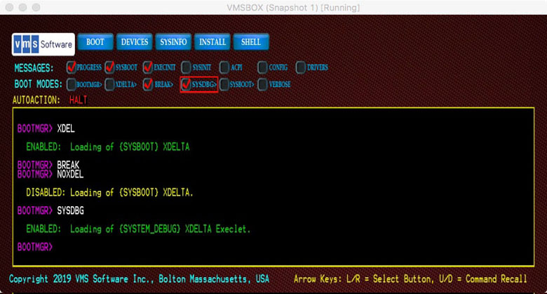
7.2. Boot Manager Startup
The Boot Manager provides diagnostic messages to help troubleshoot any problems that affect the loading and initialization of the system prior to transfer to SYSBOOT.EXE.
Note
Once the first SYSBOOT message appears, the Boot Manager's job is over and system debugging tools are required for further problem analysis.
BOOTMGR> BOOTMGRThis will enable messages with details of the early boot process up to the transfer of control to SYSBOOT.EXE. Along with additional messages, the user will be prompted for examination of key data structures related to boot.
In rare cases where the Boot Manager has trouble relocating images, setting the BOOTMGR and VERBOSE flags together will display intricate details of image relocation. Note, however, that this is time-consuming and generates large amounts of output.
BOOTMGR> MEMCHECKTo prevent booting in order to use this diagnostic, issue the following command:
BOOTMGR> HALT
BOOTMGR> DEVCHECKAdditional device related information can be obtained from the following commands:
BOOTMGR> DEVICE PCI
BOOTMGR> DEVICE USB
BOOTMGR> DEVICE LIST
Logging of Boot Manager messages must be done through a connected terminal emulator. The Boot Manager does not itself provide logging features.
If you wish to capture a Boot Manager screen shot, you can press the F1 key at any
BOOTMGR> or PAGE prompt and a bitmap file named SNAPSHOT.BMP will
be saved to the root UEFI file system device (fs0:, etc.). Only one file will be
saved at a time and is over-written each time F1 is pressed.
7.3. MemoryDisk
The MemoryDisk (SYS$MD.DSK) is a Logical Disk (LD) container file which is critical for booting as it contains all of the files that comprise a minimum bootable VSI OpenVMS Kernel. The structure and custom boot block used during boot are critical and should not be tampered with.
The MemoryDisk is initialized and maintained by a system command procedure SYS$UPDATE:SYS$MD.COM. This procedure is run during installation and again in the event that a file contained in the MemoryDisk is updated through a PCSI Kit or Patch installation. This is done automatically by the various utilities that are concerned with the MemoryDisk. The procedure takes great care to maintain the integrity of the MemoryDisk as well as the symlinks that are used by the OS when referencing these files. Under normal circumstances SYS$MD.COM should never be invoked manually unless instructed to do so by VSI Support for specific troubleshooting reasons.
The MDCHECK command enables additional messages and debugging
features involving MemoryDisk operations. This can be useful to support engineers
when investigating boot problems.
Caution
Since the MemoryDisk itself is a bootable entity, located inside the system disk and having three partitions of its own, there are several critical boot blocks and related structures involved in booting. Use care to avoid renaming or relocating the files: SYS$MD.DSK (the MemoryDisk) or SYS$EFI.SYS (the UEFI partition) on the system disk. Additionally, avoid adding or removing files from within the MemoryDisk or UEFI partition. Corruption of either of these container files may result in an unbootable system.
7.4. Network/Web Server and VMS_KITBOOT
Many things can interfere with network booting. When you initially launch VMS_KITBOOT.EFI it will attempt to identify available network adapters. Failing to locate a suitable adapter is a clear sign that your guest network is not properly configured. Verify that you have defined a network adapter and that your host is able to access the network itself since all network traffic ultimately passes through the host.
VMS_KITBOOT requires that your target system be on a network segment with a DHCP Server. Lack of DHCP Server is one of the most common problems reported.
If you guest adapter appears to be properly configured but still fails to respond, try changing your adapter type from Bridged Adapter to NAT or vice versa. If this does not resolve the problem, seek assistance from a network administrator or other sources familiar with your chosen VM product.
The VMS_KITBOOT.EFI utility is based on the open-source iPXE software. When this underlying software encounters an error, it displays a URL and error code. If you enter this URL and code into a web browser, it will take you to a brief explanation of the error. While these messages are not always detailed, they may point you in the right direction for solving connection issues.
Once VMS_KITBOOT.EFI has selected a network adapter, it attempts to locate a web server at the IPV4 address that you provided in response to the prompt. The full URL of this request must coincide with your web server setup.
This implies that you have a web server running at this IP Address, that you have the corresponding project folder/directory named and that the installation files have been copied to this folder/directory and file protection allows for read access. If this file is correctly located and received by VMS_KITBOOT, then the Boot Manager should be downloaded and displayed.
If the kit download fails, make sure you have provided ample memory in your guest. 6GB is the recommended minimum, but during installation it may help to increase memory. If this solves the problem, you can always reduce memory after installation.
Other things that can cause the network installation to fail are if any of the files were downloaded from the VSI Customer Portal then copied to your system using the wrong FTP mode (binary versus ASCII). Files of type: .ISO, .EFI and .BMP are binary files. Note too that some web servers do not work with files having VSI OpenVMS version numbers and you will need to rename these files to remove the version number and semicolons. Some web servers are case-sensitive too.
The VSI OpenVMS Installation Kit is a large file and may take several minutes to download to your guest.
7.5. Virtual Machines
Most of the problems we have seen from VMs come down to user error,getting a command wrong or failing to define the guest properly.
It is imperative that your guest presents a UEFI Shell> prompt. If
you are unable to start a Shell, consult with your VM product documentation. VMs
need to run the Shell provided by the product. Although UEFI Shell applications are
freely available, their functionality varies widely and Shells used with VMs should
be VM-aware. Both VirtualBox and KVM support UEFI boot environments but KVM may
require installing an additional QEMU package.
If you cannot determine why the boot is failing, contact VSI Support for assistance.
7.6. Problems after Transfer to VSI OpenVMS
If you are able to download and execute the VMS_BOOTMGR.EFI utility but it appears to hang when you issue a BOOT command, try restarting your guest and setting the various message-related boot flags to get an indication of how far the boot progresses before hanging. The PROGRESS, SYSBOOT and EXEC flags should help.
If you think the Boot Manager has not transferred control to SYSBOOT, set the BOOTMGR flag too. If you see even a single message from SYSBOOT or EXECINIT, then you have progressed beyond the Boot Managers role. If it appears that your system hangs when discovering devices, you might set the CONFIG and ACPI boot flags.
The VERBOSE mode flag will enable extended messages in many cases, but be prepared to log a large amount of information. Avoid using the VERBOSE and BOOTMGR flags together as this results in a very slow boot process and an extremely large amount of message data output.
Important
Keep in mind that you must use a remote terminal emulator to communicate with VSI OpenVMS. Once you have issued a BOOT command and have executed SYSBOOT, you may no longer utilize the local keyboard; you must establish a remote terminal session to log in and use VSI OpenVMS.
If you cannot determine why the boot is failing, contact VSI Support for assistance.
7.7. Terminal Emulator Tips
The Boot Manager and Kitboot can use terminal emulators and serial ports for input and output. Establishing a remote terminal connection is essential if you intend to use XDELTA and as a general user. The logging feature of your terminal emulator provides the recommended way to obtain a log file of your entire boot process should that be necessary.
The Boot Manager and VSI OpenVMS want control of the terminal characteristics. Most of the issues with setting up a terminal utility involve command modes and line terminations.
For best results, a terminal session should be in character mode as opposed to line mode. This assures that each character is transmitted as it is entered. This is particularly important when using a debugger since they tend to have single-character command interpreters.
Additionally, avoid having your terminal utility modify line terminators, carriage returns and linefeeds. Let VSI OpenVMS handle the terminators. Lastly, where possible, disable protocol negotiations. A Telnet connection generally involves a negotiation sequence unless explicitly disabled, whereas a Raw connection has no such issues.
When using Telnet, if you have problems entering a system password during installation, check your terminal settings and CLEAR/DISABLE “Return key sends Telnet New Line instead of ^M”.
7.7.1. Terminal Connection Sequence
Some terminal emulators will attempt to take ownership of a serial port if it is not already in use. If this happens, the VMS_KITBOOT procedure or the VMS_BOOTMGR utility may consider the port as unavailable and fail to make a connection.
If this occurs, you need to follow a specific sequence when connecting.
If using a VM, start your guest and launch the VMS_BOOTMGR from the UEFI Shell.
When you reach the
BOOTMGR>prompt, start your terminal emulator.Connect using a RAW or TELNET session.
- You should now see the
BOOTMGR>prompt in your emulator.Input from the graphical console session should be functional. If this isn't working, try issuing the command:BOOTMGR> COM 1
If this still doesn't establish a connection, review the TCP Port you have assigned to COM 1. Refer to the following sections for specific emulator details or contact VSI Support for assistance.
7.7.2. Using the PuTTY Terminal Emulator
If you wish to direct Console IO to a system running Microsoft Windows, we
recommend using the PuTTY terminal emulator. You can download PuTTY from
http://putty.org. MobaXterm is another excellent terminal
utility.
Depending on how the system you are running your terminal emulator on is connected to the target system, you should select a RAW or TELNET session. The RAW option works well with VSI OpenVMS. If using TELNET, you will need to adjust various settings described below to avoid duplicate output and line termination issues.
PuTTY has several nice features that allow for control of your session. If you are working remotely using a SSH connection through your VPN, make sure that the IP Address Forwarding option is enabled (typically it is by default).
Set up your PuTTY session as follows:
Right-click on the window frame of your PuTTY session and select Change Settings.... The most important settings include the following:
In Terminal settings, check the following boxes:
TURN OFF Implicit CR in every LF
TURN OFF Implicit LF in every CR
TURN OFF Local Echo
TURN OFF Local line editing
In Window settings , set your Columns and Rows to match the Boot Manager display (typically 120 Columns, 40 Rows).
If you are using a RAW session (recommended):
Host Name: localhost
Port: 2023
Connection Type: Raw
→ in every LF: UNCHECK
→ in every CR: UNCHECK
→ : Force off
→ : Force off
→ : Passive
→ sends Telnet New Line instead of ^M: UNCHECK
If you are using a SERIAL (cabled) session:
Speed: 115200
Data Bits: 8
Stop Bits: 1
Parity: None
Flow Control: XON/XOFF
telnet> mode charTo return to line mode, issue the command:
telnet> mode line
7.7.3. CentOS Hosting VirtualBox Tip
When using CentOS as the host for VirtualBox, we initially had trouble getting a serial port connection working.
In the VirtualBox VM Ports setup, the COM 1 port is set up to forward serial traffic through TCP Port 2023, but it was not working.
It turned out that CentOS had not enabled port 2023. Below is the solution. This applies to CentOS Version 7, but probably works on other versions too.
You can see if port 2023 is enabled with the following command:
# firewall-cmd --list-ports
You will get a system output similar to the following:
23/tcp
As you can see, only port 23 was enabled.
If port 2023 was not listed, then the following two commands will fix the issue. Note that the --permanent flag assures that the port will be enabled on subsequent boots.
# firewall-cmd --permanent --add-port=2023/tcp

# firewall-cmd --reload
Now check again with the --list-ports command to verify that it
is now enabled.
Device naming is limited to bootable devices within the scope of UEFI. Some complex storage system devices cannot be enumerated until the OS is running.
A Guaranteed Unique ID.