VSI Performance Management Manager for OpenVMS Administrator Guide
- Software Version:
- VSI Performance Management V3.1-1
- Operating System and Version:
- VSI OpenVMS x86-64 Version 9.2-3 or later
Preface
VSI Performance Management is a layered product designed to reduce the time and effort required to manage and monitor system performance and to plan for future resource requirements.
1. About VSI
VMS Software, Inc. (VSI) is an independent software company licensed by Hewlett Packard Enterprise to develop and support the OpenVMS operating system.
2. Intended Audience
This guide is for system managers and system administrators who are looking for an overview of this product. It contains information about layered products designed to reduce the time and effort required to manage and monitor system performance and to plan for future resource requirements.
3. Related Documentation
For VSI Performance Management V3.1-1, the Release Notes and Installation Guide are available.
4. VSI Encourages Your Comments
You may send comments or suggestions regarding this manual or any VSI document by sending electronic mail to the following Internet address: <docinfo@vmssoftware.com>. Users who have VSI OpenVMS support contracts through VSI can contact <support@vmssoftware.com> for help with this product.
5. OpenVMS Documentation
The full VSI OpenVMS documentation set can be found on the VMS Software Documentation webpage at https://docs.vmssoftware.com.
Chapter 1. Introduction
This chapter introduces VSI Performance Management as well as its features, supported configurations, and system requirements.
1.1. VSI Performance Management
VSI Performance Management is designed to reduce the time and effort required to manage and monitor system performance and to plan for future resource requirements. These products can be used with standalone and with OpenVMS cluster systems.
VSI Performance Management includes the following components:
Performance Manager
Performance Agent
Performance Manager and Performance Agent share a common database and basic set of utilities. Any one component may provide these utilities on behalf of the other components of the same version, as shown in the following items:
Performance Agent gathers, manages, classifies, and archives OpenVMS system data. It provides the following functions:
Data collection and storage
Data archiving
Dump reports
Disk analysis
PC sampling
Real-time file activity display
Performance Manager makes recommendations for improving system performance. It does so by analyzing system data through the application of a rules-based analysis engine, identifying specific conditions causing performance degradation, and presenting detailed evidence to support its conclusions. It also provides real-time displays of performance data using either DECwindows Motif or character cell displays. The user can interactively view and investigate system performance problems and resource usage. The following functions are included in this component:
Performance knowledge base and rules compiler
Performance analysis and reports
Real-time displays of performance data
Graphing
Data export facility
The common utilities that are shared by all components provide the capability for managing and querying the files in the database. These include a workload parameter editor, a schedule file editor, a data archive, and a data file dump utility.
1.2. Performance Manager
To deal with system performance effectively, you must understand the workload and the capabilities and limitations of system resources. Generally, any attempt to improve system performance requires specific performance goals stated in measurable terms.
Performance Manager provides the tools you need to analyze, graph, and present performance data on standalone systems or clusters running OpenVMS. Performance Manager analyzes statistics and parameters collected by Performance Manager from each node in a configuration to determine whether specific conditions are contributing to system performance degradation. Based on the findings, Performance Manager recommends ways to improve system performance and provides evidence to support its conclusions.
Reports produced by Performance Manager can help you with the following:
Identify system resource limitations when they exist for the workload
Identify system parameter settings that may be adding to system overhead or degrading system performance
Evaluate trends in system performance
Evaluate the effects of changes in workload and configuration characteristics
1.3. Performance Manager Features
Performance Manager has the following major features:
Performance knowledge base and rules compiler
Analysis and Reporting Facility
Real-time displays of performance data
Graphing facility
Data export facility
1.3.1. Knowledge Base and Rules Compiler
The Performance Manager knowledge base consists of rules and thresholds used to evaluate system performance. The rules (also known as factory rules) are provided at installation time. When Performance Manager produces an Analysis Report, by default it uses the factory rules.
Performance Manager also provides the capability to define your own rules. User-defined rules are created and stored in the form of text files that contain rule definitions. The chapter Customizing the Knowledge Base explains the syntax of user-defined rules. In addition to writing new rules, you can disable any factory rules.
After you define your site-specific rules, you must compile them before Performance Manager can use them. The compiled version of your rules is called an auxiliary knowledge base. After the rules have been compiled, Performance Manager can use them along with factory rules to create an Analysis Report. You can configure your auxiliary knowledge base to be used by default, or you can manually specify it when requesting an Analysis Report.
1.3.2. Analysis and Reporting Facility
The ADVISE PERFORMANCE REPORT command invokes analysis of
performance data to generate Performance Manager reports.
You can specify five types of reports:
Analysis Report – Consists of conclusions for each node and includes cluster-wide conclusions for a clustered system. You can request the conditions that caused a rule to fire and the supporting evidence.
Brief Analysis Report – A brief version of the analysis report. It includes a one-line synopsis of each rule firing.
Histograms – Consists of chronological charts that show peak resource use.
Performance Evaluation Report – Consists of metrics for measuring performance improvement or degradation. Use these metrics to evaluate the recommendations made by Performance Manager and to measure results against baseline models.
Tabular Report – Provides a consolidated summary of some of the performance metrics related to system-wide activity, process activity and disk activity.
1.3.2.1. Generating Daily Reports Automatically
You can generate daily reports automatically by submitting a Performance Manager batch command procedure at night. The Performance Manager software kit contains a sample daily command procedure (PSPA$EXAMPLES:PSPA$DAILY.COM) that you can use as a template. You can use the OpenVMS Mail Utility to send the brief analysis to you directly.
1.3.3. Real-time Displays of Performance Data
The real-time feature provides continuously updated displays of data.
You can produce and customize three-dimensional bar graphs, strip charts, and digital meters to evaluate and investigate performance data using Performance Manager Motif real-time display.
You can also produce tabular and graphical displays to evaluate and investigate performance data by using the Character Cell interface with optional ReGIS graphics.
Using the Playback mode, you can view displays of data recorded earlier in either a continuous flow or step mode.
1.3.4. Graphing Facility
To graph chronologically any group of metrics stored in the database, use the
ADVISE PERFORMANCE GRAPH command to produce a wide range
of predefined graphs. You can also define your own custom graphs if the
predefined graphs do not meet your specific needs. You can select a specific set
of items (disks or processes) for graphing. For more information on graphing see
the chapter Generate Historical Graphs.
1.3.5. Data EXPORT Facility
The performance data from Performance Manager files can be written out to a file for subsequent processing with third-party software tools. The desired classes of data, as well as the time period of interest can be specified. The data can be averaged into a series of records representing whatever time interval the user wishes, as long as it is a multiple of the collection interval.
For instance, data collected every two minutes can be averaged into half hour records. You can select a specific set of items (disks or processes) for output. An ASCII or binary file can be created. Either daily or archived data can be exported.
1.4. DECwindows Interface
Performance Manager includes DECwindows Motif Interfaces for real-time displays and for analysis and graphing. These interfaces are installed only if the necessary windowing libraries are found in SYS$LIBRARY and the necessary DECwindows directories are accessible.
1.5. What to Expect from Performance Manager
Performance Manager analyzes collected system data required for determining whether a specific resource is causing a performance problem. The data collected at your site may cause Performance Manager rules to fire. To fire means that when all the data has been processed, Performance Manager examines the count of a rule's occurrences, and if there are enough occurrences for a particular rule, that rule is said to fire. This causes an entry for that rule to be placed in the report file in the form of a conclusion.
However, you can modify or disable Performance Manager rules or threshold values that govern performance analysis.
When you request an Analysis Report, you may receive advice about performance problems for some of the following reasons:
Inefficient setting of SYSGEN or UAF parameters
Excessive demand
Excessively long device queues
Insufficient system resources
Inefficient application design
Insufficient hardware for the workload
Before you follow any Performance Manager recommendations, ask the following questions:
Is the problem caused by a temporary condition?
Performance Manager does provide summary analysis for extended time periods, such as weeks or months.
How frequently does the problem occur?
Is there a difference in the workload before and during the time the problem occurs? (Occasionally, the problem may be caused by the inherent characteristics of an application or workload.)
If Performance Manager recommends that you need additional hardware, keep track of this recommendation over a period of time. If system performance degrades, this recommendation occurs more frequently. You must decide whether the problem is serious enough to warrant additional hardware.
Never rely solely on Performance Manager recommendations. As you become familiar with the workload on your system, you develop your own ideas on how to recognize and alleviate performance problems. Use the Performance Manager as a tool to help you discover and resolve performance problems.
Although you need the information Performance Manager provides for investigating any perceived performance problem, this information is not infallible. Occasionally, Performance Manager recommendations do not improve performance. Additional expertise, analysis, hardware, and tuning may be required to solve a specific performance problem.
1.5.1. Cross-Platform Support
If you run Performance Analysis across platforms between V3.1-1 and an Alpha or IA-64 system running prior releases of Performance Agent, you need to be aware of the following situations:
VSI does not support using an older Performance Manager (V3.0 or older) with the new Performance Agent (V3.1-1).
The Performance Manager V3.1-1 runs performance analysis on Alpha and IA-64 data from prior releases. However, the results might be different from those generated on prior releases due to the updated and new rules.
The VAX Performance Manager is not supported.
Chapter 2. Analyze Performance
This chapter contains example Performance Manager Analysis Reports and information to help you interpret them.
2.1. Analysis Reports
When you request an Analysis Report, the Performance Manager analyzes data for the requested time period and nodes against the rules in the knowledge base.
The Analysis Report consists of conclusions for each node and includes cluster-wide conclusions for a cluster system. Each conclusion is caused by a rule firing. When a rule fires, the Performance Manager reports the problem condition and makes a recommendation for improving performance. All rules are identified with a unique five-character alphanumeric code, such as {M0010}. A rule identifier appears with each conclusion.
In addition to the conclusions, you can request that the Performance Manager list
the rule conditions that satisfied the rule firing. The Performance Manager also
provides supporting evidence. By default, the Performance Manager provides
conditions and evidence when you specify an output file or when you run the analysis
process in batch mode. To suppress the conditions and evidence in the report, use
the /NOEXPLAIN qualifier.
The conclusions in the Analysis Report for a cluster system are listed in the following order by node:
Each node's local analysis and conclusions, which may include the following conclusions:
Memory-related
I/O-related
CPU-related
Miscellaneous
Auxiliary
Cluster-wide analysis and conclusions, which may include the following conclusions:
HSC limitation
Disk-related
Lock-related
Auxiliary
If you request a Performance Evaluation Report along with an Analysis Report, the performance data for each node follows that node's local analysis. The performance data for the cluster appears after the cluster-wide analysis.
Factory analysis reports can be produced only from data collected by the primary data collector, namely that which is associated with the CPD definition.
2.1.1. Interpret the Analysis Reports
This section explains excerpts from example Analysis Reports. The explanation follows each excerpt.
The header at the top of each page in the report includes the version number of the Performance Manager used to generate the report. This version number does not necessarily correspond to the version number of the Performance Agent that collected the data being analyzed.
2.1.1.1. Memory Rule Report
The following example shows a Memory Rule report:
Full Analysis BARNEY (AlphaServer ES47) Page 1
PSPA V3.1-1
10-NOV-2025 00:00 to 11-NOV-2025 00:00
CONCLUSION 1.
{M0050}
While excessive page faulting was occurring, there were
some users running images which seemed to want more
memory than their WSEXTENTS allowed. If the WSEXTENTS
for these users were larger, there may have been less
page faulting.
Increase the WSEXTENT for the following users. If
batch queue settings for working set extents are
causing the limitation, increase those. If detached
processes are causing the problem, increase the working
set extents specified in either the "RUN/PROCESS"
commands, or the calls to the $CREPRC System Service or
LIB$SPAWN Runtime Library Routine. As a last resort
for detached processes, increase the PQL_DWSEXTENT
SYSGEN parameter if it is responsible for establishing
the working set extent value for the detached process.
Total number of users needing an increase : 2
User name(s)
------------
DEBBEEW
JOHNS
CONDITIONS
1. FREELIST_FAULT_RATE + MODIFIEDLIST_FAULT_RATE +
GLOBALPAGE_FAULT_RATE .GE. 100.00 *
SOFT_FAULT_SCALING
2. IMAGE_ACTIVATION_RATE .LT. 0.50 *
IMG_ACT_RATE_SCALING
3. PAGES_ON_FREELIST .GE. 3.00 * SYSGEN_FREEGOAL
4. PROCESSES_NEED_MORE_EXTENT .EQ. 1.00
5. OCCURRENCES .GE. 1
EVIDENCE
Working Set Time range Avg Image Faults Avg sz No.
User ------------ (batch jobs Image W.Set flts/ --------- of Free of
Name Quota Extent are flaggd) Name Size cpusc Hrd Soft List Tims
------- ----- ------ ----------- -------- ------ ----- --- ----- ---------- ----


 DEBBEEW 294 1024
17:38-17:38 DBUSERS_MENU 1006 31283 295 12347 5441 4
17:38-17:38 DB_BACKUP 1005 35697 295 12347 5441 1
17:38-17:38 XFER_TO_JPM 1024 24916 295 12347 5441 3
JOHNS 294 1024
17:38-17:38 XFER_TO_JPM 1024 38432 295 12347 5441 2
The following statements are keyed to the columns in the previous Memory Rule report:
| User name associated with a process. |
| Working set quota and working set extent. |
| Time range for which selected image records for this process are summarized. |
| The first 12 characters of the image name string associated with the user's process. |
| Average working set size (in pages) for the user's process while running the specified image. |
| Total number of page faults for the user's process while running the specified image, divided by the CPU seconds for the same period. |
| Average system-wide hard page fault rate during the major sampling intervals when the user's process ran the specified image. |
| Average system-wide soft page fault rate during the major sampling intervals when the user's process ran the specified image. |
| Average size of the free page list (in pages) during the periods when the user's process ran the specified image. |
| Number of times that a Performance Manager process or image record supports the evidence. |
In the previous Memory Rule report example, the total number of page faults per CPU second are in the range of 1006 to 1024 for user DEBBEEW, and 1024 for user JOHNS. This high rate of page faulting probably contributed to the system-wide soft page fault rate of 12347, which exceeded the threshold of 100. This occurred 20 times (10 + 4 + 1 + 3 + 2) because both DEBBEEW and JOHNS WSEXTENT are both too low at the value of 1024 pages (8KB page size).
2.1.1.2. CPU Rule Analysis Report
The following example shows a CPU Rule analysis:
Full Analysis               BARNEY (AlphaServer ES47)                   Page   5
                                                                 PSPA V3.1-1
                       Thursday 13-NOV-2025 17:00 to 19:00

CONCLUSION 2.
                                                                     {C0010}
          There is an apparent bottleneck at the CPU due  to  the
          large  number  of  COM/COMO  processes.   There  exists
          higher priority process(es)  which  are  causing  lower
          priority  COM and/or COMO processes to wait for the CPU
          which may  be  the  cause  of  the  problem.   This  is
          considered   a   LOCKOUT  condition.   Examine  process
          priorities, PIXSCAN and DORMANTWAIT.

          For an equitable distribution of CPU time over the  COM
          processes, evaulate the BASE PRIORITY of the computable
          processes.

          Consider increasing PIXSCAN to allow the lower priority
          processes  to release resources they may have acquired.
          Once each second, the system raises PIXSCAN  number  of
          dormant  processes to the priority equal to that of the
          highest  priority  computable  time-share  process.   A
          dormant  process  is one that is computable and has not
          received CPU time  in  DORMANTWAIT  seconds.   Consider
          increasing PIXSCAN if the lower priority processes that
          are being locked out could potentially  lock  the  same
          resources being used by the higher priority processes.

          Total number of samples supporting this conclusion:  8

      CONDITIONS

          1. COMPUTABLE_PROCESSES .GT. SYSGEN_PIXSCAN
          2. PRIORITY_LOCKOUT .EQ. 1.00
          3. OCCURRENCES .GE. 2

      EVIDENCE


 # Proc       Process receiving most CPU          COM Process
in COM   -----------------------------------   ----------------       Time of
or COMO     USERNAME     IMAGE     %CPU  PRIB    USERNAME   PRIB     occurrence
-------  ------------ ------------ ----  ----  ------------ ----  ----------------

     8   DEBBEEW      DAILY_CHECK    50    8   SYSTEM         6    13-NOV 17:58:00
     8   DEBBEEW      DBUSERS_MENU   46    8   CBUTTERWORTH   4    13-NOV 18:06:00
     7   DEBBEEW      DBUSERS_MENU   54    8   SYSTEM         6    13-NOV 18:14:00
     8   DEBBEEW      DBUSERS_MENU   53    8   CBUTTERWORTH   4    13-NOV 18:22:00
     7   DEBBEEW      DAILY_CHECK    56    8   CBUTTERWORTH   4    13-NOV 18:30:00
     8   DEBBEEW      DBUSERS_MENU   43    8   CBUTTERWORTH   4    13-NOV 18:38:00
     8   DEBBEEW      XFER_TO_JPM    45    8   CBUTTERWORTH   4    13-NOV 18:46:00
     7   DEBBEEW      XFER_TO_JPM    51    8   SYSTEM         6    13-NOV 18:54:00
The following statements are keyed to the columns in the previous CPU Rule analysis report:
| Average number of processes in computable or computable outswapped state during the interval. |
| User name string of the process that consumed the most CPU time during the interval. |
| The first 12 characters of the image name. |
| Percentage of the total available CPU time consumed by the user's process during the interval. |
| Base priority of the process that used the most CPU time during the interval. |
| User name string for the process that was in the computable state most during the interval. |
| Base priority of the process that was in the computable state most during the interval. |
| Beginning time of the interval in which the condition occurred. |
In the previous CPU Rule analysis report example, the average number of processes in either COM or COMO state is greater than or equal to SYSGEN_PIXSCAN on eight occasions, with the actual number of COM/COMO processes ranging from 1 to 8. These blocked computable processes (for users CBUTTERWORTH and SYSTEM) have a base priority of 4 or 6. Other processes with a base priority of 8 (for user DEBBEEW) prevent the other computable processes from executing because of their elevated base priority, thereby creating the LOCKOUT condition.
2.1.1.3. I/O Rule Analysis Report
Full Analysis               BOOTES (HP BL860c i4  (2.13GHz/2)           Page  14
                                                                 PSPA V3.1-1
                       Thursday  9-AUG-2025 13:00 to 17:00

CONCLUSION 8.

                                                                         {I0080}
          The system  exceeded  the  split  I/O  rate  threshold,
          indicating  a  possible fragmentation problem.  A split
          I/O occurs when an I/O request cannot be  completed  in
          one  operation  because  it  cannot be satisfied from a
          single extent.  One or more additional  I/O  operations
          are required to complete the I/O request.

          The disk class driver for SCSI devices  may  limit  the
          size  of the disk transfer.  If the disk device is SCSI
          based, and paging,  or  applications  are  doing  large
          transfers,  a  large  split I/O ratio may not be due to
          file fragmentation.

          You can use the PSDC  command  "ADVISE  COLLECT  REPORT
          DISK_SPACE  devicename"  to  check if any of your disks
          are fragmented.  Backup and  restore  disks  regularly,
          and  on  disks with many file extension operations, try
          to keep as much as 25% of the space empty.  This  keeps
          fragmentation  from  occurring  quickly and reduces the
          seek time resulting in better I/O performance.

          Total number of samples supporting this conclusion:  2

      CONDITIONS

          1. SPLIT_IO_RATE .GE. 5.00
          2. OCCURRENCES .GE. 2

      EVIDENCE

                                               System-wide:
   Volume with highest Split I/O rate:     -------------------
-----------------------------------------    Split    Window        Time of
     Name    IO/sec Split IO/sec  Que len  I/Os /sec Turns/sec     occurrence
------------ ------ ------------  -------  --------- ---------  ----------------

USRDISK       17.92      15.73       0.06      16.21      5.53    9-AUG 16:52:00
   Top split I/O file on volume: No Hot Files
USRDISK       53.08      49.24       0.21      49.40      1.60    9-AUG 16:54:00
   Top split I/O file on volume: No Hot Files
The following statements are keyed to the columns in the previous I/O Rule Analysis report:
| Name of the volume on which excessive split I/O's occurred. |
| The average number of I/O's per second on volume USRDISK. |
| The average number of split I/O's per second on volume USRDISK. |
| The average length of the I/O queue on volume USRDISK. |
| The average number of split I/O's per second that occurred system-wide. |
| The average number of window turns per second that occurred system-wide. |
| Beginning time of the interval in which the condition occurred. |
Note
As stated in the line following each occurrence, there were no hot-files.
In the previous example I/O Rule Analysis report, volume USRDISK exceeded the split I/O threshold of 5.00 on two occasions.
2.1.1.4. Miscellaneous Rule Analysis Report
The following example shows a Miscellaneous Rule Analysis report:
Full Analysis               BARNEY (AlphaServer ES47)                   Page   2
                                                                 PSPA V3.1-1
                     10-NOV-2025 00:00 to 11-NOV-2025 00:00

CONCLUSION 2.

                                                                         {R0240}
          The following images were waiting because modified page
          writer was busy.

          When the modified page list (MPL) hits MPW_HILIMIT, the
          swapper starts writing pages from the MPL to the paging
          file until the  MPL  reaches  MPW_LOWAITLIM.   This  is
          refered  to  as  modified page writing.  To ensure that
          the MPL doesn't get too large, when the MPL reaches the
          parameter  MPW_WAITLIMIT,  processes  are placed in the
          RWMPB state.  They will remain in that state until  the
          MPL is written down to MPW_LOWAITLIM

          Typically, the reasons for this wait state are:

          1.  Insufficient page file space.
          2.  A real time job may be blocking swapper process.
          3.  Heavy paging activity.
          4.  The SYSGEN parameter MPW_HILIMIT is set too small
          5.  The SYSGEN parameter MPW_WAITLIM is set too small
          6.  Too many pages have to be flushed at a time.

          When the page file(s) are on shared disks in a cluster,
          tune  the  swapper for smaller and more frequent writes
          from the modified page list to  avoid  disk  contention
          and  longer  delays.  The SYSGEN parameters MPW_HILIMIT
          and MPW_LOWAITLIMIT determine the amount of pages which
          the swapper will write to the page file(s).

          Total number of samples supporting this conclusion:  529

 CONDITIONS

          1. PROCESS_SCAN ( PROCESS_WAS_IN_RWMPB .EQ. 1.00 )
             .GE. 1.00
          2. SYSGEN_MPW_WAITLIMIT .GE. SYSGEN_MPW_HILIMIT
          3. OCCURRENCES .GE. 5

      EVIDENCE

Full Analysis               BARNEY (AlphaServer DS15)                   Page   3
                                                                 PSPA V3.1-1301
                     10-NOV-2025 00:00 to 11-NOV-2025 00:00


        Image Waiting           User          Time of occurrence
        -------------           ----          ------------------
     DBUSERS_MENU            DEBBEEW            10-NOV 00:02:00
     XFER_TO_JPM             DEBBEEW            10-NOV 00:02:00
     DBUSERS_MENU            JOHNS              10-NOV 00:02:00
     DBUSERS_MENU            DEBBEEW            10-NOV 00:04:00
     XFER_TO_JPM             DEBBEEW            10-NOV 00:04:00
     DBUSERS_MENU            JOHNS              10-NOV 00:04:00
                               .
                               .
                               .
The following statements are keyed to the columns in the Miscellaneous Rule analysis report:
| The name of the executable image that was made to wait. |
| The user name string of the process that was running the executable image. |
| The time of the occurrence. |
2.1.1.5. Analysis Summary Report
The following example shows an Analysis Summary report:
Full Analysis           FATHOM (VMware, Inc. VMware20,1)                Page 227
                                                                 PSPA V3.1-1
                     01-OCT-2025 00:00 to 22-OCT-2025 00:00

                       ANALYSIS SUMMARY for node FATHOM

          Number of Records Processed.......................15120
          Number of Records satisfying rule conditions......8079
          Number of Records not satisfying rule conditions..7041
          Number of Conclusions.............................10
The following statements are keyed to the rows in the previous Analysis Summary report:
| Number of Performance Manager records analyzed for the specified reporting period. |
| Number of Performance Manager records that satisfied rule conditions. This number does not necessarily equal the number of rules that fired, due to rule threshold values. Although a record may satisfy a rule condition, the number of occurrences required to fire the rule may not be sufficient during the reporting period. |
| Number of Performance Manager records that did not satisfy any rule conditions. |
| Number of conclusions generated for the node being analyzed. |
Although records may have satisfied a specific rule, the number of occurrences of records satisfying a specific rule may not have reached the occurrence threshold. This means the number of conclusions may be zero while the number of records satisfying the rule conditions is greater than zero.
2.1.1.6. Cluster Rule Analysis Report
The following example shows a Cluster Rule analysis report:
Full Analysis                        CLUSTER                            Page  51
                                                                 PSPA V3.1-1
                      Wednesday 19-NOV-2025 00:00 to 16:14

CONCLUSION 19.
                                                                         {L0050}
          Queues are  forming  on  heavily  used  disks.   Longer
          delays will be experienced when longer queues form.

          Suggested Remedies:

          1.  If the disk is fragmented  (use  the  PSDC  command
              "$ADVISE  COLLECT  REPORT DISK_SPACE devicename" in
              order to check on this), then  backup  and  restore
              the  disk  using the BACKUP utility with the /IMAGE
              qualifier.

          2.  If possible, assign all new work during  the  noted
              times to other disk volumes.

          3.  If possible, attempt to lower the future  usage  of
              the noted disk volumes.

          4.  Ensure  that  file  system  cache   hit   rate   is
              acceptable.

          5.  If there are multiple hot  files,  distribute  them
              among multiple disks.

          6.  If there is a single, large hot  file,  such  as  a
              database,   consider   striping   (Raid   0).    If
              availability is important,  consider  striping  and
              mirroring (Raid 0+1).

          7.  Verify the XFC cache hit rate  is  acceptable.   If
              not,  either  increase the cache size, or determine
              which files have poor cache hit rates  and  disable
              cache   for   those   files   with   the  SET  FILE
              /CACHING_ATTRIBUTE=NO_CACHING  command.   Determine
              the  files  with  a  poor  cache  hit rate with the
              command                 SHOW                 MEMORY
              /CACHE=(VOLUME=volume-name,TOPQIO).

                Volume name(s)      Number of Samples
                --------------      -----------------
                PMJMDISK                 4

      CONDITIONS

          1. DISK_QUEUE_AT_SERVER .GE. 1.00 .OR. (
             MAXIMUM_DISK_QUEUE .GE. 1.00 .AND. DISK_IS_SERVED
             .EQ. 0.00 )
          2. CW_DISK_IO_RATE .GE. DISK_IO_RATE_THRESHOLD .OR.
             CW_DISK_THRUPUT_RATE .GE.
             DISK_THRUPUT_RATE_THRESHOLD

Full Analysis                        CLUSTER                            Page  52
                                                                 PSPA V3.1-1301
                      Wednesday 19-NOV-2025 00:00 to 16:14

          3. OCCURRENCES .GE. 1

      EVIDENCE

Disk Volume  Srv Node          Time of Occ    Shdw Rbld
    \              Avg I/O  Avg  IO Sz
    \ Src Node     per sec  Que  Pages    Hottest File
--------------------------------------------------------------------------------

PMJMDISK     BOOTES          19-NOV 16:10:00

    Cluster         2671.0 2.07   51.0 [SOFTWARE_KITS.JOBMANAGER.R3_1.IA64]DVD04
    ITAN1           333.75 2.04   61.5 [SOFTWARE_KITS.CONSOLE.R3_1.IA64]DVD02210
    BARNEY          174.09 1.85   42.5 [SOFTWARE_KITS.CONSOLE.R3_1.IA64]DVD02210
    BOOTES          1188.0 2.07   51.0 [SOFTWARE_KITS.JOBMANAGER.R3_1.IA64]DVD04

PMJMDISK     BOOTES          19-NOV 16:12:00
    Cluster         8734.0 8.42   50.5 [SOFTWARE_KITS.WATCHDOG.R2_5]DVD07105309E
    ITAN1           1016.9 6.64   61.8 [SOFTWARE_KITS.JOBMANAGER.R3_1.IA64]DVD04
    BARNEY          429.19 6.61   53.3 [SOFTWARE_KITS.CONSOLE.R3_1.IA64]DVD02210
    BOOTES          3998.0 8.42   50.5 [SOFTWARE_KITS.WATCHDOG.R2_5]DVD07105309E

PMJMDISK     BOOTES          19-NOV 16:14:00
    Cluster         7426.0 6.63   46.5 [TN7689]sysdump.dmp;1
    ITAN1           1020.0 6.64   61.8 [SOFTWARE_KITS.PERFORMANCE.R3_1_SP01.IA64
    BARNEY          485.19 6.34   54.5 [SOFTWARE_KITS.CONSOLE.R3_1.IA64]dvd02210
    BOOTES          2824.0 6.63   46.5 [TN7689]sysdump.dmp;1

PMJMDISK     BOOTES          19-NOV 16:16:00
    Cluster         5138.0 1.54   40.8 [SOFTWARE_KITS.WATCHDOG.R2_5]DVD07105309E
    ITAN1           1039.5 6.65   61.5 [SOFTWARE_KITS.WATCHDOG.R2_5]DVD07105309E
    BARNEY          471.31 6.63   53.3 [SOFTWARE_KITS.JOBMANAGER.R3_1.IA64]dvd04
    BOOTES            0.00 1.54    0.0 [DECPS-DATABASE]PSDC$BOOTES_2025NOV19.CPD
The following statements are keyed to the previous Cluster Rule analysis report example:
| Name of the disk experiencing heavy use. |
| Name of the node that actually services requests. |
| Beginning time of the interval in which the condition occurred. |
| An asterisk indicates that a disk is a shadow set and the disk underwent a COPY operation. |
| Name of the node in the cluster that shares the heavily used disk. |
| Average number of operations per second to the volume, during the given interval, both by the contributing node and the entire cluster. |
| Average size of the queue during the interval exampled, measured by the number of requests. |
| Average size, in pages, of all I/O requests during the interval. |
| When hot file data exists, the hottest file (highest I/O rate) is listed. |
In the previous Cluster Rule analysis report example, the queue length on volume PMJMDISK exceeds the value of 1.0 on four occasions. During those four occasions, the total operations per second for each interval exceeded the device threshold.
2.2. Brief Analysis Reports
The Brief Analysis Report is a synopsis of the Analysis Report. It contains the following information:
Rule identifiers.
The percentage of time there were instances of rule occurrences during the reporting period. This field is blank if the rule reflects an analysis of a summary of the over-all analysis period.
The number of records supporting the rule occurrence. This field is blank if the rule reflects an analysis of a summary of the over-all analysis period.
A brief (one line) synopsis of the problem statement.
The Brief Analysis Report provides a synopsis for each node in the cluster system, followed by a cluster-wide synopsis.
Until you are familiar with the long version of the conclusions, you should not rely solely on the Brief Analysis Report. In many instances, the one-line synopsis is not sufficient to convey the meaning of the problem.
2.2.1. Interpret the Brief Analysis Report
The following example is an example of a Brief Analysis Report. A description of each item in the report headings follows the example.
The following statements are keyed to the columns in the report example:
| Rule identifier. |
| For this reporting period, the percentage of time that the conditions of a rule were satisfied. |
| Number of records satisfying rule occurrences. |
Rules in Summary domain do not provide data in columns 2 and 3 because their conditions are based on data averaged over the entire analysis period.
Brief Analysis                       CLUSTER                            Page   1
                                                                 PSPA V3.1-1
                      Wednesday 19-NOV-2025 00:00 to 19:21

                                                      NODE: ITAN1
 ID %oftime Recds       One Line Description
----- ----- ----  ------------------------------------

C0035   1.2    7  High interrupt stack time on one or more CPUs.
M0400             SYSGEN parameter PQL_DWSDEFAULT less than PQL_DWSQUOTA.
M0401             SYSGEN parameter PQL_MWSDEFAULT less than PQL_MWSQUOTA.
M0404  100.  581  Paged dynamic memory low; increase PAGEDYN
M0412             MPW_THRESH-MPW_LOLIMIT is less than FREEGOAL-FREELIM.
M0414             SYSGEN parameter BORROWLIM greater than FREELIM.
M0417             SYSGEN parameter PQL_MWSEXTENT less than WSMAX.

Summary for ITAN1: 7 rules fired; of 581 records, 581 satisfied conditions.

                                                      NODE: BARNEY
 ID %oftime Recds       One Line Description
----- ----- ----  ------------------------------------
R0250  27.7  161  Process(es) are delayed in RWSCS; (See full report.)
C0035   1.2    7  High interrupt stack time on one or more CPUs.
M0400             SYSGEN parameter PQL_DWSDEFAULT less than PQL_DWSQUOTA.
M0401             SYSGEN parameter PQL_MWSDEFAULT less than PQL_MWSQUOTA.
R0407  100.  581  System pagefaults too high; increase SYSMWCNT.
R0095   1.2    7  Low hit ratio, high attempt rate on the file header cache.
R0050             Non-paged pool expanded; increase NPAGEDYN.
X0400  28.2  164  XFC Cache Hit Rate Low. Check individual file hit rate
X0403   2.2   13  I/Os between 33 and 64 blocks bypassing XFC Cache

Summary for BARNEY: 9 rules fired; of 581 records, 581 satisfied conditions.

                                                      NODE: BOOTES
 ID %oftime Recds       One Line Description
----- ----- ----  ------------------------------------
M0400             SYSGEN parameter PQL_DWSDEFAULT less than PQL_DWSQUOTA.
M0414             SYSGEN parameter BORROWLIM greater than FREELIM.
I0070   0.3    2  I/O to a disk is too high; load balance and/or add disks.
I0055   0.9    5  Disk IO serving is too high; remote node feels bottleneck.

Summary for BOOTES: 4 rules fired; of 581 records, 6 satisfied conditions.

                                                      CLUSTER
 ID %oftime Recds       One Line Description
----- ----- ----  ------------------------------------
L0050          5  I/O bottleneck on disk; reduce or redistribute load.
L0070         12  Remote nodes have disk queues on one or more served disks.

Summary for CLUSTER:      2 Rules fired.
Chapter 3. Evaluate Performance in Detail
This chapter contains example Performance Manager statistical reports and information to help you interpret them. For more information about obtaining Performance Manager reports, see the chapter Performance Manager Commands.
3.1. Performance Evaluation Report
The Performance Evaluation Report provides statistics on system use, component use, and process activity. It also provides metrics for performance improvement or degradation, to use when evaluating the impact of recommendations made by the Performance Manager.
The Performance Evaluation Report has the following sections:
Process statistics by primary and secondary keys
Pool statistics
CPU mode statistics
SCS statistics
Lock statistics
CI, NI, and adapter statistics
Disk statistics
Tape statistics
Hot file statistics
Summary of node's CPU and memory statistics
Histograms of CPU and memory utilization, and terminal and disk I/O
ADVISE PERFORMANCE REPORT PERFORMANCE_EVALUATIONThe
/FILTER qualifier lets you select a subset of data for
reports. For more information, see the chapter Performance
Manager Commands. 3.1.1. Interpret the Process Statistics
The following example illustrates the default process statistics section of the Performance Evaluation Report.
The /PROCESS_STATISTICS qualifier allows you to tailor the
process statistics section of the Performance Evaluation Report. You can specify
the focus of the report to obtain different sets of statistics that pertain to
the focus area. The grouping, merging, and sorting of the process data is
controlled with the primary and secondary key settings.
The following list shows the primary and secondary keys:
MODE
USERNAME
IMAGENAME
UIC_GROUP
PROCESS_NAME
WORKLOAD_NAME
ACCOUNT_NAME
PID
For more information on how to specify the
/PROCESS_STATISTICS qualifier, see the chapter Performance Manager Commands.
To display only the process statistics section of the Performance Evaluation
Report, use the qualifier /INCLUDE=PROCESS_STATISTICS.
To disable the process statistics display from the Performance Evaluation
Report, use the qualifier
/INCLUDE=NOPROCESS_STATISTICS.
Because process classification by PID or PROCESSNAME results in virtual memory requirements, these reports keys are disabled by default and require you to specifically enable them. For more information on virtual memory requirements, see the Appendix Estimate Virtual Memory Needs.
The following example shows a Performance Evaluation Report, Process Statistics by Image for Interactive, Batch, Detached, and Network Jobs:
Performance ITAN1 (HP rx2600 (1.30GHz/3.0M) Page 1
Evaluation PSPA V3.1-1
14-OCT-2025 10:00 to 14-OCT-2025 11:00
+--------------------------------------------------------------------+
| The table below lists observed workload characteristics of all the |
| interactive images that were run during the given interval. Note |
| that Diskio, Bufio and Cputim are percentage contributions of the |
| respective images to the total system load. Working set size and |
| working set faults are the average for the respective images. In |
| the case of 0 image activations, the Uptime/image and Cputim/image |
| actually report the cumulative Uptime and Cputim for the image. |
+--------------------------------------------------------------------+
Node Name: ITAN1 MODE: INTERACTIVE
# of Page Faults Avg. % of % of Uptime/ Cputim/
activ- per Actvtn Ws Direct Buffered % of image image
Image ations -Soft--Hard size I/O I/O Cputim (sec) (sec)
-------- ------- ------ ---- ------ ------ ------ ------ ------- --------
(dcl) 0 2 0 207 0.00 0.00 0.00 2384877 1.02
CDU 6 203 8 295 0.00 0.00 0.00 25 0.01
CONVERT 2 15 17 346 0.00 0.00 0.00 0 0.01
COPY 9 30 6 323 0.00 0.00 0.00 0 0.01
CREATE 1 27 14 327 0.00 0.00 0.00 0 0.01
DECW$SETSHOD 3 69 21 229 0.00 0.00 0.00 31 0.02
DELETE 17 13 3 311 0.00 0.00 0.00 0 0.00
DIRECTORY 13 35 6 227 0.00 0.00 0.00 35 0.01
EDT 1 166 11 308 0.03 0.01 0.00 85 1.66
LANCP 1 86 29 274 0.00 0.00 0.00 11 0.02
LOGINOUT 4 48 2 207 0.00 0.00 0.00 41 0.00
NCL 1 188 29 254 0.00 0.00 0.00 27 0.01
PCSI$MAIN 1 173 93 289 0.00 0.00 0.00 15 0.07
. . . . . . . . . .
. . . . . . . . . .
. . . . . . . . . .
UETUNAS00 0 0 0 131 0.00 0.00 0.00 0 0.00
VMSHELP 5 68 12 290 0.00 0.01 0.00 4690 0.04
------ ------- ------- ------
Totals 145 0.07 0.17 4.30


 Performance ITAN1 (HP rx2600 (1.30GHz/3.0M) Page 6
Evaluation PSPA V3.1-1
14-OCT-2025 10:00 to 14-OCT-2025 11:00
+------------------------------------------------------------------------+
| The following table summarizes the workload characteristics on a per |
| image activation basis. Note that values would be zeros if total |
| number of image activations is zero. |
+------------------------------------------------------------------------+
PrimaryKey: Avg. Avg. Avg. Avg.
Mode # of Avg. Soft Hard Direct Buff'd Avg. Images
Secondary Key: processes WSiz/ flts/ flts/ IO/ IO/ Cputim/ per
None activ/inact image image image image image image Second
---------------- ----- ----- ----- ----- ----- ------ ------ ------- --------


 INTERACTIVE 0 1 212 150.3 18.5 251.3 175.2 0.49 0.0001
BATCH 0 1 5358 170.6 19.6 3725.0 51465 5.96 0.0000
NETWORK 0 9 692 155.3 15.9 37.7 36063 2.49 0.0001
DETACHED 6 34 325 2360.0 19.7 10247 2023.6 1.33 0.0022
The following statements are keyed to the columns in the previous example:
| By default, the Performance Manager displays the process information by image name. In this example, images running or waiting on the system during the report time period are shown. |
| Number of times that an image was activated during the report time period. If an image has zero activations, than it has been activated previously (before the reporting period). If you specify the secondary key as USERNAMES, the Performance Manager displays the number of image activations per user. |
| Number of soft page faults incurred by an image during the report time period, divided by the number of activations. If you specify the secondary key as USERNAMES, this column displays the total number of soft page faults for all images, divided by the total number of image activations for the user. |
| Number of hard page faults incurred by an image during the report time period, divided by the number of activations. If you specify the secondary key as USERNAMES, this column displays the total number of hard page faults for all images, divided by the total number of image activations for the user, invoked per user. |
| Average number of process private pages plus the global pages for this image (or user) during the report time period. |
| Percentage of all direct I/O attributable to an image or user during the report time period. |
| Percentage of all buffered I/O attributable to an image or user during the report time period. |
| Percentage of all CPU time attributable to an image or user during the report time period. |
| Total elapsed time (wall clock, in seconds) of an image or user, divided by the number of its activations. If the number of image activations is zero, this measurement represents the total residence time of all activations of the image (or all images if the USERNAMES option was specified). |
| Total amount of CPU seconds used by processes running an image (or by a user if the USERNAMES option was specified) during the report time period, divided by the number of its activations, unless the number of activations is zero. |
| Total number of image activations due to interactive, batch, or network processes, calculated for the report time period. This example shows 145 interactive image activations. |
| Percentage of all direct I/O due to interactive, batch, or network processes during the report time period. In this example, 0.07 percent of all direct I/O was due to interactive processes. |
| Percentage of all buffered I/O due to interactive, batch, or network processes during the report time period. In this example, 0.17 percent of all buffered I/O was due to interactive processes. |
| Percentage of all CPU time used by interactive, batch, or network processes during the report time period. In this example, interactive processes consumed 4.30 percent of all CPU time. |
| Process type: interactive, batch, network or detached, or name of
workload when primary key options are used or
|
| Average number of active processes. In this example, there is an average of 0 active interactive processes during the 30 intervals. |
| Average number of inactive processes. In this example, there is an average of 1 inactive interactive processes during the 30 intervals. |
| Average number of private and global pages in the process's working set for the active processes. |
| Average number of soft page faults calculated by dividing the total number of soft page faults (for this type) by the number of image activations. A soft page fault is the total number of times that processes reference a virtual page that is not in its working set but is in memory. |
| Average number of hard page faults calculated by dividing the total number of hard page faults (for this type) by the number of image activations. A hard page fault is the total number of times that processes reference a virtual page that is not in its working set and requires a read operation from disk. |
| Average number of direct I/O operations per image. Calculated by dividing the total number of direct I/O operations (for this type of process) by the total number of image activations. |
| Average number of buffered I/O operations per image. Calculated by dividing the total number of buffered I/O operations by the total number of image activations. Buffered I/O operations use intermediate system buffers rather than process context buffers. |
| Average CPU time used per image. Calculated by dividing the total CPU time accrued by processes, in seconds, by the total number of image activations. |
| Images per second. Total number of image activations divided by the total elapsed wall-clock time during which processes were active, resulting in the average number of images completed per second. |
3.1.1.1. Interpreting Process Statistics by Image Name and User Name
/PROCESS_STATISTICS=(FOCUS=TRADITIONAL,
PRIMARY_KEY=IMAGE,SECONDARY_KEY=USERNAME)
The following statements are keyed to the columns in following example:
| Identifies the image name. The Performance Manager displays process statistics for each image executed. |
| Identifies all of the users who activated the image. |
Performance             ITAN1 (HP rx2600  (1.30GHz/3.0M)                Page   1
Evaluation                                                       PSPA V3.1-1
                     14-OCT-2025 10:00 to 14-OCT-2025 11:00


    +--------------------------------------------------------------------+
    | The table below lists observed workload characteristics of all the |
    | interactive images that were run during the given interval. Note   |
    | that Diskio, Bufio and Cputim are percentage contributions of the  |
    | respective images to the total system load.  Working set size and  |
    | working set faults are the average for the respective images.  In  |
    | the case of 0 image activations, the Uptime/image and Cputim/image |
    | actually report the cumulative Uptime and Cputim for the image.    |
    +--------------------------------------------------------------------+


  Node Name: ITAN1       IMAGENAME:   (dcl)

             # of   Page Faults  Avg.  % of     % of           Uptime/   Cputim/
             activ-  per Actvtn   Ws   Direct Buffered % of     image     image
  User       ations -Soft--Hard  size   I/O     I/O   Cputim    (sec)     (sec)
--------    ------- ------ ---- ------ ------  ------ ------  -------   --------

BLUNT            0       0    0    161   0.00    0.00   0.00     3810       0.00
DEBBEEW          0       0    0    228   0.00    0.06   0.00     6879       0.89
MCGAW            0       8    0    197   0.00    0.31   0.00  2206395       2.83
SYSTEM           0     189    0    211   0.00    0.01   0.00  3267373      54.81
SYSTEST          0       0    0    207   0.00    0.00   0.00   171601       0.03
system           0       0    0    160   0.00    0.00   0.00        0       0.00
            ------                    ------- ------- ------
Totals           0                       0.00    0.38   0.00

Performance             ITAN1 (HP rx2600  (1.30GHz/3.0M)                Page   2
Evaluation                                                       PSPA V3.1-1
                     14-OCT-2025 10:00 to 14-OCT-2025 11:00


  Node Name: ITAN1       IMAGENAME:   AUTHORIZE

             # of   Page Faults  Avg.  % of     % of           Uptime/   Cputim/
             activ-  per Actvtn   Ws   Direct Buffered % of     image     image
  User       ations -Soft--Hard  size   I/O     I/O   Cputim    (sec)     (sec)
  --------  ------- ------ ---- ------ ------  ------ ------  -------   --------
SYSTEM          14      37   21    236   0.00    0.01   0.00       36       0.02
            ------                    ------- ------- ------
Totals          14                       0.00    0.01   0.00

  Node Name: ITAN1       IMAGENAME:   CDI_CACHE_DUMP

             # of   Page Faults  Avg.  % of     % of           Uptime/   Cputim/
             activ-  per Actvtn   Ws   Direct Buffered % of     image     image
  User       ations -Soft--Hard  size   I/O     I/O   Cputim    (sec)     (sec)
  --------  ------- ------ ---- ------ ------  ------ ------  -------   --------
SYSTEM           2      33    9    212   0.00    0.00   0.00       14       0.00
            ------                    ------- ------- ------
Totals           2                       0.00    0.00   0.00
    .            .       .    .     .     .       .      .          .        .
    .            .       .    .     .     .       .      .          .        .
    .            .       .    .     .     .       .      .          .        .
    .            .       .    .     .     .       .      .          .        .

Performance             ITAN1 (HP rx2600  (1.30GHz/3.0M)                Page  27
Evaluation                                                       PSPA V3.1-1
                     14-OCT-2025 10:00 to 14-OCT-2025 11:00


    +------------------------------------------------------------------------+
    | The following table summarizes the workload characteristics on a per   |
    | image activation basis.  Note that values would be zeros if total      |
    | number of image activations is zero.                                   |
    +------------------------------------------------------------------------+


PrimaryKey:                          Avg.  Avg.   Avg.   Avg.
   Image            # of      Avg.   Soft  Hard  Direct Buff'd    Avg.   Images
Secondary Key:    processes   WSiz/  flts/ flts/  IO/    IO/    Cputim/   per
    None         activ/inact  image  image image image  image    image   Second
---------------- ----- -----  -----  ----- ----- ------ ------  ------- --------
   (dcl)             0     3    205  197.0   0.0  119.0  56079    58.56   0.0000
   AUTHORIZE         0     0    236   37.0  21.2   49.6   84.5     0.02   0.0000
   CDI_CACHE_DUM     0     0    212   33.0   9.0    4.5  142.0     0.00   0.0000
   CDU               0     0    295  258.4   9.5    3.6   15.0     0.01   0.0000
   CHECKSUM          0     0    298   40.4  15.4   11.3   66.1     0.01   0.0000
   CONFIGURE         0     1     92    0.0   0.0    0.0    0.0     0.00   0.0000
   CONVERT           0     0    346   15.0  17.0    9.0   19.5     0.01   0.0000
   COPY              0     0    180   33.8   5.1    8.2   32.1     0.01   0.0000
    .                .     .      .      .     .      .      .        .        .
    .                .     .      .      .     .      .      .        .        .
    .                .     .      .      .     .      .      .        .        .
3.1.1.2. Interpret Process Statistics by Workload
The following example illustrates the process statistics section displayed
by workload. This report displays process statistics for each workload
definition in the workload family supplied with the
/CLASSIFY_BY qualifier. In this example, the
Performance Manager uses the workload family MODEL_TRANSACTIONS including
the workload definitions SYSMAN, UTILITIES, EDITORS, and so forth.
Performance             FATHOM (VMware, Inc. VMware20,1)                Page   1
Evaluation                                                       PSPA V3.1-1
                     26-SEP-2025 00:00 to 30-SEP-2025 23:59


    +--------------------------------------------------------------------+
    | The table below lists observed workload characteristics of all the |
    | interactive images that were run during the given interval. Note   |
    | that Diskio, Bufio and Cputim are percentage contributions of the  |
    | respective images to the total system load.  Working set size and  |
    | working set faults are the average for the respective images.  In  |
    | the case of 0 image activations, the Uptime/image and Cputim/image |
    | actually report the cumulative Uptime and Cputim for the image.    |
    +--------------------------------------------------------------------+


  Node Name: FATHOM      WORKLOAD:   NETWORK

             # of   Page Faults  Avg.  % of     % of           Uptime/   Cputim/
             activ-  per Actvtn   Ws   Direct Buffered % of     image     image
  Image      ations -Soft--Hard  size   I/O     I/O   Cputim    (sec)     (sec)
  --------  ------- ------ ---- ------ ------  ------ ------  -------   --------
FILESERV         0       0    0    168   0.00    0.00   0.00   367478       0.00
REMACP           0       0    0    151   0.00    0.00   0.00   367478       0.00
            ------                    ------- ------- ------
Totals           0                       0.00    0.00   0.00

  Node Name: FATHOM      WORKLOAD:   OTHER

             # of   Page Faults  Avg.  % of     % of           Uptime/   Cputim/
             activ-  per Actvtn   Ws   Direct Buffered % of     image     image
  Image      ations -Soft--Hard  size   I/O     I/O   Cputim    (sec)     (sec)
  --------  ------- ------ ---- ------ ------  ------ ------  -------   --------
(dcl)            0      55    0    242   0.00    0.02   0.00   367216       0.30
ACME_SERVER      0       0    0    375   0.00    0.00   0.00   367478       0.11
AUDIT_SERVER     0       0    0    288   0.00    0.01   0.00   367478       0.00
DECW$SETSHOD     1      26   23    282   0.00    0.00   0.00       14       0.01
DNS$ADVER        0       0    0    986  18.96    0.63   0.00   367478      11.16
DTSS$SERVICE     0     127   17    583   1.92    4.09   0.00   367478       7.40
FASTPATH_SER     0       0    0    203   0.00    0.00   0.00   367478       0.00
IPCACP           0       0    0    181   0.00    0.00   0.00   367478       0.00
.                .       .    .      .      .       .      .        .          .
.                .       .    .      .      .       .      .        .          .
.                .       .    .      .      .       .      .        .          .
NSCHED           0       0    0    648   1.79    0.00   0.00   367478      14.26
RUNDET           2      12    6    330   0.00    0.01   0.00        0       0.01
SCHED$LISTEN     0       0    0    470   0.00    0.00   0.00   367478       0.00
SCHEDULER$DO     9      78   23    364   0.05    0.01   0.00        0       0.01
SCHEDULER$IN    10     123   64    382   0.01    0.08   0.00        4       0.03
TCPIP$PWIPAC     0       1    1    371   0.04    0.04   0.00   367478       0.03
TCPIP$TELNET     1     252  124    647   0.00    0.12   0.00       63       0.13
TPSERV           0   16175    0    220   0.00    4.98   0.00   367478      28.20
            ------                    ------- ------- ------
Totals          29                      23.82   50.18   0.02

  Node Name: FATHOM      WORKLOAD:   SYSMAN

             # of   Page Faults  Avg.  % of     % of           Uptime/   Cputim/
             activ-  per Actvtn   Ws   Direct Buffered % of     image     image
  Image      ations -Soft--Hard  size   I/O     I/O   Cputim    (sec)     (sec)
  --------  ------- ------ ---- ------ ------  ------ ------  -------   --------
CONFIGURE        0       0    0    170   0.00    0.00   0.00   367478       0.00
CSP              0       0    0    222   0.00    0.00   0.01   367478      72.64
ERRFMT           0       0    0    238  73.82   43.97   0.13   367478     926.52
INSTALL          8       8   11    359   0.00    0.03   0.00        0       0.00
JBC$JOB_CONT     0       0    0    246   0.01    0.01   0.00   367478       0.45
OPCOM            0       1    0    193   0.48    4.95   0.00   367478       9.34
PSDC$DCOMM       0       0    0    358   0.00    0.00   0.00       12       0.00
PSDC$DC_V5       0      74    0    726   1.82    0.73   0.01   367478      93.43
            ------                    ------- ------- ------
Totals           8                      76.13   49.68   0.15
.                .       .    .      .      .       .      .        .          .
.                .       .    .      .      .       .      .        .          .
.                .       .    .      .      .       .      .        .          .
Performance             FATHOM (VMware, Inc. VMware20,1)                Page   3
Evaluation                                                       PSPA V3.1-1
                     26-SEP-2025 00:00 to 30-SEP-2025 23:59


    +------------------------------------------------------------------------+
    | The following table summarizes the workload characteristics on a per   |
    | image activation basis.  Note that values would be zeros if total      |
    | number of image activations is zero.                                   |
    +------------------------------------------------------------------------+


PrimaryKey:                          Avg.  Avg.   Avg.   Avg.
  Workld            # of      Avg.   Soft  Hard  Direct Buff'd    Avg.   Images
Secondary Key:    processes   WSiz/  flts/ flts/  IO/    IO/    Cputim/   per
    None         activ/inact  image  image image image  image    image   Second
---------------- ----- -----  -----  ----- ----- ------ ------  ------- --------
   NETWORK           0     2    160    0.0   0.0    0.0    0.0     0.00   0.0000
   OTHER             2    18    375  764.6  84.6 2927.4 8508.1     6.32   0.0001
   SYSMAN            3     3    299   17.4  11.3  33919  30538   137.80   0.0000
   UTILITIES         0     0    275   33.3   5.4    7.4   26.7     0.01   0.0001
The following statement is keyed to the column in the previous example:
The Primary Key: Workld indicates the workload names
associated with the specified workload family.
3.1.1.3. View Process Statistics with a Generalized Set of Metrics
The following report example illustrates the process statistics section
with a focus on CPU, memory, and I/O data, primarily presented as rates.
Some UAF parameters are also provided. This format of the report is obtained
by using the qualifier
/PROCESS_STATISTICS=FOCUS=GENERAL.
To view the report with a different orientation, provide your choice of sort keys. For example, the following syntax presents the statistics by workload family with a breakdown by image:
/PROCESS_STATISTICS=
(FOCUS=GENERAL,PRIMARY_KEY=WORKLOAD,SECONDARY_KEY=IMAGENAME)
Performance             FATHOM (VMware, Inc. VMware20,1)                Page   1
Evaluation                                                          PSPA V3.1-1
                     11-OCT-2025 00:00 to 21-OCT-2025 00:00


    +------------------------------------------------------------------------------------------------------------------------+
    | The following table gives the average general statistics for processes during the selected time frame.                 |
    +------------------------------------------------------------------------------------------------------------------------+

Primary/Secondary Key              Img  Cpu time  DirI/O  BufI/O  SftFlt  HrdFlt   Ave     Max     Ave     WS      WS      WS
   User/ Image         Pri  State  Cnt   (Min)     /Sec    /Sec    /Sec    /Sec   WSsize  WSsize  Global Default  Quota   Extent
--------------------- ----- ----- ----- -------- ------- ------- ------- ------- ------- ------- ------- ------- ------- -------
AUDIT$SERVER
   AUDIT_SERVER        9/ 8   HIB     0    0.000    0.00    0.00    0.00    0.00     290     290       9    2266    4532   87680
DEBBEEW
   (dcl)               4/ 4   CUR     0    0.036    0.00    0.03    0.00    0.00     267     268      52    2266    4532   87680
   LOGINOUT            4/ 4   CUR  8170    0.999    0.09    0.16    0.82    0.04     273     319      57    2266    4532   87682
   SCHEDULER$DOO_COMM  4/ 4   CUR  4085    0.996    0.08    0.03    0.48    0.13     385     391      94    2266    4532   87680
DNA$SessCtrl
   NET$ACP             5/ 4   HIB     0    0.000    0.00    0.00    0.00    0.00     325     325      13    2266    4532   87680
INTERnet
   TCPIP$INETACP       9/ 8   HIB     0    0.001    0.00    0.00    0.00    0.00     457     457      89    2266    4532   87680
JOHNS
   (dcl)               4/ 4   CUR     0    0.007    0.00    0.01    0.00    0.00     268     268      52    2266    4532   87680
   LOGINOUT            4/ 4   CUR  3799    0.544    0.04    0.08    0.40    0.02     276     336      59    2266    4532   87678
   SCHEDULER$DOO_COMM  4/ 4   COM  1900 5150.677 6975.84    0.01    0.25    0.06     332     391      59    2266    4532   87679
         .              .      .     .       .        .      .        .       .       .       .        .     .        .      .
         .              .      .     .       .        .      .        .       .       .       .        .     .        .      .
         .              .      .     .       .        .      .        .       .       .       .        .     .        .      .
   TPSERV              8/ 8   HIB     0    1.145    0.00    0.07    0.05    0.00     220     221      13    2266    4532   87680
   UNZIP               5/ 4   CUR     1    0.001    0.00    0.00    0.00    0.00     332     332      60    2266    4532   87680
TCPIP$FTP
   TCPIP$FTP_SERVER   10/ 8   LEF     0    0.000    0.00    0.00    0.00    0.00     913     913     206    2266    4532   87680
system
   (dcl)               5/ 4   CUR     0    0.000    0.00    0.00    0.00    0.00     305     305      45    2266    4532   87680
   LOGINOUT            4/ 4   CUR     4    0.000    0.00    0.00    0.00    0.00     229     229      38    2266    4532   87680
   SSH$SFTP-SERVER     5/ 4   CUR     4    0.278    0.03    0.06    0.00    0.00    1033    1062     354    2266    4532   87680
The following statements describe the columns in the previous report:
Primary/Secondary Key – This column lists the primary and secondary key identifiers for the process detail lines. The keys may be Mode, Username, Imagename, Processname, Account, UIC group, Workloadname, or PID.
Pri – This column shows the process's current priority and base priority. For more than one process, they are averages weighted by the process's uptime.
State – This column represents the scheduling state of the process for the most recent data. For more than one process, this column reflects the state of only one of these processes.
Img Cnt – This column provides the number of image activations as a count for the process or processes.
Cpu time (Min) – This column provides the amount of CPU time consumed by the process or processes in minutes.
DirI/O /Sec – This column provides the average Direct I/O rate per second for the process or processes.
BufI/O /Sec – This column provides the average Buffered I/O rate per second for the process or processes.
SftFlt /Sec – This column provides the average soft pagefault rate per second for the process or processes.
HrdFlt /Sec – This column provides the average hard pagefault rate per second for the process or processes.
Ave WSsize – This column provides the average working set size (private pages + global pages) for the process. For more than one process, the value is an average weighted by the processes' uptime.
Max WSsize – This column provides the maximum working set size (private pages + global pages) of any one process, for any one recording example.
Ave Global – This column provides the average number of global workingset pages for the process. For more than one process, the value is an average weighted by the processes' uptime.
WS Default – This column provides the WSDEFAULT value for the process. For more than one process, the value is an average weighted by the processes' uptime.
WS Quota – This column provides the WSQUOTA value for the process. For more than one process, the value is an average weighted by the processes' uptime.
WS Extent – This column provides the WSEXTENT value for the process. For more than one process, the value is an average weighted by the processes' uptime.
3.1.1.4. View Process Statistics with an Emphasis on CPU Metrics
The following report example illustrates the process statistics section
with a focus on CPU related statistics. The default primary and secondary
keys are USERNAME and IMAGENAME. This format of the report is obtained by
using the qualifier
/PROCESS_STATISTICS=FOCUS=CPU_RELATED. To view the report
with a different orientation, provide your choice of sort keys. For example,
the following syntax presents the statistics by imagename with a breakdown
of who is using those images:
/PROCESS_STATISTICS=
(FOCUS=CPU_RELATED,PRIMARY_KEY=IMAGENAME,SECONDARY_KEY=USERNAME)
Performance             FATHOM (VMware, Inc. VMware20,1)                Page   1
Evaluation                                                          PSPA V3.1-1
                     11-OCT-2025 00:00 to 21-OCT-2025 00:00

    +------------------------------------------------------------------------------------------------------------------------+
    | The following table gives the average CPU related statistics for processes during the selected time frame.             |
    +------------------------------------------------------------------------------------------------------------------------+

Primary/Secondary Key   %CPU    Cpu time  Uptime Response Terminal Terminl               Img  COM    SftFlt Dsk I/O TapeI/O Process
   User/ Image        Utilizatn  (Min)    (Min)  tim(sec) Inpt/Sec Chrs/sec  Pri  State  Cnt  Prct    /Sec    /Sec    /Sec   Mwait
--------------------- --------- -------- ------- -------- -------- -------- ----- ----- ----- ----- ------- ------- ------- -------
AUDIT$SERVER
   AUDIT_SERVER           0.00     0.000 14400.0     0.00     0.00     0.00  9/ 8   HIB     0   0.0    0.00    0.00    0.00
DEBBEEW
   (dcl)                  0.00     0.036 1273.53     0.00     0.00     0.00  4/ 4   CUR     0   0.0    0.00    0.02    0.00
   LOGINOUT               0.00     0.999 2420.84     0.01     0.00     0.00  4/ 4   CUR  8170   0.0    0.82    0.02    0.00     Scs
   SCHEDULER$DOO_COMM     0.00     0.996   34.40     0.00     0.00     0.00  4/ 4   CUR  4085   0.2    0.48    0.02    0.00     Scs
DNA$SessCtrl
   NET$ACP                0.00     0.000 14400.0     0.00     0.00     0.00  5/ 4   HIB     0   0.0    0.00    0.00    0.00
INTERnet
   TCPIP$INETACP          0.00     0.001 14400.0     0.00     0.00     0.00  9/ 8   HIB     0   0.0    0.00    0.00    0.00
JOHNS
   (dcl)                  0.00     0.007  110.58     0.00     0.00     0.00  4/ 4   CUR     0   0.2    0.00    0.00    0.00
   LOGINOUT               0.00     0.544  834.82     0.03     0.00     0.00  4/ 4   CUR  3799   0.0    0.40    0.01    0.00     Scs
   SCHEDULER$DOO_COMM    17.89  5150.677 5402.56     0.00     0.00     0.00  4/ 4   COM  1900   2.7    0.25    0.02    0.00     Scs
     .                      .        .      .          .        .        .     .     .     .     .      .       .       .
     .                      .        .      .          .        .        .     .     .     .     .      .       .       .
     .                      .        .      .          .        .        .     .     .     .     .      .       .       .
system
   (dcl)                  0.00     0.000    0.00     0.00     0.00     0.00  5/ 4   CUR     0   0.0    0.00    0.00    0.00
   LOGINOUT               0.00     0.000    0.00     0.00     0.00     0.00  4/ 4   CUR     4   0.0    0.00    0.00    0.00
   SSH$SFTP-SERVER        0.00     0.278   27.22     0.00     0.00     0.00  5/ 4   CUR     4   1.2    0.00    0.03    0.00
The following statements describe the columns in the previous example:
Primary/Secondary Key – Lists the primary and secondary key identifiers for the process detail lines. The keys may be Mode, Username, Imagename, Processname, Account, UIC group, Workloadname, or PID.
%CPU Utilizatn – Provides the amount of CPU time consumed by the process (or processes) represented as a percentage of the node's total capacity. If this is a cluster report (/PROCESS=CLUSTER), then the figure is a percentage of the cluster's total capacity. The process CPU time is scaled by the node's VUP rating (power rating).
Cpu time (Min) – Provides the amount of CPU time consumed by the process or processes in minutes.
Uptime (Min) – Provides the total amount of wall-clock time during which the process(es) were resident on the system, in minutes.
Response tim(sec) – Represents the average response time per terminal input operation for the process or processes.
Terminal Inpt/Sec – Provides the average number of Terminal Inputs (completion of a read QIO to the terminal) per second for the process or processes.
Terminl Chrs/sec – Provides the average number of bytes (characters) per second transferred to, or received from the terminal, for the process or processes.
Pri – Shows the process's current priority and base priority. For more than one process, they are averages weighted by the process's uptime.
State – Represents the scheduling state of the process for the most recent data. For more than one process, this column reflects the state of only one of these processes.
Img Cnt – Provides the number of image activations as a count for the process or processes.
COM Prct – Provides the percent of time that a process is observed in the COM scheduler state. If more than one process is represented, this figure could be greater than 100, however, it is still a meaningful gauge as to which processes are queued up at the CPU.
Sft Flt/Sec – Provides the average soft pagefault rate per second for the process or processes.
Dsk I/O/Sec – Provides the average number of disk I/O operations per second for the process or processes.
Tape I/O/Sec – Provides the average number of tape I/O operations per second for the process or processes.
Process Mwait – If the process (or processes) was observed by the data collector in an MWAIT scheduler state, the resource name is provided (RSN). The low numbered resource states have precedence if more than one state was recorded. The order of precedence starting with the highest is: RWAST, MAILBOX, NPDYNMEM, PGFILE, PGDYNMEM, BRKTHRU, IACLOCK, JQUOTA, LOCKID, SWPFILE, MPLEMPTY, MPWBUSY, SCS, CLU.
3.1.1.5. View Process Statistics with an Emphasis on I/O Metrics
The following report example illustrates the process statistics section
with a focus on process I/O related metrics, primarily presented as rates.
Up to 3 top volume names associated with the I/O activity are also
displayed. The example uses the default primary and secondary keys of
USERNAME and IMAGENAME. This format of the report is obtained by using the
qualifier /PROCESS_STATISTICS=FOCUS=IO_RELATED. To view
the report with a different orientation, provide your choice of sort keys.
For example, the following syntax presents the statistics by imagename with
a breakdown by user:
/PROCESS_STATISTICS=
(FOCUS=IO_RELATED,PRIMARY_KEY=IMAGENAME,SECONDARY_KEY=USERNAME)
Performance             FATHOM (VMware, Inc. VMware20,1)                Page   1
Evaluation                                                          PSPA V3.1-1
                     11-OCT-2025 00:00 to 21-OCT-2025 00:00


    +------------------------------------------------------------------------------------------------------------------------+
    | The following table gives the average I/O statistics for processes during the selected time frame.                     |
    +------------------------------------------------------------------------------------------------------------------------+

Primary/Secondary Key  DirI/O  BufI/O  HrdFlt  Img   Dsk Ops KB Thru -----Top Disk------ ---2nd Top Disk---- ---3rd Top Dsk-----
   User/ Image          /Sec    /Sec    /Sec   Cnt     /Sec  put/sec Volume Name  IO/sec Volume Name  IO/sec Volume Name  IO/sec
--------------------- ------- ------- ------- -----  ------- ------- ------------ ------ ------------ ------ ------------ ------
AUDIT$SERVER
   AUDIT_SERVER          0.00    0.00    0.00     0     0.00     0.0                0.00                0.00                0.00
DEBBEEW
   (dcl)                 0.00    0.03    0.00     0     0.02     0.0     PMJMDISK   0.02       FATHOM   0.00                0.00
   LOGINOUT              0.09    0.16    0.04  8170     0.02     0.0     PMJMDISK   0.02       FATHOM   0.00                0.00
   SCHEDULER$DOO_COMM    0.08    0.03    0.13  4085     0.02     0.0     PMJMDISK   0.01       FATHOM   0.00                0.00
DNA$SessCtrl
   NET$ACP               0.00    0.00    0.00     0     0.00     0.0                0.00                0.00                0.00
INTERnet
   TCPIP$INETACP         0.00    0.00    0.00     0     0.00     0.0       FATHOM   0.00                0.00                0.00
JOHNS
   (dcl)                 0.00    0.01    0.00     0     0.00     0.0     PMJMDISK   0.00       FATHOM   0.00                0.00
   LOGINOUT              0.04    0.08    0.02  3799     0.01     0.0     PMJMDISK   0.01       FATHOM   0.00      USRDISK   0.00
   SCHEDULER$DOO_COMM 6975.84    0.01    0.06  1900     0.02     0.0     PMJMDISK   0.01       FATHOM   0.00                0.00
       .                  .        .       .     .        .       .         .        .            .      .            .       .
       .                  .        .       .     .        .       .         .        .            .      .            .       .
       .                  .        .       .     .        .       .         .        .            .      .            .       .
system
   (dcl)                 0.00    0.00    0.00     0     0.00     0.0                0.00                0.00                0.00
   LOGINOUT              0.00    0.00    0.00     4     0.00     0.0                0.00                0.00                0.00
   SSH$SFTP-SERVER       0.03    0.06    0.00     4     0.03     0.8       FATHOM   0.03                0.00                0.00
The following statements describe the columns in the previous example:
Primary/Secondary Key – This column lists the primary and secondary key identifiers for the process detail lines. The keys may be Mode, Username, Imagename, Processname, Account, UIC group, Workloadname, or PID.
DirI/O /Sec – This column provides the average Direct I/O rate per second for the process or processes.
BufI/O /Sec – This column provides the average Buffered I/O rate per second for the process or processes.
HrdFlt /Sec –This column provides the average hard pagefault rate per second for the process or processes.
Img Cnt – This column provides the number of image activations as a count for the process or processes.
Dsk Ops /Sec – This column provides the average number of disk I/O operations per second for the process or processes.
KB Thruput/sec – This column provides the average number of Kilobytes transferred to or from disks, per second, for the process or processes.
Top Disk – Volume Name IO/sec
This column provides both the volume name and average I/O rate, for the disk which this process or processes access most. Note that the I/O rate might be understated, and that some other disk might be accessed heavily but not reported, because the primary data collector is only capturing the top two devices that the process uses, each two minute interval. If an alternate collection is used, these columns show no data, since the data is not provided by an alternate collector.
2nd Top Disk –Volume Name IO/sec
See previous paragraph.
3rd Top Dsk – Volume Name IO/sec
See previous paragraph.
3.1.1.6. View Process Statistics with an Emphasis on Memory Metrics
The following report example illustrates the process statistics section
with a focus on process memory related metrics. Some relevant UAF parameters
are also displayed. The example uses the default primary and secondary keys
of IMAGENAME and USERNAME. This format of the report is obtained by using
the qualifier /PROCESS_STATISTICS=FOCUS=MEMORY_RELATED.
To view the report with a different orientation, provide your choice of sort
keys. For example, the following syntax presents the statistics by user with
a breakdown by image:
/PROCESS_STATISTICS=
(FOCUS=MEMORY_RELATED,PRIMARY_KEY=USERNAME,SECONDARY_KEY=IMAG ENAME)
Performance             FATHOM (VMware, Inc. VMware20,1)                Page   1
Evaluation                                                          PSPA V3.1-1
                     11-OCT-2025 00:00 to 21-OCT-2025 00:00


    +------------------------------------------------------------------------------------------------------------------------+
    | The following table gives the average memory statistics for processes during the selected time frame.                  |
    +------------------------------------------------------------------------------------------------------------------------+

Primary/Secondary Key  SftFlt  HrdFlt   Ave     Ave     Ave   Obs   Max     Max     Ave     Ave     WS      WS      WS     Uptime
  Image/  User          /Sec    /Sec  Private  Global VA Spac PFW VA Spac  WSsize  WSsize  WSlist Default  Quota   Extent   (min)
--------------------- ------- ------- ------- ------- ------- --- ------- ------- ------- ------- ------- ------- ------- --------
(dcl)
   DEBBEEW               0.00    0.00     215      52  170544   N  170544     268     267    2266    2266    4532   87680  1273.53
   JOHNS                 0.00    0.00     216      52  170548   N  171424     268     268    2266    2266    4532   87680   110.58
   SYSTEM                0.00    0.00     272      49  170862   N  171552     462     321    2266    2266    4532   87671 22691.30
   system                0.00    0.00     260      45  170544   N  170544     305     305    2266    2266    4532   87680     0.00
ACME_SERVER
   SYSTEM                0.00    0.00     357      18  173339   N  173344     375     375    2266    2266    4532   87680 14399.98
AUDIT_SERVER
   AUDIT$SERVER          0.00    0.00     281       9  167988   N  167984     290     290    2266    2266    4532   87680 14399.98
CONFIGURE
   SYSTEM                0.00    0.00     170       0  166770   N  166768     170     170    2266    2266    4532   87680 14399.98
     .                    .       .        .        .    .      .     .        .       .       .       .       .      .       .
     .                    .       .        .        .    .      .     .        .       .       .       .       .      .       .
     .                    .       .        .        .    .      .     .        .       .       .       .       .      .       .
TPSERV
   SYSTEM                0.05    0.00     207      13  166998   N  167008     221     220    2266    2266    4532   87680 14399.98
UNZIP
   SYSTEM                0.00    0.00     272      60  172992   N  172992     332     332    2266    2266    4532   87680     0.15
The following statements describe the columns in the previous example:
Primary/Secondary Key – This column lists the primary and secondary key identifiers for the process detail lines. The keys may be Mode, Username, Imagename, Processname, Account, UIC group, Workloadname, or PID.
SftFlt /Sec – This column provides the average soft pagefault rate per second for the process or processes.
HrdFlt /Sec – This column provides the average hard pagefault rate per second for the process or processes.
Ave Private –This column provides the average number of private workingset pages for the process. For more than one process, the value is an average weighted by the processes uptime.
Ave Global – This column provides the average number of global workingset pages for the process. For more than one process, the value is an average weighted by the processes uptime.
Ave VA Spac –This column provides the average number of process virtual pages for the process. For more than one process, the value is an average weighted by the processes uptime.
Obs PFW – This column is set to a Y if the process was observed by the data collector in the pagefault wait scheduler state (PFW).
Max VA Spac – This column provides the maximum number of virtual address space pages for any one process, for any one recording example.
Max WSsize – This column provides the maximum working set size (private pages + global pages) of any one process, for any one recording example.
Ave WSsize –This column provides the average working set size (private pages + global pages) for the process. For more than one process, the value is an average weighted by the processes uptime.
Ave WSlist – This column provides the average working set list size for the process. For more than one process, the value is an average weighted by the processes uptime.
WS Default – This column provides the WSDEFAULT value for the process. For more than one process, the value is an average weighted by the processes uptime.
WS Quota – This column provides the WSQUOTA value for the process. For more than one process, the value is an average weighted by the processes uptime.
WS Extent – This column provides the WSEXTENT value for the process. For more than one process, the value is an average weighted by the processes uptime.
Uptime (min) – This column provides the total amount of wall-clock time during which the process(es) were resident on the system, in minutes.
3.1.2. Interpret Pool Statistics
The pool statistics follow the process statistics for each node in a cluster system. To display only the pool and Virtual I/O cache statistics section of the Performance Evaluation Report, use the following qualifier:
/INCLUDE=POOL_STATISTICS
To disable the pool statistics display from the report, use this qualifier:
/INCLUDE=NOPOOL_STATISTICS
The following example shows the pool statistics of the Performance Evaluation Report:
Performance                 BARNEY (AlphaServer ES47)                   Page   1
Evaluation                                                       PSPA V3.1-1
                     01-DEC-2025 00:00 to 10-DEC-2025 00:00


    +--------------------------------------------------------------------+
    | The following table gives the average pool resources used and      |
    | allocated on this node.  N/A means not applicable.                 |
    +--------------------------------------------------------------------+

                                    NP-POOL         LOCKS        RESOURCES
--------------------------------------------------------------------------
Avg number in use                    8636621          1393           1374
Max number in use                    9044096          1446           1424
Number of intvls w/expansns               23             0            N/A
Allocation (NPAGEDYN)                7421952          3227           4096
Virtual Alloc (NPAGEVIR)            50085888           N/A            N/A

                               4                                      5
Virtual I/O Cache            Pages                        Rate per second
-------------------------------------------------------------------------
Average Total Size           14221    Average Read I/O             20.76
Average Free                   319    Average Read Hit              4.19
Average in Use               13903    Average Write I/O             0.19
Maximum Size (SPTEs)         17482    I/O Bypassing the Cache       0.00
-------------------------------------------------------------------------
Average Files Retained         354    Cache Effectiveness           20.2 %
The following statements are keyed to the columns in the previous example:
| Non-paged pool in blocks |
| Number of locks |
| Number of named resources known by the Distributed Lock Manager |
3.1.3. Interpret CPU Mode Statistics
The CPU mode statistics follow the pool statistics for each node in a cluster system. To display only the CPU mode statistics section of the Performance Evaluation Report, use the qualifier:
/INCLUDE=MODE_STATISTICS
To disable the CPU mode statistics display from the report, use the qualifier:
/INCLUDE=NOMODE_STATISTICS
The following example shows the CPU mode statistics section of the Performance Evaluation report:
Performance             BOOTES (HP BL860c i4  (2.13GHz/2)               Page   1
Evaluation                                                       PSPA V3.1-1
                     09-DEC-2025 00:00 to 11-DEC-2025 00:00

    +------------------------------------------------------------------------+
    | The following table gives the average percent of time in each of the   |
    | various CPU modes for each active processor in the local node.         |
    | "Samples" is the record count contributing to the summary line.        |
    +------------------------------------------------------------------------+

 Node  CPU                Super-                                  MP
 Name  No.  Kernel  Exec   visor  User  Interrupt  Compat  Null  Synch  Samples
------ ---  ------  ----  ------  ----  ---------  ------  ----  -----  -------

BOOTES   0    0.0    0.0     0.1   0.0      1.6       0.0  98.2    0.0    1249
BOOTES   1    0.0    0.0     0.1   0.0      0.0       0.0  99.9    0.0    1249
BOOTES   2    0.0    0.1     0.2   0.0      0.5       0.0  99.2    0.0    1249
BOOTES   3    0.0    0.1     0.3   0.0      0.0       0.0  99.6    0.0    1249
BOOTES   4    0.0    0.1     0.3   0.0      0.0       0.0  99.6    0.0    1249
BOOTES   5    0.0    0.2     0.5   0.0      0.0       0.0  99.3    0.0    1249
BOOTES   6    0.0    0.1     0.3   0.0      0.0       0.0  99.5    0.0    1249
BOOTES   7    0.0    0.1     0.3   0.0      0.0       0.0  99.6    0.0    1249
BOOTES   8    0.2    0.9     2.8   0.0      0.0       0.0  96.1    0.0    1249
BOOTES   9    0.6    2.1     6.4   0.0      0.0       0.0  91.0    0.0    1249
BOOTES  10    1.6    5.7    18.1   0.1      1.3       0.0  73.3    0.0    1249
BOOTES  11    2.7   10.2    32.4   0.0      0.0       0.0  54.7    0.0    1249
BOOTES  12    3.3   12.7    40.1   0.1      0.0       0.0  43.8    0.0    1249
BOOTES  13    3.5   13.4    42.2   0.1      0.0       0.0  40.8    0.0    1249
BOOTES  14    3.6   13.8    43.4   0.1      0.0       0.0  39.1    0.0    1249
BOOTES  15    2.6    8.8    27.6   0.1      0.2       0.0  60.7    0.0    1249
The following statements are keyed to the previous example:
| Physical processor identification |
| Percentage of time in kernel mode for this physical processor |
| Percentage of time in executive mode for this physical processor |
| Percentage of time in supervisor mode for this physical processor |
| Percentage of time in user mode for this physical processor |
| Percentage of time in interrupt stack for this physical processor |
| Percentage of time in compatibility mode for this physical processor |
| Percentage of time in null mode for this physical processor |
| Percentage of time in multiprocessor synchronization mode for this physical processor |
| Number of Performance Manager data records contributing to the above statistics |
3.1.4. Interpret SCS Statistics
If included in the Performance Evaluation Report, SCS statistics, follow the CPU mode statistics for each node in a cluster. This report also presents cluster-wide SCS statistics. The SCS statistics are not included in the default group of Performance Report options.
To enable the SCS statistics display from the Performance Evaluation Report, use the following qualifier:
/INCLUDE=SCS_STATISTICS
The following statements are keyed to the columns in the SCS Statistics report:
| Other nodes in cluster. The Performance Manager reports SCS message and transfer rate statistics as seen by node NODE2 to the other nodes listed here. |
| Port name if multiple paths are possible. |
| Physical circuit connecting all nodes on a common interconnect. |
| Datagram send rate per second. |
| Datagram receive rate per second. |
| Datagram discard rate per second. |
| Message send rate. |
| Message receive rate. |
| Block send rate. |
| Block request rate. |
| Kilobyte send rate. |
| Kilobyte receive rate. |
| Kilobyte map rate. |
| Send credit waits. |
| Buffered descriptor waits. |
The following example shows the Performance Evaluation report, SCS Statistics:
Performance                          CLUSTER                            Page   1
Evaluation                                                       PSPA V3.1-1
                     09-DEC-2025 00:00 to 11-DEC-2025 00:00

    +------------------------------------------------------------------------+
    | The following table gives the SCS message and transfer rates from      |
    | ITAN1     to all other nodes in the cluster.  Values are rates (/sec). |
    +------------------------------------------------------------------------+

CLUSTR PATH  CIR-   DGS DGS DGS MGS  MGS  BLKS  BLKS   KB    KB    KB     CRD BDT
 NODE  PORT  CUIT   SND RCV DSD SND  RCVD SEND  RQSTD  SEND  RCVD  MAPPED WAI WAI
------ ---- ------- --- --- --- ---- ---- ----- -----  ----  ----  ------ --- ---

BARNEY PEA0 NI-0      0   0   0    3    4     1     0     7     0       7 0.0 0.0
BART   PEA0 NI-0      0   0   0    1    1     0     0     0     0       5 0.0 0.0
BOOTES PEA0 NI-0      0   0   0  327  115     0     0     0     0       0 0.0 0.0
FATHOM PEA0 NI-0      0   0   0   93   92    90     0   135     0     135 0.0 0.0
Total  PEA0 NI-0      0   0   0  423  212    91     1   142     1     148 0.0 0.0
  .      .    .       .   .   .   .    .      .     .    .      .      .   .   .
  .      .    .       .   .   .   .    .      .     .    .      .      .   .   .
  .      .    .       .   .   .   .    .      .     .    .      .      .   .   .

    +------------------------------------------------------------------------+
    | The following table gives the SCS message and transfer rates to the    |
    | target node from other nodes in the cluster.  Values are rates (/sec). |
    +------------------------------------------------------------------------+

TARGET NODE: BARNEY

SOURCE PATH  CIR-   DGS DGS DGS MGS MGS  BLKS  BLKS   KB    KB    KB     CRD BDT
 NODE  PORT  CUIT   SND RCV DSD SND RCVD SEND  RQSTD  SEND  RCVD  MAPPED WAI WAI
------ ---- ------- --- --- --- --- ---- ----- -----  ----  ----  ------ --- ---
ITAN1  PEA0 NI-0      0   0   0    3    4     1     0     7     0       7 0.0 0.0
Total       NI-0      0   0   0    3    4     1     0     7     0       7 0.0 0.0
   .    .    .        .   .   .    .    .     .     .     .     .       .  .   .
   .    .    .        .   .   .    .    .     .     .     .     .       .  .   .
   .    .    .        .   .   .    .    .     .     .     .     .       .  .   .
3.1.5. Interpret cluster-wide Lock Statistics
The lock statistics are the first cluster-wide statistics, and follow the system-specific SCS statistics. To display only the lock statistics section of the Performance Evaluation Report, use this qualifier:
/INCLUDE=LOCK_STATISTICS
To disable the lock statistics display from the report, use this qualifier:
/INCLUDE=NOLOCK_STATISTICS
The following example shows the lock statistics section of the Performance Evaluation Report:
Performance                          CLUSTER                            Page   2
Evaluation                                                       PSPA V3.1-1
                     09-DEC-2025 00:00 to 11-DEC-2025 00:00


    +-----------------------------------------------------------------------+
    | The following table gives a summary of the average amount of lock     |
    | traffic per second in the cluster                                     |
    +-----------------------------------------------------------------------+


                Local           Incoming          Outgoing      Waiting LOCK- Deadlk Deadlk
   Node      ENQ/CVT/DEQ       ENQ/CVT/DEQ       ENQ/CVT/DEQ    locks   DIRWT  find  search
 -------- ----------------- ----------------- ----------------- ------- ----- ------ ------

 BARNEY       4/    6/    4     0/    0/    0     1/    1/    1       0     0      0      0
 ITAN1        5/    4/    5     1/    2/    2   107/  111/  107       0     0      0      0
 BOOTES     399/  398/  399   192/  200/  192     9/    7/    9       1     1      0      0
 FATHOM      12/   12/   12    10/    6/   10    89/   91/   89       0     0      0      0
 -------- ----- ----- ----- ----- ----- ----- ----- ----- ----- ------- ----- ------ ------
 Total      420/  419/  420   204/  209/  204   204/  208/  204       1     1      0      0
The following statements are keyed to the columns in previous example:
| Each node in the cluster. |
| Average enqueue (ENQ), conversion (CVT), and dequeue (DEQ) lock requests per second for locks that are managed by the node requesting the lock. An enqueue lock request queues a new lock resource. A conversion lock request occurs when a lock of one mode has already been granted and a lock request to change the lock mode is to be granted. A dequeue lock request releases the granted lock. |
| Average lock requests per second for locks that are managed by the local node but originate on other nodes. |
| Average lock requests per second for locks that originate on a local node but are managed by other nodes. |
| Average number of ENQ lock requests per second that had to wait in the wait queue. |
| Value of the SYSGEN parameter LOCKDIRWT on each respective node. |
| Deadlock detections per second during the reporting period. |
| Deadlock searches per second during the reporting period. |
3.1.6. Interpret cluster-wide CI, NI, and Adapter Statistics
The CI, NI, and adapter statistics follow the cluster-wide Lock statistics. To display only the CI, NI, and adapter statistics section of the Performance Evaluation Report, use the following qualifier:
/INCLUDE=CI_NI_AND_ADAPTER_STATISTICS
To disable the CI, NI and adapter statistics display from the report, use the following qualifier:
/INCLUDE=NOCI_NI_AND_ADAPTER_STATISTICS
Note
The phrase CI, NI and adapter statistics is seen in the Performance Evaluation Report to describe cluster interconnect statistics in general. CI hardware is not supported on either VSI IA-64 or VSI x86-64 Servers. In clusters consisting of only IA-64 nodes, x86-64 nodes, or a mixed-architecture cluster consisting of only those two server architectures, you will only see NI adapters.
Performance                          CLUSTER                            Page   2
Evaluation                                                       PSPA V3.1-1
                     09-DEC-2025 00:00 to 11-DEC-2025 00:00

    +------------------------------------------------------------------------+
    |          CI, NI, and Adapter Statistics   (values are rates/sec)       |
    +------------------------------------------------------------------------+

                                                                       Block
 Cir-                      Path  Data-  Mess-    Disk       Disk      Transfers
 cuit    Node  Component   Name  grams   ages Operations KB Thruput  KB Thruput
------  ------ ---------   ----  -----  ----- ---------- ----------  ----------

NI-0           ** total **         0.0 1043.8       93.8      150.6      149.0
NI-0    BARNEY NI          PEA0    0.0   12.7        1.0        7.2        7.6
NI-0    BOOTES NI          PEA0    0.0  843.6        0.0        0.0        0.9
NI-0    FATHOM NI          PEA0    0.0  588.8       92.5      139.0      139.2
NI-0    ITAN1  NI          PEA0    0.0  635.2       93.8      150.6      145.5
The following statements are keyed to the columns in the previous report:
| Device identification of path to remote SCS nodes. |
| Node name of the cluster node. |
| Adapter type for the cluster node (all Ethernet adapter types are reported as NI). |
| The device name of the cluster interconnect path. |
| Number of datagrams per second sent and received by this node's port. |
| Number of messages per second sent and received by this node's port. |
| Number of disk I/O operations per second delivered through this port. |
| Number of kilobytes per second delivered through this port to disks. |
| Number of kilobytes per second total delivered through this port. |
3.1.7. Interpret cluster-wide Disk Statistics
The disk statistics follow the cluster-wide CI, NI, and adapter statistics. To display only the disk statistics section of the Performance Evaluation Report, use the following qualifier:
/INCLUDE=DISK_STATISTICS
To disable the disk statistics display from the report, use the following qualifier:
/INCLUDE=NODISK_STATISTICS
The following report shows an example of the disk statistics section of the Performance Evaluation report:
Performance                          CLUSTER                            Page   2
Evaluation                                                       PSPA V3.1-1
                     09-DEC-2025 00:00 to 11-DEC-2025 00:00


    +-----------------------------------------------------------------------+
    | The following table gives the summary of all disk activity as seen    |
    | by the indicated node.  An "*" for service node indicates that more   |
    | than one was detected.                                                |
    +-----------------------------------------------------------------------+


Disk    Avg I/O  Avg   Avg    IOsz  Source  Service Resp % IO % IO        # of
Volume  per Sec Queue Kb/sec blocks  Node    Node   TmMs Read Split Type Samples
------  ------- ----- ------ ------ ------ -------- ---- ---- ----- ---- -------

ARCVMSKIT1    ($1$DGA822)
           0.00  0.00    0.0    0.0          *              0    0  GENER
           0.00  0.00    0.0    0.0 BOOTES BOOTES      0    0    0          1264
           0.00  0.00    0.0    0.0  ITAN1 ITAN1       0    0    0          1237

BARTSYS       ($5$DKA0)
          11.22  0.07  167.4   29.9  ITAN1 BART        6  100    0  GENER     33

CSC$COMMON    ($1$DGA818)
           0.00  0.00    0.0    0.0          *              0    0  GENER
           0.00  0.00    0.0    0.0 BOOTES BOOTES      0    0    0          1264
           0.00  0.00    0.0    0.0  ITAN1 ITAN1       0    0    0          1237
     .      .     .       .      .       .             .    .    .    .       .
     .      .     .       .      .       .             .    .    .    .       .
     .      .     .       .      .       .             .    .    .    .       .

FATHOMSYSDSK  ($1$DKB100)
           3.86  0.00   33.6   17.4 FATHOM FATHOM      0    8    7  GENER   1264

GNV_SRC       ($1$DGA41)
           0.00  0.00    0.0    0.0          *              0    0  GENER
           0.00  0.00    0.0    0.0 BOOTES BOOTES      0    0    0          1264
           0.00  0.00    0.0    0.0  ITAN1 ITAN1       0    0    0          1237

HDSN_BOOTES   ($3$DKA200)
           0.49  0.00    3.4   13.7 BOOTES BOOTES      7    1    5  GENER   1264

I64SYS        ($10$DKA100)
           1.79  0.00   17.2   19.2        ITAN1           77    1  GENER
          40.25  0.30  296.4   14.7 BARNEY             7  100    0            29
           0.18  0.00    0.1    1.5 BOOTES             5  100    0            30
           0.84  0.00    8.1   19.2  ITAN1             2   77    1          1237
           0.00  0.00    0.0    0.0  ITAN1 ITAN1       0    0    0          1237

PMJMDISK      ($1$DGA500)
         589.08  0.10  884.4    3.0          *            100    0  UNKOW
           0.03  0.00    0.3   22.5 BARNEY BARNEY      9   23   11          1204
         394.13  0.02  591.3    3.0 BOOTES BOOTES      0  100    0          1264
          92.62  0.06  139.1    3.0 FATHOM ITAN1       1  100    0          1264
         104.55  0.02  157.1    3.0  ITAN1 ITAN1       0  100    0          1237
The following statements are keyed to the columns in the previous example:
| Volume name of the disk to which one or more nodes in the cluster directs activity. |
| Average number of I/O operations per second to the disk volume. For each disk, the total I/O per second is reported, followed by a breakdown of this activity from contributing nodes, when applicable. In this example, there was an average of 589.08 I/O operations per second to disk volume PMJMDISK, with node BARNEY contributing an average of 0.03 I/O operations per second, node BOOTES contributing 394.13, node FATHOM contributing 92.62, and node ITAN1 accounting for the remaining 104.55 I/O operations per second. |
| Average number of I/O requests waiting for service to the disk. The average queue size for each disk is followed by a breakdown of this value from contributing nodes, when applicable. |
| Average number of kilobytes per second transferred to or from the disk. |
| Average size of the I/O operations to the disk, in pages. The average size for each disk is followed by a breakdown of this value from contributing nodes, when applicable. |
| Name of the node that uses the various disk volumes. For rows in which no source node name appears, the data refers to the cluster-wide activity on the disk volume. |
| Name of the node that services I/O requests. An asterisk denotes that more than 1 server existed for this disk. |
| Percentage of time that I/O requests are outstanding to the volume for each node utilizing the disk volume. |
| Percentage of total I/O activity devoted to read operations. This value for each disk is followed by the percentage of read operations to the disk from contributing nodes, when applicable. |
| Percentage of total I/O activity that were split I/O operations. This value for each disk is followed by the percentage of read operations to the disk from contributing nodes, when applicable. |
| Disk volume type. |
| Count of the Performance Manager records containing data for a disk volume during the interval. |
3.1.8. Interpret cluster-wide Tape Statistics
The tape statistics follow the cluster-wide disk statistics.
To display only the tape statistics section of the Performance Evaluation Report, use the following qualifier:
/INCLUDE=TAPE_STATISTICS
To disable the tape statistics display from the report, use the following qualifier:
/INCLUDE=NOTAPE_STATISTICS
The following example shows the tape statistics section of the Performance Evaluation Report:
Performance                          CLUSTER                            Page   1
Evaluation                                                          PSPA V3.1-1
                    Monday 01-DEC-2025 09:00 to 19:20
  +-----------------------------------------------------------------------+
  | The following table gives the summary of all tape activity as seen    |
  | by the indicated node.  An "*" for service node indicates that more   |
  | than one was detected.                                                |
  +-----------------------------------------------------------------------+

Tape    Avg I/O  Avg   Avg    IOsz  Source Service  %    % IO % IO        # of
Volume  per Sec Queue Kb/sec in pgs  Node   Node   Busy  Read Split Type Samples
------  ------- ----- ------ ------ ------ ------ ------ ---- ----- ---- -------

30NOV1        ($10$MKA100)
           3.76 20.14  119.1   63.3 BOOTES ITAN1   15.46    0    0  GENER     9
ABC           ($10$MKA100)
          99.21 61.30  270.5    5.5 BOOTES ITAN1   39.62    0    0  GENER     9
The following statements are keyed to the columns in the previous report:
| Volume name of the tape to which one or more nodes in the cluster directs activity. |
| Average number of I/O operations per second to the tape volume. For each tape, the total I/O per second is reported, followed by a breakdown of this activity from contributing nodes, when applicable. |
| Average number of I/O requests waiting for service to the tape. The average queue size for each tape is followed by a breakdown of this value from contributing nodes, when applicable. |
| Average number of kilobytes per second transferred to or from the tape. |
| Average size of the I/O operations to the tape, in pages. The average size for each tape is followed by a breakdown of this value from contributing nodes, when applicable. |
| Name of the node that uses the various tape volumes. For rows in which no source node name appears, the data refers to the cluster-wide activity on the tape volume. |
| Name of the node that services I/O requests. |
| Percentage of time that I/O requests are outstanding to the volume for each node utilizing the tape volume. |
| Percentage of total I/O activity devoted to read operations. This value for each tape is followed by the percentage of read operations to the tape from contributing nodes, when applicable. |
| Percentage of total I/O activity that was split I/O operations. This value for each tape is followed by the percentage of read operations to the tape from contributing nodes, when applicable. |
| Tape volume type. In this example, all of the tapes are GENERIC. |
| Count of the Performance Manager records containing data for a tape volume during the interval. |
The following example shows the cluster-wide tape statistics section of the Performance Evaluation report:
Performance                          CLUSTER                            Page   1
Evaluation                                                          PSPA V3.1-1
                    Monday 01-DEC-2025 09:00 to 19:20
+-----------------------------------------------------------------------+
| The following tables gives the summary of all tape activity as seen   |
| by the indicated node. |
+-----------------------------------------------------------------------+

                         Percent       Metrics during active records
Cluster Tape             of records    ----------------------------- Device
Node    controller Unit  with activity I/Os/sec    Errors/sec          Type
------- ---------- ----  ------------- ----------- -----------       -------

ITAN1       MFA      0      0.813        0.325        0.000            TU78
DEMAND      MUA      0      0.000        0.000        0.000            TA78
            MUA      1      0.000        0.000        0.000            TA78
NODE01      MFA      0      0.000        0.000        0.000            TU78
            MUA      0      0.000        0.000        0.000            TA78
            MUA      1      0.000        0.000        0.000            TA78
The following statements are keyed to the columns in the previous example:
| Node name |
| Tape controller |
| Unit number |
| Percentage of records having tape activity on a given node during the interval |
| I/O operations per second to the tape controller unit |
| Errors per second |
| Tape controller unit type |
3.1.9. Interpret cluster-wide Hot File Statistics
In the Performance Evaluation Report, the hot file statistics follow the
cluster-wide tape statistics. The hot file statistics highlight the files with
the most I/O operations for each disk in the configuration. By default, the 20
hottest files are provided for each disk; however, you can change this number by
specifying /HOTFILE_LIMIT=n on the command line.
To display only the hot file statistics section of the report, use the qualifier:
/INCLUDE=HOTFILE_STATISTICS
To disable the hot file statistics display from the Performance Evaluation Report, use the following qualifier:
/INCLUDE=NOHOTFILE_STATISTICS
The following example shows the hot file statistics section of the Performance Evaluation report:
Performance                          CLUSTER                            Page   2
Evaluation                                                       PSPA V3.1-1
                     09-DEC-2025 00:00 to 11-DEC-2025 00:00

    +-----------------------------------------------------------------------+
    | The following table gives a summary of the top  20 hottest files      |
    | as collected for disks with a queue higher than the /HOT_QUEUE value. |
    +-----------------------------------------------------------------------+

     IO Rate  %   %     Peak
    --------- Ops Ops   Time   Rec
Dev  Avg Peak Rds Spl DD-HH:MM Cnt     File spec
--- ---- ---- --- --- -------- --- ------------------------------------------

BARTSYS  ($5$DKA0)
     171  171 100   0 10-16:26   1 [SYS0.SYSEXE] SYSDUMP.DMP;1
    0.50 0.50 100   0 10-16:26   1 [VMS$COMMON.CDE$DEFAULTS.SYSTEM.APPCONFIG.ICONS] C.DIR;1
    0.25 0.25 100   0 10-16:26   1 [VMS$COMMON.SYSFONT.DECW] 100DPI.DIR;1
    0.20 0.20 100   0 10-16:26   1 [VMS$COMMON.SYSFONT.DECW] EURO_100DPI.DIR;1
    0.20 0.20 100   0 10-16:26   1 [VMS$COMMON.SYSFONT.DECW] 75DPI.DIR;1
    0.05 0.05 100   0 10-16:26   1 [VMS$COMMON.SYS$ZONEINFO.SYSTEM] ANTARCTICA.DIR;1
    0.05 0.05 100   0 10-16:26   1 [VMS$COMMON.SYS$ZONEINFO.SYSTEM] EUROPE.DIR;1
       .  .    .    .    .       .                       .
       .  .    .    .    .       .                       .
       .  .    .    .    .       .                       .
I64SYS  ($10$DKA100)
     130  207 100   0 10-15:20   2 [SYS0.SYSEXE] SYSDUMP.DMP;1
    63.6 63.6 100   0 10-09:48   1 [BLUNT] allmarc.zip;1
    25.1 25.1 100   0 10-09:48   1 [ABS_SAVE.CATALOG] TEST_BAOE_INSNC.DAT;2
    18.7 18.7 100   0 10-09:48   1 [BLUNT] operator.bck;1
    8.48 8.48 100   0 10-09:48   1 [BLUNT] SHC_I64VMS_V1001_204.ZIP;1
      .  .    .    .    .       .                       .
      .  .    .    .    .       .                       .
      .  .    .    .    .       .                       .
    0.01 0.01 100   0 10-09:48   1 [APACHE.HTDOCS.manual.STYLE] MANUAL^.ES.XSL;1
The following statements are keyed to the columns in the previous example:
| The disk device and volume name. |
| The average I/O rate, in I/O operations per second, for the intervals of time when the file is “hot.” |
| The peak I/O rate, in I/O operations per second, for the interval record when the file is “hottest.” |
| The percentage of I/O activity devoted to file READ operations. |
| The percentage of I/O activity where a split I/O operation occurred. |
| The interval time for the peak file activity. The hours and minutes are preceded by the day of the month. In this case, 10-16:26 represents December 10 at 16:26 p.m. Because this report can span multiple days, the Performance Manager reports the day as well as the time in this field. |
| The record count indicates the number of Performance data records during the reporting period in which the file is “hot.” |
| The file specification for the hot file. If the file is deleted before the Performance Manager detects its specification, the FID is provided in parentheses instead of its name. All non-virtual QIO activity to the disk is reported under the filespec “(Non Virtual QIO).” |
3.1.10. Interpret cluster-wide Summary Statistics
In the Performance Evaluation Report, the summary statistics follow the cluster-wide hot file statistics. The summary statistics highlight the CPU and memory utilization for the configuration.
To display only the summary statistics section of the report, use the following qualifier:
/INCLUDE=SUMMARY_STATISTICS
To disable the summary statistics display from the report, use this qualifier:
/INCLUDE=NOSUMMARY_STATISTICS
The following example shows the summary statistics section of the Performance Evaluation report:
Performance                          CLUSTER                            Page   2
Evaluation                                                          PSPA V3.1-1
                     09-DEC-2025 00:00 to 11-DEC-2025 00:00

    +-----------------------------------------------------------------------+
    | The following table gives a summary of the average CPU and MEMORY     |
    | utilization, and average number of jobs by type for each node.        |
    +-----------------------------------------------------------------------+

                                          Average number of processes   Ave.
                               CPU   MEM  ----------------------------  No. of
 Node      Hardware Type      %Util %Util Intractv Batch Netwrk Detach  Users
------ ---------------------- ----- ----- -------- ----- ------ ------  ------

BARNEY AlphaServer DS15         0.3  55.6     1.22  0.00  11.93  31.75     0.2
 ITAN1 HP rx2600  (1.30GHz/3.   2.3  68.3     2.01  1.01  12.02  40.65     1.0
BOOTES HP BL860c i4  (2.13GHz  19.1  19.0     1.00  0.00   3.88  39.72     0.0
FATHOM VMware, Inc. VMware20,  39.3  15.3     3.00  0.00   1.09  18.87     1.0
The following statements are keyed to the previous example:
| Node name. |
| Type of processor. |
| Average percentage of time that each node's CPU was used during the reporting time period. On an SMP system, all active processors are considered when computing this value. |
| Average percentage of each node's memory that was used during the reporting time period. |
| Average number of interactive jobs, by node, during the reporting period. |
| Average number of batch jobs, by node, during the reporting period. |
| Average number of network jobs, by node, during the reporting period. |
| Average number of detached jobs, by node, during the reporting period. |
| Average number of users during the reporting period. |
3.2. Histograms
Histograms provide a chronological view of the CPU, memory, disk, and terminal I/O use for each node, as well as node status information. Select histograms by specifying the HISTOGRAM option in the command line as follows:
$ ADVISE PERFORMANCE REPORT HISTOGRAMS
The data in histograms shows how the system is being used during the specified time interval. A shorter reporting period alters the scale of the histograms, providing finer resolution. This information helps you double-check some of the conclusions reached by the Performance Manager, including CPU and memory limitations.
3.2.1. Image Residence Histograms
You can also plot the residence time for a specified interactive image. The residence time is the time, in seconds, between image activation and image termination. This information can help you track images that consume a fixed amount of resources, such as a database update. Changes in the affect the residence time of jobs that use a fixed amount of resources.
In the CPU Utilization histogram, interrupts (designated by “X”) used approximately 10 percent of the CPU, interactive jobs used 40 percent of the CPU, and batch jobs used 85 percent of the CPU between the hours of 8:00AM and 12:00 PM on December 13th, 2025.
An asterisk (*) appears in the histogram if there is a discrepancy between the total CPU utilization and the utilization accounted for by processes. This can happen if the image activation rate is high and the Performance Agent cannot capture all of the image activity.
3.2.1.1. CPU Utilization Histogram
The following example shows a CPU Utilization histogram:
Histograms              FATHOM (VMware, Inc. VMware20,1)                Page   1
                                                                    PSPA V3.1-1
                     09-DEC-2025 00:00 to 15-DEC-2025 00:00

                                                         *--------------------*
                                                         |    Legend:         |
                                                         |                    |
                                                         | D  DECnet jobs     |
                                                         | I  interactive     |
                                                         | B  batch           |
                                                         | O  overhead        |
                                                         |    (swapper+netacp)|
                                                         | X  intrupt & mpsync|
                           CPU utilization               | *  other           |
                           ---------------               *--------------------*
%used
  100 |
   95 |
   90 |
   85 |                                                     BB
   80 |                  IIIIIIIIIIIIIIIIIIIIIIIIIIIIIIIIIIIBBB
   75 |                  IIIIIIIIIIIIIIIIIIIIIIIIIIIIIIIIIIIBBBIIIIIIIIIIIIIIII
   70 |                  IIIIIIIIIIIIIIIIIIIIIIIIIIIIIIIIIIIBBBBBBIIIIIIIIIIIII
   65 |                 IIIIIIIIIIIIIIIIIIIIIIIIIIIIIIIIIIIIBBBBBIIIIIIIIIIIIII
   60 |                 IIIIIIIIIIIIIIIIIIIIIIIIIIIIIIIIIIIIBBBBBIIIIIIIIIIIIII
   55 |          IIIIIIIIIIIIIIIIIIIIIIIIIIIIIIIIIIIIIIIIIIIBBBBBBBBBIIIIIIIIII
   50 |          IIIIIIIIIIIIIIIIIIIIIIIIIIIIIIIIIIIIIIIIIIIBBBBIIIIIIIIIIIIIII
   45 |         IIIIIIIIIIIIIIIIIIIIIIIIIIIIIIIIIIIIIIIIIIIIBBBBIIIIIIIIIIIIIII
   40 |         IIIIIIIIIIIIIIIIIIIIIIIIIIIIIIIIIIIIIIIIIIIIIIIIIIIIIIIIIIIIIII
   35 |         IIIIIIIIIIIIIIIIIIIIIIIIIIIIIIIIIIIIIIIIIIIIIIIIIIIIIIIIIIIIIII
   30 |         IIIIIIIIIIIIIIIIIIIIIIIIIIIIIIIIIIIIIIIIIIIIIIIIIIIIIIIIIIIIIII
   25 |         IIIIIIIIIIIIIIIIIIIIIIIIIIIIIIIIIIIIIIIIIIIIIIIIIIIIIIIIIIIIIII
   20 |         IIIIIIIIIIIIIIIIIIIIIIIIIIIIIIIIIIIIIIIIIIIIIIIIIIIIIIIIIIIIIII
   15 |         IIIIIIIIIIIIIIIIIIIIIIIIIIIIIIIIIIIIIIIIIIIIIIIIIIIIIIIIIIIIIII
   10 |         IIIIIIIIIXXXXXXXXXXXXXXXXXXXXXXXXXXXXXXXXXXXXXXXXXXXXXXXXXXXXXX
    5 |XXXXXXXXXXXXXXXXXXXXXXXXXXXXXXXXXXXXXXXXXXXXXXXXXXXXXXXXXXXXXXXXXXXXXXXX
      |------------10----------11----------12----------13----------14----------

         Each Column represents approximately 120 minutes starting from
         09-DEC 00:00:00 to 15-DEC 00:00:00.  An "N" indicates NO DATA.
The following statements are keyed to the CPU Utilization histogram example:
| Explanatory list of symbols in the histogram columns. |
| Percentage of CPU time used by categories of processes and system overhead. |
| Number of days spanned by the reporting period. This histogram reflects a reporting period of 6 days. |
3.2.1.2. Physical Memory Use Histogram
The following example shows a physical memory use histogram:
Histograms              FATHOM (VMware, Inc. VMware20,1)                Page   2
                                                                    PSPA V3.1-1
                     09-DEC-2025 00:00 to 15-DEC-2025 00:00

                                                        *-------------------*
                                                        |    Legend:        |
                                                        |                   |
                                                        | . Free List       |
                                                        | m Modified List   |
                                                        | u User Ws         |
                                                        | s Tot Wss For All |
                                                        |   'System' Users  |
                           PHYSICAL MEMORY USAGE        | v VMS Allocated   |
                           ---------------------        *-------------------*
% of memory
  100 |........................................................................
   95 |........................................................................
   90 |........................................................................
   85 |........................................................................
   80 |........................................................................
   75 |........................................................................
   70 |........................................................................
   65 |........................................................................
   60 |........................................................................
   55 |........................................................................
   50 |........................................................................
   45 |........................................................................
   40 |........................................................................
   35 |........................................................................
   30 |........................................................................
   25 |........................................................................
   20 |..........uuuuuuuuuuuuuuuuuuuuuuuuuuuuuuuuuuuuuuuuuuuuuuuuuuuuuuuuuuuuuu
   15 |uuuuuuuuuuuuuuuuuuuuuuuuuuuuuuuuuuuuuuuuuuuuuuuuuuuuuuuuuuuuuuuuuuuuuuuu
   10 |vvvvvvvvvvvvvvvvvvvvvvvvvvvvvvvvvvvvvvvvvvvvvvvvvvvvvvvvvvvvvvvvvvvvvvvv
    5 |vvvvvvvvvvvvvvvvvvvvvvvvvvvvvvvvvvvvvvvvvvvvvvvvvvvvvvvvvvvvvvvvvvvvvvvv
      |------------10----------11----------12----------13----------14----------

         Each Column represents approximately 120 minutes starting from
         09-DEC 00:00:00 to 15-DEC 00:00:00.  An "N" indicates NO DATA.
The following statements are keyed to the columns in the previous example:
| Explanatory list of units in the histogram columns. |
| Percentage of memory used. |
| Number of hours spanned by the reporting period. This histogram reflects a reporting period of 6 days. |
3.2.1.3. Disk I/O Per Second Histogram
The following example shows a disk I/O per second histogram:
Histograms              FATHOM (VMware, Inc. VMware20,1)                Page   3
                                                                    PSPA V3.1-1
                        Monday 29-DEC-2025 15:00 to 17:00

                                                          *---------------*
                                                          |    Legend:    |
                                                          |               |
                                                          | * user io     |
                           DISK I/O PER SECOND            | P pag+swping  |
                           -------------------            *---------------*
IOs per sec
    511
 1020 |
  986 |
  952 |
  918 |
  884 |
  850 |
  816 |
  782 |
  748 |
  714 |
  680 |
  646 |
  612 |
  578 |
  544 |          *
  510 |          **
  476 |      *  ***
  442 |      * ****
  408 |   *  *******
  374 |   *  *******
  340 |   *  *******
  306 |   *  *******
  272 |   **********
  238 |   ***********
  204 |   ***********
  170 |   ***********
  136 |   ***********
  102 |   *********** **
   68 |************************************************************
   34 |******P*****************************************************NNNNNNNNNNNN
      |------------------------------16----------------------------17----------

         Each Column represents approximately 2 minutes starting from
         29-DEC 15:00:00 to 29-DEC 17:00:00.  An "N" indicates NO DATA.
The following statements are keyed to the previous example:
| Explanatory list of units in the histogram columns. |
| The number of disk I/Os per second attributable to either user I/O or paging and swapping. |
| Number of hours spanned by the reporting period. This histogram reflects a reporting period of 24 hours. |
3.2.1.4. Terminal I/O Per Second Histogram
The following example shows a terminal I/O per second histogram:
Histograms              FATHOM (VMware, Inc. VMware20,1)                Page   4
                                                                 PSPA V3.1-1
                        Friday 09-JAN-2026 18:00 to 20:00

                                                          *---------------*
                                                          |    Legend:    |
                                                          |               |
                                                          |  L = LTx      |
                                                          |  T = TTx      |
                                                          |  X = TXx      |
                                                          |  V = NVx      |
                                                          |  W = WTx/TWx  |
                           TERMINAL I/O PER SECOND        |  R = RTx      |
                           -----------------------        *---------------*
IOs per sec
   2219
 4440 |
 4218 |
 3996 |
 3774 |
 3552 |
 3330 |
 3108 |
 2886 |
 2664 |
 2442 |
 2220 |                      L        LLL L   L   LLLLLLLLLLLLLLLLL
 1998 |                  LLLLLLL LLLLLLRLLRLLLLLLRLRLLLLLRRRLLLLRLR
 1776 |                  RLRRRRRLRRLRRRRRRRLRRRRRRRRRRRRRRRRRRRRRRR
 1554 |                  RRRRRRRRRRRRRRRRRRRRRRRRRRRRRRRRRRRRRRRRRR
 1332 |                  RRRRRRRRRRRRRRRRRRRRRRRRRRRRRRRRRRRRRRRRRR
 1110 |                  RRRRRRRRRRRRRRRRRRRRRRRRRRRRRRRRRRRRRRRRRR
  888 |                  RRRRRRRRRRRRRRRRRRRRRRRRRRRRRRRRRRRRRRRRRR
  666 |                 LRRRRRRRRRRRRRRRRRRRRRRRRRRRRRRRRRRRRRRRRRR
  444 |              LLLRRRRRRRRRRRRRRRRRRRRRRRRRRRRRRRRRRRRRRRRRRR
  222 |            LLLLLRRRRRRRRRRRRRRRRRRRRRRRRRRRRRRRRRRRRRRRRRRRNNNNNNNNNNNN
      |------------------------------19----------------------------20----------

         Each Column represents approximately 2 minutes starting from
         09-JAN 18:00:00 to 09-JAN 20:00:00.  An "N" indicates NO DATA.
The following statements are keyed to the columns in the previous example:
| Explanatory list of units in the histogram columns. |
| The number of terminal I/Os per second. |
| Number of hours spanned by the reporting period. This histogram reflects a reporting period of 2 hours. |
3.2.1.5. System Uptime Chart Histogram
The following example shows a system uptime chart histogram:
Histograms                           CLUSTER                            Page   5
                                                                    PSPA V3.1-1
                        Monday 29-DEC-2025 15:00 to 17:00


    +-------------------------------------------------------------------------+
    | The following chart presents the status of each node in the cluster     |
    | over the report time period.                                            |
    +-----------------------------------------+      Legend:                  |
                                              |                               |
                                              | "."  Node up with data        |
                                              | "n"  Node up (no data wanted) |
                                              | "N"  Node up (no data found)  |
                                              | "d"  Node down                |
                                              | "u"  unknown (and no data)    |
                                              +-------------------------------+

FATHOM |............................................................uuuuuuuuuuuu
 ITAN1 |ndnnnnnnnnnnnnnnnnnnnnnnnnnnnnnnnnnnnnnnnnnnnnnnnnnnnnnnnnnnuuuuuuuuuuuu
  BART |ndnnnnnnnnnnnnnnnnnnnnnnnnnnnnnnnnnnnnnnnnnnnnnnnnnnnnnnnnnnuuuuuuuuuuuu
BARNEY |ndnnnnnnnnnnnnnnnnnnnnnnnnnnnnnnnnnnnnnnnnnnnnnnnnnnnnnnnnnnuuuuuuuuuuuu
BOOTES |ndnnnnnnnnnnnnnnnnnnnnnnnnnnnnnnnnnnnnnnnnnnnnnnnnnnnnnnnnnnuuuuuuuuuuuu
       |------------------------------16----------------------------17----------

         Each Column represents approximately 2 minutes starting from
         29-DEC 15:00:00 to 29-DEC 17:00:00.
The following statements are keyed to the columns in the previous example:
| Explanatory node status. |
| List of node names in the cluster. |
| Number of hours spanned by the reporting period. This histogram reflects a reporting period of 2 hours. |
3.2.1.6. Combined CPU Usage Chart Histogram
The following example shows a combined CPU usage chart histogram:
Histograms                           CLUSTER                            Page  22
                                                                    PSPA V3.1-1
                     28-JAN-2026 00:00 to 29-JAN-2026 00:00

                                            *----------------------------------*
                                            |              Legend:             |
                                            |                                  |
                                            |   a = BARNEY      b = ITAN1      |
                                            |   c = BOOTES      d = FATHOM     |
                                            |   e = BART                       |
                                            |   O = Cluster Utilization        |
                 COMBINED CPU USAGE CHART   |       (Scaled by CPU speed)      |
                 ------------------------   *----------------------------------*
% utilized
  100 |
   95 |
   90 |                                                       d
   85 |                                                       .d
   80 |                                                       ..
   75 |                                            ee        d..d
   70 |                                           a..        ....
   65 |   a                                       ... e      ....d
   60 |  a.    dd                                 ... .     d.....d
   55 |  ..a  d..dd   dddd                ddddddda...e.     .......dddd
   50 |ad...d .....  d....     d          .............e ee ...........d
   45 |......d.....dd.....ddddd.aaa      d.............. ..a............dd
   40 |............................a     ...............a.................d
   35 |.............................a   d.................................. d
   30 |..............................ddd...................................d.d
   25 |.......................................................................d
   20 |......O..........OOO.....OOO.OOO.................OOO.........OOOOOOOO...
   15 |OOOOOO.OOOOOOOOOO...OOOOO...O...OOOOOOOOOOO....OO...OOO...OOO........OOO
   10 |...........................................OOOO........OOO..............
    5 |bbbbbbbbbbbbbbbbbbbbbbbbbbbbbbbbbbbbbbbbbbbbbbbbbbbbbbbbbbbbbbbbbbbbbbbb
    0 |
      |---01-02-03-04-05-06-07-08-09-10-11-12-13-14-15-16-17-18-19-20-21-22-23-

         Each Column represents approximately 20 minutes starting from
         28-JAN 00:00:00 to 29-JAN 00:00:00.  An "N" indicates NO DATA.
The following statements are keyed to the previous example:
| Explanatory list of symbols in the histogram columns. |
| Percentage utilizations of the most- and least-used nodes in a cluster for a requested period. |
| Imbalance in cluster-wide CPU use (represented by periods). |
| cluster-wide averages (designated by O) for all of the nodes included in the report. Os print on top of all other symbols when coincident with another legal symbol. |
| Number of hours spanned by the reporting period. This histogram reflects a reporting period of 24 hours. |
3.3. Tabular Report Sections
The Tabular Report provides statistics summarized by classes of metrics. These classes include CPU, DISK, I/O, LOCK, MEMORY, PAGING, PROCESS, SCS, and CACHE. The report classes are accessed by using the SECTION qualifier.
The sections include the following classes:
- Configuration Section
Overview section listing node, collection interval and reporting interval information
- Summary Section
Presents classes CPU, I/O, LOCK, MEMORY, PAGING, SCS, and CACHE.
- Disk Section
Presents the DISK metrics class.
- Process Section and Extended Process Section
Presents the PROCESS metrics class.
Because the Tabular Process Metrics displays the information by PID, IMAGENAME, PROCESSNAME, ACCOUNT, and USERNAME, you must specify all these key levels when selecting data in either command mode or via the DECwindows interface.
The Tabular report can be requested in either a final form, which presents the
data summarized over the entire reporting period specified, or in an interval form,
which presents a series of sub-reports for the reporting interval specified. For
example, if the overall time period indicated by the /BEGIN
and/END qualifiers is one hour, and the
/INTERVAL qualifier is used with a value of 600 seconds, each
requested report section is produced 6 times, summarizing successive 10 minute
periods.
The Interval reports (all sections) are available from the DCL command line interface. Command mode does not provide access to the Interval reports. The DECwindows Motif interface allows viewing of interval data with the exception of the Process Section.
Examples of final tabular reports are shown in the following sections.
To display the Tabular Report, specify the ADVISE PERFORMANCE REPORT
TABULAR command.
3.3.1. System Configuration Data
The following example shows a tabular report with system configuration data:
Tabular Report                                       BARNEY (AlphaServer DS15)                                            Page   1
                                                                                                                     PSPA V3.1-1301
                                               09-JAN-2026 00:00 to 10-JAN-2026 00:00
           +------------------------------------- OpenVMS System Configuration -------------------------------------+
           !                                                                                                        !
           ! Node : BARNEY                                                                                          !
           ! Data collection started : 09-JAN-2026 00:00:00.00                                                      !
           ! Data collection ended :   09-JAN-2026 19:02:00.00                                                      !
           ! Sample interval :       120 seconds /      2.0 minutes                                                 !
           ! Report generated :         9-JAN-2026 19:02:24.41                                                      !
           ! Processor type is : AlphaServer DS15                                                                   !
           ! Running OpenVMS version V8.4-2L2                                                                       !
           ! Total memory :  1048576 pages = 512.00 MB                                                              !
           ! Non-paged memory =   109376 pages (10.4 % of total memory)                                             !
           ! Paged memory =   939200 pages (89.6 % of total memory)                                                 !
           ! System working set =     1024 pages ( 0.1 % of paged memory)                                           !
           ! User memory (paged-system work.set) =   938176 pages (99.9 % of paged memory : 89.5 % of total memory) !
           !                                                                                                        !
+--------------------------------------------------------------------------------------------------------+- Node
The name of the node for which the system configuration data has been gathered.
- Data collection started
The date/time data collections were started.
- Data collection ended
The date/time of the last record in the log file.
- Example interval
The interval at which data is collected, also referred to as the collection interval. The collection interval is expressed in seconds and minutes. Data is collected during each interval and written to the log file at the specified intervals.
- Report generated
The time when the report was generated.
- Processor type is
The processor type, for example, Alphaserver DS15.
- Running OpenVMS version
The current version of OpenVMS.
- Total memory
The total physical memory used by the OpenVMS operating system in pages and in megabytes. This is the smaller of the actual physical memory on the system and the system parameter PHYSICALPAGES.
For Integrity, Alpha, and x86-64 systems, memory figures are presented as pagelets (512 bytes).
- Nonpaged memory
The difference between the amount of total memory and paged memory: (total memory)-(paged memory) expressed in pages and as a percentage of total memory. It includes the PFN database, nonpaged executive code and data, nonpaged pool, and the system header. If the system parameters POOLPAGING or SYSPAGING are set to zero, then the paged pool or paged system pages, which are normally paged in the system working set, are instead allocated as nonpaged memory.
- Paged memory
The total paged memory is expressed in pages and as a percentage of total memory and is represented by the PFN database. This memory is consumed by the user working sets, the system working set, and the page cache (free and modified page lists).
- System working set
The number of pages set by the system parameter SYSMWCNT is expressed in pages and as a percentage of paged memory.
- User memory
The difference between the amount of paged memory and the system working set:
(paged memory) - (system working set)
These are expressed in pages and as percentages of both paged and total memory. It represents the memory available for user working sets and the free and modified page lists.
3.3.2. Summary Statistics Sections
The following example shows the Summary Statistics sections:
Tabular Report                                        BART (AlphaServer DS15)                                         Page   1
                                                                                                                PSPA V3.1-1301
                                                 Thursday 29-JAN-2026 17:30 to 19:05

           +------------------------------------- OpenVMS System Configuration -------------------------------------+
           !                                                                                                        !
           ! Node : BART                                                                                            !
           ! Data collection started : 29-JAN-2026 17:30:00.00                                                      !
           ! Data collection ended :   29-JAN-2026 19:06:00.00                                                      !
           ! Sample interval :       120 seconds /      2.0 minutes                                                 !
           ! Report generated :        29-JAN-2026 19:07:57.09                                                      !
           ! Processor type is : AlphaServer DS15                                                                   !
           ! Running OpenVMS version V8.4-2L1                                                                       !
           ! Total memory :  1048576 pages = 512.00 MB                                                              !
           ! Non-paged memory =   137092 pages (13.1 % of total memory)                                             !
           ! Paged memory =   911484 pages (86.9 % of total memory)                                                 !
           ! System working set =    11548 pages ( 1.3 % of paged memory)                                           !
           ! User memory (paged-system work.set) =   899936 pages (98.7 % of paged memory : 85.8 % of total memory) !
           !                                                                                                        !
           +--------------------------------------------------------------------------------------------------------+

Tabular Report                                        BART (AlphaServer DS15)                                         Page   2
                                                                                                                PSPA V3.1-1301
                                                 Thursday 29-JAN-2026 17:30 to 19:05

 ***********************                     Node: BART       Final Statistics                         ***********************
 ***********************   Data Analyzed: from  29-JAN-2026 17:30:00.00  to  29-JAN-2026 19:06:00.00   ***********************

+---- Avg Process-Memory Counts ----+------ Memory Utilization ------+- Avg Mem/CPU -+----------- Swapper Counts ------------+
!                                   !                                !     Queues    !                                       !
! Proc   Balset   Free       Modify !  Total   Paged   User   Modify !               !                Header  Header Swapper !
! Count  Count    Pages       Pages ! MEMutl  MEMutl  MEMutl  MEMutl !  Mem     CPU  ! InSWP  OutSWP  InSWP   OutSWP   CPU % !
! -----  ------ --------- --------- ! ------  ------  ------  ------ ! -----   ----- ! ------ ------  ------  ------  ------ !
!    52      50    69591      77341 ! 93.4 %  92.4 %  92.3 %   8.6 % !     0       0 !      0      0       0       0   0.0 % !
+-----------------------------------+--------------------------------+---------------+---------------------------------------+

 +----------------------------- CPU Statistics --------------------------+------------------+
 !  CPU   Total   MP     Inter                                           !                  !
 !   ID    Idle  Synch   Stack   Kernel   Exec   Super    User   Compat  !  System   Task   !
 !  ---  ------  ------  ------  ------  ------  ------  ------  ------  !  ------  ------  !
 !    0   80.4 %   0.0 %   1.8 %   1.1 %   3.7 %  12.9 %   0.1 %   0.0 % !    6.6 %  13.0 % !
 +-----------------------------------------------------------------------+------------------+

 +-------- Lost CPU --------+----------- CPU and I/O Overlap ----------+
 !                   Page   !                                          !
 !   Page    Swap   or Swp  !  CPU+IO   CPU     I/O    Multi   CPU+IO  !
 !   Wait    Wait    Wait   !   Idle    Only    Only    I/O     Busy   !
 !  ------  ------  ------  !  ------  ------  ------  ------  ------  !
 !    0.0 %   0.0 %   0.0 % !   75.1 %  18.9 %   5.4 %   0.0 %   0.5 % !
 +--------------------------+------------------------------------------+
+--------------------------------------- Paging Rates (per second) ----------------------+ +----------------+ ! ! ! ! ! Page System Pages Read Pages Write Free Modify Dzero Gvalid WritIn ! ! Hard Soft ! ! Faults Faults Read I/Os Writen I/Os List List Faults Faults Prog ! ! Faults Faults ! ! ------ ------ ------ ------ ------ ------ ------ ------ ------ ------ ------ ! ! ------ ------ ! ! 18.7 0.0 3.7 1.7 0.0 0.0 1.3 3.1 9.0 3.6 0.0 ! ! 9.2 % 90.8 %! +----------------------------------------------------------------------------------------+ +----------------+ +--------- I/O Rates (per second) ---------+ +------ File I/O Rates (per second) -----+ +----------+ ! ! ! ! ! AVE ! ! Direct Buffrd Lognam Mailbx Mailbx ! ! Window Window Split Erase File ! ! Open ! ! I/Os I/Os Trans Reads Writes ! ! Hits Turns I/Os I/Os Opens ! ! Files ! ! ------ ------ ------ ------ ------ ! ! ------ ------ ------ ------ ------ ! ! ------ ! ! 114.5 8.1 13.5 0.2 0.2 ! ! 114.9 0.8 0.0 0.0 0.2 ! ! 481.7 ! +------------------------------------------+ +----------------------------------------+ +----------+
Tabular Report                                    BART (AlphaServer DS15)                                             Page   3
                                                                                                              PSPA V3.1-1301
                                                 Thursday 29-JAN-2026 17:30 to 19:05

 +---------- File Cache Attempt Rate (per second) ----------+    +----------------- File cache Effectivness ----------------+
 !                                                          !    !                                                          !
 !    Dir    Dir             File    File             Bit   !    !    Dir    Dir             File    File             Bit   !
 !    FCB    Data    Quota   Id      Hdr    Extent    Map   !    !    FCB    Data    Quota   Id      Hdr    Extent    Map   !
 !  ------  ------  ------  ------  ------  ------  ------  !    !  ------  ------  ------  ------  ------  ------  ------  !
 !     0.9     1.2     0.0     0.0     3.5     0.0     0.0  !    !  100.0 %  99.9 %   0.0 % 100.0 %  99.3 %  97.7 %   0.0 % !
 +----------------------------------------------------------+    +----------------------------------------------------------+

 +------------------------------------ Lock Rates (per second) -----------------------------------+
 !                                                                                                !
 !                                                                   Directory        Deadlock    !
 !    New ENQ      Converted ENQ        DEQ         Blocking AST     Functions        Messages    !
 ! --------------  --------------  --------------  --------------  --------------  -------------- !
 !  Local    19.9   Local    19.1   Local    19.9   Local     0.0                                 !
 !     In    42.3      In    43.5      In    42.2      In     0.3      In     0.0      In     0.0 !
 !    Out    96.4     Out    98.0     Out    96.4     Out     0.0     Out     2.6     Out     0.0 !
 +------------------------------------------------------------------------------------------------+

 +---------------- Lock Counts ----------------+ +-------------------------- XFC Cache Statistics ---------------------------+
 !                                             ! !          (per second)             |            I/O Size in Blocks         !
 !  ENQ     ENQ    Dlock  Dlock  Total  Total  ! ! Read   Read   Write   Read  Write       <     33       65      128    >   !
 !  Wait   NotQD   Search  Find  Locks  Resrcs ! ! I/Os   Hit %  I/Os   Bypass Bypass     33     64      127      255   255  !
 !------- -------- ------ ----- ------- -------! !------ ------ ------- ------ ------ ------- -------- -------- ------ ------!
 !   1632      413      0     0    1558    1487! !   113  1.8 %     1        0      0   640843      34        1      0      0!
 +---------------------------------------------+ +---------------------------------------------------------------------------+

 +----------------------------------- System Communication Service Rates (per second) ---------------------------------------+
 !                                                                                                                           !
 !                Data G   Data G   Data G   Msgs     Msgs     Snd Cr   Send     K Byte   Reqst    K Byte   K Byte   Buf Dsc !
 !   Node Name    Sent     Recvd    Discd    Sent     Recvd    Queued   Data     Sent     Data     Reqd     Mapd     Queued  !
 !   ---------    ------   ------   ------   ------   ------   ------   ------   ------   ------   ------   ------   ------  !
 !   BART            0.0      0.0      0.0      0.0      0.0      0.0      0.0      0.0      0.0      0.0      0.0      0.0  !
 !   BOOTES          0.0      0.0      0.0    119.7     93.8      0.0      0.0      0.0      0.1      0.0      0.1      0.0  !
 !   BARNEY          0.0      0.0      0.0    142.5    160.1      0.0      0.0      0.0      0.1      0.0    167.7      0.0  !
 !   ITAN1           0.0      0.0      0.0     11.4     25.3      0.0      0.0      0.0      0.0      0.0      0.3      0.0  !
 !   FATHOM          0.0      0.0      0.0    178.5     63.9      0.0      0.0      0.0      0.2      0.1      0.2      0.0  !
 +---------------------------------------------------------------------------------------------------------------------------+
3.3.2.1. Avg Process-Memory Counts
Average memory statistics provide page, process, and cache information. These metrics are collected from OpenVMS performance statistics.
- Proc Count
The number of processes in the system (including SWAPPER).
- Balset Count
The number of processes resident in the balance set.
- Free Pages
The free page list size that is based upon the average number of pages in the free list for the reporting interval.
- Modify Pages
The modified page list size that represents the average number of modified pages for the reporting interval.
3.3.2.2. Memory Utilization
This section reports memory utilization for the reporting interval.
- Total MEMutl
The percentage of total available memory that is being utilized, computed as (total system memory-free pages) / (Total Memory).
- Paged MEMutl
The percentage of pageable memory utilized in the interval, computed as (paged memory-free pages) / (Paged Memory).
- User MEMutl
The percentage of user memory being utilized in the interval, computed as (user memory-free pages) / (User Memory).
- Modify MEMutl
The percentage of modified memory being utilized, computed as (modify pages) / (user memory).
3.3.2.3. Avg Mem/CPU Queues
This section reports the number of times processes were waiting for memory or CPU.
- Mem
The average number of processes waiting for available memory. Equivalent to the count of processes in the computable outswapped queue (COMO).
- CPU
The average number of processes waiting for the CPU. There is a queue if this number is greater than one (1) (the process that would have run in absence of the Performance collection process). Equivalent to the sum of processes in the computable queue (COM).
3.3.2.4. Swapper Counts
This section reports the metrics of the swapper process.
- InSWP
The number of process inswaps performed during the reporting interval.
- OutSWP
The number of process outswaps performed during the reporting interval.
- Header
The number of process headers swapped in during the reporting interval.
- Header OutSWP
The number of process headers swapped out during the reporting interval. A process body may be swapped out without outswapping the corresponding header.
- Swapper CPU %
The percentage of CPU time used by the SWAPPER process. This includes time for swapping, modified page writing, and process working set trimming activities. Also some of the swapper activity may be reported as MP_SYNCH time.
3.3.2.5. CPU Statistics
In a multiprocessor system, the statistics for the additional processors are included for the following metrics:
- CPU ID
A unique number distinguishing one processor from another.
- Total Idle
The percentage of time that the CPU was idle.
- MP_SYNCH Wait
The time a CPU spends waiting to acquire a spinlock in kernel mode. This metric is always 0 on a single processor system.
- Inter Stack
Percentage of CPU time spent executing on the interrupt stack.
- Kernel
Percentage of CPU time spent executing in kernel mode (for example, while in the OpenVMS executive) but not on the interrupt stack.
- Exec
Percentage of time the CPU spent executing in executive mode. For example, RMS is usually executed in executive mode.
- Super
Percentage of time the CPU spent executing in supervisor mode. For example, DCL normally executes in supervisor mode.
- User
Percentage of time the CPU spent executing in user mode.
- Compat
Percentage of CPU time spent in (PDP-11) compatibility mode. Not all processors support compatibility mode; hence, in these cases this value is always zero.
- System
Computed as the sum of the interrupt, busy wait, kernel, and executive CPU Busy percentages. This metric represents the amount of CPU time the system uses to keep itself running and can be thought of as overhead.
- Task
Computed as the sum of the supervisor, user, and compatibility mode busy percentages. This metric represents the amount of CPU time the system uses to perform work.
3.3.2.6. Lost CPU
This section reports occurrences of the CPU's inability to execute because of some memory limitation.
- Page Wait
Percentage of time that the CPU was idle and at least one disk device had paging I/O in progress. In a multiprocessor system, all CPUs must be idle.
- Swap Wait
Percentage of time that the CPU was idle and at least one disk device had swapping I/O in progress. This includes both swapping and modified page writing. In a multiprocessor system, both CPUs must be idle.
- Page or Swp Wait
Percentage of time that the CPU was idle and at least one disk device had either page I/O or swap I/O in progress. In a multiprocessor system, both CPUs must be idle. Page and swap data is based on statistics Performance collects at 100-millisecond intervals from I/Os waiting to be processed.
3.3.2.7. CPU and I/O Overlap
This section reports the CPU and I/O overlap statistics collected by the PSDCTIMER.EXE timer driver.
- CPU+IO Idle
The percentage of time that the CPU and all disk devices were idle.
- CPU Only
The percentage of time (non-overlapped CPU time) that a CPU was busy, and no disk device was busy.
- I/O Only
The percentage of time that the CPU or all CPUs in a multiprocessor system were idle and at least one disk device
- Multi I/O
The percentage of time that two or more of the disk devices were busy.
- CPU+IO Busy
The percentage of time (overlapped CPU and I/O time) that both the CPU (at least one CPU in a multiprocessor system) and at least one disk device were busy.
Note
CPU and I/O overlap statistics are not available if the PSDCTIMER.EXE driver was not loaded when data was collected.
3.3.2.8. Paging Rates
This section reports paging subsystem or memory management metrics. This data is collected from OpenVMS performance statistics.
- Page Faults
The total number of page faults per second (both hard and soft) during the reporting interval. This includes system faults.
- System Faults
The number of page faults incurred in system space per second during the reporting interval. The following are examples of system components that are pageable in system space: XQP caches, logical name tables, process page tables, global page table, and some OpenVMS executive code, for example, RMS. System Fault is a special designation for a page fault, in addition to the types of faults described below.
- Pages Read
The number of pages read per second to resolve page faults during the reporting interval. Note that this may be from a page file, an image file, or a file-backed global section.
- Read I/Os
The number of page read I/O operations per second during the reporting interval.
- Pages Written
The number of pages written per second to disk during the reporting interval, including pages written to the swapping file, to mapped image sections, and to the paging file for modified page writing. Not included are pages written to user files (RMS).
- Write I/Os
The number of page write I/O operations per second during the reporting interval.
- Free List
The number of page faults per second resolved from the free list during the reporting interval.
- Modify List
The number of page faults per second resolved from the modified list during the reporting interval.
- Dzero Faults
The number of page faults per second resolved as demand zero pages during the reporting interval.
- Gvalid Faults
The number of page faults per second resolved as valid global pages (already in memory) during the reporting interval.
- WritIn Prog
WritIn Prog faults are the number of page faults per second resolved from pages currently being written to disk.
- Hard Faults
The percentage of Page Faults that required a read from disk. This is (read I/Os)/(page faults) expressed as a percentage.
- Soft Faults
The percentage of page faults that were resolved from memory, that is, without reading from disk. This is equal to (100 hard faults) percent.
3.3.2.9. I/O Rates
This section describes the I/O subsystem collected from OpenVMS performance data.
- Direct I/Os
The number of direct I/O operations performed per second during the reporting interval, exclusive of page and swap I/O. This system-wide statistic is also exclusive of I/O to mapped image sections, but includes RMS I/O.
- Buffrd I/Os
The number of buffered I/O operations system-wide, performed per second during the reporting interval.
- Lognam Trans
The number of logical name translations system-wide, performed per second during the reporting interval.
- Mailbx Reads
The number of mailbox reads system-wide, performed per second during the reporting interval.
- Mailbx Write
The number of mailbox writes performed per second during the reporting interval.
3.3.2.10. File I/O Rates
This section reports file system metrics (XQP) collected from OpenVMS performance statistics.
- Window Hits
The number of times the executive I/O subsystem successfully maps a virtual to logical segment, without needing to invoke XQP services.
- Window Turns
The number of times the XQP updates the Window Control Block (WCB). Window turns occur when the executive I/O subsystem fails to map a virtual-to-logical segment using the current contents of the Window Control Block (WCB). The XQP updates the WCB with virtual-to-logical mapping information by reading a new portion of the file's header from disk or cache and reissues the I/O transfer. A large number of window turns usually indicate that a file or volume is fragmented. If the WCB is regarded as a cache of file mapping pointers, each window turn indicates a cache miss.
A very large file may cause excess window turns due to its size, even if the file is contiguous. This is because the maximum size of a window control block pointer is 65K blocks. If you encounter this case, you should provide a larger default window size when mounting the disk.
- Split I/Os
The number of times the executive must map and queue a segment in a multi-segment request to a driver. A split I/O occurs when the executive I/O subsystem cannot map a single logical I/O request as a single physically contiguous request and must split the logical request into multiple physical segments. Usually Split I/Os result from transfers occurring on fragmented disks.
- Erase
The number of disk erase I/O operations per second (for example, when the DCL commands
DELETE/ERASEorPURGE/ERASEare used).- File Opens
This is the number of file open requests during the reporting interval.
3.3.2.11. AVE Open Files
This section reports open files.
- AVE Open File
This is the average number of open files on any disk device during the reporting interval.
3.3.2.12. File Cache Attempt Rate
This section reports the file system cache statistics. System caches hold frequently accessed disk blocks of various types. Blocks in file cache do not require disk I/O; therefore, the use of caches expedites I/O requests.
- Dir FCB
The number of attempts per second that were made to find directory file control blocks in the directory cache.
- Dir Data
The number of attempts per second that were made to find directory data in the directory cache.
- Quota
The number of attempts per second that were made to find entries in the quota cache.
- File Id
The number of attempts per second that were made to find file identifiers in the file ID cache.
- File Hdr
The number of attempts per second that were made to find file headers in the file header cache.
- Extent
The number of attempts per second that were made to find extents in the extent cache.
- Bit Map
The number of attempts per second that were made to find entries in the bit map cache.
3.3.2.13. File Cache Effectiveness
For each item (for example, Dir FCB), the effectiveness is computed as the ratio of (item hits)/(item hits + item misses) expressed as a percentage.
- Dir FCB
The effectiveness of the directory cache for finding directory file control blocks.
- Dir Data
The effectiveness of the directory cache for finding directory data.
- Quota
The effectiveness of the quota cache.
- File Id
The effectiveness of the file ID cache.
- File Hdr
The effectiveness of the file header cache.
- Extent
The effectiveness of the extend cache.
- Bit Map
The effectiveness of the bit map cache.
3.3.2.14. Lock Rates
This section reports the lock manager metrics collected from OpenVMS performance statistics. This report contains three columns: Local, In and Out. Each of these columns report rates for a variety of lock manipulation requests, such as New ENQ, Converted ENQ, and DEQ.
Rates for locking information are:
- Local
Lock manipulation requests made at the local node for the benefit of that node.
- In
Lock manipulation requests coming to the local node from other nodes in a cluster.
- Out
Lock manipulation requests being sent from the local node to other nodes in the cluster.
Lock manipulation requests are:
- New ENQ
The number of new locks requested (enqueued) per second.
- Converted ENQ
The number of lock conversion requests per second.
- DEQ
he number of locks released (dequeued) per second.
- Blocking AST
The number of blocking ASTs received per second. Use of blocking ASTs allows a process to lock a resource and then release it only when another process requests that resource. When another process requests a lock on the resource, a blocking AST is delivered to the process currently holding the lock.
- Directory Functions
The number of messages per second for directory operations. There are three categories: the rate for lookups in a directory, the rate for inserts in a directory, and the rate for deletes from a directory.
- Deadlock Messages
The number of messages per second required for deadlock detection.
3.3.2.15. Lock Counts
This section reports lock statistics. With the exception of the Total Resrcs field, all data is collected from OpenVMS performance statistics.
- ENQ Wait
The number of times lock requests were forced to wait.
- ENQ NotQD
The number of times a lock request was not granted (process failed to get lock and did not wait).
- DLock Search
The number of times a search for deadlocks was initiated by the system. The system parameter, DEADLOCK_WAIT, defines the number of seconds that a lock request must wait before the system initiates a deadlock search on behalf of that lock.
- DLock Find
The number of times a deadlock was found. The system selects a victim of the deadlock and does not grant the new lock or lock conversion request.
- Total Locks
The total number of locks taken out on all resources. This number is an average of the examples taken at each recording interval over the reporting interval.
- Total Resrcs
The total number of resources that can be locked. This number is an average of the examples taken at each recording interval over the reporting interval.
3.3.3. System Communication Service Rates
These statistics are collected from OpenVMS performance statistics for each node in a cluster that was present during the reporting interval. Each line of statistics gives the name of the node that is sending data to, or receiving data from, the local node. There are three types of messages:
Datagrams
Block transfers
Sequenced messages
Datagrams are used primarily by DECnet, the CI, and by the HSC for error logging. The delivery and order of messages is not guaranteed.
For block transfer mode, if I/Os are targeted to disks on an HSC, the Kbytes mapped by the local node are recorded, but not the transfer counts, nor the Kbytes transferred. This is because the HSC actually initiates the block mode transfer.
If I/Os are targeted to disks hosted on an OpenVMS node (MSCP server), the hosting OpenVMS node shows the transfer counts, and Kbytes mapped as I/O that it initiated to satisfy requests for data made by a remote node. This is the only time numbers for transfer counts and Kbytes transferred are reported.
The initiator of the transfer is not the node that issues the initial QIO but the node that issues the SCS directive for block mode transfer services to satisfy the I/O request.
Sequenced messages are used by the Distributed Lock and Connection Managers, also implicitly in disk I/O to set up block mode transfers. For sequenced messages SCS imposes its own flow control, and delivery and order of messages is guaranteed.
- Data G Sent
Rate (number per second) at which datagrams are sent to the named node by the local node doing the data collection.
- Data G Recvd
Rate (number per second) at which datagrams are received from the named node by the local node doing the data collection.
- Data G Discd
Rate (number per second) at which datagrams are discarded by the CI port driver because a receive buffer is not available. This is the rate at which datagrams are sent to, but never received by, the named node from the local node doing the data collection.
- Msgs Sent
Rate (number per second) at which sequenced messages are sent to the named node by the local node doing the data collection.
- Msgs Recvd
Rate (number per second) at which sequenced messages are received from the named node by the local node doing the data collection.
- Snd Cr Queued
Metric related to sequenced messages. The number of times that a local node Sysap (system application) had to wait for sufficient “credits” on the target node to become available to complete a transfer. The number of credits is controlled by the system parameter SCSRESPCNT.
- Send Data
Metric related to block transfers. The number of times per second that data was written to a remote node using block mode transfers that were initiated by the local node. This field is zero for all other nodes in the list.
- K Byte Sent
The amount of information, in Kbytes, written to some remote node using block mode transfers that were initiated by the local node. (Used for block transfers, primarily HSC, MSCP, and Connection Manager transfers.) This field is zero for all other nodes in the list.
A process on a remote node does a QIO read from a disk that is hosted locally. The MSCP server on the local node has to read the data from the local disk, then do an SCS Send Data Directive that initiates a block mode transfer to write that data to the remote node.
- Reqst Data
Metric related to block transfers. The number of times per second that data was read from a remote node using block mode transfers that were initiated by the local node. This field is zero for all other nodes in the list.
- K Byte Reqd
The amount of information, in Kbytes, read from a remote node using block mode transfers that were initiated by the local node. (Used for block transfers, primarily HSC, MSCP, and Connection Manager transfers.) This field is zero for all other nodes in the list.
A process on a remote node does a QIO write to a disk that is hosted locally. The MSCP server on the local node has to do an SCS Request Data Directive that initiates a block mode transfer to read from the remote node so that it can write that data to the local disk.
- K Byte Mapd
The amount of buffer space, in kilobytes, mapped to receive data from or send data to the named node by the local node doing the data collection. Used for block transfers, primarily HSC, MSCP, and Connection Manager transfers.
- Buf Dsc Queued
Metric related to block transfers. The number of times that a local node Sysap attempted to map a buffer and there were no free buffer descriptor table (BDT) entries available. The number of BDTs is controlled by the system parameter SCSBUFCNT.
3.3.4. Disk and Server Statistics Section
The following example shows the Disk Statistics Section:
Tabular Report                                       BARNEY (AlphaServer DS15)                                            Page   4
                                                                                                                        PSPA V3.1-1
                                                 Thursday 29-JAN-2026 17:00 to 17:59

+------------------------------------------------ Disk Statistics ------------------------------------------+
!                        Work                                                    Resp                       !
! Node: YQUEM            Avail  Paging  Swping  Contlr   Rate    Read   Remote   Time   Queue   Space       !
!                         %       %       %       %      (/s)     %      I/O%    (ms)   Length  Used %      !
!                       ------  ------  ------  ------  ------  ------  ------  ------  ------  ------      !
! DSA0                     0.0     0.0     0.0     0.0     0.0     0.0     0.0       0     0.0    95.8      !
! DSA1                     0.0     0.0     0.0     0.0     0.0     0.0     0.0       0     0.0    80.9      !
! DSA10                    2.2     0.0     0.0     2.4     0.7    86.7     0.0      36     0.0    61.1      !
! DSA111                  11.7    26.1     0.0    14.8     4.0    71.8     0.0      34     0.1    98.8      !
! DSA12                    0.6     0.0     0.0     0.5     0.1    79.3     0.0      43     0.0    32.8      !
! DSA29                    0.2     0.0     0.0     0.3     0.1    56.5     0.0      35     0.0    81.8      !
! DSA30                    1.0    34.9     0.0     1.0     0.3    62.4     0.0      39     0.0    99.0      !
! DSA31                    2.1     0.0     0.0     2.9     0.8    57.3     0.0      30     0.0    99.9      !
! DSA32                    1.0     0.0     0.0     0.9     0.2    80.6     0.0      40     0.0    99.3      !
! DSA33                    0.0     0.0     0.0     0.0     0.0    93.3     0.0      28     0.0    85.0      !
! .                          .       .       .       .       .       .       .       .       .       .      !
! .                          .       .       .       .       .       .       .       .       .       .      !
! .                          .       .       .       .       .       .       .       .       .       .      !
! YQUEM$DFSC7101           0.0     0.0     0.0     0.0     0.0     0.0     0.0       0     0.0  Unknown     !
! YQUEM$DFSC7102           0.0     0.0     0.0     0.0     0.0     0.0     0.0       0     0.0  Unknown     !
! YQUEM$DFSC7103           0.0     0.0     0.0     0.0     0.0     0.0     0.0       0     0.0  Unknown     !
! YQUEM$DFSC7104           0.0     0.0     0.0     0.0     0.0     0.0     0.0       0     0.0  Unknown     !
! YQUEM$DFSC7105           0.0     0.0     0.0     0.0     0.0     0.0     0.0       0     0.0  Unknown     !
+-----------------------------------------------------------------------------------------------------------+
The following statistics are given for each mounted disk:
- Work Avail %
The percentage of time that the disk had any type of I/O request outstanding.
- Paging %
The percentage of the Work Avail time that the disk was doing paging I/O (including I/O to and from paging files, image activations or global section writes.
- Swping %
The percentage of the Work Avail time that the disk was doing swapping I/O. This includes both swapping and modified page writing.
- Contlr %
The percentage of this disk controller's activity that was busy because of this disk.
- Rate(/s)
The number of I/O operations per second performed by the disk.
- Read %
The percentage of read I/O performed to the disk.
- Remote I/O %
The percentage of I/O to a disk performed on behalf of other nodes in a cluster system.
- Resp Time (ms)
The response time is the mean time, per I/O request, for the device in milliseconds. This is the total time taken to perform an I/O request and is the sum of the queuing time at the server and the service time. It is measured from the time the I/O request is issued until the time the controller completes the request.
- Queue length
The average number of disk I/O requests waiting for service.
- Space Used %
The percentage of the total disk volume space that is allocated. Reported only for file structured and mounted disks.
The following example shows the Server Statistics Section:
Tabular Report                                       BARNEY (AlphaServer DS15)                                            Page   4
                                                                                                                        PSPA V3.1-1
                                                 Thursday 29-JAN-2026 17:00 to 17:59

 +-------------------- Server Statistics ---------------------+
 !                                                            !
 !                    Work                                    !
 !                    Avail     Paging    Swaping    Queue    !
 !                      %         %         %       Length    !
 !                    ------    ------    ------    ------    !
 !  BARNEY               0.1       0.0       0.0       0.0    !
 !  BART                 0.0       0.0       0.0       0.0    !
 !  BOOTES               0.0       0.0       0.0       0.0    !
 !  FATHOM               0.0       0.0       0.0       0.0    !
 !  ITAN1                0.0       0.0       0.0       0.0    !
 +------------------------------------------------------------+
The server statistics reported are as follows:
- Work Avail %
The percentage of time there were I/O requests at the server queue. Reported only for By Node statistics.
- Paging %
The percentage of the work available marked as Page I/O.
- Swping %
The percentage of work available marked as Swap I/O.
- Queue Length
The average sum of the requests at the server queue.
3.3.5. Process Metrics Data
Process metrics consist of:
Standard process metrics (with image name)
Extended process metrics
3.3.5.1. Standard Process Metrics
The following example shows standard process metrics data. Standard process metrics are collected by the Performance software from process data structures and include these statistics:
- PID
The process identification in hexadecimal.
- Process Name
The process name.
- UIC
The process user identification code.
- Pri
The process priority (0 to 31). This is the priority of the process at the time the example is taken.
- State
The process scheduling state. This is the state of the process at the time the example is taken. In final tabular statistics, the state of the last interval is reported.
- Image Count
The number of images activated by the process during the interval.
- CPUtime (min)
The CPU time in minutes accrued by the process during the last reporting interval.
- Direct I/O
The number of direct I/O operations issued by the process during the last reporting interval as a rate per second.
- Buffrd I/O
The number of buffered I/O operations issued by the process during the last reporting interval as a rate per second.
- Page Flts
The number of page faults incurred by the process during the reporting interval as a rate per second.
- Flt I/O
The number of page fault I/Os incurred by the process during the reporting interval as a rate per second.
- Working Set (MIN/AVE/MAX)
The minimum, average, and maximum working set size for the process during the reporting interval.
- Mo
The process mode (IN=Interactive, BA=batch, NE=network, DE=detached).
- Image Name
A line containing the image name follows each process-metrics line if the image name was collected and reported. This is the name of the image at the time the example is taken.
+-------------------------------------------------------- Process Metrics ------------------------------------------------------+ ! ! ! Process Image CPUtime DirI/O BufI/O Pg Flt FltI/O Working Set ! ! PID Name UIC Pri State Count (min) /sec /sec /sec /sec MIN AVE MAX Mo ! ! -------- --------------- ------------- ----- ----- ----- -------- ------ ------ ------ ------ ------ ------ ------ -- ! ! 25200081 SWAPPER [1,4] 16/16 HIB 0 0.000 0.0 0.0 0.0 0.0 4 4 4 DE ! ! Swapper ! ! 25200087 CLUSTER_SERVER [1,4] 13/11 HIB 0 0.006 0.0 0.0 0.0 0.0 112 112 112 DE ! ! BARNEY$DKA100:[SYS0.SYSCOMMON.][SYSEXE]CSP ! ! 25200088 CONFIGURE [1,4] 9/ 8 HIB 0 0.000 0.0 0.0 0.0 0.0 28 28 28 DE ! ! BARNEY$DKA100:[SYS0.SYSCOMMON.][SYSEXE]CONFIGURE ! ! 25200089 LANACP [1,4] 13/11 HIB 0 0.000 0.0 0.0 0.0 0.0 164 164 164 DE ! ! BARNEY$DKA100:[SYS0.SYSCOMMON.][SYSEXE]LANACP ! ! 2520008B FASTPATH_SERVER [1,4] 9/ 9 HIB 0 0.000 0.0 0.0 0.0 0.0 96 96 96 DE ! ! BARNEY$DKA100:[SYS0.SYSCOMMON.][SYSEXE]FASTPATH_SERVER ! ! 2520008C IPCACP [1,4] 9/ 8 HIB 0 0.000 0.0 0.0 0.0 0.0 51 51 51 DE ! ! BARNEY$DKA100:[SYS0.SYSCOMMON.][SYSEXE]IPCACP ! ! 2520008D ERRFMT [1,6] 7/ 6 HIB 0 0.000 0.0 0.0 0.0 0.0 128 128 128 DE ! ! BARNEY$DKA100:[SYS0.SYSCOMMON.][SYSEXE]ERRFMT ! ! 2520008E CACHE_SERVER [1,4] 16/16 HIB 0 0.000 0.0 0.0 0.0 0.0 43 43 43 DE ! ! BARNEY$DKA100:[SYS0.SYSCOMMON.][SYSEXE]FILESERV ! ! 2520008F OPCOM [1,4] 8/ 5 HIB 0 0.002 0.0 0.2 0.0 0.0 59 59 59 DE ! ! BARNEY$DKA100:[SYS0.SYSCOMMON.][SYSEXE]OPCOM ! ! 25200115 NSCHED [1,4] 6/ 5 LEF 0 0.196 31.3 0.0 0.0 0.0 598 598 598 DE ! ! $1$DGA500:[NSCHED.ALPHA.V84-2L2.EXE]NSCHED ! . . . . . . . . . . . . . . . . . . . . . . . . . . . . . . . . . . . . . . . . . . ! 25215245 SCHED#_60 [100,103] 4/ 4 CUR 2 0.001 0.0 0.0 0.2 0.0 82 96 278 DE ! ! 25215246 SCHED#_69 [25,50] 4/ 4 CUR 3 0.001 0.0 0.0 0.2 0.0 73 85 416 DE ! ! 25215247 SCHED#_56 [100,102] 4/ 4 CUR 2 0.001 0.0 0.0 0.2 0.0 92 96 428 DE ! ! $1$DGA500:[NSCHED.ALPHA.V84-2L2.EXE]SCHEDULER$DOO_COMMAND ! +-------------------------------------------------------------------------------------------------------------------------------+- Extended Process Metrics
The following example shows process metrics data. Extended process metrics include these statistics:
- PID
The process identification number in hexadecimal.
- User Name
The user name for the process.
- Account
The account name for the process.
- Globl (MIN/AVE/MAX)
The minimum, average, and maximum number of global pages in use by the process at the reporting interval.
- Priv (MIN/AVE/MAX)
The minimum, average, and maximum number of process private pages in use by the process at the reporting interval.
- WS Deflt
The working set default value for the process.
- WS Quota
The working set quota value for the process.
- WS Extnt
The working set extent value for the process.
- Virt (MIN/AVE/MAX)
The minimum, average, and maximum virtual page count for the process during the reporting interval.
+------------------------------------------------ Extended Process Metrics -------------------------------------------------+
!                                                                                                                           !
!                                MIN     AVE    MAX     MIN     AVE     MAX     WS      WS     WS      MIN     AVE     MAX  !
!   PID    User Name   Account  Globl   Globl  Globl   Priv    Priv    Priv    Deflt   Quota  Extnt   Virt    Virt    Virt  !
! ------- ----------- -------- ------  -----  ------  ------  ------  ------  ------  -----  ------  ------  ------  ------ !
! 25200081 SYSTEM                   0       0      0       4       4       4       1       1      1      16      16      16 !
! 25200087 SYSTEM     <start>      20      20     20      92      92      92     128     256  16384  165440  165439  165440 !
! 25200088 SYSTEM     <start>       0       0      0      28      28      28     128     256  16384  165056  165055  165056 !
! 25200089 SYSTEM     <start>      26      26     26     138     138     138     147     312    512  166352  166351  166352 !
! 2520008B SYSTEM     <start>      25      25     25      71      71      71     147     294  16384  165024  165025  165024 !
! 2520008C SYSTEM     <start>       1       1      1      50      50      50     128     256    512  164752  164752  164752 !
! 2520008D SYSTEM     <start>      35      35     35      93      93      93     128     256  16384  165440  165439  165440 !
          .     .        .          .       .      .       .       .       .       .       .      .       .       .       .
          .     .        .          .       .      .       .       .       .       .       .      .       .       .       .
          .     .        .          .       .      .       .       .       .       .       .      .       .       .       .
! 252102A7 CBUTTERWORTH _EPM       24      30     64      88     110     214     128     256   1024  168624  169230  178320 !
! 252102A8 JOHNS                    2       7     58      88      98     370     128     256   1024  167920  169267  178320 !
! 25210327 CBUTTERWORTH _EPM        3      71     76      82     331     352     128     256   1024  172528  178603  213264 !
! 25210328 DEBBEEW                  6       8     61      78      84     232     128     256   1024  172528  172991  178320 !
! 252103A7 DEBBEEW                  4      10     86      96     118     415     128     256   1024  167920  169976  178320 !
! 252103A8 DEBBEEW                  2       6     79      75      82     349     128     256   1024  167920  172221  178320 !
! 25210427 CBUTTERWORTH _EPM        6       8     64      69      74     223     128     256   1024  169936  172974  178320 !
+---------------------------------------------------------------------------------------------------------------------------+
3.3.6. Cluster Summary Statistics (with By Node Breakout)
Tabular cluster reports have two formats: by cluster and by node. The following example shows final statistics by cluster. In both formats, statistics are given for memory, CPU, disks, and locks.
Tabular Report                                          CLUSTER                                                Page   1
                                                                                                         PSPA V3.1-1301
                                               29-JAN-2026 00:00 to 31-JAN-2026 00:0

 **********************                              Final Statistics                               *********************
 **********************  Data Analyzed: from  29-JAN-2026 00:00:00.00  to  30-JAN-2026 18:00:00.00  *********************

 +---------------------------------------------- CLUSTER Memory ----------------------------------------------+
 !                                                                                                            !
 !                    Total    Memory   Proc     Balset   Page     Hard     Soft     Gvalid   System  InSWP   !
 !                    MEMutl   Queue    Count    Count    Faults   Faults   Faults   Faults   Faults  Count   !
 !                      (%)    (avg)    (avg)    (avg)    (/sec)    (%)      (%)     (/sec)   (/sec)  (tot)   !
 !                    ------   ------   ------   ------   ------   ------   ------   ------   ------  ------  !
 ! BARNEY               76.3        0       43       41   3493.1      2.3     97.7      3.9      4.8       0  !
 ! ITAN1                80.3        0       54       52      0.5      1.0     99.0      0.0      0.0       0  !
 ! BOOTES               23.4        0       37       35   7845.2     53.1     46.9     43.9      0.0       0  !
 ! FATHOM               10.8        0       31       29    113.6     38.4     61.6      5.4      0.0       0  !
 ! BART                 92.7        0       52       50     17.7      9.2     90.8      3.4      0.0       0  !
 +------------------------------------------------------------------------------------------------------------+

 +--------------------------------------- CLUSTER CPU --------------------------------------------+--- CLUSTER I/O ---+
 !                                                                                                !                   !
 !                 CPU    System   Task    CPU     CPU    CPU+IO   CPU     I/O    Multi   CPU+IO  !  Direct   Buffrd  !
 !                 Busy   CPU      CPU     Queue   Idle   Idle     Only    Only   I/O     Busy    !  I/Os     I/Os    !
 !                  (%)   (%)      (%)     (avg)    (%)    (%)     (%)     (%)    (%)      (%)    !  (/sec)   (/sec)  !
 !                ------  ------  ------  ------  ------  ------  ------  ------  ------  ------  !  ------   ------  !
 ! BARNEY           33.4    12.5    21.0       1    66.6    38.2    21.4     0.0     0.0     0.0  !   186.0      5.4  !
 ! ITAN1             1.3     1.3     0.0       0    98.7    58.9     0.8     0.0     0.0     0.0  !    59.5     31.8  !
 ! BOOTES           15.4     4.7    10.6       0    84.6     0.0     0.0     0.0     0.0     0.0  !  4305.8      9.9  !
 ! FATHOM           38.2    20.2    18.0       0    61.8     0.0     0.0     0.0     0.0     0.0  !   267.4      3.6  !
 ! BART             25.2     7.9    17.3       1    74.8    38.0    18.0     2.6     0.0     1.0  !   113.0      7.6  !
 +------------------------------------------------------------------------------------------------+-------------------+

 +-------------------------- CLUSTER Lock -------------------------+
 !                                                                 !
 !                    H-Orig    Out      Enq     Dir Op   R-Orig   !
 !                    Lck Act   Bound    Wait    Incomg   Lck Act  !
 !                    (/sec)     (%)     (%)     (/sec)   (/sec)   !
 !                    ------   ------   ------   ------   ------   !
 ! BARNEY              329.6     71.6      0.6      0.0    132.1   !
 ! ITAN1               199.2     94.8      0.8      0.0      6.2   !
 ! BOOTES              440.8     63.4      0.6     12.9    217.0   !
 ! FATHOM              688.7     14.9      0.4      0.0    574.2   !
 ! BART                345.1     75.1      0.1      0.0    137.5   !
 +-----------------------------------------------------------------+
3.3.6.1. Memory By Cluster Format
In the By Cluster format for summary statistics, the leftmost column of the tabular report contains the words Node Average, Node Minimum, Node Maximum, and Cluster Total. Each of these words begins a line of memory statistics. For Cluster Total, the value is left blank in case of percentages.
- Node Average
The average value of the statistic across all nodes in the cluster system.
- Node Minimum
The minimum value of the statistic across all nodes in the cluster system.
- Node Maximum
The maximum value of the statistic across all nodes in the cluster system.
- Cluster Total
The total value of the statistic across all nodes in the cluster system.
3.3.6.2. By Node Format
The following example shows final statistics by node:
Tabular Report                                      CLUSTER                                            Page   1
                                                                                                 PSPA V3.1-1301
                                               29-JAN-2026 00:00 to 31-JAN-2026 00:00

********************                              Final Statistics                               *******************
********************  Data Analyzed: from  29-JAN-2026 00:00:00.00  to  30-JAN-2026 18:08:00.00  *******************

+---------------------------------------------- CLUSTER Memory ----------------------------------------------+
!                                                                                                            !
!                    Total    Memory   Proc     Balset   Page     Hard     Soft     Gvalid   System  InSWP   !
!                    MEMutl   Queue    Count    Count    Faults   Faults   Faults   Faults   Faults  Count   !
!                      (%)    (avg)    (avg)    (avg)    (/sec)    (%)      (%)     (/sec)   (/sec)  (tot)   !
!                    ------   ------   ------   ------   ------   ------   ------   ------   ------  ------  !
! BARNEY               76.3        0       43       41   3543.5      2.3     97.7      4.0      4.8       0  !
! ITAN1                80.3        0       54       52      0.5      1.0     99.0      0.0      0.0       0  !
! BOOTES               23.4        0       37       35   7851.4     53.1     46.9     43.9      0.0       0  !
! FATHOM               10.8        0       31       29    113.2     38.4     61.6      5.3      0.0       0  !
! BART                 92.7        0       52       50     17.7      9.2     90.8      3.4      0.0       0  !
+------------------------------------------------------------------------------------------------------------+

+------------------------------------- CLUSTER CPU --------------------------------------------+--- CLUSTER I/O ---+
!                                                                                              !                   !
!               CPU    System   Task    CPU     CPU    CPU+IO   CPU     I/O    Multi   CPU+IO  !  Direct   Buffrd  !
!               Busy   CPU      CPU     Queue   Idle   Idle     Only    Only   I/O     Busy    !  I/Os     I/Os    !
!                (%)   (%)      (%)     (avg)    (%)    (%)     (%)     (%)    (%)      (%)    !  (/sec)   (/sec)  !
!              ------  ------  ------  ------  ------  ------  ------  ------  ------  ------  !  ------   ------  !
! BARNEY         33.6    12.5    21.1       1    66.4    38.2    21.6     0.0     0.0     0.0  !   187.8      5.4  !
! ITAN1           1.3     1.3     0.0       0    98.7    59.0     0.8     0.0     0.0     0.0  !    59.5     31.8  !
! BOOTES         15.4     4.7    10.6       0    84.6     0.0     0.0     0.0     0.0     0.0  !  4308.0      9.9  !
! FATHOM         38.0    20.1    17.9       0    62.0     0.0     0.0     0.0     0.0     0.0  !   266.6      3.6  !
! BART           25.4     7.9    17.5       1    74.6    37.9    18.3     2.6     0.0     1.0  !   113.1      7.6  !
+----------------------------------------------------------------------------------------------+-------------------+

+-------------------------- CLUSTER Lock -------------------------+
!                                                                 !
!                    H-Orig    Out      Enq     Dir Op   R-Orig   !
!                    Lck Act   Bound    Wait    Incomg   Lck Act  !
!                    (/sec)     (%)     (%)     (/sec)   (/sec)   !
!                    ------   ------   ------   ------   ------   !
! BARNEY              331.7     70.9      0.6      0.0    134.5   !
! ITAN1               199.2     94.8      0.8      0.0      6.2   !
! BOOTES              440.6     63.5      0.6     12.9    216.4   !
! FATHOM              686.6     14.9      0.4      0.0    572.3   !
! BART                345.3     75.2      0.1      0.0    137.0   !
+-----------------------------------------------------------------+
In the By Node format for summary statistics, the leftmost column of the tabular report contains the name of each node. Each node name begins a line of summary statistics as in the case of By Cluster format. These statistics show the contribution of each individual node to each summary statistic.
- By Cluster or By Node Summary Statistics
The following is an explanation of memory statistics in By Cluster and By Node formats:
- Total MEMutl (%)
This is equal to (Total Memory-Free Pages / Total Memory).
- Memory Queue (avg)
The average number of processes waiting for available memory. The value of Memory Queue is equivalent to the count of processes in the computable outswapped queue (COMO).
- Proc Count (avg)
The number of processes in the system (including SWAPPER).
- Balset Count (avg)
The number of processes resident in the balance set.
- Page Faults (/sec)
The total number of page faults per second during the example interval.
- Hard Faults (%)
The percentage of Page Faults that required a read from disk. This is (Read I/Os)/(Page Faults) expressed as a percentage.
- Soft Faults (%)
The percentage of Page Faults that were resolved from memory, that is, without reading from disk. This is equal to (100 Hard Faults) %.
- Gvalid Faults (/sec)
The number of page faults per second resolved as valid global pages (already in memory) during the example interval.
- System Faults (/sec)
The number of page faults incurred in system space per second during the example interval.
- InSWP Count (avg)
The number of process inswaps performed during the last example interval.
The following CPU statistics are reported in By Cluster and By Node formats:
- CPU Busy (%)
Percentage of time the CPU time spent in interrupt stack, busy wait, kernel, executive, supervisor, user, and compatibility modes. This is the sum of System CPU % and Task CPU %.
- System CPU (%)
The sum of the interrupt, kernel, executive and busy wait CPU percentages.
- Task CPU (%)
The sum of the supervisor, user, and compatibility mode busy percentages.
- CPU Queue (avg)
The average number of processes waiting for the CPU. There is a queue if this number is greater than one (1) (the process that would have run in absence of the collection process). Equivalent to the sum of processes in the computable queue (COM).
- CPU Idle (%)
The percentage of time that the CPU was idle.
- CPU+IO Idle (%)
The percentage of time that the CPU and all disk devices (selected for data collection) were idle.
- CPU Only (%)
The percentage of time (non-overlapped CPU time) that the CPU was busy and no disk device (selected for data collection) was busy.
- I/O Only (%)
The percentage of time (non-overlapped I/O time) that the CPU was idle and at least one disk device (selected for data collection)was busy.
- Multi I/O (%)
The percentage of time that two (2) or more disk devices (selected for data collection) were busy.
- CPU+IO Busy (%)
The percentage of time (overlapped CPU and I/O time) that both the CPU and at least one disk device (selected for data collection) were busy.
The following I/O statistics are reported in By Cluster and By Node formats.
- Direct I/Os (/sec)
The number of direct I/O operations performed per second during the example interval, exclusive of page and swap I/O.
- Buffrd I/Os (/sec)
The number of buffered I/O operations performed per second during the example interval.
The following lock statistics are reported in By Cluster and By Node formats:
- H-Orig Lck Act (/sec)
This metric is the Host-Originated Locking Activity per second. This is the amount of locking activity generated by the host node. It is equal to the sum of local and outgoing enqueue operations, plus local and outgoing converted enqueue operations, plus local and outgoing dequeue operations.
- Out Bound (%)
This is the percentage of the host originated locking activity (above) which had to be serviced by other nodes in the cluster. It is equal to the sum of the outgoing enqueue, outgoing converted enqueue, and outgoing dequeue operations, divided by the total host originated lock activity.
- Enq Wait (%)
This is the percentage of enqueue and converted enqueue operations that were forced to wait. It is equal to the enqueue wait rate, divided by the sum of local and outgoing enqueue and local and outgoing converted enqueue, operations.
- Dir Op Incomg (/sec)
This metric is the Directory Operations Incoming per second. This is the number of lock directory operations per second being requested of the host node.
- R-Orig Lck Act (/sec)
This is the number of locking operations performed on the host node on behalf of other nodes in the cluster. It is equal to the sum of incoming enqueue, incoming converted enqueue, and incoming dequeue operations.
3.3.7. Cluster Disk and Server Statistics (with By Node Breakout)
The Performance software reports disk statistics By Cluster and By Node. Cluster statistics represent the total of all disk I/O for a cluster. By Node statistics represent each node's contribution to the cluster I/O load. The following example shows disk statistics by cluster:
Tabular Report                                   CLUSTER                                              Page   1
                                                                                                PSPA V3.1-1301
                                                  Friday 30-JAN-2026 00:00 to 18:27

 *****************                             Final Statistics                              *****************
 ***************** Data Analyzed: from  30-JAN-2026 00:00:00.00  to  30-JAN-2026 18:28:00.00 *****************

 +------------------------ CLUSTER Disk Statistics -----------------------+
 !                                                                        !
 !                                                 Resp                   !
 !                        Paging  Swping   Rate    Time   Queue   Space   !
 !                          %       %      (/s)    (ms)   Length  Used %  !
 !                        ------  ------  ------  ------  ------  ------  !
 !   $1$DGA1000              0.0     0.0     0.0       3     0.0       0  !
 !   $1$DGA34                0.0     0.0     0.0       0     0.0      43  !
 !   $1$DGA35                0.0     0.0     0.0       8     0.0       0  !
 !   $1$DGA41                0.0     0.0     0.0       0     0.0      67  !
 !   $1$DGA42                0.0     0.0     0.0       0     0.0      39  !
 !   $1$DGA500               0.0     0.0  1024.2       0     0.3      31  !
          .                    .       .       .       .       .       .
          .                    .       .       .       .       .       .
          .                    .       .       .       .       .       .
 !   $1$DKB100               0.3     0.0     0.4       0     0.0      93  !
 !   $1$LDM9310              0.0     0.0     0.0       0     0.0      86  !
 !   $10$DKA100              0.0     0.0     0.7       7     0.0      88  !
 !   $3$DKA200               0.1     0.0     0.3       6     0.0      11  !
 !   $5$DKA0                 0.2     0.0     0.3       5     0.0      58  !
 !   BARNEY$DKA100           0.0     0.0     0.2      11     0.0      78  !
 +------------------------------------------------------------------------+
The way the Performance software counts a node's contribution when calculating By Node and By Cluster disk statistics is based upon the node's relationship to the disk. There are two types of relationships a node may have to a disk; a disk may be either hosted or served by a node.
If a node is directly connected to a disk by a MASSBUS, UNIBUS, HSC (Hierarchical Storage Controller), SCSI, or SATA the disk is hosted by the node. If a node is not directly connected to a disk and must go through an intermediary node that hosts the disk, the disk is served.
For the purposes of this discussion, the term, direct access, refers to the relationship where a node hosts a disk, and the term, remote access, refers to the relationship where a node serves a disk.
The reason a node's relationship is important when calculating disk statistics is because the I/O of a node with remote access to a disk is processed through a node with direct access to the disk. Therefore, rates for the node with remote access are included in disk statistics for the node with direct access and in the disk statistics for the remote node as well.
The calculation of Total Cluster Disk I/O rates is fairly simple; the disk statistics from the nodes with direct access to the disk are added together. Data from nodes with remote access to the disk is ignored, as this data is already accounted for by nodes with direct access to the disk.
The following table is a summary of how the software calculates By Cluster disk statistics:
| Disk/Node Relationship | Calculation of Total Cluster Disk Statistics |
|---|---|
|
One or more nodes with direct access and any number of nodes with remote access |
Add I/O data from node(s) with direct access to disk |
|
No nodes with direct access in the collection specification and one or more nodes with remote access |
Add I/O data from all nodes with remote access only |
Depending upon the number of nodes with direct and remote access to the disk, computing By Node I/O disk statistics is complex and sometimes not possible to calculate for all nodes. This is because it is not always possible to distinguish each node's contribution to the total Cluster I/O rate.
When there is only one node with direct access to a disk and any number of nodes with remote access, the By Node contribution of the node with direct access is calculated as follows: Subtract the I/O statistics of any nodes with remote access from the I/O statistics of the node with direct access. The By Node contribution of nodes with remote access to the disk is the I/O statistic for each remote node.
In the case of more than one node with direct access to a disk and more than one node with remote access, calculation of each node's contribution is not possible because there is no way to distinguish which node with direct access performed the I/O operations for which nodes with remote access.
The following table shows a summary of how the software calculates By Node disk statistics:
| Disk/Node Relationship | Calculation of By Node Disk Statistics |
|---|---|
|
One or more nodes with direct access; no nodes with remote access |
Take I/O data from node with direct access to disk. |
|
One node with direct access; one or more nodes with remote access |
Node(s) with remote access, take I/O data from the node with remote access. Node with direct access, subtract all remote access nodes' I/O statistics from the direct access node's I/O statistics. (Information is unavailable if all data is not present, that is, when interval times for all nodes do not align.) |
|
More than one node with direct access; more than one node with remote access | Unable to report By Node data. |
The following Example Configuration diagram below is an example system configuration. There are two disks, DU1 and DB2, and three nodes, A, B and C. Disk DU1 is hosted by nodes A and B; that is, nodes A and B have direct access to DU1. Nodes A and B are served to disk DB2; that is, nodes A and B have remote access to disk DB2. Node C has remote access to disk DU1 and direct access to DB2.
Detailed examples of how the Performance software would calculate By Cluster and By Node disk statistics using the example configuration are given in the following By Cluster and By Node report format explanations.
3.3.7.1. Disk By Cluster Format
In the By Cluster format for disk statistics, the leftmost column of the tabular report contains the name of each disk that is accessible cluster-wide. Disk names are usually prefixed by a node name or allocation class. Each disk name begins a line of disk statistics. Each statistic shows the activity for the specific disk due to all nodes in the cluster.
When determining cluster-wide statistics for a disk, only statistics from nodes with direct access are considered. This is because I/O for nodes with remote access is processed by nodes directly accessing the disk and is therefore already included in the node with direct access statistics. For example, the software would calculate cluster rates for disks DU1 and DB2 in the following figure as follows:
For disk $1$DGA0: connected to the storage controller, all I/Os come to this disk through host (direct access) nodes A and B. Therefore, adding the I/O statistics from each of these nodes provides the total cluster I/O for disk $1$DGA0. The I/O statistics of node C are already included in the I/O statistics for nodes A and B and are therefore ignored.
For disk DKA0, node C is the host (direct access) node. All I/Os come to this disk through node C; therefore, the I/O statistic of node C provides the total cluster I/O rate for disk DKA0. As above, the I/O statistics of nodes A and B are already included in the I/O statistics for node C and are therefore ignored.
Example Configuration: Disk By Cluster Format
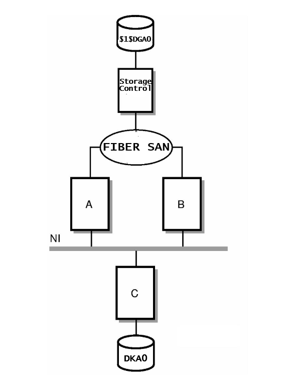
3.3.7.2. Disk By Node Format
The following example shows disk statistics in By Node format:
Tabular Report                                                CLUSTER                                                     Page   2
                                                                                                                     PSPA V3.1-1301
                                                  Friday 30-JAN-2026 00:00 to 18:47

 +----------------------------------- BY NODE Disk Statistics -------------------------+
 !                                                                                     !
 !                             Work                             Resp                   !
 !                             Avail   Paging  Swping   Rate    Time   Queue   Space   !
 !                               %       %       %      (/s)    (ms)   Length  Used %  !
 !                             ------  ------  ------  ------  ------  ------  ------  !
 ! $1$DGA1000                                                                          !
 !       BARNEY                   0.0     0.0     0.0     0.0       2     0.0       0  !
 !       ITAN1                    0.0     0.0     0.0     0.0       0     0.0       0  !
 !       BOOTES                   0.0     0.0     0.0     0.0       0     0.0       0  !
 !       FATHOM                   0.0     0.0     0.0     0.0       0     0.0       0  !
 !       BART                     0.0     0.0     0.0     0.0       3     0.0       0  !
           .                        .       .       .       .       .       .       .
           .                        .       .       .       .       .       .       .
           .                        .       .       .       .       .       .       .
 ! $1$DGA500                                                                           !
 !       BARNEY                   7.9     0.0     0.0   515.9       0     0.1      31  !
 !       ITAN1                    2.8     0.0     0.0    59.5       0     0.0      31  !
 !       BOOTES                   1.8     0.0     0.0   130.8       0     0.0      31  !
 !       FATHOM                   0.0     0.0     0.0   199.9       1     0.1      31  !
 !       BART                     6.9     0.0     0.0   120.7       1     0.1      31  !
           .                        .       .       .       .       .       .       .
           .                        .       .       .       .       .       .       .
           .                        .       .       .       .       .       .       .
 ! $5$DKA0                                                                             !
 !       BART                     0.2     0.2     0.0     0.3       5     0.0      58  !
 ! BARNEY$DKA100                                                                       !
 !       BARNEY                   0.2     0.0     0.0     0.2      11     0.0      78  !
 +-------------------------------------------------------------------------------------+
In the By Node format for disk statistics, the leftmost column of the tabular report contains the name of each disk, followed by the name of each node from which the disk was accessed. Following each node name is the processor type; and if the node hosted the disk, the word host.
Each disk, with node names, begins a line of disk statistics similar to the By Cluster format. These statistics show the contribution of each individual node to the cluster-wide activity of a specific disk. The way the Performance software determines a node's contribution to the cluster-wide activity of a disk depends upon whether the node has direct or remote access to the disk. For nodes with remote access, the I/O statistic for each node is that node's contribution to the total cluster I/O load.
In the case of a configuration with one node with direct access to the disk and any number of nodes with remote access, I/O statistics for the node with direct access includes I/Os from any nodes with remote access to the disk.
Therefore, to compute the direct access node's contribution, the software subtracts the number of I/Os of the nodes with remote access from the I/O information of the node with direct access.
In the case of two nodes with direct access to a disk with any number of nodes with indirect access, both direct nodes' I/O statistics include I/O from any remote nodes. Therefore, it is not possible to compute the By Node contribution to the cluster total of the nodes with direct access to the disk. The By Node contribution of the nodes that access the disk remotely is each node's I/O statistics.
For example, the software would calculate By Node rates for disks $1$DGA0 and DKA0: in the example configuration as follows. For disk $1$DGA0 with the storage controller, all I/Os come to this disk through host (direct access) Nodes A and B. The I/O information for these nodes includes I/O from the served (remote access) Node C. There is no way to distinguish whether Node C's I/Os were processed by Node A or Node B. Therefore, calculating the By Node contribution for Nodes A and B, which directly access the disk, is not possible. The By Node contribution for Node C, which has remote access to Disk $1$DGA0, is the I/O statistic for Node C.
For disk DKA0:, Node C is the host (direct access) node; all I/Os come to this disk through Node C. Therefore, to calculate Node C's By Node contribution, subtract from Node C's I/O information from Nodes A and B, which have remote access to DKA0:. The By Node contribution of Nodes A and B, is each node's I/O statistics.
3.3.7.3. By Cluster and By Node Disk Statistics
The following discussion explains the By Cluster and By Node Disk Statistics. The disk statistics reported in By Cluster and By Node formats are as follows:
- Work Avail%
The percentage of time that work was available for the disk. Reported only for By Node statistics.
- Paging %
The percentage of the work available, marked as Page I/O.
- Swping %
The percentage of the work available, marked as Swap I/O. This includes both swapping and modified page writing.
- Rate(/s)
The number of I/O operations per second performed by the device.
- Resp Time(ms)
The response time. This is the mean total service time, per I/O request, for the device in milliseconds. This is the total time taken to service an I/O request and is the sum of the queuing time and the busy time. It is thus measured from the time the I/O request is issued until the time the controller completes the request. This value is computed as (Average device queue length)/Rate.
- Queue length
The average number of disk I/O requests waiting for service.
- Space Used %
The percentage of the total disk volume space that is allocated. Reported only for mounted disks.
3.3.7.4. Server By Cluster Format
The following example shows server statistics in BYCLUSTER format.
In the By Cluster format for server statistics, the leftmost column of the tabular report contains the name of each server that is accessible cluster-wide. Server names are followed, in parentheses, by the name of the CPU or HSC server with which they are associated. Each server name begins a line of server statistics. Each statistic shows the activity for the specific server due to all nodes in the cluster, as shown in the following example:
 +----------------- CLUSTER Server Statistics ---------------+
 !                                                           !
 !                   Alloc     Paging    Swping    Queue     !
 !                   Class       %         %       Length    !
 !                   ------    ------    ------    ------    !
 ! BARNEY    (ALPH)       0       0.0       0.0       0.0    !
 ! BART      (ALPH)       5       0.2       0.0       0.0    !
 ! BOOTES    (IA64)       3       0.0       0.0       0.0    !
 ! FATHOM    (X86 )       1       0.3       0.0       0.0    !
 ! ITAN1     (IA64)      10       0.0       0.0       0.0    !
 +-----------------------------------------------------------+
3.3.7.5. Server By Node Format
In the By Node format for server statistics, the leftmost column of the tabular report contains the name of each server that is accessible cluster-wide. This is followed by the name of each node from which the server was accessed. Each server, by node name, begins a line of server statistics as in the case of By Cluster format. These statistics show the contribution of each individual node to the activity of a specific server. Server names are followed, in parentheses, by the processor type or HSC type with which they are associated. Node names are followed, in parentheses, by the processor type for the node. The following example shows server statistics in BYNODE format:
 +----------------- BY NODE Server Statistics ---------------+
 !                                                           !
 !                   Work                                    !
 !                   Avail     Paging    Swping    Queue     !
 !                     %         %         %       Length    !
 !                   ------    ------    ------    ------    !
 ! BARNEY     (ALPH)                                         !
 !    BARNEY  (Alph)    0.1       0.0       0.0       0.0    !
 !    ITAN1   (HP r)    0.0       0.0       0.0       0.0    !
 !    BOOTES  (HP B)    0.0       0.0       0.0       0.0    !
 !    FATHOM  (VMwa)    0.0       0.0       0.0       0.0    !
 !    BART    (Alph)    0.1       0.0       0.0       0.0    !
 ! BART       (ALPH)                                         !
 !    BARNEY  (Alph)    0.0       0.0       0.0       0.0    !
 !    ITAN1   (HP r)    0.0       0.0       0.0       0.0    !
 !    BOOTES  (HP B)    0.0       0.0       0.0       0.0    !
 !    FATHOM  (VMwa)    0.0       0.0       0.0       0.0    !
 !    BART    (Alph)    0.0       0.2       0.0       0.0    !
         .        .       .         .         .         .
         .        .       .         .         .         .
         .        .       .         .         .         .
 ! FATHOM     (X86 )                                         !
 !    BARNEY  (Alph)    0.0       0.0       0.0       0.0    !
 !    ITAN1   (HP r)    0.0       0.0       0.0       0.0    !
 !    BOOTES  (HP B)    0.0       0.0       0.0       0.0    !
 !    FATHOM  (VMwa)    0.0       0.3       0.0       0.0    !
 !    BART    (Alph)    0.0       0.0       0.0       0.0    !
 ! ITAN1      (IA64)                                         !
 !    BARNEY  (Alph)    0.0       0.0       0.0       0.0    !
 !    ITAN1   (HP r)    0.1       0.0       0.0       0.0    !
 !    BOOTES  (HP B)    0.0       0.0       0.0       0.0    !
 !    FATHOM  (VMwa)    0.0       0.0       0.0       0.0    !
 !    BART    (Alph)    0.0       0.0       0.0       0.0    !
 +-----------------------------------------------------------+
3.3.7.6. By Cluster and By Node Server Statistics
The server statistics reported in By Cluster and By Node formats are:
- Alloc Class
The allocation class of the node or HSC associated with the server. Reported only for By Cluster statistics.
- Work Avail %
The percentage of time there were I/O requests at the server queue. Reported only for By Node statistics.
- Paging %
The percentage of the work available marked as Page I/O.
- Swping %
The percentage of work available marked as Swap I/O.
- Queue Length
The average sum of the requests at the server queue.
Chapter 4. Generate Historical Graphs
You can generate graphs and pie charts from current or historical data for many
aspects of the system. Numerous types of predefined graphs are available. You can also
create custom graphs to represent your site-specific needs. These graphs can be printed
or displayed on your terminal. The /FILTER qualifier lets you select
a subset of data for graphs. For more information, see the chapter Performance
Manager Commands.
4.1. Generate Predefined Graphs
You can generate predefined graphs in the following three ways:
At the DCL level – see Section 4.1.1, ''Generate Graphs from the DCL Level''
Within the Performance Manager command mode – see Section 4.1.2, ''Generate Graphs in Command Mode''
Within the DECwindows interface – see Chapter 8, "Use the DECwindows Motif Interface".
Regardless of the method you use, the basic process is the same. The Performance Manager selects, reads, and buckets the data, then formats and writes the graph to the output device.
Each method has its own advantages and disadvantages in terms of ease of use, efficiency, and equipment. This section discusses how to create single and multiple graphs from the DCL level and within the Performance Manager command mode. The DECwindows Motif Interface is discussed in the Chapter 8, "Use the DECwindows Motif Interface".
4.1.1. Generate Graphs from the DCL Level
Generating graphs at the DCL level offers the most efficient method of selecting data. Only those metrics contributing to the selected graphs are saved and bucketed when the performance data is read. The CPU demand is mostly for reading and decoding the data files. By contrast, the data selection for the DECwindows and command mode interfaces is somewhat more costly because all the performance metrics are usually saved and bucketed in anticipation of a subsequent user request to view them. See Appendix D, "Estimate Virtual Memory Needs" for information on estimating virtual memory needs and selecting data.
To generate a graph or pie chart, use the following commands:
$ ADVISE PERFORMANCE GRAPH
$ ADVISE PERFORMANCE PIE_CHART
With either command, you can control the data selection by specifying a time
period and list of node names. The /TYPE qualifier specifies
graphs or performance metrics or both. The /FORMAT qualifier
controls the format of the output data. The /OUTPUT qualifier
directs the output data to the desired destination.
You can generate all of the predefined graphs in a single command by using the
/TYPE=ALL_GRAPHS qualifier. However, if you do not
specify a graph, the CPU Utilization graph is the default.
4.1.2. Generate Graphs in Command Mode
If you are investigating performance data interactively, generating graphs from command mode offers several distinct advantages. Once the data has been loaded into memory, you can view graphs and reports quickly, skipping around as dictated by your investigation, without causing the input data to be reread and reanalyzed. Also, if you need to produce output files in different formats, command mode is more efficient than using DCL commands.
To invoke command mode, enter the following command:
$ ADVISE PERFORMANCE
PSPA>
In command mode, you must first select the data you want to use, and then you specify the method you want to use to view it.
The graphs can be viewed in ReGIS mode on a terminal, and then written to a file in Postscript, for example, without having to reread and analyze the data. Also, you can switch between graphs and pie charts without reprocessing the data.
To select data, enter the SELECT command and specify the
processing options you want to use. You can specify any or all of these
processing options: ANALYSIS, PERFORMANCE, and GRAPHS. For example:
PSPA> SELECT GRAPHS /NODE=FATHOM
This command selects data for node FATHOM; subsequent GRAPH
commands use this data to generate graphs.
The ANALYSIS option provides the results of the factory rules and optionally user rules that may fire as a result of your performance data.
The PERFORMANCE_EVALUATION option allows you to view and output sections of the Performance Evaluation Report and Tabular Report, which contain statistics about the system, including process and disk activity, and summaries.
The GRAPHS option lets you control how data is to be
selected for subsequent graphing operations (including pie charts). The GRAPHS
option has the following eight sub-options:
IMAGENAMES
USERNAMES
HOTFILES
USERVOLUMES
IO_DEVICES (and workloads)
BY_NODE
ALL
DEFAULT
DEFAULT, generates graphs for IMAGENAMES, USERNAMES, and IO_DEVICES (and workloads).
DEFAULT is used in the absence of any specified graph processing options. ALL is equivalent to the complete list: IMAGENAMES, USERNAMES, HOTFILES, USERVOLUMES, IO_DEVICES (and workloads), and BY_NODE.
Note that when you are processing a large amount of data, each option can pose significant additional CPU and memory demands on your process.
If you specify NOALL, only system-level metrics are saved. NOALL is helpful when you need to select data as fast as possible, and retain the ability to generate graphs for the system-level metrics. The system-level metrics are always saved BY_NODE as well.
The processing options IMAGENAMES, USERNAMES, HOTFILES, IO_DEVICES (and workloads), and USERVOLUMES cause the selection process to maintain the graph statistics for each unique occurrence of an image name, user name, and so forth. The BY_NODE option causes these statistics to be maintained on both a per-node and a composite (all nodes) basis. The BY_NODE option can increase the memory demands to select the data, as a factor of the number of nodes being selected. See Appendix D, "Estimate Virtual Memory Needs" for information on estimating virtual memory needs and selecting data.
After selecting the data, you can specify as many GRAPH, PIE_CHART, or REPORT commands as you wish. You can also select more data. The chapter Chapter 7, "Use Command Mode Commands" describes the commands available in command mode.
Because Performance Manager provides so many different choices for predefined and custom graphs, you may prefer to use an interactive dialogue to make your selections.
You can request this interactive prompting from within
command mode by entering the GRAPH/TYPE=PROMPT command. The
Performance Manager's response is as follows:
PSPA> GRAPH/TYPE=PROMPT
                          Please select either   1) a predefined graph or
                                                 2) a custom graph
                                Choice:
                                      .
                                      .
                                      .
Enter the graph type keyword (<cr> for list): cpu_utilization.
A graph is produced. When you press Return, prompting continues.
4.2. Generate Multiple Graphs
When you generate multiple graphs with one DCL command or in Command Mode, you can
produce a separate output file for each graph by specifying the
/OUTPUT qualifier. The Performance Manager names each file
according to the node and graph type with a default or user-specified file
type.
For example, the following command creates a separate graph output file for each graph. The files reside in the default directory, and are named FATHOM_CPU_UTILIZATION.REG and FATHOM_TOP_BUSY_VOLUMES.REG.
$ ADVISE PERFORMANCE GRAPH/TYPE=(CPU_UTILIZATION,TOP_BUSY_VOLUMES)-
_$ /FORMAT=REGIS=CHARACTERISTIC=COLOR/NODE=FATHOM/OUT=[]
You can specify device, directory, and filenames with the
/OUTPUT qualifier if you do not want to take the
defaults.
4.3. Components of Graphs
Each graph has the same basic components, as shown in the following table:
|
Component |
Applies to |
|---|---|
|
Title |
graphs and pie charts |
|
Subtitle |
graphs and pie charts |
|
Axis |
labels graphs only |
|
X- and Y-axis markers |
graphs only |
|
Legend |
graphs only |
|
Units and Unit total |
pie charts only |
|
MIN, MAX, and AVG |
graphs only, if one metric or if items are stacked |
The following list describes each component:
- Title
For the predefined graphs, the title identifies the type of graph and is centered at the top of the graph. For custom graphs, the title is PSPA CUSTOM GRAPH unless you specify a title. Titles for ReGIS and PostScript graphs are in enlarged characters.
- Subtitle
The graph and pie chart subtitle gives the node name (or the list of node names for composite graphs) and the date and time of the selected data. Also, the x-axis data points and the width, in time, of each point, is provided for graphs.
- Axis Labels
All graphs have Time implied as the x-axis label. Labels for the y-axis specify the units of the plotted values, for example, Page Faults Per Second. If metrics of differing units coexist on the graph, the y-axis label is blank.
- Y-Axis Markers
Axis markers indicate the magnitude and time of any point on the graph. The x-markers indicate the time and are displayed differently depending on the graphic format. The x-markers are displayed as HH:MM, HH, MM:SS, MM, DD, or MMM depending on the graph time range, and graphic format. When graphing historical data, month or even years may appear, depending on the time range selected.
The y-markers are based on the maximum value of all the data points. The increments are obtained from an internal table to make the graph easy to read. You may define the maximum value on the y-axis by using, the Y_AXIS_MAXIMUM keyword.
- Legend
The legend appears at the bottom of the graph for all graphs other than ANSI graphs. The legend identifies the name of the metric, and the color, pattern, or graph character associated with it. For the predefined TOPxxx graphs, the items are always in the same format and order; for example, other (users, workloads, images, volumes, disks, and so forth), topmost, second top, third top, fourth, and fifth.
4.4. Composite Graphs
If multiple nodes contribute data to a graph, the graph is considered a composite graph. Data for each node can be added together, scaled by some factor, and added, or averaged. The method used depends on the metric being displayed. CPU percentages are scaled by CPU VUP rating, then added.
Response times, I/O sizes, and disk space are averaged for each node and all other metrics are summed for each node.
To generate composite graphs, specify /COMPOSITE on the DCL
command line, or if in command mode with more than one nodes data selected, omit the
/NODE qualifier. When using Windows, the CLUSTER option or
ALL NODES option generates the composite graph.
You can recognize a composite graph if there is more than one node listed in the subtitle.
Note
When you produce a composite Graph or Pie Chart and the nodes contribute data to the graph for different time periods (possibly missing data), the results are undefined. Composite Graphs and Pie Charts show accurate totals and averages when the data for the nodes correspond to the same time period.
4.5. Stacked Graphs
Graphs showing more than one metric can be displayed either stacked or unstacked.
When stacked, the metric data points are added such that the top-most category on
the graph plots the sum of all the metrics. You can specify that all graphs be
stacked with the /STACK qualifier or you can specify that none
are to be stacked with the /NOSTACK qualifier. Also, each graph
you request can have its own specific stack or nostack attribute.
Stacking is provided by default on some graphs, where it makes good sense to do so, and the remaining graphs are provided unstacked. Specifically, rates, percentages, and counts are stacked by default, and response times, I/O size, and disk space utilization are unstacked, by default.
4.6. Create Typical Time Period Graphs
If you want your graphs to represent a typical time period, such as an average
day, you can turn on graph averaging. On the DCL command line, specify
/AVERAGE=DAILY (WEEKLY, MONTHLY, and
QUARTERLY are also options). From command mode the
/AVERAGE qualifier must be specified with the SELECT verb.
Window users can set this option from the Select Data dialog box under Additional
Options....
If you want a typical Monday type graph, you specify
/AVERAGE=WEEKLY and specify a schedule with only Monday as
indicated in the following example:
/SCHEDULE=(NOEVERYDAY,MON=0-24)
If history data, with the periodicity attribute set, is used for the graph, the history's periodicity is used for (and overrides) the graph averaging.
4.7. Scheduling
If you want certain time periods included and others not included on the graph,
you can use a combination of the schedule and dates features. The
/SCHEDULE qualifier, and the schedule time clocks in the
window interface, allow you to specify desired hours on a weekly basis for inclusion
on the graph. If you need more specific selection time frames, you can use a DATES
file (see the /DATES qualifier), which specifies an unlimited
number of date ranges, to indicate the desired time frames for inclusion in the
graph.
You may want to use both the /DATES qualifier and the
/SCHEDULE qualifier together. For example, if you need a
graph depicting an average Monday through Thursday prime time for the first week of
September, October, November and December of 2025, your schedule and dates file
would be as follows:
MYDATES.DAT:
07-SEP-2025,11-SEP-2025
05-OCT-2025,09-OCT-2025
02-NOV-2025,06-NOV-2025
07-DEC-2025,11-DEC-2025
To use this dates file, enter a command similar to the following:
$ ADVISE PERFORMANCE GRAPH/SCHEDULE=(NOWEEKENDS,WEEKDAYS=(9-12 -,
_$ 14-17),NOFRIDAY)/DATES=MYDATES.DAT/AVERAGE=WEEKLY
4.8. Use Binary Graph Data
The DECwindows and the command mode interfaces let you save the graph data that you selected for viewing into a file. This binary file can later be reloaded into either of the interfaces and the graphs presented, eliminating the need for re-analyzing the data.
The following example shows the command mode interface:
 $ ADVISE PERFORMANCE
 PSPA> SELECT GRAPHS=BY_NODE /BEG=26-JAN-2026:9/END=26-JAN-2026:17
 PSPA> SAVE JAN26.GRAPHS
 PSPA> EXIT

 $ ADVISE PERFORMANCE
 PSPA> LOAD JAN26.GRAPHS
 PSPA> GRAPH /TYPE=CPU_UTILIZATION /NODE=NODE1
You can modify the PSPA$DAILY.COM file in PSPA$EXAMPLES to save the graph data during a nightly batch job and the next day, load the data if the analysis report indicated any problems.
4.9. Components of Pie Charts
Each pie chart includes the following components:
- Title
For the predefined pie charts, the title identifies the type of pie chart.
- Subtitle
The pie chart subtitle gives the node name (or the list of node names for composite pie charts) and the date and time of the selected data.
- Whole Pie Represents
The Whole Pie represents the sum of metric values represented by each pie slice.
- Pie Slices
The Pie Slices represent the average value of the metric over the time period presented in descending order by value.
- Label
The label associated with each slice identifies the metric or item being presented along with the percentage contribution to the pie chart. The actual value of the metric can be obtained through either the tabular or CSV pie chart formats.
- Legend
The legend identifies the name of the metric, and the color, pattern, or character associated with it.
4.10. Pie Chart Presentation of CPU Utilization
Pie charts that reflect metrics measured in terms of CPU percentages now have two
possible presentations. If you specify /PERCENTAGE=MAXIMUM, the
pie is drawn in terms of 100 percent, with an IDLE section appearing. If you specify
/PERCENTAGE=TOTAL the pie is drawn to represent the total of
the metrics presented.
For example, if you are producing a pie chart of CPU utilization and the parts of the pie chart have the following values:
Interactive 30%
Batch 10%
Network 5%
Overhead 1%
Interrupts 5%
Other 0%
If you specify /PERCENTAGE=MAXIMUM, the pie chart contains an
idle slice representing 49 percent of the total pie with the remaining 51 percent
representing their respective slices.
If you specify /PERCENTAGE=TOTAL, the pie chart represents the
sum of these parts, a total of 51 percent utilization, with the largest slice of the
pie (approximately 3/5) being represented by Interactive.
If you do not specify /PERCENTAGE on the PIE command line, then
/PERCENTAGE=MAXIMUM is assumed. This qualifier has no effect
on graphs, custom pie charts, or pie charts of metrics other than CPU
Utilization.
4.11. Format Graphs and Pie Charts
You can control the format of the Performance Manager's graphs and pie charts. The following formats are available:
|
Format available |
Graphs |
Pie Charts |
|---|---|---|
|
PostScript |
Y |
y |
|
Tabular |
Y |
y |
|
CSV |
Y |
y |
|
ReGIS |
Y | |
|
ANSI |
Y |
The ANSI-formatted, tabular and PostScript output can be printed on any output device. Color graphs print or display on monochrome devices in shades of gray.
See the discussion on the logical names to change the colors of the ReGIS and PostScript graphs in the Appendix Performance Manager Logical Names.
4.11.1. Refresh a ReGIS Graph with New Characteristics
After you generate a ReGIS graph to the SYS$OUTPUT device, you receive the following prompt:
Type <CR> to continue

If a broadcast message disrupts the display of the ReGIS graph
you can refresh the display with the following procedure.

You can either enter a C (for color), P (for pattern),
or L (for line) to regenerate the graph currently on the screen
with a changed characteristic. The DCL qualifiers that obtain
these characteristics are as follows:

/FORMAT=ReGIS=CHARACTERISTIC=COLOR
/FORMAT=ReGIS=CHARACTERISTIC=LINE
/FORMAT=ReGIS=CHARACTERISTIC=PATTERN
With each method, it is possible to redraw the current graph if a broadcast message disrupts the display.
4.11.2. Output Formats
The following figure, PostScript Graph, illustrates a PostScript formatted color graph. The graph was generated with the following command:
$ ADVISE PERFORMANCE GRAPH/BEGINNING=28-FEB-2026:13:00/ENDING=28-FEB-2026:17:00 -
_$ /TYPE=CPU_UTILIZATION/NODE=FATHOM/OUTPUT=FATHOM_CPU_UTIL.PS -
_$ /FORMAT=POSTSCRIPT=CHARACTERISTIC=COLOR
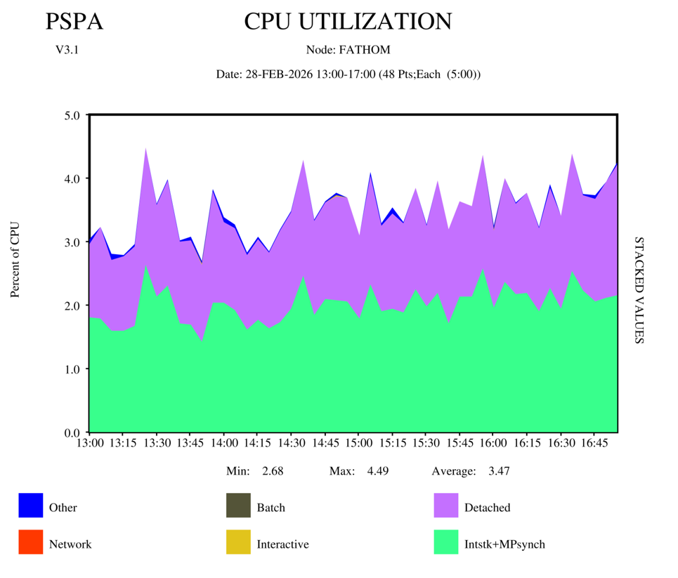 |
The following figure, PostScript Formatted Line Graph, illustrates a PostScript formatted color line graph. The graph was generated with the following command:
$ ADVISE PERFORMANCE GRAPH/BEGINNING=28-FEB-2026:13:00/ENDING=28-FEB-2026:17:00 -
_$ /TYPE=CPU_UTILIZATION/NODE=FATHOM/OUTPUT=FATHOM_CPU_UTIL_LINE.PS -
_$ /NOSTACK/FORMAT=POSTSCRIPT=CHARACTERISTIC=(LINE,COLOR)
The LINE keyword is used with the /NOSTACK qualifier to
avoid occlusion.
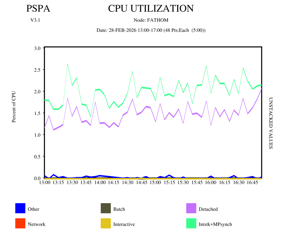 |
ANSI Formatted Graph is the same CPU utilization graph as Tabular Formatted Graph in ANSI formatted output. The default width of an ANSI graph is 132 characters. This graph overrides the default width. It was generated with the following command:
$ ADVISE PERFORMANCE GRAPH/BEGINNING=28-FEB-2026:13:00 -
_$ /ENDING=28-FEB-2026:17:00/TYPE=CPU_UTILIZATION/NODE=FATHOM
_$ /OUTPUT=FATHOM_CPU_UTIL.LIS/FORMAT=ANSI=(WIDTH=
79,HEIGHT=25)
                                CPU UTILIZATION
                                 Node: FATHOM
                         Date: 28-FEB-2026 13:00-17:00

                                                 LEGEND:
                                                 * =  Other
                                                 N =  Network
                                                 B =  Batch
                                                 I =  Interactive
                                                 D =  Detached
                                                 X =  Intstk+MPsynch
                                                 (Metric Values are Stacked)
Y-Units: Percent of CPU

  5.0 !
  4.8 !         D       *          I     D  D
  4.6 !         D       D          D     D  D
  4.4 !         D       D          D  D  D  D              D           D   D D
  4.2 !      D  D       D          D  D DD  D              D  *D       D   D D
  4.0 !      D  D       D          D  D DD  D     D  D     D  DD    D  D D D D
  3.8 !      DD DD      D          DD D DD  D    DD *D  DD D  DD D  DD DDDDD D
  3.6 !      DD DD D    DD        DDD D DD  D  D DD DD  DDDD  DD D  DD DDDDD D
  3.4 !D D   DDDDDDD    DD D D   DDDDDD DD DDDDD DD DDD DDDD**DDDD DDD DDDDDDD
  3.2 !D DD  DDDDDDD  D DD D DD DDDDDDD DD DDDDD DD DDDDDDDDDDDDDDDDDD DDDDDDD
  3.0 !D DD  DDDDDDDDDD DD D DD DDDDDDDDDD DDDDD DD DDDDDDDDDDDDDDDDDD DDDDDDD
  2.8 !D DDD DDDXDDDDDD XD DDDD DDDDDDDDDDDDDDDD DD*DDDDDDDDDDDDDDDDDDDDDDDDDD
  2.6 !DDDDDDDDDXDDDDDDDXDDDDDDDDDDXDDDDDXDDXDDDDDDDDDDDDDDXDDDDDDDDDDDXDDDDDD
  2.4 !DDDDDDDDDXDDDDDDDXDDDDDDDDDDXDDXDXXDDXDDDDDXDDDDDDDXXDDXXDDDDXDDXDXDXDD
  2.2 !DDDDDDXXXXXXXDDDDXXDDDDDDDDXXXDXDXXDDXDDDDXXDXXDDXXXXDXXXXXDXXXDXXXXXDX
  2.0 !XDXDDDXXXXXXXDDDDXXDXDDDDDXXXXXXDXXDXXXXXDXXDXXDDXXXXXXXXXXDXXXDXXXXXXX
  1.8 !XDXXDDXXXXXXXDDXDXXDXDXXDDXXXXXXXXXDXXXXXDXXDXXXXXXXXXXXXXXXXXXDXXXXXXX
  1.6 !XXXXXXXXXXXXXXXXDXXXXXXXXXXXXXXXXXXXXXXXXXXXXXXXXXXXXXXXXXXXXXXXXXXXXXX
  1.4 !XXXXXXXXXXXXXXXXXXXXXXXXXXXXXXXXXXXXXXXXXXXXXXXXXXXXXXXXXXXXXXXXXXXXXXX
  1.2 !XXXXXXXXXXXXXXXXXXXXXXXXXXXXXXXXXXXXXXXXXXXXXXXXXXXXXXXXXXXXXXXXXXXXXXX
  1.0 !XXXXXXXXXXXXXXXXXXXXXXXXXXXXXXXXXXXXXXXXXXXXXXXXXXXXXXXXXXXXXXXXXXXXXXX
  0.8 !XXXXXXXXXXXXXXXXXXXXXXXXXXXXXXXXXXXXXXXXXXXXXXXXXXXXXXXXXXXXXXXXXXXXXXX
  0.6 !XXXXXXXXXXXXXXXXXXXXXXXXXXXXXXXXXXXXXXXXXXXXXXXXXXXXXXXXXXXXXXXXXXXXXXX
  0.4 !XXXXXXXXXXXXXXXXXXXXXXXXXXXXXXXXXXXXXXXXXXXXXXXXXXXXXXXXXXXXXXXXXXXXXXX
  0.2 !XXXXXXXXXXXXXXXXXXXXXXXXXXXXXXXXXXXXXXXXXXXXXXXXXXXXXXXXXXXXXXXXXXXXXXX
      ++-----+-----+-----+-----+-----+-----+-----+-----+-----+-----+-----+----
     13:00 13:20 13:40 14:00 14:20 14:41 15:01 15:21 15:41 16:01 16:22 16:42

             Min:    2.47   Max:    4.77   Average:    3.47
The following table, Tabular Formatted Output, illustrates tabular formatted output. Tabular output is in 132-column format. It was generated with the following command:
$ ADVISE PERFORMANCE GRAPH/BEGINNING=28-FEB-2026:13:00 -
_$ /ENDING=28-FEB-2026:17:00/TYPE=CPU_UTILIZATION/NODE=FATHOM -
_$ /OUTPUT=FATHOM_CPU_UTIL_TAB.LIS/FORMAT=TABULAR
                                                           CPU UTILIZATION
                                                            Node: FATHOM
                                                    Date: 28-FEB-2026 13:00-17:00

Metric Values are Stacked (eg. Added to the left)
Units:     Percent of CPU

Time                      Other             Network               Batch         Interactive            Detached      Intstk+MPsynch
28-FEB-2026 13:00        2.8214              2.7106              2.7106              2.7106              2.7106              1.7731
28-FEB-2026 13:02        3.9244              3.8651              3.8651              3.8651              3.8651              2.1943
28-FEB-2026 13:04        2.3474              2.3200              2.3200              2.3200              2.3200              1.4408
28-FEB-2026 13:06        2.6768              2.6768              2.6768              2.6768              2.6768              1.4215
28-FEB-2026 13:08        3.7838              3.7838              3.7838              3.7838              3.7799              2.1548
28-FEB-2026 13:10        2.8297              2.6886              2.6886              2.6886              2.6886              1.6303
28-FEB-2026 13:12        3.1782              3.0597              3.0597              3.0597              3.0555              1.7222
28-FEB-2026 13:14        2.3916              2.3916              2.3916              2.3916              2.3877              1.4266
.
.
.
28-FEB-2026 16:52        4.8650              4.8650              4.8650              4.8650              4.8650              2.5681
28-FEB-2026 16:54        3.3454              3.3454              3.3454              3.3454              3.3454              1.8111
28-FEB-2026 16:56        4.1280              4.0640              4.0640              4.0640              4.0640              1.9765
28-FEB-2026 16:58        4.3638              4.3638              4.3638              4.3638              4.3598              2.3131


 Minimum Values          0.0000              0.0000              0.0000              0.0000              0.4667              1.1170
 Maximum Values          0.1721              0.0000              0.0000              0.0083              2.5333              2.8176
 Average Values          0.0270              0.0000              0.0000              0.0014              1.4553              1.9827
The following example, CSV Formatted Output, illustrates CSV formatted output. It was generated with the following command:
$ ADVISE PERFORMANCE GRAPH/BEGINNING=28-FEB-2026:13:00 /ENDING=28-FEB-2026:17:00 -
_$ /NODE=(FATHOM,BART,BARNEY,ITAN1,BOOTES) -
_$ /FORMAT=CSV=X_POINTS=8/TYPE=CUSTOM=SYSTEM_METRIC=CPU_TOTAL/COMPOSITE -
_$ /OUTPUT=CLUSTER_CPU_TOTAL.CSV
PSPA CUSTOM GRAPH
Nodes: FATHOM, BART, BARNEY, ITAN1, BOOTES
Date: 28-FEB-2026 13:00-17:00
Metric Values are Stacked (eg. Added to the left)
Units:     %CPU Total Busy
Time      ITAN1       BOOTES        BARNEY       BART        FATHOM
2/28/2026 13:00       11.5186       4.894        0.0071      0.0016       0.0007
2/28/2026 13:30       11.5004       3.5459       0.0072      0.0016       0.0007
2/28/2026 14:00       11.4638       4.8981       0.0068      0.0016       0.0007
2/28/2026 14:30       11.2118       7.2896       0.008       0.0017       0.0008
2/28/2026 15:00       11.2534       6.5587       0.0078      0.0017       0.0008
2/28/2026 15:30       11.4544       4.3147       0.0082      0.0017       0.0008
2/28/2026 16:00       11.3385       4.7145       0.0082      0.0017       0.0008
2/28/2026 16:30       11.1457       3.6029       0.0081      0.0018       0.0009
PostScript Formatted Pie Chart Output illustrates PostScript formatted output for a pie chart. It was generated with the following command:
$ ADVISE PERFORMANCE PIE_CHART/BEGINNING=28-FEB-2026:13:00 -
_$ /ENDING=28-FEB-2026:17:00/NODE=(FATHOM,BART,BARNEY,ITAN1,BOOTES) -
_$ /FORMAT=POSTSCRIPT=CHARACTERISTICS=COLOR/TYPE=CUSTOM=SYSTEM_METRIC=CPU_TOTAL -
_$/COMPOSITE/OUTPUT=CLUSTER_CPU_TOTAL.PS
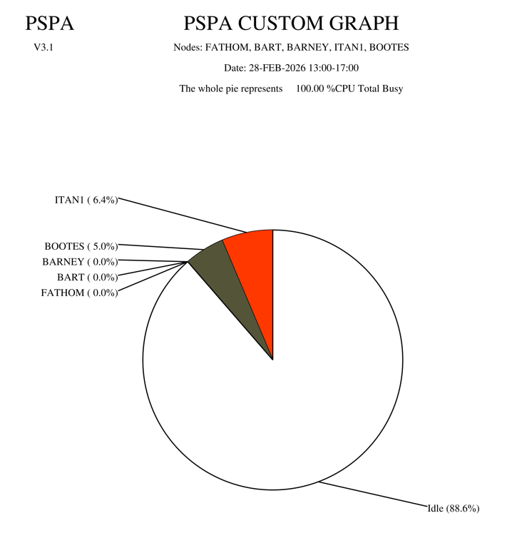 |
The following example, Tabular Formatted Pie Chart Output, illustrates tabular formatted output for a pie chart. It was generated with the following command:
$ ADVISE PERFORMANCE PIE_CHART/BEGINNING=28-FEB-2026:13:00 -
_$ /ENDING=28-FEB-2026:17:00/NODE=(FATHOM,BART,BARNEY,ITAN1,BOOTES) -
_$ /FORMAT=TABULAR/TYPE=CUSTOM=SYSTEM_METRIC=CPU_TOTAL/COMPOSITE -
_$ /OUTPUT=CLUSTER_CPU_PIE_TAB.LIS
                                   PSPA CUSTOM GRAPH
                    Nodes: FATHOM, BART, BARNEY, ITAN1, BOOTES
                           Date: 28-FEB-2026 13:00-17:00

                The whole pie represents     100.00 %CPU Total Busy


Item                          Value       Percent of Total
-----------------------   -------------   ----------------
ITAN1                           6.38352       6.384 %
BOOTES                          4.96963       4.970 %
BARNEY                          0.00600       0.006 %
BART                            0.00091       0.001 %
FATHOM                          0.00077       0.001 %
Idle                           88.63917      88.639 %
The following example, CSV Formatted Pie Chart Output, illustrates CSV formatted output for a pie chart. It was generated with the following command:
$ ADVISE PERFORMANCE PIE_CHART/BEGINNING=28-FEB-2026:13:00 -
_$ /ENDING=28-FEB-2026:17:00/NODE=(FATHOM,BART,BARNEY,ITAN1,BOOTES) -
_$ /FORMAT=CSV/TYPE=CUSTOM=SYSTEM_METRIC=CPU_TOTAL/COMPOSITE -
_$ /OUTPUT=CLUSTER_CPU_PIE.CSV
PSPA CUSTOM GRAPH
Nodes: FATHOM, BART, BARNEY, ITAN1, BOOTES
Date: 28-FEB-2026 13:00-17:00
The whole pie represents     100.00 %CPU Total Busy
Item       Value       Percent of Total
ITAN1      6.38352       6.384
BOOTES     4.96963       4.97
BARNEY     0.006         0.006
BART       0.00091       0.001
FATHOM     0.00077       0.001
Idle      88.63917      88.639
4.11.3. Data Resolution with X_POINTS
For ReGIS and PostScript graphs, the X_POINTS keyword indicates the number of
data points to plot along the x-axis of the graph, and is
specified with the
/FORMAT=REGIS=X_POINTS=number
qualifier, from a DCL command, or
/X_POINTS=number qualifier from
command mode.
For Tabular graphs, the X_POINTS keyword specifies the number of data points
to present in the report, and is specified with the
/FORMAT=TABULAR=X_POINTS=number
qualifier. The valid range for X_POINTS is 2 to 480, the
default is generally from 45 to 90, but is computed to produce an even time
interval per point.
The following are examples of specifying the X_POINTS keyword:
DCL command:
$ ADVISE PERFORMANCE GRAPH/FORMAT=REGIS=X_POINTS=number
Command mode:
PSPA> SELECT GRAPH/X_POINTS=number
DECwindows:
Specify the Additional Options... option from the Select Data dialog box.
As the value of X_POINTS increases, more peaks and valleys appear on a graph. As the value decreases, the peaks and valleys are smoother because Performance Manager averages data points within the time frame requested.
The next three figures illustrate the relationship between the value of X_POINTS and a time frame of 4 hours. During this period the Performance Manager records statistics 120 times (every 2 minutes).
For the first graph, X_POINTS is specified as 60, thus two data records are averaged to calculate the value of each point plotted.
This command generates the graph:
$ ADVISE PERFORMANCE GRAPH /BEGINNING=16-APR-2026:17:00:00 -
_$ /ENDING=17-APR-2026:12:00:00/TYPE=CPU_UTILIZATION/NODE=FATHOM -
_$ /FORM=POSTSCRIPT=(CHARACTERISTIC=COLOR)
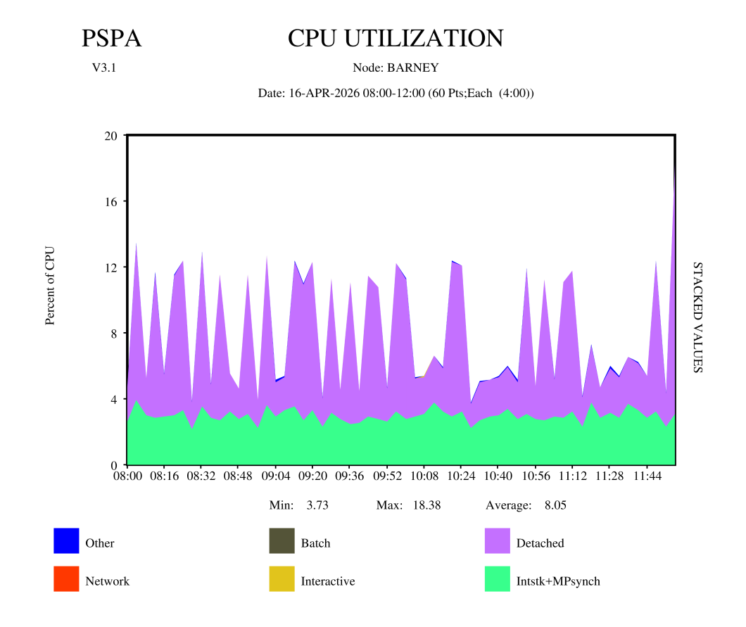 |
In the Maximum X_POINTS Graph, the value of X_POINTS is 480. Therefore, the graphing facility did not average the data.
This following command generates the following graph:
$ ADVISE PERFORMANCE GRAPH /BEGINNING=16-APR-2026:08:00:00 -
_$ /ENDING=16-APR-2026:12:00:00/TYPE=CPU_UTILIZATION/NODE=BARNEY -
_$ /FORM=POSTSCRIPT=(CHARACTERISTIC=COLOR,X_POINTS=480)
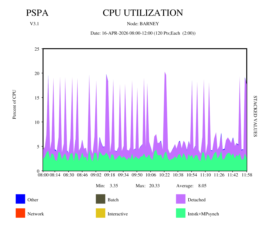 |
In the Minimum X_POINTS Graph, the value of X_POINTS is 8. The graphing facility averages every 15 data points in the four hour time span.
This command generates the graph:
ADVISE PERFORMANCE GRAPH /BEGINNING=16-APR-2026:08:00:00 -
_$ /ENDING=16-APR-2026:12:00:00/TYPE=CPU_UTILIZATION/NODE=BARNEY -
_$ /FORM=POSTSCRIPT=(CHARACTERISTIC=COLOR,X_POINTS=8)
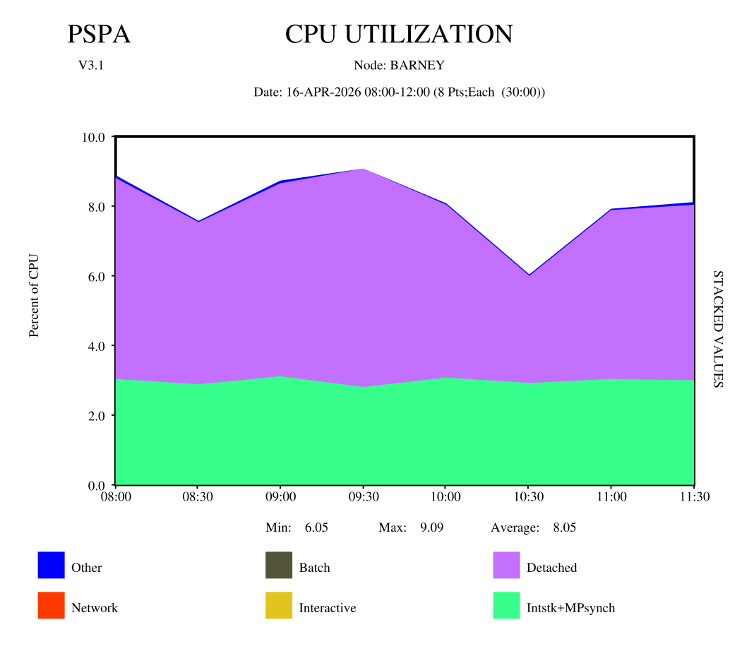 |
4.12. Generate Custom Graphs
The Custom graph type behaves differently than all other graph types because to control the graph data, you must specify one metric and up to six data items or up to six metrics and one data item.
You can use metrics from one of the following groups for a custom graph:
System metrics
Process metrics, selected by user name, image name or workload name
Disk device metrics, selected by device name or volume name
Processor mode metrics, selected by processor ID
HSC metrics, selected by HSC node name
SCS metrics, selected by SCS cluster node name
Rule metrics (for archived data only), selected by rule ID
HSC channel metrics, selected by HSC channel name
File metrics, selected by file name
Process Disk Volume I/O Rates, selected by user name and volume name, or image name and volume name
These metrics are described in the chapter Performance Manager Commands.
You can specify the metrics and data items by one of the following methods:
DCL command
Interactive prompting
The units that the various metrics represent may differ, for example, I/Os per second or percentage of CPU time. The Performance Manager allows you to include data with different metrics on the same graph. Use your discretion when doing this, however.
4.12.1. Graph System Metrics
The following command generates a custom graph:
$ ADVISE PERFORMANCE GRAPH/TYPE=CUSTOM=( -
_$ SYSTEM_METRICS=(DZRO,GVALID),TITLE="Pagefaulting")
The following example, Prompting for System Metrics Custom Graph, shows Performance Manager prompts and user input that generate the same graph in command mode:
$ ADVISE PERFORMANCE
PSPA> SELECT/BEGINNING=16-APR-2026:08:00 -
_PSPA> /ENDING=17-APR-2026:14:00:/NODE=(BARNEY,FATHOM) GRAPH=BY_NODE
The resulting graph appears in the example, Custom Graph for System Metrics.
PSPA> SELECT/BEGINNING=16-APR-2026:18:00 -
_PSPA> /ENDING=17-APR-2026:14:00:00 -
_PSPA> /NODE=(FATHOM)

              Processing Options
      -----------------------------------
      ANALYSIS REPORT                 YES
      PERFORMANCE_EVALUATION REPORT   YES
          Hot File Statistics         YES
          Process Statistics          YES
             By MODE                  YES
             By USERNAME              YES
             By IMAGENAME             YES
             By UICGROUP              YES
             By PROCESSNAME           NO
             By WORKLOAD              YES
             By ACCOUNTNAME           YES
             By PID                   NO
          All other statistics        YES
      GRAPHS                          YES
          User Names                  YES
          Image Names                 YES
          Hot File Names              NO
          User/Image Volume IO        NO
          IO Devices & workloads      YES
          By Node details             NO

Reading data for node FATHOM
PSPA>
PSPA> GRAPH/TYPE=PROMPT/FORMAT=POSTSCRIPT=CHARACTERISTIC=COLOR/OUT=CUSTOM_PAGFAULT.PS


   Please select either 1) a predefined graph or
                        2) a custom graph

             Choice [1]: 2

For the CUSTOM Graph, select one of the following:

1.  System Metrics
2.  Process metrics selected by user name
3.  Process metrics selected by image name
4.  Process metrics selected by workload name
5.  Disk device metrics selected by device name
6.  Disk device metrics selected by volume name
7.  Processor mode metrics by physical processor ID
8.  HSC metrics by HSC node name
9.  SCS metrics by SCS Cluster node name
10. RULE metrics by rule id
11. HSC Channel metrics by channel name
12. File metrics by file name
13. IOs by Username and Volumename
14. IOs by Imagename and Volumename
15. IOs by Workloadname and Volumename

Enter Choice (1 - 15): 1  [1]
Select Up to 6 System Metrics (<CR> for list):  [2]

GRAPH

  /TYPE

    CUSTOM

      System_metrics

         Select up to 6 of the following system metrics to be displayed on
         a custom graph:

         Sampled %CPU mode metrics (for all CPUs in an SMP configuration):

         COMPAT    EXEC      FILE_SYS    IDLE    INTERRUPT
         KERNEL    MP_SYNCH  SUPER       USER_MODE
         VBSSCPUTICK

         Sampled process counts by process state:

         COLPG     MWAIT     CEF         PFW     CUR
         LEF       LEFO      HIB         HIBO    SUSP
         SUSPO     FPG       COM         COMO
         INPROCACT           INPROCINACT
         OUTPROCACT          OUTPROCINACT
         TOTAL_PROCESSES

         Also: NUMBER_OF_USERS

         Sampled process counts by type:

         BATCH_PROCESSES           INTERACTIVE_PROCESSES
         NETWORK_PROCESSES  DETACHED_PROCESSES

         Derived CPU time metrics:

               %CPU Utilization                   Compute Queue
         ------------------------------     --------------------------
         CPU_BATCH      CPU_INTERACTIVE     BATCH_COMQ     INT_COMQ
         CPU_NETWORK    CPU_OTHER           NETWORK_COMQ   DETACHED_COMQ
         CPU_DETACHED   CPU_TOTAL
         CPU_MP_INT


         Timer Driver, Extended CPU metrics:

                         %CPU Utilization
         ----------------------------------------------------
         SWPBUSY    IOBUSY     ANYIOBUSY    PAGEWAIT    SWAPWAIT
         MMGWAIT    SYSIDLE    CPUONLY      IOONLY      CPUIO


         Sampled paging/swapping/memory metrics:

                   Paging Rates             MemoryPages    Swaprate
         ---------------------------------   --------      --------
         DZROFAULTS  FAULTS     FREEFAULTS    FREECNT      INSWAP
         GVALID      MFYFAULTS  PREADIO       MFYCNT
         PREADS      PWRITES    PWRITIO
         SYSFAULTS   WRTINPROG  IMAGE_ACTIVATIONS

         Derived paging/swapping/memory metrics:

         Memory Utilization as a percentage   Pagefile Utilization
         ----------------------------------   --------------------
          FREELIM    FREELIST   MODIFIED      PAGEFILE_UTILIZATION
          MEM_TOTAL  SYSTEMWS   USERWS
         VMSALLOC

         Sampled system IO rates:

         BUFIO      DIRIO    ERASE_QIO    FILE_CACHE_HIT
         FILE_CACHE_MISS     FILE_OPEN    LOGNAM   MBREADS      MBWRITES
         SPLITIO    WINDOW_TURN

         Derived system IO rates:

                Disks                        Terminals and Printers
         --------------------------    ---------------------------------
         DISK_PAGING  DISK_SWAPPING    LAT_TERMIO  NV_TERMIO  RT_TERMIO
         DISK_USER                     TT_TERMIO   TX_TERMIO  TW_TERMIO
                                       WT_TERMIO   OTHERBUFIO


         Sampled DECnet metrics:

         ARRLOCPK    ARRTRAPK    DEPLOCPK    RCVBUFFL    TRCNGLOS

         Sampled distributed locking metrics:

         DEADLOCK_FIND    DEADLOCK_SEARCH  DIR_IN
         DIR_OUT          INCOMING_LOCKING LOCAL_LOCKING
         OUTGOING_LOCKING

         Sampled pool metrics:

         CACHE_SIZE     CACHE_FREE      CACHE_USED       CACHE_MAXIMUM
         CACHE_READIO   CACHE_READHITS  CACHE_WRITEIO    CACHE_WRITEHITS
         CACHE_RBYPASS  CACHE_WBYPASS   CACHE_EFFECTIVENESS
         CACHE_MISS_LT_33               CACHE_MISS_33_64 CACHE_MISS_65_127
         CACHE_MISS_128_255             CACHE_MISS_GT_255
         IRP_CNT        IRP_MAX         LOCK_CNT         LRP_CNT
         LRP_MAX        NP_FREE_BLOCKS  NP_FREE_BYTES    NP_FREE_LEQ_32
         NP_MAX_BLOCK   NP_MIN_BLOCK    NP_POOL_MAX      PG_FREE_BLOCKS
         PG_FREE_BYTES  PG_FREE_LEQ_32  PG_MAX_BLOCK     PG_MIN_BLOCK
         PG_POOL_MAX    RESOURCE_CNT    SRP_CNT          SRP_MAX

         Other system metrics:

         SM_RESPONSE        MED_RESPONSE         LG_RESPONSE
         CPU_VUP_RATING     RELATIVE_CPU_POWER


Select Up to 6 System Metrics (<CR> for list): DZROFAULTS,MFYFAULTS,FREEFAULTS  [3]
Enter an optional title for the CUSTOM graph <40 characters max>
Title [PSPA Custom Graph]:Custom Pagefault  [4]
PSPA>
The following statements are keyed to the Prompting for System Metrics Graph:
1 was entered to select System Metrics.
<CR> was entered to select the list of system metrics.
DZROFAULTS, MFYFAULTS, FREEFAULTS to select those three metrics.
Custom Pagefault was entered to select the custom graph title.
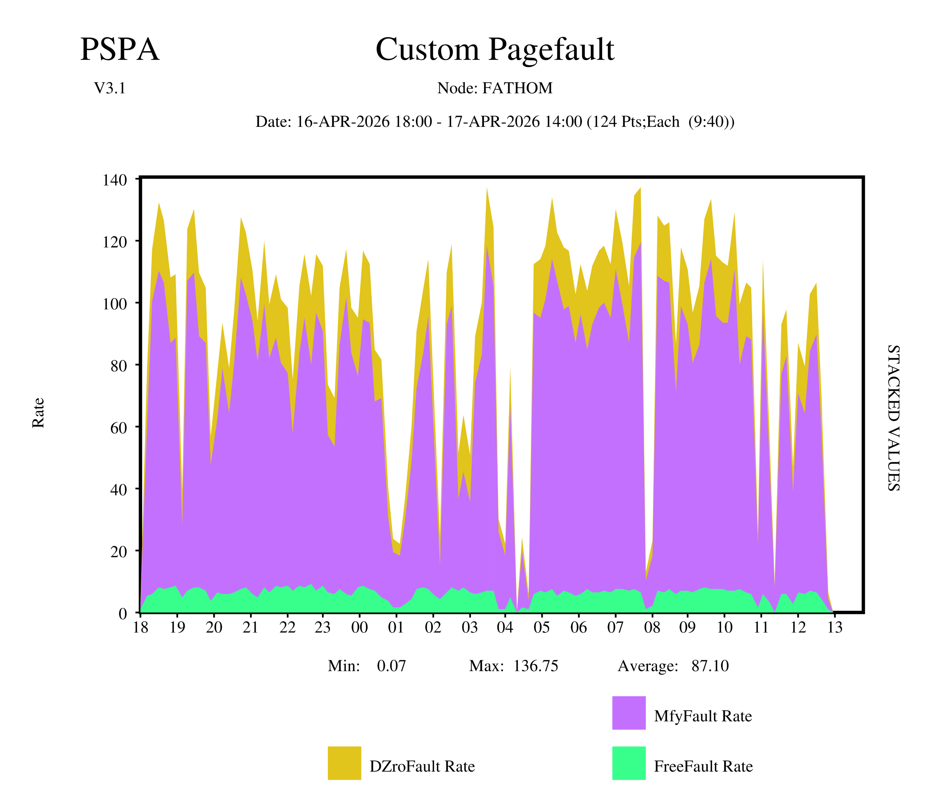 |
4.12.2. Graph Process Metrics by User
When graphing process metrics by user you must specify either of the following user names and process metrics:
A list of up to six user names and a single process metric, or
A single user name with a list of up to six process metrics
Performance Manager graphs include the metrics for all users that match any one of the user names you specify in the list. The resulting graph depicts each of the specified users or metrics separately on the plot.
To graph process metrics by user in DCL mode, issue the command:
$ ADVISE PERFORMANCE GRAPH -
_$ /TYPE=CUSTOM=(USER_METRICS=CPUTIME, -
_$ SELECTION=(CBUTTERWORTH,JOHNS,DEBBEEW),TITLE="CPU time used by the team") -
_$ /BEGINNING=18-APR-2026:08:00/END=18-APR-2026:17:00/NODE=BARNEY -
_$ /FORMAT=REGIS=CHARACTERISTIC=COLOR/OUTPUT=TEAM_CPU.PS
The Prompting for Process Custom Graph example shows Performance Manager prompts and user input that generate the same graph using command mode and specifying the following command after data selection:
PSPA> GRAPH/TYPE=PROMPT/FORMAT=POSTSCRIPT=CHARACTERISTIC=COLOR -
_PSPA> /OUT=TEAM_CPU.PS
The graph itself appears in the figure, Custom Graph for Process Usage.
The following statements are keyed to the Prompting for Process Custom Graph example:
2 was entered to select process metrics selected by user name.
The user names were entered to select the users.
<CR> was entered to request the list of process metrics.
CPUTIME was selected from the list and entered.
The Custom graph title was entered.
   Please select either 1) a predefined graph or
                        2) a custom graph

             Choice [1]: 2

For the CUSTOM Graph, select one of the following:

1.  System Metrics
2.  Process metrics selected by user name
3.  Process metrics selected by image name
4.  Process metrics selected by workload name
5.  Disk device metrics selected by device name
6.  Disk device metrics selected by volume name
7.  Processor mode metrics by physical processor ID
8.  HSC metrics by HSC node name
9.  SCS metrics by SCS Cluster node name
10. RULE metrics by rule id
11. HSC Channel metrics by channel name
12. File metrics by file name
13. IOs by Username and Volumename
14. IOs by Imagename and Volumename
15. IOs by Workloadname and Volumename

Enter Choice (1 - 15): 2   [1]
Select Up to 6 User Names (<CR> for list): CBUTTERWORTH, JOHNS, DEBBEEW  [2]
Select one process metric (<CR> for list): [3]

GRAPH

  /TYPE

    CUSTOM

      Process_metrics


         The following process metrics can be requested on a custom graph.

         BUFIO      CPUTIME      DIRIO           DSKIO
         DSKTP      FAULTS       HARDFAULTS      IMAGE_ACTIVATIONS
         IO_SIZE    RESIDENCE    RESPONSE_TIME   TAPIO
         TAPTP      TERM_INPUT   TERM_THRUPUT    WSSIZE
         VASIZE


Select one process metric (<CR> for list): CPUTIME [4]
Enter an optional title for the CUSTOM graph <40 characters max>
Title [PSPA Custom Graph]:CPU time used by the team [5]
PSPA> exit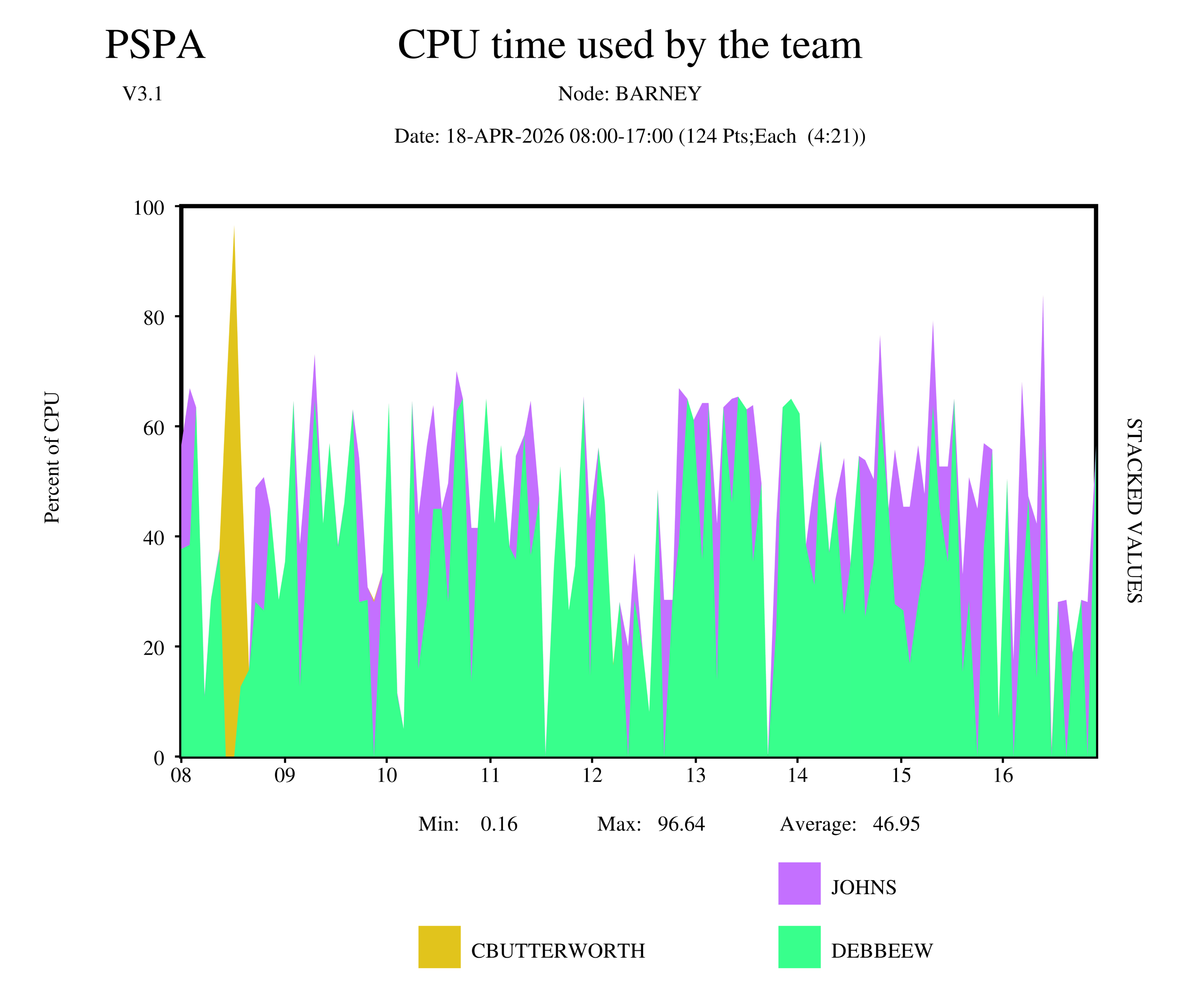 |
4.13. Graph the Hot File Activity
By default, PA combines files with the same names regardless of differing
directory or device locations. To separate files having different directories or
devices, you must define the logical names PSPA$GRAPH_FILE_DIRECTORY and
PSPA$GRAPH_FILE_DEVICE. Or, alternatively, use the /FILTER
qualifier to select hotfile records for specific processes and/or disk
devices.
If the graph legend is undesirable due to its length, you have several options to shrink the font used to print the legend. DECwindows has a Resources file that can change the font. PostScript has a logical name.
The Pie Chart can be presented in tabular format which gives a wider legend text.
If the file is deleted before the prod_fam Performance Manager detects its specification, its name is not available. The FID is provided in parentheses instead of its name. All non-virtual QIO activity to the disk is reported under the file specification, Non Virtual QIO.
Chapter 5. Customize the Knowledge Base
This chapter provides information about the knowledge base, rules, and customizing both.
5.1. The Knowledge Base
The Performance Manager makes assertions and inferences about system performance based on a large and changing body of technical information called a knowledge base. This information is in the form of performance rules. Performance rules come from one or two sources. The first source of rules is the product itself. The factory rules are automatically loaded by the user interfaces that require them. The second source is an auxiliary rules file, which you create.
While the Performance Manager is designed to work without any modifications, an experienced system manager can further benefit from the tool by customizing the knowledge base. Good reasons to customize the knowledge base include the following rules:
Eliminating the firing of rules for conditions that are customary and unchangeable for your system
Refining rules to filter testing of specific images or other conditions that are a required and unchangeable part of your workload
Modifying the characteristics of certain (older) disk devices that you might own and still use (for example, RZ57)
Adding rules to check for additional warning conditions that are specific for your own workloads and systems
5.2. Investigate Rule Firing
The factory rules embedded in the Performance Manager follow the methodology in the VSI's OpenVMS Performance Management guide. Some rules go beyond this methodology.
Keep in mind that, while the Performance Manager alerts you to potential performance problems, it does not (by default) screen out firings that are insignificant. Some circumstances on your system might fire a rule, for a one-time transient condition, without any implications for the long-term performance of your system. The factory rules try to minimize this possibility by setting occurrence thresholds within rules, but this might still happen.
Figure out whether you need to be concerned about a particular rule firing. Check the evidence provided with each rule. Does the problem appear to be persistent (as indicated by many lines of evidence)? Check the time of occurrence: does this happen at the same time as a regularly scheduled job? Make sure you understand the meaning of each data item presented. If you are unsure of a definition, look it up in the Data Cell Types and Use section, or use the online Help system, which contains hotspots to all the data items in the Conditions and in the Evidence. Many of the data items presented as evidence are used in the rule's conditions: read the conditions, and understand how each data item is being used, and what values would cause it to fire.
You are probably very familiar with approximate or typical values for many parameters of your systems. If a rule fires, but all related evidence appears normal for your environment, then you probably want to adjust that rule's thresholds to reflect more precisely the upper bounds of performance for your particular workloads and systems. For more information on how to do this, see How to Implement Changes in this chapter.
However, if the evidence presented does not look normal, or if you don't know what normal looks like for those data items, you need to investigate further. One good way is to generate graphs of those or related data items for the time periods given in the evidence, and then look for unusual spikes of activity. If you find spikes occurring at the same time in different graphs, then you might suspect that the data items graphed are somehow related to the underlying problem, which might lead you to ideas of what might be changed to fix the problem.
Another path of investigation is to look for related rule firings. A rule might not present the full picture by itself, but when coupled with related rules, could give you a clear indication of the source of the problem. Related rules need not appear one after the other, as Performance Manager processes rules in the following order: CPU, memory, I/O, resource (miscellaneous), and (after all nodes have been analyzed) cluster-wide. (You do not need to have a cluster for one of these rules to fire, but the metrics used are not specific to an individual node, so they are evaluated after all node-specific rules.) Rules which require special evidence processing (as indicated by the absence of evidence data items in the rules source file) are presented first.
Finally, if you observe a persistent performance problem, you can use the Real-time Motif displays to investigate dynamically-see the chapters Use the DECwindows Motif Real-time Display and Customize the DECwindows Motif Real-time Display. This new functionality supports progressive disclosure, so that you can start monitoring with high-level system displays, and then progressively launch panels to focus on perceived problem areas, as they are occurring.
5.3. Components of Rules
A rule is a conditional statement in an if/then format. A rule can contain multiple conditions. The Performance Manager evaluates rules while generating Analysis Reports. If all conditions of the rule are true, then there is a rule occurrence. If the number of rule occurrences meet the rule occurrence threshold, the rule is said to fire and the Performance Manager reports the associated rule conclusion.
A Performance Manager rules file contains entities known as constructs. Performance Manager rule constructs represent rules. Rule construct elements govern the syntax of the rule.
5.3.1. Rules File Constructs
The format of a rules file is not rigid. Multiple spaces, tabs, carriage return, and form feeds are treated as a single space. A rules file can include the following five constructs:
RULE
DISABLE
LITERAL
COMMENT
THRESHOLD
These rule constructs, their format, and use are discussed next:
RULE
Constructs define rules.
The format of the rule construct is as follows:
RULE rule_elements ENDRULE
The rule construct consists of seven rule elements. The optional elements in the list following are enclosed in brackets:
Rule ID element
[Domain element]
Rule condition element [Rule condition element...]
[Occurrence threshold element]
[Evidence element]
[Conclusion text element]
[Brief conclusion text element]
Once defined and compiled, the rules can be supplied to the analysis process to cause a conclusion to be fired as appropriate or can be supplied to the archival process to cause the number of occurrences of the rule to be archived.
DISABLE
Constructs allow you to turn off individual rules.
The format of the disable construct is as follows:
DISABLE rule_id [rule_id...];
The parameter rule id specifies which rule or rules to disable; the construct ends with a semicolon (;).
LITERAL
Constructs allow you to define unique symbols for use in a rule expansion.
The format of the literal construct is as follows:
LITERAL literal_definition [literal_definition...] ENDLITERAL
A literal definition is defined as:
literal_symbol = decimal_value
A literal symbol is a unique symbol that you have equated to a decimal value. A literal symbol can contain up to 40 alphanumeric characters that have not been defined before as a literal, a threshold, or a data cell. A literal symbol can be used in a rule expansion.
COMMENT
Constructs allow you to include notations in the rules file.
An exclamation point (!), occurring as the first character in the line, denotes a comment construct. The Performance Manager ignores any text on the line after the exclamation point.
THRESHOLD
Constructs allow you to modify internal thresholds that affect the calculation of derived data cells.
The format of a threshold construct is as follows:
THRESHOLD threshold_definition [threshold_definition...] ENDTHRESHOLD
- A threshold definition is defined as:
threshold_name = decimal_value
A threshold name must match one of the Performance Manager's predefined thresholds. These thresholds are not used directly in the rule expression; however, they influence the resultant value of some data cells that can be used in rule expressions. Some thresholds act as occurrence limits for a few factory rules.
The following table lists the Performance Manager's predefined thresholds and the default value of each threshold, and describes how each threshold affects the data cells or evidence.
All thresholds have a prefix of TD. These thresholds cannot be redefined, but their values can be modified.
The following tables show the Performance Manager thresholds:
| Name | Default Value | Description |
|---|---|---|
|
TD_MIN_DSKSPC_PCT |
.05 |
The minimum percentage of disk free blocks required to set the data cell ANY_DISK_FULL to 1 for a given Performance Manager two-minute record. |
|
TD_DISK_QL_MAX |
1 |
The maximum queue length on any disk required to set the data cell ANY_DISK_OVER_QL_THRESHOLD to 1 for a given Performance Manager two-minute record. This affects condition-checking on rules I0040, I0050, I0055, I0060, and I0150. |
|
TD_SMP_VUP_RATIO |
85 |
A percentage of the threshold TD_SINGLE_CPU_VUP_n value applied to additional CPUs in an SMP system used to compute the total VUPs. This is used to compute the data cell CPU_VUP_RATING for processor type N. See the processor specific thresholds in the next table. |
|
TD_M0010_PROBRECS_PER _IMAGE |
4 |
Number of records for any one image required to fire the rule M0010. |
|
TD_PROCESS |
2 |
Number of problem records per user/image combination required to include the record into the evidence for rules M0050, M0055, and M0060. |
|
TD_CIO |
4 |
Number of problem records per disk volume required to include the image into the evidence for rule L0050, L0060, and L0070. |
|
TD_IO_ERROR |
2 |
Number of problem records per disk volume required to include the volume into the evidence for rule L0080. |
|
TD_CI_PORT_IO |
1500000 |
Number of bytes per second through any CI port required to set the data cell EXCESS_THRUPUT_ON_ANY_CHANNEL to 1 for a given Performance Manager two-minute record. |
|
TD_UNIBUS_CHANNEL_IO |
1000000 |
Number of bytes per second through any UNIBUS port required to set the data cell EXCESS_THRUPUT_ON_ANY_CHANNEL to 1 for a given Performance Manager two-minute record. |
|
TD_KDA_CHANNEL_IO |
800000 |
Number of bytes per second through any KDA50 port required to set the data cell EXCESS_THRUPUT_ON_ANY_CHANNEL to 1 for a given Performance Manager two-minute record. |
|
TD_KDB_CHANNEL_IO |
900000 |
Number of bytes per second through any KDB port required to set the data cell EXCESS_THRUPUT_ON_ANY_CHANNEL to 1 for a given Performance Manager two-minute record. |
|
TD_MASSBUS_CHANNEL_IO |
1700000 |
Number of bytes per second through any MASSBUS port required to set the data cell EXCESS_THRUPUT_ON_ANY_CHANNEL to 1 for a given Performance Manager two-minute record. |
|
TD_GENERIC_DISK_IO |
30 |
Default I/O operation per second threshold for disks that are not covered in the translation table (TD_Tn_x) thresholds. |
|
TD_GENERIC_DISK_THRUPUT |
1000000 |
Default number of bytes per second threshold for disks that are not covered in the translation table (TD_In_x) thresholds. |
| TD_T1_RK06 | 20 |
I/O per second threshold for disk type. Data cell DISK_IO_RATE_THRESHOLD has this value if the current disk subrecord is of this type. |
|
TD_T2_RK07 |
20 |
Same as previous. |
|
TD_T3_RP04 |
26 |
Same as previous. |
|
TD_T4_RP05 |
26 |
Same as previous. |
|
TD_T5_RP06 |
26 |
Same as previous. |
|
TD_T6_RM03 |
26 |
Same as previous. |
|
TD_T7_RP07 |
32 |
Same as previous. |
|
TD_T8_RP07HT |
32 |
Same as previous. |
|
TD_T13_RM80 |
30 |
Same as previous. |
|
TD_T15_RM05 |
26 |
Same as previous. |
|
TD_T20_RA80 |
27 |
Same as previous. |
|
TD_T21_RA81 |
28 |
Same as previous. |
|
TD_T22_RA60 |
20 |
Same as previous. |
|
TD_T25_RD51 |
10 |
Same as previous. |
|
TD_T27_RD52 |
20 |
Same as previous. |
|
TD_T28_RD53 |
26 |
Same as previous. |
|
TD_T30_RA82 |
33 |
Same as previous. |
|
TD_T31_RD31 |
18 |
Same as previous. |
|
TD_T32_RD54 |
26 |
Same as previous. |
|
TD_T34_RRD50 |
20 |
Same as previous. |
|
TD_T36_RX33 |
10 |
Same as previous. |
|
TD_T37_RX18 |
10 |
Same as previous. |
|
TD_T38_RA70 |
32 |
Same as previous. |
|
TD_T39_RA90 |
34 |
Same as previous. |
|
TD_T40_RD32 |
20 |
Same as previous. |
|
TD_T42_RX35 |
10 |
Same as previous. |
|
TD_T43_RF30 |
24 |
Same as previous. |
|
TD_T44_RF71 |
24 |
Same as previous. |
|
TD_T45_RD33 |
18 |
Same as previous. |
|
TD_T46_ESE20 |
240 |
Same as previous. |
|
TD_T47_TU56 |
30 |
Same as previous. |
|
TD_T48_RZ22 |
24 |
Same as previous. |
|
TD_T49_RZ23 |
24 |
Same as previous. |
|
TD_T50_RZ24 |
32 |
Same as previous. |
|
TD_T51_RZ55 |
31 |
Same as previous. |
|
TD_T52_RRD40S |
20 |
Same as previous. |
|
TD_T53_RRD40 |
20 |
Same as previous. |
|
TD_T54_GENERIC_DK |
30 |
Same as previous. |
|
TD_T55_RX23 |
10 |
Same as previous. |
|
TD_T56_RF31 |
78 |
Same as previous. |
|
TD_T57_RF72 |
37 |
Same as previous. |
|
TD_T58_RAM_DISK |
130 |
Same as previous. |
|
TD_T59_RZ25 |
38 |
Same as previous. |
|
TD_T60_RZ56 |
34 |
Same as previous. |
|
TD_T61_RZ57 |
38 |
Same as previous. |
|
TD_T62_RX23S |
10 |
Same as previous. |
|
TD_T63_RX33S |
10 |
Same as previous. |
|
TD_T64_RA92 |
33 |
Same as previous. |
|
TD_T65_SSTRIPE |
60 |
Same as previous. |
|
TD_T66_RZ23L |
30 |
Same as previous. |
|
TD_T67_RX26 |
10 |
Same as previous. |
|
TD_T68_RZ57I |
38 |
Same as previous. |
|
TD_T70_RZ58 |
4 |
Same as previous. |
|
TD_T71_SCSI_MO |
20 |
Same as previous. |
|
TD_T72_RRD42 |
20 |
Same as previous. |
|
TD_T73_CD_LOADER_1 |
20 |
Same as previous. |
|
TD_T74_ESE25 |
240 |
Same as previous. |
|
TD_T75_RFH31 |
78 |
Same as previous. |
|
TD_T76_RFH72 |
37 |
Same as previous. |
|
TD_T77_RF73 |
44 |
Same as previous. |
|
TD_T78_RFH73 |
44 |
Same as previous. |
|
TD_T79_RA72 |
40 |
Same as previous. |
|
TD_T80_RA71 |
40 |
Same as previous. |
|
TD_T81_RF35 |
69 |
Same as previous. |
|
TD_T82_RFH35 |
69 |
Same as previous. |
|
TD_T83_RF31F |
40 |
Same as previous. |
|
TD_T84_RZ72 |
37 |
Same as previous. |
|
TD_T85_RZ73 |
36 |
Same as previous. |
|
TD_T86_RZ35 |
53 |
Same as previous. |
|
TD_T87_RZ24L |
35 |
Same as previous. |
|
TD_T88_RZ25L |
41 |
Same as previous. |
|
TD_T89_RZ55L |
34 |
Same as previous. |
|
TD_T90_RZ56L |
37 |
Same as previous. |
|
TD_T91_RZ57L |
42 |
Same as previous. |
|
TD_T92_RA73 |
44 |
Same as previous. |
|
TD_T93_RZ26 |
50 |
Same as previous. |
|
TD_T94_RZ36 |
51 |
Same as previous. |
|
TD_T95_RZ74 |
47 |
Same as previous. |
|
TD_T96_ESE52 |
1300 |
Same as previous. |
|
TD_T97_ESE56 |
1300 |
Same as previous. |
|
TD_T98_ESE58 |
1300 |
Same as previous. |
|
TD_T99_RZ27 |
51 |
Same as previous. |
|
TD_I1_RK06 |
530000 |
Number of bytes per second threshold for disk type. Data cell DISK_THRUPUT_RATE_THRESHOLD has this value if the current disk sub-record is of this type. |
|
TD_I2_RK07 |
530000 |
Same as previous. |
|
TD_I3_RP04 |
800000 |
Same as previous. |
|
TD_I4_RP05 |
800000 |
Same as previous. |
|
TD_I5_RP06 |
800000 |
Same as previous. |
|
TD_I6_RM03 |
1200000 |
Same as previous. |
|
TD_I7_RP07 |
1300000 |
Same as previous. |
|
TD_I8_RP07HT |
2200000 |
Same as previous. |
|
TD_I13_RM80 |
1000000 |
Same as previous. |
|
TD_I15_RM05 |
1200000 |
Same as previous. |
|
TD_I20_RA80 |
800000 |
Same as previous. |
|
TD_I21_RA81 |
1500000 |
Same as previous. |
|
TD_I22_RA60 |
1300000 |
Same as previous. |
|
TD_I25_RD51 |
300000 |
Same as previous. |
|
TD_I27_RD52 |
530000 |
Same as previous. |
|
TD_I28_RD53 |
530000 |
Same as previous. |
|
TD_I30_RA82 |
1600000 |
Same as previous. |
|
TD_I31_RD31 |
500000 |
Same as previous. |
|
TD_I32_RD54 |
530000 |
Same as previous. |
|
TD_I34_RRD50 |
120000 |
Same as previous. |
|
TD_I36_RX33 |
400000 |
Same as previous. |
|
TD_I37_RX18 |
400000 |
Same as previous. |
|
TD_I38_RA70 |
1000000 |
Same as previous. |
|
TD_I39_RA90 |
1900000 |
Same as previous. |
|
TD_I40_RD32 |
500000 |
Same as previous. |
|
TD_I42_RX35 |
400000 |
Same as previous. |
|
TD_I43_RF30 |
900000 |
Same as previous. |
|
TD_I44_RF71 |
900000 |
Same as previous. |
|
TD_I45_RD33 |
500000 |
Same as previous. |
|
TD_I46_ESE20 |
2000000 |
Same as previous. |
|
TD_I47_TU56 |
750000 |
Same as previous. |
|
TD_I48_RZ22 |
1000000 |
Same as previous. |
|
TD_I49_RZ23 |
1000000 |
Same as previous. |
|
TD_I50_RZ24 |
1200000 |
Same as previous. |
|
TD_I51_RZ55 |
1000000 |
Same as previous. |
|
TD_I52_RRD40S |
120000 |
Same as previous. |
|
TD_I53_RRD40 |
120000 |
Same as previous. |
|
TD_I54_GENERIC_DK |
750000 |
Same as previous. |
|
TD_I55_RX23 |
400000 |
Same as previous. |
|
TD_I56_RF31 |
2100000 |
Same as previous. |
|
TD_I57_RF72 |
1200000 |
Same as previous. |
|
TD_I58_RAM_DISK |
5000000 |
Same as previous. |
|
TD_I59_RZ25 |
1800000 |
Same as previous. |
|
TD_I60_RZ56 |
1400000 |
Same as previous. |
|
TD_I61_RZ57 |
1700000 |
Same as previous. |
|
TD_I62_RX23S |
400000 |
Same as previous. |
|
TD_I63_RX33S |
400000 |
Same as previous. |
|
TD_ _RA92 |
1900000 |
Same as previous. |
|
TD_I65_SSTRIPE |
1200000 |
Same as previous. |
|
TD_I66_RZ23L |
1200000 |
Same as previous. |
|
TD_I67_RX26 |
500000 |
Same as previous. |
|
TD_I68_RZ57I |
1500000 |
Same as previous. |
|
TD_I70_RZ58 |
3100000 |
Same as previous. |
|
TD_I71_SCSI_MO |
750000 |
Same as previous. |
|
TD_I72_RRD42 |
120000 |
Same as previous. |
|
TD_I73_CD_LOADER_1 |
120000 |
Same as previous. |
|
TD_I74_ESE25 |
2000000 |
Same as previous. |
|
TD_I75_RFH31 |
2100000 |
Same as previous. |
|
TD_I76_RFH72 |
1600000 |
Same as previous. |
|
TD_I77_RF73 |
2100000 |
Same as previous. |
|
TD_I78_RFH73 |
2100000 |
Same as previous. |
|
TD_I79_RA72 |
1400000 |
Same as previous. |
|
TD_I80_RA71 |
1400000 |
Same as previous. |
|
TD_I81_RF35 |
2600000 |
Same as previous. |
|
TD_I82_RFH35 |
2600000 |
Same as previous. |
|
TD_I83_RF31F |
1400000 |
Same as previous. |
|
TD_I84_RZ72 |
1400000 |
Same as previous. |
|
TD_I85_RZ73 |
1900000 |
Same as previous. |
|
TD_I86_RZ35 |
2600000 |
Same as previous. |
|
TD_I87_RZ24L |
1900000 |
Same as previous. |
|
TD_I88_RZ25L |
2000000 |
Same as previous. |
|
TD_I89_RZ55L |
1100000 |
Same as previous. |
|
TD_I90_RZ56L |
1500000 |
Same as previous. |
|
TD_I91_RZ57L |
1800000 |
Same as previous. |
|
TD_I92_RA73 |
2100000 |
Same as previous. |
|
TD_I93_RZ26 |
2600000 |
Same as previous. |
|
TD_I94_RZ36 |
3700000 |
Same as previous. |
|
TD_I95_RZ74 |
3100000 |
Same as previous. |
|
TD_I96_ESE52 |
2000000 |
Same as previous. |
|
TD_I97_ESE56 |
2000000 |
Same as previous. |
|
TD_I98_ESE58 |
2000000 |
Same as previous. |
|
TD_I99_RZ27 |
3700000 |
Same as previous. |
5.3.1.1. Processor-Specific Thresholds
The processor-specific thresholds can be modified by using threshold scaling factors indicated in the following table:
| Threshold Name | Affected Data Cell Name |
|---|---|
|
TD_SINGLE_CPU_VUP_n |
CPU_VUP_RATING |
|
TD_SOFT_FAULT_SCALING_n |
SOFT_FAULT_SCALING |
|
TD_HARD_FAULT_SCALING_n |
HARD_FAULT_SCALING |
|
TD_IMGACT_SCALING_n |
IMGACT_SCALING |
|
TD_COM_SCALING_n |
COM_SCALING |
The n is an integer that specifies an individual processor and must be replaced by a model number. All Integrity servers use 4096 for a model number. For Alpha systems, you can get the model number of a specific processor by using the $GETSYI system service using the item code SYI$HWMODEL. An entry of zero is used for an unknown model.
A scale factor of 1.0 is used as a basis for the rules when applied to a VAX-11/780 system.
For example, the threshold construct TD_SOFT_FAULT_SCALING_40 = 0.4 places the value 0.4 in the data cell SOFT_FAULT_SCALING when a VAX model 40 is being analyzed. A VAX model 40 is a MicroVAX 2000.
5.3.2. Rule Construct Elements
A rule construct consists of up to seven elements. Each construct begins with RULE and ends with ENDRULE. The following sections describe each of the elements listed in the following table:
| Element | Presence | Description |
|---|---|---|
|
Rule ID |
Required |
Identifies a rule definition. |
|
Domain |
Optional |
Identifies the domain; default is LOCAL. |
|
Rule conditions |
Required |
There must be at least one condition. |
|
Occurrence |
Optional |
Number of occurrences for the rule to fire; default is one. |
|
Evidence |
Optional |
If omitted, no evidence is presented. |
|
Conclusion text |
Optional |
If omitted, no conclusion text is presented. |
|
Brief conclusion text |
Optional |
If omitted, no conclusion text is presented. |
5.3.2.1. Auxiliary Rules File Example
As shown in the following example, the first three elements – rule ID, domain, and the rule conditions – must be in this order. The next four elements may be in any order.
! Disable M0020
DISABLE M0020
! Fire this rule after 4 occurrences
LITERAL Too_many = 4 ENDLITERAL
Rule UM020 Domain Local
Hard_fault_rate .ge. td_high_hard_fault * Hard_fault_scaling;
Img_activations_per_pid .ge. TD_HIGH_IMGACT * Img_act_rate_scaling;
occurrences = Too_many;
Evidence =
User_name(High_Img_activations_Pid_x)
Img_activations_per_pid
Time;
EndRule
5.3.2.2. Rule ID Element
The rule ID identifies the rule. Each rule must begin with a unique rule identifier. The format of a rule identifier is this:
RULE rule_ID
Where rule_ID:
Is one to five alphanumeric characters.
Does not have a zero for the second character. The zero is reserved for use by VSI.
Is not already defined by Performance Manager factory rules.
By convention, the first character of a rule identifier describes the rule performance category. The Performance Manager uses the alphabetic characters in the following table as the first letter of the rule identifier.
The following table lists the rule ID abbreviations:
| Letter | Rule Performance Category |
|---|---|
|
C |
CPU-related rule |
|
M |
Memory-related rule |
|
I |
I/O-related rule |
|
R |
Resource (miscellaneous) rule |
|
L |
Cluster-related rule |
|
X |
XFC-related rule |
5.3.2.3. Domain Element
The domain element defines the context in which the rule exists. The association between a rule and its domain designates when a rule is tested and under which Analysis Report section the rule firing is reported.
The definition of a domain for Performance Manager knowledge base processing is based on the sub-records that are read from collected data. Each rule exists within a single domain. Also, each data cell is associated with a set of domains. Rules can reference any data cells in the domain in which the rule exists. If you omit the domain element, the default domain for the rule is LOCAL.
The format of the domain element is as follows:
DOMAIN domain_name [TRACE]
5.3.2.3.1. domain_name
Can be one of the following names:
CLUSTER
COMMUNICATION
CONFIGURATION
CPU
DISK
FILE
LOCAL
LOCALC
PROCESS
SUMMARY
TAPE
5.3.2.4. Domain Names, Rule Testing, and Reporting
Domain selection determines the data against which the rule is evaluated, the frequency with which the rule is tested and the Analysis Report section in which the conclusion is reported. See the following table. An interval record contains data for a single node in a cluster system.
|
Domain Name |
Report Section |
Testing Frequency |
|---|---|---|
|
CLUSTER |
Cluster analysis |
Multiple times depending on the number of disks |
|
COMMUNICATION |
Local analysis |
Multiple times per interval record depending on the number of terminal controllers |
|
CONFIGURATION |
Local analysis |
Multiple times per interval record depending on the number of remote nodes within a cluster system |
|
CPU |
Local analysis |
Multiple times per interval record depending on the number of processors in a multiprocessor system |
|
DISK |
Local analysis |
Multiple times per interval record depending on the number of disk sub-records |
|
FILE |
Local analysis |
Multiple times per interval record depending on the number of hot file sub-records |
|
LOCAL |
Local analysis |
Once per interval record |
|
LOCALC |
Cluster analysis |
Once per interval record |
|
PROCESS |
Local analysis |
Multiple times per interval record depending on the number of process sub-records |
|
SUMMARY |
Local analysis |
Once per node |
|
TAPE |
Local analysis |
Multiple times per interval record depending on the number of tape sub-records |
Optionally, you can display a trace each time a rule's condition is tested. During report generation, the Performance Manager displays the trace only on the terminal screen.
The following code is sample output using TRACE:
%RULETRACE of UM010 condition 1 is TRUE
%RULETRACE of UM010 condition 2 is FALSE
The Performance Manager displays this debugging information for each rule condition when the condition is evaluated and terminates with the first FALSE condition. It is possible that the Performance Manager does not output a trace for your rule. This occurs when another rule with a rule condition identical to one of your rule's conditions is evaluated to FALSE. In this case, the Performance Manager does not evaluate your rule because it is known to be false.
The relationship between domains and data cells is fixed. Rules are in domains. Data cells are in one or more domains.
Rules defined in the CLUSTER or SUMMARY domain can reference data cells only in the CLUSTER or SUMMARY domain, respectively.
Rules defined in the LOCAL domain can reference data cells in the LOCAL domain and in other domains, but only if there is an index specifier for the specific domain.
Rules defined in any of the remaining seven domains – COMMUNICATION, CONFIGURATION, CPU, DISK, FILE, PROCESS, or TAPE – can reference data cells in their own domains or the LOCAL domain. The rule can reference data cells in any other six domains only if there is an index specifier for the other domains.
5.3.2.5. Rule Condition Element
A rule must have one or more rule conditions. A rule condition is an expression that the Performance Manager resolves to true or false status during the course of rule evaluation. A rule condition must end with a semicolon (;). If the Performance Manager evaluates the rule condition to 1.0, then the rule condition is true; otherwise, it is false.
A rule condition is composed of rule expressions. A rule expression is one of the following values:
decimal_value
literal_symbol
tally_data_cell
(rule_expression)
numeric_data_cell [(index_specifier_data_cell)]
boolean_data_cell [(index_specifier_data_cell)]
scan_routine_data_cell(rule_expression)
string_item string_operator string_item
rule_expression numeric_binary_operator rule_expression
5.3.2.6. Rule Expression Operators and Descriptions
A numeric or string operator is one of the symbols listed in the following table:
| Symbol | Definition |
|---|---|
|
.EQS. |
String equal to string |
|
.NES. |
String not equal to string |
|
* |
Multiply |
|
/ |
Divided by |
|
+ |
Plus |
|
- |
Minus |
|
.EQ. |
Equal to |
|
.NE. |
Not equal to |
|
.LT. |
Less than |
|
.LE. |
Less than or equal to |
|
.GT. |
Greater than |
|
.GE. |
Greater than or equal to |
|
.AND. |
And |
|
.OR. |
Or |
The Boolean operators .AND. and .OR. evaluate to either a decimal 1.0 for true or a 0 for false. The operands are treated as true if their values equal decimal 1.0, and anything else as false. Valid components of rule expressions are defined as follows:
A decimal value is a rational number.
A literal symbol is a symbol previously defined by the literal construct.
A tally data cell is a data cell (see the Data Cell Types and Use section).
Parentheses can be used to denote precedence.
A numeric data cell is a data cell (see the Data Cell Types and Use section).
An index specifier data cell is a data cell (see the Data Cell Types and Use section).
A Boolean data cell is a data cell (see the Data Cell Types and Use section).
A scan routine data cell is a data cell (see the Data Cell Types and Use section).
A string item is either a string data cell (see the Data Cell Types and Use section) or a string literal, where the literal string is enclosed in quotation marks.
A string operator is either the .EQS. or .NES. operator.
A numeric binary operator is one of the operators in the previous table.
5.3.2.7. Occurrence Element
When the Performance Manager evaluates a rule and all of the conditions of the rule are true, there is a rule occurrence. The number of times the Performance Manager evaluates a rule depends upon its domain, the number of interval records, and the number of nodes. The format for an occurrence element is as follows:
OCCURRENCES = {literal_symbol | decimal_value}; A literal symbol or decimal value specifies the number of times a rule must occur for it to fire. The occurrence element ends with a semicolon (;). When a rule fires, an entry is made in the Analysis Report.
5.3.2.8. Evidence Element
You can specify evidence for every rule. You can select one or more data cells to use in the evidence list. You cannot use scan routine data cells as evidence. When the rule fires (all rule conditions are true and the occurrence threshold is met), the Performance Manager saves the current values for all data cells listed as evidence.
The format for an evidence element is as follows:
EVIDENCE = evidence_value [evidence_value...];
Evidence value is a data cell that is not a scan routine:
data_cell [(index_specifier[(index_specifier)])]
The evidence element ends with a semicolon (;). When a rule fires, an entry is made in the Analysis Report.
5.3.2.9. Present the Evidence
The Performance Manager starts preparing conclusions, if any, after all data has been processed. After the conclusion, the Performance Manager lists the evidence in the Analysis Report in tabular format. Each column corresponds to an evidence data cell and is indicated by an appropriate column header.
If there are many evidence fields, the width of the evidence columns could exceed 80 characters. If, when writing user auxiliary rules, you do not want the width to exceed 80 characters, then you must limit the number of evidence items. The width of each evidence column depends on the column header and the width of the data that must be displayed.
5.3.2.10. Performance Manager Factory Evidence
The Performance Manager's factory rules use column headers that are created to improve readability. If you need to reference the same data cell that is displayed as evidence on a factory rule conclusion, reference the factory rules file PSPA$EXAMPLES:PSPA$KB.VPR to see what evidence data cells are provided for the desired rule.
These factory rules have special evidence processing:
|
M0010 |
M0050 |
M0055 |
|
M0060 |
M0421 |
R0140 |
|
R0150 |
R0160 |
R0170 |
|
R0210 |
R0230 |
R0240 |
|
R0245 |
R0250 |
R0270 |
|
R0280 |
L0040 |
L0050 |
|
L0060 |
L0070 |
L0080 |
|
L0090 |
The special processing allows non-chronological sorting and the use of special display requirements. These rules do not have evidence data cells listed in the factory rules file. The evidence headers and conclusions for factory rules are stored in the file SYS$SYSTEM:PSPA$MSG.TXT.
See the Data Cell Types and Use section for a list and description of the data cells.
5.3.2.11. Conclusion Text Element
A conclusion is a block of text presented in the Analysis Report when a rule fires. It describes the problem detected by the rule. The format for conclusion text is shown in the following code:
CONCLUSION "text_string"
Conclusions can contain multiple lines of text. An example of a multiline conclusion follows:
CONCLUSION
" Queues are forming on heavily used disks.
 Longer delays will be experienced when longer queues form."
The format of this conclusion (10 spaces at the beginning of each line) ensures consistent formatting with Performance Manager factory rules.
5.3.2.12. Brief Conclusion Text Element
A brief conclusion is one line of text presented in the Brief Analysis Report when a rule fires. A brief conclusion describes the problem detected by the rule. The format for a brief conclusion is the following code:
BRIEF_CONCLUSION "text_string"
To ensure consistent formatting with Performance Manager factory rules, the text must be aligned with the left quotation mark.
5.4. Data Cell Types and Use
The Performance Manager sub-record types in the following table are stored in
Performance Manager data records. You can access the fields within the sub-records
as data cells within a rule construct. See Appendix C, "Performance Manager Data Cells"
for the names of the data cells. You can also dump them using the ADVISE
COLLECT REPORT DUMP_DATACELLS command. This command produces a dump
report of all data cells in the LOCAL domain.
The following table shows the data sub-record types and associated domains:
| Sub-record Type | Associated Domain |
|---|---|
|
Communication |
COMMUNICATION |
|
Configuration |
CONFIGURATION |
|
CPU |
CPU |
|
Disk |
DISK |
|
Hot_Files |
FILE |
|
Metrics |
COMMUNICATION, CONFIGURATION, CPU, DISK, FILE, LOCAL, PROCESS, TAPE |
|
Parameters |
COMMUNICATION, CONFIGURATION, CPU, DISK, FILE, LOCAL, SUMMARY, PROCESS, TAPE |
|
Process |
PROCESS |
|
Tape |
TAPE |
Note
The CLUSTER domain references a sub-record type that exists only in memory. It does not exist in the Performance Manager data records.
If you write a rule in the LOCAL domain, the data cells available to the rule conditions and rule evidence include all values from the metrics and parameters records for a single node. The Performance Manager evaluates the rule once for each interval record (2 minutes for daily data, user-defined for history data), for each node that is processed. For example, an hour of daily data at the default interval contains 30 records per node for the LOCAL domain.
If you write a rule in the PROCESS domain, data cells available to the rule include all values from the process sub-record. Metric and parameter sub-record data cells are also available from the PROCESS domain because they are part of the current interval record containing the given process sub-record for the current node. The Performance Manager passes each of the process sub-records through all rules in the PROCESS domain for each interval record and for each node.
The number of process sub-records that the Performance Manager examines depends on the number of processes logged in, the time range, system activity, and for history files, the workload classification scheme. You must reference data in a process sub-record from the PROCESS domain or from the LOCAL, COMMUNICATION, CONFIGURATION, CPU, DISK, FILE, or TAPE domains with a process domain index specifier. The Index Specifier Data Cell section describes Index Specifier data cells.
The SUMMARY and CLUSTER domains do not directly correlate to Performance Manager data records; however, they are derived from them.
The data cells available in the SUMMARY domain are metrics that are maximums or averaged from all of the interval records. After processing all the data for a single node, the summary data cells become available in the SUMMARY domain. The last parameter sub-record is also available in the SUMMARY domain. The number of times the Performance Manager tests a rule in the SUMMARY domain is equal to the number of nodes processed.
After the Performance Manager processes all nodes data, the data cells available in the CLUSTER domain are disk statistics that represent the cluster perspective of the I/O traffic. The Performance Manager combines data from each node's two-minute disk sub-records into a set of two-minute cluster records in memory. The Performance Manager provides items such as cluster-wide throughput and operation rates; however, there is no longer any association with the “current two-minute” data record. Metric and parameter sub-record values (available from the LOCAL domain) are not accessible from the CLUSTER domain.
The following table lists the seven types of data cells:
| Data Cell Types | Brief Descriptions |
|---|---|
|
Boolean |
1.0 (True) or 0 (False) |
|
Numeric |
Floating point value |
|
String |
An ASCII string |
|
Time |
Clock time for data |
|
Scan routines |
Loads tally data cells and returns sub-record count |
|
Tally |
Derived data |
|
Index specifier |
Index to a sub-record |
5.4.1. Boolean Data Cell
A Boolean data cell is a value provided by the Performance Manager software that represents the result of applying a commonly needed condition to a domain (or a subset of internal records). A Boolean data cell has a value of true (1.0) or false (0).
For example, the ANY_DISK_OVER_THRESHOLD data cell is set to either true or false. If it is set to TRUE, at least one disk for the current Performance Manager interval record has exceeded the I/O rate threshold for the given disk type. If this Boolean operator did not exist, you would have to use an expression similar to the following code:
DISK_SCAN(DISK_IO_RATE .GE. DISK_IO_RATE_THRESHOLD) .GT. 0
5.4.2. Numeric Data Cell
A numeric data cell provides a floating-point value. For example, NUMBER_OF_PROCESS is a numeric data cell in the LOCAL domain that contains the floating-point value for the average number of processes resident on the system during the given two-minute period for the current node.
5.4.3. String Data Cell
A string data cell provides the actual string when the cell is used as evidence. However, when you use it in a rule condition, you must compare the string data cell to another string data cell or to a string literal with one of the string operators (.EQS. or .NES.).
5.4.4. Time Data Cell
The time data cell represents the time of the current Performance Manager interval record. You cannot use this data cell in a rule condition; however, it is valid as an evidence item.
5.4.5. Scan Routine Data Cell
You can use scan routines to scan sub-records in the target domain. The scan routine data cell name starts with the target domain name. The scan routine data cell counts sub-record occurrences and tallies data into tally data cells for use in a rule expression. The scan routine data cell requires a rule expression, enclosed with parentheses, following the scan routine name. This rule expression can contain data cells. These cells referenced in the rule expression must be in the target domain scanned by the scan routine.
For example, you can use the scan routine data cell PROCESS_SCAN to return tally information. If a rule is in the LOCAL domain, you can use the following rule expression to test whether the image XYZZY.EXE is being used:
PROCESS_SCAN (IMAGE_NAME .EQS. "XYZZY") .GT. 0
The PROCESS domain is the target domain for PROCESS_SCAN.
The value that a scan routine returns is an integer indicating the number of times the specified expression tested true (evaluated to 1.0). In this case, the value returned by PROCESS_SCAN would be the count of process sub-records with an image name of XYZZY. If the value is greater than 0, the rule expression is true.
These scan routine data cells are valid:
COMMUNICATION_SCAN
CONFIGURATION_SCAN
CPU_SCAN
DISK_SCAN
FILE_SCAN
PROCESS_SCAN
TAPE_SCAN
You cannot use scan routine data cells as evidence.
5.4.6. Tally Data Cell
Tally data cells contain data tallied from those sub-records scanned when the scan routine rule expression holds true.
Each scan routine has a target domain. Each tally data cell has a target domain. A given scan routine updates those tally data cells with the same target domain as the scan routine's target domain. Scan routine data cell names start with the target domain name.
For a given rule, you can use tally data cells in a rule expression or evidence after a call to a scan routine. For example, a LOCAL domain rule with the following expression makes available the process TALLY fields that contain the sum of all PROCESS domain metrics for process sub-records with the user name of CHARLIE:
PROCESS_SCAN(USER_NAME .EQS. "CHARLIE") .GT. 0
Subsequent rule expressions may use the tally data cells in the same rule. For example:
PROCESS_CPUTIME_TALLY .GT. 1000
5.4.6.1. Tally Data Cells and Associated Scan Routines
The following table shows tally data cells and the associated scan routines:
| Scan Routines | Tally Data Cells Updated by Scan Routines |
|---|---|
|
COMMUNICATION_SCAN |
COMM_OPERATION_RATE_TALLY |
|
CONFIGURATION_SCAN |
|
|
CPU_SCAN |
|
|
DISK_SCAN |
|
|
FILE_SCAN |
|
|
PROCESS_SCAN |
|
|
TAPE_SCAN |
|
5.4.7. Index Specifier Data Cell
Index specifiers are data cells that indicate a specific occurrence of a sub-record that has a unique characteristic in one of these domains:
COMMUNICATION
CONFIGURATION
CPU
DISK
FILE
PROCESS
TAPE
During analysis, the Performance Manager reads an interval record. The Performance Manager evaluates rules in the following domains:
LOCAL
PROCESS
DISK
FILE
CPU
COMMUNICATION
CONFIGURATION
TAPE
Data cells available in the LOCAL domain are available to rules in all of these domains. You can reference data cells in the PROCESS, DISK, FILE, CPU, COMMUNICATION, CONFIGURATION, or TAPE domains and not in the LOCAL domain directly by rules within that domain, or indirectly with an index specifier to data cells in any of the other domains. Each index specifier data cell has a target domain. The target domain indicates the name of the domain of the desired data cell.
For example, the index specifier TOP_CPU_PROC_X points to a specific process sub-record for the current interval. You might use the index specifier in rule definitions in the LOCAL, DISK, FILE, CPU, COMMUNICATION, CONFIGURATION, or TAPE domains.
Specify the PROCESS domain data cell with the index specifier as a parameter. A rule expression for a rule in the LOCAL domain is as follows:
PROCESS_CPUTIME(TOP_CPU_PROC_X)
This expression calculates which process has the highest CPU time. Although PROCESS_CPUTIME is a PROCESS domain data cell, TOP_CPU_PROC_X is a LOCAL domain index specifier that has a target domain of PROCESS. So, you can reference any PROCESS domain data cell from a rule in the LOCAL domain by using an index specifier with the target domain of PROCESS. The maximum index depth for index specifiers is two.
5.5. Implement Changes
This section provides scenarios for customizing the knowledge base with the following actions:
Disabling an existing rule
Modifying an existing rule
Adding a new rule
Changing a threshold value
Changing a rule literal value
While the scenarios assume that your auxiliary rules file is called MYRULES.VPR, you can name it whatever you like, provided that it conforms to standard OpenVMS naming conventions.
There are two files to which you probably need to refer when making changes to the factory rules. The first is a copy of the source file for the factory rules, located in PSPA$EXAMPLES:PSPA$KB.VPR. The second is the message text file (which contains the Conclusions and Evidence headings), located in SYS$SYSTEM:PSPA$MSG.TXT. You should make a copy of each in your private directory to modify; do not edit these files directly.
5.5.1. Disable an Existing Rule
Assume that you work in a secure government facility, and data security is a top priority. You do not care if security erase I/Os exceed their default threshold of 1 I/O per second, and would like to disable the rules that check for this.
To do this, first check in the source file of the factory rules (PSPA$EXAMPLES:PSPA$KB.VPR) and in the message text file (SYS$SYSTEM:PSPA$MSG.TXT) for the rules of interest. You find one rule, I0180, which focuses on security erasures. To eliminate this rule from further consideration in your knowledge base, add the following line to your rules source file MYRULES.VPR:
DISABLE I0180;
The semicolon terminator (;) is important: if you forget one of these, your auxiliary rules file probably does not compile.
To use this rule file, see the sections Build an Auxiliary Knowledge Base and Use an Auxiliary Knowledge Base for Reporting and Archiving.
5.5.2. Modify an Existing Rule
Assume that you do not want to see all the lines of evidence produced by rule R0095 for the image VMSBUXX, because you cannot change the operation of this image. To modify a rule, you need to first disable the factory version of that rule, then copy the factory version into your MYRULES.VPR file and modify it accordingly. Make sure that you define all literals used in this rule, see the section Change a Rule Value.
The following example shows how your auxiliary rules file might look.
The bulk of the new rule came from the corresponding factory rule in PSPA$EXAMPLE:PSPA$KB.VPR. The only difference is the addition of a condition to filter out VMSBUXX image records from the rules processing. The actual rule number could not simply be copied in the auxiliary rules file, as a zero in the second character is reserved.) Most of the conclusion sections were copied from their corresponding sections in SYS$SYSTEM:PSPA$MSG.TXT. The example also shows that you can make minor modifications to the factory rules, without investing significant time and effort.
To use this rule file, see the sections Build an Auxiliary Knowledge Base and Use an Auxiliary Knowledge Base for Reporting and Archiving sections.
To change an Existing Rule, use the following code:
DISABLE R0095;
Literal TD_FILE_CACHE_HITRATIO = 70
TD_FILE_CACHE_MISSEDIO_RATE = 5
TD_XQP_CACHE = 10
EndLiteral

Rule UR095
XQP_Cache_hit_ratio .lt. td_file_cache_hitratio;
XQP_Cache_missedio_rate .ge. td_file_cache_missedio_rate;
File_header_Cache_HR .lt. td_file_cache_hitratio;
(100 - File_header_Cache_HR) / 100 * File_header_Cache_AR
  .ge. td_file_cache_missedio_rate;
Disk_header_cache_size(Highest_IO_rate_disk_x) .ge.
   Sysgen_Acp_Hdrcache;
Image_name(Top_Dirio_process_x) .nes. "BACKUP";
Image_name(Top_Dirio_process_x) .nes. "VMSBUXX";
Occurrences = td_XQP_cache;

Evidence =
  Sysgen_Acp_Hdrcache
  Disk_Header_Cache_size(Highest_IO_rate_disk_x)
  File_header_Cache_HR
  File_header_Cache_AR
  Volume_name(top_dskio_proc_topdsk_x)
  Disk_IO_rate(top_dskio_proc_topdsk_x)
  User_name(top_dskio_process_x)
  Image_name(top_dskio_process_x)
  Time;
Conclusion
"There are too many disk I/Os caused by a low hit ratio on
the file header cache. This will occur if your workload
causes disk files to be scanned instead of repeatedly
accessed (i.e., BACKUP, DIR, SEARCH, etc). However, if your
workload does not scan disk files, so that there is still
useful information in the cache, then you may benefit by
using AUTOGEN with the feedback mechanism to automatically
increase the SYSGEN parameter ACP_HDRCACHE. After
successive uses of AUTOGEN, its feedback mechanism provides
the system with sufficient file header cache for the average workload."
Brief_conclusion
"Low hit ratio, high attempt rate on the file header cache."
EndRule
5.5.3. Add a New Rule
Assume that a user would like you to add a rule that fires when any disk is low on space. The following data cells: DISK_MAX_BLOCKS, ANY_DISK_FULL (a binary data cell type derived from DISK_MAX_BLOCKS), and DISK_MOST_FULL_X (an index specifier pointing to the most affected disk) make this type of rule possible. An example of adding a new rule to check for disk space shortages follows:
To creating a new rule, use the following code:
Rule UI101
  Any_disk_full .eq. True;
  Occurrences = td_IO;

Evidence =
  Volume_name(Disk_most_full_x)
  Disk_free_pages(Disk_most_full_x)
  Time;

Conclusion
  "The following disks are almost full. You should purge or
  delete any unnecessary files. You might also consider
  moving some files to a disk with more free space."

Brief_conclusion
  "Disk space shortage. Clean up disk or off-load some files."

EndRule
You could insert the type of rule shown in the previous example in many possible places within the I/O decision tree used by the Performance Manager software, which would add more conditions to those presented here. Also, you might have a large reference database that completely fills up N-1 volumes of its volume set, so you would want to exclude those from consideration. Finally, you might want to show additional data cells in the Evidence.
5.5.4. Change a Threshold Value
Assume that you would like to be even more proactive detecting potential bottlenecks on disks. You might want to reduce the global threshold on disk queue length (which is used as an initial condition in many disk rules) from 1.0 to 0.66, and see how many more rule firings you get as a result of this change.
The list of all Performance Manager thresholds is presented in the Performance Manager Thresholds table at the beginning of this chapter. To implement a change like this is relatively straightforward. Simply add the following line to your MYRULES.VPR file:
Threshold TD_DISK_QL_MAX = 0.66 EndThreshold
Assume that you would like to make this change, plus raise the threshold of free space remaining on a disk from 5 percent to 10 percent (for use in the rule that you just finished adding in the last section). To change more than one threshold, you might want to change your format within MYRULES.VPR to the following, for greater clarity:
Threshold
TD_DISK_QL_MAX = 0.66
TD_MIN_DSKSPC_PCT = 0.10
EndThreshold
There are other cases when a threshold might need to be changed. For example, if you own older RF31 disk drives, you should change the RF31 threshold values, as they now reflect the performance of the newer RF31T disk. (The internal model number used by OpenVMS to identify disk types is no longer unique: this is the first case of an ID number being re-used for a newer disk, but more recycling of IDs is expected in the future.)
Also, certain disks may be able to process many more I/Os per second than indicated by the given disk thresholds, if they are able to make effective use of their (embedded or intelligent controller based) disk cache. If you have many I/O rule firings, but upon investigation, find relatively low queue lengths on disks that are processing I/Os at a much higher rate than shown in the Performance Manager Thresholds table, then you might want to increase your disk operations rate thresholds to account for this performance, and eliminate these extraneous rule firings.
You might want to change processor-specific thresholds (in the Performance Manager Thresholds table). To learn what default values are in effect for your system, you can produce a dump report for a single two-minute interval as follows:
$ ADVISE COLLECT REPORT DUMP_DATACELLS -
_$ /BEGINNING=hh:mm/ENDING=hh:mm+2/NODE_NAMES=node1
hh:mm+2
Take the the actual hours and minutes from the beginning statement, add two minutes, and then enter the final value in the hh:mm format. Do not use +2 as part of the syntax.
Look up the values given for their corresponding data cells CPU_VUP_RATING, COM_SCALING, SOFT_FAULT_SCALING, HARD_FAULT_SCALING, and IMG_ACT_RATE_SCALING. (Since the DUMP_DATACELLS report produces voluminous output for each interval, and since the processor-specific thresholds do not change, generate this report for only one two-minute interval to learn their (fixed) values.)
These scaling factors are multiplied by the values shown in the following examples before being applied in rule condition-checking:
Soft fault scaling factors are multiplied by TD_HIGH_SOFT_FAULT (rule literal), default value = 100.
Hard fault scaling factors are multiplied by TD_HIGH_HARD_FAULT (rule literal), default value = 10.
Image activation scaling factors are multiplied by TD_HIGH_IMGACT (rule literal), default value = 0.5.
Number in the Compute queue scaling factors are multiplied by TD_COM_PROCESSES (rule literal), default value = 5.
VUPS for SMP systems are computed by adding 85 percent (threshold TD_SMP_VUP_RATIO) of the single processor VUPS rating for each additional processor.
If you decide that you would like to refine the scaling factors to more precisely reflect typical activity on your system, then you need to know your system's hardware model ID number. To get this, enter the following at the DCL prompt:
$ n = f$getsyi("hw_model")
$ show symbol n
Assume that this action returned the number 230 to you. Then, if you want to change the threshold for the number of jobs in the Compute queue from its default value of 1.30 to 1.45, you just add another line in MYRULES.VPR in the following format:
Threshold TD_COM_SCALING_230 = 1.45 EndThreshold
5.5.5. Change a Rule Literal Value
Assume that security (due to its additional overhead)is not a priority for your systems. Minimal security erasure I/Os should occur on your system. You would like to change the threshold used in rule I0180 from 1.0 to 0.1. You look in the source file for the factory rules (PSPA$EXAMPLES:PSPA$KB.VPR) and find TD_HIGH_ERASE_IO = 1.0 in the initial literals section.
5.5.5.1. Performance Manager Rule Literals
This rule literals section is listed in the following table for ease of reference:
Literal
     TD_HIGH_ERASE_IO = 1.00
     TD_DISK_QUEUE_LENGTH = 1.00
     TD_HIGH_PROC_PAGE_FAULT = 500
     TD_IO_ERROR_COUNT = 2
     TD_XFC_ATTEMPT = 50
     TD_XFC_CACHE_HIT_RATE = 70
     TD_CONTROLLER_CACHE_SIZE = 32
     TD_IO = 4
     TD_CPU = 4
     TD_IMG = 10
     TD_XQP_CACHE = 10
     TD_PAR = 4
     TD_SYS = 4
     TD_HDW = 10
     TD_RSR_PPR = 2
     TD_RSR_INT = 10
     TD_HIGH_INTERRUPT_STACK = 20
     TD_HIGH_KERNEL_MODE = 30
     TD_HIGH_EXEC_MODE = 35
     TD_HIGH_HARD_FAULT = 10
     TD_HIGH_SOFT_FAULT = 100
     TD_HIGH_DECNET_RATE = 100
     TD_IDLE_MEM_RATIO = 0.05
     TD_HIGH_SWAPPING = 1.00
     TD_LOW_SWAP_IDLETIME = 20
     TD_LOW_BALSET_MEM_AVL = 15
     TD_HIGH_GLOBAL_FAULT = 40
     TD_HIGH_SYSTEM_FAULT = 3
     TD_HIGH_SPLIT_IO = 5
     TD_HIGH_TURN_RATE = 6
     TD_FILE_CACHE_HITRATIO = 70
     TD_FILE_CACHE_MISSEDIO_RATE = 5
     TD_COM_PROCESSES = 5
     TD_CPU_NORMAL_OVERHEAD = 7
     TD_HIGH_SYS_BUFIO = 70
     TD_HIGH_FILE_SYSTEM = 30
     TD_HIGH_SYS_OPENS = 5
     TD_HIGH_TERM_IO = 60
     TD_HIGH_IMGACT = 0.5
     TD_POOL_EXPANSION_RATIO = 0.40
     TD_POOL_EXPANSION_LIMIT_RATIO = 0.85
     TD_CIBCI_PEAK_KBTHRUPUT = 1200
     TD_BCAA_PEAK_KBTHRUPUT = 1400
     TD_BCAB_PEAK_KBTHRUPUT = 2200
     TD_CIXCD_PEAK_KBTHRUPUT = 9000
     TD_CI780_PEAK_KBTHRUPUT = 1900
     TD_ADAPTER_SATURATION_WARNIING_RATIO = 0.80
     TD_AVG_MESSAGE_SIZE_KB = 0.117
     True = 1
     False = 0
Endliteral
While thresholds affect all rules, literals affect the rules that are local to them (that is, included in the same file). So, to make this change effective, you need to disable the original factory rules and copy over your own versions of this rule into your auxiliary knowledge base, where it may be compiled with the new, lower value of TD_HIGH_ERASE_IO.
5.5.5.2. Changing a Rule Value
An example of what you would include in your MYRULES.VPR to effect this change follows:
DISABLE I0180;

Literal TD_HIGH_ERASE_IO = 0.1 EndLiteral

Rule UI180
 Split_io_rate .lt. td_high_split_io;
 Window_turn_rate .lt. td_high_turn_rate;
 Erase_QIO_rate .ge. td_high_erase_io;
 Occurrences = td_io;

Evidence =
 Erase_QIO_rate
 Time;

Conclusion
"Security erasures (as measured by Erase I/Os) have exceeded
threshold. These I/Os may be generated on a per-file basis
by the use of $DELETE /ERASE or $PURGE /ERASE. They may also
be generated on a per-volume basis through the use of
$SET VOLUME /ERASE_ON_DELETE or by *NOT* turning off the
HIGHWATER_MARKING attribute, which OpenVMS enables by
default for all volumes."

Brief_conclusion
"Security erasures detected; disable if not necessary."

EndRule
In the previous example, the conditions and evidence were copied from the factory rules source file, while the conclusion and brief conclusion were copied from the message text file.
5.6. Build an Auxiliary Knowledge Base
You can supplement and disable Performance Manager rules. To modify the effect of the default Performance Manager knowledge base, create an auxiliary knowledge base with your own rule definitions. Edit your rules using a standard text editor.
Build your auxiliary knowledge base by entering the following command:
$ ADVISE PERFORMANCE COMPILE MYRULES.VPR
In this example, MYRULES.VPR is the name of your source rules file. The Performance Manager compiles the rules, and then names the resultant knowledge base MYRULES.KB.
Note
If you compile an auxiliary rules file, it is valid only for the version of the Performance Manager software on which it was compiled (and later versions). Use caution to not place it in a cluster common area. This is due to concern that the compiled rules file might be used on older software versions where the new keywords and data cells are not defined. The filename PSPA$KB.KB is reserved by VSI and should not be used to name an auxiliary rules file.
5.7. Use an Auxiliary Knowledge Base for Reporting and Archiving
The Performance Manager generates Analysis Reports based on the Performance Manager factory knowledge base combined with the auxiliary knowledge base when you specify the name of your auxiliary rules file with the following command:
$ ADVISE PERFORMANCE REPORT ANALYSIS/RULES=MYRULES.KB
The Performance Manager archives analysis results for rules in all domains, except CLUSTER and SUMMARY. When you issue the following command, rule occurrences based on the Performance Manager factory knowledge base combined with the auxiliary knowledge base are archived:
$ ADVISE ARCHIVE/RULES=MYRULES.KB
If you want to use the auxiliary knowledge base regularly, you can use the
Performance Manager Parameter Editor (ADVISE EDIT command) to set
the AUTO_AUGMENT parameter to the name of your rule file. This setting becomes the
system-wide default. The Performance Manager uses your auxiliary knowledge base file
and augments the factory rules whenever you generate an Analysis Report or archive
data.
When configuring AUTO_AUGMENT to use an auxiliary rules file in an OpenVMS Cluster, place the file in PSDC$DATABASE or place it in another directory that is accessible by all nodes of the cluster. If a logical name is used within the file specification, be sure that the logical name is defined in the SYSTEM logical name table on all nodes. Alternatively, the cluster logical name table could be used.
You can override the AUTO_AUGMENT parameter and specify another auxiliary rules file with the following command:
$ ADVISE PERFORMANCE REPORT ANALYSIS/RULES=MY_OTHER_RULES.KB
You can override the AUTO_AUGMENT parameter entirely and specify no auxiliary rules with the following command:
$ ADVISE PERFORMANCE REPORT ANALYSIS/NORULES
To clear the automatic augmenting of your site-specific rules, specify SET NOAUTO_AUGMENT with the Performance Manager Parameter Editor.
Chapter 6. Performance Manager Commands
This is a reference chapter for the Performance Manager command syntax. It describes
all commands, their qualifiers, keywords, and options. See the Performance
Agent Administrator Guide for a complete description of the
ADVISE ARCHIVE, ADVISE COLLECT, and
ADVISE EDIT commands.
At installation time the Performance Manager software adds the ADVISE
PERFORMANCE command to the DCL command table. To start a Performance
Manager action, issue the ADVISE PERFORMANCE command with the
appropriate action option to perform the desired task, for example, ADVISE
PERFORMANCE COMPILE.
ADVISE
                PERFORMANCE
ADVISE PERFORMANCE — This command initiates the functions of the Performance Manager module.
Format
ADVISE PERFORMANCE option
ADVISE/INTERFACE[={DECWINDOWS|MOTIF}]
Description
The ADVISE PERFORMANCE command options are described
individually in this guide. If you do not specify an option, the command
defaults to command mode with a PSPA> prompt. For more information
about command mode, see the chapters Customize the Knowledge Base and Chapter 7, "Use Command Mode Commands".
If the /INTERFACE qualifier is used
to start the DECwindows interface, refer to the Chapter 8, "Use the DECwindows Motif Interface" for more information. The
following table lists the ADVISE PERFORMANCE command
options:
| Option | Function |
|---|---|
|
COMPILE |
Compiles user rules. |
|
DISPLAY |
Activates the Performance Manager Real-time Display Interface. |
|
EXPORT |
Activates the data export facility. |
|
GRAPH/PIE_CHART |
Activates the Performance Manager graphing facility. |
|
REPORT |
Activates the Performance Manager reporting facility. |
|
SHOW VERSION |
Identifies the current version of the Performance Manager module. |
ADVISE
                PERFORMANCE COMPILE
ADVISE PERFORMANCE COMPILE — This command invokes the Performance Manager rules compiler to compile a set of user rules from the specified file.
Format
ADVISE PERFORMANCE COMPILE file-spec
Parameter
file-spec
The file specification of a text file that contains user-defined rules or disabled Performance Manager factory rules. The default file type is .VPR.
Description
ADVISE PERFORMANCE COMPILE invokes the rules compiler to
compile a set of rules into the auxiliary knowledge base. The output file is a
compiled version of the rules (and thresholds) in an efficient format used to
produce an Analysis Report. To use the auxiliary knowledge base, specify the
file name with the /RULES qualifier when you generate either
a Brief_Analysis or an Analysis report.
During the archiving process, the auxiliary rules can be applied to the data being processed, resulting in “rules” records being added to the archive files. Later processing of the archived data allows the rules records to be graphed, reported on, or dumped.
Optionally, set AUTO_AUGMENT in the parameters file and specify the file specification for the auxiliary knowledge base. The Performance Manager software uses your rules to augment the Performance Manager factory rules.
For information and additional examples on how to create an auxiliary rules file, see the chapter Customize the Knowledge Base.
Qualifiers
- /RULES=file-spec
Specifies the name of the auxiliary knowledge base output file. By default, the Performance Manager rules compiler creates an output file in the default directory with the file name of the specified input file and file type of .KB.
Examples
$ ADVISE PERFORMANCE COMPILE MY_SITE
The Performance Manager reads the MY_SITE.VPR file and compiles the rules for subsequent use. The Performance Manager creates a file named MY_SITE.KB in the default directory.
To use the compiled rules in conjunction with Performance Manager factory rules, type the following command:
$ ADVISE PERFORMANCE REPORT ANALYSIS/RULES=MY_SITE
Or alternately, use the Parameter Edit Utility to automatically use your compiled rules:
$ ADVISE EDIT
PSDC_EDIT> SET AUTO_AUGMENT DEVICE:[DIRECTORY]MY_SITE.KB PSDC_EDIT> EXIT
$ ADVISE PERFORMANCE REPORT ANALYSIS
In either case, the Performance Manager reads in the compiled user rules in addition to the default Performance Manager rules when generating an Analysis Report.
$ ADVISE PERFORMANCE GRAPH/HISTORY=MONTHLY-USER -
_$ /TYPE=TOP_CPU_RULE_OCC
The top firing rules concerning CPU usage during the last month are displayed.
ADVISE PERFORMANCE DISPLAY
ADVISE PERFORMANCE DISPLAY — This command invokes dynamic displays using a DECwindows Motif interface or using a character-cell terminal.
Format
ADVISE PERFORMANCE DISPLAY display_keyword
Description
Use the ADVISE PERFORMANCE DISPLAY command to produce
dynamic Performance Manager displays. The following section describes the
qualifiers you can use with the ADVISE PERFORMANCE DISPLAY
command to control displays. The display keywords are:
CHARACTER_CELL
Provides dynamic displays on a character cell terminal.
WINDOWS
Provides dynamic displays using a DECwindows Motif interface.
Qualifiers
Some of the following qualifiers are valid for both the CHARACTER_CELL and WINDOWS interfaces, while others are valid for only CHARACTER_CELL. Each qualifier has one of the following interface annotations:
(C) – CHARACTER_CELL only
(C,W) – Both CHARACTER_CELL and WINDOWS
- /BEGINNING=time
(C) Specifies the starting date and time for the display, for doing playback. Normally, you do not need to specify this qualifier, however to view previously recorded data using the Real-time displays, specify the desired begin time. When completed with the display, use the DISCONNECT and EXIT push buttons to exit.
You can specify either an absolute time or a combination of absolute and delta times. For complete information on specifying time values, see VSI's OpenVMS User's Manual (or type HELP DATE_TIME).
You can also use the keywords TODAY, TOMORROW and YESTERDAY.
/BEGINNINGis mutually exclusive (or ignored) with/MODE=NETWORK.
- /COLLECTION_DEFINITION=collection-definition-name
(C,W) Specifies the name of the Collection Definition, and hence the collected data that you use for the dynamic display. If you omit this qualifier, data is obtained from the Collection Definition called "CPD". Use the
ADVISE COLLECT SHOW STATUScommand to see which collection definitions are active.The
/COLLECTION_DEFINITIONqualifier is used in conjunction with the/MODE=DISKFILEqualifier and is ignored if you specify/MODE=NETWORK.
- /DISK_DEVICES=(devicename,...)
(C,W) The
/DISK_DEVICESqualifier allows you to specify a list of disk device names that are included in the Real-time Character Cell displays. If the qualifier is omitted, all disk devices are included on the displays.Server statistics are provided for the servers that provide access to the disks selected. This qualifier is mutually exclusive with
/VOLUMES.
- /DNS_NAMES=filename
(C) Specifies the node name translation file for DECnet-Plus support when node synonyms are not defined. This qualifier is used along with the
/MODE=NETWORKqualifier.The format of this ASCII file is one translation per line which consists of two names separated by a comma. Provide the cluster name first and then the DECnet-Plus name (or name segment) or address. For example:
LATOUR,DEC:.TAY.StanWilk
For more information on this translation file, see the appendix Performance Manager Logical Names.
- /NODE_NAMES=(nodename,...)
(C,W) Specifies the node for which data is to be displayed. By default, all nodes associated with the collection definition are displayed.
- /MODE={NETWORK|DISKFILE}
(C,W) Specifies which data gathering mode to use. DISKFILE access does not start up a new data collector, whereas the NETWORK keyword does. DISKFILE allows use of the cluster's currently open collection files for the source of data. DISKFILE cannot be used for displaying data from remote nodes Real-time; only for nodes within the current cluster. However, data from remote nodes can be selected for viewing in playback mode.
DISKFILE mode lets you display additional information that only the main CPD Performance Manager collects. This includes process terminal response time, hot file records, and process device I/O rates. For the Motif displays, you can view several default panels that refer to this additional information, see Chapter 10, "Customize the DECwindows Motif Real-time Display" for these panels with (MODE=DISKFILE).
- /INTERVAL=seconds
(C,W) Specifies the interval, in seconds, between collection records when collecting data in NETWORK mode. The
/INTERVALqualifier is ignored when you specify/MODE=DISKFILE; the interval is that of the collection selected. The valid range is 1 to 86400.
- /RULES=file-spec
(C) With the character cell interface, generates brief conclusions based on a knowledge base you have specified to supplement the default knowledge base. The file-spec must point to the auxiliary knowledge base which has previously been compiled with the
ADVISE PERFORMANCE COMPILEcommand. The default file type is .KB.If you specify
/NORULES, no auxiliary knowledge base is used for the display, even if AUTO_AUGMENT is enabled.
- /VOLUMES=(name,...)
(C) The
/VOLUMESqualifier allows you to specify a list of disk volume names that is included in the Real-time Character Cell displays. If the qualifier is omitted, all disk devices are included on the displays.Server statistics are provided for the servers that provide access to the disks selected. This qualifier is mutually exclusive with
/DISK_DEVICES.
- /INITIAL=(options)
(C) With the character cell interface, indicates which display to bring up first, and what values to use for the Investigate screen scale factors.
The options are as follows:
SCREEN=
NODE
PROCESS
DISK
RULES
INVESTIGATE_SYSTEM
INVESTIGATE_MEMORY
INVESTIGATE_CPU
INVESTIGATE_IO
INVESTIGATE_LOAD
RESOURCE_MEMORY
RESOURCE_CPU
RESOURCE_DISK
PROCESS_SCALING = n,
WORKINGSET_SCALING = n,
RATE_PER_SECOND_SCALING = n
ADVISE PERFORMANCE EXPORT
ADVISE PERFORMANCE EXPORT — This command allows Performance Manager data to be converted into a format you can use for further processing.
Format
ADVISE PERFORMANCE EXPORT
Description
The EXPORT command converts Performance Manager data into a
format that can be read and processed by an alternative analysis tool.
This command generates a file in CSV (comma separated variable) format. Other tools can then import this data file directly for further processing.
Qualifiers
- /BEGINNING=time
Specifies the starting date and time of the data to be exported. If
/ENDINGis not specified, the default/BEGINNINGtime is TODAY. If/ENDINGis specified, the default/BEGINNINGtime is 00:00 of the date specified with/ENDING./BEGINNINGis incompatible with the/DATESqualifier.
- /CLASS=(item[,...])
Specifies which optional classes of statistics are included in the export file.
You can select any of the following class items:
Keyword Meaning ALL
Report all optional class statistics, along with default classes
CPU
Report CPU statistics
DEFAULT_STATISTICS
Report CPU, DISK, I/O, MEMORY, PAGE_FAULT and XQP_CACHE statistics
DEVICE
Report device statistics
DISK
Report disk statistics
I/O
Report I/O statistics
LOCK
Report lock statistics
MEMORY
Report memory statistics
PAGE_FAULT
Report page fault statistics
PROCESS[=([NO]EXTENDED,[NO]IMAGE,ALL)
Report process statistics
SYSTEM_COMMUNICATION
Report system communication services statistics
XQP_CACHE
Report XQP statistics
You can negate these keywords to indicate that reporting of a particular class of data is not wanted. Also, you can specify
/CLASS=(ALL[,negated-keyword])to allow an “all but these” capability.The DEFAULT_STATISTICS class of statistics is always on unless specifically negated. For example, if
/CLASS=LOCKis specified, then CPU, DISK, I/O, MEMORY, PAGE_FAULT, XQP_CACHE and LOCK statistics are exported. To disable any classes of data which are part of the DEFAULT_STATISTICS group, you must specify NODEFAULT_STATISTICS. Therefore, if you want to report only disk and CPU data, specify/CLASS=(NODEFAULT_STATISTICS,CPU,DISK).The PROCESS keyword allows you to specify the optional keywords EXTENDED, IMAGE or ALL. The presence of the EXTENDED keyword indicates that the extended process metric data is to be exported along with the standard process metric data. If you do not specify EXTENDED, then NOEXTENDED is assumed. The presence of the IMAGE keyword indicates that the image name for each process is to be exported along with the standard process metric data. If you do not specify IMAGE, then NOIMAGE is assumed. The presence of the ALL keyword indicates that all available process metric data is to be exported, including the standard process metric data, the extended process metric data, and the image name.
If you omit the
/CLASSkeyword from the command line, then/CLASS=DEFAULT_STATISTICSis assumed.
- /CLASSIFY_BY=USERGROUP=workload-family
Lets you specify a workload family to control how process data is classified. By default, all process data is exported without being summarized.
- /COLLECTION_DEFINITION=collection-definition-name
Specifies the name of the Collection Definition, and hence the collected data that you want to export. If you omit this qualifier, daily data is obtained from the Collection Definition called “CPD.” To view the Collection Definitions that you have available, use the DCL command
ADVISE COLLECT SHOW SCHEDULE. If you want to use history data instead of daily data, use the/HISTORYqualifier instead of the/COLLECTION_DEFINITIONqualifier. These two qualifiers are mutually exclusive.
- /DATES=filespec
- Specifies that a file containing a series of date ranges is to be used in place of the
/BEGINNINGand/ENDINGqualifiers. Each line in the dates file should look as follows:dd-mmm-yyyy hh:mm:ss.cc,dd-mmm-yyyy hh:mm:ss.cc
The time can be either omitted entirely or truncated. Any truncated parts of the time default to 0. The periods of time represented by each line in the file need not be contiguous but they must be in ascending order.
/DATESis incompatible with the/BEGINNINGand/ENDINGqualifiers.
- /ENDING=time
Specifies the ending date and time of the data to be exported. If you do not specify
/BEGINNING, the default ending time is the current time. If you specify/BEGINNING, the default ending time is midnight (23:59) for the same day.
- /FILTER=keyword
The
/FILTERqualifier allows you select a subset of the daily or history data for exporting. Process data and disk data can be filtered.Process data can be filtered by using any of the filter keywords: USERNAMES, IMAGENAMES, PROCESSNAMES, ACCOUNTNAMES, UICS, PIDS or WORKLOADNAMES. If a process record's identification information matches any of the identification specifications that are specified, then that record is selected.
Likewise, disk data can be filtered by using either of the filter keywords, VOLUMENAMES and DEVICENAMES. If a device record's identification information matches any of the volume names or device names that are specified, then that record is selected.
The following table lists the keywords:
Keyword Description /USERNAMES=(string,...)
Specify
/FILTER=USERNAMESto export all process records with the username matching any of the specified strings./IMAGENAMES=(string,...)
Specify
/FILTER=IMAGENAMESto export all process records with the imagename matching any of the specified strings. Do not specify any trailing ".EXE", nor the file version, device or directory./PROCESSNAMES=(string,...)
Specify
/FILTER=PROCESSNAMESto export all process records with the processname matching any of the specified strings. The match string is case sensitive, so if the process names have any lowercase letters, spaces or tabs, use double quotes when you enter the value (e.g.,/FILTER=PROCESSNAMES="--RTserver--")./ACCOUNTNAMES=(string,...)
Specify /FILTER=ACCOUNTNAMES to export all process records with the accountname matching any of the specified strings.
/WORKLOADNAMES= (workloadname,...)
Specify
/FILTER=WORKLOADNAMESto export all process records associated with any of the specified workloads. This filter is valid only if the/CLASSIFY_BYqualifier is used to specify a classification scheme for your workload data./UICS=(uic,...)
Specify
/FILTER=UICSto export all process records with the UIC matching any of the specified UICs. An asterisk may be used to wildcard either the group or user field of the specified UICs./PIDS=(pid,...)
Specify
/FILTER=PIDSto export all process records with the PID matching any of the specified PIDs./VOLUMENAMES=(string,...)
Specify
/FILTER=VOLUMENAMESto export all disk records with the volumename matching any of the specified strings. Do not specify any trailing colon./DEVICENAMES=(string,...)
Specify
/FILTER=DEVICENAMESto export all disk records with the devicename matching any of the specified strings. Do not specify any trailing colon.
- /HISTORY=history-descriptor-name
Allows you to select history data from the Performance Manager database. By default, daily .CPD files are processed. However, by specifying the name of a history file descriptor you can select historical data instead.
You must have previously defined the descriptor-name in the parameters file and have used the archiving facility to create the history files. Use the DCL command
ADVISE EDITto start the parameters editor. From the utility, you can ADD, DELETE, MODIFY, and SHOW history file descriptors.If you want to use history data instead of daily data, use the
/HISTORYqualifier instead of the/COLLECTION_DEFINITIONqualifier. These two qualifiers are mutually exclusive.
- /INTERVAL=seconds
Specifies the elapsed time to be summarized in an output record. Its minimum value is that of the performance data file being exported. It must be a multiple of the interval of the data file, and are rounded up to match such a value.
The default value is the interval of the data file being exported. The value is expressed in seconds.
- /NODE_NAME=node-name
Identifies the node for which data is to be exported.
/NODE_NAMEis required if your collection definition supports multiple nodes. Only one node's data can be written out to an export file.
- /OUTPUT[=file-spec]
Specifies the name of the export file. If you do not specify
/OUTPUT, or if you specify/OUTPUTwithout a file specification, a default filename of PSPA$DUMP.DAT is used.
- /PROCESS_STATISTICS=([PRIMARY_KEY=option] [,SECONDARY_KEY=option])
This qualifier allows you to specify how process records can be summarized and sorted, and to indicate what output fields to preserve in the output. By default, all details are preserved, and all fields are supplied. The default settings are:
- /PROCESS_STATISTICS=(PRIMARY_KEY=PID, SECONDARY_KEY=IMAGENAME)
If you use
/CLASSIFY_BYto attach workload information to the process records, you affect the default PRIMARY_KEY, which then becomes WORKLOAD_NAME. To obtain all detail fields (such as PID), including the workload name, you must specify both the/CLASSIFY_BYqualifier, and the/PROCESS_STATISTICS = (PRIMARY_KEY=PID, SECONDARY_KEY=IMAGENAME)settings.Primary key options are:
PRIMARY_KEY={MODE|USERNAME|IMAGENAME|UIC_GROUP|PROCESS_NAME| WORKLOAD_NAME|ACCOUNT_NAME|PID}Key option Description MODE
Group process statistics by the process mode (Interactive, Batch, Network, or Detached).
USERNAME
Group process statistics by the process's User name. (The fields UIC and ACCOUNT are also enabled when this key is specified.)
IMAGENAME
Group process statistics by the process's Image Name. (The field IMAGE_DIRECTORY is also enabled when this key is used in combination with PID.)
UIC_GROUP
Group process statistics by the process's UIC Group.
PROCESS_NAME
Group process statistics by the process name.
WORKLOAD_NAME
Group process statistics by the workload name.
You must specify
/CLASSIFY_BYto indicate the workload family that you intend to use.ACCOUNT_NAME
Group process statistics by the process's account name.
PID
Group process statistics by the process's EPID. (The fields USERNAME, PROCESS_NAME, UIC, MODE and ACCOUNT are also enabled when this key is specified. If both PID and IMAGENAME are used for the primary and secondary keys, the WORKLOAD_NAME and IMAGE fields are also enabled ( (i.e., all fields are enabled.)
Secondary key options are:
SECONDARY_KEY={MODE|USERNAME|IMAGENAME|UIC_GROUP|PROCESS_NAME| WORKLOAD_NAME|ACCOUNT_NAME|PID}Secondary key option Description MODE
Provide process records subgrouped by the process mode (Interactive, Batch, Network, or Detached).
USERNAME
Provide process records subgrouped by the process's User name. (The fields UIC and ACCOUNT are also enabled when this key is specified.)
IMAGENAME
Provide process records subgrouped by the process's Image Name. (The field IMAGE_DIRECTORY is also enabled when this key is used in combination with PID.)
UIC_GROUP
Provide process records subgrouped by the process's UIC Group.
PROCESS_NAME
Provide process records subgrouped by the process name.
WORKLOAD_NAME
Provide process records subgrouped by the workload name. You must specify
/CLASSIFY_BYto indicate the workload family that you intend to use.ACCOUNT_NAME
Provide process records subgrouped by the process's account name.
PID
Provide process records subgrouped by the process's EPID. (The fields USERNAME, PROCESS_NAME, UIC, MODE and ACCOUNT are also enabled when this key is specified. If both PID and IMAGENAME are used for the primary and secondary keys, the WORKLOAD_NAME and IMAGE fields are also enabled, that is all fields are enabled.)
If the value for secondary key is the same as for the primary key, no secondary level breakout occurs. This also happens if the primary key is specified and no secondary key is given.
The following example demonstrates the use of this qualifier:
$ ADVISE PERFORMANCE EXPORT /CLASS=(NODEFAULT, PROCESS)/NODE=MYNODE - _$
/BEGIN=time/END=time -
_$ /PROCESS_STATISTICS=(PRIMARY_KEY=IMAGENAME,SECONDARY_KEY=PID) -
_$ /CLASSIFY_BY=USERGROUP=MODEL_TRANSACTIONS
This command produces an output file called PSPA$DUMP.DAT in the current directory, in ASCII CSV format. The process data records contain all detail fields, including the workload name with which it is associated, sorted by imagename first, then PID within that. The
/CLASSIFY_BYqualifier is needed to specify the Family definition (and Workload definitions) that define the workload groups.
- /SCHEDULE=({day=(hour-range[,...]) | NOday}[,...])
Where day is one of the following words:
EVERYDAY
WEEKDAYS
WEEKENDS
MONDAY
TUESDAY
WEDNESDAY
THURSDAY
FRIDAY
SATURDAY
SUNDAY
The hour-range is in the form of m-n where m is an integer (hour) from 0 to 23 and n is an integer (hour) from 1 to 24 and larger than m.
Use the
/SCHEDULEqualifier to select a sub-set of the performance data for exporting. By default all data between the/BEGINNINGtime and the/ENDINGtime is selected. Use the day keywords with hour ranges to specify what data is to be included.Negate any of the day keywords to omit data for a range of days. Do not specify any hour ranges with negated keywords.
- /TYPE={ASCII | BINARY}
There are two different data types available for the exported file, ASCII and BINARY.
The default type is ASCII which provides data in CSV (comma separated variable) format with text items in quotes. For examples commands and the resulting output data, see Appendix E, "Output Format for ASCII-CSV Data".
To use either format in subsequent processing of the data, two files have been placed in the PSPA$EXAMPLES directory area, PSPA$DUMP_ASCII.DTR and PSPA$DUMP_BINARY.DTR. To specify a format, supply a value to the qualifier of “ASCII” or “BINARY.” The default is “BINARY.”
Examples
$ ADVISE PERFORM EXPORT/TYPE=BINARY -
_$ /CLASS=(NODEFAULT,MEMORY)/NODE=MYNODE/BEGIN=9:00 -
_$ /END=10:00/OUTPUT=MYNODE_MEMORY.BIN
The previous command creates an export file containing memory statistics for node MYNODE for an hour's worth of data.
$ADVISE PERFORM EXPORT/TYPE=BINARY -
_$ /CLASS=(NODEFAULT,MEMORY)/NODE=MYNODE/BEGIN=20-Jan-2025 -
_$ /END=21-Jan-2025/INTERVAL=1800/OUTPUT=MYNODE_MEMORY.20JAN
The previous command creates a file with a day's worth of data summarized into 30 minute records.
 $ DTR
 DTR>DEFINE DICTIONARY CDD$TOP.DECPS_BIN;
 DTR>SET DICTIONARY CDD$TOP.DECPS_ASC;
 DTR>@PSPA$EXAMPLES:PSPA$DUMP_BINARY.DTR
 DTR>DEFINE DOMAIN MEMORY_BIN USING BINARY_RECORD ON -
 CON>MYNODE_MEMORY.20JAN;
 DTR>READY MEMORY_BIN
 DTR>FIND MEMORY_BIN WITH DATA_TYPE = "MEMO"
 [48 records found]
 DTR>LIST ALL HEADER AND MEMO
The previous command shows you how you can examine the binary data with DATATRIEVE, interactively. The DATATRIEVE record definition is contained in PSPA$EXAMPLE:PSPA$DUMP_BINARY.DTR and PSPA$EXAMPLE:PSPA$DUMP_ASCII.DTR.
ADVISE PERFORMANCE GRAPH
ADVISE PERFORMANCE GRAPH — Use this command to chronologically graph any group of metrics stored in the Performance Manager database.
Format
ADVISE PERFORMANCE GRAPH
Description
The Performance Manager can produce a multitude of predefined graphs. You can
also define your own custom graphs if the predefined graphs do not meet your
specific needs. You can generate multiple graphs with a single command. The
Performance Manager produces at least one graph, and can produce many graphs
depending on how you specify the /TYPE and
/NODE qualifiers.
When producing many graphs, you are likely to benefit by using the command
mode interface invoked by the ADVISE PERFORMANCE command.
Command mode allows many graphs to be built in memory and selectively viewed or
written to a file. You can also direct the output to either the
SYS$OUTPUT device or an output device as specified
by the /OUTPUT qualifier.
The Performance Manager generates the graphs using ReGIS format if the
SYS$OUTPUT device has the ReGIS capability, or if you specify
/FORMAT=ReGIS. Otherwise, the Performance Manager
generates a less resolute graph using standard ASCII characters.
Qualifiers
- /AVERAGE={DAILY | WEEKLY | MONTHLY | QUARTERLY}
Causes graphs to depict a summarization of a specified time period. The selected data is averaged into the time period selected. See Chapter 4, "Generate Historical Graphs" for more information.
If you also use the
/SCHEDULEor/DATESqualifiers, the DAILY and WEEKLY graphs are trimmed to show only the selected hours.If history data with the periodicity attribute is selected, the
/AVERAGEvalue is automatically set to that periodicity value. This is true regardless of whether the/AVERAGEqualifier is used.
- /BEGINNING=date
Specifies the beginning date and time of data selected for graphing. Where date represents the date and time in standard DCL format.
The date and time format is the standard DCL format, either absolute or relative. If you do not specify the
/BEGINNINGqualifier, the Performance Manager uses 00:00:00 on the same day for which the ending date and time is specified. If you do not specify an/ENDINGqualifier, the Performance Manager uses 00:00:00 of the current day as the default beginning time.You can also use the keywords TODAY and YESTERDAY. See VSI's OpenVMS User's Manual, or access the HELP topic SPECIFY DATE_TIME for complete information on specifying time values.
/BEGINNINGis incompatible with the/DATESqualifier.
- /COLLECTION_DEFINITION=collection-definition-name
Specifies the name of the Collection Definition, and hence the collected data that you desire to use for the graph. If you omit this qualifier, daily data is obtained from the Collection Definition called "CPD".
To view the Collection Definitions that you have available, use the DCL command
ADVISE COLLECT SHOW ALL.If you want to use history data instead of daily data, use the
/HISTORYqualifier instead of the/COLLECTION_DEFINITIONqualifier./COLLECTION_DEFINITIONis incompatible with the/HISTORYqualifier.
- /CLASSIFY_BY=USERGROUP=family_name
Specifies the workload family whose workload definitions are to be used for summarizing process activity. This affects the TOP_WORKLOAD graph types as well as custom graphs with WORKLOAD metrics by providing the desired metrics on an individual workload basis. The default is “other” which averages all process activity together. The family_type of USERGROUP is required. No restrictions are made on the family name.
- /COMPOSITE
Combines data from all nodes into a single graph. Data from each node is either added or averaged.
The following command produces a graph of the total number of processes in the cluster.
$ ADVISE PERFORMANCE GRAPH/COMPOSITE/TYPE=PROCESSES
When the Performance Manager combines I/O data from more than one node, it is possible to double count I/O operations to a disk device if it is served. Therefore, when you specify
/COMPOSITE, the Performance Manager does not count all MSCP-served I/O for individual disks.When generating a customized graph for a single metric with
/COMPOSITE, the Performance Manager graphs the metric by node.When graphing CPU percentages with the
/COMPOSITEqualifier each node's CPU time is scaled according to the VUP rating to produce a cluster average CPU utilization.For more information, see the chapter Generate Historical Graphs.
- /DATES=filespec
Specifies that a file containing a series of date ranges is to be used in place of the
/BEGINNINGand/ENDINGqualifiers. Each line in the dates file should look like the following command:dd-mmm-yyyy hh:mm:ss.cc,dd-mmm-yyyy hh:mm:ss.cc
The time can be either omitted entirely or truncated. Any truncated parts of the time defaults to 0. The periods of time represented by each line in the file need not be contiguous but they must be in ascending order.
/DATESis incompatible with the/BEGINNINGand/ENDINGqualifiers.
- /ENDING=date
Specifies the ending date and time of the graph. Where date represents the date and time in standard DCL format.
If you do not specify
/BEGINNING,/ENDINGdefaults to the current time. If you do specify/BEGINNING, the/ENDINGdefault are midnight (23:59) of the beginning date.You can specify either an absolute time or a combination of absolute and delta times. You can also use the keywords TODAY, TOMORROW, and YESTERDAY. See VSI's OpenVMS User's Manual, or access the HELP topic SPECIFY DATE_TIME for complete information on specifying time values.
/ENDINGis incompatible with the/DATESqualifier.
- /FILTER=keyword
The
/FILTERqualifier allows you select a subset of the daily or history data for graphing. Process data and disk data can be filtered.Hotfile data is also filtered. When you specify filtering by process, a hotfile record is selected if accessed by the specified process. When you specify filtering by disk device, a hotfile record is selected if located on the specified device. For hotfile records matching both process and disk device, specify filtering by both process and device.
Process data can be filtered by using any of the filter keywords: USERNAMES, IMAGENAMES, PROCESSNAMES, ACCOUNTNAMES, UICS, PIDS or WORKLOADNAMES. If a process record's identification information matches any of the identification specifications that are specified, then that record is selected.
Likewise, disk data can be filtered by using either of the filter keywords, VOLUMENAMES and DEVICENAMES. If a device record's identification information matches any of the volume names or device names that are specified, then that record is selected.
The following table lists the
/FILTERkeyword options:Keyword Description /USERNAMES=(string,...)
Specify
/FILTER=USERNAMESto graph all process records with the username matching any of the specified strings./IMAGENAMES=(string,...)
Specify
/FILTER=IMAGENAMESto graph all process records with the imagename matching any of the specified strings. Do not specify any trailing ".EXE", nor the file version, device or directory./PROCESSNAMES=(string,...)
Specify
/FILTER=PROCESSNAMESto graph all process records with the processname matching any of the specified strings. The match string is case sensitive, so if the process names have any lowercase letters, spaces or tabs, use double quotes when you enter the value (e.g.,/FILTER=PROCESSNAMES="--RTserver--")./ACCOUNTNAMES=(string,...)
Specify /FILTER=ACCOUNTNAMES to graph all process records with the accountname matching any of the specified strings.
/WORKLOADNAMES =(workloadname,...)
Specify /FILTER=WORKLOADNAMES to graph all process records associated with any of the specified workloads. This filter is valid only if the /CLASSIFY_BY qualifier is used to specify a classification scheme for your workload data.
/UICS=(uic,...)
Specify /FILTER=UICS to graph all process records with the UIC matching any of the specified UICs. An asterisk may be used to wildcard either the group or user field of the specified UICs.
/PIDS=(pid,...)
Specify /FILTER=PIDS to graph all process records with the PID matching any of the specified PIDs.
/VOLUMENAMES=(string,...)
Specify /FILTER=VOLUMENAMES to graph all disk records with the volumename matching any of the specified strings. Do not specify any trailing colon.
/DEVICENAMES=(string,...)
Specify /FILTER=DEVICENAMES to graph all disk records with the devicename matching any of the specified strings. Do not specify any trailing colon.
- /FORMAT= ...
- Full syntax:
/FORMAT={
ReGIS[=(CHARACTERISTIC={COLOR | LINE | PATTERN}
[,X_POINTS=l ])] |
ANSI=[(HEIGHT=m,WIDTH=n,LINE)] |
TABULAR[=X_POINTS=l] |
CSV[=X_POINTS=l]
POSTSCRIPT=(CHARACTERISTIC={COLOR,LINE,
PATTERN},X_POINTS=l)
Where:
l
Is in the range of 2 to 480, and a best-fit value is chosen by default.
m
Is greater than or equal to 20 and less than or equal to 60.
n
Is greater than or equal to 40 and less than or equal to 132.
The Performance Manager graphs ReGIS or ANSI graph by default, depending on the device characteristics of the SYS$OUTPUT device. ANSI and ReGIS formats are not available with pie charts. You may override the default with the
/FORMATqualifier. A graph is one of four formats: ANSI, REGIS, TABULAR or PostScript.Optionally, you may specify whether ReGIS graphs use LINE, PATTERN, or COLOR. COLOR is the default. PATTERN is incompatible with COLOR.
Use the X_POINTS keyword to specify the number of data points to plot across a ReGIS graph. The valid range for X_POINTS is 2 to 480. By default, the Performance Manager chooses a best-fit value for x-points so that the time period represented by each point is even.
As the value of X_POINTS increases, spikes and valleys become more defined and the graph has a higher resolution. A low number of X_POINTS produces a smoother graph because the graphing facility averages any additional data points within the time frame requested. Consider the time frame of a particular graph request when you determine the value of X_POINTS.
For example, over a 12-hour span, the Performance Manager records statistics 360 times (every 2 minutes). If the value of X_POINTS is 24, the graphing facility averages every 15 data records (or 30 minutes) and produces a graph with smooth flow. If the value of X_POINTS is 72, the graphing facility averages every 5 data records (or 10 minutes) and produces a graph with valleys and spikes.
Use the WIDTH keyword to specify the column width of the ANSI graph output. Valid widths range from 40 to 132 columns. If you do not specify the
WIDTHqualifier, the Performance Manager uses the terminal width setting. When you specify the/OUTPUTqualifier or generate the graph under batch, the width of the graph is 132 columns.Use the HEIGHT keyword to specify the graph height of the ANSI graph output. Valid heights are from 20 to 60 lines. If you do not specify HEIGHT, the Performance Manager uses the terminal page length setting. When you use the
/OUTPUTqualifier or generate the graph under batch, the height of the graph is 40 lines.
- /HISTORY=history_descriptor_name
Allows you to select history data from the Performance Manager database. By default, daily data files are used to supply data for graphing. However, by specifying the name of a history file descriptor, you can select historical data instead.
You must define the history file descriptor in the parameters file and have archived data according to the descriptor's definition. Use the DCL command
ADVISE EDITto invoke the Performance Manager Parameter Edit Utility. From the utility, you can ADD, DELETE, MODIFY, and SHOW history file descriptors. Use theADVISE ARCHIVEcommand to create the archived files.If history data with the periodicity attribute is selected, the
/AVERAGEvalue is automatically set to that periodicity value. This is true regardless of whether the/AVERAGEqualifier is used./HISTORYis incompatible with the/COLLECTION_DEFINITIONqualifier.For information on how to produce a graph of history data including a typical time period, see the chapter Generate Historical Graphs.
Note
If model data was not archived, the
/CLASSIFY_BYqualifier is restricted to those workload families specified in the history file descriptor.
- /NODE_NAMES=(node-name[,...])
Identifies the nodes to graph.
The Performance Manager creates a separate graph for each node unless you specify the
/COMPOSITEqualifier. If you omit the/NODE_NAMESqualifier, all the nodes in the schedule file associated with the specified collection definition (CPD by default) are used for the graph(s). If you specify only one node, the parentheses can be omitted. Do not use wildcard characters in the node-name specifications.
- /OUTPUT=filespec
Creates an output file that contains the graphs. The default file extension for a ReGIS graph is .REG, the file type for ANSI and TABULAR formatted graphs is .RPT and the file extension for PostScript is .PS.
When you generate multiple graphs with a single command line, you can create a unique output file for each graph. To do this, omit the file name with the
/OUTPUTqualifier. The Performance Manager generates a separate file for each graph created and uses the graph type keyword as the unique file name.For example:
 $ ADVISE PERFORMANCE GRAPH/NODE=SYSDEV/END=1/TYPE=(MEM,CPU_U,CPU_MODE)
 /OUTPUT=.REG
 %PSPA-I-CREAGRAPHOUT, PSPA Graph created file MUMMS$DKA300:[CORREY]SYSDEV_CPU_UTILIZATION.REG;1
 %PSPA-I-CREAGRAPHOUT, PSPA Graph created file MUMMS$DKA300:[CORREY]SYSDEV_MEMORY_UTILIZATION.REG;1
 %PSPA-I-CREAGRAPHOUT, PSPA Graph created file MUMMS$DKA300:[CORREY]SYSDEV_CPU_MODES.REG;1
- /RULES[=file-spec], /NORULES
Loads information from the rules file to establish user-defined hardware scaling factors. The file-spec must point to an auxiliary knowledge base which has previously been compiled with the
ADVISE PERFORMANCE COMPILEcommand. The default file type is .KB. If theNORULESqualifier is specified no augmentation of the factory rules occur. See also the chapter Customize the Knowledge Base.
- /SCHEDULE=({day=(hour-range)[,...]|NOday}[,...])
Specifies that a subset of Performance Manager data is to be used (or not used if keyword negation is specified) to generate graphs. By default, the Performance Manager selects all data between the
/BEGINNINGtime and the/ENDINGtime, or as specified with the/DATESqualifier.The
SCHEDULEqualifier accepts the following values:day
SUNDAY, MONDAY, TUESDAY, WEDNESDAY, THURSDAY, FRIDAY, SATURDAY, EVERYDAY, WEEKDAYS or WEEKENDS.
hour-range
Specified as m-n, where m and n are numbers from 0 to 24, and m is less than n. You can specify more than one hour range for a given day. Hour-range is mutually exclusive with the NO option.
If you omit a day keyword, the data for that day is selected. Data selection for individual days of the week can be inhibited by negating the keyword (for example, NOSUNDAY) or for all of the days of the week by specifying the NOEVERYDAY keyword. The values [NO]WEEKDAYS and [NO]WEEKENDS similarly can be used to enable or disable data selection for weekdays and weekends.
You must specify an hour range for any non-negated day keyword. Do not include an hour range if you are specifying a negated day keyword, such as NOMONDAY.
Less inclusive keyword values override more inclusive values. For example, MONDAY=10--12 overrides EVERYDAY=8--17 for Monday, but the Performance Manager selects data from 8:00 a.m. to 5:00 p.m. for all of the other days of the week.
For example:
 $ ADVISE PERFORMANCE GRAPH -
 _$ /SCHEDULE=(NOEVERYDAY,WEEKDAYS=(8-12,13-17))
Graphs do not depict the time periods deselected by the
/SCHEDULEqualifier.
- /SELECT[={GREATER_THAN[:percent] | LESS_THAN[:percent]}], /NOSELECT
Use
/SELECTin conjunction with the optional threshold values which may be specified on a per graph type basis.If this qualifier is present, before a graph is produced, a check is made to see if the values to be graphed fall within the threshold values for the indicated percentage of points. If so, then the graph (or pie chart) is produced. If not, no graph is produced. For details on THRESHOLD, see the
/TYPEqualifier.Keyword Description GREATER_THAN:percent
At least “percent” of the graph points plotted must be greater than or equal to the threshold value specified with the
/TYPEqualifier.LESS_THAN:percent
At least “percent” of the graph points plotted must be less than or equal to the threshold value specified with the
/TYPEqualifier.These keywords accept a single value representing the percentage of the points plotted that must meet the threshold criteria before the graph is produced. Each graph point value is determined by the sum (STACKED) of the items depicted (up to 6). If the GREATER_THAN keyword is specified without a value, then 50 percent is assumed. If the LESS_THAN keyword is specified without a value, then 90 percent is assumed.
If the
/SELECTqualifier is present without a keyword, then GREATER_THAN:50 is assumed. For example:$ ADVISE PERFORMANCE GRAPH /BEGINNING=10/ENDING=11/NODE=YQUEM - _$ /TYPE=(CPU_U:THRESHOLD:25,CPU_M:THRESHOLD:35,TOP_CPU_I:THRESHOLD:45)- _$ /SELECT=GREATER/OUTPUT=.REGIS %PSPA-I-CREAGRAPHOUT, PSPA Graph created file BADDOG:[CORREY.WORK.PSPA]YQUEM_CPU_UTILIZATION.REG;1
This command requests that three graphs be produced. The CPU Utilization graph is produced, if 50 percent or more of the data points exceed 25 percent CPU utilization. The CPU_MODES graph is produced if 50 percent or more of the data points exceed 35 percent CPU utilization. The TOP_CPU_IMAGES graph is produced if 50 percent or more of the data points exceed 45 percent CPU utilization. In this case only one graph is produced.
 $ ADVISE PERFORMANCE GRAPH /BEGINNING=10/ENDING=11/NODE=YQUEM -
 _$ /TYPE=(CPU_U:THRESHOLD:25,CPU_M:THRESHOLD:35,TOP_CPU_I:THRESHOLD:15)-
 _$ /SELECT=GREATER/OUTPUT=.REGIS
 %PSPA-I-CREAGRAPHOUT, PSPA Graph created file BADDOG:[CORREY.WORK.PSPA]YQUEM_CPU_UTILIZATION.REG;3
 %PSPA-I-CREAGRAPHOUT, PSPA Graph created file BADDOG:[CORREY.WORK.PSPA]YQUEM_TOP_CPU_IMAGES.REG;1
This command produced two of three graphs because threshold quantity for the last graph was lowered.
$ ADVISE PERFORMANCE GRAPH /BEGINNING=10/ENDING=11/NODE=YQUEM -
 _$ /TYPE=(CPU_U:THRESHOLD:25,CPU_M:THRESHOLD:35,TOP_CPU_I:THRESHOLD:15) -
 _$ /SELECT=GREATER:90/OUTPUT=.REGIS
 $
The previous command generated none of the graphs because in all cases 90 percent of the graph points did not exceed the specified thresholds.
- /STACK, /NOSTACK
Stacks the values for each category on the graph. Use /NOSTACK to overlay the values on the graph. ReGIS graphs using
/NOSTACKmay cause some occlusion if you do not specify/FORMAT=ReGIS=CHARACTERISTICS=LINEalso. If you are requesting a series of graphs in one command, you can override the/[NO]STACKqualifier by specifying the [NO]STACK keyword following each graph type. See Chapter 4, "Generate Historical Graphs" for an illustration of the use of the/NOSTACKqualifier and for additional information about default behavior.
- /TYPE=
- Full syntax:
/TYPE=
([NO]graph_type[=([NO]STACK,Y_AXIS_MAXIMUM=n,
TITLE=string)],...,
ALL_GRAPHS[=([NO]STACK,THRESHOLD=m,
Y_AXIS_MAXIMUM=n)],
CUSTOM=(see below “TYPE=CUSTOM”))
Specifies which of the graphs you want generated.
Use the TITLE keyword to override the Performance Manager supplied title. The text string may be a maximum of 40 characters.
The STACK keyword for a particular graph type overrides the setting established by the
/STACKqualifier.The THRESHOLD keyword specifies a threshold value associated with the graph. The m specifier is a positive decimal value. A horizontal line is placed on the graph at the position on the Y-axis associated with the value. You can use THRESHOLD in conjunction with the
/SELECTqualifier to prevent the generation of the graph or pie chart.The Y_AXIS_MAXIMUM specifies a fixed y-axis to be used for the graph. The default behavior is to setup the y-axis so that the maximum data point appears near the top of the graph. This graph modifier allows you to specify the y-axis so that you can compare data from different graphs without having different scales on the y-axis. The n specifier is a positive decimal value.
You can specify multiple graphs in a single command. For example, you can specify /TYPE=(TOP_IO_DISKS,TOP_HARDFAULTING_IMAGES). Of course, /
TYPE=ALL_GRAPHSgenerate all of the predefined graphs. To suppress a graph type, specify NO graph_type.CPU_UTILIZATION is the default graph type.
The following list contains all of the available Performance Manager graphs:
[NO]ALL_GRAPHS
[NO]COMPUTE_QUEUE
[NO]CPU_MODES
[NO]CPU_UTILIZATION
CUSTOM
[NO]DECNET
[NO]DISKS
[NO]FAULTS
[NO]FILECACHE
[NO]JOBS
[NO]LOCKS
[NO]MEMORY_UTILIZATION
[NO]PROCESSES
[NO]RESPONSE_TIME
[NO]TERMINALS
[NO]TOP_BDT_W
[NO]TOP_BLKS_R
[NO]TOP_BLKS_S
[NO]TOP_BUFIO_IMAGES
[NO]TOP_BUFIO_USERS
[NO]TOP_BUFIO_WORKLOADS
[NO]TOP_BUSY_DISKS
[NO]TOP_BUSY_PROCESSOR
[NO]TOP_BUSY_VOLUMES
[NO]TOP_CHANNEL_IO
[NO]TOP_CHANNEL_QUELEN
[NO]TOP_CHANNEL_THRUPUT
[NO]TOP_CLUSTER_RULE_OCC
[NO]TOP_COMPAT_PROCESSOR
[NO]TOP_CPU_IMAGES
[NO]TOP_CPU_RULE_OCC
[NO]TOP_CPU_USERS
[NO]TOP_CPU_WORKLOADS
[NO]TOP_CR_W
[NO]TOP_DGS_D
[NO]TOP_DGS_R
[NO]TOP_DGS_S
[NO]TOP_DIRIO_IMAGES
[NO]TOP_DIRIO_USERS
[NO]TOP_DIRIO_WORKLOADS
[NO]TOP_DISKIO_IMAGES
[NO]TOP_DISKIO_USERS
[NO]TOP_DISKIO_WORKLOADS
[NO]TOP_EXEC_PROCESSOR
[NO]TOP_FAULTING_IMAGES
[NO]TOP_FAULTING_USERS
[NO]TOP_FAULTING_WORKLOADS
[NO]TOP_FREEBLK_DISKS
[NO]TOP_FREEBLK_VOLUMES
[NO]TOP_HARDFAULTING_IMAGES
[NO]TOP_HARDFAULTING_USERS
[NO]TOP_HARDFAULTING_WORKLOADS
[NO]TOP_HSC_DISK_IO
[NO]TOP_HSC_DISK_THRUPUT
[NO]TOP_HSC_IO
[NO]TOP_HSC_TAPE_IO
[NO]TOP_HSC_TAPE_THRUPUT
[NO]TOP_HSC_THRUPUT
[NO]TOP_IDLE_PROCESSOR
[NO]TOP_IMAGE_ACTIVATIONS
[NO]TOP_IMAGE_VOLUME_IO
[NO]TOP_INTERRUPT_PROCESSOR
[NO]TOP_IOSIZE_DISKS
[NO]TOP_IOSIZE_VOLUMES
[NO]TOP_IOSIZE_IMAGES
[NO]TOP_IOSIZE_USERS
[NO]TOP_IOSIZE_WORKLOADS
[NO]TOP_IO_DISKS
[NO]TOP_IO_FILES
[NO]TOP_IO_RULE_OCC
[NO]TOP_IO_VOLUMES
[NO]TOP_KB_MAP
[NO]TOP_KB_RC
[NO]TOP_KB_S
[NO]TOP_KERNEL_PROCESSOR
[NO]TOP_MEMORY_RULE_OCC
[NO]TOP_MGS_R
[NO]TOP_MGS_S
[NO]TOP_MP_SYNCH_PROCESSOR
[NO]TOP_MSCPIO_FILES
[NO]TOP_PAGING_DISKS
[NO]TOP_PAGING_FILES
[NO]TOP_PAGING_VOLUMES
[NO]TOP_POOL_RULE_OCC
[NO]TOP_PRCT_FREE_DISKS
[NO]TOP_PRCT_FREE_VOLUMES
[NO]TOP_PRCT_USED_DISKS
[NO]TOP_PRCT_USED_VOLUMES
[NO]TOP_QUEUE_DISKS
[NO]TOP_QUEUE_VOLUMES
[NO]TOP_READ_DISKS
[NO]TOP_READ_FILES
[NO]TOP_READ_VOLUMES
[NO]TOP_RESIDENT_IMAGES
[NO]TOP_RESIDENT_USERS
[NO]TOP_RESIDENT_WORKLOADS
[NO]TOP_RESOURCE_RULE_OCC
[NO]TOP_RESPONSE_TIME_DISKS
[NO]TOP_RESPONSE_TIME_FILES
[NO]TOP_RESPONSE_TIME_IMAGES
[NO]TOP_RESPONSE_TIME_USERS
[NO]TOP_RESPONSE_TIME_VOLUMES
[NO]TOP_RESPONSE_TIME_WORKLOADS
[NO]TOP_RULE_OCCURRENCES
[NO]TOP_SPLITIO_DISKS
[NO]TOP_SPLITIO_FILES
[NO]TOP_SPLITIO_VOLUMES
[NO]TOP_SUPER_PROCESSOR
[NO]TOP_TERMINAL_INPUT_IMAGES
[NO]TOP_TERMINAL_INPUT_USERS
[NO]TOP_TERMINAL_INPUT_ WORKLOADS
[NO]TOP_TERMINAL_THRUPUT_IMAGES
[NO]TOP_TERMINAL_THRUPUT_USERS
[NO]TOP_TERMINAL_THRUPUT_ WORKLOADS
[NO]TOP_THRUPUT_DISKS
[NO]TOP_THRUPUT_FILES
[NO]TOP_THRUPUT_IMAGES
[NO]TOP_THRUPUT_USERS
[NO]TOP_THRUPUT_VOLUMES
[NO]TOP_THRUPUT_WORKLOADS
[NO]TOP_USER_IMAGE_ACTIVATIONS
[NO]TOP_USER_PROCESSOR
[NO]TOP_USER_VOLUME_IO
[NO]TOP_VA_IMAGES
[NO]TOP_VA_USERS
[NO]TOP_VA_WORKLOADS
[NO]TOP_WORKLOAD_IMAGE_ ACTIVATIONS
[NO]TOP_WRITE_DISKS
[NO]TOP_WRITE_FILES
[NO]TOP_WRITE_VOLUMES
[NO]TOP_WSSIZE_IMAGES
[NO]TOP_WSSIZE_USERS
[NO]TOP_WSSIZE_WORKLOADS
The following sections list the graph types and their descriptions. Included are keywords used with the
/TYPEqualifier./TYPE=CUSTOM
You must specify the items for the Performance Manager to graph. The metrics and selection objects are described below.
ADVISE PERFORMANCE GRAPH/TYPE=CUSTOM=({SYSTEM_METRICS=(system_metrics) | USER_METRICS=(process_metrics),SELECTION=(usernames) | IMAGE_METRICS=(process_metrics),SELECTION=(imagenames) | WORKLOAD_METRICS=(process_metrics),SELECTION=(workloadnames)| DEVICE_METRICS=(disk_metrics),SELECTION=(devicenames) | VOLUME_METRICS=(disk_metrics),SELECTION=(volumenames) | CPU_METRICS=(cpu_modes),SELECTION=(Phy-cpu-ids) | HSC_METRICS=(hsc_metrics),SELECTION=(HSC-nodenames) | SCS_METRICS=(scs_metrics),SELECTION=(SCS-nodenames) | RULE_METRICS=(rule_metrics),SELECTION=(Rule-ids) | CHANNEL_METRICS=(channel_metrics),SELECTION=(channel-specs) | FILE_METRICS=(file_metrics),SELECTION=(file-names) | DISK_USER_METRICS=(disk_user_metrics),SELECTION=(username-volumename) | DISK_IMAGE_METRICS=(disk_image_metrics),SELECTION=(imagename-volumename)} [,[NO]STACK] [,Y_AXIS_MAXIMUM=n] [,THRESHOLD=m] [,TITLE=string])Where:metric_class
The metrics are grouped together by metric class and described in the next table.
Selection_string
Specify up to six strings, or only one if you specify multiple metrics. The strings are used to match against Performance Manager records to select data for the CUSTOM graph. If you specify
/TYPE= CUSTOM= (USER_METRICS=
                                                  CPUTIME,SELECTION= WILK)
the Performance Manager selects and graph all process records which have the username field “WILK.”The CUSTOM graph type allows you to graph a selection of metrics for either the system, or selected users, images, workloads, disk devices, volumes, HSCs, SCS nodes, rule-ids or channels. You may graph up to six selections with a single metric, or up to six metrics with a single selection. The Performance Manager either prompts you in command mode for the data (
ADVISE
                                    PERFORMANCE
) or you can specify the desired metrics and selections in a single DCL command.For example:
 $ ADVISE PERFORMANCE GRAPH/TYPE = CUSTOM = SYSTEM_METRICS = -
 _$ (DZROFAULTS,GVALID)
The SELECTION string must be chosen based on the metric class that you use:
If the metric class is USER_METRICS then the selection strings are interpreted as user names.
If the metric class is IMAGE_METRICS then the selection strings are interpreted as image names.
If the metric class is WORKLOAD_METRICS then the selection strings are interpreted as workload names. (Unless you use the
/CLASSIFY_BYqualifier to characterize the process data into various workloads, all workload data is grouped into the default workload called “OTHER.”)If the metric class is DEVICE_METRICS then the selection strings are interpreted as device names.
If the metric class is VOLUME_METRICS then the selection strings are interpreted as volume names.
If the metric class is CPU_METRICS then the selection strings are interpreted as physical processor IDs which are in the form NODENAME_INTEGER, such as, NODE1_3.
To display a graph which shows active CPUs in an OpenVMS multiprocessing system, enter a command similar to the following:
$ ADVISE PERFORMANCE GRAPH/END=0:10/NODE=YQUEM -
_$ /TYPE=TOP_BUSY_PROCESSOR
Specifying a physical CPU ID allows you to isolate and analyze one CPU of a selected node in an SMP configuration.
If the metric class is HSC_METRICS then the selection strings are interpreted as HSC node names.
If the metric class is SCS_METRICS then the selection strings are interpreted as cluster node names.
If the metric class is FILE_METRICS then the selection strings are interpreted as file names.
If the metric class is RULE_METRICS then the selection strings are interpreted as rule IDs.
Note
Rule Metrics are available only from history files.
If the metric class is DISK_USER_METRICS, then the selection strings are interpreted as username-volumename.
If the metric class is DISK_IMAGE_METRICS, then the selection strings are interpreted as imagename-volumename.
If the metric class is CHANNEL_METRICS then the selection strings are interpreted as a channel-spec which is the HSC nodename, an underscore, and the HSC's channel number (for example, HSC001_6).
The following tables identify the custom graphing metrics grouped by metric class.
Channel Description CHANNEL_IO
Number of I/O operations transferred by the HSC K.SDI channel
CHANNEL_QUELEN
Number of I/O operations outstanding to all disks on the HSC K.SDI channel
CHANNEL_THRUPUT
Number of bytes per second transferred by the HSC K.SDI channel
CPU Description P_BUSY
Percentage of time that the physical CPU was busy
P_COMPAT
Percentage of time that the physical CPU was in compatibility mode
P_EXEC
Percentage of time that the physical CPU was in exec mode
P_IDLE
Percentage of time that the physical CPU was idle
P_INTERRUPT
Percentage of time that the physical CPU was in interrupt stack mode
P_KERNEL
Percentage of time that the physical CPU was in kernel mode
P_MP_SYNCH
Percentage of time that the physical CPU was in MP_synch mode
P_SUPER
Percentage of time that the physical CPU was in supervisor mode
P_USER
Percentage of time that the physical CPU was in USER mode
Disk
Description
BUSY
Percent of time that there was one or more outstanding I/O operation to the disk
D_IO_SIZE
Number of 512 byte pages per I/O request
D_RESPONSE_TIME
Average number of milliseconds to process an I/O operation (Note that this is zero if there are no I/O operations)
SPLITIO
Number of split I/O operations per second to the disk
FREEBLKS
Number of free blocks on the disk
MSCPIO
Number of MSCP I/O operations per second
PAGIO
Number of paging and swapping I/O operations per second
PRCT_FREE
Percentage of free disk space for a given disk
PRCT_USED
Percentage of used disk space for a given disk
QUEUE
Average number of I/O operations outstanding
READIO
Number of read I/O operations per second
THRUPUT
Number of Kbytes per second transferred to or from the disk
TOTIO
Number of I/O operations per second
WRITIO
Number of write I/O operations per second
Disk User
Description
USER_VOLUME_IO
Number of I/Os per second for the user's use of the disk volume. This is based on the collected top two disks' I/O rates per process.
HSC
Description
HSC_DISK_IO
Number of disk I/O operations performed by the HSC
HSC_DISK_THRUPUT
Number of bytes per second transferred to and from disks on the HSC
HSC_IO
Number of I/O operations transferred by the HSC
HSC_TAPE_IO
Number of tape I/O operations performed by the HSC
HSC_TAPE_THRUPUT
Number of bytes per second transferred to and from tapes on the HSC
HSC_THRUPUT
Number of bytes per second transferred by the HSC
File Metric
Description
FILE_TOTIO
Number of I/O's per second to this file.
FILE_PAGIO
Number of paging I/Os per second to this file.
FILE_READIO
Number of read I/O's per second to this file.
FILE_WRITIO
Number of write I/O's per second to this file.
FILE_THRUPUT
Number of bytes per second transferred to or from this file.
FILE_RESPONSE_TIME
Average number of milliseconds elapsed between the start of the IO (SIO) and its completion (EIO), for all of the I/Os to the file.
FILE_SPLITIO
Number of split I/O's per second to this file.
Process
Description
BUFIO
Number of process buffered I/O operations per second
CPUTIME
Percent of total CPU time that the process(es) consumed
DIRIO
Number of process direct I/O operations per second
DSKIO
Number of process disk I/O operations per second
DSKTP
Number of process bytes per second transferred to and from disks
FAULTS
Number of process hard and soft page faults per second
HARDFAULTS
Number of process page fault I/O operations per second
IMAGE_ACTIVATIONS
Number of process image activations per second
IO_SIZE
Average number of pages per process disk I/O
RESIDENCE
Number of resident processes with either the specified user name or image name
RESPONSE_TIME
Average number of seconds between the end-transaction for a terminal read, and the start-transaction for the next terminal read, or an image termination.
TAPIO
Number of process tape I/O operations per second.
TAPTP
Number of process bytes per second transferred to and from tapes.
TERM_INPUT
Number of process terminal read operations per second.
TERM_THRUPUT
Number of process bytes per second transferred via terminal reads.
VASIZE
Number of pages in the virtual address space for a given process
WSSIZE
Number of working set pages (X 1000) per process
Rule
Description (Rule Metrics available from history data only)
CLUSTER_OCCURRENCES
Number of rules prefixed with the letter “L” that fired per hour. (Does not include any rules in Domain Cluster)
CPU_OCCURRENCES
Number of rules prefixed with the letter “C” that fired per hour
IO_OCCURRENCES
Number of rules prefixed with the letter “I” that fired per hour
MEMORY_OCCURRENCES
Number of rules prefixed with the letter “M” that fired per hour
OCCURRENCES
Number of rules that fired per hour (including user written rules)
POOL_OCCURRENCES
Number of rules in the set: R0020, R0025, R0030, R0035, R0040, R0045, R0050, R0060, R0070, R0080 that fired per hour
RESOURCE_OCCURRENCES
Number of rules prefixed with an “R” but not in the above set that fired per hour
SCS
Description
BDT_W
Number of times per second that message had to wait for buffers
BLKS_R
Block request rate
BLKS_S
Block send rate
CR_W
Number of times per second that messages had to wait due to insufficient credits
DGS_D
Datagrams discarded rate
DGS_R
Datagram receive rate
DGS_S
Datagram send rate
KB_MAP
Kbytes transferred rate
KB_RC
Kbytes received rate
KB_S
Kbytes sent rate
MGS_R
Message receive rate
MGS_S
Message send rate
System
Description
ARRLOCPK
Arriving local packets per second
ARRTRAPK
Transit packets per second
BATCH_COMQ
Number of computable batch processes
BATCH_PROCESSES
Number of Batch processes
BUFIO
Buffered I/O per second
CEF
Average number of processes in common event flag wait state
COLPG
Average number of processes in collided page wait state
COM
Average number of processes in computable state
COMO
Average number of processes in computable outswapped state
COMPAT
Percent CPU time spent in compatibility mode
CPU_BATCH
Percent CPU time used by batch jobs
CPU_DETACHED
Percent CPU time used by detached jobs
CPU_INTERACTIVE
Percent CPU time used by interactive jobs
CPU_NETWORK
Percent CPU time used by network jobs
CPU_OTHER
Percent CPU time for which the Performance Manager did not capture process data
CPU_TOTAL
Percent CPU time not in idle mode
CPU_VUP_RATING
The VUP rating of the CPU
SWPBUSY
Percentage of CPU SWAPPER busy
IOBUSY
Percentage of CPU Multi I/O busy
ANYIOBUSY
Percentage of CPU Any I/O busy
PAGEWAIT
Percentage of CPU idle: page wait
SWAPWAIT
Percentage of CPU idle: swap wait
MMGWAIT
Percentage of CPU idle: page or swap wait
SYSIDLE
Percentage of CPU and I/O idle
CPUONLY
Percentage of CPU only busy
IOONLY
Percentage of I/O only busy
CPUIO
Percentage of CPU and I/O busy
CUR
Average number of processes in currently executing process state
DEADLOCK_FIND
Number of deadlocks found by OpenVMS per second
DEADLOCK_SEARCH
Number of deadlock searches per second
DEPLOCPK
Departing local packets per second
DETACHED_COMQ
Number of computable detached processes
DETACHED_PROCESSES
Number of detached processes
DIRIO
Direct I/O per second
DISK_PAGING
Number of paging I/O operations per second
DISK_SWAPPING
Number of swapping I/O operations per second
DISK_USER
Number of user I/O disk operations per second
DZROFAULTS
Number of demand-zero page faults per second
ERASE_QIO
Number of Erase QIO operations per second
EXEC
Percent CPU time charged to executive mode
FILE_OPEN
Number of files opened per second
FILE_SYS
Percent CPU time spent in the file system
System
Description
FPG
Average number of processes in free page wait state
FREECNT
Free list page count
FREEFAULTS
Number of free list page faults per second
FREELIM
Percent of physical memory allocated to the free list by the SYSGEN parameter FREELIM
FREELIST
Percent of physical memory on the FREELIST, excluding the number of pages for FREELIM
GVALID
Global page faults per second
HIB
Average number of processes in hibernate wait state
HIBO
Average number of processes in hibernate outswapped wait state
IDLE
Percent CPU time that is idle time
IMAGE_ACTIVATIONS
Number of image activations per second
INCOMING_LOCKING
Number of incoming ENQs or Lock Conversion (CVTs) from remote nodes per second
INPROCACT
Number of active inswapped processes
INPROCINACT
Number of inactive inswapped processes
ISWPCNT
Inswaps per second
INTERACTIVE_PROCESSES
Number of interactive processes INTERRUPT Percent CPU time spent on the interrupt stack
INT_COMQ
Number of computable interactive processes
IRP_CNT
Count of the IRPs in use
IRP_MAX
Length of the IRP list
KERNEL
Percent CPU time charged to kernel mode time
LAT_TERMIO
Number of LAT terminal I/O operations per second
LEF
Average number of processes in local event flag wait state
LEFO
Average number of processes in local event flag outswapped wait state
LG_RESPONSE
Average process terminal response time for interactions requiring greater than 1.0 CPU seconds
LOCAL_LOCKING
Number of local node ENQs or Lock Conversion (CVTs) per second
LOCK_CNT
Count of lock IDs in use
LOGNAM
Number of logical name translations per second
LRP_CNT
Count of the LRPs in use
LRP_MAX
Length of the LRP list
MBREADS
Mailbox reads per second
MBWRITES
Mailbox writes per second
MED_RESPONSE
Average process terminal response time for interactions requiring greater than or equal to 0.1 CPU seconds, and less than 1.0 CPU seconds
MEM_TOTAL
Percent of physical memory in use, excluding pages on the free and modified list
MFYCNT
Modified list page count
MFYFAULTS
Number of modified list pagefaults per second
MODIFIED
Percent of physical memory on the modified list
MP_SYNCH
CPU time charged while waiting for a resource protected by a spin lock to be freed
MWAIT
Average number of processes in miscellaneous wait state
NETWORK_COMQ
Number of computable network processes
NETWORK_PROCESSES
Number of network processes
NP_FREE_BLOCKS
Count of non-paged blocks
NP_FREE_BYTES
Number of free Kbytes in non-paged pool
NP_FREE_LEQ_32
Number of free non-paged pool blocks less than or equal to 32 bytes in size
NP_MAX_BLOCK
Size, in Kbytes, of largest free non-paged pool block
NP_MIN_BLOCK
Size, in bytes, of smallest free non-paged pool block
NP_POOL_MAX
Size, in Kbytes, of non-paged pool
NV_TERMIO
Number of NV terminal I/O operations per second
OTHERBUFIO
Number of buffered I/O operations less any terminal I/O operations per second
OUTGOING_LOCKING
Number of outgoing ENQs or Lock Conversion (CVTs) to remote nodes per second
OUTPROCACT
Number of active outswapped processes (COMO)
OUTPROCINACT
Number of inactive outswapped processes
PAGEFILE_UTILIZATION
Percent of pagefile pages in use or occupied
PFW
Average number of processes in page fault wait state
PG_FREE_BLOCKS
Count of paged blocks
PG_FREE_BYTES
Number of free Kbytes in paged pool
PG_FREE_LEQ_32
Number of free paged pool blocks less than or equal to 32 bytes in size
PG_MAX_BLOCK
Size, in Kbytes, of largest free paged pool block
PG_MIN_BLOCK
Size, in bytes, of smallest free paged pool block
PG_POOL_MAX
Size, in Kbytes, of paged pool
PREADIO
Read operations per second from a disk due to a page fault
PREADS
Pages read per second from a disk due to a page fault
PWRITES
Pages written per second to paging files
PWRITEIO
Write operations per second to paging files
RCVBUFFL
Receiver buffer failures per second
RELATIVE_CPU_POWER
This node's VUP rating as a percentage of the composite of selected nodes
RESOURCE_CNT
Count of resources in use
RT_TERMIO
Number of remote (RT) terminal I/O operations per second
SM_RESPONSE
Average process terminal response time for interactions requiring less than 0.1 CPU seconds
SPLITIO
Number of split I/O transfers per second
SRP_CNT
Count of SRPs in use
SRP_MAX
Length of the SRP list
SUPER
Percent CPU time charged to supervisor mode
SUSP
Average number of processes in suspend wait state
SUSPO
Average number of processes in suspend outswapped wait state
SYSFAULTS
System page faults per second
SYSTEMWS
Percent of physical memory used by processes with the user name of SYSTEM
TOTAL_PROCESSES
Total number of processes
TRCNGLOS
Transit congestion losses per second
TT_TERMIO
Number of TT terminal I/O operations per second
TW_TERMIO
Number of DECterm I/O operations per second
TX_TERMIO
Number of TX terminal I/O operations per second
USERWS
Percent of physical memory used by process working sets
USER_MODE
Percent CPU time spent in user mode
VMSALLOC
Percent of physical memory allocated to OpenVMS (including pool)
WINDOW_TURN
Number of file window turns per second
WRTINPROG
Transition page faults per second
WT_TERMIO
Number of UIS terminal operations per second
- /TYPE=COMPUTE_QUEUE (Number of Processes in COM and COMO)
Plots the number of computable processes categorized by:
Network processes (NETWORK_COMQ)
Interactive processes (INT_COMQ)
Batch processes (BATCH_COMQ)
Detached processes (DETACHED_COMQ)
- /TYPE=CPU_MODES (CPU Modes)
Plots the percentage of CPU time spent in the various processor modes:
Multiprocessor synchronization (MP_SYNCH)
User (USER_MODE)
Supervisor (SUPER)
Executive (EXEC)
Kernel (KERNEL)
Interrupt Stack (INTERRUPT)
- /TYPE=CPU_UTILIZATION (CPU Utilization)
Plots 6 metrics for percent CPU utilization:
Interrupt stack and MP Synch (CPU_MP_INT)
Detached processes (CPU_DETACHED)
Interactive processes (CPU_INTERACTIVE)
Batch processes (CPU_BATCH)
Network processes (CPU_NETWORK)
Other (CPU_OTHER)
This is the default graph type.
- /TYPE=DECNET (System-Wide DECnet Traffic)
Plots the number of DECnet operations per second in terms of:
Arriving packets (ARRLOCPK)
Departing packets (DEPLOCPK)
Transit packets (ARRTRAPK)
- /TYPE=DISKS (DISK I/O)
Plots the disk operations per second categorized by:
User (DISK_USER)
Paging (DISK_SWAPPING)
Swapping (DISK_PAGING)
- /TYPE=FAULTS (Page Fault Rate)
Plots the page fault rate per second, and places the rate into these categories:
Demand zero page faults (DZROFAULTS)
Free page faults (FREEFAULTS)
Modified page faults (MFYFAULTS)
Global page faults (GVALID)
Hard page faults (PREADIO)
System page faults (SYSFAULTS)
- /TYPE=FILECACHE (File Cache Usage)
Plots the file operation attempt rate to the file system caches categorized by:
Hits (FILE_CACHE_HIT)
Misses (FILE_CACHE_MISS)
- /TYPE=JOBS (Number of Jobs)
Plots the number of processes categorized by:
Interactive (INTERACTIVE_PROCESSES)
Batch (BATCH_PROCESSES)
Network (NETWORK_PROCESSES)
Detached (DETACHED_PROCESSES)
- /TYPE=LOCKS (Distributed Locking)
Plots the number of distributed lock operations per second categorized by:
Incoming enqueues and converts (INCOMING_LOCKING)
Outgoing enqueues and converts (OUTGOING_LOCKING)
Local enqueues and converts (LOCAL_LOCKING)
- /TYPE=MEMORY_UTILIZATION (Memory Utilization)
Plots physical memory usage categorized by:
Percentage allocated to the free list (FREELIM)
Percentage in the modified page list (MODIFIED)
Percentage allocated to user processes (USERWS)
Percentage allocated to system processes (SYSTEMWS)
Percentage allocated to OpenVMS (VMSALLOC)
- /TYPE=PROCESSES (Number of Processes by State)
Plots the number of processes categorized as:
Inswapped/active (INPROCACT)
Inswapped/inactive (INPROCINACT)
Outswapped/inactive (OUTPROCINACT)
Outswapped/active (OUTPROCACT)
- /TYPE=RESPONSE_TIME (Terminal Response Time)
Plots the terminal response time for interactive processes categorized as:
Large transactions (LG_RESPONSE)
Medium transactions (MED_RESPONSE)
Small transactions (SM_RESPONSE)
- /TYPE=TERMINALS (Terminal I/O)
Plots the number of terminal operations per second categorized by the type of terminal used:
TX (TX_TERMIO)
TT (TT_TERMIO)
RT (RT_TERMIO)
LT (LAT_TERMIO)
NV (NV_TERMIO)
TW (TW_TERMIO)
- /TYPE=TOP_BDT_W (Top BDT Wait Rate)
Plots five remote nodes with the highest rate of BDT waits (plus “Other”) resulting when a local node issues an I/O, but the connection had to wait for a buffer descriptor. The metric graphed is BDT_W.
- /TYPE=TOP_BLKS_R (Top Blk Transfers Requested)
Plots the top five nodes with the highest block transfer requests (plus “Other”) from the remote system to the local system. The metric graphed is BLKS_R.
- /TYPE=TOP_BLKS_S (Top Blk Transfers Sent)
Plots the top five nodes with the highest block transfers sent (plus “Other”) from the local system to the remote system. The metric graphed is BLKS_S.
- /TYPE=TOP_BUFIO_IMAGES (Top Buffered I/O Images)
Plots the top five (plus “Other Images”) creators of buffered I/O by image names. The metric graphed is BUFIO.
- /TYPE=TOP_BUFIO_USERS (Top Buffered I/O Users)
Plots the top five (plus “Other Users”) creators of buffered I/O by user names. The metric graphed is BUFIO.
- /TYPE=TOP_BUFIO_WORKLOADS (Top Buffered I/O Workloads)
Plots the top five (plus “Other Users”) creators of buffered I/O by workload names. The metric graphed is BUFIO.
- /TYPE=TOP_BUSY_DISKS (Top Busy Disk Device)
Plots the five (plus “Other Disks”) disk devices that experienced the highest busy time percentages. The metric graphed is BUSY.
- /TYPE=TOP_BUSY_PROCESSOR (Top Busy Physical Processor)
Plots the five (plus “Other”) processors that experienced the highest busy time percentages. The metric graphed is P_BUSY.
- /TYPE=TOP_BUSY_VOLUMES (Top Busy Disk Volume)
Plots the five (plus “Other Volumes”) disk volumes that experienced the highest busy time percentages. The metric graphed is BUSY.
- /TYPE=TOP_CHANNEL_IO (Top HSC Channel I/O)
Plots the five (plus “Other”) HSC channels that experienced the largest I/O rate, in I/Os per second. The metric graphed is CHANNEL_IO.
- /TYPE=TOP_CHANNEL_QUELEN (Top Queue HSC Channel)
Plots the five (plus “Other”) HSC channels that experienced the largest queue length. The metric graphed is CHANNEL_QUELEN.
Note
The channel names are provided in the format nodename_n, where n represents the channel number (K.SDI) on the HSC node indicated by node name. If the channel cannot be identified, the character u is substituted for n. See logical name PSDC$hscname_hscunitnumber in the Performance Agent Administrator Guide.
- /TYPE=TOP_CHANNEL_THRUPUT (Top HSC Channel Thruput)
Plots the five (plus “Other”) HSC channels that experienced the largest throughput rate, in Kilobytes per second. The metric graphed is CHANNEL_THRUPUT.
Note
The channel names are provided in the format nodename_n, where n represents the channel number (K.SDI) on the HSC node indicated by node name. If the channel cannot be identified, the character u is substituted for n. See logical name PSDC$hscname_hscunitnumber in the Performance Agent Administrator Guide.
- /TYPE=TOP_CLUSTER_RULE_OCC (Top Cluster Rule Occurrences)
Plots the five (plus “Other”) rule identifiers that fired, as a rate per hour. The metric graphed is CLUSTER_OCCURRENCES and is available only from history data.
- /TYPE=TOP_COMPAT_PROCESSOR (Top Compat Mode Processor)
Plots the five (plus “Other”) processors in terms of time spent in compatibility mode, as a percent of CPU time. The metric graphed is P_COMPAT.
- /TYPE=TOP_CPU_IMAGES (Top CPU Images)
Plots the top five (plus “Other Images”) consumers of CPU time by image name. The metric graphed is CPUTIME.
- /TYPE=TOP_CPU_RULE_OCC (Top CPU Rule Occurrences)
Plots the five (plus “Other”) CPU rule identifiers that fired, as a rate per hour. The metric graphed is CPU_OCCURRENCES and is available only from history data.
- /TYPE=TOP_CPU_USERS (Top CPU Users)
Plots the top five (plus “Other Users”) consumers of CPU time by user name. The metric graphed is CPUTIME.
- /TYPE=TOP_CPU_WORKLOADS (Top CPU Workloads)
Plots the top five (plus “Other”) workloads as consumers of CPU time. The metric graphed is CPUTIME.
- /TYPE=TOP_CR_W (Top Credit Wait Rate)
Plots five nodes with the highest rate of credit waits (plus “Other”) resulting when a connection has to wait for a send credit. The metric graphed is CR_W.
- /TYPE=TOP_DGS_D (Top Datagrams Discarded)
Plots five nodes with the most datagrams discarded (plus “Other”)resulting when application datagrams are discarded by the port driver. The metric graphed is DGS_D.
- /TYPE=TOP_DGS_R (Top Datagrams Received)
Plots five nodes with the most datagrams received (plus “Other”)resulting when the local system receives datagrams over the connection from the remote system and given to SYSAP. The metric graphed is DGS_R.
- /TYPE=TOP_DGS_S (Top Datagrams Sent)
Plots five nodes with the most datagrams sent (plus “Other”) resulting when application datagrams are sent over the connection. The metric graphed is DGS_S.
- /TYPE=TOP_DIRIO_IMAGES (Top Direct I/O Images)
Plots the top five (plus “Other Images”) creators of direct I/O by image name. The metric graphed is DIRIO.
- /TYPE=TOP_DIRIO_USERS (Top Direct I/O Users)
Plots the top five (plus “Other Users”) creators of direct I/O by user name. The metric graphed is DIRIO.
- /TYPE=TOP_DIRIO_WORKLOADS (Top Direct I/O Workloads)
Plots the top five (plus “Other Users”) creators of direct I/O by workload name. The metric graphed is DIRIO.
- /TYPE=TOP_DISKIO_IMAGES (Top Image I/O Operations)
Plots the top five (plus “Other Images”) creators of disk I/O by image name. The metric graphed is DSKIO.
- /TYPE=TOP_DISKIO_USERS (Top User Disk Operations)
Plots the top five (plus “Other Users”) creators of disk I/O by user name. The metric graphed is DSKIO.
- /TYPE=TOP_DISKIO_WORKLOADS (Top Workload Disk Operations)
Plots the top five (plus “Other”) creators of disk I/O by workload name. The metric graphed is DSKIO.
- /TYPE=TOP_EXEC_PROCESSOR (Top Exec Mode Processor)
Plots the five (plus “Other”) processors in terms of time spent in executive mode, as a percent of CPU time. The metric graphed is P_EXEC.
- /TYPE=TOP_FAULTING_IMAGES (Top Faulting Images)
Plots the top five (plus “Other Images”) creators of page faults by image name. The metric graphed is FAULTS.
- /TYPE=TOP_FAULTING_USERS (Top Faulting Users)
Plots the top five (plus “Other Users”) creators of page faults by user name. The metric graphed is FAULTS.
- /TYPE=TOP_FAULTING_WORKLOADS (Top Faulting Workloads)
Plots the top five (plus “Other Users”) creators of page faults by workload name. The metric graphed is FAULTS.
- /TYPE=TOP_FREEBLK_DISKS (Top Freeblks Disk Device)
Plots the top five (plus “Other”) disk devices in terms of number of free disk pages. The metric graphed is FREEBLKS.
- /TYPE=TOP_FREEBLK_VOLUMES (Top Freeblks Disk Volume)
Plots the top five (plus “Other”) disk volumes in terms of number of free disk pages. The metric graphed is FREEBLKS.
- /TYPE=TOP_HARDFAULTING_IMAGES (Top Hard Faulting Images)
Plots the top five (plus “Other Images”) creators of hard page faults by image name. The metric graphed is HARDFAULTS.
- /TYPE=TOP_HARDFAULTING_USERS (Top Hard Faulting Users)
Plots the top five (plus “Other Users”) creators of hard page faults by user name. The metric graphed is HARDFAULTS.
- /TYPE=TOP_HARDFAULTING_WORKLOADS (Top Hard Faulting Workloads)
Plots the top five (plus “Other Users”) creators of hard page faults by workload name. The metric graphed is HARDFAULTS.
- /TYPE=TOP_HSC_DISK_IO (Top HSC Disk IO)
Plots the top five (plus “Other”) HSCs in terms of disk I/O operations per second. The metric graphed is HSC_DISK_IO.
- /TYPE=TOP_HSC_DISK_THRUPUT (Top HSC Disk Thruput)
Plots the top five (plus “Other”) HSCs in terms of disk throughput in Kilobytes per second. The metric graphed is HSC_DISK_THRUPUT.
- /TYPE=TOP_HSC_IO (Top HSC IO)
Plots the top five (plus “Other”) HSCs in terms of I/O operations per second. The metric graphed is HSC_IO.
- /TYPE=TOP_HSC_TAPE_IO (Top HSC Tape IO)
Plots the top five (plus “Other”) HSCs in terms of tape I/O operations per second. The metric graphed is HSC_TAPE_IO.
- /TYPE=TOP_HSC_TAPE_THRUPUT (Top HSC Tape Thruput)
Plots the top five (plus “Other”) HSCs in terms of tape thruput in Kilobytes per second. The metric graphed is HSC_TAPE_THRUPUT.
- /TYPE=TOP_HSC_THRUPUT (Top HSC Thruput)
Plots the top five (plus “Other”) HSCs in terms of total thruput in Kilobytes per second. The metric graphed is HSC_THRUPUT.
- /TYPE=TOP_IMAGE_ACTIVATIONS (Top Images Activated)
Plots the top five (plus “Other”) images in terms of image activations per second. The metric graphed is IMAGE_ACTIVATIONS.
- /TYPE=TOP_IMAGE_VOLUME_IO (Top I/O Images and the Disk Volumes they access)
Plots the top five (plus “Other”) image and volume name pairs in terms of their I/O rate. The metric graphed is IMAGE_VOLUME_IO.
- /TYPE=TOP_INTERRUPT_PROCESSOR (Top Interrupt Stack Processor)
Plots the five (plus “Other”) processors in terms of time spent on the interrupt stack, as a percent of CPU time. The metric graphed is P_INTERRUPT.
- /TYPE=TOP_IO_DISKS (Top Operations Disk Device)
Plots the five (plus “Other Disks”) disk devices that incurred the highest I/O rates. The metric graphed is TOTIO.
- /TYPE=TOP_IO_FILES (Top IO Operations Files)
Plots the five (plus “Other”) files that incurred the highest I/O rates. The metric graphed is FILE_TOTIO.
- /TYPE=TOP_IO_RULE_OCC (Top IO Rule Occurrences)
Plots the five (plus “Other”) IO rule identifiers that fired, as a rate per hour. The metric graphed is IO_OCCURRENCES.
- /TYPE=TOP_IO_VOLUMES (Top Operations Disk Volume)
Plots the five (plus “Other Volumes”) disk volumes that incurred the highest I/O rates.
- /TYPE=TOP_KB_MAP (Top Kilobyte Mapped Rate)
Plots five nodes (plus “Other”) in terms of the number of kilobytes of data mapped for block transfer. The metric graphed is KB_MAP.
- /TYPE=TOP_KB_RC (Top Kilobyte Received Rate)
Plots five nodes (plus “Other”) in terms of the number of kilobytes of data received by the local system from the remote system through request-data commands. The metric graphed is KB_RC.
- /TYPE=TOP_KB_S (Top KB Sent Rate)
Plots five nodes (plus “Other”) in terms of the number of kilobytes of data sent from the local system to the remote system through send-data commands. The metric graphed is KB_S.
- /TYPE=TOP_KERNEL_PROCESSOR (Top Kernel Mode Processor)
Plots the five (plus “Other”) processors in terms of time spent in kernel mode as a percent of CPU time. The metric graphed is P_KERNEL.
- /TYPE=TOP_MEMORY_RULE_OCC (Top Memory Rule Occurrences)
Plots the five (plus “Other”) memory rule identifiers that fired, as a rate per hour. The metric graphed is MEMORY_OCCURRENCES and is available only from history data.
- /TYPE=TOP_MGS_R (Top Messages Received)
Plots five nodes (plus “Other”) in terms of number of application datagram messages received over the connection. The metric graphed is MGS_R.
- /TYPE=TOP_MGS_S (Top Messages Sent)
Plots five nodes (plus “Other”) in terms of number of application datagram messages sent over the connection. The metric graphed is MGS_S.
- /TYPE=TOP_MP_SYNCH_PROCESSOR (Top MP Synch Mode Processor)
Plots the five (plus “Other”) processors in terms of time spent in MP synchronization mode, as a percent of CPU time. The metric graphed is P_MP_SYNCH.
- /TYPE=TOP_MSCPIO_FILES (Top MSCP I/O Operations Files)
Plots the five (plus “Other”) files that incurred the highest MSCP I/O rates. The metric graphed is FILE_MSCPIO.
- /TYPE=TOP_PAGING_DISKS (Top PG&SWP Operations Disk Device)
Plots the five (plus “Other Disks”) disk devices that incurred the highest I/O paging and swapping rates. The metric graphed is PAGIO.
- /TYPE=TOP_PAGING_FILES (Top PG&SWP Operations Files)
Plots the five (plus “Other”) files that incurred the highest I/O paging and swapping rates. The metric graphed is FILE_PAGIO.
- /TYPE=TOP_PAGING_VOLUMES (Top PG&SWP Operations Disk Volume)
Plots the five (plus “Other Volumes”) disk volumes that incurred the highest I/O paging and swapping rates. The metric graphed is PAGIO.
- /TYPE=TOP_POOL_RULE_OCC (Top Pool Rule Occurrences)
Plots the five (plus “Other”) pool rule identifiers that fired, as a rate per hour. The metric graphed is POOL_OCCURRENCES and is available only from history data.
- /TYPE=TOP_PRCT_FREE_DISKS (Top Percent Freeblks Disk Device)
Plots the top five (plus “Other”) disk devices in terms of percentage of free disk blocks. The metric graphed is PRCT_FREE.
- /TYPE=TOP_PRCT_USED_DISKS (Top Percent Usedblks Disk Device)
Plots the top five (plus “Other”) disk devices in terms of percentage of used disk blocks. The metric graphed is PRCT_USED.
- /TYPE=TOP_PRCT_FREE_VOLUMES (Top Percent Freeblks Disk Volume)
Plots the top five (plus “Other”) disk volumes in terms of percentage of free disk blocks. The metric graphed is PRCT_FREE.
- /TYPE=TOP_PRCT_USED_VOLUMES (Top Percent Usedblks Disk Volume)
Plots the top five (plus “Other”) disk volumes in terms of percentage of used disk blocks. The metric graphed is PRCT_USED.
- /TYPE=TOP_QUEUE_DISKS (Top Queue Disk Device)
Plots the five (plus “Other Disks”) disk devices that experienced the longest queue lengths. The metric graphed is QUEUE.
- /TYPE=TOP_QUEUE_VOLUMES (Top Queue Disk Volume)
Plots the five (plus “Other Volumes”) disk volumes that experienced the longest queue lengths. The metric graphed is QUEUE.
- /TYPE=TOP_READ_DISKS (Top Read Operations Disk Device)
Plots the five (plus “Other Disks”) disk devices that incurred the highest read I/O rates. The metric graphed is READIO.
- /TYPE=TOP_READ_FILES (Top Read Operations Files)
Plots the five (plus “Other”) files that incurred the highest read I/O rates. The metric graphed is FILE_READIO.
- /TYPE=TOP_READ_VOLUMES (Top Read Operations Disk Volume)
Plots the five (plus “Other Volumes”) disk volumes that incurred the highest read I/O rates. The metric graphed is READIO.
- /TYPE=TOP_RESIDENT_IMAGES (Most Resident Images)
Plots the top five (plus “Other Images”) images most resident on the system by image name. The metric graphed is RESIDENCE.
- /TYPE=TOP_RESIDENT_USERS (Most Resident Users)
Plots the top five (plus “Other Users”) users most resident on the system by user name. Note that each subprocess adds to the residence for the parent process's user name. The metric graphed is RESIDENCE.
- /TYPE=TOP_RESIDENT_WORKLOADS (Most Resident Workloads)
Plots the top five (plus “Other Workloads”) workloads most resident on the system by workload name. The metric graphed is RESIDENCE.
- /TYPE=TOP_RESOURCE_RULE_OCC (Top Resource Rule Occurrences)
Plots the five (plus “Other”) resource rule identifiers that fired, as a rate per hour. The metric graphed is RESOURCE_OCCURRENCES and is available only from history data.
- /TYPE=TOP_RESPONSE_TIME_DISKS (Top Response Time Disk Device)
Plots the five (plus “Other Disks”) disk devices that incurred the highest response times. The metric graphed is D_RESPONSETIME.
- /TYPE=TOP_RESPONSE_TIME_FILES (Top Response Time Files)
Plots the five (plus “Other”) files that incurred the highest response times. The metric graphed is FILE_RESPONSE_TIME.
- /TYPE=TOP_RESPONSE_TIME_IMAGES (Top Image Response Time)
Plots the five (plus “Other Images”) images with the highest terminal response time. The metric graphed is RESPONSE_TIME.
- /TYPE=TOP_RESPONSE_TIME_USERS (Top User Response Time)
Plots the five (plus “Other Users”) users with the highest terminal response time. The metric graphed is RESPONSE_TIME.
- /TYPE=TOP_RESPONSE_TIME_VOLUMES (Top Response Time Disk Volume)
Plots the five (plus “Other Volumes”) disk volumes that have the highest response times. The metric graphed is D_RESPONSETIME.
- /TYPE=TOP_RESPONSE_TIME_WORKLOADS (Top Workload Response Time)
Plots the five (plus “Other Workloads”) workloads with the highest terminal response time. The metric graphed is RESPONSE_TIME.
- /TYPE=TOP_RULE_OCCURRENCES (Top Rule Occurrences)
Plots the five (plus “Other”) rule identifiers that fired, as a rate per hour. The metric graphed is OCCURRENCES and is available only from history data.
- /TYPE=TOP_SPLITIO_DISKS (Top Split Operations Disk Device)
Plots the five (plus “Other”) disk devices that have the highest split I/O operations. The metric graphed is SPLITIO.
- /TYPE=TOP_SPLITIO_FILES (Top Split Operations Files)
Plots the five (plus “Other”) files that have the highest split I/O operations. The metric graphed is FILE_SPLITIO.
- /TYPE=TOP_SPLITIO_VOLUMES (Top Split Operations Disk Volume)
Plots the five (plus “Other”) disk volumes that have the highest split I/O operations. The metric graphed is SPLITIO.
- /TYPE=TOP_SUPER_PROCESSOR (Top Supervisor Mode Processor)
Plots the five (plus “Other”) processors in terms of time spent in Supervisor mode, as a percent of CPU time. The metric graphed is P_SUPER.
- /TYPE=TOP_TERMINAL_INPUT_IMAGES (Top Image Terminal Input)
Plots the top five (plus “Other Images”) images with the highest character per second terminal input. The metric graphed is TERM_INPUT.
- /TYPE=TOP_TERMINAL_INPUT_USERS (Top User Terminal Input)
Plots the top five (plus “Other Users”) users with the highest character per second terminal input. The metric graphed is TERM_INPUT.
- /TYPE=TOP_TERMINAL_INPUT_WORKLOADS (Top Workload Terminal Input)
Plots the top five (plus “Other Workloads”) workloads with the highest character per second terminal input. The metric graphed is TERM_INPUT.
- /TYPE=TOP_TERMINAL_THRUPUT_IMAGES (Top Image Terminal Thruput)
Plots the top five (plus “Other Images”) images with the highest character per second terminal thruput. The metric graphed is TERM_THRUPUT.
- /TYPE=TOP_TERMINAL_THRUPUT_USERS (Top User Terminal Thruput)
Plots the top five (plus “Other Users”) users with the highest character per second terminal thruput. The metric graphed is TERM_THRUPUT.
- /TYPE=TOP_TERMINAL_THRUPUT_WORKLOADS (Top Workload Terminal Thruput)
Plots the top five (plus “Other Workloads”) workloads with the highest character per second terminal thruput. The metric graphed is TERM_THRUPUT.
- /TYPE=TOP_THRUPUT_DISKS (Top Throughput Disk Device)
Plots the five (plus “Other Disks”) disk devices that incurred the highest throughput rates. The metric graphed is THRUPUT.
- /TYPE=TOP_THRUPUT_FILES (Top Throughput Files)
Plots the five (plus “Other”) files that incurred the highest throughput rates. The metric graphed is FILE_THRUPUT.
- /TYPE=TOP_THRUPUT_IMAGES (Top Throughput Images)
Plots the five (plus “Other”) images with the highest throughput rates. The metric graphed is THRUPUT.
- /TYPE=TOP_THRUPUT_USERS (Top Throughput Users)
Plots the five (plus “Other”) users with the highest throughput rates. The metric graphed is THRUPUT.
- /TYPE=TOP_THRUPUT_VOLUMES (Top Throughput Disk Volume)
Plots the five (plus “Other”) disk volumes that incurred the highest throughput rates. The metric graphed is THRUPUT.
- /TYPE=TOP_THRUPUT_WORKLOADS (Top Throughput Workloads)
Plots the five (plus “Other”) workloads with the highest throughput rates. The metric graphed is THRUPUT.
- /TYPE=TOP_USER_IMAGE_ACTIVATIONS (Top Image Activations Users)
Plots the top five (plus “Other”) users in terms of image activations per second. The metric graphed is IMAGE_ACTIVATIONS.
- /TYPE=TOP_USER_PROCESSOR (Top User Mode Processor)
Plots the five (plus “Other”) processors in terms of time spent in User mode, as a percent of CPU time. The metric graphed is P_USER.
- /TYPE=TOP_USER_VOLUME_IO (Top I/O Users and the Disk Volumes they access)
Plots the top five (plus “Other”) user and volume name pairs in terms of their I/O rate. The metric graphed is USER_VOLUME_IO.
- /TYPE=TOP_WORKLOAD_IMAGE_ACTIVATIONS (Top Image Activations Workload)
Plots the top five (plus “Other”) workloads in terms of image activations per second. The metric graphed is IMAGE_ACTIVATIONS.
- /TYPE=TOP_WRITE_DISKS (Top Write Operations Disk Device)
Plots the five (plus “Other Disks”) disk devices that incurred the highest write I/O rates. The metric graphed is WRITIO.
- /TYPE=TOP_WRITE_FILES (Top Write Operations Files)
Plots the five (plus “Other”) files that incurred the highest write I/O rates. The metric graphed is FILE_WRITIO.
- /TYPE=TOP_WRITE_VOLUMES (Top Write Operations Disk Volume)
Plots the five (plus “Other Volumes”) disk volumes that incurred the highest write I/O rates. The metric graphed is WRITIO.
- /TYPE=TOP_VA_IMAGES (Top VA Space Images)
Plots the top five (plus “Other Images”) images that had the largest combined virtual address space by image name. The metric graphed is VASIZE.
- /TYPE=TOP_VA_USERS (Top VA Space Users)
Plots the top five (plus “Other Users”) users that had the largest combined virtual address space by user name. The metric graphed is VASIZE.
- /TYPE=TOP_VA_WORKLOADS (Top VA Space Workload)
Plots the top five (plus “Other”) workloads that had the largest combined virtual address space. The metric graphed is VASIZE.
- /TYPE=TOP_WSSIZE_IMAGES (Top WS Size Images)
Plots the top five (plus “Other Images”) images that had the largest combined working set sizes by image name. The metric graphed is WSSIZE.
- /TYPE=TOP_WSSIZE_USERS (Top WS Size Users)
Plots the top five (plus “Other Users”) users that had the largest combined working set sizes by user name. The metric graphed is WSSIZE.
- /TYPE=TOP_WSSIZE_WORKLOADS (Top WS Size Workload)
Plots the top five (plus “Other”) workloads that had the largest combined working set sizes. The metric graphed is WSSIZE.
Examples
$ ADVISE PERFORMANCE GRAPH
The default graph of CPU_UTILIZATION, for today, is displayed for all nodes.
$ ADVISE PERFORMANCE GRAPH/TYPE=TOP_RESPONSE_TIME_VOLUME -
_$ /NOSTACK/FORMAT=REGIS=CHARACTERISTICS=LINE
The previous command produces a graph of the top response times for the top 5 disks. /NOSTACK and LINE are used together to compare the response times on a graph without any occlusion.
$ ADVISE PERFORMANCE GRAPH/COMPOSITE-
_$ /BEGINNING=9-JAN-2025:09:00/ENDING=10-JAN-2025:09:00-
_$ /TYPE=TOP_IO_VOLUME/HISTORY=monthly_user
The previous command produces one composite graph of archived data for all nodes in the cluster system.
$ ADVISE PERFORMANCE
PSPA> SELECT/BEGIN=12:00
PSPA> GRAPH/TYPE=PROMPT
                          Please select either   1) a predefined graph or
                                                 2) a custom graph
                                Choice:
                                      .
                                      .
                                      .
In command mode GRAPH/TYPE=PROMPT displays available graph
types and custom metrics as shown in the previous command.
ADVISE PERFORMANCE PIE_CHART
ADVISE PERFORMANCE PIE_CHART — Use this command to produce a pie chart instead of a graph. The
PIE_CHART option has the same format as the ADVISE PERFORMANCE
GRAPH command, however the data is presented as a pie chart
instead of as a graph.
Format
ADVISE PERFORMANCE PIE_CHART
Description
The Performance Manager can produce a multitude of predefined charts, however, only PostScript and DECwindows formats are supported. The pie charts have the advantage of being able to display more than the top 5 values.
Qualifiers
ADVISE PERFORMANCE PIE_CHART
qualifiers, refer to the
ADVISE PERFORMANCE
GRAPH command.- /FILTER=keyword
The
/FILTERqualifier allows you select a subset of the daily or history data for charting. Process data and disk data can be filtered.Hot file data is also filtered. When you specify filtering by process, a hot file record is selected if accessed by the specified process. When you specify filtering by disk device, a hot file record is selected if located on the specified device. For hot file records matching both process and disk device, specify filtering by both process and device.
Process data can be filtered by using any of the filter keywords: USERNAMES, IMAGENAMES, PROCESSNAMES, ACCOUNTNAMES, UICS,PIDS or WORKLOADNAMES. If a process record's identification information matches any of the identification specifications that are specified, then that record is selected.
Likewise, disk data can be filtered by using either the filter keywords, VOLUMENAMES or DEVICENAMES. If a device record's identification information matches any of the volume names or device names that are specified, then that record is selected.
The following table lists the FILTER keyword options:
Keyword
Description
/USERNAMES=(string,...)
Specify
/FILTER=USERNAMESto chart all process records with the username matching any of the specified strings./IMAGENAMES=(string,...)
Specify
/FILTER=IMAGENAMESto chart all process records with the image name matching any of the specified strings. Do not specify any trailing ".EXE", nor the file version, device or directory./PROCESSNAMES=(string,...)
Specify
/FILTER=PROCESSNAMESto chart all process records with the process name matching any of the specified strings. The match string is case sensitive, so if the process names have any lowercase letters, spaces or tabs, use double quotes when you enter the value (e.g.,/FILTER=PROCESSNAMES="– RTserver--")./ACCOUNTNAMES=(string,...)
Specify
/FILTER=ACCOUNTNAMESto chart all process records with the account name matching any of the specified strings./WORKLOADNAMES= (workloadname,...)
Specify
/FILTER=WORKLOADNAMESto chart all process records associated with any of the specified workloads.This filter is valid only if the
/CLASSIFY_BYqualifier is used to specify a classification scheme for your workload data./UICS=(uic,...)
Specify
/FILTER=UICSto chart all process records with the UIC matching any of the specified UICs. An asterisk may be used to wildcard either the group or user field of the specified UICs./PIDS=(pid,...)
Specify
/FILTER=PIDSto chart all process records with the PID matching any of the specified PIDs./VOLUMENAMES=(string,...)
Specify
/FILTER=VOLUMENAMESto chart all disk records with the volume name matching any of the specified strings. Do not specify any trailing colon./DEVICENAMES=(string,...)
Specify
/FILTER=DEVICENAMESto chart all disk records with the device name matching any of the specified strings. Do not specify any trailing colon.
- /PERCENTAGE = {TOTAL | MAXIMUM}
Specifies that a pie chart representing data in units of percentages is to be filled out to be the MAXIMUM of 100 percent, or is to represent only the TOTAL of the parts. For example; if you are producing a pie chart of CPU Utilization, and the parts of the pie chart have the following values:
Interactive 30%
Batch 10%
Network 5%
Overhead 1%
Interrupts 5%
Other 0%
If you specify
/PERCENTAGE=TOTAL, the pie chart represents the sum of these parts, a total of 51 percent utilization, with the largest slice of the pie (approximately 3/5ths) being represented by “Interactive.” If you specify/PERCENTAGE=MAXIMUM, the pie chart contains a slice representing IDLE at 49 percent of the total pie with the remaining 51 percent representing their respective slices. If/PERCENTAGEis not used on the Pie command line, then/PERCENTAGE=MAXIMUMis assumed.This qualifier has no effect on graphs, custom pie charts, or pie charts of metrics other than CPU Utilization.
ADVISE PERFORMANCE REPORT
ADVISE PERFORMANCE REPORT — This command generates Analysis Reports, Performance Evaluation Reports, Tabular Reports and Histograms using daily or historical data.
Format
ADVISE PERFORMANCE REPORT report_keyword[,...])
Description
Use the ADVISE PERFORMANCE REPORT command to produce
Performance Manager reports. The Performance Manager can generate reports using
either daily or historical data. The following section describes the qualifiers
you can use with the ADVISE PERFORMANCE REPORT command to control report
generation. The report keywords are as follows:
ANALYSIS
Consists of conclusions, conditions, and evidence for each rule that fired for each node and includes cluster-wide conclusions for a cluster system.
BRIEF_ANALYSIS
A brief version of the analysis report consisting of a one-line synopsis of each conclusion.
HISTOGRAMS
Consists of chronological charts that show peak resource usage. The Performance Manager produces a report containing separate histograms for CPU utilization, number of disk I/Os, number of terminal I/Os, memory usage, node status information, and, if you include the /IMAGE qualifier, an image residence time histogram. Use of the /IMAGE qualifier it limited to the DCL command interface.
PERFORMANCE_EVALUATION
TABULAR[=(FINAL,INTERVAL,BYCLUSTER,BYNODE)
Contains an overview of the system activity on a per node basis, or cluster-wide. Subsections of this report can be selected or omitted with the
/SECTIONqualifier.The Tabular report can be presented in the following ways:
FINAL
Each Tabular report section is presented with statistics representing the whole time period.
INTERVAL
Each Tabular report section is presented for each reporting interval. By default the reporting interval is the same as the recording interval, however you can specify the reporting interval with the
/INTERVALqualifier.BYCLUSTER
Each Tabular report section is presented in a cluster-wide format. The configuration section is not available in the cluster-wide format.
BYNODE
Each Tabular report section is presented in a cluster-wide format with the by-node detail included. The configuration section is not available in the cluster-wide format.
If both BYNODE and BYCLUSTER are omitted, the Tabular report sections are presented on a node by node basis, and not on a cluster-wide basis. By default, if none of the above options are specified, FINAL is assumed.
Using BYCLUSTER or BYNODE presents a different output format than FINAL or INTERVAL. For example, the following commands produce different output formats:
ADVISE PERF REPORT TABULAR/SECTION=ALL
ADVISE PERF REPORT TABULAR=BYCLUSTER/SECTION=ALL
Examples
 $ ADVISE PERFORMANCE REPORT ANALYSIS,PERFORMANCE_EVALUATION-
 _$ /OUTPUT=SAMPLE
This command produces an Analysis Report and a Performance Evaluation Report
for the current day using a beginning time of midnight (00:00) and the current
time of day as the ending time. The reports contain information for each of the
nodes listed in the Performance Manager schedule file. The
/OUTPUT qualifier directs the output to a file called
SAMPLE.RPT. (The .RPT extension is the default.)
 $ ADVISE PERFORMANCE REPORT ANALYSIS/NODE_NAMES=DEMAND -
 _$ /NOEXPLAIN/RULES=MYRULES
This command produces an Analysis Report for the node DEMAND. This report is
for the current day using the beginning time of midnight (00:00) and the current
time of day as the ending time. In addition to the Performance Manager factory
rules, the Performance Manager use an auxiliary knowledge base. The
/NOEXPLAIN qualifier indicates that the report contains
only conclusions and recommendations, omitting the rule conditions and the
evidence. Because the /OUTPUT qualifier is not specified, the
report is displayed on the terminal.
 $ ADVISE PERFORMANCE REPORT BRIEF_ANALYSIS-
 _$ /BEGIN=30-JUN-2025:10:00/END=30-JUN-2025:14:00 -
 _$ /OUTPUT=ZERO_IN
This command produces a Brief Analysis Report for the time period between
10:00 a.m. and 2:00 p.m. on June 30, 2025. The /OUTPUT
qualifier directs the output to a file called ZERO_IN.RPT. The Brief Analysis
Report contains rule identifiers, the percentage of time for which there were
instances of rule occurrences during the reporting period, the number of
Performance Manager data records (two-minute records) supporting the rule
occurrence, and a brief (no more than one line) synopsis of the problem
statement. A cluster-wide synopsis follows the synopsis for each node.
As you become more familiar with analysis reports, the brief report may be sufficient on a daily basis.
 $ ADVISE PERFORMANCE REPORT ANALYSIS,PERFORMANCE_EVALUATION -
 _$ /BEGIN=10:00/END=14:00 -
 _$ /OUTPUT=ZERO_IN
This command produces both an Analysis Report and a Performance Evaluation
Report for the nodes listed in the schedule file. These reports are for the time
period between 10:00 a.m. and 2:00 p.m. on the current day. The
/OUTPUT qualifier directs the output to a file called
ZERO_IN.RPT.
 $ ADVISE PERFORMANCE REPORT HISTOGRAM,PERFORMANCE_EVALUATION -
 _$ /PROCESS_STATISTICS= -
 _$ (PRIMARY_KEY=USERNAME,SECONDARY_KEY=IMAGENAME )-
 _$ /INCLUDE=PROCESS/END=8/IMAGE=LOGINOUT/OUTPUT=CHECK_BREAKIN
This command produces a Performance Evaluation Report for the current day from
midnight to 8:00 a.m. An additional histogram for the LOGINOUT image is
generated. The /OUTPUT qualifier writes the Performance
Evaluation Report to a file called CHECK_BREAKIN.RPT. Only the Process
Statistics section of the Performance Report is produced showing the process
activity of each user by image.
 $ ADVISE PERFORMANCE REPORT TABULAR=INTERVAL -
 _$ /INTERVAL=600/BEGIN=10:00/END=11:00 -
 _$ /NODE=MYNODE/SECTION=SUMMARY_STATISTICS
This command produces the summary statistics section of the tabular report for the node MYNODE. The section is repeated 6 times, each summarizing 10 minutes of data from within the 1 hour reporting period.
ADVISE PERFORMANCE SHOW VERSION
ADVISE PERFORMANCE SHOW VERSION — Use this command to display the current version of the Performance Manager module.
Format
ADVISE PERFORMANCE SHOW VERSION
Example
 $ ADVISE PERFORMANCE SHOW VERSION <Return>
 Performance Manager version Vx.x-yymm built dd-MMM-yyyy
 $
The ADVISE PERFORMANCE SHOW VERSION command in this example
displays a version of x.x-yymm.
Chapter 7. Use Command Mode Commands
This is a reference chapter for the Performance Manager command mode syntax. Command mode allows you to specify an analysis period that you may want to investigate and then to interactively view graphs and reports.
To start a command mode session, enter the DCL command ADVISE
PERFORMANCE.
ADVISE
                PERFORMANCE
ADVISE PERFORMANCE — This command invokes a Performance Manager command mode session.
Format
ADVISE PERFORMANCE
Description
When you invoke command mode you see the PSPA> prompt. At this
prompt you can enter the commands listed in the following table. You can end a
command mode session with the EXIT command.
|
Command |
Function |
|---|---|
|
SELECT |
Causes data to be selected for subsequent viewing by
|
|
LOAD |
Loads a binary graph data file. |
|
GRAPH/PIE_CHART |
Causes a graph or pie chart to be produced from the selected data. |
|
REPORT |
Causes the preparation of one of the reports. |
|
SAVE |
Saves a binary graph data file. |
|
PSPAWN |
Creates a subprocess of the current process. |
|
EXIT |
Causes the program to exit. |
|
HELP |
Assists the user by providing a detailed discussion of any parameter or qualifier. |
|
@ |
Executes the commands in the file-spec. |
SELECT
SELECT — This command selects data for analysis.
Format
SELECT option[,...]
Description
The SELECT command causes data to be selected for
subsequent viewing by GRAPH and REPORT
commands. The following table lists all the SELECT command
options.
You can abort the SELECT operation and return to the
PSPA> prompt by entering Ctrl+C.
Options
|
Option |
Function |
|---|---|
|
ANALYSIS |
Enables the viewing of the Analysis Report from the selected data. By default, the Performance Manager provides analysis processing. |
|
PERFORMANCE_EVALUATION-[=([NO]suboption,...)] |
Enables the viewing of the Performance Evaluation Report, the Tabular Report and Histograms from the selected data. Suboptions include HOT_FILE, PROCESS (=key levels), and ALL. The PROCESS keyword may be followed by a list of PROCESS Key Levels indicating the detail level by which process data can be reported. These key levels include: IMAGENAME, MODE, USERNAME, UIC_GROUP, PROCESS_NAME, WORKLOAD_NAME, ACCOUNT_NAME, and PID. For a description of these key levels, see the table of focus types in ADVISE PERFORMANCE REPORT. The Tabular process metrics require ALL key levels. When specifying PID or PROCESS_NAME key levels, additional virtual memory may be required. See Estimate Virtual Memory Needs for more information. By default, the Performance Manager provides Performance Evaluation processing without Process key levels, PID, or Processname. |
|
GRAPHS[=([NO]suboption,...)] |
Suboptions include IMAGENAMES, USERNAMES, HOTFILES, USERVOLUMES, IO_DEVICES, BY_NODE, ALL, and DEFAULT. DEFAULT consists of IMAGENAMES, USERNAMES and IO_DEVICES. By default, the Performance Manager provides GRAPH=DEFAULT processing. |
Qualifiers
- /AVERAGE={DAILY | WEEKLY | MONTHLY | QUARTERLY}
Causes graphs to depict a specified time period. The selected data is averaged into the time period selected. If you also use the
/SCHEDULEqualifier, the DAILY and WEEKLY graphs are trimmed to show only the selected hours.The DAILY and WEEKLY graphs must select data from at least two different days, and the MONTHLY and QUARTERLY graphs must select data from at least two different months.
If history data with the periodicity attribute is selected, the
/AVERAGEvalue is automatically set to that periodicity value. This is true regardless of whether the/AVERAGEqualifier is used.
- /BEGINNING=date
Specifies the beginning time for the data selection. By default 00:00 is used.
- /CLASSIFY_BY= USERGROUP= family_name
Specifies the family name, which dictates how to classify the workload for workload graphs, and the process statistics section of the Performance Evaluation Report. By default, no classification is used.
- /COLLECTION_DEFINITION=collection-definition-name
Specifies the name of the Collection Definition, and hence the collected data that you desire to use for graphs and reports. If you omit this qualifier, daily data is obtained from the Collection Definition called "CPD".
To view the Collection Definitions that you have available, use the DCL command
ADVISE COLLECT SHOW ALL.If you want to use history data instead of daily data, use the
/HISTORYqualifier instead of the/COLLECTION_DEFINITIONqualifier. These two qualifiers are mutually exclusive.
- /DATES=filespe
Specifies that a file containing a series of date ranges is to be used in place of the
/BEGINNINGand/ENDINGqualifiers. Each line in the dates file should look like the following code:dd-mmm-yyyy hh:mm:ss.cc,dd-mmm-yyyy hh:mm:ss.cc
The time may be omitted entirely or may be truncated. Any truncated parts of the time are defaulted to 0. The periods of time represented by each line in the file need not be contiguous but they must be in ascending order.
/DATESis mutually exclusive with/BEGINNINGand/ENDING.
- /ENDING=date
Specifies the ending time for the data selection. By default, 23:59 or NOW is used.
- /FILTER=keyword
The
/FILTERqualifier allows you select a subset of the daily or history data for interactive displays. Process data and disk data can be filtered.Hotfile data is also filtered. When you specify filtering by process, a hotfile record is selected if accessed by the specified process. When you specify filtering by disk device, a hotfile record is selected if located on the specified device. For hotfile records matching both process and disk device, specify filtering by both process and device.
Process data can be filtered by using any of the filter keywords: USERNAMES, IMAGENAMES, PROCESSNAMES, ACCOUNTNAMES, UICS, PIDS or WORKLOADNAMES. If a process record's identification information matches any of the identification specifications that are specified, then that record is selected.
Likewise, disk data can be filtered by using any of the filter keywords: VOLUMENAMES and DEVICENAMES. If a device record's identification information matches any of the volume names or device names that are specified, then that record is selected.
Keyword
Description
/FILTER=USERNAMES=(string,...)
Specify
/FILTER=USERNAMESto select all process records with the username matching any of the specified strings./FILTER=IMAGENAMES=(string,...)
Specify
/FILTER=IMAGENAMESto select all process records with the imagename matching any of the specified strings. Do not specify any trailing “.EXE,” nor the file version, device or directory./FILTER=PROCESSNAMES =(string,...)
Specify
/FILTER=PROCESSNAMESto select all process records with the processname matching any of the specified strings. The match string is case sensitive, so if the process names have any lowercase letters, spaces or tabs, use double quotes when you enter the value (e.g.,/FILTER=PROCESSNAMES="– RTserver--")./FILTER=ACCOUNTNAMES =(string,...)
Specify
/FILTER=ACCOUNTNAMESto select all process records with the accountname matching any of the specified strings./FILTER=WORKLOADNAMES= (workloadname,...)
Specify
/FILTER=WORKLOADNAMESto select all process records associated with any of the specified workloads. This filter is valid only if the/CLASSIFY_BYqualifier is used to specify a classification scheme for your workload data./FILTER=UICS=(uic,...)
Specify
/FILTER=UICSto select all process records with the UIC matching any of the specified UICs. An asterisk may be used to wildcard either the group or user field of the specified UICs./FILTER=PIDS=(pid,...)
Specify
/FILTER=PIDSto select all process records with the PID matching any of the specified PIDs./FILTER=VOLUMENAMES =(string,...)
Specify
/FILTER=VOLUMENAMESto select all disk records with the volumename matching any of the specified strings. Do not specify any trailing colon./FILTER=DEVICENAMES =(string,...)
Specify
/FILTER=DEVICENAMESto select all disk records with the devicename matching any of the specified strings. Do not specify any trailing colon.
- /HISTORY= history-descriptor-nam
Specifies the name of a history file descriptor to cause history files to be used instead of daily data. By default, no history selection is made.
- /NODE_NAMES=(nodename[,...])
Specifies the list of node names on which to select data. By default, the Performance Manager uses all nodes.
- /RULES=file
Specifies a user compiled rules file to be used when data is selected for Analysis.
- /SCHEDULE= (dow=m-n[,...])
Specifies that a weekly selection schedule is to be used when selecting data. By default, no schedule is used.
- /X_POINTS=n
Specifies the number of points to plot along the x-axis for graphs.
/X_POINTS also affects the width of ANSI formatted graphs. The default value varies depending on the time period selected.
LOAD
LOAD — This command allows you to load a selection of graph data that was previously saved to the specified file. If you already have a period of time selected, this command replaces the current selection.
Format
LOAD file-spec
GRAPH
GRAPH — This command graphs any group of metrics stored in the database that are
selected with the SELECT command.
Format
GRAPH
Description
The Performance Manager can produce a multitude of predefined graphs. You can also define your own custom graphs if the predefined graphs do not meet your specific needs.
Qualifiers
- /FORMAT
Specifies the graph's output format. Options include:
REGIS=[CHARACTERISTICS=(COLOR,LINE,PATTERN)]
POSTSCRIPT=[CHARACTERISTICS=(COLOR,LINE,
PATTERN)]|TABULAR|ANSI[=(HEIGHT=n[,LINE])]
CSV
The default value depends on terminal characteristics. For more information, see the section Advise Performance Graph.
- /NODE_NAME=nodename
Specifies the preparation of a graph for only one of the selected nodes. The BY_NODE graph processing option may be required during data selection if the metric is not a system metric. By default, the Performance Manager prepares graphs for all selected nodes (Composite graphs).
- /OUTPUT=filespec
Creates an output file that contains the graphs. The default file extension for a ReGIS graph is .REG, the file type for ANSI and TABULAR formatted graphs is .RPT and the file extension for PostScript is .PS.
When you generate multiple graphs with a single command line, you can create a unique output file for each graph. To do this, omit the file name with the
/OUTPUTqualifier. The Performance Manager generates a separate file for each graph created and uses the graph type keyword as the unique file name.For example:
$ ADVISE PERFORMANCE GRAPH/NODE=SYSDEV/END=1/TYPE=(MEM,CPU_U,CPU_MODE)
/OUTPUT=.REG
%PSPA-I-CREAGRAPHOUT, PSPA Graph created file MUMMS$DKA300:[CORREY]SYSDEV_CPU_UTILIZATION.REG;1
%PSPA-I-CREAGRAPHOUT, PSPA Graph created file MUMMS$DKA300:[CORREY]SYSDEV_MEMORY_UTILIZATION.REG;1
%PSPA-I-CREAGRAPHOUT, PSPA Graph created file MUMMS$DKA300:[CORREY]SYSDEV_CPU_MODES.REG;1
- /SELECT[={GREATER_THAN[:percent] | LESS_THAN[:percent]}], /NOSELECT
Use
/SELECTin conjunction with the optional threshold values which may be specified on a per graph type basis.If this qualifier is present, before a graph is produced, a check is made to see if the values to be graphed fall within the threshold values for the indicated percentage of points. If so, then the graph (or pie chart) is produced. If not, no graph is produced. For details on THRESHOLD, see the
/TYPEqualifier.Keyword
Description
GREATER_THAN:percent
At least “percent” of the graph points plotted must be greater than or equal to the threshold value specified with the
/TYPEqualifier.LESS_THAN:percent
At least “percent” of the graph points plotted must be less than or equal to the threshold value specified with the
/TYPEqualifier.These keywords accept a single value representing the percentage of the points plotted that must meet the threshold criteria before the graph is produced. Each graph point value is determined by the sum (STACKED) of the items depicted (up to 6). If the GREATER_THAN keyword is specified without a value, then 50 percent is assumed. If the LESS_THAN keyword is specified without a value, then 90 percent is assumed.
If the
/SELECTqualifier is present without a keyword, then GREATER_THAN:50 is assumed. For example:$ ADVISE PERFORMANCE GRAPH /BEGINNING=10/ENDING=11/NODE=YQUEM - _$ /TYPE=(CPU_U:THRESHOLD:25,CPU_M:THRESHOLD:35,TOP_CPU_I:THRESHOLD:45)- _$ /SELECT=GREATER/OUTPUT=.REGIS %PSPA-I-CREAGRAPHOUT, PSPA Graph created file BADDOG:[CORREY.WORK.PSPA]YQUEM_CPU_UTILIZATION.REG;1
This command requests that three graphs be produced. The CPU Utilization graph is produced, if 50 percent or more of the data points exceed 25 percent CPU utilization. The CPU_MODES graph is produced if 50 percent or more of the data points exceed 35 percent CPU utilization. The TOP_CPU_IMAGES graph is produced if 50 percent or more of the data points exceed 45 percent CPU utilization. In this case only one graph is produced.
$ ADVISE PERFORMANCE GRAPH /BEGINNING=10/ENDING=11/NODE=YQUEM -
_$ /TYPE=(CPU_U:THRESHOLD:25,CPU_M:THRESHOLD:35,TOP_CPU_I:THRESHOLD:15)-
_$ /SELECT=GREATER/OUTPUT=.REGIS
%PSPA-I-CREAGRAPHOUT, PSPA Graph created file BADDOG:[CORREY.WORK.PSPA]YQUEM_CPU_UTILIZATION.REG;3
%PSPA-I-CREAGRAPHOUT, PSPA Graph created file BADDOG:[CORREY.WORK.PSPA]YQUEM_TOP_CPU_IMAGES.REG;1
This command produced two of three graphs because threshold quantity for the last graph was lowered.
$ ADVISE PERFORMANCE GRAPH /BEGINNING=10/ENDING=11/NODE=YQUEM -
_$ /TYPE=(CPU_U:THRESHOLD:25,CPU_M:THRESHOLD:35,TOP_CPU_I:THRESHOLD:15) -
_$ /SELECT=GREATER:90/OUTPUT=.REGIS $
The previous command generated none of the graphs because in all cases 90 percent of the graph points did not exceed the specified thresholds.
- /STACK, /NOSTACK
Stacks the values for each category on the graph. Use
/NOSTACKto overlay the values on the graph. ReGIS graphs using/NOSTACKmay cause some occlusion if you do not specify/FORMAT=ReGIS=CHARACTERISTICS=LINEalso. If you are requesting a series of graphs in one command, you can override the/[NO]STACKqualifier by specifying the [NO]STACK keyword following each graph type. See Chapter 4, "Generate Historical Graphs" for an illustration of the use of the/NOSTACKqualifier and for additional information about default behavior.
- /TYPE=
- Full syntax:
/TYPE={
(graph_type[=([NO]STACK,Y_AXIS_MAXIMUM=n,
THRESHOLD=m,TITLE=string)],...)|
ALL_GRAPHS[=([NO]STACK,THRESHOLD=m,Y_AXIS_MAXIMUM=n)]
CUSTOM=(see “/TYPE=CUSTOM in Chapter 6”)|
PROMPT}
Specifies which of the graphs you want generated.
The PROMPT keyword specifies that the Performance Manager prompt you for the graph types and custom metrics. Using PROMPT has the advantage of allowing an interactive user the ability to preview any predefined or custom graphs quickly and view any item categories to see what choices exist.
Use the TITLE keyword to override the Performance Manager supplied title. The text string may be a maximum of 40 characters.
The STACK keyword for a particular graph type overrides the setting established by the
/STACKqualifier.The THRESHOLD keyword specifies a threshold value associated with the graph. THRESHOLD does not apply to pie chart graphs and is ignored. The m specifier is a positive decimal value.
The Y_AXIS_MAXIMUM specifies a fixed y-axis to be used for the graph. The default behavior is to setup the y-axis so that the maximum data point appears near the top of the graph. This graph modifier allows you to specify the y-axis so that you can compare data from different graphs without having different scales on the y-axis. The n specifier is a positive decimal value.
You can specify multiple graphs in a single command. For example, you can specify
/TYPE=(TOP_IO_DISKS,TOP_HARDFAULTING_IMAGES). Of course,/TYPE=ALL_GRAPHSgenerates all of the predefined graphs. CPU_UTILIZATION is the default graph type.For a list of valid graph types, see the chapter Performance Manager Commands.
PIE_CHART
PIE_CHART — Use this command to produce a pie chart instead of a graph. The
PIE_CHART option has the same format as the
GRAPH command, however the data is presented as a pie
chart instead of as a graph.
Format
PIE_CHART
Description
The Performance Manager software can produce a multitude of predefined or
custom pie charts, in the following formats PostScript and DECwindows formats,
tabular, and CSV. In command mode the /OUTPUT qualifier must
be used to direct the output to a PostScript file.
The /PERCENTAGE qualifier is specific to the
PIE_CHART command. For other applicable
PIE_CHART qualifiers, see the GRAPH
command.
Qualifiers
- /PERCENTAGE = {TOTAL | MAXIMUM}
Specifies that a pie chart representing data in units of percentages is to be filled out to be the MAXIMUM of 100 percent, or is to represent only the TOTAL of the parts. For example; if you are producing a pie chart of CPU Utilization, and the parts of the pie chart have the following values:
Interactive 30%
Batch 10%
Network 5%
Overhead 1%
Interrupts 5%
Other 0%
If you specify
/PERCENTAGE=TOTAL, the pie chart represents the sum of these parts, a total of 51 percent utilization, with the largest slice of the pie (approximately 3/5ths) being represented by “Interactive.” If you specify/PERCENTAGE=MAXIMUM, the pie chart contains a slice representing IDLE at 49 percent of the total pie with the remaining 51 percent representing their respective slices. If/PERCENTAGEis not used on the Pie command line, then/PERCENTAGE=MAXIMUMis assumed.This qualifier has no effect on graphs, custom pie charts, or pie charts of metrics other than CPU Utilization.
REPORT
REPORT — This command generates Performance Manager Analysis Reports, Performance Evaluation Reports, Tabular Reports, and Histograms.
Format
REPORT report_keyword[,...]
Description
Use the REPORT command to produce Performance Manager
reports. The Performance Manager can generate reports using either daily or
historical data. The following table lists all the REPORT command
options.
Options
|
Option |
Function |
|---|---|
|
ANALYSIS |
Displays the full Analysis Report. |
|
BRIEF_ANALYSIS |
Displays the brief Analysis Report. |
|
PERFORMANCE_EVALUATION |
Displays the Performance Evaluation Report. |
|
HISTOGRAMS |
Displays standard ANSI graphs of CPU, memory, and I/O use. The Image Residence histogram is not available in Command Mode. |
|
TABULAR=[{FINAL|BYCLUSTER|BYNODE}] |
Displays an overview of the system activity on a per node
basis, or clusterwide. Subsections of this report can be
selected or omitted with the |
Qualifiers
- /EXPLAIN, /NOEXPLAIN
Specifies for the Full Analysis Report, whether to include the rule's conditions and evidence in the report output. By default, the Performance Manager uses the
/EXPLAINqualifier for a batch process or if/OUTPUTis specified or asks you if the process is interactive.
- /HOTFILE_LIMIT=n
Specifies the maximum number of hot files to list per disk volume in the Hotfile Statistics section of the Performance Evaluation Report. By default the maximum number of hot files is 20.
- /INCLUDE =(section,...)
Specifies which sections of the Performance Evaluation Report are to be included. The negatable options are as follows:
ALL_STATISTICS
POOL_STATISTICS
LOCK_STATISTICS
TAPE_STATISTICS
SCS_STATISTICS
HOTFILE_STATISTICS
CI_NI_AND_ADAPTER_STATISTICS
DISK_STATISTICS
SUMMARY_STATISTICS
PROCESS_STATISTICS
MODE_STATISTICS
RULE_STATISTICS
By default, the Performance Manager includes all sections except SCS statistics. Rule statistics are only available with archived data.
- /NODE_NAME=nodename
Specifies the preparation of a report for only one of the selected nodes. By default, the Performance Manager prepares reports for all selected nodes. cluster-wide statistics are always included.
- /OUTPUT=filespec
Specifies an output file specification as a destination for the report output. By default, the output file destination is SYS$OUTPUT.
- /PROCESS_STATISTICS=
- Full syntax:
/PROCESS_STATISTICS=([FOCUS={TRADITIONAL|SUMMARY|
GENERAL|MEMORY_RELATED|
IO_RELATED|CPU_RELATED}]
[,PRIMARY_KEY={
MODE|
USERNAME|
IMAGENAME|
UIC_GROUP|
PROCESS_NAME|
WORKLOAD_NAME|
ACCOUNT_NAME|
PID}]
[,SECONDARY_KEY={
MODE|
USERNAME|
IMAGENAME|
UIC_GROUP|
PROCESS_NAME|
WORKLOAD_NAME|
ACCOUNT_NAME|
PID}]
[,[NO]CLUSTER]
[,[NO]BY_NODE])
The previous code lets you tailor the process statistics section of the Performance Evaluation report. You can specify the focus of the report to obtain slightly different sorts of statistics that pertain to the focus area. The grouping, merging, and sorting of the process data is controlled with the primary and secondary key settings. To use a given primary or secondary key, you must have previously specified the process key level with the
SELECTcommand. See the description of thePERFORMANCE_EVALUATIONoption withSELECT. Also, you can specify whether a cluster-wide report, or a node-by-node presentation is desired.By default, the focus area is TRADITIONAL, that being an image based report showing relative resource consumption. Reports are provided by node, unless otherwise specified.
Where:
FOCUS Types:
Provide:
TRADITIONAL
An 80 column report showing process CPU, memory and I/O statistics on a per image activation basis, or as a relative percentage. The default primary and secondary keys are MODE and IMAGENAME. The SUMMARY focus report is also provided with the TRADITIONAL flavor.
SUMMARY
An 80 column report showing process CPU, memory and I/O counts on a per image activation basis. The default primary key is MODE (no secondary key).
GENERAL
A 132 column report showing process CPU, memory and I/O statistics primarily as rates. Some UAF parameters are also provided. The default primary and secondary keys are USERNAME and IMAGENAME.
MEMORY_RELATED
A 132 column report showing primarily process memory related statistics. Some UAF parameters are also provided. The default primary and secondary keys are IMAGENAME and USERNAME.
IO_RELATED
A 132 column report showing primarily process I/O related statistics as rates. The default primary and secondary keys are USERNAME and IMAGENAME.
CPU_RELATED
A 132 column report showing primarily process CPU related statistics. The default primary and secondary keys are USERNAME and IMAGENAME.
Primary Keys:
Provide:
MODE
Group process statistics by the process mode (Interactive, Batch, Network, or Detached).
USERNAME
Group process statistics by the process's User name.
IMAGENAME
Group process statistics by the process's Image Name.
UIC_GROUP
Group process statistics by the process's UIC Group.
PROCESS_NAME
Group process statistics by the process name.
WORKLOAD_NAME
Group process statistics by the workload name. You must specify
/CLASSIFY_BYto indicate the workload family that you intend to use.ACCOUNT_NAME
Group process statistics by the process's account name.
PID
Group process statistics by the process's PID.
Secondary Keys:
Provide:
MODE
Process statistics detail lines by the process mode (Interactive, Batch, Network, or Detached).
USERNAME
Process statistics detail lines by the process's User name.
IMAGENAME
Process statistics detail lines by the process's Image name.
UIC_GROUP
Process statistics detail lines by the process's UIC Group.
PROCESS_NAME
Process statistics detail lines by the process name.
WORKLOAD_NAME
Process statistics detail lines by the workload name. You must specify
/CLASSIFY_BYto indicate the workload family that you intend to use.ACCOUNT_NAME
Process statistics detail lines by the process's account name.
PID
Process statistics detail lines by the process's PID.
Other Options: Provide:
Provide:
[NO]CLUSTER
A summary of process data for the entire cluster, scaled by CPU speed. The default is NOCLUSTER
[NO]BY_NODE
Per node detail of cluster process data. The default is NOBY_NODE if you specify CLUSTER.
If the value for the secondary key is the same as the primary key, no secondary level breakout occurs. This also happens if you specify the primary key and no secondary key is given.
The CLUSTER and BY_NODE keywords allow you to specify that the process statistics section of the Performance Evaluation Report is to present data combining process information for all selected nodes (CLUSTER), and if so, whether the (BY_NODE) detail should also be included. By default, process data is not combined for all selected nodes.
When the CLUSTER option is used, the percentage of CPU Utilization for the data line of each process is scaled according to the processor speeds of the nodes in the cluster. The speed ratings can be changed using an auxiliary knowledge base.
If you specify CLUSTER or BY_NODE, a by-node breakdown of the process data is provided following the line representing the cluster-wide data.
- /SECTION=(item[,...])
Specifies which sections of the Tabular Report should be displayed. By default, all are displayed.
For node analysis, the available sections are as follows:
CONFIGURATION
SUMMARY_STATISTICS
DISK_STATISTICS
PROCESS_STATISTICS
EXTENDED_PROCESS_STATISTICS
For PROCESS_STATISTICS and EXTENDED_PROCESS_STATISTICS, the process data must be selected with the PROCESS=ALL keyword. For example:
PSPA> SELECT=PERFORMANCE=PROCESS=ALL
For cluster analysis, the available sections are as follows:
SUMMARY_STATISTICS
DISK_STATISTICS
SAVE
SAVE — This command allows you to save a selection of graph data to a disk file
in a binary format. All graph data points are saved, and they can be reloaded
using the LOAD command. The SAVE operation
does not affect the current selection.
Format
SAVE file-spec
SPAWN
SPAWN — This command creates a subprocess of the current process. Portions of the current process context are copied to the subprocess.
Format
SPAWN [command-string]
Parameter
command-string
Specifies a command string of less than 132 characters that is to be executed in the context of the created subprocess. When the command completes execution, the subprocess terminates and control returns to the parent process.
Description
The SPAWN command creates a subprocess of your current
process with the following attributes copied from the parent process:
All symbols except $RESTART, $SEVERITY, and $STATUS
Key definitions
The current keypad state
The current prompt string
All process logical names and logical name tables except those explicitly marked CONFINE or those created in executive or kernel mode
Default disk and directory
Current SET MESSAGE settings
Current process privileges
Control and verification states
Note that some attributes, such as the process's current command tables, are not copied.
EXIT
EXIT — This command returns you to the DCL command level.
Format
EXIT
@(Execute Procedure)
@(Execute Procedure)
Format
@ file-spec
Description
The @ command causes subsequent commands to be obtained
from the specified file, instead of the user's terminal. When all the commands
are executed, command input is returned to the user's terminal.
Chapter 8. Use the DECwindows Motif Interface
This chapter provides information about using the Performance Manager DECwindows Motif Interface to perform Performance Manager analysis functions.
8.1. Start the DECwindows Motif Interface
To use the windowing interface, the Performance Manager does not need to be installed or running on a workstation. The windowing interface can be started and directed to your workstation by setting host to the node or cluster where the Performance Manager is installed, and issuing the commands:
$ SET DISPLAY/CREATE/NODE=mynode
$ ADVISE/INTERFACE=MOTIF
or
$ ADVISE/DECWINDOWS
Note
If the fonts required by the Performance Manager interface are not present, a warning appears listing the expected font names. All fonts used can be redirected to those available in your environment by modifying the Performance Manager resource, DECPS$RESOURCES.DAT.
For any font not available, the DECwindows tool kit provides a “best fit” substitute which may alter the intended presentation. For more information about the Resource File, see the Installation Guide.
8.1.1. Use the Main Window
When initiated, DECwindows Motif displays its main window, from which you select the activity you want to perform. It reflects the status of your use of the application and, if available, the status of data collection in your environment.
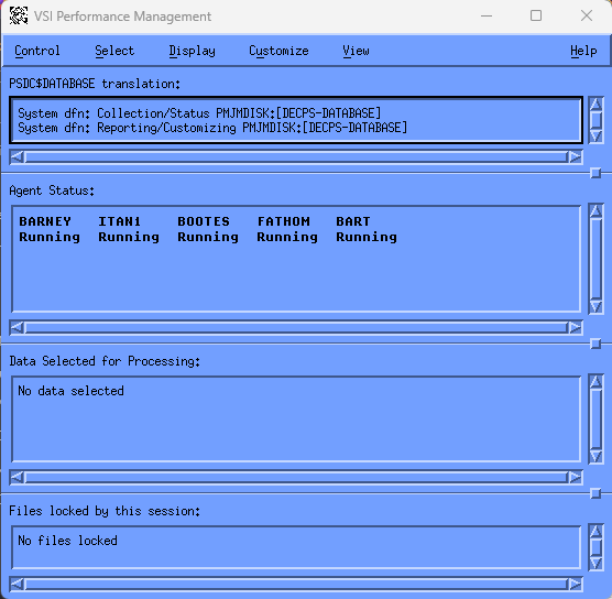
The Performance Manager Main Window lets you do the following tasks:
Control the DECwindows interface
Select data for analysis
Display analyzed data
Customize data collection, PSDC$DATABASE definition, and the parameters file
View or remove specified main window sections
Get Help, either Contextual (specific to a widget) or General (relating to a window)
8.1.2. Main Window Status Information
The Performance Manager Main Window displays the following information:
PSDC$DATABASE Translation
Displays the following directory information:
Collection/Status – Displays the system-wide definition of the logical name PSDC$DATABASE. If there is a data collector running on your analysis node, this directory contains the data files produced by the Performance Manager and the schedule file for controlling the collection.
Reporting/Customizing – Displays the process definition of the logical name PSDC$DATABASE, if it exists. If not, the job definition, group definition, or system definition is displayed.
If you want to analyze a Performance Manager database directory other than the system directory, you can specify an alternate directory. This directory might contain Performance Manager data files from another cluster or archived data whose classification definition is not applicable to your current scheme.
Performance Manager Status
The status of the data collection process can be one of the following:
Running
Stopped
Down
Waiting due to schedule
Waiting for disk space
No path to database device
Unknown (user lacks SYSLCK privilege)
For more information on Performance Manager status, see the Performance Manager Administrator Guide.
Data Selected for Processing – Displays the start and end time of the analysis period, the processing options chosen and the nodes selected for analysis. Until you select data, the message “No data selected” is displayed and all display menu options are disabled.
This is a brief list of the results of an analysis of performance data. Additional information can be gained by reviewing the Work in Progress box and the Data Selection box.
Files locked by this session – Displays one of the following files:
Schedule file
Parameters file
No files locked
The schedule file is locked when you customize Data Collection and is unlocked when you complete your changes.
The parameters file is locked when you customize parameters. When you complete your changes a message box appears asking you if you want to release the file. See the section How You Customize for more information about customizing either file.
8.2. How You Control the DECwindows Interface
Pull down the Control menu and release on the menu item you want. The Control menu lets you do the following actions:
Save reports
Monitor work in progress
Read the Parameters file
Write the Parameters file
Load binary graph data
Save binary graph data
Quit the DECwindows session
8.2.1. Save the Reports
To save the reports:
Release on the Save As... menu item to save reports.
Performance Manager displays the Save Reports Dialog Box. The reports reflect the data selected for analysis as shown in the main window's Data Selected for Processing Section. This option is disallowed if no data has been selected or if data selection was canceled.
For details of data selection, see the section How You Select Data for Analysis.
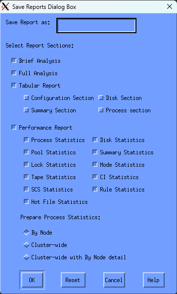
Enter a file name and select report sections you want to save.
Click OK to apply your selections and save the indicated reports. The dialog box is removed from the screen and the file created.
Click Reset to redisplay the default settings if you changed settings without applying them. Or, click Cancel to dismiss the dialog box without changing any settings or saving a report.
8.2.2. Monitor the Work in Progress
To monitor the work in progress:
To display the Performance Manager Work in Progress dialog box, release on Work in Progress...
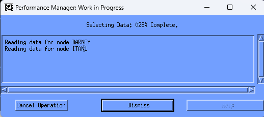
The work that is being monitored is the reading of the Performance Manager data files and the building of the internal data structures needed for the requested analysis.
This work is started as a result of data selection. See the section How You Select Data for Analysis for information on requesting an analysis of performance.
If the analysis process is currently active, the completion percentage is less than 100 percent. Click the Cancel Operation button to stop work in progress and cancel data selection.
No reporting capabilities are allowed until a complete data selection is performed.
When work is complete, click the Dismiss button to clear the dialog box from your screen.
The Main Window's Data Selected for Processing Section is updated to reflect the new selection.
If data is missing from the selected time period, missing data messages appear in the Work in Progress box. This is to alert you that a subsequent examination of the selected analysis period may be incomplete or inaccurate.
The length of time required to read and analyze the selected data depends on the options selected (such as hot file information) and the duration of time (1 hour as opposed to one day). You may want to remove the Main window and leave only the Work in Progress box on the screen.
8.2.3. Read the Parameter File
To read the parameter file:
Release on the Read Parameter File... menu item. You are prompted with the following message:
Important
By clicking YES, any changes to the parameter file that you have made are not saved and are lost.
Click YES to load and view the parameters file.
8.2.4. Write the Parameter File
To write the parameter file, release on the Write Parameter File... menu item if you want to save changes you have made to the file. Or, if you have not made changes, this option is desensitized.
8.2.5. Load the Binary Graph Data
The Performance Manager software lets the saving of analyzed data required to support graphing functions in a summarized format. To load one of these files and use the graphing options, release on the Load Binary Graph Data menu item. The Performance Manager software displays the Load Graph Data Dialog Box.
To load the binary graph data, specify a file to which a selection of previously saved graphing data is to be loaded.
If you previously requested data analysis using an option from the Select menu, access to that analysis data is lost.
Normally Performance Manager data is selected and processed prior to performing any of the display functions available. This selection process can be very time consuming, especially if you have activated all processing options.
If, at a later date, you want to view other graphs or pie charts associated with the original selection, you might want to use the Save and Load graph data features. Otherwise, the only way to recover the selected data, is to reselect. A faster way is to save the selected data so that if later review of the same time period is required, you can use the load function for much faster retrieval of the data.
8.2.6. Save the Binary Graph Data
To save the binary graph data:
Release on the Save Binary Graph Data menu item. Performance Manager displays the Save Graph Data Dialog Box.
Specify a file to which the currently selected graph data is to be saved in a binary format.
All graph data points are saved, and the file can be reloaded using the Load Graph Data Dialog Box. The save operation does not affect the current selection.
You can also load and save this binary graph data using the DCL command mode interface.
8.2.7. Quit the Session
To end a DECwindows session:
Click the Quit menu item.
If you have any outstanding changes to the Schedule file or the Parameters file, you are asked if you want to save them.
Click Yes to save your changes, or click No to quit without saving your changes. The interface proceeds to end of job.
8.3. How You Select Data for Analysis
The DECwindows Interface lets you analyze performance data and display graphs, pie charts, and reports, including the Analysis Report, Performance Evaluation Report, Tabular Report and Dump Reports. You must specify the time period, the nodes, and the processing options desired, before these functions can be performed.
To analyze Performance Manager data:
Pull down the Select menu and release on the menu item you want.
The Select menu lets you specify the following data for analysis:
Data collected today
Specific data
Data collected during the last hour of the current day
8.3.1. Select Today's Data
By default, the Performance Manager selects daily data for all nodes and analyzes data for the Analysis, Performance, and Tabular Reports and the graphs and pie charts unless you have adjusted these options by using the Specific Data... menu item.
The Performance Manager uses 00:00:00 of the current day as the beginning time and the current time as the ending time and chooses the CPD collection as the source. To select the default, release on Select Today from the Select menu. You can override the defaults if you have a local resource file (PSPA$SELECT.DAT) that sets your preferred defaults. See the section Data to be analized for a discussion of the Resource file.
8.3.2. Select Specific Data
Choose the Specific Data... menu item from the Select menu to specify data to be analyzed. Performance Manager displays the Performance Manager Data Selection dialog box.
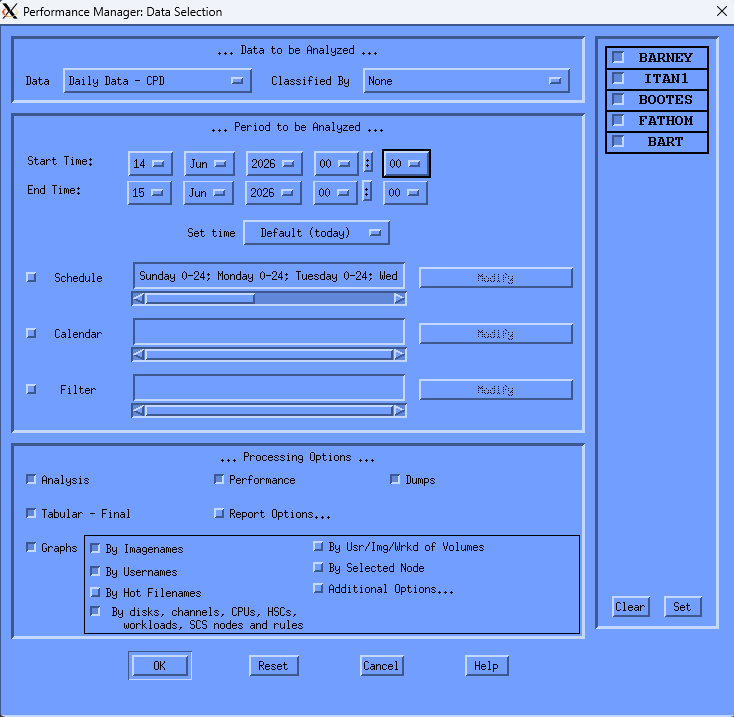
The time period and the processing options selected affect the amount of time needed to complete the analysis and the quantity of memory required (generally restricted by your pagefile quota, PGFLQUO, and the system parameter VIRTUALPAGECNT).
See the Appendix Estimate Virtual Memory Needs for information on estimating virtual memory needs and selecting data.
Including each graphing sub-option expands the memory and CPU requirements. Selecting archived data in place of daily data reduces memory and processing time, but also reduces flexibility. The By Selected Node menu item associated with graphing greatly increases memory requirements, as does the number of x-points.
The Performance Manager Data Selection dialog box lets you perform the following actions:
Choose type and classification of data to be analyzed
Set the beginning and ending date and time of the reporting period
Set hourly schedule within the beginning and ending date
Specify a Calendar file, indicating specific dates for analysis.
Choose processing and report options
Choose nodes for which data is to be reported
8.3.2.1. Data to Be Analyzed
Enter any of the following information:
- Data
Specifies the source of data to be analyzed. Press MB1 on the Data option item and a menu appears. The menu lists daily data collection definitions in your local schedule file and history file definitions in your local parameter file.
Release on the item you want. The option menu disappears. The menu item you chose is now the current source for performance data. The default data source is daily data from the CPD collection definition.
Note
Changing the source of data may change how it can be classified and which nodes can be analyzed. If you have chosen a history file descriptor, the Classify By options are changed to reflect those specified by the descriptor's definition. If you choose daily data, Classify By options reflect all workload families currently defined in the parameters file. If a data source selection nullifies the current Classify By selection, the Classify By selection is reset to the default of None.
For daily collection definitions, the nodes specified by the collection definition are the only valid nodes for analysis. For this reason the source of the data should always be chosen ahead of the classification of the data and the nodes to be analyzed.
If you select archived data for processing, the history files will be locked, blocking any archiving process. Also, if an archiving process is in progress, the DECwindows interface will be suspended from reading the files until the archiving is complete.
- Classified By
Specifies how the Performance Manager is to classify process activity in the Process Statistics Reports and in graphs presenting workload metrics. Press MB1 on the Classify By option item and a menu appears. The menu lists workload families. Release on the family name you want.
The default option is None, which results in the following summarizations. All graph data will be displayed in the workload Other. All Process Statistics reports will use the processing modes of Interactive, Batch, Network, or Detached.
8.3.2.2. Period to Be Analyzed
Enter any of the following information:
- Start time\End time
Hold MB1 down on any of the date and time fields to see all available choices. Release MB1 on the desired value. Press and hold MB2 to advance through the possible values. Press and hold MB3 to move back through the values.
These controls are desensitized if you have enabled the calendar option and have loaded a file of date ranges.
Press MB1 on the Set time option button and an option menu appears. Enter any of the following options:
Default (today) – Specifies midnight to now.
Yesterday – Specifies yesterday, from midnight to midnight.
Most recent hour – Specifies the last 60 minutes.
First hour of today – Specifies the time period of 00:00 to 01:00.
Advance by a day – Increment the beginning and end dates by one.
Backup by a day – Decrement beginning and end dates by one.
Specify text...– Release on the Specify text... menu item to specify the beginning and end day and time from the keyboard.
Performance Manager displays the Performance Manager Time Selection Box.
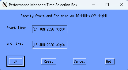
The day and time can be entered in the format shown in the window.
Clicking on the OK button applies the start and end times and removes the dialog box from the screen. The Reset button restores the start and end times to those displayed in the Performance Manager Data Selection box.
Clicking on the Cancel button removes the dialog box without changing the time fields currently displayed in the Data Selection box.
- Schedule
Specifies a subset of hours within your beginning and ending reporting period. Release on the Modify button and a Schedule Selection dialog box appears.
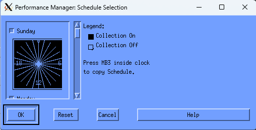
A 24-hour clock is displayed. A bar on the right side of the clock lets you scroll to each day of the week. By default, data collection is set ON for each hour of the day, every day of the week.
To set the clock:
Set or reset the square toggle button above the clock to turn data analysis on or off for an entire day.
To turn off data collection for a specific hour, point to the hour on the clock and click MB1. Holding MB1 down and dragging the pointer around the clock will set data collection to the value of the initial hour setting for a series of hours.
Drag the slider on the scroll bar to display the collection schedule for each day of the week or click the up or down stepping arrows.
To duplicate a day's schedule:
Press and hold MB3 inside the clock. A pop-up menu is displayed. Release on the Cut menu item.
Scroll to another day and press MB3 inside the clock. Release on the appropriate Paste menu item. The clock displays the copied schedule.
The OK button removes the dialog box and applies the new schedule. Reset causes the schedule to revert to your previous selection. Cancel removes the Schedule Selection dialog box.
- Calendar
Lets you specify a series of date ranges that are listed in a text file. For example, if you wanted to generate graphs and reports for the all Mondays in January, but wanted to substitute a Tuesday for the Martin Luther King holiday, you could create a text file with the following entries:
 05-JAN-2026 10:00, 05-JAN-2026 12:00
 05-JAN-2026 14:00, 05-JAN-2026 16:00
 12-JAN-2026 10:00, 12-JAN-2026 12:00
 12-JAN-2026 14:00, 12-JAN-2026 16:00
 20-JAN-2026 10:00, 20-JAN-2026 12:00
 20-JAN-2026 14:00, 20-JAN-2026 16:00
 26-JAN-2026 10:00, 26-JAN-2026 12:00
 26-JAN-2026 14:00, 26-JAN-2026 16:00
The above date list indicates that the hours of 10 to 12 a.m. and 2 to 4 p.m. should be processed for the 4 days specified. Tuesday the 20th is processed in place of Monday the 19th, a holiday.
Release on the Modify button and a Performance Manager Dates File Selection box appears.
Enter the name of the file containing the date ranges and release on OK. When the dates are successfully loaded, the box is removed and the Start Time and End Time buttons are updated and desensitized. Click the Calendar button to turn off the Dates File.
- Filtering Options
Click Filter to select a subset of data for reporting and graphing. Click Modify to change the entries for filtering.
The Selection Filters dialog box lets you select a subset of the daily or history data for PA reports and graphs. Process data and disk data can be filtered.
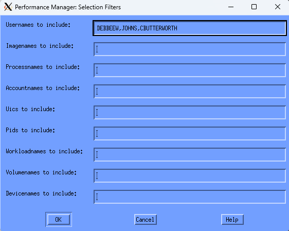
Process data can be filtered by using any of the filter entries: Usernames, Imagenames, Processnames, Accountnames, UICs, PIDs or Workloadnames. If a process record's identification information matches any of the identification specified, that record is selected. When using one or more of the process filters, the following PA reports and graphs include only information on the selected processes:
Process Statistics section of the Performance Evaluation Report
Process and Extended Process Metrics sections of the Tabular report.
Hot file report (only files used by the specified processes are selected)
Top or Custom Username, Imagename, and Workloadname graphs
Top or Custom User_Volume, Image_Volume, and Workload_Volume graphs
Top or Custom Hot file graphs (only files used by the specified processes are selected)
Likewise, disk data can be filtered by using any of the filter entries: Volumenames and Devicenames. If a device record's identification information matches any of the volume names or device names specified, that record is selected. When using one or more of the disk filters, the following PA reports include only information on the selected disks:
Disk Statistics section of the Performance Evaluation Report
Disk Metrics section of the Tabular report
Hot file report (only files located on the specified disk are selected.)
Top or Custom Volumename and Devicename graphs
Top or Custom User_Volume, Image_Volume, and Workload_Volume graphs
Top or Custom Hot file graphs (only files located on the specified disk are selected
If you specify both a process filter and a disk filter, the hot file report section and hot file graphs will select only hot files that are both located on the specified disk volume, and used by the specified process. The same will be true for the User_Volume, Image_Volume, and Workload_Volume graphs.
The following entries allow you to select specific processes or disks for the reports and graphs:
- Usernames
Specify a list of strings (separated by commas, spaces or tabs) to generate reports and graphs for all process records with the username matching any of the specified strings.
- Imagenames
Specify a list of strings (separated by commas, spaces or tabs) to generate reports and graphs for all process records with the imagename matching any of the specified strings. Do not specify any trailing ".EXE", nor the file version, device or directory.
- Processnames
Specify a list of strings (separated by commas, spaces or tabs) to generate reports and graphs for all process records with the processname matching any of the specified strings. The match string is case sensitive, so if the process names have any lower case letters, spaces or tabs, use double quotes when you enter the value; (for example,"--RTserver--").
- Accountnames
Specify a list of strings (separated by commas, spaces or tabs) to generate reports and graphs for all process records with the accountname matching any of the specified strings.
- Workloadnames
Specify a list of strings (separated by commas, spaces or tabs) to generate reports and graphs for all process records associated with any of the specified workloads. This filter is valid only if the Classified By option is used to specify a classification scheme for your workload data.
- Uics
Specify a list of UICs (separated by commas, spaces or tabs) to generate reports and graphs for all process records with the UIC matching any of the specified UICs. An asterisk may be used to wildcard either the group or user field of the specified UICs.
- Pids
Specify a list of PIDs (separated by commas, spaces or tabs) to generate reports and graphs for all process records with the PID matching any of the specified PIDs.
- Volumenames
Specify a list of strings (separated by commas, spaces or tabs) to generate reports and graphs for all disk records with the volumename matching any of the specified strings. Do not specify any trailing colon.
- Devicenames
Specify a list of strings (separated by commas, spaces or tabs) to generate reports and graphs for all disk records with the devicename matching any of the specified strings. Do not specify any trailing colon.
8.3.2.3. Process Your Options
You can enter any of the following options:
- Analysis
Directs the Performance Manager to analyze the data to generate an Analysis Report.
- Performance
Directs the Performance Manager to analyze the data to generate Performance Evaluation and Process Statistics Reports. The primary key for presenting process statistics defaults to Interactive, Batch, Network, Detached, or Other organization. The secondary key defaults to Imagename.
While viewing the resulting report, an option is provided to re-sort the process statistics.
- Dumps
Specifies that the unanalyzed data will be made available for user inspection. Since no pre-processing of the data is required for dumps, no overhead is added to the analysis process. Refer to the VSI Performance Manager Administrator Guide for more information about dump reports.
- Tabular-Final
Directs the Performance Manager to analyze data to generate the Tabular Report sections averaged over the entire analysis period.
- Report Options
Displays options for summarizing process statistics and for specifying the reporting intervals, as shown in the following screen:
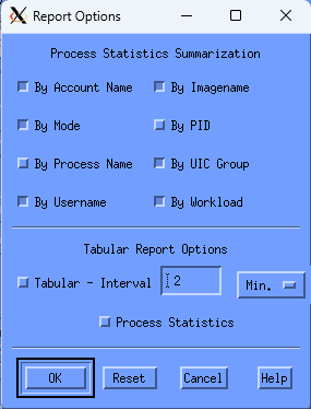
- Tabular-Interval
Directs the Performance Manager to prepare interval reports summarizing data into specified intervals. This reporting option is unavailable unless the Final Tabular report is selected. Once selected, the reporting interval becomes available. Performance Manager data collection for daily performance data is recorded every two minutes. This is the default reporting interval. This value can be adjusted by varying the supplied value of 2 and the units value of minutes. When the analysis process is initiated, it may override your selections for the reporting interval if it is not a multiple of the recording interval.
- Graphs
Directs the Performance Manager to analyze the data to generate all graphs and pie charts. The options are as follows:
By Imagenames – Enables graphing of process statistics by imagename.
By Usernames – Enables graphing of process statistics by user name.
By Hot Filenames – Enables graphing of file statistics by file name.
By Disks, channels, CPUs, HSCs, workloads, SCS nodes and rules – Enables graphs for listed categories.
By Users/Images of Volumes – Enables graphing of process I/O statistics by the user or image of volumes.
By Selected Node – Enables predefined top graphs and custom graphs for selected nodes. The system metric graphs are always available By node. This option greatly increases memory requirements.
Additional Options... – Click the Additional Options... button and the interface displays the Performance Manager Graph Options dialog box.
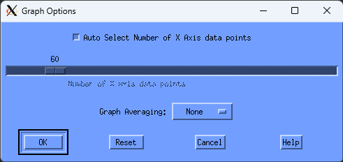
The Auto Select Number of X Axis data points button is used to have the Performance Manager choose a value that results in an even time interval to be represented by each data point. When you disable this button, you can specify the number of X Axis data points to plot across a graph.
As the value of X Axis data points increases, spikes and valleys become more defined and the graph has a higher resolution. A low number of X Axis data points produces a smoother graph because the graphing facility may average multiple data points within the time frame specified.
Press on the Graph Averaging button and an option menu appears. The selected data is averaged into the time period selected. For more information on graph averaging, see the chapter “Generating Historical Graphs."
- Node Control and Toggle Buttons
By default, the Performance Manager analyzes data for all nodes in your schedule file. Click a node's toggle button to include or exclude the node from the processing. Clear and Set buttons are available for adjusting all toggles.
- Control Buttons
The OK button applies your selection, removes the data selection box and activates a Performance Manager Work in Progress dialog box which includes a real time display of the progress of the analysis procedure. See the Controlling the DECwindows Motif Interface section for details of the Work in Progress box.
The Cancel button closes the Data Selection dialog box and resets all widgets.
The Reset button sets all widgets back to their settings of either the startup defaults or the last approved selection.
8.3.3. Select the Last Hour
Release on the Last Hour option from the Select menu to apply the current data selection settings, for the last hour of the day. To review what the current data selection settings are, release on the Specific data... menu item and view the Data Selection dialog box.
8.3.4. Use Custom Default Settings
You can override the default data selection settings by providing a selections resource file, PSPA$SELECT.DAT in the DECW$USER_DEFAULTS directory area (typically SYS$LOGIN). A sample file is provided in PSPA$EXAMPLES.
The PSPA$SELECT.DAT file will be read once when you make the first data selection. This file can be edited with a text editor. A leading exclamation point (!) makes a setting a comment.
Only override those items that are significant to you, as the process does slow the activation of the Data Selection dialog box.
8.4. How You Display Analyzed Data
To display reports or graphs, pull down the Display Menu and release on the option you want. The Display menu lets you generate the following reports:
Brief Analysis Reports
Full Analysis Reports
Performance Evaluation Reports
Process Statistics Reports
Tabular Reports
Graphs and pie charts
Dump Reports
For more information about dump reports, see the Performance Agent Administrator Guide.
Until a complete data selection process has occurred, these options are unavailable.
8.4.1. Brief Analysis Report
Release on the Brief Analysis menu item from the Display menu to open a Performance Manager Analysis Report window.
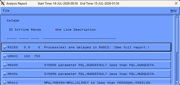
The Brief Analysis Report lists the rules that fired during the analysis period. Click anywhere on the rule and Performance Manager DECwindows opens another Analysis Report window that displays the fired rule's conclusions, conditions, and evidence.
To return to the Brief Analysis Report, pull down the File menu and release on the Close menu item or click the Close button at the bottom of the window.
8.4.2. Full Analysis Report
Release on the Full Analysis menu item from the Display menu to open a Performance Manager Analysis Report window, as shown in the following screen:
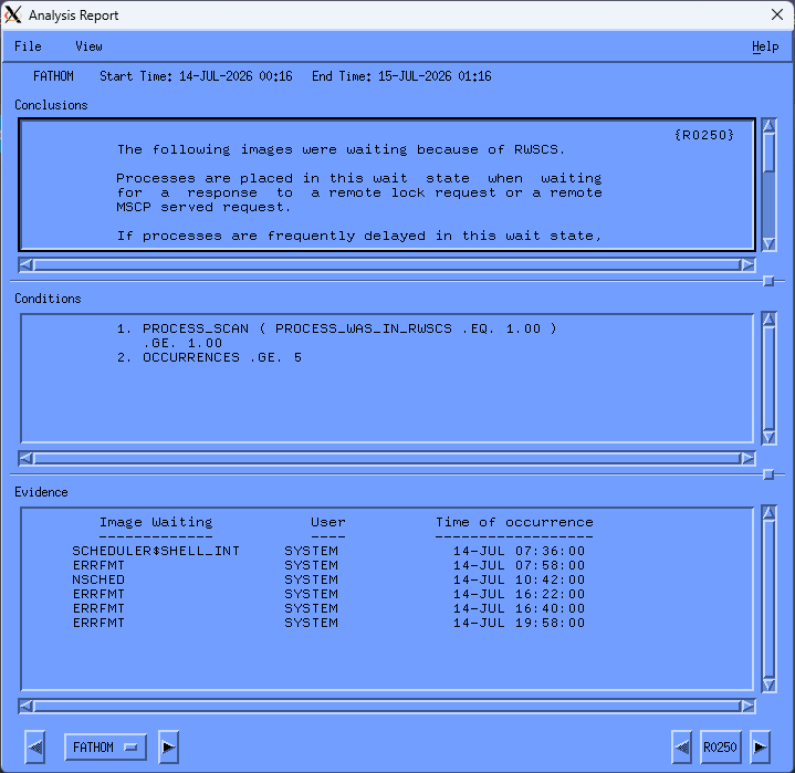
The menu bar contains File and View menus. To close the window, pull down the File menu and release on the Close menu item.
By default, the Full Analysis Report lists conclusions, evidence, and rule conditions that satisfied rule firings. To remove either evidence or conditions or both from your report, pull down the View menu and release on the appropriate item.
To proceed through the list of nodes, click the appropriate Node arrow button or hold MB1 down on the node button to display an option menu with the selected nodes. Releasing on the desired node name updates the window with that node's report.
If more than eight nodes were selected for analysis, the node option menu contains two <more> buttons, which cause the node names to be shifted up or down when the cursor is within their option entry. To stop the shifting, move the cursor out of the more button. Releasing on a node name causes the Analysis Report window to be updated with that node's report. Releasing on a more button causes the report window to be updated with data of the node name adjacent to the more button.
To proceed through the list of conclusions, click the appropriate rule ID arrow button.
8.4.3. Performance Evaluation Report
Release on the Performance Evaluation menu item from the Display menu to open the Performance Manager Performance Evaluation window, as shown in the following screen:
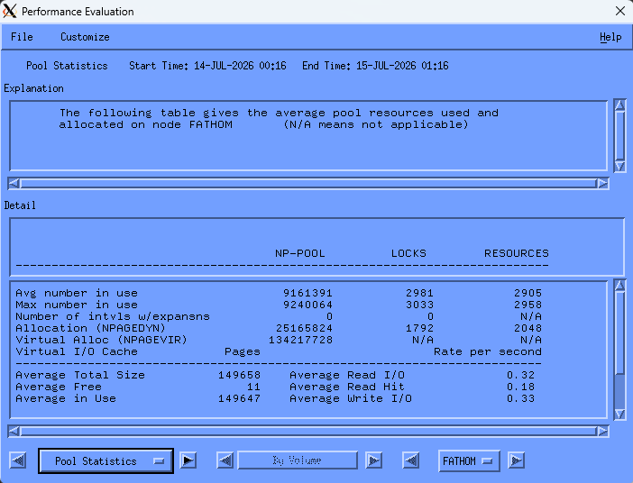
To navigate through the Performance Evaluation Report, click the Statistics label. An option menu appears listing all of the Performance Evaluation Reports. Release on the report section you want displayed. You can also advance through the report by clicking on the appropriate direction arrows.
The Section label, here labeled SOURCE, changes according to the report being viewed, and will be desensitized if irrelevant. The arrows on either side of this label allow you to advance to other sections of the report.
Press on the Node button and an option menu appears listing the nodes for which the report is available. Release on the node you want displayed. Only pool statistics are available by node.
To exit from the Performance Evaluation window, pull down the File menu and release on Close.
To customize the Performance Evaluation Report, pull down the Customize menu and release on the menu item you want.
The Customize menu lets you alter the hotfiles report.
- Set hotfile limit..
Release on the Set Hotfile limit... menu item to display the Set Hotfile limit dialog box containing a scale set at the current hotfile reporting count, as shown in the following screen:
Drag the arrow to change the number of files that you want reported for each disk device.
- Control Buttons
The OK button applies the change and removes the dialog box.
The Reset button restores the value to your last selection (if you previously changed the default) or to the default value of 20.
The Cancel button removes the dialog box without changing the limit.
8.4.4. Process Statistics
Release on the Process Statistics menu item from the Display menu to open the Performance Manager Process Statistics window, as shown in the following screen:
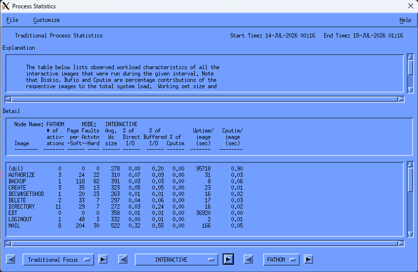
To navigate through the Process Statistics Reports, click the Traditional Focus label. An option menu appears listing all of the Process Statistics Reports.
Release on the report type you want displayed. You can also advance through the reports by clicking on the appropriate direction arrows.
The Section label, here labeled INTERACTIVE, changes according to the report section being viewed, and will be desensitized if irrelevant. The arrows on either side of this label allow you to advance to other sections of the report.
Holding MB1 down on the section label will display all other available reports. Releasing MB1 on the desired report name will update the Detail window.
Press on the Node button and an option menu appears listing the nodes on which the report is based. Release on the node you want displayed.
To exit from the Process Statistics window, pull down the File menu and release on Close.
To customize the Process Statistics Report, pull down the Customize menu and release on the menu item you want.
The Customize menu lets you enter any of the following:
- Cluster stats by node
Release on the Cluster stats by node menu item to turn on or off the reporting of cluster-wide process statistics by node.
8.4.4.1. Report keys...
To re-sort the process data, release on the Report keys... menu item. The Performance Manager displays the Primary and Secondary Keys dialog box.
The Primary and Secondary keys you specify are applied when you use the SAVE AS option to save process statistics, as shown in the following screen:
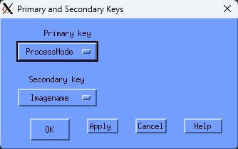
- Control Buttons
The OK button removes the dialog box, sorts the process data, and re-displays the report.
The Apply button sorts the process data and re-displays the report.
The Cancel button removes the dialog box without changing the keys.
8.4.5. Tabular Report Sections
Release on the Tabular Report menu item from the Display menu to open the Performance Manager Tabular Report window, as shown in the following screen:
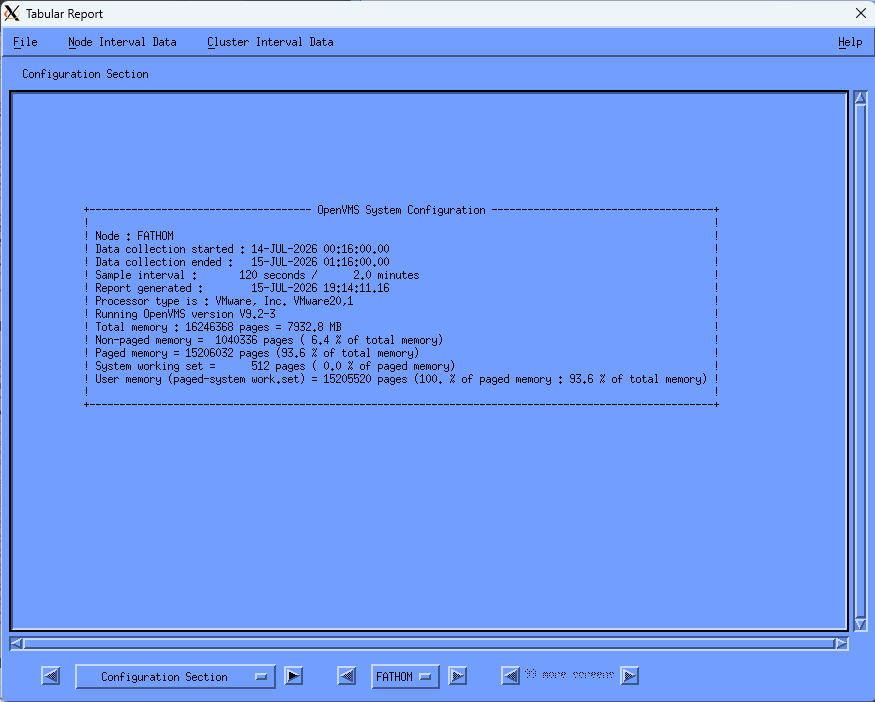
To navigate through the Tabular Report, click the arrow buttons on either side of the Configuration label. This updates the window with the Summary, Process, Extended Process, Disk, or Server Statistics sections for node reporting. Cluster-wide reports are also provided for summary, process, disk, and server reports which focus on either a cluster view or a by-node view. The window is sized to accommodate the requirements of the Summary Statistics display. The section label changes according to what section is currently viewed, as are the arrow buttons enabled or disabled.
Pressing the node button (labeled FATHOM in the figure) displays an option menu with the list of selected node names for which the report can be viewed. Releasing on a node name causes the report window to be updated with that node's data. The arrow buttons on either side of the node button can be used to progress sequentially through the selected nodes.
The node option menu and arrow buttons are not enabled while cluster reports are being viewed.
The process and disk report sections can generate many screens worth of data. When viewing these report sections the number of screens available for viewing and the arrow buttons on either side become enabled to allow reviewing all available data.
To exit from the Tabular Report window, pull down the File menu and release on Close.
8.4.5.1. Tabular Interval Report Sections
In addition to viewing the tabular report statistics summarized over the selected analysis period, you can also view classes of statistics according to a subinterval specified during data selection. The menu entries Node Interval Data and Cluster Interval Data provide access to the subinterval statistics windows. If the Tabular-Interval option was not chosen during data selection, these menu options are desensitized.
The node statistics classes include memory, CPU, paging, I/O, XQP, lock, SCS, and process statistics. Each class appears in a separate window. If the node selected in the parent window is changed, the interval statistics windows are all updated with that node's data. The beginning time stamp of each interval is included in the display.
The cluster statistics classes include memory, CPU, and lock statistics, either in terms of minimum/maximum/average displays or by node displays.
For details on the data displayed in the different report sections, see the chapter Evaluate Performance in Detail.
8.4.6. Graphs
To view graphs or pie charts of selected data, release on the graph item of the Display menu. The Performance Manager Graph window is displayed, as shown in the following screen:
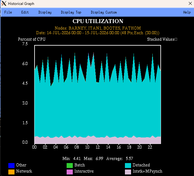
Each graph has the same basic format. The components are these:
- Title
The title is centered at the top of the graph and identifies the type of graph.
- Subtitle
The subtitle gives the node name (or list of node names for composite graphs), the date and time of the selected data, the number of x-axis data points, and the time represented by each point.
- Axis Labels
Time is implied as the x-axis label. Labels on the y-axis specify the units of the plotted values, for example, Percent of CPU.
- X and Y-Axis Markers
Axis markers indicate the magnitude and time of any point on the graph. The x-markers indicate the time. The y-markers are scaled based on the maximum value of all the data points.
- Legend
The legend appears at the bottom of the graph. The legend identifies the name of the metric, and the color or pattern associated with it.
The Performance Manager Graph Window lets you do the following:
Save the graph
Edit the graph format
Display predefined graphs
Display Top system use graphs
Display Custom graphs
8.4.6.1. Save a Graph
To save the graph or pie chart:
Pull down the File menu and release on the Save as... menu item.
The Performance Manager Save Graph or Save Pie Dialog Box is displayed, as shown in the following screen:
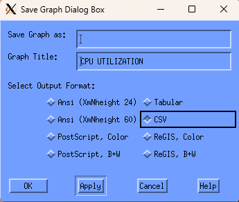
The Save Graph or Save Pie dialog boxes allow you to do the following actions:
Specify a file name
Select an output format
More output formats are available for graphs than for pie charts.
Specify the title
Click OK to save the graph or pie chart to a file. Or, click Cancel to remove the window from the screen, with no data being saved.
8.4.6.2. Edit the Graph Format
Pull down the Edit menu. You can change the following aspects of the graph:
- Stack
Specifies that the values for each category on the graph are to be stacked. This is the default.
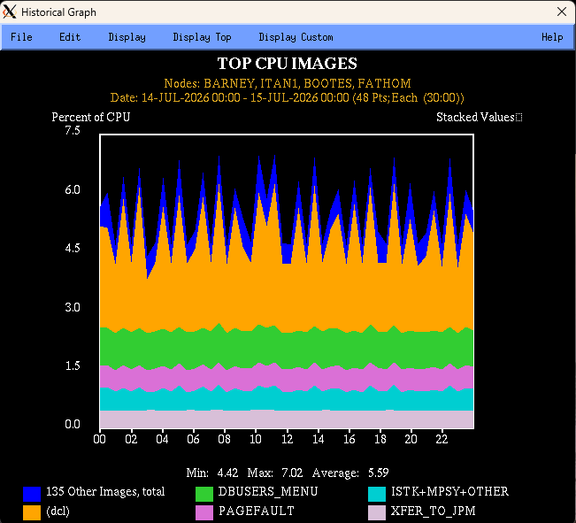
Release on the button to turn Stack off. The Performance Manager software displays a line mode graph to avoid occlusion. The values for each category are overlaid or unstacked.
If you request an unstacked graph of top metrics, the items grouped together are displayed as an average instead of a total.
- Pie Chart
Specifies that the display is to be a pie chart. A pie chart produces a slice for each item, using size to depict average units of measure over the specified time period. When pie charts are displayed, stack and line mode toggle buttons do not affect the display.
For more information, see the chapter Generate Historical Graphs.
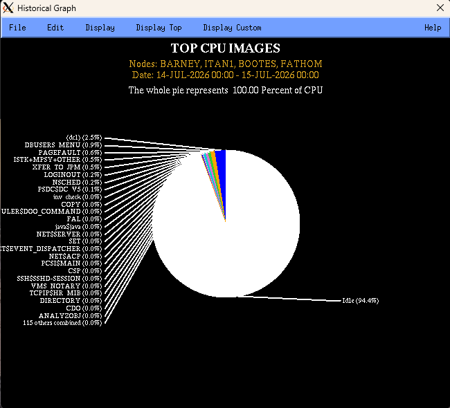
- Monochrome
Specifies that shades of a single color shall be used to display the graph or pie chart.
- Line Mode
Specifies that the values for each category on the graph are to be displayed in a line mode. Click the button to turn line mode off or on.
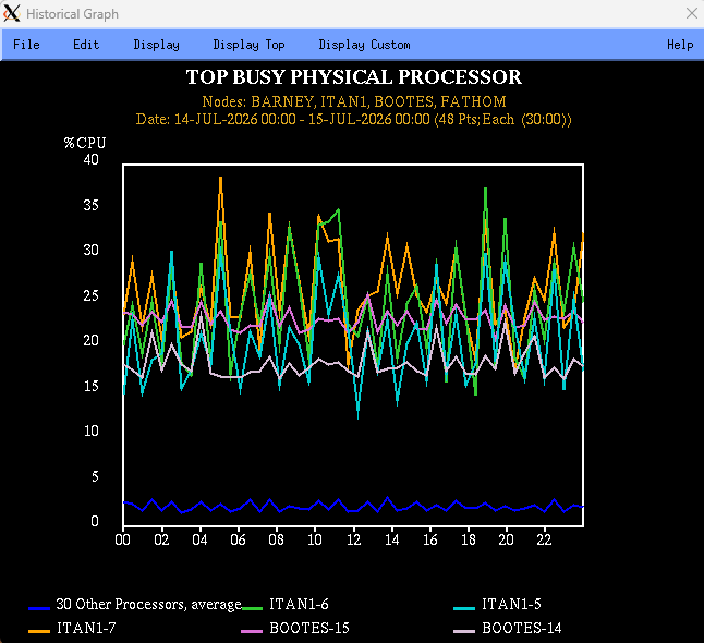
- Editing Panel
Release on the Editing Panel menu item and the Performance Manager interface displays a Graph Panel dialog box.
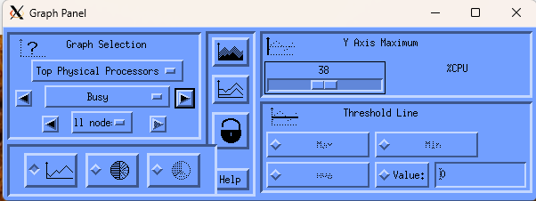
The Graph Panel dialog box contains five sections that allow you to enter any of the following:
Graph selection – The first option menu lets you specify a major class of graphs to be viewed. In response, Performance Manager replaces the entries in the second option menu with those that are appropriate for the class you specified in the first option menu.
The graph window is updated with the first graph in the list indicated by the major category. An exception to this is switching between the Top User and Top Image categories, which causes the same graph metric to be displayed.
Selecting the major category of custom graph updates the lower menu with custom classes. Selecting a custom subclass, causes the custom graph metrics dialog box to appear. For more information about displaying custom graphs, see the section Display Custom Graphs.
The arrow buttons allow you to proceed through the categories in the specified class.
If multiple nodes have been selected for graphing, access to graphs by individual nodes is provided. Press MB1 on the CLUSTER menu entry to view the popup menu with all selected node names. Release MB1 on the node to be graphed. The arrow keys allow stepping through the node names sequentially.
Access to the System graph category is always available by node. To access the other graph categories, when the data was selected, the BY NODE toggle button must have been set.
Graph format – This radio box lets you choose between a graph and a pie chart. For graphs displaying data in terms of percentages (CPU UTILIZATION), Performance Manager provides an additional option. If selected, the percentage reflected in the pie is 100%, with a slice labeled IDLE added to the pie chart.
Middle section (contains 4 buttons arranged vertically) – This panel contains two toggle buttons for adjusting the graph presentation, a lock for locking your settings, and a Help button.
The top toggle button flips the graph from line mode to fill mode, and back again. The pixmap on the button reverses to be the opposite of the state of the graph, allowing you to see where you can go.
The second toggle button changes the graph presentation from stacked to unstacked, and back again. A stacked graph displays the metrics one on top of another. An unstacked graph displays each metric value with respect to the X-axis. This can cause occlusion of some details, so it is best to view unstacked graphs in line mode.
The lock button will lock your current settings for stack/unstack, line/fill mode, Y-axis maximum, and threshold line selection. As you view different graphs, the same settings will be applied.
Y Axis maximum – Specifies a new value for Y Axis Maximum. This lets you minimize the affect of spikes on graph presentation and to gain consistency in graphs generated from different data selections.
You can either drag the pointer across the scale or click either side of the value to adjust the scale. Press and hold MB1 to scroll the values.
The Y Axis Maximum value is maintained until the next data selection.
Threshold line – Specifies a line to be displayed on the graph reflecting the value of the selected button. You can also specify a specific value at which a threshold line is to be displayed.
The Max, Min, and Ave lines are available only for stacked graphs.
- Change Color
Releasing MB1 on an option in the Change Color submenu causes Performance Manager to display a color mixing dialog box. The colors you establish are used when you save a color PostScript graph.
- By Node
Releasing MB1 on a node name in the By Node submenu causes the current graph and all subsequent graphs to be drawn for that node only.
Note
If you did not select the By Selected Node processing option in the Data Selection dialog box, only system metrics graphs are available by node.
All Nodes – Releasing MB1 on All Nodes causes the current graph and all subsequent graphs to be redrawn for all nodes selected. When all nodes are selected the graph becomes a Composite graph. See the chapter Generate Historical Graphs for more information on Composite graphs.
8.4.6.3. Display Predefined Graphs
Pull down the Display menu to view the possible system metrics graphs. Release on the type of graph you want. Your choice is displayed in the Performance Manager Graph Window, as shown in the following screen:
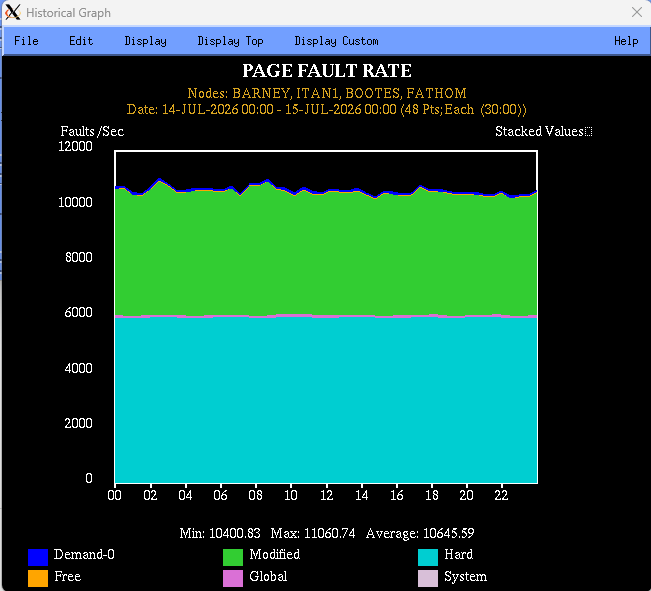
8.4.6.4. Display Top System Use Graphs
Pull down the Display Top menu to display graphs of top system use. Point to a Top menu item and click the submenu icon. Click a menu item in the submenu. The graph you have chosen is displayed, as shown in the following screen:
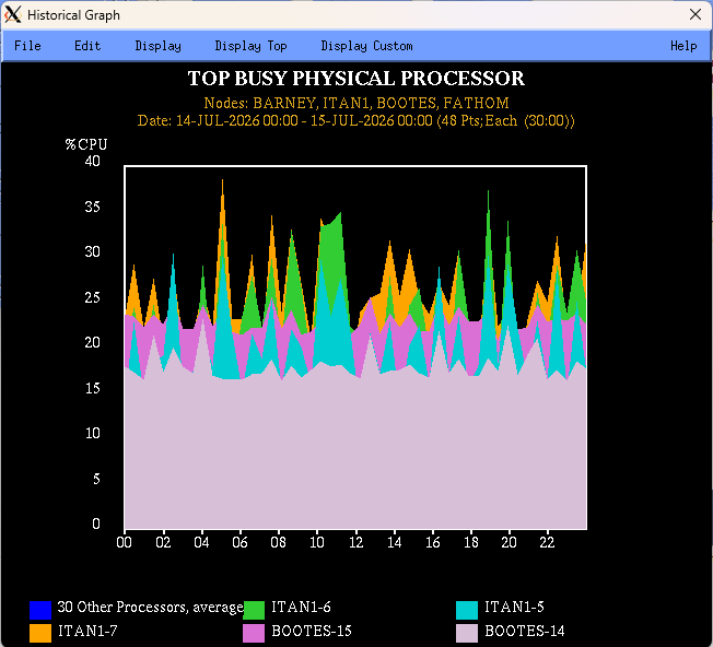
For more information on predefined graphs, see the chapter Evaluate Performance in Detail.
8.4.6.5. Display Custom Graphs
Pull down the Display Custom menu to display custom graphs. Choose the custom graph category that you want to select. Performance Manager interface displays a dialog box, as shown in the following screen:
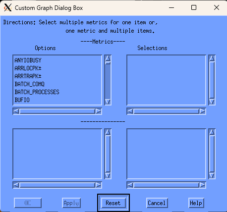
You can take the following actions in this screen:
To move your selected option into the selections box, click a metric option. Up to six system metrics can be selected.
To apply your changes and draw the graph, click the Apply button without closing the dialog box.
To apply your changes and close the dialog box, click the OK button.
To clear all selected items, click the Reset button.
To close the dialog box without applying any changes, click the Cancel button.
For most custom categories, additional items appear in the lower option box. You can display up to six metrics when using system metrics. For other types of metrics you can display up to six metrics when one item is chosen and up to six items when one metric is chosen.
8.5. How You Customize
To select and item for customization, pull down the Customize menu and release on the item.
The Customize menu lets you perform the following actions:
View and change Performance Agent settings
Specify or redefine the PSDC$DATABASE definition
View and change Performance Manager parameters
8.5.1. Customize the Data Collection
To view Performance Agent settings, pull down the Customize menu and release on the Data Collection... menu item.
The Performance Manager DECwindows Motif displays the Performance Agent Collection Definition dialog box.
The primary data collection process collects performance data according to parameters in the CPD collection definition within the schedule file. If no other collection definitions exist, the CPD parameters will be displayed in the Collection Definitions box, as shown in the following screen:
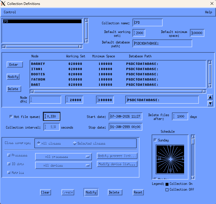
The Collection Definition dialog box lets you do the following actions:
Modify, create, or remove collection definitions
Change collection parameters
Change collection schedules
Add or remove nodes
Your changes to the Collection Definition file are applied when you pull down the Control menu and release on Save schedule file or exit. If you change settings and then decide not to use the changes, pull down the Control menu and release on Load schedule file to start over with the latest version.
When you are done with this window, pull down the Control menu and release on Exit.
Before writing out a new schedule file or releasing the lock, a message box appears with one of the following messages:
(If modifications have been made:) Do you want to write out your changes to the schedule file and release the lock?
(If no modifications have been made:) You have locked access to the schedule File, do you want to release it to other users?
Press YES to release the lock. Your modifications, if any, are written out.
Press NO to keep the lock. Your modifications, if any, are not written out.
8.5.1.1. Modify or Create a Collection Definition
The names of the collection definitions are listed in the box at the upper left-hand corner. To select a collection definition, click the collection definition. The definition and current parameters will appear. Use the Tab key to move between parameter entries or point to the entry and click MB1.
Click the buttons at the bottom of the window to perform the following actions:
- Clear
Removes all the entries from display and restores all default values
- Create
Adds the collection definition you have created to the list
The software displays an error message if it finds an error in your entries.
- Modify
Updates the collection definition with your changes.
- Delete
Removes the collection definition from the list and restores all default values
- Reset
Returns all the parameters on display to their original values
8.5.1.2. Change the Collection Definition Parameters
To change the collection definitions, enter any of the following parameters:
- Collection Definition List
The box in the upper left-hand corner contains the names of the current collection definitions. When you click an entry, the parameters for that collection definition appear.
- Collection name
The Collection name is a text field that shows the name of the definition currently displayed. When creating a new definition, use this field to enter the name. Names can be up to 20 characters in length.
- Default working set
Enter the working set quota. This value is a decimal number greater than 1024 that sets both the working set quota and the working set extent if the value is higher than the default values. By default, the working set quota is 2048 and the working set extent is 20K. You can override this default by specifying values for individual nodes.
- Default minimum space
Enter the minimum number of blocks of free disk space needed on each database disk for each node in the definition. Data collection suspends recording if there are fewer blocks of free disk space available. You can override this default by specifying values for individual nodes.
- Default database path
The default database path for all nodes in the collection definition. You can override this default by specifying values for individual nodes.
- Node Definition Section
This displays the nodes in a collection definition. Default values are displayed. Although the changes that you make appear as they are made, they are not applied to the collection definition until you click the Create or Modify buttons at the bottom of the window.
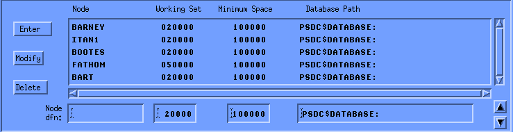
To add a node, enter the name and make any modifications you want to the default values shown to the right. Then press Return or click Enter.
To modify a node entry, double-click it. The definition appears under the list. Make the changes you wish and then press Return or click Modify to the left of the box.
To delete one or more nodes, click the entries in the list, and then click Delete to the left of the box.
To change the order of the nodes in the list, click the node to be moved, and then the arrows in the right-hand corner. Only one node can be moved at a time.
The changes you make in the node definition section do not modify the collection definition until you click Create or Modify to update the entire collection definition.
- Enter
Enter lets a new node to be added to the node list. When you type in a new node name, you can click Enter or press Return to add it to the list.
- Modify
Modify takes changes you make to a node definition and puts the changes into the list. Modify is disabled until you have selected a node from the list by double-clicking on the node. Changes to the collection definition take effect when you click Modify at the bottom of the window.
- Delete
Delete removes any selected, or highlighted, nodes from the list. The nodes are removed from the collection definition when you click Modify at the bottom of the window.
- Hot file queue
To enable hot file collection in the CPD collection definition, the toggle button to the left must be on. This lets you specify the queue length in the text entry box. This pertains only to the CPD collection definition because only the primary data collector collects hot file data.

Enter the minimum average queue size that a disk must have to start collecting the hottest files for that disk. This value is a decimal number less than 100.00 and greater than or equal to 0.00. The default is 0.33.
If the toggle button is off, no hot file data is collected.
If the toggle button is on, you must specify a queue length or accept the default value.
- Collection interval
The Collection interval specifies the number in seconds in a sampling interval. At the end of this time period, data is recorded into an interval record.
The CPD collection definition has an interval of 120 seconds which cannot be modified.
You can specify an interval from 1 to 3600 seconds for other definitions.
- Delete files after
Enter the number of days that data is to be retained. The default is seven days for the primary data collector. Data files are automatically deleted from the database when they are older than the specified number of days.
For alternate data collectors, the default is 99,999 days which lets you control the how long data files are retained.
This value should be coordinated with any data archiving and the amount of free space required for the database area. For information on archiving, see the Performance Agent Administrator Guide.
- Start date
The date and time on which the collection definition goes into effect. A data collection process will hibernate until this date and time. The formatting is as follows: DD-MMM-YYYY HH:MM
- End date
The date and time on which a data collection process Is to terminate. The formatting is as follows: DD-MMM-YYYY HH:MM
- Changing the Collection Schedule
A 24-hour clock is displayed. A bar on the right side of the clock lets you scroll to each day of the week. By default, data collection is set ON for each hour of the day, every day of the week.
To set the clock:
Set or reset the square toggle button above the clock to turn data collection on or off for an entire day.
To turn off data collection for a specific hour, point to the hour on the clock and click MB1. Holding MB1 down and dragging the pointer around the clock will set data collection to the value of the initial hour setting for a series of hours.
Drag the slider on the scroll bar to display the collection schedule for each day of the week or click the up or down stepping arrows.
To duplicate a day's schedule:
Press and hold MB3 inside the clock. A pop-up menu is displayed. Release on the Cut menu item.
Scroll to another day and press MB3 inside the clock. Release on the Paste menu item. The clock displays the copied schedule.
- Class Coverage Section
The Class Coverage section lets you specify which major areas of performance data should be collected. While the CPD can not be limited, other collection definitions can be limited to only those classes of data needed for special-purpose analysis.
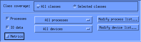
The toggle buttons enable you to choose all or selected classes.
- All classes
Turn on this toggle button to collect all classes of data.
- Selected classes
Turn on this toggle button to choose which classes of data you wish to collect: processes; I/O data; or metrics.
- Processes
Turn on this toggle button to collect Process data or to collect process data for specified processes.
- I/O data
Turn on this toggle button to collect I/O data or to collect I/O data on specified devices.
- Metrics
The Metrics field lets you choose whether or not to collect a summary set of system metrics including such data items as memory utilization, CPU, and I/O parameters.
- All processes
When you select the collection of process data, the All Processes option is collected by default. If you have modified the process list, the menu is revised to reflect the type of coverage list (include or exclude) and the count of specified processes. Clicking on this menu will display the correct list. This menu provides a convenient way to view the coverage list.
- Modify process list...
Click this button to specify a list of processes in the Collection Coverage List box. You specify a list of processes to be included in collection or excluded from collection.
- All devices
When you select the collection of I/O data, the All Devices option is collected by default. If you have modified the device list, the menu is revised to reflect the type of coverage list (include or exclude) and the count of specified devices. Clicking on this menu will display the correct list. This menu provides a convenient way to view the coverage list.
- Modify device list...
Click this button to specify a list of devices in the Collection Coverage List box. You specify a list of devices to be included in collection or excluded from collection.
- Coverage Lists
For Process and Disk classes, you can collect data for specific lists of items or exclude lists of items.
To create a list of processes, push down and hold on the uppermost box in this window, which displays All processes or one of the other options. When the menu appears, pull down to the menu item you want and release.
Click the text entry field to activate the cursor.
To add a process name, enter a name and press Return or click the Enter button. The name will appear in the list box and be cleared from the text entry field.
To delete a name, click the name in the name list box, then click the Delete button. The name is removed from the list box. To remove multiple names, click the names and then click the Delete button.
To create a list of devices, push down and hold on the uppermost box in this window, which displays All devices or one of the other options. When the menu appears, pull down to the menu item you want and release.
Click the text entry field to activate the cursor.
To add a device name, enter a name and press Return or click the Enter button. The name will appear in the list box and be cleared from the text entry field.
To delete a name, click the name in the name list box, then click the Delete button. The name is removed from the list box. To remove multiple names, click the names and then click the Delete button.
The following sample Collection Coverage List box shows a list of processes for which no data is to be collected.
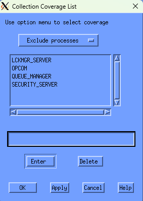
The type of list being managed cannot be converted. For example, an include processes list cannot become an exclude processes list. All list entries must be deleted before the coverage list type can be changed.
8.5.2. Customize the PSDC$DATABASE Definition
To specify or redefine a PSDC$DATABASE definition, pull down the Customize menu and release on the PSDC$DATABASE definition... menu item.
DECwindows Motif displays the Set Database dialog box. This box lets you redirect editing and review of dump reports to an alternate database area. You can also redirect performance analysis to an alternate area.
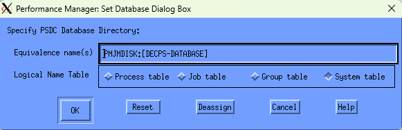
The translation of the lowest level definition is displayed, along with a toggle setting indicating the logical name table in which it is defined.
To remove a definition, click Deassign. The dialog box is removed, and the definition at the next highest level goes into effect, possibly reloading a schedule and parameter file.
To create a new definition, click a toggle to specify which logical name table the definition should be placed in and type in the new definition. Click OK when done. The dialog box is removed and any new schedule and parameter files are loaded. There must be at least one definition of PSDC$DATABASE defined for the interface to run.
8.5.3. Customize Parameters
The DECwindows Motif Interface lets you view and change the Performance Manager parameters file. The Performance Manager Parameters file contains workload definitions, family definitions, history file descriptors, and auxiliary knowledge base information.
See the Performance Agent Administrator Guide for more discussion of these definitions.
8.5.3.1. Start Parameter Editing
To edit parameters:
Pull down the Customize menu in the Performance Manager Main Menu.
Click the pointer on the Parameters menu item.
Choose a menu item from that submenu.
Only one user at a time is allowed to edit data in the parameter file PSDC$PARAMS.DAT. The file is locked by anyone using any editor. If the file is locked by another user when you initiate any of the parameter menu's submenus, a message box appears explaining that read-only access to the file is allowed. You are able to view the contents of the file, but any requests to change data are denied. Should the file become unlocked during the course of your DECwindows Motif session, a second message box appears asking you if you would now like update capabilities. Indicate your choice by clicking on either Yes or No.
Once you have gained update access to the file, it is unavailable to other users. Whenever you close one of the parameter editor's dialog boxes, you are asked if you would now like to release the file.
When you have completed your set of changes to the file, click Yes in response to this request. Otherwise, as long as your DECwindows Motif session remains active, even though you may be doing other tasks, such as graphing, you still have the file locked.
A reminder of the status of the parameter file appears in the main window.
8.5.4. Workload Definitions
To create or modify workload definitions in the parameters file, pull down the parameter submenu and choose the Workload Definitions menu item. The Performance Manager displays the Workload Definitions dialog box, as shown in the following screen:
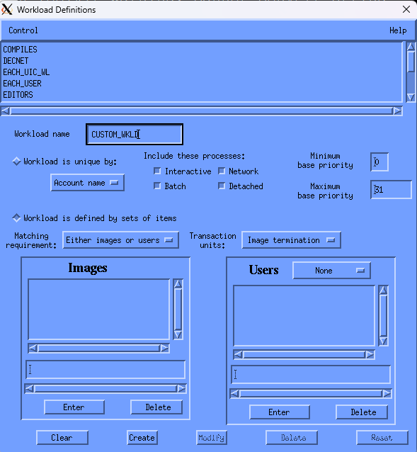
The menu bar contains Control and Help menus. A list of defined workload definitions appears at the top of the dialog box. To close the dialog box, pull down the Control menu and click the Exit menu item. The Workload Definitions dialog box lets you do the following:
Create a workload definition
Delete a workload definition
Modify a workload definition
8.5.4.1. Create a Workload Definition
Use the following options to create workload definitions.
- Workload name
Enter the name of the workload definition. The workload definition's name is limited to 20 characters.
- Workload is unique by
Lets you specify a category for workload summarization. A workload will be defined for each unique element of the category you choose.
Click the Workload is unique by toggle button and then click MB1 on the box beneath this that displays Account name when first accessed. The option menu will appear displaying the following items:
Account name
Process name
Image name
UIC group
User name
PID
Click MB1 on the category you want.
- Include these processes
Set the toggle buttons to specify the processing modes to be included by the workload definition.
Interactive
Batch
Network
Detached
- Process base priority
Enter the minimum and maximum values for the process' Base Priority to be included in the definition. Values can range from 0 to 31 and the minimum value must be less than or equal to the maximum.
- Workload is defined by sets of items
Selects the alternative to unique by criteria. lets you enter lists of user criteria, or images, or both for defining a workload.
- Matching requirement:
This is an option menu with two entries. Press MB1 on the current setting to view the choices.
- Either images or users
Indicates that the Performance Manager will match either the image names or the user criteria of a process record to include the process data in the workload.
- Both images and users
Indicates that the Performance Manager must match both the image names and the user criteria of a process record to include the process data in the workload.
- Transaction units
This is an option menu with two entries. Press MB1 on the current setting to view the choices. Click either image termination or terminal responses to indicate how response time should be evaluated. This will affect the workload frequency when building a model. See the
ADD/WORKLOADcommand in the VSI Performance Management Agent Administrator Guide for information about transaction units.- Images
Click the text entry field to activate the text insertion cursor.
To add an Image name, enter a name and press Return or click the Enter button. The name will appear in the list box and be cleared from the text entry field. If you wish to preserve lower case characters, enclose image names in double quotes when you enter them.
To delete an Image name, click the name in the image name list box, then click the Delete button. The name is removed from the list box. To remove multiple names, click all their names and then click the Delete button.
A list of image names can be provided through a file. Use the at sign (@) as the first character to indicate that the text is to be interpreted as a file name. The default directory is assumed if not supplied, as is a file type of .DAT. The format of the file must be a series of image names separated by white space or commas. Supply only the filename field; do not include the file type.
Image names can contain wildcard characters. Image names can contain up to 39 characters. If you wish to preserve lower case characters, enclose image names in double quotes when you enter them.
- Users
Press MB1 on the Users option menu to view the categories available. Release MB1 on the entry indicating the type of user you want to create. You cannot create a list until you make this selection.
To add a user field, enter the appropriate string and press the Return key or click the Enter button. The field will appear in the list box and be cleared from the text entry field.
To delete a user field, click the entry in the user list box, then click the Delete button. The entry is removed from the list box. To remove multiple entries, click all entries to be deleted the fields and then click the Delete button.
A list of user entries can be provided through a file. Use the at sign (@) as the first character to indicate that the text is to be interpreted as a file name. The default directory is assumed if not supplied, as is a file type of .DAT. The format of the file must be a series of user fields separated by white space or commas.
User names can contain wildcard characters. User names longer than 12 characters are truncated to 12 characters to ensure a match because the Performance Agent compares up to 12 user name characters only. Account names can be up to 8 characters in length, and process names up to 15. If you wish to preserve lower case characters, enclose your entries in double quotes.
User criteria can be specified in terms of UICs, account names, process names, or user names.
A UIC group can be indicated by using an asterisk for the user number, ([200,*]).
- Control Buttons
The Clear button removes all dialog box entries.
The Create button adds the workload name to the list and clears the entries.
8.5.4.2. Delete a Workload Definition
To delete a workload definition
Click a workload definition name.
The dialog box is updated to show the current definition field settings.
Click the Delete control button to remove the workload definition.
The Performance Manager removes the workload definition name from the workload list and clears the definition fields. If the definition is not deleted, a message box is displayed, explaining why the request cannot be executed. A failure can occur when a workload family has been defined in terms of this workload. A list of those families displays.
Modify the workload family to remove the reference to this workload definition.
8.5.4.3. Modify Workload Definitions
To modify a workload definition
Click a workload definition name.
The dialog box will display the current definition values.
Modify settings as you wish and click Modify at the bottom of the box.
8.5.5. Workload Family Definitions
To define or modify workload families:
Pull down the Parameters submenu and choose the Workload Families... menu item.
Performance Manager displays the Workload Family Definitions dialog box, as shown in the following screen:
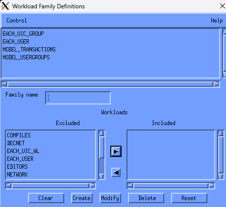
The menu bar contains Control and Help menus. A list of workload family names appears at the top of the dialog box.
To close the dialog box, pull down the Control menu, drag the pointer to the Exit menu item and release MB1.
The Workload Family Definitions dialog box lets you do the following actions:
Create a workload family
Delete a workload family
Modify a workload family
8.5.5.1. Create a Workload Family
To create a workload family, enter any of the following parameters:
- Family Name
Enter the name of the workload family. The family name is limited to 20 characters.
- Workload Specification
The Workloads Excluded list box contains a list of workload definitions. To add a workload definition to a workload family, click the workload name and click the Include transfer button (right arrow).
To indicate a position within this included workload list, click an existing entry in the Workloads Included list box. All new workload definitions will be placed ahead of this entry. To deselect a position entry, click it again. All new entries will be placed at the end. The position of a workload within a family can determine which workload will include a transaction. When a transaction qualifies for more that one workload, it will be included in the first listed matching workload.
To add multiple workload definitions, click all their names contained in the Excluded list box. Then click the Include transfer button.
The Workloads Included list box contains a list of workload definitions in the new workload family. To remove an entry from the INCLUDED list box, click the name and click the Exclude transfer button (left arrow). To delete multiple workload definitions, click all their names and then click the Exclude transfer button.
- Control Buttons
To remove all entries and cancel the definition, click the Clear button.
To add a family definition to the defined list and clear the entries, click the Create button.
8.5.5.2. Modify or Delete a Workload Family
To modify a workload family, click a family name. The family name and the Workload Included list box display the definition of the selected family.
- Family Name
When you modify a family name, the Performance Manager assumes that you want to create a workload family based on the displayed definitions.
- Workload Specifications
The Workloads Excluded list box contains a list of workload definitions that are not part of this family. To add a workload, click the workload definition name and click the Include transfer button (right arrow). To add multiple workload definitions, click all their names contained in the Excluded list box. Then click the Include transfer button.
To indicate a position within this included workload list, click an existing entry in the Included list box. All new workload definitions will be placed ahead of this entry. To deselect a position entry, click it again. All new entries will be placed at the end.
The Workloads Included list box contains the names of the workload definitions in the family. To remove an entry from the Included list box, click the name and click the Exclude transfer button.
- Control Buttons
The Clear button removes all entries.
The Modify button applies the changes and clears the entries.
The Delete button removes the selected family name and its definition.
The Reset button redisplays all entries for the current family definition.
8.5.6. History File Descriptors
To create, modify, or delete history file descriptors in the parameters file:
Pull down the Parameter submenu and choose the History File Descriptors menu item.
The Performance Manager displays the History File Descriptors dialog box.
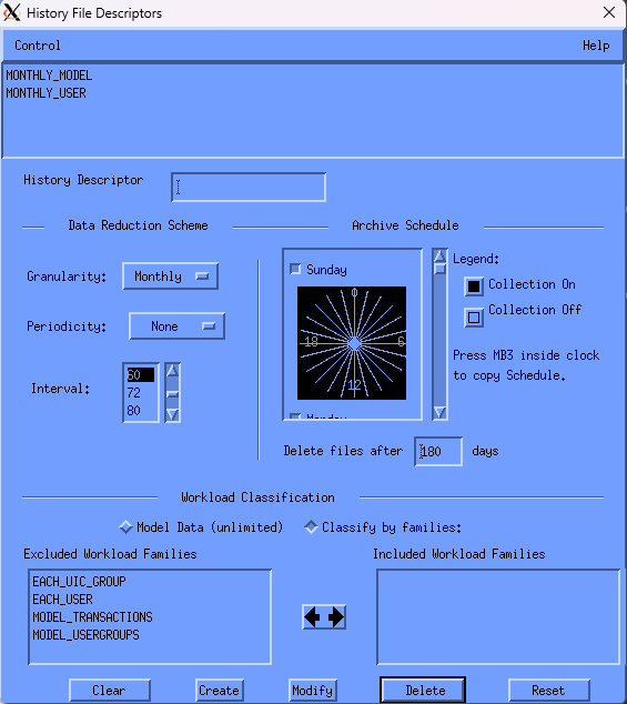
The menu bar contains Control and Help menus. A list of history file descriptors appears at the top of the dialog box.
To close the dialog box, pull down the Control menu and click the Exit menu item.
The History File descriptor dialog box lets you do the following actions:
Create a history file descriptor
Delete a history file descriptor
Modify a history file descriptor
For a detailed description of history file descriptors, see the Performance Agent Administrator Guide.
8.5.6.1. Create a History File Descriptor
Enter any of the following parameters:
- History Descriptor
Enter the name of the history file descriptor. The descriptor name is limited to 20 characters.
- Data Reduction Scheme
By default, the granularity value is monthly. Click and hold the pointer on monthly and the granularity pop-up menu displays a list of value options. Release the mouse button when the cursor is on your choice. The pop-up menu disappears and your selection is displayed.
By default, the periodicity value is None. Click and hold the pointer on the current value and the periodicity pop-up menu displays a list of value options. Release the mouse button when the cursor is on your choice. The pop-up menu disappears and your selection is displayed.
By default, the interval value, the time period over which the Performance Manager averages daily data records into a single history data record, is 60 minutes. To display valid entries, click the up or down arrow. When your selection is displayed, click the value. Your choice will be highlighted.
- Archive Schedule
A 24-hour clock is displayed. A bar on the right side of the clock lets you scroll to each day of the week. By default, archiving is set on for 24 hours a day, seven days a week, including holidays.
To set the clock:
Set or reset the square toggle button above the clock to turn archiving on or off for an entire day.
To turn archiving off for a specific hour, point to the hour on the clock and click MB1. Holding down MB1 and dragging the pointer around the clock will turn off archiving for a series of contiguous hours.
Drag the slider on the scroll bar to display the archiving schedule for each day of the week or click the up or down stepping arrows.
To duplicate a day's schedule
Press and hold MB3 inside the clock. A pop-up menu is displayed. Release on the Cut menu item.
Scroll to another day and press MB3 inside the clock. Release on the Paste menu item. The clock displays the copied schedule.
- Workload Classification
By default, Performance Manager stores process data in the history file summarized by workload families. To save modeling data in the history file, click the model data (unlimited) button. When model data is enabled, no workload families can be selected and raw process data will be preserved. Specific classification can then be done when the archived data is processed.
If you choose Classify by Families without specifying the workload families, process data will be summarized into four records representing interactive, batch, network, and detached processing. All other process data will be lost such as process data based on image name, account name, and so on.
- Workload Families Excluded
The Workload Families Excluded list box contains a list of workload families. To add a workload family to a history file definition, click a workload family name and click the transfer button.
To add multiple workload families, click all their names contained in the Excluded list box. Then click the transfer button.
- Workload Families Included
The Workload Families Included list box contains a list of workload family names. These names specify the workload families that define the new history descriptor. To remove an entry from the Included list box, click the name and click the transfer button.
- Control Buttons
The Clear button removes all entries and cancels the definitions.
The Create button adds the family definitions to the defined list and clears the entries.
8.5.6.2. Delete a History File Descriptor
To delete a history file descriptor:
Click a defined history file descriptor name.
The dialog box displays the current definition values.
Click the Delete button to remove the history file descriptor.
Performance Manager removes the descriptor name from the history file descriptor list and clears the definition fields. If the history file descriptor is not deleted, a message box displays explaining why your request was not executed. A failure occurs when history files are created from this definition; a list of these history file names displays.
Delete the files, then remove the definition.
8.5.6.3. Modify a History File Descriptor
To modify a history file descriptor, click a defined history file descriptor name.
The dialog box displays the current definition values. You can modify only the archive schedule.
- Control Buttons
The Clear button removes all entries and cancels the modifications.
The Modify button applies the changes and clears the entries.
The Delete button removes a selected family definition.
The Reset button redisplays the current family definition.
8.5.7. Parameter Settings
To view parameter settings:
Pull down the Parameters submenu and choose the Parameter Settings menu item.
Performance Manager displays the Parameter Settings dialog box, as shown in the following screen:
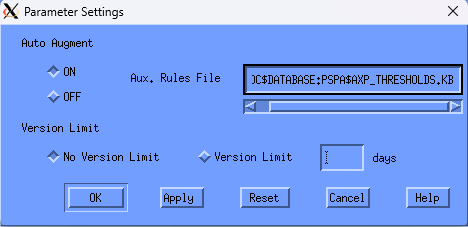
Highlighted buttons indicate the current settings. Your changes in the Parameter Settings box are applied when you click OK or Apply.
Click the Reset button to restore the last settings that have been applied. Or, click the Cancel button to close the dialog box without applying any changes.
From the Parameter Settings dialog box, you can set any of the following parameters:
- Auto Augment
Click the ON button to establish automatic augmentation of an auxiliary knowledge base for analysis. The initial setting is OFF.
When auto augment is set on, the dialog box lets you enter the file specification of the compiled auxiliary rules file.
For more information, see the
SET AUTO
                                            AUGMENT
command described in the Performance Agent Administrator Guide.- Version Limit
Enter a decimal number to modify the file version limit on the Performance Manager parameters file and history files. The initial setting is 180.
8.6. View the Main Window
To view the main window, pull down the View menu and choose the Main window sections you want to display.
Depending on your processing mode, not all the sections in the Main window may be relevant or of interest. To allow for smaller windows and the elimination of distracting sections, the View menu contains a series of toggle buttons that can be set or reset to add or remove sections of the Main window. Resetting a toggle button causes a section to disappear; setting it restores the section. Do not remove the File Locks section if you share editing access of database files with other users.
Chapter 9. Use the DECwindows Motif Real-time Display
This chapter provides information about the use and basic modification of the default displays supplied with the Performance Manager real-time display.
These predefined displays consist of windows or instrument panels containing bar graphs, strip charts, or meters. These instruments are used to view OpenVMS system performance statistics.
To access performance data for use with the Real-time Display, you must have the
Performance Manager installed and access to the data established for the target node
using proxies or network objects. Refer to the Performance Agent Administrator
Guide for more information. To use the Real-time feature with DECnet-Plus
when node synonyms are not defined, you will need to create a node name translation file
and use the /DNS_NAME qualifier. For more information on this logical
name, PSPA$DNS_NAMES, and the translation file, refer to the Appendix Performance Manager
Logical Names.
9.1. Start the Real-time Display
To start the Real-time Display, enter the following command:
$ ADVISE PERFORMANCE DISPLAY WINDOW -
_$ /MODE={NETWORK|DISKFILE}/NODE=(nodename[,...])
For more information about command syntax, see the chapter Performance Manager Commands.
Note
The output for the Real-time
Display must be directed to your display using the DCL
SET DISPLAY command. For more information on starting
Performance Manager Real-time and a complete description of all parameter
options, see the chapter Customize the DECwindows Motif Real-time
Display.
The Real-time Display shows the following default panel on your display:
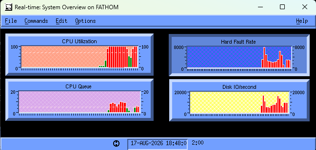
If the primary Performance Manager is not running on the monitored system, or the Real-time data collector is unable to start, an informational message is displayed. The Performance Agent Administrator Guide describes the steps that the system manager needs to take to enable data collection for a user.
9.2. Control the Real-time Display
In addition to the initial default instrument panels, an icon for the Panel Manager is displayed when you start the Real-time Display. To display the Panel Manager, double-click the Real-time Display icon.
The Panel Manager is the control point for the Real-time Display:
To stop the display, including the Panel Manager and all other panel windows that are invoked, choose the Exit menu item from the File menu in the Panel Manager menu bar.
To display previously recorded data, choose the Playback item from the File menu.
The Panel Manager lists the panels available to you. When you install Performance Manager for the first time, the list contains the names of all the default panels distributed with the Performance Manager.
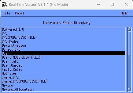
9.4. Use the Panel Commands Menu
To specify commands, pull down the Commands menu and release on the menu item you want. You can choose any of the following commands:
Connect
Connects instruments to online data.
Disconnect
Disconnects instruments from online data.
Set Interval...
Changes the update frequency of data in an instrument panel (default of 10 seconds). The interval is specified in minutes and seconds. The instrument panel must be disconnected before this option is available.
9.5. Default Panel Descriptions
The default panels within the Real-time Display alert you to potential performance problems in any of the following four major resource categories:
CPU utilization
CPU queuing
Memory page faulting
Disk I/O activity
When the Real-time Display is started, the System Overview default panel is displayed, which provides a summary for these four performance indicators.
9.5.1. System Overview
The System Overview Panel is the control panel for accessing information on any of these key system resources using the panel launch capability of the Real-time Display. The following table provides the panel information:
9.5.1.1. Label Metric Units Next Panel
|
Label |
Metric |
Units |
Next Panel |
|---|---|---|---|
|
CPU Utilization |
CPU utilization |
Percentage (100% maximum) |
CPU |
|
CPU Queue |
Computable queue length |
Process count | |
|
Hard Fault Rate |
Hard page fault rate |
Faults per second |
Page Faults |
|
Disk IO/second |
Total disk I/O operation rate |
Operations per second |
Disk |
To navigate from one level of panels to the next, double-click a label shown on a panel.
9.5.2. Default Panel Hierarchy
The following table shows the hierarchy of the default panels:
|
Resource |
Level 2 Panel |
Level 3 Panel |
Level 4 Panel |
|---|---|---|---|
|
CPU Utilization |
CPU |
CPU Modes User CPU |
-- Process CPU Image CPU |
|
CPU Queue |
Process Wait |
Image CPU |
-- |
|
Hard Fault Rate |
Page Faults |
Fault Rates User Faults Memory |
-- Process Faults Memory Allocation User Memory Page File Allocation |
|
Disk IO/second |
Disk |
Volume Info Disk Info |
-- -- |
Each of the panels accessed from the System Overview panel are discussed in the following sections.
9.5.3. CPU Utilization Panel Descriptions
The CPU Utilization graph on the System Overview panel lets you access the following panels:
CPU
CPU Modes
User CPU
Process CPU
Image CPU
This series of panels lets you investigate the use of the CPU on the monitored system. You can investigate the top users of the CPU and view what processes and images each user is executing.
The following tables describe the information presented within each panel:
9.5.3.1. CPU Panel
|
Label |
Metric |
Units |
Next Panel |
|---|---|---|---|
|
CPU Utilization |
CPU utilization |
Percentage (100% maximum) |
CPU Modes |
|
CPU Only |
CPU is busy and no disk I/O is busy |
Percentage |
-- |
|
CPU & I/O Busy |
CPU is busy and disk I/O is also busy |
Percentage |
-- |
|
I/O Only |
Disk I/O is busy when CPU is not busy |
Percentage |
-- |
|
CPU & I/O Idle |
CPU and I/O are not busy |
Percentage |
-- |
|
Top Users (list) |
CPU Utilization by User |
Percentage |
User CPU |
9.5.3.2. CPU Modes Panel
|
Label |
Metric |
Units |
Next Panel |
|---|---|---|---|
|
Int |
Interrupt mode time |
Percentage (100% maximum) |
-- |
|
MP |
MultiProcessor synchronization mode time |
Percentage |
-- |
|
Ker |
Kernel mode time |
Percentage |
-- |
|
Exc |
Executive mode time |
Percentage |
-- |
|
Sup |
Supervisor mode time |
Percentage |
-- |
|
Usr |
User mode time |
Percentage |
-- |
|
Cmpt |
Compatibility mode time |
Percentage |
-- |
9.5.3.3. User CPU Panel
|
Label |
Metric |
Units |
Next Panel |
|---|---|---|---|
|
CPU Utilization (with history) |
CPU utilization |
Percentage |
-- |
|
CPU Utilization (current) |
CPU utilization |
Percentage |
-- |
|
Direct I/O Rate |
Direct I/O for this user |
Operations per second |
-- |
|
Disk I/O Rate |
Disk I/O for this user |
Operations per second |
-- |
|
Disk Thruput |
Disk throughput |
Kilobytes per second |
-- |
|
Hard Fault Rate |
Hard page fault rate |
Faults per second |
-- |
|
Soft Fault Rate |
Soft page fault rate |
Faults per second |
-- |
|
Buf I/O Rate |
Buffered I/O rate |
Operations per second |
-- |
|
User Processes (list) |
CPU utilization by process for this user |
Percentage |
Process CPU |
|
User Images (list) |
CPU utilization by image for this user |
Percentage |
Image CPU |
9.5.3.4. Process CPU Panel
|
Label |
Metric |
Units |
Next Panel |
|---|---|---|---|
|
CPU Utilization (with history) |
CPU utilization for this process |
Percentage (100% maximum) |
-- |
|
CPU Utilization (current) |
CPU utilization for this process |
Percentage (100% maximum) |
-- |
|
Direct I/O Rate |
Direct I/O for this process |
Operations per second |
-- |
|
Disk I/O Rate |
Disk I/O for this process |
Operations per second |
-- |
|
Disk Thruput |
Disk throughput |
Kilobytes per second |
-- |
|
Hard Fault Rate |
Hard page fault rate |
Faults per second |
-- |
|
Soft Fault Rate |
Soft page fault rate |
Faults per second |
-- |
|
Buf I/O Rate |
Buffered I/O rate |
Operations per second |
-- |
|
Wssize |
Working Set size for this process |
Pages |
-- |
|
Wsdefault |
Working set default setting for this process |
Pages |
-- |
|
Wsquota |
Working set quota setting for this process |
Pages |
-- |
|
Wsext |
Working set extent setting for this process |
Pages |
-- |
|
Private |
Private memory size for this process |
Pages |
-- |
|
Global |
Global memory size for this process |
Pages |
-- |
|
Virtual Addr |
Virtual address size for this process |
Pages |
-- |
|
User Name |
User name for this process |
Alphabetic |
-- |
|
Account |
User account for this process |
Alphabetic |
-- |
|
Process ID |
Process ID (PID) for this process |
Numeric |
-- |
|
Image Name |
Current image name for this process |
Alphabetic |
-- |
|
Process State |
Current process state |
Alphabetic |
-- |
|
Process Priority |
Current priority for this process |
Numeric |
-- |
|
Base Priority |
Base priority for this process |
Numeric |
-- |
9.5.4. CPU Queue Panel Descriptions
The CPU Queue graph on the System Overview panel lets you access the following panels:
Process Wait
Image CPU
This series of panels lets you investigate the cause of high CPU queues on the monitored system. You can investigate the top images using the CPU.
The following tables describe the information presented within each panel:
9.5.4.1. Process Wait Panel
|
Label |
Metric |
Units |
Next Panel |
|---|---|---|---|
|
Computable Process Count (with history) |
Number of processes in COM queue |
Count |
-- |
|
Total Processes |
Number of processes scheduled |
Count |
-- |
|
Computable (current) |
Number of processes on COM queue |
Count |
-- |
|
Hibernating |
Number of processes in HIB state |
Count |
-- |
|
LEF Wait |
Number of processes in LEF state |
Count |
-- |
|
Page Fault Wait |
Number of processes in PFW state |
Count |
-- |
|
Top Images (list) |
CPU utilization of top images |
Percentage |
Image CPU |
9.5.4.2. Image CPU Panel
|
Label |
Metric |
Units |
Next Panel |
|---|---|---|---|
|
CPU Utilization (with history) |
CPU utilization for this image |
Percentage |
-- |
|
CPU Utilization (current) |
CPU utilization for this image |
Percentage |
-- |
|
Direct I/O Rate |
Direct I/O for this image |
Operations per second |
-- |
|
Disk I/O Rate |
Disk I/O for this image |
Operations per second |
-- |
|
Disk Thruput |
Disk throughput |
Kilobytes per second |
-- |
|
Hard Fault Rate |
Hard page fault rate |
Faults per second |
-- |
|
Soft Fault Rate |
Soft page fault rate |
Faults per second |
-- |
|
Buf I/O Rate |
Buffered I/O rate |
Operations per second |
-- |
|
CPU Utilization (list) |
CPU Utilization for image by user |
Percentage |
-- |
|
Total Mem Pages |
Total of all Working Sets for processes running this image |
Pages |
-- |
|
WSdefault |
Working set default setting for this process |
Pages |
-- |
|
WSquota |
Working set quota setting for this process |
Pages |
-- |
|
WSext |
Working set extent setting for this process |
Pages |
-- |
|
Private |
Private memory size for this process |
Pages |
-- |
|
Global |
Global memory size for this process |
Pages |
-- |
9.5.5. Hard Fault Rate Panel Descriptions
The Fault Rate graph on the System Overview panel lets you access the following panels:
Page Faults
User Faults
Process Faults
Fault Types
Memory
Memory Allocation
User Memory
Page File Allocation
This series of panels lets you investigate the causes of hard page faulting on the monitored system. You can investigate the top faulting and top memory users and view what processes each user is executing.
The following tables describe the information presented within each panel:
9.5.5.1. Page Faults Panel
|
Label |
Metric |
Units |
Next Panel |
|---|---|---|---|
|
Hard Faults Rate |
Hard page fault rate by user |
Faults per second |
Fault Rates |
|
Hard Fault Rate for Top Users (list) |
Hard page faults by user |
Faults per second |
User faults |
|
Total Memory Utilization |
Total memory utilization |
Percentage |
Memory |
9.5.5.2. Faults Rates Panel
|
Label |
Metric |
Units |
Next Panel |
|---|---|---|---|
|
Soft Faults |
Soft page fault rate |
Faults per second |
-- |
|
Hard Faults |
Hard page fault rate |
Faults per second |
-- |
|
Demand Zero |
Demand zero page fault rate |
Faults per second |
-- |
|
System Faults |
System page fault rate |
Faults per second |
-- |
|
In Swap |
In swap operations rate |
Swaps per second |
-- |
|
Out Swap |
Out swap operations rate |
Swaps per second |
-- |
9.5.5.3. User Faults Panel
|
Label |
Metric |
Units |
Next Panel |
|---|---|---|---|
|
Hard Faults for User |
Hard page fault rate for this user |
Faults per second |
-- |
|
Hard Fault Rate by User Process (list) |
Hard page faults by process for this user |
Faults per second |
Process Faults |
|
Total Memory Pages |
Memory for this user |
Pages |
-- |
9.5.5.4. Process Faults Panel
|
Label |
Metric |
Units |
Next Panel |
|---|---|---|---|
|
Hard Faults for Proc |
Hard page fault rate for this process |
Faults per second |
-- |
|
User Name |
User name for this process |
Alphabetic |
-- |
|
Image Name |
Image name executed by this process |
Alphabetic |
-- |
|
Account |
User account for this process |
Alphabetic |
-- |
|
PID |
Process ID for this process |
Numeric |
-- |
|
Mode |
Process mode (interactive, batch, network, detached, other) |
Alphabetic |
-- |
|
CPU Utilization |
CPU utilization for this process |
Percentage |
-- |
|
Disk I/O Rate |
Disk I/O for this image |
Operations per second |
-- |
|
Disk Thruput |
Disk throughput |
Kilobytes per second |
-- |
|
Hard Fault Rate |
Hard page fault rate |
Faults per second |
-- |
|
Soft Fault Rate |
Soft page fault rate |
Faults per second |
-- |
|
Buf I/O Rate |
Buffered I/O rate |
Operations per second |
-- |
|
Direct I/O Rate |
Direct I/O rate |
Operations per second |
-- |
9.5.5.5. Memory Panel
|
Label |
Metric |
Units |
Next Panel |
|---|---|---|---|
|
Free List Pages |
Number of pages on free list |
Pages |
Memory Allocation |
|
Total Memory Pages by Users (list) |
Memory by user name |
Pages |
User Memory |
|
Page File Utilization |
Page file utilization |
Percentage |
Page File Allocation |
9.5.5.6. Memory Allocation Panel
|
Label |
Metric |
Units |
Next Panel |
|---|---|---|---|
|
Free List Fault Rate |
Free list fault rate |
Faults per second |
-- |
|
Top Memory Processes (list) |
Memory by process name |
Pages |
-- |
|
Paged Bytes |
Number of pages in paged pool |
Pages |
-- |
|
NonPaged Bytes |
Number of pages in nonpaged pool |
Pages |
-- |
|
Free Balance Slots |
Number of free balance set slots |
Count |
-- |
|
IRPs Used* |
Number of IRP packets in use |
Count |
-- |
|
SRPs Used* |
Number of SRP packets in use |
Count |
-- |
|
LRPs Used* |
Number of LRP packets in use |
Count |
-- |
The fields marked with the "*" are obsolete and are set to zero.
9.5.5.7. User Memory Panel
|
Label |
Metric |
Units |
Next Panel |
|---|---|---|---|
|
Total Memory Pages for User |
Memory utilization for this user |
Pages |
-- |
|
CPU Utilization |
CPU utilization for this user |
Percentage |
-- |
|
Disk I/O Rate |
Disk I/O for this user |
Operations per second |
-- |
|
Disk Thruput |
Disk throughput |
Kilobytes per second |
-- |
|
Hard Fault Rate |
Hard page fault rate |
Faults per second |
-- |
|
Soft Faults Rate |
Soft page fault rate |
Faults per second |
-- |
|
Buf I/O Rate |
Buffered I/O rate |
Operations per second |
-- |
|
Direct I/O Rate |
Direct I/O rate |
Operations per second |
-- |
|
User Processes (list) |
Memory utilization by process for this user |
Percentage |
-- |
9.5.5.8. Page File Allocation Panel
|
Label |
Metric |
Units |
Next Panel |
|---|---|---|---|
|
Page File Write Rate |
Page file write rate |
Pages per second |
-- |
|
Page/Swap I/O Rate Top Volumes (list) |
Page/Swap I/O Rate by volume |
Faults per second |
-- |
|
Read Rate |
Page read operation rate |
Operations per second |
-- |
|
Write Rate |
Page write operation rate |
Operations per second |
-- |
|
Read I/O Rate |
Page read disk operation rate |
Operations per second |
-- |
|
Write I/O Rate |
Page write disk operation rate |
Operations per second |
-- |
|
Swap Busy |
Swapper busy |
Percentage |
-- |
|
Swap Wait |
Swapper wait |
Percentage |
-- |
9.5.6. Disk Rate Panel Descriptions
The Disk Rate graph on the System Overview panel lets you access the following panels:
Disk
Volume Info
Disk Info
This series of panels lets you investigate the I/O activity on the monitored system. You can investigate the top volumes and devices.
The following tables describe the information presented within each panel:
9.5.6.1. Disks Panel
|
Label |
Metric |
Units |
Next Panel |
|---|---|---|---|
|
Disk I/O/second |
Disk I/O operation rate |
Operations per second |
-- |
|
Top Volume (list) |
Disk I/O operation rate for top volumes |
Operations per second |
Volume Info |
|
Top Device (list) |
Disk I/O operation rate for top devices |
Operations per second |
Disk Info |
9.5.6.2. Volume Info Panel
|
Label |
Metric |
Units |
Next Panel |
|---|---|---|---|
|
I/O Rate for Volume (with history) |
Disk I/O operation rate for this volume |
Operations per second |
-- |
|
I/O Rate (current) |
Disk I/O operation rate for this volume |
Operations per second |
-- |
|
KB/second |
Disk throughput for this volume |
Kilobytes per second |
-- |
|
Disk Reads/second |
Disk read I/O operations for this volume |
Operations per second |
-- |
|
Disk Writes/second |
Disk write I/O operations for this volume |
Operations per second |
-- |
|
Page/Swap I/O Rate |
Disk page and swap I/O operations for this volume |
Operations per second |
-- |
9.5.6.3. Disks Info Panel
|
Label |
Metric |
Units |
Next Panel |
|---|---|---|---|
|
I/O Rate for Device (with history) |
Disk I/O operation rate |
Operations per second |
-- |
|
I/O Rate (current) |
Disk I/O operation rate for this device |
Operations per second |
-- |
|
KB/second |
Disk thruput for this device |
Kilobytes per second |
-- |
|
Disk Reads/second |
Disk read I/O operations for this device |
Operations per second |
-- |
|
Disk Writes/second |
Disk write I/O operations for this device |
Operations per second |
-- |
|
Page/Swap I/O Rate |
Disk page and swap I/O operations for this device |
Operations per second |
-- |
9.6. Review Data in Playback Mode
Playback mode lets you display data recorded earlier. Select the Playback item from the File menu in the Panel Manager window.
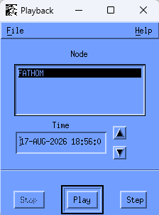
- Node
Click the node for which you want to display data.
- Time
Time displays the time for which data is being displayed. To select a time from which to display data records, click Stop and then on the time box. Edit the date and time to select the beginning time you want. Click Play to start the display. Alternately, you can click the arrows to the right of the box to increment the time ahead or back.
- Play
Click Play to start a continuous display of the data from the time displayed.
- Step
Click Step to display data from the next interval.
9.7. Set the Thresholds and Ranges
You can set threshold values for strip charts and bar graphs to alert you to potential performance problems. When a threshold value is exceeded, the color of the indicator changes. For example, the CPU utilization threshold on the strip chart in the CPU panel is set to alert you when CPU utilization exceeds 70 percent. If the percent utilization exceeds 70 percent the bar on the strip chart changes from black to red for the period of time during which the threshold is exceeded.
To set a threshold value:
Click MB1 anywhere in the instrument to be modified. The instrument appears to be depressed to show that it has been selected.
Press and hold MB3 to display the pop-up editing menu. The menu lets you edit the following items:
Ranges and thresholds
Patterns and colors
Choose Ranges and Thresholds by moving the cursor over this selection and releasing the MB3 button. For example, the following dialog box is displayed when one of the graphs on the System Overview panel is selected, as shown in the following screen:
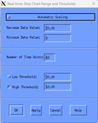
This dialog box is also used to set the scale for an instrument. The maximum and minimum data values to be displayed for the bar or strip chart can be set. In addition, the strip chart can be set to automatic scaling whereby the height of the chart is dynamically adjusted to match the largest data value shown.
The Ranges and Thresholds dialog box lets you set two levels of thresholds.
To modify a threshold value, click the threshold field and type the new value.
The x-axis on the strip chart can be changed by specifying a new value for the Number of Time Units. This value, with the display interval, determines the amount of time represented on the strip chart.
To apply your changes:
Click the Apply button at the bottom of the dialog box.
When you are satisfied with all your changes and want to exit the dialog box, click OK; to exit without saving any changes, click Cancel.
9.8. Change the Colors and Patterns
You can customize the colors used in any part of a PA Real-time Display panel or instrument.
To change the high threshold color for the strip chart in the CPU panel:
Select the instrument by pressing MB1 within the instrument's border. The instrument will appear depressed to indicate that it has been selected.
Press MB3 and hold to get the pop-up menu.
Choose Colors and Patterns by moving the cursor over this selection and releasing the MB3 button. The following dialog box is displayed:
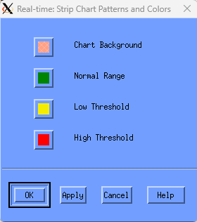
This dialog box lets you set colors for the thresholds set in the Ranges and Thresholds dialog. You can use these colors to alert you to potential performance problems.
Alter the background or the threshold colors by clicking on the associated button on this dialog. The Pattern Editor dialog is displayed.
Select new patterns and colors for each graph part, click OK on all dialoges to effect the change.
Chapter 10. Customize the DECwindows Motif Real-time Display
This chapter provides information about using the Panel Manager to customize the DECwindows Motif Real-time Display.
10.1. Access the Panel Manager
Use the following steps to access the Panel Manager:
Start the DECwindows Motif Real-time display by entering the following command:
$ ADVISE PERFORMANCE DISPLAY WINDOWS/MODE=NETWORK
For more information about the
DISPLAY WINDOWScommand syntax, see the chapter Performance Manager Commands.Performance Manager displays the Panel Manager icon and the System Overview panel, as shown in the following screen:
Equation 1: System Overview Panel
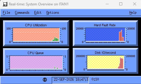
Double-click the Panel Manager icon or from the System Overview Panel, pull down the File menu, and click the Panel Manager... menu item.
Performance Manager displays the Real-time Panel Manager window, as shown in the following screen:
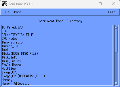
Performance Manager displays the Real-time Panel Manager window, which lets you do the following actions:
Specify actions on panels
Close the DECwindows session
10.2. Specify Actions on Panels
To specify actions on selected panels, pull down the Panel menu and click the menu item you want. The Panel menu lets you:
- Open panels
You open a panel either to view it for modifications or to connect it to a node for displaying real-time data.
Click the panel name to select a panel. Pull down the Panel menu and click the Open menu item. Performance Manager displays the selected panel.
You can also open a panel by double-clicking on the panel name.
- Rename panels
Specifies a panel name change.
- Create panels
Click the Create menu item from the Panel menu and Performance Manager displays the Panel Name dialog, as shown in the following screen:
Type a panel name and click the OK button.
When you enter a panel name, the Panel Name dialog is removed and the name you specified is listed in the Instrument Panel Directory of the Panel Manager.
- Copy panels
Click a panel name to select a panel. Pull down the Panel menu and click the Copy menu item. The Copy Panel dialog is displayed, as shown in the following screen:
Type the new panel name and click the OK button.
- Delete panels
Click a panel name to select a panel. Pull down the Panel menu and click the Delete menu item. The following message box is displayed, as shown in the following screen:
If you click OK, that panel is deleted.
- Auto Startup
Enable or disable a panel to startup automatically. When you enable automatic startup for a panel, it will be displayed and an attempt to connect will be made when you invoke the Real-time Display software. You can have several panels set for automatic startup.
To enable a panel to startup automatically:
Select a panel from the Instrument Panel Directory in the Panel Manager by clicking on the panel name.
Choose Enable from the Auto Startup menu.
The Instrument Panel Directory is updated. The label /auto_startup is appended to the panel name.
To disable a panel from starting automatically
Select a panel from the Instrument Panel Directory in the Panel Manager by clicking on the panel name.
Choose Disable from the Auto Startup menu.
The Instrument Panel Directory is updated. The label /auto_startup appended to the panel name is removed.
- Auto Connect
Enable or disable a panel to connect automatically. When you enable automatic connection for a panel, it will to connect when you open the panel. You can have several panels set for automatic connection.
To enable a panel to connect automatically
Select a panel from the Instrument Panel Directory in the Panel Manager by clicking on the panel name.
Choose Enable from the Auto Connect menu.
The Instrument Panel Directory is updated. The label /auto_connect is appended to the panel name.
To disable a panel from connecting automatically:
Select a panel from the Instrument Panel Directory in the Panel Manager by clicking on the panel name.
Choose Disable from the Auto Connect menu.
The Instrument Panel Directory is updated. The label /auto_connect appended to the panel name is removed.
10.3. Terminate the Session
To end a DECwindows session:
Pull down the File menu in the Panel Manager window and click the Exit menu item.
If you have modified panels, Performance Manager displays the following message:
Click Yes and your changes are not saved. Or, click No and the exit process is aborted.
To save a panel, use the Save or Save As... menu entry in the panel.
See the section Set the Panel Options section for more information about saving a panel.
10.4. How You Edit the Panel Instruments
To edit instruments:
Pull down the Edit menu on any open panel and release on the menu item you want.
The Edit menu lets you perform the following actions:
Modify instruments
Enable build mode
Create instruments
- Strip charts
A graphical representation of a data item in an X, Y wide grid. New data items enter from the right and the entire chart moves to the left with the oldest data disappearing at the left edge. A strip chart gives a pictorial view of historical data. An example of a strip chart is a medical electrocardiogram (EKG).
- Bar graphs
A graphical representation of a data item in which the height or length of the bar represents the magnitude of the data item. At each interval the bar is redrawn for the new value of the data item, so the bar grows or shrinks as intervals progress.
- Meters
The numerical or string representation of the data item. An automobile odometer is an example of a meter.
Copy instruments
Delete instruments
Assign metrics
Assign launch panels
To edit instruments:
Enable build mode.
Select an instrument.
Select an editing function.
10.4.1. Enable the Build Mode
Enabling the build mode lets you create and edit instruments within the displayed panel.
To enable the build mode:
Pull down the Edit menu.
Click the Build Mode menu item
Click the Enable menu item in the submenu.
10.4.2. Modify the Instruments
To modify the instruments:
Pull down the Edit menu, choose the Build Mode menu item and click the Enable submenu item.
Select an instrument.
Pull down the Edit menu, choose the Modify menu item and select a menu item in the submenu.
This Modify submenu lets you do the following actions:
Set ranges and thresholds
Set patterns and colors
Modify parts
The contents of the Modify submenu varies depending on the type of instrument selected. These submenu items are also available in a pop-up menu when you press MB3 in the window work area.
10.4.2.1. Set Ranges and Thresholds
Clicking on the Ranges and Thresholds menu item, Performance Manager displays the Ranges and Thresholds dialog for the selected instrument.
Depending on your selected instrument, Performance Manager displays one of the following dialoges:
Bar Graph Range and Thresholds dialog
Strip Chart Range and Thresholds dialog
The following example shows the Bar Graph Range and Thresholds screen:
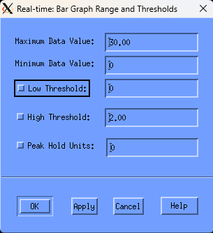
The Bar Graph Range and Thresholds dialog lets you do the following actions:
Set maximum and minimum data values
Set low and high thresholds
Set peak hold units
You can enter any of the following values:
- Maximum Data Value
Specifies the maximum value of the graph's scale. The default value is 100.
- Minimum Data Value
Specifies the minimum value of the graph's scale. The default value is 0.
- Low Threshold
Enables and specifies a value line to be displayed on the graph. Data below this line is displayed in the patterns and colors you set for low threshold.
- High Threshold
Enables and specifies a value line to be displayed on the graph. Data above this line is displayed in the patterns and colors you set for high threshold.
- Peak Hold Units
Enables peak hold and specifies the number of units of time the peak (maximum value attained by the metric) is held in the display. This peak value indicator is displayed in the patterns and colors you set for the peak hold.
10.4.2.2. Strip Chart
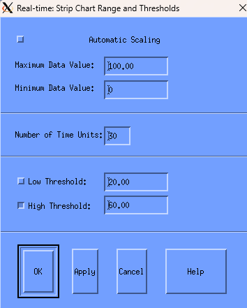
The Strip Chart Range and Thresholds dialog lets you do the following actions:
Set automatic scaling
Set maximum and minimum data values
Set number of time units along the x-axis
Set low and high thresholds
You can enter any of the following values:
- Automatic Scaling
Specifies that the height of the chart is to be dynamically adjusted to match the largest data value shown.
- Maximum Data Value
Specifies the maximum value of the chart's scale. The default value is 100.
- Minimum Data Value
Specifies the minimum value of the chart's scale. The default value is 0.
- Number of Time Units
Specifies the number of time intervals to display in the chart. For example, if the data collection time interval is 10 seconds and the number of time interval units is set at 30, then up to 300 seconds, or 5 minutes of data is displayed.
- Low Threshold
Enables and specifies a value line to be displayed on the chart. Data below this line appears in the patterns and colors you set for low threshold.
- High Threshold
Enables and specifies a value line to be displayed on the chart. Data above this line appears in the patterns and colors you set for high threshold.
10.4.2.3. Set Patterns and Colors
To set patterns and colors for the selected instrument:
Pull down the Modify submenu.
Choose the Pattern and Colors menu item.
Performance Manager displays the appropriate Patterns and Colors dialog for that instrument.
10.4.2.4. Bar Graph
The Bar Graph Patterns and Colors dialog allows you set the pattern and color of the instrument graph, as shown in the following screen:
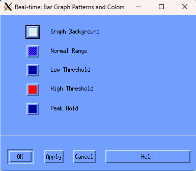
You can set the bar graph with the following attributes:
Background
Normal Range
Low Threshold
High Threshold
Peak Hold
To set the Patterns and Colors for each of these attributes:
Click the appropriate button.
Performance Manager displays the Pattern Editor dialog, as shown in the following screen:
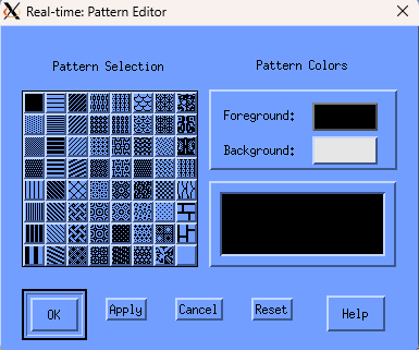
Click a pattern in the dialog and the selected pattern is displayed in the pattern viewer.
To change the graph's pattern color, click the Foreground or Background button. Performance Manager displays a color mixing dialog.
Click Help for information on how to use the color mixing dialog.
10.4.2.5. Strip Chart
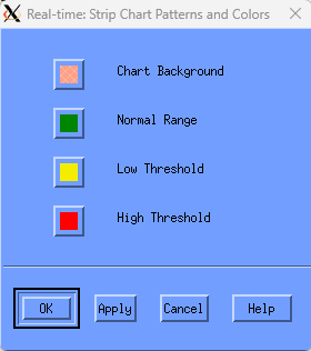
The Strip Chart Patterns and Colors dialog lets you set the pattern and color of the chart with the following attributes:
Background
Normal Range
Low Threshold
High Threshold
To set the Patterns and Colors for each of these attributes:
Click the appropriate button.
Performance Manager displays the Pattern Editor dialog.
Click a pattern in the dialog and the selected pattern is displayed in the pattern viewer.
To change the chart's pattern color, click the Foreground or Background button.
Performance Manager displays a color mixing dialog.
Click Help for information on how to use the color mixing dialog.
10.4.2.6. Modify Parts
To modify the parts of an instrument:
Pull down the Edit menu, choose the Build Mode menu item and click the Enable submenu item.
Select the instrument by clicking on it.
Pull down the Edit menu, choose the Modify menu item and click the Parts... menu item in the submenu.
Performance Manager displays the appropriate Parts dialog for the selected graph or chart in one of the following boxes:
Bar Graph Parts Definition dialog
Strip Chart Parts Definition dialog
Meter Parts Definition dialog
The Bar Graph Parts Definition dialog lets you specify:
Title String – Set the toggle button to display a title. Enter a title in the text entry box.
Data Name – Set the toggle button to specify the title to be the metric name, overriding any supplied string.
10.4.2.7. Bar Graph Parts
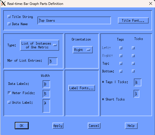
- Start date
Click the Title Font... button and Performance Manager displays the Font Selection dialog, as shown in the following screen:
The Font Selection dialog lets you specify the following font characteristics:
Family
Size
Weight
Slant
Note
Font options not available on your server are disabled.
- Metric Type
Specifies a list of instances of one metric or a list of metrics.
For example, to show the CPU Utilization for multiple processes on the system, use the List of Instances option.
To show a CPU mode (Interrupt, Kernel, Supervisor, and so on) for the system, choose the List of Metrics option since each metric has only one value associated with it.
- Number of List Entries
Specifies the number of bars to be displayed.
- Orientation
Specifies the orientation of the bar graph's maximum value.
- Data labels: width (in characters)
Specifies the space available for the data labels, based on the characteristics of the font you have selected.
- Meter: width (in characters)
Specifies the space available for the meter, based on the characteristics of the font you have selected.
Set the toggle button to include a meter for the bars. Specify the space for the meter in characters.
- Units label: width (in characters)
Specifies the space available for the units label, based on the characteristics of the font you have selected.
Set the toggle button to include a units label for the bars. Specify the space for the units label in characters.
- Label Fonts
The Font Selection dialog lets you specify label font characteristics.
- Location of Tags and Ticks
Specifies whether tags (numeric values indicating a chart's scale) and tick marks are displayed on the left or right side or top or bottom of the chart. Tick marks can be displayed without tags. When tags are selected, tick marks are displayed automatically.
- Number of Tags/Ticks
Specifies the number of tags and corresponding tick marks to be displayed. The default is six tags.
- Number of Short Ticks
Specifies number of minor tick marks to be displayed between the major tick marks set in Number of Tags/Ticks. The default is one.
10.4.2.8. Strip Chart Parts
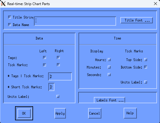
The Strip Chart Parts dialog lets you specify the following attributes:
- Title
Set the toggle button to display a title. Enter a title in the text entry box.
- Data Name
Set the toggle button to specify the title to be the metric name, overriding any supplied string.
- Title Font
The Font Selection dialog lets you specify the following font characteristics:
Family
Size
Weight
Slant
Font options not available on your server will be disabled.
- Data
Tags
Specifies whether the tags are displayed on the left or right side of the chart, or both.
Tick Marks
Specifies whether tick marks are displayed on the left or right side of the chart, or both. Tick marks can be displayed without tags. When tags are selected, tick marks are displayed automatically.
Number of Tags/Tick Marks
Specifies the number of tags and corresponding tick marks to be displayed. The default is six tags.
Number of Short Tick Marks
Specifies the number of minor tick marks to be displayed. The default is one.
Units Label
Specifies whether the units label is included in the display.
- Time
Display
Specifies whether the time display will include hours, minutes, and seconds or a subset of these.
Tick Marks
Specifies whether tick marks are displayed on the top or bottom of the chart, or both.
Units Label
Specifies whether the time units label in included in the display.
Labels Font
The Font Selection dialog lets you specify font characteristics.
10.4.2.9. Meter Parts
The Meter Parts Definition dialog lets you specify the following attributes:
- Title String
Set the toggle button to display a title. Enter a title in the text entry box.
- Data Name
Set the toggle button to specify the title to be the metric name, overriding any supplied string.
- Title Font
The Font Selection dialog lets you specify the following font characteristics:
Family
Size
Weight
Slant
Font options not available on your server will be disabled.
- Metric Type
Specifies a list of instances of one metric or a list of metrics.
For example, to show the CPU Utilization for multiple processes on the system, use the List of Instances option.
To show a CPU mode (Interrupt, Kernel, Supervisor, and so forth) for the system, choose the List of Metrics option since each metric has only one value associated with it.
- Number of List Entries
Specifies the number of meters to be displayed.
- Label Fonts
The Font Selection dialog lets you specify label font characteristics.
- Data labels: width (in characters)
Specifies the space available for the data labels, based on the characteristics of the font you have selected.
- Metric fields: width (in characters)
Specifies the space available for the meter, based on the characteristics of the font you have selected.
- Units label: width (in characters)
Specifies the space available for the units label, based on the characteristics of the font you have selected.
Set the toggle button to include a units label for the meters. Specify the space for the units label in characters.
10.4.2.10. Create Instruments
To create an instrument:
Pull down the Edit menu, choose the Build Mode option, and click the Enable submenu option.
Pull down the Edit menu, choose the Create menu item, and click the submenu entry.
You can choose from the following instruments:
Strip Chart
Bar Graph
Meter
10.4.2.11. Copy Instruments
To copy instruments:
Pull down the Edit menu, choose the Build Mode option and release on the Enable submenu option.
Select the instrument.
Pull down the Edit menu and choose the Copy menu item.
The cursor changes to an indicator that represents the upper left corner of the instrument. Position the cursor at the desired location for the new instrument in the panel. Click MB1 and the instrument is displayed.
10.4.2.12. Delete Instruments
To delete instruments:
Pull down the Edit menu, choose the Build Mode menu item and release on the Enable submenu item.
Select the instrument.
Pull down the Edit menu and choose the Delete menu item.
Performance Manager displays the following message box:
10.4.2.13. Assign Metrics
To specify metrics to be displayed:
Pull down the Edit menu, choose the Build Mode menu item and click the Enable submenu item.
Select the instrument.
Pull down the Edit menu and choose the Assign Metrics... menu item.
Performance Manager displays an Instrument Metric Selections dialog, as shown in the following screen:
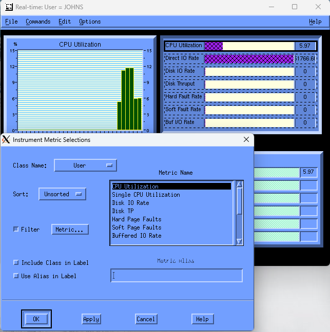
When Assign Metrics is chosen, the first metric field in the instrument to be assigned a metric will appear with a solid outline. If the instrument has more than one field, the others will appear with a dashed outline.
The Instrument Metric Selection dialog lets you perform the following actions:
Select a metric class
Select a metric name
Sort metric classes in ascending or descending order
Filter metric selections by value or instance
Include the class name in the instrument label
Specify a metric alias (a user supplied string which is displayed instead of the metric name)
The first metric field will automatically be selected, as shown by the solid outline. If another field is desired, click the instrument's outlined metric field. You may have to move the dialog out of the way if it occludes the instrument being modified. The Instrument Metric Selections dialog displays the instrument's current metric name and class. Hold MB1 down on the class name option menu to see all available choices. Release MB1 on the desired class name. A list of applicable metrics is displayed. Click the metric name you want to display. See Appendix Appendix C, "Performance Manager Data Cells" for a description of each metric.
Once you are satisfied with the metric selection for the field and you wish to specify another field in the instrument, press Apply and then select another field by clicking with MB1 within the dashed outline defining the field.
A sort option can be selected for all metric classes other than System.
To display only the data that matches a specific filtering criteria
Select the Filter toggle.
This makes available the Metric... button.
Click Metric... to display the Filter Metric Selection dialog.
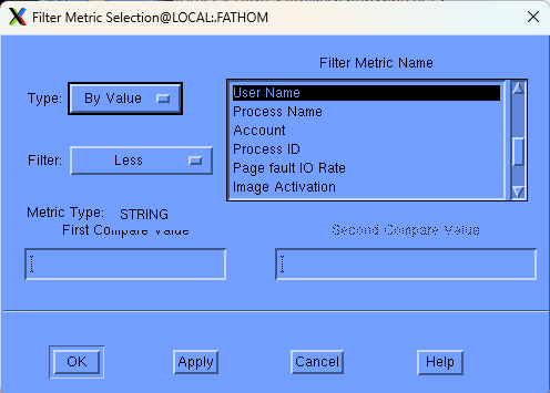
The Filter Metric Selection dialog lets you perform the following actions:
Select a filter type
Select a filter metric name
Select the filter criteria
Specify filter values
To enable filtering, position the mouse cursor over the Type option menu and hold down MB1. The following options are displayed:
No Filter
By Value
By Instance
To enable filtering based on a metric value, select the By Value option. To enable filtering based on a specific data item identifier such as a specific user name, process name, disk name, and so on, select the By Instance option.
For the By Value option, you can then specify the range of values to be displayed using the Filter option menu. Press and hold MB1 over the Filter options to see the following range of options:
Less
Less or Equal
Equal
Not Equal
Greater or Equal
Greater
In Range
Out of Range
The value to be compared for range determination can be entered in the Compare Value fields or can be based on a value from a parent panel, as described below.
If the Filter metric is a string then the value specified is interpreted as all uppercase unless the string is contained within double quotes.
If the instrument being modified is launched from another panel, then a value may be implicitly passed to this panel. In this case, this value is considered the instance value. See the Launching Panels section for more information. If you want to use this instance value, select By Instance in the Type option menu and select the applicable Filter Metric Name corresponding to the passed value and leave the Compare Value field empty.
Clicking on the Apply button, applies your choices without closing the dialog. The OK button applies your choices and closes the dialog.
10.4.2.14. Assign Launch Panels
Performance Manager allows a panel to be activated, or launched, from an instrument within a different panel. In addition, a data item can be passed to the launched panel. This data item (the instance value) can then be used in a subsequent filtering of information displayed in the launched panel's instruments.
To assign launch panels:
Pull down the Edit menu, choose the Build Mode menu item and click the Enable submenu item.
Select the instrument that will launch a new panel.
Pull down the Edit menu, and choose the Assign Launch Panel... menu item.
Performance Manager displays a Launch Panel Selection dialog as shown in the following screen:
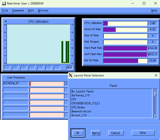
When you chose assign launch panel, the first metric field in the instrument to be assigned a launch panel will appear with a solid outline. If the instrument has more than one field that can launch panels, these appear with a dashed outline.
When you are satisfied with the launch panel assignment for the field and you wish to specify another field in the instrument, click Apply and select another field by clicking with MB1 within the dashed outline defining the field.
When you are satisfied with all the selections, click OK.
10.4.2.15. Launch Panels
Once launch panels are set and you are connected, double-click the metric name or metric instance name you want to pass to the specified launch panel. Performance Manager displays this panel using the information passed.
For strip charts, digital meters, and bar graphs with one or more different metrics displayed (List of Metrics as the type), you can now launch the selected panel by double-clicking on the instrument title. For bar graphs that display multiple instances of a metric, for example, a bar graph of the CPU utilization for the top 7 users, you can double-click an instance identified by user name and have that name passed to the launched panel. The launched panel can then filter its displayed metrics based on the specific user.
See the section Assign Metrics for information on metric filtering.
To disable panel launching, select the Remove Launch Panel menu item and click OK.
The following example illustrates progressive disclosure using panel launching:
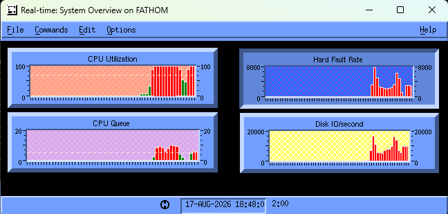
In the following example, double-clicking on the metric CPU Utilization instrument in the Performance Manager System Overview panel launches the CPU panel on node ITAN1. The node ITAN1 and the current interval are passed to the panel CPU.
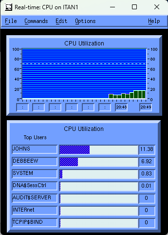
Double-clicking on the Top Users metric name JOHNS launches the user CPU panel passing it the current interval, the node ITAN1, and the user name JOHNS, as shown in the following screen:
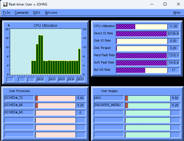
Each of the metrics in the panel are filtered by the user name JOHNS. For example, the User Processes instrument is set up as follows:
The instrument's main metric is Process CPU Utilization sorted in ascending order. The metric is filtered by instance with a filter metric of user name. The filter compare value is left blank so the value is passed from the panel. The instrument's second metric is process name using an alias of User Processes.
10.5. How You Set the Panel Options
To set the panel options:
Pull down the Options menu of the Instrument Panel.
Choose the menu item you want.
The Options menu lets you perform the following actions:
Set panel status
Specify panel background
Specify panel title
Specify panel node and instance type
Remove panel menu
10.5.1. Set the Panel Status
To set the panel status
Pull down the Options menu.
Choose the Status Display menu item.
Choose either the Restore or Remove submenu items.
The panel status is either displayed or removed from the panel's lower border. The Panel Status displays the following items:
Panel mode
Connected, indicated by a circle enclosing a vertical line
Disconnected, indicated by a circle enclosing a broken vertical line
Last instrument update time, if connected
Interval in minutes and seconds
10.5.2. Specify the Panel Background
To specify the panel background
Pull down the Options menu and choose the Panel Background... menu item.
Performance Manager displays the Pattern Editor.
See the section Set Patterns and Colors section for a discussion on how to use the Pattern Editor.
10.5.3. Specify a Panel Title
To specify a title
Pull down the Options menu and choose the Panel Title... menu item.
Performance Manager displays the Panel Title dialog, as shown in the following screen:
Enter the title and click the OK button.
The supplied string can optionally have appended to it the node name and the instance value.
10.5.4. Specify the Panel Node and Metric Instance Data
To specify the node for which data is to be displayed:
Pull down the Options menu.
Choose the Node and Metric Instance Name... menu item.
Performance Manager displays the Node and Metric Instance Name dialog, as shown in the following screen:
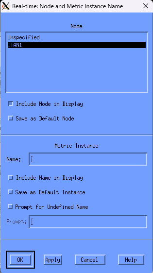
The Node and Metric Instance Name dialog lets you perform the following actions:
Show the current node assigned to the panel
This would have been specified by you as a default, or at connect time, or when the panel was launched. If the panel was launched, the node passed in the launch overrides the default.
Include the node in the panel's title display
Specify the node as the default
Show the current metric instance name
This would have been specified by you as a default, by a prompt dialog at connect time, or when the panel was launched. If the panel was launched, the metric instance name passed in the launch overrides the default.
You can also change the metric instance name by entering a new name in the Metric Instance text entry box. The metric name is interpreted as all uppercase unless you contain the name within double quotes.
Include the metric instance name in the panel's title display
Specify the name as the default
Select prompting at connect time if a metric instance name is not defined
Define the prompt string
For example, if the instruments in a panel are set up to look at metrics for a specific user, a user name is required to specify the metric fully. In this case, the prompt might be:
Enter User Name:. If prompting is selected, then a prompt dialog appears at connect time requesting a user name.Panels requiring specific metric instance names (such as user name or process name), must be provided with a prompt for the appropriate name. This lets the panel to be invoked from the panel manager and to display without errors. An example is the User_CPU panel (labeled User=JOHNS) described in the Launching Panels section.
Note
Any changes to the node selection or the metric instance name will have no affect on the instruments until the panel is connected or reconnected.
10.5.5. Remove Panel Menu
To remove the panel menu
Pull down the Options menu and click the Remove Panel menu item. The menu is removed from the panel.
To restore the menu, click MB3 and a pop-up menu displays.
Click the Restore Panel Menu option.
If no instrument is active when there is no panel menu, the pop-up menu options are limited to the following actions:
Close
Save
Restore Panel Menu
10.5.6. Save the Panel
To save a panel:
Pull down the File menu and release on the Save menu item.
To specify a new panel name, click the Save As... menu item. The Panel Name dialog appears.
Enter the new panel name and click the OK button.
10.5.7. Close the Panel
To close an instrument pane:
Pull down the File menu and click the Close menu item.
If you modified the instrument, Performance Manager displays the following message:
Click Yes to save the modifications and close. Or, click No to close without saving your changes.
Chapter 11. Use the Character-Cell Real-time Display
This chapter provides information about the Performance Manager character-cell Real-time Display.
11.1. Character-Cell Display Functions
The Performance Manager character-cell displays gather and present performance
data using a video terminal. Some displays are available on terminals that support
DEC_CRT characteristics, such as the VT100. Use the SET
TERMINAL/DEC_CRT command to set characteristics for these terminals.
Other displays are available only for ReGIS-compatible terminals, such as the VT340.
If the terminal supports color, or if an external color monitor is attached, a
multicolored display is generated. The display can also be printed on a graphics dot
matrix printer.
11.1.1. Prerequisites
The Performance Manager character-cell displays have the following mandatory software and hardware requirements:
For real-time remote data collection (
/MODE=NETWORKcommand), see the discussion about establishing remote access in the Performance Agent Administrator Guide.For file access (
/MODE=DISKFILEcommand), SYSLCK privilege is required.A ReGIS-compatible terminal such as the VT125, VT240, VT241, VT330, VT340, or DECterm window is needed for most displays invoked through the
INVESTIGATEcommand.A terminal with DEC_CRT characteristics, such as a VT100, is needed for all other displays.
Any number of users with these resources can simultaneously run the Performance Manager Real-time character-cell displays.
11.2. Start the Character-Cell Displays
Character-cell displays can be invoked for either a single node or multiple nodes of a cluster system.
To begin collecting data for all nodes in a cluster system and to display system metrics in realtime mode
Enter the following command:
$ ADVISE PERFORMANCE DISPLAY CHARACTER_CELL
PA displays a multi-node screen.
To view previously recorded data in playback mode, use the
/BEGINNINGqualifier.For more information on how to use the
ADVISE PERFORMANCE
                            DISPLAY
command, see the chapter Performance Manager Commands.
11.3. Control the Displays
Once you have started a character-cell display, you can control the display and its characteristics with commands.
The following table shows the Performance Manager character-cell commands available at the PSRT> prompt. These commands control which displays and metrics are shown on the terminal.
The keypad keys perform other functions such as selecting users, nodes, and metrics for display, and controlling the playback of data.
| Command | Function |
|---|---|
|
CPU |
Provides a multi-node display of CPU utilization. |
|
DISKS |
Provides a composite display for all disks, servers, or volumes. |
|
DISPLAY x |
Provides a multi-node display for the desired metric. |
|
FREEZE |
Stops the input data stream. |
|
STEP |
Advances to the next interval while display is suspended. |
|
IMAGENAME name |
Provides a process display for the specified image name. |
|
INVESTIGATE SYSTEM_OVERVIEW_DISPLAY |
Provides the ReGIS display for investigating the selected system. |
|
INVESTIGATE MEMORY_DISPLAY |
Provides the ReGIS display for investigating the selected system's memory. |
|
INVESTIGATE IO_DISPLAY |
Provides the ReGIS display for investigating the selected system's I/O rate. |
|
INVESTIGATE CPU_DISPLAY |
Provides the ReGIS display for investigating the selected system's CPU. |
|
INVESTIGATE LOAD_BALANCE_DISPLAY |
Provides the ReGIS or ANSI display for investigating the selected system's load balance. |
|
INVESTIGATE |
Provides the ReGIS display for investigating the last selected display or the system display if none had been selected. |
|
I/O |
Provides a multi-node display of direct, paging and swapping I/O rate. |
|
MEMORY |
Provides a multi-node display of memory utilization. |
|
PAGEFILE |
Provides a multi-node display of Pagefile Utilization. |
|
PID n |
Provides a process display for the specified PID. |
|
RESOURCE CPU_DISPLAY |
Provides a multi-node display of CPU resources. |
|
RESOURCE DISK_DISPLAY |
Provides a multi-node display of disk resources. |
|
RESOURCE MEMORY_DISPLAY |
Provides a multi-node display of memory resources. |
|
RESOURCE |
Provides the multi-node resource display for the last selected display or the CPU display if none had been selected. |
|
RESUME |
Resumes the data input stream that was stopped by the
|
|
RULES |
Provides a per-node display of rules that have fired on that node. |
|
SET SCALING PROCESS n WORKING_SET n RATE_PER_SECOND n |
Changes scale (number within a tick mark) for process, working set size, and I/Os per second scales. |
|
USERNAME name |
Provides a process display for the specified user name. |
11.4. Display Multi-node Statistics
A bar-graph style screen appears when you start Performance Manager character-cell displays. By default, the percentage of CPU utilization for each node in the cluster is displayed.
If you are collecting data at two-minute intervals, factory rule IDs or user rule IDs, or both, may also appear after the time stamp. For shorter intervals, the user rules may appear.
See the RULES command and the /RULES
qualifier for more information.
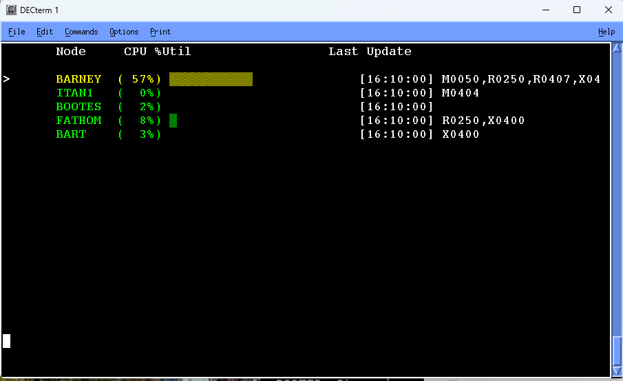
You can display in the following metrics previous screen:
Percentage of memory utilization
Disk I/Os per second
Percentage of pagefile utilization
Any other system data cell collected and provided. For a list of the system metrics you can select, see Appendix C, "Performance Manager Data Cells". Only numeric metrics in Domain LOCAL can be requested.
Use the multi-node keypad to perform the following tasks:
Get Help
Zoom in on node
Change to the next node
Change to the previous node
Change to the resource display
Change to the next metric
Change to the investigate display
Change to the previous metric
The following illustration shows the functions of the multi-node display keypad:
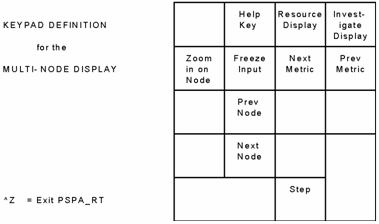
11.5. Display Single-Node Statistics
To navigate through the list of nodes:
Press KP2 or KP5.
The arrow identifies the node you choose to monitor.
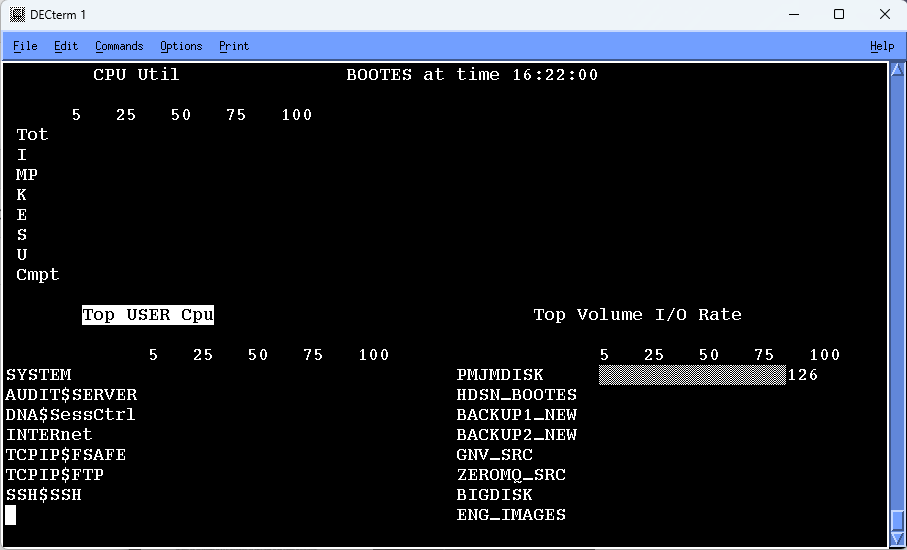
The Performance Manager single-node screen provides the following three sections:
CPU utilization and mode statistics
Top processes statistics
Top device statistics
The Process Statistics and Device Statistics sections can be updated with a new set of metrics. The title of the currently selected section is in reverse video. Press KP3 to select a different section.
Enter the Help command or press PF2 to display the single-node display keypad.
The following table shows the functions of the single-node display keypad:
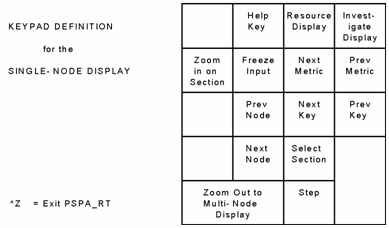
11.5.1. Display CPU Utilization
The CPU Utilization screen displays total utilization and the percentage of CPU utilization of each of the following processor modes:
Interrupt stack
MP synchronization
Kernel mode
Executive mode
Supervisor mode
User mode
Compatibility mode
11.5.2. Display Top Processes Statistics
Process statistics are summarized and presented by the process key. The process statistics are presented in descending order by the selected metric value.
To summarize the process statistics according to a different key
Press KP6.
The available process keys are as follows:
TOP User metric
TOP Image metric
TOP Process metric
TOP Account metric
TOP PID metric
To change the metric displayed:
Press KP9.
The available metrics are as follows:
CPU
Disk I/O
Disk Thruput
Soft Faults
Hard Faults
Buffered I/O
Direct I/O
WS pgs
Private pages
Global pages
V/A pages
11.5.3. Display Top Device Statistics
Device statistics are summarized and presented by the device key. The device statistics are presented in descending order by the selected metric value.
To summarize the device statistics according to a different key:
Press KP6.
The available device keys areas follows:
TOP Volume metric
TOP Disk metric
TOP Server metric
To change the metric displayed:
Press KP9.
The available metrics are as follows:
I/O Rate
KB per second
Read Rate
Write Rate
Page/Swap I/O Rate
11.6. Display Process Information
Performance Manager provides a Process display when you press KP7 from the single-node display when the Process Statistics section is selected or when you enter any of the following commands to the PSRT> prompt:
USERNAME name
IMAGENAME name
PID n
The following illustration is an example of a user name Process display:
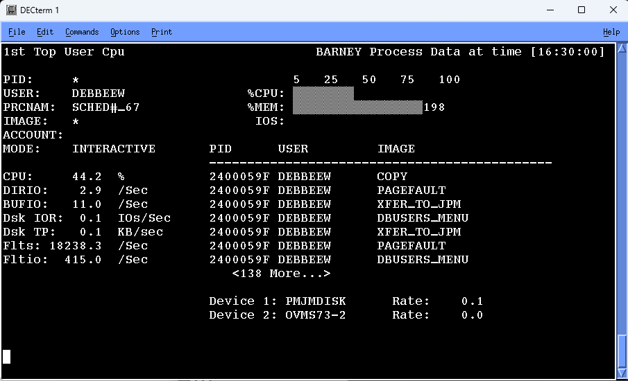
In the upper left corner is a line describing the current summarization and sort position of the Process information. This text follows the format "nth TOP key metric", where you select the key by pressing KP6 (either User, Image, Processname, Accountname, or PID), and metric is selected by KP9 (see the previous section for a list of available metrics). To proceed to the nth + 1 entry, press KP1, or KP4 to go back. To lock the display on a specific process, enter PID nnnnnnnn for the desired PID.
Also in the upper left corner is the process identification section: user name, image name, process name, account name PID, and process mode for the currently displayed process. If any of these fields have an asterisk (*), more than one process has been summarized for this screen, and the given field had more than one value.
The following screen is an example of the Performance Manager Real-time Process Display, Single Process:
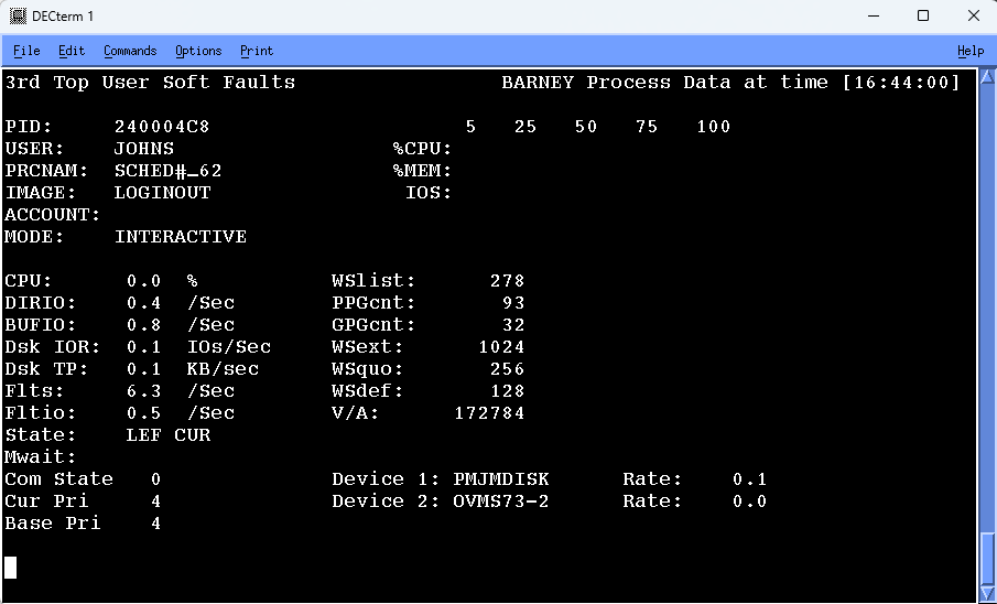
In the upper right corner is the name of the node and the current time of the data being viewed. Next, on the right side, are three bar charts that show CPU utilization, memory utilization and the processes working set as a percentage of the total system's memory, and the number of disk I/Os as a rate per second.
The mid-section of the screen contains the process statistics for the selected process, as in the previous illustration. If more than one process matches the selection criteria (such as a given user name), the working set data and state information is replaced by a list of processes that match the criteria, as in an earlier illustration (Performance Manager Real-time Process Display, Multiple Processes).
You can scroll through the process instances, as appear in the previous
illustration, by using NextScreen and PrevScreen keys. If there is a particular PID,
user name or image name that you want to lock the display on, enter the
USERNAME, IMAGENAME, or
PID command to do so.
For example:
PSRT> USER HOFFMAN

The last section of the display is the “volumes” section (also appearing in the
earlier illustration showing Performance Manager Real-time Process Display,
Multiple Processes), where disk volumes and I/O rates appear. These represent the
top disks that the processes use and are list up to the top five disk volumes
recorded by the main collector. By pressing KP3, you can view the top files being
used by the processes. The top volumes and files data is available only when the
/MODE=DISKFILE comma
Press PF2 to view the keypad for Process displays. The following illustration shows the functions of the Process display keypad:
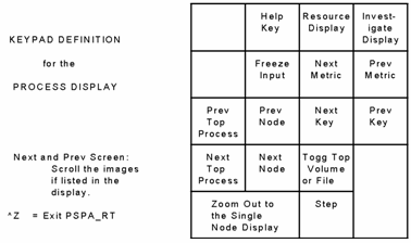
11.7. Display Disk Information
Performance Manager provides a Disks display when you enter the following command:
PSRT> DISKS
The following illustration is an example of a Disks display:
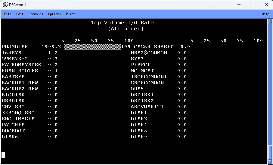
Press PF2 to view the keypad for the Disks display. The following illustration shows the functions of the Disks display keypad.
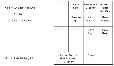
Press KP6 (to scroll through Disk keys and KP9) to scroll through disk metrics. To return to the multi-node display, press KP0.
11.8. Display Rules Information
To obtain the Rules display:
Enter the
RULEScommand.If any factory or user rules fire for the last data record processed, the rule ID and a brief explanation are displayed. If data is displayed at less than two-minute intervals, then only user rules are displayed.
Note
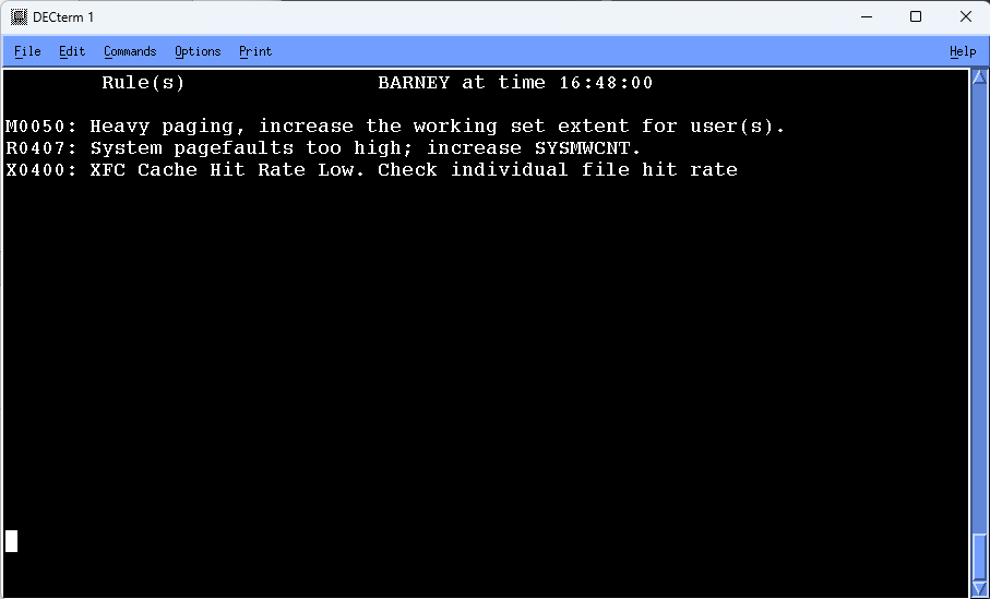
11.9. Display RESOURCE Information
The purpose of the Resource displays is to permit evaluation of resource utilization in interactive mode for one or more nodes in a cluster system.
RESOURCE CPU_DISPLAY RESOURCE MEMORY_DISPLAY RESOURCE DISK_DISPLAY
RESOURCE or press PF3
11.9.1. RESOURCE Keypad
The following illustration shows the functions of the RESOURCE keypad:
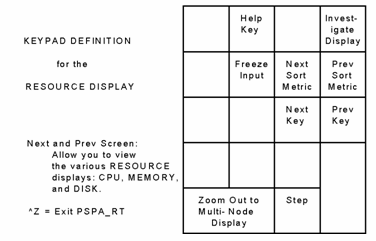
11.9.2. Balance Cluster System Utilization Using the Resource Display
Use the Resource displays to determine the workload on nodes and disks on your cluster system, and balance the workload as necessary. For example, if your Resource display shows one node that has a high percentage of a resource in use, you may wish to move work from that node to other nodes to balance resource utilization on your cluster system.
Each display shows cluster-wide information consisting of memory, disk, or CPU metrics for selected nodes and disks in a cluster. Each display consists of the following two parts:
An upper part containing metrics appropriate to the display name (for example, memory-related metrics). This part is unique for each different type of display.
A lower part containing memory utilization, direct I/O rate, and CPU utilization for selected nodes in the cluster. This part is the same for each of the three displays.
The lower portion of a display common to all three displays is described in the following section.
11.9.3. Lower (Common) Resource Display
The lower or common portion of each resource display contains bar graphs for nodes in the cluster. An example is the lower portion of the next illustration. The scale at left and right is graduated from 0 to 100, and is interpreted either as a percentage or an absolute value depending on the particular metric.
There is a bar graph for each node in the current group set for display, the node name being displayed at the bottom of each graph.
The bar graph for a node contains three separate columns (metrics) as follows:
- Memory Utilization (M)
This column is headed by the letter M, and is a percentage value as indicated by the percent sign (%) at the bottom of the column. The value is that of Total MEMutl expressed as a percentage. Total MEMutl is given by
(((Total Memory)-(Free Pages))/(Total Memory)).
- I/O Rate (I)
This column is headed by the letter I, and is an absolute value (rate) as indicated by the letter R at the bottom of the column. The value is the Direct I/O rate (number of direct I/Os per second) for the node. If the rate exceeds 100 direct I/Os per second, the column is filled with asterisks.
- CPU Utilization (C)
This column is headed by the letter C, and is a percentage value as indicated by the percent sign (%) at the bottom of the column. The value is the percentage of the CPU being utilized, which is equal to the sum of the System and Task CPU percentages given in the tabular reports.
11.9.4. Memory Display
The Memory display contains memory statistics for analyzing a memory resource limitation is a cluster-wide manner.
An example of a resource Memory display is shown in the following illustration:
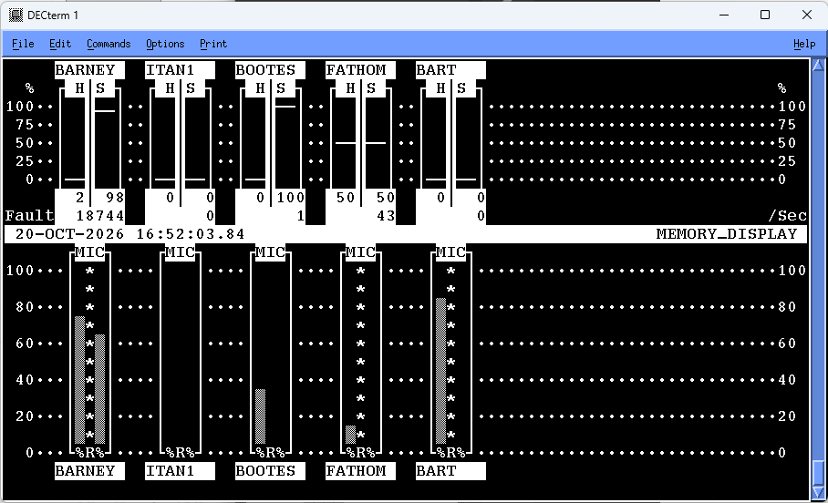
The top half of the memory display contains a bar graph for each cluster node currently set for display. The scale shown at right and left shows a percentage value ranging from 0 to 100%.
The name of the node is given at the top of an individual node graph, while the total page fault rate (faults per second) for the node is shown as a number at bottom right. Each node graph has two columns as follows:
- Hard Faults (H)
This column is headed by the letter H, and is a percentage value. The value is not only given by the column height, but is also shown as a number at the bottom of the column. The value is the percentage of the total faults for the node that were hard (required a read from disk).
- Soft Faults (S)
This column is headed by the letter S, and is a percentage value. The value is not only given by the column height, but is also shown as a number at the bottom of the column. The value is the percentage of the total faults for the node that were soft (resolved from memory without requiring a read from disk).
Note
The bottom value in this column is the total page fault rate (faults per second both hard and soft) for the node.
11.9.5. Disk Display
The Disk display contains disk statistics for analyzing an I/O resource limitation in a cluster-wide manner.
An example of a resource Disk display is shown in the following illustration:
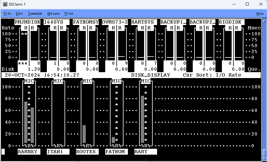
The top half of the disk display contains a bar graph for each disk currently set for display. The scale shown at right and left shows an absolute value ranging from 0 to 100. The scale at left is headed with the word Rate, while the scale at right is head Msec (Milliseconds). The rate scale is used with the leftmost column in the bar graph for a particular disk, while the Msec scale is used with the rightmost column.
The name of the disk is given at the top of an individual disk graph.
Preceding the disk name is a number, which corresponds to the number assigned
the disk when listing disk groups with the SHOW GROUP
command. This number allows a partial disk name, as given at the top of each
disk graph, to be associated with the full disk name as given by SHOW
GROUP subcommand.
The number of I/O packets in the disk queue for each disk is shown as a number at the bottom right of each disk graph. Each disk graph has two columns as follows:
- Rate (R)
This leftmost column is headed by the letter R, and is an absolute value. The value is not only given by the column height, using the leftmost scale (Rate scale), but is also shown as a number at the bottom of the column. The value is the number of direct I/Os per second for the disk.
- Response (R)
This rightmost column is headed by the letter R, and is an absolute value. The value is not only given by the column height, using the rightmost scale (Msec scale), but is also shown as a number at the bottom of the column. The value is the response time of the disk in milliseconds. This is the average time to process one I/O including both queuing time and service time.
Note that the bottom value in this column is the average number of I/O packets in the disk queue. If the value of the Rate or Response time exceeds 100, asterisks are shown at the top of the column, but the value is still given at the bottom of the column. If the actual value should exceed three digits, then asterisks are shown in place of the value.
11.9.6. CPU Display
The CPU display contains CPU statistics for analyzing a CPU resource limitation in a cluster-wide manner.
An example of a resource CPU display is shown in the following table:
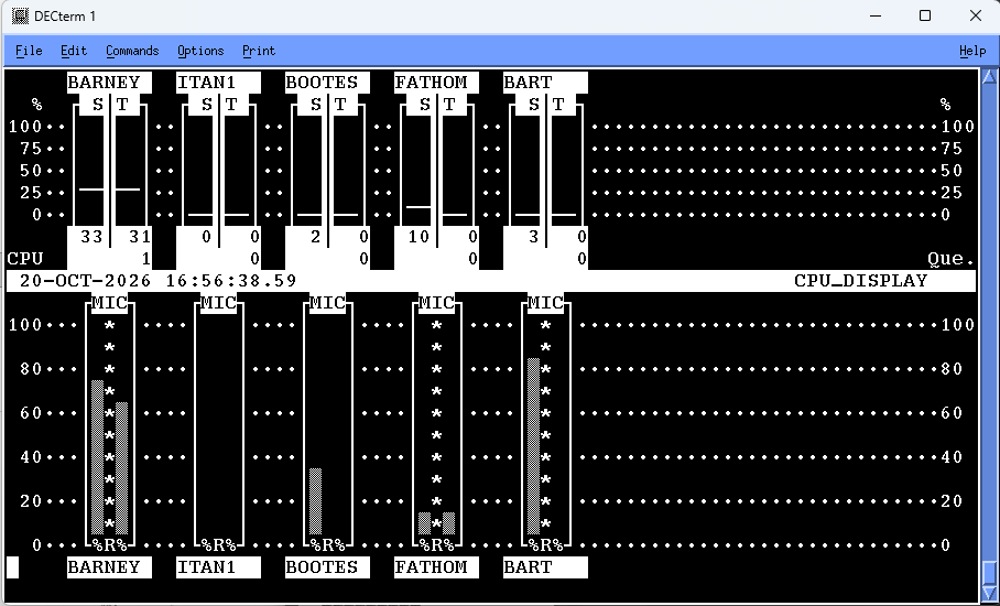
The top half of the CPU display contains a bar graph for each cluster node currently set for display. The scale shown at right and left shows a percentage value ranging from 0 to 100%.
The name of the node is given at the top of an individual node graph, while the average number of processes in the CPU queue for the node is shown as a number at bottom right. There is a real queue if this number is greater than 1. This number is equivalent to the sum of processes in the computable queue (COM). Each node graph has two columns as follows:
- System CPU (S)
This column is headed by the letter S, and is a percentage value. The value is not only given by the column height, but is also shown as a number at the bottom of the column. The value is the percentage of the total CPU time used by the System (Interrupt stack, Kernel mode, Executive mode).
- Task CPU (T)
This column is headed by the letter T, and is a percentage value. The value is not only given by the column height, but is also shown as a number at the bottom of the column. The value is the percentage of the total CPU time used by user tasks (Supervisor, User, and Compatibility modes).
Note that the bottom value in this column is the average number of processes in the CPU queue. For a real queue to exist, this value must be at least 2.
11.10. The INVESTIGATE Command
The purpose of the Investigate displays is to help you evaluate performance on one node. All displays except one require use of a ReGIS-compatible terminal.
You may use the keypad or INVESTIGATE commands to control the
display and its characteristics.
11.10.1. INVESTIGATE Command Options
The INVESTIGATE commands are shown in the following
table:
| Command | Function |
|---|---|
|
INVESTIGATE CPU_DISPLAY |
Displays CPU statistics. |
|
INVESTIGATE IO_DISPLAY |
Displays I/O statistics. |
|
INVESTIGATE LOAD_BALANCE_DISPLAY |
Displays load balance statistics. |
|
INVESTIGATE MEMORY_DISPLAY |
Displays memory statistics. |
|
INVESTIGATE SYSTEM_OVERVIEW_DISPLAY |
Displays system overview statistics. |
The Load Balance display is the only Investigate display available for both ReGIS and DEC_CRT terminals. It contains the same information in both cases. On ReGIS terminals, it is a Kiviat graph, and for DEC_CRT terminals, it is a bar graph.
The System Overview is the default Investigate display for ReGIS-compatible terminals, and for non-ReGIS or DEC_CRT terminals the default is the Load Balance display.
The following illustrations show an example of the ReGIS version of the system Overview display, an example of the ReGIS Load Balance display, and an example of the DEC_CRT (ANSI) version of the Load Balance display.
Additional displays show memory, I/O, and CPU statistics and require a ReGIS-compatible terminal. There is also an example of the Memory display, an example of the I/O display, and an example of the CPU display.
11.10.2. INVESTIGATE Keypad
The following illustration shows the functions of the INVESTIGATE keypad:
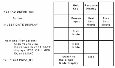
11.11. Evaluate Performance Using the Investigate Displays
The System and Load Balance displays provide graphic information to determine which of the three main system resources (memory, I/O, or CPU) is a limitation. To investigate a limitation in more detail, use the Memory, I/O, and CPU displays.
For a detailed description of a system tuning methodology, see VSI's OpenVMS Performance Management guide.
When determining a limitation in a main resource, investigate the resources in the following order:
Memory
I/O
CPU
The order is important because memory limitations cause paging and swapping, which lead to I/O and CPU problems.
Begin your tuning investigation by using the System Overview or Load Balance displays, as shown in the following screens:
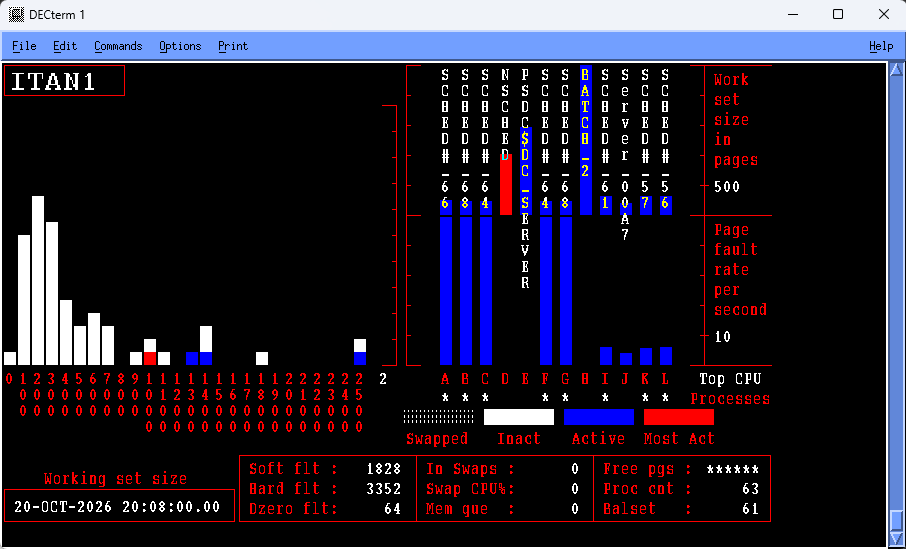
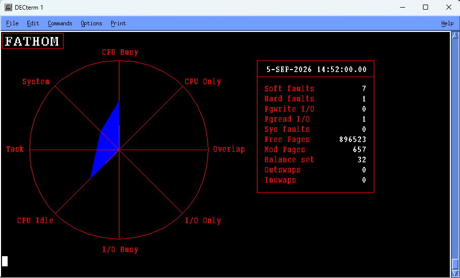
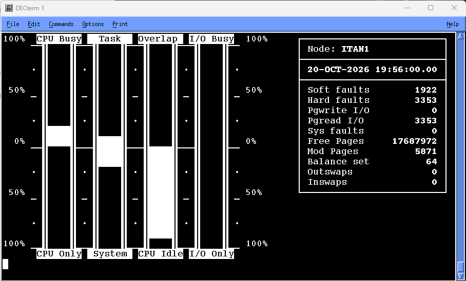
11.11.1. Investigate a Memory Limitation
The chief indicators of a memory limitation are as follows:
- No free memory
Look at the value of free pages, the memory bar histogram, and the memory queue (Mem que).
If the value of free pages approaches that of FREELIM (the system parameter that sets a lower limit on the number of pages on the free list), this indicates a memory shortage.
The memory bar histogram shows the amount of memory used by the free and modified page lists with respect to that available for user working sets. Again, a shortage of memory for the page caches (free plus modify lists) indicates a high degree of user memory utilization, and consequently a memory shortage.
A nonzero value of Mem que indicates processes in the memory queue in computable outswapped states, awaiting memory that is unavailable.
- Page fault high
Look at the value of Pgflts (page faults), Sysflts (system faults), and paging in the IO_window for disks.
For a VAX-11/780 CPU, a value of Pgflts (page fault rate, or number of faults [hard and soft, including system] per second) greater than 100 is cause for concern. For other CPUs, use an appropriate threshold such as that supplied with the factory knowledge base. If Pgflts is greater than this number, page faults might be excessive on your system.
Sysflts (the rate at which pages are faulted into the system working set) should be no more than 1 fault per second; otherwise, the system is faulting itself to do work on the users' behalf. If system faults are high, it might be necessary to increase the value of system parameter SYSMWCNT, which controls the system working set size. Note that this does not apply to OpenVMS x86-64.
If disks are spending an excessive percentage of their time doing paging (indicated by the disk bars in the IO_window), then a memory limitation is causing harmful I/O effects.
- Swapping high
Look at the value of “Inswaps,” the value of “Mem que,” and the amount of swapping and modified page writing done by the disks (Swap/Mod in the disk bars).
Inswaps gives the number of processes that were swapped back into memory during the last sample interval, and Mem que is the number of processes waiting for memory. If these are significant, then swapping is a problem on your system, and either indicates a memory limitation or memory management problem.
If disks are spending an excessive percentage of their time doing swapping and modified page writing (indicated by the disk bars in the IO_window), then a memory limitation is causing harmful I/O effects.
11.11.2. Investigate an I/O Limitation
The chief indicators of an I/O limitation are as follows:
- Direct I/O high
Look at the value of Dir I/O, as well as Data in the disk bar histogram.
Dir I/O gives the system-wide direct I/O rate, including all disks. If there is a high direct I/O rate for your system, the disks might be a bottleneck. A value for direct I/O rate that exceeds this number indicates a high direct I/O rate.
Data in the disk bars shows how much of the disk's time is spent doing I/O on behalf of the user. A high rate for a given disk may indicate that the disk is a bottleneck.
- Buffered I/O high
A high value of Buf I/O (the buffered I/O rate) may indicate an I/O limitation. If the value of Buf I/O exceeds this number, a high buffered I/O rate is indicated.
11.11.3. Investigate a CPU Limitation
The chief indicators of a CPU limitation are as follows:
- Processes in the CPU queue
Look at the value of CPU queue and at processes in the COM/CUR states in the Priority bars.
CPU que gives the number of processes waiting for the CPU (COM state). There is a real queue if this value is greater than 1. (The process displaced by Performance Manager; the NULL process is not counted.) The existence of a real CPU queue indicates a CPU limitation.
A significant number of processes in the COM/CUR states (COM = computable, waiting for the CPU; CUR = the current process) also indicates a CPU queue, and consequently a CPU limitation.
- No idle time
Look at the Idle (Idl) bar in the center of the display. If there is no CPU idle time, then the CPU is a limitation.
- System CPU time high
Compare the system CPU time (sum of Int/Ker/Exe bars) with the task CPU time (sum of Sup/Com/Use bars). The system CPU time is the sum of time spent on the interrupt stack, and in kernel and executive modes. The task CPU time is the sum of time spent in supervisor, compatibility, and user modes. The sum of interrupt and kernel CPU time should not exceed 40 percent in most environments.
11.11.4. Isolate the Cause of a Memory Limitation
If an examination of the system overview reveals a memory limitation, you can investigate the cause of the limitation in more detail using the Memory display. The following illustration is an example of the Memory display:
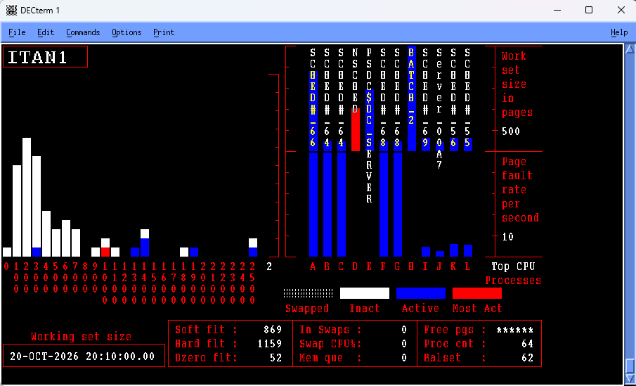
The Memory display draws attention to the following indicators:
- Hard versus Soft faults
Look at the value of Hard flt and Soft flt. Hard flt gives the number of page faults per second that were resolved by reading from the disk. Soft flt gives the number of faults per second resolved from memory. A hard fault involves I/O and is more expensive than a soft fault. Hard faults in a properly managed system should be no more than about 10 percent of the total faults (Hard flt + Soft flt).
- Inappropriate working set (WS) sizes
Look at the Process bars at the right on the Memory display. This shows the working set size and page fault rate for the top faulting processes. Adjust the scaling factors, if necessary. Look for processes that are faulting heavily but have small working sets. If your system has ample memory, increase the working set quota (WSQUOTA) and the working set extent (WSEXTENT) for these processes. If memory is short on your system, increase WSQUOTA and WSEXTENT for these processes at the expense of processes that are not faulting but have large working sets.
- Inappropriate automatic working set adjustment (AWSA) parameters
Look at the Process bar at the right on the Memory display. Look for top faulting processes with fluctuating working set sizes. If the working set size for such a process increases and decreases accompanied by page faulting, then the AWSA parameters might be out of adjustment. System parameters that affect automatic working set adjustment are PFRATH, PFRATL, WSINC, WSDEC, AWSTIME, AWSMIN, GROWLIM, BORROWLIM, and QUANTUM. Automatic decrementing can be turned off by setting PFRATL = 0 (this is normally recommended). Do not change any of the other parameters without a thorough understanding of the AWSA mechanism.
The automatic memory reclamation mechanism of OpenVMS should be enabled. This is controlled with the SYSGEN parameter MMG.CTLFLAGS.
- Too many image activations
Look at the value of Dzero flts. A large number of demand zero faults indicates an excessive number of image activations. Activating an image in a process involves considerable overhead. If Dzero faults is a large percentage of total faults (Hard flt + Soft flt), image activations might be excessive. Paging induced by image activations is unlikely to respond to system parameter changes. Application design changes are needed.
- Balance set too small
Note
This section does not apply to OpenVMS x86-64.
Look at Proc cnt (number of processes on system), Balset (number of processes in balance set), Free pgs (number of pages of free memory), and swapped processes. If the balance set count is too small, processes are swapped even if there is still free memory. If Balset is significantly less than Proc cnt, and Free pgs is adequate, then the balance set count is too low. Set the system parameter BALSETCNT to a value two less than the system parameter MAXPROCESSCNT.
- A few active processes consuming memory
Look at the Process bars, in particular for active processes with large working sets. For example, a low priority compute-bound process is less likely to be swapped than one that performs terminal I/O. They may cause other processes to swap.
Decreasing DORMANTWAIT may help if the large processes are above their working set quotas. You can also suspend the large process with
SET PROCESS/SUSPENDand allow the swapper to trim it back to SWPOUTPGCNT. The underlying problem might be that WSQUOTA is too large for the process.- Large processes with swapping disabled
Look at the Working Set and Process bars for inactive processes with large working sets. If these processes have swapping disabled, they cannot be swapped but retain memory at the expense of other processes. Use the system dump analyzer (SDA) to see if a large, inactive process has the PSWAPM (prohibit swap mode) bit set.
- Inappropriate page cache sizes
Look at the page fault rate (Hard flt and Soft flt), free memory (Free pgs), and swapping (Working Set and Process bars).
If the overall fault rate is high, and the faults are mostly soft faults, the page cache might be too large. This may also be accompanied by swapping and extensive free and modified page lists. The page cache is encroaching on memory that could be made available for working sets.
If the overall faulting rate is low while the hard fault rate is high, the page cache is ineffective; that is, the free page list and/or modified page list is too small. There is ample memory for working sets but the caching effectiveness is low.
The sizes of the page caches are controlled by the system parameters FREELIM, FREEGOAL, MPW_LOLIMIT, and MPW_THRESH.
11.11.5. Isolate the Cause of an I/O Limitation
If an examination of the system overview reveals an I/O limitation, you can investigate the cause of the limitation in more detail using the I/O display.
The following illustration is an example of the I/O display:
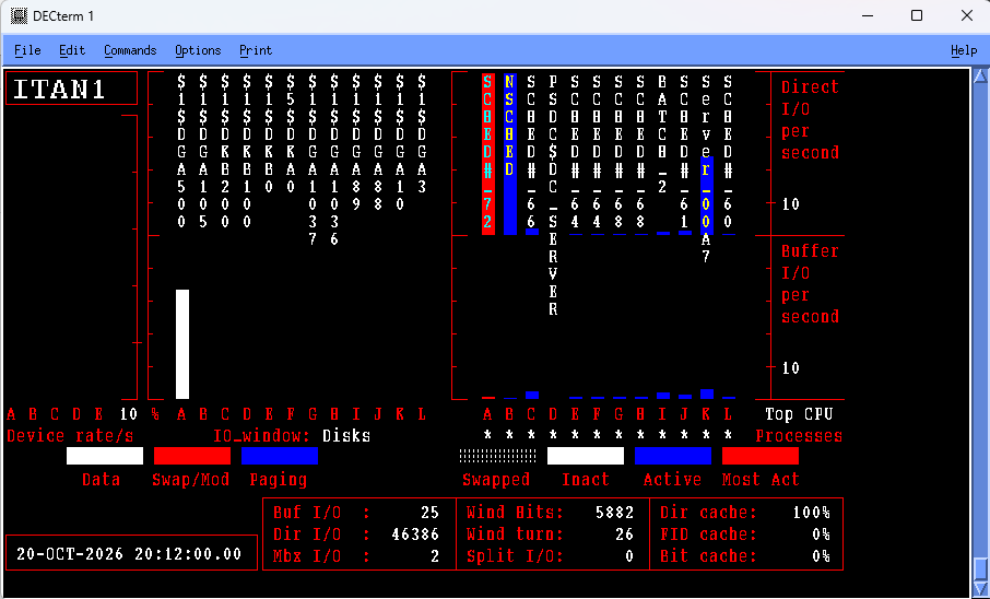
11.11.6. Isolate the Cause of a CPU Limitation
If an examination of the system overview reveals a CPU limitation, you can investigate the cause of the limitation in more detail using the CPU display. The following illustration is an example of the CPU display:
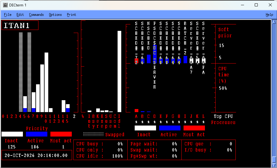
Examine the following CPU display indicators:
- Any available CPU
Look at the Idl bar (CPU Idle time) in the CPU mode bars in the middle of the CPU display. If there is no idle time, the CPU is a bottleneck.
- A few processes blocking other processes
The blocking high-priority process might be: running an inefficient program, acting as a server, or acting as a process with which other processes must communicate.
Look at the Priority bars for high-priority, active processes, or at the Process bars for high-priority processes with a high CPU time percentage. Corrective action might include changing process priorities in the user authorization file, defining priorities in the user login command file, or changing the priorities of processes while they execute.
- Lost CPU time
Look at Page wait, Swap wait, and Pg+Swp Wt. CPU time might be lost because the CPU has to wait for disk transfers, or page or swap I/O to complete.
A high value of Pg+Swp Wt is cause for concern. It indicates a memory problem resulting in a CPU limitation.
- High device CPU usage
Look at the CPU mode bars, Int (interrupt stack). A high value for Int might be cause for concern. Processes might be blocked from using the CPU because of too many device interrupts.
Use the
ADVISE COLLECT SYSTEMcommand to collect system-wide PC samples and determine the system module usage (for example, the device driver); hence, the device(s) responsible for the excessive interrupts.- Excessive kernel and/or executive CPU time
Look at the Ker (Kernel) and Exe (Executive) bars in the CPU mode bars. If time in Kernel mode is excessive and is not due to page faulting, or if time in Executive mode is excessive, use the
ADVISE COLLECT SYSTEMcommand to collect system-wide PC samples, and determine the processes and system modules responsible.Interrupt plus kernel CPU time should not be greater than 40 percent of total CPU time.
11.12. Exit the Character-Cell Displays
To exit the Performance Manager Real-time character-cell displays, press Ctrl+Z at the PSRT> prompt.
Appendix A. Performance Manager Messages and Recovery Procedures
This appendix describes messages that the Performance Manager software generates.
A.1. Sample Performance Manager Message
The following illustration illustrates the parts of a sample Performance Manager message:
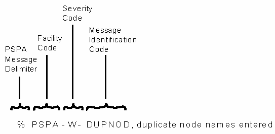
A.2. Severity Codes
The following table defines the severity codes that are assigned to messages:
| Severity Code | Explanation |
|---|---|
|
I |
Informational; the Performance Manager software sometimes provides additional information about an action. |
|
W |
Warning; the command may have performed some, but not all, of a requested action; verify the command or output. |
|
E |
Error; The output or program result is incorrect, but the Performance Manager software attempts to continue the execution. |
|
F |
Fatal; the Performance Manager software terminates execution of the request. |
To display error messages, type the following command:
$ HELP ADVISE PERFORMANCE ERROR
Each description includes a recovery procedure. Messages are listed alphabetically by the identification code that precedes the text of each message.
Appendix B. Performance Manager Logical Names
Performance Manager logical names begin with the prefix PSPA$. This appendix lists those names and describes how they are used to control various aspects of the Performance Manager module.
B.1. PSPA$DISPLAY_PROCESS_CPU_UNNORMALIZED
When this logical name is defined to anything, the Real-time Character-Cell display utility (ADVISE PERFORMANCE DISPLAY CHARACTER_CELL) displays the process CPU Utilization percentage relative to a single CPU, rather than to the total CPU time available for all CPUs in the system. This has an effect only when viewing processes on an SMP system containing more than one CPU. By default all CPU percentages are displayed relative to the total CPU time across all CPUs in the system.
This logical name has an effect on the single-node display and the process display when the current process key is either Top PID or Top Process. Top Users, Images, or Accounts will always show the CPU utilization percentage normalized with respect to the total system CPU time.
B.2. PSPA$DNS_NAMES
Define this logical name in the Process table to a node name translation file specification. Create this file to enable Real-time data transport in DECnet-Plus environments when node synonyms are not defined.
The file contains translations from OpenVMS cluster to DECnet-Plus fullname. The format of this ASCII file is one translation per line that consists of two names separated by a comma. The first name is a one to six character OpenVMS cluster name and the second name is a one to five hundred eleven character DECnet-Plus fullname (or segment thereof) or address that DECnet-Plus software will accept to establish a network connection. For example:
LATOUR,DEC:.TAY.StanWilks
B.3. PSPA$EXAMPLES
A system logical name defined by PSPA$STARTUP.COM indicating the directory where Performance Manager example files are located. This area may contain the following commands or rules:
|
PSPA$DAILY.COM |
Template command procedure to generate daily reports |
|
PSPA$GETDATA.COM |
Command procedure to create image from PSPA$GETDATA.MAR and .C |
|
PSPA$KB.VPR |
Performance Manager factory rules source file |
B.4. PSPA$GIVE_DEVICE_SERVICE
For the disk statistics section of the Performance Evaluation Report, the column labeled “Busy %” is changed to “Service Time,” when this logical name is defined to anything.
B.5. PSPA$GRAPH_CHARS
A user defined logical which specifies a string of six characters to be used in place of the normal ANSI graph legend characters.
B.6. PSPA$GRAPH_FILE_DEVICE
A user defined logical which when defined to anything causes the graph metrics for File Names to be displayed by file name and device.
B.7. PSPA$GRAPH_FILE_DIRECTORY
A user defined logical which when defined to anything causes the graph metrics for File Names to be displayed by file name and directory.
B.8. PSPA$GRAPH_LEGEND_FONT_POINT
Define this logical name to a number specifying a font point size for the PostScript graph item labels. If the PostScript Graph labels are longer than 24 characters, and you do not want the labels truncated, use this logical name to cause the labels to not truncate, and to be reduced in size, so as to fit on the page. By default, the graph legend font point is 10. Defining PSPA$GRAPH_LEGEND_FONT_POINT to 7 should reduce the font sufficiently, and a 5 makes the font size very small, but accommodates up to 50 characters.
B.9. PSPA$GRAPH_PATH
When this logical name is defined to anything, the graph metrics for “SCS Nodes” is displayed by pathname instead of nodename. This provides more detailed information about the load on each adapter for a given node.
B.10. PSPA$HLS
Specifies ReGIS HLS encodings enabling user specifications of color planes for the Performance Manager Color ReGIS graphs. The equivalence string must be a sequence of 4 plane definitions. The following example demonstrates the setting for the default graph colors:
$ DEFINE PSPA$HLS "H0L0S0 H0L50S50 H160L42S100 H0L100S0"
In this example, plane 0 is black (L0 - lightness zero%) and plane 3 is white (L100 - lightness 100%). H is HUE (0-360), S is SATURATION (0-100).
B.11. PSPA$PIE_FONT_POINT
Define this logical name to a number specifying a font point size for the PostScript pie chart item labels. If the pie chart labels are so long that they extend beyond the sides of the paper, use this logical name to cause the labels to fit on the page. By default PSPA$PIE_FONT_POINT is set to 10. Setting it to 7 should reduce the font sufficiently.
B.12. PSPA$PS_RGB_1 through PSPA$PS_RGB_6
These logical names allow the setting of the RGB color settings for the Performance Manager Color PostScript graphs. You can also use them to specify grey shades for black and white printers.
Each logical name pertains to one of the 6 colors that may appear. PSPA$PS_RGB_1 refers to the first color, appearing at the bottom of the graph, whose legend is located at the lower right of the display.
Specify a triplet of decimal values, separated by spaces, in the range of 0-1, where the first is for red, then green, and blue. A lower value produces a darker shade. For example the following settings establish the default colors for Performance Manager PostScript Graph Colors:
|
DEFINE PSPA$PS_RGB_1 ".22 1 .55" |
Green |
|
DEFINE PSPA$PS_RGB_2 ".77 .44 1 " |
Magenta |
|
DEFINE PSPA$PS_RGB_3 ".88 .77 .11" |
Yellow |
|
DEFINE PSPA$PS_RGB_4 ".33 .33 .22" |
Brown |
|
DEFINE PSPA$PS_RGB_5 "1 .22 0 " |
Red, slightly Orange |
|
DEFINE PSPA$PS_RGB_6 "0 0 1 " |
Blue |
If you want to specify grey shades, make the values for red, green and blue the same. For example:
|
DEFINE PSPA$PS_RGB_1 "0 0 0" |
Black |
|
DEFINE PSPA$PS_RGB_2 ".2 .2 .2" | |
|
DEFINE PSPA$PS_RGB_3 ".4 .4 .4" | |
|
DEFINE PSPA$PS_RGB_4 ".6 .6 .6" | |
|
DEFINE PSPA$PS_RGB_5 ".8 .8 .8" | |
|
DEFINE PSPA$PS_RGB_6 ".95 .95 .95" |
near White |
B.13. PSPA$SKIP_DISK_FILTER
For the disk reports, you can enable this logical name to have entries for shadowset member units included. By default, shadowset member units are not included in the disk reports. The logical name is enabled when defined to anything.
B.14. PSPA$SKIP_PIE_PERCENT
Define this logical to anything to suppress the printing of the percentages on the pie charts. If the pie chart labels are so long that they extend beyond the sides of the paper, the use of this logical name may make the labels fit.
B.15. PSPA$SUPRESS_TAPE_STATS_BY_VOLUME
The Tape Statistics section of the Performance Evaluation Report has a section for volumes, and a section for tape devices. If you define this logical name to anything, the tape statistics by volume is suppressed.
B.16. PSPA$UNNORMALIZE_CUSTOM_CPU
When this logical name is defined to anything, custom graphs of CPU utilization, depicting more than one node, will not have the percentage scaled by the nodes' Relative CPU power. By default, all composite graphs of CPU Utilization are scaled by each node's Relative CPU Power.
Appendix C. Performance Manager Data Cells
Data cells provide access to Performance Manager data for writing analysis rules or for writing your own applications. Each data cell entry is displayed in the following format:
Data cell name (derived)
Description
Data Type
Domains
Target Domain
The data cell name is the name used when writing auxiliary rules. If a data cell is calculated from other data cells, thresholds, or provided routines, the word derived will be displayed in parentheses after its name.
The description explains the contents of the data cell. The data type describes the format of the data. Valid data types are:
INDEX-SPECIFIER
NUMERIC
SCAN-ROUTINE
STRING
TALLY
TIME
Domains identify the valid domains, by name, from which a rule may reference a data cell. When writing rules, specify a domain name as the rule's domain to access the data cell.
C.2. Performance Manager Data Cells
ACTIVE_PROCESSORS (Derived)
This is the number of active CPUs for the local node for the current interval record in LOCAL domain, and for the local node for the last interval record in SUMMARY domain.
|
Data Type: |
NUMERIC |
|
Domains: |
COM,CFG,CPU,DSK,FIL,LOC,PRO,SUM,TAP |
ANYIO_BUSY (MET_F_SPMIOBUSY)
Percentage of time that at least one disk device was busy for the local node for the current interval record.
|
Data Type: |
NUMERIC |
|
Domains: |
COM,CFG,CPU,DSK,FIL,LOC,PRO,TAP |
ANY_DISK_FULL (Derived)
This contains a Boolean value zero or one; where one (truth) represents the fact that the percentage of free space on any disk is less than or equal to the minimum disk free space percentage threshold, TD_MIN_DSKSPC_PCT. The data cell refers to the local node for the current interval record.
|
Data Type: |
NUMERIC |
|
Domains: |
COM,CFG,CPU,DSK,FIL,LOC,PRO,TAP |
ANY_DISK_OVER_QL_THRESHOLD (Derived)
This contains a Boolean value zero or one; where one (truth) represents the fact that the queue length on any disk is greater than or equal to the maximum disk queue length threshold, TD_DISK_QL_MAX. The data cell refers to the local node for the current interval record.
|
Data Type: |
NUMERIC |
|
Domains: |
COM,CFG,CPU,DSK,FIL,LOC,PRO,TAP |
ANY_DISK_OVER_THRESHOLD (Derived)
This contains a Boolean value zero or one; where one (truth) represents the fact that the operations rate on any disk is greater than or equal to the threshold for that disk type. The disk I/O threshold, such as TD_T21_RA81, is of the form TD_Tn_xxxx where n is the integer disk type as defined in STARLET, and xxxx is the disk model name. The data cell refers to the local node for the current interval record.
|
Data Type: |
NUMERIC |
|
Domains: |
COM,CFG,CPU,DSK,FIL,LOC,PRO,TAP |
ARRIVG_DECNET_PACKET_RATE (MET_F_ARRLOCPK)
Average DECNET arriving local packet rate per second for the local node for the current interval record.
|
Data Type: |
NUMERIC |
|
Domains: |
COM,CFG,CPU,DSK,FIL,LOC,PRO,TAP |
AVERAGE_IRPS_INUSE (Derived)
This contains a value representing the average number of IRPs in use on the local node for all of the intervals.
|
Data Type: |
NUMERIC |
|
Domains: |
SUMMARY |
AVERAGE_LOCKS_INUSE (Derived)
This contains a value representing the average number of locks in use on the local node for all of the intervals.
|
Data Type: |
NUMERIC |
|
Domains: |
SUMMARY |
AVERAGE_LRPS_INUSE (Derived)
This contains a value representing the average number of LRPsin use on the local node for all of the intervals.
|
Data Type: |
NUMERIC |
|
Domains: |
SUMMARY |
AVERAGE_RESOURCES_INUSE (Derived)
This contains a value representing the average number of resources in use on the local node for all of the intervals.
|
Data Type: |
NUMERIC |
|
Domains: |
SUMMARY |
AVERAGE_SRPS_INUSE (Derived)
This contains a value representing the average number of SRPs in use on the local node for all of the intervals.
|
Data Type: |
NUMERIC |
|
Domains: |
SUMMARY |
AVERAGE_WORKING_SET_SIZE (Derived)
This contains the value of the average working set size for all processes for the local node for the current interval.
|
Data Type: |
NUMERIC |
|
Domains: |
COM,CFG,CPU,DSK,FIL,LOC,PRO,TAP |
AVG_NONPAGEDPOOLBYTES_INUSE (Derived)
This contains a value representing the average number of non-page pool bytes in use on the local node for all of the intervals.
|
Data Type: |
NUMERIC |
|
Domains: |
SUMMARY |
AWSA_IS_SLOW (Derived)
This contains a Boolean value zero or one where one (truth) represents the presence of slow automatic working set adjustment for 2 or more processes on the local node for the current interval.
|
Data Type: |
NUMERIC |
|
Domains: |
COM,CFG,CPU,DSK,FIL,LOC,PRO,TAP |
BADPAGE_FAULT_RATE (MET_F_BADPAGE_FAULTS)
Average number of page faults per second from the bad page list for the local node for the current interval record.
|
Data Type: |
NUMERIC |
|
Domains: |
COM,CFG,CPU,DSK,FIL,LOC,PRO,TAP |
BATCH_COUNT (MET_F_BATCH)
This contains a value representing the average number of batch processes on the local node for the current interval.
|
Data Type: |
NUMERIC |
|
Domains: |
COM,CFG,CPU,DSK,FIL,LOC,PRO,TAP |
BIG_WS_AND_BIG_QUOTAS (Derived)
This contains a Boolean value representing the presence of large working sets and quotas on the local node for the current interval.
|
Data Type: |
NUMERIC |
|
Domains: |
COM,CFG,CPU,DSK,FIL,LOC,PRO,TAP |
BLKS_FREE_IN_NONPAGED_POOL (MET_F_NP_FREE_BLOCKS)
This contains the number of free blocks in non-paged pool for the current interval for the local node.
|
Data Type: |
NUMERIC |
|
Domains: |
COM,CFG,CPU,DSK,FIL,LOC,PRO,TAP |
BLKS_FREE_IN_PAGED_POOL (MET_F_PG_FREE_BLOCKS)
This contains the number of free blocks in paged pool for the current interval for the local node.
|
Data Type: |
NUMERIC |
|
Domains: |
COM,CFG,CPU,DSK,FIL,LOC,PRO,TAP |
BLOCK_REQUEST_DATAS_INITIATED (SCS_F_REQDATS)
This contains the value representing the number of block transfers initiated per second for request data's on the local node to the remote node for the current configuration record and interval.
|
Data Type: |
NUMERIC |
|
Domains: |
CFG |
BLOCK_REQUEST_DATAS_INIT_TALLY (Derived)
This contains the sum of the values representing the number of block transfers initiated per second for request data's on the local node to the remote node for all the current configuration subrecords which were selected by the most recent CONFIGURATION_SCAN routine operation.
|
Data Type: |
TALLY |
|
Domains: |
COM,CFG,CPU,DSK,FIL,LOC,PRO,TAP |
|
Target Domains: |
CFG |
BLOCK_SEND_DATAS_INITIATED (SCS_F_SNDATS)
This contains the value representing the number of block transfers initiated per second on the local node to the remote node for the current configuration record and interval.
|
Data Type: |
NUMERIC |
|
Domains: |
CFG |
BLOCK_SEND_DATAS_INIT_TALLY (Derived)
This contains the sum of the values representing the number of block transfers initiated per second on the local node to the remote node for all the current configuration subrecords that were selected by the most recent CONFIGURATION_SCAN routine operation.
|
Data Type: |
TALLY |
|
Domains: |
COM,CFG,CPU,DSK,FIL,LOC,PRO,TAP |
|
Target Domains: |
CFG |
BUFFERED_IO_RATE (MET_F_BUFIO)
Average buffered I/O rate per second for the local node for the current interval record.
|
Data Type: |
NUMERIC |
|
Domains: |
COM,CFG,CPU,DSK,FIL,LOC,PRO,TAP |
BUFFER_DESC_QUEUE_RATE (SCS_F_QBDT_CNT)
This contains the value representing the number of times per second that a block transfer was queued because there were no available buffers on the local node to receive data from the remote node for the current configuration record and interval.
|
Data Type: |
NUMERIC |
|
Domains: |
CFG |
BUFFER_DESC_QUEUE_TALLY (Derived)
This contains the sum of the values representing the number of times per second that a block transfer was queued because there were no available buffers on the local node to receive data from the remote node for all the current configuration subrecords which were selected by the most recent CONFIGURATION_SCAN routine operation.
|
Data Type: |
TALLY |
|
Domains: |
COM,CFG,CPU,DSK,FIL,LOC,PRO,TAP |
|
Target Domains: |
CFG |
BYTES_FREE_IN_NONPAGED_POOL (MET_F_NP_FREE)
This contains the number of free bytes in non-paged pool for the current interval for the local node.
|
Data Type: |
NUMERIC |
|
Domains: |
COM,CFG,CPU,DSK,FIL,LOC,PRO,TAP |
BYTES_FREE_IN_PAGED_POOL (MET_F_PG_FREE)
This contains the number of free bytes in paged pool for the current interval for the local node.
|
Data Type: |
NUMERIC |
|
Domains: |
COM,CFG,CPU,DSK,FIL,LOC,PRO,TAP |
BYTES_IN_NONPAGED_POOL (MET_F_NP_POOL_MAX)
This contains the number of bytes in non-paged pool for the current interval for the local node.
|
Data Type: |
NUMERIC |
|
Domains: |
COM,CFG,CPU,DSK,FIL,LOC,PRO,TAP |
BYTES_IN_PAGED_POOL (MET_F_PG_POOL_MAX)
This contains the number of bytes in paged pool for the current interval for the local node.
|
Data Type: |
NUMERIC |
|
Domains: |
COM,CFG,CPU,DSK,FIL,LOC,PRO,TAP |
CACHE_FREE (MET_F_CACHE_FREE)
This contains the number of free pages in the I/O Cache for the current interval for the local node.
|
Data Type: |
NUMERIC |
|
Domains: |
COM,CFG,CPU,DSK,FIL,LOC,PRO,TAP |
CACHE_MAXIMUM (MET_F_CACHE_MAXI)
This contains the maximum number of pages (SPTEs) in the I/O Cache for the current interval for the local node.
|
Data Type: |
NUMERIC |
|
Domains: |
COM,CFG,CPU,DSK,FIL,LOC,PRO,TAP |
CACHE_MISSES_LT33 (MET_F_CACHE_MISS_LT33)
The number of read operations with a block size less than 33 that bypassed the XFC for the current interval for the local node.
|
Data Type: |
NUMERIC |
|
Domains: |
LOC |
CACHE_MISSES_3364 (MET_F_CACHE_MISS_3364)
The number of read operations with a block size from 33 to 65 that bypassed the XFC for the current interval for the local node
|
Data Type: |
NUMERIC |
|
Domains: |
LOC |
CACHE_MISSES_65127 (MET_F_CACHE_MISS_65127)
The number of read operations with a block size from 33 to 65 that bypassed the XFC for the current interval for the local node
|
Data Type: |
NUMERIC |
|
Domains: |
LOC |
CACHE_MISSES_128255 (MET_F_CACHE_MISS_128255)
The number of read operations with a block size from 128 to 255 that bypassed the XFC for the current interval for the local node
|
Data Type: |
NUMERIC |
|
Domains: |
LOC |
CACHE_MISSES_GT255 (MET_F_CACHE_MISS_GT255)
The number of read operations with a block size greater than 255 that bypassed the XFC for the current interval for the local node
|
Data Type: |
NUMERIC |
|
Domains: |
LOC |
CACHE_RBYPASS (MET_F_CACHE_RBYPASS)
This contains the number of read I/O operations per second bypassing the I/O cache for the current interval for the local node.
|
Data Type: |
NUMERIC |
|
Domains: |
COM,CFG,CPU,DSK,FIL,LOC,PRO,TAP |
CACHE_READHITS (MET_F_CACHE_READHITS)
This contains the number of read I/O operations per second to the I/O Cache that were satisfied by the cache, for the current interval for the local node.
|
Data Type: |
NUMERIC |
|
Domains: |
COM,CFG,CPU,DSK,FIL,LOC,PRO,TAP |
CACHE_READIO (MET_F_CACHE_RDIO)
This contains the number of read I/O operations per second to the I/O Cache for the current interval for the local node.
|
Data Type: |
NUMERIC |
|
Domains: |
COM,CFG,CPU,DSK,FIL,LOC,PRO,TAP |
CACHE_SIZE (MET_F_CACHE_SIZE)
This contains the current size (in pages) of the I/O Cache for the current interval for the local node.
|
Data Type: |
NUMERIC |
|
Domains: |
COM,CFG,CPU,DSK,FIL,LOC,PRO,TAP |
CACHE_USED (MET_F_CACHE_USED)
This contains the number of used pages in the I/O Cache for the current interval for the local node.
|
Data Type: |
NUMERIC |
|
Domains: |
COM,CFG,CPU,DSK,FIL,LOC,PRO,TAP |
CACHE_WBYPASS (MET_F_CACHE_WBYPASS)
This contains the number of write I/O operations per second bypassing the I/O Cache for the current interval for the local node.
|
Data Type: |
NUMERIC |
|
Domains: |
COM,CFG,CPU,DSK,FIL,LOC,PRO,TAP |
CACHE_WRITEIO (MET_F_CACHE_WRIO)
This contains the number of write I/O operations per second to the I/O Cache for the current interval for the local node.
|
Data Type: |
NUMERIC |
|
Domains: |
COM,CFG,CPU,DSK,FIL,LOC,PRO,TAP |
CHANNEL_OVER_THRESH_PORT (Derived)
This contains the adapter nexus number that is experiencing excessive throughput on the local node for the current interval, or a zero. It is zero if the Boolean data cell EXCESS_THRUPUT_ON_ANY_CHANNEL is zero.
|
Data Type: |
NUMERIC |
|
Domains: |
COM,CFG,CPU,DSK,FIL,LOC,PRO,TAP |
CHANNEL_OVER_THRESH_THRUPUT (Derived)
This contains a value representing the throughput rate through the adapter nexus port that is experiencing excessive throughput on the local node for the current interval, or a zero. It is zero if the Boolean data cell EXCESS_THRUPUT_ON_ANY_CHANNEL is zero.
|
Data Type: |
NUMERIC |
|
Domains: |
COM,CFG,CPU,DSK,FIL,LOC,PRO,TAP |
CHANNEL_OVER_THRESH_TYPE (Derived)
This contains a text string representing the type of I/O adapter such as "CI", "MASSBUS",... that is experiencing excessive throughput on the local node for the current interval, or "None". It is "None" if the Boolean data cell EXCESS_THRUPUT_ON_ANY_CHANNEL is zero.
|
Data Type: |
NUMERIC |
|
Domains: |
COM,CFG,CPU,DSK,FIL,LOC,PRO,TAP |
COMMUNICATION_SCAN (Derived)
Provides the count of communication subrecords for which the specified rule expression is true. The expression will be evaluated for each communication subrecord.
|
Data Type: |
SCAN |
|
Domains: |
COM,CFG,CPU,DSK,FIL,LOC,PRO,TAP |
|
Target Domains: |
COM |
COMM_CONTROLLER_NAME (COM_A_CTLR_NAME)
This contains a string indicating the terminal controller of the current communication subrecord for the current interval.
|
Data Type: |
STRING |
|
Domains: |
COM |
COMM_OPERATION_RATE (COM_F_OPCNT)
This contains a value representing the average operations rate for the current communications subrecord on the local node for the current interval.
|
Data Type: |
NUMERIC |
|
Domains: |
COM |
COMM_OPERATION_RATE_TALLY (Derived)
This contains a value representing the sum of values of the average operations rate for all the current communications subrecords which were selected by the most recent COMMUNICATION_SCAN routine operation.
|
Data Type: |
TALLY |
|
Domains: |
COM,CFG,CPU,DSK,FIL,LOC,PRO,TAP |
|
Target Domains: |
COM |
COMO_PROCESSES_ARE_AT_BPRI (Derived)
This contains a Boolean value zero or one, one (true) representing the presence of processes in computable outswapped state and running at base priority on the local node for the current interval.
|
Data Type: |
NUMERIC |
|
Domains: |
COM,CFG,CPU,DSK,FIL,LOC,PRO,TAP |
COMPAT (MET_F_COMPAT)
Average percentage of CPU time spent in Compatibility mode for all processors in the local node for the current interval record.
|
Data Type: |
NUMERIC |
|
Domains: |
COM,CFG,CPU,DSK,FIL,LOC,PRO,TAP |
COMPUTABLE_PROCESSES (Derived)
This contains a value representing the number of computable processes (MET_F_COM + MET_F_COMO) on the local node for the current interval.
|
Data Type: |
NUMERIC |
|
Domains: |
COM,CFG,CPU,DSK,FIL,LOC,PRO,TAP |
COMPUTABLE_PROCESSES_OVR_DEFPRI (Derived)
This contains a value representing the number of computable processes with a scheduling priority at or above the default priority DEFPRI on the local node for the current interval.
|
Data Type: |
NUMERIC |
|
Domains: |
COM,CFG,CPU,DSK,FIL,LOC,PRO,TAP |
COM_SCALING (Derived)
This contains a value representing scaling factor for the compute queue length for the local node. The value is obtained from the threshold TD_COM_SCALING_n where n is the hardware model number of the local node. By default, if the local node is a VAX 11-780, the value would be 1.0.
The value of this data cell can be modified using a threshold construct.
|
Data Type: |
NUMERIC |
|
Domains: |
COM,CFG,CPU,DSK,FIL,LOC,PRO,TAP |
CONFIGURATION_SCAN (Derived)
Provides the count of configuration subrecords for which the specified rule condition is true. The condition will be evaluated for each configuration subrecord.
|
Data Type: |
SCAN |
|
Domains: |
COM,CFG,CPU,DSK,FIL,LOC,PRO,TAP |
|
Target Domains: |
CFG |
CPUIO_BUSY (MET_F_SPMCPUIO)
Percentage of time that both the CPU and at least one disk device were busy for the local node for the current interval record.
|
Data Type: |
NUMERIC |
|
Domains: |
COM,CFG,CPU,DSK,FIL,LOC,PRO,TAP |
CPUIO_IDLE (MET_F_SPMSYSIDLE)
Percentage of time that the CPU and all disk devices were idle for the local node for the current interval record.
|
Data Type: |
NUMERIC |
|
Domains: |
COM,CFG,CPU,DSK,FIL,LOC,PRO,TAP |
CPU_BUSY (MET_F_SPMBUSY)
Percentage of time that the CPU was busy for the local node for the current interval record.
|
Data Type: |
NUMERIC |
|
Domains: |
COM,CFG,CPU,DSK,FIL,LOC,PRO,TAP |
CPU_COMPAT (CPU_F_COMPAT)
This contains the value representing the percent of time spent in COMPATIBILITY mode for the physical CPU represented by the current CPU subrecord and interval.
|
Data Type: |
NUMERIC |
|
Domains: |
CPU |
CPU_COMPAT_TALLY (Derived)
This contains the sum of the values representing the percent of time in COMPATIBILITY mode for the current CPU subrecords which were selected by the most recent CPU_SCAN routine operation.
|
Data Type: |
TALLY |
|
Domains: |
COM,CFG,CPU,DSK,FIL,LOC,PRO,TAP |
|
Target Domains: |
CFG |
CPU_EXEC (CPU_F_EXEC)
This contains the value representing the percent of time spent in EXEC mode for the physical CPU represented by the current CPU subrecord and interval.
|
Data Type: |
NUMERIC |
|
Domains: |
CPU |
CPU_EXEC_TALLY (Derived)
This contains the sum of the values representing the percent of time in EXEC mode for the current CPU subrecords which were selected by the most recent CPU_SCAN routine operation.
|
Data Type: |
TALLY |
|
Domains: |
COM,CFG,CPU,DSK,FIL,LOC,PRO,TAP |
|
Target Domains: |
CPU |
CPU_IDLE (CPU_F_NULL)
This contains the value representing the percent of time the CPU was idle for the physical CPU represented by the current CPU subrecord and interval.
|
Data Type: |
NUMERIC |
|
Domains: |
CPU |
CPU_IDLE_TALLY (Derived)
This contains the sum of the values representing the percent of time the CPU was idle for the current CPU subrecords which were selected by the most recent CPU_SCAN routine operation.
|
Data Type: |
TALLY |
|
Domains: |
COM,CFG,CPU,DSK,FIL,LOC,PRO,TAP |
|
Target Domains: |
CPU |
CPU_INTERRUPT (CPU_F_INTERRUPT)
This contains the value representing the percent of time spent on the interrupt stack for the physical CPU represented by the current CPU subrecord and interval.
|
Data Type: |
NUMERIC |
|
Domains: |
CPU |
CPU_INTERRUPT_TALLY (Derived)
This contains the value representing the percent of time spent on the interrupt stack for the physical CPU represented by the current CPU subrecord and interval.
|
Data Type: |
TALLY |
|
Domains: |
COM,CFG,CPU,DSK,FIL,LOC,PRO,TAP |
|
Target Domains: |
CPU |
CPU_IS_PRIMARY (CPU_C_PRIMID)
This contains either the values 1, if the CPU for the current CPU subrecord is the primary CPU, or a 0 if it is not the primary CPU.
|
Data Type: |
NUMERIC |
|
Domains: |
CPU |
CPU_IS_RUNNING (CPU_C_RUN)
This contains either the values 1, if the physical CPU for the current CPU subrecord is running, or a 0 if it is stopped.
|
Data Type: |
NUMERIC |
|
Domains: |
CPU |
CPU_KERNEL (CPU_F_KERNEL)
This contains the value representing the percent of time spent in KERNEL mode for the physical CPU represented by the current CPU subrecord and interval.
|
Data Type: |
NUMERIC |
|
Domains: |
CPU |
CPU_KERNEL_TALLY (Derived)
This contains the sum of the values representing the percent of time in KERNEL mode for the current CPU subrecords which were selected by the most recent CPU_SCAN routine operation.
|
Data Type: |
TALLY |
|
Domains: |
COM,CFG,CPU,DSK,FIL,LOC,PRO,TAP |
|
Target Domains: |
CPU |
CPU_MP_SYNCH (CPU_F_MP_SYNCH)
This contains the value representing the percent of time spent in MP_SYNCH mode for the physical CPU represented by the current CPU subrecord and interval.
|
Data Type: |
NUMERIC |
|
Domains: |
CPU |
CPU_MP_SYNCH_TALLY (Derived)
This contains the sum of the values representing the percent of time in MP_SYNCH mode for the current CPU subrecords which were selected by the most recent CPU_SCAN routine operation.
|
Data Type: |
TALLY |
|
Domains: |
COM,CFG,CPU,DSK,FIL,LOC,PRO,TAP |
|
Target Domains: |
CPU |
CPU_ONLY (MET_F_SPMCPUONLY)
Percentage of time that a CPU was busy and all disk devices were idle for the local node for the current interval record.
|
Data Type: |
NUMERIC |
|
Domains: |
COM,CFG,CPU,DSK,FIL,LOC,PRO,TAP |
CPU_PHYSICAL_ID (Derived)
This contains a string indicating the CPU's physical ID of the current CPU subrecord for the current interval.
|
Data Type: |
STRING |
|
Domains: |
CPU |
CPU_SCAN (Derived)
Provides the count of CPU subrecords for which the specified rule condition is true. The condition will be evaluated for each CPU subrecord.
|
Data Type: |
SCAN |
|
Domains: |
COM,CFG,CPU,DSK,FIL,LOC,PRO,TAP |
|
Target Domains: |
CPU |
CPU_SUPER (CPU_F_SUPER)
This contains the value representing the percent of time spent in SUPERVISOR mode for the physical CPU represented by the current CPU subrecord and interval.
|
Data Type: |
NUMERIC |
|
Domains: |
CPU |
CPU_SUPER_TALLY (Derived)
This contains the sum of the values representing the percent of time in SUPERVISOR mode for the current CPU subrecords which were selected by the most recent CPU_SCAN routine operation.
|
Data Type: |
TALLY |
|
Domains: |
COM,CFG,CPU,DSK,FIL,LOC,PRO,TAP |
|
Target Domains: |
CPU |
CPU_USER (CPU_F_USER)
This contains the value representing the percent of time spent in USER mode for the physical CPU represented by the current CPU subrecord and interval.
|
Data Type: |
NUMERIC |
|
Domains: |
CPU |
CPU_USER_TALLY (Derived)
This contains the sum of the values representing the percent of time in USER mode for the current CPU subrecords which were selected by the most recent CPU_SCAN routine operation.
|
Data Type: |
TALLY |
|
Domains: |
COM,CFG,CPU,DSK,FIL,LOC,PRO,TAP |
|
Target Domains: |
CPU |
CPU_VUP_RATING (Derived)
This contains a value representing the VAX Unit of Processing (VUP) for a single physical processor for the local node.
|
Data Type: |
NUMERIC |
|
Domains: |
COM,CFG,CPU,DSK,FIL,LOC,PRO,TAP |
CW_DISK_CHANNEL_IO (Derived)
This contains a value representing the disk operations rate to the HSC's K.SDI channel associated with the current disk for all nodes during the current interval.
|
Data Type: |
NUMERIC |
|
Domains: |
CLU |
CW_DISK_CHANNEL_RATIO (Derived)
This contains a percentage value representing the cluster-wide ratio of disk operations for the current disk to the operations on the HSC's K.SDI channel associated with the current disk for all nodes during the current interval.
|
Data Type: |
NUMERIC |
|
Domains: |
CLU |
CW_DISK_ERROR_COUNT (Derived)
This contains a value representing the cluster-wide disk error count for the current disk for all nodes during the current interval.
|
Data Type: |
NUMERIC |
|
Domains: |
CLU |
CW_DISK_IO_RATE (Derived)
This contains a value representing the cluster-wide disk operations rate for the current disk for all nodes during the current interval.
|
Data Type: |
NUMERIC |
|
Domains: |
CLU |
CW_DISK_THRUPUT_RATE (Derived)
This contains a value representing the cluster-wide disk throughput rate in bytes per second for the current disk for all nodes during the current interval.
|
Data Type: |
NUMERIC |
|
Domains: |
CLU |
CW_TOP_FILE_NAME (Derived)
This contains a text string representing the file name of the file with the highest disk operations rate for all nodes for the current disk.
|
Data Type: |
STRING |
|
Domains: |
CLU |
CW_TOP_FILE_OPCNT (Derived)
This contains a value representing the disk operations rate of the file with the highest disk operations rate for the current disk for all nodes during the current interval.
|
Data Type: |
NUMERIC |
|
Domains: |
CLU |
CW_VOLUME_NAME (Derived)
This contains a string of text representing the cluster-wide volume name for the current disk during the current interval.
|
Data Type: |
STRING |
|
Domains: |
CLU |
DATAGRAMS_DISCARDED (SCS_F_DGDISCARD)
This contains the value representing the number of datagrams discarded per second by the local node and received from the remote node for the current configuration record and interval.
|
Data Type: |
NUMERIC |
|
Domains: |
CFG |
DATAGRAMS_DISCARDED_TALLY (Derived)
This contains the sum of the values representing the number of datagrams discarded per second by the local node and received from the remote node for all the current configuration subrecords which were selected by the most recent CONFIGURATION_SCAN routine operation.
|
Data Type: |
TALLY |
|
Domains: |
COM,CFG,CPU,DSK,FIL,LOC,PRO,TAP |
|
Target Domains: |
CFG |
DATAGRAMS_RECEIVED (SCS_F_DGRCVD)
This contains the value representing the number of datagrams received per second on the local node from the remote node for the current configuration record and interval.
|
Data Type: |
NUMERIC |
|
Domains: |
CFG |
DATAGRAMS_RECEIVED_TALLY (Derived)
This contains the sum of the values representing the number of datagrams received per second on the local node from the remote node for all the current configuration subrecords which were selected by the most recent CONFIGURATION_SCAN routine operation.
|
Data Type: |
TALLY |
|
Domains: |
COM,CFG,CPU,DSK,FIL,LOC,PRO,TAP |
|
Target Domains: |
CFG |
DATAGRAMS_SEND_RATE (SCS_F_DGSENT)
This contains the value representing the number of datagrams sent per second from the local node to the remote node for the current configuration record and interval.
|
Data Type: |
NUMERIC |
|
Domains: |
CFG |
DATAGRAMS_SEND_TALLY (Derived)
This contains the sum of the values representing the number of datagrams sent per second from the local node to the remote node for all the current configuration subrecords which were selected by the most recent CONFIGURATION_SCAN routine operation.
|
Data Type: |
TALLY |
|
Domains: |
COM,CFG,CPU,DSK,FIL,LOC,PRO,TAP |
|
Target Domains: |
CFG |
DEADLOCK_FIND_RATE (MET_F_DLCKFND)
This contains the number of deadlock finds per second for the current interval for the local node.
|
Data Type: |
NUMERIC |
|
Domains: |
COM,CFG,CPU,DSK,FIL,LOC,PRO,TAP |
DEADLOCK_SEARCH_RATE (MET_F_DLCKSRCH)
This contains the number of deadlock searches per second for the current interval for the local node.
|
Data Type: |
NUMERIC |
|
Domains: |
COM,CFG,CPU,DSK,FIL,LOC,PRO,TAP |
DECNET_RECV_BUFF_FAIL_RATE (MET_F_RCVBUFFL)
This contains the number of times per second the DECNET receiver buffer failed for the current interval for the local node.
|
Data Type: |
NUMERIC |
|
Domains: |
COM,CFG,CPU,DSK,FIL,LOC,PRO,TAP |
DECNET_TRANSIT_CONGSN_LOSS_RATE (MET_F_TRCNGLOS)
Average DECNET transit congestion loss rate per second for the local node for the current interval record.
|
Data Type: |
NUMERIC |
|
Domains: |
COM,CFG,CPU,DSK,FIL,LOC,PRO,TAP |
DECNET_TRANSIT_PACKET_RATE (MET_F_ARRTRAPK)
Average rate per second for the local node for the current interval record.
|
Data Type: |
NUMERIC |
|
Domains: |
COM,CFG,CPU,DSK,FIL,LOC,PRO,TAP |
DEMANDZERO_FAULT_RATE (MET_F_DZROFLTS)
Average number of demand zero pagefaults per second for the local node for the current interval record.
|
Data Type: |
NUMERIC |
|
Domains: |
COM,CFG,CPU,DSK,FIL,LOC,PRO,TAP |
DEPARTG_DECNET_PACKET_RATE (MET_F_DEPLOCPK)
Average DECNET departing local packet rate per second for the local node for the current interval record.
|
Data Type: |
NUMERIC |
|
Domains: |
COM,CFG,CPU,DSK,FIL,LOC,PRO,TAP |
DEVICE_NAME (DEV_A_DEVNAME)
This contains a string indicating the disk device of the disk for which the current disk subrecord pertains (e.g., $2$DUA11).
|
Data Type: |
STRING |
|
Domains: |
DSK |
DIRECTORY_DATA_CACHE_AR (Derived)
Attempt rate per second to the directory data cache for the local node for the current interval record.
|
Data Type: |
NUMERIC |
|
Domains: |
COM,CFG,CPU,DSK,FIL,LOC,PRO,TAP |
DIRECTORY_DATA_CACHE_HR (Derived)
Hit ratio to the directory data cache for the local node for the current interval record. Calculated by dividing the number of directory data cache hits by the number of directory data cache attempts (hits + misses), times 100.
|
Data Type: |
NUMERIC |
|
Domains: |
COM,CFG,CPU,DSK,FIL,LOC,PRO,TAP |
DIRECTORY_INDEX_CACHE_AR (Derived)
Attempt rate per second to the directory index cache for the local node for the current interval record.
|
Data Type: |
NUMERIC |
|
Domains: |
COM,CFG,CPU,DSK,FIL,LOC,PRO,TAP |
DIRECTORY_INDEX_CACHE_HR (Derived)
Hit ratio to the directory index cache for the local node for the current interval record. Calculated by dividing the number of directory index cache hits by the number of directory index cache attempts (hits + misses), times 100.
|
Data Type: |
NUMERIC |
|
Domains: |
COM,CFG,CPU,DSK,FIL,LOC,PRO,TAP |
DIRECT_IO_RATE (MET_F_DIRIO)
Average direct I/O rate per second for the local node for the current interval record.
|
Data Type: |
NUMERIC |
|
Domains: |
COM,CFG,CPU,DSK,FIL,LOC,PRO,TAP |
DISK_BUSY_PERCENT (DEV_F_BUSY)
This contains a value representing the average percent of time the I/O requests were outstanding to the current disk on the local node for the current interval.
|
Data Type: |
NUMERIC |
|
Domains: |
DSK |
DISK_BUSY_PERCENT_TALLY (Derived)
This contains the sum of the values representing the average busy percentage for the current disk subrecords which were selected by the most recent DISK_SCAN routine operation.
|
Data Type: |
TALLY |
|
Domains: |
COM,CFG,CPU,DSK,FIL,LOC,PRO,TAP |
|
Target Domains: |
DSK |
DISK_CACHE_NAME (DEV_A_CACHENAME)
This contains a string representing the file specification of the cache for the current disk on the local node for the current interval.
|
Data Type: |
STRING |
|
Domains: |
DSK |
DISK_CONTROLLER (DEV_A_CTLR_NAME)
This contains a string indicating the controller name of the current disk on the local node for the current interval (e.g., DUA).
|
Data Type: |
STRING |
|
Domains: |
DSK |
DISK_DINDX_CACHE_SIZE (DEV_F_DINDXSIZE)
This contains a value representing the number of entries in the directory index cache for the current disk on the local node for the current interval.
|
Data Type: |
NUMERIC |
|
Domains: |
DSK |
DISK_DIRDATA_CACHE_SIZE (DEV_F_DIRSIZE)
This contains a value representing the number of entries in the directory data cache for the current disk on the local node for the current interval.
|
Data Type: |
NUMERIC |
|
Domains: |
DSK |
DISK_ERROR_COUNT (DEV_F_ERRCNT)
This contains a value representing the number of errors recorded for the current disk on the local node for the current interval.
|
Data Type: |
NUMERIC |
|
Domains: |
DSK |
DISK_ERROR_COUNT_TALLY (Derived)
This contains the sum of the values representing the number of errors for the current disk subrecords which were selected by the most recent DISK_SCAN routine operation.
|
Data Type: |
TALLY |
|
Domains: |
COM,CFG,CPU,DSK,FIL,LOC,PRO,TAP |
|
Target Domains: |
DSK |
DISK_EXTENT_CACHE_SIZE (DEV_F_EXTSIZE)
This contains a value representing the number of entries in the file extent cache for the current disk on the local node for the current interval.
|
Data Type: |
NUMERIC |
|
Domains: |
DSK |
DISK_FID_CACHE_SIZE (DEV_F_FIDSIZE)
This contains a value representing the number of entries in the file ID cache for the current disk on the local node for the current interval.
|
Data Type: |
NUMERIC |
|
Domains: |
DSK |
DISK_FREE_PAGES (DEV_F_FREE)
This contains a value representing the average number of free pages on the current disk on the local node for the current interval.
|
Data Type: |
NUMERIC |
|
Domains: |
DSK |
DISK_FREE_PAGES_TALLY (Derived)
This contains the sum of the values representing the number of free pages for the current disk subrecords which were selected by the most recent DISK_SCAN routine operation.
|
Data Type: |
TALLY |
|
Domains: |
COM,CFG,CPU,DSK,FIL,LOC,PRO,TAP |
|
Target Domains: |
DSK |
DISK_HAS_A_PAGING_FILE (Derived)
This contains a Boolean value representing true (1.0) if there is a paging file installed on the current disk on the local node for the current interval.
|
Data Type: |
NUMERIC |
|
Domains: |
DSK |
DISK_HAS_A_SWAPPING_FILE (Derived)
This contains Boolean a value representing true (1.0) if there is a swapping file installed on the current disk on the local node for the current interval.
|
Data Type: |
NUMERIC |
|
Domains: |
DSK |
DISK_HEADER_CACHE_SIZE (DEV_F_HDRSIZE)
This contains a value representing the number of entries in the file header cache for the current disk on the local node for the current interval.
|
Data Type: |
NUMERIC |
|
Domains: |
DSK |
DISK_INTERVAL_MS (DEV_F_ITVL)
This contains a value representing the uptime of the disk in milliseconds for the current disk on the local node for the current interval.
|
Data Type: |
NUMERIC |
|
Domains: |
DSK |
DISK_IO_RATE (DEV_F_OPCNT)
This contains a value representing the average number of I/O requests per second to and from the current disk on the local node for the current interval.
|
Data Type: |
NUMERIC |
|
Domains: |
DSK |
DISK_IO_RATE_TALLY (Derived)
This contains the sum of the values representing the average I/O rate for the current disk subrecords which were selected by the most recent DISK_SCAN routine operation.
|
Data Type: |
NUMERIC |
|
Domains: |
COM,CFG,CPU,DSK,FIL,LOC,PRO,TAP |
|
Target Domains: |
DSK |
DISK_IO_RATE_THRESHOLD (Derived)
This contains a value representing the disk I/O rate threshold for the current disk during the current interval. This value is obtained from the threshold TD_Tn_xxxx where n is the disk type model number found in STARLET ($DCDEF) for the current disk, and xxxx is its type (e.g., TD_T21_RA81).
DISK_IS_SERVED (Derived)
This contains a Boolean value indicating whether the current disk is MSCP served during the current interval.
|
Data Type: |
NUMERIC |
|
Domains: |
CLU |
DISK_MAP_CACHE_SIZE (DEV_F_MAPSIZE)
This contains a value representing the number of entries in the bitmap cache for the current disk on the local node for the current interval.
|
Data Type: |
NUMERIC |
|
Domains: |
DSK |
DISK_MAX_BLOCKS (DEV_F_MAXBLOCK)
This contains a value representing the maximum number of blocks on the current disk on the local node for the current interval.
|
Data Type: |
NUMERIC |
|
Domains: |
DSK |
DISK_MOST_FULL_X (Derived)
This contains an index pointing to the disk subrecord experiencing excessively limited free space on a disk on the local node for the current interval. It is set up when the cell ANY_DISK_FULL becomes true.
|
Data Type: |
INDEX |
|
Domains: |
COM,CFG,CPU,DSK,FIL,LOC,PRO,TAP |
|
Target Domains: |
DSK |
DISK_MSCP_IO_RATE (DEV_F_MSCPOP)
This contains a value representing the average number of MSCP served I/O requests per second to and from the current disk on the local node for the current interval.
|
Data Type: |
NUMERIC |
|
Domains: |
DSK |
DISK_MSCP_IO_RATE_TALLY (Derived)
This contains the sum of the values representing the average MSCP served I/O rate for the current disk subrecords which were selected by the most recent DISK_SCAN routine operation.
|
Data Type: |
TALLY |
|
Domains: |
COM,CFG,CPU,DSK,FIL,LOC,PRO,TAP |
|
Target Domains: |
DSK |
DISK_MSCP_PAGING_IO_RATE (DEV_F_MSCPPG)
This contains a value representing the average number of MSCP served paging I/O requests per second to and from the current disk on the local node for the current interval.
|
Data Type: |
NUMERIC |
|
Domains: |
DSK |
DISK_MSCP_PAGING_IO_TALLY (Derived)
This contains the sum of the values representing the average MSCP served paging I/O rate for the current disk subrecords which were selected by the most recent DISK_SCAN routine operation.
|
Data Type: |
TALLY |
|
Domains: |
COM,CFG,CPU,DSK,FIL,LOC,PRO,TAP |
|
Target Domains: |
DSK |
DISK_MSCP_THRUPUT_RATE (DEV_F_MSCPIO)
This contains a value representing the average number of bytes per second transferred to and from the current disk on the local node for the current interval.
|
Data Type: |
NUMERIC |
|
Domains: |
DSK |
DISK_MSCP_THRUPUT_TALLY (Derived)
This contains the sum of the values representing the average MSCP served throughput rate for the current disk subrecords which were selected by the most recent DISK_SCAN routine operation.
|
Data Type: |
TALLY |
|
Domains: |
COM,CFG,CPU,DSK,FIL,LOC,PRO,TAP |
|
Target Domains: |
DSK |
DISK_OVER_QL_THRESHOLD_X (Derived)
This contains an index pointing to the disk subrecord experiencing an excessive queue length on a disk on the local node for the current interval. It is set up when the cell ANY_DISK_OVER_QL_THRESHOLD becomes true.
|
Data Type: |
INDEX |
|
Domains: |
COM,CFG,CPU,DSK,FIL,LOC,PRO,TAP |
|
Target Domains: |
DSK |
DISK_OVER_THRESHOLD_X (Derived)
This contains an index pointing to the disk subrecord experiencing an excessive operations rate on a disk on the local node for the current interval. It is set up when the cell ANY_DISK_OVER_THRESHOLD becomes true.
|
Data Type: |
INDEX |
|
Domains: |
COM,CFG,CPU,DSK,FIL,LOC,PRO,TAP |
|
Target Domains: |
DSK |
DISK_PAGING_IO_RATE (DEV_F_PAGOP)
This contains a value representing the average number of paging I/O requests per second to and from the current disk on the local node for the current interval.
|
Data Type: |
NUMERIC |
|
Domains: |
DSK |
DISK_PAGING_IO_RATE_TALLY (Derived)
This contains the sum of the values representing the average paging I/O rate for the current disk subrecords which were selected by the most recent DISK_SCAN routine operation.
|
Data Type: |
TALLY |
|
Domains: |
COM,CFG,CPU,DSK,FIL,LOC,PRO,TAP |
|
Target Domains: |
DSK |
DISK_PAGING_THRUPUT_RATE (DEV_F_PAGIO)
This contains a value representing the average number of bytes per second for paging I/Os transferred to and from the current disk on the local node for the current interval.
|
Data Type: |
NUMERIC |
|
Domains: |
DSK |
DISK_PAGING_THRUPUT_TALLY (Derived)
This contains the sum of the values representing the average paging throughput rate for the current disk subrecords which were selected by the most recent DISK_SCAN routine operation.
|
Data Type: |
TALLY |
|
Domains: |
COM,CFG,CPU,DSK,FIL,LOC,PRO,TAP |
|
Target Domains: |
DSK |
DISK_QUEUE_AT_SERVER (Derived)
This contains a value representing the OpenVMS node server queue length for the local disk during the current interval. For an HSC based disk, this cell This contains the highest queue for all nodes on the CI.
|
Data Type: |
NUMERIC |
|
Domains: |
CLU |
DISK_QUEUE_LENGTH (DEV_F_QLEN)
This contains a value representing the average number of outstanding I/O requests for the current disk on the local node for the current interval.
|
Data Type: |
NUMERIC |
|
Domains: |
DSK |
DISK_QUEUE_LENGTH_TALLY (Derived)
This contains the sum of the values representing the average queue length for the current disk subrecords which were selected by the most recent DISK_SCAN routine operation.
|
Data Type: |
TALLY |
|
Domains: |
COM,CFG,CPU,DSK,FIL,LOC,PRO,TAP |
|
Target Domains: |
DSK |
DISK_QUOTA_CACHE_SIZE (DEV_F_QUOSIZE)
This contains a value representing the number of entries in the quota cache for the current disk on the local node for the current interval.
|
Data Type: |
NUMERIC |
|
Domains: |
DSK |
DISK_READ_IO_RATE (DEV_F_RDCNT)
This contains a value representing the average number of read I/O requests per second from the current disk on the local node for the current interval.
|
Data Type: |
NUMERIC |
|
Domains: |
DSK |
DISK_READ_IO_RATE_TALLY (Derived)
This contains the sum of the values representing the average read I/O rate for the current disk subrecords which were selected by the most recent DISK_SCAN routine operation.
|
Data Type: |
TALLY |
|
Domains: |
COM,CFG,CPU,DSK,FIL,LOC,PRO,TAP |
|
Target Domains: |
DSK |
DISK_SCAN (Derived)
Provides the count of disk subrecords for which the specified rule condition is true. The condition will be evaluated for each disk subrecord.
|
Data Type: |
SCAN |
|
Domains: |
COM,CFG,CPU,DSK,FIL,LOC,PRO,TAP |
|
Target Domains: |
DSK |
DISK_SERVER_HWNAME (DEV_A_HWNAME)
This contains a string indicating the hardware name of the Integrity server, or Alpha node which serves the current disk to the local node for the current interval. If the server is an HSC, this field is blank.
|
Data Type: |
STRING |
|
Domains: |
DSK |
DISK_SERVER_HWTYPE (DEV_A_HWTYPE)
This contains a string indicating the hardware type of the cluster node which serves the current disk's data to the local node for the current interval (e.g., HS50, ALPHA, IA64).
|
Data Type: |
STRING |
|
Domains: |
DSK |
DISK_SERVER_NODENAME (DEV_A_NODENAME)
This contains a string indicating the cluster node name of the node which serves the current disk's data to the local node for the current interval.
|
Data Type: |
STRING |
|
Domains: |
DSK |
DISK_SERVICE_TIME (DEV_F_SERVICE)
This contains a value representing the average number of milliseconds between the I/O events START-I/O and END-I/O for all I/Os for the current disk on the local node for the current interval.
|
Data Type: |
NUMERIC |
|
Domains: |
DSK |
DISK_SERVICE_TIME_TALLY (Derived)
This contains the sum of the values representing the average number of milliseconds between the I/O events START-I/O and END-I/O for all I/Os for the current disk subrecords which were selected by the most recent DISK_SCAN routine operation.
|
Data Type: |
TALLY |
|
Domains: |
COM,CFG,CPU,DSK,FIL,LOC,PRO,TAP |
|
Target Domains: |
DSK |
DISK_SPLIT_IO_RATE (DEV_F_SPLIT)
This contains a value representing the average number of split I/O requests per second to and from the current disk on the local node for the current interval.
|
Data Type: |
NUMERIC |
|
Domains: |
DSK |
DISK_SPLIT_IO_TALLY (Derived)
This contains the sum of the values representing the average split I/O rate for the current disk subrecords which were selected by the most recent DISK_SCAN routine operation.
|
Data Type: |
TALLY |
|
Domains: |
COM,CFG,CPU,DSK,FIL,LOC,PRO,TAP |
|
Target Domains: |
DSK |
DISK_SWAPPING_IO_RATE (DEV_F_SWPOP)
This contains a value representing the average number of swapping I/O requests per second to and from the current disk on the local node for the current interval.
|
Data Type: |
NUMERIC |
|
Domains: |
DSK |
DISK_SWAPPING_IO_TALLY (Derived)
This contains the sum of the values representing the average swapper I/O rate for the current disk subrecords which were selected by the most recent DISK_SCAN routine operation.
|
Data Type: |
TALLY |
|
Domains: |
COM,CFG,CPU,DSK,FIL,LOC,PRO,TAP |
|
Target Domains: |
DSK |
DISK_SWAPPING_THRUPUT_RATE (DEV_F_SWPIO)
This contains a value representing the average number of bytes per second (for swapping I/Os) transferred to and from the current disk on the local node for the current interval.
|
Data Type: |
NUMERIC |
|
Domains: |
DSK |
DISK_SWAPPING_THRUPUT_TALLY (Derived)
This contains the sum of the values representing the average swapper throughput rate for the current disk subrecords which were selected by the most recent DISK_SCAN routine operation.
|
Data Type: |
TALLY |
|
Domains: |
COM,CFG,CPU,DSK,FIL,LOC,PRO,TAP |
|
Target Domains: |
DSK |
DISK_THRUPUT_RATE (DEV_F_IOCNT)
This contains a value representing the average number of bytes per second transferred to and from the current disk on the local node for the current interval.
|
Data Type: |
NUMERIC |
|
Domains: |
DSK |
DISK_THRUPUT_RATE_THRESHOLD (Derived)
This contains a value representing the disk throughput rate threshold for the current disk. This value is obtained from the threshold TD_In_xxxx where n is the disk type model number found in STARLET ($DCDEF) for the current disk, and xxxx is its type (e.g., TD_I21_RA81).
|
Data Type: |
NUMERIC |
|
Domains: |
CLU |
DISK_THRUPUT_TALLY (Derived)
This contains the sum of the values representing the average throughput rate for the current disk subrecords which were selected by the most recent DISK_SCAN routine operation.
|
Data Type: |
TALLY |
|
Domains: |
COM,CFG,CPU,DSK,FIL,LOC,PRO,TAP |
|
Target Domains: |
DSK |
DISK_TOP_OPERATION_FILE_X (Derived)
This contains an index specifier identifying the hot file subrecord for the hottest file in terms of I/O operations per second on the current disk on the local node for the current interval.
|
Data Type: |
INDEX |
|
Domains: |
DSK |
|
Target Domains: |
FIL |
DISK_TOP_SPLIT_IO_FILE_X (Derived)
This contains an index specifier identifying the hot file subrecord for the hottest file in terms of split I/O operations per second on the current disk on the local node for the current interval.
|
Data Type: |
INDEX |
|
Domains: |
DSK |
|
Target Domains: |
FIL |
DYN_EXPANSION_COUNT (Derived)
A count of the number of times nonpaged pool is increased, for the local node for all of the intervals.
|
Data Type: |
NUMERIC |
|
Domains: |
SUMMARY |
DYN_MAXLEN (Derived)
The maximum number of bytes in nonpaged pool for the local node for all of the intervals.
|
Data Type: |
NUMERIC |
|
Domains: |
SUMMARY |
ENQUEUE_LOCKS_NOT_QUEUED_RATE (MET_F_ENQNOTQD)
This contains the number of enqueue lock requests not queued per second for the current interval for the local node.
|
Data Type: |
NUMERIC |
|
Domains: |
COM,CFG,CPU,DSK,FIL,LOC,PRO,TAP |
ENQUE_LOCKS_FORCED_TO_WAIT_RATE (MET_F_ENQWAIT)
This contains the number of enqueue lock requests per second that had to enter the lock wait queue for the current interval for the local node.
|
Data Type: |
NUMERIC |
|
Domains: |
COM,CFG,CPU,DSK,FIL,LOC,PRO,TAP |
ERASE_QIO_RATE (MET_F_ERASEIO)
Average erase QIO rate per second for the local node for the current interval record.
|
Data Type: |
NUMERIC |
|
Domains: |
COM,CFG,CPU,DSK,FIL,LOC,PRO,TAP |
EXCESS_THRUPUT_ON_ANY_CHANNEL (Derived)
This contains a Boolean value of zero or one; one (true) represents the presence of excessive throughput on an I/O channel on the local node for the current interval. This is determined if the channel I/O exceeds the amount indicated by the appropriate threshold, TD_MASSBUS_CHANNEL_IO, TD_UNIBUS_CHANNEL_IO, TD_KDA_CHANNEL_IO, TD_KDB_CHANNEL_IO, or TD_CI_PORT_IO.
|
Data Type: |
NUMERIC |
|
Domains: |
COM,CFG,CPU,DSK,FIL,LOC,PRO,TAP |
EXEC (MET_F_EXEC)
Average percentage of CPU time spent in Executive mode for all processors in the local node for the current interval record.
|
Data Type: |
NUMERIC |
|
Domains: |
COM,CFG,CPU,DSK,FIL,LOC,PRO,TAP |
FAMILY_NAME (PRO_A_FAMILY)
This contains a string indicating the family name for which the current process subrecord pertains on the local node. This filled in when the data is supplied from a history file, otherwise it is blank.
|
Data Type: |
STRING |
|
Domains: |
PRO |
FASTER_TERMINAL_IO (Derived)
This contains a value representing the sum of terminal operations rate to all but TTx terminals on the local node for the current interval.
|
Data Type: |
NUMERIC |
|
Domains: |
COM,CFG,CPU,DSK,FIL,LOC,PRO,TAP |
FILE_DEVICE (FIL_A_DEVICE)
This contains a string indicating the disk device on which the current file in the hot file subrecord is located.
|
Data Type: |
STRING |
|
Domains: |
FIL |
FILE_DIRECTORY (FIL_A_DIRECTORY)
This contains a string indicating the disk directory in which the current file in the hot file subrecord is located.
|
Data Type: |
STRING |
|
Domains: |
FIL |
FILE_EXTENT_CACHE_AR (Derived)
Attempt rate per second to the extent cache for the local node for the current interval record.
|
Data Type: |
NUMERIC |
|
Domains: |
COM,CFG,CPU,DSK,FIL,LOC,PRO,TAP |
FILE_EXTENT_CACHE_HR (Derived)
Hit ratio to the extent cache for the local node for the current interval record. Calculated by dividing the number of extent cache hits by the number of extent cache attempts (hits + misses), times 100.
|
Data Type: |
NUMERIC |
|
Domains: |
COM,CFG,CPU,DSK,FIL,LOC,PRO,TAP |
FILE_HEADER_CACHE_AR (Derived)
Attempt rate per second to the file header cache for the local node for the current interval record.
|
Data Type: |
NUMERIC |
|
Domains: |
COM,CFG,CPU,DSK,FIL,LOC,PRO,TAP |
FILE_HEADER_CACHE_HR (Derived)
Hit ratio to the file header cache for the local node for the current interval record. Calculated by dividing the number of file header cache hits by the number of file header cache attempts (hits + misses), times 100.
|
Data Type: |
NUMERIC |
|
Domains: |
COM,CFG,CPU,DSK,FIL,LOC,PRO,TAP |
FILE_ID_CACHE_AR (Derived)
Attempt rate per second to the file ID cache for the local node for the current interval record.
|
Data Type: |
NUMERIC |
|
Domains: |
COM,CFG,CPU,DSK,FIL,LOC,PRO,TAP |
FILE_ID_CACHE_HR (Derived)
Hit ratio to the file ID cache for the local node for the current interval record. Calculated by dividing the number of file ID cache hits by the number of file ID cache attempts (hits + misses), times 100.
|
Data Type: |
NUMERIC |
|
Domains: |
COM,CFG,CPU,DSK,FIL,LOC,PRO,TAP |
FILE_MSCP_IO_RATE (FIL_F_MSCPOP)
This contains a value indicating the number of MSCP (served) I/O operations per second issued to the file (indicated by FILE_DEVICE, FILE_DIRECTORY and FILE_NAME) for the current interval.
|
Data Type: |
NUMERIC |
|
Domains: |
FIL |
FILE_NAME (FIL_A_FILE)
This contains a string indicating the name of the file for which the current hot file subrecord pertains, in domain FILE.
|
Data Type: |
STRING |
|
Domains: |
FIL |
FILE_OPEN_RATE (MET_F_OPENS)
Average file open rate per second for the local node for the current interval record.
|
Data Type: |
NUMERIC |
|
Domains: |
COM,CFG,CPU,DSK,FIL,LOC,PRO,TAP |
FILE_OPERATION_RATE (FIL_F_OPCNT)
This contains a value indicating the number of I/O operations per second issued to the file (indicated by FILE_DEVICE, FILE_DIRECTORY and FILE_NAME) for the current interval.
|
Data Type: |
NUMERIC |
|
Domains: |
FIL |
FILE_OPERATION_TALLY (Derived)
This contains the sum of the values indicating the number of I/Os per second transferred to and from all hot files (indicated by FILE_DEVICE, FILE_DIRECTORY and FILE_NAME) for the current hot file subrecords which were selected by the most recent FILE_SCAN routine operation.
|
Data Type: |
TALLY |
|
Domains: |
COM,CFG,CPU,DSK,FIL,LOC,PRO,TAP |
|
Target Domains: |
FIL |
FILE_PAGING_IO_RATE (FIL_F_PAGOP)
This contains a value indicating the number of paging I/O operations per second issued to the file (indicated by FILE_DEVICE, FILE_DIRECTORY and FILE_NAME) for the current interval.
|
Data Type: |
NUMERIC |
|
Domains: |
FIL |
FILE_PAGING_IO_TALLY (Derived)
This contains the sum of the values indicating the number of Paging I/Os per second transferred to and from all hot files (indicated by FILE_DEVICE, FILE_DIRECTORY and FILE_NAME) for the current hot file subrecords which were selected by the most recent FILE_SCAN routine operation.
|
Data Type: |
TALLY |
|
Domains: |
COM,CFG,CPU,DSK,FIL,LOC,PRO,TAP |
|
Target Domains: |
FIL |
FILE_READ_RATE (FIL_F_RDCNT)
This contains a value indicating the number of read I/O operations per second issued to the file (indicated by FILE_DEVICE, FILE_DIRECTORY and FILE_NAME) for the current interval.
|
Data Type: |
NUMERIC |
|
Domains: |
FIL |
FILE_READ_TALLY (Derived)
This contains the sum of the values indicating the number of Read I/Os per second transferred from all hot files (indicated by FILE_DEVICE, FILE_DIRECTORY and FILE_NAME) for the current hot file subrecords which were selected by the most recent FILE_SCAN routine operation.
|
Data Type: |
TALLY |
|
Domains: |
COM,CFG,CPU,DSK,FIL,LOC,PRO,TAP |
|
Target Domains: |
FIL |
FILE_SCAN (Derived)
Provides the count of hot file subrecords for which the specified rule condition is true. The condition will be evaluated for each hot file subrecord.
|
Data Type: |
SCAN |
|
Domains: |
COM,CFG,CPU,DSK,FIL,LOC,PRO,TAP |
|
Target Domains: |
FIL |
FILE_SPLIT_IO_RATE (FIL_F_SPLITS)
This contains a value indicating the number of split I/O operations per second issued to the file (indicated by FILE_DEVICE, FILE_DIRECTORY and FILE_NAME) for the current interval.
|
Data Type: |
NUMERIC |
|
Domains: |
FIL |
FILE_SPLIT_IO_TALLY (Derived)
This contains the sum of the values indicating the number of Split I/Os per second transferred to and from all hot files (indicated by FILE_DEVICE, FILE_DIRECTORY and FILE_NAME) for the current hot file subrecords which were selected by the most recent FILE_SCAN routine operation.
|
Data Type: |
TALLY |
|
Domains: |
COM,CFG,CPU,DSK,FIL,LOC,PRO,TAP |
|
Target Domains: |
FIL |
FILE_SWAPPING_IO_RATE (FIL_F_SWPOP)
This contains a value indicating the number of I/O operations per second issued by the SWAPPER to the file (indicated by FILE_DEVICE, FILE_DIRECTORY and FILE_NAME) for the current interval.
|
Data Type: |
NUMERIC |
|
Domains: |
FIL |
FILE_SWAPPING_IO_TALLY (Derived)
This contains the sum of the values indicating the number of swapping I/Os per second transferred to and from all hot files (indicated by FILE_DEVICE, FILE_DIRECTORY and FILE_NAME) for the current hot file subrecords which were selected by the most recent FILE_SCAN routine operation.
|
Data Type: |
TALLY |
|
Domains: |
COM,CFG,CPU,DSK,FIL,LOC,PRO,TAP |
|
Target Domains: |
FIL |
FILE_THROUGHPUT (FIL_F_IOCNT)
This contains a value indicating the number of bytes per second transferred to and from the file (indicated by FILE_DEVICE, FILE_DIRECTORY and FILE_NAME) for the current interval.
|
Data Type: |
NUMERIC |
|
Domains: |
FIL |
FILE_THROUGHPUT_TALLY (Derived)
This contains the sum of the values indicating the number of bytes per second transferred to and from all hot files (indicated by FILE_DEVICE, FILE_DIRECTORY and FILE_NAME) for the current hot file subrecords which were selected by the most recent FILE_SCAN routine operation.
|
Data Type: |
TALLY |
|
Domains: |
COM,CFG,CPU,DSK,FIL,LOC,PRO,TAP |
|
Target Domains: |
FIL |
FREELIST_FAULT_RATE (MET_F_FREFLTS)
Average number of page faults per second from the free page list for the local node for the current interval record.
|
Data Type: |
NUMERIC |
|
Domains: |
COM,CFG,CPU,DSK,FIL,LOC,PRO,TAP |
FREE_BALANCE_SET_SLOTS (Derived)
This contains a value representing the number of balance set slots on the local node for the current interval.
|
Data Type: |
NUMERIC |
|
Domains: |
COM,CFG,CPU,DSK,FIL,LOC,PRO,TAP |
GLOBALPAGE_FAULT_RATE (MET_F_GVALID)
Average number of global page faults per second for the local node for the current interval record.
|
Data Type: |
NUMERIC |
|
Domains: |
COM,CFG,CPU,DSK,FIL,LOC,PRO,TAP |
GLOBAL_PGS_TALLY (Derived)
This contains the sum of the values representing the number of global pages in the working sets for all of the current process subrecords which were selected by the most recent PROCESS_SCAN routine operation.
|
Data Type: |
TALLY |
|
Domains: |
COM,CFG,CPU,DSK,FIL,LOC,PRO,TAP |
|
Target Domains: |
PRO |
HARD_FAULT_RATE (Derived)
Average number of hard page faults per second for the local node for the current interval record. This is derived from the sum of MET_F_PREADIO and MET_F_PWRITIO.
|
Data Type: |
NUMERIC |
|
Domains: |
COM,CFG,CPU,DSK,FIL,LOC,PRO,TAP |
HARD_FAULT_SCALING (Derived)
This contains a value representing scaling factor for the hard page fault rate for the local node. The value is obtained from the threshold TD_HARD_FAULT_SCALING_n where n is the hardware model number of the local node. By default, if the local node is a VAX 11-780, the value would be 1.0. The value of this data cell can be modified using a threshold construct.
|
Data Type: |
NUMERIC |
|
Domains: |
COM,CFG,CPU,DSK,FIL,LOC,PRO,TAP |
HEAD_IN_SWAP_RATE (MET_F_HISWPCNT)
Average process header inswap rate per second for the local node for the current interval record.
|
Data Type: |
NUMERIC |
|
Domains: |
COM,CFG,CPU,DSK,FIL,LOC,PRO,TAP |
HEAD_OUT_SWAP_RATE (MET_F_HOSWPCNT)
Average process header outswap rate per second for the local node for the current interval record.
|
Data Type: |
NUMERIC |
|
Domains: |
COM,CFG,CPU,DSK,FIL,LOC,PRO,TAP |
HIGHEST_IO_RATE_DISK_X (Derived)
This contains an index pointing to the disk subrecord that has the highest I/O operations rate on the local node for the current interval.
|
Data Type: |
INDEX |
|
Domains: |
COM,CFG,CPU,DSK,FIL,LOC,PRO,TAP |
|
Target Domains: |
DSK |
HIGHEST_QUEUE_DISK_X (Derived)
This contains an index pointing to the disk subrecord that has the highest queue on the local node for the current interval.
|
Data Type: |
INDEX |
|
Domains: |
COM,CFG,CPU,DSK,FIL,LOC,PRO,TAP |
|
Target Domains: |
DSK |
HIGHEST_SPLITIO_RATE_DISK_X (Derived)
This contains an index pointing to the disk subrecord that has the highest split I/O operations rate on the local node for the current interval.
|
Data Type: |
INDEX |
|
Domains: |
COM,CFG,CPU,DSK,FIL,LOC,PRO,TAP |
|
Target Domains: |
DSK |
HIGH_IMG_ACTIVATIONS_PID_X (Derived)
This contains an index pointing to the process subrecord whose PID has the highest number of image activations on the local node for the current interval.
|
Data Type: |
INDEX |
|
Domains: |
COM,CFG,CPU,DSK,FIL,LOC,PRO,TAP |
|
Target Domains: |
PRO |
HSC_IO_RATE (Derived)
This contains a value representing the disk operations rate of the current HSC controller.
|
Data Type: |
NUMERIC |
|
Domains: |
CLU |
HSC_NODE_NAME (Derived)
This contains a text string representing the node name of the current HSC controller.
|
Data Type: |
STRING |
|
Domains: |
CLU |
HSC_THRUPUT_RATE (Derived)
This contains a value representing the disk throughput rate in bytes per second of the current HSC controller.
|
Data Type: |
NUMERIC |
|
Domains: |
CLU |
HSC_TYPE_HSC40 (Derived)
This contains a Boolean value 1 if the current HSC controller is an HSC40.
|
Data Type: |
NUMERIC |
|
Domains: |
CLU |
HSC_TYPE_HSC50 (Derived)
This contains a Boolean value 1 if the current HSC controller is an HSC50.
|
Data Type: |
NUMERIC |
|
Domains: |
CLU |
HSC_TYPE_HSC60 (Derived)
This contains a Boolean value 1 if the current HSC controller is an HSC60.
|
Data Type: |
NUMERIC |
|
Domains: |
CLU |
HSC_TYPE_HSC65 (Derived)
This contains a Boolean value 1 if the current HSC controller is an HSC65.
|
Data Type: |
NUMERIC |
|
Domains: |
CLU |
HSC_TYPE_HSC70 (Derived)
This contains a Boolean value 1 if the current HSC controller is an HSC70.
|
Data Type: |
NUMERIC |
|
Domains: |
CLU |
HSC_TYPE_HSC90 (Derived)
This contains a Boolean value 1 if the current HSC controller is an HSC90.
|
Data Type: |
NUMERIC |
|
Domains: |
CLU |
HSC_TYPE_HSC95 (Derived)
This contains a Boolean value 1 if the current HSC controller is an HSC95.
|
Data Type: |
NUMERIC |
|
Domains: |
CLU |
IDLE (MET_F_IDLE)
Average percentage of CPU idle time for the local node for the current interval record.
|
Data Type: |
NUMERIC |
|
Domains: |
COM,CFG,CPU,DSK,FIL,LOC,PRO,TAP |
IDLE_PROC_WITH_BIG_WS (Derived)
This contains a Boolean value representing the presence of one or more idle processes with overly large working sets on the local node for the current interval.
|
Data Type: |
NUMERIC |
|
Domains: |
COM,CFG,CPU,DSK,FIL,LOC,PRO,TAP |
IMAGE_ACTIVATION_RATE (MET_F_IMGACTS)
This contains the number of image activations per second for the current interval for the local node.
|
Data Type: |
NUMERIC |
|
Domains: |
COM,CFG,CPU,DSK,FIL,LOC,PRO,TAP |
IMAGE_HUNG_IN_MWAIT_NOT_RWAST (Derived)
This contains a Boolean value of zero or one, one (true) representing the presence of an image hung in an MWAIT state other than an AST resource wait state on the local node for the current interval.
|
Data Type: |
NUMERIC |
|
Domains: |
COM,CFG,CPU,DSK,FIL,LOC,PRO,TAP |
IMAGE_HUNG_IN_RWAST (Derived)
This contains a Boolean value of zero or one, one (true) representing the presence of an image hung in an RWAST resource wait state on the local node for the current interval.
|
Data Type: |
NUMERIC |
|
Domains: |
COM,CFG,CPU,DSK,FIL,LOC,PRO,TAP |
IMAGE_NAME (PRO_A_IMAGENAME)
This contains a string indicating the image name for which the current process subrecord pertains on the local node for the current interval.
|
Data Type: |
STRING |
|
Domains: |
PRO |
IMAGE_TERMINATION_RATE (MET_F_IMGTRMS)
This contains the number of image terminations per second for the current interval for the local node.
|
Data Type: |
NUMERIC |
|
Domains: |
COM,CFG,CPU,DSK,FIL,LOC,PRO,TAP |
IMG_ACTIVATIONS_PER_PID (Derived)
This contains a value representing the average image activation rate for the PID indicated by the process subrecord indexed by the cell HIGH_IMAGE_ACTIVATIONS_PID_X on the local node for the current interval.
|
Data Type: |
NUMERIC |
|
Domains: |
COM,CFG,CPU,DSK,FIL,LOC,PRO,TAP |
IMG_ACT_RATE_SCALING (Derived)
This contains a value representing scaling factor for the image activation rate for the local node. The value is obtained from the threshold TD_IMG_ACT_SCALING_n where n is the hardware model number of the local node. By default, if the local node is a VAX 11-780, the value would be 1.0.
The value of this data cell can be modified using a threshold construct.
|
Data Type: |
NUMERIC |
|
Domains: |
COM,CFG,CPU,DSK,FIL,LOC,PRO,TAP |
INCOMING_BLOCKING_AST_RATE (MET_F_BLK_IN)
This contains the number of incoming blocking ASTs queued per second for the current interval for the local node.
|
Data Type: |
NUMERIC |
|
Domains: |
COM,CFG,CPU,DSK,FIL,LOC,PRO,TAP |
INCOMING_DEADLOCK_MESSAGE_RATE (MET_F_DLCKMSGS_IN)
This contains the number of incoming deadlock detection messages per second for the current interval for the local node.
|
Data Type: |
NUMERIC |
|
Domains: |
COM,CFG,CPU,DSK,FIL,LOC,PRO,TAP |
INCOMING_DIRECTORY_FUNCT_RATE (MET_F_DIR_IN)
This contains the number of incoming directory operations per second for the current interval for the local node.
|
Data Type: |
NUMERIC |
|
Domains: |
COM,CFG,CPU,DSK,FIL,LOC,PRO,TAP |
INCOMING_LOCK_CONVERSION_RATE (MET_F_ENQCVT_IN)
This contains the number of incoming enqueue lock conversion requests per second for the current interval for the local node.
|
Data Type: |
NUMERIC |
|
Domains: |
COM,CFG,CPU,DSK,FIL,LOC,PRO,TAP |
INCOMING_LOCK_DEQUEUE_RATE (MET_F_DEQ_IN)
This contains the number of incoming dequeue lock requests per second for the current interval for the local node.
|
Data Type: |
NUMERIC |
|
Domains: |
COM,CFG,CPU,DSK,FIL,LOC,PRO,TAP |
INCOMING_LOCK_ENQUEUE_RATE (MET_F_ENQNEW_IN)
This contains the number of new incoming enqueue requests per second for the current interval for the local node.
|
Data Type: |
NUMERIC |
|
Domains: |
COM,CFG,CPU,DSK,FIL,LOC,PRO,TAP |
INTERACTIVE_COUNT (MET_F_INTERACTIVE)
This contains a value representing the average number of interactive processes on the local node for the current interval.
|
Data Type: |
NUMERIC |
|
Domains: |
COM,CFG,CPU,DSK,FIL,LOC,PRO,TAP |
INTERRUPT_STACK (MET_F_INTSTK)
Average percentage of CPU time on the Interrupt Stack for all processors in the local node for the current interval record.
|
Data Type: |
NUMERIC |
|
Domains: |
COM,CFG,CPU,DSK,FIL,LOC,PRO,TAP |
IN_SWAP_RATE (MET_F_ISWPCNT)
Average inswap rate per second for the local node for the current interval record.
|
Data Type: |
NUMERIC |
|
Domains: |
COM,CFG,CPU,DSK,FIL,LOC,PRO,TAP |
IO_ONLY (MET_F_SPMIOONLY)
Percentage of time that the CPU or all CPUs in a multiprocessing system were idle and at least one disk device was busy for the local node for the current interval record.
|
Data Type: |
NUMERIC |
|
Domains: |
COM,CFG,CPU,DSK,FIL,LOC,PRO,TAP |
IRPS_IN_LIST (MET_F_IRP_MAX)
This contains the total number of IRPs for the current interval for the local node.
|
Data Type: |
NUMERIC |
|
Domains: |
COM,CFG,CPU,DSK,FIL,LOC,PRO,TAP |
IRPS_IN_USE (MET_F_IRP_CNT)
This contains the number of IRPs in use for the current interval for the local node.
|
Data Type: |
NUMERIC |
|
Domains: |
COM,CFG,CPU,DSK,FIL,LOC,PRO,TAP |
IRP_EXPANSION_COUNT (Derived)
A count of the number of times that the number of intermediate request packets needed to be increased, for the local node for all of the intervals.
|
Data Type: |
NUMERIC |
|
Domains: |
SUMMARY |
IRP_MAXLEN (Derived)
The maximum size of the IRP list for the local node for all of the intervals.
|
Data Type: |
NUMERIC |
|
Domains: |
SUMMARY |
IS_AN_ALPHA (Derived)
This contains a one if the hardware model is an Alpha (zero if not) for the local node for the current interval record in LOCAL domain, and for the local node for the last interval record in SUMMARY domain.
|
Data Type: |
NUMERIC |
|
Domains: |
COM,CFG,CPU,DSK,FIL,LOC,PRO,TAP |
IS_AN_IA64 (Derived)
This contains a one if the hardware model is an Integrity server (zero if not) for the local node for the current interval record in LOCAL domain, and for the local node for the last interval record in SUMMARY domain.
|
Data Type: |
NUMERIC |
|
Domains: |
COM,CFG,CPU,DSK,FIL,LOC,PRO,TAP |
IS_A_VAX (Derived)
This contains a one if the hardware model is a VAX (zero if not) for the local node for the current interval record in LOCAL domain, and for the local node for the last interval record in SUMMARY domain.
|
Data Type: |
NUMERIC |
|
Domains: |
COM,CFG,CPU,DSK,FIL,LOC,PRO,TAP |
KB_MAPPED (SCS_F_KBYTMAPD)
This contains the value representing the number of kilobytes mapped per second between the local node and the remote node (indicated by the cell SCS_NODENAME) for the current configuration record and interval.
|
Data Type: |
NUMERIC |
|
Domains: |
CFG |
KB_MAPPED_TALLY (Derived)
This contains the sum of the values representing the number of kilobytes transferred per second between the local node and the remote node for all the current configuration subrecords which were selected by the most recent CONFIGURATION_SCAN routine operation.
|
Data Type: |
TALLY |
|
Domains: |
COM,CFG,CPU,DSK,FIL,LOC,PRO,TAP |
|
Target Domains: |
CFG |
KB_RECEIVED_VIA_REQST_DATAS (SCS_F_KBYTREQD)
This contains the value representing the number of kilobytes transferred per second via request data's to the local node from the remote node for the current configuration record and interval.
Data Type: NUMERIC
Domains: CFG
KB_RECVD_VIA_REQST_DATAS_TALLY (Derived)
This contains the sum of the values representing the number of kilobytes transferred per second via request data's from the local node to the remote node for all the current configuration subrecords which were selected by the most recent CONFIGURATION_SCAN routine operation.
|
Data Type: |
TALLY |
|
Domains: |
COM,CFG,CPU,DSK,FIL,LOC,PRO,TAP |
|
Target Domains: |
CFG |
KB_SENT_VIA_SEND_DATAS (SCS_F_KBYTSENT)
This contains the value representing the number of kilobytes transferred per second via send data's from the local node to the remote node for the current configuration record and interval.
|
Data Type: |
NUMERIC |
|
Domains: |
CFG |
KB_SENT_VIA_SEND_DATAS_TALLY (Derived)
This contains the sum of the values representing the number of kilobytes transferred per second via sent data's from the local node to the remote node for all the current configuration subrecords which were selected by the most recent CONFIGURATION_SCAN routine operation.
|
Data Type: |
TALLY |
|
Domains: |
COM,CFG,CPU,DSK,FIL,LOC,PRO,TAP |
|
Target Domains: |
CFG |
KERNEL (MET_F_KERNEL)
Average percentage of CPU time spent in Kernel mode for all processors in the local node for the current interval record.
|
Data Type: |
NUMERIC |
|
Domains: |
COM,CFG,CPU,DSK,FIL,LOC,PRO,TAP |
LARGEST_BLK_IN_NONPAGED_POOL (MET_F_NP_MAX_BLOCK)
This contains the number of bytes in the largest block in non-paged pool for the current interval for the local node.
|
Data Type: |
NUMERIC |
|
Domains: |
COM,CFG,CPU,DSK,FIL,LOC,PRO,TAP |
LARGEST_BLK_IN_PAGED_POOL (MET_F_PG_MAX_BLOCK)
This contains the number of bytes the largest block in paged pool for the current interval for the local node.
|
Data Type: |
NUMERIC |
|
Domains: |
COM,CFG,CPU,DSK,FIL,LOC,PRO,TAP |
LARGEST_WS_PROC_X (Derived)
This contains an index pointing to the process subrecord, for a unique username, with the largest working set on the local node for the current interval.
|
Data Type: |
INDEX |
|
Domains: |
COM,CFG,CPU,DSK,FIL,LOC,PRO,TAP |
|
Target Domains: |
PRO |
LARGE_BATCH_PROCESSES_EXISTS (Derived)
This contains a Boolean value representing the presence of one or more large batch processes on the local node for the current interval.
|
Data Type: |
NUMERIC |
|
Domains: |
COM,CFG,CPU,DSK,FIL,LOC,PRO,TAP |
LARGE_COM_PROCESS_EXISTS (Derived)
This contains a Boolean value representing the presence of a large process in computable state, on the local node for the current interval.
|
Data Type: |
NUMERIC |
|
Domains: |
COM,CFG,CPU,DSK,FIL,LOC,PRO,TAP |
LARGE_NOSWAP_PROCESS_EXISTS (Derived)
This contains a Boolean value representing the presence of a large process where the PSWAPM privilege inhibited swapping on the local node for the current interval.
|
Data Type: |
NUMERIC |
|
Domains: |
COM,CFG,CPU,DSK,FIL,LOC,PRO,TAP |
LARGE_NOSWAP_PROCESS_X (Derived)
This contains an index pointing to the process subrecord, for a unique username, for a large process with the PSWAPM privilege enabled on the local node for the current interval.
|
Data Type: |
INDEX |
|
Domains: |
COM,CFG,CPU,DSK,FIL,LOC,PRO,TAP |
|
Target Domains: |
PRO |
LARGE_PROCESSES_EXIST (Derived)
This contains a Boolean value representing the presence of one or more large processes on the local node for the current interval.
|
Data Type: |
NUMERIC |
|
Domains: |
COM,CFG,CPU,DSK,FIL,LOC,PRO,TAP |
LCK_EXPANSION_COUNT (Derived)
A count of the number of times the LOCKIDTBL needed to be extended when the system ran out of LOCKIDTBL entries, for the local node for all of the intervals.
|
Data Type: |
NUMERIC |
|
Domains: |
SUMMARY |
LCK_MAXLEN (Derived)
The maximum number of entries in the Lock ID table for the local node for all of the intervals.
|
Data Type: |
NUMERIC |
|
Domains: |
SUMMARY |
LOCAL_BLOCKING_AST_RATE (MET_F_BLK_LOC)
This contains the number of local blocking ASTs queued per second for the current interval for the local node.
|
Data Type: |
NUMERIC |
|
Domains: |
COM,CFG,CPU,DSK,FIL,LOC,PRO,TAP |
LOCAL_LOCK_CONVERSION_RATE (MET_F_ENQCVT_LOC)
This contains the number of new local enqueue lock conversion requests per second for the current interval for the local node.
|
Data Type: |
NUMERIC |
|
Domains: |
COM,CFG,CPU,DSK,FIL,LOC,PRO,TAP |
LOCAL_LOCK_DEQUEUE_RATE (MET_F_DEQ_LOC)
This contains the number of local dequeue lock requests per second for the current interval for the local node.
|
Data Type: |
NUMERIC |
|
Domains: |
COM,CFG,CPU,DSK,FIL,LOC,PRO,TAP |
LOCAL_LOCK_ENQUEUE_RATE (MET_F_ENQNEW_LOC)
This contains the number of new local enque requests per second for the current interval for the local node.
|
Data Type: |
NUMERIC |
|
Domains: |
COM,CFG,CPU,DSK,FIL,LOC,PRO,TAP |
LOCKIDS_IN_USE (MET_F_LOCK_CNT)
This contains the number lock IDs for the current interval for the local node.
|
Data Type: |
NUMERIC |
|
Domains: |
COM,CFG,CPU,DSK,FIL,LOC,PRO,TAP |
LOCKID_TABLE_SIZE (MET_F_LOCK_MAX)
This contains the lock ID table length in entries. for the current interval for the local node.
|
Data Type: |
NUMERIC |
|
Domains: |
COM,CFG,CPU,DSK,FIL,LOC,PRO,TAP |
LOCK_RESOURCES_IN_USE (MET_F_RESOURCE_CNT)
This contains the number lock resources known by the local node for the current interval.
|
Data Type: |
NUMERIC |
|
Domains: |
COM,CFG,CPU,DSK,FIL,LOC,PRO,TAP |
LOGICAL_NAME_TRANSLATION_RATE (MET_F_LOGNAM)
Average logical name translation rate per second for the local node for the current interval record.
|
Data Type: |
NUMERIC |
|
Domains: |
COM,CFG,CPU,DSK,FIL,LOC,PRO,TAP |
LRPS_IN_LIST (MET_F_LRP_MAX)
This contains the total number of LRPs for the current interval for the local node.
|
Data Type: |
NUMERIC |
|
Domains: |
COM,CFG,CPU,DSK,FIL,LOC,PRO,TAP |
LRPS_IN_USE (MET_F_LRP_CNT)
This contains the number of LRPs in use for the current interval for the local node.
|
Data Type: |
NUMERIC |
|
Domains: |
COM,CFG,CPU,DSK,FIL,LOC,PRO,TAP |
LRP_EXPANSION_COUNT (Derived)
A count of the number of times that the number of large request packets needed to be increased, for the local node for all of the intervals.
|
Data Type: |
NUMERIC |
|
Domains: |
SUMMARY |
LRP_MAXLEN (Derived)
The maximum size of the LRP list for the local node for all of the intervals.
|
Data Type: |
NUMERIC |
|
Domains: |
SUMMARY |
MAILBOX_READ_RATE (MET_F_MBREADS)
Average mailbox read rate per second for the local node for the current interval record.
|
Data Type: |
NUMERIC |
|
Domains: |
COM,CFG,CPU,DSK,FIL,LOC,PRO,TAP |
MAILBOX_WRITE_RATE (MET_F_MBWRITES)
Average mailbox write rate per second for the local node for the current interval record.
|
Data Type: |
NUMERIC |
|
Domains: |
COM,CFG,CPU,DSK,FIL,LOC,PRO,TAP |
MASTER_PID (PRO_L_MPID)
This contains a hexadecimal representation of the master PID for the current process subrecord on the local node for the current interval record.
|
Data Type: |
NUMERIC |
|
Domains: |
PRO |
MAXIMUM_DISK_QUEUE (Derived)
This contains a value representing the maximum queue length for the current disk for all cluster members during the current interval.
|
Data Type: |
NUMERIC |
|
Domains: |
CLU |
MAXIMUM_IRPS_INUSE (Derived)
This contains a value representing the maximum number of IRPs in use on the local node for all of the intervals.
|
Data Type: |
NUMERIC |
|
Domains: |
SUMMARY |
MAXIMUM_LOCKS_INUSE (Derived)
This contains a value representing the maximum number of locks in use on the local node for all of the intervals.
|
Data Type: |
NUMERIC |
|
Domains: |
SUMMARY |
MAXIMUM_LRPS_INUSE (Derived)
A count of the maximum number of large request packs in use for the local node for all of the intervals.
|
Data Type: |
NUMERIC |
|
Domains: |
SUMMARY |
MAXIMUM_RESOURCES_INUSE (Derived)
This contains a value representing the maximum number of resources known by the local node for all of the intervals.
|
Data Type: |
NUMERIC |
|
Domains: |
SUMMARY |
MAXIMUM_SRPS_INUSE (Derived)
This contains a value representing the maximum number of SRPs in use on the local node for all of the intervals.
|
Data Type: |
NUMERIC |
|
Domains: |
SUMMARY |
MAXIMUM_WORKING_SET_SIZE (Derived)
This contains the value of the maximum working set size of all processes for the local node for the current interval.
|
Data Type: |
NUMERIC |
|
Domains: |
COM,CFG,CPU,DSK,FIL,LOC,PRO,TAP |
MAX_NONPAGEDPOOLBYTES_INUSE (Derived)
This contains a value representing the maximum number of non-paged pool bytes in use on the local node of all of the intervals.
|
Data Type: |
NUMERIC |
|
Domains: |
SUMMARY |
MEMORY_PAGES_NOT_ALLOC_TO_VMS (MET_F_USERPAGES)
This contains the number of user memory pages for the current interval for the local node.
|
Data Type: |
NUMERIC |
|
Domains: |
COM,CFG,CPU,DSK,FIL,LOC,PRO,TAP |
MODIFIEDLIST_FAULT_RATE (MET_F_MFYFLTS)
Average number of pagefaults per second from the modified page list for the local node for the current interval record.
|
Data Type: |
NUMERIC |
|
Domains: |
COM,CFG,CPU,DSK,FIL,LOC,PRO,TAP |
MP_SYNCH (MET_F_MP_SYNCH)
Average percentage of CPU time spent in MP synchronization for the local node for the current interval record.
|
Data Type: |
NUMERIC |
|
Domains: |
COM,CFG,CPU,DSK,FIL,LOC,PRO,TAP |
MULTI_IO (MET_F_SPMIOBUSY)
Percentage of time that two or more of the disk devices were busy for the local node for the current interval record.
|
Data Type: |
NUMERIC |
|
Domains: |
COM,CFG,CPU,DSK,FIL,LOC,PRO,TAP |
NETWORK_COUNT (MET_F_NETWORK)
This contains a value representing the average number of network processes on the local node for the current interval.
|
Data Type: |
NUMERIC |
|
Domains: |
COM,CFG,CPU,DSK,FIL,LOC,PRO,TAP |
NODENAME (Derived)
Name of the local node that the other data cells in the same domains refer.
|
Data Type: |
STRING |
|
Domains: |
COM,CFG,CPU,DSK,FIL,LOC,PRO,TAP |
NODE_INDX (Derived)
|
Data Type: |
NUMERIC |
|
Domains: |
COM,CFG,CPU,DSK,FIL,LOC,PRO,TAP |
NONPRIMARY_IDLE (Derived)
Average percentage of CPU time idle for the processors other than the primary processor in the local node for the current interval record.
|
Data Type: |
NUMERIC |
|
Domains: |
COM,CFG,CPU,DSK,FIL,LOC,PRO,TAP |
NO_IMAGES_SEEN_IN_RWAST (Derived)
This contains a value representing the count of images seen by the data collector in an AST resource wait state on the local node for the current interval.
|
Data Type: |
NUMERIC |
|
Domains: |
COM,CFG,CPU,DSK,FIL,LOC,PRO,TAP |
NO_IMAGES_SEEN_IN_RWBRK (Derived)
This contains a value representing the count of images seen by the data collector in a breakthrough resource wait state on the local node for the current interval.
|
Data Type: |
NUMERIC |
|
Domains: |
COM,CFG,CPU,DSK,FIL,LOC,PRO,TAP |
NO_IMAGES_SEEN_IN_RWCLU (Derived)
This contains a value representing the count of images seen by the data collector in a cluster transition resource wait state on the local node for the current interval.
|
Data Type: |
NUMERIC |
|
Domains: |
COM,CFG,CPU,DSK,FIL,LOC,PRO,TAP |
NO_IMAGES_SEEN_IN_RWIMG (Derived)
This contains a value representing the count of images seen by the data collector in an image activation lock resource wait state on the local node for the current interval.
|
Data Type: |
NUMERIC |
|
Domains: |
COM,CFG,CPU,DSK,FIL,LOC,PRO,TAP |
NO_IMAGES_SEEN_IN_RWLCK (Derived)
This contains a value representing the count of images seen by the data collector in a lock ID resource wait state on the local node for the current interval.
|
Data Type: |
NUMERIC |
|
Domains: |
COM,CFG,CPU,DSK,FIL,LOC,PRO,TAP |
NO_IMAGES_SEEN_IN_RWMBX (Derived)
This contains a value representing the count of images seen by the data collector in a mailbox resource wait state on the local node for the current interval.
|
Data Type: |
NUMERIC |
|
Domains: |
COM,CFG,CPU,DSK,FIL,LOC,PRO,TAP |
NO_IMAGES_SEEN_IN_RWMPB (Derived)
This contains a value representing the count of images seen by the data collector in a modified page list busy resource wait state on the local node for the current interval.
|
Data Type: |
NUMERIC |
|
Domains: |
COM,CFG,CPU,DSK,FIL,LOC,PRO,TAP |
NO_IMAGES_SEEN_IN_RWMPE (Derived)
This contains a value representing the count of images seen by the data collector in a modified page list empty resource wait state on the local node for the current interval.
|
Data Type: |
NUMERIC |
|
Domains: |
COM,CFG,CPU,DSK,FIL,LOC,PRO,TAP |
NO_IMAGES_SEEN_IN_RWNPG (Derived)
This contains a value representing the count of images seen by the data collector in a nonpaged dynamic memory resource wait state on the local node for the current interval.
|
Data Type: |
NUMERIC |
|
Domains: |
COM,CFG,CPU,DSK,FIL,LOC,PRO,TAP |
NO_IMAGES_SEEN_IN_RWPAG (Derived)
This contains a value representing the count of images seen by the data collector in a paged dynamic memory resource wait state on the local node for the current interval.
|
Data Type: |
NUMERIC |
|
Domains: |
COM,CFG,CPU,DSK,FIL,LOC,PRO,TAP |
NO_IMAGES_SEEN_IN_RWPFF (Derived)
This contains a value representing the count of images seen by the data collector in a paging file resource wait state on the local node for the current interval.
|
Data Type: |
NUMERIC |
|
Domains: |
COM,CFG,CPU,DSK,FIL,LOC,PRO,TAP |
NO_IMAGES_SEEN_IN_RWQUO (Derived)
This contains a value representing the count of images seen by the data collector in a job quota resource wait state on the local node for the current interval.
|
Data Type: |
NUMERIC |
|
Domains: |
COM,CFG,CPU,DSK,FIL,LOC,PRO,TAP |
NO_IMAGES_SEEN_IN_RWSCS (Derived)
This contains a value representing the count of images seen by the data collector in an SCS resource wait state on the local node for the current interval.
|
Data Type: |
NUMERIC |
|
Domains: |
COM,CFG,CPU,DSK,FIL,LOC,PRO,TAP |
NO_IMAGES_SEEN_IN_RWSWP (Derived)
This contains a value representing the count of images seen by the data collector in a swapping file resource wait state on the local node for the current interval.
|
Data Type: |
NUMERIC |
|
Domains: |
COM,CFG,CPU,DSK,FIL,LOC,PRO,TAP |
NUMBER_OF_INSWAPPED_PROCESSES (Derived)
This contains a value representing the number of processes in the balance set on the local node for the current interval.
|
Data Type: |
NUMERIC |
|
Domains: |
COM,CFG,CPU,DSK,FIL,LOC,PRO,TAP |
NUMBER_OF_OUTSWAPPED_PROCESSES (Derived)
This contains a value representing the number of processes not in the balance set on the local node for the current interval.
|
Data Type: |
NUMERIC |
|
Domains: |
COM,CFG,CPU,DSK,FIL,LOC,PRO,TAP |
NUMBER_OF_PROCESSES (MET_F_PROCCNT)
This contains a value representing the average number of processes on the local node for the current interval.
|
Data Type: |
NUMERIC |
|
Domains: |
COM,CFG,CPU,DSK,FIL,LOC,PRO,TAP |
NUM_PROCS_NOT_USING_WS_LOANS (Derived)
This contains the value indicating a count of processes not using working set loans on the local node for the current interval.
|
Data Type: |
NUMERIC |
|
Domains: |
COM,CFG,CPU,DSK,FIL,LOC,PRO,TAP |
OPEN_FILES (MET_F_OPEN_FILES)
Average number of open files for the local node for the current interval record.
|
Data Type: |
NUMERIC |
|
Domains: |
COM,CFG,CPU,DSK,FIL,LOC,PRO,TAP |
OUTGOING_BLOCKING_AST_RATE (MET_F_BLK_OUT)
This contains the number of outgoing blocking ASTs queued per second for the current interval for the local node.
|
Data Type: |
NUMERIC |
|
Domains: |
COM,CFG,CPU,DSK,FIL,LOC,PRO,TAP |
OUTGOING_DEADLOCK_MESSAGE_RATE (MET_F_DLCKMSGS_OUT)
This contains the number of outgoing deadlock detection messages per second for the current interval for the local node.
|
Data Type: |
NUMERIC |
|
Domains: |
COM,CFG,CPU,DSK,FIL,LOC,PRO,TAP |
OUTGOING_DIRECTORY_FUNCT_RATE (MET_F_DIR_OUT)
This contains the number of outgoing directory operations per second for the current interval for the local node.
|
Data Type: |
NUMERIC |
|
Domains: |
COM,CFG,CPU,DSK,FIL,LOC,PRO,TAP |
OUTGOING_LOCK_CONVERSION_RATE (MET_F_ENQCVT_OUT)
This contains the number of outgoing enqueue lock conversion requests per second for the current interval for the local node.
|
Data Type: |
NUMERIC |
|
Domains: |
COM,CFG,CPU,DSK,FIL,LOC,PRO,TAP |
OUTGOING_LOCK_DEQUEUE_RATE (MET_F_DEQ_OUT)
This contains the number of outgoing dequeue lock requests per second for the current interval for the local node.
|
Data Type: |
NUMERIC |
|
Domains: |
COM,CFG,CPU,DSK,FIL,LOC,PRO,TAP |
OUTGOING_LOCK_ENQUEUE_RATE (MET_F_ENQNEW_OUT)
This contains the number of new outgoing enqueue lock requests per second for the current interval for the local node.
|
Data Type: |
NUMERIC |
|
Domains: |
COM,CFG,CPU,DSK,FIL,LOC,PRO,TAP |
OUT_SWAP_RATE (MET_F_OSWPCNT)
Average outswap rate per second for the local node for the current interval record.
|
Data Type: |
NUMERIC |
|
Domains: |
COM,CFG,CPU,DSK,FIL,LOC,PRO,TAP |
PAGEFILE_PAGE_READ_RATE (MET_F_PREADS)
Average number of pages per second read from the page files for the local node for the current interval record.
|
Data Type: |
NUMERIC |
|
Domains: |
COM,CFG,CPU,DSK,FIL,LOC,PRO,TAP |
PAGEFILE_PAGE_WRITE_RATE (MET_F_PWRITES)
Average number of pages per second written to the page files for the local node for the current interval record.
|
Data Type: |
NUMERIC |
|
Domains: |
COM,CFG,CPU,DSK,FIL,LOC,PRO,TAP |
PAGEFILE_READ_IO_RATE (MET_F_PREADIO)
Average number of reads per second from the page files for the local node for the current interval record.
|
Data Type: |
NUMERIC |
|
Domains: |
COM,CFG,CPU,DSK,FIL,LOC,PRO,TAP |
PAGEFILE_UTILIZATION (Derived)
This contains the ratio of used (not free) to total pages in all paging files for the current interval for the local node.
|
Data Type: |
NUMERIC |
|
Domains: |
COM,CFG,CPU,DSK,FIL,LOC,PRO,TAP |
PAGEFILE_WRITE_IO_RATE (MET_F_PWRITIO)
Average number of writes per second to the page files for the local node for the current interval record.
|
Data Type: |
NUMERIC |
|
Domains: |
COM,CFG,CPU,DSK,FIL,LOC,PRO,TAP |
PAGES_ON_FREELIST (MET_F_FREECNT)
Average number pages on the free page list for the local node for the current interval record.
|
Data Type: |
NUMERIC |
|
Domains: |
COM,CFG,CPU,DSK,FIL,LOC,PRO,TAP |
PAGES_ON_MODIFIEDLIST (MET_F_MFYCNT)
Average number pages on the modified page list for the local node for the current interval record.
|
Data Type: |
NUMERIC |
|
Domains: |
COM,CFG,CPU,DSK,FIL,LOC,PRO,TAP |
PAGE_CONVERT (Derived)
This contains a one if the hardware model is a VAX (2 if not), necessary to scale rules which depend on CPU-specific page counts, for the local node for the current interval record in LOCAL domain, and for the local node for the last interval record in SUMMARY domain.
|
Data Type: |
NUMERIC |
|
Domains: |
COM,CFG,CPU,DSK,FIL,LOC,PRO,TAP |
PAGE_WAIT (MET_F_SPMPAGEWAIT)
Percentage of time that the CPU was idle and at least one disk device had paging I/O in progress for the local node for the current interval record.
|
Data Type: |
NUMERIC |
|
Domains: |
COM,CFG,CPU,DSK,FIL,LOC,PRO,TAP |
PERCENT_CPU_TIME_IN_FILE_SYSTEM (MET_F_FILECPU)
Average percentage of CPU time spent in the file system on the local node for the current interval record.
|
Data Type: |
NUMERIC |
|
Domains: |
COM,CFG,CPU,DSK,FIL,LOC,PRO,TAP |
PGLET_CONVERT (Derived)
This contains a one if the hardware model is a VAX (16 if not), necessary to adjust rules which mix page and pagelet parameters, for the local node for the current interval record in LOCAL domain, and for the local node for the last interval record in SUMMARY domain.
|
Data Type: |
NUMERIC |
|
Domains: |
COM,CFG,CPU,DSK,FIL,LOC,PRO,TAP |
PORT_KB_MAPPED (Derived)
This contains the value representing the number of kilobytes mapped per second from the local node's port to all other nodes for the current configuration record and interval.
|
Data Type: |
NUMERIC |
|
Domains: |
CFG |
PORT_MESSAGES (Derived)
This contains the value representing the number of messages sent and received per second from the local node's port to all other nodes for the current configuration record and interval.
|
Data Type: |
NUMERIC |
|
Domains: |
CFG |
PRIMARY_IDLE (Derived)
Average percentage of CPU time idle for the primary processor in the local node for the current interval record.
|
Data Type: |
NUMERIC |
|
Domains: |
COM,CFG,CPU,DSK,FIL,LOC,PRO,TAP |
PRIMARY_INTERRUPT_STACK (Derived)
Average percentage of CPU time on the Interrupt Stack for the primary processor in the local node for the current interval record.
|
Data Type: |
NUMERIC |
|
Domains: |
COM,CFG,CPU,DSK,FIL,LOC,PRO,TAP |
PRIORITY_LOCKOUT (Derived)
This contains a Boolean value representing the presence of a priority lockout of a computable process by another with excessive CPU utilization on the local node for the current interval. The process's priority which is causing the lockout must have a priority larger than DEFPRI.
|
Data Type: |
NUMERIC |
|
Domains: |
COM,CFG,CPU,DSK,FIL,LOC,PRO,TAP |
PRIVATE_PGS_TALLY (Derived)
This contains the sum of the values representing the number of physical private pages in the working sets for all of the current process subrecords which were selected by the most recent PROCESS_SCAN routine operation.
|
Data Type: |
TALLY |
|
Domains: |
COM,CFG,CPU,DSK,FIL,LOC,PRO,TAP |
|
Domains: |
PRO |
PROCESSES_IN_CEF (MET_F_CEF)
This contains a value representing the average number of processes in common event flag wait state on the local node for the current interval. (Sampled every 5 seconds)
|
Data Type: |
NUMERIC |
|
Domains: |
COM,CFG,CPU,DSK,FIL,LOC,PRO,TAP |
PROCESSES_IN_COLPG (MET_F_COLPG)
This contains a value representing the average number of processes in collided page wait state on the local node for the current interval. (Sampled every 5 seconds)
|
Data Type: |
NUMERIC |
|
Domains: |
COM,CFG,CPU,DSK,FIL,LOC,PRO,TAP |
PROCESSES_IN_COM (MET_F_COM)
This contains a value representing the average number of processes in the computable state on the local node for the current interval. (Sampled every 5 seconds)
|
Data Type: |
NUMERIC |
|
Domains: |
COM,CFG,CPU,DSK,FIL,LOC,PRO,TAP |
PROCESSES_IN_COMO (MET_F_COMO)
This contains a value representing the average number of processes in the outswapped computable state on the local node for the current interval. (Sampled every 5 seconds)
|
Data Type: |
NUMERIC |
|
Domains: |
COM,CFG,CPU,DSK,FIL,LOC,PRO,TAP |
PROCESSES_IN_CUR (MET_F_CUR)
This contains a value representing the average number of processes in the currently executing state on the local node for the current interval. (Sampled every 5 seconds)
|
Data Type: |
NUMERIC |
|
Domains: |
COM,CFG,CPU,DSK,FIL,LOC,PRO,TAP |
PROCESSES_IN_FPG (MET_F_FPG)
This contains a value representing the average number of processes in free page wait state on the local node for the current interval. (Sampled every 5 seconds)
|
Data Type: |
NUMERIC |
|
Domains: |
COM,CFG,CPU,DSK,FIL,LOC,PRO,TAP |
PROCESSES_IN_HIB (MET_F_HIB)
This contains a value representing the average number of processes in hibernate wait state on the local node for the current interval. (Sampled every 5 seconds)
|
Data Type: |
NUMERIC |
|
Domains: |
COM,CFG,CPU,DSK,FIL,LOC,PRO,TAP |
PROCESSES_IN_HIBO (MET_F_HIBO)
This contains a value representing the average number of processes in outswapped hibernate wait state on the local node for the current interval. (Sampled every 5 seconds)
|
Data Type: |
NUMERIC |
|
Domains: |
COM,CFG,CPU,DSK,FIL,LOC,PRO,TAP |
PROCESSES_IN_LEF (MET_F_LEF)
This contains a value representing the average number of processes in local event flag wait state on the local node for the current interval. (Sampled every 5 seconds)
|
Data Type: |
NUMERIC |
|
Domains: |
COM,CFG,CPU,DSK,FIL,LOC,PRO,TAP |
PROCESSES_IN_LEFO (MET_F_LEFO)
This contains a value representing the average number of processes in outswapped local event flag wait state on the local node for the current interval. (Sampled every 5 seconds)
|
Data Type: |
NUMERIC |
|
Domains: |
COM,CFG,CPU,DSK,FIL,LOC,PRO,TAP |
PROCESSES_IN_MWAIT (MET_F_MWAIT)
This contains a value representing the average number of processes in MUTEX or resource wait state on the local node for the current interval. (Sampled every 5 seconds)
|
Data Type: |
NUMERIC |
|
Domains: |
COM,CFG,CPU,DSK,FIL,LOC,PRO,TAP |
PROCESSES_IN_PFW (MET_F_PFW)
This contains a value representing the average number of processes in page fault wait state on the local node for the current interval. (Sampled every 5 seconds)
|
Data Type: |
NUMERIC |
|
Domains: |
COM,CFG,CPU,DSK,FIL,LOC,PRO,TAP |
PROCESSES_IN_SUSP (MET_F_SUSP)
This contains a value representing the average number of processes in suspend wait state on the local node for the current interval. (Sampled every 5 seconds)
|
Data Type: |
NUMERIC |
|
Domains: |
COM,CFG,CPU,DSK,FIL,LOC,PRO,TAP |
PROCESSES_IN_SUSPO (MET_F_SUSPO)
This contains a value representing the average number of processes in outswapped suspend wait state on the local node for the current interval. (Sampled every 5 seconds)
|
Data Type: |
NUMERIC |
|
Domains: |
COM,CFG,CPU,DSK,FIL,LOC,PRO,TAP |
PROCESSES_NEED_MORE_EXTENT (Derived)
This contains a Boolean value representing the presence of one or more processes which need larger working set extents on the local node for the current interval.
|
Data Type: |
NUMERIC |
|
Domains: |
COM,CFG,CPU,DSK,FIL,LOC,PRO,TAP |
PROCESSES_NEED_MORE_WSMAX (Derived)
This contains a Boolean value representing the presence of one or more processes which need larger working set maximums on the local node for the current interval.
|
Data Type: |
NUMERIC |
|
Domains: |
COM,CFG,CPU,DSK,FIL,LOC,PRO,TAP |
PROCESSES_WAIT_IN_RWSWP (Derived)
This contains a Boolean value representing the presence of processes waiting in a swapping file resource wait state on the local node for the current interval.
|
Data Type: |
NUMERIC |
|
Domains: |
COM,CFG,CPU,DSK,FIL,LOC,PRO,TAP |
PROCESS_BASE_PRIORITY (PRO_B_PRIB)
This contains a value representing the process's base priority. This cell pertains to the current process subrecord on the local node for the current interval.
|
Data Type: |
NUMERIC |
|
Domains: |
PRO |
PROCESS_BUFFERED_IO_RATE (PRO_F_BUFIOS)
This contains a value representing the buffered I/O rate of the current process subrecord on the local node for the current interval.
|
Data Type: |
NUMERIC |
|
Domains: |
PRO |
PROCESS_BUFFERED_IO_TALLY (Derived)
This contains the sum of the values representing the buffered I/O rate for all of the current process subrecords which were selected by the most recent PROCESS_SCAN routine operation.
|
Data Type: |
TALLY |
|
Domains: |
COM,CFG,CPU,DSK,FIL,LOC,PRO,TAP |
|
Domains: |
PRO |
PROCESS_COMMAND_WAIT (PRO_F_COMMAND_WAIT)
This contains a value representing the number of milliseconds elapsed from the start of the most recent terminal read request to the end of the current interval represented by this record.
|
Data Type: |
NUMERIC |
|
Domains: |
PRO |
PROCESS_COM_PERCENT (PRO_F_COMPU)
This contains a value representing the percent of time in the computable state over the processes uptime for the current process subrecord on the local node for the current interval. (Sampled every 5 seconds)
|
Data Type: |
NUMERIC |
|
Domains: |
PRO |
PROCESS_COM_PERCENT_TALLY (Derived)
This contains the sum of the values representing the percent of time in the computable state for all of the current process subrecords which were selected by the most recent PROCESS_SCAN routine operation.
|
Data Type: |
TALLY |
|
Domains: |
COM,CFG,CPU,DSK,FIL,LOC,PRO,TAP |
|
Domains: |
PRO |
PROCESS_CPUTIME (PRO_F_CPUTIM)
This contains a value representing the CPU time in milliseconds for the current process subrecord on the local node.
|
Data Type: |
NUMERIC |
|
Domains: |
PRO |
PROCESS_CPUTIME_TALLY (Derived)
This contains the sum of the values representing the amount of CPU time of all of the current process subrecords which were selected by the most recent PROCESS_SCAN routine operation.
|
Data Type: |
TALLY |
|
Domains: |
COM,CFG,CPU,DSK,FIL,LOC,PRO,TAP |
|
Domains: |
PRO |
PROCESS_CURRENT_PRIORITY (PRO_B_PRIB)
This contains a value representing the process's current priority. This cell pertains to the current process subrecord on the local node for the current interval.
|
Data Type: |
NUMERIC |
|
Domains: |
PRO |
PROCESS_DIRECT_IO_RATE (PRO_F_DIRIOS)
This contains a value representing the direct I/O rate of the current process subrecord on the local node for the current interval.
|
Data Type: |
NUMERIC |
|
Domains: |
PRO |
PROCESS_DIRECT_IO_TALLY (Derived)
This contains the sum of the values representing the direct I/O rate for all of the current process subrecords which were selected by the most recent PROCESS_SCAN routine operation.
|
Data Type: |
TALLY |
|
Domains: |
COM,CFG,CPU,DSK,FIL,LOC,PRO,TAP |
|
Domains: |
PRO |
PROCESS_DISABLED_ADJUSTMENT (PRO_B_AWSA)
This contains a Boolean value where a 1 means the process has working set adjustment disabled. This cell pertains to the current process subrecord on the local node for the current interval.
|
Data Type: |
NUMERIC |
|
Domains: |
PRO |
PROCESS_DISK_IO_RATE (PRO_F_OPS)
This contains a value representing the disk I/O rate of the current process subrecord on the local node for the current interval.
|
Data Type: |
NUMERIC |
|
Domains: |
PRO |
PROCESS_DISK_IO_TALLY (Derived)
This contains the sum of the values representing the disk I/O rate for all of the current process subrecords which were selected by the most recent PROCESS_SCAN routine operation.
|
Data Type: |
TALLY |
|
Domains: |
COM,CFG,CPU,DSK,FIL,LOC,PRO,TAP |
|
Domains: |
PRO |
PROCESS_DISK_THRUPUT (PRO_F_THRUPUT)
This contains a value representing the disk throughput of the current process subrecord on the local node for the current interval.
|
Data Type: |
NUMERIC |
|
Domains: |
PRO |
PROCESS_DISK_THRUPUT_TALLY (Derived)
This contains the sum of the values representing the disk throughput for all of the current process subrecords which were selected by the most recent PROCESS_SCAN routine operation.
|
Data Type: |
TALLY |
|
Domains: |
COM,CFG,CPU,DSK,FIL,LOC,PRO,TAP |
|
Domains: |
PRO |
PROCESS_IMAGE_ACTIVATION (PRO_B_IMGACT)
This contains a Boolean value where for .CPD data, a 1 means the process's activated the image during the current interval, and for History data, a 1 means that one or more activations took place for data summarized into this process subrecord. This cell pertains to the current process subrecord on the local node for the current interval.
|
Data Type: |
NUMERIC |
|
Domains: |
PRO |
PROCESS_IMAGE_ACTS_TALLY (Derived)
This contains the sum of the values representing the image activation rate for all of the current process subrecords which were selected by the most recent PROCESS_SCAN routine operation.
|
Data Type: |
TALLY |
|
Domains: |
COM,CFG,CPU,DSK,FIL,LOC,PRO,TAP |
|
Domains: |
PRO |
PROCESS_IMAGE_ACT_RATE (PRO_F_IMGACTS)
This contains a value representing the image activation rate of the current process subrecord on the local node for the current interval.
|
Data Type: |
NUMERIC |
|
Domains: |
PRO |
PROCESS_IMAGE_LOGIN (PRO_B_LOGIN)
This contains a Boolean value where a 1 means the process logged in. For history data, it means one or more processes. This cell pertains to the current process subrecord on the local node for the current interval.
|
Data Type: |
NUMERIC |
|
Domains: |
PRO |
PROCESS_IMAGE_LOGOUT (PRO_B_LOGOUT)
This contains a Boolean value where a 1 means the process logged out. For history data, it means one or more processes. This cell pertains to the current process subrecord on the local node for the current interval.
|
Data Type: |
NUMERIC |
|
Domains: |
PRO |
PROCESS_IMAGE_TERMINATION (PRO_B_IMGTRM)
This contains a Boolean value where for .CPD data, a 1 means the process's terminated the image which triggered the creation of this subrecord, and for History data, a 1 means that one or more image terminations took place for data summarized into this process subrecord. This cell pertains to the current process subrecord on the local node for the current interval.
|
Data Type: |
NUMERIC |
|
Domains: |
PRO |
PROCESS_RESPONSE_WAIT (PRO_F_RESPONSE_WAIT)
This contains a value representing the number of milliseconds elapsed from the completion of the most recent terminal read to the end of the current interval represented by this record.
|
Data Type: |
NUMERIC |
|
Domains: |
PRO |
PROCESS_SCAN (Derived)
Provides the count of process subrecords for which the specified rule expression is true on the local node for the current interval.
|
Data Type: |
SCAN |
|
Domains: |
COM,CFG,CPU,DSK,FIL,LOC,PRO,TAP |
|
Domains: |
PRO |
PROCESS_STATE (PRO_A_STATE)
This contains a string representing the process's scheduling state at the end of the sampling interval. This cell pertains to the current process subrecord on the local node for the current interval.
|
Data Type: |
STRING |
|
Domains: |
PRO |
PROCESS_STATUS (PRO_B_STATUS)
This contains a code representing the process's status where 0 means interactive, 1 means batch, and 2 means network. This cell pertains to the current process subrecord on the local node for the current interval.
|
Data Type: |
NUMERIC |
|
Domains: |
PRO |
PROCESS_TAPE_IO_RATE (PRO_F_TAPE_IO)
This contains a value representing the tape I/O rate of the current process subrecord on the local node for the current interval.
|
Data Type: |
NUMERIC |
|
Domains: |
PRO |
PROCESS_TAPE_THRUPUT (PRO_F_TAPE_THRUPUT)
This contains a value representing the tape throughput rate of the current process subrecord on the local node for the current interval.
|
Data Type: |
NUMERIC |
|
Domains: |
PRO |
PROCESS_TERM_INPUT (PRO_F_TERM_INPUT)
This contains a value representing the rate of terminal inputs for the current process subrecord on the local node for the current interval.
|
Data Type: |
NUMERIC |
|
Domains: |
PRO |
PROCESS_TERM_RESPONSE_TIME (PRO_F_RESPONSE_TIME)
This contains a value representing the average number of milliseconds between the completion of a read I/O request and the start of the next I/O on the user's terminal, for the current process subrecord on the local node for the current interval.
|
Data Type: |
NUMERIC |
|
Domains: |
PRO |
PROCESS_TERM_RESPONSE_TIME2 (PRO_F_RESPONSE_TIME2)
This contains a value representing the average number of milliseconds between the completion of a read I/O request and the start of the next read I/O on the user's terminal, for the current process subrecord on the local node for the current interval.
|
Data Type: |
NUMERIC |
|
Domains: |
PRO |
PROCESS_TERM_THINK_TIME (PRO_F_THINK_TIME)
This contains a value representing the average number of milliseconds between the start of a read I/O request to the user's terminal, and the completion of that I/O, for the current process subrecord on the local node for the current interval.
|
Data Type: |
NUMERIC |
|
Domains: |
PRO |
PROCESS_TERM_THRUPUT (PRO_F_TERM_THRUPUT)
This contains a value representing the I/O rate in bytes to terminal devices for the current process subrecord on the local node for the current interval.
|
Data Type: |
NUMERIC |
|
Domains: |
PRO |
PROCESS_UPTIME (PRO_F_UPTIME)
This contains a value representing the uptime in seconds of the current process subrecord on the local node for the current interval.
|
Data Type: |
NUMERIC |
|
Domains: |
PRO |
PROCESS_UPTIME_TALLY (Derived)
This contains the sum of the values representing the uptime for all of the current process subrecords which were selected by the most recent PROCESS_SCAN routine operation.
|
Data Type: |
TALLY |
|
Domains: |
COM,CFG,CPU,DSK,FIL,LOC,PRO,TAP |
|
Domains: |
PRO |
PROCESS_VIRTUAL_PAGES (PRO_F_VA_USED)
This contains a value representing the number of virtual pages used by this process. This cell pertains to the current process subrecord on the local node for the current interval.
|
Data Type: |
NUMERIC |
|
Domains: |
PRO |
PROCESS_WAS_IN_CEF (PRO_V_SSS_CEF)
This contains a Boolean value where 1 represents the fact that this process was seen at least once by the Performance Manager in the common event flag wait scheduler state. This cell pertains to the current process subrecord on the local node for the current interval.
|
Data Type: |
NUMERIC |
|
Domains: |
PRO |
PROCESS_WAS_IN_COLPG (PRO_V_SSS_COLPG)
This contains a Boolean value where 1 represents the fact that this process was seen at least once by the Performance Manager in the collided page wait scheduler state. This cell pertains to the current process subrecord on the local node for the current interval.
|
Data Type: |
NUMERIC |
|
Domains: |
PRO |
PROCESS_WAS_IN_COM (PRO_V_SSS_COM)
This contains a Boolean value where 1 represents the fact that this process was seen at least once by the Performance Manager in the compute queue. This cell pertains to the current process subrecord on the local node for the current interval.
|
Data Type: |
NUMERIC |
|
Domains: |
PRO |
PROCESS_WAS_IN_COMO (PRO_V_SSS_COMO)
This contains a Boolean value where 1 represents the fact that this process was seen at least once by the Performance Manager in the compute outswapped queue. This cell pertains to the current process subrecord on the local node for the current interval.
|
Data Type: |
NUMERIC |
|
Domains: |
PRO |
PROCESS_WAS_IN_CUR (PRO_V_SSS_CUR)
This contains a Boolean value where 1 represents the fact that this process was seen at least once by the Performance Manager in as the current process scheduled. This cell pertains to the current process subrecord on the local node for the current interval.
|
Data Type: |
NUMERIC |
|
Domains: |
PRO |
PROCESS_WAS_IN_FPG (PRO_V_SSS_FPG)
This contains a Boolean value where 1 represents the fact that this process was seen at least once by the Performance Manager in the free page wait scheduler state. This cell pertains to the current process subrecord on the local node for the current interval.
|
Data Type: |
NUMERIC |
|
Domains: |
PRO |
PROCESS_WAS_IN_HIB (PRO_V_SSS_HIB)
This contains a Boolean value where 1 represents the fact that this process was seen at least once by the Performance Manager in the hibernate scheduler state. This cell pertains to the current process subrecord on the local node for the current interval.
|
Data Type: |
NUMERIC |
|
Domains: |
PRO |
PROCESS_WAS_IN_HIBO (PRO_V_SSS_HIBO)
This contains a Boolean value where 1 represents the fact that this process was seen at least once by the Performance Manager in the outswapped hibernate scheduler state. This cell pertains to the current process subrecord on the local node for the current interval.
|
Data Type: |
NUMERIC |
|
Domains: |
PRO |
PROCESS_WAS_IN_LEF (PRO_V_SSS_LEF)
This contains a Boolean value where 1 represents the fact that this process was seen at least once by the Performance Manager in the local event flag wait scheduler state. This cell pertains to the current process subrecord on the local node for the current interval.
|
Data Type: |
NUMERIC |
|
Domains: |
PRO |
PROCESS_WAS_IN_LEFO (PRO_V_SSS_LEFO)
This contains a Boolean value where 1 represents the fact that this process was seen at least once by the Performance Manager in the outswapped local event flag wait scheduler state. This cell pertains to the current process subrecord on the local node for the current interval.
|
Data Type: |
NUMERIC |
|
Domains: |
PRO |
PROCESS_WAS_IN_MWAIT (PRO_V_SSS_MWAIT)
This contains a Boolean value where 1 represents the fact that this process was seen at least once by the Performance Manager in the mutex wait scheduler state. This cell pertains to the current process subrecord on the local node for the current interval.
|
Data Type: |
NUMERIC |
|
Domains: |
PRO |
PROCESS_WAS_IN_PFW (PRO_V_SSS_PFW)
This contains a Boolean value where 1 represents the fact that this process was seen at least once by the Performance Manager in the page fault wait scheduler state. This cell pertains to the current process subrecord on the local node for the current interval.
|
Data Type: |
NUMERIC |
|
Domains: |
PRO |
PROCESS_WAS_IN_RWAST (PRO_V_RSN_ASTWAIT)
This contains a Boolean value where 1 represents the fact that this process was seen at least once by the Performance Manager in the RWAST mwait state. This cell pertains to the current process subrecord on the local node for the current interval.
|
Data Type: |
NUMERIC |
|
Domains: |
PRO |
PROCESS_WAS_IN_RWBRK (PRO_V_RSN_BRKTHRU)
This contains a Boolean value where 1 represents the fact that this process was seen at least once by the Performance Manager in the RWBRK mwait state. This cell pertains to the current process subrecord on the local node for the current interval.
|
Data Type: |
NUMERIC |
|
Domains: |
PRO |
PROCESS_WAS_IN_RWCLU (PRO_V_RSN_CLU)
This contains a Boolean value where 1 represents the fact that this process was seen at least once by the Performance Manager in the RWCLU mwait state. This cell pertains to the current process subrecord on the local node for the current interval.
|
Data Type: |
NUMERIC |
|
Domains: |
PRO |
PROCESS_WAS_IN_RWIMG (PRO_V_RSN_IACLOCK)
This contains a Boolean value where 1 represents the fact that this process was seen at least once by the Performance Manager in the RWIMG mwait state. This cell pertains to the current process subrecord on the local node for the current interval.
|
Data Type: |
NUMERIC |
|
Domains: |
PRO |
PROCESS_WAS_IN_RWLCK (PRO_V_RSN_LOCKID)
This contains a Boolean value where 1 represents the fact that this process was seen at least once by the Performance Manager in the RWLCK mwait state. This cell pertains to the current process subrecord on the local node for the current interval.
|
Data Type: |
NUMERIC |
|
Domains: |
PRO |
PROCESS_WAS_IN_RWMBX (PRO_V_RSN_MAILBOX)
This contains a Boolean value where 1 represents the fact that this process was seen at least once by the Performance Manager in the RWMBX mwait state. This cell pertains to the current process subrecord on the local node for the current interval.
|
Data Type: |
NUMERIC |
|
Domains: |
PRO |
PROCESS_WAS_IN_RWMPB (PRO_V_RSN_MPWBUSY)
This contains a Boolean value where 1 represents the fact that this process was seen at least once by the Performance Manager in the RWMPB mwait state. This cell pertains to the current process subrecord on the local node for the current interval.
|
Data Type: |
NUMERIC |
|
Domains: |
PRO |
PROCESS_WAS_IN_RWMPE (PRO_V_RSN_MPLEMPTY)
This contains a Boolean value where 1 represents the fact that this process was seen at least once by the Performance Manager in the RWMPE mwait state. This cell pertains to the current process subrecord on the local node for the current interval.
|
Data Type: |
NUMERIC |
|
Domains: |
PRO |
PROCESS_WAS_IN_RWNPG (PRO_V_RSN_NPDYNMEM)
This contains a Boolean value where 1 represents the fact that this process was seen at least once by the Performance Manager in the RWNPG mwait state. This cell pertains to the current process subrecord on the local node for the current interval.
|
Data Type: |
NUMERIC |
|
Domains: |
PRO |
PROCESS_WAS_IN_RWPAG (PRO_V_RSN_PGDYNMEM)
This contains a Boolean value where 1 represents the fact that this process was seen at least once by the Performance Manager in the RWPAG mwait state. This cell pertains to the current process subrecord on the local node for the current interval.
|
Data Type: |
NUMERIC |
|
Domains: |
PRO |
PROCESS_WAS_IN_RWPFF (PRO_V_RSN_PGFILE)
This contains a Boolean value where 1 represents the fact that this process was seen at least once by the Performance Manager in the RWPFF mwait state. This cell pertains to the current process subrecord on the local node for the current interval.
|
Data Type: |
NUMERIC |
|
Domains: |
PRO |
PROCESS_WAS_IN_RWQUO (PRO_V_RSN_JQUOTA)
This contains a Boolean value where 1 represents the fact that this process was seen at least once by the Performance Manager in the RWQUO mwait state. This cell pertains to the current process subrecord on the local node for the current interval.
|
Data Type: |
NUMERIC |
|
Domains: |
PRO |
PROCESS_WAS_IN_RWSCS (PRO_V_RSN_SCS)
This contains a Boolean value where 1 represents the fact that this process was seen at least once by the Performance Manager in the RWSCS mwait state. This cell pertains to the current process subrecord on the local node for the current interval.
|
Data Type: |
NUMERIC |
|
Domains: |
PRO |
PROCESS_WAS_IN_RWSWP (PRO_V_RSN_SWPFILE)
This contains a Boolean value where 1 represents the fact that this process was seen at least once by the Performance Manager in the RWSWP mwait state. This cell pertains to the current process subrecord on the local node for the current interval.
|
Data Type: |
NUMERIC |
|
Domains: |
PRO |
PROCESS_WAS_IN_SUSP (PRO_V_SSS_SUSP)
This contains a Boolean value where 1 represents the fact that this process was seen at least once by the Performance Manager in the suspended scheduler state. This cell pertains to the current process subrecord on the local node for the current interval.
Data Type: NUMERIC
PROCESS_WAS_IN_SUSPO (PRO_V_SSS_SUSPO)
This contains a Boolean value where 1 represents the fact that this process was seen at least once by the Performance Manager in the outswapped suspended scheduler state. This cell pertains to the current process subrecord on the local node for the current interval.
|
Data Type: |
NUMERIC |
|
Domains: |
PRO |
Data Type: NUMERIC
Domains:
PROCESS_WS_GTR_QUOTA_EXIST (Derived)
This contains a Boolean value representing the presence of one or more processes where the working set is greater than its WSQUOTA on the local node for the current interval.
|
Data Type: |
NUMERIC |
|
Domains: |
COM,CFG,CPU,DSK,FIL,LOC,PRO,TAP |
PROCESS_WS_GTR_QUOTA_PROC_X (Derived)
This contains an index pointing to the process subrecord, for a unique username, for processes where the working set is greater than its WSQUOTA on the local node for the current interval.
|
Data Type: |
INDEX |
|
Domains: |
COM,CFG,CPU,DSK,FIL,LOC,PRO,TAP |
|
Domains: |
PRO |
PROC_NOT_USING_WS_LOAN_X (Derived)
This contains an index pointing to a process subrecord not using its working set loans on the local node for the current interval.
|
Data Type: |
INDEX |
|
Domains: |
COM,CFG,CPU,DSK,FIL,LOC,PRO,TAP |
|
Domains: |
PRO |
PROC_TYPE (PRO_L_PROCTYPE)
This contains a hexadecimal representation of the type of process (bit 0 = interactive, bit 1 = batch, bit 2 = network, bit 3 = detached, bit 4 = subprocess) for the current process subrecord on the local node for the current interval record.
|
Data Type: |
NUMERIC |
|
Domains: |
PRO |
PSWP_WAIT (MET_F_SPMMMGWAIT)
Percentage of time that the CPU was idle and at least one disk device had either paging I/O or swapping I/O in progress for the local node for the current interval record.
|
Data Type: |
NUMERIC |
|
Domains: |
COM,CFG,CPU,DSK,FIL,LOC,PRO,TAP |
QUOTA_CACHE_AR (Derived)
Attempt rate per second to the quota cache for the local node for the current interval record.
|
Data Type: |
NUMERIC |
|
Domains: |
COM,CFG,CPU,DSK,FIL,LOC,PRO,TAP |
QUOTA_CACHE_HR (Derived)
Hit ratio to the quota cache for the local node for the current interval record. Calculated by dividing the number of quota cache hits by the number of quota cache attempts (hits + misses), times 100.
|
Data Type: |
NUMERIC |
|
Domains: |
COM,CFG,CPU,DSK,FIL,LOC,PRO,TAP |
RDTS_IN_LIST (MET_F_RDT_MAX)
This contains the total number entries in the I/O request descriptor table for the current interval for the local node.
|
Data Type: |
NUMERIC |
|
Domains: |
COM,CFG,CPU,DSK,FIL,LOC,PRO,TAP |
RDT_WAIT_RATE (MET_F_RDT_QUE)
This contains the number entries in the I/O request descriptor table in a wait queue for the current interval for the local node.
|
Data Type: |
NUMERIC |
|
Domains: |
COM,CFG,CPU,DSK,FIL,LOC,PRO,TAP |
SCS_ADAPTERNAME (CFG_A_ADAPTER)
This contains the adapter name string of the remote node's adapter for the current configuration subrecord (e.g., "CIXCD").
|
Data Type: |
INDEX |
|
Domains: |
CFG |
SCS_ADAPTER_ID (CFG_L_ADAPTER_ID)
This contains the adapter code of the remote node's adapter for the current configuration subrecord. See PSPA$LIB for a list of known codes.
|
Data Type: |
NUMERIC |
|
Domains: |
CFG |
SCS_NODENAME (CFG_A_NODENAME)
This contains the name of the remote node in the cluster system configuration for the current configuration subrecord.
|
Data Type: |
STRING |
|
Domains: |
CFG |
SCS_NODE_HWNAME (CFG_A_HWNAME)
This contains the hardware type string of the remote node for the current configuration subrecord.
|
Data Type: |
STRING |
|
Domains: |
CFG |
SCS_NODE_IS_HSCCFG_V_STATUS_HSC
This contains a Boolean of either the values 1, if the hardware type of the remote node for the current configuration subrecord is a HSC, or a 0 if it is not an HSC.
|
Data Type: |
NUMERIC |
|
Domains: |
CFG |
SCS_NODE_IS_MEMBERCFG_V_STATUS_MEMBER
This contains a Boolean of either the values 1, if the remote node for the current configuration subrecord is a cluster member, or a 0 if it is not a member.
|
Data Type: |
NUMERIC |
|
Domains: |
CFG |
SCS_NODE_IS_VAXCFG_V_STATUS_VAXNODE
This contains a Boolean of either the values 1, if the remote node for the current configuration subrecord is a VAX, or a 0 if it is not a VAX.
|
Data Type: |
NUMERIC |
|
Domains: |
CFG |
SCS_NODE_ON_CICFG_V_STATUS_CI
This contains a Boolean of either the values 1, if the remote node for the current configuration subrecord is accessed over the CI, or a 0 if it is not.
|
Data Type: |
NUMERIC |
|
Domains: |
CFG |
SCS_NODE_ON_NICFG_V_STATUS_NI
This contains a Boolean of either the values 1, if the remote node for the current configuration subrecord is accessed over the NI, or a 0 if it is not.
|
Data Type: |
NUMERIC |
|
Domains: |
CFG |
SCS_NODE_ON_RFCFG_V_STATUS_RF
This contains a Boolean of either the values 1, if the remote node for the current configuration subrecord is accessed over an RF controller, or a 0 if it is not.
|
Data Type: |
NUMERIC |
|
Domains: |
CFG |
SCS_PATHNAME (CFG_A_PATH)
This contains the device name string for the path over which the local node has SCS communications with the remote node indicated by SCS_NODENAME for the current configuration subrecord (e.g., PAA0 or PEA0).
|
Data Type: |
STRING |
|
Domains: |
CFG |
SEND_CREDIT_QUEUE_RATE (SCS_F_QCR_CNT)
This contains the value representing the number of times per second that SCS messages had to be queued on the local node that were destined for the remote node indicated by SCS_NODENAME for the current configuration record and interval.
|
Data Type: |
NUMERIC |
|
Domains: |
CFG |
SEND_CREDIT_QUEUE_TALLY (Derived)
This contains the sum of the values representing the number of times per second that an SCS message had to be queued on the local node that was destined for the remote node for all the current configuration subrecords which were selected by the most recent CONFIGURATION_SCAN routine operation.
|
Data Type: |
TALLY |
|
Domains: |
COM,CFG,CPU,DSK,FIL,LOC,PRO,TAP |
|
Domains: |
CFG |
SEQUENCED_MESSAGES_RECD_TALLY (Derived)
This contains the sum of the values representing the number of messages received per second on the local node from the remote node for all the current configuration subrecords which were selected by the most recent CONFIGURATION_SCAN routine operation.
|
Data Type: |
TALLY |
|
Domains: |
COM,CFG,CPU,DSK,FIL,LOC,PRO,TAP |
|
Domains: |
CFG |
SEQUENCED_MESSAGES_RECEIVED (SCS_F_MSGRCVD)
SEQUENCED_MESSAGES_RECEIVED This contains the value representing the number of messages received per second on the local node from the remote.
|
Data Type: |
NUMERIC |
|
Domains: |
CFG |
SEQUENCED_MESSAGES_SENT (SCS_F_MSGSENT)
This contains the value representing the number of messages sent per second from the local node to the remote node for the current configuration record and interval.
|
Data Type: |
NUMERIC |
|
Domains: |
CFG |
SEQUENCED_MESSAGES_SENT_TALLY (Derived)
This contains the sum of the values representing the number of messages sent per second from the local node to the remote node for all the current configuration subrecords which were selected by the most recent CONFIGURATION_SCAN routine operation.
|
Data Type: |
TALLY |
|
Domains: |
COM,CFG,CPU,DSK,FIL,LOC,PRO,TAP |
|
Domains: |
CFG |
SMALLEST_BLK_IN_NONPAGED_POOL (MET_F_NP_MIN_BLOCK)
This contains the number of bytes in the smallest block in non-paged pool for the current interval for the local node.
|
Data Type: |
NUMERIC |
|
Domains: |
COM,CFG,CPU,DSK,FIL,LOC,PRO,TAP |
SMALLEST_BLK_IN_PAGED_POOL (MET_F_PG_MIN_BLOCK)
This contains the number of bytes the smallest block in paged pool for the current interval for the local node.
|
Data Type: |
NUMERIC |
|
Domains: |
COM,CFG,CPU,DSK,FIL,LOC,PRO,TAP |
SMALL_BLKS_FREE_NONPAGED_POOL (MET_F_NP_FREE_LEQU_32)
This contains the number of free blocks less than or equal to 32 bytes in non-paged pool for the current interval for the local node.
|
Data Type: |
NUMERIC |
|
Domains: |
COM,CFG,CPU,DSK,FIL,LOC,PRO,TAP |
SMALL_BLKS_FREE_PAGED_POOL (MET_F_PG_FREE_LEQU_32S)
This contains the number of free blocks less than or equal to 32 in paged pool for the current interval for the local node.
|
Data Type: |
NUMERIC |
|
Domains: |
COM,CFG,CPU,DSK,FIL,LOC,PRO,TAP |
SOFT_FAULT_RATE (Derived)
Average number of soft pagefaults per second for the local node for the current interval record.
|
Data Type: |
NUMERIC |
|
Domains: |
COM,CFG,CPU,DSK,FIL,LOC,PRO,TAP |
SOFT_FAULT_SCALING (Derived)
This contains a value representing scaling factor for the soft page fault rate for the local node. The value is obtained from the threshold TD_SOFT_FAULT_SCALING_n where n is the hardware model number of the local node. By default, if the local node is a VAX 11-780, the value would be 1.0. The value of this data cell can be modified using a threshold construct.
|
Data Type: |
NUMERIC |
|
Domains: |
COM,CFG,CPU,DSK,FIL,LOC,PRO,TAP |
SPLIT_IO_RATE (MET_F_SPLIT)
Average split I/O rate per second for the local node for the current interval record.
|
Data Type: |
NUMERIC |
|
Domains: |
COM,CFG,CPU,DSK,FIL,LOC,PRO,TAP |
SRPS_IN_LIST (MET_F_SRP_MAX)
This contains the total number of SRPs for the current interval for the local node.
|
Data Type: |
NUMERIC |
|
Domains: |
COM,CFG,CPU,DSK,FIL,LOC,PRO,TAP |
SRPS_IN_USE (MET_F_SRP_CNT)
This contains the number of SRPs in use for the current interval for the local node.
|
Data Type: |
NUMERIC |
|
Domains: |
COM,CFG,CPU,DSK,FIL,LOC,PRO,TAP |
SRP_EXPANSION_COUNT (Derived)
A count of the number of times that the number of small request packets needed to be increased, for the local node for all of the intervals.
|
Data Type: |
NUMERIC |
|
Domains: |
SUMMARY |
SRP_MAXLEN (Derived)
The maximum size of the SRP list for the local node for all of the intervals.
|
Data Type: |
NUMERIC |
|
Domains: |
SUMMARY |
STORAGE_MAP_CACHE_AR (Derived)
Attempt rate per second to the storage bit map cache for the local node for the current interval record.
|
Data Type: |
NUMERIC |
|
Domains: |
COM,CFG,CPU,DSK,FIL,LOC,PRO,TAP |
STORAGE_MAP_CACHE_HR (Derived)
Hit ratio to the storage bit map cache for the local node for the current interval record. Calculated by dividing the number of storage bit map cache hits by the number of storage bit map cache attempts (hits + misses), times 100.
|
Data Type: |
NUMERIC |
|
Domains: |
COM,CFG,CPU,DSK,FIL,LOC,PRO,TAP |
SUPER (MET_F_SUPER)
Average percentage of CPU time spent in Supervisor mode for all processors in the local node for the current interval record.
|
Data Type: |
NUMERIC |
|
Domains: |
COM,CFG,CPU,DSK,FIL,LOC,PRO,TAP |
SWAPPER_TRIMMING_TOO_SEVERE (Derived)
This contains a Boolean value representing severe swapper trimming on the local node for the current interval.
|
Data Type: |
NUMERIC |
|
Domains: |
COM,CFG,CPU,DSK,FIL,LOC,PRO,TAP |
SWAP_BUSY (MET_F_SPMSWPBUSY)
Percentage of time that the Swapper was busy for the local node for the current interval record.
|
Data Type: |
NUMERIC |
|
Domains: |
COM,CFG,CPU,DSK,FIL,LOC,PRO,TAP |
SWAP_WAIT (MET_F_SPMSWAPWAIT
Percentage of time that the CPU was idle and at least one disk device had swapping I/O in progress for the local node for the current interval record.
|
Data Type: |
NUMERIC |
|
Domains: |
COM,CFG,CPU,DSK,FIL,LOC,PRO,TAP |
SYSGEN_ACP_DINDXCACHE (PAR_F_ACP_DINDXCACHE)
The value of the SYSGEN parameter ACP_DINDXCACHE which controls the size (blocks) of the directory index cache and the number of buffers used on a cache-wide basis, for the local node for the current interval record in LOCAL domain, and for the local node for the last interval record in SUMMARY domain.
|
Data Type: |
NUMERIC |
|
Domains: |
COM,CFG,CPU,DSK,FIL,LOC,PRO,SUM,TAP |
SYSGEN_ACP_DIRCACHE (PAR_F_ACP_DIRCACHE)
The value of the SYSGEN parameter ACP_DIRCACHE which sets the number of pages (blocks) for caching directory blocks, for the local node for the current interval record in LOCAL domain, and for the local node for the last interval record in SUMMARY domain.
|
Data Type: |
NUMERIC |
|
Domains: |
COM,CFG,CPU,DSK,FIL,LOC,PRO,SUM,TAP |
SYSGEN_ACP_EXTCACHE (PAR_F_ACP_EXTCACHE)
The value of the SYSGEN parameter ACP_EXTCACHE which sets the number of entries in the extent cache, for the local node for the current interval record in LOCAL domain, and for the local node for the last interval record in SUMMARY domain.
|
Data Type: |
NUMERIC |
|
Domains: |
COM,CFG,CPU,DSK,FIL,LOC,PRO,SUM,TAP |
SYSGEN_ACP_EXTLIMIT (PAR_F_ACP_EXTLIMIT)
The value of the SYSGEN parameter ACP_EXTLIMIT which specifies the maximum amount of free space to which the extent cache can point, expressed in thousandths of the currently available free blocks on the disk, for the local node for the current interval record in LOCAL domain, and for the local node for the last interval record in SUMMARY domain.
|
Data Type: |
NUMERIC |
|
Domains: |
COM,CFG,CPU,DSK,FIL,LOC,PRO,SUM,TAP |
SYSGEN_ACP_FIDCACHE (PAR_F_ACP_FIDCACHE)
The value of the SYSGEN parameter ACP_FIDCACHE which sets the number of file identification slots cached, for the local node for the current interval record in LOCAL domain, and for the local node for the last interval record in SUMMARY domain.
|
Data Type: |
NUMERIC |
|
Domains: |
COM,CFG,CPU,DSK,FIL,LOC,PRO,SUM,TAP |
SYSGEN_ACP_HDRCACHE (PAR_F_ACP_HDRCACHE)
The value of the SYSGEN parameter ACP_HDRCACHE which sets the number of pages (blocks) for caching file header blocks, for the local node for the current interval record in LOCAL domain, and for the local node for the last interval record in SUMMARY domain.
|
Data Type: |
NUMERIC |
|
Domains: |
COM,CFG,CPU,DSK,FIL,LOC,PRO,SUM,TAP |
SYSGEN_ACP_MAPCACHE (PAR_F_ACP_MAPCACHE)
The value of the SYSGEN parameter ACP_MAPCACHE which sets the number of pages (blocks) for caching index file bit map blocks, for the local node for the current interval record in LOCAL domain, and for the local node for the last interval record in SUMMARY domain.
|
Data Type: |
NUMERIC |
|
Domains: |
COM,CFG,CPU,DSK,FIL,LOC,PRO,SUM,TAP |
SYSGEN_ACP_QUOCACHE (PAR_F_ACP_QUOCACHE)
The value of the SYSGEN parameter ACP_QUOCACHE which sets the number of quota file entries cached, for the local node for the current interval record in LOCAL domain, and for the local node for the last interval record in SUMMARY domain.
|
Data Type: |
NUMERIC |
|
Domains: |
COM,CFG,CPU,DSK,FIL,LOC,PRO,SUM,TAP |
SYSGEN_ACP_WORKSET (PAR_F_ACP_WORKSET)
The value of the SYSGEN parameter ACP_WORKSET which sets the default size (pagelets) of a working set for an ACP, for the local node for the current interval record in LOCAL domain, and for the local node for the last interval record in SUMMARY domain.
|
Data Type: |
NUMERIC |
|
Domains: |
COM,CFG,CPU,DSK,FIL,LOC,PRO,SUM,TAP |
SYSGEN_AWSMIN (PAR_F_AWSMIN)
The value of the SYSGEN parameter AWSMIN which establishes the lowest number of pages (pagelets) to which a working set limit can be decreased by automatic working set adjustment, for the local node for the current interval record in LOCAL domain, and for the local node for the last interval record in SUMMARY domain.
|
Data Type: |
NUMERIC |
|
Domains: |
COM,CFG,CPU,DSK,FIL,LOC,PRO,SUM,TAP |
SYSGEN_AWSTIME (PAR_F_AWSTIME)
The value of the SYSGEN parameter AWSTIME which specifies the minimum amount of processor time that must elapse for the system to collect a significant sample of a working set's page fault rate, for the local node for the current interval record in LOCAL domain, and for the local node for the last interval record in SUMMARY domain.
|
Data Type: |
NUMERIC |
|
Domains: |
COM,CFG,CPU,DSK,FIL,LOC,PRO,SUM,TAP |
SYSGEN_BALSETCNT (PAR_F_BALSETCNT)
The value of the SYSGEN parameter BALSETCNT which is the number of working sets which determines the maximum number of processes that can be concurrently resident for the current interval for the local node.
|
Data Type: |
NUMERIC |
|
Domains: |
COM,CFG,CPU,DSK,FIL,LOC,PRO,SUM,TAP |
SYSGEN_BORROWLIM (PAR_F_BORROWLIM)
The value of the SYSGEN parameter BORROWLIM which defines the minimum number of pages required on the free page list before the system will permit process growth beyond the working set quota (WSQUOTA) for the process, for the local node for the current interval record in LOCAL domain, and for the local node for the last interval record in SUMMARY domain.
|
Data Type: |
NUMERIC |
|
Domains: |
COM,CFG,CPU,DSK,FIL,LOC,PRO,SUM,TAP |
SYSGEN_CACHE_STATE (PAR_F_CACHE_STATE)
The value of the SYSGEN parameter VCC_FLAGS in combination with the state of the cluster and OpenVMS version, allow this data cell to reflect one of the following states for the virtual I/O Cache: (1) indicates the cache is enabled, (2) a heterogeneous cluster disables the cache, (4) disabled cache, (8) in determinant cache state; cannot decode data structures, (16) XFC is operating in FULL mode, (32) XFC is operating in REDUCED mode.
|
Data Type: |
NUMERIC |
|
Domains: |
COM,CFG,CPU,DSK,FIL,LOC,PRO,SUM,TAP |
SYSGEN_DEADLOCK_WAIT (PAR_F_DEADLOCK_WAIT)
The value of the SYSGEN parameter DEADLOCK_WAIT which defines the number of seconds that a lock request must wait before the system initiates a deadlock search on behalf of that lock, for the local node for the current interval record in LOCAL domain, and for the local node for the last interval record in SUMMARY domain.
|
Data Type: |
NUMERIC |
|
Domains: |
COM,CFG,CPU,DSK,FIL,LOC,PRO,SUM,TAP |
SYSGEN_DEFPRI (PAR_F_DEFPRI)
The value of the SYSGEN parameter DEFPRI which is the default priority for job initiations for the current interval for the local node.
|
Data Type: |
NUMERIC |
|
Domains: |
COM,CFG,CPU,DSK,FIL,LOC,PRO,SUM,TAP |
SYSGEN_DORMANTWAIT (PAR_F_DORMANTWAIT)
The value of the SYSGEN parameter DORMANTWAIT which indicates the number of seconds that may elapse without a significant event before the system treats a low priority computable process as a dormant process for scheduling purposes for the current interval for the local node.
|
Data Type: |
NUMERIC |
|
Domains: |
COM,CFG,CPU,DSK,FIL,LOC,PRO,SUM,TAP |
SYSGEN_FREEGOAL (PAR_F_FREEGOAL)
The value of the SYSGEN parameter FREEGOAL which establishes the number of pages that you want to reestablish on the free page list following a system memory shortage, for the local node for the current interval record in LOCAL domain, and for the local node for the last interval record in SUMMARY domain.
|
Data Type: |
NUMERIC |
|
Domains: |
COM,CFG,CPU,DSK,FIL,LOC,PRO,SUM,TAP |
SYSGEN_FREELIM (PAR_F_FREELIM)
The value of the SYSGEN parameter FREELIM which sets the minimum number of pages that must be on the free page list, for the local node for the current interval record in LOCAL domain, and for the local node for the last interval record in SUMMARY domain.
|
Data Type: |
NUMERIC |
|
Domains: |
COM,CFG,CPU,DSK,FIL,LOC,PRO,SUM,TAP |
SYSGEN_GBLPAGEPS (PAR_F_GBLPAGES)
The value of the SYSGEN parameter GBLPAGES which is the global page table entry count which establishes the size of the global page table and the limit for the total number of global pages that can be created for the current interval for the local node.
|
Data Type: |
NUMERIC |
|
Domains: |
COM,CFG,CPU,DSK,FIL,LOC,PRO,SUM,TAP |
SYSGEN_GBLSECTIONPS (PAR_F_GBLSECTIONS)
The value of the SYSGEN parameter GBLSECTIONS which sets the number of global section descriptors allocated in the system header at bootstrap time, for the local node for the current interval record in LOCAL domain, and for the local node for the last interval record in SUMMARY domain.
|
Data Type: |
NUMERIC |
|
Domains: |
COM,CFG,CPU,DSK,FIL,LOC,PRO,SUM,TAP |
SYSGEN_GROWLIM (PAR_F_GROWLIM)
The value of the SYSGEN parameter GROWLIM which sets the number of pages that the system must have on the free page list so that a process can add a page to its working set when it is above quota, for the local node for the current interval record in LOCAL domain, and for the local node for the last interval record in SUMMARY domain.
|
Data Type: |
NUMERIC |
|
Domains: |
COM,CFG,CPU,DSK,FIL,LOC,PRO,SUM,TAP |
SYSGEN_IOTA (PAR_F_IOTA)
The value of the SYSGEN parameter IOTA which sets the I/O time allowance (in 10 millisecond units) used to charge the current residence quantum for each voluntary wait, for the local node for the current interval record in LOCAL domain, and for the local node for the last interval record in SUMMARY domain.
|
Data Type: |
NUMERIC |
|
Domains: |
COM,CFG,CPU,DSK,FIL,LOC,PRO,SUM,TAP |
SYSGEN_IRPCOUNT (PAR_F_IRPCOUNT)
The value of the SYSGEN parameter IRPCOUNT which sets the number of pre-allocated intermediate request packets, for the local node for the current interval record in LOCAL domain, and for the local node for the last interval record in SUMMARY domain.
|
Data Type: |
NUMERIC |
|
Domains: |
COM,CFG,CPU,DSK,FIL,LOC,PRO,SUM,TAP |
SYSGEN_IRPCOUNTV (PAR_F_IRPCOUNTV)
The value of the SYSGEN parameter IRPCOUNTV which is the virtual IRP count which is the number of intermediate request packets to which the IRP list may be extended for the current interval for the local node.
|
Data Type: |
NUMERIC |
|
Domains: |
COM,CFG,CPU,DSK,FIL,LOC,PRO,SUM,TAP |
SYSGEN_LCKMGR_MODE (PAR_F_LCKMGR_MODE)
The value of the SYSGEN parameter LCKMGR_MODE, which controls the use of the Dedicated CPU Lock Manager, for the local node for the current interval record in LOCAL domain, and for the local node for the last interval record in SUMMARY domain.
|
Data Type: |
NUMERIC |
|
Domains: |
COM,CFG,CPU,DSK,FIL,LOC,PRO,SUM,TAP |
SYSGEN_LOAD_SYS_IMAGEPS (PAR_F_LOAD_SYS_IMAGES)
The value of the SYSGEN parameter LOAD_SYS_IMAGES, which controls the loading of system images described in the system image data file VMS$SYSTEM_IMAGES, for the local node for the current interval record in LOCAL domain, and for the local node for the last interval record in SUMMARY domain.
|
Data Type: |
NUMERIC |
|
Domains: |
COM,CFG,CPU,DSK,FIL,LOC,PRO,SUM,TAP |
SYSGEN_LOCKDIRWT (PAR_F_LOCKDIRWT)
The value of the SYSGEN parameter LOCKDIRWT which is the lock manager directory system weight which determines the portion of the lock manager directory which will be handled by this system for the current interval for the local node.
|
Data Type: |
NUMERIC |
|
Domains: |
COM,CFG,CPU,DSK,FIL,LOC,PRO,SUM,TAP |
SYSGEN_LOCKIDTBL (PAR_F_LOCKIDTBL)
The value of the SYSGEN parameter LOCKIDTBL which sets the initial number of entries in the system Lock ID table and defines the amount by which the Lock ID table is extended whenever the system runs out of locks, for the local node for the current interval record in LOCAL domain, and for the local node for the last interval record in SUMMARY domain.
|
Data Type: |
NUMERIC |
|
Domains: |
COM,CFG,CPU,DSK,FIL,LOC,PRO,SUM,TAP |
SYSGEN_LONGWAIT (PAR_F_LONGWAIT)
The value of the SYSGEN parameter LONGWAIT that defines how much real time (in seconds) must elapse before the swapper considers a process to be temporarily idle. This applies to the local node for the current interval record in LOCAL domain, and for the local node for the last interval record in SUMMARY domain.
|
Data Type: |
NUMERIC |
|
Domains: |
COM,CFG,CPU,DSK,FIL,LOC,PRO,SUM,TAP |
SYSGEN_LRPCOUNT (PAR_F_LRPCOUNT)
The value of the SYSGEN parameter LRPCOUNT which sets the number of pre-allocated large request packets, for the local node for the current interval record in LOCAL domain, and for the local node for the last interval record in SUMMARY domain.
|
Data Type: |
NUMERIC |
|
Domains: |
COM,CFG,CPU,DSK,FIL,LOC,PRO,SUM,TAP |
SYSGEN_LRPCOUNTV (PAR_F_LRPCOUNTV)
The value of the SYSGEN parameter LRPCOUNTV which establishes the upper limit to which LRPCOUNT can be automatically increased by the system, for the local node for the current interval record in LOCAL domain, and for the local node for the last interval record in SUMMARY domain.
|
Data Type: |
NUMERIC |
|
Domains: |
COM,CFG,CPU,DSK,FIL,LOC,PRO,SUM,TAP |
SYSGEN_LRPSIZE (PAR_F_LRPSIZE)
The value of the SYSGEN parameter LRPSIZE which indicates the size (in bytes) of the large request packets, for the local node for the current interval record in LOCAL domain, and for the local node for the last interval record in SUMMARY domain.
|
Data Type: |
NUMERIC |
|
Domains: |
COM,CFG,CPU,DSK,FIL,LOC,PRO,SUM,TAP |
SYSGEN_MAXPROCESSCNT (PAR_F_MAXPROCESSCNT)
The value of the SYSGEN parameter MAXPROCESSCNT which is the maximum number of processes allowed on the system for the current interval for the local node.
|
Data Type: |
NUMERIC |
|
Domains: |
COM,CFG,CPU,DSK,FIL,LOC,PRO,SUM,TAP |
SYSGEN_MINWSCNT (PAR_F_MINWSCNT)
The value of the SYSGEN parameter MINWSCNT which is the minimum working set size – the minimum number of fluid pages not locked in a working set required for the execution of a process for the current interval for the local node.
|
Data Type: |
NUMERIC |
|
Domains: |
COM,CFG,CPU,DSK,FIL,LOC,PRO,SUM,TAP |
SYSGEN_MMG_CTLFLAGPS (PAR_F_CTLFLAGS)
The value of the SYSGEN parameter MMG_CTLFLAGS which sets the target system memory management control settings, for the local node for the current interval record in LOCAL domain, and for the local node for the last interval record in SUMMARY domain.
|
Data Type: |
NUMERIC |
|
Domains: |
COM,CFG,CPU,DSK,FIL,LOC,PRO,SUM,TAP |
SYSGEN_MPW_HILIMIT (PAR_F_MPW_HILIMIT)
The value of the SYSGEN parameter MPW_HILIMIT which sets un upper limit for the modified page list, for the local node for the local node for the current interval record in LOCAL domain, and for the local node for the last interval record in SUMMARY domain.
|
Data Type: |
NUMERIC |
|
Domains: |
COM,CFG,CPU,DSK,FIL,LOC,PRO,SUM,TAP |
SYSGEN_MPW_LOLIMIT (PAR_F_MPW_LOLIMIT)
The value of the SYSGEN parameter MPW_LOLIMIT which sets the lower limit for the modified page list, for the local node for the current interval record in LOCAL domain, and for the local node for the last interval record in SUMMARY domain.
|
Data Type: |
NUMERIC |
|
Domains: |
COM,CFG,CPU,DSK,FIL,LOC,PRO,SUM,TAP |
SYSGEN_MPW_THRESH (PAR_F_MPW_THRESH)
The value of the SYSGEN parameter MPW_THRESH which sets the lower bound of pages that must exist on the modified page list before the swapper writes this list to acquire free pages, for the local node for the current interval record in LOCAL domain, and for the local node for the last interval record in SUMMARY domain.
|
Data Type: |
NUMERIC |
|
Domains: |
COM,CFG,CPU,DSK,FIL,LOC,PRO,SUM,TAP |
SYSGEN_MPW_WAITLIMIT (PAR_F_MPW_WAITLIMIT)
The value of the SYSGEN parameter MPW_WAITLIMIT which sets the number of pages on the modified page list that will cause a process to wait until the next time the modified page writer writes the modified list, for the local node for the current interval record in LOCAL domain, and for the local node for the last interval record in SUMMARY domain.
|
Data Type: |
NUMERIC |
|
Domains: |
COM,CFG,CPU,DSK,FIL,LOC,PRO,SUM,TAP |
SYSGEN_MPW_WRTCLUSTER (PAR_F_MPW_WRTCLUSTER)
The value of the SYSGEN parameter MPW_WRTCLUSTER which sets the number of pages to be written during one I/O operation from the modified page list to the page file or a section file, for the local node for the current interval record in LOCAL domain, and for the local node for the last interval record in SUMMARY domain.
|
Data Type: |
NUMERIC |
|
Domains: |
COM,CFG,CPU,DSK,FIL,LOC,PRO,SUM,TAP |
SYSGEN_MULTIPROCESSING (PAR_F_MULTIPROC)
The value of the SYSGEN parameter MULTIPROCESSING which enables full-checking synchronization for the local node for the current interval record in LOCAL domain, and for the local node for the last interval record in SUMMARY domain.
|
Data Type: |
NUMERIC |
|
Domains: |
COM,CFG,CPU,DSK,FIL,LOC,PRO,SUM,TAP |
SYSGEN_MULTITHREAD (PAR_F_MULTITHREAD)
The value of the SYSGEN parameter MULTITHREAD, which controls the availability of kernel threads functions, for the local node for the current interval record in LOCAL domain, and for the local node for the last interval record in SUMMARY domain.
|
Data Type: |
NUMERIC |
|
Domains: |
COM,CFG,CPU,DSK,FIL,LOC,PRO,SUM,TAP |
SYSGEN_NPAGEDYN (PAR_F_NPAGEDYN)
The value of the SYSGEN parameter NPAGEDYN which sets the size of nonpaged dynamic pool in bytes, for the local node for the current interval record in LOCAL domain, and for the local node for the last interval record in SUMMARY domain.
|
Data Type: |
NUMERIC |
|
Domains: |
COM,CFG,CPU,DSK,FIL,LOC,PRO,SUM,TAP |
SYSGEN_NPAGEVIR (PAR_F_NPAGEVIR)
The value of the SYSGEN parameter NPAGEVIR which defines the maximum size to which NPAGEDYN can be increased, for the local node for the current interval record in LOCAL domain, and for the local node for the last interval record in SUMMARY domain.
|
Data Type: |
NUMERIC |
|
Domains: |
COM,CFG,CPU,DSK,FIL,LOC,PRO,SUM,TAP |
SYSGEN_PAGEDYN (PAR_F_PAGEDYN)
The value of the SYSGEN parameter PAGEDYN which sets the size of the paged dynamic pool in bytes, for the local node for the current interval record in LOCAL domain, and for the local node for the last interval record in SUMMARY domain.
|
Data Type: |
NUMERIC |
|
Domains: |
COM,CFG,CPU,DSK,FIL,LOC,PRO,SUM,TAP |
SYSGEN_PFCDEFAULT (PAR_F_PFCDEFAULT)
The value of the SYSGEN parameter PFCDEFAULT which sets the page fault cluster size for the local node for the current interval record in LOCAL domain, and for the local node for the last interval record in SUMMARY domain.
|
Data Type: |
NUMERIC |
|
Domains: |
COM,CFG,CPU,DSK,FIL,LOC,PRO,SUM,TAP |
SYSGEN_PFRATH (PAR_F_PFRATH)
The value of the SYSGEN parameter PFRATH which specifies the page fault rate above which the limit of a working set is automatically increased, for the local node for the current interval record in LOCAL domain, and for the local node for the last interval record in SUMMARY domain.
|
Data Type: |
NUMERIC |
|
Domains: |
COM,CFG,CPU,DSK,FIL,LOC,PRO,SUM,TAP |
SYSGEN_PFRATL (PAR_F_PFRATL)
The value of the SYSGEN parameter PFRATL which specifies the page fault rate below which the limit of a working set is automatically decreased, for the local node for the current interval record in LOCAL domain, and for the local node for the last interval record in SUMMARY domain.
|
Data Type: |
NUMERIC |
|
Domains: |
COM,CFG,CPU,DSK,FIL,LOC,PRO,SUM,TAP |
SYSGEN_PHYSICALPAGEPS (PAR_F_PHYSICALPAGES)
The value of the SYSGEN parameter PHYSICALPAGES which sets the maximum number of physical pages to be used for the local node for the current interval record in LOCAL domain, and for the local node for the last interval record in SUMMARY domain.
|
Data Type: |
NUMERIC |
|
Domains: |
COM,CFG,CPU,DSK,FIL,LOC,PRO,SUM,TAP |
SYSGEN_PIXSCAN (PAR_F_PIXSCAN)
The value of the SYSGEN parameter PIXSCAN which determines the maximum number of processes to scan for priority boosting, for the local node for the current interval record in LOCAL domain, and for the local node for the last interval record in SUMMARY domain.
|
Data Type: |
NUMERIC |
|
Domains: |
COM,CFG,CPU,DSK,FIL,LOC,PRO,TAP |
SYSGEN_POOLCHECK (PAR_F_POOLCHECK)
The value of the SYSGEN parameter POOLCHECK which enables a reserved debugging aid in locating problems within OpenVMS data structures by verifying memory allocations and deallocations for the local node for the current interval record in LOCAL domain, and for the local node for the last interval record in SUMMARY domain.
|
Data Type: |
NUMERIC |
|
Domains: |
COM,CFG,CPU,DSK,FIL,LOC,PRO,TAP |
SYSGEN_PQL_DWSDEFAULT (PAR_F_PQL_DWSDEFAULT)
The value of the SYSGEN parameter PQL_DWSDEFAULT, which sets the default working set size for a process created by the Create Process ($CREPRC) system service or the DCL command RUN (Process), for the local node for the current interval record in LOCAL domain, and for the local node for the last interval record in SUMMARY domain.
|
Data Type: |
NUMERIC |
|
Domains: |
COM,CFG,CPU,DSK,FIL,LOC,PRO,TAP |
SYSGEN_PQL_DWSEXTENT (PAR_F_PQL_DWSEXTENT)
The value of the SYSGEN parameter PQL_DWSEXTENT, which sets the default working set extent for a process created by the Create Process ($CREPRC) system service or the DCL command RUN (Process), for the local node for the current interval record in LOCAL domain, and for the local node for the last interval record in SUMMARY domain.
|
Data Type: |
NUMERIC |
|
Domains: |
COM,CFG,CPU,DSK,FIL,LOC,PRO,TAP |
SYSGEN_PQL_DWSQUOTA (PAR_F_PQL_DWSQUOTA)
The value of the SYSGEN parameter PQL_DWSQUOTA, sets the default working set quota for a process created by the Create Process ($CREPRC) system service or the DCL command RUN (Process), for the local node for the current interval record in LOCAL domain, and for the local node for the last interval record in SUMMARY domain.
|
Data Type: |
NUMERIC |
|
Domains: |
COM,CFG,CPU,DSK,FIL,LOC,PRO,TAP |
SYSGEN_PQL_MWSDEFAULT (PAR_F_PQL_MWSDEFAULT)
The value of the SYSGEN parameter PQL_MWSDEFAULT, which sets the minimum default working set size for a process created by the Create Process ($CREPRC) system service or the DCL command RUN (Process), for the local node for the current interval record in LOCAL domain, and for the local node for the last interval record in SUMMARY domain.
|
Data Type: |
NUMERIC |
|
Domains: |
COM,CFG,CPU,DSK,FIL,LOC,PRO,TAP |
SYSGEN_PQL_MWSEXTENT (PAR_F_PQL_MWSEXTENT)
The value of the SYSGEN parameter PQL_MWSEXTENT, which sets the minimum working set extent for a process created by the Create Process ($CREPRC) system service or the DCL command RUN (Process), for the local node for the current interval record in LOCAL domain, and for the local node for the last interval record in SUMMARY domain.
|
Data Type: |
NUMERIC |
|
Domains: |
COM,CFG,CPU,DSK,FIL,LOC,PRO,TAP |
SYSGEN_PQL_MWSQUOTA (PAR_F_PQL_MWSQUOTA)
The value of the SYSGEN parameter PQL_MWSQUOTA, which sets the minimum working set quota for a process created by the Create Process ($CREPRC) system service or the DCL command RUN (Process), for the local node for the current interval record in LOCAL domain, and for the local node for the last interval record in SUMMARY domain.
|
Data Type: |
NUMERIC |
|
Domains: |
COM,CFG,CPU,DSK,FIL,LOC,PRO,TAP |
SYSGEN_QUANTUM (PAR_F_QUANTUM)
The value of the SYSGEN parameter QUANTUM which defines the maximum amount of processor time a process can receive before control passes to another process of equal priority that is ready to compute, for the local node for the current interval record in LOCAL domain, and for the local node for the last interval record in SUMMARY domain.
|
Data Type: |
NUMERIC |
|
Domains: |
COM,CFG,CPU,DSK,FIL,LOC,PRO,TAP |
SYSGEN_RESHASHTBL (PAR_F_RESHASHTBL)
The value of the SYSGEN parameter RESHASHTBL which defines the number of entries in the lock management resource name hash table, for the local node for the current interval record in LOCAL domain, and for the local node for the last interval record in SUMMARY domain.
|
Data Type: |
NUMERIC |
|
Domains: |
COM,CFG,CPU,DSK,FIL,LOC,PRO,TAP |
SYSGEN_SMP_CPUPS (PAR_F_SMP_CPUS)
The value of the SYSGEN parameter SMP_CPUS, which sets which secondary processors, if available, are to be booted into the multiprocessing system at boot time, for the local node for the current interval record in LOCAL domain, and for the local node for the last interval record in SUMMARY domain.
|
Data Type: |
NUMERIC |
|
Domains: |
COM,CFG,CPU,DSK,FIL,LOC,PRO,TAP |
SYSGEN_SPTREQ (PAR_F_SPTREQ)
The value of the SYSGEN parameter SPTREQ which sets the number of system page table (SPT) entries required for mapping the OpenVMS Executive image, RMS image, SYSMSG.EXE file, multiport memory structures, and other OpenVMS components, for the local node for the current interval record in LOCAL domain, and for the local node for the last interval record in SUMMARY domain.
|
Data Type: |
NUMERIC |
|
Domains: |
COM,CFG,CPU,DSK,FIL,LOC,PRO,TAP |
SYSGEN_SRPCOUNT (PAR_F_SRPCOUNT)
The value of the SYSGEN parameter SRPCOUNT which sets the number of pre-allocated small request packets, for the local node for the current interval record in LOCAL domain, and for the local node for the last interval record in SUMMARY domain.
|
Data Type: |
NUMERIC |
|
Domains: |
COM,CFG,CPU,DSK,FIL,LOC,PRO,SUM,TAP |
SYSGEN_SRPCOUNTV (PAR_F_SRPCOUNTV)
The value of the SYSGEN parameter SRPCOUNTV which establishes the upper limit to which SRPCOUNT can be automatically increased by the system, for the local node for the current interval record in LOCAL domain, and for the local node for the last interval record in SUMMARY domain.
|
Data Type: |
NUMERIC |
|
Domains: |
COM,CFG,CPU,DSK,FIL,LOC,PRO,TAP |
SYSGEN_SRPSIZE (PAR_F_SRPSIZE)
The value of the SYSGEN parameter SRPSIZE which indicates the size (in bytes) of the small request packets, for the local node for the current interval record in LOCAL domain, and for the local node for the last interval record in SUMMARY domain.
|
Data Type: |
NUMERIC |
|
Domains: |
COM,CFG,CPU,DSK,FIL,LOC,PRO,TAP |
SYSGEN_SWPALLOCINC (PAR_F_SWPALLOCINC)
The value of the SYSGEN parameter SWPALLOCINC which sets the swap file allocation increment value (in blocks), used to backup swap file allocation space in the swap or page file, for the local node for the current interval record in LOCAL domain, and for the local node for the last interval record in SUMMARY domain.
|
Data Type: |
NUMERIC |
|
Domains: |
COM,CFG,CPU,DSK,FIL,LOC,PRO,TAP |
SYSGEN_SWPOUTPGCNT (PAR_F_SWPOUTPGCNT)
The value of the SYSGEN parameter SWPOUTPGCNT which defines the minimum number of pages (pagelets) to which the swapper should attempt to reduce a process before swapping it out, for the local node for the current interval record in LOCAL domain, and for the local node for the last interval record in SUMMARY domain.
|
Data Type: |
NUMERIC |
|
Domains: |
COM,CFG,CPU,DSK,FIL,LOC,PRO,TAP |
SYSGEN_SWPRATE (PAR_F_SWPRATE)
The value of the SYSGEN parameter SWPRATE which sets the swapping rate and serves to limit the consumption of disk bandwidth by swapping, for the local node for the current interval record in LOCAL domain, and for the local node for the last interval record in SUMMARY domain.
|
Data Type: |
NUMERIC |
|
Domains: |
COM,CFG,CPU,DSK,FIL,LOC,PRO,TAP |
SYSGEN_SYSMWCNT (PAR_F_SYSMWCNT)
The value of the SYSGEN parameter SYSMWCNT which is the system working set count which establishes the number of pages for the working set containing the currently resident pages of pageable system space for the current interval for the local node.
|
Data Type: |
NUMERIC |
|
Domains: |
COM,CFG,CPU,DSK,FIL,LOC,PRO,TAP |
SYSGEN_VBSS_ENABLE (PAR_F_VBSSENA)
The value of the SYSGEN parameter VBSS_ENABLE which determines whether Virtual Balance Slots (available with OpenVMS V6.0 and above) are enabled for the local node for the current interval record in LOCAL domain, and for the local node for the last interval record in SUMMARY domain.
|
Data Type: |
NUMERIC |
|
Domains: |
COM,CFG,CPU,DSK,FIL,LOC,PRO,TAP |
SYSGEN_WSDEC (PAR_F_WSDEC)
The value of the SYSGEN parameter WSDEC that specifies the number of pages (pagelets) by which the limit of a working set is automatically decreased at each adjustment interval. This value applies to the local node for the current interval record in LOCAL domain, and for the local node for the last interval record in SUMMARY domain.
|
Data Type: |
NUMERIC |
|
Domains: |
COM,CFG,CPU,DSK,FIL,LOC,PRO,TAP |
SYSGEN_WSINC (PAR_F_WSINC)
The value of the SYSGEN parameter WSINC which specifies the number of pages (pagelets) by which the limit of a working set is automatically increased at each adjustment interval, for the local node for the current interval record in LOCAL domain, and for the local node for the last interval record in SUMMARY domain.
|
Data Type: |
NUMERIC |
|
Domains: |
COM,CFG,CPU,DSK,FIL,LOC,PRO,TAP |
SYSGEN_WSMAX (PAR_F_WSMAX)
The value of the SYSGEN parameter WSMAX which is the maximum size of the process working set which determines the system wide maximum size of a process working set regardless of process quota for the current interval for the local node.
|
Data Type: |
NUMERIC |
|
Domains: |
COM,CFG,CPU,DSK,FIL,LOC,PRO,TAP |
SYSTEM_FAULT_RATE (MET_F_SYSFAULTS)
Average number of system page faults per second for the local node for the current interval record.
|
Data Type: |
NUMERIC |
|
Domains: |
COM,CFG,CPU,DSK,FIL,LOC,PRO,TAP |
TAPE_CONTROLLER (MAG_A_CTLR_NAME)
This contains hardware controller type string of the tape drive for the current tape record in TAPE domain (e.g., MUA).
|
Data Type: |
STRING |
|
Domains: |
TAP |
TAPE_DEVNAME (MAG_A_DEVNAME)
This contains the OpenVMS device name string for the current tape record in TAPE domain (e.g., $2$MUA1).
|
Data Type: |
STRING |
|
Domains: |
TAP |
TAPE_ERROR_COUNT (MAG_F_ERRCNT)
This contains the number of errors accumulated over the current interval for the current tape record in TAPE domain.
|
Data Type: |
NUMERIC |
|
Domains: |
TAP |
TAPE_ERROR_TALLY (Derived)
This contains the sum of the ERROR counts for tape drives for all the tape subrecords which were selected by the most recent TAPE_SCAN routine operation.
|
Data Type: |
TALLY |
|
Domains: |
COM,CFG,CPU,DSK,FIL,LOC,PRO,TAP |
|
Target Domains: |
TAP |
TAPE_IO_RATE (MAG_F_OPCNT)
This contains the number of I/O's per second for the current tape record in TAPE domain.
|
Data Type: |
NUMERIC |
|
Domains: |
TAP |
TAPE_IO_TALLY (Derived)
This contains the sum of all I/O rates to tape drives for all the tape subrecords which were selected by the most recent TAPE_SCAN routine operation.
|
Data Type: |
TALLY |
|
Domains: |
COM,CFG,CPU,DSK,FIL,LOC,PRO,TAP |
|
Target Domains: |
TAP |
TAPE_SCAN (Derived)
Provides the count of tape subrecords for which the specified rule condition is true. The condition will be evaluated for each tape subrecord.
|
Data Type: |
SCAN |
|
Domains: |
COM,CFG,CPU,DSK,FIL,LOC,PRO,TAP |
|
Target Domains: |
TAP |
TAPE_SERVER_HWTYPE (MAG_A_HWTYPE)
This contains hardware type string of the node which serves the tape drive to the cluster, for the current tape record in TAPE domain.
|
Data Type: |
STRING |
|
Domains: |
TAP |
TAPE_SERVER_NODENAME (MAG_A_NODENAME)
This contains nodename string of the node which serves the tape drive to the cluster, for the current tape record in TAPE domain.
|
Data Type: |
STRING |
|
Domains: |
TAP |
TERMINAL_IO (Derived)
This contains a value representing the sum of terminal operations rate to all communications terminals on the local node for the current interval.
|
Data Type: |
NUMERIC |
|
Domains: |
COM,CFG,CPU,DSK,FIL,LOC,PRO,TAP |
TICKER_IS_ON (Derived)
The value of the SYSGEN parameter MMG_CTLFLAGS has bit zero set for the local node for the current interval record in LOCAL domain, and for the local node for the last interval record in SUMMARY domain.
|
Data Type: |
NUMERIC |
|
Domains: |
COM,CFG,CPU,DSK,FIL,LOC,PRO,TAP |
TIME (Derived)
This contains the date and time associated with the current interval for either the local node, or the cluster wide I/O data cells.
|
Data Type: |
TIME |
|
Domains: |
COM,CFG,CPU,DSK,FIL,LOC,PRO,TAP |
TOP_BDTW_SCS_NODE_X (Derived)
This contains an index pointing to the configuration subrecord, for the SCS node with the most BDT waits on the local node for the current interval.
|
Data Type: |
INDEX |
|
Domains: |
COM,CFG,CPU,DSK,FIL,LOC,PRO,TAP |
|
Target Domains: |
CFG |
TOP_BUFIO_PROCESS_X (Derived)
This contains an index pointing to the process subrecord that has the highest buffered I/O operations rate on the local node for the current interval.
|
Data Type: |
INDEX |
|
Domains: |
COM,CFG,CPU,DSK,FIL,LOC,PRO,TAP |
|
Target Domains: |
PRO |
TOP_COM_PROC_BPRI (Derived)
This contains a value representing the base priority of the process subrecord with the most time in the COM state on the local node for the current interval.
|
Data Type: |
NUMERIC |
|
Domains: |
COM,CFG,CPU,DSK,FIL,LOC,PRO,TAP |
TOP_COM_PROC_BPRI_A (Derived)
This contains a value representing the base priority of the process subrecord with the most time in the COM state. If PRIORITY_LOCKOUT is true (1.0), this cell will contain the base priority of the process which is probably unable to utilize the CPU because of a priority lockout, and pointed to by the cell TOP_COM_PROC_X_A.
|
Data Type: |
NUMERIC |
|
Domains: |
COM,CFG,CPU,DSK,FIL,LOC,PRO,TAP |
TOP_COM_PROC_X (Derived)
This contains an index pointing to the process subrecord with the most time spent in the scheduler computable state on the local node for the current interval.
|
Data Type: |
INDEX |
|
Domains: |
COM,CFG,CPU,DSK,FIL,LOC,PRO,TAP |
|
Target Domains: |
PRO |
TOP_COM_PROC_X_A (Derived)
This contains an index pointing to the process subrecord with the highest percentage of time being computable. If PRIORITY_LOCKOUT is true (1.0), this cell will point to the most computable process subrecord which has a lower priority than the high priority process. This process is probably unable to utilize the CPU because of a priority lockout.
|
Data Type: |
INDEX |
|
Domains: |
COM,CFG,CPU,DSK,FIL,LOC,PRO,TAP |
|
Target Domains: |
PRO |
TOP_CPU_PROC_BPRI (Derived)
This contains a value representing the base priority of the process subrecord with the highest CPU utilization on the local node for the current interval.
|
Data Type: |
NUMERIC |
|
Domains: |
COM,CFG,CPU,DSK,FIL,LOC,PRO,TAP |
TOP_CPU_PROC_CPU (Derived)
This contains a value representing the percent of CPU utilization of the process with the highest CPU utilization on the local node for the current interval.
TOP_CPU_PROC_X indicates this process.
|
Data Type: |
NUMERIC |
|
Domains: |
COM,CFG,CPU,DSK,FIL,LOC,PRO,TAP |
TOP_CPU_PROC_X (Derived)
This contains an index pointing to a process subrecord whose process has the highest CPU utilization on the local node for the current interval.
|
Data Type: |
INDEX |
|
Domains: |
COM,CFG,CPU,DSK,FIL,LOC,PRO,TAP |
|
Target Domains: |
PRO |
TOP_CW_SCS_NODE_X (Derived)
This contains an index pointing to the configuration subrecord for the remote SCS node for which the local node suffered the highest rate of credit waits for the current interval.
|
Data Type: |
INDEX |
|
Domains: |
COM,CFG,CPU,DSK,FIL,LOC,PRO,TAP |
|
Target Domains: |
CFG |
TOP_DIRIO_PROCESS_DIRIO (Derived)
This contains a value representing the highest direct I/O operations rate for a process subrecord on the local node for the current interval.
|
Data Type: |
NUMERIC |
|
Domains: |
COM,CFG,CPU,DSK,FIL,LOC,PRO,TAP |
TOP_DIRIO_PROCESS_X (Derived)
This contains an index pointing to the process subrecord that has the highest direct I/O operations rate on the local node for the current interval.
|
Data Type: |
INDEX |
|
Domains: |
COM,CFG,CPU,DSK,FIL,LOC,PRO,TAP |
|
Target Domains: |
PRO |
TOP_DIRIO_PROC_TOPDSK_X (Derived)
This contains an index pointing to the disk record with the highest operations rate for the process subrecord that has the highest direct I/O operations rate on the local node for the current interval.
|
Data Type: |
INDEX |
|
Domains: |
COM,CFG,CPU,DSK,FIL,LOC,PRO,TAP |
|
Target Domains: |
DSK |
TOP_DISKS_PROCESS_X (Derived)
This contains an index pointing to the process subrecord that has the highest I/O operations rate to the highest I/O rate disk, on the local node for the current interval.
|
Data Type: |
INDEX |
|
Domains: |
COM,CFG,CPU,DSK,FIL,LOC,PRO,TAP |
|
Target Domains: |
PRO |
TOP_DSKIO_PROCESS_DSKIO (Derived)
This contains a value representing the highest disk I/O operations rate for a process subrecord on the local node for the current interval.
|
Data Type: |
NUMERIC |
|
Domains: |
COM,CFG,CPU,DSK,FIL,LOC,PRO,TAP |
TOP_DSKIO_PROCESS_X (Derived)
This contains an index pointing to the process subrecord that has the highest disk I/O operations rate on the local node for the current interval.
|
Data Type: |
INDEX |
|
Domains: |
COM,CFG,CPU,DSK,FIL,LOC,PRO,TAP |
|
Target Domains: |
PRO |
TOP_DSKIO_PROC_TOPDSK_X (Derived)
This contains an index pointing to the disk record with the highest operations rate for the process subrecord that has the highest disk I/O operations rate on the local node for the current interval.
|
Data Type: |
INDEX |
|
Domains: |
COM,CFG,CPU,DSK,FIL,LOC,PRO,TAP |
|
Target Domains: |
DSK |
TOP_HF_IMAGE_X (Derived)
This contains an index pointing to the process subrecord, whose image, has the highest hard page fault rate of all process subrecords on the local node for the current interval.
|
Data Type: |
INDEX |
|
Domains: |
COM,CFG,CPU,DSK,FIL,LOC,PRO,TAP |
|
Target Domains: |
PRO |
TOP_HF_USER_X (Derived)
This contains an index pointing to the process subrecord, whose user has the highest hard page fault rate of all process subrecords on the local node for the current interval.
|
Data Type: |
INDEX |
|
Domains: |
COM,CFG,CPU,DSK,FIL,LOC,PRO,TAP |
|
Target Domains: |
PRO |
TOP_QLEN_DISKS_PROCESS_X (Derived)
This contains an index pointing to the process subrecord that has the highest I/O operations rate to the disk with the highest queue length, on the local node for the current interval.
|
Data Type: |
INDEX |
|
Domains: |
COM,CFG,CPU,DSK,FIL,LOC,PRO,TAP |
|
Target Domains: |
PRO |
TOTAL_FAULT_RATE (MET_F_FAULTS)
This contains a number representing the total page faults per second for the local node for the current interval record.
|
Data Type: |
NUMERIC |
|
Domains: |
COM,CFG,CPU,DSK,FIL,LOC,PRO,TAP |
TOTAL_OF_WS_SIZES (Derived)
This contains the value representing the total number of pages (PPGCNT+GPGCNT) that all processes are using on the local node for the current interval.
|
Data Type: |
NUMERIC |
|
Domains: |
COM,CFG,CPU,DSK,FIL,LOC,PRO,TAP |
TRANSITION_FAULT_RATE (MET_F_TRANSFLTS)
Average number of global page faults per second for the local node for the current interval record.
|
Data Type: |
NUMERIC |
|
Domains: |
COM,CFG,CPU,DSK,FIL,LOC,PRO,TAP |
TROLLER_IS_ON (Derived)
The value of the SYSGEN parameter MMG_CTLFLAGS has bit 1 set for the local node for the current interval record in LOCAL domain, and for the local node for the last interval record in SUMMARY domain.
|
Data Type: |
NUMERIC |
|
Domains: |
COM,CFG,CPU,DSK,FIL,LOC,PRO,TAP |
USER (MET_F_USER)
Average percentage of CPU time spent in User mode for all processors in the local node for the current interval record.
|
Data Type: |
NUMERIC |
|
Domains: |
COM,CFG,CPU,DSK,FIL,LOC,PRO,TAP |
USER_NAME (PRO_A_USERNAME)
This contains a string indicating the user name for which the current process subrecord pertains on the local node for the current interval.
|
Data Type: |
STRING |
|
Domains: |
PRO |
VBS_INTSTK (MET_F_VBSSCPUTICK)
Average percentage of CPU time on the Interrupt Stack spent on behalf of VBS (Virtual Balance Set) transitions only for all processors in the local node for the current interval record.
|
Data Type: |
NUMERIC |
|
Domains: |
COM,CFG,CPU,DSK,FIL,LOC,PRO,TAP |
VMS543_OR_LATER (Derived)
This contains a one if the version of OpenVMS is V5.4-3 or later (zero if not) for the local node for the current interval record in LOCAL domain, and for the local node for the last interval record in SUMMARY domain.
|
Data Type: |
NUMERIC |
|
Domains: |
COM,CFG,CPU,DSK,FIL,LOC,PRO,SUM,TAP |
VMS60_OR_LATER (Derived)
This contains a one if the version of OpenVMS is V6.0 or later (zero if not) for the local node for the current interval record in LOCAL domain, and for the local node for the last interval record in SUMMARY domain.
|
Data Type: |
NUMERIC |
|
Domains: |
COM,CFG,CPU,DSK,FIL,LOC,PRO,SUM,TAP |
VMS732_OR_LATER (Derived)
This contains a one if the version is OpenVMS 7.3-2 or later (zero if not) for the local node for the current interval record in LOCAL domain, and for the local node for the last interval record in SUMMARY domain.
|
Data Type: |
NUMERIC |
|
Domains: |
COM,CFG,CPU,DSK,FIL,LOC,PRO,SUM,TAP |
VMS82_OR_LATER (Derived)
This contains a one if the version is OpenVMS 8.2 or later (zero if not) for the local node for the current interval record in LOCAL domain, and for the local node for the last interval record in SUMMARY domain.
|
Data Type: |
NUMERIC |
|
Domains: |
COM,CFG,CPU,DSK,FIL,LOC,PRO,SUM,TAP |
VMS83_OR_LATER (Derived)
This contains a one if the version is OpenVMS 8.3 or later (zero if not) for the local node for the current interval record in LOCAL domain, and for the local node for the last interval record in SUMMARY domain.
|
Data Type: |
NUMERIC |
|
Domains: |
COM,CFG,CPU,DSK,FIL,LOC,PRO,SUM,TAP |
VOLUME_NAME (DEV_A_VOLNAME)
This contains a string indicating the volume label of the disk for which the current disk subrecord pertains, in domain DISK.
|
Data Type: |
STRING |
|
Domains: |
DSK |
WINDOW_TURN_RATE (MET_F_FCPTURN)
Average window turn rate per second for the local node for the current interval record.
|
Data Type: |
NUMERIC |
|
Domains: |
COM,CFG,CPU,DSK,FIL,LOC,PRO,TAP |
WORKING_SET_DEFAULT (PRO_F_DFWSCNT)
This contains a value representing the UAF parameter WSDEF of the current process subrecord on the local node for the current interval.
|
Data Type: |
NUMERIC |
|
Domains: |
PRO |
WORKING_SET_DEFAULT_TALLY (Derived)
This contains the sum of the values representing the number of pages allocated as working set defaults for all of the current process subrecords which were selected by the most recent PROCESS_SCAN routine operation.
|
Data Type: |
TALLY |
|
Domains: |
COM,CFG,CPU,DSK,FIL,LOC,PRO,TAP |
|
Target Domains: |
PRO |
WORKING_SET_EXTENT (PRO_F_WSEXTENT)
This contains a value representing the current working set extent of the current process subrecord on the local node for the current interval.
|
Data Type: |
NUMERIC |
|
Domains: |
PRO |
WORKING_SET_EXTENT_TALLY (Derived)
This contains the sum of the values representing the number of pages allocated as working set extents for all of the current process subrecords which were selected by the most recent PROCESS_SCAN routine operation.
|
Data Type: |
TALLY |
|
Domains: |
COM,CFG,CPU,DSK,FIL,LOC,PRO,TAP |
|
Target Domains: |
PRO |
WORKING_SET_FAULT_IO_RATE (PRO_F_PGFLTIO)
This contains a value representing the hard page fault rate per CPU second for the current process subrecord on the local node for the current interval.
|
Data Type: |
NUMERIC |
|
Domains: |
PRO |
WORKING_SET_FAULT_IO_TALLY (Derived)
This contains the sum of the values representing the hard page fault rate per CPU second for all of the current process subrecords which were selected by the most recent PROCESS_SCAN routine operation.
|
Data Type: |
TALLY |
|
Domains: |
COM,CFG,CPU,DSK,FIL,LOC,PRO,TAP |
|
Target Domains: |
PRO |
WORKING_SET_FAULT_RATE (PRO_F_PAGEFLTS)
This contains a value representing the soft page fault rate per CPU second for the current process subrecord on the local node for the current interval.
|
Data Type: |
NUMERIC |
|
Domains: |
PRO |
WORKING_SET_FAULT_TALLY (Derived)
This contains the sum of the values representing the soft page fault rate per CPU second for all of the current process subrecords which were selected by the most recent PROCESS_SCAN routine operation.
|
Data Type: |
TALLY |
|
Domains: |
COM,CFG,CPU,DSK,FIL,LOC,PRO,TAP |
|
Target Domains: |
PRO |
WORKING_SET_GLOBAL_PGS (PRO_F_GPGCNT)
This contains a value representing the number of physical global pages in the current working set of the current process subrecord on the local node for the current interval.
|
Data Type: |
NUMERIC |
|
Domains: |
PRO |
WORKING_SET_LIST (PRO_F_WSSIZE)
This contains a value representing the number of pages allowed in the current working set of the current process subrecord on the local node for the current interval.
|
Data Type: |
NUMERIC |
|
Domains: |
PRO |
WORKING_SET_LIST_TALLY (Derived)
This contains the sum of the values representing the number of total pages in the working sets for all of the current process subrecords which were selected by the most recent PROCESS_SCAN routine operation.
|
Data Type: |
TALLY |
|
Domains: |
COM,CFG,CPU,DSK,FIL,LOC,PRO,TAP |
|
Target Domains: |
PRO |
WORKING_SET_PRIVATE_PGS (PRO_F_PPGCNT)
This contains a value representing the number of physical private pages in the current working set of the current process subrecord on the local node for the current interval.
|
Data Type: |
NUMERIC |
|
Domains: |
PRO |
WORKING_SET_QUOTA (PRO_F_WSQUOTA)
This contains a value representing the current working set quota of the current process subrecord on the local node for the current interval.
|
Data Type: |
NUMERIC |
|
Domains: |
PRO |
WORKING_SET_QUOTA_TALLY (Derived)
This contains the sum of the values representing the number of pages allocated as working set quotas for all of the current process subrecords which were selected by the most recent PROCESS_SCAN routine operation.
|
Data Type: |
TALLY |
|
Domains: |
COM,CFG,CPU,DSK,FIL,LOC,PRO,TAP |
|
Target Domains: |
PRO |
WORKLOAD_NAME (PRO_A_WORKLOAD)
This contains a string indicating the workload name for which the current process subrecord pertains on the local node. This filled in when the data is supplied from a history file, otherwise it is blank.
|
Data Type: |
STRING |
|
Domains: |
PRO |
WRITE_IN_PROGRESS_FAULT_RATE (MET_F_WRTINPROG)
Average number of write-in-progress page faults per second for the local node for the current interval record.
|
Data Type: |
NUMERIC |
|
Domains: |
COM,CFG,CPU,DSK,FIL,LOC,PRO,TAP |
WS_DECREMENTING_NEEDED (Derived)
This contains a Boolean value detecting a condition warranting working set decrementing on the local node for the current interval.
|
Data Type: |
NUMERIC |
|
Domains: |
COM,CFG,CPU,DSK,FIL,LOC,PRO,TAP |
WS_DECREMENTING_TOO_SEVERE (Derived)
This contains a Boolean value representing severe working set decrementing on the local node for the current interval.
|
Data Type: |
NUMERIC |
|
Domains: |
COM,CFG,CPU,DSK,FIL,LOC,PRO,TAP |
XQP_ACCESS_LOCK_RATE (MET_F_ACCLCK)
Average XQP access lock rate per second for the local node for the current interval record.
|
Data Type: |
NUMERIC |
|
Domains: |
COM,CFG,CPU,DSK,FIL,LOC,PRO,TAP |
XQP_ACCESS_LOCK_WAIT_RATE (MET_F_XQPCACHEWAIT)
Average XQP access lock wait rate per second for the local node for the current interval record.
|
Data Type: |
NUMERIC |
|
Domains: |
COM,CFG,CPU,DSK,FIL,LOC,PRO,TAP |
XQP_CACHE_HIT_RATE (MET_F_HIT)
Average XQP cache hit rate per second for the local node for the current interval record.
|
Data Type: |
NUMERIC |
|
Domains: |
COM,CFG,CPU,DSK,FIL,LOC,PRO,TAP |
XQP_CACHE_HIT_RATIO (Derived)
This contains a value representing the ratio of disk cache hits to misses on the local node for the current interval.
|
Data Type: |
NUMERIC |
|
Domains: |
COM,CFG,CPU,DSK,FIL,LOC,PRO,TAP |
XQP_CACHE_MISSEDIO_RATE (Derived)
This contains a value representing the disk cache miss rate on the local node for the current interval.
|
Data Type: |
NUMERIC |
|
Domains: |
COM,CFG,CPU,DSK,FIL,LOC,PRO,TAP |
XQP_VOL_AND_DIR_LOCK_WAIT_RATE (MET_F_SYNCHWAIT)
Average XQP directory and volume synchronization lock wait rate per second for the local node for the current interval record.
|
Data Type: |
NUMERIC |
|
Domains: |
COM,CFG,CPU,DSK,FIL,LOC,PRO,TAP |
XQP_VOL_AND_DIR_SYNCH_LOCK_RATE (MET_F_SYNCHLCK)
Average XQP directory and volume synchronization lock rate per second for the local node for the current interval record.
|
Data Type: |
NUMERIC |
|
Domains: |
COM,CFG,CPU,DSK,FIL,LOC,PRO,TAP |
XQP_VOL_SYNCH_LOCK_RATE (MET_F_VOLLCK)
Average XQP volume synchronization lock rate per second for the local node for the current interval record.
|
Data Type: |
NUMERIC |
|
Domains: |
COM,CFG,CPU,DSK,FIL,LOC,PRO,TAP |
XQP_VOL_SYNCH_LOCK_WAIT_RATE (MET_F_VOLWAIT)
Average XQP volume synchronization lock wait rate per second for the local node for the current interval record.
|
Data Type: |
NUMERIC |
|
Domains: |
COM,CFG,CPU,DSK,FIL,LOC,PRO,TAP |
Appendix D. Estimate Virtual Memory Needs
This appendix helps you to estimate the virtual memory requirements for the Performance Manager when performing the following tasks:
Generating Reports and Graphs using the DCL user interface
Selecting daily or history data using the Command Mode interface
Selecting daily or history data using the DECwindows interface
The virtual address space that a process may use is governed by smallest of either the process quota PGFLQUOTA, or the SYSGEN Parameter VIRTUALPAGECNT. Since an image is generally forced to exit when its virtual address space is exhausted, it is best to plan to have a sufficient amount for the desired task.
D.1. How Performance Manager Uses Virtual Memory
Performance Manager uses process virtual address space to accumulate, summarize, and sort performance data for the presentation of graphs and reports. The input data that is provided to PA for reporting or graphing determines the amount of memory required. You may either count or estimate the number of items you have in the input data files to make an estimate for the amount of virtual memory needed.
Process data is generally the most likely category of performance data that occupies process virtual address space. PA allows you to save process data at various levels of detail, from process_mode (interactive, batch, network, or detached) to the most detailed level, by process ID (PID). If you choose the most detailed level of reporting or graphing, more virtual memory is required.
The following estimates assume a page size of 512 bytes. On OpenVMS IA-64, Alpha, and x86-64 systems, these would be considered pagelets.
D.2. For Graphs
To estimate the process virtual pages needed for ALL graphs, use the following formula:
Pages required for graphing =
(xp / 128) * nn *
(126 +
18 * (nu + ni + nw) +
28 * nd +
8 * nf +
2 * nuid)
where:
- xp
# of x-points
- nu
# of users
- n
# of images
- nw
# of workloads
- nd
# of disks
- nf
# of hotfiles
- nuid
# of activity entries for users and images of specific disks.
- nn
# number of nodes + 1
(set to 1, if BY-NODE graph option is off)
D.3. For Reports
For the Performance Evaluation/Process Statistics, and the Tabular Report/Process Metrics section, to estimate the process virtual pages needed for the process reports, use the following formula:
Pages required for reporting = number of process instances * 0.43
The number of process instances is the number of unique occurrences of a process PID, imagename, username, processname, accountname, UIC group, and execution mode. Each of these item keys may be disabled by selecting reports or report options that do not require that level.
Performance Manager provides a set of default processing options that is designed to provide a medium amount of detail for the reporting and graphing functions, but that would require significantly less memory than if all processing options were enabled.
D.4. For Integrity Servers and Alpha Systems
When selecting data for both reporting and graphing from either Command Mode or DECwindows,
To estimate the number of pages needed (pagelets on Integrity and Alpha systems), use the following formula:
Pages required for reporting +
Pages required for graphing + 20000
A safe approach is to provide as much process PFGLQUOTA as possible for the Performance Manager process since any unneeded pages are not wasted.
Appendix E. Output Format for ASCII-CSV Data
This appendix describes the format of the data file you create when you use the
ADVISE PERFORMANCE EXPORT/TYPE=ASCII command. The appendix shows
examples of each data record followed by a table showing each example value, data item,
and a description of each item. The data is in CSV (Comma Separated Variable) format
with each item appearing as a fixed length field within the record.
In an actual data file, the version record appears first indicating the node processed, data version, and image. Each subsequent data record appears on a line beginning with the record header. In the examples where a single data record line is too long to show here, the record appears on several lines.
The records are described in the following sections:
Record Header
Version Data Record
Memory Statistics
CPU Statistics Data Record
Secondary CPU Statistics Data Record
Page Statistics Data Record
I/O Statistics Data Record
XQP Statistics Data Record
System Communications Services Data Record
Lock Statistics Data Record
Device Statistics Data Record
Disk Statistics Data Record
Service Statistics Data Record
Process Metric Statistics Data Record
E.1. Record Header
This record header appears at the beginning of each data record.
"14-JAN-2026 10:00:00.00","14-JAN-2026 10:02:00.00","SNOLPD ","PROC", 120.0
Where "PROC" could be "CPU ", "DEVI", "DISK", "I/O ", "LOCK", "MEMO", "PAGE", "PROC", "SYST", or "XQP".
|
Example |
Data item |
Description |
Position |
Length |
|---|---|---|---|---|
|
"14-JAN-2026 10:00:00.00" |
start_time |
interval start time |
2 |
23 |
|
"14-JAN-2026 10:02:00.00" |
end_time |
interval end time |
29 |
23 |
|
"SNOLPD " |
system_na me |
cluster node name |
56 |
15 |
|
"PROC" |
data_type |
type of data in this record |
75 |
4 |
|
120.0 |
seconds |
seconds of data in this interval |
82 |
7 |
E.2. Version Data Record
The version record appears as the first record in the data file.
"Vx.x", "REPORT=LOG_FILE", "Vx.x", "CPD"
|
Example |
Data item |
Description |
Position |
Length |
|---|---|---|---|---|
|
"Vx.x" |
image |
image version |
92 |
7 |
|
"REPORT=LOG_FILE " |
report_progr am |
type of report – LOG_FILE/HISTO RY |
103 |
17 |
|
"Vx.x" |
data_vers |
version of data file |
122 |
7 |
|
"CPD" |
input_source _1 |
file – HISTORY or LOGFILE |
133 |
22 |
E.3. Memory Statistics Data Record
The following example commands show how to export and display memory statistics.
$ ADVISE PERFORMANCE EXPORT /NODE=ULTRA/OUTPUT=EXP.MEM/CLASS=(NODEFAULT, MEMORY)-
_$ /BEGINNING=26-JAN-2026:14:00:00.00/ENDING=26-JAN-2026:14:02:00.00
$ TYPE EXP.MEM
"ULTRA ", "VERS", "Vx.x", "REPORT=LOG_FILE", "Vx.x", "CPD
" "26-JAN-2026 14:00:00.00", "26-JAN-2026 14:02:00.00", "ULTRA ", "MEMO", 160.0, 327680, 78.5, 282821, 44859, 5000, 277821, 16352.0,
70438, 6.5, 2.0, 122.0, 89.2, 219.7, 0.0, 217.7,
0.0, 0.0, 0.0, 0.0
$
|
Example |
Data item |
Description |
Position |
Length |
|---|---|---|---|---|
|
160.0 |
mbytes |
megabytes of phys memory available |
91 |
7 |
|
327680 |
pfn_phypgcn t |
pages of physical memory available |
100 |
7 |
|
78.5 |
mem_util |
percentage of total memory in use |
109 |
7 |
|
282821 |
paged |
# of pgs for pageable memory |
118 |
7 |
|
44859 |
nonpaged |
# of pgs for non-paged memory |
122 |
7 |
|
5000 |
sys_workset |
# of pgs for the system workingset |
131 |
7 |
|
277821 |
user_workset |
# of pgs avail for user workingsets |
140 |
7 |
|
16352.0 |
modifyp |
size of the modified page list |
149 |
7 |
|
70438 |
freep |
size of the free page list |
158 |
7 |
|
6.5 |
net_proc |
# of network processes |
167 |
7 |
|
2.0 |
bat_proc |
# of batch processes |
176 |
7 |
|
122.0 |
other_proc |
# of other types of processes |
185 |
7 |
|
inter_proc |
# of interactive processes |
194 |
7 | |
|
219.7 |
total_proc |
total process count |
203 |
7 |
|
0.0 |
como_state |
# of procs in comp outswap state |
212 |
7 |
|
217.7 |
balance_set |
# of procs in the balance set |
221 |
7 |
|
0.0 |
inswp_count |
# of inswap operations |
230 |
7 |
|
0.0 |
outswp_coun t |
# of outswap operations |
239 |
7 |
|
0.0 |
hdr_inswp |
# of header inswap operations |
248 |
7 |
|
0.0 |
hdr_outswp |
# of header outswap operations |
257 |
7 |
E.4. CPU Statistics Data Record
The following example commands show how to export and display CPU statistics:
$ ADVISE PERFORMANCE EXPORT /NODE=ULTRA/OUTPUT=EXP.CPU/CLASS=(NODEFAULT, CPU)-
_$ /BEGINNING=26-JAN-2026:14:00:00.00/ENDING=26-JAN-2026:14:02:00.00
$ TYPE EXP.CPU
"ULTRA ", "VERS", "Vx.x", "REPORT=LOG_FILE", "Vx.x", "CPD "
"26-JAN-2026 14:00:00.00", "26-JAN-2026 14:02:00.00", "ULTRA ", "CPU",
56.8, 0.9, 0.3, 0.0, 1.3, 0.0, 40.4, 58.0,
1.3, 2315.0, 34.4, 0.1, 4.8, 35.1, 9.8, 0.0,
9.8, 42.9, 22.0, 12.4, 22.7, 0.15, 1, 0.3
$
|
Example |
Data item |
Description |
Position |
Length |
|---|---|---|---|---|
|
56.8 |
interrupt |
% of time in interrupt mode |
91 |
7 |
|
0.9 |
kernel |
% of time in kernel mode |
100 |
7 |
|
0.3 |
exec |
% of time in executive mode |
109 |
7 |
|
0.0 |
super |
% of time in supervisor mode |
118 |
7 |
|
1.3 |
user |
% of time in user mode |
127 |
7 |
|
0.0 |
compat |
% of time in compatibility mode |
136 |
7 |
|
40.0 |
idle |
% of time in idle mode |
145 |
7 |
|
58.0 |
system_cpu |
% of time in system mode (I+K+E) |
154 |
7 |
|
1.3 |
task_cpu |
% of time in task mode (S+U+C) |
163 |
7 |
|
2315.0 |
extcpu_samp les |
number of extended CPU samples |
172 |
7 |
|
34.4 |
cpu_busy |
% of time CPU found busy |
181 |
7 |
|
0.1 |
swap_busy |
% of time swapper busy |
190 |
7 |
|
4.8 |
multio_busy |
% of time more than 1 disk busy |
199 |
7 |
|
35.1 |
anyio_busy |
% of time when at least 1 disk busy |
208 |
7 |
|
9.8 |
pagewait |
% of idle time with page i/o outstand. |
217 |
7 |
|
0.0 |
swapwait |
% of idle time with swap i/o outstand. |
226 |
7 |
|
9.8 |
mmgwait |
% of idle time with page or swap i/o outstanding |
235 |
7 |
|
42.9 |
sysidle |
% of time CPU and disks idle |
244 |
7 |
|
22.0 |
cpu_only |
% of time CPU busy and disks idle |
253 |
7 |
|
12.4 |
cpu_io |
% of time CPU busy and at least 1 disk busy |
262 |
7 |
|
22.7 |
io_only |
% of time at least 1 disk busy and CPU idle |
272 |
7 |
|
0 |
com_state |
number of processes in computable state |
280 |
7 |
|
1 |
cpu_id |
CPU id number, e.g., BI node number CPU board(s) |
289 |
3 |
|
0.3 |
busy_wait |
% of time in busy wait (spin time) |
294 |
7 |
E.5. Secondary CPU Statistics Data Record
The following example output shows these Secondary CPU statistics:
"ULTRA ", "VERS", "Vx.x", "REPORT=LOG_FILE", "Vx.x", "CPD "
"26-JAN-2026 14:00:00.00", "26-JAN-2026 14:02:00.00", "ULTRA ", "SECO",
0.8, 10.2, 1.6, 0.1, 2.9, 0.0, 76.1, 12.6,
3.0, 2, 8.3
|
Example |
Data item |
Description |
Position |
Length |
|---|---|---|---|---|
|
0.8 |
sec_interrupt |
% of time in interrupt mode |
91 |
7 |
|
10.2 |
sec_kernel |
% of time in kernel mode |
100 |
7 |
|
1.6 |
sec_exec |
% of time in executive mode |
109 |
7 |
|
0.1 |
sec_super |
% of time in supervisor mode |
118 |
7 |
|
2.9 |
sec_user |
% of time in user mode |
127 |
7 |
|
0.0 |
sec_compat |
% of time in compatibility mode |
136 |
7 |
|
76.1 |
sec_idle |
% of time in idle mode |
145 |
7 |
|
12.6 |
sec_system_c pu |
% of time in system mode (I+K+E) |
154 |
7 |
|
3.0 |
sec_task_cpu |
% of time in task mode (S+U+C) |
163 |
7 |
|
fill_1 |
Obsolete | |||
|
fill_2 |
Obsolete | |||
|
2 |
sec_cpu_id |
CPU id number |
190 |
3 |
|
8.3 |
sec_busy_wait |
% of time in a busy wait (spintime) |
195 |
7 |
E.6. Page Statistics Data Record
The following example commands show how to export and display page statistics:
$ ADVISE PERFORMANCE EXPORT /NODE=ULTRA/OUTPUT=EXP.PAGE/CLASS=(NODEFAULT, PAGE)-
_$ /BEGINNING=26-JAN-2026:14:00:00.00/ENDING=26-JAN-2026:14:02:00.00
$ TYPE EXP.PAGE
"ULTRA ", "VERS", "Vx.x", "REPORT=LOG_FILE", "Vx.x", "CPD "
"26-JAN-2026 14:00:00.00", "26-JAN-2026 14:02:00.00", "ULTRA ", "PAGE",
118.4, 0.0, 3.5, 28.9, 0.0, 33.5, 56.8, 18.0,
6.3, 0.0, 0.0, 0.1, 3.0, 97.0, 0.0
$
|
Example |
Data item |
Description |
Position |
Length |
|---|---|---|---|---|
|
118.4 |
tot_faults |
total page faults/second |
91 |
7 |
|
0.0 |
pwrite_fault s |
pages write I/Os/second |
100 |
7 |
|
3.5 |
readio_fault s |
page read I/Os/second |
109 |
7 |
|
28.9 |
pages_read |
number pages read/second |
118 |
7 |
|
0.0 |
pages_writt en |
number pages written/second |
127 |
7 |
|
33.5 |
dzro_faults |
demand zero faults/second |
136 |
7 |
|
56.8 |
gvalid_fault s |
global valid faults/second |
145 |
7 |
|
18.0 |
modify_faul ts |
modified list faults/second |
154 |
7 |
|
6.3 |
free_faults |
free list faults/second |
163 |
7 |
|
0.0 |
sys_faults |
system page faults/second |
172 |
7 |
|
0.0 |
bad_faults |
bad list faults/second |
181 |
7 |
|
0.1 |
trans_faults |
transition state faults/second |
190 |
7 |
|
3.0 |
hard_faults |
% of total faults which were hard |
199 |
7 |
|
97.0 |
soft_faults |
% of total faults which were soft |
208 |
7 |
|
0.0 |
write_in_pr og |
write in progress faults/second |
217 |
7 |
E.7. I/O Statistics Data Record
The following example commands show how to export and display I/O statistics:
$ ADVISE PERFORMANCE EXPORT /NODE=ULTRA/OUTPUT=EXP.IO/CLASS=(NODEFAULT, IO)-
_$ /BEGINNING=26-JAN-2026:14:00:00.00/ENDING=26-JAN-2026:14:02:00.00
$ TYPE EXP.IO
"ULTRA ", "VERS", "Vx.x", "REPORT=LOG_FILE", "Vx.x", "CPD "
"26-JAN-2026 14:00:00.00", "26-JAN-2026 14:02:00.00", "ULTRA ", "IO",
1.4, 0.2, 15.8, 91.6, 1066.0, 1.2, 13.8, 97.0,
45.4, 3.2, 3.2, 0.0
$
|
Example |
Data item |
Description |
Position |
Length |
|---|---|---|---|---|
|
1.4 |
w_turns |
window turn operations/second |
91 |
7 |
|
0.2 |
splits |
split I/O operations/second |
100 |
7 |
|
15.8 |
w_hits |
window hits/second |
109 |
7 |
|
91.6 |
w_hitr |
window hits+turns/window hits |
118 |
7 |
|
1066.0 |
openf |
number of open files |
127 |
7 |
|
1.2 |
opens |
number of file open ops/sec |
136 |
7 |
|
13.8 |
dirio |
direct I/O operations/second |
145 |
7 |
|
97.0 |
bufio |
buffered I/O operations/second |
154 |
7 |
|
45.4 |
lognam |
logical name translations/second |
163 |
7 |
|
3.2 |
mbxread |
mailbox read operations/second |
172 |
7 |
|
3.2 |
mbxwrites |
mailbox write operations/second |
181 |
7 |
|
0.0 |
erase_ios |
erase I/O operations/second |
190 |
7 |
E.8. XQP Statistics Data Record
The following example commands show how to export and display XQP statistics:
$ ADVISE PERFORMANCE EXPORT /NODE=ULTRA/OUTPUT=EXP.XQP/CLASS=(NODEFAULT, XQP)-
_$ /BEGINNING=26-JAN-2026:14:00:00.00/ENDING=26-JAN-2026:14:02:00.00
$ TYPE EXP.XQP
"ULTRA ", "VERS", "Vx.x", "REPORT=LOG_FILE", "Vx.x", "CPD "
"26-JAN-2026 14:00:00.00", "26-JAN-2026 14:02:00.00", "ULTRA ", "XQP",
99.7, 3.0, 100.0, 0.1, 100.0, 0.2, 100.0, 0.3,
80.8, 5.5, 88.7, 4.5, 0.0, 0.0
$
|
Example |
Data item |
Description |
Position |
Length |
|---|---|---|---|---|
|
99.7 |
dir_hit |
% directory FCB entries found in cache |
91 |
7 |
|
3.0 |
dir_rate |
directory FCB cache lookups/second |
100 |
7 |
|
100.0 |
quota_hit |
percent quota entries found in cache |
109 |
7 |
|
0.1 |
quota_rate |
quota cache lookups/second |
118 |
7 |
|
100.0 |
fid_hit |
percent file id entries found in cache |
127 |
7 |
|
0.2 |
fid_rate |
file id cache lookups/second |
136 |
7 |
|
100.0 |
extent_hit |
percent extent entries found in cache |
145 |
7 |
|
0.3 |
extent_rate |
extent cache lookups/second |
154 |
7 |
|
80.8 |
filhdr_hit |
% file header entries found in cache |
163 |
7 |
|
5.5 |
filhdr_rate |
file header cache lookups/second |
172 |
7 |
|
88.7 |
dirdata_hit |
% directory data entries found in cache |
181 |
7 |
|
4.5 |
dirdata_rate |
directory data cache lookups/second |
190 |
7 |
|
0.0 |
stormap_hit |
storage bitmap entries found in cache |
199 |
7 |
|
0.0 |
stormap_rate |
storage bitmap cache lookups/second |
208 |
7 |
|
0.0 |
stormap_hit |
storage bitmap entries found in cache |
199 |
7 |
|
0.0 |
stormap_rate |
storage bitmap cache lookups/second |
208 |
7 |
E.9. System Communication Services Data Record
The following example commands show how to export and display system communication statistics:
$ ADVISE PERFORMANCE EXPORT /NODE=SNOLPD/OUTPUT=EXP.SYS –
_$ /CLASS=(NODEFAULT, SYSTEM_COMMUNICATION)-
_$ /BEGINNING=26-JAN-2026:14:00:00.00/ENDING=26-JAN-2026:14:02:00.00
$ TYPE EXP.SYS "SNOLPD ", "VERS", "Vx.x", "REPORT=LOG_FILE", "Vx.x", "CPD "
"26-JAN-2026 14:00:00.00", "26-JAN-2026 14:02:00.00", "SNOLPD ", "SYST", 120.2, "SNOLPD ", 0.0, 0.0, 0.0, 10.2, 0.0,
0.0, 4.5, 4.5, 0.0, 0.0, 0.0, 0.0
$
|
Example |
Data item |
Description |
Position |
Length |
|---|---|---|---|---|
|
"SNOLPD " |
scs_node |
name of node |
92 |
17 |
|
0.0 |
data_gs_recvd |
data gram msg received/sec |
111 |
7 |
|
0.0 |
data_gs_sent |
data gram msg sent/sec |
120 |
7 |
|
0.0 |
data_gs_discd |
data gram msg discarded |
129 |
7 |
|
10.2 |
k_bytes_mapd |
KB of buffer space to receivesend data from this node by local node |
138 |
7 |
|
0.0 |
k_bytes_requst |
KBytes of info to receive from some remote node by local node |
147 |
7 |
|
0.0 |
k_bytes_sent |
KBytes of info to send to some remote node from local node |
156 |
7 |
|
4.5 |
msgs_recvd |
# of msg received from this node by local node |
165 |
7 |
|
4.5 |
msgs_sent |
# of msg send by local node to this node |
174 |
7 |
|
0.0 |
qd_buf_descrs |
# of times/sec buffer descriptor entry not available |
183 |
7 |
|
0.0 |
qd_buf_credit |
# of times/sec local node had to wait for "credits" on remote node |
192 |
7 |
|
0.0 |
reqst_data |
"read" ops/sec initiated by local node for some remote node |
201 |
7 |
|
0.0 |
sent_data |
"write" ops/sec initiated by local node for some remote node |
210 |
7 |
E.10. Lock Statistics Data Record
The following example commands show how to export and display lock statistics:
$ ADVISE PERFORMANCE EXPORT /NODE=ULTRA/OUTPUT=EXP.LOCK/CLASS=(NODEFAULT, LOCK)
_$ /BEGINNING=26-JAN-2026:14:00:00.00/ENDING=26-JAN-2026:14:02:00.00
$ TYPE EXP.LOCK
"ULTRA ", "VERS", "Vx.x", "REPORT=LOG_FILE", "Vx.x", "CPD" "26-JAN-2026
14:00:00.00", "26-JAN-2026 14:02:00.00", "ULTRA ", "LOCK",
23.2, 12.6, 0.0, 19.8, 4.6, 0.0, 24.0, 12.8,
0.0, 0.1, 0.0, 0.1, 9.5, 0.0, 0.0, 0.0,
44.0, 0.0, 0.0, 0.0, 10308.0, 4835.0
$
|
Example |
Data item |
Description |
Position |
Length |
|---|---|---|---|---|
|
23.2 |
enq_local |
enq ops/sec by lcl node for lcl lcks |
91 |
7 |
|
12.6 |
enq_in |
enq ops/sec req by rem node for lcl lcks |
100 |
7 |
|
0.0 |
enq_out |
enq ops/sec req by lcl node for rem lcks |
109 |
7 |
|
19.8 |
cvtenq_local |
conv ops/sec by lcl node for lcl lcks |
118 |
7 |
|
4.6 |
cvtenq_in |
conv ops/sec by rem nodes for lcl lcks |
127 |
7 |
|
0.0 |
cvtenq_out |
conv ops/sec by lcl node for remote lcks |
136 |
7 |
|
24.0 |
deq_local |
deq ops/sec by lcl node for lcl lcks |
145 |
7 |
|
12.8 |
deq_in |
deq ops/sec by remote nodes for lcl lcks |
154 |
7 |
|
0.0 |
deq_out |
deq ops/sec by lcl node for remote lcks |
163 |
7 |
|
0.1 |
blkast_local |
blking ast/sec by lcl node for lcl lcks |
172 |
7 |
|
0.0 |
blkast_in |
blking ast/sec by rem nodes for lcl lcks |
181 |
7 |
|
0.1 |
blkast_out |
blking ast/sec by lcl node for rem lcks |
190 |
7 |
|
0.0 |
dirfunc_out |
lcks/sec for directory ops by lcl node for lcl directories |
208 |
7 |
|
0.0 |
dlckmsg_in |
deadlock msg/sec received from rem nodes |
217 |
7 |
|
0.0 |
dlckmsg_out |
deadlock msg/sec sent to remote nodes |
226 |
7 |
|
44.0 |
enq_wait |
# of times lock unavailable and process waited |
235 |
7 |
|
0.0 |
enq_notqd |
# of times lock unavailable and process did not wait |
244 |
7 |
|
0.0 |
dlck_search |
# of times a deadlock search initiated by lcl system |
253 |
7 |
|
0.0 |
dlck_find |
# of times a deadlock condition was found by lcl system |
262 |
7 |
|
10308.0 |
tot_locks |
total # of lcks outstanding |
271 |
7 |
|
4835.0 |
tot_resources |
total # of resources that can be locked |
280 |
7 |
|
9.5 |
dirfunc_in |
lcks/sec for directory ops by remote node for lcl directories |
199 |
7 |
E.11. Device Statistics Data Record
The following example commands show how to export and display device statistics:
$ ADVISE PERFORMANCE EXPORT /NODE=ULTRA/OUTPUT=EXP.DEV/CLASS=(NODEFAULT, DEVICE)-
_$ /BEGINNING=26-JAN-2026:14:00:00.00/ENDING=26-JAN-2026:14:02:00.00
$ TYPE EXP.DEV
"ULTRA ", "VERS", "Vx.x", "REPORT=LOG_FILE", "Vx.x", "CPD "
"26-JAN-2026 14:00:00.00", "26-JAN-2026 14:02:00.00", "ULTRA ", "DEVI",
"$1$DAD0 ", 0.0
$
|
Example |
Data item |
Description |
Position |
Length |
|---|---|---|---|---|
|
"$1$DAD0 " |
device_name |
device name |
92 |
20 |
|
0.0 |
device_rate |
I/O operations/second to device |
115 |
7 |
E.12. Disk Statistics Data Record
The following example commands show how to export and display disk statistics:
$ ADVISE PERFORMANCE EXPORT /NODE=ULTRA/OUTPUT=EXP.DISK/CLASS=(NODEFAULT, DISK)-
_$ /BEGINNING=26-JAN-2026:14:00:00.00/ENDING=26-JAN-2026:14:02:00.00
$ TYPE
EXP.DISK
"ULTRA ", "VERS", "Vx.x", "REPORT=LOG_FILE", "Vx.x", "CPD "
“26-JAN-2026 14:00:00.00", "26-JAN-2026 14:02:00.00", "ULTRA ", "DISK",
"$1$DUA30 ", 0.0, 0.0, 0.0, 0.0, -1.0,
0.0, -1.0, -1.0, 0.0, 0.0, 0.0, 0.0, 44.2,
2376153, 1324938, 0.0
$
|
Example |
Data item |
Description |
Position |
Length |
|---|---|---|---|---|
|
"$1$DUA30 " |
disk_name |
device name |
92 |
20 |
|
0.0 |
work_avail |
% of time work was available for disk |
115 |
7 |
|
0.0 |
total_work |
total # of work request |
124 |
7 |
|
0.0 |
disk_paging |
% of total work marked as pagio |
142 |
7 |
|
-1.0 |
rem_paging |
% of total work marked as pagio from remote systems |
151 |
7 |
|
0.0 |
disk_swping |
% of total work marked as swapio |
160 |
7 |
|
-1.0 |
rem_swping |
% of total work marked as swapio from remote systems |
169 |
7 |
|
-1.0 |
server |
% of server's work charged to this disk |
178 |
7 |
|
0.0 |
disk_rate |
I/O rate/second |
187 |
7 |
|
0.0 |
service_time |
service time in ms |
196 |
7 |
|
0.0 |
response_time |
response time in ms |
205 |
7 |
|
0.0 |
que_length |
average queue length |
214 |
7 |
|
44.2 |
space_used |
average % space used |
223 |
7 |
|
2376153 |
max_blocks |
average maximum space for use |
232 |
7 |
|
1324938 |
free_blocks |
average free space |
241 |
7 |
|
0.0 |
read_cdrps |
read operations for this disk |
250 |
7 |
|
0.0 |
remote_work |
# of work requests from remote systems |
133 |
7 |
E.13. Server Statistics Data Record
The following example shows the server records that follow the Disk statistics (shown in the Disk Statistics Data Record section) in the exported file:
$ TYPE EXP.SERV
"ULTRA ", "VERS", "Vx.x", "REPORT=LOG_FILE", "Vx.x", "CPD "
"26-JAN-2026 14:00:00.00", "26-JAN-2026 14:02:00.00", "ULTRA ", "SERV",
"HSC0 ", "HS70", 1, 0.2, 0.0, 0.0, 0.0
$
|
Example |
Data item |
Description |
Position |
Length |
|---|---|---|---|---|
|
"HSC0 " |
srv_name |
name |
92 |
16 |
|
"HS70" |
srv_type |
type |
112 |
4 |
|
1 |
srv_alloc_cls |
allocation class |
119 |
7 |
|
0.2 |
srv_work_avail |
% of time work was avail for server |
128 |
7 |
|
0.0 |
srv_paging |
% of server's work marked as pagio |
137 |
7 |
|
0.0 |
srv_swping |
% of server's work marked as swapio |
146 |
7 |
|
0.0 |
srv_que_length |
average length of server work queue |
155 |
7 |
E.14. Process Metric Statistics Data Record
The following example commands show how to export and display process statistics:
$ ADVISE PERFORMANCE EXPORT /NODE=ULTRA/OUTPUT=EXP.PROC -
_$ /CLASS=(NODEFAULT, PROCESS)-
_$ /BEGINNING=26-JAN-2026:14:00:00.00/ENDING=26-JAN-2026:14:02:00.00
$ TYPE EXP.PROC
"ULTRA ", "VERS", "Vx.x", "REPORT=LOG_FILE", "Vx.x", "CPD "
"26-JAN-2026 14:00:00.00", "26-JAN-2026 14:02:00.00", "ULTRA ", "PROC",
26E00824, "MACNEIL ", "[00750,000021]", 4, "LEF ", 0.0, 0.0,
0.0, 0.0, 0.0, 0.0, 408.0, 408.0, 408.0, "I",
"MACNEIL ", "CC_Y4Y ", 156.0, 156.0, 156.0, 252.0, 252.0,
252.0, 1024.0, 4096.0, 16000.0, 4620.0, 4620.0,
4620.0, "$1$DUA3: ","[SYS5.SYSCOMMON.][SYSEXE] ","SET "
$
|
Example |
Data item |
Description |
Position |
Length |
|---|---|---|---|---|
|
26E00824 |
PID |
Process ID |
91 |
8 |
|
"MACNEIL " |
proc_name |
process name |
102 |
16 |
|
"[00750,000021]" |
asc_uic |
ASCII UIC |
121 |
14 |
|
4 |
priority |
software priority |
138 |
2 |
|
"LEF " |
proc_state |
process_state |
144 |
5 |
|
0.0 |
image_count |
image count |
152 |
7 |
|
0.0 |
cpu_time |
CPU time in minutes |
161 |
7 |
|
0.0 |
dir_io |
direct i/o rate/second |
170 |
7 |
|
0.0 |
buf_io |
buffered i/o rate/second |
179 |
7 |
|
0.0 |
faults |
page faults/second |
188 |
7 |
|
0.0 |
fault_io |
page fault i/os/second |
197 |
7 |
|
408.0 |
min_ws |
minimum working set size |
206 |
7 |
|
408.0 |
ave_ws |
average working set size |
215 |
7 |
|
408.0 |
max_ws |
maximum working set size |
224 |
7 |
|
"I" |
mode |
process mode – interactive,batc h,network,deta ched, other |
233 |
1 |
|
"MACNEIL " |
user_name |
user name |
239 |
12 |
|
"CC_Y4Y " |
account |
account |
255 |
8 |
|
156.0 |
min_gbl_pgs |
minimum global pages |
266 |
7 |
|
156.0 |
ave_gbl_pgs |
average global pages |
275 |
7 |
|
156.0 |
max_gbl_pgs |
maximum global pages |
284 |
7 |
|
252.0 |
min_prv_pgs |
minimum private pages |
293 |
7 |
|
252.0 |
ave_prv_pgs |
average private pages |
302 |
7 |
|
252.0 |
max_prv_pgs |
maximum private pages |
311 |
7 |
|
1024.0 |
ws_default |
working set default |
320 |
7 |
|
4096.0 |
ws_quota |
working set quota |
329 |
7 |
|
16000.0 |
ws_extent |
working set extent |
338 |
7 |
|
4620.0 |
min_virt |
minimum virtual size |
347 |
7 |
|
4620.0 |
ave_virt |
average virtual size |
356 |
7 |
|
4620.0 |
max_virt |
maximum virtual size |
365 |
7 |
|
"$1$DUA3: " |
image_dev |
image device name |
375 |
25 |
|
"[SYS5.SYSCOM- MON.][SYSEXE] " |
image.dir |
image name directory |
404 |
37 |
|
"SET " |
image_name |
image file name |
445 |
39 |
|
"UTILITIES " |
workload_name |
the workload name provided with /CLASSIFY qualifier |
488 |
18 |
Appendix F. How You Graph Seven or More CPUs
Performance Manager can graph six CPUs per command. If you need to create a graph that displays seven or more CPUs for a node, you need to write CSV files for 6 CPUs at a time, manually create a merged CSV file, move the file to a Windows® machine, and then use Microsoft Excel® to create a graph.
To graph seven or more CPU's complete the following tasks in order:
Create a CSV file
Create More CSV Files as Necessary
Create a Single CSV File
Send the CSV file to a Windows Machine
Create the graph in Excel
Create a CSV file
You need to create a CSV file that contains the custom graph data for first set of six CPUs. The
ADVISE PERFORM GRAPHcommand has a CUSTOM type option.Use this command with the following options:
$ ADVISE PERFORM GRAPH /NODE=nodename -
/OUT=nodename_cpus_nn1_nn2.CSV /FORMAT=CSV -
/BEGIN=dd-mmm-yyyy:hh:mm /END=dd-mmm-yyyy:hh:mm -
/TYPE=CUSTOM=(CPU_METRICS=P_BUSY, -
SELECTION=(cpuid,cpuid,cpuid,cpuid,cpuid,cpuid))
For example, the command for the first six CPUs of node RX8620:$ ADVISE PERFORM GRAPH /NODE=RX8620 - /OUT=RX8620_CPUS_0_5.CSV /FORMAT=CSV - /BEGIN=15-JAN-2008:13:00 - /END=15-JAN-2008:13:10 - /TYPE=CUSTOM=(CPU_METRICS=P_BUSY, SELECTION= - (RX8620-0,RX8620-1,RX8620-2,RX8620-3,RX8620-4,RX8620-5))
Create More CSV Files as Necessary
Repeat step 1 for each set of CPUs. Ensure you add no more than six CPUs to each file.
Create a Single CSV File
You need to append the CPU data for the same collection interval to the existing record, and keep the order of the CPUs in each record.
To create a single CSV file:
Edit the first file.
Open the second file.
Append the CPU ids to the end of the “Time” record.
Append the CPU data for each collection interval to the end of the record for that collection interval.
Repeat for any additional files.
Insert a second comma after “Time” in the time record.
Edit the format of the time fields for best display in the Excel graph. Change the quoted string to comma-separated values. For example, change "15-JAN-2008 13:00" to 15-JAN-2008,13:00.
For example, for two files with a total of 12 CPUs:
File 1
"PSPA CUSTOM GRAPH"
"Node: RX8620"
"Date: 15-JAN-2008 13:00-13:10"
"Metric Values are Stacked (eg. Added to the left)"
"Units: %PROCESSOR Total Busy"
"Time","RX8620-0","RX8620-1","RX8620-2","RX8620-3","RX8620-4","RX8620-5"
"15-JAN-2008 13:00",0.9183,0.2475,0.1250,0.1250,0.1108,0.0033
"15-JAN-2008 13:02",0.9192,0.2450,0.1233,0.1233,0.1100,0.0025
"15-JAN-2008 13:04",0.9192,0.2458,0.1250,0.1250,0.1058,0.0008
"15-JAN-2008 13:06",1.1150,0.3717,0.2358,0.2208,0.1892,0.0175
"15-JAN-2008 13:08",0.9175,0.2433,0.1242,0.1242,0.1067,0.0000
File 2
"PSPA CUSTOM GRAPH"
"Node: RX8620"
"Date: 15-JAN-2008 13:00-13:10"
"Metric Values are Stacked (eg. Added to the left)"
"Units: %PROCESSOR Total Busy"
"Time","RX8620-6","RX8620-7","RX8620-8","RX8620-9","RX8620-10","RX8620-11"
"15-JAN-2008 13:00",0.0092,0.005,0,0,0,0
"15-JAN-2008 13:02",0.0092,0.005,0,0,0,0
"15-JAN-2008 13:04",0.0075,0.0017,0,0,0,0
"15-JAN-2008 13:06",0.1425,0.1233,0.1067,0.0425,0.0292, 0.015
"15-JAN-2008 13:08",0.0075,0.0017,0,0,0,0
Resulting File After Merge and Edits
"PSPA CUSTOM GRAPH"
"Node: RX8620"
"Date: 15-JAN-2008 13:00-13:10"
"Metric Values are Stacked (eg. Added to the left)"
"Units: %PROCESSOR Total Busy"
"Time",,"RX8620-0","RX8620-1","RX8620-2","RX8620-3","RX8620-4","RX8620-
5","RX8620-6","RX8620-7","RX8620-8","RX8620-9","RX8620-10","RX8620-11"
15-JAN-2008,13:00,0.9183,0.2475,0.1250,0.1250,0.1108,0.0033,0.0092,0.005,0,0,0,0
15-JAN-2008,13:02,0.9192,0.2450,0.1233,0.1233,0.1100,0.0025,0.0092,0.005,0,0,0,0
15-JAN-2008,13:04,0.9192,0.2458,0.1250,0.1250,0.1058,0.0008,0.0075,0.0017,0,0,0,0
15-JAN-
2008,13:06,1.1150,0.3717,0.2358,0.2208,0.1892,0.0175,0.1425,0.1233,0.1067,0.0425,
0.0292, 0.015
15-JAN-2008,13:08,0.9175,0.2433,0.1242,0.1242,0.1067,0.0000,0.0075,0.0017,0,0,0,0
Send the CSV File to a Windows Machine
Send the CSV file to a Windows machine. Utilize whatever method works best for you; FTP, for example.
Create the Graph in Excel
To create the graph in Excel:
Open the .CSV file in Excel.
Select the data beginning with cell A6 through the lower right cell you want to graph.
Click the Chart Wizard, or from the Worksheet Menu Bar, click Insert, Chart.
Select Chart Type Column with chart sub-type from row three, left sub-type 3-D Column, and then click Next.
Select Columns and then click Next.
Enter the title Processor Busy.
Set the X-axis as Time, the Y-axis as CPU, and the Z-axis as % Processor Total Busy, and then click Next.
In Step 4 of the wizard, click As a new sheet for the chart location, and then click Finish.
The chart appears on a new sheet in the current Excel file, as shown in this example:
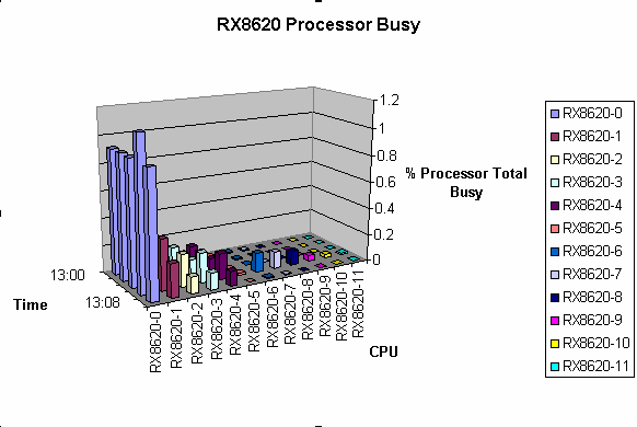
To adjust the chart, right click in the chart and choose an option from the pop-up menu.
Tips for viewing your data in the Excel Chart:
Use the 3-D View to rotate the chart.
If the collection intervals are all on a single day, you can choose to omit Column A from your graph selection. Add the date to the worksheet title for the chart, or to the Chart Title.
Glossary
- Actual or real workload
The actual or real workload is the work actually performed by the computer system. Ideally, the actual workload is identical to the business workload.
- Adapter
An adapter is a hardware interface between a device controller and a system backplane or bus.
- Analysis report
An analysis report is a report that identifies the effects of system parameter settings, hardware configurations, and workload mixes on the performance of any cluster node or the entire cluster system. This report provides conclusions with supporting evidence and makes recommendations.
- Analysis summary
The analysis summary is a short summary appearing in the analysis report after each node analysis. The summary contains the following information:
Number of Performance Manager records analyzed for the specific reporting period
Number of Performance Manager records that satisfied any rules
Number of Performance Manager records that did not satisfy any rules
Number of conclusions generated for the node being analyzed
- Archive
Archive is the act of compressing Performance Manager daily data records into history files, which can be used in place of daily data to create reports, models, and graphs.
- Auxiliary knowledge base
Auxiliary knowledge base is A collection of user-defined site-specific rules and thresholds that have been compiled with the rules compiler (name.KB) and used to augment the factory supplied rules.
- Auxiliary rules
Auxiliary rules are the source files containing user-defined site-specific rules and thresholds that collectively comprises the auxiliary knowledge base.
- Baseline load
A Baseline load is the Performance Manager's measurements of your existing system or cluster System. This data is stored in a model input file (.MDL).
- Baseline model
A baseline model is a model generated from historic or daily Performance Manager data. The model output provides a workload characterization report. An unmodified .MDL file, the baseline load, represents Performance Manager measurements of your existing system. The model generated from this file is known as the baseline model.
- Buffered I/O operation
A buffered I/O operation occurs each time an intermediate system buffer is used in place of the process context buffer.
- Business workload
A business workload is the work the business expects its computer to perform.
- Computer system
The computer system is all of the computer hardware on which business work is performed.
- Conclusions
Conclusions are Text displayed in an analysis report.
- CPU branch explicit
In a modeling context, the CPU branch explicit is the probable distribution of load across CPUs for a workload or transaction class. Probabilities must sum to one. This data is included in the model input file.
- Custom graph
A custom graph is a graph type which allows you to specify which Performance Manager data items to graph.
- Daily data files
Daily data files are created by the Performance Manager CPD data collector, one for each node in the cluster, each day. The filename has the following format:
PSDC$DATABASE:PSDC$nodename_yyyymmmdd.CPD
- Data cell
A data cell is the basic unit of data used to create analysis reports. This data is either retrieved directly from a field in a subrecord of a daily data record or derived from it. The data cell is typically used as a variable in a rule expression.
- Data collection error log
The data collection error log is an ASCII file common to the entire cluster system called PSDC$DATABASE:PSDC$DC.LOG. Errors that occur during data collection are recorded in this file.
- Data collection schedule
The data collection schedule is a user-defined schedule by which the Performance Agent determines when to record data and what data to record for each node in the cluster.
- Data collection synchronization
Data collection synchronization is a method used to correlate intervals measured on different nodes within a cluster system; those intervals must represent the same real time to make analysis effective.
- Data files
Data files are the files containing performance data from which reports and graphs are constructed.
- Data record
The data record contains performance data written by the data collector. The CPD data collector writes one data record for each two-minute interval.
- Database directory
The database directory is a directory located on a permanently mounted disk, accessible to every node in the cluster. The data collection process writes the daily data files to this area. Performance Manager software references this area via the system wide logical name PSDC$DATABASE.
- Dates file
The dates file contains a list of dates used to select data.
- Device
A device is a piece of hardware in the computer system. It performs measurable units of work.
- Direct I/O
The number of direct I/O operations performed per second. This illustration is tallied at the $QIO application interface layer.
- Disk branch by source
In a modeling context, disk branch by source is the probable distribution of load across disks by originating CPU for a workload or a transaction class. Probabilities must sum to one. This data is included in the model input file.
- Disk I/O
Disk I/O is the number of I/O operations per second for the device. This illustration is tallied at the physical device driver layer.
- Dump report
A dump report contains formatted output of data fields for each record of a Performance Manager daily data file or history file.
- Evidence
Evidence supports lines of performance data displayed in an analysis report.
- Factory rules
Factory rules are the performance rules supplied with the Performance Manager in the PSPA$EXAMPLES area in the file named PSPA$KB.VPR.
- Family name
Family name is an identifier for a group of workload definitions, also known as a workload (transaction or usergroup) family.
- Family type
There are two family types
Usergroup families contain workload definitions based on user criteria.
Transaction families contain workload definitions based on image and process data.
Specify either family with the /CLASSIFY_BY qualifier to control use of the family for the reporting facility.
- File type
A file type is specified by one of the following extensions in its name:
.COM Various command files
.CPD Cluster Performance Data file
.DAT Parameters and schedule file
.EXE Various image files
.HLB Parameter Editor help file
.KB Compiled rules Knowledge Base file
.LIB Model library file
.LIS A report file
.LOG Data collection process error log file
.MAR Sample macro application file
.MDL Model file
.name History file, name is history file descriptor; also, alternate data file name
.name_JOU History journal file
.REG A ReGIS graph written to a disk file
.TXT Holidays and message files
.VPR Performance Rules source file
- Granularity
Granularity is a Performance Manager parameter file element that specifies for each history file descriptor how often a history file is created.
- Hard page fault
A hard page fault occurs each time a process references a virtual page that is not in its working set and requires a read operation from disk, a hard page fault is generated.
- Histogram
A histogram is a (ASCII) graphic chronological chart showing resource use.
- History database
The history database is reduced data from the daily data files, which resides in the history files.
- History file
The history file contains data archived from the daily data files. The number of history files created and maintained depends upon the number of history file descriptors and the associated granularity. The filename has the form PSDC$DATABASE:PSDC$nodename_dd-mmm-yyyy_dd-mmm-yyyy.name.
- History file descriptor
The history file descriptor contains the description that Performance Manager uses to determine how to archive data to the file.
- Holidays file
The holidays file contains a list of holiday dates. The Performance Agent uses the holiday schedule on these dates. The file name is PSDC$HOLIDAYS.TXT.
- Hot files
Hot files are the most frequently accessed files on each disk. The Performance Agent collects hot file data when the length of a disk queue exceeds the HOTFILE_QUEUE setting.
- Interaction
An interaction with a device is a two-step process. First, a unit of work to be done (job, user, process, and so forth) enters the queue of the device. Then, the unit of work is serviced by the device (in a manner dependent on the queueing discipline) and departs the device. The concept may be generalized to the system as a whole. The set of device interactions required to process each unit of work is called a transaction.
- Interval
In the context of a history file, interval is an ADVISE EDIT ADD/HISTORY qualifier and a Performance Manager parameter file element.
In the context of a daily CPD data file, the interval for writing records is fixed at two minutes.
In the context of real-time displays, the interval is user-defined (default interval=10 seconds, minimum=1 second).
- Journal file
The journal file is when Performance Agent software creates one history journal file for each history file. These are used by the update process in conjunction with the daily data files to recreate corrupt or deleted history files. The filename has the form PSDC$DATABASE:PSDC$nodename_dd-mmm-yyyy_dd-mmm-yyyy.name_JOU. Do not delete these files. If they exist they are needed.
- Knowledge base
The knowledge base is a file consisting of Performance Manager performance rules used to analyze daily or historic Performance Manager data. It may be augmented using an auxiliary knowledge base.
- Measured workload
The measured workload is the workload that can be observed on the system. Ideally, the measured workload is identical to the actual workload, but specified in different terms.
The measured workload is specified by the resource demands it places on the actual system. These demands, or loadings, are given as the service times of the users at each device along with the number of expected transactions at each device.
- Model
A model is an abstraction of a system focusing on high-level performance characteristics.
- MODEL_TRANSACTIONS
Model_transactions are a default workload family defined in the parameters file. It can be used to characterize workloads in the transaction class for modeling.
- MODEL_USERGROUPS
Model_usergroups is a default workload family defined in the parameters file. It can be used to characterize workloads in the user group class for modeling.
- Modeling
Modeling is the process of gathering, organizing, and evaluating principal components of a system and the ways in which they interact for the purposes of understanding and predicting system behavior.
- MSCP
MSCP-Mass Storage Control Protocol. A software protocol used to communicate between a VAX or Alpha processor and a disk controller such as an HSC.
- OpenVMS Cluster
An OpenVMS Cluster is a highly integrated organization of AlphaServer and VSI Integrity server system–or VAX and VSI AlphaServer system–applications, operating systems, and storage devices.
- OTHER
All workload families have the catch-all workload OTHER to absorb process data that does not match the selection criteria of any defined workload.
- Parameters file
PSDC$PARAMS.DAT is the parameters file resides in the PSDC$DATABASE area and serves as a repository for workload characterizations, history file descriptors and other Performance Manager parameters.
- Performance Agent
The Performance Agent is a detached process that collects and records performance data for specified nodes in the cluster system according to a weekly schedule.
- Performance evaluation report
The performance evaluation report is a statistical report that helps you determine whether changes that you implemented (based on recommendations in the Analysis Report) improved or degraded system performance.
- Periodicity
Periodicity is a parameter file element for a history file descriptor that specifies how often the averaging cycle is restarted.
- Predefined graph
A predefined graph is a graph in which the Performance Manager defines the metrics plotted.
- Queue length
Queue length is the average number of outstanding requests, either waiting for or receiving service.
- Queueing network model
Queueing network model is a mathematical abstraction of a system where the computer system is represented as a network of queues. Each queue in the network is evaluated analytically.
- Raw data file
- Recommendation
A recommendation is the text presented in an analysis report that offers system tuning advice based on rules firing. See Rule conclusion.
- Residence time
Residence time is the time, in seconds, between image activation and image termination. Average time that a request spends while waiting for and receiving service.
- Response time
Response time is the elapsed time between the arrival of a request and the moment of completion. In the context of modeling, the interval between the moment a request arrives at a device and request completion at a device.
- Rule
A rule is one or more rule conditions that are evaluated when Performance Manager Analysis reports are generated. Rules are applied to daily or historic data. If all conditions for a rule are true then there is a rule occurrence. Rules are defined to expose areas of potential system problems. See Rule firing.
- Rule conclusion
A rule conclusion is a rule element. The conclusions are Performance Manager recommendations based on the conclusion text element of a rules file rule construct.
- Rule condition
A rule element. A rule condition is made up of one or more rule expressions. Describes the circumstances that must be true to cause a rule occurrence.
- Rule elements
The seven rule elements that can exist in a rule construct are as follows:
Brief Conclusion element
Conclusion element
Domain element
Evidence element
Occurrence element
Rule condition element
Rule ID element
- Rule evidence
A rule element. Data satisfying a rule occurrence in a Performance Manager analysis report. The evidence consists of data cell names and values. Typically these data cells are some of those contained in the rule expressions.
- Rule expressions
Components of rule conditions which may include the following:
Decimal values
Literal symbols
Tally data cells
Numeric data cells
Boolean data cells
Scan routine data cells
String operators
Numeric binary operators
Parentheses for precedence
- Rule firing
After all the data has been processed, when creating a report, the Performance Manager examines the number of rule occurrences for each rule. If the rule occurrence threshold is met for a particular rule, the rule is said to fire. For each rule that fires, an entry is made in the Analysis report. The entry may include evidence and conclusions.
- Rule identifier
A rule element. A five-character alphanumeric code enclosed in braces, for example, {M0010} which uniquely identifies a rule. (A zero for the second character is reserved for Digital use only.)
- Rule occurrence
Each time all the rule conditions for a given rule are true, there is one rule occurrence. See Rule firing.
- Rules compiler
The rules compiler generates a binary knowledge base file (name.KB)from an ASCII rules source file (name.VPR).
- Rules file
The rules file is a compiled knowledge base file (name.KB). A Performance Manager rules source file (name.VPR).
- Rules file constructs
The following five constructs can exist in a Rules File:
Comment construct
Disable construct
Literal construct
Rule construct
Threshold construct
- Saturation
Saturation is the point at which response time at a device becomes substantially higher than the service time.
- Schedule file
The schedule file is a file, PSDC$SCHEDULE.DAT, that resides in the PSDC$DATABASE area and controls when Performance Manager daily data is recorded.
- Shadow set
A shadow set is one or more compatible physical disk volumes connected together for volume shadowing and represented by a virtual unit. Thus, the term shadow set refers to the physical unit and the virtual unit.
- Soft page fault
Each time a process references a virtual page that is not in its working set but is in memory, a soft page fault is generated.
- Split I/O
Split I/O is the number of additional physical disk I/O operations required to complete a single user's I/O request, which could not be satisfied in a single I/O to a device.
- Transaction
A transaction is a quantifiable unit of work that typically delineates a single processing step in computer systems.
- Transaction class
A transaction class is a group of related transactions. They may be related by the function they perform, by the users who initiate them, or by other quantities you define. Transactions may also be determined by the system resource demands. The Performance Manager software generally refers to a transaction class as a workload.
- Transaction class workload
A transaction class workload is a workload that contains data bucketed by a workload definition defined in terms of images.
- Transaction workload family
A transaction workload family is a set of image based workload definitions.
- User defined graph
- Usergroup workload family
A usergroup workload family is a set of user based workload definitions.
- Utilization
The percentage of a resource's capacity being used.
- VAXcluster system
A multipurpose system configured by interconnecting or clustering VAX processors and storage controllers to provide increased capabilities for sharing data, distributing workloads, and providing greater system and data availability.
- VUP
VAX unit of processing speed. The VUP rating measures the CPU power of a system compared to a VAX 11/780. A VAX 11/780 has a VUP rating of 1.0.
- Wait time
Wait time, or queueing time, is the average time each request spends waiting in a queue for service. During this time, the request accomplishes no useful work. Wait time may be derived specifically for each device in the system or for the system as a whole.
- Workload
A representation of the actual system's resource demands. Performance Manager software reports graphs and capacity plans based on workloads. Workload definitions specify to Performance Manager software how to organize the system load into workloads.
- Workload definition
A workload definition can be one or more users, image names, or processes that represent units of work on the system. Workload definitions are identified and stored in the Performance Manager parameters file. The goal is to express the system's total workload in manageable and meaningful units against which Performance Manager can report. Use
ADVISE EDITto create, modify and delete workload definitions.A Transaction workload definition contains at least one image name. Typically this workload will contain images with similar resource demands.
A Usergroup workload definition contains a user specifier (such as accountname, username, processname, UIC code). Typically this workload will contain a group of users who belong to the same business unit, such as a department.
Transaction and Usergroup are terms applied to a workload by the
/CLASSIFY_BYqualifier.- Workload family
A workload family is a collection of workload definitions collectively representing the entire work on a computer system.
- Workload family name
A workload family name is a name that identifies a group of workloads that collectively constitute a unit called a family.
- Workload name
A workload name is a name that identifies a workload or workload definition.
- Workload selection criteria
A workload selection criteria is the criteria by which process data is assigned to a workload. A workload is selected when process data matches on either or both of a user specifier or image name.