VSI TCP/IP Services for OpenVMS Management
- Software Version:
- VSI TCP/IP Services Version 6.0
Preface
The TCP/IP Services product is the VSI implementation of the TCP/IP networking protocol suite and internet services for OpenVMS Alpha and OpenVMS VAX systems.
TCP/IP Services provides a comprehensive suite of functions and applications that support industry-standard protocols for heterogeneous network communications and resource sharing.
This manual provides system and network managers with information needed for the day-to-day management of the TCP/IP Services software product. This manual is best used in conjunction with the VSI TCP/IP Services for OpenVMS Management Command Reference manual.
See the VSI TCP/IP Services for OpenVMS Installation and Configuration manual for information about installing, configuring, and starting this product.
1. About VSI
VMS Software, Inc. (VSI) is an independent software company licensed by Hewlett Packard Enterprise to develop and support the OpenVMS operating system.
2. Intended Audience
This manual is for experienced OpenVMS and UNIX system managers and assumes a working knowledge of OpenVMS system management, TCP/IP networking, and TCP/IP terminology.
3. Document Structure
|
Chapters 1–5 |
Describes how to configure network interfaces, how to set up serial lines, and how to configure and manage routing. |
|
Chapters 6 and 7 |
Describes how to set up and manage the BIND server, resolver, and load broker components. |
|
Chapters 8–12 |
Describes how to set up the following network services:
|
|
Chapters 13–19 |
Describes how to configure network applications that let
users send and receive electronic mail from the internet,
establish login sessions with a remote host, and transfer
files. These network applications include:
|
|
Chapters 20 and 21 |
Describes how to configure, use, and manage the components that enable transparent network file sharing, including the NFS server and NFS client. |
|
Chapters 22–24 |
Describes how to configure and manage network printing services, including LPD/LPR, TELNETSYM, and PC-NFS. |
|
Appendices A, B, and C |
Provides appendixes that:
|
4. Related Documents
|
Manual |
Contents |
|---|---|
|
VSI TCP/IP Services for OpenVMS Concepts and Planning |
This manual provides conceptual information about TCP/IP networking on OpenVMS systems, including general planning issues to consider before configuring your system to use the TCP/IP Services software. This manual also describes the manuals in the TCP/IP Services documentation set and provides a glossary of terms and acronyms for the TCP/IP Services software product. |
|
VSI TCP/IP Services for OpenVMS Installation and Configuration |
This manual explains how to install and configure the TCP/IP Services product. |
|
VSI TCP/IP Services for OpenVMS User's Guide |
This manual describes how to use the applications available with TCP/IP Services such as remote file operations, email, TELNET, TN3270, and network printing. This manual explains how to use these services to communicate with systems on private internets or on the worldwide Internet. |
|
VSI TCP/IP Services for OpenVMS Management |
This manual describes how to configure and manage the TCP/IP Services product. Use this manual with the VSI TCP/IP Services for OpenVMS Management Command Reference manual. |
|
VSI TCP/IP Services for OpenVMS Management Command Reference |
This manual describes the TCP/IP Services management commands. Use this manual with the current manual. |
|
VSI TCP/IP Services for OpenVMS ONC RPC Programming |
This manual presents an overview of high-level programming using open network computing remote procedure calls (ONC RPC). This manual also describes the RPC programming interface and how to use the RPCGEN protocol compiler to create applications. |
|
VSI TCP/IP Services for OpenVMS Sockets API and System Services Programming |
This manual describes how to use the Sockets API and OpenVMS system services to develop network applications. |
|
VSI TCP/IP Services for OpenVMS SNMP Programming and Reference |
This manual describes the Simple Network Management Protocol (SNMP) and the SNMP application programming interface (eSNMP). It describes the subagents provided with TCP/IP Services, utilities provided for managing subagents, and how to build your own subagents. |
|
VSI TCP/IP Services for OpenVMS Guide to IPv6 |
This manual describes the IPv6 environment, the roles of systems in this environment, the types and function of the different IPv6 addresses, and how to configure TCP/IP Services to access the 6bone network. |
For a comprehensive overview of the TCP/IP protocol suite, you might find the book Internetworking with TCP/IP: Principles, Protocols, and Architecture, by Douglas Comer, useful.
5. VSI Encourages Your Comments
You may send comments or suggestions regarding this manual or any VSI document by sending electronic mail to the following Internet address: <docinfo@vmssoftware.com>. Users who have VSI OpenVMS support contracts through VSI can contact <support@vmssoftware.com> for help with this product.
6. OpenVMS Documentation
The full VSI OpenVMS documentation set can be found on the VMS Software Documentation webpage at https://docs.vmssoftware.com.
7. Conventions
| Convention | Meaning |
|---|---|
|
Ctrl/ x |
A sequence such as Ctrl/ x indicates that you must hold down the key labeled Ctrl while you press another key or a pointing device button. |
|
PF1 x |
A sequence such as PF1 x indicates that you must first press and release the key labeled PF1 and then press and release another key or a pointing device button. |
|
Return |
In examples, a key name enclosed in a box indicates that you press a key on the keyboard. (In text, a key name is not enclosed in a box.) |
... |
A horizontal ellipsis in examples indicates one of the
following possibilities:
|
. . . |
A vertical ellipsis indicates the omission of items from a code example or command format; the items are omitted because they are not important to the topic being discussed. |
|
( ) |
In command format descriptions, parentheses indicate that you must enclose the options in parentheses if you choose more than one. |
|
[ ] |
In command format descriptions, brackets indicate optional choices. You can choose one or more items or no items. Do not type the brackets on the command line. However, you must include the brackets in the syntax for OpenVMS directory specifications and for a substring specification in an assignment statement. |
|
[ |] |
In command format descriptions, vertical bars separate choices within brackets or braces. Within brackets, the choices are options; within braces, at least one choice is required. Do not type the vertical bars on the command line. |
|
{ } |
In command format descriptions, braces indicate required choices; you must choose at least one of the items listed. Do not type the braces on the command line. |
|
bold text |
This typeface represents the introduction of a new term. It also represents the name of an argument, an attribute, or a reason. |
|
italic text |
Italic text indicates important information, complete titles of manuals, or variables. Variables include information that varies in system output (Internal error number), in command lines (/PRODUCER= name), and in command parameters in text (where dd represents the predefined code for the device type). |
|
UPPERCASE TEXT |
Uppercase text indicates a command, the name of a routine, the name of a file, or the abbreviation for a system privilege. |
|
|
Monospace type indicates code examples and interactive screen displays. In the C programming language, monospace type in text identifies the following elements: keywords, the names of independently compiled external functions and files, syntax summaries, and references to variables or identifiers introduced in an example. |
|
- |
A hyphen at the end of a command format description, command line, or code line indicates that the command or statement continues on the following line. |
|
numbers |
All numbers in text are assumed to be decimal unless otherwise noted. Nondecimal radixes—binary, octal, or hexadecimal—are explicitly indicated. |
All numbers are decimal unless otherwise noted.
All Ethernet addresses are hexadecimal.
Chapter 1. Managing TCP/IP Services
Reviewing pertinent databases, logical names, and configuration guidelines (Section 1.1, ''Getting Started'').
Enabling support for DECnet over TCP/IP, and PATHWORKS (Advanced Server) (Section 1.2, ''Enabling PATHWORKS/Advanced Server and DECnet-over-TCP/IP Support'').
Creating user accounts and proxy identities (Section 1.3, ''Setting Up User Accounts and Proxy Identities'').
Configuring TCP/IP Services on an OpenVMS cluster (Section 1.4, ''Configuring a TCP/IP Cluster'').
Starting services with the auxiliary server (Section 1.5, ''Auxiliary Server'').
1.1. Getting Started
This manual assumes you installed and configured TCP/IP Services software with the configuration procedure SYS$MANAGER:TCPIP$CONFIG.COM, as described in the VSI TCP/IP Services for OpenVMS Installation and Configuration manual. This menu-driven procedure configures the software components you select or all of the TCP/IP Services software components. The "out-of-the-box" defaults are designed to get your system up and running as an internet host with minimal effort.
|
Database |
File Name |
|---|---|
|
BOOTP database |
SYS$COMMON:[SYSEXE]TCPIP$BOOTP.DAT ? |
|
Configuration database |
SYS$COMMON:[SYSEXE]TCPIP$CONFIGURATION.DAT |
|
Export database |
SYS$COMMON:[SYSEXE]TCPIP$EXPORT.DAT |
|
Hosts database |
SYS$COMMON:[SYSEXE]TCPIP$HOST.DAT |
|
Networks database |
SYS$COMMON:[SYSEXE]TCPIP$NETWORK.DAT |
|
Proxy database |
SYS$COMMON:[SYSEXE]TCPIP$PROXY.DAT |
|
Routes database |
SYS$COMMON:[SYSEXE]TCPIP$ROUTE.DAT |
|
Services database |
SYS$COMMON:[SYSEXE]TCPIP$SERVICE.DAT |
1.1.1. Logical Names
Logical names allow you to customize or modify component behavior. Logical names also point to directories, database files, and log files.
TCPIP$BOOTP (if the BOOTP service is configured)
TCPIP$CONFIGURATION
TCPIP$EXPORT
TCPIP$HOST
TCPIP$NETWORK
TCPIP$PROXY
TCPIP$ROUTE
TCPIP$SERVICE
Service-specific logical names should be defined while the service is not running. Always stop the service before defining logical names.
Most logical names require SYSTEM privileges in order to affect the service. You should use the /EXECUTIVE and /SYSTEM qualifiers on the DEFINE command line.
It is important to always use the standard, documented shutdown procedures to stop the services and to stop TCP/IP Services; otherwise, logical names may revert to their default definitions.
Many services reference service-specific configuration files. To specify different configuration options for the nodes in an OpenVMS cluster, you can modify service-specific logical name so that the configuration files are specific to each node. In clusters with a shared system disk, the default device (SYS$SYSDEVICE) is a cluster-common directory.
- Shut down the service:
$ @SYS$STARTUP:TCPIP$service_SHUTDOWN.COM - Enter the DEFINE command for the service-specific logical name:
$ DEFINE/SYS/EXEC logical-name SYS$SPECIFIC:[directory]logical-name
- Start the service:
$ @SYS$STARTUP:TCPIP$service_STARTUP
See individual component chapters in this manual for information on how specific components use logical names.
1.1.2. Modifying Your Configuration
After the initial configuration, you may want to reconfigure existing components or configure new ones, disable and re-enable components, add hosts, reconfigure routing, and so forth.
Note
You cannot use TCPIP$CONFIG to set up SLIP or PPP lines. See Chapter 3, "Configuring and Managing Serial Lines" for more information.
In some instances, TCPIP$CONFIG only partially configures a component (for example, when configuring a BIND name server). You may need to run additional setup programs or enter management commands to complete the configuration and fine-tune your environment.
Manually adding information, such as database records, that the configuration procedure cannot handle
Temporarily enabling or disabling a service
Configuring customized applications
Tuning performance
Troubleshooting
1.1.3. Saving Changes
SET commands modify the software dynamically, as it is running. Changes made in this manner are not saved permanently and are overwritten if they differ from settings in the permanent configuration database.
SET CONFIGURATION commands modify the permanent database but do not take effect until the next time the product starts up.
To make changes take effect immediately and modify permanent settings, enter both the interactive SET and permanent SET CONFIGURATION commands.
SET CONFIGURATION [NO]BIND
SET CONFIGURATION COMMUNICATION
SET CONFIGURATION ENABLE [NO]SERVICE
SET CONFIGURATION [NO]INTERFACE
SET CONFIGURATION [NO]NAME_SERVICE
SET CONFIGURATION NOMAP
SET CONFIGURATION PROTOCOL
SET CONFIGURATION SMTP
SET CONFIGURATION SNMP
SET CONFIGURATION START ROUTING
Note
Throughout this manual, all commands are assumed to be TCP/IP management commands. Any DCL commands that are mentioned are identified as such.
For a full description of the TCP/IP management commands and a discussion of how to use them, see the VSI TCP/IP Services for OpenVMS Management Command Reference manual.
1.1.4. Starting and Stopping the Software
$ @SYS$STARTUP:TCPIP$STARTUP
The startup procedure enables the configured services and initializes the configured network interfaces.
The TCPIP$STARTUP procedure has been modified to check the presence and installation of SSL3 images as recognized. If these checks fail, TCPIP$STARTUP will be unable to complete successfully, thus one of two error messages will be displayed.
If the required images are not found, you will get the following error message:
$ @sys$startup:tcpip$startup
%TCPIP-E-STARTFAIL, failed to start TCP/IP Services
-TCPIP-E-SSLNOTFOUND, required product SSL3 not found on system.
If SSL3$STARTUP has not been executed, thus the images are unrecognized, the following error message will be reported:
$ @sys$startup:tcpip$startup
%TCPIP-E-STARTFAIL, failed to start TCP/IP Services
-TCPIP-E-SSLNOTSTARTED, SSL3 has not been started.
$ @SYS$STARTUP:TCPIP$SHUTDOWN
Stops network communication
Disables active services
Deletes the network interface definitions
Deassigns defined logical names
Deletes installed images
$ @SYS$STARTUP:TCPIP$STARTUP.COM
SYS$STARTUP:TCPIP$SYSTARTUP.COM
SYS$STARTUP:TCPIP$SYSHUTDOWN.COM
The site-specific startup procedure is invoked after all the TCP/IP services have been started. These files are not overwritten when you install a new version of TCP/IP Services.
VSI recommends that you use the TCPIP$CONFIG configuration procedure to stop and start services. However, startup and shutdown files are provided for individual services, allowing you to stop and start individual components without impacting the operation of the remaining TCP/IP Services software.
This feature allows you to modify a service configuration without restarting the TCP/IP Services product. For example, you can shut down the LPD service, change its configuration parameters, and then restart it, without interrupting the other TCP/IP services that are running on the system.
SYS$STARTUP:TCPIP$ service_STARTUP.COM, a supplied command procedure that ensures the environment is configured appropriately and starts up the component specified by service.
SYS$STARTUP:TCPIP$ service_SHUTDOWN.COM, a supplied command procedure that shuts down a specific service component without affecting the other services that are running.
SYS$STARTUP:TCPIP$ service_SYSTARTUP.COM can be used to store site-specific startup commands.
This procedure is invoked by the appropriate service-specific startup procedure prior to running the service. Use the *_SYSTARTUP procedure to modify the behavior of the service each time the service or TCP/IP Services is restarted. For example, to enable debugging mode for DHCP, define the logical TCPIP$DHCP_DEBUG in the SYS$STARTUP:TCPIP$DHCP_SYSTARTUP.COM file. When DHCP next starts, it will run in debug mode.
SYS$STARTUP:TCPIP$ service_SYSHUTDOWN.COM can be used to store site-specific shutdown commands.
Service-specific startup and shutdown procedures, as well as configuration parameters, are described in the later chapters of this manual.
1.1.5. Editing Configuration Files
LPD/LPR
SMTP
IMAP
Field1: Value1 Field2: Value2
.
.
.Field names start in column 1, are terminated with a colon (:), and are not case sensitive.
Values vary depending on the field.
If a value consists of a list of items, specify them on multiple lines by pressing the Tab key before continuing the value on the subsequent lines. For example:Field1: Item1, TabItem2, TabItem3 Field2: Value2
Or specify each value as a separate instance of the same field. For example:Field1: Item1 Field1: Item2 Field1: Item3An alternative format is:Field1: Item1, Item2, Item3The maximum number of characters in a value is 500. Unless otherwise noted, a field's value is not case sensitive.
Fields described as Boolean have the following legal values:To turn the feature on
To turn the feature off
ON
OFF
TRUE
FALSE
1
0
YES
NO
To comment out a line, type an exclamation point (!) in column 1.
1.2. Enabling PATHWORKS/Advanced Server and DECnet-over-TCP/IP Support
TCP/IP Services software includes the PATHWORKS Internet Protocol (PWIP) driver and the PWIP ancillary control process (PWIP_ACP).
The PWIP driver allows OpenVMS systems that are running both the VSI PATHWORKS/Advanced Server and the TCP/IP Services software to communicate with personal computers running PATHWORKS client software. It also enables the DECnet-over-TCP/IP feature, which is included with the DECnet-Plus for OpenVMS Version 6.0 and later software. For more information about DECnet over TCP/IP, see the DECnet-Plus for OpenVMS documentation.
1.2.1. Starting and Stopping the PWIP Driver
SYS$STARTUP:TCPIP$PWIP_DRIVER_STARTUP.COM allows you to start up the PWIP driver.
SYS$STARTUP:TCPIP$PWIP_DRIVER_SHUTDOWN.COM allows you to shut down the PWIP driver.
SYS$STARTUP:TCPIP$PWIP_DRIVER_SYSTARTUP.COM can be used as a repository for site-specific definitions and parameters to be invoked when the PWIP driver is started.
SYS$STARTUP:TCPIP$PWIP_DRIVER_SYSHUTDOWN.COM can be used as a repository for site-specific definitions and parameters to be invoked when the PWIP driver is shut down.
$ @SYS$STARTUP:TCPIP$PWIP_DRIVER_STARTUP.COM
$ @SYS$STARTUP:TCPIP$PWIP_DRIVER_SHUTDOWN.COM
1.3. Setting Up User Accounts and Proxy Identities
You will need to set up accounts for local users, coordinate the establishment of corresponding accounts on remote systems, and create accounts for remote users who will be accessing server components on the local host.
When creating accounts for remote users, you can create one account for all remote users, an account for groups of remote users, or accounts for individual users. The strategy you use depends on your organization, system resources, and security needs.
Certain product components (for example, LPD, RSH, RLOGIN, and NFS) act as servers for remote clients. You control access to your system and to these services by giving remote users proxy identities. A proxy identity maps a user account on one host to an account on another host. The information you provide with each entry, along with the privileges you set for the account, lets you specifically grant or deny access to your system.
Communication proxy
A communication proxy provides an identity for remote users of RSH, RLOGIN, RMT/RCD, and LPD. For each host, be sure to define the host name and any aliases. Proxy entries are case sensitive. Be sure to use the appropriate case when adding entries for remote users. Enter the ADD PROXY command as follows:TCPIP> ADD PROXY user /HOST=host /REMOTE_USER=user
You can use wildcards when adding proxy entries for users on remote systems. For example, the following command provides the identity STAFF to any user on the remote host STAR:TCPIP> ADD PROXY STAFF /HOST=STAR /REMOTE_USER=*
NFS proxy
NFS proxies provide identities for users of NFS client, NFS server, and PC-NFS. In addition to host and user information, NFS proxies provide UNIX identities with UID/GID pairs. NFS proxies can specify access to the NFS client or the NFS server, or both.
For example, the following command provides the OpenVMS identity CHESTER for a local NFS client user with the UID/GID pair 23/34.TCPIP> ADD PROXY CHESTER /NFS=OUTGOING /UID=23 /GID=34 /HOST="orbit"
This user can access remote files from the NFS server
orbit.
See the VSI TCP/IP Services for OpenVMS Management Command Reference manual for a complete description of the ADD PROXY command. For a more complete discussion about UNIX style identities and how the NFS server and client use the proxy database, see Chapter 20, "Configuring and Managing the NFS Server".
1.4. Configuring a TCP/IP Cluster
If your host is part of an OpenVMS Cluster, you can use a cluster alias to represent the entire cluster or selected host members. In this case, the network sees the cluster as a single system with one name. Alternatively, you can configure clustering using a DNS alias, as described in Chapter 6, "Configuring and Managing BIND Version 9".
Note
The cluster name is not switched from a host if there are any active TCP connections to the cluster interface on that host.
A remote host can use the cluster alias to address the cluster as a single host or the host name of the cluster member to address a cluster member individually.
All of the TCP/IP services support automatic failover and can be run on multiple nodes in an OpenVMS Cluster. For example, if more than one host in the cluster is running the NFS server, the cluster can appear to the NFS client as a single host. For more information about configuring a specific service for cluster failover, refer to the chapter in this manual that discusses the particular service.
1.4.1. Setting Up an ARP-Based Cluster
Create the interfaces for all cluster members.
- Interactively specify an ARP-based cluster alias (for example, ALLOFUS). Enter:
TCPIP> SET INTERFACE QE0 /CLUSTER=ALLOFUS  /C_NETWORK=255.255.0.0 -
_TCPIP> /C_BROADCAST=128.44.55.0
- Make these settings permanent in the configuration database. Enter:
TCPIP> SET CONFIGURATION INTERFACE QE0 /CLUSTER=ALLOFUS -
_TCPIP> /C_NETWORK=255.255.0.0 /C_BROADCAST=128.44.55.0
The interface changes take effect the next time the product starts up.
Add the cluster host name or the cluster IP address to the database of the host. Enter the same information you use with the SET INTERFACE command.
Change the interface parameters (specified with the SET INTERFACE command) only after deleting and re-creating an interface.
1.5. Auxiliary Server
The auxiliary server is the TCP/IP Services implementation of the UNIX internet daemon
(inetd). In addition to standard inetd functions, the
auxiliary server provides access control and event logging.
The auxiliary server listens continuously for incoming requests and acts as a master server for programs specified in its configuration file. The auxiliary server reduces the load on the system by invoking services only as they are needed.
1.5.1. How the Auxiliary Server Works
The auxiliary server listens for connections on the internet addresses of the services that its configuration file (TCPIP$SERVICES.DAT) specifies. When a connection is found, it invokes the server daemon for the service requested. Once a server is finished, the auxiliary server continues to listen on the socket.
TCP/IP Services proxy account
Services database
Remote client
Local OpenVMS user authorization file (UAF)
In addition, users requesting services at the client can include their user account information as part of the command line.
Once a process is created, the auxiliary server starts the requested service. All services except RLOGIN and TELNET must have access to their default device and directories and to the command procedures within them.
1.5.1.1. Rejecting Client Requests
The maximum number of simultaneous processes for the requested service has been reached.
The request is from a host that is marked for rejection.
There is a problem with the target account or directory.
1.5.1.2. Configuring the Auxiliary Server
The postinstallation configuration procedure, TCPIP$CONFIG, creates an entry in the services database (TCPIP$SERVICE.DAT) for each service you configure. If you need to modify your initial configuration, run TCPIP$CONFIG or use the SET SERVICE command.
The configuration file TCPIP$SERVICE.DAT includes information about the service name, the socket and protocol type associated with the service, the user name under which the service should run, and any special options for the service program.
- Use the OpenVMS Authorize utility to create a restricted user account for the process. Use the following qualifiers when creating the account:
/NOINTERACTIVE
/NOBATCH
/NOREMOTE
/FLAGS=(RESTRICTED,NODISUSER,NOCAPTIVE)
For more information about creating restricted accounts, see the OpenVMS system security documentation.
Provide user account information that can be used when the network process is created. Plan your requirements carefully before setting privileges, quotas, and priorities to user accounts.
Provide the network process name.
The auxiliary server builds the network process name from the character string in the services database. Enter this string with the SET SERVICE command:TCPIP> SET SERVICE service /PROCESS_NAME=process
Note
For TELNET and RLOGIN, the process name is set by either the system or users.
- Set the maximum number of server processes that can run simultaneously. This number should not exceed the maximum number of sockets allowed on the system. To set the maximum number of processes that can connect to a service at the same time, enter the following TCP/IP management command:
TCPIP> SET SERVICE service-name /LIMIT=n
In this command, service-name is the name of the service to which the connections will be limited, and n is the number of connections that will be accepted by the service at one time.
To activate the change, disable the service using the DISABLE SERVICE command, and then enable it using the ENABLE SERVICE command.
- Make sure that the protections in the systemwide SYLOGIN.COM file are set appropriately. If they are not, enter the following DCL command:
$ SET PROTECTION=(W:RE) SYS$MANAGER:SYLOGIN.COM
To ensure that the services database has an entry for each service offered, enter the SHOW SERVICE command.
1.6. Enabling Services
TCPIP> ENABLE SERVICE
The ENABLE SERVICE command immediately changes the running system. The SET CONFIGURATION ENABLE SERVICE command causes the services to be enabled the next time TCP/IP Services starts up.
To specify the type of socket, include the /PROTOCOL qualifier on the SET SERVICE command line. For example, to specify stream sockets, enter /PROTOCOL=TCP. To specify datagram sockets, enter /PROTOCOL=UDP.
KEEPALIVE (for TCP communications)
BROADCAST (for UDP communications)
To set the socket options, include the /SOCKET_OPTIONS qualifier on the SET SERVICE command.
1.6.1. Setting Up Event Logging
TCPIP> SET SERVICE service-name /LOG_OPTIONS=ALLFor a list of all the logging options, see the SET SERVICE command description in the VSI TCP/IP Services for OpenVMS Management Command Reference manual.
Some product components provide additional event logging capabilities. See individual component chapters for more information.
Chapter 2. Configuring Interfaces
OpenVMS systems running TCP/IP Services communicate with other internet hosts over a variety of physical media. Because TCP/IP is independent of the underlying physical network, IP addresses are implemented in the network software, not the network hardware. (See the TCP/IP Services Software Product Description for a complete list of supported media.)
How to configure network controllers (Section 2.2, ''Configuring Network Controllers'')
How to configure network interfaces (Section 2.3, ''Configuring Network Interfaces'')
2.1. Key Concepts
A network controller is the hardware connection between a computer system and a physical network. Controllers perform the packet channeling to and from the physical medium of your network, usually a cable.
The network interface is a logical network controller — a software component that communicates with your network software and the network controller.
For each interface, you can enable or disable the interface, set the subnet mask, and assign IP and broadcast addresses.
2.2. Configuring Network Controllers
Note
Hardware installation and configuration instructions are specific for the various network controllers. Be sure to read the instructions provided with your new hardware before installing.
2.3. Configuring Network Interfaces
The TCP/IP Services product supports one local software interface for loopbacks and one or more physical network interfaces for each physical network controller.
SET INTERFACE
SET NOINTERFACE
SET CONFIGURATION INTERFACE
SET CONFIGURATION NOINTERFACE
Note
If you are redefining an existing interface, enter the SET NOINTERFACE command before you enter the SET INTERFACE command.
2.3.1. Specifying the Interface
One letter indicating the interface type
Interface types indicate the type of controller. The following table shows the letters you can use to indicate each type of controller:For this controller
Use this interface type
ATM
I, L
Ethernet
B, C, D, F, I, N, O, Q, R, S, W, X, Z
FDDI
A, C, F, Q, R, W
Token Ring
C, R
PPP/SLIP
S
Local (loopback)
L
- One letter indicating the interface class
For this controller
Use this interface class
ATM
F
Ethernet
E
FDDI
F
Token Ring
T
PPP
P
Serial
L
X25
X
Local (loopback)
O
An integer indicating the controller number. Controller numbers are decimal numbers in the range of 0 through 25, corresponding to OpenVMS hardware controller letters A through Z. The default is 0.
Primary interfaces for Ethernet controllers have names in the range SE, SE0, SE1, SE2, … SE24, SE25.
Interfaces for PPP controllers have names in the range PP, PP0, PP1, … PP998, PP999.
Note
OpenVMS network devices are always template devices and are enumerated as FWA0, FWB0, FWC0, ...FWY0, FWZ0.
If the system has multiple interfaces, you can configure failSAFE IP to provide automatic failover from one interface to the next. This is useful if an interface goes offline or fails. For more information, see Chapter 5, "Configuring and Managing failSAFE IP".
2.3.2. Specifying the Network Mask
An IP address consists of a network number and a host number. The network mask is the part of the host field of the IP address the identifies the network. Every host on the same network must have the same network mask. To specify the network mask, use the /NETWORK_MASK qualifier.
The bits representing the network fields to 1
The bits representing the host field to 0
You can also divide the host field into a site-specific network and host field.
2.3.3. Specifying Additional IP Addresses
Associate multiple addresses to an existing interface.
You can use the
ifconfigutility to associate multiple addresses with an existing interface. There is no limit to the number of aliases that can be created, and ranges of network addresses can be easily created. You should include theifconfigcommand in SYS$STARTUP:TCPIP$SYSTARTUP.COM to ensure the network aliases are re-created whenever TCP/IP Services is restarted.For example, assume interface WF0 exists with a network address of 10.10.1.100 and a 24-bit subnet mask. To add an alias with an address of 10.10.2.100 with a 24-bit subnet mask, follow these steps:- Define foreign commands:
$ @SYS$MANAGER:TCPIP$DEFINE_COMMANDS.COM
- Display the current interfaces. Use quotation marks to preserve case. For example:
$ netstat -n "-I" wf0
Name  Mtu   Network     Address      Ipkts Ierrs    Opkts Oerrs  Coll
WF0   4470
<Link>    0:0:f8:bd:bc:22     3049700  0  2976912   0     0
WF0   4470  10.10.1     10.10.1.100  3049700     0  2976912   0     0
- Add the network alias:
$ ifconfig wf0 alias 10.10.2.100/24
- Display the current interfaces. For example:
$ netstat -n "-I" wf0
Name  Mtu   Network     Address      Ipkts Ierrs   Opkts Oerrs  Coll
WF0   4470
<Link>    0:0:f8:bd:bc:22   049700     0  2976912   0     0
WF0   4470  10.10.1     10.10.1.100  3049700     0  2976912   0   0
WF0   4470  10.10.2     10.10.2.100  3049700     0  2976912   0   0
A range of network addresses can be associated with an interface by using thealiaslistparameter to theifconfigcommand. For more information, enter the following command:TCPIP> HELP IFCONFIG PARAMETERS
Configure a pseudo-interface.
A pseudo-interface can be created to associate another network address with the same physical interface also. Use the SET INTERFACE TCP/IP Services management command to create a pseudo-interface. See Section 4.4.3, ''Extending Routing'' for more information.
Chapter 3. Configuring and Managing Serial Lines
A serial connection is made between two systems using modems and telephone lines or other serial lines. TCP/IP Services supports serial connections using the PPP (Point-to-Point Protocol) and SLIP (Serial Line IP) protocols. SLIP includes CSLIP (compressed SLIP). You can use any standard OpenVMS terminal device as a PPP or SLIP line. (PPP is available for OpenVMS Alpha systems only.)
How to set up a PPP interface (Section 3.2, ''Setting Up a PPP Interface (Alpha Only)'')
How to set up a SLIP interface (Section 3.3, ''Setting Up a SLIP Interface'')
How to solve serial line problems (Section 3.4, ''Solving Serial Line Problems'')
3.1. Key Concepts
If your OpenVMS system is part of a large network, you will probably use both PPP and SLIP for your serial connections. As an Internet standard, PPP is often preferred because it ensures interoperability between systems from a wide variety of vendors. PPP provides a way for your OpenVMS Alpha system to establish a dynamic IP network connection over a serial line without an additional router or additional server hardware.
SLIP has been in use for a longer period of time and is available for most terminal servers and in most PC implementations of TCP/IP. Because SLIP and PPP do not communicate with each other, hosts wanting to communicate must use the same protocol. For example, if your terminal server supports only SLIP, remote hosts that connect through this server must also use SLIP.
3.1.1. PPP and SLIP
One of the largest applications for IP over serial lines is dialup access. With this type of configuration, the OpenVMS host answers calls and establishes a connection initiated by a user on a client host. The client host can be another OpenVMS system, a UNIX system, or a PC. Or users on the host can originate the dialup connection to a remote host or terminal server running the same protocol.
Dedicated serial lines running PPP or SLIP can also be used to connect separate LANs into a single WAN. In such a configuration, the host at each end of the serial connection is always the same; no other hosts are allowed to connect to either serial device.
3.1.2. Assigning an IP Address to Your PPP or SLIP Interface
Every network interface must have its own unique IP address. Interfaces cannot share IP addresses.
If you configure PPP interfaces for multiple remote hosts, the remote hosts can obtain their individual IP addresses from your host when they connect. Similarly, you can configure a PPP interface on your system without knowing your own IP address and obtain it when you connect to a remote system.
Before establishing SLIP communication with a remote host, however, you must obtain the IP address for the host's serial interface and assign IP addresses for each interface you configure on the local host.
When using SLIP, consider placing each serial line in a separate subnetwork. You accomplish this by assigning the same subnet mask for the interfaces at either end of the link.
If you need to use an address in the same subnetwork as your site LAN, use the proxy Address Resolution Protocol (ARP) feature (see Section 3.3.4, ''Connecting a Host to the LAN'').
3.1.3. Serial Line Internet Protocol
|
Character |
Function |
Hex Value |
Decimal Values |
|---|---|---|---|
|
END |
Marks the end of the datagram. When the receiving SLIP encounters the END character, it knows that it has a complete datagram. |
C0 |
192 |
|
ESC |
Indicates the end of the SLIP control characters. |
DB |
219 |
The SLIP starts by sending an END character. If END is encountered within the datagram as data, the SLIP inserts an escape character, sending the two-character sequence DB DC instead. If the ESC character appears within the datagram as data, it is replaced with the two-character sequence DB DD. The datagram ends with the END character after the last byte in the packet is transmitted.
There is neither a standard SLIP specification nor a defined maximum packet size for the SLIP. The TCP/IP Services implementation of SLIP accepts 1006-byte datagrams and does not send more than 1006 bytes in a datagram.
Compressed SLIP provides header compression that is beneficial for small packets and low-speed serial links. Header compression improves packet throughput. You can enable the CSLIP by means of the /COMPRESS qualifier when you enter a SET INTERFACE command. See Table 3.3, ''Command Qualifiers Used for Configuring SLIP'' for more information.
3.1.4. Point-to-Point Protocol
PPP uses a frame format that includes a protocol field. The protocol field identifies the protocol (for example, IP, DECnet, or OSI) to be used for communication between the two hosts. The PPP defines the network frame in a 5-byte header and 3-byte trailer. A PPP frame starts and ends with the control byte 7E hex (126 decimal). The address and control bytes are constant. The 2-byte protocol field indicates the contents of the PPP frame.
3.2. Setting Up a PPP Interface (Alpha Only)
SET INTERFACE PP n, where n is the number of the interface, takes effect immediately and stays in effect until the next TCP/IP Services shutdown.
SET CONFIGURATION INTERFACE PP n, where n is the number of the interface, makes the change part of the permanent configuration and takes effect at the next TCP/IP Services startup.
Note
Specifying PP without the interface number is equivalent to specifying PP0.
If you enter a SHOW INTERFACE command, the address does not appear until a PPP connection is actually established.
|
Qualifier |
Description |
|---|---|
|
/COMPRESS=[ON |OFF |AUTOMATIC] |
Optional. The default is ON. Use to negotiate header compression. |
|
/DESTINATION=[ host_name | IP_address] |
Optional. The default is no destination host. If you do not specify the client host's address, the PPP obtains the correct address from the client host. If the host is used as a dialup provider, use this command to specify a unique IP address for a client. In this case, you must also specify your host address with the /HOST qualifier. |
|
/HOST=[ host_name | IP_address] |
Required when setting up a host as a dialup provider; otherwise optional. Host name or IP address using the interface. If your host is multihomed, specify the unique IP address if the two IP addresses map to the same host name. |
|
/NETWORK_MASK= IP_address |
Optional. The subnet mask of the local PPP interface in dotted-decimal notation. |
|
/SERIAL_DEVICE= device |
Required for hard-wired or dedicated modem connections. Identifies the OpenVMS device name assigned to the PPP interface, for example, TTA1. |
3.2.1. Setting Up Your Host for PPP Connections
A PPP dialup provider answers modem calls from PPP clients, assigns IP addresses, and establishes PPP connections initiated by client hosts.
Typically, a PPP dialup provider is permanently connected to the network through an interface such as Ethernet. The dialup provider services PPP clients that initiate temporary, dialup connections because they do not have permanent connections.
- A PPP client establishes a temporary PPP connection to a dialup provider or a terminal server.
Note
For information about establishing a PPP client connection from a UNIX system, refer to the UNIX documentation. For a connection from a PC, refer to the PC's dialup networking instructions. You will need to configure your modem correctly as outlined in the Section 3.2.1.2, ''Configuring the Modem''.
|
Step |
Task |
OpenVMS Dialup Provider |
OpenVMS Client |
|---|---|---|---|
|
1 |
Install the correct terminal driver. |
Yes |
Yes |
|
2 |
Configure your modem. |
Yes |
Yes |
|
3 |
Set up an asynchronous port for modem connections. |
Yes |
Yes |
|
4 |
Configure an interface for a serial PPP connection. |
Yes |
Optional |
|
5 |
Enable IP forwarding and dynamic routing, as appropriate. |
Yes |
No |
|
6 |
Initiate a PPP connection. NETMBX and OPER privileges required. |
No |
Yes |
3.2.1.1. Installing the Terminal Driver
$ RUN SYS$SYSTEM:SYSMAN

SYSMAN> IO CONNECT VTA0 /NOADAPTER /DRIVER=SYS$TTDRIVER
SYSMAN> EXIT
After you run SYSMAN, confirm that the VTA0 device was created. For more information about SYSMAN and its parameters, see the VSI OpenVMS System Management Utilities Reference Manual, Volume II: M–Z.
http://ftp.service.digital.com/public/vms/axp/v7.1/alppppd01_071.A-DCX_AXPEXE
http://ftp.service.digital.com/public/vms/axp/v7.1/alppppd01_071.CVRLET_TXT
3.2.1.2. Configuring the Modem
Make sure the serial port and modem cable support modem control signals. (VSI's BC22F cable is an example of such a cable.)
Determine whether there are any baud rate restrictions associated with your phone line or on your connecting cable (when using a null modem or modem eliminator).
Adjust the settings on your modem to enable AT commands, as appropriate for your modem. Some modems require you to set DIP switches, while others require you to specify software settings.
Sample DIP switch configuration settings for U.S. Robotics Courier modems are as follows. Note the following designations in these samples:- X = setting on (although different settings might work)
- X** = setting on (required)
Dialup provider settings:DTR normal X** DTR always on Verbal result codes X Numeric results codes Suppress result codes X** Display result codes Echo offline commands X No echo offline commands Auto answer on ring X** Suppress auto answer Normal carrier detect X** Carrier detect override Display all results codes X Result codes orig. mode only Disable AT command set Enable AT command set X Disconnect with +++ No disconnect with +++ X Load NVRAM defaults X Load &FO settings
Client settings (defaults):DTR normal X DTR always on Verbal result codes X Numeric results codes Suppress result codes Display result codes X Echo offline commands X No echo offline commands Auto answer on ring Suppress auto answer X Normal carrier detect X Carrier detect override Display all results codes X Result codes orig. mode only Disable AT command set Enable AT command set X** Disconnect with +++ X No disconnect with +++ Load NVRAM defaults X Load &FO settings
If possible, also configure the modem so that it does not assert the Data Terminal Ready (DTR) signal until it asserts the Carrier Detect (CD) signal. This configuration ensures that the terminal driver does not drop the DTR signal prematurely.
3.2.1.3. Setting Up an Asynchronous Port
Setting up the PPP dialup provider
Enter the SET TERMINAL command and qualifiers appropriate for your modem connection. (Note that some qualifiers require LOG_IO or PHY_IO privilege, or both.) For example:$ SET TERMINAL TTA0: /ALTYPEAHD /AUTOBAUD /DIALUP /DISCONNECT /EIGHTBIT - _$ /MODEM /NOHANGUP /NOHOSTSYNC /NOPASTHRU /NOREADSYNCH /NOTTSYNCH - _$ /PERMANENT /TYPE_AHEAD
Where:/ALTYPEAHD
Creates a permanent, alternate type-ahead buffer. (The system parameter TTY_ALTYPADH determines the size of the type-ahead buffer.) Helpful when transferring larger files. This qualifier is required.
/AUTOBAUD
Detects the incoming baud rate.
/DIALUP
Specifies that the terminal is a dialup terminal. This qualifier is required.
/DISCONNECT
Ensures that the process is disconnected if the line detects a hangup.
/EIGHTBIT
Sets the terminal to use the 8-bit ASCII format. This qualifier is required.
/MODEM
Specifies the use of a modem. This qualifier is required.
/NOHANGUP
Does not hang up the modem when the client logs off. This is the default. This qualifier is required.
/NOHOSTSYNC
Does not allow the use of Ctrl/S or Ctrl/Q functions from the terminal to stop or resume transmission when the input buffer is full or empty. This is the default.
/PASTHRU
The terminal passes format-type data, such as carriage returns and tabs, to an application program as binary data. This is the default.
/NOREADSYNCH
Does not allow the use of Ctrl/S or Ctrl/Q functions to synchronize data transmitted from the terminal. This is the default.
/NOTTSYNCH
Does not allow transmission to be stopped or resumed by entering Ctrl/S or Ctrl/Q, respectively.
/PERMANENT
Saves the settings.
/TYPE_AHEAD
Enables remote modems. Must be set. The terminal accepts unsolicited input to the limit of the type-ahead buffer. This is the default.
For detailed information about these and other SET TERMINAL qualifiers, see the VSI OpenVMS DCL Dictionary: N–Z.
Setting up the PPP client (OpenVMS Alpha only)
Enter the SET TERMINAL command and qualifiers appropriate for your connection, as listed for the dialup provider, with the exception of /AUTOBAUD.
Set the baud rates using the /SPEED=(input-rate,output-rate) qualifier. If the rates are the same, specify /SPEED= rate (for example, /SPEED=9600).
3.2.1.4. Configuring a PPP Interface
Configuring the PPP dialup provider
Use the SET INTERFACE command and qualifiers to configure the interface for a serial PPP connection and assign a host name, IP address, network mask, and IP address for the client host, as applicable:TCPIP> SET INTERFACE PP n /SERIAL_DEVICE=TT n: /HOST= IP_address - _TCPIP> /NETWORK_MASK= IP_address /DESTINATION= IP_address /COMPRESS=AUTO
In this command:n is the controller name and unit number.
The /HOST address is the IP address.
The /NETWORK_MASK IP address is required if your network uses subnets.
The /DESTINATION address is the IP address assigned to the client host making a connection request. This address always overrides the client's own IP address, if the client has one.
/COMPRESS=AUTO turns off IP header compression unless the client uses it.
Configuring the PPP client (OpenVMS Alpha only) (Optional)
Use the SET INTERFACE command and /HOST qualifier to assign an IP address:TCPIP> SET INTERFACE PP n /SERIAL_DEVICE=TT n: /HOST= IP_address
In this command, n is the interface number. If you omit the interface number, PP0 is used.
If you do not specify your host's IP address using SET INTERFACE, the dialup provider or terminal server provides an IP address after the connection is established.Note
If the connecting client host has only a loopback and tunnel interface defined:A default route to the PPP interface is added to the routing table when the connection is established.
The IP address of the PPP interface is assigned to the logical names TCPIP$INET_HOSTADDR and UCX$INET_HOSTADDR (for backward compatibility).
3.2.1.5. Enabling IP Forwarding (Dialup Provider Only)
TCPIP> SET PROTOCOL IP/FORWARD
TCPIP> SET CONFIGURATION PROTOCOL IP/FORWARD
sysconfig utility. First, define the TCP/IP Services foreign
commands:$ @SYS$MANAGER:TCPIP$DEFINE_COMMANDS.COM
sysconfig commands: $ sysconfig -r inet ipforwarding=1 $ sysconfig -r inet ipgateway=1 $ sysconfig -q inet
Note
These changes affect the running system only. To make permanent changes to the system, modify the TCPIP$ETC:SYSCONFIGTAB.DAT database as described in the VSI TCP/IP Services for OpenVMS Tuning and Troubleshooting guide.
To send notifications automatically on all connected LANs when new hosts or networks become reachable, use dynamic routing with the /SUPPLY option. For example, every time a PPP link is set up to a new subnetwork, RIP (Routing Information Protocol) advertises a corresponding route.
TCPIP> START ROUTING /SUPPLY
TCPIP> SET CONFIGURATION START ROUTING /SUPPLY
If your PPP and Ethernet interfaces are in the same network, a route is created automatically for the client hosts and an ARP proxy is advertised.
3.2.1.6. Initiating a PPP Connection
You use the OpenVMS PPP utility (PPPD) and associated commands to establish and manage a temporary PPP connection from an OpenVMS Alpha client host to an OpenVMS dialup provider or terminal server. Note that NETMBX and OPER privileges are required to establish a successful connection and to display OPCOM messages.
|
Command |
Function |
|---|---|
|
CONNECT |
Establishes a network connection through the current physical port or a specified remote port. |
|
DIAL_OUT |
Allows direct access to a device in order to dial out over a modem or link to an external device. |
|
DISCONNECT |
Terminates the network connection and returns control to the terminal driver. |
|
EXIT |
Leaves the utility and returns you to the DCL command prompt ($). |
|
HELP |
Displays help text for PPPD commands. |
|
SET |
Determines the device and line characteristics for the specified terminal. |
|
SHOW |
Displays the device and line characteristics of the specified terminal. |
Confirm that you have NETMBX and OPER privileges.
Use the PPPD command DIAL_OUT and specify the terminal device. After the
atdtcommand, enter the telephone number of the dialup provider or terminal server. (With some modems, you might need to type the number again until dialing begins.)For example:$ PPPD PPPD> DIAL_OUT TTA0 Type control-~ to send a break control-\ to disconnect control-@ to switch to a Point-to-Point connection. atdt 8671234- If you are connecting to another OpenVMS system, log in to the system after you dial up, and enter the following commands to establish the connection:
$ PPPD
PPPD> CONNECT
To end the connection, enter the DISCONNECT TT n command at the PPPD> prompt and log out.
- If you are connecting to a terminal server, enter the CONNECT PPP prompt at the LOCAL> prompt. An informational message will confirm the PPP connection:
LOCAL> CONNECT PPP

Local -561- Starting SLIP or PPP datalink session
%PPPD-I-CONNECTTERM, converting connection on device _TTA0: to a
Point-to-Point connection
To end the connection, enter DISCONNECT TT n at the PPPD> prompt. After the connection is terminated, an OPCOM message is displayed. For example:%%%%%%%%%%% OPCOM 23-APR-1998 15:44:32.10 %%%%%%%%%%% Message from user XYZnet on JONES %TCPIP-S-PPPDISCONN, Disconnected PPP Interface PP1 on TTA0
3.2.2. Removing the PPP Configuration
- If you created a PPP interface, return the associated terminal port to general use. Enter:
TCPIP> SET NOINTERFACE PPnIn this example, n is the number of the interface. If you omit the interface number, PP0 is assumed.
If you added special route and proxy entries with the PPP line, remove them.
If you changed any terminal settings in preparation for PPP, restore them. Enter the DCL command SET TERMINAL, and wait for the modem to reset and free the port and phone line.
3.3. Setting Up a SLIP Interface
Configuring the network interface for SLIP is the same as configuring the interface for Ethernet connections. In this case, the network interface is the modem connection. Remember that before you can configure a SLIP line, you must choose an IP address for the interface at each end of the line and establish a physical connection.
SET INTERFACE SLn, where n is the number of the interface. If you omit the interface number, SL0 is assumed. This command takes effect immediately and stays in effect until the next TCP/IP Services shutdown.
SET CONFIGURATION INTERFACE SLn, where n is the number of the interface. If you omit the interface number, SL0 is assumed. This command makes the change part of the permanent configuration. The change takes effect at the next product startup.
|
Qualifier |
Description |
|---|---|
|
/[NO]AUTO_START |
Optional. The default is /AUTO_START. Automatically creates the interface on startup. |
|
/COMPRESS=[ON |OFF |AUTOMATIC] |
Optional. The default is no compression. Enables or disables TCP header compression (CSLIP). With /COMPRESS=AUTOMATIC, compression remains off unless the remote host begins to use it. |
|
/[NO]FLOWCONTROL |
Optional. The default is No flow control. Enables the special handling of XON and XOFF characters to work properly with modems that are configured to interpret these characters locally. Specify /FLOWCONTROL only if the host at the other end of the line is another host running TCP/IP Services. If you cannot use /FLOWCONTROL, configure your modem to pass all the XON and XOFF characters through transparently. |
|
/HOST=(host_name, IP_address) |
Required. Host name or IP address of the local host. If your host is multihomed, you must specify an address in dotted-decimal notation. |
|
/NETWORK_MASK= subnet_address |
Required. The subnet mask of the local SLIP interface in dotted-decimal notation. |
|
/SERIAL_DEVICE= device |
Required for hard-wired or dedicated modem connections. Optional for dynamic connections. Identifies the OpenVMS device name assigned to the SLIP interface, for example, TTA1. |
TCPIP> SET INTERFACE SL5 /HOST=CROW /NETWORK_MASK=255.255.255.0 -
_TCPIP> /SERIAL_DEVICE=TTA3 /COMPRESS=ON /FLOWCONTROL
3.3.1. Setting Up Hard-Wired SLIP Lines
Establish a physical connection. Plug in a serial cable between the two host systems or ensure that they are both cabled to opposite ends of a leased line.
Obtain an IP address if necessary.
Configure the SLIP interface. Enter the SET INTERFACE command with the /HOST and /SERIAL_DEVICE qualifiers, which are required.
3.3.2. Setting Up SLIP Dialup Lines
You can configure either a terminal server port or an OpenVMS system to answer dialin calls.
Configure the appropriate settings for the terminal port to which you will connect. Begin a dialog of dialing (or answering) commands with your modem. The specific required commands depend on the type of modem you are using.
For example, to prevent the modem from hanging up when you exit the DTE session to bring up the SLIP line, enter the following command:$ SET TERMINAL TTA2 /PERMANENT /MODEM /NOHANGUP
To disable interactive logins on the line, enter the following command:$ SET TERMINAL TTA2 /PERMANENT /NOTYPEAHEAD
Any SLIP data that arrives before you enter the SET INTERFACE command is ignored. Otherwise, this command triggers the creation of a new interactive login process.
To enable interactive logins after a user sends a Break, enter the following command:$ SET TERMINAL TTA2 /PERMANENT /NOAUTOBAUD /SECURE_SERVER
Configure the modem. Enter the appropriate commands to dial the telephone and establish communication.
Unless you are setting up a SLIP line between two hosts running TCP/IP Services and plan to use the /FLOWCONTROL qualifier at both ends, disable modem recognition of XON and XOFF characters. (If SLIP packets have Ctrl/S and Ctrl/Q characters embedded in them as data, you must prevent the modem from trying to interpret these characters.)
Either use hardware flow control or disable flow control entirely. The following examples disable all flow control.- With a DECmodem V32 in AT command mode, set the following values:
AT%F0— No speed buffering flow controlAT%M0— Disable speed buffering (optional)
- With a DECmodem V32 in DMCL mode, set the following values:
SET P2/SBUSET P1/SBUprompts appropriate_answers
- With a U.S. Robotics Sportster modem, set the following values:
AT&B0— Variable, follows connection rate (optional)AT&H0— Flow control disabledAT&I0— Software flow control disabled
Obtain IP addresses if necessary.
- To dial in, follow these steps:
- Enter the SET HOST /DTE command:
$ SET HOST /DTE TTnx - Type the telephone number. For example:
atdt telephone_number The connected system displays its interactive (command mode) prompt. You are talking to the terminal server and can now make the connection.
The terminal server is a DECserver 700 terminal server.
The user directs the modem to dial the telephone number 222-2222.
The password prompt of the terminal server is
#.The terminal server's current login password is
hootowl.The terminal server's prompt is
Local>.The user types Ctrl/\ (Ctrl key plus backslash) to escape from the terminal server to the SLIP host.
The user defines interface SL2 and identifies it as SLIP device TTA1: with IP address 1.2.3.4. Communication on this line will use CSLIP.
$ SET HOST /DTE TTA2

%REM-I-TOQUIT, connection established
Press Ctrl/\ to quit, Ctrl/@ for command mode

atdt 2222222

CONNECT 9600

# hootowl (not echoed)

Network Access SW V1.5 for DS700-16
(c) Copyright 1994, Digital Equipment Corporation - All Rights Reserved
Please type HELP if you need assistance

Enter username>SLIP-USER

Local> CONNECT SLIP
Ctrl/\

TCPIP> SET INTERFACE SL2 /HOST=1.2.3.4 /NETWORK_MASK=255.255.255.0 -
_TCPIP> /SERIAL_DEVICE=TTA1: /COMPRESS=ON
3.3.3. Setting Up Your Host as a SLIP Dialup Provider
You can configure your host to answer calls and establish connections initiated by users on remote hosts.
Over the line you will define as a SLIP line, dial in to the host.
Log in to the remote host.
Enter an appropriate SET INTERFACE command with the /SERIAL_DEVICE qualifier to turn the line into a SLIP line.
For example, the following command creates a SLIP interface named SL5, using the terminal device associated with the session where the command is entered.TCPIP> SET INTERFACE SL5 /HOST=192.208.35.5 /SERIAL_DEVICE=TT
Log out.
As soon as you log out, your terminal port becomes a SLIP interface. Without causing the modem to hang up, start SLIP on the remote system.
To facilitate connection setup for end users, create a dedicated user name for each remote host that dials in. These users need to have a LOGIN.COM procedure that invokes appropriate SET TERMINAL commands and TCP/IP management SET INTERFACE commands, terminating with a LOGOUT command. Every user should specify a different SLIP interface name and host name (or IP address). These users require the OPER privilege to create interfaces.
TCPIP> SET PROTOCOL IP /FORWARD

TCPIP> SET CONFIGURATION PROTOCOL IP /FORWARD
TCPIP> START ROUTING /SUPPLY

TCPIP> SET CONFIGURATION START ROUTING /SUPPLY
3.3.4. Connecting a Host to the LAN
You can make your SLIP-connected host appear as if it were directly connected to the LAN. This is possible using a proxy ARP server (usually the same host that is acting as a SLIP gateway into the LAN).
To use proxy ARP (Address Resolution Protocol), assign to the remote host an IP address in the same subnetwork as the LAN. As other hosts on the LAN attempt to communicate with the remote host, the SLIP gateway answers ARP queries for the remote host by giving its own LAN address. The gateway then forwards packets across the SLIP line.
Many DECserver terminal server products support SLIP connections and implement proxy ARP. If you dial in from an OpenVMS host to a terminal server, the terminal server automatically detects your IP address and begins responding to ARP queries, forwarding packets as necessary.
To use proxy ARP with a DECserver terminal server, assign an IP address in the same subnetwork as the terminal server.
An IP address has not already been associated with your port.
Header compression is available, if you plan to use it.
3.3.5. Setting Up a SLIP Gateway with Proxy ARP
It is also possible to set up your host as a SLIP gateway with proxy ARP. You might prefer this approach if your dialin modems are attached directly to an OpenVMS system rather than to a terminal server.
- Create a SLIP interface in another network or subnetwork, for example:
$ TCPIP SET INTERFACE SL0 /HOST=10.1.2.3 /SERIAL_DEVICE=TTA2
- Add a host route for the remote system. For example:
$ TCPIP SET ROUTE FINCH /GATEWAY=10.1.2.3
- Configure an ARP entry for the remote host, listing your own Ethernet address (as shown in TCPIP SHOW INTERFACE /FULL). For example:
$ TCPIP SET ARP 08-00-2B-2C-4F-46 FINCH /PUBLIC
- Enable IP packet forwarding, if not already done. Enter:
$ TCPIP SET PROTOCOL IP /FORWARD
When your host is set up as a SLIP gateway, create an interface on the remote host at the other end of the serial line. Specify an address in the same subnetwork as the LAN.
Although the two ends of the SLIP line are in different subnetworks, traffic can flow properly due to the interface route you added with the SET ROUTE command.
3.3.6. Shutting Down SLIP
- Return the associated terminal port to general use. Enter:
$ TCPIP SET NOINTERFACE interface If you added special route and proxy entries in conjunction with the SLIP line, remove them.
If you changed any terminal settings in preparation for SLIP, restore them using the SET TERMINAL command.
3.4. Solving Serial Line Problems
- Check the equipment used by both the client and the dialin provider:
Do the cables work?
Are the modems configured properly?
Are the DIP switches on the modems set correctly?
Are the modem software settings correct? Make sure that flow control is disabled.
Are all clients and dialup providers using unique addresses?
After a software upgrade, be sure to reboot and restart TCP/IP Services.
- Make sure the SET HOST attempts have not exceeded the OpenVMS security level. To check and then delete, if necessary, any information about these attempts, enter the following commands. Note that SECURITY privilege must be enabled to use these commands.
$ SHOW INTRUSION $ DELETE/INTRUSION_RECORD source - Make sure that IP forwarding is enabled using the following command:
TCPIP> SHOW PROTOCOL IP/FORWARD
- Make sure the terminal characteristics for the terminal device associated with the interface are set up as follows:
$ SET TERMINAL TTnx /ALTYPEAHD /AUTOBAUD /DIALUP -
_$ /DISCONNECT /EIGHTBIT /MODEM /NOHANGUP /NOHOSTSYNC /NOPASTHRU -
_$ /NOREADSYNCH /NOTTYSYNCH /PERMANENT /TYPE_AHEAD
Make sure you specify the /TYPE_AHEAD qualifier when you enter the SET TERMINAL command to set up an asynchronous port.
- Enter the SET HOST/DTE command to make sure you can log in to the system:
$ SET HOST/DTE TTnxIf you cannot log in to or communicate with the system, you may be using the wrong terminal device name (TT nx).
Set up OPCOM to receive messages using the DCL command REPLY/ENABLE. You need OPER privileges to use OPCOM.
- You need NETMBX and OPER privileges to establish a successful connection. If these privileges are not enabled when you enter the CONNECT command, you will see messages similar to the following:
$ PPPD
PPPD> CONNECT

\}`}"}(}"6~ <CTRL/@>
%PPPD-I-CONNECTTERM, converting connection on device _TTA0: to a
Point-to-Point connection
%PPPD-E-CALLBACKERR, error calling network callback
%SYSTEM-F-NOPRIV, insufficient privilege or object protection violation
%PPPD-F-ABORT, fatal error encountered; operation terminated
Note that the extraneous data in this sample is an ASCII representation of IP packets transmitted over the open line.
PPP sets up a default route on the client if one did not exist. Typically, a default route exists if another interface exists on the client.
- Attempt to ping the remote system:
TCPIP> PING host-nameWatch the modem's LED display as you attempt to communicate using the PING command.
You might not be able to ping the system if the serial line is tied up with a large FTP operation.
- Use the TCPTRACE command to see packets going in and out of the local system. For information about using TCPTRACE, enter:
$ HELP TCPTRACE
- Display a count of the packets being sent and received on the problem interface, in full screen format, updated every second. For a SLIP problem, enter:
TCPIP> SHOW INTERFACE SLnTo display the packet counts for PPP problem, enter:TCPIP> SHOW INTERFACE PPnIn these commands, n is the interface number.
3.4.1. Solving PPP Problems
- If the virtual terminal software has not been loaded, the following error will be displayed when you try to connect:
%PPPD-E-NEEDVIRTTERM, point-to-point connection on device _TTB0: must
be done on a virtual terminal
Correct this problem by entering the following commands before you dial out:$ RUN SYS$SYSTEM:SYSMAN SYSMAN> IO CONNECT VT/NOADAPTER/DRIVER=SYS$LOADABLE_IMAGES:SYS$TTDRIVER.EXE SYSMAN> EXIT
To make this permanent, add the following commands to the SYS$MANAGER:SYSTARTUP_VMS.COM file:$ SET PROCESS/PRIVILEGE=CMKRNL $ SYSMANIO = "SYSMAN IO" $ SYSMANIO CONNECT VT/NOADAPTER/DRIVER=SYS$LOADABLE_IMAGES:SYS$TTDRIVER.EXE
Be sure to terminate any old virtual terminal sessions.
If you are trying to use OpenVMS as a PPP client to your ISP (Internet service provider), check where the ISP uses an authentication protocol, such as CHAP, PAP, or RADIUS. These protocols are not supported and will prevent a connection to OpenVMS.
Chapter 4. Configuring and Managing Routing
Routing allows traffic from your local network to reach its destination elsewhere on the internet. Hosts and gateways on a network use routing protocols to exchange and store routing information. Routing is the act of forwarding datagrams based on information stored in a routing table.
How to configure static routes (Section 4.2, ''Configuring Static Routes'')
How to enable and disable dynamic routing (Section 4.3, ''Enabling and Disabling Dynamic Routing'')
How to configure GATED (Section 4.4, ''Configuring GATED'')
4.1. Key Concepts
If the hosts on your network need to communicate with computers on other networks, a route through a gateway must be defined. All hosts and gateways on a network store information about routes in routing tables. With TCP/IP Services, routing tables are maintained in both dynamic and permanent memory.
You can define routes manually (static routing), or you can enable routing protocols that exchange information and build routing tables based on the information exchanged (dynamic routing).
4.1.1. Static Routing
Because static routing requires manual configuration, it is most useful when the number of gateways is limited and where routes do not change frequently. For information on manually configuring routing, see Section 4.2, ''Configuring Static Routes''.
4.1.2. Dynamic Routing
Complex environments require a more flexible approach to routing than a static routing table provides. Routing protocols distribute information that reflect changing network conditions and update the routing table accordingly. Routing protocols can switch to a backup route when a primary route becomes unavailable and can determine the best route to a given destination.
Dynamic routing tables use information received by means of routing protocol updates; when routes change, the routing protocol provides information about the changes.
Routing daemons implement a routing policy, that is, the set of rules that specify which routes go into the routing table. A routing daemon writes routing messages to a routing socket, causing the kernel to add a new route, delete an existing route, or modify an existing route.
The kernel also generates routing messages that can be read by any routing socket when events occur that may be of interest to the process, for example, the interface has gone down or a redirect has been received.
TCP/IP Services implements two routing daemons: the Routing Daemon (ROUTED) and the Gateway Routing Daemon (GATED). The following sections provide more information.
4.1.2.1. Routing Daemon (ROUTED)
This daemon (pronounced route-dee) supports the Routing Information Protocol (RIP). When ROUTED starts, it issues routing update requests then listens for responses. A system configured to supply RIP information responds to the request with an update packet. The update packet contains destination addresses and routing metrics associated with each destination. After receiving a RIP update, the ROUTED uses the information to update its routing table.
To configure dynamic routing with ROUTED, see Section 4.3, ''Enabling and Disabling Dynamic Routing''.
4.1.2.2. Gateway Routing Daemon (GATED)
|
Protocol |
RFC |
Description |
|---|---|---|
|
Routing Information Protocol (RIP) Versions 1 and 2 |
RFC 1058, RFC 1723 |
RIP is a commonly used interior protocol that selects the route with the lowest metric (hop count) as the best route. |
|
Open Shortest Path First (OSPF) Version 2 |
RFC 1583 |
Another interior routing protocol, OSPF is a link-state protocol (shortest path first) and better suited than RIP for use in complex networks with many routers. |
|
Exterior Gateway Protocol (EGP) |
RFC 904 |
EGP exchanges reachability information between autonomous systems. An autonomous system is usually defined as a set of routers under a single administration, using an interior gateway protocol and common metric to route packets. Autonomous systems use exterior routing protocols to route packets to other autonomous systems. |
|
Border Gateway Protocol (BGP) |
RFCs 1163, 1267, 1771 |
Like EGP, BGP exchanges reachability information between autonomous systems but supports nonhierarchical topologies. BGP uses path attributes to provide more information about each route. Path attributes can include, for example, administrative preferences based on political, organizational, or security considerations. |
|
Router Discovery |
RFC 1256 |
This protocol is used to inform hosts of the availability of routers that it can send packets to, and to supplement a statically configured default router. |
These routing protocols are configured in the GATED configuration file TCPIP$GATED.CONF. This file contains statements that control tracing options, select routing protocols, manage routing information, and manage independent system routing.
For information on configuring dynamic routing with GATED, see Section 4.4, ''Configuring GATED''.
4.2. Configuring Static Routes
The first time you run the configuration procedure, TCPIP$CONFIG.COM, static routing is configured automatically. To manually configure static routing, use the CREATE ROUTE command to create an empty routes database file.
Note
Do not enter the CREATE ROUTE command unless you intend to reconfigure your entire cluster.
4.2.1. Creating a Default Route
$ TCPIP SET ROUTE /DEFAULT /GATEWAY=16.20.0.173
$ TCPIP SET ROUTE /DEFAULT /GATEWAY=16.20.0.173 /PERMANENT
Use the SET NOROUTE command to remove a route.
route UNIX command. In this case,
to ensure the default route is recreated next time
TCP/IP Services is started, add the command to
SYS$STARTUP:TCPIP$SYSTARTUP.COM. For example, to
create the same default route as defined above,
use the following UNIX style
command:$ route add default 16.20.0.173
$ route delete default 16.20.0.173
4.2.2. Manually Defining Static Routes
If TCP/IP Services is not active, SET ROUTE modifies the permanent database.
If TCP/IP Services is active, SET ROUTE modifies the volatile database.
If TCP/IP Services is active, SET ROUTE/PERMANENT updates the permanent database.
The IP address or domain name of the destination host or network
The IP address or host name of a gateway that can reach the destination host
VSI strongly recommends that you do not specify alias names with the destination parameter or the /GATEWAY= host qualifier.
TCPIP> SET ROUTE network_IP_address /GATEWAY="gateway" /NETWORK
TCPIP> SET ROUTE remote_host /GATEWAY="gateway"
4.2.2.1. Examples
- In the following example, the network is active. The SET ROUTE command adds a route to the volatile routes database. TCPIP starts directing communication for
flamingothrough gatewayfrancolin.TCPIP> SET ROUTE "flamingo" /GATEWAY="francolin"
- In the following example, the network is active. The SET ROUTE command defines a routing path in the volatile routes database. The command specifies that traffic for the network with IP address 128.30.0.0 uses gateway
francolin.TCPIP> SET ROUTE 128.30.0.0 /NETWORK /GATEWAY="francolin"
- In the following example, the network is not active. The SET ROUTE command adds the new route to the permanent routes database. The next time the product starts up, packets for NENE will go through a gateway called
bird.of.paradise.TCPIP> SET ROUTE NENE /GATEWAY="bird.of.paradise"
At startup, the information in the permanent routes database, if any exists, is loaded into the volatile routes database. You can add permanent routes while the product is stopped or while it is running. If it is running, use the /PERMANENT qualifier.
- The following command permanently sets routing for host
albatrossto go through gatewaybirdygate.TCPIP> SET ROUTE "albatross" /GATEWAY="birdygate" /PERMANENT
A default route is a route used to direct data that is addressed to an unidentifiable network address. To define a default route, use the /DEFAULT qualifier.
- The following command sets a default route. NIGHTINGALE is the default gateway.
TCPIP> SET ROUTE /DEFAULT /GATEWAY=NIGHTINGALE
To check that your routes are set up correctly, use either the LOOP or PING command.
4.2.3. Displaying Manually Defined Routes
To display static routes, use the SHOW ROUTE command. To see the permanent database, specify the /PERMANENT qualifier.
A — Active route (A route that was created manually or associated with an interface.)
D — Dynamic route. (A route that was dynamically created by the ROUTED or GATED routing daemon.)
H — Host route (A route to a host.)
N — Network route (A route to a network.)
P — Permanent route (A route from the route database.)
To display a route that was defined by an address, specify either its address or a wildcard.
- The following example displays information about all the manually defined routes.
TCPIP> SHOW ROUTE /FULL DYNAMIC Type Destination Gateway AN 11.111.0.0 destin_host1 11.110.5.118 gate_host AH 22.111.4.10 destin_host2 22.110.5.120 gate_host_2 - The following example displays the permanent static routes that were defined with SET ROUTE/PERMANENT.
TCPIP> SHOW ROUTE /PERMANENT

                       PERMANENT

Type        Destination            Gateway

PN    0.0.0.0            11.20.208.100   pterodactyl.extinct.com
PN    1.1.1.1            22.2.2.2
netstat UNIX command.
For example, to display the routes, and suppress
conversion of network numbers to names, enter the
following
commands:$ @SYS$MANAGER:TCPIP$DEFINE_COMMANDS.COM $ netstat -rn Routing tables Destination Gateway Flags Refs Use Interface Route Tree for Protocol Family 26: Route Tree for Protocol Family 2: default 16.20.0.173 UG 0 0 WE1 default 16.20.0.173 UG 0 0 WE0 16.20/16 16.20.208.161 U 2 56 WE1 16.20/16 16.20.208.160 U 1 9 WE0 16.20.208.160 16.20.208.160 UHL 0 0 WE0 16.20.208.161 16.20.208.161 UHL 0 0 WE1 127.0.0.1 127.0.0.1 UHL 1 1 LO0
netstat utility, enter the
following
command:TCPIP> HELP NETSTAT
4.3. Enabling and Disabling Dynamic Routing
Select the Routing option from the Core Environment menu.
Answer "Yes" to the question "Do you want to configure dynamic ROUTED or GATED routing [NO]:"
- You are asked whether you want to enable GATED.
Do you want to enable GATED routing configuration?
If you answer "Yes" to this question, GATED will be enabled. If you answer "No," ROUTED will be enabled.
If you choose to enable ROUTED, indicate whether you want your host to supply RIP updates to other hosts on the network (in addition to receiving RIP updates) and the default network route.
If you choose to enable GATED, you must also configure the routing protocols in the GATED configuration file TCPIP$GATED.CONF. See Section 4.4, ''Configuring GATED'' for more information about configuring GATED.
Select the "Routing" option from the CORE ENVIRONMENT menu.
- Answer "Yes" to the following questions:
Do you want to reconfigure dynamic ROUTED or GATED routing [NO]: Y

Do you want to disable dynamic ROUTED or GATED routing configuration
[NO]: Y
Alternatively, enter the TCP/IP management command STOP ROUTING.
When you disable GATED routing, the GATED routes are preserved. To disable GATED and remove all GATED routes from the routing table, enter the command STOP ROUTING/GATED.
4.4. Configuring GATED
Use TCPIP$CONFIG to enable GATED.
Edit the TCPIP$GATED.TEMPLATE file.
Save the file TCPIP$GATED.CONF in the SYS$SYSDEVICE:[TCPIP$GATED] directory.
If GATED is already running, stop it by entering the command STOP ROUTING/GATED.
Start GATED by entering the command START ROUTING/GATED.
See the VSI TCP/IP Services for OpenVMS Management Command Reference manual for detailed descriptions of the SET GATED and START ROUTING/GATED commands.
If you do not format the configuration file correctly, GATED terminates.
For specific information about how to edit the GATED configuration file, see Appendix A, "Gateway Routing Daemon (GATED) Configuration Reference".
4.4.1. Datagram Reassembly Time
Reassembly is the process of reconstructing a complete data message from received fragments. The reassembly timer determines the length of time allowed for the reassembly process. You can modify the reassembly timer to ensure that IP datagram fragments are optimally reassembled at the destination host.
If the timer expires before the host receives all the fragments, they are discarded.
An inappropriately small interval might result in too many datagrams being discarded.
An excessive interval might degrade internet performance.
- For the current session:
TCPIP> SET PROTOCOL IP /REASSEMBLY_TIMER=n - To reset at the next TCP/IP Services startup:
TCPIP> SET CONFIGURATION PROTOCOL IP /REASSEMBLY_TIMER=n
In the following example, the first command changes the IP reassembly time to 20 seconds on the running system. This new setting remains in effect until the next TCP/IP Services startup.
TCPIP> SET PROTOCOL IP /REASSEMBLY_TIMER=20

TCPIP> SET CONFIGURATION PROTOCOL IP /REASSEMBLY_TIMER=20
4.4.2. Enabling Forwarding
TCPIP> SET PROTOCOL IP /FORWARD
TCPIP> SET CONFIGURATION PROTOCOL IP /FORWARD
TCPIP> SHOW PROTOCOL /PARAMETERS
sysconfig utility to
enable forwarding. First, define foreign
commands:$ @SYS$MANAGER:TCPIP$DEFINE_COMMANDS.COM
sysconfig
command:
$ sysconfig -r inet ipforwarding=1 ipgateway=1
To make sure forwarding is enabled after restarting TCP/IP Services, define these attributes in the SYSCONFIGTAB.DAT database file, as described in the VSI TCP/IP Services for OpenVMS Tuning and Troubleshooting guide.
$ sysconfig -q inet ipforwarding ipgateway
When multiple networks share the same physical media and the host has just one interface, it is still possible to forward packets between these networks by creating a network alias, as described in Section 2.3.3, ''Specifying Additional IP Addresses''.
TCPIP> SET CONFIGURATION INTERFACE WE0 /HOST=16.20.1.180 -
_TCPIP> /NETWORK_MASK=255.255.255.0 /BROADCAST_MASK=16.20.1.255

TCPIP> SET CONFIGURATION INTERFACE WEA0 /HOST=16.20.2.180 -
_TCPIP> /NETWORK_MASK=255.255.255.0 /BROADCAST_MASK=16.20.2.255

TCPIP> SET CONFIGURATION PROTOCOL IP /FORWARD
When TCP/IP Services is restarted, the host will forward packets between these networks.
$ ifconfig we0 aliaslist 16.20.1-2.180/24

$ sysconfig -r inet ipforwarding=1 ipgateway=1
4.4.3. Extending Routing
To use extended routing, define pseudointerfaces. A pseudointerface is a data structure that extends routing. Like an interface, the name of an internet pseudointerface is three alphabetic characters, followed by the pseudointerface unit number in the range of 0 through 255.
The first two characters are the same as the two characters in the internet interface name (interface type and interface class). See Section 2.3.1, ''Specifying the Interface'' for more information about interface names.
The third character identifies the controller letter that corresponds to the OpenVMS hardware controller.
- Internet interfaces:
ZE0
ZE1
- Internet pseudointerfaces, each with its own IP address, network mask, and broadcast mask:
SEA
SEA0
SEA1
.
.
.
SEA254
SEB255
- Define the pseudointerfaces using the SET INTERFACE and SET CONFIGURATION INTERFACE commands:
TCPIP> SET NOINTERFACE interface

TCPIP> SET INTERFACE interface /HOST=host -
_TCPIP> /NETWORK_MASK=mask /BROADCAST_MASK=b_mask

TCPIP> SET CONFIGURATION INTERFACE interface /HOST=host -
_TCPIP> /NETWORK_MASK=mask /BROADCAST_MASK=b_mask
For example, to specify the pseudointerface FFA0 on host KESTREL, with network mask 255.255.0.0 and broadcast mask to 128.30.0.0, enter:TCPIP> SET NOINTERFACE FFA0 TCPIP> SET INTERFACE FFA0 /HOST=KESTREL /NETWORK_MASK=255.255.0.0 - _TCPIP> /BROADCAST_MASK=128.30.0.0
- Enter the same information into the configuration database to set up the interfaces at startup. For example:
TCPIP> SET CONFIGURATION INTERFACE FFA0 /HOST=KESTREL -
_TCPIP> /NETWORK_MASK=255.255.0.0 /BROADCAST_MASK=128.30.0.0
To display information about the network interfaces, use the SHOW INTERFACE command. To remove the interface from the configuration database, use the SET CONFIGURATION NOINTERFACE command.
4.4.4. Interface Routes
If you have a configuration in which multiple networks share the same physical LAN, you can communicate directly with hosts in other networks without the need of a pseudointerface for each network.
You can use a broadcast address to designate an interface route, also called a metric 0 route.
As the gateway for the route, enter either one of the host's own addresses or the broadcast address associated with an interface.
TCP/IP Services recognizes this route as an interface route.
Configure the hosts in the other network to recognize that your network is present on their LAN.
TCPIP> SET ROUTE 192.199.199.0 /NETWORK /GATEWAY=99.1.2.3
TCPIP> SET ROUTE 99.0.0.0 /NETWORK /GATEWAY=192.199.199.255
4.4.5. Manually Configuring a Hardware Address
The remote host does not support the Address Resolution Protocol (ARP). You need static mapping of IP addresses to hardware addresses.
The remote host is running ARP, but a change was made to the internet interface on that host.
To notify your system about the change, flush the address mapping tables. Use the SET NOARP command to do this.
TCPIP> SET ARP AA-02-04-05-06-07 ROOK
Chapter 5. Configuring and Managing failSAFE IP
The network interface card (NIC) fails.
A cable is disconnected or broken.
A switch for a port fails.
The node or the TCP/IP Services software is shut down.
How to configure failSAFE IP (Section 5.2, ''Configuring failSAFE IP'')
How to manage failSAFE IP (Section 5.3, ''Managing failSAFE IP'')
5.1. Key Concepts
The failSAFE service monitors an interface and takes appropriate action upon detecting interface failure or recovery. failSAFE IP provides IP address redundancy by requiring the same IP address to be configured on multiple interfaces. Only one instance of each IP address is active at any time; the other duplicate IP addresses are in standby mode.
Standby IP addresses can be configured on multiple interfaces within the same node or across an OpenVMS Cluster. The interfaces are monitored by the failSAFE IP service. When an interface fails, each active IP address on the failed interface is removed and the standby IP address becomes active. If an address is not preconfigured with a standby, then the address is removed from the failed interface until it recovers.
Static routes on the failed interface are also removed and are configured on any interface where their network is reachable.
When an interface recovers, it can request that its IP addresses be returned to it when the interface is configured as the home interface for one or more addresses. When the home interface recovers, it requests that the current holder of the address give it up. (For more information about home interfaces, see Section 5.2.3, ''Creating and Displaying Home Interfaces''.)
The current holder of an address does not release an address if this action will result in dropped connections, or if the current holder is also designated as a home interface for that address.
Management intervention can be taken to force the removal of an address.
5.2. Configuring failSAFE IP
Assign the same IP address to multiple interfaces. Only one instance of that address is active; all other instances are in standby mode. For simple configurations, use the TCPIP$CONFIG Core Interface menu to assign an IP address to multiple interfaces. Alternatively, use the
ifconfigutility, which provides a greater degree of management control. For more information, see Section 5.2.1, ''Configuring failSAFE IP Manually''.Use the TCPIP$CONFIG.COM command procedure to enable the failSAFE IP service, which monitors the health of interfaces and takes appropriate action when it detects interface failure or recovery. This service is available from the Optional Components menu.
5.2.1. Configuring failSAFE IP Manually
A failSAFE IP address can be configured by using the TCPIP$CONFIG.COM command procedure, or manually by using the TCP/IP management command SET INTERFACE.
$ TCPIP
TCPIP> SET INTERFACE IE0/HOST=10.10.10.1
TCPIP> SET INTERFACE IEB0/HOST=10.10.10.1
ifconfig utility to configure an
interface manually. For
example:$ ifconfig ie0 10.10.10.1 $ ifconfig ie1 alias 10.10.10.1
ifconfig utility. For
example:$ ifconfig -a
IE0: flags=c43
<UP,BROADCAST,RUNNING,MULTICAST,SIMPLEX>
*inet 10.10.10.1 netmask ff000000 broadcast 10.255.255.255
IE1: flags=c03
<UP,BROADCAST,MULTICAST,SIMPLEX>
failSAFE IP Addresses:
inet 10.10.10.1 netmask ff000000 broadcast 10.255.255.255 (on HUFFLE IE0)Note
In an OpenVMS Cluster, an IP address with active connections cannot be reassigned to another node in the cluster. Therefore, you should always configure a standby interface on the same node as the home interface.
DNS-controlled primary addresses should be placed under the control of the BIND/DNS load broker to make sure that the DNS alias continues to be available.
ifconfig utility provides greater control of failSAFE IP addresses.
Table 5.1, ''ifconfig Options for failSAFE IP'' describes the ifconfig options
that support failSAFE IP.|
Option |
Description |
|---|---|
|
[ |
Forces an interface to fail. You can recover the interface using
the |
|
[ |
Forces an alias address to be created with a home interface. This option is used when creating IP addresses. By default, all primary IP addresses are created with a home interface. |
|
[ |
Creates an address that is not managed by failSAFE IP. All IP addresses are created as failSAFE addresses by default, except for addresses assigned to the loopback interface LO0 (for instance, the local host address 127.0.0.1). |
5.2.2. Modifying the failSAFE IP Configuration Parameters
SYS$SYSDEVICE:[TCPIP$FSAFE]TCPIP$FAILSAFE.CONF
|
Parameter |
Description |
Default |
|---|---|---|
|
GENERATE_TRAFFIC |
Enables failSAFE IP to periodically generate either MAC-level broadcasts or gratuitous ARP packets. ARP traffic requires an active IP address on the NIC. MAC-level traffic is sent regardless of the NIC configured with IP. You can also use this parameter to turn off traffic generation. This parameter allows three settings:
For example,to generate periodic ARP packets, enter the following
parameter in the configuration file:
GENERATE_TRAFFIC: ARP |
MAC |
|
MAC_PTY |
If MAC-level broadcast traffic is being generated, the MAC protocol type may also be specified as a two-byte hexadecimal number. For example, from the Web site, http://www.iana.org/assignments/ethernet-numbers, the DEC Diagnostic protocol type has a value of 6005. For example, to generate MAC protocol packets of the DEC Diagnostic
protocol, enter the following parameter in the configuration file:
MAC_PTY: 6005 |
If this parameter is not specified, an available protocol type is selected. |
|
LOGFILE |
Specifies the name and location of the log file. The logical name
TCPIP$FAILSAFE_LOGFILE points to the log file. For example, to specify
an alternate location, enter the following parameter in the
configuration file:
LOGFILE: DEV1:[STATS]FAILSAFE.LOG |
SYS$SYSDEVICE:[TCPIP$FSAFE] -
TCPIP$FAILSAFE_nodename.LOG
|
|
INTERFACE_LIST |
The list of interfaces that failSAFE monitors. |
All interfaces |
|
INFO_POLL |
Specifies the polling interval used when the interface is known to be functional. It requires two INFO_POLL timeouts to determine that an interface is not responding, at which time the polling frequency is set to the WARN_POLL period. |
3 seconds |
|
WARN_POLL |
Specifies the polling interval used when the interface first stops responding. It will continue polling the interface for RETRY_WARN attempts before the interface is deemed to be malfunctioning, at which time the polling frequency is set to ERROR_POLL and failover occurs. |
2 seconds |
|
RETRY_WARN |
Specifies the number of warning polls before the interface is deemed to be malfunctioning and the IP addresses associated with it are removed. A value of zero skips the WARN_POLL cycle. |
1 retry |
|
ERROR_POLL |
Specifies the polling interval used when the interface is deemed to be malfunctioning. failSAFE monitors a malfunctioning interface at this frequency until it determines that the interface has recovered, at which time the polling frequency is set back to the INFO_POLL period. |
30 seconds |
5.2.3. Creating and Displaying Home Interfaces
failSAFE IP addresses can be created with a designated home interface. By default, all primary IP addresses are created with a home interface. A home interface provides a preferential failover and recovery target in an effort to always migrate IP addresses to their home interface, thereby limiting the disruption to users.
ifconfig utility to create and display addresses
configured with home interfaces. For example, to create three addresses, enter the
following
commands:$ ifconfig ie0 10.10.10.1 ! primary has home interface by default $ ifconfig ie0 alias 10.10.10.2 ! alias does not $ ifconfig ie0 home alias 10.10.10.3 ! create alias with home interface
Although the TCP/IP management command SET INTERFACE can be used to create primary
and alias addresses, it does not allow you to create the home alias address. You must
use the ifconfig utility to do this.
ifconfig utility, those addresses
with a home interface are marked with an asterisk (*). For
example:$ ifconfig ie0
IE0: flags=c43
<UP,BROADCAST,RUNNING,MULTICAST,SIMPLEX>
*inet 10.10.10.1 netmask ff000000 broadcast 10.255.255.255
inet 10.10.10.2 netmask ff000000 broadcast 10.255.255.255
*inet 10.10.10.3 netmask ff000000 broadcast 10.255.255.255Note
The TCP/IP management command SHOW INTERFACE does not identify addresses with a home interface.
Note
The IP address will not migrate toward a home interface while that address has active connections.
5.3. Managing failSAFE IP
SYS$STARTUP:TCPIP$FAILSAFE_STARTUP.COM
SYS$STARTUP:TCPIP$FAILSAFE_SHUTDOWN.COM
Monitors the state of interfaces by periodically reading their Bytes Received counter.
When required, marks an interface as failed or recovered.
Maintains static routes to ensure they are preserved after interface failure or recovery.
Logs all messages to TCPIP$FAILSAFE_RUN.LOG. Important events are additionally sent to OPCOM.
Invokes a site-specific command procedure. For more information about the site-specific command procedures, see Section 20.1.1, ''Clients and Servers''.
Generates traffic to help avoid phantom failures, as described in Section 5.3.5.3, ''Avoiding Phantom Failures''.
If the failSAFE IP service is not enabled, configuring a failSAFE IP address across nodes provides identical functionality to the IP cluster alias, as described in Section 1.4, ''Configuring a TCP/IP Cluster''.
5.3.1. failSAFE IP Logical Names
You can use logical names to customize the operating environment of failSAFE IP. The logical names must be defined in the LNM$SYSTEM_TABLE for them to take effect.
|
Logical Name |
Description |
|---|---|
|
TCPIP$FAILSAFE |
Specifies the configuration file that is read by TCPIP$FAILSAFE
during startup. This logical must be defined prior to starting the
failSAFE IP service. The default file specification is
SYS$SYSDEVICE:[TCPIP$FSAFE] - TCPIP$FAILSAFE.CONF. |
|
TCPIP$FAILSAFE_FAILED_ ifname |
Simulates a failure for the named interface (ifname). This logical name is translated each time failSAFE IP reads the LAN counters. To determine the interface name, use the TCP/IP management command SHOW INTERFACE. |
|
TCPIP$SYFAILSAFE |
Specifies the name of a site-specific command procedure that is invoked when one of three conditions occurs: interface failure, retry failure, or interface recovery. The default file specification is SYS$MANAGER:TCPIP$SYFAILSAFE.COM. |
|
TCPIP$FAILSAFE_LOG_LEVEL |
Controls the volume of log messages sent to OPCOM and the log file. This logical is translated each time failSAFE IP logs a message. The default value is 0. |
|
TCPIP$FSACP_LOG_LEVEL |
Controls the volume of log messages sent to OPCOM by the ACP. This logical should be used only when directed by customer support. The default value is 0. |
5.3.2. Customizing failSAFE IP
When the interface first appears to have stopped responding. This is the first warning that a problem may exist, but no action to failover IP addresses has been taken yet.
When an attempt to generate traffic on the interface fails. After the retry limit is reached, the interface is deemed as malfunctioning, and IP addresses are removed from the interface. Failover occurs.
When the interface recovers.
SYS$MANAGER:TCPIP$SYFAILSAFE.COM
To modify the location or file name, define the logical name TCPIP$SYFAILSAFE.
P1 is the interface name (for example, IE0)
- P2 is the state. The states are:
INFO_STATE
WARN_STATE
ERROR_STATE
The TCPIP$SYFAILSAFE procedure is invoked by the TCPIP$FSAFE account, which by default has minimum privileges and quotas. It is necessary to ensure the TCPIP$SYFAILSAFE procedure is both readable and executable by the TCPIP$FSAFE account. In addition, the TCPIP$FSAFE account may require additional quotas and privileges so that it can execute all the commands contained within the TCPIP$SYFAILSAFE procedure.
5.3.3. Reestablishing Static and Dynamic Routing
When an interface fails, failSAFE IP removes all addresses and static routes from the failed interface. The static routes are reestablished on every interface where the route's network is reachable. This action can result in the creation of a static route on multiple interfaces and is most often observed with the default route.
TCPIP> STOP ROUTING /GATED
TCPIP> START ROUTING /GATED
scaninterval. You can scan the
interfaces manually using the following TCP/IP management
command:$ TCPIP SET GATED/CHECK_INTERFACES
For more information about routing protocols, see Chapter 4, "Configuring and Managing Routing".
5.3.4. Displaying the Status of Interfaces
$ pipe mcr lancp show device/count | search sys$pipe "Bytes received"/exact
Failing interface hardware
Disconnected physical link
Shutting the interface down using TCP/IP management commands
Shutting down TCP/IP Services
Shutting down a node
5.3.5. Guidelines for Configuring failSAFE IP
This section describes guidelines that can help avoid common pitfalls in configuring failSAFE IP.
5.3.5.1. Validating failSAFE IP
Most contemporary networks are highly stable and rarely suffer from the problems that require failSAFE IP. Consequently, on the few occasions where failSAFE IP is required, it is critical that the service be validated in the environment where it is being deployed. Failure to do this can result in unexpected problems at the critical moment.
Establish connections and generate IP traffic.
Using TELNET or FTP, create incoming and outgoing TCP connections to the multihomed host from inside and outside the subnet. Verify that these connections are established by using the following commands:$ @SYS$MANAGER:TCPIP$DEFINE_COMMANDS.COM $ ifconfig -a ! Check the interface addresses $ netstat -nr ! Check the routing table $ netstat -n ! identify which interfaces are being used
Simulate a failure and observe.
Simulate a failure and observe OPCOM and log file messages. Use the following command to simulate a failure:$ DEFINE/SYSTEM TCPIP$FAILSAFE_FAILED_ifname 1 ! or disconnect the cableWait long enough for failover to occur, which is signaled by OPCOM messages. Then observe the effects of failover and verify that TCP connections are still established and can transfer data. For example, TELNET sessions should respond to keyboard input.
Use the following commands to see how IP addresses and routing have changed:$ ifconfig -a ! Observe how the addresses have migrated $ netstat -nr ! Observe how the routing table has changed
- Recover from the simulated failure and observe the OPCOM messages.
$ DEASSIGN/SYSTEM TCPIP$FAILSAFE_FAILED_ifname  ! or reconnect the cable
$ ifconfig -a ! Observe how the addresses have migrated
$ netstat -nr ! Observe how the routing table has changed
Again, ensure that TCP connections are still established and can transfer data.
Note
Simulating a failure with the logical name TCPIP$FAILSAFE_FAILED_ ifname does not disrupt physical connections and therefore is not an accurate indicator of whether the services will survive a real failover situation. Consequently, this procedure should be repeated by physically removing a network cable from one or more of the interfaces. Since this action might be disruptive to network services, it should be scheduled during a maintenance period, when disruption can be tolerated.
5.3.5.2. Configuring Failover Time
The key concern for configuring the failSAFE IP service is the time it takes to detect a failure and for the standby IP address to become active. One goal of a failSAFE IP configuration is to avoid disrupting existing connections, so the failover time must be within the connection timeout.
INFO_POLL + (WARN_POLL * RETRY)
(2 * INFO_POLL) + (WARN_POLL * RETRY)
For explanations of the variables, see Table 5.2, ''failSAFE IP Configuration Parameters''. The default values (INFO_POLL=3, WARN_POLL=2, RETRY=1) result in a failover range of 5 to 8 seconds. Note that this does not take into account the system load.
The recovery time will be less than the ERROR_POLL period, which is, by default, 30 seconds.
5.3.5.3. Avoiding Phantom Failures
The health of a NIC is determined by monitoring the NIC's Bytes Received counter. This provides a protocol-independent view of the NIC counters. However, in a quiet network, there may be insufficient traffic to keep the Bytes Received counter changing within the failover detection time, thus causing a phantom failure. To counteract this, the failSAFE service attempts to generate MAC-layer broadcast messages, which are received on every interface on the LAN except for the sending interface.
Consequently, in a quiet network with only two interfaces being monitored by the failSAFE IP service, a single NIC failure can also result in a phantom failure of the other NIC, since the surviving NIC is not able to increase its own Bytes Received counter.
You can reduce phantom failures in a quiet network by configuring the failSAFE IP service for at least three interfaces on the LAN. If one interface fails, the surviving interfaces continue to maintain one another's Bytes Received counters.
5.3.5.4. Creating IP Addresses with Home Interfaces
ifconfig command, which
should be added to the SYS$STARTUP:TCPIP$SYSTARTUP.COM procedure. For example, use
the following command to create an alias address of 10.10.10.3 on interface IE0 and
to designate IE0 as its home
interface:$ ifconfig ie0 home alias 10.10.10.3/24
5.3.5.5. Private Addresses Should Not Have Clusterwide Standby Interfaces
Private addresses are those that are used for network administration and are not published as well-known addresses for well-known services. A standby interface for a private address should be configured on the same node as the home interface. This avoids a situation in which a node cannot assign any addresses to its interfaces if they have active connections on another node in the cluster.
If you want to associate the list of private addresses with a public DNS alias name, you should use the load broker to provide high availability of the DNS alias. The load broker is described in Chapter 7, "Using DNS to Balance Work Load".
Chapter 6. Configuring and Managing BIND Version 9
The Domain Name System (DNS) maintains and distributes information about Internet hosts. DNS consists of a hierarchical database containing the names of entities on the Internet, the rules for delegating authority over names, and mail routing information; and the system implementation that maps the names to Internet addresses.
Note
In this version of TCP/IP Services, the BIND Server and related utilities have been updated to use the OpenSSL shareable image SSL$LIBCRYPTO_SHR32.EXE. There is now a requirement that this shareable image from OpenSSL V1.2 or higher be installed on the system prior to starting the BIND Server.
- How to configure BIND using the BIND configuration file (Section 6.4, ''Configuring the BIND Server''), including:
How to configure dynamic updates (Section 6.4.7, ''Dynamic Updates'')
How to configure a DNS cluster failover and redundancy environment (Section 6.4.8, ''Configuring Cluster Failover and Redundancy'')
How to populate the BIND server databases (Section 6.5, ''Populating the BIND Server Databases'')
How to examine name server statistics (Section 6.6, ''Examining Name Server Statistics'')
How to configure BIND using SET CONFIGURATION BIND commands (Section 6.7, ''Configuring BIND with the SET CONFIGURATION Command'')
How to configure the BIND resolver (Section 6.8, ''Configuring the BIND Resolver'')
How to use the BIND server administrative tools (Section 6.9, ''BIND Server Administrative Tools'')
How to troubleshoot BIND server problems (Section 6.11, ''Solving Bind Server Problems'')
6.1. Key Concepts
This section serves as a review only and assumes you are acquainted with the InterNIC, that you applied for an IP address, and that you registered your domain name. You should also be familiar with BIND terminology, and you should have completed your preconfiguration planning before using this chapter to configure and manage the BIND software.
If you are not familiar with DNS and BIND, see the VSI TCP/IP Services for OpenVMS Concepts and Planning
guide. If you need more in-depth knowledge, see O'Reilly's DNS and BIND,
Fourth Edition. You can find the BIND 9 Administrator Reference
Manual at http://www.isc.org/.
6.1.1. How the Resolver and Name Server Work Together
BIND is divided conceptually into two components: a resolver and a name server. The resolver is software that queries a name server; the name server is the software process that responds to a resolver query.
Under BIND, all computers use resolver code, but not all computers run the name server process.
The BIND name server runs as a distinct process called TCPIP$BIND. On UNIX systems, the name
server is called named (pronounced name-dee). Name servers are
typically classified as master (previously called primary), slave (previously called
secondary), and caching-only servers, depending on their configurations.
6.1.2. Common BIND Configurations
You can configure BIND in several different ways. The most common configurations are resolver-only systems, master servers, slave servers, forwarder servers, and caching-only servers. A server can be any of these configurations or can combine elements of these configurations.
The forward translation file, domain_name.DB
This file maps host names to IP addresses.
The reverse translation file, address.DB
This file maps the address back to the host names. This address name lookup is called reverse mapping. Each domain has its own reverse mapping file.
Local loopback forward and reverse translation files, LOCALHOST.DB, 127_0_0.DB, and 0_0_0_0_0_0_IP6.ARPA (for IPv6).
These local host databases provide forward and reverse translation for the widely used LOCALHOST name. The LOCALHOST name is always associated with IPv4 address 127.0.0.1 and IPv6 address ::1, and is used for loopback traffic.
The hint file, ROOT.HINT
This file contains the list of root name servers.
A configuration file, TCPIP$BIND.CONF, contains statements that pull all the database files together and governs the behavior of the BIND server.
6.1.2.1. Master Servers
A master server is the server from which all data about a domain is derived. Master servers are authoritative, which means they have complete information about their domain and that their responses are always accurate.
To provide central control of host name information, the master server loads the domain's information directly from a disk file created by the domain administrator. When a new system is added to the network, only the database on the master server needs to be modified.
A master server requires a complete set of configuration files: forward translation, reverse translation, configuration, hint, and loopback files.
6.1.2.2. Slave Servers
Slave servers receive authority and their database from the master server.
A particular domain's database file is called a zone file; copying this file to a slave server is called a zone file transfer . A slave server assures that it has current information about a domain by periodically transferring the domain's zone file from the master. Slave servers are also authoritative for their domains.
Note
If you create a master, slave, or forwarder server for the same domain on which your local host resides, you should reconfigure your BIND resolver so that it uses this system (LOCALHOST) as its name server.
Slave servers require a configuration file, a hint file, and loopback files.
6.1.2.3. Caching-Only Servers
Caching-only servers get the answers to all name service queries from other name servers. Once a caching server receives an answer to a query, it saves the information and uses it in the future to answer queries itself. Most name servers cache answers and use them in this way but a caching-only server depends on this for all its server information. It does not keep name server database files as other servers do. Caching-only servers are nonauthoritative, which means that their information is secondhand and can be incomplete.
Caching-only servers require a hint file and loopback files.
6.1.2.4. Forwarder Servers
The forwarding facility can be used to create a large, sitewide cache on a few servers, thereby reducing traffic over links to external name servers. Forwarder servers process requests that slave servers cannot resolve locally (for example, because they do not have access to the Internet).
Forwarding occurs on only those queries for which the server is not authoritative and for which it does not have the answer in its cache.
A master or slave server specifies a particular host to which requests outside the local zone are sent. This is a form of Internet courtesy that limits the number of hosts that actually communicate with the root servers listed in the ROOT.HINT file.
If you configure a forwarder server, you must provide the name of the host to which requests outside your zones of authority are forwarded.
6.2. Security Considerations
Access control lists allow you to control access to the name server. See Section 6.2.1, ''Access Control Lists'' for more information.
Dynamic Update Security controls access to the dynamic update facility. See Section 6.2.2, ''Dynamic Update Security'' for more information.
Transaction Signatures (TSIG) provide key-based access to the dynamic update facility. See Section 6.2.3, ''TSIG'' for more information.
TKEY automatically generates a shared secret between two hosts. See Section 6.2.4, ''TKEY'' for more information.
SIG(0) is another method for signing transactions. See Section 6.2.5, ''SIG(0)'' for more information.
DNSSEC provides cryptographic authentication of DNS information. See Section 6.2.6, ''DNSSEC'' for more information.
6.2.1. Access Control Lists
allow-notifyallow-queryallow-recursionblackholeallow-transfer
Using ACLs, you can control who can access your name server without cluttering your configuration files with huge lists of IP addresses.
It is a good idea to use ACLs and to control access to your server. Limiting access to your server by outside parties can help prevent unwanted use of your server.
// Set up an ACL named "bogusnets" that will block RFC1918 space,
// which is commonly used in spoofing attacks.
acl bogusnets { 0.0.0.0/8; 1.0.0.0/8; 2.0.0.0/8; 192.0.2.0/24;
  224.0.0.0/3; 10.0.0.0/8; 172.16.0.0/12; 192.168.0.0/16;
};
// Set up an ACL called our-nets. Replace this with the real IP numbers.
acl our-nets { x.x.x.x/24; x.x.x.x/21; };
options {
  ...
  ...
  allow-query { our-nets; };
  allow-recursion { our-nets; };
  ...
  blackhole { bogusnets; };
  ...
};
zone "example.com" {
  type master;
  file "example_com.db";
  allow-query { any; };
};
This example allows recursive queries of the server from the outside, unless recursion has been previously disabled. For more information about how to use ACLs to protect your server, see Section 6.4.2, ''Address Match Lists''.
6.2.2. Dynamic Update Security
Access to the dynamic update facility should be strictly limited. In earlier
versions of BIND, the only way to do this was to include an IP address or network
prefix in the allow-update zone option. This method is insecure because
the source address of the update UDP packet is easily forged. Also, if the IP
addresses allowed by the allow-update option include the address of a
slave server that performs forwarding of dynamic updates, the master can be
trivially attacked by sending the update to the slave, which will forward it to the
master with its own source IP address. This causes the master to approve the update
without question.
For these reasons, updates should be authenticated cryptographically by means of
transaction signatures (TSIG). That is, the allow-update option should
list only TSIG key names, not IP addresses or network prefixes. Alternatively, you
can use the new update-policy option.
Some sites choose to keep all dynamically updated DNS data in a subdomain and to delegate that subdomain to a separate zone. This way, the top-level zone containing critical data, such as the IP addresses of public web and mail servers, need not allow dynamic updates at all.
For information about setting up dynamic updates, see Section 6.4.7, ''Dynamic Updates''.
6.2.3. TSIG
This section describes how to set up Transaction Signatures (TSIG) transaction security in BIND. It describes changes to the configuration file as well as the changes that are required for different features, including the process of creating transaction keys and how to use transaction signatures with BIND.
BIND primarily supports TSIG for server-to-server communication. This includes zone transfer, notify, and recursive query messages.
TSIG is useful for dynamic updating. A primary server for a dynamic zone should
use access control to control updates, but IP-based access control is insufficient.
The cryptographic access control provided by TSIG is far superior. To use TSIG with
the nsupdate utility, specify either the -k or
-y option on the NSUPDATE command line. For more information about
using the nsupdate utility, see Section 6.4.7.3, ''Creating Updates Manually''.
Generate shared keys for each pair of hosts.
You can generate shared keys automatically, or you can specify them manually. In the example that follows, a shared secret is generated to be shared between HOST1 and HOST2. The key name is
host1-host2. The key name must be the same on both hosts.Longer keys are better, but shorter keys are easier to read. The maximum key length is 512 bits; keys longer than that will be digested with MD5 to produce a 128-bit key. Use the
dnssec-keygenutility to generate keys automatically.The following command generates a 128-bit (16-byte) HMAC-MD5 key:$ dnssec_keygen -a hmac-md5 -b 128 -n HOST host1-host2.
In this example, the key is in the file KHOST1-HOST2.157-00000_PRIVATE. Nothing uses this file directly, but the base-64 encoded string followingKey:can be extracted from the file and can be used as a shared secret. For example:Key: La/E5CjG9O+os1jq0a2jdA==
The string
La/E5CjG9O+os1jq0a2jdA==can be used as the shared secret.Keys can also be specified manually. The shared secret is a random sequence of bits, encoded in base-64. Most ASCII strings are valid base-64 strings (assuming the length is a multiple of 4 and that only valid characters are used).
Copy the shared secret to both hosts.
Use a secure transport mechanism like a floppy disk, or a physically secure network, to copy the shared secret between hosts.
Inform the servers of the key's existence.
In the following example, HOST1 and HOST2 are both servers. Add the following to each server's TCPIP$BIND.CONF file:key host1-host2. { algorithm hmac-md5; secret "La/E5CjG9O+os1jq0a2jdA=="; };The HMAC-MD5 algorithm is the only one supported by BIND. It is recommended that either TCPIP$BIND.CONF not be world readable, or that the
keystatement be added to a nonworld readable file that is included by TCPIP$BIND.CONF. For information about thekeystatement, see Section 6.4.3.4, ''The KEY Statement''.Once the configuration file is reloaded, the key is recognized. This means that if the server receives a message signed by this key, it can verify the signature. If the signature is successfully verified, the response is signed by the same key.
Instruct the server to use the key.
Because keys are shared only between two hosts, the server must be told when keys are to be used. Add the following to the TCPIP$BIND.CONF file for HOST1. The IP address of HOST2 is 10.1.2.3.server 10.1.2.3 { keys { host1-host2. ;}; };Multiple keys can be present, but only the first is used. This statement does not contain any secrets, so you can include it in a world-readable file.
If HOST1 sends a message that is a request to that address, the message will be signed with the specified key. HOST1 will expect any responses to signed messages to be signed with the same key.
A similar statement must be present in HOST2's configuration file (with HOST1's address) for HOST2 to sign request messages to HOST1.
Implement TSIG key-based access control.
You can specify TSIG keys in ACL definitions and in the following configuration options:allow-queryallow-transferallow-update
For the key named HOST1-HOST2., specify the followingallow-updateoption:allow-update { key host1-host2. ;};This statement allows dynamic updates to succeed only if the request was signed by a key named HOST1-HOST2.
Reload the configuration file.
Changes to the configuration file will not take effect until the configuration file is reloaded. You can use one of several methods to reload the configuration file:The
rndcutilityThe TCP/IP management command SET NAME/INITIALIZE
Stopping and restarting the BIND server
Handle any errors.
The processing of TSIG-signed messages can result in several types of errors. If a signed message is sent to a non-TSIG aware server, an error is returned because the server will not understand the record. This is a result of misconfiguration; the server must be configured explicitly to send a TSIG-signed message to a specific server.
If a TSIG-aware server receives a message signed by an unknown key, the response is unsigned and an error is returned.
If a TSIG-aware server receives a message with a signature that is not validated, the response is unsigned and an error is returned.
If a TSIG aware server receives a message with a time outside of the allowed range, the response is signed, an error is returned, and the time values are adjusted so that the response can be successfully verified.
6.2.4. TKEY
TKEY is a mechanism for automatically generating a shared secret between two hosts. There are several modes of TKEY that specify how the key is generated or assigned. BIND implements only the Diffie-Hellman key exchange. Both hosts are required to have a Diffie-Hellman KEY record (although this record is not required to be present in a zone). The TKEY process must use messages signed either by TSIG or SIG(0). The result of TKEY is a shared secret that can be used to sign messages with TSIG. TKEY can also be used to delete shared secrets that it had previously generated.
The TKEY process is initiated by a client or server by sending a signed TKEY query (including any appropriate KEYs) to a TKEY-aware server. The server response, if it indicates success, contains a TKEY record and any appropriate keys. After this exchange, both participants have enough information to determine the shared secret. When Diffie-Hellman keys are exchanged, the shared secret is derived by both participants.
6.2.5. SIG(0)
BIND 9 partially supports DNSSEC SIG(0) transaction signatures as specified in RFC 2535 and RFC2931.
SIG(0) uses public and private keys to authenticate messages. Access control is performed in the same manner as TSIG keys; privileges can be granted or denied based on the key name. When a SIG(0) signed message is received, it is verified only if the key is known and trusted by the server; the server does not attempt to locate and validate the key.
SIG(0) signing of multiple-message TCP streams is not supported. The only tool shipped with BIND Version 9 that generates SIG(0) signed messages is nsupdate.
6.2.6. DNSSEC
Cryptographic authentication of DNS information is implemented using the DNS Security (DNSSEC) extensions (defined in RFC's 4033, 4034, 4035).
The
dnssec_keygen utility, which generates keys for DNSSEC (secure DNS) and TSIG (transaction signatures).The
dnssec_signzoneutility, which signs a zone and produces keyset and dsset files.
-h option displays
a full list of parameters. Note that the DNSSEC tools require the
keyset files to be in the working directory.Note
The tools shipped with TCP/IP Services V5.5 and earlier are not compatible with the current ones.
There must be communication with the administrators of the parent and/or child zone to transmit keys. A zone's security status must be indicated by the parent zone for a DNSSEC-capable resolver to trust its data. This is done through the presence or absence of a DS record at the delegation
For other servers to trust data in this zone, they must be statically configured either with this zone's zone key or with the zone key of another zone above this one in the DNS tree.
Generate keys.
To generate keys, use the
dnssec_keygenprogram.A secure zone must contain one or more zone keys. The zone keys sign all other records in the zone, as well as the zone keys of any secure delegated zones. Zone keys must have the same name as the zone, must have a name type of ZONE, and must be usable for authentication.
The following command generates a 768-bit DSA key for thechild.examplezone:$ $ dnssec_keygen -a DSA -b 768 -n ZONE child.example.
Two output files are produced: KCHILD_EXAMPLE.003-12345_KEY and KCHILD_EXAMPLE.003-12345_PRIVATE (where 12345 is the key tag). The key file names contain the key name (
child_example.), the algorithm (3 is DSA, 1 is RSAMD5, 5 is RSASHA1), and the key tag (12345, in this case). The private key (in the _PRIVATE file) is used to generate signatures, and the public key (in the _KEY file) is used to verify signatures.To generate another key with the same properties (but with a different key tag), repeat the preceding command.
It is good practice to use zone-signing keys (ZSK) as well as key-signing keys (KSK). The key-signing keys are usually the first keys from your zone that are used to build a chain of authority to the data that needs to be validated. Therefore, these keys are often called a secure entry point (SEP) key. These SEP keys are the ones that you should exchange with your parents or that verifying resolvers configure as their trust anchors. Create keys with the SEP bit set by specifying the-f KSKflag:$dnssec_keygen -f KSK -a RSASHA1 -b 768 -n ZONE child.example
Insert the public ZSK and KSK keys into the zone file using$INCLUDEstatements that specify the _KEY files. For example, in theZONE_CHILD_EXAMPLE.DBfile add the following two lines:$INCLUDE KCHILD_EXAMPLE.005-39677_KEY $INCULDE KCHILD_EXAMPLE.005-39678_KEY
where
KCHILD_EXAMPLE.005-39677_KEYis the public file containing the ZSK andKCHILD_EXAMPLE.005-39678_KEYis the public file containing the KSK.Sign the zone.
To sign a zone, use the
dnssec_signzoneutility.Any keyset files corresponding to secure subzones should be present. The zone signer will generate NSEC and RRSIG records for the zone, as well as DS for the child zones if
-dis specified. If-dis not specified then DS RRsets for the secure child zones need to be added manually.The following command signs the zone, assuming it is in a file called ZONE_CHILD_EXAMPLE.DB.$ dnssec_signzone -o child.example -k KCHILD_EXAMPLE.005-39678_KEY ZONE_CHILD_EXAMPLE.DB KCHILD_EXAMPLE.005-39677_KEY
Above,
-ospecifies the zone origin,-kspecifies the file containing the KSK, followed by the name of the zone database, then the file containing the ZSK.One output file is produced: ZONE_CHILD_EXAMPLE.DB_SIGNED. This file should be referenced by TCPIP$BIND.CONF as the input file for the zone.
dnssec_signzonewill also produce a keyset and dsset files and optionally a dlvset file. These are used to provide the parent zone administrators with the DNSKEYs (or their corresponding DS records) that are the secure entry point to the zone.Configure the servers.
Signatures are not verified when the BIND Version 9 software is loaded. Therefore, zone keys for authoritative zones do not need to be specified in the configuration file. The public key for any security root must be present in the configuration file's
trusted-keys, as described in Section 6.4, ''Configuring the BIND Server''.
6.2.6.1. DNSSEC Restrictions
Certain BIND server implementations do not support AAAA (IPv6 address) records. When queried for a AAAA (IPv6) record type by the BIND resolver, these name servers will return an NXDOMAIN status, even if an A (IPv4) record exists for the same domain name. These name servers should be returning NOERROR as the status for such a query. This problems can result in delays during host name resolution.
BIND Version 9.3.1, which is supported with this version of TCP/IP Services does not exhibit this problem.
Serving secure zones
When acting as an authoritative name server, BIND Version 9 includes KEY, SIG, and NXT records in responses as specified in RFC 2535 when the request has the DO flag set in the query.
Response generation for wildcard records in secure zones is not fully supported. Responses indicating the nonexistence of a name include a NXT record proving the nonexistence of the name itself, but do not include any NXT records to prove the nonexistence of a matching wildcard record. Positive responses resulting from wildcard expansion do not include the NXT records to prove the nonexistence of a non-wildcard match or a more specific wildcard match.
Secure resolution
Basic support for validation of DNSSEC signatures in responses has been implemented but should be considered experimental.
When acting as a caching name server, BIND Version 9 is capable of performing basic DNSSEC validation of positive as well as nonexistence responses. This functionality is enabled by including a trusted-keys clause containing the top-level zone key of the DNSSEC tree in the configuration file.
Validation of wildcard responses is not currently supported. In particular, a "name does not exist" response will validate successfully even if the server does not contain the NXT records to prove the nonexistence of a matching wildcard.
Proof of insecure status for insecure zones delegated from secure zones works when the zones are completely insecure. Privately secured zones delegated from secure zones will not work in all cases, such as when the privately secured zone is served by the same server as an ancestor (but not parent) zone.
Handling of the CD bit in queries is now fully implemented. Validation is not attempted for recursive queries if CD is set.
Secure dynamic update
Dynamic updating of secure zones has been partially implemented. Affected NXT and SIG records are updated by the server when an update occurs. Use the update-policy statement in the zone definition for advanced access control.
Secure zone transfers
BIND Version 9 does not implement the zone transfer security mechanisms of RFC 2535 because they are considered inferior to the use of TSIG or SIG(0) to ensure the integrity of zone transfers.
6.3. BIND Service Startup and Shutdown
SYS$STARTUP:TCPIP$BIND_STARTUP.COM allows you to start the BIND service.
SYS$STARTUP:TCPIP$BIND_SHUTDOWN.COM allows you to shut down the BIND service.
SYS$STARTUP:TCPIP$BIND_SYSTARTUP.COM can be used as a repository for site-specific definitions and parameters to be invoked when the BIND service is started.
SYS$STARTUP:TCPIP$BIND_SYSHUTDOWN.COM can be used as a repository for site-specific definitions and parameters to be invoked when the BIND service is shut down.
6.4. Configuring the BIND Server
This section describes how to configure the BIND name server on your local host.
BIND Version 9 stores configuration information in a text file called TCPIP$BIND.CONF. The TCP/IP Services product provides a template for this file in the SYS$SPECIFIC:[TCPIP$BIND] directory. Before starting BIND, edit this template to reflect your site-specific configuration requirements.
6.4.1. Configuration File Elements
|
Element |
Description |
|---|---|
|
|
The name of an address_match_list as defined by the
|
|
|
A list of one or more of the following elements:
See Section 6.4.2, ''Address Match Lists'' for more information. |
|
|
A quoted string that will be used as a DNS name. For
example:
"my.test.domain" |
|
|
One to four integers valued 0 through 255 and separated by dots, such as 123, 45.67 or 89.123.45.67. |
|
|
An IPv4 address with exactly four elements in dotted decimal notation. |
|
|
An IPv6 address, such as |
|
|
An |
|
|
An IP port number from 0 to 65535. Values below 1024 are
restricted to well-known processes. In some cases, an
asterisk ( |
|
|
An IP network specified as an |
|
|
A domain name representing the name of a shared key, to be used for transaction security. |
|
|
A list of one or more |
|
|
A nonnegative integer with an entire range limited by the range of a C language signed integer (2,147,483,647 on a machine with 32-bit integers). Its acceptable value might be limited further by the context in which it is used. |
|
|
A quoted string that will be used as a path name. For
example:
"SYS$SPECIFIC:[TCPIP$BIND]" |
|
|
A number, the word
unlimited, or the word
default. The maximum value of
size_spec is that of unsigned long integers
on the machine. An unlimited size_spec requests
unlimited use, or the maximum available amount. A default
size_spec uses the limit that was in force
when the server was started. A number can optionally be
followed by a scaling factor:
Integer storage overflow is silently ignored during
conversion of scaled values, resulting in values less than
intended, possibly even negative. Using the
|
|
|
Either |
|
|
One of the following:
When used in a zone, |
6.4.2. Address Match Lists
address_match_list = address_match_list_element ;
  [ address_match_list_element; ... ]
address_match_list_element = [ ! ] (ip_address [/length] |
key key_id | acl_name | { address_match_list } )An IP address (IPv4 or IPv6)
An IP prefix (in the
/notation)A key ID, as defined by the
keystatementThe name of an address match list previously defined with the
aclstatementA nested address match list enclosed in braces
Elements can be negated with a leading exclamation mark (!). The match list names
any, none, localhost, and
localnets are predefined. More information on those names can be
found in the description of the acl statement (see Section 6.4.3.1, ''The ACL Statement'').
- When used as an access control list, a non-negated match allows access and a negated match denies access. If there is no match, access is denied. The following options use address match lists for this purpose:
allow-notifyallow-queryallow-update-forwardingallow-transferallow-updateblackhol
The
listen-onoption causes the server not to accept queries on any of the machine's addresses that do not match the list.
Because of the first-match aspect of the algorithm, an element that defines a
subset of another element in the list should come before the broader element,
regardless of whether either is negated. For example, in 1.2.3/24; !
1.2.3.13;, the 1.2.3.13 element is ignored, because the algorithm will
match any lookup for 1.2.3.13 to the 1.2.3/24 element. Using !
1.2.3.13; 1.2.3/24 corrects that problem by having 1.2.3.13 blocked by
the negation, while all other 1.2.3.* hosts fall through.
6.4.3. Configuration File Format
|
Statement |
Description |
|---|---|
|
|
Specifies a named IP address matching list, for access control and other uses. |
|
|
Declares control channels to be used by the
|
|
|
Includes a file. |
|
|
Specifies key information for use in authentication and authorization using TSIG. See Section 6.2.3, ''TSIG'' for more information. |
|
|
Specifies what the server logs, and where the log messages are sent. |
|
|
Defines a named masters list for inclusion in stub and slave zone masters clauses. |
|
|
Controls global server configuration options and sets defaults for other statements. |
|
|
Sets configuration options, and sets defaults for other statements. |
|
|
Specifies trusted DNSSEC keys. |
|
|
Specifies a view. |
|
|
Specifies a zone. |
options {
        directory "SYS$SPECIFIC:[TCPIP$BIND]";
};

zone "FRED.PARROT.BIRD.COM" in {
        type master;
        file "FRED_PARROT_BIRD_COM.DB";
};


zone "0.0.127.IN-ADDR.ARPA" in {
        type master;
        file "127_0_0.DB";
};

zone "LOCALHOST" in {
        type master;
        file "LOCALHOST.DB";
};

zone "208.20.16.IN-ADDR.ARPA" in {
        type master;
        file "208_20_16_IN-ADDR_ARPA.DB";
};

zone "." in {
        type hint;
        file "ROOT.HINT";
};
C-style comments that start with /* and end with */
C++ style comments that start with // and continue to the end of the physical line
Shell or Perl-style comments that start with # and continue to the end of the physical line
Note
Do not use a semicolon (;) as a comment character in your configuration file. The semicolon indicates the end of a configuration statement; whatever follows is interpreted as the start of the next statement.
6.4.3.1. The ACL Statement
acl statement assigns a symbolic name to an address match
list. It gets its name from a primary use of address match lists: access control
lists (ACLs).Note
The access control lists used by the BIND service and OpenVMS ACLs are different structures with different purposes.
acl statement is formatted as follows:
acl acl-name {
    address_match_list
};
Note that the address match list must be defined with acl before
it can be used elsewhere; forward references are not allowed.
|
ACL |
Matches |
|---|---|
|
|
All hosts |
|
|
No hosts |
|
|
The IPv4 and IPv6 addresses of all interfaces on the system |
|
|
Any host on an IPv4 or IPv6 network for which the system has an interface. |
6.4.3.2. The CONTROLS Statement
controls statement declares control channels to be used by
system administrators to affect the operation of the local name server. These
control channels are used by the rndc utility to send commands to,
and retrieve non-DNS results from, a name server. The controls
statement is formatted as follows:
controls {
   inet (ip_addr | * ) [ port ip_port ] allow {  address_match_list  }
                keys {  key_list  };
   [ inet ...; ]
};
An inet control channel is a TCP/IP socket listening at the
specified ip_port on the specified
ip_addr, which can be either an IPv4
or IPv6 address. The asterisk character (*) is interpreted as the IPv4 wildcard
address; connections are accepted on any of the system's IPv4 addresses. To
listen on the IPv6 wildcard address, use :: for the
ip_addr. If you use the
rndc utility only on the local host, use the local loopback
address (127.0.0.1, or ::) for maximum
security.
If no port is specified, port 953 is used. * cannot be used for
ip_port.
The ability to issue commands over the control channel is restricted by the
allow and keys clauses. Connections to the control
channel are permitted based on the address match list. This is for simple IP
address based filtering only; any key_id elements of the address_match_list are
ignored.
The primary authorization mechanism of the command channel is the
key_list, which contains a list of key_ids. Each
key_id in the key_list is authorized to execute
commands over the control channel. See the section called “Format of the RNDC.CONF File” for
information about configuring keys in rndc.
If no controls statement is present, the BIND server will set up
a default control channel listening on the loopback address 127.0.0.1 and its
IPv6 counterpart ::1. In this case, and also when the
controls statement is present but does not have a
keys clause, the BIND server attempts to load the command
channel key from the file RNDC.KEY in TCPIP$ETC. To create a RNDC.KEY file, use
the following command: rndc_confgen -a
See Section 6.9, ''BIND Server Administrative Tools'' for more information about using the
rndc utility.
The RNDC.KEY feature eases the transition of systems from BIND Version 8,
which did not have digital signatures on its command channel messages and thus
did not have a keys clause. You can use an existing BIND Version 8
configuration file in BIND Version 9 unchanged, and rndc will work
the same way that ndc worked in BIND Version 8.
Because the RNDC.KEY feature is only intended to allow the backward-compatible usage of BIND Version 8 configuration files, this feature does not have a high degree of configurability. You cannot easily change the key name or the size of the secret. You should make a RNDC.CONF file with your own key if you wish to change those things.
The UNIX control channel type of BIND Version 8 is not supported in BIND
Version 9 and is not expected to be added in future releases. If it is present
in the controls statement from a BIND Version 8 configuration file,
it is ignored and a warning is logged.
controls { };6.4.3.3. The INCLUDE Statement
include statement inserts the specified file at the point
that the include statement is encountered. The include
statement facilitates the administration of configuration files by permitting
the reading or writing of some things but not others. For example, the statement
could include private keys that are readable only by a name server. The
following example shows the format of the include statement:
include filename;6.4.3.4. The KEY Statement
key statement defines a shared secret key for use with TSIG
(see Section 6.2.3, ''TSIG'') or the command channel (see Section 6.4.3.2, ''The CONTROLS Statement''). The following example shows the format of the
key
statement:key key_id { algorithm algorithm-id; secret secret-string; };
The key statement can occur at the top level of the configuration
file or inside a view statement. Keys defined in top-level
key statements can be used in all views. Keys intended for use
in a controls statement must be defined at the top level.
|
Element |
Description |
|---|---|
|
|
Specifies a domain name that uniquely identifies the
key (also known as the key name). It can be used in a
|
|
|
Specifies an authentication algorithm. The only algorithm currently supported with TSIG authentication is HMAC-MD5. |
|
|
Specifies the secret to be used by the algorithm; treated as a Base-64 encoded string. |
6.4.3.5. The LOGGING Statement
logging statement configures a wide variety of logging
options for the name server. Its channel phrase associates output methods,
format options and severity levels with a name that can then be used with the
category phrase to select the way each class of message is logged. The following
example shows the format of the logging
statement:logging {
[ channel channel_name {
(file path_name
[size size_spec]
| syslog | stderr | null );
[ severity (critical | error | warning | notice |
info | debug [ level ] | dynamic ); ]
[ print-category yes_or_no; ]
[ print-severity yes_or_no; ]
[ print-time yes_or_no; ]
}; ]
[ category category_name {
channel_name ; [ channel_name ; ... ]
}; ]
...
};logging {
category default { default_syslog; default_debug; };
category unmatched { null; };
};In BIND Version 9, the logging configuration is only established after the entire configuration file has been parsed. When the server is starting up, all logging messages regarding syntax errors in the configuration file go to the default channels.
6.4.3.5.1. The Channel Phrase
All log output goes to one or more channels; you can make as many of them
as you want. Every channel definition must include a destination clause that
says whether messages selected for the channel go to a file (by default,
TCPIP$BIND_RUN.LOG), or are discarded. It can optionally also limit the
message severity level that is accepted by the channel (the default is
info); and can specify whether to include a time stamp, the
category name and severity level (the default is not to include any).
The null destination clause causes all messages sent to the
channel to be discarded; in that case, other options for the channel are
meaningless.
The file destination clause directs the channel to a disk
file. The size option for files is used to limit log file
growth. The parameter (size_spec) is specified in
bytes, but shorthand notation can be used (for example, 100K, or 2M for 2
MB). If the file exceeds the size, the BIND server stops writing to the
file; no file version rollover occurs. After that, no data is written to the
file until the server is restarted, reloaded, or until the file is truncated
manually.
On OpenVMS, the syslog and stderr destination
clauses direct the channel to the TCPIP$BIND_RUN.LOG file.
The severity clause allows you to specify the level of
diagnostic messages to be logged.
Starting the BIND server with the
-dflag followed by a positive integer.Entering the
tracecommand with therndcutility. To set the global debug level to zero and turn off debugging mode, enter thenotracecommand.
channel specific_debug_level {
file "foo";
severity debug 3;
};Channels with dynamic severity use the server's global level to determine what messages to display.
print-time is turned on, the date and time are logged. If
print-category is requested, then the category of the
message is logged as well. Finally, if print-severity is turned
on, then the severity level of the message is logged. The
print- options can be used in any combination and are
always displayed in the following order:Time
Category
Severity
print- options:
28-Feb-2000 15:05:32.863 general: notice: running
channel default_syslog {
syslog daemon; // send to TCPIP$BIND_RUN.LOG
severity info; // only send priority info
// and higher
};
channel default_debug {
file "TCPIP$BIND_RUN.LOG"; // write to the TCPIP$BIND_RUN.LOG
severity dynamic; // log at the server's
// current debug level
};
channel default_stderr {
stderr; // write to TCPIP$BIND_RUN.LOG
severity info; // only send priority info
// and higher
};
channel null {
null; // discard anything sent to
// this channel
};
The default_debug channel only produces output when the
server's debug level is not zero. By default, the BIND server writes to the
TCPIP$BIND_RUN.LOG file.
Once a channel is defined, it cannot be redefined. Thus, you cannot alter the built-in channels directly, but you can modify the default logging by pointing categories at channels you have defined.
6.4.3.5.2. The Category Phrase
category default { default_syslog; default_debug; };channel my_security_channel {
file "my_security_file";
severity info;
};
category security {
"my_security_channel";
default_syslog;
default_debug;
};null
channel:
category lame-servers { null; };
category cname { null; };|
Category |
Meaning |
|---|---|
|
|
The logging options for those categories where no specific configuration has been defined. |
|
|
The default category for messages that are not classified. |
|
|
Messages relating to the databases used internally by the name server to store zone and cache data. |
|
|
Approval and denial of requests. |
|
|
Configuration file parsing and processing. |
|
|
DNS resolution, such as the recursive lookups performed on behalf of clients by a caching name server. |
|
|
Zone transfers the server is receiving. |
|
|
Zone transfers the server is sending. |
|
|
The NOTIFY protocol. |
|
|
Processing of client requests. |
|
|
Messages for which the BIND server was unable to determine the class, or for which there was no matching view. A one-line summary is also logged to the client category. |
|
|
Network operations. |
|
|
Dynamic updates. |
|
|
Approval and denial of update requests. |
|
|
Queries. Specify where queries should be logged
to. At startup, specifying the category queries will
also enable query logging unless
querylog option has been specified.
The query log entry reports the client's IP address
and port number. The query name, class and type. It
also reports whether the Recursion Desired flag was
set (+ if set, - if not set), EDNS was in use (E) or
if the query was signed (S).
client 127.0.0.1#62536: query: www.example.com IN AAAA +SE client ::1#62537: query: www.example.net IN AAAA -SE |
|
|
Dispatching of incoming packets to the server modules where they are to be processed. |
|
|
DNSSEC and TSIG protocol processing. |
|
|
Lame servers (misconfigurations in remote servers, discovered by BIND 9 when trying to query those servers during resolution). |
|
|
Delegation only. Logs queries that have been forced to NXDOMAIN as the result of a delegation-only zone or a delegation-only in a hint or stub zone declaration.File |
|
|
Specifies where queries should be logged to. At
startup, specifying the category queries will also
enable query logging unless the querylog option has
been specified. The query log entry reports the
client's IP address and port number. The query name,
class and type. It also reports whether the
Recursion Desired flag was set (+ if set, - if not
set), EDNS was in use (E), or if the query was
signed (S).
client 127.0.0.1#62536: query: www.example.com IN AAAA +SE client ::1#62537: query: www.example.net IN AAAA -SE |
|
|
Dispatching of incoming packets to the server modules where they are to be processed. |
|
|
DNSSEC and TSIG protocol processing. |
|
|
Lame servers (misconfiguraitons in remote servers, discovered by BIND 9 when trying to query those servers during resollution). |
|
|
Delegation only. Logs queries that have been forced to NXDOMAIN as the result of a delegation-only zone or a delegation-only in a hint or stub zone declaration. |
6.4.3.6. The MASTERS Statement
The masters statement allows for a common set of masters to be
easily used by multiple stub and slave zones.
masters name [port ip_port] { (masters_list | ip_addr [port ip_port]
[key key] ) ; [...] } ;6.4.3.7. The OPTIONS Statement
The options statement sets up global options to be used by BIND.
This statement should appear only once in a configuration file. If there is no
options statement, an options block with each option set to its
default is used.
options statement has the following
syntax:options {
[ version version_string; ]
[ hostname hostname_string; ]
[ server-id server_id_string; ]
[ directory path_name; ]
[ key-directory path_name; ]
[ named-xfer path_name; ]
[ tkey-domain domainname; ]
[ tkey-dhkey key_name key_tag; ]
[ dump-file path_name; ]
[ memstatistics-file path_name; ]
[ pid-file path_name; ]
[ statistics-file path_name; ]
[ zone-statistics yes_or_no; ]
[ auth-nxdomain yes_or_no; ]
[ deallocate-on-exit yes_or_no; ]
[ dialup dialup_option; ]
[ fake-iquery yes_or_no; ]
[ fetch-glue yes_or_no; ]
[ flush-zones-on-shutdown yes_or_no; ]
[ has-old-clients yes_or_no; ]
[ host-statistics yes_or_no; ]
[ host-statistics-max number; ]
[ minimal-responses yes_or_no; ]
[ multiple-cnames yes_or_no; ]
[ notify yes_or_no | explicit; ]
[ recursion yes_or_no; ]
[ rfc2308-type1 yes_or_no; ]
[ use-id-pool yes_or_no; ]
[ maintain-ixfr-base yes_or_no; ]
[ dnssec-enable yes_or_no; ]
[ dnssec-lookaside domain trust-anchor domain; ]
[ dnssec-must-be-secure domain yes_or_no; ]
[ forward (only | first ); ]
[ forwarders { ip_addr [port ip_port] ; [ ip_addr [port ip_port] ; ... ]
}; ]
[ dual-stack-servers [port ip_port] { (domain_name [port ip_port] |
ip_addr
[port ip_port] ) ; ... }; ]
[ check-names (master | slave | response )(warn | fail | ignore ); ]
[ allow-notify { address_match_list }; ]
[ allow-query { address_match_list }; ]
[ allow-transfer { address_match_list }; ]
[ allow-recursion { address_match_list }; ]
[ allow-update-forwarding { address_match_list }; ]
[ allow-v6-synthesis { address_match_list }; ]
[ blackhole { address_match_list }; ]
[ avoid-v4-udp-ports { port_list }; ]
[ avoid-v6-udp-ports { port_list }; ]
[ listen-on [ port ip_port ] { address_match_list }; ]
[ listen-on-v6 [ port ip_port ] { address_match_list }; ]
[ query-source [ address (ip_addr | * ) ] [ port (ip_port | * ) ]; ]
[ query-source-v6 [ address (ip_addr | * ) ] [ port (ip_port | * ) ]; ]
[ max-transfer-time-in number; ]
[ max-transfer-time-out number; ]
[ max-transfer-idle-in number; ]
[ max-transfer-idle-out number; ]
[ tcp-clients number; ]
[ recursive-clients number; ]
[ serial-query-rate number; ]
[ serial-queries number; ]
[ tcp-listen-queue number; ]
[ transfer-format (one-answer | many-answers ); ]
[ transfers-in number; ]
[ transfers-out number; ]
[ transfers-per-ns number; ]
[ transfer-source (ip4_addr | *) [port ip_port] ; ]
[ transfer-source-v6 (ip6_addr | *) [port ip_port] ; ]
[ alt-transfer-source (ip4_addr | *) [port ip_port] ; ]
[ alt-transfer-source-v6 (ip6_addr | *) [port ip_port] ; ]
[ use-alt-transfer-source yes_or_no; ]
[ notify-source (ip4_addr | *) [port ip_port] ; ]
[ notify-source-v6 (ip6_addr | *) [port ip_port] ; ]
[ also-notify { ip_addr [port ip_port] ; [ ip_addr [port ip_port] ; ... ]
};
]
[ max-ixfr-log-size number; ]
[ max-journal-size size_spec; ]
[ cleaning-interval number; ]
[ heartbeat-interval number; ]
[ interface-interval number; ]
[ statistics-interval number; ]
[ topology { address_match_list }];
[ sortlist { address_match_list }];
[ rrset-order { order_spec ; [ order_spec ; ... ] ] };
[ lame-ttl number; ]
[ max-ncache-ttl number; ]
[ max-cache-ttl number; ]
[ sig-validity-interval number ; ]
[ min-roots number; ]
[ use-ixfr yes_or_no ; ]
[ provide-ixfr yes_or_no; ]
[ request-ixfr yes_or_no; ]
[ treat-cr-as-space yes_or_no ; ]
[ min-refresh-time number ; ]
[ max-refresh-time number ; ]
[ min-retry-time number ; ]
[ max-retry-time number ; ]
[ port ip_port; ]
[ additional-from-auth yes_or_no ; ]
[ additional-from-cache yes_or_no ; ]
[ random-device path_name ; ]
[ max-cache-size size_spec ; ]
[ match-mapped-addresses yes_or_no; ]
[ preferred-glue (A | AAAA | NONE ); ]
[ edns-udp-size number; ]
[ root-delegation-only [ exclude { namelist } ] ; ]
[ querylog yes_or_no ; ]
[ disable-algorithms domain { algorithm; [ algorithm; ] }; ]
};|
Option |
Description |
|---|---|
|
|
The version the server should report using a query of
name |
|
|
The working directory of the server. Any nonabsolute path names in the configuration file is assumed to be relative to this directory. The default location for the server output file (TCPIP$BIND_RUN.LOG) is this directory. If a directory is not specified, the working directory defaults to SYS$SPECIFIC:[TCPIP$BIND]. If you are configuring a BIND failover environment in an OpenVMS Cluster, the working directory is defined by the logical TCPIP$BIND_COMMON. |
|
|
When performing dynamic update of secure zones, the directory where the public and private key files should be found, if different than the current working directory. The directory specified must be an absolute path. |
|
|
This option is obsolete. In BIND 9, no separate
|
|
|
The domain appended to the names of all shared keys
generated with TKEY. When a client requests a TKEY
exchange, it may or may not specify the desired name for
the key. If present, the name of the shared key is
formatted as follows:
"client specified part" + "tkey-domain" If it is not present, the name of the shared key is
formatted as follows:
"random hex digits" + "tkey-domain" In most cases, the domain name should be the server's domain name. |
|
|
The Diffie-Hellman key used by the server to generate shared keys with clients using the Diffie-Hellman mode of TKEY. The server must be able to load the public and private keys from files in the working directory. In most cases, the key name should be the server's host name. |
|
|
The path name of the file the server dumps the
database to when instructed to do so with the |
|
|
The path name of the file the server writes memory usage statistics to on exit. If not specified, the default is TCPIP$BIND.MEMSTATS. |
|
|
The path name of the file in which the server writes its process ID.If the path name is not specified, the default is TCPIP$BIND.PID. The PID file is used by programs that want to send signals to the running name server. Specifying pid-file none disables the use of a PID file - no file will be written and any existing one will be removed. Note that none is a keyword, not a file name, and therefore is not enclosed in double quotes. |
|
|
The path name of the file to which the server appends
statistics when instructed to do so with the |
|
|
The UDP/TCP port number the server uses for receiving and sending DNS protocol traffic. The default is 53. This option is intended mainly for server testing; a server using a port other than 53 cannot communicate with the global DNS. |
|
|
If specified the listed type (A or AAAA) will be emitted before other glue in the additional section of a query response. The default is not to preference any type (NONE). |
|
|
Turn on enforcement of delegation-only in TLDs and
root zones with an optional exclude list. Note some TLDs
are NOT delegation only (e.g. "DE", "LV", "US" and
"MUSEUM").
options
{
root-delegation-only exclude { "de"; "lv"; "us"; "museum"; };
};
|
|
|
Disable the specified DNSSEC algorithms at and below the specified name. Multiple disable-algorithms statements are allowed. Only the most specific will be applied. |
|
|
When set dnssec-lookaside provides the validator with an alternate method to validate DNSKEY records at the top of a zone. When a DNSKEY is at or below a domain specified by the deepest dnssec-lookaside, and the normal dnssec validation has left the key untrusted, the trust-anchor will be append to the key name and a DLV record will be looked up to see if it can validate the key. If the DLV record validates a DNSKEY (similarly to the way a DS record does) the DNSKEY RRset is deemed to be trusted. |
|
|
Specify heirarchies which must or may not be secure (signed and validated). If yes, then the BIND server will only accept answers if they are secure. If no, then normal dnssec validation applies allowing for insecure answers to be accepted. The specified domain must be under a trusted-key or dnssec-lookaside must be active. |
|
|
The source of entropy to be used by the server. Entropy is needed primarily for DNSSEC operations, such as TKEY transactions and dynamic update of signed zones. This option specifies the file from which to read entropy. Operations requiring entropy fail when the file has been exhausted. If this option is not specified, entropy does not take place. The |
6.4.3.7.1. Boolean Options
|
Option |
Description | |||
|---|---|---|---|---|
|
|
If YES, then the AA bit is always set on NXDOMAIN responses, even if the server is not actually authoritative. The default is NO. | |||
|
|
BIND Version 9 ignores this option and always performs the checks. | |||
|
|
If YES, then the server treats all zones as if
they are doing zone transfers across a
dial-on-demand dialup link, which can be brought up
by traffic originating from this server. This has
different effects according to zone type, and it
concentrates the zone maintenance so that it all
happens in a short interval, once every
The If the zone is a master zone then the server will
send out a NOTIFY request to all the slaves
(default). This should trigger the zone serial
number check in the slave (providing it supports
NOTIFY) allowing the slave to verify the zone while
the connection is active. The set of servers to
which NOTIFY is sent can be controlled by
If the zone is a slave or stub zone, then the server will suppress the regular "zone up to date" (refresh) queries and only perform them when the heartbeat-interval expires in addition to sending NOTIFY requests. Finer control can be achieved by using notify which only sends NOTIFY messages, notify-passive which sends NOTIFY messages and suppresses the normal refresh queries, refresh which suppresses normal refresh processing and sends refresh queries when the heartbeat-interval expires, and passive, which just disables normal refresh processing. Note that normal NOTIFY processing is not affected by dialup. | |||
|
Dialup Mode |
Normal Refresh |
Heart-beat Refresh |
Heart-beat Notify | |
|
no (default) |
yes |
no |
no | |
|
yes |
no |
yes |
yes | |
|
notify |
yes |
no |
yes | |
|
refresh |
no |
yes |
no | |
|
passive |
no |
no |
no | |
|
notify-passive |
no |
no |
yes | |
|
|
When the nameserver exits due to receiving
SIGTERM, flush or do not flush any pending zone
writes. The default is | |||
|
|
This option is obsolete. In BIND Version 9, the server does not fetch glue resource records. | |||
|
|
This option is ignored by BIND Version 9. | |||
|
|
This option is not implemented in BIND Version 9. | |||
|
|
This option is obsolete. BIND Version 9 maintains
a transaction log whenever possible. To disable
outgoing incremental zone transfers, set the
| |||
|
|
Specifies that when the server generates responses, it adds records to the authority and additional data sections only when they are required (for example, for delegations and negative responses). This might improve the performance of the server. The default is NO. | |||
|
|
This option was used in BIND Version 8 to allow a domain name to allow multiple CNAME records in violation of the DNS standards. BIND Version 9 strictly enforces the CNAME rules, both in master files and dynamic updates. | |||
|
|
Sends DNS NOTIFY messages when a zone changes for
which the server is authoritative (see Section 6.4.5, ''DNS Notify''). The messages are sent
to the servers listed in the zone's NS records
(except the master server identified in the SOA
MNAME field) and to any servers listed in the
The | |||
|
|
When a DNS query requests recursion, specifies
that the server will attempt to do all the work
required to answer the query. If the
| |||
|
|
Setting this option to YES causes the server to send NS records along with the SOA record for negative answers. The default is NO. This option is not yet implemented. | |||
|
|
This option is obsolete. BIND Version 9 always allocates query IDs from a pool. | |||
|
|
Collects statistical data on all zones in the server (unless specifically turned off on a per-zone basis by specifying zone-statistics no in the zone statement). | |||
|
|
This option is obsolete. If you need to disable
IXFR to a particular server, see the information
about the | |||
|
|
These options control the behavior of an authoritative server when answering queries that have additional data or when following CNAME and DNAME chains. When both of these options are set to YES (the default) and a query is being answered from authoritative data (a zone configured into the server), the additional data section of the reply is filled in using data from other authoritative zones and from the cache. In some situations this is undesirable, such as when there is concern over the correctness of the cache, or in servers where slave zones can be added and modified by untrusted third parties. Also, avoiding the search for this additional data speeds up server operations at the possible expense of additional queries to resolve what otherwise would be provided in the additional section. For example, if a query asks for an MX record for
host FOO.EXAMPLE.COM, the following record is found:
MX 10 mail.example.net The address records (A and AAAA) for MAIL.EXAMPLE.NET are provided as well, if they are known, even though they are not in the example.com zone. Setting these options to NO disables this behavior and makes the server only search for additional data in the zone it answers from. These options are intended for use in
authoritative-only servers or in authoritative-only
views. If you attempt to set these options to NO
without also specifying Specifying When a name server is nonrecursively queried for a
name that is not below the apex of any served zone,
it normally answers with an "upward
referral" to the root servers or to the
servers of some other known parent of the query
name. Because the data in an upward referral comes
from the cache, the server cannot provide upward
referrals when | |||
match-mapped-addresses |
When this option is set, an IPv4-mapped IPv6 address matches any address match list entries that match the corresponding IPv4 address. Use of this option is not necessary on OpenVMS systems. | |||
ixfr-from-differences |
When 'yes' and the server loads a new version of a master zone from its zone file or receives a new version of a slave file by a non-incremental zone transfer, it will compare the new version to the previous one and calculate a set of differences. The differences are then logged in the zone's journal file such that the changes can be transmitted to downstream slaves as an incremental zone transfer. By allowing incremental zone transfers to be used for non-dynamic zones, this option saves bandwidth at the expense of increased CPU and memory consumption at the master. In particular, if the new version of a zone is completely different from the previous one, the set of differences will be of a size comparable to the combined size of the old and new zone version, and the server will need to temporarily allocate memory to hold this complete difference set. | |||
multi-master |
This should be set when you have multiple masters for a zone and the addresses refer to different machines. If 'yes' BIND will not log when the serial number on the master is less than what named currently has. The default is no. | |||
dnssec-enable |
Enable DNSSEC support in the BIND Server. Unless set to yes BIND behaves as if it does not support DNSSEC. The default is no. | |||
querylog |
Specify whether query logging should be started when the BIND server starts. If querylog is not specified then the query logging is determined by the presence of the logging category queries. | |||
check-names |
This option is used to restrict the character set and syntax of certain domain names in master files and/or DNS responses received from the network. The default varies according to usage area. For master zones the default is fail. For slave zones the default is warn. For answer received from the network (response) the default is ignore. The rules for legal hostnames/mail domains are derived from RFC 952 and RFC 821 as modified by RFC 1123. check-names applies to the owner names of A, AAAA, and MX records. It also applies to the domain names in the RDATA of NS, SOA and MX records. It also applies to the RDATA of PTR records where the owner name indicated that it is a reverse lookup of a hostname. The owner name ends in IN-ADDR.ARPA, IP6.ARPA, IP6.INT. | |||
6.4.3.7.2. Forwarding Options
The forwarding facility helps you create a large, sitewide cache on a few servers, thereby reducing traffic over links to external name servers. It can also be used to allow queries by servers that do not have direct access to the Internet but that want to look up exterior names anyway. Forwarding occurs only on those queries for which the server is not authoritative and does not have the answer in its cache.
|
Option |
Description |
|---|---|
forward |
Meaningful only if the forwarders list is not
empty. A value of |
forwarders |
Specifies the IP addresses to be used for forwarding. The default is the empty list (no forwarding). |
Forwarding can also be configured on a per-domain basis, allowing for the global forwarding options to be overridden in a variety of ways. You can set particular domains to use different forwarders, or have a different forward only/first behavior, or not to forward at all. See Section 6.4.3.11, ''The ZONE Statement'' for more information.
6.4.3.7.3. Dual-stack Servers
Dual-stack servers are used as servers of last resort to work around problems in reachability due the lack of support for either IPv4 or IPv6 on the host machine.
|
Option |
Description |
|---|---|
dual-stack-servers |
Specifies host names/addresses of machines with access to both IPv4 and IPv6 transports. If a hostname is used the server must be able to resolve the name using only the transport it has. |
6.4.3.7.4. Access Control Options
Access to the server can be restricted based on the IP address of the requesting system. See Section 6.4.2, ''Address Match Lists'' for details on how to specify IP address lists.
|
Option |
Description |
|---|---|
allow-notify |
Specifies which hosts are allowed to notify this
server, a slave, of zone changes in addition to the
zone masters. The |
allow-query |
Specifies which hosts are allowed to ask ordinary
DNS questions. The |
allow-recursion |
Specifies which hosts are allowed to make recursive queries through this server. If this option is not specified, the default is to allow recursive queries from all hosts. Note that disallowing recursive queries for a host does not prevent the host from retrieving data that is already in the server's cache. |
allow-update-forwarding |
Specifies which hosts are allowed to submit
Dynamic DNS updates to slave zones to be forwarded
to the master. The default is Note that enabling the update forwarding feature on a slave server may expose master servers relying on insecure IP address based access control to attacks. |
allow-v6-synthesis |
This option was introduced for the smooth transition from AAAA to A6 and from "nibble labels" to binary labels. However, since both A6 and binary labels were then deprecated, this option was also deprecated. It is now ignored with some warning messages. |
allow-transfer |
Specifies which hosts are allowed to receive zone
transfers from the server. The
|
blackhole |
Specifies a list of addresses from which the server will not accept queries or will not use to resolve a query. The server will not respond queries from these addresses. The default is NONE. |
6.4.3.7.5. Interfaces Options
listen-on options. Table 6.10, ''Interfaces Options'' describes the listen-on
options. |
Option |
Description |
|---|---|
listen-on |
Specifies the port for listening for queries sent using IPv4 addresses. The Multiple
listen-on statements are
allowed. For example:
listen-on { 5.6.7.8; };
listen-on port 1234 { !1.2.3.4; 1.2/16; };These statements enable the name server on port 53 for the IP address 5.6.7.8, and on port 1234 of an address on the machine in net 1.2 that is not 1.2.3.4. If the |
listen-on-v6 |
Specifies the interfaces and the ports on which the server will listen for incoming queries sent using IPv6. When A list of particular IPv6 addresses can also be specified, in which case the server listens on a separate socket for each specified address, regardless of whether the desired API is supported by the system. Multiple listen-on-v6 options can be used. For example, listen-on-v6 { any; };
listen-on-v6 port 1234 { !2001:db8::/32; any; };
will enable the name server on port 53 for any IPv6 addresses (with a single wildcard socket), and on port 1234 of IPv6 addresses that is not in the prefix 2001:db8::/32 (with separate sockets for each matched address.) To make the server not listen on any IPv6 address,
use
listen-on-v6 { none; };If no listen-on-v6 option is specified, the server will not listen on any IPv6 address. |
6.4.3.7.6. The Query Address Options
If the server does not know the answer to a question, it queries other name servers. The query address options allow you to specify the address and port for these queries.
|
Option |
Description |
|---|---|
query-source |
Specifies the IPv4 address and port used for such
queries. If the address is a wildcard character or
is omitted, a wildcard IP address (INADDR_ANY) is
used. If the port is a wildcard character or is
omitted, a random unprivileged port is used.
avoid-v4-udp-ports and avoid-v6-udp-ports can be
used to prevent named from selecting certain ports.
The default is:
query-source address * port *; |
query-source-v6 |
Specifies the IPv6 address and port used for such
queries. The default is:
query-source-v6 address * port * |
The address specified in the query-source option is used for
both UDP and TCP queries, but the port applies only to UDP queries. TCP
queries always use a random, unprivileged port.
6.4.3.7.7. Zone Transfer Options
|
Option |
Description |
|---|---|
also-notify |
Defines a global list of IP addresses of name
servers that are also sent NOTIFY messages whenever
a fresh copy of the zone is loaded, in addition to
the servers listed in the zone's NS records. This
helps to ensure that copies of the zones will
quickly converge on stealth servers. If an
|
max-transfer-time-in |
Inbound zone transfers running longer than this many minutes are terminated. The default is 120 minutes (2 hours). The maximum value is 28 days (40320 minutes). |
max-transfer-idle-in |
Inbound zone transfers making no progress in this many minutes are terminated. The default is 60 minutes. The maximum value is 28 days (40320 minutes). |
max-transfer-time-out |
Outbound zone transfers running longer than this many minutes are terminated. The default is 120 minutes. The maximum value is 28 days (40320 minutes). |
max-transfer-idle-out |
Outbound zone transfers making no progress in this many minutes are terminated. The default is 60 minutes. The maximum value is 28 days (40320 minutes). |
alt-transfer-source |
An alternate transfer source if the one listed in transfer-source fails and use-alt-transfer-source is set. |
alt-transfer-source-v6 |
An alternate transfer source if the one listed in transfer-source-v6 fails and use-alt-transfer-source is set. |
use-alt-transfer-source |
Use the alternate transfer sources or not. If views are specified this defaults to no otherwise it defaults to yes (Ignored in BIND 9). |
serial-query-rate |
Slave servers periodically query master servers to
find out whether zone serial numbers have changed.
Each such query uses a minute amount of the slave
server's network bandwidth. To limit the amount of
bandwidth used, BIND 9 limits the rate at which
queries are sent. The value of the
|
serial-queries |
BIND 9 does not limit the number of outstanding
serial queries and ignores the
|
transfer-format |
Specifies whether zone transfers are sent using
the one-answer format or the many-answers format.
The The |
transfers-in |
Specifies the maximum number of inbound zone
transfers that can be running concurrently. The
default value is 10. Increasing the
|
transfers-out |
Specifies the maximum number of outbound zone transfers that can be running concurrently. Zone transfer requests in excess of the limit are refused. The default value is 10. |
transfers-per-ns |
Specifies the maximum number of inbound zone
transfers that can be concurrently transferring from
a given remote name server. The default value is 2.
Increasing the value of the
|
transfer-source |
Determines which local address is bound to IPv4
TCP connections used to fetch zones transferred
inbound by the server. It also determines the source
IPv4 address and, optionally, the UDP port used for
the refresh queries and forwarded dynamic updates.
If not set, this option defaults to a
system-controlled value, which is usually the
address of the interface closest to the remote end.
This address must appear in the remote end's
|
transfer-source-v6 |
Determines which local address is bound to IPv6
TCP connections used to fetch zones transferred
inbound by the server. This is the same as the
|
notify-source |
Determines which local source address and,
optionally, UDP port is used to send NOTIFY
messages. This address must appear in the slave
server's This statement sets the |
notify-source-v6 |
Determines which local source address and,
optionally, UDP port is used to send NOTIFY
messages. This option is identical to
|
6.4.3.7.8. Bad UDP Port Lists
avoid-v4-udp-ports and avoid-v6-udp-ports
specify a list of IPv4 and IPv6 UDP ports that will not be used as system
assigned source ports for UDP sockets. These lists prevent the BIND server
from choosing as its random source port a port that is blocked by your
firewall. If a query went out with such a source port, the answer would not
get by the firewall and the name server would have to query again.
6.4.3.7.9. Server Resource Limits
|
Option |
Description |
|---|---|
max-ixfr-log-size |
This option is obsolete; it is accepted and ignored. |
max-journal-size |
Sets a maximum size for each journal file (see Section 6.4.7.1, ''The Journal File''). When the journal file approaches the specified size, some of the oldest transactions in the journal will be automatically removed. The default is unlimited. |
host-statistics-max |
Not implemented in BIND 9. |
recursive-clients |
Specifies the maximum number of simultaneous
recursive lookups the server performs on behalf of
clients. The default is 1000. Because each recursing
client uses about 20 kilobytes of memory, the value
of the |
tcp-clients |
Specifies the maximum number of simultaneous client TCP connections that the server accepts. The default is 100. |
max-cache-size |
Specifies the maximum amount of memory (in bytes) to use for the server's cache. When the amount of data in the cache reaches this limit, the server causes records to expire prematurely so that the limit is not exceeded. In a server with multiple views, the limit applies separately to the cache of each view. The default is unlimited, which means that records are purged from the cache only when their TTL (time-to-live) values expire. |
tcp-listen-queue |
The listen queue depth. The default and minimum is 3. Values less than 3 will be silently raised. |
6.4.3.7.10. Periodic Task Intervals Options
|
Option |
Description |
|---|---|
cleaning-interval |
The server removes expired resource records from
the cache every |
heartbeat-interval |
The server performs zone maintenance tasks for all zones marked as dialup whenever this interval expires. The default is 60 minutes. Reasonable values are up to 1 day (1440 minutes). The maximum value is 28 days (40320 minutes). If set to 0, no zone maintenance for these zones will occur. |
interface-interval |
The server scans the network interface list every interface-interval minutes. The default is 60 minutes. The maximum value is 28 days (40320 minutes). If
set to 0, interface scanning will only occur when
the configuration file is loaded. After the scan,
the server will begin listening for queries on any
newly discovered interfaces (provided they are
allowed by the |
statistics-interval |
Name server statistics are logged every statistics-interval minutes. The default is 60. The maximum value is 28 days (40320 minutes). If set to 0, no statistics will be logged. This option is not yet implemented. |
6.4.3.7.11. The TOPOLOGY Statement
topology statement takes an address match list and
interprets it in a special way. Each top-level list element is assigned a
distance. Nonnegated elements get a distance based on their position in the
list; the closer the match is to the start of the list, the shorter the
distance between it and the server. A negated match is assigned the maximum
distance from the server. If there is no match, the address gets a distance
that is further than any nonnegated list element and closer than any negated
element. For example:
topology {
10/8;
!1.2.3/24;
{ 1.2/16; 3/8; };
}; topology { localhost; localnets; };Note
The topology statement is not implemented in BIND
Version 9.
6.4.3.7.12. The SORTLIST Statement
The response to a DNS query can consist of multiple resource records (RRs) forming a resource record set (RRset). The name server normally returns the RRs within the RRset in an indeterminate order. (See Section 6.4.3.7.13, ''RRset Ordering''.)
The client resolver code should rearrange the RRs as appropriate, that is, by using any addresses on the local network in preference to other addresses. However, not all resolvers can do this or are correctly configured. When a client is using a local server the sorting can be performed in the server, based on the client's address. This requires configuring only the name servers, not all the clients.
The sortlist statement takes an address match list and
interprets it even more specifically than the topology
statement does (see Section 6.4.3.7.11, ''The TOPOLOGY Statement''). Each top-level
statement in the sortlist must itself be an explicit address
match list with one or two elements. The first element (which can be an IP
address, an IP prefix, an ACL name, or a nested address match list) of each
top-level list is checked against the source address of the query until a
match is found.
Once the source address of the query is matched, if the top-level
statement contains only one element, the actual primitive element that
matched the source address is used to select the address in the response to
move to the beginning of the response. If the statement is a list of two
elements, then the second element is treated the same as the address match
list in a topology statement. Each top-level element is
assigned a distance and the address in the response with the minimum
distance is moved to the beginning of the response.
Example 1
sortlist {
{ localhost; // IF the local host
{ localnets; // THEN first fit on the
192.168.1/24; // following nets
{ 192.168.2/24; 192.168.3/24; }; }; };
{ 192.168.1/24; // IF on class C 192.168.1
{ 192.168.1/24; // THEN use .1, or .2 or .3
{ 192.168.2/24; 192.168.3/24; }; }; };
{ 192.168.2/24; // IF on class C 192.168.2
{ 192.168.2/24; // THEN use .2, or .1 or .3
{ 192.168.1/24; 192.168.3/24; }; }; };
{ 192.168.3/24; // IF on class C 192.168.3
{ 192.168.3/24; // THEN use .3, or .1 or .2
{ 192.168.1/24; 192.168.2/24; }; }; };
{ { 192.168.4/24; 192.168.5/24; }; // if .4 or .5, prefer that net
};
};Example 2
sortlist {
{ localhost; localnets; };
{ localnets; };
};6.4.3.7.13. RRset Ordering
When multiple records are returned in an answer, it might be useful to
configure the order of the records placed into the response. The
rrset-order statement permits configuration of the ordering
of the records in a multiple-record response.
order_spec is defined as follows:
[ class class_name ][ type type_name ][ name "domain_name"] order ordering
If no class is specified, the default is ANY. If no type is specified, the default is ANY. If no name is specified, the default is wildcard.
fixed(Records are returned in the order they are defined in the zone file.)random(Records are returned in random order.)cyclic(Records are returned in round-robin order.)
rrset-order {
class IN type A name "host.example.com" order random;
order cyclic;
};This example causes any responses for type A records in class IN that have
host.example.com as a suffix to always be returned in
random order. All other records are returned in cyclic order.
rrset-order statements appear, they are not
combined; the last one applies.Note
The rrset-order statement is not yet fully implemented. BIND currently does not support "fixed" ordering.
6.4.3.7.14. Tuning Options
|
Options |
Description |
|---|---|
lame-ttl |
Sets the number of seconds to cache a lame server indication. A value of zero disables caching. (This is not recommended.) The default is 600 (10 minutes); the maximum value is 1800 (30 minutes). |
max-ncache-ttl |
To reduce network traffic and increase
performance, the server stores negative answers. The
|
max-cache-ttl |
Sets the maximum time for which the server caches ordinary (positive) answers. The default is one week (7 days). |
min-roots |
The minimum number of root servers that is required for a request for the root servers to be accepted. The default is 2. This option is not yet implemented. |
sig-validity-interval |
Specifies the number of days into the future when DNSSEC signatures automatically generated as a result of dynamic updates will expire. (See Section 6.4.7, ''Dynamic Updates'' for more information.) The default is 30 days. The maximum value is 10 years (3660 days). The signature inception time is unconditionally set to one hour before the current time to allow for a limited amount of clock skew. |
edns-udp-size |
Sets the advertised EDNS UDP buffer size. Valid
values are 512 to 4096 (values outside this range
will be silently adjusted). The default value is
4096. The usual reason for setting
|
min-refresh-time max-refresh-time min-retry-time max-retry-time |
Controls the server's behavior when refreshing a zone (querying for SOA changes) or when retrying failed transfers. Usually the SOA values for the zone are used, but these values are set by the master, giving slave server administrators little control over their contents. These options allow the administrator to set a minimum and maximum refresh and retry time either per-zone, per-view, or globally. These options are valid for slave and stub zones, and clamp the SOA refresh and retry times to the specified values. |
6.4.3.7.15. Built-in Server Information Zone
|
Options |
Description |
|---|---|
version |
The version the server should report via a query of the name version.bind with type TXT, class CHAOS. The default is the real version number of this server. Specifying version none disables processing of the queries. |
hostname |
The hostname the server should report via a query of the name hostname.bind with type TXT, class CHAOS. This defaults to the hostname of the machine hosting the name server as found by gethostname(). The primary purpose of such queries is to identify which of a group of anycast servers is actually answering your queries. Specifying hostname none; disables processing of the queries. |
server-id |
The ID of the server should report via a query of
the name ID.SERVER with type TXT, class CHAOS. The
primary purpose of such queries is to identify which
of a group of anycast servers is actually answering
your queries. Specifying server-id none; disables
processing of the queries. Specifying server-id
hostname; will cause BIND to use the hostname as
found by |
6.4.3.7.16. The Statistics File
+++ Statistics Dump +++ (973798949)
— Statistics Dump — (973798949)
The time stamp is identical to the one in the beginning line.
|
Counter |
Description |
|---|---|
success |
The number of successful queries made to the server or zone. A successful query is defined as query which returns a NOERROR response with at least one answer RR. |
referral |
The number of queries that resulted in referral responses. |
nxrrset |
The number of queries that resulted in NOERROR responses with no data. |
nxdomain |
The number of queries that resulted in NXDOMAIN responses. |
recursion |
The number of queries that caused the server to perform recursion in order to find the final answer. |
failure |
The number of queries that resulted in a failure response other than those described in the preceding counters. |
Each query received by the server will cause exactly one of success, referral, nxrrset, nxdomain, or failure to be incremented, and may additionally cause the recursion counter to be incremented.
6.4.3.8. The SERVER Statement
server statement defines characteristics to be associated
with a remote name server. The server statement has the following
syntax:
server ip_addr { [ bogus yes_or_no ; ] [ provide-ixfr yes_or_no ; ] [ request-ixfr yes_or_no ; ] [ edns yes_or_no ; ] [ transfers number ; ] [ transfer-format (one-answer | many-answers ) ; ]] [ keys { string ; [ string ; [...]] } ; ] [ transfer-source (ip4_addr | *) [port ip_port] ; ] [ transfer-source-v6 (ip6_addr | *) [port ip_port] ; ] };
The server statement can occur at the top level of the
configuration file or inside a view statement. If a
view statement contains one or more server
statements, only those apply to the view, and any top-level ones are ignored. If
a view contains no server statements, any top-level
server statements are used as defaults.
server statement.|
Clause |
Description |
|---|---|
bogus |
If you discover that a remote server is giving out bad
data, marking it as |
provide-ixfr |
Determines whether the local server, acting as master,
responds with an incremental zone transfer when the
given remote server, a slave, requests it. If this
option is set to YES, incremental transfer is provided
whenever possible. If set to NO, all transfers to the
remote server are nonincremental. If not set, the value
of the |
request-ixfr |
Determines whether the local server, acting as a
slave, requests incremental zone transfers from the
given remote server, a master. If this option is not
set, the value of the IXFR requests to servers that do not support IXFR
automatically falls back to AXFR. Therefore, you do not
need to list manually which servers support IXFR and
which ones do not; the global default of YES should
always work. The purpose of the
|
edns |
Determines whether the local server attempts to use EDNS when communicating with the remote server. The default is YES. |
transfer-format |
Specifies the zone transfer method:
The |
transfers |
Limits the number of concurrent inbound zone transfers
from the specified server. If no |
keys |
Specifies a Use only one key for each server. |
transfer-source |
Specifies the IPv4 source address to be used for zone transfer with the remote server. For an IPv4 remote server, only transfer-source can be specified. |
transfer-source-v6 |
Specifies the IPv6 source address to be used for zone transfer with the remote server. For an IPv6 remote server, only transfer-source-v6 can be specified. |
6.4.3.9. The TRUSTED-KEYS Statement
The trusted-keys statement defines DNSSEC security roots. (DNSSEC
is described in Section 6.2.6, ''DNSSEC''.)
A security root is defined when the public key for a nonauthoritative zone is known but cannot be securely obtained through DNS, either because it is the DNS root zone or because its parent zone is unsigned. Once a key has been configured as a trusted key, it is treated as if it had been validated and proven secure. The resolver attempts DNSSEC validation on all DNS data in subdomains of a security root.
trusted-keys statement can contain multiple key entries. The
trusted-keys statement has the following
syntax:trusted-keys {
string number number number string ;
[ string number number number string ; [...]]
};Each statement contains the key's domain name, flags, protocol, algorithm, and base-64 representation of the key data.
The base-64 representation of the key data must be enclosed in quotation marks.
6.4.3.10. The VIEW Statement
The view statement allows a name server to answer a DNS query
differently, depending on who is asking. It is particularly useful for
implementing split DNS setups without having to run multiple servers.
view statement has the following syntax:
view view_name [class] { match-clients { address_match_list } ; match-destinations { address_match_list } ; match-recursive-only yes_or_no ; [ view_option; ...] [ zone_statement; ...] };
view statement are: view-name, which specifies the name of this view.
- class, which specifies the class for this view. If no class is given, class IN is assumed.
Note
All non-IN views must contain a hint zone. Only the IN class has compiled-in default hints.
view statement.|
Clause |
Description |
|---|---|
match-clients match-destinations |
Each |
match-recursive-only |
Only recursive requests from matching clients match that view. |
view-options
|
Many of the options given in the |
zone-statement
|
Specifies the zone information for this view. See Section 6.4.3.11, ''The ZONE Statement'' for more information. |
The order of the view statements is significant. A client request
is resolved in the context of the first view that it matches. Zones defined
within a view statement are accessible only to clients that match
the view.
By defining a zone of the same name in multiple views, different zone data can
be given to different clients; for example, internal and external clients in a
split DNS setup. Also, zone statement options can have default
values specified in the view statement; these view-specific
defaults take precedence over those in the options
statement.
view statements in the configuration file, a
default view that matches any client is automatically created in class IN. Any
zone statements specified on the top level of the configuration
file are considered to be part of this default view, and the options statement
will apply to the default view. If any explicit view statements are present, all
zone statements must occur inside view statements. Note
If any explicit view statements are present, all
zone statements must occur inside view
statements.
view statements:
view "internal" {
// This should match our internal networks.
match-clients { 10.0.0.0/8; };
// Provide recursive service to internal clients only.
recursion yes;
// Provide a complete view of the example.com zone
// including addresses of internal hosts.
zone "example.com" {
type master;
file "example-internal.db";
};
};
view "external" {
match-clients { any; };
// Refuse recursive service to external clients.
recursion no;
// Provide a restricted view of the example.com zone
// containing only publicly accessible hosts.
zone "example.com" {
type master;
file "example-external.db";
};
};6.4.3.11. The ZONE Statement
The zone statement specifies options for a specific zone. Note
that if view statements are included in the configuration file, the
zone statements must be included in view
statements.
zone statement has the following syntax:
zone zone_name [class] [{ type (master | slave | hint | stub | forward | delegation-only) ; [ allow-notify { address_match_list } ; ] [ allow-query { address_match_list } ; ] [ allow-transfer { address_match_list } ; ] [ allow-update { address_match_list } ; ] [ update-policy { update_policy_rule [...] } ; ] [ allow-update-forwarding { address_match_list } ; ] [ also-notify { ip_addr [port ip_port] ; [ ip_addr [port ip_port] ; ... ] }; ] [ check-names (warn|fail|ignore) ; ] [ dialup dialup_option ; ] [ delegation-only yes_or_no ; ] [ file string ; ] [ forward (only|first) ; ] [ forwarders { ip_addr [port ip_port] ; [ ip_addr [port ip_port] ; ... ] }; ] [ ixfr-base string ; ] [ ixfr-tmp-file string ; ] [ maintain-ixfr-base yes_or_no ; ] [ masters [port ip_port] { (masters_list | ip_addr [port ip_port] [key key] ) ; [...] } ; [ max-transfer-idle-in number ; ] [ max-transfer-idle-out number ; ] [ max-transfer-time-in number ; ] [ max-transfer-time-out number ; ] [ notify yes_or_no | explicit ; ] [ pubkey number number number string ; ] [ transfer-source (ip4_addr | *) [port ip_port] ; ] [ transfer-source-v6 (ip6_addr | *) [port ip_port] ; ] [ alt-transfer-source (ip4_addr | *) [port ip_port] ; ] [ alt-transfer-source-v6 (ip6_addr | *) [port ip_port] ; ] [ use-alt-transfer-source yes_or_no; ] [ notify-source (ip4_addr | *) [port ip_port] ; ] [ notify-source-v6 (ip6_addr | *) [port ip_port] ; ] [ zone-statistics yes_or_no ; ] [ sig-validity-interval number ; ] [ database string ; ] [ min-refresh-time number ; ] [ max-refresh-time number ; ] [ min-retry-time number ; ] [ max-retry-time number ; ] [ multi-master yes_or_no ; ] [ key-directory path_name; ] }];
6.4.3.11.1. Type of Zone
type clause. |
Type |
Description |
|---|---|
master |
The server that has a master copy of the data for the zone and that can provide authoritative answers for it. |
slave |
A replica of a master zone. The masters list specifies one or more IP addresses of master servers that the slave contacts to update its copy of the zone. Masters list elements can also be names of other masters lists. By default, transfers are made from port 53 on the servers; this can be changed for all servers by specifying a port number before the list of IP addresses, or on a per-server basis after the IP address. Authentication to the master can also be done with per-server TSIG keys. If a file is specified, then the replica will be written to this file whenever the zone is changed, and reloaded from this file on a server restart. Use of a file is recommended, since it often speeds server start-up and eliminates a needless waste of bandwidth. |
stub |
Similar to a slave zone, except that it replicates only the NS records of a master zone instead of the entire zone. Stub zones are not a standard part of the DNS; they are a feature specific to the BIND implementation. Stub zones can be used to eliminate the need for glue NS record in a parent zone at the expense of maintaining a stub zone entry and a set of name server addresses in TCPIP$BIND.CONF. This usage is not recommended for new configurations, and BIND Version 9 supports it only in a limited way. In BIND Version 8, zone transfers of a parent zone included the NS records from stub children of that zone. This made it possible to configure child stubs only in the master server for the parent zone. BIND Version 9 never mixes together zone data from different zones in this way. Therefore, if a BIND Version 9 master serving a parent zone has child stub zones, all the slave servers for the parent zone also need to have the same child stub zones. Stub zones can also be used as a way of forcing the resolution of a given domain to use a particular set of authoritative servers. For example, the caching name servers on a private network using RFC1981 addressing may be configured with stub zones for 10.in-addr.arpa to use a set of internal name servers as the authoritative servers for that domain. |
forward |
A forward zone allows you to configure forwarding
on a per-domain basis. A If you want to use this type of zone to change the
behavior of the global |
hint |
The initial set of root name servers is specified using a hint zone. When the server starts up, it uses the root hints to find a root name server and to get the most recent list of root name servers. If no hint zone is specified for class IN, the server uses a default set of root servers hints. Classes other than IN have no built-in defaults hints. |
delegation-only |
Used to enforce the delegation only status of infrastructure zones (e.g., COM, NET, ORG). Any answer that is received without a explicit or implicit delegation in the authority section will be treated as NXDOMAIN. This does not apply to the zone apex. This SHOULD NOT be applied to leaf zones.
|
6.4.3.11.2. The Zone Class
The zone name can optionally be followed by a class. If the class is not
specified, class IN (for Internet) is assumed. This is correct
for the vast majority of cases.
The hesiod class is named for an information service from
MIT's Project Athena. It is used to share information about various systems
databases, such as users, groups, printers, and so on. The keyword
HS is a synonym for hesiod.
Another MIT development is CHAOSnet, a LAN protocol created
in the mid-1970s. Zone data for CHAOSnet can be specified with
the CH class.
6.4.3.11.3. Zone Options
zone statement. |
Option |
Description |
|---|---|
allow-notify |
See the description of |
allow-query |
See the description of |
allow-transfer |
See the description of |
allow-update |
Specifies which hosts are allowed to submit dynamic DNS updates for master zones. The default is to deny updates from all hosts. Note that allowing updates based on the requestor's IP address is insecure. |
update-policy |
Specifies an update policy, as described in Section 6.4.7.2, ''Dynamic Update Policies''. |
allow-update-forwarding |
See the description of allow-update-forwarding in Table 6.9, ''Access Control Options''. |
also-notify |
Meaningful only if |
check-names |
This option is used to restrict the character set and syntax of certain domain names in master files and/or DNS responses received from the network. The default varies according to zone type. For master zones the default is fail. For slave zones the default is warn. |
database |
Specifies the type of database to be used for storing the zone data. The string following the database keyword is interpreted as a list of space-delimited words. The first word identifies the database type; any subsequent words are passed as arguments to the database to be interpreted in a way specific to the database type. The default is |
dialup |
See the description of the |
delegation-only |
The flag only applies to hint and stub zones. If set to yes then the zone will also be treated as if it is also a delegation-only type zone. |
forward |
Meaningful only if the zone has a forwarders list.
The |
forwarders |
Overrides the list of global forwarders. If the zone type is not |
ixfr-base |
BIND 9 ignores this option and constructs the name of the journal file by appending _JNL to the name of the zone file. |
ixfr-tmp-file |
Ignored in BIND 9. |
masters |
Specifies one or more IP addresses of master servers that the slave contacts to update its copy of the zone. By default, transfers are made from port 53 on the servers; this can be changed for all servers by specifying a port number before the list of IP addresses, or on a per-server basis after the IP address. Authentication to the master can also be done with per-server TSIG keys. If a file is specified, then the replica is written to this file whenever the zone is changed and is reloaded from this file on a server restart. Use of a file is recommended because it often speeds server startup and eliminates a waste of bandwidth. |
max-transfer-time-in |
See the description of
|
max-transfer-idle-in |
See the description of
|
max-transfer-time-out |
See the description of
|
max-transfer-idle-out |
See the description of
|
notify |
See the description of |
pubkey |
BIND Version 9 does not verify signatures on loading and ignores the option. |
zone-statistics |
If YES, the server keeps statistical information
for this zone, which can be dumped to the statistics
file defined in the |
sig-validity-interval |
See the description of
|
transfer-source |
See the description of
|
transfer-source-v6 |
See the description of
|
alt-transfer-source |
See the description of
|
alt-transfer-source-v6 |
See the description of
|
use-alt-transfer-source |
See the description of
|
notify-source |
See the description of |
notify-source-v6 |
See the description of
|
min-refresh-time max-refresh-time min-retry-time max-retry-time |
See the descriptions of these options in Section 6.4.3.7.14, ''Tuning Options''. |
ixfr-from-differences |
See the description of
|
key-directory |
See the description of |
multi-master |
See the description of |
6.4.4. IPv6 Support in BIND Version 9
BIND supports all forms of IPv6 name-to-address and address-to-name lookups. It also uses IPv6 addresses to make queries when running on an IPv6-capable system. For information about configuring the BIND server for IPv6, see the VSI TCP/IP Services for OpenVMS Guide to IPv6.
For forward lookups, BIND 9 supports only AAAA records. The use of A6 records is deprecated by RFC 3363, and the support for forward lookups in BIND 9 is removed accordingly. However, authoritative BIND 9 name servers still load zone files containing A6 records correctly, answer queries for A6 records, and accept zone transfer for a zone containing A6 records.
For IPv6 reverse lookups, BIND 9 supports the traditional "nibble" format used in the ip6.arpa domain, as well as the older, deprecated ip6.int domain. BIND 9 formerly supported the "binary label" (also known as "bitstring") format. The support of binary labels, however, is now completely removed according to the changes in RFC 3363. Any applications in BIND 9 do not understand the format any more, and will return an error if given. In particular, an authoritative BIND 9 name server rejects to load a zone file containing binary labels.
6.4.4.1. Address Lookups Using AAAA Records
$ORIGIN example.com. host 3600 IN AAAA 3ffe:8050:201:1860:42::1
6.4.4.2. Address-to-Name Lookups Using Nibble Format
ip6.arpa. is appended to the
resulting name. For example, the following provides reverse name lookup for a
host with address 3ffe:8050:201:1860:42::1:
$ORIGIN 0.6.8.1.1.0.2.0.0.5.0.8.e.f.f.3.ip6.arpa. 1.0.0.0.0.0.0.0.0.0.0.0.2.4.0.0 14400 IN PTR host.example.com.
6.4.5. DNS Notify
DNS Notify allows master name servers to notify their slave servers of changes to
a zone's data. In response to a NOTIFY message from a master server, the slave
checks to see whether its version of the zone is the current version. If it is not,
the slave initiates a transfer. For more information, see the description of the
notify option in Table 6.6, ''BIND Server Boolean Configuration Options''.
6.4.6. Incremental Zone Transfers (IXFR)
The incremental zone transfer (IXFR) protocol is a way for slave servers to transfer only changed data instead of having to transfer the entire zone. The IXFR protocol is documented in RFC 1995.
When acting as a master, BIND Version 9 supports IXFR for those zones in which the necessary change history information is available. These include master zones maintained by dynamic update and slave zones whose data was obtained by IXFR. For manually maintained master zones, and for slave zones obtained by performing a full zone transfer (AXFR), IXFR is supported only if the option ixfr-from-differences is set to yes.
When acting as a slave, BIND attempts to use IXFR unless it is explicitly
disabled. For more information about disabling IXFR, see the description of the
request-ixfr clause of the server statement in Section 6.4.3.8, ''The SERVER Statement''.
6.4.7. Dynamic Updates
With dynamic updates, the BIND server can add, modify, or delete records or RRsets in the master zone files.
Dynamic updating is enabled on a zone-by-zone basis by including an
allow-update or update-policy clause in the
zone statement. Dynamic updating is described in RFC 2136.
Updating of secure zones (zones using DNSSEC) is presented in RFC 3007. RRSIG and NSEC records affected by updates are automatically regenerated by the server using an online zone key. Update authorization is based on transaction signatures and an explicit server policy.
6.4.7.1. The Journal File
All changes made to a zone using dynamic update are stored in the zone's journal file. This file is automatically created by the server when the first dynamic update takes place. The name of the journal file is formed by appending _JNL to the name of the corresponding zone file. The journal file is in a binary format and should not be edited manually.
The server also occasionally writes (or "dumps") the complete contents of the updated zone to its zone file. This is not done immediately after each dynamic update; that would be too slow when a large zone is updated frequently. Instead, the dump is delayed by up to 15 minutes, allowing additional updates to take place.
When a server is restarted after a shutdown or failure, it replays the journal file to incorporate into the zone any updates that took place after the last zone dump. Changes that result from incoming incremental zone transfers are journaled in a similar way.
The zone files of dynamic zones should not be edited because they are not guaranteed to contain the most recent dynamic changes – those are only in the journal file.
- Disable dynamic updates to the zone using the following command:
$ rndc freeze zone
This will also remove the zone's .jnl file and update the master file.
Edit the zone file.
- Reload the changed zone and re-enable dynamic updates using the following command:
$ rndc unfreeze zone
Removing the _JNL file is necessary because the manual edits are not present in the journal, rendering it inconsistent with the contents of the zone file.
6.4.7.2. Dynamic Update Policies
BIND Version 9 supports two methods of granting clients the right to perform
dynamic updates to a zone. You can configure them using either the
allow-update option or the update-policy
option.
The allow-update clause works the same way as in previous
versions of BIND. It grants given clients the permission to update any record of
any name in the zone.
The update-policy clause is new in BIND 9 and allows more
fine-grained control over what updates are allowed. A set of rules is specified,
where each rule either grants or denies permissions for one or more names to be
updated by one or more identities. The rules apply to master zones only.
The update-policy statement only examines the signer of a
message; the source address is not relevant. If the dynamic update request
message is signed (that is, it includes either a TSIG or SIG(0) record), the
identity of the signer can be determined.
If an allow-update statement appears when the
update-policy statement is present, a configuration error
occurs.
(grant | deny ) identity nametype name [ types ]
Each rule grants or denies privileges. Once a message has successfully matched a rule, the operation is immediately granted or denied and no further rules are examined. A rule is matched when the signer matches the identity field, the name matches the name field in accordance with the nametype field, and the type matches the types specified in the type field.
grantordenyspecifies whether to grant or deny privileges.identity specifies the signer of the message. Use a name or a wildcard in the identity field. Normally, this is the name of the TSIG or SIG(0) key used to sign the update request. When a TKEY exchange has been used to create a shared secret, the identity of the shared secret is the same as the identity of the key used to authenticate the TKEY exchange. When the identity field specifies a wildcard name, it is subject to DNS wildcard expansion, so the rule will apply to multiple identities. The identity field must contain a fully qualified domain name.
name specifies the name to be updated.
- nametype specifies one of the following:
name, exact-match semantics. This rule matches when the name being updated is identical to the contents of the name field.
subdomain, which matches when the name being updated is a subdomain of, or identical to, the contents of the name field.wildcard, the name field is subject to DNS wildcard expansion, and this rule matches when the name being updated name is a valid expansion of the wildcard.self, which matches when the name being updated matches the contents of theidentityfield. Thenamefield is ignored, but should be the same as the identity field. The self nametype is most useful when allowing using one key per name to update, where the key has the same name as the name to be updated. The identity would be specified as * in this case.In all cases, the
namefield must specify a fully qualified domain name.types specifies the types of resource records.
If no types are specified, the rule matches all types except RRSIG, NS, SOA, and NSEC. Types can be specified by name, including ANY. ANY matches all types except NXT, which can never be updated.
6.4.7.3. Creating Updates Manually
nsupdate utility. Note
Zones that are under dynamic control using nsupdate or a
DHCP server should not be edited by hand. Manual edits could conflict
with dynamic updates and could cause loss of data.
You start the utility using the NSUPDATE command, which is defined when you run the TCPIP$DEFINE_COMMANDS.COM procedure.
You can enter commands to the nsupdate utility interactively, or
you can specify a file that contains nsupdate commands.
Transaction signatures can be used to authenticate update requests, as
described in Section 6.2.3, ''TSIG''. Signatures rely on a shared secret
that should be known to only the nsupdate utility and the name
server. TSIG uses the HMAC-MD5 encryption algorithm. It is important to specify
the encryption algorithm because additional algorithms will be made available in
the future. Use the appropriate configuration options in the server
and key statements in TCPIP$BIND.CONF to ensure the name server
associates the secret key and algorithm with the IP address of the client
application that uses TSIG authentication. The nsupdate utility
does not read the TCPIP$BIND.CONF file.
6.4.8. Configuring Cluster Failover and Redundancy
In the same OpenVMS Cluster, multiple BIND master servers can share a common database, thereby providing redundancy and a failover mechanism when one of the servers becomes unavailable.
Run the TCPIP$CONFIG command procedure, and from the Servers menu enable the BIND service.
- Edit the BIND configuration file, SYS$SPECIFIC:[TCPIP$BIND]TCPIP$BIND.CONF.
Configure the node as a master server.
- Add or edit the
optionsstatement. Thedirectorysubstatement should be as follows:options { directory "TCPIP$BIND_COMMON:[TCPIP$BIND]"; };
TCPIP$BIND_COMMON is a logical name defined in the TCPIP$BIND_COMMON_STARTUP.COM command procedure as a search list. The search list consists of the SYS$SPECIFIC:[TCPIP$BIND] directory and the common directory. In the next step, the setup command procedure prompts you to specify the device on which the common directory is to reside. If you do not specify a device, the default device and directory is common_device:[TCPIP$BIND], where common_device is generated automatically in the following manner:If the SYSUAF logical is defined, the common disk is determined from its definition.
If the SYSUAF logical is not defined, the system uses SYS$SYSDEVICE as the default device.
Run the SYS$MANAGER:TCPIP$BIND_CLUSTER_SETUP.COM command procedure.
This procedure creates two other command procedures that manage the startup and shutdown processes of the BIND component in a cluster environment:SYS$MANAGER:TCPIP$BIND_COMMON_STARTUP.COM
SYS$MANAGER:TCPIP$BIND_COMMON_SHUTDOWN.COM
These files define the BIND system logicals and accounting information. To remove the failover setup from your system, first shut down the BIND server by using the TCPIP$BIND_SHUTDOWN.COM command procedure, then delete these two files.
- Place any database files to be shared in the common directory.
Note
Remove from SYS$SPECIFIC:[TCPIP$BIND] any databases that are to be shared. Using the search list logical, BIND finds any SYS$SPECIFIC:[TCPIP$BIND] databases first and uses those. This might not be the result you want.
- Start up BIND by entering the following command:
$ @SYS$MANAGER:TCPIP$BIND_STARTUP.COM
- Configure the resolver on clients to point to the DNS master servers. You can accomplish this by listing each one. For example, issue the following command:
TCPIP> SET NAME /SYSTEM /SERVER=(master1, master2)
For master1 and master2, you can specify a node name or an IP address. For further redundancy, master1 and master2 may be a failSAFE IP address.
Caution
The use of dynamic updates in conjunction with a master BIND server that is participating in cluster failover and redundancy is not supported and might cause serious problems.
6.4.8.1. Changing the BIND Database
TCPIP> SET NAME_SERVICE /INITIALIZE /CLUSTER=dev:[directory]
common_device:[TCPIP$BIND_COMMON]If the SYSUAF logical is defined, the common disk is determined from its definition.
If SYSUAF logical is not defined, the system uses SYS$SYSDEVICE as the default device.
6.5. Populating the BIND Server Databases
Convert an existing host database with the CONVERT/UNIX BIND command.
Manually edit the ZONE.DB files.
6.5.1. Using Existing Databases
Creates a BIND server database (if needed).
Extracts data from the local hosts database. (The BIND server uses UNIX style formatted files.)
Extracts Mail Exchange (MX) information from the routes database.
Populates the BIND server database with the host and MX records.
- Creates a forward translation file with the following characteristics:
It has address, canonical name, and MX entries.
If a file with the same name as the output file already exists, the serial number from that file's start-of-authority (SOA) entry increments and becomes the serial number of the new output file.
If no previous version of the output file exists, the serial number for the new file is 1.
When you specify forward translation (by omitting the /DOMAIN qualifier), any host in the local hosts database that is not qualified with a domain is included in the target domain. For example, if the local domain is
x.y.z., the CONVERT/UNIX BIND command includes:a,b.x.y.z,c.x.y.z.zbut does not included.x.y.h. Creates a reverse translation file if you specify /DOMAIN=(domain.name) and the end of domain.name is IN-ADDR.ARPA.
The created reverse translation file has the following characteristics:Only records applicable to the domain you specify are placed into the output file.
The output file has domain name pointer entries.
If a file with the same name as the output file already exists, the serial number from that file's SOA entry increments and becomes the serial number of the new output file.
If no previous version of the output file exists, the serial number for the new file is 1.
The file selects hosts with IP addresses that match the partial IP address from domain.name. For example, /DOMAIN=16.99.IN-ADDR.ARPA does a reverse translation and selects hosts whose addresses begin with 99.16.
If the BIND server's directory is SYS$SPECIFIC:[TCPIP$BIND] and you have specified
domain abc.def.com, the default output file is named
SYS$SPECIFIC:[TCPIP$BIND]ABC_DEF_COM.DB.
VSI suggests that you do not change the default directory name. If you do, the file is created in your current directory.
ucx.ern.sea.com, creates a UCX_ERN_SEA_COM.DB file, creates a
208_20_9_IN-ADDR_ARPA.DB file, and checks the results by displaying directory
listings with the new
file.TCPIP> CONVERT/UNIX BIND /DOMAIN=UCX.ERN.SEA.COM TCPIP> CONVERT/UNIX BIND /DOMAIN=208.20.9.IN-ADDR.ARPA TCPIP> SET DEFAULT SYS$SPECIFIC:[TCPIP$BIND] $ DIRECTORY Directory SYS$SPECIFIC:[TCPIP$BIND] 127_0_0.DB;1 208_20_9_IN-ADDR_ARPA.DB;1 LOCALHOST.DB;1 LOGIN.COM;1 ROOT.HINT;1 TCPIP$BIND.CONF;1 TCPIP$BIND_CONF.TEMPLATE;1 TCPIP$BIND_RUN.LOG;4339 TCPIP$BIND_SERVER.PID;1 UCX_ERN_SEA_COM.DB;5
6.5.2. Manually Editing Zone Files
|
Record Type |
Description |
|---|---|
|
A |
A host address. |
|
A6 |
An IPv6 address. |
|
AAAA |
An IPv6 address. |
|
CERT |
A digital certificate. |
|
CNAME |
The canonical name of an alias. |
|
DNAME |
Delegation of reverse addresses. Replaces the domain name specified with another name to be looked up. (Described in RFC 2672.) |
|
GPOS |
The global position. Superseded by LOC. |
|
HINFO |
The host's CPU and operating system. |
|
KEY |
A public key associated with a DNS name. |
|
KX |
A key exchanger for this DNS name. |
|
MX |
A mail exchange for the domain. |
|
NAPTR |
A name authority pointer. |
|
NSAP |
A network service access point. |
|
NS |
An authoritative name server for the domain. Limit of 32 per domain. |
|
NXT |
Used in DNSSEC to securely indicate that RRs with an owner name in a certain name interval do not exist in a zone and to indicate what RR types are present for an existing name. For more information, see RFC 2535. |
|
PTR |
A pointer to another part of the domain name space. |
|
SIG |
A signature. Contains data authenticated in the secure DNS. For more information, see RFC 2535. |
|
SOA |
The start of an authority zone. |
|
SRV |
Information about well-known network services. Replaces WKS. |
|
TXT |
Text records. |
|
WKS |
Information about the well-known network services, such as SMTP, that a domain supports. Replaced by WKS. |
|
X25 |
Representation of X.25 network addresses. Experimental. |
[name] [ttl] IN type data
|
name |
Specifies the name of the domain object referenced by a resource record. The string entered for name is the current domain unless it ends with a dot. If the name field is blank, the record applies to the domain object last named. |
|
ttl |
Defines the length of time, in seconds, that the information in this resource record should be kept in cache. Usually, the time-to-live field is left blank, and the default ttl, set for the entire zone SOA record, is used. |
|
IN |
Identifies the record as an Internet DNS resource record. |
|
type |
Identifies what kind of resource record this is. (See Table 6.22, ''Standard Resource Record Types'' for the record types you can specify.) |
|
data |
Information specific to this type of resource record. For example, in an A record, this is the field that contains the actual IP address. |
6.5.2.1. Setting TTLs
SOA
The last field in the SOA is the negative caching TTL. This controls how long other servers cache no-such-domain (NXDOMAIN) responses from you.
The maximum time for negative caching is 3 hours (3h).
$TTL
The $TTL directive at the top of the zone file (before the SOA) gives a default TTL for every RR without a specific TTL set.
RR TTLs
Each RR can have a TTL as the second field in the RR, which controls how long other servers can cache it.
All of these TTLs default to units of seconds, though units can be explicitly
specified (for example, 1h30m for 1 hour and 30 minutes).
6.5.2.2. Zone File Directives
$ORIGIN domain-name [comment ]
Sets the domain name that is appended to any unqualified records. When a zone is first read, an implicit $ORIGIN zone-name directive is applied.
If domain specified is not absolute, the current $ORIGIN is appended to it.
For example, the following are interpreted the same way:$ORIGIN example.com WWW CNAME MAIN-SERVER
And:WWW.EXAMPLE.COM. CNAME MAIN-SERVER.EXAMPLE.COM.
$INCLUDE filename [ origin ] [ comment ]
Reads and processes the specified file as if it were included into the file at this point. If origin is specified, the file is processed with $ORIGIN set to that value; otherwise, the current $ORIGIN is used.
Once the file has been read, the origin and the current domain name revert to the values they had prior to the $INCLUDE.
$TTL default-ttl [comment]
Sets the default time to live (TTL) for subsequent records with undefined TTLs. Valid TTLs are in the range of 0 – 2147483647 seconds.
6.5.3. Saving Backup Copies of Zone Data
A slave name server saves backup copies of the zone data in SYS$SPECIFIC:[TCPIP$BIND]. Do not delete these backup copies. When the master server is down and the slave server is running, the slave server cannot perform a zone transfer until the master server comes back up. However, with backup copies, the slave server has some data (though possibly out of date) to perform its basic tasks.
6.5.4. Sample Database Files
The following sections provide sample BIND database files.
6.5.4.1. Local Loopback
;
; File name: LOCALHOST.DB
; Product: VSI TCP/IP Services for OpenVMS
; Version: X6.0-N22NOV16
;
; © Copyright 2014, 2022 VMS Software, Inc. and Hewlett Packard Enterprise Development, LP
;
;
; BIND data file for local loopback interface (forward translation)
;
$ORIGIN localhost.
@ 1D IN SOA @ root (
42 ; Serial
3H ; Refresh
15M ; Retry
1W ; Expiry
1D ) ; Minimum
;
1D IN NS @
1D IN A 127.0.0.1
;
; File name: 127_0_0.DB
; Product: VSI TCP/IP Services for OpenVMS
; Version: X6.0-N22NOV16
;
; © Copyright 2014, 2022 VMS Software, Inc. and Hewlett Packard Enterprise Development, LP
;
;
; BIND data file for local loopback interface (reverse translation)
;
$ORIGIN 0.0.127.in-addr.arpa.
@ 1D IN SOA localhost. root.localhost. (
42 ; Serial
3H ; Refresh
15M ; Retry
1W ; Expiry
1D ) ; Minimum
;
1D IN NS localhost.
1 1D IN PTR localhost.
These local host databases provide forward and reverse translation for the widely used LOCALHOST name. The LOCALHOST name is always associated with the IP address 127.0.0.1 and is used for local loopback traffic.
6.5.4.2. Hint File
This file contains root name server hints. Any name server running on a host without direct Internet connectivity should list the internal roots in its hint file.
; File name: ROOT.HINT ; ; ; DESCRIPTION: ; ; Data file for initial cache data for root domain servers. ; ; This file holds the information on root name servers needed to ; initialize cache of Internet domain name servers ; (e.g. reference this file in the "cache . <file>" ; configuration file of BIND domain name servers). ; ; This file is made available by InterNIC ; under anonymous FTP as ; file /domain/named.cache ; on server FTP.INTERNIC.NET ; -OR- RS.INTERNIC.NET ; ; last update: June 24, 2021 ; related version of root zone: 2021062401 ; ; FORMERLY NS.INTERNIC.NET ; . 3600000 NS A.ROOT-SERVERS.NET. A.ROOT-SERVERS.NET. 3600000 A 198.41.0.4 A.ROOT-SERVERS.NET. 3600000 AAAA 2001:503:ba3e::2:30 ; ; FORMERLY NS1.ISI.EDU ; . 3600000 NS B.ROOT-SERVERS.NET. B.ROOT-SERVERS.NET. 3600000 A 199.9.14.201 B.ROOT-SERVERS.NET. 3600000 AAAA 2001:500:200::b ; ; FORMERLY C.PSI.NET ; . 3600000 NS C.ROOT-SERVERS.NET. C.ROOT-SERVERS.NET. 3600000 A 192.33.4.12 C.ROOT-SERVERS.NET. 3600000 AAAA 2001:500:2::c ; ; FORMERLY TERP.UMD.EDU ; . 3600000 NS D.ROOT-SERVERS.NET. D.ROOT-SERVERS.NET. 3600000 A 199.7.91.13 D.ROOT-SERVERS.NET. 3600000 AAAA 2001:500:2d::d ; ; FORMERLY NS.NASA.GOV ; . 3600000 NS E.ROOT-SERVERS.NET. E.ROOT-SERVERS.NET. 3600000 A 192.203.230.10 E.ROOT-SERVERS.NET. 3600000 AAAA 2001:500:a8::e ; ; FORMERLY NS.ISC.ORG ; . 3600000 NS F.ROOT-SERVERS.NET. F.ROOT-SERVERS.NET. 3600000 A 192.5.5.241 F.ROOT-SERVERS.NET. 3600000 AAAA 2001:500:2f::f ; ; FORMERLY NS.NIC.DDN.MIL ; . 3600000 NS G.ROOT-SERVERS.NET. G.ROOT-SERVERS.NET. 3600000 A 192.112.36.4 G.ROOT-SERVERS.NET. 3600000 AAAA 2001:500:12::d0d ; ; FORMERLY AOS.ARL.ARMY.MIL ; . 3600000 NS H.ROOT-SERVERS.NET. H.ROOT-SERVERS.NET. 3600000 A 198.97.190.53 H.ROOT-SERVERS.NET. 3600000 AAAA 2001:500:1::53 ; ; FORMERLY NIC.NORDU.NET ; . 3600000 NS I.ROOT-SERVERS.NET. I.ROOT-SERVERS.NET. 3600000 A 192.36.148.17 I.ROOT-SERVERS.NET. 3600000 AAAA 2001:7fe::53 ; ; OPERATED BY VERISIGN, INC. ; . 3600000 NS J.ROOT-SERVERS.NET. J.ROOT-SERVERS.NET. 3600000 A 192.58.128.30 J.ROOT-SERVERS.NET. 3600000 AAAA 2001:503:c27::2:30 ; ; OPERATED BY RIPE NCC ; . 3600000 NS K.ROOT-SERVERS.NET. K.ROOT-SERVERS.NET. 3600000 A 193.0.14.129 K.ROOT-SERVERS.NET. 3600000 AAAA 2001:7fd::1 ; ; OPERATED BY ICANN ; . 3600000 NS L.ROOT-SERVERS.NET. L.ROOT-SERVERS.NET. 3600000 A 199.7.83.42 L.ROOT-SERVERS.NET. 3600000 AAAA 2001:500:9f::42 ; ; OPERATED BY WIDE ; . 3600000 NS M.ROOT-SERVERS.NET. M.ROOT-SERVERS.NET. 3600000 A 202.12.27.33 M.ROOT-SERVERS.NET. 3600000 AAAA 2001:dc3::35 ; End of file
This cache initialization file contains NS records that name root servers and A records that provide the addresses of root servers.
Run TCPIP$CONFIG.
Select the Server Components menu.
Select the BIND server.
Enable the BIND server.
This procedure creates the ROOT.HINT file and places the file in the SYS$SPECIFIC:[TCPIP$BIND] directory.
6.5.4.3. Forward Translation File
The forward translation file, domain_name.DB, stores host-name-to-address mapping. For example, the database file UCX_ERN_SEA_COM.DB is created for the domain UCX.ERN.SEA.COM.
$TTL 86400
$ORIGIN ucx.ern.sea.com.
@ IN SOA owl.ucx.ern.sea.com. pmaster.owl.ern.sea.com.
(
23 ; Serial
600 ; Refresh
300 ; Retry
172800 ; Expire
43200 ) ; Minimum
;
IN NS owl.ucx.ern.sea.com.
IN NS condor.ucx.ern.sea.com.
;
thrush IN A 9.20.208.53
condor IN A 9.20.208 or 90
birdy IN A 9.20.208.47
IN MX 10 birdy.ucx.ern.sea.com.
IN MX 100 inet-gw-1.pa.emu.com.
IN MX 100 mts-gw.pa.emu.com.
IN MX 200 crl.emu.com.
IN MX 300 nester.emu.com.
seagull IN A 9.20.208.30
IN MX 10 seagull.ucx.ern.sea.com.
IN MX 100 inet-gw-1.pa.emu.com.
IN MX 100 mts-gw.pa.emu.com.
IN MX 200 crl.emu.com.
IN MX 300 nester.emu.com.
owl IN A 9.20.208.72
IN MX 10 owl.ucx.ern.sea.com.
IN MX 100 inet-gw-1.pa.emu.com.
IN MX 100 mts-gw.pa.emu.com.
IN MX 200 crl.emu.com.
IN MX 300 nester.emu.com.
peacock IN A 9.20.208.73
IN MX 10 pultdown.ucx.ern.sea.com.
IN MX 100 inet-gw-1.pa.emu.com.
IN MX 100 mts-gw.pa.emu.com.
IN MX 200 crl.emu.com.
IN MX 300 nester.emu.com.
redwing IN A 9.20.208.79
IN MX 10 redwing.ucx.ern.sea.com.
IN MX 100 inet-gw-1.pa.emu.com.
IN MX 100 mts-gw.pa.emu.com.
IN MX 200 crl.emu.com.
IN MX 300 nester.emu.com.
robin IN A 9.20.208.47
IN A 9.20.208.30
IN A 9.20.208.72
Begins with an SOA record and a few NS records that define the domain and its servers.
Maps host names to IP addresses.
Contains A, MX, CNAME, and other records.
MX records identify the servers in a domain that are used for forwarding mail. Use MX records and preference numbers to define the order in which mail servers are used. The lower the preference number, the more desirable the server.
6.5.4.4. Reverse Translation File
The reverse translation file, address.DB, stores address-to-host-name mapping (reverse mapping) information. For example, the database file 208_20_9_IN-ADDR_ARPA.DB is created for the domain 208.20.9.IN-ADDR.ARPA.
$TTL 86400
$ORIGIN 208.20.9.in-addr.arpa.
@ IN SOA owl.ucx.ern.sea.com. pmaster.owl.ucx.ern.sea.com.
(
1 ; Serial
600 ; Refresh
300 ; Retry
172800 ; Expire
43200 ) ; Minimum
;
IN NS owl.ucx.ern.sea.com.
IN NS condor.ucx.ern.sea.com.
;
53 IN PTR thrush.ucx.ern.sea.com.
10 IN PTR condor.ucx.ern.sea.com.
47 IN PTR birdy.ucx.ern.sea.com.
30 IN PTR seagull.ucx.ern.sea.com.
72 IN PTR owl.ucx.ern.sea.com.
73 IN PTR peacock.ucx.ern.sea.com.
79 IN PTR redwing.ucx.ern.sea.com.PTR records predominate in this file because they are used to translate addresses to host names.
6.6. Examining Name Server Statistics
The TCP/IP management command SHOW NAME_SERVICE /STATISTICS
The
rndc statscommand
Statistics are logged to the TCPIP$BIND.STATS file, located in SYS$SPECIFIC:[TCPIP$BIND].
+++ Statistics Dump +++ (1004986341) success 17 referral 0 nxrrset 1 nxdomain 1 recursion 6 failure 0 — Statistics Dump — (1004986341)
The statistics dump begins with the line +++ Statistics Dump +++ (973798949). The
number in parentheses is a standard UNIX timestamp, measured as seconds since January 1,
1970. Following that line are a series of lines containing a counter type, the value of
the counter, a zone name (optional), and a view name (optional).
The lines without view and zone listed are global statistics for the entire server. Lines with a zone and view name are for the given view and zone. (The view name is omitted for the default view.)
The statistics dump ends with the line — Statistics Dump —
(973798949) The number in parentheses is identical to the number in the
beginning line.
successThe number of successful queries made to the server or zone. A successful query is defined as query that returns a NOERROR response other than a referral response.
referralThe number of queries that resulted in referral responses.
nxrrsetThe number of queries that resulted in NOERROR responses with no data.
nxdomainThe number of queries that resulted in NXDOMAIN responses.
recursionThe number of queries that caused the server to perform recursion in order to find the final answer.
failureThe number of queries that resulted in a failure response other than those described in the previous counters.
6.7. Configuring BIND with the SET CONFIGURATION Command
Note
This command creates a UCX Version 4. x configuration. If you set up your BIND name server using this command, you must also use the TCP/IP management command CONVERT/CONFIGURATION BIND command to convert the databases to the BIND Version 9 format. If you omit this step, your changes will not take effect.
6.7.1. Setting Up a Master Name Server
To instruct the master name server to read the appropriate database files using the information in TCPIP$CONFIGURATION.DAT, use the SET CONFIGURATION BIND command. Use the SHOW CONFIGURATION BIND command to display BIND information from the configuration database (TCPIP$CONFIGURATION.DAT).
TCPIP> SET CONFIGURATION BIND /CACHE TCPIP> SET CONFIGURATION BIND - _TCPIP> /PRIMARY=(DOMAIN:0.0.127.IN-ADDR.ARPA, FILE:NAMED.LOCAL) TCPIP> SET CONFIGURATION BIND - _TCPIP> /PRIMARY=(DOMAIN:UCX.ERN.SEA.COM, FILE:UCX_ERN_SEA_COM.DB) TCPIP> SET CONFIGURATION BIND - _TCPIP> /PRIMARY=(DOMAIN:208.20.9.IN-ADDR.ARPA, FILE:208_20_9_IN-ADDR_ARPA.DB)
To view these settings, use the SHOW CONFIGURATION BIND command.
6.7.2. Setting Up a Secondary (Slave) Name Server
You can configure a secondary server to populate itself by copying the DNS database files from the master server.
TCPIP> SET CONFIGURATION BIND /CACHE TCPIP> SET CONFIGURATION BIND - _TCPIP> /PRIMARY=(DOMAIN:0.0.127.IN-ADDR.ARPA, FILE:NAMED.LOCAL) TCPIP> SET CONFIGURATION BIND - _TCPIP> /SECONDARY=(DOMAIN:UCX.ERN.SEA.COM, - _TCPIP> FILE:UCX_ERN_SEA_COM.DB,HOST:OWL) TCPIP> SET CONFIGURATION BIND - _TCPIP> /SECONDARY=(DOMAIN:208.20.9.IN-ADDR.ARPA, - _TCPIP> FILE:208_20_9_IN-ADDR_ARPA.DB, - _TCPIP> HOST:OWL.UCX.ERN.SEA.COM)
6.7.3. Setting Up a Cache-Only Server
TCPIP> SET CONFIGURATION BIND /CACHE
This command points the server to the file NAMED.CA.
6.7.4. Setting Up a Forwarder Name Server
TCPIP> SET CONFIGURATION BIND /FORWARDERS=(HOST:host)Note
You cannot set up a server to be both a forwarder and a caching server.
6.8. Configuring the BIND Resolver
Note
The BIND resolver is based on the BIND Version 9 implementation of DNS.
Option
1 — Core Environment. To display your resolver configuration, enter the
following TCP/IP management command:
TCPIP> SHOW NAME_SERVICE
BIND Resolver Parameters Local domain: ucx.ern.sea.com System State: Started, Enabled Transport: UDP Domain: ucx.ern.sea.com Retry: 2 Timeout: 5 Servers: lark Path: ucx.ern.sea.com,ern.sea.com,sea.com Process State: Enabled Transport: Domain: Retry: Timeout: Servers: Path:
birdy to the local hosts database. (For more information about
using SET commands, see the VSI TCP/IP Services for OpenVMS Management Command Reference
manual.)TCPIP> SET HOST birdy /ADDRESS=9.20.208.47
TCPIP> SET NAME_SERVICE /NOSERVER=LARK /SYSTEM
This command modifies the volatile database. To make a change to the permanent database, enter the SET CONFIGURATION NAME_SERVICE command.
To view the results, enter the SHOW CONFIGURATION NAME_SERVICE command.
6.8.1. Changing the Default Configuration Using the TCP/IP Management Command Interface
Note
You can also change the default configuration in the RESOLV.CONF configuration file (described in Section 6.8.3, ''Configuring the Resolver Using RESOLV.CONF''. If you use the configuration file, any BIND resolver configuration changes you make through the TCP/IP management command interface will be ignored.
TCPIP> SET NAME_SERVICE /SERVER=host /ENABLE /SYSTEMFor host, specify the host name or IPv4 address of the BIND server or servers that the BIND resolver is to query.
To specify multiple hosts, list them by request preference. A maximum of three BIND servers will be listed. The BIND resolver sends the first lookup request to the first host on the list.
If you define a server list and then add a new server with the SET NAME_SERVICE /SERVER command, the new server is added to the end of the list.
TCPIP> SET CONFIGURATION NAME_SERVICE /SERVER=host /ENABLETCPIP> SHOW CONFIGURATION NAME_SERVICE BIND Resolver Configuration Transport: UDP Domain: ucx.ern.sea.com Retry: 2 Timeout: 5 Servers: 9.20.208.47, 9.20.208.53 Path: No values defined
6.8.2. Examples
PARROT> TCPIP TCPIP> SET NAME_SERVICE /SERVER=(PARROT,SORA,JACANA) /SYSTEM /ENABLE
TCPIP> SET NAME_SERVICE /SERVER=OSPREY
6.8.3. Configuring the Resolver Using RESOLV.CONF
You can configure the BIND resolver using the ASCII configuration file TCPIP$ETC:RESOLV.CONF.
When you configure the resolver using TCPIP$CONFIG.COM (as described in the VSI TCP/IP Services for OpenVMS Installation and Configuration, the template file TCPIP$ETC:RESOLV_CONF.TEMPLATE is created. To configure the BIND resolver, rename this file to TCPIP$ETC:RESOLV.CONF.
The RESOLV.CONF file supersedes any configuration settings you implement with the TCP/IP management command interface (described in Section 6.8.1, ''Changing the Default Configuration Using the TCP/IP Management Command Interface''. The two configuration methods cannot be used in combination with one another.
# # File name: RESOLV.CONF # Product: VSI TCP/IP Services for OpenVMS # Version: X6.0-N22NOV16 # # © Copyright 2014, 2022 VMS Software, Inc. and Hewlett Packard Enterprise Development, LP # # # DESCRIPTION: # # The RESOLV.CONF file lists name-value pairs that provide information # to the BIND resolver. # # SYNTAX: # # Caution: White space entered after the domain name is not ignored; # it is interpreted as part of the domain name. # # domain <domainname> local domain name # nameserver <address> Internet address of a name server that the # resolver should query # search <domainname> ... search list for host-name lookup # # options <option> ... list of options separated by a space; must # be all lower case; available options are: # # debug turn on resolver diagnostics # # ndots:<N> the minimum number of dots a domain name # must contain before an initial absolute # query will be made. default: 1 # # timeout:<N> amount of time the resolver will wait for # a response before retrying the query via a # different nameserver. default: 5 seconds # # attempts:<N> number of times the resolver will send a # query to each nameserver before giving up. # default: 2 # # no-tld-query do not attempt to resolve a top level # domain name # # no-check-names disables sanity checks for valid characters # in hostnames # # edns0 attach OPT pseudo-RR for EDNS0 extension # to inform DNS server of our receive buffer # size # # dname evaluate DNAME records when querying IPv6 # addresses # # nibble:<suffix> determine the base domain for reverse- # resolving IPv6 addresses in nibble mode # default: ip6.arpa # # nibble2:<suffix> determine the base domain for reverse- # resolving IPv6 addresses in nibble mode # default: ip6.int # # v6revmode:<mode> determine the strategy for reverse- # resolving IPv6 addresses. <mode> can be one # of: # single query using a base domain of ip6.arpa # both query using ip6.arpa and ip6.int # # # There are two logical names that can override values in this file: # # LOCALDOMAIN <domainname> local domain name # TCPIP$BIND_RES_OPTIONS <"options ..."> set resolver options # #domain a.b.c.d #nameserver 1.2.3.4 #nameserver 5.6.7.8 #options debug
6.8.3.1. Specifying Nameservers With IPv6 Addresses
You can use RESOLV.CONF to specify nameservers with IPv6 addresses. The BIND resolver then uses the IPv6 transport to contact the nameserver and for subsequent communications.
server: IPv6
To obtain more detailed information, including the name and IP address of the
nameserver used for resolution, use the dig utility, described in
Section 6.11.1, ''BIND Server Diagnostic Tools''.
6.8.3.2. Resolver Default Retry and Timeout
The BIND resolver searches the local hosts database (TCPIP$HOST.DAT), and then TCPIP$ETC:IPNODES.DAT. If the information is not found, the resolver queries the BIND nameserver for host information.
The timeout is the length of time that the resolver will wait for a response from a nameserver before sending another query. If the resolver encounters an error that indicates the nameserver is actually down or unreachable, or if it times out, it doubles the timeout and queries the nameserver again. This process is repeated up to three more times, until the default of four retry attempts is reached. The default is two retries and a timeout of five seconds. Therefore, only one set of retries (a total of two queries) will be made to each nameserver. This reduces the amount of time a user must wait for the resolver to return if none of the nameservers are responding.
|
Name Servers Configured | |||
|---|---|---|---|
|
Retry |
1 |
2 |
3 |
|
0 |
5 sec |
(2x)5 sec |
(3x)5 sec |
|
1 |
10 sec |
(2x)5 sec |
(3x)3 sec |
|
Total |
15 sec |
20 sec |
24 sec |
Therefore, if you configure three nameservers, the resolver queries the first server with a timeout period of five seconds. If that query times out, the resolver queries the second server with the same timeout, and similarly for the third. If the resolver cycles through all three servers, it doubles the timeout period and divides by three (rounded down), resulting in three seconds, and queries the first nameserver again.
6.8.4. Resolver Default Search Behavior
The host name, with the default domain appended
Just the host name
TCPIP> SHOW HOST OWL
ucx.ern.sea.com, the resolver
performs lookups as follows: On the host name and domain
owl.ucx.ern.sea.com.If that lookup was unsuccessful, the resolver searches for host
owl.
This behavior is different than the resolver lookup behavior in previous releases (UCX BIND Version 4. x.). The following section provides more information.
6.8.5. Resolver Search Behavior in Earlier Releases
Appended the default domain to the host name and performed a lookup.
If the previous lookup failed, the resolver removed the leftmost label from the default domain name, appended the result to the host name and performed the lookup.
If that lookup failed, the resolver again removed the leftmost label from the default domain name, appended the result to the host name, and performed the lookup.
For each unsuccessful lookup, this procedure was repeated until only two labels remained in the resulting domain name.
If all these attempts failed, the resolver tried just the host name as typed (as long as it contained at least one dot).
TCPIP> SHOW HOST OWL
ucx.ern.sea.com, the resolver
performed lookups as follows: On
owl.ucx.ern.sea.com.If the previous lookup was unsuccessful, the resolver searched for
owl.ern.sea.com.If that lookup was unsuccessful, the resolver searched for
owl.sea.com.Finally, if the preceding lookup was unsuccessful, the resolver searched for
owl.
6.8.6. Setting the Resolver's Domain Search List
The search list is provided to make entering lookup commands easier by not requiring you to type fully qualified domain names. The search list consists of domain names that the resolver uses when performing lookups. By default, the search list consists of only the default domain, which is stored in the TCPIP$CONFIGURATION.DAT file.
6.8.6.1. Setting the Search List with TCP/IP Management Commands
TCPIP> SET NAME_SERVICE /PATH=(ucx.ern.sea.com,dux.sea.com,mux.ern.sea.com)/SYSTEM
TCPIP> SHOW HOST CANARY
On
canary.ucx.ern.sea.com.If the previous lookup was unsuccessful, the resolver searches for
canary.dux.sea.com.If that lookup was unsuccessful, the resolver searches for
canary.mux.ern.sea.com.If that lookup was unsuccessful, the resolver searches for
canary.
TCPIP> SHOW NAME_SERVICE BIND Resolver Parameters Local domain: ucx.ern.sea.com System State: Started, Enabled Transport: UDP Domain: ucx.ern.sea.com Retry: 2 Timeout: 5 Servers: ucx, lemng, 16.99.0.10 Path: ucx.ern.sea.com, dux.ern.sea.com, mux.ern.sea.com Process State: Enabled Transport: Domain: Retry: Timeout: Servers: Path: $
Any additions you make are appended to the end of the search list.
TCPIP> SET NAME_SERVICE /NOPATH=dux.ern.sea.com /SYSTEM
6.8.6.2. Setting the Search List with TCP/IP Management Commands
search
directive. For example: search ucx.ern.sea com dux.sea.com mux.ern.sea.com
Note
When you run TCPIP$CONFIG.COM after upgrading from UCX to TCP/IP
Services for OpenVMS, the system creates a domain search list that is
consistent with the UCX default lookup behavior. TCPIP$CONFIG.COM uses
the default domain to create a search list consisting of each parent
domain. For example, if the default domain is
ucx.ern.sea.com, the resulting search list is
ucx.ern.sea.com,ern.sea.com,sea.com. You can modify the
current search list by using the SET CONFIGURATION NAME_SERVER /PATH
command.
6.9. BIND Server Administrative Tools
The
bind_checkconfutility checks the syntax of the BIND server configuration file.The
bind_checkzoneutility checks a zone file for syntax and consistency.The
dnssec_keygengenerates keys for DNSSEC (secure DNS) and TSIG (transaction signatures).The
dnssec_signzoneutility signs a zone.The
rndcutility allows you to control the operation of a name server.The
rndc_confgenutility generates configuration files for therndcutility.
Note
BIND_CHECKCONF BIND_CHECKZONE DIG DNSSEC_KEYGEN DNSSEC_SIGNZONE HOST NSUPDATE RNDC_CONFGEN
bind_checkconf
bind_checkconf — Checks the syntax of a BIND server configuration file.
Syntax
bind_checkconf [-v] [-j] [-t directory]
filename [-z]
Description
The bind_checkconf utility checks the syntax, but not the semantics, of a BIND server configuration file.
Options
- -j
When loading a zonefile, read the journal if it exists.
- -z
Perform a test load of the master zonefiles found in TCPIP$BIND.CONF.
- -t directory
Looks for filename in the specified directory. The default directory is SYS$SPECIFIC:[TCPIP$BIND].
- -v
Displays only the version number of the
bind_checkconfutility and exits.- filename
Specifies the name of the configuration file to be checked. The default file is SYS$SPECIFIC:[TCPIP$BIND]TCPIP$BIND.CONF.
bind_checkzone
bind_checkzone — Checks a zone file for syntax and consistency.
Syntax
bind_checkzone [-d] [-j] [-q] [-v] [-c class]
[-k mode] [-n mode] [-o
filename] [-t directory] [-w
directory] [-D] zonename
filename
Description
The bind_checkzone utility checks the syntax and integrity of a
zone file. It performs the same checks as the BIND server does when it loads a
zone. This makes bind_checkzone useful for checking zone files
before configuring them into a name server.
Options
- -d
Enables debugging mode.
- -j
When loading the zonefile, read the journal if it exists.
- -q
Enables quiet mode (exit code only).
- -v
Displays the version number of
bind_checkzoneand exits.- -c class
Specifies the class of the zone. If not specified, the default is IN.
- -k mode
- Perform "check-name" checks with the specified failure mode. Possible modes are:
failwarn(default)ignore
- -n mode
- Specify whether NS records should be checked to see if they are addresses. Possible modes are:
failwarn(default)ignore
- -o filename
Write zone output to the specified file. Only valid when used with the
-Doption.- -t directory
Looks for the zone in the specified directory. The default directory is SYS$SYSPECIFIC:[TCPIP$BIND].
- -w directory
Change directory so that relative filenames in master file $INCLUDE directives work. This is similar to the
directoryclause in the TCPIP$BIND.CONF configuration file.- -D
Dump zone file information in canonical format.
- zonename
Specifies the name of the zone being checked.
- filename
Specifies the name of the zone file.
dnssec_keygen
dnssec_keygen — Generates keys for DNSSEC.
Syntax
dnssec_keygen -a algorithm -b
keysize -n nametype [-c
class] [-e] [-f flag] [-g
generator] [-h] [-k] [-p
protocol] [-r randomfile] [-s
strength] [-t type] [-v
level] name
Description
The dnssec_keygen utility generates keys for DNSSEC, as defined
in RFC 2535. It can also generate keys for use with TSIG (Transaction
Signatures), as defined in RFC 2845.
Parameters
- name
Specifies the name of the domain.
Options
- -a algorithm
- Selects the cryptographic algorithm. The value of algorithm must be one of the following:
RSAMD5 (RSA)
RSASHA1
DSA
DH (Diffie-Hellman)
HMAC-MD5
These values are not case sensitive. HMAC-MD5 and DH automatically set the
-koption. - -b keysize
- Specifies the number of bits in the key. The choice of key size depends on the algorithm used:
RSAMD5/RSASHA1 keys must be between 512 and 4096 bits.
DH keys must be between 128 and 4096 bits.
DSA keys must be between 512 and 1024 bits and must be an exact multiple of 64.
HMAC-MD5 keys must be between 1 and 512 bits.
- -n nametype
- Specifies the owner type of the key. The value of nametype must one of the following:
ZONE (for a DNSSEC zone key (KEY/DNSKEY))
HOST or ENTITY (for a key associated with a host (KEY))
USER (for a key associated with a user (KEY))
OTHER (DNSKEY)
These values are not case sensitive.
- -c class
Indicates that the DNS record containing the key should have the specified class. If not specified, class IN is used.
- -e
If generating an RSAMD5/RSASHA1 key, specifies the use of a large exponent.
- -f flag
Set the specified flag in the flag field of the KEY/DNSKEY record. The only recognized flag is KSK (Key Signing Key) DNSKEY.
- -g generator
If generating a Diffie-Hellman key, specifies the generator. Allowed values for generator are 2 and 5. If no generator is specified, a known prime from RFC 2539 is used, if possible; otherwise the default is 2.
- -h
Displays a short summary of the options and arguments to the
dnssec_keygencommand.- -k
Generate KEY records rather than DNSKEY records.
- -p protocol
Sets the protocol value for the generated key. The value of protocol is a number between 0 and 255. The default is 3 (DNSSEC). Other possible values for this argument are listed in RFC 2535 and its successors.
- -r randomfile
- Specifies the source of randomness. The default source of randomness is keyboard input. randomfile specifies the name of a file containing random data to be used instead of the default. The special value
keyboardindicates that keyboard input should be used.Note
When you use the keyboard to generate random data, you must input a large amount of data. Input requiring hundreds of lines of data is not unusual for some algorithms. The string "stop typing" appears when enough data has been input.
- -s strength
Specifies the strength value of the key. The value of strength is a number between 0 and 15. This option is currently not used.
- -t type
- Indicates the use of the key. The type must be one of the following:
AUTHCONF (authenticate and encrypt data)
NOAUTHCONF (do not authenticate and do not encrypt data)
NOAUTH (do not authenticate data)
NOCONF (do not encrypt data)
The default is AUTHCONF.
- -v level
Sets the debugging level.
Generated Keys
dnssec_keygen completes successfully, it displays a string
of the following form to standard
output:Knnnn.aaa-iiiii
dnssec_makekeyset utility. The
string is interpreted as follows: nnnn is the key name.
aaa is the numeric representation of the algorithm.
iiiii is the key identifier (or footprint).
dnssec_keygen creates two files, with names based on the printed
string. The file K nnnn. aaa-
iiiii_KEY contains the public key, and K
nnnn. aaa-
iiiii_PRIVATE contains the private key.
The _KEY file contains a DNS KEY record that can be inserted into a zone file (either directly, or using an $INCLUDE statement).
The _PRIVATE file contains algorithm-specific fields. For security reasons, this file does not have general read permission.
Both _KEY and _PRIVATE files are generated for symmetric encryption algorithms such as HMAC-MD5, even though the public and private key are equivalent.
Examples
example.com, enter
the following command:
$ dnssec_keygen -a DSA -b 768 -n ZONE example.com
Kexample_com.003-26160
In this example, dnssec_keygen creates the files
KEXAMPLE_COM.003-26160_KEY and KEXAMPLE_COM.003-26160_PRIVATE.
dnssec_signzone
dnssec_signzone — Signs a zone.
Syntax
dnssec_signzone [-a] [-c class] [-d
directory] [-s start-time] [-e
end-time] [-f output-file]
[-g] [-h] [-i interval] [-k key]
[-l domain] [-n nthreads] [-o
origin] [-p] [-r randomfile]
[-t] [-v level] [-z] zonefile [
key...]
Description
The dnssec_signzone utility signs a zone. It generates NSEC and
RRSIG records and produces a signed version of the zone. The security status of
delegations from the signed zone (that is, whether the child zones are secure or
not) is determined by the presence or absence of a keyset file for each child
zone.
example_com.db,
add:$INCLUDE Kexample_com.003-26160_KEY ; ZSK $INCLUDE Kexample_com.003-26161_KEY ; KSK
Parameters
- zonefile
Specifies the file containing the zone to be signed.
- key...
Specifies the keys used to sign the zone. If no keys are specified, the default is all zone keys that have private key files in the current directory.
Options
- -a
Verifies all generated signatures.
- -c class
Specifies the DNS class of the zone.
- -d directory
Looks for
signedkeyfiles in the specified directory.- -s start-time
Specifies the date and time when the generated RRSIG records become valid. This can be either an absolute or relative time. An absolute start time is indicated by a number in YYYYMMDDHHMMSS notation. For example, 20000530144500 denotes 14:45:00 UTC on May 30, 2000. A relative start time is indicated by
+N, which is N seconds from the current time. If no start time is specified, the current time minus one hour (to allow for clock skew) is used.- -e end-time
Specifies the date and time when the generated RRSIG records expire. An absolute time is indicated in YYYYMMDDHHMMSS notation. A time relative to the start time is indicated by
+N, which is N seconds from the start time. A time relative to the current time is indicated bynow+N. If no end time is specified, 30 days from the start time is used as a default.- -f output-file
Specifies the name of the output file containing the signed zone. The default is to append _SIGNED to the input file name.
- -g
Generate DS records for child zones from keyset file. Existing DS records will be removed.
- -h
Displays a short summary of the options and arguments to the
dnssec_signzonecommand.- -i interval
When a previously signed zone is passed as input, records may be signed again. The
intervaloption specifies the cycle interval as an offset from the current time (in seconds). If an RRSIG record expires after the cycle interval, it is retained. Otherwise, it is considered to be expiring soon, and it will be replaced.The default cycle interval is one quarter of the difference between the signature end and start times. Therefore, if neither the end time nor the start time is specified, the
dnssec_signzoneutility generates signatures that are valid for 30 days, with a cycle interval of 7.5 days. Therefore, if any existing RRSIG records are due to expire in less than 7.5 days, they are replaced.- -k key
Treat specified key as a key signing key, ignoring any key flags. This option can be specified multiple times.
- -l domain
Generate a DLV set in addition to the key (DNSKEY) and DS sets. The domain is appended to the name of the records.
- -n nthreads
Specifies the number of threads to use. By default, one thread is started for each detected CPU.
- -o origin
Specifies the zone origin. If this option is not specified, the name of the zone file is assumed to be the origin.
- -p
Uses pseudorandom data when signing the zone. This is faster, but less secure, than using real random data. This option can be useful when signing large zones or when the entropy source is limited.
- -r randomfile
- Specifies the source of randomness. The default source of randomness is keyboard input. randomfile specifies the name of a file containing random data to be used instead of the default. The special value
keyboardindicates that keyboard input should be used.Note
When you use the keyboard to generate random data, you must input a large amount of data. Input requiring hundreds of lines of data is not unusual for some algorithms. The string "stop typing" appears when enough data has been input.
- -t
Displays statistics at completion.
- -v level
Sets the debugging level.
- -z
Ignore KSK flag on key when determining what to sign.
Examples
example.com zone with the DSA key
generated by the dnssec_keygen utility. The zone's keys must be in
the zone. If there are keyset files associated with the child
zones, they must be in the current directory.
$ dnssec_signzone -o example.com example_com.db Kexample_com.003-26160
dnssec_signzone creates the file
EXAMPLE_COM.DB_SIGNED. This file should be referenced in a zone statement in the
TCPIP$BIND.CONF file. This command displays the following:
example_com.db_signed
rndc
rndc — Controls the operation of the BIND server.
Syntax
rndc [-c config] [-k
keyfile] [-s server] [-p
port] ["-V"] [-y key-id]
command
Description
The rndc utility controls the operation of a name server.
rndc communicates with the name server over a TCP connection,
sending commands authenticated with digital signatures. The only supported
authentication algorithm is HMAC-MD5, which uses a shared secret on each end of
the connection. This provides TSIG-style authentication for the command request
and the name server's response. All commands sent over the channel must be
signed by a key_id known to the server.
In Bind Version 9 start, restart, and stop are accomplished using the command procedures as described in Section 6.3, ''BIND Service Startup and Shutdown''.
The rndc utility reads a configuration file to determine how to
contact the name server and to decide what algorithm and key it should
use.
rndc configuration file is TCPIP$ETC:RNDC.CONF,
but an alternate location can be specified with the -c option. If
the configuration file is not found, rndc also looks in
TCPIP$ETC:RNDC.KEY. The RNDC.KEY file is generated by running rndc_confgen
-a. This command provides basic functionality, but it offers less
configuration flexibility than modifying the RNDC.CONF file. Note
For the BIND server to recognize a newly generated RNDC.KEY file, you must stop and restart the BIND server.
Format of the RNDC.CONF File
rndc utility is
TCPIP$ETC:RNDC.CONF. The structure of this file is similar to TCPIP$BIND.CONF.
Statements are enclosed in braces and are terminated with semicolons. Clauses in
the statements are also terminated with semicolons. For
example:options {
default-server localhost;
default-key samplekey;
};
server localhost {
key samplekey;
};
key samplekey {
algorithm hmac-md5
secret "c3Ryb25nIGVub3VnaCBmb3IgYSBtYW";
};- The
optionsstatement contains three clauses:The
default-serverclause is followed by the name or address of a name server. This host is used when the name server is not specified as an argument torndc.The
default-keyclause is followed by the name of a key, which is represented by akeystatement and is used when the key-id is not specified on therndccommand line and when nokeyclause is found in a matchingserverstatement. This key is used to authenticate the server's commands and response.The
default-portclause is followed by the port to connect to on the remote name server. This port is used if no-p portstatement is supplied on therndccommand line and noportclause is included in a matchingserverstatement.
The
serverstatement specifies a host name or address for a name server. The statement may include thekeyclause and theportclause. The key name must match the name of a key statement in the file. The port number specifies the port to connect to.- The
keystatement specifies the name of a key. The statement has two clauses:algorithmspecifies the encryption algorithm forrndcto use (HMAC-MD5).A
secretclause containing the 64-bit encoding of the algorithm's encryption key. The base-64 string is enclosed in quotation marks.To generate the base-64 string for the
secretclause, use therndc_confgenutility. For example, enter the following command:$ rndc_confgenA complete RNDC.CONF file, including the randomly-generated key, is automatically generated. The
rndc_confgencommand also displays commentedkeyandcontrolsstatements for the TCPIP$BIND.CONF file.
Commands
- reload
Reloads configuration file and zones.
- reload zone [ class [ view]]
Reload the given zone.
- refresh zone [ class [ view]]
Schedule zone maintenance for the given zone.
- retransfer zone [ class [ view]]
Retransfer the specified zone from the master.
- freeze zone [ class [ view]]
Suspend updates to a dynamic zone. This allows manual edits to be made to a zone normally updated by dynamic update. It also causes changes in the journal file to be synchronized into the master and the journal file to be removed. All dynamic update attempts will be refused while the zone is frozen.
- unfreeze zone [ class [ view]]
Enable updates to a frozen dynamic zone. This causes the server to reload the zone from disk, and re-enables dynamic updates after the load has completed. After a zone is unfrozen, dynamic updates will no longer be refused.
- reconfig
Reloads the configuration file and loads new zones, but does not reload existing zone files even if they have changed. This is faster than a full reload when there is a large number of zones because it avoids the need to examine the modification times of the zones files.
- stats
Writes server statistics to the statistics file, TCPIP$BIND.STATS.
- querylog
Toggles query logging. Query logging can also be enabled by explicitly directing the
queriescategory to a channel in the logging section of TCPIP$BIND.CONF.- dumpdb
Dumps the server's caches to the dump file, TCPIP$BIND_DUMP.DB.
- trace
Increments the servers debugging level by one.
- trace level
Sets the server's debugging level to an explicit value.
- notrace
Sets the server's debugging level to 0.
- flush
Flushes the server's cache.
- flush-updates
Saves any pending dynamic updates being stored in the zone journal (_JNL) files to the master zone files. (This command is available on OpenVMS systems only.)
- status
Displays the status of the server. The number of zones includes the internal
/CH zone, and the default ./IN hint zone if no root zone has been explicitly configured.
Options
- -c config-file
Uses config-file as the configuration file instead of the default, TCPIP$ETC:RNDC.CONF.
- -k keyfile
Use the specified keyfile instead of the default (TCPIP$ETC:RNDC.KEY). If the configuration file does not exist, the key from TCPIP$ETC:RNDC.KEY will be used instead.
- -s server
Specifies the name or address of the server which matches a server statement in the configuration file for
rndc. If no server is supplied on the command line, the host named by thedefault-serverclause in theoptionstatement of the configuration file is used.- -p port
Send commands to the specified TCP port instead of the default control channel port, 953.
- "-V"
Enables verbose logging. Use quotation marks to preserve uppercase options.
- -y keyid
Use the specified keyid from the configuration file specified with the
-coption. If the configuration file was not specified on the command line, therndcconfiguration file, RNDC.CONF, is used. The keyid must be known by the BIND server with the same algorithm and secret string in order for control message validation to succeed.If no keyid is specified,
rndcfirst looks for akeyclause in theserverstatement of the server being used, or if noserverstatement is present for that host, then thedefault-keyclause of theoptionsstatement.Note that the configuration file contains shared secrets that are used to send authenticated control commands to name servers. Therefore, the file should not have general read or write access.
rndc_confgen
rndc_confgen — Generates the configuration files used by the rndc
utility.
Syntax
rndc_confgen [-a] [-b keysize] [-c
keyfile] [-h] [-k keyname] [-p
port] [-r randomfile] [-s
address]
Description
The rndc_confgen utility generates configuration files for the
rndc utility. It can be used as a convenient alternative to
writing the RNDC.CONF file and the corresponding controls and key statements in
TCPIP$BIND.CONF by hand. The utility can be run with the -a option
to set up an RNDC.KEY file, thereby avoiding the need for an RNDC.CONF file and
a controls statement.
Options
- -a
Configures
rndcautomatically. This option creates the file RNDC.KEY in TCPIP$ETC that is read by bothrndcand the BIND server on startup. The RNDC.KEY file defines a default command channel and authentication key, allowingrndcto communicate with the BIND server on the local host with no further configuration.Using the
-aoption allows BIND Version 9 andrndcto be used as drop-in replacements for BIND Version 8 andndc, with no changes to the existing TCPIP$BIND.CONF file.If a more elaborate configuration than that generated byrndc_confgen -ais required (for example, ifrndcis to be used remotely), you should runrndc_confgenwithout the-aoption and set up a TCPIP$RNDC.CONF file and a TCPIP$BIND.CONF file as directed.Note
For the BIND server to recognize a newly generated RNDC.KEY file, you must stop and restart the BIND server.
- -b keysize
Specifies the size of the authentication key in bits. Must be between 1 and 512 bits; the default is 128.
- -c keyfile
Used with the
-aoption to specify an alternate location for RNDC.KEY.- -h
Prints a short summary of the options and arguments to
rndc_confgen.- -k keyname
Specifies the key name of the
rndcauthentication key. This must be a valid domain name. The default isrndc-key.- -p port
Specifies the command channel port where the BIND server listens for connections from
rndc. The default is 953.- -r randomfile
Specifies a source of random data for generating the authorization. The default source of randomness is keyboard input. randomfile specifies the name of a file containing random data to be used instead of the default. The special value
keyboardindicates that keyboard input should be used.- -s address
Specifies the IP address where the BIND server listens for command channel connections from
rndc. The default is the loopback address 127.0.0.1.
nsupdate
nsupdate — Updates Domain Name System (DNS) servers interactively.
Syntax
nsupdate [-d] [-y keyname:secret | [-k
keyfile] [-r udpretries] [-t
timeout] [-u udptimeout] [-v]
[ filename]
Description
The nsupdate utility creates dynamic updates, which are sent to a
DNS server to update the zone database. nsupdate uses the DNS
resolver library to send dynamic updates to a DNS server requesting the addition
or deletion of resource records. The zone must be configured to accept dynamic
updates for the nsupdate utility to work.
The nsupdate command can accept either a command or the name of a
command file.
Zones that are under dynamic control (with nsupdate or a DHCP
server) should not be edited by hand. Manual updates could conflict with dynamic
updates, causing data to be lost.
category section name ttl type rdata- category is any one of the following keywords:
updatezoneprereq
- section is any one of the following keywords:
adddeletenxdomainyxdomainnxrrsetyxrrset
name is the name of the entry being added.
ttl is the time to live (in seconds) for this entry. After this time period, the name server no longer serves the entry.
type specifies the RR type (for example, A, CNAME, NS, MX, TXT).
rdata specifies the data appropriate for the RR type being updated.
Lines beginning with a semicolon are comments and are ignored.
Options
- -d
Specifies debug mode.
- -y keyname:secret
Generates a signature, where keyname specifies the name of the key and secret is a base-64 encoded secret. This option is not recommended because it displays the shared secret in plain text. Instead, use the
-koption.- -k keyfile
- Specifies a file that contains the shared secret. The file name has the following format:
Kname.157-random_PRIVATE
For historical reasons, the file Kname.157-random_KEY must also be present.
- -r udpretries
Sets the number of UDP retries. The default is 3. If zero, only one update request will be made.
- -t timeout
Sets the maximum time an update request can take before it is aborted. The default is 300 seconds. Zero can be used to disable the timeout.
- -u udpretries
Sets the UDP retry interval. The default is 3 seconds. If zero, the interval will be computed from the timeout interval and number of UDP retries.
- -v
Specifies that
nsupdateuse the TCP protocol instead of the UDP protocol. By default,nsupdatesends update requests using UDP.- filename
Specifies a file that contains
nsupdatecommands.If you do not specify the name of a command file, the NSUPDATE command prompts for a command line. Enter one or more of the following commands.
Commands
- server servername [port]
Sends all dynamic update requests to the specified name server. When no name server is specified, the
nsupdateutility sends updates to the master server of the correct zone. The MNAME field of that zone's SOA record identifies the master server for that zone. port is the port number to which the dynamic update requests are sent on the specified name server. If no port number is specified, the default DNS port number of 53 is used.- local address [port]
Sends all dynamic update requests using the local address. When no local address is provided, the
nsupdateutility sends updates using an address and port chosen by the system. Specify port to make requests come from a specific port. If no port number is specified, the system assigns one.- zone zonename
Specifies that all updates are to be made to the specified zone. If no
zonecommand is provided, thensupdateutility attempts to determine the correct zone to update based on the rest of the input.- class classname
Specifies the default class. If no class is specified, the default class is IN.
- key keyname secret
Specifies that all updates are to be TSIG signed, using the specified keyname and key secret pair.
The
keycommand overrides any key specified on the command line using the-yor-koptions.- prereq nxdomain domain-name
Requires that no resource record of any type exist with the specified domain name.
- prereq yxrset domain-name type [data]
Makes the presence of an RR set of the specified type owned by domain-name a prerequisite to performing the update. This requires that a resource record of the specified type, class, and domain name must exist. If class is omitted,
IN(Internet) is assumed.- prereq nxrrset domain-name [class] {type}
Makes the nonexistence of an RRset of type owned by domain-name a prerequisite to performing the update specified in successive update commands. This requires that no resource record exist of the specified type, class, and domain name. If class is omitted,
IN(Internet) is assumed.The data from each set of prerequisites of this form sharing a common type, class, and domain name are combined to form a set of resource records. This set of resource records must exactly match the set of resource records on the zone at the given type, class, and domain name. The data is written in the standard text representation of the resource record's RDATA.
- prereq yxdomain domain-name
Makes the existence of the specified domain-name a prerequisite to performing the update. This requires that the domain name has at least one resource record of any type.
- update delete domain-name ttl[class] [type] [rdata]
Deletes any resource records with the specified domain name. If type and data are provided, only matching resource records are removed. If class is omitted,
IN(Internet) is assumed. The ttl value is ignored and is included only for compatibility.- update add domain-name ttl[class] type data
Adds a new resource record with the specified ttl, class, and data to the zone. The ttl value, the type, and the data must be included. The class is optional and defaults to IN.
- show
Displays the current message, containing all of the prerequisites and updates specified since the last
sendcommand.- send
Sends the current message. This is equivalent to entering a blank line.
- answer
Displays the answer.
Examples
$ TYPE NSUPD.TXT update delete www.nads.zn. update add www.nads.zn. 60 CNAME ivy18.nads.zn $ NSUPDATE NSUPD.TXT
This example shows how to supply a file (NSUPD.TXT) to the
nsupdateutility.$ NSUPDATE > update delete oldhost.example.com A > update add newhost.example.com 86400 A 172.16.1.1 >
This example shows how the
nsupdateutility is used interactively to insert and delete resource records from theexample.comzone. Notice that the input contains an extra blank line so that a group of commands are sent as one dynamic update request to the master name server forexample.com.Any A records for
oldhost.example.comare deleted, and an A record fornewhost.example.comwith IP address 172.16.1.1 is added. The newly added record has a TTL value of 86400 seconds (one day).$ NSUPDATE > prereq nxdomain nickname.example.com > update add nickname.example.com 86400 CNAME somehost.example.com >
This example tells the BIND server to verify the prerequisite condition that no resource records of any type exist for
nickname.example.com. If any records exist, the update request fails. If no records with that name exist, a CNAME is added for it.This prerequisite condition is an RFC restriction that has been relaxed to allow for RRSIG, DNSKEY, and NSEC records to exist.
After entering data in interactive mode, press Return (or Enter) on a line with no data to complete the input. Alternatively, you can issue the SEND command. The
nsupdateutility then processes all update entries in one operation.
6.10. BIND Version 9 Restrictions
Certain DNS server implementations do not support AAAA (IPv6 address) records. When queried for an AAAA (IPv6) record type by the BIND resolver, these name servers will return an NXDOMAIN status, even if an A (IPv4) record exists for the same domain name. These name servers should be returning NOERROR as the status for such a query. This problem can result in delays during host name resolution.
BIND Version 9.3.1, which is supported with this release of TCP/IP Services, and prior versions of BIND do not exhibit this problem.
Serving secure zones
When acting as an authoritative name server, BIND Version 9 includes KEY, SIG, and NXT records in responses as specified in RFC 2535 when the request has the DO flag set in the query.
Response generation for wildcard records in secure zones is not fully supported. Responses indicating the nonexistence of a name include an NXT record proving the nonexistence of the name itself, but do not include any NXT records to prove the nonexistence of a matching wildcard record. Positive responses resulting from wildcard expansion do not include the NXT records to prove the nonexistence of a non-wildcard match or a more specific wildcard match.
Secure resolution
Basic support for validation of DNSSEC signatures in responses has been implemented but should be considered experimental.
When acting as a caching name server, BIND Version 9 is capable of performing basic DNSSEC validation of positive as well as nonexistence responses. You can enable this functionality by including a
trusted-keysclause containing the top-level zone key of the DNSSEC tree in the configuration file.Validation of wildcard responses is not currently supported. In particular, a "
name does not exist" response will validate successfully even if the server does not contain the NXT records to prove the nonexistence of a matching wildcard.Proof of insecure status for insecure zones delegated from secure zones works when the zones are completely insecure. Privately secured zones delegated from secure zones will not work in all cases, such as when the privately secured zone is served by the same server as an ancestor (but not parent) zone.
Handling of the CD bit in queries is now fully implemented. Validation is not attempted for recursive queries if CD is set.
Secure dynamic update
Dynamic updating of secure zones has been partially implemented. Affected NXT and SIG records are updated by the server when an update occurs. Use the
update-policystatement in the zone definition for advanced access control.Secure zone transfers
BIND Version 9 does not implement the zone transfer security mechanisms of RFC 2535 because they are considered inferior to the use of TSIG or SIG(0) to ensure the integrity of zone transfers.
6.11. Solving Bind Server Problems
6.11.1. BIND Server Diagnostic Tools
The
digutilityThe
hostutilityThe
nslookuputility
Note
The nslookup utility is no longer recommended. Use the dig utility
instead.
dig
dig — Gathers information from the Domain Name System servers.
Syntax
dig [@ server] [-
option] [ name] [
type] [ class] [
queryopt...]
Description
dig is a flexible tool for interrogating DNS name servers. It
performs DNS lookups and displays the answers that are returned from the
name servers that were queried. Most DNS administrators use dig
to troubleshoot DNS problems because of its flexibility, ease of use and
clarity of output. Other lookup tools tend to have less functionality than
dig.
Although dig normally is used with command-line arguments, it
also has a batch mode of operation for reading lookup requests from a file.
A brief summary of its command-line arguments and options is printed when
the -h option is given. Unlike earlier versions of BIND, the BIND Version 9
implementation of dig allows multiple lookups to be issued from
the command line.
Unless it is told to query a specific name server, dig tries
each of the servers listed in your resolver configuration. When no command
line arguments or options are given, dig performs an NS query
for "." (the root).
dig has two modes: simple interactive mode, for a single
query, and batch mode, which executes a query for each in a list of several
query lines. All query options are accessible from the command line.
To get online help for the dig utility, enter the
-h option on the command line. For example: $ dig
-h
Parameters
- @ server
Specifies the name or IP address of the name server to query. This can be either an IPv4 address in dotted-decimal notation or an IPv6 address in colon-delimited notation. When the supplied server argument is a host name,
digresolves that name before querying that name server. If no server argument is provided,digconsults your resolver configuration and queries the name servers listed there. The reply from the name server that responds is displayed.- name
Specifies the name of the resource record to look up.
- type
Indicates the type of query required (ANY, A, MX, SIG, and so forth). If the type parameter is not supplied,
digperforms a lookup for an A record.- class
Specifies the DNS query class. The default is class
IN(Internet).
Options
- -b address
Sets the source IP address of the query to address. This must be a valid address on one of the host's network interfaces or
0.0.0.0or::. You can specify an optional port by appending#port.- -c class
Specifies the query class. class is any valid class, such as
HSforhesiodrecords orCHforCHAOSnetrecords. The default query class isIN(Internet).- -f filename
Makes
digoperate in batch mode by reading a list of lookup requests to process from the specified file. The file contains a number of queries, one per line. Each entry in the file should be organized in the same way thatdigqueries are presented using the command-line interface.- -k filename
Allows you to sign the DNS queries sent by
digand their responses using transaction signatures (TSIG). Specify a TSIG key file for filename.- -p port
Allows you to specify a nonstandard port number. port is the port number that
diguses to send its queries instead of the standard DNS port number 53. You can use this option to test a name server that has been configured to listen for queries on a nonstandard port number.- -t type
Sets the query type to type, which can be any valid query type supported in BIND Version 9. The default query type is A, unless the
-xoption is supplied to indicate a reverse lookup. A zone transfer can be requested by specifying a type of AXFR. When an incremental zone transfer (IXFR) is required, type is set toixfr=N. The incremental zone transfer contains the changes made to the zone since the serial number in the zone's SOA record was N.- -x addr
Specifies reverse lookups (mapping addresses to names). addr is either an IPv4 address in dotted-decimal notation or a colon-delimited IPv6 address. This option eliminates the need to provide the name, class, and type arguments.
digautomatically performs a lookup for a name like11.12.13.10.in-addr.arpaand sets the query type and class to PTR and IN, respectively. By default, IPv6 addresses are looked up using the IP6.ARPA domain and the nibble format. To use the older RFC 1886 method using the IP6.INT domain, specify the-ioption. Bit string labels (RFC 2874) are now experimental and are not attempted.- -y name:key
Allows you to specify the TSIG key itself on the command line. name is the name of the TSIG key and key is the actual key. The key is a base-64 encoded string, typically generated by
dnssec_keygen. When using TSIG authentication withdig, the name server that is queried needs to know the key and algorithm that is being used. In BIND, this is done by providing appropriate key and server statements in TCPIP$BIND.CONF.- -4
Forces dig to only use IPv4 query transport.
- -6
Forces dig to only use IPv6 query transport.
Query Options
Each query option is identified by a keyword preceded by a plus sign (+).
Some keywords set or reset an option. These can be preceded by the string
no to negate the meaning of that keyword. Other keywords
(like that which sets the timeout interval) assign values to options. These
types of keywords have the form
+keyword=value.
The query options are:
- +[no]tcp
Specifies whether to use TCP when querying name servers. The default behavior is to use UDP unless an AXFR or IXFR query is requested, in which case a TCP connection is used.
- +[no]vc
Specifies whether to use TCP when querying name servers. This alternate syntax to
[no]tcpis provided for backward compatibility. (vcstands for virtual circuit.)- +[no]ignore
Ignores truncation in UDP responses instead of retrying with TCP. By default, TCP retries are performed.
- +domain= name
Sets the search list to contain the single domain name, as if specified in a domain directive in your resolver configuration. Enables search list processing as if the
searchoption were specified.- +[no]search
Specifies whether to use the search list defined by the path directive in your resolver configuration. By default, the search list is not used.
- +[no]defname
This deprecated option is treated as a synonym for
[no]search.- +[no]aaonly
Sets the
aaflag in the query.- +[no]aaflag
Same as
+[no]aaonly.- +[no]cl
Display or no not display the class when printing the record.
- +[no]adflag
Specifies whether to set the AD (authentic data) bit in the query. The AD bit currently has a standard meaning only in responses, not in queries, but the ability to set the bit in the query is provided for completeness.
- +[no]cdflag
Specifies whether to set the CD (checking disabled) bit in the query. This requests the server to not perform DNSSEC validation of responses.
- +[no]recurse
Toggles the setting of the RD (recursion desired) bit in the query. This bit is set by default, which means
dignormally sends recursive queries. Recursion is automatically disabled when thenssearchortracequery options are used.- +[no]nssearch
Attempts to find the authoritative name servers for the zone containing the name being looked up. Displays the SOA record that each name server has for the zone.
- +[no]trace
Toggles tracing of the delegation path from the root name servers for the name being looked up. Tracing is disabled by default. When tracing is enabled,
digmakes iterative queries to resolve the name being looked up, following referrals from the root servers and showing the answer from each server that was used to resolve the lookup.- +[no]cmd
Toggles the printing of the initial comment in the output identifying the version of
digand the query options that have been applied. This comment is printed by default.- +[no]short
Provides a terse answer. The default is to print the answer in verbose form.
- +[no]identify
Specifies whether to show the IP address and port number that supplied the answer when the
+shortoption is enabled. If terse answers are requested, the default is not to show the source address and port number of the server that provided the answer.- +[no]comments
Toggles the display of comment lines in the output. The default is to print comments.
- +[no]stats
Toggles the printing of statistics, such as when the query was made, the size of the reply, and so on. The default behavior is to print the query statistics.
- +[no]qr
Specifies whether to print the query as it is sent. By default, the query is not printed.
- +[no]question
Specifies whether to print the question section of a query when an answer is returned. The default is to print the question section as a comment.
- +[no]answer
Specifies whether to display the answer section of a reply. The default is to display the answer section.
- +[no]authority
Specifies whether to display the authority section of a reply. The default is to display the authority section.
- +[no]additional
Specifies whether to display the additional section of a reply. The default is to display the additional section.
- +[no]all
Specifies whether to set or clear all display flags.
- +time= T
Sets the timeout for a query to T seconds. The default timeout is 5 seconds. An attempt to set T to less than 1 results in a query timeout of 1 second.
- +retry=A
Sets the number of times to try UDP queries to the server to A instead of to the default of 2. Unlike
+tries, this does not include the initial query.- +tries= A
Sets the number of times to try UDP queries to the server to A instead of the default of 2. Unlike
+tries, this does not include the initial query.- +ndots= D
Set the number of dots that have to appear in name to D for it to be considered absolute. The default value is 1.
Names with fewer dots are interpreted as relative names and are searched for in the domains listed in the search or domain directive in your resolver configuration.
- +bufsize= B
Set the UDP message buffer size advertised using EDNS0 to B bytes. The maximum and minimum sizes of this buffer are 65535 and 0, respectively. Values outside this range are rounded up or down appropriately.
- +[no]multiline
Prints records like the SOA records in a verbose multiline format with human-readable comments. The default is to print each record on a single line, to facilitate machine parsing of the output.
- +[no]fail
Do not try the next server if you receive a SERVFAIL. The default is to not try the next server which is the reverse of normal stub resolver behaviour.
- +[no]besteffort
Attempts to display the contents of messages which are malformed. The default is to not display malformed answers.
- +[no]dnssec
Requests DNSSEC records be sent by setting the DNSSEC OK bit (DO) in the the OPT record in the additional section of the query.
- +[no]sigchase
Chase DNSSEC signature chains.
- +trust-key= nnnn
Specify a trusted key to be used with
+sigchase.- +[no]topdown
When chasing DNNSEC signature chains, perform a top-down validation.
Multiple Queries
The BIND Version 9 implementation of dig supports the
specification of multiple queries on the command line (in addition to
supporting the -f batch file option). Each of those queries can
be supplied with its own set of flags, options, and query options.
Each query argument represent an individual query in the command-line syntax. Each individual query consists of any of the standard options and flags, the name to be looked up, an optional query type and class, and any query options that are needed.
A global set of query options, which should be applied to all queries, can
also be supplied. These global query options must precede the first tuple of
name, class, type, options, flags, and query options supplied on the command
line. Any global query options (except for the +[no]cmd option)
can be overridden by a query-specific set of query options.
Examples
The following example shows how to use dig from the command
line to make three lookups:
An ANY query for
www.isc.orgA reverse lookup of 127.0.0.1
A query for the NS records of
isc.org.
dig +qr www.isc.org any -x 127.0.0.1 isc.org ns +noqr ; < <>> DiG 9.2.0 < <>> +qr www.isc.org any -x 127.0.0.1 isc.org ns +noqr ;; global options: printcmd ;; Got answer: ;; ->>HEADER < <- opcode: QUERY, status: NOERROR, id: 38437 ;; flags: qr rd ra; QUERY: 1, ANSWER: 1, AUTHORITY: 5, ADDITIONAL: 5 ;; QUESTION SECTION: ;www.isc.org. IN ANY ;; ANSWER SECTION: www.isc.org. 3421 IN CNAME isc.org. ;; AUTHORITY SECTION: isc.org. 3421 IN NS gns1.nominum.com. isc.org. 3421 IN NS gns2.nominum.com. isc.org. 3421 IN NS ns-ext.vix.com. isc.org. 3421 IN NS ns-int.vix.com. isc.org. 3421 IN NS ns1.gnac.com. ;; ADDITIONAL SECTION: ns1.gnac.com. 17389 IN A 209.182.195.77 gns1.nominum.com. 92 IN A 198.133.199.1 gns2.nominum.com. 68661 IN A 198.133.199.2 ns-ext.vix.com. 2601 IN A 204.152.184.64 ns-int.vix.com. 828 IN A 204.152.184.65 ;; Query time: 134 msec ;; SERVER: 127.0.0.1#53(127.0.0.1) ;; WHEN: Tue Nov 6 13:09:16 2001 ;; MSG SIZE rcvd: 241 ;; Got answer: ;; ->>HEADER < <- opcode: QUERY, status: NOERROR, id: 16441 ;; flags: qr aa rd ra; QUERY: 1, ANSWER: 1, AUTHORITY: 1, ADDITIONAL: 1 ;; QUESTION SECTION: ;1.0.0.127.in-addr.arpa. IN PTR ;; ANSWER SECTION: 1.0.0.127.in-addr.arpa. 86400 IN PTR localhost. ;; AUTHORITY SECTION: 0.0.127.in-addr.arpa. 86400 IN NS localhost. ;; ADDITIONAL SECTION: localhost. 86400 IN A 127.0.0.1 ;; Query time: 224 msec ;; SERVER: 127.0.0.1#53(127.0.0.1) ;; WHEN: Tue Nov 6 13:09:16 2001 ;; MSG SIZE rcvd: 93 ;; Got answer: ;; ->>HEADER < <- opcode: QUERY, status: NOERROR, id: 9922 ;; flags: qr rd ra; QUERY: 1, ANSWER: 5, AUTHORITY: 0, ADDITIONAL: 5 ;; QUESTION SECTION: ;isc.org. IN NS ;; ANSWER SECTION: isc.org. 3421 IN NS ns-ext.vix.com. isc.org. 3421 IN NS ns-int.vix.com. isc.org. 3421 IN NS ns1.gnac.com. isc.org. 3421 IN NS gns1.nominum.com. isc.org. 3421 IN NS gns2.nominum.com. ;; ADDITIONAL SECTION: ns1.gnac.com. 17389 IN A 209.182.195.77 gns1.nominum.com. 92 IN A 198.133.199.1 gns2.nominum.com. 68661 IN A 198.133.199.2 ns-ext.vix.com. 2601 IN A 204.152.184.64 ns-int.vix.com. 828 IN A 204.152.184.65 ;; Query time: 198 msec ;; SERVER: 127.0.0.1#53(127.0.0.1) ;; WHEN: Tue Nov 6 13:09:17 2001 ;; MSG SIZE rcvd: 223
A global query option of +qr is applied so that
dig shows the initial query it made for each lookup. The
final query has a local query option of +noqr, which means that
dig will not print the initial query when it looks up the
NS records for isc.org.
Amount of time the query took
Server and port to which the query was sent, in the form server# port
Date and time of the query
Message size
host
host — The host utility allows you to look up Internet host
names. By default, the host utility converts between host names
and Internet addresses, but its functionality can be extended with the use
of options.
Syntax
host [-a"C"dlr"T"vw] [-c class] [-i] ["-N"
ndots] ["-R" number] [-t
type] ["-W" wait] [-4]
[-6] name [
server]
Note
Use quotation marks to preserve the casing of uppercase options.
Description
The host utility is used to convert names to IP addresses and
vice versa. When no arguments or options are given, the host
utility prints a short summary of its command line arguments and
options.
Parameters
- name
Specifies the domain name that is to be looked up. It can also be a dotted-decimal IPv4 address or a colon-delimited IPv6 address, in which cases the
hostperforms a reverse lookup for that address by default.- [server]
Specifies the name or IP address of the name server that the
hostutility should query instead of the server or servers listed in your resolver configuration.
Options
- -a
Equivalent to setting the
-voption and asking thehostutility to make a query of typeANY.- "-C"
- Displays the SOA records for zone name from all the listed authoritative name servers for that zone. The list of name servers is defined by the NS records that are found for the zone. The
-Coption must be enclosed in quotation marks. For example:$ host "-C" name - -c class
Makes a DNS query of class class. This can be used to look up
hesiodorCHAOSnetclass resource records. The default class isIN(Internet).- -d
Specifies verbose output.
- -l
Selects list mode. This makes the
hostutility perform a zone transfer for zone name. Transfer the zone, printing out the NS, PTR, and address records (A/AAAA). If combined with the-aoption, all records will be printed.- -i
Specifies that reverse lookups of IPv6 addresses should use the IP6.INT domain as defined in RFC 1886. The default is to use IP6.ARPA.
- "-N" number
Sets the number of dots that have to be in the zone name for it to be considered absolute. The default value is 1. Names with fewer dots are interpreted as relative names and are searched for in the domains listed in the search path defined in the resolver configuration.
- "-R" number
Changes the number of UDP retries for a lookup. The value for number indicates how many times the
hostutility repeats a query that does not get answered. The default number of retries is 1. If number is negative or zero, the number of retries defaults to 1.- -r
Makes nonrecursive queries. Setting this option clears the RD (recursion desired) bit in the query that the
hostutility makes. This should mean that the name server receiving the query does not attempt to resolve name. The-roption enableshostto mimic the behavior of a name server by making nonrecursive queries and expecting to receive answers to those queries that are usually referrals to other name servers.- "-T"
Uses a TCP connection when querying the name server. By default, the
hostutility uses UDP when making queries.TCP is automatically selected for queries that require it, such as zone transfer (AXFR) requests.
- -t type
Selects the query type. type can be any recognized query type, such as CNAME, NS, SOA, SIG, KEY, or AXFR. When no query type is specified, the
hostutility automatically selects an appropriate query type. By default, thehostutility looks for A records, but if the-Coption is specified, queries are made for SOA records. If name is a dotted-decimal IPv4 address or a colon-delimited IPv6 address, the host utility queries for PTR records. If a query type of IXFR is chosen the starting serial number can be specified by appending an equal sign followed by the starting serial number (e.g.,-t IXFR=12345678).- -v
Generates verbose output.
- "-W" wait
Makes the
hostutility wait for the number of seconds specified by wait before making the query. If wait is less than 1, the wait interval is set to 1 second.- -w
Waits forever for a reply. The time to wait for a response is set to the number of seconds given by the hardware's maximum value for an integer quantity.
- -4
Forces the
hostutility to only use IPv4 query transport.- -6
Forces the
hostutility to only use IPv6 query transport.
6.12. Using NSLOOKUP to Query a Name Server
The nslookup utility is a debugging tool provided with BIND that allows anyone to
directly query a name server and retrieve information. Use NSLOOKUP to determine whether
your local name server is running correctly or to retrieve information from remote
servers.
nslookup makes direct queries to name servers around the world to obtain DNS
information, which includes the following:Host names and addresses on the local domain
Host names and addresses on remote domains
Host names that serve as Mail Exchange (MX) records
Name servers for a specific zone
Note
The nslookup utility is not recommended. Use the dig
utility instead.
nslookup utility, enter the following
command:$ HELP TCPIP_SERVICES NSLOOKUP
6.13. Solving Specific Name Server Problems
The following sections describe some problems commonly encountered with BIND and how to solve them.
6.13.1. Server Not Responding
%TCPIP-W-BIND_NOSERVNAM, Server with address 199.85.8.8 is not responding %TCPIP-E-BIND_NOSERVERS, Default servers are not available %TCPIP-W-NORECORD, Information not found -TCPIP-E-BIND_NOSERVERS, Default servers are not available
When the CONVERT/ULTRIX BIND /DOMAIN command creates the .DB files from the hosts database, it cannot detect the existence or the names of name servers in a domain. Therefore, it does not add NS records for the name servers to the .DB files.
Stop the BIND server.
Manually add NS records for the missing names.
Update the start-of-authority (SOA) records by incrementing the serial number.
Restart the BIND server.
Chapter 7. Using DNS to Balance Work Load
This chapter describes how to use DNS to balance the network traffic on a multihomed host or on network servers when you have multiple systems providing the same network service.
Load sharing using the default DNS method of round-robin scheduling.
Load balancing using the TCP/IP Services load broker. Load broker is a configurable, calculated, load-balancing mechanism for distributing the work load among DNS cluster members.
DNS clusters (Section 7.1, ''DNS Clusters'')
Round-robin scheduling (Section 7.2, ''Round-Robin Scheduling'')
Load broker concepts (Section 7.3, ''Load Broker Concepts'')
Load broker startup and shutdown (Section 7.4, ''Load Broker Startup and Shutdown'')
Configuring the load broker (Section 7.5, ''Configuring the Load Broker'')
Metric server startup and shutdown (Section 7.6, ''Metric Server Startup and Shutdown'')
Solving load broker problems (Section 7.7, ''Solving Load Broker Problems'')
7.1. DNS Clusters
TCP/IP Services defines the term DNS cluster to refer to several A resource records for a single host name. This could be the A resource records for a multihomed host or the A resource records for one or more servers which are to share a work load.
7.2. Round-Robin Scheduling
Round-robin (or "cyclic") scheduling is the default load-sharing method used by a DNS server. If multiple resource records satisfy a query, the BIND server returns them each time in a round-robin order. The round-robin scheme is a simple rotation where client requests are passed from one cluster member to the next. The round-robin scheme is also useful for MX records to share mail loads among multiple equivalent gateways of the same MX preference.
Unlike the traditional load-balancing method, round-robin does not take into account the current work load on the DNS cluster members and does not know whether these hosts are up or down.
The following example demonstrates how round-robin load sharing works.
robin. When the DNS
server receives queries for robin, it shuffles the A resource records in a
round-robin
manner.
;
; TCP/IP DNS cluster load sharing - round robin method
; DNS cluster alias: "robin"
robin IN A 9.20.208.47
IN A 9.20.208.30
IN A 9.20.208.72
;
birdy IN A 9.20.208.47
seagull IN A 9.20.208.30
owl IN A 9.20.208.72
;$ TELNET ROBIN %TELNET-I-TRYING, Trying ... 9.20.208.47 %TELNET-I-SESSION, Session 01, host birdy, port 23 -TELNET-I-ESCAPE, Escape character is ^]
The TELNET client connects to host birdy at IP address 9.20.208.47, the
first resource record in the list.
$ TELNET ROBIN %TELNET-I-TRYING, Trying ... 9.20.208.30 %TELNET-I-SESSION, Session 01, host seagull, port 23 -TELNET-I-ESCAPE, Escape character is ^]
The TELNET client connects to host seagull at IP address 9.20.208.30, the
next resource record in the list.
$ TELNET ROBIN %TELNET-I-TRYING, Trying ... 9.20.208.72 %TELNET-I-SESSION, Session 01, host owl, port 23 -TELNET-I-ESCAPE, Escape character is ^]
TELNET connects to host owl at IP address 9.20.208.72, the next resource
record in the list.
$ TELNET ROBIN %TELNET-I-TRYING, Trying ... 9.20.208.47 %TELNET-I-SESSION, Session 01, host birdy, port 23 -TELNET-I-ESCAPE, Escape character is ^]
TELNET again connects to host birdy at IP address 9.20.208.47. This is
the start of the cycle repeating. The cycle repeats for the subsequent queries.
TCPIP> SHOW HOST ROBIN
BIND database
Server: 9.20.208.72 owl.ucx.ern.sea.com
Host address Host name
9.20.208.47 robin.ucx.ern.sea.com
9.20.208.30 robin.ucx.ern.sea.com
9.20.208.72 robin.ucx.ern.sea.com
TCPIP> SHOW HOST ROBIN
BIND database
Server: 9.20.208.72 owl.ucx.ern.sea.com
Host address Host name
9.20.208.30 robin.ucx.ern.sea.com
9.20.208.72 robin.ucx.ern.sea.com
9.20.208.47 robin.ucx.ern.sea.com
TCPIP> SHOW HOST ROBIN
BIND database
Server: 9.20.208.72 owl.ucx.ern.sea.com
Host address Host name
9.20.208.72 robin.ucx.ern.sea.com
9.20.208.47 robin.ucx.ern.sea.com
9.20.208.30 robin.ucx.ern.sea.com
TCPIP> SHOW HOST ROBIN
BIND database
Server: 9.20.208.72 owl.ucx.ern.sea.com
Host address Host name
9.20.208.47 robin.ucx.ern.sea.com
9.20.208.30 robin.ucx.ern.sea.com
9.20.208.72 robin.ucx.ern.sea.comBIND Version 9 uses random cyclic scheduling, in which the server randomly chooses a starting point in the RRset and returns the records in order starting at that point, wrapping around the end of the RRset if necessary.
7.2.1. Disabling Round-Robin Scheduling
BIND Version 9 does not allow you to disable round-robin scheduling.
7.3. Load Broker Concepts
TCP/IP Services provides a configurable, calculated, load-balancing mechanism called the load broker for distributing the load across systems in a DNS cluster.
Unlike round-robin scheduling (the default method used by most DNS name servers), the load broker takes into account the load on all DNS cluster participants. The load broker polls DNS cluster members and updates the DNS namespace accordingly.
7.3.1. How the Load Broker Works
When the load broker starts, it reads its configuration file and starts polling DNS cluster members. The load broker exchanges messages with DNS cluster members that run the metric server. The metric server (Section 7.3.3, ''How the Metric Server Calculates Load '') calculates the current rating and reports it when polled by the load broker. Periodically, the load broker sorts the list of addresses based on metric rating reports, drops the systems that are not responding after being polled three times, and takes a subset of the list and compares it to the name server information. To do the comparison, the load broker sends a host lookup request to the specified name server. If the lists are the same, the load broker does not make any change. If the lists are different, the load broker updates the name server data by sending a dynamic update request to the specified name server.
The name server uses round-robin scheduling to further balance the load across the members of a DNS cluster. So every consecutive request for translating the DNS cluster name results in a list being returned, rotated by one.
The dns-ttl value stored in the load broker configuration file
governs how long the record is to be cached by other name servers. If some
intermediate name server caches the "A" resource records for a given DNS cluster
name, it caches it for the period of time defined by the dns-ttl value.
The default dns-ttl value is 45 seconds. If less time is required, you
can set dns-ttl to a smaller value. To suppress any caching, you can
set the dns-ttl to 0.
The dns-refresh time specifies how often the DNS information for a
given DNS cluster is refreshed. The default is 30 seconds. The minimum is 10
seconds. If you want to quickly pick up changes in the system load (reported by
metric servers), set dns-refresh to a smaller number.
If the load broker has not received a response from a metric server after being
polled three times (one polling interval and two 5-second retry intervals), the load
broker marks the address for removal from the DNS alias. This removal will occur at
the next dns-refresh interval.
polling-interval
should be set to a value that is less than one-third of the value specified as the
dns-refresh period.
polling-interval < (dns-refresh) / 3
The masters list specifies the authoritative name servers to which
queries will be sent. Only one name server at a time is sent a query. A query is
sent to the first name server specified. If that name server does not respond to the
query, then the query is sent to the next name server specified. This process
continues until either a name server responds or the list is exhausted. Note that
the name servers specified in the masters statement are not necessarily the servers
that will be sent dynamic updates.
A query for A resource records is sent to the name server to obtain the list of addresses associated with the load broker cluster name that is to be updated. The load broker can then perform its comparison to determine whether any updates need to be made.
A query for the SOA resource record is sent to the name server so that the load broker can determine the primary master name server for the zone. The primary master name server is then sorted to the top of the name server list that will be sent dynamic update requests.
A query for NS resource records is sent to the name server to retrieve the list of name servers that will receive dynamic updates. Dynamic updates are sent to only one server at a time. A dynamic update is sent to the first server on the list. If that name server does not respond, or rejects the dynamic update, then the dynamic update is sent to the next server on the list. This process continues until either the dynamic update is accepted by the name server or the name server list is exhausted.
The name server must be set up to allow dynamic updates from the system that runs the load broker. For information about configuring dynamic updates, see Section 6.4.7, ''Dynamic Updates''.
TCP/IP Services supports dynamic updating of only one master server in a DNS cluster environment.
7.3.2. Managing the Load Broker in an OpenVMS Cluster
By default, you can run the load broker on multiple systems in an OpenVMS Cluster. This is accomplished through a locking mechanism. The first load broker process to start in the cluster obtains the lock. Any load broker processes started afterward go into a standby state and wait for the lock to be released. If the system running the first load broker process goes down, the load broker process releases the lock, allowing the next available standby load broker process to obtain the lock. This system then runs the active load broker process; additional servers remain on standby.
$ DEFINE /SYSTEM TCPIP$LBROKER_ALLOW_CONCURRENT_SERVERS 1
7.3.3. How the Metric Server Calculates Load
rating = availability + workload - penalty
Availability
Availability is calculated using the IJOBLIM system parameters and the SDA global reference variable IJOBCNT in the following equation:availability = (20*(IJOBLIM-IJOBCNT))/IJOBLIM
Workload
One consideration in the work load calculation is the system manager's estimate of the host's relative CPU power specified by the system logical TCPIP$METRIC_CPU_RATING.
To set a CPU power value, use the DCL command DEFINE to define the system logical name TCPIP$METRIC_CPU_RATING with a value. The CPU rating value can range from 1 (the lowest CPU power) to 100 (the highest CPU power). If a value is specified, the value is used instead of the term (min(235,IJOBLIM) in the following equation.workload = (min(235,IJOBLIM)*100)/(100+load_average)
When you set the logical value to 0, or if you do not define TCPIP$METRIC_CPU_RATING, the metric server uses the value of the system parameter IJOBLIM to calculate work load.
load_averageis an average of the current CPU load taken every second. It is calculated by using 97.9% of the previous CPU load and 2.1% of the current CPU load value.Penalty
The metric server uses the FREEGOAL system parameter and the SDA global reference variable FREECNT to calculate an available memory penalty.penalty = 40*((FREEGOAL+2048-FREECNT)/(FREEGOAL+2048))
The value of
penaltyis subtracted from the rating only if the value is positive. If the value of FREECNT is high enough, the value ofpenaltyis not applied.
7.4. Load Broker Startup and Shutdown
The load broker can be shut down and started independently. This is useful when you change parameters or logical names that require the service to be restarted.
SYS$STARTUP:TCPIP$LBROKER_STARTUP.COM allows you to start up the load broker service.
SYS$STARTUP:TCPIP$LBROKER_SHUTDOWN.COM allows you to shut down the load broker service.
SYS$STARTUP:TCPIP$LBROKER_SYSTARTUP.COM can be used as a repository for site-specific definitions and parameters to be invoked when the load broker is started.
SYS$STARTUP:TCPIP$LBROKER_SYSHUTDOWN.COM can be used as a repository for site-specific definitions and parameters to be invoked when the load broker is shut down.
7.5. Configuring the Load Broker
To configure the load broker, edit the file TCPIP$LBROKER_CONF.TEMPLATE located in SYS$SYSDEVICE:[TCPIP$LD_BKR], then rename the file to TCPIP$LBROKER.CONF.
After making changes to TCPIP$LBROKER.CONF, restart the load broker by running TCPIP$CONFIG, or by using the shutdown and startup procedures.
cluster "clustername.domain.com"
{
[dns-ttl nn;]
[dns-refresh nn;]
masters {ip_address};
[polling-interval nn;]
[max-members nn;]
members {ip_address};
failover {ip_address};
[ keys { string; [ string; [...]] }; ]
};|
Statement |
Description |
|---|---|
members |
Specifies the IP address for each DNS cluster member. |
failover |
Specifies the address of the host to use if all other members are down. |
masters |
Specifies the IP addresses of authoritative name servers. |
dns-ttl |
Specifies the time to live for a given record. The value you
provide governs how long the record is to be cached by other
name servers. If some intermediate name servers cache A resource
records for a given DNS cluster name, they cache it for the
period specified by |
dns-refresh |
Specifies how often the DNS information for a given DNS
cluster name is refreshed. The default is 30 seconds. The
minimum is 10 seconds. The value of this field should be set
relative to the value of |
polling-interval |
Specifies the length of time between polls to cluster members. The default is 30 seconds. The minimum is 5 seconds. |
keys |
Specifies a |
max-members |
Specifies the maximum number of IP addresses to be returned to the name server in each dynamic update. For effective load balancing, this number should be between one-third and one-half the number of participating DNS cluster members. |
cluster "www.tcpip.ern.sea.com"
{
dns-ttl 45;
dns-refresh 30;
masters {
9.20.208.53;
};
polling-interval 9;
max-members 3;
members {
9.20.208.100;
9.20.208.53;
9.20.208.54;
9.20.208.80;
9.20.208.129;
9.20.208.130;
};
failover 9.20.208.200;
};- Enter the CONVERT/CONFIGURATION BIND/CLUSTER command, as shown in the following example:
TCPIP> CONVERT/CONFIGURATION BIND - _TCPIP> /CLUSTER=SYS$SYSDEVICE:[TCPIP$LD_BKR]TCPIP$LBROKER.CONF
The output from this command is a TCPIP$LBROKER.CONF file containing your basic configuration.
Edit the TCPIP$LBROKER.CONF file to produce a complete configuration file.
7.5.1. Configuring the Load Broker with TSIG
This section describes how to set up Transaction Signatures (TSIG) security in the Load Broker. TSIG provides authentication and data integrity between the Load Broker and the DNS server. To use TSIG, configuration must occur on the Load Broker and on the DNS server. For more information on configuring the BIND/DNS server, see Section 6.2.3, ''TSIG''.
key in the Load Broker
configuration file TCPIP$LBROKER.CONF. The following example shows the format of the
key statement:
key key_id { algorithm algorithm-id; secret secret-string; };Table 6.3, ''Key Statement Elements'' describes the elements of the key statement.
|
Element |
Description |
|---|---|
key_id |
Specifies a domain name that uniquely identifies the key
(also known as the key name). It can be used in a
|
algorithm-id
|
Specifies an authentication algorithm. The only algorithm currently supported with TSIG authentication is HMAC-MD5. |
secret-string |
Specifies the secret to be used by the algorithm; treated as a Base-64 encoded string. |
7.5.1.1. Configuring the Load Broker to Use TSIG
Generate the
secret-stringthat will be used in thekeystatement on the Load Broker and the DNS server. The key name must be the same on both.Longer keys are better, but shorter keys are easier to read. The maximum key length is 512 bits. Use the
dnssec-keygenutility to generate keys automatically.The following command generates a 128-bit (16-byte) HMAC-MD5 key:
$ dnssec_keygen -a hmac-md5 -b 128 -n HOST host1-host2
In this example, the key is in the files KHOST1-HOST2.157-00000_PRIVATE and KHOST1-HOST2.157-00000_KEY. Nothing uses these files directly, but the base-64 encoded string following Key: (in different font) can be extracted from either file and can be used as a shared secret. For example:
Key: La/E5CjG9O+osljq0a2jdA==
The string
La/E5CjG9O+osljq0a2jdA==can be used as the shared secret.Keys can also be specified manually. The shared secret is a random sequence of bits, encoded in base-64. Most ASCII strings are valid base-64 strings (assuming the length is a multiple of 4 and that only valid characters are used).
Inform the Load Broker of the key's existence. Add the following to TCPIP$LBROKER.CONF:
key host1-host2 {
    algorithm hmac-md5;
    secret "La/E5CjG9O+osljq0a2jdA==";
};
Instruct the Load Broker to use the key. Add a
keysstatement to the cluster (in different font) statement in TCPIP$LBROKER.CONF:cluster "cluster1.sample.hp.com." { masters { 1.2.3.4; }; dns-refresh 60; polling-interval 30; max-members 2; keys { host1-host2; }; members { 1.2.3.5; 1.2.3.6; 1.2.3.7; }; };Multiple keys may be specified and used.
On the DNS server that is authoritative for the zone, add a matching key statement to the configuration file. For TCP/IP Services BIND, the key will be added to TCPIP$BIND.CONF.
Add an allow-update sub-statement to the zone statement in the BIND configuration file for the zone that the Load Broker will be updating, specifying the key name. The zone should be a "master" zone.
See Chapter 6, "Configuring and Managing BIND Version 9" for more information.
Restart the Load Broker.
The DNS server will now authenticate Dynamic Update requests from the Load Broker based on the shared key.
Note
# DESCRIPTION:
#
#   This file contains configuration information for the LBROKER  server.
#   Before starting the LBROKER server, you must edit this file and  copy
#   it to SYS$SYSDEVICE:[TCPIP$LD_BKR]TCPIP$LBROKER.CONF.
#
#   Refer  to  the  HP TCP/IP Services for OpenVMS Management  guide  for
#   instructions on editing and using this file.

key oak {
        algorithm "hmac-md5";
        secret "Bj1xjGUTkzclXQ6aT/UGoA==";
};

cluster "timber.sqa.tcpip.zko.hp.com."
{
  masters {
        16.116.93.66;
  };
  dns-ttl               43200;
  dns-refresh           30;
  polling-interval       5;
  max-members  4;
  keys { oak; };
  members {
        16.116.93.67;
        16.116.93.68;
        16.116.93.69;
        16.116.93.70;
  };
  failover 16.116.93.68;
};
7.5.2. Enabling the Load Broker
Ensure that all hosts in the DNS cluster are running TCP/IP Services.
Configure the load broker (see Section 7.5, ''Configuring the Load Broker'').
Configure the primary master name server that is authoritative for the zone containing the DNS cluster resource record to allow dynamic updates from the host on which the load broker is running. For information about configuring dynamic updates, see Section 6.4.7, ''Dynamic Updates''.
You can also configure the master name server with the
allow-update-forwardingoption, so that slave servers that are sent dynamic updates will forward them to the master name server. For more information, see Table 6.21, ''Zone Options''.Ensure TCP/IP connectivity between the DNS cluster members and the load broker.
- Enable the metric server on each member of the DNS cluster:
- Run the following command procedure:
$ @SYS$MANAGER:TCPIP$CONFIG
- On the TCPIP$CONFIG Server Components Configuration menu, select option 8:
8 – METRIC.
- On the Metric configuration display, select option 2:
2 – Start service on this node.
DNS cluster hosts and clients are not required to be on the same bridged LAN.
The number of DNS cluster member hosts is limited to 32.
A BIND name server can also be a DNS cluster member host.
The authoritative name server can run any BIND name server that supports BIND 8.1.1 or later or that supports dynamic updates.
7.5.3. Load Broker Logical Names
|
Logical Name |
Description |
|---|---|
|
TCPIP$LBROKER_LOG_LEVEL value |
Turns on diagnostics and writes them to the TCPIP$LBROKER_RUN.LOG located in SYS$SYSDEVICE:[TCPIP$LD_BKR]. Valid values are 1 and 2 (2 provides more detailed diagnostics). |
|
TCPIP$LBROKER_ALLOW_CONCURRENT_SERVERS | |
|
Turns off the clusterwide load-broker locking mechanism, allowing separate load broker processes to run on each node in the OpenVMS Cluster. To disable the clusterwide load-broker locking mechanism, enter the following command: | |
$ DEFINE /SYSTEM TCPIP$LBROKER_ALLOW_CONCURRENT_SERVERS 1 | |
|
When you define this logical and then start the load broker, multiple load brokers in an OpenVMS Cluster will be active. For more information, refer to Section 7.3.2, ''Managing the Load Broker in an OpenVMS Cluster''. | |
7.5.4. Metric Server Logical Names
|
Logical Name |
Description |
|---|---|
|
TCPIP$METRIC_CPU_RATING value |
Sets a bias value that represents your estimate of the relative CPU power. Valid values range from 1 (lowest CPU power) to 100 (highest CPU power). Use a value of 0 (zero) to specify the default (The value of the system parameter IJOBLIM is used). |
|
TCPIP$METRIC_COMPUTE_INTERVAL value |
Specifies how often the metric server computes the rating. Valid value (in seconds) is a number from 1 to 300. The default is 10 seconds. |
|
TCPIP$METRIC_LOG_LEVEL value |
Turns on diagnostics logged to the file TCPIP$METRIC_RUN.LOG located in SYS$SPECIFIC:[TCPIP$METRIC]. Valid values are 1 or 2 (2 provides more detailed diagnostics). |
7.6. Metric Server Startup and Shutdown
The metric server starts up automatically at system startup time if the service was previously enabled and can be shut down and started independently.
SYS$STARTUP:TCPIP$METRIC_STARTUP.COM allows you to start up the metric service.
SYS$STARTUP:TCPIP$METRIC_SHUTDOWN.COM allows you to shut down the metric service.
SYS$STARTUP:TCPIP$METRIC_SYSTARTUP.COM can be used as a repository for site-specific definitions and parameters to be invoked when the metric service is started.
SYS$STARTUP:TCPIP$METRIC_SYSHUTDOWN.COM can be used as a repository for site-specific definitions and parameters to be invoked when the metric service is shut down.
7.7. Solving Load Broker Problems
The metricview utility, to display metric information regarding DNS cluster members.
Diagnostic log files.
7.7.1. Metricview Utility
The metricview utility is used to read the metric ratings. It displays the metric rating of the member hosts in the TCP/IP DNS cluster.
$ @SYS$STARTUP:TCPIP$DEFINE_COMMANDS.COM
$ metricview
Host                                                    Rating
----                                                    ------
10.10.2.11      rufus.lkg.dec.com                         47
10.10.2.255     peach.lkg.dec.com                         51
/HOST=hostnameOnly the specified host will be queried. If the host is multihomed, it will send replies out over each interface, resulting in a separate metricview display line for each interface. Note that the metric rating is calculated on a per-host basis, so the ratings will be the same for each interface of a multihomed host.
7.7.2. Viewing Diagnostic Messages
If you define the logical name TCPIP$METRIC_LOG_LEVEL, the metric server writes diagnostic messages to the TCPIP$METRIC_RUN.LOG file. If you experience problems with the metric server, define TCPIP$METRIC_LOG_LEVEL and, after a period of operation, review the messages in the TCPIP$METRIC_RUN.LOG file for an indication of what the problem could be. See Section 7.5.4, ''Metric Server Logical Names'' for a description of the logical name.
Chapter 8. Configuring and Managing BOOTP
The Bootstrap Protocol (BOOTP) server answers network bootstrap requests from diskless workstations and other network devices such as routers, terminal servers, and network switching equipment. When it receives such a request, the BOOTP server looks up the client's address in the BOOTP database file.
The Trivial File Transfer Protocol (TFTP) handles the file transfer from a TFTP server to a diskless client or other remote system. The client initiates the file transfer. TFTP is described in Chapter 9, "Configuring and Managing TFTP".
Because BOOTP is a subset of DHCP, you cannot enable both BOOTP and DHCP on the same host.
How to plan for configuring BOOTP (Section 8.2, ''BOOTP Planning and Preconfiguration Tasks'')
How to configure the BOOTP service (Section 8.3, ''Configuring the BOOTP Service'')
How to manage the BOOTP service (Section 8.4, ''Managing the BOOTP Service'')
Create the BOOTP database and populate it with client entries (Section 8.5, ''Creating a BOOTP Database'')
Solve BOOTP problems (Section 8.6, ''Solving BOOTP Problems'')
8.1. Key Concepts
The BOOTP server answers client requests for diskless client configuration by sending address and file name information to the client. When the client receives this information from the BOOTP server, it initiates a file transfer using the TFTP protocol.
The BOOTP server receives a configuration request from a client. A broadcast request goes out to all potential servers on the subnetwork or is directed to a predetermined known server address.
The BOOTP server reads information in the BOOTP database to get information about the client. The identity of the client is based on the network hardware address contained in the request.
BOOTP identifies the network client.
- BOOTP constructs a response that contains all of the information in the BOOTP database for that client. The client information in the database includes:
Client's IP address
Client's host name (usually)
Name and size of the client's system load file
IP address of the TFTP server storing this file
IP addresses of the hosts offering common network services, such as a log server or a print (LPD) server
When the client receives the configuration information in the BOOTP response, it sends a request to the TFTP server host named in the response. This request is necessary only if the client must retrieve the load file.
If the client sends a read request (RRQ) to the TFTP server, the TFTP server attempts to locate this file. If it finds the file, the server transfers it to the client.
8.2. BOOTP Planning and Preconfiguration Tasks
When planning BOOTP, you need to make decisions about the network configuration and the local BOOTP service.
8.2.1. Network Configuration Decisions
- What clients will access the BOOTP server? For each client, obtain the following information:
System image and location from where it can be copied
Additional information requested
Hardware address
IP address
What hosts in your network will run the BOOTP server?
Will gateways be used for downloading? Gateways let you specify a specific path for the data transfer.
Do you want to limit client access to specific server directories?
8.2.2. BOOTP Service Decisions
Default priority for the TCPIP$BOOTP server account in the user authorization file (UAF)
For optimal performance, use the default priority level for the TCPIP$BOOTP user account.
In a large or active subnetwork, clients might generate several broadcast requests per minute. The server continues to process all incoming requests, even those for which it lacks information in its database.
In most cases, all this processing does not create system performance problems. However, it does use, perhaps unnecessarily, system resources. A different network configuration might avoid wasted system overhead.
Segmented subnetworks
To reduce large volumes of BOOTP request traffic to a specific server, segment very large subnetworks with filtering bridges.
If you configure multiple servers, each server competes to provide the requested configuration information. For efficient use of each server, partition the database with a subset of the overall client population designated to each server.
Separate directory for each client
To avoid writing over the same file name with configuration information from multiple clients, create a separate subdirectory for each client in the TCPIP$TFTP_ROOT directory tree.
Some BOOTP clients, such as routers and terminal servers, can store configuration options on the BOOTP server host. In a network with two or more of these clients, the clients can use the same file name to store the configuration information with TFTP.
Security needs
Identify your system's security needs (see Section 8.2.3, ''BOOTP Security'').
8.2.3. BOOTP Security
For security purposes, the server runs as an unprivileged image that can access only the directories and files for which it has read access.
VSI recommends that you safeguard your system's normal file protection mechanisms from unauthorized access. In particular, ensure the security of system files.
Ensure that neither server has automatic access to any files.
To make files accessible to the BOOTP server, grant appropriate access to its account. Use the normal OpenVMS file protection procedures. To display the current file protection settings on a directory, enter the DCL command DIRECTORY/SECURITY.
Prevent unauthorized access to sensitive system or user data. Before you enable BOOTP, ensure that you have set up all the necessary file protections.
Give the TCPIP$BOOTP user account read access to the files in the TCPIP$TFTP_ROOT: directory tree that might be used for downloading.
Some clients first send a BOOTP request for the name of the file that they need downloaded. On receipt, BOOTP opens the file for read access and retrieves its size. BOOTP needs access to confirm that the file exists and to provide the size of the file to the client in the BOOTP response.
Ensure that BOOTP has access to this file.
8.3. Configuring the BOOTP Service
To set up the BOOTP server software, run TCPIP$CONFIG (see the VSI TCP/IP Services for OpenVMS Installation and Configuration manual).
BOOTP user account
Service records in the services database
Default directories
Empty TCPIP$BOOTP database file
8.4. Managing the BOOTP Service
The following sections describe how to manage the BOOTP service.
8.4.1. Enabling and Disabling BOOTP
- On the running system:
ENABLE SERVICE BOOTP
DISABLE SERVICE BOOTP
- In the configuration database:
SET CONFIGURATION ENABLE SERVICE BOOTP
SET CONFIGURATION ENABLE NOSERVICE BOOTP
SHOW SERVICE BOOTP
SHOW CONFIGURATION ENABLE SERVICE BOOTP
- To display information about the BOOTP server processes, enter the SHOW SERVICE command. For example:
TCPIP> SHOW SERVICE BOOTP

Service         Port  Proto   Process       Address    State
BOOTP             67  UDP     TCPIP$BOOTP   0.0.0.0    Enabled
- To display BOOTP service settings and statistics, include the /FULL qualifier. For example:
TCPIP> SHOW SERVICE BOOTP /FULL

Service: BOOTP
                  State:     Enabled
Port:        67   Protocol:  UDP             Address:  0.0.0.0
Inactivity:   5   User_name: TCPIP$BOOTP     Process:  TCPIP$BOOTP
Limit:        1   Active:      1             Peak:       1

File:  TCPIP$SYSTEM:TCPIP$BOOTP_RUN.COM
Flags: Listen

Socket Opts:  Rcheck Scheck
 Receive:            0     Send:               0

Log Opts:     Acpt Actv Dactv Conn Error Exit Logi Logo Mdfy Rjct TimeO Addr
 File:        SYS$SYSDEVICE:[TCPIP$BOOTP]TCPIP$BOOTP_RUN.LOG

Security
 Reject msg:  not defined
 Accept host: 0.0.0.0
 Accept netw: 0.0.0.0
8.4.2. BOOTP Management Commands
|
Command |
Function |
|---|---|
|
CONVERT/VMS BOOTP |
Populates an existing BOOTP database with entries from a UNIX
|
|
CREATE BOOTP |
Creates an empty BOOTP database. |
|
SET BOOTP |
Adds or modifies client entries to the BOOTP database. |
|
SHOW BOOTP |
Displays client information from the BOOTP database. |
|
ENABLE SERVICE BOOTP |
Dynamically enables the BOOTP service. |
|
DISABLE SERVICE BOOTP |
Dynamically disables the BOOTP service. |
|
SET CONFIGURATION ENABLE SERVICE BOOTP | |
|
Sets the configuration database to enable BOOTP at product startup. | |
|
SET CONFIGURATION DISABLE SERVICE BOOTP | |
|
Sets the configuration database to disable BOOTP at product startup. | |
|
SET SERVICE BOOTP |
Configures the BOOTP service in the services database. |
|
SET NOSERVICE BOOTP |
Disables the BOOTP service in the configuration database. |
|
SHOW SERVICE BOOTP |
Displays BOOTP server information stored in the services database. |
8.4.3. BOOTP Logical Names
|
Name |
Function |
|---|---|
|
TCPIP$BOOTP |
Points to the location of the BOOTP database file. |
|
TCPIP$TFTP_ROOT |
Defines a concealed device. Points to the TFTP data storage tree, for example, SYS$SYSDEVICE:[TCPIP$TFTP_ROOT.]. |
|
TCPIP$BOOTP_TRACE |
Displays the client hardware address for every incoming BOOTP request and response to requests. |
8.4.4. BOOTP Startup and Shutdown
SYS$STARTUP:TCPIP$BOOTP_STARTUP.COM allows you to start up BOOTP.
SYS$STARTUP:TCPIP$BOOTP_SHUTDOWN.COM allows you to shut down BOOTP.
SYS$STARTUP:TCPIP$BOOTP_SYSTARTUP.COM can be used as a repository for site-specific definitions and parameters to be invoked when BOOTP is started.
SYS$STARTUP:TCPIP$BOOTP_SYSHUTDOWN.COM can be used as a repository for site-specific definitions and parameters to be invoked when BOOTP is shut down.
8.5. Creating a BOOTP Database
If you choose to configure BOOTP while configuring TCP/IP Services, TCPIP$CONFIG creates an empty BOOTP database.
If you need to create it manually, use the TCP/IP management command CREATE BOOTP. This command creates the file SYS$SYSTEM:TCPIP$BOOTP.DAT. The command uses the logical name TCPIP$BOOTP to point to the BOOTP database file. To create a separate database, perhaps in a different disk directory or with a different file name, modify this logical name.
To create a temporary, separate, and empty BOOTP file, you can use a process-specific logical name. However, VSI does not recommend creating separate or private BOOTP databases because the TCPIP$BOOTP user account requires read access to the database file.
8.5.1. Populating the BOOTP Database
Client's hardware address (required).
Either the client's name or IP address (required).
Network mask (required).
Client's system image file name (required).
Interim gateway (routing) systems.
- Either the name or IP address of other network servers. Some of the optional servers that you can specify are:
Cookie servers
IEN-116 name servers
IMPRESS network image servers
LPR print servers
MIT-LCS UDP logging servers
DNS (BIND) name servers
Resource location (RLP) servers
Network time servers
CONVERT/VMS BOOTP (adds UNIX client records; see Section 8.5.2, ''Converting UNIX Records''))
SET BOOTP (adds individual client records; see Section 8.5.3, ''Creating Individual Entries'')
8.5.2. Converting UNIX Records
You can use the BOOTP client information in an existing UNIX boot file. The CONVERT/VMS
BOOTP command populates the existing BOOTP database with entries from a BIND formatted UNIX
/etc/bootptab file.
$ DEFINE /SYSTEM TCPIP$BOOTP SYS$COMMON:[SYSEXE]TCPIP$BOOTP.DAT
If you do not define TCPIP$BOOTP, the database is created as [current_directory]TCPIP$BOOTP.DAT.
/etc/bootptab file,
follow these steps:Copy the
/etc/bootptabfile to your system.- Edit the output file. Examine the directory path for each client entry. Modify the UNIX path names to OpenVMS specifications. For example, change:
:hd=/usr/apple/orange/bootptab:
to:hd="DISK_BIRD2$:[USR.APPLE.ORANGE]BOOTPTAB.DAT":
Note that this is a UNIX file and is not compatible with OpenVMS.
- Enter the CONVERT command as follows:
TCPIP> CONVERT /VMS BOOTP
The command reads the entries in your edited output file and adds them to the BOOTP database. If it finds an existing record for a client with a converted record, and if the information differs, the command updates the existing record with the newer data.
CONVERT/VMS BOOTP source_file /ADD_HOST /FILE=sys_image_file
source_file
Specifies the name of the file you edited (the output from the COPY command). The default is ETC.BOOTPTAB.
/ADD_HOST
Adds client entries that are new to your system to the hosts database. The default is not to add client entries to the hosts database.
/FILE= sys_image_file
Specifies the download file. Use this parameter if you are adding new clients to the BOOTP database. All these new clients have the same download file.
8.5.3. Creating Individual Entries
SET BOOTP host /FILE=download_file/HARDWARE=ADDRESS=hex_address
TCPIP> SET BOOTP PLOVER /HARDWARE=ADDRESS=08-00-2D-20-23-21 /FILE=PLOVER.SYS
TCPIP> SHOW BOOTP

Host                                    Hardware address

10.10.2.3                               08-00-00-20-23-21
10.10.2.120                             08-00-2B-A2-20-49
10.10.2.22                              08-00-2D-20-23-21
8.5.4. Modifying and Deleting Entries
seagull, tern, and sandpiper as
gateways for downline loading to PLOVER:
TCPIP> SET BOOTP PLOVER /NOGATEWAYS=(seagull,tern,sandpiper)
To delete an entry from the BOOTP database, use the SET NOBOOTP command.
8.6. Solving BOOTP Problems
Inaccurate client information in the BOOTP database.
Directory access restrictions because the TCPIP$BOOTP user account is not privileged.
File access restrictions because the TCPIP$BOOTP user account is not privileged.
Verify the accuracy of the information in the BOOTP database for that client, especially the hardware address and image file name.
Turn on logging.
Ensure that the BOOTP server has access to directories and files.
Set directory and file protections appropriately.
The BOOTP server ignores incoming requests from unknown clients (for example, clients that are not found in the BOOTP database). Therefore, it can be difficult to identify why incoming requests are not serviced.
$ DEFINE /SYSTEM TCPIP$BOOTP_TRACE 1
$ @SYS$STARTUP:TCPIP$BOOTP_SHUTDOWN.COM
$ @SYS$STARTUP:TCPIP$BOOTP_STARTUP.COM
Remove the logical names and restart BOOTP as soon as the problem is fixed. On a busy network with frequent BOOTP requests, the log file can rapidly consume large amounts of space on your system disk.
Chapter 9. Configuring and Managing TFTP
The Trivial File Transfer Protocol (TFTP) handles the file transfer from a TFTP server to a diskless client or other remote system. The client initiates the file transfer.
If the client sends a read request to the TFTP server, the server attempts to locate this file.
The Bootstrap Protocol (BOOTP) server answers network bootstrap requests from diskless workstations and other network devices such as routers, terminal servers, and network switching equipment. For more information about setting up the BOOTP service, see Chapter 8, "Configuring and Managing BOOTP".
How to set up the TFTP service (Section 9.2, ''Setting up the TFTP Service'')
TFTP security (Section 9.3, ''TFTP Security'')
How to solve TFTP problems (Section 9.4, ''Solving TFTP Problems'')
9.1. Key Concepts
TFTP clients are not registered in a database.
TFTP, which runs as an unprivileged user in the TCPIP$TFTP account, is restricted to those files that the normal unprivileged user can access.
TFTP clients are not regulated by the usual OpenVMS user security methods.
No user name or password is required to use the TFTP service.
9.2. Setting up the TFTP Service
To set up the TFTP server software, run the TCPIP$CONFIG procedure. Refer to the VSI TCP/IP Services for OpenVMS Installation and Configuration manual for information about running TCPIP$CONFIG.
A TFTP user account
Service records in the services database
Default directories
A TFTP root directory to which the logical name TCPIP$TFTP_ROOT: will point
9.2.1. Transferring Data to the TFTP Host
The TFTP server allows clients to transfer data and program images to the TFTP server host. However, before the data transfer, a file must be created on the TFTP server host to which the data is transferred. This process controls the creation of files on the host, thereby preventing unwanted files from being created on the TFTP host.
Each incoming transfer of data to a file creates a new version of the target file. As a result, you must manage the consumption of disk space on the server system by carefully setting up file version limits for the target files and directories.
$ CREATE/DIRECTORY/VERSION_LIMIT=10 [MYPROJECT.SAVE]
For more information about managing the directories and files for TFTP transfers, see Section 9.3, ''TFTP Security''.
9.2.2. TFTP Management Commands
|
Command |
Function |
|---|---|
|
ENABLE SERVICE TFTP |
Enables the TFTP service. |
|
DISABLE SERVICE TFTP |
Disables the TFTP service. |
|
SET SERVICE TFTP |
Configures TFTP in the service database. |
|
SET NOSERVICE TFTP |
Disables TFTP in the service database. |
|
SHOW SERVICE TFTP |
Displays information about TFTP from the service database. |
9.2.3. TFTP Logical Names
|
Name |
Function |
|---|---|
|
TCPIP$TFTP_EXTLOG |
Enables logging of client read and write requests, as well as any error messages the server reports to the clients while processing those requests. By default, this logical name is set to 0, or OFF. |
|
TCPIP$TFTP_FASTCLOSE |
If set, the socket and file are closed immediately after the server receives the last block of a file, on client write operations. If the logical is set, the server's last acknowledgment message is lost and no retransmission is done. This may appear to the client to be a failure. By default, this logical is set to 0, or OFF. |
|
TCPIP$TFTP_ROOT |
Defines a concealed device that points to TFTP data storage. By default, the concealed device is SYS$SYSDEVICE:[TCPIP$TFTP_ROOT]. For more information, see Section 9.3, ''TFTP Security''. |
|
TCPIP$TFTP_TRACE |
Enables logging of detailed tracing information about server operation, including logging of blocks sent and received, as well as other useful trace information. By default, this logical name is set to 0, or OFF. |
9.2.4. TFTP Startup and Shutdown
SYS$STARTUP:TCPIP$TFTP_STARTUP.COM allows you to start up TFTP separately.
SYS$STARTUP:TCPIP$TFTP_SHUTDOWN.COM allows you to shut down TFTP separately.
SYS$STARTUP:TCPIP$TFTP_SYSTARTUP.COM can be used as a repository for site-specific definitions and parameters to be invoked when TFPT is started.
SYS$STARTUP:TCPIP$TFTP_SYSHUTDOWN.COM can be used as a repository for site-specific definitions and parameters to be invoked when TFTP is shut down.
9.2.5. Enabling and Disabling TFTP
- On the running system:
ENABLE SERVICE TFTP
DISABLE SERVICE TFTP
- In the configuration database:
SET CONFIGURATION ENABLE SERVICE TFTP
SET CONFIGURATION DISABLE SERVICE TFTP
SHOW SERVICE TFTP
SHOW CONFIGURATION ENABLE SERVICE TFTP
TCPIP> SHOW SERVICE TFTP /FULL

Service: TFTP
                           State:     Enabled
Port:            69     Protocol:  UDP            Address:  0.0.0.0
Inactivity:       5     User_name: TCPIP$TFTP     Process:  TCPIP$TFTP
Limit:            1     Active:         1         Peak:          1

File:         SYS$SYSDEVICE:[TCPIP$TFTP]TCPIP$TFTP_RUN.COM
Flags:        Listen

Socket Opts:  Rcheck Scheck
 Receive:            0     Send:               0

Log Opts:     Acpt Actv Dactv Conn Error Exit Logi Logo Mdfy Rjct TimO Addr
 File:        SYS$SYSDEVICE:[TCPIP$TFTP]TCPIP$TFTPD_RUN.LOG

Security
 Reject msg:  not defined
 Accept host: 0.0.0.0
 Accept netw: 0.0.0.0
9.3. TFTP Security
For security purposes, the server runs as an unprivileged image that can access only the directories and files for which it has read access.
VSI recommends that you safeguard your system's normal file protection mechanisms from unauthorized TFTP access. In particular, ensure the security of system files.
If the unprivileged TFTP server has read access to the requested file, the client uses a fully qualified file name, including the device, directory, name, and extension, to directly access the file.
If the client specifies only the file name and extension, the TFTP server attempts to locate the file in the default TFTP directory tree.
You can designate this directory tree with the system logical name TCPIP$TFTP_ROOT:. This is a concealed device name that usually points to the directory SYS$SYSDEVICE:[TCPIP$TFTP_ROOT]. When looking for a directory, the TFTP server looks first in the TCPIP$TFTP_ROOT: area with the same name as the requesting client's host name.
For example, if a client named GULL.SHORE.COM sends a read request for the file SERVICE.DAT, the server's first attempt to find the file is in TCPIP$TFTP_ROOT:[GULL]. If that directory does not exist, the server next looks in the TCPIP$TFTP_ROOT: root directory, for example, in TCPIP$TFTP_ROOT:[000000]SERVICE.DAT.
If the TFTP client requests a file by specifying a name in UNIX format (for example,
/etc/gull/myfile), TFTP translates this file specification into OpenVMS
format.
Ensure that neither server has automatic access to any files.
To make files accessible to the TFTP server, grant appropriate access to its account. Use the normal OpenVMS file protection procedures. For example, enter the DCL command DIRECTORY/SECURITY.
Prevent unauthorized access to sensitive system or user data. Before you enable TFTP, ensure that you have set up all the necessary file protections.
Give the TCPIP$TFTP user account read access to the files in the TCPIP$TFTP_ROOT: directory tree that might be used for downloading.
9.4. Solving TFTP Problems
Ensure that the TFTP server has access to directories and files. Set protections accordingly.
Create the target files to enable TFTP to reply to write requests.
The log file, SYS$SYSDEVICE:[TCPIP$TFTP]TCPIP$TFTP_RUN.LOG, can be useful for troubleshooting TFTP transfer failures.
Chapter 10. Configuring and Managing the Portmapper
The Portmapper service eliminates the need to preconfigure all client and server remote procedure call (RPC) applications with the port numbers they use. The Portmapper "listens" at port 111 and maintains a database of registered server programs, their unique program numbers, and assigned port numbers.
How to configure the services that use RPC with information that the Portmapper needs (Section 10.1, ''Configuring Services to Use the Portmapper'')
How to start up and shut down the Portmapper (Section 10.2, ''Portmapper Startup and Shutdown'')
How to display Portmapper settings (Section 10.3, ''Displaying Portmapper Information'')
For information about programming with the RPC application programming interface (API), refer to the VSI TCP/IP Services for OpenVMS ONC RPC Programming manual.
10.1. Configuring Services to Use the Portmapper
MOUNT
NFS Server
PC-NFS
Any customer-developed programs that use RPC
When you configure these services with TCPIP$CONFIG, you are automatically prompted to set up the Portmapper service. The Portmapper service is then started when you start TCP/IP Services.
TCPIP> SET SERVICE service -
_TCPIP> /RPC=(PROGRAM_NUMBER=n, VERSION_NUMBER=(LOWEST=n, HIGHEST=n))
|
Service |
Default Program Number |
Default Lowest Version |
Default Highest Version |
|---|---|---|---|
|
MOUNT |
100005 |
1 |
3 |
|
NFS Server |
100003 |
2 |
3 |
|
PC-NFS |
150001 |
1 |
2 |
|
PORTMAPPER |
100000 |
1 |
1 |
10.2. Portmapper Startup and Shutdown
The Portmapper service can be shut down and started independently. This is useful when you change parameters or logical names that require the service to be restarted.
SYS$STARTUP:TCPIP$PORTMAPPER_STARTUP.COM allows you start up the Portmapper service separately.
SYS$STARTUP:TCPIP$PORTMAPPER_SHUTDOWN.COM allows you to shut down the Portmapper service separately.
SYS$STARTUP:TCPIP$PORTMAPPER_SYSTARTUP.COM can be used as a repository for site-specific definitions and parameters used in the Portmapper startup procedure.
SYS$STARTUP:TCPIP$PORTMAPPER_SYSHUTDOWN.COM can be used as a repository for site-specific definitions and parameters used in the Portmapper shutdown procedure.
10.3. Displaying Portmapper Information
- The following example displays the RPC options for these running services: MOUNT, NFS, PC-NFS, and the Portmapper.
TCPIP> SHOW SERVICE /RPC /PERMANENT RPC Protocol Versions Service Program Number Lowest / Highest MOUNT 100005 1 3 NFS 100003 2 3 PCNFS 150001 1 2 PORTMAPPER 100000 2 2 TCPIP> - In the following example, the /FULL and /PERMANENT qualifiers display the RPC options for the NFS server, whose program number is 100003, lowest version is 2, and highest version is 3.
TCPIP> SHOW SERVICE NFS /FULL /PERMANENT

Service: NFS

Port:             2049     Protocol:  UDP             Address:  0.0.0.0
Inactivity:          0     User_name: TCPIP$NFS         Process:  TCPIP$NFS
Limit:               1

File:         TCPIP$SYSTEM:TCPIP$NFS_RUN.COM
Flags:        TCPIP

Socket Opts:  Rcheck Scheck
 Receive:        64000     Send:           64000

Log Opts:     Acpt Actv Dactv Conn Error Exit Logi Logo Mdfy Rjct TimO Addr
 File:        SYS$SYSDEVICE:[TCPIP$NFS]TCPIP$NFS_RUN.LOG

RPC Opts
 Program number:      100003  Low version:      2   High version:      3

Security
 Reject msg:  not defined
 Accept host: 0.0.0.0
 Accept netw: 0.0.0.0
TCPIP>
- The following example shows how to display information about all the registered applications:
TCPIP> SHOW PORTMAPPER Program Number Version Protocol Port-number Process Service-name --------------------- ------- -------- ----------- -------- ------------ 000186A0 ( 100000) 2 TCP 111 00000060 PORTMAPPER 000186A0 ( 100000) 2 UDP 111 00000060 PORTMAPPER 000186A5 ( 100005) 1 UDP 10 00000064 MOUNT 000186A5 ( 100005) 3 UDP 10 00000064 MOUNT 000186A5 ( 100005) 1 TCP 10 00000064 MOUNT 000186A5 ( 100005) 3 TCP 10 00000064 MOUNT 000186A3 ( 100003) 2 TCP 2049 00000065 NFS 000186A3 ( 100003) 2 UDP 2049 00000065 NFS 000186A3 ( 100003) 3 TCP 2049 00000065 NFS 000186A3 ( 100003) 3 UDP 2049 00000065 NFS - The following example shows how to monitor the server:
TCPIP> SHOW SERVICE PORTMAPPER

Service     Port      Protocol        Process     Address     State

PORTMAPPER   111       TCP,UDP      TCPIP$PORTM     0.0.0.0     Enabled

TCPIP>
Chapter 11. Configuring and Managing NTP
The Network Time Protocol (NTP) synchronizes time and coordinates time distribution throughout a TCP/IP network. NTP provides accurate and dependable timekeeping for hosts on TCP/IP networks. TCP/IP Services NTP software is an implementation of the NTP Version 4 specification and maintains compatibility with NTP Versions 1, 2, and 3.
Time synchronization is important in client/server computing. For example, systems that share common databases require coordinated transaction processing and timestamping of instrumental data.
NTP provides synchronization that is traceable to clocks of high absolute accuracy and avoids synchronization to clocks that keep incorrect time.
How to start up and shut down NTP (Section 11.3, ''NTP Service Startup and Shutdown'')
How to configure the NTP host (Section 11.4, ''Configuring Your NTP Host'')
How to configure the host as a backup time server (Section 11.5, ''Configuring NTP as Backup Time Server'')
NTP event logging (Section 11.6, ''NTP Event Logging'')
How to configure NTP authentication (Section 11.7, ''NTP Authentication Support'')
How to use NTP utilities (Section 11.8, ''NTP Utilities'')
How to solve NTP problems (Section 11.10, ''Solving NTP Problems'')
11.1. Key Concepts
Synchronized timekeeping means that hosts with accurate system timestamps send time quotes to each other. Hosts that run NTP can be either time servers or clients, although they are often both servers and clients.
NTP does not attempt to synchronize clocks to each other. Rather, each server attempts to synchronize to Coordinated Universal Time (UTC) using the best available source and the best available transmission paths to that source. NTP expects that the time being distributed from the root of the synchronization subnet will be derived from some external source of UTC (for example, a radio clock).
If your network is isolated and you cannot access other NTP servers on the internet, you can designate one of your nodes as the reference clock to which all other hosts will synchronize.
11.1.1. Time Distributed Through a Hierarchy of Servers
In the NTP environment, time is distributed through a hierarchy of NTP time servers. Each server adopts a stratum that indicates how far away it is operating from an external source of UTC. NTP times are an offset of UTC. Stratum 1 servers have access to an external time source, usually a radio clock. A stratum 2 server is one that is currently obtaining time from a stratum 1 server; a stratum 3 server gets its time from a stratum 2 server; and so on. To avoid long-lived synchronization loops, the number of strata is limited to 15.
Lower-strata hosts act as time servers.
Higher-strata hosts are clients that adjust their time clocks according to the servers.
Internet time servers are usually stratum 1 servers. Other hosts connected to an internet time server have stratum numbers of 2 or higher and can act as time servers for other hosts on the network. Clients usually choose one of the lowest accessible stratum servers from which to synchronize.
11.1.2. How Hosts Negotiate Synchronization
The identifying stratum number of each host is encoded within UDP datagrams. Peers communicate by exchanging these timestamped UDP datagrams. NTP uses these exchanges to construct a list of possible synchronization sources, then sorts them according to stratum and synchronization distance. Peers are accepted or rejected, leaving only the most accurate and precise sources.
NTP evaluates any new peer to determine whether it qualifies as a new (more suitable) synchronization source.
The peer is not synchronized.
The stratum is higher than the current source's stratum.
The peer is synchronized to the local node.
There is no current time source.
The current source is unreachable.
The current source is not synchronized.
The new source's stratum is lower than the current source.
The new source's stratum is the same as the current source, but its distance is closer to the synchronization source by more than 50 percent.
11.1.3. How the OpenVMS System Maintains the System Clock
The OpenVMS system clock is maintained as a software timer with a resolution of 100 nanoseconds, updated at 10-millisecond intervals. A clock update is triggered when a register, loaded with a predefined value, has decremented to zero. Upon reaching zero, an interrupt is triggered that reloads the register, and the process is repeated.
The smaller the value loaded into this register, the more quickly the register reaches zero and triggers an update. Consequently, the clock runs more quickly. A larger value means more time between updates; therefore, the clock runs more slowly. A clock tick is the amount of time between clock updates.
11.1.4. How NTP Makes Adjustments to System Time
Once NTP has selected a suitable synchronization source, NTP compares the source's time with that of the local clock. If NTP determines that the local clock is running ahead of or behind the synchronization source, NTP uses a general drift mechanism to slow down or speed up the clock as needed. NTP accomplishes this by issuing a series of new clock ticks. For example, if NTP detects that the local clock is drifting ahead by +0.1884338 second, it issues a series of new ticks to reduce the difference between the synchronization source and the local clock.
If the local system time is not reasonably correct, NTP does not set the local clock. For example, if the new time is more than 1000 seconds off in either direction, NTP does not set the clock. In this case, NTP logs the error and shuts down.
NTP maintains a record of the resets it makes along with informational messages in the NTP log file, TCPIP$NTP_RUN.LOG. For details about event logging and for help interpreting an NTP log file, see Section 11.6, ''NTP Event Logging''.
11.1.5. Configuring the Local Host
The system manager of the local host, determines which network hosts to use for synchronization and populates an NTP configuration file with a list of the participating hosts.
Client/server mode
This mode indicates that the local host wants to obtain time from the remote server and will supply time to the remote server. This mode is appropriate in configurations involving a number of redundant time servers interconnected through diverse network paths. Internet time servers generally use this mode.
Indicate this mode with apeerstatement in the configuration file, as shown in the following example:peer 18.72.0.3
Client mode
This mode indicates that the local host wants to obtain time from the remote server but will not provide time to the remote server. Client mode is appropriate for file server and workstation clients that do not provide synchronization to other local clients. A host with higher stratum generally uses this mode.
Indicate client mode with theserverstatement in the configuration file, as shown in the following example:server 18.72.0.3
Broadcast mode
This mode indicates that the local server will send periodic broadcast messages to a client population at the broadcast/multicast address specified. This specification normally applies to the local server operating as a sender.
Indicate this mode with abroadcaststatement in the configuration file, as shown in the following example:broadcast 18.72.0.255
Multicast mode
A multicast client is configured using the
broadcaststatement, but with a multicast group (class D) address instead of a local subnet broadcast address. However, there is a subtle difference between broadcasting and multicasting. Broadcasting is specific to each interface and local subnet address. If more than one interface is attached to a machine, a separatebroadcaststatement applies to each one.IP multicasting is a different paradigm. A multicast message has the same format as a broadcast message and is configured with the same
broadcaststatement, but with a multicast group address instead of a local subnet address. By design, multicast messages travel from the sender via a shortest-path or shared tree to the receivers, which might require these messages to emit from one or all interfaces but to carry a common source address. However, it is possible to configure multiple multicast group addresses using multiplebroadcaststatements. Other than these differences, multicast messages are processed just like broadcast messages. Note that the calibration feature in broadcast mode is extremely important, since IP multicast messages can travel far different paths through the IP routing fabric than can ordinary IP unicast messages.The Internet Assigned Number Association (IANA) has assigned multicast group address 224.0.1.1 to NTP, but you should use this address only where the multicast span can be reliably constrained to protect neighbor networks. In general, you should use group addresses that have been given out by your administrator, as described in RFC 2365, or GLOP group addresses, as described in RFC 2770.
Manycast mode
Manycasting is an automatic discovery and configuration paradigm new to NTP Version 4. See Section 11.2, ''Manycast Mode''.
Iburst mode
The
iburstkeyword can be configured when it is important to set the clock quickly, such as when an association is either first mobilized or first becomes reachable, or when the network attachment requires an initial calling or training procedure. The burst is initiated only when the server first becomes reachable. It results in good accuracy with intermittent connections typical of PPP and ISDN services. Outlyers caused by initial dialup delays and other factors are avoided, and the client sets the clock within 30 seconds after the first message.The
burstkeyword can be configured in cases of excessive network jitter or when the network attachment requires an initial calling or training procedure. The burst is initiated at each poll interval when the server is reachable. The burst does produce additional network overhead and can cause trouble if used indiscriminately. It should be used only if the poll interval is expected to settle to values equal to or greater than 1024 seconds.
11.2. Manycast Mode
Manycasting is an automatic discovery and configuration paradigm new to NTP Version 4. It is intended as a means for a client to survey the nearby network neighborhood to find cooperating servers, validate them using cryptographic means and evaluate their time values with respect to other servers that might be lurking in the vicinity. The intended result is that each client mobilizes associations with a given number of the "best" nearby servers, yet automatically reconfigures to sustain this number of servers should one or another fail.
Manycasting can be used with either symmetric key or public key cryptography. Public key
cryptography offers the best protection against compromised keys and is generally considered
stronger. By default, either of these two means is required, but this can be overridden by the
disable auth command.
A manycast client association is configured using the manycastclient
configuration command, which is similar to the server configuration command, but
with a broadcast or multicast address. Depending on address family, the manycast client sends
ordinary client mode messages, but with a broadcast address rather than a unicast address. It
sends only if less than a given threshold of servers have been found and then only at the
minimum feasible rate and minimum feasible time-to-live (TTL) hops. There can be as many
manycast client associations as different broadcast addresses, each one serving as a template
for a future unicast client/server association.
Manycast servers configured with the manycastserver command listen on the
specified broadcast address for manycast client messages. If a manycast server is in scope of
the current TTL and is itself synchronized to a valid source and operating at a stratum level
equal to or lower than the manycast client, it replies to the manycast client message with an
ordinary unicast server message.
The manycast client receiving this message mobilizes a preemptable client association according to the matching manycast client template, but only if cryptographically authenticated and the server stratum is less than or equal to the client stratum. The client runs the NTP mitigation algorithms, which act to demobilize all but a threshold number of associations according to stratum and synchronization distance. The surviving associations then continue in ordinary client/server mode.
If for some reason the number of available servers falls below the threshold, the manycast
client resumes sending broadcast messages. The polling strategy is designed to reduce as much
as possible the volume of broadcast messages and the effects of implosion due to
near-simultaneous arrival of manycast server messages. The strategy is determined by the
tos and ttl configuration commands described below.
It is possible and frequently useful to configure a host as both manycast client and manycast server. A number of hosts configured this way and sharing a common group address will automatically organize themselves in an optimum configuration based on stratum and synchronization distance.
For example, consider an NTP subnet of two primary servers and several secondary servers and a
number of dependent clients. All servers and clients have identical configuration files
including both multicastclient and multicastserver commands using,
for instance, multicast group address 239.1.1.1. Each primary server configuration file must
include commands for the primary reference source such as a GPS receiver.
The remaining configuration files for all secondary servers and clients have the same
contents, except for the tos command, which is specific for each stratum level.
For stratum 1 and stratum 2 servers, that command is not necessary. For stratum 3 and above
servers the tos floor value is set to the intended stratum number. Thus, all
stratum 3 configuration files use tos floor 3, all stratum 4 files use tos
floor 4, and so forth.
Once operations have stabilized, the primary servers will find the primary reference source and each other, because they both operate at the same stratum (1), but not with any secondary server or client, since these operate at a higher stratum. The secondary servers will find the servers at the same stratum level. If one of the primary servers loses its GPS receiver, it will continue to operate as a client and other clients will time out the corresponding association and re-associate accordingly.
11.2.1. Manycast Options
Following are options that can be used with manycast.
tos [ ceiling ceiling | cohort {0 | 1} | floor
                  floor | minclock minclock | minsane
                  minsane ]
This command affects the clock selection and clustering algorithms. It can be used to select the quality and quantity of peers used to synchronize the system clock and is most useful in manycast mode.
The variables operate as follows:ceiling ceilingServers with stratum at or above
ceilingwill be discarded if there are at leastminclockpeers remaining. This value defaults to 15, but can be changed to any number from 1 to 15.cohort 0 | 1This is a binary flag which enables (0) or disables (1) manycast server replies to manycast clients with the same stratum level. This is useful to reduce implosions where large numbers of clients with the same stratum level are present. The default is to enable these replies.
floor floorPeers with strata below
floorwill be discarded if there are at leastminclockpeers remaining. This value defaults to 1, but can be changed to any number from 1 to 15.minclock minclockThe clustering algorithm repeatedly casts out outlyer associations until no more than
minclockassociations remain. This value defaults to 3, but can be changed to any number from 1 to the number of configured sources.minsane minsaneThis is the minimum number of candidates available to the clock selection algorithm in order to produce one or more truechimers for the clustering algorithm. If fewer than this number are available, the clock is undisciplined and allowed to run free. The default is 1 for legacy purposes. However, according to principles of Byzantine agreement,
minsaneshould be at least 4 in order to detect and discard a single falseticker.
ttl hop...This command specifies a list of TTL values in increasing order. Up to 8 values can be specified. In manycast mode these values are used in turn in an expanding-ring search. The default is eight multiples of 32 starting at 31.
11.3. NTP Service Startup and Shutdown
SYS$STARTUP:TCPIP$NTP_STARTUP.COM allows you to start the NTP service.
SYS$STARTUP:TCPIP$NTP_SHUTDOWN.COM allows you to shut down the NTP service.
SYS$STARTUP:TCPIP$NTP_SYSTARTUP.COM can be used as a repository for site-specific definitions and parameters to be invoked when the NTP service is started.
SYS$STARTUP:TCPIP$NTP_SYSHUTDOWN.COM can be used as a repository for site-specific definitions and parameters to be invoked when the NTP service is shut down.
11.4. Configuring Your NTP Host
Select time sources.
Obtain the IP addresses or host names of the time sources.
Obtain the version number of NTP that the hosts are running.
To ensure reliable synchronization, select multiple time sources that you are certain provide accurate time and that are synchronized to an Internet time server.
The local host to another peer at the same stratum, unless the latter is receiving time from a lower stratum source to which the local host cannot connect.
More than one host in a particular administrative domain to the same time server outside that domain.
To simplify configuration file maintenance, avoid configuring peer associations with higher-stratum servers.
11.4.1. Creating the Configuration File
Note
If a UCX version of NTP is configured on your system, your TCPIP$NTP.CONF file is created automatically and is populated with entries from the file UCX$NTP.CONF when you run the TCPIP$CONFIG procedure.
11.4.2. Configuration Statements and Options
The various modes are determined by the command keyword and the required IP address.
Addresses are classed by type as (s), a remote server, or peer (IPv4 class A, B
and C); (b) the broadcast address of a local interface; (m) a
multicast address (IPv4 class D); or (r) a reference clock address
(127.127.x.x).
If IPv6 is enabled on the system, support for the IPv6 address family is generated in
addition to the default support of the IPv4 address family. IPv6 addresses can be identified
by the presence of colons (:) in the address field. IPv6 addresses can be used
nearly everywhere that IPv4 addresses can be used, with the exception of reference clock
addresses, which are always IPv4. Note that in contexts where a host name is expected, a
-4 qualifier preceding the host name forces DNS resolution to the IPv4
namespace, while a -6 qualifier forces DNS resolution to the IPv6
namespace.
There are three types of associations: persistent, preemptable and ephemeral. Persistent
associations are mobilized by a configuration command and never demobilized. Preemptable
associations, which are new to NTPv4, are mobilized by a configuration command which
includes the prempt flag and are demobilized by timeout or error. Ephemeral
associations are mobilized upon arrival of designated messages and demobilized by timeout or
error.
peer address [options ...]
server address [options ...]
broadcast address [options ...]
manycastclient address [options ...]
Following are options that can be used with these commands:
peer address [key ID | autokey] [version

number] [prefer] [minpoll
interval] [maxpoll

interval]
server
address [key
ID
| autokey]
[version
number] [prefer ][burst] [iburst]
[minpoll
interval] [maxpoll
interval]
broadcast
address [key
ID
| autokey]
[version
number][minpoll
interval][ttl
nn]
manycastclient
address [key
ID
| autokey]
[version
number][[minpoll
interval]
[maxpoll
interval][ttl
nn]
These four statements specify the time server name or address to be used and the mode in which to operate. The address can be either a DNS name or an IP address.peer— For typesaddresses only, this statement mobilizes a persistent symmetric-active mode association with the specified remote peer. This statement should not be used for typeb, typem, or typeraddresses.server— For typesand typeraddresses only. This statement mobilizes a persistent client mode association with the specified remote server or local reference clock. This statement should not be used for typebor typemaddresses.broadcast— For typeband typemaddresses only. This statement mobilizes a persistent broadcast mode association. Multiple statements can be used to specify multiple local broadcast interfaces (subnets) or multiple multicast groups. Note that local broadcast messages go only to the interface associated with the subnet specified, but multicast messages go to all interfaces.manycastclient— For typemaddresses only. This statement mobilizes a manycast client mode association for the multicast address specified. In this case, a specific address must be supplied that matches the address used on themanycastserverstatement for the designated manycast servers.The
manycastclientstatement specifies that the local server is to operate in client mode with the remote servers that are discovered as the result of broadcast/multicast messages. The client broadcasts a request message to the group address associated with the specifiedaddressand specifically enabled servers respond to these messages. The client selects the servers providing the best time and continues as with theserverstatement. The remaining servers are discarded as if never heard.
The following table describes the options to the NTP configuration statements:Option
Description
autokeyAll packets sent to and received from the server or peer are to include authentication fields encrypted using the autokey scheme described in Section 11.7, ''NTP Authentication Support''. This option is valid with all commands.
key IDFor all packets sent to the address, includes authentication fields encrypted using the specified key identifier, an unsigned 32-bit integer. The default is no encryption.
version numberSpecifies the version number to be used for outgoing NTP packets. Versions 1, 2, 3, and 4 are the choices. The default is 4.
preferMarks the server as preferred. This host will be chosen for synchronization from a set of correctly operating hosts.
burstWhen the server is reachable, send a burst of eight packets instead of the usual one. The packet spacing is normally 2 s; however, the spacing between the first and second packets can be changed with the
calldelaycommand to allow additional time for a modem or ISDN call to complete. This option is valid with only theservercommand and is a recommended option with this command when themaxpolloption is 11 or greater.iburstWhen the server is unreachable, send a burst of eight packets instead of the usual one. The packet spacing is normally 2 s; however, the spacing between the first and second packets can be changed with the
calldelaycommand to allow additional time for a modem or ISDN call to complete. This option is valid with only theservercommand and is a recommended option with this command.noselectMarks the server as unused, except for display purposes. The server is discarded by the selection algorithm. This option is valid only with the
serverandpeercommands.minpoll intervalSpecifies the minimum polling interval for NTP messages, in seconds to the power of 2. The allowable range is 4 (16 seconds) to 14 (16384 seconds), inclusive. This option is not applicable to reference clocks. The default is 6 (64 seconds).
maxpoll intervalSpecifies the maximum polling interval (in seconds), for NTP messages. The allowable range is 4 (16 seconds) to 14 (16384 seconds) inclusive. The default is 10 (1024 seconds). This option does not apply to reference clocks.
ttl nnSpecifies the time-to-live for multicast packets. Used only with broadcast and manycast modes.
broadcastclient [novolley]This statement enables reception of broadcast server messages to any local interface (type b) address. Ordinarily, upon receiving a message for the first time, the broadcast client measures the nominal server propagation delay using a brief client/server exchange with the server, after which it continues in listen-only mode. If the novolley keyword is present, the exchange is not used and the value specified in the
broadcastdelaycommand is used or, if thebroadcastdelaycommand is not used, the default 4.0 ms. Note that, in order to avoid accidental or malicious disruption in this mode, both the server and client should operate using symmetric key or public key authentication as described in Section 11.7, ''NTP Authentication Support''. Note that thenovolleykeyword is incompatible with public key authentication.broadcastdelay secondsThe broadcast and multicast modes require a special calibration to determine the network delay between the local and remote servers. Usually, this is done automatically by the initial protocol exchanges between the client and server. In some cases, the calibration procedure fails because of network or server access controls. This statement specifies the default delay to be used under these circumstances. Typically (for Ethernet), a number between 0.003 and 0.007 second is appropriate. When this statement is not used, the default is 0.004 second.
calldelay delayThis option controls the delay in seconds between the first and second packets sent in burst or iburst mode to allow additional time for a modem or ISDN call to complete.
multicastclient addressThis statement enables reception of multicast server messages to the multicast group address(es) (type m) specified. Upon receiving a message for the first time, the multicast client measures the nominal server propagation delay using a brief client/server exchange with the server, then enters the broadcast client mode, in which it synchronizes to succeeding multicast messages. Note that, in order to avoid accidental or malicious disruption in this mode, both the server and client should operate using symmetric key or public key authentication as described in Section 11.7, ''NTP Authentication Support''.
manycastserver addressThis statement enables reception of manycast client messages to the multicast group addresses (type
m) specified. At least one address is required. The Internet Assigned Number Association (IANA) has assigned multicast group address 224.0.1.1 to NTP, but you should use this address only where the multicast span can be reliably constrained to protect neighbor networks. In general, you should use group addresses that have been given out by your administrator, as described in RFC 2365, or GLOP group addresses, as described in RFC 2770. Note that to avoid accidental or malicious disruption in this mode, both the server and client should use authentication and the same trusted key and key identifier.driftfile file-specificationThis statement specifies the name of the file used to record the frequency offset of the local clock oscillator. If the file exists, it is read at startup to set the initial frequency offset, and then is updated hourly with the current frequency computed by the NTP server.
If the file does not exist or if the
driftfilestatement is not specified in the configuration file, the initial frequency offset is assumed to be zero. If the file does not exist but thedriftfilekeyword is specified without a parameter, the default, SYS$SPECIFIC:[TCPIP$NTP]TCPIP$NTP.DRIFT is used.In these cases, it might take some hours for the frequency to stabilize and for the residual timing errors to subside.
The drift file TCPIP$NTP.DRIFT consists of a single floating-point number that records the frequency of the offset measured in parts per million (ppm).
enable auth | bclient | monitor | ntp | stats
disable auth | bclient | monitor | ntp | stats
These statements enable and disable the following server options:authControls synchronization with unconfigured peers only if the peer has been correctly authenticated using a trusted key and key identifier. By default,
authis enabled.bclientControls the server to listen for messages from broadcast or multicast servers. By default,
bclientis disabled.monitorControls the monitoring facility. By default,
monitoris enabled.ntpEnables the server to adjust its local clock by means of NTP. If disabled, the local clock free runs at its intrinsic time and frequency offset. This statement is useful in case the local clock is controlled by some other device or protocol and NTP is used only to provide synchronization to other clients. In this case, the local clock driver can be used to provide this function and also certain time variables for error estimates and leap indicators. The default for this flag is enable.
statsEnables the statistics facility. By default,
statsis enabled.logconfig configkeywordThis statement controls the amount and type of output written to the system log file. By default, all output is turned off. All
configkeywordkeywords can be prefixed with a plus sign (+) to add messages or a minus sign (-) to remove messages. Messages can be controlled in four classes (clock,peer,sys, andsync). Within these classes, four types of messages can be controlled. Informational messages (info) control configuration information. Event messages (events) control logging of events (reachability, synchronization, alarm conditions). Statistics messages (statistics) control statistical output. The final message group is the status (status) messages. This message group describes mainly the synchronization status.Configuration keywords are formed by concatenating the message class with the event class. Theallprefix can be used instead of a message class. A message class can also be followed by theallkeyword to enable or disable all messages of the respective message class. Therefore, a minimal log configuration might look like the following example:logconfig +sysevents +syncstatus
This configuration would list the synchronization state of the NTP server and the major system events.
For a simple reference server, the following minimum message configuration might be useful:logconfig +syncall +clockall
This configuration lists all clock information and synchronization information. All other events and messages about peers, system events, and so forth, are suppressed.
tinker[panic panic | dispersion dispersion| freq freq | minpoll minpoll | allan allan| huffpuff huffpuff]
This statement can be used to alter several system variables in exceptional circumstances. It should occur in the configuration file before any other configuration options. The default values of these options have been carefully optimized for a wide range of network speeds and reliability expectations. In general, they interact in intricate ways that are hard to predict, and some combinations can result in unpredictable behavior. It is rarely necessary to change the default values.
The options operate as follows:panic panicThis option becomes the new value for the panic threshold, normally 1000 seconds. If set to zero, the panic sanity check is disabled and a clock offset of any value is accepted.
dispersion dispersionThis option becomes the new value for the dispersion increase rate, usually .000015.
minpoll minpollThis option becomes the new value for the minimum poll interval used when configuring a multicast client, a manycast client, and symmetric passive-mode association. The value defaults to 6 (64 seconds) and has a lower limit of 4 (16 seconds).
freq freqThe argument becomes the initial value of the frequency offset in parts-per-million. This overrides the value in the frequency file, if present, and avoids the initial training state if it is not.
allan allanThis option becomes the new value for the minimum Allan intercept, which is a parameter of the PLL/FLL clock discipline algorithm. The value defaults to 1024 seconds, which is also the lower limit.
huffpuff huffpuffThis option becomes the new value for the experimental huff-n-puff filter span, which determines the most recent interval that the algorithm will search for a minimum delay. The lower limit is 900 seconds (15 minutes), but a more reasonable value is 7200 (2 hours). There is no default, since the filter is not enabled unless this statement is given.
11.4.2.1. NTP Monitoring Options
TCP/IP Services NTP includes a comprehensive monitoring facility that is suitable for continuous, long-term recording of server and client timekeeping performance. Statistics files are managed using file generation sets and scripts.
statistics name [ ... ]Enables writing of statistics records. The following is a list of the supported name statistics:loopstatsEnables recording of loop filter statistics information. Each update of the local clock outputs a line of the following form to the file generation set namedloopstats:48773 10847.650 0.0001307 17.3478 2
The first two fields show the date (Modified Julian Day) and time (seconds and fraction past UTC midnight). (A Julian Day [JD] begins at noon and runs until the next noon. The JD number is the number of days [or part of a day] since noon [UTC] on January 1, 4713 B.C. A Modified Julian Day [MJD] is the JD minus 2,400,000.5.)
The next three fields show time offset (in seconds), frequency offset (in parts per million), and time constant of the clock discipline algorithm at each update of the clock.
peerstatsEnables recording of peer statistics information. This includes statistics records of all peers of an NTP server and of special signals, where present and configured. Each valid update appends a line of the following form to the current element of a file generation set namedpeerstats:48773 10847.650 127.127.4.1 9714 -0.001605 0.00000 0.00142
The first two fields show the date (Modified Julian Day) and time (seconds and fraction past UTC midnight). The next two fields show the peer address and status, respectively. The status field is encoded in hexadecimal. The final three fields show the offset, delay, and dispersion (in seconds).
clockstatsEnables recording of clock driver statistics information. Each update received from a clock driver outputs a line in the following form to the file generation set namedclockstats:49213 525.624 127.127.4.1 93 226 00:08:29.606 D
The first two fields show the date (Modified Julian Day) and time (seconds and fraction past UTC midnight). The next field shows the clock address. The final field shows the last time code received from the clock in decoded ASCII format, where meaningful. In some clock drivers, a good deal of additional information can be gathered and displayed as well. For further details, see information specific to each clock.
cryptostatsEnables recording of cryptographic public key protocol information. Each message received by the protocol module appends a line of the following form to the file generation set namedcryptostats:49213 525.624 127.127.4.1 messageThe first two fields show the date (Modified Julian Day) and time (seconds and fraction past UTC midnight). The next field shows the peer address in dotted-quad notation. The final message field includes the message type and certain ancillary information. See Section 11.7, ''NTP Authentication Support'' for further information.
rawstatsEnables recording of raw timestamps. Each valid update appends a line in the following form to the file-generation set namedrawstats:51554 79509.68 9.20.208.53 9.20.208.97 3156617109.664603 3156617109.673268 03456142.801203010 3156619216.137622
The first two fields show the date (Modified Julian Day) and time (seconds and fraction past UTC midnight). The next two fields show the peer and local addresses. The next four fields are:The origination timestamp
The received timestamp
The transmitted timestamp (the last one sent to the same peer)
The timestamp of the packet's arrival on the server
statsdir directory-pathIndicates the full path of a directory in which statistics files should be created.
11.4.2.2. Access Control Options
TCP/IP Services NTP implements a general-purpose address-and-mask based restriction list. The list is sorted by address and by mask, and the list is searched in this order for matches. The last match to be found defines the restriction flags associated with the incoming packets. The source address of incoming packets is used for the match. The 32-bit address is and'ed with the mask associated with the restriction entry, and then is compared with the entry's address (which has also been and'ed with the mask) to look for a match.
Although this facility might be useful for keeping unwanted or broken remote time servers from affecting your own, it is not considered an alternative to the standard NTP authentication facility.
11.4.2.2.1. The Kiss-of-Death Packet
Ordinarily, packets denied service are simply dropped with no further action except
incrementing statistics counters. Sometimes a more proactive response is needed, such as
a server message that explicitly requests the client to stop sending and leave a message
for the system operator. A special packet format has been created for this purpose
called the kiss-of-death (kod) packet. kod packets have the leap bits set unsynchronized
and stratum set to zero and the reference identifier field set to a four-byte ASCII
code. If the noserve or notrust flag of the matching restrict
list entry is set, the code is DENY; if the limited flag is set and the
rate limit is exceeded, the code is RATE. Finally, if a cryptographic violation occurs,
the code is CRYP.
A client receiving a kod performs a set of sanity checks to minimize security exposure, then updates the stratum and reference identifier peer variables, sets the access denied (TEST4) bit in the peer flash variable and sends a message to the log. As long as the TEST4 bit is set, the client will send no further packets to the server. The only way at present to recover from this condition is to restart the protocol at both the client and server. This happens automatically at the client when the association times out. It will happen at the server only if the server operator cooperates.
11.4.2.2.2. Access Control Statements and Flags
restrict address [mask mask][flag][...]
The address argument is the address of a host or network. The mask argument defaults to 255.255.255.255, meaning that address is treated as the address of an individual host. A default entry (address 0.0.0.0, mask 0.0.0.0) is always the first entry in the list. The text string DEFAULT with no mask option can be used to indicate the default entry.
The flag argument always restricts access (that is, an entry with no flags indicates that free access to the server is to be given). The flags are not orthogonal in that more restrictive flags often make less restrictive ones redundant. The flags can generally be classed into two categories: those that restrict time service and those that restrict informational queries and attempts to do run-time reconfiguration of the server.
You can specify one or more of the flags shown in the following table:Table 11.1. Restrict Statement Flags Flag
Description
kodIf access is denied, send a kiss-of-death packet.
ignoreIgnore all packets from hosts that match this entry. If this flag is specified, do not respond to queries and time server polls.
noqueryDeny
ntpqandntpdcqueries. Time service is not affected.nomodifyDeny
ntpqandntpdcqueries that attempt to modify the state of the server (i.e., run time reconfiguration). Queries which return information are permitted.noserveDeny all packets except
ntpqandntpdcqueries.nopeerDeny packets that would result in mobilizing a new association. This includes broadcast, symmetric-active, and manycast client packets when a configured association does not exist.
notrustDeny packets unless the packet is cryptographically authenticated..
limitedDeny service if the packet spacing violates the lower limits specified in the
discardcommand. A history of clients is kept using the monitoring capability of the NTP server. Thus, monitoring is always active as long as there is a restriction entry with thelimitedflag.ntpportThis is actually a match algorithm modifier, not a restriction flag. Its presence causes the restriction entry to be matched only if the source port in the packet is the standard NTP UDP port (123). Both
ntpportandnon-ntpportcan be specified. Thentpportis considered more specific and is sorted later in the list.versionIgnore these hosts if not the current NTP version. Default restriction list entries, with the flags
ignore,interface,ntpport, for each of the local host's interface addresses are inserted into the table at startup to prevent the server from attempting to synchronize to its own time. A default entry is also always present if it is otherwise unconfigured. No flags are associated with the default entry (that is, everything but your own NTP server is unrestricted).discard[average avg] [minimum min] [monitor prob]Sets the parameters of the
limitedfacility that protects the server from client abuse. Theaveragesubcommand specifies theminimumaverage packet spacing, while the minimum subcommand specifies the minimum packet spacing. Packets that violate these minima are discarded and a kod packet returned if enabled. The default minimum average and minimum are 5 and 2, respectively. Themonitorsubcommand specifies the probability of discard for packets that overflow the rate-control window.
11.4.2.3. Sample NTP Configuration File
#
# File name:      TCPIP$NTP.CONF
# Product:        VSI TCP/IP Services for OpenVMS
# Version:        X6.0-N22NOV16
#
# © Copyright 2014, 2022 VMS Software, Inc. and Hewlett Packard Enterprise Development, LP.
#

#
# NTP server configuration file
#

#
# DESCRIPTION:
#
#    This file contains configuration information  for  the  NTP  server.
#    Before  starting the NTP server, you must edit this  file  and  copy
#    it to SYS$SPECIFIC:[TCPIP$NTP]TCPIP$NTP.CONF.
#
#    Refer  to  the HP TCP/IP Services for OpenVMS Management  guide  for
#    instructions on editing and using this file.
#
#
# CONFIGURATION INSTRUCTIONS:
#
#    The Network Time Protocol  (NTP)  provides synchronized  timekeeping
#    among  a  set  of  distributed time servers and clients.   The local
#    OpenVMS  host  maintains an NTP configuration file,  TCPIP$NTP.CONF,
#    of participating peers.  The NTP configuration  file  is  maintained
#    in the SYS$SPECIFIC:[TCPIP$NTP] directory.
#
#    Determine the peer hosts with which the local hosts should negotiate
#    and  synchronize.  Include at least one (but preferably three) hosts
#    that you are certain have the following characteristics:
#
#      1. provide accurate time
#      2. synchronize to Internet Time Servers
#     (if they are not themselves Internet Time Servers)
#
#    The NTP configuration file is not dynamic,  and  therefore  requires
#    restarting NTP after being edited to make the changes  take  effect.
#    However, you can make runtime configuration  requests  interactively
#    using the NTPDC utility.
#
#
# CONFIGURATION:
#
#    Your NTP configuration file  should  always  include  the  following
#    driftfile entry.  The driftfile is the name of the file that  stores
#    the clock drift (also known as frequency error) of the system clock.

driftfile SYS$SPECIFIC:[TCPIP$NTP]TCPIP$NTP.DRIFT

#    Samples entries follow below.  Replace them with your  own  list  of
#    hosts and identify the appropriate association mode.  If you specify
#    multiple hosts, NTP  can  choose  the  best  source  with  which  to
#    synchronize.  This also provides redundancy in case one of the hosts
#    becomes unavailable.
#
#    Client/Server Mode
#
#    Client/Server mode indicates that the local  host  wants  to  obtain
#    time  from  the  remote server and is willing to supply time to  the
#    remote server.  Indicate Client/Server mode with a  peer  statement.
#    Identify each peer with a fully-qualified DNS host name  or  with an
#    IP address in dotted-decimal notation.

peer 10.1.2.3
peer ntp0.myorg.mycorp.com
peer ntp1.myorg.mycorp.com

#    Client Mode
#
#    Client mode indicates that the local host wants to obtain time  from
#    the  remote server but it is not willing  to  provide  time  to  the
#    remote server.  Indicate client  mode  with  the  server  statement.
#    Identify each server with a fully-qualified DNS host name or with an
#    IP address in dotted-decimal notation.

server 10.2.3.4
server 10.3.4.5
server ntp3.myorg.mycorp.com

#    The following commands allow interoperation of NTP with another time
#    service such as DTSS.  If enabled (by removing #), NTP will not  set
#    the system clock.

# server 127.127.1.0 prefer
# fudge 127.127.1.0 stratum 0

#    The following commands allow this node to act as a backup NTP server
#    (or as the sole NTP server on an isolated network),  using  its  own
#    system clock as  the  reference source.  If enabled (by removing #),
#    this NTP server will  become  active  only  when  all  other  normal
#    synchronization sources are unavailable.

# server 127.127.1.0
# fudge 127.127.1.0 stratum 8
11.4.3. Using NTP with Another Time Service
A local host can run more than one time service. For example, a host can have both NTP and DTSS (Digital Time Synchronization Service) installed. However, only one of these time services is allowed to set the system clock.
server 127.127.1.0 prefer
fudge 127.127.1.0 stratum 0
In these statements, the hardware address of the local clock (LOCAL) is 127.127.1.0. These statements force NTP to use its own system clock as a reference clock. The host continues to respond to NTP time queries but does not make any adjustments to the system clock, thereby allowing the other time service to make those changes.
11.5. Configuring NTP as Backup Time Server
server 127.127.1.0
fudge 127.127.1.0 stratum 8
In this example, the stratum is set to a high number (8) so that it will not interfere with any other, possibly better, time synchronization source. You should set the stratum to a number that is higher than the stratum of all other time synchronization sources.
11.6. NTP Event Logging
Synchronization status that indicates synchronization was lost, stratum changes, and so forth
System time adjustments
Time adjustment status
Logging can be increased by using the logconfig option in TCPIP$NTP.CONF. For more information, see Section 11.4.2, ''Configuration Statements and Options''.
$ DEFINE /SYSTEM TCPIP$NTP_LOG_LEVEL n|
Message |
Description |
|---|---|
|
Time slew time |
Indicates that NTP has set the local clock by slewing the local time to match
the synchronization source. This happens because the local host is no longer
synchronized. For example:
time slew -0.218843 s |
|
Synchronization lost |
This usually occurs after a time reset. All peer filter registers are cleared, for example, for that particular peer; all state variables are reset along with the polling interval; and the clock selection procedure is once again performed. |
|
Couldn't resolve hostname, giving up on it |
Indicates that the host name could not be resolved. This peer will not be
considered for the candidate list of peers. For
example:
couldn't resolve 'fred', giving up on it |
|
Send to IP-address: reason |
Indicates that a problem occurred while sending a packet to its destination.
The most common reason logged is "connection refused." For example:
sendto(16.20.208.100): connection refused |
|
Time Correction of delta-time seconds exceeds sanity limit (1000); set clock manually to the correct UTC time |
NTP has detected a time difference greater than 1000 seconds between the local clock and the server clock. You must set the clock manually and then restart NTP. Once NTP sets the clock, it continuously tracks the discrepancy between the local time and NTP time and adjusts the clock accordingly. |
|
offset: n sec freq x ppm poll: y sec error z |
An hourly message, in which:
|
|
No clock adjustments will be made, DTSS is active |
Indicates that the DTSS time service is running on the system. The DTSS time
service should be disabled if you would like NTP to set the system time. To
disable the DTSS time service, follow these steps:
Alternatively, you can configure the NTP server not to make clock adjustments, as described in Section 11.4.3, ''Using NTP with Another Time Service''. NTP dynamically detects whether the DTSS time service is enabled at any time and will log this message if appropriate. |
|
Clock adjustments will resume. DTSS no longer active |
Indicates that the DTSS time service has been disabled on the system. NTP will now handle clock adjustments. NTP dynamically detects whether the DTSS time service is enabled at any time and will log this message if appropriate. |
11.6.1. Sample NTP Log Files
ntpd version = 4.2.0
precision = 976.500 usec
no IPv6 interfaces found
frequency initialized 3.307 PPM from SYS$SPECIFIC:[TCPIP$NTP]TCPIP$NTP.DRIFT
synchronized to 16.141.42.135, stratum=2
offset: -0.005229 sec  freq: 2.557 ppm  poll: 512 sec  error: 0.028384
offset: 0.005578 sec  freq: 3.181 ppm  poll: 1024 sec  error: 0.016115
offset: 0.019279 sec  freq: 4.563 ppm  poll: 1024 sec  error: 0.009479
offset: 0.025102 sec  freq: 5.392 ppm  poll: 1024 sec  error: 0.006337
offset: 0.024946 sec  freq: 5.933 ppm  poll: 512 sec  error: 0.003737
offset: 0.003863 sec  freq: 5.950 ppm  poll: 512 sec  error: 0.003157
offset: -0.001525 sec  freq: 6.021 ppm  poll: 1024 sec  error: 0.002122
no servers reachable
offset: 0.036898 sec  freq: 7.105 ppm  poll: 16 sec  error: 0.011337
synchronized to 16.141.42.135, stratum=2
offset: -0.006789 sec  freq: 7.179 ppm  poll: 128 sec  error: 0.008491
offset: -0.063347 sec  freq: 7.001 ppm  poll: 512 sec  error: 0.012344
offset: -0.015588 sec  freq: 4.727 ppm  poll: 256 sec  error: 0.007519
offset: -0.017718 sec  freq: 6.508 ppm  poll: 512 sec  error: 0.014940
========
ntpd version = 4.2.0
precision = 1000.000 usec
frequency initialized 8.824 PPM from SYS$SPECIFIC:[TCPIP$NTP]TCPIP$NTP.DRIFT
system event 'event_restart' (0x01) status 'sync_alarm, sync_unspec, 1 event,
event_unspec' (0xc010) peer 16.103.128.90 event 'event_reach' (0x84) status
'unreach, conf, 1 event, event_reach' (0xa014)
signal_no_reset: signal 14 had flags 2
peer 16.140.0.12 event 'event_reach' (0x84) status 'unreach, conf,
1 event, event_reach' (0xa014) peer 16.141.40.135 event 'event_reach' (0x84)
status 'unreach, conf, 1 event, event_reach' (0xa014) system event
'event_peer/strat_chg' (0x04) status 'sync_alarm, sync_ntp, 2 events,
event_restart' (0xc621) synchronized to 16.141.42.135, stratum=1 system event
'event_sync_chg' (0x03) status 'leap_none, sync_ntp, 3 events, event_peer/strat_chg'
(0x634) system event 'event_peer/strat_chg' (0x04) status 'leap_none, sync_ntp,
4 events, event_sync_chg' (0x643) offset -0.002887 sec freq 8.833 ppm error 0.011770 poll 8
offset: -0.002887 sec  freq: 8.833 ppm  poll: 256 sec  error: 0.011770
offset -0.002329 sec freq 8.822 ppm error 0.012771 poll 9
offset: -0.002329 sec  freq: 8.822 ppm  poll: 512 sec  error: 0.012771
11.7. NTP Authentication Support
Authentication support allows the NTP client to verify that the server is in fact known and trusted and not an intruder intending accidentally or on purpose to masquerade as that server. The NTPv3 specification RFC-1305 defines a scheme which provides cryptographic authentication of received NTP packets. Originally, this was done using the Data Encryption Standard (DES) algorithm operating in Cipher Block Chaining (CBC) mode, commonly called DES-CBC. Subsequently, this was replaced by the RSA Message Digest 5 (MD5) algorithm using a private key, commonly called keyed-MD5. Either algorithm computes a message digest, or one-way hash, which can be used to verify the server has the correct private key and key identifier.
NTPv4 retains the NTPv3 scheme, properly described as symmetric key cryptography, and, in addition, provides a new Autokey scheme based on public key cryptography. Public key cryptography is generally considered more secure than symmetric key cryptography, since the security is based on a private value that is generated by each host and never revealed. With the exception of the group key described later, all key distribution and management functions involve only public values, which considerably simplifies key distribution and storage. Public key management is based on X.509 certificates, which can be provided by commercial services or produced by utility programs in the OpenSSL software library or the included utilities.
Though the algorithms for symmetric key cryptography are included in the NTPv4 distribution, public key cryptography requires the OpenSSL software library to be installed before running NTP. The minimum version required is SSL for OpenVMS V1.2.
Authentication is configured separately for each association using the key or
autokey subcommand on the peer, server,
broadcast, and manycastclient configuration commands as described
in Table 11.3, ''Authentication Commands''. The authentication options described below specify the
locations of the key files, if other than default, which symmetric keys are trusted and the
interval between various operations, if other than default.
Authentication is always enabled, although ineffective if not configured as described below. If an NTP packet arrives including a message authentication code (MAC), it is accepted only if it passes all cryptographic checks. The checks require correct key ID, key value and message digest. If the packet has been modified in any way or replayed by an intruder, it will fail one or more of these checks and be discarded. Furthermore, the Autokey scheme requires a preliminary protocol exchange to obtain the server certificate, verify its credentials and initialize the protocol
The auth flag controls whether new associations or remote configuration commands
require cryptographic authentication. This flag can be set or reset by the enable
and disable commands and also by remote configuration commands sent by an ntpdc
program running on another machine. If this flag is enabled, which is the default case, new
broadcast/manycast client and symmetric passive associations and remote configuration commands
must be cryptographically authenticated using either symmetric key or public key cryptography.
If this flag is disabled, these operations are effective even if not cryptographically
authenticated. It should be understood that operating with the auth flag disabled
invites a significant vulnerability where a rogue hacker can masquerade as a truechimer and
seriously disrupt system timekeeping. Note that this flag has no purpose other than to allow
or disallow a new association in response to new broadcast and symmetric active messages and
remote configuration commands and, in particular, the flag has no effect on the authentication
process itself.
11.7.1. Symmetric Key Cryptography
The original RFC-1305 specification allows any one of possibly 65,534 keys, each distinguished
by a 32-bit key identifier, to authenticate an association. The servers and clients involved
must agree on the key and key identifier to authenticate NTP packets. Keys and related
information are specified in a key file, which must be distributed and stored using secure
means beyond the scope of the NTP protocol itself. Besides the keys used for ordinary NTP
associations, additional keys can be used as passwords for the ntpq and
ntpdc utility programs. Ordinarily, the keys file is generated
by the ntp_keygen program.
When the NTP server is first started, it reads the key file specified in the keys
configuration command and installs the keys in the key cache. However, individual keys must
be activated with the trustedkey command before use. This allows, for instance,
the installation of possibly several batches of keys and then activating or deactivating
each batch remotely using ntpdc. This also provides a revocation capability
that can be used if a key becomes compromised. The requestkey command selects
the key used as the password for the ntpdc utility, while the
controlkey command selects the key used as the password for the
ntpq utility.
11.7.2. Public Key Cryptography
NTPv4 supports the original NTPv3 symmetric key scheme described in RFC-1305 and in addition the Autokey protocol, which is based on public key cryptography. The Autokey Version 2 protocol described in Section 11.7.2.1, ''Autokey Protocol'' verifies packet integrity using MD5 message digests and verifies the source with digital signatures and any of several digest/signature schemes. Optional identity schemes described in Section 11.7.2.4, ''Identity Schemes'' and based on cryptographic challenge/response algorithms are also available. Using these schemes provides strong security against replay with or without modification, spoofing, masquerade and most forms of clogging attacks.
11.7.2.1. Autokey Protocol
What makes Autokey special is the way in which these algorithms are used to deflect intruder attacks while maintaining the integrity and accuracy of the time synchronization function. The detailed design is complicated by the need to provisionally authenticate under conditions when reliable time values have not yet been acquired. Only when the server identities have been confirmed, signatures verified and accurate time values obtained does the Autokey protocol declare success.
The NTP message format has been augmented to include one or more extension fields between the original NTP header and the message authenticator code (MAC). The Autokey protocol exchanges cryptographic values in a manner designed to resist clogging and replay attacks. It uses timestamped digital signatures to sign a session key and then a pseudo-random sequence to bind each session key to the preceding one and eventually to the signature. In this way the expensive signature computations are greatly reduced and removed from the critical code path for constructing accurate time values.
Each session key is hashed from the IPv4 or IPv6 source and destination addresses and key identifier, which are public values, and a cookie that can be a public value or hashed from a private value depending on the mode. The pseudo-random sequence is generated by repeated hashes of these values and saved in a key list. The server uses the key list in reverse order, so as a practical matter the next session key cannot be predicted from the previous one, but the client can verify it using the same hash as the server.
There are three Autokey protocol variants in NTP, one for client/server mode, another for broadcast/multicast mode, and a third for symmetric active/passive mode. For instance, in client/server mode the server keeps no state for each client, but uses a fast algorithm and a private value to regenerate the cookie upon arrival of a client message. A client sends its designated public key to the server, which generates the cookie and sends it to the client encrypted with this key. The client decrypts the cookie using its private key and generates the key list. Session keys from this list are used to generate message authentication codes (MAC) that are checked by the server for the request and by the client for the response.
11.7.2.2. Certificate Trails
A timestamped digital signature scheme provides secure server authentication, but it does not provide protection against masquerade, unless the server identity is verified by other means. The PKI security model assumes each client is able to verify the certificate trail to a trusted certificate authority (TA), where each ascendent server must prove identity to the immediately descendant client by independent means, such as a credit card number or PIN. While Autokey supports this model by default, in a hierarchical ad-hoc network, especially with server discovery schemes like Manycast, proving identity at each rest stop on the trail must be an intrinsic capability of Autokey itself.
Our model is that every member of a closed group, such as might be operated by a timestamping service, be in possession of a secret group key. This could take the form of a private certificate or one or another identification schemes described in the literature and below. Certificate trails and identification schemes are at the heart of the NTP security model preventing masquerade and middleman attacks. The Autokey protocol operates to hike the trails and run the identity schemes.
An NTP secure group consists of a number of hosts dynamically assembled as a forest with roots the trusted hosts (TH) at the lowest stratum of the group. The TH do not have to be, but often are, primary (stratum 1) servers. A TA, not necessarily a group host, generates private and public identity values and deploys selected values to the group members using secure means.
The Alice group consists of TH Alice, which is also the TA, and Carol. Dependent servers Brenda and Denise have configured Alice and Carol, respectively, as their time sources. Stratum 3 server Eileen has configured both Brenda and Denise as her time sources. The certificates are identified by the subject and signed by the issuer. Note that the group key has previously been generated by Alice and deployed by secure means to all group members.
The steps in hiking the certificate trails and verifying identity are as follows.
At startup each host loads its self-signed certificate from a local file. By convention the lowest stratum server certificates are marked trusted in an X.509 extension field. As Alice and Carol have trusted certificates, they need do nothing further to validate the time. It could be that the TH depends on servers in other groups; this scenario is discussed later.
Brenda, Denise and Eileen start with the Autokey Parameter Exchange, which establishes the server name, signature scheme and identity scheme for each configured server. They continue with the Certificate Exchange, which loads server certificates recursively until a self-signed trusted certificate is found. Brenda and Denise immediately find self-signed trusted certificates for Alice, but Eileen will loop because neither Brenda nor Denise has its own certificates signed by either Alice or Carol.
Brenda and Denise continue with the Identity Exchange, which uses one of the identity schemes described below to verify each has the group key previously deployed by Alice. If this succeeds, each continues in step 4.
Brenda and Denise present their certificates to Alice for signature. If this succeeds, either or both Brenda and Denise can now provide these signed certificates to Eileen, which may be looping in step 2. When Eileen receives them, she can now follow the trail in either Brenda or Denise to the trusted certificates for Alice and Carol. Once this is done, Eileen can execute the Identity Exchange and Signature Exchange just as Brenda and Denise.
11.7.2.3. Secure Groups
Each host holds a private group key generated by a trusted authority (TA).
A host is trusted if it operates at the lowest stratum in the group and has a trusted, self-signed certificate.
A client verifies group membership if the server has the same key and has an unbroken certificate trail to a trusted host.
Each compartment is assigned a group key by the TA, which is then deployed to all group members by secure means. For retrieval purposes the name of the group key file is the name of a TH.
For various reasons it may be convenient for a server to hold keys for more than one group. There are three secure groups: Alice, Helen, and Carol.
Hosts A, B, C and D belong to the Alice group, hosts R, S to the Helen group and hosts X, Y and Z to the Carol group. Hosts A, B, R and X hold trusted certificates, while the remaining hosts hold standard certificates. Hosts A, B, C, D and X hold the group key for Alice; hosts R, S and X hold the group key for Helen; hosts X, Y and Z hold the group key for Carol.
The name of the group key file in Carol is X, while the name of that file in Helen is R, since there is no ambiguity in server selection. Alice is a special case, as the name of the group key depends on which server is chosen by the selection algorithm. By convention, both A and B generate individual group keys and distribute them to all group hosts by secure means. Then, it doesn't matter whether the certificate trail lands on A or B. Note that only X needs the group keys for Alice and Helen; Carol and her dependents need only her group key.
In most identity schemes there are two kinds of group keys, server and client. The intent of the design is to provide security separation, so that servers cannot masquerade as TAs and clients cannot masquerade as servers. Assume for example that Alice and Helen belong to national standards laboratories and their group keys are used to confirm identity between members of each group. Carol is a prominent corporation receiving standards products via broadcast satellite and requiring cryptographic authentication.
Perhaps under contract, trusted host X belonging to the Carol group rents client keys for both Alice and Helen and has server keys for Carol. Hosts Y and Z have only client keys for Carol. The Autokey protocol operates as previously described for each group separately while preserving security separation. Host X can prove identity in Carol to clients Y and Z, but cannot prove to anybody that she can sign certificates for either Alice or Helen.
Ordinarily, it would not be desirable to reveal the group key in server keys and forbidden to reveal it in client keys. This can be avoided using the MV identity scheme described later. It allows the same broadcast transmission to be authenticated by more than one key, one used internally by the laboratories (Alice and/or Helen) and the the other handed out to clients like Carol. In the MV scheme these keys can be separately activated upon subscription and deactivated if the subscriber fails to pay the bill.
The following example shows operational details where more than one group is involved, in this case Carol and Alice. As in the previous example, Brenda has configured Alice as her time source and Denise has configured Carol as her time source. Alice and Carol have server keys; Brenda and Denise have server and client keys only for their respective groups. Eileen has client keys for both Alice and Carol. The protocol operates as previously described to verify Alice to Brenda and Carol to Denise.
The interesting case is Eileen, who may verify identity via Brenda or Denise or both. To do that she uses the client keys of both Alice and Carol. But, Eileen doesn't know which of the two keys to use until hiking the certificate trail to find the trusted certificate of either Alice or Carol and then loading the associated local key. This scenario can of course become even more complex as the number of servers and depth of the tree increase. The bottom line is that every host must have the client keys for all the lowest-stratum trusted hosts it is ever likely to find.
11.7.2.4. Identity Schemes
While the identity scheme described in RFC-2875 is based on a ubiquitous Diffie-Hellman infrastructure, it is expensive to generate and use when compared to others described here. There are five schemes now implemented in Autokey to prove identity: (1) private certificates (PC), (2) trusted certificates (TC), (3) a modified Schnorr algorithm (IFF aka Identify Friendly or Foe), (4) a modified Guillou-Quisquater algorithm (GQ), and (5) a modified Mu-Varadharajan algorithm (MV).
For more information, see Section 11.7.4, ''Operation''.
11.7.3. Naming and Addressing
Note that Autokey does not use DNS to resolve addresses, because DNS cannot be completely trusted until the name servers have synchronized clocks. The cryptographic name used by Autokey to bind the host identity credentials and cryptographic values must be independent of interface, network and any other naming convention. The name appears in the host certificate in either or both the subject and issuer fields, so protection against DNS compromise is essential.
By convention, the name of an Autokey host is the name returned by the
gethostname() call. By the system design model, there are no provisions to
allow alternate names or aliases. However, this is not to say that DNS aliases, different
names for each interface, etc., are constrained in any way.
Also note that Autokey verifies authenticity using the host name, network address and public keys, all of which are bound together by the protocol specifically to deflect masquerade attacks. For this reason Autokey includes the source and destination IP addresses in message digest computations and so the same addresses must be available at both the server and client. For this reason operation with network address translation schemes is not possible. This reflects the intended robust security model where government and corporate NTP servers are operated outside firewall perimeters.
11.7.4. Operation
A specific combination of authentication scheme (none, symmetric key, public key) and identity scheme is called a cryptotype, although not all combinations are compatible. There may be management configurations where the clients, servers, and peers may not all support the same cryptotypes. A secure NTPv4 subnet can be configured in many ways while keeping in mind the principles explained above and in this section. Note, however, that some cryptotype combinations may successfully interoperate with each other, but may not represent good security practice.
The cryptotype of an association is determined at the time of mobilization, either at
configuration time or sometime later when a message of appropriate cryptotype arrives. When
mobilized by a server or peer configuration command and no
key or autokey subcommands are present, the association is not
authenticated; if the key subcommand is present, the association is
authenticated using the symmetric key ID specified; if the autokey subcommand
is present, the association is authenticated using Autokey.
When multiple identity schemes are supported in the Autokey protocol, the first message exchange determines which one is used, called the cryptotype. The client request message contains bits corresponding to which schemes it has available. The server response message contains bits corresponding to which schemes it has available. Both server and client match the received bits with their own and select a common scheme.
Following the principle that time is a public value, a server responds to any client packet that matches its cryptotype capabilities. Thus, a server receiving an unauthenticated packet will respond with an unauthenticated packet, while the same server receiving a packet of a cryptotype it supports will respond with packets of that cryptotype. However, unconfigured broadcast or manycast client associations or symmetric passive associations will not be mobilized unless the server supports a cryptotype compatible with the first packet received. By default, unauthenticated associations will not be mobilized unless overridden in a decidedly dangerous way.
Some examples may help to reduce confusion. Client Alice has no specific cryptotype selected. Server Bob has both a symmetric key file and minimal Autokey files. Alice's unauthenticated messages arrive at Bob, who replies with unauthenticated messages. Cathy has a copy of Bob's symmetric key file and has selected key ID 4 in messages to Bob. Bob verifies the message with his key ID 4. If it is the same key and the message is verified, Bob sends Cathy a reply authenticated with that key. If verification fails, Bob sends Cathy a thing called a crypto-NAK, which tells her something broke. She can see the debris using the ntpq program.
Denise has rolled her own host key and certificate. She also uses one of the identity schemes that Bob uses. She sends the first Autokey message to Bob and they both dance the protocol authentication and identity steps. If all turns out well, Denise and Bob continue as described above.
It should be clear from the above that Bob can support all the girls at the same time, as long as he has compatible authentication and identity credentials. Now, Bob can act just like the girls in his own choice of servers; he can run multiple configured associations with multiple different servers (or the same server, although that might not be useful). But, wise security policy might preclude some cryptotype combinations; for instance, running an identity scheme with one server and no authentication with another might not be wise.
11.7.5. Key Management
The cryptographic values used by the Autokey protocol are incorporated as a set of files
generated by the ntp_keygen utility program, including symmetric key, host key
and public certificate files, as well as sign key, identity parameters and leapseconds
files. Alternatively, host and sign keys and certificate files can be generated by the
OpenSSL utilities, and certificates can be imported from public certificate authorities.
Note that symmetric keys are necessary for the ntpq and ntpdc
utility programs. The remaining files are necessary only for the Autokey protocol.
Certificates imported from OpenSSL or public certificate authorities have certain limitations.
The certificate should be in ASN.1 syntax, X.509 Version 3 format and encoded in PEM, which
is the same format used by OpenSSL. The overall length of the certificate encoded in ASN.1
must not exceed 1024 bytes. The subject distinguished name field (CN) is the
fully qualified name of the host on which it is used; the remaining subject fields are
ignored. The certificate extension fields must not contain either a subject key identifier
or a issuer key identifier field; however, an extended key usage field for a trusted host
must contain the value trustRoot. Other extension fields are ignored.
11.7.6. Authentication Statements and Commands
|
Command |
Description |
|---|---|
|
|
Specifies the interval between regenerations of the session key list used with the Autokey protocol. Note that the size of the key list for each association depends on this interval and the current poll interval. The default value is 12 (4096 s or about 1.1 hours). For poll intervals above the specified interval, a session key list with a single entry will be regenerated for every message sent. |
|
|
Specifies the key identifier to use with the |
|
|
This command requires the OpenSSL library. It activates public key
cryptography, selects the message digest and signature encryption scheme, and
loads the required private and public values described above. If one or more
files are left unspecified, the default names are used as described above.
Unless the complete path and name of the file are specified, the location of a
file is relative to the keys directory specified in the
keysdir
command or default SYS$SPECIFIC:[TCPIP$NTP]. Following are the subcommands:
|
|
|
Specifies the complete path and location of the MD5 key file containing the
keys and key identifiers used by the NTP server, |
|
|
This command specifies the default directory path for cryptographic keys,
parameters and certificates. The default is
|
|
|
Specifies the key identifier to use with the |
|
|
Specifies the interval between re-randomization of certain cryptographic values used by the Autokey scheme, as a power of 2 in seconds. These values need to be updated frequently in order to deflect brute-force attacks on the algorithms of the scheme; however, updating some values is a relatively expensive operation. The default interval is 16 (65,536 s or about 18 hours). For poll intervals above the specified interval, the values will be updated for every message sent. |
|
|
Specifies the key identifiers that are trusted for the purposes of
authenticating peers with symmetric key cryptography, as well as keys used by
the |
11.7.7. Error Code
Errors can occur due to mismatched configurations, unexpected restarts, expired certificates,
and unfriendly people. In most cases the protocol state machine recovers automatically by
retransmission, timeout and restart, where necessary. Some errors are due to mismatched
keys, digest schemes or identity schemes and must be corrected by installing the correct
media and/or correcting the configuration file. One of the most common errors is expired
certificates, which must be regenerated and signed at least once per year using the
tcpip$ntp_keygen program.
|
Error |
Description |
|---|---|
|
101 |
Bad field format or length. The packet has invalid version, length or format. |
|
102 |
Bad timestamp. The packet has invalid version, length or format. |
|
103 |
Bad filestamp. The packet filestamp is the same or older than the most recent received. This could be due to a replay or a key file generation error. |
|
104 |
Bad or missing public key. The public key is missing, has incorrect format or is an unsupported type. |
|
105 |
Unsupported digest type. The server requires an unsupported digest/signature scheme. |
|
106 |
Unsupported identity type. The client or server has requested an identity scheme the other does not support. |
|
107 |
Bad signature length. The signature length does not match the current public key. |
|
108 |
Signature not verified. The message fails the signature check. It could be bogus or signed by a different private key. |
|
109 |
Certificate not verified. The certificate is invalid or signed with the wrong key. |
|
110 |
Host certificate expired. The old server certificate has expired. |
|
111 |
Bad or missing cookie. The cookie is missing, corrupted, or bogus. |
|
112 |
Bad or missing leapseconds table. The leapseconds table is missing, corrupted, or bogus. |
|
113 |
Bad or missing certificate. The certificate is missing, corrupted, or bogus. |
|
114 |
Bad or missing group key. The identity key is missing, corrupt, or bogus. |
|
115 |
Protocol error. The protocol state machine has wedged due to unexpected restart. |
|
116 |
Server certificate expired. The old server certificate has expired. |
11.7.8. Leapseconds Table
The NIST provides a file documenting the epoch for all historic occasions of leap second insertion since 1972. The leapsecond table shows each epoch of insertion along with the offset of International Atomic Time (TAI) with respect to Coordinated Universal Time (UTC), as disseminated by NTP. The table can be obtained directly from NIST national time servers.
While not strictly a security function, the Autokey protocol provides a means to securely
retrieve the leapsecond table from a server or peer. Servers load the leapsecond table
directly from the file specified in the crypto command, with default
ntpkey_leap, while clients can obtain the table indirectly from the servers
using the Autokey protocol. Once loaded, the table can be provided on request to other
clients and servers.
11.7.9. Configuring Autokey
This section provides a step-by-step guide for setting up NTP Autokey Authentication. There are three Identity Schemes available in the NTP Reference Implementation: IFF, GQ, and MV. Although examples of server parameter generation and client parameter installation are provided for all available Identity Schemes, it is not necessary to use all of them.
Note
Enforcement of NTP Authentication (with restrict statements) is beyond the scope
of this topic.
Note
Broadcast and Multicast Autokey are configured on the server side. Unicast Autokey is configured on the client side.
11.7.9.1. Client/Server Setup Procedure
Note
In each of the following examples, the server is "Alice" and the client is "Bob". You can use
the default sys$specific:[tcpip$ntp] directory to store the keys or
create a new directory.
in
TCPIP$NTP.CONF:server 127.127.1.0 prefer fudge 127.127.1.0 stratum 0
In this particular example the stratum is set to 0, but it could be set to any low stratum value.
Note
The -"T" option for ntp_keygen should only be used by a Trusted
Authority (e.g. time server) for an NTP Trust Group.
11.7.9.1.1. Using The Default TC Identity Scheme (Method 1)
- On both Alice and Bob, add two lines to
TCPIP$NTP.CONF:keysdir SYS$SPECIFIC:[TCPIP$NTP] crypto
- On Bob, add the server line for Alice to Bob's
TCPIP$NTP.CONF:server alice autokey
- On Alice, generate the keys and trusted certificate:
ALICE>ntp_keygen -"T"
- On Bob, generate the keys and non-trusted certificate:
BOB>ntp_keygen
- Start NTP on Alice and Bob:
ALICE>@sys$startup:tcpip$ntp_startup
BOB>@sys$startup:tcpip$ntp_startup
11.7.9.1.2. Using The Default TC Identity Scheme (Method 2)
- On Alice, add two lines to
TCPIP$NTP.CONF:keysdir SYS$SPECIFIC:[TCPIP$NTP] crypto pw littlesecret - On Bob, add three lines to
TCPIP$NTP.CONF:keysdir SYS$SPECIFIC:[TCPIP$NTP] crypto pw bigsecret server alice autokey - On Alice, generate the keys and trusted certificate using passwords:
ALICE>ntp_keygen -"T" -p littlesecret -q bigsecret
- On Bob, generate the keys and non-trusted certificate using passwords:
BOB>ntp_keygen -q bigsecret - Start NTP on Alice and Bob:
 ALICE>@sys$startup:tcpip$ntp_startup
 BOB>@sys$startup:tcpip$ntp_startup
11.7.9.1.3. Using The PC Identity Scheme
- On both Alice and Bob, add two lines to
TCPIP$NTP.CONF:keysdir SYS$SPECIFIC:[TCPIP$NTP] crypto pw littlesecret - On Bob, add the server line for Alice to Bob's
TCPIP$NTP.CONF:server alice autokey
- On Alice, generate the keys and certificate:
ALICE>ntp_keygen -"P" -p littlesecret Copy the certificate (
tcpip$ntpkey_rsa-md5cert_alice.timestamp) and the key (tcpip$ntpkey_rsakey_alice.timestamp) from Alice to Bob's keysdir.- On Bob, create symbolic links to the files:
 BOB>ntp_keygen -"P" -l tcpip$ntpkey_rsakey_alice.timestamp -
 _BOB> tcpip$ntpkey_rsa-md5cert_alice.timestamp
- Start NTP on Alice and Bob:
ALICE>@sys$startup:tcpip$ntp_startup
BOB>@sys$startup:tcpip$ntp_startup
11.7.9.1.4. Using The IFF Scheme
The IFF parameter generation process produces a server key that should not be distributed to other members of the NTP Trust Group. The IFF Group Key is exported to each client and may be distributed through encrypted email or even by pasting them across terminal windows.
- On both Alice and Bob, add two lines to
TCPIP$NTP.CONF:keysdir SYS$SPECIFIC:[TCPIP$NTP] crypto pw littlesecret - On Bob, add the server line for Alice to Bob's
TCPIP$NTP.CONF:server alice autokey
- On Alice, create the trusted public key and identity scheme parameter file. Use a password with at least four characters.
ALICE>ntp_keygen -"T" -"I" -p littlesecret - On Bob, generate the client parameters using the server password:
BOB>ntp_keygen -"H" -p littlesecret Copy the tcpip$ntpkey_iffpar_alice.timestamp from Alice to Bob's keysdir.
- On Bob, create a symbolic link to the file:
BOB>ntp_keygen -"I" -l tcpip$ntpkey_iffpar_alice_tcpip_zko_h.3344261784
- Start NTP on Alice and Bob:
ALICE>@sys$startup:tcpip$ntp_startup
BOB>@sys$startup:tcpip$ntp_startup
11.7.9.1.5. Using The Alternate IFF Scheme
- On Alice, add two lines to
TCPIP$NTP.CONF:keysdir SYS$SPECIFIC:[TCPIP$NTP] crypto pw littlesecret - On Bob, add three lines to
TCPIP$NTP.CONF:keysdir SYS$SPECIFIC:[TCPIP$NTP] crypto pw bigsecret server alice autokey - On Alice, create the trusted public key and identity scheme parameter file. Use a password with at least four characters.
ALICE>ntp_keygen -"T" -"I" -p littlesecret - On Bob, generate the client parameters using the client password:
BOB>ntp_keygen -"H" -p bigsecret - On Alice, extract the client key specifying the server password and the client password:
ALICE>ntp_keygen -e -q littlesecret -p bigsecret
The output displays on the screen.
- On Bob, create a file with the name specified in the screen output from the previous step, the file name after "Writing new IFF key." Paste the output from the previous step into the file. Following is an example of the final file on Bob (the first two lines starting with # are comments but required for proper operation):
   BOB> typ SYS$SPECIFIC:[TCPIP$NTP]TCPIP$NTPKEY_IFFKEY_ALICE.3344272304
# SYS$SPECIFIC:[TCPIP$NTP]TCPIP$NTPKEY_IFFKEY_ALICE.3344272304
# Thu Dec 22 15:32:10 2005
-----BEGIN DSA PRIVATE KEY-----
Proc-Type: 4,ENCRYPTED
DEK-Info: DES-CBC,E03763213C218BDC

O9xAmWUEfJzCYEO6Zgn1KWm67M9NKlc/LzqHH+1K/kWQ/YXudUIf1ugdj+Umpphy
R5UyrpVz8kWms4M/VsPZBvMgP2SIXPyYO5ANz0WlMYbk9Myd8Xfc/6LEhYMEhxeM
Mjo95aUuWq/+YtlEAzrVvWjhQnHvNpHJtQxNw/7L6/ftVOGT0MuB1e9jJoaGo+lp
yBSbhUYmwiyZfJUYvteXfOME/XH3rEx3h8/8k88zL1qACetHxeFmUMIoQq7lUqjg
CeKMAidxgUWlmhixYVcUtvuD0ZNYqQ4jjUFfDrlgfAPmeHNLndehEStcQbB3ItLC
-----END DSA PRIVATE KEY-----
- Create a symbolic link to the client key:
BOB>ntp_keygen -"I" -l tcpip$ntpkey_iffkey_alice.3344272304
- Start NTP on Alice and Bob:
ALICE>@sys$startup:tcpip$ntp_startup
BOB>@sys$startup:tcpip$ntp_startup
11.7.9.1.6. Using the GQ scheme
The GQ parameter generation process produces a key file that is shared between all members of an NTP Trust Group.
- On both Alice and Bob, add two lines to
TCPIP$NTdP.CONF:keysdir SYS$SPECIFIC:[TCPIP$NTP] crypto pw littlesecret - On Bob, add the server line for Alice to Bob's
TCPIP$NTP.CONF:server alice autokey
- On Alice, generate the GQ parameters:
ALICE>ntp_keygen -"T" -"G" -p littlesecret - On Bob, generate the client parameters using the server password:
BOB>ntp_keygen -"H" -p littlesecret Copy the GQ group key
tcpip$ntpkey_gqpar_alice.timestampfrom Alice to Bob's keysdir.- On Bob, create a symbolic link to the file, using the
-roption to specify the server name:BOB>ntp_keygen -"G" -r alice -l tcpip$ntpkey_gqpar_alice.timestamp
- Start NTP on Alice and Bob:
ALICE>@sys$startup:tcpip$ntp_startup
BOB>@sys$startup:tcpip$ntp_startup
11.7.9.1.7. Using the MV scheme
The MV parameter generation process produces a server key which must not be distributed to other members of the NTP Trust Group, and a number of client keys.
- On both Alice and Bob, add two lines to
TCPIP$NTP.CONF:keysdir SYS$SPECIFIC:[TCPIP$NTP] crypto pw littlesecret - On Bob, add the server line for Alice to Bob's
TCPIP$NTP.CONF:server alice autokey
- On Alice, generate the MV parameters. The MV parameter generation process produces a server key and a number of client keys. When choosing the number of client keys avoid factors of 512 and do not exceed 30. The following command generates four keys (N-1, where N is 5):
ALICE>ntp_keygen -"T" -"V" 5 -p littlesecret - On Bob, generate the client parameters using the server password:
BOB>ntp_keygen -"H" -p littlesecret Copy any one of the MV client keys
tcpip$ntpkey_mvkeyN_alice.timestampfrom Alice to Bob's keysdir.- On Bob, create a symbolic link to the file. Specify
1after the-"V"option so it does not complain that the-"V"option requires a value. The1will be ignored.BOB>ntp_keygen -"V" 1 -l tcpip$ntpkey_mvkeyN_alice.timestamp
- Start NTP on Alice and Bob:
ALICE>@sys$startup:tcpip$ntp_startup
BOB>@sys$startup:tcpip$ntp_startup
11.7.9.1.8. Broadcast and Multicast Autokey
autokey to the broadcast line in tcpip$ntp.conf for the
broadcast/multicast address that you want to authenticate with
Autokey:broadcast my.broadcast.or.multicast.address autokey
The assigned NTP Multicast address is 224.0.1.1, but other valid multicast addresses may be used.
11.7.9.1.9. Monitoring Authentication Status
Use ntpq -c assoc to check the authentication status of ntp associations.
ok in the auth
column:ind assID status conf reach auth condition last_event cnt =========================================================== 1 60 9614 yes yes ok sys.peer reachable 1
Use ntpq -c readvar to view the Autokey certificates help by the NTP
Server.
11.7.9.2. Updating the Client and Server Parameters
The client and server key and certificate are valid for only one year and should be updated periodically (e.g., monthly).
$ntp_keygen -"T" -q serverpassword$ntp_keygen -q clientpassword11.8. NTP Utilities
NTPTRACE, the trace utility that follows the chain of NTP servers back to their master time source. For information about using NTPTRACE, see Section 11.8.1, ''Tracing a Time Source with NTPTRACE''.
NTPDC, the special query program that provides extensive state and statistics information and allows you to set configuration options at run time. Run this program in interactive mode or with command-line arguments.
For information about using NTPDC, see Section 11.8.2, ''Making Run-Time Requests with NTPDC''.
NTPQ, the standard query program that queries NTP servers about their current state and requests changes to that state.
For information about using NTPQ, see Section 11.8.3, ''Querying the NTP Server with NTPQ''.
NTP_GENKEYS, the random key generator program that generates random keys that are used by the NTP Version 3 and NTP Version 4 symmetric key authentication scheme.
To define the commands described in the following sections, run the following procedure:$ @SYS$MANAGER:TCPIP$DEFINE_COMMANDS.COM
11.8.1. Tracing a Time Source with NTPTRACE
Use the NTPTRACE utility to determine the source from which an NTP server obtains its time. NTPTRACE follows the chain of time servers back to the master time source.
NTPTRACE [option...]$ NTPTRACE LOCALHOST: stratum 3, offset -0.000000, synch distance1.50948 parrot.birds.com: stratum 2, offset -0.126774, synch distance 0.00909 fred.birds.com: stratum 1, offset -0.129567, synch distance 0.00168, refid 'GPS'
Host name
Host stratum
Time offset between the host and the local host (not always zero for LOCALHOST).
Synchronization distance
Reference clock ID (only for stratum 1 servers)
Option | Description |
|---|---|
| Enables debugging output. |
| Displays IP addresses instead of host names. This may be necessary if a name server is down. |
| Sets the number of retransmission attempts for each host. The default is 5. |
| Sets the retransmission timeout (in seconds). The default is 2. |
| Displays additional information about the NTP servers. |
11.8.2. Making Run-Time Requests with NTPDC
You can make run-time changes to NTP with query commands by running the NTPDC utility. NTPDC displays time values in seconds.
Run-time requests are always authenticated requests. Authentication not only provides verification that the requester has permission to make such changes, but also gives an extra degree of protection against transmission errors.
receive timestamp. If they differ by more than a small amount, the request is
rejected for the following reasons: To make it more difficult for an intruder to overhear traffic on your LAN.
To make it more difficult for topologically remote hosts to request configuration changes to your server.
$ NTPDC
NTPDC>
Interactive commands
Control commands
Run-time configuration request commands
The following sections describe the NTPDC commands.
11.8.2.1. NTPDC Interactive Commands
help [command-keyword]Enter a question mark (?) to display a list of all the command keywords known to this version of NTPDC. Enter a question mark followed by a command keyword to display information about the function and use of the command.
host hostnameSets the host to which future queries will be sent. The hostname can be either a host name or a numeric address.
hostnames [ yes | no ]If you specify
yes, host names are displayed. If you specifyno, numeric addresses are displayed. The default isyesunless you include the-noption on the command line, as described in Table 11.4, ''NTPTRACE Options''.keyid key-IDSpecifies the key number to be used to authenticate configuration requests. This must correspond to a key number the server has been configured to use for this purpose.
quitExits NTPDC.
passwdPrompts you to enter a password (not echoed) to be used to authenticate configuration requests. The password must correspond to the key configured for use by the NTP server for this purpose.
timeout millisecondsSpecify a timeout period for responses to server queries. The default is about 8000 milliseconds (8 seconds). Because NTPDC retries each query once after a timeout, the total waiting time for a timeout is twice the timeout value set.
11.8.2.2. NTPDC Control Message Commands
Control message commands request information about the server. These are read-only commands in that they make no modification of the server configuration state.
listpeersDisplays a brief list of the peers for which the server is maintaining state. These include all configured peer associations as well as peers whose stratum is such that the server considers them to be possible future synchronization candidates.
peersObtains a list of peers for which the server is maintaining state, along with a summary of that state. The summary information includes:The address of the remote peer
The local interface address (0.0.0.0 if a local address has not been determined)
The stratum of the remote peer (a stratum of 16 indicates the remote peer is unsynchronized)
The polling interval (in seconds)
The reachability register (in octal)
The current estimated delay, offset, and dispersion of the peer (in seconds)
In addition, the character in the left margin indicates the operating mode of this peer entry, as follows:- Plus sign (+) denotes symmetric active.
- Minus sign (-) indicates symmetric passive.
- Equals sign (=) means the remote server is being polled in client mode.
- Up arrow (^) indicates that the server is broadcasting to this address.
- Tilde (~) denotes that the remote peer is sending broadcasts.
- Asterisk (*) marks the peer to which the server is currently synchronizing.
The contents of the host field can be one of the following four forms:Host name
IP address
Reference clock implementation name with its parameter
REFCLK (implementation numberparameter)
If you specify
hostnames no, only IP addresses are displayed.dmpeersDisplays a slightly different peer summary list, identical to the output of thepeerscommand except for the character in the leftmost column. Characters appear only beside peers that were included in the final stage of the clock selection algorithm:- Dot (.) indicates that this peer was rejected in the "falseticker" detection.
- Plus sign (+) indicates that the peer was accepted.
- Asterisk (*) denotes the peer to which the server is currently synchronizing.
showpeer peer-address [...]Shows a detailed display of the current peer variables for one or more peers.
pstats peer-address [...]Shows per-peer statistics counters associated with the specified peers.
loopinfo [ oneline | multiline ]Displays the values of selected loop-filter variables. The loop filter is the part of NTP that adjusts the local system clock. These options include:offset— the last offset given to the loop filter by the packet processing code.frequency— the frequency error of the local clock (in parts per million).time_const— controls the stiffness of the phase-lock loop and, therefore, the speed at which it can adapt to oscillator drift.watchdog timer— the number of seconds that have elapsed since the last sample offset was given to the loop filter.
The
onelineandmultilineoptions specify the format in which this information is to be displayed;multilineis the default.sysinfoDisplays a variety of system state variables, such as the state related to the local server. These variables include:system flags— shows various system flags, some of which can be set and cleared by theenableanddisableconfiguration commands, respectively. These are theauth,bclient,monitor,ntp, andstatsflags.stability— the residual frequency error remaining after the system frequency correction is applied. It is intended for maintenance and debugging.broadcastdelay— shows the default broadcast delay as set by thebroadcastdelayconfiguration command.authdelay— shows the default authentication delay as set by theauthdelayconfiguration command.
sysstatsDisplays statistics counters maintained in the protocol module.
memstatsDisplays statistics counters related to memory allocation code.
iostatsDisplays statistics counters maintained in the input/output module.
timerstatsDisplays statistics counters maintained in the timer/event queue support code.
reslistDisplays the server's restriction list. This list is displayed in the order in which the restrictions are applied.
monlist [version]Displays traffic counts collected. This information is maintained by the monitor facility. Normally you do not need to specify the version number.
11.8.2.3. NTPDC Request Commands
addpeer peer-address
                  key-ID[version]
                    [prefer]
Adds a configured peer association at the given address and operates in symmetric active mode. The existing association with the same peer can be deleted when this command is executed or can be converted to conform to the new configuration.
The key-ID is the key identifier for
requestkey, as described in Table 11.3, ''Authentication Commands''. All outgoing packets to the remote server have an authentication field attached that is encrypted with this key.The value for version can be 1, 2, 3 or 4. The default is Version 4.
The prefer keyword indicates a preferred peer that will be used for clock synchronization, if possible.
addserver peer-address key-ID [version] [prefer]This command is the same as
addpeerexcept that the operating mode is client.broadcast peer-address key-ID[version] [prefer]This command is the same as
addpeerexcept that the operating mode is broadcast. In this case, a valid key identifier and key value are required. The peer-address parameter can be either the broadcast address of the local network or a multicast group address assigned to NTP.unconfig peer-address [...]Causes the configured bit to be removed from the specified remote peer. This command deletes the peer association. When appropriate, however, the association may persist in an unconfigured mode if the remote pee continues in this fashion.
enable [flag] [...]disable [flag] [...]These commands operate in the same way as the
enableanddisableconfiguration commands. For details, see Section 11.4.2, ''Configuration Statements and Options''.fudge peer-address [time1][time2] [stratum stratum] [refID]Provides a way to set time, stratum, and identification data for a reference clock. (The TCP/IP Services product supports only the local reference clock.)
Use the following syntax to enter the NTPDC foreign command:NTPDC [-i] [-l] [-n] [-p]
[-s] [-c
command][host1,host2,...]
Table 11.5, ''NTPDC Options'' describes the NTPDC options.
Option | Description |
|---|---|
| The command argument is interpreted as an interactive format command and is added to the list
of commands to be executed on the specified hosts. You can specify multiple
|
| Forces NTPDC to operate in interactive mode. |
| Obtains a list of peers that are known to the servers. |
| Displays all host addresses in numeric format rather than converting them to host names. |
| Displays a list of the peers known to the server as well as a summary of their state. |
| Displays a list of the peers known to the server as well as a summary of their state. Uses a
slightly different format than the |
11.8.3. Querying the NTP Server with NTPQ
The NTPQ program allows you to query the NTP server about its current state and to request changes to that state. NTPQ can also obtain and display a list of peers in a common format by sending multiple queries to the server.
The NTPQ program authenticates requests based on the key entry in the keys file that is
configured using the controlkey command (described in Table 11.3, ''Authentication Commands'').
The NTPQ program uses NTP mode 6 packets to communicate with the NTP server; therefore, NTPQ can query any compatible server on the network. Because NTP is a UDP protocol, this communication is somewhat unreliable over long distances (in terms of network topology). The NTPQ program makes one attempt to restransmit requests and times out requests if the remote host does not respond within the expected amount of time. NTPQ displays time values in milliseconds.
$ NTPQ NTPQ>
command [options...]
? [command-keyword]A question mark (?) by itself prints a list of all the command keywords known to this version of NTPQ. A question mark followed by a command keyword prints function and usage information about the command.
addvars variable-name[=value] [,...]rmvars variable-name [,...]clearvarsThe data carried by NTP mode 6 messages consists of a list of items in the following form:
variable-name=valueIn requests to the server to read variables, the =value portion is ignored and can be omitted. The NTPQ program maintains an internal list in which data to be included in control messages can be assembled and sent using the
readlistandwritelistcommands. Theaddvarscommand allows variables and their optional values to be added to the list. If you want to add more than one variable, separate the list items by commas and do not include blank spaces. Thermvarscommand removes individual variables from the list, while theclearvarscommand removes all variables from the list.authenticate yes | noBy default, NTPQ does not authenticate requests unless they are write requests. The
authenticate yescommand causes NTPQ to send authentication with all requests it makes. Authenticated requests cause some servers to handle requests slightly differently. To prevent any mishap, do a peer display before turning on authentication.cookedReformats variables that are recognized by the server. Variables that NTPQ does not recognize are marked with a trailing question mark (?).
debug more | less | noAdjusts the level of NTPQ debugging. The default is
debug no.helpDisplays the list of NTPQ interactive commands. This is the same as entering a question mark (?).
host [hostname]Sets the host to which future queries will be sent; host-name can be either a host name or an Internet address. If host-name is not specified, the current host is used.
hostnames yes | noIf
yesis specified, displays host names in information displays. Ifnois specified, displays Internet addresses instead. The default ishostnames yes. The default can be modified using the command line option-n.key-ID nSpecifies the key ID number to be used to authenticate configuration requests. This must correspond to a key ID number the server has been configured to use for this purpose.
keytype md5 | desSets the authentication key to either MD5 or DES. Only MD5 is supported in this implementation.
ntpversion 1 | 2 | 3 | 4Sets the NTP version number that NTPQ claims in packets. The default is Version 2 to maintain compatibility with older versions. Mode 6 control messages (as well as modes) did not exist in NTP Version 1.
passwdPrompts you to enter a password (not echoed) to be used to authenticate configuration requests. The password must correspond to the key value configured for use by the NTP server for this purpose.
quitExits NTPQ.
rawDisplays all output from query commands as received from the remote server. The only data formatting performed is to translate non-ASCII data into a printable form.
timeout millisecondsSpecifies a timeout period for responses to server queries. The default is about 5000 milliseconds. Since NTPQ retries each query once after a timeout, the total waiting time for a timeout is twice the timeout value.
11.8.3.1. NTPQ Control Message Commands
Each peer known to an NTP server has a 16-bit integer association identifier assigned to it. NTP control messages that carry peer variables must identify the peer that the values correspond to by including the peer's association ID. An association ID of zero indicates the variables are system variables whose names are drawn from a separate name space.
peers command,
which sends a preprogrammed series of messages to obtain the data it needs, and the
mreadlist and mreadvar commands, which are repeated for each
specified association. associationsDisplays a list of association identifiers and peer status for recognized peers of the server being queried. The list is printed in columns. The first of these is an index that numbers the associations from 1 for internal use; the second is the actual association identifier returned by the server; and the third is the status word for the peer. This list is followed by a number of columns containing data decoded from the status word. The data returned by the associations command is cached internally in NTPQ. The index is then used when dealing with servers that use association identifiers. For any subsequent commands that require an association identifier as an argument, the index can be used as an alternative.
lassociationsObtains and displays a list of association identifiers and peer status for all associations for which the server is maintaining state. This command differs from the
associationscommand only for servers that retain state for out-of-spec client associations. Normally such associations are omitted from the display when theassociationscommand is used but are included in the output of thelassociationscommand.lopeersObtains and displays a list of all peers and clients having the destination address.
lpassociationsDisplays data for all associations, including unrecognized client associations, from the internally cached list of associations.
lpeersSimilar to
peersexcept that a summary of all associations for which the server is maintaining state is displayed. This command can produce a much longer list of peers.mreadlist assocID assocIDSimilar to the
readlistcommand except that the query is done for each of a range of (nonzero) association IDs. This range is determined from the association list cached by the most recentassociationscommand.mreadvar assocID assocID[variable-name[=value] [,...] ]Similar to the
readvarcommand except that the query is done for each of a range of (nonzero) association IDs. This range is determined from the association list cached by the most recentassociationscommand.opeersAn old form of the
peerscommand, with the reference ID replaced by the local interface address.passociationsDisplays association data concerning recognized peers from the internally cached list of associations. This command performs identically to the
associationscommand except that it displays the internally stored data rather than make a new query.peersDisplays a list of recognized peers of the server, along with a summary of each peer's state. Summary information includes the address of the remote peer; the reference ID (0.0.0.0 if the reference ID is unknown); the stratum of the remote peer; the polling interval (in seconds); the reachability register (in octal); and the current estimated delay, offset, and dispersion of the peer (in milliseconds).
The character in the left margin indicates the fate of this peer in the clock selection process. The codes are as follows:Table 11.6. Peer State Symbols Symbol
Indicates
Space
The peer was discarded, because of high stratum or failed sanity checks.
Lowercase x
The peer was designated a "falseticker" by the intersection algorithm.
Dot (.)
The peer was culled from the end of the candidate list.
Hyphen (-)
The peer was discarded by the clustering algorithm.
Plus sign (+)
The peer was included in the final selection set.
Pound sign (
#)The peer was selected for synchronization, but the distance exceeds the maximum.
Asterisk (*)
The peer was selected for synchronization.
Because the
peerscommand depends on the ability to parse the values in the responses it gets, it might fail to work with servers that control the data formats poorly.The contents of the host field can be in one of four forms: a host name, an IP address, a reference clock implementation name with its parameter, or REFCLK (implementation number parameter). If you specified
hostnames no, the IP addresses are displayed.pstatus assocIDSends a read status request to the server for the given association. The names and values of the peer variables returned are printed. The status word from the header is displayed preceding the variables, both in hexadecimal and in English.
readlist [assocID]Requests that the server return the values of the variables in the internal variable list. If the association ID is omitted or is zero, the variables are assumed to be system variables. Otherwise, they are treated as peer variables. If the internal variable list is empty, a request is sent without data; the remote server should return a default display.
readvar [assocID][variable-name[=value] [,...]]Requests that the values of the specified variables be returned by the server by sending a read variables request. If the association ID is omitted or is zero, the variables are system variables; otherwise, they are peer variables, and the values returned are those of the corresponding peer. If the variable list is empty, a request is sent without data; the remote server should return a default display.
showvarsDisplays the variables on the variable list.
versionDisplays the NTPQ version number.
writelist [assocID]Like the
readlistrequest except that the internal list variables are written instead of read.writevar assocIDvariable-name=value [,...]Like the
readvarrequest except that the specified variables are written instead of read. At this time, no variables can be modified with thewritevarcommand.
Use the following syntax to enter the NTPQ foreign command: NTPQ [-i] [-n] [-p] [-c
command] [host1,host2,...]
|
Option |
Description |
|---|---|
|
|
Adds the specified interactive command to the list of commands to be
executed on the specified host. You can enter multiple |
|
|
Forces NTPQ to operate in interactive mode. This is the default mode of operation. |
|
|
Displays host addresses numeric format rather than converting them to host names. |
|
|
Displays a list of the peers known to the server as well as a summary of their state. |
The -c and -p options send the query to the specified host
immediately. If you omit the host names, the default is the local host. To enter
interactive mode, specify the -i or -n option.
11.9. Generating Public and Private Keys with ntp_keygen
This program generates cryptographic data files used by the NTPv4 authentication and identification schemes. It generates MD5 key files used in symmetric key cryptography. In addition, if the OpenSSL software library has been installed, it generates keys, certificate, and identity files used in public key cryptography. These files are used for cookie encryption, digital signature and challenge/response identification algorithms compatible with the Internet standard security infrastructure.
By default, files are not encrypted by ntp_keygen. The -p
password option specifies the write password and -q
password option the read password for previously encrypted
files. If an encrypted file is read successfully and no write password is specified, the read
password is used as the write password by default.
The NTP Server configuration command crypto pw password
specifies the read password for previously encrypted files. The server exits if the password
is missing or incorrect. For convenience, if a file has been previously encrypted, the default
read password is the name of the host running the program. If the previous write password is
specified as the host name, these files can be read by that host with no explicit
password.
All files are in PEM-encoded printable ASCII format, so they can be embedded as MIME
attachments in mail to other sites and certificate authorities. File names begin with the
prefix tcpip$ntpkey_ and end with the postfix
_hostname.filestamp, where hostname is usually the
string returned by the gethostname() routine, and filestamp
is the NTP seconds when the file was generated, in decimal digits. This both guarantees
uniqueness and simplifies maintenance procedures, because all files can be quickly removed by
the delete tcpip$ntpkey* command or all files generated at a specific time can be
removed by the delete *.filestamp command. To further reduce
the risk of misconfiguration, the first two lines of a file contain the file name and
generation date and time as comments.
All files are installed by default in the keys directory
sys$specific:[tcpip$ntp]. The actual location of the keys directory and each file
can be overridden by configuration commands, but this is not recommended. Normally, the files
for each host are generated by that host and used only by that host, although exceptions exist
as noted later on this page. Files are given read (R), write (W), and delete (D) access for
system (S) and owner (O).
The recommended practice is to keep the file name extensions when installing a file and to
install a symbolic link from the generic names specified elsewhere on this page to the
generated files. This allows new file generations to be activated simply by changing the link.
If a link is present, NTP Server follows it to the file name to extract the filestamp. If a
link is not present, NTP Server extracts the filestamp from the file itself. This allows
clients to verify that the file and generation times are always current. The
ntp_keygen program uses the same extension for all files generated at one time,
so each generation is distinct and can be readily recognized in monitoring data.
11.9.1. Synopsis
ntp_keygen [ -deGgHIMPT ] [ -c [RSA-MD2 | RSA-MD5 | RSA-SHA | RSA-SHA1 | RSA-MDC2 | RSA-RIPEMD160 | DSA-SHA | DSA-SHA1 ] ] [ -i name ] [ -l file] [ -p password ] [ -q password] [ -m modulus] [-r hostname] [ -S [ RSA | DSA ] ] [ -s name ] [ -v nkeys ] [ -V nkeys ]
11.9.2. Running ntp_keygen
Note
To use ntp_keygen, you must have system management privileges.
When run for the first time, or if all tcpip$ntpkey files have been removed, the
program generates a RSA host key file and matching RSA-MD5 certificate file, which is all
that is necessary in many cases. The program also generates symbolic links from the generic
names to the respective files. If run again, the program uses the same host key file, but
generates a new certificate file and link.
The host key is used to encrypt the cookie when required and so must be RSA type. By default, the host key is also the sign key used to encrypt signatures. When necessary, a different sign key can be specified and this can be either RSA or DSA type. By default, the message digest type is MD5, but any combination of sign key type and message digest type supported by the OpenSSL library can be specified, including those using the MD2, MD5, SHA, SHA1, MDC2 and RIPE160 message digest algorithms. However, the scheme specified in the certificate must be compatible with the sign key. Certificates using any digest algorithm are compatible with RSA sign keys; however, only SHA and SHA1 certificates are compatible with DSA sign keys.
Private/public key files and certificates are compatible with other OpenSSL applications and very likely other libraries as well. Certificates or certificate requests derived from them should be compatible with extant industry practice, although some users might find the interpretation of X509v3 extension fields somewhat liberal. However, the identification parameter files, although encoded as the other files, are probably not compatible with anything other than Autokey.
Installing the keys with the default protections might not work in NFS-mounted shared file
systems, as NFS clients may not be able to write to the shared keys directory. In this case,
NFS clients can specify the files in another directory using the keysdir
command. There is no need for one client to read the keys and certificates of other clients
or servers, as these data are obtained automatically by the Autokey protocol.
Ordinarily, cryptographic files are generated by the host that uses them, but it is possible for a trusted agent (TA) to generate these files for other hosts; however, in such cases files should always be encrypted. The subject name and trusted name default to the hostname of the host generating the files, but can be changed b y command line options. It is convenient to designate the owner name and trusted name as the subject and issuer fields, respectively, of the certificate. The owner name is also used for the host and sign key files, while the trusted name is used for the identity files.
11.9.3. Random Seed File
All cryptographically sound key generation schemes must have means to randomize the entropy
seed used to initialize the internal pseudo-random number generator used by the library
routines. The OpenSSL library uses a designated random seed file for this purpose. The file
must be available when starting NTP and the ntp_keygen program. If a site
supports OpenSSL, it is very likely that means to do this are already available.
It is important to understand that entropy must be evolved for each generation, for otherwise the random number sequence would be predictable. Various means dependent on external events, such as keystroke intervals, can be used to do this and some systems have built-in entropy sources. Suitable means are described in the OpenSSL software documentation, but are outside the scope of this discussion.
The entropy seed used by the OpenSSL library is contained in a file, usually called
.rnd, which must be available when starting NTP or the
ntp_keygen program. The NTP Server will first look for the file using the
path specified by the randfile subcommand of the crypto
configuration command. If not specified in this way, or when starting the
ntp_keygen program, the OpenSSL library will look for the file in the user
home directory. If not found there, the OpenSSL library will look in the location specified
by the keysdir configuration command that defaults to
sys$specific:[tcpip$ntp]. If the file is not available or cannot be written,
NTP writes a message to the NTP log file and then exits.
11.9.4. Trusted Hosts and Groups
Each cryptographic configuration involves selection of a signature scheme and identification scheme, called a cryptotype, as described in Table 11.3, ''Authentication Commands''. The default cryptotype uses RSA encryption, MD5 message digest and TC identification. First, configure a NTP subnet including one or more low-stratum trusted hosts from which all other hosts derive synchronization directly or indirectly. Trusted hosts have trusted certificates; all other hosts have nontrusted certificates. These hosts will automatically and dynamically build authoritative certificate trails to one or more trusted hosts. A trusted group is the set of all hosts that have, directly or indirectly, a certificate trail ending at a trusted host. The trail is defined by static configuration file entries or dynamic means described on the Section 11.4, ''Configuring Your NTP Host'' page.
Perform the following on each trusted host. To insure a fresh fileset, remove all
tcpip$ntpkey files, then run ntp_keygen -T to generate keys and
a trusted certificate. On all other hosts do the same, but leave off the -T
flag to generate keys and nontrusted certificates. When complete, start NTP on the systems
beginning at the lowest stratum and working up the tree. It may take some time for Autokey
to instantiate the certificate trails throughout the subnet, but setting up the environment
is completely automatic.
If it is necessary to use a different sign key or different digest/signature scheme than the
default, run ntp_keygen with the -S type option, where
type is either RSA or DSA. You most often need to
do this when a DSA-signed certificate is used. If it is necessary to use a different
certificate scheme than the default, run ntp_keygen with the -c
scheme option and selected scheme as needed. If ntp_keygen is run again without
these options, it generates a new certificate using the same scheme and sign key.
After setting up the environment it is advisable to update certificates from time to time, if
only to extend the validity interval. Simply run ntp_keygen with the same flags
as before to generate new certificates using existing keys. However, if the host or sign key
is changed, the NTP Server should be restarted. When the NTP Server is restarted, it loads
any new files and restarts the protocol. Other dependent hosts will continue as usual until
signatures are refreshed, when the protocol is restarted.
11.9.5. Identity Schemes
As described in Section 11.7.2.4, ''Identity Schemes'', the default TC identity scheme is vulnerable to a middleman attack. However, there are more secure identity schemes available, including PC, IFF, GQ and MV. These schemes are based on a TA, one or more trusted hosts and some number of nontrusted hosts. Trusted hosts prove identity using values provided by the TA, while the remaining hosts prove identity using values provided by a trusted host and certificate trails that end on that host. The name of a trusted host is also the name of its subgroup and also the subject and issuer name on its trusted certificate. The TA is not necessarily a trusted host in this sense, but often is.
In some schemes there are separate keys for servers and clients. A server can also be a client of another server, but a client can never be a server for another client. In general, trusted hosts and nontrusted hosts that operate as both server and client have parameter files that contain both server and client keys. Hosts that operate only as clients have key files that contain only client keys.
The PC scheme supports only one trusted host in the group. On trusted host alice
run ntp_keygen -"P"
-p password to generate the host key file
tcpip$ntpkey_RSAkey_alice.filestamp and trusted
private certificate file
tcpip$ntpkey_RSA-MD5_cert_alice.filestamp. Copy both
files to all group hosts; they replace the files that would be generated in other schemes.
On each host bob use the -l option to install a symbolic link from
the generic name tcpip$ntpkey_host_bob to the host key file and symbolic link
tcpip$ntpkey_cert_bob to the private certificate file. Note the generic links
are on bob, but point to files generated by trusted host alice. In
this scheme it is not possible to refresh either the keys or certificates without copying
them to all other hosts in the group.
For the IFF scheme proceed as in the TC scheme to generate keys and certificates for all group
hosts, then for every trusted host in the group, generate the IFF parameter file. On trusted
host alice run tcpip$ntp_keygen -"T" -"I" -p password to
produce her parameter file tcpip$ntpkey_IFFpar_alice.filestamp, which includes
both server and client keys. Copy this file to all group hosts that operate as both servers
and clients and install a symbolic link using the -l option from the generic
tcpip$ntpkey_iff_alice to this file. If there are no hosts restricted to
operate only as clients, there is nothing further to do. Because the IFF scheme is
independent of keys and certificates, these files can be refreshed as needed.
If a rogue client has the parameter file, it could masquerade as a legitimate server and
present a middleman threat. To eliminate this threat, the client keys can be extracted from
the parameter file and distributed to all restricted clients. After generating the parameter
file, on alice run ntp_keygen -e and pipe the output to a file or
mail program. Copy or mail this file to all restricted clients. On these clients install a
symbolic link from the generic tcpip$ntpkey_iff_alice to this file by issuing
the command ntp_keygen -"I" -l file. To further protect
the integrity of the keys, each file can be encrypted with a secret password.
For the GQ scheme proceed as in the TC scheme to generate keys and certificates for all group
hosts, then for every trusted host in the group, generate the IFF parameter file. On trusted
host alice run ntp_keygen -"T" -"G" -p password to produce her parameter file
tcpip$ntpkey_GQpar_alice.filestamp, which includes both server and client
keys. Copy this file to all group hosts and install a symbolic link from the generic
tcpip$ntpkey_gq_alice to this file by issuing the command ntp_keygen
-"G" -l file. In addition, on each host bob
install a symbolic link from generic tcpip$ntpkey_gq_bob to this file. As the
GQ scheme updates the GQ parameters file and certificate at the same time, keys and
certificates can be regenerated as needed.
For the MV scheme, proceed as in the TC scheme to generate keys and certificates for all group
hosts. For illustration assume trish is the TA, alice one of several trusted hosts and bob
one of her clients. On TA trish run ntp_keygen -"V"
(n) -p password, where
n is the number of revokable keys (typically 5) to produce the
parameter file tcpip$ntpkey_MVpar_trish.filestamp and client key files
tcpip$ntpkey_MVkeyd_trish.filestamp where d is the key
number (0 < d < n). Copy the parameter file to alice and install
a symbolic link from the generic tcpip$ntpkey_mv_alice to this file by issuing
the command ntp_keygen -"V" -l file. Copy one of the
client key files to alice for later distribution to her clients. Which client
key file goes to alice does not matter, because they all work the same way.
alice copies the client key file to all of her clients. On client
bob install a symbolic link from generic tcpip$ntpkey_mv_bob to
the client key file. As the MV scheme is independent of keys and certificates, these files
can be refreshed as needed.
Table 11.8, ''Command Line Options'' describes the command line options.
Option | Description |
|---|---|
| Select certificate message digest/signature encryption scheme. Note that RSA schemes must be
used with a RSA sign key and DSA schemes must be used with a DSA sign key. The
default without this option is |
| Enable debugging. This option displays the cryptographic data produced in eye-friendly billboards. |
| Write the IFF client keys to the standard output. This is intended for automatic key distribution by copy or mail. |
| Generate parameters and keys for the GQ identification scheme, obsoleting any that may exist. |
| Generate keys for the GQ identification scheme using the existing GQ parameters. If the GQ parameters do not yet exist, create them first. |
| Generate new host keys, obsoleting any that may exist. |
| Generate parameters for the IFF identification scheme, obsoleting any that may exist. |
| Set the suject name to name. This is used as the subject field in certificates and in the file name for host and sign keys. |
| Create a symbolic link from the generic scheme file to host, certificate, or paramater file specified. Requires specification of identity scheme option first on command line. |
| Generate MD5 keys, obsoleting any that may exist. |
| The modulus size in bits used to generate keys and parameters. Default is 512 bits. |
| Generate a private certificate. By default, the program generates public certificates. |
| Encrypt generated files containing private data with password and the DES-CBC algorithm. |
| Set the password for reading files to password. |
| Set the name of the trusted host to hostname. |
| Generate a new sign key of the designated type, obsoleting any that may exist. By default, the program uses the host key as the sign key. |
| Set the issuer name to name. This is used for the issuer field in certificates and in the file name for identity files. |
| Generate a trusted certificate. By default, the program generates a non-trusted certificate. |
| Generate parameters and keys for the Mu-Varadharajan (MV) identification scheme. |
| Generate keys for the MV identification scheme using the existing VM parameters. If the MV parameters do not yet exist, create them. |
11.9.6. Cryptographic Data Files
All other file formats begin with two lines. The first contains the file name, including the
generated host name and filestamp. The second contains the datestamp. Lines beginning with
# are considered comments. Cryptographic values are encoded first using ASN.1
rules, then encrypted, if necessary, and finally written PEM-encoded printable ASCII format
preceded and followed by MIME content identifier lines.
11.9.7. Generating Symmetric Keys
The ntp_keygen program can be used to generate MD5 symmetric keys using the
-"M" option. This will create a keys file,
tcpip$ntpkey_MD5key_hostname.filestamp. The NTP server
recognizes the file via the keys command in tcpip$ntp.conf, which
specifies the name of the keys file. Because the file contains private shared keys, it
should be visible only to authorized users and distributed by secure means to other subnet
hosts. Though this file is not used with the Autokey Version 2 protocol, it is needed to
authenticate some remote configuration commands used by the ntpq and
ntpdc utilities.
Note
Generating cryptographic values can take some time, from one to several minutes with modern architectures, and up to tens of minutes to an hour with older architectures.
11.9.7.1. Authentication Key Format
The NTP service reads keys from a keys file that is specified using the
keys command in the configuration file. You can supply one or more keys
from 1 to 15 in the keys file.
key-ID key-type key-value
key-ID, which is an arbitrary, unsigned 32-bit number (in decimal). The range of possible values is 1 to 15. Key IDs are specified by the
requestkeyandcontrolkeystatements in the configuration file. The key ID number 0 (56 zero bits) is reserved; it is used to indicate an invalid key ID or key value.key-type, which identifies the type of key value. Only one key format, M, is currently supported. This indicates that the MD5 authentication scheme is being used.
- key-value, which is an ASCII string up to 8 characters long. The following characters are not allowed:
- space
- pound sign (#)
- \t
- \n
- \0
Because this file contains authorization data, VSI recommends that you limit read access to this file. In particular, you should disable world read access.
# # 4 M DonTTelL 6 M hElloWrl 12 M ImASecrt
11.10. Solving NTP Problems
More than one service is actively setting the system clock.
NTP can run with other time services but must be explicitly instructed not to set the system clock. NTP can still provide synchronization to other clients even if it is not updating the system clock.
NTP appears to be running without error, but the system clock is off by a one-, two-, three-, or four-hour interval.
You might need to adjust the time zone differential. For more information, please consult the OpenVMS documentation set.
11.10.1. NTP Debugging Techniques
Once the configuration file has been created and edited, the next step is to verify correct operation and then fix any resulting problems.
11.10.1.1. Initial Startup
The best way to verify correct operation is by using the NTPQ and NTPDC programs, either on the server itself or from another machine elsewhere in the network. The NTPQ program implements the management functions specified in the NTP specification RFC 1305, Appendix A. The NTPDC program implements additional functions not provided in the standard. Both programs can be used to inspect the state variables defined in the specification and, in the case of NTPDC, additional ones of interest. In addition, the NTPDC program can be used to selectively reconfigure and enable or disable some functions while the server is running. Problems are apparent in the server's log file. The log file should show the startup banner, some brief initialization data, and the computed precision value.
Another common problem is incorrect DNS names. Check that each DNS name used in the
configuration file exists and that the address responds to the ping command.
When the server is first started it normally polls the servers listed in the configuration
file at 64-second intervals. To allow a sufficient number of samples for the NTP
algorithms to discriminate reliably between correctly operating servers and possible
intruders, at least four valid messages from the majority of servers and peers listed in
the configuration file are required before the server can set the local clock. However, if
the difference between the client time and server time is greater than the panic threshold
(which defaults to 1000 seconds), the server sends a message to the server log and shuts
down without setting the clock. It is necessary to set the local clock to within the panic
threshold first, either manually by wristwatch and the SET TIME command. The panic
threshold can be changed by the tinker panic statement.
11.10.1.2. Verifying Correct Operation
-n switch to avoid
distractions because of name resolution problems. Use the peer command to
display a list showing the status of configured peers and other clients trying to access
the server. After operating for a few minutes, the display should look similar to the
following:
NTPQ> peer
remote refid st t when poll reach delay offset jitter
=====================================================================
-isipc6.cairn.ne .GPS1. 1 u 18 64 377 65.592 -5.891 0.044
+saicpc-isiepc2. pogo.udel.edu 2 u 241 128 370 10.477 -0.117 0.067
+uclpc.cairn.net pogo.udel.edu 2 u 37 64 177 212.111 -0.551 0.187
*pogo.udel.edu .GPS1. 1 u 95 128 377 0.607 0.123 0.027The host names or addresses shown in the remote column correspond to the server
and peer entries listed in the configuration file; however, the DNS names might not agree
if the names listed are not the canonical DNS names. The refid column shows
the current source of synchronization; the st column shows the stratum; the
t column shows the type (u = unicast, m =
multicast, l = local, - = don't know); and the poll
column shows the poll interval in seconds. The when column shows the time (in
seconds) since the peer was last heard, and the reach column shows the status
of the reachability register (in octal) (see RFC 1305). The remaining entries show the
latest delay, offset, and jitter (in milliseconds). Note that, in NTP Version 4, what used
to be the dispersion column is replaced by the jitter column.
The symbol at the left margin displays the synchronization status of each peer. The currently selected peer is marked with an asterisk (*), while additional peers that are not currently selected but are designated acceptable for synchronization are marked with a plus sign (+). Peers marked with * and + are included in the weighted average computation to set the local clock; the data produced by peers marked with other symbols are discarded. See Table 11.6, ''Peer State Symbols'' for the meaning of these symbols.
NTPQ> associations ind assID status conf reach auth condition last_event cnt =========================================================== 1 50252 f314 yes yes ok outlyer reachable 1 2 50253 f414 yes yes ok candidat reachable 1 3 50254 f414 yes yes ok candidat reachable 1 4 50255 f614 yes yes ok sys.peer reachable 1
Each line in this display is associated with the corresponding line in the preceding
peer display. The assID column shows the unique identifier for
each mobilized association, and the status column shows the peer status word
(in hexadecimal), as defined in the NTP specification.
readvar command and the respective assID identifier to
display a detailed synopsis for the selected peer, as shown in the following
example:NTPQ> readvar 50253 status=f414 reach, conf, auth, sel_candidat, 1 event, event_reach, srcadr=saicpc-isiepc2.cairn.net, srcport=123, dstadr=140.173.1.46, dstport=123, keyid=3816249004, stratum=2, precision=-27, rootdelay=10.925, rootdispersion=12.848, refid=pogo.udel.edu, reftime=bd11b225.133e1437 Sat, Jul 8 2000 13:59:01.075, delay=10.550, offset=-1.357, jitter=0.074, dispersion=1.444, reach=377, valid=7, hmode=1, pmode=1, hpoll=6, ppoll=7, leap=00, flash=00 ok, org=bd11b23c.01385836 Sat, Jul 8 2000 13:59:24.004, rec=bd11b23c.02dc8fb8 Sat, Jul 8 2000 13:59:24.011, xmt=bd11b21a.ac34c1a8 Sat, Jul 8 2000 13:58:50.672, filtdelay= 10.45 10.50 10.63 10.40 10.48 10.43 10.49 11.26, filtoffset= -1.18 -1.26 -1.26 -1.35 -1.35 -1.42 -1.54 -1.81, filtdisp= 0.51 1.47 2.46 3.45 4.40 5.34 6.33 7.28,
This example was chosen to illustrate one of the most complex configurations involving symmetric modes. As the result of debugging experience, the names and values of these variables might change from time to time. The fields in this display include most variables defined in the NTP Version 3 specification, as well as those defined for NTP Version 4.
A useful indicator of miscellaneous problems is the flash value, which reveals
the state of the various sanity tests on incoming packets. There are currently eleven
bits, one for each test, numbered from right to left. If the test fails, the corresponding
bits are set to 1 and 0. If any bit is set following each processing step, the packet is
discarded.
The three lines identified as filtdelay, filtoffset, and
filtdisp reveal the round-trip delay, clock offset and dispersion for each
of the last eight measurement rounds (all in milliseconds). Note that the dispersion,
which is an estimate of the error, increases as the age of the sample increases. From
these data, it is usually possible to determine the incidence of severe packet loss,
network congestion, and unstable local clock oscillators. Every case is unique; however,
if one or more of the rounds show large values or change radically from one round to
another, the network is probably congested or experiencing loss.
Once the server has set the local clock, it continuously tracks the discrepancy between local time and NTP time and adjusts the local clock accordingly. This adjustment consists of two components: time and frequency. Adjustments to time and frequency are determined automatically by the clock discipline algorithm, which functions as a hybrid phase/frequency feedback loop. The behavior of this algorithm is controlled carefully to minimize residual errors resulting from normal network jitter and frequency variations of the local clock hardware oscillator. However, when started for the first time, the algorithm may take some time to converge on the intrinsic frequency error of the host machine.
readvar statement
(without the argument), as shown in the following example:
NTPQ> readvar status=0644 leap_none, sync_ntp, 4 events, event_peer/strat_chg, version="ntpd 4.0.99j4-r Fri Jul 7 23:38:17 GMT 2002 (1)", processor="i386", system="FreeBSD3.4-RELEASE", leap=00, stratum=2, precision=-27, rootdelay=0.552, rootdispersion=12.532, peer=50255, refid=pogo.udel.edu, reftime=bd11b220.ac89f40a Sat, Jul 8 2002 13:58:56.673, poll=6, clock=bd11b225.ee201472 Sat, Jul 8 2002 13:59:01.930, state=4, phase=0.179, frequency=44.298, jitter=0.022, stability=0.001, hostname="barnstable.udel.edu", publickey=3171372095, params=3171372095, refresh=3172016539
An explanation of most of these variables is in the RFC 1305 specification. The most useful
variables are clock, which shows when the clock was last adjusted, and
reftime, which shows when the server clock of refid was last
adjusted. The mean millisecond time offset (phase) and deviation
(jitter) monitor the clock quality, and the mean Ppm frequency offset
(frequency) and deviation (stability) monitor the clock
stability and serve as useful diagnostic tools. NTP operators have found that these data
represent useful environment and hardware alarms. If the motherboard fan or some hardware
bit malfunctions, the system clock is usually the first to reflect these problems.
When nothing seems to happen in the peer display after several minutes, it might
indicate a network problem. One common network problem is an access-controlled router on
the path to the selected peer, or an access-controlled server using methods described in
Section 11.4.2.2, ''Access Control Options''. Another common problem is that the server is down or
is running in unsynchronized mode because of a local problem. Use the NTPQ program to look
at the server variables in the same way you look at your own.
11.10.1.3. Special Problems
The frequency tolerance of computer clock oscillators can vary widely, which can put a strain on the server's ability to compensate for the intrinsic frequency error. While the server can handle frequency errors up to 500 parts per million (ppm), or 43 seconds per day, values much higher than 100 ppm reduce the headroom and increase the time to identify the particular value and record it in the TCPIP$NTP.DRIFT file. In extreme cases, before the particular oscillator frequency error has been determined, the residual system time offsets can sweep from one extreme to the other of the 128-millisecond tracking window only for the behavior to repeat at 900-second intervals until the measurements have converged.
To determine whether excessive frequency error is occurring, observe the nominal
filtoffset values for a number of rounds and divide by the poll interval.
If the result is approximately 500 ppm, NTP probably will not work properly until the
frequency error is reduced.
A common cause of this problem is the hardware time-of-year (TOY) clock chip, which must be disabled when NTP disciplines the software clock.
If the TOY chip is not the cause, the problem might be that the hardware clock frequency is too slow or too fast.
NTPD provides for access controls that deflect unwanted traffic from selected hosts or
networks. The controls described in Section 11.4.2.2, ''Access Control Options'' include detailed
packet filter operations based on source address and address mask. Normally, filtered
packets are dropped without notice other than to increment tally counters. However, the
server can be configured to generate a kiss-of-death (kod) packet to be sent to the
client. If outright access is denied, the kod is the response to the first client packet.
In this case, the client association is permanently disabled and the access-denied bit is
set in the flash peer variable, and a message is sent to the server's log
file.
The access control provisions include a limit on the packet rate from a host or network. If an incoming packet exceeds the limit, it is dropped and a kod is sent to the source. If this occurs after the client association has synchronized, the association is not disabled, but a message is sent to the system log. For more information, see Section 11.4.2.2, ''Access Control Options''.
11.10.1.4. Debugging Checklist
Check the TCPIP$NTP_RUN.LOG log file for messages about configuration errors, name lookup failures, or initialization problems.
Using
pingor other utilities,verify that packets actually do make the round trip between the client and server. Usingdigor other utilities, verify that the DNS server names do exist and resolve to valid Internet addresses.Using the NTPDC program, verify that the packets received and packets sent counters are incrementing. If the sent counter does not increment and the configuration file includes configured servers, something might be wrong in the host network or the interface configuration. If this counter does increment but the received counter does not increment, something might be wrong in the network, the remote server NTP server might not be running, or the server itself might be down or not responding.
If both the sent and received counters do increment but the
reachvalues in thepeerdisplay with NTPQ continues to show zero, received packets are probably being discarded. If this is the case, the cause should be evident from theflashvariable.If the
reachvalues in thepeerdisplay show that the servers are alive and responding, note the symbols at the left margin that indicate the status of each server resulting from the various grooming and mitigation algorithms. After a few minutes of operation, one of the reachable server candidates should show an asterisk (*). If this does not happen, the intersection algorithm, which classifies the servers as "truechimers" or "falsetickers", might be unable to find a majority of "truechimers" among the server population.
Chapter 12. Configuring and Managing SNMP
The Simple Network Management Protocol (SNMP) is network management technology that facilitates the management of a TCP/IP network or internet in a vendor-independent manner. SNMP enables a network administrator to manage the various network components using a set of well-known procedures understood by all components, regardless of the vendor that manufactured them.
Configuring SNMP on your OpenVMS system allows a remote SNMP management client to obtain information about your host and to set system and network parameters.
How to manage the SNMP service (Section 12.2, ''Managing the SNMP Service'')
How to verify the installation of SNMP (Section 12.3, ''Verifying the SNMP Installation'')
How to configure SNMP (Section 12.4, ''Configuring SNMP'')
SNMP log files (Section 12.5, ''SNMP Log Files'')
How to solve SNMP problems (Section 12.6, ''Solving SNMP Problems'')
For information about writing programs using SNMP, refer to the VSI TCP/IP Services for OpenVMS SNMP Programming and Reference guide.
12.1. Key Concepts
Management consoles, sometimes called clients, network management stations, or directors
Agents, sometimes called servers
The management console is the system that issues a query; the agents run on the system being queried. Queries are sent and received in the form of protocol data units (PDUs) inside SNMP messages, which are carried in user data protocol (UDP) datagrams.
Respond to a client's read requests ("gets") for network information.
Process client write requests ("sets") on your host's MIB data items.
Send alert messages ("traps") to a client as a result of events that might need to be monitored (for example, an authentication failure).
TCP/IP Services provides an SNMP master agent, two subagents (MIB II and Host Resources MIB), a MIB converter and compiler, a simple MIB browser, and MIB utility programs. Each subagent contains routines that perform read and write operations on its MIB data items.
|
Component |
Description |
|---|---|
|
Master agent SNMP Version 2 |
Process name: TCPIP$SNMP_ n, where n is the number of times that the master agent has been started since the SNMP service was enabled. Keeps track of managed objects and allows objects to register themselves. Sends information about these objects to remote SNMP management consoles. Also maintains a small set of variables for the MIB II component. |
|
MIB II |
Process name: TCPIP$OS_MIBS. Provides information about the TCP/IP protocol stack and other network activity. |
|
Host resources MIB |
Process name: TCPIP$HR_MIB. Provides information about the host system. |
|
MIB converter |
Extracts a MIB definition in ASN.1 notation into a MIB definition (.MY) file. |
|
MIB compiler |
Compiles MIB-definition files (for example, CHESS_MIB.MY) into source code templates for use in building subagents. |
|
SNMP utility programs |
Acts as a simple clients to obtain a set of values for a MIB and to listen for and send trap messages. For information about using the MIB utility programs, see the VSI TCP/IP Services for OpenVMS SNMP Programming and Reference manual. |
|
SNMP subagent example |
Implements an example based on the chess game; includes executable and source code. |
12.1.1. Understanding How SNMP Operates
The TCPIP$CONFIG procedure sets up the SNMP UDP-based service at well-known port 161.
In addition, TCPIP$CONFIG sets up required files in the SYS$SYSDEVICE:[TCPIP$SNMP] directory.
The SNMP startup procedure (SYS$STARTUP:TCPIP$SNMP_STARTUP.COM) runs from the general TCPIP$STARTUP.COM procedure or can be run directly by the system manager.
Checks the TCP/IP Services license and enables the SNMP service.
Installs images with the required privileges (as appropriate: BYPASS, PHY_IO, and WORLD).
Runs SYS$STARTUP:TCPIP$SNMP_SYSTARTUP.COM.
To ensure compatibility with previous versions of TCP/IP Services, TCPIP$SNMP_SYSTARTUP.COM in turn runs SYS$SYSDEVICE:[TCPIP$SNMP]TCPIP$EXTENSION_MIB_STARTUP.COM, which installs and adjusts privileges for any additional, user-written subagents.
Purges log files in the SYS$SYSDEVICE:[TCPIP$SNMP] directory.
Runs the subagent image as a detached process.
Runs SYS$SYSDEVICE:[TCPIP$SNMP]TCPIP$EXTENSION_MIB_RUN.COM to start any additional subagents.
As each subagent starts, it makes itself known to the master agent, a sequence that includes registering the MIB subtrees that the subagent maintains and communicating the port number on which it listens.
The master agent listens for incoming SNMP requests from clients on port 161. Authentication is limited to the validation of the community name. When a request arrives, the master agent communicates with the appropriate subagent.
Subagent routines collect the requested data and return the data to the master agent.
The master agent responds to the client from which the original request was made.
The SNMP shutdown procedure TCPIP$SNMP_SHUTDOWN.COM runs either from the general shutdown procedure TCPIP$SHUTDOWN.COM or can be run directly by the system manager.
Stops subagent processes and removes the SNMP images.
Runs the SYS$STARTUP:TCPIP$SNMP_SYSHUTDOWN.COM procedure.
To ensure compatibility with previous versions, this procedure in turn runs SYS$SYSDEVICE:[TCPIP$SNMP]TCPIP$EXTENSION_MIB_SHUTDOWN.COM, which stops any additional subagent processes and deinstalls their images, if necessary.
12.1.2. Ensuring Access to Mounted Data
If the proxy setup between the SNMP server and the NFS server is not correct, the Host Resources MIB subagent cannot access data that has been mounted.
To ensure access to mounted data, set up a proxy to an anonymous user (for example, to TCPIP$NOBODY) on the NFS server system. For more information about adding proxy entries, see Chapter 20, "Configuring and Managing the NFS Server".
12.2. Managing the SNMP Service
SYS$STARTUP:TCPIP$SNMP_STARTUP.COM allows you to start up the SNMP service.
SYS$STARTUP:TCPIP$SNMP_SHUTDOWN.COM allows you to shut down the SNMP service.
Both the startup and shutdown procedures invoke the appropriate TCPIP$EXTENSION_MIB_*.COM file to ensure compatibility with previous versions of TCP/IP Services.
These files might be overwritten when you install subsequent versions of the TCP/IP Services product. For more information about these procedures, see Section 12.1.1, ''Understanding How SNMP Operates''.
SYS$STARTUP:TCPIP$SNMP_SYSTARTUP.COM can be used as a repository site-specific definitions and parameters to be invoked when SNMP is started.
SYS$STARTUP:TCPIP$SNMP_SYSHUTDOWN.COM can be used as a repository for site-specific definitions and parameters to be invoked when SNMP is shut down.
Enter the commands for starting and stopping site-specific subagents in these command procedures.
12.3. Verifying the SNMP Installation
- Log in to the SYSTEM account, or make sure that your process has the following privileges:
TMPMBX
NETMBX
SETPRV
- Run the command procedure:
$ @SYS$MANAGER:TCPIP$CONFIG
Enter option 7 (Run tests), and then option 2 from the TCP/IP Services Test menu.
Note that, like the Internet IVP, the SNMP IVP requires that TCP/IP Services be running. (It does not require that SNMP be running.)
- To run the SNMP IVP any time after exiting the configuration procedure, enter the following command:
$ RUN SYS$COMMON:[SYSTEST.TCPIP]TCPIP$SNMPIVP.EXE
12.3.1. SNMP Executable and Command Files
|
File |
Location |
Function |
|---|---|---|
|
TCPIP$ESNMP_SERVER.EXE |
SYS$SYSTEM |
Master agent image. |
|
TCPIP$OS_MIBS.EXE |
SYS$SYSTEM |
MIB II subagent image. |
|
TCPIP$HR_MIB.EXE |
SYS$SYSTEM |
Host Resources MIB subagent image. |
|
TCPIP$SNMP_REQUEST.EXE |
SYS$SYSTEM |
Simple MIB browser. |
|
TCPIP$SNMP_TRAPSND.EXE |
SYS$SYSTEM |
Program for sending trap messages. |
|
TCPIP$SNMP_TRAPRCV.EXE |
SYS$SYSTEM |
Program for receiving trap messages. |
|
TCPIP$ESNMP_SHR.EXE |
SYS$SHARE |
Routines in the eSNMP application programming interface (API). |
|
TCPIP$SNMP_STARTUP.COM |
SYS$STARTUP |
Installs master and subagent images and runs TCPIP$SNMP_RUN.COM. |
|
TCPIP$SNMP_RUN.COM |
TCPIP$SYSTEM |
Starts the master agent and subagents. |
|
TCPIP$SNMP_SHUTDOWN.COM |
SYS$STARTUP |
Stops the master agent and subagents. |
|
TCPIP$SNMP_SYSTARTUP.COM |
SYS$STARTUP |
Sets site-specific configuration values on startup. |
|
TCPIP$SNMP_SYSHUTDOWN.COM |
SYS$STARTUP |
Sets site-specific configuration values on shutdown. |
|
TCPIP$EXTENSION_MIB_ STARTUP.COM | ||
|
SYS$SYSDEVICE:[TCPIP$SNMP] |
Starts custom subagents. | |
|
TCPIP$EXTENSION_MIB_ SHUTDOWN.COM | ||
|
SYS$SYSDEVICE:[TCPIP$SNMP] |
Shuts down custom subagents. | |
|
TCPIP$VMS_SNMP_CONF.DAT |
SYS$SYSDEVICE:[TCPIP$SNMP] |
User-editable configuration data file. |
|
TCPIP$SNMP_CONF.DAT |
SYS$SYSDEVICE:[TCPIP$SNMP] |
Configuration data file used in the startup of the master agent and standard subagents. |
12.4. Configuring SNMP
Using the standard TCPIP$CONFIG.COM procedure and the SET CONFIGURATION SNMP command. These methods write configuration information into the TCP/IP Services configuration database file TCPIP$CONFIGURATION.DAT. Section 12.4.1, ''Initial SNMP Configuration'' describes how to use TCPIP$CONFIG to initially configure SNMP.
- Editing the text configuration file TCPIP$VMS_SNMP_CONF.DAT, located in the SYS$SYSDEVICE:[TCPIP$SNMP] directory. This method provides options not available with TCPIP$CONFIG and with the SET CONFIGURATION SNMP command.
Note
Although the OpenVMS SNMP configuration file is based on the UNIX implementation, there are several important differences. For example, the option
snmpEnableAuthenTrapsis not used. See the description of specific options for details.The configuration file is described in Section 12.4.3, ''SNMP Options''.
Assigning logical names. This method provides the same options as the text configuration file. For more information, see Section 12.4.3, ''SNMP Options''.
Values specified through TCPIP$CONFIG or SET CONFIGURATION SNMP take precedence over any options specified in the TCPIP$VMS_SNMP_CONF.DAT file or set with logical names.
Values specified in the TCPIP$VMS_SNMP_CONF.DAT file take precedence over logical name settings.
12.4.1. Initial SNMP Configuration
Note
You cannot use TCPIP$CONFIG to modify your existing SNMP configuration; TCPIP$CONFIG is intended only to set up a new SNMP configuration.
To modify the current SNMP configuration (for example, to specify an additional community name and address), you must enter the SET CONFIGURATION SNMP command with applicable qualifiers.
When you run TCPIP$CONFIG after a TCP/IP Services upgrade, be sure to disable and then reenable the SNMP service.
- The name of the person to contact about the system. For example:
TCPIP> SET CONFIGURATION SNMP/CONTACT="Sam Spade"
- The physical location of the system. For example:
TCPIP> SET CONFIGURATION SNMP - _TCPIP> /LOCATION=(FIRST="Falcon Building",SECOND="Los Angeles, CA")
The community information used to authenticate requests from a network manager and to determine the addresses to which trap messages are sent.
SNMP network management clients are grouped into communities as specified in RFC 1157. You can define one or more communities, which your master agent uses to authenticate requests.
The parameters you specify for each community are as follows:Community name
The name associated with the community. The standard community is "public." You can choose not to provide this community name when you run TCPIP$CONFIG. Answer no to the question "Do you want to provide the public community." If you disable the public community, you might need to reconfigure SNMP clients in your environment.
Community names are case sensitive. When you use TCPIP$CONFIG to specify a community name, do not use quotation marks to preserve the case; the case is preserved exactly as you enter it. However, if you customize your existing SNMP configuration using the SET CONFIGURATION SNMP command, make sure you enclose the community name in quotation marks to preserve the case. If you do not enclose the community name in quotation marks, the name is changed to all uppercase.
The community name must be a string of alphanumeric characters. You cannot include a space or other nonalphanumeric character in the community name.
You can also modify the community name using the
communityoption in the configuration file, as described in Table 12.4, ''SNMP Operation Options''.Community address
The address associated with the community. One community name can have multiple addresses in its entry. For example:TCPIP> SET CONFIGURATION SNMP /ADDRESS=(6.10.1.2,100.2.2.1)
Specifying address 0.0.0.0 for READ and WRITE allows any host the type of access specified. To allow any network manager to monitor your system remotely, specify the standard community name (public, in lowercase letters) with address 0.0.0.0. For example:TCPIP> SET CONFIGURATION SNMP /COMMUNITY="public" /ADDRESS=0.0.0.0
Traps are sent to UDP port 162 on hosts for all trap addresses regardless of community name. The use of address 0.0.0.0 on a trap means that traps are not sent unless another address is also specified.
Types of access
The types of access associated with the community are described in the following table:Access Type
Allows the Master Agent and Subagent to...
READ
Respond to a client's read requests (gets) for network information. Default. Members of a read-only community do not have write access to the SNMP MIB objects.
TRAP
Send alert messages (traps) to a client as a result of unusual events. For example, a trap message is sent to the client as a result of a
getrequest that specifies an unauthorized community string (authenticationFailure).WRITE
Process client write requests (sets) on your host's MIB data items.
get requests,
enter:
TCPIP> SET CONFIGURATION SNMP /COMMUNITY="public" /TYPE=READ
set requests, use the /FLAGS=SETS
qualifier. For example:
TCPIP> SET CONFIGURATION SNMP /COMMUNITY="public" /FLAGS=SETS
12.4.2. Displaying the Current SNMP Configuration
TCPIP> SHOW CONFIGURATION SNMP /FULL SNMP Configuration Flags: AuthenTraps Sets Contact: Sam Spade Location First: Falcon Building Second: Los Angeles, CA Community Type address_list public Read 0.0.0.0 writeit Read Write 9.20.208.53 trapit Read Trap 9.20.208.53, 9.20.208.100
In this example, the configuration allows read access to any client on any host through
the public community and read/write access to the client on host 9.20.208.53
through the writeit community. In addition, trap messages are sent to UDP port
162 on hosts 9.20.208.53 and 9.20.208.100.
Alternatively, you can display the configuration options in the SNMP configuration text file described in Section 12.4.3, ''SNMP Options''. For more information, see Section 12.6.5.2, ''Displaying Configuration Information''.
12.4.3. SNMP Options
You can configure the way SNMP runs by entering SNMP options into the SNMP configuration file TCPIP$VMS_SNMP_CONF.DAT.
When it starts, the SNMP master agent creates the temporary file SYS$SYSDEVICE:[TCPIP$SNMP]TCPIP$TMP_SNMP_CONF.DAT from data in the standard TCP/IP configuration database file TCPIP$CONFIGURATION.DAT. For troubleshooting purposes, a few versions of this file are preserved. The master agent appends this temporary file to TCPIP$VMS_SNMP_CONF.DAT to produce the master configuration file TCPIP$SNMP_CONF.DAT.
When the standard OS_MIBS and HR_MIB subagents start up, they read TCPIP$SNMP_CONF.DAT. Only the master agent and these standard subagents use values in the text files.
snmp_gen_logfile configuration option:
$ ASSIGN/SYSTEM 1 TCPIP$SNMP_GEN_LOGFILE
If a configuration option is not handled by the eSNMP API, the subagent must include an
explicit genenv() or similar call to access the value of the option.
12.4.3.1. Using Logical Names to Configure SNMP
Most configuration options have a corresponding logical name. In some cases, you can define system logical names as an alternative to entering a value in the text file. For a list of the options and their associated logical names, see Section 12.4.3.4, ''SNMP Configuration Options''.
12.4.3.2. Dynamic Options
Define the appropriate logical name.
Edit the configuration file, then define
snmp_signalto besighup. Be sure to deassignsnmp_signalafterwards to prevent continuous rereading of the configuration file.
12.4.3.3. Modifying the Configuration File
The master agent and the subagents convert lines in the configuration file that begin
with the OpenVMS-specific config command to user-mode process logicals by
adding the prefix TCPIP$. For example, SNMP_GEN_LOGFILE becomes TCPIP$SNMP_GEN_LOGFILE.
(This mechanism does not apply to options with other keywords, such as trap.)
Because the logicals are local to agent processes, they are not visible to a DCL command
SHOW LOGICAL issued in another process.
If there are lines with duplicate configuration tags, the last line supersedes all others. Because the temporary file TCPIP$TMP_CONF.DAT (described in Section 12.4.3, ''SNMP Options'') is appended after the user-editable TCPIP$VMS_SNMP_CONF.DAT file, the standard TCPIP configuration values from that temporary file always supersede those from the user-edited file.
Lines in the configuration file that begin with a pound sign (#) are ignored. The pound sign is the comment character.
Option names and values are not case sensitive. Boolean values are considered on if the option is present with no value. Otherwise, they are considered off. Thus, to turn off an option that was enabled at startup, you must specify zero as the value.
If you specify a value that is longer than the limit, the value is converted to hexadecimal and then truncated. For example, if you specify the value 257 in place of an 8-bit unsigned value, it is converted to hexadecimal (0101) and truncated to 1.
12.4.3.4. SNMP Configuration Options
config option-name value
Logging options, described in Table 12.3, ''SNMP Logging Options''. These options control the way messages are logged.
Operation options, described in Table 12.4, ''SNMP Operation Options''. These options control the operational settings for SNMP. Some of these options cannot be set by using a logical name.
Timing options, described in Table 12.5, ''Timing and Timeout Handling Options''. These options control the way timeouts are handled.
Testing and troubleshooting options, described in Table 12.6, ''Testing and Troubleshooting Options''. These options are useful when you are testing SNMP functions and troubleshooting subagent problems.
Backward-compatibility options, described in Table 12.7, ''Backward-Compatibility Options''. These options are available to provide compatibility with subagents developed under previous versions of SNMP.
|
SNMP_GEN_LOGFILE | |
|
Logical name: |
TCPIP$SNMP_GEN_LOGFILE |
|
Format: |
|
|
Description: |
Redirects messages to SYS$OUTPUT and records them in the following files:
|
|
Type: |
Dynamic |
|
SNMP_SUPPRESS_LOGGING_TIMESTAMP | |
|
Logical name: |
TCPIP$SNMP_SUPPRESS_LOGGING_TIMESTAMP |
|
Format: |
|
|
Description: |
Specifies whether a timestamp is included in the log message. If not defined, a timestamp is included. The value can be 1 (to prevent timestamp information from being included) or 0 (to allow timestamp information to be included; the default). |
|
Type: |
Dynamic |
|
SNMP_VERBOSE_LOGGING | |
|
Logical name: |
TCPIP$SNMP_VERBOSE_LOGGING |
|
Format: |
|
|
Description: |
Specifies whether to log detailed information or not. The value can be 1 (to log detailed information) or 0 (to log the default amount of information). |
|
Type: |
Dynamic |
|
COMMUNITY | |
|
Logical name: |
Not available |
|
Format: |
|
|
Description: |
Specifies the community name. See Section 12.4, ''Configuring SNMP'' for more information about specifying a community name. |
|
Type: |
Dynamic |
|
SNMPENABLEAUTHENTRAPS | |
|
Logical name: |
Not available |
|
Format: |
|
|
Description: |
This configuration option reflects the setting of the /FLAGS=AUTHENTICATION qualifier to the SET CONFIGURATION SNMP command and is included in the configuration file for backward compatibility. This option in the configuration file is ignored. |
|
Type: |
Not dynamic |
|
SNMP_RESTARTS | |
|
Logical name: |
TCPIP$SNMP_RESTARTS |
|
Format: |
|
|
Description: |
Specifies the maximum number of times to restart a subagent. The default for OS_MIBS and HR_MIB is 3. |
|
Type: |
Not dynamic |
|
SNMP_SELECT_ERROR_LIMIT | |
|
Logical name: |
TCPIP$SNMP_SELECT_ERROR_LIMIT |
|
Format: |
|
|
Description: |
Specifies the number of iterations for the error limit. The default value is 100. |
|
Type: |
Not dynamic |
|
SNMP_SIGNAL | |
|
Logical name: |
TCPIP$SNMP_SIGNAL |
|
Format: |
|
|
Description: |
Simulates a UNIX-style signal that affects the way agents operate. Following is a list of values:
Do not set this option in the configuration text file. After setting the logical name, be sure to reset it to prevent system performance problems. |
|
Type: |
Dynamic |
|
SYSNAME | |
|
Logical name: |
Not available |
|
Format: |
SYSNAME host-name
|
|
Description: |
Specifies the SNMP host name. This host name is used only by SNMP. You can reset the host name by editing this option and then restarting the master agent. |
|
Type: |
Not dynamic |
|
SYSCONTACT | |
|
Logical name: |
Not available |
|
Format: |
SYSCONTACT contact-information
|
|
Description: |
Specifies the contact information. Do not modify this option. Use TCPIP$CONFIG or the SET CONFIGURATION SNMP command to change the information associated with this option. |
|
Type: |
Not dynamic |
|
SYSLOCATION | |
|
Logical name: |
Not available |
|
Format: |
SYSLOCATION host-location
|
|
Description: |
Specifies the host or contact location information. Do not modify this option. Use TCPIP$CONFIG or the SET CONFIGURATION SNMP command to change the information associated with this option. |
|
Type: |
Not dynamic |
|
trap | |
|
Logical name: |
Not available |
|
Format: |
|
|
Description: |
Specifies:
For information about setting individual trap types depending on the destination host, see Section 12.6.5.3, ''Enabling SNMP Version 1 Traps''. |
|
Type: |
Not dynamic |
|
AGENTX_SESSION_TIMEOUT | |
|
Logical name: |
TCPIP$AGENTX_SESSION_TIMEOUT |
|
Format: |
|
|
Description: |
Specifies the default timeout for a session between a subagent and the master agent. Subagents can supersede this value when they register their MIBs. The value of this option is used by both the master agent and the subagent. Normally, all subagents running on the same host have the same timeout value, which is specified by this option. When the subagent reads the value of this option, the value is interpreted
as follows:
When the master agent reads the value of this option, the value is
interpreted as follows:
The maximum value you can specify is 255. This option can be used to increase the timeout for communication between the master agent and subagents on a slow system. |
|
Type: |
Dynamic |
|
SNMP_MASTER_TIMEOUT | |
|
Logical name: |
TCPIP$SNMP_MASTER_TIMEOUT |
|
Format: |
|
|
Description: |
Specifies (in seconds) the default time to wait listening for an SNMP request. The default is 10 seconds. |
|
Type: |
Not dynamic |
|
SNMP_ARE_YOU_THERE_TIME | |
|
Logical name: |
TCPIP$SNMP_ARE_YOU_THERE_TIME |
|
Format: |
|
|
Description: |
Specifies the time subagents wait between sending the
For the OS_MIBS and the HR_MIB, the default is 5400 seconds (90 minutes). If you also specify the |
|
Type: |
Dynamic |
|
SNMP_POLL_TIME | |
|
Logical name: |
TCPIP$SNMP_POLL_TIME |
|
Format: |
|
|
Description: |
Specifies the interval between times that interface counts and other values are reset for standard subagents. |
|
Type: |
Dynamic |
|
SNMP_INACT_TERM | |
|
Logical name: |
TCPIP$SNMP_INACT_TERM |
|
Format: |
|
|
Description: |
In this format, n can be 1 (to terminate the master agent) or 0 (to never terminate the master agent). Specify the amount of time to wait using the SNMP_INACT_TIME option. |
|
Type: |
Dynamic |
|
SNMP_INACT_TIME | |
|
Logical name: |
TCPIP$SNMP_INACT_TIME |
|
Format: |
|
|
Description: |
Specifies (in seconds) the amount of time that must pass before the subagent is considered inactive (that is, the amount of time during which the master agent receives no message from the subagent). See also the SNMP_INACT_TERM and SNMP_ARE_YOU_THERE_TIME options. |
|
Type: |
Dynamic |
Time-related parameters are important in determining the responsiveness of the SNMP agents to client requests, particularly on systems with limited memory or those that are heavily loaded.
On startup, each subagent first sets up a default session timeout (see the AGENTX_SESSION_TIMEOUT option). It then registers its MIB regions. The subagent can register each of its MIB regions with a different timeout. A value of 0 causes the session timeout for the entire subagent to be used.
The master agent listens for SNMP requests. The timeout value is 10 seconds, unless the SNMP_MASTER_TIMEOUT option has been defined. After a timeout occurs, the master agent updates counters, checks for requests, then loops to wait for another SNMP request. When an SNMP request arrives, the master agent determines which if any registered subagents can handle it. It then resets the SNMP_MASTER_TIMEOUT timeout to use the maximum of the timeouts for all MIB regions involved.
When it is not processing an SNMP request, a subagent may send
are_you_there messages to the master agent at a default interval determined
by the subagent. For the chess example, the default is 30 seconds; for the OS_MIBS and
HR_MIB subagents, the default is 5400 seconds (90 minutes). Both values are derived from
those used in the UNIX implementation of SNMP; the second value was set high to minimize
system overhead.
SNMP_ARE_YOU_THERE_TIME and SNMP_INACT_TIME
The SNMP_ARE_YOU_THERE_TIME option determines the time between
are_you_theremessages. If the SNMP_INACT_TERM option is set, and if the master agent does not receive any SNMP request orare_you_theremesages from a subagent during the time associated with the SNMP_INACT_TIME option, the master agent automatically exits. By default, the SNMP_INACT_TERM option is not set.If the SNMP_ARE_YOU_THERE_TIME option is not set and no external SNMP requests are received, the master agent will exit even if subagents are still active.
SNMP_INACT_TIME and SNMP_POLL_TIME
The values for these options should be a multiple of the value of the SNMP_MASTER_TIMEOUT option.
The master agent checks whether these intervals have elapsed after the time specified by the SNMP_MASTER_TIMEOUT option. Therefore, a value for these two options that is not a multiple of SNMP_MASTER_TIMEOUT will have the same effect as one that is the next higher multiple.
The client should allow a large enough timeout interval to accommodate the server to avoid query failures or unnecessary retries. Particular care is required when network load is high and when communicating with heavily used servers and those in which tracing is turned on. See Table 12.6, ''Testing and Troubleshooting Options'' for details on using trace.
|
ACCEPT | |
|
Logical name: |
Not available |
|
Format: |
|
|
Description: |
If nonlocal subagents are allowed (using the SNMP_ALLOW_INET_TRANSPORT, AGENT_INET_ADDR, or AGENTX_INET_PORT option), the ACCEPT option specifies the IP address of the host from which a connection will be accepted. If these options are not set, connections from nonlocal subagents are rejected. To allow access from all subagents, specify the IP-address as 0.0.0.0. |
|
Type: |
Dynamic |
|
AGENTX_LOCAL_PORT | |
|
Logical name: |
TCPIP$AGENTX_LOCAL_PORT |
|
Format: |
|
|
Description: |
Specifies the local port number from which to accept nonlocal subagent connections. |
|
Type: |
Dynamic |
|
AGENTX_INET_PORT | |
|
Logical name: |
TCPIP$AGENTX_INET_PORT |
|
Format: |
|
|
Description: |
Specifies the TCP/IP port number from which to accept connections from nonlocal subagents. |
|
Type: |
Dynamic |
|
SNMP_ALLOW_INET_TRANSPORT | |
|
Logical name: |
TCPIP$SNMP_ALLOW_INET_TRANSPORT |
|
Format: |
|
|
Description: |
Specifies whether the master agent accepts connections from nonlocal subagents. |
|
Type: |
Dynamic |
|
SNMP_TRACE | |
|
Logical name: |
TCPIP$SNMP_TRACE |
|
Format: |
|
|
Description: |
Allows you to direct trace log messages to standard log files when agents are running in normal production mode. (Alternatively, you can get trace logs while running the subagent in interactive mode, as described in Section 12.6.4, ''Obtaining Trace Log Messages''.) Running with tracing produces a great deal of output and may slow down the
system. In addition, utilities like the MIB browser
( The type of data and the amount of data logged for custom subagents depends on how the subagents are programmed, except for the logging that is handled automatically by the eSNMP API routines. The chess example code provides some samples of using the ESNMP_LOG macro. |
|
Type: |
Not dynamic |
|
SNMP_PROHIBIT_DUPLICATE_REGISTRATIONS | |
|
Logical name: |
TCPIP$SNMP_PROHIBIT_ DUPLICATE_REGISTRATIONS |
|
Format: |
|
|
Description: |
In this format, n can be 1 (to set the option), or 0 (to turn the option off). If this option is set, a subagent that tries to register with the same name as a previously registered subagent will be rejected. By default, duplicate registrations are allowed; the AgentX protocol does not check for duplicate subagents based on the subagent name. |
|
Type: |
Dynamic |
|
SNMP_V1_TRAP_DEFAULT | |
|
Logical name: |
TCPIP$SNMP_V1_TRAP_DEFAULT |
|
Format: |
|
|
Description: |
In this format, n can be 1 (to set the option), or 0 (to turn the option off). When this option is set, traps defined in the TCPIP$CONFIG.COM procedure or using the TCP/IP management command SET CONFIGURATION SNMP are sent in SNMP Version 1 format. The default is to send these types of traps in Version 2 format. |
|
Type: |
Dynamic |
12.5. SNMP Log Files
TCPIP$SNMP_RUN.LOG
TCPIP$OS_MIBS.LOG
TCPIP$HR_MIB.LOG
The output is written to these files continuously while SNMP processes are running. Buffering may cause a delay in writing to disk; therefore, if a process is terminated abnormally, some data may be lost.
TCPIP$SNMP_RUN.LOG
TCPIP$OS_MIBS.ERR
TCPIP$HR_MIB.ERR
Unlike a regular log or a trace log, this output is written when the corresponding SNMP process terminates. Therefore, abnormal termination can cause data to be lost.
All of the listed log files are located in the SYS$SYSDEVICE:[TCPIP$SNMP] directory. The configuration-related files described in Section 12.4.3, ''SNMP Options'' are also stored there. TCP/IP Services does not allow you write to log files in other directories.
The log level and specific events during processing determine how much information is recorded in the log files; log files can be empty or nonexistent.
Trace (logs trace, warning, and error messages)
Warning (logs warning and error messages)
Error
The default logging level for the master agent and standard subagents is Warning. Because the Chess example subagent does not use a default, messages are captured only if you specify tracing, as described in Section 12.6.4, ''Obtaining Trace Log Messages''.
Many logging options are configurable using the text configuration file SYS$SYSDEVICE:[TCPIP$SNMP]TCPIP$VMS_SNMP_CONF.DAT; see Table 12.3, ''SNMP Logging Options'' for more details.
|
Agent |
Process |
SYS$OUTPUT |
|---|---|---|
|
Master agent |
TCPIP$SNMP |
TCPIP$ESNMP_SERVER process-ID.LOG |
|
Resident subagent |
TCPIP$SNMP |
TCPIP$ESNMP_RESIDENT _SUBAGENT process-ID.LOG |
|
OS_MIBS |
TCPIP$OS_MIBS |
TCPIP$OS_MIBS process-ID.LOG |
|
HR_MIB |
TCPIP$HR_MIB |
TCPIP$HR_MIB process-ID.LOG |
Unless it is suppressed, the timestamp gives a line-by-line record of when output was written to each file and is useful in resolving timing-related problems.
The SNMP_GEN_LOGFILE option does not affect the name of the output file for customer written subagents. Customer-written subagents generate files based on the IMAGENAME symbol in SYS$SYSDEVICE:[TCPIP$SNMP]TCPIP$EXTENSION_MIB_RUN.COM.
For details about logging from customer extension subagents, refer to the VSI TCP/IP Services for OpenVMS SNMP Programming and Reference guide.
12.6. Solving SNMP Problems
The following sections contain information about how to analyze and solve many SNMP problems. Be sure to configure SNMP according to the instructions in this guide, and use the information here and in the VSI TCP/IP Services for OpenVMS SNMP Programming and Reference guide when writing your own subagents.
12.6.1. Multiple SNMP Processes Displayed for SHOW SYSTEM Command
When you enter the DCL command SHOW SYSTEM during the TCPIP or SNMP startup sequence, the process TCPIP$SNMP_ n may appear in the display without the subagent processes (TCPIP$OS_MIBS and TCPIP$HR_MIB). This is because TCPIP$SNMP is the main SNMP process started by the TCP/IP kernel when the SNMP service is enabled; it starts the subagents as detached processes, and then continues to run as the master agent. The number at the end of this process name reflects the number of times this main process has started since SNMP has been enabled.
12.6.2. Problems Starting and Stopping SNMP Processes
Check the log files for any errors indicating timeouts, protection problems, or configuration errors.
Start up the master agent and subagents by running the images interactively and enabling tracing (see Section 12.6.4, ''Obtaining Trace Log Messages'').
To verify the SNMP installation, enter the command SHOW CONFIGURATION SNMP, as described in Section 12.4.2, ''Displaying the Current SNMP Configuration''.
$ @SYS$STARTUP:TCPIP$SNMP_SHUTDOWN
If you disable the SNMP service by entering the DISABLE SERVICE SNMP command, automatic restarts are prevented, but detached SNMP master and subagent processes are not stopped.
12.6.3. Restarting MIB Subagent Processes
Usually the SNMP master agent and subagent processes start up and are shut down together as described in Section 12.1.1, ''Understanding How SNMP Operates''.
If the SNMP master agent process stops for any reason, TCP/IP Services attempts to restart it and, if successful, increments the count (n) in the process name TCPIP$SNMP_ n. As part of the startup sequence, any subagents that have stopped will be restarted. If a subagent process has not stopped, an attempt to restart it will have no effect because OpenVMS does not allow a duplicate process name (unlike the SNMP master agent, subagent names do not include a startup count).
Restart TCP/IP Services.
Restart SNMP.
Manually stop the TCPIP$SNMP_ n process to force a master agent restart.
Configure the SNMP variable AUTRESTARTS and stop all the subagent processes. See Section 12.4.3, ''SNMP Options'' for more information.
12.6.4. Obtaining Trace Log Messages
Configure SNMP to enable trace output while SNMP continues processing.
Enable tracing while running SNMP interactively.
To configure SNMP to log tracing messages while it is running, set the
snmp_trace configuration option. With this option enabled, trace output is
produced and written to standard logs (see Section 12.5, ''SNMP Log Files'') when agents
are run in normal production mode.
See Section 12.4.3, ''SNMP Options'' for details about the configuration options and about how to enable those options dynamically or without running interactively.
- Shut down SNMP. Enter:
$ @SYS$STARTUP:TCPIP$SNMP_SHUTDOWN
- From separate windows, run the master agent and subagents interactively. For example, run each image by entering the following commands in separate windows:
$ MCR TCPIP$ESNMP_SERVER -T $ MCR TCPIP$OS_MIBS -TRACE $ MCR TCPIP$HR_MIB -TRACE
To specify custom subagents located in directories other than SYS$SYSTEM, use the MCR command and specify the full directory path. For example, to run the Chess example subagent with trace logging, enter the following command:$ MCR SYS$COMMON:[SYSHLP.EXAMPLES.TCPIP.SNMP]TCPIP$CHESS_SUBAGENT -TRACE
When agents are run interactively, output comes to the terminal unless the SNMP_GEN_LOGFILE option is enabled.
Running in trace mode can produce a great deal of output, and also slow down performance
significantly. Programs like browsers may need to allow a longer timeout interval under
these circumstance. For example, use the -w with the supplied MIB
browser.
For more information about the MIB browser supplied with TCP/IP Services, and on using tracing with custom subagents, see the VSI TCP/IP Services for OpenVMS SNMP Programming and Reference guide.
The type of trace data written depends on the way the subagent routines are programmed, except for logging handled within eSNMP API routines. For more details, see the Chess example code.
12.6.5. Processing Set Requests and Traps
Set requests from
management clients correctly, follow these steps: Configure SNMP to allow the master agent to process
Setrequests, either by using the TCPIP$CONFIG.COM configuration procedure or by using the SET CONFIGURATION SNMP command.Make sure that the management client is configured correctly for
GetandSetrequests, as described in the VSI TCP/IP Services for OpenVMS SNMP Programming and Reference guide.Configure write communities as needed on the OpenVMS server. Refer to Section 12.6.5.2.2, ''Verifying Community Information'' for more information.
Make sure that the requested MIB variable is defined with write access and implemented as such in the subagent. Refer to the VSI TCP/IP Services for OpenVMS SNMP Programming and Reference guide for more information.
If SNMP is not responding to Set requests after you follow these steps,
refer to Section 12.6.6, ''Solving Management Client Response Problems'' for troubleshooting procedures and Section 12.6.5.2.2, ''Verifying Community Information'' to check the community configuration information.
12.6.5.1. Enabling Set Request Processing and Authentication Traps
Do you want to allow clients modify (SET) access?
To enable set requests and traps on an existing SNMP configuration, enter
the SET CONFIGURATION SNMP command with the /FLAGS= options
qualifier, specifying the SETS option to enable set requests and the
AUTHEN_TRAPS option to enable sending authentication failure traps.
- SNMP functions without the need to configure flags for
setcommands (/FLAGS=SETS) and authentication traps (/FLAGS=AUTHEN_TRAPS). Note that when you enter the SHOW CONFIGURATION SNMP command, the keywords associated with these flags are displayed as follows:Flags: AuthenTraps Sets
The /FLAGS=SETS qualifier is required to enable SNMP client
setcommand requests. Ifsetcommands are not enabled, the client receives a "no such variable" message, even if access type requirements are met. (See the command guidelines in Section 12.6.5.1, ''Enabling Set Request Processing and Authentication Traps''.)The /FLAGS=AUTHEN_TRAPS qualifier allows the SNMP master to send trap messages to specified trap community addresses when MIB access with a community name is not supported by the agent. This also allows the master to send trap messages when the agent does not grant the host the access required for a request (for example, READ for a
getrequest or WRITE for asetrequest).
set requests and to allow
authentication traps on an existing SNMP configuration, enter the following command:
TCPIP> SET CONFIGURATION SNMP/FLAGS=(SETS,AUTHEN_TRAPS)
See the VSI TCP/IP Services for OpenVMS Management Command Reference guide for detailed information about the SET CONFIGURATION SNMP command.
Restart SNMP after making any changes to the configuration.
12.6.5.2. Displaying Configuration Information
Flags: AuthenTraps Sets
SNMP will function even if you do not include the /FLAGS=SETS and /FLAGS=AUTHEN_TRAPS qualifiers.
TCPIP> SET CONFIGURATION /FLAGS=NOSETS TCPIP> SET CONFIGURATION /FLAGS=NOAUTHEN_TRAPS
$ TYPE SYS$SYSDEVICE:[TCPIP$SNMP]TCPIP$VMS_SNMP_CONF.DAT trap V1 elmginkgo 15.9.0.200 community alternate 15.4.3.2 read community public 0.0.0.0 read community TRAPIT 1.2.4.5 write trap v2c TRAPIT 1.2.4.5 community rw 10.1.1.3 write community rw 15.9.0.200 write
TCPIP> SHOW CONFIGURATION SNMP/FULL
Community Type Address_list
public Read 0.0.0.0
TRAPIT Read Write Trap
1.2.4.5
rw Read Write 10.1.1.3, 15.9.0.20012.6.5.2.1. Specifying Location and Contact Information
To specify the location and contact information, include the /LOCATION and /CONTACT qualifiers on the SET CONFIGURATION SNMP command line.
TCPIP> SHOW CONFIGURATION SNMP/FULL SNMP Configuration Flags: Sets Contact: not defined Location: not defined
TCPIP> SET CONFIGURATION SNMP /LOCATION=(NOFIRST,NOSECOND)
Note
If you enabled SNMP when you had a previous version of TCP/IP Services installed, you might need to specify NOTHIRD through NOSIXTH to remove existing location information.
Once you specify a contact name using /CONTACT= name, you can change the name but you cannot remove it. If you enter /CONTACT="#", the previously specified contact name remains in effect.
12.6.5.2.2. Verifying Community Information
TCPIP> SHOW CONFIGURATION SNMP /FULL
Also, check the community configuration in the TCPIP$VMS_SNMP_CONF.DAT file, as described in Table 12.4, ''SNMP Operation Options''.
Make sure that the community string used in the messages matches a valid community
of the appropriate type on the server. Check also that the MIB variable is defined with
write access and implemented as such in the subagent. Note that in OpenVMS standard
MIBS, the Set command is not implemented for some variables defined as
writable in the MIB II and Host Resources MIB.
For example, the community must be configured as /TYPE=(READ,WRITE) to process
set requests.
set commands or to other requests: One of conditions listed above has not been met.
The community name is invalid. Check to make sure uppercase or lowercase letters are specified correctly. Community names are case sensitive.
SNMP is not running on the system.
There are network, delay, or timeout problems.
The community address was specified incorrectly.
Communities with write access are not defined on the server.
The "public" community configuration was not specified as /TYPE=READ with address 0.0.0.0.
The SNMP configuration is correct, but SNMP was not restarted after changes were made.
12.6.5.3. Enabling SNMP Version 1 Traps
By default, SNMP sends Version 2 traps, which can be configured using either the
TCPIP$CONFIG.COM procedure or the SET CONFIGURATION SNMP command. You can modify SNMP to
send Version 1 traps by default, using the trap option described in Table 12.4, ''SNMP Operation Options''.
trap
option:trap v1 community IP-address[:port]
trap
option:trap v2c community IP-address[:port]
community specifies the community name.
IP-address specifies the IP address of host that is listening for traps.
port specifies the port number. The default port number is 162.
v1 or v2c). For example,
the following entries in the TCPIP$VMS_SNMP_CONF.DAT file will cause a Version 1 trap to
go to the host with the IP address 120.2.1.2 (community name v1type), and a Version 2 trap
to go to the host with the IP address 120.2.2.2 (community name v2type). Both traps will
go to the well-known port
162:trap v1 v1type 120.1.2.1 trap v2c v2type 12.2.2.2
12.6.6. Solving Management Client Response Problems
set, get,
getnext, or getbulk requests, even though the SNMP server is
configured and running, the problem might be with the operation of the subagent or in the
transmission of the query or response message. To test, follow these guidelines:- Confirm that TCP/IP Services is running on your host. Enter:
TCPIP> SHOW INTERFACE
- If TCP/IP Services is not running, a response similar to the following is displayed:
%TCPIP-E-INTEERROR, error processing interface request -TCPIP-E-NOTSTARTED, TCP/IP Services is not running
- If TCP/IP Services is running, a response similar to the following is displayed:
Packets Interface IP_Addr Network mask Receive Send MTU WE0 126.65.100.68 255.255.0.0 20298 5 1500 WF0 126.65.100.108 255.255.0.0 20290 2 4470 LO0 127.0.0.1 255.0.0.0 3290 3290 0
- To ensure the successful startup of the SNMP master agent and subagents and the operation of the TCPIP$SNMP_REQUEST utility (MIB browser), confirm that the BIND resolver has been configured correctly by entering the following command:
TCPIP> SHOW NAME_SERVICE
Refer to Chapter 6, "Configuring and Managing BIND Version 9" for information about configuring the BIND resolver.
- Check the status of the SNMP service using the following DCL command:
SHOW LOGICAL/TABLE=TCPIP$STARTUP_TABLE.
This command shows when each TCP/IP Services service startup completed and which user performed each startup. If the SNMP service is not listed, it was either shut down or it was not started.
Use the MIB browser on the host to retrieve the OID in question, as described in VSI TCP/IP Services for OpenVMS SNMP Programming and Reference.
If the local query is successful, use a MIB browser from another host. This is useful when timeout problems indicate that network delays are the cause of the problem.
Check the log files for any problems associated with SNMP startup. For detailed information, start the SNMP components separately with tracing enabled, as described in Section 12.6.4, ''Obtaining Trace Log Messages''.
- Use a protocol analyzer to intercept messages going to the target. The TCPTRACE utility is available on OpenVMS hosts. Enter the DCL command HELP TCPTRACE for information about how to use this utility. For the failing message:
Confirm the community configuration, as described in Section 12.6.5.2.2, ''Verifying Community Information''. Make sure the default community is configured correctly. For example, make sure that a read-only community name, such as "public," is not being used for
setrequests. For more information about community names, refer to the VSI TCP/IP Services for OpenVMS SNMP Programming and Reference guide.Check to make sure the client used the correct query format.
Check for problems with ownership, protections, or installation of images, using standard OpenVMS DCL commands, such as DIRECTORY and INSTALL.
For example, the following message indicates that one of these factors is a possible problem:WARNING: select returned -1 on snmpd sockets: not owner
The owner for all SNMP executables should be [SYSTEM]. At a minimum, the protection should be set to S:RWED,O:RWED,G:RE,W:RE.
- If you cannot get a response for MIB variables handled by certain subagents, verify that the subagents are running by entering the following command:
$ SHOW SYSTEM
Check for the following processes:TCPIP$SNMP_ n (master agent)
TCPIP$OS_MIBS (standard subagent)
TCPIP$HR_MIB (standard subagent)
See the VSI TCP/IP Services for OpenVMS SNMP Programming and Reference guide for descriptions of these processes.
Also check for custom subagents whose process names appear after RUN commands in the following command procedure:
SYS$SYSDEVICE:[TCPIP$SNMP]TCPIP$EXTENSION_MIB_RUN.COM.If these processes and additional subagents follow the model of the Chess example, they should be in LEF state. Excessive time in HIB state indicates a problem. If the processes are not there, check log files for the possible cause of abnormal termination. Note that you must run the SYS$STARTUP:TCPIP$SNMP_SHUTDOWN.COM procedure in order to see entries in the latest .LOG and .ERR files. If a query on members of thehrFSTablegroup results in no response or in a "no such name" response, the problem might be one of the following:No devices are mounted through NFS.
Access to mount information is not available because the proxy is not set up to allow the TCPIP$HR_MIB subagent to access NFS-mounted disks.
Additional problems occur if file protections or installation privileges were changed on SYS$SYSTEM:TCPIP$HR_MIB.EXE.
12.6.6.1. Solving Timeout Problems with SNMP Subagents
If queries from a client to an OpenVMS SNMP server are consistently timing out, consider solutions on either the client or server side. For information about checking the client side, refer to the VSI TCP/IP Services for OpenVMS SNMP Programming and Reference guide.
Adjust the default timeout value for master agent/subagent communication by redefining the system logical TCPIP$ESNMP_DEFAULT_TIMEOUT, as described in Table 12.5, ''Timing and Timeout Handling Options''.
Analyze the performance of slow areas of subagent code to improve the speed of those areas.
Split up one subagent into multiple subagents, each handling a subset of the original OID tree.
Adjust the timeout for individual subagents using
esnmp_init(), as described in the VSI TCP/IP Services for OpenVMS SNMP Programming and Reference guide.
Before making extensive modifications to either the client or the server, consider analyzing the network load for congestion problems.
12.6.7. Disabling SNMP OPCOM Messages
TCPIP> SET SERVICE SNMP /LOG=NOALL TCPIP> DISABLE SERVICE SNMP TCPIP> ENABLE SERVICE SNMP
Be aware that when you disable OPCOM messages, you may be suppressing information that is useful for solving problems.
Chapter 13. Configuring and Managing TELNET
The TCP/IP Services product includes and implementation of the TELNET end-user application.
This chapter describes how to set up your host as a TELNET server.
For information about using TELNET, see the VSI TCP/IP Services for OpenVMS User's Guide. For information about using the TELNET print symbiont, see Chapter 23, "Setting Up and Managing TELNETSYM".
How to manage the TELNET service (Section 13.1, ''Managing TELNET'')
How to solve TELNET problems (Section 13.2, ''Solving TELNET Problems'')
13.1. Managing TELNET
Setting up user accounts
Creating and deleting sessions
Displaying login messages
13.1.1. TELNET Startup and Shutdown
The TELNET service can be shut down and started independently of TCP/IP Services. This is useful when you change parameters or logical names that require the service to be restarted.
SYS$STARTUP:TCPIP$TELNET_STARTUP.COM allows you to start up TELNET independently.
SYS$STARTUP:TCPIP$TELNET_SHUTDOWN.COM allows you to shut down TELNET independently.
SYS$STARTUP:TCPIP$TELNET_SYSTARTUP.COM can be used as a repository for site-specific definitions and parameters to be invoked when TELNET is started.
SYS$STARTUP:TCPIP$TELNET_SYSHUTDOWN.COM can be used as a repository for site-specific definitions and parameters to be invoked when TELNET is shut down.
13.1.2. Managing TELNET with Logical Names
|
Logical Name |
Description |
|---|---|
|
TCPIP$TELNET_NO_REM_ID |
Disables the intrusion detection mechanism used by DECnet network login logicals SYS$REM_ID, SYS$REM_NODE, SYS$NODE_FULLNAME. When this logical is set to TRUE, the SYS$REM* logicals are not set, thus bypassing intrusion-detection on logins. By default, this logical is not set. |
|
TCPIP$TELNET_TRUST_LOCATION |
Disables all login attempts from port 8 on this server, regardless of the target user name. The location specified by the client is used to set the SYS$REM* logical names. The result is the TELNET server trusts the client's location string. This setting is not recommended since it allows clients to log in from various locations, avoiding the limit on invalid logins. By default, this logical is not set. |
|
TCPIP$TELNET_VTA |
Enables TELNET virtual terminals. Set the logical to TRUE to enable virtual terminals
on TELNET connections. Set the logical to FALSE to disable them. For example:
$ DEFINE/SYSTEM/EXEC TCPIP$TELNET_VTA "TRUE" |
13.1.3. Setting Up User Accounts
Hosts typically run a TELNET server with TELNET client software. Users on client hosts need valid accounts on server hosts before using TELNET to establish a remote session.
If your local host is to be a TELNET server, create OpenVMS accounts for remote users. You can create several individual accounts or one account that many remote users will share.
13.1.4. Creating and Deleting Sessions
TELNET> CREATE_SESSION host port dev-unit
TELNET> DELETE_SESSION dev-unit$ TELNET /CREATE_SESSION TS405 2002 902
|
Qualifier |
Description |
|---|---|
|
/TIMEOUT |
Creates a TELNET device that has the following connection attributes:
|
|
/NOTIMEOUT |
Creates a TELNET device that breaks the connection when the device is finally deassigned (the last channel assignment is deassigned). |
13.1.5. Displaying Login Messages
TCPIP> SET SERVICE TELNET /LOG=(LOGIN,LOGOUT)
13.1.6. TELNET Client (TN3270)
IBM 3270 Information Display System (IDS) terminal emulation (TN3270) lets users make connections to hosts that use IBM 3270 model terminals.
TN3270 has default IBM 3270 IDS function assignments for DIGITAL keyboards. In addition, users can make their own assignments and might ask you for help. TCP/IP Services provides EBCDIC-to-DMCS and DMCS-to-EBCDIC translation tables you can customize. Appendix B, "EBCDIC/DMCS Translation Tables" describes how to customize and rebuild these translation tables.
$ HELP TN3270
13.1.7. Configuring and Managing the Kerberos TELNET Server
Kerberos is a network authentication protocol designed to provide strong authentication for client/server applications by using secret-key cryptography. Kerberos uses strong cryptography so that a client can prove its identity to a server (and vice versa) across an insecure network connection. The TCP/IP TELNET service uses Kerberos to make sure the identity of any user who requests access to a remote host is authentic.
TCP/IP Services supports Kerberos security for TELNET connections, providing a Kerberos TELNET server and a Kerberos TELNET client.
Before you can use the Kerberos TELNET client, the OpenVMS Security Client software must be configured on the OpenVMS system. For more information about installing and configuring the OpenVMS Security Client software, see the VSI Open Source Security for OpenVMS, Volume 3: Kerberos manual.
Note
Encryption is not supported in this version of TCP/IP Services.
For information about using the Kerberos TELNET client, refer to the VSI TCP/IP Services for OpenVMS User's Guide.
13.1.7.1. Configuring the Kerberos TELNET Server
TCP/IP Services supports a separate Kerberos TELNET server, in addition to the standard TCP/IP TELNET server.
You can enable the TELNET server with Kerberos support by selecting the Kerberos TELNET server from the TCPIP$CONFIG.COM command procedure, as described in the VSI TCP/IP Services for OpenVMS Installation and Configuration guide.
13.1.7.2. Connecting to the Kerberos TELNET Server
$ TELNET/AUTHENTICATE terse.mbs.com /PORT=2323 %TELNET-I-TRYING, Trying ... 17.21.205.153 %TELNET-I-SESSION, Session 01, host terse.mbs.com, port 2323 -TELNET-I-ESCAPE, Escape character is ^] Welcome to OpenVMS (TM) Alpha Operating System, Version V7.3 Username:
13.1.8. Kerberos Principal Names
Before you use the Kerberos TELNET client, make sure the local host name is fully qualified
in the local hosts database. Kerberos realms form principal names using fully-qualified domain
names. For example, terse.mbs.com is a fully qualified domain name;
terse is a simple host name.
TCP/IP Services for OpenVMS is usually configured so that the host name is entered in the hosts
database as a simple host name. That is, on host TERSE, the TCP/IP management command SHOW HOST
TERSE returns terse, not terse.mbs.com.
- Find the host's numeric address. For example:
$ TCPIP TCPIP> SHOW HOST terse LOCAL database Host address Host name 15.28.311.11 terse - Remove the simple host name. For example:
TCPIP> SET NOHOST terse/CONFIRM
- Use the SET HOST command to associate the fully qualified domain name with the IP address, as shown in the following example:
TCPIP> SET host "terse.mbs.com"/ADDRESS=15.28.311.11 - _TCPIP> /ALIAS=("TERSE.MBS.COM", "terse", "TERSE")Specify the /ALIAS qualifier to ensure that applications can handle host names in uppercase and lowercase.
- Confirm that the first name returned is fully qualified.
TCPIP> SHOW HOST terse LOCAL database Host address Host name 15.28.311.11 terse.mbs.com, TERSE.MBS.COM, terse, TERSE
13.2. Solving TELNET Problems
To improve TELNET performance, try modifying some of the internet parameters. These changes might also decrease the use of system resources.
13.2.1. TELNET Characteristics That Affect Performance
TCPIP> SHOW SERVICE TELNET /FULL
Service: TELNET State: Enabled Port: 23 Protocol: TCP Address: 0.0.0.0 Inactivity: 1 User_name: Process: not defined Limit:30 Active: 1 Peak: 4 File: not defined Flags: Listen Priv Rtty Socket Opts: Keepalive Receive: 3000 Send: 3000 Log Opts: Actv Dactv Conn Error Logi Logo Mdfy Rjct Addr File: not defined Security Reject msg: not defined Accept host: 0.0.0.0 Accept netw: 0.0.0.0
13.2.2. Requests That Cannot Be Satisfied
SS$_EXQUOTA
Too many sessions
To determine whether this is the cause of the problem, check to see whether the maximum number of concurrent sessions has been exceeded. Enter the following TCP/IP management command:TCPIP> SHOW SERVICE TELNET
If the maximum number of concurrent sessions has been exceeded, the display shows:PEAK=limitTo increase the number of allowed sessions, enter the following command:TCPIP> SET SERVICE TELNET /LIMIT=nInsufficient OpenVMS nonpaged pool
To determine whether this is the cause of the problem, check to see whether the OpenVMS nonpaged pool is insufficient for servicing a new TELNET connection. If so, monitor the server.
To improve any of the parameters, redefine the logical names.
Excessive OpenVMS login sessions
To determine whether this is the cause of the problem, check to see whether the limit for maximum OpenVMS sessions has been exceeded. If the current value is not appropriate, redefine it.
Verify that the CHANNELCNT parameter (in SYSGEN) is larger than the number of simultaneous TELNET and RLOGIN sessions that you plan to support.
Chapter 14. Configuring and Managing FTP
The File Transfer Protocol (FTP) software transfers files between "nontrusted" hosts. Nontrusted hosts require user name and password information for remote logins.
The TCP/IP Services product includes an implementation of the FTP end-user applications.
How to manage the FTP service (Section 14.1, ''Managing FTP'')
How to solve FTP problems (Section 14.2, ''Solving FTP Problems'')
For information on using FTP, see the VSI TCP/IP Services for OpenVMS User's Guide.
14.1. Managing FTP
Enabling and disabling FTP
Starting and Stopping FTP
Configuring anonymous FTP
Defining FTP logical names
Monitoring FTP with FTP log files
14.1.1. Enabling and Disabling FTP
After FTP is configured by TCPIP$CONFIG, the postinstallation configuration procedure, it is started automatically when TCP/IP Services is started. To disable FTP when TCP/IP Services starts, use the SET CONFIGURATION NOSERVICE command.
See the VSI TCP/IP Services for OpenVMS Management Command Reference for descriptions of the SET SERVICE and SET CONFIGURATION SERVICE commands.
14.1.2. FTP Startup and Shutdown
The FTP service can be shut down and started independently from TCP/IP Services. This is useful when you change parameters or logical names that require the service to be restarted.
SYS$STARTUP:TCPIP$FTP_STARTUP.COM allows you to start FTP independently.
SYS$STARTUP:TCPIP$FTP_SHUTDOWN.COM allows you to shut down FTP independently.
SYS$STARTUP:TCPIP$FTP_SYSTARTUP.COM can be used as a repository for site-specific definitions and parameters to be invoked when FTP is started.
SYS$STARTUP:TCPIP$FTP_SYSHUTDOWN.COM can be used as a repository for site-specific definitions and parameters to be invoked when FTP is shut down.
14.1.3. Configuring Anonymous FTP
Anonymous FTP is an FTP session in which a user logs in to the remote server using the user name ANONYMOUS and, by convention, the user's real user name as the password.
On the local FTP server, local users can access files without password authentication. Remote users do not require an account. File access is controlled by regular OpenVMS access restrictions.
|
network |
full access |
|
batch |
no access |
|
local |
no access |
|
dialup |
no access |
|
local |
no access |
The usual OpenVMS file protection codes restrict file access for inbound anonymous FTP sessions to this directory, its subdirectories, and files with an owner attribute of [ANONY,ANONYMOUS].
Copy files to and from GUEST$PUBLIC.
- From the ANONYMOUS$USER directory:
Delete files
Create directories
Delete directories
Rename files
Rename directories
You can set up guest and public directories for bulletin board or group interest. Make sure the directory protections are set to read-only or read/write, as needed.
ubird connects to the
ANONYMOUS account on OpenVMS host TRAGOPAN. TRAGOPAN asks for
ubird's password, which is not echoed. In
response to this request, the user should supply the local system
user name for identification
purposes.% ftp tragopan
Connected to tragopan.asian.pheasant.edu.
220 tragopan.asian.pheasant.edu FTP Server (Version 5.1) Ready.
Name (tragopan:wings): ANONYMOUS
331 Guest login ok, send ident as password.
Password: CARIBBEAN
230 Guest login ok, access restrictions apply.
Welcome to HP TCP/IP Services for OpenVMS
on internet host TRAGOPAN Date 24-JUN-2000
FTP>14.1.3.1. Concealed File Systems
The FTP server processes each command individually as it receives the command and displays a reply based on the command parameters. A reply can include a file specification that displays part of the server file system.
14.1.3.2. Setting Up Anonymous FTP
Use the TCPIP$CONFIG procedure to create an account named ANONYMOUS with the password GUEST.
To create the ANONYMOUS user account, select Optional Components from the main menu, then select Setup Anonymous FTP Account and Directories.
Set user account access restrictions NOLOCAL, NOBATCH, NOREMOTE, and NODIALUP.
Optionally, create public directories and assign to them the devices names GUEST$PUBLIC and ANONYMOUS$USER. VSI neither creates nor recommends the use of these directories. If you create these directories, be careful to set protections on them to allow read access only (for GUEST$PUBLIC) and use other security measures to protect the ANONYMOUS$USER directory.
Create a welcome banner.
When an anonymous user logs in, FTP informs the user of the account's restrictions. You can use the TCPIP$FTP_ANONYMOUS_WELCOME logical name add more information to the welcome text for anonymous users.
Define this logical using the following format:$ DEFINE/SYSTEM/EXEC TCPIP$FTP_ANONYMOUS_WELCOME "Anonymous User Account"
Specify the file name and location for the log files generated by FTP sessions.
Use the TCPIP$FTP_ANONYMOUS_LOG logical name. If you do not define TCPIP$FTP_ANONYMOUS_LOG, FTP puts the files in SYS$SYSDEVICE:[TCPIP$FTP]TCPIP$FTP_ANONYMOUS.LOG.
Set this logical when the FTP server is not running. For example, to shut down the FTP server, define the file name and location of the log file, and then restart the server, enter the following commands:$ @SYS$STARTUP:TCPIP$FTP_SHUTDOWN.COM $ DEFINE/SYSTEM TCPIP$FTP_ANONYMOUS_LOG dev:[directory]filename $ @SYS$STARTUP:TCPIP$FTP_STARTUP.COMWhere dev:[directory]filename is a complete directory and file name specification.
Specify a user name for the anonymous FTP account. Define the logical name TCPIP$FTP_ANONYMOUS_ALIAS. See Table 14.1, ''FTP Logical Names'' for more information.
14.1.4. Managing FTP with Logical Names
|
Logical Name |
Description |
|---|---|
|
TCPIP$FTP_ALLOW_ADDR_REDIRECT |
Allows active-mode connections from an IP address other than the server's. By default, such connections are not allowed, thereby preventing unauthorized data connections from unknown servers. |
|
TCPIP$FTP_ALLOW_PORT_REDIRECT |
Allows passive-mode connections from ports other than port 20. By default, such connections are not allowed, preventing unauthorized data connections from unknown servers. |
|
TCPIP$FTP_ANONYMOUS_ALIAS |
Defines an equivalence list (up to 10 entries) of the login names of users with access to the ANONYMOUS account. These users share the same access rights and restrictions. If you do not define this logical name, the default is ANONYMOUS as the only login name. The following command shows how to create an
equivalence list with the names THOMAS, JONES, and
SMITH. These users can log in to the ANONYMOUS
account without a password.
$ DEFINE/SYSTEM/EXEC TCPIP$FTP_ANONYMOUS_ALIAS - _$ THOMAS,JONES,SMITH |
|
TCPIP$FTP_ANONYMOUS_DIRECTORY |
Defines public directories accessible by the anonymous FTP user. |
|
TCPIP$FTP_ANONYMOUS_LOG |
Defines the location of the anonymous log file. The default is SYS$SYSDEVICE:[TCPIP$FTP]. |
|
TCPIP$FTP_ANONYMOUS_WELCOME |
Allows you to specify text that is displayed to anonymous users at connect time, after the login sequence. For more information, see Section 14.1.3.2, ''Setting Up Anonymous FTP''. |
|
TCPIP$FTP_COMPAT_REV |
Allows you to set V5.1 compatibility mode for the user process. V5.1 compatibility mode disables certain file specification changes that were made under V5.3 for the Common Operating Environment (COE). To enable V5.1 compatibility mode, define
the logical name to 5.1. For example:
$ DEFINE TCPIP$FTP_COMPAT_REV "5.1" |
|
TCPIP$FTPD_COMPAT_REV |
Allows you to set V5.1 compatibility mode
for all users. To enable V5.1 compatibility,
define the logical name to 5.1. For example:
$ DEFINE/SYSTEM TCPIP$FTPD_COMPAT_REV "5.1" |
|
TCPIP$FTP_CONVERT_FILE |
Define this logical name as TRUE or FALSE. If defined as TRUE, the FTP server converts files to variable with fixed-length control (VFC) formatted files before transfer. With the VFC file, users retain the Record Management Services (RMS) formatting information of their files. For more information about RMS, refer to the VSI OpenVMS Record Management Services Reference Manual Manual. If TCPIP$FTP_CONVERT_FILE is defined as FALSE, there is no conversion, and RMS formatting information is lost after the file transfer. |
|
TCPIP$FTPD_ALLOW_ADDR_REDIRECT |
Allows passive-mode connections from an IP address other than the client's. By default, such connections are not allowed, thereby preventing unauthorized data connections from unknown clients. |
|
TCPIP$FTPD_ALLOW_PORT_REDIRECT |
Allows passive-mode connections from a privileged port. By default, such connections are not allowed, preventing unauthorized data connections from unknown clients. |
|
TCPIP$FTPD_DIR_RECURSIVE |
Enables recursive directory listings for the
|
|
TCPIP$FTPD_IDLETIMEOUT |
Defines the maximum time interval that FTP child processes can remain idle before FTP closes them. TCP/IP Services terminates the FTP process if no control or data connection activity exists for the specified time. The default idle time is 15 minutes. This feature can help to improve system performance. Specify the value as hh:mm:ss. |
|
TCPIP$FTPD_KEEPALIVE |
Enables the FTP server to detect idle and
broken FTP connections. Define this logical on the
server host by entering:
TCPIP> DEFINE /SYSTEM/EXEC TCPIP$FTPD_KEEPALIVE 1 |
|
TCPIP$FTPD_LOG_CLIENT_ACTIVITY |
Activates logging of session-specific information, requests, and responses. The log file created is SYS$LOGIN:TCPIP$FTP_SERVER.LOG. |
|
TCPIP$FTPD_NO_FILESIZE_HINT |
If defined, the FTP client does not display the file size hint. |
|
TCPIP$FTP_FILE_ALQ |
Specifies the number of blocks to be preallocated by Record Management Services (RMS) to a disk when a file is created. |
|
TCPIP$FTP_FILE_DEQ |
Specifies the number of blocks to be added when RMS automatically extends the file. |
|
TCPIP$FTP_HELP |
Specifies an alternate HELP file. By
default, the command HELP FTP reads the data in
SYS$HELP:TCPIP$FTP_HELP.HLB. This logical allows
you to specify an alternate HELP file, useful for
getting information in a non-English language. For
example, to define an alternate HELP library file,
enter the following
command:
$ DEFINE/SYSTEM TCPIP$FTP_HELP dev:[directory]filename.HLB
where dev:[directory]filename.HLB specifies the alternate HELP library file. |
|
TCPIP$FTP_KEEPALIVE |
Enables the FTP client to detect idle and
broken FTP connections. Define this logical name
in the system logical name table, as follows:
$ DEFINE /SYSTEM/EXEC TCPIP$FTP_KEEPALIVE 1 |
|
TCPIP$FTP_NO_VERSION |
If defined, FTP does not send file version
numbers when you enter the
mget and
the ls commands to a host that is not
an OpenVMS host. Define this logical name in the
system logical name table, as follows:
$ DEFINE /SYSTEM/EXEC TCPIP$FTP_NO_VERSION 1 |
|
TCPIP$FTP_RAW_BINARY |
With this logical name turned on, FTP transfers files in block I/O mode if the server and client are in binary (image) mode. To activate this feature, define the logical name as TRUE. An FTP end-user can override your FALSE definition with the FTP PUT /RAW command. |
|
TCPIP$FTP_SERVER |
Defines the name and location of the
TCPIP$FTP_SERVER.LOG file. By default, the log
file is stored in the directory pointed to by
SYS$LOGIN. For example, to specify a different
directory, enter the following command:
$ DEFINE/SYSTEM TCPIP$FTP_SERVER dev: -[directory]filename.log
|
|
TCPIP$FTP_SERVER_ANNOUNCE |
Allows you to specify text that is displayed to users when they connect, before the login sequence. The following example shows how to specify a
prelogin announcement:
$ DEFINE/SYSTEM/EXEC TCPIP$FTP_SERVER_ANNOUNCE "FTP Ready" To activate this change, shut down the FTP server and restart it, as described in Section 14.1.2, ''FTP Startup and Shutdown''. |
|
TCPIP$FTP_SERVER_LOG_CLIENT_BY_ADDRESS |
Specifies that the FTP server will be using IP addresses instead of host names. |
|
TCPIP$FTP_SERVER_NAME_SERVICE_RETRY |
Specifies the number of times the BIND resolver should attempt to contact a BIND server if the first attempt fails. This logical name has no effect if the FTP server is using IP addresses instead of host names (that is, the logical name TCPIP$FTP_SERVER_LOG_CLIENT_BY_ADDRESS is defined). |
|
TCPIP$FTP_SERVER_NAME_SERVICE_TIMEOUT |
Specifies the number of seconds for the timeout interval. For more information, refer to the description of the SET NAME_SERVICE/TIMEOUT command in the VSI TCP/IP Services for OpenVMS Management Command Reference manual. This logical name has no effect if the FTP server is using IP addresses instead of host names (that is, the logical name TCPIP$FTP_SERVER_LOG_CLIENT_BY_ADDRESS is defined). |
|
TCPIP$FTP_STREAMLF |
If defined, the FTP server and client create files as RMS STREAM_LF files. The default is variable-length files. |
|
TCPIP$FTP_SERVER_GENERIC_READY_MESSAGE |
If defined, the FTP server will not display
specific service information when users connect.
For example, when this logical name is not
defined:
NODE> FTP FTPSERVER/USER=auser/PASS=mypassword 220 ftpserver.node.com FTP Server (Version 5.4) Ready. Connected to ftpserver.mysys.myco.com. 331 Username AUSER requires a Password 230 User logged in. FTP> When this logical name is defined, the
following is displayed when users connect:
$ FTP FTPSERVER/USER=auser/PASS=mypassword 220 FTP server ready Connected to ftpserver.mysys.myco.com. 331 Username AUSER requires a Password 230 User logged in. FTP> You must restart the FTP service after changing the setting of this logical name. |
|
TCPIP$FTP_WNDSIZ |
Sets the size of the TCP send and receive transmission windows. Specify a decimal number for the number of bytes. |
14.1.4.1. FTP Log Files
SYS$SYSDEVICE:[TCPIP$FTP]TCPIP$FTP_RUN.LOG
This log file contains an abbreviated dialog of each new connection process. It is created by each new invocation of the server and is accessible only after an ongoing connection times out or after being closed by the user.
SYS$SYSDEVICE:[TCPIP$FTP]TCPIP$FTP_ANONYMOUS.LOG
This log file contains Anonymous FTP entries that show:The user name and source host (FTP client) for the session
The time the session was initiated and terminated
The FTP command that was entered
A time notation for the command
The source and destination file names
SYS$LOGIN:TCPIP$FTP_SERVER.LOG
This log file is created in the user's default login directory. It records session information, requests, and responses. To initiate the creation of this log file, the user can define the TCPIP$FTP_LOG_CLIENT_ACTIVITY logical name. To ensure that all users' FTP activity is being logged, define this logical systemwide, as described in Section 14.1.4, ''Managing FTP with Logical Names''.
$ SET FILE file /VERSION=n
14.2. Solving FTP Problems
14.2.1. Illegal Command Error
500 Illegal {PORT|LPRT|EPRT} command.The FTP server and client prevent data connection "theft" by a third party. For the FTP server, this applies to passive-mode connections from an IP address other than the client's, or from a privileged port. For the FTP client, this applies to active-mode connections from an IP address other than the server's, or from a port other than port 20.
|
Server |
Client |
|---|---|
|
TCPIP$FTPD_ALLOW_ADDR_REDIRECT |
TCPIP$FTP_ALLOW_ADDR_REDIRECT |
|
TCPIP$FTPD_ALLOW_PORT_REDIRECT |
TCPIP$FTP_ALLOW_PORT_REDIRECT |
These logical names allow you to relax the IP address and port checks independently in the FTP server and the FTP client. For more information, see Table 14.1, ''FTP Logical Names''.
14.2.2. Performance
You can improve FTP performance for users who transfer large files from systems that are not running TCP/IP Services to a host running the TCP/IP Services software.
FTP calls RMS to create the file.
RMS creates the file with the system's default for number of blocks to be allocated (FTP_FILE_ALQ value).
If the file being copied is larger than the space originally allocated, RMS extends the space by adding blocks of memory space.
The number of extension blocks is determined by the system's RMS default extension quantity (FTP_FILE_DEQ value). For more information about RMS, refer to the VSI OpenVMS Record Management Services Reference Manual.
Reset buffer sizes
Preallocate disk blocks
Increase the inactivity timer
These logical names are described in the following sections.
14.2.2.1. Buffer Sizes
For a systemwide change, redefine this logical name in the system table.
Edit the SYS$MANAGER:TCPIP$SERVICES_SETUP file to add this line:$ DEFINE /SYSTEM /EXEC TCPIP$FTP_WNDSIZ 4096
For the change to apply to one user, define the logical name in the LOGIN.COM file in the default directory of that user.
For noisy lines, such as modems, you should set the value of the TCPIP$FTP_WNDSIZ parameter to a lower number.
14.2.2.2. File Allocation and Extension Sizes
FTP logical names preallocate disk blocks. FTP tells RMS to truncate unused blocks so that disk space is not wasted. This can affect RMS performance.
TCPIP$FTP_FILE_ALQ — Modifies the allocation quantity.
Specifies the number of blocks to be allocated to a disk file when it is created. For example:$ DEFINE /SYSTEM/EXEC TCPIP$FTP_FILE_ALQ 50000
TCPIP$FTP_FILE_DEQ — Default extension quantity.
Specifies the number of blocks to be added when RMS automatically extends the file. For example,$ DEFINE TCPIP$FTP_FILE_DEQ 100
Define these logicals in the TCPIP$SYSTARTUP.COM procedure, or in the SYS$MANAGER:STARTUP_VMS.COM file before the command that starts TCP/IP Services. Because disk quotas may control the system, these logical names are defined by default as zero (system RMS defaults) or are undefined. For file transfers between hosts that both use VMS Plus mode, these logical names have no effect.
14.2.2.3. Inactivity Timer
The larger the inactivity timer value, the longer FTP maintains sessions without timing out. Excessive inactive sessions might slow down performance, degrade security, or prevent other users from establishing sessions.
$ DEFINE TCPIP$FTPD_IDLETIMEOUT 01:00:00
Chapter 15. Remote (R) Commands
|
RCP |
Allows files to be copied between remote hosts. |
|
RLOGIN |
Provides interactive access to remote hosts. |
|
RSH |
Passes a command to a remote host for execution. |
|
REXEC |
Authenticates and executes RCP and other commands. |
|
RMT/RCD |
Provides remote access to magnetic tape and CD-ROM drives. |
How to manage the R command servers (Section 15.2, ''Managing the R Command Servers'')
Security considerations (Section 15.3, ''Security Considerations'')
How to create a welcome message (Section 15.4, ''Creating a Welcome Message'')
How the Remote Magnetic Tape/Remote CD-ROM (RMT/RCD) service operates (Section 15.5, ''Remote Magnetic Tape and Remote CD-ROM (RMT/RCD)'')
For information about using these applications, see the VSI TCP/IP Services for OpenVMS User's Guide.
15.1. Key Concepts
In addition to password authentication, the R commands use a system based on trusted hosts and users. Trusted users on trusted hosts are allowed to
access the local system without providing a password. Trusted hosts are also called
"equivalent hosts" because the software assumes that users given access to a remote
host should be given equivalent access to the local host. The system assumes that user accounts
with the same name on both hosts are "owned" by the same user. For example, the user
logged in as molly on a trusted system is granted the same access as a user logged
in as molly on the local system.
/etc/hosts.equivThis file defines the trusted hosts and users for the entire system.
.rhostsThis file defines the trusted hosts and users for an individual user account. This file is located in the user's home directory.
On OpenVMS hosts, the proxy database TCPIP$PROXY.DAT defines trusted hosts and users for the entire system.
15.2. Managing the R Command Servers
The following sections describe the command procedures and logical names used in managing the R command servers.
15.2.1. R Command Server Startup and Shutdown
Each R command server can be shut down and started independently. This is useful when you change parameters or logical names that require the service to be restarted.
SYS$STARTUP:TCPIP$REXEC_STARTUP.COM
SYS$STARTUP:TCPIP$RMT_STARTUP.COM
SYS$STARTUP:TCPIP$RSH_STARTUP.COM
SYS$STARTUP:TCPIP$RLOGIN_STARTUP.COM
SYS$STARTUP:TCPIP$REXEC_SHUTDOWN.COM
SYS$STARTUP:TCPIP$RMT_SHUTDOWN.COM
SYS$STARTUP:TCPIP$RSH_SHUTDOWN.COM
SYS$STARTUP:TCPIP$RLOGIN_SHUTDOWN.COM
SYS$STARTUP:TCPIP$REXEC_SYSTARTUP.COM
SYS$STARTUP:TCPIP$RMT_SYSTARTUP.COM
SYS$STARTUP:TCPIP$RSH_SYSTARTUP.COM
SYS$STARTUP:TCPIP$RLOGIN_SYSTARTUP.COM
SYS$STARTUP:TCPIP$REXEC_SYSHUTDOWN.COM
SYS$STARTUP:TCPIP$RMT_SYSHUTDOWN.COM
SYS$STARTUP:TCPIP$RSH_SYSHUTDOWN.COM
SYS$STARTUP:TCPIP$RLOGIN_SYSHUTDOWN.COM
15.2.2. Managing RLOGIN with Logical Names
|
Logical Name |
Description |
|---|---|
|
TCPIP$RLOGIN_VTA |
Enables RLOGIN virtual terminals. To enable virtual terminals on RLOGIN connections,
set the value of this logical name to TRUE. To disable them, set the value to FALSE. For
example:
$ DEFINE/SYSTEM/EXEC TCPIP$RLOGIN_VTA "TRUE" For more information, see Section 15.3, ''Security Considerations''. |
|
TCPIP$RLOGIN_MESSAGE |
Specifies the welcome message displayed by the RLOGIN server. For more information, see Section 15.4, ''Creating a Welcome Message''. |
15.3. Security Considerations
Because R commands can bypass normal password verification, it is important to configure these applications carefully to avoid compromising system security. In a complex networking environment, improperly configured R commands can open access to your host to virtually anyone on the network.
TCPIP> ADD PROXY user /HOST=host /REMOTE_USER=user
For each host, be sure to define the host name and any aliases.
Users with communication proxies cannot use virtual terminals. Therefore, if the logical name TCPIP$RLOGIN_VTA is set, users logging in by proxies will observe that the terminal device they are assigned is displayed as TNA nnn rather than VTA nnn. For more information, see Section 15.2.2, ''Managing RLOGIN with Logical Names''.
15.3.1. Registering Remote Users
|
Database File |
Type of Information |
|---|---|
|
|
Host name and user name |
|
|
Host name and user name |
For users on OpenVMS clients running TCP/IP Services, check that the appropriate proxy information is in the remote system's proxy database.
TCPIP> SET SERVICE service /FLAGS=APPLICATION_PROXYWith this flag set, the R commands use the communication entries in the proxy database for authentication.
TCPIP> SET SERVICE RLOGIN /REJECT=HOSTS=(loon,ibis,tern)
15.3.2. Case-Sensitivity Flag
Uppercase, the user must use the /NOLOWERCASE qualifier.
Lowercase, RSH and RLOGIN default to /LOWERCASE.
If the flag CASE_INSENSITIVE is set, the server matches an incoming user name with an all-lowercase or an all-uppercase remote user name in the proxy database.
The case-sensitivity flag for RLOGIN, RSH, and RCP defaults to CASE_INSENSITIVE. With this setting, the server accepts both all-uppercase and all-lowercase user names.
Ensure that RSH is enabled, because no RCP service exists. Instead, RCP uses the RSH server process. (RCP uses RSH or REXEC to do its work. RSH must be configured properly for RCP to work.)
15.4. Creating a Welcome Message
$ DEFINE /SYSTEM TCPIP$RLOGIN_MESSAGE "OpenVMS RLOGIN Server Version 5.4"
15.5. Remote Magnetic Tape and Remote CD-ROM (RMT/RCD)
The Remote Magnetic Tape/Remote CD-ROM (RMT/RCD) server provides remote system access to local
OpenVMS magnetic tape and CD-ROM drives. The tape or CD-ROM drives appear to the RMT client users
as if they were mounted locally. The RMT server fully implements the UNIX commands
rdump and rrestore and the OpenVMS commands MOUNT, BACKUP, COPY, and
EXCHANGE.
This section assumes that you are familiar with device mounting and server access conditions relevant to the R command services.
15.5.1. Preparing Drives for Remote Mounts
Enable the RSH, REXEC, and RMT services.
Load a magnetic tape or CD-ROM into the device.
With a tape device, the client mounts and allocates the tape; you do not need to perform this task.
With a CD-ROM device, you need to make the device accessible by entering a MOUNT /SYSTEM command.
- Make sure the remote shell command (RSH) works from the UNIX root account.
Create the OpenVMS account named ROOT. This account must have PHYIO and VOLPRO privileges.
- Create a communication proxy that associates the remote RMT client user with the OpenVMS account ROOT on the RMT server host. For example:
TCPIP> add proxy root /HOST=host /REMOTE=user
See Section 15.3, ''Security Considerations'' for more information about communication proxies.
Make sure the
rshcommand works from the user's account on the remote UNIX host.- For the OpenVMS account ROOT, suppress SYS$LOGIN and LOGIN.COM in batch job output by entering the following commands in the command procedure:
$ RMT_VERIFY = 'F$VERIFY(0) ... $ IF (F$MODE() .NES. "OTHER") THEN $RMT_VERIFY = F$VERIFY(RMT_VERIFY)
15.5.2. Client Utilities
On the remote host, a user can use rdump to dump files to OpenVMS tapes, or
rrestore to restore files from OpenVMS tapes. The functionality of
rdump and rrestore depends entirely on the type of UNIX system you
use and not on the RMT service. For example, not all UNIX systems let you restore files
selectively using rrestore.
When you enter these remote dump and restore commands, you must specify either a valid OpenVMS magnetic-tape device name, or a file name.
See the sections on dump, rdump, restore, and rrestore in your
client system's documentation for details. Be careful about the order in which you specify
options on the command line.
rdump command:
> /etc/rdump 0f lilac:mua0:/nomount/density=1600 /usr
In the example, the remote user requests to remotely dump the /usr file system
onto device mua0: on system lilac and specifies the
/nomount qualifier and a tape density of 1600 bits per inch.
|
Qualifier |
Description |
|---|---|
|
/[NO]ASSIST |
Specifies whether to use operator assistance to mount the volume. The default is /NOASSIST. |
|
/BLOCKSIZE= n |
Specifies the block size for magnetic tape volumes. The default is 65534 bytes. |
|
/CD |
Indicates that the remote device is a CD-ROM device. |
|
/COMMENT= "string" |
Specifies additional information included with the operator request when the mount operation requires operator assistance (/ASSIST). The comment appears in the OPCOM message for the operator. |
|
/DENSITY= n |
Specifies the density (in bits per inch) at which to write a foreign or unlabeled magnetic tape. The default is the current density. |
|
/[NO]MOUNT |
Specifis whether to use the OpenVMS MOUNT service to mount the tape. /NOMOUNT gains access to the tape directly without mounting it. Use this for UNIX utilities that expect the tape drive to hold its position (not rewind) if the utility closes it. The default is /MOUNT. |
|
/[NO]REWIND |
Specifies whether to rewind the drive when it is closed. The default is /REWIND. |
|
/[NO]STREAM |
Specifies whether to read the tape in record mode (/NOSTREAM) or byte-stream mode (/STREAM). The default is /STREAM. |
|
/[NO]UNLOAD |
Specifies whether to unload the drive when it is closed. The default is /UNLOAD. |
|
/[NO]WRITE |
Specifies whether you can write to the magnetic tape. The default is /WRITE. |
15.5.3. Client Examples
rdump and rrestore functions from a UNIX
client system. These commands dump two UNIX directories to the tape with separate
rdump commands. These commands then restore files selectively from the tape to the
UNIX client system: - Put the directories on the tape by entering two
rdumpcommands. Specify the/nomount/norewind/nounloadqualifiers to prevent OpenVMS from rewinding the tape. Although the UNIX system reports that the tape was rewound, it was not actually rewound. The commands are:UNIX> /etc/rdump 0f vax:device/nomount/norewind/nounload dir1 UNIX> /etc/rdump 0f vax:device/nomount/norewind/nounload dir2
Restore the files selectively from the tape using
rrestore. Be sure the tape is loaded and rewound. Use either the interactive or noninteractive command syntax.
The rrestore command might display messages such as "You have not read any
volumes yet" and then ask you to specify the next volume. Although these messages might
appear, rrestore should work properly.
rrestore extracts the file specified by
file_name from dump file number 2 on the tape:
UNIX> /etc/rrestore fsx vax:device/nomount/nounload/norewind 2 file-namerrestore invokes the interactive utility to let the
user specify particular files that were put on the tape in dump file 2. The add
command then adds the files to the extraction list and the extract command restores
them:
UNIX> /etc/rrestore fis vax:device/nomount/nounload/norewind 2
restore> add file_name
restore> extractChapter 16. Configuring and Managing SMTP
The Simple Mail Transfer Protocol (SMTP) is a standard protocol that provides a reliable and efficient mail delivery system between systems communicating in a TCP/IP network. SMTP specifies the format of control messages sent between two machines to exchange electronic mail, but it does not specify the mail interface.
The TCP/IP Services product implements SMTP as an OpenVMS symbiont that works with the OpenVMS Mail utility.
How to configure SMTP (Section 16.2, ''Configuring SMTP'')
How to create a local alias file (Section 16.3, ''Creating a Local Alias File'')
How to manage SMTP (Section 16.4, ''Managing SMTP'')
How to modify the SMTP configuration (Section 16.5, ''Modifying the SMTP Configuration'')
How to configure the SMTP Antispam feature (Section 16.6, ''Configuring SMTP Antispam'')
How to manage the SMTP send-from-file (SFF) feature (Section 16.7, ''Managing SMTP Send-From-File (SFF)'')
How to disable the SMTP outbound alias feature (Section 16.8, ''Disabling SMTP Outbound Alias'')
How to solve SMTP problems (Section 16.9, ''Solving SMTP Problems'')
See the VSI TCP/IP Services for OpenVMS User's Guide for information about using SMTP to send and receive mail.
16.1. Key Concepts
To be reliable, electronic mail systems must be able to cope with situations where the recipient is temporarily unavailable, for example, if the recipient's host is down or off line. Mail must also be able to handle situations where some of the recipients on a distribution list are available and some are not.
SMTP is a store-and-forward mail protocol that accepts mail from an originating host and forwards it through one or more intermediate hosts before it reaches its final destination. Note that this behavior differs from OpenVMS Mail, where mail is sent directly from the originating node to the destination node.
Local mail is mail destined for a local system. If SMTP receives mail for any local systems, it delivers the mail using OpenVMS Mail rather than forwarding it on to another system.
16.1.1. How SMTP Clients and Servers Communicate
In most implementations, SMTP servers listen at port 25 for client requests. In the TCP/IP Services implementation of SMTP, the SMTP receiver is invoked by the auxiliary server when an inbound TCP/IP connect comes in to port 25 (if the SMTP service is enabled). The auxiliary server runs the command procedure specified in the SMTP service database entry that runs the receiver. The receiver image is SYS$SYSTEM:TCPIP$SMTP_RECEIVER.EXE. The receiver process runs in the TCPIP$SMTP account.
The SMTP symbiont processes all mail on the host. It receives jobs one at a time from the generic SMTP queue and delivers them either locally by means of OpenVMS Mail, or remotely by means of SMTP.
The configuration procedure TCPIP$CONFIG sets up the SMTP queues for you. See Section 16.2, ''Configuring SMTP'' for more information on configuring SMTP.
After receiving a client request, the SMTP server responds, indicating its status (available or not available). If the server is available, it starts an exchange of control messages with the client to relay mail. (Like FTP, SMTP does not define a message format. SMTP commands are sent as ASCII text, and the SMTP server at the remote host parses the incoming message to extract the command.)
The auxiliary server listens for requests, starts the SMTP receiver, and accepts the TCP connection.
The client identifies itself by sending its fully qualified domain name.
The server replies with its own fully qualified domain name.
The client sends the full mail address of the sender enclosed in angle brackets; if the server is able to accept the mail, it returns a readiness code.
The client sends the full mail address (also enclosed in angle brackets) of the message's intended recipients.
The client sends the body of the message.
|
Command |
Description |
|---|---|
|
HELO |
Identifies the originating host to the server host. Use the /DOMAIN qualifier to provide the name of the originating host. |
|
MAIL FROM: < reverse-path> |
Identifies the address at which undeliverable mail should be returned. Usually is the originating host. |
|
RCPT TO: < forward-path> |
Address of the intended receiver. If sending mail to multiple recipients, use one RCPT TO command for each recipient. |
|
DATA |
Signals the end of the RCPT TO commands and tells the recipient to prepare to receive the message itself. |
|
QUIT |
Indicates no more commands. |
These commands are described in RFC 821.
16.1.2. Understanding the SMTP Control File
With TCP/IP Services SMTP, each mail message is packaged into a special-purpose binary file called a control file. This control file is submitted to a generic SMTP queue to be processed by the SMTP symbiont. Each control file contains one SMTP mail message. Note that an SMTP message addressed to multiple recipients is stored in one control file.
Control file names provide information about the mail contained within. The format for the control file name is as follows:
yymmddmmshh_user-name_pid.TCPIP_scnode
yymmddmmshh | is the timestamp taken when the file is created. |
user-name | is the user name of the process in which
the control file was created. Values for this name include:
|
pid | is the process identification. |
scnode | is the value of the SYSGEN SCSNODE parameter. |
16.1.3. Understanding OpenVMS Sender Headers
From: header.
However, SMTP supports a large set of sender headers, including: Resent-Reply-To:Resent-From:Reply-To:Resent-Sender:Sender:ReturnPath:
When it composes an OpenVMS Mail message from an SMTP mail message, SMTP supplies the first
SMTP header that it finds for the OpenVMS Mail From:
header.
16.1.4. Understanding SMTP Addresses
SMTP addresses are of the form userID@domain.name, where domain.name refers to a domain for which there is a DNS MX record. Mail Exchange (MX) records tell SMTP where to route the mail for the domain.
16.1.5. How SMTP Routes Mail
Local MX database
BIND MX records
BIND A records
Local hosts database
Most messages are routed using the BIND records. Local MX records are useful if you want to customize your system's mail routing. DNS-based records are networkwide. If you have local MX records, remember that they are case sensitive and are available on the local node only.
16.1.5.1. Using MX Records
Destination domain | Matches the domain portion of the address. This is the Multiple MX records for the same destination are allowed. Therefore, in a sense, the destination domain field allows duplicate keys. |
Gateway host name | Specifies the name of the host through which mail sent to the destination domain should be routed. |
Preference | Prioritizes multiple MX records for the same destination domain. The lower the preference value, the higher the priority for the MX record. That is, lower-preference MX records are attempted before higher-preference records. Multiple MX records to the same domain can have the same preferences. |
Enables load balancing between mail routers. In this case, use the same preferences for all the MX records with the same destination domain.
Ensures that mail can still be delivered even if one of the routers becomes unavailable.
Provides MX-based routes for mail inside and outside a firewall.
16.1.5.2. Using SMTP Zones and Alternate Gateways
When you configure SMTP, you supply the name of the domain for your environment with the /ZONE qualifier to the SET CONFIGURATION SMTP command. If you do not include this qualifier, the zone defaults to your local domain.
When the network serves multiple email domains, as when the network is a merging of multiple legacy networks each with their own email domains, you may want to specify a list of zones.
TCPIP> set conf smtp/zone="dec.com,hp.com,compaq.com,digital.com"
Mail for delivery outside of your zone is sent to its destination by the alternate gateway, as defined by the /GATEWAY qualifier. If you define an alternate gateway, SMTP routes mail to destinations outside the SMTP zone defined on the alternate gateway. SMTP uses MX records for routing mail within the zone and, if no alternate gateway is defined, elsewhere as well.
TCPIP> SET CONFIGURATION SMTP/GATEWAY=ALTERNATE=MY.ALT.MYZONE.COM TCPIP> SET CONFIGURATION SMTP/ZONE=MYZONE.COM
See the VSI TCP/IP Services for OpenVMS Management Command Reference manual for a detailed description of the SET CONFIGURATION SMTP command.
To send mail to the alternate gateway, SMTP does an MX lookup on the alternate gateway and uses the resulting list of MX records to get the mail to the alternate gateway. To understand the advantages of this method over a simple lookup of A records, consider the following example.
TCPIP> SHOW CONFIGURATION SMTP ... Alternate gateway: relay.abc.com ... Zone: abc.com ...
relay.abc.com. Therefore,
relay.abc.com is not a valid host name.
This is demonstrated by the following command:
TCPIP> SHOW HOST RELAY.ABC.COM %TCPIP-W-NORECORD, Information not found -RMS-E-RNF, record not found
There is no such host as relay.abc.com because relay.abc.com is only
an MX destination domain with multiple records at the same
preference.
TCPIP> SHOW MX RELAY.ABC.COM
BIND MX database
Server: 1.2.3.4 host.abc.com
Gate address Preference Gate name
1.3.4.5 100 mail11.abc.com
1.3.5.6 100 mail13.abc.com
2.4.5.6 200 mail2.abc.com
2.4.5.7 200 mail1.abc.com
3.4.5.6 300 mail21.abc.com
3.4.6.7 300 mail12.abc.comIn this example, when SMTP receives a mail message destined for a domain outside of the
abc.com domain, it uses the list of MX
records to send the mail to the entity called
relay.abc.com. Even when mail is routed
through the alternate gateway, the MX lookup list is
used.
This type of configuration provides redundancy. Even if one or more of the systems pointed to by the MX records is down, mail can be routed through one of the systems that is running.
If the alternate gateway was reached through a simple A record (hostname) lookup and the host was down or could not be reached, all outbound mail outside the zone would have to wait until the host came back on line.
TCPIP> SET CONFIGURATION SMTP/ALTERNATE=GATEWAY=1.2.3.4
In this case, all mail destined for the alternate gateway will go to the specified IP address (1.2.3.4) with no MX lookup.
16.2. Configuring SMTP
Relays messages
Determines the route
Determines how many times it retries a relay and the length of time between delivery attempts
Sends and receives timeouts
For a complete description of this command, its qualifiers, and options, see the VSI TCP/IP Services for OpenVMS Management Command Reference manual.
16.2.1. Mail Utility Files
File Name | Description |
|---|---|
LOGIN.COM | Used by the auxiliary server. |
TCPIP$SMTP_RECV_RUN.COM | Used by the auxiliary server, and stored in the TCPIP$SYSTEM directory. |
TCPIP$SMTP_LOGFILE.LOG | Log of mail queue and symbiont activities. |
TCPIP$SMTP_RECV_RUN.LOG | Log of incoming mail. |
To analyze the consistency of the SMTP queues against the directories containing the SMTP utility files, enter the ANALYZE MAIL command.
16.2.2. Creating a Postmaster Account
SMTP requires that the system be able to receive mail addressed to the user name POSTMASTER. This user name is the destination for bounced mail messages.
A bounced mail message is a mail message that has been returned by a remote server because neither the recipient specified in the original mail message, nor the original sender can be found by the local SMTP server.
TCPIP$SMTP@node.domain$ SET PROC/PRIV=SYSPRV $ MAIL MAIL> SET FORWARD/USER=POSTMASTER SYSTEM MAIL> SET FORWARD/USER=TCPIP$SMTP SYSTEM MAIL> SET FORWARD/USER=UCX_SMTP SYSTEM
This ensures that bounced mail messages are sent to the SYSTEM user (usually the system manager).
$ DEFINE /SYSTEM TCPIP$SMTP_POSTMASTER_ALIAS user-nameIn this example, user-name is the user name. For more information, see Section 16.5, ''Modifying the SMTP Configuration''.
16.3. Creating a Local Alias File
You can used a local alias to define a list of domains that SMTP will interpret as local. If SMTP receives mail for any of the domains specified as local aliases, it will deliver the mail on the local system using OpenVMS Mail rather than forward it on to another system.
This is useful in an OpenVMS Cluster environment, where you want mail sent to any of the cluster hosts to be delivered locally rather than take the extra step of relaying it from one cluster node to another. It is also useful if you want to set up your OpenVMS host to receive inbound mail either for different domains unrelated to the actual domain of your host or for alias names of your host.
For example, if your host was a.b.com and you had entries for
x.y.com and y.z.com in your local alias
file, any mail to x.y.com and y.z.com would be
delivered locally on your host. (To implement this fully, set up DNS MX
records so that mail to the x.y.com and y.z.com
domains is routed to your host.) For more information about setting up DNS
records, see Chapter 6, "Configuring and Managing BIND Version 9".
! ! This is the local alias file. ! ourdomain.edu ourdomain1.edu ourdomain2.edu ourdomain3.edu
TCPIP$SMTP_COMMON, where each host listed in the TCPIP$SMTP_LOCAL_ALIASES.TXT file receives clusterwide messages
SYS$SPECIFIC:[TCPIP$SMTP] (local system use)
Stop and then restart SMTP for the change to take effect.
If SMTP cannot locate the TCPIP$SMTP_LOCAL_ALIASES.TXT file, it looks for the file TCPIP$SMTP_COMMON:UCX$SMTP_LOCAL_ALIASES.TXT. This ensures functionality for mixed clusters (that is, clusters running the current version of TCP/IP Services and earlier versions of the product (UCX)), where the TCPIP$SMTP_COMMON and UCX$SMTP_COMMON logicals point to the same directory. Note that when SMTP looks for UCX$SMTP_LOCAL_ALIASES.TXT it looks for it in the TCPIP$SMTP_COMMON: directory rather than in the UCX$SMTP_COMMON: directory.
16.4. Managing SMTP
|
Command |
Function |
Required Privilege |
|---|---|---|
|
ANALYZE MAIL |
Verifies the consistency of the SMTP queues against the SMTP working directory. |
SYSPRV or BYPASS. |
|
DISABLE SERVICE SMTP |
Stops SMTP service. |
Follows OpenVMS file protection rules. |
|
ENABLE SERVICE SMTP |
Initializes communications for SMTP. |
Follows OpenVMS file protection rules. |
|
REMOVE MAIL |
Deletes the specified mail entries from the SMTP queues. | |
|
SEND MAIL |
SMTP requeues a mail message for delivery. |
SYSPRV or BYPASS for messages other than yours. |
|
SET CONFIGURATION SMTP |
Modifies the characteristics of the SMTP sender and receiver. |
SYSPRV or BYPASS. |
|
SHOW CONFIGURATION SMTP |
Displays the system characteristics for SMTP. |
Follows OpenVMS file protection rules. |
|
SET SERVICE SMTP |
Defines, modifies, or deletes the SMTP service in the services database. |
SYSPRV or BYPASS. |
|
SHOW MAIL |
Displays information about mail for the specified user. |
SYSPRV or BYPASS. |
|
SHOW SERVICE SMTP |
Displays statistical information about the SMTP server. |
Follows OpenVMS file protection rules. |
|
START MAIL |
Starts the SMTP queuing mechanism. |
SYSPRV or BYPASS. |
|
STOP MAIL |
Stops the SMTP queuing mechanism. |
SYSPRV or BYPASS. |
16.4.1. Displaying Mail Queues
To monitor the mail queues, examine the TCPIP$SMTP_LOGFILE.LOG and the TCPIP$SMTP_RECV_RUN.LOG files.
16.4.2. Changing the Number of Mail Queues
- Stop SMTP and MAIL on the root node by entering the following commands:
TCPIP> DISABLE SERVICE SMTP TCPIP> STOP MAIL
- Change the SMTP configuration by entering the following command:
TCPIP> SET CONFIGURATION SMTP/QUEUES=new_numberThe maximum number of queues set with this command is 10.
- Restart SMTP and MAIL by entering the following commands:
TCPIP> START MAIL TCPIP> ENABLE SERVICE SMTP
16.4.3. Displaying SMTP Routing Information
To display SMTP routing information, use the SHOW MX_RECORDS command. If you omit destination from the command line, you see the entries in the local MX database.
If you specify destination, you see all the entries in all the databases that the SMTP mailer would look at, if necessary, to route mail to the destination. The local MX database and the DNS MX database are usually as far as TCP/IP Services needs to search.
16.4.4. SMTP Logging
TCPIP$SMTP_LOGFILE.LOG
TCPIP$SMTP_RECV_RUN.LOG
The symbiont and receiver contain a feature called snapshot logging, which allows you to run with full diagnostics enabled but to write the diagnostics to the log file only if an error is signaled. This feature saves disk space and allows the receiver or the symbiont, or both, to run at a normal speed. As each line of diagnostic text is generated, it is saved in an internal snapshot buffer rather than to the disk. The buffer is circular in that once it fills up, new lines of text start to overwrite the old data already there. This functionality provides a snapshot of the last lines of diagnostic text.
Logical names are available to modify the way SMTP logs information and the type of information it reports. These are described in Section 16.5, ''Modifying the SMTP Configuration''.
16.4.5. Starting and Stopping SMTP
SMTP consists of two components: the sender (the queuing mechanism) and the receiver. You must start the sender before enabling the receiver. The receiver is activated by the auxiliary server.
The SMTP can be shut down and started independently. This is useful when you change parameters or logical names that require the service to be restarted.
SYS$STARTUP:TCPIP$SMTP_STARTUP.COM allows you to start up the SMTP independently.
SYS$STARTUP:TCPIP$SMTP_SHUTDOWN.COM allows you to shut down the SMTP independently.
SYS$STARTUP:TCPIP$SMTP_SYSTARTUP.COM can be used as a repository for site-specific definitions and parameters to be invoked when the SMTP is started.
SYS$STARTUP:TCPIP$SMTP_SYSHUTDOWN.COM can be used as a repository for site-specific definitions and parameters to be invoked when the SMTP is shut down.
$ @SYS$STARTUP:TCPIP$SMTP_STARTUP.COM
$ @SYS$STARTUP:TCPIP$SMTP_SHUTDOWN.COM
16.5. Modifying the SMTP Configuration
Event-and error-logging diagnostics
How mail headers are displayed
How mail is routed
How SMTP interacts with OpenVMS Mail
SYS$STARTUP:TCPIP$SMTP_SYSTARTUP.COM, for setting logicals when SMTP starts up
SYS$STARTUP:TCPIP$SMTP_SYSHUTDOWN.COM, for setting logicals when SMTP shuts down
SYS$STARTUP:TCPIP$SMTP_STARTUP.COM
SYS$STARTUP:TCPIP$SMTP_SHUTDOWN.COM
For more information, see Section 16.4.5, ''Starting and Stopping SMTP''.
16.5.1. Defining SMTP Logical Names
Each SMTP logical name changes a configuration setting for handling SMTP mail operations. Some SMTP logical names enable or disable configuration options. If you define the logical name, the option is considered to be enabled. If the logical name is not defined, the option is disabled.
To disable this type of configuration option, simply remove the logical name.
To define this type of logical, set its value to 1.
$ DEFINE/SYSTEM TCPIP$SMTP_RECV_TRACE 1
$ DEFINE/SYSTEM TCPIP$SMTP_LOG_LEVEL 3
Note
Always use the /SYSTEM qualifier when you define an SMTP logical name, except where noted in Table 16.4, ''SMTP Logical Names''.
Receiver
Symbiont
MAIL$PROTOCOL (used to communicate with OpenVMS Mail)
Each logical name can be used by one or more of the SMTP components.
16.5.2. SMTP Logical Names
|
Name |
Component |
Explanation |
|---|---|---|
|
TCPIP$SMTP_LOG_LEVEL |
Symbiont |
Sets the log level, according to the value
you supply:
|
|
TCPIP$SMTP_NOSEY |
Symbiont |
Used with TCPIP$SMTP_LOG_LEVEL to print the
full subject RFC headers information. If not
defined, the header is logged as
|
|
TCPIP$SMTP_LOG_LINE_ NUMBERS |
Symbiont Receiver MAIL$PROTOCOL |
Writes line numbers to SMTP logs. |
|
TCPIP$SMTP_SYMB_TRACE |
Symbiont |
Logs all messages received from and
transmitted to remote SMTP servers. Used to trace
the SMTP application layer protocol. Any
nonprinting characters or control characters that
are sent or received are printed as
\n, where
n is the hexadecimal value of
the character. For example, command lines and
replies are terminated with a
<CR><LF> that appear in the log
file as follows:
send buf=MAIL FROM:<jones@acme.com>\d\a recv buf=250 <jones@acme.com>... Sender OK\d\a In this message, \d\a
is the |
|
TCPIP$SMTP_RECV_TRACE |
Receiver |
Logs all messages received from and transmitted to remote SMTP clients. Used to trace the SMTP application layer protocol. The same conventions for logging nonprinting characters or control characters are used. |
|
TCPIP$SMTP_RECV_DEBUG |
Receiver |
Logs full diagnostics, similar to the TCPIP$SMTP_LOG_LEVEL 5 logical name. |
|
TCPIP$SMTP_VMSMAIL_SEND |
MAIL$PROTOCOL |
Logs diagnostic messages to a file named DEBUG.TXT in the default directory. This logical name is reserved for use by VSI. |
|
TCPIP$SMTP_VMSMAIL_PARSE |
Symbiont Receiver MAIL$PROTOCOL |
Causes the SMTP address parsing code to log diagnostics. This logical name is reserved for use by VSI. |
|
TCPIP$SMTP_SYMB_ SNAPSHOT_BLOCKS |
Symbiont |
Enables snapshot logging for the symbiont. The value you assign to this logical specifies the size of the snapshot buffer in OpenVMS blocks (1 block = 512 bytes). In addition to enabling snapshot logging, you must also specify the type of logging using the TCPIP$SMTP_LOG_LEVEL logical name. When you enable snapshot buffering for the symbiont, it takes some time for the symbiont process to stop when you enter the STOP MAIL command or when you stop the queue. The delay depends on the size of the snapshot buffer and the speed of the system and its disks. For example, the following command lines set
the log level to 5 and enable snapshot logging for
the SMTP symbiont with a snapshot buffer of 200
blocks:
$ DEFINE/SYSTEM TCPIP$SMTP_LOG_LEVEL 5 $ DEFINE/SYSTEM - TCPIP$SMTP_SYMB_SNAPSHOT_BLOCKS 200 |
|
TCPIP$SMTP_RECV_ SNAPSHOT_BLOCKS |
Receiver |
Enables snapshot logging for the receiver. The value you assign to this logical name specifies the size of the snapshot buffer in OpenVMS blocks (1 block = 512 bytes). When you enable snapshot buffering, you must also specify the type of logging, using the TCPIP$SMTP_RECV_DEBUG and TCPIP$SMTP_RECV_TRACE logical names. For example, the following command line sets
all of the receiver diagnostics on and enables
snapshot logging for the receiver with a snapshot
buffer of 200 blocks:
$ DEFINE/SYSTEM TCPIP$SMTP_RECV_DEBUG 1 $ DEFINE/SYSTEM TCPIP$SMTP_RECV_TRACE 1 $ DEFINE/SYSTEM - TCPIP$SMTP_RECV_SNAPSHOT_BLOCKS 200 |
|
TCPIP$SMTP_NO_SUBS_ DOMAIN_INBOUND |
Symbiont Receive MAIL$PROTOCOL |
Instructs SMTP not to consider mail that is sent to the substitute domain as local mail. By default, SMTP recognizes mail that is addressed to the substitute domain as local mail. To change this default, define the logical name TCPIP$SMTP_NO_SUBS_DOMAIN_INBOUND. |
|
TCPIP$SMTP_COMMON |
Symbiont Receiver MAIL$PROTOCOL |
Specifies the default SMTP common directory for an OpenVMS Cluster. By default, the SMTP common directory is SYS$SPECIFIC:[TCPIP$SMTP]. This directory is used to store bounced mail control files, receiver control files, symbiont log files, distribution lists, and the local aliases (TCPIP$SMTP_LOCAL_ALIASES.TXT). If you define a different directory to be used as the SMTP common directory, make sure the directory you specify allows read (R) and write (W) access. Copy the distribution lists and the local aliases files to the directory you specify. If the directory is shared between a system running a previous version of the product (UCX) and this version, granting G:RWE privilege is sufficient because the UCX_SMTP and TCPIP$SMTP accounts are in the same group. |
|
TCPIP$SMTP_JACKET_LOCAL |
Symbiont |
Puts the SMTP jacket on local mail to provide sufficient information to the POP server. |
|
TCPIP$SMTP_INBOUND_NOXVMS |
Symbiont |
Disables use of the the RFC
If the TCPIP$SMTP_INBOUND_NOXVMS option is
not defined, the |
|
TCPIP$SMTP_VMSDEF_TO |
Symbiont |
Causes OpenVMS callable mail to use the
default text for the |
|
TCPIP$SMTP_MTS_ALLIN1 |
Symbiont |
Used for compatibility with older versions
of MR/MRGATE. When relaying mail from the SMTP
environment to MTS (the message router), the
symbiont puts |
|
TCPIP$SMTP_POSTMASTER_ ALIAS |
Symbiont |
Enables mail bounced by the local host to appear to be from a user name other than TCPIP$SMTP@ node.domain. Specify the user name portion of the
address, not including the host name. For example:
$ DEFINE/SYSTEM - TCPIP$SMTP_POSTMASTER_ALIAS "Postmaster" |
|
In this example, bounced mail sent from the local host appears to be from Postmaster@ node.domain rather than from TCPIP$SMTP@ node.domain. Be sure to set up a forwarding entry for the user name you specify. (For more information, see Section 16.2.2, ''Creating a Postmaster Account''.) | ||
|
TCPIP$SMTP_REWRITE _MTS_FROM |
Symbiont |
If you have most or all of your users' mail forwarded to ALL-IN-1, use this logical name to instruct the symbiont to parse the user name out of the complex MTS address and append the local host name instead. As a result, only a simple address is sent to the Internet and any replies are relayed correctly to MTS. |
|
TCPIP$SMTP_ALTGATE_ALWAYS |
Symbiont |
Sends all mail that is destined for another system (nonlocal mail) to the alternate gateway. A zone check is not performed. |
|
TCPIP$SMTP_MX_IF_NOALTGATE |
Symbiont |
Use MX records to connect to a host if the alternate gateway cannot be reached. |
|
TCPIP$SMTP_NO_MX |
Symbiont |
Does not use MX records to route mail. Attempts to translate the domain part of each SMTP address into a host name and send the mail directly to that address. If the host name does not translate to an address, the mail is returned. If the host is not available, the mail is queued again. |
|
TCPIP$SMTP_LOCAL_ ALIAS_ONLY |
Symbiont |
Uses only the contents of the local alias file for determining whether a mail message is local. |
|
TCPIP$SMTP_PROHIBIT_ USER_HEADERS |
MAIL$PROTOCOL |
Disables outbound alias processing. This prevents the use of the TCPIP$SMTP_FROM logical. |
|
TCPIP$SMTP_SFF_ REQUIRES_PRIV |
MAIL$PROTOCOL |
Requires users to set either SYSPRV, BYPASS or OPER privileges before using the Send From File (SFF) feature. For more information about this feature, see Section 16.7, ''Managing SMTP Send-From-File (SFF)''. |
|
TCPIP$SMTP_8BITMIME_ HACK |
Receiver |
Enables SMTP to accept 8BITMIME requests from SMTP clients, preventing remote clients from converting the message into a 7-bit format before sending the mail message to the SMTP server. On some displays, such as that used by OpenVMS Mail (a character-cell based mailer), certain 8-bit strings, such as accented characters, are converted and displayed in coded sequences. To prevent this behavior, set the following
logical:
$ DEFINE/SYS/ - EXEC TCPIP$SMTP_8BITMIME_HACK 1 |
|
When this logical is set, the SMTP receiver tells remote SMTP clients that 8-bit characters are supported. In this case, the client does not convert them to 7-bit format. | ||
|
TCPIP$SMTP_SUPPRESS_ VERSION_INFO |
Symbiont Receiver |
Prevents SMTP from revealing TCP/IP Services version information. |
|
TCPIP$SMTP_SFF_REQUIRES_ PRIV |
Symbiont Receiver |
Requires users to set either SYSPRV, BYPASS or OPER privileges before using SFF. |
16.6. Configuring SMTP Antispam
SPAM is the Internet equivalent of junk mail and is a growing source of annoyance to Internet users. Antispam is a function of SMTP that is designed to inhibit the transmission of spam.
SMTP Antispam is implemented in the SMTP receiver which, for the purposes of this discussion, is called the SMTP server. The following sections describe how to enable and configure SMTP Antispam.
16.6.1. Enabling and Managing SMTP Antispam
TCPIP$SMTP_COMMON:SMTP.CONFIG
The logical name TCPIP$SMTP_COMMON is defined at TCP/IP Services startup. For more information, see Section 16.5, ''Modifying the SMTP Configuration''.
The SMTP.CONFIG file should be owned by TCPIP$SMTP and protection should be set to (W:RE).
The file SMTP_CONFIG.TEMPLATE is provided to help you create this file; it contains guidelines on how to configure Antispam.
For guidelines about specifying configuration options in the SMTP.CONFIG file, see Section 1.1.5, ''Editing Configuration Files''.
16.6.1.1. SMTP Antispam Field Names
|
Field Name |
Value |
Default |
|---|---|---|
|
Allow-EXPN |
Controls whether the EXPN command can be used. Specify one of the
following:
|
LOCALLY |
|
Allow-VRFY |
Controls whether the VRFY command can be used. Specify one of the
following:
|
LOCALLY |
|
Good-Clients |
A list of the IP addresses, IP nets, DNS hostnames, and DNS MX domains of known good SMTP clients. |
If not defined, SMTP will not check IP address of SMTP client against this list. |
|
Bad-Clients |
A list of the IP addresses, IP nets, DNS hostnames, and DNS MX domains of known bad SMTP clients. |
If not defined, SMTP will not check IP address of SMTP client against this list. |
|
Relay-Zones |
A list of the SMTP domains to which the system will relay mail even if it is from an unknown client. |
If not defined, SMTP will not check recipient address of mail against this list. |
|
RBLs |
A list of domains that maintain RBL lists. For more information, see Section 16.6.4, ''Real-Time Black Hole Lists (RBL)''. |
If not defined, SMTP will not check IP address of SMTP client against any RBL lists. |
|
Relay-Based-On-Mx |
TRUE or FALSE. If TRUE, the SMTP server accepts relays from unknown clients to recipients where the recipient's domain has an MX record naming the local host as a gateway. |
FALSE |
|
Reject-Unbacktranslatable-IP |
TRUE or FALSE. If TRUE, the SMTP server rejects any mail from an SMTP client whose IP address cannot be backtranslated to a hostname. |
FALSE |
|
Accept-Unqualified-Senders |
TRUE or FALSE. If TRUE, the SMTP server accepts mail for which the sender address (the address from the MAIL FROM command) has no domain or an unqualified domain. |
FALSE |
|
Accept-Unresolvable-Domains |
TRUE or FALSE. If TRUE, the SMTP server accepts mail for which the sender address (the address from the MAIL FROM command) has a domain that cannot be resolved using MX lookup. |
FALSE |
|
Reject-Mail-From |
A list of wildcarded patterns that are matched against the sender address. If a match occurs, the MAIL FROM command is rejected and the link is disconnected. |
If not defined, SMTP will not check the sender address of the mail against the list. |
|
Accept-Mail-From |
A list of wildcarded patterns that are matched against the sender address if the sender address has matched one of the entries in the Reject-Mail-From list. If the sender address matches the Accept-Mail-From list, the message is sent on. |
If not defined, SMTP will not check the sender address of the mail against the list. |
|
SPAM-Action |
Allows you to configure the way SMTP reports a spam event. Specify a
comma-separated list including one or more of the following:
|
OPCOM |
|
Security |
FRIENDLY or SECURE. This value specifies the type of error text sent to the SMTP client when disconnecting a link because of a spam event. A value of SECURE means to send purposely unhelpful error text. A value of FRIENDLY means to send helpful error text. |
SECURE |
|
Unbacktranslatable-IP-Text Bad-Clients-Text Client-In-RBL-Text Reject-Mail-From-Text Unqualified-Sender-Text Unresolvable-Domain-Text SPAM-Relay-Text EXPN-Used-Text VRFY-Used-Text |
These individual fields (one for each type of SPAM event) hold the error text to be sent to the SMTP client. These override values set in the Security field. |
The default for each of these is set according to the value of the Security field. See Section 16.6.7.3, ''Specifying the Spam Rejection Text'' for more information. |
|
Symbiont-Checks-Delivery |
TRUE or FALSE Specifies whether the receiver checks to see if the recipient email address in the RCPT TO SMTP protocol command is deliverable. This solves the problem where SPAM arrives on the host for a non-existent user and is bounced by your host's symbiont process to the email address in the SPAM's Return-Path: header. The SPAM's Return-Path: header contains an invalid email address, so the bounced SPAM is in turn bounced back to your host's POSTMASTER account. The POSTMASTER account's mail is forwarded to the SYSTEM account, which means that the SYSTEM user must constantly separate these doubly bounced SPAMs from their valid email. The default setting (FALSE) causes the SMTP receiver to check for undeliverable email. This prevents the problem by not letting the SPAM for the unknown user onto the host in the first place. To restore the old behavior (symbiont checks delivery), set this option to TRUE. |
FALSE |
The following sections provide further information about the configuration options.
16.6.2. Preventing Spam Route-Through
Senders of spam routinely use unaware Internet hosts as route-through hosts for their spam. This illicit use of other SMTP servers is known as SPAM route-through.
Spam mailing lists contain the of addresses and sending a spam takes a great deal of time. Therefore, senders of spam prefer to use hosts other than their own to send the message. The victim is a host not protected by a firewall or by software that is aware of spam. The SMTP client software that generates spam connects to the victim SMTP server host and issues multiple RCPT TO commands, which may number in the thousands. The SMTP client then sends the message to the victim host and closes the link. It is now left to the victim host to do the real work of relaying the spam to the thousands of recipients.
Fortunately, the route-through attack can often be detected. Most or all of the recipients of the spam will not be within the victim's own domains or IP networks. They will be somewhere outside in the expanse of the Internet. You must trap for the situation where an unknown SMTP client is trying to use your system to relay mail to recipients in domains outside its own. If you specify the "known world" and the "unknown world," the SMTP server can detect this type of spam attack.
Good-Clients, a list of the IP addresses, IP networks, DNS host names, and DNS MX domains of known good SMTP clients.
Relay-Zones, a list of the SMTP domains to which SMTP will relay mail even if it is from an unknown client.
The SMTP server checks the IP address of the client against the Good-Clients list. If a match occurs, the client is considered "known good" and it is free to use the local system to relay without further checking. However, if no match against the Good-Clients list occurs, the client is considered "unknown" and the process goes to step 2.
When the client is unknown, the domain of the address in each RCPT TO command is checked against the Relay-Zones list. If a match occurs, the RCPT TO command is accepted, because it is a relay from the unknown world to the known world (for example, e-mail from the Internet). If a match does not occur, the RCPT TO is considered unacceptable for route-through.
The SMTP server allows an SMTP client to attempt route-through twice; if a third attempt is made, the SMTP server rejects the RCPT TO command, disconnects the link, and reports a spam event. For more information about spam event reporting, see Section 16.6.7, ''Specifying Handling of Spam Events''.
If neither Good-Clients nor Relay-Zones is configured, relay checking depends on the setting of the SMTP configuration relay flag. If the relay flag is set, all relays are allowed; if it is not set, relays are not allowed.
TCPIP> SMTP SET CONFIGURATION/OPTION=RELAY
16.6.2.1. Specifying the Good-Clients List
IP address
IP network
DNS hostname
DNS MX domain
Good-Clients: 1.2.0.0/16, 2.3.4.0/24,
2.3.4.5, relay.abc.comThis Good-Clients list contains two IP networks (1.2.0.0 and 2.3.4.0), an IP address
(2.3.4.5), and a DNS entry (relay.abc.com). An
entry that does not follow the standard IP address or
network format is assumed to be a DNS entry.
16.6.2.2. Processing DNS Entries in the Good-Clients List
An entry that is not apparently an IP address or IP network is assumed to be a DNS host name, and the matching IP address is stored in the list.
For an entry that cannot be resolved as a DNS host name, the SMTP server looks for MX records.
TCPIP> show host relay.abc.com
%TCPIP-W-NORECORD, information not found
-RMS-E-RNF, record not found
TCPIP> show mx relay.abc.com
BIND MX database
Server: 1.2.3.4 host.abc.com
Gate address Preference Gate name
1.3.4.5 100 mail11.abc.com
1.3.5.6 100 mail13.abc.com
2.4.5.6 200 mail2.abc.com
2.4.5.7 200 mail1.abc.com
3.4.5.6 300 mail21.abc.com
3.4.6.7 300 mail12.abc.comTo include the addresses listed as MX gateways in this example, enter
relay.abc.com in the Good-Clients
list.
16.6.2.3. Mail Relay to MX Gateways
You can configure the SMTP server to relay mail from an unknown SMTP client to a domain that does not match the entries Relay-Zones but that has an MX record naming the local host as an MX gateway. To enable this feature, set the Relay-Based-On-Mx option to TRUE in SMTP.CONFIG.
For example, the Relay-Zones list is not specified on example host
VMShost.abc.com. When an unknown host
tries to relay mail to podunk.def.com through
VMShost, and the Relay-Based-On-Mx option is enabled, the
SMTP server on VMShost searches for MX records for
podunk.def.com. If one of PODUNK's MX
records lists VMShost as the MX gateway, the relay is
accepted, even though the SMTP client is unknown and the
RCTP TO address did not match the Relay-Zones list.
16.6.2.4. Specifying the Relay-Zones List
*.domain is implied). For example:
Relay-Zones: def.com,
abc.com,
company.comThis example specifies the relay of mail from unknown SMTP clients to any host within the
def.com, abc.com, or
company.com domain. Because of implied
wildcarding, domains like VMShost.abc.com match
against this list.
16.6.2.5. Examples of Specifying Good-Clients and Relay-Zones
host.abc.com is the host, and Good-Clients and
Relay-Zones lists are configured as
follows:Good-Clients: 1.2.0.0/16, 2.3.0.0/16, relay.abc.com Relay-Zones: def.com, abc.com, company.com
The Good-Clients list specifies clients whose IP addresses are in the 1.2 or 2.3 subnets or
whose IP addresses match the
relay.abc.com.
host.abc.com is not protected by a firewall
and has direct Internet connectivity.The following example explains the process of handling a mail message where the client is unknown and RCPT TO address is unknown.
A host with the IP address 2.2.3.5 connects to VMShost's SMTP server. The client sends a RCPT TO address ofjones@someplace.else.com. The SMTP server:Fails to find a matching IP address in the Good-Clients list. The client is considered unknown.
Fails to find the domain of the RCPT TO address in the Relay-Zones list.
- The RCPT TO command is rejected with the following message:
<<<RCPT TO:><jones@someplace.else.com> >>>550 User not local, Relay disabled.
This example shows the process of handling a mail message for which the client is unknown but the RCPT TO address is accepted.
A host with the IP address 2.2.3.5 connects to VMShost's SMTP server. This IP address does not match Good-Clients, so the client is considered unknown.
However, if the client sends a RCPT TO address of
smith@foobar.xxx.def.com, the domain of the RCPT TO address is matched against the Relay-Zones list. The RCPT TO addressfoobar.xxx.def.commatches the Relay-Zones list, so the RCPT TO command is accepted.In this example, the client with IP address 1.2.1.2 connects to VMShost's SMTP server. This IP address matches Good-Clients (it is in subnet 1.2). Therefore, the client is considered known. The SMTP server does not check the domains of the RCPT TO addresses.
16.6.3. Blocking Mail from Specified Clients
Bad-Clients: 1.2.3.5, 100.101.102.103
If Bad-Clients is configured, the SMTP server checks the IP address of the client against the list. If a match occurs, the SMTP client is considered "known bad;" the server sends a failure message to the client and then disconnects the link.
16.6.3.1. Resolving Conflicts between Bad-Clients and Good-Clients
The Bad-Clients and Good-Clients lists are not mutually exclusive. If an SMTP client's IP address may be resolved in both lists, the entry that most closely matches the client's IP address is used.
Bad-Clients: 1.0.0.0/8 Good-Clients: 1.2.3.6
When an SMTP connection comes in from IP address 1.2.3.6, which is in the 1.0.0.0 subnet, the client may be considered a known bad client. But because the specific IP address is specified in the Good-Clients list, the message is accepted.
16.6.4. Real-Time Black Hole Lists (RBL)
www.blackholes.mail-abuse.org
To use the RBL, configure the RBLs list in the SMTP.CONFIG file (described in Section 16.6.1, ''Enabling and Managing SMTP Antispam''). The RBLs configuration option lists the domains providing RBL services. You can specify a list of RBLs, thereby accommodating individual RBLs and additional Internet-provided RBLs along with the current one.
RBLs: blackholes.mail-abuse.org, rbl.ourcompany.com
If the SMTP server matches the IP address of the client with an entry in any of the RBLs in the list, the server sends a failure message to the client and disconnects the link.
If a client IP address matches one in the Good-Clients list, the message is accepted; the SMTP server does not check the RBLs.
16.6.5. Translating Client IP Addresses
You can configure SMTP to translate the client's IP address to a host name, and to disconnect the link if no host name exists. To enable this feature, set the Reject-Unbacktranslatable-IP option in SMTP.CONFIG. Translation is not performed if the SMTP client's IP address matches an entry in the Good-Clients list.
16.6.6. Blocking Mail from Specified Senders
You configure SMTP to reject mail based on the address of the sender. The sender's address is specified in the MAIL FROM command. (The terms "sender address" and "MAIL FROM address" are synonymous.) To specify sender addresses from whom mail will always be rejected, include the Reject-Mail-From list in the SMTP.CONFIG file.
The Reject-Mail-From list includes wildcarded patterns that are checked against the sender address. If the SMTP server matches the sender address against a pattern in the Reject-Mail_From list, the MAIL FROM command is rejected and the link is disconnected. Wildcarded patterns may include the standard asterisk (*) and percent sign (%) wildcard characters.
Reject-Mail-From: *.xyz.com, known.spammer@*, *the_internet*
To specify hosts from which to allow mail, even if the address matches that specified in the Reject-Mail-From list, include them in the Accept-Mail-From list in SMTP.CONFIG.
The Accept-Mail-From list includes wildcarded patterns that are checked against the sender address. If the SMTP server finds that the MAIL FROM address matches an entry in the Reject-Mail-From list, it then checks the Accept-Mail-From list also. You can use this list to allow mail from legitimate senders in the domains listed in the Reject-Mail-From list.
Accept-Mail-From: *@notabadguy.xyz.com, the_internet_news@somehwere.com
In this example, the entry the_internet_news@somehwere.com allows mail from the
sender address the_internet_news@somehwere.com, even
though it matches the entry *the_internet* from the
Reject-Mail-From list. Likewise, it accepts mail from
jones@notabadguy.xyz.com, even though it
matches the entry *.xyz.com in the Reject-Mail-From
list.
Accept-Unqualified-Senders
By default, if the TCP/IP Services SMTP server receives a message with an unqualified sender address, or with a sender address with no domain at all, it will reject the MAIL FROM command and disconnect the link.
For example, the following sender addresses would be rejected by default:MAIL FROM:<somebody> MAIL FROM:<somebody@someplace>
The first address has no domain and the second has an unqualified domain.
To accept mail with these types of sender addresses, set Accept-Unqualified-Senders in SMTP.CONFIG, as follows:Accept-Unqualified-Senders: TRUE
When the Accept-Unqualified-Senders option is set, the SMTP server does not check whether the sender address either has a domain or is fully qualified.
Accept-Unresolvable-Domains
By default, if the SMTP server fails to find an MX record for the sender address, it rejects the MAIL FROM command and disconnects the link.
You can specify that messages with unresolvable domains be accepted by setting the Accept-Unresolvable-Domains configuration option to TRUE in SMTP.CONFIG, as follows:Accept-Unresolvable-Domains: TRUE
When Accept-Unresolvable-Domains is set, the SMTP server will not perform an MX lookup on the sender address.
16.6.7. Specifying Handling of Spam Events
Whenever the TCP/IP Services SMTP server disconnects a link with a client as a result of the Antispam checking, it generates an event message. You can control the way events are handled using the procedures in the following sections.
16.6.7.1. Reporting Spam Events
Send an OPCOM message.
Send a /TYPE=USER message to the accounting subsystem.
NONE
OPCOM (the default)
ACCOUNTING
SPAM-Action: OPCOM, ACCOUNTING
SPAM-Action: NONE
16.6.7.2. Configuring Spam Security
SECURE (the default)
If Security is set to SECURE, the messages do not indicate the cause of the disconnect.
FRIENDLY
If Security is set to FRIENDLY, the messages indicate the cause of the disconnect.
16.6.7.3. Specifying the Spam Rejection Text
You can specify the rejection text message to be sent to the client. The field names for these options end in "-Text", and the values for them must be a single line of text. These fields override the default text associated with the specific spam event.
Unbacktranslatable-IP-Text: Closing transmission channel.
Bad-Clients-Text: Closing transmission channel.
Client-In-RBL-Text: Closing transmission channel.
Reject-Mail-From-Text: Closing transmission channel.
Unqualified-Sender-Text: Closing transmission channel.
Unresolvable-Domain-Text: Closing transmission channel.
SPAM-Relay-Text: User not local, Relay disabled.
Unbacktranslatable-IP-Text: I can't backtranslate your IP address to a host name.
Bad-Clients-Text: Your IP address or subnet is in my list of bad ones.
Client-In-RBL-Text: Your IP address is in my RBL list.
Reject-Mail-From-Text: That sender address is in my list of bad ones.
Unqualified-Sender-Text: That sender address is unqualified.
Unresolvable-Domain-Text: That sender address is unresolvable into a host name or MX domain.
SPAM-Relay-Text: Both you and the recipient are unknown to me. I will not relay.
Unbacktranslatable-IP-Text: Your IP address is unbacktranslatable. SPAMMER!
16.7. Managing SMTP Send-From-File (SFF)
SMTP allows you to create a mail message in a file and send it to the SMTP mailer to be delivered with headers you specify. Using SFF, you can create automated tools that compose and send mail messages.
SFF is also useful for forwarding nontext (MIME) files because it prevents the mailer from
encapsulating the MIME and SMTP headers in the body of a new mail message.
In this way, SMTP functions like the redirect command on your
personal computer.
16.7.1. SFF Security Measures
The ability to create messages with arbitrary headers could be used to spoof message headers. To limit this, SFF adds a Received: header to the headers you supply. This tells you the origin of an attempted spoofed message.
You can invoke SFF from an application or from DCL, as described in the following sections.
16.7.2. Invoking SFF from an Application
unsigned int TCPIP$SMTP_SEND_FROM_FILE(infile_name, logfd, log_level) char *infile_name; FILE *logfile_name; int log_level;
infile_name
Specifies the name of the text file that contains the RFC 822 mail message and SMTP protocol information. For more information, refer to the VSI TCP/IP Services for OpenVMS User's Guide.
logfile_name
The name of the file to which diagnostic messages will be logged. This file must be opened by the caller before calling this routine. If no log file is specified, output goes to SYS$OUTPUT. This parameter is optional.
log_level
The debug log level: either 1 (on) or 0 (off). The default is 0 (no logging). This parameter is optional.
To call the routine, link with TCPIP$SMTP_MAILSHR.EXE/SHARE.
16.7.3. Invoking SFF from DCL
$ SMTP_SFF:==$TCPIP$SYSTEM:TCPIP$SMTP_SFF.EXE
This command takes UNIX style parameters and passes them to SFF.
SMTP_SFF infile_name [-log logfile_name] [-loglevel log_level]
infile_name
Specifies the name of the text file that contains the RFC 822 mail message and SMTP protocol information. For more information, refer to the VSI TCP/IP Services for OpenVMS User's Guide.
logfile_name
The name of the file to which to log diagnostic messages. If no log file is specified, the default is SYS$OUTPUT. This parameter is optional.
log_level
The debug log level: either 1 (on) or 0 (off). The default is 0 (no logging). This parameter is optional.
16.8. Disabling SMTP Outbound Alias
Users can specify an outbound alias that is applied to mail as it is sent and specifies the network address to which a reply will be sent. The outbound alias is defined using the TCPIP$SMTP_FROM logical, which is described in the VSI TCP/IP Services for OpenVMS User's Guide.
$ DEFINE/SYSTEM TCPIP$SMTP_PROHIBIT_USER_HEADERS 1
16.9. Solving SMTP Problems
- Check the directory SYS$SPECIFIC:[TCPIP$SMTP] for the following log files:
TCPIP$SMTP_LOGFILE.LOG
This log file monitors queue activity.
TCPIP$SMTP_RECV_LOGFILE.LOG
This log file is created with every message received.
Purge the directory regularly.
Use the TCPIP$SMTP_LOG_LEVEL logical, as described in Section 16.5, ''Modifying the SMTP Configuration''.
Check the mail in the TCPIP$SMTP account.
Forward TCPIP$SMTP mail to the SYSTEM account for monitoring. By default, remote login to TCPIP$SMTP is not allowed.
Check the directory SYS$SPECIFIC:[TCPIP$SMTP] for lost mail.
If an incoming mail message was undeliverable and the error message was also undeliverable, the SMTP control file is left in this directory, not in the queue.
Check the consistency of the SMTP queues against the directories with the SMTP utility files.
Enter the ANALYZE MAIL command (see Section 16.9.1, ''Verifying SMTP Control Files'').
16.9.1. Verifying SMTP Control Files
Checks that all the current entries in the SMTP queues have a supporting control file in the mail directory of a user. You can specify a user or analyze the mail of all users.
Checks that there are no lost control files in the SMTP working directory.
The /DELETE qualifier deletes each control file lacking a corresponding queue entry.
- The /REPAIR qualifier fixes these errors:
Resubmits for delivery each valid control file in the SMTP directory with no entry in an SMTP queue.
Deletes each invalid control file (fails the internal consistency check) and the corresponding queue entry.
Either requeues or deletes messages placed on hold.
- The following command encounters a problem, displays a description and solution, and then requests confirmation before fixing each record.
TCPIP> ANALYZE MAIL /REPAIR /CONFIRM %TCPIP-E-ANA_SUP_BADIICGSIZE, Problem: Bad initial inode cell group size: bad_value Solution: Will be replaced by default size: good_value CONFIRM [Y/N/G]:
- The following command creates a summary of SMTP entries and control files for user DRAKE.
TCPIP> ANALYZE MAIL DRAKE %TCPIP-I-ANA_RUNING, ANALYZE runs on node DODO %TCPIP-I-ANA_NOENTR, no queue entry found for file NEST3$:[DRAKE]93042311394417_DRAKE.UCX_DODO;1 %TCPIP-I-ANA_COMPLE, ANALYZE completed on node DODO %TCPIP-I-ANA_FEPAIR, found 0 file-queue entry pairs %TCPIP-I-ANA_DELQEN, deleted 0 queue entries %TCPIP-I-ANA_FILNOQ, found 1 files with no queue entries %TCPIP-I-ANA_FILHLD, holding 0 files in directory %TCPIP-I-ANA_FILDEL, deleted 0 files from the Postmaster directory %TCPIP-I-ANA_SUBFIL, submitted 0 files to the generic queue %TCPIP-I-ANA_FILACE, encountered 0 file access errors %TCPIP-I-ANA_NONCFF, found 0 non-unknown files in Postmaster directory %TCPIP-I-ANA_FILCOR, found 0 corrupted CF files in Postmaster directory
- The following command:
Creates a summary of SMTP entries and control files for user DRAKE.
Requeues control files lacking corresponding queue entries.
Deletes control files created before November 24, 1999.
TCPIP> ANALYZE MAIL DRAKE /REPAIR /DELETE=BEFORE=24-NOV-1999
16.9.2. Slow Antispam Checking
The operational speed of the SMTP Antispam feature depends on the relative health of the DNS server. A malfunctioning DNS server can slow the operation of SMTP Antispam checking.
Chapter 17. Configuring and Managing the POP Server
The Post Office Protocol (POP) server and the Simple Mail Transfer Protocol (SMTP) server software work together to provide reliable mail management in a client/server environment.
The POP server acts as an interface to the mail repository. It accepts and stores mail messages for you, even when your client system is not connected, and forwards those messages to you at your request. POP is used mostly by PC clients to ensure that mail is received and retained even when the system is not connected to the network.
After the POP server is enabled on your system, you can modify the default characteristics by defining logical names.
How to start up and shut down the POP server (Section 17.2, ''POP Server Startup and Shutdown'')
How to modify POP server characteristics (Section 17.3, ''Modifying POP Server Characteristics'')
How to enable MIME mail using POP (Section 17.4, ''Enabling MIME Mail'')
How to configure and use secure POP (Section 17.5, ''Secure POP'')
How to solve POP problems (Section 17.6, ''Solving POP Problems'')
17.1. Key Concepts
The POP server is an implementation of the Post Office Protocol Version 3 server (the public domain IUPOP3 server) specified in RFC 1725.
PC systems that may not be connected to a network for periods of time
Smaller nodes that may not have sufficient resources to keep an SMTP server and associated local mail delivery system resident and continuously running
With POP, mail is delivered to a shared mail server, and a user periodically downloads unread mail. Once delivered, the messages are deleted from the server.
The POP server is assigned port 110, and all POP client connections are made to this port.
The following sections review the POP process and describe how the TCP/IP Services software implements POP. If you are not familiar with POP, refer to RFC 1725 or introductory POP documentation for more information.
17.1.1. POP Server Process
The POP server is installed with SYSPRV and BYPASS privileges and runs in the TCPIP$POP account, which receives the correct quotas from the TCPIP$CONFIG procedure. The POP server is invoked by the auxiliary server.
The POP server uses security features provided in the protocol and in the OpenVMS operating system, as well as additional security measures. These methods provide a secure process that minimizes the possibility of inappropriate access to a user's mail file on the served system.
You can modify the POP server default characteristics and implement new characteristics by defining the system logical names outlined in Section 17.3, ''Modifying POP Server Characteristics''.
17.1.2. How to Access Mail Messages from the POP Server
To access mail messages from the POP server, you configure a user name and password, or the POP shared secret-password string, into your client mail application.
Your client system opens the TCP connection and attempts to access the server by entering applicable POP commands such as USER (user name) and PASS (password), or APOP (shared secret password). In addition, POP supports the UID command, which some POP clients use, where the UID (user identification) that POP creates for each mail message is a concatenation of the user name and the date of arrival.
+OK POP server ready TCPIP V5.1 [hostname and IP_Address]By default, the POP server reads mail from the user's OpenVMS NEWMAIL folder. If you do not instruct the POP server to delete the mail, the server either moves the mail to the MAIL folder (if the logical name TCPIP$POP_USE_MAIL_FOLDER is defined) or keeps it in the NEWMAIL folder (if the logical name TCPIP$POP_LEAVE_IN_NEWMAIL is defined). These logical names are described in Section 17.3, ''Modifying POP Server Characteristics''.
17.1.3. How the POP Server Initiates and Manages a TCP Connection
The POP server starts the service by listening on TCP port 110. The client initiates a
connection when it wants to make use of the POP service. The POP server sends either a greeting
message confirming the connection (a message with the +OK prefix) or a message that
the connection was not successful (a message with the -ERR prefix).
POP permits only two user name and password authorization attempts per TCP connection. After the second failure, POP closes the connection. Once connected, the client and server exchange commands and responses.
When the POP server detects a blocked TCP connection, it suspends output to the connection for 2 seconds to allow it to unblock. Upon retry, if the connection is still blocked, the POP server waits 4 seconds before trying again, and so on up to 32 seconds. If the connection is still blocked after 32 seconds, the POP server shuts down the connection and sends an error message to the log file, allowing other client connections to continue to operate.
17.1.4. How the POP Server Handles Foreign Message Formats
POP contains minimal support for mail messages that contain foreign formats. Such messages are usually binary and therefore are not transferred to the POP client. Instead, the POP server transfers the message headers, along with a brief message instructing the user to log in and extract the foreign message into a file. Foreign messages are moved into your MAIL folder; they are never deleted by the POP server.
17.1.5. How the POP Server Authorizes Users
|
Method |
Description |
|---|---|
|
Shared secret-password string |
Most secure POP server access method. Initiated by the client system through the APOP command. Allows a user to become authorized by the POP server without the need to send a password over the network. Eliminates a potential path for unauthorized users to obtain a password and break into the system. POP requires a shared secret string from any user who wants to read mail using the APOP authorization method. For information about creating the shared secret string, see the VSI TCP/IP Services for OpenVMS User's Guide. |
|
User name and password |
Least secure POP server access method. Initiated by the client system through the USER and PASS commands. The POP server authorizes the client to access the desired mailbox based on receipt
of a valid user name and password.
|
|
OpenVMS SYSUAF settings on user accounts |
Access to the POP server is not permitted if:
|
|
Ability to disable the USER and PASS commands |
Allows the system manager to use the APOP authorization method for all POP clients, the more secure means of user authorization. When you disable the USER and PASS commands (by defining the logical name TCPIP$POP_DISUSERPASS), the POP server responds to the commands with a failure message. |
17.1.6. Understanding POP Message Headers
Mail message headers sent by the POP server must conform to the standard specified for SMTP in RFC 822. Because many of the messages received on an OpenVMS system are not in the SMTP format (for example, DECnet mail or mail from another message transport system), the POP server builds a new set of headers for each message based on the OpenVMS message headers.
|
POP Message Header |
Obtained From |
|---|---|
|
|
Arrival date of message. Changed to UNIX format. |
|
|
OpenVMS message |
|
|
OpenVMS Mail |
|
|
OpenVMS Mail |
|
|
OpenVMS Mail |
|
|
OpenVMS Mail |
|
|
Server host name and POP version information. Sent only if logical name TCPIP$POP_SEND_ID_HEADERS is defined. |
|
|
Message UID. Sent only if logical name TCPIP$POP_SEND_ID_HEADERS is defined. |
The TCPIP$POP_IGNORE_MAIL11_HEADERS logical name is defined (see Section 17.3, ''Modifying POP Server Characteristics'').
The
From:address is an SMTP address.The SMTP qualifier /OPTION=TOP_HEADERS is set.
Note that the POP server checks the SMTP configuration database to ensure that it has been configured with the qualifier /OPTION=TOP_HEADERS so that headers print at the top of the message. If the POP logical name TCPIP$POP_IGNORE_MAIL11_HEADERS is defined, the SMTP option TOP_HEADERS must also be set. If not, the POP server issues a warning in the log file and does not acknowledge the TCPIP$POP_IGNORE_MAIL11_HEADERS definition.
17.1.6.1. How POP Rebuilds the OpenVMS Mail From: Field
The most important message header is the From: header, because it can be used
as a destination address if a reply is requested from the POP client. Therefore, the POP server
rebuilds the OpenVMS Mail From: field in compliance with RFC 822 before sending
the header to the POP client.
From:
field are as follows: |
Address Type |
Address Format |
|---|---|
|
SMTP |
SMTP%" legal-address," where legal-address is an address that is compliant with RFC 822 and is commonly in the user@domain format |
|
DECnet |
node::username |
|
User name |
username |
|
DECnet address within quotation marks |
node::"user@host" |
|
Cluster-forwarding SMTP address |
node::SMTP% "user@domain" |
The host name is the same as the substitute domain specified in the SMTP configuration.
The host name is found in the TCPIP$SMTP_LOCAL_ALIASES.TXT file.
Some POP client systems are confused by the use of personal names when you attempt to reply to a mail message or when the name contains commas or other special characters. If you define the TCPIP$POP_PERSONAL_NAME logical name outlined in Section 17.3, ''Modifying POP Server Characteristics'', make sure you test the configuration carefully with your POP client systems.
The following sections describe how POP rebuilds the message From: field for
each type of address.
17.1.6.1.1. SMTP Address
From: field of an SMTP address. For example, message header
From: SMTP%"james.jones@federation.gov"becomes:
From: james.jones@federation.gov
From: SMTP%"¢ABCMTS::MRGATE::\¢ABCDEF::VIVALDI \¢¢@xyz.org"
From: "ABCMTS::MRGATE::\"ABCDEF::VIVALDI\""@xyz.org"
17.1.6.1.2. DECnet Address
GENERIC
The entire address is changed to the SMTP format. For example, from hostwidgets.xyzcorp.com, the message headerFrom: ORDERS::J_SMITH
becomes:From: "ORDERS::J_SMITH"@widgets.xyzcorp.com
NONE
TheFrom:line is sent to the POP client unmodified. For example:From: ORDERS::J_SMITH
You cannot reply to this type of message because the SMTP server does not accept an address in this form.
TRANSFORM
The POP server attempts to translate the DECnet node name to a TCP/IP host name. If the name can be translated, the POP server checks to see whether the translated host name is local. If so, the
From:header becomes an address in the form user@ substitute-domain. If not, theFrom:header becomes an address in the form user@ hostname. Note that the POP and SMTP servers call the same routine to determine if a host name is local.The following examples show some ways the POP server translates DECnet node names to TCP/IP node names. In these examples:The local host name is
orders.acme.widgets.com- ORDERS translates to
"orders.acme.widgets.com"- The message header
From: ORDERS::J_SMITH
becomes:From: j_smith@orders.acme.widgets.com
- For a substitute domain of
acme.widgets.com, the message headerFrom: ORDERS::J_SMITH
becomes:From: j_smith@acme.widgets.com
- If HOST12 translates to
host12.acme.widgets.com, which is not local onorders.acme.widgets.com, the message headerFrom: HOST12::J_JONES
becomes:From: j_jones@host12.acme.widgets.com
- If HOST13 does not translate and host
orders.acme.widgets.comhas no substitute domain defined, the message headerFrom: HOST13::J_JONES
becomes:From: "HOST13::J_JONES"@orders.acme.widgets.com
17.1.6.1.3. User Name-Only Address
If an SMTP substitute domain is defined, the POP server appends it to the user name, followed by a commercial at sign (@). Otherwise, POP uses the local host name.
acme.widgets.com, the
message header From: Smithbecomes:
From: smith@acme.widgets.com
17.1.6.1.4. DECnet Address That Contains Quotation Marks
GENERIC
The address is changed to the SMTP format. For example, on hostwidgets.xyzcorp.com, the message headerFrom: ORDERS::"j_smith@acme.com"
becomes:From: "ORDER::\"j_smith@acme.com\""@widgets.xyzcorp.com
NONE
TheFrom:line is passed to the POP client without being modified. For example:From: ORDERS::"j_smith@acme.com"
You cannot reply to this type of mail message because the SMTP server does not accept an address of this form.
TRANSFORM
The POP server uses the text inside the quotation marks. For example, the message headerFrom: ORDERS::"j.smith@acme.com"
becomes:From: j.smith@acme.com
17.1.6.1.5. Cluster-Forwarding SMTP Address
From: ABCDEF::SMTP%"james.jones@federation.gov"becomes:
From: james.jones@federation.gov
17.1.6.1.6. All Other Addresses
Quotation marks in the address are prefixed with the backslash (
) escape character.The entire address is placed within quotation marks.
A commercial at sign (@) is appended.
If the SMTP substitute domain is configured, it is appended. Otherwise, the name of the local host is appended.
xyz.org, the message header
From: ABCMTS::MRGATE::"ORDERS::SPECIAL"becomes:
From: "ABCMTS::MRGATE::\"ORDERS::SPECIAL\""@xyz.org
If the logical name TCPIP$POP_IGNORE_MAIL11_HEADERS is defined and the address is an SMTP
address, the rebuilt From: field is not displayed to the user. In this case, the
POP server sends the actual headers from the body of the mail as the mail headers.
17.2. POP Server Startup and Shutdown
The POP server process starts automatically if you specified automatic startup during the configuration procedure (TCPIP$CONFIG.COM).
The POP server can be shut down and started independently of TCP/IP Services. This is useful when you change parameters or logical names that require the service to be restarted.
SYS$STARTUP:TCPIP$POP_STARTUP.COM allows you to start up the POP server independently.
SYS$STARTUP:TCPIP$POP_SHUTDOWN.COM allows you to shut down the POP server independently.
SYS$STARTUP:TCPIP$POP_SYSTARTUP.COM can be used as a repository for site-specific definitions and parameters to be invoked when the POP server is started.
SYS$STARTUP:TCPIP$POP_SYSHUTDOWN.COM can be used as a repository for site-specific definitions and parameters to be invoked when the POP server is shut down.
17.3. Modifying POP Server Characteristics
To modify the default POP server settings and configure additional characteristics, define TCPIP$POP logical names in the POP_SYSTARTUP.COM file. If you modify the POP startup file, restart the POP server to make the changes take effect.
Security levels
Error-message logging
Maximum number of mail messages downloaded per connection
Link idle time
Mail header options
Ability to set the size of the TCP flow control buffer
Ability to disable the USER and PASS commands
Ability to purge mail messages
|
Logical Name |
Description |
|---|---|
|
TCPIP$POP_SECURITY value |
Defines a level of security for the POP server. Determines the timing and text of
error messages sent from the POP server to the POP client when authorization errors occur
(for example, when an invalid user name or password is sent):
|
|
TCPIP$POP_DISABLE_CLEARTEXT |
If defined, the POP server process does not serve incoming connections to the cleartext POP port (port 110). It will listen on port 110 and respond to any client that tries to connect with a failure message. See Section 17.5.3, ''Controlling Secure POP With Logical Names'' for more information. |
|
TCPIP$POP_DISABLE_SSL |
If defined, the POP server process does not serve incoming connections to the Secure POP port (port 995). The POP server does not listen on port 995. Clients trying to connect have their connections rejected. See Section 17.5.3, ''Controlling Secure POP With Logical Names'' for more information. |
|
TCPIP$POP_CERT_FILE |
Specifies the name of the certificate file that POP uses for SSL. If not defined, the default is SSL$CERTS:SERVER.CRT. See Section 17.5.3, ''Controlling Secure POP With Logical Names'' for more information. |
|
TCPIP$POP_KEY_FILE |
Specifies the name of the key file that POP uses for SSL. If not defined, the default is SSL$KEY:SERVER.KEY. See Section 17.5.3, ''Controlling Secure POP With Logical Names'' for more information. |
|
TCPIP$POP_TRACE |
If defined, the POP server records all messages sent to and received from the POP client in a log file. |
|
TCPIP$POP_LOG_LEVEL value |
Defines the type of messages logged by the POP server:
|
|
TCPIP$POP_POSTMASTER value |
Defines a person or persons to receive a failure mail message from the POP server
startup procedure (TCPIP$POP_STARTUP.COM) when the POP server exits with an error. For
example, to have the failure mail message sent to users JONES and SMITH, define the logical
name as
follows:
$ DEFINE/SYSTEM TCPIP$POP_POSTMASTER "JONES, SMITH" |
|
TCPIP$POP_MESSAGE_MAXIMUM n |
Defines the maximum number of mail messages that a single client can download per connection, where n is a number from 0 to 65,535. If not defined, the POP server uses the default value of 0 (no maximum). |
|
TCPIP$POP_LINK_IDLE_TIMEOUT n |
Determines the length of time the server allows a link to a POP client to remain idle, where n is a number specified in OpenVMS delta time delimited by quotation marks. A POP link remains active until it is released by the POP client. If not defined, the POP server does not set a link idle value (0 00:00:00.00). |
|
TCPIP$POP_PERSONAL_NAME |
If defined, the POP server provides the POP clients with the message header
|
|
TCPIP$POP_LEAVE_IN_NEWMAIL |
If defined, mail that has been read by the PC client but not deleted remains in the NEWMAIL folder. Allows users to access mail from different systems and determine when to move or delete the mail from the POP server. If not defined, mail that has been read but not deleted is moved to the MAIL folder. |
|
TCPIP$POP_USE_MAIL_FOLDER |
If defined, moves all mail to the MAIL folder and displays this folder instead of the NEWMAIL folder. |
|
TCPIP$POP_FAST_SCAN |
If defined, the POP server estimates the number of bytes for the size of the mail message based on the number of lines in the message instead of counting the exact number of bytes. Setting this logical may improve performance. |
|
TCPIP$POP_MAXIMUM_THREADS |
Allows you to define the number of process threads that POP can activate. The default is 15. If you set this logical to 1, the POP server becomes single threaded. This logical is recommended only as a temporary solution to system resource problems. |
|
TCPIP$POP_IGNORE_MAIL11_HEADERS |
If defined, the POP server ignores the OpenVMS message headers when the OpenVMS Mail
For information about how POP forms message headers, see Section 17.1.6, ''Understanding POP Message Headers''. |
|
TCPIP$POP_SEND_ID_HEADERS |
If defined, the POP server sends |
|
TCPIP$POP_DECNET_REWRITE value |
Determines how the POP server rebuilds a simple DECnet address (of the form
node::user) in the OpenVMS Mail
From: field when it
sends the mail to the POP client; value is one of the following:
For more information about how POP rebuilds the message headers, see Section 17.1.6.1.2, ''DECnet Address''. |
|
TCPIP$POP_QUOTED_DECNET_REWRITE value |
Determines how the POP server rebuilds a DECnet address that contains quotation marks
(an address of the form node::"user@host") in the OpenVMS Mail
From: field when it sends the message to the POP client;
value is one of the following:
For more information about how POP rebuilds the message headers, see Section 17.1.6.1.4, ''DECnet Address That Contains Quotation Marks''. |
|
TCPIP$POP_SNDBUF n |
Allows you to increase or decrease the size of the TCP flow control buffer. Sets the SO_SNDBUF socket option to a specific number; n is the number 512 or greater. If not defined, the POP server uses the value specified in the SHOW PROTOCOL/PARAMETERS command. |
|
TCPIP$POP_DISUSERPASS |
Disables the client USER and PASS commands and sends a failure message to the POP client on receipt of either command. For more information about POP user authorization methods, see Section 17.1.5, ''How the POP Server Authorizes Users''. |
|
TCPIP$POP_PURGE_RECLAIM |
If defined, the POP server performs a PURGE/RECLAIM command action after it deletes messages. |
17.4. Enabling MIME Mail
The MIME (Multipurpose Internet Mail Extensions) specification provides a set of additional headers you can use so users can send mail messages composed of more than simple ASCII text. MIME is an enhancement to RFC 822.
Configure the SMTP server with the /OPTION=TOP_HEADERS qualifier, because the first lines of mail text after the four OpenVMS message header lines and the initial separating line must be the MIME headers.
Configure the POP server with the TCPIP$POP_IGNORE_MAIL11_HEADERS logical name. Otherwise, MIME headers are not parsed as message headers.
The OpenVMS Mail
From:field must be recognized as an SMTP address. Otherwise, the POP server sends the headers it creates from OpenVMS message headers as the headers of the mail message. For information about POP message headers, see Section 17.1.6, ''Understanding POP Message Headers''.Define the logical name TCPIP$SMTP_JACKET_LOCAL to 1 for all SMTP cluster systems, which ensures that the mail will be delivered if the domain in theFrom:orTo:fields appears local. For example:$ DEFINE/SYSTEM TCPIP$SMTP_JACKET_LOCAL 1
If MIME mail does not decode, check the mail headers on the client system. If you see multiple blocks of headers and the MIME version header is not in the first block, confirm that you have followed these guidelines.
17.5. Secure POP
Secure POP provides secure retrieval of mail.
The secure POP server accepts connections on port 995. Secure POP encrypts passwords, data, and POP commands and is compatible with clients that use the Secure Sockets Layer (SSL), such as Microsoft Outlook.
To use this feature, you must download the HP SSL kit for OpenVMS Alpha from the HP OpenVMS web site. If the OpenVMS SSL software is not installed, the POP server will communicate in non-SSL mode. It is easy to configure the SSL POP server. You can use self-signed certificates or CA-issued certificates for greater security. For more information, see the VSI Open Source Security for OpenVMS manual.
The POP client must also be configured to use the secure POP server. Refer to your client documentation for procedures.
17.5.1. Installing SSL Shareable Images
$ INSTALL CREATE SYS$LIBRARY:SSL$LIBCRYPTO_SHR32.EXE $ INSTALL CREATE SYS$LIBRARY:SSL$LIBSSL_SHR.EXE
The secure POP startup procedure does not install these images. You must ensure they are installed before the TCP/IP Services startup procedure runs.
The POP server is implemented with links to the OpenVMS SSL software, thereby allowing new versions of the SSL software to be installed and utilized by the POP server automatically. The SSL software must be loaded with the OpenVMS INSTALL command for any changes to affect the POP server.
17.5.2. Starting SSL before TCP/IP Services
The SSL logical names are defined by the SSL startup procedure. Therefore, if you have POP configured to use SSL logical names to locate the certificate and key files, you must ensure that the SSL startup procedure is run before the TCP/IP Services startup procedure.
17.5.3. Controlling Secure POP With Logical Names
TCPIP$POP_DISABLE_CLEARTEXT
If this logical name is defined, the POP server process does not serve incoming connections to the cleartext POP port (port 110). It will listen on port 110 and respond to any client that tries to connect with a failure message.
The text of the message depends on the value of the TCPIP$POP_SECURITY logical name, as follows:If the TCPIP$POP_SECURITY logical name is defined to SECURE, the error message sent to the client is terse.
If the TCPIP$POP_SECURITY logical name is defined to FRIENDLY, the error message informs the client that the cleartext POP service at port 110 is not running and that the client should be reconfigured to use Secure POP at port 995.
If the TCPIP$POP_DISABLE_CLEARTEXT logical name is not defined, the POP server will listen on port 110.
TCPIP$POP_DISABLE_SSL
If this logical name is defined, the POP server process does not serve incoming connections to the Secure POP port (port 995). The POP server does not listen on port 995. Clients trying to connect have their connections rejected.
If the TCPIP$POP_DISABLE_SSL logical name is not defined, the POP server will listen on port 995 if the SSL shareable images listed in Section 17.5.1, ''Installing SSL Shareable Images'' are present on your system and installed with the OpenVMS INSTALL command.
TCPIP$POP_CERT_FILE
Specifies the name of the certificate file that POP uses for SSL. If this logical name is not defined, the default is SSL$CERTS:SERVER.CRT.
TCPIP$POP_KEY_FILE
Specifies the name of the key file that POP uses for SSL. If this logical name is not defined, the default is SSL$KEY:SERVER.KEY.
17.5.4. Specifying Certificate and Key Files
You can use logical names to specify the location of certificate and key files. The values assigned to these logical names may be full or partial file specifications. That is, you may specify the directory, the file name, or both. The parts of the file specification that you do not specify are supplied from the defaults.
- This example allows you to keep the files in the SSL directories but make them unique for the exclusive use of the secure POP server.
Logical Name
Defined To
File Specification
TCPIP$POP_CERT_FILE
"TCPIP$POP"
SSL$CERTS:TCPIP$POP.CRT
TCPIP$POP_KEY_FILE
"TCPIP$POP"
SSL$KEY:TCPIP$POP.KEY
- This example allows you to move the files to the TCPIP$POP account's home directory for exclusive use by the secure POP server.
Logical Name
Defined To
File Specification
TCPIP$POP_CERT_FILE
"SYS$LOGIN:SSL"
SYS$LOGIN:SSL.CRT
TCPIP$POP_KEY_FILE
"SYS$LOGIN:SSL"
SYS$LOGIN:SSL.KEY
- This example assumes that CLUSTERDEV points to a device that is visible across the OpenVMS Cluster and allows you to have single copies of the files. Make sure the device is mounted before starting the POP server.
Logical Name
Defined To
File Specification
TCPIP$POP_CERT_FILE
"CLUSTERDEV:[CERTS]"
CLUSTERDEV:[CERTS]SERVER.CRT
TCPIP$POP_KEY_FILE
"CLUSTERDEV:[CERTS]"
CLUSTERDEV:[CERTS]SERVER.KEY
If you use the full defaults for the POP certificate and key files, any use of the SSL certificate tool to create a new certificate or key file might affect Secure POP because the POP server and certificate tool use the same default file names.
17.5.5. Security Recommendations for the SSL Key File
To maximize security, you should restrict access to the .KEY file to users who need to use it. You can use a combination of file protections, file ownership, and ACLs to accomplish this. For the POP server to access the .KEY file, read access to the file must be granted to the TCPIP$POP account. If you are sharing the .KEY file between different SSL-enabled applications, those applications must also have access to the .KEY file.
Because the information in the certificate file is public, it does not require the same security restrictions.
17.5.6. Encrypted Private Keys
Secure POP does not support encrypted private keys. When you generate a private key, you can choose to have the key encrypted in a passphrase that you provide. This requires all users of the private key to have access to the passphrase. The Secure POP server cannot access the passphrase.
17.6. Solving POP Problems
Reviewing error and OPCOM messages sent to the log file
Simulating a POP client and entering XTND commands
17.6.1. POP Server Messages
Many of the problems encountered using POP pertain to failed or misinterpreted commands or authorization errors. As the first step toward solving problems, you should review the messages provided by the POP server.
The POP server logs command error and OPCOM (authorization) messages in the file SYS$SYSDEVICE:[TCPIP$POP]POP_RUN.LOG. By default, the POP server sends informative error messages to the client about specific errors.
If the SERVICE database log option REJECT is set, the POP server sends OPCOM messages when it rejects POP client commands because of authorization failures. These errors include the receipt of a client's USER command with an invalid user name, or a PASS command with an invalid password.
$ TCPIP SET SERVICE POP/LOG=NOREJECT
17.6.2. Using POP Extension Commands
|
Command |
Action |
|---|---|
|
XTND CLIENT |
Logs POP client information (if the client supplies it). Helpful for troubleshooting if you use POP with a variety of POP clients that identify themselves. |
|
XTND LOGLEVEL |
Dynamically adjusts POP logging level. Supported levels are INFORMATIONAL (default), ERROR, THREAD, and DEBUG. |
|
XTND STATS |
Displays POP statistics in the following
format:
+OK Statistics follow
Version Number : TCPIP X5.0, OpenVMS V7.1 Alpha
Logging Level : DEBUG
Current Time : 1999-04-06 06:13:46
Start Time : 1999-04-04 06:42:17
CPU Seconds : 7.89 (0 mins, 7 secs)
Current Threads : 1
Total Threads : 6
Max Threads : 1
Too Many Threads : 0
Normal Disconnects : 5
Abnormal Disconnects : 0
Client Timeouts : 0
Blocked Socket Count : 0
Retrieved Messages : 4
Retrieved Octets : 1102
Average Octets : 275
Minimum Octets : 222
Maximum Octets : 319
Auth Failures : 1
Current Users :
0. smith
|
|
XTND SHUTDOWN |
Performs an orderly shutdown of POP. Waits for current client connections to disconnect. Recommended over the DCL command STOP. |
Enter the TELNET command to the POP port (110).
Using the USER and PASS command, enter your user name and password.
Enter an XTND command.
$ TELNET UCXSYS 110 %TELNET-I-TRYING, Trying ... 16.20.208.53 %TELNET-I-SESSION, Session 01, host ucxsys, port 110 +OK POP server TCPIP Version 5.0, OpenVMS V7.1 Alpha at ucxsys.acme.com, up since 1999-04-04 06:42:17 <24A00E61._6_APR_1999_06_02_31_15@ucxsys.acme.com> USER username +OK Password required for "username" PASS password +OK Username/password combination ok XTND LOGLEVEL DEBUG +OK logging level changed to debug QUIT +OK TCPIP POP server at ucxsys.acme.com signing off.
Chapter 18. Configuring and Managing the IMAP Server
The IMAP server for OpenVMS Mail and the Simple Mail Transfer Protocol (SMTP) server software work together to provide reliable mail management in a client/server environment.
The IMAP server allows users to access their OpenVMS Mail mailboxes by clients such as Microsoft Outlook so that they can view, move, copy and delete messages. The SMTP server provides the extra functionality of allowing the clients to create and send mail messages.
After the IMAP server is enabled on your system, you can modify the default characteristics by editing the configuration file (described in Section 18.2.3, ''Modifying IMAP Server Characteristics'').
How to start up and shut down the IMAP server (Section 18.2.1, ''Starting Up and Shutting Down the Server'')
How to view the server event log file (Section 18.2.2, ''Viewing Server Event Log Files'')
How to modify IMAP server characteristics (Section 18.2.3, ''Modifying IMAP Server Characteristics'')
How to enable MIME mail using IMAP (Section 18.3, ''Enabling MIME Mail'')
For information about setting up your client PC and using IMAP, refer to the VSI TCP/IP Services for OpenVMS User's Guide.
18.1. Key Concepts
IMAP stands for Internet Message Access Protocol. The IMAP server allows users to access their OpenVMS Mail mailboxes by clients communicating with the IMAP4 protocol as defined in RFC 2060. The supported clients used to access email are PC clients running Microsoft Outlook or Netscape Communicator.
The IMAP server is by default assigned port number 143, and all IMAP client connections are made to this port.
The following sections review the IMAP process and describe how the TCP/IP Services software implements IMAP. If you are not familiar with IMAP, refer to RFC 2060 or introductory IMAP documentation for more information.
18.1.1. IMAP Server Process
The IMAP server is installed with SYSPRV, BYPASS, DETACH, SYSLCK, SYSNAM, NETMBX, and TMPMBX privileges. It runs in the TCPIP$IMAP account, which receives the correct quotas from the TCPIP$CONFIG procedure. The IMAP server is invoked by the auxiliary server.
The IMAP server uses security features provided in the protocol and in the OpenVMS operating system, as well as additional security measures. These methods provide a secure process that minimizes the possibility of inappropriate access to a user's mail file on the served system.
You can modify the IMAP server default characteristics and implement new characteristics by defining the configuration options described in Section 18.2.3, ''Modifying IMAP Server Characteristics''.
18.2. IMAP Server Control
Starting and stopping the server
Viewing event logs for each server
Modifying options that control server behavior
Tuning the server
The following sections describe these management functions.
18.2.1. Starting Up and Shutting Down the Server
The IMAP server process starts automatically if you specified automatic startup during the configuration procedure (TCPIP$CONFIG.COM).
The IMAP server can be shut down and started independently of TCP/IP Services. This is useful if you change configuration options that require the service to be restarted.
SYS$STARTUP:TCPIP$IMAP_STARTUP.COM allows you to start the IMAP server.
SYS$STARTUP:TCPIP$IMAP_SHUTDOWN.COM allows you to shut down the IMAP server.
SYS$STARTUP:TCPIP$IMAP_SYSTARTUP.COM — to be used as a repository for site-specific definitions and parameters to be invoked when the IMAP server is started.
SYS$STARTUP:TCPIP$IMAP_SYSHUTDOWN.COM — to be used as a repository for site-specific definitions and parameters to be invoked when the IMAP server is shut down.
Note that these files are not overwritten when you reinstall TCP/IP Services.
18.2.2. Viewing Server Event Log Files
The IMAP server records start and stop server events in an event log file. Other events, such as failed user authentication events, are also recorded in this log file. The file is called TCPIP$IMAP_HOME:TCPIP$IMAP_EVENT$ node.LOG, where node is the name of the node on which the server is running.
18.2.3. Modifying IMAP Server Characteristics
To modify the default IMAP server settings and to configure additional characteristics, edit the configuration file TCPIP$IMAP_HOME:TCPIP$IMAP.CONF. If you modify the IMAP server configuration file, restart the IMAP server to make the changes take effect.
Server port number
Mail header options
Number of live connections per server process
For guidelines about specifying configuration options in the IMAP.CONF configuration file, see Section 1.1.5, ''Editing Configuration Files''.
|
Option Name |
Description |
|---|---|
|
Server-Port |
TCP/IP port number for connection between IMAP clients and the IMAP Server. The default value is 143. |
|
Ignore-Mail11-Headers |
If set to True, the default, the IMAP server ignores the
OpenVMS message headers when mail is sent via SMTP, which
contains an SMTP address in the |
|
Send-ID-Headers |
If set to True, the IMAP server sends
|
|
Decnet-Rewrite |
Determines how the IMAP server rebuilds a simple DECnet
address (of the form node::
user) when it sends the mail to the
IMAP client The value of this option can be one of the
following:
For more information about how IMAP rebuilds the message headers, see the VSI TCP/IP Services for OpenVMS User's Guide. |
|
Quoted-Decnet-Rewrite |
Determines how the IMAP server rebuilds a DECnet address
that contains quotation marks (of the form
node::
"user@host") in the OpenVMS Mail
From: field when it sends the message to
the IMAP client. The value of this option may be one of the
following:
For more information about how IMAP rebuilds the message headers, see Section 17.1.6.1.4, ''DECnet Address That Contains Quotation Marks''. |
|
Personal-Name |
If defined, the IMAP server provides the IMAP clients with
the message header Some IMAP client systems are confused by the use of personal names when you attempt to reply to a mail message or when the name contains commas or other special characters. If you define the configuration option Personal-Name described in this guide, then before going live make sure you test the configuration carefully with your IMAP client systems to ensure that message replies work successfully. |
|
Gateway-Node |
If defined, the local node or cluster name is superseded by the value of this configuration option, when supplying a route from SMTP into DECnet as part of an address. The Gateway-Node value should be an Internet address of a TCP/IP Services SMTP server node. For example, suppose a Decnet node name of ORDERS cannot be mapped, and the address is ORDERS::J_SMITH and Gateway-Node is defined to be widgets.xyzcorp.com, then the resulting address will be "ORDERS::J_SMITH"@widgets.xyzcorp.com. |
|
Max-Connections |
Each time the number of live connections to the server reaches the Max-Connections parameter (default = 25), a new process is started. The old server does not accept new connections and will shut down as soon as all existing connections are closed by the client or after 20 minutes, whichever comes first. Service may be interrupted for up to 5 seconds while one process takes over from the other. The service limit default value (currently 16) should not be less than the application limit of 25. Use the TCP/IP management command SET SERVICE IMAP/LIMIT to increase the server limit to a large number, such as 1600. You should avoid changing the value of this option unless instructed by VSI support personnel. Too low a setting will result in unnecessary delays, and too high a setting will result in too many connections contesting per-process-limited OpenVMS Mail resources. |
|
Message-Cap |
The IMAP server has a configurable limit on the number of messages displayed in a folder, defined by the Message-Cap parameter. If this parameter is not defined, or if it is set to the default of 0, then no limit is applied. If a user tries to list a folder containing more messages than the limit, then only the first n messages will be displayed, where n is the value of the Message-Cap parameter. To display more messages, delete or move mail messages, and purge the folder of deleted messages. |
|
Server-Trace |
The default for this setting is False. If set to True, a trace file is created as TCPIP$IMAP_HOME:TCPIP$IMAP_ node_ mmddhhmmssTRACE.LOG, where node is the node name where the IMAP server is running and mmddhhmmss is the time that the trace log is created. All communication between IMAP clients and the IMAP server is logged, with the exception of passwords. Since a large amount of data is recorded on a busy system, it is recommended that tracing be turned on only for short periods. To turn tracing on or off, it is necessary to restart the IMAP server. |
|
Trace-Synch |
This setting only applies when the setting Server-Trace is set to True. Trace-Synch governs the frequency with which the trace log is flushed. Trace-Synch is a non-negative integer value which specifies the number of trace log writes between each full flush of the trace log output to disk. Flushing the log more frequently lowers the number of log writes that could be lost at the end of the log in the event of a server process crash but it also means slower performance. Conversely less frequent flushing means better performance but more lines possibly lost at the end of the log on a server crash. A value of 0, which is the default, means not to flush to disk until the server process exits, though OpenVMS Record Management Services (RMS) will flush to disk periodically anyway. This is the highest performance option but in the event of a server crash many lines of trace log information might be lost. If you want the server to flush on each log write set Trace-Synch to 1. This is the slowest performer but safest regarding potential loss of trace log data in the event of a server crash. Benchmark testing has proven that a value of 100 strikes a good balance between performance and data loss. |
18.2.4. Tuning the Server
This section is intended for system managers who want to know more detailed information about the IMAP server.
18.2.4.1. Tuning Issues
The only tuning issue pertains to the server's use of Virtual Memory (VM). The IMAP server can use large amounts of VM and might require some tuning to get dependable performance.
The exhaustion of virtual memory can be manifested in different ways including the server process crashing with error messages that could appear to be caused by different problems such as access violations, ROPRAND as well as INSVIRMEM errors. Some crashes produce PTHREAD_DUMP.LOG files in TCPIP$IMAP_HOME.
Although the process crashes might appear to be from different causes, memory exhaustion can be confirmed by examining the job termination information at the end of the TCPIP$IMAP_RUN.LOG. If the "Peak virtual size" value is at or above the TCPIP$IMAP account's PGFLQUO value, then the process probably terminated due to insufficient virtual memory.
$!
$! This shows the PID(s) of the IMAP process(es)...
$ SHOW SYSTEM/PROCESS=*IMAP*
$!
$! To show the process's PAGFILCNT do
$ WRITE SYS$OUTPUT "''F$GETJPI("insert-pid-here","PAGFILCNT")'"18.2.4.2. Tuning Options
Give more dynamic memory to an IMAP server process
If sufficient memory is available, increase the PGFLQUO of the TCPIP$IMAP account (adjusting any SYSGEN parameters that limit PGFLQUO). Take into account that multiple server processes might need to run concurrently on a heavily loaded system when assigning a high PGFLQUO.
The amount of memory an IMAP server can use at peak is the sum of the following elements:Memory required at start-up: 10000 blocks
Memory per connection: 1500 blocks. The number of connections per Server is limited by the Max-Connections configuration option, default 25. Thus in a default configuration the amount required is 37500 blocks.
Memory per message: If a user lists a large folder, then the Server requires an extra 3 blocks per message. If you estimate that your users are opening, at peak, folders with an average of 1000 messages, then the amount of memory required is the following:
Max-Connections * 3 * 1000
This is 75,000 blocks in a default configuration. The Message-Cap configuration option can be used to limit the maximum number of messages in a folder that can be viewed. If Message-Cap is defined, then the formula is:
Max-Connections * 3 * Message-Cap
For more information about these configuration options, see Table 18.1, ''IMAP Configuration Options''.
Reduce IMAP server demand for memory
There are two IMAP configuration options that can be used to reduce each IMAP server process's consumption of dynamic memory: Max-Connections and Message-Cap.
Because Max-Connections limits the number of connections that can be served simultaneously, it implicitly limits the quantity of VM consumed by each IMAP server process. Note that while reducing Max-Connections reduces the dynamic memory consumption of each IMAP server process it results in more IMAP server processes; there will be more processes each using less dynamic memory.
Message-Cap limits the number of messages passed back to the client when a folder is selected.
18.3. Enabling MIME Mail
The MIME (Multipurpose Internet Mail Extensions) specification provides a set of additional headers you can use so that users can send mail messages composed of more than simple ASCII text. MIME is an enhancement to RFC 822.
Configure the SMTP server with the /OPTION=TOP_HEADERS qualifier, because the first lines of mail text after the four OpenVMS message header lines and the initial separating line must be the MIME headers.
Configure the IMAP server with the option Ignore-Mail11-Headers set to True, or leave this option undefined, since True is the default value. Otherwise, MIME headers are not parsed as message headers.
The OpenVMS message
From:field must be recognized as an SMTP address. Otherwise, the IMAP server sends the headers it creates from OpenVMS message headers as the headers of the mail message. For information about IMAP message headers, see Section 17.1.6, ''Understanding POP Message Headers''.Define the logical name TCPIP$SMTP_JACKET_LOCAL to 1 for all SMTP cluster systems. This ensures that the mail is delivered if the domain in theFrom:orTo:field appears local. For example:$ DEFINE/SYSTEM TCPIP$SMTP_JACKET_LOCAL 1
If MIME mail does not decode, check the mail headers on the client system. If you see multiple blocks of headers and the MIME version header is not in the first block, confirm that you have followed these guidelines. Note that the headers of messages forwarded over OpenVMS Mail are mapped only if there is no cover note (that is, if the headers of a forwarded message are at the top of the message immediately following the headers of the forwarding message).
Chapter 19. Configuring XDMCP-Compatible X Displays
The X Window System, developed by the Massachusetts Institute of Technology, is a network-based graphics window system based on the client/server application model. The X protocol, through which the client and server communicate, runs on TCP/IP Services or DECnet. This means that an X display on one system can display information output from an application running on another system in the network.
An X terminal
A workstation that has the X Window System software installed and configured
A PC running Windows or Windows NT and some X Window System software, such as eXcursion or Exceed
XDMCP queries (Section 19.2, ''XDMCP Queries'')
XDM configuration files (Section 19.3, ''XDM Configuration Files'')
XDM log files (Section 19.4, ''XDM Log Files'')
XDM server startup and shutdown (Section 19.5, ''XDM Server Startup and Shutdown'')
Configuring the XDM server (Section 19.6, ''Configuring the XDM Server'')
Configuring other X displays (Section 19.8, ''Configuring Other X Displays'')
19.1. Key Concepts
The X Display Manager (XDM) is an X client that manages the login process of a user's X window session. XDM is responsible for displaying a login screen on a display specified by an X server, establishing an X window session, and running scripts that start other X clients. When the user logs out of the X session, XDM is responsible for closing all connections and resetting the terminal for the next user session.
An earlier version of XDM had limitations that were resolved with the introduction of the XDM Control Protocol (XDMCP). Before XDMCP, XDM used the XSERVERS file to keep track of the X terminals for which it managed the login process. At startup, XDM initialized all X terminals listed in the XSERVERS file. If the X terminal was turned off and then on again, XDM had no way of knowing that a new login process should be initiated at the X terminal. To reinitialize the X terminal, the XDM process had to be restarted. This problem was solved through the development of the XDM Control Protocol.
Now, because of XDMCP, XDM can listen for management requests from X terminals as well as use the XSERVERS file for the X terminals that were not XDMCP compatible. Most X terminals today are XDMCP compatible.
The TCP/IP Services implementation of XDM is based on the X11R6.1 release from X Consortium.
19.2. XDMCP Queries
Direct
X terminals, configured for the direct request method, send a connection request to a specific host.
Broadcast
X terminals, configured for a broadcast request, send out a general query to ask for service from all nodes running XDM. A list of the responding nodes is then presented to the user for selection by the client software.
Indirect
An indirect request is used to relay a request for service from one XDM node to another.
The TCP/IP Services implementation of XDM does not support the indirect query with a chooser box supported by some other XDM servers.
An authentication protocol is supported for all three types of requests.
19.3. XDM Configuration Files
Master configuration (XDM_CONFIG.CONF)
Servers (XSERVERS.TXT)
Access (XACCESS.TXT)
Keys (XDM_KEYS.TXT)
Session (XDM_XSESSION.COM)
After installing XDM, you can use the TCP/IP Services-supplied configuration templates located in SYS$SPECIFIC:[TCPIP$XDM] to create the configuration files. The default directory location of the configuration and template files is the SYS$SPECIFIC:[TCPIP$XDM] directory.
19.3.1. Master Configuration File
The master configuration file, which is an optional file, specifies the location and file names of the other configuration files used to control the operation of XDM.
! ! File name: XDM_CONFIG.CONF ! Product: VSI TCP/IP Services for OpenVMS ! Version: X6.0-N22NOV16 ! ! ? Copyright 2014, 2022 VMS Software, Inc. and Hewlett Packard Enterprise Development, LP ! ! ! XDM master configuration file ! DisplayManager.keyFile: SYS$SPECIFIC:[TCPIP$XDM]XDM_KEYS.TXT DisplayManager.servers: SYS$SPECIFIC:[TCPIP$XDM]XSERVERS.TXT DisplayManager.accessFile: SYS$SPECIFIC:[TCPIP$XDM]XACCESS.TXT DisplayManager*RemoveDomainname: true
SYS$SPECIFIC:[TCPIP$XDM]XDM_CONFIG.CONF
XDM uses the DisplayManager*RemoveDomainname: value when computing
the display name for XDMCP clients. BIND, when performing a host name lookup creates
a fully qualified host name for the X terminal. When this keyword is set to TRUE,
XDM removes the domain name portion of the host name if it is the same as the local
host domain. The default value of DisplayManager*RemoveDomainname: is
TRUE.
19.3.2. XACCESS.TXT File
The XACCESS.TXT file, a required file, allows or restricts access to remote X servers. If the XACCESS.TXT file is not present, the system restricts all remote X server access. You use this file to control the way XDM responds to broadcast, direct, and indirect requests from X servers.
SYS$SPECIFIC:[TCPIP$XDM]XACCESS.TXT
DisplayManager.accessFile: WORK1$:[XDM]XACCESS.TXT
# # File name: XACCESS.TXT # Product: VSI TCP/IP Services for OpenVMS # Version: X6.0-N22NOV16 # # © Copyright 2014, 2022 VMS Software, Inc. and Hewlett Packard Enterprise Development, LP. # # # access control file for XDMCP connections # # # To control Direct and Broadcast access: # # pattern # # To control Indirect queries: # # pattern list of hostnames and/or macros ... # # To define macros: # # %name list of hosts ... # # The first form tells xdm which displays to respond to itself. # The second form tells xdm to forward indirect queries from hosts # matching the specified pattern to the indicated list of hosts. #s # In all cases, xdm uses the first entry which matches the terminal; # for IndirectQuery messages only entries with right hand sides can # match, for Direct and Broadcast Query messages, only entries without # right hand sides can match. # * #any host can get a login window # # To hardwire a specific terminal to a specific host, you can # leave the terminal sending indirect queries to this host, and # use an entry of the form: # #terminal-a host-a
The supplied template file allows any access from any host. To restrict access, see the following sections for more information.
Allowing Direct Access
condor.company.com
Denying Access
!rufus.company.com
You can use the question mark (?) and the asterisk (*) wildcard characters to specify host names that vary with one character or more than one character.
Allowing Indirect Access
rufus.company.com richard.company.com henry.company.com william.company.com
19.3.3. XSERVERS.TXT File
The XSERVERS.TXT file was originally used to specify all X servers to be managed by XDM. However, since the introduction of XDMCP, there is no need to specify X servers that are XDMCP compatible in this file.
This file now specifies the X servers that do not support XDMCP. Unlike other XDM implementations, this file is not used to specify XDM support for the local display server.
SYS$SPECIFIC:[TCPIP$XDM]XSERVERS.TXT
DisplayManager.servers: WORK1$:[XDM]XSERVERS.TXT
# # File name: XSERVERS.TXT # Product: VSI TCP/IP Services for OpenVMS # Version: X6.0-N22NOV16 # # © Copyright 2014, 2022 VMS Software, Inc. and Hewlett Packard Enterprise Development, LP # # # This file can be used to suppport X terminals which do not support XDMCP # # # For each terminal, add a line that consists of # DisplayName:0 foreign # # Where DisplayName is a IP name. # rufus.compaq.com:0 foreign
In Example 19.3, ''XSERVERS.TXT File'', the word "foreign" indicates that the X server is running on another machine.
19.3.4. XDM_KEYS.TXT File
The XDM_KEYS.TXT file provides XDM-AUTHENTICATION-1 style XDMCP authentication. This optional file contains key ID and key value pairs for use with X terminals that support or require XDM authorization.
Each noncomment line in the XDM_KEYS.TXT file contains a display ID and a key value. The file is used when a request containing a display ID key is received from an X terminal. The corresponding key value is encrypted and returned to the X terminal. If the key value in the configuration file matches the key value specified by the X terminal's control information, the session is allowed.
SYS$SPECIFIC:[TCPIP$XDM]XDM_KEYS.TXT
DisplayManager.keyFile: WORK1$:[XDM]XDM_KEYS.TXT
# # File name: XDM_KEYS.TXT # Product: VSI TCP/IP Services for OpenVMS # Version: X6.0-N22NOV16 # # © Copyright 2014, 2022 VMS Software, Inc. and Hewlett Packard Enterprise Development, LP. # # # XDM security key file # # # Excursion Display ID: Excursion Cookie: # test123456 123457 # # Exceed Display ID: Exceed Key: # HCLpcXserver:629409365 1234568
19.3.5. XDM_XSESSION.COM File
p1
display parameter nodename[:server[.screen]] and creates the DECwindows
display using the following
command:$ SET DISPLAY/CREATE/NODE=workstation_display/TRANSPORT=TCPIP/SERVER=server_number - /SCREEN=screen_number
$ @CDE$PATH:XSESSION.COM
$ @SYS$MANAGER:DECW$STARTSM.COM
SET DISPLAY command), XDM looks for an XDM_XSESSION.COM file in the
user's SYS$LOGIN directory. If found, XDM executes that file instead, passing it
both the full display specification nodename[:server[.screen]] as
p1, and just the nodename as p2. Users then have full
control over exactly what type of session they prefer to start. For example, to
simply start a DECterm, the following DCL commands would be placed into their
XDM_XSESSION.COM file:
$ CREATE/TERMINAL/WAIT/WINDOW_ATTRIBUTES=(ICON=""p2"",TITLE=window_title)
For a complete description of the CREATE command and its qualifiers, use the DCL command HELP at the OpenVMS system prompt.
19.4. XDM Log Files
XDM server log file
X terminal process log file
User process log file
|
Process |
File Name |
Location |
|---|---|---|
|
XDM server |
TCPIP$XDM_RUN.LOG |
SYS$SPECIFIC:[TCPIP$XDM] |
|
X terminal |
xterm_name_domain.COM |
SYS$SPECIFIC:[TCPIP$XDM.WORK] |
|
xterm_name_domain.ERR |
SYS$SPECIFIC:[TCPIP$XDM.WORK] | |
|
xterm_name_domain.OUT |
SYS$SPECIFIC:[TCPIP$XDM.WORK] | |
|
User |
xterm_name_domain.LOG |
SYS$LOGIN |
19.5. XDM Server Startup and Shutdown
The XDM server can be shut down and started independently from the rest of the TCP/IP Services software. This is useful when you change parameters or logical names that require the service to be restarted.
SYS$STARTUP:TCPIP$XDM_STARTUP.COM allows you to start up the XDM service.
SYS$STARTUP:TCPIP$XDM_SHUTDOWN.COM allows you to shut down the XDM service.
SYS$STARTUP:TCPIP$XDM_SYSTARTUP.COM can be used as a repository for site-specific definitions and parameters to be invoked when XDM is started.
SYS$STARTUP:TCPIP$XDM_SYSHUTDOWN.COM can be used as a repository for site-specific definitions and parameters to be invoked when XDM is shut down.
19.6. Configuring the XDM Server
- Run SYS$MANAGER:TCPIP$CONFIG to create the default directories and a user ID for the XDM component. The configuration procedure checks to see whether the following DECwindows components are installed:
SYS$COMMON:[SYSLIB]DECW$XLIBSHR.EXE
SYS$COMMON:[SYSLIB]DECW$XTLIBSHRR5.EXE
SYS$COMMON:[SYSLIB]DECW$TRANSPORT_COMMON.EXE (VAX only)
If the DECwindows components are not found, TCPIP$CONFIG notifies you and gives you the option of configuring XDM, with the assumption that before you attempt to activate XDM you will install the DECwindows components. TCPIP$CONFIG notifies you of this situation with the following prompt:XDM requires DECwindows components that are not installed. Attempts to activate XDM will fail. Type C to continue with XDM configuration, or E to exit [ E ]: - If necessary, use the template files located in SYS$SPECIFIC:[TCPIP$XDM] to create an XDM_CONFIG.CONF, XSERVERS.TXT, XACCESS.TXT, and XDM_KEYS.TXT file. These files are not required unless you want to:
Configure a non-XDMCP X display
Restrict access to a remote X server
Provide XDMCP authentication
Change the way XDM computes the display name for XDMCP clients.
Run SYS$MANAGER:TCPIP$CONFIG to enable XDM.
19.7. Ensuring XDM Is Enabled and Running
$ TCPIP SHOW SERVICE XDM Service Port Proto Process Address State XDM 177 UDP TCPIP$XDM 0.0.0.0 Enabled
19.8. Configuring Other X Displays
If you have an X terminal that does not support the XDMCP protocol, you can manage this terminal by using an XSERVERS.TXT configuration file. See Section 19.3.3, ''XSERVERS.TXT File'' for information about how to create the configuration file.
If you are running hp eXcursion, refer to the PATHWORKS 32 eXcursion User’s Guide for configuration information. For all other X servers, refer to the third-party X Window System software documentation for information about how to configure their product.
Chapter 20. Configuring and Managing the NFS Server
The Network File System (NFS) server software lets you set up file systems on your OpenVMS host for export to users on remote NFS client hosts. These files and directories appear to the remote user to be on the remote host even though they physically reside on the local system.
After the NFS server is installed on your computer, you must configure the server to allow network file access.
How to start up and shut down the NFS server (Section 20.2, ''NFS Server Startup and Shutdown'')
How to set up the NFS server in an OpenVMS cluster (Section 20.3, ''Running the NFS Server on an OpenVMS Cluster System'')
How to set up PC-NFS (Section 20.4, ''Setting Up PC-NFS'')
How to manage the MOUNT service (Section 20.5, ''Managing the MOUNT Service'')
How to register users and hosts (Section 20.6, ''Registering Users and Hosts'')
How to back up the file system (Section 20.7, ''Backing Up a File System'')
How to set up and export an OpenVMS file system (Section 20.8, ''Setting Up and Exporting an OpenVMS File System'')
How to set up and export a container file system (Section 20.9, ''Setting Up and Exporting a Container File System'')
How to manage a container file system (Section 20.10, ''Maintaining a Container File System'')
How to set up and manage NFS security controls (Section 20.11, ''Setting Up NFS Security Controls'')
How to modify NFS server characteristics (Section 20.12, ''Modifying NFS Server Attributes'')
How to modify file system characteristics (Section 20.13, ''Modifying File System Characteristics'')
NFS file locking (Section 20.14, ''File Locking'')
How to improve the performance of NFS operations (Section 20.15, ''Improving NFS Server Performance'')
See Chapter 21, "Configuring and Managing the NFS Client" for information on managing the NFS client.
If your network includes PC clients, you may want to configure PC-NFS. Section 20.1.9, ''Granting Access to PC-NFS Clients'' and Section 20.4, ''Setting Up PC-NFS'' provide more information.
20.1. Key Concepts
NFS software was originally developed on and used for UNIX machines. For this reason, NFS implementations use UNIX style conventions and characteristics. The rules and conventions that apply to UNIX files, file types, file names, file ownership, and user identification also apply to NFS.
Because the TCP/IP Services product runs on OpenVMS, the NFS software must accommodate the differences between UNIX and OpenVMS file systems, for example, by converting file names and mapping file ownership information. You must understand these differences to configure NFS properly on your system, to select the correct file system for the application, and to ensure that your file systems are adequately protected while granting access to users on remote hosts.
The following sections serve as a review only. If you are not familiar with NFS, see the VSI TCP/IP Services for OpenVMS Concepts and Planning manual for more information.
20.1.1. Clients and Servers
NFS is a client/server environment that allows computers to share disk space and allows users to work with their files from multiple computers without copying them to their local system. The NFS server can make any of its file systems available to the network by exporting the files and directories. Users on authorized client hosts access the files by mounting the exported files and directories. The NFS client systems accessing your server may be running UNIX, OpenVMS, or other operating systems.
The NFS client identifies each file system by the name of its mount point on the server. The mount point is the name of the device or directory at the top of the file system hierarchy that you create on the server. An NFS device is always named DNFS n. The NFS client makes file operation requests by contacting your NFS server. The server then performs the requested operation.
20.1.2. NFS File Systems on OpenVMS
The OpenVMS system includes a hierarchy of devices, directories and files stored on a Files–11 On-Disk Structure (ODS-2 or ODS-5) formatted disk. OpenVMS and ODS-2 or ODS-5 define a set of rules that govern files within the OpenVMS file system. These rules define the way that files are named and catalogued within directories.
If you are not familiar with OpenVMS file systems, refer to the VSI OpenVMS System Manager's Manual, Volume 1: Essentials to learn how to set up and initialize a Files–11 disk.
You can set up and export two different kinds of file systems: a traditional OpenVMS file system or a UNIX-style file system built on top of an OpenVMS file system. This UNIX-style file system is called a container file system.
20.1.2.1. Selecting a File System
Each file system is a multilevel directory hierarchy: on OpenVMS systems, the top level of the directory structure is the master file directory (MFD). The MFD is always named [000000] and contains all the top-level directories and reserved system files. On UNIX systems or with a container file system, the top-level directory is called the root.
You can set up and export either an OpenVMS file system or a container file system. Which one you choose depends on your environment and the user needs on the NFS client host.
Your environment calls for extensive file sharing between your OpenVMS system and another OpenVMS host, or between your system and a UNIX client.
Users on the client need to maintain multiple versions of files.
Select the OpenVMS file system if you need to share files between users on OpenVMS and users on NFS clients.
You do not require extensive file sharing between your OpenVMS system and a UNIX client.
Client applications require symbolic or hard links or special files.
20.1.2.2. Understanding the Container File System
The NFS software lets you create a logical UNIX style file system on your OpenVMS host that conforms to UNIX file system rules. This means that any UNIX application that accesses this file system continues to work as if it were accessing files on a UNIX host.
An OpenVMS server can support multiple container file systems. Creating a container file system is comparable to initializing a new disk with an OpenVMS volume structure, because it provides the structure that enables users to create files. The file system parameters, directory structure, UNIX style file names, and file attributes are catalogued in a data file called a container file.
The number of UNIX containers you should create depends on how you want to manage your system.
In a container file system, each conventional UNIX file is stored as a separate data file. The container file also stores a representation of the UNIX style directory hierarchy and, for each file name, a pointer to the data file. In addition to its UNIX style name, each file in the container file system has a system-assigned valid Files–11 file name.
An OpenVMS directory exists for each UNIX directory stored in the container. All files catalogued in a UNIX directory are also catalogued in the corresponding OpenVMS directory; however, the UNIX directory hierarchy is not duplicated in the OpenVMS directory hierarchy.
Note
Except for backing up and restoring files, you should not use DCL commands to manipulate files in a container file system. Instead, use the commands described in Section 20.10, ''Maintaining a Container File System''.
For more information about backing up and restoring files, see Section 20.7, ''Backing Up a File System'' and Section 20.10.7, ''Restoring a Container File System''.
For information about setting up container file systems, see Section 20.9, ''Setting Up and Exporting a Container File System''.
20.1.2.3. NFS Support for Extended File Specifications
The NFS server and the NFS client support OpenVMS extended file specifications (EFS) on ODS-5 disk volumes.
You can use NFS server to export files on OpenVMS ODS-5 volumes. The traditional ODS-2 volumes continue to be supported. The NFS client can emulate an ODS-5 volume.
Note that the NFS server and NFS client support the ISO Latin-1 character set only.
If an ODS-5 volume is mapped and exported, the NFS server automatically supports EFS features and ignores the NAME_CONVERSION option of the EXPORT command, if it is specified in the export record.
On ODS-2 volumes (with or without the NAME_CONVERSION option), files with all uppercase names are displayed on non-OpenVMS clients with all lowercase letters. On ODS-5 volumes, the file names are displayed by clients in the same case as they are displayed locally on the server host.
If an ODS-2 volume contains file names that were created using the NAME_CONVERSION option of the NFS EXPORT command and include lowercase or special characters that are invalid for ODS-2 file names, those file names displayed locally on the server host contain character sequences (escape codes), as described in Appendix C, "How NFS Converts File Names". If the DCL SET VOLUME /STRUCTURE_LEVEL=5 command is performed on this volume, the names are displayed by clients with the character sequences exactly as they are displayed locally on the server host.
20.1.3. How the Server Grants Access to Users and Hosts
The export database, TCPIP$EXPORT.DAT, is a collection of entries used to store information about the file systems you want to make available to users on client hosts.
Each entry specifies a directory on the local system and one or more remote hosts allowed to mount that directory. A user on a client host can mount any directory at or below the export point, as long as OpenVMS allows access to the directory. Exporting specific directories to specific hosts provides more control than exporting the root of a file system (or the MFD in an OpenVMS system) to all hosts.
The proxy database, TCPIP$PROXY.DAT, is a collection of entries used to register the identities of users on client hosts. To access file systems on your local server, remote users must have valid accounts on your OpenVMS host.
The proxy entries map each user's remote identity to a corresponding identity associated with each user's OpenVMS account. When a user on the client host initiates a file access request, the server checks the proxy database before granting or denying the user access to the file.
These database files are usually created by TCPIP$CONFIG and can be shared by all OpenVMS Cluster nodes running TCP/IP Services. To control access to these database files, set the OpenVMS file protections accordingly. By default, World access is denied.
Section 20.6, ''Registering Users and Hosts'' describes how to create these database files on your server.
20.1.4. How the Server Maps User Identities
Both OpenVMS and UNIX based systems use identification codes as a general method of resource protection and access control. Just as OpenVMS employs user names and UICs for identification, UNIX identifies users with a user name and a user identifier (UID) and one or more group identifiers (GIDs). Both UIDs and UICs identify a user on a system.
The proxy database contains entries for each user who accesses a file system on your local server. Each entry contains the OpenVMS user name, the UID/GID pair that identifies the user's account on the client system, and the name of the client host. This file is loaded into dynamic memory when the server starts.
Identity of the requester as a UID/GID pair
Requested NFS operation and any data associated with the operation
The server searches its proxy database for an entry that corresponds to the requester's UID/GID pair. If the UID maps to an OpenVMS account, the server grants access to the file system according to the privileges set for that account.
OpenVMS User_name Type User_ID Group_ID Host_name ACCOUNT2 OND 15 15 *
After the OpenVMS identity is resolved, the NFS server uses this acquired identity for all data access, as described in Section 20.1.7, ''How OpenVMS and the NFS Server Grant File Access''.
20.1.5. Mapping the Default User
noproxy_uidnoproxy_gid
$ @SYS$MANAGER:TCPIP$DEFINE_COMMANDS $ SYSCONFIG -r nfs_server noproxy_uid=-2 noproxy_gid=-2
If the server finds a proxy entry for the default user, it grants access to OpenVMS files as the OpenVMS user associated with "nobody" in the proxy record. TCP/IP Services normally uses the UNIX user "nobody" (–2/–2) as the default user.
To temporarily modify run-time values for the default user, use the /UID_DEFAULT and /GID_DEFAULT qualifiers to the SET NFS_SERVER command.
To permanently modify these values, edit the SYS$STARTUP:TCPIP$NFS_SYSTARTUP.COM file with the commands to define new values for the UID and GID logical names. See Section 20.12, ''Modifying NFS Server Attributes'' for instructions on modifying SYSCONFIG variables to change the default values.
noproxy_enabled. See
Section 20.11, ''Setting Up NFS Security Controls'' for more information. Note
The configuration procedure for the NFS client creates a nonprivileged account with the user name TCPIP$NOBODY. You may want to add a proxy record for the default user that maps to the TCPIP$NOBODY account.
20.1.6. Mapping a Remote Superuser
When a remote UNIX client does a mount, it is often performed by the superuser. (In some UNIX implementations, this can be performed only by the superuser.)
A superuser (root) on a remote client does not automatically become a privileged user on
the server. Instead, the superuser (UID=0) is mapped to the default user defined with the
attributes noproxy_uid and noproxy_gid. (By default, user
"nobody" (–2/–2) is used.)
You may have remote clients that use the superuser to mount file systems. If you want to grant normal root permissions, add a proxy record with UID=0/GID=1 and map this to an appropriate OpenVMS account. The ability of the remote superuser to mount and access files on the server is controlled by the privileges you grant for this OpenVMS account.
20.1.7. How OpenVMS and the NFS Server Grant File Access
To protect your exported file systems, you must take care when granting account and system privileges for remote users. You must also understand how OpenVMS grants access to files.
The NFS server uses the proxy database to map the incoming user identity to an OpenVMS account. The server uses the account's UIC to evaluate the protection code, along with other security components, before granting or denying access to files.
If the proxy account has an access control entry (ACE) that denies or grants access, the NFS server honors that. However, access checking by the client can make such ACEs ineffective.
For a more thorough discussion on access checking, refer to the VSI OpenVMS Guide to System Security.
20.1.8. Understanding the Client's Role in Granting Access
Before sending a user request to the NFS server, the client performs its own access checks. This check occurs on the client host and causes the client to grant or deny access to data. This means that even though the server may grant access, the client may deny access before the user's request is even sent to the server host. If the client user maps to an OpenVMS account that is not allowed access to a file, an ACL entry may not allow access from an NFS client as it would locally for that OpenVMS account.
With this variable set, the TCP/IP Services startup procedure creates the TCPIP$NFS_REMOTE identifier. For example, you can use this identifier in the ACL to reject access to some (or all) files available through NFS. (See Section 20.12, ''Modifying NFS Server Attributes'' for more information about logical names.)
20.1.9. Granting Access to PC-NFS Clients
TCP/IP Services provides authentication services to PC-NFS clients by means of PC-NFS. As with any NFS client, users must have a valid account on the NFS server host, and user identities must be registered in the proxy database.
Because PC operating systems do not identify users with UID/GID pairs, these pairs must be assigned to users. PC-NFS assigns UID/GID pairs based on information you supply in the proxy database.
The PC client sends a request for its UID/GID pair. This request includes the PC's host name with an encoded representation of the user name and password.
PC-NFS responds by searching the proxy database and SYSUAF for a matching entry and by checking the password.
If a matching entry is located, PC-NFS returns the UID/GID pair to the PC client. The PC stores the UID/GID pair for later NFS requests.
If PC-NFS does not find an entry for the PC client in the proxy database, it maps the PC client to the default user TCPIP$NOBODY account. In this case, restricted access is granted based on privileges established for the default user account. See Section 20.1.5, ''Mapping the Default User'' for more discussion on the default user.
20.2. NFS Server Startup and Shutdown
The NFS server can be shut down and started independently. This is useful when you change parameters or logical names that require the service to be restarted.
SYS$STARTUP:TCPIP$NFS_SERVER_STARTUP.COM allows you to start up the NFS server independently.
When it detects a request from a client host, the auxiliary server starts the NFS server. The NFS server startup command procedure enables the server for automatic startup.
SYS$STARTUP:TCPIP$NFS_SERVER_SHUTDOWN.COM allows you to shut down the NFS server independently.
You can stop the NFS server even though clients still have file systems mounted on the server. If a client has a file system mounted with the
hardoption of the UNIXmountcommand, and the client accesses the file system while the server is down, the client will stall while it is waiting for a response from the server.Alternatively, if the client has a file system mounted using the
softoption of the UNIXmountcommand, the client will receive an error message if it attempts to access a file.Because the NFS protocol is stateless, clients with file systems mounted on the server do not need to remount when the server is restarted. To ensure this uninterrupted service, you must be sure all file systems are mapped before restarting the NFS server. The simplest way to do this is to use the SET CONFIGURATION MAP command.
SYS$STARTUP:TCPIP$NFS_SERVER_SYSTARTUP.COM can be used as a repository for site-specific definitions and parameters to be invoked when the NFS server is started.
SYS$STARTUP:TCPIP$NFS_SERVER_SYSHUTDOWN.COM can be used as a repository for site-specific definitions and parameters to be invoked when the NFS server is shut down.
20.3. Running the NFS Server on an OpenVMS Cluster System
If the NFS server resides on more than one host in an OpenVMS Cluster system, you can manage the proxy database and the export database as a homogeneous OpenVMS Cluster system (one proxy file on the OpenVMS Cluster system) or a heterogeneous OpenVMS Cluster system (a different proxy database on each host in the cluster).
The NFS server automatically responds to the requests it receives on any TCP/IP network interface. Therefore, if several OpenVMS Cluster nodes have Internet cluster interfaces, the server can execute as a clusterwide application. Clients that mount file systems using the ARP-based cluster alias can then be served by any of the NFS servers in the cluster. Because NFS uses cluster failover, if one of the servers is taken down, client requests are redirected to another host in the cluster.
Note
Do not use a DNS-based cluster alias for this purpose.
20.4. Setting Up PC-NFS
If you plan to export file systems to PC-NFS client hosts, you must enable PC-NFS using TCPIP$CONFIG. The PC-NFS process starts automatically.
DISABLE SERVICE PCNFS (temporarily disables PC-NFS)
ENABLE SERVICE PCNFS (enables PC-NFS)
SHOW SERVICE PCNFS (displays information used for troubleshooting)
For information about setting up PC-NFS for printing, see Chapter 24, "Setting Up PC-NFS".
20.5. Managing the MOUNT Service
The MOUNT service responds to Version 1 of the MOUNT protocol, which is used with Version 2 of the NFS protocol. It also supports Version 3 of the MOUNT protocol, which is used with Version 3 of the NFS protocol.
The MOUNT service is started automatically when you start the NFS server (for example, using TCPIP$NFS_SERVER_STARTUP.COM).
|
Attribute |
Description |
|---|---|
|
|
Verifies the Internet addresses of hosts that make mount and unmount requests.
If a client's address cannot be translated into a host name by the
Requires name resolution to be enabled. |
|
|
Turns on Internet address verification and domain checking. If you are running the BIND service, MOUNT verifies that a host making a mount or unmount request is in the server's domain. |
|
|
Verifies the Internet address of hosts that make mount and unmount requests.
If a client's address cannot be translated into a host name by the
Requires name resolution to be enabled. If the The |
|
|
Allows nonroot mount requests to be served. In previous versions of TCP/IP Services, the servicing of nonroot mount requests was allowed by default. With this version, this attribute must be set to allow nonroot mount requests. Specify this attribute only if there are clients (such as desktop computers) that require it. |
|
|
Turns on Internet address verification and subdomain checking. If you are running the BIND service, the MOUNT service verifies that a host making a mount or unmount request is in the server's domain or subdomain. |
See Section 20.12, ''Modifying NFS Server Attributes'' for information about using the SYSCONFIG command.
20.6. Registering Users and Hosts
In a NFS environment shared by UNIX hosts, a common user authorization domain may be used. In this configuration, each user's UID is unique for all the hosts. On OpenVMS, however, the user authorization file (UAF) cannot be shared, but client user identifiers must be mapped to OpenVMS accounts. Therefore, users on client hosts must have corresponding OpenVMS accounts on the OpenVMS NFS server.
To establish this common allocation on OpenVMS, each client UID must be mapped to a unique OpenVMS account. This arrangement requires a separate OpenVMS account for each NFS client. It is possible to use the same OpenVMS account for multiple users, but this is not recommended for accounts in which users have read or edit access to files.
After setting up appropriate accounts, you must register users in the proxy database and set mount points in the export database.
20.6.1. Adding Proxy Entries
Each user accessing your local server must be registered in the proxy database. See Section 20.1.3, ''How the Server Grants Access to Users and Hosts'' if you are not familar with how the server uses this database to grant access to remote users. You should create the proxy database before the NFS server starts. If you are adding proxies, create the OpenVMS accounts before creating the proxy entries.
An empty proxy database file, TCPIP$PROXY.DAT, is created for you when you first use the TCPIP$CONFIG configuration procedure to configure NFS. This file is empty until you populate it with proxy entries for each NFS user. If you do not use TCPIP$CONFIG to configure NFS, use the CREATE PROXY command to create the empty database file. The file TCPIP$PROXY.DAT resides in the SYS$COMMON:[SYSEXE] directory.
TCPIP> ADD PROXY user_name /UID=nn /GID=nn /HOST=host_name
TCPIP> ADD PROXY SMITH /UID=53 /GID=45 /HOST="june"
TCPIP> ADD PROXY SMITH /UID=53 /GID=45 /HOST=("APRIL","MAY","JUNE")TCPIP> ADD PROXY SMITH /UID=53 /GID=45 /HOST=*
20.6.2. Adding Entries to the Export Database
If you use the configuration procedure to configure NFS, the export database is created for you, if it does not already exist. This file is empty until you populate it with mount point entries. If you do not use TCPIP$CONFIG to configure NFS, use the CREATE EXPORT command to create the empty database file.
TCPIP> ADD EXPORT "/path/name" /HOST=host_name
See the VSI TCP/IP Services for OpenVMS Management Command Reference manual for more information about these commands and command qualifiers.
OpenVMS device name
A device name and directory
A logical name
20.7. Backing Up a File System
You can back up NFS-mounted files using standard OpenVMS backup procedures. For more information, see the OpenVMS documentation.
If you back up an OpenVMS file system or a container file system while remote users are accessing the files, the resulting save set may contain files that are in an inconsistent state. For a container file system, there is the additional danger that the container file itself may be in an inconsistent state.
Furthermore, the OpenVMS Backup utility does not issue warning messages when backing up files that are opened by the NFS server, even when the /IGNORE=INTERLOCK qualifier to the BACKUP command was not used.
The approach to backing up is to schedule the backup for a time when users will not be accessing the files. Then either unmap the file systems to be backed up or shut down the NFS server.
If you perform an incremental backup (using the /SINCE=MODIFIED qualifier to the BACKUP command) on container file systems, a separate copy of the container must also be backed up because the container file's modification date never changes. See Section 20.9, ''Setting Up and Exporting a Container File System'' for information about setting up container file systems; see Section 20.10, ''Maintaining a Container File System'' for information about managing container file systems.
20.8. Setting Up and Exporting an OpenVMS File System
The following example describes how to set up an OpenVMS file system on the OpenVMS server
and how to make the file system available to Joe Brown, a user on UNIX client
ultra.
joe.- Log in to a UNIX node to find the UID/GID for the UNIX user
joeby entering the following command:% grep joe /etc/passwd joe: (encrypted password) :27:58: ...
The fields
:27:58of the password entry forjoeare the UID and GID. In this example,joehas UID=27 and GID=58. Log in to the OpenVMS server.
The OpenVMS files exist on DSA301:[BROWN.TEST]. Joe wants to export the files in the subdirectory TEST to his UNIX machine,
ultra.- Enter the following commands:
$ TCPIP TCPIP> ADD PROXY BROWN /UID=27 /GID=58 /HOST=ultra TCPIP> MAP "/vmsdisk" DSA301: TCPIP> ADD EXPORT "/vmsdisk/brown/test" /HOST=ultra
If you want to make the mapping permanent, enter a SET CONFIGURATION MAP command.
If users need to create files with case-sensitive names or names containing characters that do not conform to the OpenVMS syntax, you can enable name conversion, which gives users more file-naming flexibility without creating a container file system. Use the /OPTIONS=NAME_CONVERSION qualifier to the command ADD EXPORT to enable this option.
Note
If any client hosts had the file system mounted before the name conversion was enabled, they must dismount and remount for this feature to take effect.
For more information about file name conversion, see Appendix C, "How NFS Converts File Names".
20.9. Setting Up and Exporting a Container File System
A container file system is similar to a UNIX file system. When you create a container file system, you must specify an owner, using the /USER_NAME qualifier to the CREATE CONTAINER command.
$ DIR DKA0:[NFS] Directory DKA0:[NFS] 00012201$BFS.DIR;1 NFS.CONTAINER;1 Total of 2 files.
The files contained within the directory should not be manipulated directly within OpenVMS except in the case of incremental backups, which require a separate backup of the container file.
If the container file system is for the use of just one remote user, that user can be the owner. If it is for the use of several users, the owner should be a user whose UIC is mapped to UID=0/GID=1 (UNIX user root). In either case, the name set with this qualifier must already be registered in the proxy database. This user also becomes the owner of the internal root directory of the container.
- Add a proxy entry for the owner of the container file system.
TCPIP> ADD PROXY SYSTEM /UID=0 /GID=1 /HOST=*
- Create an empty container file system on an OpenVMS volume, assign an owner, and set permissions.
TCPIP> CREATE CONTAINER DSA101:[TEST] /USER_NAME=SYSTEM - _TCPIP> /ROOT_MODE=751 /HOST="june"
The preceding example creates a container file system named TEST on device DSA101:. The user with a UID of 0 is assigned as owner. The permissions are assigned as follows:- Owner: read, write, and execute (7)
- Group: read and execute (5)
- World: execute (1)
- Map the OpenVMS volume on which the container file has been created.
TCPIP> MAP "/test_dsk" DSA101:
Note that it is important to map the underlying volume before mapping the container file system to make it available to the NFS server and the management control program. It is possible to use a volume both as an OpenVMS style file system and a container file system. If the disk was already in use as a OpenVMS style file system, it may already be mapped. In that case, you can skip this step.
- Map the container file system to make it available to NFS client hosts. This mapping gives the file system its UNIX style name and UNIX style attributes. For example:
TCPIP> MAP "/test" DSA101:[TEST]
To make the mappings permanent, also use the SET CONFIGURATION MAP command.
- If you do not already have proxies for the users, create them now. For example:
TCPIP> ADD PROXY USER1 /UID=234 /GID=14 /HOST=*
- In the root directory, create a top-level directory for each remote user. Be sure to specify directory ownership and set file permissions as needed for your environment. For example,
TCPIP> CREATE DIRECTORY "/test/user1" /USER_NAME=USER1 /MODE=751 /HOST="june"
- Export the root directory or the user top-level directories in the container file system. To export the root directory, enter:
TCPIP> ADD EXPORT "/test" /HOST=*
To export the user top-level directory, enter:TCPIP> ADD EXPORT "/test/user1" /HOST="june"
20.10. Maintaining a Container File System
Displaying directory listings
Copying files
Removing links to a file or directory
Deleting files
Verifying the integrity of the file system
Rebuilding the container file system
For complete command descriptions, see the VSI TCP/IP Services for OpenVMS Management Command Reference manual.
20.10.1. Displaying Directory Listings
TCPIP> DIRECTORY "/path/name"In this example, /path/name is a valid UNIX directory specification that begins with a slash (/) and is enclosed in quotation marks.
/FULL specifies that a comprehensive list of information is displayed for each file displayed by the DIRECTORY command. The default provides a brief listing of the files in the directory.
/VMS provides the corresponding OpenVMS file name for each file in the directory.
20.10.2. Copying Files into a Container File System
You cannot use the DCL command COPY to create files in a container file system, because the UNIX directory structure is fully contained in the corresponding container file. Instead, you must use the TCP/IP Services IMPORT command to copy a file from an OpenVMS directory into a container file system. Similarly, use the TCP/IP Services EXPORT command to copy a file from a container file system into an OpenVMS directory.
If the OpenVMS data file does not have the STREAM_LF record format, it will automatically be converted to STREAM_LF. Use the /NOCONVERT qualifier to prevent the conversion.
20.10.3. Removing Links to a File
A link is a directory entry referring to a file. A file can have several links to it. A link (hard link) to a file is indistinguishable from the original directory entry. Any changes to the file are independent of the link used to reference the file. A file cannot be deleted (removed) until the link count is zero.
Users can create multiple links to a file. A user sometimes creates a link to a file so that the file appears in more than one directory.
All links to a file are of equal value. If a file has two links and one link is removed, the file is still accessible through the remaining link. When the last existing link is removed (the link count is zero), the file is no longer accessible and is deleted.
letter located at /usr/smith, enter the following
command:TCPIP> REMOVE FILE "/usr/smith/letter"
20.10.4. Removing Links to a Directory
Like UNIX files, UNIX directories have links to them. An empty directory is deleted when the last link to the directory is removed.
smith at /usr, enter the following
command:TCPIP> REMOVE DIRECTORY "/usr/smith"
20.10.5. Deleting a Container File System
TCPIP> DELETE CONTAINER WORK1$:[GROUP_A]
Use the UNMAP command to unmap the container file system before you delete it.
20.10.6. Verifying the Integrity of a Container File System
If you are experiencing disk read or write errors or encountering problems backing up the container.
If you are making copies or restoring files from a backup.
The container file records the volume label and the Files–11 file identifiers of the actual files on the disk. If you copy the file system or change the volume label, you must run ANALYZE CONTAINER/REPAIR after you copy the files so that the file identifiers and volume label are corrected for the new location of the files.
During system startup after a system failure.
You can use the ANALYZE CONTAINER command to check the integrity of your container file system. This command is similar in function to the DCL ANALYZE/DISK_STRUCTURE command.
Note
The underlying OpenVMS file system must be mapped before you use the ANALYZE CONTAINER command.
/GroupA located in WORK1$:[GROUP_A], enter the following
commands:TCPIP> UNMAP "/GroupA" TCPIP> MAP "/group_a" WORK1$: TCPIP> ANALYZE CONTAINER WORK1$:[GROUP_A]
File system access to the container file is suspended while the container is being analyzed.
|
UNIX Item |
OpenVMS Conceptual Equivalent |
Description |
|---|---|---|
|
Super block |
Home block |
Contains the basic information on the internal structuring of the container file. |
|
Inode |
File header |
Each file or directory has an inode that contains information describing the file. The inode is a central definition of the file. |
|
Directory |
Directory |
Contains the file names and directory hierarchy information. File name entries contain links to the inode information. |
|
Bitmap |
BITMAP.SYS |
Contains the container file internal allocation information. Only one bitmap exists in the container file. |
For a complete description of the ANALYZE CONTAINER command and its qualifiers, see the VSI TCP/IP Services for OpenVMS Management Command Reference manual.
20.10.7. Restoring a Container File System
For a typical image restore, follow normal OpenVMS procedures.
For a nonimage restore, an additional step is required after the restore. The Files–11 file identifiers are recorded in the container file. These must be updated by the TCP/IP management command ANALYZE CONTAINER /REPAIR.
This extra step is also required for an image restore if the save set is being restored with the /NOINITIALIZE qualifier to a volume with a different label or if it is being restored to a bound volume set that has a member that was added since the time of the image backup.
20.11. Setting Up NFS Security Controls
The NFS server and the OpenVMS operating system provide many levels of security controls you can use to protect your file systems. Section 20.1.3, ''How the Server Grants Access to Users and Hosts'', Section 20.1.4, ''How the Server Maps User Identities'', and Section 20.1.7, ''How OpenVMS and the NFS Server Grant File Access'' describe how the server uses the proxy and export databases to restrict client access, and how to use OpenVMS account privileges and file protections to control access to files and directories.
The NFS server provides additional security controls through the use of the
noproxy_enabled attribute. You can set this attribute in the NFS server
site-specific startup file SYS$STARTUP:TCPIP$NFS_SERVER_SYSTARTUP.COM.
The server uses this attribute while it is running. If the attribute is set, a proxy is not required for users attempting to access the NFS server. For more information about the NFS server attributes, see Table 20.3, ''Modifying NFS Server Attributes''.
20.12. Modifying NFS Server Attributes
Proxy security
Default proxy UID
Default proxy GID
Maximum concurrent TCP threads
Maximum concurrent UDP threads
To make permanent modifications, use the SYSCONFIGDB utility to include the new settings in the SYSCONFIGTAB.DAT file, as described in the VSI TCP/IP Services for OpenVMS Tuning and Troubleshooting guide.
$ @SYS$STARTUP:TCPIP$NFS_SERVER_SHUTDOWN.COM $ @SYS$STARTUP:TCPIP$NFS_SERVER_STARTUP.COM
Future upgrades or installations will not overwrite the definitions in the SYSCONFIGTAB file.
Modifying NFS server characteristics can affect NFS server performance. Be sure you understand the impact (review Section 20.15, ''Improving NFS Server Performance'') before making any changes.
|
Attribute |
Description |
|---|---|
|
|
Enables the use of the If the value is 0, files owned by a user that is not in the proxy database are
assumed to be owned by UID=-2/GID=-2. If the value is 1, files owned by a user not
in the proxy database are reported to be owned by the values of the
|
|
|
Specifies the default UID when a user cannot be translated by the proxy. |
|
|
Specifies the default GID when a user cannot be translated by the proxy. |
|
|
Specifies the number of concurrent TCP threads within the server. A value of zero will disable the TCP protocol. |
|
|
Specifies the number of concurrent UDP threads within the server. This value must not be zero. |
|
|
Specifies the number of seconds in the time interval since the last file access request. The server keeps an activity timestamp for each opened file to help manage the open file cache. You can also modify this value with the /INACTIVITY qualifier to the SET NFS_SERVER command. The default setting for this variable is 120, or 2 minutes. Be careful not to set this value to a small interval; this might reduce performance. |
|
|
Controls the way the NFS server accesses the directory cache. For more information, see Section 20.15.3, ''Managing the File Name Cache''. |
20.13. Modifying File System Characteristics
The file SYS$STARTUP:TCPIP$NFS_STARTUP.COM contains definitions of logical names that set the file system parameters. To change the settings of these logical names, define them in the SYS$STARTUP:TCPIP$SYSTARTUP.COM command procedure by using the /EXECUTIVE_MODE and /SYSTEM qualifiers.
|
Logical Name |
Description |
|---|---|
|
TCPIP$CFS_CACHE_LOW_LIMIT |
Defines the minimum size of the free buffer list. When the list is smaller than the value of this logical name, the file system starts to reclaim used buffers. The default is 4 buffers. The free buffer list needs at least 4 free buffers (not taken by cache). If the actual number of free buffers is less than TCPIP$CFS_CACHE_LOW_LIMIT, the used buffers are returned to the free list until the size of the free list reaches the value of TCPIP$CFS_CACHE_HIGH_LIMIT. |
|
TCPIP$CFS_CACHE_HIGH_LIMIT |
Defines the number of buffers the file system tries to keep in the free buffer list. The default is 8 buffers. See TCPIP$CFS_CACHE_LOW_LIMIT. In a busy server environment, setting this parameter higher is likely to improve performance. |
|
TCPIP$CFS_CACHE_SIZE |
Defines the maximum number of cache buffers to be allocated. |
|
TCPIP$CFS_NAME_CACHE_SIZE |
Establishes the size of the file name cache. For more information, see Section 20.15.3, ''Managing the File Name Cache''. |
|
TCPIP$CFS_ODS_CACHE_SIZE |
Establishes the size of the ODS cache. For more information, see Section 20.15.3, ''Managing the File Name Cache''. |
|
TCPIP$CFS_PREFER_VERSION |
Controls whether the number after a dot in a file name is interpreted as a file extension or a version number. By default, a dot followed by a number is assumed to be a file extension. When this logical name is set, the number is assumed to be a version number. This logical name applies to ODS-5 volumes using typeless directories. |
|
TCPIP$CFS_TRANSFERSIZE |
Defines the optimum size (in bytes) of the data transferred between server and client on READ and WRITE operations. The default is 8K bytes (8192 bytes). This value is used in most NFS server implementations. |
|
TCPIP$CFS_SHOW_VERSION |
Sets the SHOW_VERSION logical name ON or OFF. If ON, the NFS server returns to the client file names with version numbers, even if there is only one version of the file. The default is OFF. |
|
TCPIP$CFS_MODUS_OPERANDI |
Defines various operating modes. Use only under the advice of your VSI support representative. |
|
TCPIP$CFS_FATAL_MESSAGES |
Defines the terminal device to which the important error messages are directed, in addition to the normal error messages that are sent to the operator's console. The default is _OPA0:. |
20.14. File Locking
Note
This version of NFS does not support byte-range locking. If a byte-range lock request is received, it is handled as a file lock request.
lockd) and the Network Status Monitor (NSM) (also known
as RPC statd). The NLM coordinates locks made by clients. The NSM recovers lock
information in case the server or client fails. The NSM uses the NLM to keep the host list
when the client or the server fails and reboots, as follows: If the client fails and reboots, it notifies the NSMs on its host list. In turn, the NSMs tell their local NLMs to free any locks held for that client.
If the server fails, when it reboots it notifies the NSMs on each client host in its host list. In turn, the client NSMs tell their local NLMs to request again all the locks that were granted on their behalf by the server before it failed.
TCPIP$LOCKD_TIMEOUT_PERIOD specifies the timeout period (in seconds). This value defines the amount of time for the client to wait before retransmitting a lock request to which the server has not responded. The default setting is 5 seconds.
TCPIP$LOCKD_GRACE_PERIOD specifies the grace period (in seconds). This value defines the amount of time the NLM will deny new lock requests after a failure while the NSM is recovering the lock status. The default setting is 15 seconds.
SYS$STARTUP:TCPIP$LOCKD_SYSTARTUP.COM
20.14.1. File Locking Service Startup and Shutdown
The file locking services can be shut down and started independently of TCP/IP Services. This is useful when you change parameters or logical names that require the service to be restarted.
SYS$STARTUP:TCPIP$LOCKD_STARTUP.COM allows you to start up the LOCKD component independently.
SYS$STARTUP:TCPIP$STATD_STARTUP.COM allows you to start up the STATD component independently.
SYS$STARTUP:TCPIP$LOCKD_SHUTDOWN.COM allows you to shut down the LOCKD component independently.
SYS$STARTUP:TCPIP$STATD_SHUTDOWN.COM allows you to shut down the STATD component independently.
SYS$STARTUP:TCPIP$LOCKD_SYSTARTUP.COM can be used as a repository for site-specific definitions and parameters to be invoked when the LOCKD component is started.
SYS$STARTUP:TCPIP$LOCKD_SYSHUTDOWN.COM can be used as a repository for site-specific definitions and parameters to be invoked when the LOCKD component is shut down.
20.15. Improving NFS Server Performance
This section provides information to help you identify and resolve problems and tune system performance.
20.15.1. Displaying NFS Server Performance Information
The SHOW NFS_SERVER command displays information about the running NFS server. You can use the information to tune NFS server performance.
You can enter SHOW NFS_SERVER for a specific client or host if it is listed in the proxy database. The counter information can be especially useful in determining the load on your system.
For more information about the SHOW NFS_SERVER command, refer the VSI TCP/IP Services for OpenVMS Management Command Reference.
20.15.2. Increasing the Number of Active Threads
The NFS server is an asynchronous, multithreaded process. This means that multiple NFS requests can be processed concurrently. Each NFS request is referred to as a thread. With increased server activity, client users may experience timeout conditions. Assuming the server host has the available resources (CPU, memory, and disk speed), you can improve server response by increasing the number of active threads. You do this by changing the value for the appropriate NFS server attributes, as described in Section 20.12, ''Modifying NFS Server Attributes''.
To set the maximum number of TCP threads, set the
tcp_threadsattribute.To set the maximum number of UPD threads, set the
udp_threadsattribute.
These attributes are not dynamically loadable. You must restart the NFS server in order to effect the changes. See Section 20.12, ''Modifying NFS Server Attributes'' for more information.
Do not set the UDP maximum threads to zero. If you set the variable to zero, the protocol will be disabled.
If you increase the number of active threads, you should also consider increasing the timeout period on UNIX clients. You do this with the /TIMEOUT option to the TCP/IP Services MOUNT command.
If your clients still experience timeout conditions after increasing the number of active threads and the timout period on the client, you may need to upgrade your hardware.
20.15.3. Managing the File Name Cache
The NFS server caches the contents of directory files in addition to the content of other files. The server must access the directory files to cache them.
TCPIP$CFS_NAME_CACHE_SIZE
This logical name establishes the size of the file name cache. The cache size is represented as the number of 128-byte entries. File names up to 88 bytes long are stored in each 128-byte name cache entry. The cache is retained in least recently used (LRU) order, so that the most referenced entries are retained. Certain directory modification operations remove all entries for the directory from the cache.
The file name cache reduces the number of QIO operations required by the NFS server to look up files by name. The cache increases the virtual memory requirements of the NFS server by 128 bytes times the number of entries configured by the logical name.
TCPIP$CFS_ODS_CACHE_SIZE
This logical name establishes the size of the ODS cache, which retains information about sequential files that will require record format conversion.
The cache size is expressed as the number of 64-byte entries. Entries are retained in LRU order, so that the most referenced entries are retained.
In addition to 64-bytes per entry, the record conversion information created when the file is first accessed is retained as well. This change increases the virtual memory required by the NFS server, but also greatly improves performance for files that require format conversion. The ODS cache is used on internal file access and deaccess operations and when attribute information is read.
In addition, you can also use the NFS sysconfig attribute
ovms_xqp_plus_enabled to modify the behavior of the NFS server to take
advantage of the directory and name caches. This attribute is specified as a bit mask. The
default value is 0, or OFF.
1 (open directory on LOOKUP)
When an NFS LOOKUP operation is performed on a directory, the directory is accessed. This allows subsequent operations to use the directory cache. If the name cache is enabled, entries will be posted to it.
2 (open directory on READDIR)
When an NFS READDIR operation is received, the directory is accessed. This allows subsequent operations to use the directory cache.
4 (open file on GETATTR)
When the attributes of a file subject to record format conversion are read and the MODUS_OPERANDI mask 512 is enabled, the file's true size (that is, its converted size) is to be returned. If this option is enabled, then the access to convert the file will be cached for up to the number of seconds specified by the subsystem attribute
vnode_age. If the ODS name cache is also enabled, the size and conversion information will be retained in the ODS cache until either the file is deleted or the entry is replaced by another, subject to the LRU behavior.
Obtain a combination of choices by adding the desired values. For example, enter 7 for a combination of the three.
When directory caching is enabled, the system must be configured to be able to handle
the increased directory cache requirements. The following SYSGEN parameters may need to be
increased, depending on the maximum number of files that the NFS server may access at any
given time. This maximum is determined by the FILLM quota of the NFS$SERVER account and the
SYSGEN parameter CHANNELCNT.
ACP_DINDXCACHE
Increase this value by the number of NFS server channels.
ACP_DIRCACHE
Increase this value by four times ACP_DINDXCACHE.
To calculate the PAGEDYN value, add the values of these parameters and multiply by 512.
20.15.4. OpenVMS SYSGEN Parameters That Affect Performance
CHANNELCNT
The CHANNELCNT parameter sets the maximum number of channels that a process can use. Ensure that CHANNELCNT is set large enough to handle the total number of files accessed by all clients.Note
The NFS server process is also limited by the FILLM of the TCPIP$NFS account's SYSUAF record. The effective value is the lower of the FILLM and CHANNELCNT values.
ACP parameters
The NFS server issues a large number of ACP QIO calls through CFS. Altering certain ACP parameters could yield better performance. Directory searching and file attribute management constitutes a majority of the ACP operations. Therefore, VSI recommends that you monitor and adjust the following parameters as necessary:ACP_HDRCACHE
ACP_MAPCACHE
ACP_DIRCACHE
ACP_FIDCACHE
ACP_DATACACHE
To monitor these parameters, use the MONITOR utility (for example, MONITOR FILE_SYSTEM_CACHE), and the AUTGEN FEEDBACK command. For more information, refer to the VSI OpenVMS System Management Utilities Reference Manual, Volume II: M–Z.
LOCK parameters
The various lock manager parameters may need some alteration because CFS uses the lock manager extensively. A lock is created for each file system, each referenced file, and each data buffer that is loaded into the CFS cache.
VIRTUALPAGECNT
Maximum virtual size of a process in pages. The NFS server requires larger-than-normal amounts of virtual address space to accommodate structures and buffer space.
WSMAX
Maximum physical size of a process in pages. The larger the working set, the more pages of virtual memory that can remain resident. Larger values reduce page faults and increase the server's performance.
Chapter 21. Configuring and Managing the NFS Client
The Network File System (NFS) client software enables client users to access file systems made available by an NFS server. These files and directories physically reside on the remote (server) host but appear to the client as if they were on the local system. For example, any files accessed by an OpenVMS client — even a UNIX file — appear to be OpenVMS files and have typical OpenVMS file names.
How to start up and shut down the NFS client ( Section 21.2, ''NFS Client Startup and Shutdown'')
How to register users in the proxy database ( Section 21.3, ''Registering Users in the Proxy Database'')
How to mount files and directories ( Section 21.4, ''Mounting Files and Directories'')
For information about the NFS server, see Chapter 20, "Configuring and Managing the NFS Server".
21.1. Key Concepts
Because the NFS software was originally developed on and used for UNIX machines, NFS implementations use UNIX file system conventions and characteristics. This means that the rules and conventions that apply to UNIX file types, file names, file ownership, and user identification also apply to NFS.
Because the TCP/IP Services NFS client runs on OpenVMS, the client must accommodate the differences between the two file systems, for example, by converting file names and mapping file ownership information. You must understand these differences to configure NFS properly and to successfully mount file systems from an NFS server.
The following sections serve as a review only. If you are not familiar with these topics, see the VSI TCP/IP Services for OpenVMS Concepts and Planning guide for a more detailed discussion of the NFS implementation available with the TCP/IP Services software.
21.1.1. NFS Clients and Servers
NFS is a client/server environment that allows computers to share disk space and users to work with their files from multiple computers without copying them to the local system. Computers that make files available to remote users are NFS servers. Computers with local users accessing and creating remote files are NFS clients. A computer can be an NFS server or an NFS client, or both a server and a client.
Attaching a remote directory to the local file system is called mounting a directory. A directory cannot be mounted unless it is first exported by an NFS server. The NFS client identifies each file system by the name of its mount point on the server. The mount point is the name of the device or directory at the top of the file system hierarchy. An NFS device is always named DNFS n.
All files below the mount point are available to client users as if they reside on
the local system. The NFS client requests file operations by contacting a remote NFS
server. The server then performs the requested operation. The NFS client
automatically converts all mounted directories and file structures, contents, and
names to the format required by OpenVMS. For example, a UNIX file named
/usr/webster/.login would appear to an OpenVMS client as
DNFS1:[USR.WEBSTER].LOGIN;1.
For more information on how NFS converts file names, see Appendix C, "How NFS Converts File Names".
21.1.2. Storing File Attributes
The OpenVMS operating system supports multiple file types and record formats. In contrast, NFS and UNIX systems support only byte-stream files, seen to the OpenVMS client as sequential STREAM_LF files.
This means the client must use special record handling to store and access non-STREAM_LF files. The OpenVMS NFS client accomplishes this with attribute description files (ADFs). These are special companion files the client uses to hold the attribute information that would otherwise be lost in the translation to STREAM_LF format. For example, a SET FILE/NOBACKUP command causes the client to create an ADF, because NFS has no concept of this OpenVMS attribute.
21.1.2.1. Using Default ADFs
The client provides default ADFs for files with the following extensions: .EXE, .HLB, .MLB, .OBJ, .OLB, .STB, and .TLB. (The client does not provide ADFs for files with the .TXT and .C extensions, because these are STREAM_LF.) The client maintains these ADFs on the server.
For example, SYS$SYSTEM:TCPIP$EXE.ADF is the default ADF for all .EXE type files. When you create .EXE files (or if they exist on the server), they are defined with the record attributes from the single default ADF file. The client refers only to the record attributes and file characteristics fields in the default ADF.
21.1.2.2. How the Client Uses ADFs
By default, the client uses ADFs if they exist on the server. The client updates existing ADFs or creates them as needed for new files. If you create a non-STREAM_LF OpenVMS file or a file with access control lists (ACLs) associated with it on the NFS server, the NFS client checks to see whether a default ADF can be applied. If not, the client creates a companion ADF to hold the attributes.
The client hides these companion files from the user's view. If a user renames or deletes the orginal file, the client automatically renames or deletes the companion file. However, if a user renames or deletes a file on the server side, the user must also rename the companion file; otherwise, file attributes are lost.
You can modify this behavior with the /NOADF qualifier to the MOUNT command. The /NOADF qualifier tells the client to handle all files as STREAM_LF unless a default ADF matches. This mode is only appropriate for read-only file systems because the client cannot adequately handle application-created files when /NOADF is operational.
21.1.2.3. Creating Customized Default ADFs
On the client, create a special application file that results in creating an ADF on the server. Suppose that application file is called
TEST.GAF.- On the server, check the listing for the newly created file. For example:
> ls -a . .. .$ADF$test.gaf;1 test.gaf
Note that the ADF (
.$ADF$test.gaf;1) was created with the data file (TEST.GAF). - On the server, copy the ADF file to a newly created default ADF file on the client. For example:
> cp .\$ADF\$test.gaf\;1 gaf.adf
Note that the backslashes (\) are required for entering the UNIX system nonstandard dollar sign ($) and semicolon (;) symbols.
- On the client, copy the new default ADF file to the SYS$SYSTEM directory. For example:
$ COPY GAF.ADF SYS$COMMON:[SYSEXE]TCPIP$GAF.ADF
Dismount all the NFS volumes and mount them again. This starts another NFS ancillary control process (ACP) so that the newly copied default ADF file can take effect.
21.1.3. NFS Client Support for Extended File Specifications
The NFS client supports the extended character set supported by the OpenVMS operating system. Extended file specifications are provided by the ODS-5 file system.
The NFS client does not support NUL (ASCII 0). The length of a file name is limited to 232 characters, including the file name, dot, file extension, semicolon, and version number.
TCPIP$NFS_CLIENT_MOUNT_DEFAULT_STRUCTURE_LEVEL
You can use this logical name to ensure that all NFS disks on the system have ODS-5 support enabled. Set the value of the logical to 2 for ODS-2 (the default), or 5 for ODS-5. To override this logical, include the /STRUCTURE qualifier to the TCP/IP management command MOUNT.
$ TCPIP TCPIP> MOUNT DNFS0: BOOK1 BEATRICE - _TCPIP> /PATH="/INFERNO" /HOST="FOO.BAR.EREWHON" - _TCPIP> /OPTIONS=TYPELESS /STRUCTURE=5 /SYSTEM
The /OPTIONS=TYPELESS qualifier is required because the path name did not include ".dir." If you specify ".dir" on the path, you do not need to include the /OPTIONS=TYPELESS qualifier.
5 to indicate ODS-5
2 to indicate ODS-2 (the default)
TCPIP> HELP MOUNT/STRUCTURE
Note
$ SHOW DEVICE/FULL ... Disk DNFS1:, device type Foreign disk type 7, is online, mounted, file-oriented device, shareable, accessed via DFS ...
21.1.4. How the NFS Client Authenticates Users
Both the NFS server and NFS client use the proxy database to authenticate users. The proxy database is a collection of entries used to register user identities. To access file systems on the remote server, local users must have valid accounts on the remote server system.
The proxy entries map each user's OpenVMS identity to a corresponding NFS identity on the server host. When a user initiates a file access request, NFS checks the proxy database before granting or denying access to the file.
Note
The configuration procedure for the NFS server creates a nonprivileged account with the user name TCPIP$NOBODY. You might want to add a proxy record for the default user (-2/-2) that maps to the TCPIP$NOBODY account.
21.1.5. How the NFS Client Maps User Identities
Both OpenVMS and UNIX based systems use identification codes as a general method of resource protection and access control. Just as OpenVMS employs user names and UICs for identification, UNIX identifies users with a user name and a user identifier (UID) and group identifier (GID) pair. Both UIDs and GIDs are used to identify a user on a system.
The proxy database contains entries for each user wanting to access files on a server host. Each entry contains the user's local OpenVMS account name, the UID/GID pair that identifies the user's account on the server system, and the name of the server host. This file is loaded into dynamic memory when the NFS client starts. Whenever you modify the UID/GID to UIC mapping, you must restart the NFS client software by dismounting and remounting all the client devices. (Proxy mapping always occurs even when operating in OpenVMS to OpenVMS mode.)
The only permission required by the UNIX file system for deleting a file is write access to the last directory in the path specification.
You can print a file that is located on a DNFS n: device. However, the print symbiont, which runs as user SYSTEM, opens the file only if it is world readable or if there is an entry in the proxy database that allows read access to user SYSTEM.
21.1.6. NFS Client Default User
You can associate a client device with a user by designating the user with the /UID and /GID qualifiers to the MOUNT command. If you do not specify a user with the /UID and /GID qualifiers, NFS uses the default user –2/–2. If the local user or the NFS client has no proxy for the host serving a DNFS device, all operations performed by that user on that device are seen as coming from the default user (–2/–2).
To provide universal access to world-readable files, you can use the default UID instead of creating a proxy entry for every NFS client user.
VSI strongly recommends that, for any other purposes, you provide a proxy with a unique UID for every client user. Otherwise, client users may see unpredictable and confusing results when they try to create files.
21.1.7. How the NFS Client Maps UNIX Permissions to OpenVMS Protections
Both OpenVMS and UNIX based systems use a protection mask that defines categories
assigned to a file and the type of access granted to each category. The NFS server
file protection categories, like those on UNIX systems, include: user,
group and other, each having read (r), write
(w), or execute (x) access. The OpenVMS categories are
SYSTEM, OWNER, GROUP, and WORLD. Each category can have up to four types of access:
read (R), write, (W), execute (E), and delete (D). The NFS client handles file
protection mapping from server to client.
OpenVMS delete access does not directly translate to a UNIX protection category. A UNIX user can delete a file as long as he or she has write access to the parent directory. The user can see whether or not he or she has permissions to delete a file by looking at the protections on the parent directory. This design corresponds to OpenVMS where the absence of write access to the parent directory prevents users from deleting files, even when protections on the file itself appear to allow delete access. For this reason, the NFS client always displays the protection mask of remote UNIX files as permitting delete access for all categories of users.
Since a UNIX file system does not have a SYSTEM protection mask (the superuser has all permissions for all files) the NFS client displays the SYSTEM as identical to the OWNER mask.
21.1.8. Guidelines for Working with DNFS Devices
BACKUP and RESTORE operations
The OpenVMS NFS client does not emulate the on-disk structure of actual OpenVMS disks. Therefore, applications that need direct knowledge of the OpenVMS on-disk structure, such as image backup and restore, work differently with DNFS n: volumes than with other volumes.
File identification
The NFS client constructs OpenVMS file identifiers (FIDs) dynamically. The remote NFS server does not store them. Each NFS client constructs its own FIDs, possibly leading to different FIDs of the same file for different NFS clients.
Disk quotas
Disk quotas for OpenVMS disks are not applicable to DNFS n: disks.
21.1.9. How NFS Converts File Names
Because NFS uses UNIX style syntax for file names, valid OpenVMS file names may be invalid on the NFS server and vice versa. The NFS software automatically converts file names to the format required by either the client or the server. (NFS always converts file names even when both the NFS client and the NFS server are OpenVMS hosts.)
All name-mapping sequences on the OpenVMS client begin with the dollar sign ($) escape character. Appendix C, "How NFS Converts File Names" lists the rules that govern these conversions and provides a list of character sequences, server characters, and octal values used for NFS name conversion.
21.2. NFS Client Startup and Shutdown
The NFS client can be shut down and started independently of TCP/IP Services. This is useful when you change parameters or logical names that require the service to be restarted.
SYS$STARTUP:TCPIP$NFS_CLIENT_STARTUP.COM allows you to start up the NFS client independently.
SYS$STARTUP:TCPIP$NFS_CLIENT_SHUTDOWN.COM allows you to shut down the NFS client independently.
SYS$STARTUP:TCPIP$NFS_CLIENT_SYSTARTUP.COM can be used as a repository for site-specific definitions and parameters to be invoked when the NFS client is started.
For example, use this file to store systemwide MOUNT commands.
SYS$STARTUP:TCPIP$NFS_CLIENT_SYSHUTDOWN.COM can be used as a repository for site-specific definitions and parameters to be invoked immediately before the NFS client is shut down.
21.3. Registering Users in the Proxy Database
Users on your client host must have corresponding accounts on the NFS server host. After making sure client users have appropriate accounts, you must register them with the proxy database. The NFS client, the NFS server, and the PC-NFS daemon all use the proxy database.
If you use TCPIP$CONFIG to configure NFS, the index file TCPIP$PROXY.DAT is created
for you. This file is empty until you populate it with proxy entries. If you do not use
the configuration procedure, use the CREATE PROXY command to create the empty database
file. The file TCPIP$PROXY.DAT resides in the SYS$COMMON:[SYSEXE] directory by default.
You can change the location of the proxy database by redefining the logical name
TCPIP$PROXY. (You can also create a proxy database file from a UNIX formatted
/etc/password file by using the CONVERT/VMS PROXY command.)
ADD PROXY
REMOVE PROXY
SHOW PROXY
TCPIP> ADD PROXY username /NFS=type /UID=n /GID=n /HOST=host_name
Changes in the proxy database take effect only after you dismount all DNFS n: devices and remount them. An exception is DNFS0:, which is present if the NFS client driver is loaded and cannot be mounted or dismounted.
|
Field |
Meaning |
|---|---|
|
OpenVMS user name |
Name of the NFS user's OpenVMS account |
|
Type |
Direction of NFS communication allowable to the user. Specify
one of the following:
|
|
UID/GID pair |
Remote identity of the user. Required even if both client and server are OpenVMS hosts. |
|
Remote host name |
Name of the remote host, which is one of the following:
|
For each NFS user, obtain the OpenVMS user name from the OpenVMS user authorization file (UAF). If a user name is not in the UAF, use the OpenVMS Authorize utility to add it.
Obtain the UID/GID pair for each NFS user from the
/etc/passwordfile on the NFS server.Enter SHOW PROXY.
- Enter ADD PROXY for each NFS user you want to add to the proxy database. For example:
TCPIP> ADD PROXY GANNET /NFS=(OUTGOING,INCOMING) /UID=1111 /GID=22 /HOST=CLIENT1
Reenter SHOW PROXY to confirm the new information.
VMS User_name Type User_ID Group_ID Host_name GANNET OND 1111 22 CLIENT1, client1 GEESE OND 1112 22 * GREBE OND 1113 22 client1, client2 GROUSE OD 1114 23 client3 GUILLEMOT OD 1115 23 client3 GULL OD 1116 23 client4
21.4. Mounting Files and Directories
MOUNT
SHOW MOUNT
DISMOUNT
TCPIP> MOUNT mount_point /HOST="host" /PATH="/path/name"
Note
By default, a mount is considered a system mount and privileges are required unless the /SHARE qualifier is used. See Section 21.4.1, ''User-Level Mounting'' for information on user-level mounting.
/usr/users/curlew, which physically
resides on NFS server
loon.TCPIP> MOUNT DNFS2: /HOST="loon" /PATH="/usr/users/curlew"
%DNFS-S-MOUNTED, /users/curlew mounted on DNFS2:[000000]
MOUNT DNFS0:/HOST="loon" /PATH="/usr/curlew" %DNFS-S-MOUNTED, /usr/curlew mounted on DNFS3:[000000]
User-level mounting (Section 21.4.1, ''User-Level Mounting'')
Automounting (Section 21.4.2, ''Automounting'')
Background mounting (Section 21.4.3, ''Background Mounting'')
Overmounting (Section 21.4.4, ''Overmounting'')
Occluded mounting (Section 21.4.5, ''Occluded Mounting'')
See the VSI TCP/IP Services for OpenVMS Management Command Reference manual for a complete list of MOUNT options and command qualifiers.
21.4.1. User-Level Mounting
The NFS client supports shared mounting by using the /SHARE qualifier with the MOUNT command. Any user with the CMKRNL privilege can mount a file system using the /SHARE qualifier. The /SHARE qualifier places the logical name in the job logical name table and increments the volume mount count, regardless of the number of job mounts. When the job logs out, all job mounts are dismounted, which causes the volume mount count to be decremented.
TCPIP> MOUNT DNFS1: /HOST=BART /PATH="/DKA100/ENG" TCPIP> MOUNT DNFS1: /HOST=BART /PATH="/DKA100/ENG" /SHARE
This mount request increments the mount count by 1. You must specify the /SHARE qualifier with the same host name and path as used in the initial mount to ensure that the mount is seen as a shared mount instead of as a new mount request.
With an initial /SYSTEM or /GROUP mount.
With a DCL command MOUNT/SHARE or a TCP/IP management command MOUNT/SHARE that completes without an error. (This contrasts with overmount, where the previous mounting point is dismounted. This condition can increment or decrement the mount count or leave it unchanged.)
With the TCP/IP command DISMOUNT, the NFS ACP dismounts one or (in the case of /ALL) more mount points. If the mount point being dismounted is the only or last one for the device, the device is dismounted for all users who mounted it, and the mount count is decremented to zero. If more that one mount point exists, the mount point is dismounted along with a specifically shared mount.
With the DCL command DISMOUNT, the OpenVMS operating system checks for job mounts first. If a job mount for the specified device exists, the /JOB mount is dismounted, any logical name associated with the /JOB mount is deallocated, and the mount count is decremented by one. If no JOB mount exists, OpenVMS checks for /SYSTEM and /GROUP mounts. If one exists, and the user has the required privilege, the /SYSTEM or /GROUP mount is dismounted, any associated logical name is deallocated, and the mount count is decremented by 1. No mount points are dismounted until the mount count reaches zero.
If the user does not have the required SYSNAM or GRPNAM privilege, the following error message is returned:SYSTEM-F-NO-PRIVILEGE, operation requires privilege
If no /SYSTEM or /GROUP mount exists, the following error message is returned:%DISM-W-CANNOTDMT, NFSn: cannot be dismounted %SYSTEM -F -DEVNOTMOUNT, device is not mounted
TCPIP> MOUNT DNFS1:[A] /HOST=BART /PATH="/DKA0/ENG"/
Mount count: 1 system mount, not incremented
TCPIP> MOUNT DNFS1:[A] /HOST=BART /PATH="/DKA0/ENG" /SHARE
Mount count: 2 (incremented)
$ MOUNT/SHARE DNFS1:
Mount count: 3 (incremented)
TCPIP> MOUNT DNFS1:[B] /HOST=MARGE /PATH="DKA0/TEST"
Mount count: 3 (system mount, not incremented)
TCPIP> DISMOUNT DNFS1:[A]
Mount count: 2
$ DISMOUNT DNFS1:
Mount count: 1 (removed mount in example 3, decremented)
$ DISMOUNT DNFS1:
Mount count: 0 (removed mount in example 4, decremented)
The original mount for BART "/ENG" on DNFS1:[A], along with its shared mount, is dismounted. The subsequent DISMOUNT commands dismount examples 3 and 4, leaving nothing mounted.
21.4.2. Automounting
Automounting allows you to mount a remote file system on an as-needed basis. This means that the client automatically and transparently mounts a remote server path as soon as the user accesses the path name.
Automounting is convenient for file systems that are inactive for large periods of time. When a user on a system invokes a command to access a remote file or directory, the automount daemon mounts the file and keeps it mounted as long as the user needs it. When a specified amount of time elapses without the file being accessed, it is dismounted. You can specify an inactivity period (5 minutes is the default), after which the software automatically dismounts the path.
You specify automounting and an inactivity interval with the qualifier /AUTOMOUNT=INACTIVITY: OpenVMS_delta_time.
The inactivity interval is the maximum inactive period for the mount attempt. When this period expires, the NFS client dismounts the path name as described below.
/usr/webster
residing on host robin onto the OpenVMS mount point DNFS67:. When it
references the path name, the client keeps the path mounted unless it reaches an
inactive period of 10 minutes, after which it dismounts the file system. With
subsequent references, the client remounts the file system. For
example:TCPIP> MOUNT DNFS67: /HOST="robin" - _TCPIP> /PATH="/usr/webster" /AUTOMOUNT=INACTIVITY=00:10:00
21.4.3. Background Mounting
Background mounting allows you to retry a file system mount that initially failed. For example, you may have set mount points in your system startup command file so they are automatically mounted every time your system reboots. In this scenario, if the server is unavailable (because, for example, the server is also rebooting), the mount requests fail. With background option set, the client continues to try the mount after the initial failure. The client continues trying up to 10 times at 30-second intervals (default) or for the number of retries and interval you specify.
If you specify background mounting, you should also use the /RETRIES qualifier with a small nonzero number. This qualifier sets the number of times the transaction itself should be retried. Specify background mounting, along with the desired delay time and retry count parameters, with the qualifier /BACKGROUND=[DELAY:OpenVMS_delta_time,RETRY:n].
/flyer, which physically resides on host
migration. If the mount fails, the NFS client waits 1 minute and
then retries the connection up to 20 times. For
example:TCPIP> MOUNT DNFS4: /HOST="migration" /PATH="/flyer" - _TCPIP> /BACKGROUND=(DELAY:00:01:00, RETRY:20) /RETRIES=4
If you use the /BACKGROUND qualifier, VSI strongly recommends that you also use the /RETRIES qualifier specifying a nonzero value. If you use the default value for /RETRIES (zero), the first mount attempt can never complete except by succeeding, and the process doing the mount will hang until the server becomes available.
21.4.4. Overmounting
Overmounting allows you to mount another path onto an existing mount point. Specify overmounting with the /FORCE qualifier. The client dismounts the original mount point and replaces it with a new one.
TCPIP> MOUNT DNFS123:[USERS.MNT] /HOST="robin" /PATH="/usr" %DNFS-S-MOUNTED, /usr mounted on _DNFS123:[USERS.MNT] TCPIP> MOUNT DNFS123:[USERS.MNT] /HOST="robin" /PATH="/usr/tern" /FORCE %DNFS-S-REMOUNTED, _DNFS123:[USERS.MNT] remounted as /usr/tern on ROBIN
The second MOUNT command specifies a lower level in the server path. This constitutes another path name and qualifies for an overmount.
21.4.5. Occluded Mounting
Occluded mounting allows you to mount a file system onto a client mount point that is higher or lower in the directory structure than an existing, active mount. This is different from overmounting because dismounting does not occur. Instead, the client occludes (hides from view) the subdirectories that are added to or dropped from the original mount specification when you perform a directory listing.
Specify the /FORCE qualifier with an occluded mount.
TCPIP> MOUNT DNFS2:[USERS.SPARROW.MNT] /HOST="birdy" /PATH="/usr" %DNFS-S-MOUNTED, /usr mounted on _DNFS2:[USERS.SPARROW.MNT] TCPIP> MOUNT DNFS2:[USERS.SPARROW] /HOST="birdy" /PATH="/usr" /FORCE %DNFS-S-MOUNTED, /usr mounted on _DNFS2:[USERS.SPARROW] -TCPIP-I-OCCLUDED, previous contents of _DNFS2:[USERS.SPARROW] occluded
The following example shows a mount of UNIX directory /usr to the
OpenVMS device and directory DNFS3:[0,0].
unix% ls grebe wings pratincole
$ TCPIP MOUNT DNFS3: /HOST="unix" /PATH="/usr"
$ TCPIP SHOW MOUNT DNFS3: /FULL . . .
$ DIRECTORY [0,0] Directory DNFS3:[000,000] GREBE.DIR;1 WINGS.DIR;1 PRATINCOLE.DIR;1 Total of 3 files.
Chapter 22. Setting Up and Managing the LPR/LPD Print Service
The LPR/LPD facility allows other network hosts to access printers on the server system and
provides local access to printers on remote hosts. Remote print server and the client hosts
must run Version 4.2 or later of the Berkeley Software Distribution line printer spooler
software (lpd) to interoperate with TCP/IP Services LPR/LPD.
How to configure the LPR/LPD print service (Section 22.3, ''Configuring LPR/LPD'')
How to start up and shut down LPD (Section 22.4, ''LPD Server Startup and Shutdown'')
How to configure printers (Section 22.5, ''Configuring Printers'')
How to set up clusterwide print queues (Section 22.6, ''LPD Server Cluster Support'')
How to manage LPD server queues (Section 22.7, ''Managing LPD Server Queues'')
How to change the definition of the LPD spooler directory (Section 22.8, ''Defining the LPD Spooler Directory'')
How to control access to local LPD server queues (Section 22.9, ''Controlling Access to Local Queues'')
How to enable LPR/LPD OPCOM messages (Section 22.10, ''Receiving LPR/LPD OPCOM Messages'')
How to use OpenVMS flag page options with LPR/LPD (Section 22.11, ''Using OpenVMS Flag Page Options'')
How to solve LPR/LPD problems (Section 22.12, ''Solving LPD Problems'')
22.1. Key Concepts
PRINT – to submit a print job to a remote printer whose queue is managed by the LPD symbiont.
LPRM – to remove (cancel) a pending print job previously spooled.
LPQ – to view the queue of pending jobs for a remote printer.
For general information about using these commands, see the VSI TCP/IP Services for OpenVMS User's Guide.
LPD receiver – a process that handles the incoming request from the remote system over the network. It copies the control file (CF) and data file (DF) representing the print job to the requested printer's LPD spool directory, and places the control file on the print queue for further processing. The receiver also handles LPQ and LPRM functions from remote clients.
LPD symbiont – which parses the print job's control file and submits the data files to the designated local printer's print queue.
The same LPD symbiont image is used for both client and server. It acts as the client on queues set up for remote printers, and it acts as the server on the local LPD queue.
The LPD uses the printcap database to process print requests. The printcap database,
located in SYS$SPECIFIC:[TCPIP$LPD]:TCPIP$PRINTCAP.DAT, is an ASCII file that defines
the print queues. The printcap entries are similar in syntax to the entries in a UNIX
/etc/printcap file.
Use the printer setup program LPRSETUP to configure or modify printers. The setup program creates spool directories and log files based on the information you supply. Section 22.5, ''Configuring Printers'' describes how to use the printer setup program to configure printers.
22.2. Configuring LPD for IPv6 Support
IPv6 support is automatically allowed for LPD on systems where LPD is already enabled. On systems where LPD is not already enabled, IPv6 will be set when the LPD service is configured.
TCPIP>SHOW SERVICE LPD/FULL
Service: LPD
...
Flags: Listen IPv6
...If LPD is configured already, the LPD service database entry is automatically updated to have the IPV6 flag set. If not, then the flag is set when LPD is configured with the TCPIP$CONFIG procedure.
22.3. Configuring LPR/LPD
Adds the LPD service to the services database.
Adds the TCPIP$LPD account to the SYSUAF.DAT database.
Creates the directory SYS$SPECIFIC:[TCPIP$LPD] for the TCPIP$LPD account.
Enables both client and server components.
Creates the configuration file TCPIP$LPD_CONF.TEMPLATE in the directory TCPIP$LPD_ROOT:[000000].
You can use the TCPIP$LPD_CONF.TEMPLATE file to create a TCPIP$LPD.CONF configuration file, which allows you to change the way the LPD facility operates. For guidelines about specifying configuration options in the LPD.CONF file, see Section 1.1.5, ''Editing Configuration Files''.
After you modify the TCPIP$LPD.CONF file, you must stop and restart LPD using the TCPIP$LPD_STARTUP.COM and TCPIP$LPD_SHUTDOWN.COM command procedures.
|
Configuration Option |
Description |
|---|---|
|
|
Specifies not to insert an extra line-feed character at the beginning of print files. |
|
|
Indicates how long after repeated timeouts a connection should be maintained before closing the connection. The value is specified in seconds. The Drop timer is in effect only after the link has been
established, and it takes effect only if the
|
|
|
Specifies the length of time for the LPD server to wait for an
incoming LPD connection, in OpenVMS delta time format. The
default is 5 minutes. This behavior requires that the
|
|
|
Specifies the number of inbound execution queues to create for each cluster node when the LPD server starts. The default is 1. |
|
|
Specifies the number of seconds to wait before checking the other end of a link that appears to be idle. The Keepalive timer detects when a remote host has failed or has been brought down, or when the logical connection has been broken. |
|
|
Specifies the maximum number of times the LPD server should
retry a connection. The default is no maximum (the same as
setting this option to 0). This behavior requires that the
|
|
|
Enables the persistence of the LPD server. This behavior is disabled by default. |
|
|
Specifies the number of seconds to wait before timing out the connection. The value of the The Probe timer controls:
|
|
|
Controls VSI PrintServer extension support. By default,
PrintServer extensions are supported by LPD. To disable support,
specify the |
|
|
Specifies the amount of time to wait before requeuing a print
job that failed because of a soft error, such as the loss of the
TCP connection. The default is 5 minutes ( |
|
|
Specifies the OpenVMS delta time for which the LPD symbiont
will continue to requeue a print job that has failed with a soft
error. The default is 1 hour ( |
|
|
By default, the LPD server inserts a line feed into the byte
stream after the SETUP module and before the actual print file.
This option allows you to control this behavior. To prevent LPD
from inserting line-feed characters, set this option to TRUE.
For information about controlling this behavior using the
|
|
|
Controls whether LPD will add extra line feed characters to files with embedded carriage control (the default). Set this option to preserve the behavior of previous versions of TCP/IP Services. This is useful when your users print from VSI PATHWORKS Client software. |
|
|
Specifies the number of outbound execution queues to create for each cluster node when the LPD server starts. The default is 0. |
|
|
Controls whether the the LPD print symbiont process running in an inbound execution queue (TCPIP$LPD_IN_ nodename_ nn) will synchronize on the completion of each job that it submits to a final destination print queue. If the LPD service log option LOGOUT is set using the TCP/IP management command SET SERVICE/LOG, when a print job submitted by the symbiont process completes, the LPD server synchronizes and sends an OPCOM message containing the job number, queue name, and user and host names of the submitter. Each synchronization causes the consumption of one slot of the symbiont process's AST quota and some dynamic memory. If many jobs submitted by an LPD symbiont process are pending (for example, because the print queue to which they were submitted has been stopped), the symbiont process can exhaust its AST quota or virtual memory. If the Setting this option to FALSE helps limit the exhaustion of dynamic memory or AST quota when many print jobs are outstanding, because most print jobs do not use mailback completion (/PARAMETERS=MAIL) or layup files (/PARAMETERS=LAYUP_DEFINITION). The default setting for the |
|
|
Enables the OpenVMS flag-page print options described in Section 22.11, ''Using OpenVMS Flag Page Options''. |
|
|
Writes diagnostics to the LPD queue log file. Applies to outbound jobs (LPD client) and to inbound jobs (LPD server) that are processed by the LPD symbiont controlling the local print queue. See Section 22.12, ''Solving LPD Problems'' for more information. |
|
|
Writes diagnostics to the receiver log file TCPIP$LPD_RCV_LOGFILE.LOG. Applies to inbound jobs (LPD server) from the time they are received from the remote host over the network to the time they are queued to the local print queue for processing by the LPD print symbiont. See Section 22.12, ''Solving LPD Problems'' for more information. |
22.4. LPD Server Startup and Shutdown
The LPD server can be shut down and started independently of TCP/IP Services. This is useful when you change parameters or configuration options that require the service to be restarted.
SYS$STARTUP:TCPIP$LPD_STARTUP.COM allows you to start up the LPD server independently.
SYS$STARTUP:TCPIP$LPD_SHUTDOWN.COM allows you to shut down LPD server independently.
SYS$STARTUP:TCPIP$LPD_SYSTARTUP.COM can be used as a repository for site-specific definitions and parameters to be invoked when the LPD server is started.
SYS$STARTUP:TCPIP$LPD_SYSHUTDOWN.COM can be used as a repository for site-specific definitions and parameters to be invoked when the LPD server is shut down.
22.5. Configuring Printers
This section describes how use the printer setup program,
SYS$SYSTEM:TCPIP$LPRSETUP.EXE, to configure a printer directly connected to your
computer. Similar to the UNIX /usr/sbin/lprsetup utility, you can also use
this program to modify a printer's configuration or to remove a printer.
Printer name, including all synonyms (aliases)
Printer type (local or remote)
Host and printer name for the remote printer
Spool directory
Error log directory
Note
Inbound execution queues do not have printcap entries; rather,
they take on the characteristics of the local queues to which they submit print
jobs.
Creates or edits the existing printcap database.
Creates a spooling directory.
Creates an error log file.
Prompts you to modify previously selected symbols.
|
Command |
Description |
|---|---|
|
add |
Adds a printer name. The printer name is the name of a LPD client print queue that users can specify in the /QUEUE qualifier to the PRINT command. |
|
delete |
Removes an existing printer from your configuration. |
|
view |
Displays the contents of the current printcap database. |
|
help |
Displays online help about the LPRSETUP program. |
|
exit |
Exits from the LPRSETUP program. |
You can abbreviate any command option with its initial letter. Enter information at each prompt, or press Return (or Enter) to accept the default. Enter a question mark (?) to obtain a description of the information requested at each prompt.
$ RUN SYS$SYSTEM:TCPIP$LPRSETUP
TCPIP Printer Setup Program
Command
< add delete view help exit >: add
Adding printer entry, type '?' for help.
Enter printer name to add : LOCAL1
Enter the FULL name of one of the following printer types:
remote local : local
Enter printer synonym:
Enter full file specification for spool directory
SPOOLER DIRECTORY 'sd' : [SYS$SPECIFIC:[TCPIP$LPD.LOCAL1]] ?
Enter full file specification for printer log file.
printer error log file 'lf' [SYS$SPECIFIC:[TCPIP$LPD]LOCAL1.LOG] ?
Enter the name of the printcap symbol you want to modify. Other
valid entry is :
'q' to quit (no more changes)
The names of the printcap symbols are:
sd for the printer spool directory
lf for the printer error log file
lp for the name of the local printer
ps for the LPD PrintServer extensions flag
rm for the name of the remote host
rp for the name of the remote printer
fm for the printer form field
pa for the /PASSALL flag
nd for the /NODELETE flag
cr for the cr flag
sn for the setup NoLF flag
p1-p8 for the /PARAMETER=(p1,...,p8) field
Enter symbol name: q
Symbol type value
------ ---- -----
Error log file : lf STR /SYS$SPECIFIC/TCPIP$LPD/LOCAL1.LOG
Printer Queue : lp STR LOCAL1
Spool Directory : sd STR /SYS$SPECIFIC/TCPIP$LPD/LOCAL1
Are these the final values for printer LOCAL1 ? [y]
Adding comments to printcap file for new printer, type '?' for help.
Do you want to add comments to the printcap file [n] ? :
***********************************************
* TCPIP$LPD_SYSTARTUP.COM TCPIP$LPD_PRINTCAP*
* and TCPIP$LPD_SYSHUTDOWN.COM *
* have been updated for this printer *
* *
* Set up activity is complete for this printer*
***********************************************
Command
< add delete view help exit >: exit$ RUN SYS$SYSTEM:TCPIP$LPRSETUP
Command
< add delete view help exit >: delete
Deleting a printer entry, type '?' for help.
Enter printer name to delete (or view to view printcap file): LOCAL1
Symbol type value
------ ---- -----
Error log file : lf STR /SYS$SPECIFIC/TCPIP$LPD/LOCAL1.LOG
Printer Queue : lp STR LOCAL1
Spool Directory : sd STR /SYS$SPECIFIC/TCPIP$LPD/LOCAL1
Delete LOCAL1, are you sure? [n] y
Deleted file: /SYS$SPECIFIC/TCPIP$LPD/LOCAL1.LOG
Deleted files from spooling directory: /SYS$SPECIFIC/TCPIP$LPD/LOCAL1
Removed spooling directory: /SYS$SPECIFIC/TCPIP$LPD/LOCAL1.DIR
Command
< add delete view help exit >: exit22.5.1. Printer Characteristics
printcap symbols and associated values. Table 22.3, ''Printcap Symbols'' describes the printcap symbols.|
Symbol |
Description |
|---|---|
|
sd |
Printer spool directory, specified as a UNIX path name. |
|
lf |
Error log file, specified as a UNIX path name. This is optional. If you do not specify an error log file, errors are logged to the operator console. An error log can be shared by all local printers if you specify the same file in each printcap printer entry. |
|
lp |
Name of the local printer. |
|
ps |
LPD PrintServer extensions flag. |
|
rm |
Name or IP address of the remote host. You can enter an
IPv6 IP address by entering a backslash (
:rm=3ffe\:1200\:4120\:1000\:a00\:2bff\:fee1\:4499:\ Note that it is preferable to specify the host name instead of the IP address. |
|
rp |
Name of the remote printer. The printer name is case
sensitive. If you are configuring an LPD print queue to
print ASCII text files to an HP LaserJet printer with a
JetDirect network card, set the value of the
rp
printcap field to text. For example:
:rp = text\ To configure this type of printer for printing PostScript
or binary files, set this field to |
|
fm |
Printer form field. This is equivalent to the OpenVMS
command PRINT/FORM. For example,
:fm=CENTER:\
allows the job to print as if the following command were
entered:
$ PRINT file-name/FORM=CENTERForms have attributes like print image width and length, or paper stock, which are associated with the print queue when it starts up. To see which forms have been defined for your system, use the DCL command SHOW QUEUE/FORM. To see which form is currently the default for the print queue, enter SHOW QUEUE/FULL. |
|
pa |
/PASSALL flag. Tells the print symbiont to ignore any formatting and to send the file to the printer with its format suppressed. |
|
nd |
/NODELETE flag. Specifies that the temporary file created in TCPIP$LPD for an inbound print job will not be deleted after printing. By default, these temporary files are deleted after printing. |
|
cr |
Not supported by TCP/IP Services. |
|
sn |
Prevents the LPD server from inserting a line feed into the byte stream after the SETUP module and before the actual print file. Including this |
|
p1-p8 |
Equivalent to the PRINT/PARAMETER qualifier on the DCL command line. You can specify up to eight optional parameters that are unique to the print symbiont. If the DECprint Supervisor software is running on the system, enter HELP PRINT_PARAMETER for information about the available parameters. |
To make the printcap entries easier to read, use one symbol per line,
placing a colon (:) at the start of each line and a colon and backslash (:\) at the
end of the line to separate the symbols. The last printcap entry ends
with a colon (:).
printcap database that
identifies a local printer.
# LOCAL1|local1:\ :lf=/SYS$SPECIFIC/TCPIP$LPD/LOCAL1.LOG:\ :lp=LOCAL1:\ :sd=/SYS$SPECIFIC/TCPIP$LPD/LOCAL1:\ :nd:
printcap entry that identifies a remote
printer:
# REMOTE1|remote1:\ :lf=/SYS$SPECIFIC/TCPIP$LPD/REMOTE1.LOG:\ :rp=REMOTE1:\ :rm=hermes:\ :sd=/SYS$SPECIFIC/TCPIP$LPD/:
22.5.1.1. Setting Up Print Spool Directories
Each printer must have its own spool directory located under the SYS$SPECIFIC:[TCPIP$LPD] directory. The spool directory acts as a printer's spooling queue; it contains the files that are queued for printing on that particular printer. A printer spool directory should have the same name as the printer reference name and must be located on the machine to which the printer is attached. Specify the directory using a UNIX-style path name.
printcap database using the sd symbol. For
example:
:sd=/SYS$SPECIFIC/TCPIP$LPD/LOCAL1:\
22.5.1.2. Setting Up Error Logging
The LPD records printer errors in a log file located in the SYS$SPECIFIC:[TCPIP$LPD] directory. You can set up a separate log file for each printer, or you can set up one to be shared by all local printers.
printcap database, use the symbol
lf and specify the directory as a UNIX path. For example, to
specify a log file for the print queue named LOCAL1, the printcap
entry would be as
follows::lf=/SYS$SPECIFIC/TCPIP$LPD/LOCAL1.LOG:\
:lp=LOCAL1:\ :lf=/SYS$SPECIFIC/TCPIP$LPD/TCPIP$LPD_LOGFILE.LOG:\ . . . :lp=LOCAL2"\ :lf=/SYS$SPECIFIC/TCPIP$LPD/TCPIP$LPD_LOGFILE.LOG:
22.5.1.3. Support for PrintServer Extensions
ps field in the queue's printcap entry with a
value of non_PS. The printcap entry looks as follows:
:rm=Remote1 :ps=non_PS Q
If you do not define a ps entry, LPD assumes the printer supports
the PrintServer extensions.
Note that you can also configure this option systemwide with the
PS-extensions configuration option. Values for this option are
non_PS and LPS. For more information about the LPD
configuration options, see Table 22.1, ''LPD Configuration Options and Descriptions''.
If a printcap entry does not have a ps field defined, LPD uses
the value of the configuration option. By default, LPD uses PrintServer
extensions.
22.6. LPD Server Cluster Support
TCPIP$LPD_IN, the generic print queue for print jobs destined for printers on the local system.
TCPIP$LPD_IN_ nodename_ nn, execution queues for each node in the OpenVMS Cluster, where nodename is the cluster node's SCS name, and nn is the number of the execution queue within the set of execution queues on that node. You can specify one or more execution queues for each node in the cluster using the
Inbound-Queues-Per-Nodeconfiguration option, as described in Section 22.3, ''Configuring LPR/LPD''. By default, on execution queue is automatically created for each node in the cluster. The TCPIP$LPD_IN generic queue refers to the execution queues by number (that is, all the first execution queues on all the nodes, followed the second, and so forth), thus achieving load balancing across all the nodes in the cluster.TCPIP$LPD_OUT, the generic print queue for print jobs destined for printers on remote systems. Outbound execution queues (also called utility print queues) are not created by default. You must specify the creation of outbound execution queues, using the
Utility-Queues-Per-Nodeconfiguration option, as described in Table 22.1, ''LPD Configuration Options and Descriptions''.As with the inbound execution queues, the TCPIP$LPD_OUT generic queue points to the execution queues by number, thus achieving load balancing.
22.6.1. Creating LPD Utility Queues
LPD utility queues are outbound execution queues for printers on remote LPD hosts. The generic queue TCPIP$LPD_OUT can point to one or more outbound execution queues for each node in the OpenVMS Cluster, named TCPIP$LPD_OUT_ nodename_ nn, where nodename is the SCS node name of the cluster node, and nn is the number of the queue on that node.
By default, outbound execution queues are not created automatically when TCP/IP Services starts up.
printcap attributes of the utility queues are defined by default as follows:
TCPIP$LPD_OUT_nodename_nn:\ :lf=/TCPIP$LPD_ROOT/000000/TCPIP$LPD_OUt_nodename_nn.LOG:\ :lp=TCPIP$LPD_OUT_nodename_nn:\ :rm=localhost:\ :sd=/TCPIP$LPD_ROOT/TCPIP$LPD_OUT_nodename_nn:\
Entries in the printcap file are required only if you want to change one of these
default settings.
22.6.2. Using Clusterwide Print Queues
/PARAMETER=(HOST= hostname), where hostname is the name of the remote LPD host.
/PARAMETER=(PRINTER= printername), where printername is the name of the printer on the remote LPD host.
$ PRINT/QUEUE=TCPIP$LPD_OUT/PARAMETER=(HOST=LPDSVR.XYZ.ORG,PRINTER=XYZPRINT)- _$ SYS$LOGIN:LOGIN.COM
You might want to associate DCL symbols with the destination printers, creating command names that are easy to remember. The new command names can be made available systemwide by including them in the system SYLOGIN.COM file.
$ XYZPRINT :== $ PRINT/QUEUE=TCPIP$LPD_OUT - _$ /PARAMETER=(HOST=LPDSVR.XYZ.ORG,PRINTER=XYZPRINT)
If the logical name is defined systemwide, the XYZPRINT command always prints to the specified printer on the specified host.
22.6.3. Configuring a High-Availability LPD Server
You can use the LPD server cluster features to provide a high-availability, load-balanced LPD server. To configure this, create a cluster alias for all of the IP interfaces of your LPD server nodes. On your LPD clients, specify the cluster alias as the LPD server to which to send LPD jobs. For more information about load balancing and the load broker, see Chapter 7, "Using DNS to Balance Work Load".
22.7. Managing LPD Server Queues
$ @SYS$STARTUP:TCPIP$LPD_STARTUP
$ @SYS$STARTUP:TCPIP$LPD_SHUTDOWN
To display the status of a remote queue, enter the LPQ command at the DCL prompt. To remove jobs from a remote printer queue, enter the LPRM command at the DCL prompt. For more information about these commands, refer to the VSI TCP/IP Services for OpenVMS User's Guide.
$ LPRM EIDER_DOWN_Q /ALL
22.8. Defining the LPD Spooler Directory
The TCPIP$LPD_ROOT logical name defines the LPD root directory, which is SYS$SPECIFIC:[TCPIP$LPD], by default.
$ DEFINE/SYSTEM/EXECUTIVE_MODE/TRANSLATION_ATTRIBUTES=(CONCEALED,TERMINAL) - _$ TCPIP$LPD_ROOT dev:[directory])
printcap file when you define the LPD root
directory. The root directory is defined in the printcap file using the
following entry:
:sd= /TCPIP$LPD_ROOT/000000/MYQUEUE:\
22.9. Controlling Access to Local Queues
You can grant or deny remote users access to the LPD server by entering the command SET SERVICE LPD /FLAGS=APPLICATION_PROXY. This causes LPD to authenticate remote users through the TCP/IP Services proxy database. You identify the remote users by adding communication proxy entries in the proxy database, TCPIP$PROXY.DAT. Each remote user allowed to access your local queues must have an entry.
TCPIP> ADD PROXY user_name /HOST=host_name /REMOTE_USER=user_name
/REMOTE_USER="unixuser"
TCPIP> ADD PROXY R_USERS /HOST=REMOTE1 /REMOTE_USER="*"
TCPIP> SET SERVICE LPD /REJECT=HOSTS=(loon,ibis,tern)
Application Proxy is configured for the LPD service to map remote host names and remote user names to local user names.
LPRM is used.
The value used in the communication proxy database entry for the remote host name (TCPIP ADD PROXY/HOST qualifier) is not wildcarded.
The DNS backtranslation of the LPD client's IPv6 address returns a host name that is not the LPD client's canonical name.
If proxy records do not exist for both the LPD client remote host's canonical name and for its IPv6 specific hostname, then LPRM commands will fail with a "no privilege" error.
22.10. Receiving LPR/LPD OPCOM Messages
$ TCPIP SET SERVICE LPD /LOG=option
$ REPLY /ENABLE=OPCOMLOGIN — LPD receiver startup and exit
LOGOUT — Job completion
ACTIVATE — Queue startup
For a complete list of logging options, refer to the description of the SET SERVICE command in the VSI TCP/IP Services for OpenVMS Management Command Reference manual.
22.11. Using OpenVMS Flag Page Options
/FLAG qualifier of the DCL PRINT command
/DEFAULT=FLAG setting on the LPD print queue
/SEPARATE=FLAG setting on the LPD print queue
To enable these features, use the VMS-Flagpages configuration option, as
described in Table 22.1, ''LPD Configuration Options and Descriptions''. This option applies to all print
queues.
VMS-Flagpages option, LPD does the following: Obeys the OpenVMS instructions regarding flag pages for outbound jobs.
Submits inbound jobs with /FLAG or /NOFLAG, based on the presence of the L card directive in the LPD control file received from the remote host.
Inbound jobs with an L card directive are submitted to the destination print queue as PRINT /FLAG.
Inbound jobs without an L card directive are submitted to the destination print queue as PRINT /NOFLAG.
Note that this configuration setting renders meaningless the /PARAMETERS=NOFLAG qualifer to the DCL command PRINT.
22.12. Solving LPD Problems
22.12.1. Obtaining LPD and TELNETSYM Debugging Information
To display debugging information for LPD or TELNETSYM, set the TELNET_UTIL_DEBUG logical name.
22.12.2. Obtaining LPD and LPR Diagnostic Messages
In addition to the LPR and LPD symbionts, the LPD receiver logs diagnostic
messages to the error log file specified in the printcap database (as
described in Section 22.5.1.2, ''Setting Up Error Logging'').
Use the Symbiont-Debug and Receiver-Debug configuration
options to control LPR/LPD diagnostic information recorded in the log files.
Symbiont-Debug and Receiver-Debug are bit-mapped values.
The low-order three bits turn on all diagnostics generated by either the sender or
the receiver.
Bit 0 indicates minimal debugging information.
Bit 1 indicates an intermediate amount of debugging information.
Bit 2 indicates the full amount of debuggging information available.
Bit 3 logs the actual data sent and received over the network.
If you set the fourth bit, the LPD symbiont logs each buffer that it sends over the TCP/IP link, and the LPD receiver logs each buffer that it receives from the TCP/IP link. The log files let you see exactly what the LPD is sending (for outbound jobs) and receiving (for inbound jobs).
Symbiont-Debug: 8 Receiver-Debug: 8
For example, to obtain all diagnostic information, set both options to 15.
Note that using these settings during normal system operation can affect the performance of LPD and may produce large log files.
For more information about the LPD configuration options, see Table 22.1, ''LPD Configuration Options and Descriptions''.
Chapter 23. Setting Up and Managing TELNETSYM
The TELNET print symbiont (TELNETSYM) provides remote printing services that enable the use of standard OpenVMS printing features not available with the LPR/LPD print service. With TELNETSYM configured on your system, you can set up and manage a remote printer attached to a remote terminal server as if it were directly connected to your system. The TELNET symbiont functions like LATSYM, the symbiont for local area transport (LAT) software.
Transfers record-oriented data to printers.
Configures printers attached to terminal servers that support TELNET.
Supports outbound print jobs and offers standard OpenVMS preformatting for outbound print jobs.
How to start up and shut down the TELNETSYM print service (Section 23.2, ''TELNETSYM Service Startup and Shutdown'')
How to set up a TELNETSYM print queue (Section 23.3, ''Setting Up Print Queues'')
How to set up a relay queue (Section 23.4, ''Setting Up Relay Queues'')
How to managing and customize TELNETSYM print queues (Section 23.5, ''Managing and Customizing Your Print Queues'')
How to solve TELNETSYM problems (Section 23.6, ''Solving TELNETSYM Problems'')
23.1. Key Concepts
TELNETSYM is a true OpenVMS print symbiont; it performs all print formatting functions, such as header and trailer page generation, pagination, queuing, and handling of multiple forms. TELNETSYM extends the OpenVMS print symbiont by redirecting its output to a network (TELNET) channel.
23.1.1. TELNETSYM Process Names
TELNETSYM sets its process names to TCPIP$TNS1, TCPIP$TNS2, and so on. Each TELNETSYM process can control up to 32 print queues. You can control the maximum number of print queues by defining the TCPIP$TELNETSYM_STREAMS logical, as described in Section 23.5.6, ''Setting the Number of Execution Queues''.
23.1.2. TELNETSYM Modifications to the Output Stream
TELNETSYM adds escape (0xFF) bytes in the data stream so they are not mistakenly interpreted as TELNET protocol IAC commands.
TELNETSYM doubles any TELNET IAC characters found in the byte stream unless TCPIP$TELNETSYM_RAW_TCP is defined for the queue. The IAC character is a hexadecimal FF.
If the print job is queued with the /PASSALL qualifier, TELNETSYM sets up a binary TELNET channel by inserting IAC-DO-BINARY and IAC-WILL-BINARY escape sequences.
You can turn off this behavior by defining the logical name TCPIP$TELNETSYM_RAW_TCP for the queue. If you set this logical name, none of this processing is done.
The IAC-DO-BINARY sequence is 6 bytes, which are symbolically:
IAC, DO, BINARY, IAC, WILL, BINARY
FF,FD,00,FF,FB,00
TELNETSYM does not add any additional data to the stream other than that described. It does not insert form feed characters that were not present in the output from the OpenVMS print symbiont. Therefore, any additional characters observed as added to a print job come from the OpenVMS or other print symbiont (for example, VSI PATHWORKS/Advanced Server for OpenVMS).
TELNETSYM can remove (suppress) any form feed (0x0c) characters that the OpenVMS print symbiont adds to the beginning or end of print jobs. Use the TCPIP$TELNETSYM_SUPPRESS_FORMFEEDS logical name to control this function, as described in Section 23.6.4.1, ''Controlling Form Feed Suppression''.
23.2. TELNETSYM Service Startup and Shutdown
The TELNETSYM service can be shut down and started independently of TCP/IP Services. This is useful when you change parameters or logical names that require the service to be restarted.
SYS$STARTUP:TCPIP$TELNETSYM_STARTUP.COM allows you to start up the TELNETSYM service independently.
SYS$STARTUP:TCPIP$TELNETSYM_SHUTDOWN.COM allows you to shut down the TELNETSYM service independently.
For starting TELNETSYM queues, see Section 23.3, ''Setting Up Print Queues'' and Section 23.4, ''Setting Up Relay Queues''.
For customizing the behavior of TELNETSYM using logical names, see Section 23.5, ''Managing and Customizing Your Print Queues''.
SYS$STARTUP:TCPIP$TELNETSYM_SYSTARTUP.COM can be used as a repository for site-specific definitions and parameters to be invoked when the TELNETSYM service is started.
SYS$STARTUP:TCPIP$TELNETSYM_SYSHUTDOWN.COM can be used as a repository for site-specific definitions and parameters to be invoked when the TELNETSYM service is shut down.
23.3. Setting Up Print Queues
- Specify the TELNETSYM image name in the /PROCESSOR qualifier, as follows:
/PROCESSOR=TCPIP$TELNETSYM
- Specify the host name and port number to which the queue sends the print data with the /ON qualifier, as follows:
/ON="hostname:portnumber"
xyz_q to print using TELNETSYM to
host printserver.xyz.com at TCP port 4242,
enter:$ INITIALIZE /QUEUE /PROCESSOR=TCPIP$TELNETSYM - _$ /ON="printserver.xyz.com:4242" xyz_q
23.4. Setting Up Relay Queues
You can redirect the output of TELNETSYM to another queue rather than sending it directly to a remote printer. A queue with this setup is a relay queue. Use relay queues to funnel fully formatted output to an outbound LPD queue. LPD transfers jobs that are fully formatted on the sending side by OpenVMS.
In this case, TELNETSYM saves the output stream to a temporary file and then submits the file to the destination queue.
/ON="TCPIP$QUEUE:qname"$ INITIALIZE /QUEUE /ON="TCPIP$QUEUE:LPD_Q4" - _$ /PROCESS=TCPIP$TELNETSYM /DEVICE=PRINTER RELAYQ_4
23.5. Managing and Customizing Your Print Queues
You can manage and customize TELNETSYM for each print queue by defining logical names before you start the queue. Because the logical names are translated once at queue startup time, they can be defined differently for each TELNETSYM queue. Use the /SYSTEM qualifier when defining TELNETSYM logical names. You must stop and restart the print queue to establish the changes you make with logical names.
Some TELNETSYM configuration logical names are used to set a configuration option either ON or OFF. If the logical name is defined, the option is ON. If it is not defined, the option is OFF. Other logical names require a specific value.
The following sections describe TELNETSYM logical names.
23.5.1. Controlling the Print Stream
TCPIP$TELNETSYM_RAW_TCP
Suppresses all TELNET type modifications of the print output stream.
This logical name also prevents the TELNETSYM from doubling IAC characters and sending the TELNET escape sequence to negotiate binary options for files printed /PASSALL.
TCPIP$TELNETSYM_SUPPRESS_FORMFEEDS
Suppresses form feeds between jobs. This includes the form feed that is normally sent before the first job printed to a print queue and the form feed sent at the end of every job. For more information, see Section 23.6.4.1, ''Controlling Form Feed Suppression''.
23.5.2. Setting Up Error Logging
OPCOM messages sent by TELNETSYM include the name of the execution queue. In addition, each TELNETSYM queue has a log file named TCPIP$TELNETSYM_ queue-name.LOG.
By default, TELNETSYM sends messages to the operator and records error and informational messages in the file TCPIP$TELNETSYM_ queue-name.LOG. This file is located in SYS$SPECIFIC:[TCPIP$LPD].
You can use logical names to modify the way the TELNETSYM logs information and the type of information it reports. For example, TELNETSYM can log diagnostic messages that you can use when troubleshooting problems with a link.
TCPIP$TELNETSYM_VERBOSE
Turns on the logging of TELNETSYM diagnostics to the file TCPIP$TELNETSYM.LOG. These diagnostics include informational messages that indicate when links have come up or gone down and error messages.
TCPIP$TELNETSYM_NO_OPCOM
Stops TELNETSYM from sending messages to the operator console.
TCPIP$TELNETSYM_DEBUG
Used with TCPIP$TELNETSYM_VERBOSE, this logical name tells TELNETSYM which diagnostic message types to log.
Specify a value for each bit. Each bit set in the value turns on a particular logging function. The options are:Bit 0
Tracks the flow of code. For example:xyz-n-xyz-routine entered
Bit 1
Tracks the allocation of memory. For example:just freed address 7F0000
Bit 2
Logs the bytes sent and received over TCP/IP link.
To set a bit, assign the value to the logical name whose binary equivalent would have the bit set. For example, you can tell TELNETSYM to log everything that it writes to and receives from the TCP/IP link by entering:$ DEFINE /SYSTEM TCPIP$TELNETSYM_DEBUG 4
Decimal 4 is binary 100 with bit 2 set. Note that you can achieve different combinations by setting more than one bit in the value. A value of 3, for example, sets bits 0 and 1, causing logging of flow of code and memory allocation diagnostics.
If TCPIP$TELNETSYM_DEBUG is undefined, TELNETSYM does not log these diagnostics.
Bit 2 is useful in unassisted problem solving. Be aware, however, that the log file can become large because all the data sent over the link to the printer is logged. Bits 0 and 1 are primarily for use by VSI. However, with knowledge of PSM$ symbionts, you might find all the options useful.
TCPIP$TELNETSYM_LOG_KEEP
By default, TELNETSYSM saves all log files. Define this logical name to limit the number of log files saved. The value assigned to this logical name is the number of versions of a log file TELNETSYM will allow before it starts purging. When the number of files reaches the number you specified, TELNETSYM starts purging files.
For example, to configure the queue to purge after more than three copies of the same log file are created, define the logical name as follows:$ DEFINE /SYSTEM TCPIP$TELNETSYM_LOG_KEEP 3
TCPIP$TELNETSYM_SCRATCH
By default, TELNETSYM stores log files and any temporary files created by relay queues in the directory SYS$SPECIFIC:[TCPIP$LPD]. You can change the default directory for one or all of your TELNETSYM queues. For example:$ DEFINE /SYSTEM TCPIP$TELNETSYM_SCRATCHdevice:[directory.path]
If you define the logical name TCPIP$TELNETSYM_SCRATCH, the log files are stored in the TCPIP$TELNETSYM_SCRATCH directory.
If you do not define TCPIP$TELNETSYM_SCRATCH, the log files are stored in TCPIP$LPD_ROOT.
23.5.3. Controlling Characteristics of the TCP/IP Link
TCPIP> SHOW PROTOCOL TCP /PARAMETER
TCP
Delay ACK: enabled
Window scale: enabled
Drop count: 8
Probe timer: 150
Receive Send
Push: disabled disabled
Quota: 61440 61440TCPIP$TELNETSYM_KEEPALIVE
Controls Keepalive processing.
The Keepalive timer is used to periodically test the other end of a link that appears to be idle. Its purpose is to detect when a remote host has failed or has been brought down, or when the logical connection has been broken.
For TELNETSYM, you control this timer with the following command:$ DEFINE/SYS TCPIP$TELNETSYM_KEEPALIVE 1
If you change this logical name, you must stop and restart the TELNETSYM queue for the new setting to take effect.
By default, the Keepalive timer is disabled. Broken connections will be detected only when the relevant application sends data.
TCPIP$TELNETSYM_DROPTIME
The Drop timer indicates how long a connection should be maintained (after repeated timeouts) before closing the connection. The Drop timer is in effect only after the link has been established, and it takes effect only if the Keepalive logical is also defined.
You control the Drop timer by entering the following command:$ DEFINE/SYS TCPIP$TELNETSYM_DROPTIMExIn this command, x specifies the number of seconds to hold the connection before closing it.
The default value for the Drop timer is 300 seconds.
Note that the value for the Drop timer must be greater than the value for the Probe timer. When you define only one of these TELNETSYM logical names, the default value will be used for the other logical name.
TCPIP$TELNETSYM_PROBETIME
This logical name allows you to control the Probe timer.
The Probe timer defines:When establishing an initial connection, the number of seconds TCP/IP Services will wait for a response before a timeout occurs. You can enable this function even if the Keepalive timer is disabled.
The length of time allowed to pass before TCP/IP Services checks an idle connection. This function requires that the Keepalive timer be enabled.
You control the Probe timer by entering the following command:$ DEFINE/SYS TCPIP$TELNETSYM_PROBETIMExIn this command, x specifies the number of seconds to wait before timing out the connection.
The value of the Probe timer must always be less than or equal to the value of the Drop timer. The default value for the Probe timer is 75 seconds.
TCPIP$TELNETSYM_SNDBUF
Specifies the size of the socket send buffer that TELNETSYM uses.
23.5.4. Establishing a TELNETSYM Link
If a network link has not been established, the TELNET symbiont attempts to establish one. Printing starts when the link is successfully established. The TELNET symbiont continues to try to establish a network link until it is successful or until a retry interval you define has expired.
The logical name TCPIP$TELNETSYM_RETRY_INTERVAL defines the time for TELNETSYM to wait between link-establishment retries when link establishment has failed. The value for this logical name is an OpenVMS delta time.
If this logical name is not defined, TELNETSYM defaults to a wait period of 3 minutes between retries.
$ DEFINE /SYSTEM TCPIP$TELNETSYM_RETRY_INTERVAL "0 00:00:30.00"
23.5.5. Releasing a TELNETSYM Link
By default, TELNETSYM releases an established link at the end of a print job. This behavior is useful when multiple systems contend for the same printer. Configuring TELNETSYM to release the link at the end of a job allows other systems to print quickly. However, this behavior can also be a disadvantage because of the overhead involved with link creation for each print job.
When there is little or no contention for a printer, it is useful to configure TELNETSYM to release the link only after a certain period of idle time has passed. With this approach, TELNETSYM waits for the configured idle time to elapse and then closes the link. This option works well within batch printing applications.
Use the logical name TCPIP$TELNETSYM_IDLE_TIMEOUT to define the length of time to wait before terminating an inactive link. Specify a value that is an OpenVMS delta time.
$ DEFINE /SYSTEM TCPIP$TELNETSYM_IDLE_TIMEOUT "0 00:10:00.00"
Idle time occurs during printing as well as between print jobs. Any idle time on the link can cause a timeout. Therefore, it is important to adjust the value of this logical carefully.
23.5.6. Setting the Number of Execution Queues
The logical name TCPIP$TELNETSYM_STREAMS defines the number of execution queues handled by each TELNETSYM process. The value you enter (a number from 1 through 32) when defining this logical name is passed to the PSM$PRINT system routine. The default is a maximum of 32 queues per symbiont process.
Use this logical to turn TELNETSYM into a single-threaded symbiont (value=1) in which each queue runs its own process. This makes diagnosing problems easier and lessens the consequences of a failure.
If you are defining this logical name, define it once. Do not define it differently for each TELNETSYM print queue.
23.6. Solving TELNETSYM Problems
To avoid potential problems with TELNET printing, be aware of the following guidelines and considerations.
23.6.1. Using TCPIP$TELNETSYM for the First Time
/PROCESSOR=TELNETSYM
/PROCESSOR=TCPIP$TELNETSYM
23.6.2. Printing to Terminal Servers
Input flow control is disabled for the port to which you are printing.
Enter:> CHANGE PORTport INPUT FLOW DISABLEDThe TELNET server for the terminal server port is set to recognize a new line as a carriage-return character followed by a line feed character.
Enter:> CHANGE PORTport TELNET SERVER NEWLINE TO HOST
23.6.3. Stalled Print Queues
When you print a job to a TELNETSYM queue, a link must be established between the queue and the printer. If there is high contention for the printer, it might be busy, causing the first attempt to fail.
TELNETSYM continues to try to establish the link, according to the retry interval logical name TCPIP$TELNETSYM_RETRY_INTERVAL. Until the link is established, the execution queue stalls. When the link comes up, the job prints. A stalled TELNETSYM queue is not necessarily an error.
If the queue stalls while printing a job, the printer probably requires human intervention; that is, the printer is out of paper or jammed.
23.6.4. Solving Formatting Problems
- Define the logical as 4 in the system table. Enter:
$ DEFINE /SYSTEM TCPIP$TELNETSYM_DEBUG 4 $ STOP /QUEUE /RESET TELNETSYM_queue-name $ START /QUEUE TELNETSYM_queue-name
Print the job that does not print properly.
Look at the TELNETSYM log file for the queue.
This file has messages that show you every byte sent over the link to the printer, such as control characters and setup/reset modules.
If the raw TCP logical name is not defined, you will see doubled IAC characters (hexadecimal FF).
If you print /PASSALL with the raw TCP logical name not defined, the job starts with the TELNET options negotiation sequence "do binary, will binary."
Identify the problem. Either fix it or report it to your VSI support representative. Keep in mind that the OpenVMS print symbiont may be the cause of the problem. TELNETSYM only modifies the output as described in Section 23.1.2, ''TELNETSYM Modifications to the Output Stream''.
Turn off debug mode.
Start the TELNETSYM queue.
23.6.4.1. Controlling Form Feed Suppression
Bits 0 and 1 specify when to do form feed suppression. It can be done at either job setup or job completion time, or both. At least one of these bits must be set to enable form feed suppression.
- Bits 4 and 5 together specify how to perform form feed suppression. With TCP/IP Services, you can set either of two levels of form feed suppression. Both levels eliminate the form feed character from the stream of output bytes that is sent when the queue is first started.
Level 1 form feed suppression operates similarly to form feed suppression under previous versions of TCP/IP Services. It will not eliminate subsequent form feed characters, but will instead substitute a line feed character for the form feed character. As a result, what would have been a carriage-return/form feed sequence in the output stream becomes a carriage-return/linefeed sequence.
Level 2 form feed suppression eliminates all form feed characters and carriage-return/form feed sequences from the output stream.
This example shows how to determine the value of the TCPIP$TELNETSYM_SUPPRESS_FORMFEEDS logical if you want level 2 form feed suppression at both job setup and job completion times. The value of the logical is determined by the bit settings shown in Figure 23.1, ''TCPIP$TELNETSYM_SUPPRESS_FORMFEEDS Level 2 Setting''.
Figure 23.1. TCPIP$TELNETSYM_SUPPRESS_FORMFEEDS Level 2 Setting 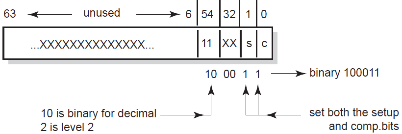 The binary value for level 2 form feed suppression at both job setup and job completion time is 100011 (hexadecimal 23 or decimal 35). Because the value of the logical is a decimal value, you define it as follows:
$ DEFINE/SYSTEM TCPIP$TELNETSYM_SUPPRESS_FORMFEEDS 35
This example shows how to determine the value of the TCPIP$TELNETSYM_SUPPRESS_FORMFEEDS logical if you want level 1 form feed suppression at job completion time only. The value of the logical is determined by the following bit settings shown in Figure 23.2, ''TCPIP$TELNETSYM_SUPPRESS_FORMFEEDS Level 1 Setting''.
Figure 23.2. TCPIP$TELNETSYM_SUPPRESS_FORMFEEDS Level 1 Setting 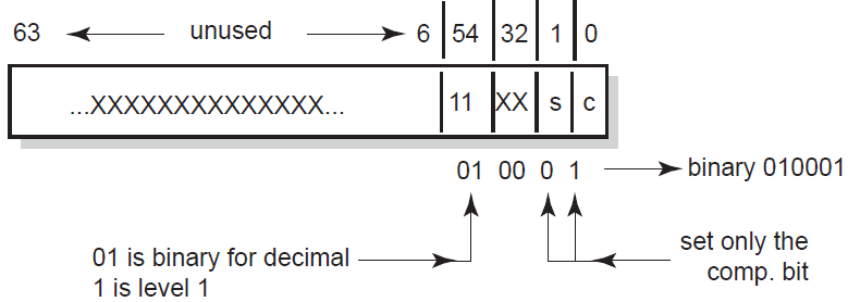 The binary value for level 1 form feed suppression at job completion time only is 010001 (hexadecimal 11 or decimal 17). Because the value of the logical is a decimal value, you define it as follows:
$ DEFINE/SYSTEM TCPIP$TELNETSYM_SUPPRESS_FORMFEEDS 17
23.6.4.2. Buffer Dumps
Carriage Control Form Feed Carriage Control Line Feed Tab the text "Use Your Screen Saver to Conserve Energy." Carriage Return Line Feed
\0D\0C\0D\0A\09Use Your Screen Saver to Conserve Energy.\0D\0A
\FF\FD\00\FF\FB\00
Chapter 24. Setting Up PC-NFS
The PC-NFS server provides authentication and print services for personal computers running PC-NFS. Users on a PC client can associate the name of the PC printer with an OpenVMS print queue and print files to the associated queue. To access the PC-NFS server, PC users must have an entry in the proxy database and have corresponding OpenVMS accounts on the server.
How to start up and shut down the PC-NFS server (Section 24.1, ''PC-NFS Startup and Shutdown'')
How to provide PC-NFS printing services (Section 24.2, ''Providing PC-NFS Print Services'')
How to manage PC-NFS print queues (Section 24.3, ''Managing PC-NFS Print Queues'')
PC-NFS authentication (Section 24.4, ''PC-NFS Authentication'')
For information about setting up NFS proxy identities for PC-NFS client users, see Chapter 20, "Configuring and Managing the NFS Server".
24.1. PC-NFS Startup and Shutdown
The PC-NFS server can be shut down and started up independently of TCP/IP Services. This is useful when you change parameters or logical names that require the service to be restarted.
SYS$STARTUP:TCPIP$PCNFS_STARTUP.COM allows you to start up the PC-NFS server independently.
SYS$STARTUP:TCPIP$PCNFS_SHUTDOWN.COM allows you to shut down the PC-NFS server independently.
SYS$STARTUP:TCPIP$PCNFS_SYSTARTUP.COM can be used as a repository for site-specific definitions and parameters to be invoked when the PC-NFS server is started.
SYS$STARTUP:TCPIP$PCNFS_SYSHUTDOWN.COM can be used as a repository for site-specific definitions and parameters to be invoked when the PC-NFS server is shut down.
24.2. Providing PC-NFS Print Services
If one does not already exist, create a spool directory.
- Map the OpenVMS device to the spool directory path name. For example:
TCPIP> MAP "/PC_PRINT/WORK" DSA31:
- Make the path available with the ADD EXPORT command as follows:
TCPIP> ADD EXPORT "/PC_PRINT/WORK" /HOST=* /OPTIONS=TYPELESS_DIRECTORIES
- Create or edit the SYS$STARTUP:TCPIP$PCNFS_SYSTARTUP.COM file to include the following logical name definitions:
DEFINE /SYSTEM TCPIP$PCNFSD_SPOOLDEV DSA31: DEFINE /SYSTEM TCPIP$PCNFSD_SPOOLEXPORT "/PC_PRINT/WORK"
The logical name TCPIP$PCNFSD_SPOOLDEV specifies the device name for the spool device; TCPIP$PCNFSD_SPOOLEXPORT specifies the exported spool directory.
24.3. Managing PC-NFS Print Queues
List jobs queued from the PC
Cancel queued jobs
Obtain a list of available print queues
Obtain status of a particular print queue
24.4. PC-NFS Authentication
When accessing files on an NFS server, a PC user obtains authentication once from any host running PC-NFS. The user can also access NFS files on that host or other hosts, even if the user's UID/GID has proxy mappings to a different OpenVMS account on each TCP/IP host.
However, with PC-NFS printing, if the PC user obtains authentication from one host, the user can only print successfully on other TCP/IP Services hosts that have a valid OpenVMS account for the same user name.
Appendix A. Gateway Routing Daemon (GATED) Configuration Reference
This appendix describes how to configure the Gateway Routing Daemon (GATED).
A.1. The GATED Configuration File
You must configure the GATED protocols before starting GATED routing by editing the configuration file TCPIP$GATED.CONF, located in SYS$SYSDEVICE:[TCPIP$GATED]. A template file TCPIP$GATED.TEMPLATE is also available in this directory.
The file TCPIP$GATED.CONF contains statements that select routing protocols, manage routing information, manage independent system routing and control tracing options.
After editing the configuration, enter the TCP/IP management command TCPIP START ROUTING/GATED to start the GATED process. If the configuration file is not formatted correctly, GATED will not be able to parse the file and GATED will terminate.
If you make changes to the GATED configuration file after the GATED process is already running, you must stop GATED by entering the command TCPIP STOP ROUTING/GATED. Then restart the GATED process to make the changes take affect.
See VSI TCP/IP Services for OpenVMS Management Command Reference for detailed descriptions of the SET GATED and START ROUTING/GATED commands.
A.2. Configuration File Statement Syntax
[backbone | (area area)]In this example, the brackets indicate that either parameter is optional. The keywords are
backbone and area. The vertical bar indicates that either
backbone or area area can be
specified. Because area is in italics, it is a parameter that you
provide.
A pound sign (#)
The C-style comments that start with /* and end with */
Note
In a GATED configuration file, statements end with a semicolon (;). Do not use a semicolon as a comment character in your configuration file. Anything following a semicolon is interpreted as the start of the next statement.
A.3. Statement Grouping
Options statements
Interface statements
Definition statements
Protocol statements
Static statements
Control statements
Aggregate statements
Note
Entering a statement out of order causes an error when parsing the configuration file.
%directivestatements%tracestatements
These statements provide instructions to the parser, and control tracing from the configuration file. They do not control the configuration of any protocol and may occur anywhere in the configuration file.
A.4. Configuration Statements
|
Command |
Type |
Description |
|---|---|---|
|
|
directive |
Sets the directory for |
|
|
directive |
Includes a file into TCPIP$GATED.CONF. |
|
|
trace |
Specifies which events are traced. |
|
|
definition |
Defines GATED options. |
|
|
definition |
Defines GATED interfaces. |
|
|
definition |
Defines the autonomous system (AS) number. |
|
|
definition |
Defines the originating router (BGP, OSPF). |
|
|
definition |
Defines invalid destination addresses. |
|
|
protocol |
Enables the RIP protocol. |
|
|
protocol |
Configures kernel interface options. |
|
|
protocol |
Enables the OSPF protocol. |
|
|
protocol |
Enables the EGP protocol. |
|
|
protocol |
Enables the BGP protocol. |
|
|
protocol |
Configures the processing of ICMP redirects. |
|
|
protocol |
Configures the processing of general ICMP packets. |
|
|
protocol |
Enables reporting to SNMP. |
|
|
static |
Defines static routes. |
|
|
control |
Defines which routes to import. |
|
|
control |
Defines which routes to export. |
|
|
control |
Defines which routes to aggregate. |
|
|
control |
Defines which routes to generate. |
A.5. Creating the GATED Configuration File
To create a configuration file for your local host, edit a copy of the sample file TCPIP$GATED.TEMPLATE (located in the SYS$SYSDEVICE:[TCPIP$GATED] directory),then save the file to SYS$SYSDEVICE:TCPIP$GATED.CONF.
#
# File name: TCPIP$GATED.CONF
# Product: VSI TCP/IP Services for OpenVMS
# Version: X6.0-N22NOV16
#
# © Copyright 2014, 2022 VMS Software, Inc. and Hewlett Packard Enterprise Development, LP.
#
#
# GATED server configuration file
#
interfaces {
interface all passive ;
};
#
# Protocols:
#
rip on {
broadcast;
interface all ripin ripout version 1;
};
redirect on;
routerdiscovery server off;
hello off;
ospf off;
egp off;
bgp off;
snmp off;
#
# Static routes:
#
#static {
# 10.1.2.0 mask 255.255.255.0 gateway 10.1.1.1;
# default gateway 10.1.2.3;
# };
#
# Policy:
#
#export proto rip {
# proto static { all metric 1; };
# proto direct { all; };
# proto rip { all; };
# };
A.6. Defining Preferences and Routing
The configuration file can define routes from one protocol or peer to another, assigning each route a value, called a preference.
The preference value determines the order of routes to the same destination in a single
routing database. The active route is chosen by the lowest preference value. Some
protocols implement a second preference (preference2), sometimes referred
to as a "tie breaker."
May appear in several different configuration statements in the configuration file. Be aware, however, that the last, or most specific value set for a route is the value GATED will use.
May specify one network interface over another, one protocol over another, or one remote gateway over another.
Cannot be used to control the selection of routes within an interior gateway protocol (IGP). That function is accomplished automatically by the protocol based on metric.
May select routes from the same exterior gateway protocol (EGP) learned from different peers or autonomous systems.
The route with the best (numerically smallest) preference is selected.
If the two routes have the same preference, the route with the best (numerically smallest)
preference2is selected.A route from an IGP is selected over a route from an EGP. The least preferred is a route learned indirectly by an IGP from an EGP.
- If autonomous system (AS) path information is available, it is used to help determine the most preferred route as follows:
A route with an AS path is selected over one without an AS path.
If the AS paths and origins are identical, the route with the lower metric is selected.
A route with an AS path origin of IGP is preferred over a route with an AS path origin of EGP. The least preferred is an AS path with an unknown origin.
A route with a shorter AS path is preferred.
If both routes are from the same protocol and AS, the one with the lowest metric is selected.
The route with the lowest numeric next-hop address is used.
A.6.1. Assigning Preferences
A default preference is assigned to each source from which GATED receives routes. Preference values range from 0 to 255, with the lowest number indicating the most preferred route.
Table A.2, ''Default Preference Values'' lists each type of route, the statement (or clause within statements) that sets preference for the route, and the default preference for each type of route.
|
Preference |
Defined by Statement |
Default |
|---|---|---|
|
Direct connected networks |
interface |
0 |
|
OSPF routes |
ospf |
10 |
|
Internally generated default |
gendefault |
20 |
|
Redirects |
redirect |
30 |
|
Routes learned through route socket |
kernel |
40 |
|
Static routes from config |
static |
60 |
|
ANS SPF (SLSP) routes |
slsp |
70 |
|
HELLO routes |
hello |
90 |
|
RIP routes |
rip |
100 |
|
Point-to-point interface |
110 | |
|
Routes to interfaces that are down |
interfaces |
120 |
|
Aggregate/generate routes |
aggregate/generate |
130 |
|
OSPF AS external routes |
ospf |
150 |
|
BGP routes |
bgp |
170 |
|
EGP |
egp |
200 |
A.6.2. Sample Preference Specifications
interfaces {
interface 138.66.12.2 preference 10 ;
} ;
rip yes {
preference 90 ;
} ;
import proto rip gateway 138.66.12.1 preference 75 ;A.7. Tracing Options
You can specify tracing options at the following levels: file specifications, control options, and global and protocol specific tracing options. Unless overridden, tracing options from the next higher level are inherited by lower levels. For example, Border Gateway Protocol (BGP) peer tracing options are inherited from BGP group tracing options, which are inherited from global BGP tracing options, which are inherited from global GATED tracing options. At each level, tracing specifications override the inherited options.
traceoptions [trace_file [replace] [size size[k|m] files files]] [control_options] trace_options[except trace_options] ; traceoptions none ;
|
Option |
Definition |
|---|---|
|
|
Specifies the file to receive tracing information. If this file name does not begin with a slash (/), the directory in which GATED was started is prepended to the name. |
|
|
Replaces an existing trace file. The default is to append to an existing file. |
|
|
Limits the maximum size of the trace file to the specified size (minimum 10 kilobytes). When the trace file reaches the specified size, it is renamed to file.0, then file.1, file.2, up to the maximum number of files (minimum specification is 2). |
|
|
Specifies options that control the appearance of tracing. The only valid value is nostamp, which specifies that a timestamp should not be prepended to all trace lines. |
|
|
Enables a broad class of tracing and then disables more specific options. |
|
|
Specifies that all tracing should be turned off for this protocol or peer. |
A.7.1. Global Tracing Options
|
Option |
Definition |
|---|---|
|
|
Traces the lexical analyzer and parser. Used mainly by GATED developers for debugging. |
|
|
Traces the allocation of and freeing of policy blocks. Used mainly by the GATED developers for debugging. |
|
|
Traces symbols read from the kernel at startup. The principal way to specify this level of tracing is by the -t option on the command line, because the symbols are read from the kernel before parsing the configuration file. |
|
|
Traces the reading of the kernel interface list. It is useful to specify this with the -t option on the command line, because the first interface scan is done before reading the configuration file. |
Option | Description |
|---|---|
| Turns on all of the options flags. |
| A shorthand notation for specifying both normal and route. |
| Traces state machine transitions in the protocols. |
| Traces normal protocol occurrences. Abnormal protocol occurrences are always traced. |
| Traces the application of protocol and user-specified policy to routes being imported and exported. |
| Traces system interface and processing associated with this protocol or peer. |
| Traces timer usage by this protocol or peer. |
| Traces routing table changes for routes installed by this protocol or peer. |
Note
Not all of these options apply to all of the protocols. In some cases, their use does not make sense (for instance, RIP does not have a state machine) and in some instances the requested tracing has not been implemented (such as RIP support of the policy option).
It is not possible to specify packet tracing from the command line because a global option for packet tracing would potentially create too much output.
When protocols inherit their tracing options from the global tracing options, tracing levels
that do not make sense (such as parse, adv, and
packet tracing options) are masked out.
Global tracing statements have an immediate effect, especially parsing options that affect the parsing of the configuration file. Tracing values inherited by protocols specified in the configuration file are initially inherited from the global options in effect as they are parsed, unless they are overridden by more specific options.
After the configuration file is read, tracing options that were not explicitly specified are inherited from the global options in effect at the end of the configuration file.
A.7.2. Packet Tracing
|
|
Specifies a more verbose format to provide more
information about the contents of the packet. The
|
|
|
Limits the tracing to packets sent received. If neither
the |
|
|
Limits the tracing to packets received. If neither the
|
Note
If a protocol allows several different types of packet tracing, modifiers can be applied to each individual type. Be aware, however, that within one tracing specification the trace flags are summed up, so specifying detail packets turns on full tracing for all packets.
A.8. Directive Statements
%directory directoryDefines the directory in which the include files are stored. When it is used, GATED searches the directory identified by path name for any included files that do not have a fully qualified file name (do not begin with "/"). This statement does not change the current directory; it only specifies the prefix applied to included file names.
%include filenameIdentifies an include file. The contents of the file is included in the TCPIP$GATED.CONF file at the point where the
%includedirective is located. If the file name is not fully qualified (does not begin with backslash (/), it is considered to be relative to the directory defined in the%directorydirective. The%includedirective statement causes the specified file to be parsed completely before resuming with this file. Nesting up to ten levels is supported. The maximum nesting level can be increased by changing the definition of FI_MAX in theparse.hfile.
In a complex environment, segmenting a large configuration into smaller, more easily understood segments might be helpful, but one of the advantages of GATED is that it combines the configuration of several different routing protocols into a single file. Segmenting a small file unnecessarily complicates routing configurations.
A.9. Options Statements
The options statement allows specification of some global options. If used, options must appear before any other type of configuration statement in the TCPIP$GATED.CONF file.
options [nosend] [noresolv] [gendefault [preference preference] [gateway gateway]] [mark time] ;
| |
When If a gateway is specified, the default route is installed in the kernel forwarding table with a next hop of the listed gateway. Note that the use of the more general [generate default] option is preferred to the use of the
| |
| Do not send any packets. This option makes it possible to run GATED on a live network to test protocol interactions without actually participating in the routing protocols. The packet traces in the GATED log can be examined to verify that GATED is functioning properly. This is useful for the RIP interface. This option does not apply to BGP and is not useful with EGP and OSPF. |
| By default, GATED tries to resolve symbolic names into IP addresses by using the gethostbyname() and getnetbyname() library calls. These calls usually use the Domain Name System (DNS) instead of the host's local host and network tables. If there is insufficient routing information to send DNS queries, GATED deadlocks during startup. This option can be used to prevent these calls; symbolic names result in configuration file errors. |
| Specifying this option causes GATED to output a message to the trace log at the specified interval. This can be used to determine if GATED is still running. |
A.10. Interface Statements
An interface is the connection between a router and one of its attached networks. A physical
interface can be specified by interface name, by IP address, or by domain name (unless
the network is an unnumbered point-to-point network). Multiple levels of reference in
the configuration language allow identification of interfaces using a wildcard or
interface type name. Be careful with the use of interface names because future versions
of TCP/IP Services may allow more than one address per interface. The
interface_list is a list of one or more interface names including
wildcard names (names without a number) and names that may specify more than one
interface or address, or the token all for all interfaces.
interfaces {
options
[strictinterfaces]
[scaninterval
time]
[aliases-nexthop (primary
| lowestip
| keepall )
;
interface
interface_list
[preference
preference]
[down preference
preference]
[passive]
[simplex]
[reject]
[blackhole]
[ AS autonomoussystem ]
;
define
address
[broadcast
address]
| [pointtopoint
address]
[netmask
mask]
[multicast]
;
} ;
options portion of the interfaces statement allows configuration of the
following global options related to interfaces: |
|
Indicates that it is a fatal error to refer to an interface in
the configuration file that is not present when GATED is started
and not listed in a define statement. Without
|
|
|
Specifies how often GATED scans the kernel interface list for changes. The default is every 15 seconds on most systems, and 60 seconds on systems that pass interface status changes through the routing socket (BSD 4.4). Note that GATED also scans the interface list on receipt of a SET GATED/CHECK_INTERFACES. |
|
| |
|
Specifies which address GATED will install as the next hop for
interface routes. If you specify | |
interface portion of the interfaces statement sets interface options on the
specified interfaces. An interface list is all or a list of interface names (see Section A.10.1, ''Interface Lists''), domain names, or numeric addresses.
Options available on this statement are:|
| |
|
Sets the preference for routes to this interface when it is up and appears to be functioning properly. The default preference is 0. | |
|
| |
|
Sets the preference for routes to this interface when GATED does not believe it to be functioning properly, but the kernel does not indicate it is down. The default value is 120. | |
|
|
Prevents GATED from changing the preference of the route to this interface if it is not believed to be functioning properly due to lack of received routing information. The GATED daemon only performs this check if the interface is actively participating in a routing protocol. |
|
|
Defines an interface as unable to hear its own broadcast packets. Some systems define an interface as simplex with the IFF_SIMPLEX flag; others require it to be specified in the configuration file. On simplex interfaces, a sender's own packets are assumed to have been looped back in software and are not used as an indication that the interface is functioning properly. |
|
|
Specifies that the address of the interface matching these criteria is used as the local address when installing reject routes in the kernel. Use |
|
|
Specifies that the address of the interface matching these criteria is used as the local address when installing reject routes in the kernel. Use this only with systems based on BSD 4.3 Tahoe or earlier that have installed a reject/blackhole pseudo interface. |
define portion of the interfaces statement defines interfaces that might not
be present when GATED is started so they may be referenced in the configuration file
when strictinterfaces is defined. The following are valid define keywords: |
|
Defines the interface as broadcast capable (for example, Ethernet or Token Ring) and specifies the broadcast address. |
|
|
Defines the interface as a point-to-point interface (for example, SLIP or PPP) and specifies the address on the local side. The first address on the define statement references the address of the host on the remote end of the interface, the address specified after this pointopoint keyword defines the address on the local side of the interface. |
|
|
Specifies the subnet mask to be used on this interface. This is ignored on point-to-point interfaces. |
|
|
Specifies that the interface is multicast capable. |
|
|
Specifies the AS that will be used to create an AS path associated with the route created from the definition of this interface. |
A.10.1. Interface Lists
|
ALL |
Refers to all available interfaces. |
|
Interface name wildcard |
Refers to all the interfaces of the same type. Interfaces consist of the device driver name and a unit number, for example, LE0. References to the name contain only alphabetic characters and match any interfaces that have the same alphabetic part. |
|
Interface name |
Refers to a specific interface, usually one physical interface. These are specified as an alphabetic part followed by a numeric part. This will match one specific interface. But be aware that on many systems, there can be more than one protocol (for example, IP) address on a given physical interface. For example, EF1 matches an interface named EF1, but not an interface named EF10. |
|
Interface address |
Matches one specific interface. The reference can be by
protocol address (for example, 10.0.0.51) or by symbolic
host name (for example, |
If many interface lists are present in the TCPIP$GATED.CONF file with more than one parameter, these parameters are collected at run time to create the specific parameter list for a given interface. If the same parameter is specified on more than one list, the parameters with the most specific interface are used.
rip yes {
interface all noripin noripout ;
interface le ripin ;
interface le1 ripout ;
} ;In this example, RIP packets are accepted from interfaces LE0 and LE1, but nor from DU0. RIP packets are sent only on interface LE1.
A.10.1.1. Example of Current Define Statements for GATED
interfaces {
define 192.168.12.5 broadcast 192.168.12.255 netmask 255.255.255.0 ;
define 192.168.13.129 netmask 255.255.255.252 broadcast 192.168.13.131;
# pointtopoint - is local side, 1st address is remote
define 192.168.13.116 pointtopoint 192.168.13.114 multicast;
};The first define statement has an Ethernet where you need to define the broadcast address as a /24.
The second define statement shows how a /30 may be implemented in the define statement. The define tells GATED to treat the interface with a local address of 192.168.13.129, a netmask of 255.255.255.252, and a broadcast address of 192.168.13.131.
The third define statement shows how a point-to-point interface is defined. The remote side of the point-to-point interface is specified first, and the local side (the one on this machine) is specified second.
A.10.2. IP Interface Addresses and Routes
|
Loopback |
This interface must have the address of 127.0.0.1. Packets
sent to this interface are sent back to the originator. This
interface is also used as an interface for implementing
other features, such as reject and blackhole routes.
Although a netmask is reported on this interface, it is
ignored. It is useful to assign an additional address to
this interface that is the same as the OSPF or BGP
|
|
Broadcast |
This is a multiaccess interface capable of a physical level broadcast, such as Ethernet, Token Ring, and FDDI. This interface has an associated subnet mask and broadcast address. The interface route to a broadcast network is a route to the complete subnet. |
|
Point-to-point |
This is a tunnel to another host, usually on some sort of serial link. This interface has a local address and a remote address. The remote address must be unique among all the interface addresses on a given router. If a subnet mask is specified on a point-to-point interface, it is only used by RIP version 1 to determine which subnets may be propagated to the router on the other side of this interface. |
|
Nonbroadcast multi-access (NBMA) |
This type of interface is multiaccess, but not capable of broadcast, for example, frame relay and X.25. This type of interface has a local address and a subnet mask. (Not supported.) |
The GATED daemon ensures that there is a route available to each IP interface that is configured and up. Normally this is done by the SET INTERFACE command that configures the interface; GATED also does it to ensure consistency.
For point-to-point interfaces, GATED installs some special routes. GATED installs a route to the local address pointing at the loopback interface with a preference of 110. This ensures that packets originating on this host destined for this local address are handled locally.
OSPF prefers to route packets for the local interface across the point-to-point link where they will be returned by the router on the remote end. This is used to verify operation of the link. Because OSPF installs routes with a preference of 10, these routes override the route installed with a preference of 110.
When the status of an interface changes, GATED notifies all the protocols, which take the appropriate action. The GATED daemon assumes that interfaces that are not marked UP do not exist.
The GATED daemon ignores any interfaces that have invalid data for the local, remote, or broadcast addresses or the subnet mask. Invalid data includes zeros in any field. The GATED daemon also ignores any point-to-point interface that has the same local and remote addresses; it assumes it is in some sort of loopback test mode.
A.11. Definition Statements
Definition statements are general configuration statements that relate to all of GATED, or at
least to more than one protocol. The three definition statements are
autonomoussystem, routerid, and martians. If
used, autonomoussystem, routerid, and martians,
must appear before any other type of configuration statement in TCPIP$GATED.CONF
file.
A.11.1. Autonomous System Configuration
The statement autonomoussystem as_number [loops
number]; sets the AS number of this router used
by BGP EGP. The AS number is the official autonomous system number assigned to you
by the Network Information Center (NIC).
The loops parameter is only for protocols supporting AS paths, such as BGP. It controls the number of times this autonomous system may appear in an AS path and defaults to 1 (one).
A.11.2. Router ID Configuration
The statement routerid host; sets the router identifier for
use by the BGP and OSPF protocols. The default is the address of the first interface
encountered by GATED. The address of a non-point-to-point interface is preferred
over the local address of a point-to-point interface, and an address on a loopback
interface that is not the loopback address (127.0.0.1) is most preferred.
A.11.3. Martian Configuration
martians {
host host [allow] ;
network [allow] ;
network mask mask [allow] ;
network masklen number [allow] ;
default [allow] ;
} ;The martians martian_list statement adds martian addresses
to a martian address list. Routing information will not be accepted from the
addresses specified in this list.
You can specify the allow parameter to explicitly allow a subset of a range that was disallowed.
A.11.4. Sample Definition Statements
options gendefault ;
autonomoussystem 249 ;
interface 128.66.12.2 passive ;
martians {
0.0.0.26
};The
optionsstatement tells the system to generate a default route when it peers with an EGP or BGP neighbor.The
autonomoussystemstatement tells GATED to use AS number 249 for EGP and BGP.The
interfacestatement tells GATED not to mark interface 128.66.12.2 as down even if it sees no traffic.The
martiansstatement prevents routes to 0.0.0.26 from ever being accepted.
A.12. Protocol Overview
Unicast routing protocols allow packets to be routed to one destination. All routing protocols determine the "best" route to each destination, and they distribute routing information among the systems on a network. Routing protocols are divided into two general groups: interior (or intradomain routing) protocols and exterior (or interdomain routing) protocols. GATED software combines management of the interior and exterior routing protocols in one software daemon.
A.12.1. Interior Routing Protocols
RIP
The Routing Information Protocol, Version 1 and Version 2, is the most commonly used interior protocol. RIP selects the route with the lowest metric as the best route. The metric is a hop count representing the number of gateways through which data must pass to reach its destination. The longest path that RIP accepts is 15 hops. If the metric is greater than 15, a destination is considered unreachable and GATED discards the route. RIP assumes the best route is the one that uses the fewest gateways i.e., the shortest path, not taking into account congestion or delay on route.
The RIP version 1 protocol is described in RFC 1058 and the RIP version 2 protocol is described in RFC 1723.
OSPF
Open Shortest Path First is a link-state protocol. OSPF is better suited than RIP for complex networks with many routers. OSPF provides equal cost multipath routing.
OSPF is described in RFC 1583, the MIB is defined in RFC 1253. Other related documents are RFC 1245, RFC 1246 and RFC 1370.
A.12.2. Exterior Routing Protocol
EGP
Exterior Gateway Protocol: Originally EGP reachability information was passed into ARPANET/MILNET "core" gateways where the best routes were chosen and passed back out to all connected autonomous systems. As the Internet moved toward a less hierarchical architecture, EGP, an exterior routing protocol which assumes a hierarchical structure, became less effective.
The EGP protocol is described in RFC 827 and RFC 904.
BGP
Border Gateway Protocol is replacing EGP as the exterior protocol of choice. BGP exchanges reachability information between autonomous systems, but provides more capabilities than EGP. BGP uses path attributes to provide more information about each route as an aid in selecting the best route. Path attributes may include, for example, administrative preferences based on political, organizational, or security (policy) considerations in the routing decision. BGP supports nonhierarchical topologies and can be used to implement a network structure of equivalent autonomous systems.
BGP version 1 is described in RFC 1105; version 2 in RFC 1163; version 3 in RFC 1267; and version 4 in RFC 1771. The version 3 MIB is described in RFC 1269. The three documents, RFC 1164, RFC 1268, and RFC 1772, describe the application of versions 2, 3, and 4 in the Internet. A protocol analysis of an experience with BGP version 3 is available in RFC 1265 and RFC 1266. RFC 1397 talks about advertising a default route in BGP version 2 and 3.
BGP version 4 is described in RFC 1771. The BGP V4 MIB implemented by GATED is draft standard, but is scheduled to go to standard. Other references for BGP are: RFC 1997 (BGP Communities), RFC 1966 (BGP Route Reflection), RFC 1966 (BGP AS Confederations), and RFC 1403 (BGP–OSPF interaction). A useful application document is: RFC 1998 (An Application of the BGP Community Attribute in Multi-home Routing).
A.12.3. Router Discovery Protocol
The Router Discovery protocol is used to inform hosts of the availability of other hosts to which it can send packets. Router Discovery is used to supplement a statically configured default router. This is the preferred protocol for hosts to run. They are discouraged from wiretapping routing protocols. Router Discovery is described in RFC 1256
A.12.4. ICMP
On systems without the BSD routing socket, GATED listens to ICMP messages received by the system. Processing of ICMP redirect messages is handled by the redirect statement.
A.12.5. Redirect
The redirect code process ICMP or ISO redirects learned by monitoring ICMP messages, or via the routing socket on systems that support it. It processes the redirect request and decides whether to accept the redirect. If the redirect is accepted, a route is installed in the GATED routing table with the protocol redirect. Redirects are deleted from the routing table after 3 minutes.
A.12.6. Kernel Interface
Although the kernel interface is not technically a routing protocol, it has many characteristics of one, and GATED handles it similarly. The routes GATED chooses to install in the kernel forwarding table are those that will actually be used by the kernel to forward packets.
The add, delete and change operations that GATED must use to update the typical kernel forwarding table take a non-trivial amount of time. The time used does not present a problem for older routing protocols (RIP, EGP), which are not particularly time critical and do not easily handle very large numbers of routes anyway. The newer routing protocols (OSPF, BGP) have stricter timing requirements and are often used to process many more routes. The speed of the kernel interface becomes critical when these protocols are used.
A.12.7. Static Routes
Static statements define the static routes used by GATED. A single static statement can specify any number of routes. The static statements occur after protocol statements and before control statements in the TCPIP$GATED.CONF file. Any number of static statements may be specified, each containing any number of static route definitions. These routes can be overridden by routes with better preference values.
A.13. The ICMP Statement
On systems without the BSD routing socket, GATED listens to ICMP messages received by the system. GATED currently supports router discovery as well as redirect. Processing of ICMP redirect messages is handled by the redirect statement.
Use the ICMP statement to trace the ICMP messages that GATED receives.
icmp {
traceoptions trace_options ;
}
traceoptions trace_options ;A.13.1. Tracing Options
detail and recv):|
|
All ICMP packets received. |
|
|
Only ICMP REDIRECT packets received. |
|
|
Only ICMP ROUTER DISCOVERY packets received. |
|
|
Only ICMP informational packets, which include mask request/response, info request/response, echo request/response and time stamp request/response. |
|
|
Only ICMP error packets, which include time exceeded, parameter problem, unreachable and source quench. |
A.14. Redirect Processing
The redirect code is passed ICMP or ISO redirects learned by monitoring ICMP messages, or via the routing socket on systems that support it. It processes the redirect request and decides whether to accept the redirect. If the redirect is accepted, a route is installed in the GATED routing table with the protocol redirect. Redirects are deleted from the routing table after 3 minutes.
If GATED determines that a redirect is not acceptable, it tries to figure out if the kernel forwarding table has been modified. On systems where ICMP messages are monitored this is accomplished by trying to second guess what the kernel would have done with the redirect. On systems with the routing socket, the kernel provides and indication of whether the redirect was accepted; GATED ignores redirects that were not processed.
If GATED has determined that the state of the kernel forwarding table has been changed, the necessary requests to the kernel are made to restore the correct state.
You cannot disable the processing of ICMP redirects, even when the system is functioning as a router. To ignore the effects of redirects, GATED must process each one and actively restore any changes it made to the kernel's state. Because of the mechanisms involved there will be windows where the effects of redirects are present in the kernel.
By default, GATED removes redirects when actively participating in an interior gateway protocol (RIP or OSPF). It is not possible to enable redirects once they have been automatically disabled. Listening to RIP in nobroadcast mode does not cause redirects to be ignored, nor does the use of EGP and BGP. Redirects must be manually configured off in these cases.
Note that in accordance with the latest IETF Router Requirements document, GATED insures that all ICMP net redirects are processed as host redirects. When an ICMP net redirect is accepted, GATED issues the requests to the kernel to make sure that the kernel forwarding table is updated to reflect a host redirect instead of a net redirect.
The redirect statement does not prevent the system from sending redirects, only from listening to them.
redirect yes
| no
| on
| off
[ {
preference preference ;
interface interface_list
[ noredirects ] | [redirects ] ;
trustedgateways gateway_list ;
traceoptions trace_options ;
} ] ;preferencesets the preference for a route learned from a redirect. The default is 30.interfaceis the interface statement, which allows the enabling and disabling of redirects on an interface-by-interface basis. See Section A.10.1, ''Interface Lists'' for the description of the interface_list. The parameters are:noredirects– Specifies that redirects received from the specified interface will be ignored. The default is to accept redirects on all interfaces.redirects– This is the default. This argument may be necessary when noredirects are used on a wildcard interface descriptor.
trustedgatewaysdefines the list of gateways from which redirects will be accepted. The gateway_list is a list of host names or addresses. By default, all routers on the shared network(s) are trusted to supply redirects. But if thetrustedgatewaysclause is specified, only redirects from the gateways in the list are accepted.
There are no redirect-specific tracing options. All nonerror messages are traced under the normal class.
A.15. The Router Discovery Protocol
The Router Discovery Protocol is an IETF standard protocol used to inform hosts of the existence of routers. It is intended to be used instead of having hosts wiretap routing protocols such as RIP. It is used in place of, or in addition to statically configured default routes in hosts.
The protocol is split into to portions, the server portion which runs on routers, and the client portion that runs on hosts. GATED treats these much like two separate protocols, only one of which may be enabled at a time.
A.15.1. The Router Discovery Server
The Router Discovery Server runs on routers and announces their existence to hosts. It does this by periodically multicasting or broadcasting a Router Advertisement to each interface on which it is enabled. These Router Advertisements contain a list of all the routers addresses on a given interface and their preference for use as a default router.
Initially these Router Advertisements occur every few seconds, then fall back to every few minutes. In addition, a host may send a Router Solicitation to which the router will respond with a unicast Router Advertisement (unless a multicast or broadcast advertisement is due momentarily).
Each Router Advertisement contains a Advertisement Lifetime field, which indicates for how long the advertised addresses are valid. This lifetime is configured such that another Router Advertisement will be sent before the lifetime has expired. A lifetime of zero is used to indicate that one or more addresses are no longer valid.
On systems supporting IP multicasting, the Router Advertisements are by default sent to the all-hosts multicast address 224.0.0.1. However, the use of broadcast may be specified. When Router Advertisements are being sent to the all-hosts multicast address, or an interface is configured for the limited-broadcast address 255.255.255.255, all IP addresses configured on the physical interface are included in the Router Advertisement. When the Router advertisements are being sent to a net or subnet broadcast, only the address associated with that net or subnet is included.
routerdiscovery server yes | no | on | off [ {
traceoptions trace_options ;
interface interface_list
[ minadvinterval time ]
[ maxadvinterval time ]
[ lifetime time ]
;
address interface_list
[ advertise ] | [ ignore ]
[ broadcast ] | [ multicast ]
[ ineligible ] | [ preference preference ]
;
} ] ;traceoptionsspecifies the Router Discovery tracing options (see Section A.15.3, ''Tracing Options'').interfacespecifies the parameters that apply to physical interfaces. Note a slight difference in convention from the rest of GATED,interfacespecifies just physical interfaces (such as LE0, EF0 and EN1), whileaddressspecifies protocol (in this case IP) addresses.The interface parameters are:maxadvintervalspecifies the maximum time allowed between sending broadcast or multicast Router Advertisements from the interface. Must be no less than 4 and no more than 30:00 (30 minutes or 1800 seconds). The default is 10:00 (10 minutes or 600 seconds).minadvintervalspecifies the minimum time allowed between sending unsolicited broadcast or multicast Router Advertisements from the interface. Must be no less than 3 seconds and no greater than maxadvinterval. The default is 0.75 *maxadvinterval.lifetimespecifies the life time of addresses in a Router Advertisement. Must be no less thanmaxadvintervaland no greater than 2:30:00 (two hours, thirty minutes or 9000 seconds). The default is 3 *maxadvinterval.
addressspecifies the parameters that apply to the specified set of addresses on this physical interfaces. Note a slight difference in convention from the rest of GATED,interfacespecifies just physical interfaces (such as LE0, EF0 and EN1), whileaddressspecifies protocol (in this case IP) addresses.Theaddressparameters are:advertise, which Specifies that the specified addresses should be included in Router Advertisements. This is the default.ignore, which specifies that the specified addresses should not be included in Router Advertisements.broadcast, which specifies that the given addresses should be included in a broadcast Router Advertisement because this system does not support IP multicasting, or some hosts on attached network do not support IP multicasting. It is possible to mix addresses on a physical interface such that some are included in a broadcast Router Advertisement and some are included in a multicast Router Advertisement.broadcastis the default if the router does not support IP multicasting.multicast, which specifies that the given addresses should only be included in a multicast Router Advertisement. If the system does not support IP multicasting the addresses will not be included. If the system supports IP multicasting, the default is to include the addresses in a multicast Router Advertisement if the given interface supports IP multicasting, if not the addresses will be included in a broadcast Router Advertisement.preference, which specifies the preferability of the addresses as a default router address, relative to other router addresses on the same subnet. A 32-bit, signed, twos-complement integer, with higher values meaning more preferable. Note that hex 80000000 may only be specified as ineligible. The default is 0.ineligible, which specifies that the given addresses will be assigned a preference of (hex 80000000) which means that it is not eligible to be the default route for any hosts.This is useful when the addresses should not be used as a default route, but are given as the next hop in an ICMP redirect. This allows the hosts to verify that the given addresses are up and available.
A.15.2. The Router Discovery Client
A host listens for Router Advertisements via the all-hosts multicast address (224.0.0.2), If IP multicasting is available and enabled, or on the interface's broadcast address. When starting up, or when reconfigured, a host may send a few Router Solicitations to the all-routers multicast address, 224.0.0.2, or the interface's broadcast address.
When a Router Advertisement with non-zero lifetime is received, the host installs a default
route to each of the advertised addresses. If the preference
ineligible, or the address is not on an attached interface, the route
is marked unusable but retained. If the preference is usable, the metric is set as a
function of the preference such that the route with the best preference is used. If
more than one address with the same preference is received, the one with the lowest
IP address will be used. These default routes are not exportable to other
protocols.
When a Router Advertisement with a zero lifetime is received, the host deletes all routes with next-hop addresses learned from that router. In addition, any routers learned from ICMP redirects pointing to these addresses will be deleted. The same will happen when a Router Advertisement is not received to refresh these routes before the lifetime expires.
routerdiscovery client yes | no | on | off [ {
traceoptions trace_options ;
preference preference ;
interface interface_list
[ enable ] | [ disable ]
[ broadcast ] | [ multicast ]
[ quiet ] | [ solicit ]
;
} ] ;traceoptionsspecifies the tracing options for OSPF (see Section A.15.3, ''Tracing Options'').preferencespecifies the preference of all Router Discovery default routes. The default is 55.interfacespecifies the parameters that apply to physical interfaces. Note a slight difference in convention from the rest of GATED,interfacespecifies just physical interfaces (such as LE0, EF0 and EN1). The Router Discovery Client has no parameters that apply only to interface addresses.Theinterfaceparameters that apply to physical interfaces are:enable, which specifies that Router Discovery should be performed on the specified interfaces. This is the default.disable, which specifies that Router Discovery should not be performed on the specified interfaces.broadcast, which specifies that Router Solicitations should be broadcast on the specified interfaces. This is the default if IP multicast support is not available on this host or interface.multicast, which specifies that Router Solicitations should be multicast on the specified interfaces. If IP multicast is not available on this host and interface, no solicitation will be performed. The default is to multicast Router Solicitations if the host and interface support it, otherwise Router Solicitations are broadcast.quiet, which specifies that no Router Solicitations will be sent on this interface, even though Router Discovery will be performed.solicit, which specifies that initial Router Solicitations will be sent on this interface. This is the default.
A.15.3. Tracing Options
The Router Discovery Client and Server support the state trace flag, which traces
various protocol occurrences.
The Router Discovery Client and Server do not directly support any packet tracing options, tracing of router discovery packets is enabled with the ICMP statement.
A.16. The Kernel Statement
While the kernel interface is not technically a routing protocol, it has many of the characteristics of one, and GATED handles it similarly to one. The routes GATED chooses to install in the kernel forwarding table are those that will actually be used by the kernel to forward packets.
The add, delete and change operations GATED must use to update the typical kernel forwarding table take a non-trivial amount of time. This does not present a problem for older routing protocols (RIP, EGP), which are not particularly time critical and do not easily handle very large numbers of routes anyway. The newer routing protocols (OSPF, BGP) have stricter timing requirements and are often used to process many more routes. The speed of the kernel interface becomes critical when these protocols are used.
To prevent GATED from locking up for significant periods of time installing large numbers of routes (up to a minute or more has been observed on real networks), the processing of these routes is now done in batches. The size of these batches may be controlled by the tuning parameters described below, but normally the default parameters will provide the proper functionality.
During normal shutdown processing, GATED normally deletes all the routes it has installed in the kernel forwarding table, except for those marked with retain. Optionally, GATED can leave all routes in the kernel forwarding table by not deleting any routes. In this case changes will be made to insure that routes with a retain indication are installed in the table. This is useful on systems with large numbers of routes as it prevents the need to re-install the routes when GATED restarts. This can greatly reduce the time it takes to recover from a restart.
A.16.1. Forwarding Tables and Routing Tables
The table in the kernel that controls the forwarding of packets is a forwarding table, also known as a forwarding information base, or FIB. The table that GATED uses internally to store routing information it learns from routing protocols is a routing table, also known as a routing information base, or RIB. The routing table is used to collect and store routes from various protocols. For each unique combination of network and mask an active route is chosen, this route will be the one with the best (numerically smallest) preference. All the active routes are installed in the kernel forwarding table. The entries in this table are what the kernel actually uses to forward packets.
A.16.2. Updating the Forwarding Table
There are two main methods of updating the kernel FIB, the ioctl() interface and
the routing socket interface. Their various characteristics are described
here.
A.16.2.1. Updating the Forwarding Table with the ioctl Interface
ioctl interface to the forwarding table was introduced in BSD 4.3. This is a
one-way interface; it only allows GATED to update the kernel forwarding table.
It has several other limitations:Fixed subnet masks
The BSD 4.3 networking code assumed that all subnets of a given network had the same subnet mask. This limitation is enforced by the kernel. The network mask is not stored in the kernel forwarding table, but determined when a packet is forwarded by searching for interfaces on the same network.
One way interface
GATED is able to update the kernel forwarding table, but it is not aware of other modifications of the forwarding table. GATED is able to listen to ICMP messages and guess how the kernel has updated the forwarding table with response to ICMP redirects.
Blind updates
GATED is not able to detect changes to the forwarding table resulting from the use of the ROUTE command. Use of the ROUTE command on systems that use the
ioctl()interface is strongly discouraged while GATED is running.Changes not supported
In all known implementations, there is no change operation supported, to change a route that exists in the kernel, the route must be deleted and a new one added.
A.16.2.2. Updating the Forwarding Table with the Routing Socket Interface
ioctl() interface: Variable subnet masks
The network mask is passed to the kernel explicitly. This allows different masks to be used on subnets of the same network. It also allows routes with masks that are more general than the natural mask to be used. This is known as classless routing.
Two way interface
Not only is GATED able to change the kernel forwarding table with this interface, but the kernel can also report changes to the forwarding table to GATED. The most interesting of these is an indication that a redirect has modified the kernel forwarding table; this means that GATED no longer needs to monitor ICMP messages to learn about redirects. Plus, there is an indication of whether the kernel processed the redirect, GATED can safely ignore redirect messages that the kernel did not process.
Updates visible
Changes to the routing table by other processes, including the route command are received via the routing socket. This allows GATED to insure that the kernel forwarding table is synchronized with the routing table. Also, it allows the system administrator to perform some operations with the ROUTE command while GATED is running.
Changes supported
There is a functioning change message that allows routes in the kernel to be atomically changed. Some early verions of the routing socket code had bugs in the change message processing. There are compilation time and configuration time options that cause delete and add sequences to be used instead of change messages.
Expandable
New levels of kernel and GATED communications may be added by adding new message types.
A.16.3. Reading the Forwarding Table
When GATED starts up it reads the kernel forwarding table and installs corresponding routes in the routing table. These routes are called remnants and are timed out after a configured interval (which defaults to 3 minutes), or as soon as a more attractive route is learned. This allows forwarding to occur during the time it takes the routing protocols to start learning routes.
Reading forwarding table with KMEM
On many systems, especially those based on BSD 4.3, GATED must have knowledge of the kernel's data structures to read the current state of forwarding table. This method is slow and subject to error if the kernel forwarding table is updated while GATED is reading it. This can happen if the system administrator uses the ROUTE command, or an ICMP redirect message is received while GATED is starting up.
Due to an oversight, some systems (such as OSF/1) that are based on BSD 4.3 Reno or later, do not have the getkerninfo() system call described below, which allows GATED to read routes from the kernel without knowing about kernel internal structures. On these systems it is necessary to read the kernel radix tree from kernel memory. This is even more error-prone than reading the hash based forwarding table.
Reading the forwarding table via
getkerninfoorsysctlBesides the routing socket, BSD 4.3 Reno introduced the
getkerninfo()system call. This call allows a user process (of which GATED is one) to read information from the kernel without knowledge of the kernel data structures. In the case of the forwarding table, it is returned to GATED atomically as a series of routing socket messages. This prevents the problem associated with the forwarding table changing while GATED is in the process of reading it.BSD 4.4 changed the
getkerninfo()interface into thesysctl()interface, which takes different parameters, but otherwise functions identically.Reading the forwarding table via OS specific methods
Some operating systems define their own method of reading the kernel forwarding table.
A.16.4. Reading the Interface List
Reading the interface list with SIOCGIFCONF
On systems based on BSD 4.3, 4.3 Reno and 4.3 Net/2 the SIOCGIFCONF
ioctlinterface is used to read the kernel interface list. Using this method, a list of interfaces and some basic information about them is return by the SIOCGIFCONF call. Other information must be learned by issuing otherioctls to learn the interface network mask, flags, MTU, metric, destination address (for point-to-point interfaces) and broadcast address (for broadcast capable interfaces).GATED reads rereads this list every 15 second looking for changes. When the routing socket is in use, it also rereads it whenever a messages is received indicating a change in routing configuration. Receipt of a SIGUSR2 signal also causes GATED to reread the list. This interval may be explicitly configured in the interface configuration.
Reading the interface list with
sysctlBSD 4.4 added the ability to read the kernel interface list via the
sysctlsystem call. The interface status is returned atomically as a list of routing socket messages that GATED parses for the required information.BSD 4.4 also added routing socket messages to report interface status changes immediately. This allows GATED to react quickly to changes in interface configuration.
When this method is in use, GATED rereads the interface list only once a minute. It also rereads it on routing table changes indications and when a SIGUSR2 is received. This interval may be explicitly configured in the interface configuration.
A.16.5. Reading Interface Physical Addresses
Later version of the getkerninfo() and sysctl() interfaces return the interface physical addresses as part of the interface information. On most systems where this information is not returned, GATED scans the kernel physical interface list for this information for interfaces with IFFBROADCAST set, assuming that their drivers are handled the same as Ethernet drivers. On some systems, system specific interfaces are used to learn this information.
The interface physical addresses are useful for IS-IS. For IP protocols, they are not currently used, but they may be used in the future.
A.16.6. Reading Kernel Variables
At startup, GATED reads some special variables out of the kernel. This is usually done with
the nlist (or kvm_nlist) system call, but some systems use
different methods.
The variables read include the status of UDP checksum creation and generation, IP forwarding and kernel version (for informational purposes). On systems where the routing table is read directly from kernel memory, the root of the hash table or radix tree routing table is read. On systems where interface physical addresses are not supplied by other means, the root of the interface list is read.
A.16.7. Special Route Flags
RTF_REJECT
Instead of forwarding a packet like a normal route, routes with RTF_REJECT cause packets to be dropped and unreachable messages to be sent to the packet originators. This flag is only valid on routes pointing at the loopback interface.
RTF_BLACKHOLE
Like the RTF_REJECT flag, routes with RTF_BLACKHOLE cause packets to be dropped, but unreachable messages are not sent. This flag is only valid on routes pointing at the loopback interface.
RTF_STATIC
When GATED starts, it reads all the routes currently in the kernel forwarding table. Besides interface routes, it usually marks everything else as a remnant from a previous run of GATED and deletes it after a few minutes. This means that routes added with the ROUTE command will not be retained after GATED has started.
To fix this the RTF_STATIC flag was added. When the route command is used to install a route that is not an interface route it sets the RTF_STATIC flag. This signals to GATED that the specified route was added by the systems administrator and should be retained.
A.16.8. Kernel Configuration Syntax
kernel {
options
[ nochange ]
[ noflushatexit ]
;
routes number ;
flash
[ limit number ]
[ type interface | interior | all ]
;
background
[ limit number ]
[ priority flash | higher | lower ]
;
traceoptions trace_options ;
} ;optionsspecifies kernel options. Valid options are:nochange, which, on systems supporting the routing socket, ensures that changes operations will not be performed, only deletes and adds. This is useful on early versions of the routing socket code where the change operation was broken.noflushatexit, which specifies that during normal shutdown processing GATED deletes all routes from the kernel forwarding table that do not have a retain indication. Thenoflushatexitoption prevents route deletions at shutdown. Instead, routes are changed and added to make sure that all the routes marked with retain get installed.This is useful on systems with thousands of routes. Upon startup GATED will notice which routes are in the kernel forwarding table and not have add them back.
routesspecifies the routes number. On some systems kernel memory is at a premium. With this parameter a limit can be placed on the maximum number of routes GATED will install in the kernel. Normally GATED adds/changes/deletes routes in interface/internal/external order, for example, it queues interface routes first, followed by internal routes, followed by external routes, and processes the queue from the beginning. If a this parameter is specified and the limit is hit, GATED does two scans of the list instead. On the first scan it does deletes, and also deletes all changed routes, turning the queued changes into adds. It then rescans the list doing adds in interface/internal/external order until it hits the limit again. This will tend to favor internal routes over external routes. The default is not to limit the number of routes in the kernel forwarding table.flashspecifies that a route has changed. The process of notifying the protocols is called a flash update. The kernel forwarding table interface is the first to be notified. Normally a maximum of 20 interface routes may be processed during one flash update. Theflashcommand allows tuning of the following parameters:limit number, which specifies the maximum number of routes which may be processed during one flash update. The default is 20. A value of -1 will cause all pending route changes of the specified type to be processed during the flash update.type, which specifies the type of routes that will be processed during a flash update. Interior specifies that interior routes will also be installed (see Section A.12.1, ''Interior Routing Protocols'').allspecifies the inclusion of exterior routes as well (see Section A.12.2, ''Exterior Routing Protocol''). The default isinterface, which specifies that only interface routes will be installed during a flash update.Specifying flash limit -1 all causes all routes to be installed during the flash update; this mimics the behavior of previous versions of GATED.
backgroundspecifies that the remaining routes are processed in batches in the background, that is, when no routing protocol traffic is being received. Normally, 120 routes are installed at a time to allow other tasks to be performed and the background processing is done at lower priority than flash updates the following parameters allow tuning of these parameters:limit, which specifies the number of routes which may be processed at during one batch. The default is 120.priority, which specifies the priority of the processing of batches of kernel updates in relationship to the flash update processing. The default islower, which means that flash updates are processed first. To process kernel updates at the same priority as flash updates, specifyflash. To process kernel updates at a higher priority, usehigher.
A.16.9. Kernel Tracing Options
| Symbols read from the kernel, by nlist() or similar interface. |
| Interface list scan. This option is useful when entered from the command line as the first interface list scan is performed before the configuration file is parsed. |
| Routes read from the kernel when GATED starts. |
| Requests by GATED to Add/Delete/Change routes in the kernel forwarding table. |
ioctl() interface to the kernel.infoRecords informational messages received from the routing socket, such as TCP lossage, routing lookup failure, and route resolution requests. GATED does not currently do processing on these messages, just logs the information if requested.
detail, send, and
recv) specify the types of message and include:routesRoutes exchanged with the kernel, including Add/Delete/Change messages and Add/Delete/Change messages received from other processes.
redirectRedirect messages received from the kernel.
interfaceInterface status messages received from the kernel. These are only supported on systems with networking code derived from BSD 4.4.
otherOther messages received from the kernel, including those mentioned in the info type above.
A.17. Static Routes Statements
Static statements define the static routes used by GATED. A single static statement can specify any number of routes. The static statements occur after protocol statements and before control statements in the TCPIP$GATED.CONF file. Any number of static statements may be specified, each containing any number of static route definitions. These routes can be overridden by routes with better preference values.
There are two forms of static statements. One defines a static route through a gateway. The other is used to support multiple network addresses on a single interface.
static {
(host host ) | default |
(network [ (mask mask ) | (masklen number ) ] )
gateway gateway_list
[ interface interface_list ]
[ preference preference ]
[ retain ]
[ reject ]
[ blackhole ]
[ noinstall ] ;
(network [ (mask mask ) | (masklen number ) ] )
interface interface
[ preference preference ]
[ retain ]
[ reject ]
[ blackhole ]
[ noinstall ] ;
} ;
host host | default | network [ (mask mask )
| (masklen number ) ] gateway gateway_list)This is the most general form of the static statement. It defines a static route through one or more gateways. Static routes are installed when one or more of the gateways listed are available on directly attached interfaces. If more than one eligible gateway is available, these are limited by the number of multipath destinations supported (this compile-time parameter is currently almost always one on UNIX).
static {
(host host ) | default |
(network [ (mask mask ) | (masklen number ) ] )
gateway gateway_list
[ interface interface_list ]
[ preference preference ]
[ retain ]
[ reject ]
[ blackhole ]
[ noinstall ] ;
(network [ (mask mask ) | (masklen number ) ] )
interface interface
[ preference preference ]
[ retain ]
[ reject ]
[ blackhole ]
[ noinstall ] ;
} ;
network [ (mask mask ) | (masklen number ) ] interface interface
This sytax is used to define a static interface route which is used for primitive support of multiple network addresses on one interface.
interface interface_listWhen
interfaceis specified, gateways are only considered valid when they are on one of these interfaces. See Section A.10.1, ''Interface Lists'' for the description of the interface_list.preference preferenceSelects the preference of this static route. The preference controls how this route competes with routes from other protocols. The default preference is 60.
retainNormally, GATED removes all routes except interface routes from the kernel forwarding table during a graceful shutdown. The
retainoption may be used to prevent specific static routes from being removed.retaininsures that some routing is available when GATED is not running.rejectInstead of forwarding a packet like a normal route, reject routes cause packets to be dropped and unreachable messages to be sent to the packet originators. Specifying
rejectcauses this route to be installed as a reject route. Not all kernel forwarding engines support reject routes.blackholeA blackhole route is the same as a reject route except that unreachable messages are not supported. Specifying
blackholecauses this route to be installed as a blackhole route.noinstallNormally the route with the lowest preference is installed in the kernel forwarding table and is the route exported to other protocols. When
noinstallis specified on a route, it will not be installed in the kernel forwarding table when it is active, but it will still be eligible to be exported to other protocols.
A.18. Control Statements
Route filtering, described in Section A.18.1, ''Route Filtering''
Matching AS paths, as described in Section A.18.2, ''Matching AS Paths''
Importing routes, as described in Section A.18.3, ''The Import Statement''
Exporting routes, as described in Section A.18.4, ''The Export Statement''
The source of exported routes, as described in Section A.18.5, ''Specifying the Source''
Route aggregation, as described in Section A.18.6, ''Route Aggregation''
A.18.1. Route Filtering
Routes are filtered by specifying configuration language that will match a certain set of routes by destination, or by destination and mask. Among other places, route filters are used on martians, and in import and export statements.
The action taken when no match is found is dependent on the context, for instance import and export route filters assume an all reject ; at the end a list.
A route will match the most specific filter that applies. Specifying more than one filter with the same destination, mask and modifiers will generate an error.
network [ exact | refines | between number and number ] network mask mask [ exact | refines | between number and number ] network masklen number [ exact | refines | between number and number ] all default host host
These are all the possible formats for a route filter. Not all of these formats are available in all places, for instance the host and default formats are not valid for martians.
In most cases it is possible to specify additional parameters relevant to the context of the filter. For example, on a martian statement it is possible to specify the allow keyword, on an import statement you can specify a preference, and on an export you can specify a metric.
network [ exact | refines | between lownumber and highnumber ] network mask mask [ exact | refines | between lownumber and highnumber ]] network masklen number [ exact | refines | between lownumber and highnumber ]
Matching usually requires both an address and a mask, although the mask is implied in the shorthand forms listed below. These three forms vary in how the mask is specified. In the first form, the mask is implied to be the natural mask of the network. In the second, the mask is explicitly specified. In the third, the mask is specified by the number of contiguous one bits.
If no additional parameters are specified, any destination that falls in the range given by the network and mask is matched, the mask of the destination is ignored. If a natural network is specified, the network, any subnets, and any hosts will be match. The two optional modifiers cause the mask of the destination to be considered also:exactSpecifies that the mask of the destination must match the supplied mask exactly. This is used to match a network, but no subnets or hosts of that network.
refinesSpecifies that the mask of the destination must be more specified (for example, longer) than the filter mask. This is used to match subnets or hosts of a network, but not the network.
between lownumber and highnumberSpecifies that the mask of the destination must be as or more specific (for example, as long as or longer) than the lower limit (lownumber) and no more specific (for example, as long as or shorter) than the upper limit (highnumber). Note that
exactandrefinesare both special cases ofbetween.allThis entry matches anything. It is equivalent to:0.0.0.0 mask 0.0.0.0
defaultMatches the default route. To match, the address must be the default address and the mask must be all zeros. This is equivalent to:0.0.0.0 mask 0.0.0.0 exact
host hostMatches the specific host. To match, the address must exactly match the specified host and the network mask must be a host mask (i.e. all ones). This is equivalent to:host mask 255.255.255 exact
A.18.2. Matching AS Paths
An AS path includes a list of autonomous systems that routing information has passed through to get to a specified router, and an indicator of the origin of this list. This routing information can be used to prefer one path to a destination network over another. The primary method for preferring a route with GATED is to specify a list of filters to be applied to AS paths when importing and exporting routes.
Each autonomous system that a route passed through prepends its AS number to the beginning of the AS path.
AS path regular expressions are defined in RFC 1164.
A.18.2.1. AS Path-Matching Syntax
aspath aspath_regexp origin ([ any ] ) | [ igp ] | [egp ] | [ incomplete ] ) aspath aspath_regexp
aspath specifies that an AS matching the aspath_regexp with
the specified origin is
matched.origin ([ any ] | [ igp ] | [ egp ] | [ incomplete ] )
An origin of igp indicates the route was learned from an intradomain
routing protocol and is most likely complete. An origin of egp
indicates the route was learned from an interdomain routing protocol that does
not support AS paths (EGP, for example), and the path is most likely not
complete. When the path information is definitely not complete, an origin of
incomplete is used. An origin of any can be used
for any origin.
A.18.2.2. AS Path Regular Expressions
Technically, an AS path regular expression is a regular expression with the alphabet being the set of AS numbers. An AS path regular expression is composed of one or more AS paths expressions. An AS path expressions is composed of AS path terms and AS path operators.
A.18.2.3. AS Path Terms
autonomous_system
Specifies any valid autonomous system number, from one through 65534 inclusive.
dot (.)
Matches any autonomous system number.
(aspath_regexp )Group subexpressions in parentheses. An operator, such as * or ? works on a single element or on a regular expression enclosed in parentheses.
A.18.2.4. AS Path Operators
An AS path operator is one of the following:
aspath_term {m,n}
Indicates a regular expression followed by {m,n} (where m and n are nonnegative integers and m
<= n) specifies at least m and at most n repetitions.aspath_term {m}
Indicates a regular expression followed by {m}. When m is a positive integer, the expression specifies exactly m repetitions.
aspath_term {m,}
Indicates a regular expression followed by {m,} (where m is a positive integer), and specifies m or more repetitions.
aspath_term *
Indicates an AS path term followed by asterisk (*), specifying zero or more repetitions. This is shorthand for {0,}.
aspath_term +
Indicates a regular expression followed by plus sign (+), specifying one or more repetitions. This is shorthand for {1,}.
aspath_term ?
Indicates a regular expression followed by question mark (?), specifying zero or one repetition. This is shorthand for {0,1}.
aspath_term | aspath_term
Matches the AS term on the left, or the AS term on the right.
A.18.3. The Import Statement
Importation of routes from routing protocols and installation of the routes in GATED'S routing database is controlled by import statements. The format of an import statement varies depending on the source protocol.
A.18.3.1. Specifying Preferences
restrict
preference preferencerestrictspecifies that the routes are not desired in the routing table. In some cases this means that the routes are not installed in the routing table. In others it means that they are installed with a negative preference; this prevents them from becoming active so they will not be installed in the forwarding table, or exported to other protocols.preferencespecifies the preference value used when comparing this route to other routes from other protocols. The route with the lowest preference available at any given route becomes the active route, is installed in the forwarding table, and is eligible to be exported to other protocols. The default preferences are configured by the individual protocols.
A.18.3.2. Route Filters
restrict is specified on the first line of
a statement), all routes from the specified source will match that statement. If
any filters are specified, only routes that match the specified filters will be
imported. That is, if any filters are specified, a statement like all
restrict ; is assumed at the end of the list.
network [ exact | refines | between number and number] network mask mask [exact | refines | between number and number ] network masklen number [ exact | refines | between number and number ] default host host
A.18.3.3. Importing Routes from BGP and EGP
import proto bgp | egp autonomoussystem autonomous_system [ aspath-opt ] restrict ; import proto bgp | egp autonomoussystem autonomous_system [ aspath-opt ] [ preference preference ] { route_filter [ restrict | (preference preference ) ] ; } ; import proto bgp aspath aspath_regexp origin any | ([ igp ] [egp ] [ incomplete ] ) [ aspath-opt ] restrict ; import proto bgp aspath aspath_regexp origin any | ([ igp ] [egp ] [ incomplete ] ) [ aspath-opt ] [ preference preference ] { route_filter [ restrict | (preference preference ) ] ; } ;
EGP importation may be controlled by autonomous system. BGP also supports controlling propagation by the use of an AS path regular expressions, which are documented in the section on Matching AS paths. Note that EGP and BGP versions 2 and 3 only support the propagation of natural networks, so the host and default route filters are meaningless. BGP version 4 supports the propagation of any destination along with a contiguous network mask.
The aspath-opt option allows the specification of import policy based on the path
attributes found in the BGP update. (The option is not usable with EGP.) If
multiple communities are specified in the aspath-opt option, only
updates carrying all of the specified communities will be matched. If
none is specified, only updates lacking the community attribute
will be matched.
Note that it is quite possible for several BGP import clauses to match a given update. If more
than one clause matches, the first matching clause will be used; all later
matching clauses will be ignored. For this reason, it is generally desirable to
order import clauses from most to least specific. An import clause without an
aspath-opt option will match any update with any communities or
none.
EGP and BGP both store any routes that were rejected implicitly by not being metioned in a route filter, or explicitly with the restrict keyword in the routing table with a negative preference. A negative preference prevents a route from becoming active, which prevents it from being installed in the forwarding table, or exported to other protocols. This aleviates the need to break and re-establish a session upon reconfiguration if importation policy is changed.
A.18.3.4. Importing Routes from RIP and Redirects
import proto rip | hello | redirect
[ (interface interface_list ) | (gateway gateway_list ) ]
restrict ;import proto rip | hello | redirect
[ (interface interface_list ) | (gateway gateway_list ) ]
[ preference preference ] {
route_filter [ restrict | (preference preference ) ] ;
} ;The importation of RIP and redirect routes may be controlled by any of protocol, source interface and source gateway. If more than one is specified, they are processed from most general (protocol) to most specific (gateway).
RIP does not support the use of preference to choose between routes of the same
protocol. That is left to the protocol metrics. These protocols do not save
routes that were rejected since they have short update intervals.
A.18.3.5. Importing Routes from OSPF
import proto ospfase [ tag ospf_tag ] restrict ; import proto ospfase [ tag ospf_tag ] [ preference preference ] { route_filter [ restrict | (preference preference ) ] ; } ;
Due to the nature of OSPF, only the importation of ASE routes may be controlled. OSPF intra- and inter-area routes are always imported into the GATED routing table with a preference of 10. If a tag is specified, the import clause will only apply to routes with the specified tag.
It is only possible to restrict the importation of OSPF ASE routes when functioning as an AS border router. This is accomplished by specifying an export ospfase clause. Specification of an empty export clause may be used to restrict importation of ASEs when no ASEs are being exported.
Like the other interior protocols, preference can not be used to choose between OSPF ASE routes, that is done by the OSPF costs. Routes that are rejected by policy are stored in the table with a negative preference.
A.18.4. The Export Statement
The import statement controls which routes received from other systems are used by GATED; the export statement controls which routes are advertised by GATED to other systems. Like the import statement, the syntax of the export statement varies slightly per protocol. The syntax of the export statement is similar to the syntax of the import statement, and the meanings of many of the parameters are identical. The main difference between the two is that while route importation is just controlled by source information, route exportation is controlled by both destination and source.
The outer portion of a given export statement specifies the destination of the routing information you are controlling. The middle portion restricts the sources of importation that you wish to consider. And the innermost portion is a route filter used to select individual routes.
A.18.4.1. Specifying Metrics
restrict
metric metricrestrictspecifies that nothing should be exported. If specified on the destination portion of the export statement it specifies that nothing at all should be exported to this destination. If specified on the source portion it specifies that nothing from this source should be exported to this destination. If specified as part of a route filter it specifies that the routes matching that filter should not be exported.metric metricspecifies the metric to be used when exporting to the specified destination.
A.18.4.2. Route Filters
restrict is specified on the
first line of a statement), all routes from the specified source will match that
statement. If any filters are specified, only routes that match the specified
filters will be exported. That is, if any filters are specified, a all
restrict ; statement is assumed at the end of the
list.network [ exact | refines | between number and number ] network mask mask [exact | refines | between number and number ] ] network masklen number [ exact | refines | between number and number ] ] default host host
A.18.4.3. Specifying the Destination
As mentioned above, the syntax of the export statement varies depending on the protocol it is being applied to. One thing that applies in all cases is the specification of a metric. All protocols define a default metric to be used for routes being exported, in most cases this can be overridden at several levels of the export statement.
The specification of the source of the routing information being exported (the
export_list) is described below.
Exporting to EGP and BGP
export proto bgp | egp as autonomous system restrict ;export proto bgp | egp as autonomous system [ aspath-opt ] [ metric metric ] { export_list ; } ;
Exportation to EGP and BGP is controlled by an autonomous system. The same policy is applied to all routers in the AS. EGP metrics range from 0 to 255 inclusive, with zero being the most attractive.
BGP metrics are 16 bit unsigned quantities; that is, they range from 0 to 65535 inclusive with 0 being the most attractive. While BGP version 4 actually supports 32 bit unsigned quantities, GATED does not yet support this. In BGP version 4, the metric is otherwise known as the Multi-Exit Discriminator, or MED.
In BGP, the aspath-opt option may be used to send the BGP community
attribute. Any communities specified with the aspath-opt option are
sent in addition to any received with the route or specified in the
group statement.
If no export policy is specified, only routes to attached interfaces will be exported. If any policy is specified the defaults are overridden; it is necessary to explicitly specify everything that should be exported.
Note that EGP and BGP versions 2 and 3 only support the propagation of natural networks, so the host and default route filters are meaningless. BGP version 4 supports the propagation of any destination along with a contiguous network mask.
Exporting to RIP
export proto rip
[ (interface interface_list ) | (gateway gateway_list ) ]
restrict ;export proto rip
[ (interface interface_list ) | (gateway gateway_list ) ]
[ metric metric ] {
export_list ;
} ;Exportation to RIP is controlled by any of protocol, interface or gateway. If more than one is specified, they are processed from most general (protocol) to most specific (gateway).
It is not possible to set metrics for exporting RIP routes into RIP. Attempts to do this are silently ignored.
If no export policy is specified, RIP and interface routes are exported into RIP. If any
policy is specified, the defaults are overridden; it is necessary to explicitly
specify everything that should be exported in the
export_list.
When exporting routes from other protocols, it is important to specify a metric on the
export statement or in the route filters. Unless this is done,
the value specified in defaultmetric is used. If not specified, the
defaultmetric value is 16 (unreachable). It is likely that this
is not the desired result.
RIP version 1 assumes that all subnets of the shared network have the same subnet mask so they are only able to propagate subnets of that network. RIP version 2 removes that restriction and is capable of propagating all routes when not sending version 1 compatible updates.
To announce routes which specify a next hop of the loopback interface (that is, static and internally generated default routes) via RIP, it is necessary to specify the metric at some level in the export clause. Just setting a default metric for RIP is not sufficient. This is a safeguard to verify that the announcement is intended.
Exporting to OSPF
export proto osfpase [ type 1 | 2 ] [ tag ospf_tag ]
restrict ;
export proto osfpase [ type 1 | 2 ] [ tag ospf_tag ]
[ metric metric ] {
export_list ;
} ;It is not possible to create OSPF intra- or interarea routes by exporting routes from the GATED routing table into OSPF. It is only possible to export from the GATED routing table into OSPF ASE routes. It is also not possible to control the propagation of OSPF routes within the OSPF protocol.
There are two types of OSPF ASE routes, type 1 and type 2. The default type is specified by
the defaults subclause of the ospf clause. This may be
overridden by a specification on the export statement.
OSPF ASE routes also have the provision to carry a tag. This is an arbitrary 32 bit number
that can be used on OSPF routers to filter routing information. The default tag
specified by the OSPF defaults clause may be overridden by a tag
specified on the export statement.
A.18.5. Specifying the Source
The export list specifies export based on the origin of a route and the syntax varies depending on the source.
Exporting BGP and EGP Routes
proto bgp | egp autonomoussystem autonomous_system restrict ;proto bgp | egp autonomoussystem autonomous_system [ metric metric ] { route_filter [ restrict | (metric metric ) ] ; } ;
BGP and EGP routes may be specified as the source autonomous system. All routes may be exported by AS path.
Exporting RIP Routes
proto rip
[ (interface interface_list ) | (gateway gateway_list ) ]
restrict ;proto rip
[ (interface interface_list ) | (gateway gateway_list ) ]
[ metric metric ] {
route_filter [ restrict | (metric metric ) ] ;
} ;RIP routes may be exported by protocol, source interface, or source gateway.
Exporting OSPF Routes
proto ospf | ospfase restrict ; proto ospf | ospfase [ metric metric ] { route_filter [ restrict | (metric metric ) ] ; } ;
Both OSPF, and OSPF ASE routes may be exported into other protocols.
Exporting Routes from Nonrouting Protocols
Non-routing with interface
proto direct | static | kernel
[ (interface interface_list ) ]
restrict ;proto direct | static | kernel
[ (interface interface_list ) ]
[ metric metric ] {
route_filter [ restrict | (metric metric ) ] ;
} ;directroutes to directly attached interfaces.staticstatic routes specified in a static clause.kernelon systems with the routing socket, routes learned from the routing socket are installed in the GATED routing table with a protocol of kernel. These routes may be exported by referencing this protocol. This is useful when it is desirable to have a script install routes with the ROUTE command and propagate them to other routing protocols.
Nonrouting by Protocol
proto default | aggregate
restrict ;proto default | aggregate
[ metric metric ] {
route_filter [ restrict | (metric metric ) ] ;
} ;default refers to routes created by the
gendefaultoption. It is recommended that route generation be used instead.aggregate refers to routes synthesized from other routes when the aggregate and generate statements are used. See Section A.18.6, ''Route Aggregation'' for more information.
Exporting by AS Path
proto proto | all aspath aspath_regexp origin any | ([ igp ] [egp ] [ incomplete ] ) restrict ;proto proto | all aspath aspath_regexp origin any | ([ igp ] [egp ] [ incomplete ] ) [ metric metric ] { route_filter [ restrict | (metric metric ) ] ; } ;
When BGP is configured, all routes are assigned an AS path when they are added to the routing table. For all interior routes, this AS path specifies IGP as the origin and no AS in the AS path; the current AS is added when the route is exported. For EGP routes, this AS path specifies EGP as the origin and the source AS as the AS path. For BGP routes, the AS path is stored as learned from BGP.
AS path regular expressions are described in Section A.18.2, ''Matching AS Paths''.
Exporting by Route Tag
proto proto | all tag tag restrict ;
proto proto | all tag tag
[ metric metric ] {
route_filter [ restrict | (metric metric ) ] ;
} ;Both OSPF and RIP version 2 currently support tags, all other protocols always have a tag of zero. The source of exported routes may be selected based on this tag. This is useful when routes are classified by tag when they are exported into a given routing protocol.
A.18.6. Route Aggregation
Route aggregation is a method of generating a more general route given the presence of a specific route. It is used, for example, at an autonomous system border to generate a route to a network to be advertised using EGP, if one or more subnets of that network have been learned using RIP. Older versions of GATED automatically performed this function, generating an aggregate route to a natural network (using the old Class A, B and C concept), if there is an interface to a subnet of that natural network. However, that was not always the correct thing to do, and, with the advent of classless interdomain routing it is even more frequently the wrong thing to do. Therefore, aggregation must be explicitly configured. No aggregation is performed unless explicitly requested in an aggregate statement.
Route aggregation is also used by regional and national networks to reduce the amount of routing information passed around. With careful allocation of network addresses to clients, regional networks can just announce one route to regional networks instead of hundreds.
Aggregate routes are not actually used for packet forwarding by the originator of the aggregate route; they are used only by the receiver, if it wishes. A router receiving a packet that does not match one of the component routes that led to the generation of an aggregate route is supposed to respond with an ICMP network unreachable message. This is to prevent packets for unknown component routes from following a default route into another network where they would be forwarded back to the border router, and around and around again and again, until their TTL expires. Sending an unreachable message for a missing piece of an aggregate is only possible on systems with support for reject routes.
A slight variation of aggregation is the generation of a route based on the existence of certain conditions. This is sometimes known as the route of last resort. This route inherits the next hops and AS path from the contributor specified with the lowest (most favorable) preference. The most common usage for this is to generate a default based on the presence of a route from a peer on a neighboring backbone.
A.18.6.1. Aggregation and Generation Syntax
aggregate and generation statements are as
follows:
aggregate default
| (network [ (mask mask ) | (masklen number ) ] )
[ preference preference ] [ brief ] {
proto [ all | direct | static | kernel | aggregate | proto ]
[ (as autonomous system ) | (tag tag )
| (aspath aspath_regexp ) ]
restrict ;
proto [ all | direct | static | kernel | aggregate | proto ]
[ (as autonomous system ) | (tag tag )
| (aspath aspath_regexp ) ]
[ preference preference ] {
route_filter [ restrict | (preference preference ) ] ;
} ;
} ;
generate dffault
| (network [ (mask mask )
| (masklen )
[ preference preference ] [ brief ] {
proto [ all | direct | static | kernel | aggregate |
proto ]
[ (as autonomous system ) | (tag tag )
| (aspath aspath_regexp ) ]
restrict ;
proto [ all | direct | static | kernel | aggregate | proto ]
[ (as autonomous system ) | (tag tag )
| (aspath aspath_regexp ) ]
[ preference preference ] {
route_filter [ restrict | (preference preference ) ];
} ;
} ;preferencespecifies the preference to assign to the resulting aggregate route. The default preference is 130.briefused to specify that the AS path should be truncated to the longest common AS path. The default is to build an AS path consisting of SETs and SEQUENCEs of all contributing AS paths.protospecifies, in addition to the special protocols listed, the contributing protocol may be chosen from among any of the ones supported (and currently configured into) GATED.asrestricts selection of routes to those learned from the specified autonomous system.tagrestricts selection of routes to those with the specified tag.aspathrestricts selection of routes to those that match the specified AS path.restrictindicates that these routes are not to be considered as contributors of the specified aggregate. The specified protocol may be any of the protocols supported by GATED.
A route may only contribute to an aggregate route which is more general than itself; it must match the aggregate under its mask. Any given route may only contribute to one aggregate route, which will be the most specific configured, but an aggregate route may contribute to a more general aggregate.
Route Filters
all restrict
; statement is assumed at the end of the
list.network [exact | refines | between number and number ] network mask mask [exact | refines | between number and number ] network masklen number [ exact | refines | between number and number ] ] default host host
A.19. Sample Host Configurations
- The following sample configuration file emulates ROUTED. It runs RIP and only sends updates if there is more than one interface up and IP forwarding is enabled in the kernel:
# rip yes ; #Note that RIP will not run if UDP checksums are disabled in the kernel.
- The following sample runs RIP in quiet mode; it only listens to packets, no matter how many interfaces are configured:
# rip yes ; { nobroadcast ; } ; # - The following sample is suitable for any system that runs RIP and has only one network interface:
# # do not time-out the network interface # interface 136.66.12.2 passive ; # # enable rip # rip yes ; #The
passivekeyword prevents GATED from changing the preference of the route to this interface if it is believed to be down due to lack of received routing information. The interface passive statement identifies a router with a guest host on an Ethernet.In the example, the route is through the directly attached network interface. Normally, when GATED thinks an interface is down, it removes it from the routing database to prevent a gateway from announcing that it can route data through a nonoperational interface.
If the host has only one interface, it should not be removed from the routing database even if the interface is down (the interface 136.66.12.2 passive statement in the example). RIP is enabled with the
rip yesstatement. This statement is not required because it is the default, but the explicit statement in the GATED.CONF file serves to document the configuration to prevent future confusion.
A.19.1. Sample RIP and EGP Configuration
# generate a default route if an EGP neighbor is acquired
#
options gendefault ;
#
# define the autonomous system number for EGP
#
autonomoussystem 303 ;
#
# enable RIP
#
rip yes ;
#
# enable EGP with hello interval 1 1/2 minute, poll
# interval 10 minutes, neighbors 26.6.0.103 and 26.20.0.72
#
egp yes {
packetsize 24488 ;
group minhello 1:30 minpoll 10:00 {
neighbor 26.6.0.103 ;
neighbor 26.20.0.72 ;
} ;
} ;
#
# announce 136.66 to AS 183
#
export proto egp as 183 {
proto direct {
136.66 metric 0 ;
} ;
} ;
#
# announce default through RIP with a metric of 3
#
export proto rip interface 136.66.12.1 {
proto default {
announce 0.0.0.0 metric 3 ;
} ;
} ;Packetsizeparameter, which defines the initial size of update packets accepted.Groupclause, which sets parameters for all of the EGP neighbors in the group.Minhelloandminpoll, which set the protocol timers.
The first export statement directs GATED to use EGP to advertise the network
(136.66.0.0) to the Internet. This is the address of the network, not of a gateway.
The second export statement is used to announce the default route to
subnet 136.66.12.0 with a metric of 3.
A.19.2. Sample BGP and OSPF Configuration
# # # # # # # # # # # # # # # # # # #
interfaces {options all passive; };
autonomoussystem 1019;
routerid 19.1.1.18;
rip no;
hello no;
egp no;
bgp yes {
preference 50 ;
group type
External peeras 2021
{
peer 21.5.1.21
;
} ;
group type
IGP peeras 1019
{
peer 19.1.1.19
;
} ;
} ;
ospf yes {
area 0.0.0.2 {
authtype none;
networks {
119.0.0.0 mask 255.0.0.0 ;
} ;
interface 119.2.128.18
cost 1 {
retransmitinterval 5;
transitdelay 1;
priority 1;
hello interval 10;
routerdeadinterval 40;
} ;
interface 119.4.128.18
cost 1 {
retransmitinterval 5;
transitdelay 1;
priority 1;
hellointerval 60;
routerdeadinterval 180;
} ;
} ;
backbone {
authype none;
interface 19.1.1.19
cost 1 {
retransmitinterval 5;
transitdelay 1;
priority 1;
hellointerval 60;
routerdeadinterval 180;
} ;
} ;
} ;
export proto ospfase type 1 {
proto bgp as 2021 {
ALL
metric 1; };
proto direct {
ALL
metric 1; };
} ;
export proto bgp as 2021 {
proto direct {
ALL
metric 1; } ;
proto ospfase {
ALL
metric 1; } ;
} ;In this example, two autonomous systems (one internal, one external) are directly connected through a router that is attached to a backbone speaking OSPF. The AS number 1019 is defined early, because it is a definition statement that occurs again in the first protocol statement, which enables BGP. The first export statement directs GATED to advertise routes from the internal group AS 1019. The group AS 1019 is running OSPF as its interior gateway protocol and is running BGP as its exterior routing protocol to route information to the external group AS 2021.
Routes to two local Ethernets in AS 1019, identified as 119.2.128.18 and 119.4.128.18 (119.0.0.0 mask 255.0.0.0), are advertised along with the OSPF backbone (19.1.1.19). The parameters for AS path, path origin, and transitive optional attributes, including transmission intervals, are defined. The second export statement announces the default route to AS 2021 with a metric of 1.
A.20. For More Information
www.gated.org
Appendix B. EBCDIC/DMCS Translation Tables
The TCP/IP Services TELNET implementation supports IBM 3270 terminal emulation. The default translation tables satisfy most users' needs.
B.1. Macros for Modifying the Translation Tables
If the standard translation table does not suit your needs, you can modify it by specifying macros in the file TN3270DEF.MAR. You should copy TN3270DEF.MAR from TCPIP$EXAMPLES into your current default directory and edit it with any editor supported by your system.
|
eb |
The EBCDIC code for the character you want to translate. |
|
as |
The DMCS code for the character you are translating to. (You can specify the actual DMCS display character instead of the code, if you want to. To do this, enter a single quotation mark before you type the character, for example, ’!, ’A, ’g, and so on.) |
EB2AS eb, as
The EB2AS macro lets you change an entry in the EBCDIC-to-DMCS table without affecting the DMCS-to-EBCDIC table. For example:
EB2AS 5A, ’!
In this example, the EBCDIC hexadecimal code 5A is translated to the DMCS exclamation point (hexadecimal code 21). The macro does not affect the translation of a DMCS exclamation point to its EBCDIC equivalent.
AS2EB as, eb
The AS2EB macro lets you change an entry in the DMCS-to-EBCDIC table without affecting the EBCDIC-DMCS table. For example:
AS2EB ’[, 5F
In this example, the DMCS open bracket character (hexadecimal code 5B) is translated to the EBCDIC hexadecimal code 5F. The macro does not affect the translation of the EBCDIC code 5F to DMCS.
REVTRA eb, as
The REVTRA macro combines the functions of the EB2AS and AS2EB macros, enabling you to change the same translation in both the DMCS-to-EBCDIC and EBCDIC-to-DMCS tables. For example:
REVTRA 4A, A2
In this example, the macro changes the EBCDIC-to-DMCS translation table so that the EBCDIC character represented by the hexadecimal code 4A translates to a DMCS cent sign (hexadecimal code A2.) The DMCS-to-EBCDIC translation table is also changed so that a DMCS cent sign translates to the EBCDIC character represented by the hexadecimal code 4A.NOTE
If you use the REVTRA macro, you must give new translations to the codes used as arguments to the macro. You can do this with the EB2AS and AS2EB macros.
B.2. Building Translation Tables
Before you edit the file TN3270DEF.MAR, save the original by copying it from TCPIP$EXAMPLES to your current default directory. Edit the file in your own directory.
- Assemble the file you just edited:
$ MACRO/OBJECT TN3270DEF
When you assemble the template file, you create an object file containing two 256-byte translation tables labeled $AS2EB:: and $EB2AS::. This object file can be linked to a user application program.
- Link the new file to create the translation table, enter:
$ LINK/SYSTEM/HEADER TN3270DEF
- Copy the resulting image to the system library. Enter:
$ COPY TN3270DEF.EXE SYS$LIBRARY:TN3270DEF.TBL
The .EXE file is renamed to .TBL in this final step.
B.3. Examples of Modifying Translation Tables
- The following code segment translates the ASCII left bracket, hexadecimal code 5B, to the EBCDIC cent sign, hexadecimal code 4A. The change causes the EBCDIC cent sign to be translated into the ASCII cent sign, hexadecimal A2. When the REVTRA macro is used, it leaves the ASCII left bracket unmapped, and a second macro, AS2EB, is used to map the ASCII left bracket to the EBCDIC SUB character, hexadecimal 3F.
DMFILL = 26. ; This argument causes all the EBCDIC ; characters that normally map to an ASCII ; backslash in the standard table to map ; to an ASCII SUB character, code 26 ; decimal, 1A hexadecimal. REVTRA 4A,A2 ; Map the EBCDIC cent character (4A) ; to/from the ASCII cent character (A2). AS2EB 5B,3F ; Map the ASCII "[" (5B) to the EBCDIC ; SUB character (3F).The preceding macro could also be written in the following way:AS2EB '[,3F
- The following example shows the macros used to modify the standard translation tables to the translation tables used by IBM 3270TE.
DMFILL = 26. REVTRA 4A,A2 ; Map the EBCDIC cent character (4A) ; to the ASCII cent character (A2). ; Because this macro leaves ASCII "[" (5B) ; still mapped to the EBCDIC cent character ; (4A), it must be remapped. REVTRA 4F,7C ; Map the EBCDIC "|" (4F) to/from ; the ASCII "|" (7C). REVTRA 6A,A1 ; Map EBCDIC "dashed vbar" (6A) to/from ASCII ; inverted ! (A1). REVTRA 5A,'! ; Map EBCDIC "!" (5A) to/from ASCII "!" (21). AS2EB '],3F ; Map ASCII "]" (5D) to the EBCDIC SUB ; character (3F). AS2EB 5B,3F ; Map the ASCII "[" (5B) to the EBCDIC ; SUB character (3F).
The DMCS contains 256 characters. The first 128 characters are the same as the standard ASCII character set. None of the remaining characters map to a printable EBCDIC character; therefore, they translate to the EBCDIC SUB character.
Appendix C. How NFS Converts File Names
Rule | What Happens to File Names from NFS to OpenVMS |
|---|---|
1 | Lowercase characters become uppercase (unless Rule 2 applies). For example, |
2 | Initial uppercase characters or a sequence of case-shifted characters are prefixed with the
"$" escape character. For example, |
3 | A file without a version gets a version number preceded by a semicolon. For example,
|
4 | If a file name does not include a dot (.), a dot is added before the version number semicolon.
For example, |
5 | After its name is converted, a file will not appear in an
OpenVMS directory listing if any one of the following criteria are met:
|
6 | If the file name has a dot, the dot is preserved unless the resulting file name fails one of
the tests in Rule 5; if so, the dot becomes "$5N" and the same rule
applies to each subsequent dot found. For example,
|
7 | If the file name is a directory, each dot becomes "$5N" and the file name gets the ".DIR"
extension. For example, |
8 | Invalid OpenVMS characters become the escape character sequences in the second column of Table C.2, ''NFS Client Name Conversion'' ("$" followed by a digit and a
letter). For example, |
9 | Any existing "$" becomes "$$" (plus any "$" added due to Rule 2 or 8 above). For example,
|
|
OpenVMS Character Sequence |
Server Character |
Octal Value |
|---|---|---|
|
$6A |
<CTRL/@> |
000 |
|
$4A |
<CTRL/A> |
001 |
|
$4B |
<CTRL/B> |
002 |
|
$4C |
<CTRL/C> |
003 |
|
$4D |
<CTRL/D> |
004 |
|
$4E |
<CTRL/E> |
005 |
|
$4F |
<CTRL/F> |
006 |
|
$4G |
<CTRL/G> |
007 |
|
$4H |
<CTRL/H> |
010 |
|
$4I |
<CTRL/I> |
011 |
|
$4J |
<CTRL/J> |
012 |
|
$4K |
<CTRL/K> |
013 |
|
$4L |
<CTRL/L> |
014 |
|
$4M |
<CTRL/M> |
015 |
|
$4N |
<CTRL/N> |
016 |
|
$4O |
<CTRL/O> |
017 |
|
$4P |
<CTRL/P> |
020 |
|
$4Q |
<CTRL/Q> |
021 |
|
$4R |
<CTRL/R> |
022 |
|
$4S |
<CTRL/S> |
023 |
|
$4T |
<CTRL/T> |
024 |
|
$4U |
<CTRL/U> |
025 |
|
$4V |
<CTRL/V> |
026 |
|
$4X |
<CTRL/W> |
027 |
|
$4X |
<CTRL/X> |
030 |
|
$4Y |
<CTRL/Y> |
031 |
|
$4Z |
<CTRL/Z> |
032 |
|
$6B |
<CTRL/[> |
033 |
|
$6C |
<CTRL/]> |
034 |
|
$6D |
<CTRL/]> |
035 |
|
$6E |
<CTRL/^> |
036 |
|
$6F |
<CTRL/_> |
037 |
|
$7A |
<SPACE> |
040 |
|
$5A |
! |
041 |
|
$5B |
" |
042 |
|
$5C |
# |
043 |
|
$5E |
% |
045 |
|
$5F |
& |
046 |
|
$5G |
' |
047 |
|
$5H |
( |
050 |
|
$5I |
) |
051 |
|
$5J |
* |
052 |
|
$5K |
+ |
053 |
|
$5L |
, |
054 |
|
$5N |
. |
056 |
|
i$5O |
/ |
057 |
|
$5Z |
: |
072 |
|
$7B |
; |
073 |
|
$7C |
< |
074 |
|
$7D |
= |
075 |
|
$7E |
> |
076 |
|
$7F |
? |
077 |
|
$8A |
@ |
100 |
|
$8B |
[ |
133 |
|
$8C |
\ |
134 |
|
$8D |
] |
135 |
|
$8E |
^ |
136 |
|
$9A |
` |
140 |
|
$9B |
{ |
172 |
|
$9C |
| |
174 |
|
$9D |
} |
175 |
|
$9E |
~ |
176 |
|
$9F |
<DEL> |
177 |
If the BOOTP service is configured.
If no output has been generated, a .LOG or .ERR file might not exist.
The display of these characters depends on the type of terminal.
These characters translate to the EBCDIC SUB character, which has an EBCDIC code of 63 decimal (3F hexadecimal).