VSI TCP/IP Services for OpenVMS Concepts and Planning
- Software Version:
- VSI TCP/IP Services Version 5.7
- Operating System and Version:
- VSI OpenVMS IA-64 Version 8.4-1H1 or higher
VSI OpenVMS Alpha Version 8.4-2L1 or higher
Preface
An open communications standard defined by the worldwide networking community, TCP/IP consists of numerous application, routing, transport, and network management protocols. These protocols enable any connected host to communicate with any other connected host, without needing to know details about the other host or the intervening network topology. Computers and networks from different manufacturers running different operating systems can interoperate seamlessly.
The VSI TCP/IP Services for OpenVMS product is an implementation of the TCP/IP networking protocol suite and internet services for OpenVMS Alpha and OpenVMS VAX systems.
This manual introduces the TCP/IP Services product and provides conceptual and planning information to help you configure and manage the product.
1. About VSI
VMS Software, Inc. (VSI) is an independent software company licensed by Hewlett Packard Enterprise to develop and support the OpenVMS operating system.
2. Intended Audience
This manual is for anyone who needs an overview of the TCP/IP Services product.
See the VSI TCP/IP Services for OpenVMS User's Guide for information on using TCP/IP Services applications and the guide for details on configuring VSI TCP/IP Services for OpenVMS Management and managing the TCP/IP Services product.
3. Document Structure
This manual contains the following chapters:
Chapter 1 provides an overview of the TCP/IP Services product.
Chapter 2 describes the network implementation differences between UNIX and OpenVMS.
Chapter 3 describes the many decisions you need to make about OpenVMS configuration options before configuring TCP/IP Services.
Chapter 4 describes OpenVMS operating system features that support the TCP/IP environment.
Chapter 5 describes key concepts of network server features: NTP, routing, BOOTP and DHCP, FTP, and SNMP.
Chapter 6 describes mail services: Post Office Protocol (POP), SMTP, and IMAP.
Chapter 7 discusses ways to connect to the network, such as TELNET, PPP and SLIP, DECnet-over-TCP/IP, NFS, and XDM.
Chapter 8 describes the TCP/IP Services implementation of the Berkeley Internet Name Domain (BIND) service.
Chapter 9 provides guidelines, scenarios, and checklists for deploying IPv6 on a single system in a network.
4. Related Documents
| Manual | Contents |
|---|---|
| VSI TCP/IP Services for OpenVMS Concepts and Planning | This manual provides conceptual information about TCP/IP networking on OpenVMS systems, including general planning issues to consider before configuring your system to use the TCP/IP Services software. This manual also describes the manuals in the TCP/IP Services documentation set and provides a glossary of terms and acronyms for the TCP/IP Services software product. |
| VSI TCP/IP Services for OpenVMS Installation and Configuration | This manual explains how to install and configure the TCP/IP Services product. |
| VSI TCP/IP Services for OpenVMS User's Guide | This manual describes how to use the applications available with TCP/IP Services such as remote file operations, email, TELNET, TN3270, and network printing. |
| VSI TCP/IP Services for OpenVMS Management | This manual describes how to configure and manage the TCP/IP Services product. |
| VSI TCP/IP Services for OpenVMS Management Command Reference | This manual describes the TCP/IP Services management commands. |
| VSI TCP/IP Services for OpenVMS ONC RPC Programming | This manual presents an overview of high-level programming using open network computing remote procedure calls (ONC RPCs). This manual also describes the RPC programming interface and how to use the RPCGEN protocol compiler to create applications. |
| VSI TCP/IP Services for OpenVMS Sockets API and System Services Programming | This manual describes how to use the Sockets API and OpenVMS system services to develop network applications. |
| VSI TCP/IP Services for OpenVMS SNMP Programming and Reference | This manual describes the Simple Network Management Protocol (SNMP) and the SNMP application programming interface (eSNMP). It describes the subagents provided with TCP/IP Services, utilities provided for managing subagents, and how to build your own subagents. |
| VSI TCP/IP Services for OpenVMS Guide to IPv6 | This manual describes the IPv6 environment, the roles of systems in this environment, the types and function of the different IPv6 addresses, and how to configure TCP/IP Services to access the IPv6 network. |
This manual describes concepts that are specific to the VSI TCP/IP Services for OpenVMS implementation of TCP/IP. If you are looking for a comprehensive overview of the TCP/IP protocol suite, you might find the following useful:
Comer, Douglas E. Internetworking with TCP/IP Volume 1: Principles, Protocols, and Architecture. 4th edition. Englewood Cliffs, NJ: Prentice Hall; ISBN: 0130183806, 2000.
Stevens, W. Richard. UNIX Network Programming Volume 1: Networking APIs: Sockets and XTI. Second edition, Prentice Hall PTR; ISBN: 013490012X, 1997
5. OpenVMS Documentation
The full VSI OpenVMS documentation set can be found on the VMS Software Documentation webpage at https://docs.vmssoftware.com.
6. VSI Encourages Your Comments
You may send comments or suggestions regarding this manual or any VSI document by sending electronic mail to the following Internet address: <docinfo@vmssoftware.com>. Users who have VSI OpenVMS support contracts through VSI can contact <support@vmssoftware.com> for help with this product.
7. Conventions
| Convention | Meaning |
|---|---|
|
Ctrl/ x |
A sequence such as Ctrl/ x indicates that you must hold down the key labeled Ctrl while you press another key or a pointing device button. |
|
PF1 x |
A sequence such as PF1 x indicates that you must first press and release the key labeled PF1 and then press and release another key or a pointing device button. |
|
Return |
In examples, a key name enclosed in a box indicates that you press a key on the keyboard. (In text, a key name is not enclosed in a box.) |
... |
A horizontal ellipsis in examples indicates one of the following possibilities:
|
. . . |
A vertical ellipsis indicates the omission of items from a code example or command format; the items are omitted because they are not important to the topic being discussed. |
|
( ) |
In command format descriptions, parentheses indicate that you must enclose the options in parentheses if you choose more than one. |
|
[ ] |
In command format descriptions, brackets indicate optional choices. You can choose one or more items or no items. Do not type the brackets on the command line. However, you must include the brackets in the syntax for OpenVMS directory specifications and for a substring specification in an assignment statement. |
|
[ |] |
In command format descriptions, vertical bars separate choices within brackets or braces. Within brackets, the choices are options; within braces, at least one choice is required. Do not type the vertical bars on the command line. |
|
{ } |
In command format descriptions, braces indicate required choices; you must choose at least one of the items listed. Do not type the braces on the command line. |
|
bold text |
This typeface represents the introduction of a new term. It also represents the name of an argument, an attribute, or a reason. |
|
italic text |
Italic text indicates important information, complete titles of manuals, or variables. Variables include information that varies in system output (Internal error number), in command lines (/PRODUCER= name), and in command parameters in text (where dd represents the predefined code for the device type). |
|
UPPERCASE TEXT |
Uppercase text indicates a command, the name of a routine, the name of a file, or the abbreviation for a system privilege. |
|
|
Monospace type indicates code examples and interactive screen displays. In the C programming language, monospace type in text identifies the following elements: keywords, the names of independently compiled external functions and files, syntax summaries, and references to variables or identifiers introduced in an example. |
|
- |
A hyphen at the end of a command format description, command line, or code line indicates that the command or statement continues on the following line. |
|
numbers |
All numbers in text are assumed to be decimal unless otherwise noted. Nondecimal radixes—binary, octal, or hexadecimal—are explicitly indicated. |
Chapter 1. Introducing VSI TCP/IP Services for OpenVMS
The VSI TCP/IP Services for OpenVMS product is the OpenVMS implementation of the industry-standard TCP/IP suite of communications protocols. With TCP/IP Services, users, administrators, and programmers can perform tasks from anywhere in the network, such as:
Network file access: accessing files on remote hosts
Sending e-mail: exchanging messages between hosts
Application development: developing TCP/IP applications for communication between local and remote hosts
File transfer: exchanging files between hosts
Accessing user information: accessing information about other users logged onto local or remote hosts
Remote management: managing and monitoring the network and applications from remote hosts
TELNET:logging on to a remote host
Remote command execution: issuing commands to remote hosts
Remote printing: sending print jobs to a remote printer, and receiving print jobs from a remote host
Networking booting: providing boot service for a remote host
Users can perform internetworking tasks seamlessly without worrying about the hardware details of each individual network. The TCP/IP Services provides interoperability and resource sharing between OpenVMS systems, UNIX systems, and other systems that support the TCP/IP protocol suite and Sun Microsystems Network File System (NFS). Internet hosts share data and resources by using standard TCP/IP protocols over a number of network hardware configurations including Ethernet, Fiber Distributed Data Interface (FDDI), Token Ring, and asynchronous transfer mode (ATM).
This chapter discusses the following topics. More details about these topics are provided elsewhere in this manual and in other VSI TCP/IP Services for OpenVMS and OpenVMS documentation set manuals.
Overview of TCP/IP Services
Other VSI OpenVMS products that require TCP/IP
Application programming interfaces (APIs)
Requests for Comments (RFCs)
1.1. Overview of TCP/IP Services
TCP/IP Services provides support for several protocols at every level of the TCP/IP model’s protocol layers.
Data Link layer
Internet layer
Transport layer
Application layer
Figure 1.1, ''The TCP/IP Model'' shows the various layers and protocols of the TCP/IP model. A description of each layer and protocol follows the figure.
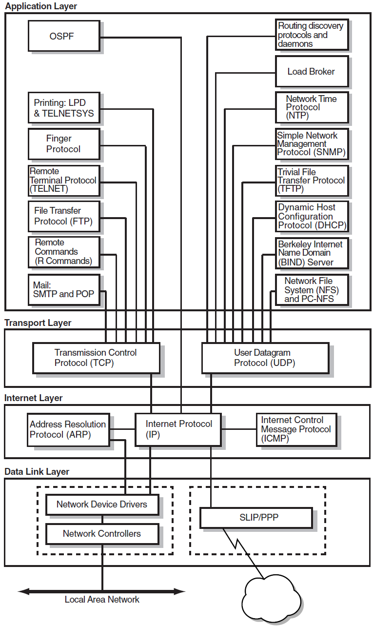
1.1.1. Data Link Layer
At the base of the TCP/IP layers, the Data Link layer formats data and provides services that directly access the physical network.
This layer also receives data that is routed from the Internet layer and transmits the data to its destination, converting logical IP addresses to physical addresses of the network adapter or network interface cards (NICs) using the Address Resolution Protocol (ARP).
Some commonly used network architectures designed for the physical network are Ethernet and its variants, Token Ring, FDDI, and ATM.
A single host computer can have multiple NICs. This configuration is termed a multihomed host. Depending on your network setup, the Data Link layer’s configuration may vary. For more information, see Chapter 3, "OpenVMS Server and Network Configurations".
1.1.2. Internet Layer
The Internet layer moves data around the internet. The Internet Protocol uses addressing to deliver and route packets across networks independently of the network cabling.
At this level, the protocols are:
Internet Protocol (IP)
Internet Control Message Protocol (ICMP)
Address Resolution Protocol (ARP)
The protocol also encapsulates datagram headers, sends ICMP error and control messages, and maps ARP address conversions.
Routing protocols at this layer are:
Routing Information Protocol (RIP) Versions 1 and 2
Open Shortest Path First (OSPF) Version 2
Exterior Gateway Protocol (EGP)
Border Gateway Protocol (BGP)
Router Discovery
For more information about these protocols, see Chapter 5, "Network Server Services".
1.1.3. Transport Layer
The Transport layer enables a flow of data between two hosts. The protocols at this layer are either connection oriented, in which the protocol establishes and maintains the connection between communicating hosts to prevent errors, or connectionless, in which a one-way datagram is sent to a destination host.
The TCP/IP Services supports both transport protocols:
The connection-oriented protocol, Transmission Control Protocol (TCP) provides a reliable data flow between two hosts. TCP is used for complex, large packets that have an IP address.
The connectionless protocol, User Datagram Protocol (UDP) provides a much simpler service to the Application layer than TCP but does not guarantee reliability. UDP is used for simple, small packets and requests for dynamic IP address assignment. UDP packets have a MAC address.
1.1.4. Application Layer
The top layer of the TCP/IP protocol suite, the Application layer handles the details of the particular application, protocol, or user command; it is not concerned with the movement of data across the network.
TCP/IP Services supports the following TCP/IP applications, protocols, and user services:
Remote Computing Services
Remote computing applications enable networked users to run software on remote systems. TCP/IP Services include the following remote computing application components:
TELNET enables remote login to other hosts in the network. VSI TCP/IP Services provides simultaneous multiple sessions, IBM3270 terminal emulation (TN3270) and two interface formats: DCL style and UNIX style.
Remote, or R, commands are use for the following:
RLOGIN for remote login
RSH for remote shell capabilities
REXEC to execute commands to a remote host
RMT/RCD to read magnetic tapes or CD-ROMs from remote hosts
XDM is a network-based graphics window system based on the client/server application model. It enables a system to display information output from an application that is running on another system in the network.
The FINGER utility is used to display user information for the network.
File Transfer Services
TCP/IP Services includes the following components that let users transfer data files between local and remote hosts:
File Transfer Protocol (FTP) transfers files between hosts.
Trivial File Transfer Protocol (TFTP) downloads and transfers files. VSI TCP/IP Services supports downloading of system image and other information to client hosts.
Resource Services
Line printer/line printer daemon (LPR/LPD) provides printing services to local and remote hosts.
TELNET print symbiont (TELNETSYM) provides remote printing services that enable OpenVMS printing features not available with the LPR/LPD print service.
Network File System (NFS) is a protocol that allows computers to access remote files as if they were local files, regardless of operating system, hardware type, or architectural differences between the local and remote systems. This is accomplished in a client/server environment where specific implementations on NFS exist on both the client and server machines.
PC-NFS is a daemon that enables access to the NFS server from a PC by providing authentication services to PC-NFS clients.
Electronic Mail Services
Communication functions such a electronic mail are vital both within an organizational internet and across the Internet worldwide. The electronic mail components of TCP/IP Services are:
Simple Mail Transfer Protocol (SMTP) is the TCP/IP standard protocol for transferring electronic mail messages from one system to another.
IMAP is the Internet Message Access Protocol. IMAP enables clients to access email messages and folders from an IMAP server and synchronize them locally. This enables a client to organize email messages and folders without continuous access to the server.
Post Office Protocol (POP) is a mail repository used primarily by PCs.
1.2. Application Support
Beyond the industry-standard TCP/IP application services, TCP/IP Services provides support for the following products:
PATHWORKS or Advanced Server
DECnet-Plus
1.2.1. PATHWORKS and DECnet-over-TCP/IP Support
The VSI TCP/IP Services for OpenVMS software includes the PWIP driver and the PWIPACP network ancillary control process (ACP). The PWIP driver enables communication between OpenVMS systems running both PATHWORKS server and TCP/IP Services software, and personal computers running PATHWORKS client software. It also enables the DECnet-over-TCP/IP feature, which is included with the DECnet-Plus for OpenVMS Version 6.0 and later software. For more information, see Chapter 7, "Connectivity Services".
1.3. APIs
Network applications specific to the VSI TCP/IP Services can use the following application programming interfaces (APIs):
Berkeley Sockets Interface
OpenVMS QIO System Services interface
ONC RPC programming interface
SNMP programming interface
1.3.1. Berkeley Sockets Interface
Sockets have become a popular programming interface. The Berkeley Sockets Interface is a programming interface that provides applications with access to network communication protocols. A socket is a generalized UNIX communication endpoint on which the TCP/IP protocols have been implemented. Using the socket programming interface makes it easy to implement network applications.
OpenVMS provides support for the socket interface through the C programming language and the VSI C Run-Time Library. The benefits of using the socket interface on the OpenVMS platform include:
Ease of porting network applications from other platforms to the OpenVMS platform. A sockets interface can be generic.
Many application developers are familiar with the programming environment.
In addition to the TCP/IP protocols, there are options for other types of protocols.
For more details, refer to the VSI TCP/IP Services for OpenVMS Sockets API and System Services Programming manual.
1.3.2. OpenVMS QIO System Service Interface
The standard I/O programming interface on OpenVMS uses the QIO (queue input/output) system services. QIO services provide a rich set of functions for controlling devices, and connections and for performing input (read) and output (write) operations.
The benefits of using the OpenVMS QIO interface include:
Support for the QIO interface in the following programming languages:
MACRO-32
VSI C
VSI Fortran
VSI Ada
VSI and VAX BASIC
VAX BLISS-32
VSI COBOL
VAX Pascal
VSI PL/1
Ability to handle complex applications with many concurrent connections
Efficient input/output operations
Robust asynchronous event handling (While sockets offer the ability to do nonblocking I/O operations, they do not offer the ability to perform asynchronous I/O.)
Ease of DECnet applications portability to TCP/IP protocols
For more details, refer to the VSI TCP/IP Services for OpenVMS Sockets API and System Services Programming manual.
SRI QIO Compatibility
TCP/IP Services provides support for customer applications using the INETDRIVER QIO interface developed at Stanford Research Institute (SRI) in 1980-81. An SRI QIO emulator that translates non-TCP/IP Services QIO interfaces into TCP/IP Services QIO programming interfaces can be configured by using the TCPIP$CONFIG procedure.
1.3.3. ONC RPC Programming Interface
The RPC programming interface is an industry-standard, portable API that is an efficient alternative to using sockets for application development. Programmers do not need an in-depth knowledge of networking protocols to use RPC.
One strong point of the RPC interface is its ability to distribute functions across the network. This is done in an architecture-independent manner, thereby avoiding problems with floating-point formats and byte-address ordering that often occur when interacting between architectures.
This API includes:
Library of RPC function calls
Portmapper service, which is a service that client programs can use to determine the port number that another service uses. Clients use the Portmapper Service for NFC, PC-NFS, and RPC applications.
External data representation (XDR) routines
For more details, refer to the VSI TCP/IP Services for OpenVMS ONC RPC Programming manual.
1.3.4. SNMP Programming Interface
The Extensible Simple Network Management Protocol (eSNMP) API provides routines for developing applications that remotely manage and collect data from network devices such as routers, bridges, and hosts.
These network devices run software that carries out management commands that either get information from devices or set operating parameters for devices.
Other network applications send commands to network devices to perform configuration management, monitor network traffic, or troubleshoot network problems.
The SNMP API provides routines for the following functions:
Establish, maintain, and terminate communication with the master agent
Manipulate, reformat, extract, and compare data
Control information that is written to log files
The SNMP API routines are almost identical in function and interface with the routines in the UNIX API.
For more details, refer to the VSI TCP/IP Services for OpenVMS SNMP Programming and Reference manual.
1.4. Understanding RFCs
Although TCP/IP is monitored by a number of organizations, no single entity owns this protocol; its specifications are publicly available and are constantly growing as communications requirements evolve.
The process by which the specifications evolve is through a mechanism called Requests for Comments (RFCs). When someone has an idea for a new or improved capability for TCP/IP, he or she writes a proposal, posts it on the Internet as an Internet draft, and requests comments from the networking community. After a review and revision cycle, working code is developed and an RFC becomes a standard protocol.
RFCs are available on the Internet.
Note that, although RFCs recommend implementation guidelines, the actual implementation of an RFC can and must differ from the RFC in minor ways. When product documentation refers to specific RFCs, be aware that the RFC only sets the standard for development. Product developers must design their software for the specific environment and requirements of their customers.
Chapter 2. Understanding OpenVMS and UNIX Implementations
An important step in planning a network host implementation is to gain an understanding of the computing environments in which the network services will run. UNIX implementations of TCP/IP Services are often ported to OpenVMS. As a result, they often appear to be identical. However, there are many significant differences. This chapter describes key implementation differences between UNIX and OpenVMS networks. The following topics are discussed:
Evaluating the computing environment
File compatibility
Portability
Determining which file system to use
Things to Consider In planning your TCP/IP Services environment, consider the following:
Do I need to migrate from one operating system to the other?
Do I need to set up a system that coexists with multiple operating systems?
Should I choose a Files–11 file system or a container file system?
2.1. Evaluating the Computing Environment
The issues of working in a heterogeneous computing environment that includes OpenVMS and Tru64 UNIX operating systems are complex. Consider these concepts when evaluating or implementing an interoperability strategy:
Migration occurs when software applications are rewritten as necessary to be ported from one operating system to the other. In a general sense, not only the applications but also the users migrate to another system. Migration implies a gradual replacement of the original system with the new system.
Coexistence occurs when two or more systems, such as OpenVMS and Tru64 UNIX, are maintained as part of a larger, heterogeneous computing environment. The amount of interoperability varies with the individual configurations. It is possible to set up nearly identical network configurations, thereby reducing maintenance.
2.1.1. Understanding the Open Systems Concept
The client/server model of computing means that users running applications on their PCs and workstations are networked with larger departmental systems. The departmental systems provide a variety of services to the clients, such as access to common database, print, and backup/archive services.
To best serve this model of computing, the systems must be open. Open environments support interoperability and application portability and enable developers and users to easily use different platforms. The OpenVMS operating system is an open system with an extensive list of functions.
An open system allows the OpenVMS operating system, whether powered by Alpha or VAX, to interoperate efficiently with UNIX and with other vendors’ operating systems, particularly with Windows NT and other UNIX operating systems.
2.1.2. Understanding the Middleware Concept
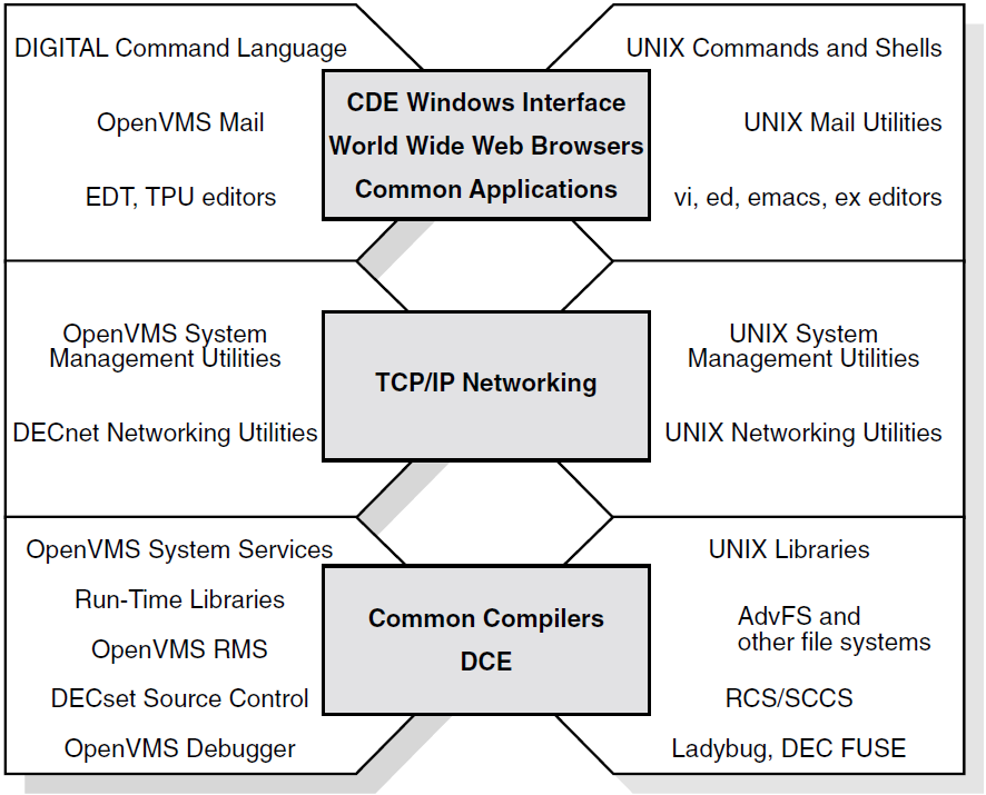
Implementing open systems means using the right middleware between the operating system and the hardware platform and applications. Consistent middleware affords interoperability and portability when and where it is needed. An open systems strategy involves a consistent middleware approach that is based on standards and is embodied in layered software and in individual operating systems, such as OpenVMS and UNIX. DCE (Distributed Computing Environment) is an example of middleware, with standard interfaces supported on both OpenVMS and UNIX. DCE is an architecture of standard programming interfaces, conventions, and server functions that transparently distributes applications across heterogeneous networks.
As shown in Figure 2.1, ''Comparison of OpenVMS and UNIX'', OpenVMS and UNIX interoperate efficiently, especially in areas that are common to both platforms: windowing interface, standard POSIX and DCE programming interfaces, compilers, networking products, and applications.
2.2. File Compatibility
The Network File System, or (NFS) provides a standard for the exchange of data between machines running different operating systems. NFS enables users to access directories and files on remote computers transparently, as if they were on the local system. NFS accomplishes this because it is implemented on the both the remote and the local computer.
NFS protocol achieves portability between different machines, operating systems, network architectures, and transport protocols through the use of Remote Procedure Call (RPC) and External Data Representation (XDR). For more information about RPCs and XDR, refer to the VSI TCP/IP Services for OpenVMS ONC RPC Programming manual.
Using NFS is simple. Configuring and implementing NFS, however, are more complex. For NFS concepts and considerations, as well as detailed configuration and implementation information, refer to the VSI TCP/IP Services for OpenVMS Management guide.
TCP/IP Services accommodates the numerous key differences between UNIX and OpenVMS to make user interaction between the two operating systems appear transparent. This enables all systems on a heterogeneous network to store and share files and applications regardless of file specification and structure differences.
This section discusses:
Directory hierarchies
File specifications
Linking files
File structures
File ownership
File protection
UNIX style file system on TCP/IP Services hosts
2.2.1. Directory Hierarchies
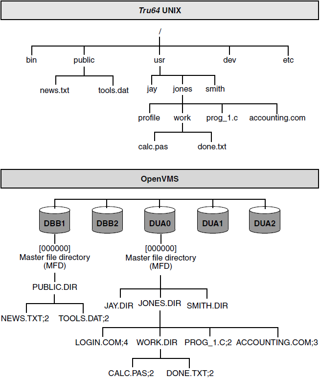
Unlike OpenVMS, the UNIX hierarchy appears as one tree (starting from the root directory, or “/”) that can be located on more than one device. Table 2.1, ''Directory Hierarchy Differences'' describes the differences between the OpenVMS and Tru64 UNIX directory hierarchies.
| OpenVMS | UNIX |
|---|---|
| Reside on one volume having one root above all directories on the volume. | Can reside on multiple volumes. |
| Device names included in file specifications. | Device names not included in file specifications. |
Figure 2.2, ''Comparison of UNIX Directory and OpenVMS Directory Hierarchies'' illustrates the differences between a UNIX file structure and an OpenVMS file structure.
2.2.2. File Specifications
There are basic differences between OpenVMS and UNIX file specifications. Table 2.2, ''File Specification Differences'' summarizes the differences.
| OpenVMS | UNIX |
|---|---|
|
Files are delimited in the following way:
The ODS-5 file system implements extended file specifications and is a step toward improving interoperability. ODS-5 is described later in this chapter. For complete details about the ODS-5 file specification, refer to the OpenVMS product documentation. |
The slash (/) is the only delimiter that the UNIX file specification format uses. The first slash in a UNIX file specification represents the root directory. Subsequent slashes separate each element of the file specification (the directories from the other directories and the file name). In theory, there is no limit to the number of directory levels in a UNIX file specification. |
OpenVMS file specification format
On a standard Files-11 On-Disk Structure Level 2 (ODS-2) volume, an OpenVMS file specification has the following format:
device:[directory.subdirectory]filename.type;version
UNIX file specification format
On a UNIX system, the file specification has the following format:
/directory/subdirectory/filename
2.2.3. Absolute and Relative File Specifications
OpenVMS and UNIX both have two types of file specifications or pathnames: absolute and relative. Table 2.3, ''Absolute and Relative File Specification Differences'' describes the differences between the two platforms.
| OpenVMS | UNIX |
|---|---|
|
The relative path for file [.accounting.calc;1] The absolute path is: usr:[jones.accounting.calc;1] |
The relative pathname for file accounting/calc The absolute pathname is /usr/jones/accounting/calc On UNIX systems, absolute pathnames use the entire directory path that leads to the file, beginning with the root, which is represented by an initial slash. The root directory is the first directory in the file system. All other files and directories trace their ancestry back to the root. Relative pathnames begin the directory path with the current working directory and exclude the current working directory name in the pathname. There is no initial slash in a relative pathname. |
2.2.4. File Specifications
There are fundamental differences between file names specified in OpenVMS and in UNIX. Table 2.4, ''File Specification Differences'' describes those differences.
| OpenVMS | UNIX |
|---|---|
|
Includes, in this order:
An OpenVMS file specification can have a maximum of 255 characters. The file name and file type can have up to 39 characters each and are separated by a period. For example: FILE_NAME.TXT;1 Valid characters in an OpenVMS file name or type include: A–Z, a–z, 0–9, underscore (_), hyphen (-), and dollar sign ($). The version number (preceded by a semicolon) is a decimal number from 1 to 32767; it differentiates versions of the same file. |
Contains up to 1024 characters, with each element of the pathname containing up to 255 characters. UNIX file specifications have the following format: file_name.txt Some older versions of the UNIX operating system limit the size of one element to 14 characters, or have other limits that you can change if you recompile the kernel. In theory, you can use any ASCII character in a UNIX pathname except for the slash (/) and null characters. For example, a valid file name in UNIX can be: report.from.january_24 However, avoid characters (such as the pipe (|) character) that can have special meaning to the UNIX shell. |
2.2.5. Case Sensitivity
Case sensitivity differs between the two operating systems. Table 2.5, ''Case-Sensitivity Differences'' describes the difference.
| OpenVMS (ODS-2) | UNIX |
|---|---|
|
Stores everything in uppercase. For example, any case variations of the following file name is stored in uppercase: CHAPTER_ONE.TXT;1 |
Regards uppercase and lowercase characters as different characters. For example, on a UNIX system, the following file names represent three different files:
|
2.2.6. File Types
Table 2.6, ''File Type Differences'' describes the file type differences between OpenVMS and UNIX.
| OpenVMS | UNIX |
|---|---|
|
Important in OpenVMS file identification The file type usually describes the kind of data in the file. For example, a text file typically has a file type of .TXT. All OpenVMS directories have a file type of .DIR. |
UNIX systems do not use file types. However, UNIX has certain naming conventions that resemble OpenVMS file types. For example, file names ending in UNIX directories do not have file types. |
2.2.7. Version Numbers
Table 2.7, ''Version Number Differences'' describes file version number differences between OpenVMS and UNIX.
| OpenVMS | UNIX |
|---|---|
|
Every file has a version number. When a file is created, the system assigns it a version number of 1. Subsequently, when a file is edited or when subsequent versions of that file are created, the version number automatically increases by 1. Therefore, many versions of a file with the same file name can exist in the same directory. For example: FILE_NAME.TXT;1 FILE_NAME.TXT;2 FILE_NAME.TXT;3 |
The UNIX file system does not support automatic creation of multiple versions. In most cases, if you edit a UNIX file, the system saves only the most recently edited copy. For example: file_name.txt |
2.2.8. Linking Files
A link is a directory entry that refers to a file or another directory. Table 2.8, ''Link Files Differences'' describes the differences between OpenVMS and UNIX file linking.
| OpenVMS | UNIX |
|---|---|
|
Files can exist without links. Hard Links OpenVMS systems allows you to perform a function similar to hard links with the SET FILE/ENTER and SET FILE/REMOVE commands. The OpenVMS operating system does not maintain a count of links to a file. As a result, you can delete a file without deleting its links. Symbolic Links OpenVMS file systems do not support symbolic links. |
Files cannot exist without links. Hard Links Hard links allow users to share the same file under different pathnames. A hard link cannot span file systems. On UNIX systems, any changes to the file are independent of the link used to refer to the file. The UNIX system maintains a count of the number of links to each file. If removing a link results in the link count becoming zero, the file is deleted. A file can be deleted only by removing all of its links. Symbolic Links A symbolic link is a file that contains the name of the file to which it is connected. Symbolic links provide a path to the original file. A UNIX symbolic link can span file systems. Unlike a hard link, a symbolic link does not maintain a link count. In addition, symbolic links can exist after the file is deleted. However, the system returns an error if the symbolic link file is accessed after the file it names is deleted. |
2.2.9. File Structures
Table 2.9, ''File Structure Differences'' describes the differences between the OpenVMS and UNIX file structures.
| OpenVMS | UNIX |
|---|---|
|
Supports three file structures: indexed, relative, and sequential. OpenVMS also supports the following record formats and record attributes:
|
Supports byte streams only. The records in UNIX text files have the same format as the OpenVMS Record Management Services (RMS) STREAM_LF record format. |
2.2.10. File Ownership
The OpenVMS and UNIX operating systems use different mechanisms for file ownership. Table 2.10, ''File Ownership Differences'' describes those differences.
| OpenVMS | UNIX |
|---|---|
|
The OpenVMS operating system controls file ownership and access through a user identification code (UIC). A UIC is a 32-bit value that consists of a 14-bit group number, a 16-bit member number, and 2 reserved bits. Each user of the system has a UIC defined in the SYSUAF file. Access to objects depends on the relationship between the UIC of the accessing process and the UIC of the object (the file or directory). OpenVMS controls file access through an access control list (ACL). You can deny or grant read, write, execute, delete, and control access to a user or group of users who have the identifier specified by the ACL. For additional ACL information, refer to the OpenVMS documentation set. The NFS protocol does not provide ACL support. Therefore, the NFS client is unaware of ACLs that the NFS server applies to the file. Consequently, the NFS client cannot use an ACL to control file access. Access control is determined through standard file protections. For more information, see Chapter 2, "Understanding OpenVMS and UNIX Implementations". |
The UNIX operating system controls access to files with user identification (UID) and group identification (GID). UNIX uses 32-bit UIDs and GIDs. For compatibility, NFS also recognizes 32–bit UIDs and GIDs. |
2.2.11. File Protections
The OpenVMS and UNIX operating systems use similar file protection schemes, as shown in Table 2.11, ''Comparison of File Protection''.
| Mechanism | OpenVMS | UNIX |
|---|---|---|
| User classifications |
SYSTEM (S) OWNER (O) GROUP (G) WORLD (W) Classification depends on the relationship between the UIC of the accessing process and the object. |
System category is not used. System administrators always have access to UNIX files. |
| Protection levels |
READ (R) WRITE (W) EXECUTE (E) – Controls file execution and directory search access DELETE (D) |
A file is deleted if it is unlinked from the directory and had no links in other directories. Write access to the directory is refused. |
| Syntax | s:rwed, o:rwed, g:rwed, w:rwed |
The protection levels are divided into groups of three characters:
|
2.3. Portability
The TCP/IP Services allows you to create a logical UNIX style file system on an OpenVMS host. Remote UNIX hosts that have NFS software can then access this file system. When a remote UNIX system accesses files, these files conform to UNIX file system rules, not to the OpenVMS rules. This ensures that existing UNIX applications work without change. The logical UNIX file system resides on a Files-11 formatted disk and is represented as a set of Files-11 files called a container file system. For information about creating a UNIX file system on an OpenVMS host, refer to the VSI TCP/IP Services for OpenVMS Management guide.
The UNIX file names and attributes are catalogued in the container file, one of the files in the container file system. The container file also has a representation of the UNIX directory hierarchy and a pointer to the data file for each file name. In addition to its UNIX name, each file in the container file system has a valid Files-11 file name assigned by the system. An OpenVMS directory exists for each UNIX directory stored in the container file. All files catalogued in a UNIX directory are also catalogued in the corresponding OpenVMS directory. However, the UNIX directory hierarchy is not duplicated in the OpenVMS directory hierarchy. Each UNIX file is represented as an OpenVMS data file. Therefore, OpenVMS utilities, such as BACKUP, can use standard methods to access these files.
2.4. Determining Which File System to Use
The first step in managing your TCP/IP Services system is to decide which file system to use. NFS on OpenVMS enables you to set up and export three different kinds of file systems:
OpenVMS On-Disk Structure (ODS-2) file system, in which devices, directories, and files are stored on a Files-11 formatted disk
OpenVMS On-Disk Structure (ODS-5) file system, which enables creation and storage of files with extended file names for compatibility with other file systems, such as Windows.
UNIX, or container, file system, built on top of an OpenVMS system. If you are not familiar with OpenVMS file systems, refer to the OpenVMS System Manager’s Manual: Essentials to learn how to set up and initialize a Files-11 disk. As Figure 2.2, ''Comparison of UNIX Directory and OpenVMS Directory Hierarchies'' shows, both file systems are structured as hierarchical, multilevel directories. On OpenVMS systems, the top level is called the master file directory, or MFD. This directory contains all the directories and reserved system files. The directory is named [000000]. On UNIX systems, the top-level directory is called the root, or / .
Table 2.12, ''NFS Server Features Available to Non-OpenVMS Clients'' lists the NFS server features available to non-OpenVMS clients based on file system choice.
| Features | ODS-2 | OD2–2 with name conversion | ODS-5 | Container file system |
|---|---|---|---|---|
| Files easily shared between remote clients and local OpenVMS users | Yes | Yes | Yes | No |
| Mixed case, special characters, and extra dots in file names | No | Yes | Yes | Yes |
| Long file names | No | No | Yes | Yes |
| File names look the same to remote clients and local OpenVMS users | Uppercase to local users, lowercase to remote clients | No | Yes | N/A |
| Support for hard links, symbolic links, special files | No | No | No | Yes |
| UNIX compatible timestamps | No | No | No | Yes |
| Case-sensitive lookup | N/A | Yes | No | Yes |
The dual cataloguing of files to both OpenVMS file systems limits the set of DCL commands. OpenVMS utilities, such as BACKUP, can use standard methods to access the files. However, except for backing up and restoring files, you should not use DCL commands to manipulate files in a container file system.
Decision Point
Your file system choice depends on your environment and the user needs on the NFS client host. Consider using an OpenVMS file system if:
Your users share most files between your OpenVMS system and another OpenVMS host, or between your OpenVMS system and a UNIX client.
Your client users need to maintain multiple versions of files.
You share files between users on OpenVMS and users on NFS clients.
File sharing between your OpenVMS system and a UNIX client is minimal.
Client applications use symbolic or hard links or special files.
For More Information
For more information about the following topics, refer to the VSI TCP/IP Services for OpenVMS Management manual:
Setting up container file systems
Configuring and implementing the NFS server
For a list of commonly used UNIX commands and their equivalents on OpenVMS, refer to the VSI TCP/IP Services for OpenVMS Tuning and Troubleshooting manual.
For more details about interoperability between UNIX and OpenVMS, refer to the VSI OpenVMS and UNIX Interoperability and Migration Guide. This guide discusses products and services, available both from VSI and from other vendors, that might provide solutions to interoperability problems.
For more information about RPCs and XDR, refer to the VSI TCP/IP Services for OpenVMS ONC RPC Programming manual.
For additional ACL information, refer to the OpenVMS documentation set.
Chapter 3. OpenVMS Server and Network Configurations
There are several server and network configurations to consider before installing TCP/IP Services for OpenVMS. This chapter describes the following concepts that will enable you to make informed decisions about these configuration options:
OpenVMS VAX and Alpha similarities and differences
Cluster environments
Multiple interfaces and multihoming
Pseudointerfaces
Serial lines
Note
VAX development has limited continued support. VAX users should consider migrating to Alpha, if possible.
Things to Consider
In planning your TCP/IP Services for OpenVMS configurations, consider the following:
Does the network contain VAX or Alpha systems, or both?
Is my system running a DHCP server?
Is my system running a DHCP client?
How many interfaces does the system have?
Do I have serial lines in my network? If so, for which systems are they used?
3.1. Understanding OpenVMS VAX and Alpha Systems
You need to consider several issues when you plan to add one or more OpenVMS Alpha systems to your OpenVMS VAX computing environment. For full details about the similarities and differences between OpenVMS Alpha and OpenVMS VAX, refer to the VSI OpenVMS Compatibility Between VAX and Alpha guide.
3.1.1. User Environment
The user environment on OpenVMS Alpha is virtually the same as that on OpenVMS VAX. Table 3–1 describes the similarities and differences.
| Component Similarities | OpenVMS VAX Differences | OpenVMS Alpha Differences |
|---|---|---|
|
Digital Command Language (DCL) Essentially the same on both systems. | None | Refer to the few exceptions in the OpenVMS Compatibility Between VAX and Alpha guides available on line. |
|
DCL Help Most DCL help text is common to both systems. | System-specific information is identified by the phrase “On VAX.” | System-specific information is identified by the phrase “On Alpha.” |
|
DCL command procedures Most DCL command procedures, with commands, qualifiers, and lexical functions, work on both systems. | None | A few command procedures contain qualifiers not available on OpenVMS Alpha. |
|
Databases Standard databases, such as Oracle Rdb, function the same on both systems. | None |
Most third-party databases available for OpenVMS VAX are also available for OpenVMS Alpha. |
3.1.2. System Management Environment
Most OpenVMS VAX system management utilities, command formats, and tasks are identical on OpenVMS Alpha, with the following exceptions:
On VAX, use of the POLYCENTER Software Installation utility is limited to the installation of layered products, such as VSI TCP/IP Services for OpenVMS.
On Alpha, the POLYCENTER Software Installation utility is also used to install both the OpenVMS operating system and layered products.
For more information about implementation differences between OpenVMS VAX and OpenVMS Alpha, refer to the VSI OpenVMS System Manager's Manual.
3.1.3. Programming Environment
The same types of programming development tools that OpenVMS VAX programmers use are available on OpenVMS Alpha systems, such as the Linker utility, the Librarian utility, the OpenVMS Debugger (also known as the symbolic debugger), the Delta/XDelta Debugger, and run-time libraries. However, some TCP/IP Services components are available only on OpenVMS Alpha, including:
BIND Version 9
IMAP
PPP
These components are introduced later in this manual.
For details about the similarities and differences between the programming environment on VAX and Alpha, refer to A Comparison of System Management on OpenVMS AXP and OpenVMS VAX, which provides guidelines for developing applications that run on both OpenVMS VAX and OpenVMS Alpha, as well as additional guidelines for systems that run in a mixed-architecture OpenVMS Cluster.
3.2. OpenVMS Cluster Configuration
VSI TCP/IP Services for OpenVMS supports OpenVMS Cluster systems and the use of cluster aliases. The network sees the cluster as one system with one name, the cluster alias. A remote host can use the cluster alias to address the cluster as one host, or it can use the host name of a cluster member to address a cluster member individually.
In a DECnet network, it is convenient to be able to treat nodes within a homogeneous OpenVMS Cluster as though they were a single node. You can do this by establishing an alias node identifier for the cluster. You can specify the alias node identifier as either a unique node address or a corresponding node name. Any member node can elect to use this special node identifier as an alias while retaining its own unique node identification. For more information on the use of the optional cluster alias node identifier, refer to the VSI OpenVMS DECnet Networking Manual.
Note
DECnet–Plus software is not required in an OpenVMS Cluster configuration. However, DECnet–Plus is necessary if internode process-to-process communication using DECnet mailboxes is needed. For more information about DECnet-Plus in an OpenVMS Cluster configuration, refer to the Guidelines for OpenVMS Cluster Configurations manual.
For load balancing, an OpenVMS Cluster can consist entirely of OpenVMS Alpha nodes or of a combination of OpenVMS VAX and OpenVMS Alpha nodes.
You can have numerous OpenVMS Cluster configurations. For complete information about supported devices and configurations, refer to Guidelines for OpenVMS Cluster Configurations and the OpenVMS Cluster Software Software Product Description (SPD). For complete information about setting up and using an OpenVMS Cluster environment, refer to the VSI OpenVMS Cluster Systems Manual.
3.2.1. Failover Capability
Failover capability is the hallmark of a cluster environment. If one computer, or node, in the cluster fails, the others can assume its functionality and continue. This is called automatic failover.
Each node (as a member of the host configuration in
the cluster) retains a separate IP address. This is beneficial for troubleshooting the
individual node because you can ping the specific node to see whether it is
running.
All of the TCP/IP services support automatic failover and can run on multiple nodes in an OpenVMS Cluster. For example, if more than one node in the cluster is running the NFS server, the cluster can appear to the NFS client as a single host. For more information about configuring a specific service for cluster failover, refer to the particular service in the VSI TCP/IP Services for OpenVMS Management guide.
3.2.2. Connection Load Balancing
Load balancing using the TCP/IP Services is defined by the load broker. The load broker is a configurable, calculated, load-balancing mechanism for distributing the work load among DNS (Domain Name System, which maintains and distributes information about Internet hosts) cluster members. For more information about DNS, see Chapter 5, "Network Server Services".
Unlike round-robin scheduling (the default method used by most DNS name servers, in which each individual node in the cluster is polled in a continual, specific order), the load broker takes into account the load on all DNS cluster participants. The load broker polls DNS cluster members and updates the metric server accordingly.
When the load broker starts, it reads its configuration file and starts polling DNS cluster members. The load broker exchanges messages with DNS cluster members that run the metric server, which calculates the current load on a DNS cluster host by using a specific equation. The metric server calculates the current rating and reports it when polled by the load broker. Periodically, the load broker sorts the list of addresses based on metric rating reports, drops the systems that do not respond after being polled three times, and compares a subset of the list with the name server information.
To do the comparison, the load broker sends a host lookup request to the specified name server. If the lists are the same, the load broker does not make changes. If the lists are different, the load broker updates the name server data by sending a dynamic update request to the specified name server. The name server uses round-robin scheduling to further balance the load across the members of a DNS cluster. Thus, every consecutive request for translating the DNS cluster name results in a returned list, is rotated by one.
For specific information about configuring the load broker, starting and stopping the metric server, and troubleshooting, refer to the VSI TCP/IP Services for OpenVMS Management guide.
3.3. Multihoming and Multiple Interfaces
Although host computers can have several network interface cards (NICs) installed, you can configure the host through a single, primary interface. This section introduces the following concepts:
Multihomed computers
Primary interface
Pseudointerfaces
3.3.1. Multihomed Computers
Individual host computers can have multiple network interface cards per computer. Such a computer is called multihomed. These physical interfaces can be connected to different types of networks, such as Ethernet, FDDI, Token Ring, asynchronous transfer mode (ATM), Gigabit Ethernet, and serial communications lines. Each physical interface is associated with one device driver (network interface). A single network interface can have more than one IP address.
Note
If a host has multiple interfaces under DHCP (Dynamic Host Configuration Protocol) control and receives a different host name from a DHCP server on each of the DHCP-controlled interfaces, the DHCP client uses the host name it receives on the primary interface to configure the host name for the client. For more information about DHCP, see Chapter 5, "Network Server Services".
3.3.2. Primary Interface
Although you can have multiple physical interfaces on a single computer, some of the parameters that are configurable by DHCP are interface specific. Examples of interface-specific parameters are the IP address and subnet mask. However, most DHCP configurable parameters are systemwide configurable parameters. Examples of systemwide parameters are the host name and DNS domain name. The TCP/IP Services DHCP client supports controlled configuration of systemwide configurable items by designation of a primary interface.
The primary interface is the interface on which the DHCP client uses systemwide parameters received from the DHCP server to configure the system. Systemwide parameters received on an interface that is not designated as primary are not configured on your system by the server. Although only one interface on a system is designated as the primary DHCP interface, the system is not required to have any interface designated as primary.
If a system has multiple interfaces and only one is under DHCP control, you can configure the systemwide parameters manually. DHCP client uses the following rules to resolve conflicts:
The only-one-primary-interface rule
This rule solves the potential conflict between two DHCP controlled interfaces on a host getting different systemwide parameter values. To resolve the conflict, you designate one interface to be the primary interface and the parameters that you receive on that interface are the values the DHCP client uses to configure the system. TCP/IP Services does not let you designate two primary interfaces.
The primary-interface-not-required rule
This rule solves the problem of DHCP configuring interfaces with an IP address but also keeping manual control of the systemwide parameters. In this case, the DHCP client does not designate the interface as the primary interface, and it ignores any systemwide parameters it receives from a DHCP server.
For details about configuring multiple interfaces, refer to the VSI TCP/IP Services for OpenVMS Management guide.
3.3.3. Pseudointerfaces
To use extended routing, you can define pseudointerfaces. A pseudointerface is a data structure that extends subnet routing using a network interface. Each network interface has one name and at most nine pseudointerface names. Each network interface and pseudointerface has its own IP address, network mask, and broadcast mask.
Like an interface, the name of an internet pseudointerface consists of three alphabetic characters, followed by the pseudointerface unit number in the range of 0 through 255. The first two characters are the same as the two characters in the internet interface name (interface type and interface class). The third character identifies the controller letter that corresponds to the OpenVMS hardware controller. For more information about interface names, refer to the VSI TCP/IP Services for OpenVMS Management guide.
3.4. Serial Line Connections
A serial connection is made between two systems using modems and telephone lines or other serial lines. TCP/IP Services supports serial connections using PPP (Point-to-Point Protocol) and SLIP (Serial Line Internet Protocol). SLIP includes CSLIP (compressed SLIP). You can use any standard OpenVMS terminal device as a PPP or a SLIP line. However, PPP is available for OpenVMS Alpha systems only.
One of the largest applications for IP over serial lines is dialup access. With this type of configuration, your OpenVMS host answers calls and establishes a connection initiated by a user on a client host. The client host can be another OpenVMS system, a UNIX system, or a PC. Alternatively, users on your host can originate the dialup connection to a remote host or terminal server that is running the same protocol. Dedicated serial lines running PPP or SLIP can also be used to connect separate LANs into a single WAN. In such a configuration, the host at each end of the serial connection is always the same; no other hosts are allowed to connect to either serial device.
If your OpenVMS system is part of a large network, you will probably use both PPP and SLIP for your serial connections. As an Internet standard, PPP is often preferred because it ensures interoperability between systems from a wide variety of vendors. PPP provides a way for your OpenVMS Alpha system to establish a dynamic IP network connection over a serial line without additional router or server hardware.
SLIP has been in use for a longer period of time than PPP and is available for most terminal servers and in most PC implementations of TCP/IP. Because SLIP and PPP do not communicate with each other, hosts must use the same protocol in order to communicate. For example, if your terminal server supports only SLIP, remote hosts that connect through this server must also use SLIP. For more information about configuring serial lines, refer to the VSI TCP/IP Services for OpenVMS Management guide.
For More Information
For more information about the following topics, refer to the VSI TCP/IP Services for OpenVMS Management guide.
Configuring and troubleshooting OpenVMS Clusters, including load balancing and failover configurations
Configuring multiple interfaces and multihomed systems
Details about pseudointerfaces
Configuring serial lines
For detailed descriptions of OpenVMS Alpha and VAX similarities and differences, refer to A Comparison of System Management on OpenVMS AXP and OpenVMS VAX.
For complete information about supported devices and configurations, refer to the Guidelines for OpenVMS Cluster Configurations and the OpenVMS Cluster Software Software Product Description (SPD). For complete information about setting up and using an OpenVMS Cluster environment, refer to the VSI OpenVMS Cluster Systems Manual.
Chapter 4. OpenVMS Operating System TCP/IP Features
The OpenVMS operating system contains a number of features that are of specific benefit to the TCP/IP environment. This chapter discusses the following topics related to these features:
TCP/IP management commands
Using logical names
OpenVMS System Dump Analysis (SDA) Tool
Accessing system messages through operator communication manager (OPCOM) and log files
Comparison of ODS-5 and ODS-2 file structures
Print queues (network printers)
Things to Consider
In planning your TCP/IP Services for OpenVMS, consider the following:
Should I use ODS-5? For which disks?
Where should I store the log files?
Which printers in my system are network shareable? How will users access them?
Which printers in my system are on a serial line?
Should I configure PATHWORKS shares for printers?
4.1. TCP/IP Management Control Program
The TCP/IP Services Management Control Program is a comprehensive, easy-to-use network management tool that includes more than 100 OpenVMS commands. TCP/IP Services provides this management command interface to configure and modify parameters of components, configure customer-developed services, enable and disable running components, and monitor the running software.
To start the management control program, enter the following command:
$ TCPIP
TCPIP>
At the TCPIP> prompt, you can enter commands such as the following:
SHOW SERVICES
SHOW CONFIGURATION
HELP
SET HOST
COPY
DIR
You can also use UNIX management commands to manage some components of TCP/IP Services.
To use UNIX management commands at the DCL prompt, run the following command procedure:
$ @SYS$MANAGER:TCPIP$DEFINE_COMMANDS
Then enter UNIX commands as you would on a UNIX system.
TCP/IP management commands are described fully in the VSI TCP/IP Services for OpenVMS Management Command Reference manual, and in the TCP/IP Services online help.
TCPIP> HELP
To exit the management control program, enter the following command:
TCPIP> EXIT
To obtain information about TCP/IP Services, enter the following command at the DCL prompt:
$ HELP TCPIP_SERVICES
4.2. Defining Logical Names
Logical names allow you to customize component behavior. Logical names can point to directories, database files, and log files.
To define a logical name, enter the following DCL command:
$ DEFINE logical-name
For more information about these logical names, refer to the VSI TCP/IP Services for OpenVMS Management guide.
The TCPIP$CONFIG database predefines logical names for various databases. During the menu-driven installation procedure, the software configures either the components you select or all of the TCP/IP Services software components. These defaults are designed to get your system up and running as an internet host with minimal effort. TCPIP$CONFIG creates the database files.
After the initial configuration of a component, you can use logical names to modify the settings of the component-specific parameters. Many logical names are defined as “existence logical names”; that is, they can be either on or off. Any value associated with them is ignored. Others require a value of text string as a definition. Every logical name has a default setting.
For more information about how TCP/IP Services components uses logical names, see relevant chapters in this manual and refer to the VSI TCP/IP Services for OpenVMS Management guide.
4.3. OpenVMS System Dump Analysis (SDA) Tool
TCP/IP Services for OpenVMS provides network-specific enhancements to the OpenVMS System Dump Analysis (SDA) tool. For more information about SDA enhancements, refer to DCL online help.
If your system fails, you can run the SDA tool on system reboot to analyze the system crash dump. You can do this by adding command lines to the SYSTARTUP_VMS.COM procedure.
If you are unable to analyze a process dump with the debugger, use the System Dump Analyzer (SDA) utility. Refer to the ANALYZE/CRASH command in online help for more information. For example:
$ ANALYZE/CRASH billsystem.dmp

OpenVMS (TM) Alpha system dump analyzer
...analyzing a compressed process dump...

Dump taken on 24-JUL-2002 12:03:40.95
SDA>
For details, refer to the OpenVMS VAX System Dump Analyzer Utility Manual and the OpenVMS Alpha System Dump Analyzer Utility Manual.
4.4. System Messages
You can keep log files of events, changes, and other configuration data in two ways.
Using OPCOM (operator communication manager) — available only if you have system privileges.
Using log files that most components establish when they are configured.
System messages are saved to either one of these utilities. Both are described in this section.
4.4.1. OPCOM
Any terminal that is connected to the operating system can be established as an operator’s terminal if OPCOM (operator communication manager) is running. When an operator who is logged in to an account with OPER privilege enters the REPLY/ENABLE command at the designated terminal, that terminal can be used to respond to user requests and to monitor device status. Operator messages are displayed on the system console terminal unless the terminal is explicitly disabled as an operator’s terminal.
To set up a terminal to receive OPCOM messages, enter the following command:
$ REPLY/ENABLE
4.4.2. Log Files
Event logging can help you manage the TCP/IP Services software. By default, user-defined services do not log events, but event logging is enabled by default for all supplied services. You can configure the product to log events to the operator’s console or to a log file, or to both. Every component has a default log file. For more information about log files, refer to the VSI TCP/IP Services for OpenVMS Management guide.
To set up event logging, enter the following command:
TCPIP> SET SERVICE service-name /LOG_OPTIONS=ALL
For a list of all the logging options, refer to the SET SERVICE command description in the VSI TCP/IP Services for OpenVMS Management Command Reference manual.
Some product components provide additional event logging capabilities. For more information, see the relevant chapters in this manual.
4.5. ODS-5 and ODS-2 File Structures
OpenVMS implements On-Disk Structure Level 5 (ODS-5). This structure provides the basis for creating and storing files with extended file names. The format was introduced for compatibility with other file systems, such as Windows. You can choose whether or not to convert a volume to ODS-5 on your OpenVMS Alpha systems.
The ODS-5 volume structure provides the following features:
Long file names
More legal characters in file names
Preservation of case in file names
These features are described in detail in the OpenVMS product documentation.
ODS-5 provides enhanced file-sharing capabilities for TCP/IP Services as well as for Advanced Server for OpenVMS (or PATHWORKS for OpenVMS), DCOM, and Java™ applications. Once ODS-5 volumes are enabled, some of the new capabilities can impact certain applications or layered products as well as some areas of system management.
The following sections summarize how the enabling of ODS-5 volumes can impact system management, users, and applications.
4.5.1. Considerations for System Management
RMS access to deep directories and extended file names is available only on ODS-5 volumes mounted on OpenVMS Alpha Version 7.2 systems and higher. VSI recommends that ODS-5 volumes be enabled only on homogeneous OpenVMS Alpha clusters. If ODS-5 is enabled in a mixed-version or mixed-architecture OpenVMS Cluster, the system manager must follow special procedures and must be aware of the following specific restriction: users must access ODS-5 files and deep directories from OpenVMS Alpha systems only because these capabilities are not supported on earlier versions of the operating system.
4.5.2. Considerations for Users
Users on OpenVMS Alpha systems can take advantage of all Extended File Specifications capabilities on ODS-5 volumes that are mounted on those systems. A user on a mixed-version or mixed-architecture OpenVMS Cluster is subject to some limitations in ODS-5 functionality.
For detailed information about mixed-version or mixed-architecture support, refer to the OpenVMS product documentation.
4.5.3. Considerations for Applications
You can select ODS-5 functionality on a volume-by-volume basis. If ODS-5 volumes are not enabled on your system, all existing applications will continue to function as before. If ODS-5 volumes are enabled, be aware of the following changes:
OpenVMS file handling and command-line parsing are modified to enable them to work with extended file names on ODS-5 volumes and maintain compatibility with existing applications. The majority of existing, unprivileged applications will work with most extended file names, but some applications might need modifications to work with all extended file names.
Privileged applications that perform filename parsing and need to access ODS-5 file names or volumes should be analyzed to determine whether they require modification.
On ODS-5 volumes, existing applications and layered products that are coded to documented interfaces, as well as most DCL command procedures, should continue to work without modification.
However, applications that are coded to undocumented interfaces or that include any of the following might need to be modified to function as expected on an ODS-5 volume:
Internal knowledge of the file system, including knowledge of:
Data layout on the disk
Contents of file headers
Contents of directory files
File name parsing tailored to a particular on-disk structure.
Assumptions about the syntax of file specifications, such as the placement of delimiters and legal characters.
Assumptions about the case of file specifications. Mixed-case and lowercase file specifications are not converted to uppercase. This can affect string-matching operations.
4.6. Network Printers
Resource sharing lets users access network printers as if they were directly connected to the user’s local systems. With resource sharing, users can access these resources directly after making the initial connection. This is different from file transfer programs in which files must be transferred completely from the remote system before they can be used.
The printer-sharing components of TCP/IP Services include:
Line printer/line printer daemon (LPR/LPD), which provides print services to remote and local hosts.
The TELNET print symbiont (TELNETSYM) provides remote printing services that enables OpenVMS printing features not available with the LPR/LPD print service.
Serial line connection.
PC-NFS, which provides authentication and print services for personal computers running PC-NFS.
If a printer is on the network, you must set it up like any OpenVMS printer. For information about setting up OpenVMS printers, refer to the relevant OpenVMS documentation.
4.6.1. Line Printer Daemon (LPD) Service
The VSI TCP/IP Services for OpenVMS software provides network printing through LPR/LPD. The LPR/LPD service has both a client component (LPR) and a server component (LPD). LPD provides remote printing services for many client hosts, including OpenVMS, UNIX, and Windows NT client hosts. Each print queue is either local or remote. Local print queues handle inbound jobs; remote print queues handle outbound jobs for remote printers.
The print setup utility (TCPIP$LPRSETUP) does the following:
Updates the related printcap database.
Creates and starts queues.
Allows you to add commands to the automatic startup and shutdown command procedures.
To print, users at an OpenVMS client enter the DCL command PRINT.
Users working on UNIX clients typically enter the lpr command.
To use the VSI TCP/IP Services for OpenVMS network printer services, you need the following:
The remote host name.
The name of the remote print queue or the local queue name. (LPD accepts both local and remote entries.)
PrintServer extensions to use the PRINT/PARAMETERS=options=value command.
TCP/IP Services for OpenVMS installed and LPR/LPD enabled on your OpenVMS system.
Both the client component (LPR) and the server component (LPD) are partially included in an OpenVMS queue symbiont. The client is activated when you use one of the following commands
PRINT—to submit a print job to a remote printer whose queue is managed by the LPD symbiont.
LPRM—to remove (cancel) a pending print job that was previously spooled.
LPQ—to view the queue of pending jobs for a remote printer
The LPD server is activated when a remote user submits a print job to a printer that is configured on the OpenVMS server. The LPD server consists of the following two components:
LPD receiver—a process that handles the incoming request from the remote system over the network. The LPD receiver copies the control file (CF) and data file (DF) that represent the print job to the requested printer’s LPD spool directory, and places the control file in the print queue for further processing. The receiver also handles LPQ and LPRM functions from remote clients.
LPD symbiont—parses the print job’s control file, and submits the data files to the designated local printer’s print queue.
The same LPD symbiont image is used for both client and server. It acts as the client
on queues that are set up for remote printers, and it acts as the server on the local
LPD queue. The LPD uses the printcap database to process print requests. The printcap
database, located in SYS$SPECIFIC:[TCPIP$LPD]TCPIP$PRINTCAP.DAT, is an ASCII text file
that defines the print queues. The printcap entries are similar in syntax to the entries
in a UNIX /etc/printcap file.
Use the printer setup program LPRSETUP to configure or modify printers. The setup program creates spool directories and log files based on the information you supply. For more information and example setup listings, refer to the VSI TCP/IP Services for OpenVMS Management guide.
For more information about the following network printing services, refer to the VSI TCP/IP Services for OpenVMS User's Guide:
Sending print jobs to a printer connected to a remote internet host
Displaying print queue status
Canceling print jobs
Receiving on local (OpenVMS system) print queues print jobs initiated from a user on a UNIX system
Getting a "finished" notification through SMTP mail
4.6.2. TELNET Print Symbiont
The TELNET print symbiont (TELNETSYM) provides remote printing services that enables OpenVMS printing features not available with the LPR/LPD print service. With TELNETSYM, the local OpenVMS system drives a remote printer as if it were directly connected. This is achieved by attaching a printer to a remote TCP/IP terminal server. The TELNET print symbiont has the following functions:
Transfers record-oriented data to and from disks and printers.
Configures printers attached to terminal servers that support TELNET.
Supports outbound functions (to a remote printer), and offers preformatting to outbound print jobs.
Note
TELNET does not work with terminal servers that use only the local area transport (LAT) protocol. The terminal server must support TCP/IP.
The system that originates the print jobs handles the standard print control functions, such as header-page generation, pagination, queuing, and handling of multiple forms. TELNETSYM extends the OpenVMS print symbiont by redirecting its output to a network channel.
Each TELNETSYM process can control up to 16 print queues. You can control the maximum number of print queues by defining the TCPIP$TELNETSYM_STREAMS logical.
For detailed information about configuring and managing TELNETSYM, refer to the VSI TCP/IP Services for OpenVMS Management guide.
4.6.3. Serial Line Printer Connections
A serial connection for a remote printer is made between a system and a serial line printer. VSI TCP/IP Services for OpenVMS supports serial connections using the PPP (Point-to-Point Protocol) and SLIP (Serial Line IP), or CSLIP protocols. You can use any standard OpenVMS terminal device as a PPP or a SLIP line. If the remote system is configured as a gateway to a network, local users can also reach other systems on that network through the serial connection. For more information about serial line configurations, see Chapter 3, "OpenVMS Server and Network Configurations".
4.6.4. Sharing Network Printers Using PATHWORKS (Advanced Server)
Because everyone on a network uses print services, make sure that network print operations are set up efficiently and cost effectively. The choices that you need to make might include the following:
Which printers to use
Which computers to use as print servers
How to configure shared printers for maximum use
Determine which printers you want to make available to your server community.
Some considerations regarding printers include:
Location
Select printers that are closest to the physical location of users who require their output.
Cost of use
You might want to restrict access to expensive-to-use printers rather than make them available to all network users. Conversely, using one network printer for several groups in a building is less expensive than using separate printers for each group in the building.
Resolution
Users who frequently print graphics require printers with higher resolution. Groups who usually print text files can use lower-resolution printers.
A computer can act simultaneously as a print server and a file server. The decision to combine print and file servers might depend on security concerns. Although printers should always be available to their users, you might want to locate a file server in a secure place. Regardless of the size of your network, you most likely will install printers on a few select computers. The only special hardware requirement for print servers is that, if you are using parallel or serial printers, the print servers must have the correct output ports.
Unlike parallel and serial devices, printers with built-in network adapter cards do not have to be adjacent to the print server. Network-interface printers are attached to the network through a built-in adapter card. The location of this type of printer has no effect on printing performance, provided that users and printers are not on opposite sides of a network bridge. An Advanced Server print server can control a virtually unlimited number of network-interface printers.
The Advanced Server makes printers available to network users through print shares. In addition, you can use a generic queue when several like printers are available to the user. A generic queue can point to several execution queues and is used to distribute printer work load among several like printers by routing a print job to the first available printer through that printer’s execution queue. (If you manage the shared printers from Windows NT, the Advanced Server allows you to set up a printer pool, which is similar in function to an OpenVMS generic queue.)
You can use the Advanced Server ADMINISTER command line interface to add printers (as print queues) and print shares to the Advanced Server and to manage them. Alternatively, beginning with Version 7.3 of the Advanced Server for OpenVMS, you can configure the server to allow management of shared printers from Windows NT using the Windows NT print services. The default is to use the Advanced Server ADMINISTER command line interface.
Each print share points to a single print queue with the same name as the share. Permissions that you assign to the share are applied automatically to the associated print queue. As with any other shared resource, a share can be accessed over the network by users who have the appropriate permissions. Four types of permissions apply to print shares: Print (the default), None (no access), Manage Documents, and Full (full control).
For more information about sharing network printers, refer to the Advanced Server for OpenVMS Concepts and Planning Guide.
4.6.5. PC-NFS
The PC-NFS server provides authentication and print services for PCs running NFS. Users on a PC client can associate the name of the PC printer with an OpenVMS print queue and can print files to the associated queue. However, VSI recommends that PC clients use other mechanisms for accessing OpenVMS print queues.
To access the NFS server, PC users must have an entry in the proxy database and must have corresponding OpenVMS accounts on the server. For more information about configuring PC-NFS, refer to the VSI TCP/IP Services for OpenVMS Management guide.
For More Information
For detailed information about configuring and managing TELNETSYM, LPD, and PC-NFS, refer to the VSI TCP/IP Services for OpenVMS Management guide.
For more information about network printing services, refer to the VSI TCP/IP Services for OpenVMS User's Guide.
For more information about the management control commands and for a list of all the logging options within the SET SERVICE command, refer to the VSI TCP/IP Services for OpenVMS Management Command Reference manual or to online help.
For complete information about ODS-5 features, refer to the OpenVMS documentation set.
For more information about sharing network printers, refer to the Advanced Server for OpenVMS Concepts and Planning Guide.
For more information about preinstallation tasks and the step-by-step installation, refer to the VSI TCP/IP Services for OpenVMS Installation and Configuration guide.
Chapter 5. Network Server Services
This chapter describes key concepts for the following network server features:
Network Time Protocol (NTP)
Routing
Remote client management (BOOTP/DHCP)
File Transfer Protocol (FTP)
SNMP
Things to Consider
In planning your TCP/IP Services for OpenVMS, consider the following:
Will the system serve as a time server and at what stratum? Where does the authoritative time come from?
Do I need to remote boot any clients? Which kinds?
Will the system serve as a router? What kind?
Which file transfer method should I use: FTP or RCP? What are the security needs, client types, and the purposes of the transfer?
Will I need to service SNMP programs?
5.1. Network Time Protocol (NTP)
The Network Time Protocol (NTP) synchronizes time and coordinates time distribution throughout a TCP/IP network. TCP/IP Services NTP software is an implementation of the NTP Version 4 specification and maintains compatibility with NTP Versions 1, 2, and 3.
Time synchronization is important in client/server computing. For example, systems that share common databases require coordinated transaction processing and timestamping of instrumental data.
Synchronized timekeeping means that hosts with accurate system timestamps send time quotes to each other. Hosts running NTP can be either a time server or a time client, although they often are both a server and a client. NTP does not attempt to synchronize clocks to each other. Rather, each server attempts to synchronize to Coordinated Universal Time (UTC) using the best available source and the best available transmission paths to that source. NTP expects that the time being distributed from the root of the synchronization subnet is derived from some external source of UTC (for example, a radio clock).
If your network is isolated and you cannot access other NTP servers on the internet, you can designate one of your nodes as the reference clock to which all other hosts will synchronize.
Running an NTP server is optional. If you do set up an NTP server, you must decide whether it will be the authoritative server or whether you will get time from another server.
5.1.1. Time Distributed Through a Hierarchy of Servers
In the NTP environment, time is distributed through a hierarchy of NTP time servers. Each server adopts a stratum that indicates how far away it is operating from an external source of UTC. NTP times are an offset of UTC. Stratum 1 servers have access to an external time source, usually a radio clock. A stratum 2 server is one that is currently obtaining time from a stratum 1 server; a stratum 3 server gets its time from a stratum 2 server, and so on. To avoid long-lived synchronization loops, the number of strata is limited to 15.
Stratum 2 (and higher) hosts might be company or campus servers that obtain time from some number of primary servers and provide time to many local clients. In general:
Lower-stratum hosts act as time servers.
Higher-stratum hosts are clients that adjust their time clocks according to the servers.
Internet time servers are usually stratum 1 servers. Other hosts connected to an internet time server have stratum numbers of 2 or higher and may act as time servers for other hosts on the network. Clients usually choose one of the lowest accessible stratum servers from which to synchronize.
5.1.2. How the OpenVMS System Maintains the System Clock
The OpenVMS system clock is maintained as a software timer with a resolution of 100 nanoseconds, updated at 10-millisecond intervals. A clock update is triggered when a register, loaded with a predefined value, has decremented to zero. Upon reaching zero, an interrupt is triggered that reloads the register, and repeats the process.
The smaller the value loaded into this register, the more quickly it reaches zero and triggers an update. In such an instance, the clock runs more quickly. A larger value means more time between updates; therefore, the clock runs more slowly. The amount of time between clock updates is known as a clock tick.
5.1.3. How NTP Adjusts System Time
Once NTP has selected a suitable synchronization source, NTP compares the source’s time with that of the local clock. If NTP determines that the local clock is running ahead of or behind the synchronization source, NTP uses a general drift mechanism to slow down or speed up the clock as needed. NTP accomplishes this by issuing a series of new clock ticks. For example, if NTP detects that the local clock is drifting ahead by +0.1884338 second, it issues a series of new ticks to reduce the difference between the synchronization source and the local clock.
If the local system time is not reasonably correct, NTP does not set the local clock. For example, if the new time is more than 1000 seconds off in either direction, NTP does not set the clock. In this case, NTP logs the error and shuts down.
NTP maintains a record of the resets it makes along with informational messages in the NTP log file, TCPIP$NTP_RUN.LOG. For more details about event logging and for help interpreting an NTP log file, refer to the VSI TCP/IP Services for OpenVMS Management guide.
Fore information regarding operating system and daylight saving time issues, refer to the OpenVMS documentation set.
5.1.4. Configuring the Local Host
As the system manager of the local host, you determine which network hosts to use for synchronization and for populating an NTP configuration file with a list of the participating hosts.
You can configure NTP hosts in one or more of the following modes:
Client/server mode
This mode indicates that the local host wants to obtain time from the remote server and is willing to supply time to the remote server, if necessary. This mode is appropriate in configurations that involve a number of redundant time servers interconnected through diverse network paths. Most internet time servers use this mode.
Client mode
This mode indicates that the local host wants to obtain time from the remote server but it is not willing to provide time to the remote server. Client mode is appropriate for file server and workstation clients that do not provide synchronization to other local clients. In general, hosts with a higher stratum use this mode.
Broadcast mode
This mode indicates that the local server will send periodic broadcast messages to a client population at the broadcast/multicast address specified. Normally, this specification applies to the local server that is operating as a sender. To specify broadcast mode, use a broadcast declaration in the configuration file.
For information about additional modes, refer to the TCP/IP Services release notes.
5.1.5. Using the Distributed Time Synchronization Service (DTSS)
Your system might be using the Distributed Time Synchronization Service (DTSS). DTSS is provided as an option with DECnet-Plus and the Distributed Computing Environment (DCE). If you are using DTSS, you must use the procedures supplied with DTSS to set time zone information.
If you are running Version 7.3 or later, you can disable DTSS in favor of running NTP. Define the logical name NET$DISABLE_DTSS to keep DECnet-Plus DECdts from starting.
5.2. Routing
Routing is the act of forwarding datagrams based on information stored in a routing table. Routing allows traffic from your local network to reach its destination elsewhere on the internet. Hosts and gateways on a network use routing protocols to exchange and store routing information.
If the hosts on your network need to communicate with computers on other networks, a route through a gateway must be defined. All hosts and gateways on a network store information about routes in routing tables. With TCP/IP Services, routing tables are maintained on the disk and in dynamic memory.
The TCP/IP Services product provides two types of routing. You can define routes manually (static routing), or you can enable routing protocols that exchange information and build routing tables based on the exchanged information (dynamic routing).
5.2.1. Static Routing
Because static routing requires manual configuration, it is most useful when the number of gateways is limited and when routes do not change frequently. For information about manually configuring routing, refer to the VSI TCP/IP Services for OpenVMS Management guide.
5.2.2. Dynamic Routing
Complex environments require a more flexible approach to routing than a static routing table provides. Routing protocols distribute information that reflect changing network conditions and update the routing table accordingly. Routing protocols can switch to a backup route when a primary route becomes unavailable, and can determine the best route to a given destination.
Dynamic routing tables use information that is received by means of routing protocol updates; when routes change, the routing protocol provides information about the changes.
Routing daemons implement a routing policy, that is, a set of rules that specify which routes go into the routing table. A routing daemon writes routing messages to a routing socket, which causes the kernel to add a new route or delete, or modify, an existing route.
The kernel also generates routing messages that can be read by any routing socket when events occur that might be of interest to the process (for example, the interface has gone down or a redirect has been received).
TCP/IP Services implements two routing daemons: the Routing Daemon (ROUTED) and the Gateway Routing Daemon (GATED). The following sections provide more information about these daemons.
Routing Daemon (ROUTED)
The ROUTED daemon (pronounced “route-dee”) supports the Routing Information Protocol (RIP). When ROUTED starts, it issues routing update requests and then listens for responses. A system that is configured to supply RIP information responds to the request with an update packet. The update packet contains destination addresses and routing metrics associated with each destination. After receiving a RIP update, the ROUTED uses the information to update its routing table.
For details about how to configure dynamic routing with ROUTED, refer to the VSI TCP/IP Services for OpenVMS Management guide.
Note
ROUTED supports Routing Information Protocol (RIP) V1 only. ROUTED is considered older technology, and many system administrators are replacing it with GATED.
Gateway Routing Daemon (GATED)
The GATED daemon (pronounced “gate-dee”) supports interior and exterior gateway protocols. It obtains information from several routing protocols and selects the best routes based on that information. You can configure GATED to use one or more of the protocols described in Table 5.1, ''GATED Protocols and RFCs''.
| Protocol | Description | Described in this RFC |
|---|---|---|
| Routing Information Protocol (RIP) supports both Versions 1 and 2 | RIP is a commonly used interior protocol that selects the route with the lowest metric (hop count) as the best route. | RFCs 1058, 1723 |
| Open Shortest Path First (OSPF) Version 2 | Another interior routing protocol, OSPF is a link state protocol (shortest path first). It is better suited than RIP for use in complex networks with many routers. | RFC 1583 |
| Exterior Gateway Protocol (EGP) | EGP exchanges reachability information between autonomous systems. An autonomous system is usually defined as a set of routers under a single administration, using an interior gateway protocol and common metric to route packets. Autonomous systems use exterior routing protocols to route packets to other autonomous systems. | RFC 904 |
| Border Gateway Protocol (BGP) | Like EGP, BGP exchanges reachability information between autonomous systems but supports non-hierarchical topologies. BGP uses path attributes to provide more information about each route. Path attributes can include, for example, administrative preferences based on political, organizational, or security considerations. | RFCs 1163, 1267, 1771 |
| Router Discovery | This protocol is used to inform hosts of the availability of routers that it can send packets to, and to supplement a statically configured default router. | RFC 1256 |
Note
The list in Table 5.1, ''GATED Protocols and RFCs'' is continually updated. For the latest details, refer to the VSI TCP/IP Services for OpenVMS Software Product Description.
The routing protocols described in Table 5–1 are configured in the GATED configuration file, TCPIP$GATED.CONF. This file contains statements that control tracing options, select routing protocols, manage routing information, and manage independent system routing.
Under GATED, load balancing provides for identical routes based on the reference
count and use count (you can observe this through netstat -r). GATED
chooses from among identical routes the one with the lowest reference count. If there is
more than one lowest reference count, it uses the lowest use count.
Although ROUTED allows multiple default routes, it does not monitor interface states. Conversely, GATED monitors interface status changes; however, it does not allow multiple default routes.
For information about configuring dynamic routing with GATED, refer to the VSI TCP/IP Services for OpenVMS Management guide.
5.3. Remote Client Management (BOOTP/DHCP)
Dynamic Host Configuration Protocol (DHCP), a superset of the Bootstrap Protocol (BOOTP), provides a centralized approach to the configuration and maintenance of IP address space. DHCP allows system managers to configure various clients on a network from a single location.
DHCP allocates temporary or permanent IP addresses from an address pool to client hosts on the network. DHCP can also configure client parameters (such as default gateway parameter), domain name server (DNS) parameters, and subnet masks for each host running a DHCP client.
With DHCP, system managers can centralize TCP/IP network configurations and management tasks involved with network connections. DHCP makes network administration easier by allowing:
Consistent application of network parameters, such as subnet masks and default routers, to all hosts on a network
Support for both DHCP and BOOTP clients
Static (permanent) mapping of hardware addresses to IP addresses
Dynamic (temporary) mapping of hardware addresses to IP addresses, where the client leases the IP address for a defined length of time
Note
An OpenVMS system running TCP/IP Services can be configured as either a DHCP server or a client, but not as both. Moreover, do not attempt to configure both BOOTP and DHCP; if you do, the configuration generates a warning message.
In addition, the TCP/IP Services implementation of DHCP includes support for DHCP server failover in an OpenVMS Cluster environment. For more information about the OpenVMS Cluster environment, refer to Chapter 3, "OpenVMS Server and Network Configurations".
As a superset of BOOTP functionality, DHCP offers robust configuration services, including IP addresses, subnet masks, and default gateways.
DHCP is built on the client/server model in the following respects:
The DHCP server is a host that provides initialization parameters.
The DHCP client is a host that requests initialization parameters from a DHCP server. A router cannot be a DHCP client.
5.3.1. How DHCP Operates
DHCP consists of two components:
A mechanism for allocating network addresses to clients
A set of rules for delivering client-specific configuration parameters from a DHCP server to a client
The server and client communicate to accomplish the following steps:
When a DHCP client boots, it broadcasts a DHCP request, asking that any DHCP server on the network provide it with an IP address and configuration parameters.
A DHCP server on the network that is authorized to configure this client sends the client a reply that offers an IP address.
When the client receives the offer, it can accept it or wait for other offers from other servers on the network.
Once the client accepts an offer, it sends an acceptance message to the server.
When the server receives the acceptance message, it sends an acknowledgment with the offered IP address and any other configuration parameters that the client requested. (The server only responds to specific client requests; it does not impose any parameters on the client.)
If the dynamic address allocation method is used, the IP address offered to the client has a specific lease time that determines how long the IP address is valid.
During the lifetime of the lease, the client repeatedly asks the server to renew. If the client does not renew it, the lease expires.
Once the lease expires, the IP address can be recycled and given to another client. When the client reboots, it can be given the old address, if available, or it can be assigned a new address.
For more information about how DHCP operates, refer to RFC 2131 and RFC 1534.
5.3.2. How DHCP Allocates IP Addresses
With TCP/IP Services, DHCP uses dynamic and static IP address-mapping methods. Table 5.2, ''DHCP IP Address Allocation Methods'' describes the allocation methods that service DHCP and BOOTP-only client requests.
| Method | Applicable Client | Description |
|---|---|---|
| Dynamic | DHCP and BOOTP |
The DHCP server assigns an IP address from an address pool to a client for a specified amount of time (or until the client explicitly relinquishes the address). Addresses no longer needed by clients can be reused. Use dynamic allocation when:
For BOOTP clients, DHCP assigns dynamic IP addresses from the address pool and stores the addresses in the lease database by assigning each lease a time of infinity. |
| Static | DHCP and BOOTP |
The system manager manually assigns an IP address to a client and uses DHCP to pass the assigned address to the client. Use static allocation in an error-prone environment where it is desirable to manage IP address assignment outside of DHCP control. |
| Finite | BOOTP-only |
The DHCP server assigns an IP address from the pool to the BOOTP client and defines a lease time based on certain parameters you define in the SERVER.PCY file. When the lease expires, the DHCP server pings the IP address. If the server receives a reply, it extends the lease and does not offer the address to a new client. If not, the address is free and can be assigned to a new client. |
The typical network uses a combination of static and dynamic DHCP addressing. As the local system manager or network administrator, you must decide which IP addressing methods are appropriate for your specific policies and environment.
For detailed information about configuring the different types of addressing for clients on your network, refer to the VSI TCP/IP Services for OpenVMS Management guide.
5.3.3. Relationship Between DHCP and BOOTP
From the client’s perspective, DHCP is an extension of the BOOTP functionality. DHCP allows existing BOOTP clients to operate with DHCP servers without having to change the client’s initialization software.
Based on the format of BOOTP messages, the DHCP message format does the following:
Captures the BOOTP relay agents and eliminates the need for a DHCP server on each physical network segment.
Allows existing BOOTP clients to operate with DHCP servers.
Messages that include a DHCP message-type option are assumed to have been sent by a DHCP client. Messages without the DHCP message-type option are assumed to have been sent by a BOOTP client.
DHCP improves the BOOTP-only functionality in the following ways:
DHCP allows the serial reassignment of network addresses to different clients by assigning a network address for a finite lease period.
DHCP allows clients to acquire all of the IP configuration parameters they need to operate.
Note
BOOTP is considered older technology and many system administrators are replacing it with DHCP.
5.3.4. Client ID
With BOOTP, a client is identified by its unique media access control (MAC) address, which is associated with the network adapter card.
DHCP uses a client identifier (ID) to uniquely identify the client and to associate it with a lease. The client creates the client ID from one of the following types of addresses:
The MAC address.
A variation of the MAC address. For example, Windows clients create the client ID by prepending the hardware type to the hardware address.
If the client does not include a client ID in the request, the server uses the client’s MAC address.
5.4. File Transfer Services
TCP/IP Services includes the following components enable users to transfer data files between local and remote hosts:
FTP (File Transfer Protocol), which transfers files between hosts.
Trivial File Transfer Protocol (TFTP), which downloads and transfers files.
R commands, which copy files to or from remote hosts.
5.4.1. FTP (File Transfer Protocol)
FTP is a TCP/IP standard, high-level protocol used to transfer files bidirectionally. FTP enables users to access files interactively, list directories on a remote host, delete and rename files on the remote host, and transfer files between hosts.
FTP also provides authentication control, which requires users or clients to correctly enter a login name and password to the server before requesting file transfers. The server can refuse access if login and password combinations are invalid.
FTP allows users who do not have a login name or a password to access certain files on a system using an anonymous login name. This functionality is called Anonymous FTP and might include one or more of the following restrictions:
Limited browsing through the file system. Users can access only the anonymous guest (or home) directory and a public directory. The public directory might contain general bulletin information to which the user has read-only access.
Access to files from (get) or copying files to (put) the guest directory only.
Access to files (get) from the public directory only.
Delete privileges for files in the guest directory that are owned by the anonymous account.
For more information about setting up FTP, refer to the VSI TCP/IP Services for OpenVMS Management guide.
5.4.2. Trivial FTP (TFTP)
TFTP provides a simple, unsophisticated file transfer service. It is intended for applications that do not need complex interactions between a client and server. TFTP can be hardcoded in read-only memory to execute a network bootstrap program. Once it begins execution, TFTP allows the bootstrap program to use the same underlying protocols that the operating system uses. This makes it possible for one host to boot from a server on another physical network.
TCP/IP Services supports downloading of system images and other types of information for client hosts with TFTP.
TFTP transfers files from a TFTP server to diskless clients or other remote systems. The client initiates the file transfer. If the client sends a read request to the TFTP server, the server attempts to locate this file.
TFTP has the following characteristics:
TFTP clients are not registered in a database.
TFTP runs as an unprivileged user in the TCPIP$TFTP account and therefore is restricted to files that the unprivileged user can access.
TFTP clients are not regulated by the usual OpenVMS user security methods.
No user name or password is required to use the TFTP service.
For information about how to set up TFTP, refer to the VSI TCP/IP Services for OpenVMS Installation and Configuration manual.
5.4.3. R Commands
The TCP/IP Services software includes client and server implementations of the Berkeley Remote (R) command applications. These applications provide users with the following capabilities:
RCP – Allows files to be copied between remote hosts.
RLOGIN — Provides interactive access to remote hosts.
RSH — Passes a command to a remote host for execution.
REXEC – Authenticates and executes RCP and other commands.
RMT/RCD – Provides remote access to magnetic tape and CD-ROM drives.
In addition to password authentication, the R commands use a system based on trusted hosts and users. Trusted users on trusted hosts are allowed to access the local system without providing a password.
Trusted hosts are also called equivalent hosts because the software assumes that users who have access to a remote host should be given equivalent access to the local host. The system assumes that user accounts with the same name on both hosts are ‘‘owned’’ by the same user. For example, the user logged in as BETHANY on a trusted system is granted the same access as a user logged in as BETHANY on the local system.
This authentication system requires databases that define the trusted hosts and the trusted users. On UNIX systems, these databases are:
/etc/hosts.equiv– defines the trusted hosts and users for the entire system.rhosts– defines the trusted hosts and users for an individual user account. This file is located in the user’s home directory.
On OpenVMS hosts, the proxy database TCPIP$PROXY.DAT defines trusted hosts and trusted users for the entire system.
Each of these topics is covered in detail in the VSI TCP/IP Services for OpenVMS Management guide.
5.4.4. Differences Between FTP and RCP
Unlike FTP, the RCP protocol provides no method of transferring file type information between the sender and the recipient. It transfers only length, a modified and created timestamp, protection mode, and the byte stream of file data. As a result, RCP is unable to determine the file type of a file it receives.
To revert the file type to a usable format in transfers between OpenVMS systems, if the original file is fixed length or undefined, you can change the attributes on the Stream_LF copy to correspond to the format of the original file. To do so, enter the DCL command SET FILE in the following format:
SET FILE/ATTR=(file-attribute[,...])
For example, the following command transfers an OpenVMS executable image file (with a fixed record length of 512-bytes, and makes the file executable again.
$ SET FILE/ATTR=(rfm:fix, lrl:512) rcp-copied-file.exe
You can also use a logical name to change the behavior set by the options.
Although RCP uses secure authentication for security, it has file size limitations that FTP does not have. FTP has no security; passwords are sent in ASCII. RCP sends only the length of the file (in ASCII format). OpenVMS interprets this length as a signed 32-bit integer. Therefore, files transferred using RCP must no more than (2 GB -1) bytes (0x7FFFFFF=2147483647 bytes or roughly 1 byte less than 4194304 RMS 512 byte blocks).
5.5. Simple Network Management Protocol (SNMP)
The Simple Network Management Protocol (SNMP) is network management technology that facilitates the management of a TCP/IP network or internet in a vendor-independent manner. SNMP enables a network administrator to manage the various network components using a set of well-known procedures understood by all components, regardless of the original manufacturers.
Configuring SNMP on your OpenVMS system allows a remote SNMP management client to obtain information about your host and to set system and network parameters.
5.5.1. Configuring SNMP
Systems using SNMP fall into two categories:
Management consoles (sometimes called clients, network management stations, or directors)
Agents (sometimes called servers)
The management console is the system that issues a query; the agents run on the system being queried. Queries are sent and received in the form of protocol data units (PDUs) inside SNMP messages, which are carried in user data protocol (UDP) datagrams. You can configure your host so that an SNMP client can obtain information about your host and perform updates on your host’s management information base (MIB) data items. For example, you can configure your host to:
Respond to a client’s read requests (Gets) for network information.
Process client write requests (Sets) on your host’s MIB data items.
Send alert messages (Traps) to a client as a result of events that might need to be monitored (for example, an authentication failure).
Table 5.3, ''SNMP Components'' describes the SNMP components and the sample code supplied for custom subagent development.
| Component | Description |
|---|---|
| Master agent SNMP Version 2 | Process name: TCPIP$SNMP_n. Keeps track of managed objects
and allows objects to register themselves. Sends information about these
objects to remote SNMP management consoles. Also maintains a small set of
variables for the MIB II component. |
| MIB II | Process name: TCPIP$OS_MIBS. Provides information about the TCP/IP protocol stack and other network activity. |
| Host Resources MIB | Process name: TCPIP$HR_MIB. Provides information about the host system. |
| MIB converter | Extracts a MIB definition in ASN.1 notation into a MIB definition (.MY) file. |
| MIB compiler | Compiles a MIB-definition files (for example, CHESS_MIB.MY) into source code templates for use in building subagents. |
| SNMP utility programs | Acts as a simple client to obtain a set of values for a MIB and to listen for and send trap messages. For information about using the MIB utility programs, refer to the VSI TCP/IP Services for OpenVMS SNMP Programming and Reference guide. |
| SNMP subagent example | Implements an example based on the chess game; includes executable and source code. |
5.5.2. Ensuring Access to Mounted Data
If the proxy setup between the SNMP server and the NFS server is not correct, the host resources MIB subagent cannot access data that has been mounted.
To ensure access to mounted data, set up a proxy to an anonymous user (for example, to TCPIP$NOBODY) on the NFS server system. For more information about adding proxy entries, refer to the VSI TCP/IP Services for OpenVMS Management guide.
For More Information
For detailed information about the following topics, refer to the VSI TCP/IP Services for OpenVMS Management guide:
Event logging
Help interpreting an NTP log file
Configuring static routing
Configuring dynamic routing
Configuring the different types of addressing for clients on your network
Configuring FTP
Using R commands
Chapter 6. Mail Services
Mail Services are an extremely important part of TCP/IP Services. Everyone who uses the network — from administrators, to programmers, to users accesses — this service on a regular basis. This chapter describes Post Office Protocol (POP), SMTP, and IMAP.
Things to Consider
In planning your TCP/IP Services for OpenVMS mail services, consider the following:
Should I use POP or IMAP for my mail services?
Can my SMTP clients and servers communicate?
Will OpenVMS mail headers be translated by the chosen protocol?
What types of mail clients will I support?
What types and sizes of files will the mail system encounter?
6.1. Post Office Protocol (POP)
The VSI TCP/IP Services for OpenVMS Post Office Protocol (POP) server and the SMTP server work together to provide a reliable mail service. POP is a mail repository used primarily by PCs to ensure that mail is accepted even when the PC is turned off. With POP, the PC user need not be concerned with configuring the system as an SMTP server. The user logs on to the client system’s mail application, and the POP server forwards any new mail messages from the OpenVMS NEWMAIL folder to the PC. The POP server is an OpenVMS implementation of the Post Office Protocol, Version 3 (RFC 1725) and is based on the Indiana University POP server (IUPOP3).
The POP server is assigned port 110, and all POP client connections are made to this port.
6.1.1. POP Server Process
The POP server is installed with SYSPRV and BYPASS privileges and runs in the TCPIP$POP account, which receives the correct quotas from the TCPIP$CONFIG procedure. The POP server is invoked by the auxiliary server.
TCP/IP Services implements the UNIX internet daemon inetd function,
through the security and event logging of the auxiliary server process. The auxiliary
server simplifies application writing and manages overhead by reducing simultaneous
server processes on the system. In addition, the auxiliary server does the
following:
Eliminates high overhead resulting from nonstop running of all service processes.
Uses proxy and service databases to provide system security through authentication of service requests.
Supports event and error logging.
The POP server uses security features provided in the protocol and in the OpenVMS operating system, as well as additional security measures. These methods provide a secure process that minimizes the possibility of inappropriate access to a user’s mail file on the served system.
You can modify the POP server default characteristics, and you can implement new characteristics by defining logical names described in the VSI TCP/IP Services for OpenVMS Management guide.
6.1.2. How to Access Mail Messages from the POP Server
To access mail messages from the POP server, you configure a user name and password or the POP shared secret-password string, into your client mail application.
Your client system opens the TCP connection and attempts to access the server by entering applicable POP commands such as USER (user name) and PASS (password), or APOP (shared secret password). In addition, POP supports the UID command, which some POP clients use, in which the UID (user identification) that POP creates for each mail message is a concatenation of the user name and the date of arrival.
By default, the POP server reads mail from the user’s OpenVMS NEWMAIL folder. If you do not instruct the POP server to delete the mail, the server either moves the mail to the MAIL folder (if the logical name TCPIP$POP_USE_MAIL_FOLDER is defined) or keeps it in the NEWMAIL folder (if the logical name TCPIP$POP_LEAVE_IN_NEWMAIL is defined). These logical names are described in the VSI TCP/IP Services for OpenVMS Management guide.
6.1.3. How the POP Server Handles Foreign Message Formats
POP contains minimal support for mail messages that contain foreign formats. Such messages are usually binary and therefore are not transferred to the POP client. Instead, the POP server transfers the message headers, along with a brief message instructing the user to log in and extract the foreign message into a file. Foreign messages are moved into your OpenVMS MAIL folder; the POP server then never deletes.
6.1.4. How the POP Server Authorizes Users
Table 6.1, ''POP User Authorization Methods'' describes the methods the POP server process uses to authorize user access.
| Method | Description |
|---|---|
| Shared secret password |
Most secure POP server access method. Initiated by the client system through the APOP command. Allows a user to become authorized by the POP server without having to send a password over the network. Eliminates a potential path for unauthorized users to obtain a password and break into the system. POP requires a shared secret password from any user who wants to read mail using the APOP authorization method. For information about creating the shared secret password, refer to the VSI TCP/IP Services for OpenVMS User's Guide. |
| User name and password |
Least secure POP server access method. Initiated by the client system through the USER and PASS commands. The POP server authorizes the client to access the desired mailbox based on receipt of a valid user name and password. |
| OpenVMS SYSUAF settings on user accounts |
Access to the POP server is not permitted if:
|
| Ability to disable the USER and PASS commands |
Allows the system manager to use the APOP authorization method for all POP clients, the more secure means of user authorization. When you disable the USER and PASS commands (by defining the logical name TCPIP$POP_DISUSERPASS), the POP server responds to the commands with a failure message. |
6.1.5. Understanding POP Message Headers
Mail message headers sent by the POP server must conform to the standard specified for SMTP in RFC 822. Because many of the messages received on an OpenVMS system are not in SMTP format (for example, DECnet mail or mail from another message transport system), the POP server builds a new set of headers for each message based on the OpenVMS message headers.
Table 6.2, ''Forwarded POP Mail Messages Header'' describes POP headers on forwarded mail messages.
| POP Message Header | Obtained From |
|---|---|
Date: | Arrival date of message. Changed to UNIX format. |
From: | OpenVMS message From: field. Rebuilt to ensure RFC 822
compatibility. |
To: | OpenVMS Mail To: field. Not rebuilt. |
CC: | OpenVMS Mail CC: field. Not rebuilt. |
Subject: | OpenVMS Mail Subj: field. Not rebuilt. |
X-VMS-From: | OpenVMS Mail From: field. Not rebuilt. |
X-POP3-Server: | Server host name and POP version information. Sent only if logical name TCPIP$POP_SEND_ID_HEADERS is defined. |
X-POP3-ID: | Message UID. Sent only if logical name TCPIP$POP_SEND_ID_HEADERS is defined. |
How POP Rebuilds the OpenVMS Mail From: Field
The most important message header is the From: header because it can be used as a destination address if a reply is requested from the POP client. Therefore, the POP server rebuilds the OpenVMS Mail From: field in compliance with RFC 822 before sending the header to the POP client.
Table 6.3, ''OpenVMS Address Types'' describes the types of addresses that can appear in the
OpenVMS Mail From: field.
| Address Type | Address Format |
|---|---|
| SMTP | SMTP%legal-address, where legal-address is an address that is compliant with RFC 822 and is commonly in the user@domain format. |
| DECnet | node::username |
| User name | username |
| DECnet address within quotation marks | node::"user@host" |
| Cluster-forwarding SMTP address | node::SMTP%”user@domain" |
A host name is local if one of the following is true:
The host name is the same as the substitute domain specified in the SMTP configuration.
The host name is found in the TCPIP$SMTP_LOCAL_ALIASES.TXT file.
Some POP client systems are confused by the use of personal names when you attempt to reply to a mail message or when the name contains commas or other special characters. If you define the TCPIP$POP_PERSONAL_NAME logical name described in the VSI TCP/IP Services for OpenVMS Management guide, make sure you test the configuration carefully with your POP client systems.
If the logical name TCPIP$POP_IGNORE_MAIL11_HEADERS is defined and the address is an
SMTP address, the rebuilt From: field is not displayed to the user. In this
case, the POP server sends the actual headers from the body of the mail as the mail
headers.
6.2. Simple Mail Transfer Protocol (SMTP)
To be reliable, electronic mail systems must be able to cope with situations in which the recipient is temporarily unavailable; for example, if the recipient’s host is down or off line. Mail must also be able to handle situations in which some of the recipients on a distribution list are available and some are not.
Simple Mail Transfer Protocol (SMTP) is the TCP/IP standard protocol for transferring electronic mail messages from one system to another. SMTP specifies how systems interact and the format of the mail messages they exchange. The VSI TCP/IP Services SMTP implementation uses the OpenVMS Mail utility.
The OpenVMS Mail utility automatically recognizes an SMTP host address. For example:
$ MAIL

MAIL> SEND

To: jones@widgets.com
6.2.1. How SMTP Clients and Servers Communicate
In most implementations, SMTP servers listen at port 25 for client requests. In the TCP/IP Services implementation of SMTP, the SMTP receiver is invoked by the auxiliary server when an inbound TCP/IP connect arrives at port 25 (if the SMTP service is enabled). The auxiliary server runs the command procedure specified in the SMTP service database entry that runs the receiver. The receiver image is SYS$SYSTEM:TCPIP$SMTP_RECEIVER.EXE. The receiver process runs in the TCPIP$SMTP account.
The SMTP symbiont processes all mail on the host. It receives jobs one at a time from the generic SMTP queue and delivers them either locally by means of OpenVMS Mail or remotely by means of SMTP.
After receiving a client request, the SMTP server responds, indicating its status (available or not available). If the server is available, it starts an exchange of control messages with the client to relay mail. (Like FTP, SMTP does not define a message format. SMTP commands are sent as ASCII text, and the SMTP server at the remote host parses the incoming message to extract the command.)
The following steps occur:
The auxiliary server listens for requests, starts the SMTP receiver, and accepts the TCP connection.
The client identifies itself by sending its fully qualified domain name.
The server replies with its own fully qualified domain name.
The client sends the full e-mail address of the sender enclosed in angle brackets; if the server is able to accept the mail, it returns a readiness code.
The client sends the full mail address (also enclosed in angle brackets) of the message’s intended recipient.
The client sends the body of the message. A minimum of five control message commands are required to conduct steps 1 through 5.
Table 6.4, ''SMTP Client Commands'' describes the control message commands.
| Command | Description |
|---|---|
| HELLO | Identifies the originating host to the server host. Use the /DOMAIN qualifier to provide the name of the originating host. |
| MAIL FROM:<reverse-path> | Identifies the address at which undeliverable mail should be returned. Usually is the originating host. |
| RCPT TO:<forward-path> | Address of the intended receiver. If sending mail to multiple recipients, use one RCPT TO command for each recipient. |
| DATA | Signals the end of the RCPT TO commands and tells the recipient to prepare to receive the message. |
| QUIT | Signals the end of the RCPT TO commands and tells the recipient to prepare to receive the message. |
These commands are described in detail in RFC 821.
The configuration procedure TCPIP$CONFIG sets up the SMTP queues for you. For more information about configuring SMTP, refer to the VSI TCP/IP Services for OpenVMS Management guide.
6.2.2. Understanding How SMTP Translates OpenVMS Mail Headers
The OpenVMS Mail utility contains up to four headers in a mail message:
From:To:Subj:CC:
SMTP supports a large set of mail headers, including:
Resent-Reply-To:Resent-From:Reply-To:Resent-Sender:Sender:ReturnPath:
When it composes an OpenVMS Mail message, SMTP uses the text from the first SMTP
header in the list that it finds for the OpenVMS Mail From: header.
6.2.3. Understanding SMTP Addresses
SMTP addresses are of the form userID@domain.name, where domain.name is a domain for which there is a DNS Mail Exchange (MX) record. Mail Exchange records tell SMTP where to route the mail for the domain.
6.3. IMAP
IMAP is the Internet Message Access Protocol. The IMAP Server allows users to access their OpenVMS Mail mailboxes by clients communicating with the IMAP4 protocol as defined in RFC 2060. The supported clients used to access e-mail are PC clients running Microsoft Outlook or Netscape Communicator.
By default, the IMAP Server is assigned port number 143. All IMAP clients connect to this port.
The following sections review the IMAP process and describe how the TCP/IP Services software implements IMAP. If you are not familiar with IMAP, refer to RFC 2060 or introductory IMAP documentation for more information.
6.3.1. IMAP Server Process
The IMAP Server is installed with SYSPRV, BYPASS, DETACH, SYSLCK, SYSNAM, NETMBX, and TMPMBX privileges. It runs in the TCPIP$IMAP account, which receives the correct quotas from the TCPIP$CONFIG procedure. The IMAP Server is invoked by the auxiliary server.
The IMAP Server uses security features provided in the protocol and in the OpenVMS operating system, as well as additional security measures. These methods provide a secure process that minimizes the possibility of inappropriate access to a user’s mail file on the served system.
You can modify the IMAP Server default characteristics and implement new characteristics by defining the configuration options described in the TCP/IP Services release notes.
6.3.2. How OpenVMS Mail Folder Names Map to IMAP Mailbox Names
OpenVMS Mail folders are presented to the IMAP client as IMAP mailboxes. All mailboxes are presented to the client in lowercase characters, beginning with an initial capital letter, and with capital letters following each space, at sign (@), opening parenthesis ( "(" ), underscore (_), and hyphen (-).
The OpenVMS NEWMAIL folder requires special treatment . Because the IMAP protocol requires a top-level mailbox called Inbox, the NEWMAIL folder is mapped to Inbox. When the user opens the mailbox called Mail (which maps to file MAIL.MAI), the NEWMAIL folder is not listed so that the user is not confused by seeing the same folder listed twice.
OpenVMS Mail folder names are usually in all uppercase characters but can contain lowercase characters. Any lowercase characters are mapped to an underscore (_ ) followed by the character’s uppercase equivalent. Underscores are mapped to double underscores (_ _), and dollar signs are mapped to double dollar signs ($$).
Table 6.5, ''OpenVMS Mail Folder-Name Mapping'' shows the effects of folder-name mapping.
| OpenVMS Mail Folder Name | IMAP Mailbox Name |
|---|---|
| HELLO | Hello |
| Hello | H_e_l_l_o |
| HELLO-ALL | Hello-All |
| HELLO_ALL | Hello_ _All |
| HELLO&ALL | Hello$$All |
6.3.3. How the IMAP Server Handles Foreign Message Formats
The IMAP Server determines the correct format for common file types. It does this by checking the beginning of the file for a recognizable file header that matches a set contained in the configuration file TCPIP$IMAP_HOME:TCPIP$IMAP_MAGIC.TXT (analogous to the magic files found on UNIX systems). If a matching file header is found, the server can let the client know the MIME type and subtype of the file.
6.3.4. Understanding IMAP Message Headers
Mail message headers sent by the IMAP Server must conform to the standard specified in RFC 822. Because many of the messages received on an OpenVMS system are not in the RFC 822, or Internet, format (for example, DECnet mail or mail from another message transport system), the IMAP Server builds a new set of headers for each message that is not RFC 822 format and that is based on the OpenVMS message headers.
Table 6.6, ''IMAP Server Forwarded Message Headers'' describes the headers on mail messages that are forwarded by the IMAP Server.
| IMAP Message Header | Obtained From |
|---|---|
| Date: | Arrival date of message. Changed to Internet format, which shows the day of the week, the date, the time, and the time zone offset from Greenwich Mean Time (GMT). An example of the format is Wed, 30 May 01 16:19:53 +0100. |
| From: | OpenVMS message From: field. Rebuilt to ensure RFC 822
compatibility. |
| To: | OpenVMS Mail To: field. Rebuilt to ensure RFC 822
compatibility |
| CC: | OpenVMS Mail CC: field. Rebuilt to ensure RFC 822
compatibility. |
| Subject: | OpenVMS Mail Subj: field. Accented characters are RFC 2047
encoded, but the change is not visible to users because IMAP clients reverse
the encoding. |
| X-VMS-From: | OpenVMS Mail From: field. Not rebuilt. |
| X-IMAP4-Server: | Server host name and IMAP version information. Sent only if configuration option Send-ID-Headers is set to True. |
| X-IMAP4-ID: | Message UID. Sent only if configuration option Send-ID-Headers is set to True. |
The IMAP Server sends these message headers to the IMAP Client unless both of the following conditions are true:
The configuration option Ignore-Mail11-Headers is set to True or is not defined.
The message text starts with SMTP headers.
6.3.5. How IMAP Rebuilds OpenVMS Mail Address Fields
It is important for the IMAP Server to rebuild the From: header, because
this header can be used as a destination address if a reply is requested from the IMAP
client. The same is true for To: and CC: headers if the user
requests that a reply be sent to other listed recipients. Therefore, the IMAP Server
rebuilds these fields in compliance with RFC 822 before sending the header to the IMAP
Client.
Table 6.7, ''Various Address Types'' describes the different types of addresses that can appear in the OpenVMS Mail address fields.
| Address Type | Address Format |
|---|---|
| SMTP | SMTP%"legal-address", where
legal-address is an address that is compliant with
RFC 822 and is commonly in the format
user@domain. |
| DECnet | node::username |
| User name | username |
| DECnet | address node::"user@host" |
| Cluster forwarding | node::SMTP%"user@domain"
SMTP_address |
A host name is local if one of the following conditions is true:
The host name is the same as the substitute domain specified in the SMTP configuration.
The host name is found in the TCPIP$SMTP_LOCAL_ALIASES.TXT file.
Some IMAP client systems are confused by the use of personal names when you attempt to reply to a mail message or when the name contains commas or other special characters. If you define the configuration option Personal-Name described in the VSI TCP/IP Services for OpenVMS Management guide, make sure you test the configuration carefully with your IMAP Client systems before going live to ensure that message replies work successfully.
For More Information
For detailed information about the following topics, refer to the VSI TCP/IP Services for OpenVMS Management guide:
Defining the system logical names to modify the POP server default characteristics and implement new characteristics
The logical names TCPIP$POP_USE_MAIL_FOLDER and TCPIP$POP_LEAVE_IN_NEWMAIL for storing POP mail.
The TCPIP$POP_PERSONAL_NAME logical name.
SMTP
For more information about the TCP/IP management commands, refer to the VSI TCP/IP Services for OpenVMS Management Command Reference manual.
For more information about IMAP modifications, commands, and configurations, refer to the TCP/IP Services release notes.
For more information about creating the shared secret string using the APOP authorization method, see the VSI TCP/IP Services for OpenVMS User's Guide.
For more information about the SET MX_RECORDS command, see the VSI TCP/IP Services for OpenVMS Management Command Reference guide.
Chapter 7. Connectivity Services
VSI TCP/IP Services provides several ways to connect to the network. This chapter discusses the following connectivity methods:
TELNET
PPP and SLIP
NFS
XDM
DECnet over TCP/IP
Things to Consider
In planning your TCP/IP Services for OpenVMS configuration, consider the following:
Should I configure SLIP or PPP?
Should I configure for DECnet over TCP/IP?
Do I need to set up NFS?
7.1. TELNET
TELNET is a standard protocol that provides remote terminal connection or login service. TELNET enables users at one site to interact with a remote system at another site, as if the user terminals were connected directly to the remote system. The VSI TCP/IP Services for OpenVMS product implements TELNET to provide:
Simultaneous multiple sessions
IBM 3270 terminal emulation (TN3270)
Two supported interface formats: DCL style and UNIX style
For more information about managing TELNET, refer to the VSI TCP/IP Services for OpenVMS Management guide. For more information about using TELNET, refer to the VSI TCP/IP Services for OpenVMS User's Guide.
7.2. PPP and SLIP
At the Network Interface layer, standard encapsulation of IP packets are defined for the various hardware types. For example, Ethernet uses the Ethernet frame standard to enclose the data being sent with header fields. Serial line connections use either the Serial Line Internet Protocol (SLIP or CSLIP) or the Point-to-Point Protocol (PPP) (Alpha only).
7.2.1. Assigning an IP Address to Your PPP or SLIP Interface
Every network interface must have its own unique IP address. Interfaces cannot share IP addresses.
If you configure PPP interfaces for multiple remote hosts, the remote hosts can obtain their individual IP addresses from your host when they connect. Similarly, you can configure a PPP interface on your system without knowing your own IP address, and you can obtain the IP address when you connect to a remote system.
Before you establish SLIP communication with a remote host, however, you must obtain the IP address for the host’s serial interface and assign IP addresses for each interface you configure on the local host.
When using SLIP, consider placing each serial line in a separate subnetwork. You accomplish this by assigning the same subnet mask for the interfaces at either end of the link.
If you need to use an address in the same subnetwork as your site LAN, use the proxy Address Resolution Protocol (ARP) feature. For more information about ARP, refer to the VSI TCP/IP Services for OpenVMS Management guide.
7.2.2. Serial Line Internet Protocol (SLIP)
SLIP sends a datagram across the serial line as a series of bytes. Table 7.1, ''SLIP Characters'' shows how SLIP uses the following characters to determine when a series of bytes should be grouped together.
| Character | Function | Hexadecimal Value | Decimal Value |
|---|---|---|---|
| END | Marks the end of the datagram. When the receiving SLIP encounters the END character, SLIP knows that it has a complete datagram. | C0 | 192 |
| ESC | Indicates the end of the SLIP control characters. | D8 | 219 |
SLIP starts by sending an END character. If END is encountered within the datagram as data, SLIP inserts an escape character, sending the two character sequence DB DC instead. If the ESC character appears within the datagram as data, it is replaced with the two-character sequence DB DD. The datagram ends with the END character after the last byte in the packet is transmitted.
There is neither a standard SLIP specification nor a defined maximum packet size for SLIP. The TCP/IP Services implementation of SLIP accepts 1006-byte datagrams and does not send more than 1006 bytes in a datagram.
Compressed SLIP provides header compression that is beneficial for small packets and for low-speed serial links. Header compression improves packet throughput. You can enable CSLIP by using the /COMPRESS qualifier when you enter the SET INTERFACE command.
7.2.3. Point-to-Point Protocol (PPP)
PPP uses a frame format that includes a protocol field. The protocol field identifies the protocol (for example, IP, DECnet, or OSI) to be used for communication between the two hosts. The PPP defines the network frame in a 5-byte header and 3-byte trailer. A PPP frame starts and ends with the control byte 7E hexadecimal (126 decimal). The address and control bytes are constant. The 2-byte protocol field indicates the contents of the PPP frame.
7.3. Network File System (NFS)
The Network File System (NFS) server software lets you set up file systems on your OpenVMS host for export to users on remote NFS client hosts. These files and directories appear to the remote user to be on the remote host even though they physically reside on the local system.
After the NFS server is installed on your computer, you must configure the server to allow network file access.
Note
If your network includes PC clients, you might want to configure PC-NFS.
NFS software was originally developed and used on UNIX machines. For this reason, NFS implementations use UNIX conventions and characteristics. The rules and conventions that apply to UNIX files, file types, file names, file ownership, and user identification also apply to NFS.
Because the TCP/IP Services product runs on OpenVMS, the NFS software must accommodate the differences between UNIX and OpenVMS file systems, for example, by converting file names and mapping file ownership information. You must understand these differences to configure NFS properly on your system, to select the correct file system for the application, and to ensure that your file systems are adequately protected while granting access to users on remote hosts.
7.3.1. Clients and Servers
NFS is a client/server environment that allows computers to share disk space and allows users to work with their files from multiple computers without copying them to their local system. The NFS server can make any of its file systems available to the network by exporting the files and directories. Users on authorized client hosts access the files by mounting the exported files and directories. The NFS client systems accessing your server might be running UNIX, OpenVMS, or other operating systems.
The NFS client identifies each file system by the name of its mount point on the server. The mount point is the name of the device or directory at the top of the file system hierarchy that you create on the server. An NFS device is always named DNFSn. The NFS client makes file operation requests by contacting your NFS server. The server then performs the requested operation.
7.3.2. NFS File Systems on OpenVMS
The OpenVMS system includes a hierarchy of devices, directories and files stored on a Files–11 On-Disk Structure Level 2 (ODS-2) or Level 5 (ODS-5) formatted disk. OpenVMS and ODS-2 define a set of rules that govern files within the OpenVMS file system. These rules define the way that files are named and catalogued within directories.
If you are not familiar with OpenVMS file systems, refer to the VSI OpenVMS System Manager's Manual, Volume 1: Essentials to learn how to set up and initialize a Files–11 disk.
You can set up and export two different kinds of file systems: a traditional OpenVMS file system or a UNIX style file system built on top of an OpenVMS file system. This UNIX style file system is called a container file system.
Each file system is a multilevel directory hierarchy: on OpenVMS systems, the top level of the directory structure is the master file directory (MFD). The MFD is always named [000000] and contains all the top-level directories and reserved system files. On UNIX systems or with a container file system, the top-level directory is called the root.
For information about container file systems and about selecting a file system, refer to Chapter 2, "Understanding OpenVMS and UNIX Implementations".
7.3.3. How the Server Grants Access to Users and Hosts
Once a disk on the OpenVMS system is mapped to a pathname, the MFD or any directory below it can be exported. The server uses the following database files to grant access to users on client hosts:
The export database, TCPIP$EXPORT.DAT, is a collection of entries that store information about the file systems you want to make available to users on client hosts.
Each entry specifies a directory on the local system and one or more remote hosts that are allowed to mount that directory. A user on a client host can mount any directory at or below the export point, as long as OpenVMS allows access to the directory. Exporting specific directories to specific hosts provides more control than exporting the root of a file system (or the MFD in an OpenVMS system) to all hosts.
The proxy database, TCPIP$PROXY.DAT, is a collection of entries that register the identities of users on client hosts. To access file systems on your local server, remote users must have valid accounts on your OpenVMS host.
The proxy entries map each user’s remote identity to a corresponding identity associated with each user’s OpenVMS account. When a user on the client host initiates a file access request, the server checks the proxy database before granting or denying the user access to the file.
These database files are created by TCPIP$CONFIG and can be shared by all OpenVMS Cluster nodes running TCP/IP Services. To control access to these database files, set the OpenVMS file protections accordingly. By default, world access is denied.
For more information about how to create these database files on your server, refer to the VSI TCP/IP Services for OpenVMS Management guide.
7.3.4. How the Server Maps User Identities
Both OpenVMS and UNIX systems use identification codes as a general method of resource protection and access control. Just as OpenVMS employs user names and UICs for identification, UNIX identifies users with a user name and a user identifier (UID) and one or more group identifiers (GIDs). Both UIDs and UICs identify users on a system.
The proxy database contains entries for each user who accesses a file system on your local server. Each entry contains the OpenVMS user name, the UID/GID pair that identifies the user’s account on the client system, and the name of the client host. This file is loaded into dynamic memory when the server starts.
When a user on the OpenVMS client host requests access to a file, the client searches its proxy database for an entry that maps the requester’s identity to a corresponding UID/GID pair. (Proxy lookup is performed only on OpenVMS servers; UNIX clients already know the user by its UID/GID pair.) If the client finds a match, it sends a message to the server that contains the following:
Identity of the requester as a UID/GID pair
Requested NFS operation and any data associated with the operation
The server searches its proxy database for an entry that corresponds to the requester’s UID/GID pair. If the UID maps to an OpenVMS account, the server grants access to the file system according to the privileges set for that account. In the following example, the proxy entry maps a client user with UID=15/GID=15, to the OpenVMS account named ACCOUNT2. Any files owned by user ACCOUNT2 are deemed also to be owned by user UID=15 and GID=15.
OpenVMS      Type User_ID    Group_ID    Host_name
User_name
ACCOUNT2            OND           15          15 *
After the OpenVMS identity is resolved, the NFS server uses this acquired identity for all data access, as described in the VSI TCP/IP Services for OpenVMS Management guide.
7.3.5. Granting Access to PC-NFS Clients
TCP/IP Services provides authentication services to PC-NFS clients by means of PC-NFS. As with any NFS client, users must have a valid account on the NFS server host, and user identities must be registered in the proxy database.
Because PC operating systems do not identify users with UID/GID pairs, these pairs must be assigned to users. PC-NFS assigns UID/GID pairs based on information you supply in the proxy database. The following describes this assignment sequence:
The PC client sends a request for its UID/GID pair. This request includes the PC’s host name with an encoded representation of the user name and password.
PC-NFS responds by searching the proxy database and SYSUAF for a matching entry and by checking the password. If a matching entry is located, PC-NFS returns the UID/GID pair to the PC client. The PC stores the UID/GID pair for later NFS requests.
If PC-NFS does not find an entry for the PC client in the proxy database, it maps the PC client to the default user TCPIP$NOBODY account. In this case, the client may abort the mount attempt. If the client does complete the mount, restricted access may be granted based on privileges established for the default user account.
For more discussion about the default user, refer to the VSI TCP/IP Services for OpenVMS Management guide.
7.4. X Display Manager (XDM)
The X Window System, developed at the Massachusetts Institute of Technology, is a network-based graphics window system based on the client/server application model. The X protocol, through which the client and server communicate, runs on UNIX domain sockets, TCP/IP, or DECnet. This means that an X display on one system can display information output from an application running on another system in the network.
An X display is a graphic output device that is known by the X Display Manager (XDM). These devices can include:
An X terminal
A workstation that has the X Window System software installed and configured
A PC running Windows or Windows NT and some X Window System software, such as eXcursion or Exceed
The X Display Manager (XDM) is an X client that manages the login process of a user’s X window session. XDM is responsible for displaying a login screen on a display specified by an X server, establishing an X window session, and running scripts that start other X clients. When the user logs out of the X session, XDM is responsible for closing all connections and for resetting the terminal for the next user session.
An earlier version of XDM had limitations that were resolved with the introduction of the XDM Control Protocol (XDMCP). Before XDMCP, XDM used the XSERVERS file to keep track of the X terminals for which it managed the login process. At startup, XDM initialized all X terminals listed in the XSERVERS file. If the X terminal was turned off and then turned on again, XDM had no way of knowing that a new login process should be initiated at the X terminal. To reinitialize the X terminal, the XDM process had to be restarted. XDMCP solves this problem.
With XDMCP, XDM can listen for management requests from X terminals as well as use the XSERVERS file for the X terminals that were not XDMCP compatible. (Most X terminals today are XDMCP compatible.)
The TCP/IP Services implementation of XDM is based on the X11R6.1 release from X Consortium.
7.5. DECnet over TCP/IP
TCP/IP Services software includes the PATHWORKS Internet Protocol (PWIP) driver and the PWIP ancillary control process (PWIP_ACP). The PWIP driver allows OpenVMS systems that are running DECnet over TCP/IP, which is included with the DECnet-Plus for OpenVMS Version 6.0 and later software.
In a multiprotocol networking environment, DECnet-Plus enables OSI and DECnet applications to run over an IP network backbone. The OSI over TCP/IP (using RFC 1006) software enables OSI applications such as FTAM, Virtual Terminal, and X.400 to run over TCP/IP. The DECnet over TCP/IP (using RFC 1859) feature allows traditional DECnet applications to run over TCP/IP. Examples of traditional DECnet applications are mail, cterm, and fal.
With RFC 1006 and RFC 1859, OSI and DECnet applications can accept IP names and addresses. These names and addresses are translated by BIND servers. The DECnet and OSI applications include those supplied by VSI, third-party applications, and user-written applications.
RFC 1006 is a standard of the Internet community. It defines how to implement ISO 8073 Class 0 on top of TCP. Hosts that implement RFC 1006 are expected to listen on TCP port 102.
DECnet over TCP/IP uses RFC 1859, which defines how to implement ISO 8073, Transport Class 2 Non-Use of Explicit Flow Control on Top of TCP (RFC 1006 Extension). Hosts that implement RFC 1859 are required to listen on well-known TCP port 399.
Note
Use DECnet over TCP/IP if you need to:
Link DECnet nodes using TCP/IP.
Join two existing DECnet networks without renumbering.
Run IP-only traffic in part of the backbone and continue using DECnet applications and user interfaces without extra costs and retraining.
When running DECnet over TCP/IP, you can use an IP host name such as the one in the following example:
$ set host remotehst6.acme.com
For more information about making connections using DECnet over TCP/IP, see the DECnet-Plus for OpenVMS documentation.
For More Information
For detailed information about the following topics, refer to the VSI TCP/IP Services for OpenVMS Management guide:
Managing TELNET
The proxy Address Resolution Protocol (ARP) feature
Commands to use to edit the container file system files
Backing up and restoring files or setting up container file systems
Creating specific database files on your server.
The acquired identity that NFS server uses for all data access
Instructions for modifying SYSCONFIG variables to change the default values
Disabling the default user mapping and setting additional security controls
Setting ACLs to deny access
The default user
For more information about using TELNET, refer to the VSI TCP/IP Services for OpenVMS User's Guide.
For more information about access checking, refer to the VSI OpenVMS Guide to System Security.
To learn how to set up and initialize a Files–11 disk, refer to the VSI OpenVMS System Manager's Manual, Volume 1: Essentials.
Chapter 8. Domain Name System/BIND (DNS/BIND)
TCP/IP Services for OpenVMS software supports the Berkeley Internet Name Domain (BIND) service, which is a popular implementation of the Domain Name System (DNS). BIND has been ported to many platforms, including UNIX, Windows NT, and OpenVMS.
Before you add BIND servers to your network, you should understand the basic BIND service concepts as they apply to the TCP/IP Services for OpenVMS product.
They are described in this chapter in the following topics:
Overview of the BIND Service
BIND Service Components
Domains
Domain Names
Zones
Reverse Domain
BIND Server Functions
BIND Server Configuration File
BIND Server Database Files
BIND Resolver
Note
BIND Version 9 is supported on Alpha systems only, and future support of BIND Version 8 on VAX systems will be limited. Therefore, if you are using BIND Version 8 on a VAX system, VSI recommends that you upgrade your BIND server to an Alpha system.
Things to Consider
In planning your TCP/IP Services for OpenVMS configuration, consider the following:
Should I configure BIND as a resolver only?
Should I configure BIND as a name server only?
Should I configure BIND and both a resolver and name server?
8.1. Overview of the BIND Service
DNS has a hierarchical, distributed namespace that makes it easy for people to remember and locate the many hosts located throughout the Internet. Since computers remember and locate the same hosts through a numerical address, computers need a method for converting the host name to a numerical address.
BIND is a lookup service that maps host names to IP addresses and IP addresses to host names in response to queries from other BIND servers and clients in the network. BIND can also provide information on available mail servers and well-known services for a domain.
Based on a client/server model, BIND servers maintain databases of host names, IP addresses, mail records, text records, and other network objects. When client systems require this information, they query the servers.
IP address space allocation is one of the many duties for which ICANN (Internet Corporation for Assigned Names and Numbers), a non-profit corporation, assumes responsibility. ICANN also manages protocol parameter assignment, domain name system management, and root server system management functions, which were previously performed under U.S. Government.
8.2. BIND Service Components
The BIND service contains two parts: the BIND resolver and the BIND server.
BIND resolver — client software interface that:
Formulates queries.
Sends queries to BIND servers for answers.
Interprets the server’s answer.
Returns the information to the requesting network application.
BIND server — server software that responds to client queries by providing:
Authoritative or nonauthoritative answers to queries about host names and IP addresses for which the server has an answer.
Information about other authoritative servers that can answer queries about host names/IP addresses for which the server does not have an answer.
Information about how to get closer to the answer if the server does not have either an answer or information about other authoritative servers
Information about mail servers and other network application servers (for example, FTP, TELNET).
8.3. Domains
The Internet name space is based on a hierarchical tree structure. Each node in the tree is referred to as a domain or a subdomain. A domain is an administrative entity that allows for decentralized management of host names, addresses, and user information. Domains can refer to an administrative point in the name space tree or a specific host. A domain is identified by a domain name and includes the name space at or below the domain name. A subdomain is every domain in the name space below the root domain.
Typically, each domain has a domain administrator responsible for coordinating and managing the domain. The domain administrator registers a second-level or lower domain by interacting with the domain administrator in the next higher-level domain.
The domain administrator’s duties include:
Ensuring reliable service
Ensuring that the BIND data is current
Taking prompt action when necessary, for example, if protocols are violated or other serious issues occurs
Controlling the assignments of the host and domain names
The domain administrator furnishes users with access to names and name-related information both inside and outside the local domain.
8.4. Domain Names
The InterNIC assigns names for all top-level domains as well as domains directly below the top-level domains. Individuals are responsible for assigning lower-level domains and host names.
Each domain has a label. For example, the label for the top-level domain for commercial organizations is com. A label is unique within its parent domain.
The concatenation of all the domain labels from the top-level domain to the lowest-level
domains is called a fully qualified domain name. The
labels are listed from right to left and are separated by dots. For example, the domain
name for a subdomain within the com domain would be abc.com;
abc is the label for the ABC company’s subdomain, and com is the label for
the commercial domain. This structure allows administration and data maintenance to be
delegated down the hierarchical tree.
Note
The term domain name is sometimes used to refer to a specific domain label. The name of the root domain of the name space is a dot (.).
8.4.1. Types of Domain Names
There are two types of domain names: the fully qualified name and the relative name.
The fully qualified name represents the complete domain name. This is also known as the absolute or canonical name. For example:
boston.cities.vsi.com
A domain name that is fully qualified is absolute. You should not append further BIND extensions to the name.
The relative name represents the starting name (label) of an absolute domain name. Relative names are incomplete but are completed by the BIND service using knowledge of the local domain. Relative host names, such as
boston.cities, are automatically expanded to the fully qualified domain name when given in a typical command.
8.4.2. Domain Name Format
The format of domain and host labels have the following characteristics:
Contains characters, digits, or a hyphen.
Must begin with a character or digit.
Must not end with a hyphen.
Has a maximum of 63 characters for each label.
Has a maximum of 255 characters in a fully qualified domain name.
Although label names can contain up to 63 characters, it is best to choose names that are 12 characters or less because the canonical (fully qualified) domain names are easier to keep track of if they are short. The sum of all the label characters and label lengths cannot exceed 255.
Note
Domain names are not case sensitive. However, the case of entered names is preserved whenever possible.
For example, the fully qualified domain name us.sales.vsi.com is broken
down as follows (from right to left):
The
comlabel refers to the commercial top-level domain.The
vsilabel refers to thevsidomain, a subdomain of the commercial domain.The
saleslabel refers to thesalesdomain, a subdomain of thevsidomain.The
uslabel refers to the host calledus, a subdomain of thesalesdomain.
8.5. Zones
For management reasons, a domain can be divided into zones, which are discrete, nonoverlapping subsets of the domain. A zone usually represents an administrative or geographic boundary, and authority for the zone may or may not be delegated to another responsible group or person. Each zone starts at a designated level in the domain name tree and extends down to the leaf domains (individual host names) or to a point in the tree where authority has been delegated to another domain.
A common zone is a second-level domain, such as abc.com. Many second-level
domains divide their zones into smaller zones. For example, a university might divide its
domain name space into zones based on departments. A company might divide its domain name
space into zones based on branch offices or internal divisions. Authority for the zone is
generally delegated to the department or branch office. The department or branch office
then has the responsibility for maintaining the zone data.
All the data for the zone is stored on the master server in zone files.
8.5.1. Delegation
When a zone is very large and difficult to manage, authority for a portion of the zone can be delegated to another server; the responsibility for maintaining the zone information is also delegated.
For example, the edu zone contains many educational organizations. Each
organization is delegated the authority for managing their portion of the
edu zone, thereby creating subzones. For example, both
rpi.edu and uml.edu are subzones of the edu
zone and each organization has the responsibility for maintaining the zone information
and the master and slave servers for their respective zones.
8.6. Reverse Domains
The Internet has a special domain used for locating gateways and supporting internet address-to-host name lookups. The mapping of internet addresses to domain names is called reverse translation. The special domain for reverse translation is the IN-ADDR.ARPA domain.
8.7. BIND Server Functions
If a network consists of relatively few hosts, host name to IP address translations can be accomplished by using a centralized hosts database file.
As soon as a network connects to another network, or when the number of hosts grows large, a more robust method for performing host name/IP address translation is required. In particular, when a network is part of the worldwide internet, no single database can keep track of all addressing information. A considerable number of hosts and network domains are added, changed, and deleted every day.
BIND uses different types of name servers to ensure that all queries are resolved quickly and efficiently:
Root servers
Master name servers
Slave name servers
Forwarder servers
Caching-only servers
When a client makes a query, a name server can be in one of three possible states:
It knows the IP address authoritatively, based on addresses residing in its data files.
It knows the IP address but not authoritatively, from data cached in its memory from a previous query
It does not know the address and must refer the query to another server.
The following sections discuss the different types of name servers and their primary responsibilities in the distributed environment of BIND and DNS.
8.7.1. Root Name Servers
Root name servers are the master name servers for the top-level domains of the internet root zone. If the root name server is not the authority for a zone, it knows whom to contact to find out which server is the authority.
If a nonroot server receives a request for a name that is not within its zone, the server starts name resolution at the root zone and accesses the root servers to get the needed information.
The InterNIC determines root servers for the top-level domain, such as
A.ROOT_SERVERS.NET, which is a current server name (formerly,
ns.internic.net). These servers change from time to time. You can obtain
the up-to-date list by:
Copying the named root file maintained at the InterNIC by using FTP anonymous login to
ftp.rs.internic.net(198.41.0.6). The file is in the domain subdirectory.Using the
digutility.Using the online registration process at the InterNIC web site.
These servers know about all the top-level DNS domains on the Internet. You must know about these servers when you make queries about hosts outside of your local domain. The host names and internet addresses of these machines change periodically. Therefore, check with the InterNIC to obtain changes, and store them in the hints file of the BIND name servers (usually called ROOT.HINT on a TCP/IP Services system).
8.7.2. Master Name Server
There are two types of master servers: a master name server and a slave name server (also called a secondary master name server).
The master server is the primary authority for the zone. The master server has complete information about the zone, and it stores the information in its database files. If network information changes, those changes are captured in the master server’s database files.
A server can be a master server for more than one zone, acting as the master name server for some zones and a slave name server for others.
You can have more than one master server; however, maintaining two sets of database files requires making the same changes to both sets of files. A more efficient solution is to have one master server and one or more slave servers that obtain their zone information from the master server.
8.7.3. Slave Name Server
A slave name server is an administrative convenience that provides redundancy of information and that shares the load of the master name server. A slave name server receives its authority and zone data from a master name server. Once it is running, a slave name server periodically checks with the master name server for zone changes. If the slave’s serial number is less than the master’s serial number, the slave requests a zone transfer.
The slave name servers poll the master server at predetermined intervals specified in the zone database files. A time lapse between changing the master server’s databases and the slave name servers requesting the update may exist.
8.7.4. Forwarder Servers
Often it is beneficial to limit the traffic to the Internet. The reason might be a slow internet connection or you are being charged by the number of packets.
Funneling DNS Internet queries through one name server can reduce the number of queries going out to the Internet. A name server that performs this function is a forwarder. The forwarder handles all off-site queries and in doing so builds up a cache of information; this reduces the number of queries that the forwarder needs to make to satisfy a query.
Forwarder servers have access to the Internet and are able to obtain information regarding other servers that is not currently found in local caches. Because a forwarder server can receive requests from several slave servers, it can acquire a larger local cache than can a slave server. All hosts in the domain have more information available locally because the forwarder servers have a large cache. This means that the server sends fewer queries from that site to root servers on networks outside the internet.
8.7.5. Caching-Only Servers
All servers cache the information they receive for use until the data expires. The length of time a server caches the information is based on a time-to-live (TTL) field attached to the data the server receives.
Caching-only servers have no authority for any zone, and thus do not have complete information for any zone. Their database contains information acquired in the process of finding answers to clients’ queries.
8.7.6. Configurations Without Internet Access
You can run the BIND service on a local network that does not have internet access. In this configuration, the servers resolve local queries only. Any request that depends on Internet access goes unresolved.
8.7.7. Zone Transfers
Zone transfers are the process by which slave servers obtain their zone data. When a slave server starts up and periodically thereafter, the server checks whether its data is up to date. It does this by polling a master server to see whether the master server’s zone database serial number is greater than the slave’s. If so, the slave performs a zone transfer over the network.
An essential point in this polling environment is that whenever a change is made to a master server’s zone database file, the zone’s serial number must be incremented for the change to propagate to other servers. If the serial number does not change, the slave server does not know it should perform a zone transfer.
Zone Change Notification
In addition to slave servers polling to determine the necessity for a zone transfer, BIND provides a mechanism for a master server to notify slaves of changes to a zone’s database.
When a master server determines that a change has been made to a database, it will send a NOTIFY message to all the slave servers for the zone. The slave servers respond with a NOTIFY response to stop any further NOTIFY messages from the master before they query the master server for the start of authority (SOA) record of the zone. When the query is answered, the slave checks the serial number in the SOA record and if the serial number changes, the slave transfers the zone. This interrupt feature combined with polling provides a good balance between slow propagation of data because of long refresh times and periods of inconsistent data between authority servers when zone data is updated.
Dynamic Update
DNS Dynamic Update, a BIND feature, provides for zone changes in real time, without having to change a database file and then signal the master server to reload the zone data. Most often, these changes come from other network applications, like DHCP servers, which automatically assign an IP address to a host and then want to register the host name and IP address with BIND.
Dynamic Update provides for:
Adding and deleting individual resource records
Deleting a set of resource records with the same name, class, and type
Deleting all records associated with a given name
Specifying that prerequisite records exist before adding an address record
Dynamic updates are remembered over system reboots or restart of the BIND server.
Whenever the BIND server starts up, it looks for and reads the file where it logged
updates (typically, domain.db_jnl) and merges the updates into its cache of
zone data. While running, the BIND server occasionally writes any pending dynamic
updates to the zone database file.
Note
You should not manually edit the zone database file of a zone that is being dynamically updated.
8.8. BIND Server Configuration Files
BIND reads information from an ASCII file called TCPIP$BIND.CONF. On UNIX systems, the
file name is named.conf. This configuration file consists of statements that
specify:
The location of each BIND database file
Global configuration options
Logging options
Zone definitions
Information used for authentication
8.9. BIND Server Database Files
Files residing on BIND server systems contain the database of information needed to resolve BIND queries. The following sections describe the four database files used by the server:
Master zone file
Reverse zone file
Loopback interface files
Hints file
For detailed information about how to create and name these files, refer to the VSI TCP/IP Services for OpenVMS Management manual.
8.9.1. Master Zone File
A master server maintains the master zone file. This file contains:
Start-of-authority (SOA) records, which specify the domain name for the zone, a serial number, refresh time, retry and other administrative information
NS records, which specify all the servers for the zone
Address resource (A) records for each host in the zone
MX records for mail servers
CNAME records for specifying alias names for hosts
Other various resource records
There is one master zone file for each zone for which the server has authority.
8.9.2. Reverse Zone File
For every host with an A record in the master zone file, an IP address must be mapped back to a host name. This is accomplished by using a zone file for a special domain called the IN-ADDR.ARPA domain.
The zone file for this domain contains PTR records that specify the reverse translations (address-to-host name) required for the zone. There is an IN-ADDR.ARPA zone file for each network represented in the master zone file including the loopback interface.
8.9.3. Loopback Interface Files
The loopback interface files define the zone of the local loopback interface, known
as LOCALHOST. There is a master zone file and a reverse zone file for
LOCALHOST. The resource record for this file defines
LOCALHOST with a network address of 127.0.0.1. TCP/IP Services for
OpenVMS configuration procedure creates these two files and calls them
LOCALHOST.DB and 127_0_0.DB.
8.9.4. Hints File
The hints file contains information about the authoritative name servers for top-level domains. You can obtain this information from the InterNIC. However, the TCP/IP Services TCPIP$CONFIG procedure creates this file during the configuration procedure.
8.10. BIND Resolver
The BIND resolver is a set of routines that is linked into each network application that needs DNS name resolution services. The resolver formulates one or more queries based on the resolver’s configuration and information supplied by network applications; it sends the queries to a server to obtain an answer.
You can configure the following resolver features:
Define the default domain.
Specify a domain search list.
Specify the name servers to query.
Specify a transport (either UDP or TCP).
Specify a timeout interval for requests.
The VSI TCP/IP Services for OpenVMS Management guide contains information about how to configure the resolver.
8.10.1. Default Domain
The default domain is the domain in which the client host resides. When resolving a query when just the host name is supplied, the resolver appends the default domain to the host name and then processes the query. This is a convenience for the user. It saves typing a fully qualified domain name.
8.10.2. Search List
The search list is also another convenience for the user. The default search list is derived from the default domain and is applied if the user enters a domain name that is not fully qualified.
8.10.3. Name Servers
You can configure the resolver to query any name server, including the local host, and you can specify a maximum of three name servers. The resolver queries each name server in the order listed until it receives an answer or times out.
For More Information
For detailed information about DNS/BIND, refer to the VSI TCP/IP Services for OpenVMS Management guide.
Chapter 9. IPv6
Internet Protocol Version 6 (IPv6), as defined in RFC 2460, is the replacement Network layer protocol for the Internet and is designed to replace Internet Protocol Version 4 (IPv4). IPv6 also changes the structure of the Internet architecture. This does not mean that you have to deploy IPv6 all at once across your network; rather, you can make the change in stages because IPv6 and IPv4 were designed to interoperate. This chapter provides guidelines for deployment, deployment scenarios, and checklists for you to consult before you configure a single system or your entire network.
Things To Consider
Before implementing IPv6 into your network, consider the following:
Is my system part of an IPv6 network?
What is my internet/intranet scenario?
9.1. Understanding IPv6
The following is a summary of IPv6 features:
Addressing
The IPv6 address is 128 bits in length (compared with the 32-bit IPv4 address) and uses a new text representation format. In addition, there are three types of IPv6 addresses: unicast, anycast, and multicast. The unicast address consists of an address prefix and a 64-bit interface identifier. For information about IPv6 addresses, refer to the VSI TCP/IP Services for OpenVMS Guide to IPv6 manual and to RFC 2373.
Neighbor discovery
Neighbor discovery is a mechanism by which IPv6 nodes on the same link discover each other’s presence, determine each other’s link-local addresses, find routers, and maintain reachability information about paths to active neighbors and remote destinations. For more information, refer to RFC 2461.
Stateless address autoconfiguration
The process by which IPv6 nodes listen for router advertisement packets from routers and learn IPv6 address prefixes. The node creates IPv6 unicast addresses by combining the prefix with a datalink-specific interface identifier that is typically derived from the datalink address of the interface. The OpenVMS operating system performs this process automatically. For more information, refer to RFC 2462.
9.1.1. Mobile IPv6
TCP/IP Services enables an OpenVMS node to operate as a mobile IPv6 correspondent node. The Internet Protocol Version 6 (IPv6) was designed to support mobility through features like its extensible header structure, address autoconfiguration, security (IPsec) and tunneling. mobile IPv6 builds upon these features.
In a mobile IPv6 environment, nodes can have the following roles:
Mobile node, which is a host or router that can change its point of attachment from one link to another while still being reachable through its home address.
Correspondent node, which is a peer node with which a mobile node is communicating. The correspondent node (host or router) can be either mobile or stationary.
Home agent, which is a router on a mobile node’s home link with which the mobile node registers its current care-of address. (Currently, OpenVMS cannot operate as a home agent).
A mobile node on its home link has a home address. The subnet prefix of this address is the home network’s subnet prefix. The mobile node is always addressable by its home address.
When the mobile node is away from home, on a foreign link, it acquires a care-of address. The subnet prefix of this address is the foreign network’s subnet prefix. A mobile node can have multiple care-of addresses, the care-of address registered with the mobile node’s home agent is called its primary care-of address.
The association of the mobile node’s home address with its care-of address is called a binding. This association has a lifetime. Each node maintains a cache of all bindings.
When the mobile node is on its home link, packets from the correspondent node that are addressed to the mobile node’s home address are delivered through standard IP routing mechanisms.
When the mobile node is on a foreign link, it configures a care-of address and registers it with its home agent by sending the home agent a binding update. Packets sent by a correspondent node to the mobile node’s home address arrive at its home link. The home agent intercepts the packets, encapsulates them, and tunnels them to the mobile node ’s registered care-of address.
After the mobile node receives the tunneled packets, the mobile node assumes that the original sending correspondent node has no binding cache entry for the mobile node care-of address, otherwise the correspondent node sends the packet directly to the mobile node using a routing header.
The mobile node then sends a binding update to the correspondent node. The correspondent node creates a binding between the home address and care-of address.
Packets flow directly between the correspondent node and mobile node. This route optimization eliminates what is commonly known as triangle routing. or congestion at the mobile node’s home agent and home link. It also reduces the impact of any possible failure of the home agent, the home link, or intervening networks leading to or from the home link, since these nodes and links are not involved in the delivery of most packets to the mobile node.
Away from home, the mobile node sends a home address option to inform the receiver of its home address enabling the receiver to correctly identify the connection to which the packet belongs. When the mobile node returns to its home link, the mobile node sends a binding update to the home agent and to the correspondent node to clear the bindings.
For more information about mobile IPv6, refer to the TCP/IP Services release notes.
9.2. Understanding How Tunnels Work
Tunneling IPv6 packets in IPv4 is a mechanism that allows IPv6 nodes to interoperate with IPv4 hosts and routers. This approach enables the gradual deployment of IPv6 in your network.
OpenVMS systems can have both an IPv4 address and an IPv6 address. An end system with both addresses is considered a v4/v6 host; a router with both addresses is considered a v4/v6 router. A v4/v6 host can use IPv6 to communicate with other v4/v6 hosts on the same communications link. However, when these hosts need to communicate over an IPv4 network, the hosts need to tunnel the IPv6 packets in IPv4 packets in order for the IPv4 routing infrastructure to route the packets to the destination host.
The OpenVMS implementation of tunneling IPv6 packets in IPv4 uses bidirectional configured tunnels to carry IPv6 packets through an IPv4 routing infrastructure; unidirectional tunnels are not supported. This means that a configured tunnel must be created on the nodes at both ends of the tunnel. A bidirectional configured tunnel behaves as a virtual point-to-point link. For the remainder of this chapter, the term configured tunnel refers to a bidirectional configured tunnel.
A configured tunnel has a source IPv4 address and a destination IPv4 address. Table 9.1, ''Tunnel Configurations'' describes which configured tunnels are possible.
| Tunnel Configuration | Description | Described in... |
|---|---|---|
| Router-to-router tunnel | The v4/v6 routers are connected by an IPv4 infrastructure. For end-to-end communications, this represents only one segment of the total path. | Section 9.3.3, ''Intranet-to-Internet-to-Intranet Scenario'' |
| Host-to-router tunnel | The v4/v6 host and v4/v6 router are connected by an IPv4 infrastructure. For end-to-end communications, this represents the first segment of the total path. | Section 9.3.1, ''Intranet Scenario'' |
| Host-to-host tunnel | The v4/v6 hosts are connected by an IPv4 infrastructure. For end-to-end communications, this represents the total path since the tunnel spans the total path. | Section 9.3.1, ''Intranet Scenario'' |
| Router-to-host tunnel | The v4/v6 router and v4/v6 host are connected by an IPv4 infrastructure. For end-to-end communications, this represents the final segment of the total path. | Section 9.3.2, ''Intranet-to-Internet Scenario'' |
For more information about tunnels refer to VSI TCP/IP Services for OpenVMS Guide to IPv6.
TCP/IP Services Version 5.3 includes support for a new tunnel IPv6 transition mechanism called 6to4, as defined in RFC 3056.
For more information about the 6to4 mechanism, refer to the TCP/IP Services release notes.
9.3. Developing an Implementation Plan
The following three scenarios, in order of increasing complexity, serve as models for deploying IPv6 in your network:
Intranet
Intranet-to-internet
Intranet-to-internet-to-intranet
The following sections describe each scenario.
9.3.1. Intranet Scenario
In this scenario, you deploy IPv6 hosts on a small subnet in your network. These hosts communicate with each other using link-local addresses. If you add an IPv6 router to the subnet and advertise an address prefix, each IPv6 host autoconfigures a global IPv6 address and uses that address to communicate with other IPv6 hosts.
As you become more experienced with using IPv6, for the next phase you can add an IPv6 host or hosts on other subnets in your network. Communications between IPv6 hosts on different subnets occur using configured router-to-host tunnels and host-to-router tunnels. The existing IPv4 routing infrastructure is used to get the packets end to end.
The following figures illustrate an intranet scenario in which a corporation has three departments in a local geographic area. Department A has deployed v4/v6 hosts and a v4/v6 router. Departments B and C have deployed only one v4/v6 host each, with a majority of v4 hosts.
In Figure 9.1, ''Routing IPv6 Traffic from Host A to Host F'', to communicate with host F, native IPv6 traffic is routed from host A to host F via router A.
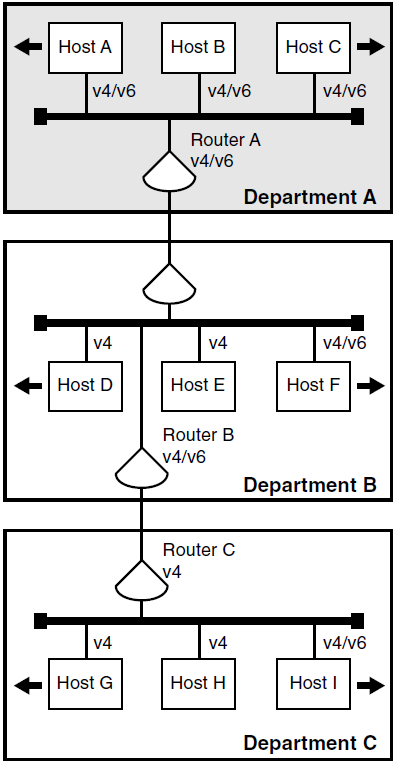
In Figure 9.2, ''Routing IPv6 Traffic from Host A to Host I'', to communicate with host I, host A sends an IPv6 packet to router A. Router A forwards the IPv6 packet to router B. Router B encapsulates the IPv6 packet and sends the IPv4 packet over a router-to-host tunnel to Host I, which decapsulates the IPv4 packet. The IPv4 infrastructure routes the packet to host I. For hosts, the host-to-router tunnel is more efficient because host A, host B, and host C administrators do not need to create individual host-to-host tunnels for each destination host.
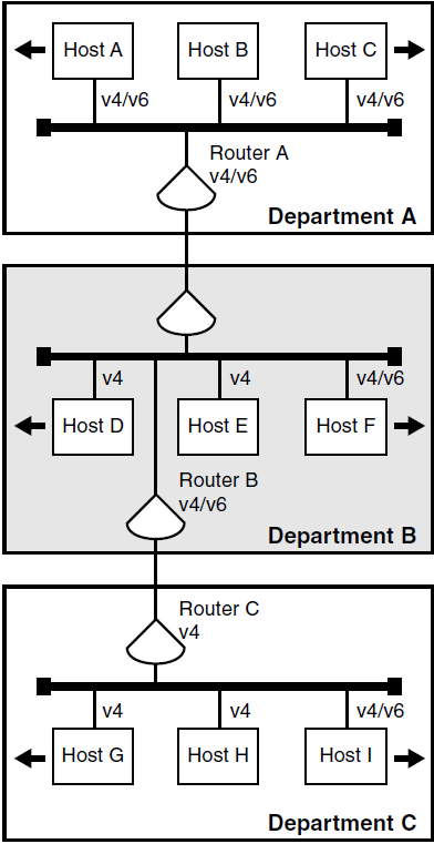
In Figure 9.3, ''Routing IPv6 Traffic from Host I to Host A'', to communicate with host A, host I encapsulates the IPv6 packet and sends the IPv4 packet over a host-to-router tunnel to router B. From there, router B decapsulates the IPv4 packet and routes the IPv6 packet to host A. For hosts, the host-to-router tunnel is more efficient because the host I administrator does not need to create individual host-to-host tunnels for each destination host.
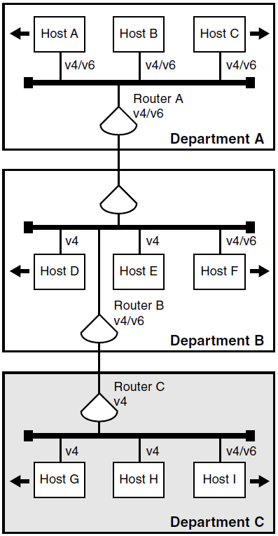
9.3.2. Intranet-to-Internet Scenario
In this scenario, you add a v4/v6 router to your network and use it to communicate with the global Internet. The IPv6 hosts communicate with the v4/v6 router using IPv6. For IPv6 traffic to v4/v6 hosts on the 6bone or the Internet, you configure router-to-host tunnels.
Figure 9.4, ''Routing IPv6 Traffic from Host A to Host J'' illustrates a scenario in which the corporation described in the chapter adds a connection from router A to the Internet. Potential destination nodes are in turn connected to the Internet.
In Figure 9.4, ''Routing IPv6 Traffic from Host A to Host J'', to communicate with host J, host A sends the IPv6 packet to router A. Router A encapsulates the IPv6 packet and sends the IPv4 packet over a router-to-host tunnel to host J, which decapsulates the IPv4 packet.
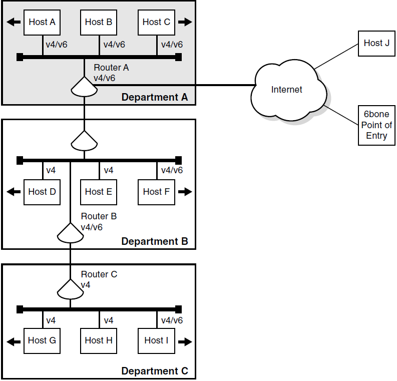
To communicate with the 6bone, host A sends the IPv6 packet to router A. Router A encapsulates the IPv6 packet and sends the IPv4 packet over a router-to-host tunnel to the 6bone point of entry. The point of entry router decapsulates the IPv4 packet and routes the IPv6 packet to its destination.
9.3.3. Intranet-to-Internet-to-Intranet Scenario
In this scenario, you add v4/v6 routers on remote subnets and connect the two of them through the Internet to create a virtual private network (VPN). An example of this might be a global corporation with manufacturing in one country and a design center in another country. The IPv6 hosts communicate with the v4/v6 routers using IPv6. For IPv6 traffic between the v4/v6 routers on each subnet, you configure router-to-router tunnels.
Figure 9.5, ''Routing IPv6 Traffic from Host A to Host K'' illustrates a scenario in which the corporation described in the previous sections wants to connect its corporate network with one of its geographically remote departments to create a VPN.
To communicate with host K, host A sends the IPv6 packet to router A. Router A encapsulates the IPv6 packet and sends the IPv4 packet over a router-to-router tunnel to router E, which decapsulates the IPv4 packet and routes the IPv6 packet to host K. For routers, the router-to-router tunnel is more efficient because the router A administrator does not need to create individual router-to-host tunnels for each destination host.
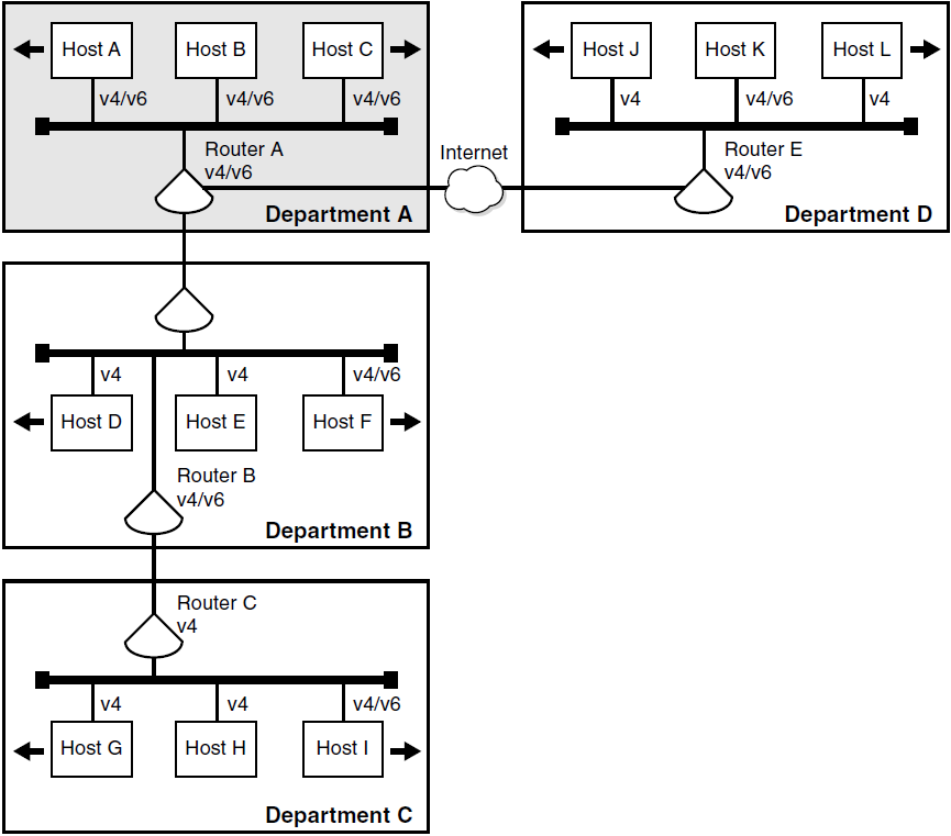
9.4. Porting Existing IPv4 Applications
The OpenVMS operating system provides the basic application programming interfaces (APIs) as defined in RFC 2553. You can use the APIs and the AF_INET6 sockets in your existing applications (or in new applications) to communicate with IPv4 nodes today. Your ported applications will continue to communicate with IPv4 nodes and will be ready to communicate with IPv6 nodes. For more information, refer to the VSI TCP/IP Services for OpenVMS Sockets API and System Services Programming manual and the VSI TCP/IP Services for OpenVMS Guide to IPv6 manual.
9.5. Obtaining IPv6 Addresses
IPv6 addresses are now being deployed by the regional registries. To obtain an IPv6 address or block of addresses, contact your Internet Service Provider (ISP).
If you are an Internet Service Provider, contact your upstream registry or one of the registries at the following locations:
APNIC (Asia-Pacific Network Information Center)
ARIN (American Registry for Internet Numbers)
RIPE NCC (Réseau IP Européens)
Because of the need to test various implementation of the IPv6 RFCs, the Internet Engineering Task Force (IETF) has defined a temporary IPv6 address allocation scheme. You can assign the addresses in this scheme to hosts and routers for testing IPv6 on the 6bone.
After you contract with your ISP for a block of addresses, your deployment of IPv6 in your network begins the process of renumbering of your network. In IPv4, network renumbering was a difficult and time-consuming process. In IPv6, network renumbering is more dynamic. This enables you to renumber your network for any of the following reasons:
Your enterprise is growing and needs more address space.
Your network needs are changing.
Your enterprise wants a global presence.
You are outgrowing your ISP.
Whatever the reason, when your current ISP contract expires, your right to use the block of IPv6 addresses also expires. Although network renumbering is simplified in IPv6, the following points will help ease the process:
Have your routers advertise new network prefixes and deprecate the old prefixes by setting a lifetime.
Change DNS servers to advertise node names and the new addresses.
Do not hard code addresses in configuration files, because this makes the process more complex and labor intensive.
Clear all server caches, as appropriate.
9.6. Installing IPv6-Capable Routers
This process depends on the hardware vendor you have chosen. You will need to define what address prefixes the router will advertise and the interfaces over which to advertise them.
9.7. Configuring Domain Name System/BIND (DNS/BIND) Servers
The OpenVMS operating system supports AAAA lookups over IPv4 (AF_INET) connections only. The resolver and server have not been ported to IPv6, but IPv6 applications can make getaddrinfo and getnameinfo calls to retrieve the AAAA records.
Before you configure a DNS/BIND server to operate in an IPv6 environment, review the following steps:
Select a node to function as an IPv6 name server.
Dedicate a zone to IPv6 addresses or add IPv6 addresses to your enterprise’s current zone. If you want global IPv6 name services, you must delegate a domain under the
ip6.intdomain for the reverse lookup of IPv6 addresses. Do not point different zone names to the same zone database file.See RFC 1886 and RFC 3152 for more information.
If the system is configured as a DNS/BIND server, change the resolver configuration to point to the local node for name lookups.
For more information about configuring Domain Name System, refer to the VSI TCP/IP Services for OpenVMS Guide to IPv6 manual.
9.8. Configuring IPv6 Routers
Before you configure IPv6 routers, consider the following points:
Identify the interfaces over which to run IPv6.
Decide whether you need a configured IPv4 tunnel for communications with other IPv6 nodes or networks. You will need the remote node’s IPv4 address (the remote end of the tunnel) and your node’s IPv4 address (this end of the tunnel).
Decide whether you want to configure static routes. You might want to configure static routes if one of the following conditions is true:
You want a configured tunnel and you are not advertising an address prefix on the tunnel link.
You want a configured tunnel and the router on the other end of the tunnel is not running the RIPng protocol.
Your system is not running the RIPng protocol.
Identify the interface (LAN, SLIP, or configured tunnel) on which you want to run the RIPng protocol or to advertise an address prefix. If you choose the latter, you must decide on the address prefix to advertise.
For more information, refer to the VSI TCP/IP Services for OpenVMS Guide to IPv6 manual.
9.9. Configuring IPv6 Hosts
Before you configure an IPv6 host, consider the following points:
Identify the interfaces over which to run IPv6.
Decide whether you need a configured IPv4 tunnel for communications with other IPv6 nodes or networks. You will need the remote node’s IPv4 address (the remote end of the tunnel) and your node’s IPv4 address (this end of the tunnel).
Decide whether you want to configure static routes. You might want to configure static routes if you want a configured tunnel to a router and the router is not advertising itself as a default router on the tunnel link.
For more information, refer to the VSI TCP/IP Services for OpenVMS Guide to IPv6 manual.
For More Information
For detailed information about the following topics, refer to the VSI TCP/IP Services for OpenVMS Guide to IPv6 manual:
IPv6 addresses
APIs and the AF_INET6 sockets
Developing applications that use AF_INET6 sockets and client/server code
Configuring the DNS/BIND server
Changing the resolver configuration to point to the local node for name lookups
Configuring IPv6 routers
Configuring an IPv6 host
For more information about APIs and the AF_INET6 sockets, refer to the VSI TCP/IP Services for OpenVMS Sockets API and System Services Programming guide.
For more information about advanced IPv6 API, refer to the TCP/IP Services release notes.